Large eddy simulations of gaseous flames in gas turbine combustion chambers L.Y.M. Gicquel ⇤ , G. Sta↵elbach and T. Poinsot CERFACS, 42 Avenue G. Coriolis, 31057 Toulouse Cedex 1, France Abstract Recent developments in numerical schemes, turbulent combustion models and the regular increase of computing power allow Large Eddy Simulation (LES) to be applied to real industrial burners. In this paper, two types of LES in complex geometry combustors and of specific interest for aeronautical gas turbine burners are reviewed: (1) laboratory-scale combustors, without compressor or turbine, in which advanced measurements are possible and (2) combustion chambers of existing engines operated in realistic operating conditions. Laboratory-scale burners are designed to assess modeling and fundamental flow aspects in controlled configurations. They are necessary to gauge LES strategies and identify potential limitations. In specific cir- cumstances, they even o↵er near model-free or DNS-like LES computations. LES in real engines illustrate the potential of the approach in the context of industrial burners but are more difficult to validate due to the limited set of available measurements. Usual approaches for turbulence and combus- tion sub-grid models including chemistry modeling are first recalled. Limiting ⇤ Corresponding author. Tel.: +33 (0)5 61 19 30 46; Fax: +33 (0)5 61 19 30 00 Email address: [email protected] (L.Y.M. Gicquel) URL: http://www.cerfacs.fr (L.Y.M. Gicquel) Preprint submitted to Progress in Energy and Combustion Science March 28, 2012

Welcome message from author
This document is posted to help you gain knowledge. Please leave a comment to let me know what you think about it! Share it to your friends and learn new things together.
Transcript

Large eddy simulations of gaseous flames in gas turbine
combustion chambers
L.Y.M. Gicquel⇤, G. Sta↵elbach and T. Poinsot
CERFACS, 42 Avenue G. Coriolis, 31057 Toulouse Cedex 1, France
Abstract
Recent developments in numerical schemes, turbulent combustion models
and the regular increase of computing power allow Large Eddy Simulation
(LES) to be applied to real industrial burners. In this paper, two types of
LES in complex geometry combustors and of specific interest for aeronautical
gas turbine burners are reviewed: (1) laboratory-scale combustors, without
compressor or turbine, in which advanced measurements are possible and
(2) combustion chambers of existing engines operated in realistic operating
conditions. Laboratory-scale burners are designed to assess modeling and
fundamental flow aspects in controlled configurations. They are necessary
to gauge LES strategies and identify potential limitations. In specific cir-
cumstances, they even o↵er near model-free or DNS-like LES computations.
LES in real engines illustrate the potential of the approach in the context
of industrial burners but are more di�cult to validate due to the limited
set of available measurements. Usual approaches for turbulence and combus-
tion sub-grid models including chemistry modeling are first recalled. Limiting
⇤Corresponding author. Tel.: +33 (0)5 61 19 30 46; Fax: +33 (0)5 61 19 30 00Email address: [email protected] (L.Y.M. Gicquel)URL: http://www.cerfacs.fr (L.Y.M. Gicquel)
Preprint submitted to Progress in Energy and Combustion Science March 28, 2012

cases and range of validity of the models are specifically recalled before a dis-
cussion on the numerical breakthrough which have allowed LES to be applied
to these complex cases. Specific issues linked to real gas turbine chambers
are discussed: multi-perforation, complex acoustic impedances at inlet and
outlet, annular chambers... Examples are provided for mean flow predictions
(velocity, temperature and species) as well as unsteady mechanisms (quench-
ing, ignition, combustion instabilities). Finally, potential perspectives are
proposed to further improve the use of LES for real gas turbine combustor
designs.
Keywords: Large Eddy Simulations, Complex geometry, Swirled flows,
Gaseous combustion, Turbulent combustion, Gas turbine
2

Contents
1 Introduction 5
2 Fundamentals of LES for complex burner simulations 9
2.1 The filtering approach: implicit, explicit and no-model ap-
proaches . . . . . . . . . . . . . . . . . . . . . . . . . . . . . . 9
2.2 LES transport equations and sub-models . . . . . . . . . . . . 12
2.2.1 Turbulence models for velocity and scalars . . . . . . . 15
2.2.2 Combustion models . . . . . . . . . . . . . . . . . . . . 18
2.2.3 LES and the DNS limit modeling constraint . . . . . . 25
2.3 Numerical methods . . . . . . . . . . . . . . . . . . . . . . . . 27
2.3.1 High-order schemes, mesh type and complex geometries 27
2.3.2 Implicit versus explicit time integration, incompress-
ible, low Mach and fully compressible approaches . . . 28
2.3.3 Boundary condition treatment and stability . . . . . . 30
2.4 The massively parallel context, mesh generation and data man-
agement . . . . . . . . . . . . . . . . . . . . . . . . . . . . . . 30
3 Laboratory-scale burner simulations 31
3.1 Key geometrical features . . . . . . . . . . . . . . . . . . . . . 32
3.2 Flow validations . . . . . . . . . . . . . . . . . . . . . . . . . . 32
3.3 Reacting flow validations . . . . . . . . . . . . . . . . . . . . . 36
3.3.1 Statistically stationary flow conditions: . . . . . . . . . 37
3.3.2 Leadership-class LES modeling and predictions: . . . . 41
3.3.3 Thermo-acoustic instabilities: . . . . . . . . . . . . . . 45
3.3.4 Transient operating conditions: . . . . . . . . . . . . . 47
3

4 Real engine combustor simulations 49
4.1 Specific features and missing links . . . . . . . . . . . . . . . . 49
4.2 Current state-of-the-art LES for real engine combustors . . . . 50
4.2.1 Swirler simulations: . . . . . . . . . . . . . . . . . . . . 52
4.2.2 Single sector simulations: . . . . . . . . . . . . . . . . . 53
4.2.3 Full annular burner simulations: . . . . . . . . . . . . . 57
5 Conclusions and perspectives 59
4

1. Introduction
Aeronautical turbulent reacting flows involve a wide range of scales and
complexities caused by the specific shapes of engines and the combustion
regimes encountered in these devices. Because of the space and weight con-
straints, designers need to develop burners which ensure maximum e�ciency
and compactness. Over the years, manufacturers have gained significant ex-
perience and existing designs largely rely on flow recirculations to increase
mixing and flow-though times despite a reduced size combustion chamber. In
parallel, pollutant emissions and regulations have induced changes of technol-
ogy with the emergence of partially premixed and premixed burners. Multi-
point fuel injection systems and staging are also being implemented as po-
tential solutions to the new regulations. All these concepts increase the
complexity of the flow and lead to specific flow dynamics and combustion
responses. Although these designs are being routinely evaluated by Com-
putational Fluid Dynamics (CFD), most present modeling strategies rely
on Reynolds Average Navier-Stokes (RANS) approaches developed for mean
stationary flows [1, 2, 3, 4, 5, 6, 7, 8, 9, 10]. Such models benefit from ex-
tensive research and developments from the scientific community and have
been successfully calibrated on simple fundamental configurations. However,
the complexity of flows in modern gas turbines adds multiple constraints on
RANS and limits their precision, Fig. 1. Alternative numerical solutions are
thus needed to further increase the share of CFD and decrease the number
of real engine tests and design iterations.
CFD alternatives to RANS for aeronautical gas turbine applications must
5

justify the increase in development, maintenance and computer costs. These
new tools need also to be compatible with existing industrial knowledge
and conception rules. The use of new CFD approaches and their future
in the design chain is still unclear. It will probably depend on the computing
power available to engineers as well as their ability to master and analyze
ever more complex predictions. From a modeling point of view, combustion
CFD scientists improved numerical predictions by focusing their e↵orts on
time and space dependent descriptions of the problems. The main objective
of such unsteady simulation is to relax the modeling constraints by taking
into account unsteadinesses and inhomogeneities which are very di�cult to
model with RANS [11, 12, 13]. Two fully unsteady computing and model-
ing strategies are currently available for turbulent reacting flows: (1) Direct
Numerical Simulations (DNS) and (2) Large Eddy Simulations (LES). While
DNS, Fig. 1 (c), suppress any notion of modeling [14, 15, 16, 17, 18, 19]
aside from the chemical model which needs to be supplied, LES, Fig. 1
(b), introduce a scale separation between the large and small scale flow mo-
tions [20, 21, 22, 23, 24, 25, 26, 27, 28, 29, 30]. Small scale e↵ects on the
large scales are thus to be mimicked by a model.
With DNS all scales must be resolved and computing costs grow with the
flow turbulent Reynolds and Damkohler numbers [31], respectively noted
Ret = u0lt/⌫ and Da = ⌧t/⌧c. These two numbers involve the turbulent ve-
locity fluctuation, u0, its characteristic length scale, lt, and time scale, ⌧t as
well as the dynamic fluid viscosity, ⌫ and a chemical time scale, ⌧c. For DNS
of non-reacting turbulent flows, every flow scale is to be resolved so scaling
6

laws read: Ret < N (4/3), where N is the number of cells in each direction
and Re3t < M , where M is the number of temporal integration steps [30, 32].
Both criteria are needed to ensure a proper statistical representation of the
larger flow scale as well as of the dissipative scales (Kolmogorov length scale,
⌘K [33, 34]). For turbulent premixed reacting flows, the spatial scaling is
RetDa < (N/Q)2 for a one-step irreversible reaction, Q being the number of
grid points in the thin reaction zone (of the order of 20 for simple chemical
schemes) [32]. DNS is hence limited by two ratios: lt/�0l , the turbulent to
flame thickness ratio and u0/s0l , the turbulent to chemical speeds. For DNS
of turbulent non-premixed reacting flows, mixing and chemical times need
to be both accurately represented since ⌧c is controlled not only by the mix-
ing of the adjacent streams of fuel and oxidizer but also by the consumption
rate (that locates around the stoichiometric line). However both phenom-
ena are flow dependent and clear numerical constraints are di�cult to obtain
unless more constraints are provided [35, 36, 37]. Current computing strate-
gies [38, 39, 40, 41, 37] with adaptive meshing and high-order numerical
schemes [42, 43, 44, 45, 46] allow to cover simple configurations which are
used for model validations and understanding of fundamentals of turbulent
reacting flows [43, 47, 46]. Aeronautical reactive flows remain out of reach
because of the high Reynolds number, O(108), and the highly energetic fuels
yielding lt/�0l to be of the order of 10 to 1, 000 and u0/s0l to range from 0.5
to 500 depending on the target application.
LES put less stringent limits for the computational size by filtering out
all flow small scales. Ideally for non-reacting, Sug-Grid Scale (SGS) flow
7

models impose that the scale separation or filter cut-o↵ frequency lies in the
inertial range of the turbulent spectrum yielding Ret < (q N)(4/3) where q is
the proportionality factor between ⌘K , the Kolmogorov length scale, and the
cut-o↵ length of the filter, �F . Hence, and aside from the chemistry prob-
lem, LES allow simulating turbulent flows with turbulent Reynolds numbers
approximately 500 times larger than DNS with the same number of points.
Evaluation of the proper scaling for turbulent reacting LES remains unclear
and often depends on the turbulent combustion model used to close the cor-
responding SGS terms.
Over the two last decades, DNS and LES have grown very rapidly thanks
to the large increase in computing power and the rise of massively parallel
architectures. LES codes and models have appeared as a clear scientific alter-
native to RANS and they are routinely being developed and bench-marked by
the turbulent combustion scientific community. Recent developments of this
approach now focus on transient flow phenomena with added complexities:
i.e. multi-phase flows, ignition and extinction sequences... Note however that
numerical and modeling pre-requisite conditions are usually not available in
the literature especially for real aeronautical burner simulations. The actual
contribution of such methods and their potential use in the context of the
industrial design chain are thus still to be investigated and tested.
This review intents to highlight available strategies and models that have
allowed LES of aeronautical applications as well as their validations thereby
underlying the current status and potential limitations or need for develop-
8

ments [48]. To do so the document focuses only on recent years gaseous
reacting LES in light of the industrial need. Details on LES (modeling, nu-
meric, massively parallel computations...) are first provided. Specificities
related to industrial flow burners are then given along with the step-by-step
recent LES validations for industry-like experimental burners. The advent
of highly resolved LES (almost DNS-like computations) are specifically dis-
cussed for these simplified yet complex burners and issues pertaining to the
modeling hypotheses of LES sub-models are underlined. Real burner LES are
then reviewed to yield the industrial state-of-the-art and highlight potential
directions for future developments.
2. Fundamentals of LES for complex burner simulations
This section describes the basics of LES: i.e. fundamentals, models for
very high Reynolds number flows and the limiting case of low Reynolds num-
ber flows, discretization of the governing model equations, boundary condi-
tions and their impact on the predictions. A specific subsection is dedicated
to the current state-of-the-art computing facilities and their impact on LES
strategies.
2.1. The filtering approach: implicit, explicit and no-model approaches
LES usually rely on spatial filtering where a filter G(x,x0; t), not yet
defined, is convoluted with the instantaneous evolution equations or flow
variables. Explicit and implicit approaches yield di↵erent classes of LES: the
former introduces the filter explicitly, applies it to the governing equations
and then discretizes the problem to obtain the solution numerically; the latter
associates the discretization of the governing equations by an under-resolved
9

grid to a filtering procedure which is undetermined hence implicit. This
section describes the di↵erences between the two approaches and highlights
their links with the numerical schemes. Details about the closure problem
and the current LES models available are given in the following sub-sections.
Filtering can be performed in the space or frequency domains. Although
LES in the frequency domain have interesting properties, their use in industry-
like configurations is unrealistic. The discussion is limited here to spatially
dependent filters and temporally invariant functions [49]: i.e. G(x,x0; t) =
G(x � x
0; t). To ease manipulation of the governing equations, the filter is
usually selected to satisfy the conservation of constants (linearity), local in-
variance and whenever possible to commute with derivation [30, 50]. These
constraints are strong and often do not apply to bounded non-uniform non-
homogeneous flow problems. Commutation errors are usually imbedded in
real flow LES formalisms [51] unless specific filters are introduced [52, 53, 54,
55]. To ensure a proper flow representation, generic properties of the initial
set of Navier-Stokes equations for reacting mixtures are also to be conserved.
Typically, Galilean, time, rotational, refection invariances and material in-
di↵erence [56, 57, 58] of the filtered quantities are desirable. The unfiltered
Navier-Stokes equations satisfy these constraints but the LES equations may
not because of the models proposed as closures. For reacting flows, the most
important property is probably the need to conserve bounds to ensure that
filtered species mass fractions do not go above one and below zero. That
simple mathematical property translates in the need for positive filters.
10

Although the notion of filters is mastered in the mathematical context,
its use in LES codes is not well defined (see chapter 7 of [30] for details). The
previous discussions on the desired filter properties are justified in the explicit
filtering context: i.e. the filter is well defined and the governing equations
are the result of the convolution operation. However, solving for the filtered
transport equations requires numerical schemes that solve a discrete represen-
tation of the continuous problem. This discretization introduces new spatial
scales into the problem especially if the grid is non-uniform (typical of indus-
trial LES solvers). Changes of cell topologies or mesh stretching are known
problems from the purely numerical point of view. In a fully explicit LES
approach, the discretization should not introduce un-controlled uncertainties
so that high-order non-dissipative and non-dispersive schemes are manda-
tory [59]. Their use whenever possible however increases the computer cost
of such simulations. To reduce spurious numerical oscillations implicit filter-
ing or pre-filtering can be introduced in the simulation (at every time step for
example) [59, 58] but again an additional overhead is inferred. Theoretically,
the notion of e↵ective filter issued by a simulation can be introduced [23] ir-
respectively of the numerics or filter used to derive the governing equations.
In this context, LES can be viewed as a combination of one subgrid model
and one numerical scheme, leading to an unknown filter also called ’e↵ective
filter’ [60, 30]. The fact that subgrid models and numerical schemes are in-
trinsically linked has lead to alternative solutions where all the dissipation is
provided by the numerics only and no sub-grid model is used [61, 62]. In that
case, ”no model” LES or MILES (Monotone Integrated Large-Eddy Simula-
tion) can be performed if the numerical scheme is constructed adequately [63].
11

Despite various potential frameworks, the risk with all these LES ap-
proaches is clear. It essentially stems from the ratio between the simulation
inertia forces to the simulation dissipative forces (resolved field convective
force over the model plus numerical dissipation forces): if this e↵ective sim-
ulation Reynolds number locally depends explicitly on the grid or model
and di↵ers from the real flow Reynolds number, large flow di↵erences are
expected. Such criteria are particularly critical for transitioning flows or spe-
cific regions of a turbulent flows (near wall region). Despite this limit, recent
developments prove LES to be a promising tool for complex applications.
Its strong ties with numerics and modeling essentially yields a di�cult en-
vironment for scientists to adequately evaluate and assess potential paths of
improvements towards fully controlled and mastered LES at an engineering
level.
2.2. LES transport equations and sub-models
Due to the non-linear nature of the governing equations of turbulent
reacting flows, spatial filtering yields a closure problem where sets of new
unknown terms need to be modeled for the problem to be solved numeri-
cally [1, 2, 3, 4, 5, 6, 7, 8, 9, 10]. Denoting the Favre filtered field by,
⇢ f(x; t) =
Z⇢(x� x
0; t) f(x� x
0; t) G(x� x
0) dx0, (1)
12
⇢ standing for the fluid density, the following recursive properties apply to
any quantity ⌧ combining primitive variables [64],
⌧(f, g) = ff g � ef eg, (2)
⌧(f, g, h) = ]f g h � ef eg eh (3)
� ef ⌧(g, h) � eg ⌧(f, h) � eh ⌧(f, g)
These terms and the LES models used for them must satisfy the desired filter
properties described in section 2.1. For turbulent reacting flows, the filtered
compressible, multi-species governing LES equations read:
Species ↵ mass fraction, Y↵, conservation:
@ ⇢ fY↵@t
+@
@xj
(⇢ fY↵ euj) = � @
@xj
[Jj,↵ + Jj,↵t] + !↵, (4)
Momentum conservation:
@ ⇢ eui
@t+
@
@xj
(⇢ eui euj) = � @
@xj
[P �ij � ⌧ij � ⌧ijt], (5)
Total energy, E, conservation:
@ ⇢ eE@t
+@
@xj
(⇢ eE euj) = � @
@xj
[ui (P �ij � ⌧ij) + qj + qjt] + !T , (6)
where, P is the pressure, ui the ith component of the flow velocity vector,
Jj,↵, ⌧ij, qj are respectively used to denote the species di↵usion fluxes, the
viscous stress tensor and heat flux [32]. Finally, !↵ and !T are the species
source terms and heat release rate issued by the chemical process taking
place in the flame. The ideal gas law and mixing laws are also needed to
close the problem. In Eqs. (4)-(6), three classes of unknown terms can be
13

distinguished. They involve correlations between velocity components, ui,
species mass fractions, Y↵, temperature, T , (denoted by the superscript t in
Eqs. (4)-(6)) as well as chemical source terms, !↵, !T :
• Second-order correlations, ⌧ijt = � ⇢ ⌧(ui, uj), Jj,↵
t= ⇢ ⌧(ui, Y↵)...
appear when rewriting the convective terms of the filtered governing
equations. These quantities are usually associated with the loss of in-
formation due to filtering fields containing a large range of length and
time scales as encountered in a turbulent flow (i.e. without chemical re-
action) [65, 66]. The associated terms are the so-called Sub-Grid Scale
(SGS) Reynolds stresses appearing in the filtered momentum conser-
vation equations, Eq. (5), and the SGS scalar fluxes appearing in the
filtered species conservation equations [67, 10, 32], Eq. (4).
• When solving for the mixture species equations, higher order correla-
tion terms arise from the filtering of the highly non linear chemical
reactions that control the consumption and production of species and
heat release: i.e. !↵, !T . These chemical source terms need to be
addressed accurately if combustion is to be properly predicted. Such
terms involve complex products of species mass fraction to given pow-
ers, exponential functions of temperature and they can not be simply
approximated by the substitution in the respective expressions of the
filtered fields [68, 69, 70]. The art of turbulent combustion modeling
is a key ingredient of models for !↵ and !T : many models actually
express source terms as functions of new quantities such as the scalar
dissipation rate or the flame surface density, depending on the com-
bustion regime [71, 72, 73, 74, 75, 76, 77, 78] and require additional
14

conservation equations.
• Other terms such as ⌧(ui, uj, uk) or ⌧(ui, p) are often disregarded and
will not be comprehensively discussed here unless specifically needed.
For example, transport of any energy which includes the flow kinetic en-
ergy, yields, after filtering, a third order term which needs closure [79].
Compressible flow governing equations also involve pressure-velocity
terms that may be of importance [80, 81, 82]. Similarly, it is of usual
practice to neglect molecular properties fluctuations (such as viscosity,
di↵usivity...).
2.2.1. Turbulence models for velocity and scalars
SGS Reynolds stress models: Conventional SGS Reynolds stress models
are based on the Boussinesq hypothesis and the notion of turbulent viscos-
ity. These are probably the most popular models and almost exclusively used
in industrial flow LES. A non-comprehensive view of such closures is provided
below with emphasis on their derivation and the target properties, Table. 1.
Since real reacting flow LES mainly treat the problem in physical space, only
models applicable in this context are addressed, although spectral models
do provide important information. For more information or a current status
on developments in LES turbulent modeling, readers are referred to more
fundamental reviews [22, 25, 29, 30].
The Smagorinsky model [83] is probably the most popular turbulent clo-
sure model when dealing with complex configurations because of its simplicity
and robustness. Derived in the context of isotropic decaying turbulence [84]
15
with an assumption of equilibrium between kinetic energy fluxes at all turbu-
lent scales, its advantages and weaknesses are well known. Its first weakness
is that it is not suitable for transitioning flows or to treat wall turbulence.
Improvements of the original model cover its use for anisotropic grids [85, 86],
automatic estimations of the model constant [87, 88, 89] through the use of
dynamic procedures based on Germano’s identity [64] or the use of a trans-
port equation for the SGS kinetic energy to account for non-equilibrium of
the turbulent field [90, 91]. Although dynamic procedures clearly improve
LES predictions and extend the general use of the SGS closures, their imple-
mentation in general purpose LES codes usually requires some local averag-
ing [88, 89, 92, 93] and an implementation of a test filter.
In the context of wall bounded or transitioning flows with a strong impact
of the mean shear, the conventional eddy viscosity estimates over-predict the
turbulent di↵usivity resulting in excessive turbulent di↵usion and artificial
re-laminarization of the LES filtered field. Based on turbulent properties
and invariants [94, 95, 56, 96], new expressions are possible to improve the
model behavior as produced by [97, 30, 98, 99, 100] similarly to RANS ap-
proaches [101]. An alternative for wall bounded flows which still remains a
weak point of LES SGS models is the use of correction functions or specific
wall modeling [102, 103, 104, 105].
A second class of SGS velocity model relies on the similarity hypothesis
between the resolved field and a test scale [106]. Linearization of the similar-
ity hypothesis yields the so-called tensorial eddy viscosity model or non-linear
16

model [107]. Deconvolution methods have also appeared [108] and although
these new models have shown great potential in a priori validations, a poste-
riori use proved them to be insu�ciently dissipative. Mixed closures relying
on the first set of Smagorinsky like models and similarity expressions have
been proposed [109, 110].
Other approaches [90, 111, 112, 86, 113, 114, 115, 116, 117, 63] with var-
ious degrees of maturity illustrate the still on-going e↵ort to propose reliable
and more general turbulent LES closures.
SGS species and scalar flux models: Similarly to the velocity SGS term,
the species or scalar SGS flux is usually modeled based on the Boussinesq
hypothesis and the use of turbulent Schmidt or Prandtl numbers [118]. Such
numbers are necessary to deal with the di↵erences in physics that govern the
evolution equations: i.e. turbulent fluctuations cover all scales from integral
to Kolmogorov scales [33, 119] while scalar fluctuations go all the way to
the Batchelor or Corrsin (Sc < 1) scales [3, 120, 70]. Dynamic procedures
have also been proposed [80, 121, 122] following the formalism discussed
above. Extensions using di↵erent tensorial relationships have also been de-
veloped [123, 124].
For species and temperature turbulent mixing, alternatives to the gra-
dient di↵usion hypothesis are scarce and mainly reduce to the Linear Eddy
Mixing (LEM) model [125, 126, 127, 128, 129, 130, 131, 132, 133] or trans-
ported FDF approaches [134, 135]. It is important to note that most of the
17

mixing LES models available today strongly rely on the accuracy of the tur-
bulent viscosity closure. Furthermore these are usually directly applied to
turbulent reacting flows despite the clear limitations and the strong link that
exists between mixing and chemical reactions [68, 136, 70].
2.2.2. Combustion models
The filtered species and energy equations can not be closed without a
significant modeling e↵ort. They are not only governed by turbulence but
also depend on mixing: di↵erent combustion regimes are possible depending
on the flow configuration, type of fuel and injection system present in the
burner [76]. Combustion regimes are usually introduced to characterize the
physical processes that dominate a flame and to choose closure models: i.e.
flamelet, distributed reaction, thickened flame... [76, 137] Laminar flames are
the natural starting point to distinguish combustion modes present in real ap-
plications: di↵usion flames, premixed flames and partially premixed flames.
The addition of turbulence is usually introduced through the notion of com-
bustion diagrams to justify the use of a specific turbulent combustion model
knowing the combustion mode. Contrarily to RANS, LES models must also
degenerate naturally to filtered laminar flames in zones where turbulence is
low: they must preserve a large part of the flame structure.
A brief overview of major LES combustion/chemistry sub-models is pro-
vided below relying on the presentations of [76] and [137]. More comprehen-
sive reviews on this specific problem are available in [138, 139, 140, 141, 142,
143, 144, 78, 77, 78].
18

Chemical description: Combustion is a multi-scale phenomenon involving
a broad range of time scales which find their root at the atom level. Starting
with the atomic bounds around 10�15 s, Arrhenius laws allow to reduce time
scales of leading species from 10�15 s to 10�10 s and of the order of seconds for
slower reactions. Integrating such sparse systems remains a challenging task
especially when they need to be coupled to transport phenomena. To start
addressing such issues prior to their use in a CFD code, di↵erent methods
are available and one needs to choose from a wide range of strategies [137]:
• Constitutive relations: such as Arrhenius laws for rate constants aim
at representing atomistic precess by a continuum.
• Chemical mechanism reduction: intent to identify most important species
and reaction steps in order to decrease significantly the number of
species and reactions needed to represent the initial skeletal mecha-
nism. Di↵erent techniques exist for reductions: i.e. Quasi-steady state
(QSS), Partial Equilibrium (PE), Computational Singular Perturbation
(CSP) [145], Intrinsic Low-dimensional Manifold (ILDM) [146, 147].
• Sti↵ chemistry integrators: aim at removing sti↵ness in the set of ordi-
nary or partial di↵erential equations [148, 149] needed to describe the
reduced chemical system in the presence of transport.
• Storage chemistry approaches: aim at accelerating the chemistry in-
tegration while the CFD integration proceeds. Tabulation of pre-
computed laminar or turbulent flames falls in this class of approaches.
19

Flamelet Generated Manifolds (FGM) [150, 151] or Flamelet Prolon-
gation of ILDM (FPI) [152, 153, 154, 155, 156] tables are typical exam-
ples. In Situ Adaptive Tabulation (ISAT) [157], Piece-wise Reusable
Implementation of Solution Mapping (PRISM) [158] or Artificial Neu-
ral Networks (ANN) [159] are other examples where the tables adapt
automatically during the CFD computation.
The main limitation behind all reduction methods is the reduced range of
applicability. The final kinetic model also ends up having strong links with
the turbulent combustion model which itself contains underlying assump-
tions (often related to specific combustion modes and regimes). All these
observations seriously reduce the extent and generality of some of the tables
or schemes obtained.
Turbulent combustion models: The turbulent combustion closures avail-
able to the CFD LES community are numerous and are often direct exten-
sions of RANS turbulent combustion models. Such direct extensions are
legitimate since all scales associated to the flame are usually below the LES
filter length scale. Care is however needed as discussed in Section 2.2.3.
Like RANS modeling, LES turbulent combustion models rely heavily on
the combustion fundamental theories and combustion modes: i.e. fully pre-
mixed, non-premixed [70] for which the basic properties are recalled below.
• Premixed flames are combustion modes where fuel and oxidizer are fully
mixed before reacting: the flame front separates the unburnt premixed
gases from the fully burnt reactants. Species and temperature transport
20

is important only in the vicinity of the flame. Under the assumption of a
simplified chemical description and transport, the governing equations
can be recast into a single global equation for the progress variable
characterizing the state of reaction. This progress variable is usually
noted c and non-dimensionalized to equal zero in fresh gases and one
in burnt gases. The unfiltered or exact evolution equation of c reads:
@ ⇢ c
@t+
@
@xj
[ ⇢ uj c ] =@
@xl
⇢D
@c
@xl
�+ !c. (7)
If the flame is thin and can be described as a propagating front, Eq. (7)
can be written in a propagative form called the G-equation by tracking
the position of an iso-c surface [75]:
@ ⇢ c
@t+
@
@xj
[ ⇢ uj c ] = ⇢ s0L@c
@xl
(8)
where the laminar flame speed noted s0L appears explicitely and charac-
terizes the propagation of the local premixed flame elements [160, 161,
162].
• For non-premixed or di↵usion flames, fuel and oxidizer are separated
and combustion occurs in the di↵usive region where molecular and tur-
bulent transport allow mixing of the two components prior to reaction.
Here again, laminar and SGS mixing terms are essential since they con-
trol the rate of consumption [75, 76, 70]. For simplified transport and
kinetics, Schwab-Zeldovich [163] variables or conserved scalars (noted
Z) transport equations can be derived to represent the state of mix-
ing within the flame independently of reaction. Its unfiltered or exact
21
transport equation reads:
@ ⇢ Z
@t+
@
@xj
[ ⇢ uj Z ] =@
@xl
⇢D
@Z
@xl
�. (9)
Similarly to premixed modes, a coordinate attached to the stoichiomet-
ric iso-Z surface allows to recast the species transport equations with
specific di↵usive terms: scalar dissipation rate � = D @Z@x
l
@Z@x
l
, species
transport across iso-Z lines in the normal and tangential iso-Z directions
and reaction. Neglecting curvature e↵ects, local composition within the
flame appears to be controlled by the scalar dissipation rate.
• All regimes which are nor premixed neither non-premixed are called
partially premixed. They are encountered quite often in gas turbines
and are much less understood. Such regimes control auto-ignition prob-
lems, flame stabilization in the near field of burners, local quenching
or re-ignition mechanisms. A simplified partially premixed flame pro-
totype is the triple flame configuration [164, 165, 166, 167, 168, 169,
170, 171]. Classical models developed for premixed or purely di↵usion
flames should not be used unless specifically adapted.
Based on these fundamental developments for specific combustion modes,
many turbulent combustion models are available for LES. Following the clas-
sification of [172, 76, 31], one distinguishes between the purely geometrical
and pseudo-statistical/statistical type of closures.
In purely geometrical approaches, the governing equations are in a prop-
agation form and unclosed terms are provided in light of the combustion
regimes characterized by the turbulent Reynolds number, Ret, turbulent
22
Damkohler number, Dat and/or the turbulent Karlovitz number, Kat. These
models are usually linked to the flamelet assumption: i.e. the reaction zone
is thin compared to turbulent length scales and only curvature, stretch and
wrinkling e↵ects impact the filtered rate of reaction in the iso-c or iso-Z
formulations. For this class of models the notion of flame surface density
per unit volume, ⌃, or flame wrinkling factors, ⌅, can also be introduced to
evaluate the filtered value of the reaction rate [173, 174, 175, 176, 177, 178]
using: f!k =f⌦k
e⌃, where f⌦k stands for the local density filtered burning rate
of species k per unit flame area, or using a model for e⌅ = f⌦k/q
@ec@x
l
@ec@x
l
, the
wrinkling factor. Both approaches require information on the flame inner
structure and chemistry.
In statistical models, SGS terms can be constructed using the Filtered
Density Function (FDF) or Probability Density Function (PDF) associated
with the filtering operation of LES [179] (cf. [180] for further discussions on
the di↵erences between FDF and PDF formalisms in LES). The main result
of such formalisms is that unknowns can be obtained by direct integration
of the FDF or PDF. In these methods, two distinct sub-classes are to be
distinguished:
• The presumed approach where the FDF/PDF form is fixed a priori
and usually parameterized by the local value of the filtered quantity
and its second filtered central moments. Conventional presumed PDF
shapes are the delta, beta, Gaussian and Log-Normal functions. Within
the same working frame, the Conditional Filtered Moment Closure
(CMC) [181, 137] approach consists in solving the transport equations
23

of the conditionally filtered terms (some of which appear in the evo-
lution equation of the FDF/PDF) which can then be multiplied by
a presumed FDF/PDF and integrated to yield estimates of the SGS
unknowns.
• The transported FDF/PDF approach solves directly for the governing
equation of the function and performs the numerical integration of the
estimated FDF/PDF to yield values for the filtered unclosed terms
present in the LES transport equations.
From a modeling point of view each approach implies the closure of spe-
cific terms appearing in the evolution equations. In that respect, SGS or
equivalent terms involving mixing through velocity/species are to be ad-
dressed unless the velocity/species FDF/PDF is considered [182, 183, 113,
134, 135, 184, 185]. Scalar dissipation rate or equivalent terms must be closed
too [186, 67, 74].
One last type of model for LES of turbulent reacting flows can also be
somehow classified as pseudo-statistical approach: the Linear Eddy Model
(LEM) [131, 132]. In this approach, the initial filtered profiles (or coarse-
grained structures) are mapped onto a so-called triple-map structure which
is parameterized by a PDF and aims at representing the e↵ect of eddies on
mixing as well as stirring all the way to the viscous range. Reaction is taken
into account in this 1-D space. Each physical process is taken into account
using a splitting operator technique preserving specific time scales of each
process.
24

Table 2 summarizes possible LES turbulent combustion models with speci-
ficities and context of development. For further information, readers are
redirected to [76, 137] and turbulent combustion books [75, 119, 31, 187].
2.2.3. LES and the DNS limit modeling constraint
Originally LES models were constructed for non reacting flows and de-
rived in the high Reynolds number limit to ensure the existence of the inertial
range within the turbulent spectrum. Another constraint is that LES model
contributions should vanish as the filter size tends to zero to recover the
DNS limit of the simulations: i.e. a fully resolved simulation where all of
the dissipative scales are captured. Likewise and to properly recover the DNS
limit or transition regions, models should distinguish regions of potential low
Reynolds number from fully turbulent ones, go to zero near walls and flows in
solid rotation or purely sheared, in axisymmetric or isotropic expansion (or
contraction). With such constraints dynamic filtering [87, 64, 88, 85, 188]
and higher order tensor relationships constitute clear benefits since introduc-
ing increased locality through test filtering or improved asymptotic behaviors
of the SGS modeling issued by a better qualification of the local resolved flow
state, Table. 1.
For reacting flows, the situation is more complicated because combustion
almost always takes place at scales which are not resolved today. For exam-
ple, LES of experiments with low Reynolds but large Damkohler numbers
corresponds to flows where all turbulent scales can be resolved but the flame
front reaction zone is still under-resolved. Typically, in real applications the
fuel consumption rate of highly energetic species such as kerosene is large and
25

leads to Damkohler numbers larger than one (i.e. very thin reaction fronts).
Within the same flow, the Damkohler number associated with the chemical
steps of NO or CO are usually close to one. Modeling is thus confronted
with the major di�culty of ensuring the proper description of the interaction
of the kerosene consumption in a thin front strongly a↵ected by turbulence
while providing the missing information for slowly evolving chemical reac-
tions in an inhomogeneous hot medium that is weakly turbulent. Modeling
is thus essential: even-though models are usually derived for flames in highly
turbulent flows, they must also be able to propagate quasi-laminar fronts in
low turbulence zones as well as in highly resolved intense turbulent fields.
In some configurations, neglected terms in the exact filtered transport equa-
tions may play non-negligible roles [189, 190, 191, 192]. Such issues are
becoming of greater importance with the advent of massively parallel com-
puters: in a few years, these computing resources will allow to resolve flow
and flame structures in such regimes and SGS models must degenerate to
true DNS [189, 190, 191, 192].
A final observation which further underlines the potential di�culty of
mastering the DNS limit of LES comes from recent works on LES modeling
for stationary turbulent flows [193, 194, 195, 196]. From these studies, it is
clear that defining a clear procedure to unanimously qualify di↵erent LES
approaches is not an easy task. Indeed, it is now well accepted that a LES
prediction is the result of combined modeling and numerical errors and the
behavior of such a cocktail is often counter-intuitive [193, 194, 195, 196]. For
example, if one accepts to change the value of the Smagorinsky constant
26

noted CS, an optimal grid resolution CS pair exists which provides good
quality predictions [193, 194, 196] at minimum cost and away from the DNS
limit. Because of such observations, multiple LES quality indices have been
proposed [197, 198, 199, 193] for non-reacting and reacting [200] flows. These
issues are still to be answered to systematically qualify LES SGS modeling
and numerical strategies for an improved understanding of LES predictions
in complex geometries.
2.3. Numerical methods
LES flow solvers are either incompressible, fully compressible or based on
the low Mach number approximation. Each approach imposes di↵erent algo-
rithms, computer costs and numerical schemes which may not be compatible
with LES basic constraints. However and based on current state-of-the-art
LES solvers, key features seem to emerge and this section summarizes them
with a specific emphasis on their advantages and disadvantages. Readers can
find details associated to High Performance Computing for CFD on massively
parallel systems in recent review papers [201, 202]. A non-comprehensive list
of codes dedicated to LES of reacting flows is provided in Table. 3 along with
the numerical characteristics retained in each case and the research groups
involved in their developments.
2.3.1. High-order schemes, mesh type and complex geometries
Despite recent controversies, there is little doubt that high-order schemes
are desirable for LES to minimize numerical dispersion and dissipation and
to preserve good quality unsteady flow predictions. That constraint imposes
the use of high-order centered spatial schemes with the addition of artificial
27

viscosity on highly disturbed grids. In a world where only simple geometries
would be computed (for example laboratory-scale systems), this constraint
would lead to structured grid methods on which high-order schemes (from
4 to 8th order) are easily built. Unfortunately, most real combustion cham-
bers have geometries which are so complicated that meshing them with a
multi-block structured grid takes too much time. In addition, good strong
scaling requires balanced decomposition of the computational domain which is
di�cult with a pre-decomposed block-structured approach in geometries other
than cubes and assimilated. As a result, most recent LES codes for real gas
turbines are developed using unstructured or hybrid grids. Interestingly, on
such grids, developing high-order numerical schemes is a challenge. Most
existing solvers on unstructured grids are limited to second-order spatial
accuracy except the (expensive) TTGC scheme developed by Oxford and
CERFACS [203]. Combining the accuracy of high-order schemes developed
for structured grids with the flexibility of unstructured grid solvers is a key
issue in the construction of combustion LES solvers.
2.3.2. Implicit versus explicit time integration, incompressible, low Mach and
fully compressible approaches
Combustion codes are easily written in compressible form: a simple ex-
plicit technique allows to develop rapidly a solver for LES of reacting flows on
unstructured grids. The main disadvantage of such solvers is that their time
step is limited by the CFL condition which is controlled by the sound speed.
For very slow flames, computing a flow-through time can require too many
time iterations and lead to a very slow computation (or large turn around
time). This discussion is actually complicated by di↵erent issues:
28
• Alternative solutions to explicit compressible codes are: (1) time im-
plicit compressible methods and (2) low-Mach formulations. In time
implicit compressible methods, the full compressible equations are solved
implicitly to remove the CFL constraint. In low-Mach formulations,
acoustics are removed from the conservation equations and a Poisson
solver is needed to obtain pressure at each instant. For approaches (1)
and (2), large implicit systems must be solved at each iteration. Both
approaches are found in combustion codes [204, 205] and constitute
interesting and e�cient alternative methods.
• The fully compressible solvers still have a few advantages [206, 201]:
being explicit, they are e�cient on very massively parallel systems.
They also capture acoustics naturally, a property which is mandatory
to study certain instabilities. In practice, implicit compressible solvers
are stable over a wide range of CFL numbers but they are not precise
and must be run for constrained CFL values (smaller than 10), making
them potentially as slow as explicit solvers. The main reason for such
a behavior is linked to the matrix inversion which is time consuming.
Low-Mach number codes o↵er more convincing performances especially
for very slow flames where acoustics is not important and the linear
system to be solved of reasonable size.
• In practice, in most gas turbine combustion chambers, Mach numbers
are not small. Within swirlers, Mach numbers of the order of 0.3 are
common. At chamber outlets, a throat created by the high pressure
stator usually creates a choked region. For these cases, compressible
29
solvers remain mandatory.
2.3.3. Boundary condition treatment and stability
The numerical treatment of the flow boundary conditions is also of im-
portance and can result in artificially stable or unstable computations. These
treatments di↵er depending on the set of equations solved (i.e. compress-
ible or incompressible Navier-Stokes equations). An important conclusion
reached in the last ten years is that the flow within the combustion chamber
can be computed with much more precision using LES than RANS and that,
at this level of precision, outlet and inlet conditions become critical. Typ-
ically, a proper LES of a combustion chamber should include a description
of the mean and turbulent flow at the inlet (resolved in time). Moreover,
the acoustic impedances at inlet (compressor side) and outlet (turbine side)
should also be known: this is not the case today and work is required on
these questions because these boundary conditions probably control the flow
more than the details of the SGS models used within the chamber.
2.4. The massively parallel context, mesh generation and data management
Real burner LES imply the use of high end massively parallel super-
computers which process data subsets of the same problem in parallel. E�-
cient and minimum exchanges of information are mandatory to ensure scal-
ability up to thousands of cores. Message passing coding is at the root of
parallel computing. As mentioned above, e�cient message passing for CFD
in gas turbine chambers requires using fully unstructured grids. However,
the generation of large unstructured meshes and their partitioning become
bottlenecks today [201, 202, 207]. I/O must also be totally reorganized to
30

avoid slowing down the code. These issues raise specific questions about the
exploitation and maintenance of the codes: maintaining a code which can run
e�ciently both on distributed and shared memory machines with thousand
of cores is extremely di�cult.
All of the above mentioned modeling and algorithmic issues are clearly of
major importance for real applications. Building codes aiming at simulating
real industrial problems often imposes a list of sacrifices: spatial accuracy and
modeling are usually sacrificed to ensure robustness and performance, thereby
giving access to LES predictions of such complex flows with a bounded and
reasonable computer cost. These choices are clearly needed and based on
specific and scientifically identified pros and cons, simple models may be fa-
vored provided that their limits are well understood and implications on the
LES predictions well anticipated. The di�culty inherent to such choices and
model limitations are thus of foremost importance to ensure valuable exploita-
tion and understanding of the obtained results to contribute to the decision
making. The next section reviews aspects of the validation steps followed by
researchers and industry to better qualify the di↵erent LES numerical and
modeling strategies available today.
3. Laboratory-scale burner simulations
Laboratory-scale burners are usually designed to assess modeling and
fundamental flow aspects in controlled configurations. They are necessary to
assess LES strategies as well as their limitations, reliability, capability and
orient future developments.
31

3.1. Key geometrical features
To be representative of real gas turbines, laboratory burners need to re-
tain specific features and cover a wide range of turbulent flows and physics
that are present in gas turbine engines. For example, it is desirable to
use real swirlers and to mount them on experimental test facilities heav-
ily equipped with flow and combustion diagnostics. Since 2000, multiple
laboratories have followed this path. In the following mainly swirled flames
are discussed as they are typical of the next generation of gas turbine com-
bustion chambers. Swirl is used to generate large recirculation zones that
are usually located right outside the injection system, improve mixing, ease
flame stabilization and locally increase the flow residence time thereby re-
ducing the size of the combustion chamber [208, 209]. Simple laboratory
burners [208, 210, 211, 212, 213, 214, 215, 216, 217, 218, 219, 220, 221] with
such features have been used to qualify LES.
3.2. Flow validations
Swirling flows without combustion have been heavily investigated (see
reviews [222, 208, 223, 224, 225, 226, 227, 228]). They nonetheless remain
di�cult to compute [209] even though recent LES [229, 230, 231, 232, 233]
allow confidence in this modeling strategy for more complex geometries. The
main specificities of swirl confined flows are illustrated on Fig. 2. The two
main non-dimensional numbers controlling simple swirled flows are the Swirl
number, S and the Reynolds number, Re:
S =G�
R Gx
=
R R
0 U W r2 dr
RR R
0 U2r dr, (10)
32
Re =U0 R
⌫. (11)
S measures the ratio of the axial flux of the swirl momentum, G� [kg m2
s�2], to the axial flux of the axial momentum, Gx [kg m2 s�2] multiplied by
a characteristic length of the swirl annulus, R [m]. In Eq. (10), U [m/s] and
W [m/s] are the mean axial and tangential velocities measured in a plane
usually located at the exit of the swirl generator. The Reynolds number
is defined using the bulk axial velocity, U0, the swirler annulus radius, R,
and the fluid kinematic viscosity, ⌫. Other definitions are possible for the
swirl number and originate from purely geometrical considerations [215]. For
example, the geometrical swirl,
Sg =W0
U0, (12)
is often encountered.
Depending on Re and S, the following mechanisms and structures appear:
• Inner Recirculating Zone (IRZ): This region is created by the intense
swirl. Usually located right along the axis of the swirler, this recir-
culation bubble appears for large values of S (typically above 0.6).
It results from the radial pressure gradient generated by the guided
rotating flow (large tangential velocity component of the flow) and
the flow expansion through a nozzle at the chamber inlet: the ra-
dial pressure gradient and axial velocity components suddenly decay
producing a negative axial pressure gradient and a reverse flow or
IRZ [222, 208, 223, 224, 225, 227, 226, 228].
33
• Corner Recirculating Zones (CRZ): In confined configurations, the sud-
den expansion of the flow at the chamber inlet is partly controlled by
flow recirculating bubbles present at the outer edges of the dump [208,
234, 224].
• Processing Vortex Core (PVC) and Vortex Breakdown (VB): Under
specific conditions (still not clearly mastered) the central vortex core
present in the inner parts of the swirler or the IRZ becomes unstable
giving rise to the PVC [224]. This destabilization can induce oscil-
lations of the IRZ in the axial and azimuthal directions. The PVC
believed to be at the origin of such oscillations coincides with a vor-
ticity tube of helical shape located at the outer rim of the IRZ. This
thin vortex tube has a helicoidal shape can be co- or counter-rotative
to swirl, Fig. 3. It then can turn around the swirler axis in the swirl or
opposite direction. In some cases several vortex tubes may co-exist at
the same time [235, 236, 237]. Finally, this specific structure is highly
dependent of the CRZ and IRZ interactions [238], which are controlled
by the details of the swirler and dump configurations.
LES flow predictions and validations on unconfined swirled configurations
provide an evaluation of LES codes on flows typical of real burners (Table 4).
A typical experiment proposed for this specific purpose is the Sandia burner
described on Fig. 4 and investigated numerically by [229, 232, 233] in its
non-reacting operation. Other swirl injector systems [239, 240, 241], Fig. 5,
have been also investigated numerically [230, 242, 243, 244] with the same
observations as the one produced below.
34

Predictions of the mean statistical flow features: For large swirl number
and moderate swirl Reynolds number flows [245, 215], LES of the configura-
tion illustrated on Fig. 4 is found to be quite insensitive to grid resolution and
SGS modeling, Fig. 6(a). At moderate swirl numbers, near Vortex Break-
down (VB): i.e. S ⇡ 0.5, predictions are more sensitive but remain interest-
ing and encouraging, Fig. 6(b). SGS dynamic procedure and grid resolution
may be of importance in such critical flow conditions. Inflow conditions are
also suspected to be of primary importance and should at least reproduce
the unsteady e↵ect of a turbulent flow entering the computational domain.
LES still remain the only current modeling strategy that correctly predicts
mean statistical (i.e. mean and Root Mean Square (RMS)) flow features in
strongly swirled flows.
Predictions of the unsteadiness of swirl flow features: The unsteady struc-
tures characteristic of swirl flows control the fuel and air mixing process and
the interactions between the flame and the flow. These unsteady characteris-
tics are much less investigated or validated because of the di�culty in prop-
erly characterizing such motions experimentally or numerically. The PVC is
known to be weakly dependent of Re and its frequency f can be expressed
in terms of a Strouhal number, fDe/U0 where De stands for the swirler exit
diameter [228]. Evaluations of the LES issued PVC’s [239, 240] and their
Strouhal numbers for the cold flow configuration of Fig. 5 (a) are overall in
agreement with experimental findings [241, 246, 247, 248, 249, 250], Fig. 7;
typical findings report approximately 10% errors when comparing LES PVC
frequencies with experimental measurements.
35

For these well documented geometries [245, 215, 239, 240, 251, 252, 253],
LES predictions are encouraging, Figs. 6 & 7. In configurations where S
is above the critical swirl number of 0.5 � 0.6 where VB is expected [254,
238, 255], results are very satisfactory (cf Sandia configuration of Fig. 6).
In most reacting systems, the fuel injection location within the swirler is of
importance not only because it determines mixing, but also because of the
interaction and potential flow topology change they may have on the swirling
flow. Jet/IRZ interaction is often present and impacts the evolution of the
PVC and even the IRZ itself as discussed by [228] (cf. Fig. 6 for a typical
example).
3.3. Reacting flow validations
LES of reacting flows is a relatively new research topic which only emerged
in the early nineties and became a focus point of CFD research in the late
nineties. This contrasts with research on ’pure’ LES (i.e. without reac-
tion) that appeared in the sixties in the weather-forecast community [83, 90].
Many reasons explain these di↵erences. The first one probably originates
from the turbulent combustion community itself which dedicated a lot of ef-
fort in implementing new combustion models for RANS and naturally lags
the turbulent community. Second, computer power and the emergence of
highly e�cient machines and algorithms only recently allowed to address
even simple laboratory-scale configurations which was a necessary step for
the turbulent reacting LES concept to be validated. Finally, very few the-
ories or mathematical models are available for turbulent reacting flows for
36

conceptual validations. This is clearly not the case for turbulent non-reacting
flows. In parallel to these e↵orts, new flame modeling concepts appeared and
the turbulence as well as the turbulent combustion communities started to
recognize the role of the most energetic flow structures in CFD. All these de-
velopments are transcribed in the TNF workshop series [256] or Combustion
Symposium series [257] which mainly addressed RANS modeling validations
until the 1990s and now focus almost exclusively on LES.
The following discussion focuses on some of the recent contributions and
e↵orts in the field of reacting LES in swirled configurations. First, statisti-
cally stationary unconfined and confined simple configurations are reviewed
followed by a discussion on recent leading-edge LES applications to illustrate
the possibilities of massively parallel architectures. Finally, two specific re-
search subjects benefiting from these recent LES developments are discussed:
(1) thermo-acoustic instabilities often encountered in real gas turbine engines
and (2) transient phenomena (ignition, extinction sequences...).
3.3.1. Statistically stationary flow conditions:
Many LES contributions mainly aim at validating SGS turbulent com-
bustion models (cf. the series of TNF workshop proceedings and comments
on the matter). Swirled flames have been computed only recently, Fig. 8
(predictions for the Sandia burner of Fig. 4), and most of the e↵ort has been
concentrated on jet flames. A list of the identified productions for laboratory
swirled flames is given on Table 4. These studies generally demonstrate the
superiority of LES for turbulent reacting flows. The main reason originates
in the natural unsteady nature of the governing LES equations which dynam-
37

ically reproduce the interactions that control mixing and turbulence/flame
interactions over a wide range of applications. These laboratory tests have
however a major limitation to qualify SGS sub-models for mixing and turbu-
lent flame interactions: their Reynolds number is low inducing a significant
overlap of the inertial and dissipative scales thereby violating the scale separa-
tion hypothesis needed for most SGS closures. Conclusions are thus di�cult
to extrapolate to real gas turbine flows where the flow Reynolds number is
much higher. Fuels are also much more energetic (thinner flame fronts) and
grid resolutions much lighter. All of these issues have been identified and
highlighted in Section 2.2.2. The di�culty reduces in discriminating turbu-
lent combustion models based on reliable quality criteria in the context of
mixing and reaction. This last subject still remains an open issue despite
recent contributions [200].
Recent LES publications on gaseous laboratory scale swirl flames for the
Sandia burner illustrated on Fig. 4 and complementing the predictions of
Fig. 8, provide first insights on the importance of modeling strategies. This
example was produced jointly by researchers in England (Imperial College
and Loughborough University) [258] with two low Mach number structured
(in cartesian and/or cylindrical formulations) LES codes. Results are pro-
vided on Fig. 9 for the swirled experiment of [215, 216]operated with methane,
air and hydrogen for two swirl numbers (Sg = 0.32 for SMH1 and Sg = 0.54
for SMH2, respectively). Although the codes di↵er, they theoretically use
the same LES formalism. The simulations are produced on di↵erent grids
and slightly di↵erent boundary conditions. SGS velocity closures rely on
38
dynamic closures [24] with numerical regularization for unphysical model
coe�cients (clipping). Turbulent combustion modeling relies on single or
multiple flamelet approaches, Eq. (9). Chemical terms are obtained from
two chemistry models with variable or constant strain rates and a subgrid
scalar variance, gZ Z � eZ eZ, is coupled to a presumed Beta PDF. Depending
on the LES method available in each code, the scalar variance is closed either
by use of [259] or [260].
Mean velocity, mixture fraction and temperature predictions for SMH1
are compared to experimental data on Fig. 9. When available RMS pro-
files are added. Similar results for SMH2 are also available [258]. Overall,
both LES codes and strategies provide similar behaviors. Grid sensitivity
and inflow boundary specifications are specifically highlighted underlying
the di�culty of clearly di↵erentiating one modeling strategy compared to
another one (see above discussion on boundary condition e↵ects). However,
both approaches provide very satisfactory predictions of the mean and RMS
flow fields irrespectively of the flow swirl number. Mixing is well predicted
for both experimental conditions. Mean temperature profiles are consistent
with experiments.
Similar validations against laboratory scale burners with more complex
geometries start to appear. Such a comparison has recently been produced
within the context of the TIMECOP AE European project 1 involving major
1TIMECOP AE stands for Toward Innovative Methods for Combustion Prediction in
Aero-Engines, FP6-2005-Aero-1.
39

European aeronautical engine manufacturers. This specific study follows the
MOLECULES European project 2 where the same injector was studied but
operated with gaseous methane [240, 241]. For the case discussed here, pure
gaseous kerosene is injected separately from the swirled air stream and the
rig is operated at di↵erent mean pressures. Details on the swirler geometry
are visible on Fig. 5 (b). Both computations include the fuel injection sys-
tem: i.e. the swirler veins and the fuel axial pipe, Fig. 10 (a) & (b), to avoid
specifying inflow conditions which may impact the predictions. Here again
mesh resolution, numerics and formalisms di↵er. The flow solver from Tech-
nische Universitat Darmstadt (TUD) is a low Mach number, second order
accurate in time and space, multi-block solver. CERFACS’s code is third
order in time and space, explicit and fully compressible. Turbulent com-
bustion modeling also di↵er. The latter relies on tabulated chemistry and
a conserved scalar [144] approach while the former uses a reduced two-step
mechanism [261] coupled to the Dynamic Thickened Flame model [262]. The
main outcome is a weak but observable di↵erence in exit swirler axial veloc-
ity and RMS profiles, Fig. 10 (c) & (d), obtained with the two codes. The
main reason for such findings is the relative di↵erence in axial momentum
flux at the fuel jet exit predicted by each simulations (di↵erent jet profiles).
These small flow di↵erences impose changes in IRZ topologies which in turns
impact the flame stabilization mechanism and localization. In fact one LES
prediction produces a lifted flame when the other predicts a flame anchored
slightly inside the swirler. Of course turbulent combustion modeling and
2MOLECULES stands for Modeling of Low Emissions Combustors using Large Eddy
Simulations, GRD1-2000-2522.
40

most likely chemistry is involved in such stabilization processes. However
the importance is not clear. Despite these observations, mean and RMS flow
predictions agree with experimental data and uncertainties do not exceed
10% if compared to experimental findings which also contain measurement
errors. Note that direct views of the operating burner could not clearly dis-
criminate between a lifted or anchored flame.
An open question which seems relevant in light of the previous comparison
is the actual IRZ and PVC dynamics in confined and complex reacting flows.
No clear experimental assessment of PVC behavior in combusting conditions
is currently available although experimental investigations specifically point
to such issues [240, 263, 253]. Certain LES results confirm the presence of
a PVC in cold flow conditions and observe its presence or disappearance
in reacting flows. Such a structure is of critical importance especially for
complex systems where fuel injection is usually located in the near region of
the PVC [264]. The PVC will play a role in the flame stabilization process or
flow transition from one operating condition to another. This is an additional
di�culty to qualify LES in an industrial context since such behaviors may
be amplified or damped by modeling and discretization errors. At least the
question emerges due to the potential benefit of simulating fully unsteady
features by LES which is not possible with RANS.
3.3.2. Leadership-class LES modeling and predictions:
In recent years, the advent of massively parallel machines o↵ering PetaFlops
(one million billions of floating point operations, 1015, per second) [265, 206]
or projections for ExaFlops (1018) capabilities in 2020. Such new horizon and
41
machines infer a new impetus to code developers and new coding strategies
or data management schemes to better benefit from the added computing
power. The net result is the emergence of new LES codes able to manage
e�ciently hundred thousand and even billion points LES. With such capa-
bilities new modeling constraints appear and help understanding or assessing
each model contribution in specific and well mastered circumstances by seri-
ously reducing the impact of numerics for example. This recent environment
yields new types of LES results that are presented here. Issues pertaining to
the nearly fully resolved fields are also illustrated.
Highly resolved LES predictions: This brute-force method has produced
quite successful results for the DLR-A flame [266, 267, 268] and the PREC-
CINSTA burner [269, 270, 271]. Figure 11 presents (a) the DLR-A set-up
along with (b) scatter plots of temperature, methane and CO mass fractions
as functions of the mixture fraction space, Z, at given axial stations in the
jet obtained by measurements and LES [272, 273]. Predictions and mea-
surements are in excellent agreement. This is also confirmed for mean and
RMS velocity profiles at multiple axial locations [273]. Higher order quanti-
ties that are usually required and of importance for higher Reynolds number
flames (here the reported value is Re ⇡ 15, 000) can be probed accurately in
the simulation and in the experiment [273] to validate the modeling strategy.
Conclusions derived from these analyses are useful but only constitute a first
step toward higher order and model validations for real industrial configura-
tions that use much more complex fuels and operate at much higher Reynolds
numbers.
42

More complex configurations such as the PRECCINSTA burner [269, 270,
271] for which Re = 40, 000 have also been treated with such codes [247, 274,
275, 276, 190, 192, 205, 277]. In [192, 205] and although modeling hypothe-
ses are still present, numerical predictions and mesh independence have been
obtained for mean flow quantities and RMS in cold flow conditions, Fig. 12.
For the stations of interest which target the IRZ, various LES grid resolu-
tions are obtained with a highly resolved LES (claimed to be a DNS provided
that modeling can be disgarded) using 2.6 billion tetrahedral cells by use of a
low Mach number code relying on a fourth-order finite volume scheme. For
this cold flow condition, LES converges reasonably well with first and second
order mean flow statistics becoming independent of the grid resolution for
329 million or more tetrahedra. In reacting conditions, convergence can also
be reached but at a higher cost: i.e. for this tool and modeling at least ⇡ 450
million cells are needed [192]. Such findings are very encouraging since they
confirm that even outside the theoretical framework for which models are
derived and specifically in near realistic experimental setups, convergence is
accessible. The next step is to clearly assess the importance of the modeling
hypotheses by a posteriori validations and identifications of the various terms
at play in such predictions (i.e. detailed estimates of balance equations).
Comparisons of mean combustion quantities with experimental findings,
Fig. 13 (a), provide excellent agreement for all major species profiles. Uncer-
tainties remain present for RMS values of species mass fractions, Fig. 13 (b).
Issues pertaining to the actual accuracy of the measurements for these quanti-
43

ties need to be precisely known. For example, the experimental measurement
volume is larger than the cell size currently used in the computation. Likewise
the time scales integrated and represented by both diagnostics di↵er: LES
can only reasonably compute few flow-through times (generally milliseconds)
when measurements run over several minutes. Finally, modeling is still re-
quired in such LES. Typically, the hypothesis of a perfectly premixed burner
is assumed in this work when recent experimental and numerical findings
show that incomplete mixing is present in the experiment [271, 277]. Tabu-
lation is also required and specific closures valid under the purely premixed
combustion are used. Another interesting question (especially from a pure
industrial point of view) is: what modeling terms among the numerics, LES
models, boundary conditions... provide the leading contribution to these pre-
dictions and to what level?
Highly resolved LES modeling:New code capabilities conjugated with mas-
sively parallel machines o↵er an alternative view to the conventional tur-
bulent combustion LES modeling strategy. Indeed, in the long term, LES
(and even DNS) grid independent solutions will be applicable to some real
industrial flow problems. In other words, we will simply compute most of
phenomena that are today modeled. Even though this perspective is exciting
and will certainly become true in the next years for simplified lab-scale burn-
ers [278, 205] , it remains probably a very long term option in gas turbines.
First, as pointed out in [190, 279], conventional approximations provided for
the filtered viscous stress tensor may not be su�cient to fully recover ex-
pected flame behaviors in the context of fully resolved premixed flames [191].
44

LES models do not converge to DNS when the number of grid points increases
because SGS models usually neglect certain e↵ects. For example, Schmidt
numbers are often assumed to be equal in LES, an assumption which may be
acceptable for LES but not for DNS. Similarly many SGS models derived for
premixed turbulent flows can not capture a laminar or well resolved laminar
front. Finally, technological devices present in real gas turbine combustors
(e↵usion cooling, two-phase flows) will require modeling even on a petascale
machine.
3.3.3. Thermo-acoustic instabilities:
Thermo-acoustic stability of gas turbine combustors has been the subject
of intense research due to the potential constraints imposed by new reg-
ulations on pollutant emissions [280, 281]. To meet these new objectives,
conventional designs have to operate in lean premixed modes: i.e. fuel and
oxidizer enter the swirler as a partially premixed gas. However such con-
figurations are known to be prone to thermo-acoustic instabilities [31, 282].
These oscillatory operating conditions must be avoided since they reduce
considerably the life-time of the engine. The di�culty in predicting such
physics is that the driving force involves the coupling (in phase and space)
of heat release fluctuations and acoustic perturbations as evidenced by the
Rayleigh criterion [283, 284, 285, 286, 287, 288, 31, 282]. The combustion
response to flow perturbations (acoustic or hydrodynamic) is thus the trig-
gering mechanism.
Two numerical strategies essentially relying on LES can be adopted to
45
investigate the thermo-acoustic response of a design. The first approach di-
rectly simulates the experimental or real geometry by use of compressible
LES. The aim is to rely on the LES behavior: i.e. growth or damping of
acoustic fluctuations by the computations and the eventual limit-cycle typi-
cal of a saturated thermo-acoustic operating mode. Although this approach
presents some interest in real applications where no data is available, such
predictions will clearly be influenced by all the parameters identified previ-
ously. It will also depend on the modeler ability to properly treat the acoustic
boundary conditions of its simulation [289, 290, 291, 292, 293]. Extending
this procedure to the entire range of conditions of a real burner is still too
costly. The alternative approach is to use thermo-acoustic Helmholtz solvers
and model or obtain the so called Flame Transfer Function (FTF) [286]
or Flame Describing Function (FDF) [294] by use of acoustically forced
LES [295, 296, 293]. This approach allows to separate the acoustic problem
(which is handled by the acoustic solver) and the flame response problem
(which can be computed by LES on smaller domains).
For swirled flames, the best tools to evaluate the flame response are LES
or experiments [297, 298, 299, 296, 300, 219, 301, 220, 221, 302]. Recent
publications [219, 221, 302] highlight the influence of swirl. In particular,
the conversion of acoustic energy into vortical energy across the swirler is
evidenced [302]. The main impact on the flow is a fluctuating component of
the swirl number due to the convected vortical structures generated within
the swirler. For such flows, the flame response not only contains the acoustic
response but also a non-linear component imposed by the flow modification.
46

A direct consequence is that the flame response depends not only on the
acoustic perturbation frequency but also its amplitude. Combining LES and
laser diagnostics on a laboratory swirled flame, Fig. 14, Palies et al. [302]
have studied the constructive or destructive interactions of the phenomena
determining the flame response. LES are here quite successful in reproducing
the experimental observations, Fig. 15. Detailed comparisons between phase
averaged views of the forced burner and LES, Fig. 16, confirm the suitability
of the approach (at least for the frequency of interest) to reproduce the flame
response.
In parallel to these theoretical developments which now rely on the ex-
perimental diagnostics and LES, more realistic burners are treated numeri-
cally. The PRECCINSTA burner, Fig. 12, has been specifically designed for
thermo-acoustic studies and preliminary LES results [247] reproduce certain
unstable operating conditions. Some unstable cases could however not be
recovered with fully premixed LES. In fact recent simulations [277] confirm
experimental evidence that partial pre-mixing is of importance in triggering
the oscillation under specific conditions (� = 0.7) [271, 303, 304]. Such re-
sults emphasize the need for comprehensive studies of the LES ability and
modeling capabilities or sensitivity to properly understand thermo-acoustic
instabilities.
3.3.4. Transient operating conditions:
LES being intrinsically unsteady, one single fully transient flow (i.e. non-
statistically stationary) can be obtained. Although such predictions usually
require averaging multiple LES [305], individual predictions can guide our
47

understanding of complex phenomena otherwise inaccessible by conventional
or industrial numerical tools.
Two transient reacting flows of great interest to the gas turbine manu-
facturers are the forced ignition or re-ignition and extinction phases of gas
turbine engines. Forced numerical ignition studies for aeronautical applica-
tions have recently started [306, 307, 308, 309, 310, 311, 312] to complement
theoretical and experimental works [305, 311, 313].
Laboratory test cases providing a direct comparison between measure-
ments and LES are very promising. An example of forced ignition studied
experimentally by [314], Fig. 17, and computed with LES by [310] are pre-
sented in Figs. 18 & 19. Two sequences are shown on Figs. 18 & 19 and
illustrate the capacity of the approach to address the notion of success or
failure the flame stabilization process. For a given energy deposit at a given
position but at two di↵erent instants of a statistically stationary flow, one
observes two distinct transient predictions: a failed one, Fig. 18, and a suc-
cessful ignition, Fig. 19. Multiple parameters play determining roles in the
initially formed flame kernel (if created by a spark or a laser ignitor). Local
values of the flammability limits are of course of importance, but so is the
turbulence at the flame surface. Naturally, legitimate questions arise from
such simulations [308, 309, 315]. LES remain nonetheless the only tool ca-
pable of producing such predictions for high Reynolds number flows.
48
4. Real engine combustor simulations
LES in real engines first appeared in 2004� 2008 [316, 317, 318, 48, 319,
320]. These simulations are more di�cult to validate due to the limited
set of available measurements and the extreme simplifications introduced
in comparison to real operating burners. This section reviews recent LES
performed for gaseous reacting flows in real engine combustors. The primary
objective of the discussion is to provide a status and highlight the added
value of LES for industrial flows.
4.1. Specific features and missing links
Performing LES in real chambers imposes geometrical or physical simpli-
fications:
• Boundary conditions (inflow, outflow conditions and impedances): real
burners are fed by a compressor and blow into a turbine, Fig. 20 (a).
These devices control the inflow and outflow conditions of the com-
bustion chamber. Acoustically they induce impedances which need to
be evaluated if0LES are to be representative of a real operating condi-
tion of the engine. Contrarily to most experimental set-ups, fuel and
air enter the combustor through multiple inlets and yield a partially
premixed environment. The major consequence of these technological
choices is that the local flame combustion modes and regimes or the
local value of the equivalence ratio are not known.
• Cooling devices: Technological e↵ects (multi-perforated plates, dilution
jets, films...), Fig. 20 (b), are present in all parts of the combustion
49

chamber to make sure that the combustor walls can durably sustain
the hot product temperatures issued by combustion.
• Fuels (liquid and heavily carbonated fuels or even multi-component
fuels): Most real aeronautical engines operate on liquid fuels, Fig. 20
(c). Modeling sprays raises a new and significant di�culty (compared to
gas combustion). An additional complexity is due to the kinetic models
required for such fuels: describing the chemistry of hydrogen in an
academic experiment can be done but this exercise remains impossible
today for the multi-component fuels with long carbon chains found in
gas turbines.
On-going researches focus on these di�culties through various mathemat-
ical tools and developments that may be integrated in a LES solver target-
ing real gas turbines. Interested readers are pointed to the homogenization
techniques for multi-perforated walls [321, 322, 323], Euler/Euler [324, 325,
326, 327, 328] and Euler/Lagrange [329, 330] formalisms for two-phase flows
as well as on-going developments in the field of primary and secondary at-
omization [331]. In parallel and to improve the prediction of the thermal
environment of such devices, recent contributions address multi-physics type
of solutions where wall heat transfer [332, 333] and/or radiation [334] are
coupled with LES.
4.2. Current state-of-the-art LES for real engine combustors
Provided that modelers accept necessary simplifications, real engine LES
are currently possible as detailed in Table 5. Since the first published re-
sults [316, 317, 318, 48, 319, 320], multiple laboratories and industrial groups
50
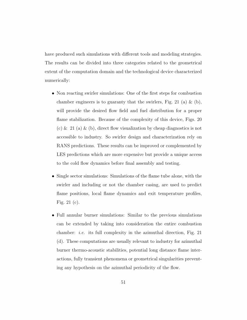
have produced such simulations with di↵erent tools and modeling strategies.
The results can be divided into three categories related to the geometrical
extent of the computation domain and the technological device characterized
numerically:
• Non reacting swirler simulations: One of the first steps for combustion
chamber engineers is to guaranty that the swirlers, Fig. 21 (a) & (b),
will provide the desired flow field and fuel distribution for a proper
flame stabilization. Because of the complexity of this device, Figs. 20
(c) & 21 (a) & (b), direct flow visualization by cheap diagnostics is not
accessible to industry. So swirler design and characterization rely on
RANS predictions. These results can be improved or complemented by
LES predictions which are more expensive but provide a unique access
to the cold flow dynamics before final assembly and testing.
• Single sector simulations: Simulations of the flame tube alone, with the
swirler and including or not the chamber casing, are used to predict
flame positions, local flame dynamics and exit temperature profiles,
Fig. 21 (c).
• Full annular burner simulations: Similar to the previous simulations
can be extended by taking into consideration the entire combustion
chamber: i.e. its full complexity in the azimuthal direction, Fig. 21
(d). These computations are usually relevant to industry for azimuthal
burner thermo-acoustic stabilities, potential long distance flame inter-
actions, fully transient phenomena or geometrical singularities prevent-
ing any hypothesis on the azimuthal periodicity of the flow.
51

4.2.1. Swirler simulations:
Real swirlers include complex flow passages or veins with multiple ob-
stacles and wing profiles that impose a rotating motion to the air streams.
Current technologies involve an increasing number of veins that can be co
or counter rotating, axially or radially oriented, Fig. 22 (a). In order to
guide the flow and control the mass flow rate (i.e. flow split), the shape of
the veins is usually highly convoluted and optimized. These Venturi, flares
and separators, Fig. 22 (a), control the swirl number of each passage. Most
importantly, the swirler is the component of the combustor through which
fuel feeds the burner. Fuel injection points may be multiple, located at vari-
ous locations within the swirler and based on various types of technologies.
In real applications, these injection points can also be operated simultane-
ously or independently depending on the operating condition of the engine
(idle, ignition sequence, cruise or full power). In more advanced designs, fuel
staging is also used in control strategies to avoid thermo acoustic instabilities.
With such complex systems, the main di�culty resides in the engineer’s
ability to guaranty a clear understanding of the mean flow patterns. The
main di�culty is to properly predict the IRZ relative position with respect
to the chamber end-wall or inner end-wall of the swirler. Two swirled flows
(Fig. 22 (b) & (c)) were investigated by LES [242, 243] to assess flow dynam-
ics and more specifically the position and breakdown of the IRZ as discussed
in details in [244]. A second example is shown on Fig. 23 which presents the
mean axial velocity component predicted by LES for four di↵erent concepts
of swirler. The position of the IRZ in front of the swirler can change even for
52

small geometrical modifications. The example of Fig. 23 (b) shows that, in
some cases, the IRZ penetrates all the way inside the component producing
di↵erent flow opening angles at the exit of the device. The added value of
LES is also to give reliable access to the unsteady features of the flow as
illustrated on Fig. 24: the mean axial velocity component profile along the
axis of the four designs with the envelope of resolved fluctuating component
(i.e.: +/ � u0). Of course, qualifying one design compared to another is a
matter of choice and depends on the objective of the engineer.
A typical example related to thermo-acoustic instabilities, is the analysis
and assessment of the swirler flow reactivity to external forcing. For such
analyses [335], the flow response to various fluctuations is possible by LES.
In [335], the response of a radial swirl injector to mass flow rate perturba-
tions is obtained for a wide range of frequencies. Similarly to [302] but in
non-reacting conditions, the flow response to acoustic forcing provides un-
derstanding of the leading mechanisms governing the acoustic admittance of
the devices. These computations help to qualify the impact such oscillations
can have on the mixing of air and fuel [302, 250, 277] prior to combustion in
the main chamber.
4.2.2. Single sector simulations:
Pioneering studies on real industrial combustion chamber [316, 318, 48,
319] mainly focused on a single sector description of the full annular gas
turbine burner (Figs. 25 & 26) thereby imposing an axi-periodic hypothesis
on the flow realization. This simplification is mainly justified by the need to
reduce the computational overhead of LES. The primary objective of such
53

computations, Fig. 26, is to qualify LES strategies and codes on industrial
problems and assess the gain o↵ered by the method when compared to RANS
tools.
Since experimental measurements of the reacting flow in real configura-
tions are scarce, industrial design criteria are used to assess any new nu-
merical approach. Very limited information is known on real engines and
design parameters are only indirect diagnostics: typically, while academic
experiments provide velocity, temperature and species fields in the whole
combustor, real combustor data correspond only to a few temperature mea-
surements at the chamber outlet and one value of the total flow rate. One
important quality parameter scrutinized by engineers is the mean exit tem-
perature field of the combustion chamber because it controls the lifetime of
the turbine blades. Improved estimates of this field induce better known lim-
its of the engine operation and e↵ectively translate in turbine blades that are
more e↵ectively designed and cooled. Ideally the exit combustor temperature
profile should be well homogenized thanks to an e�cient mixing in time and
space of the hot products of combustion with cooler air coming from dilution
jets and wall films [336]. Of course this optimal point is di�cult to reach
in combustors which are more and more compact and require larger amount
of air to go through the swirler (to improve premixing needed for pollutant
reduction). Long and di�cult design iterative loops based on RANS are thus
needed to locate the primary and secondary jet positions that meet specific
objectives.
54

Preliminary LES of single sector computations with similar geometrical
constraints as the one encountered with RANS were rapidly produced [316,
48, 318, 319]. Comparisons are obtained for the Radial Temperature Distri-
bution Function (RTDF), which corresponds to the radial representation of
the mean azimuthal variations of the temperature elevation relative to a ref-
erence value [319]. Figure 27 shows that LES provide better representations
of this crucial parameter for di↵erent types of engines. These preliminary
studies, also point out that to capture the mixing process between hot and
fresh gases, the flame stabilization mechanism, the swirler [316] as well as
part of the casing [48] may need to be included in the computational do-
main [337]. To reduce the boundary condition impact, an ad-hoc strategy is
to extend the computational domain to zones where the boundary conditions
are known [338, 339, 340, 341].
Local mesh resolution e↵ects have also been investigated [320, 342]. Pre-
liminary conclusions are in agreement with theoretical analyses and observa-
tions obtained on laboratory-scale burners. However, in complex configura-
tions, mean fields seem relatively insensitive to mesh resolution when looking
at velocity statistics. Conclusions are not as clear for reacting LES especially
for combustion quantities. Turbulent combustion modeling e↵ects have been
obtained [343] for a fixed grid resolution and show reasonable agreement be-
tween all mean fields irrespectively of the model used (CMC-LES [344] or
EBU-LES [343]). All these findings confirm the robustness of LES for an
industrial use.
55

Similarly to the predictions obtained in the research context of thermo-
acoustic instabilities, single sector real engine LES provide estimates of FTF’s
that are otherwise not accessible or very costly to produce experimentally [345,
346]. These FTF’s can then be used along with thermo-acoustic solvers
(Helmholtz or network models) to determine the thermo-acoustic stability
map of a burner [347, 348, 298, 299]. For such LES [349], the compressible
solver needs to consider an acoustically open numerical setup (no acoustic
reflection at the inflow and outflow conditions of the LES computational
domain). Acoustic forcing of the inflow (or outflow) [290, 350, 291, 292]
is then applied to determine the frequency dependent function that is the
FTF [351, 352, 353], Fig. 28. It is important to underline at this point that
current FTF estimates obtained with such single sector LES impose specific
constraints. Typically, such FTF’s are representative of a flame response
issued by acoustic modes inducing flow perturbations going through the stud-
ied burner. In some situations, azimuthal acoustic modes, often triggered
in annular combustors, may arise from flame interactions issued by purely
azimuthal modes that can be potentially transparent from the swirler passage
point of view. These issues and potential limits are clearly unanswered today
and are being investigated by di↵erent institutions in the world.
Finally, fully transient phases as encountered in the ignition of a burner
are also available in real burners [354, 344, 312]. These predictions are more
di�cult to assess.
56

4.2.3. Full annular burner simulations:
The increase in computing power combined with the potential simplifica-
tion of the boundary conditions has lead to computations of complete cham-
bers. Typically, full annular combustor demonstrations have been produced
recently [355, 356, 357, 358, 342]. Such extended computational domains are
justified only if information proceeds in the azimuthal direction and can not
be properly captured with a single sector hypothesis: for example to simulate
flame propagation from a burner to the next after ignition of a flame ker-
nel [307], neighboring flames that interact with each other or the existence
of an azimuthal thermo-acoustic instabilities [356].
Figure 29 presents snapshots of two full burner LES obtained by con-
sidering the entire geometry of the burner located between the compres-
sor and the turbine for (a) a Turbomeca burner [342] and (b) the CE-
SAR combustor [358]. In both predictions pressure oscillations are reported
and linked to azimuthal thermo-acoustic modes. Compared to single sector
LES [355, 357, 358], the aerodynamics within the combustion chamber di↵er
and the secondary jet mixing with the hot products changes from burner
to burner. Reports on the LES behaviors and indirect observations on the
real engines confirm the good quality of the predictions thereby providing
some confidence in the ability of LES to at least reproduce macroscopic un-
steady flow in real engines. These results not only provide a demonstration of
the current status of advanced LES solvers when used on massively parallel
computers but also give access to new sets of data. Indeed such unsteady
fields need now to be studied to feed the design chain and complement design
assessments based on RANS. From a theoretical point of view, these simula-
57

tions greatly contribute to our understanding of azimuthal thermo-acoustic
instabilities in complex burners and open new perspectives in terms of inves-
tigations. Indeed and despite the fact that great care still needs to be taken,
resulting limit-cycles and the their triggering mechanisms are clearly of great
importance.
Finally, it is interesting to discuss the first simulation of ignition in a full
annular chamber [307]. For this demonstration, the problem of burner to
burner flame propagation is specifically addressed: two opposite torch igni-
tors located in an annular combustion chamber provide the initial energy to
the non reacting flow mixture of air and fuel, Fig. 30 (a). As time proceeds
the resulting flames propagate in opposite directions to ignite the di↵erent
neighboring sectors of the entire combustor, Figs. 30 (b)-(c). Such a se-
quence is inherently unsteady and goes from a statistically stationary cold
flow engine to a fully statistically stationary reacting flow corresponding to
an engine ready for operation. LES [307] o↵er a first view of that phase
that could be envisioned by engineers only indirectly. Indeed, test-bench fa-
cilities can in this case at best provide an integrated view of the process or
indirect diagnostics such as the engine pressure and power output while the
light-around proceeds. Results reveal that the whole ignition process takes
around 40 ms, that the flame front is propagating azimuthally at 20 m/s and
is mainly driven by gas expansion.
58
5. Conclusions and perspectives
Over the last decade LES of turbulent reacting flows has received great
interest from the scientific community. This interest now spreads to com-
panies because LES are the only alternative to the two extreme numerical
tools available to the combustion community: Direct Numerical Simulations
(DNS) and Reynolds Average Navier-Stokes Simulations (RANS) [359].
• In the former, the turbulent reacting flow is addressed in a brute force
way and all scales are resolved in space and time by the numerical
scheme which needs to be highly accurate and used in very small well-
controlled computational domains to ensure reliable and stable simu-
lations.
• In the latter, the governing equations are first mathematically recast
into a new set of equations (usually time-independent) governing the
spatial evolution of the mean flow quantities. All scales of interactions
require modeling which is a quite di�cult task.
Despite its intrinsic di�culties, RANS has rapidly entered the design
chain of current industrial gas turbine manufacturers. It has benefited from
intense researches and modeling contributions and is today very cost e↵ec-
tive. DNS is almost model free but is not applicable to industrial applications
because it is too computer intensive and unable to deal with Reynolds num-
bers or the geometrical complexities of real applications. The computing
power for such exercises is simply not accessible. It is nonetheless a very
valuable scientific tool that benefits from the current and future evolutions
of super-computing and has become a key element of the recent modeling
59

strategies.
LES represent partially the unsteady dynamics of the flows present in
DNS and required for improved predictability while alleviating the modeling
e↵ort needed with RANS. Being a fully unsteady formalism, LES computer
cost is typically 100 times larger than RANS. However, since only the large-
scale flow quantities are solved for, the Reynolds number and Damkholer
number flows accessible to LES are greatly extended compared to DNS. As
a result, if one takes into account the increasing computing power, LES can
be performed today for many burners, in one night (like RANS a few years
ago) with a precision which is not very far from DNS.
Despite such progresses, comprehensive and detailed studies are still needed
to further extend LES to real combustors. Aside from the recurring di�culty
of properly addressing turbulent reacting flows, which is independent of the
numerical approach, grid resolution plays a determining role in LES model
assessments. This specific issue becomes more complicated in industrial ap-
plications where combustion modes and regimes are a priori unknown and
grid resolution is far from being uniform. The influence of boundary con-
ditions on the predictions also appears to be of importance for LES of lab-
oratory or real engine configurations. Recent developments in algorithmic
open new perspectives on the e↵ective contributions of modeling compared
to numerics. The new generations of solvers allow to include geometrical
complexities appearing in real applications thereby providing more realistic
and predictive simulations. They also lead to more systematic analyses of the
60

modeling hypotheses needed to produce LES closures with reduced numerical
impact. At the same time and because of the reduced size of the local mesh
resolution accessible to these codes, new LES closures can arise focusing on
new formalisms oriented toward mixing and flame inner structures subject
to quasi-fully resolved turbulent fields.
The last decade has seen many new applications of LES to real combus-
tors. Transient reacting flows such as forced ignition sequences of burners are
now numerically addressed in parallel to advanced experiments with tempo-
rally resolved diagnostics. Thermo-acoustic instability is also a field which
now relies as much on numerics as on experiments. LES of both problems
have appeared to assess real engine combustion chambers and preliminary
results are very encouraging. More simulations are being produced within
industry to complement RANS predictions and improve the design cycle of
the next generation of aeronautical engines. However, this ultimate objective
still requires further modeling to be able to take into account the multi-phase
flow nature of the fuel alimentation of real engines. Better estimates of the
thermal environment will probably require considering conduction, radiation
and technological solutions that are still di�cult to address directly numer-
ically with the available grid resolution or even theoretically in the context
of LES.
Acknowledgements
The authors thank the CFD Team at CERFACS: trainees, PhD’s, Post-
Doctoral fellows, sta↵ as well as industrial partners who contributed in pro-
61

ducing some of the results and points discussed here. Research partners from
European projects, Universities and Industries are acknowledged for sharing
their results for this review and for participating in fruitful discussions and
exchanges which make the turbulent combustion field of research a very stim-
ulating environment for students, young researchers and engineers.
62

References
References
1. Von Karman T, L. H. On the statistical theory of isotropic turbulence.
In: Proceedings of the Royal Society of London. 1938, .
2. Hinze JO. Turbulence. McGraw-Hill; 1959.
3. Tennekes H, Lumley JL. A first course in turbulence. Cambridge:
M.I.T. Press; 1972.
4. Launder BE, Spalding DB. The numerical computation of turbulent
flows. Comput. Methods Appl. Mech. Eng. 1974;3(2):269–289.
5. Reynolds WC. Computation of turbulent flows. Ann. Rev. Fluid Mech.
1976;8:183–208.
6. Lumley JL. Computational modeling of turbulent flows. Adv. Appl.
Mech. 1978;18:123–176.
7. Lesieur M. Turbulence in fluids. Fluid Mechanics and its applications.
Kluwer Academic Publishers; 1990.
8. Chassaing P. Mecanique des fluides, Elements d’un premier parcours.
Cepadues-Editions; 2000.
9. Chassaing P. Turbulence en mecanique des fluides, Analyse
du phenomene dans une perspective de modelisation a l’usage de
l’ingenieur. Institut National Polytechnique de Toulouse; 2000.
10. Pope SB. Turbulent flows. Cambridge University Press; 2000.
63

11. Zukoski EE, Marble FE. Combustion researches and reviews. Paris:
Butterworths Scientific Publications; 1955, p. 167.
12. Spalding DB. Mathematical models of turbulent flames, a review.
Combust. Sci. Tech. 1976;13:3–25.
13. Jones WP, Whitelaw JH. Calculation methods for reacting turbulent
flows: a review. Combust. Flame 1982;48:1–26.
14. Kim J, Moin P, Moser R. Turbulence statistics in fully developed
channel flow at low Reynolds number. J. Fluid Mech. 1987;177:133–
166. doi:10.1017/S0022112087000892.
15. Spalart PR. Direct simulation of a turbulent boundary layer
up to Re✓ = 1410. J. Fluid Mech. 1988;187:61–98. doi:
10.1017/S0022112088000345.
16. Jimenez J, Moin P. The minimal flow unit in near-wall turbulence.
J. Fluid Mech. 1991;225:213–240. doi:10.1017/S0022112091002033.
17. Sumitani Y, Kasagi N. Direct numerical simulation of turbulent trans-
port with uniform wall injection and suction. Am. Inst. Aeronaut.
Astronaut. J. 1995;33(7):1220–1228.
18. Kawamura H, Ohsaka K, Abe H, Yamamoto K. DNS of turbulent
heat transfer in channel flow with low to medium-high Prandtl number
fluid. Int. J. Heat Fluid Flow 1998;19:482–491. doi:10.1016/S0142-
727X(98)10026-7.
64

19. Moser R, Kim J, Mansour N. Direct numerical simulation of turbulent
channel flow up to Re⌧ = 590. Phys. Fluids 1999;11(4):943–945.
doi:10.1063/1.869966.
20. Leonard A. Energy cascade in large eddy simulations of turbulent fluid
flows. Adv Geophys 1974;18(A):237–248.
21. Ferziger J. Large eddy simulations of turbulent flows. Am. Inst.
Aeronaut. Astronaut. J. 1977;15(9):1261–1267.
22. Rogallo R, Moin P. Numerical simulation of turbulent flows. Ann.
Rev. Fluid Mech. 1985;17:99–137.
23. Mason PJ. Large-eddy simulation: a critical review of the tech-
nique. Quarterly Journal of the Royal Meteorology Society 1994;120
(A)(515):1–26.
24. Piomelli U, Chasnov JR. Large eddy simulations: theory and appli-
cations. In: Hallback H, Henningson D, Johansson A, Alfredsson P,
editors. Turbulence and Transition Modelling. Kluwer Academic Pub-
lishers; 1996, p. 269 – 336.
25. Lesieur M, Metais O. New trends in large-eddy simulations of turbu-
lence. Ann. Rev. Fluid Mech. 1996;28:45 – 82.
26. Ferziger J. Large eddy simulation: an introduction and perspective.
In: Metais O, Ferziger J, editors. New tools in turbulence modelling.
Les Editions de Physique - Springer Verlag; 1997, p. 29 – 47.
65
27. Lesieur M. Turbulence in fluids ; vol. 40 of Fluid Mechanics and its
applications. Kluwer Academic Publishers; 3rd rev. ed.; 1997.
28. Piomelli U. Large-eddy simulation: achievements and challenges. Prog.
Aerospace Sci. 1999;35:335–362.
29. Meneveau C, Katz J. Scale-invariance and turbulence models for large
eddy simulation. Ann. Rev. Fluid Mech. 2000;32:1–32.
30. Sagaut P. Large eddy simulation for incompressible flows. Springer;
2002.
31. Poinsot T, Veynante D. Theoretical and Numerical Combustion. R.T.
Edwards, 2nd edition; 2005.
32. Poinsot T, Kestens T, Nicoud F. Using computational fluid dynamics
to study flow control. Computational Methods for Control Applications
2002;16:327–346.
33. Kolmogorov AN. The local structure of turbulence in incompressible
viscous fluid for very large reynolds numbers. C. R. Acad. Sci. , USSR
1941;30:301.
34. Kolmogorov AN. A refinement of hypothesis concerning the local struc-
ture of turbulence in a viscous incompressible fluid at high reynolds
number. J. Fluid Mech. 1962;62:82.
35. Linan A. The asymptotic structure of counterflow di↵usion flames for
large activation energies. Acta Astronautica 1974;1:1007.
66

36. Cuenot B, Poinsot T. Asymptotic and numerical study of di↵usion
flames with variable lewis number and finite rate chemistry. Combust.
Flame 1996;104:111–137.
37. Vervisch L, Poinsot T. Direct numerical simulation of non premixed
turbulent flames. Ann. Rev. Fluid Mech. 1998;30:655–692.
38. Givi P. Model-free simulations of turbulent reactive flows. Prog.
Energy Comb. Sci. 1989;15:1–107.
39. Givi P. Spectral and random vortex methods in turbulent reacting
flows. In: Williams F, P. L, editors. Turbulent Reacting Flows. Aca-
demic Press; 1994, p. 475–572.
40. Poinsot T, Haworth D. DNS and modelling of the interaction between
turbulent premixed flames and walls. In: Proc. of the Summer Pro-
gram . Center for Turbulence Research, NASA Ames/Stanford Univ.;
1992, p. 307–324.
41. Poinsot T, Candel S, Trouve A. Application of direct numerical sim-
ulation to premixed turbulent combustion. Prog. Energy Comb. Sci.
1996;21:531–576.
42. Bell J, Day M, Grcar J, Lijewski M, Driscoll JF, Filatyev S. Numerical
simulation of a laboratory-scale turbulent slot flame. Proc. Combust.
Inst. 2007;31:1299–1307.
43. Bell J, Cheng R, Day M, Beckner V, Leijewski M. Interaction of tur-
bulence and chemistry in a low-swirl burner. J of Physics: Conference
Series 2008;125:012027.
67

44. Gao X, Groth C. A parallel solution-adaptive methodfor three-
dimensional turbulent non-premixed combusting flows. J. Comput.
Phys. 2010;229:3250–3275.
45. Aspden A, Day M, Bell J. Characterization of low lewis number flames.
Proc. Combust. Inst. 2011;33(1):1463–1471.
46. Aspden A, Day M, Bell J. Lewis number e↵ects in distributed flames.
Proc. Combust. Inst. 2011;33(1):1473–1480.
47. Day M, Bell J, Bremer P, Pascucci V, Beckner V, Lijewski M. Turbu-
lence e↵ects on cellular burning structures in lean premixed hydrogen
flames. Combustion and Flame 2009;156(5):1035–1045.
48. James S, Zhu J, Anand M. Large eddy simulation as a design tool for
gas turbine combustion systems. Am. Inst. Aeronaut. Astronaut. J.
2006;44:674–686.
49. Aldama AA. Lecture Notes in Engineering ; vol. 49. New York:
Springer-Verlag; 1990.
50. Moureau V. Private communication; 2006.
51. Fureby C, Tabor G. Mathematical and physical constraints on large-
eddy simulations. Theory Comput Fluid Dyn 1997;(9):85–102.
52. Ghosal S. An analysis of numerical errors in large eddy simulations of
turbulence. J. Comput. Phys. 1996;125:187 – 206.
53. Vasilyev OV, Lund TS, Moin P. A general class of commutative filters
for les in complex geometries. J. Comput. Phys. 1998;146:82–104.
68

54. Morinishi Y, Vasilyev OV. A recommended modification to the dy-
namic two-parameter mixed subgrid scale model for large eddy simula-
tion of wall bounded turbulent flow. Phys. Fluids 2001;13(11):3400–
3410. doi:10.1063/1.1404396.
55. Moureau VR, Vasilyev OV, Angelberger C, Poinsot TJ. Commuta-
tion errors in Large Eddy Simulations on moving grids: Application to
piston engine flows. In: Proc. of the Summer Program . Center for
Turbulence Research, NASA AMES/Stanford University, USA; 2004,
p. 157–168.
56. Speziale CG. Galilean invariance of subgrid-scale stress models in the
large-eddy simulation of turbulence. J. Fluid Mech. 1985;156:55–62.
57. Vreman B, Guerts B, Kuerten H. Realizability conditions for the tur-
bulent stress tensor in large eddy simulation. J. Fluid Mech. 1994;
278:351–364.
58. Ghosal S. Mathematical and physical constraints on large-eddy simula-
tion of turbulence. Am. Inst. Aeronaut. Astronaut. J. 1999;37(4):425.
59. Kravchenko AG, Moin P. On the e↵ect of numerical errors in large eddy
simulations of turbulent flows. J. Comput. Phys. 1997;131(2):310–
322. doi:10.1006/jcph.1996.5597.
60. Muchinsky A. A similarity theory of locally homogeneous anisotropic
turbulence generated by a Smagorinsky-type LES. J. Fluid Mech.
1996;325:239–260.
69

61. Fureby C, Grinstein FF. Monotonically integrated large-eddy simu-
lation of free shear flows. Am. Inst. Aeronaut. Astronaut. J. 1999;
37(5):544–556.
62. Garnier E, Mossi M, Sagaut P, Deville M. On the use of shock-
capturing schemes for large eddy simulation. J. Comput. Phys. 1999;
153:273–311.
63. Grinstein F, Margonin L, Rider W. Implicit large eddy simulation:
computing turbulent fluid dynamics. Cambridge University Press; 2007.
64. Germano M. Turbulence: the filtering approach. J. Fluid Mech. 1992;
238:325–336.
65. Nallasamy N. Turbulence models and their applications to the predic-
tion of internal flows, a review. Comput. Fluids 1987;15(2):151–194.
66. Speziale CG. Turbulence modeling for time-dependent RANS and
VLES: a review. Am. Inst. Aeronaut. Astronaut. J. 1998;36(2):173–
184. doi:10.2514/2.7499.
67. Pitsch H, Steiner H. Scalar mixing and dissipation rate in large-eddy
simulations of non-premixed turbulent combustion. Proc. Combust.
Inst. 2000;28:41–49.
68. Williams FA. Combustion Theory. Menlo Park, CA: Benjamin Cum-
mings; 1985.
69. Peters N. Length scales in laminar and turbulent flames. Numerical
approaches to combustion modeling. 1989.
70
70. Kuo KK. Principles of combustion. Hoboken, New Jersey: John Wiley
& Sons, Inc.; 2nd ed.; 2005.
71. Williams FA. A review of some theoretical combustions of turbulent
flame structure. In: AGARD Conference Proceedings ; vol. 164. 1975,
p. II.1.1–25.
72. Libby PA, Williams FA. Turbulent combustion: fundamental aspects
and a review. In: Williams F, Libby P, editors. Turbulent Reacting
Flows. Academic Press London; 1994, p. 2–61.
73. Candel S, Veynante D, Lacas F, Darabiha N, Baum M, Poinsot T. A
review of turbulent combustion modeling. ERCOFTAC Bulletin 1994;
20:9–16.
74. Vervisch L, Veynante D. Interlinks between approaches for modeling
turbulent flames. Proc. Combust. Inst. 2000;28:175–183.
75. Peters N. Turbulent combustion. Cambridge University Press; 2001.
76. Veynante D, Vervisch L. Turbulent combustion modeling. Prog. En-
ergy Comb. Sci. 2002;28:193 – 266.
77. Riley J. Review of large-eddy simulation of non-premixed turbulent
combustion. J. Fluids Eng. 2006;128(2):209–215.
78. Pitsch H. Large eddy simulation of turbulent combustion. Ann. Rev.
Fluid Mech. 2006;38:453–482.
71
79. Favre A. Statistical equations of turbulent gases. In: Problems of
hydrodynamics and continuum mechanics. Philadelphia: SIAM; 1969,
p. 231–266.
80. Moin P, Squires KD, Cabot W, Lee S. A dynamic subgrid-scale model
for compressible turbulence and scalar transport. Phys. Fluids 1991;
A 3(11):2746–2757. doi:10.1063/1.858164.
81. Erlebacher G, Hussaini MY, Speziale CG, Zang TA. Toward the large-
eddy simulation of compressible turbulent flows. J. Fluid Mech. 1992;
238:155–185.
82. Vreman B, Geurts B, Kuerten H. Subgrid modeling in LES of com-
pressible flow. Appl Sci Res 1995;54:191–203.
83. Smagorinsky J. General circulation experiments with the primitive
equations: 1. the basic experiment. Mon. Weather Rev. 1963;91:99–
164.
84. Lilly DK. The representation of small-scale turbulence in numerical
simulation experiments. In: Proceedings of the IBM Scientific Comput-
ing Symposium on Environmental Sciences. Yorktown Heights, USA;
1967, .
85. Scotti A, Meneveau C, Lilly DK. Generalized smagorinsky model for
anisotropic grids. Phys. Fluids A 1993;5(9):2306–2308.
86. Scotti A, Meneveau C, Fatica M. Generalized smagorinsky model for
anisotropic grids. Phys. Fluids 1997;9(6):1856–1858.
72

87. Germano M, Piomelli U, Moin P, Cabot W. A dynamic subgrid-scale
eddy viscosity model. Phys. Fluids 1991;3(7):1760–1765.
88. Lilly DK. A proposed modification of the germano sub-grid closure
method. Phys. Fluids 1992;4(3):633–635. URL LES.
89. Ghosal S, Moin P. The basic equations for the large eddy simulation of
turbulent flows in complex geometry. J. Comput. Phys. 1995;118:24
– 37.
90. Deardor↵ J. The use of subgrid transport equations in a three-
dimensional model of atmospheric turbulence. ASME J Fluids Eng
1973;95:429–438.
91. Schumann U. Subgrid scale model for finite di↵erence simulations of
turbulent flows in plane channels and annuli. J. Comput. Phys. 1975;
18:376–404.
92. Meneveau C, Lund T, Cabot W. A lagrangian dynamic subgrid-scale
model of turbulence. J. Fluid Mech. 1996;319:353.
93. Porte-Aget F, Meneveau C, Parlange M. A dynamic scale depen-
dent model for large eddy simulation: Application to the atmospheric
boundary layer. J. Fluid Mech. 2000;415:261–284.
94. Schumann U. Realizability of reynolds-stress turbulence models. Phys.
Fluids 1977;20(5).
95. Speziale CG. Invariance of reynolds stress models. Phys. Fluids 1979;
22:1033.
73

96. Vreman B, Geurts B, Kuerten H. On the formulation of the dynamic
mixed subgrid-scale model. Phys. Fluids 1994;6(12):4057–4059.
97. Ducros F, Nicoud F, Poinsot T. Wall-adapating local eddy-viscosity
models for simulations in complex geometries. In: ICFD. Baines M. J.;
1998, p. 293–300.
98. Vreman AW. An eddy-viscosity subgrid-scale model for turbulent
shear flow: algebraic theory and applications. Phys. Fluids 2004;
16(10):3670–3681. doi:10.1063/1.1785131.
99. Kalitzin G, Templeton JA, Medic G. A near-wall eddy-viscosity for-
mulation for LES. In: CY-Les 2005 Limassol, Cyprus. 2005, .
100. Nicoud F, Hubert Baya Toda H, Cabrit O, Bose S, Lee J. Using singular
values to build a subgrid-scale model for large eddy simulations. Phys.
Fluids 2011;23(085106).
101. Gatski TB, Speziale CG. On explicit algebraic stress models for com-
plex turbulent flows. J. Fluid Mech. 1993;254:59–78.
102. Piomelli U. High Reynolds number calculations using the dynamic
subgrid-scale stress model. Phys. Fluids A 1993;5:1484–1490.
103. Piomelli U, Balaras E. Wall-layer models for large-eddy sim-
ulations. Ann. Rev. Fluid Mech. 2002;34:349–374. doi:
10.1146/annurev.fluid.34.082901.144919.
104. Piomelli U, Balaras E, Pasinato H, Squires KD, Spalart PR. The inner–
outer layer interface in large-eddy simulations with wall-layer mod-
74
els. Int. J. Heat Fluid Flow 2003;24(4):538–550. doi:10.1016/S0142-
727X(03)00048-1.
105. Piomelli U. Wall-layer models for large-eddy simula-
tions. Prog. Aerospace Sci. 2008;44(6):437–446. doi:
10.1016/j.paerosci.2008.06.001.
106. Bardina J, Ferziger JH, Reynolds WC. Improved subgrid scale models
for large-eddy simulations. Am. Inst. Aeronaut. Astronaut. J. 1980;
34:1111–1119.
107. Clark R, Ferziger J, Reynolds W. Evaluation of subgrid models unsing
an accurately simulated flow. J. Fluid Mech. 1979;91:1–16.
108. Adams N, Stolz S. Deconvolution methods dor subgrid-scale approxi-
mations in les. In: Geurts B, editor. Modern simulation strategies for
turbulent flow. Edwards; 2001, p. 21–44.
109. Zang Y, Street RL, Kose↵ JR. A dynamic subgrid-scale model and
its application to turbulent recirculating flows. Phys. Fluids 1993;
5(12):3186–3196.
110. Lodato G, Domingo P, Vervisch L. Three-dimensional boundary cond-
tions for direct and large-eddy simulation of compressible viscous flow.
J. Comput. Phys. 2008;.
111. Porter D, Pouquet A, Woodward P. Kolmogorov-like spectra in de-
caying three-dimensional supersonic flows. Phys. Fluids 1994;6:2133–
2142.
75

112. Misra A, Pullin D. A vortex-based subgrid stress model for large-eddy
simulation. Phys. Fluids 1997;9:2443–2454.
113. Gicquel L, Givi P, Jaberi F, Pope S. Velocity filtered density func-
tion for large eddy simulation of turbulent flows. Phys. Fluids 2002;
14:1196–1213.
114. Fureby C, Grinstein F. Large eddy simulation of high-reynolds-number
free and wall-bounded flows. J. Comput. Phys. 2002;181:68–97.
115. Layton WJ. A mathematical introduction to large
eddy simulations. Tech. Rep.; University of Pitts-
burg. Department of Mathematics; 2002. URL
http://www.mathematics.pitt.edu/research/technical-reports.php.
116. Geurts B, Holm D. Leray and ns-alpha modeling of turbulent mixing.
J. Turb. 2006;(10).
117. Farhat C, Rajasekharan A, Koobus B. A dynamic variational multi-
scale method for large eddy simulations on unstructured meshes. Com-
put. Methods Appl. Mech. Eng. 2006;195(13-16):1667–1691.
118. Mathey F, Chollet JP. Subgrid-scale model of scalar mixing for large
eddy simulation of turbulent flows. In: Chollet JP, Voke PR, Kleiser L,
editors. Direct and Large Eddy Simulation II. Kluwer Academic Pub-
lishers; 1997, p. 103 – 114.
119. Pope SB. Stochastic lagrangian models of velocity in homogeneous
turbulent shear flow. Phys. Fluids 2002;14(5):1696–1702.
76

120. Batchelor GK. An introduction to fluid dynamics. Cambridge: Cam-
bridge University Press; 1988.
121. Wong VC, Lilly DK. A comparison of two dynamic subgrid clo-
sure methods for turbulent thermal convection. Phys. Fluids 1994;
6(2):1016–1023. doi:10.1063/1.868335.
122. Wang W, Pletcher RH. On the large eddy simulation of a turbu-
lent channel flow with significant heat transfer. Phys. Fluids 1996;
8(12):3354–3366. doi:10.1063/1.869110.
123. Wang BC, Yee E, Bergstrom DJ, Iida O. New dynamic subgrid-scale
heat flux models for large-eddy simulation of thermal convection based
on the general gradient di↵usion hypothesis. J. Fluid Mech. 2008;
604:125–163. doi:10.1017/S0022112008001079.
124. You D, Moin P. A dynamic global-coe�cient subgrid-scale model for
large-eddy simulation of turbulent scalar transport in complex geome-
tries. Phys. Fluids 2009;21(4):045109. doi:10.1063/1.3115068.
125. Kerstein AR. A linear eddy model of turbulent scalar transport and
mixing. Combust. Sci. Tech. 1988;60:391.
126. Kerstein AR. Linear-eddy modeling of turbulent transport: Part ii.
application to shear layer mixing. Combust. Flame 1989;75(3 - 4):397
– 413.
127. Kerstein AR. Linear-eddy modelling of turbulent transport. part 3.
mixing and di↵erential molecular di↵usion in round jets. J. Fluid
Mech. 1990;216:411 – 435.
77
128. Kerstein AR. Linear-eddy modelling of turbulent transport. part 6.
microstructure of di↵usive scalar mixing fields. J. Fluid Mech. 1991;
231:361 – 394.
129. McMurthy PA, Menon S, Kerstein AR. A linear eddy subgrid model
for turbulent reacting flows: application to hydrogen-air combustion.
Proc. Combust. Inst. 1992;24(1):271 – 278.
130. Kerstein AR. Linear eddy modeling of turbulent transport. part 4:
structure of di↵usion flames. Combust. Sci. Tech. 1992;81:75 – 96.
131. McMurthy PA, Gansauge TC, Kerstein AR, Krueger SK. Linear eddy
simulations of mixing in a homogeneous turbulent flow. Phys. Fluids
A 1993;5(4):1023 – 1034.
132. Menon S, McMurthy PA, Kerstein AR. A linear eddy mixing model
for large eddy simulation of turbulent combustion. In: Galperin B,
Orzag S, editors. Large eddy simulation of complex engineering and
geophysical flows. Cambridge University Press; 1993, p. 87 – 314.
133. Menon S, McMurtry PA, Kerstein AR. A linear eddy subgrid model
for turbulent combustion: Application to premixed combustion. In:
93-0107 A, editor. 31st Aerospace Sciences Meeting and Exhibit. Reno,
NV; 1993, .
134. Sheikhi M, Drozda T, Givi P, Jaberi F, Pope S. Large eddy simulation
of a turbulent nonpremixed piloted methane jet flame (sandia flame d).
Proc. Combust. Inst. 2005;20:549–556.
78

135. Sheikhi M, Givi P, Pope S. Velocity-scalar filtered mass density func-
tion for large eddy simulation of turbulent reacting flows. Phys. Fluids
2007;9(095106):19.
136. Peters N, Rogg B. Reduced Kinetic Mechanisms for Applications in
Combustion Systems. Lecture Notes in Physics. Heidelberg: Springer
Verlag; 1993.
137. Echeckki T, Mastorakos E. Advances, new trends and persepctives. In:
Echeckki T, Mastorakos E, editors. Turbulent Combustion Modeling ;
vol. 95 of Fluid Mechanics and its Applications. Springer; 2011, .
138. Cook AW, Riley JJ. Subgrid scale modeling for turbulent reacting
flows. Combust. Flame 1998;112:593 – 606.
139. Candel S, Thevenin D, Darabiha N, Veynante D. Progress in numerical
combustion. Combustion Science and Technology 1999;149:297–337.
140. Bilger R. Future progress in turbulent combustion research. Prog.
Energy Comb. Sci. 2000;26:367–380.
141. Branley N, Jones W. Large eddy simulation of turbulent flames. In:
European Congress on Computational Methods in Applied Science and
Engineering. Barcelona, Spain; 2000, p. 1–23.
142. Menon S. Subgrid combustion modelling for large-eddy simulations.
Int J Engine Research 2000;1:209–227.
143. Givi P. A review of modern developmebts in large eddy simulation of
turbulent reactuve flows. In: DNS/LES Progress and Challenges. Pro-
79

ceedings of the Third AFOSR International Conference on DNS/LES ;
ADP013626. Defense Technicel Information Center Compilation Part
Notice; 2001, .
144. Janicka J, Sadiki A. Large eddy simulation for turbulent combustion.
Proc. Combust. Inst. 2004;30:537–547.
145. Lam S, Goussis D. Understanding complex chemical kinetics with com-
putational singular perturbation. Proc. Combust. Inst. 1988;:931–941.
146. Maas U, Pope SB. Implementation of simplified chemical kinetics based
on low-dimensional manifolds. Proc. Combust. Inst. 1992;24:719–729.
147. Maas U, Pope SB. Simplifying chemical kinetics: intrinsic low-
dimensional manifolds in composition space. Combust. Flame 1992;
88:239–264.
148. Brown P, Byrne G, Hindmarsh A. Vode: A variable coe�cent ode
solver. SIAM J. Sci. Comput. 1989;10:1038–1051.
149. Petzold L. A descriotion of dassl: A di↵erential/algebrais system solver.
Tech. Rep. SAND82-8637; Sandia National Laboratories; 1982.
150. van Oijen JA, Lammers FA, de Goey LPH. Modeling of premixed
laminar flames using flamelet generated manifolds. Combust. Sci.
Tech. 2001;127:2124–2134.
151. de Goey LPH, van Oijen JA, Bongers H, Groot GRA. New flamelet
based reduction methods: the bridge between chemical reduction tech-
80

niques and flamelet methods. In: European Combustion Meeting.
Orleans (France); 2003, .
152. Gicquel O, Darabiha N, Thevenin D. Laminar premixed hydrogen/air
counterflow flame simulations using flame prolongation of ildm with
di↵erential di↵usion. Proc. Combust. Inst. 2000;28:1901–1908.
153. Fiorina B, Baron R, Gicquel O, Thevenin D, Carpentier S, Darabiha
N. Modelling non-adiabatic partially premixed flames using flame-
prolongation of ildm. Combust. Theory and Modelling 2003;7:449–
470.
154. Fiorina B, Gicquel O, Vervisch L, Carpentier S, Darabiha N. Premixed
turbulent combustion modeling using a tabulated detailed chemistry
and pdf. Proc. Combust. Inst. 2004;30:in press.
155. Fiorina B, Gicquel O, Vervisch L, Carpentier S, Darabiha N. Ap-
proximating the chemical structure of partially-premixed and di↵usion
counter-flow flames using FPI flamelet tabulation. Combust. Flame
2005;140:147–160.
156. Gicquel O. Developpement de methodes automatiques de reduction
de schemas cinetiques dediees a la combustion laminaire et turbulente.
Habilitation a diriger des recherches; 2005.
157. Pope SB. Computationally e�cient implementation of combustion
chemistry using in situ adaptive tabulation. Combust. Theory and
Modelling 1997;1:41–63.
81
158. Tonse S, Moriary N, Brown N, Frenklach M. Prism: piece reusable im-
plementation of solution mapping. an economical strategy for chemical
kinetics. Israel Journal of Chemistry 1999;39:97–106.
159. Christo F, Masri A, Nebot E. An integrated pdf/neural network ap-
proach for simulating turbulent reactinf systems. Proc. Combust. Inst.
1996;27:1793–1807.
160. Searby G, Quinard J. Direct and indirect measurements of markstein
numbers of premixed flames. Combust. Flame 1990;82:298–311.
161. Bradley D, Gaskell PH, Gu XJ. Burning velocities, markstein lengths,
and flame quenching for spherical methane-air flames: a computational
study. Combust. Flame 1996;104(1/2):176–198.
162. Gu XJ, Haq MZ, Lawes M, Woolley R. Laminar burning velocity and
markstein lengths of methane-air mixtures. Combust. Flame 2000;
121:41–58.
163. Zeldovich YB, Frank-Kamenetskii DA. Selected works of Ya. B. Zel-
dovich, Chemical Physics and Hydrodynamics,. Princeton University
Press; 1962.
164. Hartley L, Dold JW. Flame propagation in a nonuniform mixture:
analysis of a triple flame. Combust. Sci. Tech. 1991;80:23.
165. Kioni PN, Rogg B, Bray KNC, Li nan A. Flame spread in laminar
mixing layers: the triple flame. Combust. Flame 1993;95:276.
82
166. Veynante D, Duclos J, Piana J. Experimental analysis of flamelet mod-
els for premixed turbulent combustion. Proc. Combust. Inst. 1994;
25(1):1249–1256.
167. Ruetsch G, Veynante D, Vervisch L, Poinsot T, Li nan A. Triple flame
structure and di↵usion flame stabilization. In: APS Meeting. Atlanta;
1994, .
168. Ruetsch GR, Vervisch L, Li nan A. E↵ects of heat release on triple
flames. Phys. Fluids 1995;7(6):1447–1454.
169. Domingo P, Vervisch L. Triple flames and partially premixed combus-
tion in autoignition of non-premixed mixtures. Proc. Combust. Inst.
1996;26(1):233–240.
170. Kioni PN, Bray KNC, Greenhalgh DA, Rogg B. Experimental and
numerical study of a triple flame. Combust. Flame 1998;116:192–
206.
171. Ghosal S, Vervisch L. Theoretical and numerical investigation of a
symmetrical triple flame using a parabolic flame type approximation.
J. Fluid Mech. 2000;415:227–260.
172. Veynante D, Poinsot T. Reynolds averaged and large eddy simulation
modeling for turbulent combustion. In: Metais O, Ferziger J, editors.
New tools in turbulence modelling. Lecture 5. Les editions de Physique,
Springer; 1997, p. 105–135.
173. Broadwell JE, Mungal MG. Molecular mixing and chemical reactions
in turbulent shear layers. Proc. Combust. Inst. 1989;22(1):579–587.
83
174. Cant RS, Bray KNC. Strained laminar flamelet calculations of pre-
mixed turbulent combustion in a closed vessel. Proc. Combust. Inst.
1989;22(1):791–799.
175. Ashurst WT, McMurtry PA. Flame generation of vorticity: vortex
dipoles from monopoles. Combust. Sci. Tech. 1989;66:17–37.
176. Candel S, Veynante D, Lacas F, Maistret E, Darabiha N, Poinsot T.
Coherent flame model: applications and recent extensions. In: Lar-
routurou BE, editor. Advances in combustion modeling. Series on ad-
vances in mathematics for applied sciences. World Scientific, Singapore;
1990, p. 19–64.
177. Cant RS, Pope SB, Bray KNC. Modelling of flamelet surface to volume
ratio in turbulent premixed combustion. Proc. Combust. Inst. 1991;
23(1):809–815.
178. Cant RS, Rutland CJ, Trouve A. Statistics for laminar flamelet mod-
eling. In: Proc. of the Summer Program . Center for Turbulence
Research, Stanford Univ./NASA-Ames; 1990, p. 271–279.
179. Gao F. A large-eddy simulation scheme for turbulent reacting flows.
Phys. Fluids 1993;5(6):1282–1284.
180. Pope SB. Self-conditioned fields for large-eddy simulations of turbulent
flows. J. Fluid Mech. 2010;652:139–169.
181. Navarro-Martinez S, Kronenburg A. Les-cmc simulations of a turbulent
blu↵-body flame. Proc. Combust. Inst. 2007;31:1721–1728.
84

182. Colucci P, Jaberi F, Givi P, Pope S. Filtered density function for
large eddy simulation of turbulent reacting flows. Phys. Fluids 1998;
10:499–515.
183. Jaberi F, Colucci P, James S, Givi P, Pope S. Filtered mass density
function for large-eddy simulation of turbulent reacting flows. J. Fluid
Mech. 1999;401:85–121.
184. Drozda TG, sheikhi MRH, Madnia CK, Givi P. Developments in for-
mulation and application of the filtered density function. Flow, Turb.
and Combustion 2007;78:35–67.
185. sheikhi MRH, Givi P, Pope S. Frequency-velocity-scalar filtered mass
density function for large eddy simulation of turbulent flows. Phys.
Fluids 2009;21(075102).
186. Pope SB. Computations of turbulent combustion: progress and chal-
lenges. Proc. Combust. Inst. 1991;23(1):591–612.
187. Candel S. Combustion. Ecole d’ete d’analyse numerique EDF-CEA-
INRIA; 1993.
188. Meneveau C, Lund T. The dynamic smagorinsky model and scale-
dependent coe�cients in the viscous range of turbulence. Phys. Fluids
1997;9(12):3932–3934.
189. Fiorina B, Gicquel O, Veynante D. Turbulent flame simulation tak-
ing advantage of tabulated chemistry self-similar properties. Proc.
Combust. Inst. 2009;32:1687–1694.
85

190. Fiorina B, Vicquelin R, Auzillon P, Darabiha N, Gicquel O, Veynante
D. A filtered tabulated chemistry model for LES of premixed combus-
tion. Combust. Flame 2010;157(3):465–475.
191. Kemenov K, Pope S. Molecular di↵usion e↵ects in les of a piloted
methane-air flame. Combust. Flame 2011;158(2):240–254.
192. Moureau V, Domingo P, Vervisch L. From large-eddy simula-
tion to direct simulation of a lean premixed swirl flame: Fil-
tered laminar flame-pdf modeling. Combust. Flame 2011;
(doi:10.1016/j.combustflame.2010.12.004).
193. Geurts BJ, Frohlich J. A framework for predictind accuracy limitations
in large-eddy simulations. Phys. Fluids 2002;14(6):L41–L44.
194. Meyers J, Geurts BJ, Baelmans M. Database analysis of errors in
large-eddy simulation. Phys. Fluids 2003;15(9):2740–2755.
195. Meyers J, Sagaut P. Is plane-channel flow a friendly case for the testing
of large-eddy simulation subgrid-scale models? Phys. Fluids 2007;
19:1–4.
196. Lucor D, Meyers J, Sagaut P. Sensitivity analysis of large-eddy simula-
tions to subgrid-scale-model parametric uncertainty using polynomial
chaos. J. Fluid Mech. 2007;585:255–279.
197. Pope SB. Ten questions concerning the large-eddy simulation of tur-
bulent flows. New Journal of Physics 2004;6:35.
86

198. Celik I, Cehreli A, Yavuz I. Index of resolution quality for large eddy
simulations. J Fluids Eng 2005;127(949-958).
199. Klein M. An attempt to assess the quality of large eddy simulations in
the context of implicit filtering. Flow, Turb. and Combustion 2005;
75(1-4):131–147.
200. Vervishc L, Domingo P, Lodato G, Veynante D. Scalar energy fluc-
tuations in Large-Eddy Simulation of turbument flames: Statistical
budgets and mesh quality criterion. Combustion and Flame 2010;
157(4):778–789.
201. Gourdain N, Gicquel L, Montagnac M, Vermorel O, Gazaix M, Sta↵el-
bach G, et al. High performance parallel computing of flows in complex
geometries - part 1: methods. Computational Science and Discovery
2009;2:015003 (26pp).
202. Gourdain N, Gicquel L, Sta↵elbach G, Vermorel O, Duchaine F, Bous-
suge JF, et al. High performance parallel computing of flows in complex
geometries - part 2: applications. Computational Science and Discov-
ery 2009;2:015004 (28pp).
203. Colin O, Rudgyard M. Development of high-order taylor-galerkin
schemes for unsteady calculations. J. Comput. Phys. 2000;
162(2):338–371.
204. Grcar J, Bell J, Day M. The soret e↵ect in naturally propagating, pre-
mixed, lean, hydrogen-air flames. Proc. Combust. Inst. 2009;32(1173).
87

205. Moureau V, Domingo P, Vervisch L. Design of a massively parallel
cfd code for complex geometries. Comptes Rendus Mecanique 2011;
doi:10.1016/j.crme.2010.12.001.
206. Chen JH. Petascale direct numerical simulation of turbulent combus-
tion - fundamental insights towards predictive models. Proc. Combust.
Inst. 2011;33(1):99–123.
207. Gicquel L, Gourdain N, Boussuge JF, Deniau H, Sta↵elbach G, Wolf
P, et al. High performance parallel computing of flows in complex
geometries. Comptes Rendus Mecanique 2011;339:104–124.
208. Syred N, Beer J. Combustion in swirling flows: a review. Combust.
Flame 1974;23(143-201).
209. Sloan DG, Smith PJ, Smoot LD. Modeling of swirl in turbulent flow
systems. Prog. Energy Comb. Sci. 1986;12:163–250.
210. Gupta A, Beer J, Swithenbank J. Concentric multi-annular swirl
burner: stability limits and emission characteristics. Proc. Combust.
Inst. 1977;16:79–91.
211. Weber R, Visser B, Boysan F. Assessment of turbulent modeling for
engineering prediction of swirling vortices in the near burner zone. Int.
J. Heat Fluid Flow 1990;11:225–238.
212. Kitoh O. Experimental study of turbulent swirling flow in a straight
pipe. J. Fluid Mech. 1991;225:445–465.
88

213. Ahmed S. Velocity measurements and turbulence statistics of a con-
fined isthermal swirling flow. Experimental, Thermal and Fluid Science
1998;17:256–270.
214. Nathan G, Turns Hill S, Luxton R. An axisylletruc fluidic nozzle to
generate jet precession. J. Fluid Mech. 1998;370:347–380.
215. Al-Abdeli Y, Masri A. Recirculation and flow field regimes of un-
confined non-reacting swirling flow. Experimental, Thermal and Fluid
Science 2003;23:655–665.
216. Masri AR, Kalt P, Barlow RS. The compositional structure of swirl-
stabilised turbulent nonpremixed flames. Combust. Flame 2004;
137:1–37.
217. Gentemann A, Hirsch C, Kunze K, Kiesewetter F, Sattelmayer T, Po-
lifke W. Validation of flame transfer function reconstruction for per-
fectly premixed swirl flames. In: ASME , editor. ASME Turbo Expo.
Vienna, Austria: ASME; 2004, p. Paper GT2004–53776.
218. Hirsch C, Fanaca D, Alemela D, Polifke R, Sattelmayer W. Influence
of the swirler design on the flame transfer function of premixed flames.
In: ASME , editor. Proceedings of AMSE Turbo Expo: Power for Land,
Sea and Air ; Paper GT2005-68195. Nevada, USA: ASME Turbo-Expo;
2005, .
219. Palies P, Durox D, Schuller T, Morenton P, Candel S. Dynamics of
premixed confined swirling flames. Comptes Rendus Mecanique 2009;
337:395–405.
89

220. Komarek T, Polifke W. Impact of swirl fluctuations on the flame re-
sponse of a perfectly premixed swirl burner. J Eng for Gas Turbines
and Power 2010;132(6):061503.
221. Palies P, Durox D, Schuller T, Candel S. the combined dynamics of
swirler and turbulent premixed swirling flames. Combust. Flame 2010;
157:1698–1717.
222. Sarpkaya T. On stationary and travelling vortex breakdowns. J. Fluid
Mech. 1971;45:545–559.
223. Escudier MP, Zehnder N. Vortex-flow regimes. J. Fluid Mech. 1982;
115:105–121.
224. Gupta AK, Lilley DG, Syred N. Swirl flows. Abacus Press; 1984.
225. Escudier M. Vortex breakdown: observations and explanations.
Progress in Aerospace Sciences 1988;25:189–229.
226. Lucca-Negro O, O’Doherty T. Vortex breakdown: a review. Prog.
Energy Comb. Sci. 2001;27:431–481.
227. Novak F, Sarpkaya T. Turbulent vortex breakdown at high reynolds
numbers. Am. Inst. Aeronaut. Astronaut. J. 2000;38:825–834.
228. Syred N. A review of oscillation mechanims and the role of the pre-
cessing vortex core in swirl combustion systems. Prog. Energy Comb.
Sci. 2006;32(2):93–161.
90

229. Pierce CD, Moin P. A dynamic model for subgrid scale variance and
dissipation rate of a conserved scalar. Phys. Fluids 1998;10(12):3041–
3044.
230. Wang P, Bai X, Wessman M, Kingmann J. Large eddy simulation
and experimental studies of a confined turbulent swirling flow. Phys.
Fluids 2004;16:3306–3324.
231. Kempf AM, Janicka J, Lindstedt R. Large eddy simulation of a blu↵
body stabilized non-premixed flame. Combust. Flame 2006;144:170–
189.
232. Malalasekera W, Ibrahim SS, Rang Dinesh KKJ, Kirkpatrick MP.
Large eddy simulation of isothermal turbulent swirling jets. Combust.
Sci. Tech. 2007;179(8):1481–1525.
233. Stein O, Kempf AM, Janicka J. Les of the sydney swirl flame series:
an initial investigation of the fluid dynamics. Combustion Science and
Technology 2007;179(1 & 2):173–189.
234. Syred N, Dahmen K. The e↵ect of high levels of confinement upon
the aerodynamics of swirl burners. AIAA Journal of Energy 1978;
2(1):8–15.
235. Midgley K, Spencer A, McGuirk J. Unsteady flow structures in radial
swirler fed fuel injectors. In: ASME , editor. Proceedings of AMSE
Turbo Expo: Power for Land, Sea and Air. Vienna, Austria; 2004, .
236. Midgley K, Spencer A, McGuirk J. Unsteady flow structures in radial
91

swirler fed fuel injectors. Journal of Engineering for Gas Turbines and
Power 2005;127(4):755–765.
237. Spencer A, McGuirk J. Vortex breakdown in swirling fuel injector
flows. Journal of Engineering for Gas Turbines and Power 2008;
130(2):021503–021511.
238. Valera-Medina A, Syred N, Gri�ths A. Visualisation of isothermal
large coherent structures in a swirl burner. Combust. Flame 2009;
156:1723–1734.
239. Janus B, Dreizler A, Janicka J. Flow field and structure of swirl stabi-
lized non-premixed natural gas flames at elevated pressure. In: ASME
, editor. Proceedings of ASME Turbo Expo: Power for Land, Sea and
Air. Vienna, Austria: ASME; 2004, .
240. Janus B, Dreizler A, Janicka J. Experimental study on stabilization of
lifted flames in a model gt combustor. Flow, Turb. and Combustion
2004;75:293–315.
241. Wegner B, Kempf A, Schneider C, Sadiki A, Schafer M. Large eddy sim-
ulation of combustion processes under gas turbine conditions. Progress
in Computational Fluid Dynamics, An International Journal 2004;
(3/4/5):257–263.
242. Wang S, Hsieh S, Yang V. Unsteady flow evolution in swirl injector with
radial entry. i. stationary conditions. Phys. Fluids 2005;17:045106.
243. Wang S, Yang V. Unsteady flow evolution in swirl injector with radial
entry. ii. external excitations. Phys. Fluids 2005;17:045107.
92

244. Wang S, Yang V, Hsiao G, Mongia H. Large eddy simulation of gas
turbine swirl injector flow dynamics. J. Fluid Mech. 2007;583:99–122.
245. Al-Abdeli Y, Masri AR. Stability charcteristics and flow-fields of tur-
bulent non-premixed swirling flames. Combust. Theory and Modelling
2003;7:731–766.
246. Selle L, Lartigue G, Poinsot T, Koch R, Schildmacher KU, Krebs W,
et al. Compressible large-eddy simulation of turbulent combustion in
complex geometry on unstructured meshes. Combust. Flame 2004;
137(4):489–505.
247. Roux S, Lartigue G, Poinsot T, Meier U, Berat C. Studies of mean
and unsteady flow in a swirled combustor using experiments, acoustic
analysis and large eddy simulations. Combust. Flame 2005;141:40–54.
248. Wang LP, Wexler AS, Zhou Y. Statistical mechanical description and
modelling of turbulent collision of inertial particles. J. Fluid Mech.
2000;415:117–153.
249. Wang M, Moin P. Dynamic wall modeling for large-eddy simulation
of complex turbulent flows. Phys. Fluids 2002;14(7):2043–2051. doi:
10.1063/1.1476668.
250. Huang Y, Yang V. Dynamis and stability of lean-premixed swirl-
stabilized combustion. Prog. Energy Comb. Sci. 2009;35:293–364.
251. Lu X, Wang S, Sung HG, Hsieh SY, Yang V. Large-eddy simulations
of turbulent swirling flows injected into a dump chamber. J. Fluid
Mech. 2005;527:171–195.
93

252. Wegner B, Maltsev A, Schneider C, Sadiki A, Dreizler A, Janicka J.
Assessment of unsteady rans in predicting swirl flow instability based
on les and experiments. Int. J. Heat Fluid Flow 2004;25:528–536.
253. Stohr M, Sadanandan R, Meier W. Experimetnal study of unsteady
flame structures of an oscillating swirl flame in a gas turbine model
combustor. Proc. Combust. Inst. 2009;32:2925–2932.
254. Ranga Dinesh K, Kirkpatrick MP. Study of jet precession, recirculation
and vortex breakdown in turbulent swirling jets using les. Computers
and Fluids 2009;38:1232–1242.
255. Ranga Dinesh K, Kirkpatrick MP, Jenkins K. Investigation of the
influence of swirl on a confined coannular swirl jet. Computers and
Fluids 2010;39:756–767.
256. TNF . Turbulent non-premixed flame series. 1996. URL
http://www.sandia.gov/TNF/abstract.html.
257. Combustion Institute . Combustion symposium se-
ries. http://www.journals.elsevier.com/proceedings-
of-the-combustion-institute/; 1948. URL
http://www.journals.elsevier.com/proceedings-of-the-combustion-institute/.
258. Kempf A. Les validation from experiments. Flow, Turb. and Combus-
tion 2008;80:351–373.
259. Branley N, Jones WP. Large eddy simulation of a turbulent non-
premixed flame. Combust. Flame 2001;127:1914–1934.
94

260. Forkel H, Janicka J. Large-eddy simulation of a turbulent hydrogen
di↵usion flame. Flow, Turb. and Combustion 2000;65(2):163–175.
261. Franzelli B, Riber E, Sanjose M, Poinsot T. A two-step chemical scheme
for kerosene-air premixed flames. Combust. Flame 2010;157(7):1364–
1373.
262. Legier JP, Varoquie B, Lacas F, Poinsot T, Veynante D. Large eddy
simulation of a non-premixed turbulent burner using a dynamically
thickened flame model. In: Eds AP, Candel S, editors. IUTAM Sym-
posium on Turbulent Mixing and Combustion. Kluwer Academic Pub-
lishers; 2002, p. 315 – 326.
263. Freitag M, Janicka J. Investigation of a strongly swirled premixed flame
using les. Proc. Combust. Inst. 2007;31:1477–1485.
264. Li G, Gutmark E. Boundary conditions e↵ects on nonreacting and re-
acting flows in a multiswirl combustor. Am. Inst. Aeronaut. Astronaut.
J. 2006;44(3):444–456.
265. RIKEN . The development of the next-generation supercomputer.
2006. URL http://www.nsc.riken.jp/index-eng.html.
266. Bergmann V, Meier W, Wol↵ D, Stricker W. Appl Phys B 1998;66:489.
267. Meier W, Barlow RS, Chen YL, Chen JY. Ramman/rayleigh/lif mea-
surements in a turbulent ch4/h2/n2 jet di↵usion flame: experimen-
tal techniques and turbulence-chemistry interaction. Combust. Flame
2000;123(3):326–343.
95
268. Schneider C, Dreizler A, Janicka J. Flow field measuremenets of stable
and locally extinguishing hydircarbon-fuelled jet flames. Combust.
Flame 2003;135(1-2):185–190.
269. Weigand P, Meier W, Duan X, Stricker W, Aigner M. Investigations of
swirl flames in a gas turbine model combustor: I. flow field, structures,
temperature, and species distributions. Combust. Flame 2006;144(1-
2):205–224.
270. Meier W, Duan X, Weigand P. Investigations of swirl flames in a gas
turbine model combustor: I. flow field, structures, temperature, and
species distributions. Combust. Flame 2006;144(1-2):225–236.
271. Meier W, Weigand P, Duan X, Giezendanner-Thoben R. Detailed
characterization of the dynamics of thermoacoustic pulsations in a lean
premixed swirl flame. Combust. Flame 2007;150(1-2):2–26.
272. Kaiser S, Frank J. Imaging of dissipative structures in the near-field
of a turbulent non-premixed jet flame. Proc. Combust. Inst. 2007;
31:1515–1523.
273. Frank JH, Kaiser SA, Oefelein JC. Analysis of scalar mixing dynamics
in les using high-resolution imaging of laser rayleigh scattering in tur-
bulent non-reacting jets and non-premixed jet flames. Proc. Combust.
Inst. 2011;33(1):1373–1381.
274. Moureau V, Minot P, Pitsch H, Berat C. A ghost-fluid method for
large-eddy simulations of premixed combustion in complex geometries.
J. Comput. Phys. 2007;221(600-614).
96

275. Galpin J, Naudin A, Vervisch L, Angelberger C, Colin O, Domingo P.
Large-eddy simulation of a fuel-lean premixed turbulent swirl-burner.
Combust. Flame 2008;155(1-2):247–266.
276. Albouze G, Poinsot T, Gicquel LYM. Chemical kinetics modelisation
and les combustion model e↵ects on a perfectly premixed burner. C.
R. Acad. Sci. Mecanique 2009;337(6-7):318–328.
277. Franzelli B, Riber E, Gicquel L, Poinsot T. Large-Eddy Simulation
of combustion instabilities in a lean partially premixed swirled flame.
Combust. Flame 2012;159(2):621–637.
278. Yoo C, Sankaran R, Chen JH. Three-dimensional direct numerical
simulation of a turbulent lifted hydrogen jet flame in heated coflow:
flame stabilization and structure. J. Fluid Mech. 2010;640:453–481.
279. Auzillon P, Fiorina B, Vicquelin R, Darabiha N, Gicquel O, Veynante
D. Modeling chemical flame structure and combustion dynamics in les.
Proc. Combust. Inst. 2011;33(1):1331–1338.
280. Advisory Council for Aeronautics Research in Europe . Towards 2050.
2011. URL http://www.acare4europe.com/.
281. United Nations . Framework convention on climate change. 1997. URL
http://unfccc.int/kyoto protocol/items/2830.php.
282. Lieuwen T, Yang V. Combustion instabilities in gas turbine engines.
operational experience, fundamental mechanisms and modeling. In:
Prog. in Astronautics and Aeronautics AIAA; vol. 210. 2005, .
97

283. Rayleigh L. The explanation of certain acoustic phenomena. Nature
1878;July 18:319–321.
284. Crocco L. Aspects of combustion instability in liquid propellant rocket
motors. part i. J. American Rocket Society 1951;21:163–178.
285. Crocco L. Aspects of combustion instability in liquid propellant rocket
motors. part ii. J. American Rocket Society 1952;22:7–16.
286. Crocco L, Cheng SI. Theory of combustion instability in liquid pro-
pellant rocket motors ; vol. Agardograph No 8. Butterworths Science;
1956.
287. Candel S, Huynh C, Poinsot T. Some modeling methods of combustion
instabilities. In: Unsteady Combustion. Praia da Granja; 1993, .
288. Candel S, Huynh. C, Poinsot T. Some modeling methods of combus-
tion instabilities. In: Unsteady combustion. Nato ASI Series, Kluwer
Academic Publishers, Dordrecht; 1996, p. 83–112.
289. Poinsot T, Lele S. Boundary conditions for direct simulations of com-
pressible viscous flows. J. Comput. Phys. 1992;101(1):104–129. doi:
10.1016/0021-9991(92)90046-2.
290. Nicoud F. Defining wave amplitude in characteristic boundary condi-
tions. J. Comput. Phys. 1998;149(2):418–422.
291. Kaufmann A, Nicoud F, Poinsot T. Flow forcing techniques for nu-
merical simulation of combustion instabilities. Combust. Flame 2002;
131:371–385.
98

292. Selle L, Nicoud F, Poinsot T. The actual impedance of non-reflecting
boundary conditions: implications for the computation of resonators.
Am. Inst. Aeronaut. Astronaut. J. 2004;42(5):958–964.
293. Martin C, Benoit L, Sommerer Y, Nicoud F, Poinsot T. LES and
acoustic analysis of combustion instability in a staged turbulent swirled
combustor. Am. Inst. Aeronaut. Astronaut. J. 2006;44(4):741–750.
294. Noiray N, Durox D, Schuller T, Candel S. A unified framework for
nonlinear combustion instability analysis based on the flame describ-
ing function a unified framework for nonlinear combustion instability
analysis based on the flame describing function. J. Fluid Mech. 2008;
615:139–167.
295. Benoit L, Nicoud F. Numerical assessment of thermo-acoustic insta-
bilities in gas turbines. In: ICFD. Oxford: Baines M. J.; 2004, .
296. Giauque A, Selle L, Poinsot T, Buechner H, Kaufmann P, Krebs W.
System identification of a large-scale swirled partially premixed com-
bustor using LES and measurements. J. Turb. 2005;6(21):1–20.
297. Sattelmayer T. Influence of the combustor aerodynamics on combus-
tion instabilities from equivalence ratio fluctuations. J. Eng. Gas Turb.
and Power 2003;125:11–19.
298. Lawn CJ, Evesque S, Polifke W. A model for the thermo-acoustic re-
sponse of a premixed swirl burner: Part i: Acoustic aspects. Combust.
Sci. Tech. 2004;176(8):1331–1358.
99

299. Lawn CJ, Polifke W. A model for the thermo-acoustic response of a
premixed swirl burner: Part ii: The flame response. Combust. Sci.
Tech. 2004;176(8):1359–1390.
300. Huber A, Polifke W. Dynamics of practical premix flames, part i:
Model structure and identification. Int J of Spray and Combustion
Dynamics 2009;1(2):199–229.
301. Tay Wo Chong L, Komarek T, Kaess R, Foeller S, Polifke W. Identifi-
cation of flame transfer functions from les of a premixed swirl burner.
In: ASME Turbo Expo; GT2010-22769. Glasgow, Scotland; 2010, .
302. Palies P, Schuller T, Durox D, Candel S. Modelling of premixed swirling
flames transfer functions. Proc. Combust. Inst. 2011;33(2):2967–2974.
303. Sengissen A, Giauque A, Sta↵elbach G, Porta M, Krebs W, Kaufmann
P, et al. Large eddy simulation of piloting e↵ects on turbulent swirling
flames. Proc. Combust. Inst. 2007;31:1729–1736.
304. Sengissen A, Kampen JFV, Huls R, Sto↵els G, Kok JBW, Poinsot
T. Les and experimental studies of cold and reacting flows in a swirled
partially premixed burner with and without fuel modulation. Combust.
Flame 2007;150:40–53.
305. Mastorakos E. Ignition of turbulent non-premixed flames. Prog. En-
ergy Comb. Sci. 2009;35(1):57–97.
306. Boileau M, Mossa JB, Cuenot B, Poinsot T, Bissieres D, Berat C. To-
ward LES of an ignition sequence in a full helicopter combustor. In: 1st
100

Workshop INCA. SNECMA, Villaroche, France; 2005, p. 27–34. URL
http://www.cerfacs.fr/ cfdbib/repository/TR CFD 05 72.pdf.
307. Boileau M, Sta↵elbach G, Cuenot B, Poinsot T, Berat
C. LES of an ignition sequence in a gas turbine en-
gine. Combust. Flame 2008;154(1-2):2–22. URL
http://www.cerfacs.fr/'cfdbib/repository/TR CFD 07 112.pdf.
308. Lacaze G, Richardson E, Poinsot TJ. Large eddy simulation of spark ig-
nition in a turbulent methane jet. Combust. Flame 2009;156(6):1993–
2009.
309. Lacaze G, Cuenot B, Poinsot TJ, Oschwald M. Large eddy simula-
tion of laser ignition and compressible reacting flow in a rocket-like
configuration. Combust. Flame 2009;156(6):1166–1180.
310. Subramanian V, Domingo P, Vervisch L. Large-Eddy Simulation of
forced ignition of an annular blu↵-body burner. Combust. Flame 2010;
157(3):579–601.
311. Weckering J, Sadiki A, Janicka J, Mastorakos E, Eggels R. A forced
ignition probability analysis using les and lagrangian particle. Proc.
Combust. Inst. 2011;33(2):2919–2925.
312. Jones WP, Prasad VN. Les-pdf simulation of a spark ignited turbulent
methane jet. Proc. Combust. Inst. 2011;33(1):1355–1363.
313. Cuenot B, Eyssartier A, Gicquel L, Poinsot T. Prediction of ignition
probability of turbulent two-phase flames in industrial burners. Com-
bust. Flame 2011;submitted.
101

314. Ahmed SF, Balachandran R, Marchione T, Mastorakos E. Spark ig-
nition of turbulent nonpremixed blu↵-body flames. Combust. Flame
2007;151:366–385.
315. Colin O, Tru�n K. A spark ignition model for large eddy simulation
based on an fsd transport equation (issim-les). Proc. Combust. Inst.
2011;33(2):3097–3104.
316. Mare FD, Jones WP, Menzies K. Large eddy simulation of a model
gas turbine combustor. Combust. Flame 2004;137:278–295.
317. Mahesh K, Constantinescu G, Apte S, Iaccarino G, Ham F, Moin P.
Large eddy simulation of reacting turbulent flows in complex geome-
tries. In: ASME J. Appl. Mech. ; vol. 73. 2006, p. 374–381.
318. Moin P, Apte SV. Large-eddy simulation of realistic gas turbine com-
bustors. Am. Inst. Aeronaut. Astronaut. J. 2006;44(4):698–708.
319. Boudier G, Gicquel LYM, Poinsot T, Bissieres D, Berat C. Compar-
ison of LES, RANS and experiments in an aeronautical gas turbine
combustion chamber. Proc. Combust. Inst. 2007;31:3075–3082.
320. Boudier G, Gicquel LYM, Poinsot T, Bissieres D, Berat C. E↵ect of
mesh resolution on large eddy simulation of reacting flows in complex
geometry combustors. Combust. Flame 2008;155(1-2):196–214.
321. Mendez S, Nicoud F. Large-eddy simulation of a bi-periodic turbulent
flow with e↵usion. J. Fluid Mech. 2008;598:27–65.
102

322. Mendez S, Nicoud F. Adiabatic homogeneous model for flow around
a multiperforated plate. Am. Inst. Aeronaut. Astronaut. J. 2008;
46(10):2623–2633.
323. Mendez S, Eldredge J. Acoustic modeling of perforated plates with bias
flow for large-eddy simulations. J. Comput. Phys. 2009;228(13):4757–
4772.
324. Massot M, Villedieu P. Modelisation multi-fluide eulerienne pour la
simulation de brouillards denses polydisperses. C. R. Acad. Sci.
Problemes mathematiques de la mecanique 2001;332(9):869–874.
325. Laurent F, Massot M, Villedieu P. Eulerian multi-fluid modeling for
the numerical simulation of coalescence in polydisperse dense liquid
sprays. J. Comput. Phys. 2004;194(2):505–543.
326. Fevrier P, Simonin O, Squires K. Partitioning of particle velocities
in gas-solid turbulent flows into a continuous field and a spatially un-
correlated random distribution: Theoretical formalism and numerical
study. J. Fluid Mech. 2005;533:1–46.
327. Sirignano WA. Volume averaging for the analysis of turbulent spray
flows. Int. J. Multiphase Flow 2005;31(6):675–705.
328. Riber E, Garcıa. M, Moureau V, Pitsch H, Simonin O, Poinsot T.
Evaluation of numerical strategies for LES of two-phase reacting flows.
J. Comput. Phys. 2009;228(2):539–564.
329. Apte SV, Mahesh K, Moin P, Oefelein JC. Large-eddy simulation
103
of swirling particle-laden flows in a coaxial-jet combustor. Int. J.
Multiphase Flow 2003;29(8):1311–1331.
330. Reveillon J, Pera C, Massot M, Knikker R. Eulerian analysis of the dis-
persion of evaporating polydispersed sprays in a statistically stationary
turbulent flow. J. Turb. 2004;5(1):1–27.
331. Lefebvre AH. Atomization and Sprays. Combustion (Hemisphere Pub-
lishing Corporation). Taylor & Francis; 1989.
332. Duchaine F, Corpron A, Pons L, Moureau V, Nicoud F, Poinsot T.
Development and assessment of a coupled strategy for conjugate heat
transfer with large eddy simulation: Application to a cooled turbine
blade. Int. J. Heat Fluid Flow 2009;30:1129–1141.
333. Duchaine F, Mendez S, Nicoud F, Corpron A, Moureau V, Poinsot T.
Conjugate heat transfer with large eddy simulation application to gas
turbine components. C. R. Acad. Sci. Mecanique 2009;337(6-7):550–
561.
334. Amaya J, Cabrit O, Poitou D, Cuenot B, El Hafi M. Unsteady cou-
pling of Navier-Stokes and radiative heat transfer solvers applied to an
anisothermal multicomponent turbulent channel flow. J. Quant. Spec.
Rad. Transf. 2010;111(2):295–301. doi:10.1016/j.jqsrt.2009.06.014.
335. Wang Y. Direct numerical simulation of non-premixed combustion with
soot and thermal radiation. Phd thesis; University of Maryland; 2005.
336. Lefebvre AH. Gas Turbines Combustion. Taylor & Francis; 1999.
104
337. Fureby C, Grinstein F, Li G, Gutmark E. An experimental and compu-
tational study of a multi-swirl gas turbine combustor. Proc. Combust.
Inst. 2007;31(2):3107–3114.
338. Roux A. Simulation aux grandes echelles d’un statoreacteur. Ph.D.
thesis; Universite de Toulouse - Ecole doctorale MEGeP; CERFACS -
CFD Team, Toulouse; 2009.
339. Roux A, Gicquel LYM, Reichstadt S, Bertier N, Sta↵elbach G, Vuillot
F, et al. Analysis of unsteady reacting flows and impact of chemistry
description in large eddy simulations of side-dump ramjet combustors.
Combust. Flame 2010;157:176–191.
340. Leyko M, Nicoud F, Moreau S, Poinsot T. Massively parallel les of
azimuthal thermo-acoustic instabilities in annular gas turbines. C. R.
Acad. Sci. Mecanique 2009;337(6-7):415–425.
341. Leyko M, Nicoud F, Poinsot T. Comparison of direct and indirect com-
bustion noise mechanisms in a model combustor. Am. Inst. Aeronaut.
Astronaut. J. 2009;47(11):2709–2716. doi:10.2514/1.43729.
342. Wolf P, Balakrishnan R, Sta↵elbach G, Gicquel L, Poinsot T. Using
LES to study reacting flows and instabilities in annular combustion
chambers. Flow, Turb. and Combustion 2012;88(1-2):191–206.
343. Stow SR, Zedda M, Triantafyllidis A, Garmory A, Mastorakos E, Mos-
bach T. Conditional moment closure les modelling of an aero-engine
combustor at relight conditions. In: AMSE , editor. Proceedings of
ASME Turbo Expo 2011 ; GT2011-45100. ASME; 2011, .
105
344. Triantafyllidis A, Mastorakos E, Eggels R. Large eddy simulations
of forced ignition of a non-premixed blu↵-body methane flame with
conditional moment closure. Combust. Flame 2009;156:2328–2345.
345. Polifke W, Paschereit CO. Determination of thermo-acoustic transfer
matrices by experiment and computational fluid dynamics. ERCOF-
TAC bulletin; 1998, p. 38.
346. Schuermans B, Polifke W, Paschereit CO. Modeling transfer matri-
ces of premixed flames and comparison with experimental results. In:
International Gas Turbine & Aeroengine Congress & Exposition. Indi-
anapolis/Indiana: ASME Paper; 1999, .
347. Nicoud F, Benoit L. Global tools for thermo-acoustic instabilities in
gas turbines. In: APS/DFD meeting ; vol. 48 of Bull. Amer. Phys. Soc.
New York; 2003, .
348. Benoit L, Nicoud F. Numerical assessment of thermo-acoustic instabil-
ities in gas turbines. Int. J. Numer. Meth. Fluids 2005;47(8-9):849–
855.
349. Sta↵elbach G, Gicquel LYM, Poinsot T. Highly parallel large eddy
simulation of multiburner configurations in industrial gas turbines. The
Cyprus International Symposium on Complex E↵ects in Large Eddy
Simulation 2005;.
350. Polifke W, Poncet A, Paschereit CO, Doebbeling K. Reconstruction
of acoustic transfer matrices by instationnary computational fluid dy-
namics. J. Sound Vib. 2001;245(3):483–510.
106

351. Kaess R, Polifke W, Poinsot T, Noiray N, Durox D, Schuller T, et al.
Cfd-based mapping of the thermo-acoustic stability of a laminar premix
burner. In: Proc. of the Summer Program . Center for Turbulence
Research, NASA AMES, Stanford University, USA; 2008, p. 289–302.
352. Sensiau C, Nicoud F, Poinsot T. A tool to study azimuthal and spinning
modes in annular combustors. Int Journal Aeroacoustics 2009;8(1):57–
68.
353. Tru�n K, Poinsot T. Comparison and extension of methods for acous-
tic identification of burners. Combust. Flame 2005;142(4):388–400.
354. Pascaud S, Boileau M, Martinez L, Cuenot B, Poinsot T. LES of steady
spray flame and ignition sequences in aeronautical combustors. In: 1st
workshop INCA. SNECMA, Villaroche, France; 2005, p. 19–26. URL
http://www.cerfacs.fr/ cfdbib/repository/TR CFD 05 70.pdf.
355. Boudier G, Lamarque N, Sta↵elbach G, Gicquel L, Poinsot T. Thermo-
acoustic stability of a helicopter gas turbine combustor using large-eddy
simulations. Int Journal Aeroacoustics 2009;8(1):69–94.
356. Sta↵elbach G, Gicquel L, Boudier G, Poinsot T. Large eddy simulation
of self-excited azimuthal modes in annular combustors. Proc. Combust.
Inst. 2009;32:2909–2916.
357. Wolf P, Sta↵elbach G, Roux A, Gicquel L, Poinsot T, Moureau V. Mas-
sively parallel les of azimuthal thermo-acoustic instabilities in annular
gas turbines. C. R. Acad. Sci. Mecanique 2009;337(6-7):385–394.
107

358. Chapuis M, Fureby C, Fedina E, Alin N, Tegner J. Les modeing of
combustion applications using OpenFOAM. In: Pereira J, Sequeira A,
editors. V European Conference on Computational Dynamics ; ECCO-
MAS CFD 2010. 2010, p. 1–20.
359. Brinkman W. The opportunities and challenges of exascale comput-
ing. Summary Report of the Advanced Scientific Computing Advisory
Committee (ASCAC) Subcommittee; US Department of Energy, O�ce
of Science; 2010.
360. Boudier G, Sta↵elbach G, Gicquel L, Poinsot T. Mesh dependency of
turbulent reacting large-eddy simulations in a gas turbine combustion
chamber. In: ERCOFTAC 24-26 october LB, editor. QLES (Quality
and reliability of LES) workshop. 2007, .
361. Jimenez C, Cuenot B, Poinsot T, Haworth D. Numerical simulation
and modeling for lean stratified propane-air flames. Combust. Flame
2002;128(1-2):1–21.
362. Senoner JM, Sanjose M, Lederlin T, Jaegle F, Riber E, Cuenot B, et al.
Evaluation of numerical strategies for LES of two-phase reacting flows.
In: 2nd colloque INCA. Rouen, France: CORIA; 2008, .
363. Senoner J, Sanjose M, Lederlin T, Jaegle F, Garcıa M, Riber E, et al.
Evaluation of numerical strategies for two-phase reacting flows. C. R.
Acad. Sci. Mecanique 2009;337(6-7):528–538.
364. Lecourd R, Linassier G, Lavergne G. Detailed characterisation of
a swirled air/kerosene spray in reactive and non reactive conditions
108

downstream from an actual turbojet injection system. ASME2011-
45173. ASME; Vancouver, Canada: Turbo Expo 2011; 2011, .
365. Dudebout R, James S. Single annular combustor for emissions reduc-
tion: Technology developmebt for small engines. In: Proceedings of
2011 ISABE Conference; ISABE-2011-1119. Stockholm, Sweden: IS-
ABE; 2011, .
366. James S. 2011. Private Communication.
367. Eggels R. 2012. Private Communication.
368. Baya Toda H, Tur�n K, Nicoud F. Is the dynamic procedure ap-
propriate for all sgs models? In: Pereira J, Sequeira A, editors. V
European Conference on Computational Dynamics. Lisbon, Portugal:
ECCOMAS; 2010, .
369. Pierce CD, Moin P. Progress-variable approach for large eddy simu-
lation of non-premixed turbulent combustion. J. Fluid Mech. 2004;
504:73–97.
370. Raman V, Pitsch H. Large eddy simulation of blu↵ body stabiliezd
non-premixed flame using a recursive-refinement procedure. Combust.
Flame 2005;142:329–347.
371. Dinesh KKJR, Malalasekera WMG, Ibrahim SS, Kirkpatrick MP.
Large eddy simulation of turbulent non-premixed swirling flames.
ICHMT 2006;10:593–596.
109

372. Stein O, Kempf A. Les of the sydney swirl flame series: a study of
vortex breakdown in isothermal and reacting flows. Proc. Combust.
Inst. 2007;31:1755–1763.
373. Kempf A, Malalasekera W, Rang Dinesh KKJ, Stein O. Large eddy
simulations of swirling non-premixed flames with flamelet models: A
comparison of numerical methods. Flow, Turb. and Combustion 2008;
81(4):523–561.
374. Malalasekera W, Rang Dinesh KKJ, Ibrahim SS, Masri AR. Les of
recirculation and vortex breakdown in swirling flames. Combust. Sci.
Tech. 2008;180(5):809–832.
375. El-Asrag H, Menon S. Large eddy simulation of blu↵-body stabilized
swirling non-premixed flames. Proc. Combust. Inst. 2007;31:1747–
1754.
376. James S, Zhu J, Anand M. Les of turbulent flames using the filtered
density function model. Proc. Combust. Inst. 2007;31:1737–1745.
377. Domingo P, Vervisch L, Veynante D. Large-eddy simulation of a
lifted methane jet flame in a vitiated coflow. Combust. Flame 2008;
152(3):415–432.
378. Nogenmyr KJ, Fureby C, Bai X, Petersson P, Collin R, Linne M. Large
eddy simulation and laser diagnostic studies on a low swirl stratified
premixed flame. Combust. Flame 2009;156:25–36.
379. Grinstein F, Fureby C. Les studies of the flow in a swirl gas combustor.
Proc. Combust. Inst. 2005;30(2):1791–1798.
110
380. Kim WW, Menon S, Mongia HC. Large-eddy simulation of a gas tur-
bine combustor. Combust. Sci. Tech. 1999;143(1-6):25–62.
381. Kim WW, Menon S. An unsteady incompressible navier stokes solver
for LES of turbulent flows. Int J Num Meth Fluids 1999;31:983–1017.
382. Fureby C. A fractal flame-wrinkling large-eddy simulation model
for premixed turbulent combustion. Proc. Combust. Inst. 2005;
30(1):593–601.
383. Duwig C, Fuchs L. Study of flame stabilization in a swirling com-
bustor using a new flamelet formulation. Combust. Sci. Tech. 2005;
177(8):1485–1510.
384. Shinjo J, Matsuyama S, Mizobuchi Y, Ogawa S. Study on flame dy-
namics with secondary fuel injection control by large eddy simulation.
Combust. Flame 2007;150(4):277–291.
385. Selle L, Benoit L, Poinsot T, Nicoud F, Krebs W. Joint use of com-
pressible large-eddy simulation and helmoltz solvers for the analysis of
rotating modes in an industrial swirled burner. Combust. Flame 2006;
145(1-2):194–205.
386. Sommerer Y, Galley D, Poinsot T, Ducruix S, Lacas F, Veynante D.
Large eddy simulation and experimental study of flashback and blow-
o↵ in a lean partially premixed swirled burner. J. Turb. 2004;5.
387. Huang Y, Sung HG, Hsieh SY, Yang V. Large eddy simulation
of combustion dynamics of lean-premixed swirl-stabilized combustor.
J. Prop. Power 2003;19(5):782–794.
111

388. Huang Y, Yang V. Bifurcation of flame structure in a lean premixed
swirl-stabilized combustor: Transition from stable to unstable flame.
Combust. Flame 2004;136:383–389.
389. Huang Y, Yang V. E↵ect of swirl on combustion dynamics in a lean-
premixed swirl-stabilized combustor. Proc. Combust. Inst. 2005;
30:1775–1782.
390. Huang Y, Wang S, Yang V. Systematic analysis of lean-premixed
swirl-stabilized combustion. Am. Inst. Aeronaut. Astronaut. J. 2006;
44(724-740).
391. Sankaran V, Menon S. Les of spray combustion in swirling flows.
J. Turb. 2002;3:011.
392. Cannon S, Adumitroaie V, Smith C. Les modeling of combustion dy-
namics in lean-premixed combustors. 2001-GT-375. ASME; 2001, .
393. Cannon S, Zuo B, Smith C. Les predictions of combustor emissions
from a practical industrial fuel injector. 203-GT-38200. ASME; 2003, .
394. Stone C, Menon S. Swirl control of combustion instabilities in a gas
turbine combustor. Proc. Combust. Inst. 2002;29(1):155–160.
395. Stone C, Menon S. Open-loop control of combustion instabilities in a
model gas turbine combustor. J. Turb. 2003;4:020.
396. Pitsch H, de la Geneste LD. Large eddy simulation of premixed tur-
bulent combustion using a level-set approach. Proc. Combust. Inst.
2002;29:2001–2008.
112
397. Eggenspieler G, Menon S. Modeling pollutant formation near lean
blow-out in gas turbine engines. In: Recent Advances in Direct and
Large-Eddy Simulations. Boston: Kluwer Academic; 2003, p. 351–358.
398. Eggenspieler G, Menon S. Large-eddy simulation of pollutant emission
in a doe-hat combustor. J. Prop. Power 2004;20(6):1076–1085.
399. Menon S, Patel N. Subgrid modeling for simulation of spray combustion
in large scale combustors. Am. Inst. Aeronaut. Astronaut. J. 2006;
44(4):709–723.
400. Patel N, Menon S. Simulation of spray–turbulence–flame interactions
in a lean direct injection combustor. Combust. Flame 2008;153(1-
2):228–257.
401. Schmitt P, Poinsot T, Schuermans B, Geigle KP. Large-eddy simu-
lation and experimental study of heat transfer, nitric oxide emissions
and combustion instability in a swirled turbulent high-pressure burner.
J. Fluid Mech. 2007;570:17–46. doi:10.1017/S0022112006003156.
402. Bicen AF, Tse DGN, Whitelaw JH. Combustor, characteristics of a
model can-type combustor. Tech. Rep. Rep. FS/87/28; Imperial Col-
lege; London; 1987.
403. Bicen AF, Tse DGN, Whitelaw JH. Combustion characteristics of a
model can-type combustor. Combust. Flame 1990;80(2):111–125.
404. Sta↵elbach G, Poinsot T. High performance computing for combustion
applications. In: Super Computing 2006. Tampa, Florida, USA; 2006,
.
113

405. Moin P. Large eddy simulation of multi-phase turbulent flows in real-
istic combustors. Prog. Comput. Fluid Dynamics 2004;4:237–240.
406. Li S, Williams F, Gebert K. A simplified, fundamentally based method
for calculating nox emissions in lean premixed combustors. Combust.
Flame 1999;119:367–373.
407. Mongia H. Taps - a 4th generation propulstion combustor technology
for low emissions. AIAA Paper 2003-2657 2003;.
408. Richardson S, Mastorakos E. Conditional moment closure modelling
for spark ignition in a turbulent n-heptane spray. In: 5th Mediterranean
Combustion Symposium. 2007, .
409. Batchelor GK. The role of big eddies in homogeneous turbulence 1948;
.
114

List of Captions
Table captions
Table 1: Tentative classification of the turbulent SGS LES closures avail-
able.
Table 2: Tentative classification of the turbulent reacting LES closures avail-
able.
Table 3: Tentative survey of the massively parallel codes available for com-
plex reacting LES applications.
Table 4: Tentative survey of laboratory scale burner LES’s.
Table 5: Tentative survey of real scale burner LES’s.
Figure captions
Figure 1: Schematic representation of the three numerical methods used
to simulate turbulent reacting flows: (a) RANS provide access to a tempo-
rally/ensemble averaged field representing the flow field in complex systems
(extracted from [319]); (b) LES give access to a temporally and spatially
evolving set of fields representative of the spatially filtered governing system
of equations (extracted from [360, 320]) and (c) DNS provide the exact spa-
tially and temporally evolving field obtained by directly solving the governing
equations (extracted from [361]).
Figure 2: Typical view of the main flow structures present outside a
swirler from a real aeronautical burner provided by Turbomeca and mounted
115
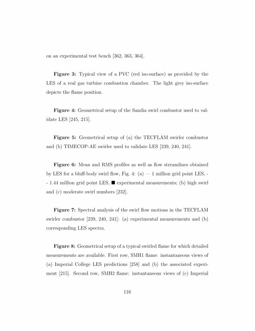
on an experimental test bench [362, 363, 364].
Figure 3: Typical view of a PVC (red iso-surface) as provided by the
LES of a real gas turbine combustion chamber. The light grey iso-surface
depicts the flame position.
Figure 4: Geometrical setup of the Sandia swirl combustor used to val-
idate LES [245, 215].
Figure 5: Geometrical setup of (a) the TECFLAM swirler combustor
and (b) TIMECOP-AE swirler used to validate LES [239, 240, 241].
Figure 6: Mean and RMS profiles as well as flow streamlines obtained
by LES for a blu↵-body swirl flow, Fig. 4: (a) — 1 million grid point LES, -
- 1.44 million grid point LES, ⌅ experimental measurements; (b) high swirl
and (c) moderate swirl numbers [232].
Figure 7: Spectral analysis of the swirl flow motions in the TECFLAM
swirler combustor [239, 240, 241]: (a) experimental measurements and (b)
corresponding LES spectra.
Figure 8: Geometrical setup of a typical swirled flame for which detailed
measurements are available. First row, SMH1 flame: instantaneous views of
(a) Imperial College LES predictions [258] and (b) the associated experi-
ment [215]. Second row, SMH2 flame: instantaneous views of (c) Imperial
116

College LES predictions [258] and (b) the associated experiment [216].
Figure 9: Comparisons of the numerical predictions [258] with exper-
imental data [215] for SMH1: (a) mean axial velocity profiles, (b) mean
mixture fraction and their respective RMS (b) and (d) along with (e) the
mean temperature profiles.
Figure 10: Instantaneous views of the axial velocity component: (a)
TUD, (b) CERFACS. Temporal averages of the two LES’s are compared to
experimental measures for (c) the mean axial velocity component and (d) its
RMS at four axial locations within the chamber (courtesy of P. Pantangi, A.
Sadiki, M. Haege and A. Dreizler from TUD University, Germany).
Figure 11: (a) DLR-A flame configuration and highly resolved LES mesh
along with (b) a comparisons of scatter plots obtained by measurements (red)
and LES (blue) [273].
Figure 12: Massively parallel LES predictions of the Precinsta burner:
(a) instantaneous velocity field and (b) turbulent structures [205].
Figure 13: Mean profiles of (a) the CO2 mass fraction and (b) its RMS
obtained by LES and in the experiment at di↵erent stations within the com-
bustor.
117

Figure 14: Views of (a) the experimental burner and (b) swirler used to
determined FTF/FDF’s experimentally and numerically [302].
Figure 15: Temporal evolution of the heat release rate fluctuation ob-
tained by LES and experimentally [302] for the above configuration, Fig. 14.
Figure 16: Direct comparisons of experimental observations (left col-
umn) and LES predictions (right column) for a swirl stabilized premixed
flame subject to an external acoustic forcing. All snapshots are taken at
equal phase angles and allow to retrieve leading mechanisms governing the
FDF [302].
Figure 17: Configuration to study ignition in a blu↵body case [314].
Figure 18: Failed ignition sequence as observed in time by LES [310]
of the experimentally diagnosed configuration of [314] shown on Fig. 17.
Snapshots correspond to the instantaneous field of temperature (dark iso-
contours) after sparking at t = 0 ms. Each instant also shows the isostoi-
chiometric line.
Figure 19: Successful ignition sequence as observed in time by LES [310]
of the experimentally diagnosed configuration of [314] and shown on Fig. 17.
Snapshots correspond to the instantaneous field of temperature (dark iso-
contours) after sparking at t = 0 ms. Each instant also shows the isostoi-
chiometric line.
118

Figure 20: Typical view of an aeronautical gas turbine engine: (a) full
engine, (b) combustor flame tube and (c) a detailed view of a recent swirler
design. Fuel injection points are here visualized through red dots.
Figure 21: Geometrical elements of a gas turbine for which LES is re-
ported: (a) & (b), swirler ; (c) single sector domain taking into account the
swirler (orange), the flame tube (dark grey) and the chamber casing (yellow);
(d) full annular configuration with all sectors, swirlers and the entire flame
tube. The particular example corresponds to a reverse combustor design.
Figure 22: Real swirler design as reported by [335, 244, 250]: (a) de-
scription of the di↵erent elements present on a design for the CFM56 engine
and LES predictions of an industrial swirler and whose swirl number is (b)
S = 0.35 and (c) S = 0.49 (instantaneous views of the azimuthal velocity
component vector).
Figure 23: Real swirler designs evaluated through LES of non-reacting
flow: views of the axial mean velocity component, the flow going from left
to right (dark blue corresponds to large values of back flow; courtesy of A.
Roux from Turbomeca, Safran group).
Figure 24: Mean axial velocity profiles along the symmetry axis of the
swirlers of Fig. 23. The superposed grey envelop represents the extent of
the potential local and instantaneous value of the axial velocity component
119

obtained by LES (courtesy of A. Roux from Turbomeca, Safran group).
Figure 25: Single sector LES: views of the di↵erent computational do-
mains treated by LES [316, 317, 318, 48, 319, 320].
Figure 26: Typical view of a aeronautical gas turbine engine LES: in-
stantaneous field prediction for (a) Pratt & Withney engine [318], (b) a
helicopter engine from Turbomeca (Safran group) [319], (c) and (d) two
combustor concepts from Honeywell [365, 366], (e) a Rolls-Royce lean burn
engine [367].
Figure 27: Outlet normalized temperature profiles (RDTF) obtained
numerically by LES, RANS and experiments for di↵erent real combustors:
(a) Pratt & Whitney engine (LES, line and experiment, symbols) in the
plane identified in Fig. 26 [318] (a); (b) Turbomeca engine (LES, RANS and
experiment) [319] and (c) Rolls-Royce engine (LES with and without the cas-
ing and RANS with the casing) [48]: Symbol, rig measurements ; —, LES of
liner plus annuli; - -, LES of liner only; and -.-, RANS simulation of liner only.
Figure 28: FTF predictions of an industrial burner by treating (a) one
single and (b) three burner forced LES [349].
Figure 29: nstantaneous snapshot of LES predictions in full annular real
combustors: (a) from [358] and (b) from [355, 356, 357, 342].
120

Figure 30: LES of a light-around sequence obtained for an annular
combustion chamber [307].
121

List of Tables
122

Tab
le1:
Tentative
classification
oftheturbulent
SGSLESclosuresavailable.
Fundam
enta
lhypoth
esis
Modelproperties
Nea
rwallbeh
avior
Solid
rotation
Pure
shea
rCon
trac
tion
/ex
pan
sion
Axisymmetric
Isotropic
Eddy
viscosity
closu
res
1
Smag
orinsky[83]
Production=
dissipation
O(y
0)
01
⇡3.46
⇡2.45
Wale[97]
Production=dissipation
O(y
3)
⇡0.9
0⇡
0.15
0
Vreman
[98]
Production=
dissipation
O(y
1)
⇡0.71
0⇡
1.22
1
Sigma[100
]Production=
dissipation
O(y
3)
00
00
Dynam
icclosu
res
2
German
o[64,
88]
Production=
dissipation
O(y
0)
Tobedetermined
-strongdep
enden
cyon
thehom
ogen
izationprocedure
Sim
ilarity
base
dclosu
res
Bardina[106
]Sca
lesimilarityhypothesis
Tobedetermined
-strongdep
enden
cyon
thehom
ogen
izationprocedure
Mixed
closu
res
Sam
gorinsky-B
ardina
[109
,
110]
Sca
lesimilarityhypothesis
&Pro-
duction=
dissipation
Tobedetermined
-strongdep
enden
cyon
thehom
ogen
izationprocedure
Non-lin
earclosu
re
Ten
sorial
visco
sity
[107
],de-
convolution
model
[108
]
Production=
dissipation
Tobedetermined
Oneorm
oreequation
closu
res
Additional
tran
sporteq
ns[90,
91,89
]
Production6=
dissipation
Tobedetermined
[1]Con
clusion
san
dob
servationsex
trac
tedfrom
[100
],[2]Con
clusion
san
dob
servationsex
trac
tedfrom
[368
]
123

Tab
le2:
Tentative
classification
oftheturbulent
reactingLESclosuresavailable.
Form
alism
Modeling
Solved
quantity
Closu
res
Reaction
sourcete
rm
Rangeofapplication
Geom
etric
G-field
GST
⇢u
ST
q@
eG
x
i
@
eG
x
iPremixed
Flamesurfacedensity
e ⌃f ⌦k
e ⌃f ⌦k
Allmodes
Flamewrinkling
ece ⌅
⇢u
s0 l
e ⌅q
@ec
x
i
@ec
x
iAllmodes
Thickenedflame
e Y kE
(E�cien
cyfunction)
E!
k(eY
k,
eT)
F(F
,th
icke
ningfactor)
Allmodes
Sta
tistical
PresumedFDF/PDF
e Z;(g ZZ
�e Z
e Z)
(g u iZ
�eu i
e Z);
^D
@Z
@x
k
@Z
@x
k�
D@
eZ
@x
k
@
eZ
@x
k
R!k
(Z)f(Z
)dZ
Non
-premixed
ec;(ecc�
ecec)
(fu ic�
eu iec);
^D
@c
@x
k
@c
@x
k�
D@ec
@x
k
@ec
@x
k
R!k
(c)f(c)dc
Premixed
flam
es
Allof
theab
ove
Allof
theab
ove
RR!k
(c,Z
)f(c,Z
)dcdZ
Allmodes
CMC
g Y k|c
g u i|c;u
i
Yk
|c;
^D
@Y
m@x
l
@Y
n@x
l|c
R!k
|cf(c)dc
Premixed
] Y k|Z
g u i|Z
;ui
Yk
|Z;
^D
@Y
m@x
l
@Y
n@x
l|Z
R!k
|Zf(Z
)dZ
Non
-premixed
Yk
|Z,c
ui
|Z,c;
^ui
Yk
|Z,c;
^D
@Y
m@x
l
@Y
n@x
l|Z
,cRR
!k
|c,Z
f(c,Z
)dcdZ
Allmodes
LEM
e Y kf(l)
!k
(Yk
)Allmodes
TransportedFDF/PDF
f(⇠)
g u i|⇠;
^D
@c
@x
l
@c
@x
l|⇠
R!c
(⇠)f(⇠)d⇠
Premixed
f(⌘)
g u i|⌘;
^D
@Z
@x
l
@Z
@x
l|⌘
R!k
(⌘)f(⌘)d⌘
Non
-premixed
f(
k
)ui
| k
;^
D@Y
m@x
l
@Y
n@x
l|
k
R!k
( j
)f(
j
)d j
Allmodes
124

Tab
le3:
Tentative
survey
ofthemassively
parallelcodes
available
forcomplexreactingLESap
plication
s.Code
Form
alism
Num
erics
Target
burners
PUFFIN
(Loughboro
ugh
Univer-
sity
)
Low
Mach
,conse
rved
scalar
/pro
gre
ss
variable
Navier-Sto
kes
Second
ord
erin
time
and
space,multi-
block
stru
ctu
red
code
Lab-scale
burn
ers
FLOW
SI(ImperialCollege)
Low
Mach
,conse
rved
scalar
/pro
gre
ss
variable
Navier-Sto
kes
Second
ord
erin
time
and
space,multi-
block
stru
ctu
red
code
Lab-scale
burn
ers
BOFFIN
(ImperialCollege)
Low
Mach
,conse
rved
scalar
/pro
gre
ss
variable
Navier-Sto
kes
Second
ord
erin
time
and
space,multi-
block
body
fitted
stru
ctu
red
code
Lab-and
real-sc
ale
burn
ers
FASTEST
3D
(Tech
nicalUniversity
ofDarm
stadt)
Low
Mach
,conse
rved
scalar
/pro
gre
ss
variable
Navier-Sto
kes
Second
ord
erin
time
and
space,multi-
block
body
fitted
stru
ctu
red
code
Lab-scale
burn
ers
CDP
(Sta
nford
University)
Low
Mach
,conse
rved
scalar
/pro
gre
ss
variable
Navier-Sto
kes
Secondord
erin
timeandsp
ace,unstru
c-
ture
dmesh
es
Lab-and
real-sc
ale
burn
ers
NGA
(Sta
nford
University;Univer-
sity
of
Colora
do;
Corn
ell
Univer-
sity
;Pitsc
h)
Low
Mach
,multi-sp
ecies
(tra
nsp
orted
PDF)Navier-Sto
kes
Second
ord
erin
time
and
space,multi-
block
stru
ctu
red
code
Lab-scale
burn
ers
RAPTOR
(Sandia
National
Lab.
code)
Compre
ssib
le,
multi-sp
ecies
Navier-
Sto
kes
Second
ord
erin
time
and
space,multi-
block
stru
ctu
red
code
Lab-and
real-sc
ale
burn
ers
LESLIE
(Giorg
iaIn
st.ofTech
.)Compre
ssib
lemulti-sp
ecies,
conse
rved
scalar/
pro
gre
ssvariable
Navier-Sto
kes
Second
ord
er
intime,
fourth
ord
er
in
space,
multi-block
hybrid
(structu
red,
unstru
ctu
red)code
Lab-and
real-sc
ale
burn
ers
Penn.Sta
teUniversity
code
Compre
ssib
le,
multi-sp
ecies
Navier-
Sto
kes
Second
ord
erin
time
and
space,multi-
black
stru
ctu
red
code
Lab-scale
burn
ers
YALES2
(CORIA
)Low
Mach
,conse
rved
scalar
/pro
gre
ss
variable
Navier-Sto
kes
Explicit,th
ird
ord
erin
timeand
space,
unstru
ctu
red
/hybrid
mesh
es
Lab-and
real-sc
ale
burn
ers
AVBP
(CERFACS)
Compre
ssib
le,
multi-sp
ecies
Navier-
Sto
kes
Explicit,th
ird
ord
erin
timeand
space,
unstru
ctu
red
/hybrid
mesh
es
Lab-and
real-sc
ale
burn
ers
PRECIS
E(R
olls-Royce)
Low
Mach
/compre
ssib
le,
conse
rved
scalar
/pro
gre
ssvariable
&multi-
speciesNavier-Sto
kes
Third
ord
erin
timeand
space,unstru
c-
ture
dmesh
es
Lab-and
real-sc
ale
burn
ers
THETA
(Deutsch
es
Zentrum
fuer
Luft-und
Raumfahrt
e.V
-DLR)
Multi-sp
eciesNavier-Sto
kes
Secondord
erin
timeandsp
ace,unstru
c-
ture
dmesh
es
Lab-and
real-sc
ale
burn
ers
OpenFoam
Low
Mach
/compre
ssib
le,
conse
rved
scalar
/pro
gre
ssvariable
&multi-
speciesNavier-Sto
kes
Secondord
erin
timeandsp
ace,unstru
c-
ture
dmesh
es
Lab-and
real-sc
ale
burn
ers
FLUENT
(ANSYS)
Low
Mach
/compre
ssib
le,
conse
rved
scalar
/pro
gre
ssvariable
&multi-
speciesNavier-Sto
kes
Secondord
erin
timeandsp
ace,unstru
c-
ture
dmesh
es
Lab-and
real-sc
ale
burn
ers
125

Table 4: Tentative survey of laboratory scale burner LES’s.
Ref. Code Turbulence Combustion Target applications
[231] FLOWSI Dyn. Smag. Non-reacting Blu↵ body flame
[229, 230, 232, 233] Unknown Dyn. Smag. Non-reacting Swirl flames series
[241] Unknown Smag. Non-reacting TECFLAM burner
[242, 243, 244, 250] Penn. State Smag. Non-reacting Swirl Mixer (US Patent)
[369] CDP Dyn. Smag. Z, c, flamelet Non-prem. coaxial jet comb.
[181] Unknown CMC Blu↵ body
[370, 184] Unknown Smag. FDF Blu↵ body
[371, 372, 373, 374] Unknown Dyn. Smag. c, flamelet Swirl flames series
[375] LESLIE LDKM LEM Swirl flames series
[376] PRECISE Smag. FDF Swirl flames series
[377] SiTCom Smag. PCM-FPI Lifted flame, vitiated coflow
[378] LESLIE LDKM, Mixed Flamelet G, EDC finite rate Swirl stratified prem. flame
[302] AVBP Wale Thick. Flame, reduced chem. Prem. swirl comb.
[275, 276] AVBP Wale PCM-FPI Prem. swirl comb.
[192, 205] YALES2 Dyn. Smag. C, tabulated chem. Prem. swirl comb.
[190] AVBP Wale FTACLES - FPI Prem. swirl comb.
[247] AVBP Smag. Thick. Flame Prem. swirl comb.
[379, 380, 381] Unknown LDKM Reduced chem., wrinkling [382] GE LM 6000 comb.
[383] Unknown Smag. c, flame wrinkling, flamelet Prem. swirl comb.
[384] Unknown Smag. G and Z, flamelet Partially prem. comb.
[380] Unknown Unknown G Swirl comb.
[246, 385] AVBP Smag. Thick. Flame, reduced chem. Siemens burner
[386, 293] AVBP Smag. Thick. Flame, reduced chem. Prem. staged burner
[387, 388, 389, 390] Penn. State Smag. G, flamelet Prem. swirl comb.
[391] LESLIE LDKM Reduced chem. GE DACRS comb.
[392, 393] Unknown Smag. EBU, reduced chem. DOE-NETL prem. comb.
[394, 395] LESLIE LDKM G and Z, flamelet Prem. comb.
[396] Unknown Smag. Level-set, flamelet Prem. comb.
[383] Unknown Smag. Flamelet Swirl comb.
[337] Unknown LDKM, Mixed Z, c, flamelet [382] TARS burner [264]
[397, 398] Unknown Smag. G, flamelet GE-LM6000, DOE-HAT
[399, 400] LESLIE LDKM LEM-LES, reduced chem. GE-1
[401] AVBP Smag. Thick. Flame, reduced chem. Alstom swirl
[296, 303, 304] AVBP Smag. Thick. Flame, reduced chem. Siemens stratified
126

Tab
le5:
Tentative
survey
ofreal
scaleburner
LES’s.
Ref.
Code
Turbulence
Combustion
Targetapplications
[316
]BOFFIN
Smag
.-Lilly
Z,presu
med
PDF,flam
elet
Rolls-R
oyce
Tay
engine[402
,40
3]
[349
,40
4]AVBP
Smag
.Thicke
nFlame,
reducedch
emistry
Siemen
sburn
er
[405
,31
8,
317]
CDP
Dyn.Smag
.e Z,ec,presu
med
PDF’s,co
mplexknietics
[369
]Pratt
&W
hitney
combustor
[48]
PRECISE
Dyn.Smag
.EDB,tw
o-step
chem
istry
Rolls-R
oyce
dev
elop
men
tburn
er
[399
]LESLIE
LDKM
LEM-L
ES,th
ree-step
chem
istry[406
,39
9]TAPS(G
E-2)co
mbustor
[407
,39
9]
[319
,36
0,
320]
AVBP
Smag
.Thicke
nFlamemodel,reducedch
emistry
Arriushelicop
terco
mbustionch
amber
from
Turb
omeca
[312
]BOFFIN
Dyn.Smag
.Transp
ortedPDF
Ignitionsequen
ceof
aRolls-R
oyce
burn
er
[343
]PRECISE
Dyn.Smag
.CMC
orEBU,on
e-step
chem
istry[408
]Ignitionsequen
ceof
aRolls-R
oyce
burn
er
[365
,36
6]Unknow
nUnknow
nUnknow
nHon
eywellburn
ers
[306
,30
7]AVBP
Smag
.Thicke
nFlame,
reducedch
emistry
Ignitionsequen
ceof
Turb
omecaburn
er
[355
,35
6,
357,
342]
AVBP
Smag
.Thicke
nFlame,
reducedch
emistry
Ard
iden
helicop
terch
amber
from
Turb
omeca
[358
]Open
foam
LDKM,
Mixed
model
PaS
R-L
ES[409
,70
],reducedch
emistry
CESAR
combustionch
amber
127

List of Figures
Figure 1: Schematic representation of the three numerical methods used to simulate tur-
bulent reacting flows: (a) RANS provide access to a temporally/ensemble averaged field
representing the flow field in complex systems (extracted from [319]); (b) LES give access
to a temporally and spatially evolving set of fields representative of the spatially filtered
governing system of equations (extracted from [360, 320]) and (c) DNS provide the exact
spatially and temporally evolving field obtained by directly solving the governing equations
(extracted from [361]).
128

Figure 2: Typical view of the main flow structures present outside a swirler from a
real aeronautical burner provided by Turbomeca and mounted on an experimental test
bench [362, 363, 364].
129

Figure 3: Typical view of a PVC (red iso-surface) as provided by the LES of a real gas
turbine combustion chamber. The light grey iso-surface depicts the flame position.
130

Figure 4: Geometrical setup of the Sandia swirl combustor used to validate LES [245, 215].
131
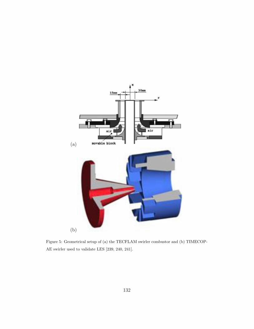
(a)
(b)
Figure 5: Geometrical setup of (a) the TECFLAM swirler combustor and (b) TIMECOP-
AE swirler used to validate LES [239, 240, 241].
132

(a)
(b) (c)
Figure 6: Mean and RMS profiles as well as flow streamlines obtained by LES for a blu↵-
body swirl flow, Fig. 4: (a) — 1 million grid point LES, - - 1.44 million grid point LES, ⌅experimental measurements; (b) high swirl and (c) moderate swirl numbers [232].
133

(a)
(b)
Figure 7: Spectral analysis of the swirl flow motions in the TECFLAM swirler combus-
tor [239, 240, 241]: (a) experimental measurements and (b) corresponding LES spectra.
134

(a) (b)
(c) (d)
Figure 8: Geometrical setup of a typical swirled flame for which detailed measurements
are available. First row, SMH1 flame: instantaneous views of (a) Imperial College LES
predictions [258] and (b) the associated experiment [215]. Second row, SMH2 flame:
instantaneous views of (c) Imperial College LES predictions [258] and (b) the associated
experiment [216].135

(a)
(b)
(c)
(d)
(e)
Figure
9:Com
parison
sof
thenu
merical
prediction
s[258]withexperim
entaldata[215]forSMH1:
(a)meanax
ialvelocity
profiles,
(b)meanmixture
fraction
andtheirrespective
RMS(b)an
d(d)alon
gwith(e)themeantemperature
profiles.
136

(a) (b)
(c)
(d)
Figure 10: Instantaneous views of the axial velocity component: (a) TUD, (b) CERFACS.
Temporal averages of the two LES’s are compared to experimental measures for (c) the
mean axial velocity component and (d) its RMS at four axial locations within the chamber
(courtesy of P. Pantangi, A. Sadiki, M. Haege and A. Dreizler from TUD University,
Germany).
137

(a)
(b)
Figure 11: (a) DLR-A flame configuration and highly resolved LES mesh along with (b)
a comparisons of scatter plots obtained by measurements (red) and LES (blue) [273].
138

(a)
(b)
Figure 12: Massively parallel LES predictions of the Precinsta burner: (a) instantaneous
velocity field and (b) turbulent structures [205].
139

(a)
(b)
Figure 13: Mean profiles of (a) the CO2 mass fraction and (b) its RMS obtained by LES
and in the experiment at di↵erent stations within the combustor.
140

(a) (b)
Figure 14: Views of (a) the experimental burner and (b) swirler used to determined
FTF/FDF’s experimentally and numerically [302].
141

Figure 15: Temporal evolution of the heat release rate fluctuation obtained by LES and
experimentally [302] for the above configuration, Fig. 14.
142

00
600
1200
1800
2400
3000
Figure 16: Direct comparisons of experimental observations (left column) and LES predic-
tions (right column) for a swirl stabilized premixed flame subject to an external acoustic
forcing. All snapshots are taken at equal phase angles and allow to retrieve leading mech-
anisms governing the FDF [302].
143

Figure 17: Configuration to study ignition in a blu↵body case [314].
144

(a) (b)
t = 0 ms t = 0.15 ms
(c) (d)
t = 1 ms t = 3 ms
(e) (f)
t = 5 ms t = 10 ms
Figure 18: Failed ignition sequence as observed in time by LES [310] of the experimentally
diagnosed configuration of [314] shown on Fig. 17. Snapshots correspond to the instanta-
neous field of temperature (dark iso-contours) after sparking at t = 0 ms. Each instant
also shows the isostoichiometric line.
145

(a) (b)
t = 0 ms t = 0.16 ms
(c) (d)
t = 1 ms t = 5 ms
(e) (f)
t = 20 ms t = 45 ms
Figure 19: Successful ignition sequence as observed in time by LES [310] of the experi-
mentally diagnosed configuration of [314] and shown on Fig. 17. Snapshots correspond
to the instantaneous field of temperature (dark iso-contours) after sparking at t = 0 ms.
Each instant also shows the isostoichiometric line.
146
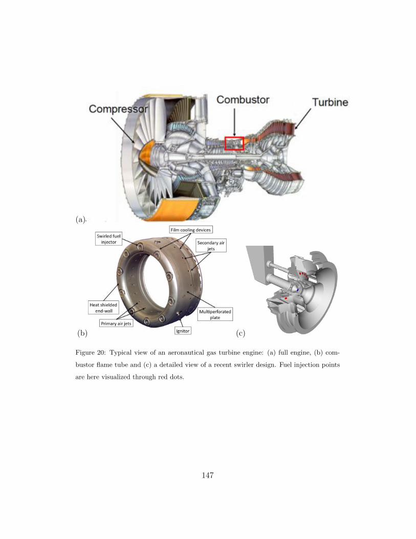
(a)
(b) (c)
Figure 20: Typical view of an aeronautical gas turbine engine: (a) full engine, (b) com-
bustor flame tube and (c) a detailed view of a recent swirler design. Fuel injection points
are here visualized through red dots.
147

(a) (b)
(c) (d)
Figure 21: Geometrical elements of a gas turbine for which LES is reported: (a) & (b),
swirler ; (c) single sector domain taking into account the swirler (orange), the flame
tube (dark grey) and the chamber casing (yellow); (d) full annular configuration with
all sectors, swirlers and the entire flame tube. The particular example corresponds to a
reverse combustor design.
148
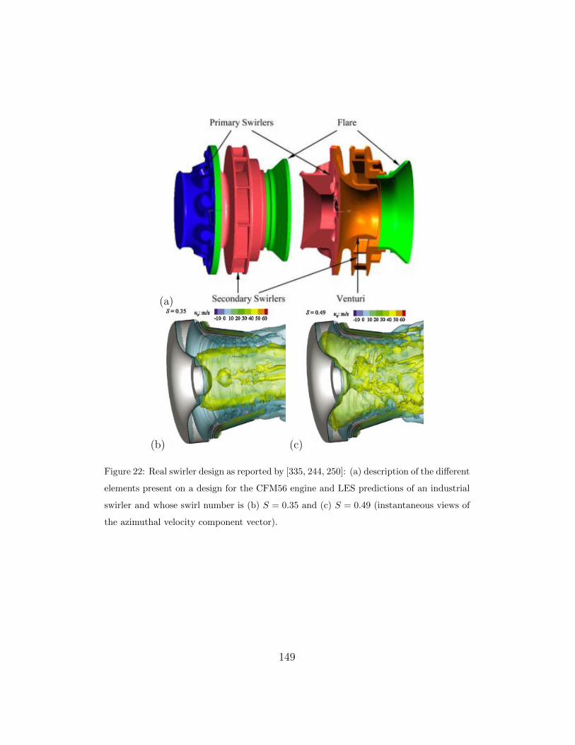
(a)
(b) (c)
Figure 22: Real swirler design as reported by [335, 244, 250]: (a) description of the di↵erent
elements present on a design for the CFM56 engine and LES predictions of an industrial
swirler and whose swirl number is (b) S = 0.35 and (c) S = 0.49 (instantaneous views of
the azimuthal velocity component vector).
149

(a) (b)
(c) (d)
Figure 23: Real swirler designs evaluated through LES of non-reacting flow: views of the
axial mean velocity component, the flow going from left to right (dark blue corresponds
to large values of back flow; courtesy of A. Roux from Turbomeca, Safran group).
150
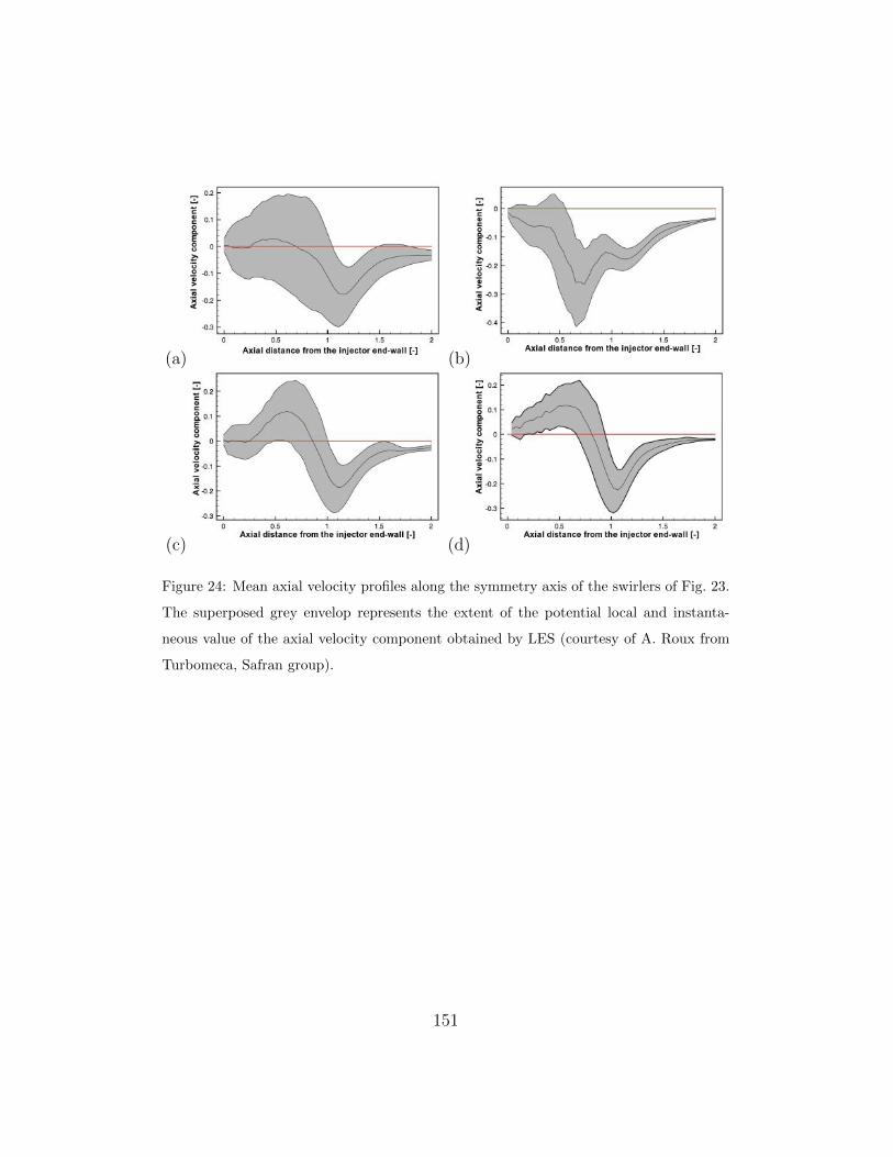
(a) (b)
(c) (d)
Figure 24: Mean axial velocity profiles along the symmetry axis of the swirlers of Fig. 23.
The superposed grey envelop represents the extent of the potential local and instanta-
neous value of the axial velocity component obtained by LES (courtesy of A. Roux from
Turbomeca, Safran group).
151
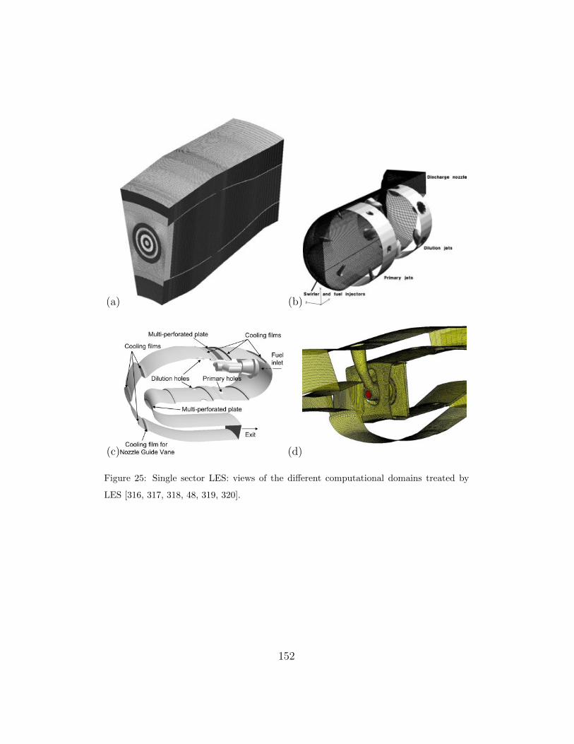
(a) (b)
(c) (d)
Figure 25: Single sector LES: views of the di↵erent computational domains treated by
LES [316, 317, 318, 48, 319, 320].
152

(a) (b)
(c) (d)
(e)
Figure 26: Typical view of a aeronautical gas turbine engine LES: instantaneous field
prediction for (a) Pratt & Withney engine [318], (b) a helicopter engine from Turbomeca
(Safran group) [319], (c) and (d) two combustor concepts from Honeywell [365, 366], (e)
a Rolls-Royce lean burn engine [367].
153

(a) (b)
(c)
Figure 27: Outlet normalized temperature profiles (RDTF) obtained numerically by LES,
RANS and experiments for di↵erent real combustors: (a) Pratt & Whitney engine (LES,
line and experiment, symbols) in the plane identified in Fig. 26 [318] (a); (b) Turbomeca
engine (LES, RANS and experiment) [319] and (c) Rolls-Royce engine (LES with and
without the casing and RANS with the casing) [48]: Symbol, rig measurements ; —, LES
of liner plus annuli; - -, LES of liner only; and -.-, RANS simulation of liner only.
154

(a)
(b)
Figure 28: FTF predictions of an industrial burner by treating (a) one single and (b) three
burner forced LES [349].
155

(a)
(b)
Figure 29: Instantaneous snapshot of LES predictions in full annular real combustors: (a)
from [358] and (b) from [355, 356, 357, 342].
156

(a) (b)
(c) (d)
Figure 30: LES of a light-around sequence obtained for an annular combustion cham-
ber [307].
157
Related Documents