Joint International Topical Meeting on Mathematics & Computation and Supercomputing in Nuclear Applications (M&C + SNA 2007) Monterey, California, April 15-19, 2007, on CD-ROM, American Nuclear Society, LaGrange Park, IL (2007) LARGE EDDY SIMULATION OF WIRE-WRAPPED FUEL PINS I: Hydrodynamics of a Single Pin Paul Fischer, James Lottes, and Andrew Siegel Mathematics and Computer Science Division Argonne National Laboratory Argonne, IL 60439 [email protected], [email protected], [email protected] Giuseppe Palmiotti Nuclear Engineering Division Argonne National Laboratory Argonne, IL 60439 [email protected] ABSTRACT We present large-eddy simulations of flow and heat transfer in a wire-wrapped fuel assembly at sub- channel Reynolds numbers of Re h =4684–29184. The domain consists of a single pin in a hexagonally periodic array, corresponding to two interior subchannels. Periodic boundary conditions are also used in the axial direction over a single wire-wrap period. Key Words: wire-wrapped fuel pin 1. Introduction Proposed designs for advanced burner reactors call for liquid sodium coolant passing through subassemblies of hexagonally arrayed fuel pins. The fuel pins in each subassembly are separated by wire wrap spacers wound helically along the pin axes. A single assembly will comprise 217 pins in a hexagonal array, with about 5 turns of the wire along the length of each pin. In addition to spacing the pins, the wire wrap is designed to promote mixing of the coolant between the channels that are formed by the pin array. Enhanced mixing can lead to reduced peak pin temperatures. The ability to predict (and optimize) mixing behavior can lead to reduced hot channel factors and thereby allow operation at higher power levels. In addition to the mixing, it is of interest in the design of the overall core to predict the distribution of the coolant flow, including the amount passing through the near-wall subchannels. Analysis of wire-wrapped fuel pins is challenging for several reasons. The Reynolds number based on the hydraulic radius, Re h = UD h /ν , is in the range of 40000–65000, which means the flow is turbulent. The turbulence is further promoted by the wire wrap. Because it creates multiple contact points and lines, the wire wrap makes the geometry (and mesh) relatively complex. Moreover, with > 400 subchannels and L/D h ≈ 360, the geometry of just a single subassembly is large. There are hundreds of assemblies in the reactor. Most thermal-hydraulics analysis is therefore based on subchannel modeling, which use a few hundred degrees of freedom per channel to represent mass, momentum, and energy balances at axial positions along the channel. Subchannel models of a full core will have ∼ 10 7 control volumes. Subchannel models are relatively fast and will likely be the mainstay of reactor-scale analysis for the foreseeable future. However, they rely on experimentally determined coefficients to account for interchannel mixing.

Welcome message from author
This document is posted to help you gain knowledge. Please leave a comment to let me know what you think about it! Share it to your friends and learn new things together.
Transcript

Joint International Topical Meeting on Mathematics & Computation and Supercomputing in Nuclear Applications (M&C + SNA2007)Monterey, California, April 15-19, 2007, on CD-ROM, American Nuclear Society, LaGrange Park, IL (2007)
LARGE EDDY SIMULATION OF WIRE-WRAPPED FUEL PINS I:Hydrodynamics of a Single Pin
Paul Fischer, James Lottes, and Andrew SiegelMathematics and Computer Science Division
Argonne National LaboratoryArgonne, IL 60439
[email protected], [email protected], [email protected]
Giuseppe PalmiottiNuclear Engineering DivisionArgonne National Laboratory
Argonne, IL [email protected]
ABSTRACT
We present large-eddy simulations of flow and heat transfer in a wire-wrapped fuel assembly at sub-channel Reynolds numbers ofReh=4684–29184. The domain consists of a single pin in a hexagonallyperiodic array, corresponding to two interior subchannels. Periodic boundary conditions are also used inthe axial direction over a single wire-wrap period.
Key Words: wire-wrapped fuel pin
1. Introduction
Proposed designs for advanced burner reactors call for liquid sodium coolant passing through subassembliesof hexagonally arrayed fuel pins. The fuel pins in each subassembly are separated by wire wrap spacerswound helically along the pin axes. A single assembly will comprise 217 pins in a hexagonal array, withabout 5 turns of the wire along the length of each pin. In addition to spacing the pins, the wire wrap isdesigned to promote mixing of the coolant between the channels that are formed by the pin array. Enhancedmixing can lead to reduced peak pin temperatures. The ability to predict (and optimize) mixing behaviorcan lead to reduced hot channel factors and thereby allow operation athigher power levels. In addition tothe mixing, it is of interest in the design of the overall core to predict the distribution of the coolant flow,including the amount passing through the near-wall subchannels.
Analysis of wire-wrapped fuel pins is challenging for several reasons. The Reynolds number based onthe hydraulic radius,Reh = UDh/ν, is in the range of 40000–65000, which means the flow is turbulent.The turbulence is further promoted by the wire wrap. Because it creates multiple contact points and lines,the wire wrap makes the geometry (and mesh) relatively complex. Moreover,with > 400 subchannelsandL/Dh ≈ 360, the geometry of just a single subassembly is large. There are hundreds of assembliesin the reactor. Most thermal-hydraulics analysis is therefore based on subchannel modeling, which use afew hundred degrees of freedom per channel to represent mass, momentum, and energy balances at axialpositions along the channel. Subchannel models of a full core will have∼ 107 control volumes. Subchannelmodels are relatively fast and will likely be the mainstay of reactor-scale analysis for the foreseeable future.However, they rely on experimentally determined coefficients to account for interchannel mixing.

Paul Fischer et al.
Figure 1. Isosurfaces of axial velocity (w = 0.5U0) at startup forH/D = 13.4, Reh=4684: (top to bottom)tU/D=.05, 5.05, 10.05, 15.05. Flow is from left to right.
Computational fluid dynamics (CFD) offers the opportunity for detailed analyses that may lead to improve-ments in the subchannel model coefficients and may also provide a means of validating the applicabilityof subchannel models to specific (albeit reduced) geometries a posteriori. Several efforts to apply CFD towire-wrap geometries are already underway, including the recent workof Ahmad and Kim [1], who useCFD coupled with a turbulence model based on the Reynolds averaged Navier-Stokes (RANS) equations tostudy 7- and 19-pin configurations. These results are encouraging and it appears that RANS computationscan provide the detailed flow analysis that will be required for improved modeling insight and that will beimportant for coupling to equally detailed neutronics computations. A particular challenge for RANS mod-els, which also require empirical constants, is to properly identify separation zones in regions of adversepressure gradient (e.g., on the leeward side of the wire).
At a finer scale, one can also consider CFD based on direct numerical or large eddy simulation (DNS orLES), in which the governing equations are solved with either no (DNS) or minimal (LES) closure modeling.In the case of LES, one simulates only the energy-carrying large scales of motion and typically augments theNavier-Stokes equations with a spatially varying dissipation mechanism such as an eddy- or hyperviscosityto account for subgrid scale motion.
2 Filtered Spectral Element Simulations
As an initial step towards parameter-free thermal-hydraulic simulation, we have analyzed a single periodiccell in the wire-wrap geometry of Fig. 1 using the spectral element method (SEM) introduced by Patera

Wire Wrap Fuel Pin Arrays
Figure 2. Cross-section of comptational mesh atz=0: (left) tiled mesh showing computational domainhighlighted with the nodal distribution forN=7; (right) close up of instantaneous in-plane velocity atz=0for H/D=13.4,Re = 28104, N = 9.
in 1984 [8]. The SEM is a high-order weighted residual technique that combines the geometric flexibilityof finite elements with the rapid convergence and tensor-product efficiencies of global spectral methods.Within each ofE elements, the solution, data, and geometry are approximated byN th-order tensor-productpolynomials, resulting inn ≈ EN3 grid points. The polynomials are Lagrangian interpolants based on theGauss-Lobatto-Legendre quadrature points, which provide for stableand efficient evaluation of the bilinearforms arising in the weighted residual formulation. Because it has minimal numerical dissipation and dis-persion, the SEM is ideally suited for high fidelity transport of small scale structures, as arise in the presentcase [3].
The current simulations are based on thelPN − lPN−2 formulation of Maday and Patera [7], which uses adiscontinuous pressure approximation of orderN − 2 and continuous velocity approximations of orderN .Time advancement is semi-implicit, with explicit treatment of the nonlinear terms and implicit treatmentof the viscous and pressure/incompressiblity terms. The latter are further decoupled through an algebraicsplitting that leads to discrete Helmholtz solves for the velocity components and a discrete Poisson equationfor the pressure, each of which is solved using preconditioned conjugate gradient iteration. Preconditioningfor the pressure system is based on the spectral element multigrid procedure developed in [4].
The time advancement is augmented with the stabilizing filter developed in [5], which removes energy fromthe highest modes and thus serves as a drain for the energy cascade. Because it damps only the highest ordermodes within each element, the filter retains spectral accuracy and automaticallyshuts off in regions wherethe flow is well resolved. The filter thus acts like a hyperviscosity and has been successfully used in a priorstudy of rod bundles in a square lattice [6].
The pin geometry corresponds to the configuration of Cheng and Todreas [2] with a pitch to diameter ra-tio of P/D = 1.154 and helical wire-wrap pitch ofH = 13.4 D. The hydraulic diameter in this caseis Dh = .4684D, not accounting for the presence of the wire. The wire diameter,Dw, is 90.6% of the
Paul Fischer et al.
Figure 3. Mean velocity distributions atz = 0 for (left) Re = 14052, H/D=20.1, N=7 and (right)Re = 28104, H/D=13.4,N=9. Only 1/4 of the vectors are shown.
minimum gap and a fillet of radius .6Dw is added to simplify the meshing. Both axial and horizontal pe-riodicity were assumed, corresponding to a pin located in the middle of the assembly, as illustrated in Fig.2. (Seven-pin configurations comprising 18 subchannels are currentlyunder investigation.) Our single-pin(two-subchannel) geometry is discretized withE=29520 elements of orderN=7 (8.7 M points), which pro-vides roughly 28 points across each subchannel half-width and 840 points in the axial direction. Simulationof one flow-through time requires 15 hours on 2048 processors of the IBM BlueGene at Argonne. ForH/D=13.4, we studied Reynolds numbersReh=4684, 14592, and 29184, usingN=9 in the latter case. Wealso examined the case ofH/D=20.1,Reh=14592, usingN=7. Statistics were typically gathered over asingle flow-through time.
Flow through the domain was imposed by applying a body force in thez direction, corresponding to a meanaxial pressure drop. Because of the linearity of the implicit substeps, it is possible to implicitly establishthe forcing necessary to maintain a constant mean flow velocityU by first advancing the Navier-Stokessystem without a body force and then adding to the resultant velocity/pressure fields an auxiliary solution,(αu0, αp0). The constantα is chosen at each step such that the net solution satisfies the desired flow rate.The fields(u0, p0) solve the unsteady Stokes problem with unit forcing and are precomputed once andstored.
3 Results
Figure 2 (right) shows a typical in-plane velocity field forRe=28104,N=9 atz=0. The small-scale structuresoscillate rapidly and tend to move with the passage of the low-speed streaks (Fig. 1). The large vortex nearthe center, however, is relatively persistent at this axial station and is a result of separation from the wirebelow. This central vortex is evident in the time-averaged velocity distributions of Fig. 3 and was alsoobserved in the RANS calculations of Ahmad and Kim [1]. The vortex at the 6o’clock position in theRe=14052 case of of Fig. 3 (left) appears to subside with increased Reynolds number (right) and was notpresent in theRe = 60840 RANS computation [1].
Wire Wrap Fuel Pin Arrays
0 2 4 6 8 10 12 14 16 1810
−12
10−10
10−8
10−6
10−4
10−2
100
102
TIME
Ek
Energy vs. time for k=50 & 200, Re=4684
0 2 4 6 8 10 12 14 160
0.1
0.2
0.3
0.4
0.5
0.6
0.7
0.8
0.9
1
TIME
DR
AG
Drag vs. time: H/D=20.1, Re=14052
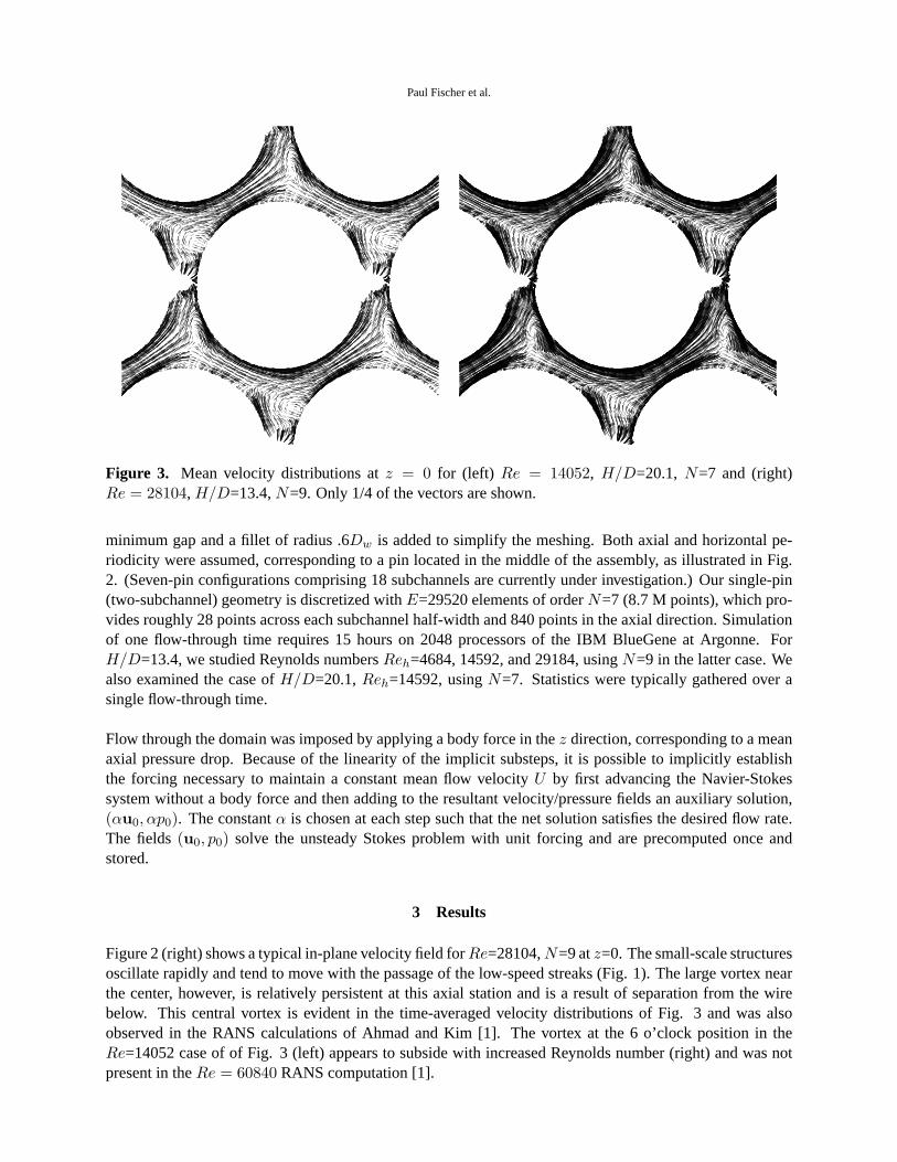
Figure 4. (left) Evolution of kinetic energy at wavenumbersk = 50 (solid) andk = 200 (dashed) takenalong the subchannel centerline forRe = 4684, H/D=13.4; (right) evolution of drag, normalized byρU2,for Re = 14052, H/D=20.1.
The flow typically reached a saturated nonlinear state within one flow-throughtime, indicating that turbu-lence will saturate within the first wire pitch in the developing (i.e., non-periodic) flow case. This observationis consistent with experimental observations that development lengths are typically less thanH. The evo-lution to turbulence is evident in Fig. 1, which shows the development of low-speed streaks near the pinsurface at timestU/D=.05–15.05. Figure 4 (left) shows the kinetic energy history,Ek(t), for wave numbersk = 50 and200, for impulsively started flow. It is clear that even the high wave number energy saturates byt/UD ≈ 12, well within a single flow-through time. Here,Ek(t) is computed from the Fourier transformof the axial distribution of the velocity along one of the channel centerlines at several time instances. Fig-ure 4 (right) shows the evolution of the total drag, skin friction, and form drag, normalized byρU2 for theReh=14592,H/D=20.1 case, which was started fromH/D=13.4 solution. Form drag accounts for about8% of the net pressure drop for these configurations.
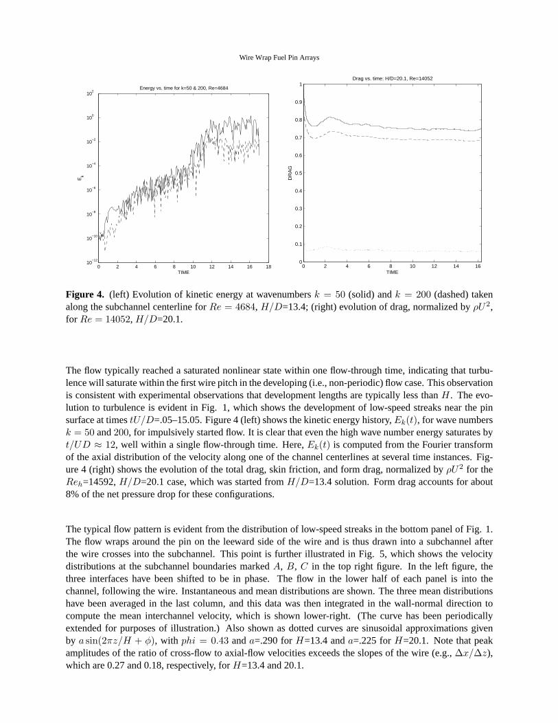
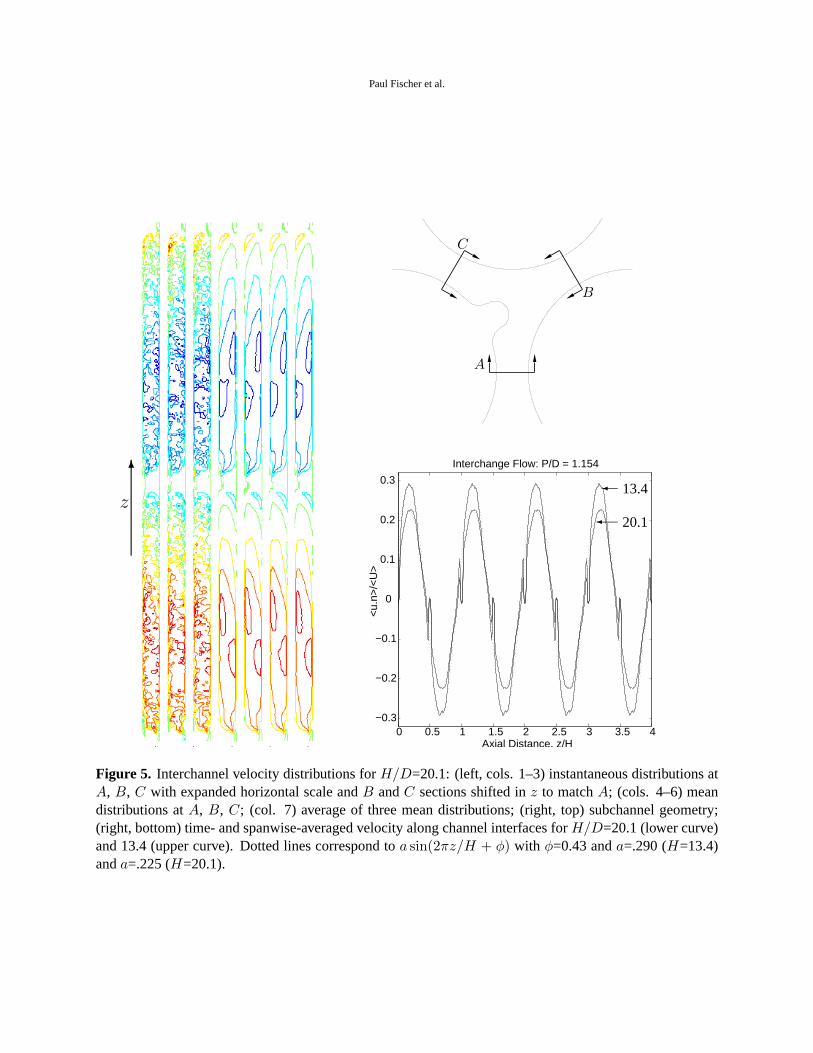
The typical flow pattern is evident from the distribution of low-speed streaks in the bottom panel of Fig. 1.The flow wraps around the pin on the leeward side of the wire and is thus drawn into a subchannel afterthe wire crosses into the subchannel. This point is further illustrated in Fig. 5, which shows the velocitydistributions at the subchannel boundaries markedA, B, C in the top right figure. In the left figure, thethree interfaces have been shifted to be in phase. The flow in the lower halfof each panel is into thechannel, following the wire. Instantaneous and mean distributions are shown. The three mean distributionshave been averaged in the last column, and this data was then integrated in thewall-normal direction tocompute the mean interchannel velocity, which is shown lower-right. (The curve has been periodicallyextended for purposes of illustration.) Also shown as dotted curves are sinusoidal approximations givenby a sin(2πz/H + φ), with phi = 0.43 anda=.290 forH=13.4 anda=.225 forH=20.1. Note that peakamplitudes of the ratio of cross-flow to axial-flow velocities exceeds the slopes of the wire (e.g.,∆x/∆z),which are 0.27 and 0.18, respectively, forH=13.4 and 20.1.
Paul Fischer et al.
6
z
0 0.5 1 1.5 2 2.5 3 3.5 4−0.3
−0.2
−0.1
0
0.1
0.2
0.3
Axial Distance, z/H
<u.
n>/<
U>
Interchange Flow: P/D = 1.154
� 13.4
� 20.1
A
B
C
Figure 5. Interchannel velocity distributions forH/D=20.1: (left, cols. 1–3) instantaneous distributions atA, B, C with expanded horizontal scale andB andC sections shifted inz to matchA; (cols. 4–6) meandistributions atA, B, C; (col. 7) average of three mean distributions; (right, top) subchannel geometry;(right, bottom) time- and spanwise-averaged velocity along channel interfaces forH/D=20.1 (lower curve)and 13.4 (upper curve). Dotted lines correspond toa sin(2πz/H + φ) with φ=0.43 anda=.290 (H=13.4)anda=.225 (H=20.1).

Wire Wrap Fuel Pin Arrays
4 Summary
We have made a preliminary investigation of the hydrodynamics of wire-wrapped fuel pins. While theseresults do not yet address important features such as wall and cornerchannels, they do serve as a startingpoint for insight into interchannel transport. The simulations also provide accurate flow fields that can bedirectly coupled with larger (i.e., multichannel) thermal hydraulics computations or used to provide accuratemean and fluctuating flow fields that can serve as surrogate flow fields. Weanticipate expanding this workto include multiple channels, including wall and corner channels, in the near future.
Acknowledgments
This work was supported by the U.S. Dept. of Energy under Contract DE-AC02-06CH11357.

Paul Fischer et al.
REFERENCES
[1] A. Ahmad and K.-Y. Kim,Three-dimensional analysis of flow and heat transfer in a wire-wrapped fuelassembly, Proc. of ICAPP 05 (Seoul, Korea), 2005.
[2] S.K. Cheng and N.E. Todreas,Models and correlations for bare and wire-wrapped hexagonal rodbundles- bundle friction factors, subchannel friction factors and mixing parameters, Nuclear Eng. andDesign.
[3] P.F. Fischer, G.W. Kruse, and F. Loth,Spectral element methods for transitional flows in complex ge-ometries, J. Sci. Comput.17 (2002), 81–98.
[4] P.F. Fischer and J.W. Lottes,Hybrid Schwarz-multigrid methods for the spectral element method: Ex-tensions to Navier-Stokes, Domain Decomposition Methods in Science and Engineering Series (R. Ko-rnhuber, R. Hoppe, J. Priaux, O. Pironneau, O. Widlund, and J. Xu,eds.), Springer, Berlin, 2004.
[5] P.F. Fischer and J.S. Mullen,Filter-based stabilization of spectral element methods, Comptes rendus del’Academie des sciences, Serie I- Analyse numerique332 (2001), 265–270.
[6] P.F. Fischer and C.P. Tzanos,Filtered simulations of turbulence in a reactor rod bundle flow, Proc. Am.Nuc. Soc. Mtg., San Diego, June 2005. Preprint ANL/MCS-P1213-0105 (2005).
[7] Y. Maday and A.T. Patera,Spectral element methods for the Navier-Stokes equations, State-of-the-ArtSurveys in Computational Mechanics (A.K. Noor and J.T. Oden, eds.), ASME, New York, 1989, pp. 71–143.
[8] A.T. Patera,A spectral element method for fluid dynamics : laminar flow in a channel expansion, J.Comput. Phys.54 (1984), 468–488.
Related Documents