74 Call our toll free number 800-848-5611 or visit our web site for the most current product and technical information at www.itwredhead.com Uses standard drill bits— no special drill bits to purchase or lose! DESCRIPTION/SUGGESTED SPECIFICATIONS SAVE TIME EASILY INSTALLED n Installs in less than half the time of wedge anchors or adhesive anchors n Simply drill a pilot hole and drive the LDT anchor by hand or impact EASILY REMOVED n No torching or grinding required to remove anchors SAVE MONEY LOWER DRILL BIT COSTS n Use standard ANSI bits instead of proprietary bits n Single piece design, no nut and washer to assemble USE STANDARD ANSI BITS n No special proprietary bits to purchase or lose n Reduce chances for anchor failure due to incorrect bit usage Finished head, Removable Anchor Self-threading Anchors — SPECIFIED FOR ANCHORAGE INTO CONCRETE The LDT anchor is a high performance anchor that cuts its own threads into concrete. Anchor bodies are made of hardened carbon steel and zinc plated, Grade 5. The anchors shall have a finished hex washer head with anti-rotation serrations to prevent anchor back-out. The head of the anchor is stamped with a length identification code for easy inspection. The hole shall be drilled with carbide tipped hammer drill bits made in accordance to ANSI B212.15-1994. LDT Self-threading Anchor Large Diameter Tapcon ( LDT ) Anchors LDT (3/8" & 1/2") (5/8" & 3/4") Sawtooth ™ ADVANTAGES Sawtooth Threads ™ diameters available on 5/8” and 3/4” IMPROVED PERFORMANCE IN LARGE DIAMETER HOLES n Superior performance to wedge anchor n Higher loads in shallow embedments n Closer edge/spacing distance than mechanical anchors n More threads for better thread engagement and higher pullout resistance n Durable induction-hardened tip EASY INSTALLATION n Easy 2-step installation, simply drill a pilot hole and drive n Installs in less than half the time of a wedge anchor n Efficient thread cutting n Use standard drill bit sizes n Single piece design—no nut and washer assembly n Easily removed Patented Sawtooth ™ thread design drives easily into concrete to optimize pullout performance and installation speed

Welcome message from author
This document is posted to help you gain knowledge. Please leave a comment to let me know what you think about it! Share it to your friends and learn new things together.
Transcript

74 Call our toll free number 800-848-5611 or visit our web site for the most current product and technical information at www.itwredhead.com
Uses standard drill bits—
no special drill bits to
purchase or lose!
DESCRIPTION/SUGGESTED SPECIFICATIONS
SAVE TIMEEASILY INSTALLEDn Installs in less than half the time of wedge anchors
or adhesive anchorsn Simply drill a pilot hole and drive the LDT anchor by
hand or impact
EASILY REMOVEDn No torching or grinding required to remove anchors
SAVE MONEYLOWER DRILL BIT COSTSn Use standard ANSI bits instead of proprietary bitsn Single piece design, no nut and washer to assemble
USE STANDARD ANSI BITSn No special proprietary bits to purchase or losen Reduce chances for anchor failure due to incorrect
bit usage
Finished head, Removable Anchor
Self-threading Anchors — SPECIFIED FOR ANCHORAGE INTO CONCRETE
The LDT anchor is a high performance anchor that cuts its own threads into concrete.
Anchor bodies are made of hardened carbon steel and zinc plated, Grade 5.
The anchors shall have a finished hex washer head with anti-rotation serrations to prevent anchor back-out. The head of the anchor is stamped with a length identification code for easy inspection.
The hole shall be drilled with carbide tipped hammer drill bits made in accordance to ANSI B212.15-1994.
LDT Self-threading Anchor
LargeDiameter
Tapcon (LDT ) Anchors
LDT(3/8" & 1/2") (5/8" & 3/4")
Sawtooth™
ADVANTAGES
Sawtooth Threads™ diameters available on 5/8” and 3/4”
IMPROVED PERFORMANCE IN LARGE DIAMETER HOLESn Superior performance to wedge anchorn Higher loads in shallow embedmentsn Closer edge/spacing distance than
mechanical anchorsnMore threads for better thread engagement
and higher pullout resistancen Durable induction-hardened tip
EASY INSTALLATIONn Easy 2-step installation, simply drill
a pilot hole and driven Installs in less than half the time of a
wedge anchorn Efficient thread cuttingn Use standard drill bit sizesn Single piece design—no nut and
washer assemblyn Easily removed
Patented Sawtooth™ thread design drives easily into concrete to optimize pullout performance and installation speed
75Call our toll free number 800-848-5611 or visit our web site for the most current product and technical information at www.itwredhead.com
SELECTION CHART
LDT SIZE
ANSI STANDARD DRILL BIT
DIAM.
🅐ANCHOR HEAD (SOCKET SIZE)
DIAM.WASHER
DIAM.
🅑MINIMUM
EMBEDMENT🅒
HOLE DEPTH
USE IN
CONCRETE
CMU
HOLLOW GROUT-FILLED
LDT 3/8" 5/16" 9/16" 13/16" 1-1/2" 2-1/2" YES YES YES
LDT 1/2" 7/16" 3/4" 1" 2-1/2" 3-1/2" YES NO YES
LDT 5/8" 1/2" 13/16" 1-3/16" 2-3/4" 3-3/4" YES NO YES
LDT 3/4" 5/8" 15/16" 1-5/16" 3-1/4" 4-1/4" YES NO YES
See page 75 for effective lengths and length indication code.
INSTALLATION STEPS
LDT Anchors
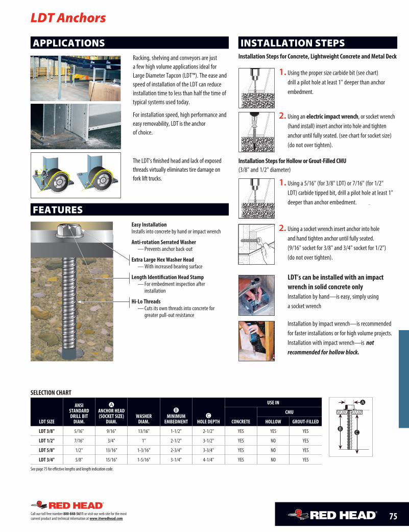
APPLICATIONSRacking, shelving and conveyors are just a few high volume applications ideal for Large Diameter Tapcon (L DT ™). The ease and speed of installation of the LDT can reduce installation time to less than half the time of typical systems used today.
For installation speed, high performance and easy removability, LDT is the anchor of choice.
FEATURESEasy InstallationInstalls into concrete by hand or impact wrench
Anti-rotation Serrated Washer— Prevents anchor back-out
Extra Large Hex Washer Head— With increased bearing surface
Length Identification Head Stamp— For embedment inspection after installation
Hi-Lo Threads— Cuts its own threads into concrete for greater pull-out resistance
1. Using the proper size carbide bit (see chart) drill a pilot hole at least 1" deeper than anchor embedment.
2. Using an electric impact wrench, or socket wrench (hand install) insert anchor into hole and tighten anchor until fully seated. (see chart for socket size) (do not over tighten).
2. Using a socket wrench insert anchor into hole and hand tighten anchor until fully seated. (9/16" socket for 3/8" and 3/4" socket for 1/2") (do not over tighten).
C
1. Using a 5/16" (for 3/8" LDT) or 7/16" (for 1/2" LDT) carbide tipped bit, drill a pilot hole at least 1" deeper than anchor embedment.
Installation Steps for Concrete, Lightweight Concrete and Metal Deck
Installation Steps for Hollow or Grout-Filled CMU (3/8" and 1/2" diameter)
Installation by impact wrench—is recommended for faster installations or for high volume projects. Installation with impact wrench—is not recommended for hollow block.
LDT’s can be installed with an impact wrench in solid concrete only
Installation by hand—is easy, simply using a socket wrench
The LDT’s finished head and lack of exposed threads virtually eliminates tire damage on fork lift trucks.
A
CB

76 Call our toll free number 800-848-5611 or visit our web site for the most current product and technical information at www.itwredhead.com
LENGTH INDICATION CODEDESIGN GUIDEFor proper selection of anchor diameters based upon pre-drilled holes in base plates and fixtures.
EffectiveLength
EffectiveLength
Length Code letter located on top of head. Additional number 4 indicates 410 stainless steel
PART NO. CARBON STEEL
ZINC PLATED
PART NO. FOR 410 STAINLESS
STEEL
ANCHOR DIA. DRILL BIT DIA. ANCHOR LENGTH
MAX. THICKNESS OF MATERIAL TO
BE FASTENED QTY/WT PER BOX
qty / lbs.
QTY/WT PER MASTER
CARTON qty / lbs.in. (mm) in. (mm) in. (mm) in. (mm)
LDT-3816 SLDT-3816 3/8 (9.5) 5/16 (7.9) 1-3/4 (44.5) 1/4 (6.4) 50 / 3.0 400 / 24.0
LDT-3824 SLDT-3824 3/8 (9.5) 5/16 (7.9) 2-1/2 (63.5) 1 (25.4) 50 / 4.5 400 / 34.0
LDT-3830 SLDT-3830 3/8 (9.5) 5/16 (7.9) 3 (76.2) 1-1/2 (38.1) 50 / 5.0 400 / 40.0
LDT-3840 SLDT-3840 3/8 (9.5) 5/16 (7.9) 4 (101.6) 2-1/2 (63.5) 50 / 6.5 400 / 52.0
LDT-3850 SLDT-3850 3/8 (9.5) 5/16 (7.9) 5 (127.0) 3-1/2 (89.0) 40 / 7.5 320 / 60.0
LDT-1230 SLDT-1230 1/2 (12.7) 7/16 (11.1) 3 (76.2) 1/2 (12.7) 25 / 4.5 150 / 27.0
LDT-1240 SLDT-1240 1/2 (12.7) 7/16 (11.1) 4 (101.6) 1-1/2 (38.1) 25 / 6.0 150 / 36.6
LDT-1250 SLDT-1250 1/2 (12.7) 7/16 (11.1) 5 (127.0) 2-1/2 (63.5) 25 / 7.6 150 / 45.6
LDT-1260 — 1/2 (12.7) 7/16 (11.1) 6 (152.4) 4 (101.6) 20 / 9.0 120 / 54.0
LDT-5830 — 5/8 (15.9) 1/2 (12.7) 3 (76.2) 1/4 (6.4) 10 / 3.5 100 / 35.0
LDT-5840 — 5/8 (15.9) 1/2 (12.7) 4 (101.6) 1-1/4 (31.8) 10 / 4.0 100 / 40.0
LDT-5850 — 5/8 (15.9) 1/2 (12.7) 5 (127.0) 2-1/4 (57.1) 10 / 4.7 100 / 47.0
LDT-5860 — 5/8 (15.9) 1/2 (12.7) 6 (152.4) 3-1/4 (82.6) 10 / 5.4 50 / 27.0
LDT-3444 — 3/4 (19.1) 5/8 (15.9) 4-1/2 (114.3) 1-1/4 (31.8) 10 / 7.4 50 / 37.0
LDT-3454 — 3/4 (19.1) 5/8 (15.9) 5-1/2 (139.7) 2-1/4 (57.1) 10 / 8.1 50 / 40.5
LDT-3462 — 3/4 (19.1) 5/8 (15.9) 6-1/4 (158.8) 3 (76.2) 10 / 9.1 30 / 27.3
* The stainless steel LDTs will have the number 4 stamped on the head next to the length indication code
HOLE DIAMETER IN FIXTURE SUGGESTED LDT DIAMETERin. (mm) in. (mm)
7/16 (11.1) 3/8 (9.5)1/2 (12.7) 3/8 (9.5)
9/16 (14.3) 1/2 (12.7)5/8 (15.9) 1/2 (12.7)3/4 (19.1) 5/8 (15.9)7/8 (22.2) 3/4 (19.1)
CODELENGTH OF ANCHOR
in. (mm)
A 1-1/2 < 2 (38.1 < 50.8)B 2 < 2-1/2 (50.8 < 63.5)C 2-1/2 < 3 (63.5 < 76.2)D 3 < 3-1/2 (76.2 < 88.9)E 3-1/2 < 4 (88.9 < 101.6)F 4 < 4-1/2 (101.6 < 114.3)G 4-1/2 < 5 (114.3 < 127.0)H 5 < 5-1/2 (127.0 < 139.7)I 5-1/2 < 6 (139.7 <152.4)J 6 < 6-1/2 (152.4 < 165.1)
ANCHOR DIAMETER EMBEDMENT DEPTH
f’c = 2000 PSI (13.8 MPa) f’c = 3000 PSI (20.7 MPa) f’c = 4000 PSI (27.6 MPa)
TENSION SHEAR TENSION SHEAR TENSION SHEARin. (mm) in. (mm) lbs. (kN) lbs. (kN) lbs. (kN) lbs. (kN) lbs. (kN) lbs. (kN)
3/8 (9.5)
1-1/2 (38.1) 1,336 (5.9) 2,108 (9.4) 1,652 (7.3) 2,764 (12.3) 1,968 (8.8) 3,416 (15.2)2 (50.8) 1,492 (6.6) 3,036 (13.5) 2,024 (9.0) 3,228 (14.4) 2,552 (11.4) 3,420 (15.2)
2-1/2 (63.5) 3,732 (16.6) 3,312 (14.7) 3,748 (16.7) 3,364 (15.0) 3,760 (16.7) 3,424 (15.2)3-1/2 (88.9) 5,396 (24.0) 3,312 (14.7) 6,624 (29.5) 3,368 (15.0) 7,852 (34.9) 3,428 (15.2)
1/2 (12.7)2 (50.8) 3,580 (15.9) 5,644 (25.1) 3,908 (17.4) 6,512 (29.0) 4,236 (18.8) 7,380 (32.8)
3-1/2 (88.9) 7,252 (32.3) 6,436 (28.6) 8,044 (35.8) 7,288 (32.4) 8,836 (39.3) 8,140 (36.2)4-1/2 (114.3) 10,176 (45.3) 7,384 (32.8) 10,332 (46.0) 7,968 (35.4) 10,488 (46.7) 8,552 (38.0)
5/8 (15.9)2-3/4 (69.9) 5,276 (23.5) 8,656 (38.5) 6,560 (29.2) 11,064 (49.2) 7,844 (34.8) 13,476 (59.9)3-1/2 (88.9) 7,972 (35.5) 10,224 (45.5) 9,848 (43.8) 12,144 (54.0) 11,724 (52.2) 14,060 (62.5)4-1/2 (114.3) 11,568 (51.5) 12,316 (54.8) 13,432 (59.8) 13,580 (60.4) 16,892 (75.1) 14,840 (66.0)
3/4 (19.1)3-1/4 (82.6) 6,876 (30.6) 7,140 (31.8) 9,756 (43.4) 10,728 (47.7) 12,636 (56.2) 14,316 (63.6)4-1/2 (114.3) 10,304 (45.8) 13,120 (58.4) 14,424 (64.2) 16,868 (75.0) 18,540 (82.5) 20,612 (91.7)5-1/2 (139.7) 13,048 (58.0) 17,908 (79.7) 18,156 (80.8) 21,718 (96.9) 23,268 (130.5) 25,652 (114.1)
To calculate the Allowable Load of the anchor, divide the Ultimate Load by 4.
SELECTION CHART
LDT Carbon and Stainless Steel
Carbon Steel with Zinc Plating: Meets ASTM B695 and B633 specifications for zinc plating of 5um = .0002” thickness. This coating is well suited for non-corrosive interior environments. Stainless Steel: Provides additional corrosion protection for outdoor applications.
PERFORMANCE TABLE
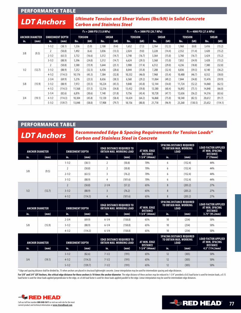
LDT Anchors Ultimate Tension and Shear Values (lbs/kN) in Solid Concrete
77Call our toll free number 800-848-5611 or visit our web site for the most current product and technical information at www.itwredhead.com
ANCHOR DIAMETER EMBEDMENT DEPTH
f’c = 2000 PSI (13.8 MPa) f’c = 3000 PSI (20.7 MPa) f’c = 4000 PSI (27.6 MPa)
TENSION SHEAR TENSION SHEAR TENSION SHEARin. (mm) in. (mm) lbs. (kN) lbs. (kN) lbs. (kN) lbs. (kN) lbs. (kN) lbs. (kN)
3/8 (9.5)
1-1/2 (38.1) 1,336 (5.9) 2,108 (9.4) 1,652 (7.3) 2,764 (12.3) 1,968 (8.8) 3,416 (15.2)2 (50.8) 1,492 (6.6) 3,036 (13.5) 2,024 (9.0) 3,228 (14.4) 2,552 (11.4) 3,420 (15.2)
2-1/2 (63.5) 3,732 (16.6) 3,312 (14.7) 3,748 (16.7) 3,364 (15.0) 3,760 (16.7) 3,424 (15.2)3-1/2 (88.9) 5,396 (24.0) 3,312 (14.7) 6,624 (29.5) 3,368 (15.0) 7,852 (34.9) 3,428 (15.2)
1/2 (12.7)2 (50.8) 3,580 (15.9) 5,644 (25.1) 3,908 (17.4) 6,512 (29.0) 4,236 (18.8) 7,380 (32.8)
3-1/2 (88.9) 7,252 (32.3) 6,436 (28.6) 8,044 (35.8) 7,288 (32.4) 8,836 (39.3) 8,140 (36.2)4-1/2 (114.3) 10,176 (45.3) 7,384 (32.8) 10,332 (46.0) 7,968 (35.4) 10,488 (46.7) 8,552 (38.0)
5/8 (15.9)2-3/4 (69.9) 5,276 (23.5) 8,656 (38.5) 6,560 (29.2) 11,064 (49.2) 7,844 (34.8) 13,476 (59.9)3-1/2 (88.9) 7,972 (35.5) 10,224 (45.5) 9,848 (43.8) 12,144 (54.0) 11,724 (52.2) 14,060 (62.5)4-1/2 (114.3) 11,568 (51.5) 12,316 (54.8) 13,432 (59.8) 13,580 (60.4) 16,892 (75.1) 14,840 (66.0)
3/4 (19.1)3-1/4 (82.6) 6,876 (30.6) 7,140 (31.8) 9,756 (43.4) 10,728 (47.7) 12,636 (56.2) 14,316 (63.6)4-1/2 (114.3) 10,304 (45.8) 13,120 (58.4) 14,424 (64.2) 16,868 (75.0) 18,540 (82.5) 20,612 (91.7)5-1/2 (139.7) 13,048 (58.0) 17,908 (79.7) 18,156 (80.8) 21,718 (96.9) 23,268 (130.5) 25,652 (114.1)
ANCHOR DIAMETER EMBEDMENT DEPTHEDGE DISTANCE REQUIRED TO OBTAIN MAX. WORKING LOAD AT MIN. EDGE
DISTANCE 1-3/4" (44mm)
SPACING DISTANCE REQUIRED TO OBTAIN MAX. WORKING
LOADLOAD FACTOR APPLIED
AT MIN. SPACING DISTANCE 3" (76mm)in. (mm) in. (mm) in. (mm) in. (mm)
3/8 (9.5)
1-1/2 (38.1) 2 (50.8) 70% 6 (152.4) 44%
2 (50.8) 2 (50.8) 70% 6 (152.4) 44%
2-1/2 (63.5) 3 (76.2) 70% 6 (152.4) 44%
3-1/2 (88.9) 4 (101.6) 70% 6 (152.4) 44%
1/2 (12.7)
2 (50.8) 2-1/4 (57.2) 65% 8 (203.2) 27%
3-1/2 (88.9) 3 (76.2) 65% 8 (203.2) 27%
4-1/2 (114.3) 4 (101.6) 65% 8 (203.2) 27%
ANCHOR DIAMETER EMBEDMENT DEPTHEDGE DISTANCE REQUIRED TO OBTAIN MAX. WORKING LOAD AT MIN. EDGE
DISTANCE 1-3/4" (44mm)
SPACING DISTANCE REQUIRED TO OBTAIN MAX. WORKING
LOADLOAD FACTOR APPLIED
AT MIN. SPACING DISTANCE
3.75” (95.2mm)in. (mm) in. (mm) in. (mm) in. (mm)
5/8 (15.9)
2-3/4 (69.9) 6-1/4 (158.8) 65% 10 (254) 50%
3-1/2 (88.9) 6-1/4 (158.8) 65% 10 (254) 50%
4-1/2 (114.3) 6-1/4 (158.8) 65% 10 (254) 50%
ANCHOR DIAMETER EMBEDMENT DEPTHEDGE DISTANCE REQUIRED TO OBTAIN MAX. WORKING LOAD AT MIN. EDGE
DISTANCE 1-3/4" (44mm)
SPACING DISTANCE REQUIRED TO OBTAIN MAX. WORKING
LOADLOAD FACTOR APPLIED
AT MIN. SPACING DISTANCE
4.5” (114.3mm)in. (mm) in. (mm) in. (mm) in. (mm)
3/4 (19.1)
3-1/2 (82.6) 7-1/2 (191) 65% 12 (305) 50%
4-1/2 (114.3) 7-1/2 (191) 65% 12 (305) 50%
5-1/2 (139.7) 7-1/2 (191) 65% 12 (305) 50%
* Edge and spacing distance shall be divided by .75 when anchors are placed in structural lightweight concrete. Linear interpolation may be used for intermediate spacing and edge distances.For 5/8” and 3/4” LDT Anchors, the critical edge distance for these anchors is 10 times the anchor diameter. The edge distance of these anchors may be reduced to 1-3/4” provided a 0.65 load factor is used for tension loads, a 0.15 load factor is used for shear loads applied perpendicular to the edge, or a 0.60 load factor is used for shear loads applied parallel to the edge. Linear interpolation may be used for intermediate edge distances.
PERFORMANCE TABLE
LDT Anchors Ultimate Tension and Shear Values (lbs/kN) in Solid Concrete Carbon and Stainless Steel
PERFORMANCE TABLE
LDT Anchors Recommended Edge & Spacing Requirements for Tension Loads* Carbon and Stainless Steel in Concrete
78 Call our toll free number 800-848-5611 or visit our web site for the most current product and technical information at www.itwredhead.com
ANCHOR DIAMETER EMBEDMENT DEPTHEDGE DISTANCE REQUIRED TO OBTAIN MAX. WORKING LOAD AT MIN. EDGE
DISTANCE 1-3/4" (44mm)
SPACING DISTANCE REQUIRED TO OBTAIN MAX. WORKING LOAD
LOAD FACTOR APPLIED AT MIN. SPACING
DISTANCE 3" (76mm)in. (mm) in. (mm) in. (mm) in. (mm)
3/8 (9.5)
1-1/2 (38.1) 3 (76.2) 25% 6 (152.4) 57%
2 (50.8) 4 (101.6) 25% 6 (152.4) 57%
2-1/2 (63.5) 5 (127.0) 25% 6 (152.4) 57%
3-1/2 (88.9) 5 (127.0) 25% 6 (152.4) 57%
1/2 (12.7)
2 (50.8) 5 (127.0) 25% 8 (203.2) 60%
3-1/2 (88.9) 5 (127.0) 25% 8 (203.2) 60%
4-1/2 (114.3) 5-1/2 (139.7) 25% 8 (203.2) 60%
5/8 (15.9)
2-3/4 (69.9) 6-1/4 (158.8) 15%**/60%*** 10 (254) 75%
3-1/2 (88.9) 6-1/4 (158.8) 15%**/60%*** 10 (254) 75%
4-1/2 (114.3) 6-1/4 (158.8) 15%**/60%*** 10 (254) 75%
3/4 (19.1)
3-1/2 (82.6) 7-1/2 (191) 15%**/60%*** 12 (305) 75%
4-1/2 (114.3) 7-1/2 (191) 15%**/60%*** 12 (305) 75%
5-1/2 (139.7) 7-1/2 (191) 15%**/60%*** 12 (305) 75%
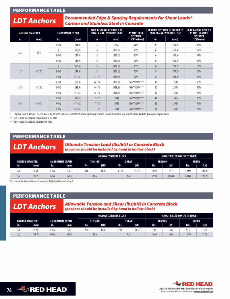
* Edge and spacing distances shall be divided by .75 when anchors are placed in structural lightweight concrete. Linear interpolation may be used for intermediate spacing and edge distances.** 15% = shear load applied perpendicular to the edge*** 60% = shear load applied parallel to the edge
ANCHOR DIAMETER EMBEDMENT DEPTH
HOLLOW CONCRETE BLOCK GROUT FILLED CONCRETE BLOCK
TENSION SHEAR TENSION SHEARin. (mm) in. (mm) lbs. (kN) lbs. (kN) lbs. (kN) lbs. (kN)
3/8 (9.5) 1-1/2 (38.1) 916 (4.1) 3,176 (14.1) 1,592 (7.1) 3,900 (17.3)
1/2 (12.7) 2-1/2 (63.5) N/A N/A 5,924 (26.4) 6,680 (29.7)
To calculate the Allowable Load of the anchor, divide the Ultimate Load by 4.
PERFORMANCE TABLE
LDT Anchors Recommended Edge & Spacing Requirements for Shear Loads* Carbon and Stainless Steel in Concrete
PERFORMANCE TABLE
LDT Anchors Ultimate Tension Load (lbs/kN) in Concrete Block (anchors should be installed by hand in hollow block)
PERFORMANCE TABLE
LDT Anchors Allowable Tension and Shear (lbs/kN) in Concrete Block (anchors should be installed by hand in hollow block)
ANCHOR DIAMETER EMBEDMENT DEPTH
HOLLOW CONCRETE BLOCK GROUT FILLED CONCRETE BLOCK
TENSION SHEAR TENSION SHEARin. (mm) in. (mm) lbs. (kN) lbs. (kN) lbs. (kN) lbs. (kN)
3/8 (9.5) 1-1/2 (38.1) 229 (1.0) 794 (3.5) 398 (1.8) 975 (4.3)1/2 (12.7) 2-1/2 (63.5) N/A N/A 1,481 (6.6) 1,670 (7.4)
79Call our toll free number 800-848-5611 or visit our web site for the most current product and technical information at www.itwredhead.com
5/8" DRILL BIT9/16" DRILL BITDRILL BIT SIZE REQUIRED
7"
7/16" DRILL BIT
4-1/2" 4-1/2"
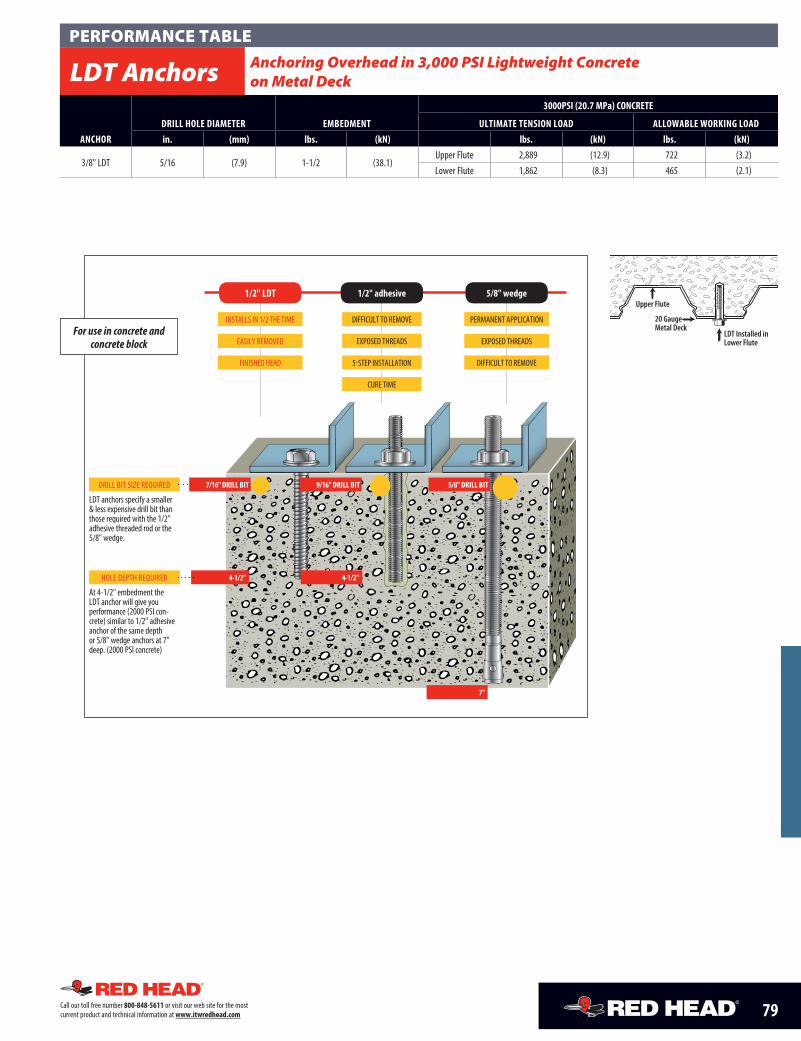
LDT anchors specify a smaller & less expensive drill bit than those required with the 1/2" adhesive threaded rod or the 5/8" wedge.
DIFFICULT TO REMOVE
EXPOSED THREADS
5-STEP INSTALLATION
CURE TIME
INSTALLS IN 1/2 THE TIME
EASILY REMOVED
FINISHED HEAD
PERMANENT APPLICATION
EXPOSED THREADS
DIFFICULT TO REMOVE
HOLE DEPTH REQUIRED
At 4-1/2" embedment the LDT anchor will give you performance (2000 PSI con-crete) similar to 1/2" adhesive anchor of the same depth or 5/8" wedge anchors at 7" deep. (2000 PSI concrete)
For use in concrete and concrete block
1/2" LDT 1/2" adhesive 5/8" wedge
ANCHORDRILL HOLE DIAMETER EMBEDMENT
3000PSI (20.7 MPa) CONCRETE
ULTIMATE TENSION LOAD ALLOWABLE WORKING LOADin. (mm) lbs. (kN) lbs. (kN) lbs. (kN)
3/8" LDT 5/16 (7.9) 1-1/2 (38.1)Upper Flute 2,889 (12.9) 722 (3.2)Lower Flute 1,862 (8.3) 465 (2.1)
LDT Installed inLower Flute
20 Gauge Metal Deck
Upper Flute
PERFORMANCE TABLE
LDT Anchors Anchoring Overhead in 3,000 PSI Lightweight Concrete on Metal Deck
Related Documents