4/17/93 LANTNAVFACENGCOM A&E GUIDE GUIDE FOR ARCHITECT ENGINEER FIRMS PERFORMING SERVICES FOR THE ATLANTIC DIVISION NAVAL FACILITIES ENGINEERING COMMAND 1510 GILBERT STREET NORFOLK, VIRGINIA 23511-2699

Welcome message from author
This document is posted to help you gain knowledge. Please leave a comment to let me know what you think about it! Share it to your friends and learn new things together.
Transcript

4/17/93 LANTNAVFACENGCOM A&E GUIDE
GUIDE FOR ARCHITECT ENGINEER FIRMS
PERFORMING SERVICES FOR THE
ATLANTIC DIVISION
NAVAL FACILITIES ENGINEERING COMMAND
1510 GILBERT STREET
NORFOLK, VIRGINIA 23511-2699

4/17/93 LANTNAVFACENGCOM A&E GUIDE
RECORD OF REVISIONSREV DATE OF DATENO. REVISION DESCRIPTION ENTERED
INITIALS
1
2
3
4
5
6
7
8
9
10
11
12
13
14
15
2
4/21/93 LANTNAVFACENGCOM A&E GUIDE
FORWARD
1. This publication is issued to provide guidance to Architect-Engineer (A&E) firmsperforming services for the Department of the Navy, Atlantic Division, Naval FacilitiesEngineering Command (LANTNAVFACENGCOM). It is essential that all A&Epersonnel and associates responsible for preparing plans, specifications, cost estimates,studies or other services, follow all procedures and instructions outlined herein AllA&E contracts issued by LANTNAVFACENGCOM reference this guide as part of thecontract. This also includes A&E contracts issued by:
OICC Naval Hospital, Portsmouth, VirginiaEFA Med Naples, Italy
2. Contract services of this nature fall into three broad classes:
a. Architect and Engineering Services related to construction, maintenance,alteration or repair of shore facilities. The product of this class of service is a set ofconstruction documents; i.e., drawings, specifications, cost estimate and pre and postdesign support such as soil borings, site topography, and construction surveillance.
b. Engineering Services related to planning, inspection, study and projectdevelopment for existing or proposed facilities. The product of this class of service isnormally a study or report.
c. Environmental studies and remedial designs in accordance with Federal /State / Local environmental laws and regulations.
3. A firm providing contract services to the Navy will be the Designer of Record andwill incur the usual professional responsibilities and liabilities for the specificproject/task. We evaluate design changes which occur during construction andactively pursue A&E liability if appropriate. The Designer of Record should becomefamiliar with the contract terms and content of this publication with respect to pre andpost construction design responsibilities. Problems typically encountered in severalcritical areas of project development are listed below in an effort to focus yourattention. These areas should receive special emphasis as applicable.
a. FIELD WORK - Properly conducted field and condition surveys are essential.This data must be complete, accurately documented and appropriately incorporatedinto the plans and specifications to avoid large and expensive change orders andconstruction delays.
3

4/21/93 LANTNAVFACENGCOM A&E GUIDE
b. COST AND BUDGET CONTROL - Effective cost control is essential tosuccessful project development. Establishment of an adequate budget and a designcost control system at the beginning of a project and continuing application of thissystem throughout the design process can prevent costly redesign of projects.
c. SCHEDULING AND SUBMITTALS - Project schedules are established at theoutset to meet the customer’s operational commitments and inserted in our masterscheduling process to balance our workload. Adherence to the established schedule ornotification of need for change is imperative. Incomplete and/or uncoordinatedsubmittals are a major problem and will not be accepted. During fee negotiations, theDesigner of Record should assure that the preparation period is adequate to allow for athorough review by the firm prior to submission.
d. DESIGN QUALITY CONTROL - Design Quality is a high priority and is theresponsibility of the A&E firm. At times it appears that A&E firms rely on aGovernment review to provide quality control for the plans and specifications. This, ofcourse, usually delays the return of submittals, involves additional time on our part,and often ultimately results in a poor set of bid documents. Coordination among thevarious disciplines as well as sections of the specifications is often a major problem thatneed particular improvement. It is expected that your control program must be theprimary discipline to deliver the level of design quality expectation. Time spentpreparing a quality design package will reduce redesign effort and time spentresolving problems during the construction contract phase.
4. Where the provisions of this guide address the same subject as the contract clauses,the contract clauses shall govern.
5. Work of the A&E will be reviewed by LANTNAVFACENGCOM only to the extentnecessary to establish conformance with authorized scope and applicable Navy designcriteria, and to establish reasonable assurance that work can be completed within fundsauthorized. The A&E shall accept full responsibility for the technical accuracy andprofessional quality of all work and materials which are furnished under a contractwith LANTNAVFACENGCOM.
6. LANTNAVFACENGCOM is committed to Quality. To achieve this goal we . . . .
l Expect professional performance from A&Es.
l Insist on first class service.
l Strive for environmental compatible solutions.
4

4/21/93 LANTNAVFACENGCOM A&E GUIDE
l Require A&Es to document and implement their own Quality Assurance Plan.
l Insist on attention to details.
l Strive for technical, functional and aesthetic solutions responsive to customerneeds and expectations. prudent balance between need and desire, and between theideal and the realistic in terms of constructability.
l Require project execution to stay within scope and budget.
l Expect A&E to stay on schedule.
We appreciate your support in achieving thesegoals and objectives.

4/17/93 LANTNAVFACENGCOM A&E GUIDE
(Blank Page)
6
4/17/93 LANTNAVFACENGCOM A&E GUIDEINDEX
1.
1.1
1.2
1.3
1.4
1.5
1.6
1.7
1.8
1.9
1.10
1.11
DEFINITIONS AND GENERAL GUIDANCE Page
DEFINITIONS . . . . . . . . . . . . . . . . . . . . . . . . . . . . . . . . . . . . . . . . . . . . .
PHILOSOPHY . . . . . . . . . . . . . . . . . . . . . . . . . . . . . . . . . . . . . . . . . . . . .
CONFLICTS OF INTEREST . . . . . . . . . . . . . . . . . . . . . . . . . . . . . . . . . .
RELEASE OF INFORMATION PERTAINING TO DESIGN PROJECTS
ECONOMY IN DESIGN AND CONSTRUCTION . . . . . . . . . . . . . . . . . . .
SELECTION OF MATERIALS . . . . . . . . . . . . . . . . . . . . . . . . . . . . . . . . .
DATA AND MATERIAL FURNISHED BY THE GOVERNMENT. . . . . .
CONSULTATION SERVICES . . . . . . . . . . . . . . . . . . . . . . . . . . . . . . . . .
A&E PERFORMANCE EVALUATION . . . . . . . . . . . . . . . . . . . . . . . . . .
A&E PERFORMANCE AWARDS . . . . . . . . . . . . . . . . . . . . . . . . . . . . . . .
PROGRESS PAYMENTS . . . . . . . . . . . . . . . . . . . . . . . . . . . . . . . . . . . . .
Instructions for Completing Contractor’s Invoice . . . . . . . . . . . . . . . . . .
Contractor’s Invoice . . . . . . . . . . . . . . . . . . . . . . . . . . . . . . . . . . . . . . . . . .
1-1
1-3
1-3
1-3
1-4
1-4
1-5
1-5
1-7
1-7
1-9
1-12
1-13
Instructions for Completing Contract Performance Statement . . . . . . . . .1-14
Contract Performance Statement . . . . . . . . . . . . . . . . . . . . . . . . . . . . . . 1-15
Instructions for Completing Affidavit . . . . . . . . . . . . . . . . . . . . . . . . . . . 1-16
Affidavit . . . . . . . . . . . . . . . . . . . . . . . . . . . . . . . . . . . . . . . . . . . . . . . . . 1-17
Instructions for Completing Contractor’s Release . . . . . . . . . . . . . . . . . . . . . 1-18
Contractor’s Release Under Contract . . . . . . . . . . . . . . . . . . . . . . . . . . . . . 1-19
i
4/17/932.
2.1
2.2
2.3
2.4
2.5
2.6
2.7
2.8
2.9
2.10
2.11
2.12
2.13
2.14
2.15
2.16
LANTNAVFACENGCOM A&E GUIDECONTRACTOR REQUIREMENTS Page
QUALITY OF WORK . . . . . . . . . . . . . . . . . . . . . . . . . . . . . . . . . . . . . . . . 2-1
A&E LIABILITY . . . . . . . . . . . . . . . . . . . . . . . . . . . . . . . . . . . . . . . . . . . . . 2-1
SCOPE . . . . . . . . . . . . . . . . . . . . . . . . . . . . . . . . . . . . . . . . . . . . . . . . . . . . 2-2
CONFERENCES AND INSPECTIONS . . . . . . . . . . . . . . . . . . . . . . . . . . . . 2-3
DESIGN SCHEDULE AND PROGRESS REPORTING . . . . . . . . . . . . . . . . 2-3
SITE INFORMATION . . . . . . . . . . . . . . . . . . . . . . . . . . . . . . . . . . . . . . . . .
SURVEYS . . . . . . . . . . . . . . . . . . . . . . . . . . . . . . . . . . . . . . . . . . . . . . . . . .
SUBSURFACE CONDITIONS . . . . . . . . . . . . . . . . . . . . . . . . . . . . . . . . . .
CONSTRUCTION SCHEDULE . . . . . . . . . . . . . . . . . . . . . . . . . . . . . . . . . .
OCCUPATIONAL SAFETY AND HEALTH STANDARDS . . . . . . . . . .
VALUE ENGINEERING (VE) . . . . . . . . . . . . . . . . . . . . . . . . . . . . . . . . . . . .
ELECTRICAL DESIGNS . . . . . . . . . . . . . . . . . . . . . . . . . . . . . . . . . . . . . .
CONCEPT DEVELOPMENT FOR MEDICAL PROJECTS . . . . . . . . . . .
SHORE ELECTRONICS PROJECTS . . . . . . . . . . . . . . . . . . . . . . . . . . . . .
SITE ADAPTATION OF STANDARD OR CONSTRUCTIONDRAWINGS . . . . . . . . . . . . . . . . . . . . . . . . . . . . . . . . . . . . . . . . . . . . . . . .
CONSTRUCTION AND OPERATING PERMITS . . . . . . . . . . . . . . . . . .
SAMPLE CONTRACT A&E PROGRESS REPORT . . . . . . . . . . . . . . . . . .
2-4
2-4
2-5
2-5
2-6
2-7
2-9
2-9
2-9
2-9
2-10
2-12
3. SUBMITTAL REQUIREMENTS
3.1 INTRODUCTION . . . . . . . . . . . . . . . . . . . . . . . . . . . . . . . . . . . . . . . . . . . . 3-1
ii
4/17/93 LANTNAVFACENGCOM A&E GUIDE3.
3.2
3.3
3.3.1
3.3.2
3.3.3
3.3.4
3.3.5
3.3.6
3.3.7
3.3.8
3.3.9
4.
4.1
4.2
4.3
4.4
4.5
4.5.1
4.5.2
4.5.3
4.5.4
SUBMITTAL REQUIREMENTS (CONT)
A&E SEAL ON DOCUMENTS. . . . . . . . . . . . . . . . . . . . . . . . . . . . . . . . . .
DESIGN SUBMITTALS . . . . . . . . . . . . . . . . . . . . . . . . . . . . . . . . . . . . . .
PEP SUBMITTAL . . . . . . . . . . . . . . . . . . . . . . . . . . . . . . . . . . . . . . . . . . .
35% STATION PRESENTATION . . . . . . . . . . . . . . . . . . . . . . . . . . . . . . .
35% SUBMITTAL . . . . . . . . . . . . . . . . . . . . . . . . . . . . . . . . . . . . . . . . . . .
100% SUBMITTAL . . . . . . . . . . . . . . . . . . . . . . . . . . . . . . . . . . . . . . . . . .
FINAL SUBMITTAL . . . . . . . . . . . . . . . . . . . . . . . . . . . . . . . . . . . . . . . . .
NATIONAL CAPITAL PLANNING COMMISSION (NCPC AND/ORCOMMISSION OF FINE ARTS (CFA) PRESENTATION . . . . . . . . . . . .
HOST NATION APPROVAL . . . . . . . . . . . . . . . . . . . . . . . . . . . . . . . . . . .
DUALLANGUAGE . . . . . . . . . . . . . . . . . . . . . . . . . . . . . . . . . . . . . . . . . .
ITALIAN LAW COMPLIANCE . . . . . . . . . . . . . . . . . . . . . . . . . . . . . . . . .
BASIS OF DESIGN
INTRODUCTION . . . . . . . . . . . . . . . . . . . . . . . . . . . . . . . . . . . . . . . . . . . .
BASIS OF DESIGN - SUGGESTED FORMAT . . . . . . . . . . . . . . . . . . . . .
ARCHITECTURAL . . . . . . . . . . . . . . . . . . . . . . . . . . . . . . . . . . . . . . . . . . .
STRUCTURAL . . . . . . . . . . . . . . . . . . . . . . . . . . . . . . . . . . . . . . . . . . . . . .
CIVIL . . . . . . . . . . . . . . . . . . . . . . . . . . . . . . . . . . . . . . . . . . . . . . . . . . . . .
SITE PLAN. . . . . . . . . . . . . . . . . . . . . . . . . . . . . . . . . . . . . . . . . . . . . . . . .
Page
3-1
3-2
3-2
3-5
3-7
3-10
3-13
3-16
3-17
3-18
3-18
4-1
4-1
4-1
4-3
4-4
4-4
ENVIRONMENTAL CONSTRUCTION & OPERATING PERMITS. . . . . . 4-4
ASBESTOS, LEAD BASED PAINT, AND TOXIC WASTE . . . . . . . . . . . . 4-5
WATER SUPPLY . . . . . . . . . . . . . . . . . . . . . . . . . . . . . . . . . . . . . . . . . . . 4-7
iii
4/17/934.
4.5.5
4.5.6
4.5.7
4.5.8
4.5.9
4.5.10
4.5.11
4.5.12
4.5.13
4.6
4.6.1
4.6.2
4.6.3
4.6.4
4.6.5
4.6.6
4.6.7
4.7
4.7.1
4.7.2
4.8
4.8.1
BASIS OF DESIGN (CONT)LANTNAVFACENGCOM A&E GUIDE
SEWERS AND SEWAGE DISPOSAL SYSTEMS . . . . . . . . . . . . . . . . . . .
ROADS, DRIVEWAYS, PARKING AREAS, AND WALKS . . . . . . . . . .
AIRFIELD PAVEMENT. . . . . . . . . . . . . . . . . . . . . . . . . . . . . . . . . . . . . . .
DUST AND EROSION CONTROL. . . . . . . . . . . . . . . . . . . . . . . . . . . . . . .
CATHODIC PROTECTION & PROTECTIVE COATINGS . . . . . . . . . . . .
FENCING . . . . . . . . . . . . . . . . . . . . . . . . . . . . . . . . . . . . . . . . . . . . . . . . .
RAILROADS . . . . . . . . . . . . . . . . . . . . . . . . . . . . . . . . . . . . . . . . . . . . . . .
PHYSICAL SECURITY. . . . . . . . . . . . . . . . . . . . . . . . . . . . . . . . . . . . . . .
STORMWATER MANAGEMENT PLAN . . . . . . . . . . . . . . . . . . . . . . . .
MECHANICAL . . . . . . . . . . . . . . . . . . . . . . . . . . . . . . . . . . . . . . . . . . . . .
MECHANICAL SYSTEMS . . . . . . . . . . . . . . . . . . . . . . . . . . . . . . . . . . . .
PLUMBING. . . . . . . . . . . . . . . . . . . . . . . . . . . . . . . . . . . . . . . . . . . . . . . .
Page
4-7
4-8
4-8
4-9
4-9
4-12
4-12
4-12
4-13
4-13
4-13
4-13
HEATING, VENTILATION, AND COOLING . . . . . . . . . . . . . . . . . . . . . . . 4-14
ENERGY CONSERVATION . . . . . . . . . . . . . . . . . . . . . . . . . . . . . . . . . . . 4-17
HEATING PLANTS AND HEATING PLANT ADDITIONS . . . . . . . . . . . 4-19
REFRIGERATION (COLD STORAGE) . . . . . . . . . . . . . . . . . . . . . . . . . .
FUEL DISTRIBUTION AND STORAGE . . . . . . . . . . . . . . . . . . . . . . . . .
FIRE PROTECTION AND SAFETY . . . . . . . . . . . . . . . . . . . . . . . . . . . . . .
FIRE PROTECTION SYSTEMS . . . . . . . . . . . . . . . . . . . . . . . . . . . . . . . . . .
SYSTEM SAFETY . . . . . . . . . . . . . . . . . . . . . . . . . . . . . . . . . . . . . . . . . . . .
ELECTRICAL . . . . . . . . . . . . . . . . . . . . . . . . . . . . . . . . . . . . . . . . . . . . .
ELECTRICAL SYSTEMS . . . . . . . . . . . . . . . . . . . . . . . . . . . . . . . . . . . . . . .
iv
4-19
4-19
4-30
4-30
4-31
4-32
4-32
4/17/934.
4.8.2
4.8.3
5.
5.1
5.2
5.3
5.4
5.5
5.6
5.7
5.8
5.9
5.10
5.11
5.12
5.13
5.14
DRAWING NUMBERS. . . . . . . . . . . . . . . . . . . . . . . . . . . . . . . . . . . . . . . .
MATERIAL SYMBOLS ON DRAWINGS . . . . . . . . . . . . . . . . . . . . . . . . . .
DUAL LANGUAGE DRAWINGS . . . . . . . . . . . . . . . . . . . . . . . . . . . . . . . .
RELATION OF DRAWINGS AND SPECIFICATIONS . . . . . . . . . . . . . . .
COMMON DISCREPANCIES IN NOMENCLATURE . . . . . . . . . . . . . . .
BORING LOG PRESENTATION . . . . . . . . . . . . . . . . . . . . . . . . . . . . . . .
5.15 METRIC DIMENSIONING . . . . . . . . . . . . . . . . . . . . . . . . . . . . . . . . .
6. SPECIFICATIONS
6.1
6.2
GENERAL . . . . . . . . . . . . . . . . . . . . . . . . . . . . . . . . . . . . . . . . . . . . . . .
GUIDE SPECIFICATIONS . . . . . . . . . . . . . . . . . . . . . . . . . . . . . . . . .
LANTNAVFACENGCOM A&E GUIDEBASIS OF DESIGN (CONT) Page
ELECTRONIC SYSTEMS . . . . . . . . . . . . . . . . . . . . . . . . . . . . . . . . . . . . 4-34
INSTRUMENTATION AND CONTROL SYSTEMS . . . . . . . . . . . . . . . . . 4-38
DRAWING/SKETCHES
ARRANGEMENT AND PRESENTATION OF DRAWINGS . . . . . . . . . . . 5-1
SIZES OF DRAWINGS/SKETCHES . . . . . . . . . . . . . . . . . . . . . . . . . . . . .
DRAFTING MEDIA. . . . . . . . . . . . . . . . . . . . . . . . . . . . . . . . . . . . . . . . . .
ORIENTATION . . . . . . . . . . . . . . . . . . . . . . . . . . . . . . . . . . . . . . . . . . . . .
LETTERING AND SHADING . . . . . . . . . . . . . . . . . . . . . . . . . . . . . . . . .
SECTION AND DETAIL DESIGNATION . . . . . . . . . . . . . . . . . . . . . . .
SCALES. . . . . . . . . . . . . . . . . . . . . . . . . . . . . . . . . . . . . . . . . . . . . . . . . . .
TITLE BLOCKS. . . . . . . . . . . . . . . . . . . . . . . . . . . . . . . . . . . . . . . . . . . . .
v
5-1
5-3
5-3
5-3
5-4
5-4
5-4
5-5
5-5
5-5
5-5
5-5
5-7
5-7
6-1
6-1
4/17/936.
6.3
6.4
6.5
6.6
6.7
6.8
6.9
6.10
6.11
6.12
6.13
6.14
6.15
LANTNAVFACENGCOM A&E GUIDESPECIFICATIONS (CONT)
REFERENCES . . . . . . . . . . . . . . . . . . . . . . . . . . . . . . . . . . . . . . . . . . . . .
SPECIFYING NEW MATERIALS . . . . . . . . . . . . . . . . . . . . . . . . . . . . . .
SPECIFYING FOREIGN MATERIALS . . . . . . . . . . . . . . . . . . . . . . . . . .
PROPRIETARY AND RESTRICTIVE REQUIREMENTS . . . . . . . . . . .
PRE-QUALIFICATION STATEMENTS AND EXPERIENCEREQUIREMENTS . . . . . . . . . . . . . . . . . . . . . . . . . . . . . . . . . . . . . . . . . .
PHRASEOLOGY. . . . . . . . . . . . . . . . . . . . . . . . . . . . . . . . . . . . . . . . . . .
MISUSE OF WORDS . . . . . . . . . . . . . . . . . . . . . . . . . . . . . . . . . . . . . . . .
USE OF ABBREVIATIONS AND SYMBOLS . . . . . . . . . . . . . . . . . . . . . .
STANDARD PLATES, SKETCHES, AND DETAILS . . . . . . . . . . . . . . . . .
SUBMITTAL PROCEDURES . . . . . . . . . . . . . . . . . . . . . . . . . . . . . . . . . .
BID ITEMS. . . . . . . . . . . . . . . . . . . . . . . . . . . . . . . . . . . . . . . . . . . . . . . .
FEDERAL AND MILITARY SPECIFICATIONS . . . . . . . . . . . . . . . . . . .
INTERIM SPECIFICATION REVISIONS (ISR) . . . . . . . . . . . . . . . . . . . . .
Page
6-2
6-3
6-3
6-4
6-4
6-5
6-6
6-7
6-8
6-8
6-14
6-15
6-15
7. COST ESTIMATES
7.1 GENERAL . . . . . . . . . . . . . . . . . . . . . . . . . . . . . . . . . . . . . . . . . . . . . . . . . 7-1
7.2 PROJECT DESIGN ESTIMATES . . . . . . . . . . . . . . . . . . . . . . . . . . . . . . . 7-1
7.2.1 35% DESIGN. . . . . . . . . . . . . . . . . . . . . . . . . . . . . . . . . . . . . . . . . . . . . . . 7-2
7.2.2 100% DESIGN. . . . . . . . . . . . . . . . . . . . . . . . . . . . . . . . . . . . . . . . . . . . . . 7-2
7.2.3 FINAL . . . . . . . . . . . . . . . . . . . . . . . . . . . . . . . . . . . . . . . . . . . . . . . . . . . . 7-4
vi
4/17/937.
7.3
7.4
7.4.1
COST ESTIMATES (CONT)LANTNAVFACENGCOM A&E GUIDE
Page
ESTIMATES FOR NEGOTIATED CONSTRUCTION CONTRACTS . . . . 7-4
ESTIMATES FOR PROJECTS LOCATED OUTSIDE CONUS . . . . . . . . . 7-5
ESTIMATES FOR PROJECTS LOCATED IN ICELAND . . . . . . . . . . . . . . 7-6
8.
8.1
8.1.1
8.1.2
POST DESIGN SERVICES
CONSULTATION DURING CONSTRUCTION . . . . . . . . . . . . . . . . . . .
GENERAL . . . . . . . . . . . . . . . . . . . . . . . . . . . . . . . . . . . . . . . . . . . . . . . .
BASIS OF PAYMENT FOR REIMBURSABLE CONSULTATION . . . . .
CHANGES TO NEGOTIATED/CONTRACTED REIMBURSABLECONSULTATION . . . . . . . . . . . . . . . . . . . . . . . . . . . . . . . . . . . . . . . . . . .
REQUESTS FOR CONSULTATION . . . . . . . . . . . . . . . . . . . . . . . . . . . . .
CONSULTATION REPORTS . . . . . . . . . . . . . . . . . . . . . . . . . . . . . . . . . .
DESIGN FIELD SUPPORT . . . . . . . . . . . . . . . . . . . . . . . . . . . . . . . . . . .
GENERAL . . . . . . . . . . . . . . . . . . . . . . . . . . . . . . . . . . . . . . . . . . . . . . . .
NUMBER OF SITE VISITS . . . . . . . . . . . . . . . . . . . . . . . . . . . . . . . . . . . .
A&E TASKS AND RESPONSIBILITIES FOR DESIGN FIELDSUPPORT . . . . . . . . . . . . . . . . . . . . . . . . . . . . . . . . . . . . . . . . . . . . . . . . .
SHOP DRAWINGS/SUBMITTAL REVIEW . . . . . . . . . . . . . . . . . . . . . . .
CONTRACTOR’S QUALITY CONTROL MANAGER IS APPROVINGAUTHORITY . . . . . . . . . . . . . . . . . . . . . . . . . . . . . . . . . . . . . . . . . . . . . .
RESERVATION OF REVIEW AND APPROVAL BY THE
8-1
8-1
8.1.3
8.1.4
8.1.5
8.2
8.2.1
8.2.2
8-2
8-3
8-3
8-4
8-5
8-5
8-6
8.2.3
8.3
8-7
8-8
8.3.18-9
8.3.2GOVERNMENT OF CONTRACTOR SUBMITTALS ON CONSTRUCTIONCONTRACTS . . . . . . . . . . . . . . . . . . . . . . . . . . . . . . . . . . . . . . . . . . . . . . 8-16
8.3.3 GOVERNMENT IS APPROVING AUTHORITY . . . . . . . . . . . . . . . . . . . . 8-25
Vii
4/17/93 LANTNAVFACENGCOM A&E GUIDE8.
8.3.4
8.4
8.5
8.5.1
8.5.2
8.5.3
8.5.4
8.6
POST DESIGN SERVICES (CONT)
MISCELLANEOUS SUBMITTAL REVIEW ASPECTS . . . . . . . . . . . . . . .
RECORD DRAWINGS . . . . . . . . . . . . . . . . . . . . . . . . . . . . . . . . . . . . . . .
INTERIOR DESIGN (OPTION) . . . . . . . . . . . . . . . . . . . . . . . . . . . . . . . . .
GENERAL . . . . . . . . . . . . . . . . . . . . . . . . . . . . . . . . . . . . . . . . . . . . . . . . .
SCOPE . . . . . . . . . . . . . . . . . . . . . . . . . . . . . . . . . . . . . . . . . . . . . . . . . . .
DEVELOPMENT SEQUENCE AND SUBMITTAL REQUIREMENTS ....
GUIDELINES FOR SELECTING FURNITURE AND ACCESSORIES ....
OPERATING AND MAINTENANCE SUPPORT INFORMATION(OMSI) (OPTION) . . . . . . . . . . . . . . . . . . . . . . . . . . . . . . . . . . . . . . . . . . .
CATHODIC PROTECTION SYSTEM INSPECTION, TESTING ANDACCEPTANCE (OPTION) . . . . . . . . . . . . . . . . . . . . . . . . . . . . . . . . . . . . .
Page
8-27
8-28
8-28
8-28
8-28
8-30
8-30
8.7
8-31
8-34
ATTACHMENTS
A. ELECTRICAL DESIGN GUIDE (3/93 Revised)
viii
4/17/93 LANTNAVFACENGCOM A&E GUIDESECTION 1. DEFINITIONS AND GENERAL GUIDANCE
1.1 DEFINITIONS
A&E: An architectural firm, an engineering firm, or an architectural andengineering firm engaged for design services.
Appendix A: The document that defines the A&E’s detailed scope of work toinclude amount of construction funds available, activity points of contact, schedules forsubmittals, etc.
Architect or Engineer in Charge (AIC/EIC) The individual withinLANTNAVFACENGCOM who is designated as the point of contact on technicalm a t t e r s .
CAD: Computer Aided Drafting
CMC: Commandant Marine Corps
CNO: Chief of Naval Operations
COE: Corps of Engineers
COMNAVMEDCOM: Commander, Naval Medical Command
Contract Specialist (CS): The individual within the Contracts Office who isresponsible to ensure that regulations, laws and procedures are complied with in theaward of a contract.
Contracting Officer: The Commander, Atlantic Division, Naval FacilitiesEngineering Command or the Commander’s designee. Only Contracting Officers areauthorized to enter into, modify and/or terminate contracts, issue final decisions oncontract disputes, and assign responsibility for conducting negotiations.
Design Division: That department within LANTNAVFACENGCOMresponsible for technical review and coordination of all A&E construction contractdocuments.
DMFO: Defense Medical Facilities Officer (DOD Medical Projects)
DOD: Department of Defense
1-1
4/17/93 LANTNAVFACENGCOM A&E GUIDEEFD: Engineering Field Division such as LANTNAVFACENGCOM,
CHESNAVFACENGCOM or NORTHNAVFACENGCOM
ES: Engineering services
FAR: Federal Acquisition Regulations
LANTNAVFACENGCOM: Atlantic Division, Naval Facilities EngineeringCommand, Norfolk, Virginia, often referred to as “LANTDIV”
MCON: Military Construction - Navy
MILCON: Military Construction - DOD
NAVFACENGCOM: Naval Facilities Engineering Command, headquarters inAlexandria, Virginia, often referred to as “NAVFAC”
OICC: Officer in Charge of Construction
OMSI: Operation and Maintenance Support Information
PEP: Parametric Estimating and Programming. The document prepared tosupport a MCON project for Congress to approve the programming and appropriationcycles. The PEP is a concept design effort and replaces the 0-35% design/ProjectEngineering Documentation process. Preparation instructions are available for a PEP.
Project Manager (PM): The individual within the Acquisition Department ofLANTNAVFACENGCOM who serves as the liaison between the A&E and theContracting Officer. Unless specifically directed otherwise, all contact between theA&E and LANTNAVFACENGCOM will be conducted through the assigned PM.Variations to this standard procedure will be handled by special instructions prior tonegotiation and award of the contract. The PM is not authorized to modify the terms(scope/price/schedule of performance) of a contract.
ROICC: Resident Officer in Charge of Construction, at a specific station or facilitydesignated by the Contracting Officer. He is responsible for the field administration ofconstruction contracts.
Mailing Address: All correspondence and submittals shall be addressed to:Commander, Atlantic Division, Naval Facilities Engineering Command (AttentionAppropriate Project Manager), 1510 Gilbert Street, Norfolk, Virginia 23511-2699.
1-2
4/17/93 LANTNAVFACENGCOM A&E GUIDE1.2 PHILOSOPHY
Prior to commencing design, the A&E should become thoroughly familiar withcurrent design criteria, standard method/procedures, guides, specifications, project siteconditions, project costs and specific project requirements. Generally, a prenegotiationconference will be conducted on all military construction funded projects and on otherprojects of significant magnitude or complexity where we or the A&E determine it willbe beneficial.
The A&E should be aware that there are differences between private work andGovernment work such as: (1) the Government cannot limit bidding to a selected list ofcontractors known to do good work unless approved in advance under specific andlimited circumstances. In most cases, any contractor may bid. Therefore, drawings andspecification requirements must leave nothing to the imagination. They must be clear,concise, and provide thorough detailing of existing and proposed construction. (2)Department of Defense requires the use of Federal, Military, and Industryspecifications for procurement of materials and equipment covered by thesespecifications. Use of these specifications assures the non-restrictive competitionrequired in the expenditure of public funds. Proprietary specifications are not allowedwithout written authorization. Failure to grasp these basic differences in rules andpolicies has been the source of many costly disputes. It is essential that all personnelresponsible for the execution of an A&E or ES contract with LANTNAVFACENGCOMstudy this guide and follow the procedures and instructions set forth herein. Generalinstructions can not cover every situation. Specific problems relating to a particularproject will be jointly resolved in conferences with activity personnel and the PM.
1.3 CONFLICTS OF INTEREST
Firms which design, prepare plans and specifications, or cost estimates for aconstruction contract or procurement of supplies or services, cannot provide theconstruction or supplies or services. This limitation also applies to subsidiaries andaffiliates of a firm.
1.4 RELEASE OF INFORM&ON PERTAINING TO DESIGN PROJECTS
The A&E shall give no information concerning a project to anyone other thanauthorized station personnel, other A&Es performing design of related facilities andpersonnel of LANTNAVFACENGCOM. During the bidding period, any requestsmade of the A&E by prospective bidders for clarification or intent of drawings andspecifications should be referred to the Director, Construction Contracts Division,LANTNAVFACENGCOM, telephone 804-444-9522. However, sources of supply forspecial equipment may be given to contractors. The A&E should promptly notifyLANTNAVFACENGCOM of any necessary corrections or clarifications of the drawings
1-3
4/17/93 LANTNAVFACENGCOM A&E GUIDEand specifications. Release in any form of information pertinent to a project underdesign or construction for publication, for public speeches or address shall not be madewithout first securing clearance and a release in writing from the Commander, AtlanticDivision, Naval Facilities Engineering Command. All material for which clearance isdesired shall be submitted in duplicate.
1.5 ECONOMY IN DESIGN AND CONSTRUCTION
It is LANTNAVFACENGCOM’s objective to obtain a functionally adequate,habitable, and economical facility. In the design of all projects, it is the Navy’s policy toprovide functional facilities of a durability consistent with the mission. The A&E shallbear in mind that the interest of the Government is to acquire facilities which areeconomical in design, construction, operation and maintenance. Accordingly, althoughdue consideration shall be given to appearance, structures shall not entail frills andembellishments and shall not be conceived on the basis of unnecessarily complicatedand costly construction systems, materials, or equipment.
Although the above paragraph stresses economical design, the A&E isresponsible to assure compatibility of the new structure with the architectural characterof the base activity. For people oriented facilities such as: Bachelor Enlisted Quarters(BEQ), Bachelor Officers’ Quarters (BOQ), dining facilities, lounges, recreation areas,libraries, chapels and theaters, the A&E will be responsible for a totally integrateddesign. Integrated design means the complete design of a facility, taking intoconsideration all engineering disciplines involved plus landscape architecture andcomplete interior design for a comprehensively designed facility. An integrated designachieves harmony of site, landscaping, building design and functional requirements.
1.6 SELECTION OF MATERIALS
LANTNAVFACENGCOM’s objective is to provide functional and economicalshore facilities for the Navy establishment. We are not in the research anddevelopment business. Consequently, it is necessary to investigate thoroughly all newmaterials that have not been proven in the specific type of service involved, or whosepromotion is based upon unsupported statements and lists of supposedly satisfiedusers. Materials must be used in a manner that will afford the maximum service at thelowest life cycle cost. Operation and maintenance costs must be weighed against initialcosts to achieve maximum economy. Before deciding upon a specific material fordesign or specification purposes, the following points shall be considered:
A. Contemplated life of the facility.
B. Climatic and operating conditions.
1-4
4/17/93 LANTNAVFACENGCOM A&E GUIDEC. Will material be used to the best advantage under contemplated
conditions, including aesthetics?
D. Is material a stock item or does it require special processing?
E. Availability of material in the area of usage.
F. Is material proprietary or restrictive?
Where new unproven materials are selected, documentation including detailedeconomic analysis justifying its use may be required.
For overseas locations, the A&E must investigate and consider the types ofconstruction material and trades indigenous to the area.
1.7 DATA AND MATERIAL FURNISHED BY THE GOVERNMENT
A. Schematics, designs, and other criteria furnished with the contract’sAppendix A.
B. Military Bulletin, MIL-BUL-34 (previously NAVFAC Publication P-34),“Engineering and Design Criteria for Navy Facilities” (updated quarterly), contains alisting of current criteria and is available from the Specifications Branch(telephone 804-444-9906). Copies of NAVFAC Design Manuals required for a specificproject will be furnished upon request to the PM. It is the A&E’s responsibility toupdate all Design Manuals the firm uses based on the most current changes. The A&Eshould ensure receipt of MIL, Handbook 1190 (MIL-HDBK-1190), “Facility Planning andDesign Guide”. This handbook updates and supersedes much design criteriapreviously established by DOD.
C. Materials furnished by the Government such as: reference drawings,surveys and soil borings are provided to assist the A&E and are not intended in anyway to relieve the responsibilities of the A&E, unless otherwise noted by theContracting Officer. The A&E of record will be totally responsible for all informationdescribed in the design documents.
1.8 CONSULTATION SERVICES
During design or study preparation, various disciplines are available forconsultation. When the A&E contract is for drawings and specifications preparation,our personnel identify the project by the last four digits of the CONSTRUCTION
1-5
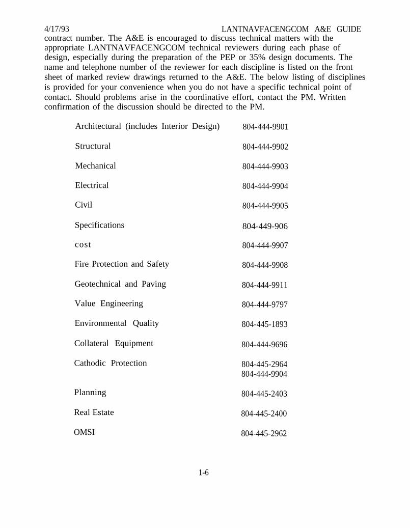
4/17/93 LANTNAVFACENGCOM A&E GUIDEcontract number. The A&E is encouraged to discuss technical matters with theappropriate LANTNAVFACENGCOM technical reviewers during each phase ofdesign, especially during the preparation of the PEP or 35% design documents. Thename and telephone number of the reviewer for each discipline is listed on the frontsheet of marked review drawings returned to the A&E. The below listing of disciplinesis provided for your convenience when you do not have a specific technical point ofcontact. Should problems arise in the coordinative effort, contact the PM. Writtenconfirmation of the discussion should be directed to the PM.
Architectural (includes Interior Design)
Structural
Mechanical
Electrical
Civil
Specifications
cost
Fire Protection and Safety
Geotechnical and Paving
Value Engineering
Environmental Quality
Collateral Equipment
Cathodic Protection
Planning
Real Estate
OMSI
804-444-9901
804-444-9902
804-444-9903
804-444-9904
804-444-9905
804-449-906
804-444-9907
804-444-9908
804-444-9911
804-444-9797
804-445-1893
804-444-9696
804-445-2964804-444-9904
804-445-2403
804-445-2400
804-445-2962
1-6
4/17/93 LANTNAVFACENGCOM A&E GUIDE1.9 A&E PERFORMANCE EVALUATION
An evaluation of the performance of the A&E is prepared concurrent with thefinal review of the drawings and specifications or other services performed. Thisevaluation includes a rating of the services performed in such categories asthoroughness of site investigation, quality control procedures and execution,plans/specifications accurate and coordinated, plans clear and detailed sufficiently,management and adherence to schedules, meeting cost limitations, suitability of designor study results, solution environmentally suitable, cooperativeness andresponsiveness, quality of briefings and presentations. The completed evaluation ispermanently retained in the A&E’s file at LANTNAVFACENGCOM for review andconsideration by future Selection Boards and is distributed the A&E of record and toother Government agencies (via the Architect/Engineering Contract AdministrationSupport System (ACASS), Portland, Oregon). A&E ratings are available for review bythe Designer of Record upon request to the PM.
Upon completion of the construction contract, a second evaluation iscompleted by the ROICC with emphasis on quality and constructability of the design;timeliness and response with respect to shop drawing review, clarification ofdrawings/specification intent and resolution of construction problems, andcooperation. This rating is used in conjunction with the rating described above indetermining an overall A&E rating.
1.10 A&E PERFORMANCE AWARDS
Six programs currently exist to provide recognition of outstandingperformance:
A. Naval Facilities Engineering Command - American Institute of ArchitectsBiennial Awards Program for Distinguished Architectural Achievement (NAVFACInstruction 5061.6, latest edition).
PURPOSE: To recognize outstanding architectural design, encourageprofessionalism, and promote excellence in design of facilities designed forNAVFACENGCOM.
B. Industrial Incentive Plan. (LANTNAVFACENGCOMINST 4804.1C)
PURPOSE: To provide recognition for performance by a contractor inexcess of contract requirements, in one or a combination of the following areas:
1-7

4/17/93Better product.
LANTNAVFACENGCOM A&E GUIDE
Speed of accomplishment.
Savings to the Government.
Cooperation beyond the contract terms to serve the convenience of theCommand, the Navy, or the U. S. Government.
C. Department of Defense Design Awards Program (NAVFACINST 5061.6,the latest edition).
PURPOSE: Promote excellence in architectural and engineering designand provide motivation and recognition for architects/engineers who design facilitiesfor the military departments.
D. Naval Facilities Engineering Command - Institute of Business DesignersBiennial Competition for Achievement in Interior Design (NAVFACINST 5061.6, latestedition).
PURPOSE: To recognize high quality interior design.
LANTNAVFACENGCOM encourages A&E participation in these programs.For further information, contact the Architectural Branch Head, telephone 804-444-9901.
E. Exemplary Fulfillment of A&E Contract Services Awards.
PURPOSE: Recognition is provided for performance by contractors inexcess of contract requirements in one or a combination of several areas. This programallows giving special recognition for exemplary performance in the delivery ofparticular aspects of A&E provided services. Two types of awards exist for exemplaryfulfillment of one or a combination of A&E services. The first, given by theCommander/Commanding Officer of an EFD or independent OICC, is the Certificateof Appreciation granted for exemplary performance on a contract. The second, givenby the Commander, NAVFACENGCOM, is the Commander’s Certificate ofCommendation granted for outstanding performance significantly in excess of contractrequirements.
F. Design Excellence Award.
PURPOSE: Recognition is provided under the Design Excellence Awardprogram for exemplary performance in the provision of all aspects of A&E provided
1-8
4/17/93 LANTNAVFACENGCOM A&E GUIDEdesign services. A&E contractors cannot be considered for this award untilconstruction is underway and the effectiveness of the A&E prepared plans andspecifications vis a vis design change order rate and usability, and the A&E’scooperation in resolving construction problems can be accurately assessed.
1.11 PROGRESS PAYMENTS
It is our policy to process partial payments. Generally, we process paymentrequests made concurrent with a review submittal (i.e., PEP, 35%, 100%, etc.) requiredby the project scope. However, other progress payments will be processed whenaccompanied by adequate evidence of progress.
Requests for payment consist of two parts, A and B, which should beforwarded as follows:
A. Part A (Invoice):
All invoices must contain the following:
(1) Contractor’s Invoice (with original signature) NAVFAC Form 7300/41(Rev 7/85).
(2) Contract Performance Statement (1 copy) LANTDIV NORVAForm 4-7300/18 (New 2-81).
(3) Affidavit (with original signature) LANTDIV NORVAForm 4-4235/4 (Rev 5-81).
(a) Notary signature required for Virginia firms.
(b) Notary signature and notary stamp or raised seal required forfirms located out of the state of Virginia.
Submit all invoices to:
COMMANDERATTN CODE 02254LANTNAVFACENGCOM1510 GILBERT STNORFOLK VA 23511-2699
1-9
LANTNAVFACENGCOM A&E GUIDEPart B (Supporting Documents): (Submit seven days prior to Part A)
4/17/93B.
Supporting documents must contain the following:
(1) Contract Performance Statement.
(2) Progress submittals - evidence supporting your work completed (i.e.,copy of plans, studies, reports, field notes, minutes of meetings held).
Submit all supporting documents to:
COMMANDERATTN CODE *LANTNAVFACENGCOM1510 GILBERT STNORFOLK VA 23511-2699
*Contact Project Manager (PM) for designated Code
Requests for payment received without supporting documents will bereturned unpaid.
Sample copies of these forms addressed above are provided in the followingpages along with instructions on how to properly complete your invoice. Invoicesubmittals made incorrectly (i.e., invoice not signed, wrong contract number, affidavitnot signed and notarized, performance statement not extended, etc.) will be promptlyreturned to you for correction. We will process all correct invoices in a timely manner.A Contractor’s Release (2 copies with original signatures) must accompany your finalinvoice.
If you have any questions concerning payments, please contact the A&EContracts Program Branch, telephone 804-444-9586.
1-10

4/17/93 LANTNAVFACENGCOM A&E GUIDE
(Blank Page)
1-11

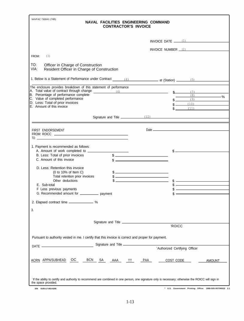
4/17/93 LANTNAVFACENGCOM A&E GUIDEINSTRUCTIONS FOR COMPLETING CONTRACTOR’S INVOICE
NAVFAC 7300/41 (Rev 7/85)
(See Sample - Page 1-13)
(1) Date Submitted
(2) Number of Invoices Submitted
(3) Full Name of A&E Firm as Shown on Contract
(4) A&E Contract Number
(5) Location of Work Performed
(6) Change Order Number (if applicable)
(7) Total Value of Contract through All Change Orders
(8) Percentage Complete of Total Contract Amount
(9) Value of Work Performed
(10) Total Amount Paid to Date
(11) Amount Invoiced
(12) Original Signature of Company Official
1-12
NAVFAC 7300/41 (7/85)
NAVAL FACILITIES ENGINEERING COMMANDCONTRACTOR’S INVOICE
INVOICE DATE (1)
INVOICE NUMBER (2)
FROM: (3)
TO: Officer in Charge of ConstructionVIA: Resident Officer in Charge of Construction
1. Below is a Statement of Performance under Contract (4) at (Station) (5)
The enclosure provides breakdown of this statement of performanceA. Total value of contract through change (6) (7)B. Percentage of performance complete
$(8)
C. Value of completed performance %(9)
D. Less: Total of prior invoices$
E. Amount of this invoice $ (10)
$ (11)
Signature and Title (12)
FIRST ENDORSEMENTFROM: ROICCTO:
Date
1. Payment is recommended as follows:A. Amount of work completed to $B. Less: Total of prior invoices $C. Amount of this invoice $
D. Less: Retention this invoice(0 to 10% of Item C) $Total retention prior invoices $Other deductions $ $
E. Sub-total $F Less previous payments $G. Recommended amount for payment $
2. Elapsed contract time %
3.
Signature and Title1ROICC
Pursuant to authority vested in me. I certify that this invoice is correct and proper for payment.
DATE Signature and Title1 Authorized Certifying Officer
ACRN APPN/SUBHEAD OC BCN SA AAA TT PAA COST CODE AMOUNT
1 If the ability to certify and authority to recommend are combined in one person, one signature only is necessary; otherwise the ROICC will sign inthe space provided.
S/N 0105-LF-003-0205 * U.S. Government Printing Office: 1988-505-007/90632 2.1
1-13
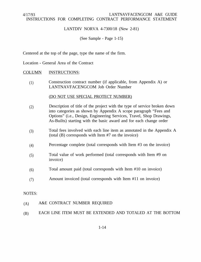
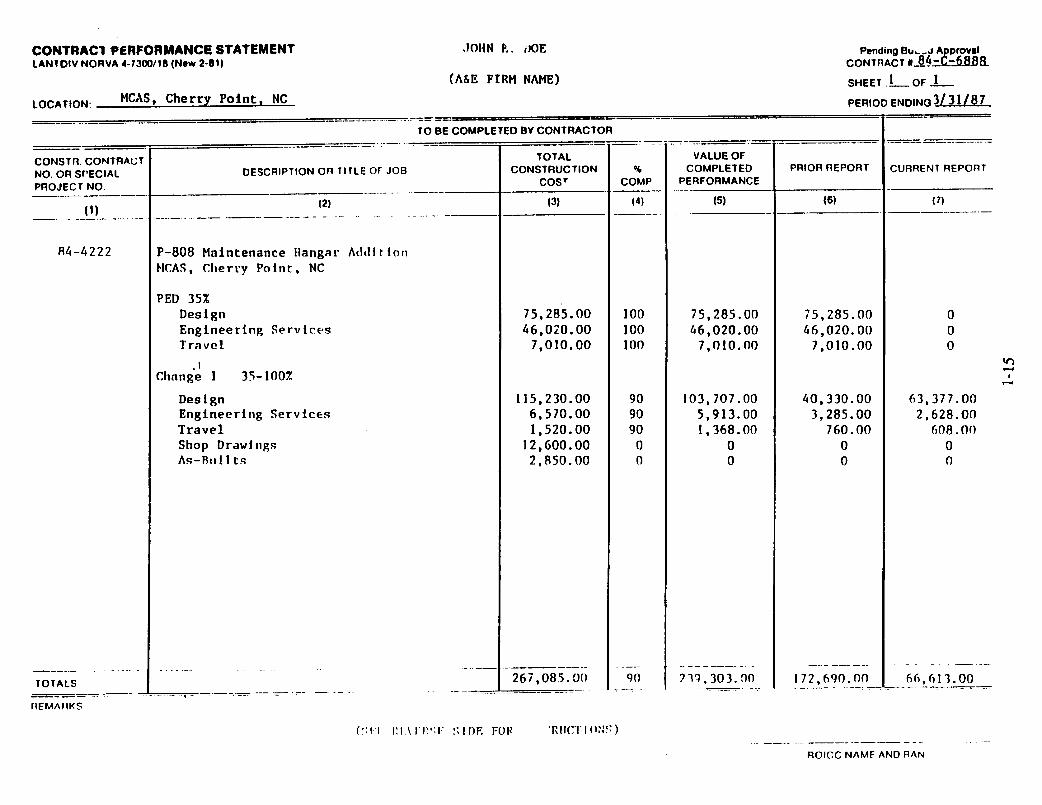
4/17/93 LANTNAVFACENGCOM A&E GUIDEINSTRUCTIONS FOR COMPLETING CONTRACT PERFORMANCE STATEMENT
LANTDIV NORVA 4-7300/18 (New 2-81)
(See Sample - Page 1-15)
Centered at the top of the page, type the name of the firm.
Location - General Area of the Contract
COLUMN INSTRUCTIONS:
(1) Construction contract number (if applicable, from Appendix A) orLANTNAVFACENGCOM Job Order Number
(DO NOT USE SPECIAL PROTECT NUMBER)
(2)
(3)
(4)
(5)
(6)
(7)
Description of title of the project with the type of service broken downinto categories as shown by Appendix A scope paragraph “Fees andOptions” (i.e., Design, Engineering Services, Travel, Shop Drawings,As-Builts) starting with the basic award and for each change order
Total fees involved with each line item as annotated in the Appendix A(total (B) corresponds with Item #7 on the invoice)
Percentage complete (total corresponds with Item #3 on the invoice)
Total value of work performed (total corresponds with Item #9 oninvoice)
Total amount paid (total corresponds with Item #10 on invoice)
Amount invoiced (total corresponds with Item #11 on invoice)
NOTES:
(A) A&E CONTRACT NUMBER REQUIRED
(B) EACH LINE ITEM MUST BE EXTENDED AND TOTALED AT THE BOTTOM
1-14

4/17/93
(1)
(2)
(3)
(4)
(5)
(6)
(7)
(8)
(9)
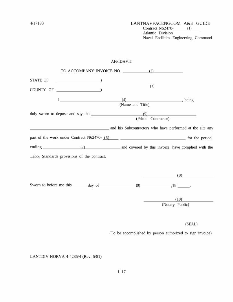
LANTNAVFACENGCOM A&E GUIDEINSTRUCTIONS FOR COMPLETING AFFIDAVIT
LANTDIV NORVA 4-4235/4 (Rev. 5/81)
(See Sample - Page 1-17)
A&E Contract Number
Invoice Number
State and County Located
Name and Title of Company Official Signing Affidavit
Name of A&E Firm
A&E Contract Number
Period Ending for Work Performed
Original Signature of Company Official
Date Signed and Notarized
(10) Notary’s Signature (Notary Stamp or Raised Seal is Required forOut-of-State Firms)
AN AFFIDAVIT IS NOT REQUIRED FOR OVERSEAS FIRMS
1-16
4/17193 LANTNAVFACENGCOM A&E GUIDEContract N62470- (1)Atlantic DivisionNaval Facilities Engineering Command
AFFIDAVIT
TO ACCOMPANY INVOICE NO. (2)
STATE OF )
(3)COUNTY OF )
I (4)(Name and Title)
, being
duly sworn to depose and say that (5)(Prime Contractor)
and his Subcontractors who have performed at the site any
part of the work under Contract N62470- (6) for the period
ending (7) and covered by this invoice, have complied with the
Labor Standards provisions of the contract.
(8)
Sworn to before me this day of (9) ,19 .
(10)(Notary Public)
(SEAL)
(To be accomplished by person authorized to sign invoice)
LANTDIV NORVA 4-4235/4 (Rev. 5/81)
1-17
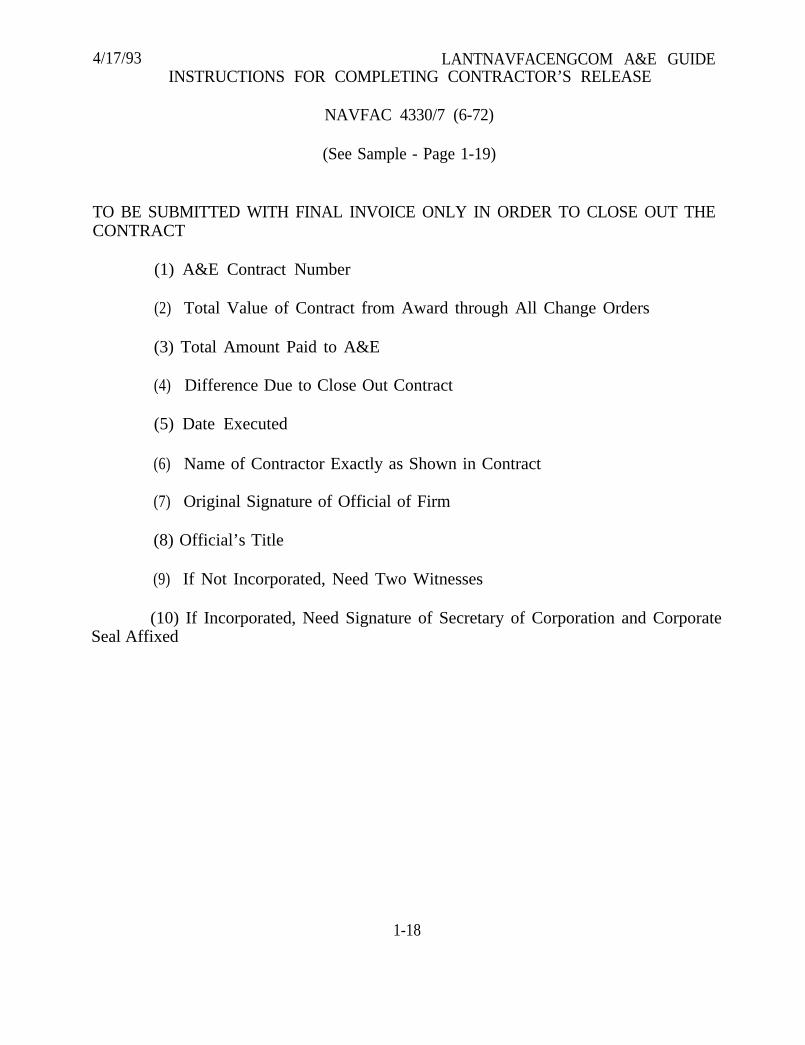
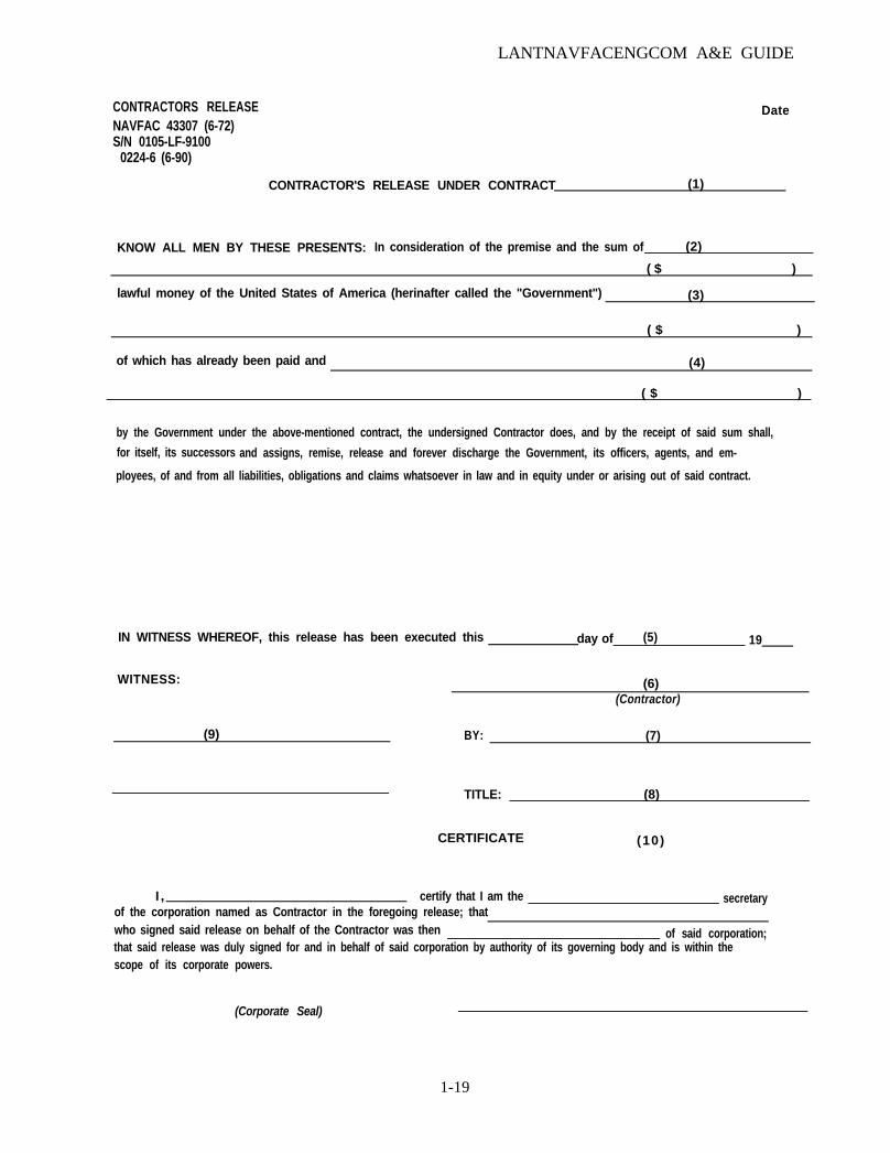
4/17/93 LANTNAVFACENGCOM A&E GUIDEINSTRUCTIONS FOR COMPLETING CONTRACTOR’S RELEASE
NAVFAC 4330/7 (6-72)
(See Sample - Page 1-19)
TO BE SUBMITTED WITH FINAL INVOICE ONLY IN ORDER TO CLOSE OUT THECONTRACT
(1) A&E Contract Number
(2) Total Value of Contract from Award through All Change Orders
(3) Total Amount Paid to A&E
(4) Difference Due to Close Out Contract
(5) Date Executed
(6) Name of Contractor Exactly as Shown in Contract
(7) Original Signature of Official of Firm
(8) Official’s Title
(9) If Not Incorporated, Need Two Witnesses
(10) If Incorporated, Need Signature of Secretary of Corporation and CorporateSeal Affixed
1-18
LANTNAVFACENGCOM A&E GUIDE
DateCONTRACTORS RELEASENAVFAC 43307 (6-72)S/N 0105-LF-9100
0224-6 (6-90)
CONTRACTOR'S RELEASE UNDER CONTRACT (1)
KNOW ALL MEN BY THESE PRESENTS: In consideration of the premise and the sum of (2)
( $ )
lawful money of the United States of America (herinafter called the "Government") (3)
of which has already been paid and
( $ )
(4)
( $ )
by the Government under the above-mentioned contract, the undersigned Contractor does, and by the receipt of said sum shall,
for itself, its successors and assigns, remise, release and forever discharge the Government, its officers, agents, and em-
ployees, of and from all liabilities, obligations and claims whatsoever in law and in equity under or arising out of said contract.
IN WITNESS WHEREOF, this release has been executed this day of (5) 19
WITNESS: (6)(Contractor)
(9) BY: (7)
TITLE: (8)
CERTIFICATE (10)
I , certify that I am theof the corporation named as Contractor in the foregoing release; that
secretary
who signed said release on behalf of the Contractor was then of said corporation;that said release was duly signed for and in behalf of said corporation by authority of its governing body and is within thescope of its corporate powers.
(Corporate Seal)
1-19

4/17/93 LANTNAVFACENGCOM A&E GUIDE
(Blank Page)
1-20
4/17/93 LANTNAVFACENGCOM A&E GUIDESECTION 2. CONTRACTOR REQUIREMENTS
2.1 QUALITY OF WORK
The A&E shall be responsible for the professionalism and technical accuracyand coordination of all services such as designs, drawings, specifications, costestimates, and other work or materials furnished by the contractor under this contract.
The project submitted by the A&E shall represent the best engineering solutionpossible for the scope of work in the A&E contract. All work must be in accordancewith current criteria, guides, and specifications established by the Naval FacilitiesEngineering Command, and shall be in accordance with the best engineering practices.Workmanship shall be neat with all lines and lettering of uniform weight and clarityfor complete legibility and satisfactory reproduction. Any computer disks submittedmust be scanned for viruses using a commercial virus scanning program. All elementsof submittals shall be checked by the A&E and such check shall be made by personsother than those preparing the materials and by Professional personnel trained in thatspecific discipline. It will be reviewed by the various departments inLANTNAVFACENGCOM for compliance with Government requirements andstandard criteria. Errors and deficiencies shall be corrected by the A&E at noadditional cost to the Government.
2.2 A&E LIABILITY
Neither LANTNAVFACENGCOM’s review, approval, or acceptance of, norpayment for any of the services required shall be construed to operate as a waiver ofany rights or of any cause of action arising out of the performance of the contract. TheA&E shall be and remain liable to the Government for all costs of any kind which areincurred by the Government as a result of negligent Performance of any of the servicesfurnished.
Reimbursement of costs incurred by the Government as a result of A&E’s errorand/or negligent performance are actively pursued by LANTNAVFACENGCOM.Upon determination that there may be A&E financial responsibility involved, the A&Eshall be contacted by the ROICC. The A&E shall be advised of the design deficiencyand requested to provide a technical solution to the problem, including cost estimate.The A&E shall be further informed that it is the ROICC’s opinion that the A&E may beheld financially responsible, but that the final decision rests with the ContractingOfficer. A&E financial responsibility can include contractor extended overhead costs.Therefore, upon notification of potential liability, the A&E should coordinate with thedirecting official to determine required technical support and timing to minimize delaycosts. Pending final decision by the Contracting Officer, the A&E will be invited toattend all price
2-1
4/17/93 LANTNAVFACENGCOM A&E GUIDEnegotiations for corrective work. The A&E shall participate as a non-voting technicaladvisor to the Government negotiating board. Inability to obtain agreement from theA&E as to financial responsibility or A&E unwillingness to participate in negotiationsshall not be cause for delay or remedial construction contract action by the ROICC.
As an alternate to the above, the A&E (where design error is clearly at fault)may discharge the firm’s financial responsibility through negotiation with, and directpayment to, the contractor. This action must be participated in and sanctioned by theROICC.
2.3 SCOPE
The A&E is restricted to the authorized contract scope of work provided in thecontract’s Appendix A. Deviations from the scope include incorporatingembellishments within the project scope, increasing the cost above programmedamounts for the project, increases in area, major changes in construction criteria, theinclusion of unauthorized buildings or areas, selections of specific systems orequipment without economic or technical evaluation, or introduction of specialequipment. (In no case will changes to the contract scope be made at the activitylevel or by the PM. The A&E’s responsibility is directly to the Contracting Officerand any requested deviation from the scope or elaborations within the scope mustbe brought to the attention of the Project Manager.)
It is the A&E’s contractual responsibility to design a facility which can beconstructed within the funds available and meets the design energy targets. Refer toEnergy Conservation in the Basis of Design Section.
During the progress of the work, the A&E may expect minor changes incriteria within the general scope of the project and should make necessary adjustmentsaccordingly. Generally the PEP or 35% design submittal is intended to clarify andestablish specified requirements of the project. Incorporation of Value Engineering(VE) comments of minor consequence, systems justified on pay back which should havebeen evaluated during PEP or 35% design preparation, and changes in functionallayout occurring during review are considered within scope of the contract. Shouldmajor changes in the scope of work be required, a contract modification will be issued.
A member or individual of the A&E firm shall be designated as ProjectManager (PM) and LANTNAVFACENGCOM shall be so notified, and as such theperson shall be fully cognizant of the requirements of the performance schedule. ThePM will work directly with the assigned LANTNAVFACENGCOM PM who willfurnish design guidance necessary for the successful execution of the work.
2-2

4/17/93 LANTNAVFACENGCOM A&E GUIDE2.4 CONFERENCES AND INSPECTIONS
Prior to submitting a fee proposal (unless exempted by the PM), it is theresponsibility of the A&E to visit and inspect the location of the work and tobecome acquainted with all pertinent local conditions. Following conclusion of feenegotiations and at the initial field investigation visit, the A&E shall contact thePublic Works Officer or Commanding Officer and discuss the contract scope of workschedule of performance. It is the policy of LANTDIV that a preproposal or predesignmeeting be formally conducted on all MILCON and other major funded projects.Where the Activity is located at excessive distance (generally overseas), specific feereimbursement will be provided for this purpose. The PM will establish the method.All conferences with LANTNAVFACENGCOM personnel or Station personnel,including telephone conversations, consultation, etc., which involve some question ofscope, primary design element, or other consideration of basic import, shall besubmitted in writing by the A&E and forwarded to LANTNAVFACENGCOM, markedfor the attention of the Project Manager; the general intent being that the PM will befully apprised of all factors affecting the project. The contract scope of work orschedule of performance shall not under any circumstances be modified without acontract modification.
2.5 DESIGN SCHEDULE AND PROGRESS REPORTING
It is the A&E’s responsibility to be fully cognizant of the contractualrequirements of the schedule of performance. During the course of the work, the A&Ewill provide an assessment of his progress to the LANTNAVFACENGCOM PM. Theprogress report will be submitted not later than the 15th of each month and will reflectthe most current data at the time of submission. At a minimum, the followinginformation will be provided:
A. Contracted schedule percentage complete.
B. Actual percentage complete.
C. If the progress is in arrears, the A&E must develop a plan of action tocorrect the slippage and meet contractual milestones.
D. List outstanding actions/decisions, the action/decision responsible partyand the date the action/decision must be resolved to maintain the contracted schedule.
The A&E progress report should be submitted on the Contract A&E ProgressReport form, signed and dated by a principal of the firm. (See sample Contract A&EProgress Report, Page 2-12.)
2-3
4/17/93 LANTNAVFACENGCOM A&E GUIDEAll submittals shall comply with the A&E Guide and with the Appendix A
requirements contained in the A&E Contract. Incomplete packages submitted for thesole purpose of meeting a contract date will be returned. Associated invoices will alsobe returned unpaid until receipt of a complete resubmittal.
Noncompliance with these reporting procedures and failure to meet thecontracted schedule will be considered when the A&E Performance Evaluation isprepared.
2.6 SITE INFORMATION
Any available information relative to existing conditions at the site of theconstruction will be furnished to the A&E who (unless fee negotiations establishotherwise) shall evaluate and verify such information and make field measurementsand investigations as necessary to prepare adequate construction drawings andspecifications. When the exposure of existing subsurface construction is considerednecessary, the A&E shall arrange with the PM for accomplishment of this work TheA&E shall contact the Public Works Officer and obtain approval to dig, probe,sample or drill in order to avoid injury or damage from encountering active utilities.
2.7 SURVEYS
The A&E shall make all field surveys required for design and preparation ofconstruction documents. In general, this may consist of topographic site surveys,alignment, profiles and cross sections. A sufficient number of semi-permanent surveypoints to serve as initial horizontal and vertical survey controls for construction of theproject shall be set. The horizontal control points and bench marks shall be shown anddescribed on the plans. The datum used shall be that used for the station or area inquestion and shall be shown on the appropriate site drawings. The surveying firmshall obtain from LANTNAVFACENGCOM (not the Activity) the bench mark ordatum location to be used for the project design. That datum shall be confirmed inwriting. Failure to comply with this requirement may be cause for survey/designrework at no additional cost to the Government. Boundary surveys to be used asinstruments for real estate purposes shall carry the seal of a licensed land surveyoracceptable to the political subdivision in question.
Determine from LANTNAVFACENGCOM Code 405 if digital graphicsdatabase of field survey is required, and if so, follow these instructions: Field Surveyshall be provided in an AutoCAD compatible format, either DXF or .DWG, submittedon high density floppy disks containing the finished drawings upon approval of thefinal
2-4
4/17/93 LANTNAVFACENGCOM A&E GUIDEsubmittal. Layering shall be in accordance with CAD LAYER GUIDELINES (ALAPublication R809), Chapter 3, “Summary Layer List Without Modifiers.” Code 405 willadvise when sub-modifiers are required. This publication is available from theAmerican Institute of Architects Press, 1735 New York Avenue, N.W., Washington, DC20006. The eight character drawing file name will be set up in the following manner:
0187C001
0187 - First four characters are the last four digits of the construction contractnumber
C - One digit, always C001 - Three digit drawing number
Provide one file of the survey in its entirety and one file of the survey as afinished drawing.
2.8 SUBSURFACE CONDITIONS
The A&E is required to take soil borings and evaluate subsurface conditions inall cases where the Contracting Officer and A&E determine that soil explorations andlaboratory soil test data are necessary, i.e., when adequate data is not available in theLANTNAVFACENGCOM’s files. Complete reports of these tests, including specificinterpretations and recommendations, are essential and copies of such reports shall bemade part of the information available to all prospective bidders. The A&E shallanalyze and interpret all necessary information concerning foundation soil conditionsand shall include, in the preparation of specifications and drawings, complete andspecific coverage of procedures for foundation construction and for handling unusualsubsurface conditions. Soil explorations and tests should conform to the essentialrequirements outlined in NAVFAC Design Manual DM-7, “Soil Mechanics and EarthStructures” and MIL-HDBK 1021, “Airfield Pavement”. The A&E shall contact thePublic Works Officer prior to arriving on the station and obtain approval to dig,probe, sample or drill in order to avoid injury or damage from encountering activeutilities.
2.9 CONSTRUCTION SCHEDULE
Construction scheduling, i.e., sequence of events and time of construction, isrequired to be submitted for all projects. For projects which involve interruptions ofexisting building operations or major utility usage, it is the A&E’s responsibility to
2-5

4/17/93 LANTNAVFACENGCOM A&E GUIDEdiscuss the required outages and interruptions with the appropriate station PublicWorks and operations personnel, and establish a construction schedule for theseinterruptions in the contract specifications. Where these outages and interruptionsadversely impact the project costs or time for completion, notify the PM. A briefdescription of the restrictions and their basis may be required.
2.10 OCCUPATIONAL SAFETY AND HEALTH STANDARDS
“Occupational Safety and Health Standards” are applicable to A&E contracts.The Department of the Army, Corps of Engineers, “Safety and Health RequirementsManual”, Federal, State, and local laws, rules, regulations, and special requirementsestablished during fee negotiations shall form the basis of those requirements. Ourparticular concern is directed to individual safety during performance of contractrequirements while on Navy property. The A&E of record (hereinafter referred to asthe contractor) has the primary responsibility of assuring the safety and health of thefirm’s personnel while on Navy property.
The contractor, in coordination with the using Activity, shall determine allknown hazards relating to the project site. Prior to initiating field investigation, thecontractor shall ensure that a safety plan is developed and distributed to the PublicWorks Officer.
The plans should address as a minimum:
A. Personal protective equipment required.
B. Definition of work zone limits.
C. Special safety precautions included in contract fee negotiations.
D. Hazard recognition and evaluation; e.g., hazards requiring accompaniedperformance by two or more persons, subsurface or overhead hazards which may beencountered, and special procedures, if any, to be followed, such as asbestos hazardsand procedures and decontamination procedures, etc.
E. Activity point of contact and telephone number to be advised concurrentwith site access and in event of emergency.
only.The safety plan submitted to the Government shall be for information purposes
The CONTRACTOR SHALL CONTACT THE DESIGNATED ACTIVITYPOINT OF CONTACT PRIOR TO EACH VISIT TO THE SITE.
2-6
4/17/93 LANTNAVFACENGCOM A&E GUIDE2.11 VALUE ENGINEERING (VE)
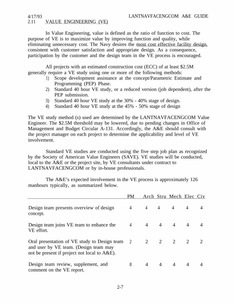
In Value Engineering, value is defined as the ratio of function to cost. Thepurpose of VE is to maximize value by improving function and quality, whileeliminating unnecessary cost. The Navy desires the most cost effective facility design,consistent with customer satisfaction and appropriate design. As a consequence,participation by the customer and the design team in the VE process is encouraged.
All projects with an estimated construction cost (ECC) of at least $2.5Mgenerally require a VE study using one or more of the following methods:
1) Scope development assistance at the concept/Parametric Estimate andProgramming (PEP) Phase.
2) Standard 40 hour VE study, or a reduced version (job dependent), after thePEP submission.
3) Standard 40 hour VE study at the 30% - 40% stage of design.4) Standard 40 hour VE study at the 45% - 50% stage of design
The VE study method (s) used are determined by the LANTNAVFACENGCOM ValueEngineer. The $2.5M threshold may be lowered, due to pending changes in Office ofManagement and Budget Circular A-131. Accordingly, the A&E should consult withthe project manager on each project to determine the applicability and level of VEinvolvement.
Standard VE studies are conducted using the five step job plan as recognizedby the Society of American Value Engineers (SAVE). VE studies will be conducted,local to the A&E or the project site, by VE consultants under contract toLANTNAVFACENGCOM or by in-house professionals.
The A&E’s expected involvement in the VE process is approximately 126manhours typically, as summarized below.
PM Arch Stru Mech Elec Civ
Design team presents overview of design 4 4 4 4 4 4concept.
Design team joins VE team to enhance theVE effort.
4
Oral presentation of VE study to Design team 2and user by VE team. (Design team maynot be present if project not local to A&E).
Design team review, supplement, andcomment on the VE report.
8 4 4 4 4 4
4 4 4 4 4
2 2 2 2 2
2-7
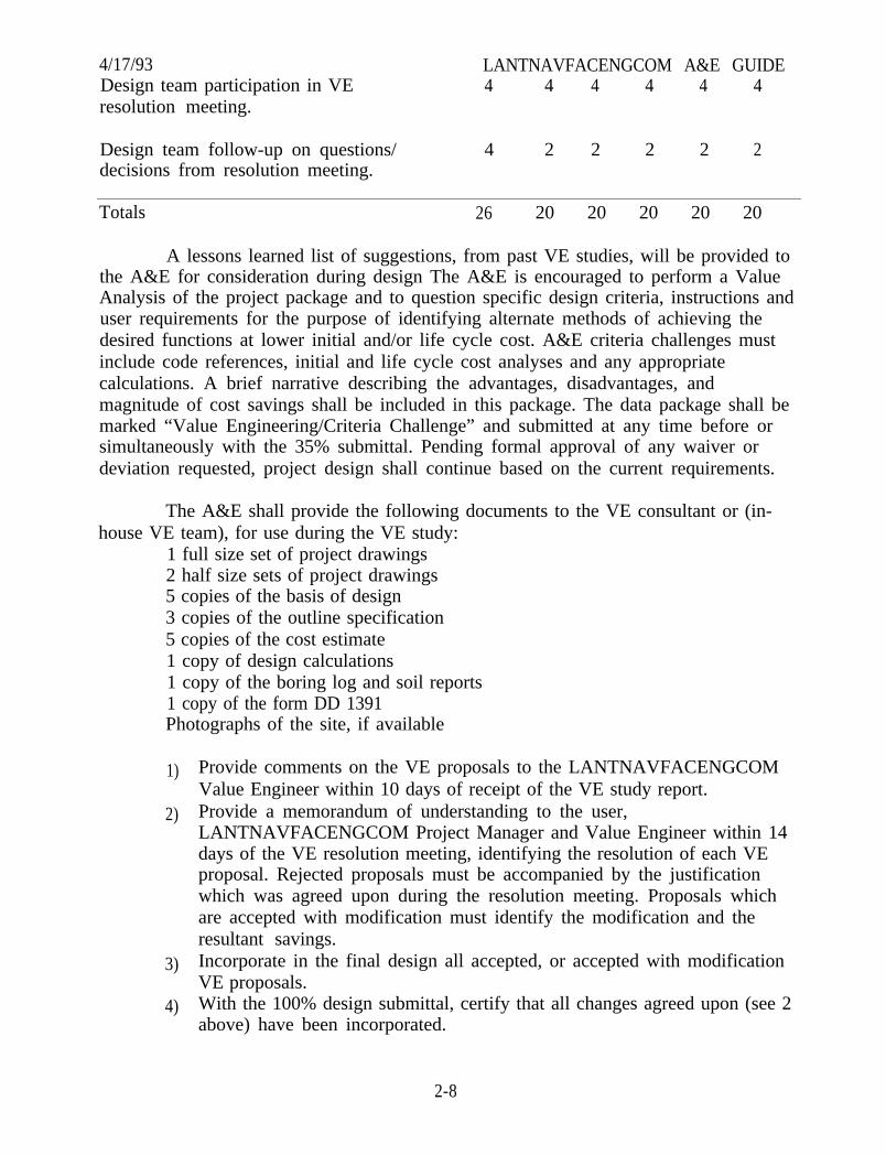
4/17/93 LANTNAVFACENGCOM A&E GUIDEDesign team participation in VE 4 4 4 4 4 4resolution meeting.
Design team follow-up on questions/ 4 2 2 2 2 2decisions from resolution meeting.
Totals 26 20 20 20 20 20
A lessons learned list of suggestions, from past VE studies, will be provided tothe A&E for consideration during design The A&E is encouraged to perform a ValueAnalysis of the project package and to question specific design criteria, instructions anduser requirements for the purpose of identifying alternate methods of achieving thedesired functions at lower initial and/or life cycle cost. A&E criteria challenges mustinclude code references, initial and life cycle cost analyses and any appropriatecalculations. A brief narrative describing the advantages, disadvantages, andmagnitude of cost savings shall be included in this package. The data package shall bemarked “Value Engineering/Criteria Challenge” and submitted at any time before orsimultaneously with the 35% submittal. Pending formal approval of any waiver ordeviation requested, project design shall continue based on the current requirements.
The A&E shall provide the following documents to the VE consultant or (in-house VE team), for use during the VE study:
1 full size set of project drawings2 half size sets of project drawings5 copies of the basis of design3 copies of the outline specification5 copies of the cost estimate1 copy of design calculations1 copy of the boring log and soil reports1 copy of the form DD 1391Photographs of the site, if available
1)
2)
3)
4)
Provide comments on the VE proposals to the LANTNAVFACENGCOMValue Engineer within 10 days of receipt of the VE study report.Provide a memorandum of understanding to the user,LANTNAVFACENGCOM Project Manager and Value Engineer within 14days of the VE resolution meeting, identifying the resolution of each VEproposal. Rejected proposals must be accompanied by the justificationwhich was agreed upon during the resolution meeting. Proposals whichare accepted with modification must identify the modification and theresultant savings.Incorporate in the final design all accepted, or accepted with modificationVE proposals.With the 100% design submittal, certify that all changes agreed upon (see 2above) have been incorporated.
2-8
4/17/93 LANTNAVFACENGCOM A&E GUIDE5) Confer with and seek approval from the LANTNAVFACENCOM Value
Engineer on all VE resolutions which are proposed to be changed after theresolution meeting.
2.12 ELECTRICAL DESIGNS
Electrical designs shall be based on the Electrical Design Guide, Attachment A.
2.13 CONCEPT DEVELOPMENT FOR MEDICAL PROTECTS
Development of pre-concept, concept and final concepts is required forMILCON funded medical projects intended to provide patient care. Generally, initialdevelopment is based on a space program. Special instructions will be provided forthese phases of design. Concept design precedes PEP and 35% design preparation.
2.14 SHORE ELECTRONICS PROJECTS
Selected MCON projects which are to provide facilities in support ofcommunications and electronics are designated as Shore Electronics Projects.
All Shore Electronics Projects have a Base Electronics System Engineering Plan(BESEP). The BESEP is a technical document which contains six separate sections. Thesixth section is facility guidance and is designed to provide the designer with technicalinformation about the electronic/communications equipment to be installed within thefacility. This guidance covers areas such as types and quantity of power; specializedgrounding; filters and shielding; specialized fire protection; and structural and roomconfiguration peculiarities which are mandated by equipment configurations and/oroperational requirements. The Space and Warfare Systems Command is responsible forthe preparation of BESEPs and the designer is required to follow the guidancecontained within it.
Specifically, the BESEP will provide the Design Agent with technical guidanceto address the requirements outlined in the Basis of Design Section.
2.15 SITE ADAPTATION OF STANDARD OR CONSTRUCTION DRAWINGS
On certain repetitive type structures, such as BEQs, BOQs, and subsistencebuildings and on certain technical structures, a definitive layout or constructiondrawings may be furnished to the A&E for site adaptation. The A&E is responsible forproviding a complete cost estimate and complete specifications based on current guidespecifications. Site adaptation, in general, consists of modifying the foundationstructure to fit the site and making necessary mechanical changes (heating, evaporativecooling or air conditioning) to fit the climatic conditions existing at the site. If otherchanges in standard plans or construction drawings are contemplated, such changeswill normally be spelled out in the scope of work.
2-9
4/17/93 LANTNAVFACENGCOM A&E GUIDEIt is not the responsibility of the A&E to review the design of the standard orconstruction drawings furnished for technical accuracy. However, if errors in thedrawings are discovered or if the design or functional layout appears unworkable forsite adaptation, the matter will be brought immediately to the attention of the PM.If the A&E cannot fit necessary mechanical or electrical equipment into the spaceprovided in the standard plan, then such space will be adjusted or increased asnecessary for the equipment. Such necessary changes are part of site adaptation.
2.16 CONSTRUCTION AND OPERATING PERMITS
A Procedures for Preparing Permit Application:
For projects that require construction and operating permit applications, alist of those required permits shall be included in the contract’s Appendix “A”. Thedesigner is responsible to have knowledge of the project’s geographical location and theenvironmental construction and operating permits required for the facility. Thedesigner is responsible to confirm any requirements for the project.
The A&E should not be contacting the regulator without guidance andapproval by the LANTDIV technical code.
The draft permit application for some permits can be submitted prior to 35%.The schedule in the Appendix A should identify the draft and final permit applicationdates. In multi-discipline projects, like BEQ, vehicle maintenance shops, warehouse,etc. usually the regulated aspects of the design can be scheduled early in the design sothat permit applications can be made. This particularly applies to civil site work as thesite work is generally complete prior to the architectural and electrical drawings. Theapplications will be reviewed by the cognizant LANTNAVFACENGCOM TechnicalCode for accuracy and completeness. If needed, the reviewed permits shall be returnedfor correction to the A&E along with the completed review package.
B. Procedures for Submitting and Obtaining Permit Approvals:
(1) The A&E Firm will submit the reviewed permit applications (withcorrections) by letter to the PM who will forward it to the cognizantLANTNAVFACENGCOM Technical Code prior to the 100% submittal.
for:(2) The LANTNAVFACENGCOM Technical Code shall be responsible
2-10
4/17/93 LANTNAVFACENGCOM A&E GUIDE(a) Reviewing and certifying that permit applications are ready for
signature by the “Applicant”. The applicant’s name for construction permits shall be“Commander, Atlantic Division, Naval Facilities Engineering Command, Code 09A”.“Agent” or point of contact with the regulatory agencies will be established by theTechnical Code in the letter submitting the permit application.
(b) Submitting the permit applications and necessary liaison with theappropriate regulatory agency. CNO policy requires permit applications be signed byan O-6 or above.
(c) Attending public hearings as needed. The A&E may bedirected to attend any public hearings which may be held, but only theappropriate LANTNAVFACENGCOM Technical Code shall be the officialLANTNAVFACENGCOM representative.
(d) If a public notice is required by a particular Government agency(such as COE, VMRC, etc.), the Technical Code is responsible for ensuring thatadvertisement is made.
(e) Forwarding approved permits to the PM.
(3) Where possible, the intent is to have the approved permits available atthe same time the 100% design is submitted to LANTNAVFACENGCOM for review.NOTE: Several types of permit applications require final design information and“approved” permits may not be available at the 100% design stage.
(4) For overseas activities, design and documentation for projects whichhave environmental pollution discharges, shall be consistent with the OverseasEnvironmental Baseline Guidance Document (OEBGD) dated October 1992. Finalgoverning standards (FGS) for specific countries are being developed to supplementthe OEBGD. The FGS for Italy, Spain and Greece should be completed by the end of FY94 and for other countries by the end of FY 95. The A&E should contact the projectmanager for any special constraints or considerations that may exist. Permitapplications for Puerto Rico require a Puerto Rico P.E. stamp.
2-11
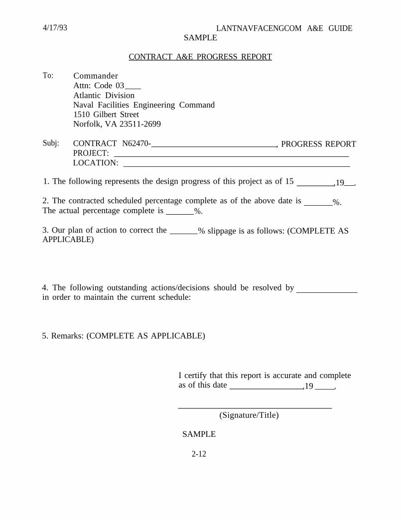
4/17/93 LANTNAVFACENGCOM A&E GUIDESAMPLE
CONTRACT A&E PROGRESS REPORT
To: CommanderAttn: Code 03Atlantic DivisionNaval Facilities Engineering Command1510 Gilbert StreetNorfolk, VA 23511-2699
Subj: CONTRACT N62470- , PROGRESS REPORTPROJECT:LOCATION:
1. The following represents the design progress of this project as of 15 ,19 .
2. The contracted scheduled percentage complete as of the above date isThe actual percentage complete is %.
%.
3. Our plan of action to correct theAPPLICABLE)
% slippage is as follows: (COMPLETE AS
4. The following outstanding actions/decisions should be resolved byin order to maintain the current schedule:
5. Remarks: (COMPLETE AS APPLICABLE)
I certify that this report is accurate and completeas of this date ,19 .
(Signature/Title)
SAMPLE
2-12
4/17/93 LANTNAVFACENGCOM A&E GUIDESECTION 3. SUBMITTAL REQUIREMENTS
3.1 INTRODUCTION
This section discusses the design related submittal of plans and specificationsfor review. Project budget related submittal will be required for those contractsrequiring preparation of Parametric Estimating and Programming (PEP). PEPrequirements are established by separate instructions.
Submittal requirements will be covered in the Appendix A. At timescircumstances dictate that a formal 35% submittal be waived. When thesecircumstances exist, waiving the 35% submittal is intended to save the time required forsubmittal preparation and review and not to “Short-cut” project development. Whenthe formal submittal is waived, the A&E shall at the 35% design stage contact theactivity, present the design as developed thus far, assure mutual understanding ofscope and discuss functional and/or operational requirements which impact the designand/or the construction. Concurrently, the A&E shall coordinate withLANTNAVFACENGCOM regarding project scope and development, i.e., guidespecifications, cost estimating, fire protection, etc. For projects overseas, see section3.3.7, 3.3.8 and 3.3.9 for additional requirements.
3.2 A&E SEAL ON DOCUMENTS
A principal or authorized licensed or certified employee shall apply a stamp orpreprinted seal to final and complete cover sheets of plans, drawings, plats, technicalreports and specifications, and to each original sheet of plans, drawings or plats,prepared by the Registered Architect or Professional Engineer or someone under thisdirect control and personal supervision. For additional requirements in Italy, seeSection 3.3.9, Italian Law Compliance.
A. All seal imprints on final documents shall bear an original signature anddate.
B. Incomplete plans, documents and sketches, whether advance orpreliminary copies, shall be so identified and need not be sealed or signed.
C. All plans, drawings or plats prepared by the Registered Architect orProfessional Engineer shall bear the Registered Architect or Professional Engineer’sname or firm name, address, and project name.
D. The seal of each Registered Architect or Professional Engineer responsiblefor each professional shall be used.
E. Application of the seal and signature indicates acceptance of responsibilityfor work shown thereon.
3-1
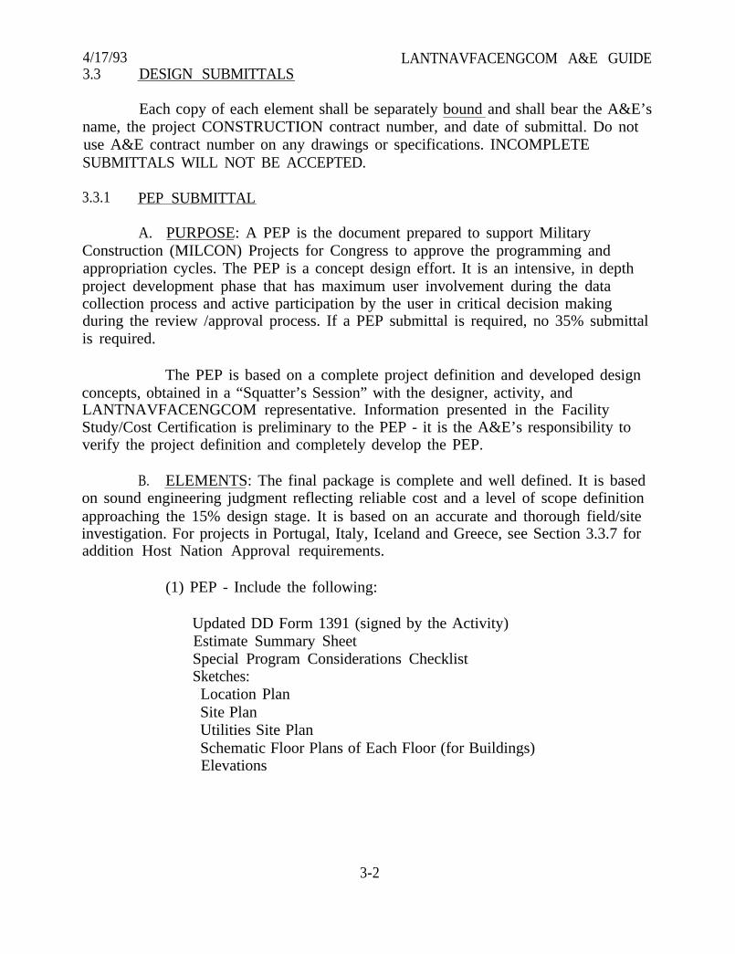
4/17/93 LANTNAVFACENGCOM A&E GUIDE3.3 DESIGN SUBMITTALS
Each copy of each element shall be separately bound and shall bear the A&E’sname, the project CONSTRUCTION contract number, and date of submittal. Do notuse A&E contract number on any drawings or specifications. INCOMPLETESUBMITTALS WILL NOT BE ACCEPTED.
3.3.1 PEP SUBMITTAL
A. PURPOSE: A PEP is the document prepared to support MilitaryConstruction (MILCON) Projects for Congress to approve the programming andappropriation cycles. The PEP is a concept design effort. It is an intensive, in depthproject development phase that has maximum user involvement during the datacollection process and active participation by the user in critical decision makingduring the review /approval process. If a PEP submittal is required, no 35% submittalis required.
The PEP is based on a complete project definition and developed designconcepts, obtained in a “Squatter’s Session” with the designer, activity, andLANTNAVFACENGCOM representative. Information presented in the FacilityStudy/Cost Certification is preliminary to the PEP - it is the A&E’s responsibility toverify the project definition and completely develop the PEP.
B. ELEMENTS: The final package is complete and well defined. It is basedon sound engineering judgment reflecting reliable cost and a level of scope definitionapproaching the 15% design stage. It is based on an accurate and thorough field/siteinvestigation. For projects in Portugal, Italy, Iceland and Greece, see Section 3.3.7 foraddition Host Nation Approval requirements.
(1) PEP - Include the following:
Updated DD Form 1391 (signed by the Activity)Estimate Summary SheetSpecial Program Considerations ChecklistSketches:Location PlanSite PlanUtilities Site PlanSchematic Floor Plans of Each Floor (for Buildings)Elevations
3-2
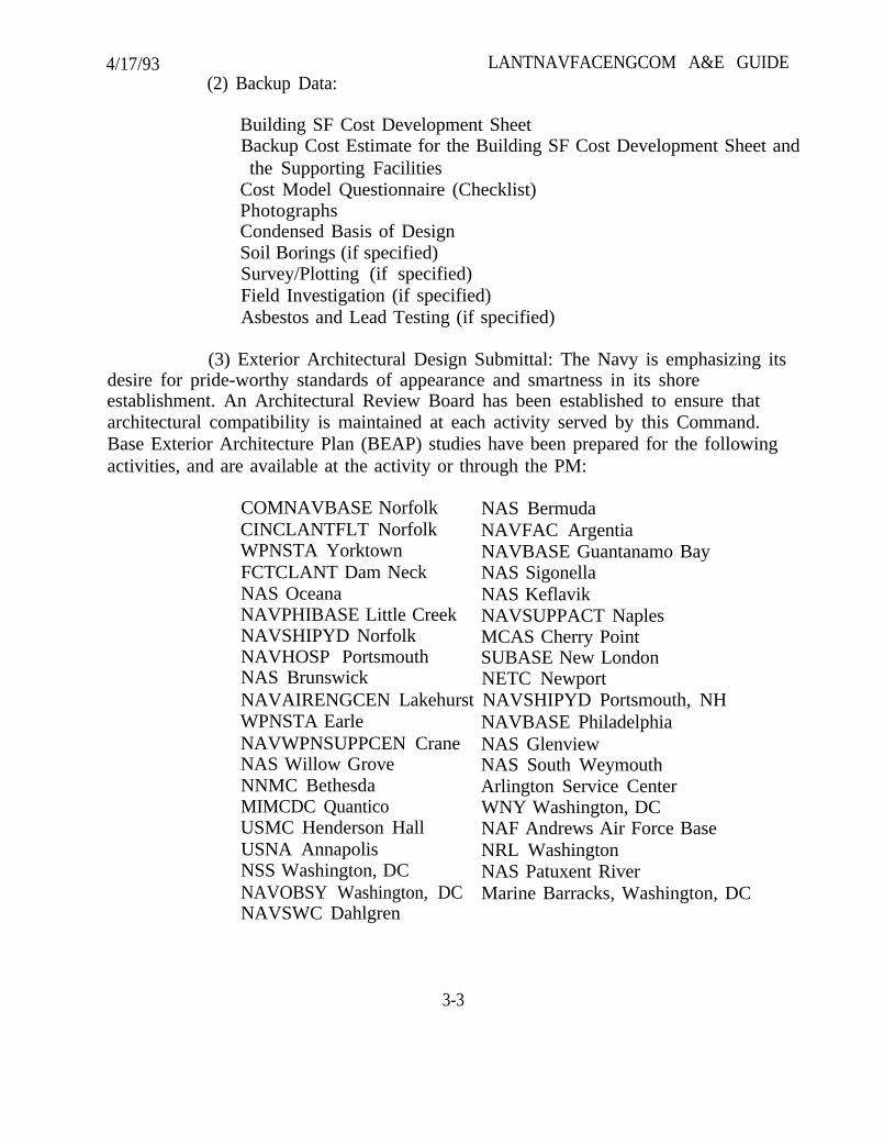
4/17/93(2) Backup Data:
LANTNAVFACENGCOM A&E GUIDE
Building SF Cost Development SheetBackup Cost Estimate for the Building SF Cost Development Sheet andthe Supporting Facilities
Cost Model Questionnaire (Checklist)PhotographsCondensed Basis of DesignSoil Borings (if specified)Survey/Plotting (if specified)Field Investigation (if specified)Asbestos and Lead Testing (if specified)
(3) Exterior Architectural Design Submittal: The Navy is emphasizing itsdesire for pride-worthy standards of appearance and smartness in its shoreestablishment. An Architectural Review Board has been established to ensure thatarchitectural compatibility is maintained at each activity served by this Command.Base Exterior Architecture Plan (BEAP) studies have been prepared for the followingactivities, and are available at the activity or through the PM:
COMNAVBASE Norfolk NAS BermudaCINCLANTFLT Norfolk NAVFAC ArgentiaWPNSTA Yorktown NAVBASE Guantanamo BayFCTCLANT Dam Neck NAS SigonellaNAS Oceana NAS KeflavikNAVPHIBASE Little Creek NAVSUPPACT NaplesNAVSHIPYD Norfolk MCAS Cherry PointNAVHOSP Portsmouth SUBASE New LondonNAS Brunswick NETC NewportNAVAIRENGCEN Lakehurst NAVSHIPYD Portsmouth, NHWPNSTA EarleNAVWPNSUPPCEN CraneNAS Willow GroveNNMC BethesdaMIMCDC QuanticoUSMC Henderson HallUSNA AnnapolisNSS Washington, DCNAVOBSY Washington, DCNAVSWC Dahlgren
NAVBASE PhiladelphiaNAS GlenviewNAS South WeymouthArlington Service CenterWNY Washington, DCNAF Andrews Air Force BaseNRL WashingtonNAS Patuxent RiverMarine Barracks, Washington, DC
3-3
4/17/93 LANTNAVFACENGCOM A&E GUIDEIn addition to these studies, several bases also have their own design
guides which include recommended colors and materials. Consult the PM for moreinformation.
Where a BEAP has been completed, it shall be used as a principalguide in evaluating the compatibility of a new structure with the existing architecturalcharacter of the activity. In all cases, accepted design precepts (scale, proportion,rhythm, etc.) should also be used as a basis for architectural compatibility.Appropriateness of the proposed construction materials as they relate to surroundingbuildings must also be considered, as well as the geological and climatic conditions.The area of concern of the Architectural Review Board is specifically limited to theexterior aesthetics of facilities and complexes. It is not the intent to concern the Boardin any way with the functional organization or material choices for structures except asthey affect exterior appearance.
Concurrent with submission of the PEP submittal or the 35%submittal, a SEPARATE SUBMISSION of an Exterior Architectural Design Submittal tothe Architectural Review Board is required. A formal presentation may be required formore highly visible projects. Should substantial changes occur after the 35% designreview, a complete review may be requested at the final submittal. The ExteriorArchitectural Design Submittal shall consist of the following:
(a) Statement of Compatibility - Provide a brief description of thedesign, stating concisely the architectural compatibility of the project with the existingpermanent facilities and the BEAP, if one exists. This includes not only buildingcharacteristics, but a site analysis, visual environmental concept, and appropriatenessof construction methods and materials.
(b) Drawings - Provide the following scale drawings, developed tothe stage indicated:
1. Site Plan - Indicate site boundaries, building locations(existing, proposed, and future), parking, pedestriancirculation, pedestrian and service entrances, andlandscaping.
2. Floor Plans - Indicate main entrances, service areas, roomdesignations, and exterior stairs and ramps.
3. Elevations - Indicate all exterior materials, architecturalcharacteristics and design elements, doors and windows.
3-4
4/17/93 LANTNAVFACENGCOM A&E GUIDE(c) Exterior Color Board - Provide actual samples of all exterior
materials and colors.
(d) Photographs - Provide sufficient color slides or color printsnecessary to indicate the character of the existing facilities on the base judged by theA&E to have influence on the architectural design of his project. The three (3) nearestpermanent buildings must be included.
(4) See Value Engineering Section 2.11 for VE Submittal Requirements.
3.3.2 35% STATION PRESENTATION
A. PURPOSE: After the PEP has been prepared, there may be a delay ofseveral months until the project is approved for final design and options for finaldesign exercised. The presentation proposed by this item allows the Activity a chanceto reverify that the A&E is proceeding from the project concept and scope phase to adesign stage that still meets their functional and organizational requirements. It is notintended to be a thorough technical presentation, but functional reconfirmation Therewill be no break in the design process as the A&E proceeds to the next submittal stage.
B. ELEMENTS:
(1) Drawings
Civil
Site PlanUtility Plan
Architectural
Floor PlansFurniture Footprint Plan.Finish ScheduleRoof PlanElevationsTypical Walls Sections
Mechanical
Schema tic DiagramsMechanical Room Plans - Major Equipment
3-5
4/17/93
(2)
(3)
(4)
(5)budget, identify6.13)
(6)
(7)
(8)
(9)
LANTNAVFACENGCOM A&E GUIDEElectrical
Site PlanOne Line Diagrams, Power and Special System Riser Diagrams
(FA, CATV, CCTV, Intercom, etc.)
Basis of Design - See Section 4.
Preliminary Color Design - See Section 4.3.
Outline Specifications - See Section 6.
Cost Estimate (if estimated construction cost exceeds the establishedpotential additive bid items in accordance with the A&E Guide Section
Geotechnical reports and foundation studies
Proposed construction schedule and schedule of major utility outages
Preliminary Calculations
See Value Engineering Section 2.11 for VE Submittal Requirements.
C. PROCEDURE
(1) Upon receipt of contract notification to proceed to final design, theA&E shall contact the Activity and establish a presentation date (generally 30 days inthe future); and advise the PM. The PM and AIC/EIC will attend on a case-by-casebasis depending upon location, complexity of the project, and schedule conflicts.
(2) The A&E will mail or hand carry submittals to the requireddistribution 7 days in advance of the presentation date. This will allow all parties toreview and become familiar with the submittal.
(3) The A&E will conduct a “one-day presentation to walk the Activitythrough the design. The results of the presentation are:
(a) Activity understands what they are getting.
(b) Activity concurs with basic design.
(c)design.
The A&E has all the information needed to proceed to final
(4) The A&E will publish results of the meeting.
3-6
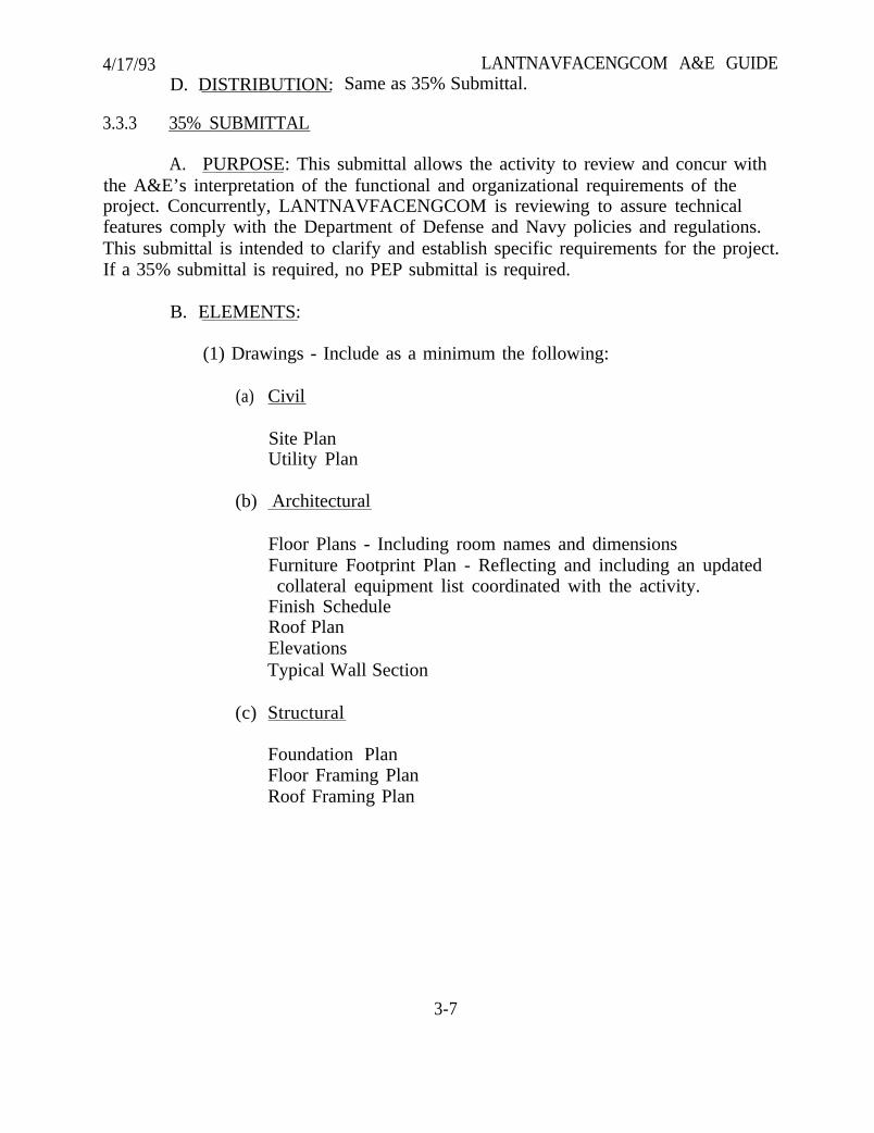
4/17/93 LANTNAVFACENGCOM A&E GUIDED. DISTRIBUTION: Same as 35% Submittal.
3.3.3 35% SUBMITTAL
A. PURPOSE: This submittal allows the activity to review and concur withthe A&E’s interpretation of the functional and organizational requirements of theproject. Concurrently, LANTNAVFACENGCOM is reviewing to assure technicalfeatures comply with the Department of Defense and Navy policies and regulations.This submittal is intended to clarify and establish specific requirements for the project.If a 35% submittal is required, no PEP submittal is required.
B. ELEMENTS:
(1) Drawings - Include as a minimum the following:
(a) Civil
Site PlanUtility Plan
(b) Architectural
Floor Plans - Including room names and dimensionsFurniture Footprint Plan - Reflecting and including an updatedcollateral equipment list coordinated with the activity.
Finish ScheduleRoof PlanElevationsTypical Wall Section
(c) Structural
Foundation PlanFloor Framing PlanRoof Framing Plan
3-7
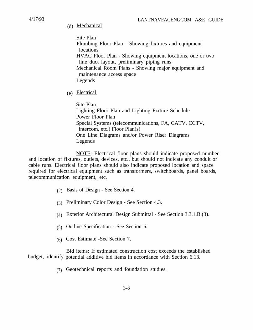
4/17/93(d) Mechanical
Site PlanPlumbing Floor Plan - Showing fixtures and equipmentlocations
HVAC Floor Plan - Showing equipment locations, one or twoline duct layout, preliminary piping runs
Mechanical Room Plans - Showing major equipment andmaintenance access space
Legends
(e) Electrical
LANTNAVFACENGCOM A&E GUIDE
Site PlanLighting Floor Plan and Lighting Fixture SchedulePower Floor PlanSpecial Systems (telecommunications, FA, CATV, CCTV,intercom, etc.) Floor Plan(s)
One Line Diagrams and/or Power Riser DiagramsLegends
NOTE: Electrical floor plans should indicate proposed numberand location of fixtures, outlets, devices, etc., but should not indicate any conduit orcable runs. Electrical floor plans should also indicate proposed location and spacerequired for electrical equipment such as transformers, switchboards, panel boards,telecommunication equipment, etc.
(2)
(3)
(4)
(5)
(6)
budget, identify
(7)
Basis of Design - See Section 4.
Preliminary Color Design - See Section 4.3.
Exterior Architectural Design Submittal - See Section 3.3.1.B.(3).
Outline Specification - See Section 6.
Cost Estimate -See Section 7.
Bid items: If estimated construction cost exceeds the establishedpotential additive bid items in accordance with Section 6.13.
Geotechnical reports and foundation studies.
3-8
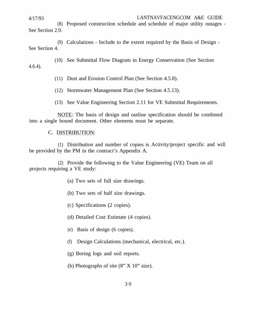
4/17/93 LANTNAVFACENGCOM A&E GUIDE(8) Proposed construction schedule and schedule of major utility outages -
See Section 2.9.
(9) Calculations - Include to the extent required by the Basis of Design -See Section 4.
4.6.4).(10) See Submittal Flow Diagram in Energy Conservation (See Section
(11) Dust and Erosion Control Plan (See Section 4.5.8).
(12) Stormwater Management Plan (See Section 4.5.13).
(13) See Value Engineering Section 2.11 for VE Submittal Requirements.
NOTE: The basis of design and outline specification should be combinedinto a single bound document. Other elements must be separate.
C. DISTRIBUTION:
(1) Distribution and number of copies isbe provided by the PM in the contract’s Appendix A.
Activity/project specific and will
(2) Provide the following to the Value Engineering (VE) Team on allprojects requiring a VE study:
(a) Two sets of full size drawings.
(b) Two sets of half size drawings.
(c) Specifications (2 copies).
(d) Detailed Cost Estimate (4 copies).
(e) Basis of design (6 copies).
(f) Design Calculations (mechanical, electrical, etc.).
(g) Boring logs and soil reports.
(h) Photographs of site (8” X 10” size).
3-9
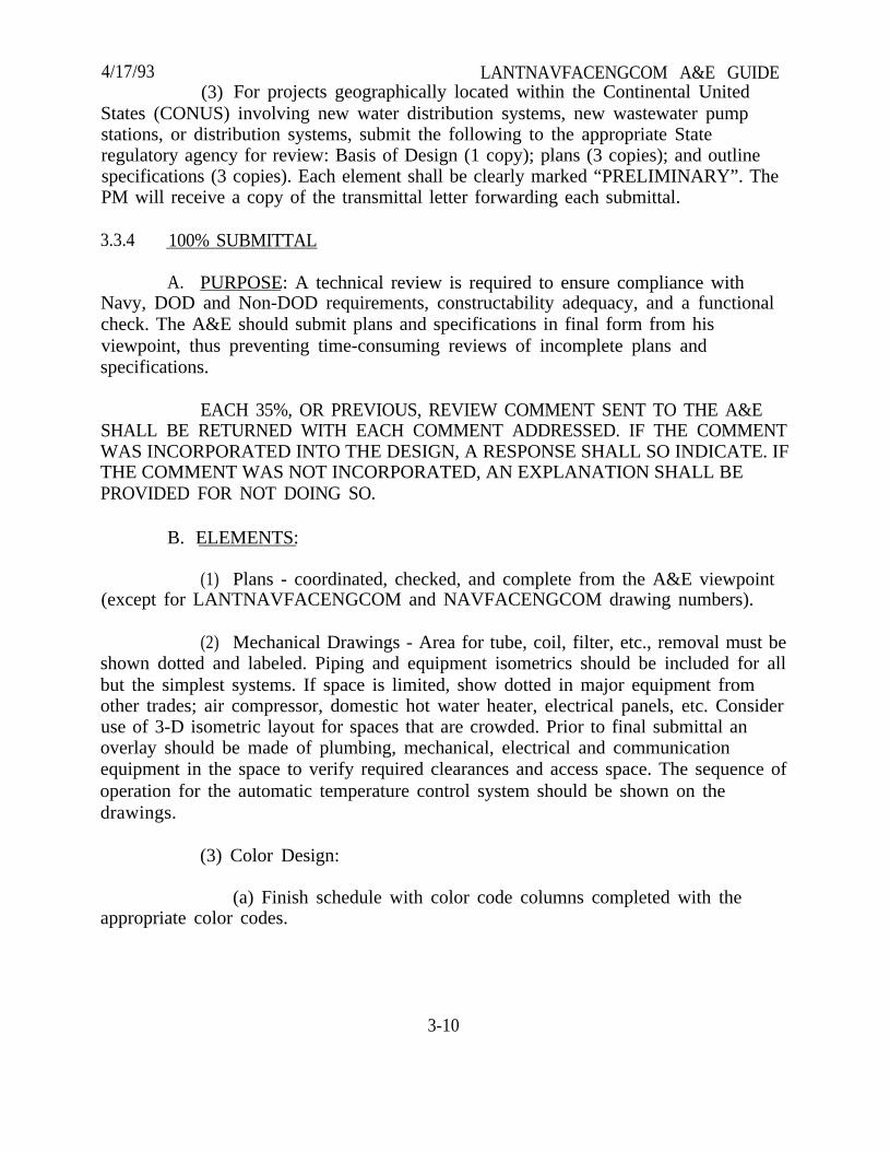
4/17/93 LANTNAVFACENGCOM A&E GUIDE(3) For projects geographically located within the Continental United
States (CONUS) involving new water distribution systems, new wastewater pumpstations, or distribution systems, submit the following to the appropriate Stateregulatory agency for review: Basis of Design (1 copy); plans (3 copies); and outlinespecifications (3 copies). Each element shall be clearly marked “PRELIMINARY”. ThePM will receive a copy of the transmittal letter forwarding each submittal.
3.3.4 100% SUBMITTAL
A. PURPOSE: A technical review is required to ensure compliance withNavy, DOD and Non-DOD requirements, constructability adequacy, and a functionalcheck. The A&E should submit plans and specifications in final form from hisviewpoint, thus preventing time-consuming reviews of incomplete plans andspecifications.
EACH 35%, OR PREVIOUS, REVIEW COMMENT SENT TO THE A&ESHALL BE RETURNED WITH EACH COMMENT ADDRESSED. IF THE COMMENTWAS INCORPORATED INTO THE DESIGN, A RESPONSE SHALL SO INDICATE. IFTHE COMMENT WAS NOT INCORPORATED, AN EXPLANATION SHALL BEPROVIDED FOR NOT DOING SO.
B. ELEMENTS:
(1) Plans - coordinated, checked, and complete from the A&E viewpoint(except for LANTNAVFACENGCOM and NAVFACENGCOM drawing numbers).
(2) Mechanical Drawings - Area for tube, coil, filter, etc., removal must beshown dotted and labeled. Piping and equipment isometrics should be included for allbut the simplest systems. If space is limited, show dotted in major equipment fromother trades; air compressor, domestic hot water heater, electrical panels, etc. Consideruse of 3-D isometric layout for spaces that are crowded. Prior to final submittal anoverlay should be made of plumbing, mechanical, electrical and communicationequipment in the space to verify required clearances and access space. The sequence ofoperation for the automatic temperature control system should be shown on thedrawings.
(3) Color Design:
(a) Finish schedule with color code columns completed with theappropriate color codes.
3-10

4/17/93 LANTNAVFACENGCOM A&E GUIDE(b) Where other than usual painting or wall covering schemes or
ceramic wall tile, graphics, built-in equipment or window treatments are used, labeledfloor plans, elevations and sketches using the color codes as necessary should bedrawn.
(c) A color legend along with color notes should be completedreferencing and specifying all finishes used in the finish schedule.
(d) A color board identifying all finish colors listed in the finishschedule, labeled with appropriate color codes. The board should be a reasonable,transferable size (maximum size 20” X 30”).
(e) Check with activity to ensure that collateral equipment list isaccurate. If necessary, revise the collateral equipment list and furniture footprint.
(4) Specification - photographic copies of fully edited guide specificationssupplemented as required are acceptable. Specifications must be thoroughly edited forcoordination with the drawings. See Section 6.
(5) Cost Estimate - See Section 7.
(a) CES Estimates:
1. Computer run estimate
2. Marked 35% estimate
3. Vendor/manufacturer quotes
(b) Manual Estimates:
1. Backup estimate with summary sheets
2. Marked 35% estimate
3. Vendor/manufacturer quotes
(c) Bid Items - if estimated construction cost exceeds constructionfunds available, identify in conjunction with the activity additive bid items andrespective values with detailed back-up estimates required to produce a base bidwithin available construction funds. See Section 6.13 for additional information.
3-11
4/17/93 LANTNAVFACENGCOM A&E GUIDE(6) Draft Environmental Construction and/or Operating Permit(s)
(7) Calculations - engineering calculations shall be neat, legible, logicallyordered, bound and indexed. Design data shall be clearly stated. Formulas andreference sources shall be cited. Designers and checkers shall initial and date eachcomputation sheet. In addition to calculations required at the 35% submittal, electricalcalculations required at the 100% submittal shall include, as applicable, calculationsindicated by Attachment A. Upon request A&E firms using computerized designprocedures must submit, in conjunction with calculations:
(a) A description of the type(s) and configuration(s) used.
(b) Copies of all pertinent input and output data.
(c) Documentation of each program may be requested, including awritten summary of the program intent and function, assumptions, formulas,numerical methods used, nomenclature, limitations of the program, and referencesused in developing the program. In the event “non-proven” programs are used, acomputer run by the A&E of a check problem may be required by the reviewer forverification at no expense to the Government.
(d) See Submittal Flow Diagram in Energy Conservation (Section4.6.4.
(8) Dust and Erosion Control Plan (See Section 4.5.8).
(9) Stormwater Management Plan (See Section 4.5.13).
(10) Manufacturer’s catalog data of major equipment which was used asbasis of design. Data shall include dimensions, weights, and specified ratings.Examples of major equipment requiring catalog data are:
(a) Switchgear/substations
(b) M-G sets
(c) Eng-Gen sets
(d) IDS
(e) Frequency converters
3-12
4/17/93(f)
(g)
(h)
(i)
(j)
(k)
FiltersLANTNAVFACENGCOM A&E GUIDE
Heat rejection equipment
HVAC
Pumps, fans and air compressors
Domestic hot water heaters
Other special equipment
(11) Certification that Value Engineering items are incorporated intodesign (See Value Engineering Section 2.11).
(12) All marked materials returned to the A&E with previous submittal(i.e., plans, specifications, cost estimate, Basis of Design, Calculations, reports, etc.).
C. DISTRIBUTION:
(1) Distribution of plans, specifications and cost estimate are projectspecific and are provided by the PM in the contract’s Appendix A.
(2) Two copies each of the remaining submittal elements will beforwarded to LANTNAVFACENGCOM only.
(3) For projects geographically located within the Continental UnitedStates (CONUS), involving stormwater management practices, new water distributionsystems, new wastewater pump stations, or distribution systems, the A&E shall submitany permit applications and/or submittal packages to the PM, unless expressedotherwise in the Appendix A. The PM will forward the package to the appropriatetechnical code for submission to the regulator. This is consistent withLANTNAVFACINST 11010.21 of 6 June 1990.
3.3.5 FINAL SUBMITTAL
A. PURPOSE: To finalize design phase and prepare documents forconstruction contract advertisement.
EACH 100% REVIEW COMMENT SENT TO THE A&E SHALL BERETURNED WITH EACH COMMENT ADDRESSED. IF THE COMMENT WASINCORPORATED INTO THE DESIGN, A RESPONSE SHALL SO INDICATE. IF THECOMMENT WAS NOT INCORPORATED, AN EXPLANATION SHALL BE PROVIDEDFOR NOT DOING SO.
3-13
4/17/93 LANTNAVFACENGCOM A&E GUIDEB. ELEMENTS:
APPROPRIATE SIGNATURES. The A&E is responsible for obtaining the“Satisfactory To” signature of the Commanding Officer or the Public Works designatorof the activity prior to final submission of all projects.
All documents shall have the seal of the A&E responsible for the work asrequired by Section 3.2. A firm or partnership stamp is not acceptable. Where thefirm’s state of residency does not provide for professional sealing, compliance with thestate’s normal requirements will suffice.
FINAL TRACINGS. Final tracings, masters and any other data developedby the A&E shall become the property of the Government unless stated otherwise in thecontract.
For projects on AutoCAD (or other CAD systems) all computer aideddesign disks shall be turned over to the Government as requested by the PM. Refer toparagraph 2.7 for field survey submittal requirements. Scan all computer diskssubmitted for viruses using a commercial virus scanning program.
(1) Original tracings plus 2 sets of prints.
(2) Final Specifications (Bond plus 2 copies).
(3) Interior Color Design.
(a) One color board displaying all materials labeled with color codes.Maximum size to be 20" X 30".
(b) Two 8-1/2” X 11” binders containing all coded materials.
(c) Furniture footprint reflecting final collateral equipment list andthe color study when one has been required.
(d) Finalized finish schedule, color legend and color notes.
(4) Cost Estimate.
(a) CES Estimate
(1) Computer run estimate
3-14
4/17/93
(b) Manual Estimates
(c)
(1) Backup estimate with summary sheet(s)
(2) Marked 100% estimate
(3) Vendor/manufacturer quotes
Proposed bid items with detailed backup estimate (if estimated
(2)
(3)
LANTNAVFACENGCOM A&E GUIDEMarked 100% estimate
Vendor/manufacturer quotes
construction cost exceeds construction funds available).
(5) Calculations.
(6) All marked materials returned with previous submittal.
(7) Field Notes, Reports and Studies.
(8) Environmental Construction and/or Operating Permit(s).
(9) All NAVFAC DMs furnished by LANTNAVFACENGCOM at projectcommencement.
NOTE: ALL COMPUTATIONS, STUDIES AND OTHER SIGNIFICANTMATERIAL SHALL BE BOUND IN BOOK FORM.
C. QUALITY CONTROL DATA: Your firm will be expected to perform aquality control review. This review will evaluate both the technical accuracy anddiscipline coordination. Your Final Submittal shall include a single set of final printsand specifications highlighted to indicate that the review was performed andcorrections made and a signature in the “Quality Review Signature Block” (see below)on the original of the cover sheet of “F” size drawings or on the “Quality Control” line inthe title block of the cover sheet of “D” size drawings, indicating a quality review wasperformed. Such items as section, detail, and note references to other sheets, majordimensions, and equipment locations shall be marked. Verify that all equipment iscorrectly identified the same way on all sheets and in the specifications. Ensure that allwork as indicated on the drawings is fully and consistently specified.
3-15

4/17/93 LANTNAVFACENGCOM A&E GUIDE
QUALITY CONTROL REVIEW
Signature Date
Quality Review Signature Block
D. DISTRIBUTION:
(1) Except as otherwise noted above or as specified in the contract’sAppendix A, submit one copy of each element to LANTNAVFACENGCOM.
(2) For projects geographically located within the Continental UnitedStates (CONUS) involving storm water management practices, new water distributionsystems, new wastewater pump stations or distribution systems, provide the followingto the appropriate State regulatory agency for review: Plans and specifications (3copies each). The cover sheet on all copies of both the plans and specifications mustbear an original seal and signature of the professional engineer responsible for thedesign. The PM will receive a copy of the transmittal letter forwarding each submittal.
3.3.6 National Capital Planning Commission (NCPC) and/or Commission of FineArts (CFA) Presentation
The presentation material is required to obtain the approval of the two Commissions.
A. PURPOSE: To clearly demonstrate to the two Commissions the intent andquality of the project and to obtain the acceptance of the Commissions.
B. ELEMENTS:
(1) One set of drawings mounted on presentation boards and renderedwith appropriate color (Approx. 30 inches by 40 inches)
(2) Project data report
(3) Environmental assessment statement
(4) Seven record copies of all materials for NCPC and three additionalcopies for DFA (when required).
3-16

4/17/93 LANTNAVFACENGCOM A&E GUIDE(5) Eight and one-half inches by eleven inches, black and white reductions
of the record copies.
(6) Photographs of the existing conditions.
NOTE: The A&E shall be responsible for making those modifications to the design andto the presentation material requested by the Commissions and authorized by theGovernment.
C. DISTRIBUTION
(1) Distribution and number of copies is Activity/project specific and willbe provided by the PM in the contract’s Appendix A.
3.3.7 HOST NATION APPROVAL:
A. PURPOSE: Bilateral Agreements with certain countries require formalHost Nation Approval of our work during the design process. Host Nation approval isrequired prior to our proceeding to construction. The submission is required for allprojects that propose new inventory at the activity. Projects that propose renovation orrepair that alters the exterior appearance of an existing facility shall also be submittedfor Host Nation Approval. Documentation preparation is required as part of the A&Econtract and will be submitted concurrent with the PEP (or 35% submittal). Unlessdirected otherwise by the contracted scope of services, the A&E shall not assume anyformal presentation or involvement with the Host Nation Approval process beyond thescope outlined below. The countries are:
Portugal - U.S. text, no translation required.
Italy - U.S. and Italian text required.
Iceland - U.S. text, no translation required.
Greece - U.S. and Greek text required.
B. ELEMENTS: The submission shall consist of the following componentsformalized in standard 8 1/2 x 11 inch binder:
(1) Illustrative statement of the projects intent.:
(a) Purpose of construction
(b) Requirements to be met by this construction
(c) Type of construction proposed
3-17

4/21/93 LANTNAVFACENGCOM A&E GUIDE
(d) Range of cost (use a span of cost to avoid compromise of bid estimate;e.g. $1M - $2M, $3M - $5M etc.)
(e) Environmental Statement: Provide statement “This project will notcontribute to water or air pollution and will not adversely affect the ecology” or astatement of measures and criteria to mitigate environmentally sensitive features of thedesign
(f) Statement of military or operational necessity for the project.(Information to be provided by the Project Manager).
(2) Provide a statement of physical security features the facility will contain(unclassified). Describe any automatic reporting to centralized activity securityproposed.
(3) Provide photographs of adjacent facilities and surroundings.
(4) Provide site plan clearly indicating the location of the proposed project inthe context of the installation and associated roads, sidewalks, substations, pumphouses, parking, etc. Buildings to be demolished or abandoned must be shown.
(5) Floor plans and elevations.
(6) Exterior colors proposed.
c . DISTRIBUTION: Two copies of the draft shall be submitted with the PEP(or 35% submittal) for review. Ten copies of the final document shall be submitted asconclusion of the PEP documentation review.
3.3.8 DUAL LANGUAGE: Preparation of plans and specifications is required to beprepared in dual language at a majority of our overseas locations. The A&E shallpresume translation is required unless the contracted scope indicates otherwise.
3.3.9 ITALIAN LAW COMPLIANCE: Final plans prepared for construction in Italyrequire certification by an engineer or architect registered on the National ProfessionalRolls of Italy. Certification in the form of a letter, attesting to the designs compliancewith all Italian codes satisfies this requirement. In addition, a structural certification isrequired in the form of a signature on the structural drawings and on the structuraldesign calculations. Plans prepared by a U.S. registered professional organization shallbe stamped by the designer of record and/or the participating Italian registered firm.
3-18
4/17/93SECTION 4. BASIS OF DESIGN
LANTNAVFACENGCOM A&E GUIDE
4.1 INTRODUCTION
The basis of design should be a bound presentation of facts sufficientlycomplete in accordance with the following suggested format to expediteLANTNAVFACENGCOM review of the preliminary submittal. Detailed designcomputations, sizing of members or conductors, details of connections, etc., are notnecessary with the basis of design, but general computations supporting systemselection are required.
The Criteria Manual is MIL-HDBK-1190 dated 1 September 1987, “FacilityPlanning and Design Guide.”
4.2 BASIS OF DESIGN - SUGGESTED FORMAT
The following guidance is written around new building type construction.Where a project consists primarily of mechanical, electrical, structural, or anotherdiscipline, the basis of design shall provide more detailed information for the majordiscipline.
4.3 ARCHITECTURAL
A. Statement of the type of construction adopted with reference to theoccupancy, anticipated tenure of usage, degree of fire resistance, and maximumallowable floor areas and number of stories allowed by the Uniform Building Code.For Overseas locations, include any restrictions the host country may require.
B. Statement as to the type of thermal insulation to be provided, whenrequired, and the value of the “U” factors for the various portions of the structure, i.e.,roof, walls, floor, etc. Also provide description of all architectural energy conservingfeatures to be incorporated, including any passive solar systems. Refer to the EnergyConservation Section for additional information. Refer to ASHRAE Standard 90.1-1989, Section 8.5 for determining “U” factors instead of previous DOD criteria.
C. Provide a one page narrative description of the preliminary color designconcept addressing Architectural finishes and colors. Describe materials for all majoritems of construction and all interior and exterior finishes. The description of finishes(colors, textures, and patterns) shall be accomplished by the use of a finish schedule,color legend and notes. The finish schedule on the drawings shall identify interiorbuilding material finishes (A&E may choose room-by-room name or number format).
4-1
4/17/93 LANTNAVFACENGCOM A&E GUIDEFor the completed project all reference to building colors shall be on the drawings inthe color legend that is referenced to the finish schedule. Any finishes not referenced inthe color code columns of the finish schedule should be in either the comments sectionor color notes. Provide a generic color board referencing the narrative.
NOTE: Informal liaison with the Architectural Branch, Interior DesignSection, telephone 804-444-9984, is encouraged to facilitate orderly development ofintegrated colors/finishes.
D. A description of items not considered to be a permanent part of thestructure, such as work benches, shelving, bins and removable partitions.
E. Analyze the design for compliance with DM-01.03, ArchitecturalAcoustics, and DM3.10, Noise and Vibration Control. Include a statement as to generaladherence to this criteria. When required, list areas of high noise and vibration andacoustic design principles applied.
F. PROVISIONS FOR PHYSICALLY HANDICAPPED PERSONS: Facilitiesrequired to be accessible to physically handicapped persons shall be designed andconstructed or retrofitted in accordance with the Uniform Federal AccessibilityStandards (UFAS), Federal Register, (49 FR 31528 dated August 7 1984, as amended by51 FR 18647 dated May 21, 1986) (reference (5e)). Requirements for new construction,additions, and alterations vary and are specified in the standards. In general, allfacilities worldwide which re-open to the public, or to limited segments of the public,or which may be visited by the public in the conduct of normal business, shall bedesigned and constructed to be accessible to physically handicapped persons includingfacilities constructed with nonappropriated funds, privately financed facilities onmilitary installations, and contractor-owned facilities where the Department of Defenseis funding all or any part of the construction. In fact, every facility should be designedto assure access to physically handicapped persons unless “its intended use isspecifically restricted to able-bodied military personnel.” Able-bodied militarypersonnel is defined as those military personnel considered to be physically fit forduty. At least five percent of family housing units at an installation and not less thanone unit shall be accessible.
G. Computation of gross floor area in accordance with MIL-HDBK-1190.Gross floor areas should be indicated on the drawings.
4-2
4/17/93 LANTNAVFACENGCOM A&E GUIDEH. Analysis of Life Safety Code (NFPA 101) requirements for all occupancies
involved. Determine occupancy classifications, calculated occupant load, number andsize of exits and other requirements. Describe unusual or critical code requirementsand indicate how such requirements will be met.
I. Describe special construction features incorporated into the facility such asbarred windows, special wall/roof construction, raised computer flooring, RFShielding, HEMP protection, etc.
J. The architect shall identify to the structural designer all partitions, i.e.,non-loadbearing walls (full height and less than full height), so that requiredstrengthening can be determined. These considerations shall include seismic, wind andother dynamic loads applied to these walls. The partitions may be wood or steel studframed, or CMU. Appropriate control joints shall also be considered.
4.4 STRUCTURAL
A. Description of foundation conditions, type of foundation to be used,method by which the allowable bearing values are to be determined, and maximumallowable bearing capacity for the foundations. Geotechnical information includingfield boring notes and report of recommendations shall be submitted.
B. Statement of the type of construction adopted, and reason therefor, withcapacity, dimensions, or other size criteria, and list of material selected with designstrengths.
C. Special features to be included in the structure which are not evident fromthe drawings.
D. Description of the structural floor and roof systems proposed, with length,spacing and size of principal members (for beam and girder, etc.).
E. Description of the Lateral Force Resisting System proposed withappropriate materials and dimensions.
F. Statement of live loading to be used, to include floor loads, wind, snow,earthquake, etc., with data to justify.
G. Statement of any special considerations that affect the design (e.g.,“superflat floors” for high stacking warehouses, special corrosion resistancerequirements, retractable roofs, etc.).
4-3

4/17/93 LANTNAVFACENGCOM A&E GUIDEH. Contact the cognizant PM for extent of crane design required. Include
special considerations as to crane and monorail requirements; i.e., special architectural-structural considerations, area of service, and type of system.
I. The usual accepted means of structural system selection is economy.Demonstrate this with computations of various appropriate framing systems and costcomparisons of each, including:
(1) ‘Typical bay” member sizing and cost comparisons of alternatestructural systems;
(2) Horizontal force resisting system for wind and earthquake;
(3) Consideration of unusual geometry (long span, high bay, deep cuts,etc.);
(4) Consideration of heavy equipment supports.
4.5 CIVIL
4.5.1 SITE PLAN
A. Provide site plan showing layout and utility connections. It isLANTNAVFACENGCOM policy that site plans shall be drawn to a scale of 1" = 25'whenever feasible, allowing for ease of conversion to the metric system and aid in theeventual compilation and updating of utility and planning maps.
B. Describe and quantify the dredging requirement, proposed disposal-plan,status of the dredging permit, and status of the Environmental Impact Statement (EIS).Identify dredge depth and quality control procedure requirements.
4.5.2 ENVIRONMENTAL CONSTRUCTION AND OPERATING PERMITS
A. Identify with a narrative description the pollution that will be generatedon-site during construction and a proposed method that can be specified to control thepollution. A detailed description of construction pollution control shall be outlined inthe basis of design for air pollution, pollution to ground and surface waters and thecentral prohibited discharges to on-site sewage systems. Provide as appropriate theelements proposed for final design needed for a storm water pollution prevention plan.
B. Environmental Operating Permits - Identify by a narrative descriptioneach of the permits needed to operate the proposed design. Identify assumptions andlimitations that are proposed as a basis for design. Address discharge limitations of airand water pollution with regard to MIL-HDBKs and regulatory requirements.
4-4

4/17/93 LANTNAVFACENGCOM A&E GUIDEThe above requirement is particularly related to designs for incinerators, sewage plants,water plants, industrial process facilities, power and heat generator facilities, and solidwaste handling facilities. When subsurface tile filtration is being considered for sewagedisposal, a soil percolation test will be required for each such disposal system.
C. Design of Oil Spill Prevention Control and Countermeasures (SPCC)systems shall be in accordance with Federal Register, Title 40, Part 112 titled “OilPollution Prevention.” The Civil Engineering Branch will provide detailed criteria forincorporation of SPCC design into basis of design.
4.5.3 ASBESTOS, LEAD BASED PAINT, AND TOXIC WASTE
A. The A&E shall investigate for the presence of asbestos or toxic wastematerials that will be disturbed in any way by the proposed work. The A&E shalldetermine the scope of the investigation, using information in the guide specificationNFGS-02080 as guidance, and enlisting the advice of consultants. The project architectshould develop scope for miscellaneous building materials, the mechanical engineer forHVAC and process systems, and the electrical engineer for power manholes and otherwiring systems. It is important to realize that debris from one discipline’s work canadversely effect the work of others. The ROICC Office and Public Works Departmentresponsible for the project site are also excellent sources of historical data from pastsimilar work or Station developed repairs. A certified testing laboratory shall be usedto sample and test the suspected asbestos, lead based paint or toxic waste materials.However, the A&E shall review the work of the laboratory and require additional teststhat may be required to fully determine the extent of the asbestos, lead based paint ortoxic waste materials. Change orders for additional testing are appropriate. Two (2)copies of testing laboratory results shall be provided to LANTNAVFACENGCOM. Ifasbestos, lead based paint or toxic waste materials are found, the A&E shall indicate theextent of asbestos, lead based paint or toxic waste removal in the project documentsand specify removal procedures in accordance with applicable regulations and insufficient detail for the contractor to submit an accurate bid. (Note - Pipe insulationshall be indicated by major systems on “as-built” type drawings, etc.). If testing isperformed and the material does not contain asbestos or lead based paint, add a noteon the drawings to the effect.
B. For asbestos removal, several different cleanup scenarios are presented:
(1) Complete Cleanup: A project is scoped for removal of all asbestosbearing materials within a crawl space. In this case, the A&E shall be requested to takeasbestos insulation samples (pipe coverings), soil surface contamination samples(debris), and soil contamination samples. The results from testing the soil and soilsurface contamination samples will be used to determine the scope of cleanupoperations.
4-5
4/17/93 LANTNAVFACENGCOM A&E GUIDEOne alternative to consider when soil contamination occurs would be to determine ifthe debris trail follows a geometric pattern; i.e., only under the pipe runs. If this is true,it might be more economical to treat those areas, only, by removal. However, therequirement for soil removal should be backed by laboratory tests and properinterpretation of the law as it pertains. If soil surface contamination exists, removal ofthe debris, only, may be adequate if subsequent air and soil samples indicate anacceptable environment. If contamination is not found, the following statement shall beplaced on the drawings beside the crawl space: “Soil (debris) has been tested andfound to be asbestos free.” When soil samples show contamination, the statement, “Soil(debris) is contaminated with asbestos” shall be used. Similar situations occur in otherareas of a building, such as mechanical rooms, attics and high truss areas, and spacesbetween floors. In attics, the ceiling and/or the insulation above it would be treatedlike the soil previously mentioned. The appropriate statement would then have theformat: “The area is contaminated with asbestos (debris).”
(2) Partial Cleanup: A project where insulation has been tested asrequired and some asbestos has been found, and only the pipes/materials beingworked on will be reinsulated or removed and replaced. This could happen in a crawlspace, attic, mechanical equipment room, high truss area above ceilings, pipe chasesand other areas. In these cases, the following note shall be placed on the plumbing ormechanical drawings, as well as drawings of other disciplines which will beperforming work in area: “Asbestos is present in the area. Protect allpersonnel within this asbestos area during the entire construction period by complyingwith 29 CFR 1926.58.” Also when appropriate, along with the 35% submittal, address aletter to the Station with the following comments: “Asbestos laden pipe insulation wasfound during sampling on the following lines and it is likely that asbestos insulationexists beyond the limits of this project.” Then list the pipe lines involved. A similarscenario would be appropriate for new electrical work in existing manholes. Cablesthat are not to be worked on need not be cleaned. However, the contractor must bewarned about the potentially hazardous environment.
(3) No Cleanup: A project where the building is older than 1975 and nowork is to be done on existing piping or asbestos suspected materials (i.e., apparentlyno testing required). However, the A&E should consider that, when running newpiping or conduit in an older building, the existing finish materials that require drillingand cutting to allow the work to pass, or the spaces, especially attics and crawl spaces,through which the work must pass may be asbestos contaminated. Testing should bedone and the existing asbestos identified. In this scenario, the same note shall beapplied to the drawings as if it was a Partial Cleanup: “Asbestos is present in the
area. Protect all personnel within this asbestos area by complyingwith 29 CFR 1926.58.”
4-6

4/17/93 LANTNAVFACENGCOM A&E GUIDE(4) Total Demolition: A project where a building or facility is to be
demolished and the site readied to receive a new building or facility. Each possiblebuilding material that historically could have been an asbestos based material shouldbe tested. Instances of asbestos contamination should be clearly indicated, by specificbuilding system, with special care taken to include any secondary contamination thatmight have occurred due to debris from that system. If a specific system indicates atendency toward asbestos contamination, then the entire system should be so treated.Also, in facilities scheduled for demolition, investigation should be made to findsources of hidden asbestos.
C. If the A&E decides to obtain the services of an outside testing organizationto assist in defining the asbestos related work, the emphasis should be on anorganization that can provide in-house engineering. They should be capable of usingengineering judgment and experience to search out suspected sources of asbestos, withthe initiative to suggest further testing when required, and the knowledge andexperience with the EPA directives to interpret them and suggest the most financiallyefficient cleanup methods. They should also be capable of producing detailedengineering drawings delineating the extent of the asbestos removal effort required, ina biddable format, and professionally seal these drawings themselves.
4.5.4 WATER SUPPLY
A. Describe the existing system, indicating particularly the type, capacity,condition, present water use, and unsatisfactory elements.
B.well, etc.
State type of construction proposed, materials for water mains, type of
C. For exterior distribution systems, state design parameters includingdomestic and fire flow, residual pressure, elevation differentials, etc. Includedesigner’s initial estimate of pipe sizes. For projects geographically located within theContinental United States coordination with the appropriate State Regulatory Agency isrequired.
D. State tentative sizes, elevations, capacity, etc., as can readily be determinedwithout long computations or design consideration for reservoirs, treatment units,pumping stations, well pumps, and such units.
4.5.5 SEWERS AND SEWAGE DISPOSAL SYSTEMS
A. Describe the existing system indicating particularly the type, capacity,condition, present flow, and unsatisfactory elements. Address the adequacy of thedown storm sewers for capacity and of the pumping station to prevent overflowsincluding alarms, power, and assumed response time by the base operations staff.
4-7
4/17/93 LANTNAVFACENGCOM A&E GUIDEB. Describe the degree of treatment and each of the unit processes proposed.
Address the operational requirement related to the selected type of treatment.
C. State design factors with present and projected design population loads forsewage treatment plants. For projects geographically located within the ContinentalUnited States, coordinate with the PM and Code 181 for special meetings andsubmissions to the State Regulatory Agencies.
D. State materials to be used for sewer systems and sewage treatment plants.
E. Identify standards (Federal, State, local) governing the design.
F. Describe the impact of steam condensation and cooling water dischargeson existing sewer piping and sewage treatment plants and the estimated cost ofdistribution and treatment of this additional loading. Analyze the dischargealternatives for industrial waste water related to a direct discharge, no discharge or adischarge to the sanitary. Provide a cost based solution considering applicableenvironmental regulations.
4.5.6 ROADS, DRIVEWAYS, PARKING AREAS, AND WALKS
A. State general soil conditions, with a brief outline of soil exploration andtesting performed.
B. Describe the type and volume of traffic, controlling wheel loads and typesor classes of roads under consideration with justification for any deviation from criteriathicknesses for these classes.
4.5.7 AIRFIELD PAVEMENT
A. The relative economies of rigid and flexible paving are constantlychanging with the improvement of design features and construction techniques andwith the development of new products. These factors are of significant importance inboth new pavement construction and in the rehabilitation of existing pavements. Allprojects require careful study and evaluation of the in-place materials and the proposedconstruction materials. For these reasons, LANTNAVFACENGCOM will reviewcarefully the proposed design cross sections on all major airfield paving projects.
B. State general soil conditions with a brief outline of soil exploration andtesting performed.
C.conditions.
Identify design wheel loading, type of aircraft, any abnormal operating
4-8
4/17/93 LANTNAVFACENGCOM A&E GUIDED. Identify type of pavement; bituminous, concrete, reinforced, etc.
E. Note deviations from Naval Air Systems Command planning standardswith reasons therefor.
F. Describe method of handling storm drainage.
G. State type of lighting to be provided. Evaluate adequacy of existingrunway and taxiway regulator capacities.
4.5.8 DUST AND EROSION CONTROL
A. Dust and erosion control, where deemed necessary, will be considered anintegral part of all design and construction projects. Such controls will be generallylimited to areas actually scarred or denuded in the process of constructing a project.Dust and erosion control will not be confused with landscaping. 35% submittal will
contain the necessary design data, outline specifications, and costs for dust and erosioncontrol measures where applicable. The Basis of Design will include a statementregarding the type of treatment selected, affecting areas, and reasons for selection oftype and determination of areas.
B. Erosion Control Plan for projects in North Carolina - An Erosion ControlPlan (ECP) must be filed with the Department of Environmental Management (DEM),Land Quality Section, Wilmington or Washington, North Carolina for projects whichdisturb more than one acre of land. The ECP should be filed with the State at the 100%design stage. The A&E of record is responsible for coordinating with DEM andobtaining written approval for the ECP.
C. Erosion Control Plan for projects in Virginia - An Erosion Control Plan(ECP) is required for all projects which disturb more than 10,000 SF. The ECP does nothave to be submitted to the State since LANTNAVFACENGCOM has a blanketapproval for erosion control from the Soil Conservation Service in Virginia. However,ECP must comply with State standards and be included in contract drawings andspecifications at the 100% stage of design.
4.5.9 CATHODIC PROTECTION & PROTECTIVE COATINGS
Cathodic Protection (CP) is required for all underground or submergedstructures on which corrosion may have severe environmental or structural effects orsignificant economic impact.
A. Types of structures for which the installation of CP and protective coatingsis required by Federal Regulations include, but may not be limited to:
4-9
4/17/93 LANTNAVFACENGCOM A&E GUIDE(1) Underground Fuel Storage Tanks (40 CFR 280 and 281)
(2) Fuel and POL Pipelines (49 CFR 195)
(3) Natural Gas Pipelines (49 CFR 192)
(4) Liquified Natural Gas Facilities (49 CFR 193)
B. In addition to the structures above, CP and protective coatings must beprovided per NAVFACENGCOM policy for the following types of buried/submergedmetallic structures regardless of soil or water corrosivity:
(1) Underground oxygen piping
(2) The waterside of new steel sheetpile bulkheads
(3) New steel pile pier supports and steel fender piles
(4) Steel water storage tanks (elevated or reservoirs)
(5) Underground structures storing hazardous products
(6) Steel utility piping in soils having resistivity below 100,000 ohm-cm
(7) The exterior bottom of aboveground POL tanks
(8) Hydraulic piston cylinders for elevators and lifts (standard CP design)
C. The requirement for CP, protective coatings and joint bonding on thefollowing types of structures must be determined by economic analysis and therecommendations of a qualified corrosion engineer based on soil resistivity orcorrosivity if submerged:
(1) Ferrous metal gravity sewer lines (any soil resistivity)
(2) Existing steel waterfront structures
(3) Buried ductile/cast iron pipe (soil resistivity above 10,000 ohm-cm:joint bonds only)
(4) Concrete encased rebar in piles for piers, seawalls and quay walls.
4-10
4/17/93(5) Steel sheetpiles (landslide)
LANTNAVFACENGCOM A&E GUIDE
(6) Underground compressed gas distribution systems (except oxygen)
(7) Water distribution systems
(8) Concentric neutral cable
(9) Heating (steam or hot water) distribution systems
(10) Other buried/submerged metallic structures not covered above
D. CP surveys and designs must be performed by a registered corrosionengineer or National Association of Corrosion Engineers (NACE) certified corrosion orCP specialist with at least five years experience in the type of CP system beingdesigned. The consultant’s qualifications shall be verified.
E. Designs for CP must comply with the following:
(1) MIL-HDBK 1004/10, Electrical Engineering, Cathodic Protection
(2) CP systems must be designed to provide protective potentials thatmeet the requirements of applicable NACE recommended practices (i.e., RP01-69,RP02-85, RP03-88, etc.)
(3) All CP designs must be based on specific field tests made at theproposed construction site. Tests would include soil resistivity (Wenner Four Pinmethod), water corrosivity (pH), structure-to-electrolyte (S/E), and potentialmeasurements (on existing structures or test specimens). Results of field testing will beprovided with design submission.
(4) Designs must include test stations, electrolyte access points and/orreference electrodes required for routine operation, maintenance and potentialsurveying of the CP systems.
(5) Specifications will provide procedures for recommended acceptancetesting including static (native) potentials, initial and final system potentials, andinterference tests.
(6) Air Force designs will also comply with the current Air Force CPEngineering Technical Letter (ETL).
4-11

4/17/93 LANTNAVFACENGCOM A&E GUIDE(7) CP and Protective Coatings for projects prepared under contract to
EFA Med shall be reviewed by LANTNAVFACENGCOM.
F. The LANTNAVFACENGCOM points of contact for CP areMr. Karl D. Liebrich, Code 4041, telephone 804-444-9966, and Mr. David F. Jutton,Code 1614C, telephone 804-445-2964. They should be contacted for designrequirements and coordination with existing CP systems.
4.5.10 FENCING
State type, height, and justification for fencing.
4.5.11 RAILROADS
A. State general soil conditions, outline the soil exploration and testingperformed or to be performed, and such results thereof as may be available.
B. State type of service for which railroad track will be provided, anticipatedvolume and type of traffic, the ruling grade, and the maximum curvature.
C. Describe proposed type, source and thickness of ballast, weight of rail andsource, treatment, and dimensions of ties proposed.
4.5.12 PHYSICAL SECURITY
A. State the type of classified material to be stored and describe the specificconstruction standards required by OPNAVINST 5510.1G, Department of the NavyInformation and Personnel Security Program Regulation.
B. State the category of Arms, Ammunition and Explosives (A&E) to bestored and describe the level of protection required by OPNAVINST 5530.13, PhysicalSecurity Instruction for Sensitive Conventional A&E.
C. Based on consultation with the activity’s Security Officer and OPNAVINST5530.14B, Navy Physical Security and Loss Prevention Manual, state what areas will bedesignated as restricted areas. Describe the provisions incorporated in the design toensure the proper level of control in these areas.
4-12
4/17/93 LANTNAVFACENGCOM A&E GUIDE4.5.13 STORMWATER MANAGEMENT PLAN
A. State what management plans are required: For projects in NorthCarolina, a Stormwater Management Plan (SMP) must be filed with the Department ofEnvironmental Management (DEM), Water Quality Section, Wilmington orWashington, North Carolina for projects which disturb more than one acre of land. Anoutline of the proposed SMP will be included in the 35% submittal and should be filedwith the State at the 100% design stage. The A&E of record is responsible forcoordinating with DEM and obtaining written approval for the SMP.
B. For projects in Virginia, a Stormwater Management Plan (SMP) is notrequired at this time. However, stormwater regulations are being revised for certainlocalities in Virginia, and this requirement may change.
C. The A&E will be required to coordinate with the State to ensure that anyregulations enacted into law subsequent to the publishing of the guide will be observedand required filing of a SMP must be prepared for submittal during preliminary designfor review. Subsequently the A&E will be responsible for filing with the State at the100% design stage (or at the time specified by the PM).
4.6 MECHANICAL
4.6.1 MECHANICAL SYSTEMS
As an objective, mechanical systems should be simple and reliable whileproviding a comfortable environment for building occupants with minimumconsumption of energy. The Navy does not have building operators, the mechanicalsystems should be self sufficient. Maintenance costs must reflect the complexity of thesystem. If the present values of alternative systems are close, select the simpler system.Adequate space must be allocated for proper access and maintenance of equipment.Mechanical room plan and sections must be large enough to show access areas andresolution of interferences.
4.6.2 PLUMBING
A. Determination of number of each type of fixture based upon the number ofpersons to be served.
B. Estimated number of fixture units and water demand in gpm for allplumbing fixtures.
‘4-13

4/17/93 LANTNAVFACENGCOM A&E GUIDEC. Estimated maximum and minimum water pressure at each building and
indicate if booster pumping will be required.
D. Type, size and design temperature of domestic water heater anddistribution system. Also, a statement as to whether heat recovery is contemplated fordomestic water heating.
E. Design temperature of domestic hot water distribution system and extentof recirculation system within building.
F. Provide a description of any special mechanical systems such ascompressed air, hydraulic, nitrogen, etc., including an explanation of the mediumsource.
4.6.3 HEATING, VENTILATION, AND COOLING (See Chapter 8 and Chapter 10of MILL-HDBK-1190 and DM 3.03)
A. General
(1) Calculations - Use of professionally recognized, nationally usedcomputerized load calculations is encouraged. See 100% submittal requirements.
NOTE: Copies of input and output data are required. Computer disks may also berequested.
(2) Outside Design Conditions - Table T-1 “Outside Design TemperatureLANTNAVFACENGCOM Activities”, included at the end of this section shall beutilized in the design of all new and rehabilitation type construction, except for criticalareas where specialized technical requirements demand exact humidity or temperaturecontrol. For these areas, use 1% dry bulb temperature and 1% mean coincident wetbulb temperature for summer and 99% dry bulb for winter.
(3) The sequence of operation for the automatic temperature controlsystem should be shown on the drawings.
B. Heating
(1) Comfort Heating - The heating inside design temperature forpersonnel comfort should be 68°F [20°C] for administrative and living areas, 55°F[12.8°C] for working areas, and 40°F [4.4°C] for storage areas for the prevention offreezing.
4-14
4/17/93 LANTNAVFACENGCOM A&E GUIDE(2) Describe the source of thermal energy which will be used, such as
extension of central high pressure steam with meter, hot water with meter, orindependent heating facility with the type of fuel to be utilized. Also explain why thissource was selected in lieu of other available sources. Where there is a possibility ofmore than one type being economical or where it is large enough to qualify underEnergy Conservation, a computerized analysis shall be included to justify the selection.Resistance electricity and L.P. gas are not allowed for space comfort heating except inunusual situations. Contact LANTNAVFACENGCOM Mechanical EngineeringBranch, telephone 804-444-9903, for guidance concerning allowable fuel sources.
(3) Briefly describe and/or show on the drawings the type and routing ofthe system proposed to convey the heat source, if applicable; for example, 100 psig lowlevel, aboveground steam and condensation lines on concrete support, interconnectingto the existing system at manhole no. 150 and traveling due north into the mechanicalequipment room. State if condensate return system is to be utilized. If condensate is tobe wasted, heat reclaim should be considered. For Tidewater area activities wastedcondensate should go to the storm system. For all other activities wasted condensateshould go to the sanitary sewer system. If wasted to sanitary sewer within 100 feet oflift station, condensate should be cooled to 110°F otherwise use cooling well for onehour of retention (unless specifically instructed otherwise). Indicate the maximumhourly production of condensate so LANTNAVFACENGCOM may make a study ofthe storm or sanitary system adequacy and determine if there are any permitrequirements. Include this in the “civil” basis of design section.
(4) Provide a complete description and schematics of the heating systemproposed including an explanation of why this system is preferred over others. Alsoindicate locations of major components of the system. For larger systems which qualifyunder energy conservation, a computerized comparison between at least two systems isrequired.
C. Ventilation (ASHRAE Ventilation Standard 62 (latest edition)).
(1) State whether a gravity or mechanical system is to be used andprovide a brief description of the type proposed.
(2) Indicate the number of outside air changes per hour in various areas,the type of filtration, if applicable, and whether OSHA requirements are applicable.
(3) State if smoke removal systems are to be employed in accordance withMIL-HDBK-1008 (latest edition).
(4) Describe the operation of the system in summer and winter modes.
4-15
4/17/93 LANTNAVFACENGCOM A&E GUIDED. Cooling
(1) Comfort Cooling - The air-conditioned inside design temperature forpersonnel comfort should be 15°F [9.4°C] less than the 2-1/2% outside dry bulbweather condition, but should not exceed 78°F [25.6°C] dry bulb or be less than 75°F[23.9°C] dry bulb. The design relative humidity should be 50% minimum or the designtemperature equal to the outside air dew point design temperature, whichever is less.
(2) Psychometric calculations shall be illustrated on psychometric chartsand submitted with prefinal.
(3) “Humid Area” criteria is provided in MIL-HDBK-1190. For areas which this applies, see Table T-1 included at the end of this section.
(4) Provide a complete description and schematics of the cooling systemproposed including an explanation of why this system is preferred over others. Alsoindicate locations of major components of the system. For larger systems which qualifyunder energy conservation, a computerized comparison between at least two systems isrequired.
(5) Provide a statement of areas to be cooled for determining whether airconditioning is authorized in accordance with MIL-HDBK-1190.
(6) Identify special humidification or dehumidification requirements, aswell as special filtration requirements.
E. Combination Systems - For systems in which the heating, ventilatingand/or cooling are combined, repetition may be eliminated by consolidating theinformation.
F. Briefly describe the HVAC Control System type and functions.
4-16
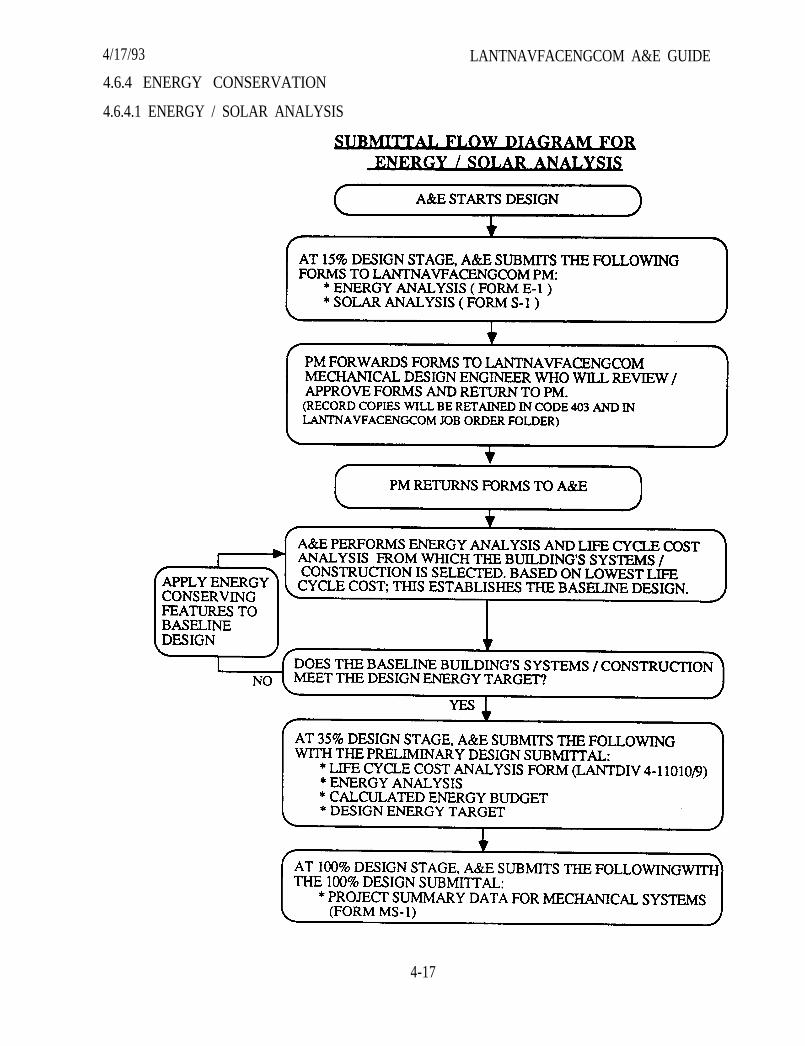
LANTNAVFACENGCOM A&E GUIDE4/17/93
4.6.4 ENERGY CONSERVATION
4.6.4.1 ENERGY / SOLAR ANALYSIS
4-17
4/17/93 LANTNAVFACENGCOM A&E GUIDE4.6.4.2 ENERGY CONSERVATION METHODS
The intent is to bring a multidiscipline approach to the project which recognizes andprioritizes the major load components of the building and focuses efforts on these to meet designenergy targets.
A. The Solar Analysis Form (Form S-1) and the Energy Analysis Form(Form E-1) at the end of this section must be submitted to this Command, attention thePM, by the A&E prior to the 35% basis of design. The submittal of these forms isappropriate at the project’s 15% stage to allow for a review by theLANTNAVFACENGCOM Mechanical Engineering Branch.
The number and type of alternatives to be analyzed will be based onproject information provided in scope of work. Form E-1 shall indicate the proposedalternatives and zones and include the best available floor plan. This Command willreview the recommendations and return the form to the A&E: Approved, approved asnoted or disapproved. The remaining analysis does not require approval prior to runbut must contain logic for selection.
Selection of energy analysis alternatives on Form E-1 should concentrateon other (architectural, electrical) aspects of the project when the type of building, suchas a BOQ, an airfield hangar, etc., has been previously studied or a particularmechanical system is considered most desirable. Contact the Mechanical EngineeringBranch prior to submitting Forms E-1 and S-1 if this applies or if you have anyquestions.
B. After receiving the approved forms, the A&E shall perform acomputerized energy analysis and a life cycle cost analysis for an new building ormajor renovation project that is only heated and exceeds 20,000 ft2 [1,858m2], or isheated and air-conditioned and exceeds 8,000 ft2 [743m2]. The computer program shallbe a professionally recognized and proven program which makes hourly calculationsas a basis. Programs available are Carrier EC 20-II HAP, DOE 2.1, and Trane Trace-Ultra. If other programs are to be considered, documentation showing Federal andState approval should be forwarded for approval prior to sending in the energyanalysis with the 35% submittal. Facilities with less than the square footage can useeither manual or computerized methods to meet the energy analysis requirement. Acopy of “Instructions for Preparation of Economic Analysis (JAN 90)” is available fromthe LANTNAVFACENGCOM Cost Engineering Branch as a guide in proper economicanalysis format. Contact the Mechanical Engineering Branch for the utility rates to usein the analysis.
C. Within the limits of functionality and life cycle cost effectiveness, allfacilities shall be designed to meet the design energy target shown in Table 8-1 ofMIL-HDBK-1190. To establish the domestic hot water load portion of the designenergy target use “average day” values from table one, chapter 54 of the 1987 ASHRAE,HVAC Systems and Applications. Use ASHRAE standard 90.1-1989-Section 8.5 todetermine “U” factors instead of previous DOD criteria.
4-18

4/17/93 LANTNAVFACENGCOM A&E GUIDESee Table T-2 for guidelines in using the building design energy target.Justification/rationale is required should the annual energy consumption estimateexceed the design energy budget target.
4.6.4.3 ENERGY CONSERVATION SUBMITTAL REQUIREMENTS(See Flow Diagram, Section 4.6.4)
A. 15% Submittal. Forms S-1 and E-1.
B. 35% Submittal. Energy Analysis and Life Cycle Cost Analysis (FormLANTDIV 4-11010/9).
C. 100% submittal. Form MS-1.
4.6.5 HEATING PLANTS AND HEATING PLANT ADDITIONS
A. Before stating the type of fuel to be used and an economic comparison ofthe selected fuel with other available fuels, contact the LANTNAVFACENGCOMMechanical Engineering Branch for the latest criteria for fuel selection.
B. Describe new boilers including size, pressure and type.
C. Describe any new auxiliaries to be added and what source of power willbe used for their operation.
D. Describe the fuel storage and conveying system to be installed.
E. Describe the safety and combustion control systems utilized and how theywill perform.
4.6.6 REFRIGERATION (COLD STORAGE)
A. Identify areas to be refrigerated, indicating their usage and temperaturesto be maintained.
B. Describe type of refrigeration equipment and systems.
4.6.7 FUEL DISTRIBUTION AND STORAGE
A. Gas
(1) Describe type, location of take off from supply, and available pressure.
(2) Identify type and materials for pipe and valves.
4-19
4/17/93B. Liquid Petroleum Products
LANTNAVFACENGCOM A&E GUIDE
(1) Describe unloading facilities, such as dock, tank, car, or truck.
(2) Describe type of system and proposed features.
(3) State basis for storage capacity, rate of pumping, and number ofdispensing outlets.
(4) Describe power supply, power requirements and hazard classification.
(5) Identify type and materials for pipe, tank and valves.
4-20

4/17/93 LANTNAVFACENGCOM A&E GUIDEOUTSIDE DESIGN TEMPERATURE
LANTNAVFACENGCOM ACTIVITIES
SITES IN U.S.
Degrees Win te r DegreesAir Conditioning D a y s D e s i g n D a y s A i r C o n d i t i o n i n g D O D
Design Data Cool ing Data Heating Criteria Data DesignD. Bu lb W.Bulb Energy
D. Bulb / MCWB** D. Bulb 93F 80F 73F 67F Budget(2-1/2%) (97-1/2%) (HOURS) (HOURS) Region
KENTUCKY
Covington 90 / 72 1080
Louisville 93 / 74 1268 4640
Lexington 91 / 73 1197
Louisville 93 / 74 1268 4640
Owensboro 94 / 75 1444
NORTH CAROLINA
Cape Hatteras
Cherry Point
Hartford (‘67 issue)
Camp Lejeune
VIRGINIA
Charlottesville
Chincoteague('67 issue)
Eustis, Fort
Lynchburg
Newport News
86 / 77 1550 27 2731 0 832 1521 2771 4
90 / 78 1922 24 2832 23 1055 1342 2760 4
90 / 79 N / A 25 N / A 48 990 1238 2526 N / A
90 / 79 1810 23 2901 30 1020 1481 2870 4
91 / 74
88 / 77
90 / 76 1585 20 3752 26 875 807 2065 4
90 / 74 1100 16 4233 31 696 376 1544 3
90 / 77 1539 20 3549 21 809 1010 2290 4
1263
N / A
6
10
8
10
10
5070
4729
4220
24 748 316 1423 4
80 1022 668 1886 3
37 822 401 1641 3
80 1022 668 1886 3
113 1106 777 1942 3
18 4162 54 964 376 1544 3
20 N / A 15 649 864 2281 N / A
* Areas considered “Humid Areas”** MCWB - Mean Coincident Welt Bulb Temp @ 2 1/2% DBT
Table T-14-21

4/17/93 LANTNAVFACENGCOM A&E GUIDEOUTSIDE DESIGN TEMPERATURE
LANTNAVFACENGCOM ACTIVITIES
SITES IN U.S.
Degrees Win te r DegreesAir Conditioning D a y s D e s i g n D a y s A i r C o n d i t i o n i n g D O D
Design Data Cool ing Data Heating Criteria Data DesignD. Bu lb W. Bu lb Energy
D. Bulb / MCWB** D. Bulb 93F 80F 73F 67F Budget(2 1/2%) (97 1/2%) (HOURS) (HOURS) Region
VIRGINIA (CONT.)
Norfolk 91 / 76 4
Northwest (‘67 issue) 92 / 79 N / A
Petersburg (‘67 issue) 94 / 77 N / A
Portsmouth 91 / 76 4
Richmond 92 / 76 4
Roanoke 91 / 72 3
Virginia Beach 89 / 76 4
Williamsburg 91 / 76 4
Yorktown 90 / 77 4
WEST VIRGINIA
Charleston 90 / 73
Huntington 91 / 74
Parkersburg 90 / 74
Wheeling 86 / 71
Sugar Grove (‘67 issue) 85 / 72
1441 22 3488 41 074 961 2238
N / A 25 N / A 55 1010 1110 2412
N / A 18 N / A 120 1006 795 1991
1441 22 3488 41 874 961 2238
1353 17 3939 70 932 765 1973
1030 16 4307 38 810 223 1468
1485 22 3639 12 708 856 2184
1345 20 3671 42 905 807 2065
1539 20 3623 21 809 1010 2290
1055 11 4590 25 744 315 1521 3
1098 10 4374 47 797 470 1671 3
1045 11 4817 33 736 401 1528 3
647 5 5930 5 461 105 886 2
N / A 5 N / A 2 381 116 743 N / A
* Areas considered “Humid Areas”** MCWB - Mean Coincident Welt Bulb Temp @ 2 1/2% DBT
4-22Table T-1

4/17/93 LANTNAVFACENGCOM A&E GUIDE
Degrees Win te r DegreesAir Conditioning D a y s D e s i g n Days Ai r Condi t ion ing DOD
Design Data Cool ing Data Heating Criteria Data DesignD. Bulb W. Bulb Energy
SITES OUTSIDE U.S. D. Bulb / MCWB** D. Bulb 93F 80F 73F 67F Budget( 2 1 / 2 % ) (97 1/2%) (HOURS) (HOURS) Region
AFRICA
Bahrain:
Bahrain IAP / Muharraq 100/80
Morocco:
Kenitra 86 / 71
Somalia:
*Berbera (105/87)
Kenya:
*Mandera 97 / 82
*Mombasa (93 / 77)
Nairobi 85 / 64
ATLANTIC OCEAN
Azores:
Lajes Field, Terceira 78 / 70
Villa doPorto 78 / 68(‘67 issue)
Bermuda:
*All localities (85 / 78)
Iceland:
Keflavik 57 / 52
N / A 54 172 1298 4174 3884 4392 N / A
1044 41 1230 32 338 106 1720 5
6746 69 0 834 4354 3922 4387 6
7004 69 0 394 3134 2380 4065 6
5569 68 0 33 2620 3756 4368 6
1377 47 966 0 441 0 150 0
621 48 1332 0 24 17 889 5
N / A 52 N / A 0 45 0 456 N / A
2631
0
54
17
325 0 1272 2014 3626 6
8838 0 0 0 0 1
* Areas considered “Humid Areas”** MCWB - Mean Coincident Welt Bulb Temp @ 2 1/2% DBT
Table T-1
4-23
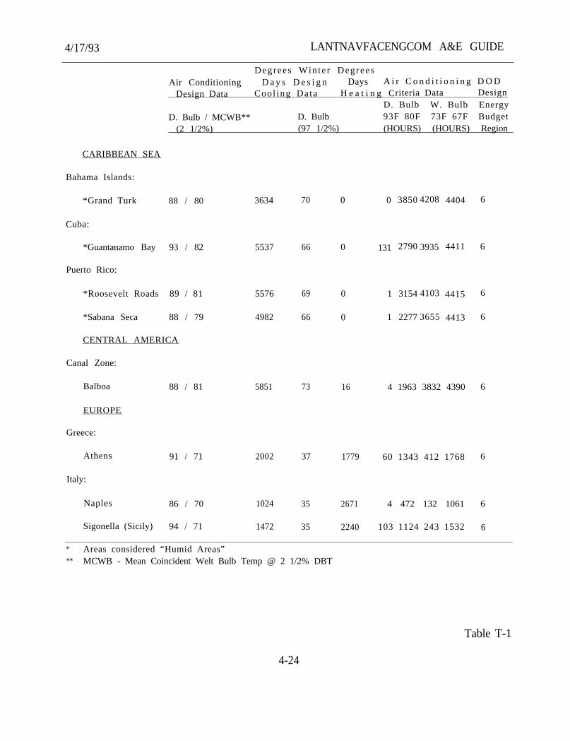
4/17/93 LANTNAVFACENGCOM A&E GUIDE
Degrees Win te r DegreesAir Conditioning D a y s D e s i g n Days A i r C o n d i t i o n i n g D O D
Design Data Cool ing Data H e a t i n g Criteria Data DesignD. Bulb W. Bulb Energy
D. Bulb / MCWB** D. Bulb 93F 80F 73F 67F Budget(2 1/2%) (97 1/2%) (HOURS) (HOURS) Region
CARIBBEAN SEA
Bahama Islands:
*Grand Turk 88 / 80 0 3850 4208 4404 6
Cuba:
*Guantanamo Bay 93 / 82 131 2790 3935 4411 6
Puerto Rico:
*Roosevelt Roads 89 / 81 1 3154 4103 4415 6
*Sabana Seca 88 / 79 1 2277 3655 4413 6
CENTRAL AMERICA
Canal Zone:
Balboa 88 / 81 6
EUROPE
Greece:
Athens 91 / 71 6
Italy:
Naples 86 / 70 6
Sigonella (Sicily) 94 / 71
3634
5537
5576
4982
5851
2002
1024
1472
70 0
66 0
69 0
66 0
73
37
35
35
16 4 1963 3832 4390
1779 60 1343 412 1768
2671 4 472 132 1061
2240 103 1124 243 1532 6
* Areas considered “Humid Areas”** MCWB - Mean Coincident Welt Bulb Temp @ 2 1/2% DBT
4-24
Table T-1
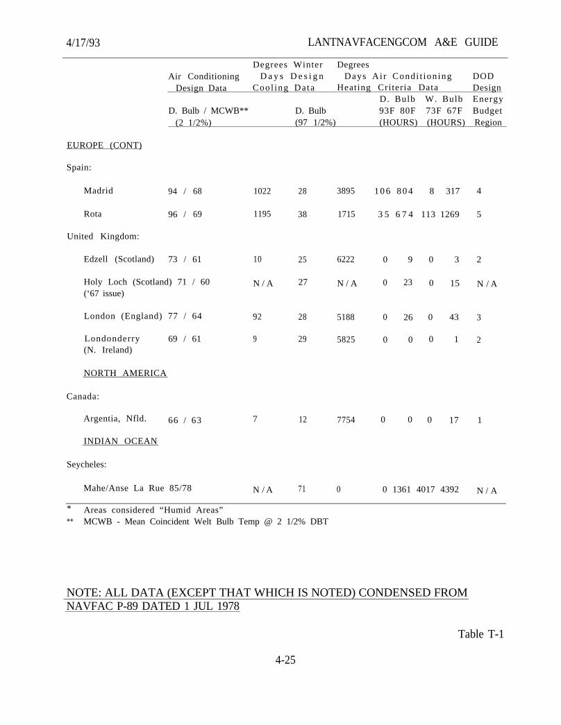
4/17/93 LANTNAVFACENGCOM A&E GUIDE
EUROPE (CONT)
Spain:
Madrid
Rota
United Kingdom:
Edzell (Scotland)
Degrees Winter DegreesAir Conditioning D a y s D e s i g n Days Ai r Condi t ion ing DOD
Design Data Cool ing Data Heating Criteria Data DesignD. Bulb W. Bulb Energy
D. Bulb / MCWB** D. Bulb 93F 80F 73F 67F Budget(2 1/2%) (97 1/2%) (HOURS) (HOURS) Region
94 / 68 1022 28 3895
96 / 69 1195 38 1715
73 / 61 10 0 3
Holy Loch (Scotland) 71 / 60 0 15(‘67 issue)
London (England) 77 / 64 0 43
Londonderry 69 / 61 0 1(N. Ireland)
NORTH AMERICA
Canada:
Argentia, Nfld. 66 / 63 0 0 0 17
INDIAN OCEAN
Seycheles:
Mahe/Anse La Rue 85/78
N / A
92
9
7
N / A
25 6222
27 N / A
28 5188
29 5825
12
71
7754
0
1 0 6 8 0 4
3 5 6 7 4
0 9
0 23
0 26
0 0
8 317
113 1269
0 1361 4017 4392 N / A
4
5
2
N / A
3
2
1
* Areas considered “Humid Areas”** MCWB - Mean Coincident Welt Bulb Temp @ 2 1/2% DBT
NOTE: ALL DATA (EXCEPT THAT WHICH IS NOTED) CONDENSED FROMNAVFAC P-89 DATED 1 JUL 1978
Table T-1
4-25
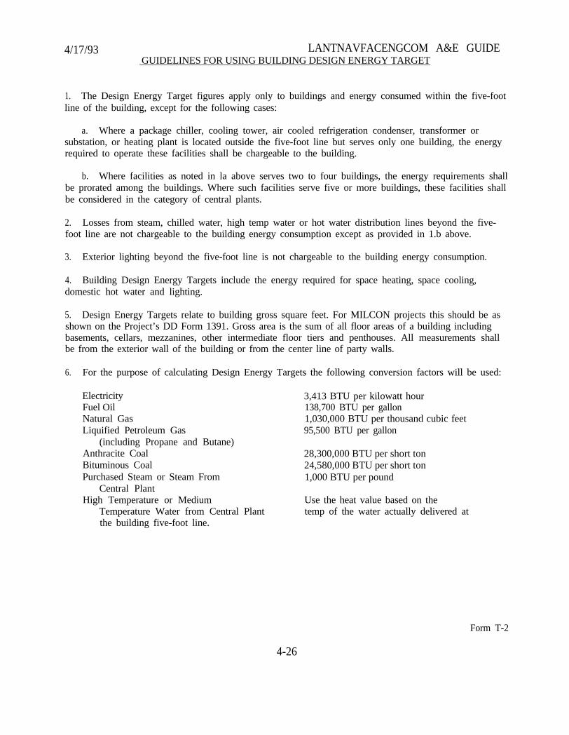
4/17/93 LANTNAVFACENGCOM A&E GUIDEGUIDELINES FOR USING BUILDING DESIGN ENERGY TARGET
1. The Design Energy Target figures apply only to buildings and energy consumed within the five-footline of the building, except for the following cases:
a. Where a package chiller, cooling tower, air cooled refrigeration condenser, transformer orsubstation, or heating plant is located outside the five-foot line but serves only one building, the energyrequired to operate these facilities shall be chargeable to the building.
b. Where facilities as noted in la above serves two to four buildings, the energy requirements shallbe prorated among the buildings. Where such facilities serve five or more buildings, these facilities shallbe considered in the category of central plants.
2. Losses from steam, chilled water, high temp water or hot water distribution lines beyond the five-foot line are not chargeable to the building energy consumption except as provided in 1.b above.
3. Exterior lighting beyond the five-foot line is not chargeable to the building energy consumption.
4. Building Design Energy Targets include the energy required for space heating, space cooling,domestic hot water and lighting.
5. Design Energy Targets relate to building gross square feet. For MILCON projects this should be asshown on the Project’s DD Form 1391. Gross area is the sum of all floor areas of a building includingbasements, cellars, mezzanines, other intermediate floor tiers and penthouses. All measurements shallbe from the exterior wall of the building or from the center line of party walls.
6. For the purpose of calculating Design Energy Targets the following conversion factors will be used:
ElectricityFuel OilNatural GasLiquified Petroleum Gas
(including Propane and Butane)Anthracite CoalBituminous CoalPurchased Steam or Steam From
Central PlantHigh Temperature or Medium
Temperature Water from Central Plantthe building five-foot line.
3,413 BTU per kilowatt hour138,700 BTU per gallon1,030,000 BTU per thousand cubic feet95,500 BTU per gallon
28,300,000 BTU per short ton24,580,000 BTU per short ton1,000 BTU per pound
Use the heat value based on thetemp of the water actually delivered at
4-26
Form T-2
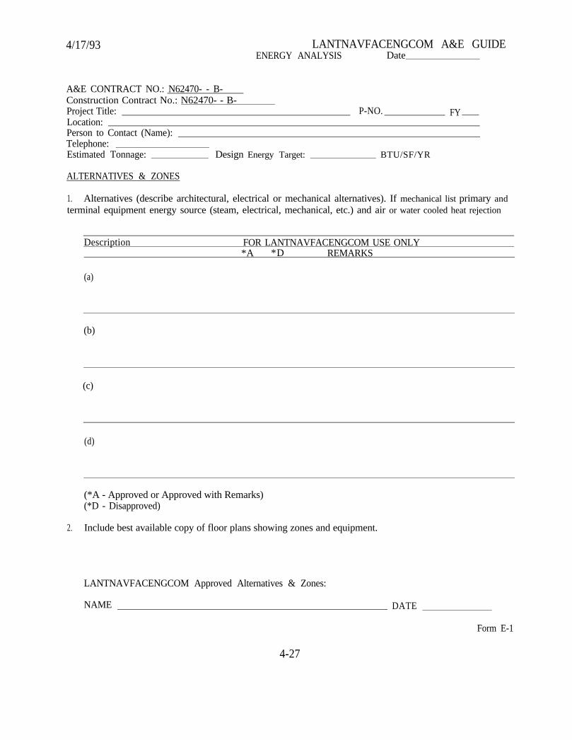
4/17/93 LANTNAVFACENGCOM A&E GUIDEENERGY ANALYSIS Date
A&E CONTRACT NO.: N62470- - B-Construction Contract No.: N62470- - B-Project Title:Location:Person to Contact (Name):Telephone:Estimated Tonnage: Design Energy Target:
P-NO. FY
BTU/SF/YR
ALTERNATIVES & ZONES
1. Alternatives (describe architectural, electrical or mechanical alternatives). If mechanical list primary andterminal equipment energy source (steam, electrical, mechanical, etc.) and air or water cooled heat rejection
Description FOR LANTNAVFACENGCOM USE ONLY*A *D REMARKS
(a)
(b)
(c)
(d)
(*A - Approved or Approved with Remarks)(*D - Disapproved)
2. Include best available copy of floor plans showing zones and equipment.
LANTNAVFACENGCOM Approved Alternatives & Zones:
NAME DATE
Form E-1
4-27

4/17/93 LANTNAVFACENGCOM A&E GUIDESOLAR ANALYSIS
1. Input Information (Prepared by A&E)
A&E CONTRACT NO.: N62470- -B-Construction Contract No.: N62470- -B-Project Title:Location:
P-NO FY
Person to Contact (Name):Telephone:
Escalation Dates:Contract Award - Month YearB.O.D. - Month Year
Contingency %Type System (DHW/Space Heating)Domestic Hot Water Demand:
Gal. Per day required -Ga. Per hour recovery required
Back-up Energy Source:Oil Steam: Electric:Gas O i l On PeakOther C o a l
Building Floor Area Sq. Ft.Off Peak
Number of People:Compass Direction of Collector-Normal
II. Results (LANTNAVFACENGCOM)
A. For projects at locations other than Bermuda, Central America, Cuba, Puerto Rico, and otherCaribbean Islands:
In view of recent past studies for active solar utilization at this location which clearlyindicated Solar Energy not to be feasible, solar was not studied for this specific project.
B. For projects at Bermuda, Central America, Cuba, Puerto Rico, and other Caribbean Islands:
A life cycle cost solar analysis was performed by LANTNAVFACENGCOM. Resultsindicate that solar energy is not feasible for this project.
A life cycle cost solar analysis was performed by LANTNAVFACENGCOM. Resultsindicate system is cost effective. The following information applies:
Solar Design cost ($000)Collector Area (SF)Solar System Cost ($0000)Energy Contribution from Solar System, %
SIRDiscount Payback (years)Annual Energy Saved (MBTU)
III. This completed form shall be included in the basis of design 35% submittal.
LANTNAVFACENGCOM Approved:Name
4-28
DateForm S-1
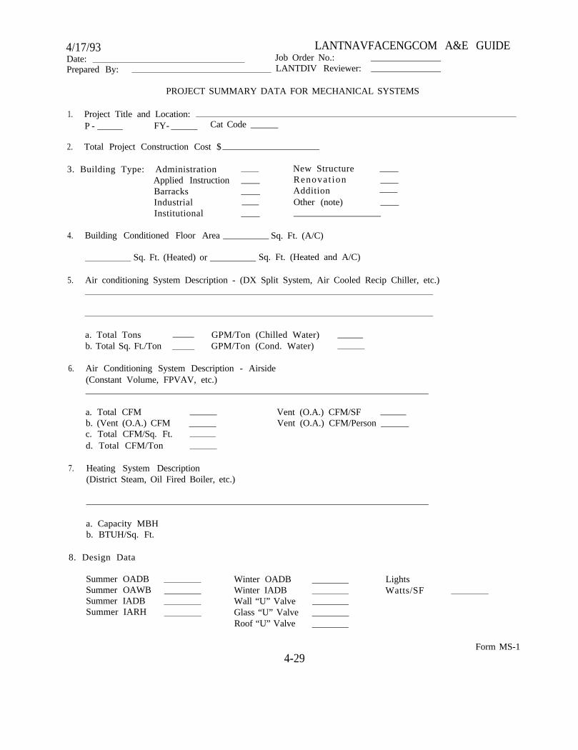
4/17/93 LANTNAVFACENGCOM A&E GUIDEDate: Job Order No.:Prepared By: LANTDIV Reviewer:
PROJECT SUMMARY DATA FOR MECHANICAL SYSTEMS
1. Project Title and Location:P - FY- Cat Code
2. Total Project Construction Cost $
3. Building Type: AdministrationApplied Instruction BarracksIndustrialInstitutional
New StructureRenovat ionAdditionOther (note)
4. Building Conditioned Floor Area Sq. Ft. (A/C)
Sq. Ft. (Heated) or Sq. Ft. (Heated and A/C)
5. Air conditioning System Description - (DX Split System, Air Cooled Recip Chiller, etc.)
a. Total Tons GPM/Ton (Chilled Water)b. Total Sq. Ft./Ton GPM/Ton (Cond. Water)
6. Air Conditioning System Description - Airside(Constant Volume, FPVAV, etc.)
a. Total CFM Vent (O.A.) CFM/SFb. (Vent (O.A.) CFM Vent (O.A.) CFM/Personc. Total CFM/Sq. Ft.d. Total CFM/Ton
7. Heating System Description(District Steam, Oil Fired Boiler, etc.)
a. Capacity MBHb. BTUH/Sq. Ft.
8. Design Data
Summer OADBSummer OAWBSummer IADBSummer IARH
Winter OADBWinter IADBWall “U” ValveGlass “U” ValveRoof “U” Valve
LightsWatts/SF
Form MS-14-29
4/17/93 LANTNAVFACENGCOM A&E GUIDE4.7 FIRE PROTECTION AND SAFETY
4.7.1 FIRE PROTECTION SYSTEMS
A. Automatic sprinkler and gaseous extinguishing system piping layoutsshall not be designed; i.e., a piping plan will generally not be provided to show newwork. Such a plan may be necessary to indicate existing piping sizes and locations orto show pipe routing where interference problems exist. In instances wherearchitectural and interior design features are critical (e.g. lobbies, clubs, BEQ/BOQrooms), it may necessary to show sprinkler head or piping locations. A schematic riserdiagram is required and points of connection must be identified.
B. Describe fire detection and alarm systems including location of detectors,manual stations, audible devices, control panel, etc. Number of conductors shall not beindicated unless required to ensure proper interface with existing systems or forunusual or complex systems.
C. Indicate location of water supply main entrance to building and detail ofsprinkler valves. Also indicate location and details of gaseous extinguishing systemequipment and supplies; show piping to the extent required by space limitations,where potential interference problems may occur, etc.
D. Refer to the latest edition of MLHDBK-1008 “Fire Protection for FacilitiesEngineering, Design, and Construction” for specific applications and requirements forvarious types of fire protection systems. Such systems must meet applicable NFPAstandards.
E. Provide the following information about sprinkler systems:
(1) Authority for installation of sprinkler systems,
(2) Hazard classification of occupancy and whether system will behydraulically calculated or follow the pipe schedule method.
(3) For hydraulically designed systems, state density and area ofapplication as well as water supply available at point of connection (static pressure andresidual pressure at design flow). This data must be based upon flow tests at or nearthe point of connection and must appear in the Basis of Design.
4-30
4/17/93 LANTNAVFACENGCOM A&E GUIDE(4) Identify type(s) of automatic sprinkler system(s) involved, i.e., wet-
pipe, dry-pipe, preaction and/or deluge. Indicate areas to be protected and each typeof system proposed. If the use of a preaction or deluge system is contemplated, contactthe Fire Protection Branch at (804) 444-9908, for guidance before proceeding withdesign.
(5) Provide fire pump data if applicable.
4.7.2 SYSTEM SAFETY
A. Each A&E contract shall contain system safety requirements andinformation, presented in the contract as follows:
(1) The “System Safety and Hazard Analysis” paragraph of the A&E’sappendix A, indicating safety concerns and project requirements.
(2) LANTDIV Form 5100/12, “Preliminary hazard List (PHL) and RiskAssessment Code Validation”, will be included as an Appendix A attachment ifavailable.
(3) If the project has been determined to represent a critical or serioussafety risk, (Risk Assessment Code 1 or 2), a Preliminary Hazard Analysis will beincluded as an Appendix A attachment and a Requirements Hazard Analysis (RHA)must be provided as part of the design submittal. LANTNAVFACENGCOMINST5100.13 of 19 February 1992 defines RHA requirements.
B. Take the following action:
(1) Review the system safety requirements presented and determine theextent of their applicability to the project.
(2) Research safety criteria requirements for the indicated hazards.
(3) Document compliance with safety requirements and provide asummary of intended or actual compliance actions.
(4) Ensure that the final plans/specifications for the project adequatelyaddress all safety items.
(5) If a Risk Assessment Code of 1 or 2 has been assigned to the project,request a copy of LANTNAVFACENGCOMINST 5100.13, “Execution of Facility SystemSafety,” and include the preparation of an RHA in the design effort. The services of asystem safety consultant may be necessary to produce this document.
4-31
4/17/934.8 ELECTRICAL
LANTNAVFACENGCOM A&E GUIDE
4.8.1 ELECTRICAL SYSTEMS
A. Interior distribution systems.
(1) Electrical characteristics (phase, voltage, and number of conductors).
(2) Breakdown, by category, of the estimated connected loads, demandfactors and demand loads for each category, total demand load, diversity factor, andtotal diversified demand load. Load categories shall include the following:
(a)
(b)
(c)
(d)
Lighting load.
Convenience outlet load.
Mechanical equipment load, such as heating, air conditioning, etc.
Special operating equipment loads, such as compressors,generators, pumps and power receptacles being provided to serve special equipment.
(e) User equipment loads.
(f) Miscellaneous/other loads.
(3) Type of wiring system, such as rigid conduit, electrical metallictubing, nonmetallic sheathed cable, etc., and where proposed to use. (CURRENTCRITERIA PROHIBITS EMBEDDING ALUMINUM CONDUIT IN CONCRETE.CURRENT PROJECTS SHOULD BE REVIEWED TO MAKE SURE THAT CONDUIT,PIPE, BARS, ANCHORS, FLASHING, OR OTHER ALUMINUM PARTS ARE NOTEMBEDDED IN CONCRETE.)
(4) Type of conductor and insulation material, such as CU THW, ALXHHW, etc., and where proposed to use.
(5) A statement describing proposed standards of design, such as voltagedrop, lighting intensities, type of light sources, and a statement regarding the use ofselective switching or other energy conserving features.
(6) Provide short circuit calculations.
4-32

4/17/93 LANTNAVFACENGCOM A&E GUIDE(7) Description (including Riser Diagrams) of Cable Television Systems
(CATV), Closed Circuit Television Systems (CCTV), nurse call, intercom, sound, signal,and fire alarm systems.
(8) Statement relative to supporting facilities (outlets, raceways, andbackboard) to be provided for telecommunication systems. Number and location oftelecommunication outlets (i.e., telephone, computer, word processing, etc.) should beobtained from the using activity. Identify space required for telecommunicationequipment, point of connection to base telephone system, size of incomingduct/conduit, and size of equipment mounting backboard; this information should beobtained from the Activity Providing Telephone Service (APTS) officer. Statementrelative to interface provision for multi-use systems (i.e., intercom, telephone, etc.).A&E must provide all facility support for proposed telephone equipment installations,i.e., conduit, duct, and backboard. Design and procurement of telephone system to beaccomplished by the Activity Providing Telephone Service (APTS) officer.
(9) Provide lighting calculations keyed to lighting floor plan and lightingfixture schedule.
B. Exterior distribution systems.
(1) Contact the Utilities Engineering Branch (telephone 804-445-2998) forlocation and characteristics of nearest electrical power source capable of supplyingproject requirements. Do not contact local utility companies.
(2) Statement relative to the adequacy of the primary power source at thepoint of pick-up. If primary source is inadequate, state measures proposed to correctthe deficiency.
(3) Electrical characteristics of power source, including circuitinterrupting requirements and voltage regulation.
(4) Estimate of total connected load and resulting kilowatt demand loadby applying proper demand and diversity factors, if a group of loads is involved.
(5) Basis for selection of primary and/or secondary distribution voltage.
(6) Type of conductor material, such as copper or aluminum, and whereproposed to use. Type of insulation for cable systems.
(7) A statement describing pertinent standards of design, such as voltagedrop, physical characteristics of overhead or underground circuits, type of lightingunits and lighting intensities.
4-33
4/17/93 LANTNAVFACENGCOM A&E GUIDE(8) Manhole design calculations as applicable.
(9) Type and adequacy of signal and fire alarm systems, including astatement as to spare capacity on fire alarm circuit. For fire alarm assistance, contactthe Fire Protection Branch (telephone 804-444-9908). THE IMPORTANCE OF EARLYRESOLUTION OF THE FIRE PROTECTION REQUIREMENTS CANNOT BE OVEREMPHASIZED.
(10) Type, adequacy and routing of supporting structure(s) fortelecommunication cable. Exterior cabling for systems owned and operated by theGovernment shall be provided by the construction contract (type and size of cable to beobtained from APTS officer. Procurement of exterior cabling for other thanGovernment-owned and operated systems shall be accomplished by the APTS officer.
4.8.2 ELECTRONIC SYSTEMS
A. System engineering concepts. Describe the proposed type of system, itsfunctions and the interrelationships if the system is a multi-use system (i.e., security,EMCS, etc.; see items (1) and (2) below).
B. Indicate circuit requirements.
C. Indicate equipment selection in such categories as: Government-furnishedequipment; standard manufacturer or commercially available items; and specialequipment requiring developmental, research; or breadboard methods to meet therequirements.
D. Describe site or location considerations.
E. Identify required radio path and propagation.
F. Define antenna requirements such as types, separation, tower heights,aircraft clearance, and area requirements.
G. Describe antenna transmission lines, terminations, and switchings.
H. Identify azimuth coverage of radar installations.
I. Describe bonding and grounding requirements.
J. Describe communication and control cables and radio links.
4-34
4/17/93 LANTNAVFACENGCOM A&E GUIDEK. Identify test equipment, repair shop, and spare parts storage requirements.
L. Describe equipment, instrumentation, arrangement, and spacerequirements indicating requirements for racks, consoles, and individual mountings.Provide the most economical design in first cost, operation and maintenance costs, andoperating conditions conforming to best engineering concepts.
M. Identify wiring and cabling requirements plus terminations.
N. Identify power and lighting requirements, including emergency orstandby requirements.
O. Describe air conditioning, including humidity and dust-controlrequirements.
P. Identify interference and clearance requirements.
Q. State security requirements (including tempest and red/black criteria).
(1) Security/Entry Control System
Specific site physical security requirements are to be obtained from theClaimant/User, various Navy, DOD and other Security Criteria. The objective is toidentify early in the concept analysis those physical security requirements resultingfrom local unique environment, conditions, operations, and mission of the facility sothey can be fully and properly incorporated into the facility design. Refer to MIL-HDBK-1013/1 and DM 13.02 for further guidance.
Identify separately from the other project elements the requirementsfor Intrusion Detection Systems (IDS). Any of the following items and theirinterconnecting circuits may be considered part of an IDS:
Annunciation Panels and CabinetsVisual and Audible AnnunciatorsMagnetic SwitchesProximity (capacitance) SensorsVolumetric Sensors (passive infrared, microwave, and ultrasonic)Wire GridsVibration DetectorsPower Supplies Integral to Items on this listClosed Circuit Television Cameras and Monitors, and Video Recorders
used for Intrusion Detection purposesAccess Control Systems
4-35

4/17/93 LANTNAVFACENGCOM A&E GUIDEIDS installation can be divided into five general functional categories:
(a)
(b)
(c)
(d)
(e)
Navy MCON funded projects
Nuclear ordnance storage sites
Conventional arms, ammunition, and explosives storage sites(A&E)
Marine Corps funded projects
All other special projects and non-MCON funded projects
Planning, design and installation of IDS categories (a), (b), and (c) arethe responsibility of the Naval Investigative Service Command (COMNISCOM). A&Eshall coordinate IDS power requirements and conduit runs for IDS categories (a), (b),and (c) with the appropriate contacts within COMNISCOM.
Category (e) projects are planned and designed by the A&E utilizingcommercial systems for installation by the construction contractor. Identify areasrequiring IDS and types of systems and sensors proposed. For category (d) projects,consult PM for guidance to determine if IDS will be A&E designed.
Describe access control equipment (versus IDS) when required andoutline location, function, and area of control and clearly show where access controland IDS are integral to one another.
(2) Energy Monitoring and Control Systems (EMCS)
(a) Military installations where an EMCS is in existence or proposed,new construction projects shall meet the following requirements. Table 4.8.2.1identifies installations where EMCS requirements are applicable. If applicable, contactthe PM to obtain the A&E Guide for EMCS interfacing, which further describes sizesand types of systems.
1. Provide sensor and control points terminated in a DataTerminal Cabinet (DTC) for future interface with EMCS.
2. Provide backboard for future Field Interface Device (FID) orMultiplexer (MUX).
4-36
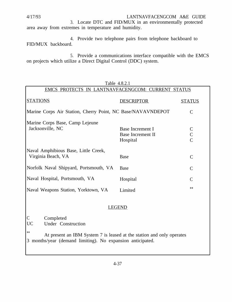
4/17/93 LANTNAVFACENGCOM A&E GUIDE3. Locate DTC and FID/MUX in an environmentally protected
area away from extremes in temperature and humidity.
4. Provide two telephone pairs from telephone backboard toFID/MUX backboard.
5. Provide a communications interface compatible with the EMCSon projects which utilize a Direct Digital Control (DDC) system.
Table 4.8.2.1EMCS PROTECTS IN LANTNAVFACENGCOM: CURRENT STATUS
STATIONS DESCRIPTOR STATUS
Marine Corps Air Station, Cherry Point, NC Base/NAVAVNDEPOT
Marine Corps Base, Camp LejeuneJacksonville, NC
Naval Amphibious Base, Little Creek,Virginia Beach, VA
Norfolk Naval Shipyard, Portsmouth, VA
Naval Hospital, Portsmouth, VA
Naval Weapons Station, Yorktown, VA
Base Increment IBase Increment IIHospital
Base
Base
Hospital
Limited
LEGEND
C CompletedUC Under Construction
C
CCC
C
C
C
**
** At present an IBM System 7 is leased at the station and only operates3 months/year (demand limiting). No expansion anticipated.
4-37
4/17/93 LANTNAVFACENGCOM A&E GUIDE4.8.3 INSTRUMENTATION AND CONTROL SYSTEMS
A. Describe the demolition of any existing Instrumentation and ControlSystem (I&CS) to be removed. Identify any equipment to be salvaged. Identify anyequipment to be relocated or reused.
B. Describe the overall process to be controlled, and the overall controlphilosophy. Indicate the control system inputs from the process, and the controlsystem outputs to the process. Describe the process sensors and signals; and describethe control system signals and actuating devices. Describe the control algorithms to beimplemented. Provide a general sequence of operations. Indicate a typical functionaldiagram for control of the major processes; similar to a Scientific Apparatus MakersAssociation (SAMA) diagram or a function blockware diagram.
C. Describe the control equipment signal processing scheme, i.e., electricanalog or digital; single processor or distributed processors; programmable logiccontroller based; personal computer based; single loop controller based; multi-loopcontroller based; or mini-computer based. Indicate the expected update frequency forcritical, typical, and noncritical data points in the system. Indicate the expected end-to-end control accuracy’s.
D. Describe the hard wired control logic scheme; provide a typical ladderlogic diagram to illustrate the method to be used on the contract drawings.
E. Describe the control program programming scheme; ladder diagram logic(preferred), function block logic (acceptable). Provide a typical diagram to illustratethe method to be used on the contract drawings.
F. Describe the control program development system input/output andstorage device(s); describe the control program development tools to be provided, bothhardware and software.
G. Describe the operator’s control station/panels, and provide a general planand panel layout.
H. Describe the communications scheme to be implemented throughout thesystem and between the I&CS and other related systems within the project.
4-38
4/17/93 LANTNAVFACENGCOM A&E GUIDESECTION 5. DRAWINGS/SKETCHES
5.1 ARRANGEMENT AND PRESENTATION OF DRAWINGS
Drawings should be arranged in the following order:
Title Sheet and Index (can be included with plot and vicinity plan sheetand should not be used on projects requiring ten or less sheets)
Vicinity Map/Location PlanCivil Demolition, Layout, Grading and Storm Drainage, Water and
SanitaryBoring LogsLandscapingArchitecturalStructuralFire Protection (if included as separate sheets)PlumbingMechanical (heating, ventilation, exterior steam and gas distribution)Solar (if included)Electrical (including electrical site plan)
Drawings should be consistent in presentation and format. If our disciplineshows written notes and material directly on phases, sections and details, then otherdisciplines shall conform to that presentation format, and not use numbers to refer to anumerical legend elsewhere on the drawing.
5.2 SIZES OF DRAWINGS/SKETCHES
LANTNAVFACENGCOM uses the following size drawings:
Letter-Size 8-1/2” x 11”: Use for letter-size sketches and PEDs. Include1/2” border on all four sides (3/4” border is required atbound edge).
“D” Size 24” x 36”: Use “D” size in all cases unless specificallydirected otherwise by the PM. Use for PEP sketches andreduce to 8 1/2” x 11” for PEP document.
“F” Size 28” x 40”: No longer used unless specifically authorized bythe PM.
Figure 5.2.1 depicts drawing and title block requirements.
5-1


4/17/93 LANTNAVFACENGCOM A&E GUIDE5.3 DRAFTING MEDIA
Unless otherwise instructed, completed sets of working drawings will be inpencil or ink on tracing cloth or polyester drafting film with a minimum base thicknessof .004 inch matted both sides. The A&E must furnish his own tracing cloth/draftingfilm. Use of Computer Aided Drafting (CAD) to produce final working drawings isacceptable and is encouraged.
5.4 ORIENTATION
The orientation of NAVFAC drawings should be arranged with North towardthe top (or left edge, if better suited) of the plotted sheet and normal to the sheetborderline. On individual sheets, if the shape of the area dictates, North can beoriented between these directions to accommodate the site. For example, on drawingshaving excessive longitudinal but limited lateral dimensions, such as those for roadsand railroads, North can be oriented obliquely to make the best use of available space.All discipline drawings should be consistent in orientation in so far as practicable.
It is customary for a building plan to be oriented with the main entrancetoward the bottom or right edge of the sheet, depending upon the building shape. It iscustomary for a building plan to also be oriented in the same orientation as the siteplan.
5.5 LETTERING AND SHADING
The Naval Facilities Engineering Command uses the 35mm filming system filefor retention of construction drawings. This office is using half-size bidders’ drawings.The quality of these reduced prints is a direct result of the drafting efforts of the A&Epreparing the drawings. The finest cameras and most carefully controlled processingcannot produce good results unless the original drawing is of a high quality.
Unnecessary detail--poor spacing--careless lettering--weak lines, and letteringwhich is crowded and too small result in illegible films for full-scale and half-scalereproductions. Information and reinforcing details, contained in poached areas willnot reproduce; therefore, poaching is not acceptable. The minimum size lettering onall project drawings shall be 5/32” high (1/8” high or Leroy Guide L120 for computeraided drafting). Where CADD is being used, Leroy Guide L100 lettering may be usedfor existing topographical features only. Make minimum gap between lines equal toone-half the letter height. Lettering and line weight must be in accordance with theabove.
5-3
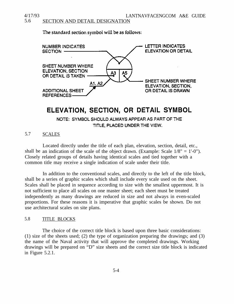
4/17/93 LANTNAVFACENGCOM A&E GUIDE5.6 SECTION AND DETAIL DESIGNATION
5.7 SCALES
shall beLocated directly under the title of each plan, elevation, section, detail, etc.,an indication of the scale of the object drawn. (Example: Scale 1/8" = 1'-0").
Closely related groups of details having identical scales and tied together with acommon title may receive a single indication of scale under their title.
In addition to the conventional scales, and directly to the left of the title block,shall be a series of graphic scales which shall include every scale used on the sheet.Scales shall be placed in sequence according to size with the smallest uppermost. It isnot sufficient to place all scales on one master sheet; each sheet must be treatedindependently as many drawings are reduced in size and not always in even-scaledproportions. For these reasons it is imperative that graphic scales be shown. Do notuse architectural scales on site plans.
5.8 TITLE BLOCKS
The choice of the correct title block is based upon three basic considerations:(1) size of the sheets used; (2) the type of organization preparing the drawings; and (3)the name of the Naval activity that will approve the completed drawings. Workingdrawings will be prepared on “D” size sheets and the correct size title block is indicatedin Figure 5.2.1.
5-4
4/17/93 LANTNAVFACENGCOM A&E GUIDE5.9 DRAWING NUMBERS
The Procurement Instrument Identification Number System (PIIN System)consists of 13 alphanumeric characters. An example of the PIIN number isN62470-84-B-4001. Applying the appropriate procedural derivation, the specificationnumber is 05-84-4001. The construction contract PIIN number and associatedspecification number are assigned when 35% review submission is returned to theA&E; EFD and NAVFAC drawing numbers are assigned and forwarded to the A&Eupon review and return of the 100% design submittal.
5.10 MATERIAL SYMBOLS ON DRAWINGS
Unless indicated otherwise in this document, material symbols shown ondrawings shall be consistent with those used in the most recent issue ArchitecturalGraphic Standards.
5.11 DUAL LANGUAGE DRAWINGS
For dual language projects, provide adequate space below each note, title,symbol, etc. for the foreign language translation. The final drawing shall not appearcluttered or congested.
5.12 RELATION OF DRAWINGS AND SPECIFICATIONS
Drawings and specifications shall supplement each other and must not conflict.Terminology used in specifications and drawings should be the same. If theterminology used in the drawings shall vary and revision of the drawings is notpracticable, the specifications must reconcile such differences in a manner similar to thefollowing: “Hollow tile (also indicated as ‘clay tile’ and ‘terra cotta tile’), etc.”
5.13 COMMON DISCREPANCIES IN NOMENCLATURE
There are many phrases and statements placed on drawings which areconsidered satisfactory in professional architectural and engineering practice but arenot acceptable in the preparation of drawings for the Navy. The following is a list ofsuch items found repeatedly on drawings submitted by A&Es. After each discrepancyor group of related discrepancies there is the preferred designation.
5-5
4/17/93 LANTNAVFACENGCOM A&E GUIDEA. INCORRECT: “As instructed by the Architect.”
CORRECT: “As instructed by the Contracting Officer.”
NOTE: Contract drawings should be so clearly detailed as to precludethe use of this statement except in most unusual circumstances.
B. INCORRECT: “By others.”“By the Navy.”“By the Naval Facilities Engineering Command.”
CORRECT: “By the Government.”
C. INCORRECT: “By Electrical Contractor.”“By Plumbing Contractor.”“By the Plumber.”“By the Elevator Contractor.”
EXPLANATION: Usually no statement is necessary. The Governmentrecognizes only the prime contractor; the breakdowninto trades is not in accordance with Governmentpractice. In the event work is shown on thedrawings which is not included in the scope of thecontract, use the following:
CORRECT: “Not in contract” or“By Government.”
D. INCORRECT: “12 GA zinc-coated steel flashing.”“Copper flashing.”
CORRECT: “Metal flashing” (Metals are referred to only as metal and notas a particular kind of gauge. Kind and weight are coveredin the specifications. This does not apply where it isnecessary to match existing metals.)
E. INCORRECT: “Formica.”
CORRECT: “Plastic Laminate” (Proprietary names are notpermitted.)
5-6

4/17/93 LANTNAVFACENGCOM A&E GUIDEF. INCORRECT: “See Arch. Sheets”
CORRECT: “See Sheet A-4” (Refer to a specific sheet number.)
5.14 BORING LOG PRESENTATION
Figure 5.14.1 represents a typical drawing developed to present boring logs(includes groundwater observations), soil conditions, and testing accomplished duringdesign. This information in the format shown shall be included on the contractdrawings for all projects on which soil information is obtained. The boring logs and/ortest data presented shall be accompanied by notes to adequately explain all elements oflogs and/or test data. Required notes shall also include reference to drawings showingplotted boring locations if they are not shown on a boring location plan on the boringlog drawings.
5.15 METRIC DIMENSIONING
For Iceland, all continental Europe, Africa and Mediterranean Area projects;Provide all plan layouts in metric dimensioning. English dimensioning will be utilizedwherever products to be procured are anticipated to be manufactured in English units(i.e., 2' x 2' suspended acoustical ceiling tiles). Design calculations shall be in the sameunits as are the drawings. The detailed cost estimate shall also be in the same units asthe drawings and in the local currency, as appropriate. Specifications shall have thedimensioning dependent on the source of the material (i.e., concrete pipe is a localproduct to be primarily dimensioned in metric, whereas mechanical and electricalitems may be purchased in the U. S. and thus will be primarily dimensioned inEnglish). The key is use what is appropriate in the Host Nation. When metricdimensioning is used, it should be based on actual building products of that country.European standards shall be utilized in lieu of strict metric dimensioning (i.e., 300 mmpipe for 12” pipe, in lieu of 304.8 mm, shall be used. Do not use eight inch masonrycoursing and then translate those dimensions to metric units; course a building out inmetric materials).
For all NATO Projects: For Type “B” Cost Estimates all units of measure shallbe metric (with dual U. S. units, if desired). This applies to both the drawings and theexplanatory report. For final design documents units of measure shall be whatever isstandard for the Host Nation.
5-7

4/17/93 LANTNAVFACENGCOM A&E GUIDE
(Blank Page)
5-8
4/17/93 LANTNAVFACENGCOM A&E GUIDESECTION 6. SPECIFICATIONS
6.1 GENERAL REQUIREMENTS FOR THE PREPARATION OF PROJECTSPECIFICATIONS
The project specifications form a part of the contract documents. Format andgeneral instructions for the preparation of project specifications are included inMIL-HDBK-1006/1, “Policy and Procedures for Project Drawing and SpecificationPreparation” (previously NAVFAC DM-6). Specifications are required to be inSPECSINTACT System format, based on NAVFAC guide specifications, and edited andsupplemented to suit the particular project. Scan all computer disks submitted forviruses using a commercial virus scanning program. The specifications shall be as briefas possible, definite, and free of ambiguities and omissions, which might result incontroversies and contractor claims for additional compensation.
6.2 GUIDE SPECIFICATIONS
Guide specifications of NAVFAC “NFGS” Series shall be utilized in thepreparation of project specifications. These specifications are available on the CD-ROMas described herein. Any hard copy required by the A&E may be printed therefrom.Hard copy may also be obtained from Standardization Documents Order Desk,Building 4D, 700 Robbins Avenue, Philadelphia, PA 19111-5094. Examplespecifications (e.g., color design) will be furnished by the Specifications Branch, ifapplicable. The A&E shall carefully edit, modify, and supplement these sections andprepare additional sections in the same format to ensure they are coordinated with theproject design. The latest guides, the “NFGS” series, should be considered as standardsfor format where they differ from earlier guides. For further (latest) information onpreparation of specifications, see “Instructions to A&Es and Typists,” which is availablefrom the Specifications Branch.
NAVFAC Guide Specifications in the “SPECSINTACT” System are availablethrough the National Institute of Building Sciences (NIBS) in accordance with thefollowing:
- Compact Disc, Read Only Memory (CD-ROM) laser disc (holdsequivalent of 250,000 pages of information)
- CD-ROM Reader
- Information on obtaining subscriptions to the Construction CriteriaBase (CCB) containing “SPECSINTACT” may be obtained from thefollowing:
6-1
4/17/93 LANTNAVFACENGCOM A&E GUIDENATIONAL INSTITUTE OF BUILDING SCIENCESATTN CCB1090 VERMONT AVE NW SUITE 700WASHINGTON DC 20005
Telephone: 202-289-7800
NOTE: It is imperative that the A&E discuss SPECSINTACT features with theSpecifications Branch Head prior to beginning any specification preparation so that anagreement can be reached regarding the proper version of the CD-ROM to use for aspecific project. This will minimize or eliminate rework of specifications following areissuance of the CD-ROM.
6.3 REFERENCES
Military Bulletin 34 (MIL-BUL-34) (previously NAVFAC P-34) lists all currentFederal and Military Specifications and industry and technical society specificationscommonly used in Navy construction and repair work and which are referenced inNAVFAC guide specifications. MIL-BUL-34 resides on the CD-ROM. It is alsoavailable from Standardization Documents Order Desk, Building 4D, 700 RobbinsAvenue, Philadelphia, PA 19111-5094. It is essential that the A&E become thoroughlyfamiliar with existing design criteria and publications which are referenced in theguide specifications before they are referenced in the project specifications. Beforeactually referencing one of these specifications, the following points should beresolved:
A. Does the amount of material and the nature of the project justifyreferencing the publications and testing required therein (particularly for materials onwhich such tests are not common)?
B. Do the referenced publications cover material of a quality and typesuitable for the service required?
In referencing publications, the following rules should be followed:
A. Do not copy portions of publications in the project specifications, exceptwhere applicable portions are short in length and remainder of the publications doesnot apply to the specific project. In this case, do not list or reference the publication inthe project specification.
6-2
4/17/93 LANTNAVFACENGCOM A&E GUIDEB. Avoid reference to specific paragraphs in the publication unless the
paragraphs referenced are the only portions of the publication that are applicable to thespecific project.
C. Avoid repeated references to a publication within the same section
D. Read carefully all “Notes on the Use of the Publication”.
E. Specify types, classes, weights, and similar applicable characteristicsrequired to ensure accurate description.
6.4 SPECIFYING NEW MATERIALS
From time to time requests are made to consider the use of materials which arecomparatively new. The fact that a material is new should not necessarily bar its use,provided it has been thoroughly investigated. Neither should previous use place amaterial in an “approved” category. Usually, service records of new materials do notexist. It is necessary, therefore, to base judgments upon laboratory tests. Such tests, inorder to be accepted as authoritative, should be made by impartial qualifiedlaboratories. Tests conducted by laboratories employed by manufacturers do notalways show possible defects in the material tested. Unless a material is tested underthe conditions of actual use, or comparisons are made under like conditions, the resultsare not conclusive. Most reputable manufacturers will furnish readily all requestedinformation and answer all reasonable questions. Unless the manufacturer of a newmaterial furnishes factual data sufficient to evaluate the material, it should not beconsidered for use. If a material is considered for use, a suggested competitive-typespecification should be obtained from the manufacturer. Such a specification must beanalyzed and revised as necessary to assure that a competitive, good-quality productwill be obtained.
6.5 SPECIFYING FOREIGN MATERIALS
For overseas projects the Buy American Act does not apply. Therefore,specifications shall be written to reflect the use of local materials, standards and codes.U. S. Standards shall not be used unless they are a recognized standard which is usedin the local area or if the use of U. S. Materials is required. Use of SPECSINTACT isoptional. A&E may use specifications from previous projects which have beenlocalized but must, if used, be updated to current standards and technology and shallincorporate Interim Specification Revisions (ISR). A submittal register shall beprovided.
6-3

4/17/93 LANTNAVFACENGCOM A&E GUIDE6.6 PROPRIETARY AND RESTRICTIVE REQUIREMENTS
A. Proprietary Specifications. The restrictions below are contained in theFederal Acquisition Regulations (FAR) and certain statutes. From time to time asituation arises in which only a single product will perform the required function. Insuch cases, the A&E should forward a request to the LANTNAVFACENGCOM PMfully justifying use of the sole source product. Proprietary or restrictive requirementsshall not be used unless it is conclusively established that no substitute will serve thepurpose. Timely submittal of the request is required to avoid delays in the work. Ifsuch authorization is granted, the item should be specified by manufacturer’s name andcatalog number, followed by “notwithstanding any other provision of this contract, noother product will be acceptable” or language of similar import. This is necessitated bythe Contract Clauses which permit substitution of any supposedly equal product unlesssuch language is used. Use of proprietary items is prohibited unless formal writtenapproval is obtained.
B. “Or Equal” Specifications. Specifying items by naming acceptablecommercial products followed by the words “or equal” is permitted under thefollowing conditions: (a) there are no Government Guide specifications for the item, (b)the item is a minor part of the construction project, and (c) the item cannot adequatelybe described because of technically involved construction or composition. In eachinstance a minimum of three manufacturers shall be included in the descriptionfollowed by the words “or equal”. The essential features (salient characteristics) of theitem must also be set forth in sufficient detail to establish the basis upon which theequality of nonlisted products will be determined.
C. Experience clauses shall not ordinarily be included in the technicalspecifications. Experience clauses which occur in NAVFAC guide specifications havebeen reviewed and approved by a Level I Contracting Officer and may be used withoutfurther approval or waiver.
6.7 PRE-QUALIFICATION STATEMENTS AND EXPERIENCE REQUIREMENTS
Projects utilizing conventional construction methods and materials can not berestricted with respect to bidders, building systems, or materials. Occasionally aproject is unique in nature or has special circumstances which dictate use ofunconventional methods. For these projects the A&E shall identify and document tothe PM the need and basis of need for unique construction or state-of-the-artprocurements. Documentation shall include a description of the unique features, thereasons for their uniqueness, and a description of the prequalification and experiencerequirements necessary to adequately construct these features. Documentation shouldbe forwarded to the PM as soon as possible in the design process.
6-4
4/17/93 LANTNAVFACENGCOM A&E GUIDE6.8 PHRASEOLOGY
The following instructions which relate to common errors in phrasing haveevolved from NAVFAC experience with A&E specifications:
A. Under “Requirements” do not say “the work consists of”. Drawings shouldshow scope. If necessary to list certain parts, say “the work includes”.
B. In lieu of reference to the accompanying drawings or the ContractingOfficer, use the words “as shown”, "as indicated", “as detailed” or “as approved”, “asdirected”, “as permitted”, do not use “as shown on drawings” or “as approved by theContracting Officer”. That clause of the Contract Clauses, entitled, “Specifications andDrawings for Construction”, defines the meaning of these and similar terms.
C. Do not use the expression “to satisfaction of the Contracting Officer” or“satisfactory to the Contracting Officer”. The contract states specifically that all workmust meet the approval of the Contracting Officer.
D. There are two parties to the contract, (1) the Government, represented bythe Contracting Officer and (2) the Contractor. Therefore, do not use such expressionsas “subject to the approval of the architect”, “when in the opinion of the architect”, “thiscontractor”, "masonry contractor", or “subcontractor”. Do not use the term “owner”;rather, use the term “Government”.
E. Do not use “etc.“; the term is too indefinite for bidding and inspectionpurposes.
F. The use of the expression “as indicated on the drawings” is very seldomnecessary; the fact that a detail is on the drawings makes it unnecessary to mention it inthe specification. If the expression is used, and the item is not shown, the contractor isnot required to provide it.
G. Do not use expressions such as “The work required shall include, unlessstated specifically otherwise, the provision of all materials for the installation of allconcrete, including reinforcement necessary to the construction and completion of thework in accordance with the drawings, the specifications, and the intent thereof”. Sincethe drawings indicate clearly the exact limitations of the several classes of work,defining the limits of work within the specifications is superfluous and may becontradictory by failure to mention something shown clearly and intended to beincluded.
6-5
4/17/93 LANTNAVFACENGCOM A&E GUIDEH. Minimize the use of cross references and in no case use paragraph
numbers for this purpose. If necessary to refer to a particular paragraph, do so by itstitle and the section number and title under which it is to be found. Cross references ofthe following type are totally unnecessary: “Painting of the wood work is coveredunder “‘Painting”’ or “painting is specified hereinafter”.
I. Do not place upon the contractor the responsibility for the possibleinaccuracy of, or the lack of, information on the part of the Government; e.g., never usesentences similar to “although the drawings indicate approximately the conditions thatare likely to be found, bidders should satisfy themselves as to the actual conditions, forwhile they are believed to be shown, the Government does not guarantee the accuracyof the information given and the bidder shall assume all responsibility in the use ofsuch”. Remember that the Government is responsible for the accuracy andsufficiency of the information it gives to bidders or contractors and the A&E is inturn responsible to the Government for that same information. It will be necessary toestablish in the project specification a definite basis of bid. For example, on a roofrehabilitation project where the extent of defective construction is unknown, thespecification shall set forth, as a basis of bid, a definite amount of work to be performedand provide for adjustment in accordance with the Contract Clauses if the extent ofwork varies from the amount stated under the basis of bid.
J. Do not include “warranties” in technical sections unless they are for morethan one year, and generally not unless they are included in the NAVFAC guidespecification. A one year warranty is covered in the Contract Clauses.
K. Do not set up a paragraph in the various sections entitled “Work notIncluded”. Specify the work that is included under the respective sections.
L. Specifications should clearly delineate equipment, ducts and pipingsystems which are required to be insulated. The phrase “insulating all ducts except inconditioned spaces” has resulted in differences of opinion and claim situations; also allduct systems should be appropriately designated as supply, exhaust, fresh air intake, orreturn to further clarify insulating requirements.
6.9 MISUSE OF WORDS
A.all defects”.
Do not confuse any and all; e.g., “Correct any defects” should read “Correct
B. Do not confuse either or both; e.g., “Paint sheet metal on either side”should read “Paint sheet metal on both sides.” “Either” implies a choice.
6-6
4/17/93 LANTNAVFACENGCOM A&E GUIDEC. Do not confuse or and and; e.g., “It shall be free from defects of
workmanship and material which would impair its strength or durability.” The use of“or” for “and” or “and” for “or” in this sentence would result in a meaning not intended.
D. Do not use “and/or”. The courts have considered this phrase to beintentionally ambiguous and, therefore, to be interpreted in favor of the Contractor.
E. Use statements which are definite and do not contain words and phraseswhich may be ambiguous. Examples:
“Remove the equipment from the building during the alterations andreinstall the equipment after completion of the alterations.” Do not say “Remove andreplace the equipment as indicated.” “Replace” can mean “put back” or “reinstall”.
“Remove the existing culverts and reinstall the culverts in the newlocations.” Do not say “Replace the existing culverts as indicated on the drawings.”
“Remove existing and provide electrical wiring.” Do not say: “Replace theelectrical wiring” as this implies reinstallation of the old wiring.
F. “Provide” is defined in the Contract Clauses as “furnish and install”. Whenmaterial or equipment is furnished by the Government directly or under other contractsfor installation by the contractor, the term, “install” should be used; however, thecontractor may be required to “provide” foundations, fastenings, etc., for theinstallation. If the word “install” is used alone, the bidder or contractor has a right toassume, on the basis of the definition cited, that the Government will “furnish” thematerials in question.
G. Certain terms and designations of work phases, rooms and areascommonly used in Naval activities should not be used in construction specifications,for example: Bulkhead (for wall), deck (for any floor), ladder (for stair), head (fortoilet), galley (for kitchen), overhead (for ceiling), etc.
H. Provide statements of direction, opposed to statements of information; e.g.,“wall shall be painted” should read “paint the wall.” "To be ...". "shall be ...", "will be ..."does not affix responsibility.
6.10 USE OF ABBREVIATIONS AND SYMBOLS
In general, abbreviations should be avoided except those which are generallyunderstood and accepted and can be used economically: e.g., psig, cfm, kw. (The useof ft., in., lbs., %, do not offer great savings).
6-7
4/17/93 LANTNAVFACENGCOM A&E GUIDEThe use of symbols is undesirable for three basic reasons: (1) most are difficult toproduce on a typewriter; (2) they frequently have more than one meaning; (3) the typistmay not know what is intended and therefore type an improper symbol. Feet ('), inch("), degree (°), pound and number (#), should be written out, except that number maybe abbreviated (No.). In the text it is preferable to spell figures except where they givedimensions, for example: “Ten buildings”, “100 feet long”; however, “one” and “zero”,where used singly shall always be spelled out. Never use both the written andnumerical figure, “ten (10).”
6.11 STANDARD PLATES, SKETCHES, AND DETAILS
Except as provided in Section 5 for sketches in amendments, plates, sketches,and details shall be provided on the drawings and not in the specifications.
6.12 SUBMITTAL PROCEDURES
A. 35% SUBMITTAL (OUTLINE SPECIFICATIONS). Before starting work onproject specifications, the A&E personnel who prepare the project specification shallconfer as necessary with the LANTNAVFACENGCOM Specifications Branch to ensurea clear understanding of current Government requirements. All A&Es starting theirfirst project for LANTNAVFACENGCOM shall confer with the Engineering andDesign Division and particularly the Specifications Branch before starting any work.The Specifications Branch will provide A&Es with a document titled ‘Instructions toA&Es and Typists”, and this document should be thoroughly studied prior tobeginning preparation of specifications.
After the preliminary architectural and engineering studies have beencompleted and the basic features of the proposed design have been established, butbefore any detailed preparation of project specifications is begun, an outlinespecification shall be submitted as a part of the 35% submittal.
The outline specification should list each anticipated section of the projectspecification along with appropriate statements applicable to each section. The outlinespecification should state all basic construction items and specific types of materials,and should be complete enough to enable LANTNAVFACENGCOM to ascertain thatthe proper guide specifications are being used and to provide appropriate guidance tothe A&E. Where the specification writer is editing documents within the computer, theuse of hard CODY is optional and the document to be furnished for review or final bondmanuscript may be developed entirely from the specification processor. In any event,the Guide Specification to be used must be approved at the 35% stage. The outlinespecifications should describe any special conditions of service and site conditionsinherent in the project. The following sample outline specification illustrates the typeof information desired:
6-8
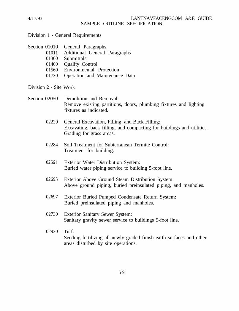
4/17/93 LANTNAVFACENGCOM A&E GUIDESAMPLE OUTLINE SPECIFICATION
Division 1 - General Requirements
Section 010100101101300014000156001730
General ParagraphsAdditional General ParagraphsSubmittalsQuality ControlEnvironmental ProtectionOperation and Maintenance Data
Division 2 - Site Work
Section 02050 Demolition and Removal:Remove existing partitions, doors, plumbing fixtures and lightingfixtures as indicated.
02220
02284
02661
02695
02697
02730
02930 Turf:Seeding fertilizing all newly graded finish earth surfaces and otherareas disturbed by site operations.
General Excavation, Filling, and Back Filling:Excavating, back filling, and compacting for buildings and utilities.Grading for grass areas.
Soil Treatment for Subterranean Termite Control:Treatment for building.
Exterior Water Distribution System:Buried water piping service to building 5-foot line.
Exterior Above Ground Steam Distribution System:Above ground piping, buried preinsulated piping, and manholes.
Exterior Buried Pumped Condensate Return System:Buried preinsulated piping and manholes.
Exterior Sanitary Sewer System:Sanitary gravity sewer service to buildings 5-foot line.
6-9
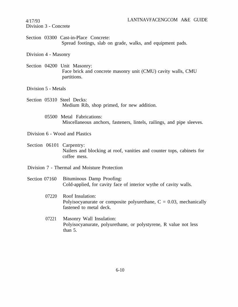
4/17/93Division 3 - Concrete
LANTNAVFACENGCOM A&E GUIDE
Section 03300 Cast-in-Place Concrete:Spread footings, slab on grade, walks, and equipment pads.
Division 4 - Masonry
Section 04200 Unit Masonry:Face brick and concrete masonry unit (CMU) cavity walls, CMUpartitions.
Division 5 - Metals
Section 05310 Steel Decks:Medium Rib, shop primed, for new addition.
05500 Metal Fabrications:Miscellaneous anchors, fasteners, lintels, railings, and pipe sleeves.
Division 6 - Wood and Plastics
Section 06101 Carpentry:Nailers and blocking at roof, vanities and counter tops, cabinets forcoffee mess.
Division 7 - Thermal and Moisture Protection
Section 07160
07220
07221
Bituminous Damp Proofing:Cold-applied, for cavity face of interior wythe of cavity walls.
Roof Insulation:Polyisocyanurate or composite polyurethane, C = 0.03, mechanicallyfastened to metal deck.
Masonry Wall Insulation:Polyisocyanurate, polyurethane, or polystyrene, R value not lessthan 5.
6-10
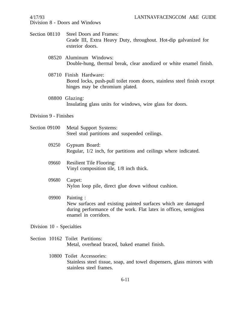
4/17/93Division 8 - Doors and Windows
LANTNAVFACENGCOM A&E GUIDE
Section 08110 Steel Doors and Frames:Grade III, Extra Heavy Duty, throughout. Hot-dip galvanized forexterior doors.
08520 Aluminum Windows:Double-hung, thermal break, clear anodized or white enamel finish.
08710 Finish Hardware:Bored locks, push-pull toilet room doors, stainless steel finish excepthinges may be chromium plated.
08800 Glazing:Insulating glass units for windows, wire glass for doors.
Division 9 - Finishes
Section 09100 Metal Support Systems:Steel stud partitions and suspended ceilings.
09250 Gypsum Board:Regular, 1/2 inch, for partitions and ceilings where indicated.
09660 Resilient Tile Flooring:Vinyl composition tile, 1/8 inch thick.
09680 Carpet:Nylon loop pile, direct glue down without cushion.
09900 Painting :New surfaces and existing painted surfaces which are damagedduring performance of the work. Flat latex in offices, semiglossenamel in corridors.
Division 10 - Specialties
Section 10162 Toilet Partitions:Metal, overhead braced, baked enamel finish.
10800 Toilet Accessories:Stainless steel tissue, soap, and towel dispensers, glass mirrors withstainless steel frames.
6-11
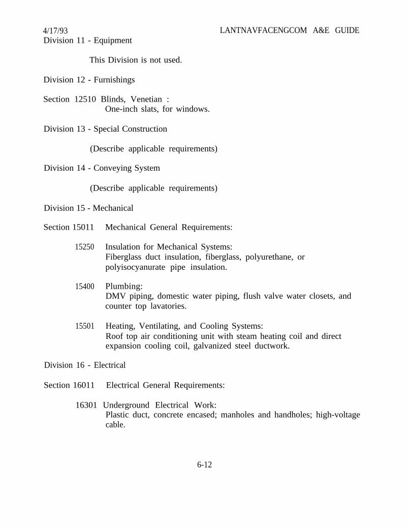
4/17/93Division 11 - Equipment
This Division is not used.
Division 12 - Furnishings
Section 12510 Blinds, Venetian :One-inch slats, for windows.
Division 13 - Special Construction
(Describe applicable requirements)
Division 14 - Conveying System
(Describe applicable requirements)
Division 15 - Mechanical
Section 15011
15250
15400
15501
LANTNAVFACENGCOM A&E GUIDE
Mechanical General Requirements:
Insulation for Mechanical Systems:Fiberglass duct insulation, fiberglass, polyurethane, orpolyisocyanurate pipe insulation.
Plumbing:DMV piping, domestic water piping, flush valve water closets, andcounter top lavatories.
Heating, Ventilating, and Cooling Systems:Roof top air conditioning unit with steam heating coil and directexpansion cooling coil, galvanized steel ductwork.
Division 16 - Electrical
Section 16011 Electrical General Requirements:
16301 Underground Electrical Work:Plastic duct, concrete encased; manholes and handholes; high-voltagecable.
6-12
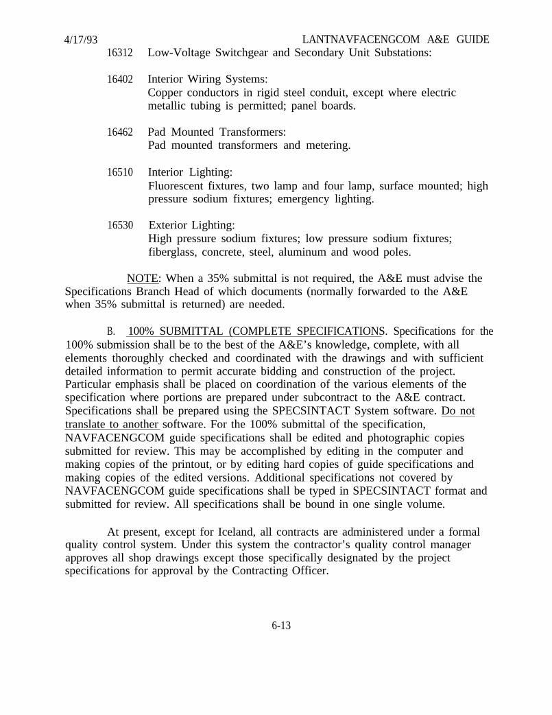
4/17/93 LANTNAVFACENGCOM A&E GUIDE16312 Low-Voltage Switchgear and Secondary Unit Substations:
16402 Interior Wiring Systems:
16462
16510
16530
Copper conductors in rigid steel conduit, except where electricmetallic tubing is permitted; panel boards.
Pad Mounted Transformers:Pad mounted transformers and metering.
Interior Lighting:Fluorescent fixtures, two lamp and four lamp, surface mounted; highpressure sodium fixtures; emergency lighting.
Exterior Lighting:High pressure sodium fixtures; low pressure sodium fixtures;fiberglass, concrete, steel, aluminum and wood poles.
NOTE: When a 35% submittal is not required, the A&E must advise theSpecifications Branch Head of which documents (normally forwarded to the A&Ewhen 35% submittal is returned) are needed.
B. 100% SUBMITTAL (COMPLETE SPECIFICATIONS. Specifications for the100% submission shall be to the best of the A&E’s knowledge, complete, with allelements thoroughly checked and coordinated with the drawings and with sufficientdetailed information to permit accurate bidding and construction of the project.Particular emphasis shall be placed on coordination of the various elements of thespecification where portions are prepared under subcontract to the A&E contract.Specifications shall be prepared using the SPECSINTACT System software. Do nottranslate to another software. For the 100% submittal of the specification,NAVFACENGCOM guide specifications shall be edited and photographic copiessubmitted for review. This may be accomplished by editing in the computer andmaking copies of the printout, or by editing hard copies of guide specifications andmaking copies of the edited versions. Additional specifications not covered byNAVFACENGCOM guide specifications shall be typed in SPECSINTACT format andsubmitted for review. All specifications shall be bound in one single volume.
At present, except for Iceland, all contracts are administered under a formalquality control system. Under this system the contractor’s quality control managerapproves all shop drawings except those specifically designated by the projectspecifications for approval by the Contracting Officer.
6-13
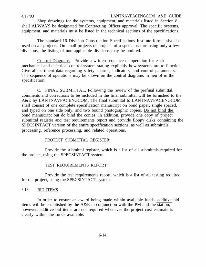
4/17/93 LANTNAVFACENGCOM A&E GUIDEShop drawings for the systems, equipment, and materials listed in Section 8
shall ALWAYS be designated for Contracting Officer approval. The specific systems,equipment, and materials must be listed in the technical sections of the specifications.
The standard 16 Division Construction Specifications Institute format shall beused on all projects. On small projects or projects of a special nature using only a fewdivisions, the listing of non-applicable divisions may be omitted.
Control Diagrams - Provide a written sequence of operation for eachmechanical and electrical control system stating explicitly how systems are to function.Give all pertinent data regarding safety, alarms, indicators, and control parameters.The sequence of operations may be shown on the control diagrams in lieu of in thespecification.
C. FINAL SUBMITTAL. Following the review of the prefinal submittal,comments and corrections to be included in the final submittal will be furnished to theA&E by LANTNAVFACENGCOM. The final submittal to LANTNAVFACENGCOMshall consist of one complete specification manuscript on bond paper, single spaced,and typed on one side only, and two bound photographic copies. Do not bind thebond manuscript but do bind the conies. In addition, provide one copy of projectsubmittal register and test requirements report and provide floppy disks containing theSPECSINTACT version of the entire specification sections, as well as submittalsprocessing, reference processing, and related operations.
PROTECT SUBMITTAL REGISTER:
Provide the submittal register, which is a list of all submittals required forthe project, using the SPECSINTACT system.
TEST REQUIREMENTS REPORT:
Provide the test requirements report, which is a list of all testing requiredfor the project, using the SPECSINTACT system.
6.13 BID ITEMS
In order to ensure an award being made within available funds, additive biditems will be established by the A&E in conjunction with the PM and the station;however, additive bid items are not required whenever the project cost estimate isclearly within the funds available.
6-14
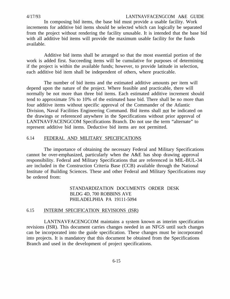
4/17/93 LANTNAVFACENGCOM A&E GUIDEIn composing bid items, the base bid must provide a usable facility. Work
increments for additive bid items should be selected which can logically be separatedfrom the project without rendering the facility unusable. It is intended that the base bidwith all additive bid items will provide the maximum usable facility for the fundsavailable.
Additive bid items shall be arranged so that the most essential portion of thework is added first. Succeeding items will be cumulative for purposes of determiningif the project is within the available funds; however, to provide latitude in selection,each additive bid item shall be independent of others, where practicable.
The number of bid items and the estimated additive amounts per item willdepend upon the nature of the project. Where feasible and practicable, there willnormally be not more than three bid items. Each estimated additive increment shouldtend to approximate 5% to 10% of the estimated base bid. There shall be no more thanfour additive items without specific approval of the Commander of the AtlanticDivision, Naval Facilities Engineering Command. Bid items shall not be indicated onthe drawings or referenced anywhere in the Specifications without prior approval ofLANTNAVFACENGCOM Specifications Branch. Do not use the term “alternate” torepresent additive bid items. Deductive bid items are not permitted.
6.14 FEDERAL AND MILITARY SPECIFICATIONS
The importance of obtaining the necessary Federal and Military Specificationscannot be over-emphasized, particularly when the A&E has shop drawing approvalresponsibility. Federal and Military Specifications that are referenced in MIL-BUL-34are included in the Construction Criteria Base (CCB) available through the NationalInstitute of Building Sciences. These and other Federal and Military Specifications maybe ordered from:
STANDARDIZATION DOCUMENTS ORDER DESKBLDG 4D, 700 ROBBINS AVEPHILADELPHIA PA 19111-5094
6.15 INTERIM SPECIFICATION REVISIONS (ISR)
LANTNAVFACENGCOM maintains a system known as interim specificationrevisions (ISR). This document carries changes needed in an NFGS until such changescan be incorporated into the guide specification. These changes must be incorporatedinto projects. It is mandatory that this document be obtained from the SpecificationsBranch and used in the development of project specifications.
6-15

4/17/93 LANTNAVFACENGCOM A&E GUIDE
(Blank Page)
6-16
4/17/93SECTION 7. COST ESTIMATES
LANTNAVFACENGCOM A&E GUIDE
7.1 GENERAL
A detailed cost estimate is required with each submittal. All estimates shall beprepared in the Cost Engineering System (CES) format whether manually or computerprepared. Scan all computer disks submitted for viruses using a commercial virusscanning program. The estimate detail for each submittal shall be consistent with thelevel of design required for that submittal. Accurate quantity take-off, inclusion of allappropriate CES systems, and accurate unit prices for the project’s geographic locationare fundamental to the development of a good cost estimate.
The A&E’s objective is to develop a final estimate that will be within 10% (±) ofthe lowest responsible bid. This requires responsible pricing, experienced judgmentand an accurate assessment of the market conditions. When this objective is not met, itis necessary for bid evaluation that the A&E submit a comparison of cost between thelow bid and the final A&E estimate. Reasons for major differences, sorted byspecification division, must be stated with a recommendation to award or reject. Thisbid analysis must be received within one week after notification that it is required andis to be provided at no additional cost to the Government.
Properly prepared cost estimates provide a check of plans and specificationsfor constructability, coordination conflicts, discrepancies, omissions and cost control.They are used by the Government to establish/verify budgets (verification of contractbid prices) and to develop historical data for future budget estimating.
Prior to fee negotiations for ALL PROJECTS, the A&E shall contact the CostEngineering Branch, telephone 804-444-9907, to discuss cost estimating requirements.Criteria for geographic location, multi-buildings process, MCON, O&MN, may bediscussed. MIL-HDBK-1010 illustrates basic CES estimating.
Final Government estimates are to be marked by the A&E with “For OfficialUse Only.” Access to or disclosure of information within the estimate is limited tothose personnel whose official duties require knowledge of the estimate.
7.2 PROTECT DESIGN ESTIMATES
The estimate at each submittal is expected to reflect the A&E’s best informationand experience. Expected bid opening date shall be established by theLANTNAVFACENGCOM PM. Pricing must reflect all requirements of the contractplans and specifications. The individual preparing the estimate should verify that all
7-1
4/17/93 LANTNAVFACENGCOM A&E GUIDEspecification requirements are priced with particular attention to Division One and thewage rates. Size, material quality, and type of item shall be part of the description toenable unit cost verification without constant reference to drawings and specifications.
7.2.1 35% DESIGN
Preliminary Estimate Based on Materials Take-Off. The estimate for thissubmittal shall reflect cost based on reasonably accurate take-off of materials/systemsconsistent with the level of design. For those elements of the project where the status ofdesign does not permit a reasonably accurate take-off of quantities or firm pricing ofindividual items of work, systems unit prices may be used. Lump sum costs are notacceptable. Use of empirical costs shall be minimized. The estimate may besubmitted two weeks (maximum) after the submittal of drawings to ensure an estimatebased on “as submitted” drawings and specifications.
Separate estimates will be prepared for each new non-identical building,structure, or addition costing over $50,000 contract cost. Costs of alteration work toexisting buildings will not be included with the building addition costs. When oneconstruction contract contains more than one type of work (i.e., new construction,repair, equipment installation, etc.), the estimate shall be structured such that each typeof work is identified separately. In addition to a master summary sheet, each type ofwork requires a separate summary sheet. Costs from these separate summary sheetsmust be directly transferable to the master summary sheet.
Beginning with the 35% estimate, a separate line item must be included forContract Quality Control (CQC) projects. CQC is a contractor responsibility inspectionsystem added to most projects that exceed $2,000,000 in construction cost. Unlessdirected otherwise, allow 3% of the construction cost for CQC. CQC is not used ondredging projects or in Iceland.
Thirty-Five Percent Estimates Should Monitor the Estimated Construction CostDuring Design. The 35% estimate may be either in manual (use standard CES Systems)or CES format. The 35% estimate, through adjustments, should monitor the estimatedconstruction cost until the prefinal estimate is prepared. It is very important that if theestimate indicates that the design exceeds the allocated funds, the PM be contacted forinstructions.
7.2.2 100% DESIGN
The 100% estimate shall be prepared from the 35% submittal documents. Theestimate may be submitted up to two weeks after the 100% submittal. A narrative
7-2
4/17/93 LANTNAVFACENGCOM A&E GUIDEdescription of each system shall be provided in the estimate. This narrative and theSystem Cost are related in subsequent CES historical files. Quotations must beobtained for all items of substantial quantity or cost. Price sources shall be in the formof written quotations or may be taken by telephone and included with the estimate. Ineither case provide the company name, person contacted and date of quote. Costs in anestimate are considered to be a reasonable price that a contractor would be expected topay. Estimates which do not conform to these format and information requirementswill be returned for revision. The A&E must compare the estimate with theauthorized scope of work and authorized funds. Separate systems within an estimatemust be prepared for each bid item identified in the specifications, including unit costsfor piling, and shall be submitted in the proper format.
For all projects over $500,000, and for all new buildings or additions over$100,000, a CES estimate is required. Unique projects not readily adaptable to CES maybe discussed with Cost Engineering Branch. For negotiated construction contracts, seeparagraph 7.3. Hard copies of estimates will be required for each submittal. The CESprogram, data base and User’s Guide are included on the Construction Criteria Base(CCB) compact disc. Call the Cost Engineering Branch, telephone 804-444-9768, if theCCB is not available. Include the following reports (menu selections) with eachsubmittal.
A. Input listing (sorted)
B. Summary - Yes (choose “No” for summary %)
C. Mark-up
D. Modifier
E. Detailed Estimate with Systems Sort
F. Spec Section Summary
Contact should be made with the PM prior to the 100% submission toreconfirm programmed construction costs for the contract. Where A&E estimateexceeds programmed construction costs, recommendations for cost reduction orproposed bid items must be provided with the prefinal submission. The estimate maybe submitted not more than two weeks after drawing submittal to ensure an estimatebased on “as submitted” drawings and specifications.
7-3
4/17/93 LANTNAVFACENGCOM A&E GUIDEMinimum computer equipment necessary for running estimates is:
A. Hardware
(1) Microcomputer (IBM 286 processor or better recommended)
(2) 640 K RAM memory
(3) Standard microcomputer printer (laser printer suggested)
(4) Hard disk (8 megabytes minimum)
B. Minimum Software Requirements
(1) MS-PC DOS Version 3.3 (or greater)
(2) The file CONFIG.SYS in the root directory with the following linesincluded:
FILE = 31BUFFERS = 30
These are the minimum values required to run CES.
(3) System time and date must be accurate.
7.2.3 FINAL
The final estimate submittals shall include the complete estimate on floppydisk, the same as the 100% except for correction/inclusion of 100% comments. Theestimate may be submitted up to two weeks following the final documents submittal toensure coordination.
7.3 ESTIMATES FOR NEGOTIATED CONSTRUCTION CONTRACTS
In addition to requirements established for competitively bid constructioncontracts, estimates for negotiated construction contracts shall:
A. Use a computer run CES estimate including the Detailed Estimate (CSISort) report unless estimated construction cost is less than $50,000. Ensure thenegotiated estimate choice is “Yes”.
7-4
4/17/93 LANTNAVFACENGCOM A&E GUIDEB. Final estimate must accurately reflect the final plans and specifications.
Negotiation will require a comparison of the contractor’s estimate and the A&Eestimate. Field overhead must be itemized as System 001. Where conflicts exist, theA&E may be required to provide prompt validation of items in question.
C. Should conflicts between plans and specifications occur, the A&E willpromptly clarify intent and prepare a draft “as negotiated” amendment;
7.4 ESTIMATES FOR PROTECTS LOCATED OUTSIDE CONUS
In addition to the provisions set forth above, reduction of the foreign exchangecosts (FEC) requires special attention. The project shall be designed to utilize materialwhich will reduce the FEC in all areas not in conflict with local construction methods orcountry-to-country agreements.
Estimates prepared for work outside the CONUS will be based on pricesprevailing in the area in which work is to be performed. Unusual conditions peculiarto the project under design shall be considered. The blanket use of geographical factorswill not be permitted.
Back-up estimates for overseas areas may be prepared in local currency or inU. S. dollars depending on the country (contact the Cost Engineering Branch, telephone804-444-9907). A second summary sheet in dollars must be shown and used as a coversheet. When estimates are prepared in a foreign currency, two summary sheets shall beused in the back-up estimate. The foreign exchange rate used shall be indicated on thecost summary. This rate will vary from year-to-year and differ between MCON andNon-Appropriated Fund Projects. Contact the Cost Engineering Branch for the correctrate. Quantity take-off may be in metric or English units, however, one summary sheetmust be in English units.
In overseas countries where labor and material escalation is allowed andcompensated during construction, the estimate escalation must be prepared in thefollowing manner:
When construction contractor pricing will be based upon local bid prices atthe time of bidding without any consideration of escalation: the designer of record willescalate to the 1/3 point of construction. The assumed bid date shall be established bythe PM; escalate from that point to the 1/3 point of construction. The estimatesummary shall indicate date escalated to and % escalation.
United States material purchases and shipping to overseas projects shouldbe escalated using U. S. escalation/rates and bid date formula.
7-5

4/17/93 LANTNAVFACENGCOM A&E GUIDE7.4.1 ESTIMATES FOR PROTECTS LOCATED IN ICELAND
The A&E will be given specific written guidance for preparation ofGovernment estimates for Iceland projects including samples of Icelandic PrimeContractor estimates for similar type projects. Level of detail for repair projects will bethe same as new construction.
7-6
4/17/93 LANTNAVFACENGCOM A&E GUIDESECTION 8. POST DESIGN SERVICES
8.1 CONSULTATION DURING CONSTRUCTION
8.1.1 GENERAL
The A&E shall provide consultation services during the construction period aswell as the design period. Such consultation may or may not be reimbursable asfollows:
A. Non-Reimbursable Consultation: Under paragraph 3(g) of Section 01011,“General Paragraphs”, of the A&E Contract, the A&E shall promptly furnishconsultation services without additional compensation. Such consultation typicallyoccurs in the form of a Request for Information (RFI) from the ROICC. Typically, RFIsinclude providing clarification of the intent of the drawings and specifications inresponse to questions which routinely arise during the course of construction and mayresult in preparation of amplifying drawings, specifications, amendments, changeorders and cost estimates to correct errors, omissions, inconsistencies between drawingsand specifications, conflicts in dimensions, lack of detail or poor design quality in thedrawings and specifications. Amplifying drawings, specifications, amendments,change orders and cost estimates shall be prepared in accordance with the provisionsand standards set forth in this A&E Guide. In such cases, the A&E shall assure throughdiscussions with the ROICC the timing required for preparation of such documents tominimize delay to the construction. It is expected that the A&E will provide a responseto an RFI not later than 3 working days after notification. Where the response to an RFIrequires additional time, the A&E shall notify the ROICC as to the expected date ofresponse.
B. Reimbursable Consultation: In addition to non-reimbursable consultation,reimbursable A&E services may be required for specialized consultation withLANTNAVFACENGCOM and ROICC personnel either at the site of construction or inthe A&E’s office regarding matters of a nature not included under “GeneralParagraphs” of the A&E Contract. Such consultation includes:
(1) Consultation regarding unforeseen problems or questions duringconstruction.
(2)limited to:
Consultation on critical items during construction, including, but not
8-1
4/17/93 LANTNAVFACENGCOM A&E GUIDE(a) Assisting the ROICC in final field checkout of basic mechanical
and electrical systems.
(b) Witnessing final acceptance tests for HVAC systems.
(c) Witnessing and certifying construction contractor compliance withfield test procedures for specialized mechanical, electrical and electronic systemsdesigned for the project. Such services shall be performed by registered professionalengineers and include the A&E’s certification of compliance by the constructioncontractor with all specified test procedures, a critique of the data obtained and thestated or implied results of the tests performed.
(3) The preparation of all changes or additions to the drawings orspecifications, amendments, change orders and cost estimates resulting from a changein scope, unforeseen conditions, or other modifications. Such drawings, specifications,amendments, change orders and cost estimates shall be prepared in accordance withthe provisions and standards set forth in this A&E Guide. In such cases, the A&E shallassure through discussions with the ROICC the timing required for preparation of suchdocuments to minimize delay to the construction.
(4) Evaluation of construction contractor proposed exceptions or variationsto the requirements of the contract documents (beyond the scope of routine shopdrawing submittal deviations).
(5) Evaluation of construction contractor Value Engineering ChangeProposals.
8.1.2 BASIS OF PAYMENT FOR REIMBURSABLE CONSULTATION
Payment for reimbursable consultation services, whether performed in theA&E’s office or at the construction site, will be made on a cost per manday (8 hour)basis. The number and cost of reimbursable consultation mandays required both at thesite and in the A&E’s office will be discussed during fee negotiations, and the A&EContract will stipulate a lump sum price for consultation reflecting these negotiations.This lump sum price is contingent upon the scale, type and complexity of constructionas well as the amount of funds available. It should be noted that although the lumpsum contracted price for consultation reflects the anticipated amount of consultationrequired, no minimum amount is guaranteed. Payment for consultation services willbe made on an “as requested” basis.
8-2
4/17/93 LANTNAVFACENGCOM A&E GUIDETo establish the A&E’s cost per manday for office and site consultation services
and to facilitate contract modifications for changes to the amount of A&E consultationrequired, the A&E shall submit with his fee proposal the following unit prices fornegotiation:
A. Labor cost per day per person (average cost per person (RA or PE),including overhead and profit, for 8 hours).
B. Labor cost per person associated with travel time (round trip) from theA&E office to the site.
C. Travel cost per day (e.g., car operating costs or car rental) at the site.
D. Travel cost per trip in addition to above (e.g., plane fare) to the site.
E. Lodging cost per night per person at the site.
F. Per diem per day per person (e.g., meals) at the site.
8.1.3 CHANGES TO NEGOTIATED/CONTRACTED REIMBURSABLECONSULTATION
If, during the course of the A&E contract, the Government wishes to changethe number of contracted A&E reimbursable consultation mandays, an adjustment incontract price will be made in accordance with the negotiated unit pricing requestedabove and a contract modification will be issued.
8.1.4 REQUESTS FOR CONSULTATION
Requests for A&E consultation during construction will be sent directly fromthe ROICC. In most cases, the A&E will initially receive such requests by telephoneand, depending upon the circumstances, a follow-up letter. In the initial contract, theROICC and A&E shall establish the reasons for the consultation request, determinewhether the A&E’s consultation effort is reimbursable and, if so, an agreed upon priceand schedule to perform the consultation services using the contract unit prices foroffice and site consultation, the ROICC shall issue a firm fixed price order for therequired services keeping within the lump sum contracted price.
8-3
4/17/938.1.5 CONSULTATION REPORTS
LANTNAVFACENGCOM A&E GUIDE
8.1.5.1 GENERAL
At the completion of each site consultation visit but prior to leaving the job site,the A&E shall submit to the ROICC a brief handwritten report of the services renderedand send one copy to the PM. Within 5 working days following the completion of eachoffice consultation request, the A&E shall submit two copies of a final typed report tothe ROICC and one copy to the PM. Each report shall include as a minimum:
A. A cover letter indicating the A&E and Construction Contracts involved,the telephone conversation or letter requesting the site or office consultation, the ordernumber of the consultation, and the A&E representatives who performed the serviceswith their titles.
B. A description of the services rendered.
C. Persons contacted and those in attendance during the consultation.Include their telephone numbers.
D. Problems encountered.
E. Recommended solutions or proposed milestones for resolution.
8.1.5.2 EVALUATION OF CONTRACTOR PROPOSED EXCEPTIONS ORVARIATIONS TO THE CONTRACT DOCUMENTS
In addition to the general requirements, consultation reports on A&Eevaluation of construction contractor proposed exceptions or variations to the contractdocuments shall address:
A. Whether the proposed substitution is of equal, better, or lesser quality thanthe design requirements.
B. If of lesser quality, the difference in value.
C. If of equal or better quality, the advantages to the Government in acceptingthe substitution at no change in contract price.
8.1.5.3 EVALUATION OF CONSTRUCTION CONTRACTOR VALUEENGINEERING CHANGE PROPOSALS (VECPs)
The purpose of a VECP is to achieve savings in cost by adjusting the design soas to permit more economical methods and materials of construction and still maintain
8-4
4/17/93 LANTNAVFACENGCOM A&E GUIDEthe operational, functional and aesthetic quality of the facility. Note that a constructioncontractor VECP differs from a construction contractor proposed variation or exceptionto the contract documents in that a VECP must maintain at least the same level ofquality as in the original design while a proposed variation or exception could lowerthe quality of construction. Under the VECP program, the contractor and Governmentshare in the savings resulting from acceptable proposals while a full credit (deduct) inthe construction contract price is taken for approved variations or exceptions which areof lesser quality than the original design.
In addition to the general requirements, consultation reports on A&Eevaluation of VECPs shall include:
A. The advantages and disadvantages of the VECP.
B. Economic analysis and justification for recommending approval orrejection of the VECP.
In order to avoid tacit delays to construction, Government processing time forVECPs is held to 21 calendar days from the date the ROICC receives the VECP packagefrom the contractor. Accordingly, the A&E shall complete and forward consultationreports on VECPs to the ROICC and PM within 5 working days from the time ofreceipt. When the VECP is of the nature that the response requires additional time, theA&E shall notify the ROICC as to the expected date of responses. In addition, the A&Eshall also forward one copy of the VECP consultation report toLANTNAVFACENGCOM Code 04B.
8.2 DESIGN FIELD SUPPORT
8.2.1 GENERAL
Unless Supervision and Inspection Services are negotiated and contracted as aContract Phase, the A&E has no field construction responsibilities. The ROICC isresponsible for field administration and the Government’s quality assurance programrelative to the construction contractor’s quality control program. However, to assist theROICC in this endeavor, the A&E shall at the Government’s option, provide DesignField Support.
Design Field Support consists of periodic site visits by teams of A&E personnelto observe and report on particular phases of construction or problems, ascertain theprogress of construction and to assist the ROICC in quality assurance measures. Thepurpose of the team visits is to ascertain whether work-in-place satisfactorily meets theintent of the design and to keep the A&E aware of the status and quality ofconstruction. As a general rule, design field support is required for critical designelements or phases of the construction work.
8-5
4/17/93 LANTNAVFACENGCOM A&E GUIDEThe number of visits and A&E team composition is based on the size, complexity,qualifications of ROICC personnel at the site and location of the project. The requestfor a site visit and the preferred A&E team composition will be determined by theROICC. Only the design disciplines directly involved with that particular criticaldesign element should make site visits. Visits will be coordinated and scheduled bythe ROICC to allow the A&E and Government to get maximum benefit from each trip.
8.2.2 NUMBER OF SITE VISITS
The number of site visits and stage of construction shall be addressed in theA&E Contract Appendix A.
For purposes of establishing a level of effort for negotiation for Design FieldSupport, the A&E shall submit proposed costs for performing this work based on thefollowing assumed site visits by the indicated A&E personnel (break down and showall associated travel expenses):
A. Pre-Construction Conference (1 day) (A&E attendance required only forhighly complex or high visibility projects): The A&E’s Project Manager shall attend thepreconstruction conference for the purpose of consultation on matters relating to theproject and to become acquainted with problems which the ROICC and/or theconstruction contractor anticipate during construction. The A&E’s Project Managershall be prepared to answer construction contractor questions regarding the drawingsand specifications. The atmosphere and tone of the conference shall be such that teambuilding is promoted between the ROICC, A&E and contractor. The A&E shall submitto the ROICC, within 5 calendar days following the conference, 2 copies of writtendocumentation of answers to all questions/problems not resolved during the pre-construction conference. Submit one copy of such documentation to the PM.
B. 25% Construction Progress Review (1 day): Team normally to consist ofStructural Engineer and one other technical discipline.
C. 50% Construction Progress Review (1 day): Team normally to consist ofArchitect, roofing specialist and one other technical discipline.
D. 75% Construction Progress Review (1 day): Team normally to consist ofArchitect, Mechanical Engineer (HVAC), Electrical Engineer and one other technicaldiscipline.
1. Facility Review (1 day): Coincident with the above, a representative ofthe LANTNAVFACENGCOM Construction Division may attend and note would betaken of the state of the quality of the construction. LANTNAVFACENGCOM wouldprepare a report for the ROICC’s use with input from the A&E’s representatives.
8-6

4/17/93 LANTNAVFACENGCOM A&E GUIDEE. 100% Construction Completion Review (1 day): Team normally to consist
of Architect, Mechanical Engineer (HVAC), Electrical Engineer and one other technicaldiscipline.
F. Post Occupancy Evaluation (POE) (1 day field time at site, 1 day officetime): Team normally consists of Architect, Mechanical Engineer and ElectricalEngineer. This site visit will be conducted with a representative fromLANTNAVFACENGCOM, ROICC and Public Works, and will include consultationwith the users. It would generally be held about 10 months after occupancy.
The A&E or the ROICC may propose an alternate number of visits or alternateor additional personnel team members from those listed above for negotiation wherewarranted by the type, complexity, scale, or location of the construction. The ROICCwill approve or disapprove any proposed variation in the negotiated frequency ormakeup of team visits.
8.2.3 A&E TASKS AND RESPONSIBILITIES FOR DESIGN FIELD SUPPORT
A&E participants in the construction progress reviews shall be alert to anddocument the presence of perceived deficiencies in the construction work and shallnote potential coordination problems which may be avoidable. The constructionprogress review teams shall not conduct tests of equipment or systems and shall notdisturb the work performed by the construction contractor in any manner that mightcause the construction contractor to have to perform additional work. The A&E shallprovide construction contract drawings and specifications for team participants to useduring the construction progress reviews.
At the conclusion of each team review, which shall take no more than sixhours, the A&E shall informally advise the ROICC of any observed deficiencies inconstruction or coordination problems. A handwritten report of all observeddeficiencies and potential coordination problems shall be prepared at the siteimmediately following the team reviews and given to the ROICC. One additional copyof each report shall be forwarded to the PM. The handwritten report shall identify theconstruction contract, the A&E firm and Government participants in the team reviewand their specific disciplines. Each observed construction deficiency shall be addressedseparately in the report by citing the specific construction contract requirement(specification paragraph or drawing detail) which pertains to the observed deficiencyand stating specifically how the observed construction differs from that required in theconstruction contract documents or from that intended by the designer. The A&E shallalso comment on the advisability of corrective measures to be taken in such instances.The A&E shall also comment on observed coordination problems such as, for example,where installation of mechanical work and either structural work or architectural
8-7

4/17/93 LANTNAVFACENGCOM A&E GUIDEfeatures may encounter problems due to improper layout or poor usage of availablespace within a ceiling cavity or utility corridor. In addition, although the A&E is notresponsible contractually for construction safety, serious life safety hazards observedshall be included in the report. The post occupancy inspection report will includelessons learned in providing a quality facility that meets the user’s expectations as wellas identifying warranty related problems and latent defects and potential maintenanceproblems. Navy criteria deficiencies shall also be noted..
8.3 SHOP DRAWINGS/SUBMITTAL REVIEW
At the Government’s option, checking of shop drawings/submittals and otherdata submitted by the construction contractor is an A&E’s responsibility. The A&Eshall provide and use the shop drawing approval stamp shown in Figure 8.1 to processshop drawing submittals.
NOTE: Shop drawings/submittals shall include all submittal descriptions(SD) as listed in Section 01300, “Submittals” of the construction contract specifications.
Generally, all CONUS projects utilize formal quality control procedures.Under these procedures, the contractor’s quality control manager approves forconstruction all shop drawings and submittals except those specifically designated inthe project specification for approval by the Contracting Officer.
Accurate, timely review of ALL submittals including operation andmaintenance data packages, is an A&E’s responsibility. The sub-section entitled "ShopDrawing Review Procedures” outlines the procedure for handling submittals on allprojects, including both those where the contractor’s quality control manager is theapproving authority and those where the Government (LANTNAVFACENGCOM orA&E firm) is the approving authority.
From the A&E view point there is no difference in the review of submittalswhether the approving authority is the Government or the contractor’s quality controlmanager. Since the contractor’s quality control manager is approving the majority ofthe submittals for construction, then distributing approved copies to the A&E andothers, these items must be reviewed promptly. It is the A&E’s responsibility toimmediately advise the ROICC of problems/discrepancies encountered in contractorapproved submittals.
8-8
4/17/93 LANTNAVFACENGCOM A&E GUIDE
8.3.1 CONTRACTOR’S QUALITY CONTROL MANAGER IS APPROVINGAUTHORITY
8.3.1.1 STATESIDE CONTRACTS - Submittals shall be submitted and distributed inaccordance with the flow charts on the next 4 pages:
Submittal Flow Chart #1
Submittal Flow chart #1-0 (OMSI requirements apply)
Submittal Flow Chart #2
Submittal Flow Chart #2-0 (OMSI requirements apply)
8-9
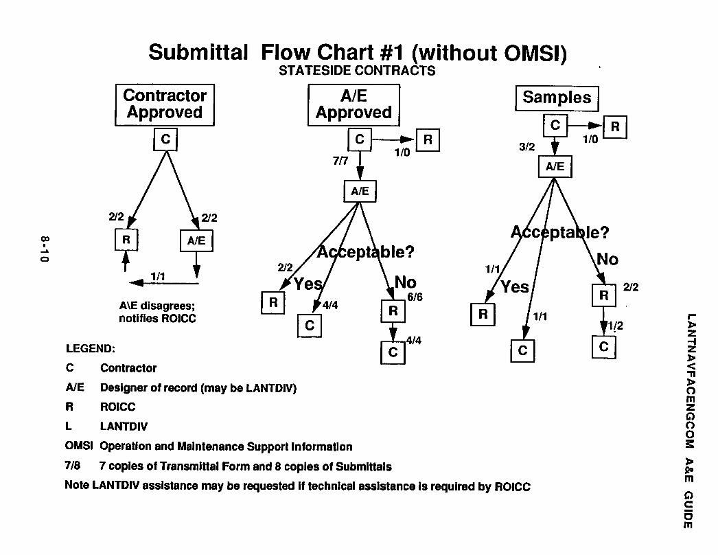
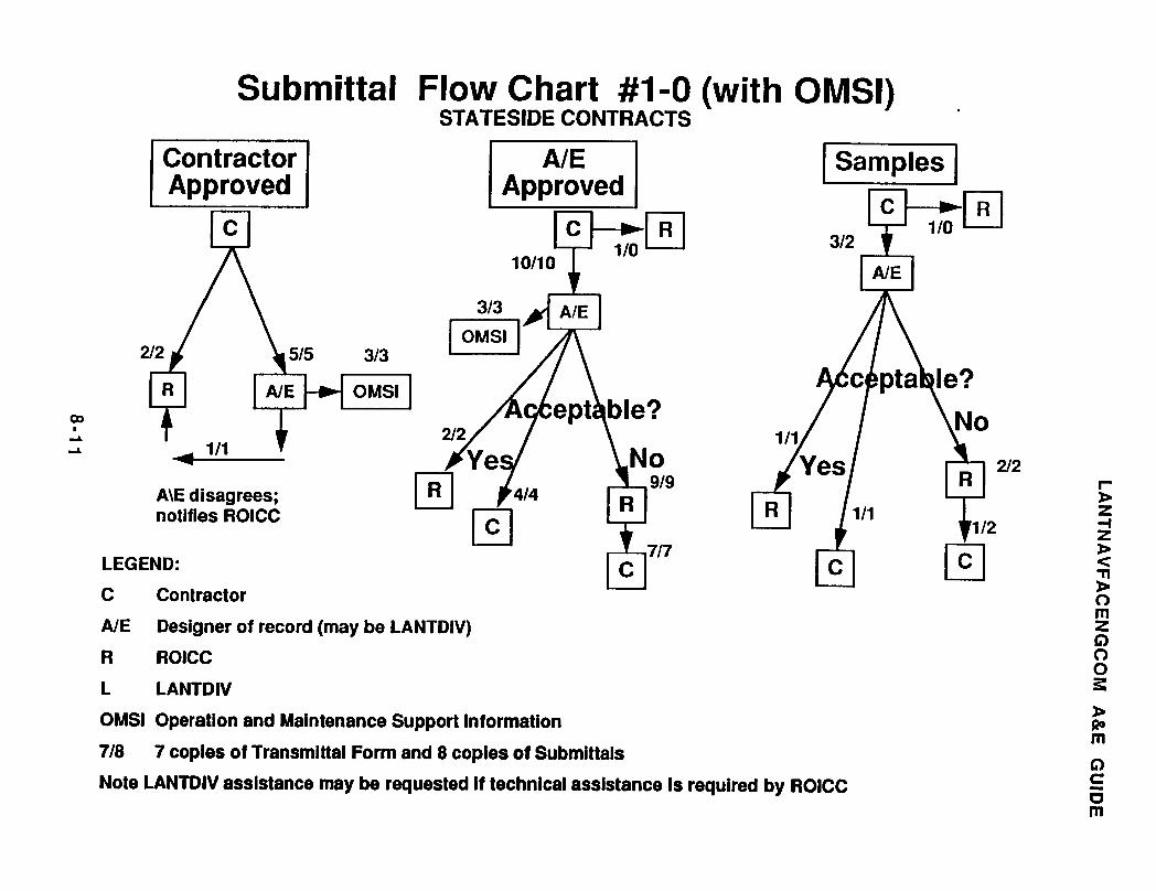
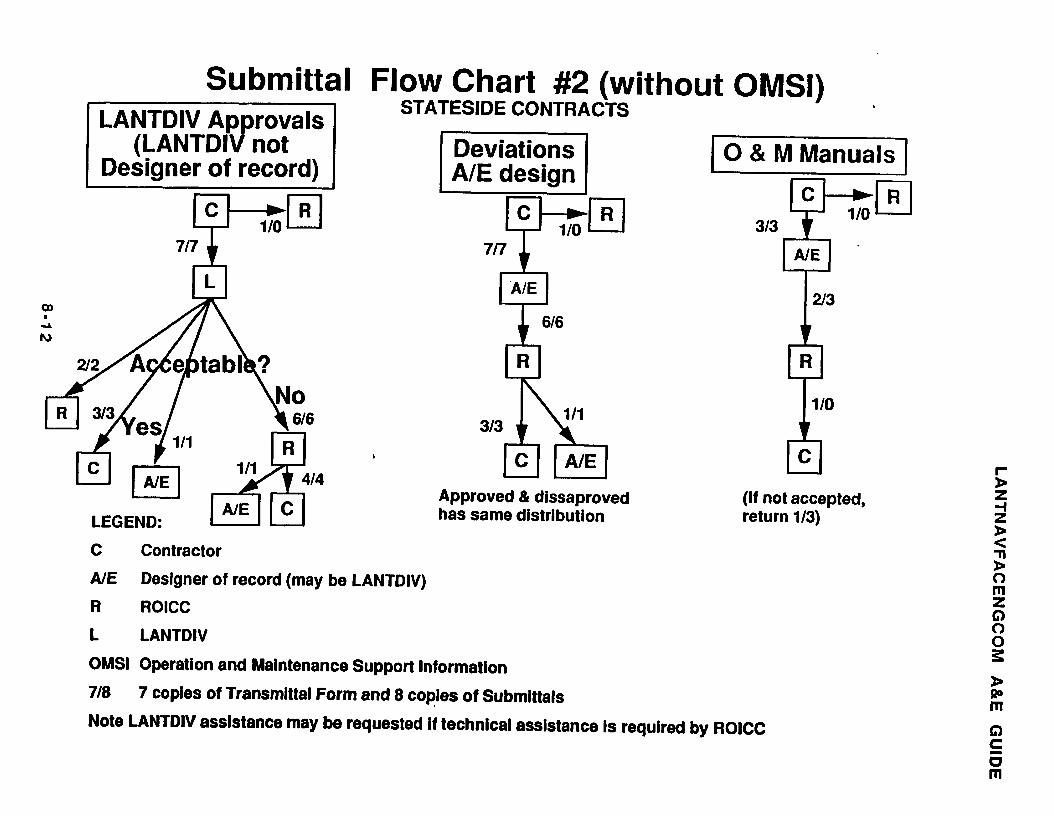
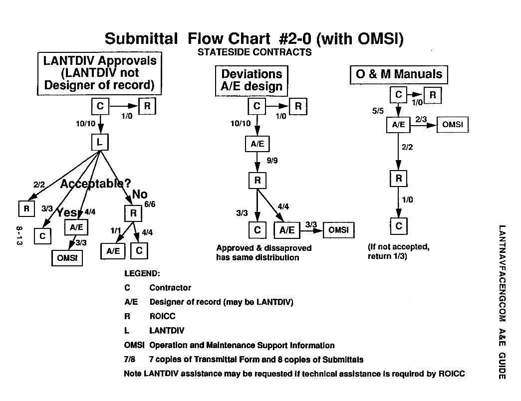
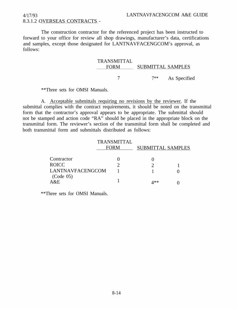
4/17/93 LANTNAVFACENGCOM A&E GUIDE8.3.1.2 OVERSEAS CONTRACTS -
The construction contractor for the referenced project has been instructed toforward to your office for review all shop drawings, manufacturer’s data, certificationsand samples, except those designated for LANTNAVFACENGCOM’s approval, asfollows:
TRANSMITTALFORM SUBMITTAL SAMPLES
7 7** As Specified
**Three sets for OMSI Manuals.
A. Acceptable submittals requiring no revisions by the reviewer. If thesubmittal complies with the contract requirements, it should be noted on the transmittalform that the contractor’s approval appears to be appropriate. The submittal shouldnot be stamped and action code “RA” should be placed in the appropriate block on thetransmittal form. The reviewer’s section of the transmittal form shall be completed andboth transmittal form and submittals distributed as follows:
TRANSMITTALFORM SUBMITTAL SAMPLES
ContractorROICCLANTNAVFACENGCOM
(Code 05)A&E
**Three sets for OMSI Manuals.
0 02 2 11 1 0
1 4** 0
8-14
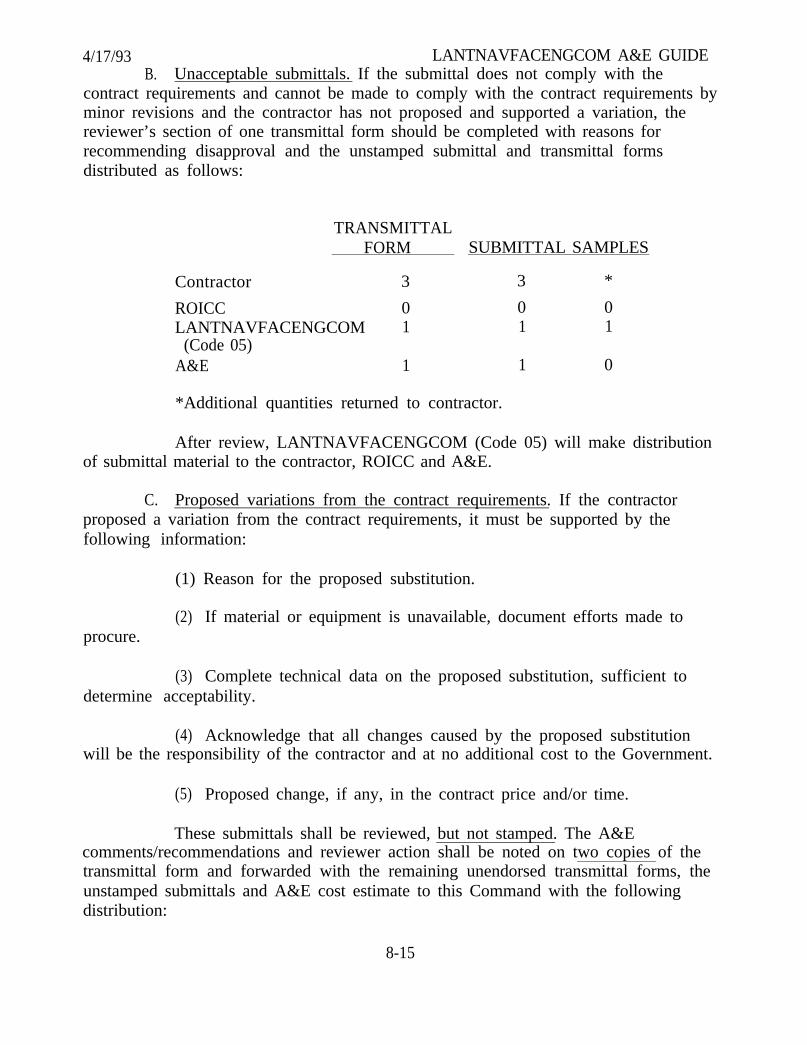
4/17/93 LANTNAVFACENGCOM A&E GUIDEB. Unacceptable submittals. If the submittal does not comply with the
contract requirements and cannot be made to comply with the contract requirements byminor revisions and the contractor has not proposed and supported a variation, thereviewer’s section of one transmittal form should be completed with reasons forrecommending disapproval and the unstamped submittal and transmittal formsdistributed as follows:
TRANSMITTALFORM SUBMITTAL SAMPLES
Contractor 3 3 *
ROICC 0 0 0LANTNAVFACENGCOM 1 1 1
(Code 05)A&E 1 1 0
*Additional quantities returned to contractor.
After review, LANTNAVFACENGCOM (Code 05) will make distributionof submittal material to the contractor, ROICC and A&E.
C. Proposed variations from the contract requirements. If the contractorproposed a variation from the contract requirements, it must be supported by thefollowing information:
(1) Reason for the proposed substitution.
procure.(2) If material or equipment is unavailable, document efforts made to
(3) Complete technical data on the proposed substitution, sufficient todetermine acceptability.
(4) Acknowledge that all changes caused by the proposed substitutionwill be the responsibility of the contractor and at no additional cost to the Government.
(5) Proposed change, if any, in the contract price and/or time.
These submittals shall be reviewed, but not stamped. The A&Ecomments/recommendations and reviewer action shall be noted on two copies of thetransmittal form and forwarded with the remaining unendorsed transmittal forms, theunstamped submittals and A&E cost estimate to this Command with the followingdistribution:
8-15
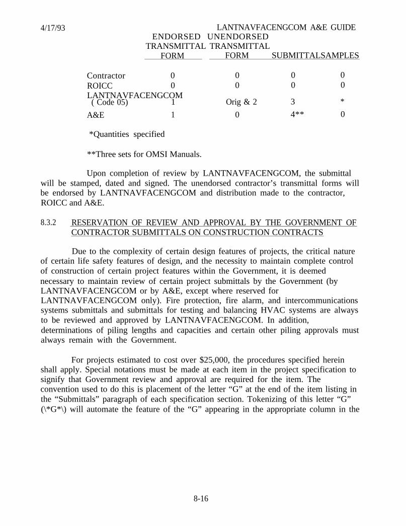
4/17/93 LANTNAVFACENGCOM A&E GUIDEENDORSED UNENDORSED
TRANSMITTAL TRANSMITTALFORM FORM SUBMITTALSAMPLES
Contractor 0 0 0 0ROICC 0 0 0 0LANTNAVFACENGCOM
( Code 05) 1 Orig & 2 3 *
A&E 1 0 4** 0
*Quantities specified
**Three sets for OMSI Manuals.
Upon completion of review by LANTNAVFACENGCOM, the submittalwill be stamped, dated and signed. The unendorsed contractor’s transmittal forms willbe endorsed by LANTNAVFACENGCOM and distribution made to the contractor,ROICC and A&E.
8.3.2 RESERVATION OF REVIEW AND APPROVAL BY THE GOVERNMENT OFCONTRACTOR SUBMITTALS ON CONSTRUCTION CONTRACTS
Due to the complexity of certain design features of projects, the critical natureof certain life safety features of design, and the necessity to maintain complete controlof construction of certain project features within the Government, it is deemednecessary to maintain review of certain project submittals by the Government (byLANTNAVFACENGCOM or by A&E, except where reserved forLANTNAVFACENGCOM only). Fire protection, fire alarm, and intercommunicationssystems submittals and submittals for testing and balancing HVAC systems are alwaysto be reviewed and approved by LANTNAVFACENGCOM. In addition,determinations of piling lengths and capacities and certain other piling approvals mustalways remain with the Government.
For projects estimated to cost over $25,000, the procedures specified hereinshall apply. Special notations must be made at each item in the project specification tosignify that Government review and approval are required for the item. Theconvention used to do this is placement of the letter “G” at the end of the item listing inthe “Submittals” paragraph of each specification section. Tokenizing of this letter “G”(\*G*\) will automate the feature of the “G” appearing in the appropriate column in the
8-16
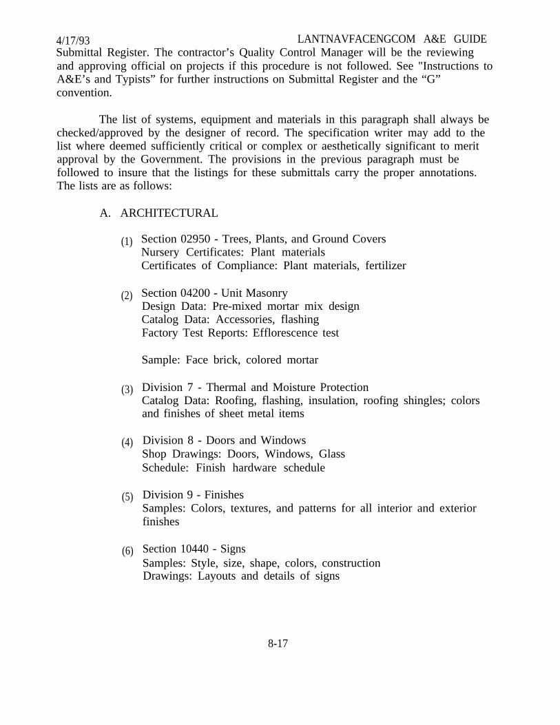
4/17/93 LANTNAVFACENGCOM A&E GUIDESubmittal Register. The contractor’s Quality Control Manager will be the reviewingand approving official on projects if this procedure is not followed. See "Instructions toA&E’s and Typists” for further instructions on Submittal Register and the “G”convention.
The list of systems, equipment and materials in this paragraph shall always bechecked/approved by the designer of record. The specification writer may add to thelist where deemed sufficiently critical or complex or aesthetically significant to meritapproval by the Government. The provisions in the previous paragraph must befollowed to insure that the listings for these submittals carry the proper annotations.The lists are as follows:
A. ARCHITECTURAL
(1)
(2)
(3)
(4)
(5)
(6)
Section 02950 - Trees, Plants, and Ground CoversNursery Certificates: Plant materialsCertificates of Compliance: Plant materials, fertilizer
Section 04200 - Unit MasonryDesign Data: Pre-mixed mortar mix designCatalog Data: Accessories, flashingFactory Test Reports: Efflorescence test
Sample: Face brick, colored mortar
Division 7 - Thermal and Moisture ProtectionCatalog Data: Roofing, flashing, insulation, roofing shingles; colorsand finishes of sheet metal items
Division 8 - Doors and WindowsShop Drawings: Doors, Windows, GlassSchedule: Finish hardware schedule
Division 9 - FinishesSamples: Colors, textures, and patterns for all interior and exteriorfinishes
Section 10440 - SignsSamples: Style, size, shape, colors, constructionDrawings: Layouts and details of signs
8-17

4/17/93(7)
(8)
(9)
LANTNAVFACENGCOM A&E GUIDESection 11400 - Food ServiceCatalog Data: Food service equipmentDrawings: Equipment layout, utilities, custom fabricated equipmentTest Reports: Food service equipment
Section 11702 - Medical EquipmentCatalog Data: Medical equipmentDrawings: Equipment layout, utilitiesCertificates of Compliance: Medical equipment
Section 12333 - WardrobesReview all submittals
(10) Section 12337 - Casework, Metal and WoodCatalog Data: CaseworkDrawings: Wall and base cabinets, countertopsSamples: Colors, finishesCertificates of compliance: Cabinets
(11) Section 12391- Residential Kitchen and Vanity CabinetsCatalog Data: Cabinets, countertops, hardwareDrawings: Layout, details, dimensionsSamples: Cabinet finishes, countertop finishesCertificates of Compliance: Cabinets, countertops
(12) Section 12711 - Theater SeatingDrawings: Theater seats, seating layoutSamples: Upholstery material, theater seats
(13) Section 14200 - Electric ElevatorsSection 14214 - Hydraulic ElevatorsCatalog Data: Cars, doors, frames, accessoriesDrawings: Layout, cars, doors, framesSample: Elevator car flooring
B. STRUCTURAL
(1) Division 2 - Steel Sheet Piling and Prestressed ConcreteSheet PilingShop Drawings and Calculations
(2) Section 02720 - Storm Drainage SystemShop Drawings for Precast manholes, including Calculations
8-18
4/17193
(3)
(4)
(5)
(6)
(7)
(8)
(9)
LANTNAVFACENGCOM A&E GUIDE
Section 02491 - Pier TimberworkShop Drawings
Section 03300 - Cast in Place ConcreteShop Drawings for Reinforcing Steel
Section 03361 - ShotcreteReinforcing Steel Drawings
Section 03498 - Concrete PolesShop Drawings
(a) Concrete Poles(b) Reinforcing Steel(c) Prestressing Steel, including design calculations
Section 03410 - Precast Concrete(Non-Prestressed)Shop DrawingsRevision to design, including design calculations
Section 03411 - Precast Concrete Wall PanelsShop Drawings and Descriptive Data:
(a) Wall panel dimensions, cross section, edge details, reinforcing,etc.
(b) Design Calculations.(c) Location and details of anchorage devices and lifting devices
embedded in panel and connection details to building framingsystem.
(d) Location and details of anchorage devices provided forattachment of wall panels to supporting structure.
Section 03412 - Precast Prestressed ConcreteShop Drawings:
(a) Connections to supporting construction as required by design.(b) Location and size of all openings 10 inches in diameter, 10 inch
square and larger to be cast into member.
8-19
4/17/93 LANTNAVFACENGCOM A&E GUIDE(c) Headers for openings where additional structural work
required.(d) Reinforcing, including prestressing steel details.(e) Minimum concrete compressive strengths at initial prestress
and 28 day, and the initial prestress to be applied.
(10) Section 04200 - Unit MasonryShop Drawings:
(a) Wall reinforcing(b) Bond beams(c) Lintels
(11) Section 05120 - Structural SteelShop Drawings
(12) Section 05400 - Cold-Forming Metal Framing
(a) Shop Drawings and Manufacturer’s Literature.(b) Design Calculations as necessary to indicate compliance withload bearing requirements.
(13) Section 05500 - Metal FabricationShop Drawings: Trench covers and frames, steel stairs, floorgratings and frames.
(14) Section 06100 - Rough CarpentryShop Drawings: Structural glued laminated fabricated woodtrusses and other fabricated structural members.
(15) Section 06500 - Fiberglass GratingManufacturer’s DataShop Drawings
(16) Section 08372 - Steel Sliding Óhangar DoorsDesign Drawings and CalculationsShop DrawingsOperating Drawing and Instruction
(17) Section 08315 - Blast DoorsShop Drawing and Manufacturer’s DataCalculations Demonstrating Design Compliance
8-20
4/17/93 LANTNAVFACENGCOM A&E GUIDE(18) Section 09875 - Conductive and Spark Resistant Concrete Floor
FinishManufacturer’s Literature and DataManufacturer’s Instruction
(19) Section 13121 - Pre-Engineered Metal BuildingErection Instructions and Diagrams:
(a) Anchor bolt layout and sizes(b) Structural connections(c) Roofing and siding connections(d) All details and instructions necessary for completion assembly(e) Shop drawings as necessary to supplement the instruction and
drawings if required for the proper erection and installation ofbuilding components.
(f) Design calculations
(20) Section 13209 - Water Storage TanksShop Drawings
(21) Section 14200 - Electrical Passenger/Freight Elevators
In seismic Zone 3 or greater, details of equipment foundations,restraints, attachment of rail to the structure and details of earthquake protection.Provide calculations certified by a licensed structural engineer.
(22) Other Division 14Review all submittals for cranes, monorails, and hoists.
(23) Section 16301 - Underground Electrical WorkShop Drawings/Manufacturer’s Data for precast manhole andhandholes - calculations and shop drawings.
C. MECHANICAL
(1) Boilers and warm air furnaces greater than 50,000 Btu/hr.,including controls and auxiliaries.
(2) Air and gas compressors greater than 25 SCFM and greater than250 psig.
8-21
4/17/93 LANTNAVFACENGCOM A&E GUIDE(3) Air pollution control devices (including electrostatic precipitators,
bag-houses, mechanical collectors, scrubbers and demisters).
(4) Chillers and refrigerator compressors greater than 15 tons.
(5) Cooling towers, evaporative condensers, and radiators greaterthan 15 tons.
(6) Air conditioning and condensing units greater than 15 tons.
(7) Heat pumps greater than 5 tons.
(8) High-efficiency filters and filter boxes.
(9) Heating, Ventilating, and Air Conditioning (HVAC) controlsystems.
(10) Terminal devices which modulate to control space conditions(Variable Air Volume (VAV) boxes, term air blender units,induction units, and fan-coil units).
(11) Heat exchangers greater than 100,000 Btu/hr.
(12) Air ducts for systems with pressures of 3 inch wg or greater.
(13) Air handling units and unit heaters greater than 2,000 SCFM.
(14) Fans for heating and ventilating units with motors 3 hp andgreater.
(15) Pumps with motors 3 hp and greater.
(16) POL and Aviation fueling system components and controls.
(17) Plug, ball, trunnion mounted butterfly, and double block andbleed valves on Petroleum Oil and Lubricant (POL) systems.
(18) Buried factory preinsulated steam and condensate piping andcontractor system design drawings (pipe, insulation, conduit, andsystem design layout only).
(19) Specialized or unusually complicated equipment.
8-22

4/17/93 LANTNAVFACENGCOM A&E GUIDE(20) Testing/Adjusting/Balancing; Heating/Ventilating/Cooling
System.
(21) Fire protection systems.
(22) Plumbing fixtures, faucets, tub/shower supply faucets, andflushometers.
D. ELECTRICAL
(1) Section 16216 - Diesel Engine-Generator SetReview all submittals
(2) Section 16262 - Automatic Transfer SwitchesReview all submittals
(3) Section 16301 - Underground Electrical WorkReview submittals for high voltage cable, terminators, and splicekits, and for precast manholes and handholes.
(4) Section 16304 - 480V Pier Power Outlet AssembliesReview all submittals
(5) Section 16305 - 400-Hertz Low-Voltage SubstationReview all submittals
(6) Section 16306 - 400-Hertz Solid State Frequency ConverterReview all submittals
(7) Section 16312 - Low Voltage Switchgear and Secondary UnitSubstationsReview all submittals
(8) Section 16313 - Medium-Voltage Switchgear and Primary UnitSubstationsReview all submittals
(9) Section 16370 - Overhead Electrical WorkReview submittals for transformers, cut-outs, arresters, and poletop switches
(10) Section 16402 - Interior Wiring SystemsReview submittals for receptacles, circuit breakers, transformers,panel boards, motor control centers, and field tests.
8-23
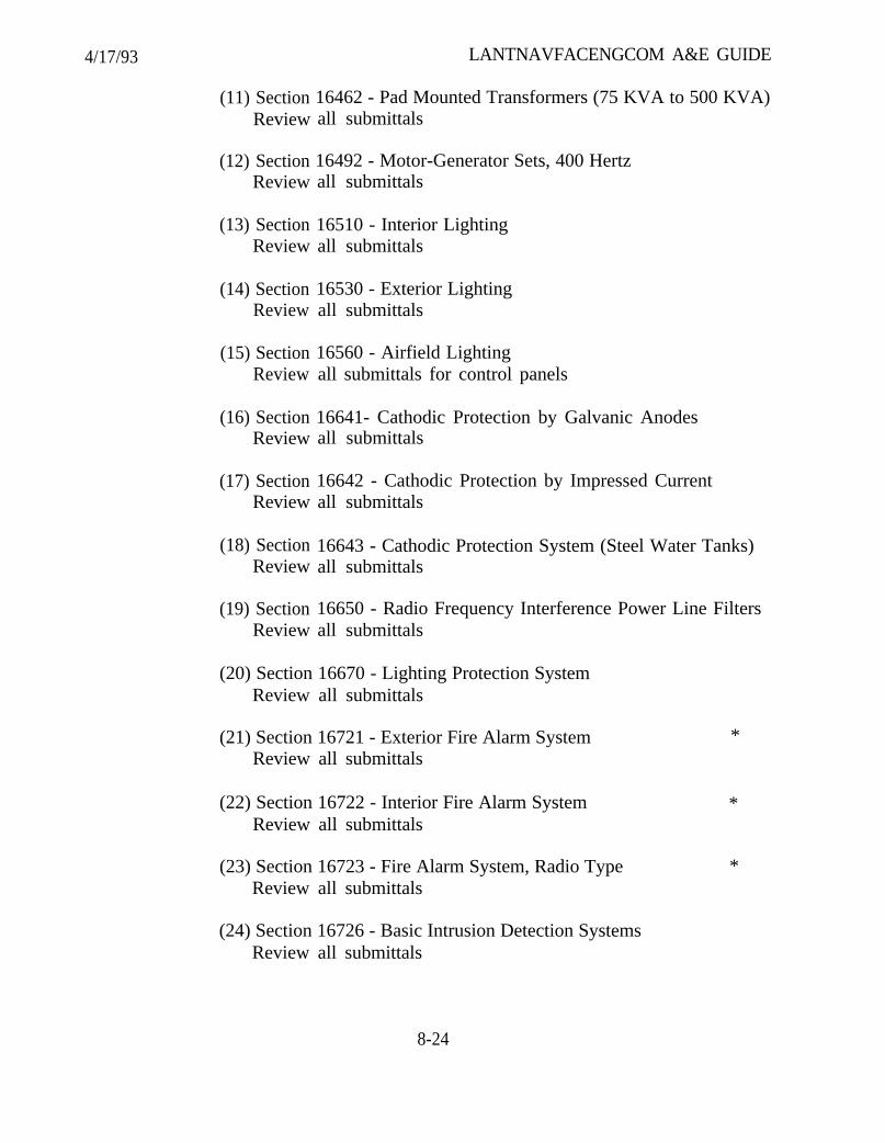
4/17/93 LANTNAVFACENGCOM A&E GUIDE
(11) Section 16462 - Pad Mounted Transformers (75 KVA to 500 KVA)Review all submittals
(12) Section 16492 - Motor-Generator Sets, 400 HertzReview all submittals
(13) Section 16510 - Interior LightingReview all submittals
(14) Section 16530 - Exterior LightingReview all submittals
(15) Section 16560 - Airfield LightingReview all submittals for control panels
(16) Section 16641- Cathodic Protection by Galvanic AnodesReview all submittals
(17) Section 16642 - Cathodic Protection by Impressed CurrentReview all submittals
(18) Section 16643 - Cathodic Protection System (Steel Water Tanks)Review all submittals
(19) Section 16650 - Radio Frequency Interference Power Line FiltersReview all submittals
(20) Section 16670 - Lighting Protection SystemReview all submittals
(21) Section 16721 - Exterior Fire Alarm System *Review all submittals
(22) Section 16722 - Interior Fire Alarm System *Review all submittals
(23) Section 16723 - Fire Alarm System, Radio Type *Review all submittals
(24) Section 16726 - Basic Intrusion Detection SystemsReview all submittals
8-24
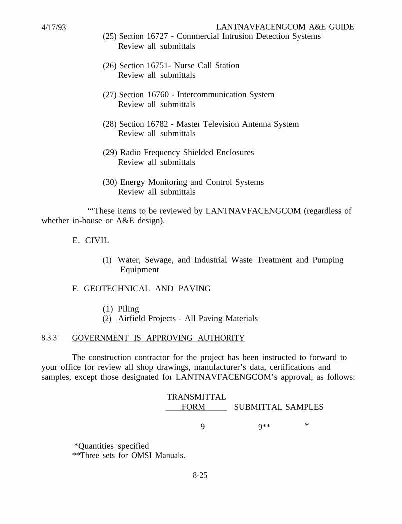
4/17/93(25) Section
Review
LANTNAVFACENGCOM A&E GUIDE16727 - Commercial Intrusion Detection Systemsall submittals
(26) Section 16751- Nurse Call StationReview all submittals
(27) Section 16760 - Intercommunication SystemReview all submittals
(28) Section 16782 - Master Television Antenna SystemReview all submittals
(29) Radio Frequency Shielded EnclosuresReview all submittals
(30) Energy Monitoring and Control SystemsReview all submittals
“‘These items to be reviewed by LANTNAVFACENGCOM (regardless ofwhether in-house or A&E design).
E. CIVIL
(1) Water, Sewage, and Industrial Waste Treatment and PumpingEquipment
F. GEOTECHNICAL AND PAVING
(1) Piling(2) Airfield Projects - All Paving Materials
8.3.3 GOVERNMENT IS APPROVING AUTHORITY
The construction contractor for the project has been instructed to forward toyour office for review all shop drawings, manufacturer’s data, certifications andsamples, except those designated for LANTNAVFACENGCOM’s approval, as follows:
TRANSMITTALFORM SUBMITTAL SAMPLES
9 9** *
*Quantities specified**Three sets for OMSI Manuals.
8-25
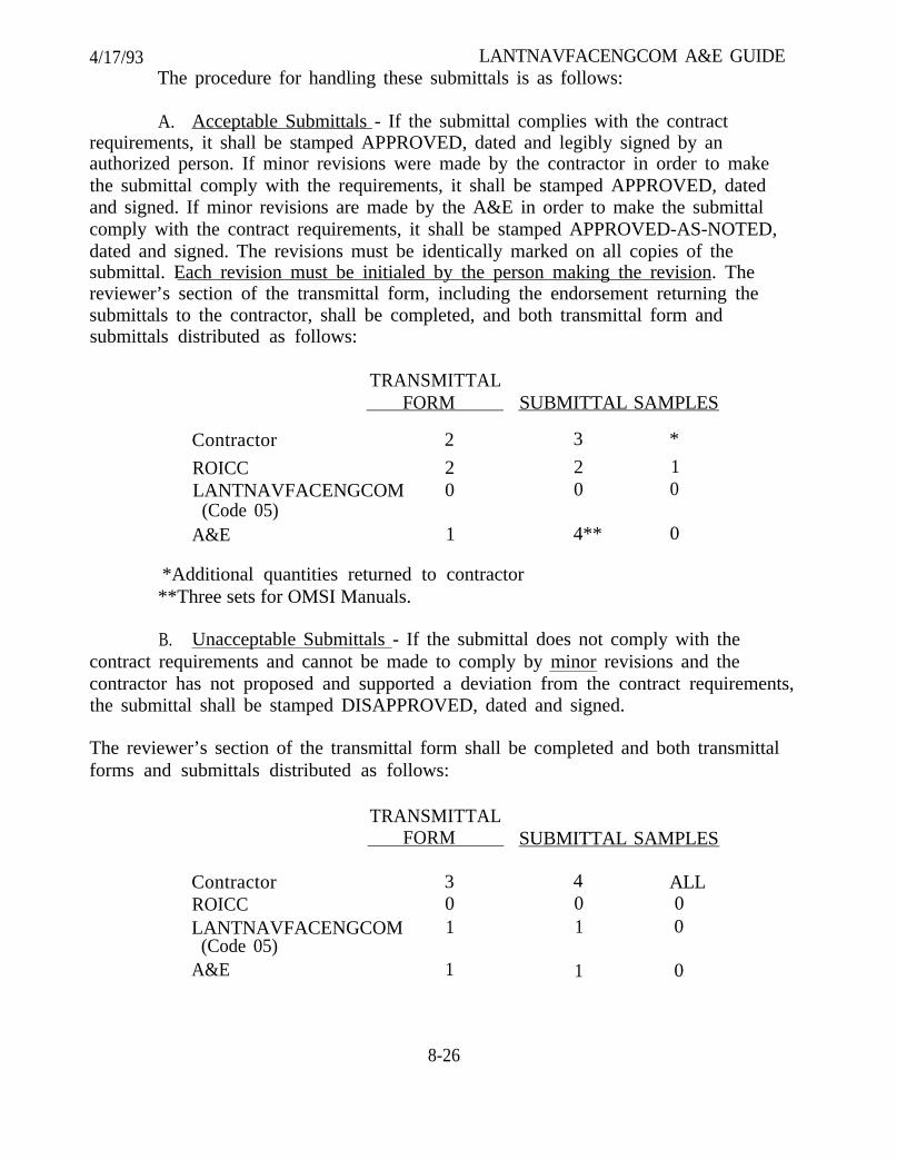
4/17/93 LANTNAVFACENGCOM A&E GUIDEThe procedure for handling these submittals is as follows:
A. Acceptable Submittals - If the submittal complies with the contractrequirements, it shall be stamped APPROVED, dated and legibly signed by anauthorized person. If minor revisions were made by the contractor in order to makethe submittal comply with the requirements, it shall be stamped APPROVED, datedand signed. If minor revisions are made by the A&E in order to make the submittalcomply with the contract requirements, it shall be stamped APPROVED-AS-NOTED,dated and signed. The revisions must be identically marked on all copies of thesubmittal. Each revision must be initialed by the person making the revision. Thereviewer’s section of the transmittal form, including the endorsement returning thesubmittals to the contractor, shall be completed, and both transmittal form andsubmittals distributed as follows:
TRANSMITTALFORM SUBMITTAL SAMPLES
Contractor 2 3 *
ROICC 2 2 1LANTNAVFACENGCOM 0 0 0
(Code 05)A&E 1 4** 0
*Additional quantities returned to contractor**Three sets for OMSI Manuals.
B. Unacceptable Submittals - If the submittal does not comply with thecontract requirements and cannot be made to comply by minor revisions and thecontractor has not proposed and supported a deviation from the contract requirements,the submittal shall be stamped DISAPPROVED, dated and signed.
The reviewer’s section of the transmittal form shall be completed and both transmittalforms and submittals distributed as follows:
TRANSMITTALFORM SUBMITTAL SAMPLES
Contractor 3 4 ALLROICC 0 0 0LANTNAVFACENGCOM 1 1 0
(Code 05)A&E 1 1 0
8-26

4/17/93 LANTNAVFACENGCOM A&E GUIDEC. Proposed deviations from the contract requirements - If the contractor
proposes a deviation from the contract requirements, it must be supported by thefollowing information:
(1) Reason for the proposed substitution.
procure.(2) If material or equipment is unavailable, document efforts made to
(3) Complete technical data on the proposed substitution, sufficient todetermine acceptability.
(4) Acknowledge that all changes caused by the proposed substitution willbe the responsibility of the contractor and at no additional cost to the Government.
(5) Proposed change, if any, in the contract price and/or time.
These submittals shall be reviewed but not stamped. The A&Ecomments/recommendations and reviewer action shall be noted on one copy of thetransmittal forms, the unstamped submittals and A&E cost estimate and forwarded tothe ROICC. Refer to Submittal Flow Chart #2.
Upon completion of review by LANTNAVFACENGCOM, the submittalwill be stamped, dated and signed, and distribution made to the contractor, ROICC,and A&E.
8.3.4 MISCELLANEOUS SUBMITTAL REVIEW ASPECTS
A. When a submittal must be revised by the A&E due to such reasons aschanged Government requirements or correction of design deficiency, it must beforwarded to this Command (Code 05) with an explanation for the new requirementsand the estimated change in contract price for the contractor to comply with the newrequirements.
B. Only certifications which state that the item submitted complies with thecontract requirements are acceptable. A statement that the item submitted is equal to orbetter than the specified item will not suffice.
C. When a submittal cannot be reviewed within two weeks, the ROICC mustbe advised of the estimated date of review completion.
D. The contractor has also been requested to submit three copies of hissubmittal register to your office. It is requested that you review this register to assurethat all submittals required by the contract specifications have been included. If the
8-27
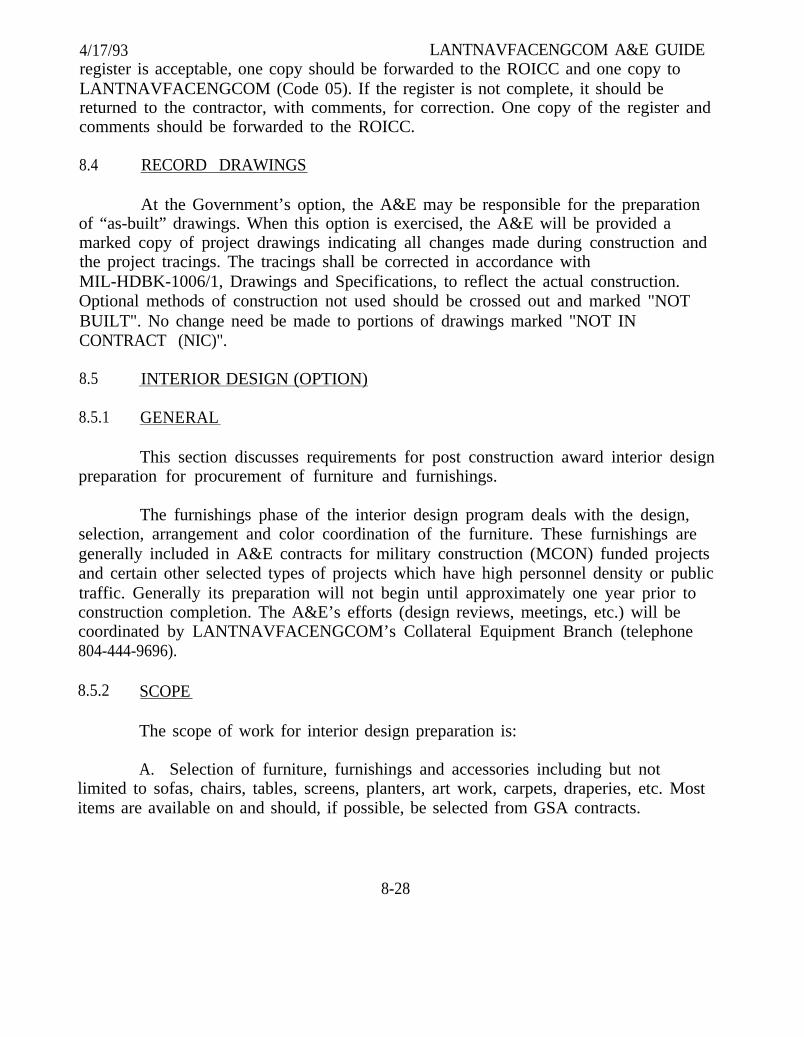
4/17/93 LANTNAVFACENGCOM A&E GUIDEregister is acceptable, one copy should be forwarded to the ROICC and one copy toLANTNAVFACENGCOM (Code 05). If the register is not complete, it should bereturned to the contractor, with comments, for correction. One copy of the register andcomments should be forwarded to the ROICC.
8.4 RECORD DRAWINGS
At the Government’s option, the A&E may be responsible for the preparationof “as-built” drawings. When this option is exercised, the A&E will be provided amarked copy of project drawings indicating all changes made during construction andthe project tracings. The tracings shall be corrected in accordance withMIL-HDBK-1006/1, Drawings and Specifications, to reflect the actual construction.Optional methods of construction not used should be crossed out and marked "NOTBUILT". No change need be made to portions of drawings marked "NOT INCONTRACT (NIC)".
8.5 INTERIOR DESIGN (OPTION)
8.5.1 GENERAL
This section discusses requirements for post construction award interior designpreparation for procurement of furniture and furnishings.
The furnishings phase of the interior design program deals with the design,selection, arrangement and color coordination of the furniture. These furnishings aregenerally included in A&E contracts for military construction (MCON) funded projectsand certain other selected types of projects which have high personnel density or publictraffic. Generally its preparation will not begin until approximately one year prior toconstruction completion. The A&E’s efforts (design reviews, meetings, etc.) will becoordinated by LANTNAVFACENGCOM’s Collateral Equipment Branch (telephone804-444-9696).
8.5.2 SCOPE
The scope of work for interior design preparation is:
A. Selection of furniture, furnishings and accessories including but notlimited to sofas, chairs, tables, screens, planters, art work, carpets, draperies, etc. Mostitems are available on and should, if possible, be selected from GSA contracts.
8-28
4/17/93 LANTNAVFACENGCOM A&E GUIDEB. For items not available on GSA contract, the A&E will prepare adequate
specifications and other data, such as written justifications giving reasons why itemsspecified were not on GSA contracts, necessary for procurement actions.
C. The A&E shall select and coordinate all colors, fabrics, etc., with the colorsof the building finishes. Although building finishes are selected during design, theA&E shall verify actual contractor applied finishes through field verification and/orcoordination with the ROICC staff.
D. Presentation boards of a minimum size of 15 x 20 inches shall be prepared.These boards are to include furniture placement plan, catalog cut-outs of furniture,furnishings and accessories, color samples, material swatches of draperies, carpets andfabrics.
E. A minimum of five interior design 8-1/2 x 11 inch binders/packages shallbe prepared and delivered to the Collateral Equipment Branch. These brochures shallinclude but at A&E discretion are not limited to:
(1) Floor plans indicating locations of all furniture, furnishings andaccessories. These items should be identified with an item number that keys to thepresentation boards and the furniture procurement list.
(2) Procurement lists identifying all items to be purchased by stocknumber (Federal Supply items), contract number (GSA contracts), identificationnumber and description (open purchase items), quantity, price, etc. Care shall be takenin the selection of all items to ensure that delivery times are reasonably within theconstruction completion time of the project, and GSA contracts will not be expired atthe time of purchase.
(3) Photographic color reproductions or color copies of the presentationboards reduced to fit 8-1/2 x 11 inch brochure size.
(4) Purchase specifications, drawings and other supporting data for openpurchase and special order items, e.g., draperies, custom-built screens or dividers, artwork, etc.
F. Advisory service as required to make changes resulting from changes inrequirements, nonavailability of items or materials previously selected, etc.
G. Room placement sheets should be provided for each room/area, listingeach item of furniture or equipment that will go into the area.
8-29

4/17/93 LANTNAVFACENGCOM A&E GUIDE8.5.3 DEVELOPMENT SEQUENCE AND SUBMITTAL REQUIREMENTS
The following sequence will be generally followed by the A&E in developingthe interior design plan:
A. Approximately twelve months before construction completion the contractoption will be awarded. The A&E will be contacted by the Collateral EquipmentBranch and direction provided on when to begin developing the furniture andequipment procurement package. A meeting with LANTNAVFACENGCOMCollateral Equipment and Interior Design representatives will be scheduled at thistime. The purpose of this meeting will be to clarify procedures and requirements,develop tentative schedule and obtain current GSA information. The A&E should notbegin work on this phase without contract authorization.
B. The A&E will visit the activity to review the program and update theroom-by-room furniture placement plans and collateral equipment list developedduring the Color Design.
C. Submit two copies of proposed plan and collateral equipment list toLANTNAVFACENGCOM Collateral Equipment Branch in rough draft format forLANTNAVFACENGCOM review. The purpose of this review is to ensure thatproposed plan complies with basic limitations imposed by Government regulations andeliminate obvious errors, e.g., stock numbers, quantities, etc. The plan is to be updatedbased on this review.
D. Visit to activity jointly by the A&E and LANTNAVFACENGCOMrepresentatives to present the plan by means of presentation boards and updated roughdraft listings to the activity command representatives.
E. The A&E will submit the original and four copies of the final procurementpackage modified in accordance with agreements reached during the final activitypresentation.
8.5.4 GUIDELINES FOR SELECTING FURNITURE AND ACCESSORIES
A. Facilities should have functional interiors, reasonably pleasant inappearance and conducive to the purpose for which they were constructed. Lavishdesign, “gold plated” in any respect or even having the appearance of being wasteful ofGovernment funds, should be avoided. In furniture and furnishings, items which arenot to be used include oriental and decorator rugs, period furniture reproductions
8-30
4/17/93 LANTNAVFACENGCOM A&E GUIDE(Williamsburg, French Provincial, Early American, etc.) figurines or “objects d’art”, freestanding decorator items such as large world globes, leather covered furniture, andoriginal paintings or numbered prints, especially if signed by the artist, ornatechandeliers and elaborate window coverings.
B. Criteria for furniture selection shall include function, anthropometricconsiderations, maintenance, durability, comfort and cost. Careful consideration shallbe given to coordination of building and furniture finishes and colors, also shelving,storage and other similar tall or high density equipment should conform to fireregulations regarding overhead clearances, density, etc.
C. Furniture selections should be made, to the greatest extent possible fromitems available on General Service Administration (GSA) contracts. Selection ofsubstitutions for items on contract must be supported by detailed information anddocumentation. This justification must accompany any waivers submitted to the GSArequesting procurement for non-standard items.
D. Provide detailed working drawings and specifications for theprocurement, fabrication and installation of custom furniture, etc., from commercialsources.
E. Technical equipment, linens (except draperies and bedspreads),housekeeping items and other equipment shall not be included in the procurementpackage.
8.6 OPERATION AND MAINTENANCE SUPPORT INFORMATION (OMSI)(OPTION)
At the Government’s option, preparation of OMSI manuals is an A&Eresponsibility.
OMSI manuals are developed during construction of a facility to provide theActivity with the following:
Clear, comprehensive data needed to safely and efficiently operate andmaintain the actual products and systems built into a facility.
The principal OMSI elements which may be included in the manuals are:
8-31
4/17/93 LANTNAVFACENGCOM A&E GUIDEOperation and Maintenance Manual
l Overall system configuration and operationl System flow diagramsl Start-up, normal operation and shut-down proceduresl Normal operating temperatures, pressures, flow rates, etc.l Emergency operating and safety instructionsl Preventive maintenance plan and schedulel Troubleshooting guide and diagnostic techniquesl Repair and maintenance procedures, including spare parts, special
tools and test equipmentl Environmental considerationsl Training plan, staffing requirements and personnel qualificationsl Removal and replacement instructions
Operating Manual
l System design discussionl Procedures for normal start-up, operation and shutdown in manual
and automatic modesl Floor plans and schematic diagrams for flow, piping and
instrumentationl Control set points and calibration requirementsl Procedures for abnormal/alternate operational modes
User Manual
l As-built record of product and O&M data, indexed by specification,location section
l Basic descriptive data on facility; basis of designl Single line floor plansl Utility connections and cut-off pointsl Special warranty datal Expanded operation, maintenance and repair information for HVAC,
fire protection and roofing systems
All Military Construction Navy Projects (MCON) now require some degree ofOMSI (minimum of User Manual) with the exception of projects such as LandAcquisition, Paving and Dredging. Projects requiring OMSI can be classified as either aType A, B, or C. The standard package for each type of OMSI is as follows:
8-32

4/17/93Type A OMSI
LANTNAVFACENGCOM A&E GUIDE
(1) Operation and Maintenance Manual(2) User Manual
Type B OMSI (Do not use if maintenance and repair information isrequired)
(1) Operating Manual(2) User Manual
Type C OMSI
(1) User Manual
The degree of OMSI required will vary with the complexity of systems andtype of facility.
A. Facilities having complex systems such as the following would normallyrequire a Type A OMSI:
Petroleum, Oil and Lubricant (POL) Transfer/Loading FacilitiesLarge/Complex Computer Operations CenterTraining Facilities with Complex SystemsAircraft Maintenance ShopsMissile Assembly and Maintenance ShopsShip Maintenance ShopsLaboratoriesCentral Refrigeration PlantsMedical FacilitiesCommand Communication and Operation CentersPower PlantsHeating PlantsIndustrial Waste and Sewage Treatment PlantsWater Supply, Treatment and Storage, PotablePlating Shops
B. Less complex facilities where proper operation of the facility or system iscritical a Type B OMSI may be appropriate as follows (may require Type A OMSI ifmaintenance and repair information is needed):
8-33
4/17/93 LANTNAVFACENGCOM A&E GUIDEOperation and Training FacilitiesMiscellaneous/Utilities
C. Rather simple facilities such as BEQ, BOQ, Chapels, Admin Facilities,Warehouses and Community Facilities usually require a Type C OMSI.
Depending on the complexity of a particular system, even a simple facilitysuch as a Child Care Center could need a Type A OMSI to provide an OMSI Operationand Maintenance Manual for that system; e.g., Variable Air Volume (VAV) or ThermalStorage System. A project such as a hospital, however, would typically cover fifteen ormore systems in the manual.
Successful A&E preparation of an excellent quality OMSI manual requiresthat the specification include NFGS 01730, “Operation and Maintenance Data”, and thatit be properly referenced in the technical sections to specify “Data Packages” to besubmitted by the construction contractor. The A&E preparing the OMSI manuals usesthis data to develop comprehensive coverage of a system based on the as-built productsin this facility.
Three sets of all approved submittals (except samples) must be retained bythe A&E for preparation of the OMSI manuals.
LANTNAVFACENGCOM PM will advise the A&E of the type of OMSIneeded for each project. However, A&E recommendations are solicited on changes tothe OMSI type based on complexity of systems as design develops. Specific scopes ofwork for each OMSI manual are provided in Appendix A.
8.7 CATHODIC PROTECTION SYSTEM INSPECTION, TESTING ANDACCEPTANCE (OPTION)
At the Government’s option, the A&E’s corrosion engineer may be required toact as the Government corrosion engineer in final inspection, testing and acceptance ofthe cathodic protection systems installed by the construction contract for the ROICC.Responsibility may include:
A On-site consultation with the ROICC on the critical stages of construction.
B Review of Construction Contractor’s corrosion engineer cathodicprotection system start-up survey report.
8-34
4/17/93 LANTNAVFACENGCOM A&E GUIDEC. Final inspection and testing of cathodic protection systems, approximately
30 days after construction contractor’s report submittal, to verify the contractor’s reportand insure structure protection levels are in accordance with National Association ofCorrosion Engineers (NACE) recommended practices.
D. Confirmation of interference current mitigation to other structures.
E. Provide ROICC with “punch list” of construction contractor deficiencies onthe installation of the cathodic protection systems.
F. Prepare a final inspection report noting all test results to document levelsof cathodic protection throughout the structure and to establish baseline parameters.
8-35

4/17/93 LANTNAVFACENGCOM A&E GUIDE
(Blank Page)
8-36
3/93 LANTNAVFACENGCOM A&E GUIDE
ATTACHMENT A
ELECTRICAL DESIGN GUIDE
PREPARED BY:
ELECTRICAL ENGINEERING BRANCHENGINEERING AND DESIGN DIVISION
ATLANTIC DIVISIONNAVAL FACILITIES ENGINEERING COMMAND
NORFOLK, VIRGINIA
NOTE: Changes in the 3/93 edition of the Electrical Design Guide (as compared tothe 3/91 edition) are indicated by vertical lines in the margin.

3/93 LANTNAVFACENGCOM A&E GUIDE
ATTACHMENT A. ELECTRICAL DESIGN GUIDE
A.1
A.1.1
A.1.2
A.1.3
A.1.4
A.1.4.1
A.1.4.2
A.1.4.3
A.1.5
A.1.5.1
A.1.5.2
A.1.5.3
A.1.5.4
A.1.5.5
A.1.6
A.1.7
A.1.8
A.1.9
A.1.10
A.1.11
A.1.12
A1.13
A.1.14
TABLE OF CONTENTS Page
GENERAL . . . . . . . . . . . . . . . . . . . . . . . . . . . . . . . . . . . . . . . . . . A-1
PURPOSE . . . . . . . . . . . . . . . . . . . . . . . . . . . . . . . . . . . . . . . . . . A-1
DRAWING FORMAT . . . . . . . . . . . . . . . . . . . . . . . . . . . . . . . . . A-1
PREPARING SPECIFICATIONS . . . . . . . . . . . . . . . . . . . . . . . . . A-2
CALCULATIONS . . . . . . . . . . . . . . . . . . . . . . . . . . . . . . . . . . . . . A-2
DESIGNER RESPONSIBILITY . . . . . . . . . . . . . . . . . . . . . . . . . . A-2
REQUIRED CALCULATIONS . . . . . . . . . . . . . . . . . . . . . . . . . . A-2
FORMAT. . . . . . . . . . . . . . . . . . . . . . . . . . . . . . . . . . . . . . . . . . . . A-3
RISER DIAGRAMS . . . . . . . . . . . . . . . . . . . . . . . . . . . . . . . . . . . A-3
POWER ONE-LINE/RISER DIAGRAMS . . . . . . . . . . . . . . . . . . A-3
TELEPHONE RISER DIAGRAM . . . . . . . . . . . . . . . . . . . . . . . . A-4
INTERCOMMUNICATION/PAGING RISER DIAGRAM . . . . . . A-4
FIRE ALARM RISER DIAGRAM . . . . . . . . . . . . . . . . . . . . . . . . A-4
OTHER . . . . . . . . . . . . . . . . . . . . . . . . . . . . . . . . . . . . . . . . . . . . . A-5
MULTIPLE CONDUIT/CABLE RUNS . . . . . . . . . . . . . . . . . . . . A-5
REMOVAL OR REPLACEMENT OF EQUIPMENT
CONTAINING DIELECTRIC FLUID . . . . . . . . . . . . . . . . . . . . A-5
REMOVAL OF EXISTING CABLES . . . . . . . . . . . . . . . . . . . . . . A-6
MODIFICATION OF OR ADDITIONS TO EXISTING
ELECTRICAL EQUIPMENT . . . . . . . . . . . . . . . . . . . . . . . . . . A-6
ASBESTOS . . . . . . . . . . . . . . . . . . . . . . . . . . . . . . . . . . . . . . . . . . A-6
SCHEDULING AND SEQUENCING CONSTRUCTION
CONTRACTS . . . . . . . . . . . . . . . . . . . . . . . . . . . . . . . . . . . . . . . A-7
GOVERNMENT FURNISHED EQUIPMENT (GFE) . . . . . . . . . A-7
BREAKER/RELAY SETTINGS . . . . . . . . . . . . . . . . . . . . . . . . . . A-9
NON-LINEAR LOADS . . . . . . . . . . . . . . . . . . . . . . . . . . . . . . . . . A-9
ii

3/93 LANTNAVFACENGCOM A&E GUIDE
A.1.15
A.2
A.2.1
A.2.1.1
A.2.1.2
A.2.1.3
A.2.1.4
A.2.2
A.2.2.1
A.2.2.2
A.2.2.3
A.2.2.4
A.2.3
A.2.3.1
A.2.3.2
A.2.3.3
A.2.3.4
A.2.3.5
A.2.4
A.2.5
A.2.5.1
A.2.5.2
A.2.5.3
A.2.6
A.2.7
A.3
A.3.1
A.3.1.1
HAZARDOUS (CLASSIFIED) LOCATIONS . . . . . . . . . . . . . . . . A-10
ELECTRICAL SYSTEMS . . . . . . . . . . . . . . . . . . . . . . . . . . . . . . A-10
UNDERGROUND ELECTRICAL SYSTEMS . . . . . . . . . . . . . . . A-10
GENERAL GUIDANCE . . . . . . . . . . . . . . . . . . . . . . . . . . . . . . . A-10
MANHOLES (MH’S) AND HANDHOLES (HH’S) . . . . . . . . . . . A-10
LOCATING MANHOLES (MH’S) AND HANDHOLES (HH’S) . A-11
DUCTBANKS . . . . . . . . . . . . . . . . . . . . . . . . . . . . . . . . . . . . . . . A-11
OVERHEAD DISTRIBUTION SYSTEMS . . . . . . . . . . . . . . . . . A-11
CRITERIA . . . . . . . . . . . . . . . . . . . . . . . . . . . . . . . . . . . . . . . . . A-11
GENERAL RULES . . . . . . . . . . . . . . . . . . . . . . . . . . . . . . . . . . A-11
POLE PLATES AND CONDUCTORS . . . . . . . . . . . . . . . . . . . . A-12
FUSE PROTECTION . . . . . . . . . . . . . . . . . . . . . . . . . . . . . . . . . A-13
400 HERTZ SYSTEMS . . . . . . . . . . . . . . . . . . . . . . . . . . . . . . . . A-14
DESIGN CRITERIA . . . . . . . . . . . . . . . . . . . . . . . . . . . . . . . . . . A-14
NOMINAL UTILIZATION VOLTAGE . . . . . . . . . . . . . . . . . . . A-14
TECHNIQUES FOR MINIMIZING VOLTAGE DROP . . . . . . . A-14
ISOLATING 400 HZ SYSTEMS . . . . . . . . . . . . . . . . . . . . . . . . . A-14
EQUIPMENT RATING . . . . . . . . . . . . . . . . . . . . . . . . . . . . . . . A-15
DIRECT CURRENT (DC) SYSTEMS . . . . . . . . . . . . . . . . . . . . A-15
TELEPHONE SYSTEMS . . . . . . . . . . . . . . . . . . . . . . . . . . . . . . A-15
CRITERIA . . . . . . . . . . . . . . . . . . . . . . . . . . . . . . . . . . . . . . . . . A-15
GENERAL DESIGN PROCEDURE . . . . . . . . . . . . . . . . . . . . . . A-15
TELEPHONE BACKBOARD . . . . . . . . . . . . . . . . . . . . . . . . . . . A-15
EMERGENCY LIGHTS, EXIT LIGHTS, AND FIRE
PROTECTION SYSTEMS . . . . . . . . . . . . . . . . . . . . . . . . . . . . A-16
GROUNDING SYSTEMS . . . . . . . . . . . . . . . . . . . . . . . . . . . . . . . A-17
MEDIUM-VOLTAGE EQUIPMENT (2,000 - 69,000 VOLTS) . . . A-17
MEDIUM-VOLTAGE CABLE . . . . . . . . . . . . . . . . . . . . . . . . . . A-17
DESCRIPTION . . . . . . . . . . . . . . . . . . . . . . . . . . . . . . . . . . . . . . A-17
iii
3/93 LANTNAVFACENGCOM A&E GUIDE
A.3.1.2 INSULATION TYPE . . . . . . . . . . . . . . . . . . . . . . . . . . . . . . . . .
A.3.1.3 CABLE SHIELDS . . . . . . . . . . . . . . . . . . . . . . . . . . . . . . . . . . . .
A.3.1.4 NUMBER OF CONDUCTORS . . . . . . . . . . . . . . . . . . . . . . . . . . .
A.3.1.5 EXISTING CONDITIONS . . . . . . . . . . . . . . . . . . . . . . . . . . . . .
A.3.2 TRANSFORMERS . . . . . . . . . . . . . . . . . . . . . . . . . . . . . . . . . . .
A.3.2.1 PAD-MOUNTED TRANSFORMER VERSUS SECONDARY
A.3.2.2
A.3.2.3
A.3.3
A.3.4
A.3.5
A.3.6
A.4
A.4.1
A.4.2
A.4.3
A.4.4
A.5
A.5.1
A.5.1.1
A.5.1.2
A.5.2
A.5.3
A.5.3.1
A.5.3.2
A.5.3.3
A.5.3.4
UNIT SUBSTATION . . . . . . . . . . . . . . . . . . . . . . . . . . . . . . . .
LOCATION . . . . . . . . . . . . . . . . . . . . . . . . . . . . . . . . . . . . . . . . .
DESCRIPTION . . . . . . . . . . . . . . . . . . . . . . . . . . . . . . . . . . . . . .
REGULATORS . . . . . . . . . . . . . . . . . . . . . . . . . . . . . . . . . . . . . .
CAPACITORS . . . . . . . . . . . . . . . . . . . . . . . . . . . . . . . . . . . . . . .
SURGE ARRESTERS AND FUSED CUTOUTS . . . . . . . . . . . .
SWITCHGEAR . . . . . . . . . . . . . . . . . . . . . . . . . . . . . . . . . . . . . .
METERING, PT’S AND CT’S, INSTRUMENTATION,
RELAYING . . . . . . . . . . . . . . . . . . . . . . . . . . . . . . . . . . . . .
WATTHOUR METER . . . . . . . . . . . . . . . . . . . . . . . . . . . . . . . .
PT’S AND CT’S . . . . . . . . . . . . . . . . . . . . . . . . . . . . . . . . . . . . . .
INSTRUMENTATION . . . . . . . . . . . . . . . . . . . . . . . . . . . . . . . .
RELAYING . . . . . . . . . . . . . . . . . . . . . . . . . . . . . . . . . . . . . . . . .
LOW-VOLTAGE AND UTILIZATION EQUIPMENT . . . . . . . .
PANELBOARDS . . . . . . . . . . . . . . . . . . . . . . . . . . . . . . . . . . . . .
GENERAL RULES . . . . . . . . . . . . . . . . . . . . . . . . . . . . . . . . . .
PANELBOARD SCHEDULES . . . . . . . . . . . . . . . . . . . . . . . . . .
SWITCHBOARDS AND SWITCHGEAR . . . . . . . . . . . . . . . . . .
LIGHTING . . . . . . . . . . . . . . . . . . . . . . . . . . . . . . . . . . . . . . . . .
DESIGN CRITERIA . . . . . . . . . . . . . . . . . . . . . . . . . . . . . . . . . .
GENERAL GUIDELINES . . . . . . . . . . . . . . . . . . . . . . . . . . . . .
EXTERIOR SPORTS ILLUMINATION . . . . . . . . . . . . . . . . . . .
FIXTURE SCHEDULE . . . . . . . . . . . . . . . . . . . . . . . . . . . . . . .
A-17
A-18
A-18
A-18
A-18
A-18
A-18
A-19
A-19
A-20
A-20
A-21
A-21
A-21
A-21
A-21
A-21
A-22
A-22
A-22
A-22
A-23
A-24
A-24
A-24
A-24
A-25
iv
3/93 LANTNAVFACENGCOM A&E GUIDE
A.5.3.5
A.5.3.6
A.5.4
A.5.4.1
A.5.4.2
A.5.4.3
A.5.4.4
A.5.5
A.5.5.1
A.5.5.2
A.5.5.3
A.6
A.7
A.8
A.9
A.10
A.11
A.12
A.13
FIXTURE DETAILS . . . . . . . . . . . . . . . . . . . . . . . . . . . . . . . . . .
FIXTURE CONSIDERATIONS . . . . . . . . . . . . . . . . . . . . . . . . .
POLICY CONCERNING MAGNETIC CONTACTORS,
MAGNETIC MOTOR CONTROLLERS, AND DISCONNECT
SWITCHES . . . . . . . . . . . . . . . . . . . . . . . . . . . . . . . . . . . . . . .
HVAC EQUIPMENT . . . . . . . . . . . . . . . . . . . . . . . . . . . . . . . . .
UNIT HEATERS . . . . . . . . . . . . . . . . . . . . . . . . . . . . . . . . . . . .
OTHER EQUIPMENT . . . . . . . . . . . . . . . . . . . . . . . . . . . . . . . .
COMMENTS . . . . . . . . . . . . . . . . . . . . . . . . . . . . . . . . . . . . . . . .
MOTOR CONTROL EQUIPMENT . . . . . . . . . . . . . . . . . . . . . .
EQUIPMENT SELECTIONS . . . . . . . . . . . . . . . . . . . . . . . . . . .
SELECTION GUIDANCE . . . . . . . . . . . . . . . . . . . . . . . . . . . . .
MOTOR CONTROL CENTERS (MCC’S) . . . . . . . . . . . . . . . . . .
LIGHTNING PROTECTION . . . . . . . . . . . . . . . . . . . . . . . . . . .
CATHODIC PROTECTION . . . . . . . . . . . . . . . . . . . . . . . . . . . .
INTRUSION DETECTION SYSTEMS (IDS) . . . . . . . . . . . . . . .
UNINTERRUPTIBLE POWER SYSTEMS (UPS) . . . . . . . . . . .
INSTRUMENTATION AND CONTROLS . . . . . . . . . . . . . . . . .
HIGH ALTITUDE ELECTROMAGNETIC PROTECTION
(HEMP) . . . . . . . . . . . . . . . . . . . . . . . . . . . . . . . . . . . . . . . . .
ORDNANCE FACILITIES . . . . . . . . . . . . . . . . . . . . . . . . . . . . .
AUTOMATIC STANDBY POWER SYSTEMS . . . . . . . . . . . . . .
A-25
A-25
A-25
A-26
A-26
A-26
A-27
A-27
A-27
A-27
A-28
A-28
A-28
A-28
A-28
A-28
A-28
A-29
A-29

3/93 LANTNAVFACENGCOM A&E GUIDE
FIGURE 1.
FIGURE 2.
FIGURE 3.
FIGURE 4.
FIGURE 5.
FIGURE 6.
FIGURE 7.
FIGURE 8.
FIGURE 9.
FIGURE 10.
FIGURE 11.
FIGURE 12.
FIGURE 13.
FIGURES Page
ONE-LINE DIAGRAM . . . . . . . . . . . . . . . . . . . . . . . . . . . . . A-31
ONE-LINE/RISER DIAGRAM . . . . . . . . . . . . . . . . . . . . . . . A-32
PAD MTD TRANSFORMER DETAIL
UNGROUNDED OR SINGLE GROUNDED PRIMARY
SYSTEM - WITH SURGE ARRESTERS . . . . . . . . . . . . . . A-33
PAD MTD TRANSFORMER DETAIL
UNGROUNDED OR SINGLE GROUNDED PRIMARY
SYSTEM - WITHOUT SURGE ARRESTERS . . . . . . . . . . A-33
PAD MTD TRANSFORMER DETAIL
MULTI-GROUNDED PRIMARY SYSTEM (DELTA-WYE) -
WITH SURGE ARRESTERS . . . . . . . . . . . . . . . . . . . . . . . A-34
PAD MTD TRANSFORMER DETAIL
MULTI-GROUNDED PRIMARY SYSTEM (DELTA-WYE) -
WITHOUT SURGE ARRESTERS . . . . . . . . . . . . . . . . . . . A-34
PAD MTD TRANSFORMER DETAIL
MULTI-GROUNDED PRIMARY SYSTEM (WYE-WYE) -
WITH SURGE ARRESTERS . . . . . . . . . . . . . . . . . . . . . . . A-35
PAD MTD TRANSFORMER DETAIL
MULTI-GROUNDED PRIMARY SYSTEM (WYE-WYE) -
WITHOUT SURGE ARRESTERS . . . . . . . . . . . . . . . . . . . A-35
COMMUNICATIONS COORDINATION AND
RESPONSIBILITY CHART. . . . . . . . . . . . . . . . . . . . . . . . . A-36
PANELBOARD SCHEDULES - THREE PHASE . . . . . . . . . A-37
PANELBOARD SCHEDULE - SINGLE PHASE . . . . . . . . . . A-38
LIGHTING FIXTURE SCHEDULE . . . . . . . . . . . . . . . . . . . . A-38
ELECTRICAL/MECHANICAL INTERFACE
ILLUSTRATIONS . . . . . . . . . . . . . . . . . . . . . . . . . . . . . . . . A-39
vi
3/93 LANTNAVFACENGCOM A&E GUIDE
FIGURE 14. ELECTRICAL/MECHANICAL INTERFACE
ILLUSTRATIONS . . . . . . . . . . . . . . . . . . . . . . . . . . . . . . . . A-40
FIGURE 15. ELECTRICAL/MECHANICAL INTERFACE
ILLUSTRATIONS . . . . . . . . . . . . . . . . . . . . . . . . . . . . . . . . A-41
APPENDIXES
A. ELECTRICAL GUIDE LEGEND (INTERIOR) . . . . . . . . . . . . . . . . . . A-1 thru A-6
B. ELECTRICAL GUIDE LEGEND (EXTERIOR - UNDERGROUND) . B-1 thru B-3
C. ELECTRICAL GUIDE LEGEND (EXTERIOR - OVERHEAD) . . . . . C-1 thru C-4
D. ELECTRICAL GUIDE LEGEND (ONE-LINE DIAGRAMS) . . . . . . . . D-1 thru D-4
vii
3/93 LANTNAVFACENGCOM A&E GUIDE
ATTACHMENT A. ELECTRICAL DESIGN GUIDE
A.1
A.1.1
A.1.2
GENERAL
PURPOSE
The Electrical Design Guide has been developed for use by Architect-Engineer (A&E) firms that provide electrical design services under contractto the Atlantic Division, Naval Facilities Engineering Command(LANTNAVFACENGCOM). The information contained in this guide is notintended to cover every situation, but is to be followed where applicable.Situations not covered by this manual should be approached with soundtechnical judgment, common sense, and with the intent of this guide in mind.
This guide will be reviewed and updated periodically; therefore, suggestionsfor improvements or additions are invited. The LANTNAVFACENGCOMpoint of contact is Electrical Design Branch, Code 404, Mr. P. E. Glenn, P.E.,telephone 804-444-9904.
DRAWING FORMAT
a. Lighting and power shall not be shown on the same floor plan, unlessthe scale of the plan is 1/4" = 1'-0" or larger.
b. Provide adequate plans (including demolition, existing conditions, andnew work), legends, details, diagrams, schedules, etc. Provide“demolition” floor plans separate and distinct from “new work” floorplans, except where only minor demolition work is required.
c. Electrical site plans shall be separate and distinct from other utility siteplans and shall be included with the electrical drawings. However,when project requires only minor utility work, electrical and civil siteplans may be combined. “Demolition” and “New Work” shouldnormally be shown on the same site plan.
d. The orientation of electrical drawings shall be in accordance withparagraph 5.4 of the basic guide. In addition, the orientation of partialbuilding or site plans shall be identical to the orientation of the largerplan from which the partial was taken.
e. When cross-referencing sheets? each reference to a detail, partial plan,etc., shall indicate the exact title of that particular detail, partial plan,etc. Avoid vague and ambiguous references.
Attachment A-1
3/93 LANTNAVFACENGCOM A&E GUIDE
A.1.3
f. Present drawings in a clear and concise manner specifically definingthe work to be accomplished. Locate legends on the first sheet of theapplicable electrical drawings. Use multiple legends where required,carefully identifying the specific use of each legend. Avoid usingcomposite legends which include all symbols but fail to indicate whichsymbols are to be used where. Use symbols as indicated in attachedguide legends (see Appendixes A through D).
PREPARING SPECIFICATIONS
See Section 6 of the basic guide.
A.1.4 CALCULATIONS
A.1.4.1 DESIGNER RESPONSIBILITY
The designer is responsible for calculations to verify proper design andoperation of the facility to the point of connection to the existing electricalsystems.
A.1.4.2 REQUIRED CALCULATIONS
Whenever the sizing of electrical transformers, breakers, electric cables, etc.,is to be performed, provide calculations to verify proper facility design. Thefollowing calculations are usually required:
a.
b.
c.
d.
e.
f.
Short Circuit: Provide an impedance diagram with calculated fault andimpedance values. Refer to IEEE Std 399, “IEEE RecommendedPractice for Industrial and Commercial Power Systems Analysis”. Fortransformers larger than 1000 kVA in size, the primary or sourceimpedance shall not be assumed to be equal to 0; source impedance insuch situations shall be requested from LANTNAVFACENGCOMCode 163.
Voltage Drop: Quote applicable source for this calculation.
Lighting: Interior and exterior.
Load Analysis: Indicate connected load and demand load utilizingappropriate diversity and demand factors.
Motor Starting/Flicker Analysis: For motors 50 hp and greater.
Sag, Tension, and Guying Analysis: For overhead distribution systems.
Attachment A-2
3/93 LANTNAVFACENGCOM A&E GUIDE
g. Manhole Design Calculations: Provide calculations verifying thatselected manhole size is adequate for training and splicing of containedcables.
h. Cable Pulling Tension Calculations: For straight duct runs exceeding400 feet in length and for any duct run with sweeps or multiple bends.
A.1.4.3 FORMAT
a. Assumptions and given data shall be clearly provided. Calculationsshall be described fully and shall be written clearly.
b. Computer printouts are acceptable only if accompanied byexplanations to allow adequate review of calculation methods andresults.
A.1.5 RISER DIAGRAMS
A.l.5.1 POWER ONE-LINE/RISER DIAGRAMS
a. A power one-line diagram is required for:
(1) Medium-voltage distribution systems, including substations andswitching stations.
(2) Systems involving generation, either low voltage or mediumvoltage.
(3) Building switchgear, switchboards, and main distribution panels(MDP’s).
b. A one-line diagram is illustrated by Figure 1. The diagram shall showcomponents (including metering, protective relaying, etc.) and feederconductor and conduit sizes. Connections of transformers, PT’s, CT’s,capacitors, etc.. shall be shown on the one-line diagram by means ofthe proper symbol. Refer to other sections of this guide for specificinformation required to be shown for each component.
c. On most projects, it would be appropriate to combine the one-linediagram with a riser diagram. The one-line diagram would begin withthe medium-voltage system and continue through the transformer upto and including the main breaker and feeder breakers within theMDP. Sub-panels beyond the MDP would be shown in the riser
Attachment A-3

3/93 LANTNAVFACENGCOM A&E GUIDE
A.1.5.2
diagram format. A combined one-line/riser diagram is illustrated byFigure 2.
TELEPHONE RISER DIAGRAM
Show the following:
a.
b.
c.
d.
Building stub out and exterior conduit or duct runs to point ofconnection (include cable where applicable - see Figure 9)
Mounting backboard (include items addressed by paragraphsA.2.5.3b., 3c. and 3d.)
Outlets - include room numbers
Cables and raceways - include modular jacks
A.1.5.3 INTERCOMMUNICATION/PAGING RISER DIAGRAM
Show the following:
a.
b.
c.
d.
Power source
Master station with associated equipment
Speakers, outlets, etc. - include room numbers
Wiring/conduit between components
A.1.5.4 FIRE ALARM RISER DIAGRAM
Show the following:
a. Power source
b. Control panel
c. Connection to activity fire alarm system
d. Manual boxes
e. Pressure/flow switches
f. Detectors
Attachment A-4

3/93 LANTNAVFACENGCOM A&E GUIDE
g. Bells and alarms
h. Connection to shut down air-handling units
A.1.5.5 OTHER
Similar to telephone or intercommunication/paging.
A.l.6 MULTIPLE CONDUIT/CABLE RUNS
To avoid misinterpretation as to the quantity of cables and conduit requiredin multiple conduit and cable runs, use one of the following acceptabledescriptions:
Acceptable: Two 3½" conduits, each containing four - 500 kcmil and one- #2 Gnd
Acceptable: Two 3½" conduits, each with four - 500 kcmil and one - #2Gnd
Acceptable: Two 3½" conduits, with four - 500 kcmil and one - #2 Gndin each conduit
Unacceptable: Two sets of four - 500 kcmil and one - #2 Gnd in 3½"conduit
Unacceptable: Parallel Service: four - 500 kcmil and one - #2 Gnd in3½" conduit
A.1.7 REMOVAL OR REPLACEMENT OF EQUIPMENT CONTAININGDIELECTRIC FLUID
Determine the PCB content of each item of electrical equipment. If theequipment is labeled PCB filled, then it shall be assumed to contain PCBsand the following steps shall be taken:
a. Identify and request in writing that the activity test a sample ofdielectric fluid for each piece of equipment in question.
b. The test results shall be used to identify the equipment on plans as:
(1) “Non-PCB” - contains less than 50 ppm.
(2) “PCB” - contains 50 ppm or greater.
Attachment A-5
3/93 LANTNAVFACENGCOM A&E GUIDE
c. Capacitors shall be identified as follows:
A.1.8
A.1.9
(1) Capacitors containing less than 3 pounds of dielectric fluid - notrequired to be identified.
(2) Capacitors containing 3 or more pounds of dielectric fluid andmade prior to 1975 - “PCB.”
(3) Capacitors containing 3 or more pounds of dielectric fluid andmade in 1975 or later - “Non-PCB.”
d. The contract specifications shall require that PCB equipment, afterremoval from service, but before being moved from equipmentlocation and regardless of equipment condition, be drained of fluidsand that the fluids be containerized. On individual projects, verify withthe activity and with LANTNAVFACENGCOM EnvironmentalPrograms Branch (Code 182) whether PCB equipment and fluids areto be turned over to Public Works for disposal by the Government orare to be removed and disposed of under the construction contract.
REMOVAL OF EXISTING CABLES
When a project calls for removal of existing cables, these cables should bephysically removed and not simply abandoned in place. The associated ductsor conduits, if concealed and not in the way of new construction, may beabandoned in place. Existing direct buried cables would also normally beabandoned in place.
MODIFICATION OF OR ADDITIONS TO EXISTING ELECTRICALEQUIPMENT
Record, on the drawings, the manufacturer’s name and other pertinentmanufacturer’s identification (e.g., serial number, model number, style, andany other manufacturer’s identifying markings). Normally it is difficult todepict “existing to remain,” “existing, remove.” and “new” items on a singleone-line diagram; when this is the case an existing one-line diagram of theportion of electrical system to be modified shall be shown and a separateone-line diagram shall be shown indicating the changes required.
A.1.10 ASBESTOS
Any material (including fireproofing tape in manholes. handholes, and vaults)suspected of containing asbestos shall be tested by a qualified laboratory todetermine the asbestos content. Materials containing asbestos shall be
Attachment A-6
3/93
A.1.11
LANTNAVFACENGCOM A&E GUIDE
handled or removed in accordance with NFGS-01560, “EnvironmentalProtection,” or NFGS-02080, “Removal and Disposal of Asbestos Material.”
SCHEDULING AND SEQUENCING CONSTRUCTION CONTRACTS
Frequently, it is required that an activity remain in operation while newequipment is installed and existing equipment is replaced, relocated, modifiedor connected to new equipment. When either situation exists, generalstatements, such as stating that the activity will remain in operation during theentire construction period and that the contract work will be accomplished soas to cause the least possible interference with normal operations, do notadequately define the requirements to maintain electrical service during theconstruction period. The following suggestions are offered:
a. Provide a specific and detailed Sequence of Construction and Scheduleof Work to eliminate or minimize interruptions to activity operations.Include the Schedule of Work with the 35% design submittal.
b. Specifically identify required power outages. Each power outage mustbe defined in terms of advance notification, duration and when outagesmay be scheduled (e.g., after normal work hours, weekends, etc.).Coordinate power outage requirements with the activity.
c. Identify preparations and precautions required of the contractor priorto starting specific phases of work or implementing power outages.For instance, if a specific phase of work will interrupt or restrictoperations at the activity, it may be necessary to stipulate that materialand equipment required to complete the work be on hand prior tostarting the work.
d. Specify preliminary operations and testing requirements which may benecessary to ensure that the possibility of interference to activityoperations is minimized.
e. Specify the contractor’s responsibility to provide temporary powereither by means of temporary connections or temporary equipment. Iftemporary equipment is required, specify the contractor’s responsibilityfor operation. maintenance and repair, and demonstrated reliability ofthe equipment provided.
Al.12 GOVERNMENT FURNISHED EQUIPMENT (GFE)
Attachment A-7
3/93 LANTNAVFACENGCOM A&E GUIDE
Projects which include GFE have unique problems which must be givenspecial attention. Specify thoroughly the contractor’s responsibility for GFE.The following suggestions pertaining to GFE are offered:
a.
b.
c.
d.
e.
f.
g.
h.
Ensure that GFE, including associated auxiliary equipment, isadequately identified in the contract documents.
Indicate when the equipment will be available and where theequipment is to be picked up by the contractor. Identifytransportation requirements for which the contractor is responsible.
Consider storage requirements for the equipment. If the contractor isto provide storage, specify proper storage requirements.
Ensure that a complete and accurate data package for GFE isavailable, and identify the data that will be furnished to the contractorafter contract award.
Require the contractor to verify, by field inspection, documentationprovided on items pertaining to GFE which may have a significantimpact on the installation of GFE or on contractor providedequipment. For instance, if the contractor is providing an automaticcontrol switchboard for a Government furnished diesel generator, thecontractor should be required to verify the controls on the dieselgenerator which must be coordinated for proper interface with theswitchboard.
Require the contractor to coordinate GFE with contractor providedequipment. Include a requirement for the contractor to provide aninterconnecting wiring diagram showing connections between the GFEand contractor provided equipment. The interconnecting wiringdiagram must be submitted with the contractor’s submittal on the contractor provided equipment.
Identify the contractor’s responsibilities for the start-up and testing ofGFE. Coordinate this requirement with start-up and testing servicesincluded with GFE. Contractor provided start-up and testing must beperformed by a qualified person, such as a representative of themanufacturer of GFE.
The specification must specify the contractor’s responsibilities forinstalling and preparing GFE for start-up. The contractor mustaccomplish the work normally performed by the contractor forcontractor provided equipment.
Attachment A-8
3/93 LANTNAVFACENGCOM A&E GUIDE
A.1.13
A.1.14
BREAKER/RELAY SETTINGS
a. The designer shall discuss proposed relay protection schemes,including selection of relays and current transformer ratios, withLANTNAVACENGCOM Code 163 during the design process.
b. The designer shall ensure that construction contract documents requirethat the contractor submit manufacturer’s published time-currentcurves (on full size logarithmic paper) of primary fuses, relays, mainsecondary breakers, and secondary feeder protective devices.
c. Upon completion of successful shop drawing review, the designer shallproperly select high side transformer fuses and provide settings formain secondary breakers and secondary feeder protective devices. Thedesigner shall ensure that circuit components are adequately protectedagainst short circuits and ground faults and that protective devices areproperly coordinated. LANTNAVFACENGCOM Code 163 will beavailable to assist the designer if required.
d. LANTNAVFACENGCOM Code 163 shall be directly responsible forproviding settings for protective relays and for selecting proper primaryfuses (except that high side transformer fuses shall be selected by thedesigner). Required information will be forwarded toLANTNAVFACENGCOM Code 163 by the designer upon completionof successful shop drawing review.
e. Fuse selections and breaker/relay settings shall be promptlydetermined and immediately forwarded to LANTNAVFACENGCOMCode 05.
f. Please note that protective relays associated with Air Force and Armybases are not the responsibility of LANTNAVFACENGCOM Code163; the designer must obtain settings for these relays from theappropriate command.
NON-LINEAR LOADS
Many types of data processing and office equipment, such as computers,copiers, video display terminals, printers, and plotters, use switch-mode powersupplies (SMPS). While this technology provides significant reduction inequipment losses, weight, volume, and cost, it also can cause problems in thebuilding electrical distribution system SMPS draw power from the source inpulses during the peak of each voltage half-cycle, rather than continuously,resulting in severe nonlinearity and high harmonic currents.
Attachment A-9
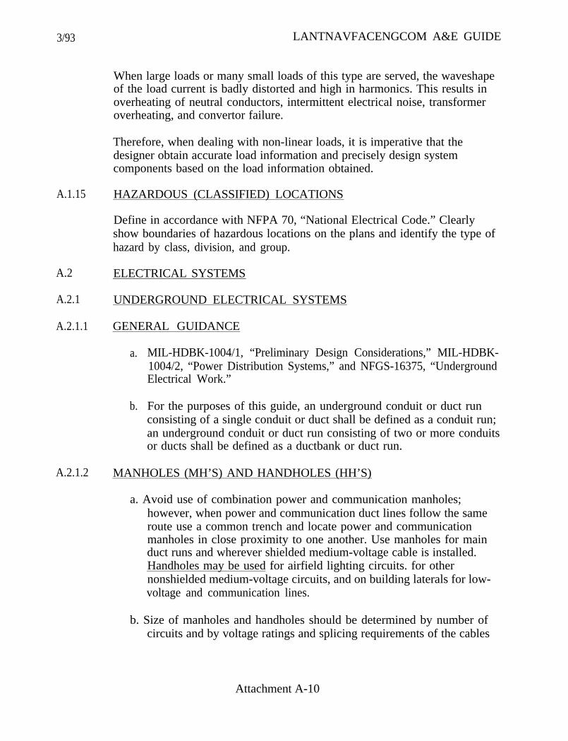
3/93 LANTNAVFACENGCOM A&E GUIDE
A.1.15
A.2
A.2.1
A.2.1.1
A.2.1.2
When large loads or many small loads of this type are served, the waveshapeof the load current is badly distorted and high in harmonics. This results inoverheating of neutral conductors, intermittent electrical noise, transformeroverheating, and convertor failure.
Therefore, when dealing with non-linear loads, it is imperative that thedesigner obtain accurate load information and precisely design systemcomponents based on the load information obtained.
HAZARDOUS (CLASSIFIED) LOCATIONS
Define in accordance with NFPA 70, “National Electrical Code.” Clearlyshow boundaries of hazardous locations on the plans and identify the type ofhazard by class, division, and group.
ELECTRICAL SYSTEMS
UNDERGROUND ELECTRICAL SYSTEMS
GENERAL GUIDANCE
a.
b.
MIL-HDBK-1004/1, “Preliminary Design Considerations,” MIL-HDBK-1004/2, “Power Distribution Systems,” and NFGS-16375, “UndergroundElectrical Work.”
For the purposes of this guide, an underground conduit or duct runconsisting of a single conduit or duct shall be defined as a conduit run;an underground conduit or duct run consisting of two or more conduitsor ducts shall be defined as a ductbank or duct run.
MANHOLES (MH’S) AND HANDHOLES (HH’S)
a. Avoid use of combination power and communication manholes;however, when power and communication duct lines follow the sameroute use a common trench and locate power and communicationmanholes in close proximity to one another. Use manholes for mainduct runs and wherever shielded medium-voltage cable is installed.Handholes may be used for airfield lighting circuits. for othernonshielded medium-voltage circuits, and on building laterals for low-voltage and communication lines.
b. Size of manholes and handholes should be determined by number ofcircuits and by voltage ratings and splicing requirements of the cables
Attachment A-10

3/93
A.2.1.3
A.2.1.4
A.2.2
A.2.2.1
A.2.2.2
LANTNAVFACENGCOM A&E GUIDE
within. Manholes should be sized to accommodate splices. Seeparagraph A.1.4.2.g.
c. Manholes should be minimum of 6’6” deep.
LOCATING MANHOLES (MH’S) AND HANDHOLES (HH’S)
a.
b.
c.
Provide MH’s/HH’s where duct lines change directions.
Provide a MH/HH within 100 feet of every riser pole unless acalculation is provided to justify a greater distance - under nocircumstances shall this greater distance exceed 200 feet.
MH separation on straight runs normally shall not exceed 400 feet. Insituations where greater separation is desired and this greaterseparation is not prohibited by either excessive pulling tension or siterequirements, MH separation of up to 600 feet may be permitted.See paragraph A.1.4.2.h.
DUCTBANKS
a. Minimum size for power distribution circuits in main duct runs shall be5 inches, unless otherwise directed.
b. Provide adequate spare capacity for all ductbanks.
OVERHEAD DISTRIBUTION SYSTEMS
CRITERIA
a. MIL-HDBK-1004/1, MIL-HDBK-1004/2, and NFGS-16370, “OverheadElectrical Work.”
b. ANSI C2. “National Electrical Safety Code.”
GENERAL RULES
a. Provide a detailed site plan with coordinated legend.
b. Use a separate symbol for each individual circuit; define each circuitby voltage level and number, size and type of conductors.
c. Coordinate guying and conductor sag information shown on thedrawings with that shown in the specifications.
Attachment A-11

3/93
A.2.2.3
LANTNAVFACENGCOM A&E GUIDE
d. When in doubt as howreview the informationsketches 16302L-1.1 through 16302L-1.5a.
to show overhead distribution work, carefullycontained on LANTNAVFACENGCOM
e. Do not use symbols which describe facilities in general or vague terms.
f. Do not describe proposed work by referencing sketch numbers insteadof pole detail designation symbols.
g. Do not use pole detail designation symbols to describe existingfacilities.
h. Do not install transformer banks, underground terminals, or switcheson corner, angle, or other congested poles. These devices must beinstalled on uncongested tangent poles.
POLE PLATES AND CONDUCTORS
a.
b.
Use LANTNAVFACENGCOM pole plates whenever applicableLANTNAVFACENGCOM pole plates are available. In situationswhere an applicable LANTNAVFACENGCOM pole plate has notbeen developed, provide detail(s) as required. Designer developeddetails must contain level of detail equivalent to theLANTNAVFACENGCOM pole plates and include materialrequirements. Unless another presentation method is proposed to andaccepted by LANTNAVFACENGCOM Code 404,LANTNAVFACENGCOM pole plates with required supplementarydetails shall be used for pole line construction work.
(1) When using pole plates, a note referencing the pole detaildesignation symbols (similar to the following) must be placed onthe drawings:
XFB, 15FR3-N, etc.. are pole detail designation symbols. Refer toLANTNAVFACENGCOM Sketches TS-16302L-1.3 through TS-163021-43 on Sheets for an explanation of the useand description of equipment provided by these symbols.
(2) Do not modify LANTNAVFACENGCOM pole plates; anyrequired exceptions or modifications must be included assupplemental information with the pole detail designation symbols.
Use aluminum or copper conductors. Do not use aluminum-conductorsteel-reinforced (ACSR).
Attachment A-12
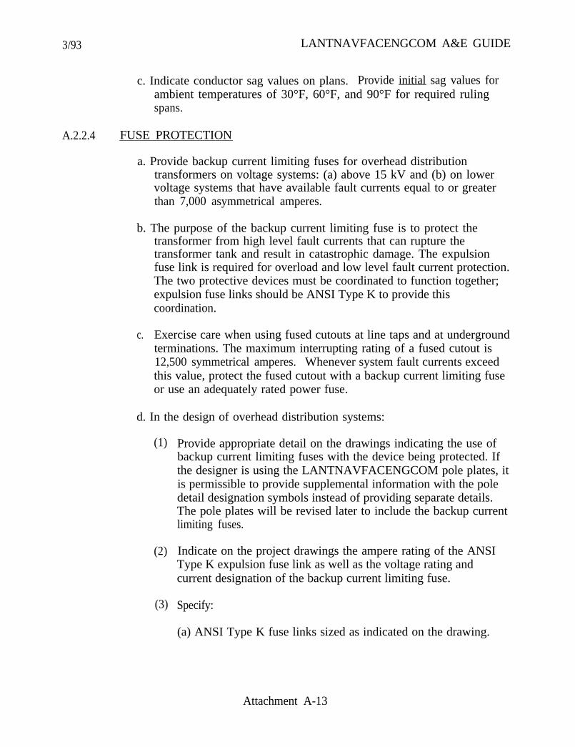
3/93 LANTNAVFACENGCOM A&E GUIDE
c. Indicate conductor sag values on plans. Provide initial sag values forambient temperatures of 30°F, 60°F, and 90°F for required rulingspans.
A.2.2.4 FUSE PROTECTION
a. Provide backup current limiting fuses for overhead distributiontransformers on voltage systems: (a) above 15 kV and (b) on lowervoltage systems that have available fault currents equal to or greaterthan 7,000 asymmetrical amperes.
b. The purpose of the backup current limiting fuse is to protect thetransformer from high level fault currents that can rupture thetransformer tank and result in catastrophic damage. The expulsionfuse link is required for overload and low level fault current protection.The two protective devices must be coordinated to function together;expulsion fuse links should be ANSI Type K to provide thiscoordination.
c. Exercise care when using fused cutouts at line taps and at undergroundterminations. The maximum interrupting rating of a fused cutout is12,500 symmetrical amperes. Whenever system fault currents exceedthis value, protect the fused cutout with a backup current limiting fuseor use an adequately rated power fuse.
d. In the design of overhead distribution systems:
(1)
(2)
(3)
Provide appropriate detail on the drawings indicating the use ofbackup current limiting fuses with the device being protected. Ifthe designer is using the LANTNAVFACENGCOM pole plates, itis permissible to provide supplemental information with the poledetail designation symbols instead of providing separate details.The pole plates will be revised later to include the backup currentlimiting fuses.
Indicate on the project drawings the ampere rating of the ANSIType K expulsion fuse link as well as the voltage rating andcurrent designation of the backup current limiting fuse.
Specify:
(a) ANSI Type K fuse links sized as indicated on the drawing.
Attachment A-13

3/93 LANTNAVFACENGCOM A&E GUIDE
(b) Testing of backup current limiting fuse in series withexpulsion fuse according to ANSI C37.41, “Design Tests forHigh-Voltage Fuses, Distribution Enclosed Single-Pole AirSwitches, Fused Disconnecting Switches, and Accessories.”
(c) Backup current limiting fuses be manufactured by A.B.Chance Co., Cooper Industries, or an approved equal.
A.2.3 400 HERTZ SYSTEMS
A.2.3.1 DESIGN CRITERIA
DM-4.05, “400 Hz Generation and Distribution Systems.”
A.2.3.2 NOMINAL UTILIZATION VOLTAGE
The nominal ac utilization voltage is 200Y/115V, three phase, 4 W.
A.2.3.3 TECHNIQUES FOR MINIMIZING VOLTAGE DROP
a. Use rigid aluminum or PVC conduit except that aluminum shall not beused in concrete.
b. Use only copper conductors.
c. Use thin-wall insulation types (THWN, THHN, XHHW, etc., shouldbe considered).
d. Use multi-conductor cables.
e. Use smaller paralleled conductors in lieu of larger single conductors.
f. Use line drop compensators.
A.2.3.4 ISOLATING 400 HZ SYSTEMS
The 400 Hz system shall be completely separate from other systems (i.e., a400 Hz circuit shall not be installed in the same box or cabinet as a 60 Hzcircuit unless barriers are used to separate sections).
Attachment A-14
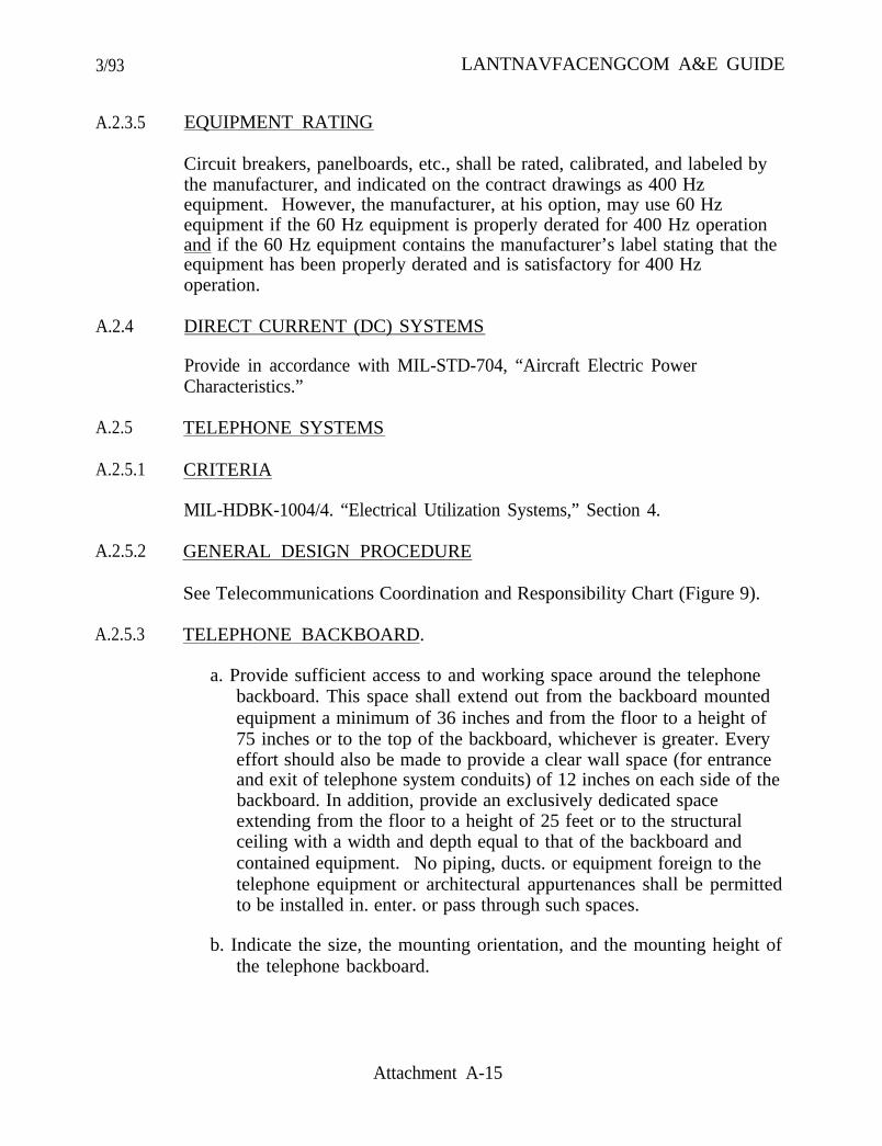
3/93
A.2.3.5 EQUIPMENT RATING
LANTNAVFACENGCOM A&E GUIDE
Circuit breakers, panelboards, etc., shall be rated, calibrated, and labeled bythe manufacturer, and indicated on the contract drawings as 400 Hzequipment. However, the manufacturer, at his option, may use 60 Hzequipment if the 60 Hz equipment is properly derated for 400 Hz operationand if the 60 Hz equipment contains the manufacturer’s label stating that theequipment has been properly derated and is satisfactory for 400 Hzoperation.
A.2.4 DIRECT CURRENT (DC) SYSTEMS
Provide in accordance with MIL-STD-704, “Aircraft Electric PowerCharacteristics.”
A.2.5 TELEPHONE SYSTEMS
A.2.5.1 CRITERIA
MIL-HDBK-1004/4. “Electrical Utilization Systems,” Section 4.
A.2.5.2 GENERAL DESIGN PROCEDURE
See Telecommunications Coordination and Responsibility Chart (Figure 9).
A.2.5.3 TELEPHONE BACKBOARD.
a. Provide sufficient access to and working space around the telephonebackboard. This space shall extend out from the backboard mountedequipment a minimum of 36 inches and from the floor to a height of75 inches or to the top of the backboard, whichever is greater. Everyeffort should also be made to provide a clear wall space (for entranceand exit of telephone system conduits) of 12 inches on each side of thebackboard. In addition, provide an exclusively dedicated spaceextending from the floor to a height of 25 feet or to the structuralceiling with a width and depth equal to that of the backboard andcontained equipment. No piping, ducts. or equipment foreign to thetelephone equipment or architectural appurtenances shall be permittedto be installed in. enter. or pass through such spaces.
b. Indicate the size, the mounting orientation, and the mounting height ofthe telephone backboard.
Attachment A-15

3/93 LANTNAVFACENGCOM A&E GUIDE
c. Provide 120 V, 15 A duplex receptacle (or other power source asrequired by the activity providing telephone service (APTS)) within3 feet of backboard. Power source shall be derived from circuit, freeof other loads, and dedicated strictly to the telephone system.
d. Provide #6 bare copper ground wire from backboard to the buildinggrounding electrode system, leaving minimum of 10 feet of wire atbackboard (i.e., enough to reach any location on backboard).
A.2.6 EMERGENCY LIGHTS, EXIT LIGHTS, AND FIRE PROTECTIONSYSTEMS
Provide power for emergency lights, exit lights, and fire protection systems inthe following manner:
a.
b.
c.
Provide unit equipment (equipment with self-contained rechargeablebattery, battery charging means, and automatic transfer to and frombattery) for emergency lights, exit lights, and fire protection systems.Specify LED type exit lights unless specifically instructed otherwise.
The branch circuit feeding the emergency lights and exit lights shall bethe same branch circuit as that serving the normal lighting in the areaand connected ahead of any local switches.
Provide power for the fire protection systems from the MDP.
- 208Y/120 V or 120/240 V systems- Provide lock-on breaker in the MDP- If more than one fire protection circuit is required, provide a
dedicated emergency panel (sized for a minimum of six circuits)powered from the lock-on breaker in the MDP.
- 450Y/277 V systems- Provide circuit from the MDP (as above) to a dedicated
emergency panel through a step-down transformer. Considerusing a packaged power supply for this transformer/emergencypanel combination. Size the emergency panel for a minimum ofsix circuits.
- Locate the dedicated emergency panel near the MDP wherepractical.
- In all cases paint the lock-on breaker in the MDP and thededicated emergency panel enclosure red. At the MDP, in
Attachment A-16
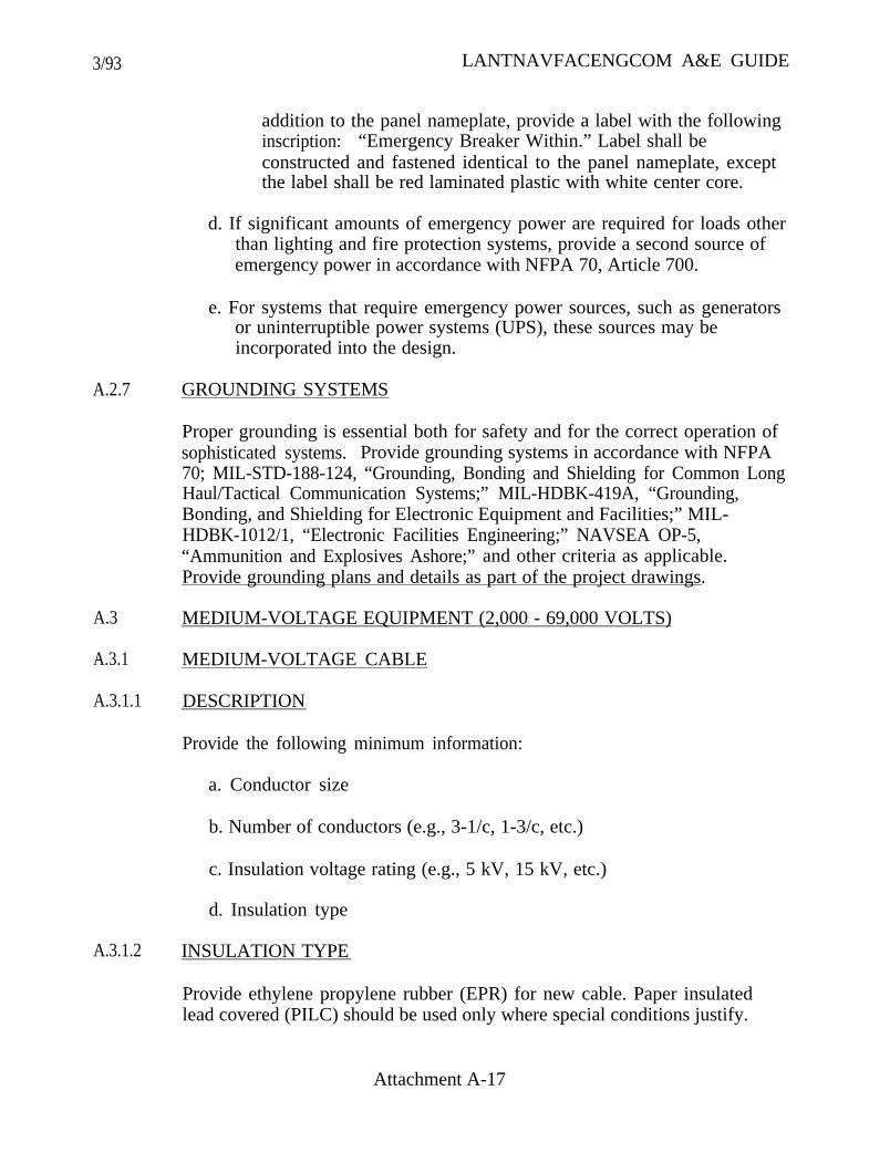
3/93 LANTNAVFACENGCOM A&E GUIDE
A.2.7
A.3
addition to the panel nameplate, provide a label with the followinginscription: “Emergency Breaker Within.” Label shall beconstructed and fastened identical to the panel nameplate, exceptthe label shall be red laminated plastic with white center core.
d. If significant amounts of emergency power are required for loads otherthan lighting and fire protection systems, provide a second source ofemergency power in accordance with NFPA 70, Article 700.
e. For systems that require emergency power sources, such as generatorsor uninterruptible power systems (UPS), these sources may beincorporated into the design.
GROUNDING SYSTEMS
Proper grounding is essential both for safety and for the correct operation ofsophisticated systems. Provide grounding systems in accordance with NFPA70; MIL-STD-188-124, “Grounding, Bonding and Shielding for Common LongHaul/Tactical Communication Systems;” MIL-HDBK-419A, “Grounding,Bonding, and Shielding for Electronic Equipment and Facilities;” MIL-HDBK-1012/1, “Electronic Facilities Engineering;” NAVSEA OP-5,“Ammunition and Explosives Ashore;” and other criteria as applicable.Provide grounding plans and details as part of the project drawings.
MEDIUM-VOLTAGE EQUIPMENT (2,000 - 69,000 VOLTS)
A.3.1 MEDIUM-VOLTAGE CABLE
A.3.1.1 DESCRIPTION
Provide the following minimum information:
a. Conductor size
b. Number of conductors (e.g., 3-1/c, 1-3/c, etc.)
c. Insulation voltage rating (e.g., 5 kV, 15 kV, etc.)
d. Insulation type
A.3.1.2 INSULATION TYPE
Provide ethylene propylene rubber (EPR) for new cable. Paper insulatedlead covered (PILC) should be used only where special conditions justify.
Attachment A-17
3/93 LANTNAVFACENGCOM A&E GUIDE
A.3.1.3 CABLE SHIELDS
Use tape shielded cables and ensure minimum cable bending radii of 12 timesthe overall cable diameter; use wire shielded cables (see NEMA WC 8,“Ethylene-Propylene-Rubber-Insulated Wire and Cable for the Transmissionand Distribution of Electrical Energy,” for minimum cable bending radii) onlywhere existing manholes are utilized and the minimum cable bending radii oftape shielded cables cannot be realized. Please note that the minimum cablebending radii refers to the inner surface of the cable and not to the axis ofthe cable.
A.3.1.4 NUMBER OF CONDUCTORS
Use l/c cables when solid dielectric cables are specified; 3/c cable may beused when special conditions justify its use.
A.3.1.5 EXISTING CONDITIONS
Ensure that new cables and specified splicing methods are compatible withexisting cables. Provide the same information (e.g., insulation type, insulationrating, conductor type, and number of conductors) for existing cables asrequired for new cables. Caution: Existing cable may be fireproofed withasbestos in manholes. Refer to paragraph A.1.10.
A.3.2 TRANSFORMERS
A.3.2.1 PAD-MOUNTED TRANSFORMER VERSUS SECONDARY UNITSUBSTATION
Pad-mounted transformers are normally used for 750 kVA and below on15 kV systems and for 500 kVA and below on 5 kV systems. For voltagesabove 15 kV and for kVA ratings above those previously indicated, it ispreferable to use secondary unit substations. When using a pad-mountedtransformer, select the applicable pad-mounted transformer detail fromFigures 3 through 8, supply the missing data. and incorporate that detail ontothe contract drawings. Do not use these details to depict secondary unitsubstations.
A.3.2.2 LOCATION
Transformer location with respect to buildings shall meet requirements ofMIL-HDBK-1008, “Fire Protection for Facilities Engineering Design andConstruction” and NFPA 70.
Attachment A-18

3/93 LANTNAVFACENGCOM A&E GUIDE
A.3.2.3 DESCRIPTION
Provide the following descriptive information on the one-line/riserdiagram/drawings:
a. Transformer type (e.g., pad mounted, pole mounted, station type, unitsubstation, etc.).
b. kVA.
c.
d.
Phase (e.g., three phase or single phase).
ANSI C57.12.20, “Overhead-Type Distribution Transformers, 500 kVAand Smaller: High-Voltage, 34,500 Volts and Below; Low-Voltage,7970/13800Y Volts and Below,” designation of voltage ratings(example: 11.5 kV - 208Y/120 volt).
e. Primary and secondary connection (when using single-phase units forthree-phase service, specifically indicate how the units are to ‘beconnected, i.e., connect delta-wye grounded for 208Y/120 voltsecondary service).
A.3.3 REGULATORS
a. Include the following information on the one-line diagram/drawings:
(1) kVA
(2) Line current at full regulation
(3) Voltage
(4) Phase
(5) Regulator type (e.g., step-voltage, induction, etc.)
(6) Style (e.g., station type, distribution, etc.)
b. Provide the following additional information in the specifications:
(1) Insulation type (e.g., oil, etc.)
(2) BIL
Attachment A-19
3/93 LANTNAVFACENGCOM A&E GUIDE
A.3.4
A.3.5
(3)
(4)
(5)
(6)
(7)
Temperature rise
Percent regulation
Number and percent steps (e.g., 32 - 5/8% steps)
Line drop compensation
Special features as needed
c. Provide bypass and disconnect switches with regulators.
CAPACITORS
a. Include the following information on the one-line diagram/ drawings:
(1) Capacitor type (e.g., outdoor. etc.)
(2) Mounting (e.g., rack mounted, etc.)
(3) kVAR per unit
(4) Number of units per bank
(5) Voltage (voltage rating of units, not the system voltage)
(6) Phase (e.g., three-phase or single-phase units)
(7) Fuse size and type
b. Fuse or otherwise protect capacitors to prevent case rupture. Providethe fuse (or other protective device) curve plotted against the caserupture curve on full size logarithmic paper. Also show the full loadand fault currents for a faulted capacitor unit on the same sheet.
c. Connect capacitors ungrounded wye, unless otherwise instructed.
SURGE ARRESTERS AND FUSED CUTOUTS
Include the following information on the one-line diagram/drawings:
a. Arrester kV rating
b. Cutout kV and ampere rating
Attachment A-20
3/93 LANTNAVFACENGCOM A&E GUIDE
c. Fuse link type and ampere rating
A.3.6 SWITCHGEAR
a. Circuit Breakers: Provide batteries for dc tripping. Do not use directtrip, ac trip, or capacitor trip.
b. Show bus size and instrumentation on one-line diagram.
c. Provide elevation drawings showing compartments, their intended use,and instruments and controls.
A.4
A.4.1
METERING, PT’S AND CT’S, INSTRUMENTATION, RELAYING
WATTHOUR METER
a.
b.
c. Place meters and meter sockets in accessible locations.
Provide watthour meters with 15-minute interval sweep-hand type kWdemand register for all buildings, except housing units.
Supply housing units with meter sockets only. Sockets shall be singlephase, four terminal, ringless with manual bypass device andpolycarbonate blank cover plate.
A.4.2 PT’S AND CT’S
a.
b.
c.
Show potential and current transformer ratios on one-line diagrams.
Carefully coordinate connection and ratio of potential transformerswith relay and meter requirements.
Provide separate current transformers for relaying and metering.Metering current transformers shall be single ratio.
A.4.3 INSTRUMENTATION
Specify complete characteristics of instrumentation.
A.4.4 RELAYING
Provide the following minimum information on the one-line diagram/drawings:
Attachment A-21
3/93 LANTNAVFACENGCOM A&E GUIDE
a.
b.
c.
d.
e.
f.
g.
h.
A.5
A.5.1
A.5.1.1
a. Function (overcurrent, voltage, differential, etc.) using ANSIdesignation numbers.
b. Quantity.
LOW-VOLTAGE AND UTILIZATION EQUIPMENT
PANELBOARDS
GENERAL RULES
As a general rule, provide one spare circuit for each five active circuitsin a panelboard to allow for future load growth. Spare circuit capacitymay consist of spare breakers or a combination of spare breakers andspaces at the designer’s discretion.
When spare circuit capacity is provided in flush-mounted panelboards,also provide additional conduit capacity to avoid tearing out of walls.The additional conduit capacity may consist of empty conduit runs tocovered boxes above the ceiling or beneath the floor. oversizingconduits in active circuits, or by other means that may seemappropriate to the designer.
Number circuits by pole number on single pole breakers and by firstpole number on two and three pole breakers.
Indicate load in amperes, not kW or kVA.
Do not show breakers by class.
Do not show estimated demand load.
Do not use fusible panelboards.
When more than 42 poles are required, provide separate panelboards.Do not use dual section panelboards.
A.5.1.2 PANELBOARD SCHEDULES
Provide panelboard schedules on the drawings in the format shown in Figures10 and 11. Include the following:
a. Panelboard designation
Attachment A-22

3/93 LANTNAVFACENGCOM A&E GUIDE
b. Voltage
c. Phase
d. Frequency (if other than 60 Hz)
e. Main amperes
f. Main breaker or lugs only
g. Surface or flush mounting
h. Minimum interrupting rating
i. Circuit number, wire size, breaker trip, load in amperes, andidentification of load associated with each branch or feeder. Pleasenote that identification of load must be specific. For example, thedirectory marking should not merely indicate “lighting,” but rather“lighting, Room 102.”
j. Total connected load
k. Any special requirements:
(1) GFI--ground fault interrupter
(2) SWD--rated for switching duty
1. Total number of poles
A.5.2 SWITCHBOARDS AND SWITCHGEAR
a. Provide. one-line diagram showing bus size, bus bracing, breaker framesize, breaker trip setting, relays, and instruments.
b. Provide elevation drawings showing compartments, their intended use,and instruments and controls.
c. Clearly indicate on the drawings that switchboards and switchgear mustbe mounted on 4-inch elevated concrete pads. Coordinate design ofpad with structural engineer.
d. Fusible switchboards may be used only if such use is justified.
Attachment A-23
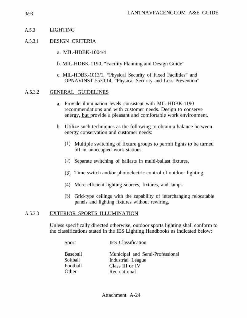
3/93
A.5.3
A.5.3.1
LIGHTING
DESIGN CRITERIA
a. MIL-HDBK-1004/4
b. MIL-HDBK-1190, “Facility Planning and Design Guide”
c. MIL-HDBK-1013/1, “Physical Security of Fixed Facilities” andOPNAVINST 5530.14, “Physical Security and Loss Prevention”
A.5.3.2 GENERAL GUIDELINES
a. Provide illumination levels consistent with MIL-HDBK-1190recommendations and with customer needs. Design to conserveenergy, but provide a pleasant and comfortable work environment.
b. Utilize such techniques as the following to obtain a balance betweenenergy conservation and customer needs:
(1)
(2)
(3)
(4)
(5)
Multiple switching of fixture groups to permit lights to be turnedoff in unoccupied work stations.
Separate switching of ballasts in multi-ballast fixtures.
Time switch and/or photoelectric control of outdoor lighting.
More efficient lighting sources, fixtures, and lamps.
Grid-type ceilings with the capability of interchanging relocatablepanels and lighting fixtures without rewiring.
A.5.3.3 EXTERIOR SPORTS ILLUMINATION
LANTNAVFACENGCOM A&E GUIDE
Unless specifically directed otherwise, outdoor sports lighting shall conform tothe classifications stated in the IES Lighting Handbooks as indicated below:
Sport IES Classification
BaseballSoftballFootballOther
Municipal and Semi-ProfessionalIndustrial LeagueClass III or IVRecreational
Attachment A-24
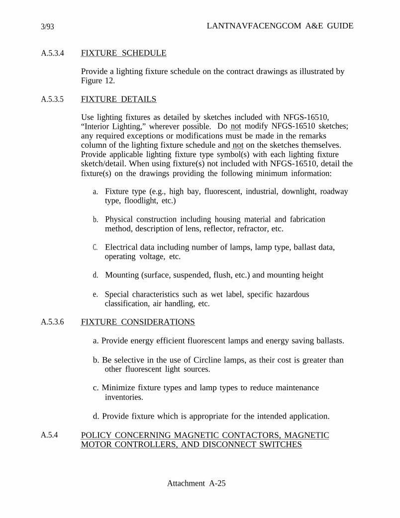
3/93 LANTNAVFACENGCOM A&E GUIDE
A.5.3.4 FIXTURE SCHEDULE
Provide a lighting fixture schedule on the contract drawings as illustrated byFigure 12.
A.5.3.5 FIXTURE DETAILS
Use lighting fixtures as detailed by sketches included with NFGS-16510,“Interior Lighting,” wherever possible. Do not modify NFGS-16510 sketches;any required exceptions or modifications must be made in the remarkscolumn of the lighting fixture schedule and not on the sketches themselves.Provide applicable lighting fixture type symbol(s) with each lighting fixturesketch/detail. When using fixture(s) not included with NFGS-16510, detail thefixture(s) on the drawings providing the following minimum information:
a. Fixture type (e.g., high bay, fluorescent, industrial, downlight, roadwaytype, floodlight, etc.)
b. Physical construction including housing material and fabricationmethod, description of lens, reflector, refractor, etc.
C. Electrical data including number of lamps, lamp type, ballast data,operating voltage, etc.
d. Mounting (surface, suspended, flush, etc.) and mounting height
e. Special characteristics such as wet label, specific hazardousclassification, air handling, etc.
A.5.3.6 FIXTURE CONSIDERATIONS
a. Provide energy efficient fluorescent lamps and energy saving ballasts.
b. Be selective in the use of Circline lamps, as their cost is greater thanother fluorescent light sources.
c. Minimize fixture types and lamp types to reduce maintenanceinventories.
d. Provide fixture which is appropriate for the intended application.
A.5.4 POLICY CONCERNING MAGNETIC CONTACTORS, MAGNETICMOTOR CONTROLLERS, AND DISCONNECT SWITCHES
Attachment A-25

3/93 LANTNAVFACENGCOM A&E GUIDE
A.5.4.1 HVAC EQUIPMENT
a. The mechanical engineer will determine which equipment will haveintegral magnetic contactors and/or disconnect switches and whichequipment will require separate magnetic motor controllers anddisconnect switches. In general, packaged refrigeration equipment hasintegral magnetic contactors and in some instances will have anintegral disconnect switch also. Air-handling units and pumps usuallyrequire separate magnetic motor controllers and disconnect switches.
b. The electrical engineer, in conjunction with the mechanical engineer,will determine the location of separate magnetic motor controllers anddisconnect switches. Magnetic motor controllers and disconnects shallbe placed in readily accessible locations (as defined by NFPA 70).
c. The electrical engineer will show separate magnetic motor controllersand separate disconnect switches on the electrical drawings.
The electrical engineer will not provide any magnetic motor controllerinformation for mechanical equipment on the electrical drawings, butwill determine the type of controller required (full voltage, reducedvoltage, reversing, multi-speed, NEMA size, and NEMA enclosuretype) and furnish same to the mechanical engineer for incorporation inmechanical equipment schedules. Mechanical equipment scheduleswill also include electrical characteristics of motor and packagedequipment; e.g., voltage, full load amperes or minimum circuitamperes, number of phases, horsepower, and frequency. Integraldisconnects, if provided, shall be noted in the mechanical equipmentschedules and coordinated with the electrical drawings. Requireintegral disconnects be furnished with thermal overloads whereappropriate for small fractional horsepower motors. The mechanicalspecifications must be coordinated with the mechanical equipmentschedules and mechanical plans.
A.5.4.2 UNIT HEATERS
Electrical unit heaters will be sized and located by the mechanical engineer,will be shown on the electrical drawings, noted and properly cross-referencedon the mechanical drawings, and specified in the electrical specifications.
A.5.4.3 OTHER EQUIPMENT
The electrical engineer must be alert for motors required for equipmentfurnished by engineers other than mechanical. These include architectural
Attachment A-26

3/93 LANTNAVFACENGCOM A&E GUIDE
equipment such as motorized doors, civil equipment such as lift stations andpumps, and structural equipment such as cranes. The electrical engineermust ensure that the required information is contained on the projectdrawings for miscellaneous equipment even if it must be added to theelectrical drawings.
A.5.4.4 COMMENTS
a. Specifically identify each piece of equipment (e.g., unit heater No. 1,unit heater No. 2, etc.).
b. See Figures 13 through 15 for typical illustrations of how to properlydisplay equipment on the contract drawings.
A.5.5 MOTOR CONTROL EQUIPMENT
A.5.5.1 EQUIPMENT SELECTIONS
The choice between using motor control centers (MCC’s), motor starterpanels, combination starters, and individual starters and disconnects must beevaluated. Several points for consideration are:
a. Centralized control location necessary or required.
b. Quantity of motors and equipment to be controlled.
C. Sizes of motors and equipment.
d. Economic considerations (price comparisons).
A.5.5.2 SELECTION GUIDANCE
a. Individual motor starters and disconnects are preferred overcombination starters and are usually more cost effective.
b. Individual motor starters and disconnects are usually preferred and aremore economical than MCC’s and motor starter panels, especiallywhere smaller motors and scattered loads are involved.
c. Motor starter panels would be preferred over MCC’s where acentralized control location is required, where NEMA Size 0 starterscan be used, or where a wall mounted versus floor mounted equipmentpanel is desirable.
Attachment A-27

3/93 LANTNAVFACENGCOM A&E GUIDE
A.5.5.3
A.6
A.7
A.8
A.9
A.10
A.11
d. MCC’s would be used where a centralized location is required andwhere the quantity of equipment and/or the starter sizes (NEMA Size1 and larger) would justify the additional expense.
MOTOR CONTROL CENTERS (MCC’S)
Provide elevation drawings identifying compartments. Provide schedule listingeach compartment. Schedule shall include (for each compartment)description of load, load in amperes, load in horsepower, NEMA size andtype of starter, breaker size, conductor and conduit size, control devices, andother special requirements.
a.
b.
Also indicate, on plans or in specifications, enclosure type, bus rating,bus material: bus bracing, NEMA class and wiring type, servicevoltage, control voltage and source, and top or bottom feed.
Clearly indicate on the drawings that MCC’s must be mounted on4-inch elevated concrete pads. Coordinate design of pad withstructural engineer.
LIGHTNING PROTECTION
Provide in accordance with MIL-HDBK-1004/6, “Lightning Protection.”
CATHODIC PROTECTION
Provide in accordance with MIL-HDBK-1004/10, “Electrical EngineeringCathodic Protection.” Also see paragraph 4.5.12 of the basic guide.
INTRUSION DETECTION SYSTEMS (IDS)
Provide in accordance with DM-13.02. “Commercial Intrusion DetectionSystem (IDS).”
UNINTERRUPTIBLE POWER SYSTEMS (UPS)
Provide in accordance with MIL-HDBK-1004/1 and MIL-HDBK-1012/1.
INSTRUMENTATION AND CONTROLS
See paragraph 4.8.3 of the basic guide.
HIGH ALTITUDE ELECTROMAGNETIC PULSE PROTECTION(HEMP)
Attachment A-28
3/93 LANTNAVFACENGCOM A&E GUIDE
Provide in accordance with MIL-HDBK-423, “High-Altitude ElectromagneticPulse (HEMP) Protection for Fixed and Transportable Ground-BasedFacilities” (draft) and MIL-STD-188-125, “High-Altitude ElectromagneticPulse (HEMP) Protection for Ground-Based C4I Facilities PerformingCritical, Time-Urgent Missions.”
A.12 ORDNANCE FACILITIES
Provide in accordance with NAVSEA OP-5.
A.13 AUTOMATIC STANDBY POWER SYSTEMS
A comprehensive guide for preparing plans and specifications for automaticstandby power systems has been prepared and is available to A&E firmsinvolved in such projects. Copies of this guide may be obtained from theLANTNAVFACENGCOM Electrical Engineering Branch through the ProjectManager.
Attachment A-29

3/93
Designer Notes:
LANTNAVFACENGCOM A&E GUIDE
Attachment A-30

3/93 LANTNAVFACENGCOM A&E GUIDE
ATTACHMENT A-31
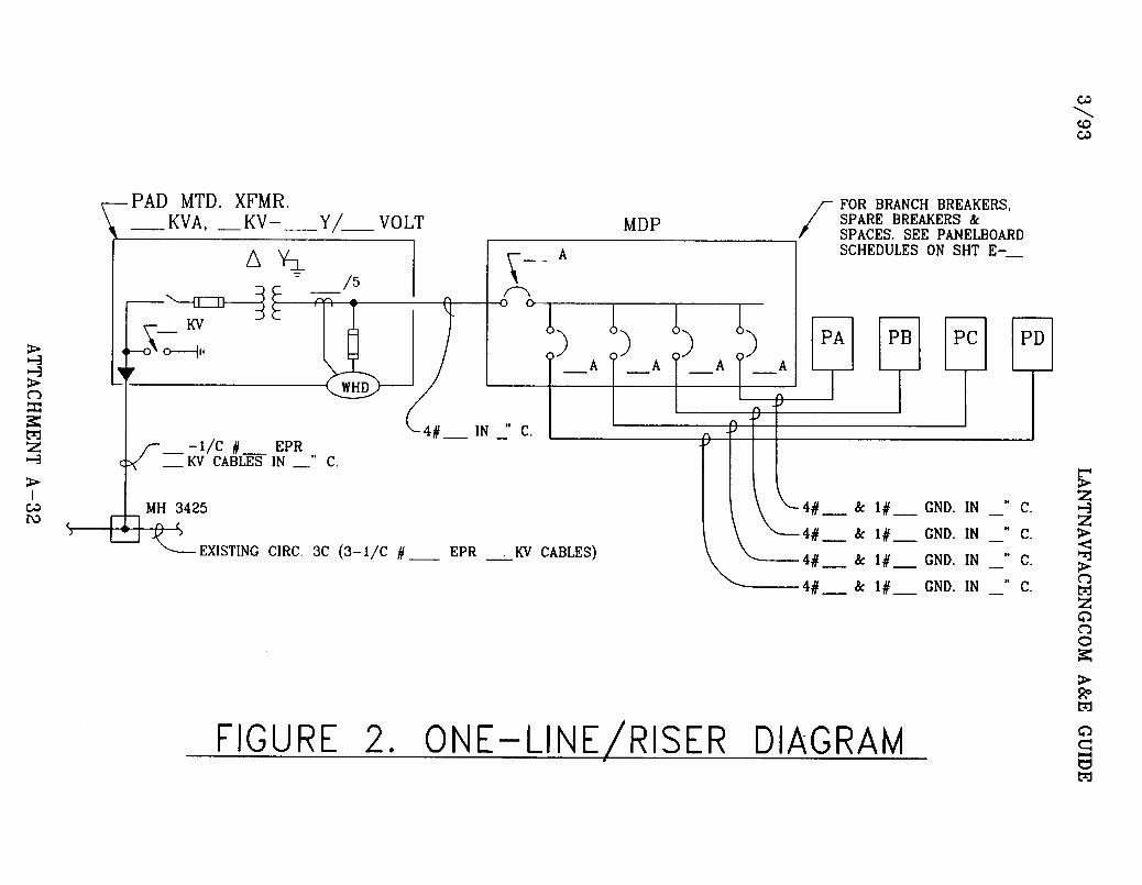
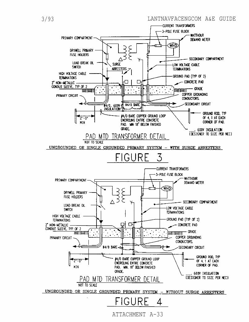
3/93 LANTNAVFACENGCOM A&E GUIDE
ATTACHMENT A-33
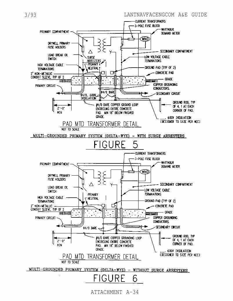
3/93 LANTNAVFACENGCOM A&E GUIDE
ATTACHMENT A-34
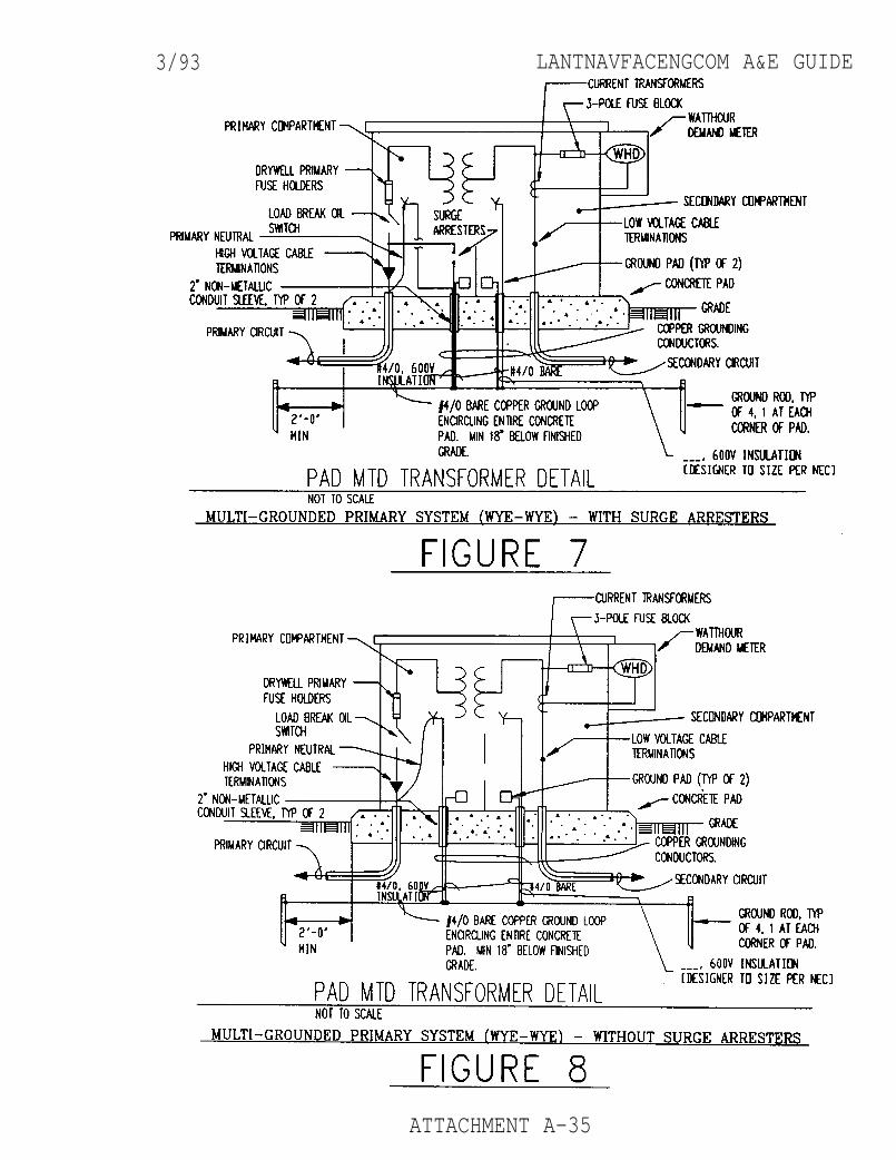
3/93 LANTNAVFACENGCOM A&E GUIDE
ATTACHMENT A-35
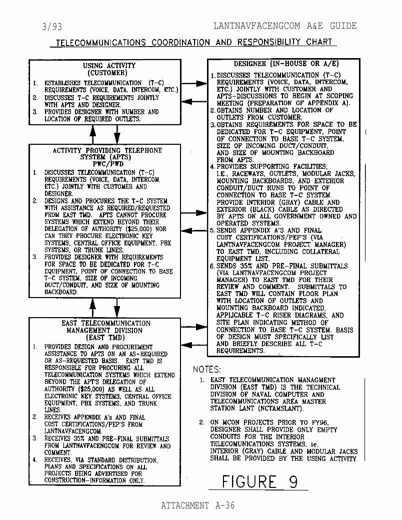
3/93 LANTNAVFACENGCOM A&E GUIDE
ATTACHMENT A-36
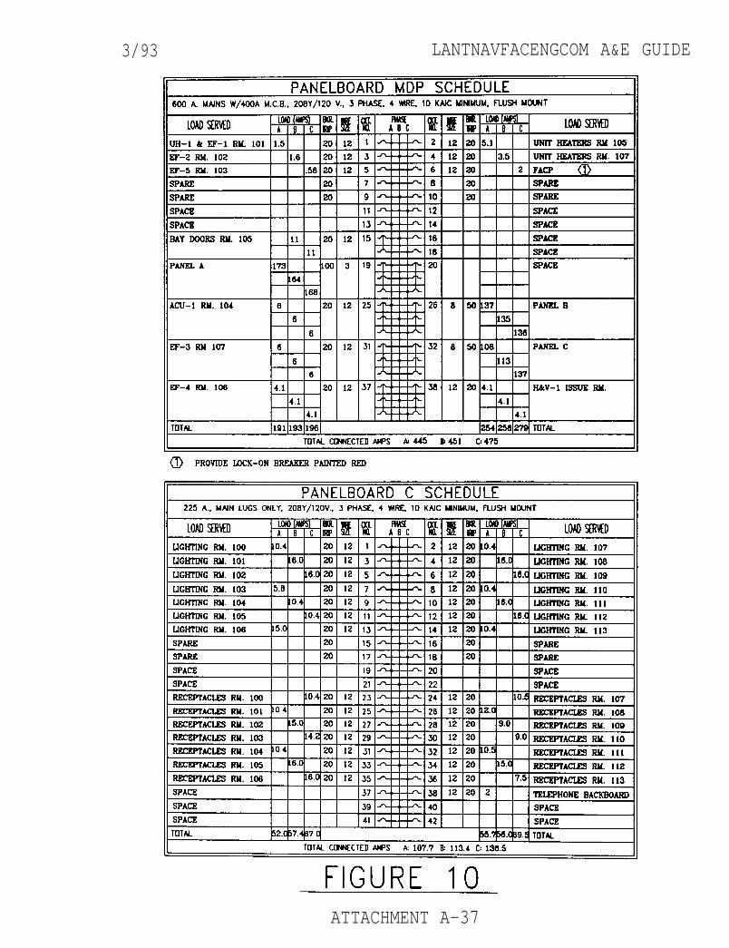
3/93 LANTNAVFACENGCOM A&E GUIDE
ATTACHMENT A-37

3/93 LANTNAVFACENGCOM A&E GUIDE
ATTACHMENT A-38
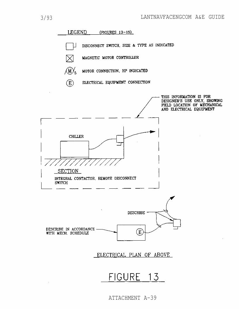
3/93 LANTNAVFACENGCOM A&E GUIDE
ATTACHMENT A-39
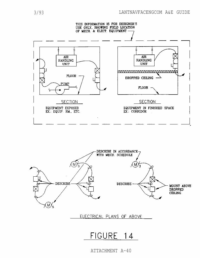
3/93 LANTNAVFACENGCOM A&E GUIDE
ATTACHMENT A-40
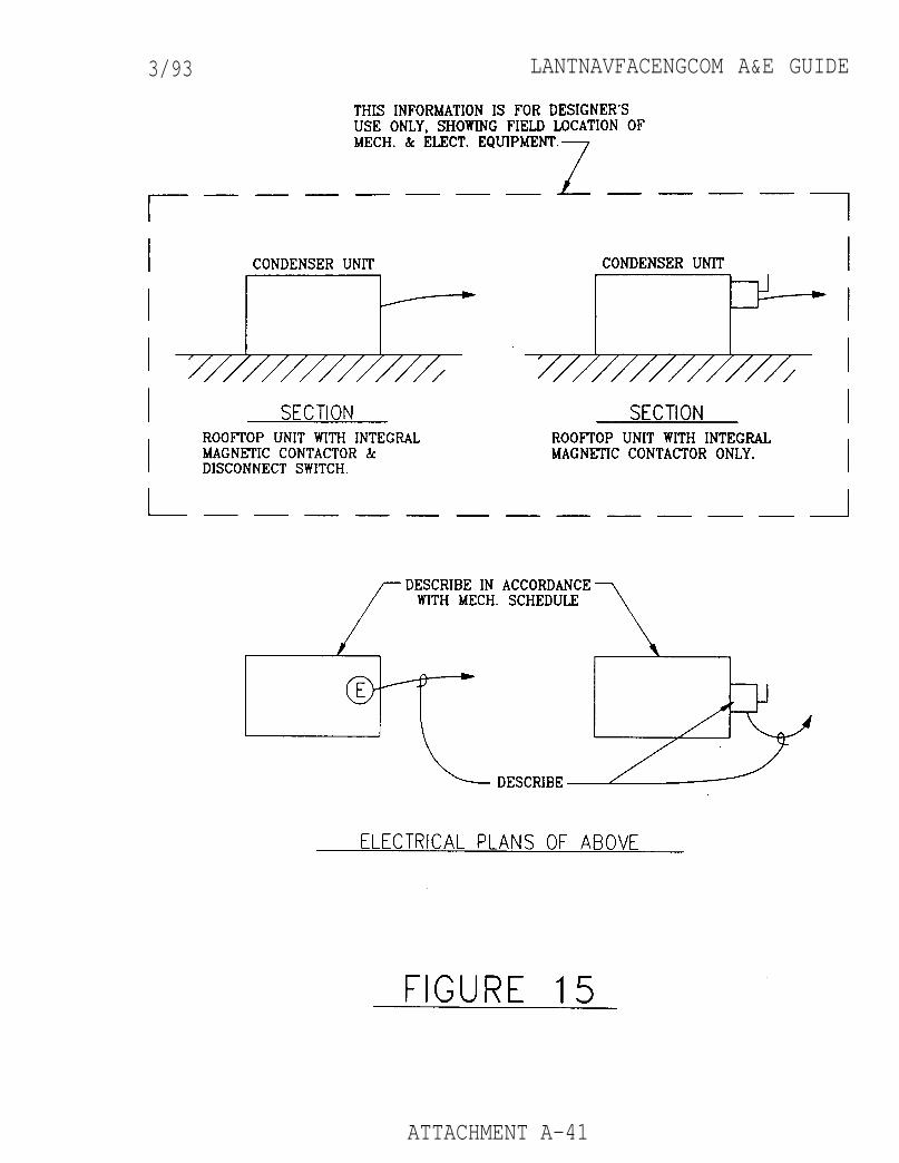
3/93 LANTNAVFACENGCOM A&E GUIDE
ATTACHMENT A-41
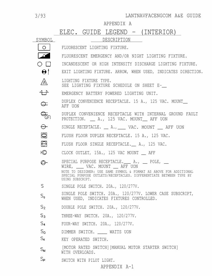
3/93 LANTNAVFACENGCOM A&E GUIDE
APPENDIX A
ELEC. GUIDE LEGEND - (INTERIOR)SYMBOL DESCRIPTION
FLUORESCENT LIGHTING FIXTURE.
FLUORESCENT EMERGENCY AND/OR NIGHT LIGHTING FIXTURE.
INCANDESCENT OR HIGH INTENSITY DISCHARGE LIGHTING FIXTURE.
EXIT LIGHTING FIXTURE. ARROW, WHEN USED, INDICATES DIRECTION.
LIGHTING FIXTURE TYPE.SEE LIGHTING FIXTURE SCHEDULE ON SHEET E-__
EMERGENCY BATTERY POWERED LIGHTING UNIT.
DUPLEX CONVENIENCE RECEPTACLE. 15 A., 125 VAC. MOUNT__AFF UON
DUPLEX CONVENIENCE RECEPTACLE WITH INTERNAL GROUND FAULTPROTECTION. __ A., 125 VAC. MOUNT__ AFF UON
SINGLE RECEPTACLE. __ A.,___ VAC. MOUNT __ AFF UON
FLUSH FLOOR DUPLEX RECEPTACLE. 15 A., 125 VAC.
FLUSH FLOOR SINGLE RECEPTACLE.__ A., 125 VAC.
CLOCK OUTLET, 15A., 125 VAC MOUNT __ AFF
SPECIAL PURPOSE RECEPTACLE.___ A., __ POLE, __WIRE, ___ VAC. MOUNT __ AFF UONNOTE TO DESIGNER: USE SAME SYMBOL & FORMAT AS ABOVE FOR ADDITIONALSPECIAL PURPOSE OUTLETS/RECEPTACLES. DIFFERENTIATE BETWEEN TYPE BYUSING SUBSCRIPT.
SINGLE POLE SWITCH. 20A., 120/277V.
SINGLE POLE SWITCH. 20A., 120/277V. LOWER CASE SUBSCRIPT,WHEN USED, INDICATES FIXTURES CONTROLLED.
DOUBLE POLE SWITCH. 20A., 120/277V.
THREE-WAY SWITCH. 20A., 120/277V.
FOUR-WAY SWITCH. 20A., 120/277V.
DIMMER SWITCH. ____ WATTS UON
KEY OPERATED SWITCH.
[MOTOR RATED SWITCH][MANUAL MOTOR STARTER SWITCH]WITH OVERLOADS.
SWITCH WITH PILOT LIGHT.APPENDIX A-1
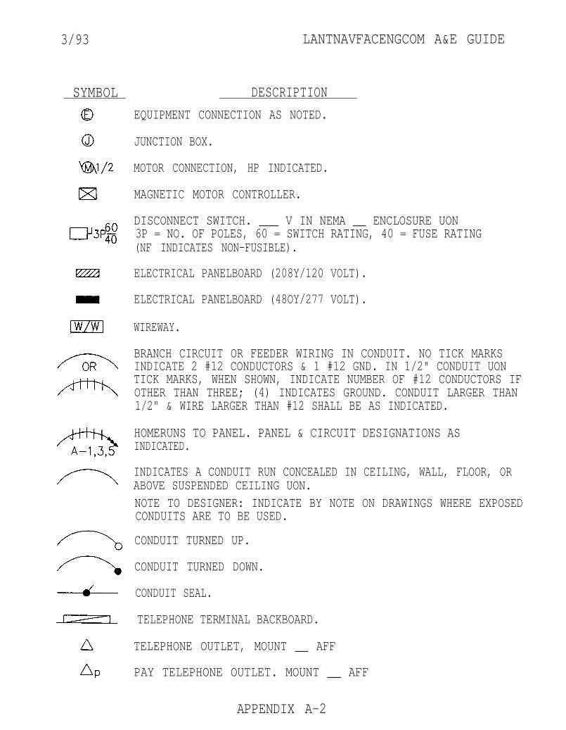
3/93 LANTNAVFACENGCOM A&E GUIDE
SYMBOL DESCRIPTION
EQUIPMENT CONNECTION AS NOTED.
JUNCTION BOX.
MOTOR CONNECTION, HP INDICATED.
MAGNETIC MOTOR CONTROLLER.
DISCONNECT SWITCH. ___ V IN NEMA __ ENCLOSURE UON3P = NO. OF POLES, 60 = SWITCH RATING, 40 = FUSE RATING(NF INDICATES NON-FUSIBLE).
ELECTRICAL PANELBOARD (208Y/120 VOLT).
ELECTRICAL PANELBOARD (48OY/277 VOLT).
WIREWAY.
BRANCH CIRCUIT OR FEEDER WIRING IN CONDUIT. NO TICK MARKSINDICATE 2 #12 CONDUCTORS & 1 #12 GND. IN 1/2" CONDUIT UONTICK MARKS, WHEN SHOWN, INDICATE NUMBER OF #12 CONDUCTORS IFOTHER THAN THREE; (4) INDICATES GROUND. CONDUIT LARGER THAN1/2" & WIRE LARGER THAN #12 SHALL BE AS INDICATED.
HOMERUNS TO PANEL. PANEL & CIRCUIT DESIGNATIONS ASINDICATED.
INDICATES A CONDUIT RUN CONCEALED IN CEILING, WALL, FLOOR, ORABOVE SUSPENDED CEILING UON.NOTE TO DESIGNER: INDICATE BY NOTE ON DRAWINGS WHERE EXPOSEDCONDUITS ARE TO BE USED.
CONDUIT TURNED UP.
CONDUIT TURNED DOWN.
CONDUIT SEAL.
TELEPHONE TERMINAL BACKBOARD.
TELEPHONE OUTLET, MOUNT __ AFF
PAY TELEPHONE OUTLET. MOUNT __ AFF
APPENDIX A-2
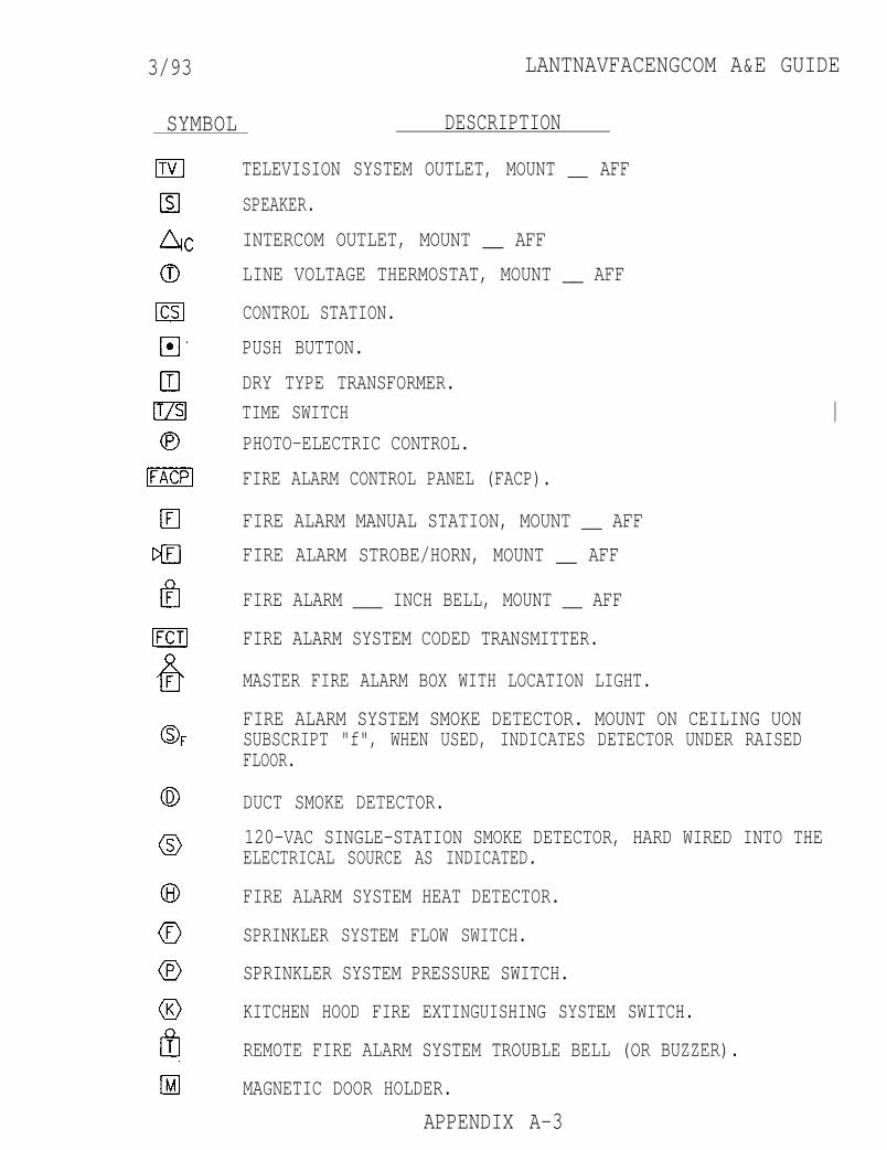
3/93 LANTNAVFACENGCOM A&E GUIDE
SYMBOL DESCRIPTION
TELEVISION SYSTEM OUTLET, MOUNT __ AFF
SPEAKER.
INTERCOM OUTLET, MOUNT __ AFF
LINE VOLTAGE THERMOSTAT, MOUNT __ AFF
CONTROL STATION.
PUSH BUTTON.
DRY TYPE TRANSFORMER.
TIME SWITCH
PHOTO-ELECTRIC CONTROL.
FIRE ALARM CONTROL PANEL (FACP).
FIRE ALARM MANUAL STATION, MOUNT __ AFF
FIRE ALARM STROBE/HORN, MOUNT __ AFF
FIRE ALARM ___ INCH BELL, MOUNT __ AFF
FIRE ALARM SYSTEM CODED TRANSMITTER.
MASTER FIRE ALARM BOX WITH LOCATION LIGHT.
FIRE ALARM SYSTEM SMOKE DETECTOR. MOUNT ON CEILING UONSUBSCRIPT "f", WHEN USED, INDICATES DETECTOR UNDER RAISEDFLOOR.
DUCT SMOKE DETECTOR.
120-VAC SINGLE-STATION SMOKE DETECTOR, HARD WIRED INTO THEELECTRICAL SOURCE AS INDICATED.
FIRE ALARM SYSTEM HEAT DETECTOR.
SPRINKLER SYSTEM FLOW SWITCH.
SPRINKLER SYSTEM PRESSURE SWITCH.
KITCHEN HOOD FIRE EXTINGUISHING SYSTEM SWITCH.
REMOTE FIRE ALARM SYSTEM TROUBLE BELL (OR BUZZER).
MAGNETIC DOOR HOLDER.
APPENDIX A-3
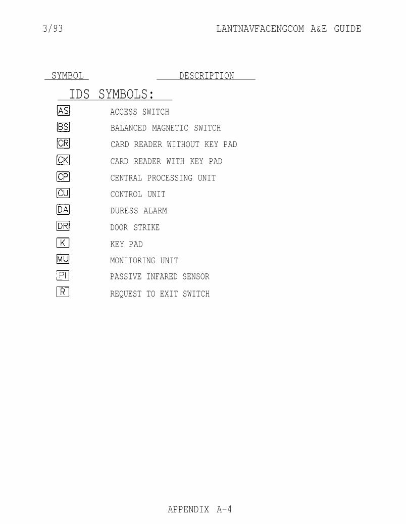
3/93 LANTNAVFACENGCOM A&E GUIDE
SYMBOL DESCRIPTION
IDS SYMBOLS:ACCESS SWITCH
BALANCED MAGNETIC SWITCH
CARD READER WITHOUT KEY PAD
CARD READER WITH KEY PAD
CENTRAL PROCESSING UNIT
CONTROL UNIT
DURESS ALARM
DOOR STRIKE
KEY PAD
MONITORING UNIT
PASSIVE INFARED SENSOR
REQUEST TO EXIT SWITCH
APPENDIX A-4
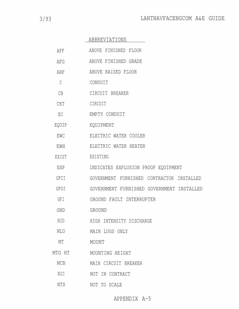
3/93 LANTNAVFACENGCOM A&E GUIDE
AFF
AFG
ARF
C
CB
CKT
EC
EQUIP
EWC
EWH
EXIST
EXP
GFCI
GFGI
GFI
GND
HID
MLO
MT
MTG HT
MCB
NIC
NTS
ABBREVIATIONS
ABOVE FINISHED FLOOR
ABOVE FINISHED GRADE
ABOVE RAISED FLOOR
CONDUIT
CIRCUIT BREAKER
CIRCUIT
EMPTY CONDUIT
EQUIPMENT
ELECTRIC WATER COOLER
ELECTRIC WATER HEATER
EXISTING
INDICATES EXPLOSION PROOF EQUIPMENT
GOVERNMENT FURNISHED CONTRACTOR INSTALLED
GOVERNMENT FURNISHED GOVERNMENT INSTALLED
GROUND FAULT INTERRUPTER
GROUND
HIGH INTENSITY DISCHARGE
MAIN LUGS ONLY
MOUNT
MOUNTING HEIGHT
MAIN CIRCUIT BREAKER
NOT IN CONTRACT
NOT TO SCALE
APPENDIX A-5
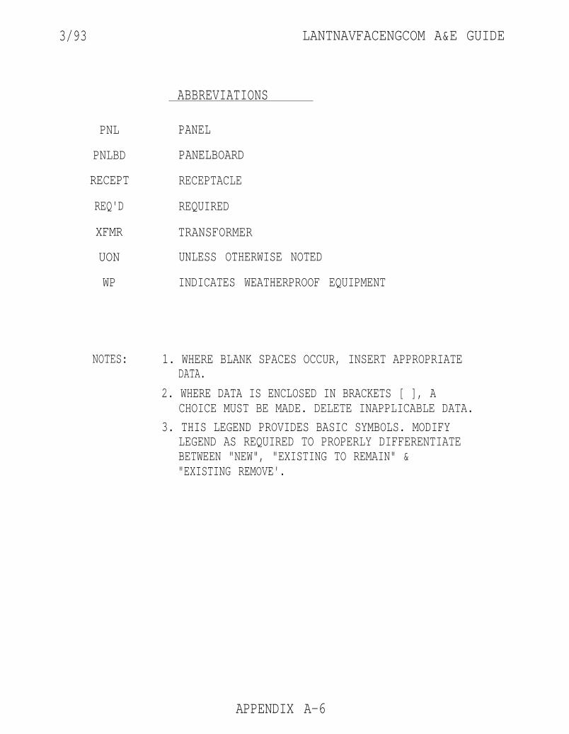
3/93 LANTNAVFACENGCOM A&E GUIDE
ABBREVIATIONS
PNL PANEL
PNLBD PANELBOARD
RECEPT RECEPTACLE
REQ'D REQUIRED
XFMR TRANSFORMER
UON UNLESS OTHERWISE NOTED
WP INDICATES WEATHERPROOF EQUIPMENT
NOTES: 1. WHERE BLANK SPACES OCCUR, INSERT APPROPRIATEDATA.
2. WHERE DATA IS ENCLOSED IN BRACKETS [ ], ACHOICE MUST BE MADE. DELETE INAPPLICABLE DATA.
3. THIS LEGEND PROVIDES BASIC SYMBOLS. MODIFYLEGEND AS REQUIRED TO PROPERLY DIFFERENTIATEBETWEEN "NEW", "EXISTING TO REMAIN" &"EXISTING REMOVE'.
APPENDIX A-6
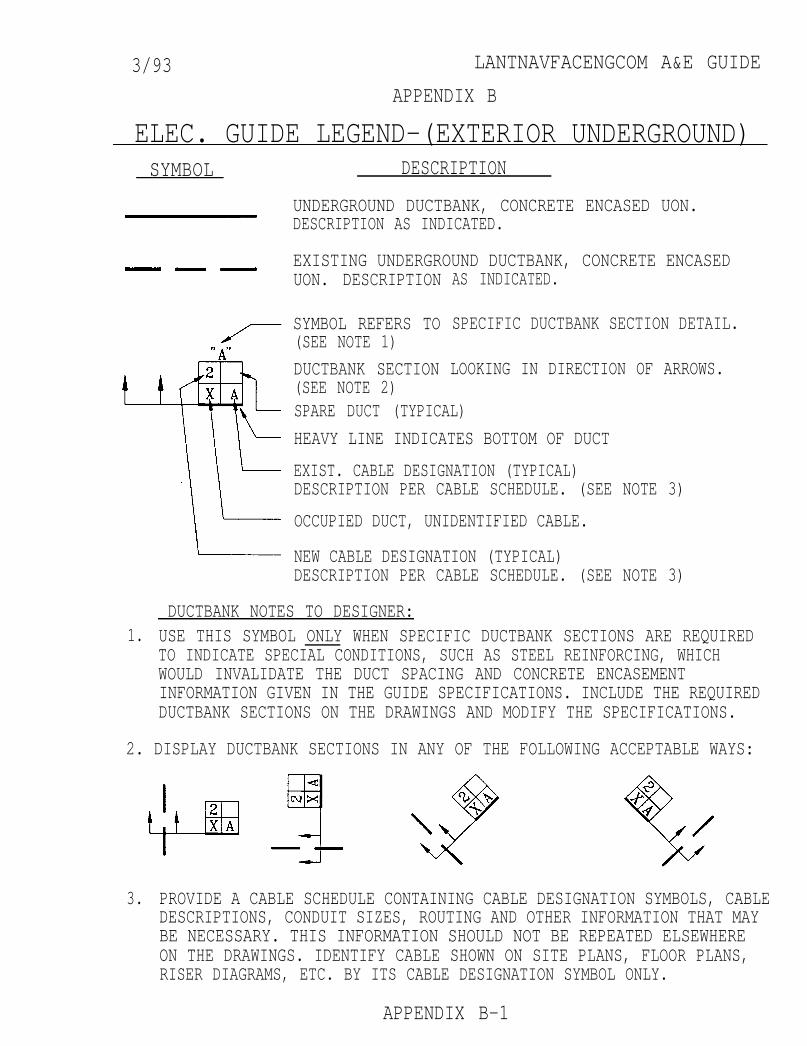
3/93 LANTNAVFACENGCOM A&E GUIDE
APPENDIX B
ELEC. GUIDE LEGEND-(EXTERIOR UNDERGROUND)SYMBOL DESCRIPTION
UNDERGROUND DUCTBANK, CONCRETE ENCASED UON.DESCRIPTION AS INDICATED.
EXISTING UNDERGROUND DUCTBANK, CONCRETE ENCASEDUON. DESCRIPTION
SYMBOL REFERS TO(SEE NOTE 1)
DUCTBANK SECTION(SEE NOTE 2)
AS INDICATED.
SPECIFIC DUCTBANK SECTION DETAIL.
LOOKING IN DIRECTION OF ARROWS.
SPARE DUCT (TYPICAL)
HEAVY LINE INDICATES BOTTOM OF DUCT
EXIST. CABLE DESIGNATION (TYPICAL)DESCRIPTION PER CABLE SCHEDULE. (SEE NOTE 3)
OCCUPIED DUCT, UNIDENTIFIED CABLE.
NEW CABLE DESIGNATION (TYPICAL)DESCRIPTION PER CABLE SCHEDULE. (SEE NOTE 3)
DUCTBANK NOTES TO DESIGNER:1. USE THIS SYMBOL ONLY WHEN SPECIFIC DUCTBANK SECTIONS ARE REQUIRED
TO INDICATE SPECIAL CONDITIONS, SUCH AS STEEL REINFORCING, WHICHWOULD INVALIDATE THE DUCT SPACING AND CONCRETE ENCASEMENTINFORMATION GIVEN IN THE GUIDE SPECIFICATIONS. INCLUDE THE REQUIREDDUCTBANK SECTIONS ON THE DRAWINGS AND MODIFY THE SPECIFICATIONS.
2. DISPLAY DUCTBANK SECTIONS IN ANY OF THE FOLLOWING ACCEPTABLE WAYS:
3. PROVIDE A CABLE SCHEDULE CONTAINING CABLE DESIGNATION SYMBOLS, CABLEDESCRIPTIONS, CONDUIT SIZES, ROUTING AND OTHER INFORMATION THAT MAYBE NECESSARY. THIS INFORMATION SHOULD NOT BE REPEATED ELSEWHEREON THE DRAWINGS. IDENTIFY CABLE SHOWN ON SITE PLANS, FLOOR PLANS,RISER DIAGRAMS, ETC. BY ITS CABLE DESIGNATION SYMBOL ONLY.
APPENDIX B-1
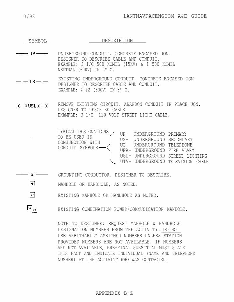
3/93 LANTNAVFACENGCOM A&E GUIDE
SYMBOL DESCRIPTION
UNDERGROUND CONDUIT, CONCRETE ENCASED UON. DESIGNER TO DESCRIBE CABLE AND CONDUIT.EXAMPLE: 3-1/C 500 KCMIL (15KV) & 1 500 KCMILNEUTRAL (600V) IN 5" C.
EXISTING UNDERGROUND CONDUIT, CONCRETE ENCASED UONDESIGNER TO DESCRIBE CABLE AND CONDUIT.EXAMPLE: 4 #2 (600V) IN 3" C.
REMOVE EXISTING CIRCUIT. ABANDON CONDUIT IN PLACE UON.DESIGNER TO DESCRIBE CABLE.EXAMPLE: 3-1/C, 120 VOLT STREET LIGHT CABLE.
TYPICAL DESIGNATIONSTO BE USED INCONJUNCTION WITHCONDUIT SYMBOLS
UP- UNDERGROUND PRIMARYUS- UNDERGROUND SECONDARYUT- UNDERGROUND TELEPHONEUFA- UNDERGROUND FIRE ALARMUSL- UNDERGROUND STREET LIGHTINGUTV- UNDERGROUND TELEVISION CABLE
GROUNDING CONDUCTOR. DESIGNER TO DESCRIBE.
MANHOLE OR HANDHOLE, AS NOTED.
EXISTING MANHOLE OR HANDHOLE AS NOTED.
EXISTING COMBINATION POWER/COMMUNICATION MANHOLE.
NOTE TO DESIGNER: REQUEST MANHOLE & HANDHOLEDESIGNATION NUMBERS FROM THE ACTIVITY. DO NOTUSE ARBITRARILY ASSIGNED NUMBERS UNLESS STATIONPROVIDED NUMBERS ARE NOT AVAILABLE. IF NUMBERSARE NOT AVAILABLE, PRE-FINAL SUBMITTAL MUST STATETHIS FACT AND INDICATE INDIVIDUAL (NAME AND TELEPHONENUMBER) AT THE ACTIVITY WHO WAS CONTACTED.
APPENDIX B-Z
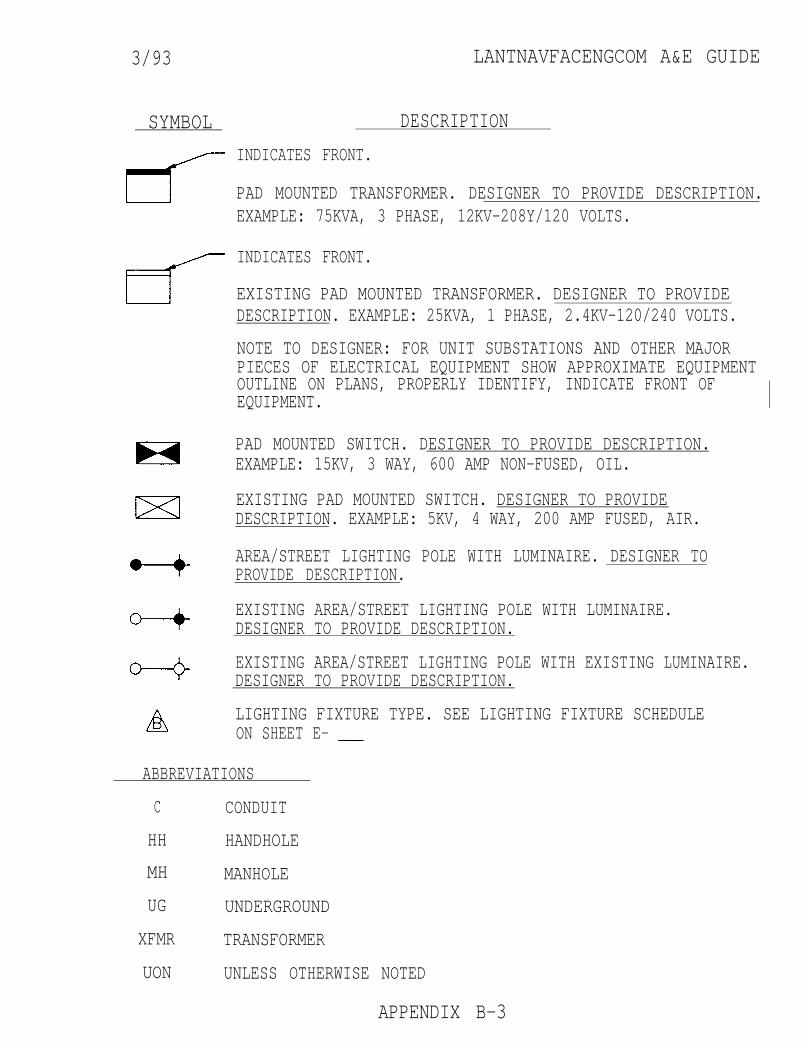
3/93 LANTNAVFACENGCOM A&E GUIDE
SYMBOL DESCRIPTION
INDICATES FRONT.
PAD MOUNTED TRANSFORMER. DESIGNER TO PROVIDE DESCRIPTION.EXAMPLE: 75KVA, 3 PHASE, 12KV-208Y/120 VOLTS.
INDICATES FRONT.
EXISTING PAD MOUNTED TRANSFORMER. DESIGNER TO PROVIDEDESCRIPTION. EXAMPLE: 25KVA, 1 PHASE, 2.4KV-120/240 VOLTS.
NOTE TO DESIGNER: FOR UNIT SUBSTATIONS AND OTHER MAJORPIECES OF ELECTRICAL EQUIPMENT SHOW APPROXIMATE EQUIPMENTOUTLINE ON PLANS, PROPERLY IDENTIFY, INDICATE FRONT OFEQUIPMENT.
PAD MOUNTED SWITCH. DESIGNER TO PROVIDE DESCRIPTION.EXAMPLE: 15KV, 3 WAY, 600 AMP NON-FUSED, OIL.
EXISTING PAD MOUNTED SWITCH. DESIGNER TO PROVIDEDESCRIPTION. EXAMPLE: 5KV, 4 WAY, 200 AMP FUSED, AIR.
AREA/STREET LIGHTING POLE WITH LUMINAIRE. DESIGNER TOPROVIDE DESCRIPTION.
EXISTING AREA/STREET LIGHTING POLE WITH LUMINAIRE.DESIGNER TO PROVIDE DESCRIPTION.
EXISTING AREA/STREET LIGHTING POLE WITH EXISTING LUMINAIRE.DESIGNER TO PROVIDE DESCRIPTION.
LIGHTING FIXTURE TYPE. SEE LIGHTING FIXTURE SCHEDULEON SHEET E- ___
ABBREVIATIONS
C CONDUIT
HH HANDHOLE
MH MANHOLE
UG UNDERGROUND
XFMR TRANSFORMER
UON UNLESS OTHERWISE NOTED
APPENDIX B-3

3/93 LANTNAVFACENGCOM A&E GUIDE
APPENDIX C
ELEC. GUIDE LEGEND-(EXTERIOR-OVERHEAD)SYMBOL DESCRIPTION
POWER POLE (HEIGHT AND CLASS AS INDICATED).
REMOVE EXISTING AND PROVIDE NEW POWER POLE (HEIGHT ANDCLASS AS INDICATED).
EXISTING POWER POLE (HEIGHT AND CLASS AS INDICATED).
REMOVE EXISTING POWER POLE (HEIGHT AND CLASS AS INDICATED).
NOTE TO DESIGNER: REQUEST POLE NUMBERS FROM THE ACTIVITY.DO NOT USE ARBITRARILY ASSIGNED NUMBERS UNLESS STATIONPROVIDED NUMBERS ARE NOT AVAILABLE. IF NUMBERS ARE NOTAVAILABLE, PRE-FINAL SUBMITTAL MUST STATE THIS FACT ANDINDICATE INDIVIDUAL (NAME AND TELEPHONE NUMBER) AT THEACTIVITY WHO WAS CONTACTED.
DOWN GUY AND ANCHOR - QUANTITY AS INDICATED IF OTHER THANONE.
EXISTING DOWN GUY AND ANCHOR - PROVIDE ADDITIONAL DOWN GUYTO EXISTING ANCHOR.
EXISTING DOWN GUY AND ANCHOR - QUANTITY AS INDICATED IFOTHER THAN ONE.
REMOVE EXISTING DOWN GUY AND ANCHOR - QUANTITY ASINDICATED IF OTHER THAN ONE.
SPAN GUY - QUANTITY AS INDICATED IF OTHER THAN ONE.
EXISTING SPAN GUY - QUANTITY AS INDICATED IF OTHER THANONE.
REMOVE EXISTING SPAN GUY - QUANTITY AS INDICATED IF OTHERTHAN ONE.
POLE MOUNTED TRANSFORMER - SINGLE PHASE WITH KVA ASINDICATED.
EXISTING POLE MOUNTED TRANSFORMER - SINGLE PHASE WITH KVAAS INDICATED.
REMOVE POLE MOUNTED SINGLE PHASE TRANSFORMER - KVA AsINDICATED.
APPENDIX C-1

3/93 LANTNAVFACENGCOM A&E GUIDE
SYMBOL DESCRIPTION
13.2 KV, 3 PHASE, 3 WIRE CIRCUIT # 1/O B. ALUM. UNLESSOTHERWISE NOTED.
NOTE TO DESIGNER: MODIFY UNDERLINED DATA TO MATCH CIRCUITVOLTAGE, SYSTEM AND CONDUCTOR CHARACTERISTICS. PROVIDETICKMARKS, IF DESIRED, TO FURTHER INDICATE NUMBER OFCONDUCTORS. TYPICAL COMMENT FOR ALL CIRCUIT SYMBOLS.
EXISTING 13.2 KV, 3 PHASE, 3 WIRE CIRCUIT - #4 W.P. CU.
REMOVE 13.2 KV, 3 PHASE, 3 WIRE CIRCUIT - 477 B. ALUM.
ONE WIRE COMMON NEUTRAL - #4 B. CU.
EXISTING ONE WIRE COMMON NEUTRAL - #4/0 B. ALUM.
REMOVE ONE WIRE COMMON NEUTRAL - 34 W.P. CU.
EXISTING ONE WIRE GROUND (STATIC) - 3/8" STEEL.
REMOVE ONE WIRE GROUND (STATIC) - 5/16" STEEL.
2 WIRE SERIES TYPE STREET LIGHTING CIRCUIT - #6 W.P. CU.
EXISTING 1 WIRE SERIES TYPE STREET LIGHTING CIRCUIT - #4B. CU.
REMOVE 2 WIRE SERIES TYPE STREET LIGHTING CIRCUIT -#6 B. CU.
2 WIRE FIRE ALARM CIRCUIT - #8 W.P. CU.
EXISTING 2 WIRE FIRE ALARM CIRCUIT - #8 W.P. CU.
REMOVE 2 WIRE FIRE ALARM CIRCUIT - #8 W.F. CU.
OPEN 3 WIRE 120/240 VOLT SECONDARY CIRCUIT.
EXISTING OPEN 3 WIRE 48OY/277 VOLT SECONDARY CIRCUIT.
REMOVE EXISTING OPEN 2 WIRE 240/480 VOLT SECONDARY CIRCUIT.
APPENDIX C-2
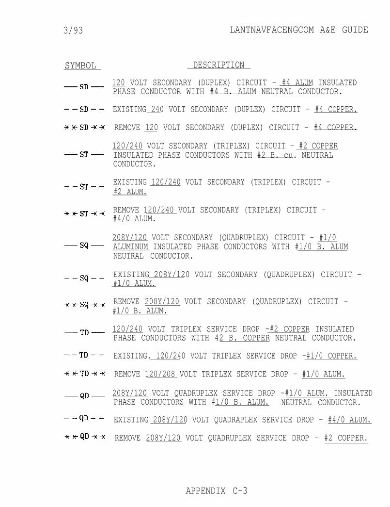
3/93 LANTNAVFACENGCOM A&E GUIDE
SYMBOL DESCRIPTION
120 VOLT SECONDARY (DUPLEX) CIRCUIT - #4 ALUM INSULATEDPHASE CONDUCTOR WITH #4 B. ALUM NEUTRAL CONDUCTOR.
EXISTING 240 VOLT SECONDARY (DUPLEX) CIRCUIT - #4 COPPER.
REMOVE 120 VOLT SECONDARY (DUPLEX) CIRCUIT - #4 COPPER.
120/240 VOLT SECONDARY (TRIPLEX) CIRCUIT - #2 COPPERINSULATED PHASE CONDUCTORS WITH #2 B. cu. NEUTRALCONDUCTOR.
EXISTING 120/240 VOLT SECONDARY (TRIPLEX) CIRCUIT -#2 ALUM.
REMOVE 120/240 VOLT SECONDARY (TRIPLEX) CIRCUIT -#4/0 ALUM.
208Y/120 VOLT SECONDARY (QUADRUPLEX) CIRCUIT - #1/0ALUMINUM INSULATED PHASE CONDUCTORS WITH #1/0 B. ALUMNEUTRAL CONDUCTOR.
EXISTING 208Y/120 VOLT SECONDARY (QUADRUPLEX) CIRCUIT -#1/0 ALUM.
REMOVE 208Y/120 VOLT SECONDARY (QUADRUPLEX) CIRCUIT -#1/0 B. ALUM.
120/240 VOLT TRIPLEX SERVICE DROP -#2 COPPER INSULATEDPHASE CONDUCTORS WITH 42 B. COPPER NEUTRAL CONDUCTOR.
EXISTING. 120/240 VOLT TRIPLEX SERVICE DROP -#1/0 COPPER.
REMOVE 120/208 VOLT TRIPLEX SERVICE DROP - #1/0 ALUM.
208Y/120 VOLT QUADRUPLEX SERVICE DROP -#1/0 ALUM. INSULATEDPHASE CONDUCTORS WITH #1/0 B. ALUM. NEUTRAL CONDUCTOR.
EXISTING 208Y/l20 VOLT QUADRAPLEX SERVICE DROP - #4/0 ALUM.
REMOVE 208Y/120 VOLT QUADRUPLEX SERVICE DROP - #2 COPPER.
APPENDIX C-3
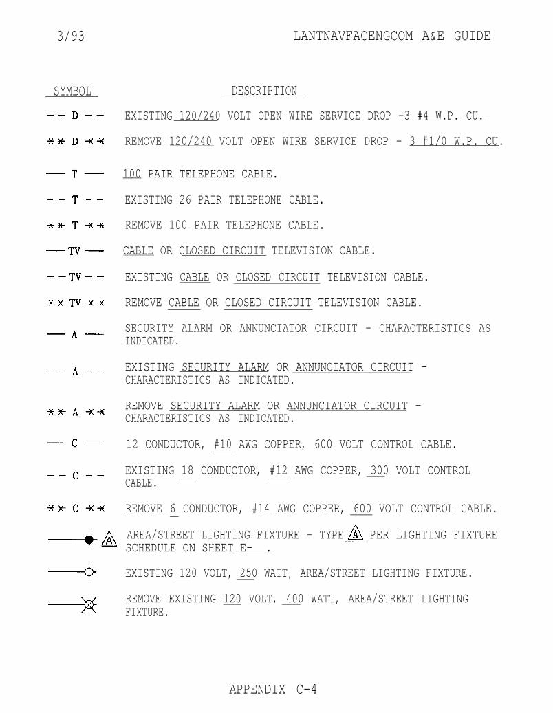
3/93
SYMBOL
LANTNAVFACENGCOM A&E GUIDE
DESCRIPTION
EXISTING 120/240 VOLT OPEN WIRE SERVICE DROP -3 #4 W.P. CU.
REMOVE 120/240 VOLT OPEN WIRE SERVICE DROP - 3 #1/0 W.P. CU.
100 PAIR TELEPHONE CABLE.
EXISTING 26 PAIR TELEPHONE CABLE.
REMOVE 100 PAIR TELEPHONE CABLE.
CABLE OR CLOSED CIRCUIT TELEVISION CABLE.
EXISTING CABLE OR CLOSED CIRCUIT TELEVISION CABLE.
REMOVE CABLE OR CLOSED CIRCUIT TELEVISION CABLE.
SECURITY ALARM OR ANNUNCIATOR CIRCUIT - CHARACTERISTICS ASINDICATED.
EXISTING SECURITY ALARM OR ANNUNCIATOR CIRCUIT -CHARACTERISTICS AS INDICATED.
REMOVE SECURITY ALARM OR ANNUNCIATOR CIRCUIT -CHARACTERISTICS AS INDICATED.
12 CONDUCTOR, #10 AWG COPPER, 600 VOLT CONTROL CABLE.
EXISTING 18 CONDUCTOR, #12 AWG COPPER, 300 VOLT CONTROLCABLE.
REMOVE 6 CONDUCTOR, #14 AWG COPPER, 600 VOLT CONTROL CABLE.
AREA/STREET LIGHTING FIXTURE - TYPE PER LIGHTING FIXTURESCHEDULE ON SHEET E- .
EXISTING 120 VOLT, 250 WATT, AREA/STREET LIGHTING FIXTURE.
REMOVE EXISTING 120 VOLT, 400 WATT, AREA/STREET LIGHTINGFIXTURE.
APPENDIX C-4
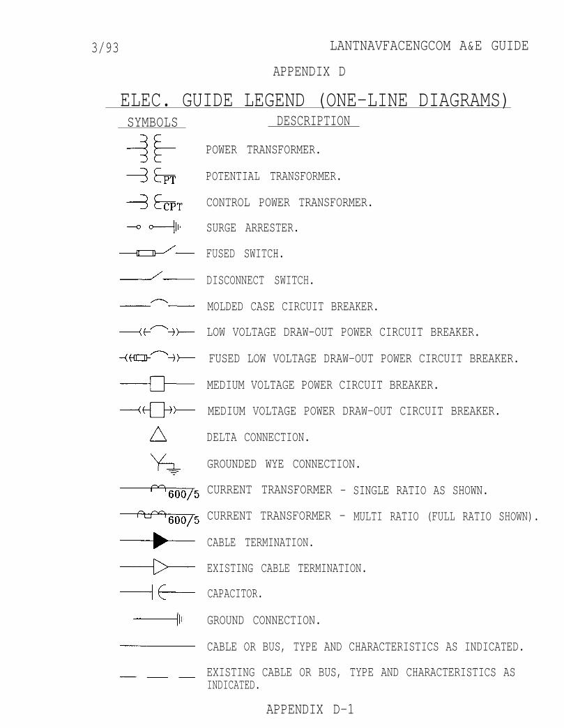
3/93 LANTNAVFACENGCOM A&E GUIDE
APPENDIX D
ELEC. GUIDE LEGEND (ONE-LINE DIAGRAMS)SYMBOLS DESCRIPTION
POWER TRANSFORMER.
POTENTIAL TRANSFORMER.
CONTROL POWER TRANSFORMER.
SURGE ARRESTER.
FUSED SWITCH.
DISCONNECT SWITCH.
MOLDED CASE CIRCUIT BREAKER.
LOW VOLTAGE DRAW-OUT POWER CIRCUIT BREAKER.
FUSED LOW VOLTAGE DRAW-OUT POWER CIRCUIT BREAKER.
MEDIUM VOLTAGE POWER CIRCUIT BREAKER.
MEDIUM VOLTAGE POWER DRAW-OUT CIRCUIT BREAKER.
DELTA CONNECTION.
GROUNDED WYE CONNECTION.
CURRENT TRANSFORMER - SINGLE RATIO AS SHOWN.
CURRENT TRANSFORMER - MULTI RATIO (FULL RATIO SHOWN).
CABLE TERMINATION.
EXISTING CABLE TERMINATION.
CAPACITOR.
GROUND CONNECTION.
CABLE OR BUS, TYPE AND CHARACTERISTICS AS INDICATED.
EXISTING CABLE OR BUS, TYPE AND CHARACTERISTICS ASINDICATED.
APPENDIX D-1
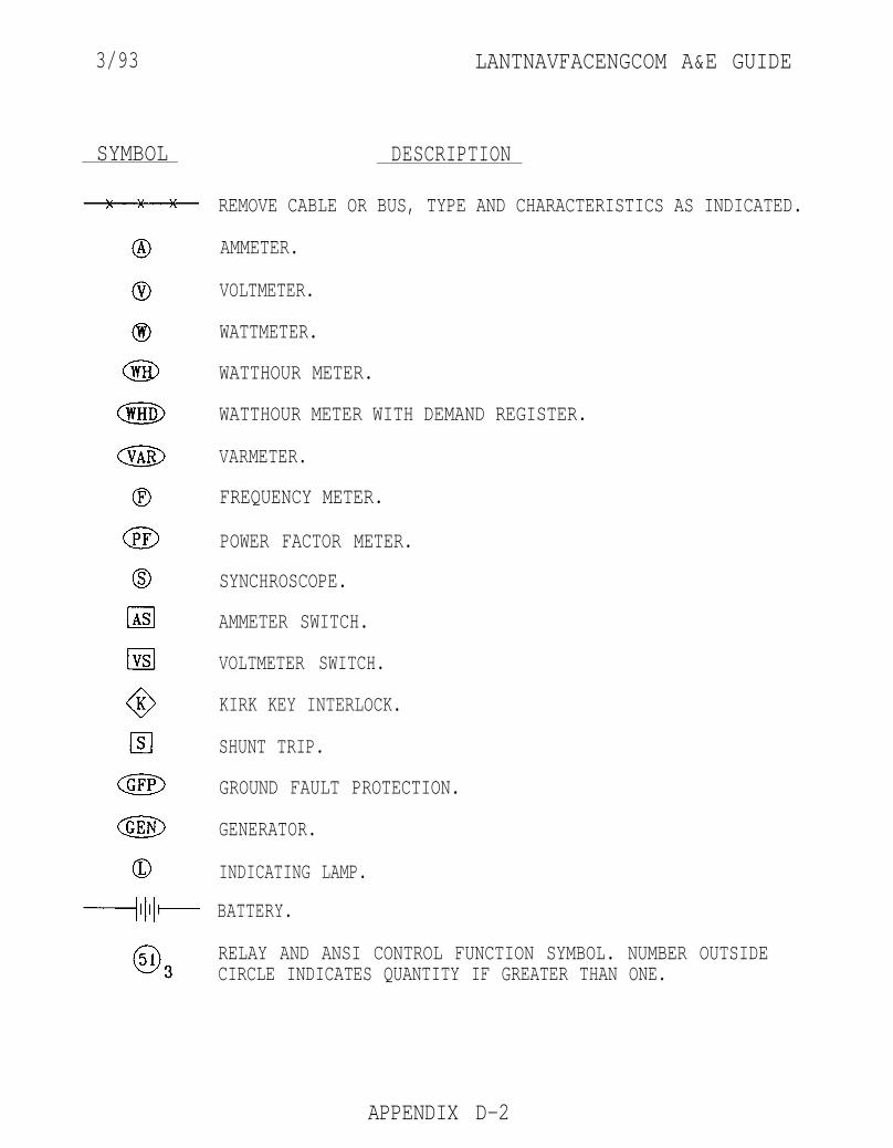
3/93 LANTNAVFACENGCOM A&E GUIDE
SYMBOL DESCRIPTION
REMOVE CABLE OR BUS, TYPE AND CHARACTERISTICS AS INDICATED.
AMMETER.
VOLTMETER.
WATTMETER.
WATTHOUR METER.
WATTHOUR METER WITH DEMAND REGISTER.
VARMETER.
FREQUENCY METER.
POWER FACTOR METER.
SYNCHROSCOPE.
AMMETER SWITCH.
VOLTMETER SWITCH.
KIRK KEY INTERLOCK.
SHUNT TRIP.
GROUND FAULT PROTECTION.
GENERATOR.
INDICATING LAMP.
BATTERY.
RELAY AND ANSI CONTROL FUNCTION SYMBOL. NUMBER OUTSIDECIRCLE INDICATES QUANTITY IF GREATER THAN ONE.
APPENDIX D-2
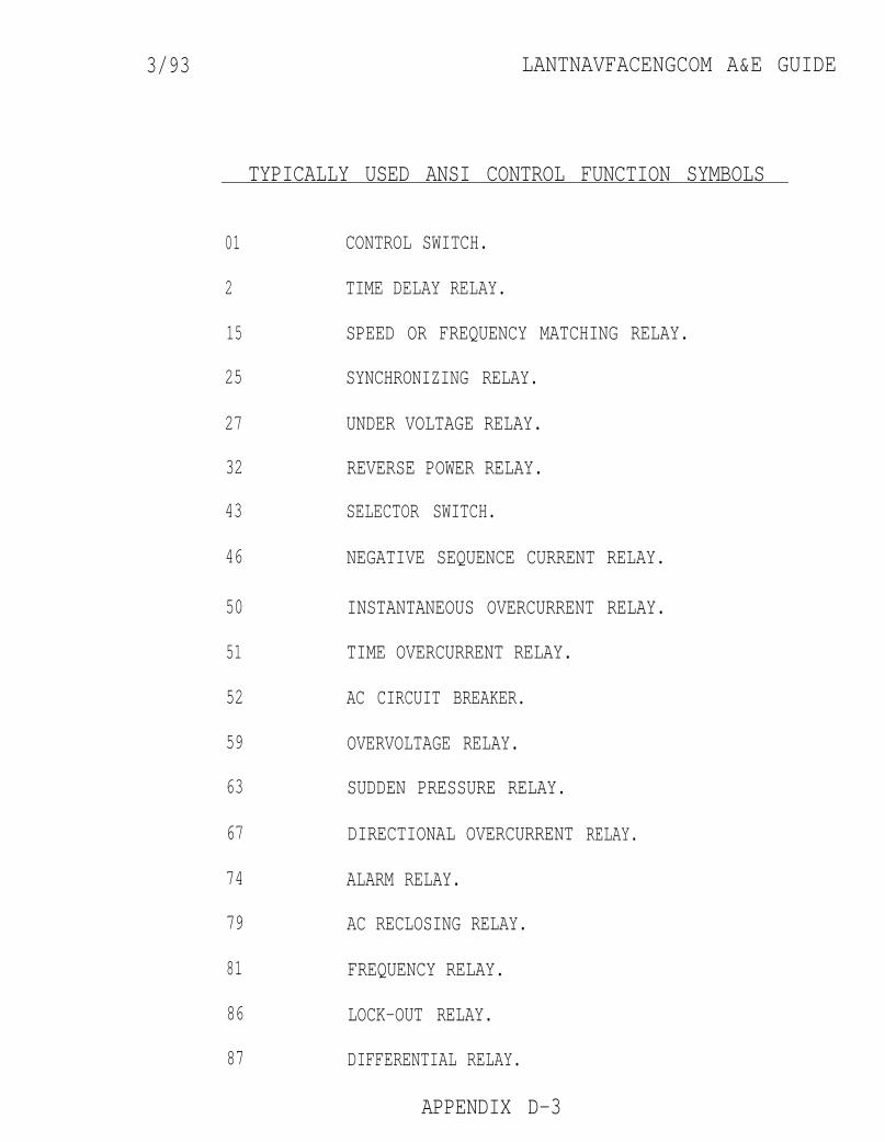
3/93 LANTNAVFACENGCOM A&E GUIDE
TYPICALLY USED ANSI CONTROL FUNCTION SYMBOLS
01
2
15
25
27
32
43
46
50
51
52
59
63
67
74
79
81
86
87
CONTROL SWITCH.
TIME DELAY RELAY.
SPEED OR FREQUENCY MATCHING RELAY.
SYNCHRONIZING RELAY.
UNDER VOLTAGE RELAY.
REVERSE POWER RELAY.
SELECTOR SWITCH.
NEGATIVE SEQUENCE CURRENT RELAY.
INSTANTANEOUS OVERCURRENT RELAY.
TIME OVERCURRENT RELAY.
AC CIRCUIT BREAKER.
OVERVOLTAGE RELAY.
SUDDEN PRESSURE RELAY.
DIRECTIONAL OVERCURRENT
ALARM RELAY.
AC RECLOSING RELAY.
FREQUENCY RELAY.
LOCK-OUT RELAY.
DIFFERENTIAL RELAY.
APPENDIX D-3
RELAY.
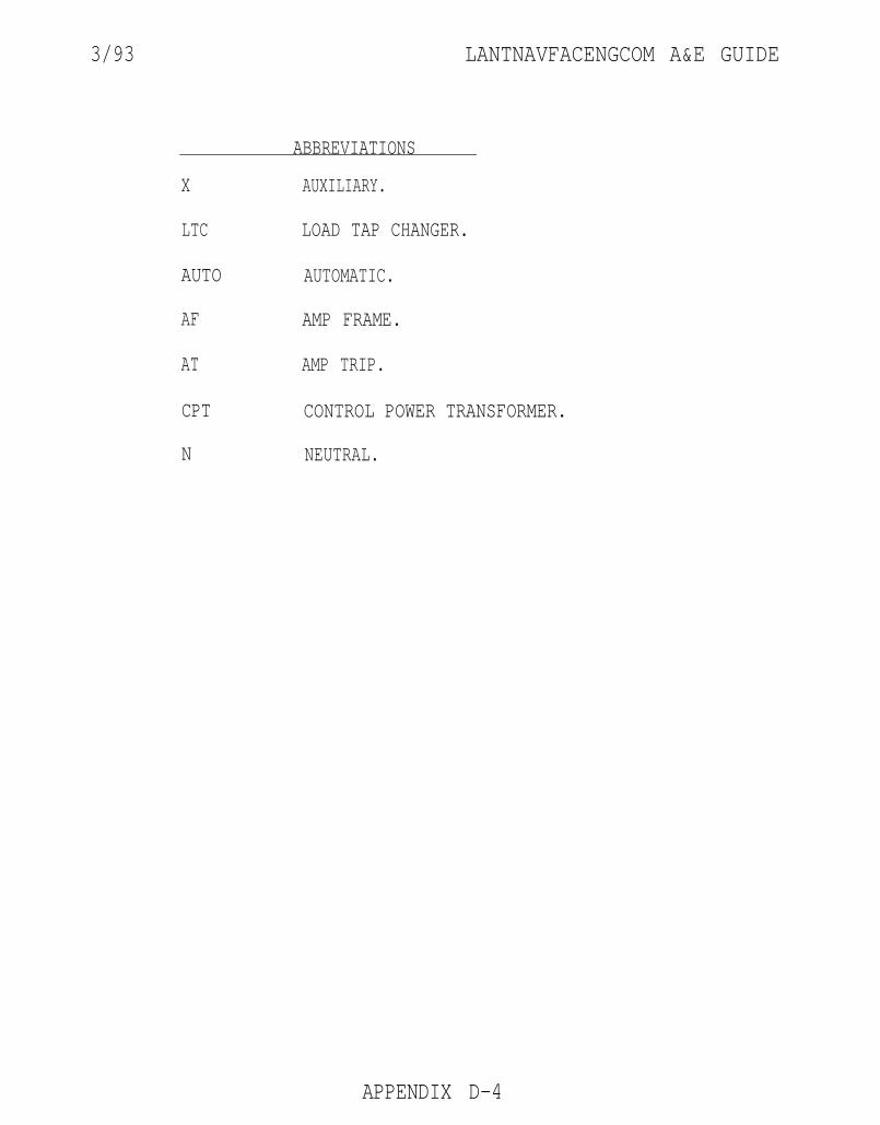
3/93 LANTNAVFACENGCOM A&E GUIDE
ABBREVIATIONS
X AUXILIARY.
LTC LOAD TAP CHANGER.
AUTO AUTOMATIC.
AF AMP FRAME.
AT AMP TRIP.
CPT CONTROL POWER TRANSFORMER.
N NEUTRAL.
APPENDIX D-4
Related Documents