1 LAN switching and Bridges Relates to Lab 6. Covers interconnection devices (at different layers) and the difference between LAN switching (bridging) and routing. Then discusses LAN switching, including learning bridge algorithm, transparent bridging, and the spanning tree protocol.

Welcome message from author
This document is posted to help you gain knowledge. Please leave a comment to let me know what you think about it! Share it to your friends and learn new things together.
Transcript
1
LAN switching and Bridges
Relates to Lab 6.Covers interconnection devices (at different layers) and the difference between LAN switching (bridging) and routing. Then discusses LAN switching, including learning bridge algorithm, transparent bridging, and the spanning tree protocol.
2
Outline
• Interconnection devices• Bridges/LAN switches vs. Routers• Bridges• Learning Bridges• Transparent bridges
3
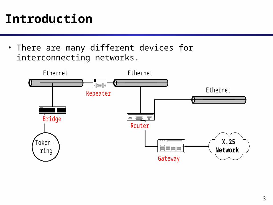
Introduction
• There are many different devices for interconnecting networks.
Ethernet
Router
Ethernet
Ethernet
Token-ring
Gateway
Bridge
Repeater
X.25Network
4
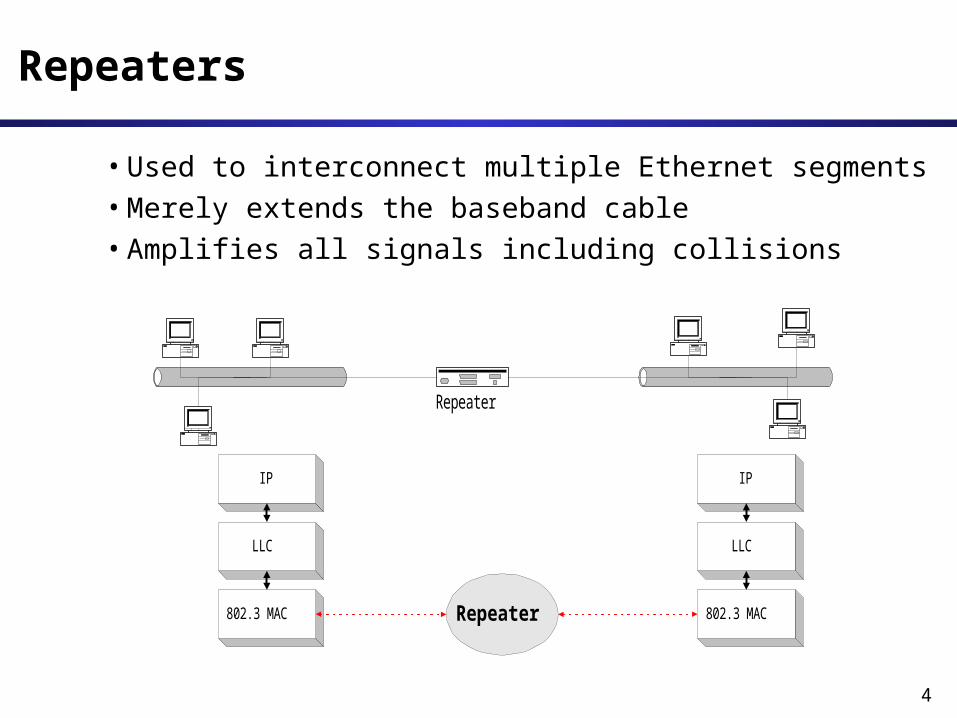
Repeaters
•Used to interconnect multiple Ethernet segments•Merely extends the baseband cable•Amplifies all signals including collisions
Repeater
IP
LLC
802.3 MAC
IP
LLC
802.3 MACRepeater
5
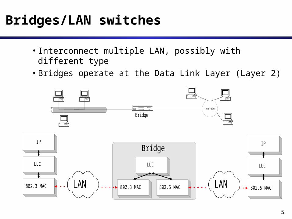
Bridges/LAN switches
•Interconnect multiple LAN, possibly with different type
•Bridges operate at the Data Link Layer (Layer 2)
BridgeToken-ring
BridgeIP
LLC
802.3 MAC 802.3 MAC 802.5 MAC
LLC
IP
LLC
802.5 MACLAN LAN
6
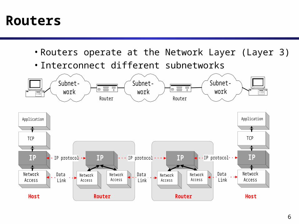
Routers
•Routers operate at the Network Layer (Layer 3) •Interconnect different subnetworks
Subnet-work
Router
Subnet-work
Router
Subnet-work
Application
TCP
IP
NetworkAccess
Application
TCP
IP
NetworkAccess
IP protocol IP protocol
DataLink
NetworkAccess
IP
NetworkAccess
NetworkAccess
IP
NetworkAccess
DataLink
DataLink
IP protocol
RouterRouter HostHost
7
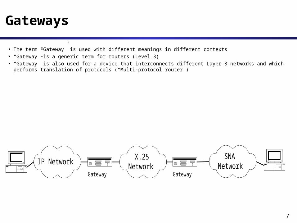
Gateways • The term “Gateway” is used with different meanings in different contexts• “Gateway” is a generic term for routers (Level 3)• “Gateway” is also used for a device that interconnects different Layer 3 networks and which performs translation of protocols (“Multi-protocol router”)
SNANetwork
GatewayIP Network
Gateway
X.25Network

8
Bridges versus Routers
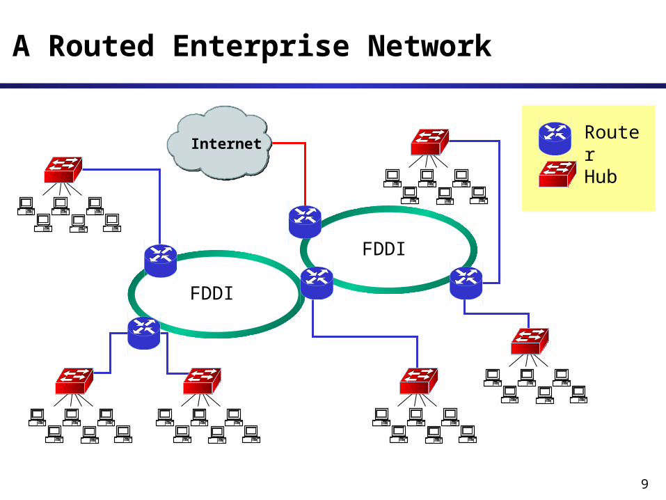
• An enterprise network (e.g., university network) with a large number of local area networks (LANs) can use routers or bridges
• Until early 1990s: most LANs were interconnected by routers
• Since mid1990s: LAN switches replace most routers
9
Internet
A Routed Enterprise Network
RouterHub
FDDI
FDDI
10
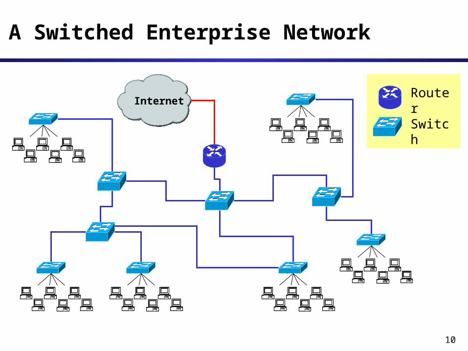
Internet
A Switched Enterprise Network
RouterSwitch
11
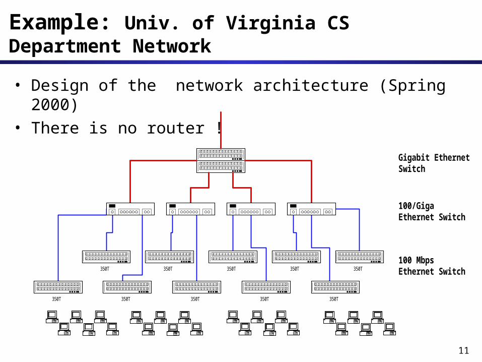
Example: Univ. of Virginia CS Department Network
• Design of the network architecture (Spring 2000)
• There is no router !
350T 350T 350T 350T350T
350T
100/GigaEthernet Switch
Gigabit EthernetSwitch
100 MbpsEthernet Switch
350T350T 350T 350T 350T

12
Bridges versus Routers
Routers
• Each host’s IP address must be configured
• If network is reconfigured, IP addresses may need to be reassigned
• Routing done via RIP or OSPF
• Each router manipulates packet header (e.g., reduces TTL field)
Bridges
• MAC addresses are hardwired
• No network configuration needed
• No routing protocol needed (sort of)– learning bridge algorithm– spanning tree algorithm
• Bridges do not manipulate frames
13
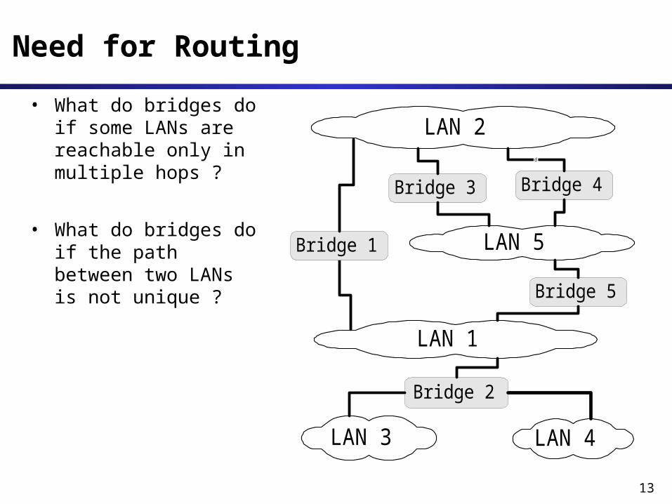
Need for Routing• What do bridges do
if some LANs are reachable only in multiple hops ?
• What do bridges do if the path between two LANs is not unique ?
LAN 2
Bridge 2
LAN 5
LAN 3
LAN 1
LAN 4
Bridge 5
Bridge 4Bridge 3d
Bridge 1
14
Transparent Bridges
• Three principal approaches can be found:– Fixed Routing– Source Routing– Spanning Tree Routing (IEEE 802.1d)
• We only discuss the last one in detail.
• Bridges that execute the spanning tree algorithm are called transparent bridges
15
Transparent Bridges
Overall design goal: Complete transparency
“Plug-and-play”Self-configuring without hardware or software changes
Bridges should not impact operation of existing LANs
Three parts to transparent bridges:(1) Forwarding of Frames(2) Learning of Addresses(3) Spanning Tree Algorithm
16
(1) Frame Forwarding
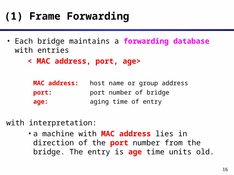
• Each bridge maintains a forwarding database with entries
< MAC address, port, age> MAC address: host name or group addressport: port number of bridgeage: aging time of entry
with interpretation: •a machine with MAC address lies in direction of the port number from the bridge. The entry is age time units old.
17
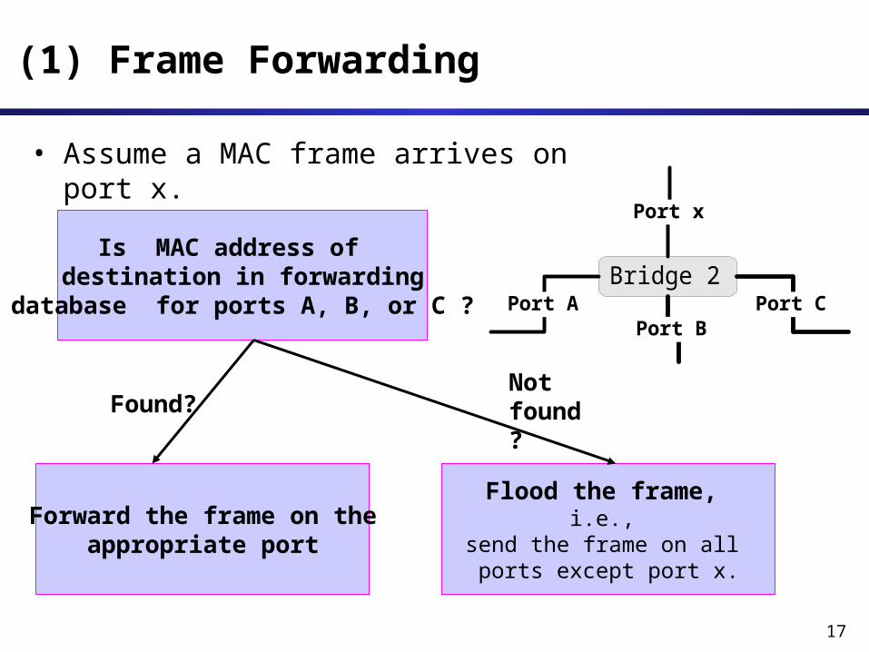
• Assume a MAC frame arrives on port x.
(1) Frame Forwarding
Bridge 2Port A Port C
Port x
Port B
Is MAC address of destination in forwarding
database for ports A, B, or C ?
Forward the frame on theappropriate port
Flood the frame, i.e.,
send the frame on all ports except port x.
Found?Notfound ?
18
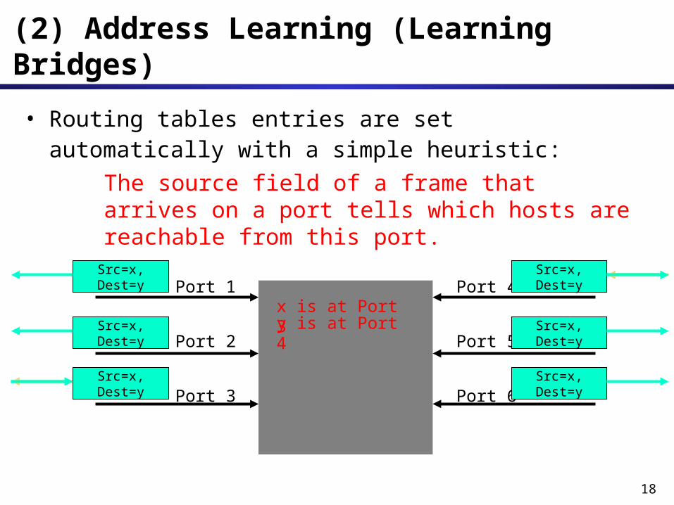
• Routing tables entries are set automatically with a simple heuristic:
The source field of a frame that arrives on a port tells which hosts are reachable from this port.
(2) Address Learning (Learning Bridges)
Port 1
Port 2
Port 3
Port 4
Port 5
Port 6
Src=x, Dest=y
Src=x, Dest=y
Src=x, Dest=y
Src=x, Dest=y
Src=x, Dest=y
Src=x, Dest=y
x is at Port 3
Src=y, Dest=x
Src=y, Dest=xSrc=x, Dest=y
y is at Port 4
Src=x, Dest=y
19
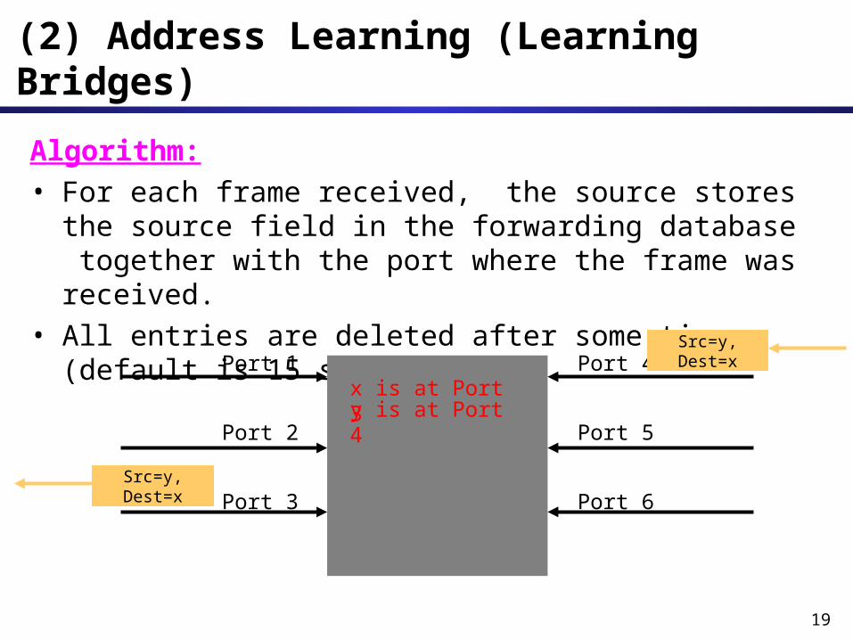
Algorithm: • For each frame received, the source stores the source field in the forwarding database together with the port where the frame was received.
• All entries are deleted after some time (default is 15 seconds).
(2) Address Learning (Learning Bridges)
Port 1
Port 2
Port 3
Port 4
Port 5
Port 6
x is at Port 3
Src=y, Dest=x
Src=y, Dest=x
y is at Port 4
20
Example
Bridge 2
Port1
LAN 1
A
LAN 2
CB D
LAN 3
E F
Port2
Bridge 2
Port1 Port2
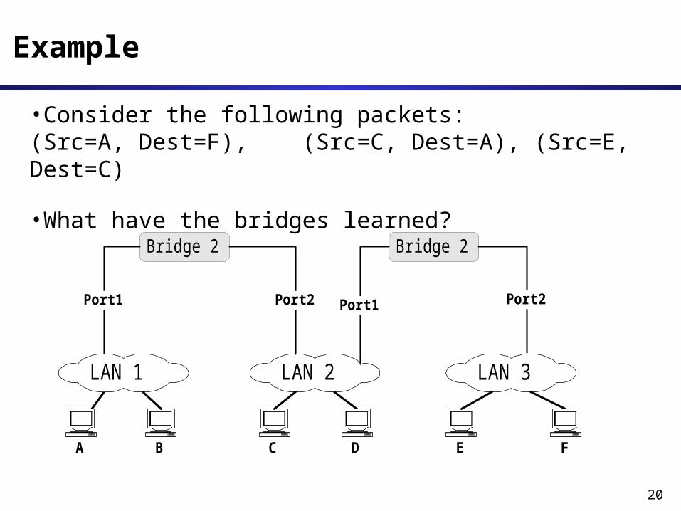
•Consider the following packets: (Src=A, Dest=F), (Src=C, Dest=A), (Src=E, Dest=C)
•What have the bridges learned?

21
• Consider the two LANs that are connected by two bridges.
• Assume host n is transmitting a frame F with unknown destination.
What is happening?• Bridges A and B flood the frame
to LAN 2.• Bridge B sees F on LAN 2 (with
unknown destination), and copies the frame back to LAN 1
• Bridge A does the same. • The copying continuesWhere’s the problem? What’s the
solution ?
Danger of Loops
LAN 2
LAN 1
Bridge BBridge A
host n
F
F F
FF
F F
22
• A solution is to prevent loops in the topology • IEEE 802.1d has an algorithm that builds and maintains a spanning tree in a dynamic environment
• Bridges that run 802.1d are called transparent bridges
• Bridges exchange messages to configure the bridge (Configuration Bridge Protocol Data Unit, Configuration BPDUs) to build the tree.
Spanning Trees / Transparent Bridges

23
What do the BPDUs do?
With the help of the BPDUs, bridges can:• Elect a single bridge as the root bridge.• Calculate the distance of the shortest path to the root bridge
• Each LAN can determine a designated bridge, which is the bridge closest to the root. The designated bridge will forward packets towards the root bridge.
• Each bridge can determine a root port, the port that gives the best path to the root.
• Select ports to be included in the spanning tree.

24
Configuration BPDUs
time since root sent amessage on
which this message is based
DestinationMAC address
Source MACaddress
ConfigurationMessage
protocol identifierversion
message typeflagsroot IDCost
bridge IDport ID
message agemaximum age
hello timeforward delay
Set to 0 Set to 0Set to 0
lowest bit is "topology change bit (TC bit)
ID of root Cost of the path from thebridge sending this
message
priority of configurable interface(used for loop detection)
ID of bridge sending this message
Time betweenrecalculations of the
spanning tree(default: 15 secs)
Time betweenBPDUs from the root
(default: 1sec)
25
Concepts
• Each bridge as a unique identifier:Bridge ID = <MAC address + priority level>
Note that a bridge has several MAC addresses (one for each port), but only one ID
• Each port within a bridge has a unique identifier (port ID).
• Root Bridge: The bridge with the lowest identifier is the root of the spanning tree.
• Root Port: Each bridge has a root port which identifies the next hop from a bridge to the root.

26
Concepts
• Root Path Cost: For each bridge, the cost of the min-cost path to the root.
Assume it is measured in #hops to the root• Designated Bridge, Designated Port: Single bridge on a LAN that provides the minimal cost path to the root for this LAN:
- if two bridges have the same cost, select the one with highest priority
- if the min-cost bridge has two or more ports on the LAN, select the port with the lowest identifier
• Note: We assume that “cost” of a path is the number of “hops”.
27
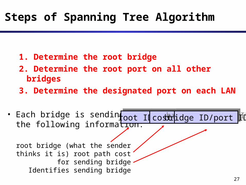
Steps of Spanning Tree Algorithm
1. Determine the root bridge2. Determine the root port on all other bridges
3. Determine the designated port on each LAN
• Each bridge is sending out BPDUs that contain the following information:
root bridge (what the sender thinks it is) root path cost
for sending bridgeIdentifies sending bridge
root IDcostbridge ID/port ID

28
Ordering of Messages
• We can order BPDU messages with the following ordering relation “<<“:
If (R1 < R2)M1<< M2
elseif ((R1 == R2) and (C1 < C2)) M1 << M2
elseif ((R1 == R2) and (C1 == C2) and (B1 < B2))M1 << M2
ID R1 C1 ID B1 ID R2 C2 ID B2<M1 M2
29
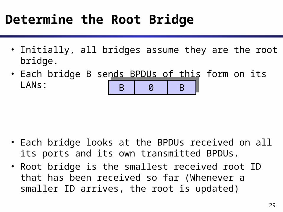
• Initially, all bridges assume they are the root bridge.
• Each bridge B sends BPDUs of this form on its LANs:
• Each bridge looks at the BPDUs received on all its ports and its own transmitted BPDUs.
• Root bridge is the smallest received root ID that has been received so far (Whenever a smaller ID arrives, the root is updated)
Determine the Root Bridge
B 0 B
30
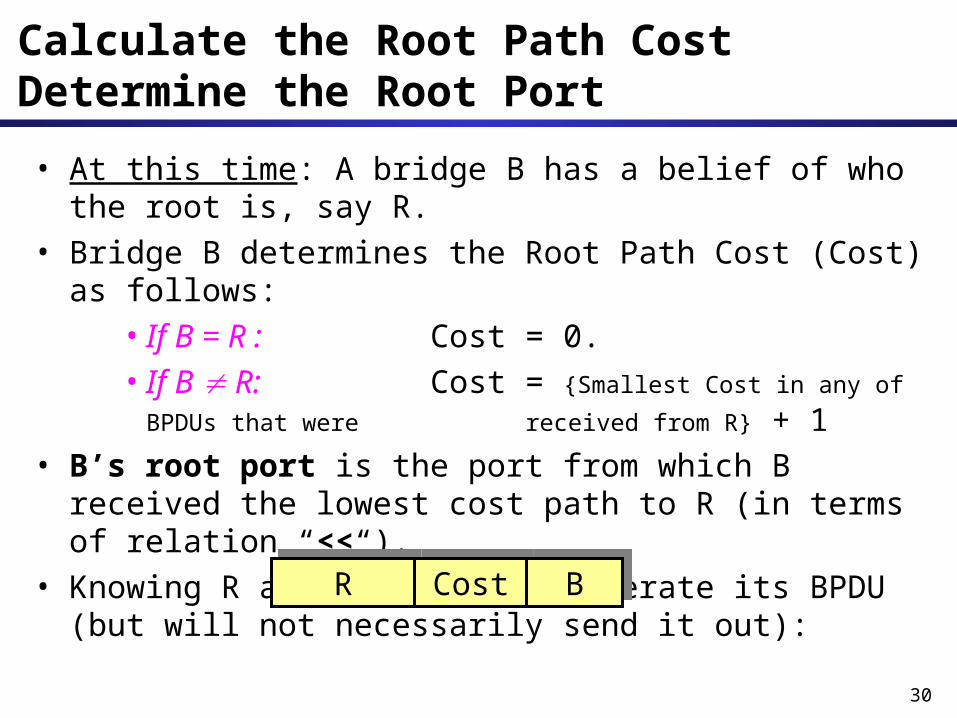
• At this time: A bridge B has a belief of who the root is, say R.
• Bridge B determines the Root Path Cost (Cost) as follows:
• If B = R : Cost = 0.• If B R: Cost = {Smallest Cost in any of BPDUs that were received from R} + 1
• B’s root port is the port from which B received the lowest cost path to R (in terms of relation “<<“).
• Knowing R and Cost, B can generate its BPDU (but will not necessarily send it out):
Calculate the Root Path CostDetermine the Root Port
R Cost B

31
• At this time: B has generated its BPDU
• B will send this BPDU on one of its ports, say port x, only if its BPDU is lower (via relation “<<“) than any BPDU that B received from port x.
• In this case, B also assumes that it is the designated bridge for the LAN to which the port connects.
Calculate the Root Path CostDetermine the Root Port
R Cost B
Bridge BPort A Port C
Port x
Port B
32
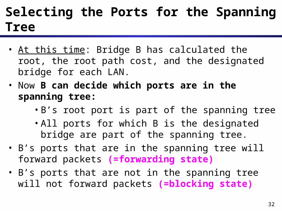
Selecting the Ports for the Spanning Tree• At this time: Bridge B has calculated the root, the root path cost, and the designated bridge for each LAN.
• Now B can decide which ports are in the spanning tree:
•B’s root port is part of the spanning tree•All ports for which B is the designated bridge are part of the spanning tree.
• B’s ports that are in the spanning tree will forward packets (=forwarding state)
• B’s ports that are not in the spanning tree will not forward packets (=blocking state)
33
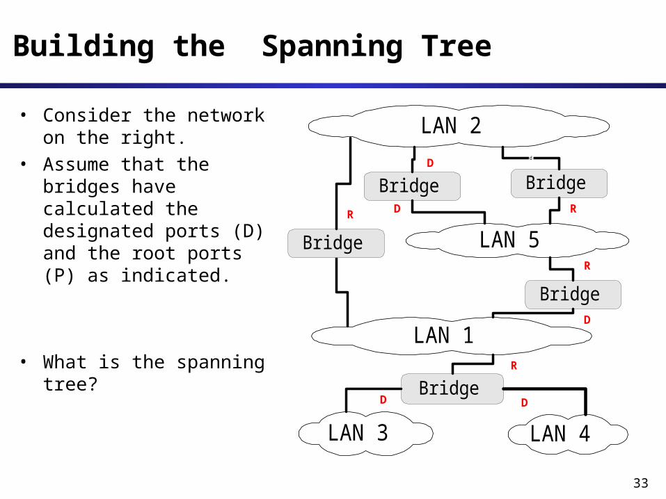
Building the Spanning Tree
LAN 2
Bridge
LAN 5
LAN 3
LAN 1
LAN 4
Bridge
BridgeBridged
Bridge
DD
D
R
DR R
R
D
• Consider the network on the right.
• Assume that the bridges have calculated the designated ports (D) and the root ports (P) as indicated.
• What is the spanning tree?
Related Documents