LANscape ® Solutions Fiber Optic Products Catalog 12TH EDITION preterminated systems | cables | connectors | cable assemblies | hardware splice closures | test equipment | splice equipment | tools & kits | rentals & training Total innovation. Total solution. Total Corning.

Welcome message from author
This document is posted to help you gain knowledge. Please leave a comment to let me know what you think about it! Share it to your friends and learn new things together.
Transcript
LANscape® SolutionsFiber Optic Products Catalog12TH EDITION
pre te rmina ted sys tems | cab les | connec to rs | cab le assembl ies | hardware
splice closures | test equipment | splice equipment | tools & kits | rentals & training
Total innovation.Total solution.Total Corning.
United States |Corning Cable Systems LLCPO Box 489Hickory, NC 28603-0489 USATEL 800 743 2675FAX 828 325 5060INTERNATIONAL +1 828 901 5000www.corning.com/cablesystems
Australia |Corning Cable Systems Pty. Ltd.74-84 Main RoadClayton, Victoria 3168AUSTRALIATEL +61 3 9538 2300FAX +61 3 9538 2316www.corning.com/cablesystems/apac/en/australia.aspx
China |Corning Cable Systems (Shanghai) Co., Ltd.3F, Li Min BuildingNo. 111 Gui Qing RoadCao He Jin High-Tech Development ZoneShanghai 200233CHINATEL +86 21 5450 4888FAX +86 21 5427 7898 (Commercial Team)FAX +86 21 5427 0083 (R&D, HR, FA)www.corningcablesystems.com.cn
Europe, the Middle Eastand Africa |Corning Cable Systems GmbH & Co. KGLeipziger Strasse 12110117 BerlinGERMANYTEL +00 800 2676 4641FAX +49 30 5303 2335www.corning.com/cablesystems/emea
Japan |Advanced Cable Systems CorporationTime 24 Building, 11 F2-4-32, Aomi, Koto-kuTokyo 135-8073JAPANTEL +81 3 5564 5021FAX +81 3 5564 5026www.advanced-cable.co.jp
Latin America |Corning Cable Systems S.A. de C.V.Rio Niágara #36 - 3Col. CuauhtemocDel. CuauhtemocC.P. 06500MEXICO, D.F.TEL +52 55 52 50 80 21FAX +52 55 52 54 51 04www.corning.com/cablesystems
Southern Asia Pacific |Corning Cable Systems SingaporeGreat World City#09-11 West Tower1 Kim Seng PromenadeSINGAPORE 237994TEL +65 6235 5605FAX +65 6735 2913www.corning.com/cablesystems/apac/en/south_east_asia.aspx
Corning Cable Systems reserves the right to improve, enhance and modify the features and specifications of Corning Cable Systems products withoutprior notification. ALTOS, Crimp & Go, DFX, ERK, FREEDM, LANscape, MIC, miniMass, OptiSplice, OptiTap, OptiTip, Pretium, TBII and UniCam areregistered trademarks of Corning Cable Systems Brands, Inc. AnyLAN, CamSplice, Elite, LID-SYSTEM, Lite, LSZH, Plug & Play, Pretium EDGE, Splice Pak,SST-Drop and Zeux are trademarks of Corning Cable Systems Brands, Inc. LST is a trademark of Corning Cable Systems LLC. Consultant LinkUp and Ex-tended Warranty are service marks of Corning Cable Systems LLC. ClearCurve and Corning are registered trademarks of Corning Incorporated. smallTALKis a registered trademark of GN Nettest (New York) Inc. CheckPoint is a trademark of GN Nettest (New York) Inc. MTP is a registered trademark of US-Conec, Ltd. ST is a registered trademark of Lucent Technologies. All other trademarks are the properties of their respective owners. Corning Cable Systemsis ISO 9001 certified. © 2010 Corning Cable Systems. All rights reserved. Published in the USA. LAN-1217-EN / April 2010

About Corning Cable Systems
CORNING CABLE SYSTEMS LANSCAPE® SOLUTIONS FIBER OPTIC PRODUCTS CATALOG | 12TH EDITION | LAN-1217-EN
Corning Cable Systems, founded in 1977, is a leadingmanufacturer of fiber optic products for voice, dataand video communications applications. Headquarteredin Hickory, North Carolina, Corning Cable Systemsis owned by Corning Incorporated, headquartered inCorning, New York.
LANscape® SolutionsCorning Cable Systems LANscape Solutions are a completeapproach to fiber cabling solutions for enterprise networks.Including a complete tip-to-tip product offering and design-through-operation services, LANscape Solutions ensure thesuccessful and efficient implementation of a fiber network thatwill serve as a stable communications infrastructure for manyyears to come.
Corning Cable Systems maintains its commitment to customersand products through many customer support programs. Whena fiber optic system is installed by a certified member companyof its Network of Preferred Installers Program, Corning CableSystems warrants LANscape Fiber Optic Cabling Solutions fora full 25 years through the Extended WarrantySM Program. TheConsultant LinkUpSM Program provides information on CorningCable Systems cabled fiber solutions and industry informationto top-level consultants and designers nationwide.
Product LinesThe broad scope of Corning Cable Systems’ product linespermits one-stop shopping. Fiber optic products include pre-terminated systems for both data center and LAN applications,outdoor cables, indoor flame-retardant cables, indoor/outdoorcables, field-installable connectors, connecting hardware,patch cords, splice equipment and test equipment, as well asengineering services and training. An extensive, nationwidedistribution system with a large inventory ensures that CorningCable Systems products are ready for immediate delivery.
Total Quality CommitmentCorning Cable Systems is dedicated to providing Total Qualityproducts and services to customers before, during and afterthe sale. This long-term commitment to quality begins withexecutive endorsement and continues throughout the organi-zation. Corning Cable Systems has received numerous qualitysupplier awards from customers and is TL-9000 registered.
We are also a recipient of the Award of Excellence from theInternational Customer Service Association.
Corning Cable Systems Quality Policy states: It is the policyof Corning Cable Systems to achieve Total Quality performancein meeting the requirements of external and internal customers.Total Quality performance means understanding who thecustomer is, what the requirements are, and meeting thoserequirements without error, on time, every time.
Industry LeadershipCorning Cable Systems has contributed extensively to the fiberoptic industry since its inception. Today, we are the largestmanufacturer of fiber optic cables in the United States. Ourcontributions include:
� Pioneer of the loose tube cable design, now recognizedas an industry standard for outside plant use
� Pioneer of the tight-buffered cable design, and the firstto manufacture high-fiber-count, NEC®-listed, tight-buffered cables
� Development of the industry’s first truly field-installablefiber optic connector with an assembly time under fiveminutes, as well as the first high-performance fieldtermination requiring no epoxy and no polishing
� Provider of the industry’s first fiber optic network cablingdesign guide and training course for enterprise networkscommunications systems
� Development of a complete fiber-to-the-desktop cablesystem solution consisting of fiber cables, outlets andcross-connect hardware
� Development of the industry’s first commercial single-mode optical time domain reflectometer (OTDR)
� Pioneer of the development of prewired optical hardwarefor system interconnection
� Invention of the first fully preterminated cabling systemsfor enterprise networks
� Introduced the first field-installable, no-epoxy/no-polish12-fiber connector (UniCam® MTP® Connector)
� Patented the TBII® Buffered Fiber, a slip layer thatallows easy removal of the buffering for splicing orconnectorization, in all Corning Cable Systems tight-buffered cables
� First to offer optical fiber cables designed to meetemerging Gigabit Ethernet applications
� Revolutionized data center design with Pretium EDGE™
Solutions, offering 100 percent more density, 35 percentfaster installations, and 25 percent faster moves, addsand changes than traditional systems
Symbol Given Multiply by to Obtain Symbol
mm millimeters 0.0394 inches in
cm centimeters 0.394 inches in
km kilometers 3281 feet ft
km kilometers 0.622 miles mi
N newtons 0.225 pound force lbf
N•m newton meter 0.738 foot pounds lbf • ft
N/cm newtons per centimeter 0.571 pounds force per inch lbf/in
kg kilograms 2.205 pounds lb
kg/km kilograms per kilometer 0.672 pounds per thousand feet lb/1000 ft
°C degrees Celsius 1.8 (then add 32)* degrees Fahrenheit °F
Symbol to Obtain Divide by Given Symbol
*When converting from °F to °C, subtract 32, then divide by 1.8.
Decimal Prefixes109 giga (G)106 mega (M)103 kilo (k)10-3 milli (m)10-6 micro (µ)10-9 nano (n)
Metric Conversion Chart
CORNING CABLE SYSTEMS LANSCAPE® SOLUTIONS FIBER OPTIC PRODUCTS CATALOG | 12TH EDITION | LAN-1217-EN
To request an additional copy of theLANscape® Solutions Fiber Optic ProductsCatalog for yourself or a colleague, pleasevisit offers.corning.com/1-lanscapecatalog

LANscape® Pretium EDGE™ Solutions ................................. 2Plug & Play™ Universal Systems ......................................... 6Plug & Play AnyLAN™ Systems ........................................... 11
OutdoorALTOS® All-Dielectric Gel-Free Cables ............................... 16ALTOS Lite™ Gel-Free,Single-Jacket, Single-Armored Cables .............................. 17ALTOS Figure-8 Gel-Free Cables ....................................... 18Tactical Cable ...................................................................... 19
Indoor/OutdoorIndustrial LSZH™ Cables...................................................... 20Mining and Petrochemical Fiber Optic Cables ................... 21FREEDM® LST™ Gel-Free Cables ...................................... 22FREEDM Loose Tube Gel-Free Cables ............................. 23FREEDM LST Gel-Free Interlocking Armored Cables ....... 24FREEDM Loose Tube Gel-FreeInterlocking Armored Cables ............................................... 25FREEDM Fan-Out Cables .................................................. 26FREEDM One Cables ......................................................... 27FREEDM One Interlocking Armored Cables ...................... 28FREEDM Ribbon Riser Cables ........................................... 29
IndoorMIC® Cables ........................................................................ 30MIC Interlocking Armored Cables ....................................... 31MIC DX Armored Cables ..................................................... 32MIC 250 Cables .................................................................. 33Fan-Out Cables ................................................................... 34Ribbon Cables ..................................................................... 35LSZH Ribbon Cables .......................................................... 36Ribbon Interlocking Armored Cables .................................. 37Ruggedized Ribbon Cables ................................................ 38
InterconnectSingle-Fiber Cables ............................................................. 39Zipcord Cables .................................................................... 40Ribbon Interconnect Cables ................................................ 41
UniCam® Connectors ......................................................... 42UniCam MTP® Connectors ................................................ 43Anaerobic-Cure Connectors ............................................... 44Heat-Cure Epoxy-and-Polish Connectors .......................... 45Fiber Optic Adapters/Interconnect Sleeves ........................ 47Cable Fan-Out Kits .............................................................. 48
Cable Assemblies ................................................................ 49
Rack-MountablePretium® Connector Housings (PCH) ................................. 51Closet Connector Housings (CCH) ..................................... 52Closet Splice Housings (CSH) ............................................ 53Closet Connector Housing Panels (CCH-CP) .................... 54Splice Trays ......................................................................... 56Cable Management Components ....................................... 58
Wall-MountableWall-Mountable Connector Housings (WCH) ..................... 59Wall-Mountable Interconnect Centers (WIC) ...................... 60Single-Panel Housing (SPH-01P) ....................................... 61Industrial Connector Housings (ICH) .................................. 62Industrial Splice Housing (ISH) ........................................... 63Environmental Distribution Center (EDC) ............................64Wall-Mountable Slack-Storage Housings (WCH-SSH) ...... 65Wall-Mountable Splice Housings (WSH) ............................ 66
ZoneFiber Zone Boxes (FZB-04U and FZB-04P) ....................... 67
OutletsWorkstation Multimedia Outlet (WMO) ............................... 68Ruggedized Information Outlet (RIO) ................................. 69
Splice Closure Fiber (SCF) Family .................................... 70UCAGrounding and UCAO Splice Closures ...................... 73
Optical Sources, Meters, Testers and Kits ......................... 75OV-1000 Optical Time Domain Reflectometer (OTDR) ...... 77OV-Mini Optical Time Domain Reflectometer (OTDR) ....... 78Video Inspection Probe (VIPROBE-DUAL) ........................ 79Optical Time Domain Reflectometer (OTDR)Launch Fiber, Access Jumper ............................................. 80Optical Network Simulation Systems .................................. 81Handheld Field Inspection Microscope ............................... 82VFL-350 Visual Fault Locator ............................................. 83CheckPoint™ Plus Fiber Identifier ....................................... 84
OptiSplice® M90e Fusion Splicer ....................................... 85OptiSplice CDS Fusion Splicer ........................................... 86OptiSplice One Handheld Fusion Splicer ........................... 87OptiSplice Ribbon Handheld Fusion Splicer ....................... 88CamSplice™ No-Adhesive Mechanical Splice .................... 89Fast Heat-Shrink Oven ........................................................ 90
Fiber Optic Connector Tool Kits ......................................... 91Connector Cleaning Kits, Tools and Consumables ............ 93Fiber Cleavers ..................................................................... 94Fusion Splice Protection ..................................................... 95Fiber Optic Splicing Tool Kits .............................................. 96Fiber Access Tools ............................................................ 101
Equipment Rental Services .............................................. 102Fiber Optic Training Programs .......................................... 105TS LAN 500 Training Course ............................................ 106TS FSD 400 Design Training Course ............................... 107TS LAN 200/TS LAN 200-A Training Courses .................. 108TS LAN 201 Training Course ............................................ 109TS LAN 300 Training Course ............................................ 110TS LAN 400 Training Course ............................................ 111
Table of Contents
CORNING CABLE SYSTEMS LANSCAPE® SOLUTIONS FIBER OPTIC PRODUCTS CATALOG | 12TH EDITION | LAN-1217-EN | PAGE 1
Preterminated Systems Hardware (continued)
Splice Closures
Test Equipment
Cables
Connectors
Cable Assemblies
Hardware
Splice Equipment
Tools & Kits
Index ...................................................................... 112
Rentals & Training
www.corning.com/cablesystemscustomer service: 800.743.2675
TABL
EOF
CONT
ENTS
PRET
ERMI
NATE
DSY
STEM
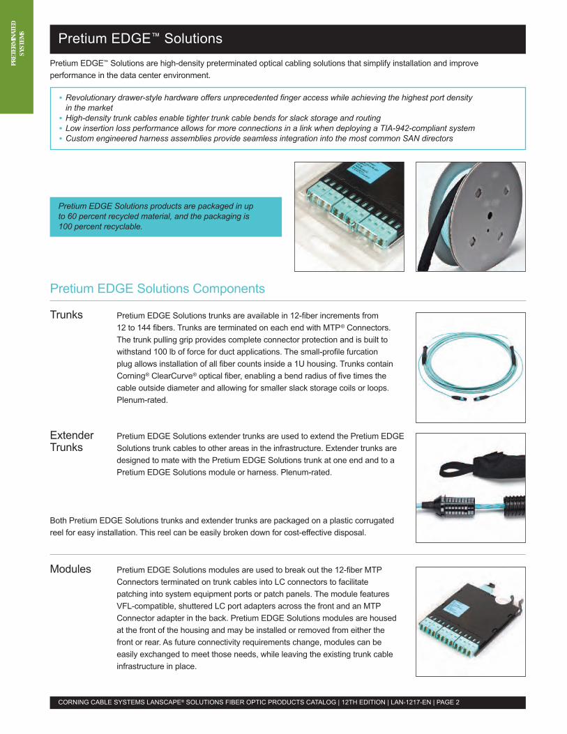
S Pretium EDGE™ SolutionsPretium EDGE™ Solutions are high-density preterminated optical cabling solutions that simplify installation and improveperformance in the data center environment.
• Revolutionary drawer-style hardware offers unprecedented finger access while achieving the highest port densityin the market
• High-density trunk cables enable tighter trunk cable bends for slack storage and routing• Low insertion loss performance allows for more connections in a link when deploying a TIA-942-compliant system• Custom engineered harness assemblies provide seamless integration into the most common SAN directors
Pretium EDGE Solutions Components
Trunks Pretium EDGE Solutions trunks are available in 12-fiber increments from12 to 144 fibers. Trunks are terminated on each end with MTP® Connectors.The trunk pulling grip provides complete connector protection and is built towithstand 100 lb of force for duct applications. The small-profile furcationplug allows installation of all fiber counts inside a 1U housing. Trunks containCorning® ClearCurve® optical fiber, enabling a bend radius of five times thecable outside diameter and allowing for smaller slack storage coils or loops.Plenum-rated.
Extender Pretium EDGE Solutions extender trunks are used to extend the Pretium EDGETrunks Solutions trunk cables to other areas in the infrastructure. Extender trunks are
designed to mate with the Pretium EDGE Solutions trunk at one end and to aPretium EDGE Solutions module or harness. Plenum-rated.
Both Pretium EDGE Solutions trunks and extender trunks are packaged on a plastic corrugatedreel for easy installation. This reel can be easily broken down for cost-effective disposal.
Modules Pretium EDGE Solutions modules are used to break out the 12-fiber MTPConnectors terminated on trunk cables into LC connectors to facilitatepatching into system equipment ports or patch panels. The module featuresVFL-compatible, shuttered LC port adapters across the front and an MTPConnector adapter in the back. Pretium EDGE Solutions modules are housedat the front of the housing and may be installed or removed from either thefront or rear. As future connectivity requirements change, modules can beeasily exchanged to meet those needs, while leaving the existing trunk cableinfrastructure in place.
CORNING CABLE SYSTEMS LANSCAPE® SOLUTIONS FIBER OPTIC PRODUCTS CATALOG | 12TH EDITION | LAN-1217-EN | PAGE 2
Pretium EDGE Solutions products are packaged in upto 60 percent recycled material, and the packaging is100 percent recyclable.
PRET
ERMI
NATE
DSY
STEM
SPretium EDGE™ Solutions
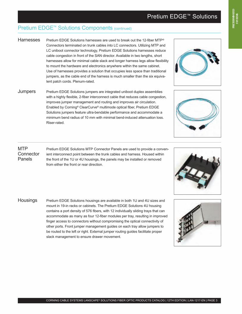
Pretium EDGE™ Solutions Components (continued)
Harnesses Pretium EDGE Solutions harnesses are used to break out the 12-fiber MTP®
Connectors terminated on trunk cables into LC connectors. Utilizing MTP andLC uniboot connector technology, Pretium EDGE Solutions harnesses reducecable congestion in front of the SAN director. Available in two lengths, shortharnesses allow for minimal cable slack and longer harness legs allow flexibilityto mount the hardware and electronics anywhere within the same cabinet.Use of harnesses provides a solution that occupies less space than traditionaljumpers, as the cable end of the harness is much smaller than the six equiva-lent patch cords. Plenum-rated.
Jumpers Pretium EDGE Solutions jumpers are integrated uniboot duplex assemblieswith a highly flexible, 2-fiber interconnect cable that reduces cable congestion,improves jumper management and routing and improves air circulation.Enabled by Corning® ClearCurve® multimode optical fiber, Pretium EDGESolutions jumpers feature ultra-bendable performance and accommodate aminimum bend radius of 10 mm with minimal bend-induced attenuation loss.Riser-rated.
CORNING CABLE SYSTEMS LANSCAPE® SOLUTIONS FIBER OPTIC PRODUCTS CATALOG | 12TH EDITION | LAN-1217-EN | PAGE 3
MTP Pretium EDGE Solutions MTP Connector Panels are used to provide a conven-Connector ient interconnect point between the trunk cables and harness. Housed withinPanels the front of the 1U or 4U housings, the panels may be installed or removed
from either the front or rear direction.
Housings Pretium EDGE Solutions housings are available in both 1U and 4U sizes andmount in 19-in racks or cabinets. The Pretium EDGE Solutions 4U housingcontains a port density of 576 fibers, with 12 individually sliding trays that canaccommodate as many as four 12-fiber modules per tray, resulting in improvedfinger access to connectors without compromising the optical connectivity ofother ports. Front jumper management guides on each tray allow jumpers tobe routed to the left or right. External jumper routing guides facilitate properslack management to ensure drawer movement.
PRET
ERMI
NATE
DSY
STEM
S Pretium EDGE™ Solutions
Insertion Loss (dB) MaxLANscape® Pretium® 300 Solutions LANscape Pretium 550 Solutions Ultra-Bendablewith Corning® ClearCurve® with ClearCurve Single-ModeOptical Fiber (OM3) Optical Fiber (OM4) Optical Fiber (OS2)
Connected Mated PairsLC 0.15 0.15 0.5MTP® Connector 0.35 0.35 0.75Modules/HarnessesLC 0.5 0.5 1.3
CORNING CABLE SYSTEMS LANSCAPE® SOLUTIONS FIBER OPTIC PRODUCTS CATALOG | 12TH EDITION | LAN-1217-EN | PAGE 4
Specifications
For detailed specifications and information, visit www.corning.com/cablesystems and enter the following literature code intothe search engine: LAN-1141-EN
Ordering InformationOM3 Part Number OM4 Part Number OS2 Part Number DescriptionNote: MMF = multimode fiber; OM3 = Pretium 300 Laser-Optimized MMF; OM4 = Pretium 550 Laser-Optimized MMF;OS2 = Ultra-Bendable Single-Mode Fiber.
Pretium EDGE™ Solutions TrunksComplete the part number by entering the trunk length in feet: 030, 040, 050, 060, 070, 080, 090, 100, 110, 120, 130, 140, 150,160, 170, 180, 190 or 200. Trunks have non-pinned MTP® Connectors on both ends, 33-in leg lengths. Part numbers shown belowhave a pulling grip on one end of the trunk. For other options, please consult the detailed specifications and information documentreferenced above.G757512TPNDDU _ _ _ F G757512QPNDDU _ _ _ F G909012GPNDDU _ _ _ F 12-fiber trunkG757524TPNDDU _ _ _ F G757524QPNDDU _ _ _ F G909024GPNDDU _ _ _ F 24-fiber trunkG757536TPNDDU _ _ _ F G757536QPNDDU _ _ _ F G909036GPNDDU _ _ _ F 36-fiber trunkG757548TPNDDU _ _ _ F G757548QPNDDU _ _ _ F G909048GPNDDU _ _ _ F 48-fiber trunkG757572TPNDDU _ _ _ F G757572QPNDDU _ _ _ F G909072GPNDDU _ _ _ F 72-fiber trunkG757596TPNDDU _ _ _ F G757596QPNDDU _ _ _ F G909096GPNDDU _ _ _ F 96-fiber trunkG7575E4TPNDDU _ _ _ F G7575E4QPNDDU _ _ _ F G9090E4GPNDDU _ _ _ F 144-fiber trunk
Pretium EDGE Solutions Extender TrunksComplete the part number by entering the trunk length in feet: 030, 040, 050, 060, 070, 080, 090, 100, 110, 120, 130, 140, 150,160, 170, 180, 190 or 200. Trunks have a pinned MTP Connector on one end and a non-pinned MTP Connector on the other end,60- and 33-in leg lengths. Part numbers shown below have a pulling grip on one end of the trunk. For other options, please consultthe detailed specifications and information document referenced above.G937512TPNCDX _ _ _ F G937512QPNCDX _ _ _ F G899012GPNCDX _ _ _ F 12-fiber trunkG937524TPNCDX _ _ _ F G937524QPNCDX _ _ _ F G899024GPNCDX _ _ _ F 24-fiber trunkG937536TPNCDX _ _ _ F G937536QPNCDX _ _ _ F G899036GPNCDX _ _ _ F 36-fiber trunkG937548TPNCDX _ _ _ F G937548QPNCDX _ _ _ F G899048GPNCDX _ _ _ F 48-fiber trunkG937572TPNCDX _ _ _ F G937572QPNCDX _ _ _ F G899072GPNCDX _ _ _ F 72-fiber trunkG937596TPNCDX _ _ _ F G937596QPNCDX _ _ _ F G899096GPNCDX _ _ _ F 96-fiber trunkG9375E4TPNCDX _ _ _ F G9375E4QPNCDX _ _ _ F G8990E4GPNCDX _ _ _ F 144-fiber trunk
Pretium EDGE Solutions ModulesAll Pretium EDGE Solutions modules use pinned MTP Adapters.ECM-UM12-05-93T ECM-UM12-05-93Q ECM-UM12-04-89G 12-fiber module, LC duplex adapters
(continued)
PRET
ERMI
NATE
DSY
STEM
SPretium EDGE™ Solutions
Ordering Information (continued)
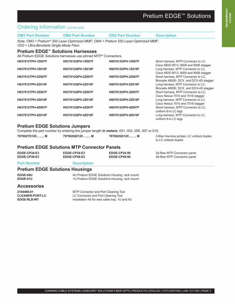
OM3 Part Number OM4 Part Number OS2 Part Number DescriptionNote: OM3 = Pretium® 300 Laser-Optimized MMF; OM4 = Pretium 550 Laser-Optimized MMF;OS2 = Ultra-Bendable Single-Mode Fiber.
Pretium EDGE™ Solutions HarnessesAll Pretium EDGE Solutions harnesses use pinned MTP® Connectors.H937912TPH-1Z007F H937912QPH-1Z007F H897812GPH-1Z007F Short harness, MTP Connector to LC,
Cisco MDS 9513, 9509 and 9506 staggerH937912TPH-1Z010F H937912QPH-1Z010F H897812GPH-1Z010F Long harness, MTP Connector to LC,
Cisco MDS 9513, 9509 and 9506 staggerH937912TPH-2Z007F H937912QPH-2Z007F H897812GPH-2Z007F Short harness, MTP Connector to LC,
Brocade 48000, DCX and DCX-4S staggerH937912TPH-2Z010F H937912QPH-2Z010F H897812GPH-2Z010F Long harness, MTP Connector to LC,
Brocade 48000, DCX and DCX-4S staggerH937912TPH-3Z007F H937912QPH-3Z007F H897812GPH-3Z007F Short harness, MTP Connector to LC,
Cisco Nexus 7010 and 7018 staggerH937912TPH-3Z010F H937912QPH-3Z010F H897812GPH-3Z010F Long harness, MTP Connector to LC,
Cisco Nexus 7010 and 7018 staggerH937912TPH-4Z007F H937912QPH-4Z007F H897812GPH-4Z007F Short harness, MTP Connector to LC,
uniform 6-in LC legsH937912TPH-4Z010F H937912QPH-4Z010F H897812GPH-4Z010F Long harness, MTP Connector to LC,
uniform 6-in LC legs
Pretium EDGE Solutions JumpersComplete the part number by entering the jumper length in meters: 001, 003, 005, 007 or 010.797902TD120 _ _ _ M 797902QD120 _ _ _ M 787802GD120 _ _ _ M 2-fiber low-loss jumper, LC uniboot duplex
to LC uniboot duplex
Pretium EDGE Solutions MTP Connector PanelsEDGE-CP24-E3 EDGE-CP24-E3 EDGE-CP24-90 24-fiber MTP Connector panelEDGE-CP48-E3 EDGE-CP48-E3 EDGE-CP48-90 48-fiber MTP Connector panel
Part Number DescriptionPretium EDGE Solutions HousingsEDGE-04U 4U Pretium EDGE Solutions Housing, rack mountEDGE-01U 1U Pretium EDGE Solutions Housing, rack mount
Accessories2104466-01 MTP Connector and Port Cleaning ToolCLEANER-PORT-LC LC Connector and Port Cleaning ToolEDGE-RLB-WT Installation Kit for wire cable tray; 1U and 4U
CORNING CABLE SYSTEMS LANSCAPE® SOLUTIONS FIBER OPTIC PRODUCTS CATALOG | 12TH EDITION | LAN-1217-EN | PAGE 5
PRET
ERMI
NATE
DSY
STEM
S Plug & Play™ Universal Systems
Plug & Play™ Universal Systems
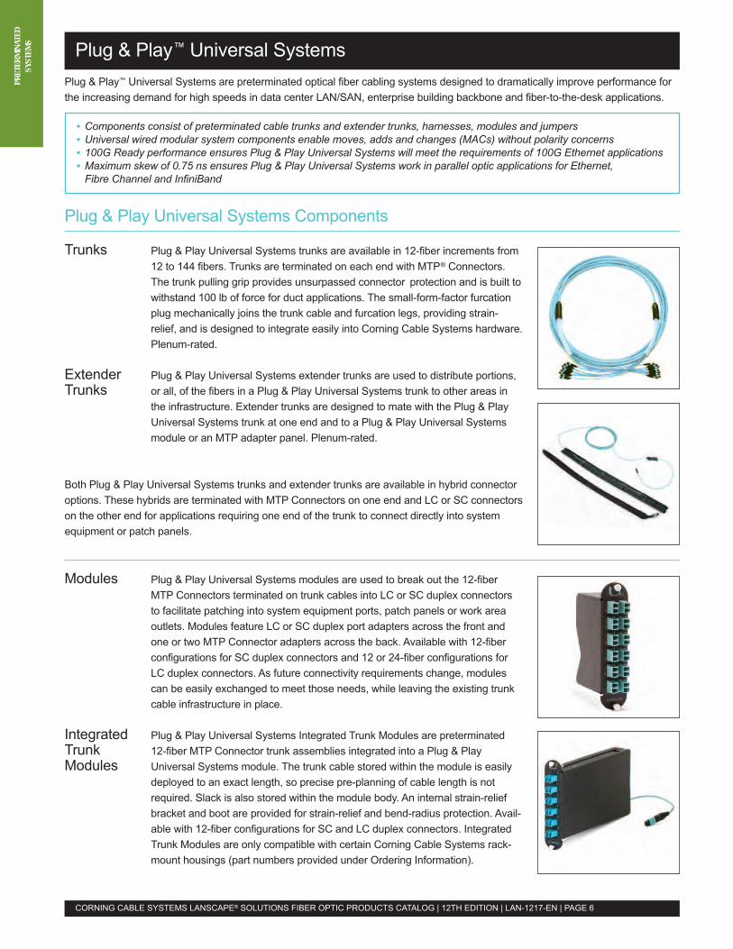
Plug & Play™ Universal Systems are preterminated optical fiber cabling systems designed to dramatically improve performance forthe increasing demand for high speeds in data center LAN/SAN, enterprise building backbone and fiber-to-the-desk applications.
• Components consist of preterminated cable trunks and extender trunks, harnesses, modules and jumpers• Universal wired modular system components enable moves, adds and changes (MACs) without polarity concerns• 100G Ready performance ensures Plug & Play Universal Systems will meet the requirements of 100G Ethernet applications• Maximum skew of 0.75 ns ensures Plug & Play Universal Systems work in parallel optic applications for Ethernet,Fibre Channel and InfiniBand
Plug & Play Universal Systems Components
Trunks Plug & Play Universal Systems trunks are available in 12-fiber increments from12 to 144 fibers. Trunks are terminated on each end with MTP® Connectors.The trunk pulling grip provides unsurpassed connector protection and is built towithstand 100 lb of force for duct applications. The small-form-factor furcationplug mechanically joins the trunk cable and furcation legs, providing strain-relief, and is designed to integrate easily into Corning Cable Systems hardware.Plenum-rated.
Extender Plug & Play Universal Systems extender trunks are used to distribute portions,Trunks or all, of the fibers in a Plug & Play Universal Systems trunk to other areas in
the infrastructure. Extender trunks are designed to mate with the Plug & PlayUniversal Systems trunk at one end and to a Plug & Play Universal Systemsmodule or an MTP adapter panel. Plenum-rated.
Both Plug & Play Universal Systems trunks and extender trunks are available in hybrid connectoroptions. These hybrids are terminated with MTP Connectors on one end and LC or SC connectorson the other end for applications requiring one end of the trunk to connect directly into systemequipment or patch panels.
Modules Plug & Play Universal Systems modules are used to break out the 12-fiberMTP Connectors terminated on trunk cables into LC or SC duplex connectorsto facilitate patching into system equipment ports, patch panels or work areaoutlets. Modules feature LC or SC duplex port adapters across the front andone or two MTP Connector adapters across the back. Available with 12-fiberconfigurations for SC duplex connectors and 12 or 24-fiber configurations forLC duplex connectors. As future connectivity requirements change, modulescan be easily exchanged to meet those needs, while leaving the existing trunkcable infrastructure in place.
Integrated Plug & Play Universal Systems Integrated Trunk Modules are preterminatedTrunk 12-fiber MTP Connector trunk assemblies integrated into a Plug & PlayModules Universal Systems module. The trunk cable stored within the module is easily
deployed to an exact length, so precise pre-planning of cable length is notrequired. Slack is also stored within the module body. An internal strain-reliefbracket and boot are provided for strain-relief and bend-radius protection. Avail-able with 12-fiber configurations for SC and LC duplex connectors. IntegratedTrunk Modules are only compatible with certain Corning Cable Systems rack-mount housings (part numbers provided under Ordering Information).
CORNING CABLE SYSTEMS LANSCAPE® SOLUTIONS FIBER OPTIC PRODUCTS CATALOG | 12TH EDITION | LAN-1217-EN | PAGE 6
PRET
ERMI
NATE
DSY
STEM
SPlug & Play™ Universal Systems
Plug & Play™ Universal Systems Components (continued)
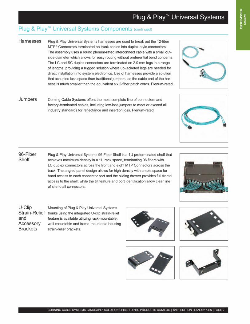
Harnesses Plug & Play Universal Systems harnesses are used to break out the 12-fiberMTP® Connectors terminated on trunk cables into duplex-style connectors.The assembly uses a round plenum-rated interconnect cable with a small out-side diameter which allows for easy routing without preferential bend concerns.The LC and SC duplex connectors are terminated on 2.0 mm legs in a rangeof lengths, providing a rugged solution where up-jacketed legs are needed fordirect installation into system electronics. Use of harnesses provide a solutionthat occupies less space than traditional jumpers, as the cable end of the har-ness is much smaller than the equivalent six 2-fiber patch cords. Plenum-rated.
Jumpers Corning Cable Systems offers the most complete line of connectors andfactory-terminated cables, including low-loss jumpers to meet or exceed allindustry standards for reflectance and insertion loss. Plenum-rated.
CORNING CABLE SYSTEMS LANSCAPE® SOLUTIONS FIBER OPTIC PRODUCTS CATALOG | 12TH EDITION | LAN-1217-EN | PAGE 7
96-Fiber Plug & Play Universal Systems 96-Fiber Shelf is a 1U preterminated shelf thatShelf achieves maximum density in a 1U rack space, terminating 96 fibers with
LC duplex connectors across the front and eight MTP Connectors across theback. The angled panel design allows for high density with ample space forhand access to each connector port and the sliding drawer provides full frontalaccess to the shelf, while the tilt feature and port identification allow clear lineof site to all connectors.
U-Clip Mounting of Plug & Play Universal SystemsStrain-Relief trunks using the integrated U-clip strain-reliefand feature is available utilizing rack-mountable,Accessory wall-mountable and frame-mountable housingBrackets strain-relief brackets.
PRET
ERMI
NATE
DSY
STEM
S
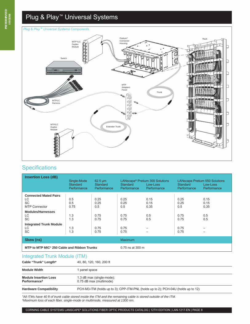
MTP®/LCDuplexModule
Switch
MTP/LCHarness
MTP/LCDuplexModule
Extender Trunk
Pretium®
ConnectorHousing
MTPAdaptersPanel
Trunk
Rack
ZSpecifications
Plug & Play™ Universal Systems
CORNING CABLE SYSTEMS LANSCAPE® SOLUTIONS FIBER OPTIC PRODUCTS CATALOG | 12TH EDITION | LAN-1217-EN | PAGE 8
Integrated Trunk Module (ITM)Cable “Trunk” Length* 40, 80, 120, 160, 200 ft
Module Width 1 panel space
Module Insertion Loss 1.3 dB max (single-mode);Performance† 0.75 dB max (multimode)
Hardware Compatibility PCH-M3-ITM (holds up to 3); CPP-ITM-PNL (holds up to 2); PCH-04U (holds up to 12)
*All ITMs have 40 ft of trunk cable stored inside the ITM and the remaining cable is stored outside of the ITM.†Maximum loss of each fiber, single-mode or multimode, measured at 1300 nm.
Insertion Loss (dB)Single-Mode 62.5 µm LANscape® Pretium 300 Solutions LANscape Pretium 550 SolutionsStandard Standard Standard Low-Loss Standard Low-LossPerformance Performance Performance Performance Performance Performance
Connected Mated PairsLC 0.5 0.25 0.25 0.15 0.25 0.15SC 0.5 0.25 0.25 0.15 0.25 0.15MTP Connector 0.75 0.5 0.5 0.35 0.5 0.35Modules/HarnessesLC 1.3 0.75 0.75 0.5 0.75 0.5SC 1.3 0.75 0.75 0.5 0.75 0.5Integrated Trunk ModuleLC 1.3 0.75 0.75 – 0.75 –SC 1.3 0.75 0.75 – 0.75 –
Skew (ns) Maximum
MTP to MTP MIC® 250 Cable and Ribbon Trunks 0.75 ns at 300 m
Plug & Play™ Universal Systems Components
PRET
ERMI
NATE
DSY
STEM
S
For detailed specifications and information, visit www.corning.com/cablesystems and enter the following literature code intothe search engine: Plug & Play™ Universal Systems: LAN-664-EN; 96-Fiber Shelf: LAN-878-EN;U-Clip Strain-Relief and Accessory Brackets: LAN-1071-EN
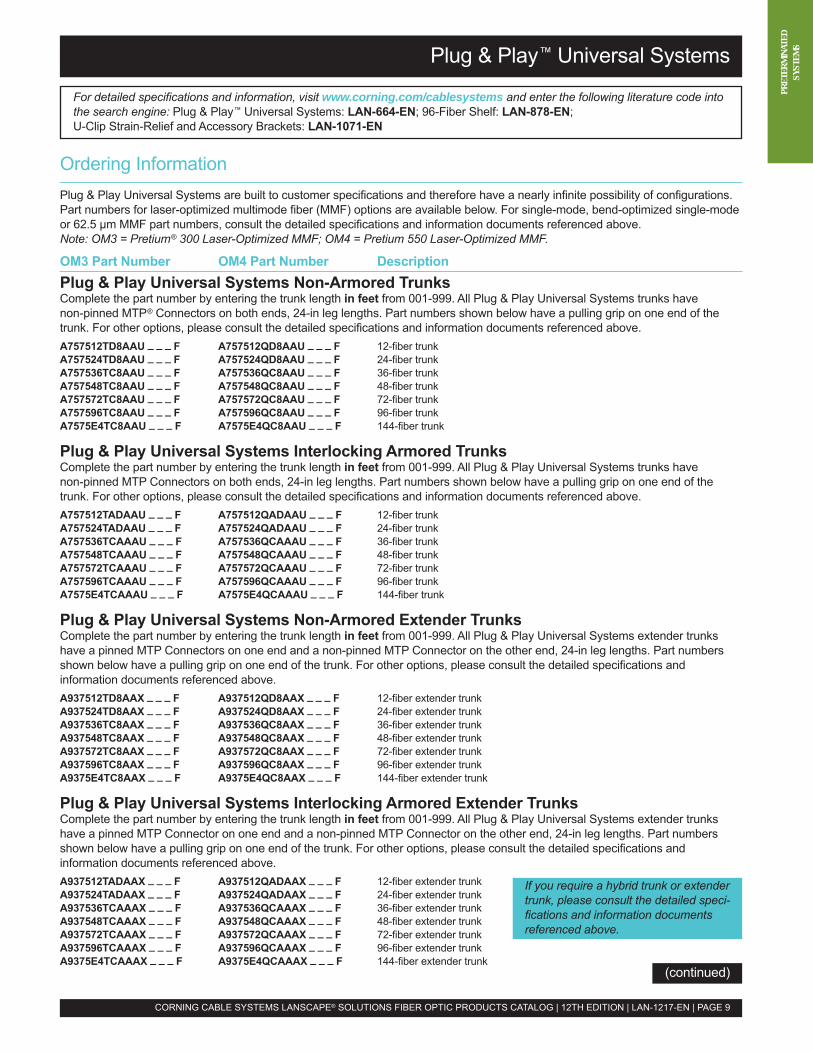
Ordering InformationPlug & Play Universal Systems are built to customer specifications and therefore have a nearly infinite possibility of configurations.Part numbers for laser-optimized multimode fiber (MMF) options are available below. For single-mode, bend-optimized single-modeor 62.5 µm MMF part numbers, consult the detailed specifications and information documents referenced above.Note: OM3 = Pretium® 300 Laser-Optimized MMF; OM4 = Pretium 550 Laser-Optimized MMF.
OM3 Part Number OM4 Part Number DescriptionPlug & Play Universal Systems Non-Armored TrunksComplete the part number by entering the trunk length in feet from 001-999. All Plug & Play Universal Systems trunks havenon-pinned MTP® Connectors on both ends, 24-in leg lengths. Part numbers shown below have a pulling grip on one end of thetrunk. For other options, please consult the detailed specifications and information documents referenced above.A757512TD8AAU _ _ _ F A757512QD8AAU _ _ _ F 12-fiber trunkA757524TD8AAU _ _ _ F A757524QD8AAU _ _ _ F 24-fiber trunkA757536TC8AAU _ _ _ F A757536QC8AAU _ _ _ F 36-fiber trunkA757548TC8AAU _ _ _ F A757548QC8AAU _ _ _ F 48-fiber trunkA757572TC8AAU _ _ _ F A757572QC8AAU _ _ _ F 72-fiber trunkA757596TC8AAU _ _ _ F A757596QC8AAU _ _ _ F 96-fiber trunkA7575E4TC8AAU _ _ _ F A7575E4QC8AAU _ _ _ F 144-fiber trunk
Plug & Play Universal Systems Interlocking Armored TrunksComplete the part number by entering the trunk length in feet from 001-999. All Plug & Play Universal Systems trunks havenon-pinned MTP Connectors on both ends, 24-in leg lengths. Part numbers shown below have a pulling grip on one end of thetrunk. For other options, please consult the detailed specifications and information documents referenced above.A757512TADAAU _ _ _ F A757512QADAAU _ _ _ F 12-fiber trunkA757524TADAAU _ _ _ F A757524QADAAU _ _ _ F 24-fiber trunkA757536TCAAAU _ _ _ F A757536QCAAAU _ _ _ F 36-fiber trunkA757548TCAAAU _ _ _ F A757548QCAAAU _ _ _ F 48-fiber trunkA757572TCAAAU _ _ _ F A757572QCAAAU _ _ _ F 72-fiber trunkA757596TCAAAU _ _ _ F A757596QCAAAU _ _ _ F 96-fiber trunkA7575E4TCAAAU _ _ _ F A7575E4QCAAAU _ _ _ F 144-fiber trunk
Plug & Play Universal Systems Non-Armored Extender TrunksComplete the part number by entering the trunk length in feet from 001-999. All Plug & Play Universal Systems extender trunkshave a pinned MTP Connectors on one end and a non-pinned MTP Connector on the other end, 24-in leg lengths. Part numbersshown below have a pulling grip on one end of the trunk. For other options, please consult the detailed specifications andinformation documents referenced above.A937512TD8AAX _ _ _ F A937512QD8AAX _ _ _ F 12-fiber extender trunkA937524TD8AAX _ _ _ F A937524QD8AAX _ _ _ F 24-fiber extender trunkA937536TC8AAX _ _ _ F A937536QC8AAX _ _ _ F 36-fiber extender trunkA937548TC8AAX _ _ _ F A937548QC8AAX _ _ _ F 48-fiber extender trunkA937572TC8AAX _ _ _ F A937572QC8AAX _ _ _ F 72-fiber extender trunkA937596TC8AAX _ _ _ F A937596QC8AAX _ _ _ F 96-fiber extender trunkA9375E4TC8AAX _ _ _ F A9375E4QC8AAX _ _ _ F 144-fiber extender trunk
Plug & Play Universal Systems Interlocking Armored Extender TrunksComplete the part number by entering the trunk length in feet from 001-999. All Plug & Play Universal Systems extender trunkshave a pinned MTP Connector on one end and a non-pinned MTP Connector on the other end, 24-in leg lengths. Part numbersshown below have a pulling grip on one end of the trunk. For other options, please consult the detailed specifications andinformation documents referenced above.A937512TADAAX _ _ _ F A937512QADAAX _ _ _ F 12-fiber extender trunkA937524TADAAX _ _ _ F A937524QADAAX _ _ _ F 24-fiber extender trunkA937536TCAAAX _ _ _ F A937536QCAAAX _ _ _ F 36-fiber extender trunkA937548TCAAAX _ _ _ F A937548QCAAAX _ _ _ F 48-fiber extender trunkA937572TCAAAX _ _ _ F A937572QCAAAX _ _ _ F 72-fiber extender trunkA937596TCAAAX _ _ _ F A937596QCAAAX _ _ _ F 96-fiber extender trunkA9375E4TCAAAX _ _ _ F A9375E4QCAAAX _ _ _ F 144-fiber extender trunk
Plug & Play™ Universal Systems
CORNING CABLE SYSTEMS LANSCAPE® SOLUTIONS FIBER OPTIC PRODUCTS CATALOG | 12TH EDITION | LAN-1217-EN | PAGE 9
(continued)
If you require a hybrid trunk or extendertrunk, please consult the detailed speci-fications and information documentsreferenced above.
PRET
ERMI
NATE
DSY
STEM
S
Ordering Information (continued)
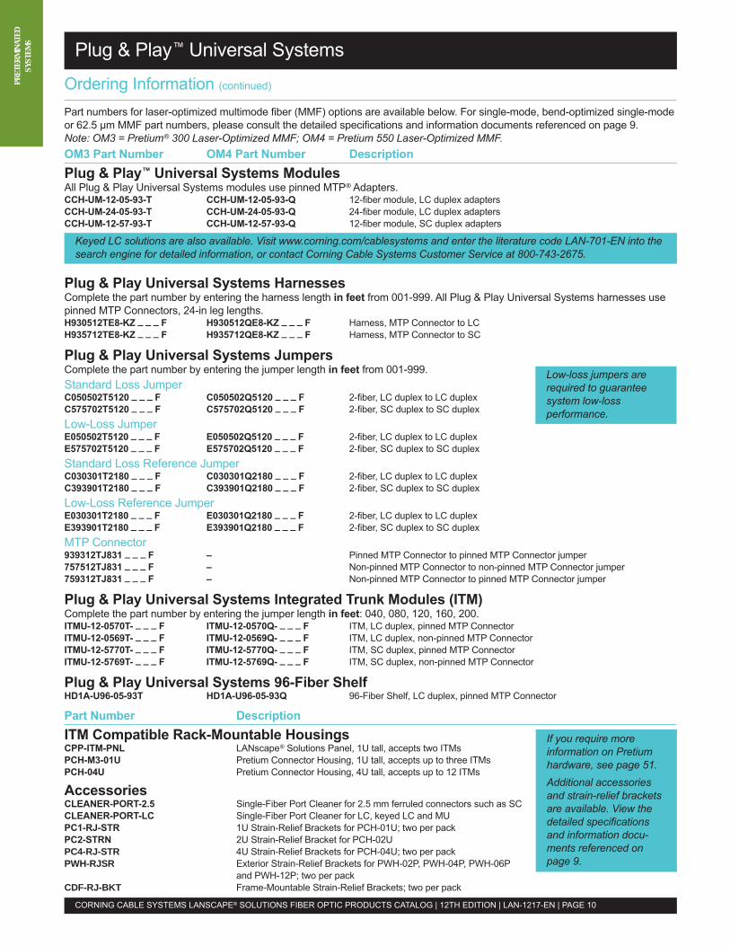
Part numbers for laser-optimized multimode fiber (MMF) options are available below. For single-mode, bend-optimized single-modeor 62.5 µm MMF part numbers, please consult the detailed specifications and information documents referenced on page 9.Note: OM3 = Pretium® 300 Laser-Optimized MMF; OM4 = Pretium 550 Laser-Optimized MMF.OM3 Part Number OM4 Part Number DescriptionPlug & Play™ Universal Systems ModulesAll Plug & Play Universal Systems modules use pinned MTP® Adapters.CCH-UM-12-05-93-T CCH-UM-12-05-93-Q 12-fiber module, LC duplex adaptersCCH-UM-24-05-93-T CCH-UM-24-05-93-Q 24-fiber module, LC duplex adaptersCCH-UM-12-57-93-T CCH-UM-12-57-93-Q 12-fiber module, SC duplex adapters
Plug & Play Universal Systems HarnessesComplete the part number by entering the harness length in feet from 001-999. All Plug & Play Universal Systems harnesses usepinned MTP Connectors, 24-in leg lengths.H930512TE8-KZ _ _ _ F H930512QE8-KZ _ _ _ F Harness, MTP Connector to LCH935712TE8-KZ _ _ _ F H935712QE8-KZ _ _ _ F Harness, MTP Connector to SC
Plug & Play Universal Systems JumpersComplete the part number by entering the jumper length in feet from 001-999.Standard Loss JumperC050502T5120 _ _ _ F C050502Q5120 _ _ _ F 2-fiber, LC duplex to LC duplexC575702T5120 _ _ _ F C575702Q5120 _ _ _ F 2-fiber, SC duplex to SC duplexLow-Loss JumperE050502T5120 _ _ _ F E050502Q5120 _ _ _ F 2-fiber, LC duplex to LC duplexE575702T5120 _ _ _ F E575702Q5120 _ _ _ F 2-fiber, SC duplex to SC duplexStandard Loss Reference JumperC030301T2180 _ _ _ F C030301Q2180 _ _ _ F 2-fiber, LC duplex to LC duplexC393901T2180 _ _ _ F C393901Q2180 _ _ _ F 2-fiber, SC duplex to SC duplexLow-Loss Reference JumperE030301T2180 _ _ _ F E030301Q2180 _ _ _ F 2-fiber, LC duplex to LC duplexE393901T2180 _ _ _ F E393901Q2180 _ _ _ F 2-fiber, SC duplex to SC duplexMTP Connector939312TJ831 _ _ _ F – Pinned MTP Connector to pinned MTP Connector jumper757512TJ831 _ _ _ F – Non-pinned MTP Connector to non-pinned MTP Connector jumper759312TJ831 _ _ _ F – Non-pinned MTP Connector to pinned MTP Connector jumper
Plug & Play Universal Systems Integrated Trunk Modules (ITM)Complete the part number by entering the jumper length in feet: 040, 080, 120, 160, 200.ITMU-12-0570T- _ _ _ F ITMU-12-0570Q- _ _ _ F ITM, LC duplex, pinned MTP ConnectorITMU-12-0569T- _ _ _ F ITMU-12-0569Q- _ _ _ F ITM, LC duplex, non-pinned MTP ConnectorITMU-12-5770T- _ _ _ F ITMU-12-5770Q- _ _ _ F ITM, SC duplex, pinned MTP ConnectorITMU-12-5769T- _ _ _ F ITMU-12-5769Q- _ _ _ F ITM, SC duplex, non-pinned MTP Connector
Plug & Play Universal Systems 96-Fiber ShelfHD1A-U96-05-93T HD1A-U96-05-93Q 96-Fiber Shelf, LC duplex, pinned MTP Connector
Part Number DescriptionITM Compatible Rack-Mountable HousingsCPP-ITM-PNL LANscape® Solutions Panel, 1U tall, accepts two ITMsPCH-M3-01U Pretium Connector Housing, 1U tall, accepts up to three ITMsPCH-04U Pretium Connector Housing, 4U tall, accepts up to 12 ITMs
AccessoriesCLEANER-PORT-2.5 Single-Fiber Port Cleaner for 2.5 mm ferruled connectors such as SCCLEANER-PORT-LC Single-Fiber Port Cleaner for LC, keyed LC and MUPC1-RJ-STR 1U Strain-Relief Brackets for PCH-01U; two per packPC2-STRN 2U Strain-Relief Bracket for PCH-02UPC4-RJ-STR 4U Strain-Relief Brackets for PCH-04U; two per packPWH-RJSR Exterior Strain-Relief Brackets for PWH-02P, PWH-04P, PWH-06P
and PWH-12P; two per packCDF-RJ-BKT Frame-Mountable Strain-Relief Brackets; two per pack
Plug & Play™ Universal Systems
CORNING CABLE SYSTEMS LANSCAPE® SOLUTIONS FIBER OPTIC PRODUCTS CATALOG | 12TH EDITION | LAN-1217-EN | PAGE 10
Keyed LC solutions are also available. Visit www.corning.com/cablesystems and enter the literature code LAN-701-EN into thesearch engine for detailed information, or contact Corning Cable Systems Customer Service at 800-743-2675.
Low-loss jumpers arerequired to guaranteesystem low-lossperformance.
If you require moreinformation on Pretiumhardware, see page 51.Additional accessoriesand strain-relief bracketsare available. View thedetailed specificationsand information docu-ments referenced onpage 9.
PRET
ERMI
NATE
DSY
STEM
SPlug & Play™ AnyLAN™ Systems
Plug & Play™ Universal Systems
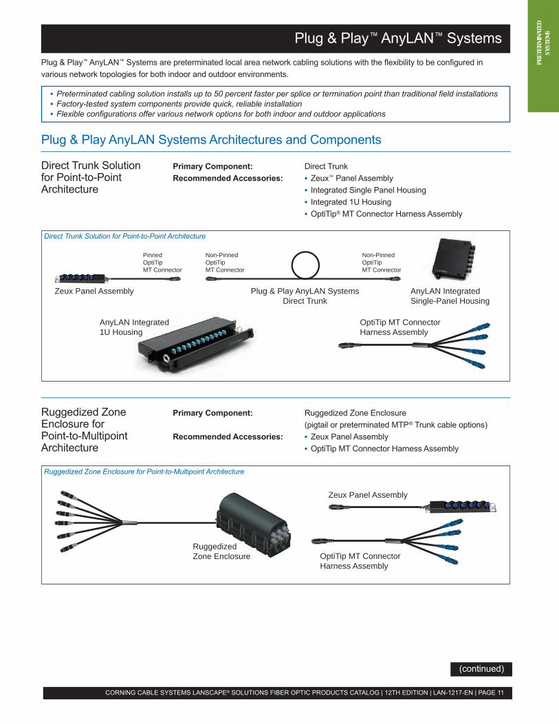
Plug & Play™ AnyLAN™ Systems are preterminated local area network cabling solutions with the flexibility to be configured invarious network topologies for both indoor and outdoor environments.
• Preterminated cabling solution installs up to 50 percent faster per splice or termination point than traditional field installations• Factory-tested system components provide quick, reliable installation• Flexible configurations offer various network options for both indoor and outdoor applications
Plug & Play AnyLAN Systems Architectures and Components
Direct Trunk Solution Primary Component: Direct Trunkfor Point-to-Point Recommended Accessories: • Zeux™ Panel AssemblyArchitecture • Integrated Single Panel Housing
• Integrated 1U Housing• OptiTip® MT Connector Harness Assembly
Plug & Play AnyLAN SystemsDirect Trunk
PinnedOptiTipMT Connector
Non-PinnedOptiTipMT Connector
Non-PinnedOptiTipMT Connector
Zeux Panel Assembly AnyLAN IntegratedSingle-Panel Housing
OptiTip MT ConnectorHarness Assembly
AnyLAN Integrated1U Housing
RuggedizedZone Enclosure OptiTip MT Connector
Harness Assembly
Zeux Panel Assembly
CORNING CABLE SYSTEMS LANSCAPE® SOLUTIONS FIBER OPTIC PRODUCTS CATALOG | 12TH EDITION | LAN-1217-EN | PAGE 11
Direct Trunk Solution for Point-to-Point Architecture
Ruggedized Zone Enclosure for Point-to-Multipoint Architecture
Ruggedized Zone Primary Component: Ruggedized Zone EnclosureEnclosure for (pigtail or preterminated MTP® Trunk cable options)Point-to-Multipoint Recommended Accessories: • Zeux Panel AssemblyArchitecture • OptiTip MT Connector Harness Assembly
(continued)
Distribution Trunk Solution for Distributed Architecture
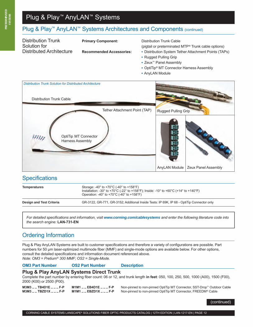
Distribution Trunk Primary Component: Distribution Trunk CableSolution for (pigtail or preterminated MTP® Trunk cable options)Distributed Architecture Recommended Accessories: • Distribution System Tether Attachment Points (TAPs)
• Rugged Pulling Grip• Zeux™ Panel Assembly• OptiTip® MT Connector Harness Assembly• AnyLAN Module
Distribution Trunk Cable
Tether Attachment Point (TAP) Rugged Pulling Grip
AnyLAN Module Zeux Panel Assembly
OptiTip MT ConnectorHarness Assembly
Plug & Play™ AnyLAN™ Systems Architectures and Components (continued)
Plug & Play™ AnyLAN™ Systems
For detailed specifications and information, visit www.corning.com/cablesystems and enter the following literature code intothe search engine: LAN-731-EN
Ordering InformationPlug & Play AnyLAN Systems are built to customer specifications and therefore a variety of configurations are possible. Partnumbers for 50 µm laser-optimized multimode fiber (MMF) and single-mode options are available below. For other options,consult the detailed specifications and information document referenced above.Note: OM3 = Pretium® 300 MMF; OS2 = Single-Mode.
OM3 Part Number OS2 Part Number DescriptionPlug & Play AnyLAN Systems Direct TrunkComplete the part number by entering fiber count: 06 or 12, and trunk length in feet: 050, 100, 250, 500, 1000 (A00), 1500 (F00),2000 (K00) or 2500 (P00).M3M3 _ _ TB4D1E _ _ _ F-P M1M1 _ _ EB4D1E _ _ _ F-P Non-pinned to non-pinned OptiTip MT Connector, SST-Drop™ Outdoor CableM3M3 _ _ TBZD1X _ _ _ F-P M1M1 _ _ EBZD1X _ _ _ F-P Non-pinned to non-pinned OptiTip MT Connector, FREEDM® Cable
SpecificationsTemperatures Storage: -40° to +70°C (-40° to +158°F)
Installation: -30° to +70°C (-22° to +158°F); Inside: -10° to +60°C (+14° to +140°F)Operation: -40° to +70°C (-40° to +158°F)
Design and Test Criteria GR-3122, GR-771, GR-3152; Additional Inside Tests: IP 69K, IP 68 - OptiTip Connector only
CORNING CABLE SYSTEMS LANSCAPE® SOLUTIONS FIBER OPTIC PRODUCTS CATALOG | 12TH EDITION | LAN-1217-EN | PAGE 12
PRET
ERMI
NATE
DSY
STEM
S
(continued)
Ordering Information (continued)
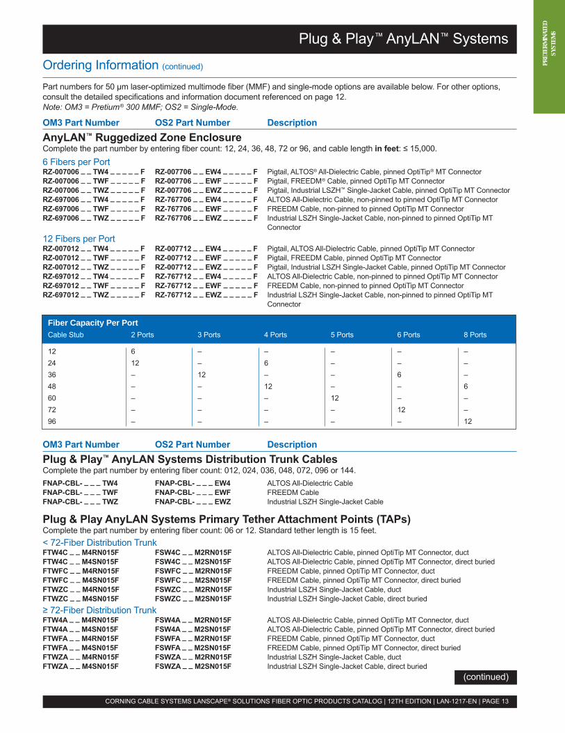
Part numbers for 50 µm laser-optimized multimode fiber (MMF) and single-mode options are available below. For other options,consult the detailed specifications and information document referenced on page 12.Note: OM3 = Pretium® 300 MMF; OS2 = Single-Mode.
OM3 Part Number OS2 Part Number DescriptionAnyLAN™ Ruggedized Zone EnclosureComplete the part number by entering fiber count: 12, 24, 36, 48, 72 or 96, and cable length in feet: ≤ 15,000.6 Fibers per PortRZ-007006 _ _ TW4 _ _ _ _ _ F RZ-007706 _ _ EW4 _ _ _ _ _ F Pigtail, ALTOS® All-Dielectric Cable, pinned OptiTip® MT ConnectorRZ-007006 _ _ TWF _ _ _ _ _ F RZ-007706 _ _ EWF _ _ _ _ _ F Pigtail, FREEDM® Cable, pinned OptiTip MT ConnectorRZ-007006 _ _ TWZ _ _ _ _ _ F RZ-007706 _ _ EWZ _ _ _ _ _ F Pigtail, Industrial LSZH™ Single-Jacket Cable, pinned OptiTip MT ConnectorRZ-697006 _ _ TW4 _ _ _ _ _ F RZ-767706 _ _ EW4 _ _ _ _ _ F ALTOS All-Dielectric Cable, non-pinned to pinned OptiTip MT ConnectorRZ-697006 _ _ TWF _ _ _ _ _ F RZ-767706 _ _ EWF _ _ _ _ _ F FREEDM Cable, non-pinned to pinned OptiTip MT ConnectorRZ-697006 _ _ TWZ _ _ _ _ _ F RZ-767706 _ _ EWZ _ _ _ _ _ F Industrial LSZH Single-Jacket Cable, non-pinned to pinned OptiTip MT
Connector12 Fibers per PortRZ-007012 _ _ TW4 _ _ _ _ _ F RZ-007712 _ _ EW4 _ _ _ _ _ F Pigtail, ALTOS All-Dielectric Cable, pinned OptiTip MT ConnectorRZ-007012 _ _ TWF _ _ _ _ _ F RZ-007712 _ _ EWF _ _ _ _ _ F Pigtail, FREEDM Cable, pinned OptiTip MT ConnectorRZ-007012 _ _ TWZ _ _ _ _ _ F RZ-007712 _ _ EWZ _ _ _ _ _ F Pigtail, Industrial LSZH Single-Jacket Cable, pinned OptiTip MT ConnectorRZ-697012 _ _ TW4 _ _ _ _ _ F RZ-767712 _ _ EW4 _ _ _ _ _ F ALTOS All-Dielectric Cable, non-pinned to pinned OptiTip MT ConnectorRZ-697012 _ _ TWF _ _ _ _ _ F RZ-767712 _ _ EWF _ _ _ _ _ F FREEDM Cable, non-pinned to pinned OptiTip MT ConnectorRZ-697012 _ _ TWZ _ _ _ _ _ F RZ-767712 _ _ EWZ _ _ _ _ _ F Industrial LSZH Single-Jacket Cable, non-pinned to pinned OptiTip MT
Connector
OM3 Part Number OS2 Part Number DescriptionPlug & Play™ AnyLAN Systems Distribution Trunk CablesComplete the part number by entering fiber count: 012, 024, 036, 048, 072, 096 or 144.FNAP-CBL- _ _ _ TW4 FNAP-CBL- _ _ _ EW4 ALTOS All-Dielectric CableFNAP-CBL- _ _ _ TWF FNAP-CBL- _ _ _ EWF FREEDM CableFNAP-CBL- _ _ _ TWZ FNAP-CBL- _ _ _ EWZ Industrial LSZH Single-Jacket Cable
Plug & Play AnyLAN Systems Primary Tether Attachment Points (TAPs)Complete the part number by entering fiber count: 06 or 12. Standard tether length is 15 feet.< 72-Fiber Distribution TrunkFTW4C _ _ M4RN015F FSW4C _ _ M2RN015F ALTOS All-Dielectric Cable, pinned OptiTip MT Connector, ductFTW4C _ _ M4SN015F FSW4C _ _ M2SN015F ALTOS All-Dielectric Cable, pinned OptiTip MT Connector, direct buriedFTWFC _ _ M4RN015F FSWFC _ _ M2RN015F FREEDM Cable, pinned OptiTip MT Connector, ductFTWFC _ _ M4SN015F FSWFC _ _ M2SN015F FREEDM Cable, pinned OptiTip MT Connector, direct buriedFTWZC _ _ M4RN015F FSWZC _ _ M2RN015F Industrial LSZH Single-Jacket Cable, ductFTWZC _ _ M4SN015F FSWZC _ _ M2SN015F Industrial LSZH Single-Jacket Cable, direct buried≥ 72-Fiber Distribution TrunkFTW4A _ _ M4RN015F FSW4A _ _ M2RN015F ALTOS All-Dielectric Cable, pinned OptiTip MT Connector, ductFTW4A _ _ M4SN015F FSW4A _ _ M2SN015F ALTOS All-Dielectric Cable, pinned OptiTip MT Connector, direct buriedFTWFA _ _ M4RN015F FSWFA _ _ M2RN015F FREEDM Cable, pinned OptiTip MT Connector, ductFTWFA _ _ M4SN015F FSWFA _ _ M2SN015F FREEDM Cable, pinned OptiTip MT Connector, direct buriedFTWZA _ _ M4RN015F FSWZA _ _ M2RN015F Industrial LSZH Single-Jacket Cable, ductFTWZA _ _ M4SN015F FSWZA _ _ M2SN015F Industrial LSZH Single-Jacket Cable, direct buried
Plug & Play™ AnyLAN™ Systems
CORNING CABLE SYSTEMS LANSCAPE® SOLUTIONS FIBER OPTIC PRODUCTS CATALOG | 12TH EDITION | LAN-1217-EN | PAGE 13
PRET
ERMI
NATE
DSY
STEM
S
(continued)
Fiber Capacity Per PortCable Stub 2 Ports 3 Ports 4 Ports 5 Ports 6 Ports 8 Ports
12 6 – – – – –24 12 – 6 – – –36 – 12 – – 6 –48 – – 12 – – 660 – – – 12 – –72 – – – – 12 –96 – – – – – 12

Ordering Information (continued)
Part numbers for 50 µm laser-optimized multimode fiber (MMF) and single-mode options are available below. For other options,consult the detailed specifications and information document referenced on page 12.Note: OM3 = Pretium® 300 MMF; OS2 = Single-Mode.
OM3 Part Number OS2 Part Number DescriptionPlug & Play™ AnyLAN™ Systems Secondary Tether Attachment Points (TAPs)Complete the part number by entering fiber count: 06 or 12. Standard tether length is 15 feet.FTW4- _ _ M4RN015F FSW4- _ _ M2RN015F ALTOS® All-Dielectric Cable, pinned OptiTip® MT Connector, ductFTW4- _ _ M4SN015F FSW4- _ _ M2SN015F ALTOS All-Dielectric Cable, pinned OptiTip MT Connector, direct buriedFTWF- _ _ M4RN015F FSWF- _ _ M2RN015F FREEDM® Cable, pinned OptiTip MT Connector, ductFTWF- _ _ M4SN015F FSWF- _ _ M2SN015F FREEDM Cable, pinned OptiTip MT Connector, direct buriedFTWZ- _ _ M4RN015F FSWZ- _ _ M2RN015F Industrial LSZH™ Single-Jacket Cable, ductFTWZ- _ _ M4SN015F FSWZ- _ _ M2SN015F Industrial LSZH Single-Jacket Cable, direct buried
Plug & Play AnyLAN Systems Rugged Pulling GripComplete the part number by entering fiber count: 012, 024, 036, 048, 072, 096 or 144.FX6- _ _ _ TW469A FX6- _ _ _ EW476A ALTOS All-Dielectric CableFX6- _ _ _ TWF69A FX6- _ _ _ EWF76A FREEDM CableFX6- _ _ _ TWZ69A FX6- _ _ _ EWZ76A Industrial LSZH Single-Jacket Cable
Plug & Play AnyLAN Systems HarnessComplete the part number by entering fiber count: 06 or 12, and harness length in feet: 010, 025, 050 or 100.00M4 _ _ TB4D1E _ _ _ F-P 00M2 _ _ EB4D1E _ _ _ F-P Pigtail, pinned OptiTip MT Connector, SST-Drop™ Outdoor Cable00M4 _ _ TBZD1X _ _ _ F-P 00M2 _ _ EBZD1X _ _ _ F-P Pigtail, pinned OptiTip MT Connector, FREEDM CableM403 _ _ TB4D1E _ _ _ F-P M202 _ _ EB4D1E _ _ _ F-P Pinned OptiTip MT Connector to LC, SST-Drop Outdoor CableM439 _ _ TB4D1E _ _ _ F-P M258 _ _ EB4D1E _ _ _ F-P Pinned OptiTip MT Connector to SC, SST-Drop Outdoor CableM450 _ _ TB4D1E _ _ _ F-P M261 _ _ EB4D1E _ _ _ F-P Pinned OptiTip MT Connector to ST® Compatible, SST-Drop Outdoor CableM403 _ _ TBZD1X _ _ _ F-P M202 _ _ EBZD1X _ _ _ F-P Pinned OptiTip MT Connector to LC, FREEDM CableM439 _ _ TBZD1X _ _ _ F-P M258 _ _ EBZD1X _ _ _ F-P Pinned OptiTip MT Connector to SC, FREEDM CableM450 _ _ TBZD1X _ _ _ F-P M261 _ _ EBZD1X _ _ _ F-P Pinned OptiTip MT Connector to ST Compatible, FREEDM Cable
Integrated Single-Panel HousingSPH-12OTC-12E4H SPH-12OTR-12A9H Single-panel wall-mountable housing, 12 fibers, LC duplex adaptersSPH-24OTC-24E4H SPH-24OTR-24A9H Single-panel wall-mountable housing, 24 fibers, LC duplex adaptersSPH-12OTC-12E7H SPH-12OTR-1259H Single-panel wall-mountable housing, 12 fibers, SC duplex adaptersSPH-12OTC-12H3H SPH-12OTR-126TH Single-panel wall-mountable housing, 12 fibers, ST Compatible adapters
Plug & Play AnyLAN Systems ModulesCCH-AM1205-70T CCH-AM1204-89G 12-fiber module, LC duplex adaptersCCH-AM2405-70T CCH-AM2404-89G 24-fiber module, LC duplex adaptersCCH-AM1257-70T CCH-AM1272-89G 12-fiber module, SC duplex adaptersCCH-AM2457-70T CCH-AM2472-89G 24-fiber module, SC duplex adapters
Integrated 1U HousingCC1-24OTC-24E4H CC1-24OTR-24A9H 1U rack-mountable housing, 24 fibers, LC duplex adaptersCC1-24OTC-24E7H CC1-24OTR-2459H 1U rack-mountable housing, 24 fibers, SC duplex adaptersCC1-24OTC-24H3H CC1-24OTR-246TH 1U rack-mountable housing, 24 fibers, ST Compatible adapters
Zeux™ Panel AssemblyComplete the part number by entering fiber count: 06 or 12, and assembly length in feet: 010, 025, 050 or 100.ZPM403 _ _ TB4D1E _ _ _ F ZPM202 _ _ EB4D1E _ _ _ F Pinned OptiTip MT Connector to LC, SST-Drop Outdoor CableZPM439 _ _ TB4D1E _ _ _ F ZPM258 _ _ EB4D1E _ _ _ F Pinned OptiTip MT Connector to SC, SST-Drop Outdoor CableZPM450 _ _ TB4D1E _ _ _ F ZPM261 _ _ EB4D1E _ _ _ F Pinned OptiTip MT Connector to ST Compatible, SST-Drop Outdoor CableZPM403 _ _ TBZD1X _ _ _ F ZPM202 _ _ EBZD1X _ _ _ F Pinned OptiTip MT Connector to LC, FREEDM CableZPM439 _ _ TBZD1X _ _ _ F ZPM258 _ _ EBZD1X _ _ _ F Pinned OptiTip MT Connector to SC, FREEDM CableZPM450 _ _ TBZD1X _ _ _ F ZPM261 _ _ EBZD1X _ _ _ F Pinned OptiTip MT Connector to ST Compatible, FREEDM Cable
Plug & Play™ AnyLAN™ Systems
CORNING CABLE SYSTEMS LANSCAPE® SOLUTIONS FIBER OPTIC PRODUCTS CATALOG | 12TH EDITION | LAN-1217-EN | PAGE 14
PRET
ERMI
NATE
DSY
STEM
S
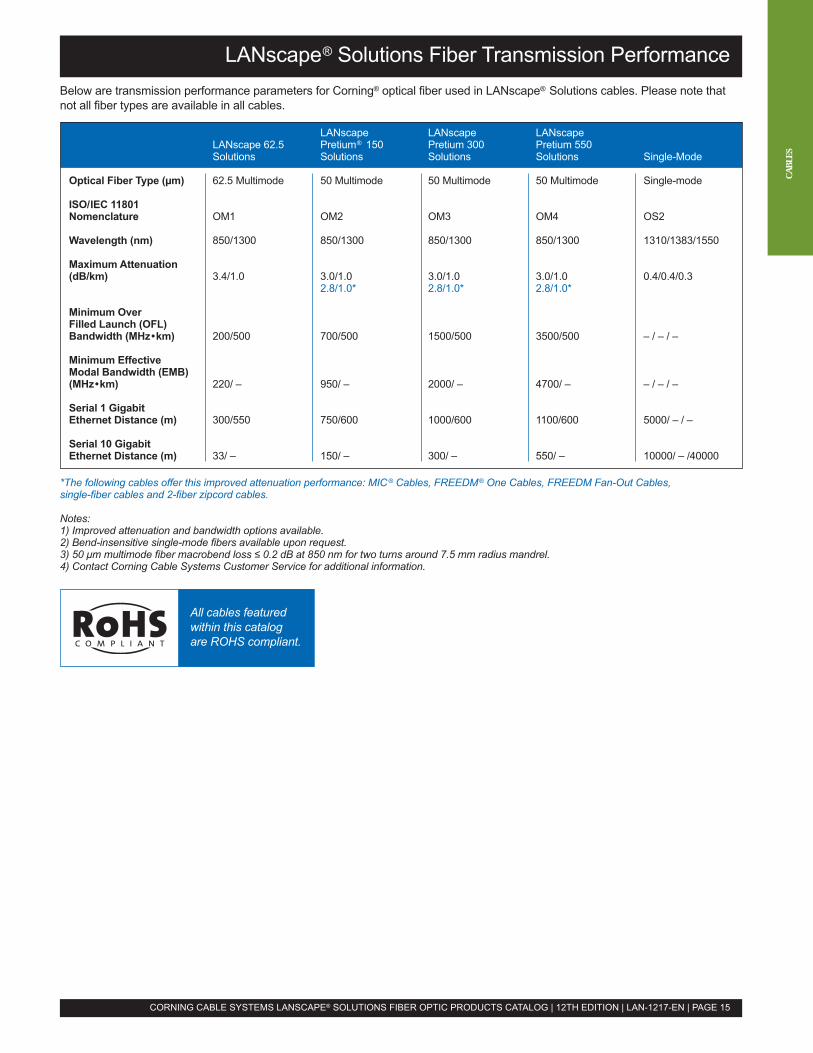
LANscape® Solutions Fiber Transmission Performance
LANscape LANscape LANscapeLANscape 62.5 Pretium® 150 Pretium 300 Pretium 550Solutions Solutions Solutions Solutions Single-Mode
Optical Fiber Type (µm) 62.5 Multimode 50 Multimode 50 Multimode 50 Multimode Single-mode
ISO/IEC 11801Nomenclature OM1 OM2 OM3 OM4 OS2
Wavelength (nm) 850/1300 850/1300 850/1300 850/1300 1310/1383/1550
Maximum Attenuation(dB/km) 3.4/1.0 3.0/1.0 3.0/1.0 3.0/1.0 0.4/0.4/0.3
2.8/1.0* 2.8/1.0* 2.8/1.0*
Minimum OverFilled Launch (OFL)Bandwidth (MHz•km) 200/500 700/500 1500/500 3500/500 – / – / –
Minimum EffectiveModal Bandwidth (EMB)(MHz•km) 220/ – 950/ – 2000/ – 4700/ – – / – / –
Serial 1 GigabitEthernet Distance (m) 300/550 750/600 1000/600 1100/600 5000/ – / –
Serial 10 GigabitEthernet Distance (m) 33/ – 150/ – 300/ – 550/ – 10000/ – /40000
Below are transmission performance parameters for Corning® optical fiber used in LANscape® Solutions cables. Please note thatnot all fiber types are available in all cables.
*The following cables offer this improved attenuation performance: MIC® Cables, FREEDM® One Cables, FREEDM Fan-Out Cables,single-fiber cables and 2-fiber zipcord cables.
Notes:1) Improved attenuation and bandwidth options available.2) Bend-insensitive single-mode fibers available upon request.3) 50 µm multimode fiber macrobend loss ≤ 0.2 dB at 850 nm for two turns around 7.5 mm radius mandrel.4) Contact Corning Cable Systems Customer Service for additional information.
CORNING CABLE SYSTEMS LANSCAPE® SOLUTIONS FIBER OPTIC PRODUCTS CATALOG | 12TH EDITION | LAN-1217-EN | PAGE 15
CABL
ES
All cables featuredwithin this catalogare ROHS compliant.
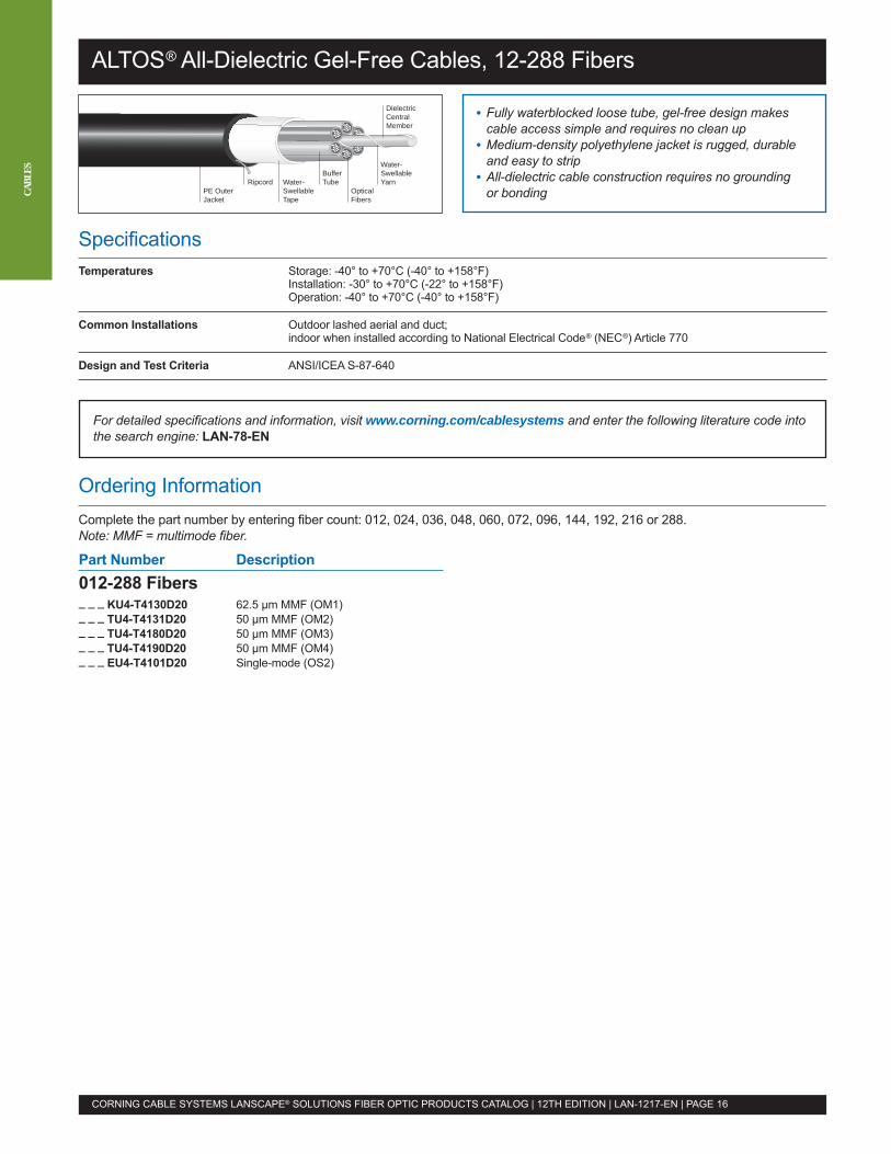
ALTOS® All-Dielectric Gel-Free Cables, 12-288 Fibers
SpecificationsTemperatures Storage: -40° to +70°C (-40° to +158°F)
Installation: -30° to +70°C (-22° to +158°F)Operation: -40° to +70°C (-40° to +158°F)
Common Installations Outdoor lashed aerial and duct;indoor when installed according to National Electrical Code® (NEC®) Article 770
Design and Test Criteria ANSI/ICEA S-87-640
• Fully waterblocked loose tube, gel-free design makescable access simple and requires no clean up
• Medium-density polyethylene jacket is rugged, durableand easy to strip
• All-dielectric cable construction requires no groundingor bonding
RipcordBuffer Tube
Water-SwellableYarnWater-
SwellableTape
OpticalFibers
DielectricCentralMember
PE OuterJacket
For detailed specifications and information, visit www.corning.com/cablesystems and enter the following literature code intothe search engine: LAN-78-EN
Ordering InformationComplete the part number by entering fiber count: 012, 024, 036, 048, 060, 072, 096, 144, 192, 216 or 288.Note: MMF = multimode fiber.
Part Number Description012-288 Fibers_ _ _ KU4-T4130D20 62.5 µm MMF (OM1)_ _ _ TU4-T4131D20 50 µm MMF (OM2)_ _ _ TU4-T4180D20 50 µm MMF (OM3)_ _ _ TU4-T4190D20 50 µm MMF (OM4)_ _ _ EU4-T4101D20 Single-mode (OS2)
CORNING CABLE SYSTEMS LANSCAPE® SOLUTIONS FIBER OPTIC PRODUCTS CATALOG | 12TH EDITION | LAN-1217-EN | PAGE 16
CABL
ES
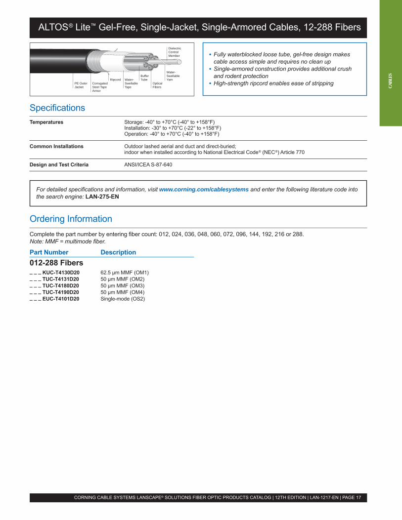
SpecificationsTemperatures Storage: -40° to +70°C (-40° to +158°F)
Installation: -30° to +70°C (-22° to +158°F)Operation: -40° to +70°C (-40° to +158°F)
Common Installations Outdoor lashed aerial and duct and direct-buried;indoor when installed according to National Electrical Code® (NEC®) Article 770
Design and Test Criteria ANSI/ICEA S-87-640
ALTOS® Lite™ Gel-Free, Single-Jacket, Single-Armored Cables, 12-288 Fibers
• Fully waterblocked loose tube, gel-free design makescable access simple and requires no clean up
• Single-armored construction provides additional crushand rodent protection
• High-strength ripcord enables ease of strippingRipcord
Buffer Tube
Water-SwellableYarnWater-
SwellableTape
OpticalFibers
DielectricCentralMember
CorrugatedSteel TapeArmor
PE OuterJacket
CORNING CABLE SYSTEMS LANSCAPE® SOLUTIONS FIBER OPTIC PRODUCTS CATALOG | 12TH EDITION | LAN-1217-EN | PAGE 17
For detailed specifications and information, visit www.corning.com/cablesystems and enter the following literature code intothe search engine: LAN-275-EN
Ordering InformationComplete the part number by entering fiber count: 012, 024, 036, 048, 060, 072, 096, 144, 192, 216 or 288.Note: MMF = multimode fiber.
Part Number Description012-288 Fibers_ _ _ KUC-T4130D20 62.5 µm MMF (OM1)_ _ _ TUC-T4131D20 50 µm MMF (OM2)_ _ _ TUC-T4180D20 50 µm MMF (OM3)_ _ _ TUC-T4190D20 50 µm MMF (OM4)_ _ _ EUC-T4101D20 Single-mode (OS2)
CABL
ES
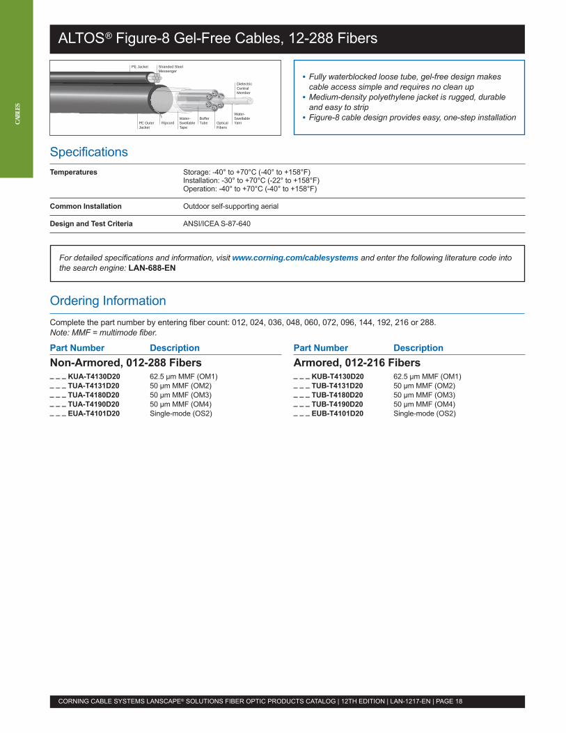
ALTOS® Figure-8 Gel-Free Cables, 12-288 Fibers
SpecificationsTemperatures Storage: -40° to +70°C (-40° to +158°F)
Installation: -30° to +70°C (-22° to +158°F)Operation: -40° to +70°C (-40° to +158°F)
Common Installation Outdoor self-supporting aerial
Design and Test Criteria ANSI/ICEA S-87-640
• Fully waterblocked loose tube, gel-free design makescable access simple and requires no clean up
• Medium-density polyethylene jacket is rugged, durableand easy to strip
• Figure-8 cable design provides easy, one-step installationRipcord
Buffer Tube
Water-SwellableYarn
Water-SwellableTape
OpticalFibers
DielectricCentralMember
PE OuterJacket
PE Jacket Stranded SteelMessenger
For detailed specifications and information, visit www.corning.com/cablesystems and enter the following literature code intothe search engine: LAN-688-EN
Part Number DescriptionArmored, 012-216 Fibers_ _ _ KUB-T4130D20 62.5 µm MMF (OM1)_ _ _ TUB-T4131D20 50 µm MMF (OM2)_ _ _ TUB-T4180D20 50 µm MMF (OM3)_ _ _ TUB-T4190D20 50 µm MMF (OM4)_ _ _ EUB-T4101D20 Single-mode (OS2)
CORNING CABLE SYSTEMS LANSCAPE® SOLUTIONS FIBER OPTIC PRODUCTS CATALOG | 12TH EDITION | LAN-1217-EN | PAGE 18
CABL
ES
Ordering InformationComplete the part number by entering fiber count: 012, 024, 036, 048, 060, 072, 096, 144, 192, 216 or 288.Note: MMF = multimode fiber.
Part Number DescriptionNon-Armored, 012-288 Fibers_ _ _ KUA-T4130D20 62.5 µm MMF (OM1)_ _ _ TUA-T4131D20 50 µm MMF (OM2)_ _ _ TUA-T4180D20 50 µm MMF (OM3)_ _ _ TUA-T4190D20 50 µm MMF (OM4)_ _ _ EUA-T4101D20 Single-mode (OS2)
SpecificationsTemperatures Storage: -57° to +85°C (-71° to +185°F)
Installation: -46° to +71°C (-51° to +160°F)Operation: -46° to +71°C (-51° to +160°F)
Impact 2.2 N•m for 50 impacts at -46°C, 100 impacts at room temperature and 50 impacts at 71°C
Common Installations Outdoor applications; mobile, portable applications;indoor when installed according to National Electrical Code® (NEC®) Article 770
Design and Test Criteria MLF-PRF-85045F and MIL-PRF-85045F/8A
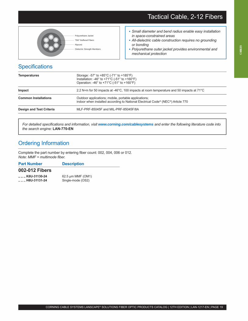
Tactical Cable, 2-12 Fibers
• Small diameter and bend radius enable easy installationin space-constrained areas
• All-dielectric cable construction requires no groundingor bonding
• Polyurethane outer jacket provides environmental andmechanical protection
Polyurethane Jacket
TBII® Buffered Fibers
Ripcord
Dielectric Strength Members
For detailed specifications and information, visit www.corning.com/cablesystems and enter the following literature code intothe search engine: LAN-770-EN
Part Number Description002-012 Fibers_ _ _ K8U-31130-24 62.5 µm MMF (OM1)_ _ _ H8U-31131-24 Single-mode (OS2)
CORNING CABLE SYSTEMS LANSCAPE® SOLUTIONS FIBER OPTIC PRODUCTS CATALOG | 12TH EDITION | LAN-1217-EN | PAGE 19
Ordering InformationComplete the part number by entering fiber count: 002, 004, 006 or 012.Note: MMF = multimode fiber.
CABL
ES
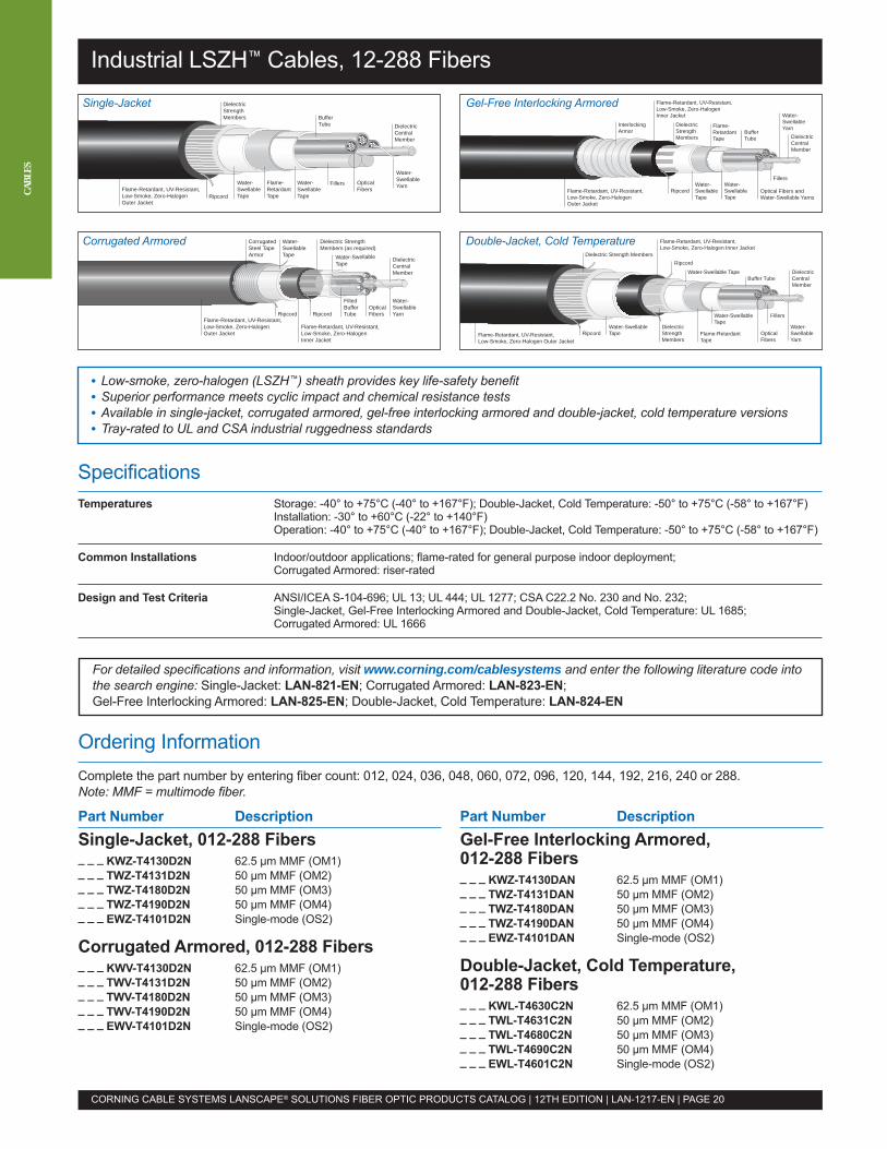
Industrial LSZH™ Cables, 12-288 Fibers
SpecificationsTemperatures Storage: -40° to +75°C (-40° to +167°F); Double-Jacket, Cold Temperature: -50° to +75°C (-58° to +167°F)
Installation: -30° to +60°C (-22° to +140°F)Operation: -40° to +75°C (-40° to +167°F); Double-Jacket, Cold Temperature: -50° to +75°C (-58° to +167°F)
Common Installations Indoor/outdoor applications; flame-rated for general purpose indoor deployment;Corrugated Armored: riser-rated
Design and Test Criteria ANSI/ICEA S-104-696; UL 13; UL 444; UL 1277; CSA C22.2 No. 230 and No. 232;Single-Jacket, Gel-Free Interlocking Armored and Double-Jacket, Cold Temperature: UL 1685;Corrugated Armored: UL 1666
• Low-smoke, zero-halogen (LSZH™) sheath provides key life-safety benefit• Superior performance meets cyclic impact and chemical resistance tests• Available in single-jacket, corrugated armored, gel-free interlocking armored and double-jacket, cold temperature versions• Tray-rated to UL and CSA industrial ruggedness standards
DielectricCentralMember
Water-SwellableYarnOptical
Fibers
Buffer Tube
FillersWater-SwellableTape
Flame-RetardantTape
Water-SwellableTape
DielectricStrengthMembers
RipcordFlame-Retardant, UV-Resistant,Low-Smoke, Zero-HalogenOuter Jacket
Water-SwellableTape
Dielectric StrengthMembers (as required)
CorrugatedSteel TapeArmor
Water-SwellableTape
DielectricCentralMember
FilledBuffer Tube
Water-SwellableYarn
OpticalFibers
Flame-Retardant, UV-Resistant,Low-Smoke, Zero-HalogenInner Jacket
Ripcord RipcordFlame-Retardant, UV-Resistant,Low-Smoke, Zero-HalogenOuter Jacket
DielectricCentralMember
Fillers
Water-SwellableYarn
Optical Fibers andWater-Swellable Yarns
Buffer Tube
Water-SwellableTape
Flame-RetardantTape
Water-SwellableTape
DielectricStrengthMembers
Ripcord
Flame-Retardant, UV-Resistant,Low-Smoke, Zero-HalogenInner Jacket
Flame-Retardant, UV-Resistant,Low-Smoke, Zero-HalogenOuter Jacket
Interlocking Armor
Ripcord
Ripcord
Water-Swellable TapeBuffer Tube
Water-SwellableTape
Fillers
Water-SwellableYarn
Dielectric Strength Members
DielectricStrengthMembers
Water-SwellableTape Flame-Retardant
TapeOpticalFibers
DielectricCentralMember
Flame-Retardant, UV-Resistant,Low-Smoke, Zero-Halogen Outer Jacket
Flame-Retardant, UV-Resistant,Low-Smoke, Zero-Halogen Inner Jacket
For detailed specifications and information, visit www.corning.com/cablesystems and enter the following literature code intothe search engine: Single-Jacket: LAN-821-EN; Corrugated Armored: LAN-823-EN;Gel-Free Interlocking Armored: LAN-825-EN; Double-Jacket, Cold Temperature: LAN-824-EN
CORNING CABLE SYSTEMS LANSCAPE® SOLUTIONS FIBER OPTIC PRODUCTS CATALOG | 12TH EDITION | LAN-1217-EN | PAGE 20
CABL
ES
Single-Jacket
Corrugated Armored
Gel-Free Interlocking Armored
Double-Jacket, Cold Temperature
Ordering InformationComplete the part number by entering fiber count: 012, 024, 036, 048, 060, 072, 096, 120, 144, 192, 216, 240 or 288.Note: MMF = multimode fiber.
Part Number DescriptionSingle-Jacket, 012-288 Fibers_ _ _ KWZ-T4130D2N 62.5 µm MMF (OM1)_ _ _ TWZ-T4131D2N 50 µm MMF (OM2)_ _ _ TWZ-T4180D2N 50 µm MMF (OM3)_ _ _ TWZ-T4190D2N 50 µm MMF (OM4)_ _ _ EWZ-T4101D2N Single-mode (OS2)
Corrugated Armored, 012-288 Fibers_ _ _ KWV-T4130D2N 62.5 µm MMF (OM1)_ _ _ TWV-T4131D2N 50 µm MMF (OM2)_ _ _ TWV-T4180D2N 50 µm MMF (OM3)_ _ _ TWV-T4190D2N 50 µm MMF (OM4)_ _ _ EWV-T4101D2N Single-mode (OS2)
Part Number DescriptionGel-Free Interlocking Armored,012-288 Fibers_ _ _ KWZ-T4130DAN 62.5 µm MMF (OM1)_ _ _ TWZ-T4131DAN 50 µm MMF (OM2)_ _ _ TWZ-T4180DAN 50 µm MMF (OM3)_ _ _ TWZ-T4190DAN 50 µm MMF (OM4)_ _ _ EWZ-T4101DAN Single-mode (OS2)
Double-Jacket, Cold Temperature,012-288 Fibers_ _ _ KWL-T4630C2N 62.5 µm MMF (OM1)_ _ _ TWL-T4631C2N 50 µm MMF (OM2)_ _ _ TWL-T4680C2N 50 µm MMF (OM3)_ _ _ TWL-T4690C2N 50 µm MMF (OM4)_ _ _ EWL-T4601C2N Single-mode (OS2)
SpecificationsTemperatures Storage: -50° to +75°C (-58° to +167°F)
Installation: -30° to +60°C (-22° to +140°F)Operation: -50° to +75°C (-58° to +167°F)*
Common Installations Indoor/outdoor applications; flame-rated for general purpose indoor deployment
Design and Test Criteria ANSI/ICEA S-104-696, CSA C22.2 No. 230 and No. 232, UL 1685
*-40°C (-40°F) minimum operation temperature for 50 µm multimode optical fiber types.
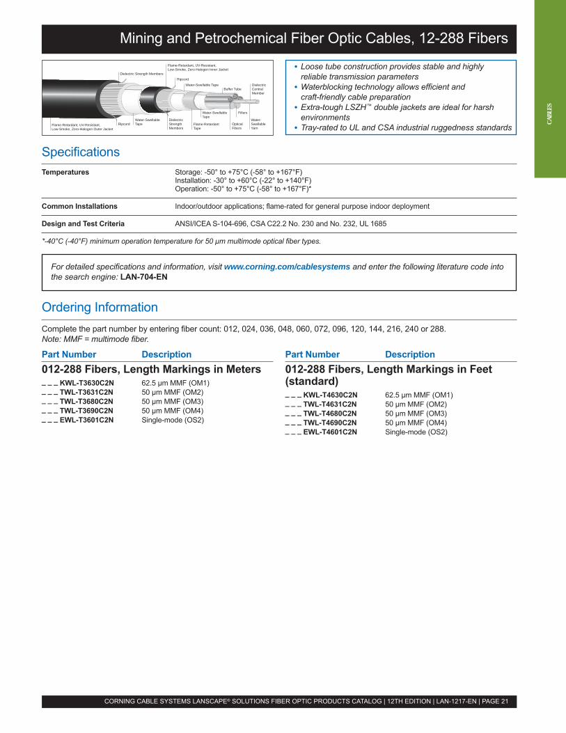
Mining and Petrochemical Fiber Optic Cables, 12-288 Fibers
• Loose tube construction provides stable and highlyreliable transmission parameters
• Waterblocking technology allows efficient andcraft-friendly cable preparation
• Extra-tough LSZH™ double jackets are ideal for harshenvironments
• Tray-rated to UL and CSA industrial ruggedness standardsRipcord
Ripcord
Water-Swellable TapeBuffer Tube
Water-SwellableTape
Fillers
Water-SwellableYarn
Dielectric Strength Members
DielectricStrengthMembers
Water-SwellableTape Flame-Retardant
TapeOpticalFibers
DielectricCentralMember
Flame-Retardant, UV-Resistant,Low-Smoke, Zero-Halogen Outer Jacket
Flame-Retardant, UV-Resistant,Low-Smoke, Zero-Halogen Inner Jacket
CORNING CABLE SYSTEMS LANSCAPE® SOLUTIONS FIBER OPTIC PRODUCTS CATALOG | 12TH EDITION | LAN-1217-EN | PAGE 21
For detailed specifications and information, visit www.corning.com/cablesystems and enter the following literature code intothe search engine: LAN-704-EN
Ordering InformationComplete the part number by entering fiber count: 012, 024, 036, 048, 060, 072, 096, 120, 144, 216, 240 or 288.Note: MMF = multimode fiber.
Part Number Description012-288 Fibers, Length Markings in Meters_ _ _ KWL-T3630C2N 62.5 µm MMF (OM1)_ _ _ TWL-T3631C2N 50 µm MMF (OM2)_ _ _ TWL-T3680C2N 50 µm MMF (OM3)_ _ _ TWL-T3690C2N 50 µm MMF (OM4)_ _ _ EWL-T3601C2N Single-mode (OS2)
Part Number Description012-288 Fibers, Length Markings in Feet(standard)_ _ _ KWL-T4630C2N 62.5 µm MMF (OM1)_ _ _ TWL-T4631C2N 50 µm MMF (OM2)_ _ _ TWL-T4680C2N 50 µm MMF (OM3)_ _ _ TWL-T4690C2N 50 µm MMF (OM4)_ _ _ EWL-T4601C2N Single-mode (OS2)
CABL
ES
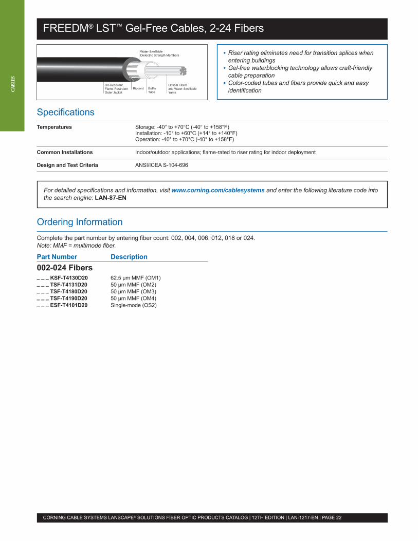
FREEDM® LST™ Gel-Free Cables, 2-24 Fibers
SpecificationsTemperatures Storage: -40° to +70°C (-40° to +158°F)
Installation: -10° to +60°C (+14° to +140°F)Operation: -40° to +70°C (-40° to +158°F)
Common Installations Indoor/outdoor applications; flame-rated to riser rating for indoor deployment
Design and Test Criteria ANSI/ICEA S-104-696
• Riser rating eliminates need for transition splices whenentering buildings
• Gel-free waterblocking technology allows craft-friendlycable preparation
• Color-coded tubes and fibers provide quick and easyidentification
Optical Fibersand Water-SwellableYarns
Buffer Tube
RipcordUV-Resistant,Flame-RetardantOuter Jacket
Water-SwellableDielectric Strength Members
For detailed specifications and information, visit www.corning.com/cablesystems and enter the following literature code intothe search engine: LAN-87-EN
CORNING CABLE SYSTEMS LANSCAPE® SOLUTIONS FIBER OPTIC PRODUCTS CATALOG | 12TH EDITION | LAN-1217-EN | PAGE 22
CABL
ES
Ordering InformationComplete the part number by entering fiber count: 002, 004, 006, 012, 018 or 024.Note: MMF = multimode fiber.
Part Number Description002-024 Fibers_ _ _ KSF-T4130D20 62.5 µm MMF (OM1)_ _ _ TSF-T4131D20 50 µm MMF (OM2)_ _ _ TSF-T4180D20 50 µm MMF (OM3)_ _ _ TSF-T4190D20 50 µm MMF (OM4)_ _ _ ESF-T4101D20 Single-mode (OS2)
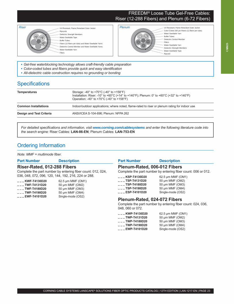
SpecificationsTemperatures Storage: -40° to +70°C (-40° to +158°F)
Installation: Riser: -10° to +60°C (+14° to +140°F); Plenum: 0° to +60°C (+32° to +140°F)Operation: -40° to +70°C (-40° to +158°F)
Common Installations Indoor/outdoor applications; where noted, flame-rated to riser or plenum rating for indoor use
Design and Test Criteria ANSI/ICEA S-104-696; Plenum: NFPA 262
FREEDM® Loose Tube Gel-Free Cables:Riser (12-288 Fibers) and Plenum (6-72 Fibers)
• Gel-free waterblocking technology allows craft-friendly cable preparation• Color-coded tubes and fibers provide quick and easy identification• All-dielectric cable construction requires no grounding or bonding
UV-Resistant, Flame-Retardant Outer Jacket
Ripcords
Dielectric Strength Members
Water-Swellable Tape
Buffer Tubes
Fibers (12 fibers per tube) and Water-Swellable Yarns
Dielectric Central Member and Water-Swellable Yarns
Water-Swellable Yarn
Fillers
CORNING CABLE SYSTEMS LANSCAPE® SOLUTIONS FIBER OPTIC PRODUCTS CATALOG | 12TH EDITION | LAN-1217-EN | PAGE 23
For detailed specifications and information, visit www.corning.com/cablesystems and enter the following literature code intothe search engine: Riser Cables: LAN-86-EN; Plenum Cables: LAN-753-EN
Ordering InformationNote: MMF = multimode fiber.
Part Number DescriptionRiser-Rated, 012-288 FibersComplete the part number by entering fiber count: 012, 024,036, 048, 072, 096, 120, 144, 192, 216, 224 or 288._ _ _ KWF-T4130D20 62.5 µm MMF (OM1)_ _ _ TWF-T4131D20 50 µm MMF (OM2)_ _ _ TWF-T4180D20 50 µm MMF (OM3)_ _ _ TWF-T4190D20 50 µm MMF (OM4)_ _ _ EWF-T4101D20 Single-mode (OS2)
Part Number DescriptionPlenum-Rated, 006-012 FibersComplete the part number by entering fiber count: 006 or 012._ _ _ KSP-T4130D20 62.5 µm MMF (OM1)_ _ _ TSP-T4131D20 50 µm MMF (OM2)_ _ _ TSP-T4180D20 50 µm MMF (OM3)_ _ _ TSP-T4190D20 50 µm MMF (OM4)_ _ _ ESP-T4101D20 Single-mode (OS2)
Plenum-Rated, 024-072 FibersComplete the part number by entering fiber count: 024, 036,048, 060 or 072._ _ _ KWP-T4130D20 62.5 µm MMF (OM1)_ _ _ TWP-T4131D20 50 µm MMF (OM2)_ _ _ TWP-T4180D20 50 µm MMF (OM3)_ _ _ TWP-T4190D20 50 µm MMF (OM4)_ _ _ EWP-T4101D20 Single-mode (OS2)
CABL
ES
UV-Resistant, Flame-Retardant Outer JacketColor-Coded 250 µm Fibers (12 fibers per tube)Water-Swellable YarnBuffer TubesDielectric Central MemberFillersWater-Swellable YarnDielectric Strength MembersWater-Swellable TapeRipcord
PlenumRiser
SpecificationsTemperatures Storage: -40° to +70°C (-40° to +158°F)
Installation: -10° to +60°C (+14° to +140°F)Operation: -40° to +70°C (-40° to +158°F)
Common Installations Indoor/outdoor applications; flame-rated to riser rating for indoor deployment
Design and Test Criteria ANSI/ICEA S-104-696
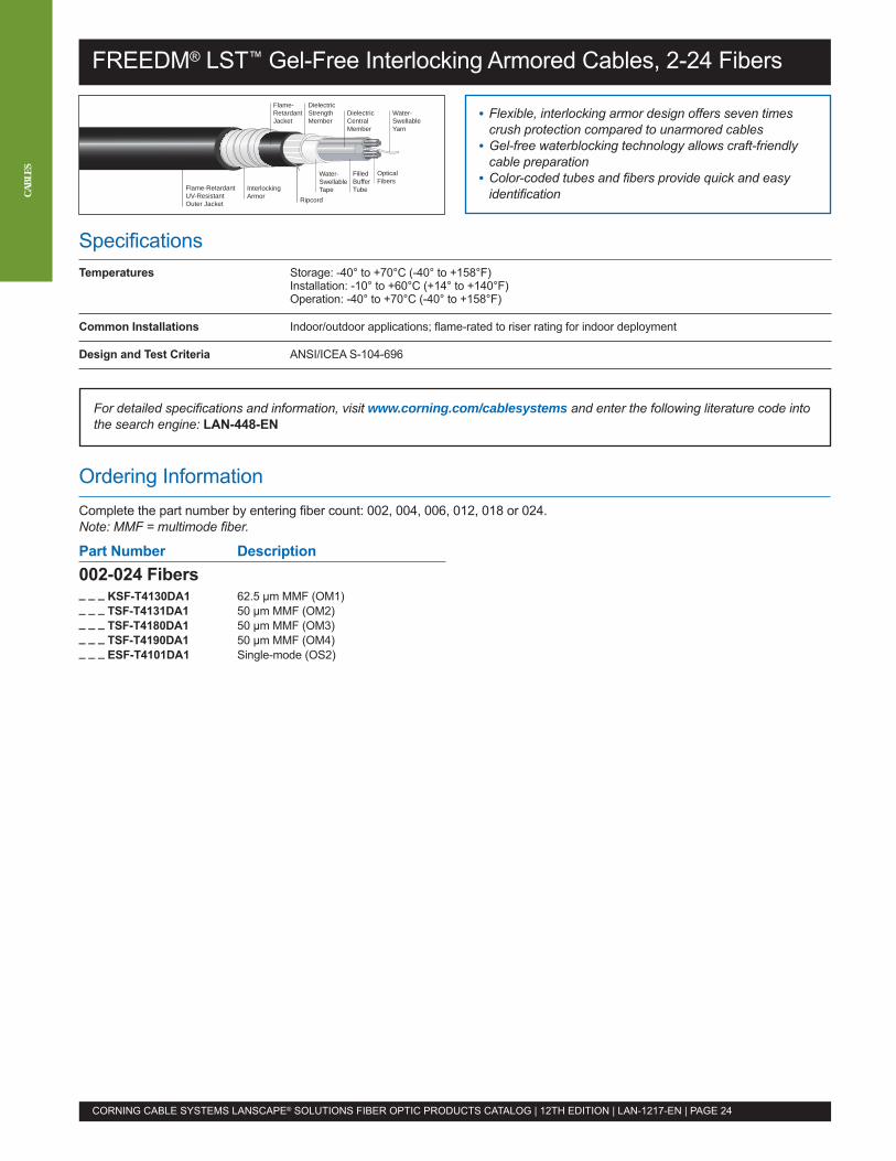
FREEDM® LST™ Gel-Free Interlocking Armored Cables, 2-24 Fibers
• Flexible, interlocking armor design offers seven timescrush protection compared to unarmored cables
• Gel-free waterblocking technology allows craft-friendlycable preparation
• Color-coded tubes and fibers provide quick and easyidentification
Water-SwellableYarn
OpticalFibers
FilledBufferTube
DielectricCentralMember
Water-SwellableTape
DielectricStrengthMember
Ripcord
Flame-RetardantJacket
InterlockingArmor
Flame-RetardantUV-ResistantOuter Jacket
CORNING CABLE SYSTEMS LANSCAPE® SOLUTIONS FIBER OPTIC PRODUCTS CATALOG | 12TH EDITION | LAN-1217-EN | PAGE 24
CABL
ES
For detailed specifications and information, visit www.corning.com/cablesystems and enter the following literature code intothe search engine: LAN-448-EN
Ordering InformationComplete the part number by entering fiber count: 002, 004, 006, 012, 018 or 024.Note: MMF = multimode fiber.
Part Number Description002-024 Fibers_ _ _ KSF-T4130DA1 62.5 µm MMF (OM1)_ _ _ TSF-T4131DA1 50 µm MMF (OM2)_ _ _ TSF-T4180DA1 50 µm MMF (OM3)_ _ _ TSF-T4190DA1 50 µm MMF (OM4)_ _ _ ESF-T4101DA1 Single-mode (OS2)
SpecificationsTemperatures Storage: -40° to +70°C (-40° to +158°F)
Installation: -10° to +60°C (+14° to +140°F)Operation: -40° to +70°C (-40° to +158°F)
Common Installations Indoor/outdoor applications; flame-rated to riser rating for indoor deployment
Design and Test Criteria ANSI/ICEA S-104-696
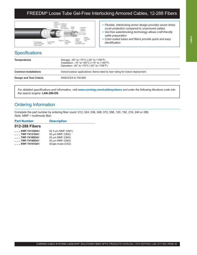
FREEDM® Loose Tube Gel-Free Interlocking Armored Cables, 12-288 Fibers
• Flexible, interlocking armor design provides seven timescrush protection compared to unarmored cables
• Gel-free waterblocking technology allows craft-friendlycable preparation
• Color-coded tubes and fibers provide quick and easyidentification
DielectricCentralMember
Water-SwellableYarn
OpticalFibersand Water-Swellable Yarns
Buffer Tube
Water-SwellableTape
DielectricStrengthMembers(as required)
Ripcord
Flame-RetardantInnerJacket
InterlockingArmor
UV-Resistant,Flame-RetardantOuter Jacket
CORNING CABLE SYSTEMS LANSCAPE® SOLUTIONS FIBER OPTIC PRODUCTS CATALOG | 12TH EDITION | LAN-1217-EN | PAGE 25
For detailed specifications and information, visit www.corning.com/cablesystems and enter the following literature code intothe search engine: LAN-280-EN
Ordering InformationComplete the part number by entering fiber count: 012, 024, 036, 048, 072, 096, 120, 192, 216, 240 or 288.Note: MMF = multimode fiber.
Part Number Description012-288 Fibers_ _ _ KWF-T4130DA1 62.5 µm MMF (OM1)_ _ _ TWF-T4131DA1 50 µm MMF (OM2)_ _ _ TWF-T4180DA1 50 µm MMF (OM3)_ _ _ TWF-T4190DA1 50 µm MMF (OM4)_ _ _ EWF-T4101DA1 Single-mode (OS2)
CABL
ES
SpecificationsTemperatures Storage: -40° to +70°C (-40° to +158°F)
Installation: -10° to +70°C (+14° to +158°F)Operation: -40° to +70°C (-40° to +158°F)
Common Installations Indoor/outdoor applications; flame-rated to riser rating for indoor deployment
Design and Test Criteria ICEA S-104-696
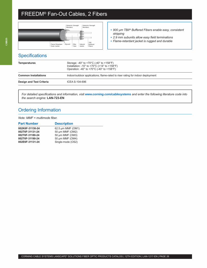
FREEDM® Fan-Out Cables, 2 Fibers
• 900 µm TBII® Buffered Fibers enable easy, consistentstripping
• 2.9 mm subunits allow easy field terminations• Flame-retardant jacket is rugged and durable
Flame-RetardantOuter Jacket
Dielectric StrengthMembers
Dielectric StrengthMembers
TBIIBufferedFibers
SubunitJacket
FillerTube
Ripcord
CORNING CABLE SYSTEMS LANSCAPE® SOLUTIONS FIBER OPTIC PRODUCTS CATALOG | 12TH EDITION | LAN-1217-EN | PAGE 26
CABL
ES
For detailed specifications and information, visit www.corning.com/cablesystems and enter the following literature code intothe search engine: LAN-723-EN
Ordering InformationNote: MMF = multimode fiber.
Part Number Description002K6F-31130-24 62.5 µm MMF (OM1)002T6F-31131-24 50 µm MMF (OM2)002T6F-31180-24 50 µm MMF (OM3)002T6F-31190-24 50 µm MMF (OM4)002E6F-31131-24 Single-mode (OS2)
SpecificationsTemperatures Storage: -40° to +70°C (-40° to +158°F)
Installation: Riser: -10° to +60°C (+14° to +140°F); Plenum: 0° to +60°C (+32° to +140°F)Operation: -40° to +70°C (-40° to +158°F)
Common Installations Indoor/outdoor applications; where noted, flame-rated to riser or plenum rating for indoor use
Design and Test Criteria ICEA S-104-696
For detailed specifications and information, visit www.corning.com/cablesystems and enter the following literature code intothe search engine: Riser Cables: LAN-520-EN, LAN-1133-EN; Plenum Cables: LAN-492-EN
Ordering InformationNote: MMF = multimode fiber.
Part Number DescriptionRiser-Rated, 006-024 FibersComplete the part number by entering fiber count: 006, 012,018 or 024._ _ _ K8F-31130-29 62.5 µm MMF (OM1)_ _ _ T8F-31131-29 50 µm MMF (OM2)_ _ _ T8F-31180-29 50 µm MMF (OM3)_ _ _ T8F-31190-29 50 µm MMF (OM4)_ _ _ E8F-31131-29 Single-mode (OS2)
Riser-Rated, 036-048 FibersComplete the part number by entering fiber count: 036 or 048._ _ _ K8F-61130-29 62.5 µm MMF (OM1)_ _ _ T8F-61131-29 50 µm MMF (OM2)_ _ _ T8F-61180-29 50 µm MMF (OM3)_ _ _ T8F-61190-29 50 µm MMF (OM4)_ _ _ E8F-61131-29 Single-mode (OS2)
Riser-Rated, 072 Fibers072K8F-T1130-29 62.5 µm MMF (OM1)072T8F-T1131-29 50 µm MMF (OM2)072T8F-T1180-29 50 µm MMF (OM3)072T8F-T1190-29 50 µm MMF (OM4)072E8F-T1131-29 Single-mode (OS2)
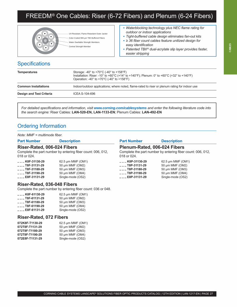
FREEDM® One Cables: Riser (6-72 Fibers) and Plenum (6-24 Fibers)
• Waterblocking technology plus NEC flame rating foroutdoor or indoor applications
• Tight-buffered cable design eliminates fan-out kits• ≥ 36 fiber count cables feature unitized design for
easy identification• Patented TBII® dual-acrylate slip layer provides faster,
easier stripping
UV-Resistant, Flame-Retardant Outer Jacket
Color-Coded 900 µm TBII Buffered Fibers
Water-Swellable Strength Members
Central Strength Member
Part Number DescriptionPlenum-Rated, 006-024 FibersComplete the part number by entering fiber count: 006, 012,018 or 024._ _ _ K8P-31130-29 62.5 µm MMF (OM1)_ _ _ T8P-31131-29 50 µm MMF (OM2)_ _ _ T8P-31180-29 50 µm MMF (OM3)_ _ _ T8P-31190-29 50 µm MMF (OM4)_ _ _ E8P-31131-29 Single-mode (OS2)
CORNING CABLE SYSTEMS LANSCAPE® SOLUTIONS FIBER OPTIC PRODUCTS CATALOG | 12TH EDITION | LAN-1217-EN | PAGE 27
CABL
ES
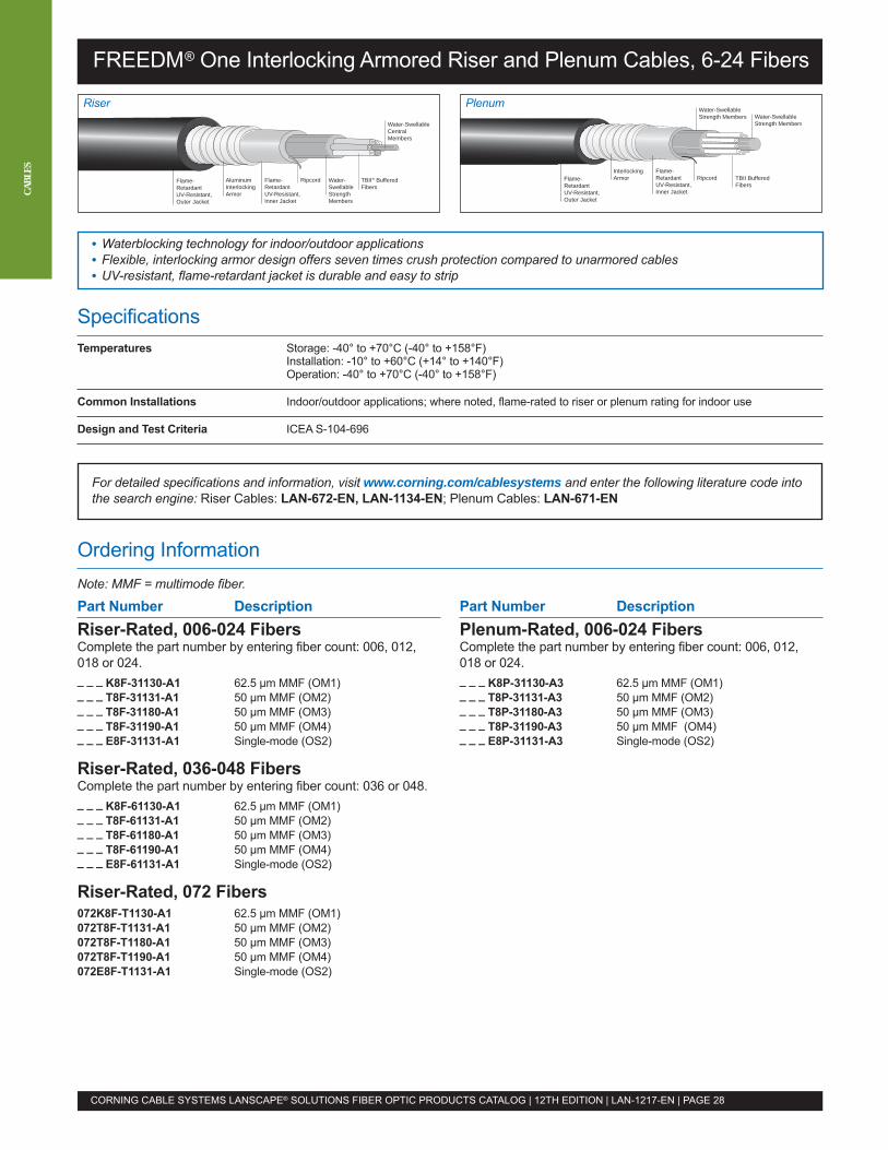
TBII BufferedFibers
Water-SwellableStrength Members Water-Swellable
Strength Members
RipcordFlame-RetardantUV-Resistant,Inner Jacket
Flame-RetardantUV-Resistant,Outer Jacket
InterlockingArmor
SpecificationsTemperatures Storage: -40° to +70°C (-40° to +158°F)
Installation: -10° to +60°C (+14° to +140°F)Operation: -40° to +70°C (-40° to +158°F)
Common Installations Indoor/outdoor applications; where noted, flame-rated to riser or plenum rating for indoor use
Design and Test Criteria ICEA S-104-696
For detailed specifications and information, visit www.corning.com/cablesystems and enter the following literature code intothe search engine: Riser Cables: LAN-672-EN, LAN-1134-EN; Plenum Cables: LAN-671-EN
Ordering InformationNote: MMF = multimode fiber.
Part Number DescriptionRiser-Rated, 006-024 FibersComplete the part number by entering fiber count: 006, 012,018 or 024._ _ _ K8F-31130-A1 62.5 µm MMF (OM1)_ _ _ T8F-31131-A1 50 µm MMF (OM2)_ _ _ T8F-31180-A1 50 µm MMF (OM3)_ _ _ T8F-31190-A1 50 µm MMF (OM4)_ _ _ E8F-31131-A1 Single-mode (OS2)
Riser-Rated, 036-048 FibersComplete the part number by entering fiber count: 036 or 048._ _ _ K8F-61130-A1 62.5 µm MMF (OM1)_ _ _ T8F-61131-A1 50 µm MMF (OM2)_ _ _ T8F-61180-A1 50 µm MMF (OM3)_ _ _ T8F-61190-A1 50 µm MMF (OM4)_ _ _ E8F-61131-A1 Single-mode (OS2)
Riser-Rated, 072 Fibers072K8F-T1130-A1 62.5 µm MMF (OM1)072T8F-T1131-A1 50 µm MMF (OM2)072T8F-T1180-A1 50 µm MMF (OM3)072T8F-T1190-A1 50 µm MMF (OM4)072E8F-T1131-A1 Single-mode (OS2)
FREEDM® One Interlocking Armored Riser and Plenum Cables, 6-24 Fibers
Water-SwellableCentralMembers
TBII® BufferedFibers
Water-SwellableStrengthMembers
RipcordFlame-RetardantUV-Resistant,Inner Jacket
Flame-RetardantUV-Resistant,Outer Jacket
AluminumInterlockingArmor
Part Number DescriptionPlenum-Rated, 006-024 FibersComplete the part number by entering fiber count: 006, 012,018 or 024._ _ _ K8P-31130-A3 62.5 µm MMF (OM1)_ _ _ T8P-31131-A3 50 µm MMF (OM2)_ _ _ T8P-31180-A3 50 µm MMF (OM3)_ _ _ T8P-31190-A3 50 µm MMF (OM4)_ _ _ E8P-31131-A3 Single-mode (OS2)
CORNING CABLE SYSTEMS LANSCAPE® SOLUTIONS FIBER OPTIC PRODUCTS CATALOG | 12TH EDITION | LAN-1217-EN | PAGE 28
CABL
ES
• Waterblocking technology for indoor/outdoor applications• Flexible, interlocking armor design offers seven times crush protection compared to unarmored cables• UV-resistant, flame-retardant jacket is durable and easy to strip
PlenumRiser
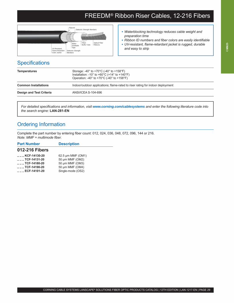
SpecificationsTemperatures Storage: -40° to +70°C (-40° to +158°F)
Installation: -10° to +60°C (+14° to +140°F)Operation: -40° to +70°C (-40° to +158°F)
Common Installations Indoor/outdoor applications; flame-rated to riser rating for indoor deployment
Design and Test Criteria ANSI/ICEA S-104-696
FREEDM® Ribbon Riser Cables, 12-216 Fibers
• Waterblocking technology reduces cable weight andpreparation time
• Ribbon ID numbers and fiber colors are easily identifiable• UV-resistant, flame-retardant jacket is rugged, durable
and easy to strip
Ripcord
Water-SwellableTapeUV-Resistant,
Flame-Retardant Outer Jacket
Dielectric Strength Members
Dielectric StrengthMembers
FilledBuffer Tube
Optical FiberRibbons
CORNING CABLE SYSTEMS LANSCAPE® SOLUTIONS FIBER OPTIC PRODUCTS CATALOG | 12TH EDITION | LAN-1217-EN | PAGE 29
For detailed specifications and information, visit www.corning.com/cablesystems and enter the following literature code intothe search engine: LAN-281-EN
Ordering InformationComplete the part number by entering fiber count: 012, 024, 036, 048, 072, 096, 144 or 216.Note: MMF = multimode fiber.
Part Number Description012-216 Fibers_ _ _ KCF-14130-20 62.5 µm MMF (OM1)_ _ _ TCF-14131-20 50 µm MMF (OM2)_ _ _ TCF-14180-20 50 µm MMF (OM3)_ _ _ TCF-14190-20 50 µm MMF (OM4)_ _ _ ECF-14101-20 Single-mode (OS2)
CABL
ES
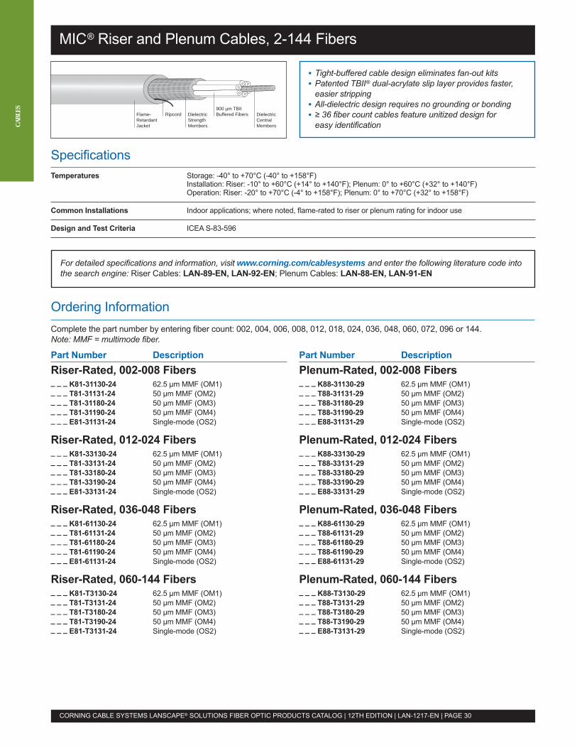
Part Number DescriptionRiser-Rated, 002-008 Fibers_ _ _ K81-31130-24 62.5 µm MMF (OM1)_ _ _ T81-31131-24 50 µm MMF (OM2)_ _ _ T81-31180-24 50 µm MMF (OM3)_ _ _ T81-31190-24 50 µm MMF (OM4)_ _ _ E81-31131-24 Single-mode (OS2)
Riser-Rated, 012-024 Fibers_ _ _ K81-33130-24 62.5 µm MMF (OM1)_ _ _ T81-33131-24 50 µm MMF (OM2)_ _ _ T81-33180-24 50 µm MMF (OM3)_ _ _ T81-33190-24 50 µm MMF (OM4)_ _ _ E81-33131-24 Single-mode (OS2)
Riser-Rated, 036-048 Fibers_ _ _ K81-61130-24 62.5 µm MMF (OM1)_ _ _ T81-61131-24 50 µm MMF (OM2)_ _ _ T81-61180-24 50 µm MMF (OM3)_ _ _ T81-61190-24 50 µm MMF (OM4)_ _ _ E81-61131-24 Single-mode (OS2)
Riser-Rated, 060-144 Fibers_ _ _ K81-T3130-24 62.5 µm MMF (OM1)_ _ _ T81-T3131-24 50 µm MMF (OM2)_ _ _ T81-T3180-24 50 µm MMF (OM3)_ _ _ T81-T3190-24 50 µm MMF (OM4)_ _ _ E81-T3131-24 Single-mode (OS2)
Part Number DescriptionPlenum-Rated, 002-008 Fibers_ _ _ K88-31130-29 62.5 µm MMF (OM1)_ _ _ T88-31131-29 50 µm MMF (OM2)_ _ _ T88-31180-29 50 µm MMF (OM3)_ _ _ T88-31190-29 50 µm MMF (OM4)_ _ _ E88-31131-29 Single-mode (OS2)
Plenum-Rated, 012-024 Fibers_ _ _ K88-33130-29 62.5 µm MMF (OM1)_ _ _ T88-33131-29 50 µm MMF (OM2)_ _ _ T88-33180-29 50 µm MMF (OM3)_ _ _ T88-33190-29 50 µm MMF (OM4)_ _ _ E88-33131-29 Single-mode (OS2)
Plenum-Rated, 036-048 Fibers_ _ _ K88-61130-29 62.5 µm MMF (OM1)_ _ _ T88-61131-29 50 µm MMF (OM2)_ _ _ T88-61180-29 50 µm MMF (OM3)_ _ _ T88-61190-29 50 µm MMF (OM4)_ _ _ E88-61131-29 Single-mode (OS2)
Plenum-Rated, 060-144 Fibers_ _ _ K88-T3130-29 62.5 µm MMF (OM1)_ _ _ T88-T3131-29 50 µm MMF (OM2)_ _ _ T88-T3180-29 50 µm MMF (OM3)_ _ _ T88-T3190-29 50 µm MMF (OM4)_ _ _ E88-T3131-29 Single-mode (OS2)
SpecificationsTemperatures Storage: -40° to +70°C (-40° to +158°F)
Installation: Riser: -10° to +60°C (+14° to +140°F); Plenum: 0° to +60°C (+32° to +140°F)Operation: Riser: -20° to +70°C (-4° to +158°F); Plenum: 0° to +70°C (+32° to +158°F)
Common Installations Indoor applications; where noted, flame-rated to riser or plenum rating for indoor use
Design and Test Criteria ICEA S-83-596
For detailed specifications and information, visit www.corning.com/cablesystems and enter the following literature code intothe search engine: Riser Cables: LAN-89-EN, LAN-92-EN; Plenum Cables: LAN-88-EN, LAN-91-EN
Ordering InformationComplete the part number by entering fiber count: 002, 004, 006, 008, 012, 018, 024, 036, 048, 060, 072, 096 or 144.Note: MMF = multimode fiber.
MIC® Riser and Plenum Cables, 2-144 Fibers
• Tight-buffered cable design eliminates fan-out kits• Patented TBII® dual-acrylate slip layer provides faster,
easier stripping• All-dielectric design requires no grounding or bonding• ≥ 36 fiber count cables feature unitized design for
easy identificationRipcord
900 µm TBIIBuffered FibersDielectric
StrengthMembers
DielectricCentralMembers
Flame-RetardantJacket
CORNING CABLE SYSTEMS LANSCAPE® SOLUTIONS FIBER OPTIC PRODUCTS CATALOG | 12TH EDITION | LAN-1217-EN | PAGE 30
CABL
ES
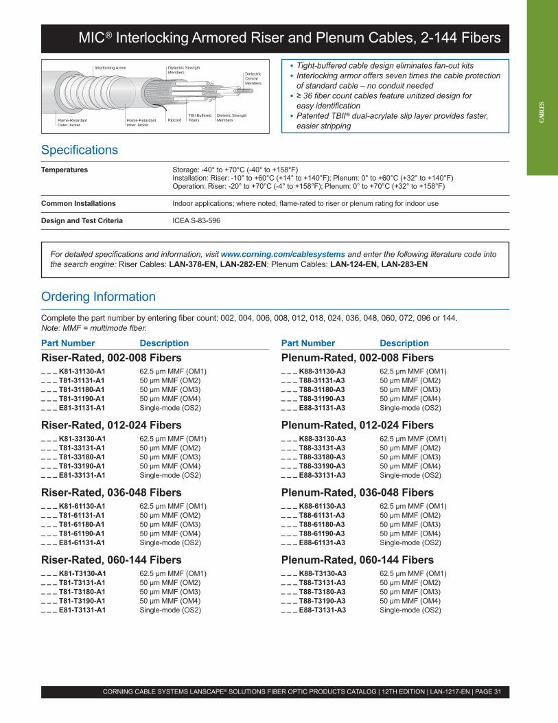
MIC® Interlocking Armored Riser and Plenum Cables, 2-144 Fibers
• Tight-buffered cable design eliminates fan-out kits• Interlocking armor offers seven times the cable protection
of standard cable – no conduit needed• ≥ 36 fiber count cables feature unitized design for
easy identification• Patented TBII® dual-acrylate slip layer provides faster,
easier strippingRipcord
Dielectric StrengthMembers
Interlocking ArmorDielectricCentralMembers
Flame-RetardantOuter Jacket
Flame-RetardantInner Jacket
TBII BufferedFibers
Dieletric StrengthMembers
CORNING CABLE SYSTEMS LANSCAPE® SOLUTIONS FIBER OPTIC PRODUCTS CATALOG | 12TH EDITION | LAN-1217-EN | PAGE 31
Part Number DescriptionRiser-Rated, 002-008 Fibers_ _ _ K81-31130-A1 62.5 µm MMF (OM1)_ _ _ T81-31131-A1 50 µm MMF (OM2)_ _ _ T81-31180-A1 50 µm MMF (OM3)_ _ _ T81-31190-A1 50 µm MMF (OM4)_ _ _ E81-31131-A1 Single-mode (OS2)
Riser-Rated, 012-024 Fibers_ _ _ K81-33130-A1 62.5 µm MMF (OM1)_ _ _ T81-33131-A1 50 µm MMF (OM2)_ _ _ T81-33180-A1 50 µm MMF (OM3)_ _ _ T81-33190-A1 50 µm MMF (OM4)_ _ _ E81-33131-A1 Single-mode (OS2)
Riser-Rated, 036-048 Fibers_ _ _ K81-61130-A1 62.5 µm MMF (OM1)_ _ _ T81-61131-A1 50 µm MMF (OM2)_ _ _ T81-61180-A1 50 µm MMF (OM3)_ _ _ T81-61190-A1 50 µm MMF (OM4)_ _ _ E81-61131-A1 Single-mode (OS2)
Riser-Rated, 060-144 Fibers_ _ _ K81-T3130-A1 62.5 µm MMF (OM1)_ _ _ T81-T3131-A1 50 µm MMF (OM2)_ _ _ T81-T3180-A1 50 µm MMF (OM3)_ _ _ T81-T3190-A1 50 µm MMF (OM4)_ _ _ E81-T3131-A1 Single-mode (OS2)
Part Number DescriptionPlenum-Rated, 002-008 Fibers_ _ _ K88-31130-A3 62.5 µm MMF (OM1)_ _ _ T88-31131-A3 50 µm MMF (OM2)_ _ _ T88-31180-A3 50 µm MMF (OM3)_ _ _ T88-31190-A3 50 µm MMF (OM4)_ _ _ E88-31131-A3 Single-mode (OS2)
Plenum-Rated, 012-024 Fibers_ _ _ K88-33130-A3 62.5 µm MMF (OM1)_ _ _ T88-33131-A3 50 µm MMF (OM2)_ _ _ T88-33180-A3 50 µm MMF (OM3)_ _ _ T88-33190-A3 50 µm MMF (OM4)_ _ _ E88-33131-A3 Single-mode (OS2)
Plenum-Rated, 036-048 Fibers_ _ _ K88-61130-A3 62.5 µm MMF (OM1)_ _ _ T88-61131-A3 50 µm MMF (OM2)_ _ _ T88-61180-A3 50 µm MMF (OM3)_ _ _ T88-61190-A3 50 µm MMF (OM4)_ _ _ E88-61131-A3 Single-mode (OS2)
Plenum-Rated, 060-144 Fibers_ _ _ K88-T3130-A3 62.5 µm MMF (OM1)_ _ _ T88-T3131-A3 50 µm MMF (OM2)_ _ _ T88-T3180-A3 50 µm MMF (OM3)_ _ _ T88-T3190-A3 50 µm MMF (OM4)_ _ _ E88-T3131-A3 Single-mode (OS2)
SpecificationsTemperatures Storage: -40° to +70°C (-40° to +158°F)
Installation: Riser: -10° to +60°C (+14° to +140°F); Plenum: 0° to +60°C (+32° to +140°F)Operation: Riser: -20° to +70°C (-4° to +158°F); Plenum: 0° to +70°C (+32° to +158°F)
Common Installations Indoor applications; where noted, flame-rated to riser or plenum rating for indoor use
Design and Test Criteria ICEA S-83-596
For detailed specifications and information, visit www.corning.com/cablesystems and enter the following literature code intothe search engine: Riser Cables: LAN-378-EN, LAN-282-EN; Plenum Cables: LAN-124-EN, LAN-283-EN
Ordering InformationComplete the part number by entering fiber count: 002, 004, 006, 008, 012, 018, 024, 036, 048, 060, 072, 096 or 144.Note: MMF = multimode fiber.
CABL
ES
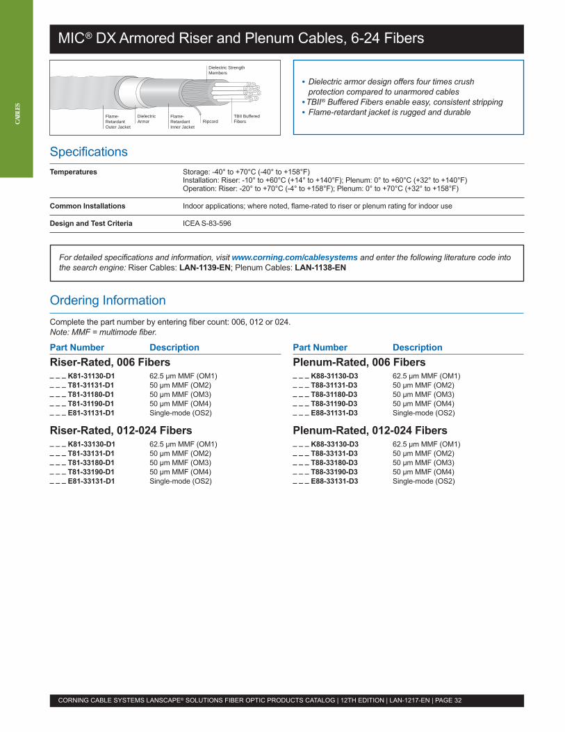
Part Number DescriptionRiser-Rated, 006 Fibers_ _ _ K81-31130-D1 62.5 µm MMF (OM1)_ _ _ T81-31131-D1 50 µm MMF (OM2)_ _ _ T81-31180-D1 50 µm MMF (OM3)_ _ _ T81-31190-D1 50 µm MMF (OM4)_ _ _ E81-31131-D1 Single-mode (OS2)
Riser-Rated, 012-024 Fibers_ _ _ K81-33130-D1 62.5 µm MMF (OM1)_ _ _ T81-33131-D1 50 µm MMF (OM2)_ _ _ T81-33180-D1 50 µm MMF (OM3)_ _ _ T81-33190-D1 50 µm MMF (OM4)_ _ _ E81-33131-D1 Single-mode (OS2)
Part Number DescriptionPlenum-Rated, 006 Fibers_ _ _ K88-31130-D3 62.5 µm MMF (OM1)_ _ _ T88-31131-D3 50 µm MMF (OM2)_ _ _ T88-31180-D3 50 µm MMF (OM3)_ _ _ T88-31190-D3 50 µm MMF (OM4)_ _ _ E88-31131-D3 Single-mode (OS2)
Plenum-Rated, 012-024 Fibers_ _ _ K88-33130-D3 62.5 µm MMF (OM1)_ _ _ T88-33131-D3 50 µm MMF (OM2)_ _ _ T88-33180-D3 50 µm MMF (OM3)_ _ _ T88-33190-D3 50 µm MMF (OM4)_ _ _ E88-33131-D3 Single-mode (OS2)
SpecificationsTemperatures Storage: -40° to +70°C (-40° to +158°F)
Installation: Riser: -10° to +60°C (+14° to +140°F); Plenum: 0° to +60°C (+32° to +140°F)Operation: Riser: -20° to +70°C (-4° to +158°F); Plenum: 0° to +70°C (+32° to +158°F)
Common Installations Indoor applications; where noted, flame-rated to riser or plenum rating for indoor use
Design and Test Criteria ICEA S-83-596
For detailed specifications and information, visit www.corning.com/cablesystems and enter the following literature code intothe search engine: Riser Cables: LAN-1139-EN; Plenum Cables: LAN-1138-EN
Ordering InformationComplete the part number by entering fiber count: 006, 012 or 024.Note: MMF = multimode fiber.
MIC® DX Armored Riser and Plenum Cables, 6-24 Fibers
• Dielectric armor design offers four times crushprotection compared to unarmored cables
•TBII® Buffered Fibers enable easy, consistent stripping• Flame-retardant jacket is rugged and durable
Dielectric StrengthMembers
TBII BufferedFibersRipcord
DielectricArmor
Flame-RetardantOuter Jacket
Flame-RetardantInner Jacket
CORNING CABLE SYSTEMS LANSCAPE® SOLUTIONS FIBER OPTIC PRODUCTS CATALOG | 12TH EDITION | LAN-1217-EN | PAGE 32
CABL
ES
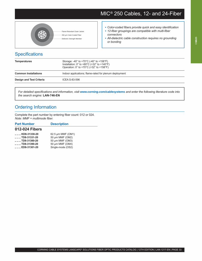
SpecificationsTemperatures Storage: -40° to +70°C (-40° to +158°F)
Installation: 0° to +60°C (+32° to +140°F)Operation: 0° to +70°C (+32° to +158°F)
Common Installations Indoor applications; flame-rated for plenum deployment
Design and Test Criteria ICEA S-83-596
MIC® 250 Cables, 12- and 24-Fiber
• Color-coded fibers provide quick and easy identification• 12-fiber groupings are compatible with multi-fiber
connectors• All-dielectric cable construction requires no grounding
or bonding
Flame-Retardant Outer Jacket
250 µm Color-Coded Fiber
Dielectric Strength Member
CORNING CABLE SYSTEMS LANSCAPE® SOLUTIONS FIBER OPTIC PRODUCTS CATALOG | 12TH EDITION | LAN-1217-EN | PAGE 33
For detailed specifications and information, visit www.corning.com/cablesystems and enter the following literature code intothe search engine: LAN-746-EN
Ordering InformationComplete the part number by entering fiber count: 012 or 024.Note: MMF = multimode fiber.
Part Number Description012-024 Fibers_ _ _ KD8-31330-20 62.5 µm MMF (OM1)_ _ _ TD8-31331-20 50 µm MMF (OM2)_ _ _ TD8-31380-20 50 µm MMF (OM3)_ _ _ TD8-31390-20 50 µm MMF (OM4)_ _ _ ED8-31301-20 Single-mode (OS2)
CABL
ES
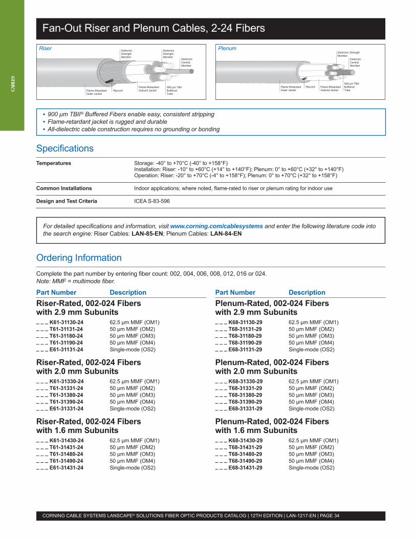
Part Number DescriptionRiser-Rated, 002-024 Fiberswith 2.9 mm Subunits_ _ _ K61-31130-24 62.5 µm MMF (OM1)_ _ _ T61-31131-24 50 µm MMF (OM2)_ _ _ T61-31180-24 50 µm MMF (OM3)_ _ _ T61-31190-24 50 µm MMF (OM4)_ _ _ E61-31131-24 Single-mode (OS2)
Riser-Rated, 002-024 Fiberswith 2.0 mm Subunits_ _ _ K61-31330-24 62.5 µm MMF (OM1)_ _ _ T61-31331-24 50 µm MMF (OM2)_ _ _ T61-31380-24 50 µm MMF (OM3)_ _ _ T61-31390-24 50 µm MMF (OM4)_ _ _ E61-31331-24 Single-mode (OS2)
Riser-Rated, 002-024 Fiberswith 1.6 mm Subunits_ _ _ K61-31430-24 62.5 µm MMF (OM1)_ _ _ T61-31431-24 50 µm MMF (OM2)_ _ _ T61-31480-24 50 µm MMF (OM3)_ _ _ T61-31490-24 50 µm MMF (OM4)_ _ _ E61-31431-24 Single-mode (OS2)
Part Number DescriptionPlenum-Rated, 002-024 Fiberswith 2.9 mm Subunits_ _ _ K68-31130-29 62.5 µm MMF (OM1)_ _ _ T68-31131-29 50 µm MMF (OM2)_ _ _ T68-31180-29 50 µm MMF (OM3)_ _ _ T68-31190-29 50 µm MMF (OM4)_ _ _ E68-31131-29 Single-mode (OS2)
Plenum-Rated, 002-024 Fiberswith 2.0 mm Subunits_ _ _ K68-31330-29 62.5 µm MMF (OM1)_ _ _ T68-31331-29 50 µm MMF (OM2)_ _ _ T68-31380-29 50 µm MMF (OM3)_ _ _ T68-31390-29 50 µm MMF (OM4)_ _ _ E68-31331-29 Single-mode (OS2)
Plenum-Rated, 002-024 Fiberswith 1.6 mm Subunits_ _ _ K68-31430-29 62.5 µm MMF (OM1)_ _ _ T68-31431-29 50 µm MMF (OM2)_ _ _ T68-31480-29 50 µm MMF (OM3)_ _ _ T68-31490-29 50 µm MMF (OM4)_ _ _ E68-31431-29 Single-mode (OS2)
SpecificationsTemperatures Storage: -40° to +70°C (-40° to +158°F)
Installation: Riser: -10° to +60°C (+14° to +140°F); Plenum: 0° to +60°C (+32° to +140°F)Operation: Riser: -20° to +70°C (-4° to +158°F); Plenum: 0° to +70°C (+32° to +158°F)
Common Installations Indoor applications; where noted, flame-rated to riser or plenum rating for indoor use
Design and Test Criteria ICEA S-83-596
For detailed specifications and information, visit www.corning.com/cablesystems and enter the following literature code intothe search engine: Riser Cables: LAN-85-EN; Plenum Cables: LAN-84-EN
Ordering InformationComplete the part number by entering fiber count: 002, 004, 006, 008, 012, 016 or 024.Note: MMF = multimode fiber.
Fan-Out Riser and Plenum Cables, 2-24 Fibers
CORNING CABLE SYSTEMS LANSCAPE® SOLUTIONS FIBER OPTIC PRODUCTS CATALOG | 12TH EDITION | LAN-1217-EN | PAGE 34
CABL
ES
DielectricCentralMember
900 µm TBII Buffered Tube
Dielectric StrengthMember
Ripcord Flame-RetardantSubunit Jacket
Flame-RetardantOuter Jacket
DielectricCentralMember
DielectricStrengthMember
900 µm TBIIBuffered Tube
RipcordFlame-RetardantSubunit Jacket
DielectricStrengthMember
Flame-RetardantOuter Jacket
• 900 µm TBII® Buffered Fibers enable easy, consistent stripping• Flame-retardant jacket is rugged and durable• All-dielectric cable construction requires no grounding or bonding
PlenumRiser
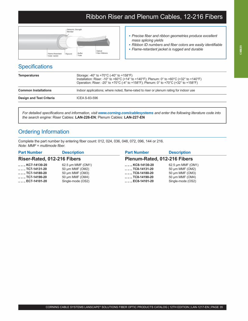
Part Number DescriptionRiser-Rated, 012-216 Fibers_ _ _ KC7-14130-20 62.5 µm MMF (OM1)_ _ _ TC7-14131-20 50 µm MMF (OM2)_ _ _ TC7-14180-20 50 µm MMF (OM3)_ _ _ TC7-14190-20 50 µm MMF (OM4)_ _ _ EC7-14101-20 Single-mode (OS2)
Part Number DescriptionPlenum-Rated, 012-216 Fibers_ _ _ KC8-14130-20 62.5 µm MMF (OM1)_ _ _ TC8-14131-20 50 µm MMF (OM2)_ _ _ TC8-14180-20 50 µm MMF (OM3)_ _ _ TC8-14190-20 50 µm MMF (OM4)_ _ _ EC8-14101-20 Single-mode (OS2)
SpecificationsTemperatures Storage: -40° to +70°C (-40° to +158°F)
Installation: Riser: -10° to +60°C (+14° to +140°F); Plenum: 0° to +60°C (+32° to +140°F)Operation: Riser: -20° to +70°C (-4° to +158°F); Plenum: 0° to +70°C (+32° to +158°F)
Common Installations Indoor applications; where noted, flame-rated to riser or plenum rating for indoor use
Design and Test Criteria ICEA S-83-596
For detailed specifications and information, visit www.corning.com/cablesystems and enter the following literature code intothe search engine: Riser Cables: LAN-226-EN; Plenum Cables: LAN-227-EN
Ordering InformationComplete the part number by entering fiber count: 012, 024, 036, 048, 072, 096, 144 or 216.Note: MMF = multimode fiber.
Ribbon Riser and Plenum Cables, 12-216 Fibers
• Precise fiber and ribbon geometries produce excellentmass splicing yields
• Ribbon ID numbers and fiber colors are easily identifiable• Flame-retardant jacket is rugged and durableOptical
Fiber RibbonsBuffer Tube
Dielectric StrengthMember
RipcordFlame-RetardantOuter Jacket
CORNING CABLE SYSTEMS LANSCAPE® SOLUTIONS FIBER OPTIC PRODUCTS CATALOG | 12TH EDITION | LAN-1217-EN | PAGE 35
CABL
ES
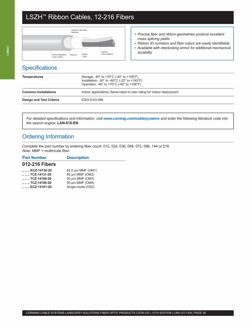
SpecificationsTemperatures Storage: -40° to +70°C (-40° to +158°F)
Installation: -30° to +60°C (-22° to +140°F)Operation: -40° to +70°C (-40° to +158°F)
Common Installations Indoor applications; flame-rated to riser rating for indoor deployment
Design and Test Criteria ICEA S-83-596
LSZH™ Ribbon Cables, 12-216 Fibers
• Precise fiber and ribbon geometries produce excellentmass splicing yields
• Ribbon ID numbers and fiber colors are easily identifiable• Available with interlocking armor for additional mechanical
durabilityOpticalFiber RibbonsBuffer
Tube
Dielectric StrengthMember
RipcordFlame-RetardantOuter Jacket
CORNING CABLE SYSTEMS LANSCAPE® SOLUTIONS FIBER OPTIC PRODUCTS CATALOG | 12TH EDITION | LAN-1217-EN | PAGE 36
CABL
ES
For detailed specifications and information, visit www.corning.com/cablesystems and enter the following literature code intothe search engine: LAN-818-EN
Ordering InformationComplete the part number by entering fiber count: 012, 024, 036, 048, 072, 096, 144 or 216.Note: MMF = multimode fiber.
Part Number Description012-216 Fibers_ _ _ KCZ-14130-20 62.5 µm MMF (OM1)_ _ _ TCZ-14131-20 50 µm MMF (OM2)_ _ _ TCZ-14180-20 50 µm MMF (OM3)_ _ _ TCZ-14190-20 50 µm MMF (OM4)_ _ _ ECZ-14101-20 Single-mode (OS2)
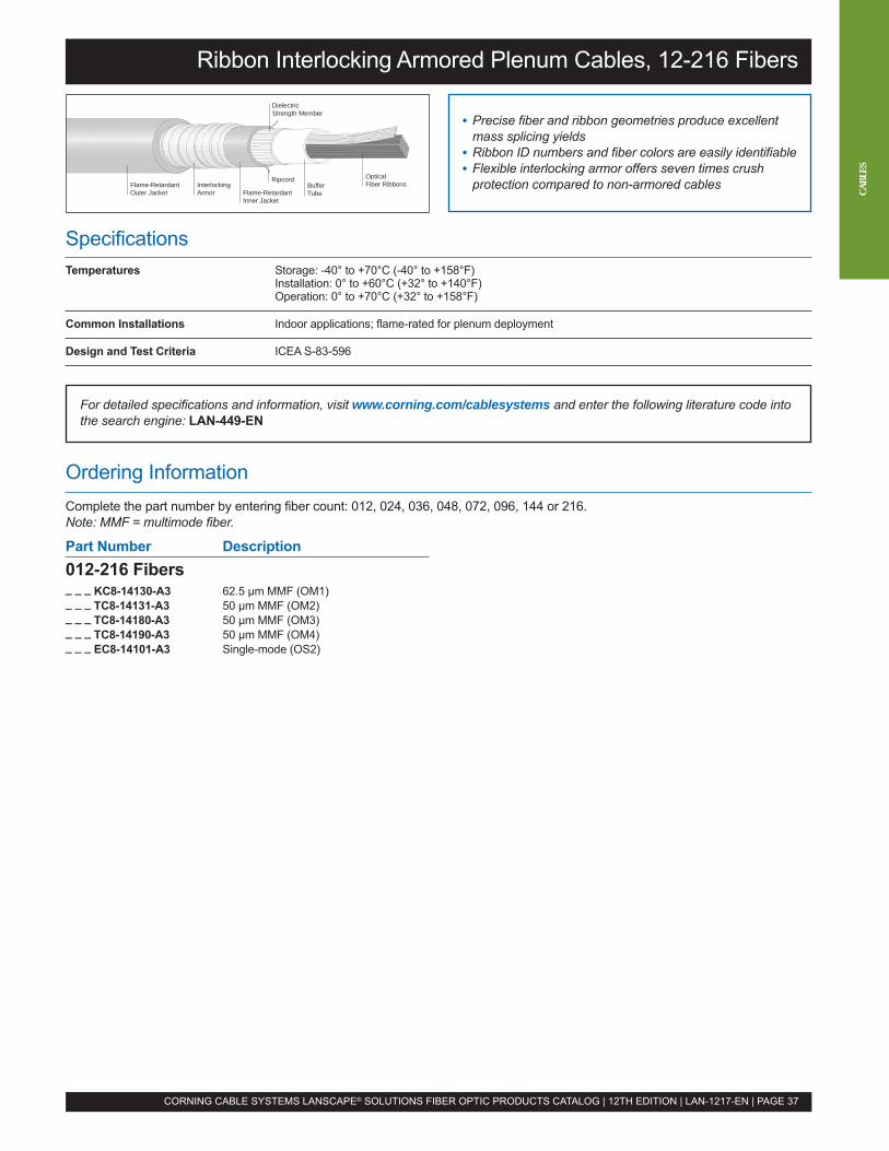
SpecificationsTemperatures Storage: -40° to +70°C (-40° to +158°F)
Installation: 0° to +60°C (+32° to +140°F)Operation: 0° to +70°C (+32° to +158°F)
Common Installations Indoor applications; flame-rated for plenum deployment
Design and Test Criteria ICEA S-83-596
Ribbon Interlocking Armored Plenum Cables, 12-216 Fibers
• Precise fiber and ribbon geometries produce excellentmass splicing yields
• Ribbon ID numbers and fiber colors are easily identifiable• Flexible interlocking armor offers seven times crush
protection compared to non-armored cablesOpticalFiber RibbonsBuffer
Tube
DielectricStrength Member
Ripcord
Flame-RetardantInner Jacket
Flame-RetardantOuter Jacket
InterlockingArmor
CORNING CABLE SYSTEMS LANSCAPE® SOLUTIONS FIBER OPTIC PRODUCTS CATALOG | 12TH EDITION | LAN-1217-EN | PAGE 37
For detailed specifications and information, visit www.corning.com/cablesystems and enter the following literature code intothe search engine: LAN-449-EN
Ordering InformationComplete the part number by entering fiber count: 012, 024, 036, 048, 072, 096, 144 or 216.Note: MMF = multimode fiber.
Part Number Description012-216 Fibers_ _ _ KC8-14130-A3 62.5 µm MMF (OM1)_ _ _ TC8-14131-A3 50 µm MMF (OM2)_ _ _ TC8-14180-A3 50 µm MMF (OM3)_ _ _ TC8-14190-A3 50 µm MMF (OM4)_ _ _ EC8-14101-A3 Single-mode (OS2)
CABL
ES
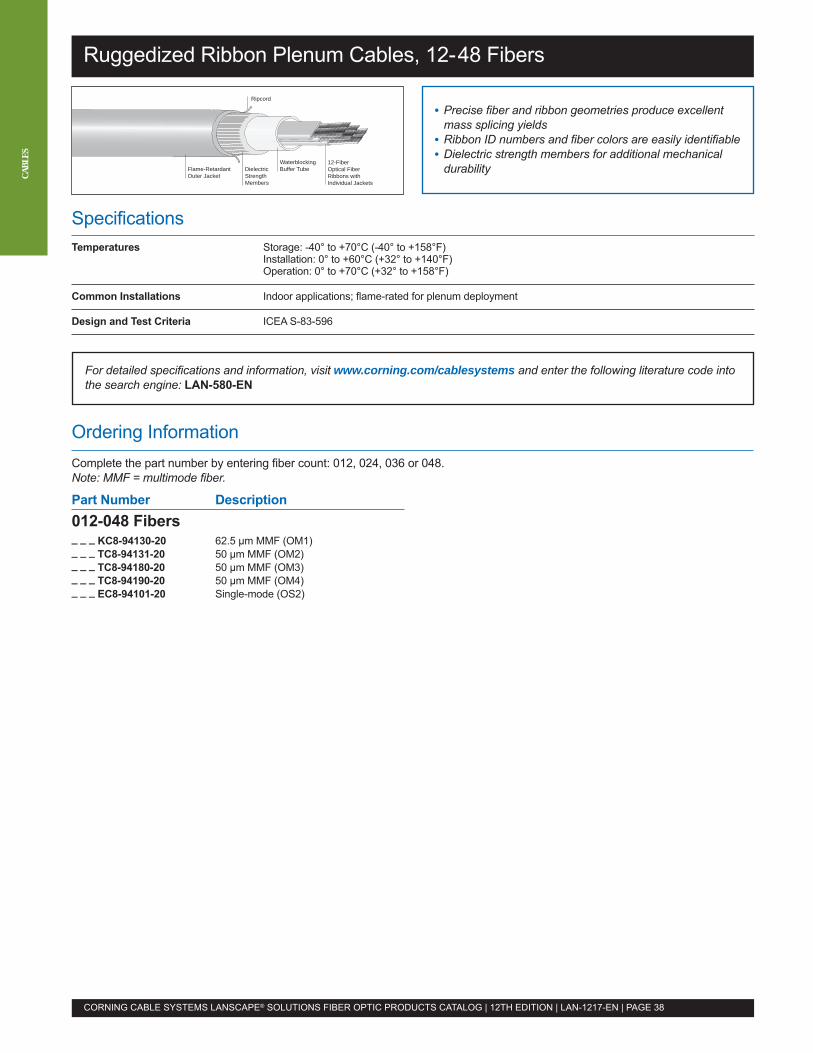
SpecificationsTemperatures Storage: -40° to +70°C (-40° to +158°F)
Installation: 0° to +60°C (+32° to +140°F)Operation: 0° to +70°C (+32° to +158°F)
Common Installations Indoor applications; flame-rated for plenum deployment
Design and Test Criteria ICEA S-83-596
Ruggedized Ribbon Plenum Cables, 12-48 Fibers
• Precise fiber and ribbon geometries produce excellentmass splicing yields
• Ribbon ID numbers and fiber colors are easily identifiable• Dielectric strength members for additional mechanical
durabilityDielectricStrengthMembers
Ripcord
12-FiberOptical FiberRibbons withIndividual Jackets
WaterblockingBuffer TubeFlame-Retardant
Outer Jacket
CORNING CABLE SYSTEMS LANSCAPE® SOLUTIONS FIBER OPTIC PRODUCTS CATALOG | 12TH EDITION | LAN-1217-EN | PAGE 38
CABL
ES
For detailed specifications and information, visit www.corning.com/cablesystems and enter the following literature code intothe search engine: LAN-580-EN
Ordering InformationComplete the part number by entering fiber count: 012, 024, 036 or 048.Note: MMF = multimode fiber.
Part Number Description012-048 Fibers_ _ _ KC8-94130-20 62.5 µm MMF (OM1)_ _ _ TC8-94131-20 50 µm MMF (OM2)_ _ _ TC8-94180-20 50 µm MMF (OM3)_ _ _ TC8-94190-20 50 µm MMF (OM4)_ _ _ EC8-94101-20 Single-mode (OS2)
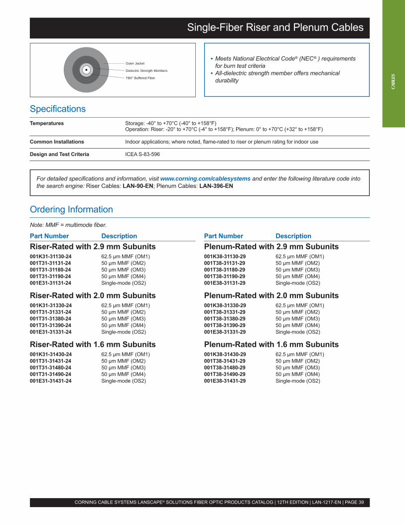
Part Number DescriptionRiser-Rated with 2.9 mm Subunits001K31-31130-24 62.5 µm MMF (OM1)001T31-31131-24 50 µm MMF (OM2)001T31-31180-24 50 µm MMF (OM3)001T31-31190-24 50 µm MMF (OM4)001E31-31131-24 Single-mode (OS2)
Riser-Rated with 2.0 mm Subunits001K31-31330-24 62.5 µm MMF (OM1)001T31-31331-24 50 µm MMF (OM2)001T31-31380-24 50 µm MMF (OM3)001T31-31390-24 50 µm MMF (OM4)001E31-31331-24 Single-mode (OS2)
Riser-Rated with 1.6 mm Subunits001K31-31430-24 62.5 µm MMF (OM1)001T31-31431-24 50 µm MMF (OM2)001T31-31480-24 50 µm MMF (OM3)001T31-31490-24 50 µm MMF (OM4)001E31-31431-24 Single-mode (OS2)
Part Number DescriptionPlenum-Rated with 2.9 mm Subunits001K38-31130-29 62.5 µm MMF (OM1)001T38-31131-29 50 µm MMF (OM2)001T38-31180-29 50 µm MMF (OM3)001T38-31190-29 50 µm MMF (OM4)001E38-31131-29 Single-mode (OS2)
Plenum-Rated with 2.0 mm Subunits001K38-31330-29 62.5 µm MMF (OM1)001T38-31331-29 50 µm MMF (OM2)001T38-31380-29 50 µm MMF (OM3)001T38-31390-29 50 µm MMF (OM4)001E38-31331-29 Single-mode (OS2)
Plenum-Rated with 1.6 mm Subunits001K38-31430-29 62.5 µm MMF (OM1)001T38-31431-29 50 µm MMF (OM2)001T38-31480-29 50 µm MMF (OM3)001T38-31490-29 50 µm MMF (OM4)001E38-31431-29 Single-mode (OS2)
Ordering InformationNote: MMF = multimode fiber.
SpecificationsTemperatures Storage: -40° to +70°C (-40° to +158°F)
Operation: Riser: -20° to +70°C (-4° to +158°F); Plenum: 0° to +70°C (+32° to +158°F)
Common Installations Indoor applications; where noted, flame-rated to riser or plenum rating for indoor use
Design and Test Criteria ICEA S-83-596
For detailed specifications and information, visit www.corning.com/cablesystems and enter the following literature code intothe search engine: Riser Cables: LAN-90-EN; Plenum Cables: LAN-396-EN
Single-Fiber Riser and Plenum Cables
• Meets National Electrical Code® (NEC® ) requirementsfor burn test criteria
• All-dielectric strength member offers mechanicaldurability
Outer Jacket
Dielectric Strength Members
TBII® Buffered Fiber
CORNING CABLE SYSTEMS LANSCAPE® SOLUTIONS FIBER OPTIC PRODUCTS CATALOG | 12TH EDITION | LAN-1217-EN | PAGE 39
CABL
ES
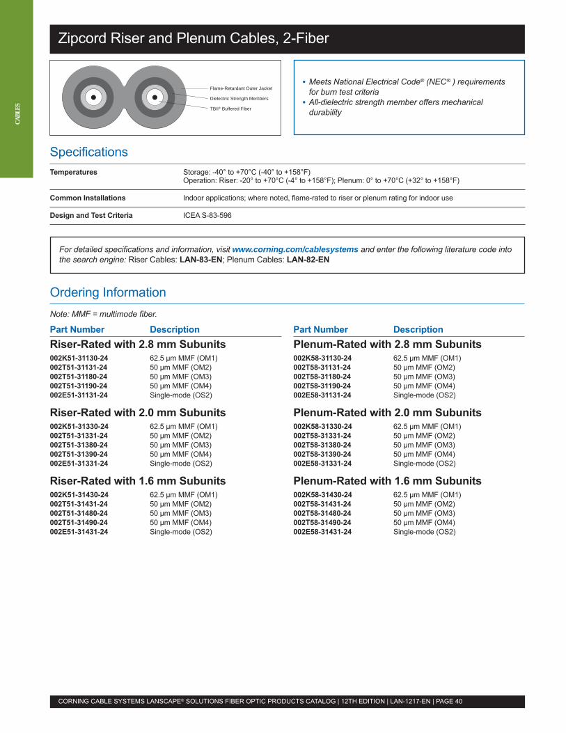
Part Number DescriptionRiser-Rated with 2.8 mm Subunits002K51-31130-24 62.5 µm MMF (OM1)002T51-31131-24 50 µm MMF (OM2)002T51-31180-24 50 µm MMF (OM3)002T51-31190-24 50 µm MMF (OM4)002E51-31131-24 Single-mode (OS2)
Riser-Rated with 2.0 mm Subunits002K51-31330-24 62.5 µm MMF (OM1)002T51-31331-24 50 µm MMF (OM2)002T51-31380-24 50 µm MMF (OM3)002T51-31390-24 50 µm MMF (OM4)002E51-31331-24 Single-mode (OS2)
Riser-Rated with 1.6 mm Subunits002K51-31430-24 62.5 µm MMF (OM1)002T51-31431-24 50 µm MMF (OM2)002T51-31480-24 50 µm MMF (OM3)002T51-31490-24 50 µm MMF (OM4)002E51-31431-24 Single-mode (OS2)
Part Number DescriptionPlenum-Rated with 2.8 mm Subunits002K58-31130-24 62.5 µm MMF (OM1)002T58-31131-24 50 µm MMF (OM2)002T58-31180-24 50 µm MMF (OM3)002T58-31190-24 50 µm MMF (OM4)002E58-31131-24 Single-mode (OS2)
Plenum-Rated with 2.0 mm Subunits002K58-31330-24 62.5 µm MMF (OM1)002T58-31331-24 50 µm MMF (OM2)002T58-31380-24 50 µm MMF (OM3)002T58-31390-24 50 µm MMF (OM4)002E58-31331-24 Single-mode (OS2)
Plenum-Rated with 1.6 mm Subunits002K58-31430-24 62.5 µm MMF (OM1)002T58-31431-24 50 µm MMF (OM2)002T58-31480-24 50 µm MMF (OM3)002T58-31490-24 50 µm MMF (OM4)002E58-31431-24 Single-mode (OS2)
Ordering InformationNote: MMF = multimode fiber.
SpecificationsTemperatures Storage: -40° to +70°C (-40° to +158°F)
Operation: Riser: -20° to +70°C (-4° to +158°F); Plenum: 0° to +70°C (+32° to +158°F)
Common Installations Indoor applications; where noted, flame-rated to riser or plenum rating for indoor use
Design and Test Criteria ICEA S-83-596
For detailed specifications and information, visit www.corning.com/cablesystems and enter the following literature code intothe search engine: Riser Cables: LAN-83-EN; Plenum Cables: LAN-82-EN
Zipcord Riser and Plenum Cables, 2-Fiber
• Meets National Electrical Code® (NEC® ) requirementsfor burn test criteria
• All-dielectric strength member offers mechanicaldurability
Flame-Retardant Outer Jacket
Dielectric Strength Members
TBII® Buffered Fiber
CORNING CABLE SYSTEMS LANSCAPE® SOLUTIONS FIBER OPTIC PRODUCTS CATALOG | 12TH EDITION | LAN-1217-EN | PAGE 40
CABL
ES
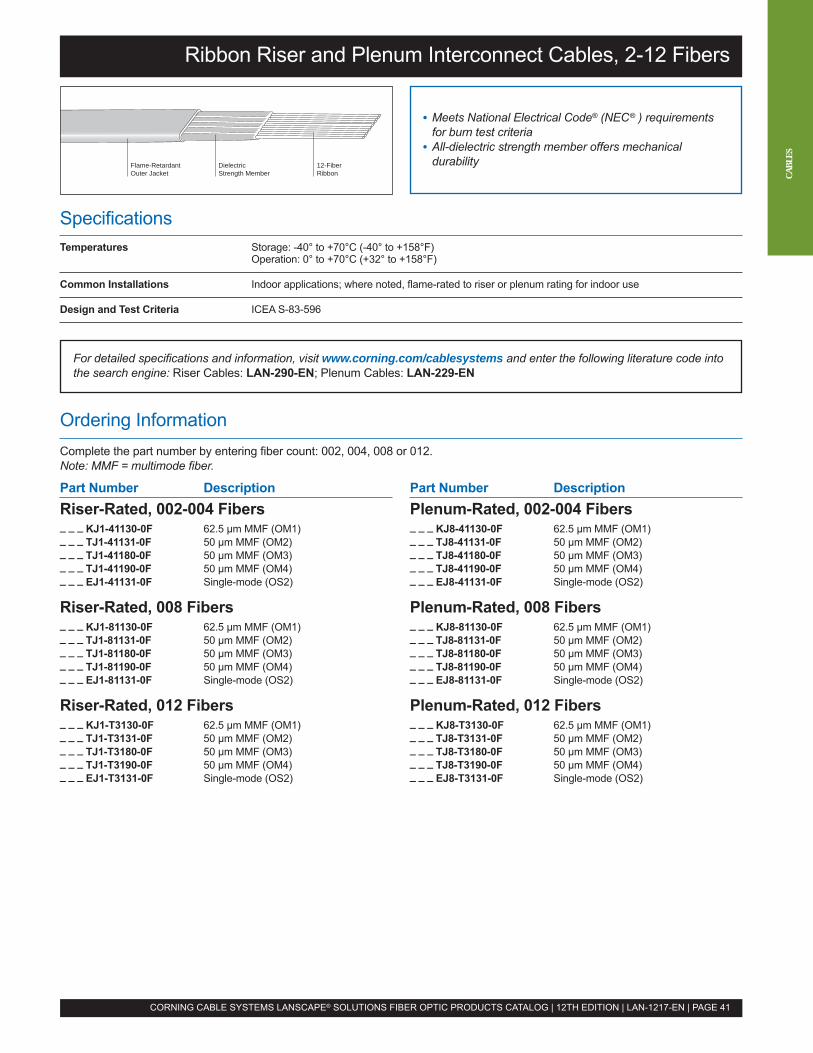
SpecificationsTemperatures Storage: -40° to +70°C (-40° to +158°F)
Operation: 0° to +70°C (+32° to +158°F)
Common Installations Indoor applications; where noted, flame-rated to riser or plenum rating for indoor use
Design and Test Criteria ICEA S-83-596
For detailed specifications and information, visit www.corning.com/cablesystems and enter the following literature code intothe search engine: Riser Cables: LAN-290-EN; Plenum Cables: LAN-229-EN
Ordering InformationComplete the part number by entering fiber count: 002, 004, 008 or 012.Note: MMF = multimode fiber.
Part Number DescriptionRiser-Rated, 002-004 Fibers_ _ _ KJ1-41130-0F 62.5 µm MMF (OM1)_ _ _ TJ1-41131-0F 50 µm MMF (OM2)_ _ _ TJ1-41180-0F 50 µm MMF (OM3)_ _ _ TJ1-41190-0F 50 µm MMF (OM4)_ _ _ EJ1-41131-0F Single-mode (OS2)
Riser-Rated, 008 Fibers_ _ _ KJ1-81130-0F 62.5 µm MMF (OM1)_ _ _ TJ1-81131-0F 50 µm MMF (OM2)_ _ _ TJ1-81180-0F 50 µm MMF (OM3)_ _ _ TJ1-81190-0F 50 µm MMF (OM4)_ _ _ EJ1-81131-0F Single-mode (OS2)
Riser-Rated, 012 Fibers_ _ _ KJ1-T3130-0F 62.5 µm MMF (OM1)_ _ _ TJ1-T3131-0F 50 µm MMF (OM2)_ _ _ TJ1-T3180-0F 50 µm MMF (OM3)_ _ _ TJ1-T3190-0F 50 µm MMF (OM4)_ _ _ EJ1-T3131-0F Single-mode (OS2)
Ribbon Riser and Plenum Interconnect Cables, 2-12 Fibers
• Meets National Electrical Code® (NEC® ) requirementsfor burn test criteria
• All-dielectric strength member offers mechanicaldurabilityFlame-Retardant
Outer JacketDielectricStrength Member
12-FiberRibbon
Part Number DescriptionPlenum-Rated, 002-004 Fibers_ _ _ KJ8-41130-0F 62.5 µm MMF (OM1)_ _ _ TJ8-41131-0F 50 µm MMF (OM2)_ _ _ TJ8-41180-0F 50 µm MMF (OM3)_ _ _ TJ8-41190-0F 50 µm MMF (OM4)_ _ _ EJ8-41131-0F Single-mode (OS2)
Plenum-Rated, 008 Fibers_ _ _ KJ8-81130-0F 62.5 µm MMF (OM1)_ _ _ TJ8-81131-0F 50 µm MMF (OM2)_ _ _ TJ8-81180-0F 50 µm MMF (OM3)_ _ _ TJ8-81190-0F 50 µm MMF (OM4)_ _ _ EJ8-81131-0F Single-mode (OS2)
Plenum-Rated, 012 Fibers_ _ _ KJ8-T3130-0F 62.5 µm MMF (OM1)_ _ _ TJ8-T3131-0F 50 µm MMF (OM2)_ _ _ TJ8-T3180-0F 50 µm MMF (OM3)_ _ _ TJ8-T3190-0F 50 µm MMF (OM4)_ _ _ EJ8-T3131-0F Single-mode (OS2)
CORNING CABLE SYSTEMS LANSCAPE® SOLUTIONS FIBER OPTIC PRODUCTS CATALOG | 12TH EDITION | LAN-1217-EN | PAGE 41
CABL
ES
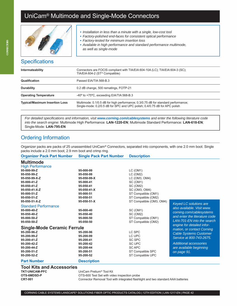
UniCam® Multimode and Single-Mode Connectors
Ordering InformationOrganizer packs are packs of 25 unassembled UniCam® Connectors, separated into components, with one 2.0 mm boot. Singlepacks include a 2.0 mm boot, 2.9 mm boot and crimp ring.Organizer Pack Part Number Single Pack Part Number DescriptionMultimodeHigh Performance95-000-99-Z 95-000-99 LC (OM1)95-050-99-Z 95-050-99 LC (OM2)95-050-99-X-Z 95-050-99-X LC (OM3, OM4)95-000-41-Z 95-000-41 SC (OM1)95-050-41-Z 95-050-41 SC (OM2)95-050-41-X-Z 95-050-41-X SC (OM3, OM4)95-000-51-Z 95-000-51 ST Compatible (OM1)95-050-51-Z 95-050-51 ST Compatible (OM2)95-050-51-X-Z 95-050-51-X ST Compatible (OM3, OM4)Standard Performance95-000-40-Z 95-000-40 SC (OM1)95-050-40-Z 95-050-40 SC (OM2)95-000-50-Z 95-000-50 ST Compatible (OM1)95-050-50-Z 95-050-50 ST Compatible (OM2)
Single-Mode Ceramic Ferrule95-200-96-Z 95-200-96 LC SPC95-200-99-Z 95-200-99 LC UPC95-200-41-Z 95-200-41 SC SPC95-200-42-Z 95-200-42 SC UPC95-200-44-Z 95-200-44 SC APC95-200-51-Z 95-200-51 ST Compatible SPC95-200-52-Z 95-200-52 ST Compatible UPC
Part Number DescriptionTool Kits and AccessoriesTKT-UNICAM-PFC UniCam Pretium® Tool KitOTS-6MDSD-P OTS-600 Test Set with video inspection probeCRT-001 Connector Removal Tool with integrated flashlight and two standard AAA batteries
SpecificationsIntermateability Connectors are FOCIS compliant with TIA/EIA 604-10A (LC); TIA/EIA 604-3 (SC);
TIA/EIA 604-2 (ST® Compatible)
Qualification Passed EIA/TIA 568-B.3
Durability 0.2 dB change, 500 rematings, FOTP-21
Operating Temperature -40º to +75ºC, exceeding EIA/TIA 568-B.3
Typical/Maximum Insertion Loss Multimode: 0.1/0.5 dB for high performance; 0.3/0.75 dB for standard performance;Single-mode: 0.2/0.5 dB for SPC and UPC polish; 0.4/0.75 dB for APC polish
• Installation in less than a minute with a single, low-cost tool• Factory-polished end-faces for consistent optical performance• Factory-tested for minimum insertion loss• Available in high performance and standard performance multimode,as well as single-mode
For detailed specifications and information, visit www.corning.com/cablesystems and enter the following literature codeinto the search engine: Multimode High Performance: LAN-1220-EN; Multimode Standard Performance: LAN-618-EN;Single-Mode: LAN-795-EN
CORNING CABLE SYSTEMS LANSCAPE® SOLUTIONS FIBER OPTIC PRODUCTS CATALOG | 12TH EDITION | LAN-1217-EN | PAGE 42
Keyed LC solutions arealso available. Visit www.corning.com/cablesystemsand enter the literature codeLAN-701-EN into the searchengine for detailed infor-mation, or contact CorningCable Systems CustomerService at 800-743-2675.Additional accessoriesare available beginningon page 91.
CONN
ECTO
RS
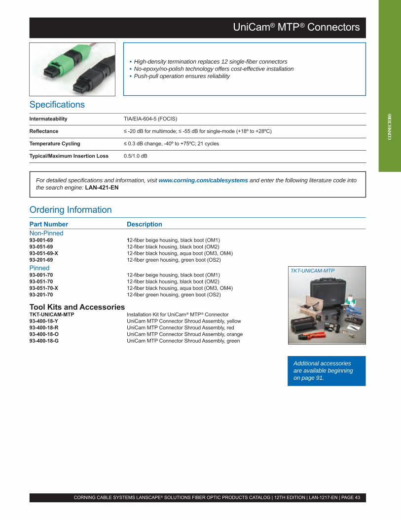
UniCam® MTP® Connectors
SpecificationsIntermateability TIA/EIA-604-5 (FOCIS)
Reflectance ≤ -20 dB for multimode; ≤ -55 dB for single-mode (+18º to +28ºC)
Temperature Cycling ≤ 0.3 dB change, -40º to +75ºC; 21 cycles
Typical/Maximum Insertion Loss 0.5/1.0 dB
• High-density termination replaces 12 single-fiber connectors• No-epoxy/no-polish technology offers cost-effective installation• Push-pull operation ensures reliability
CORNING CABLE SYSTEMS LANSCAPE® SOLUTIONS FIBER OPTIC PRODUCTS CATALOG | 12TH EDITION | LAN-1217-EN | PAGE 43
Ordering InformationPart Number DescriptionNon-Pinned93-001-69 12-fiber beige housing, black boot (OM1)93-051-69 12-fiber black housing, black boot (OM2)93-051-69-X 12-fiber black housing, aqua boot (OM3, OM4)93-201-69 12-fiber green housing, green boot (OS2)Pinned93-001-70 12-fiber beige housing, black boot (OM1)93-051-70 12-fiber black housing, black boot (OM2)93-051-70-X 12-fiber black housing, aqua boot (OM3, OM4)93-201-70 12-fiber green housing, green boot (OS2)
Tool Kits and AccessoriesTKT-UNICAM-MTP Installation Kit for UniCam® MTP® Connector93-400-18-Y UniCam MTP Connector Shroud Assembly, yellow93-400-18-R UniCam MTP Connector Shroud Assembly, red93-400-18-O UniCam MTP Connector Shroud Assembly, orange93-400-18-G UniCam MTP Connector Shroud Assembly, green
For detailed specifications and information, visit www.corning.com/cablesystems and enter the following literature code intothe search engine: LAN-421-EN
CONN
ECTO
RS
TKT-UNICAM-MTP
Additional accessoriesare available beginningon page 91.

CONN
ECTO
RS
Ordering InformationAll anaerobic-cure connectors are single packs. LC connectors come with 3 mm, 900 µm and combination 2 mm/1.6 mm boots.All SC and ST Compatible Connectors come with 3 mm, 2 mm and 900 µm boots.Part Number DescriptionMultimode95-101-98-SP LC, beige boot (OM1)95-051-98-SP LC, black boot (OM2)95-051-98-SP-X LC, aqua boot (OM3, OM4)95-101-41-SP SC, beige boot (OM1)95-051-41-SP SC, black boot (OM2)95-050-41-SP-X SC, aqua boot (OM3, OM4)95-101-52-SP ST Compatible, metal hardware, beige boot (OM1)95-051-52-SP ST Compatible, metal hardware, black boot (OM2)95-051-52-SP-X ST Compatible, metal hardware, aqua boot (OM3, OM4)Single-Mode95-201-98-SP LC, composite hardware, blue boot95-201-41-SP SC, composite hardware, blue boot95-201-52-SP ST Compatible, metal hardware, blue boot
Tool Kits and AccessoriesTKT-ANAEROBIC2 Installation Kit for Anaerobic-Cure ConnectorsTKT-ANAEROBIC2-C Anaerobic-Cure Consumables Kit for 500 connectorsCRT-001 Connector Removal Tool with integrated flashlight
and two standard AAA batteries
SpecificationsIntermateability Compliant with TIA/EIA 604-2 (ST® Compatible), 604-3 (SC) and 604-10 (LC)
Reflectance Multimode: ≤ -26 dB; Single-mode: ≤ -40 dB
Temperature Cycling ≤ 0.3 dB change, -40º to +75ºC; 21 cycles
Typical/Maximum Insertion Loss Multimode: 0.2/0.75 dB; Single-mode: 0.2/0.75 dB
• Quick-cure epoxy eliminates need for lamps or ovens• Minimal tools and no index-matching gel offers low installation cost• Hand polished for minimum insertion loss ensures reliability and optical performance
For detailed specifications and information, visit www.corning.com/cablesystems and enter the following literature code intothe search engine: LAN-460-EN
Anaerobic-Cure Connectors
CORNING CABLE SYSTEMS LANSCAPE® SOLUTIONS FIBER OPTIC PRODUCTS CATALOG | 12TH EDITION | LAN-1217-EN | PAGE 44
Keyed LC solutions arealso available. Visit www.corning.com/cablesystemsand enter the literature codeLAN-701-EN into the searchengine for detailed infor-mation, or contact CorningCable Systems CustomerService at 800-743-2675.Additional accessoriesare available beginningon page 91.
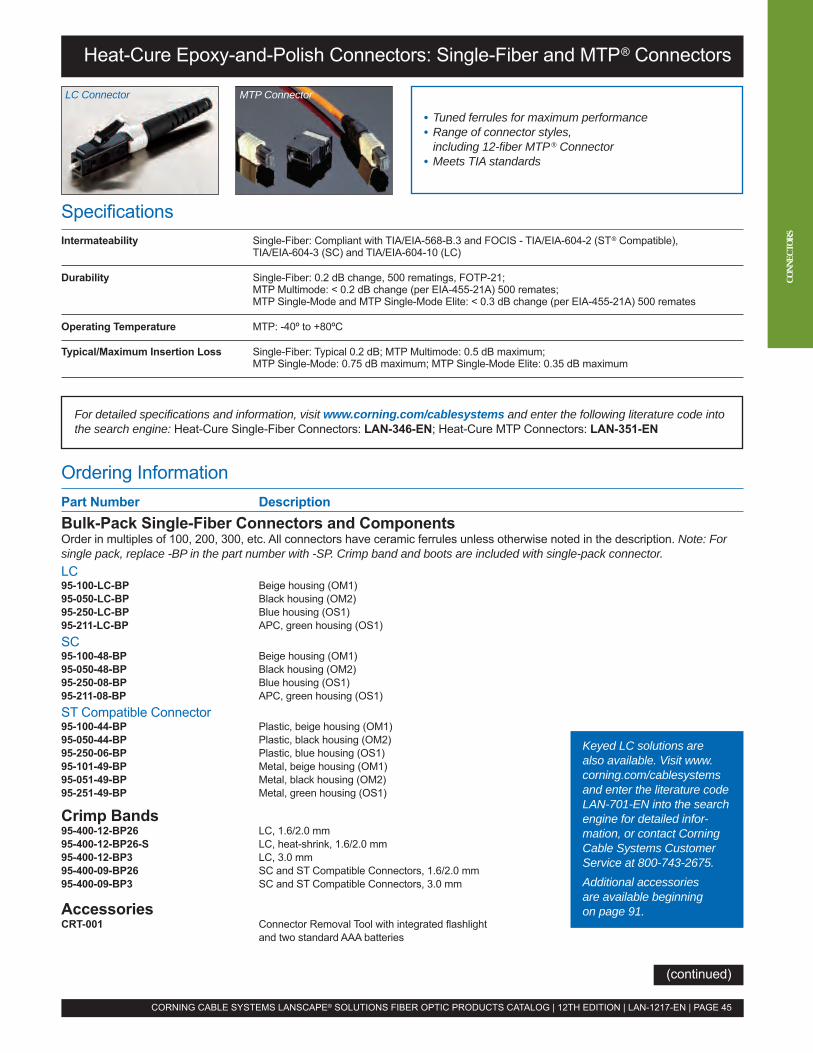
Ordering InformationPart Number DescriptionBulk-Pack Single-Fiber Connectors and ComponentsOrder in multiples of 100, 200, 300, etc. All connectors have ceramic ferrules unless otherwise noted in the description. Note: Forsingle pack, replace -BP in the part number with -SP. Crimp band and boots are included with single-pack connector.LC95-100-LC-BP Beige housing (OM1)95-050-LC-BP Black housing (OM2)95-250-LC-BP Blue housing (OS1)95-211-LC-BP APC, green housing (OS1)SC95-100-48-BP Beige housing (OM1)95-050-48-BP Black housing (OM2)95-250-08-BP Blue housing (OS1)95-211-08-BP APC, green housing (OS1)ST Compatible Connector95-100-44-BP Plastic, beige housing (OM1)95-050-44-BP Plastic, black housing (OM2)95-250-06-BP Plastic, blue housing (OS1)95-101-49-BP Metal, beige housing (OM1)95-051-49-BP Metal, black housing (OM2)95-251-49-BP Metal, green housing (OS1)
Crimp Bands95-400-12-BP26 LC, 1.6/2.0 mm95-400-12-BP26-S LC, heat-shrink, 1.6/2.0 mm95-400-12-BP3 LC, 3.0 mm95-400-09-BP26 SC and ST Compatible Connectors, 1.6/2.0 mm95-400-09-BP3 SC and ST Compatible Connectors, 3.0 mm
AccessoriesCRT-001 Connector Removal Tool with integrated flashlight
and two standard AAA batteries
For detailed specifications and information, visit www.corning.com/cablesystems and enter the following literature code intothe search engine: Heat-Cure Single-Fiber Connectors: LAN-346-EN; Heat-Cure MTP Connectors: LAN-351-EN
SpecificationsIntermateability Single-Fiber: Compliant with TIA/EIA-568-B.3 and FOCIS - TIA/EIA-604-2 (ST® Compatible),
TIA/EIA-604-3 (SC) and TIA/EIA-604-10 (LC)
Durability Single-Fiber: 0.2 dB change, 500 rematings, FOTP-21;MTP Multimode: < 0.2 dB change (per EIA-455-21A) 500 remates;MTP Single-Mode and MTP Single-Mode Elite: < 0.3 dB change (per EIA-455-21A) 500 remates
Operating Temperature MTP: -40º to +80ºC
Typical/Maximum Insertion Loss Single-Fiber: Typical 0.2 dB; MTP Multimode: 0.5 dB maximum;MTP Single-Mode: 0.75 dB maximum; MTP Single-Mode Elite: 0.35 dB maximum
Heat-Cure Epoxy-and-Polish Connectors: Single-Fiber and MTP® Connectors
• Tuned ferrules for maximum performance• Range of connector styles,including 12-fiber MTP® Connector
• Meets TIA standards
CORNING CABLE SYSTEMS LANSCAPE® SOLUTIONS FIBER OPTIC PRODUCTS CATALOG | 12TH EDITION | LAN-1217-EN | PAGE 45
CONN
ECTO
RS
MTP ConnectorLC Connector
(continued)
Keyed LC solutions arealso available. Visit www.corning.com/cablesystemsand enter the literature codeLAN-701-EN into the searchengine for detailed infor-mation, or contact CorningCable Systems CustomerService at 800-743-2675.Additional accessoriesare available beginningon page 91.
CONN
ECTO
RS
Heat-Cure Epoxy-and-Polish Connectors: Single-Fiber and MTP® Connectors
Ordering Information (continued)
BootsOrder in multiples of 100, 200, 300, etc. Note: For single pack, replace -BP in the part number with -SP. Crimp band and boots areincluded with single-pack connector.3 mm Part Number 2 mm Part Number 900 µm Part Number ColorLC95-400-11-BP3A 95-400-11-BP2A-S 95-400-11-BP9A Aqua95-400-11-BP3C 95-400-11-BP2C-S 95-400-11-BP9C Gray95-400-11-BP3Y 95-400-11-BP2Y-S 95-400-11-BP9Y Yellow95-400-11-BP3G 95-400-11-BP2G-S 95-400-11-BP9G Green95-400-11-BP3R 95-400-11-BP2R-S 95-400-11-BP9R Red95-400-11-BP3W 95-400-11-BP2W-S 95-400-11-BP9W White95-400-11-BP3N 95-400-11-BP2N-S 95-400-11-BP9N Blue95-400-11-BP3B 95-400-11-BP2B-S 95-400-11-BP9B Black95-400-11-BP3K 95-400-11-BP2K-S 95-400-11-BP9K BeigeSC95-400-31-BP3A 95-400-31-BP2A 95-400-08-BP9A Aqua95-400-31-BP3C 95-400-31-BP2C 95-400-08-BP9C Gray95-400-31-BP3Y 95-400-31-BP2Y 95-400-08-BP9Y Yellow95-400-31-BP3G 95-400-31-BP2G 95-400-08-BP9G Green95-400-31-BP3R 95-400-31-BP2R 95-400-08-BP9R Red95-400-31-BP3W 95-400-31-BP2W 95-400-08-BP9W White95-400-31-BP3N 95-400-31-BP2N 95-400-08-BP9N Blue95-400-31-BP3B 95-400-31-BP2B 95-400-08-BP9B Black95-400-31-BP3K 95-400-31-BP2K 95-400-08-BP9K BeigeST® Compatible Connector95-400-32-BP3A 95-400-32-BP2A 95-400-08-BP9A Aqua95-400-32-BP3C 95-400-32-BP2C 95-400-08-BP9C Gray95-400-32-BP3Y 95-400-32-BP2Y 95-400-08-BP9Y Yellow95-400-32-BP3G 95-400-32-BP2G 95-400-08-BP9G Green95-400-32-BP3R 95-400-32-BP2R 95-400-08-BP9R Red95-400-32-BP3W 95-400-32-BP2W 95-400-08-BP9W White95-400-32-BP3N 95-400-32-BP2N 95-400-08-BP9N Blue95-400-32-BP3B 95-400-32-BP2B 95-400-08-BP9B Black95-400-32-BP3K 95-400-32-BP2K 95-400-08-BP9K Beige
MTP® Connector FerrulesOrder in multiples of 100, 200, 300, etc.Part Number Description94-112-MM-MTBP MT 12-Fiber Multimode Ferrule94-212-SM-MTBP MT 12-Fiber Single-Mode Ferrule94-252-SME-MTBP MT 12-Fiber Single-Mode Elite™ Ferrule
MTP Connector Housing KitsKits include required boot, spring push, spring, pin, pin clamp assembly, MTP Connector housing assembly and dust cap.Order in multiples of 50 (50, 100, 150, etc.). Note: For 12-fiber MIC® 250 Cable solutions, use 12-fiber MIC 250 Interconnect Cable.MM = multimode; SM = single-mode.Ribbon Interconnect MIC 250 CableCable (Oval Strain-Relief) / Bare Ribbon / (Round Strain-Relief) /Jacketed Cable Boot Bare Ribbon Boot MIC 250 Cable BootPart Number Part Number Part Number DescriptionNon-Pinned94-115-20-BPJB 94-115-30-BPRB 94-115-40-BPDC MM, MTP Connector, beige kit94-115-21-BPJB 94-115-31-BPRB 94-115-41-BPDC MM, MTP Connector, black kit94-115-28-BPJB 94-115-38-BPRB 94-115-48-BPDC MM, MTP Connector, aqua kit94-115-22-BPJB 94-115-32-BPRB 94-115-42-BPDC SM, MTP Connector, green kit94-115-23-BPJB 94-115-33-BPRB 94-115-43-BPDC SM, MTP Elite Connector, mustard kitPinned94-115-24-BPJB 94-115-34-BPRB 94-115-44-BPDC MM, MTP Connector, beige kit94-115-25-BPJB 94-115-35-BPRB 94-115-45-BPDC MM, MTP Connector, black kit94-115-29-BPJB 94-115-39-BPRB 94-115-49-BPDC MM, MTP Connector, aqua kit94-115-26-BPJB 94-115-36-BPRB 94-115-46-BPDC SM, MTP Connector, green kit94-115-27-BPJB 94-115-37-BPRB 94-115-47-BPDC SM, MTP Elite Connector, mustard kit
CORNING CABLE SYSTEMS LANSCAPE® SOLUTIONS FIBER OPTIC PRODUCTS CATALOG | 12TH EDITION | LAN-1217-EN | PAGE 46
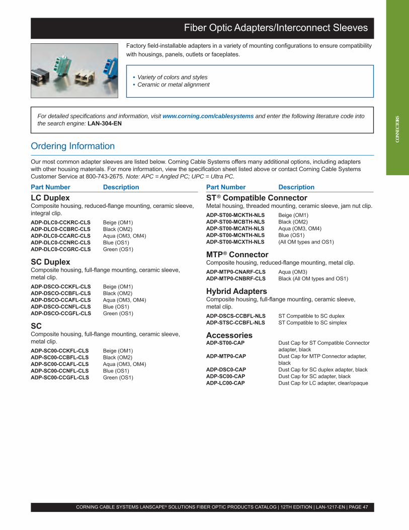
Part Number DescriptionLC DuplexComposite housing, reduced-flange mounting, ceramic sleeve,integral clip.ADP-DLC0-CCKRC-CLS Beige (OM1)ADP-DLC0-CCBRC-CLS Black (OM2)ADP-DLC0-CCARC-CLS Aqua (OM3, OM4)ADP-DLC0-CCNRC-CLS Blue (OS1)ADP-DLC0-CCGRC-CLS Green (OS1)
SC DuplexComposite housing, full-flange mounting, ceramic sleeve,metal clip.ADP-DSCO-CCKFL-CLS Beige (OM1)ADP-DSCO-CCBFL-CLS Black (OM2)ADP-DSCO-CCAFL-CLS Aqua (OM3, OM4)ADP-DSCO-CCNFL-CLS Blue (OS1)ADP-DSCO-CCGFL-CLS Green (OS1)
SCComposite housing, full-flange mounting, ceramic sleeve,metal clip.ADP-SC00-CCKFL-CLS Beige (OM1)ADP-SC00-CCBFL-CLS Black (OM2)ADP-SC00-CCAFL-CLS Aqua (OM3, OM4)ADP-SC00-CCNFL-CLS Blue (OS1)ADP-SC00-CCGFL-CLS Green (OS1)
Part Number DescriptionST® Compatible ConnectorMetal housing, threaded mounting, ceramic sleeve, jam nut clip.ADP-ST00-MCKTH-NLS Beige (OM1)ADP-ST00-MCBTH-NLS Black (OM2)ADP-ST00-MCATH-NLS Aqua (OM3, OM4)ADP-ST00-MCNTH-NLS Blue (OS1)ADP-ST00-MCXTH-NLS (All OM types and OS1)
MTP® ConnectorComposite housing, reduced-flange mounting, metal clip.ADP-MTP0-CNARF-CLS Aqua (OM3)ADP-MTP0-CNBRF-CLS Black (All OM types and OS1)
Hybrid AdaptersComposite housing, full-flange mounting, ceramic sleeve,metal clip.ADP-DSCS-CCBFL-NLS ST Compatible to SC duplexADP-STSC-CCBFL-NLS ST Compatible to SC simplex
AccessoriesADP-ST00-CAP Dust Cap for ST Compatible Connector
adapter, blackADP-MTP0-CAP Dust Cap for MTP Connector adapter,
blackADP-DSC0-CAP Dust Cap for SC duplex adapter, blackADP-SC00-CAP Dust Cap for SC adapter, blackADP-LC00-CAP Dust Cap for LC adapter, clear/opaque
Fiber Optic Adapters/Interconnect Sleeves
Ordering InformationOur most common adapter sleeves are listed below. Corning Cable Systems offers many additional options, including adapterswith other housing materials. For more information, view the specification sheet listed above or contact Corning Cable SystemsCustomer Service at 800-743-2675. Note: APC = Angled PC; UPC = Ultra PC.
• Variety of colors and styles• Ceramic or metal alignment
For detailed specifications and information, visit www.corning.com/cablesystems and enter the following literature code intothe search engine: LAN-304-EN
CORNING CABLE SYSTEMS LANSCAPE® SOLUTIONS FIBER OPTIC PRODUCTS CATALOG | 12TH EDITION | LAN-1217-EN | PAGE 47
CONN
ECTO
RS
Factory field-installable adapters in a variety of mounting configurations to ensure compatibilitywith housings, panels, outlets or faceplates.
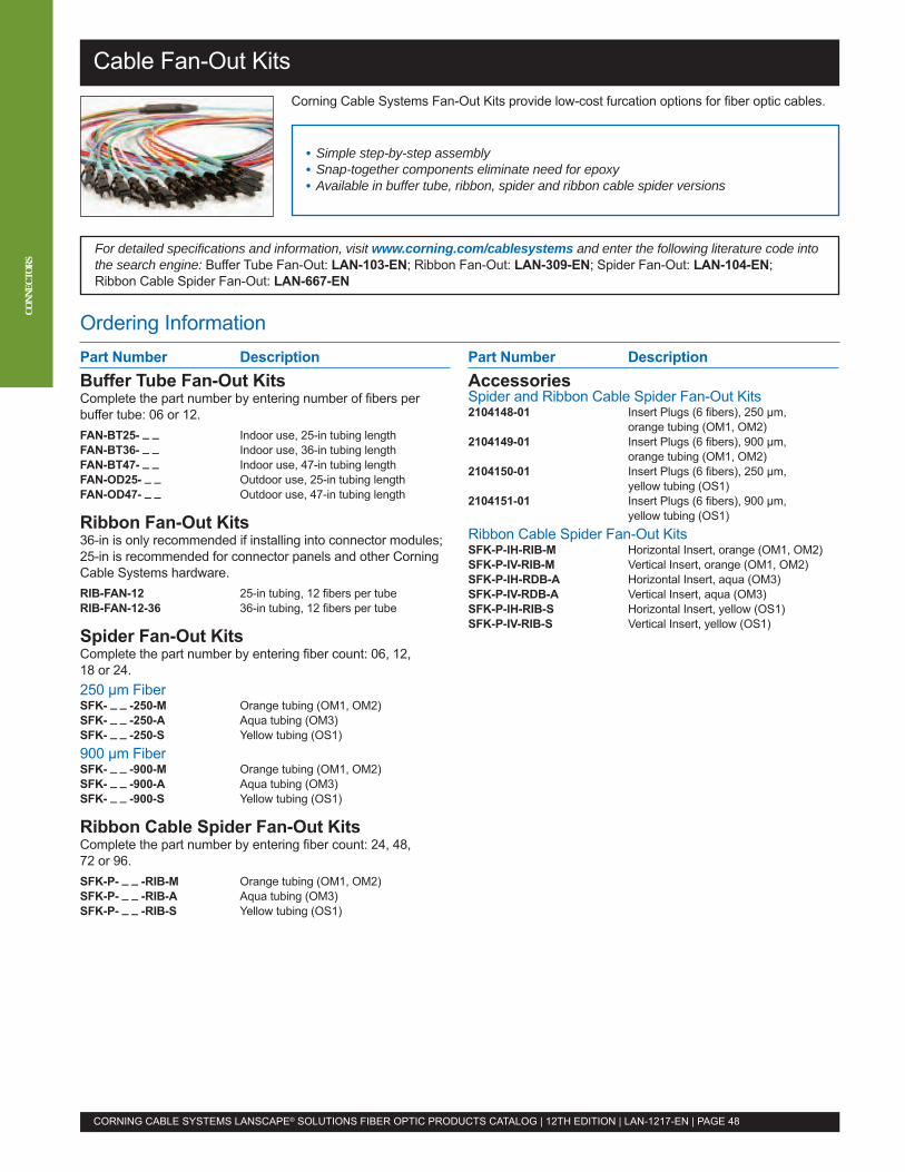
Ordering Information
For detailed specifications and information, visit www.corning.com/cablesystems and enter the following literature code intothe search engine: Buffer Tube Fan-Out: LAN-103-EN; Ribbon Fan-Out: LAN-309-EN; Spider Fan-Out: LAN-104-EN;Ribbon Cable Spider Fan-Out: LAN-667-EN
Cable Fan-Out Kits
CORNING CABLE SYSTEMS LANSCAPE® SOLUTIONS FIBER OPTIC PRODUCTS CATALOG | 12TH EDITION | LAN-1217-EN | PAGE 48
CONN
ECTO
RS
Part Number DescriptionBuffer Tube Fan-Out KitsComplete the part number by entering number of fibers perbuffer tube: 06 or 12.FAN-BT25- _ _ Indoor use, 25-in tubing lengthFAN-BT36- _ _ Indoor use, 36-in tubing lengthFAN-BT47- _ _ Indoor use, 47-in tubing lengthFAN-OD25- _ _ Outdoor use, 25-in tubing lengthFAN-OD47- _ _ Outdoor use, 47-in tubing length
Ribbon Fan-Out Kits36-in is only recommended if installing into connector modules;25-in is recommended for connector panels and other CorningCable Systems hardware.RIB-FAN-12 25-in tubing, 12 fibers per tubeRIB-FAN-12-36 36-in tubing, 12 fibers per tube
Spider Fan-Out KitsComplete the part number by entering fiber count: 06, 12,18 or 24.250 µm FiberSFK- _ _ -250-M Orange tubing (OM1, OM2)SFK- _ _ -250-A Aqua tubing (OM3)SFK- _ _ -250-S Yellow tubing (OS1)900 µm FiberSFK- _ _ -900-M Orange tubing (OM1, OM2)SFK- _ _ -900-A Aqua tubing (OM3)SFK- _ _ -900-S Yellow tubing (OS1)
Ribbon Cable Spider Fan-Out KitsComplete the part number by entering fiber count: 24, 48,72 or 96.SFK-P- _ _ -RIB-M Orange tubing (OM1, OM2)SFK-P- _ _ -RIB-A Aqua tubing (OM3)SFK-P- _ _ -RIB-S Yellow tubing (OS1)
Part Number DescriptionAccessoriesSpider and Ribbon Cable Spider Fan-Out Kits2104148-01 Insert Plugs (6 fibers), 250 µm,
orange tubing (OM1, OM2)2104149-01 Insert Plugs (6 fibers), 900 µm,
orange tubing (OM1, OM2)2104150-01 Insert Plugs (6 fibers), 250 µm,
yellow tubing (OS1)2104151-01 Insert Plugs (6 fibers), 900 µm,
yellow tubing (OS1)Ribbon Cable Spider Fan-Out KitsSFK-P-IH-RIB-M Horizontal Insert, orange (OM1, OM2)SFK-P-IV-RIB-M Vertical Insert, orange (OM1, OM2)SFK-P-IH-RDB-A Horizontal Insert, aqua (OM3)SFK-P-IV-RDB-A Vertical Insert, aqua (OM3)SFK-P-IH-RIB-S Horizontal Insert, yellow (OS1)SFK-P-IV-RIB-S Vertical Insert, yellow (OS1)
• Simple step-by-step assembly• Snap-together components eliminate need for epoxy• Available in buffer tube, ribbon, spider and ribbon cable spider versions
Corning Cable Systems Fan-Out Kits provide low-cost furcation options for fiber optic cables.
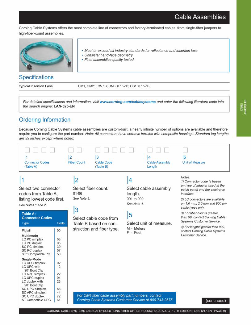
|1Select two connectorcodes from Table A,listing lowest code first.See Notes 1 and 2.
For detailed specifications and information, visit www.corning.com/cablesystems and enter the following literature code intothe search engine: LAN-525-EN
(continued)
Cable Assemblies
Ordering InformationBecause Corning Cable Systems cable assemblies are custom-built, a nearly infinite number of options are available and thereforerequire you to configure the part number. Note: All connectors have ceramic ferrules with composite housings. Standard leg lengthsare 39 inches except where noted.
• Meet or exceed all industry standards for reflectance and insertion loss• Consistent end-face geometry• Final assemblies quality tested
CORNING CABLE SYSTEMS LANSCAPE® SOLUTIONS FIBER OPTIC PRODUCTS CATALOG | 12TH EDITION | LAN-1217-EN | PAGE 49
CABL
EAS
SEMB
LIES
Corning Cable Systems offers the most complete line of connectors and factory-terminated cables, from single-fiber jumpers tohigh-fiber-count assemblies.
�� �� �� �� �� �� �� �� �� �� �� �� �� �� ��
|2Select fiber count.01-96See Note 3.
|1Connector Codes(Table A)
|2Fiber Count
|3Cable Code(Table B)
|4Cable AssemblyLength
|5Unit of Measure
Notes: 1) Connector code is based on type of adapter used at the patch panel and the electronicinterface.
2) LC connectors are available on 1.6 mm, 2.0 mm and 900 µmcable types only.
3) For fiber counts greater than 96, contact Corning Cable Systems Customer Service.
4) For lengths greater than 999,contact Corning Cable SystemsCustomer Service.
|3Select cable code fromTable B based on con-struction and fiber type.
|4Select cable assemblylength. 001 to 999See Note 4.
|5Select unit of measure.M = MetersF = Feet
SpecificationsTypical Insertion Loss OM1, OM2: 0.35 dB; OM3: 0.15 dB; OS1: 0.15 dB
For OM4 fiber cable assembly part numbers, contactCorning Cable Systems Customer Service at 800-743-2675.
Table A:Connector CodesType Code
Pigtail 00MultimodeLC PC simplex 03LC PC duplex 05SC PC simplex 39SC PC duplex 57ST® Compatible PC 50Single-ModeLC UPC simplex 02LC UPC with 12
90º Boot ClipLC APC simplex 22LC UPC duplex 04LC duplex with 23
90º Boot ClipSC UPC simplex 58SC APC simplex 44SC UPC duplex 72ST Compatible UPC 61
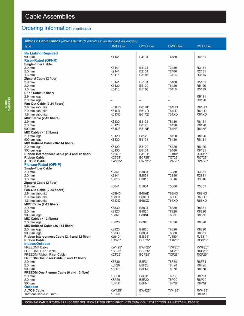
CABL
EAS
SEMB
LIES
Table B: Cable Codes (Note: Asterisk (*) indicates 25-in standard leg lengths.) Type OM1 Fiber OM2 Fiber OM3 Fiber OS1 Fiber
No Listing Required900 µm K4141 B4131 T4180 R4131Riser-Rated (OFNR)Single-Fiber Cable2.9 mm K3141 B3131 T3180 R31312.0 mm K2141 B2131 T2180 R21311.6 mm K3116 B3116 T3116 R3116Zipcord Cable (2 fiber)2.9 mm K5141 B5131 T5180 R51312.0 mm K5120 B5120 T5120 R51201.6 mm K5116 B5116 T5116 R5116DFX® Cable (2 fiber)2.9 mm legs – – – R91312.0 mm legs – – – R9120Fan-Out Cable (2-24 fibers)2.9 mm subunits K61HD B61HD T61HD R61HD2.0 mm subunits K61LD B61LD T61LD R61LD1.6 mm subunits K61XD B61XD T61XD R61XDMIC® Cable (2-12 fibers)2.9 mm K8130 B8131 T8180 R81312.0 mm K8120 B8120 T8120 R8120900 µm K81NF B81NF T81NF R81NFMIC Cable (> 12 fibers)2.0 mm legs K8120 B8120 T8120 R8120900 µm legs K8130 B8131 T8180 R8131MIC Unitized Cable (36-144 fibers)2.0 mm legs K8120 B8120 T8120 R8120900 µm legs K8130 B8131 T8180 R8131Ribbon Interconnect Cable (2, 4 and 12 fiber) KJ140* BJ131* TJ180* RJ131*Ribbon Cable KC725* BC725* TC725* RC725*ALTOS® Cable KW725* BW725* TW725* RW725*Plenum-Rated (OFNP)Single-Fiber Cable2.9 mm K3841 B3831 T3880 R38312.0 mm K2841 B2831 T2880 R28311.6 mm K3816 B3816 T3816 R3816Zipcord Cable (2 fiber)2.9 mm K5841 B5831 T5880 R5831Fan-Out Cable (2-24 fibers)2.9 mm subunits K68HD B68HD T68HD R68HD2.0 mm subunits K68LD B68LD T68LD R68LD1.6 mm subunits K68XD B68XD T68XD R68XDMIC® Cable (2-12 fibers)2.9 mm K8830 B8831 T8880 R88312.0 mm K8820 B8820 T8820 R8820900 µm legs K88NF B88NF T88NF R88NFMIC Cable (> 12 fibers)2.0 mm legs K8820 B8820 T8820 R8820MIC Unitized Cable (36-144 fibers)2.0 mm legs K8820 B8820 T8820 R8820900 µm legs K8830 B8831 T8880 R8831Ribbon Interconnect Cable (2, 4 and 12 fiber) KJ840* BJ831* TJ880* RJ831*Ribbon Cable KC825* BC825* TC825* RC825*Indoor/OutdoorFREEDM® Cable KWF25* BWF25* TWF25* RWF25*FREEDM LST™ Cable KSF25* BSF25* TSF25* RSF25*FREEDM Ribbon Riser Cable KCF25* BCF25* TCF25* RCF25*FREEDM One Riser Cable (6 and 12 fiber)2.9 mm K8F30 B8F31 T8F80 R8F312.0 mm K8F20 B8F20 T8F20 R8F20900 µm K8FNF B8FNF T8FNF R8FNFFREEDM One Plenum Cable (6 and 12 fiber)2.9 mm K8P30 B8P31 T8P80 R8P312.0 mm K8P20 B8P20 T8P20 R8P20900 µm K8PNF B8PNF T8PNF R8PNFOutdoorALTOS Cable KW425* BW425* TW425* RW425*Tactical Cable 2.0 mm K8U20 – – H8U20
Cable Assemblies
CORNING CABLE SYSTEMS LANSCAPE® SOLUTIONS FIBER OPTIC PRODUCTS CATALOG | 12TH EDITION | LAN-1217-EN | PAGE 50
Ordering Information (continued)

Pretium® Connector Housings (PCH)
Ordering InformationPretium Connector Housings ship complete with blank panels and hardware to strain-relieve one cable with the universal cableclamp (UCC). The Pretium 3-Module Housing includes cable strain-relief via the RJ-clip integration piece.Part Number DescriptionPCH-01U 1U Pretium Connector Housing; accepts up to 2 CCH panelsPCH-02U 2U Pretium Connector Housing; accepts up to 4 CCH panelsPCH-04U 4U Pretium Connector Housing; accepts up to 12 CCH panelsPCH-M3-01U 1U Pretium Connector Housing; accepts up to 3 reduced-depth
CCH-style Plug & Play Universal Systems modules
AccessoriesPC1-BKT-23 PCH-01U Mounting Brackets for 23-in frames/cabinets (1 set)PC1-STRN PCH-01U Strain-Relief Bracket; accepts up to 2 UCC kits (UCC-001)PC2-STRN PCH-02U Strain-Relief Bracket; accepts up to 2 UCC kits (UCC-001)PC4-STRN PCH-04U Strain-Relief Bracket; accepts up to 2 UCC kits (UCC-001)UCC-001 Universal Cable Clamp Strain-Relief Kit for use with PC1-STRN or PC4-STRNCJP-01U-P Pretium 1U Jumper Management Panel; provides jumper management in a 1.75-in rack spaceCJP-02U-P Pretium 2U Jumper Management Panel; provides jumper management in a 3.5-in rack spaceHDWR-LOCK-KIT Lock Kit for front and/or back door(s) of the PCH-04U housing; contains 1 lock with 2 keysPC1-LOCK-KIT Lock Kit for front and/or back door(s) of the PCH-01U housing; contains 1 lock with 2 keys
SpecificationsPart Number Dimensions (H x W x D): cm (in) Shipping Weight: kg (lb)
PCH-01U 4 x 43 x 41 (1.75 x 17 x 16) 5 (11)
PCH-02U 9 x 43 x 42 (3.5 x 17 x 16.5) 5.7 (12.6)
PCH-04U 18 x 43 x 41 (7 x 17 x 16) 7.5 (16.5)
PCH-M3-01U 4.5 x 42.5 x 33 (1.75 x 16.8 x 12.75) 3.85 (8.5)
• Compatible with Plug & Play™ Systems modules• Splice in the housing, saving rack space and the cost of additional housing• Housings have a removable latching top (01U and 02U) or forward sliding tray(PCH-M3-01U) for ease of access
• 1U = One industry-standard rack space of 1.75 in
For detailed specifications and information, visit www.corning.com/cablesystems and enter the following literature code intothe search engine: LAN-538-EN; Pretium® 3-Module Housing: LAN-727-EN
CORNING CABLE SYSTEMS LANSCAPE® SOLUTIONS FIBER OPTIC PRODUCTS CATALOG | 12TH EDITION | LAN-1217-EN | PAGE 51
HARD
WAR
EAdditional accessories may be available. View the detailed specifications and information documents referenced above.
To order Plug & Play Universal Systems modules for your PCH, see page 10. To order CCH panels, see page 54.
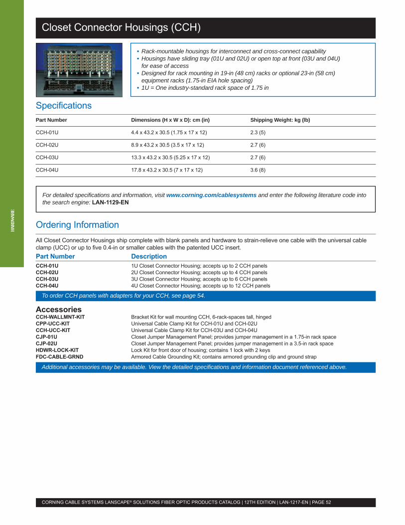
Closet Connector Housings (CCH)
Ordering InformationAll Closet Connector Housings ship complete with blank panels and hardware to strain-relieve one cable with the universal cableclamp (UCC) or up to five 0.4-in or smaller cables with the patented UCC insert.Part Number DescriptionCCH-01U 1U Closet Connector Housing; accepts up to 2 CCH panelsCCH-02U 2U Closet Connector Housing; accepts up to 4 CCH panelsCCH-03U 3U Closet Connector Housing; accepts up to 6 CCH panelsCCH-04U 4U Closet Connector Housing; accepts up to 12 CCH panels
AccessoriesCCH-WALLMNT-KIT Bracket Kit for wall mounting CCH, 6-rack-spaces tall, hingedCPP-UCC-KIT Universal Cable Clamp Kit for CCH-01U and CCH-02UCCH-UCC-KIT Universal Cable Clamp Kit for CCH-03U and CCH-04UCJP-01U Closet Jumper Management Panel; provides jumper management in a 1.75-in rack spaceCJP-02U Closet Jumper Management Panel; provides jumper management in a 3.5-in rack spaceHDWR-LOCK-KIT Lock Kit for front door of housing; contains 1 lock with 2 keysFDC-CABLE-GRND Armored Cable Grounding Kit; contains armored grounding clip and ground strap
SpecificationsPart Number Dimensions (H x W x D): cm (in) Shipping Weight: kg (lb)
CCH-01U 4.4 x 43.2 x 30.5 (1.75 x 17 x 12) 2.3 (5)
CCH-02U 8.9 x 43.2 x 30.5 (3.5 x 17 x 12) 2.7 (6)
CCH-03U 13.3 x 43.2 x 30.5 (5.25 x 17 x 12) 2.7 (6)
CCH-04U 17.8 x 43.2 x 30.5 (7 x 17 x 12) 3.6 (8)
• Rack-mountable housings for interconnect and cross-connect capability• Housings have sliding tray (01U and 02U) or open top at front (03U and 04U)for ease of access
• Designed for rack mounting in 19-in (48 cm) racks or optional 23-in (58 cm)equipment racks (1.75-in EIA hole spacing)
• 1U = One industry-standard rack space of 1.75 in
For detailed specifications and information, visit www.corning.com/cablesystems and enter the following literature code intothe search engine: LAN-1129-EN
CORNING CABLE SYSTEMS LANSCAPE® SOLUTIONS FIBER OPTIC PRODUCTS CATALOG | 12TH EDITION | LAN-1217-EN | PAGE 52
HARD
WAR
E
To order CCH panels with adapters for your CCH, see page 54.
Additional accessories may be available. View the detailed specifications and information document referenced above.
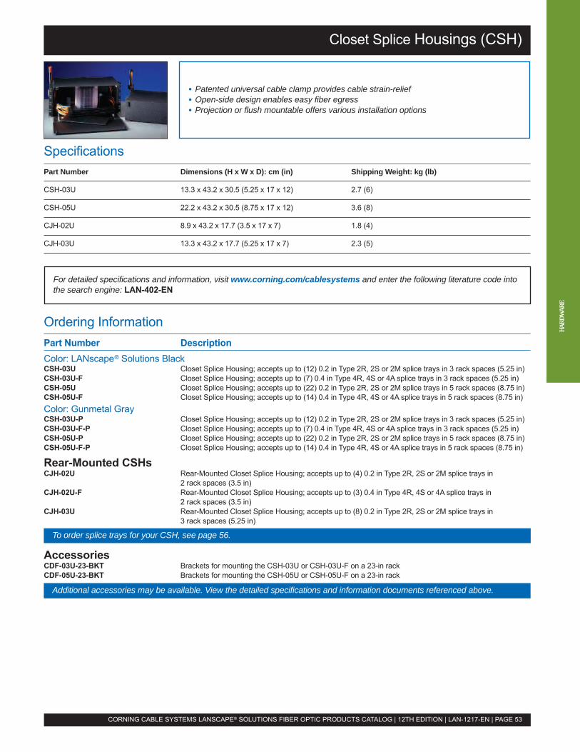
Closet Splice Housings (CSH)
Ordering InformationPart Number DescriptionColor: LANscape® Solutions BlackCSH-03U Closet Splice Housing; accepts up to (12) 0.2 in Type 2R, 2S or 2M splice trays in 3 rack spaces (5.25 in)CSH-03U-F Closet Splice Housing; accepts up to (7) 0.4 in Type 4R, 4S or 4A splice trays in 3 rack spaces (5.25 in)CSH-05U Closet Splice Housing; accepts up to (22) 0.2 in Type 2R, 2S or 2M splice trays in 5 rack spaces (8.75 in)CSH-05U-F Closet Splice Housing; accepts up to (14) 0.4 in Type 4R, 4S or 4A splice trays in 5 rack spaces (8.75 in)Color: Gunmetal GrayCSH-03U-P Closet Splice Housing; accepts up to (12) 0.2 in Type 2R, 2S or 2M splice trays in 3 rack spaces (5.25 in)CSH-03U-F-P Closet Splice Housing; accepts up to (7) 0.4 in Type 4R, 4S or 4A splice trays in 3 rack spaces (5.25 in)CSH-05U-P Closet Splice Housing; accepts up to (22) 0.2 in Type 2R, 2S or 2M splice trays in 5 rack spaces (8.75 in)CSH-05U-F-P Closet Splice Housing; accepts up to (14) 0.4 in Type 4R, 4S or 4A splice trays in 5 rack spaces (8.75 in)
Rear-Mounted CSHsCJH-02U Rear-Mounted Closet Splice Housing; accepts up to (4) 0.2 in Type 2R, 2S or 2M splice trays in
2 rack spaces (3.5 in)CJH-02U-F Rear-Mounted Closet Splice Housing; accepts up to (3) 0.4 in Type 4R, 4S or 4A splice trays in
2 rack spaces (3.5 in)CJH-03U Rear-Mounted Closet Splice Housing; accepts up to (8) 0.2 in Type 2R, 2S or 2M splice trays in
3 rack spaces (5.25 in)
AccessoriesCDF-03U-23-BKT Brackets for mounting the CSH-03U or CSH-03U-F on a 23-in rackCDF-05U-23-BKT Brackets for mounting the CSH-05U or CSH-05U-F on a 23-in rack
SpecificationsPart Number Dimensions (H x W x D): cm (in) Shipping Weight: kg (lb)
CSH-03U 13.3 x 43.2 x 30.5 (5.25 x 17 x 12) 2.7 (6)
CSH-05U 22.2 x 43.2 x 30.5 (8.75 x 17 x 12) 3.6 (8)
CJH-02U 8.9 x 43.2 x 17.7 (3.5 x 17 x 7) 1.8 (4)
CJH-03U 13.3 x 43.2 x 17.7 (5.25 x 17 x 7) 2.3 (5)
• Patented universal cable clamp provides cable strain-relief• Open-side design enables easy fiber egress• Projection or flush mountable offers various installation options
For detailed specifications and information, visit www.corning.com/cablesystems and enter the following literature code intothe search engine: LAN-402-EN
CORNING CABLE SYSTEMS LANSCAPE® SOLUTIONS FIBER OPTIC PRODUCTS CATALOG | 12TH EDITION | LAN-1217-EN | PAGE 53
To order splice trays for your CSH, see page 56.
HARD
WAR
E
Additional accessories may be available. View the detailed specifications and information documents referenced above.
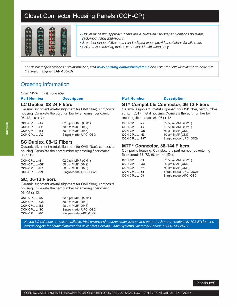
Ordering InformationNote: MMF = multimode fiber.
For detailed specifications and information, visit www.corning.com/cablesystems and enter the following literature code intothe search engine: LAN-133-EN
Closet Connector Housing Panels (CCH-CP)
• Universal design approach offers one-size-fits-all LANscape® Solutions housings,rack-mount and wall-mount
• Broadest range of fiber count and adapter types provides solutions for all needs• Colored icon labeling makes connector identification easy
CORNING CABLE SYSTEMS LANSCAPE® SOLUTIONS FIBER OPTIC PRODUCTS CATALOG | 12TH EDITION | LAN-1217-EN | PAGE 54
HARD
WAR
E
Part Number DescriptionLC Duplex, 08-24 FibersCeramic alignment (metal alignment for OM1 fiber), compositehousing. Complete the part number by entering fiber count:08, 12, 16 or 24.CCH-CP _ _ -A7 62.5 µm MMF (OM1)CCH-CP _ _ -D3 50 µm MMF (OM2)CCH-CP _ _ -E4 50 µm MMF (OM3)CCH-CP _ _ -A9 Single-mode, UPC (OS2)
SC Duplex, 08-12 FibersCeramic alignment (metal alignment for OM1 fiber), compositehousing. Complete the part number by entering fiber count:08 or 12.CCH-CP _ _ -91 62.5 µm MMF (OM1)CCH-CP _ _ -G7 50 µm MMF (OM2)CCH-CP _ _ -E7 50 µm MMF (OM3)CCH-CP _ _ -59 Single-mode, UPC (OS2)
SC, 06-12 FibersCeramic alignment (metal alignment for OM1 fiber), compositehousing. Complete the part number by entering fiber count:06, 08 or 12.CCH-CP _ _ -56 62.5 µm MMF (OM1)CCH-CP _ _ -G6 50 µm MMF (OM2)CCH-CP _ _ -E6 50 µm MMF (OM3)CCH-CP _ _ -3C Single-mode, UPC (OS2)CCH-CP _ _ -6C Single-mode, APC (OS2)
Keyed LC solutions are also available. Visit www.corning.com/cablesystems and enter the literature code LAN-701-EN into thesearch engine for detailed information or contact Corning Cable Systems Customer Service at 800-743-2675.
Part Number DescriptionST® Compatible Connector, 06-12 FibersCeramic alignment (metal alignment for OM1 fiber, part numbersuffix = 25T), metal housing. Complete the part number byentering fiber count: 06, 08 or 12.CCH-CP _ _ -25T 62.5 µm MMF (OM1)CCH-CP _ _ -15T 62.5 µm MMF (OM1)CCH-CP _ _ -G5 50 µm MMF (OM2)CCH-CP _ _ -H3 50 µm MMF (OM3)CCH-CP _ _ -19T Single-mode, UPC (OS2)
MTP® Connector, 36-144 FibersComposite housing. Complete the part number by enteringfiber count: 36, 72, 96 or 144 (E4).CCH-CP _ _ -69 62.5 µm MMF (OM1)CCH-CP _ _ -G3 50 µm MMF (OM2)CCH-CP _ _ -E3 50 µm MMF (OM3)CCH-CP _ _ -89 Single-mode, UPC (OS2)CCH-CP _ _ -90 Single-mode, APC (OS2)
(continued)

Ordering Information (continued)
Note: MMF = multimode fiber.
Closet Connector Housing Panels (CCH-CP)
CORNING CABLE SYSTEMS LANSCAPE® SOLUTIONS FIBER OPTIC PRODUCTS CATALOG | 12TH EDITION | LAN-1217-EN | PAGE 55
Part Number DescriptionLC Duplex, 3 m Pigtail6-FiberCCH-CP06-A7-P03KH 62.5 µm MMF (OM1)CCH-CP06-D3-P03CH 50 µm MMF (OM2)CCH-CP06-E4-P03SH 50 µm MMF (OM3,OM4)CCH-CP06-A9-P03RH Single-mode (OS2)12-FiberCCH-CP12-A7-P03KH 62.5 µm MMF (OM1)CCH-CP12-D3-P03CH 50 µm MMF (OM2)CCH-CP12-E4-P03SH 50 µm MMF (OM3,OM4)CCH-CP12-A9-P03RH Single-mode (OS2)24-FiberCCH-CP24-A7-P03KH 62.5 µm MMF (OM1)CCH-CP24-D3-P03CH 50 µm MMF (OM2)CCH-CP24-E4-P03SH 50 µm MMF (OM3,OM4)CCH-CP24-A9-P03RH Single-mode (OS2)
SC Duplex, 3 m Pigtail6-FiberCCH-CP06-91-P03KH 62.5 µm MMF (OM1)CCH-CP06-G7-P03CH 50 µm MMF (OM2)CCH-CP06-E7-P03SH 50 µm MMF (OM3,OM4)CCH-CP06-59-P03RH Single-mode (OS2)12-FiberCCH-CP12-91-P03KH 62.5 µm MMF (OM1)CCH-CP12-G7-P03CH 50 µm MMF (OM2)CCH-CP12-E7-P03SH 50 µm MMF (OM3,OM4)CCH-CP12-59-P03RH Single-mode (OS2)
Part Number DescriptionST® Compatible Connector, 3 m Pigtail6-FiberCCH-CP06-25T-P03KH 62.5 µm MMF (OM1)CCH-CP06-G5-P03CH 50 µm MMF (OM2)CCH-CP06-H3-P03SH 50 µm MMF (OM3,OM4)CCH-CP06-19T-P03RH Single-mode (OS2)12-FiberCCH-CP12-25T-P03KH 62.5 µm MMF (OM1)CCH-CP12-G5-P03CH 50 µm MMF (OM2)CCH-CP12-H3-P03SH 50 µm MMF (OM3,OM4)CCH-CP12-19T-P03RH Single-mode (OS2)
Colored Icons50 per pack.Blank IconsICN-YLB Blank (Yellow)ICN-RDB Blank (Red)ICN-GRB Blank (Green)ICN-BLB Blank (Blue)ICN-WTB Blank (White)Etched IconsICN-BLP Phone (Blue)ICN-RDC Computer (Red)ICN-GRT Cable TV (Green)
AccessoriesCRT-001 Connector Removal Tool
with integrated flashlightand two standard AAA batteries
HARD
WAR
E
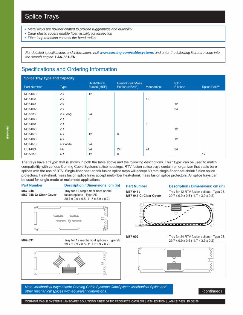
Splice Trays
• Metal trays are powder coated to provide ruggedness and durability• Clear plastic covers enable fiber visibility for inspection• Fiber loop retention controls the bend radius
For detailed specifications and information, visit www.corning.com/cablesystems and enter the following literature code intothe search engine: LAN-331-EN
CORNING CABLE SYSTEMS LANSCAPE® SOLUTIONS FIBER OPTIC PRODUCTS CATALOG | 12TH EDITION | LAN-1217-EN | PAGE 56
HARD
WAR
E
Part Number Description / Dimensions: cm (in)M67-048 / Tray for 12 single-fiber heat-shrinkM67-048-C: Clear Cover fusion splices - Type 2S
29.7 x 9.9 x 0.5 (11.7 x 3.9 x 0.2)
M67-031 Tray for 12 mechanical splices - Type 2S29.7 x 9.9 x 0.5 (11.7 x 3.9 x 0.2)
The trays have a “Type” that is shown in both the table above and the following descriptions. This “Type” can be used to matchcompatibility with various Corning Cable Systems splice housings. RTV fusion splice trays contain an organizer that seals baresplices with the use of RTV. Single-fiber heat-shrink fusion splice trays will accept 60 mm single-fiber heat-shrink fusion spliceprotectors. Heat-shrink mass fusion splice trays accept multi-fiber heat-shrink mass fusion splice protectors. All splice trays canbe used for single-mode or multimode applications.
Specifications and Ordering Information
Note: Mechanical trays accept Corning Cable Systems CamSplice™ Mechanical Splice andother mechanical splices with equivalent dimensions.
Part Number Description / Dimensions: cm (in)M67-041 / Tray for 12 RTV fusion splices - Type 2SM67-041-C: Clear Cover 29.7 x 9.9 x 0.5 (11.7 x 3.9 x 0.2)
M67-092 Tray for 24 RTV fusion splices - Type 2S29.7 x 9.9 x 0.5 (11.7 x 3.9 x 0.2)
(continued)
Splice Tray Type and CapacityHeat-Shrink Heat-Shrink Mass RTV
Part Number Type Fusion (HSF) Fusion (HSMF) Mechanical Silicone Splice Pak™
M67-048 2S 12M67-031 2S 12M67-041 2S 12M67-092 2S 24M67-112 2S Long 24M67-068 2R 6M67-061 2R 6M67-060 2R 12M67-076 4S 12 6M67-086 4S 12M67-078 4S Wide 24UST-024 4A 24 24 24 24M67-110 4R 12 6 12
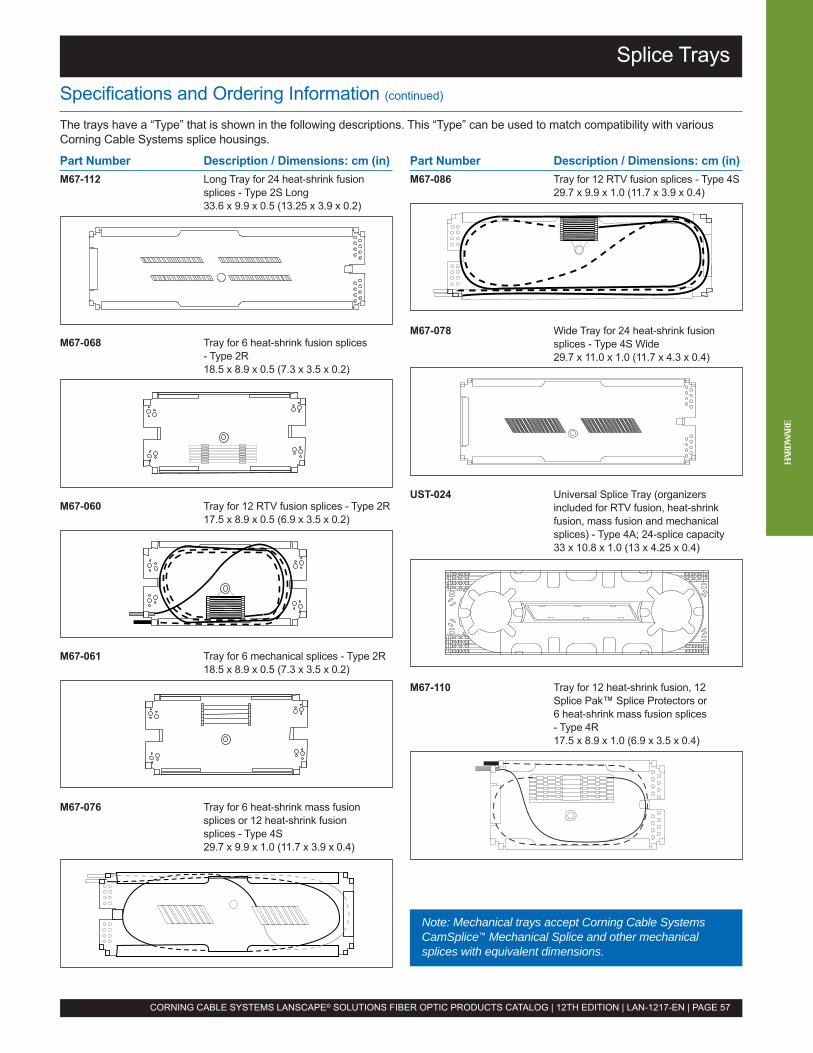
Splice Trays
CORNING CABLE SYSTEMS LANSCAPE® SOLUTIONS FIBER OPTIC PRODUCTS CATALOG | 12TH EDITION | LAN-1217-EN | PAGE 57
Part Number Description / Dimensions: cm (in)M67-112 Long Tray for 24 heat-shrink fusion
splices - Type 2S Long33.6 x 9.9 x 0.5 (13.25 x 3.9 x 0.2)
M67-068 Tray for 6 heat-shrink fusion splices- Type 2R18.5 x 8.9 x 0.5 (7.3 x 3.5 x 0.2)
Part Number Description / Dimensions: cm (in)M67-086 Tray for 12 RTV fusion splices - Type 4S
29.7 x 9.9 x 1.0 (11.7 x 3.9 x 0.4)
M67-078 Wide Tray for 24 heat-shrink fusionsplices - Type 4S Wide29.7 x 11.0 x 1.0 (11.7 x 4.3 x 0.4)
UST-024 Universal Splice Tray (organizersincluded for RTV fusion, heat-shrinkfusion, mass fusion and mechanicalsplices) - Type 4A; 24-splice capacity33 x 10.8 x 1.0 (13 x 4.25 x 0.4)
M67-110 Tray for 12 heat-shrink fusion, 12Splice Pak™ Splice Protectors or6 heat-shrink mass fusion splices- Type 4R17.5 x 8.9 x 1.0 (6.9 x 3.5 x 0.4)
M67-060 Tray for 12 RTV fusion splices - Type 2R17.5 x 8.9 x 0.5 (6.9 x 3.5 x 0.2)
M67-061 Tray for 6 mechanical splices - Type 2R18.5 x 8.9 x 0.5 (7.3 x 3.5 x 0.2)
M67-076 Tray for 6 heat-shrink mass fusionsplices or 12 heat-shrink fusionsplices - Type 4S29.7 x 9.9 x 1.0 (11.7 x 3.9 x 0.4)
Specifications and Ordering Information (continued)
The trays have a “Type” that is shown in the following descriptions. This “Type” can be used to match compatibility with variousCorning Cable Systems splice housings.
Note: Mechanical trays accept Corning Cable SystemsCamSplice™ Mechanical Splice and other mechanicalsplices with equivalent dimensions.
HARD
WAR
E
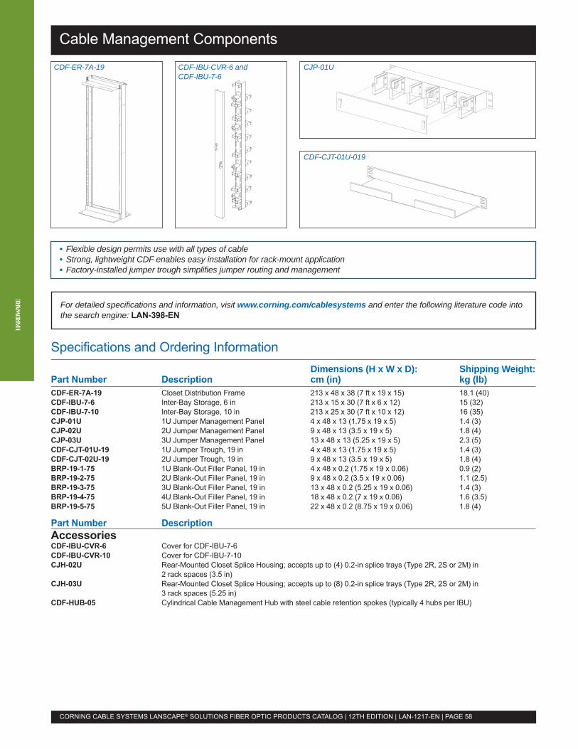
Cable Management Components
• Flexible design permits use with all types of cable• Strong, lightweight CDF enables easy installation for rack-mount application• Factory-installed jumper trough simplifies jumper routing and management
For detailed specifications and information, visit www.corning.com/cablesystems and enter the following literature code intothe search engine: LAN-398-EN
CORNING CABLE SYSTEMS LANSCAPE® SOLUTIONS FIBER OPTIC PRODUCTS CATALOG | 12TH EDITION | LAN-1217-EN | PAGE 58
HARD
WAR
E
CDF-ER-7A-19 CDF-IBU-CVR-6 andCDF-IBU-7-6
CJP-01U
CDF-CJT-01U-019
Specifications and Ordering InformationDimensions (H x W x D): Shipping Weight:
Part Number Description cm (in) kg (lb)CDF-ER-7A-19 Closet Distribution Frame 213 x 48 x 38 (7 ft x 19 x 15) 18.1 (40)CDF-IBU-7-6 Inter-Bay Storage, 6 in 213 x 15 x 30 (7 ft x 6 x 12) 15 (32)CDF-IBU-7-10 Inter-Bay Storage, 10 in 213 x 25 x 30 (7 ft x 10 x 12) 16 (35)CJP-01U 1U Jumper Management Panel 4 x 48 x 13 (1.75 x 19 x 5) 1.4 (3)CJP-02U 2U Jumper Management Panel 9 x 48 x 13 (3.5 x 19 x 5) 1.8 (4)CJP-03U 3U Jumper Management Panel 13 x 48 x 13 (5.25 x 19 x 5) 2.3 (5)CDF-CJT-01U-19 1U Jumper Trough, 19 in 4 x 48 x 13 (1.75 x 19 x 5) 1.4 (3)CDF-CJT-02U-19 2U Jumper Trough, 19 in 9 x 48 x 13 (3.5 x 19 x 5) 1.8 (4)BRP-19-1-75 1U Blank-Out Filler Panel, 19 in 4 x 48 x 0.2 (1.75 x 19 x 0.06) 0.9 (2)BRP-19-2-75 2U Blank-Out Filler Panel, 19 in 9 x 48 x 0.2 (3.5 x 19 x 0.06) 1.1 (2.5)BRP-19-3-75 3U Blank-Out Filler Panel, 19 in 13 x 48 x 0.2 (5.25 x 19 x 0.06) 1.4 (3)BRP-19-4-75 4U Blank-Out Filler Panel, 19 in 18 x 48 x 0.2 (7 x 19 x 0.06) 1.6 (3.5)BRP-19-5-75 5U Blank-Out Filler Panel, 19 in 22 x 48 x 0.2 (8.75 x 19 x 0.06) 1.8 (4)
Part Number DescriptionAccessoriesCDF-IBU-CVR-6 Cover for CDF-IBU-7-6CDF-IBU-CVR-10 Cover for CDF-IBU-7-10CJH-02U Rear-Mounted Closet Splice Housing; accepts up to (4) 0.2-in splice trays (Type 2R, 2S or 2M) in
2 rack spaces (3.5 in)CJH-03U Rear-Mounted Closet Splice Housing; accepts up to (8) 0.2-in splice trays (Type 2R, 2S or 2M) in
3 rack spaces (5.25 in)CDF-HUB-05 Cylindrical Cable Management Hub with steel cable retention spokes (typically 4 hubs per IBU)

Wall-Mountable Connector Housings (WCH)
Ordering InformationPart Number DescriptionWCH-02P Wall-Mountable Connector Housing; accepts up to 2 CCH panelsWCH-04P Wall-Mountable Connector Housing; accepts up to 4 CCH panelsWCH-06P Wall-Mountable Connector Housing; accepts up to 6 CCH panelsWCH-12P Wall-Mountable Connector Housing; accepts up to 12 CCH panels
AccessoriesWJG-02R Wall-Mountable Jumper Storage Guides for jumper managementWCH-STDOFF-BKT Wall-Mountable Connector Housing Wall Stand-off Brackets for -04P, -06P, -08P and -12PWCH-STDOFF-BKT-2P Wall-Mountable Connector Housing Wall Stand-off Brackets for -02PBKT-ALL-R23-75 Universal Rack-Mount Bracket for 19-in or 23-in equipment racksWCH-STRNRLF-KIT External Cable Strain-Relief KitHDWR-LOCK-KIT Lock Kit for front door of housing; contains 1 lock with 2 keysWCH-SSH-2 Wall-Mountable Slack Storage Housing for WCH-02PWCH-SSH-4-12 Wall-Mountable Slack Storage Housing for WCH-04P, WCH-06P, WCH-08P and WCH-12P
SpecificationsPart Number Dimensions* (H x W x D): cm (in) Shipping Weight: kg (lb)
WCH-02P 23.5 x 33.2 x 8.2 (9.25 x 13.25 x 3.25) 2.5 (5.4)
WCH-04P 34.3 x 40.8 x 10.3 (13.5 x 16.062 x 4.062) 2.8 (6.2)
WCH-06P 34.3 x 40.8 x 13 (13.5 x 16.062 x 5.125) 3.3 (7.2)
WCH-12P 34.3 x 57.1 x 13 (13.5 x 22.5 x 5.125) 4.1 (9)
*Doors in closed position.
• Interconnect and cross-connect capabilities offer a variety of applications• Drop-down access door allows for temporary work area during installation• Jumper routing guides enable easy fiber management
For detailed specifications and information, visit www.corning.com/cablesystems and enter the following literature code intothe search engine: LAN-137-EN
CORNING CABLE SYSTEMS LANSCAPE® SOLUTIONS FIBER OPTIC PRODUCTS CATALOG | 12TH EDITION | LAN-1217-EN | PAGE 59
To order CCH panels with adapters for your WCH, see page 54.
Additional accessories may be available. View the detailed specifications and information document referenced above.
HARD
WAR
E
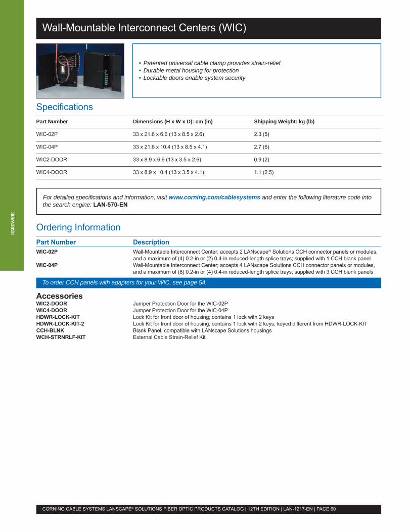
Wall-Mountable Interconnect Centers (WIC)
Ordering InformationPart Number DescriptionWIC-02P Wall-Mountable Interconnect Center; accepts 2 LANscape® Solutions CCH connector panels or modules,
and a maximum of (4) 0.2-in or (2) 0.4-in reduced-length splice trays; supplied with 1 CCH blank panelWIC-04P Wall-Mountable Interconnect Center; accepts 4 LANscape Solutions CCH connector panels or modules,
and a maximum of (8) 0.2-in or (4) 0.4-in reduced-length splice trays; supplied with 3 CCH blank panels
AccessoriesWIC2-DOOR Jumper Protection Door for the WIC-02PWIC4-DOOR Jumper Protection Door for the WIC-04PHDWR-LOCK-KIT Lock Kit for front door of housing; contains 1 lock with 2 keysHDWR-LOCK-KIT-2 Lock Kit for front door of housing; contains 1 lock with 2 keys; keyed different from HDWR-LOCK-KITCCH-BLNK Blank Panel, compatible with LANscape Solutions housingsWCH-STRNRLF-KIT External Cable Strain-Relief Kit
SpecificationsPart Number Dimensions (H x W x D): cm (in) Shipping Weight: kg (lb)
WIC-02P 33 x 21.6 x 6.6 (13 x 8.5 x 2.6) 2.3 (5)
WIC-04P 33 x 21.6 x 10.4 (13 x 8.5 x 4.1) 2.7 (6)
WIC2-DOOR 33 x 8.9 x 6.6 (13 x 3.5 x 2.6) 0.9 (2)
WIC4-DOOR 33 x 8.9 x 10.4 (13 x 3.5 x 4.1) 1.1 (2.5)
• Patented universal cable clamp provides strain-relief• Durable metal housing for protection• Lockable doors enable system security
For detailed specifications and information, visit www.corning.com/cablesystems and enter the following literature code intothe search engine: LAN-570-EN
CORNING CABLE SYSTEMS LANSCAPE® SOLUTIONS FIBER OPTIC PRODUCTS CATALOG | 12TH EDITION | LAN-1217-EN | PAGE 60
HARD
WAR
E
To order CCH panels with adapters for your WIC, see page 54.

Single-Panel Housing (SPH-01P)
Ordering InformationPart Number DescriptionSPH-01P Single-Panel, Wall-Mount Housing; accepts 1 CCH connector panel; also includes a 6-slot,
0.4-in splice holder and can be used for splice management, cross-connect or both up to 12 fibers
AccessoriesSPH-01P-BKT Ledge-Mount Bracket used to mount to the top of a ledge
SpecificationsPart Number Dimensions (H x W x D): cm (in) Shipping Weight: kg (lb)
SPH-01P 16 x 14 x 5 (6.3 x 5.5 x 2) 0.5 (1.1)
• Splice management and/or cross-connect versatility• Black metal construction provides durability and protection• Top and bottom cable entry grommets offer midspan access and environmental sealing
For detailed specifications and information, visit www.corning.com/cablesystems and enter the following literature code intothe search engine: LAN-659-EN
CORNING CABLE SYSTEMS LANSCAPE® SOLUTIONS FIBER OPTIC PRODUCTS CATALOG | 12TH EDITION | LAN-1217-EN | PAGE 61
To order CCH panels with adapters for your SPH, see page 54. HARD
WAR
E
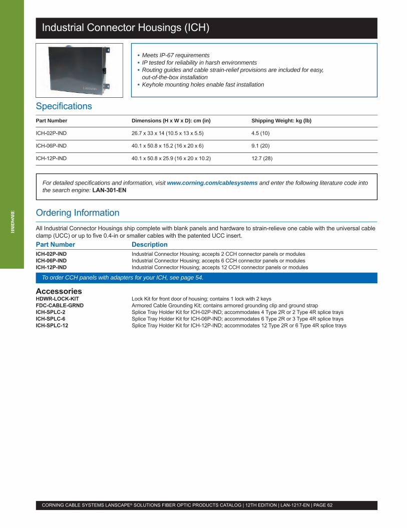
Industrial Connector Housings (ICH)
Ordering InformationAll Industrial Connector Housings ship complete with blank panels and hardware to strain-relieve one cable with the universal cableclamp (UCC) or up to five 0.4-in or smaller cables with the patented UCC insert.Part Number DescriptionICH-02P-IND Industrial Connector Housing; accepts 2 CCH connector panels or modulesICH-06P-IND Industrial Connector Housing; accepts 6 CCH connector panels or modulesICH-12P-IND Industrial Connector Housing; accepts 12 CCH connector panels or modules
AccessoriesHDWR-LOCK-KIT Lock Kit for front door of housing; contains 1 lock with 2 keysFDC-CABLE-GRND Armored Cable Grounding Kit; contains armored grounding clip and ground strapICH-SPLC-2 Splice Tray Holder Kit for ICH-02P-IND; accommodates 4 Type 2R or 2 Type 4R splice traysICH-SPLC-6 Splice Tray Holder Kit for ICH-06P-IND; accommodates 6 Type 2R or 3 Type 4R splice traysICH-SPLC-12 Splice Tray Holder Kit for ICH-12P-IND; accommodates 12 Type 2R or 6 Type 4R splice trays
SpecificationsPart Number Dimensions (H x W x D): cm (in) Shipping Weight: kg (lb)
ICH-02P-IND 26.7 x 33 x 14 (10.5 x 13 x 5.5) 4.5 (10)
ICH-06P-IND 40.1 x 50.8 x 15.2 (16 x 20 x 6) 9.1 (20)
ICH-12P-IND 40.1 x 50.8 x 25.9 (16 x 20 x 10.2) 12.7 (28)
• Meets IP-67 requirements• IP tested for reliability in harsh environments• Routing guides and cable strain-relief provisions are included for easy,out-of-the-box installation
• Keyhole mounting holes enable fast installation
For detailed specifications and information, visit www.corning.com/cablesystems and enter the following literature code intothe search engine: LAN-301-EN
CORNING CABLE SYSTEMS LANSCAPE® SOLUTIONS FIBER OPTIC PRODUCTS CATALOG | 12TH EDITION | LAN-1217-EN | PAGE 62
HARD
WAR
E
To order CCH panels with adapters for your ICH, see page 54.

Industrial Splice Housing (ISH)
Ordering InformationPart Number DescriptionISH-12SPT Industrial Splice Housing; accepts up to 12 Type 2S splice trays
AccessoriesFDC-CABLE-GRND Armored Cable Grounding Kit; contains armored grounding clip and ground strap
SpecificationsPart Number Dimensions (H x W x D): cm (in) Shipping Weight: kg (lb)
ISH-12SPT 40.1 x 50.8 x 15.2 (16 x 20 x 6) 9.1 (20)
• NEMA 250-1997 3S and IP64, 65, 66, 67 and 69k tested for reliabilityin harsh environments
• Accepts standard LANscape® Solutions splice trays• Keyhole mounting holes enable fast installation
For detailed specifications and information, visit www.corning.com/cablesystems and enter the following literature code intothe search engine: LAN-1116-EN
CORNING CABLE SYSTEMS LANSCAPE® SOLUTIONS FIBER OPTIC PRODUCTS CATALOG | 12TH EDITION | LAN-1217-EN | PAGE 63
To order splice trays for your ISH, see page 56.
HARD
WAR
E
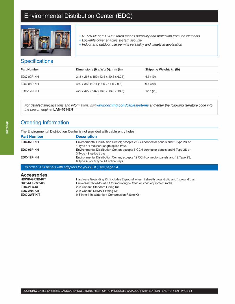
Environmental Distribution Center (EDC)
Ordering InformationThe Environmental Distribution Center is not provided with cable entry holes.Part Number DescriptionEDC-02P-NH Environmental Distribution Center; accepts 2 CCH connector panels and 2 Type 2R or
1 Type 4R reduced-length splice traysEDC-06P-NH Environmental Distribution Center; accepts 6 CCH connector panels and 6 Type 2S or
3 Type 4S splice traysEDC-12P-NH Environmental Distribution Center; accepts 12 CCH connector panels and 12 Type 2S,
6 Type 4S or 6 Type 4A splice trays
AccessoriesHDWR-GRND-KIT Hardware Grounding Kit; includes 2 ground wires, 1 sheath ground clip and 1 ground busBKT-ALL-R23-03 Universal Rack-Mount Kit for mounting to 19-in or 23-in equipment racksEDC-2EC-KIT 2-in Conduit Standard Fitting KitEDC-2N4-KIT 2-in Conduit NEMA 4 Fitting KitEDC-2WT-KIT 0.5-in to 1-in Watertight Compression Fitting Kit
SpecificationsPart Number Dimensions (H x W x D): mm (in) Shipping Weight: kg (lb)
EDC-02P-NH 318 x 267 x 159 (12.5 x 10.5 x 6.25) 4.5 (10)
EDC-06P-NH 419 x 368 x 211 (16.5 x 14.5 x 8.3) 9.1 (20)
EDC-12P-NH 472 x 422 x 262 (18.6 x 16.6 x 10.3) 12.7 (28)
• NEMA 4X or IEC IP66 rated means durability and protection from the elements• Lockable cover enables system security• Indoor and outdoor use permits versatility and variety in application
For detailed specifications and information, visit www.corning.com/cablesystems and enter the following literature code intothe search engine: LAN-401-EN
CORNING CABLE SYSTEMS LANSCAPE® SOLUTIONS FIBER OPTIC PRODUCTS CATALOG | 12TH EDITION | LAN-1217-EN | PAGE 64
HARD
WAR
E
To order CCH panels with adapters for your EDC, see page 54.
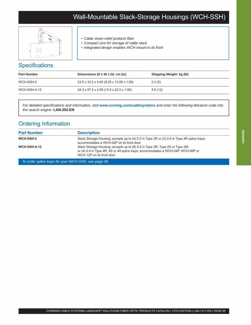
Wall-Mountable Slack-Storage Housings (WCH-SSH)
Ordering InformationPart Number DescriptionWCH-SSH-2 Slack Storage Housing; accepts up to (4) 0.2 in Type 2R or (2) 0.4 in Type 4R splice trays;
accommodates a WCH-02P on its front doorWCH-SSH-4-12 Slack Storage Housing; accepts up to (8) 0.2 in Type 2R, Type 2S or Type 2M;
or (4) 0.4 in Type 4R, 4S or 4A splice trays; accommodates a WCH-04P, WCH-06P orWCH-12P on its front door
SpecificationsPart Number Dimensions (H x W x D): cm (in) Shipping Weight: kg (lb)
WCH-SSH-2 23.5 x 33.2 x 4.95 (9.25 x 13.06 x 1.95) 2.3 (5)
WCH-SSH-4-12 34.3 x 57.2 x 4.95 (13.5 x 22.5 x 1.95) 5.5 (12)
• Cable strain-relief protects fiber• Compact size for storage of cable slack• Integrated design enables WCH mount to its front
For detailed specifications and information, visit www.corning.com/cablesystems and enter the following literature code intothe search engine: LAN-292-EN
CORNING CABLE SYSTEMS LANSCAPE® SOLUTIONS FIBER OPTIC PRODUCTS CATALOG | 12TH EDITION | LAN-1217-EN | PAGE 65
To order splice trays for your WCH-SSH, see page 56.
HARD
WAR
E
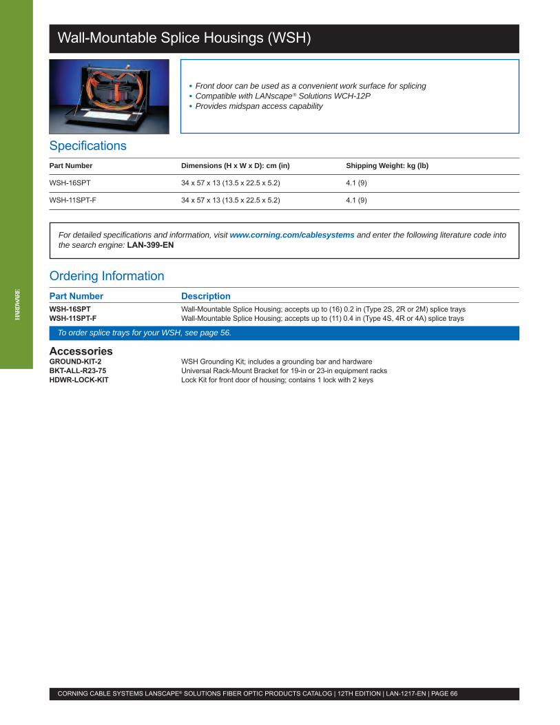
Wall-Mountable Splice Housings (WSH)
Ordering InformationPart Number DescriptionWSH-16SPT Wall-Mountable Splice Housing; accepts up to (16) 0.2 in (Type 2S, 2R or 2M) splice traysWSH-11SPT-F Wall-Mountable Splice Housing; accepts up to (11) 0.4 in (Type 4S, 4R or 4A) splice trays
AccessoriesGROUND-KIT-2 WSH Grounding Kit; includes a grounding bar and hardwareBKT-ALL-R23-75 Universal Rack-Mount Bracket for 19-in or 23-in equipment racksHDWR-LOCK-KIT Lock Kit for front door of housing; contains 1 lock with 2 keys
SpecificationsPart Number Dimensions (H x W x D): cm (in) Shipping Weight: kg (lb)
WSH-16SPT 34 x 57 x 13 (13.5 x 22.5 x 5.2) 4.1 (9)
WSH-11SPT-F 34 x 57 x 13 (13.5 x 22.5 x 5.2) 4.1 (9)
• Front door can be used as a convenient work surface for splicing• Compatible with LANscape® Solutions WCH-12P• Provides midspan access capability
For detailed specifications and information, visit www.corning.com/cablesystems and enter the following literature code intothe search engine: LAN-399-EN
CORNING CABLE SYSTEMS LANSCAPE® SOLUTIONS FIBER OPTIC PRODUCTS CATALOG | 12TH EDITION | LAN-1217-EN | PAGE 66
HARD
WAR
E
To order splice trays for your WSH, see page 56.
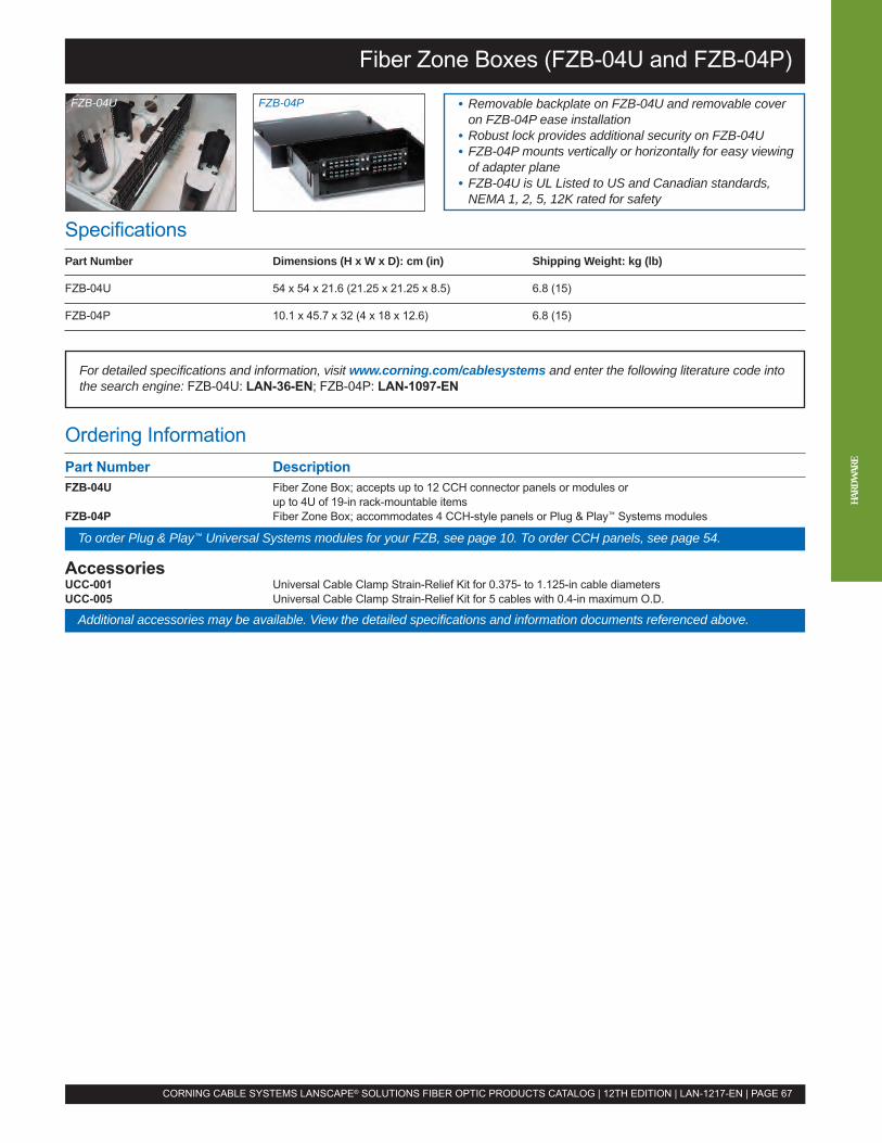
Fiber Zone Boxes (FZB-04U and FZB-04P)
Ordering InformationPart Number DescriptionFZB-04U Fiber Zone Box; accepts up to 12 CCH connector panels or modules or
up to 4U of 19-in rack-mountable itemsFZB-04P Fiber Zone Box; accommodates 4 CCH-style panels or Plug & Play™ Systems modules
AccessoriesUCC-001 Universal Cable Clamp Strain-Relief Kit for 0.375- to 1.125-in cable diametersUCC-005 Universal Cable Clamp Strain-Relief Kit for 5 cables with 0.4-in maximum O.D.
• Removable backplate on FZB-04U and removable coveron FZB-04P ease installation
• Robust lock provides additional security on FZB-04U• FZB-04P mounts vertically or horizontally for easy viewingof adapter plane
• FZB-04U is UL Listed to US and Canadian standards,NEMA 1, 2, 5, 12K rated for safety
For detailed specifications and information, visit www.corning.com/cablesystems and enter the following literature code intothe search engine: FZB-04U: LAN-36-EN; FZB-04P: LAN-1097-EN
CORNING CABLE SYSTEMS LANSCAPE® SOLUTIONS FIBER OPTIC PRODUCTS CATALOG | 12TH EDITION | LAN-1217-EN | PAGE 67
SpecificationsPart Number Dimensions (H x W x D): cm (in) Shipping Weight: kg (lb)
FZB-04U 54 x 54 x 21.6 (21.25 x 21.25 x 8.5) 6.8 (15)
FZB-04P 10.1 x 45.7 x 32 (4 x 18 x 12.6) 6.8 (15)
To order Plug & Play™ Universal Systems modules for your FZB, see page 10. To order CCH panels, see page 54.
Additional accessories may be available. View the detailed specifications and information documents referenced above.
FZB-04PFZB-04U
HARD
WAR
E
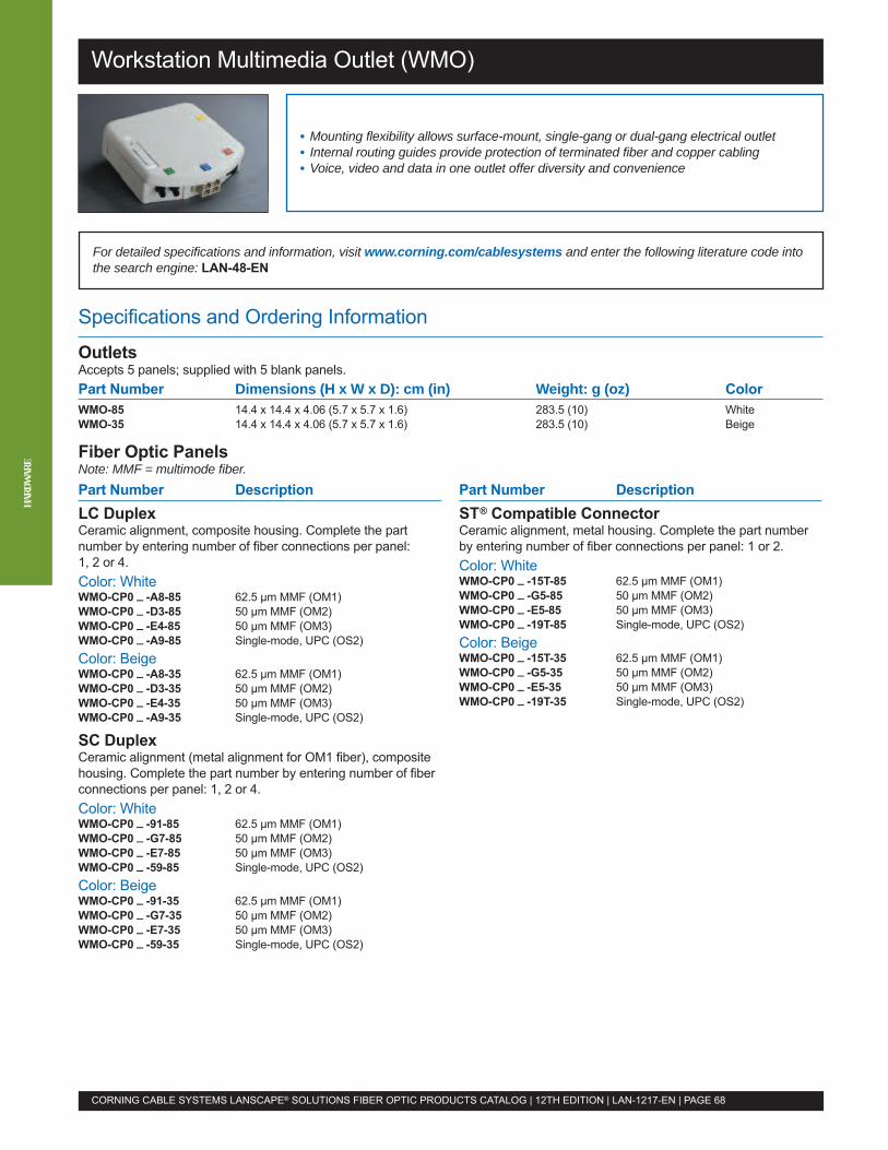
Specifications and Ordering Information
OutletsAccepts 5 panels; supplied with 5 blank panels.Part Number Dimensions (H x W x D): cm (in) Weight: g (oz) ColorWMO-85 14.4 x 14.4 x 4.06 (5.7 x 5.7 x 1.6) 283.5 (10) WhiteWMO-35 14.4 x 14.4 x 4.06 (5.7 x 5.7 x 1.6) 283.5 (10) Beige
Fiber Optic PanelsNote: MMF = multimode fiber.
For detailed specifications and information, visit www.corning.com/cablesystems and enter the following literature code intothe search engine: LAN-48-EN
Workstation Multimedia Outlet (WMO)
• Mounting flexibility allows surface-mount, single-gang or dual-gang electrical outlet• Internal routing guides provide protection of terminated fiber and copper cabling• Voice, video and data in one outlet offer diversity and convenience
CORNING CABLE SYSTEMS LANSCAPE® SOLUTIONS FIBER OPTIC PRODUCTS CATALOG | 12TH EDITION | LAN-1217-EN | PAGE 68
HARD
WAR
E
Part Number DescriptionLC DuplexCeramic alignment, composite housing. Complete the partnumber by entering number of fiber connections per panel:1, 2 or 4.Color: WhiteWMO-CP0 _ -A8-85 62.5 µm MMF (OM1)WMO-CP0 _ -D3-85 50 µm MMF (OM2)WMO-CP0 _ -E4-85 50 µm MMF (OM3)WMO-CP0 _ -A9-85 Single-mode, UPC (OS2)Color: BeigeWMO-CP0 _ -A8-35 62.5 µm MMF (OM1)WMO-CP0 _ -D3-35 50 µm MMF (OM2)WMO-CP0 _ -E4-35 50 µm MMF (OM3)WMO-CP0 _ -A9-35 Single-mode, UPC (OS2)
SC DuplexCeramic alignment (metal alignment for OM1 fiber), compositehousing. Complete the part number by entering number of fiberconnections per panel: 1, 2 or 4.Color: WhiteWMO-CP0 _ -91-85 62.5 µm MMF (OM1)WMO-CP0 _ -G7-85 50 µm MMF (OM2)WMO-CP0 _ -E7-85 50 µm MMF (OM3)WMO-CP0 _ -59-85 Single-mode, UPC (OS2)Color: BeigeWMO-CP0 _ -91-35 62.5 µm MMF (OM1)WMO-CP0 _ -G7-35 50 µm MMF (OM2)WMO-CP0 _ -E7-35 50 µm MMF (OM3)WMO-CP0 _ -59-35 Single-mode, UPC (OS2)
Part Number DescriptionST® Compatible ConnectorCeramic alignment, metal housing. Complete the part numberby entering number of fiber connections per panel: 1 or 2.Color: WhiteWMO-CP0 _ -15T-85 62.5 µm MMF (OM1)WMO-CP0 _ -G5-85 50 µm MMF (OM2)WMO-CP0 _ -E5-85 50 µm MMF (OM3)WMO-CP0 _ -19T-85 Single-mode, UPC (OS2)Color: BeigeWMO-CP0 _ -15T-35 62.5 µm MMF (OM1)WMO-CP0 _ -G5-35 50 µm MMF (OM2)WMO-CP0 _ -E5-35 50 µm MMF (OM3)WMO-CP0 _ -19T-35 Single-mode, UPC (OS2)
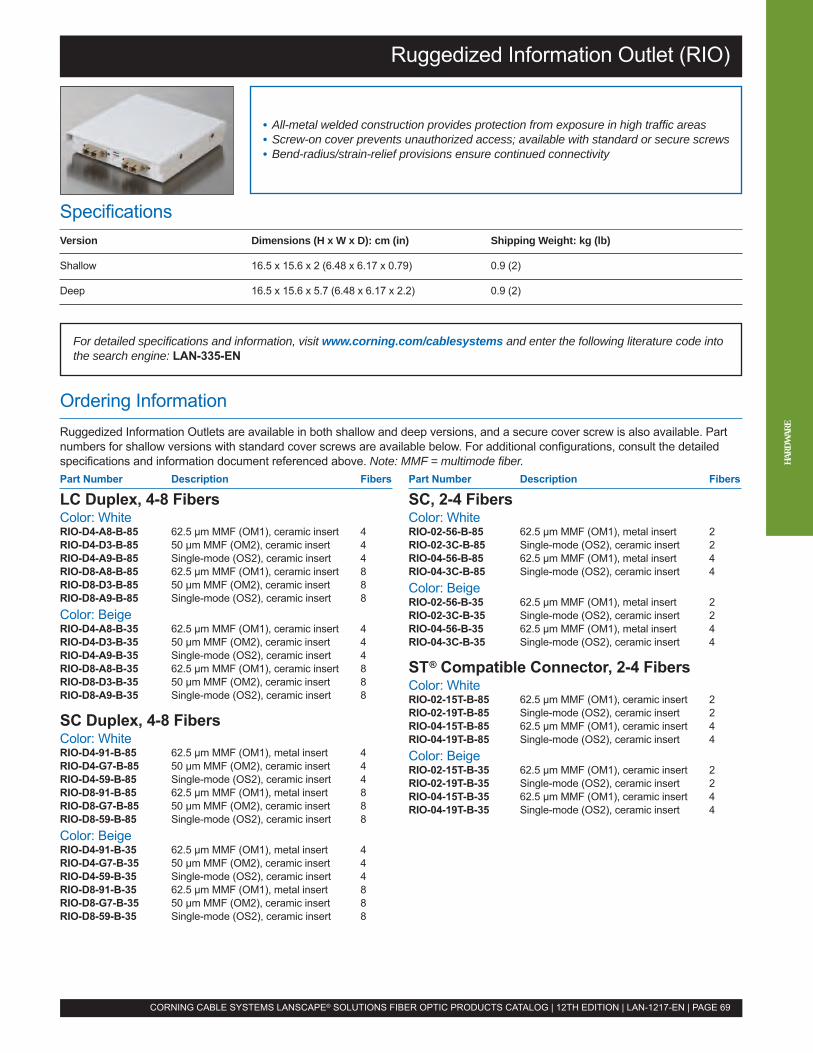
Ruggedized Information Outlet (RIO)
Ordering InformationRuggedized Information Outlets are available in both shallow and deep versions, and a secure cover screw is also available. Partnumbers for shallow versions with standard cover screws are available below. For additional configurations, consult the detailedspecifications and information document referenced above. Note: MMF = multimode fiber.
SpecificationsVersion Dimensions (H x W x D): cm (in) Shipping Weight: kg (lb)
Shallow 16.5 x 15.6 x 2 (6.48 x 6.17 x 0.79) 0.9 (2)
Deep 16.5 x 15.6 x 5.7 (6.48 x 6.17 x 2.2) 0.9 (2)
• All-metal welded construction provides protection from exposure in high traffic areas• Screw-on cover prevents unauthorized access; available with standard or secure screws• Bend-radius/strain-relief provisions ensure continued connectivity
For detailed specifications and information, visit www.corning.com/cablesystems and enter the following literature code intothe search engine: LAN-335-EN
CORNING CABLE SYSTEMS LANSCAPE® SOLUTIONS FIBER OPTIC PRODUCTS CATALOG | 12TH EDITION | LAN-1217-EN | PAGE 69
Part Number Description Fibers
LC Duplex, 4-8 FibersColor: WhiteRIO-D4-A8-B-85 62.5 µm MMF (OM1), ceramic insert 4RIO-D4-D3-B-85 50 µm MMF (OM2), ceramic insert 4RIO-D4-A9-B-85 Single-mode (OS2), ceramic insert 4RIO-D8-A8-B-85 62.5 µm MMF (OM1), ceramic insert 8RIO-D8-D3-B-85 50 µm MMF (OM2), ceramic insert 8RIO-D8-A9-B-85 Single-mode (OS2), ceramic insert 8Color: BeigeRIO-D4-A8-B-35 62.5 µm MMF (OM1), ceramic insert 4RIO-D4-D3-B-35 50 µm MMF (OM2), ceramic insert 4RIO-D4-A9-B-35 Single-mode (OS2), ceramic insert 4RIO-D8-A8-B-35 62.5 µm MMF (OM1), ceramic insert 8RIO-D8-D3-B-35 50 µm MMF (OM2), ceramic insert 8RIO-D8-A9-B-35 Single-mode (OS2), ceramic insert 8
SC Duplex, 4-8 FibersColor: WhiteRIO-D4-91-B-85 62.5 µm MMF (OM1), metal insert 4RIO-D4-G7-B-85 50 µm MMF (OM2), ceramic insert 4RIO-D4-59-B-85 Single-mode (OS2), ceramic insert 4RIO-D8-91-B-85 62.5 µm MMF (OM1), metal insert 8RIO-D8-G7-B-85 50 µm MMF (OM2), ceramic insert 8RIO-D8-59-B-85 Single-mode (OS2), ceramic insert 8Color: BeigeRIO-D4-91-B-35 62.5 µm MMF (OM1), metal insert 4RIO-D4-G7-B-35 50 µm MMF (OM2), ceramic insert 4RIO-D4-59-B-35 Single-mode (OS2), ceramic insert 4RIO-D8-91-B-35 62.5 µm MMF (OM1), metal insert 8RIO-D8-G7-B-35 50 µm MMF (OM2), ceramic insert 8RIO-D8-59-B-35 Single-mode (OS2), ceramic insert 8
Part Number Description Fibers
SC, 2-4 FibersColor: WhiteRIO-02-56-B-85 62.5 µm MMF (OM1), metal insert 2RIO-02-3C-B-85 Single-mode (OS2), ceramic insert 2RIO-04-56-B-85 62.5 µm MMF (OM1), metal insert 4RIO-04-3C-B-85 Single-mode (OS2), ceramic insert 4Color: BeigeRIO-02-56-B-35 62.5 µm MMF (OM1), metal insert 2RIO-02-3C-B-35 Single-mode (OS2), ceramic insert 2RIO-04-56-B-35 62.5 µm MMF (OM1), metal insert 4RIO-04-3C-B-35 Single-mode (OS2), ceramic insert 4
ST® Compatible Connector, 2-4 FibersColor: WhiteRIO-02-15T-B-85 62.5 µm MMF (OM1), ceramic insert 2RIO-02-19T-B-85 Single-mode (OS2), ceramic insert 2RIO-04-15T-B-85 62.5 µm MMF (OM1), ceramic insert 4RIO-04-19T-B-85 Single-mode (OS2), ceramic insert 4Color: BeigeRIO-02-15T-B-35 62.5 µm MMF (OM1), ceramic insert 2RIO-02-19T-B-35 Single-mode (OS2), ceramic insert 2RIO-04-15T-B-35 62.5 µm MMF (OM1), ceramic insert 4RIO-04-19T-B-35 Single-mode (OS2), ceramic insert 4
HARD
WAR
E
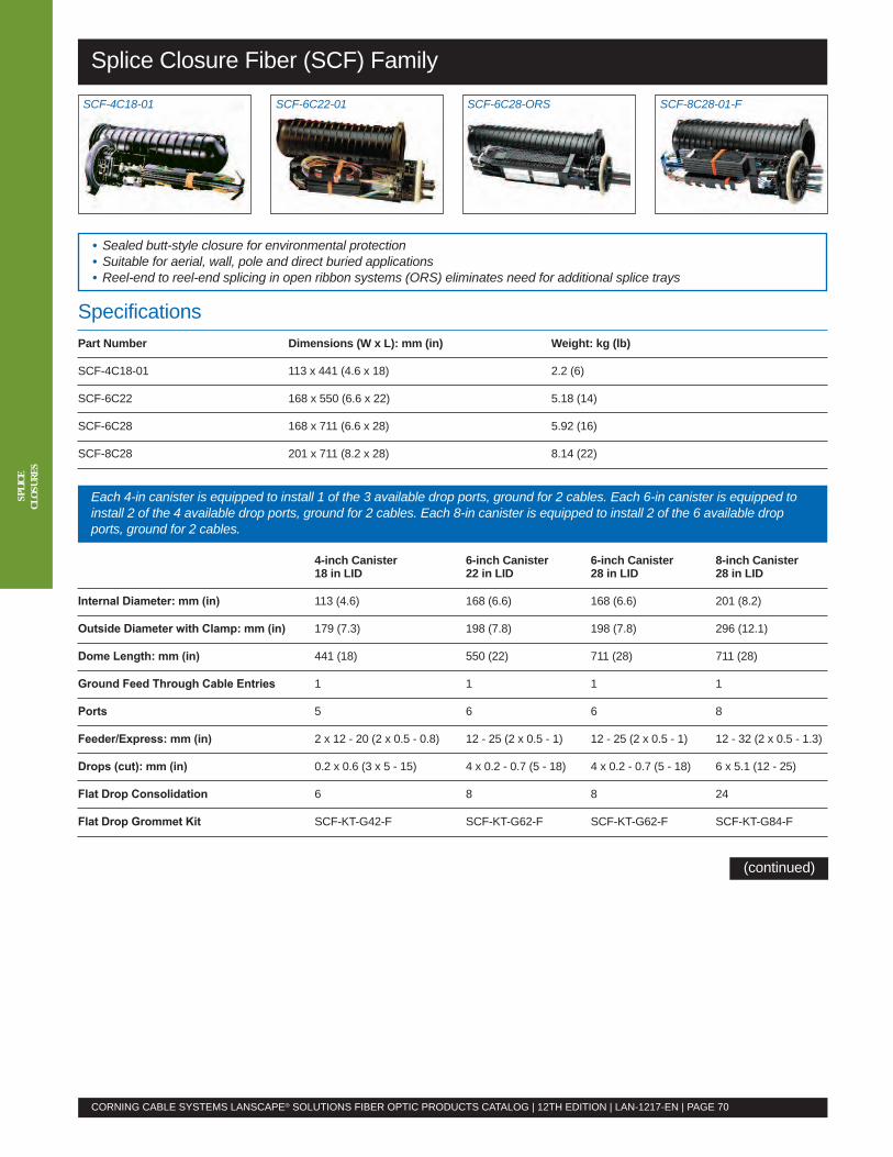
Splice Closure Fiber (SCF) Family
CORNING CABLE SYSTEMS LANSCAPE® SOLUTIONS FIBER OPTIC PRODUCTS CATALOG | 12TH EDITION | LAN-1217-EN | PAGE 70
SPLI
CECL
OSUR
ES
SCF-4C18-01 SCF-6C22-01 SCF-6C28-ORS SCF-8C28-01-F
• Sealed butt-style closure for environmental protection• Suitable for aerial, wall, pole and direct buried applications• Reel-end to reel-end splicing in open ribbon systems (ORS) eliminates need for additional splice trays
SpecificationsPart Number Dimensions (W x L): mm (in) Weight: kg (lb)
SCF-4C18-01 113 x 441 (4.6 x 18) 2.2 (6)
SCF-6C22 168 x 550 (6.6 x 22) 5.18 (14)
SCF-6C28 168 x 711 (6.6 x 28) 5.92 (16)
SCF-8C28 201 x 711 (8.2 x 28) 8.14 (22)
Each 4-in canister is equipped to install 1 of the 3 available drop ports, ground for 2 cables. Each 6-in canister is equipped toinstall 2 of the 4 available drop ports, ground for 2 cables. Each 8-in canister is equipped to install 2 of the 6 available dropports, ground for 2 cables.
4-inch Canister 6-inch Canister 6-inch Canister 8-inch Canister18 in LID 22 in LID 28 in LID 28 in LID
Internal Diameter: mm (in) 113 (4.6) 168 (6.6) 168 (6.6) 201 (8.2)
Outside Diameter with Clamp: mm (in) 179 (7.3) 198 (7.8) 198 (7.8) 296 (12.1)
Dome Length: mm (in) 441 (18) 550 (22) 711 (28) 711 (28)
Ground Feed Through Cable Entries 1 1 1 1
Ports 5 6 6 8
Feeder/Express: mm (in) 2 x 12 - 20 (2 x 0.5 - 0.8) 12 - 25 (2 x 0.5 - 1) 12 - 25 (2 x 0.5 - 1) 12 - 32 (2 x 0.5 - 1.3)
Drops (cut): mm (in) 0.2 x 0.6 (3 x 5 - 15) 4 x 0.2 - 0.7 (5 - 18) 4 x 0.2 - 0.7 (5 - 18) 6 x 5.1 (12 - 25)
Flat Drop Consolidation 6 8 8 24
Flat Drop Grommet Kit SCF-KT-G42-F SCF-KT-G62-F SCF-KT-G62-F SCF-KT-G84-F
(continued)
Splice Closure Fiber (SCF) Family
Specifications (continued)4-inch Canister 6-inch Canister 6-inch Canister 8-inch Canister18 in LID 22 in LID 28 in LID 28 in LID
End CapSCF-4C18-01(only configuration)72 splices
Dimensions (D x L): in 4 x 18 6 x 22 6 x 28 8 x 28
Splicing Capacity-01 – 72 144 240
Splicing Capacity-01-F – 96 192 288
Splicing Capacity-02 – 144 288 480
Splicing Capacity-02-F – 192 384 576
Splicing Capacity-ORS – 288 432 864
Splicing Capacity-XORS – – – 1296
0.2 in Trays for Single-Fiber SCF-ST-099 SCF-ST-099 SCF-ST-112 SCF-ST-112Splices only
0.4 in Trays for Single-Fiber orMass Splices (for -F only) – SCF-ST-116 SCF-ST-077 SCF-ST-077
CORNING CABLE SYSTEMS LANSCAPE® SOLUTIONS FIBER OPTIC PRODUCTS CATALOG | 12TH EDITION | LAN-1217-EN | PAGE 71
For detailed specifications and information, visit www.corning.com/cablesystems and enter the following literature code intothe search engine: LAN-316-EN
(continued)
Ordering InformationFor other configurations, please consult the detailed specifications and information document referenced above.Part Number Description4-in DiameterSCF-4C18-01-F 18-in length, full slack storage basket, one 0.4-in high tray stacker (single-fiber or ribbon)SCF-4C18-02-F 18-in length, reduced slack storage, two 0.4-in high tray stackers (single-fiber or ribbon)6-in DiameterSCF-6C22-01-F 22-in length, full slack storage basket, one 0.4-in high tray stacker (single-fiber or ribbon)SCF-6C22-02-F 22-in length, reduced slack storage, two 0.4-in high tray stackers (single-fiber or ribbon)SCF-6C28-01-F 28-in length, full slack storage basket, one 0.4-in high tray stacker (single-fiber or ribbon)SCF-6C28-02-F 28-in length, reduced slack storage, two 0.4-in high tray stackers (single-fiber or ribbon)SCF-6C28-ORS 28-in length, open ribbon system (does not require trays)8-in DiameterSCF-8C28-01-F 28-in length, full slack storage basket, one 0.4-in high tray stacker (single-fiber or ribbon)SCF-8C28-02-F 28-in length, reduced slack storage, two 0.4-in high tray stackers (single-fiber or ribbon)SCF-8C28-ORS 28-in length, open ribbon system (does not require trays)SCF-8C28-XORS 28-in length, open ribbon system (does not require trays)
SPLI
CECL
OSUR
ES
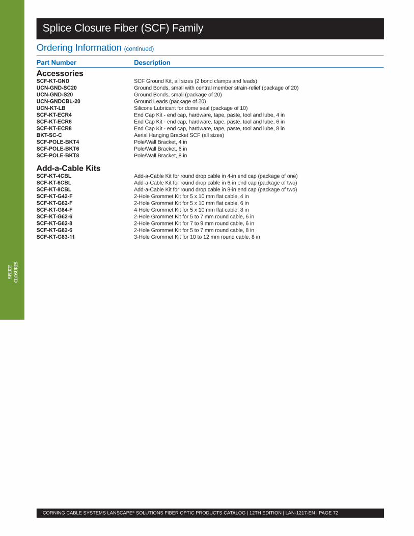
Splice Closure Fiber (SCF) Family
CORNING CABLE SYSTEMS LANSCAPE® SOLUTIONS FIBER OPTIC PRODUCTS CATALOG | 12TH EDITION | LAN-1217-EN | PAGE 72
SPLI
CECL
OSUR
ES
Ordering Information (continued)Part Number DescriptionAccessoriesSCF-KT-GND SCF Ground Kit, all sizes (2 bond clamps and leads)UCN-GND-SC20 Ground Bonds, small with central member strain-relief (package of 20)UCN-GND-S20 Ground Bonds, small (package of 20)UCN-GNDCBL-20 Ground Leads (package of 20)UCN-KT-LB Silicone Lubricant for dome seal (package of 10)SCF-KT-ECR4 End Cap Kit - end cap, hardware, tape, paste, tool and lube, 4 inSCF-KT-ECR6 End Cap Kit - end cap, hardware, tape, paste, tool and lube, 6 inSCF-KT-ECR8 End Cap Kit - end cap, hardware, tape, paste, tool and lube, 8 inBKT-SC-C Aerial Hanging Bracket SCF (all sizes)SCF-POLE-BKT4 Pole/Wall Bracket, 4 inSCF-POLE-BKT6 Pole/Wall Bracket, 6 inSCF-POLE-BKT8 Pole/Wall Bracket, 8 in
Add-a-Cable KitsSCF-KT-4CBL Add-a-Cable Kit for round drop cable in 4-in end cap (package of one)SCF-KT-6CBL Add-a-Cable Kit for round drop cable in 6-in end cap (package of two)SCF-KT-8CBL Add-a-Cable Kit for round drop cable in 8-in end cap (package of two)SCF-KT-G42-F 2-Hole Grommet Kit for 5 x 10 mm flat cable, 4 inSCF-KT-G62-F 2-Hole Grommet Kit for 5 x 10 mm flat cable, 6 inSCF-KT-G84-F 4-Hole Grommet Kit for 5 x 10 mm flat cable, 8 inSCF-KT-G62-6 2-Hole Grommet Kit for 5 to 7 mm round cable, 6 inSCF-KT-G62-8 2-Hole Grommet Kit for 7 to 9 mm round cable, 6 inSCF-KT-G82-6 2-Hole Grommet Kit for 5 to 7 mm round cable, 8 inSCF-KT-G83-11 3-Hole Grommet Kit for 10 to 12 mm round cable, 8 in
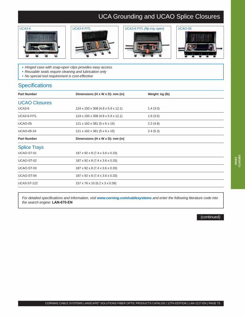
UCAGrounding and UCAO Splice Closures
CORNING CABLE SYSTEMS LANSCAPE® SOLUTIONS FIBER OPTIC PRODUCTS CATALOG | 12TH EDITION | LAN-1217-EN | PAGE 73
UCA3-6 UCA3-6 FITL UCA3-6 FITL (flip tray open) UCAO-05
• Hinged case with snap-open clips provides easy access• Reusable seals require cleaning and lubrication only• No special tool requirement is cost-effective
SpecificationsPart Number Dimensions (H x W x D): mm (in) Weight: kg (lb)
UCAO ClosuresUCA3-6 124 x 150 x 308 (4.8 x 5.9 x 12.1) 1.4 (3.0)
UCA3-6-FITL 124 x 150 x 308 (4.8 x 5.9 x 12.1) 1.6 (3.5)
UCAO-05 121 x 162 x 381 (5 x 6 x 15) 2.2 (4.8)
UCAO-05-24 121 x 162 x 381 (5 x 6 x 15) 2.4 (5.3)
Part Number Dimensions (H x W x D): mm (in)
Splice TraysUCAO-ST-01 187 x 92 x 8 (7.4 x 3.6 x 0.33)
UCAO-ST-02 187 x 92 x 8 (7.4 x 3.6 x 0.33)
UCAO-ST-03 187 x 92 x 8 (7.4 x 3.6 x 0.33)
UCAO-ST-04 187 x 92 x 8 (7.4 x 3.6 x 0.33)
UCA3-ST-122 157 x 76 x 10 (6.2 x 3 x 0.39)
(continued)
For detailed specifications and information, visit www.corning.com/cablesystems and enter the following literature code intothe search engine: LAN-670-EN
SPLI
CECL
OSUR
ES
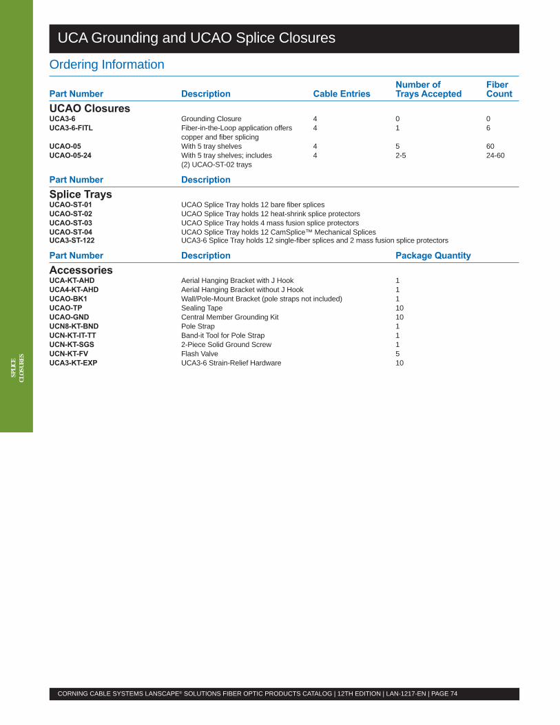
UCAGrounding and UCAO Splice Closures
CORNING CABLE SYSTEMS LANSCAPE® SOLUTIONS FIBER OPTIC PRODUCTS CATALOG | 12TH EDITION | LAN-1217-EN | PAGE 74
SPLI
CECL
OSUR
ES
Ordering InformationNumber of Fiber
Part Number Description Cable Entries Trays Accepted CountUCAO ClosuresUCA3-6 Grounding Closure 4 0 0UCA3-6-FITL Fiber-in-the-Loop application offers 4 1 6
copper and fiber splicingUCAO-05 With 5 tray shelves 4 5 60UCAO-05-24 With 5 tray shelves; includes 4 2-5 24-60
(2) UCAO-ST-02 trays
Part Number DescriptionSplice TraysUCAO-ST-01 UCAO Splice Tray holds 12 bare fiber splicesUCAO-ST-02 UCAO Splice Tray holds 12 heat-shrink splice protectorsUCAO-ST-03 UCAO Splice Tray holds 4 mass fusion splice protectorsUCAO-ST-04 UCAO Splice Tray holds 12 CamSplice™ Mechanical SplicesUCA3-ST-122 UCA3-6 Splice Tray holds 12 single-fiber splices and 2 mass fusion splice protectors
Part Number Description Package QuantityAccessoriesUCA-KT-AHD Aerial Hanging Bracket with J Hook 1UCA4-KT-AHD Aerial Hanging Bracket without J Hook 1UCAO-BK1 Wall/Pole-Mount Bracket (pole straps not included) 1UCAO-TP Sealing Tape 10UCAO-GND Central Member Grounding Kit 10UCN8-KT-BND Pole Strap 1UCN-KT-IT-TT Band-it Tool for Pole Strap 1UCN-KT-SGS 2-Piece Solid Ground Screw 1UCN-KT-FV Flash Valve 5UCA3-KT-EXP UCA3-6 Strain-Relief Hardware 10

Optical Sources, Meters, Testers and Kits
Ordering InformationPart Number DescriptionOTS-600 SeriesOptical SourcesOptical sources shown below include an integrated 650 nm visual fault locator (VFL), Li-Ion rechargeable battery and AC poweradapter, wrist strap and user’s manual.OS-403RD Multimode Optical Source (850/1300 nm LED) with SC source port adapterOS-404RXD Single-mode Optical Source (1310/1550 nm laser) with SC source port adapterOS-4RMDSD Single-mode/Multimode Optical Source (850/1300 nm LED and 1310/1550 nm laser)
with two SC source port adaptersOptical MeterOM-610 Optical Power Meter with 40 calibrated wavelengths, data storage for 10,000 traces, USB cable for
data transfer, OTS-View software, Li-Ion rechargeable battery and AC power adapter, SC meter portadapter, wrist strap and user’s manual
Optical TestersOptical testers shown below include an optical power meter, integrated 650 nm VFL, SC meter port adapter, USB cable for datatransfer, OTS-View software, Li-Ion rechargeable battery and AC power adapter, wrist strap and user’s manual.OT-611MD Multimode 2-Fiber Tester with 850/1300 nm LED source and SC source port adapterOT-612SD Single-mode 2-Fiber Tester with 1310/1550 nm laser source and SC source port adapterOT-613QD Single-mode/Multimode 2-Fiber Tester with 850/1300 nm LED and 1310/1550 nm laser sources
and two SC source port adaptersTest KitsTest kits shown below include an integrated 650 nm VFL, OM-610 power meter, USB cable for data transfer, SC source portadapter, LC meter adapter, SC meter adapter, ST® Compatible meter adapter, two Li-Ion rechargeable batteries and two ACpower adapters, OTS-View software, two wrist straps, cleaning supplies, hard transit case and user’s manual. Note: For kitswith video inspection probe (VIP) and bulkhead tip set for SC, FC and universal 2.5 mm, add -P to the part number.OTS-600MD Multimode Test Kit with OS-403RD (850/1300 nm LED) source and multimode testing mandrelsOTS-600SD Single-mode Test Kit with OS-404RXD (1310/1550 nm laser) sourceOTS-6MDSD Single-mode/Multimode Test Kit with OS-4RMDSD (850/1300 nm LED and 1310/1550 nm laser) source
and multimode testing mandrels
• OTS-600 Series auto wavelength switching anddetection cuts typical testing time in half
• OTS-600 Series offers data storage capabilities• LTK-400 Series features high output power and calibratedwavelengths for unparalleled performance
• Units may be purchased individually or as test kits
CORNING CABLE SYSTEMS LANSCAPE® SOLUTIONS FIBER OPTIC PRODUCTS CATALOG | 12TH EDITION | LAN-1217-EN | PAGE 75
TEST
EQUI
PMEN
T
SpecificationsOTS-600 Series LTK-400 Series
Dimensions (H x W x D): cm (in) 28.4 x 12.5 x 7.8 (11.19 x 4.83 x 3.06) 18.5 x 10.0 x 5.5 (7.25 x 4 x 2.125)Source: 19.0 x 10.0 x 6.2 (7.5 x 4.0 x 2.5)
Weight: kg (lb) 0.98 (2.16) 0.4 (0.9)Source: 0.48 (1.1)
Temperatures Storage: -20º to +70ºC (-4º to +158ºF) Storage: -40º to +70ºC (-40º to +158ºF)Operation: 0º to +50ºC (+32º to +122ºF) Operation: -10º to +50ºC (+14º to +122ºF)
For detailed specifications and information, visit www.corning.com/cablesystems and enter the following literature code intothe search engine: OTS-600 Series: LAN-942-EN; LTK-400 Series: LAN-629-EN
LTK-400 SeriesOTS-600 Series
(continued)
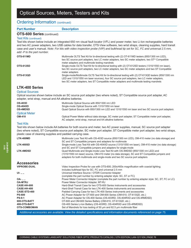
Optical Sources, Meters, Testers and Kits
CORNING CABLE SYSTEMS LANSCAPE® SOLUTIONS FIBER OPTIC PRODUCTS CATALOG | 12TH EDITION | LAN-1217-EN | PAGE 76
TEST
EQUI
PMEN
T
Ordering Information (continued)
Part Number DescriptionOTS-600 Series (continued)Test Kits (continued)Test kits shown below include an integrated 650 nm visual fault locator (VFL) and power meter, two Li-Ion rechargeable batteriesand two AC power adapters, two USB cables for data transfer, OTS-View software, two wrist straps, cleaning supplies, hard transitcase and user’s manual. Note: For kits with video inspection probe (VIP) and bulkhead tip set for SC, FC and universal 2.5 mm,add -P to the part number.OTS-611MD Multimode OLTS Test Kit for bi-directional testing with (2) OT-611MD testers (850/1300 nm LED),
two SC source port adapters, two LC meter adapters, two SC meter adapters, two ST® Compatiblemeter adapters and multimode testing mandrels
OTS-612SD Single-mode OLTS Test Kit for bi-directional testing with (2) OT-612SD testers (1310/1550 nm laser),two SC source port adapters, two LC meter adapters, two SC meter adapters and two ST Compatiblemeter adapters
OTS-613QD Single-mode/Multimode OLTS Test Kit for bi-directional testing with (2) OT-613QD testers (850/1300 nmLED and 1310/1550 nm laser sources), four SC source port adapters, two LC meter adapters,two SC meter adapters, two ST Compatible meter adapters and multimode testing mandrels
LTK-400 SeriesOptical SourcesOptical sources shown below include an SC source port adapter (two where noted), ST Compatible source port adapter, ACadapter, wrist strap, manual and AA alkaline batteries.OS-403D Multimode Optical Source with 850/1300 nm LEDOS-404XD Single-mode Optical Source with 1310/1550 nm laserOS-4MDSD Quad Optical Source with 850/1300 nm LED and 1310/1550 nm laser and two SC source port adaptersOptical MeterOM-410 Optical Power Meter without data storage, SC meter port adapter, ST Compatible meter port adapter,
AC adapter, wrist strap, manual and AA alkaline batteriesTest KitsTest kits shown below include AA batteries for both source and meter, two AC power supplies, manual, SC source port adapter(two where noted), ST Compatible source port adapter, SC meter port adapter, ST Compatible meter port adapter, two wrist straps,plastic case of cleaning supplies and padded carrying case.LTK-400MD Multimode Loss Test Kit with OS-403D source (850/1300 nm LED), OM-410 meter (no data storage) and
SC and ST Compatible jumpers and adapters for multimodeLTK-400SD Single-mode Loss Test Kit with OS-404XD source (1310/1550 nm laser), OM-410 meter (no data storage)
and SC and ST Compatible jumpers and adapters for single-modeLTK-4MDSD Quad Multimode and Single-mode Loss Test Kit with OS-4MDSD (850/1300 nm LED) and
(1310/1550 nm laser) source, OM-410 meter (no data storage), SC and ST Compatible jumpers andadapters for both multimode and single-mode and two SC source port adapters
AccessoriesVIPROBE-DUAL Video Inspection Probe for use with OTS-600; 200x/400x magnification with coaxial lighting;
includes bulkhead tips for SC, FC and universal 2.5 mmUI- _ _ Universal Interface Source / OTDR Connector Adapter
(complete the part number by entering adapter style: SC, ST or FC)OA- _ _ Power Meter Connector Adapter (complete the part number by entering adapter style: SC, ST, FC or LC)OA-MTRJ Power Meter Connector Adapter, MT-RJCASE-HH-600 Hard-Shell Transit Case for two OTS-600 Series instruments and accessoriesCASE-HH-400 Hard-Shell Transit Case for two LTK-400 Series instruments and accessoriesCASE-STD-400 Padded Carrying Case for two LTK-400 Series instruments and accessoriesPS-600 AC Power Adapter for OT-600 and OM-600 Series (OM-610, OT-613QD, etc.)PS-9-1 AC Power Adapter for OS-400 Series (OS-403RD, OS-404RXD and OS-4RMDSD)600-OTS-BATT OT-600 and OM-600 Series Battery (OM-610, OT-613QD, etc.)400-OTS-BATT OS-400 Series Li-Ion Battery (OS-403RD, OS-404RXD and OS-4RMDSD)OTS-COMBOMAN Set of Mandrels for loss testing of 50 µm and 62.5 µm multimode fiber
Additional accessories are available. View the detailed specifications and information documents referenced on page 75.
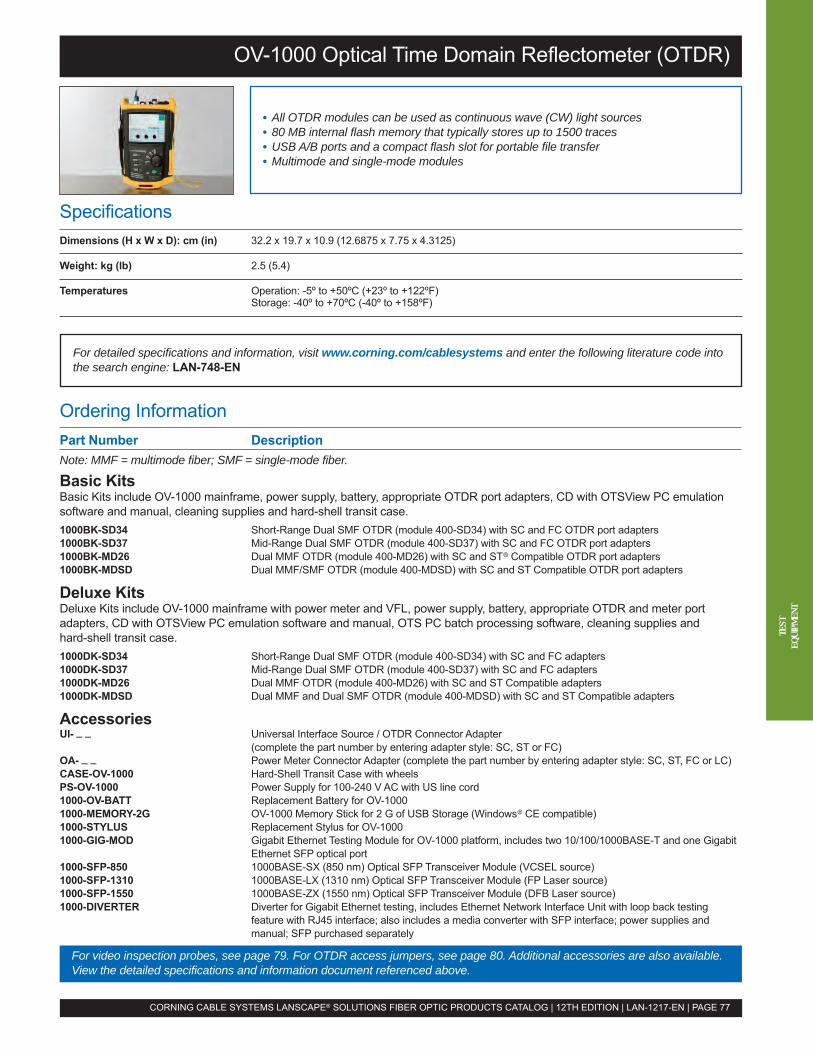
OV-1000 Optical Time Domain Reflectometer (OTDR)
Ordering InformationPart Number DescriptionNote: MMF = multimode fiber; SMF = single-mode fiber.
Basic KitsBasic Kits include OV-1000 mainframe, power supply, battery, appropriate OTDR port adapters, CD with OTSView PC emulationsoftware and manual, cleaning supplies and hard-shell transit case.1000BK-SD34 Short-Range Dual SMF OTDR (module 400-SD34) with SC and FC OTDR port adapters1000BK-SD37 Mid-Range Dual SMF OTDR (module 400-SD37) with SC and FC OTDR port adapters1000BK-MD26 Dual MMF OTDR (module 400-MD26) with SC and ST® Compatible OTDR port adapters1000BK-MDSD Dual MMF/SMF OTDR (module 400-MDSD) with SC and ST Compatible OTDR port adapters
Deluxe KitsDeluxe Kits include OV-1000 mainframe with power meter and VFL, power supply, battery, appropriate OTDR and meter portadapters, CD with OTSView PC emulation software and manual, OTS PC batch processing software, cleaning supplies andhard-shell transit case.1000DK-SD34 Short-Range Dual SMF OTDR (module 400-SD34) with SC and FC adapters1000DK-SD37 Mid-Range Dual SMF OTDR (module 400-SD37) with SC and FC adapters1000DK-MD26 Dual MMF OTDR (module 400-MD26) with SC and ST Compatible adapters1000DK-MDSD Dual MMF and Dual SMF OTDR (module 400-MDSD) with SC and ST Compatible adapters
AccessoriesUI- _ _ Universal Interface Source / OTDR Connector Adapter
(complete the part number by entering adapter style: SC, ST or FC)OA- _ _ Power Meter Connector Adapter (complete the part number by entering adapter style: SC, ST, FC or LC)CASE-OV-1000 Hard-Shell Transit Case with wheelsPS-OV-1000 Power Supply for 100-240 V AC with US line cord1000-OV-BATT Replacement Battery for OV-10001000-MEMORY-2G OV-1000 Memory Stick for 2 G of USB Storage (Windows® CE compatible)1000-STYLUS Replacement Stylus for OV-10001000-GIG-MOD Gigabit Ethernet Testing Module for OV-1000 platform, includes two 10/100/1000BASE-T and one Gigabit
Ethernet SFP optical port1000-SFP-850 1000BASE-SX (850 nm) Optical SFP Transceiver Module (VCSEL source)1000-SFP-1310 1000BASE-LX (1310 nm) Optical SFP Transceiver Module (FP Laser source)1000-SFP-1550 1000BASE-ZX (1550 nm) Optical SFP Transceiver Module (DFB Laser source)1000-DIVERTER Diverter for Gigabit Ethernet testing, includes Ethernet Network Interface Unit with loop back testing
feature with RJ45 interface; also includes a media converter with SFP interface; power supplies andmanual; SFP purchased separately
SpecificationsDimensions (H x W x D): cm (in) 32.2 x 19.7 x 10.9 (12.6875 x 7.75 x 4.3125)
Weight: kg (lb) 2.5 (5.4)
Temperatures Operation: -5º to +50ºC (+23º to +122ºF)Storage: -40º to +70ºC (-40º to +158ºF)
• All OTDR modules can be used as continuous wave (CW) light sources• 80 MB internal flash memory that typically stores up to 1500 traces• USB A/B ports and a compact flash slot for portable file transfer• Multimode and single-mode modules
For detailed specifications and information, visit www.corning.com/cablesystems and enter the following literature code intothe search engine: LAN-748-EN
CORNING CABLE SYSTEMS LANSCAPE® SOLUTIONS FIBER OPTIC PRODUCTS CATALOG | 12TH EDITION | LAN-1217-EN | PAGE 77
For video inspection probes, see page 79. For OTDR access jumpers, see page 80. Additional accessories are also available.View the detailed specifications and information document referenced above.
TEST
EQUI
PMEN
T
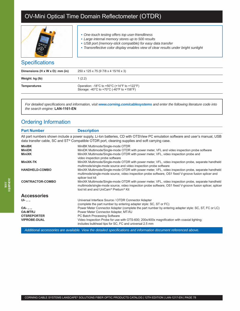
OV-Mini Optical Time Domain Reflectometer (OTDR)
Ordering InformationPart Number DescriptionAll part numbers shown include a power supply, Li-Ion batteries, CD with OTSView PC emulation software and user’s manual, USBdata transfer cable, SC and ST® Compatible OTDR port, cleaning supplies and soft carrying case.MiniBK MiniBK Multimode/Single-mode OTDRMiniDK MiniDK Multimode/Single-mode OTDR with power meter, VFL and video inspection probe softwareMiniXK MiniXK Multimode/Single-mode OTDR with power meter, VFL, video inspection probe and
video inspection probe softwareMiniXK-TK MiniXK Multimode/Single-mode OTDR with power meter, VFL, video inspection probe, separate handheld
multimode/single-mode source and video inspection probe softwareHANDHELD-COMBO MiniXK Multimode/Single-mode OTDR with power meter, VFL, video inspection probe, separate handheld
multimode/single-mode source, video inspection probe software, OS1 fixed V-groove fusion splicer andsplicer tool kit
CONTRACTOR-COMBO MiniXK Multimode/Single-mode OTDR with power meter, VFL, video inspection probe, separate handheldmultimode/single-mode source, video inspection probe software, OS1 fixed V-groove fusion splicer, splicertool kit and and UniCam® Pretium® Kit
AccessoriesUI- _ _ Universal Interface Source / OTDR Connector Adapter
(complete the part number by entering adapter style: SC, ST or FC)OA- _ _ Power Meter Connector Adapter (complete the part number by entering adapter style: SC, ST, FC or LC)OA-MTRJ Power Meter Connector Adapter, MT-RJOTSREPORTER PC Batch Processing SoftwareVIPROBE-DUAL Video Inspection Probe for use with OTS-600; 200x/400x magnification with coaxial lighting;
includes bulkhead tips for SC, FC and universal 2.5 mm
SpecificationsDimensions (H x W x D): mm (in) 250 x 125 x 75 (9 7/8 x 4 15/16 x 3)
Weight: kg (lb) 1 (2.2)
Temperatures Operation: -18°C to +50°C (+14°F to +122°F)Storage: -40°C to +70°C (-40°F to +158°F)
• One-touch testing offers top user-friendliness• Large internal memory stores up to 500 results• USB port (memory-stick compatible) for easy data transfer• Transreflective color display enables view of clear results under bright sunlight
For detailed specifications and information, visit www.corning.com/cablesystems and enter the following literature code intothe search engine: LAN-1161-EN
CORNING CABLE SYSTEMS LANSCAPE® SOLUTIONS FIBER OPTIC PRODUCTS CATALOG | 12TH EDITION | LAN-1217-EN | PAGE 78
TEST
EQUI
PMEN
T
Additional accessories are available. View the detailed specifications and information document referenced above.

Video Inspection Probe (VIPROBE-DUAL)
Ordering InformationPart Number DescriptionVideo Probe LCD Stand-alone KitVIP-LCD-KIT 3.5-in LCD Screen with Integrated (hardwired) Video Inspection Probe; includes VIPT-U12M, VIPT-U25M
and probe bulkhead tips for SC, ST® Compatible, FC, LC; AC power supply and carrying case
Video Probe LCD Kit TipsVIPT-U12M Universal Probe Tip for viewing patch cords with 1.25 mm ferrule (LC and MU)VIPT-U25M Universal Probe Tip for viewing patch cords with 2.5 mm ferrule (SC, ST Compatible, FC)VIPT-U12MA-SF Universal Probe Tip for viewing APC patch cords with 1.25 mm ferrule (LC APC)VIPT-U25MA Universal Probe Tip for viewing APC patch cords with 2.5 mm ferrule (SC APC, FC APC)VIPT- _ _ -APC Probe Bulkhead Tip for viewing an APC connector on the backside of a patch panel
(complete the part number by entering adapter style: SC, FC or LC)
Video Probe Accessory Packages for Corning Cable Systems Test EquipmentVIPROBE-DUAL Video Inspection Probe, FC and SC bulkhead tips, U25M universal patch cord tip
for 2.5 mm ferrules, compartmented plastic case for tipsVIPROBE-USB2 USB2 converter with software that allows the VIPROBE-DUAL to be used with a computer
Video Probe LCD Kit TipsVIPROBE-FSA FC and SC APC Tip for bulkhead adapterVIPROBE-LC LC Tip for bulkhead adaptersVIPROBE-LCA LC/APC Tip for bulkhead adapterVIPROBE-ST ST Compatible Tip for bulkhead adapterVIPROBE-U12 Universal Patch Cord Tip for 1.25 mm ferrules
AccessoriesCLEANER-PORT-2.5 Single-Fiber Port Cleaner for all 2.5 mm ferruled connectors such as FC, ST Compatible and SC
for PC, UPC and APC polishesCLEANER-PORT-LC Single-Fiber Port Cleaner for LC, keyed LC and MU for both UPC and APC polishes
SpecificationsVIPROBE-DUAL VIP-LCD-KIT
Weight: kg (lb) 0.2 (0.44) 1.81 (4)
Image Storage Computer or Corning TEQ None
Battery Power Supply Computer or Corning TEQ 8 AA Alkaline batteries (about 6 hours)
AC Power Supply Computer or Corning TEQ AC power supply for 100-240 V input
• LCD and video probe kit (VIP-LCD-KIT) provide a low-cost, stand-alone videoinspection solution
• Video Probe Accessory Package (VIPROBE-DUAL) compatible with OV-1000,OV-MINI and OTS-600 test equipment
• 200x and 400x magnification• Image capture capability for report documentation
For detailed specifications and information, visit www.corning.com/cablesystems and enter the following literature code intothe search engine: LAN-1186-EN
CORNING CABLE SYSTEMS LANSCAPE® SOLUTIONS FIBER OPTIC PRODUCTS CATALOG | 12TH EDITION | LAN-1217-EN | PAGE 79
Additional probe tips are available. Additional accessories may be available. View the detailed specifications and informationdocument referenced above.
TEST
EQUI
PMEN
T
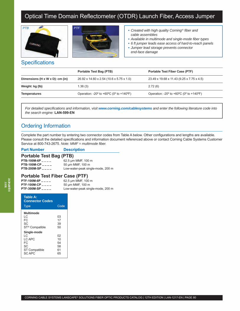
Ordering InformationComplete the part number by entering two connector codes from Table A below. Other configurations and lengths are available.Please consult the detailed specifications and information document referenced above or contact Corning Cable Systems CustomerService at 800-743-2675. Note: MMF = multimode fiber.
SpecificationsPortable Test Bag (PTB) Portable Test Fiber Case (PTF)
Dimensions (H x W x D): cm (in) 26.92 x 14.60 x 2.54 (10.6 x 5.75 x 1.0) 23.49 x 19.68 x 11.43 (9.25 x 7.75 x 4.5)
Weight: kg (lb) 1.36 (3) 2.72 (6)
Temperatures Operation: -20º to +60ºC (0º to +140ºF) Operation: -20º to +60ºC (0º to +140ºF)
For detailed specifications and information, visit www.corning.com/cablesystems and enter the following literature code intothe search engine: LAN-599-EN
Optical Time Domain Reflectometer (OTDR) Launch Fiber, Access Jumper
CORNING CABLE SYSTEMS LANSCAPE® SOLUTIONS FIBER OPTIC PRODUCTS CATALOG | 12TH EDITION | LAN-1217-EN | PAGE 80
TEST
EQUI
PMEN
T
• Created with high quality Corning® fiber andcable assemblies
• Available in multimode and single-mode fiber types• 6 ft jumper leads ease access of hard-to-reach panels• Jumper lead storage prevents connectorend-face damage
PTFPTB
Part Number DescriptionPortable Test Bag (PTB)PTB-100M-6P _ _ _ _ 62.5 µm MMF, 100 mPTB-100M-CP _ _ _ _ 50 µm MMF, 100 mPTB-200M-SP _ _ _ _ Low-water-peak single-mode, 200 m
Portable Test Fiber Case (PTF)PTF-100M-6P _ _ _ _ 62.5 µm MMF, 100 mPTF-100M-CP _ _ _ _ 50 µm MMF, 100 mPTF-300M-SP _ _ _ _ Low-water-peak single-mode, 200 m
Table A:Connector CodesType Code
MultimodeLC 03FC 17SC 39ST® Compatible 50Single-modeLC 02LC APC 10FC 54SC 58ST Compatible 61SC APC 65

Optical Network Simulation Systems
Ordering InformationEach NSS is built to customer specifications. Please consult the detailed specifications and information document referenced aboveor contact Corning Cable Systems Customer Service at 800-743-2675.
Part Number DescriptionAccessoriesTKT-CLEAN-SFC-M Deluxe Kits contain recommended products to effectively clean and inspect 2.5 mm and 1.25 mm
single-fiber connectorTKT-CLEAN-SFC Kits contain recommended products to effectively clean 2.5 mm and 1.25 mm single-fiber connectorsTKT-CLEAN-MFC-M Deluxe Kits contain recommended products to effectively clean and inspect multi-fiber connectors
such as MT-RJ and MTP® ConnectorsTKT-CLEAN-MFC Kits contain recommended products to effectively clean multi-fiber connectors such as MT-RJ and
MTP Connectors
SpecificationsDimensions (H x W x D): cm (in) 26.5 x 43 x 50 (10.5 x 17 x 19.75)
Shipping Weight: kg (lb) < 23 (< 50)
Temperatures Operation: -20º to +60ºC (0º to +140ºF)
Insertion Loss 1.0 dB maximum
Connector Reflectance Multimode LC, SC and ST® Compatible: ≤ -20 dBSingle-mode LC UPC, SC and ST Compatible UPC: ≤ -55 dBSingle-mode LC APC and SC: ≤ -70 dB
• Rack-mountable hardware accommodates longer system lengths• Available in multimode and single-mode fiber types• Compact rack-mount provides excellent protection for the stored optical fiber
For detailed specifications and information, visit www.corning.com/cablesystems and enter the following literature code intothe search engine: LAN-517-EN
CORNING CABLE SYSTEMS LANSCAPE® SOLUTIONS FIBER OPTIC PRODUCTS CATALOG | 12TH EDITION | LAN-1217-EN | PAGE 81
TEST
EQUI
PMEN
T
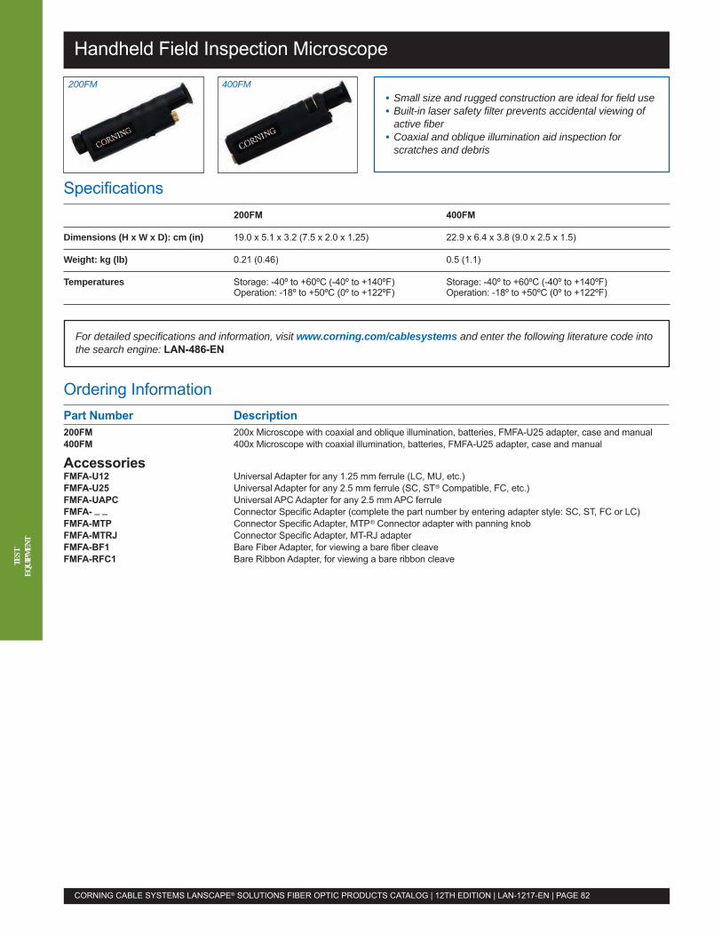
Handheld Field Inspection Microscope
Ordering InformationPart Number Description200FM 200x Microscope with coaxial and oblique illumination, batteries, FMFA-U25 adapter, case and manual400FM 400x Microscope with coaxial illumination, batteries, FMFA-U25 adapter, case and manual
AccessoriesFMFA-U12 Universal Adapter for any 1.25 mm ferrule (LC, MU, etc.)FMFA-U25 Universal Adapter for any 2.5 mm ferrule (SC, ST® Compatible, FC, etc.)FMFA-UAPC Universal APC Adapter for any 2.5 mm APC ferruleFMFA- _ _ Connector Specific Adapter (complete the part number by entering adapter style: SC, ST, FC or LC)FMFA-MTP Connector Specific Adapter, MTP® Connector adapter with panning knobFMFA-MTRJ Connector Specific Adapter, MT-RJ adapterFMFA-BF1 Bare Fiber Adapter, for viewing a bare fiber cleaveFMFA-RFC1 Bare Ribbon Adapter, for viewing a bare ribbon cleave
Specifications200FM 400FM
Dimensions (H x W x D): cm (in) 19.0 x 5.1 x 3.2 (7.5 x 2.0 x 1.25) 22.9 x 6.4 x 3.8 (9.0 x 2.5 x 1.5)
Weight: kg (lb) 0.21 (0.46) 0.5 (1.1)
Temperatures Storage: -40º to +60ºC (-40º to +140ºF) Storage: -40º to +60ºC (-40º to +140ºF)Operation: -18º to +50ºC (0º to +122ºF) Operation: -18º to +50ºC (0º to +122ºF)
For detailed specifications and information, visit www.corning.com/cablesystems and enter the following literature code intothe search engine: LAN-486-EN
CORNING CABLE SYSTEMS LANSCAPE® SOLUTIONS FIBER OPTIC PRODUCTS CATALOG | 12TH EDITION | LAN-1217-EN | PAGE 82
TEST
EQUI
PMEN
T
• Small size and rugged construction are ideal for field use• Built-in laser safety filter prevents accidental viewing ofactive fiber
• Coaxial and oblique illumination aid inspection forscratches and debris
400FM200FM
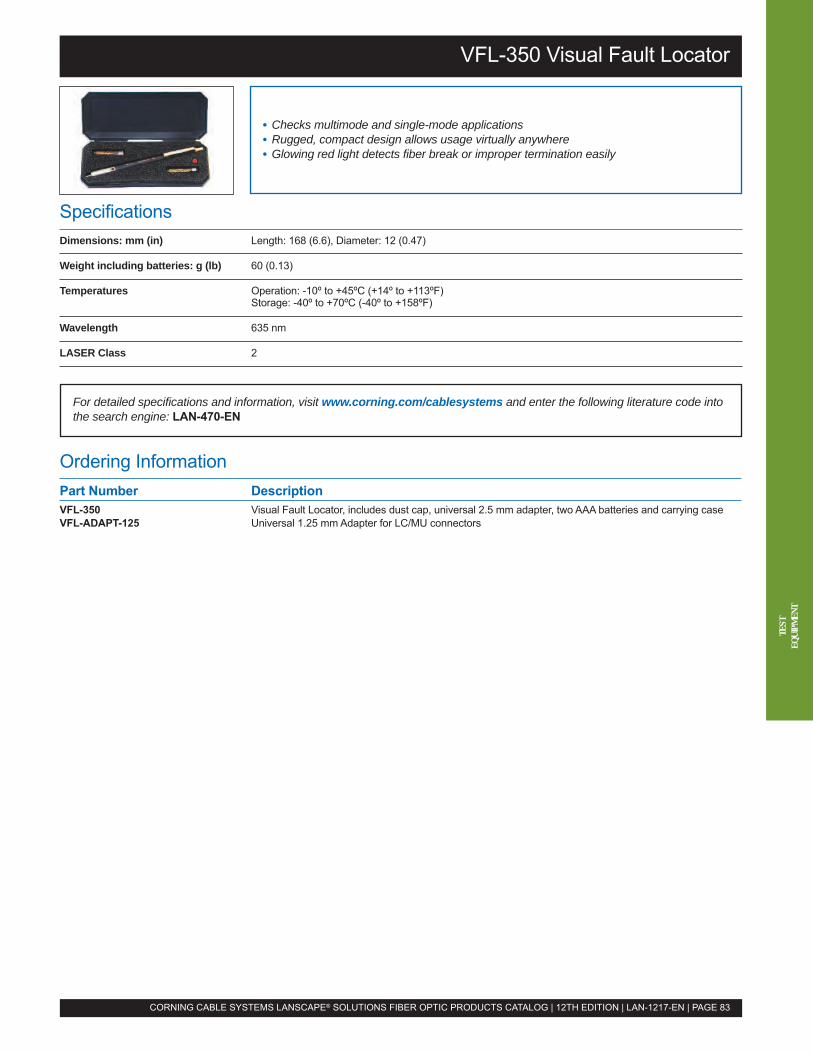
Ordering InformationPart Number DescriptionVFL-350 Visual Fault Locator, includes dust cap, universal 2.5 mm adapter, two AAA batteries and carrying caseVFL-ADAPT-125 Universal 1.25 mm Adapter for LC/MU connectors
SpecificationsDimensions: mm (in) Length: 168 (6.6), Diameter: 12 (0.47)
Weight including batteries: g (lb) 60 (0.13)
Temperatures Operation: -10º to +45ºC (+14º to +113ºF)Storage: -40º to +70ºC (-40º to +158ºF)
Wavelength 635 nm
LASER Class 2
For detailed specifications and information, visit www.corning.com/cablesystems and enter the following literature code intothe search engine: LAN-470-EN
VFL-350 Visual Fault Locator
• Checks multimode and single-mode applications• Rugged, compact design allows usage virtually anywhere• Glowing red light detects fiber break or improper termination easily
CORNING CABLE SYSTEMS LANSCAPE® SOLUTIONS FIBER OPTIC PRODUCTS CATALOG | 12TH EDITION | LAN-1217-EN | PAGE 83
TEST
EQUI
PMEN
T

SpecificationsDimensions (H x W x D): mm (in) 190 x 32 x 25 (7.50 x 1.25 x 1.00)
Weight including battery: g (oz) 230 (8)
Temperatures Operation: -20º to +50ºC (-4º to +122ºF)Storage: -40º to +60ºC (-40º to +140ºF)
Signal Indicators Traffic presence: 2 kHz test signal, detects 2 kHz, 1 kHz and 20 Hz, transmission direction, self-test andlow battery indication
Detector Sensitivity -40 dBm at 1310 nm
Induced Loss 0.6 dB at 1310 nm (typical)
CheckPoint™ Plus Fiber Identifier
Ordering InformationPart Number DescriptionCHECKPOINT-PLUS CheckPoint™ Plus Fiber Identifier with integral meter, leather carrying pouch, operating instructions and
three interchangeble adapters (FI-30418, FI-30419, FI-30420)FI-30418 CheckPoint Plus Fiber Identifier Adapter for measuring 250 µm bare fiber or a multiple fiber ribbonFI-30419 CheckPoint Plus Fiber Identifier Adapter for measuring 900 µm tight buffered fiberFI-30420 CheckPoint Plus Fiber Identifier Adapter for measuring 3.0 mm jacketed fiberFI-34788 CheckPoint Plus Fiber Identifier Adapter for measuring 2.0 mm jacketed fiberFI-35165 CheckPoint Plus Fiber Identifier Adapter for measuring 1.65 mm jacketed fiber
• Passive detection of traffic without signal interruption• Supports multiple fiber sizes• 850 to 700 nm range for single-mode and multimode applications
For detailed specifications and information, visit www.corning.com/cablesystems and enter the following literature code intothe search engine: LAN-320-EN
CORNING CABLE SYSTEMS LANSCAPE® SOLUTIONS FIBER OPTIC PRODUCTS CATALOG | 12TH EDITION | LAN-1217-EN | PAGE 84
TEST
EQUI
PMEN
T
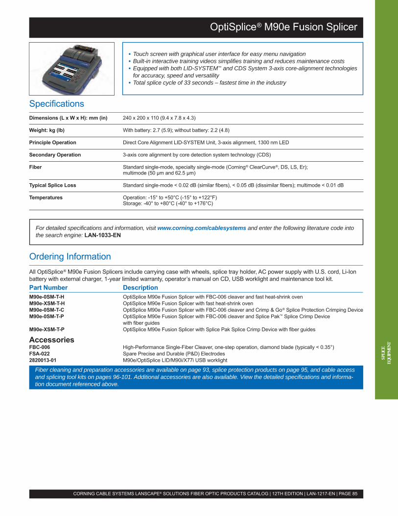
OptiSplice® M90e Fusion Splicer
SpecificationsDimensions (L x W x H): mm (in) 240 x 200 x 110 (9.4 x 7.8 x 4.3)
Weight: kg (lb) With battery: 2.7 (5.9); without battery: 2.2 (4.8)
Principle Operation Direct Core Alignment LID-SYSTEM Unit, 3-axis alignment, 1300 nm LED
Secondary Operation 3-axis core alignment by core detection system technology (CDS)
Fiber Standard single-mode, specialty single-mode (Corning® ClearCurve®, DS, LS, Er);multimode (50 µm and 62.5 µm)
Typical Splice Loss Standard single-mode < 0.02 dB (similar fibers), < 0.05 dB (dissimilar fibers); multimode < 0.01 dB
Temperatures Operation: -15° to +50°C (-15° to +122°F)Storage: -40° to +80°C (-40° to +176°C)
• Touch screen with graphical user interface for easy menu navigation• Built-in interactive training videos simplifies training and reduces maintenance costs• Equipped with both LID-SYSTEM™ and CDS System 3-axis core-alignment technologiesfor accuracy, speed and versatility
• Total splice cycle of 33 seconds – fastest time in the industry
Ordering InformationAll OptiSplice® M90e Fusion Splicers include carrying case with wheels, splice tray holder, AC power supply with U.S. cord, Li-Ionbattery with external charger, 1-year limited warranty, operator’s manual on CD, USB worklight and maintenance tool kit.Part Number DescriptionM90e-0SM-T-H OptiSplice M90e Fusion Splicer with FBC-006 cleaver and fast heat-shrink ovenM90e-XSM-T-H OptiSplice M90e Fusion Splicer with fast heat-shrink ovenM90e-0SM-T-C OptiSplice M90e Fusion Splicer with FBC-006 cleaver and Crimp & Go® Splice Protection Crimping DeviceM90e-0SM-T-P OptiSplice M90e Fusion Splicer with FBC-006 cleaver and Splice Pak™ Splice Crimp Device
with fiber guidesM90e-XSM-T-P OptiSplice M90e Fusion Splicer with Splice Pak Splice Crimp Device with fiber guides
AccessoriesFBC-006 High-Performance Single-Fiber Cleaver, one-step operation, diamond blade (typically < 0.35°)FSA-022 Spare Precise and Durable (P&D) Electrodes2820013-01 M90e/OptiSplice LID/M90i/X77i USB worklight
x
For detailed specifications and information, visit www.corning.com/cablesystems and enter the following literature code intothe search engine: LAN-1033-EN
CORNING CABLE SYSTEMS LANSCAPE® SOLUTIONS FIBER OPTIC PRODUCTS CATALOG | 12TH EDITION | LAN-1217-EN | PAGE 85
SPLI
CEEQ
UIPM
ENT
Fiber cleaning and preparation accessories are available on page 93, splice protection products on page 95, and cable accessand splicing tool kits on pages 96-101. Additional accessories are also available. View the detailed specifications and informa-tion document referenced above.

OptiSplice® CDS Fusion Splicer
SpecificationsDimensions (L x W x H): mm (in) 240 x 200 x 110 (9.4 x 7.8 x 4.3)
Weight: kg (lb) With battery: 2.7 (5.9); without battery: 2.2 (4.8)
Principle Operation 3-axis core alignment by core detection system technology (CDS)
Fiber Standard single-mode, specialty single-mode (Corning® ClearCurve®, DS, LS, Er);multimode (50 µm and 62.5 µm)
Typical Splice Loss Standard single-mode < 0.02 dB (similar fibers), < 0.05 dB (dissimilar fibers); multimode < 0.01 dB
Temperatures Operation: -15° to +50°C (-15° to +122°F)Storage: -40° to +80°C (-40° to +176°C)
• Touch screen with graphical user interface for easy menu navigation• Built-in interactive training videos simplifies training and reduces maintenance costs• 3-axis core alignment by the CDS system provides speed and versatility• Total splice cycle of 33 seconds – fastest time in the industry
Ordering InformationAll OptiSplice® CDS Fusion Splicers include carrying case with wheels, splice tray holder, AC power supply with U.S. cord, Li-Ionbattery with external charger, 1-year limited warranty, operator’s manual on CD, USB worklight and maintenance tool kit.Part Number DescriptionOSCDS-0SM-T-H OptiSplice CDS Fusion Splicer with FBC-006 cleaver and fast heat-shrink ovenOSCDS-XSM-T-H OptiSplice CDS Fusion Splicer with fast heat-shrink ovenOSCDS-0SM-T-C OptiSplice CDS Fusion Splicer with FBC-006 cleaver and Crimp & Go® Splice Protection Crimping DeviceOSCDS-0SM-T-P OptiSplice CDS Fusion Splicer with FBC-006 cleaver and Splice Pak™ Splice Crimp Device
with fiber guidesOSCDS-XSM-T-P OptiSplice CDS Fusion Splicer with Splice Pak Splice Crimp Device with fiber guides
AccessoriesFBC-006 High-Performance Single-Fiber Cleaver, one-step operation, diamond blade (typically < 0.35°)FSA-022 Spare Precise and Durable (P&D) Electrodes2820013-01 M90e/OptiSplice CDS/OptiSplice LID/M90i/X77i USB worklight
For detailed specifications and information, visit www.corning.com/cablesystems and enter the following literature code intothe search engine: LAN-1090-EN
CORNING CABLE SYSTEMS LANSCAPE® SOLUTIONS FIBER OPTIC PRODUCTS CATALOG | 12TH EDITION | LAN-1217-EN | PAGE 86
SPLI
CEEQ
UIPM
ENT
Fiber cleaning and preparation accessories are available on page 93, splice protection products on page 95, and cable accessand splicing tool kits on pages 96-101. Additional accessories are also available. View the detailed specifications and informa-tion document referenced above.

OptiSplice® One Handheld Fusion Splicer
SpecificationsDimensions (L x W x H): mm (in) 185 x 140 x 155 (7.3 x 5.5 x 6.1)
Weight: kg With battery: 2.2; without battery: 1.7
Principle Operation Fixed V-groove, automatic Z-axis alignment
Fiber Single-mode, multimode and specialty fibers including Corning® ClearCurve®
Typical Splice Loss Single-mode: ≤ 0.04 dB (similar fibers), < 0.10 dB (dissimilar fibers); multimode ≤ 0.01 dB
Temperatures Operation: -15˚ to +50˚C, up to 95% relative humidity non-condensingStorage: -40˚ to +80˚C, up to 95% relative humidity non-condensing
• 11 sec splice + 20 sec heat-shrink oven (60 mm shrink) = 31 sec typical• Graphical user interface for easy menu navigation• High-capacity Li-Ion battery 130 12-fiber splices with heat-shrink oven typical
Ordering InformationAll OptiSplice® One Handheld Fusion Splicers include one set of 250 µm handlers, carrying case, Li-Ion battery, external batterycharger, AC power supply with U.S. cord, operator’s manual (English), detachable splice tray holder/screen cover and 1-yearlimited warranty.Part Number DescriptionOS1-0SM-T-H OptiSplice One Handheld Fusion Splicer with cleaver and fast heat-shrink ovenOS1-XSM-T-H OptiSplice One Handheld Fusion Splicer with fast heat-shrink ovenOS1-0SM-T-P OptiSplice One Handheld Fusion Splicer with cleaver and Splice Pak™ Protection Crimping DeviceOS1-0SM-T-C OptiSplice One Handheld Fusion Splicer with cleaver and Crimp & Go® Splice Protection Crimping DeviceOS1-0SM-T-H-BK OptiSplice One Handheld Fusion Splicer with black housing with gray bumpers, cleaver and fast
heat-shrink oven
AccessoriesFBC-006 High-Performance Single-Fiber Cleaver, one-step operation, diamond blade (typically < 0.35°)OS-Electrode-1 Spare Electrodes for OptiSplice One Handheld Fusion SplicerOS-ADAPT900-1 Fiber Handler Set for coated 900 µm single-fiberOS-LIIONBATT-1 Spare Li-Ion Battery for OptiSplice One Handheld Fusion SplicerOS-003 Shoulder Harness and Universal Tripod Mount for OptiSplice One Handheld Fusion Splicer and
OptiSplice Ribbon Handheld Fusion Splicer, allows the splicer to be used while suspended in frontof the operator or on a standard tripod mounting system
For detailed specifications and information, visit www.corning.com/cablesystems and enter the following literature code intothe search engine: LAN-780-EN
CORNING CABLE SYSTEMS LANSCAPE® SOLUTIONS FIBER OPTIC PRODUCTS CATALOG | 12TH EDITION | LAN-1217-EN | PAGE 87
Fiber cleaning and preparation accessories are available on page 93, splice protection products on page 95, and cable accessand splicing tool kits on pages 96-101. Additional accessories are also available. View the detailed specifications and informa-tion document referenced above.
SPLI
CEEQ
UIPM
ENT
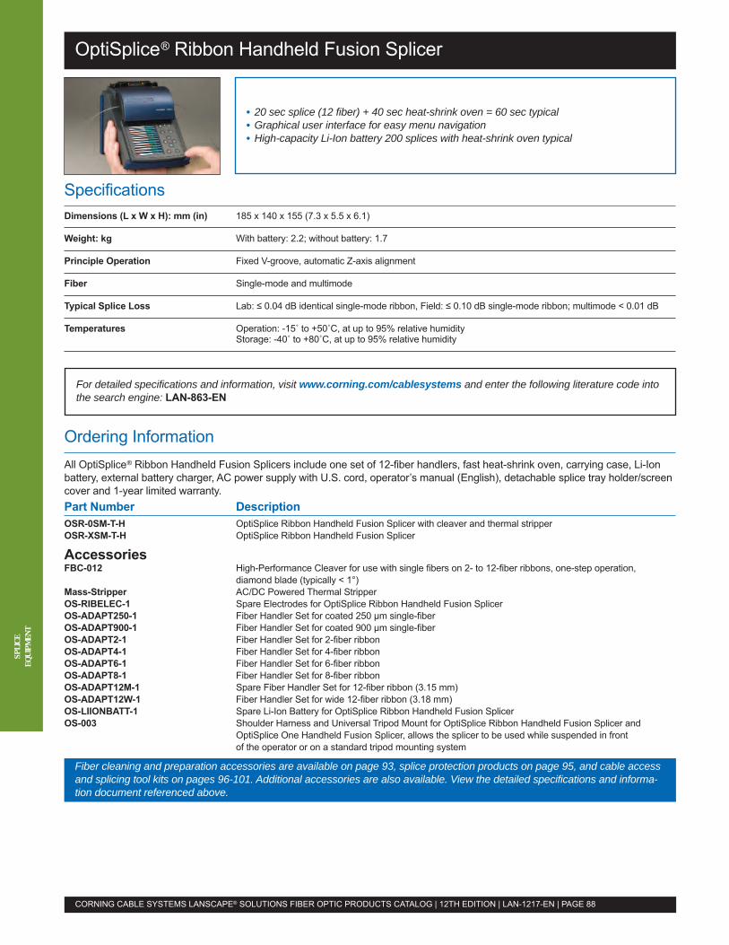
OptiSplice® Ribbon Handheld Fusion Splicer
SpecificationsDimensions (L x W x H): mm (in) 185 x 140 x 155 (7.3 x 5.5 x 6.1)
Weight: kg With battery: 2.2; without battery: 1.7
Principle Operation Fixed V-groove, automatic Z-axis alignment
Fiber Single-mode and multimode
Typical Splice Loss Lab: ≤ 0.04 dB identical single-mode ribbon, Field: ≤ 0.10 dB single-mode ribbon; multimode < 0.01 dB
Temperatures Operation: -15˚ to +50˚C, at up to 95% relative humidityStorage: -40˚ to +80˚C, at up to 95% relative humidity
• 20 sec splice (12 fiber) + 40 sec heat-shrink oven = 60 sec typical• Graphical user interface for easy menu navigation• High-capacity Li-Ion battery 200 splices with heat-shrink oven typical
Ordering InformationAll OptiSplice® Ribbon Handheld Fusion Splicers include one set of 12-fiber handlers, fast heat-shrink oven, carrying case, Li-Ionbattery, external battery charger, AC power supply with U.S. cord, operator’s manual (English), detachable splice tray holder/screencover and 1-year limited warranty.Part Number DescriptionOSR-0SM-T-H OptiSplice Ribbon Handheld Fusion Splicer with cleaver and thermal stripperOSR-XSM-T-H OptiSplice Ribbon Handheld Fusion Splicer
AccessoriesFBC-012 High-Performance Cleaver for use with single fibers on 2- to 12-fiber ribbons, one-step operation,
diamond blade (typically < 1°)Mass-Stripper AC/DC Powered Thermal StripperOS-RIBELEC-1 Spare Electrodes for OptiSplice Ribbon Handheld Fusion SplicerOS-ADAPT250-1 Fiber Handler Set for coated 250 µm single-fiberOS-ADAPT900-1 Fiber Handler Set for coated 900 µm single-fiberOS-ADAPT2-1 Fiber Handler Set for 2-fiber ribbonOS-ADAPT4-1 Fiber Handler Set for 4-fiber ribbonOS-ADAPT6-1 Fiber Handler Set for 6-fiber ribbonOS-ADAPT8-1 Fiber Handler Set for 8-fiber ribbonOS-ADAPT12M-1 Spare Fiber Handler Set for 12-fiber ribbon (3.15 mm)OS-ADAPT12W-1 Fiber Handler Set for wide 12-fiber ribbon (3.18 mm)OS-LIIONBATT-1 Spare Li-Ion Battery for OptiSplice Ribbon Handheld Fusion SplicerOS-003 Shoulder Harness and Universal Tripod Mount for OptiSplice Ribbon Handheld Fusion Splicer and
OptiSplice One Handheld Fusion Splicer, allows the splicer to be used while suspended in frontof the operator or on a standard tripod mounting system
For detailed specifications and information, visit www.corning.com/cablesystems and enter the following literature code intothe search engine: LAN-863-EN
CORNING CABLE SYSTEMS LANSCAPE® SOLUTIONS FIBER OPTIC PRODUCTS CATALOG | 12TH EDITION | LAN-1217-EN | PAGE 88
SPLI
CEEQ
UIPM
ENT
Fiber cleaning and preparation accessories are available on page 93, splice protection products on page 95, and cable accessand splicing tool kits on pages 96-101. Additional accessories are also available. View the detailed specifications and informa-tion document referenced above.

CamSplice™ No-Adhesive Mechanical Splice
Ordering InformationNote: The antitorsion CamSplice™ Mechanical Splice is not remateable.Part Number Description95-000-04 CamSplice Mechanical Splices (package of 6)95-000-04-ATC Antitorsion CamSplice Mechanical Splice for 900 µm applications
AccessoriesTKT-100-01 CamSplice Mechanical Splice Tool KitTKT-100-02 CamSplice Mechanical Splice Tool Kit with FBC-001 fiber cleaver2104040-01 CamSplice Mechanical Splice Assembly Fixture2104341-01 Crimp Tool for Antitorsion CamSplice Mechanical SpliceFBC-001 Score and Snap Fiber CleaverFBC-006 Precision Diamond Cleaver
SpecificationsCam Dimensions (L x W): mm (in) 44 x 4.2 (1.73 x 0.17)
Reflectance ≤ -45 dB for flat cleave; ≤ -60 dB for angled cleave
Temperature Range -40 to +75ºC, < 0.1 dB average variation
Splice Loss Mean: 0.15 dB; Blind: ≤ 0.3 dB
• Patented fiber alignment mechanism self-centers the fiber for accurate alignment• No adhesive or epoxy reduces splice time with no curing needed• Universal design offers one-part-fits-all fiber coatings• No polishing reduces installation time
For detailed specifications and information, visit www.corning.com/cablesystems and enter the following literature code intothe search engine: LAN-336-EN
CORNING CABLE SYSTEMS LANSCAPE® SOLUTIONS FIBER OPTIC PRODUCTS CATALOG | 12TH EDITION | LAN-1217-EN | PAGE 89
To order splice trays, see page 56.
SPLI
CEEQ
UIPM
ENT
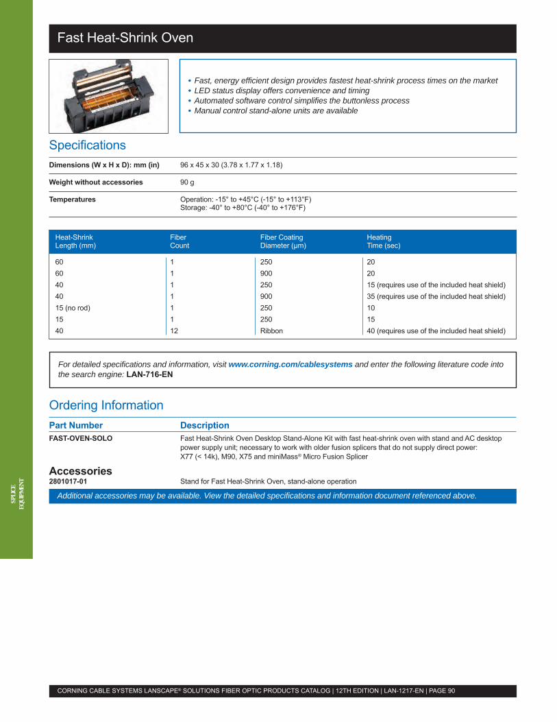
Fast Heat-Shrink Oven
Ordering InformationPart Number DescriptionFAST-OVEN-SOLO Fast Heat-Shrink Oven Desktop Stand-Alone Kit with fast heat-shrink oven with stand and AC desktop
power supply unit; necessary to work with older fusion splicers that do not supply direct power:X77 (< 14k), M90, X75 and miniMass® Micro Fusion Splicer
Accessories2801017-01 Stand for Fast Heat-Shrink Oven, stand-alone operation
SpecificationsDimensions (W x H x D): mm (in) 96 x 45 x 30 (3.78 x 1.77 x 1.18)
Weight without accessories 90 g
Temperatures Operation: -15° to +45°C (-15° to +113°F)Storage: -40° to +80°C (-40° to +176°F)
• Fast, energy efficient design provides fastest heat-shrink process times on the market• LED status display offers convenience and timing• Automated software control simplifies the buttonless process• Manual control stand-alone units are available
For detailed specifications and information, visit www.corning.com/cablesystems and enter the following literature code intothe search engine: LAN-716-EN
CORNING CABLE SYSTEMS LANSCAPE® SOLUTIONS FIBER OPTIC PRODUCTS CATALOG | 12TH EDITION | LAN-1217-EN | PAGE 90
SPLI
CEEQ
UIPM
ENT
Additional accessories may be available. View the detailed specifications and information document referenced above.
Heat-Shrink Fiber Fiber Coating HeatingLength (mm) Count Diameter (µm) Time (sec)
60 1 250 2060 1 900 2040 1 250 15 (requires use of the included heat shield)40 1 900 35 (requires use of the included heat shield)15 (no rod) 1 250 1015 1 250 1540 12 Ribbon 40 (requires use of the included heat shield)
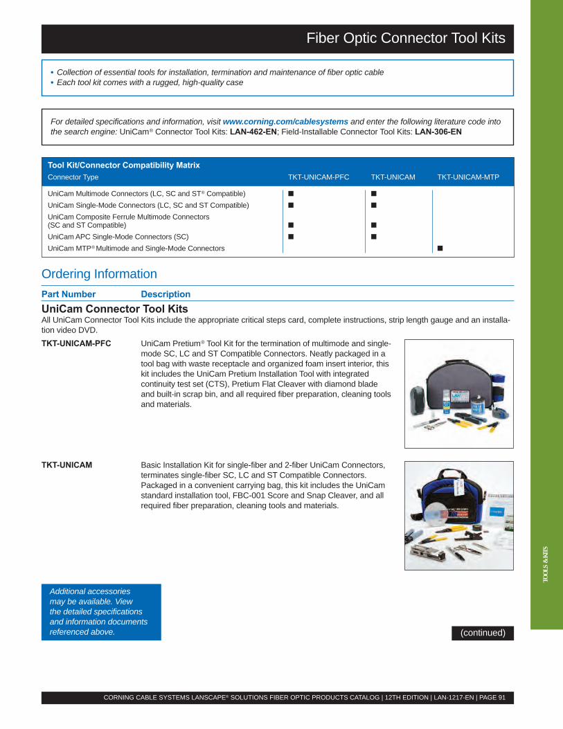
TOOL
S&
KITS
Ordering InformationPart Number DescriptionUniCam Connector Tool KitsAll UniCam Connector Tool Kits include the appropriate critical steps card, complete instructions, strip length gauge and an installa-tion video DVD.TKT-UNICAM-PFC UniCam Pretium® Tool Kit for the termination of multimode and single-
mode SC, LC and ST Compatible Connectors. Neatly packaged in atool bag with waste receptacle and organized foam insert interior, thiskit includes the UniCam Pretium Installation Tool with integratedcontinuity test set (CTS), Pretium Flat Cleaver with diamond bladeand built-in scrap bin, and all required fiber preparation, cleaning toolsand materials.
TKT-UNICAM Basic Installation Kit for single-fiber and 2-fiber UniCam Connectors,terminates single-fiber SC, LC and ST Compatible Connectors.Packaged in a convenient carrying bag, this kit includes the UniCamstandard installation tool, FBC-001 Score and Snap Cleaver, and allrequired fiber preparation, cleaning tools and materials.
Fiber Optic Connector Tool Kits
• Collection of essential tools for installation, termination and maintenance of fiber optic cable• Each tool kit comes with a rugged, high-quality case
CORNING CABLE SYSTEMS LANSCAPE® SOLUTIONS FIBER OPTIC PRODUCTS CATALOG | 12TH EDITION | LAN-1217-EN | PAGE 91
For detailed specifications and information, visit www.corning.com/cablesystems and enter the following literature code intothe search engine: UniCam® Connector Tool Kits: LAN-462-EN; Field-Installable Connector Tool Kits: LAN-306-EN
Tool Kit/Connector Compatibility MatrixConnector Type TKT-UNICAM-PFC TKT-UNICAM TKT-UNICAM-MTP
UniCam Multimode Connectors (LC, SC and ST® Compatible) � �
UniCam Single-Mode Connectors (LC, SC and ST Compatible) � �
UniCam Composite Ferrule Multimode Connectors(SC and ST Compatible) � �
UniCamAPC Single-Mode Connectors (SC) � �
UniCam MTP®Multimode and Single-Mode Connectors �
(continued)
Additional accessoriesmay be available. Viewthe detailed specificationsand information documentsreferenced above.
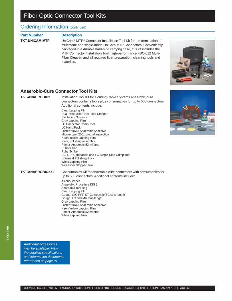
TOOL
S&
KITS
Fiber Optic Connector Tool Kits
Ordering Information (continued)
Part Number DescriptionTKT-UNICAM-MTP UniCam® MTP® Connector Installation Tool Kit for the termination of
multimode and single-mode UniCam MTP Connectors. Convenientlypackaged in a durable hard-side carrying case, this kit includes theMTP Connector Installation Tool, high-performance FBC-012 Multi-Fiber Cleaver, and all required fiber preparation, cleaning tools andmaterials.
Anaerobic-Cure Connector Tool KitsTKT-ANAEROBIC2 Installation Tool Kit for Corning Cable Systems anaerobic-cure
connectors contains tools plus consumables for up to 500 connectors.Additional contents include:Clear Lapping FilmDual-Hole Miller Tool Fiber StripperElectrician ScissorsGray Lapping FilmLC Connector Crimp ToolLC Hand PuckLoctite® #648 Anaerobic AdhesiveMicroscope, 200x coaxial inspectionNeon Yellow Lapping FilmPlate, polishing assemblyPrimer-Anaerobic 52 ml/pmpRubber PadRuby ScribeSC, ST® Compatible and FC Single-Step Crimp ToolUniversal Polishing PuckWhite Lapping FilmWire Fiber Stripper: 6 in
TKT-ANAEROBIC2-C Consumables Kit for anaerobic-cure connectors with consumables forup to 500 connectors. Additional contents include:Alcohol WipesAnaerobic Procedure ISS 2Anaerobic Tool BagClear Lapping FilmGauge, GIC RPP ST Compatible/SC strip lengthGauge, LC and MU strip lengthGray Lapping FilmLoctite® #648 Anaerobic AdhesiveNeon Yellow Lapping FilmPrimer-Anaerobic 52 ml/pmpWhite Lapping Film
CORNING CABLE SYSTEMS LANSCAPE® SOLUTIONS FIBER OPTIC PRODUCTS CATALOG | 12TH EDITION | LAN-1217-EN | PAGE 92
Additional accessoriesmay be available. Viewthe detailed specificationsand information documentsreferenced on page 91.
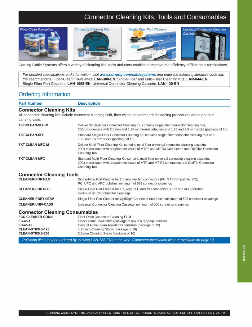
Connector Cleaning Kits, Tools and Consumables
Corning Cable Systems offers a variety of cleaning kits, tools and consumables to improve the efficiency of fiber optic terminations.
For detailed specifications and information, visit www.corning.com/cablesystems and enter the following literature code intothe search engine: Fiber-Clean® Towelettes: LAN-308-EN; Single-Fiber and Multi-Fiber Cleaning Kits: LAN-844-EN;Single-Fiber Port Cleaners: LAN-1098-EN; Universal Connector Cleaning Cassette: LAN-130-EN
CORNING CABLE SYSTEMS LANSCAPE® SOLUTIONS FIBER OPTIC PRODUCTS CATALOG | 12TH EDITION | LAN-1217-EN | PAGE 93
TOOL
S&
KITS
Fiber-Clean Towelettes Connector Cleaning Kits Single-Fiber Port Cleaners Universal Connector CleaningCassette
Polishing films may be ordered by viewing LAN-786-EN on the web. Connector installation kits are available on page 91.
Ordering InformationPart Number DescriptionConnector Cleaning KitsAll connector cleaning kits include connector cleaning fluid, fiber wipes, recommended cleaning procedures and a paddedcarrying case.TKT-CLEAN-SFC-M Deluxe Single-Fiber Connector Cleaning Kit, contains single-fiber connector cleaning reel,
200x microscope with 2.5 mm and 1.25 mm ferrule adapters and 1.25 and 2.5 mm sticks (package of 10)
TKT-CLEAN-SFC Standard Single-Fiber Connector Cleaning Kit, contains single-fiber connector cleaning reel and1.25 and 2.5 mm sticks (package of 10)
TKT-CLEAN-MFC-M Deluxe Multi-Fiber Cleaning Kit, contains multi-fiber universal connector cleaning cassette,200x microscope with adapters for visual of MTP® and MT-RJ Connectors and OptiTip® ConnectorCleaning Tool
TKT-CLEAN-MFC Standard Multi-Fiber Cleaning Kit, contains multi-fiber universal connector cleaning cassette,200x microscope with adapters for visual of MTP and MT-RJ connectors and OptiTip ConnectorCleaning Tool
Connector Cleaning ToolsCLEANER-PORT-2.5 Single-Fiber Port Cleaner for 2.5 mm ferruled connectors (FC, ST®Compatible, SC);
PC, UPC and APC polishes; minimum of 525 connector cleanings
CLEANER-PORT-LC Single-Fiber Port Cleaner for LC, keyed LC and MU connectors; UPC and APC polishes;minimum of 525 connector cleanings
CLEANER-PORT-OTAP Single-Fiber Port Cleaner for OptiTap® Connector end-faces; minimum of 525 connector cleanings
CLEANER-UNIV-CASS Universal Connector Cleaning Cassette; minimum of 500 connector cleanings
Connector Cleaning ConsumablesFCC-CLEANER-CONN Fiber Optic Connector Cleaning FluidFC-45-1 Fiber-Clean® Towelettes (package of 45) in a “pop-up” canisterFC-45-12 Case of Fiber-Clean Towelettes canisters (package of 12)CLEAN-STICKS-125 1.25 mm Cleaning Sticks (package of 10)CLEAN-STICKS-250 2.5 mm Cleaning Sticks (package of 10)
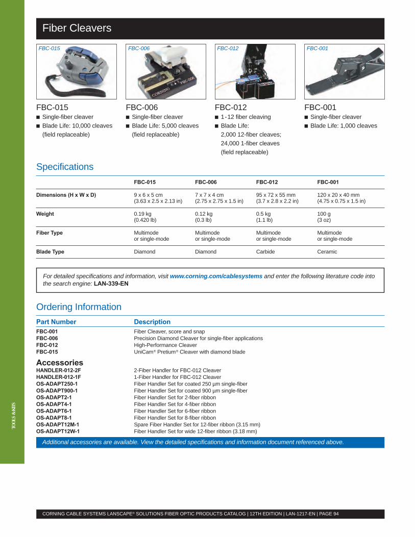
Fiber Cleavers
CORNING CABLE SYSTEMS LANSCAPE® SOLUTIONS FIBER OPTIC PRODUCTS CATALOG | 12TH EDITION | LAN-1217-EN | PAGE 94
TOOL
S&
KITS
FBC-015 FBC-006 FBC-012 FBC-001
FBC-015� Single-fiber cleaver� Blade Life: 10,000 cleaves(field replaceable)
FBC-006� Single-fiber cleaver� Blade Life: 5,000 cleaves(field replaceable)
FBC-012� 1-12 fiber cleaving� Blade Life:2,000 12-fiber cleaves;24,000 1-fiber cleaves(field replaceable)
FBC-001� Single-fiber cleaver� Blade Life: 1,000 cleaves
For detailed specifications and information, visit www.corning.com/cablesystems and enter the following literature code intothe search engine: LAN-339-EN
Ordering InformationPart Number DescriptionFBC-001 Fiber Cleaver, score and snapFBC-006 Precision Diamond Cleaver for single-fiber applicationsFBC-012 High-Performance CleaverFBC-015 UniCam® Pretium® Cleaver with diamond blade
AccessoriesHANDLER-012-2F 2-Fiber Handler for FBC-012 CleaverHANDLER-012-1F 1-Fiber Handler for FBC-012 CleaverOS-ADAPT250-1 Fiber Handler Set for coated 250 µm single-fiberOS-ADAPT900-1 Fiber Handler Set for coated 900 µm single-fiberOS-ADAPT2-1 Fiber Handler Set for 2-fiber ribbonOS-ADAPT4-1 Fiber Handler Set for 4-fiber ribbonOS-ADAPT6-1 Fiber Handler Set for 6-fiber ribbonOS-ADAPT8-1 Fiber Handler Set for 8-fiber ribbonOS-ADAPT12M-1 Spare Fiber Handler Set for 12-fiber ribbon (3.15 mm)OS-ADAPT12W-1 Fiber Handler Set for wide 12-fiber ribbon (3.18 mm)
SpecificationsFBC-015 FBC-006 FBC-012 FBC-001
Dimensions (H x W x D) 9 x 6 x 5 cm 7 x 7 x 4 cm 95 x 72 x 55 mm 120 x 20 x 40 mm(3.63 x 2.5 x 2.13 in) (2.75 x 2.75 x 1.5 in) (3.7 x 2.8 x 2.2 in) (4.75 x 0.75 x 1.5 in)
Weight 0.19 kg 0.12 kg 0.5 kg 100 g(0.420 lb) (0.3 lb) (1.1 lb) (3 oz)
Fiber Type Multimode Multimode Multimode Multimodeor single-mode or single-mode or single-mode or single-mode
Blade Type Diamond Diamond Carbide Ceramic
Additional accessories are available. View the detailed specifications and information document referenced above.
Fusion Splice Protection
SpecificationsSplice-Pak Splice Protector Crimp & Go Splice Protection Crimping Device
Closed Dimensions (H x W x D) 2.0 x 3.2 x 35.0 mm 1.1 x 3.2 x 30.0 mm
Fiber Diameter 250/250 µm, 250/900 µm, 900/900 µm Not more than 250 µm
Bare Fiber Length Not more than 25 mm Not more than 25 mm
Handling Temperature Range -5º to +45ºC -5º to +45ºC
• All splice protection choices allow individual fiber access in the splice tray• Heat-shrink protection for both single-fiber and multi-fiber applications• Splice-Pak™ and Crimp & Go® Single-Fiber Splice Protectors require no powerfor assembly
• Custom heat-shrink protection is also available upon request
For detailed specifications and information, visit www.corning.com/cablesystems and enter the following literature code intothe search engine: LAN-340-EN
CORNING CABLE SYSTEMS LANSCAPE® SOLUTIONS FIBER OPTIC PRODUCTS CATALOG | 12TH EDITION | LAN-1217-EN | PAGE 95
Ordering InformationPart Number Description2806031-01 Heat-Shrink Fusion Splice Protector Parts, single-fiber (package of 50; 60 mm long)2806032-01 Heat-Shrink Fusion Splice Protector Parts, single-fiber (package of 50; 40 mm long)2806031-04 Heat-Shrink Mass Splice Protector Parts, 2- or 4-fiber ribbon (package of 25; 40 mm long)2806031-012 Heat-Shrink Mass Splice Protector Parts, 6- or 12-fiber ribbon (package of 25; 40 mm long)FSA-012 Crimp & Go Splice Protection Crimping Device Parts (package of 150)A0276859 Splice Pak Splice Protector, yellow, 250/250 µm (package of 25)A0295149 Splice Pak Splice Protector, blue, 250/900 µm (package of 25)A0295150 Splice Pak Splice Protector, green, 900/900 µm (package of 25)FSA-019 15 mm Single-Fiber Mini Heat-Shrink Splice Protectors; mini 250 µm only (package of 100)FSA-026 15 mm Single-Fiber Mini Heat-Shrink Splice Protectors; no rod, 250 µm only (package of 100)
TOOL
S&
KITS
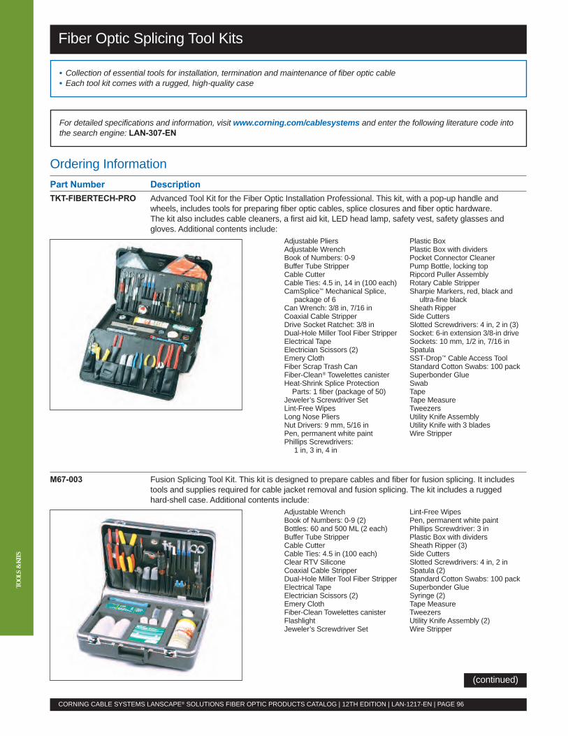
TOOL
S&
KITS
Ordering InformationPart Number DescriptionTKT-FIBERTECH-PRO Advanced Tool Kit for the Fiber Optic Installation Professional. This kit, with a pop-up handle and
wheels, includes tools for preparing fiber optic cables, splice closures and fiber optic hardware.The kit also includes cable cleaners, a first aid kit, LED head lamp, safety vest, safety glasses andgloves. Additional contents include:
Adjustable Pliers Plastic BoxAdjustable Wrench Plastic Box with dividersBook of Numbers: 0-9 Pocket Connector CleanerBuffer Tube Stripper Pump Bottle, locking topCable Cutter Ripcord Puller AssemblyCable Ties: 4.5 in, 14 in (100 each) Rotary Cable StripperCamSplice™ Mechanical Splice, Sharpie Markers, red, black and
package of 6 ultra-fine blackCan Wrench: 3/8 in, 7/16 in Sheath RipperCoaxial Cable Stripper Side CuttersDrive Socket Ratchet: 3/8 in Slotted Screwdrivers: 4 in, 2 in (3)Dual-Hole Miller Tool Fiber Stripper Socket: 6-in extension 3/8-in driveElectrical Tape Sockets: 10 mm, 1/2 in, 7/16 inElectrician Scissors (2) SpatulaEmery Cloth SST-Drop™ Cable Access ToolFiber Scrap Trash Can Standard Cotton Swabs: 100 packFiber-Clean® Towelettes canister Superbonder GlueHeat-Shrink Splice Protection Swab
Parts: 1 fiber (package of 50) TapeJeweler’s Screwdriver Set Tape MeasureLint-Free Wipes TweezersLong Nose Pliers Utility Knife AssemblyNut Drivers: 9 mm, 5/16 in Utility Knife with 3 bladesPen, permanent white paint Wire StripperPhillips Screwdrivers:
1 in, 3 in, 4 in
M67-003 Fusion Splicing Tool Kit. This kit is designed to prepare cables and fiber for fusion splicing. It includestools and supplies required for cable jacket removal and fusion splicing. The kit includes a ruggedhard-shell case. Additional contents include:
Adjustable Wrench Lint-Free WipesBook of Numbers: 0-9 (2) Pen, permanent white paintBottles: 60 and 500 ML (2 each) Phillips Screwdriver: 3 inBuffer Tube Stripper Plastic Box with dividersCable Cutter Sheath Ripper (3)Cable Ties: 4.5 in (100 each) Side CuttersClear RTV Silicone Slotted Screwdrivers: 4 in, 2 inCoaxial Cable Stripper Spatula (2)Dual-Hole Miller Tool Fiber Stripper Standard Cotton Swabs: 100 packElectrical Tape Superbonder GlueElectrician Scissors (2) Syringe (2)Emery Cloth Tape MeasureFiber-Clean Towelettes canister TweezersFlashlight Utility Knife Assembly (2)Jeweler’s Screwdriver Set Wire Stripper
Fiber Optic Splicing Tool Kits
• Collection of essential tools for installation, termination and maintenance of fiber optic cable• Each tool kit comes with a rugged, high-quality case
CORNING CABLE SYSTEMS LANSCAPE® SOLUTIONS FIBER OPTIC PRODUCTS CATALOG | 12TH EDITION | LAN-1217-EN | PAGE 96
For detailed specifications and information, visit www.corning.com/cablesystems and enter the following literature code intothe search engine: LAN-307-EN
(continued)
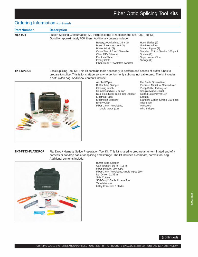
TOOL
S&
KITS
Fiber Optic Splicing Tool Kits
Ordering Information (continued)
Part Number DescriptionM67-004 Fusion Splicing Consumables Kit. Includes items to replenish the M67-003 Tool Kit.
Good for approximately 600 fibers. Additional contents include:Battery, AAAlkaline, 1.5 v (2) Hook Blades (6)Book of Numbers: 0-9 (2) Lint-Free WipesBottle: 60 ML (2) Sheath Ripper (2)Cable Ties: 4.5 in (100 each) Standard Cotton Swabs: 100 packClear RTV Silicone Spatula (2)Electrical Tape Superbonder GlueEmery Cloth Syringe (2)Fiber-Clean® Towelettes canister
TKT-SPLICE Basic Splicing Tool Kit. This kit contains tools necessary to perform end access of buffer tubes toprepare to splice. This is for craft persons who perform only splicing, not cable prep. The kit includesa soft, nylon bag. Additional contents include:
Alcohol Wipes Flat Blade ScrewdriverBuffer Tube Stripper Precision Miniature ScrewdriverCleaning Brush Pump Bottle, locking topCompressed Air, 5 oz can Sharpie Marker, blackDual-Hole Miller Tool Fiber Stripper Slotted Screwdriver: 4 inElectrical Tape SpatulaElectrician Scissors Standard Cotton Swabs: 100 packEmery Cloth Tricep ToolFiber-Clean Towelettes, Tweezers
single wipes (12) Wire Stripper
TKT-FTTX-FLATDROP Flat Drop / Harness Splice Preparation Tool Kit. This kit is used to prepare an unterminated end of aharness or flat drop cable for splicing and storage. The kit includes a compact, canvas tool bag.Additional contents include:
Buffer Tube StripperCan Wrench: 3/8 in, 7/16 inFiber Stripper, plier typeFiber-Clean Towelettes, single wipes (10)Nut Driver: 11/32 inSide CuttersSST-Drop™ Cable Access ToolTape MeasureUtility Knife with 3 blades
CORNING CABLE SYSTEMS LANSCAPE® SOLUTIONS FIBER OPTIC PRODUCTS CATALOG | 12TH EDITION | LAN-1217-EN | PAGE 97
(continued)
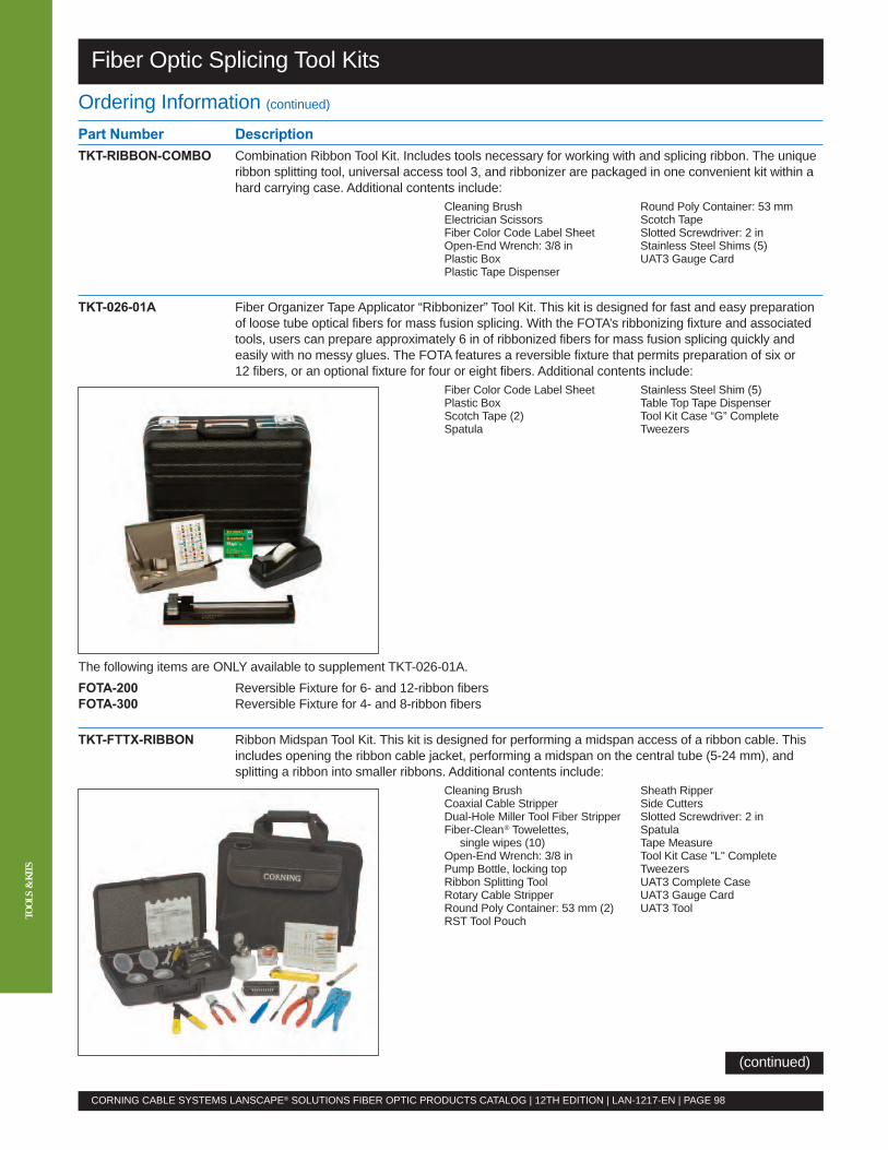
TOOL
S&
KITS
Ordering Information (continued)
Part Number DescriptionTKT-RIBBON-COMBO Combination Ribbon Tool Kit. Includes tools necessary for working with and splicing ribbon. The unique
ribbon splitting tool, universal access tool 3, and ribbonizer are packaged in one convenient kit within ahard carrying case. Additional contents include:
Cleaning Brush Round Poly Container: 53 mmElectrician Scissors Scotch TapeFiber Color Code Label Sheet Slotted Screwdriver: 2 inOpen-End Wrench: 3/8 in Stainless Steel Shims (5)Plastic Box UAT3 Gauge CardPlastic Tape Dispenser
TKT-026-01A Fiber Organizer Tape Applicator “Ribbonizer” Tool Kit. This kit is designed for fast and easy preparationof loose tube optical fibers for mass fusion splicing. With the FOTA’s ribbonizing fixture and associatedtools, users can prepare approximately 6 in of ribbonized fibers for mass fusion splicing quickly andeasily with no messy glues. The FOTA features a reversible fixture that permits preparation of six or12 fibers, or an optional fixture for four or eight fibers. Additional contents include:
Fiber Color Code Label Sheet Stainless Steel Shim (5)Plastic Box Table Top Tape DispenserScotch Tape (2) Tool Kit Case “G” CompleteSpatula Tweezers
The following items are ONLY available to supplement TKT-026-01A.FOTA-200 Reversible Fixture for 6- and 12-ribbon fibersFOTA-300 Reversible Fixture for 4- and 8-ribbon fibers
TKT-FTTX-RIBBON Ribbon Midspan Tool Kit. This kit is designed for performing a midspan access of a ribbon cable. Thisincludes opening the ribbon cable jacket, performing a midspan on the central tube (5-24 mm), andsplitting a ribbon into smaller ribbons. Additional contents include:
Cleaning Brush Sheath RipperCoaxial Cable Stripper Side CuttersDual-Hole Miller Tool Fiber Stripper Slotted Screwdriver: 2 inFiber-Clean® Towelettes, Spatula
single wipes (10) Tape MeasureOpen-End Wrench: 3/8 in Tool Kit Case "L" CompletePump Bottle, locking top TweezersRibbon Splitting Tool UAT3 Complete CaseRotary Cable Stripper UAT3 Gauge CardRound Poly Container: 53 mm (2) UAT3 ToolRST Tool Pouch
Fiber Optic Splicing Tool Kits
CORNING CABLE SYSTEMS LANSCAPE® SOLUTIONS FIBER OPTIC PRODUCTS CATALOG | 12TH EDITION | LAN-1217-EN | PAGE 98
(continued)
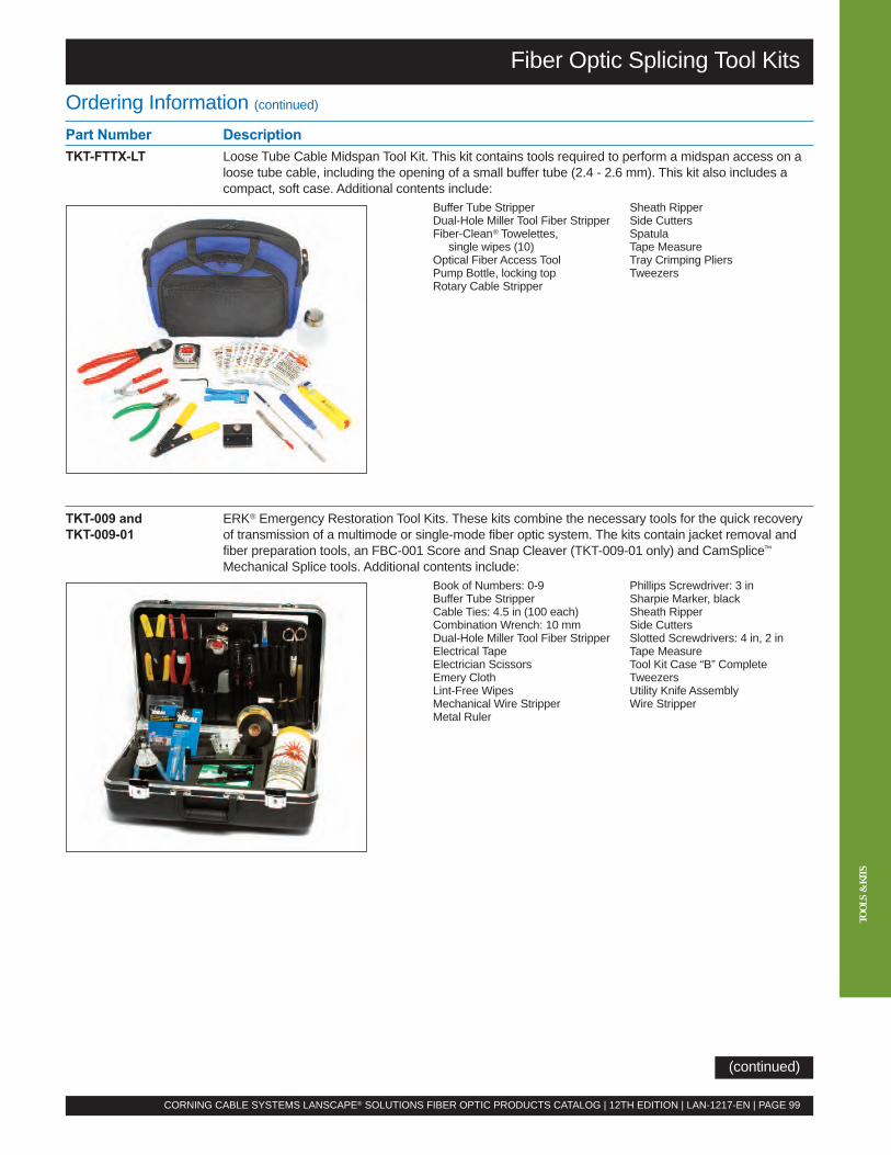
TOOL
S&
KITS
Fiber Optic Splicing Tool Kits
Ordering Information (continued)
Part Number DescriptionTKT-FTTX-LT Loose Tube Cable Midspan Tool Kit. This kit contains tools required to perform a midspan access on a
loose tube cable, including the opening of a small buffer tube (2.4 - 2.6 mm). This kit also includes acompact, soft case. Additional contents include:
Buffer Tube Stripper Sheath RipperDual-Hole Miller Tool Fiber Stripper Side CuttersFiber-Clean® Towelettes, Spatula
single wipes (10) Tape MeasureOptical Fiber Access Tool Tray Crimping PliersPump Bottle, locking top TweezersRotary Cable Stripper
TKT-009 and ERK® Emergency Restoration Tool Kits. These kits combine the necessary tools for the quick recoveryTKT-009-01 of transmission of a multimode or single-mode fiber optic system. The kits contain jacket removal and
fiber preparation tools, an FBC-001 Score and Snap Cleaver (TKT-009-01 only) and CamSplice™
Mechanical Splice tools. Additional contents include:Book of Numbers: 0-9 Phillips Screwdriver: 3 inBuffer Tube Stripper Sharpie Marker, blackCable Ties: 4.5 in (100 each) Sheath RipperCombination Wrench: 10 mm Side CuttersDual-Hole Miller Tool Fiber Stripper Slotted Screwdrivers: 4 in, 2 inElectrical Tape Tape MeasureElectrician Scissors Tool Kit Case “B” CompleteEmery Cloth TweezersLint-Free Wipes Utility Knife AssemblyMechanical Wire Stripper Wire StripperMetal Ruler
CORNING CABLE SYSTEMS LANSCAPE® SOLUTIONS FIBER OPTIC PRODUCTS CATALOG | 12TH EDITION | LAN-1217-EN | PAGE 99
(continued)
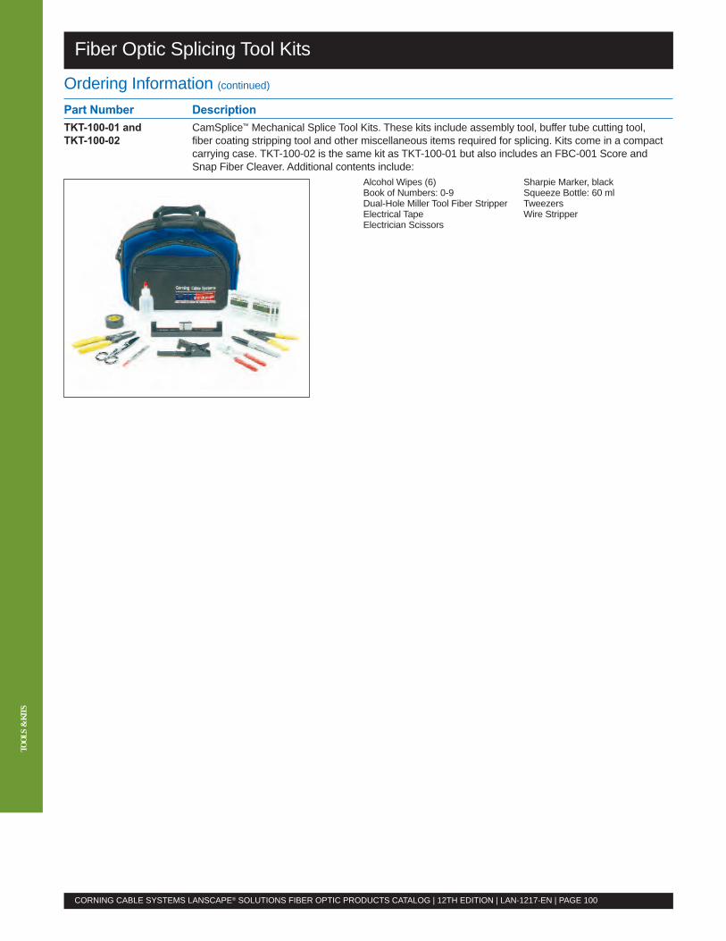
TOOL
S&
KITS
Fiber Optic Splicing Tool Kits
Ordering Information (continued)
Part Number DescriptionTKT-100-01 and CamSplice™ Mechanical Splice Tool Kits. These kits include assembly tool, buffer tube cutting tool,TKT-100-02 fiber coating stripping tool and other miscellaneous items required for splicing. Kits come in a compact
carrying case. TKT-100-02 is the same kit as TKT-100-01 but also includes an FBC-001 Score andSnap Fiber Cleaver. Additional contents include:
Alcohol Wipes (6) Sharpie Marker, blackBook of Numbers: 0-9 Squeeze Bottle: 60 mlDual-Hole Miller Tool Fiber Stripper TweezersElectrical Tape Wire StripperElectrician Scissors
CORNING CABLE SYSTEMS LANSCAPE® SOLUTIONS FIBER OPTIC PRODUCTS CATALOG | 12TH EDITION | LAN-1217-EN | PAGE 100
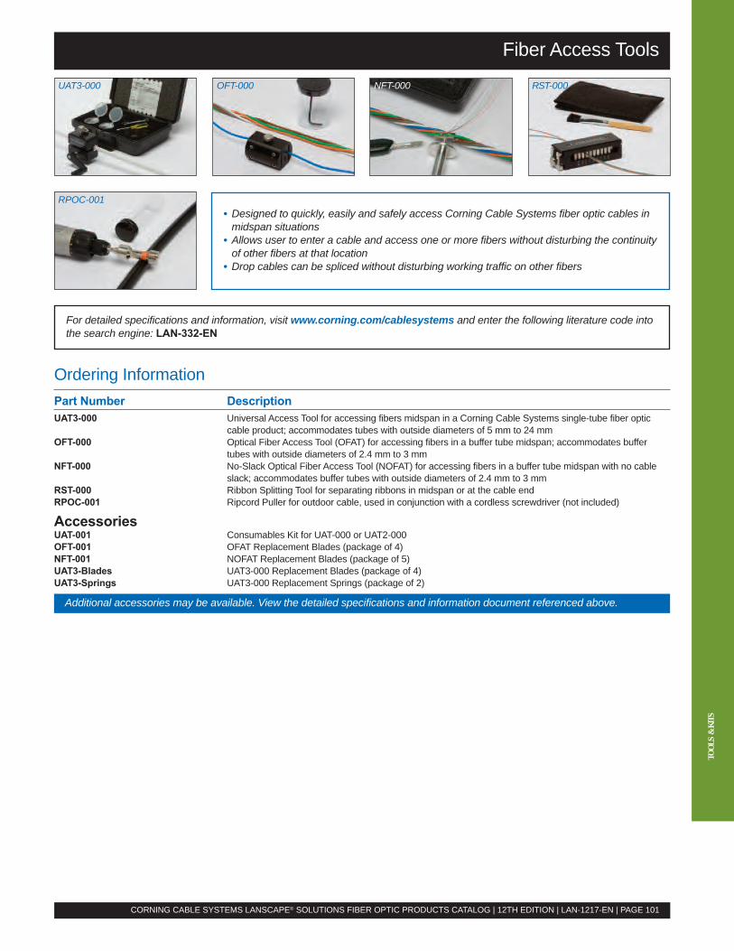
Fiber Access Tools
For detailed specifications and information, visit www.corning.com/cablesystems and enter the following literature code intothe search engine: LAN-332-EN
CORNING CABLE SYSTEMS LANSCAPE® SOLUTIONS FIBER OPTIC PRODUCTS CATALOG | 12TH EDITION | LAN-1217-EN | PAGE 101
TOOL
S&
KITS
UAT3-000 OFT-000 NFT-000 RST-000
Ordering InformationPart Number DescriptionUAT3-000 Universal Access Tool for accessing fibers midspan in a Corning Cable Systems single-tube fiber optic
cable product; accommodates tubes with outside diameters of 5 mm to 24 mmOFT-000 Optical Fiber Access Tool (OFAT) for accessing fibers in a buffer tube midspan; accommodates buffer
tubes with outside diameters of 2.4 mm to 3 mmNFT-000 No-Slack Optical Fiber Access Tool (NOFAT) for accessing fibers in a buffer tube midspan with no cable
slack; accommodates buffer tubes with outside diameters of 2.4 mm to 3 mmRST-000 Ribbon Splitting Tool for separating ribbons in midspan or at the cable endRPOC-001 Ripcord Puller for outdoor cable, used in conjunction with a cordless screwdriver (not included)
AccessoriesUAT-001 Consumables Kit for UAT-000 or UAT2-000OFT-001 OFAT Replacement Blades (package of 4)NFT-001 NOFAT Replacement Blades (package of 5)UAT3-Blades UAT3-000 Replacement Blades (package of 4)UAT3-Springs UAT3-000 Replacement Springs (package of 2)
Additional accessories may be available. View the detailed specifications and information document referenced above.
• Designed to quickly, easily and safely access Corning Cable Systems fiber optic cables inmidspan situations
• Allows user to enter a cable and access one or more fibers without disturbing the continuityof other fibers at that location
• Drop cables can be spliced without disturbing working traffic on other fibers
RPOC-001

Cable assembly part numbers are configured and may be found on page 49.
Product Description Part Number Page
IndoorFan-Out Cable, OM1, plenum, 1.6 mm subunits _ _ _ K68-31430-29 34
Fan-Out Cable, OM1, plenum, 2.0 mm subunits _ _ _ K68-31330-29 34
Fan-Out Cable, OM1, plenum, 2.9 mm subunits _ _ _ K68-31130-29 34
Fan-Out Cable, OM1, riser, 1.6 mm subunits _ _ _ K61-31430-24 34
Fan-Out Cable, OM1, riser, 2.0 mm subunits _ _ _ K61-31330-24 34
Fan-Out Cable, OM1, riser, 2.9 mm subunits _ _ _ K61-31130-24 34
Fan-Out Cable, OM2, plenum, 1.6 mm subunits _ _ _ T68-31431-29 34
Fan-Out Cable, OM2, plenum, 2.0 mm subunits _ _ _ T68-31331-29 34
Fan-Out Cable, OM2, plenum, 2.9 mm subunits _ _ _ T68-31131-29 34
Fan-Out Cable, OM2, riser, 1.6 mm subunits _ _ _ T61-31431-24 34
Fan-Out Cable, OM2, riser, 2.0 mm subunits _ _ _ T61-31331-24 34
Fan-Out Cable, OM2, riser, 2.9 mm subunits _ _ _ T61-31131-24 34
Fan-Out Cable, OM3, plenum, 1.6 mm subunits _ _ _ T68-31480-29 34
Fan-Out Cable, OM3, plenum, 2.0 mm subunits _ _ _ T68-31380-29 34
Fan-Out Cable, OM3, plenum, 2.9 mm subunits _ _ _ T68-31180-29 34
Fan-Out Cable, OM3, riser, 1.6 mm subunits _ _ _ T61-31480-24 34
Fan-Out Cable, OM3, riser, 2.0 mm subunits _ _ _ T61-31380-24 34
Fan-Out Cable, OM3, riser, 2.9 mm subunits _ _ _ T61-31180-24 34
Fan-Out Cable, OM4, plenum, 1.6 mm subunits _ _ _ T68-31490-29 34
Fan-Out Cable, OM4, plenum, 2.0 mm subunits _ _ _ T68-31390-29 34
Fan-Out Cable, OM4, plenum, 2.9 mm subunits _ _ _ T68-31190-29 34
Fan-Out Cable, OM4, riser, 1.6 mm subunits _ _ _ T61-31490-24 34
Fan-Out Cable, OM4, riser, 2.0 mm subunits _ _ _ T61-31390-24 34
Fan-Out Cable, OM4, riser, 2.9 mm subunits _ _ _ T61-31190-24 34
Fan-Out Cable, OS2, plenum, 1.6 mm subunits _ _ _ E68-31431-29 34
Fan-Out Cable, OS2, plenum, 2.0 mm subunits _ _ _ E68-31331-29 34
Fan-Out Cable, OS2, plenum, 2.9 mm subunits _ _ _ E68-31131-29 34
Fan-Out Cable, OS2, riser, 1.6 mm subunits _ _ _ E61-31431-24 34
Fan-Out Cable, OS2, riser, 2.0 mm subunits _ _ _ E61-31331-24 34
Fan-Out Cable, OS2, riser, 2.9 mm subunits _ _ _ E61-31131-24 34
LSZH™ Ribbon Cable, OM1 _ _ _ KCZ-14130-20 36
LSZH Ribbon Cable, OM2 _ _ _ TCZ-14131-20 36
LSZH Ribbon Cable, OM3 _ _ _ TCZ-14180-20 36
LSZH Ribbon Cable, OM4 _ _ _ TCZ-14190-20 36
LSZH Ribbon Cable, OS2 _ _ _ ECZ-14101-20 36
MIC® 250 Cable, OM1 _ _ _ KD8-31330-20 33
MIC 250 Cable, OM2 _ _ _ TD8-31331-20 33
MIC 250 Cable, OM3 _ _ _ TD8-31380-20 33
MIC 250 Cable, OM4 _ _ _ TD8-31390-20 33
MIC 250 Cable, OS2 _ _ _ ED8-31301-20 33
MIC Cable, OM1, IA, riser, 60-144f _ _ _ K81-T3130-A1 31
MIC Cable, OM1, IA, plenum, 12-24f _ _ _ K88-33130-A3 31
MIC Cable, OM1, IA, plenum, 2-8f _ _ _ K88-31130-A3 31
MIC Cable, OM1, IA, plenum, 36-48f _ _ _ K88-61130-A3 31
MIC Cable, OM1, IA, plenum, 60-144f _ _ _ K88-T3130-A3 31
MIC Cable, OM1, IA, riser, 12-24f _ _ _ K81-33130-A1 31
MIC Cable, OM1, IA, riser, 2-8f _ _ _ K81-31130-A1 31
MIC Cable, OM1, IA, riser, 36-48f _ _ _ K81-61130-A1 31
f = fibers | IA = interlocking armored
Index
CORNING CABLE SYSTEMS LANSCAPE® SOLUTIONS FIBER OPTIC PRODUCTS CATALOG | 12TH EDITION | LAN-1217-EN | PAGE 112
Cable Assemblies
Cables
INDE
X

INDE
X
Product Description Part Number Page
Indoor (continued)MIC® Cable, OM1, plenum, 12-24f _ _ _ K88-33130-29 30
MIC Cable, OM1, plenum, 2-8f _ _ _ K88-31130-29 30
MIC Cable, OM1, plenum, 36-48f _ _ _ K88-61130-29 30
MIC Cable, OM1, plenum, 60-144f _ _ _ K88-T3130-29 30
MIC Cable, OM1, riser, 12-24f _ _ _ K81-33130-24 30
MIC Cable, OM1, riser, 2-8f _ _ _ K81-31130-24 30
MIC Cable, OM1, riser, 36-48f _ _ _ K81-61130-24 30
MIC Cable, OM1, riser, 60-144f _ _ _ K81-T3130-24 30
MIC Cable, OM2, IA, riser, 60-144f _ _ _ T81-T3131-A1 31
MIC Cable, OM2, IA, plenum, 12-24f _ _ _ T88-33131-A3 31
MIC Cable, OM2, IA, plenum, 2-8f _ _ _ T88-31131-A3 31
MIC Cable, OM2, IA, plenum, 36-48f _ _ _ T88-61131-A3 31
MIC Cable, OM2, IA, plenum, 60-144f _ _ _ T88-T3131-A3 31
MIC Cable, OM2, IA, riser, 12-24f _ _ _ T81-33131-A1 31
MIC Cable, OM2, IA, riser, 2-8f _ _ _ T81-31131-A1 31
MIC Cable, OM2, IA, riser, 36-48f _ _ _ T81-61131-A1 31
MIC Cable, OM2, plenum, 12-24f _ _ _ T88-33131-29 30
MIC Cable, OM2, plenum, 2-8f _ _ _ T88-31131-29 30
MIC Cable, OM2, plenum, 36-48f _ _ _ T88-61131-29 30
MIC Cable, OM2, plenum, 60-144f _ _ _ T88-T3131-29 30
MIC Cable, OM2, riser, 12-24f _ _ _ T81-33131-24 30
MIC Cable, OM2, riser, 2-8f _ _ _ T81-31131-24 30
MIC Cable, OM2, riser, 36-48f _ _ _ T81-61131-24 30
MIC Cable, OM2, riser, 60-144f _ _ _ T81-T3131-24 30
MIC Cable, OM3, IA, riser, 60-144f _ _ _ T81-T3180-A1 31
MIC Cable, OM3, IA, plenum, 12-24f _ _ _ T88-33180-A3 31
MIC Cable, OM3, IA, plenum, 2-8f _ _ _ T88-31180-A3 31
MIC Cable, OM3, IA, plenum, 36-48f _ _ _ T88-61180-A3 31
MIC Cable, OM3, IA, plenum, 60-144f _ _ _ T88-T3180-A3 31
MIC Cable, OM3, IA, riser, 12-24f _ _ _ T81-33180-A1 31
MIC Cable, OM3, IA, riser, 2-8f _ _ _ T81-31180-A1 31
MIC Cable, OM3, IA, riser, 36-48f _ _ _ T81-61180-A1 31
MIC Cable, OM3, plenum, 12-24f _ _ _ T88-33180-29 30
MIC Cable, OM3, plenum, 2-8f _ _ _ T88-31180-29 30
MIC Cable, OM3, plenum, 36-48f _ _ _ T88-61180-29 30
MIC Cable, OM3, plenum, 60-144f _ _ _ T88-T3180-29 30
MIC Cable, OM3, riser, 12-24f _ _ _ T81-33180-24 30
MIC Cable, OM3, riser, 2-8f _ _ _ T81-31180-24 30
MIC Cable, OM3, riser, 36-48f _ _ _ T81-61180-24 30
MIC Cable, OM3, riser, 60-144f _ _ _ T81-T3180-24 30
MIC Cable, OM4, IA, riser, 60-144f _ _ _ T81-T3190-A1 31
MIC Cable, OM4, IA, plenum, 12-24f _ _ _ T88-33190-A3 31
MIC Cable, OM4, IA, plenum, 2-8f _ _ _ T88-31190-A3 31
MIC Cable, OM4, IA, plenum, 36-48f _ _ _ T88-61190-A3 31
MIC Cable, OM4, IA, plenum, 60-144f _ _ _ T88-T3190-A3 31
MIC Cable, OM4, IA, riser, 12-24f _ _ _ T81-33190-A1 31
MIC Cable, OM4, IA, riser, 2-8f _ _ _ T81-31190-A1 31
MIC Cable, OM4, IA, riser, 36-48f _ _ _ T81-61190-A1 31
MIC Cable, OM4, plenum, 12-24f _ _ _ T88-33190-29 30
MIC Cable, OM4, plenum, 2-8f _ _ _ T88-31190-29 30
f = fibers | IA = interlocking armored
Index
CORNING CABLE SYSTEMS LANSCAPE® SOLUTIONS FIBER OPTIC PRODUCTS CATALOG | 12TH EDITION | LAN-1217-EN | PAGE 113
Cables
www.corning.com/cablesystemscustomer service: 800.743.2675

INDE
X
Product Description Part Number Page
Indoor (continued)MIC® Cable, OM4, plenum, 36-48f _ _ _ T88-61190-29 30
MIC Cable, OM4, plenum, 60-144f _ _ _ T88-T3190-29 30
MIC Cable, OM4, riser, 12-24f _ _ _ T81-33190-24 30
MIC Cable, OM4, riser, 2-8f _ _ _ T81-31190-24 30
MIC Cable, OM4, riser, 36-48f _ _ _ T81-61190-24 30
MIC Cable, OM4, riser, 60-144f _ _ _ T81-T3190-24 30
MIC Cable, OS2, IA, riser, 60-144f _ _ _ E81-T3131-A1 31
MIC Cable, OS2, IA, plenum, 12-24f _ _ _ E88-33131-A3 31
MIC Cable, OS2, IA, plenum, 2-8f _ _ _ E88-31131-A3 31
MIC Cable, OS2, IA, plenum, 36-48f _ _ _ E88-61131-A3 31
MIC Cable, OS2, IA, plenum, 60-144f _ _ _ E88-T3131-A3 31
MIC Cable, OS2, IA, riser, 12-24f _ _ _ E81-33131-A1 31
MIC Cable, OS2, IA, riser, 2-8f _ _ _ E81-31131-A1 31
MIC Cable, OS2, IA, riser, 36-48f _ _ _ E81-61131-A1 31
MIC Cable, OS2, plenum, 12-24f _ _ _ E88-33131-29 30
MIC Cable, OS2, plenum, 2-8f _ _ _ E88-31131-29 30
MIC Cable, OS2, plenum, 36-48f _ _ _ E88-61131-29 30
MIC Cable, OS2, plenum, 60-144f _ _ _ E88-T3131-29 30
MIC Cable, OS2, riser, 12-24f _ _ _ E81-33131-24 30
MIC Cable, OS2, riser, 2-8f _ _ _ E81-31131-24 30
MIC Cable, OS2, riser, 36-48f _ _ _ E81-61131-24 30
MIC Cable, OS2, riser, 60-144f _ _ _ E81-T3131-24 30
MIC DX Armored Cable, OM1, plenum, 12-24f _ _ _ K88-33130-D3 32
MIC DX Armored Cable, OM1, plenum, 6f _ _ _ K88-31130-D3 32
MIC DX Armored Cable, OM1, riser, 12-24f _ _ _ K81-33130-D1 32
MIC DX Armored Cable, OM1, riser, 6f _ _ _ K81-31130-D1 32
MIC DX Armored Cable, OM2, plenum, 12-24f _ _ _ T88-33131-D3 32
MIC DX Armored Cable, OM2, plenum, 6f _ _ _ T88-31131-D3 32
MIC DX Armored Cable, OM2, riser, 12-24f _ _ _ T81-33131-D1 32
MIC DX Armored Cable, OM2, riser, 6f _ _ _ T81-31131-D1 32
MIC DX Armored Cable, OM3, plenum, 12-24f _ _ _ T88-33180-D3 32
MIC DX Armored Cable, OM3, plenum, 6f _ _ _ T88-31180-D3 32
MIC DX Armored Cable, OM3, riser, 12-24f _ _ _ T81-33180-D1 32
MIC DX Armored Cable, OM3, riser, 6f _ _ _ T81-31180-D1 32
MIC DX Armored Cable, OM4, plenum, 12-24f _ _ _ T88-33190-D3 32
MIC DX Armored Cable, OM4, plenum, 6f _ _ _ T88-31190-D3 32
MIC DX Armored Cable, OM4, riser, 12-24f _ _ _ T81-33190-D1 32
MIC DX Armored Cable, OM4, riser, 6f _ _ _ T81-31190-D1 32
MIC DX Armored Cable, OS2, plenum, 12-24f _ _ _ E88-33131-D3 32
MIC DX Armored Cable, OS2, plenum, 6f _ _ _ E88-31131-D3 32
MIC DX Armored Cable, OS2, riser, 12-24f _ _ _ E81-33131-D1 32
MIC DX Armored Cable, OS2, riser, 6f _ _ _ E81-31131-D1 32
Ribbon Cable, OM1, IA, plenum _ _ _ KC8-14130-A3 37
Ribbon Cable, OM1, plenum _ _ _ KC8-14130-20 35
Ribbon Cable, OM1, riser _ _ _ KC7-14130-20 35
Ribbon Cable, OM2, IA, plenum _ _ _ TC8-14131-A3 37
Ribbon Cable, OM2, plenum _ _ _ TC8-14131-20 35
Ribbon Cable, OM2, riser _ _ _ TC7-14131-20 35
Ribbon Cable, OM3, IA, plenum _ _ _ TC8-14180-A3 37
Ribbon Cable, OM3, plenum _ _ _ TC8-14180-20 35
Ribbon Cable, OM3, riser _ _ _ TC7-14180-20 35
Ribbon Cable, OM4, IA, plenum _ _ _ TC8-14190-A3 37
f = fibers | IA = interlocking armored
Index
CORNING CABLE SYSTEMS LANSCAPE® SOLUTIONS FIBER OPTIC PRODUCTS CATALOG | 12TH EDITION | LAN-1217-EN | PAGE 114
Cables

INDE
X
Product Description Part Number Page
Indoor (continued)Ribbon Cable, OM4, plenum _ _ _ TC8-14190-20 35
Ribbon Cable, OM4, riser _ _ _ TC7-14190-20 35
Ribbon Cable, OS2, IA, plenum _ _ _ EC8-14101-A3 37
Ribbon Cable, OS2, plenum _ _ _ EC8-14101-20 35
Ribbon Cable, OS2, riser _ _ _ EC7-14101-20 35
Ruggedized Ribbon Cable, OM1, plenum _ _ _ KC8-94130-20 38
Ruggedized Ribbon Cable, OM2, plenum _ _ _ TC8-94131-20 38
Ruggedized Ribbon Cable, OM3, plenum _ _ _ TC8-94180-20 38
Ruggedized Ribbon Cable, OM4, plenum _ _ _ TC8-94190-20 38
Ruggedized Ribbon Cable, OS2, plenum _ _ _ EC8-94101-20 38
Indoor/OutdoorFREEDM® Fan-Out Cable, OM1 002K6F-31130-24 26
FREEDM Fan-Out Cable, OM2 002T6F-31131-24 26
FREEDM Fan-Out Cable, OM3 002T6F-31180-24 26
FREEDM Fan-Out Cable, OM4 002T6F-31190-24 26
FREEDM Fan-Out Cable, OS2 002E6F-31131-24 26
FREEDM Loose Tube Cable, OM1, IA _ _ _ KWF-T4130DA1 25
FREEDM Loose Tube Cable, OM1, plenum, 24-72f _ _ _ KWP-T4130D20 23
FREEDM Loose Tube Cable, OM1, plenum, 6-12f _ _ _ KSP-T4130D20 23
FREEDM Loose Tube Cable, OM1, riser _ _ _ KWF-T4130D20 23
FREEDM Loose Tube Cable, OM2, IA _ _ _ TWF-T4131DA1 25
FREEDM Loose Tube Cable, OM2, plenum, 24-72f _ _ _ TWP-T4131D20 23
FREEDM Loose Tube Cable, OM2, plenum, 6-12f _ _ _ TSP-T4131D20 23
FREEDM Loose Tube Cable, OM2, riser _ _ _ TWF-T4131D20 23
FREEDM Loose Tube Cable, OM3, IA _ _ _ TWF-T4180DA1 25
FREEDM Loose Tube Cable, OM3, plenum, 24-72f _ _ _ TWP-T4180D20 23
FREEDM Loose Tube Cable, OM3, plenum, 6-12f _ _ _ TSP-T4180D20 23
FREEDM Loose Tube Cable, OM3, riser _ _ _ TWF-T4180D20 23
FREEDM Loose Tube Cable, OM4, IA _ _ _ TWF-T4190DA1 25
FREEDM Loose Tube Cable, OM4, plenum, 24-72f _ _ _ TWP-T4190D20 23
FREEDM Loose Tube Cable, OM4, plenum, 6-12f _ _ _ TSP-T4190D20 23
FREEDM Loose Tube Cable, OM4, riser _ _ _ TWF-T4190D20 23
FREEDM Loose Tube Cable, OS2, IA _ _ _ EWF-T4101DA1 25
FREEDM Loose Tube Cable, OS2, plenum, 24-72f _ _ _ EWP-T4101D20 23
FREEDM Loose Tube Cable, OS2, plenum, 6-12f _ _ _ ESP-T4101D20 23
FREEDM Loose Tube Cable, OS2, riser _ _ _ EWF-T4101D20 23
FREEDM LST™ Cable, OM1 _ _ _ KSF-T4130D20 22
FREEDM LST Cable, OM1, IA _ _ _ KSF-T4130DA1 24
FREEDM LST Cable, OM2 _ _ _ TSF-T4131D20 22
FREEDM LST Cable, OM2, IA _ _ _ TSF-T4131DA1 24
FREEDM LST Cable, OM3 _ _ _ TSF-T4180D20 22
FREEDM LST Cable, OM3, IA _ _ _ TSF-T4180DA1 24
FREEDM LST Cable, OM4 _ _ _ TSF-T4190D20 22
FREEDM LST Cable, OM4, IA _ _ _ TSF-T4190DA1 24
FREEDM LST Cable, OS2 _ _ _ ESF-T4101D20 22
FREEDM LST Cable, OS2, IA _ _ _ ESF-T4101DA1 24
FREEDM One Cable, OM1, IA, plenum, 6-24f _ _ _ K8P-31130-A3 28
FREEDM One Cable, OM1, IA, riser, 36-48f _ _ _ K8F-61130-A1 28
FREEDM One Cable, OM1, IA, riser, 6-24f _ _ _ K8F-31130-A1 28
FREEDM One Cable, OM1, IA, riser, 72f 072K8F-T1130-A1 28
f = fibers | IA = interlocking armored
Index
CORNING CABLE SYSTEMS LANSCAPE® SOLUTIONS FIBER OPTIC PRODUCTS CATALOG | 12TH EDITION | LAN-1217-EN | PAGE 115
Cables
www.corning.com/cablesystemscustomer service: 800.743.2675

INDE
X
Product Description Part Number Page
Indoor/Outdoor (continued)FREEDM® One Cable, OM1, plenum, 6-24f _ _ _ K8P-31130-29 27
FREEDM One Cable, OM1, riser, 36-48f _ _ _ K8F-61130-29 27
FREEDM One Cable, OM1, riser, 6-24f _ _ _ K8F-31130-29 27
FREEDM One Cable, OM1, riser, 72f 072K8F-T1130-29 27
FREEDM One Cable, OM2, IA, plenum, 6-24f _ _ _ T8P-31131-A3 28
FREEDM One Cable, OM2, IA, riser, 36-48f _ _ _ T8F-61131-A1 28
FREEDM One Cable, OM2, IA, riser, 6-24f _ _ _ T8F-31131-A1 28
FREEDM One Cable, OM2, IA, riser, 72f 072T8F-T1131-A1 28
FREEDM One Cable, OM2, plenum, 6-24f _ _ _ T8P-31131-29 27
FREEDM One Cable, OM2, riser, 36-48f _ _ _ T8F-61131-29 27
FREEDM One Cable, OM2, riser, 6-24f _ _ _ T8F-31131-29 27
FREEDM One Cable, OM2, riser, 72f 072T8F-T1131-29 27
FREEDM One Cable, OM3, IA, plenum, 6-24f _ _ _ T8P-31180-A3 28
FREEDM One Cable, OM3, IA, riser, 36-48f _ _ _ T8F-61180-A1 28
FREEDM One Cable, OM3, IA, riser, 6-24f _ _ _ T8F-31180-A1 28
FREEDM One Cable, OM3, IA, riser, 72f 072T8F-T1180-A1 28
FREEDM One Cable, OM3, plenum, 6-24f _ _ _ T8P-31180-29 27
FREEDM One Cable, OM3, riser, 36-48f _ _ _ T8F-61180-29 27
FREEDM One Cable, OM3, riser, 6-24f _ _ _ T8F-31180-29 27
FREEDM One Cable, OM3, riser, 72f 072T8F-T1180-29 27
FREEDM One Cable, OM4, IA, plenum, 6-24f _ _ _ T8P-31190-A3 28
FREEDM One Cable, OM4, IA, riser, 36-48f _ _ _ T8F-61190-A1 28
FREEDM One Cable, OM4, IA, riser, 6-24f _ _ _ T8F-31190-A1 28
FREEDM One Cable, OM4, IA, riser, 72f 072T8F-T1190-A1 28
FREEDM One Cable, OM4, plenum, 6-24f _ _ _ T8P-31190-29 27
FREEDM One Cable, OM4, riser, 36-48f _ _ _ T8F-61190-29 27
FREEDM One Cable, OM4, riser, 6-24f _ _ _ T8F-31190-29 27
FREEDM One Cable, OM4, riser, 72f 072T8F-T1190-29 27
FREEDM One Cable, OS2, IA, riser, 36-48f _ _ _ E8F-61131-A1 28
FREEDM One Cable, OS2, IA, plenum, 6-24f _ _ _ E8P-31131-A3 28
FREEDM One Cable, OS2, IA, riser, 6-24f _ _ _ E8F-31131-A1 28
FREEDM One Cable, OS2, IA, riser, 72f 072E8F-T1131-A1 28
FREEDM One Cable, OS2, plenum, 6-24f _ _ _ E8P-31131-29 27
FREEDM One Cable, OS2, riser, 36-48f _ _ _ E8F-61131-29 27
FREEDM One Cable, OS2, riser, 6-24f _ _ _ E8F-31131-29 27
FREEDM One Cable, OS2, riser, 72f 072E8F-T1131-29 27
FREEDM Ribbon Cable, OM1, riser _ _ _ KCF-14130-20 29
FREEDM Ribbon Cable, OM2, riser _ _ _ TCF-14131-20 29
FREEDM Ribbon Cable, OM3, riser _ _ _ TCF-14180-20 29
FREEDM Ribbon Cable, OM4, riser _ _ _ TCF-14190-20 29
FREEDM Ribbon Cable, OS2, riser _ _ _ ECF-14101-20 29
Industrial LSZH™ Cable, OM1, corrugated armored _ _ _ KWV-T4130D2N 20
Industrial LSZH Cable, OM1, double-jacket, cold temperature _ _ _ KWL-T4630C2N 20
Industrial LSZH Cable, OM1, IA _ _ _ KWZ-T4130DAN 20
Industrial LSZH Cable, OM1, single-jacket _ _ _ KWZ-T4130D2N 20
Industrial LSZH Cable, OM2, corrugated armored _ _ _ TWV-T4131D2N 20
Industrial LSZH Cable, OM2, double-jacket, cold temperature _ _ _ TWL-T4631C2N 20
Industrial LSZH Cable, OM2, IA _ _ _ TWZ-T4131DAN 20
Industrial LSZH Cable, OM2, single-jacket _ _ _ TWZ-T4131D2N 20
Industrial LSZH Cable, OM3, corrugated armored _ _ _ TWV-T4180D2N 20
Industrial LSZH Cable, OM3, double-jacket, cold temperature _ _ _ TWL-T4680C2N 20
Industrial LSZH Cable, OM3, IA _ _ _ TWZ-T4180DAN 20
f = fibers | IA = interlocking armored
Index
CORNING CABLE SYSTEMS LANSCAPE® SOLUTIONS FIBER OPTIC PRODUCTS CATALOG | 12TH EDITION | LAN-1217-EN | PAGE 116
Cables

INDE
X
Product Description Part Number Page
Indoor/Outdoor (continued)Industrial LSZH™ Cable, OM3, single-jacket _ _ _ TWZ-T4180D2N 20
Industrial LSZH Cable, OM4, corrugated armored _ _ _ TWV-T4190D2N 20
Industrial LSZH Cable, OM4, double-jacket, cold temperature _ _ _ TWL-T4690C2N 20
Industrial LSZH Cable, OM4, IA _ _ _ TWZ-T4190DAN 20
Industrial LSZH Cable, OM4, single-jacket _ _ _ TWZ-T4190D2N 20
Industrial LSZH Cable, OS2, corrugated armored _ _ _ EWV-T4101D2N 20
Industrial LSZH Cable, OS2, double-jacket, cold temperature _ _ _ EWL-T4601C2N 20
Industrial LSZH Cable, OS2, IA _ _ _ EWZ-T4101DAN 20
Industrial LSZH Cable, OS2, single-jacket _ _ _ EWZ-T4101D2N 20
Mining and Petrochemical Fiber Optic Cable, OM1, feet _ _ _ KWL-T4630C2N 21
Mining and Petrochemical Fiber Optic Cable, OM1, meters _ _ _ KWL-T3630C2N 21
Mining and Petrochemical Fiber Optic Cable, OM2, feet _ _ _ TWL-T4631C2N 21
Mining and Petrochemical Fiber Optic Cable, OM2, meters _ _ _ TWL-T3631C2N 21
Mining and Petrochemical Fiber Optic Cable, OM3, feet _ _ _ TWL-T4680C2N 21
Mining and Petrochemical Fiber Optic Cable, OM3, meters _ _ _ TWL-T3680C2N 21
Mining and Petrochemical Fiber Optic Cable, OM4, feet _ _ _ TWL-T4690C2N 21
Mining and Petrochemical Fiber Optic Cable, OM4, meters _ _ _ TWL-T3690C2N 21
Mining and Petrochemical Fiber Optic Cable, OS2, feet _ _ _ EWL-T4601C2N 21
Mining and Petrochemical Fiber Optic Cable, OS2, meters _ _ _ EWL-T3601C2N 21
InterconnectRibbon Interconnect Cable, OM1, plenum, 12f _ _ _ KJ8-T3130-0F 41
Ribbon Interconnect Cable, OM1, plenum, 2-4f _ _ _ KJ8-41130-0F 41
Ribbon Interconnect Cable, OM1, plenum, 8f _ _ _ KJ8-81130-0F 41
Ribbon Interconnect Cable, OM1, riser, 12f _ _ _ KJ1-T3130-0F 41
Ribbon Interconnect Cable, OM1, riser, 2-4f _ _ _ KJ1-41130-0F 41
Ribbon Interconnect Cable, OM1, riser, 8f _ _ _ KJ1-81130-0F 41
Ribbon Interconnect Cable, OM2, plenum, 12f _ _ _ TJ8-T3131-0F 41
Ribbon Interconnect Cable, OM2, plenum, 2-4f _ _ _ TJ8-41131-0F 41
Ribbon Interconnect Cable, OM2, plenum, 8f _ _ _ TJ8-81131-0F 41
Ribbon Interconnect Cable, OM2, riser, 12f _ _ _ TJ1-T3131-0F 41
Ribbon Interconnect Cable, OM2, riser, 2-4f _ _ _ TJ1-41131-0F 41
Ribbon Interconnect Cable, OM2, riser, 8f _ _ _ TJ1-81131-0F 41
Ribbon Interconnect Cable, OM3, plenum, 12f _ _ _ TJ8-T3180-0F 41
Ribbon Interconnect Cable, OM3, plenum, 2-4f _ _ _ TJ8-41180-0F 41
Ribbon Interconnect Cable, OM3, plenum, 8f _ _ _ TJ8-81180-0F 41
Ribbon Interconnect Cable, OM3, riser, 12f _ _ _ TJ1-T3180-0F 41
Ribbon Interconnect Cable, OM3, riser, 2-4f _ _ _ TJ1-41180-0F 41
Ribbon Interconnect Cable, OM3, riser, 8f _ _ _ TJ1-81180-0F 41
Ribbon Interconnect Cable, OM4, plenum, 12f _ _ _ TJ8-T3190-0F 41
Ribbon Interconnect Cable, OM4, plenum, 2-4f _ _ _ TJ8-41190-0F 41
Ribbon Interconnect Cable, OM4, plenum, 8f _ _ _ TJ8-81190-0F 41
Ribbon Interconnect Cable, OM4, riser, 12f _ _ _ TJ1-T3190-0F 41
Ribbon Interconnect Cable, OM4, riser, 2-4f _ _ _ TJ1-41190-0F 41
Ribbon Interconnect Cable, OM4, riser, 8f _ _ _ TJ1-81190-0F 41
Ribbon Interconnect Cable, OS2, plenum, 12f _ _ _ EJ8-T3131-0F 41
Ribbon Interconnect Cable, OS2, plenum, 2-4f _ _ _ EJ8-41131-0F 41
Ribbon Interconnect Cable, OS2, plenum, 8f _ _ _ EJ8-81131-0F 41
Ribbon Interconnect Cable, OS2, riser, 12f _ _ _ EJ1-T3131-0F 41
Ribbon Interconnect Cable, OS2, riser, 2-4f _ _ _ EJ1-41131-0F 41
Ribbon Interconnect Cable, OS2, riser, 8f _ _ _ EJ1-81131-0F 41
f = fibers | IA = interlocking armored
Index
CORNING CABLE SYSTEMS LANSCAPE® SOLUTIONS FIBER OPTIC PRODUCTS CATALOG | 12TH EDITION | LAN-1217-EN | PAGE 117
Cables
www.corning.com/cablesystemscustomer service: 800.743.2675

INDE
X
Product Description Part Number Page
Interconnect (continued)Single-Fiber Cable, OM1, plenum, 1.6 mm subunits 001K38-31430-29 39
Single-Fiber Cable, OM1, plenum, 2.0 mm subunits 001K38-31330-29 39
Single-Fiber Cable, OM1, plenum, 2.9 mm subunits 001K38-31130-29 39
Single-Fiber Cable, OM1, riser, 1.6 mm subunits 001K31-31430-24 39
Single-Fiber Cable, OM1, riser, 2.0 mm subunits 001K31-31330-24 39
Single-Fiber Cable, OM1, riser, 2.9 mm subunits 001K31-31130-24 39
Single-Fiber Cable, OM2, plenum, 1.6 mm subunits 001T38-31431-29 39
Single-Fiber Cable, OM2, plenum, 2.0 mm subunits 001T38-31331-29 39
Single-Fiber Cable, OM2, plenum, 2.9 mm subunits 001T38-31131-29 39
Single-Fiber Cable, OM2, riser, 1.6 mm subunits 001T31-31431-24 39
Single-Fiber Cable, OM2, riser, 2.0 mm subunits 001T31-31331-24 39
Single-Fiber Cable, OM2, riser, 2.9 mm subunits 001T31-31131-24 39
Single-Fiber Cable, OM3, plenum, 1.6 mm subunits 001T38-31480-29 39
Single-Fiber Cable, OM3, plenum, 2.0 mm subunits 001T38-31380-29 39
Single-Fiber Cable, OM3, plenum, 2.9 mm subunits 001T38-31180-29 39
Single-Fiber Cable, OM3, riser, 1.6 mm subunits 001T31-31480-24 39
Single-Fiber Cable, OM3, riser, 2.0 mm subunits 001T31-31380-24 39
Single-Fiber Cable, OM3, riser, 2.9 mm subunits 001T31-31180-24 39
Single-Fiber Cable, OM4, plenum, 1.6 mm subunits 001T38-31490-29 39
Single-Fiber Cable, OM4, plenum, 2.0 mm subunits 001T38-31390-29 39
Single-Fiber Cable, OM4, plenum, 2.9 mm subunits 001T38-31190-29 39
Single-Fiber Cable, OM4, riser, 1.6 mm subunits 001T31-31490-24 39
Single-Fiber Cable, OM4, riser, 2.0 mm subunits 001T31-31390-24 39
Single-Fiber Cable, OM4, riser, 2.9 mm subunits 001T31-31190-24 39
Single-Fiber Cable, OS2, plenum, 1.6 mm subunits 001E38-31431-29 39
Single-Fiber Cable, OS2, plenum, 2.0 mm subunits 001E38-31331-29 39
Single-Fiber Cable, OS2, plenum, 2.9 mm subunits 001E38-31131-29 39
Single-Fiber Cable, OS2, riser, 1.6 mm subunits 001E31-31431-24 39
Single-Fiber Cable, OS2, riser, 2.0 mm subunits 001E31-31331-24 39
Single-Fiber Cable, OS2, riser, 2.9 mm subunits 001E31-31131-24 39
Zipcord Cable, OM1, plenum, 1.6 mm subunits 002K58-31430-24 40
Zipcord Cable, OM1, plenum, 2.0 mm subunits 002K58-31330-24 40
Zipcord Cable, OM1, plenum, 2.8 mm subunits 002K58-31130-24 40
Zipcord Cable, OM1, riser, 1.6 mm subunits 002K51-31430-24 40
Zipcord Cable, OM1, riser, 2.0 mm subunits 002K51-31330-24 40
Zipcord Cable, OM1, riser, 2.8 mm subunits 002K51-31130-24 40
Zipcord Cable, OM2, plenum, 1.6 mm subunits 002T58-31431-24 40
Zipcord Cable, OM2, plenum, 2.0 mm subunits 002T58-31331-24 40
Zipcord Cable, OM2, plenum, 2.8 mm subunits 002T58-31131-24 40
Zipcord Cable, OM2, riser, 1.6 mm subunits 002T51-31431-24 40
Zipcord Cable, OM2, riser, 2.0 mm subunits 002T51-31331-24 40
Zipcord Cable, OM2, riser, 2.8 mm subunits 002T51-31131-24 40
Zipcord Cable, OM3, plenum, 1.6 mm subunits 002T58-31480-24 40
Zipcord Cable, OM3, plenum, 2.0 mm subunits 002T58-31380-24 40
Zipcord Cable, OM3, plenum, 2.8 mm subunits 002T58-31180-24 40
Zipcord Cable, OM3, riser, 1.6 mm subunits 002T51-31480-24 40
Zipcord Cable, OM3, riser, 2.0 mm subunits 002T51-31380-24 40
Zipcord Cable, OM3, riser, 2.8 mm subunits 002T51-31180-24 40
Zipcord Cable, OM4, plenum, 1.6 mm subunits 002T58-31490-24 40
Zipcord Cable, OM4, plenum, 2.0 mm subunits 002T58-31390-24 40
Zipcord Cable, OM4, plenum, 2.8 mm subunits 002T58-31190-24 40
Zipcord Cable, OM4, riser, 1.6 mm subunits 002T51-31490-24 40
Index
CORNING CABLE SYSTEMS LANSCAPE® SOLUTIONS FIBER OPTIC PRODUCTS CATALOG | 12TH EDITION | LAN-1217-EN | PAGE 118
Cables

INDE
X
Product Description Part Number Page
Interconnect (continued)Zipcord Cable, OM4, riser, 2.0 mm subunits 002T51-31390-24 40
Zipcord Cable, OM4, riser, 2.8 mm subunits 002T51-31190-24 40
Zipcord Cable, OS2, plenum, 1.6 mm subunits 002E58-31431-24 40
Zipcord Cable, OS2, plenum, 2.0 mm subunits 002E58-31331-24 40
Zipcord Cable, OS2, plenum, 2.8 mm subunits 002E58-31131-24 40
Zipcord Cable, OS2, riser, 1.6 mm subunits 002E51-31431-24 40
Zipcord Cable, OS2, riser, 2.0 mm subunits 002E51-31331-24 40
Zipcord Cable, OS2, riser, 2.8 mm subunits 002E51-31131-24 40
OutdoorALTOS® All-Dielectric Cable, OM1 _ _ _ KU4-T4130D20 16
ALTOS All-Dielectric Cable, OM2 _ _ _ TU4-T4131D20 16
ALTOS All-Dielectric Cable, OM3 _ _ _ TU4-T4180D20 16
ALTOS All-Dielectric Cable, OM4 _ _ _ TU4-T4190D20 16
ALTOS All-Dielectric Cable, OS2 _ _ _ EU4-T4101D20 16
ALTOS Figure-8 Cable, OM1, armored _ _ _ KUB-T4130D20 18
ALTOS Figure-8 Cable, OM1, non-armored _ _ _ KUA-T4130D20 18
ALTOS Figure-8 Cable, OM2, armored _ _ _ TUB-T4131D20 18
ALTOS Figure-8 Cable, OM2, non-armored _ _ _ TUA-T4131D20 18
ALTOS Figure-8 Cable, OM3, armored _ _ _ TUB-T4180D20 18
ALTOS Figure-8 Cable, OM3, non-armored _ _ _ TUA-T4180D20 18
ALTOS Figure-8 Cable, OM4, armored _ _ _ TUB-T4190D20 18
ALTOS Figure-8 Cable, OM4, non-armored _ _ _ TUA-T4190D20 18
ALTOS Figure-8 Cable, OS2, armored _ _ _ EUB-T4101D20 18
ALTOS Figure-8 Cable, OS2, non-armored _ _ _ EUA-T4101D20 18
ALTOS Lite™ Cable, OM1, single-jacket, single-armored _ _ _ KUC-T4130D20 17
ALTOS Lite Cable, OM2, single-jacket, single-armored _ _ _ TUC-T4131D20 17
ALTOS Lite Cable, OM3, single-jacket, single-armored _ _ _ TUC-T4180D20 17
ALTOS Lite Cable, OM4, single-jacket, single-armored _ _ _ TUC-T4190D20 17
ALTOS Lite Cable, OS2, single-jacket, single-armored _ _ _ EUC-T4101D20 17
Tactical Cable, OM1 _ _ _ K8U-31130-24 19
Tactical Cable, OS2 _ _ _ H8U-31131-24 19
Adapter, all OM types and OS1, MTP® Connector, black ADP-MTP0-CNBRF-CLS 47
Adapter, all OM types and OS1, ST® Compatible, beige ADP-ST00-MCXTH-NLS 47
Adapter, hybrid, ST Compatible to SC duplex ADP-DSCS-CCBFL-NLS 47
Adapter, hybrid, ST Compatible to SC simplex ADP-STSC-CCBFL-NLS 47
Adapter, OM1, LC duplex, beige ADP-DLC0-CCKRC-CLS 47
Adapter, OM1, SC duplex, beige ADP-DSCO-CCKFL-CLS 47
Adapter, OM1, SC, beige ADP-SC00-CCKFL-CLS 47
Adapter, OM1, ST Compatible, beige ADP-ST00-MCKTH-NLS 47
Adapter, OM2, LC duplex, black ADP-DLC0-CCBRC-CLS 47
Adapter, OM2, SC duplex, black ADP-DSCO-CCBFL-CLS 47
Adapter, OM2, SC, black ADP-SC00-CCBFL-CLS 47
Adapter, OM2, ST Compatible, black ADP-ST00-MCBTH-NLS 47
Adapter, OM3-OM4, LC duplex, aqua ADP-DLC0-CCARC-CLS 47
Adapter, OM3-OM4, SC duplex, aqua ADP-DSCO-CCAFL-CLS 47
Adapter, OM3-OM4, SC, aqua ADP-SC00-CCAFL-CLS 47
Adapter, OM3-OM4, ST Compatible, aqua ADP-ST00-MCATH-NLS 47
Index
CORNING CABLE SYSTEMS LANSCAPE® SOLUTIONS FIBER OPTIC PRODUCTS CATALOG | 12TH EDITION | LAN-1217-EN | PAGE 119
Cables
Connectors
www.corning.com/cablesystemscustomer service: 800.743.2675

INDE
X
Product Description Part Number Page
Adapter, OM3, MTP® Connector, aqua ADP-MTP0-CNARF-CLS 47
Adapter, OS1, LC duplex, blue ADP-DLC0-CCNRC-CLS 47
Adapter, OS1, LC duplex, green ADP-DLC0-CCGRC-CLS 47
Adapter, OS1, SC duplex, blue ADP-DSCO-CCNFL-CLS 47
Adapter, OS1, SC duplex, green ADP-DSCO-CCGFL-CLS 47
Adapter, OS1, SC, blue ADP-SC00-CCNFL-CLS 47
Adapter, OS1, SC, green ADP-SC00-CCGFL-CLS 47
Adapter, OS1, ST® Compatible, blue ADP-ST00-MCNTH-NLS 47
Anaerobic-Cure Connector, OM1, LC 95-101-98-SP 44
Anaerobic-Cure Connector, OM1, SC 95-101-41-SP 44
Anaerobic-Cure Connector, OM1, ST Compatible 95-101-52-SP 44
Anaerobic-Cure Connector, OM2, LC 95-051-98-SP 44
Anaerobic-Cure Connector, OM2, SC 95-051-41-SP 44
Anaerobic-Cure Connector, OM2, ST Compatible 95-051-52-SP 44
Anaerobic-Cure Connector, OM3-OM4, LC 95-051-98-SP-X 44
Anaerobic-Cure Connector, OM3-OM4, SC 95-050-41-SP-X 44
Anaerobic-Cure Connector, OM3-OM4, ST Compatible 95-051-52-SP-X 44
Anaerobic-Cure Connector, OS2, LC 95-201-98-SP 44
Anaerobic-Cure Connector, OS2, SC 95-201-41-SP 44
Anaerobic-Cure Connector, OS2, ST Compatible 95-201-52-SP 44
Buffer Tube Fan-Out Kit, indoor use, 25-in tubing length FAN-BT25- _ _ 48
Buffer Tube Fan-Out Kit, indoor use, 36-in tubing length FAN-BT36- _ _ 48
Buffer Tube Fan-Out Kit, indoor use, 47-in tubing length FAN-BT47- _ _ 48
Buffer Tube Fan-Out Kit, outdoor use, 25-in tubing length FAN-OD25- _ _ 48
Buffer Tube Fan-Out Kit, outdoor use, 47-in tubing length FAN-OD47- _ _ 48
Connector Removal Tool, integrated flashlight, two standard AAA batteries CRT-001 42, 44, 45
Crimp Band, LC, 1.6/2.0 mm 95-400-12-BP26 45
Crimp Band, LC, 3.0 mm 95-400-12-BP3 45
Crimp Band, LC, heat-shrink, 1.6/2.0 mm 95-400-12-BP26-S 45
Crimp Band, SC and ST Compatible Connectors, 1.6/2.0 mm 95-400-09-BP26 45
Crimp Band, SC and ST Compatible Connectors, 3.0 mm 95-400-09-BP3 45
Dust Cap, LC adapter, clear/opaque ADP-LC00-CAP 47
Dust Cap, MTP Connector adapter, black ADP-MTP0-CAP 47
Dust Cap, SC adapter, black ADP-SC00-CAP 47
Dust Cap, SC duplex adapter, black ADP-DSC0-CAP 47
Dust Cap, ST Compatible adapter, black ADP-ST00-CAP 47
Heat-Cure E&P Connector Boot, ST Compatible, 900 µm, gray 95-400-08-BP9C 46
Heat-Cure E&P Connector Boot, LC, 2 mm, aqua 95-400-11-BP2A-S 46
Heat-Cure E&P Connector Boot, LC, 2 mm, beige 95-400-11-BP2K-S 46
Heat-Cure E&P Connector Boot, LC, 2 mm, black 95-400-11-BP2B-S 46
Heat-Cure E&P Connector Boot, LC, 2 mm, blue 95-400-11-BP2N-S 46
Heat-Cure E&P Connector Boot, LC, 2 mm, gray 95-400-11-BP2C-S 46
Heat-Cure E&P Connector Boot, LC, 2 mm, green 95-400-11-BP2G-S 46
Heat-Cure E&P Connector Boot, LC, 2 mm, red 95-400-11-BP2R-S 46
Heat-Cure E&P Connector Boot, LC, 2 mm, white 95-400-11-BP2W-S 46
Heat-Cure E&P Connector Boot, LC, 2 mm, yellow 95-400-11-BP2Y-S 46
Heat-Cure E&P Connector Boot, LC, 3 mm, aqua 95-400-11-BP3A 46
Heat-Cure E&P Connector Boot, LC, 3 mm, beige 95-400-11-BP3K 46
Heat-Cure E&P Connector Boot, LC, 3 mm, black 95-400-11-BP3B 46
Heat-Cure E&P Connector Boot, LC, 3 mm, blue 95-400-11-BP3N 46
Heat-Cure E&P Connector Boot, LC, 3 mm, gray 95-400-11-BP3C 46
Heat-Cure E&P Connector Boot, LC, 3 mm, green 95-400-11-BP3G 46
Heat-Cure E&P Connector Boot, LC, 3 mm, red 95-400-11-BP3R 46
Heat-Cure E&P Connector Boot, LC, 3 mm, white 95-400-11-BP3W 46
E&P = epoxy-and-polish
Index
CORNING CABLE SYSTEMS LANSCAPE® SOLUTIONS FIBER OPTIC PRODUCTS CATALOG | 12TH EDITION | LAN-1217-EN | PAGE 120
Connectors

INDE
X
Product Description Part Number Page
Heat-Cure E&P Connector Boot, LC, 3 mm, yellow 95-400-11-BP3Y 46
Heat-Cure E&P Connector Boot, LC, 900 µm, aqua 95-400-11-BP9A 46
Heat-Cure E&P Connector Boot, LC, 900 µm, beige 95-400-11-BP9K 46
Heat-Cure E&P Connector Boot, LC, 900 µm, black 95-400-11-BP9B 46
Heat-Cure E&P Connector Boot, LC, 900 µm, blue 95-400-11-BP9N 46
Heat-Cure E&P Connector Boot, LC, 900 µm, gray 95-400-11-BP9C 46
Heat-Cure E&P Connector Boot, LC, 900 µm, green 95-400-11-BP9G 46
Heat-Cure E&P Connector Boot, LC, 900 µm, red 95-400-11-BP9R 46
Heat-Cure E&P Connector Boot, LC, 900 µm, white 95-400-11-BP9W 46
Heat-Cure E&P Connector Boot, LC, 900 µm, yellow 95-400-11-BP9Y 46
Heat-Cure E&P Connector Boot, SC, 2 mm, aqua 95-400-31-BP2A 46
Heat-Cure E&P Connector Boot, SC, 2 mm, beige 95-400-31-BP2K 46
Heat-Cure E&P Connector Boot, SC, 2 mm, black 95-400-31-BP2B 46
Heat-Cure E&P Connector Boot, SC, 2 mm, blue 95-400-31-BP2N 46
Heat-Cure E&P Connector Boot, SC, 2 mm, gray 95-400-31-BP2C 46
Heat-Cure E&P Connector Boot, SC, 2 mm, green 95-400-31-BP2G 46
Heat-Cure E&P Connector Boot, SC, 2 mm, red 95-400-31-BP2R 46
Heat-Cure E&P Connector Boot, SC, 2 mm, white 95-400-31-BP2W 46
Heat-Cure E&P Connector Boot, SC, 2 mm, yellow 95-400-31-BP2Y 46
Heat-Cure E&P Connector Boot, SC, 3 mm, aqua 95-400-31-BP3A 46
Heat-Cure E&P Connector Boot, SC, 3 mm, beige 95-400-31-BP3K 46
Heat-Cure E&P Connector Boot, SC, 3 mm, black 95-400-31-BP3B 46
Heat-Cure E&P Connector Boot, SC, 3 mm, blue 95-400-31-BP3N 46
Heat-Cure E&P Connector Boot, SC, 3 mm, gray 95-400-31-BP3C 46
Heat-Cure E&P Connector Boot, SC, 3 mm, green 95-400-31-BP3G 46
Heat-Cure E&P Connector Boot, SC, 3 mm, red 95-400-31-BP3R 46
Heat-Cure E&P Connector Boot, SC, 3 mm, white 95-400-31-BP3W 46
Heat-Cure E&P Connector Boot, SC, 3 mm, yellow 95-400-31-BP3Y 46
Heat-Cure E&P Connector Boot, SC, 900 µm, aqua 95-400-08-BP9A 46
Heat-Cure E&P Connector Boot, SC, 900 µm, beige 95-400-08-BP9K 46
Heat-Cure E&P Connector Boot, SC, 900 µm, black 95-400-08-BP9B 46
Heat-Cure E&P Connector Boot, SC, 900 µm, blue 95-400-08-BP9N 46
Heat-Cure E&P Connector Boot, SC, 900 µm, gray 95-400-08-BP9C 46
Heat-Cure E&P Connector Boot, SC, 900 µm, green 95-400-08-BP9G 46
Heat-Cure E&P Connector Boot, SC, 900 µm, red 95-400-08-BP9R 46
Heat-Cure E&P Connector Boot, SC, 900 µm, white 95-400-08-BP9W 46
Heat-Cure E&P Connector Boot, SC, 900 µm, yellow 95-400-08-BP9Y 46
Heat-Cure E&P Connector Boot, ST® Compatible, 2 mm, aqua 95-400-32-BP2A 46
Heat-Cure E&P Connector Boot, ST Compatible, 2 mm, beige 95-400-32-BP2K 46
Heat-Cure E&P Connector Boot, ST Compatible, 2 mm, black 95-400-32-BP2B 46
Heat-Cure E&P Connector Boot, ST Compatible, 2 mm, blue 95-400-32-BP2N 46
Heat-Cure E&P Connector Boot, ST Compatible, 2 mm, gray 95-400-32-BP2C 46
Heat-Cure E&P Connector Boot, ST Compatible, 2 mm, green 95-400-32-BP2G 46
Heat-Cure E&P Connector Boot, ST Compatible, 2 mm, red 95-400-32-BP2R 46
Heat-Cure E&P Connector Boot, ST Compatible, 2 mm, white 95-400-32-BP2W 46
Heat-Cure E&P Connector Boot, ST Compatible, 2 mm, yellow 95-400-32-BP2Y 46
Heat-Cure E&P Connector Boot, ST Compatible, 3 mm, aqua 95-400-32-BP3A 46
Heat-Cure E&P Connector Boot, ST Compatible, 3 mm, beige 95-400-32-BP3K 46
Heat-Cure E&P Connector Boot, ST Compatible, 3 mm, black 95-400-32-BP3B 46
Heat-Cure E&P Connector Boot, ST Compatible, 3 mm, blue 95-400-32-BP3N 46
Heat-Cure E&P Connector Boot, ST Compatible, 3 mm, gray 95-400-32-BP3C 46
E&P = epoxy-and-polish
Index
CORNING CABLE SYSTEMS LANSCAPE® SOLUTIONS FIBER OPTIC PRODUCTS CATALOG | 12TH EDITION | LAN-1217-EN | PAGE 121
Connectors
www.corning.com/cablesystemscustomer service: 800.743.2675

INDE
X
Product Description Part Number Page
Heat-Cure E&P Connector Boot, ST® Compatible, 3 mm, green 95-400-32-BP3G 46
Heat-Cure E&P Connector Boot, ST Compatible, 3 mm, red 95-400-32-BP3R 46
Heat-Cure E&P Connector Boot, ST Compatible, 3 mm, white 95-400-32-BP3W 46
Heat-Cure E&P Connector Boot, ST Compatible, 3 mm, yellow 95-400-32-BP3Y 46
Heat-Cure E&P Connector Boot, ST Compatible, 900 µm, aqua 95-400-08-BP9A 46
Heat-Cure E&P Connector Boot, ST Compatible, 900 µm, beige 95-400-08-BP9K 46
Heat-Cure E&P Connector Boot, ST Compatible, 900 µm, black 95-400-08-BP9B 46
Heat-Cure E&P Connector Boot, ST Compatible, 900 µm, blue 95-400-08-BP9N 46
Heat-Cure E&P Connector Boot, ST Compatible, 900 µm, gray 95-400-08-BP9C 46
Heat-Cure E&P Connector Boot, ST Compatible, 900 µm, green 95-400-08-BP9G 46
Heat-Cure E&P Connector Boot, ST Compatible, 900 µm, red 95-400-08-BP9R 46
Heat-Cure E&P Connector Boot, ST Compatible, 900 µm, white 95-400-08-BP9W 46
Heat-Cure E&P Connector Boot, ST Compatible, 900 µm, yellow 95-400-08-BP9Y 46
Heat-Cure E&P Connector, OM1, LC, bulk pack 95-100-LC-BP 45
Heat-Cure E&P Connector, OM1, SC, bulk pack 95-100-48-BP 45
Heat-Cure E&P Connector, OM1, ST Compatible, bulk pack 95-100-44-BP 45
Heat-Cure E&P Connector, OM1, ST Compatible, bulk pack 95-101-49-BP 45
Heat-Cure E&P Connector, OM2, LC, bulk pack 95-050-LC-BP 45
Heat-Cure E&P Connector, OM2, SC, bulk pack 95-050-48-BP 45
Heat-Cure E&P Connector, OM2, ST Compatible, bulk pack 95-050-44-BP 45
Heat-Cure E&P Connector, OM2, ST Compatible, bulk pack 95-051-49-BP 45
Heat-Cure E&P Connector, OS1, ST Compatible, bulk pack 95-251-49-BP 45
Heat-Cure E&P Connector, OS1, LC APC, bulk pack 95-211-LC-BP 45
Heat-Cure E&P Connector, OS1, LC, bulk pack 95-250-LC-BP 45
Heat-Cure E&P Connector, OS1, SC APC, bulk pack 95-211-08-BP 45
Heat-Cure E&P Connector, OS1, SC, bulk pack 95-250-08-BP 45
Heat-Cure E&P Connector, OS1, ST Compatible, bulk pack 95-250-06-BP 45
Horizontal Insert, OM1-OM2, ribbon cable spider fan-out kit SFK-P-IH-RIB-M 48
Horizontal Insert, OM3, ribbon cable spider fan-out kit SFK-P-IH-RDB-A 48
Horizontal Insert, OS1, ribbon cable spider fan-out kit SFK-P-IH-RIB-S 48
Insert Plugs (6f), OM1-OM2, spider and ribbon cable fan-out kit, 250 µm 2104148-01 48
Insert Plugs (6f), OM1-OM2, spider and ribbon cable fan-out kit, 900 µm 2104149-01 48
Insert Plugs (6f), OS1, spider and ribbon cable fan-out kit, 250 µm 2104150-01 48
Insert Plugs (6f), OS1, spider and ribbon cable fan-out kit, 900 µm 2104151-01 48
MTP® Connector Ferrule, OM1-OM4 94-112-MM-MTBP 46
MTP Connector Ferrule, OS2 94-212-SM-MTBP 46
MTP Connector Housing Kit, OM1, non-pinned, bare ribbon, beige kit 94-115-30-BPRB 46
MTP Connector Housing Kit, OM1, non-pinned, oval cable strain-relief, beige kit 94-115-20-BPJB 46
MTP Connector Housing Kit, OM1, non-pinned, round cable strain-relief, beige kit 94-115-40-BPDC 46
MTP Connector Housing Kit, OM1, pinned, bare ribbon, beige kit 94-115-34-BPRB 46
MTP Connector Housing Kit, OM1, pinned, oval cable strain-relief, beige kit 94-115-24-BPJB 46
MTP Connector Housing Kit, OM1, pinned, round cable strain-relief, beige kit 94-115-44-BPDC 46
MTP Connector Housing Kit, OM2, non-pinned, bare ribbon, black kit 94-115-31-BPRB 46
MTP Connector Housing Kit, OM2, non-pinned, oval cable strain-relief, black kit 94-115-21-BPJB 46
MTP Connector Housing Kit, OM2, non-pinned, round cable strain-relief, black kit 94-115-41-BPDC 46
MTP Connector Housing Kit, OM2, pinned, bare ribbon, black kit 94-115-35-BPRB 46
MTP Connector Housing Kit, OM2, pinned, oval cable strain-relief, black kit 94-115-25-BPJB 46
MTP Connector Housing Kit, OM2, pinned, round cable strain-relief, black kit 94-115-45-BPDC 46
MTP Connector Housing Kit, OM3-OM4, non-pinned, bare ribbon, aqua kit 94-115-38-BPRB 46
MTP Connector Housing Kit, OM3-OM4, non-pinned, oval cable strain-relief, aqua kit 94-115-28-BPJB 46
MTP Connector Housing Kit, OM3-OM4, non-pinned, round cable strain-relief, aqua kit 94-115-48-BPDC 46
MTP Connector Housing Kit, OM3-OM4, pinned, bare ribbon, aqua kit 94-115-39-BPRB 46
MTP Connector Housing Kit, OM3-OM4, pinned, oval cable strain-relief, aqua kit 94-115-29-BPJB 46
E&P = epoxy-and-polish | f = fibers
Index
CORNING CABLE SYSTEMS LANSCAPE® SOLUTIONS FIBER OPTIC PRODUCTS CATALOG | 12TH EDITION | LAN-1217-EN | PAGE 122
Connectors

INDE
X
Product Description Part Number Page
MTP® Connector Housing Kit, OM3-OM4, pinned, round cable strain-relief, aqua kit 94-115-49-BPDC 46
MTP Connector Housing Kit, OS2, non-pinned Elite™, bare ribbon, mustard kit 94-115-33-BPRB 46
MTP Connector Housing Kit, OS2, non-pinned Elite, oval cable strain-relief, mustard kit 94-115-23-BPJB 46
MTP Connector Housing Kit, OS2, non-pinned Elite, round cable strain-relief, mustard kit 94-115-43-BPDC 46
MTP Connector Housing Kit, OS2, non-pinned, bare ribbon, green kit 94-115-32-BPRB 46
MTP Connector Housing Kit, OS2, non-pinned, oval cable strain-relief, green kit 94-115-22-BPJB 46
MTP Connector Housing Kit, OS2, non-pinned, round cable strain-relief, green kit 94-115-42-BPDC 46
MTP Connector Housing Kit, OS2, pinned Elite, bare ribbon, mustard kit 94-115-37-BPRB 46
MTP Connector Housing Kit, OS2, pinned Elite, oval cable strain-relief, mustard kit 94-115-27-BPJB 46
MTP Connector Housing Kit, OS2, pinned Elite, round cable strain-relief, mustard kit 94-115-47-BPDC 46
MTP Connector Housing Kit, OS2, pinned, bare ribbon, green kit 94-115-36-BPRB 46
MTP Connector Housing Kit, OS2, pinned, oval cable strain-relief, green kit 94-115-26-BPJB 46
MTP Connector Housing Kit, OS2, pinned, round cable strain-relief, green kit 94-115-46-BPDC 46
MTP Elite Connector Ferrule, OS2 94-252-SME-MTBP 46
OTS-600 Test Set with video inspection probe OTS-6MDSD-P 42
Ribbon Cable Spider Fan-Out Kit, OM1-OM2 SFK-P- _ _ -RIB-M 48
Ribbon Cable Spider Fan-Out Kit, OM3 SFK-P- _ _ -RIB-A 48
Ribbon Cable Spider Fan-Out Kit, OS1 SFK-P- _ _ -RIB-S 48
Ribbon Fan-Out Kit, 25-in tubing RIB-FAN-12 48
Ribbon Fan-Out Kit, 36-in tubing RIB-FAN-12-36 48
Spider Fan-Out Kit, OM1-OM2, 250 µm fiber SFK- _ _ -250-M 48
Spider Fan-Out Kit, OM1-OM2, 900 µm fiber SFK- _ _ -900-M 48
Spider Fan-Out Kit, OM3, 250 µm fiber SFK- _ _ -250-A 48
Spider Fan-Out Kit, OM3, 900 µm fiber SFK- _ _ -900-A 48
Spider Fan-Out Kit, OS1, 250 µm fiber SFK- _ _ -250-S 48
Spider Fan-Out Kit, OS1, 900 µm fiber SFK- _ _ -900-S 48
UniCam® Connector, OM1, high performance, LC, organizer pack 95-000-99-Z 42
UniCam Connector, OM1, high performance, LC, single pack 95-000-99 42
UniCam Connector, OM1, high performance, SC, organizer pack 95-000-41-Z 42
UniCam Connector, OM1, high performance, SC, single pack 95-000-41 42
UniCam Connector, OM1, high performance, ST® Compatible, organizer pack 95-000-51-Z 42
UniCam Connector, OM1, high performance, ST Compatible, single pack 95-000-51 42
UniCam Connector, OM1, standard performance, SC, organizer pack 95-000-40-Z 42
UniCam Connector, OM1, standard performance, SC, single pack 95-000-40 42
UniCam Connector, OM1, standard performance, ST Compatible, organizer pack 95-000-50-Z 42
UniCam Connector, OM1, standard performance, ST Compatible, single pack 95-000-50 42
UniCam Connector, OM2, high performance, LC, organizer pack 95-050-99-Z 42
UniCam Connector, OM2, high performance, LC, single pack 95-050-99 42
UniCam Connector, OM2, high performance, SC, organizer pack 95-050-41-Z 42
UniCam Connector, OM2, high performance, SC, single pack 95-050-41 42
UniCam Connector, OM2, high performance, ST Compatible, organizer pack 95-050-51-Z 42
UniCam Connector, OM2, high performance, ST Compatible, single pack 95-050-51 42
UniCam Connector, OM2, standard performance, SC, organizer pack 95-050-40-Z 42
UniCam Connector, OM2, standard performance, SC, single pack 95-050-40 42
UniCam Connector, OM2, standard performance, ST Compatible, organizer pack 95-050-50-Z 42
UniCam Connector, OM2, standard performance, ST Compatible, single pack 95-050-50 42
UniCam Connector, OM3-OM4, high performance, LC, organizer pack 95-050-99-X-Z 42
UniCam Connector, OM3-OM4, high performance, LC, single pack 95-050-99-X 42
UniCam Connector, OM3-OM4, high performance, SC, organizer pack 95-050-41-X-Z 42
UniCam Connector, OM3-OM4, high performance, SC, single pack 95-050-41-X 42
UniCam Connector, OM3-OM4, high performance, ST Compatible, organizer pack 95-050-51-X-Z 42
UniCam Connector, OM3-OM4, high performance, ST Compatible, single pack 95-050-51-X 42
Index
CORNING CABLE SYSTEMS LANSCAPE® SOLUTIONS FIBER OPTIC PRODUCTS CATALOG | 12TH EDITION | LAN-1217-EN | PAGE 123
Connectors
www.corning.com/cablesystemscustomer service: 800.743.2675

INDE
X
Product Description Part Number Page
UniCam® Connector, OS2, LC SPC, organizer pack 95-200-96-Z 42
UniCam Connector, OS2, LC SPC, single pack 95-200-96 42
UniCam Connector, OS2, LC UPC, organizer pack 95-200-99-Z 42
UniCam Connector, OS2, LC UPC, single pack 95-200-99 42
UniCam Connector, OS2, SC APC, organizer pack 95-200-44-Z 42
UniCam Connector, OS2, SC APC, single pack 95-200-44 42
UniCam Connector, OS2, SC SPC, organizer pack 95-200-41-Z 42
UniCam Connector, OS2, SC SPC, single pack 95-200-41 42
UniCam Connector, OS2, SC UPC, organizer pack 95-200-42-Z 42
UniCam Connector, OS2, SC UPC, single pack 95-200-42 42
UniCam Connector, OS2, ST® Compatible SPC, organizer pack 95-200-51-Z 42
UniCam Connector, OS2, ST Compatible SPC, single pack 95-200-51 42
UniCam Connector, OS2, ST Compatible UPC, organizer pack 95-200-52-Z 42
UniCam Connector, OS2, ST Compatible UPC, single pack 95-200-52 42
UniCam MTP® Connector Shroud Assembly, green 93-400-18-G 43
UniCam MTP Connector Shroud Assembly, orange 93-400-18-O 43
UniCam MTP Connector Shroud Assembly, red 93-400-18-R 43
UniCam MTP Connector Shroud Assembly, yellow 93-400-18-Y 43
UniCam MTP Connector, OM1, non-pinned 93-001-69 43
UniCam MTP Connector, OM1, pinned 93-001-70 43
UniCam MTP Connector, OM2, non-pinned 93-051-69 43
UniCam MTP Connector, OM2, pinned 93-051-70 43
UniCam MTP Connector, OM3-OM4, non-pinned 93-051-69-X 43
UniCam MTP Connector, OM3-OM4, pinned 93-051-70-X 43
UniCam MTP Connector, OS2, non-pinned 93-201-69 43
UniCam MTP Connector, OS2, pinned 93-201-70 43
Vertical Insert, OM1-OM2, ribbon cable spider fan-out kit SFK-P-IV-RIB-M 48
Vertical Insert, OM3, ribbon cable spider fan-out kit SFK-P-IV-RDB-A 48
Vertical Insert, OS1, ribbon cable spider fan-out kit SFK-P-IV-RIB-S 48
OutletsRuggedized Information Outlet, OM1, LC duplex, beige, 4f RIO-D4-A8-B-35 69
Ruggedized Information Outlet, OM1, LC duplex, beige, 8f RIO-D8-A8-B-35 69
Ruggedized Information Outlet, OM1, LC duplex, white, 4f RIO-D4-A8-B-85 69
Ruggedized Information Outlet, OM1, LC duplex, white, 8f RIO-D8-A8-B-85 69
Ruggedized Information Outlet, OM1, SC duplex, beige, 4f RIO-D4-91-B-35 69
Ruggedized Information Outlet, OM1, SC duplex, beige, 8f RIO-D8-91-B-35 69
Ruggedized Information Outlet, OM1, SC duplex, white, 4f RIO-D4-91-B-85 69
Ruggedized Information Outlet, OM1, SC duplex, white, 8f RIO-D8-91-B-85 69
Ruggedized Information Outlet, OM1, SC, beige, 2f RIO-02-56-B-35 69
Ruggedized Information Outlet, OM1, SC, beige, 4f RIO-04-56-B-35 69
Ruggedized Information Outlet, OM1, SC, white, 2f RIO-02-56-B-85 69
Ruggedized Information Outlet, OM1, SC, white, 4f RIO-04-56-B-85 69
Ruggedized Information Outlet, OM1, ST Compatible, beige, 2f RIO-02-15T-B-35 69
Ruggedized Information Outlet, OM1, ST Compatible, beige, 4f RIO-04-15T-B-35 69
Ruggedized Information Outlet, OM1, ST Compatible, white, 2f RIO-02-15T-B-85 69
Ruggedized Information Outlet, OM1, ST Compatible, white, 4f RIO-04-15T-B-85 69
Ruggedized Information Outlet, OM2, LC duplex, beige, 4f RIO-D4-D3-B-35 69
Ruggedized Information Outlet, OM2, LC duplex, beige, 8f RIO-D8-D3-B-35 69
Ruggedized Information Outlet, OM2, LC duplex, white, 4f RIO-D4-D3-B-85 69
Ruggedized Information Outlet, OM2, LC duplex, white, 8f RIO-D8-D3-B-85 69
Ruggedized Information Outlet, OM2, SC duplex, beige, 4f RIO-D4-G7-B-35 69
f = fibers
Index
CORNING CABLE SYSTEMS LANSCAPE® SOLUTIONS FIBER OPTIC PRODUCTS CATALOG | 12TH EDITION | LAN-1217-EN | PAGE 124
Connectors
Hardware

INDE
X
Product Description Part Number Page
Outlets (continued)Ruggedized Information Outlet, OM2, SC duplex, beige, 8f RIO-D8-G7-B-35 69
Ruggedized Information Outlet, OM2, SC duplex, white, 4f RIO-D4-G7-B-85 69
Ruggedized Information Outlet, OM2, SC duplex, white, 8f RIO-D8-G7-B-85 69
Ruggedized Information Outlet, OS2, LC duplex, beige, 4f RIO-D4-A9-B-35 69
Ruggedized Information Outlet, OS2, LC duplex, beige, 8f RIO-D8-A9-B-35 69
Ruggedized Information Outlet, OS2, LC duplex, white, 4f RIO-D4-A9-B-85 69
Ruggedized Information Outlet, OS2, LC duplex, white, 8f RIO-D8-A9-B-85 69
Ruggedized Information Outlet, OS2, SC duplex, beige, 4f RIO-D4-59-B-35 69
Ruggedized Information Outlet, OS2, SC duplex, beige, 8f RIO-D8-59-B-35 69
Ruggedized Information Outlet, OS2, SC duplex, white, 4f RIO-D4-59-B-85 69
Ruggedized Information Outlet, OS2, SC duplex, white, 8f RIO-D8-59-B-85 69
Ruggedized Information Outlet, OS2, SC, beige, 2f RIO-02-3C-B-35 69
Ruggedized Information Outlet, OS2, SC, beige, 4f RIO-04-3C-B-35 69
Ruggedized Information Outlet, OS2, SC, white, 2f RIO-02-3C-B-85 69
Ruggedized Information Outlet, OS2, SC, white, 4f RIO-04-3C-B-85 69
Ruggedized Information Outlet, OS2, ST® Compatible, beige, 2f RIO-02-19T-B-35 69
Ruggedized Information Outlet, OS2, ST Compatible, beige, 4f RIO-04-19T-B-35 69
Ruggedized Information Outlet, OS2, ST Compatible, white, 2f RIO-02-19T-B-85 69
Ruggedized Information Outlet, OS2, ST Compatible, white, 4f RIO-04-19T-B-85 69
Workstation Multimedia Outlet, OM1, LC duplex, beige WMO-CP0 _ -A8-35 68
Workstation Multimedia Outlet, OM1, LC duplex, white WMO-CP0 _ -A8-85 68
Workstation Multimedia Outlet, OM1, SC duplex, beige WMO-CP0 _ -91-35 68
Workstation Multimedia Outlet, OM1, SC duplex, white WMO-CP0 _ -91-85 68
Workstation Multimedia Outlet, OM1, ST Compatible, beige WMO-CP0 _ -15T-35 68
Workstation Multimedia Outlet, OM1, ST Compatible, white WMO-CP0 _ -15T-85 68
Workstation Multimedia Outlet, OM2, LC duplex, beige WMO-CP0 _ -D3-35 68
Workstation Multimedia Outlet, OM2, LC duplex, white WMO-CP0 _ -D3-85 68
Workstation Multimedia Outlet, OM2, SC duplex, beige WMO-CP0 _ -G7-35 68
Workstation Multimedia Outlet, OM2, SC duplex, white WMO-CP0 _ -G7-85 68
Workstation Multimedia Outlet, OM2, ST Compatible, beige WMO-CP0 _ -G5-35 68
Workstation Multimedia Outlet, OM2, ST Compatible, white WMO-CP0 _ -G5-85 68
Workstation Multimedia Outlet, OM3, LC duplex, beige WMO-CP0 _ -E4-35 68
Workstation Multimedia Outlet, OM3, LC duplex, white WMO-CP0 _ -E4-85 68
Workstation Multimedia Outlet, OM3, SC duplex, beige WMO-CP0 _ -E7-35 68
Workstation Multimedia Outlet, OM3, SC duplex, white WMO-CP0 _ -E7-85 68
Workstation Multimedia Outlet, OM3, ST Compatible, beige WMO-CP0 _ -E5-35 68
Workstation Multimedia Outlet, OM3, ST Compatible, white WMO-CP0 _ -E5-85 68
Workstation Multimedia Outlet, OS2, LC duplex UPC, beige WMO-CP0 _ -A9-35 68
Workstation Multimedia Outlet, OS2, LC duplex UPC, white WMO-CP0 _ -A9-85 68
Workstation Multimedia Outlet, OS2, SC duplex UPC, beige WMO-CP0 _ -59-35 68
Workstation Multimedia Outlet, OS2, SC duplex UPC, white WMO-CP0 _ -59-85 68
Workstation Multimedia Outlet, OS2, ST Compatible UPC, beige WMO-CP0 _ -19T-35 68
Workstation Multimedia Outlet, OS2, ST Compatible UPC, white WMO-CP0 _ -19T-85 68
Rack-Mountable1U Blank-Out Filler Panel BRP-19-1-75 58
1U Closet Connector Housing CCH-01U 52
1U Closet Jumper Management Panel CJP-01U 52, 58
1U Jumper Trough CDF-CJT-01U-19 58
1U Pretium® Connector Housing PCH-01U 51
1U Pretium Connector Housing PCH-M3-01U 51
f = fibers
Index
CORNING CABLE SYSTEMS LANSCAPE® SOLUTIONS FIBER OPTIC PRODUCTS CATALOG | 12TH EDITION | LAN-1217-EN | PAGE 125
Hardware
www.corning.com/cablesystemscustomer service: 800.743.2675

INDE
X
Product Description Part Number Page
Rack-Mountable (continued)2U Blank-Out Filler Panel BRP-19-2-75 58
2U Closet Connector Housing CCH-02U 52
2U Closet Jumper Management Panel CJP-02U 52, 58
2U Jumper Trough CDF-CJT-02U-19 58
2U Pretium® Connector Housing PCH-02U 51
3U Blank-Out Filler Panel BRP-19-3-75 58
3U Closet Connector Housing CCH-03U 52
3U Jumper Management Panel CJP-03U 58
4U Blank-Out Filler Panel BRP-19-4-75 58
4U Closet Connector Housing CCH-04U 52
4U Pretium Connector Housing PCH-04U 51
5U Blank-Out Filler Panel BRP-19-5-75 58
Armored Cable Grounding Kit FDC-CABLE-GRND 52
Bracket Kit for wall mounting CCH CCH-WALLMNT-KIT 52
Closet Connector Housing Panel, OM1, LC duplex CCH-CP _ _ -A7 54
Closet Connector Housing Panel, OM1, MTP® Connector CCH-CP _ _ -69 54
Closet Connector Housing Panel, OM1, SC CCH-CP _ _ -56 54
Closet Connector Housing Panel, OM1, SC duplex CCH-CP _ _ -91 54
Closet Connector Housing Panel, OM1, ST® Compatible CCH-CP _ _ -25T 54
Closet Connector Housing Panel, OM1, ST Compatible CCH-CP _ _ -15T 54
Closet Connector Housing Panel, OM2, LC duplex CCH-CP _ _ -D3 54
Closet Connector Housing Panel, OM2, MTP Connector CCH-CP _ _ -G3 54
Closet Connector Housing Panel, OM2, SC CCH-CP _ _ -G6 54
Closet Connector Housing Panel, OM2, SC duplex CCH-CP _ _ -G7 54
Closet Connector Housing Panel, OM2, ST Compatible CCH-CP _ _ -G5 54
Closet Connector Housing Panel, OM3, LC duplex CCH-CP _ _ -E4 54
Closet Connector Housing Panel, OM3, MTP Connector CCH-CP _ _ -E3 54
Closet Connector Housing Panel, OM3, SC CCH-CP _ _ -E6 54
Closet Connector Housing Panel, OM3, SC duplex CCH-CP _ _ -E7 54
Closet Connector Housing Panel, OM3, ST Compatible CCH-CP _ _ -H3 54
Closet Connector Housing Panel, OS2, LC UPC duplex CCH-CP _ _ -A9 54
Closet Connector Housing Panel, OS2, MTP Connector APC CCH-CP _ _ -90 54
Closet Connector Housing Panel, OS2, MTP Connector UPC CCH-CP _ _ -89 54
Closet Connector Housing Panel, OS2, SC APC CCH-CP _ _ -6C 54
Closet Connector Housing Panel, OS2, SC UPC CCH-CP _ _ -3C 54
Closet Connector Housing Panel, OS2, SC UPC duplex CCH-CP _ _ -59 54
Closet Connector Housing Panel, OS2, ST Compatible UPC CCH-CP _ _ -19T 54
Closet Connector Housing Pigtail Panel, OM1, LC duplex, 12f CCH-CP12-A7-P03KH 55
Closet Connector Housing Pigtail Panel, OM1, LC duplex, 24f CCH-CP24-A7-P03KH 55
Closet Connector Housing Pigtail Panel, OM1, LC duplex, 6f CCH-CP06-A7-P03KH 55
Closet Connector Housing Pigtail Panel, OM1, SC duplex, 12f CCH-CP12-91-P03KH 55
Closet Connector Housing Pigtail Panel, OM1, SC duplex, 6f CCH-CP06-91-P03KH 55
Closet Connector Housing Pigtail Panel, OM1, ST Compatible, 12f CCH-CP12-25T-P03KH 55
Closet Connector Housing Pigtail Panel, OM1, ST Compatible, 6f CCH-CP06-25T-P03KH 55
Closet Connector Housing Pigtail Panel, OM2, LC duplex, 12f CCH-CP12-D3-P03CH 55
Closet Connector Housing Pigtail Panel, OM2, LC duplex, 24f CCH-CP24-D3-P03CH 55
Closet Connector Housing Pigtail Panel, OM2, LC duplex, 6f CCH-CP06-D3-P03CH 55
Closet Connector Housing Pigtail Panel, OM2, SC duplex, 12f CCH-CP12-G7-P03CH 55
Closet Connector Housing Pigtail Panel, OM2, SC duplex, 6f CCH-CP06-G7-P03CH 55
Closet Connector Housing Pigtail Panel, OM2, ST Compatible, 12f CCH-CP12-G5-P03CH 55
Closet Connector Housing Pigtail Panel, OM2, ST Compatible, 6f CCH-CP06-G5-P03CH 55
Closet Connector Housing Pigtail Panel, OM3-OM4, LC duplex, 12f CCH-CP12-E4-P03SH 55
f = fibers
Index
CORNING CABLE SYSTEMS LANSCAPE® SOLUTIONS FIBER OPTIC PRODUCTS CATALOG | 12TH EDITION | LAN-1217-EN | PAGE 126
Hardware

INDE
X
Product Description Part Number Page
Rack-Mountable (continued)Closet Connector Housing Pigtail Panel, OM3-OM4, LC duplex, 24f CCH-CP24-E4-P03SH 55
Closet Connector Housing Pigtail Panel, OM3-OM4, LC duplex, 6f CCH-CP06-E4-P03SH 55
Closet Connector Housing Pigtail Panel, OM3-OM4, SC duplex, 12f CCH-CP12-E7-P03SH 55
Closet Connector Housing Pigtail Panel, OM3-OM4, SC duplex, 6f CCH-CP06-E7-P03SH 55
Closet Connector Housing Pigtail Panel, OM3-OM4, ST® Compatible, 12f CCH-CP12-H3-P03SH 55
Closet Connector Housing Pigtail Panel, OM3-OM4, ST Compatible, 6f CCH-CP06-H3-P03SH 55
Closet Connector Housing Pigtail Panel, OS2, LC duplex, 12f CCH-CP12-A9-P03RH 55
Closet Connector Housing Pigtail Panel, OS2, LC duplex, 24f CCH-CP24-A9-P03RH 55
Closet Connector Housing Pigtail Panel, OS2, LC duplex, 6f CCH-CP06-A9-P03RH 55
Closet Connector Housing Pigtail Panel, OS2, SC duplex, 12f CCH-CP12-59-P03RH 55
Closet Connector Housing Pigtail Panel, OS2, SC duplex, 6f CCH-CP06-59-P03RH 55
Closet Connector Housing Pigtail Panel, OS2, ST Compatible, 12f CCH-CP12-19T-P03RH 55
Closet Connector Housing Pigtail Panel, OS2, ST Compatible, 6f CCH-CP06-19T-P03RH 55
Closet Distribution Frame CDF-ER-7A-19 58
Closet Splice Housing, ≤ 12 splice trays, gray CSH-03U-P 53
Closet Splice Housing, ≤ 14 splice trays, black CSH-05U-F 53
Closet Splice Housing, ≤ 14 splice trays, gray CSH-05U-F-P 53
Closet Splice Housing, ≤ 22 splice trays, black CSH-05U 53
Closet Splice Housing, ≤ 22 splice trays, gray CSH-05U-P 53
Closet Splice Housing, ≤ 4 splice trays CJH-02U 58
Closet Splice Housing, ≤ 7 splice trays, black CSH-03U-F 53
Closet Splice Housing, ≤ 7 splice trays, gray CSH-05U-F-P 53
Closet Splice Housing, ≤ 8 splice trays CJH-03U 58
Closet Splice Housing, ≤ 12 splice trays, black CSH-03U 53
Closet Splice Housing, rear-mount, ≤ 3 splice trays CJH-02U-F 53
Closet Splice Housing, rear-mount, ≤ 4 splice trays CJH-02U 53
Closet Splice Housing, rear-mount, ≤ 8 splice trays CJH-03U 53
Colored Icon, blank, blue ICN-BLB 55
Colored Icon, blank, green ICN-GRB 55
Colored Icon, blank, red ICN-RDB 55
Colored Icon, blank, white ICN-WTB 55
Colored Icon, blank, yellow ICN-YLB 55
Connector Removal Tool CRT-001 55
Cover, CDF-IBU-7-10 CDF-IBU-CVR-10 58
Cover, CDF-IBU-7-6 CDF-IBU-CVR-6 58
Cylindrical Cable Management Hub CDF-HUB-05 58
Etched Icon, cable TV, green ICN-GRT 55
Etched Icon, computer, red ICN-RDC 55
Etched Icon, phone, blue ICN-BLP 55
Inter-Bay Storage, 10 in CDF-IBU-7-10 58
Inter-Bay Storage, 6 in CDF-IBU-7-6 58
Lock Kit HDWR-LOCK-KIT 51, 52
Lock Kit, PCH-01U PC1-LOCK-KIT 51
Mounting Brackets, CSH-03U and CSH-03U-F CDF-03U-23-BKT 53
Mounting Brackets, CSH-05U and CSH-05U-F CDF-05U-23-BKT 53
Mounting Brackets, PCH-01U PC1-BKT-23 51
PCH-01U Strain-Relief Bracket PC1-STRN 51
PCH-02U Strain-Relief Bracket PC2-STRN 51
PCH-04U Strain-Relief Bracket PC4-STRN 51
Pretium® 1U Jumper Management Panel CJP-01U-P 51
f = fibers
Index
CORNING CABLE SYSTEMS LANSCAPE® SOLUTIONS FIBER OPTIC PRODUCTS CATALOG | 12TH EDITION | LAN-1217-EN | PAGE 127
Hardware
www.corning.com/cablesystemscustomer service: 800.743.2675

INDE
X
Product Description Part Number Page
Rack-Mountable (continued)Pretium® 2U Jumper Management Panel CJP-02U-P 51
Splice Tray Cover, M67-041, clear M67-041-C 56
Splice Tray Cover, M67-048, clear M67-048-C 56
Splice Tray, type 2R, ≤ 12 RTV fusion splices M67-060 57
Splice Tray, type 2R, ≤ 6 HSF splices M67-068 57
Splice Tray, type 2R, ≤ 6 mechanical splices M67-061 57
Splice Tray, type 2S Long, ≤ 24 HSF splices M67-112 57
Splice Tray, type 2S, ≤ 12 HSF splices M67-048 56
Splice Tray, type 2S, ≤ 12 mechanical splices M67-031 56
Splice Tray, type 2S, ≤ 12 RTV fusion splices M67-041 56
Splice Tray, type 2S, ≤ 24 RTV fusion splices M67-092 56
Splice Tray, type 4R, ≤ 12 HSF, ≤ 12 Splice Pak™, ≤ 6 HSMF splices M67-110 57
Splice Tray, type 4S Wide, ≤ 24 HSF splices M67-078 57
Splice Tray, type 4S, ≤ 12 RTV fusion splices M67-086 57
Splice Tray, type 4S, ≤ 6 HSMF splices or ≤ 12 HSF splices M67-076 57
Universal Cable Clamp Kit, CCH-01U and CCH-02U CPP-UCC-KIT 52
Universal Cable Clamp Kit, CCH-03U and CCH-04U CCH-UCC-KIT 52
Universal Cable Clamp Strain-Relief Kit, PC1-STRN or PC4-STRN UCC-001 51
Universal Splice Tray, type 4A, ≤ 24f splice capacity UST-024 57
Wall-Mountable0.5-in to 1-in Watertight Compression Fitting Kit EDC-2WT-KIT 64
2-in Conduit NEMA 4 Fitting Kit EDC-2N4-KIT 64
2-in Conduit Standard Fitting Kit EDC-2EC-KIT 64
Armored Cable Grounding Kit FDC-CABLE-GRND 62, 63
Blank Panel CCH-BLNK 60
Environmental Distribution Center, ≤ 12 CCH panels and ≤12 splice trays EDC-12P-NH 64
Environmental Distribution Center, ≤ 2 CCH panels and ≤ 2 splice trays EDC-02P-NH 64
Environmental Distribution Center, ≤ 6 CCH panels and ≤ 6 splice trays EDC-06P-NH 64
External Cable Strain-Relief Kit WCH-STRNRLF-KIT 59, 60
Hardware Grounding Kit HDWR-GRND-KIT 64
Industrial Connector Housing, ≤ 12 CCH connector panels ICH-12P-IND 62
Industrial Connector Housing, ≤ 2 CCH connector panels ICH-02P-IND 62
Industrial Connector Housing, ≤ 6 CCH connector panels ICH-06P-IND 62
Industrial Splice Housing, ≤ 12 splice trays ISH-12SPT 63
Jumper Protection Door, WIC-02P WIC2-DOOR 60
Jumper Protection Door, WIC-04P WIC4-DOOR 60
Ledge-Mount Bracket, SPH-01P SPH-01P-BKT 61
Lock Kit HDWR-LOCK-KIT 59, 60, 62, 66
Lock Kit, alternate keying HDWR-LOCK-KIT-2 60
Single-Panel Housing, wall-mount SPH-01P 61
Splice Tray Holder Kit, ICH-02P-IND ICH-SPLC-2 62
Splice Tray Holder Kit, ICH-06P-IND ICH-SPLC-6 62
Splice Tray Holder Kit, ICH-12P-IND ICH-SPLC-12 62
Universal Rack-Mount Bracket BKT-ALL-R23-75 59, 66
Universal Rack-Mount Kit BKT-ALL-R23-03 64
Wall-Mountable Connector Housing Wall Stand-off Brackets, WCH-02P WCH-STDOFF-BKT-2P 59
Wall-Mountable Connector Housing Wall Stand-off Brackets, WCH-04P to WCH-12P WCH-STDOFF-BKT 59
Wall-Mountable Connector Housing, ≤ 12 CCH panels WCH-12P 59
Wall-Mountable Connector Housing, ≤ 2 CCH panels WCH-02P 59
Wall-Mountable Connector Housing, ≤ 4 CCH panels WCH-04P 59
Wall-Mountable Connector Housing, ≤ 6 CCH panels WCH-06P 59
f = fibers | HSF = heat-shrink fusion | HSMF = heat-shrink mass fusion | RTV = room temperature vulcanizing
Index
CORNING CABLE SYSTEMS LANSCAPE® SOLUTIONS FIBER OPTIC PRODUCTS CATALOG | 12TH EDITION | LAN-1217-EN | PAGE 128
Hardware

INDE
X
Product Description Part Number Page
Wall-Mountable (continued)Wall-Mountable Interconnect Center, ≤ 2 CCH panels and ≤ 4 splice trays WIC-02P 60
Wall-Mountable Interconnect Center, ≤ 4 CCH panels and ≤ 8 splice trays WIC-04P 60
Wall-Mountable Jumper Storage Guides WJG-02R 59
Wall-Mountable Slack Storage Housing, ≤ 4 splice trays, WCH-02P WCH-SSH-2 59, 65
Wall-Mountable Slack Storage Housing, ≤ 8 splice trays, WCH-04P to WCH-12P WCH-SSH-4-12 59, 65
Wall-Mountable Splice Housing, ≤ 11 splice trays WSH-11SPT-F 66
Wall-Mountable Splice Housing, ≤ 16 splice trays WSH-16SPT 66
WSH Grounding Kit GROUND-KIT-2 66
ZoneFiber Zone Box, ≤ 12 CCH panels FZB-04U 67
Fiber Zone Box, ≤ 4 CCH panels FZB-04P 67
Universal Cable Clamp Strain-Relief Kit, 0.375- to 1.125-in cable diameters UCC-001 67
Universal Cable Clamp Strain-Relief Kit, 5 cables with 0.4-in maximum cable diameter UCC-005 67
1U Strain-Relief Brackets for PCH-01U PC1-RJ-STR 10
2U Strain-Relief Bracket for PCH-02U PC2-STRN 10
4U Strain-Relief Brackets for PCH-04U PC4-RJ-STR 10
AnyLAN™ Ruggedized Zone Enclosure, OM3, ALTOS® All-Dielectric Cable, 12f per port RZ-697012 _ _ TW4 _ _ _ _ _ F 13
AnyLAN Ruggedized Zone Enclosure, OM3, ALTOS All-Dielectric Cable, 6f per port RZ-697006 _ _ TW4 _ _ _ _ _ F 13
AnyLAN Ruggedized Zone Enclosure, OM3, FREEDM® Cable, 12f per port RZ-697012 _ _ TWF _ _ _ _ _ F 13
AnyLAN Ruggedized Zone Enclosure, OM3, FREEDM Cable, 6f per port RZ-697006 _ _ TWF _ _ _ _ _ F 13
AnyLAN Ruggedized Zone Enclosure, OM3, industrial LSZH™ Cable, 12f per port RZ-697012 _ _ TWZ _ _ _ _ _ F 13
AnyLAN Ruggedized Zone Enclosure, OM3, industrial LSZH Cable, 6f per port RZ-697006 _ _ TWZ _ _ _ _ _ F 13
AnyLAN Ruggedized Zone Enclosure, OM3, pigtail, ALTOS All-Dielectric Cable, 12f per port RZ-007012 _ _ TW4 _ _ _ _ _ F 13
AnyLAN Ruggedized Zone Enclosure, OM3, pigtail, ALTOS All-Dielectric Cable, 6f per port RZ-007006 _ _ TW4 _ _ _ _ _ F 13
AnyLAN Ruggedized Zone Enclosure, OM3, pigtail, FREEDM Cable, 12f per port RZ-007012 _ _ TWF _ _ _ _ _ F 13
AnyLAN Ruggedized Zone Enclosure, OM3, pigtail, FREEDM Cable, 6f per port RZ-007006 _ _ TWF _ _ _ _ _ F 13
AnyLAN Ruggedized Zone Enclosure, OM3, pigtail, industrial LSZH Cable, 12f per port RZ-007012 _ _ TWZ _ _ _ _ _ F 13
AnyLAN Ruggedized Zone Enclosure, OM3, pigtail, industrial LSZH, 6f per port RZ-007006 _ _ TWZ _ _ _ _ _ F 13
AnyLAN Ruggedized Zone Enclosure, OS2, ALTOS All-Dielectric Cable, 12f per port RZ-767712 _ _ EW4 _ _ _ _ _ F 13
AnyLAN Ruggedized Zone Enclosure, OS2, ALTOS All-Dielectric Cable, 6f per port RZ-767706 _ _ EW4 _ _ _ _ _ F 13
AnyLAN Ruggedized Zone Enclosure, OS2, FREEDM Cable, 12f per port RZ-767712 _ _ EWF _ _ _ _ _ F 13
AnyLAN Ruggedized Zone Enclosure, OS2, FREEDM Cable, 6f per port RZ-767706 _ _ EWF _ _ _ _ _ F 13
AnyLAN Ruggedized Zone Enclosure, OS2, industrial LSZH Cable, 12f per port RZ-767712 _ _ EWZ _ _ _ _ _ F 13
AnyLAN Ruggedized Zone Enclosure, OS2, industrial LSZH Cable, 6f per port RZ-767706 _ _ EWZ _ _ _ _ _ F 13
AnyLAN Ruggedized Zone Enclosure, OS2, pigtail, ALTOS All-Dielectric Cable, 12f per port RZ-007712 _ _ EW4 _ _ _ _ _ F 13
AnyLAN Ruggedized Zone Enclosure, OS2, pigtail, ALTOS All-Dielectric Cable, 6f per port RZ-007706 _ _ EW4 _ _ _ _ _ F 13
AnyLAN Ruggedized Zone Enclosure, OS2, pigtail, FREEDM Cable, 12f per port RZ-007712 _ _ EWF _ _ _ _ _ F 13
AnyLAN Ruggedized Zone Enclosure, OS2, pigtail, FREEDM Cable, 6f per port RZ-007706 _ _ EWF _ _ _ _ _ F 13
AnyLAN Ruggedized Zone Enclosure, OS2, pigtail, industrial LSZH Cable, 12f per port RZ-007712 _ _ EWZ _ _ _ _ _ F 13
AnyLAN Ruggedized Zone Enclosure, OS2, pigtail, industrial LSZH Cable, 6f per port RZ-007706 _ _ EWZ _ _ _ _ _ F 13
Exterior Strain-Relief Brackets for PWH-02P, PWH-04P, PWH-06P and PWH-12P PWH-RJSR 10
Frame-Mountable Strain-Relief Brackets CDF-RJ-BKT 10
Installation Kit for wire cable tray; 1U and 4U EDGE-RLB-WT 5
Integrated 1U Housing, OM3, rack-mount, 24f, LC CC1-24OTC-24E4H 14
Integrated 1U Housing, OM3, rack-mount, 24f, SC CC1-24OTC-24E7H 14
Integrated 1U Housing, OM3, rack-mount, 24f, ST® Compatible CC1-24OTC-24H3H 14
Integrated 1U Housing, OS2, rack-mount, 24f, LC CC1-24OTR-24A9H 14
f = fibers
Index
CORNING CABLE SYSTEMS LANSCAPE® SOLUTIONS FIBER OPTIC PRODUCTS CATALOG | 12TH EDITION | LAN-1217-EN | PAGE 129
Hardware
Preterminated Systems
www.corning.com/cablesystemscustomer service: 800.743.2675

INDE
X
Product Description Part Number Page
Integrated 1U Housing, OS2, rack-mount, 24f, SC CC1-24OTR-2459H 14
Integrated 1U Housing, OS2, rack-mount, 24f, ST® Compatible CC1-24OTR-246TH 14
Integrated Single-Panel Housing, OM3, wall-mount, 12f, LC SPH-12OTC-12E4H 14
Integrated Single-Panel Housing, OM3, wall-mount, 12f, SC SPH-12OTC-12E7H 14
Integrated Single-Panel Housing, OM3, wall-mount, 12f, ST SPH-12OTC-12H3H 14
Integrated Single-Panel Housing, OM3, wall-mount, 24f, LC SPH-24OTC-24E4H 14
Integrated Single-Panel Housing, OS2, wall-mount, 12f, LC SPH-12OTR-12A9H 14
Integrated Single-Panel Housing, OS2, wall-mount, 12f, SC SPH-12OTR-1259H 14
Integrated Single-Panel Housing, OS2, wall-mount, 12f, ST Compatible SPH-12OTR-126TH 14
Integrated Single-Panel Housing, OS2, wall-mount, 24f, LC SPH-24OTR-24A9H 14
LANscape® Solutions Panel, 1U tall, rack-mount, accepts ≤ 2 ITMs CPP-ITM-PNL 10
LC Connector and Port Cleaning Tool CLEANER-PORT-LC 5
MTP® Connector and Port Cleaning Tool 2104466-01 5
Plug & Play™ AnyLAN™ Systems direct trunk, OM3, FREEDM® Cable M3M3 _ _ TBZD1X _ _ _ F-P 12
Plug & Play AnyLAN Systems direct trunk, OM3, SST-Drop™ Outdoor Cable M3M3 _ _ TB4D1E _ _ _ F-P 12
Plug & Play AnyLAN Systems direct trunk, OS2, FREEDM Cable M1M1 _ _ EBZD1X _ _ _ F-P 12
Plug & Play AnyLAN Systems direct trunk, OS2, SST-Drop Outdoor Cable M1M1 _ _ EB4D1E _ _ _ F-P 12
Plug & Play AnyLAN Systems distribution trunk cable, OM3, ALTOS® All-Dielectric Cable FNAP-CBL- _ _ _ TW4 13
Plug & Play AnyLAN Systems distribution trunk cable, OM3, FREEDM Cable FNAP-CBL- _ _ _ TWF 13
Plug & Play AnyLAN Systems distribution trunk cable, OM3, industrial LSZH™ Cable FNAP-CBL- _ _ _ TWZ 13
Plug & Play AnyLAN Systems distribution trunk cable, OS2, ALTOS All-Dielectric Cable FNAP-CBL- _ _ _ EW4 13
Plug & Play AnyLAN Systems distribution trunk cable, OS2, FREEDM Cable FNAP-CBL- _ _ _ EWF 13
Plug & Play AnyLAN Systems distribution trunk cable, OS2, industrial LSZH Cable FNAP-CBL- _ _ _ EWZ 13
Plug & Play AnyLAN Systems harness, OM3, OptiTip® MT Connector to LC, FREEDM Cable M403 _ _ TBZD1X _ _ _ F-P 14
Plug & Play AnyLAN Systems harness, OM3, OptiTip MT Connector to LC, SST-Drop Outdoor Cable M403 _ _ TB4D1E _ _ _ F-P 14
Plug & Play AnyLAN Systems harness, OM3, OptiTip MT Connector to SC, FREEDM Cable M439 _ _ TBZD1X _ _ _ F-P 14
Plug & Play AnyLAN Systems harness, OM3, OptiTip MT Connector to SC, SST-Drop Outdoor Cable M439 _ _ TB4D1E _ _ _ F-P 14
Plug & Play AnyLAN Systems harness, OM3, OptiTip MT Connector to ST Compatible, FREEDM Cable M450 _ _ TBZD1X _ _ _ F-P 14
Plug & Play AnyLAN Systems harness, OM3, OptiTip MT Connector to ST Compatible, SST-Drop Outdoor Cable M450 _ _ TB4D1E _ _ _ F-P 14
Plug & Play AnyLAN Systems harness, OM3, pigtail, OptiTip MT Connector, FREEDM Cable 00M4 _ _ TBZD1X _ _ _ F-P 14
Plug & Play AnyLAN Systems harness, OM3, pigtail, OptiTip MT Connector, SST-Drop Outdoor Cable 00M4 _ _ TB4D1E _ _ _ F-P 14
Plug & Play AnyLAN Systems harness, OS2, OptiTip MT Connector to LC, FREEDM Cable M202 _ _ EBZD1X _ _ _ F-P 14
Plug & Play AnyLAN Systems harness, OS2, OptiTip MT Connector to LC, SST-Drop Outdoor Cable M202 _ _ EB4D1E _ _ _ F-P 14
Plug & Play AnyLAN Systems harness, OS2, OptiTip MT Connector to SC, FREEDM Cable M258 _ _ EBZD1X _ _ _ F-P 14
Plug & Play AnyLAN Systems harness, OS2, OptiTip MT Connector to SC, SST-Drop Outdoor Cable M258 _ _ EB4D1E _ _ _ F-P 14
Plug & Play AnyLAN Systems harness, OS2, OptiTip MT Connector to ST Compatible, FREEDM Cable M261 _ _ EBZD1X _ _ _ F-P 14
Plug & Play AnyLAN Systems harness, OS2, OptiTip MT Connector to ST Compatible, SST-Drop Outdoor Cable M261 _ _ EB4D1E _ _ _ F-P 14
Plug & Play AnyLAN Systems harness, OS2, pigtail, OptiTip MT Connector, FREEDM Cable 00M2 _ _ EBZD1X _ _ _ F-P 14
Plug & Play AnyLAN Systems harness, OS2, pigtail, OptiTip MT Connector, SST-Drop Outdoor Cable 00M2 _ _ EB4D1E _ _ _ F-P 14
Plug & Play AnyLAN Systems module, OM3, 12f, LC duplex CCH-AM1205-70T 14
Plug & Play AnyLAN Systems module, OM3, 12f, SC duplex CCH-AM1257-70T 14
Plug & Play AnyLAN Systems module, OM3, 24f, LC duplex CCH-AM2405-70T 14
Plug & Play AnyLAN Systems module, OM3, 24f, SC duplex CCH-AM2457-70T 14
Plug & Play AnyLAN Systems module, OS2, 12f, LC duplex CCH-AM1204-89G 14
Plug & Play AnyLAN Systems module, OS2, 12f, SC duplex CCH-AM1272-89G 14
Plug & Play AnyLAN Systems module, OS2, 24f, LC duplex CCH-AM2404-89G 14
Plug & Play AnyLAN Systems module, OS2, 24f, SC duplex CCH-AM2472-89G 14
Plug & Play AnyLAN Systems primary TAP, OM3, ALTOS All-Dielectric Cable, direct buried, < 72f trunk FTW4C _ _ M4SN015F 13
Plug & Play AnyLAN Systems primary TAP, OM3, ALTOS All-Dielectric Cable, direct buried, ≥ 72f trunk FTW4A _ _ M4SN015F 13
Plug & Play AnyLAN Systems primary TAP, OM3, ALTOS All-Dielectric Cable, duct, < 72f trunk FTW4C _ _ M4RN015F 13
Plug & Play AnyLAN Systems primary TAP, OM3, ALTOS All-Dielectric Cable, duct, ≥ 72f trunk FTW4A _ _ M4RN015F 13
Plug & Play AnyLAN Systems primary TAP, OM3, FREEDM Cable, direct buried, < 72f trunk FTWFC _ _ M4SN015F 13
Plug & Play AnyLAN Systems primary TAP, OM3, FREEDM Cable, direct buried, ≥ 72f trunk FTWFA _ _ M4SN015F 13
f = fibers | TAP = tether attachment point
Index
CORNING CABLE SYSTEMS LANSCAPE® SOLUTIONS FIBER OPTIC PRODUCTS CATALOG | 12TH EDITION | LAN-1217-EN | PAGE 130
Preterminated Systems

INDE
X
Product Description Part Number Page
Plug & Play™ AnyLAN™ Systems primary TAP, OM3, FREEDM® Cable, duct, < 72f trunk FTWFC _ _ M4RN015F 13
Plug & Play AnyLAN Systems primary TAP, OM3, FREEDM Cable, duct, ≥ 72f trunk FTWFA _ _ M4RN015F 13
Plug & Play AnyLAN Systems primary TAP, OM3, industrial LSZH™ Cable, direct buried, < 72f trunk FTWZC _ _ M4SN015F 13
Plug & Play AnyLAN Systems primary TAP, OM3, industrial LSZH Cable, direct buried, ≥ 72f trunk FTWZA _ _ M4SN015F 13
Plug & Play AnyLAN Systems primary TAP, OM3, industrial LSZH Cable, duct, < 72f trunk FTWZC _ _ M4RN015F 13
Plug & Play AnyLAN Systems primary TAP, OM3, industrial LSZH Cable, duct, ≥ 72f trunk FTWZA _ _ M4RN015F 13
Plug & Play AnyLAN Systems primary TAP, OS2, ALTOS® All-Dielectric Cable, direct buried < 72f trunk FSW4C _ _ M2SN015F 13
Plug & Play AnyLAN Systems primary TAP, OS2, ALTOS All-Dielectric Cable, direct buried, ≥ 72f trunk FSW4A _ _ M2SN015F 13
Plug & Play AnyLAN Systems primary TAP, OS2, ALTOS All-Dielectric Cable, duct, < 72f trunk FSW4C _ _ M2RN015F 13
Plug & Play AnyLAN Systems primary TAP, OS2, ALTOS All-Dielectric Cable, duct, ≥ 72f trunk FSW4A _ _ M2RN015F 13
Plug & Play AnyLAN Systems primary TAP, OS2, FREEDM Cable, direct buried, < 72f trunk FSWFC _ _ M2SN015F 13
Plug & Play AnyLAN Systems primary TAP, OS2, FREEDM Cable, direct buried, ≥ 72f trunk FSWFA _ _ M2SN015F 13
Plug & Play AnyLAN Systems primary TAP, OS2, FREEDM Cable, duct, < 72f trunk FSWFC _ _ M2RN015F 13
Plug & Play AnyLAN Systems primary TAP, OS2, FREEDM Cable, duct, ≥ 72f trunk FSWFA _ _ M2RN015F 13
Plug & Play AnyLAN Systems primary TAP, OS2, industrial LSZH Cable, direct buried, < 72f trunk FSWZC _ _ M2SN015F 13
Plug & Play AnyLAN Systems primary TAP, OS2, industrial LSZH Cable, direct buried, ≥ 72f trunk FSWZA _ _ M2SN015F 13
Plug & Play AnyLAN Systems primary TAP, OS2, industrial LSZH Cable, duct, < 72f trunk FSWZC _ _ M2RN015F 13
Plug & Play AnyLAN Systems primary TAP, OS2, industrial LSZH Cable, duct, ≥ 72f trunk FSWZA _ _ M2RN015F 13
Plug & Play AnyLAN Systems rugged pulling grip, OM3, ALTOS All-Dielectric Cable FX6- _ _ _ TW469A 14
Plug & Play AnyLAN Systems rugged pulling grip, OM3, FREEDM Cable FX6- _ _ _ TWF69A 14
Plug & Play AnyLAN Systems rugged pulling grip, OM3, industrial LSZH Cable FX6- _ _ _ TWZ69A 14
Plug & Play AnyLAN Systems rugged pulling grip, OS2, ALTOS All-Dielectric Cable FX6- _ _ _ EW476A 14
Plug & Play AnyLAN Systems rugged pulling grip, OS2, FREEDM Cable FX6- _ _ _ EWF76A 14
Plug & Play AnyLAN Systems rugged pulling grip, OS2, industrial LSZH Cable FX6- _ _ _ EWZ76A 14
Plug & Play AnyLAN Systems secondary TAP, OM3, ALTOS All-Dielectric Cable, direct buried FTW4- _ _ M4SN015F 14
Plug & Play AnyLAN Systems secondary TAP, OM3, ALTOS All-Dielectric Cable, duct FTW4- _ _ M4RN015F 14
Plug & Play AnyLAN Systems secondary TAP, OM3, FREEDM Cable, direct buried FTWF- _ _ M4SN015F 14
Plug & Play AnyLAN Systems secondary TAP, OM3, FREEDM Cable, duct FTWF- _ _ M4RN015F 14
Plug & Play AnyLAN Systems secondary TAP, OM3, industrial LSZH Cable, direct buried FTWZ- _ _ M4SN015F 14
Plug & Play AnyLAN Systems secondary TAP, OM3, industrial LSZH Cable, duct FTWZ- _ _ M4RN015F 14
Plug & Play AnyLAN Systems secondary TAP, OS2, ALTOS All-Dielectric Cable, direct buried FSW4- _ _ M2SN015F 14
Plug & Play AnyLAN Systems secondary TAP, OS2, ALTOS All-Dielectric Cable, duct FSW4- _ _ M2RN015F 14
Plug & Play AnyLAN Systems secondary TAP, OS2, FREEDM Cable, direct buried FSWF- _ _ M2SN015F 14
Plug & Play AnyLAN Systems secondary TAP, OS2, FREEDM Cable, duct FSWF- _ _ M2RN015F 14
Plug & Play AnyLAN Systems secondary TAP, OS2, industrial LSZH Cable, duct FSWZ- _ _ M2RN015F 14
Plug & Play AnyLAN Systems secondary TAP, OS2, industrial LSZH Cable, direct buried FSWZ- _ _ M2SN015F 14
Plug & Play Universal Systems 96f shelf, OM3, LC, pinned MTP® Connector HD1A-U96-05-93T 10
Plug & Play Universal Systems 96f shelf, OM4, LC, pinned MTP Connector HD1A-U96-05-93Q 10
Plug & Play Universal Systems extender trunk, OM3, IA, 12f A937512TADAAX _ _ _ F 9
Plug & Play Universal Systems extender trunk, OM3, IA, 144f A9375E4TCAAAX _ _ _ F 9
Plug & Play Universal Systems extender trunk, OM3, IA, 24f A937524TADAAX _ _ _ F 9
Plug & Play Universal Systems extender trunk, OM3, IA, 36f A937536TCAAAX _ _ _ F 9
Plug & Play Universal Systems extender trunk, OM3, IA, 48f A937548TCAAAX _ _ _ F 9
Plug & Play Universal Systems extender trunk, OM3, IA, 72f A937572TCAAAX _ _ _ F 9
Plug & Play Universal Systems extender trunk, OM3, IA, 96f A937596TCAAAX _ _ _ F 9
Plug & Play Universal Systems extender trunk, OM4, IA, 12f A937512QADAAX _ _ _ F 9
Plug & Play Universal Systems extender trunk, OM4, IA, 144f A9375E4QCAAAX _ _ _ F 9
Plug & Play Universal Systems extender trunk, OM4, IA, 24f A937524QADAAX _ _ _ F 9
Plug & Play Universal Systems extender trunk, OM4, IA, 36f A937536QCAAAX _ _ _ F 9
Plug & Play Universal Systems extender trunk, OM4, IA, 48f A937548QCAAAX _ _ _ F 9
Plug & Play Universal Systems extender trunk, OM4, IA, 72f A937572QCAAAX _ _ _ F 9
f = fibers | IA = interlocking armored | TAP = tether attachment point
Index
CORNING CABLE SYSTEMS LANSCAPE® SOLUTIONS FIBER OPTIC PRODUCTS CATALOG | 12TH EDITION | LAN-1217-EN | PAGE 131
Preterminated Systems
www.corning.com/cablesystemscustomer service: 800.743.2675

INDE
X
Product Description Part Number Page
Plug & Play™ Universal Systems extender trunk, OM4, IA, 96f A937596QCAAAX _ _ _ F 9
Plug & Play Universal Systems harness, OM3, MTP® to LC H930512TE8-KZ _ _ _ F 10
Plug & Play Universal Systems harness, OM3, MTP to SC H935712TE8-KZ _ _ _ F 10
Plug & Play Universal Systems harness, OM4, MTP to LC H930512QE8-KZ _ _ _ F 10
Plug & Play Universal Systems harness, OM4, MTP to SC H935712QE8-KZ _ _ _ F 10
Plug & Play Universal Systems integrated trunk module, OM3, LC, non-pinned MTP Connector ITMU-12-0569T- _ _ _ F 10
Plug & Play Universal Systems integrated trunk module, OM3, LC, pinned MTP Connector ITMU-12-0570T- _ _ _ F 10
Plug & Play Universal Systems integrated trunk module, OM3, SC, non-pinned MTP Connector ITMU-12-5769T- _ _ _ F 10
Plug & Play Universal Systems integrated trunk module, OM3, SC, pinned MTP Connector ITMU-12-5770T- _ _ _ F 10
Plug & Play Universal Systems integrated trunk module, OM4, LC, non-pinned MTP Connector ITMU-12-0569Q- _ _ _ F 10
Plug & Play Universal Systems integrated trunk module, OM4, LC, pinned MTP Connector ITMU-12-0570Q- _ _ _ F 10
Plug & Play Universal Systems integrated trunk module, OM4, SC, non-pinned MTP Connector ITMU-12-5769Q- _ _ _ F 10
Plug & Play Universal Systems integrated trunk module, OM4, SC, pinned MTP Connector ITMU-12-5770Q- _ _ _ F 10
Plug & Play Universal Systems jumper, OM3, 2f, LC to LC C050502T5120 _ _ _ F 10
Plug & Play Universal Systems jumper, OM3, 2f, low-loss, LC to LC E050502T5120 _ _ _ F 10
Plug & Play Universal Systems jumper, OM3, 2f, low-loss, SC to SC E575702T5120 _ _ _ F 10
Plug & Play Universal Systems jumper, OM3, 2f, SC to SC C575702T5120 _ _ _ F 10
Plug & Play Universal Systems jumper, OM4, 2f, LC to LC C050502Q5120 _ _ _ F 10
Plug & Play Universal Systems jumper, OM4, 2f, low-loss, LC to LC E050502Q5120 _ _ _ F 10
Plug & Play Universal Systems jumper, OM4, 2f, low-loss, SC to SC E575702Q5120 _ _ _ F 10
Plug & Play Universal Systems jumper, OM4, 2f, SC to SC C575702Q5120 _ _ _ F 10
Plug & Play Universal Systems module, OM3, 12f, LC CCH-UM-12-05-93-T 10
Plug & Play Universal Systems module, OM3, 12f, SC CCH-UM-12-57-93-T 10
Plug & Play Universal Systems module, OM3, 24f, LC CCH-UM-24-05-93-T 10
Plug & Play Universal Systems module, OM4, 12f, LC CCH-UM-12-05-93-Q 10
Plug & Play Universal Systems module, OM4, 12f, SC CCH-UM-12-57-93-Q 10
Plug & Play Universal Systems module, OM4, 24f, LC CCH-UM-24-05-93-Q 10
Plug & Play Universal Systems MTP Connector jumper, OM3, non-pinned to non-pinned 757512TJ831 _ _ _ F 10
Plug & Play Universal Systems MTP Connector jumper, OM3, non-pinned to pinned 759312TJ831 _ _ _ F 10
Plug & Play Universal Systems MTP Connector jumper, OM3, pinned to pinned 939312TJ831 _ _ _ F 10
Plug & Play Universal Systems non-armored extender trunk, OM3, 12f A937512TD8AAX _ _ _ F 9
Plug & Play Universal Systems non-armored extender trunk, OM3, 144f A9375E4TC8AAX _ _ _ F 9
Plug & Play Universal Systems non-armored extender trunk, OM3, 24f A937524TD8AAX _ _ _ F 9
Plug & Play Universal Systems non-armored extender trunk, OM3, 36f A937536TC8AAX _ _ _ F 9
Plug & Play Universal Systems non-armored extender trunk, OM3, 48f A937548TC8AAX _ _ _ F 9
Plug & Play Universal Systems non-armored extender trunk, OM3, 72f A937572TC8AAX _ _ _ F 9
Plug & Play Universal Systems non-armored extender trunk, OM3, 96f A937596TC8AAX _ _ _ F 9
Plug & Play Universal Systems non-armored extender trunk, OM4, 12f A937512QD8AAX _ _ _ F 9
Plug & Play Universal Systems non-armored extender trunk, OM4, 144f A9375E4QC8AAX _ _ _ F 9
Plug & Play Universal Systems non-armored extender trunk, OM4, 24f A937524QD8AAX _ _ _ F 9
Plug & Play Universal Systems non-armored extender trunk, OM4, 36f A937536QC8AAX _ _ _ F 9
Plug & Play Universal Systems non-armored extender trunk, OM4, 48f A937548QC8AAX _ _ _ F 9
Plug & Play Universal Systems non-armored extender trunk, OM4, 72f A937572QC8AAX _ _ _ F 9
Plug & Play Universal Systems non-armored extender trunk, OM4, 96f A937596QC8AAX _ _ _ F 9
Plug & Play Universal Systems non-armored trunk, OM3, 12f A757512TD8AAU _ _ _ F 9
Plug & Play Universal Systems non-armored trunk, OM3, 144f A7575E4TC8AAU _ _ _ F 9
Plug & Play Universal Systems non-armored trunk, OM3, 24f A757524TD8AAU _ _ _ F 9
Plug & Play Universal Systems non-armored trunk, OM3, 36f A757536TC8AAU _ _ _ F 9
Plug & Play Universal Systems non-armored trunk, OM3, 48f A757548TC8AAU _ _ _ F 9
Plug & Play Universal Systems non-armored trunk, OM3, 72f A757572TC8AAU _ _ _ F 9
Plug & Play Universal Systems non-armored trunk, OM3, 96f A757596TC8AAU _ _ _ F 9
Plug & Play Universal Systems non-armored trunk, OM4, 12f A757512QD8AAU _ _ _ F 9
Plug & Play Universal Systems non-armored trunk, OM4, 144f A7575E4QC8AAU _ _ _ F 9
f = fibers | IA = interlocking armored
Index
CORNING CABLE SYSTEMS LANSCAPE® SOLUTIONS FIBER OPTIC PRODUCTS CATALOG | 12TH EDITION | LAN-1217-EN | PAGE 132
Preterminated Systems

INDE
X
Product Description Part Number Page
Plug & Play™ Universal Systems non-armored trunk, OM4, 24f A757524QD8AAU _ _ _ F 9
Plug & Play Universal Systems non-armored trunk, OM4, 36f A757536QC8AAU _ _ _ F 9
Plug & Play Universal Systems non-armored trunk, OM4, 48f A757548QC8AAU _ _ _ F 9
Plug & Play Universal Systems non-armored trunk, OM4, 72f A757572QC8AAU _ _ _ F 9
Plug & Play Universal Systems non-armored trunk, OM4, 96f A757596QC8AAU _ _ _ F 9
Plug & Play Universal Systems reference jumper, OM3, 2f, LC to LC C030301T2180 _ _ _ F 10
Plug & Play Universal Systems reference jumper, OM3, 2f, low-loss, LC to LC E030301T2180 _ _ _ F 10
Plug & Play Universal Systems reference jumper, OM3, 2f, low-loss, SC to SC E393901T2180 _ _ _ F 10
Plug & Play Universal Systems reference jumper, OM3, 2f, SC to SC C393901T2180 _ _ _ F 10
Plug & Play Universal Systems reference jumper, OM4, 2f, LC to LC C030301Q2180 _ _ _ F 10
Plug & Play Universal Systems reference jumper, OM4, 2f, low-loss, LC to LC E030301Q2180 _ _ _ F 10
Plug & Play Universal Systems reference jumper, OM4, 2f, low-loss, SC to SC E393901Q2180 _ _ _ F 10
Plug & Play Universal Systems reference jumper, OM4, 2f, SC to SC C393901Q2180 _ _ _ F 10
Plug & Play Universal Systems trunk, OM3, IA 144f A7575E4TCAAAU _ _ _ F 9
Plug & Play Universal Systems trunk, OM3, IA, 12f A757512TADAAU _ _ _ F 9
Plug & Play Universal Systems trunk, OM3, IA, 24f A757524TADAAU _ _ _ F 9
Plug & Play Universal Systems trunk, OM3, IA, 36f A757536TCAAAU _ _ _ F 9
Plug & Play Universal Systems trunk, OM3, IA, 48f A757548TCAAAU _ _ _ F 9
Plug & Play Universal Systems trunk, OM3, IA, 72f A757572TCAAAU _ _ _ F 9
Plug & Play Universal Systems trunk, OM3, IA, 96f A757596TCAAAU _ _ _ F 9
Plug & Play Universal Systems trunk, OM4, IA, 12f A757512QADAAU _ _ _ F 9
Plug & Play Universal Systems trunk, OM4, IA, 144f A7575E4QCAAAU _ _ _ F 9
Plug & Play Universal Systems trunk, OM4, IA, 24f A757524QADAAU _ _ _ F 9
Plug & Play Universal Systems trunk, OM4, IA, 36f A757536QCAAAU _ _ _ F 9
Plug & Play Universal Systems trunk, OM4, IA, 48f A757548QCAAAU _ _ _ F 9
Plug & Play Universal Systems trunk, OM4, IA, 72f A757572QCAAAU _ _ _ F 9
Plug & Play Universal Systems trunk, OM4, IA, 96f A757596QCAAAU _ _ _ F 9
Pretium® Connector Housing, 1U tall, rack-mount, accepts ≤ 3 ITMs PCH-M3-01U 10
Pretium Connector Housing, 4U tall, rack-mount, accepts ≤ 12 ITMs PCH-04U 10
Pretium EDGE™ Solutions Housing, rack-mount, 1U EDGE-01U 5
Pretium EDGE Solutions Housing, rack-mount, 4U EDGE-04U 5
Pretium EDGE Solutions jumper, OS2, 2f, low-loss, LC to LC 787802GD120 _ _ _ M 5
Pretium EDGE Solutions MTP® Connector panel, OM3-OM4, 24f EDGE-CP24-E3 5
Pretium EDGE Solutions MTP Connector panel, OM3-OM4, 48f EDGE-CP48-E3 5
Pretium EDGE Solutions MTP Connector panel, OS2, 24f EDGE-CP24-90 5
Pretium EDGE Solutions MTP Connector panel, OS2, 48f EDGE-CP48-90 5
Pretium EDGE Solutions extender trunk, OM3, 12f G937512TPNCDX _ _ _ F 4
Pretium EDGE Solutions extender trunk, OM3, 144f G9375E4TPNCDX _ _ _ F 4
Pretium EDGE Solutions extender trunk, OM3, 24f G937524TPNCDX _ _ _ F 4
Pretium EDGE Solutions extender trunk, OM3, 36f G937536TPNCDX _ _ _ F 4
Pretium EDGE Solutions extender trunk, OM3, 48f G937548TPNCDX _ _ _ F 4
Pretium EDGE Solutions extender trunk, OM3, 72f G937572TPNCDX _ _ _ F 4
Pretium EDGE Solutions extender trunk, OM3, 96f G937596TPNCDX _ _ _ F 4
Pretium EDGE Solutions extender trunk, OM4, 12f G937512QPNCDX _ _ _ F 4
Pretium EDGE Solutions extender trunk, OM4, 144f G9375E4QPNCDX _ _ _ F 4
Pretium EDGE Solutions extender trunk, OM4, 24f G937524QPNCDX _ _ _ F 4
Pretium EDGE Solutions extender trunk, OM4, 36f G937536QPNCDX _ _ _ F 4
Pretium EDGE Solutions extender trunk, OM4, 48f G937548QPNCDX _ _ _ F 4
Pretium EDGE Solutions extender trunk, OM4, 72f G937572QPNCDX _ _ _ F 4
Pretium EDGE Solutions extender trunk, OM4, 96f G937596QPNCDX _ _ _ F 4
Pretium EDGE Solutions extender trunk, OS2, 12f G899012GPNCDX _ _ _ F 4
f = fibers | IA = interlocking armored
Index
CORNING CABLE SYSTEMS LANSCAPE® SOLUTIONS FIBER OPTIC PRODUCTS CATALOG | 12TH EDITION | LAN-1217-EN | PAGE 133
Preterminated Systems
www.corning.com/cablesystemscustomer service: 800.743.2675

INDE
X
Product Description Part Number Page
Pretium EDGE™ Solutions extender trunk, OS2, 144f G8990E4GPNCDX _ _ _ F 4
Pretium EDGE Solutions extender trunk, OS2, 24f G899024GPNCDX _ _ _ F 4
Pretium EDGE Solutions extender trunk, OS2, 48f G899048GPNCDX _ _ _ F 4
Pretium EDGE Solutions extender trunk, OS2, 72f G899072GPNCDX _ _ _ F 4
Pretium EDGE Solutions extender trunk, OS2, 96f G899096GPNCDX _ _ _ F 4
Pretium EDGE Solutions extender trunk, OS2, 36f G899036GPNCDX _ _ _ F 4
Pretium EDGE Solutions jumper, OM3, 2f, low-loss, LC to LC 797902TD120 _ _ _ M 5
Pretium EDGE Solutions jumper, OM4, 2f, low-loss, LC to LC 797902QD120 _ _ _ M 5
Pretium EDGE Solutions long harness, OM3, MTP® Connector to LC H937912TPH-4Z010F 5
Pretium EDGE Solutions long harness, OM3, MTP Connector to LC, Brocade 48000, DCX and DCX-4S H937912TPH-2Z010F 5
Pretium EDGE Solutions long harness, OM3, MTP Connector to LC, Cisco MDS 9513, 9509 and 9506 H937912TPH-1Z010F 5
Pretium EDGE Solutions long harness, OM3, MTP Connector to LC, Cisco Nexus 7010 and 7018 H937912TPH-3Z010F 5
Pretium EDGE Solutions long harness, OM4, MTP Connector to LC H937912QPH-4Z010F 5
Pretium EDGE Solutions long harness, OM4, MTP Connector to LC, Brocade 48000, DCX and DCX-4S H937912QPH-2Z010F 5
Pretium EDGE Solutions long harness, OM4, MTP Connector to LC, Cisco MDS 9513, 9509 and 9506 H937912QPH-1Z010F 5
Pretium EDGE Solutions long harness, OM4, MTP Connector to LC, Cisco Nexus 7010 and 7018 H937912QPH-3Z010F 5
Pretium EDGE Solutions long harness, OS2, MTP Connector to LC H897812GPH-4Z010F 5
Pretium EDGE Solutions long harness, OS2, MTP Connector to LC, Brocade 48000, DCX and DCX-4S H897812GPH-2Z010F 5
Pretium EDGE Solutions long harness, OS2, MTP Connector to LC, Cisco MDS 9513, 9509 and 9506 H897812GPH-1Z010F 5
Pretium EDGE Solutions long harness, OS2, MTP Connector to LC, Cisco Nexus 7010 and 7018 H897812GPH-3Z010F 5
Pretium EDGE Solutions module, OM3, 12f, LC ECM-UM12-05-93T 4
Pretium EDGE Solutions module, OM4, 12f, LC ECM-UM12-05-93Q 4
Pretium EDGE Solutions module, OS2, 12f, LC ECM-UM12-04-89G 4
Pretium EDGE Solutions short harness, OM3, MTP Connector to LC H937912TPH-4Z007F 5
Pretium EDGE Solutions short harness, OM3, MTP Connector to LC, Brocade 48000, DCX and DCX-4S H937912TPH-2Z007F 5
Pretium EDGE Solutions short harness, OM3, MTP Connector to LC, Cisco MDS 9513, 9509 and 9506 H937912TPH-1Z007F 5
Pretium EDGE Solutions short harness, OM3, MTP Connector to LC, Cisco Nexus 7010 and 7018 H937912TPH-3Z007F 5
Pretium EDGE Solutions short harness, OM4, MTP Connector to LC H937912QPH-4Z007F 5
Pretium EDGE Solutions short harness, OM4, MTP Connector to LC, Brocade 48000, DCX and DCX-4S H937912QPH-2Z007F 5
Pretium EDGE Solutions short harness, OM4, MTP Connector to LC, Cisco MDS 9513, 9509 and 9506 H937912QPH-1Z007F 5
Pretium EDGE Solutions short harness, OM4, MTP Connector to LC, Cisco Nexus 7010 and 7018 H937912QPH-3Z007F 5
Pretium EDGE Solutions short harness, OS2, MTP Connector to LC H897812GPH-4Z007F 5
Pretium EDGE Solutions short harness, OS2, MTP Connector to LC, Brocade 48000, DCX and DCX-4S H897812GPH-2Z007F 5
Pretium EDGE Solutions short harness, OS2, MTP Connector to LC, Cisco MDS 9513, 9509 and 9506 H897812GPH-1Z007F 5
Pretium EDGE Solutions short harness, OS2, MTP Connector to LC, Cisco Nexus 7010 and 7018 H897812GPH-3Z007F 5
Pretium EDGE Solutions trunk, OM3, 12f G757512TPNDDU _ _ _ F 4
Pretium EDGE Solutions trunk, OM3, 144f G7575E4TPNDDU _ _ _ F 4
Pretium EDGE Solutions trunk, OM3, 24f G757524TPNDDU _ _ _ F 4
Pretium EDGE Solutions trunk, OM3, 36f G757536TPNDDU _ _ _ F 4
Pretium EDGE Solutions trunk, OM3, 48f G757548TPNDDU _ _ _ F 4
Pretium EDGE Solutions trunk, OM3, 72f G757572TPNDDU _ _ _ F 4
Pretium EDGE Solutions trunk, OM3, 96f G757596TPNDDU _ _ _ F 4
Pretium EDGE Solutions trunk, OM4, 12f G757512QPNDDU _ _ _ F 4
Pretium EDGE Solutions trunk, OM4, 144f G7575E4QPNDDU _ _ _ F 4
Pretium EDGE Solutions trunk, OM4, 24f G757524QPNDDU _ _ _ F 4
Pretium EDGE Solutions trunk, OM4, 36f G757536QPNDDU _ _ _ F 4
Pretium EDGE Solutions trunk, OM4, 48f G757548QPNDDU _ _ _ F 4
Pretium EDGE Solutions trunk, OM4, 72f G757572QPNDDU _ _ _ F 4
Pretium EDGE Solutions trunk, OM4, 96f G757596QPNDDU _ _ _ F 4
Pretium EDGE Solutions trunk, OS2, 12f G909012GPNDDU _ _ _ F 4
Pretium EDGE Solutions trunk, OS2, 144f G9090E4GPNDDU _ _ _ F 4
Pretium EDGE Solutions trunk, OS2, 24f G909024GPNDDU _ _ _ F 4
Pretium EDGE Solutions trunk, OS2, 36f G909036GPNDDU _ _ _ F 4
f = fibers
Index
CORNING CABLE SYSTEMS LANSCAPE® SOLUTIONS FIBER OPTIC PRODUCTS CATALOG | 12TH EDITION | LAN-1217-EN | PAGE 134
Preterminated Systems

INDE
X
Product Description Part Number Page
Pretium EDGE™ Solutions trunk, OS2, 48f G909048GPNDDU _ _ _ F 4
Pretium EDGE Solutions trunk, OS2, 72f G909072GPNDDU _ _ _ F 4
Pretium EDGE Solutions trunk, OS2, 96f G909096GPNDDU _ _ _ F 4
Single-Fiber Port Cleaner for 2.5 mm ferruled connectors CLEANER-PORT-2.5 10
Single-Fiber Port Cleaner for LC, keyed LC and MU CLEANER-PORT-LC 10
Zeux™ Panel Assembly, OM3, OptiTip® MT Connector to LC, FREEDM® Cable ZPM403 _ _ TBZD1X _ _ _ F 14
Zeux Panel Assembly, OM3, OptiTip MT Connector to LC, SST-Drop™ Outdoor Cable ZPM403 _ _ TB4D1E _ _ _ F 14
Zeux Panel Assembly, OM3, OptiTip MT Connector to SC, FREEDM Cable ZPM439 _ _ TBZD1X _ _ _ F 14
Zeux Panel Assembly, OM3, OptiTip MT Connector to SC, SST-Drop Outdoor Cable ZPM439 _ _ TB4D1E _ _ _ F 14
Zeux Panel Assembly, OM3, OptiTip MT Connector to ST® Compatible, FREEDM Cable ZPM450 _ _ TBZD1X _ _ _ F 14
Zeux Panel Assembly, OM3, OptiTip MT Connector to ST Compatible, SST-Drop Outdoor Cable ZPM450 _ _ TB4D1E _ _ _ F 14
Zeux Panel Assembly, OS2, OptiTip MT Connector to LC, FREEDM Cable ZPM202 _ _ EBZD1X _ _ _ F 14
Zeux Panel Assembly, OS2, OptiTip MT Connector to LC, SST-Drop Outdoor Cable ZPM202 _ _ EB4D1E _ _ _ F 14
Zeux Panel Assembly, OS2, OptiTip MT Connector to SC, FREEDM Cable ZPM258 _ _ EBZD1X _ _ _ F 14
Zeux Panel Assembly, OS2, OptiTip MT Connector to SC, SST-Drop Outdoor Cable ZPM258 _ _ EB4D1E _ _ _ F 14
Zeux Panel Assembly, OS2, OptiTip MT Connector to ST Compatible, FREEDM Cable ZPM261 _ _ EBZD1X _ _ _ F 14
Zeux Panel Assembly, OS2, OptiTip MT Connector to ST Compatible, SST-Drop Outdoor Cable ZPM261 _ _ EB4D1E _ _ _ F 14
Fiber Optic Design Course, optical local area networks TS FSD 400 Design 107
Hands-On Comprehensive Installation Technology Course, multimode and single-mode TS LAN 500 106
Hands-On Installation Course for Connectorization and Testing, multimode and single-mode TS LAN 300 110
Hands-On Installation Course for Connectorization, multimode TS LAN 200 108
Hands-On Installation Course for Connectorization, multimode and single-mode TS LAN 200-A 108
Hands-On Installation Technology Course, multimode TS LAN 400 111
Hands-On Splicing Training Course TS LAN 201 109
Rental: Access Jumper, OM1, FC connector RACCJUMPMM62.5FC 103
Rental: Access Jumper, OM1, LC connector RACCJUMPMM62.5LC 103
Rental: Access Jumper, OM1, MT-RJ connector RACCJUMPMM62.5MTRJ 103
Rental: Access Jumper, OM1, SC connector RACCJUMPMM62.5SC 103
Rental: Access Jumper, OM1, ST® Compatible Connector RACCJUMPMM62.5ST 103
Rental: Access Jumper, OM2-OM4, FC connector RACCJUMPMM50FC 103
Rental: Access Jumper, OM2-OM4, LC connector RACCJUMPMM50LC 103
Rental: Access Jumper, OM2-OM4, MT-RJ connector RACCJUMPMM50MTRJ 103
Rental: Access Jumper, OM2-OM4, SC connector RACCJUMPMM50SC 103
Rental: Access Jumper, OM2-OM4, ST Compatible Connector RACCJUMPMM50ST 103
Rental: Access Jumper, OS2, angled SC connector RACCJUMPSMSCA 103
Rental: Access Jumper, OS2, FC connector RACCJUMPSMFC 103
Rental: Access Jumper, OS2, LC connector RACCJUMPSMLC 103
Rental: Access Jumper, OS2, MT-RJ connector RACCJUMPSMMTRJ 103
Rental: Access Jumper, OS2, SC connector RACCJUMPSMSC 103
Rental: Access Jumper, OS2, ST Compatible Connector RACCJUMPSMST 103
Rental: Anaerobic Connector Tool Kit RANAEROBIC 104
Rental: Cable Preparation and Fusion Splicing Tool Kit RTOOLKIT 104
Rental: CamSplice™ Mechanical Splice RMECHSPLICE 104
Rental: CamSplice Mechanical Splice Tool Kit RCAMSPLICE 104
Rental: CheckPoint™ Fiber Identifier RCHECKPOINT 104
Rental: FBC-005 High-Precision Cleaver RCLEAVER-005 102
Rental: FBC-006 High-Precision Cleaver RCLEAVER-006 102
Rental: FBC-012 High-Precision Cleaver RCLEAVER-012 102
Rental: Fiber Access Tools (OFAT, NOFAT, STOFAT, UAT, RST) RACCESSTOOL 104
f = fibers
Index
CORNING CABLE SYSTEMS LANSCAPE® SOLUTIONS FIBER OPTIC PRODUCTS CATALOG | 12TH EDITION | LAN-1217-EN | PAGE 135
Rentals & Training
Preterminated Systems
www.corning.com/cablesystemscustomer service: 800.743.2675

INDE
X
Product Description Part Number Page
Rental: Fiber Handler, coated 900 µm single fiber R900HOS1 102
Rental: Fiber Optic Talk Set RTALKSET 104
Rental: Heat Shrinks 60 mm, splicer rental only RHEATSHRINK-01 104
Rental: Heat Shrinks Ribbon, splicer rental only RHEATSHRINK-12 104
Rental: iLID Fusion Splicer RILID 102
Rental: Multitester OTDR dual MM/dual SM R500DM/DS 103
Rental: Multitester OTDR dual MM/dual SM R1000DM/DS 103
Rental: OptiSplice® LID Fusion Splicer ROSLID 102
Rental: OptiSplice M90 Fusion Splicer RM90 102
Rental: OptiSplice M90e Fusion Splicer RM90E 102
Rental: OptiSplice M90i Fusion Splicer RM90I 102
Rental: OptiSplice One Fusion Splicer ROSONE 102
Rental: OptiSplice Ribbon Fusion Splicer ROSRIBBON 102
Rental: Reference Jumper, OM1, FC connector RREFJUMPMM62.5FC 103
Rental: Reference Jumper, OM1, LC connector RREFJUMPMM62.5LC 103
Rental: Reference Jumper, OM1, MT-RJ connector RREFJUMPMM62.5MTRJ 103
Rental: Reference Jumper, OM1, SC connector RREFJUMPMM62.5SC 103
Rental: Reference Jumper, OM1, ST® Compatible Connector RREFJUMPMM62.5ST 103
Rental: Reference Jumper, OM2-OM4, FC connector RREFJUMPMM50FC 103
Rental: Reference Jumper, OM2-OM4, LC connector RREFJUMPMM50LC 103
Rental: Reference Jumper, OM2-OM4, MT-RJ connector RREFJUMPMM50MTRJ 103
Rental: Reference Jumper, OM2-OM4, SC connector RREFJUMPMM50SC 103
Rental: Reference Jumper, OM2-OM4, ST Compatible Connector RREFJUMPMM50ST 103
Rental: Reference Jumper, OS2, FC connector RREFJUMPSMFC 103
Rental: Reference Jumper, OS2, LC connector RREFJUMPSMLC 103
Rental: Reference Jumper, OS2, MT-RJ connector RREFJUMPSMMTRJ 103
Rental: Reference Jumper, OS2, SC connector RREFJUMPSMSC 103
Rental: Reference Jumper, OS2, ST Compatible Connector RREFJUMPSMST 103
Rental: Test Set, 300 Series, OM1-OM4 RTESTSETMM 103
Rental: Test Set, 300 Series, OS2 RTESTSETSM 103
Rental: Test Sets, 300 Series, OM1-OM4, OS2 RTESTSETSM/MM 103
Rental: Test Sets, 600 Series, OM1-OM4, OS2 ROTS600SM/MM 103
Rental: UniCam® Connector Tool Kit RMTPUNICAM 104
Rental: UniCam Connector Tool Kit, VFL RUNICAM 104
Rental: UniCam Pretium® Tool Kit RPRETIUM 104
Rental: Universal Interface Source/OTDR Connector Adapter, FC RPORT1000FC 103
Rental: Universal Interface Source/OTDR Connector Adapter, SC RPORT1000SC 103
Rental: Universal Interface Source/OTDR Connector Adapter, ST® Compatible RPORT1000ST 103
Rental: VFL (visual fault locator) RVFL 104
Rental: Video Inspection Probe RPROBE 103
Rental: Video Inspection Probe Tip RVPROBTIP 103
Rental: X77 Fusion Splicer RX77 102
2-Hole Grommet Kit, 5 to 7 mm round cable, 6 in SCF-KT-G62-6 72
2-Hole Grommet Kit, 5 to 7 mm round cable, 8 in SCF-KT-G82-6 72
2-Hole Grommet Kit, 5 x 10 mm flat cable, 4 in SCF-KT-G42-F 72
2-Hole Grommet Kit, 5 x 10 mm flat cable, 6 in SCF-KT-G62-F 72
2-Hole Grommet Kit, 7 to 9 mm round cable, 6 in SCF-KT-G62-8 72
2-Piece Solid Ground Screw UCN-KT-SGS 74
3-Hole Grommet Kit, 10 to 12 mm round cable, 8 in SCF-KT-G83-11 72
4-Hole Grommet Kit, 5 x 10 mm flat cable, 8 in SCF-KT-G84-F 72
MM = multimode | OTDR = optical time domain reflectometer | SM = single-mode
Index
CORNING CABLE SYSTEMS LANSCAPE® SOLUTIONS FIBER OPTIC PRODUCTS CATALOG | 12TH EDITION | LAN-1217-EN | PAGE 136
Rentals & Training
Splice Closures

INDE
X
Product Description Part Number Page
Add-a-Cable Kit, 4-in end cap SCF-KT-4CBL 72
Add-a-Cable Kit, 6-in end cap SCF-KT-6CBL 72
Add-a-Cable Kit, 8-in end cap SCF-KT-8CBL 72
Aerial Hanging Bracket UCA4-KT-AHD 74
Aerial Hanging Bracket, J hook UCA-KT-AHD 74
Aerial Hanging Bracket, SCF, all sizes BKT-SC-C 72
Band-it Tool UCN-KT-IT-TT 74
Central Member Grounding Kit UCAO-GND 74
End Cap Kit, 4 in SCF-KT-ECR4 72
End Cap Kit, 6 in SCF-KT-ECR6 72
End Cap Kit, 8 in SCF-KT-ECR8 72
Flash Valve UCN-KT-FV 74
Ground Bonds, small UCN-GND-S20 72
Ground Bonds, small with central member strain-relief UCN-GND-SC20 72
Ground Kit, SCF, all sizes SCF-KT-GND 72
Ground Leads UCN-GNDCBL-20 72
Pole Strap UCN8-KT-BND 74
Pole/Wall Bracket, 4 in SCF-POLE-BKT4 72
Pole/Wall Bracket, 6 in SCF-POLE-BKT6 72
Pole/Wall Bracket, 8 in SCF-POLE-BKT8 72
Sealing Tape UCAO-TP 74
Silicone Lubricant UCN-KT-LB 72
Splice Closure, 4-in diameter, 18-in length, full slack storage basket SCF-4C18-01-F 71
Splice Closure, 4-in diameter, 18-in length, reduced slack storage SCF-4C18-02-F 71
Splice Closure, 6-in diameter, 22-in length, full slack storage basket SCF-6C22-01-F 71
Splice Closure, 6-in diameter, 22-in length, reduced slack storage SCF-6C22-02-F 71
Splice Closure, 6-in diameter, 28-in length, full slack storage basket SCF-6C28-01-F 71
Splice Closure, 6-in diameter, 28-in length, open ribbon system SCF-6C28-ORS 71
Splice Closure, 6-in diameter, 28-in length, reduced slack storage SCF-6C28-02-F 71
Splice Closure, 8-in diameter, 28-in length, full slack storage basket SCF-8C28-01-F 71
Splice Closure, 8-in diameter, 28-in length, open ribbon system SCF-8C28-ORS 71
Splice Closure, 8-in diameter, 28-in length, open ribbon system SCF-8C28-XORS 71
Splice Closure, 8-in diameter, 28-in length, reduced slack storage SCF-8C28-02-F 71
UCA3-6 Splice Tray, 12 single-fiber splices and 2 HSMF splice protectors UCA3-ST-122 74
UCA3-6 Strain-Relief Hardware UCA3-KT-EXP 74
UCAO Closure, 5 tray shelves UCAO-05 74
UCAO Closure, 5 tray shelves, 2 UCAO-ST-02 trays UCAO-05-24 74
UCAO Closure, copper and fiber splicing UCA3-6-FITL 74
UCAO Closure, grounding UCA3-6 74
UCAO Splice Tray, 12 bare fiber splices UCAO-ST-01 74
UCAO Splice Tray, 12 CamSplice™ Mechanical Splices UCAO-ST-04 74
UCAO Splice Tray, 12 HSF splice protectors UCAO-ST-02 74
UCAO Splice Tray, 4 HSMF splice protectors UCAO-ST-03 74
Wall/Pole-Mount Bracket UCAO-BK1 74
AC/DC Powered Thermal Stripper Mass-Stripper 88
Antitorsion CamSplice Mechanical Splice, 900 µm applications 95-000-04-ATC 89
CamSplice Mechanical Splice Assembly Fixture 2104040-01 89
CamSplice Mechanical Splices 95-000-04 89
Crimp Tool, Antitorsion CamSplice Mechanical Splice 2104341-01 89
HSF = heat-shrink fusion | HSMF = heat-shrink mass fusion
Index
CORNING CABLE SYSTEMS LANSCAPE® SOLUTIONS FIBER OPTIC PRODUCTS CATALOG | 12TH EDITION | LAN-1217-EN | PAGE 137
Splice Closures
Splice Equipment
www.corning.com/cablesystemscustomer service: 800.743.2675

INDE
X
Product Description Part Number Page
Fast Heat-Shrink Oven Desktop Stand-Alone Kit FAST-OVEN-SOLO 90
Fiber Handler Set, 2-fiber ribbon OS-ADAPT2-1 88
Fiber Handler Set, 4-fiber ribbon OS-ADAPT4-1 88
Fiber Handler Set, 6-fiber ribbon OS-ADAPT6-1 88
Fiber Handler Set, 8-fiber ribbon OS-ADAPT8-1 88
Fiber Handler Set, coated 250 µm single-fiber OS-ADAPT250-1 88
Fiber Handler Set, coated 900 µm single-fiber OS-ADAPT900-1 87, 88
Fiber Handler Set, wide 12-fiber ribbon (3.18 mm) OS-ADAPT12W-1 88
High-Performance Cleaver, single fibers on 2- to 12-fiber ribbons FBC-012 88
High-Performance Single-Fiber Cleaver, one-step operation, diamond blade FBC-006 85, 86, 87, 89
OptiSplice® CDS Fusion Splicer, cleaver, Crimp & Go® Splice Protection crimping device OSCDS-0SM-T-C 86
OptiSplice CDS Fusion Splicer, cleaver, fast heat-shrink oven OSCDS-0SM-T-H 86
OptiSplice CDS Fusion Splicer, cleaver, Splice Pak™ Splice crimping device OSCDS-0SM-T-P 86
OptiSplice CDS Fusion Splicer, fast heat-shrink oven OSCDS-XSM-T-H 86
OptiSplice CDS Fusion Splicer, Splice Pak Splice crimping device OSCDS-XSM-T-P 86
OptiSplice M90e Fusion Splicer, cleaver, Crimp & Go Splice Protection crimping device M90e-0SM-T-C 85
OptiSplice M90e Fusion Splicer, cleaver, fast heat-shrink oven M90e-0SM-T-H 85
OptiSplice M90e Fusion Splicer, cleaver, Splice Pak Splice crimping device M90e-0SM-T-P 85
OptiSplice M90e Fusion Splicer, fast heat-shrink oven M90e-XSM-T-H 85
OptiSplice M90e Fusion Splicer, Splice Pak Splice crimping device M90e-XSM-T-P 85
OptiSplice One Fusion Splicer, cleaver, Crimp & Go Splice Protection crimping device OS1-0SM-T-C 87
OptiSplice One Fusion Splicer, cleaver, fast heat-shrink oven OS1-0SM-T-H 87
OptiSplice One Fusion Splicer, cleaver, fast heat-shrink oven, black housing, gray bumpers OS1-0SM-T-H-BK 87
OptiSplice One Fusion Splicer, cleaver, Splice Pak Protection crimping device OS1-0SM-T-P 87
OptiSplice One Fusion Splicer, fast heat-shrink oven OS1-XSM-T-H 87
OptiSplice Ribbon Fusion Splicer OSR-XSM-T-H 88
OptiSplice Ribbon Fusion Splicer, cleaver, thermal stripper OSR-0SM-T-H 88
Score and Snap Fiber Cleaver FBC-001 89
Shoulder Harness and Universal Tripod Mount, OptiSplice One and OptiSplice Ribbon Handheld Fusion Splicers OS-003 87, 88
Spare Electrodes, OptiSplice One Fusion Splicer OS-Electrode-1 87
Spare Electrodes, OptiSplice Ribbon Fusion Splicer OS-RIBELEC-1 88
Spare Fiber Handler Set, 12-fiber ribbon (3.15 mm) OS-ADAPT12M-1 88
Spare Li-Ion Battery, OptiSplice One and OptiSplice Ribbon Handheld Fusion Splicers OS-LIIONBATT-1 87, 88
Spare Precise and Durable (P&D) Electrodes FSA-022 85, 86
Stand, fast heat-shrink oven 2801017-01 90
USB Worklight, M90e, OptiSplice LID, M90i and X77i 2820013-01 85, 86
1000BASE-LX (1310 nm) Optical SFP Transceiver Module 1000-SFP-1310 77
1000BASE-SX (850 nm) Optical SFP Transceiver Module 1000-SFP-850 77
1000BASE-ZX (1550 nm) Optical SFP Transceiver Module 1000-SFP-1550 77
AC Power Adapter, OS-400 Series PS-9-1 76
AC Power Adapter, OT-600 Series PS-600 76
Bare Fiber Adapter FMFA-BF1 82
Bare Ribbon Adapter FMFA-RFC1 82
Battery, OS-400 Series 400-OTS-BATT 76
Battery, OT-600 Series 600-OTS-BATT 76
CheckPoint™ Plus Fiber Identifier Adapter, 1.65 mm jacketed fiber FI-35165 84
CheckPoint Plus Fiber Identifier Adapter, 2.0 mm jacketed fiber FI-34788 84
CheckPoint Plus Fiber Identifier Adapter, 250 µm bare fiber or multiple fiber ribbon FI-30418 84
CheckPoint Plus Fiber Identifier Adapter, 3.0 mm jacketed fiber FI-30420 84
CheckPoint Plus Fiber Identifier Adapter, 900 µm tight-buffered fiber FI-30419 84
Index
CORNING CABLE SYSTEMS LANSCAPE® SOLUTIONS FIBER OPTIC PRODUCTS CATALOG | 12TH EDITION | LAN-1217-EN | PAGE 138
Splice Equipment
Test Equipment

INDE
X
Product Description Part Number Page
CheckPoint™ Plus Fiber Identifier, three interchangeable adapters CHECKPOINT-PLUS 84
Cleaning Kit, multi-fiber connectors TKT-CLEAN-MFC 81
Cleaning Kit, single-fiber connectors TKT-CLEAN-SFC 81
Connector Specific Adapter FMFA- _ _ 82
Connector Specific Adapter, MT-RJ FMFA-MTRJ 82
Connector Specific Adapter, MTP® Connector FMFA-MTP 82
Deluxe Cleaning and Inspection Kit, multi-fiber connectors TKT-CLEAN-MFC-M 81
Deluxe Cleaning and Inspection Kit, single-fiber connectors TKT-CLEAN-SFC-M 81
Diverter, Gigabit Ethernet testing 1000-DIVERTER 77
Gigabit Ethernet Testing Module, OV-1000 1000-GIG-MOD 77
Handheld Field Inspection Microscope, 200x 200FM 82
Handheld Field Inspection Microscope, 400x 400FM 82
Hard-Shell Transit Case, LTK-400 Series CASE-HH-400 76
Hard-Shell Transit Case, OTS-600 Series CASE-HH-600 76
Hard-Shell Transit Case, wheels CASE-OV-1000 77
Mandrels OTS-COMBOMAN 76
MiniXK OTDR package, OS1 fixed V-groove fusion splicer, splicer tool kit HANDHELD-COMBO 78
MiniXK OTDR package, OS1 fixed V-groove fusion splicer, splicer tool kit, UniCam® Pretium® Kit CONTRACTOR-COMBO 78
OLTS Optical Test Kit, MM OTS-611MD 76
OLTS Optical Test Kit, MM/SM OTS-613QD 76
OLTS Optical Test Kit, SM OTS-612SD 76
Optical Loss Test Kit, LTK-400 Series, MM LTK-400MD 76
Optical Loss Test Kit, LTK-400 Series, Quad MM/SM LTK-4MDSD 76
Optical Loss Test Kit, LTK-400 Series, SM LTK-400SD 76
Optical Network Simulation System Custom Build 81
Optical Power Meter, LTK-400 Series OM-410 76
Optical Power Meter, OTS-600 Series OM-610 75
Optical Source, LTK-400 Series, MM OS-403D 76
Optical Source, LTK-400 Series, Quad MM/SM OS-4MDSD 76
Optical Source, LTK-400 Series, SM OS-404XD 76
Optical Source, OTS-600 Series, MM OS-403RD 75
Optical Source, OTS-600 Series, MM/SM OS-4RMDSD 75
Optical Source, OTS-600 Series, SM OS-404RXD 75
Optical Test Kit, OTS-600 Series, MM OTS-600MD 75
Optical Test Kit, OTS-600 Series, MM/SM OTS-6MDSD 75
Optical Test Kit, OTS-600 Series, SM OTS-600SD 75
Optical Tester, OTS-600 Series, MM OT-611MD 75
Optical Tester, OTS-600 Series, MM/SM OT-613QD 75
Optical Tester, OTS-600 Series, SM OT-612SD 75
OTDR, OV-1000 basic kit, dual MM 1000BK-MD26 77
OTDR, OV-1000 basic kit, dual MM/SM 1000BK-MDSD 77
OTDR, OV-1000 basic kit, mid-range dual SM 1000BK-SD37 77
OTDR, OV-1000 basic kit, short-range dual SM 1000BK-SD34 77
OTDR, OV-1000 deluxe kit, dual MM 1000DK-MD26 77
OTDR, OV-1000 deluxe kit, dual MM/SM 1000DK-MDSD 77
OTDR, OV-1000 deluxe kit, mid-range dual SM 1000DK-SD37 77
OTDR, OV-1000 deluxe kit, short-range dual SM 1000DK-SD34 77
OTDR, OV-Mini, MM/SM MiniBK 78
OTDR, OV-Mini, MM/SM, power meter, VFL MiniDK 78
OTDR, OV-Mini, MM/SM, power meter, VFL, video inspection probe MiniXK 78
OTDR, OV-Mini, MM/SM, power meter, VFL, video inspection probe, handheld MM/SM source MiniXK-TK 78
MM = multimode | OTDR = optical time domain reflectometer | SM = single-mode
Index
CORNING CABLE SYSTEMS LANSCAPE® SOLUTIONS FIBER OPTIC PRODUCTS CATALOG | 12TH EDITION | LAN-1217-EN | PAGE 139
Test Equipment
www.corning.com/cablesystemscustomer service: 800.743.2675

INDE
X
Product Description Part Number Page
OV-1000 Memory Stick, 2 G 1000-MEMORY-2G 77
Padded Carrying Case, LTK-400 Series CASE-STD-400 76
PC Batch Processing Software OTSREPORTER 78
Portable Test Bag, OM1, 100 m PTB-100M-6P _ _ _ _ 80
Portable Test Bag, OM2-OM4, 100 m PTB-100M-CP _ _ _ _ 80
Portable Test Bag, OS2, 200 m PTB-200M-SP _ _ _ _ 80
Portable Test Fiber Case, OM1, 100 m PTF-100M-6P _ _ _ _ 80
Portable Test Fiber Case, OM2-OM4, 100 m PTF-100M-CP _ _ _ _ 80
Portable Test Fiber Case, OS2, 200 m PTF-300M-SP _ _ _ _ 80
Power Meter Connector Adapter OA- _ _ 76, 77, 78
Power Meter Connector Adapter, MT-RJ OA-MTRJ 76, 78
Power Supply, 100-240 V AC, US line cord PS-OV-1000 77
Probe Bulkhead Tip VIPT- _ _ -APC 79
Replacement Battery, OV-1000 1000-OV-BATT 77
Replacement Stylus, OV-1000 1000-STYLUS 77
Single-Fiber Port Cleaner, 2.5 mm ferrules CLEANER-PORT-2.5 79
Single-Fiber Port Cleaner, LC, keyed LC and MU CLEANER-PORT-LC 79
Universal Adapter, 1.25 mm VFL-ADAPT-125 83
Universal Adapter, 1.25 mm ferrule FMFA-U12 82
Universal Adapter, 2.5 mm APC ferrule FMFA-UAPC 82
Universal Adapter, 2.5 mm ferrule FMFA-U25 82
Universal Interface Source/OTDR Connector Adapter UI- _ _ 76, 77, 78
Universal Patch Cord Tip, 1.25 mm ferrules VIPROBE-U12 79
Universal Probe Tip, 1.25 mm ferrule (LC and MU) VIPT-U12M 79
Universal Probe Tip, 1.25 mm ferrule (LC APC) VIPT-U12MA-SF 79
Universal Probe Tip, 2.5 mm ferrule (SC APC, FC APC) VIPT-U25MA 79
Universal Probe Tip, 2.5 mm ferrule (SC, ST® Compatible, FC) VIPT-U25M 79
USB2 Converter and Software VIPROBE-USB2 79
Video Inspection Probe, integrated, 3.5-in LCD screen VIP-LCD-KIT 79
Video Inspection Probe, OTS-600 VIPROBE-DUAL 76, 78, 79
Video Probe LCD Kit Tip, FC and SC APC VIPROBE-FSA 79
Video Probe LCD Kit Tip, LC VIPROBE-LC 79
Video Probe LCD Kit Tip, LC APC VIPROBE-LCA 79
Video Probe LCD Kit Tip, ST Compatible VIPROBE-ST 79
Visual Fault Locator, universal 2.5 mm adapter VFL-350 83
1-Fiber Handler, FBC-012 Cleaver HANDLER-012-1F 94
1.25 mm Cleaning Sticks CLEAN-STICKS-125 93
15 mm Single-Fiber Mini Heat-Shrink Splice Protectors, mini FSA-019 95
15 mm Single-Fiber Mini Heat-Shrink Splice Protectors, no rod FSA-026 95
2-Fiber Handler, FBC-012 Cleaver HANDLER-012-2F 94
2.5 mm Cleaning Sticks CLEAN-STICKS-250 93
Advanced Tool Kit TKT-FIBERTECH-PRO 96
Basic Splicing Tool Kit TKT-SPLICE 97
CamSplice™ Mechanical Splice Tool Kit TKT-100-01 100
CamSplice Mechanical Splice Tool Kit, cleaver TKT-100-02 100
Cleaning Kit, multi-fiber connectors TKT-CLEAN-MFC 93
Cleaning Kit, single-fiber connectors TKT-CLEAN-SFC 93
Combination Ribbon Tool Kit TKT-RIBBON-COMBO 98
Consumables Kit, UAT-000 or UAT2-000 UAT-001 101
Consumables Kit, anaerobic-cure connectors TKT-ANAEROBIC2-C 92
Crimp & Go® Splice Protection Crimping Device Parts FSA-012 95
f = fibers | OTDR = optical time domain reflectometer
Index
CORNING CABLE SYSTEMS LANSCAPE® SOLUTIONS FIBER OPTIC PRODUCTS CATALOG | 12TH EDITION | LAN-1217-EN | PAGE 140
Test Equipment
Tools & Kits

INDE
X
Product Description Part Number Page
Deluxe Cleaning and Inspection Kit, multi-fiber connectors TKT-CLEAN-MFC-M 93
Deluxe Cleaning and Inspection Kit, single-fiber connectors TKT-CLEAN-SFC-M 93
ERK® Emergency Restoration Tool Kit TKT-009 99
ERK Emergency Restoration Tool Kit, cleaver TKT-009-01 99
Fiber Handler Set, 2-fiber ribbon OS-ADAPT2-1 94
Fiber Handler Set, 4-fiber ribbon OS-ADAPT4-1 94
Fiber Handler Set, 6-fiber ribbon OS-ADAPT6-1 94
Fiber Handler Set, 8-fiber ribbon OS-ADAPT8-1 94
Fiber Handler Set, coated 250 µm single-fiber OS-ADAPT250-1 94
Fiber Handler Set, coated 900 µm single-fiber OS-ADAPT900-1 94
Fiber Handler Set, wide 12-fiber ribbon (3.18 mm) OS-ADAPT12W-1 94
Fiber Optic Connector Cleaning Fluid FCC-CLEANER-CONN 93
Fiber Organizer Tape Applicator “Ribbonizer” Tool Kit TKT-026-01A 98
Fiber-Clean® Towelettes, 12-canister case FC-45-12 93
Fiber-Clean Towelettes, canister FC-45-1 93
Flat Drop/Harness Splice Preparation Tool Kit TKT-FTTX-FLATDROP 97
Fusion Splicing Consumables Kit M67-004 97
Fusion Splicing Tool Kit M67-003 96
Heat-Shrink Fusion Splice Protector Parts, single-fiber, 40 mm 2806032-01 95
Heat-Shrink Fusion Splice Protector Parts, single-fiber, 60 mm 2806031-01 95
Heat-Shrink Mass Splice Protector Parts, 2f or 4f ribbon, 40 mm 2806031-04 95
Heat-Shrink Mass Splice Protector Parts, 6f or 12f ribbon, 40 mm 2806031-012 95
High-Performance Cleaver FBC-012 94
Installation Tool Kit, anaerobic-cure connectors TKT-ANAEROBIC2 92
Loose Tube Cable Midspan Tool Kit TKT-FTTX-LT 99
No-Slack Optical Fiber Access Tool (NOFAT) NFT-000 101
NOFAT Replacement Blades NFT-001 101
OFAT Replacement Blades OFT-001 101
Optical Fiber Access Tool (OFAT) OFT-000 101
Precision Diamond Cleaver, single-fiber applications FBC-006 94
Reversible Fixture for TKT-026-01A, 4- and 8-ribbon fibers FOTA-300 98
Reversible Fixture for TKT-026-01A, 6- and 12-ribbon fibers FOTA-200 98
Ribbon Midspan Tool Kit TKT-FTTX-RIBBON 98
Ribbon Splitting Tool RST-000 101
Ripcord Puller, outdoor cable RPOC-001 101
Score and Snap Fiber Cleaver FBC-001 94
Single-Fiber Port Cleaner, 2.5 mm ferrules CLEANER-PORT-2.5 93
Single-Fiber Port Cleaner, LC, keyed LC and MU CLEANER-PORT-LC 93
Single-Fiber Port Cleaner, OptiTap® Connector CLEANER-PORT-OTAP 93
Spare Fiber Handler Set, 12-fiber ribbon (3.15 mm) OS-ADAPT12M-1 94
Splice Pak™ Splice Protector, blue, 250/900 µm A0295149 95
Splice Pak Splice Protector, green, 900/900 µm A0295150 95
Splice Pak Splice Protector, yellow, 250/250 µm A0276859 95
UAT3-000 Replacement Blades UAT3-Blades 101
UAT3-000 Replacement Springs UAT3-Springs 101
UniCam® Basic Tool Kit TKT-UNICAM 91
UniCam MTP® Connector Tool Kit TKT-UNICAM-MTP 92
UniCam Pretium® Cleaver FBC-015 94
UniCam Pretium Tool Kit TKT-UNICAM-PFC 91
Universal Access Tool UAT3-000 101
Universal Connector Cleaning Cassette CLEANER-UNIV-CASS 93
f = fibers
Index
CORNING CABLE SYSTEMS LANSCAPE® SOLUTIONS FIBER OPTIC PRODUCTS CATALOG | 12TH EDITION | LAN-1217-EN | PAGE 141
Tools & Kits
www.corning.com/cablesystemscustomer service: 800.743.2675

Notes

Notes

Notes
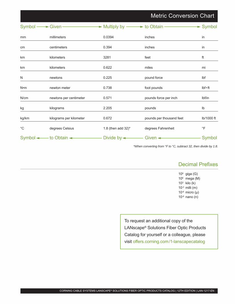
About Corning Cable Systems
CORNING CABLE SYSTEMS LANSCAPE® SOLUTIONS FIBER OPTIC PRODUCTS CATALOG | 12TH EDITION | LAN-1217-EN
Corning Cable Systems, founded in 1977, is a leadingmanufacturer of fiber optic products for voice, dataand video communications applications. Headquarteredin Hickory, North Carolina, Corning Cable Systemsis owned by Corning Incorporated, headquartered inCorning, New York.
LANscape® SolutionsCorning Cable Systems LANscape Solutions are a completeapproach to fiber cabling solutions for enterprise networks.Including a complete tip-to-tip product offering and design-through-operation services, LANscape Solutions ensure thesuccessful and efficient implementation of a fiber network thatwill serve as a stable communications infrastructure for manyyears to come.
Corning Cable Systems maintains its commitment to customersand products through many customer support programs. Whena fiber optic system is installed by a certified member companyof its Network of Preferred Installers Program, Corning CableSystems warrants LANscape Fiber Optic Cabling Solutions fora full 25 years through the Extended WarrantySM Program. TheConsultant LinkUpSM Program provides information on CorningCable Systems cabled fiber solutions and industry informationto top-level consultants and designers nationwide.
Product LinesThe broad scope of Corning Cable Systems’ product linespermits one-stop shopping. Fiber optic products include pre-terminated systems for both data center and LAN applications,outdoor cables, indoor flame-retardant cables, indoor/outdoorcables, field-installable connectors, connecting hardware,patch cords, splice equipment and test equipment, as well asengineering services and training. An extensive, nationwidedistribution system with a large inventory ensures that CorningCable Systems products are ready for immediate delivery.
Total Quality CommitmentCorning Cable Systems is dedicated to providing Total Qualityproducts and services to customers before, during and afterthe sale. This long-term commitment to quality begins withexecutive endorsement and continues throughout the organi-zation. Corning Cable Systems has received numerous qualitysupplier awards from customers and is TL-9000 registered.
We are also a recipient of the Award of Excellence from theInternational Customer Service Association.
Corning Cable Systems Quality Policy states: It is the policyof Corning Cable Systems to achieve Total Quality performancein meeting the requirements of external and internal customers.Total Quality performance means understanding who thecustomer is, what the requirements are, and meeting thoserequirements without error, on time, every time.
Industry LeadershipCorning Cable Systems has contributed extensively to the fiberoptic industry since its inception. Today, we are the largestmanufacturer of fiber optic cables in the United States. Ourcontributions include:
� Pioneer of the loose tube cable design, now recognizedas an industry standard for outside plant use
� Pioneer of the tight-buffered cable design, and the firstto manufacture high-fiber-count, NEC®-listed, tight-buffered cables
� Development of the industry’s first truly field-installablefiber optic connector with an assembly time under fiveminutes, as well as the first high-performance fieldtermination requiring no epoxy and no polishing
� Provider of the industry’s first fiber optic network cablingdesign guide and training course for enterprise networkscommunications systems
� Development of a complete fiber-to-the-desktop cablesystem solution consisting of fiber cables, outlets andcross-connect hardware
� Development of the industry’s first commercial single-mode optical time domain reflectometer (OTDR)
� Pioneer of the development of prewired optical hardwarefor system interconnection
� Invention of the first fully preterminated cabling systemsfor enterprise networks
� Introduced the first field-installable, no-epoxy/no-polish12-fiber connector (UniCam® MTP® Connector)
� Patented the TBII® Buffered Fiber, a slip layer thatallows easy removal of the buffering for splicing orconnectorization, in all Corning Cable Systems tight-buffered cables
� First to offer optical fiber cables designed to meetemerging Gigabit Ethernet applications
� Revolutionized data center design with Pretium EDGE™
Solutions, offering 100 percent more density, 35 percentfaster installations, and 25 percent faster moves, addsand changes than traditional systems
Symbol Given Multiply by to Obtain Symbol
mm millimeters 0.0394 inches in
cm centimeters 0.394 inches in
km kilometers 3281 feet ft
km kilometers 0.622 miles mi
N newtons 0.225 pound force lbf
N•m newton meter 0.738 foot pounds lbf • ft
N/cm newtons per centimeter 0.571 pounds force per inch lbf/in
kg kilograms 2.205 pounds lb
kg/km kilograms per kilometer 0.672 pounds per thousand feet lb/1000 ft
°C degrees Celsius 1.8 (then add 32)* degrees Fahrenheit °F
Symbol to Obtain Divide by Given Symbol
*When converting from °F to °C, subtract 32, then divide by 1.8.
Decimal Prefixes109 giga (G)106 mega (M)103 kilo (k)10-3 milli (m)10-6 micro (µ)10-9 nano (n)
Metric Conversion Chart
CORNING CABLE SYSTEMS LANSCAPE® SOLUTIONS FIBER OPTIC PRODUCTS CATALOG | 12TH EDITION | LAN-1217-EN
To request an additional copy of theLANscape® Solutions Fiber Optic ProductsCatalog for yourself or a colleague, pleasevisit offers.corning.com/1-lanscapecatalog

LANscape® SolutionsFiber Optic Products Catalog12TH EDITION
pre te rmina ted sys tems | cab les | connec to rs | cab le assembl ies | hardware
splice closures | test equipment | splice equipment | tools & kits | rentals & training
Total innovation.Total solution.Total Corning.
United States |Corning Cable Systems LLCPO Box 489Hickory, NC 28603-0489 USATEL 800 743 2675FAX 828 325 5060INTERNATIONAL +1 828 901 5000www.corning.com/cablesystems
Australia |Corning Cable Systems Pty. Ltd.74-84 Main RoadClayton, Victoria 3168AUSTRALIATEL +61 3 9538 2300FAX +61 3 9538 2316www.corning.com/cablesystems/apac/en/australia.aspx
China |Corning Cable Systems (Shanghai) Co., Ltd.3F, Li Min BuildingNo. 111 Gui Qing RoadCao He Jin High-Tech Development ZoneShanghai 200233CHINATEL +86 21 5450 4888FAX +86 21 5427 7898 (Commercial Team)FAX +86 21 5427 0083 (R&D, HR, FA)www.corningcablesystems.com.cn
Europe, the Middle Eastand Africa |Corning Cable Systems GmbH & Co. KGLeipziger Strasse 12110117 BerlinGERMANYTEL +00 800 2676 4641FAX +49 30 5303 2335www.corning.com/cablesystems/emea
Japan |Advanced Cable Systems CorporationTime 24 Building, 11 F2-4-32, Aomi, Koto-kuTokyo 135-8073JAPANTEL +81 3 5564 5021FAX +81 3 5564 5026www.advanced-cable.co.jp
Latin America |Corning Cable Systems S.A. de C.V.Rio Niágara #36 - 3Col. CuauhtemocDel. CuauhtemocC.P. 06500MEXICO, D.F.TEL +52 55 52 50 80 21FAX +52 55 52 54 51 04www.corning.com/cablesystems
Southern Asia Pacific |Corning Cable Systems SingaporeGreat World City#09-11 West Tower1 Kim Seng PromenadeSINGAPORE 237994TEL +65 6235 5605FAX +65 6735 2913www.corning.com/cablesystems/apac/en/south_east_asia.aspx
Corning Cable Systems reserves the right to improve, enhance and modify the features and specifications of Corning Cable Systems products withoutprior notification. ALTOS, Crimp & Go, DFX, ERK, FREEDM, LANscape, MIC, miniMass, OptiSplice, OptiTap, OptiTip, Pretium, TBII and UniCam areregistered trademarks of Corning Cable Systems Brands, Inc. AnyLAN, CamSplice, Elite, LID-SYSTEM, Lite, LSZH, Plug & Play, Pretium EDGE, Splice Pak,SST-Drop and Zeux are trademarks of Corning Cable Systems Brands, Inc. LST is a trademark of Corning Cable Systems LLC. Consultant LinkUp and Ex-tended Warranty are service marks of Corning Cable Systems LLC. ClearCurve and Corning are registered trademarks of Corning Incorporated. smallTALKis a registered trademark of GN Nettest (New York) Inc. CheckPoint is a trademark of GN Nettest (New York) Inc. MTP is a registered trademark of US-Conec, Ltd. ST is a registered trademark of Lucent Technologies. All other trademarks are the properties of their respective owners. Corning Cable Systemsis ISO 9001 certified. © 2010 Corning Cable Systems. All rights reserved. Published in the USA. LAN-1217-EN / April 2010
Related Documents