EMERGENCY 12V LIGHTING CONTROLLER Don’t get left in the dark by power cuts TEACH-IN 2010 LADDER LOGIC PROGRAMMING FOR THE PIC MICRO Part 1: Getting Started – Working with Inputs and Outputs A DIGITAL VFO WITH LCD GRAPHICS DISPLAY Uses a recycled Nokia LCD to display analogue and digital frequency readouts $8.75 US $10.25 CAN NOV 2009 PRINTED IN THE UK

Welcome message from author
This document is posted to help you gain knowledge. Please leave a comment to let me know what you think about it! Share it to your friends and learn new things together.
Transcript

EMERGENCY 12V LIGHTING CONTROLLERDon’t get left in the dark by power cuts
TEACH-IN 2010LADDER LOGIC PROGRAMMING FOR THE PIC MICROPart 1: Getting Started – Working with Inputs and Outputs
A DIGITAL VFO WITH LCD GRAPHICS DISPLAYUses a recycled Nokia LCD to display analogue and digital frequency readouts
$8.75 US $10.25 CANNOV 2009 PRINTED IN THE UK
NOV2009 Cover.indd 1 23/09/2009 15:10:51

Copyright 2009, Wimborne Publishing Ltd (Sequoia House, 398a Ringwood Road, Ferndown, Dorset BH22 9AU, UK)
and TechBites Interactive Inc.,
(PO Box 857, Madison, Alabama 35758, USA)
All rights reserved.
WARNING! The materials and works contained within EPE Online — which are made available by Wimborne Publishing Ltd and TechBites Interactive Inc — are copyrighted. You are permitted to make a backup copy of the downloaded file and one (1) hard copy of such materials and works for your personal use. International copyright laws, however, prohibit any further copying or reproduction of such materials and works, or any republication of any kind. TechBites Interactive Inc and Wimborne Publishing Ltd have used their best efforts in preparing these materials and works. However, TechBites Interactive Inc and Wimborne Publishing Ltd make no warranties of any kind, expressed or implied, with regard to the documentation or data contained herein, and specifically disclaim, without limitation, any implied warranties of merchantability and fitness for a particular purpose. Because of possible variances in the quality and condition of materials and workmanship used by readers, EPE Online, its publishers and agents disclaim any responsibility for the safe and proper functioning of reader-constructed projects based on or from information published in these materials and works. In no event shall TechBites Interactive Inc or Wimborne Publishing Ltd be responsible or liable for any loss of profit or any other commercial damages, including but not limited to special, incidental, consequential, or any other damages in connection with or arising out of furnishing, performance, or use of these materials and works.

The World’s Lowest Sleep Current MCUs:PIC® MCUs with nanoWatt XLP Technology
Microchip D
irect...2nd line
Serial EEPRO
Ms
Analog
Digital Signal
ControllersMicrocontrollers
The Microchip name and logo, the Microchip logo and PIC are registered trademarks of Microchip Technology Incorporated in the U.S.A. and other countries. All other trademarks mentioned herein are property of their respective companies. © 2009, Microchip Technology Incorporated. All Rights Reserved. ME235Eng/08.09
GET THE MOST FROM YOUR
BATTERY IN YOUR NEXT DESIGN!
1. View the Low Power Comparison
demo
2. View free Webinars and Application
Notes
3. Download the Low Power Tips ‘n Tricks
4. Order samples and development tools
www.microchip.com/XLP
Microchip’s PIC® Microcontrollers with nanoWatt XLP Technology offer the industry’s lowest currents for sleep, where extreme low power applications spend up to 99% of their time.
Extend Battery Life – Sleep current down to 20 nA – Brown-out Reset down to 45 nA – Watchdog Timer down to 400 nA – Real time clock down to 500 nA
Extreme Flexibility – 5 different low power modes to improve power & performance
in your application – Many low-power supervisors, alarms, and wake-up sources
Expanded Peripheral Set – Integrated USB, LCD, RTCC & touch sensing – Eliminates costly external components
www.microchip.com/XLP
Intelligent Electronics start with Microchip

Everyday Practical Electronics, November 2009 1
Projects and CircuitsCLASS-A HEADPHONE AMPLIFIER by Ken Ginn 10Will drive a variety of headphones
PROGRAMMABLE IGNITION SYSTEM FOR CARS – PART 3 18by John Clarke Installation, setting up and plotting the ignition timing
A DIGITAL VFO WITH GRAPHICS DISPLAY by Andrew Woodfield 32This direct digital synthesis variable frequency oscillator includes a recycled Nokia phone LCD
EMERGENCY 12V LIGHTING CONTROLLER by Jim Rowe 42Automatically stores and turns on the power for emergency lights
Series and FeaturesTEACH-IN 2010 LADDER LOGIC PROGRAMMING FOR THE PIC MICRO by Walter Ditch 50Part 1: Getting Started – Working with Inputs and Outputs
RECYCLE IT! by Julian Edgar 58There’s loads of good bits inside junked photocopiers
MAX’S COOL BEANS by Max The Magnificent 62Timelines and TechBites
CIRCUIT SURGERY by Ian Bell 63Time Domain Response
PRACTICALLY SPEAKING by Robert Penfold 66Front panel overlays and labels
PIC N’ MIX by Mike Hibbett 68Real Time Operating Systems – Part 2
TECHNO TALK by Mark Nelson 73Ratters And Rotters
NET WORK by Alan Winstanley 75Doing more business; Safe and F-Secure; Online bonus
Regulars and ServicesEDITORIAL 7
NEWS – Highlighting technology’s leading edge 8Plus everyday news from the world of electronics
PLEASE TAKE NOTE 41PIC Probe (July ’09)
CD-ROMS FOR ELECTRONICS 70A wide range of CD-ROMs for hobbyists, students and engineers
READOUT Matt Pulzer addresses general points arising 74
DIRECT BOOK SERVICE 76A wide range of technical books available by mail order, plus more CD-ROMs
EPE PCB SERVICE 78PCBs for EPE projects
ADVERTISERS INDEX 80
INCORPORATING ELECTRONICS TODAY INTERNATIONAL
www.epemag.com
ISSN 0262 3617
� PROJECTS � THEORY �� NEWS � COMMENT �� POPULAR FEATURES �
VOL. 38. No 11 November 2009
������������ ��������������������������������������� �
© Wimborne Publishing Ltd 2009. Copyright in all drawings, photographs and articles published in EVERYDAY PRACTICAL ELECTRONICS is fully protected, and reproduction or imitations in whole or in part are expressly forbidden.
Our December 2009 issue will be published on Thursday 12 November 2009, see page 80 for details.
Contents.indd 1 24/09/2009 10:13:39

Quasar - SEPTEMBER09 P1.indd 2 30/07/2009 09:03:03

Quasar - SEPTEMBER09 P2.indd 1 30/07/2009 09:05:13

November ‘09
0800 032 7241 jaycarelectronics.co.uk
ORDER YOURFREE
CATALOGUETODAY!
Everyday Practical Electronics Magazine has been publishing a series of popular kits by the acclaimed Silicon Chip Magazine Australia. These
projects are 'bullet proof' and already tested down under. All Jaycar kits aresupplied with specified board components, quality fibreglass tinned PCBs and
have clear English instructions. Watch this space for future featured kits.
EMERGENCY 12VLIGHTING CONTROLLER
KC-5456 £20.50 plus postage & packingAutomatically supplies power for 12V emergency lighting duringa blackout. The system is powered with a 7.5Ah SLA batterywhich is maintained via an external smart charger. Includesmanual override and over-discharge protection for the battery.Kit supplied with all electronic components, screen printed PCB,front panel and case. Charger and SLA battery availableseparately.
Featured in this issue of EPE
STEREO HEADPHONEDISTRIBUTION AMPLIFIER
KC-5417 £10.25 plus postage & packingEnables you to drive one or twostereo headphones from anyline level (1volt peak topeak) input. The circuitfeatures a facility to driveheadphones withimpedances from about 8-600Ω. Comes with PCBand components.
Featured in this issue of EPEAlso recommended: Box HB-6012 £2.00Power Supply Kit KC-5418 £6.00
PIC LOGICPROBE
KC-5457 £5.00 plus postage & packing
Operating on 2.8-15VDC, this logic probe is suitable for use onthe most modern circuits. Extremely compact with SMT deviceson a PCB only 5mm wide. It's capable of picking up a pulseonly 50mS long and will also detect and hold infrequent pulseswhen in latch mode. Kit includes PCB and all specifiedelectronic components including pre-programmed PIC. You'llneed to add your own case and probe - a clear ballpoint penand a darning needle work well.
As Published in EPE July 2009
VOLTAGEMONITOR
KC-5424 £6.75 pluspostage & packing
Monitors either the batteryvoltage, airflow meter or oxygen sensor
in your car. This versatile 12VDC kit features a 10 LED bargraph that indicates the measured voltage in 9-16V, 0.-5V or0-1V ranges. Features fast response time, high input impedanceand auto dimming for night time driving. Kit includes PCB withoverlay and all electronic components.
As published in EPE November 2007
COURTESY INTERIORLIGHT DELAY
KC-5392 £6.00 plus postage & packingEnables your car to have the same interior light delay featureyou find in many modern cars, allowing you time to buckle upand settle in before the light softly fades and finally goes outafter a set time. Upgraded to a much simpleruniversal wiring setup, this kit containsPCB with overlay and allelectronic components.
As published in EPEFebruary 2007
KC-5391 £4.75plus postage &packing
Allows you to use regular Ni-Cd or Ni-MH 1.2V cells, or Alkaline 1.5V cells for 9Vapplications. Using low cost, high capacity rechargeable cells, thekit will pay for itself in no-time! You can use any 1.2-1.5V cellsyou desire. Imagine the extra capacity you would have using two9000mAh D cells in replacement of a low capacity 9V cell. Kitsupplied with PCB and all electronic components.
As published in EPE June 2007
FAST NI-MHBATTERY CHARGER
KC-5453 £12.50 plus postage & packingIdeal for RC enthusiasts who burn through a lot of batteries.Capable of handling up to 15 of the same type of Ni-MH or Ni-Cd cells. Build it to suit any size cells or cell capacity and setyour own fast or trickle charge rate. Features overchargeprotection and temperature sensing. Kit includes solder mask &overlay PCB, programmed micro and all specified electroniccomponents. Case, heatsink and battery holder not included.
ROLLING CODE IRKEYLESS ENTRY SYSTEM
KC-5458 £19.00 plus postage & packingFeatures two independent door strike outputs and recognisesup to 16 separate key fobs. This advanced system keepscoded key fobs synchronised to the receiver andcompensates for out of range randombutton presses. Supplied withsolder masked and silk screenprinted PCB, two programmedmicros, battery and allelectronic components. Thereceiver requires a12VDC 1.5A powersupply. Some SMDsoldering is required.
Featured in EPEAug/Sept 2009
SMS CONTROLLERMODULE
KC-5400 £17.00 pluspostage & packingControl appliances andreceive alert notificationfrom anywhere. It controlsup to eight devices bysending plain text messagesand simultaneously monitors fourdigital inputs. It works with old Nokia handsets such as the5110, 6110, 3210, and 3310, which can be boughtinexpensively. Kit supplied with manual, PCB, pre-programmedmicrocontroller and all electronic components. Requires acommon Nokia data cable found in many retail stores.
As published in EPE March 2007
PROGRAMMABLE HIGHENERGY IGNITION SYSTEM
KC-5442 £27.75 plus postage & packingThis advanced and versatile ignition system is suited for both two & four stroke engines.Used to modify the factory ignition timing or as the basis for a stand-alone ignitionsystem with variable ignition timing, electronic coil control and anti-knock sensing.
Featured in this issue of EPE
Also available to suit: Ignition CoilDriver Kit KC-5443 £13.75Knock Sensor Kit KC-5444 £18.95
NEWTO EPE
NEWTO EPE
NEWTO EPE
3V TO 9V DC-DCCONVERTER
As published in EPE August 2009
Jaycar NOV09.indd 1 23/09/2009 14:45:11

0800 032 7241 jaycarelectronics.co.uk
FREE CATALOGUECheckout Jaycar’s extensive rangeWe have kits & electronic projects for use in:
For your FREE catalogue log on to:
or check out the range at:
HOW TO ORDEROrder Value Cost£10 - £49.99 £5£50 - £99.99 £10£100 - £199.99 £20£200 - £499.99 £30£500+ £40
Note: Products are despatched from Australia,so local customs duty & taxes may apply.Prices valid until 30/11/09
0800 032 7241*+61 2 8832 3118*
Max weight 12lb (5kg).Heavier parcels POA.Minimum order £10.
*Australian Eastern Standard Time (Monday - Friday09.00 to 17.30 GMT + 10 hours only)Expect 10-14 days for air parcel delivery
KC-5483 £29.90 plus postage & packingHigh-security rolling code 3-channel remote control that canbe used for keyless entry and control of garage doors andlights. Up to 16 transmitters may be used with the onereceiver so it's suitable for small-scale commercialapplications. The transmitter kit includes a three button keyfob case and runs on a 12V remote control battery.
Additional UHFRolling CodeTransmitter Kit KC-5484 £11.75
KC-5479 £23.25 plus postage & packingProlongs the life of your lead acid batteries. Like the original2005 project, this circuit produces short high level bursts ofenergy to reverse the sulphation effect. The battery conditionchecker is no longer included and the circuit has beenupdated and revamped to providemore reliable, long-term operation.It still includes test points for aDMM and binding posts for abattery charger. Not recommendedfor use with gel batteries
and overlay Components
KC-5485 £17.50 plus postage & packingDisplays your car's air-fuel ratio as you drive. Designed tomonitor a wideband oxygen sensor and its associatedwideband controller. Alternatively it can be used to monitor anarrowband oxygen sensor or for monitoring other types ofengine sensors.
and screen printed lid
KC-5475 £21.75 plus postage & packingCreate your own eerie sciencefiction sound effects! Updatedfeatures to one of our most popular kitsinclude extra test points, change to AC toavoid switchmode plugpackinterference, and a newskew control to varyaudio tone. Contains
machined case and allspecified components.
KC-5487 £40.50 plus postage & packingListen to CDs through a DVD player with this DAC kit to getsound quality equal to the best high-end CD players. With stereo
KC-5418 £6.00
transformer
KC-5481 £21.75 plus postage & packing
It can be used as a jukebox,a sound effects player or anexpandable digital voicerecorder. You can use it asa free-standing recorder orin conjunction with anyWindows, Mac or Linux PC.
socket and electroniccomponents.
KC-5480 £7.25 plus postage & packingA versatile active filter module that can be used either as anactive crossover, a low pass filter, or a high or band pass filterin a speaker project simply by changing a couple of jumper
components. Requires power supply (see specs), amplifiers,
operation frequency.
Input impedance: 47kΩPower supply: dual rail±15-60VDC; single rail12-30VDC or 11-43VACCurrent: 40mA max
22Hz-22kHz filter
KC-5473 £13.25 plus postage & packing
range of 200m. The receiver has momentary or toggle outputwith adjustable momentary period. Up to five receivers can be
and all specified components.
KC-5482 £23.25 plus postage & packing
batteries prior to charging or
condition indication of fair, poor, good etc. An ideal
Zapper MKIII.
electronic components
machined case included
Jaycar NOV09.indd 2 23/09/2009 14:45:24

Prices Exclude Vat @15%.UK Carriage £2.50 (less than 1kg)
£5.50 greater than 1kg or >£30Cheques / Postal orders payable to
ESR Electronic Components Ltd.PLEASE ADD CARRIAGE & VAT TO ALL ORDERS
www.esr.co.uk
Station RoadCullercoatsTyne & WearNE30 4PQ
Tel: 0191 2514363Fax: 0191 [email protected]
4000 Series4000B £0.274001B £0.164002B £0.194006B £0.654009UB £0.234010B £0.234011B £0.164012B £0.164013B £0.184014B £0.304015B £0.274016B £0.204017B £0.264018B £0.254019B £0.254020B £0.254021B £0.224022B £0.384023B £0.234024B £0.224025B £0.204026B £0.674027B £0.214028B £0.214029B £0.384030B £0.174035B £0.314040B £0.244041B £0.314042B £0.194043B £0.354046B £0.424047B £0.254048B £0.344049B £0.294049UB £0.174050B £0.204051B £0.234052B £0.324053B £0.204054B £0.564055B £0.344060B £0.174063B £0.414066B £0.174067B £2.204068B £0.194069UB £0.184070B £0.154071B £0.204072B £0.254073B £0.174075B £0.174076B £0.304075B £0.154077B £0.284078B £0.304081B £0.134082B £0.214085B £0.284086B £0.334093B £0.164094B £0.294098B £0.404099B £0.354502B £0.324503B £0.404508B £1.404510B £0.454511B £0.304512B £0.274515B £0.994516B £0.444518B £0.264520B £0.344521B £0.684526B £0.404527B £0.404529B £0.444532B £0.244536B £1.004538B £0.264541B £0.334543B £0.474555B £0.324556B £0.404584B £0.334585B £0.474724B £0.9440106B £0.1940109B £0.5840174B £0.4640175B £0.4174HC Series74HC00 £0.1674HC02 £0.1774HC03 £0.2174HC04 £0.1474HC08 £0.1774HC10 £0.2174HC11 £0.2174HC14 £0.1874HC20 £0.2874HC27 £0.1674HC30 £0.2274HC32 £0.1474HC42 £0.3674HC73 £0.4074HC74 £0.1574HC75 £0.3174HC85 £0.2374HC86 £0.2174HC107 £0.4074HC123 £0.3374HC125 £0.2674HC126 £0.4674HC132 £0.2674HC133 £0.3474HC137 £0.3074HC138 £0.2674HC139 £0.3174HC151 £0.33
74HC153 £0.3074HC154 £0.9474HC157 £0.2274HC158 £0.2374HC161 £0.2774HC162 £0.4574HC163 £0.2674HC164 £0.2074HC165 £0.2174HC173 £0.3874HC174 £0.2774HC175 £0.3574HC193 £0.3974HC195 £0.3274HC240 £0.3274HC241 £0.3774HC244 £0.4074HC245 £0.3474HC251 £0.3074HC253 £0.2574HC257 £0.2574HC259 £0.2974HC273 £0.3274HC299 £0.6174HC365 £0.2874HC367 £0.3874HC368 £0.2974HC373 £0.3574HC374 £0.3474HC390 £0.3774HC393 £0.3674HC563 £0.5674HC573 £0.2774HC574 £0.3074HC595 £0.2774HC597 £0.2274HC688 £0.4674HC4002 £0.3174HC4017 £0.2474HC4020 £0.3674HC4040 £0.2974HC4049 £0.3174HC4051 £0.5074HC4052 £0.3474HC4053 £0.2274HC4060 £0.2374HC4075 £0.2774HC4078 £0.3274HC4511 £0.6474HC4514 £0.8474HC4538 £0.4174HC4543 £0.9074LS Series74LS00 £0.3874LS01 £0.1474LS02 £0.3874LS03 £0.2174LS04 £0.3074LS05 £0.1474LS08 £0.1974LS09 £0.1574LS10 £0.2774LS11 £0.1774LS12 £0.2574LS14 £0.3674LS15 £0.2474LS20 £0.2774LS21 £0.2074LS26 £0.1774LS27 £0.2574LS30 £0.2074LS32 £0.2374LS37 £0.3174LS38 £0.1874LS40 £0.1474LS51 £0.2474LS83 £0.3874LS85 £0.4874LS86 £0.2574LS92 £0.4574LS93 £0.5874LS107 £0.3074LS109 £0.2174LS112 £0.2474LS113 £0.2374LS114 £0.3674LS122 £0.3174LS123 £0.3174LS125 £0.2874LS126 £0.2574LS132 £0.4774LS133 £0.3674LS136 £0.2374LS138 £0.3374LS145 £0.5674LS148 £0.6474LS151 £0.2974LS156 £0.3674LS157 £0.2274LS158 £0.2174LS160 £0.4874LS161 £0.3274LS162 £0.4474LS163 £0.3274LS164 £0.4374LS165 £0.4874LS173 £0.2474LS175 £0.3074LS191 £0.2774LS192 £0.6074LS193 £0.5074LS195 £0.2474LS221 £0.4174LS240 £0.3274LS241 £0.3274LS243 £0.3074LS244 £0.4174LS245 £0.4574LS247 £0.6074LS251 £0.2474LS257 £0.2474LS258 £0.2474LS266 £0.14
74LS273 £0.3274LS279 £0.2474LS283 £0.4774LS365 £0.2174LS367 £0.2174LS368 £0.2174LS373 £0.3974LS374 £0.3874LS378 £0.6274LS390 £0.3474LS393 £0.3374LS395 £0.26
Linear ICsAD524AD £23.04AD548JN £2.48AD590JH £5.28AD595AQ £13.92AD620AN £9.88AD625JN £16.20AD633JN £5.93AD648JN £2.57AD654JN £5.51AD711JN £1.97AD712JN £2.51AD736JN £5.80AD797AN £7.25AD811N £6.00AD812AN £6.32AD820AN £3.41AD822AN £4.27AD829JN £6.41AD830AN £5.44AD847JN £5.95AD9696KN £7.73ADEL2020A £5.06ADM222AH £3.55ADM232AA £3.55ADM485JN £2.97ADM666AN £2.72ADM690AN £5.13ADM691AN £6.48ADM695AN £6.48ADM699AN £3.58CA3130E £0.87CA3140E £0.63CA3240E £0.91DG211CJ £1.25DG411DJ £2.00ICL7106CPL £2.21ICL7107CPL £2.72ICL7109CLP £5.76ICL7611DCP £1.00ICL7621 £0.84ICL7660SCP £0.80ICM7555 £0.48ICM7556 £1.04L165V £2.26L272M £1.21L293E £4.20L297 £5.12L298N £3.80L4960 £2.81L6219 £4.48LF347N £0.41LF351N £0.44LF353N £0.40LF356 £0.52LF411CN £1.00LM311N8 £0.17LM319N14 £0.90LM324 £0.20LM335Z £1.12LM339N £0.18LM348N £0.36LM35DZ £1.37LM358N £0.13LM380N £0.90LM386 £0.50LM392N £1.10LM393N £0.21LM1881 £2.90LM2901N £0.15LM2917N8 £1.98LM3900N £0.72LM3914 £1.90LM3915 £2.10LM13700 £1.35LMC660CN £1.26LMC6032IN £1.55LP311N £0.74LP324N £0.75LP339N £0.75LT1013CN8 £4.64M34-1 £0.30M34-2 £0.30MAX202CPE £2.00MAX208CN £6.99MAX220CPE £5.06MAX222CPE £5.06MAX232CPE £1.30MAX483CP £3.13MAX485CP £2.04MAX631ACP £4.99MAX635ACP £4.99MAX1232CP £2.80MC1458N £0.27MC1488 £0.40MC1489 £0.35MC4558P £0.18MK484 £0.66NE521N £6.39NE555N £0.18NE556N £0.24NE5532N £0.48NE5534N £0.54NE5539N £4.35OP27CN £2.33OP90GP £2.91OP97FP £1.84OP113GP £3.44OP176GP £2.09OP177GP £1.76OP200GP £5.60
OP275GP £2.57OP282GP £2.27OP283GP £5.20OP290GP £4.28OP297GP £4.64OP400GP £11.81OP495GP £8.69RC4136 £1.00SG3524N £0.82SG3543 £6.88SSM2141P £3.21SSM2142P £6.16SSM2143P £3.78TBA120S £1.04TBA800 £0.75TBA820M £0.53TDA1170S £4.80TDA2004 £2.24TDA2003V £1.25TDA2030AV £1.24TDA2050V £2.51TDA2611A £1.88TDA2822A £0.79TDA2653A £2.99TED3718DP £5.03TEA5115 £3.11TL061CP £0.21TL062CP £0.21TL064CN £0.29TL071CN £0.30TL072CN £0.20TL074CN £0.25TL081CN £0.17TL082CN £0.32TL084CN £0.37TL7705ACP £0.82TLC271 £0.63TS272CN £0.57TS274CN £0.50TS555CN £0.26TMP01FP £5.60UA741CN £0.18ULN2003A £0.38ULN2004A £0.44ULN2803A £0.45ULN2804A £0.41
74 Series7407 £0.40
RAMGM76C88. £3.60
EPROM’s24LC08BP £0.7324LC16BP £0.6927128-200 £3.9927256-200 £3.9927C64A-15F £3.9927C256B-15F £3.0027C1001-15. £3.9827C2001-15. £4.4127C4001-10F£5.9893C46N £0.28
A/D ConvertersData Acquisi-tionAD420AN £25.38AD7528JN £11.42AD7545AK £14.04AD7828KN £20.33DAC0800 £1.36ICL7109CPL £7.75uControllersAT89C2051 £6.38PIC Series12C508A04P £0.7812C509A04P £0.8316C54C04P £1.4916C54BJW £7.6016C56A-04P £1.5616F84-04P £3.1416F84-10P £4.1616F627-04P £1.6516F627-20IP £1.8017F628-20IP £2.4016F867-04SP £5.1016F877-20P £4.62
Diodes1N914 £0.051N4001 £0.041N4002 £0.051N4003 £0.031N4004 £0.041N4005 £0.041N4006 £0.041N4007 £0.031N4148 £0.031N4149 £0.071N5400 £0.081N5401 £0.081N5402 £0.081N5404 £0.091N5406 £0.101N5407 £0.101N5408 £0.106A05 £0.276A1 £0.306A2 £0.276A4 £0.286A6 £0.326A8 £0.306A10 £0.35BA157 £0.07BA159 £0.13BAT41 £0.12BAT42 £0.07BAT46 £0.12BAT85 £0.09BAV21 £0.07BAW62 £0.08BAX16 £0.05BY127 £0.18BY133 £0.10OA91 £0.32OA200 £0.56UF4001 £0.08UF4002 £0.08UF4003 £0.09UF4004 £0.08UF4005 £0.10UF4006 £0.10UF4007 £0.14Zeners 2.7 to 33V500mW £0.061.3W £0.10
VoltageRegulators7805 £0.277806 £0.297808 £0.277812 £0.237815 £0.2378L05 £0.2278L06 £0.3278L08 £0.2278L12 £0.1678L15 £0.2678L24 £0.3978S05 £0.5378S12 £0.4278S15 £0.327905 £0.237912 £0.247915 £0.227924 £0.3879L05 £0.2079L12 £0.2679L15 £0.2879L24 £0.30ADM666AN £3.44L200CV £1.67L296 £4.42LM2940CT5 £0.84LM317LZ £0.25LM317T £0.30LM317K £2.28LM323K £2.40LM334Z £0.96LM337T £0.64LM338K £5.31LM338T £1.10LM723 £0.40LP2950CZ5.0 £0.72REF01CP £2.31TL431CP £0.14
TriacsBT136-500 £0.58BT136-600 £0.50BT137-600 £0.58BT139-500 £1.00BT139-600 £1.20BTA08-600B £0.84BTA08-600BW£0.76BTA08-600C £0.96BTA08-600SW£0.93BTA08-600TW£1.10BTA12-600BW£0.92BTA16-600CW£1.45BTA16-600B £1.28BTA26-600B £2.78TIC206D £0.84TIC206M £0.75TIC226D £0.80TIC226M £1.00TIC246D £1.00TIC246M £1.00TIC236D £1.12
Thyristors2N5060 £0.192N5061 £0.19BT151-500R £0.65PO102AA £0.30TIC106D £0.60TIC116D £0.66TIC126D £0.77
Bridge Rectifiers1A 50V £0.351A 100V £0.321A 200V £0.391A 600V £0.401A 800V £0.431.5A 50V £0.191.5A 100V £0.111.5A 200V £0.191.5A 400V £0.201.5A 600V £0.241.5A 800V £0.261.5A 1kV £0.182A 100V £0.342A 200V £0.342A 400V £0.352A 800V £0.362A 1000V £0.453A 200V £0.343A 400V £0.403A 600V £0.333A 1000V £0.334A 100V £0.784A 200V £0.804A 400V £0.864A 600V £0.906A 100V £0.496A 200V £0.646A 400V £0.536A 600V £0.676A 800V £0.378A 100V £0.988A 200V £1.008A 400V £1.208A 600V £1.338A 1000V £1.0525A 100V £1.4725A 200V £1.5425A 400V £1.9825A 600V £1.8235A 100V £1.5735A 200V £1.8035A 400V £1.4435A 600V £1.9035A 1000V £2.32
Transistors2N2222A £0.202N2646 £1.022N2904A £0.352N2905A £0.302N2907A £0.282N3053 £0.382N3054 £0.852N3055 £0.622N3439 £0.622N3440 £0.502N3702 £0.092N3703 £0.102N3704 £0.112N3705 £0.082N3772 £1.722N3773 £1.912N3819 £0.202N3903 £0.112N3904 £0.052N3905 £0.102N4401 £0.082N4403 £0.092N5245 £0.802N5296 £0.572N5401 £0.122N5551 £0.072N6491 £1.582N7000 £0.122SB548 £0.30AC127 £0.50AC187 £0.68AC188 £0.97ACY17 £4.84AD149 £1.29AD161 £0.73AD162 £0.95BC107 £0.18BC107B £0.14BC108 £0.18BC108B £0.14BC108C £0.18BC109 £0.19BC109C £0.16BC114 £0.19BC115 £0.41BC118 £0.41BC132 £0.36BC134 £0.36BC135 £0.36BC142 £0.50BC159 £0.17BC160 £0.28BC170B £0.16BC177 £0.25BC178 £0.18BC179 £0.15BC182B £0.09BC182L £0.11BC183L £0.09BC184 £0.09BC184L £0.13BC206B £0.72
BC208 £0.72BC209A £0.72BC212L £0.09BC214 £0.11BC214L £0.10BC225 £0.15BC237B £0.11BC238B £0.11BC250A £0.15BC261B £0.30BC262B £0.24BC267B £0.36BC319C £0.13BC327 £0.08BC327-25 £0.08BC328 £0.09BC337-16 £0.10BC337-25 £0.08BC348B £0.14BC357 £0.25BC393 £0.73BC461 £0.41BC463 £0.29BC477 £0.52BC479 £0.32BC516 £0.21BC517 £0.14BC546B £0.06BC546C £0.08BC547A £0.09BC547B £0.09BC547C £0.10BC548A £0.08BC548B £0.09BC548C £0.08BC549B £0.09BC549C £0.09BC550C £0.11BC556A £0.08BC556B £0.10BC557A £0.09BC557B £0.09BC557C £0.09BC558A £0.08BC558B £0.09BC559A £0.08BC560B £0.13BC636 £0.10BC637 £0.19BC638 £0.21BC639 £0.09BC640 £0.12BCY72 £0.20BD124P £6.86BD131 £0.48BD132 £0.46BD135 £0.22BD136 £0.21BD137 £0.23BD138 £0.19BD139 £0.19BD140 £0.14BD150C £0.82BD201 £0.40BD202 £0.70BD232 £0.50BD237 £0.32BD238 £0.44BD240C £0.37BD245C £1.10BD246C £1.18BD283 £0.61BD284 £0.61BD400 £0.79BD437 £0.17BD438 £0.22BD442 £0.37BD534 £0.47BD535 £0.50BD646 £0.52BD648 £0.52BDX32 £1.78BDX34C £0.45BDX53C £0.53BDX54C £0.50BF180 £0.31BF182 £0.31BF245B £0.40BF257 £0.33BF259 £0.33BF337 £0.40BF422 £0.15BF423 £0.15BF459 £0.33BF469 £0.36BFX29 £0.29BFX85 £0.33BFX88 £0.27
BFY50 £0.30BFY51 £0.22BFY52 £0.32BS107 £0.21BS170 £0.15BU208A £1.53BU326A £1.40BU500 £1.54BU508A £1.40BU508D £0.98BU806 £1.06BUT11AF £1.14BUX84 £0.78BUZ900 £7.68BUZ900P £5.74BUZ905 £7.68BUZ905P £5.55IRF530 £0.75IRF540 £0.78IRF630 £0.42IRF640 £0.72IRF730 £0.66IRF740 £0.91IRF830 £0.68IRF840 £0.78MJ2955 £0.90MJ2501 £1.60MJ3001 £1.84MJ11015 £2.45MJ11016 £2.78MJE340 £0.33MJE350 £0.32MPSA05 £0.14MPSA13 £0.09MPSA42 £0.14MPSA55 £0.13MPSA56 £0.12STP14NF10 £0.49STW80NE-10 £3.80TIP29A £0.32TIP29C £0.33TIP30A £0.47TIP30C £0.27TIP31A £0.23TIP31C £0.35TIP32A £0.29TIP32C £0.30TIP41A £0.32TIP41C £0.32TIP42A £0.47TIP42C £0.43TIP50 £0.28TIP110 £0.28TIP120 £0.30TIP121 £0.32TIP122 £0.37TIP125 £0.31TIP126 £0.31TIP127 £0.37TIP132 £0.50TIP137 £0.64TIP141 £0.93TIP142 £0.93TIP147 £1.07TIP2955 £0.46TIP3055 £0.46ZVN2106A £0.40ZVN3306A £0.30ZVN4206A £0.52ZVN4210A £0.56ZVN4306A £0.86ZVN4310A £0.88ZVP2106A £0.42ZVP2110A £0.46ZVP3306A £0.32ZTX302 £0.17ZTX450 £0.19ZTX451 £0.21ZTX453 £0.26ZTX502 £0.17ZTX550 £0.22ZTX551 £0.33ZTX600 £0.33ZTX600B £0.35ZTX605 £0.36ZTX651 £0.33ZTX653 £0.37ZTX689B £0.40ZTX690B £0.37ZTX705 £0.39ZTX750 £0.25ZTX751 £0.34ZTX753 £0.40ZTX789A £0.41ZTX790A £0.41ZTX851 £0.50ZTX853 £0.50ZTX951 £0.54
ZTX1048A £0.48ZTX1051A £0.46ZTX1053A £0.45
DiacDB3, 32V £0.08
QualityComponentsNo surplus or
redundant stock.All from leadingmanufactures.
QualityService
Sameday des-patch on allstock items.
Friendly helpfulstaff.
Fast DeliveryNextday servicefor all orders atno extra charge.
No MinimumOrder
Order what youneed, no pack
quantities or minorder value.
QuantityDiscountsAvailable
We offer dis-counts for all
items subject toquantity re-
quired, phone,fax or email for
a quote.
On the WEBCheck out ourweb site withmore products
than ever before.ComponentsConnectors
CableCCTV
EnclosuresFans & Heat-
sinksFuses
HardwareLampsLeads
PCB EquipmentPower Supplies
RelaysSolderingSoundersSwitches
Test EquipmentTools
Transformersand more
0909
NOW ONLINETransformersLarge selection
of mains &audio
transformers.
Fuses20mm, 32mmQuick Blow &
Time-lagGlass, Ceramic
www.esr.co.uk
audiotransformers.
Fuses
Potty aboutPots!
We now carry instock a wide
range ofpositive position
pots.With either witha centre click or41 click posi-tions. Log, Lin,Single or Dual
gang.
Mixed Packs224 CeramicCaps £8.50120 ElectrolyticRadil Caps £8.50120 Diode &Rectifiers £5.9580 3 & 5mmMixed LEDs £5.95610 E12 ¼WResistors £5.75480 E3 ¼WResistors £4.95100 BC..Transistors £9.90
The UK’s number 1 source of VELLEMAN® products..
We are the only current UK supplier able to offer the full range ofVelleman - Mini Kits - Kits - Modules & Test Equipment. All thelatest products added as released.
q....est productssss ad aaadaddedddeddde as

Everyday Practical Electronics, November 2009 7
Editorial Offices:EVERYDAY PRACTICAL ELECTRONICS EDITORIALWimborne Publishing Ltd., Sequoia House, 398a Ringwood Road, Ferndown, Dorset BH22 9AUPhone: (01202) 873872. Fax: (01202) 874562.Email: [email protected] Site: www.epemag.comSee notes on Readers’ Technical Enquiries below – we regret technical enquiries cannot be answered over the telephone. Advertisement Offices:Everyday Practical Electronics AdvertisementsSequoia House, 398a Ringwood Road, Ferndown, Dorset BH22 9AUPhone: 01202 873872 Fax: 01202 874562Email: [email protected]
Editor: MATT PULZERConsulting Editor: DAVID BARRINGTONSubscriptions: MARILYN GOLDBERGGeneral Manager: FAY KEARNEditorial/Admin: (01202) 873872Advertising and Business Manager: STEWART KEARN (01202) 873872On-line Editor: ALAN WINSTANLEYEPE Online (Internet version) Editors:CLIVE (Max) MAXFIELD and ALVIN BROWNPublisher: MIKE KENWARD
READERS’ TECHNICAL ENQUIRIESEmail: [email protected] are unable to offer any advice on the use, purchase, repair or modification of commercial equipment or the incorporation or modification of designs published in the magazine. We regret that we cannot provide data or answer queries on articles or projects that are more than five years’ old. Letters requiring a personal reply must be accompanied by a stamped self-addressed envelope or a self-addressed envelope and international reply coupons. We are not able to answer technical queries on the phone.
PROJECTS AND CIRCUITSAll reasonable precautions are taken to ensure that the advice and data given to readers is reliable. We cannot, however, guarantee it and we cannot accept legal responsibility for it.A number of projects and circuits published in EPE employ voltages that can be lethal. You should not build, test, modify or renovate any item of mains-powered equipment unless you fully understand the safety aspects involved and you use an RCD adaptor.
COMPONENT SUPPLIESWe do not supply electronic components or kits for building the projects featured, these can be supplied by advertisers.We advise readers to check that all parts are still available before commencing any project in a back-dated issue.
ADVERTISEMENTSAlthough the proprietors and staff of EVERYDAY PRACTICAL ELECTRONICS take reasonable precautions to protect the interests of readers by ensuring as far as practicable that advertisements are bona fide, the magazine and its publishers cannot give any undertakings in respect of statements or claims made by advertisers, whether these advertisements are printed as part of the magazine, or in inserts.The Publishers regret that under no circumstances will the magazine accept liability for non-receipt of goods ordered, or for late delivery, or for faults in manufacture.
TRANSMITTERS/BUGS/TELEPHONEEQUIPMENTWe advise readers that certain items of radio transmitting and telephone equipment which may be advertised in our pages cannot be legally used in the UK. Readers should check the law before buying any transmitting or telephone equipment, as a fine, confiscation of equipment and/or imprisonment can result from illegal use or ownership. The laws vary from country to country; readers should check local laws.
AVAILABILITYCopies of EPE are available on subscription anywhere in the world (see opposite) and from all UK newsagents (distributed by SEYMOUR). EPE can also be purchased from retail magazine outlets around the world. An Internet online version can be purchased and downloaded for just $18.99US (approx £12) per year, available from www.epemag.com
GUITAR TO MIDI SYSTEMA monophonic system that works with any guitar
MINISPOT 455kHzMODULATED OSCILLATORFor IF alignment of AM and shortwave radios
RECYCLE ITImproving the sound of salvaged loudspeaker systems
PROGRAMMABLE IGNITION SYSTEM FOR CARS PART 2Six versions to build to suit your car’s trigger input
OCT 2009 £3.95
VOL. 38 No. 11 NOVEMBER 2009
THE UK’S NO.1 MAGAZINE FOR ELECTRONICS TECHNOLOGY & COMPUTER PROJECTS
SUBSCRIPTIONSSubscriptions for delivery direct to any address in the UK: 6 months £19.95, 12 months £37.90, two years £70.50; Overseas: 6 months £23.00 standard air service or £32.00 express airmail, 12 months £44.00 standard air service or £62.00 express airmail, 24 months £83.00 standard air service or £119.00 express airmail.
Online subscriptions, for downloading the magazine via the Internet, $18.99US (approx £13) for one year available from www.epemag.com.
Cheques or bank drafts (in £ sterling only) payable to Everyday Practical Electronics and sent to EPE Subs. Dept., Wimborne Publishing Ltd. Sequoia House, 398a Ringwood Road, Ferndown, Dorset BH22 9AU. Tel: 01202 873872. Fax: 01202 874562. Email: [email protected]. Also via the Web at: www.epemag.com. Subscriptions start with the next available issue. We accept MasterCard, Maestro or Visa. (For past issues see the Back Issues page.)
BINDERSBinders to hold one volume (12 issues) are available from the above address. These are finished in blue PVC, printed with the magazine logo in gold on the spine. Price £7.95 plus £3.50 p&p (for overseas readers the postage is £6.00 to everywhere except Australia and Papua New Guinea which cost £10.50). Normally sent within seven days, but please allow 28 days for delivery – more for overseas.
Payment in £ sterling only please. Visa, Maestro and MasterCard accepted. Send, fax or phone your card number, card expiry date, valid from date and card security code (the last 3 digits on or just under the signature strip), with your name, address etc. Or order on our secure server via our UK website. Overseas customers – your credit card will be charged by the card provider in your local currency at the existing exchange rate.
����������� ���������������������� ��������
� �� ������ � ������� ������ ����� � �� ������ ��� ������ �
�������� � �� ��� ����� � �� ���� � ��� ��� � �� �������� ���
����� ��������� ����� ����� �!��� ���������"� #�� ���� � �� �����
�$������������ ������%������� ����!��� �!������������������
��������� �������"�%�������������������!�����������������������
���������������� � ���� �������������������������������������"�
While the natural selection analogy is not perfect, I often feel
� ������ ���������������������� ���������!��������������
��� ������� ���������!���������'� �������� ���������� �� � ��
������������"�(������ �����������������������������!������
������� ��������)*%%+����-��� �������"
(�� ��������������*%%����������� ������������"�.���������
!�� .�/� �� 0123�� � ��� ���� �� �������� ������4� ��� ���������
��� ��������������� ������� �����������������"�5������ � �
� ��� ��� � ���� � �� � ����� ��������� ��� �� ����� �����'������
��������������� �������-��� ����������� �������������
� �������������������������������� ������ ������!������������
� ������������"�6���������������� ����������������������
��� /������� 7��� ��� -��� � ��������� � �� ������� ������� ����
� �� �������� *%%� ����������� ����� ���� �� ����� ��� ��� �
����� ����� ��� �������� � ���� ��������"� 6� ��8�� ��� ��� ������
���� .� �����!��� !���� �� 099/�� ������ ���� ������ :;99� ��
� ���������.�!�� ��0������� ����� ������������<9�999'�����
����������"�
� �������������!������*%%�����-��� �� �����!���������
���������!��������� �������������� ���� �����������
����� ���������� �����������!����������������������!��������
��� ������ !��� ����� !� ��� ��� �� �����
��"�.���������!��� �����������������
���������������� �������=�!���.��� ����
�������� �"
Editorial.indd 7 23/09/2009 15:02:40

A roundup of the latest Everyday News from the world of
electronics
A d f th l t t E d
NEWS
MOBILE PHONES AND BRAIN TUMOURS
A new report, Cellphones and Brain Tumours: 15 Reasons for Concern,
Science, Spin and the Truth Behind Inter-phone, has been released by a group which includes Powerwatch and the Radiation Re-search Trust in the UK, and in the US, EMR Policy Institute, ElectromagneticHealth.org and The Peoples Initiative Founda-tion. Download it from: http://www.power watch.org.uk/news/20090825_fifteen_reasons_cellphones.asp
The exposé discusses research on cell-phones and brain tumours and concludes:
There is a risk of brain tumours from cellphone use
Telecom-funded studies underestimate the risk of brain tumours
Children have larger risks than adults for brain tumours
This report, sent to government leaders and media, details eleven design flaws of the 13-country, Telecom-funded Interphone study. The Interphone study, begun in 1999, was intended to determine the risks of brain tumours, but its full publication has been
held up for years. Components of this study published to date reveal what the authors call a ‘systemic-skew’, greatly underesti-mating brain tumour risk.
The design flaws include categorizing subjects who used portable phones (which emit the same microwave radiation as cell-phones,) as ‘unexposed’; exclusion of many types of brain tumours; exclusion of people who had died, or were too ill to be inter-viewed, as a consequence of their brain tu-mour; and exclusion of children and young adults, who are more vulnerable.
International scientists endorsing the report include Ronald B. Herberman MD, Director Emeritus, University of Pittsburgh Cancer Institute; David Carpenter MD, Director, Institute for Health and the En-vironment, University at Albany; Martin Blank PhD, Associate Professor of Physi-ology and Cellular Biophysics, Colum-bia University; Professor Yury Grigoriev, Chairman of Russian National Committee on Non-Ionizing Radiation Protection, and many others.
8 Everyday Practical Electronics, November 2009
A must have for Lamborghini fans – so says the Press Release, which follows – the gorgeous ASUS notebook is built for those who love liv-ing in the fast lane, with lashings of style and always on the cutting-edge of technology.
Available now at an SRP of £1,999, the VX5 comes in either a Dark Graphite Grey, or Ivory White finish on a robust chassis design that encapsulates the nonpareil styling and raw performance of the revered Lamborghini Reventón supercar.
Following its progenitor, the ASUS-Lam-borghini VX5 notebook contains an array of simply outstanding futuristic technology that delivers super-performance coupled with at-tentive design finishes – all amalgamating into a luxurious and user-centric product truly de-serving of the Lamborghini badge. With strik-ing lines, elegant curves and a textural combi-nation of mesh, chrome, ceramic and leather, the VX5 is a true reflection of the futuristic style and quality of its supercar counterpart.
So, if you understand all of that and want one, try searching for ASUS VX5
For The Man Who Has Everything
Contralube770 is a new product for electronic/elec-trical engineers and enthusiast. Recommended for use with multi-pin connectors, spade, bullet and any other type of push-fit electro mechanical contact area. For problems such as vibration corrosion, oxidation, intermittent circuitry faults/gremlin problems, water penetration and general weatherproofing issues, the solution is Contralube770.
This state-of-the-art grease was created to help people that use electronic and electrical equipment that is exposed to the weather and/or circuit connec-tions used alongside machinery, engines and any other equipment that vibrates.
“We are confident Contralube770 will be a big hit with customers,” Contralube’s head of sales and mar-keting Peter Wilks said. “Contralube770 was origi-nally designed for the automotive industry as they constantly battle with vibration corrosion and water ingress problems in their connectors and circuitry.”
Contralube770 is available in 75g tubes, will retail for around £5.99 and is available to purchase from Ma-plin Electronics via their website – www.maplin.co.uk
For more information and technical data on Contra-lube770, visit www.contralube.com
CONNECTOR PROTECTOR
News.indd 8 24/09/2009 10:43:18

Everyday Practical Electronics, November 2009 9
Soldertec Global believes that it can detect all blacktopped coun-terfeit ICs through its new service called the Ultimate Black Top Test. This new service uses the industry standard IDEA-STD-1010-A and then adds greater depth to the testing by looking at higher magnifi-cation and adding supplementary tests using advanced techniques.
Occasionally, some counterfeit parts will have been pulled from old boards and sometimes some faulty parts will not have been scrapped at the production facility. However, the vast majority of counterfeit parts will have been remarked to convince the buyer to think that what they are purchasing is exactly what they had ordered. Soldertec has the expertise and laboratory capabilities to identify the remarking, expose the fraud, and mitigate the risk.
“We are able to achieve this through using laboratory techniques which have never been used before. However, we will not divulge
how it is done as the counterfeiter may devise a measure to coun-teract our testing”, comments Soldertec Laboratory Manager, Dr Wayne Lam. “It is not magic, or if it is then it is £500,000 worth of magic, because that is the cost of all the equipment being used in the detection process.”
The Ultimate test regime involves 25 different tests and is complet-ed in approximately a day. This depth of testing enables the labora-tory to pick up all signs of prior use and remarking, with many of the techniques supporting each other and reaffirming earlier suspicions. If a suspect part is found and confirmation is required, then the part can be de-capped and the die examined in fine detail to see if it really is what it purports to be.
For further details of all the testing available from Soldertec Global, please visit: www.Soldertec.com
Counterfeit IC Detection
Australian company Little Green Genie (LGG) has embarked on a cause to help reduce the emissions created by the world’s billion-plus computers through the introduction of, they claim, the world first computer carbon offset software.
Launched recently by the Hon Kate Jones MP, Queensland Minister for Cli-mate Change and Sustainability, the LGG is a program that calculates how much energy is being used by a computer, and then uses this information to buy a proportionate amount of carbon credits to offset this use.
EMBEDDED DESIGNER’S FORUMMICROCHIP has announced the opening of registration for
its Embedded Designer’s Forum (EDF), a worldwide series of technical learning events focused on innovative technologies that will help designers stay ahead in today’s competitive environ-ment. The forums will run from October 2009 through to February 2010 at 120 locations across the world, with 51 forums located in Europe and six forums across the UK and Ireland running in No-vember and December. All attendees will receive a substantial dis-count on selected Microchip development tools, as well as a free, hands-on training class at any of Microchip’s 37 worldwide regional training centres. To register, or for more information, please visit www.microchip.com/EDF.
Showcasing the latest PIC microcontroller (MCU) technologies, the Embedded Designer’s Forums will teach designers how to add more features and functionality to their designs, for lower system costs and faster time to market. Each forum will include the fol-lowing sessions:
Lower your system power with the world’s lowest sleep power MCU
Getting the most out of the new 32MHz PIC16F enhanced 8-bit core MCUs
Expand your application with PIC32 32-bit performance
Add LCD and graphics displays to your products
Improve your user interfaces using touch-sense technology
Integrate USB connectivity into your embedded design
EDF attendees will see demos of Microchip’s easy-to-use development tools and free software libraries. Discounted tools include the MPLAB Starter Kits for PIC18 8-bit, PIC24F 16-bit, and PIC32 32-bit MCUs; the F1 Evaluation Platform for Enhanced 8-bit PIC MCUs; the mTouch Capacitive Touch Evaluation Kit; and the PICkit 3 Debug Express.
For further information, visit Microchip’s website at www.microchip.com/EDF
ftware libraries. Discounted tools include the i Pl tf f E h d 8 bit PIC MCU th
Please note that Microchip have moved
their UK offices due to continued growth. Their contact details are:Microchip Ltd, Microchip House,
720 Wharfedale Road, Winnersh Triangle, Wokingham, RG41 5TP, United Kingdom.
Tel: Main office - 0118 921 5800, Sales - 0118 921 5869. Fax: 0118 921 5820.
World’s Computer Carbon Footprint OffsetLGG spokesman, Bruce Nelson, says
with the manufacture and energy used to run computers creating as big a carbon footprint as the global airline industry, green-minded computer users now have an option to offset their PC’s carbon emissions.
“We think the public really feel a sense of duty to help offset carbon emissions, but many feel it can be too much of a hassle to really do anything,” Mr Nelson says.
“The Little Green Genie program is easy to download and calculates the com-puter’s emissions from energy use.
“It then automatically purchases car-bon credits from Climate Friendly, a founding member of the international car-bon reduction and offset alliance, which in turn supports renewable energy equal to the computer’s energy use.”
For the average computer user this will cost roughly ten dollars a year, with the sim-plicity of the program and its accuracy in calculating the emissions identified as major factors in its potential popularity with per-sonal computer users as well as businesses.
For more information or to down-load the Little Green Genie, visit www.littlegreengenie.com
News.indd 9 24/09/2009 11:31:13
10 Everyday Practical Electronics, November 2009
Constructional Project
THE�������������������� ����������������� ���������������������
����������������������������� ������������ ����������������������
�������������������������� ����������������������������������� ����������������!�������������� ��������������� �� �������� ��� �������� ��������������������������"#����$%#��������������������� ����������������� �&������� ���&'��� ������
��� ������� �������� ���������� ������� �� ������� ��� ������ ���������������� �� �������� ������ ��� �� �� ��������������������������������������� ���&'(���������� ������)������������� ����������� ��� ��� ��������� �������� ����� ���� �� � ���&'������ �� ������ )�� ���� ����� �����������������
Why Class-A?� ���&'��� ������������ �*�����
���� ����� ���� ���������� � ���� ����"#+!�,��� ��� ����������� ���&'(���������������������������� ���&������ -����� �� � ���&'(� �� ��������� �� ������� �� ���� �������� �������� ������������ ���� ���� ������������������ ������������.����&����������������/0#�'���� ���������
����� ��������������������������� �������������
Design considerations���������� ���������������������
�������� ��� �������� ��� ��� ��� ������������������������������������������������������������������������������������� &��&����������������������������12#�(3� ����������� ���� ��������� ���#�#/+���4�56!����/*47����������������������� ��� ����$##�8�������� �������"%����� ������� ���� ��� � ��� �������������������������/9�:�
)�� ����� ������ �.�������� ��� ���������������� ��� ������ ��� �����������������;����������<���������&�� � ��� ���������� ���� ���������� ����������������
����� ���� �=�� ��� ����� <���� ����� �� ������� � �������� ����� �������� ������ �� ����� ������ ���������� ������� ������� )�� ����� ��&������� �� ��� � �&���� ���� ����������������� ����������� �������������������.������������������������������������ ������������ ������
;���������������������� �����&�������� � �������� ����� ���������&��������� ����������������������������������������������� ������*����
'� ���������� �������� ��������� ��������� �������� ��� �� ���� �� ���������� ������ ������������� ;����� �����&��� �� �������� ��� �� ��� ������ ��������������������� ����������������� ���� ������� ������� ������������������������ ���������
)��������<���������������� �&��������������� ��*������������������� ����� ������ ���� ��� �� ������������������������' ��������� ����������� ���� ���� �������� ��� ���� �������� ��� �� ����� ���� ������������ ������������������������������ ������������������)��������������������������&�������������������������������������������"#����$%#�
������������� �&������� ���&'���& ������������?@���������������������������������������������������� �������������������� �������������
������������������ ���������������=��������� ������������������������������������������������ ����������������� ����������������&������������������ �������� ��
��� ���������� ������� � ����� ��������������������������� ������������������������������ ��������������������������������������������������������&���������������������������������������
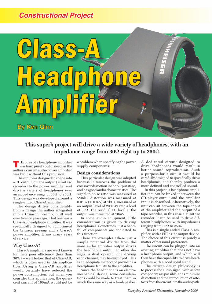
By Ken Ginn
This superb project will drive a wide variety of headphones, with an impedance range from 30Ω right up to 250Ω
Class-A Headphone Amplifier
Headphone Amp 2nd version from Matt 230909.indd 10 24/09/2009 12:04:35

Everyday Practical Electronics, November 2009 11
Constructional Project
Circuit details������������ ���������������
����� �������� �� ����� ��� ������ �� ����� ���� ������ ������ ��� ������� ������������� ���������!�����������������������"���"�!��� �������������������������� �#!���$������� ������������������������
��������������������������������-����������������%&��'� �������� ��"�������������%�'�� ����(��%�)�'����������� ��������������������!���������� �� -���*� � � ���� ��������� ������� ��������������%'�� ��)�������������������������������� ��"��� �������� �����������������������������������������-���������� �����������$��������������
������������������� ��)��������-���� ��������������������������������������� ���� �� � � � ��������� �)�� �� ��)+��������������% ���� �����������),!�).!�)/!��� � ����������)���� ��)+'���0���������������������������&�� ��� ���� ��� �������������������-����� ��� ���� "������� ������ ������!���������� ���� ��#����� ������� ���-����� %������������ ����������'�� ����
�������� �������� ���������� �� ��� ��������#���������12��!��� ������������0���������������������������)������������ ���
3���4��)���� ��)+���� �������*�������� ����� �"���� ����� ���������� ��������"��������������������5��������� �������� �� ����� ������ ������������������������������
Voltage regulation6������&����� � �������������������
� �7�18�%"�������������&����� �&�+'9��������� �����"��������)�$�����������"�������� �+�18!��� ���������"� �!��� �����#����� ��"����� �����!������*�����*��������������� ��:8��� ��������-����� ��� ���� �������� ����� ���������������� �������� �������� ��� &��!� �� ������ ���� ��$����� �������*��������������� ������������������������� � ��������������������� �������� �7��8�%����������&�+��� �&�;'!��� ����������-������ ����0�����������*�����
���� ������� ����� "������� ������-�������������� ����������������� ����������� ����*��� �� ���� �������
�"����� ���� ����*��� �� ������� ���� ���� ������ ���������� ���� �� � ���� ����� � � ���� ������*���� ��-������������������� �����������!��� �������������� ��������������������� �;2��!�������������� ��� �������������
&�� ��� ��� � ����� ���� ������������� � ���"��� �� ���� ������� "�������� �,�28�)<=��������+22Ω impedance ��� ������ %�����#�������� �:2�?�)<='�� ���� �� ���� ���� ����� ��� -������%�;Ω����+2Ω)���������8�)<=������ � ���� ��"��������������"���� ��22�?!� ������ �� ����� ���"�� ��������� �������� ��� �������������-�����@��"��������������: A�� ���� -��������"����������� �����#����� 4���2 A�����8�)<=��
������� �������� � ��� �"��������� ����� ���� ����� =��������$��B;:1!���������"��������� ������ �+2������������ ����������������������� ����������������� !������ -����A�����B�,,2�%�12����� ����'��� ������ ������� �A�����B�;+��%����-������+,����� ����'�
������������� ���������������������������������������� ���������������������!�"��� �#$%����������� �����&��
Headphone Amp 2nd version from Matt 230909.indd 11 24/09/2009 12:04:47

12 Everyday Practical Electronics, November 2009
Constructional Project
Breaking the law���� ������� ���� �� �� �� ����
��������� ������� ��������������������������������� ��������������������� -������ ��!��������� �������� ��������"������"#��� ����������� $��� ������������������%�&��"�� �� �'����������� ���� ������� ������ ���(��!�����&�� ����� ������ ��������� ����������� �� ����� �������� ��)����� �%�&���� ��������������������� ���� ����)����� �%����� �&�����������������!������������������������������"�������&�� ����� ����������������������������"#��� ������ ���� �!�
����*�"#��� �'���������� �&����� �������� ����������������������������+���� � ��� �� ��������� ��-��� ��!�������������&������������������� ���� � �" � ���� ����� ����� �����&����,�������%���������������� ������������ ����.������������.���-���� ��������������������� ���&���� ������� ������ ���!�
/�� ��"�#��������linear��������"��� �"�#�� ���� ����� �� ���.� ������������ ����������� ������ ���������������������������� ��� �����������!���%������������������%���������� ��������� ���� ������ ������������������ ���� �� ����������� ���� �� ���'�������.������!�
�����"#��� ������������������.���� ���� ���� ���� ���� ��� ����� ��� ������������+���� ������������0�������������������&��"�� ��12�� ��$$2���� �������� ��������� ���������%� ����������34�Ω����1(�Ω!� 5�� ���� ������� ���� �� ����0� ��� � ���� �"#��� ������������ �&�����.�������� ����������������!�
������67���������������"������ �����&������ ��� �8�(��%�� ������ ������&��� ��&��"�����������"����� ������ .�������������!� ������� 9����� ���� ������������ ������� ���� ��"���������������1(�Ω!������� �&����� ����"�� ������ ������)�������������� �� -���������� ��������� ������� ���!�
:���%���"����%������ ����� ���������������� ���� ��������� �����������������������������;�� �.� ���&-�.!����������&��������"������������������������ �������"��� 9!�<&���� �(�=� "���� &�� ������ �� ��������������&�.�� ��"���� �������������� ������ ���� ���;�� �.� ����� ����� ��� �.!
Power supplies���������� �����&����"�������.�
������ ��� ������������������%�"������(μ=�������.����71�7���� �����(( =���.���&� �����73�7$�������-����������������������������������&��� � ���� ������ &����� �>7?�!� ���� ������������1���@�� ��,����"�����!�5 ������ %�����((μ=�������.����7A�79�� � �� �� �μ=� �7B�74�� ��������� ������� ����� ������������'��8��������.!
���� ������ �� ������ ����� ��� ������"��� ����.%� � �� ����� ��� ����������� � .� ������� ���� ����� �� ��-�� ����������������������"������������������!�5�����������������"�� �����&��<7������ ��������������������"�������.%�"���������� �������� � ���������7���#<����� !�
5������&�� ����� ������������%���� � ���� �"#��� �� �������� ���� �� ���� ���� ������ &�� �������� ��������+����.��1�Ω!���������� -�������������������������&�� ����������� ���� ��������������������������-��� ���� ���� �� ����� �� ���������������������"#��� ������ ���� �!
������� ��� �����������7����������"#����������"�����$�?��������-;�� �.����#��������&����B(�DE%�� ������������'������������� ����� � ������� ��� ���� &�.� �� ���!� ������� 9�����������������&������������������%�� �����������"����������������%����� �������� ���������������� �����������.�����������!�
Fig.2. Circuit diagram for the dual power supply module
Inside the ������� �� �
��������������������������� ������������
control. Note the L-shaped alu-����������������������������the case lid mounting pillars
Headphone Amp 2nd version from Matt 230909.indd 12 24/09/2009 12:05:01
Everyday Practical Electronics, November 2009 13
Constructional Project
Fig.3: this 3-dimensional graph is also for a 1988 2.0-litre Ford Telstar but this time the ignition advance is plotted against engine RPM and engine load as a 15×15 map (300 RPM per site).
One positive 12V regulator (IC4) and a negative 12V regulator (IC5) are present on each channel. These supply ������������ ����������� ������� ������������� ����������������������and need heatsinking in the same man-ner as TR2 and TR3. In fact, all four devices share the same heatsink. The other regulators supplying ±15V stand �� ��� ��������� ������� � ��
Construction.
The Class-A Headphone Ampli-fier modules are built on separate printed circuit boards (PCBs); one amplifier (two for stereo) and one power supply board. The component layout and copper foil master for the amplifier PCB are shown in Fig.3 and the PCB details for the power
supply in Fig.4. The boards are available from the EPE PCB Service: code 731 for the amp (pair); 732 for the power supply.
������������������������������and power supply were housed in two separate diecast boxes. The unit can be housed in one enclosure, con-taining all three (for stereo) printed circuit boards.
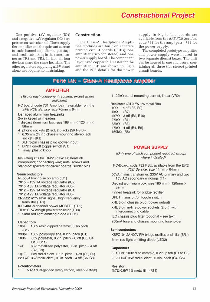
Parts List – Class-A Headphone Amplifier
AMPLIFIER(Two of each component required, except where
indicated)
PC board, code 731 Amp (pair), available from the EPE PCB Service, size 76mm × 64mm
L-shaped aluminium heatsinks2-way keyed pin headers1 diecast aluminium box, size 188mm × 120mm ×
56mm4 phono sockets (2 red, 2 black) (SK1-SK4)1 6.35mm (¼ in.) chassis mounting stereo jack
socket (JK1)1 XLR 3-pin chassis plug (power input)1 DPDT on/off toggle switch (S1)1 small plastic knob
Insulating kits for T0-220 devices; heatsink compound; connecting wire; nuts, screws and stand-off spacers for circuit boards; solder pins
SemiconductorsNE5534 low-noise op amp (IC1)7815 +15V 1A voltage regulator (IC2)7915 -15V 1A voltage regulator (IC3)7812 +12V 1A voltage regulator (IC4)7912 -12V 1A voltage regulator (IC5)2N2222 NPN small signal, high frequency
transistor (TR1)IRF540A N-channel power MOSFET (TR2)TIP31C NPN high power transistor (TR3)1 5mm red light emitting diode (LED1)
Capacitors10pF 100V resin dipped ceramic, 0.1in pitch
(C12)330pF 100V polypropylene, 0.2in. pitch (C1)100nF 63V polyester, 0.2in. pitch – 8 off (C3, C4, C10, C11)1�F 63V metallised polyester, 0.2in. pitch – 4 off (C7, C9)10�F 63V radial elect., 0.1in. pitch – 4 off (C2, C5)2200�F 35V radial elect., 0.3in. pitch – 4 off (C6, C8)
Potentiometers1 50k� dual-ganged rotary carbon, linear (VR1a/b)
1 22kΩ panel mounting cermet, linear (VR2)
Resistors (All 0.6W 1% metal film)10٠4 off (R8, R9)1k� (R7)4k7� 3 off (R2, R10)27k� (R1)33k� (R3)47k� 4 off (R4, R5)150k���(R6)
POWER SUPPLY(Only one of each component required, except
where indicated)
PC-Board, code 732 PSU, available from the EPE PCB Service, size 44mm × 64mm
50VA mains transformer: 230V AC primary and two 15V AC secondary windings (T1)
Diecast aluminium box, size 180mm × 120mm × 82mm
Finned heatsink for bridge rectifierDPDT mains on/off toggle switchXRL 3-pin chassis plug (power output)XRL 3-pin in-line power sockets (2 off), with
interconnecting cableIEC chassis plug filter (optional – see text)250mA fuse and chassis mounting fuseholder
SemiconductorsKBPC104 2A 400V PIV bridge rectifier, or similar (BR1)5mm red light emitting diode (LED2)
Capacitors3 100nF 100V disc ceramic, 0.2in. pitch (C1 to C3)2 2200�F 35V radial elect., 0.3in. pitch (C4, C5)
Resistor4k7� 0.6W 1% metal film (R11)
Headphone Amp 2nd version from Matt 230909.indd 13 24/09/2009 12:05:10

14 Everyday Practical Electronics, November 2009
Constructional Project
In the prototype, one box was used to house the mains transformer and ������� ������� �������� �������board. The second enclosure housed ������������������ �������������-phone jack socket (JK1), volume and balance controls on the front, and the power and phono sockets mounted on the rear – see photographs.
����������������� ������� ������� �part of the heatsinking arrangements and helps to cool the semiconductors. The case will get warm to the touch in use, additional heatsinking could ��� ��������� ���� �� ������ ��� ����mounted on the top of the aluminium casing, but really this is unnecessary.
In the prototype, unscreened wire was used for the input signals from the phono sockets to the volume control ���� ����� ���� ��� �� ���� ���������board. Using this arrangement caused no adverse affects in performance be-cause the wires for each channel were separated, and no noise or hum was ����������� ��� ������ ��������� ���-ing listening tests or recorded on test equipment. Purists will replace these wires with screened cable.
Two-part assemblyThe reason for the two-part as-
sembly was to ensure that the power supply did not introduce mains hum �� ��� ���������� ���� ������ �������� � ������� �� ��� ��������� ����with a three-core cable, delivering the unregulated plus and minus supplies �� ��� �������� �� ���� ����� ������supply was mounted remote from the rest of the headphone circuitry with a half-metre cable.
�����������������������������-ule resting on top of the power supply module, there was no increase in the ��������! ���� �������������� �
"������������ # ����$� � � ����� ���its own PCB; the six components for the power supply are on a separate board on the power supply assembly. ����������� ������� ��%���� � �� �������������� ������������� ��������heat it generates.
Four components (IC4, IC5 and TR2, �&'$�����������������������*+/ �also require heatsinks, provided by the usual TO-220 insulating washer, heatsink compound (if using mica washers) and small insulator bushes to mount these components to the metal bracket. This metal bracket is attached to the diecast box, with heatsink
Fig.3. Printed circuit board component layout and full-size copper foil master ����������������� ����������������������������������������
Fig.4. Power supply printed circuit board component layout and full-size copper foil master
Headphone Amp 2nd version from Matt 230909.indd 14 24/09/2009 12:05:24

Everyday Practical Electronics, November 2009 15
Constructional Project
compound to assist heat transfer away from these devices.
Always double check the wiring and orientation of components and the integrity of solder joints, both
Fig.5. Interwiring details between the two circuit boards and off-board, case ���������� ��������������
Inside the power supply unit. An IEC ����� � ��� ��� ���� �� ��� �����-type; this can be omitted if desired. The circuit board is mounted in the left-hand corner of the box on small stand-off spacers
I id h l i A IEC
on the track side of the PCB and any other component (solder pins, connec-tors). Check for ‘dry joints’ and solder bridges at this stage, as this could save a good deal of heartache at a later date. A magnifying glass is essential for this.
Danger: mains-powered circuit!
Constructing any circuit that uses mains voltages (230V AC) must be
Fig.6. Power supply interwiring details between the mains transformer, circuit board and off-board components
done carefully and safely. Follow-ing the design here should produce a safe design and a few checks throughout construction will aid in this aspect.
Check for earth continuity between the supply earth connection at the mains plug and the power supply metal casing or any exposed metal parts. Bond all metal parts – this means the two halves of the diecast box. This resistance should be as low as possible, certainly measuring less than one ohm from the mains plug earth to any metal part.
Check the isolation between the mains Earth and the Live and Neutral connections of the mains supply input, with the mains power switch in both the on and off positions. This should be measured with a DMM, and you should expect a resistance certainly higher than 200MΩ. If not, look for the fault and rectify it.
Last, check the isolation between the mains input and the power supply output, this again should be meas-ured with a DMM and be higher than 200MΩ, ie open circuit.
Check the electrical continuity from the tabs on the power devices to the chassis (heatsink), this resist-���������� ��������������������������200MΩ, ie open circuit.
TestingThe power supply unit is best
checked on its own without the
Headphone Amp 2nd version from Matt 230909.indd 15 24/09/2009 12:05:41

16 Everyday Practical Electronics, November 2009
Constructional Project
��������� ����������������������������������� ������� � � ��� ����������� ��������� ��������� �������� ������������������ ������� ������ ������� ������������ ������ ������������������ �� �������� !���������� ���������� � ������
� ��� �����"� ����� ���� ������ ����������� �� �� ��������� � ��� � � ��-����������� ������������� ��������� ��� ���� �������� ���� ���� � �"� �� � ��"������ ����� ������ ������"������������ ������� ����������������������������������� ���� ���#����$����� �������� ������ ������� ���� ����������%�������������������"������������
���� � � ������ ���� ������ ��� �����-������������ ��������������������� � ������ & � ���� �������"� ��� �������������� ������������� �����"���������������� ��''�(������������������������������������� ��� ������� ���������)��������� !��������������������-
���� ���������"� ����� ��������������������� �������������������! ������*��� ���� ������ ��� �������� � ��� ��������� �����"� ���� ��������� �������� �������������� ����� �+��������,���"�� ����� ���� ������������ ���� � ���� � �� ��� �� ���$.'�(���� �������"� ���/�'�(���0����"����������� ������������/�'�(�1�0�"���*�����������������$�23����
���� ������ �� ����� �������� 4�� � � ����5�� 6 �� � ���� ��� ���� ���������������� �����0����� ��$.������7� 7����������������"�������������� ��� �������(��� !� ������ ����������-����������������'����������� ������������ ��� ������
How does it sound?���� ���� 8� �������������� �����
������ ������ ���� ������.'�����9'� �� ���� � � � ����� ��������& �� ���� �� ���4:����"�;<="�<���!���� �"�� ��>����5������������������������ ���� ������������ ��? -� �� ?�����"�=����� ���� "�%�������(������� ���� ���� � � ���� ������� ������ ������������ ����������������������
������"�� ������������ � ����� ���=�� ��!���������������� ����! ������"��������������! ���������-������������������������ ������������1�������"��������������� ����������������� ���� ������� ���)��������������"�)������������������ �� �� �� ��� ���� �������� ��@��������
������������ ������������ ����� ����������� �������������� ������� ����������������������
������������@�����������������"��������������������� �� ������������������������ ����=�� ��������������� �������������������0�����������������-
�� ���������������� ����* �����"������� ����������������������������-�� ������������A�����"��������������� ������� ��� ���� @������� ������� ��� ��� �� � �� ������ ����������0�������"���������� ���� �*���� �������0������
���������������� ��� ������ �� ����
�������� ��� ���-���� �� ��� -� � � � �� ���@������� ��������@�������� ��� ���������� ���������� '�'��B� � ���'23� � � $��23������ �� ��� ���� ��� ����� �����-���������������'�/�B�� ��$��23��'�23"���������� ,/�B� � ���� ���������� ��� C'�23�� ���������� ����� � �� ������ � � ������ �� �������� � ���������� ���� � �� ��@������ �-� ����0������ �$'23"��������� �� �� ����'�/�B����������-@�������(������ ������� �"����������-
��� ��� ����� � � ������� � �� �������� ���@����� ������ � � ����� � ������������������ �����������������������������4��'Ω5�� ��������
����"����������������0����������� ��9��;=D����������7� 7� ������ �������-
������������������C'�B"�� ���������������� ��������@������ �� �� �����-�������$�23����� ����� ����'�'$E��������0����� ������ ��9��;=D�
��������������� ������� ������ ������ �������
�� ��� ������������ �� �������������� ����������������� ����� �� ���������������������������������������������EPE
� �� ��������� ����� ��� ����������with optional balance control
Headphone Amp 2nd version from Matt 230909.indd 16 24/09/2009 12:05:58

STEWART of READING17A King Street, Mortimer, Near
Reading RG7 3RSTelephone: (0118) 933 1111
Fax: (0118) 933 23759am – 5pm Monday - Friday
CHECK OUT OUR WEBSITE,1,000’s of items currently in stock
www.stewart-of-reading.co.ukExtra Special Oscilloscope
offer still on
Used Equipment – GUARANTEEDMost Manuals Supplied
Please check availability before ordering or calling.
Prices plus carriage and VAT
AGILENT E4402B Spectrum Analyser100HZ – 3GHZ with Option 1DN Tracking Gen; 1 DR Narrow Res; A4H GPIB, UKB £5800HP 8591E Spectrum Analyser9KHZ – 1.8GHZ with Tracking Gen £1500No Moudlings, No Handle £1250HP 35670A FFT Dynamic Signal Analyser2 Channel. Unused in original box £2500AGLIENT 83752B Synthesised Sweeper0.01-20GHZ £7000HP83731B Synthesised 1-20GHZ with Opts IEI Attenuator, IE5 High Performance Mod Gen, IE5 High Stab TB £4500HP83711B Synthesised 1-20GHZ with Opt IEIAttenuator £5000AGILENT/HP E4431B Signal Generator 250KHZ-2GHZ Digital Modulation £2750AGILENT 6632B Power Supply 0-20V 0-5A Digital IEEE £195HP8116A Pulse/Function Gen 50 MHZ £575MARCONI 2024 Signal Generator 9KHZ-2.4GHZ Opt 04/11 HPIB £950
TEKTRONIX TDS OSCILLOSCOPESSupplied with Operating Instructions & Mains Leads544A 4 Ch 500MHZ 1 GS/S Colour £1050540A 4 Ch 500MHZ 1 GS/S £950540 4 Ch 500MHZ 1 GS/S £750524A 2+2 Ch 500MHZ 500 MS/S Colour £750520A 2+2 Ch 500MHZ 500 MS/S £650
520 2+2 Ch 500MHZ 500 MS/S £550460 4 Ch 350MHZ 100 MS/S £495430A 2 Ch 400MHZ 100 MS/S £495380 2 Ch 400MHZ 2 GS/S £650350 2 Ch 200MHZ 1 GS/S £500340A 2 Ch 100MHZ 500 MS/S £395320 2 Ch 100MHZ 500 MS/S £325310 2 Ch 50 MHZ 200 MS/S £2501012 2 Ch 100MHZ 1 GS/S £425
OSCILLOSCOPESTEKTRONIX 465/465B Dual Trace 100MHZ Delay Sweep £75/£95TEKTRONIX 2235 Dual Trace 100MHZ Dual TB £150TEKTONIX 2445A 4 Ch 150MHZ Delay Sweep Cursors £225HP 54501A Digitising 2+2 Ch 100MHZ 10 MS/S £150HP 54600B Dual Trace 100MHZ 20MS/S £225PHILIPS PM3055 2+1 Ch 60MHZ Dual TB/DelayAutoset £95PHILIPS PM3065 2+1 Ch 100MHZ Dual TB/Delay Autoset £125FARNELL DTV60 Dual Trace 100MHZ £75FARNELL DTV12-14 Dual Trace 12MHZ £40HITACHI V212 Dual Trace 20MHZ £50GOULD OS300 Dual Trace 20MHZ £60LEADER LBO523 Dual Trace 40MHZ £65wer Supplies
POWER SUPPLIESFARNELL B30-10 30V 10A Variable No Meters £45FARNELL B30-20 30V 20A Variable No Meters £75FARNELL L30-1 0-30V 0-1A £30FARNELL L30-2 0-30V 0-2A £40FARNELL L30-5 0-30V 0-5A 2 Meters £50FARNELL LT30-1 0-30V 0-1A Twice £50FARNELL TSV70 MK2 0-70V 0-5A or 0-35V 0-10A £60FARNELL XA35.2T 0-35V 0-2A Twice Digital £75TAKASAGO TMO35-2 0.35V 0-2A 2 Meters £30THURLBY PL330 0-32V 0-3A Digital (Kenwood Badged) £60THURLBY PL320 0-30V 0-2A Digital £45THURLBY TS3021S 0-30V 0-2A LCD £55
MISCELLANEOUSAVO DA116 3½ Digit with Batteries & Leads £20AVO BA8 MK2 Meggar 1000V in Case £25ADRET 104A Programmable DC Voltage CurrentReference Standard IEEE & BCD £75BEAMIX 303 Temperature Calibrator £150BECKMAN HD110 3½ Digit Handheld in Carrying Case £25BLACKSTAR Orion Colour Bar Generator £50CIRRUS CRL254 Sound Level Meter with Calibrator £65COSSOR Isolating Transformer Input 250V
Output 500VA Unused £25FARNELL LF1 Sine/Sq Oscillator 10HZ-1MHZ £40FARNELL J3B Sine/Sq Oscillator 10HZ-100KHZ Low Distortion £65FLUKE 4250A Programmable Power Source 1A £125FLUKE 5200A AC Calibrator £350HP3312A Func Gen 0.1HZ-13MHZ AM/FM Sweep/Tri etc £125HP3336C Synthesised Level Gen 10HZ-21MHZ £195HP3400A True RMS Voltmeter 10HZ-10MHZ, 1mV-300V £50HP3488AHP8922S with 83220E GSM MS Test set with DSC/PSC Test Set with Aux. Ports POAHP VXI Main Frames (75000 Series; E1401A/B;E8401A) £400HP33311 Co-Axial Switch 18GHZ £75HUNTING HIVOLT DCM30/4A 0-30 KV £35LEADER LAG120B Sine/Sq Audio Gen 10HZ-1MHZ £50LEADER LDC9043 Digital Counter 100MHZ £75MARCONI TF2331 Distortion Meter £35MARCONI 2370 Spectrum Analyser 30HZ-110MHZ £395MARCONI 2430A Freq Meter 10HZ-80MHZ £50METRIX GX500 Pulse Generator Programmable £125NATIONAL PANASONIC VP7705A Distortion Meter £95PANASONIC VP8401B TV Sig Gen NTSC/PAL/MONTSC £75RACAL 1991 Counter/Timer 160MHZ 9 Digit £125RACAL 9008 Modulation Meter £50RACAL 9009 Modulation Meter £40RACAL 9904 Counter Timer 50MHZ £40RACAL 9916 Counter 10HZ – 520MHZ £55RACAL 9300B True RMS Millivoltmeter 5HZ-20MHZ usable to 60MHZ 100uV-316V £40RACAL 6103/E/G Digital Radio Test Set Various Options from £500ROBIN OM33 Digital Thermometer –No Probe. Unused £15ROBIN OM65 Digital L/C Meter Handheld, Unused £25SEWARD NOVA Pat Tester £175SHIBASOKU VS12CX Video Sweep Gen NTSC/PAL £125SOLATRON 7045 4½ Digit Bench Multimeter £30SOLATRON 7150 PLUS 6½ Digit Multimeter True RMS IEEE etc £65SOLATRON 7075 7½ Digit Multimeter, no inputconnector, AC/DS Volts Ohms £95THANDAR TG101 Function Gen 200KHZ £25THURLBY TG210 Function Gen 0.002HZ-2MHZ TTL (Kenwood Badged) £60TIME 9811 Programmable Resistance Potential Divider 10hm-1.5 Mohm 6 Digit LC Display IEEE £75WAVETEK 178 Programmable Waveform Synthesiser 1uHZ-50MHZ £195
HP53131A UNIVERSAL COUNTER WITHOPT 001 (oven)Unused Boxed 3GHZ £850 Unused Boxed 225MHZ £595Used 225MHZ £495
HP33120A FUNCTION GENERATOR100 MicroHZ – 15MHZUnused Boxed £595
STEWART - SEPT 09 FULL PAGE.indd 1 22/07/2009 15:26:37
3536
200
9-10
-11
2:21
:57
Constructional Project
18 Everyday Practical Electronics, November 2009
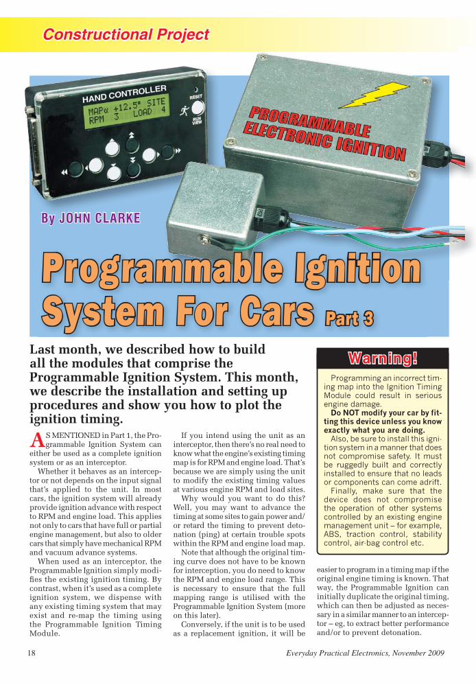
By JOHN CLARKE
Last month, we described how to build all the modules that comprise the Programmable Ignition System. This month, we describe the installation and setting up procedures and show you how to plot the ignition timing.
AS MENTIONED in Part 1, the Pro-grammable Ignition System can
either be used as a complete ignition system or as an interceptor.
Whether it behaves as an intercep-tor or not depends on the input signal that’s applied to the unit. In most cars, the ignition system will already provide ignition advance with respect to RPM and engine load. This applies not only to cars that have full or partial engine management, but also to older cars that simply have mechanical RPM and vacuum advance systems.
When used as an interceptor, the Programmable Ignition simply modi-������������������� ������contrast, when it’s used as a complete ignition system, we dispense with ���������� ������� ������ �������� ��� ��� ��� ���� � �� ����the Programmable Ignition Timing Module.
easier to program in a timing map if the original engine timing is known. That way, the Programmable Ignition can initially duplicate the original timing, which can then be adjusted as neces-sary in a similar manner to an intercep-���������������������������������� ����and/or to prevent detonation.
If you intend using the unit as an interceptor, then there’s no real need to �������������������������� ��map is for RPM and engine load. That’s because we are simply using the unit ��� ���������������� ����!����at various engine RPM and load sites.
Why would you want to do this? Well, you may want to advance the timing at some sites to gain power and/or retard the timing to prevent deto-nation (ping) at certain trouble spots within the RPM and engine load map.
Note that although the original tim-ing curve does not have to be known for interception, you do need to know the RPM and engine load range. This is necessary to ensure that the full mapping range is utilised with the Programmable Ignition System (more on this later).
Conversely, if the unit is to be used as a replacement ignition, it will be
Warning!Programming an incorrect tim-
ing map into the Ignition Timing Module could result in serious engine damage.
Do NOT modify your car by fit-ting this device unless you know exactly what you are doing.
Also, be sure to install this igni-tion system in a manner that does not compromise safety. It must be ruggedly built and correctly installed to ensure that no leads or components can come adrift.
Finally, make sure that the device does not compromise the operation of other systems controlled by an existing engine management unit – for example, ABS, traction control, stability control, air-bag control etc.
B JOHN CLARKB JOHN CLARKE
Programmable Ignition System For Cars Part 3
Programmable Ignition0507 (From Matt).indd 18 23/09/2009 14:49:15

Constructional Project
Everyday Practical Electronics, November 2009 19
In some cases, full timing informa-tion will be available from the car’s manufacturer or from a workshop manual. Usually, however, there will be no information available.
The solution is to actually measure the timing advance against changes in RPM and engine load. This is easy to do in cars with a mechanical vacuum advance mechanism, as this operates independently of engine RPM.
Plotting the timing values in cars that use engine mapping and a MAP sensor for vacuum measurement is only slightly ����� ���� ��� ����� ����� ��� ������� ��altering the pressure sent to the MAP ����������������������������������������is described in the panel headed ‘Plotting The Original Ignition Timing Values’.
Cars that utilise Mass Air Flow (MAF) sensing of engine load are much ��������� ����������������������-ping ignition advance. That’s because the engine will have to be run with varying degrees of load throughout the RPM range, and this can only be achieved on a dynamometer.
Interceptor or replacement?Note that the Programmable Igni-
tion System should be used only as an interceptor on cars that already have an engine management system. That’s because the manufacturer’s timing map will have been carefully designed for your engine. Furthermore, the timing would have been mapped against air inlet temperature, engine temperature and the air-fuel ratio to provide the best performance in all conditions.
By using the Programmable Ignition System only as an interceptor in such cars, the original timing variations ac-cording to fuel ratio, temperature, RPM and load will be retained.
By contrast, we do advocate using the Programmable Ignition System as a complete replacement in older cars, go-carts and on engines that do not currently include RPM or vacuum advance.
Many old cars provide both RPM and vacuum advance by mechanical means. Because of their age, the RPM advance system is now likely to be worn and sticky in its operation, while the vacuum actuator will often be leaky or may have failed altogether.
Most drivers do not notice if a vacu-um actuator has failed because when it �� ������������������������������������load position. As a result, power under load is retained.
provides ‘instantaneous’ changes to the timing map.
Similarly, the vacuum actuator that ������ ���� �������������� �������� �����point is slow to respond compared to using a pressure (or MAP) sensor with the Programmable Ignition System.
InstallationTypically, the Ignition Timing
Module is best mounted inside the cabin of the car; eg, somewhere under the dashboard. This allows the Hand Controller (see last month) to be eas-ily attached and used while someone else does the driving (this should be
Our experienceDuring our tests, we eliminated the
original mechanical RPM and vacuum advance systems in a 1988 Ford Telstar and used the Programmable Ignition System to provide the timing advance instead. As a result, the engine be-came far more responsive to throttle changes and was more willing to rev than before.
There are a couple of reasons for this ��������������������������������!"�����weight’ system in the distributor that provides RPM advance is fairly sluggish to respond to RPM changes. By contrast, the Programmable Ignition System
An external MAP sensor can be mounted on the �������� ������� ������������������������a vacuum hose connection to the inlet manifold.
Timing Problems With Reluctor Triggers
In some cars, when using the Pro-grammable Ignition, you may find that the ignition trigger exhibits a type of stiction effect, with the tim-ing initially failing to advance from about 0 – 5°. This effect is due to the coil firing just before the trigger signal (due to the advance setting) and the resulting high-tension signal within the distributor then interfering with the normal opera-tion of the trigger sensor.
Reluctor triggers are the most likely to be affected in this way. Hall effect, optical, engine management and points triggers are unlikely to be affected.
In some cases the effect may be dialled out by careful adjustment of VR1. Also, make sure the high-tension lead and the reluctor leads are spaced well apart and only intersect at right angles if they do need to cross.
If this does not solve the problem, then you can avoid programming
low values of advance into the Programmable Ignition. This can be done in one of two ways. First, the static timing can be set to say 10° of retard (eg, –10°) so that you need at least 10° of advance from the Programmable Ignition to get 0° timing. Of course, the entire timing map would have to be changed to include this extra 10° for all values.
An alternative method is to set the static timing to greater than the maximum amount of advance in the timing map. This value would then be subtracted from the re-quired timing value for each map site in order to determine the retard setting required for each site in the Programmable Ignition.
For example, if the static timing is +40° and the timing map value is 22°, the programmable ignition map setting would be –18° (22° – 40° = –18°).
Programmable Ignition0507 (From Matt).indd 19 23/09/2009 14:49:24
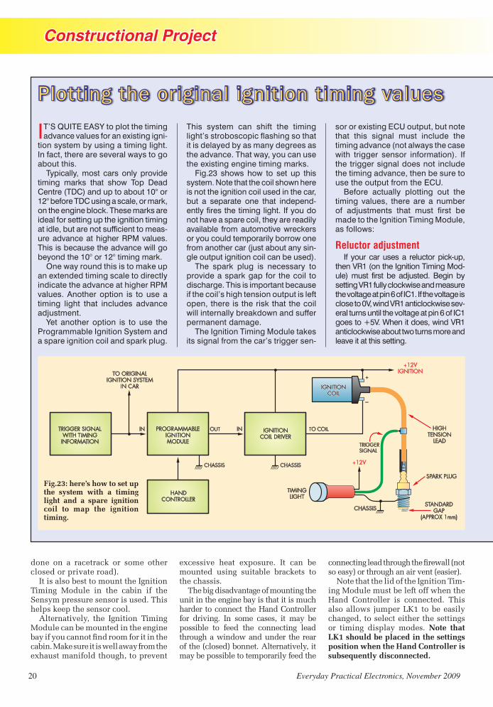
Constructional Project
20 Everyday Practical Electronics, November 2009
IT’S QUITE EASY to plot the timing advance values for an existing igni-
tion system by using a timing light. In fact, there are several ways to go about this.
Typically, most cars only provide timing marks that show Top Dead Centre (TDC) and up to about 10° or 12° before TDC using a scale, or mark, on the engine block. These marks are ideal for setting up the ignition timing at idle, but are not sufficient to meas-ure advance at higher RPM values. This is because the advance will go beyond the 10° or 12° timing mark.
One way round this is to make up an extended timing scale to directly indicate the advance at higher RPM values. Another option is to use a timing light that includes advance adjustment.
Yet another option is to use the Programmable Ignition System and a spare ignition coil and spark plug.
This system can shift the timing light’s stroboscopic flashing so that it is delayed by as many degrees as the advance. That way, you can use the existing engine timing marks.
Fig.23 shows how to set up this system. Note that the coil shown here is not the ignition coil used in the car, but a separate one that independ-ently fires the timing light. If you do not have a spare coil, they are readily available from automotive wreckers or you could temporarily borrow one from another car (just about any sin-gle output ignition coil can be used).
The spark plug is necessary to provide a spark gap for the coil to discharge. This is important because if the coil’s high tension output is left open, there is the risk that the coil will internally breakdown and suffer permanent damage.
The Ignition Timing Module takes its signal from the car’s trigger sen-
sor or existing ECU output, but note that this signal must include the timing advance (not always the case with trigger sensor information). If the trigger signal does not include the timing advance, then be sure to use the output from the ECU.
Before actually plotting out the timing values, there are a number of adjustments that must first be made to the Ignition Timing Module, as follows:
Reluctor adjustmentIf your car uses a reluctor pick-up,
then VR1 (on the Ignition Timing Mod-ule) must first be adjusted. Begin by setting VR1 fully clockwise and measure the voltage at pin 6 of IC1. If the voltage is close to 0V, wind VR1 anticlockwise sev-eral turns until the voltage at pin 6 of IC1 goes to +5V. When it does, wind VR1 anticlockwise about two turns more and leave it at this setting.
Plotting the original ignition timing values
done on a racetrack or some other closed or private road).
It is also best to mount the Ignition Timing Module in the cabin if the Sensym pressure sensor is used. This helps keep the sensor cool.
Alternatively, the Ignition Timing Module can be mounted in the engine ���������������� ����������������������cabin. Make sure it is well away from the exhaust manifold though, to prevent
excessive heat exposure. It can be mounted using suitable brackets to the chassis.
The big disadvantage of mounting the unit in the engine bay is that it is much harder to connect the Hand Controller for driving. In some cases, it may be possible to feed the connecting lead through a window and under the rear of the (closed) bonnet. Alternatively, it may be possible to temporarily feed the
������������������������� ������������so easy) or through an air vent (easier).
Note that the lid of the Ignition Tim-ing Module must be left off when the Hand Controller is connected. This also allows jumper LK1 to be easily changed, to select either the settings or timing display modes. Note that LK1 should be placed in the settings position when the Hand Controller is subsequently disconnected.
Fig.23: here’s how to set up the system with a timing light and a spare ignition coil to map the ignition timing.
Programmable Ignition0507 (From Matt).indd 20 23/09/2009 14:49:37

Constructional Project
Everyday Practical Electronics, November 2009 21
If the voltage at pin 6 of IC1 is +5V when VR1 is wound fully clockwise, then rotate VR1 fully anticlockwise and wind it clockwise until the volt-age goes to +5V. As before, now wind on VR1 by an extra two turns (clockwise this time).
Initial settingsNow for the programmed settings;
here’s the step-by-step procedure:1) Install jumper LK1 in the settings
position.2) Set the number of cylinders for
your car, the edge sense to HIGH and the diagnostic setting to ‘No Interpolation’.
3) Set the dwell to 0ms and set the oscillator to ON.
4) Increase the dwell value until the timing light fires reliably. Note that the dwell value does not change until the Up switch on the Hand Controller is released.
5) Move LK1 to the timing position and press the Reset switch on the Hand Controller so that all the timing values for the selected map return to 0.
If you now start the engine and aim the timing light at the flywheel timing marks you should see the amount of advance. If this does not seem correct, then change the edge sense to low in the settings mode (ie, temporarily move LK1 back to the settings position). If the strob-ing is erratic, try selecting the 2ms debounce option (again found in the settings mode).
Note that with this strobe set-up, the timing light will fire for every spark firing, rather than just for cyl-inder 1. This will make the visible contrast of the timing mark a little less than it otherwise would be. You can compensate for this by dabbing
some white paint on the flywheel marker.
Checking the advanceHaving gone through all these
initial adjustments, the next step is to disable any vacuum advance by removing and plugging the rubber hose that connects to the vacuum advance pressure sensor (or MAP sensor). The timing advance at idle should be set according to the manufacturer’s specifications.
For the Ford Telstar, the initial tim-ing is 6° BTC (before top centre) and this should be indicated by aiming the timing light at the timing marks. In this case, the Ignition Timing Module can now be programmed (using the Hand Controller) for a tim-ing advance of –6.0° (retard). When this is done, the timing light should now show the timing to be at exactly TDC on the flywheel marks.
Plotting the RPM advance values from here is straightforward. It’s just a matter of running the engine at specific RPM values and adjusting the ‘retard’ value programmed into the Ignition Timing Module until the timing light shows TDC in each case. The programmed values then represent the timing advance (in de-grees) for each selected RPM value.
For example, let’s say that the programmed value necessary for the timing light to show TDC is –22° when the engine is doing 3400 RPM. This simply means that, in this par-ticular case, the standard ignition has a timing advance of 22° at that engine speed.
OK, so how do we actually do this? Simple – just select the tim-ing display mode (using LK1) and then select DIAG so that the RPM is displayed. You can now plot out the advance versus RPM values by increasing the engine RPM in suit-able steps (eg, 1000 RPM) all the way to the red line and adjusting the programmed retard value so that the timing is shown at TDC. Keep a record of these advance values as you proceed.
This RPM versus timing advance is generally the high-load map because the vacuum advance line is discon-nected and plugged. However, it is not the high load map for turbo-boosted engines (see below).
The recorded timing information can now be plotted on a graph and the interpolated values transferred to the individual RPM sites. This is done as follows:1) Decide whether you want the two
RPM0 Min RPM Max RPMRPM Site RPM1 RPM2 RPM3 RPM4 RPM5 RPM6 RPM7 RPM8 RPM9 RPM10 RPM11
Load Site 0 1000 1400 1800 2200 2600 3000 3400 3800 4200 4600 5000Min load LOAD1
LOAD2LOAD3LOAD4LOAD5LOAD6LOAD7LOAD8LOAD9LOAD10
Max load LOAD11 6 6 8.5 11.5 13 15.5 19 22 26 28 32.5 34
. . . continued next page
By contrast, the Ignition Coil Driver must be mounted in the engine bay. It can be secured to the chassis using suitable brackets and should be lo-cated close to the ignition coil. If you are using a separate MAP sensor, then ����������� ����� �������������
Make sure there is a good connection ���������������������� �� ��������and the chassis. If necessary, you can run separate earth leads to ground (bolt
them to the chassis via crimp eyelet connectors).
Once you’ve made the connections, use your multimeter (set to its ohms ������� �� �������������������������are correctly grounded. You should get ��������� ����� � ���������������metal case and ground.
����������������������� ������ ������������������������������! ����������������������������"���� �#�����
Module and the Ignition Coil Driver �� ����������������� � ��$�������and automotive crimp connectors. %�������&�� ���� ��� � ��$�� ����� ���crimp connectors for the connections to the ignition coil, the +12V supply and to chassis.
#���'��*���//�&��� ��������0��from the fusebox. Be sure to choose a connection point that delivers '��*� �&�������������� ���� ��
Table 1: this table shows the interpolated advance values vs RPM for the high load site (in this case, LOAD11). These values are measured with the vacuum advance line disconnected and plugged – see text.
Programmable Ignition0507 (From Matt).indd 21 24/09/2009 14:59:09

Constructional Project
22 Everyday Practical Electronics, November 2009
11x11 maps or the single 15x15 map and select this in the settings mode.
2) Select either 1° or 0.5° resolution.3) Set the Minimum RPM and Maxi-
mum RPM values to suit the range of the engine. The Minimum RPM value is simply the idle speed, while the Maximum RPM value is the engine red line. The idle speed can be measured by setting the display to DIAG, so that it shows RPM.
When setting the Maximum RPM, adjust the RPM/SITE value so that the Maximum RPM is at or just over the value required. You can also adjust the Minimum RPM setting if necessary (see Part 1 – Sept ’09).
The Minimum RPM value be-comes the RPM1 site. The RPM step value for each site is shown in the Maximum RPM settings display. If this is 400 RPM, for example, then the RPM2 site will be 400 RPM higher than the Minimum RPM setting. Similarly, the next RPM site will be 400 RPM higher again, and
so on up to the final RPM site, which will be equal to (or slightly higher than) the Maximum RPM value.
You should now have a timing table that is similar to the one shown in Table 1. Note that we have included RPM0 on a different line because it is only there to show that the advance set-ting remains the same for RPM values below the Minimum RPM site (RPM1).
Finally, you may wish to recheck the advance values assigned to each RPM site. For example, for the table shown, you would recheck the advance at 1000, 1400, 1800, 2200, 2600, 3000, 3400, 3800, 4200, 4600 and 5000 RPM.
Vacuum advanceHaving determined the RPM site
advance values, you now need to plot the LOAD values.
First, let’s assume that you have a car with a mechanical vacuum actuator. In this case, you will need a T-piece in order to connect this existing vacuum actuator (via a hose) to the MAP sensor used with the Programmable Ignition System.
Note, however, that a T-piece is not required if your car is fitted with an existing MAP sensor. In this case, the same signal from the MAP sensor is used both for the existing ignition and for the Ignition Timing Module.
In either case, it will be necessary to feed a MAP sensor signal to the Ignition Timing Module. If you are using the Sensym sensor, then a vacuum hose has to be connected to this.
The T-piece does not have to be anything too complex. You can buy these at an automotive shop or make your own.
As shown in Fig.24, a syringe is used to vary the pressure. However, be careful not to introduce excessive pressure into the MAP sensor, as it may be damaged.
For 1-bar sensors, the syringe should be pressed all the way in before connecting it to the vacuum hose. That way, you can only ‘draw’ a vacuum by pulling on the syringe plunger (and not increase the pres-sure). The maximum value is typically around 200, but could be as high as 230 and is equivalent to a 4V to 4.5V output from the sensor.
If you are using a 2-bar sensor, first check the LOAD value at normal atmospheric air pressure. At 2-bar, this value will be about 100 greater. Do not increase pressure above this increased value (ie, the atmospheric plus 100 value).
In this case (ie, for a 2-bar sensor), the syringe should be inserted into the hose with the plunger set half-way down. If you cannot get a sufficient pressure range with this, then you will have to do the pressure changes in two steps: (1) for vacuum, insert the syringe when the plunger is fully in and draw out the plunger for vacuum; and (2) for boost pressure measure-ments, insert the syringe nozzle into the hose with the plunger fully drawn and apply boost pressure by pressing on the plunger.
During this process, be sure to always monitor the sensor output level by setting the Hand Control-ler to DIAG mode (the second line shows the pressure sensor LOAD value). If the value stops increasing as you apply more pressure, then stop immediately. This indicates
Plotting The Original Timing Values – Continued
Fig.24: here’s how to check the LOAD values in a car with a mechanical vacuum actuator. The syringe is used to vary the pressure.
Programmable Ignition0507 (From Matt).indd 22 23/09/2009 14:49:59

Constructional Project
Everyday Practical Electronics, November 2009 23
that you have reached the maximum pressure that the sensor can detect and any further increases could damage it.
Plotting vacuum advanceLet’s assume that your car uses a
vacuum actuator and you have made the necessary vacuum hose connec-tions using the T-piece. The vacuum advance plot can now be made at a fixed RPM setting that coincides with an RPM load site value.
However, do not choose the idle load point because the engine RPM will alter as vacuum advance is ap-plied, and you need to be able to adjust the throttle to maintain the fixed RPM setting. Choose the RPM2 site value instead (1400 RPM in our example).
It’s now just a matter of plotting the RPM advance against the pressure sensor LOAD reading, as shown on the Hand Controller’s display. To vary the LOAD reading, just vary the position of the syringe plunger. Be sure to adjust the throttle to com-pensate for pressure changes, to maintain engine RPM at the RPM2 site value.
In practice, the vacuum advance value will stop increasing beyond a certain min imum pressure value. This value should be recorded as the minimum load. Similarly, it will also cease changing at a certain maxi-mum pressure value and this should be recorded as the maximum load value. Enter these two values into the Minimum LOAD and Maximum LOAD settings.
Remember that the maximum load value can only be changed by increasing the LOADS/SITE value. In our example, the LOADS/SITE value is 40 and it ranges from a minimum of 151 (which becomes LOAD1) through to a maximum of 191 (LOAD11).
You can now insert the load tim-ing values into a table, as shown in Table 2.
Note that the voltage output from electronic pressure sensors (including MAP sensors) usually decreases with in-creasing vacuum (lower pressure). This means that the minimum load (maxi-mum vacuum) gives the lowest value on the DIAG display, and so this becomes the minimum load site (LOAD1).
If, for some reason, the pres-sure readings are reversed (ie, the value increases with decreas-ing vacuum), then the load site numbering will have to be reversed so that the maximum load becomes LOAD1. This is because the low-est value must be entered as the minimum load site.
Completing the tableBecause the vacuum actuator
advance system provides the same advance curve at all RPM values, it’s quite easy to complete the table. In our example, the advance increases by 1° for each decreasing LOAD site. Table 3 shows the result.
MAP sensorIf your car has an existing MAP
sensor, then the load advance will have to be plotted for each RPM site. The table then may not have a consistent change between LOAD sites, but its value will be dependent on the ignition mapping.
ProgrammingThe Ignition Timing Module can
now be programmed with the timing map. This is done using the VIEW
RPM0 Min RPM Max RPMRPM Site RPM1 RPM2 RPM3 RPM4 RPM5 RPM6 RPM7 RPM8 RPM9 RPM10 RPM11
Load Site 0 1000 1400 1800 2200 2600 3000 3400 3800 4200 4600 5000Min load LOAD1 16 16 18.5 21.5 23 25.5 29 32 36 38 42.5 44
LOAD2 15 15 17.5 20.5 22 24.5 28 31 35 37 41.5 43LOAD3 14 14 16.5 19.5 21 23.5 27 30 34 36 40.5 42LOAD4 13 13 15.5 18.5 20 22.5 26 29 33 35 39.5 41LOAD5 12 12 14.5 17.5 19 21.5 25 28 32 34 38.5 40LOAD6 11 11 13.5 16.5 18 20.5 24 27 31 33 37.5 39LOAD7 10 10 12.5 15.5 17 19.5 23 26 30 32 36.5 38LOAD8 9 9 11.5 14.5 16 18.5 22 25 29 31 35.5 37LOAD9 8 8 10.5 13.5 15 17.5 21 24 28 30 34.5 36LOAD10 7 7 9.5 12.5 14 16.5 20 23 27 29 33.5 35
Max load LOAD11 6 6 8.5 11.5 13 15.5 19 22 26 28 32.5 34
������������ ������������������������������������������������������������� ���������������������������� ����������������������� ��!"#$������������%�������������������������&'((��)������*����������%
RPM0 Min RPM Max RPMRPM Site RPM1 RPM2 RPM3 RPM4 RPM5 RPM6 RPM7 RPM8 RPM9 RPM10 RPM11
Value Load Site 0 1000 1400 1800 2200 2600 3000 3400 3800 4200 4600 5000151 LOAD1 18.5155 LOAD2 17.5159 LOAD3 16.5163 LOAD4 15.5167 LOAD5 14.5171 LOAD6 13.5175 LOAD7 12.5179 LOAD8 11.5183 LOAD9 10.5187 LOAD10 9.5191 LOAD11 6 6 8.5 11.5 13 15.5 19 22 26 28 32.5 34
setting, to enable stepping through all the map sites.
Normally, the distributor would be adjusted so that the trigger sen-sor delivers a firing signal at TDC and the timing map entered on this basis. Alternatively, you can set the distributor to deliver a firing signal at a preset advance or retard value. The entered advance values would need to be adjusted to account for this initial advance or retard setting of the distributor.
Make sure that the distributor’s rotor is still within its range for firing with the values set in the program-mable ignition. If you do not change the settings much beyond the original ignition timing curve, then the rotor will remain within range to allow the spark to bridge the gap within the distributor cap to fire the spark plugs.
Finally, don’t forget to set the in-terpolation back to ‘on’ after plotting the ignition timing.
������������!"#$��������������������������������+����� ����������������������������� &������%�,���������� ������ �������������������%
Reproduced by arrangement with SILICON CHIP
magazine 2009.www.siliconchip.com.au
Programmable Ignition0507 (From Matt).indd 23 24/09/2009 15:01:03

Constructional Project
24 Everyday Practical Electronics, November 2009
In addition, make sure that this +12V rail DOES NOT drop to 0V when the ignition is switched to START, otherwise the engine will never start.
In our case, we used twin-core shielded cable to connect between the Ignition Timing Module and an external MAP sensor mounted on the �������������� � ������������������ ��can use automotive cable.
Note that the MAP sensor must be ������ ����� ���� � ������ � �������� �double-check the wiring and voltages ��� �������������������� ������ ��� ������� ������� ����������������������!�"��� ��������� ��� �#�������� ������ ���� ������ � ������ ��� ���������������������������������$��������� �������%&������ ���'�
A toggle switch will need to be � ������ ���������� �������� �������� ���������� ����������������� �%%(%%������)��������� ����������� ��������
� �����*%���������� ������������ ��)��-����! �����"+�� ��������� ��/�������� �������$����������%%(%%� ����%0(%0'�������������*%�������������
Adjusting VR1���� ������������������� ���������� �
trigger the Ignition Timing Module, the ����������� �� �����/�������� ��12%��)������� �������� ������������� �����-������������������3"� ���������� �������������� ��������������#�$������������-��������� �� �����32����� ����/������#'�
���� ��������� ���������2"!��������������� $��� �����'�� ����� � �� �� �������������� ������� ���� ������ �� )��-���� ! ����� ����� ����� �������� �����set. You will, however, need to set the dwell for the ignition coil.
+ ��������� ��� � ��� �� ���� �����-������������������������� ������������to start from scratch. The various set-�����������������������������������������*����#45�
)�������������� �������/������67%���������������� ��� ���)����� ������������������ ������������ ��� ������������������������������ ������$ ��� �� ������ ���� ������ �������������-����'�� )��� ����� ���� ������� � ����then be checked to ensure it is set for 3������ ���� �� �#�
8��������������������� ������������� �%%(%%����� ������������%0�%0��������������������������������������9 �� �� ���� ���� ��� ��������� �����������%:� ��4�0:��� ���� ����������������� ������ �4�;��
8 ����������������������������� �������� �<����������������� ������)���������� ��� ����� ���� �� �� ���������=������ ����� ��� ������������
Dwell settingNow for the dwell setting. First,
attach an external� ���������� � � ����HT lead from the coil and connect the ����#��������������� ������$�� ���'��> ����������������?���������������������� �� ����� ��� ������� ���� � ������this connection.
8 ���������������� �4�������������internal oscillator in the Ignition Tim-ing Module to on. That done, increase �������������������������������������� ������������������
Note that the dwell value will not ������� ������ ���� @�� ������ �� ����Hand Controller is released, so be sure to release the switch each time � �����������������*� �� ������������������������������������������ ����������������������������������
Using an existing coil driver module
IN SOME CASES, it may be possi-ble for the output from the Ignition
Timing Module to drive an exist-ing ignition module (or coil driver) instead of using our Ignition Coil Driver module.
There are a few things to sort out before doing this, however. First, you must find out the voltage sense used for the trigger signal. This can easily be determined if the trigger signal is produced by the ECU. For other triggers, the sense may need to be determined by trial and error.
Initially, you should set the Ignition Timing Module’s EDGE setting to LOW. If it doesn’t work, try reduc-ing the 470Ω output resistor in the Ignition Timing Module to 220Ω in order to drive the original coil driver module.
If it still doesn’t work, try chang-ing the EDGE setting to HIGH. In addition, the Ignition Timing Module output must be inverted for positive-edge firing by taking the drive from transistor Q4 – see Fig.14 in last month’s article.
ECU trigger signalWhat if you are using the trigger
signal from an existing ECU (or en-gine management unit)?
In this case, the output may nor-mally be at +5V, with a low signal then applied to the ignition module to ‘charge’ the coil and a high-going signal subsequently used to fire a plug. Alternatively, the signal sense could be completely reverse to this.
Generally, it’s easy to determine the voltage sense by measuring the volt-age from the ECU when the engine is idling, using a multimeter set to read DC. The meter will show the average voltage of the trigger signal and so a normally low output will give a voltage below 2.5V and a normally high output will give a voltage above 2.5V.
If the measured voltage is less than +2.5V, then the plugs fire on the low-going signal edges (ie, the ECU’s output goes to +5V to ‘charge’ the coil). In this case, the EDGE setting in the Ignition Timing Module should be set to LOW.
Conversely, if the voltage is greater than +2.5V, it means that the coil charges when the ECU output goes to 0V and the plugs fire on the high-going signal edges. In this case, the EDGE setting in the Ignition Timing Module should be set to HIGH. In addition, the signal output from the Ignition Timing Module must be inverted (by taking the output from transistor Q4), as shown last month in Fig.14.
Small engine useFor some motorcycles, go-carts
and other engines, the ignition can be operated without using a MAP sensor. In this case, the MAP sen-sor input on the PC board should be connected to the 0V (ground) supply pin provided for the exter-nal MAP sensor. This will set the programmable ignition at a single fixed load setting.
In the settings, set the minimum load to about 20 and the maximum load to around 200. The ignition will then be programmed for RPM load sites only and at the fixed load setting. RPM mapping would be over 11 RPM sites (or 15 RPM sites if the single 15 × 15 map is selected).
Programmable Ignition0507 (From Matt).indd 24 23/09/2009 14:50:16

Constructional Project
Everyday Practical Electronics, November 2009 25
Disabling Original Ignition Systems
Left: you can use a simple aluminium plate like this to lock the mechanical timing weights inside a distributor. It simply slides over the distributor cam and the timing weight posts, as shown in the photos.
Inside a stripped-down distributor, showing the timing weight posts.
The aluminium plate prevents the posts attached to the weights from sliding in their slots as the RPM increases, thus locking them in position.
The partially reassembled distributor with the advance plate back in position. Because the weights are locked, the advance plate is now also locked.
stemsstems
The inlet to the vacuum actuator is disconnected and plugged.
IF YOUR CAR already has a fully electronic ignition, it can be disabled quite easily. Just disconnect the trigger sensor from the existing
ignition and connect it to the Ignition Timing Module instead.Note that with some ignition systems, you will not be able to
find a suitable trigger signal that does not also include timing information. In this case, you can only use the Programmable Ignition System as an interceptor.
To disable a mechanical advance system, you first need to remove and disassemble part of the distributor. Make sure you turn the engine to TDC for cylinder 1 before removing the distributor.
The distributor must be stripped down to give access to the mechanical weights, so they can be locked in place. We used an aluminium plate to lock the weights to the minimum advance position. The vacuum actuator hose is disconnected (to set the advance to the maximum load setting) and the inlet to the actuator is plugged.
The vacuum hose is then connected to the manifold pressure sensor that’s used with the Programmable Ignition System (eg, to an external MAP sensor or the on-board Sensym sensor). Be sure to reinstall the distributor with its rotor pointing towards the cylinder 1 high-tension terminal on the distributor cap.
ib
�
� �
�
Programmable Ignition0507 (From Matt).indd 25 23/09/2009 14:50:34
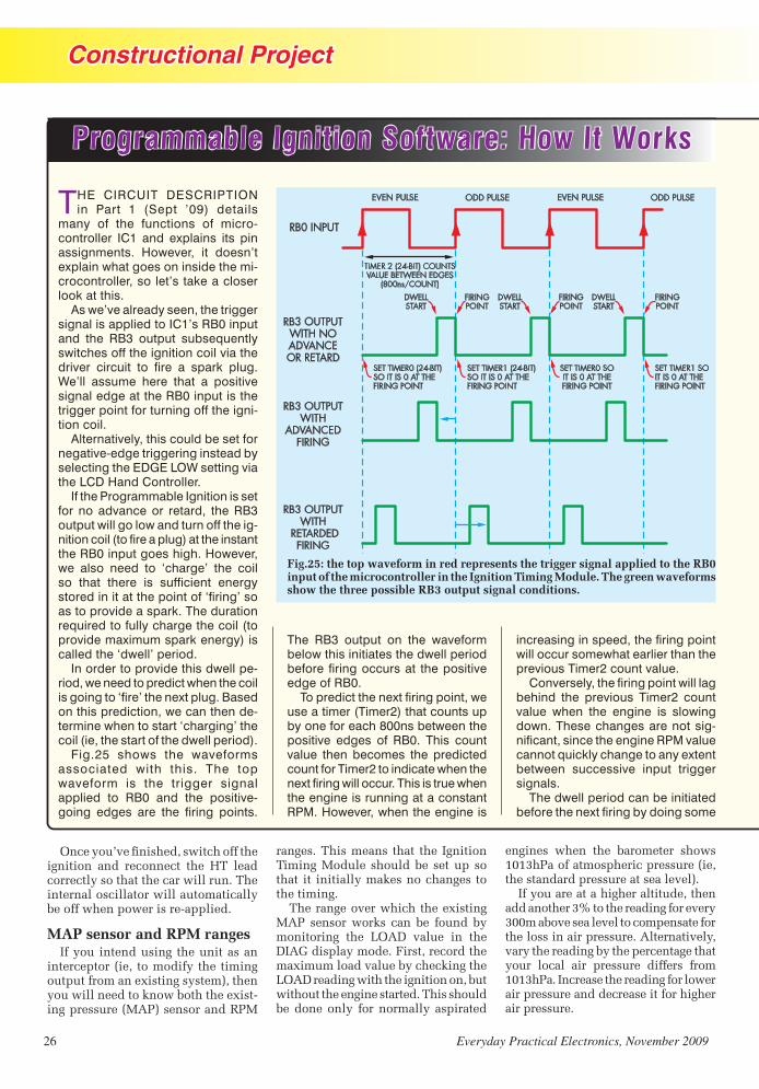
Constructional Project
26 Everyday Practical Electronics, November 2009
THE CIRCUIT DESCRIPTION in Part 1 (Sept ’09) details
many of the functions of micro- controller IC1 and explains its pin assignments. However, it doesn’t explain what goes on inside the mi-crocontroller, so let’s take a closer look at this.
As we’ve already seen, the trigger signal is applied to IC1’s RB0 input and the RB3 output subsequently switches off the ignition coil via the driver circuit to fire a spark plug. We’ll assume here that a positive signal edge at the RB0 input is the trigger point for turning off the igni-tion coil.
Alternatively, this could be set for negative-edge triggering instead by selecting the EDGE LOW setting via the LCD Hand Controller.
If the Programmable Ignition is set for no advance or retard, the RB3 output will go low and turn off the ig-nition coil (to fire a plug) at the instant the RB0 input goes high. However, we also need to ‘charge’ the coil so that there is sufficient energy stored in it at the point of ‘firing’ so as to provide a spark. The duration required to fully charge the coil (to provide maximum spark energy) is called the ‘dwell’ period.
In order to provide this dwell pe-riod, we need to predict when the coil is going to ‘fire’ the next plug. Based on this prediction, we can then de-termine when to start ‘charging’ the coil (ie, the start of the dwell period).
Fig.25 shows the waveforms associated with this. The top waveform is the trigger signal applied to RB0 and the positive- going edges are the firing points.
The RB3 output on the waveform below this initiates the dwell period before firing occurs at the positive edge of RB0.
To predict the next firing point, we use a timer (Timer2) that counts up by one for each 800ns between the positive edges of RB0. This count value then becomes the predicted count for Timer2 to indicate when the next firing will occur. This is true when the engine is running at a constant RPM. However, when the engine is
increasing in speed, the firing point will occur somewhat earlier than the previous Timer2 count value.
Conversely, the firing point will lag behind the previous Timer2 count value when the engine is slowing down. These changes are not sig-nificant, since the engine RPM value cannot quickly change to any extent between successive input trigger signals.
The dwell period can be initiated before the next firing by doing some
Fig.25: the top waveform in red represents the trigger signal applied to the RB0 input of the microcontroller in the Ignition Timing Module. The green waveforms show the three possible RB3 output signal conditions.
Programmable Ignition Software: How It Works
������������ �������� ������������ �� � ��� ���� ���������� ���� ��� �������������������������������� ����������� ����������� �������� ��������� ������������������������ ��������� ���
MAP sensor and RPM ranges ����� ������� �������� ��������
�����������! ��� ������ �������� � �����������������" �� ���������#����������� �����������$��������������" ��� �����������!%&'#������������('%�
���������� �������� ����� ���� �� � ���� � ���%����� ��������� ������ �������� �� � � �������$���������������������� � ���
����������������� ��������" �� ���%&'� ����������$�� ���� ��� ����� ������ ��� ��� ���� )�&*� ����� �� ����* &+�� ������������, ������������������" ��������������������$ �������)�&*����� ���� ������� �� � ����������� ������������ �������������� ��������������������� ������������� ��� ������
��� ���� ����� ���� ����������� ������-.-/�'�������������� ����������! ������������������������������������#�
��������������� �������� ����������������������/0������������ �������������/..��������������������������������������������� ��� �����������&������� ������������������� ������������������������������ ������ � �� �������� � ������ �����-.-/�'��� ���������������� �������������� ����������������������� ������� ������ ����������
Programmable Ignition0507 (From Matt).indd 26 23/09/2009 14:50:47

Constructional Project
Everyday Practical Electronics, November 2009 27
calculations using the Timer2 count value. If, for example, the required dwell for the coil is 4ms, we can cal-culate that this period is equal to a count of 5000. This is because 4ms requires counting 5000 of the 800ns count periods. We can then start the dwell at a count of 5000 before the next expected firing point.
Initiating the dwell start and switching off the coil to fire a plug requires another counter. At every positive signal edge on RB0, this second counter (Timer0) is set at a value so that it will reach a count of zero at the next expected firing position. Before it reaches zero, the counter is checked every 204.8ms to see if it has reached the value to start the dwell period. If this value has been reached, RB3 goes high and remains high until the counter reaches zero, at which point RB3 goes low to fire the plug.
In order to advance or retard the firing point, instead of setting Timer0 to fire at the next expected RB0 posi-tive edge, we either fire before this for advance, or later than this for retard. The dwell is also shifted to start earlier as the timing advances or later as the timing retards.
We need to make some calcula-tions in order to set Timer0 to a value that will give the correct amount of advance or retard in degrees. As we know, the Timer2 value provides us with the count between firing pulses. Firing pulses occur twice per engine revolution for a 4-cylinder 4-stroke engine, and three times per engine revolution for a 6-cylinder 4-stroke. So, for a 4-cylinder 4-stroke engine, we divide the Timer2 count by 180 because plug firings are 180° apart, with two pulses per 360° engine revolution. This gives us the count per degree.
For the 0.5° resolution setting, we divide by 360 instead of 180 to get the number of counts per 0.5°. Similarly, for a 6-cylinder engine, we divide by 120 for the 1° resolu-tion setting because there are three firing pulses per 360° engine revo-lution. The number of degrees of advance or retard required is then multiplied by the count per degree value. This is then either added to the Timer2 value to retard the timing or subtracted from the Timer2 value to advance the timing.
Timer0 is then set so that it reaches a count of zero at this altered Timer2 value. In this way, RB3 is controlled by Timer0 to set the dwell and fire a plug (when Timer0 is zero) at the required advance or retard setting.
Well, that’s basically how the system works, but in practice it’s a bit more complicated that that. In reality, there are two timers: Timer0 and Timer1. Timer0 is used to decide when to drive RB3 high (for the dwell) and low (to fire the plug) between each of the even-numbered positive edges from RB0.
By contrast, Timer1 is used to drive RB3 high and low between each of the odd-numbered RB0 positive edges.
The reason we need two timers is because one of them might still be in use, determining when to drive RB3, when the next positive edge from RB0 occurs. If only one timer was used, it could not be made ready for the next firing sequence, as this would affect the current firing posi-tion. The only alternative is to use two timers, as described.
Note that the firing point is calcu-lated from the previous RB0 positive edge and may not exactly match the current RB0 edge when there is no advance or retard adjustment. This
can happen when the engine revs are changing.
In this case, we fire the coil when the RB0 output goes high. In addi-tion, when the timing is set to retard, the firing point is recalculated when the next RB0 positive edge occurs. If the timing is set to advance, the plug will also be fired at the positive RB0 edge if it has not already fired.
Another calculation made within the microcontroller is for the engine RPM value. This calculation first divides the Timer2 count value by 16 and the result is then divided into 93,750/cylinder for a 4-stroke engine. The result is a value for the number of ‘100 RPM’ increments.
For example, lets assume that Timer2 has a count of 37,500 and we are running a 4-cylinder engine. The 37,500 is then divided by 16 to give a result of 2343. Dividing this value into 93,750/4 gives a value of 10. This is the number of ‘100 RPM’ increments, which in this case is equivalent to 1000 RPM.
This calculation is correct because with a Timer2 count of 37,500, the period between pulses is 30ms be-cause each count represents 800ns (800ns × 37,500 = 30ms). A 30ms period is 33.333Hz or 2000 pulses per minute. Since the engine is a 4-cylinder 4-stroke, there are two pulses per revolution and so the engine speed is 1000 RPM.
Calculations are also required to convert the RPM and pressure sensor values to site values. These calculations are based on the size of the map selected (11×11 or 15×15) and the minimum and maximum RPM and load values. Further calculations perform the interpolations for the advance and retard values between both the RPM and load sites.
For turbo engines, the maximum reading from the pressure sensor is found at maximum boost.
The minimum load value can be found by driving the car downhill, with the engine being overrun (eg, by shifting to a lower gear than normal). Note, however, that some cars tap the vacuum line for the vacuum measure-������������������� ���������������located within the air inlet throat. In this case, vacuum measurement is
not available on a fully-closed throt-��������������������� ����������������������� ������� ���� ����� ���������opening the throttle in this case will cause the vacuum to reappear.
����� ������ �������� ���� ����-mum load value, enter it into the settings as the Minimum LOAD. That done, enter the Maximum LOAD by altering the loads/site value so that it is equal to or a little over the value previously measured.
You now need to set the minimum and maximum RPM values to suit the range of the engine. Just set the Minimum RPM value to the idle speed and the Maximum RPM value to the engine red line.
Note that the idle speed can be meas-ured using the Programmable Ignition System, with the display set to DIAG to show the RPM.
When setting the Maximum RPM, ��������������!"#$%��������������������&����������������������������
Programmable Ignition0507 (From Matt).indd 27 24/09/2009 15:01:46

Constructional Project
28 Everyday Practical Electronics, November 2009
You can replace your existing points with a Hall effect sensor – but be warned, it takes quite a lot of preci-sion work! All the details are shown in Fig.26.
First, rotate your engine so that the rotor button in the distributor is facing the high-tension outlet for cylinder number 1. Also note the direction that the rotor button moves when the en-gine is turned in its correct direction. Set the timing mark on the flywheel to the number of degrees before Top Dead Centre (TDC) specified in the workshop manual and indicated by the engine block timing marks.
Now place a mark on the edge of the distributor body to show where the timing mark on the rotor button arm is positioned. This sets the align-ment for the Hall effect modification. The distributor can now be removed from the engine.
The Hall effect sensor is designed to be used with a rotating vane that passes through the gap incorporated in its housing. The Hall sensor is mounted on the distributor advance plate and secured using the rivets incorporated on its housing. The rotating vane needs to be made so that it spins with the distributor
shaft and its vanes pass through the sensor gap.
For this to happen, the rotating vane needs to be cup-shaped. The horizontal face has a hole to allow it to be placed on the distributor shaft and locate with the rotor button. The vertical section needs to have slots cut in it to appropriately trigger the sensor.
The number of slots on the vane equals the number of spark-plugs for which the distributor caters. So a 4-cylinder car with four spark plugs will use four slots. These slots need to be evenly spaced around the cir-cumference of the rotating vane. It is essential to be accurate here, as a 1° difference between slots represents 2° on the engine.
A 4-cylinder engine will have each slot positioned 90° apart. 6-cyclinder and V8 cars will require slots spaced 60° and 45° apart, respectively.
Making the discMaking the disc is easier if you can
start off with something that is already preformed. We used the tin-plated back-ing from a high power potentiometer. A suitable one is the Jaycar RP-3975 15W potentiometer. This provides us with a cup that is 40mm in diameter.
All that is required is to drill out a hole in the top for the distributor shaft and cut the slots in the side.
Mounting the sensorWhen this has been done, the
Hall sensor can be mounted on the distributor advance plate. The sen-sor needs to be located so that the centre of its slot is 20mm away from the centre of the distributor shaft. This will allow the 40mm diameter cup to spin without fouling the Hall sensor.
Drill the two holes in the distribu-tor advance plate and countersink the holes on the underside of the plate. This will allow space for the rivets in the Hall sensor to be peened over.
Before riveting, check that the Hall effect wires do not foul against the points cam (this happened in the distributor we were modifying!). To prevent this, the wires were passed under the Hall sensor by filing a small channel beneath the sensor, so that the wires could be fed through to the other side. The wires were then fed through a grommet in the distribu-tor’s body.
Rotating vaneThe rotating vane should be placed
over the distributor shaft and should sit on the top of the points camshaft. Check that there is sufficient clear-ance between the vanes and Hall sensor gap. If the cup needs to be higher than this, it can be placed over the rotor button shaft.
In this case, the rotating vane must be electrically connected to the dis-tributor shaft to prevent static build up
Converting From Points To A Hall Effect Sensor
This photo shows how the slotted Hall effect sensor is rivetted to the vacuum advance plate inside the distributor.
The rotor button assembly ���������������� ������camshaft, with the vanes passing through the Hall effect sensor.
Programmable Ignition0507 (From Matt).indd 28 23/09/2009 14:51:07

Constructional Project
Everyday Practical Electronics, November 2009 29
which may damage the Hall sensor. A small piece of tinplate soldered to the vane and bent so it passes up inside the rotor button to make contact with the distributor shaft is suitable.
When the Hall effect sensor has been mounted, place the rotating cup over the distributor shaft and hold it in place with the rotor button. Check that the vane spins freely through the Hall sensor slot.
Now you are ready to align the disc. Rotate the rotor button to the alignment marks set previously. Re-member, these indicate the centre position of the rotor button at number 1 cylinder timing. Move the rotating vane relative to the rotor button so
that the gap is just leaving the centre of the Hall effect sensor.
Note that you must be turning the distributor in the direction that it travels when installed in the car. Mark the position on the rotating vane and rotor button using a marking pen (do not use a scriber on the rotor button or the high tension voltage may travel down this). We soldered in a couple of PC stakes inserted into holes drilled in the top of the vane, to align the vane position – these keyed into the locating slot in the rotor button.
Gluing the vaneFinally, the rotating vane can
be glued to the bottom of the rotor
Fig.26: these diagrams and the accompanying photos show how to replace the points with a Hall effect sensor and make the rotating vane assembly. Note that the slots in the vane must be accurately positioned – see text.
button using high-temperature epoxy resin. We used JB Weld epoxy steel resin, a two-part epoxy. This is suit-able for temperatures of up to 260°C. The quick-setting version can be used for temperatrures up to 150°C.
Programmable Ignition0507 (From Matt).indd 29 23/09/2009 14:51:17

Constructional Project
30 Everyday Practical Electronics, November 2009
value required. You can also adjust the minimum RPM setting to achieve the best compromise for the adjustment.
TestingThe Programmable Ignition System
������������ ������� ����� ��� ����������If you are using it as an interceptor, make sure that all the initial timing map values are zero. You can ensure this by pressing the Reset button on the Hand Controller and waiting one second so that RESET is shown on the display. This will clear all the timing values to zero – but only for the map selected.
If you want to clear both the alpha and beta maps, then you will need to use switch S1 to select the alternative map and press the Reset button again. Of course, this only applies if the two 11x11 maps have been selected. The 15x15 map is fully reset to zero using just the Reset switch, regardless of switch S1’s position.
Now try to start the engine. If it refuses to start, then the edge setting (for the input trigger signal) may need to be set to low rather than high.
Assuming that it does start, check that it runs properly when the throttle is quickly pressed to increase the revs. If it falters, then the dwell period may need increasing a little. Additionally,
the response to the low-speed RPM setting may need to be increased by a few hundred RPM above the idle speed for best ‘take-off’ acceleration.
Altering the timing a little from its standard setting can sometimes smooth out the idle speed if it tends to be rough. It needs to be tested by both advanc-ing and retarding the existing value to �����������������������������������becomes the cranking advance as well.
These two settings (for cranking and idle) may not be compatible because the idle advance setting may make the engine hard to start. If necessary, the cranking timing can be made independ-ent of the idle timing by lowering the minimum RPM setting to below idle, but above the cranking speed. This will set the RPM1 sites for cranking only. Cranking RPM can be measured on the DIAG display during starting.
Both the off-throttle and cruising settings can generally be advanced further to improve fuel economy. How-ever, too much off-throttle and cruis-ing advance can produce poor engine response if extra throttle is suddenly applied for acceleration.
Any pinging (detonation) problems at high loads can be solved by reducing the advance. Note that with the 11×11 map,
there are 121 individual adjustments that can be made at the various RPM and engine LOAD sites. You will probably not need to alter too many of these. Just adjust those sites that need to be changed to eliminate pinging (reduce the timing value) or to provide more power under load (increase the timing value).
In practice, the vehicle can be driven with the Hand Controller con-������ ��� ���� ���� ��� ������� ����adjustments (get someone else to do the driving). However, it’s important to note that the Programmable Igni-tion will work best when the Hand Controller is in the settings mode, as selected using link LK1 on the Igni-tion Timing Module.
The microcontroller then doesn’t spend time updating the LCD mod-ule and this allows its program to be solely devoted to updating the timing. As a result, any responses to manifold pressure changes and RPM changes will not be hampered by display updates.
The Hand Controller can be discon-nected when all the settings have been entered. Note that it should only be connected or disconnected with the power to the Ignition Timing Module switched off. EPE
Get your magazine ‘instantly’ anywhere in the world – buy and download from the web.
TAKE A LOOK, A FREE ISSUE IS AVAILABLE
A one year subscription (12 issues) costs just $18.99(US)
Back issues are also available
EPE BINDERSKEEP YOUR MAGAZINES SAFE – RING US NOW!This ring binder uses a special system to allow the issues to be easily removed and re-inserted without any damage. A nylon strip slips over each issue and this passes over the four rings in the binder, thus holding the magazine in place.The binders are finished in hard-wearing royal blue PVC with the magazine logo in gold on the spine. They will keep your issues neat and tidy but allow you to remove them for use easily.The price is £7.95 plus £3.50 post and packing. If you order more than one binder add £1 postage for each binder after the initial £3.50 postage charge (overseas readers the postage is £6.00 each to everywhere except Australia and Papua New Guinea which costs £10.50 each).Send your payment in £’s sterling cheque or PO (Overseas readers send £ sterling bank draft, or cheque drawn on a UK bank or pay by card), to:
Everyday Practical Electronics, Wimborne Publishing Ltd, Sequoia House, 398a Ringwood Road, Ferndown, Dorset BH22 9AU. Tel: 01202 873872. Fax: 01202 874562.E-mail: [email protected]. Web site: http://www.epemag.comWe also accept card payments. Mastercard, Visa, or Maestro. Send your card number and card valid from and expiry date plus Maestro Issue No. and the security code on the back of the card with your order.
Programmable Ignition0507 (From Matt).indd 30 23/09/2009 14:51:30

The PicoScope 4224 and 4424 High Resolution Oscilloscopes have true 12-bit resolution inputs with a vertical accuracy of 1%. This latest generation of PicoScopes features a deep memory of 32 M samples. When combined with rapid trigger mode, this can capture up to 1000 trigger events at a rate of thousands of waveforms per second.
���� PC-based - capture, view and use the acquired
waveform on your PC, right where you need it
���� Software updates - free software updates for the life of
the product
���� USB powered and connected - perfect for use in the
field or the lab
���� Programmable - supplied with drivers and example code
www.picotech.com/scope103401480 396395
Resolution 12 bits (up to 16 bits with resolution enhancement)
Bandwidth 20 MHz (for oscillscope and spectrum modes)
Buffer Size 32 M samples shared between active channels
Sample Rate 80 MS/s maximum
Channels PicoScope 4224: 2 channels
PicoScope 4424: 4 channels
Connection USB 2.0
Trigger Types Rising edge, falling edge, edge with hysteresis,
pulse width, runt pulse, drop out, windowed
The new PicoScope 4000 Series high-resolution oscilloscopes
Pico
Scop
e 40
00 S
erie
s
supplier?
SHERWOOD ELECTRONICS
SP1 15 x 5mm Red LEDsSP2 12 x 5mm Green LEDsSP3 12 x 5mm Yellow LEDsSP5 25 x 5mm 1 part LED clipsSP6 15 x 3mm Red LEDsSP7 12 x 3mm Green LEDsSP8 10 x 3mm Yellow LEDsSP9 25 x 3mm 1 part LED clipsSP10 100 x 1N4148 diodesSP11 30 x 1N4001 diodesSP12 30 x 1N4002 diodesSP18 20 x BC182B transistorsSP20 20 x BC184B transistorsSP23 20 x BC549B transistorsSP24 4 x CMOS 4001SP25 4 x 555 timersSP26 4 x 741 Op AmpsSP28 4 x CMOS 4011SP29 4 x CMOS 4013SP33 4 x CMOS 4081SP34 20 x 1N914 diodesSP36 25 x 10/25V radial elect. caps.SP37 12 x 100/35V radial elect. caps.SP38 15 x 47/25V radial elect capsSP39 10 x 470/16V radial elect. caps.SP40 15 x BC237 transistorsSP41 20 x Mixed transistorsSP42 200 x Mixed 0·25W C.F. resistorsSP47 5 x Min. PB switchesSP49 4 x 5 metres stranded-core wireSP102 20 x 8-pin DIL socketsSP103 15 x 14-pin DIL socketsSP104 15 x 16-pin DIL socketsSP109 15 x BC557B transistorsSP112 4 x CMOS 4093SP115 3 x 10mm Red LEDsSP116 3 x 10mm Green LEDsSP118 2 x CMOS 4047SP124 20 x Assorted ceramic disc capsSP130 100 x Mixed 0·5W C.F. resistorsSP131 2 x TL071 Op AmpsSP133 20 x 1N4004 diodesSP134 15 x 1N4007 diodesSP135 5 x Miniature slide switchesSP136 3 x BFY50 transistors
SP137 4 x W005 1·5A bridge rectifiersSP138 20 x 2·2/63V radial elect. caps.SP142 2 x CMOS 4017SP143 5 Pairs min. crocodile clips
(Red & Black)SP144 5 Pairs min.crocodile clips
(assorted colours)SP146 10 x 2N3704 transistorsSP147 5 x Stripboard 9 strips x
25 holesSP151 4 x 8mm Red LEDsSP152 4 x 8mm Green LEDsSP153 4 x 8mm Yellow LEDsSP154 15 x BC548B transistorsSP156 3 x Stripboard, 14 strips x
27 holesSP160 10 x 2N3904 transistorsSP161 10 x 2N3906 transistorsSP164 2 x C106D thyristorsSP165 2 x LF351 Op AmpsSP166 20 x 1N4003 diodesSP167 5 x BC107 transistorsSP168 5 x BC108 transistorsSP172 4 x Standard slide switchesSP173 10 x 220/25V radial elect. capsSP174 20 x 22/25V radial elect. capsSP175 20 x 1/63V radial elect. caps.SP177 10 x 1A 20mm quick blow fusesSP178 10 x 2A 20mm quick blow fusesSP181 5 x Phono plugs – asstd coloursSP182 20 x 4·7/63V radial elect. caps.SP183 20 x BC547B transistorsSP186 8 x 1M horizontal trimpotsSP189 4 x 5 metres solid-core wireSP192 3 x CMOS 4066SP195 3 x 10mm Yellow LEDsSP197 6 x 20-pin DIL socketsSP198 5 x 24-pin DIL socketsSP199 5 x 2·5mm mono jack plugsSP200 5 x 2·5mm mono jack sockets
Catalogue available £1 inc. P&P orFREE with first order.
P&P £1.75 per order. NO VATCheques and Postal Orders to:SHERWOOD ELECTRONICS,
10 NEWSTEAD STREET,MANSFIELD, NOTTS. NG19 6JJ
RESISTOR PACKS – C.FilmRP3 5 each value – total 365 0·25W £3.40RP7 10 each value – total 730 0·25W £4.65RP10 1000 popular values 0·25W £6.60RP4 5 each value – total 305 0·5W £4.20RP8 10 each value – total 610 0·5W £6.85RP11 1000 popular values 0·5W £8.95
Buy 10 x £1 Special Packs and choose another one FREE
Page 31.indd 47 23/09/2009 14:52:59

Constructional Project
32 Everyday Practical Electronics, November 2009
A Digital VFO with LGraphics DisplayThis DDS VFO uses a widely available recycled Nokia cellular phone LCD to display analogue and digital frequency readouts, text and VFO status messages
FOR several years, I’ve wanted to build my own DDS (direct digital synthesis) VFO (variable
frequency oscillator).Analog Devices makes one of the
most popular ranges of DDS chips, which digitally generate precise sine-waves covering frequencies from ‘practically DC to daylight’; well, up to many hundreds of MHz.
Some time ago, I managed to obtain several samples, but that was as far as things went. I was just too busy with work and family matters to devote any dedicated time to the project.
Underlying this was a feeling that if I wrote my own software, I could customise it to suit my precise require-ments and be better placed to develop one or two other DDS-based projects I had in mind. Of course, that naively ������������ ���������������������those new designs.
Operator interfaceFirst, let’s not forget the operator
interface. Practically all existing de-signs use a standard 2-line × 20-char-acter alphanumeric display. An ear-lier pop ular design used high-current
In addition, I couldn’t locate a suit-able design to build. Practically all existing designs use one of the PIC microprocessor family. Others use several PIC microprocessors; and yet others use a further large bunch of ICs to interface displays and keypad func-tions. With my microprocessor devel-opment tools all focused on the 8051 family – and being fundamentally of a contrary nature – I was determined to use an 8051 chip in my DDS VFO, rather than mess about gearing up for another microprocessor. I also wanted to keep the chip count minimal.
Fig.1: the promise of things to come? The DDS VFO with its cellular phone ‘readout’ mounted inside an HF transceiver the author is currently working on . . .
Digital VFO Mar 08 (From Matt).indd 32 23/09/2009 14:56:41

Constructional Project
Everyday Practical Electronics, November 2009 33
LCD By Andrew
Woodfield, ZL2PD
7-segment LED displays. The size of both of these displays and the limited information presented to the operator didn’t seem ideal to me.
They certainly weren’t well-suited for the small HF transceiver I’ve also been building.
This led to another delay while I looked for alternative displays and a series of experiments with some small cheap, graphical LCD modules. These monochrome LCDs were used in many older cellular phones, as well as in some current low-cost entry-level models.
I built several small projects us-ing one of the most commonly used graphical LCDs, the Nokia 3310 LCD module (Fig.2). This LCD turned out to be very useful – it offers an 84 × 48 pixel display, with a visible area of about 35 × 25mm.
DDS oscillatorsDirect digital synthesis (DDS) is a
digital method to generate waveforms, usually sinewaves. In contrast to the more common phase-locked loop (PLL) approach, which uses a voltage con-trolled oscillator, digital dividers and
fc ADDRESSCO UN TER
SINE WA VELOOK UP
REGI STERDIGI TAL TOAN ALOG
CO NV ERTER
fOU Tn bitsUE
CLOCK
fc
PHAS E A CCU MULATO R
PHAS EREGI STER
PHAS E TOAM PLITUDE
CO NV ERTER
DIGI TAL TOAN ALOG
CO NV ERTER
fOU Tn bits
n bit carry
�14 –16
bits24 –48
bits
MUE
TUNING WORD
SYSTEM CLOCK
Fig.3: basic Direct Digital Synthesis system.
Fig.4: a typical DDS (direct digital synthesis) system.
Fig.2: the readout, from a Nokia cell-ular phone, is capable of displaying simple graphics.
Fig.5: the LCD is shown here mounted on the back of the PC board, along with the ������������ ���� � ��� ����������� � �� ������ ��������������������������
tuning word, which is usually 32 or 48 bits wide, is used to modify a phase accumulator. This outputs a 14 to 16-bit word for onward signal generation.
With this approach, and with a 32-bit tuning word, it is possible to gen-����������� ��� ����� ��������������frequencies.
For more information on DDS chips, the introductory documents on the Analog Devices website at www.analog.com are highly recommended.
��� ����� ��������� ��� ����� ����DDS oscillators are noise and spurious emissions. These can be minimised by using D/A converters with relatively long digital words. Many DDS devices are limited to 10-bit words, but new devices more often use 12-bit or 14-bit words.
This DDS VFO uses an Analogue Devices AD9850 chip (IC4), which uses
a phase detector to generate frequen-������������������������������������internal DDS chip table is passed to a digital-to-analogue (D/A) converter at a ���������������������������� ����������values equivalent to the amplitude of a sinewave, then a sinewave at a fre-quency related to the clock rate will be produced.
One such basic DDS is illustrated in Fig.3. By changing the clock speed, a wide range of sinewave frequencies can be generated. If the clock is fast enough, frequencies can readily be generated across wide ranges and at sub-Hz increments.
The completely digital nature of the DDS oscillator and its ability to gen-��������������������������������are the main advantages over PLLs.
In practice, a DDS device uses the arrangement shown in Fig.4. The
Digital VFO Mar 08 (From Matt).indd 33 23/09/2009 14:56:53

Constructional Project
34 Everyday Practical Electronics, November 2009
Above is the optical encoder, made from a surplus mechanical mousea 10-bit DAC. This delivers a spurious
emission level of –50dB.Frequencies are selected using 32
bits of a 40-bit tuning word, allowing better than 0.03Hz frequency steps with the 80MHz DDS clock used in this design. The balance of the 40-bit word is used for phase and control functions.
Since this level of resolution exceeds most requirements, many DDS VFO designs use a larger step size. In this VFO design, the user can select 10Hz, 100Hz or 1kHz steps to give three tuning rates – slow, medium and fast.
FunctionalityThe DDS VFO covers all amateur
radio bands between 160m and 10m in 10Hz, 100Hz or 1kHz increments, and will happily tune outside these bands. The LCD module displays the current operating frequency and mode of the VFO. A key feature of this design is an analogue-style graphics-driven dial displayed on the LCD. It sweeps up and down just like a conventional mechanical dial while tuning the VFO.
The VFO design also features two independent VFOs, a programmable
the fully commented source code is available from the author’s website, as ������������������� �����������������-gramming of blank microprocessors.
The designThe full circuit diagram for the Dig-
ital VFO with LCD Graphics Display is shown in Fig.7.
In contrast to other designs, this DDS VFO design is almost minimalist, using just four chips (excluding the regulators) – the microprocessor, the
Fig.6: there are two ways to construct the DDS VFO – cut the board and ‘sandwich’ the two sections as shown here, or leave the board intact (the tracks for the two sections are provided). As you can see from this photo, the component side of the PC board(s)is a groundplane, formed by using a double-sided PC board blank.
receiver IF offset capability, full RIT (receiver incremental tuning) and VFO locking. All of this software is handled within a single 20-pin low-cost Atmel 89C4051 microprocessor.
The DDS drivers within the micro-processor are quite compact, but much �������������������������������������program memory is actually required for lookup tables to handle the Nokia 3310 LCD.
Unlike standard 2-line × 20-char-acter alphanumeric displays, all the information displayed has to be gen-erated, dot-by-dot, by the 89C4051 microprocessor. Each and every character, every graphical feature, all resides within the 4K of program memory.
The VFO code itself amounts to less than 1.5Kb, the balance taken up by the graphics tables. There is also some room in the program memory to permit builders to add other features to suit individual requirements.
The code uses no special features of the AT89C4051, and so it may be used with almost any 8051-type processor possessing adequate memory.
One option might be the addition ��� ������������� �� ������������ �����example) not currently supported by the present VFO software. To that end,
Digital VFO Mar 08 (From Matt).indd 34 23/09/2009 14:57:05

Constructional Project
Everyday Practical Electronics, November 2009 35
GN
D
INO
UT
ADJ
INO
UT
1
23
4 56 7
8
10
11
1213 14 15 16
+ –
12V
DC
56
100
L1 3
90n
H*
L2 3
30n
H*
100p
F15
0pF
100p
F
100n
F33
pF
10p
F10
0nF
RFC
310
0H
120
IC5
ERA-
4
RF OU
T
100n
F
100n
F
100n
F10
0nF
RFC
1 1
00H
RFC
2 1
00H
3.9k
22p
F22
pF
X1 8
.866
MH
z
REG
2 LM
317L
Z
REG
1 7
805
10F
10F
470
330
+3.
3V
+5V +
5V
330 LE
D1
RFC
4 1
00H
47F
10k
4.7
F1
F
3 x
10k
D1–
D3
1N41
48
A K
A
K
AK
A
K
A K
1
2 3 4
56
78
V+
GN
DC
S
RST
D/C
SDA
SCL
Vo
1k10
0nF
LED
2
10k
10F
10k
22k
+5V
10k
100n
F
3,4,
6,23
7
89
5,24
11,1
8
12
14
10,1
922
123
456
7
8
78
171819
2021
25
20
SDin
Fu/d
Wc
lk
Vdda
Vddd
IC3
80M
Hz
OS
C
IC3
80M
Hz
OS
C
IC4
AD98
50D
DS+
DAC
IC4
AD98
50D
DS+
DAC
IC2
AT89
C40
51IC
2AT
89C
4051
Vdd
RST
P3.7
P1.7
P1.6
P1.5
P3.2
INT0
P3.3
INT1
P1.1
P1.2
P1.3
P1.4
P1.0
X1 X2
GN
D
P3.4
P3.1
P3.0
IC1a
IC1a
IC1b
IC1b
IC1:
LM
393
OP
TIC
AL
ENC
OD
ER
TUN
ING
STEP
BAN
DRI
T
VFO
A/
BLO
CK
PTT
Iout
B
Iout
Rset
CLK
in
Dgn
dAg
ndRST
NO
KIA
3310
LCD
MO
DU
LE
KA
BEVE
LLED
END
123
4
IN
GN
DOU
T
7805
IN
OU
T
ADJ
LM31
7LZ
LED
S
AK
ERA-
4
1N41
48
1
2,4
3
18
LCD
MO
DU
LEPI
NO
UTS
(REA
R VI
EW)
*L1:
13
turn
s on
T25-
10L2
: 12
turn
s on
T25-
10
560
2x 10k
2D
2
3 x
10k
NO
TU
SED
9
DD
S D
RIV
EN
VA
RIA
BL
E F
RE
QU
EN
CY
OS
CIL
LA
TOR
S1S2
S3 S4S5
S6
���������� ����������������������������
��������������� �����������������������������������
Digital VFO Mar 08 (From Matt).indd 35 23/09/2009 14:57:14
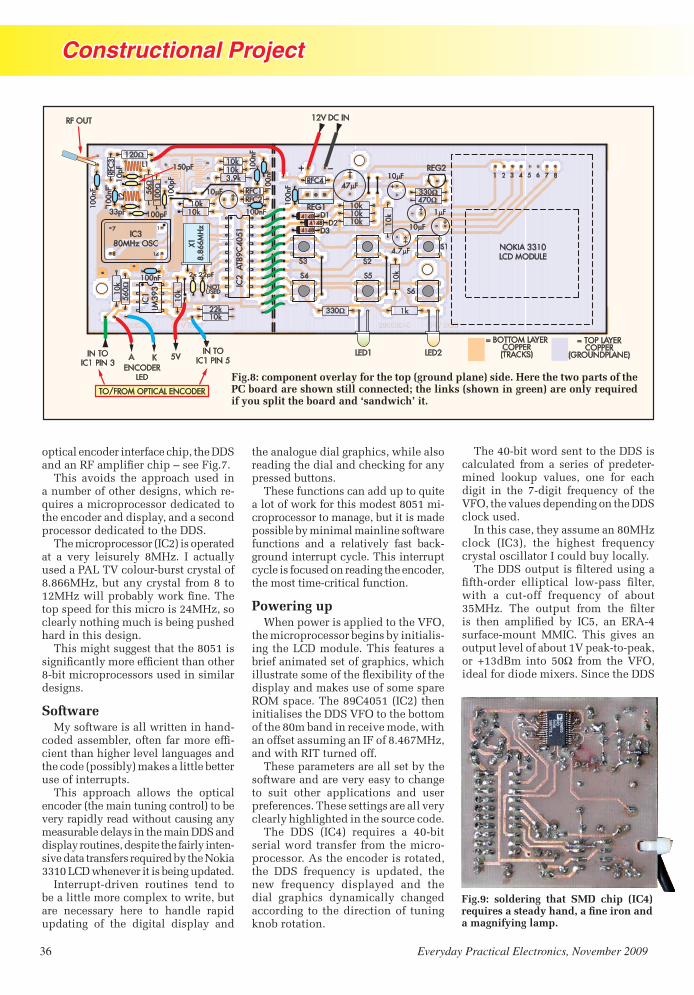
Constructional Project
36 Everyday Practical Electronics, November 2009
optical encoder interface chip, the DDS �������������� ��������� �������
����� ������� �� � ������� �� �� ��������� �������� ��� �������������� -���� ������������ ������ ����� ������� � ���� ����������!��������� �������� ������ ����� ������� �""#�
�� ��������� �����$%&'(����� ��� ����� �� � �!� ���� !� )*+.�� %� �����!��� ����/01��2������3��������!�������)�)44*+.��������!���!���� �����)� ���5'*+.���������!����6��� ���� ����� ��������������������'7*+.������ ��!������������������ ������� ���������������� �����
��������������� ���������� �)895��������������!���� � ���� ����������� ��)3������������ �������� ������������� ������
Software*!�������� ����������� ���������3
��� ����� �� ������ �� ������� � ��-�� ������������ �� � ������� �������� ���� �$�����!(���6 ������� �� �� ���� ������� ������
����� ������� ����� �� � ������ ���� ��$�� �������������������(����� �� �!�����!�� ���������������������!�� ������ �� �!������� ������""#���������!������� ���� ��� ��� �����!���� �-��� ������������ ���� ���� ���!��� �:�6���;;58�1&"��� � � ��������� �������� ��
%�� ����3���� �� ������ �� � ��� ���� ������ ���� ���� <�������� �������� � � � ����!� � � � ��� ���� � ������������� ��� �� � ������� ����!� ����
�� ������� ����������������� ������ �������� ����������� �6����������!�� �� ����������
�� � ���������������������������� ������������6������������� ���)895���-������ ������������� ��������������� ������ ��!�������������� �������� ����������� ���� �� � ���� !� ����� ���6-���������� ������!� ���������� ������!� ��������� ������ �������� � ���� ����� ��������� 3�����������������
Powering up=� ���� ������� ������� �2�>��
�� ��������� ������ ������!���������-���� �� �1&"����� ������� � ���� ������� �������� ��� ��������������������������� ���� ������ �? <�����!������ �����!�������6 ���� ������� ���� ��>*���� ���� �)@&7895�$%&'(��� ���������� ���� �""#�2�>������ ������������� �)8����������� � �� ���� �������������� ��������������%�����)�74�*+.������������%������ ������
�� � ����� � ����� ���� ���!��� �������� ������� �� �!� ��!��������� ���� ����� ��� �� ���������� ���� �� ��� � � �� ����� � �� ��������� ���� �!�� ��!��������� ������� ������ ���� ��
�� � ""#� $%&7(� � ���� �� �� 783����� ��������������� ��������� ������-��� ������0���� � ���� ���������� ����� � ""#� �� �� ��!� ��� ���� ��� �� �� �� �� �� ��!� ����! �� ���� �� ����� �������� �!������!� ����� ������������ ��� �� ���� ��������� �������6�������������
�� �783���������� �������� �""#���������� �� ����� �� � �� �� ��� � � � �-��� �� ��6�� ��� ��� �� � ���� ���������� ��� �� � �3������ �� �� ��!� ��� �� �2�>���� ���� ��� ����������� �""#����6��� ��
%���������� ���� !������ ����)8*+.����6� $%&;(�� �� � ���� ��� �� �� ��!���!�������������%��������!����!��
�� �""#������������ � ��������������3��� �� ������ ��3���� �� �������� �� ���3���� �� �� ��!� ��� ������;9*+.�� �� � ������ ����� �� � �� ����� �� �� ���� �� �!� %&9�� ��� A�037������� 3������ **%&�� ����� ��� �� ��������� � ����������52� �63��3 �6����� B5;�C�� ����� 98� ����� �� � 2�>���� ���������� ���< ����#��� ��� �""#�
04303081 04303082 DDSVFODDSVFO
+
+
+
+
+
+
120�10k
10k10k10k 10
k
10k3.9k
10k10k
56�
100�
RFC
3
RFC1RFC2
41484148
4148
D1D2
D3
RFC447 F�
REG2
REG1
330�470�
10 F�
10 F�
1 F�
4.7 F�
330� 1k
10k
22k10k
10k10
k56
0�
IC1
LM39
3
X18.
866M
Hz
IC2
AT8
9C40
51IC380MHz OSC
7
8 14
1
10 F�
100n
F
100n
F
100nF
100n
F
100n
F
100n
F100nF 2x 22pF
100p
F
100pF33pF
10pF 150pF
S1
S2S3
S4 S5
S6
LED1 LED2
L1
L2
1 2 3 4 5 6 7 8
NOKIA 3310LCD MODULE
IN TOIC1 PIN 5
IN TOIC1 PIN 3
ENCODERLED
A K
TO/FROM OPTICAL ENCODER
12V DC IN
+ –
RF OUT
5V
NOTUSED
= TOP LAYERCOPPER
(GROUNDPLANE)
= BOTTOM LAYERCOPPER(TRACKS)
Fig.9: soldering that SMD chip (IC4) ��������������� �����������������a magnifying lamp.
Fig.8: component overlay for the top (ground plane) side. Here the two parts of the PC board are shown still connected; the links (shown in green) are only required if you split the board and ‘sandwich’ it.
Digital VFO Mar 08 (From Matt).indd 36 23/09/2009 14:58:22

Constructional Project
Everyday Practical Electronics, November 2009 37
output level follows a sinx/x envelope, the output reduces to 0.8V peak-to-peak by 30MHz.
This 2dB roll-off is of little con-cern in transceiver applications such as this project, but it should be borne in mind if the software is adapted/reused for applicat- ions such as a signal generator.
The 80MHz DDS oscillator (IC3) is the reference for the VFO’s output frequency. By contrast, the microproc-essor crystal (X1) is a nominal 8MHz crystal and, as noted earlier, its exact frequency is not critical. Since output frequency accuracy and stability de-pends on the 80MHz DDS oscillator (and few of these have any external frequency adjustments available), any users requiring absolute output frequency accuracy can make the sim-ple frequency alignment adjustments within the software.
I found my VFO was accurate to a few hundred Hertz and quite adequate for my uses.
Display moduleThe Nokia 3310 LCD module re-
quires a 3.3V supply. While some 8051 chips will operate on the same 3V supply, the 80MHz oscillator demands a 5V supply. The decision was therefore made to run both a 5V rail (for the micro and oscillator) and a 3.3V rail for the LCD. It’s a slight additional complexity, but makes the design easier to convert to other types of 8051 chips should this prove desirable.
The interface between the AT-89C4051 and the display, necessary due to the different supply rails on these parts, is handled by three 1N4148 isolat-ing diodes. If you are able to purchase some 3.3V clock oscillators (a standard part, but one I couldn’t buy locally), you can easily modify the entire VFO for single supply rail operation.
The microprocessor interface for the LCD module uses fewer control lines than suggested in many refer-����������������� ��������������lines, including a reset line from the microprocessor. Careful reading of the datasheet revealed that the display chip select (CS) line can be perma-nently tied to ground (0V) at the cost of a little more current.
� �� ������ ����� ��������� ���!"�is fairly greedy, drawing around 65mA, so the modest constant 5mA consumed by the always-on LCD
turned out to be of little concern. The datasheet also suggested the pos-sibility of using a resistor-capacitor reset arrangement (10kΩ and 4.7μF) and that saved a further I/O pin. As a result, there is an additional delay of a hundred milli seconds or so at power-up, just to be sure the display has reset, but this is of little impor-tance in overall operation.
Tuning inThe main dial knob connects to an
optical encoder. This is interfaced to
the microprocessor with an LM393 comparator (IC1) to ensure clean rising and falling quadrature signals.
The use of an optical encoder delivers improved long-term reli-ability and allows users to set up the mechanics of the dial knob to suit individual taste.
Software� ����#���������#����$��������$���
via the EPE Library site, accessed via www.epemag.com. They are also available, with some additional
Figs.10 and 11: here’s the full-size artwork for both sides of the PC board; the top (ground plane) is at right. We imagine most constructors will not bother etching a second layer (even if they can) but will simply remove the top-side copper around the holes with a small twist drill (eg, 5mm). It’s tedious, but easy enough ������������������������ ����������������������������������������������The smaller holes in the ground plane are for the components which solder to both sides of the board – these should not be opened out.
734
Digital VFO Mar 08 (From Matt).indd 37 23/09/2009 14:58:45

Constructional Project
38 Everyday Practical Electronics, November 2009
information, from Andrew’s ZL2PD website – see the References panel.
Preprogrammed PICs will also be available from Magenta Electronics – see their advert in this issue for contact details.
ConstructionThe printed circuit board com-
ponent layout and full-size copper foil masters for the Digital VFO With LCD Graphics Display are shown in Fig.8 and Fig.10. This board is
available from the EPE PCB Service, code 734.
The VFO can be built either as a single PC board, measuring about 150 × 50 × 15mm (W × H × D) or in a sand-������� ��� � ����� ����������measuring 100 × 50 × 25mm (W × H × D). Those wanting a smaller version can convert the current layout to use SMD parts and reduce the dimensions by about 40%.
While the present design uses a double-sided PC board, the top side of the board is left unetched, forming a continuous copper ground. This allows the PC board to be etched in typical home workshops with ease, as if it was a single-sided PC board. That’s the method I used for the ver-sion pictured.
While I’ve used standard compo-nents as far as possible, construction is not for the faint-hearted. The DDS chip, for example, is a 28-pin SMD, with very close pin spacing. The dis-play connections are also challenging. Time and care allow both to be soldered into place, but it does require a good ���������������������������������hands, patience and good eyesight.
I’d suggest building the keyboard/��������� �������������������������-���������������������������������-���� ���� ������� ���� ��� ���������The Nokia 3310 display is supplied mounted on a plastic keypad frame assembly, complete with speaker.
������ �� ��� �������� �� �!�� ����pressed into a rubber ring – and trim the surplus plastic away with a sharp knife – being careful not to disturb the plastic around the display itself. This is essential to maintain slight compression on the metallic springs, which press onto the conductive tracks on the LCD glass.
Display wiringThe display is then wired to the
pads on the PC board. I was tempted to lay the PC board out to permit the display to be directly mounted on it, but the current method offers a little ����"�#��������$��&������������-quire some delicate soldering of wire �������� ������� ��� ������� �����connections on the rear of the display and the PC board.
I kept everything in place with a few dabs of hot glue and the display assembly was mounted a few milli-metres off the PC board with three further strategic dabs of hot glue. This
Fig.12: quadrature outputs from an optical encoder are used to tune the DDS.
IC1PIN 1
IC1PIN 1
IC1PIN 7
IC1PIN 7
ENCODER OUTPUTS WITH POSITIVE (CLOCKWISE) ROTATION
ENCODER OUTPUTS WITH NEGATIVE (ANTICLOCKWISE) ROTATION
Parts List – DDS VFO
1 double-sided PC board, code 734, available from the EPE PCB Service, size 150mm × 50mm (see text)
1 digital display ex-Nokia 3310 cellular phone (see text)1 surplus mechanical (ball-type) mouse for optical encoder parts (contain-
ing one LED and two phototransistors – see text)1 8.866MHz crystal (X1)6 PC-mount SPST ‘keyboard’ pushbutton switches
Semiconductors1 LM393 dual power voltage comparator (IC1)1 AT89C4051 microcontroller (IC2)1 80MHz oscillator (IC3)1 AD9850 (IC4)1 ERA4 (IC5)1 7805 5V positive voltage regulator (REG1)1 LM317LZ voltage regulator (REG2)3 1N4148 silicon signal diodes (D1-3)1 yellow LED 1 green LED
Capacitors1 10μF 16V PC electrolytic 3 10μF 10V PC electrolytic1 4.7μF 10V PC electrolytic1 1μF 10V PC electrolytic7 100nF polyester (code 0.1, 100n or 104) 1 150pF polyester (code 150p or 151)2 100pF polyester or ceramic (code 100p or 101)1 33pF ceramic (code 33p or 33)2 22pF ceramic (code 22p or 22)1 10pF ceramic (code 10p or 10)
Inductors1 390nH (L1) (13T 33SWG ENCU on T25-10 toroidal former)1 330nH (L2) (12T 33SWG ENCU on T25-10 toroidal former)4 100μH (RFC1-4)
Resistors (all 0.25W, 1%)1 22kΩ 12 10kΩ 1 3.9kΩ 1 1kΩ 1 560Ω 1 470Ω 2 330Ω 1 120Ω 1 100Ω 1 56Ω
Digital VFO Mar 08 (From Matt).indd 38 23/09/2009 14:58:55

Constructional Project
Everyday Practical Electronics, November 2009 39
sounds crude – but it’s unseen and the glue forms a very rigid arrangement, which can be easily adjusted with a little heat from a soldering iron.
The display is extremely light and the resulting mounting is very robust. There is also space beneath the LCD for the addition of backlighting if desired, perhaps using some diffused LEDs, although the current PC board layout does not allow for component wiring.
Don’t be tempted to remove the white plastic material from the rear of the LCD. This improves display contrast and aids backlighting. I tried some green LEDs for backlighting and they worked very well, so I may add these to my transceiver project.
An extra pull-up resistor (10kΩ) can be seen in Fig.5 mounted next to the inter-PC board wiring on the top side of the keyboard/display PC board. This was caused by a minor change in pin connections when going from my stripboard and wirewrap prototype to ����������� ��������� �������������� ��has now been added to the PC board layout shown in Figs.8 and 9.
Microprocessor boardConstruction of the DDS/micro-
processor PC board can start with the installation of the resistors and capacitors. Then proceed to add the jumpers and the various through-PC board connections if your board does not have plated-through holes.
Mount the microprocessor socket (I strongly recommend using a ‘machine screw’ IC socket for non-plated through PC boards), the LM393 comparator, crystal oscillator and crystal. The LM393 does not need a socket. Com-plete the board by soldering in the DDS chip and the ERA-4 MMIC.
The optical encoder should be added next. Although you can use a commercial model, I made my optical encoder from parts salvaged from an old PC mechanical-type mouse. It’s � ������������������������������� ����bits inside an old mouse for two such encoders.
It is possible to monitor the two output pins of the LM393 interface to � ������ ���������������������� ����using an oscilloscope (see Fig.12) while rotating the encoder.
If you test without the microproces-sor installed, which is best, you will need to add temporary pull-up resis-tors to each open-collector comparator
38
8
5954
28
40
4028
44
95N
ote
s:
1.R
edlin
esan
ddi
men
sion
sin
red
text
indi
cate
deta
ilssp
ecifi
cto
the
DD
SV
FO
.All
othe
rdi
men
sion
sm
aybe
varie
dto
suit
spec
ific
appl
icat
ions
.2.
Pan
elm
ater
ials
houl
dbe
rem
oved
from
the
shad
edar
ea.
3.D
otte
dlin
essh
owou
tline
sof
LCD
disp
lay
and
othe
rpa
nel-m
ount
edco
mpo
nent
s
21
54
Fig
.13:
sam
e-si
zed
dia
gram
of t
he
fron
t pan
el o
f th
e au
thor
’s
tran
scei
ver
(Fig
.1)
show
ing
wh
ere
the
VF
O m
oun
ts.
Digital VFO Mar 08 (From Matt).indd 39 23/09/2009 14:59:05

Constructional Project
40 Everyday Practical Electronics, November 2009
References1) The ZL2PD website can be found at www.geocities.com/zl2pd/ This contains
all of the source code and assembled hex files.
2) Analog Devices (1999) A Technical Tutorial on Digital Signal Synthesis (see www.analog.com).
3) Two websites offering Nokia 3310 LCD displays at time of writing are: www.jelu.se and gsmserver.com, although I have no experience with either source.
VFO KEY FUNCTIONSStep Selects VFO frequency increment (10Hz, 100Hz or 1kHz steps)
Band Selects desired band (160m, 80m, 60m, 40m, 30m, 20m, 15m, 12m, 10m)
RIT Changes dial to RIT (receiver incremental tuning) control, allow- ing the receiver frequency to be offset by ±5kHz in 10Hz steps
VFO A/B Selects one of two independent VFO frequency banks
Lock Locks the VFO frequency to the currently selected DDS output frequency
Tx Removes the receiver IF and RIT offsets from the VFO output frequency
LINE FUNCTION1 Reserved for a 14-character string of text, including the user’s callsign
2 Digital display of VFO frequency
3 Used by the VFO cursor which indicates the step size currently in use
4 Analogue dial display
5 RIT frequency (Only shown in RIT mode)
6 Status messages including VFO lock, VFO A/B selection, and Tx mode
Line 1 is the top-most LCD line. Lines in the software are actually numbered from 0 to 5 to match the LCD controller’s addressing scheme.
output. Any value from 4.7k٠to 100k٠�������� ���� ��� �������� ������������������ �� ����������� �������������� ����������������-����������������������������������� ��� ��� ���� � ���� ��� � � ��� ������ ���������!���
"�� #$%� ������ ��� ������������������� �������������������������� ����� ���&$��������"� ����-������������������������������� ����� ��������������������������� ����'�� � � � �'��������������������� �� ������� �������� �� #(�� ���� � ����)( ����'���*����
Making the front panel+����� �'� ��������� ��� � � ��
��,��������#(��������� ���/���������������)( ������������������������������� ���� ��2������������������������ ��'���������������2�� �����������������'��
"������ ����'����������������������� ����������� ��������� ���������� ����'��� ������� ������������������� �'��������������������� -����'���������
"� ������� ������ ����'������������������������#(������� �,������������'�����������������
"��� ��� ���� � ������ #3%�� �����&$��������"�����#3%����������%$� ������ �������������������� �� ���� ��� �� ����� � �������"��'�����#3%������������ ���������������������������������� �������'������ ���������������/���� ������������ ������������ �������������������) ��� �� ����' ������� ��� �� ������ ��� ������� �������������5�6� ������������#$%���������/���������� ��#3%������������������������� ��� �������8���/�������� �,����'������������������!������ �� �� ��'�����,��� �� ��
"�� ���� &$� ������� ��� ��������������� ����������������������� ��� ���� "��� �� �� ������� ������ � ��!������� ��� ������������������������������9��5������'��"� ��������������:��� ����������������;;/$�<��� ��=>�
Operation? �����=:;@B�%%C�����������5�6�
� ��� ������ � ��� � ���� ���� ������������������������D:;@B��/�����-� ������� ���%%C�5�6��������� �����E��'�� ����'�������#$%��
/� �� �� ����� ��� �� ��� /�������� �������������� ����'�����������E��'��� ������������%%C����������E��'� (���� ������ D:;@B�� ���������� ��� ��� /�������� �� �������������������� ������������E��'����������� �����������������������-����� �����
"��5�6��'������������� ���������� �����������������������������
��� �� ��� ��� ��� ��� #$%� ���������� ��� �� F2� � � ����'�� ���� ����� (���� ������=G�� (���� ���"� �� ������ ���'����#$%���-��������� ������� � �����H�� ��DD�:�� ����'�� ��&� � ���&$%=IGG����E� �����
"�� %%C� 5�6� �������� ������������������� ����'��� ���� ��� 2�����������������������
������� ������ ������5�6��������� �� �� ������ �������'� ���JC��,� �'�� C��� ��� ���� �� ����� �� ��� ��� �� ��� ���2���� �� ������� ��5�6��"� �������� ������������������ �������� ����
������� ��� �������������E� ���'������ (������ ��� �� �� ���� � ��� � ���'�� ����'���������� ����������� �������"��� ������� ������ ������� ������5�6���E��'� ��-���� ������������ ����'� ������������ �� � ��������� �� ��� � ��������E��'�� �� ���������������������������?������ �������-� �� �� ����E���'� ������� �� �� ���������������� �������� �����to a slower rate.
@�� ������ �� ��������������-� �������� ����/�����/,���������� ������ ������'���������������$���������2���� �������� /������ �������-���� ����*����� �� �� ���� ���� ������ �������'������ ������ �������� �����
/�� �� ��'� ����� �'���� ��� ���� ����������� ��� �� ��� �������� ����� �� �� ��� ���� �� ����'� ���������������'������������������
Digital VFO Mar 08 (From Matt).indd 40 23/09/2009 14:59:14

Constructional Project
Everyday Practical Electronics, November 2009 41
������������ �������������������������� ��� ��� �� ��������� �������� ��� �������� �
Construction options����������������� ������������ ���
����� ������� �������� �� ��� ���� ���� ������� !������ ���� ������� � "�� ��#��#������ ���� ���� $$�% �#��#�����
����������� ���������� ����� ������������������������������������������������������������� &���� ���� #������� ��� ���'�����
��������� (������ )� *+�#����#����������� ���#�,�$� ������ ��������������� ��� ��������������!������������� ���������!����� �"�� �����#�� #������ ���� ���'����'���� �����
���������������� ������-�./�(01*�2(3������� 4�56� �#��#������'��#����� *007� ���# ������� '���� ����$$�% �#��#����� ����� ��������'������ "�� ������ ��� ����#����� ���������� "�'����
�!�� �#�� ���#��� #���#���� ���������������'���������������� ��'������������������������������� ���������������������������EPE
Please add £2.00 p&p per order. Prices include UK VAT.See website for overseas prices.
Special Offer prices for limited period or while stocks last.
Peak Electronic Design Ltd, West Road House, West Road,Buxton, Derbyshire, SK17 6HF.
tel. 01298 70012 www.peakelec.co.uk [email protected]
Measure capacitance and ESR!Capacitance from 1uF to 22,000uFESR from 0.01 ohms to 20 ohms
Battery included + Gold plated croc clips
This new model of the famous offersall the great features of the ESR60 but with
extended measurement range and audible alerts.
Atlas ESR
Atlas ESR PlusThis is the !
The New Atlas ESR Plus, Model ESR70
Atlas SCR - Model SCR100 Atlas ESR - Model ESR60
£89.00 inc VAT
(£77.39+VAT)
£75.00 inc VAT(£65.21+VAT)
£87.00 inc VAT(£75.65+VAT)
Passive component analyser.Automatically identify and measureinductors, capacitors and resistors.
Auto frequency selection.Removable probes.
1uH - 10H1pF - 10,000uF1 Ohms - 2M
Atlas LCR - Model LCR40
£77.31 inc VAT(£67.23+VAT)
NEW MODEL
Special Offer!
Includes the Atlas LCR Passive Component Analyser,Atlas DCA SemiconductorAnalyser, premiumpadded carry caseand user guides.
Complete with extraspare battery.
Atlas Star Pack (LCR/DCA)
£124.99 inc VAT(£108.69+VAT)
Money Saving Pack: Save £20
Connect Triacs or Thyristors any way round.Auto part identification and pinout display.Categorises gate from 100uA to 100mA.
Load conditions regulated at 12V, 100mA,even for a dying battery.
Measures gate voltage drop.Long life alkaline battery supplied.
Supplied with premium probes.
electronic design ltd
Don’t just test it......Analyse it!
Capacitance from 1uF to 22,000uF.ESR from 0.01 ohms to 40 ohms.Great for ESR and low resistancemeasurements (short tracing etc).Automatic controlled discharge function.Audible Alerts (for good ESR, poor ESR,open circuit and more).Gold plated croc clips.User Guide and Battery included.
was £97
Identify network cabling faults as well asidentifying many types of connection
configurations automatically.Great for testing sockets and cables.
Complete with all this:
Atlas IT - Model UTP05
£69.00 inc VAT(£60.00+VAT)
SpecialO
ffer!
was £85
was £87
Atlas DCA - Model DCA55
£53.83 inc VAT(£46.81+VAT)
DarlingtonsMOSFETsDiodesTransistorsLEDsand more...
The famous Peak Atlas, now withfitted premium probes. Just connect any wayround to identify the type ofsemiconductor, pinout andlots of parameters too.Complete with battery,user guide and probes.
Look! New Probes.
Reduced Price!
TO ADVERTISE IN EVERYDAY PRACTICAL
ELECTRONICSPLEASE CONTACT
Stewart Kearn on
01202 873872or email [email protected]
PLEASE TAKE NOTE
PIC Probe July ’09 Page 15, second column – first para-
graph – should read: ‘As you do this, also check the colours: red towards the probe, green in the middle and orange towards the switch.’
The LED order shown in Fig.2 is correct.
Digital VFO Mar 08 (From Matt).indd 41 23/09/2009 16:19:38

Constructional Project
42 Everyday Practical Electronics, November 2009
WHAT happens at your place if there’s a sudden ‘blackout’ or
mains power failure? It’s a familiar story – if it’s at night, you’re left ������������ ����������������� -ing for some candles or your torch. ��� ���� ��� ���� � �� ���� �� ���� �����than likely that the batteries have ��������
This ‘emergency light’ project means that you should never have to search around in the darkness during a blackout again. As soon as the mains power fails, it automatically turns on the power for some 12V emergency lights within a second or two. It then
This easy-to-build project automatically turns on the power for 12V emergency lights within a second or two of a mains power failure. Build it and you won’t have to search for candles or your torch in the event of a blackout.
By JIM ROWE
keeps them operating until either the mains power is restored or its internal 12V sealed lead-acid (SLA) battery is discharged to the safe minimum level.
Basically, the project is designed to be used in conjunction with a small 12V/1A automatic SLA bat-tery charger, such as the Powertech MB-3526 unit sold by Jaycar. This unit normally keeps the internal SLA battery at full charge and we use this project to monitor the charging voltage so that it can determine when there is a mains failure.
That’s how it knows when to switch on your 12V emergency lights.
Running time� ��������!�"��������#������ ���
a rated capacity of 7.2Ah (ampere-hours), which should be enough to power typical domestic 12V emer-gency lights for the duration of all but the most prolonged mains failures. For example, it will power a couple of ���$�%&�'�*��+&���"��0������������������������������*�� ���������������little over one hour if you hook up a ���$��&���4�����������*�44�
How can you work out the time it will run a certain combination of 12V emergency lights? As a rough guide, you need to work out how much ����������� �4 ����������*���� ���add up the total current. Then if you divide the battery capacity by this total current, the answer will be the approximate running time in hours.
The reason why this gives only a rough guide to running time is that the nominal capacity of a battery is
Emergency 12V Lighting Controller
EmergencyLightController0108 (From Matt).indd 42 23/09/2009 15:00:06

Constructional Project
Everyday Practical Electronics, November 2009 43
to 6.7Ah. If you want to discharge it ��� ���� ��� � ���� ���������� ����������������������������������������������������������������� ����������-���������������������������
� ������������������������������!"�#$�#%&'#$(�)��������� ������������ ����� ����� #�"�� � ����� ��**����*����������*����������"�+�#�"���,������������/���������**�/���/*������������� ��� ���'���� � �� ���� �� ����0���under one hour.
��1�*��*� � �� �*�� ��� ���#%&'##(� )�� ������� � ������ �����������/�������2������������*������������+�����,�"�$�3������*���*������������2���'"�$�,�#�##3�
4������������� � ����� ���� ������*�1� � �����**���/�/*�� ��� ����� ����hours.
�� 1���*� �������� ������� ��� ��-�*��� �������������������������#%&�*������1���**���������5�������������8� ��� �+�1�*� � ��� �����5�� �� /*��0��during the day.
How it works9�������:���#��������������������*���
������������ ������5�������*����������������������������#%&';�%����<��/������ ����������1��������������**��������/�������+�����*���1������������������1����������������������
��������������������)���������=#�����������*����������/��������>���
�����=#������#>�?%%������0������ �������������*����������*���������2������**��"��1&�����������������-�������#�3 ����������5������������*��������������������5����������
���� =@� ����� �*����� ��1� ������������ ��� �*�� ���*���� �� <B=#� �������������#��0�������� ����������<B=���������*��)���������������/���!�1�������������������������C#����������*��<B=#�����������������1���������� ��� �������� ���� C#� ��� �������/�����������**�������������C#��������������**������**������*�������������*��*���*�2��������1&3�
�����**�������C#������������������� ������ ����� 2�����3��� 4@# ���������1���4@�����������������*��1����-�������)��!)���� ����������1�������������������������C#����� �4@#������*�� ��� ���� ������ ����������� ��������"��������������*�����������*� ���������� 2D3� �� C� � ��� N!������*� �����EF�B� � ����*����*�� *��������C��remains off.
G�����**� �C�������������������������������#%&��1��������*�������(����C������� �����*������������������**�
Power failure>����������������������������
���� 1����� ����� ���*��� (���� ����� ������� ����������������������*�������1������<���������������������=#�/��1�����������/������������ ���*� �
EMERGENCY 12V LIGHTING CONTROLLERFig.1: the circuit uses transistors Q1 and Q2 and 555 timer IC1 to detect when the mains fails. When it does, pin 3 of IC1 switches high and Q4 turns on and connects an SLA battery to the emergency lights. Zener diode ZD1 and transistor Q3 trigger IC1 and turn the lights off again to prevent over-discharge if the battery voltage drops below 11.6V.
/����������/����������������������%�!���������8��� ������������������������������@'%� �������H@5��������/������5���1���*����������2�������������;�%�� ���@'%��,�"$�1�3�
(��������������������/��������������������������������� �����������������-�������������1�������:���+�1�*� �if you reduce the discharge time to #����� �����������������������������
EmergencyLightController0108 (From Matt).indd 43 23/09/2009 15:00:17

Constructional Project
44 Everyday Practical Electronics, November 2009
LED1 turns off and there is no longer any base current for Q1, which turns off as well.
Transistor Q1’s collector is now pulled high (ie, to the battery voltage) via a 10kΩ resistor, thus removing the reset signal from IC1 (pin 4). At the same time, the 2.2μF capacitor on the reset line pulls the base of transistor Q2 high. Q2 thus turns on and pulls pin 3 (the ‘lower threshold’ comparator input) of IC1 low.
The 2.2μF capacitor now charges via a 10kΩ resistor, and as it does so, its charging current (and hence Q2’s base current) reduces exponentially. After a very short time, the transistor comes out of saturation and its collec-tor voltage begins to rise.
As soon as this voltage reaches the lower threshold level of IC1 (around ����� ������� ������������������‘on’. This switches IC1’s pin 3 output high (ie, to nearly +12V), in turn switch-ing on MOSFET Q4 and turning on the emergency lights and LED2. A 1.2kΩ re-sistor limits the current through LED2.
In summary then, when the mains power fails, IC1 quickly switches its pin 3 output high and Q4 and the emergency lights turn on.
If necessary, the lights can be turned off manually or prevented from turn-ing on automatically at all, using over-ride switch S1. When this is closed, IC1’s pin 4 reset input is pulled low permanently, regardless as to whether or not transistor Q1 is conducting. As a result, IC1 is kept in the reset state and so Q4 and the emergency lights remain off.
Preventing over-dischargeZener diode ZD1 and transistor
Q3 form a simple protection circuit, which prevents the SLA battery from being over-discharged during a pro-longed blackout. SLA batteries are not designed for really deep discharging and if that did occur, the battery could suffer permanent damage.
The way this circuit works is very simple. Whenever the battery voltage remains above about 11.6V, Zener
diode ZD1 conducts, and so current ��������������������٠series resistor and the base-emitter junction of tran-sistor Q3. As a result, Q3 turns on and pulls pin 6 (the upper threshold input of IC1) to less than 0.5V. This input is therefore kept inactive.
However, if the SLA battery voltage drops just below 11.6V, there is no ������������������������������!"�to keep Q3 turned on. As a result, Q3 turns off and its collector voltage rises to the battery voltage, taking pin 6 of IC1 with it.
As soon pin 6 reaches its upper threshold level of about 8V (12V × #$����%&"'������ �������������� ���pin 3 switches low. This turns off Q4 and the emergency lights to prevent any further discharging of the battery.
IC1 is now kept in the reset state until the battery voltage rises above 11.6V again, which will normally only happen when the mains power is restored. Of course, once this occurs, Q1 will turn on again and hold IC1 in the reset state, thereby preventing Q4 and the lights from turning on until the mains fails on another occasion.
ConstructionApart from the SLA battery, all of the
parts for the Emergency 12V Lighting Controller are installed on a single PC board, coded 733, and measuring 204 × 64mm. This PC board is available from the EPE PCB Service.
The board has been designed to mount vertically behind the front panel of a vented plastic instrument � ��* ������#/9�:�"�9�:�;9**��<��case size was chosen so that the SLA = ���>������� ����=��������������protect it from damage. As shown in ��������������= ���>��������������side at the rear of the case and is held down by a clamp bracket made from sheet aluminium.
The output cable from the external SLA charger is brought into the case at rear left, via a cable gland. The individu-al leads then connect to the rear of the PC
Resistor Colour Codes
❏ No. Value 4-Band Code (1%) 5-Band Code (1%) ❏ 6 10kΩ brown black orange brown brown black black red brown ❏ 1 3.9kΩ orange white red brown orange white black brown brown ❏ 1 1.5kΩ brown green red brown brown green black brown brown ❏ 1 1.2kΩ brown red red brown brown red black brown brown ❏ 1 100Ω brown black brown brown brown black black black brown
The Powertech 12V 1A SLA battery charger (Jaycar MB-3526) is ideal for use with the Lighting Controller.
Reproduced by arrangement with SILICON CHIP
* � ?��#99��www.siliconchip.com.au
EmergencyLightController0108 (From Matt).indd 44 23/09/2009 15:00:26

Constructional Project
Everyday Practical Electronics, November 2009 45
board via quick-connect spade connec-tors. Similarly, the connections between the SLA battery and the PC board are made via short lengths of heavy-duty ����������� ����������� ����������spade connectors at each end.
The six 12V output terminals (bind-ing posts) for the emergency lights (or some other load) are actually initially mounted on the front panel of the case rather than the PC board. Their terminals are then later soldered
directly to the PC board copper when the otherwise completed PC board as-sembly is attached to the panel via six M3 × 15mm tapped spacers.
Fig.2 shows the parts layout on the ��������������������� ��������������
Fig
.2: i
nst
all
the
par
ts o
n t
he
PC
boa
rd a
s sh
own
her
e, b
ut
do
not
in
itia
lly
inst
all
the
six
bin
din
g p
ost
term
inal
s. T
he
latt
er a
re m
oun
ted
on
��
����
���
���
� ��
���
���
����
��
����
���
�����
�����
��
����
����
����
�����
���
����
��
����
����
�����
�����
����
����
���
��
!"
�#$�
���
��%��
���
���
&��
���
��'
�
����
����
����
��
���
��
����
����
����
���
�
��
���
����
����
���
��
����
���
���
��
��
����
����
���
����
���
�
"�&
����
�����
��
�'��
�����
����
���
����
���
����
�()�
*����
��
����
�*��
���
��*�+
!-
���
����
����
��
�'�
���
����
��/��
����
����
����
����
���
���
�%�
���
'��
��
����
����
���
��"�
����
����
���
��0'
��&
1��
��
�����
��
����'
���(�
%��
��
���1
��
��*��
��
��'
���1
��
��/��
����
����
����
�����
���&
�����
���
����
��'
��
���
3�4
�5�
���
���
���
����
%�*
����
&%
���
����
��
�'
�����
����
����
�%��
'��
���
���
���
����
����
����
����
����
���
����
����
%��
�#
$6��
����
��
����
����
���
&*�
�'��
&��
��%
����
����
'
��
���%
���
����
���
���
�%��
���
��
����
��
EmergencyLightController0108 (From Matt).indd 45 23/09/2009 15:00:36

Constructional Project
46 Everyday Practical Electronics, November 2009
����������������� ������ ��������-������������������������������-������������ ��������������������������������������������������� ����������������������������� ����� ��!��������������������������� ��������"������ �� ��������� ��� � ���������� ����� �� � ��� ��#�����$������$���������� ������-��������������� ����������
%��� ����� ��� ���� ���� � ����� ��������������������������������&���'� ���� (����'� � ��� � ������� ������ ����������������� ����&���)*(����)�����������
+���� ��������� ������$�������� � ����������� ��� ���!�� ��� ,&.������������������������������ ��� ��� ���� ��� ����� ���� � ������� /.����� ������� ������� $���� � � ��������� ���������� ���� �������� �����
������������������ ������������������� ����������������������
��� ������� ���� ��� ��� �0� � �� - ������������������� �������1.����1����������������2.����2�����!������������������ ���������������3�3μF ����� ��� ��������� ����� ��� ���������������
Mounting the MOSFET�+/56�� 27� ��� �0�� ��� ��� ��� �
������������ ���������������������������89:������������;������������������������� �����������������������#&����� �� ����������������� ��������������������!���/������������������0��������������� �<����������������
=�� ������ ��� 5���3 � ��� ���� ���������������27>�������������������!��������������������������
������������!�����������������!�������#&�������������������!������������ ��������������������������������27>������������������� ������������������
%������� ��������������� ���������� �����������?���@61������������� $���� � � ����� ���� ��������� ���� ������� ��� ���� ��� ����������������� �������������������.3��� ��� ����� ��������������� � ���A���������������������������� ���������������� ���������������������������������
=�.3���������������������������������������������������������������� ����@61�� B������������� ��������������������������������������������������@61�������������������� ��������� ��������� �������������������������������
+������@61�������� �� ���������0����������������������������������������������������������0������������������������������
Final assembly��� ����� ����� �� ��� ���� ���-
� � � ��� ��� �0�� ���� ��� ��� ��� �����0������������������� �������������������� �� �� ��� ��� ����� ��� ����� ��� �� ������$� ����� �������������������� � ���� ����� ��!� �����$� ����� �� ������ ������ ����� ���(������������������������������������� � ����������������>����!� ���� ���
����� ��� � ��$� ��� ������������� ���� ���� ����� ���� ��������/. ���������������#&����������� �� ������ ��� ����� ��� ����������������� ����/.������������@61�������������������������������� �� ��� =�� ��� ������� � ��� �� �� ����� �� ��� ����������� ����� ���!��� ���� �� ������������ ���� ����������� �� ��������#&������
+��� $������� ��� ���� � ��������� ����� �� ������ ������ ��0� ����� ���� ��������!C���� ������������� ���� ����� ����� �� � ����� ��� ��� ���� ��������� ������� ��� ��������/. �������� ��������A������ ������������$����������������� �����=���� ����������� ������������������������������������������������� ������������������ �����$��������� ��������������������� ��� ��������� �����������
Do not solder the terminals of the binding posts yet. That step comes
Parts List – Emergency 12V Lighting Controller
1 vented instrument case, size 260 × 190 × 80mm
1 PC board, 733, available from the EPE PCB Service, size 204 × 64mm
2 19 × 19mm U-shaped TO-220 heatsinks
1 TO-220 thermal washer, or insulation kit
1 SPDT mini toggle switch (S1)1 8-pin IC socket2 single-ended quick-connect
spade lugs1 double-ended quick-connect
spade lug6 female quick-connect spade
connectors6 M3 × 15mm tapped spacers6 M3 × 6mm countersink head
machine screws10 M3 × 6mm pan-head
machine screws4 M3 nuts and star lockwashers3 binding posts/banana jack
terminals, red3 binding posts/banana jack
terminals, black1 12V 7.2Ah SLA battery (Jaycar
SB-2486)1 295 × 75mm piece of 18g
(1.3mm) aluminium sheet3 10mm-long self-tapping
screws, 4g or 5g1 cable gland, 3-6.5mm cable
size
Semiconductors1 555 timer IC (IC1)3 PN100 NPN transistors (Q1 to Q3)1 STP16NF06 N-channel 60V/16A
MOSFET (Q4)1 1N4741A 11V 1W Zener diode
(ZD1)1 5mm green LED (LED1)1 5mm red LED (LED2)1 1N5822 40V/3A Schottky diode
(D1)1 1N4148 diode (D2)
Capacitors1 2.2μF tantalum1 10nF metallised polyester
Resistors (All 0.25W, 1% metal film)6 10kΩ 1 1.2kΩ1 3.9kΩ 1 100Ω1 1.5kΩ
Where To Buy KitsThis project was developed by
Jaycar Electronics and they hold the copyright on the design and on the PC board. Complete kits are available from Jaycar Electronics (Cat. KC-5456).
In addition, Jaycar can supply the Powertech MB-3526 automatic SLA charger, along with whatever 12V lighting fixtures you need; eg, the ST-3016 and ST-3006 fluorescent lamps (both rated at 16W).
EmergencyLightController0108 (From Matt).indd 46 23/09/2009 15:00:43

Constructional Project
Everyday Practical Electronics, November 2009 47
later, after the unit has been tested. If you do solder these terminals, you will not be able to access any of the on-board components if something is wrong.
The board/panel assembly can be slipped into the lower half of the case – see photo. That done, you can then turn your attention to making up the mounting clamp bracket for the SLA battery. This is fashioned from a piece of sheet aluminium – see Fig.4.
Note that three 4mm diameter holes need to be drilled in the bracket for the mounting screws; it’s easier to drill these holes before you bend it into shape.
Fitting the batteryBefore fitting the battery into
the case, you’ll need to cut away some of the short spacing pillars moulded into the base, so the bat-tery will rest on the bottom (this is
necessary in order to provide clear-ance for the case top). The pillars to be cut away are those in the centre, directly below where the battery
sits. Make sure you don’t cut away those at either end, which are used to screw down the battery clamp bracket – see photos.
Fig.3: the leads from the battery and the charger are connected to the spade lugs on the back of the PC board using female quick-connect terminals. Note also how switch S1 is secured.
This is the view inside the completed Emergency 12V Lighting Controller. The battery in the prototype was secured using an aluminium clamp.
EmergencyLightController0108 (From Matt).indd 47 23/09/2009 15:00:59

Constructional Project
48 Everyday Practical Electronics, November 2009
This close-up view shows how the connections from the charger and the SLA battery are run to the PC board, via the quick-connect terminals. Note also the second U-shaped heatsink for Q4 on the back of the board.
The PC board mounts behind the front panel on six M3 × 15mm tapped spacers, secured at the front using countersink head M3 screws. Note how the charger’s leads are secured to the rear panel using a cable gland.
You should now be able to place the battery on its side in the case and slide the clamp bracket down over it. Complete the job by fastening the clamp bracket to the bottom of the
case bottom using three 10mm-long self-tapping screws.
���� ����� ��� �� ��� �� ���� ������gland into the 12.5mm round hole in the rear panel. That done, cut the
alligator clips off the ends of the SLA charger’s output leads, then pass the leads through the gland and into the ���������������������� ��������������female quick-connect spade connec-���� ���� ����� ��� ���� ��������� ����Charger– lugs on the rear of the PC board – see Fig.3. Take care with the polarity of the leads here.
As previously mentioned, the SLA battery is connected to
the PC board via short lengths of heavy-duty ������� �����������������
quick-connect spade connectors at each end. Complete the wiring by
�������������������������sure that the connections
are correct.Note that if you reverse the
battery connections, there may be quite a lot of damage done and
�� ���� ����� ������� ��� ����� ��-leased! You have been warned.
Checking it outCommence testing by, lightly tack
soldering a couple of temporary leads to one pair of output pads on the back of the board (ie, one to a posi-tive output terminal and the other to a negative output terminal). Connect the other ends of these leads to your multimeter and set the meter to the 20V range.
Now plug the SLA charger’s mains lead into a power outlet and switch on. This should cause the Lighting Controller’s green ‘Power’ LED (LED1) to light, indicating that the charger is supplying power to the circuit and to the SLA battery.
If the SLA battery has very little charge in it at this stage, this will be indicated by the charger’s red LED glowing. In that case, leave things for a while until the battery charges, with its terminal voltage up to at least 12.5V. This will be indicated by the red LED on the charger going out and the green ‘trickle’ LED turning on instead.
Now make sure that switch S1 is in the ‘Lights On’ (down) position, then switch the charger off at the mains outlet. Within no more than a second or two, LED1 on the Lighting Controller should go out and LED2 should light instead. This indicates that MOSFET Q4 has turned on and that 12V power from the bat-tery is now available via the output
EmergencyLightController0108 (From Matt).indd 48 23/09/2009 15:01:10

Constructional Project
Everyday Practical Electronics, November 2009 49
Fig.4: here’s how to make up the metal clamp that’s used to secure the SLA battery in the case. It’s made from 18-gauge aluminium sheet and can be bent up in a vice.
������������ ��������������������������������������������������������������of the type shown here. Both these units are available from Jaycar Electronics (ST-�!!"����#�$�%�!�"�&�����'#�������������������������&��������������������")*
terminals (this should be indicated on your multimeter).
In fact, if you connect a 12V emer-gency light in place of the meter, it should immediately light.
Assuming it all works, switch off, remove the temporary leads and solder all six binding post terminals. Your Emergency 12V Lighting Con-���������������� �����������������the top of the case. Once that’s done, switch the charger back on so that it can complete the job of topping up the battery’s charge.
While it’s doing that, you can now start mounting your 12V emergency lights and running the cabling to them. Be sure to mount the lights in locations where they will be useful when the next blackout occurs. EPE
EmergencyLightController0108 (From Matt).indd 49 23/09/2009 15:01:21

50 Everyday Practical Electronics, November 2009
Teach-In 2010
By Walter Ditch
TEACH-IN 2010LADDER LOGIC PROGRAMMING FOR THE PIC MICRO Part 1: Getting Started – Working with Inputs and Outputs
THIS�������������������������� ���������� ������ ����� ���� ����������������������������
����������� ������ ��� ��������������������������
���� ������ ���� � ������ ����� ���������������������������������������������������������������� �� �!��� � ������"��� !������������ �!��� ��� ������ ��-������� ������ ��� ������� �������� �������� �� ����� ����������������������������������#������������������"��������������������������"����������������������������� ������� ������� ������ ������$�������
!����� ����� ���� ��������������������������������������������������� ������ ��� ������ ����%������� ������� �� "�� ������� "�����������������&���������'��������������� ��� �������� �������� ����������������� ������� ������ �������� ������$��������(����'�������������������������� ������� ��� $����� ���������� ���������������������������������"��������� ������ ���� �������������������� ��������� ��� ���������������������#��������������������������������������"��$����������������������������
#�������� �������������� ��������������������� �� ���������� �������
�!�%������ ������ �� ���� ����������� �� ����� �������� ��'��� ������ ���� ��������� ������������ �� ������%���������������������� ���-���������������������������������������������
��'��� ����� ��� ������ ���� ��-���������������������������������������������!�%�������������������������������������������������"������%"������������������������#���������������������������������������������������������"����������������-"����������������������������������� ����� ����� ������� ������ "���������"���
)�"��$����������������������������������� ������ ������� ����������������������������������*
� )��������"���������������-$�������������+����������������������,
� #����������������������� ������� ���� �����%������
���������+��.,�������� )�$������� ���� "���%�������
����������(�������������������%"�����
����������������������������������"����������������������������������������� "������ ���� ��$�����%"�������������
#��� ������� ��������� ����� ��������������"���������������������"����
������"��������������������������������������������������������� ���� ��������� ���� ����� +0121345 134(��0121365136(��012176���01266�����012664,���������������������-����� ������"��� ������5��������������*
0�� 8��������96:76��������������; ������������<����������"�����������"���������������������
3�� ������#.� 3� =�"��� ; �����<���� ��������� "�� .������������+www.microchipdirect.com,
>�� .��� � .���������� 8����� >��������.�?�=����������<����������"����������Everyday Practical Electronics�+EPE,�@������)�������
7�� ������8).��������������������������� ������� ��� !�"������;���������+www.labcenter.co.uk,�
A�����������������������������������������"������������"���"�������� ����� ����� ���� ������� )���������������"������������������"����������������������������������������������������������������������'���"����������"���������������������-����������������B
Comparing PLCs and microcontrollers
#��� ����� ����������� "������� ���!�� ���� �� ���������� ������ ��
Teach-In Part 1.indd 50 23/09/2009 14:47:03

Everyday Practical Electronics, November 2009 51
Teach-In 2010
size, complexity and, of course, cost. The inputs and outputs circuits of a PLC, for example, are extremely rugged, with digital inputs often be-ing connected via opto-isolators, and digital output types including transis-tor, thyristor, triac and relay. This al-lows the PLC to directly control high power devices, such as motors, pneu-matic actuators and the like. A typical
implement combinational and se-quential logic functions in electrical control circuits, and it is in part this electrical basis which makes it easy for electrical engineers to understand – even those without a computing background. Consider, for example, a simple electrical circuit consisting of a switch and a lamp, and also its rep-resentation using a ladder diagram, as shown in Fig.1.2.
Considering the circuit on the left, closing the switch will clearly cause the lamp to light. The ladder diagram on the right is equivalent, consisting of a pair of vertical power rails, with one or more horizontal ‘rungs’. (The ladder-like appearance gives this type of diagram its name.) Closing the normally open switch contacts on the left of the ladder diagram will con-nect power through the horizontal rung, hence lighting the lamp.
Historically, the output would typically have been a relay coil, thus allowing a relatively low voltage control circuit to switch mains oper-ated power devices. For this reason, PLC inputs are often referred to as contacts, while outputs are called coils. It can be seen from the ladder diagram that an output coil is rep-resented graphically using a pair of curved braces (although a circular output symbol is sometimes seen).
This extremely simple concept is the basis of PLC operation, and in part explains why electrical engineers are so comfortable writing PLC programs.
This added complexity is avoid-ed here by the pre-configuration of default settings, such as port directions, in the supplied PLC header ����������� �������������������������������������������!��"���#�� ��input, while Port B is an output.) You can, of course, change these settings, simply by editing the relevant section $������� "��������#!�������$�% ������
commercially available PLC is shown in Fig.1.1, with input connections shown at the top and outputs at the bottom.
While the I/O connections of a mi-crocontroller operate at much lower voltage and current than those of a PLC, they are essentially the same from a software point of view. The internal structure of a microcontroller also contains many similar elements to those found inside a PLC, including a central processing unit, program mem-ory (ROM), together with a variety of volatile and non-volatile data memory types. (The content of volatile memory types, such as static RAM, is lost when power is removed, while non-volatile memory, such as EEPROM, is retained.)
The allocation of connections as in-puts or outputs is, of course, pre-deter-mined by the PLC manufacturer, since this is a pre-requisite for the connection of specialised interface circuitry. Not so in the microcontroller world, where the assembly language programmer nor-mally has to decide on port directions, ��!�� � � ����&� $� ����� ����!� ����settings, prior to actually getting the microcontroller to do something useful.
designed to work straight out of the #���%���!�� �&����"�$������!� -tion – just like a real PLC.
So, having established that PLCs and microcontrollers have a lot in
Fig.1.1. A typical industrial PLC
Fig.1.2. A simple switch and lamp circuit (left) and its equivalent ladder diagram (right)
common, let’s turn our attention to lad-"��������� �"���"�!��%� ������ ����offer in terms of software development.
Ladder diagrams and ladder logic
Ladder logic owes its origin to the use of switches and relays to
Ladder logic programs are also very concise, with a section of code to (1) read an input and then (2) control a linked output requiring as little as two lines of code. Listing 1.1 shows a possible implementation.
In general, a PLC program is cre-ated by converting each input contact
Teach-In Part 1.indd 51 23/09/2009 14:47:15

52 Everyday Practical Electronics, November 2009
Teach-In 2010
and output coil of the system’s ladder diagram into a series of equivalent program statements. Execution of the program is then a continuously operat-ing sequence of:
Reading inputs Performing logic-based
calculations Controlling outputs
This repeating process is known as the scan cycle, and is shown graphi-cally for a slightly more complex example in Fig.1.3.
It can be seen that each rung of the ladder diagram is evaluated from left to right, starting at the top rung and working progressively down (Steps 1 and 2 of Fig.1.3). The End of Program
A number of conclusions may be immediately drawn from this method of operation:
1. Execution of a PLC program con-sists of a continuously operating pro-gram loop (a repeating scan cycle), even though this is not explicitly shown in the program listing or ladder diagram.
2. The time taken for a single scan cycle will increase in line with the complexity of the program, since the execution time for a single instruction ��� ����� � ���� �������������� ������frequency.
Slightly less obviously:3. An externally applied input signal
���������������������������������������time to guarantee it being ‘seen’ by
the input phase of the scanning loop.
4. The average time taken to react to a changing input is re-lated to the scanning loop duration.
5. It may take more than one scanning loop for the results of complex calculations to fully propagate through the system. This may lead to the possibility of transient glitches as calcula-tions ‘ripple-though’.
In practice, you ������� ���� ����� ���-der logic solutions are suitable in the majority of logic-based control
scenarios, since the computer is typi-cally operating at much higher speed than the system being controlled.
Now that the basic principles of ladder logic programming have been covered, the next step is to obtain the
required software, which will then enable us to create and test an execut-able program.
Obtaining the softwareThe ladder logic software is designed
to work with the MPLAB Integrated De-velopment Environment (IDE), which is freely available for download from the Microchip website (www.microchip.com), or on CD-Rom . All that is required is to include a link to the appropriate ������� ���� ��� � ������� ���� ���� ����������������������������������������variety of PLC-style commands become available for use in your programs.
As mentioned earlier, versions of the software are available for the following commonly used PIC microcontrollers:
PIC16F627/PIC16F627A (head-�������������!"#$%&'
PIC16F628/PIC16F628A (head-�������������*"#$%&'
� #+%����0*�9����������������0*"PLC’)
P IC16F88 (header f i les ‘16F88_L.PLC’ and ‘16F88_H.PLC’ offer low voltage and high voltage program versions respectively)
� #+%���**!�9���������������**!"PLC’)
+�� ���������� ���� ����� ����� ��� ������are all 18-pin ICs, differing mainly in ���� ;������� ��� <���=����� ������ �memory, static RAM, or EEPROM-based non-volatile data memory. The PIC16F887 is a 44-pin IC, having enhanced input/output capabilities. These features are summarised in Table 1.1.
Inclusion of the appropriate header file will cause a number of default settings to be chosen, such as port directions, oscillator type and so on. These settings have been tested with a number of hardware configurations, and are intended to simplify the configuration proc-ess as far as possible. (You should of course review these settings to ensure compatibility with your own requirements.) Default options are summarised in Table 1.2.
A number of required files are available in a compressed ZIP file, which may be obtained from the the Library > Project Code section of the Everyday Practical Electronics website (www.epemag.com). The contents of the ZIP file are given in Table 1.3.
ld SWITCH ; Read state of Switch out LAMP ; Output to Lamp
Listing 1.1. A notional section of a PLC program based on the circuit and ladder diagram of Fig.1.2
Fig.1.3. The repeating scan cycle of a PLC executing a ladder logic program
statement forces program execution to ���� ����� ��������������������������rung (Step 3), causing the program to run continuously. This program might be coded using statements such as those given in Listing 1.2.
ld SWITCH_A ; Read state of Switch A out LAMP_A ; Output to Lamp A
ld SWITCH_B ; Read state of Switch B out LAMP_B ; Output to Lamp B
endp ; End of PLC program
Listing 1.2. A PLC program based on the ladder diagram of Fig.1.3
Teach-In Part 1.indd 52 23/09/2009 14:47:25

Everyday Practical Electronics, November 2009 53
Teach-In 2010
Filename Description
16F627.PLC PLC header file for the PIC16F627/627A microcontroller
16F628.PLC PLC header file for the PIC16F628/628A microcontroller
16F648.PLC PLC header file for the PIC16F648A microcontroller
16F88_L.PLC PLC header file for the PIC16F88 microcontroller – low voltage programming enabled on pin RB3
16F88_H.PLC PLC header file for the PIC16F88 microcontroller – high voltageprogramming enabled, pin RB3 available for general I/O
16F887.PLC PLC header file for the PIC16F887 microcontroller
PIC16F627.DSN Proteus VSM simulation – PIC16F627A based Digital I/O Board
PIC16F88.DSN Proteus VSM simulation – PIC16F88 based Digital I/O Board
PIC16F887.DSN Proteus VSM simulation – PIC16F887A based Digital I/O Board
Lst1_3.asm Source code file for Listing 1.3
Lst1_4.asm Source code file for Listing 1.4
Lst1_5.asm Source code file for Listing 1.5
Lst1_6.asm Source code file for Listing 1.6
Assembling and execut-ing simple PLC-style programs
In this section you will see just how easy it is to create and assemble simple programs and then run them on a variety of different PIC-based systems. I recommend that you try these activities out for yourself, if at all possible.Begin by extracting the entire
���������������� �������������-venient folder and then use the MPLAB IDE’s File > Open menu ���������������������������������asm’, the content of which is ���������������������
���������������!�����������-ally identical to the code snippet ������������������������������"�#��� #����� ��� ��� �$�%&''(�microcontroller. It is suitable for use either with the PICkit 2 Debug Express board, or with Proteus VSM electronic simu-lation software. (Note that the PICkit 2 board has a single input �*���"���#������+/�"�*���������������������������������������bit of Port B, plus eight LEDs connected to Port D – which explains the choice of inputs ���������������������������
Having displayed the source 0���!1��������3 �45"������6��step is to assemble it, in order to create a machine code (.hex) ���"�*�������������#����*�-loaded and programmed. The ����� ����� ��� ��� ������ ��� ��-quired microcontroller type by selecting the ��������� ��Device menu option, and then selecting the PIC16F887 from the Device drop-down list. Next click on the blue title bar of the ��������������������������������highlighted and then assemble �������#���������������Project > Quickbuild Lst1_3.asm menu option. If everything has gone ������������������������8���������������������������������!-#���"� ���!�������� ��� �� �5�����
Succeeded’ message, displayed in the Build tab of the Output window. The MPLAB IDE has now done its 9�#� ���� �� ��������6� ���� *���� ����been created in the same directory ��� ��� ������� ����� ���"� ������ ��� #��programmed.
Device Program(kWords)
RAM (bytes)
EEPROM (bytes)
Max I/O (bits)
Other Features
PIC16F627 1 224 128 16 2 comparators
PIC16F628 2 224 128 16 2 comparators
PIC16F648 4 256 256 16 2 comparators
PIC16F88 4 368 256 16 2 comparators 7-channel ADC
PIC16F887 8 368 256 35 2 comparators 14-channel ADC
Table 1.1. Major features of supported PIC microcontrollers
Device Inputs Outputs Other Features
PIC16F627 / 628 / 648
Port A (5 bits) Port B (8 bits) Comparators disabled, pull-ups disabled 4MHz external crystal oscillator selected
Timer 0 configured for use by PLC software MCLR enabled, Watchdog timer enabled
PIC16F88 Port A (5 bits) Port B (8 bits) Comparators disabled, pull-ups disabled 4MHz external crystal oscillator selected
Timer 0 configured for use by PLC software MCLR enabled, Watchdog timer enabled
ADC disabled
PIC16F887 Port A (8 bits) Port B (8 bits) Port E (4 bits)
Port C (8 bits) Port D (8 bits)
Comparators disabled, pull-ups disabled 4MHz internal oscillator selected
Timer 0 configured for use by PLC software MCLR disabled, Watchdog timer enabled
ADC disabled
��� �������� ������������������������������
Table 1.3. File contents of ‘PLC1.zip’
include "16F887.PLC" ; Defines PLC instructions
ld PORTB, 0 ; Read Port B bit 0 out PORTD, 0 ; Output to Port D bit 0
endp ; End of PLC program
Listing 1.3. Reading a switch and outputting to an LED (Lst1_3.asm)
Teach-In Part 1.indd 53 24/09/2009 10:10:10

54 Everyday Practical Electronics, November 2009
Teach-In 2010
Syntax Function Ladder Diagram Symbol
ld REGISTER, BIT[0-7] Read an I/O bit
ld_not REGISTER, BIT[0-7] Read an I/O bit (inverted)
out REGISTER, BIT[0-7] Send to output bit
out_not REGISTER, BIT[0-7] Send to output bit (inverted)
Table 1.4. Bit input/output commands
Fig.1.4. A Proteus VSM simulation of the PIC16F887 microcontroller
What happens next depends on how you intend to actually run the program. If you are using the PICKit 2 board then the next step is to run the PICkit 2 programmer application, then use the File > Import Hex menu option �������������������� �������������
created earlier. Next, click the Write button to program the PIC16F887 mi-crocontroller. You should see a green Programming Successful message in the programmer window at this stage. Finally, apply power to the board by clicking the On checkbox situated just
under the VDD PICkit 2 label at the upper right.
Pressing Switch 1 will now cause the LED con-nected to RD0 to toggle on and off. However, you may note that the LED actually goes out when the switch is pressed, which is the opposite of what you might have expected. Examin-ing the schematic diagram supplied with the PICkit 2 documentation solves the mystery, revealing that SW1 normally reads as a logic-1, providing a logic-0 when
pressed. The required logic of our program may be easily restored by replacing the ‘ld’ instruction with its negative logic ‘ld_not’ equivalent, as given in Table 1.4.
From Table 1.4, we can also see that a negative logic output command
Teach-In Part 1.indd 54 23/09/2009 14:47:49

Everyday Practical Electronics, November 2009 55
Teach-In 2010
(out_not) is available. Thus, we can create a logical inversion either by using ‘ld_not’ followed by ‘out’, or ‘ld’ followed by ‘out_not’. If you are using the PICkit 2 board, then you can use this information to modify the program of Listing 1.3 so that pressing the switch causes the LED to come on, rather than go out.
If you are lucky enough to have the full version of Proteus VSM, Version 7.0 or later, then this may be used to simulate the operation of the program of Listing 1.3. Begin by using Proteus to open the supplied PIC16F887.DSN ����� ���� ���� ����� � ��� ������ ��Fig.1.4.
include "16F627.PLC" ; Defines PLC instructions
ld PORTA, 0 ; Read Port A bit 0 out PORTB, 0 ; Output to Port B bit 0
ld PORTA, 1 ; Read Port A bit 1 out PORTB, 1 ; Output to Port B bit 1
endp ; End of PLC program
Listing 1.4. Reading and controlling multiple inputs and outputs (Lst1_4.asm)
Controlling multiple inputs and outputs
To take a slightly more complex example, suppose we wanted to con-trol several inputs and outputs. This could be achieved as illustrated by Listing 1.4, shown for a PIC16F627-based system.
Assuming you have a suitable PIC programmer and experimentation board, such as the Velleman K8048, the � ���������������������������������� ���������������������� ������ -ing of course to set the device type to either the PIC16F627 or PIC16F627A, as appropriate). Next, connect the
Fig.1.5. The output produced by Listing 1.4, running on a Velleman K8048 board
include "16F887.PLC" ; Defines PLC instructions
ld PORTE, 3 ; Read Port E bit 3 (ICSP pin 1) out PORTD, 3 ; Output to Port D bit 3
ld PORTB, 7 ; Read Port B bit 7 (ICSP pin 4) out PORTD, 2 ; Output to Port D bit 2
ld PORTB, 6 ; Read Port B bit 6 (ICSP pin 5) out PORTD, 1 ; Output to Port D bit 1
ld_not PORTB, 0 ; Read Port B bit 0 inverted (SW1) out PORTD, 0 ; Output to Port D bit 0
endp ; End of PLC program Listing 1.5. Controlling up to four inputs using the PICkit 2 Debug Express
(Lst1_5.asm)
programmer to your PC via the sup-plied serial cable and then download and execute the program. When the program is executed, pressing a switch ���������������� ���������������� ��A should cause the corresponding bit of Port B to be activated, as shown in Fig.1.5.
If you have access to the Proteus VSM software then you use this to load the ‘PIC16F627.DSN’ simulation and then follow the procedure described earlier to load and execute the program of Listing 1.4.
Surprisingly, it is also possible to develop similarly complex programs for the PICkit 2 Debug Express board, despite the fact that the PCB is limited to a single physical input switch! The trick in this case is to use the PICkit 2 Logic Tool application to control up to three additional digital input signals via the In Circuit Serial Programming (ICSP) interface, which links the ‘black box’ to the PIC16F887 PCB. When not being used to download programs, the Logic tool allows inputs RE3, RB7
and RB6 to be controlled by activating pins 1, 4 and 5 of the ICSP interface respectively.
To see this in action for yourself, begin by assembling the program of Listing 1.5, and then download the ������"� ������ ���� ���� ��� ����PIC16F887 in the normal way.
Next, enable power to the PCB by clicking the On check-box and then select the Tools > Logic Tool option from the pull-down menu, which will display the PICkit 2 Logic Tool dialog of Fig.1.6.
Ensure the Mode option is set to Logic I/O by clicking the button at the upper right, and then click the Enable
Our machine code program created earlier must be logically attached to the PIC16F887, prior to running the simulation. To do this, right-click on component U1 and select the Edit Properties option from the context menu to display the Edit Component dialog. From here, you can click the #����������� ��������� ���������������� $���%&'*��+/� ���� ������ �� �� *�Close the dialog and then click the Play button at the lower left of the Proteus window to run the simulation. You’ll then be able to click on the input con-nected to bit 0 of Port B, which should cause the corresponding bit of Port D to change (as illustrated by Fig.1.4).
Teach-In Part 1.indd 55 24/09/2009 10:30:42
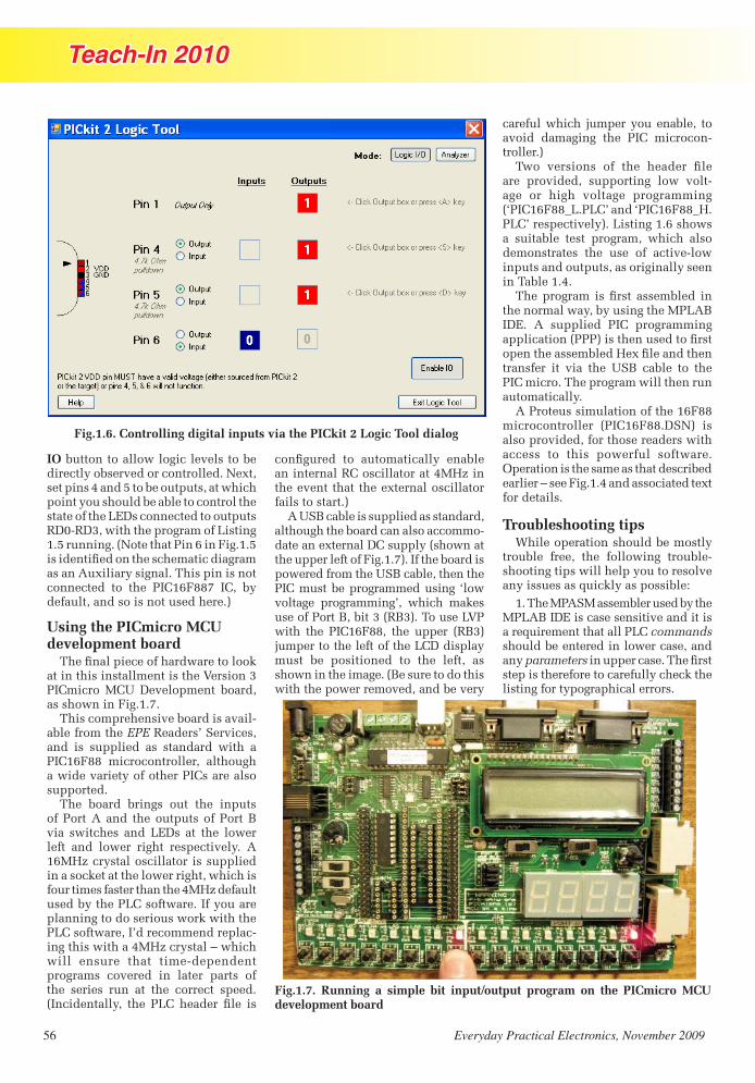
56 Everyday Practical Electronics, November 2009
Teach-In 2010
Fig.1.6. Controlling digital inputs via the PICkit 2 Logic Tool dialog
IO button to allow logic levels to be directly observed or controlled. Next, set pins 4 and 5 to be outputs, at which point you should be able to control the state of the LEDs connected to outputs RD0-RD3, with the program of Listing 1.5 running. (Note that Pin 6 in Fig.1.5 ���������������������� ����������� �as an Auxiliary signal. This pin is not connected to the PIC16F887 IC, by default, and so is not used here.)
Using the PICmicro MCU development board
������������������������������at in this installment is the Version 3 PICmicro MCU Development board, as shown in Fig.1.7.
This comprehensive board is avail-able from the EPE Readers’ Services, and is supplied as standard with a PIC16F88 microcontroller, although a wide variety of other PICs are also supported.
The board brings out the inputs of Port A and the outputs of Port B via switches and LEDs at the lower left and lower right respectively. A 16MHz crystal oscillator is supplied ���������������������������������������four times faster than the 4MHz default used by the PLC software. If you are ���������������������������������PLC software, I’d recommend replac-ing this with a 4MHz crystal – which will ensure that time-dependent programs covered in later parts of the series run at the correct speed. ��������������� ���� ���� ������� ��� ���
�������� �� ��� ��������� �������an internal RC oscillator at 4MHz in the event that the external oscillator fails to start.)
A USB cable is supplied as standard, although the board can also accommo-date an external DC supply (shown at the upper left of Fig.1.7). If the board is powered from the USB cable, then the PIC must be programmed using ‘low !������ ����� ���"�� ������ �����use of Port B, bit 3 (RB3). To use LVP with the PIC16F88, the upper (RB3) jumper to the left of the LCD display must be positioned to the left, as shown in the image. (Be sure to do this with the power removed, and be very
careful which jumper you enable, to avoid damaging the PIC microcon-troller.)
��� !������� �� ���� ������� ���are provided, supporting low volt-age or high voltage programming (‘PIC16F88_L.PLC’ and ‘PIC16F88_H.PLC’ respectively). Listing 1.6 shows a suitable test program, which also demonstrates the use of active-low inputs and outputs, as originally seen in Table 1.4.
��������� � ������� ���� ����� ���the normal way, by using the MPLAB IDE. A supplied PIC programming ���������������#�������������������������������� �����$�%�������������transfer it via the USB cable to the PIC micro. The program will then run automatically.
A Proteus simulation of the 16F88 microcontroller (PIC16F88.DSN) is also provided, for those readers with access to this powerful software. Operation is the same as that described earlier – see Fig.1.4 and associated text for details.
Troubleshooting tipsWhile operation should be mostly
trouble free, the following trouble-shooting tips will help you to resolve ��������������&�����������������'
1. The MPASM assembler used by the MPLAB IDE is case sensitive and it is a requirement that all PLC commands should be entered in lower case, and any parameters��������������*������������������������������������������������listing for typographical errors.
Fig.1.7. Running a simple bit input/output program on the PICmicro MCU development board
Teach-In Part 1.indd 56 23/09/2009 14:48:07

Everyday Practical Electronics, November 2009 57
Teach-In 2010
2. Ensure that the relevant include ���� ��� ��� �� ����� �������� ��� ������������ ������� ����� �������� ������������������������������������
��� ���� ������ �� ������ �!"�����#� �� ���� �$�� ������ � ��������� ��������������� �%��� %����������%�������������������������� ������
&��'�����������������������������(����������������������������(��� �����������(������������%�������������������)����*������������� ���� �������(� ���� �������� �� ��� ������� )���*�����������������(���� �������(������������ ��� �� ������� �� �� ������� ��%���������������
+�� '��� �� #��%� ��������� �� � ����%������������,����$���������(������,�������������������$������������(�����������%�������(����������������������������������������������-�������������������������(� ��(����%�������������������/0����������
; (Low voltage programming version ; with RB3 used as the LVP pin)
ld PORTA, 0 ; Read Port A bit 0 out PORTB, 2 ; Output to Port B bit 2
ld_not PORTA, 1 ; Read Port A bit 1 (inverted) out PORTB, 5 ; Output to Port B bit 5
ld PORTA, 2 ; Read Port A bit 2 out_not PORTB, 6 ; Output to Port B bit 6 (inverted)
ld_not PORTA, 3 ; Read Port A bit 3 (inverted) out_not PORTB, 7 ; Output to Port B bit 7 (inverted)
endp ; End of PLC program
Listing 1.6. Controlling normal and inverted signals with the PIC16F88 (Lst1_6.asm)
/��1���� �����%��������������-������������������������%����������������������������-������� �������� � ���� �� ���������� �� �� �����(� �� ������ �� ���� ����� ��� ���(��� ����%�������� � � � ������� ������ ������� %�������� %������ (��� ���������%��%�����
4��5����������(����-��������������- ��� ���� %��$� �����(��� �����������(��������� )��6�������#�������������(������ ����� ��� ���������*
Final thoughts�����������������
��6$�� (����� � ������ ���� �� � ���-�������� �� �$� ������%����� ���%��������� ��� ��� � ���������������������
%�������(����$�������������� ������� ���6������%��������$�������� ������� �������(��������(�����(���������������������$��%�����(����������
��6$�� ����� �������� � �� ����(��������������� ������$�������(���1�������������������������������$��������%������������ ��7%������-��������� ����� ��$�����������������������������������(�����
'����7� ��������������� ����������������� ������������������������������%��� ������������� ������ ������������ � ��� �������� �%������� ���� ����8!�� 9:�� �� � "9:� )�7�����$�;9:*����6��� ��� ��$�� ��� �� ����� ��� �� �$���%�����(����%�����<�������������������������� ������������� ���������������� �(� $�������� (��<������ %���� ���%���
��6�������������������%���� �-$���%������%����� ��7�� �������������������������=�����(����������(��� ����� � �������� ��� �� ������ �(� ����� ������ ������ ��� �������� ������� 5������������ ����� �� ����%��� ��%�� ����������� ���� � ������ ����� ��%��� �� � ��%���� ����� > ������ ��"!�
COOL COMPONENTS
Established in 2004, Cool Components supplies interesting, useful and powerful electronic components at excellent prices.
Arduino Boards + Shields Fast Update GPS Modules Olimex PIC, AVR + ARM Boards
Serial Bluetooth Adaptors
Plug-In Media Player Modules Serial Controlled OLED Displays Iron-On PCB Fabrication
Servos + Servo Controllers
WWW.COOLCOMPONENTS.CO.UK
Follow product news on: twitter.com/coolcomponents
0871 288 7685
We work with manufacturers including Sparkfun, Olimex, Arduino and many others to bring you the best from the cutting edge of new electronic technology.
include "16F88_L.PLC" ; Defines PLC instructions
Teach-In Part 1.indd 57 23/09/2009 14:48:19

Recycle It
58 Everyday Practical Electronics, November 2009
The quality and number of useful components depends a lot
������������������� ������ ������������� ��������������
�������������������������������������������������� ��������
��������������������! �������������"�!�����������������������
������������ ��������� ������� ����� ������������� ��
�������� ������#������ ��������� �������������������
������������������������$����������������!��������� ���
%&'�(� ������� �)��!���������������� ���������������������
�������$��� �������%*'����%*&��+���������� ���� �$�
�� ������!������!�����$� ��� �,����%*'�
b r of useful components depends a lot
� ������������� ��������������
��� �� �� ��������
�� �����
There’s lots of good bits inside junked photocopiers
-���$������������� �����������$����������$�������+����������"����������������������� �����$��������������!��!��"�� ��used to both illuminate the material to be copied and also act as a heater to cook the toner as the photocopied sheets � ��������� ������������������������+�������� �����������������$��������� .���� ��� ��������������$���� !���
-���$$��������������������������$� ������������.��� �$�������������$/� � ����������.��������01����2����������� ��� �������������������3�.���������(��������������� ����������456�"�!������������� ��$�������*46��������� �!����)�!�������������"�����������������"����������$���!��������7�� ��.������������������ ����������������������� ��� ��7��������+������ ����������#�������.��� �$��!����������� �����456����
-�������������������$��������$�������������������$�������� ���� �����������8�������� ����$��������$������������� ���!�����������.��9������������� ��������������5'���� ��� ��������� ���� ������������ �����"�!�������������������������������� ������� ������������������������:���������!������$��������������������������������������� ;
➊➋
l
BY JULIAN EDGAR
Salvage0706 (From Matt).indd 58 23/09/2009 15:07:31

Recycle It
Everyday Practical Electronics, November 2009 59
Whenever you throw away an old TV (or VCR or washing machine or dishwasher or printer) do you always think that surely there must be some good salvageable compo-nents inside? Well, this column is for you! (And it’s also for people without a lot of dough.) Each month we’ll use bits and pieces sourced from discards, sometimes in mini-projects and other times as an ideas smorgasbord.
And you can contribute as well. If you have a use for specific parts which can easily be salvaged from goods commonly being thrown away, we’d love to hear from you. Perhaps you use the pressure switch from a washing machine to control a pump. Or maybe you salvage the high-quality bearings from VCR heads. Or perhaps you’ve found how the guts of a cassette player can be easily turned into a metal detector. (Well, we made the last one up but you get the idea . . .)
If you have some practical ideas, write in and tell us!
Rat It Before You Chuck It!
➍
���� ���� ��� ��� � �� ��� ������� ����������� ������� ��� �������� ����������� �� ������� ���� �� ����� � ����� � �!�������� �� �"� ��� ��������#���������������������������$�����% ������ �������� �������������� ����������� ������ ������� ������� �
!����� � �� ��� ���&�������������� ��������� �������������'����������������������� �� �!������(�����% ���������� )���� '���(� �� ����% �� ���� ������ �' �!�����������*���+��%��������������������� �������������(������������(�'������� ����� ��'� ��� ���� � �������,�(�����������% ��������� �� ����� ����������������������+� ���'&���(�����&��������� � (������������������-��������������,
➌
➎
!�� ��� ���'���������������� �����������'���������������������� �!����������� ���� ������������������./&�����������������������'������ ������������������������ ����#����� �0������������������� ���������������� ������������./���� ����������� �����������&�������� ���������������(��������������+����������+� ���� ������ �
!�� ��'�������������� ���� ����'������'����+� ������� ������ ���� �����������������������$������������1����'�������� ��������������#������������������ ������������������'������������������&�� �����'�����������&���������������� �����+���������� � ���� �� ����� � ��������� �!������� ��'��'������� �����������'� ����+������$������� �����+�&����(�'����������� ����������23����)4�5�3/
6+�������������������� %������� ���� �����������'� ���������3/����� (���� ��'�� �������� ��'� �'&+����������� ����� � ����� �7� �������(� ��� ��������� �������������������� (���� �%����������� ��� �������������� ���������������� �8�'�+� (��������������������������� �� 9���%�$����������� ����� � ��������������%�����'��������&��� ������������ ���� �!����� ��������� �"������������������%��'��������(�����������#���������� ����9�0�����%������ �!������������������� �+�� ������ �:&�����������������(�� �������������� �+������#'� ���� ����9� ����%���� ���� �
3�� ����+��(� ���� ���� ���� ��� 3/� ���� � '���� �� ����&��� ��������� ��� ��� �!������������ ����� ����������������������������-���4:�;.<(���#�������������� ��������������+� ����������� ������#� �=���(������������������+����� &� �������%������������������ �������������� ������'����$�������������#���������������� ����� ������ � *�����(� ��#� �� � ��&��� � ������� ����� ������ ������ �����������
Salvage0706 (From Matt).indd 59 23/09/2009 15:07:42

Recycle It
60 Everyday Practical Electronics, November 2009
➏➐
➑
❾
Think ‘photocopiers’ and you’re probably immediately thinking of high-voltage power supplies. After all, photocopiers use kilovolts inside! However, while the power supplies are able to be salvaged (most copiers have at least two HV power supplies), there aren’t too many practical uses for a power supply with an output of just 290μA at 5kV! In addition, there’s usually a conventional linear power supply, typically providing 5.2V at 0.4A and 1.6A at 24V.
If you decide to strip these rather than use them whole, you’ll ��������������� ����������������� � ������� ���������are easily removed. Make sure that any high-voltage capacitors are completely discharged before touching them.
There’s also a whole lot of hardware that’s worth scrounging. The fold-down lid often uses snap-action two-position hinges, there are hundreds of machine screws, many springs, pulleys, cables and toothed belts, and a bunch of cogs and gears. There’s also something potentially even more useful – painted or plated sheet metal brackets and panels. These are ideal if you need to construct custom brackets, make a new faceplate panel or similar. And don’t forget the glass: it’s ������������������������� �������������������������of breaking it!).
This list of parts hasn’t been exhaustive – I haven’t mention ed the LED displays, the electro-mechanical counter, the electric clutches, bearings or shafts. There are usually plenty of good bits to salvage. But even if you don’t keep a lot of stuff, pulling apart a photocopier is a fun exercise in itself. It’s fascinating to see how the engineers ��������������������� �� �������������������
When you’re pulling apart a photo copier, there are a few precautions to keep in mind. First, disassemble the copier outside while wearing old clothes – inevitably, toner will get everywhere. Second, some copiers use torsion bar springs to counterbalance the weight of the open top-half. These springs are very powerful and if you undo their retaining screws while ������ ����� ��� ��� ���� ���� ��� ���and possibly cause injury. Other copiers use small ‘gas’ struts – another excellent salvage part. Finally, the high-voltage power supplies have on-board capacitors that could give a nasty bite – they should be OK if the copier hasn’t been powered-up recently, but keep it in mind or you could get a nasty shock. EPE
Reproduced by arrangement with SILICON CHIP
magazine 2009.www.siliconchip.com.au
Salvage0706 (From Matt).indd 60 23/09/2009 15:07:55

����������������������������� ������������������������������������������������������ � �
���������������� ������������������� ������������������� ������������������� ������������������� ������������������� ������������������� ������������������� �����������
Learn more at www.iobridge.co.uk
������� ������������
����������������������������������������� !������"#$���%&�����������"!�'���������������������(�!�)����� �������������������*+ ���(�!�)����������������
,����!��������-!���&!)���.��-!�����.���� ���������������-!��!��/!������0��/�����-�%����%&����� !��.�!��&��!�)�1�2�.�#��.�13#2������/�%!&������������
��������������(�!�)��������&�������(�!�)��������&�������(�!�)��������&�������(�!�)��������&������� ��#��&�)���������.���3!)!��&�������
������.���3!)!��&���������� 4����!���(������# �!&�%&������
�&��567��&��567��&��567��&��567��&���8#,�����3�&! ����
E L E C T R O N I C S LT D
135 Hunter Street Burton on Trent Staffs DE14 2STTel: 01283 565435 Fax: 01283 546932
www.magenta2000.co.uk [email protected]
Low distortion 11W/channelStereo/20W Mono. True (rms) RealPower. High Slew Rate/bandwidth& low noise. Ideal MP3 booster.Short Circuit & Overtemp. Protect-ed. STA7360 chip. Needs 8 to 18Vsupply. EPE Project May2005.
MICROSTEPPERStepping Motor Driver
KIT 914£11.90
All Prices Include VAT, Add £3.00 P&P per order, or £7.99 for nextday. Chqs. P.O. & most major cards accepted. Mail Order Only.
Includesall parts &heatsinkfor stereo& mono
20W Stereo Amp.
May 09 EPE. 1/2 1/4 1/8 and 1/16microstep driver for standard 4 phaseunipolar motors. Up to 46V at 3A.
KIT 920£18.76
Special Offer - Kit 920 + MD23200 Step motor £31.91
Adjustable current with efficientPWM control. Opto isolated in-puts and outputs for computer(LPT)# or logic level control.SLA7062M driver chip containsall sequencer logic - Only needsStep and Direction inputs.Kit includes PTH circuit boardChip, and all components.# Connection details and (Slowspeed) demo PC software: freedownload from website.
ww
w.e
pem
ag.c
om
Page 61.indd 47 23/09/2009 15:27:55

Everyday Practical Electronics, November 2009 62
FOR the last few months I’ve been working with a team of high-profile industry experts to create a radically new web-
site that will allow folks to create, deploy, and access technolo-gy-based information. “Why is this so different from anything we’ve seen before?” I hear you cry. Well, I shall elucidate... but first let me set the scene...
TimelinesI left England and moved to America almost 20 years ago
as I pen these words (eeeek... where does the time go?). Upon my arrival, I subscribed to all of the usual suspects with regard to engineering-related publications. These included EE Times, EDN (Electronic Design News), and so forth. This was prior to the Internet taking the world by storm, so all of these maga-zines were delivered the old-fashioned way – as physical printed documents that landed on the desk with a resounding ‘thud’.
In those days of yore, almost every engineer in the office sub-scribed independently. On the day a magazine was delivered, the receptionist’s desk would be buried under a mountain of the little rascals (the magazines, not the engineers). None of the re-cipients really thought about the costs involved in all of this, because these magazine subscriptions were free to qualified en-gineers ... everything was paid for by advertising.
Nothing really seemed under threat in the early days of the Internet (circa the mid 1990s), but ‘the times they were a-chang-ing!’ Consider EE Times, for example, which was (and still is) a weekly publication. Prior to the Internet, this magazine had ‘heft,’ being roughly the size and weight of one of the larger sun-day newspapers. As web-based information delivery started to make inroads, however, advertisers began to switch their atten-tion to this new form of media, and technical publications like EE Times ilk grew steadily thinner and thinner. Today? Well, let’s just say that the print versions of EE Times, EDN, and all of their cousins are but shadows of their former selves.
The fact is that the majority of today’s engineers now have little interest in print publications; instead, they prefer to glean any required information on-the-fly from the Internet. In addi-tion to searching for specific information using Google, it is also possible to access web-based versions of the various magazines. Sad to relate, however, these ‘old-school’ media houses have fallen behind the curve. They remain based on the concept of an editorial staff gathering and creating information that is subse-quently ‘fed to the masses.’
The data flow on these traditional sites is almost overwhelm-ingly unidirectional. At best, you may be able to rate an article (‘from 1 to 5 stars’) and offer comments on it. This is no longer sufficient. People now wish to have direct contact with the au-thors of articles, and also to have the ability to create and con-tribute their own content in the form of blogs, articles, reviews, and Ingenuity Unlimited-type items (circuit diagrams, design techniques, snippets of code) and so forth.
Furthermore, the most significant Internet phenomenon of recent years is that of social networking. The general public is enamoured with sites like Facebook, Twitter, and YouTube, while professionals also make use of sites like LinkedIn and Plaxo. Although these environments are interesting in their own right, they really don’t help folks who wish to create and access technical content.
TechBitesAll of this explains why I and my colleagues have been work-
ing furiously to create a new website called TechBites (www.TechBites.com), which offers a unique mix of social network-ing combined with technology content creation and delivery.
This really is rather cool. Anyone can access any of the arti-cles on the site without having to register. It’s only if you wish to comment on articles or rate articles or join discussions or com-municate with other users that you have to become a member. Membership is free, and requires only your name and email ad-dress, plus you have to choose a user name and password so you can manage your account in the future.
Once you’ve become a member, you are automatically pro-vided with your own profile page that you can share with your friends. Now, in addition to reading other members’ blogs and articles, you can create your own. When you do create an article, in addition to it appearing on your profile page, it also appears on the appropriate site-wide content page.
But wait, there’s more, because we also have the concept of ‘communities’ of folks interested in the same technological ar-eas. For example, there’s a PIC microcontroller community, a video community, a chip design community, and so forth. Any-one can join any community and, when you create a blog or an article, you can ‘tag’ it as being associated with one or more communities, in which case it will automatically appear on those community pages.
Max’s Cool Beans
By Max The Magnificent
Check out ‘The Cool Beans Blog’at www.epemag.com
Catch up with Max and his up-to-date topical discussions
Furthermore, anyone can create and lead their own commu-nity (I’m running the FPGA and chip design communities). I could waffle on about this for hours, but it would be better if you were to bounce across to TechBites.com and take a look for yourself. If you do join, be sure to visit my profile. If you click the ‘be my friend’ link on my profile, you’ll appear on my map and we can send messages to each other. I’ve never bothered to create a Facebook or Twitter account, so all of this is new to me too, but it’s actually rather fun ... why don’t you try it and see...
Blog.indd 62 23/09/2009 15:08:31

Everyday Practical Electronics, November 2009 63
Time Domain Response
Circuit SurgeryRegular Clinic by Ian Bell
RECENTLY, Circuit Surgery has provided an extended
response to Paul Goodson’s question on ‘Filter Circuits’ posted on the EPE Chatzone (chatzones.co.uk). These articles prompted some further questions, and last month we took a more in-depth look at the concept of poles and zeros. This month, we have another question relating to the first filters article. Nagi Saad emailed us to ask:
Regarding the Filters Circuits Design of July ’09 (Part 1). What is the importance of the ‘time domain response’ (Fig 4) for filter design? When is it necessary to examine it by applying a step input signal?
A step in timeA more detailed version of the figure
to which the question refers is repeated here in Fig.1. This graph shows a generic step response of a filter. This is typical of the output produced when the circuit is subjected to an idealised step input change (eg, an instantaneous change from 0V to 1V at the input at time zero). This is referred to as a ‘time domain response’ because we are looking at the behaviour of the filter in time, rather than how its response varies with frequency (which would be the obvious first thing to consider for a filter).
Other types of time domain response you may encounter are the ‘impulse response’ (which we will discuss shortly)
and the ‘ramp response’ which, as the name suggests, is a response to an input voltage ramping up linearly.
These three types of time response are available from the Filter Free design software from Nuhertz (www.nuhertz.com), which we discussed in the Aug ’09 issue (Part 2 of the initial three-part series on filters).
The step response probably provides the most direct intuitive information relating to practical circuit design. The impulse response is very important in the theory and mathematics of filter circuits.
To illustrate a number of typical step responses Fig.2 to Fig.5 show the step responses for the four types of common filter discussed in the Aug ’09 article. These are all third-order low-pass filters with cutoff frequencies of 1kHz, having Butterworth, Bessel and two types of
Chebyshev characteristics. All of these graphs were generated using Filter Free and represent idealised responses – they are not simulations of actual circuits
From the graphs, we see that Bessel filters provide little or no overshoot and ringing compared with the other types. The most significant overshoot and ringing is produced by the Chebyshev filters, which also provide the steepest cutoff in their frequency responses (see earlier article). The Butterwoth filter is in between the Bessel and Chebyshev types, both in terms of ringing and
overshoot and steepness of cutoff.There are both practical
and theoretical reasons why the step response of a filter is important. From the theoretical perspective, the step response is the output produced by an input change from 0 to 1 at time zero. The input is assumed to be zero for infinite time before this and 1 for infinite time after the step.
For linear filters (which applies to all the op-amp based filters we have been considering), the step response fully describes the filter; that is, there is a direct and specific mathematical relationship between the frequency response and the step response. If you know one of these you can determine the other.
Impulsive responseThe impulse response, which we
mentioned earlier, also fully defines a
OUTPUT VOLTAGE
TIME
OVERSHOOT RINGING
RISETIME
10% TO90% V
o
o
FINALOUTPUT V
oSETTLING TIMEFOR EXAMPLE, TO WITHIN ±5% V
SLEWRATE
PROPAGATIONDELAY
Fig.1. Time domain response
Fig.2. Butterworth third-order 1kHz low-pass filter step response
Fig.3. Bessel third-order low-pass 1kHz filter step response
Circuit Surgery.indd 63 23/09/2009 14:54:32

64 Everyday Practical Electronics, November 2009
linear filter. The ‘impulse’ is an infinitely short pulse, with infinite amplitude, but with finite energy. This is obviously a very abstract idea, but we can also think of a physical approximation of the impulse such as a quick hammer hit.
For example, consider a resonate object such as a bell. If it is given a sharp tap it will emit a fading sound at its resonant frequency. Electrical systems behave in a similar manner if a sharp voltage or current spike is applied. The impulse is the ‘mathematically perfect’ version of such a sharp tap, and is important because applying an impulse to a system reveals its characteristics.
You can imagine an impulse by considering a pulse of amplitude A and a duration of 1/A. Thus, the area under the pulse drawn on a graph is A × 1/A which is 1, whatever the value of A. The area under the pulse relates to its energy, which is constant with the scheme just described, whatever value A is used. As the value of A becomes very large (tends to infinity) the pulse becomes an ever-closer approximation to the impulse function. This is illustrated in Fig.6.
An example impulse response (filter output) is shown in Fig.7. This is for the same Chebyshev filter as the step response in Fig.4. Again, we used Filter Free to plot this graph.
ParametersReturning to Fig.1, the parameters
and features shown on that graph:
propagation delay, rise time, slew rate, settling time, ringing and overshoot may have an impact on any practical circuit using a filter.
Propagation delay is the time from an input step occurring until an output response is seen from the filter. This is related to the phase shift characteristics of the filter. The propagation delay of low-frequency low-pass filters will usually be larger than those with higher cutoff frequencies.
Rise time is the time taken for the filter output to go from 10% to 90% of its final value in response to the step input. This is related to the slew rate, which is the slope (volts per second rate of change) of the rising edge of the filter’s output. If the slew rate of the op amps used in a filter circuit is poor, the output voltage may not be able to change as fast as predicted by the step response. In such a situation, the filter’s characteristics would not be as designed, due to the limitations imposed by the op amp, and the time taken for the filter to respond to a step change may be longer than required by the application.
OvershootIt’s common for a filter’s output
voltage to go higher than the final value just after the initial rising edge of a step change. This is known as ‘overshoot’. The overshoot is often followed by a decaying
oscillation known as ‘ringing’. Some filters exhibit little or no overshoot or ringing; for example, see the Bessel filter response in Fig.3.
Overshoot or ringing may be a problem in some applications. For example the voltage reached by the overshoot may trigger a circuit to do something unwanted; however, more commonly it is the time taken for the overshoot and ringing to die away, that is the settling time, which is the important issue. This, together with the propagation delay, determines the total time it takes for the filter’s output to respond to a step input change.
An abrupt changeObviously, the step response chara-
cteristics will be more important in situations where large abrupt changes are applied to the filter. For example, if a relatively low frequency square wave (eg, less than one tenth of the cutoff frequency) is applied to a low-pass filter then the output pulses will resemble the step response.
For the filters with the step responses shown in Fig.2 to Fig.5, we can assume that at about 5ms after a step input, the output has settled very close to its final value (only 3ms is shown on the graphs). So, a square wave input to these filters with 5ms pulses (a period of 10ms, a frequency of 100Hz) will produce output
TIME
AMPLITUDE
A = 1
A = 1/2
A = 1/4A = 1/8
1/8
1/4
1/2
1
–4 –2 –1 –1/2 1/2 1 2 4
Fig.6. Visualising the impulse. As A gets larger the pulse gets shorter and taller, but retains the same area underneath it on
the graph.
Fig.7. Type-I Chebyshev third-order low-pass 1kHz filter impulse response
Fig.4. Type-I Chebyshev third-order low-pass 1kHz filter step response
Fig.5. Type-II Chebyshev third-order low-pass 1kHz filter step response
Circuit Surgery.indd 64 23/09/2009 14:54:43

Everyday Practical Electronics, November 2009 65
pulses resembling the step response curves. From a mathematical perspective, the response to a step and a slow square wave are not the same, but if the square wave pulse is equal to, or longer than, the settling time the difference will not be significant in practical terms.
Applying slow square waves to filters may provide an obvious example of the step response, but in itself may not relate very directly to real applications. An example of a common circuit where step inputs are applied to filters is shown in Fig.8.
Here, an analogue multiplexer is used to select one of several analogue inputs for conversion to digital by an ADC (which may be stand-alone or part of a microcontroller such as a PIC). Typically, these analogue inputs might be from various sensors. The filter removes noise from the measured signals and prevents aliasing in the ADC.
Different levelsAlthough the individual input signals
may change smoothly they will all be at different levels and so switching multiplexer channels will cause a step change at the filters’s input. If the analogue-to-digital conversion takes place too soon after the multiplexer has switched, the filter may not have had sufficient time to respond (propagation delay and settling time) before the measurement is made. This will compromise the accuracy of the system. If the measurement is inadvertently made during an overshoot then a very significant error may result.
Settling time is not rigidly defined – it depends on the accuracy required (settle to 1%, 0.1%, etc.). In this example, the required settling accuracy (and hence time) depends on the ADC. For an 8-bit ADC, one bit represents about 0.4% of the input range, for 12 bits about 0.02% and for 16 bits it is around 0.0015%. If the filter does not settle to within ± ½ bit within the required measurement time the resolution of the ADC is wasted.
CompromiseAs is common in all engineering
design, filtering in the circuit of Fig.8 requires a compromise. A filter with
a steep cutoff will reduce noise more effectively and provide better anti-aliasing for the ADC, but may have a time domain response which is too slow or has too much overshoot or ringing. Using a ‘softer’ filter such as a Bessel rather than the steeper cutoff type such as Chebyshev may provide the best overall performance in this type of circuit.
Application note 3203 from Maxim Integrated Products provides another possible solution to this problem in which a filter’s characteristics are changed under ‘step’ conditions in order to speed up the circuit’s response. Filters with ‘adaptive’ responses like this are not ‘linear’, making mathematical analysis much more difficult.
The Maxim circuit uses a window comparator to monitor the difference between the filter’s input and output. When this is greater than ±50mV, the filter’s cutoff frequency increases by ten times, resulting in fast step response. When the system output changes to within 50mV of the system input, the cutoff frequency is returned back to its standard value.
Their example circuit uses a MAX7409 fifth-order, low-pass, switched-capacitor filter IC. See www.maxim-ic.com/app notes.cfm/an_pk/3203 for more details.
SummaryWe have now spent several months
discussing filter circuits, but we believe that this is justifiable because filters are so important in electronic systems. The vast number of filter types and circuits (which prompted Paul’s initial question), combined with the advanced mathematics, which often accompanies discussion of filters in books and websites, can make the topic somewhat daunting. However, armed with some understanding of the basic concepts and knowledge of a few practicalities, including the impact of non-ideal components and filter performance – and after installing some free filter design software – it is possible to design useful filters without knowing any advanced mathematics.
We hope that the original three articles and the follow-up questions from Sam Zack and Nagi Saad have provided useful insights into this topic, but we would be happy to receive further questions if you have them.
MUX FILTER ADC
CHANNELSELECT
ANALOGUEINPUTS
DIGITALOUTPUT
Fig.8. Typical application in which filter step response is important
TL-500
More information:AREXX EngineeringThe NetherlandsT: +31 38 4542028F: +31 38 [email protected]
Multi Logging System which can be used inside and outside, every location where a registration of environmental conditions is needed. Also suitable for industrial use.
The System contains a software application, a Windows USB receiver and separately available wireless sensors for temperature, humidity and CO2 measurement.
The new temperature data of all sensors (every 45 seconds) is pas-sed on wirelessly (USB) to the PC for further processing. A visuali-sation program is at your disposal.
Including Messenger Soft-ware to send temperature mes- sages by email. With Email-to-SMS service, these messages can also be received by SMS.
Multi Logging System
www.rapidonline.comwww.audon.co.uk
At least 50 sensors can be connected!
UK Distributors:
Circuit Surgery.indd 65 23/09/2009 14:54:54
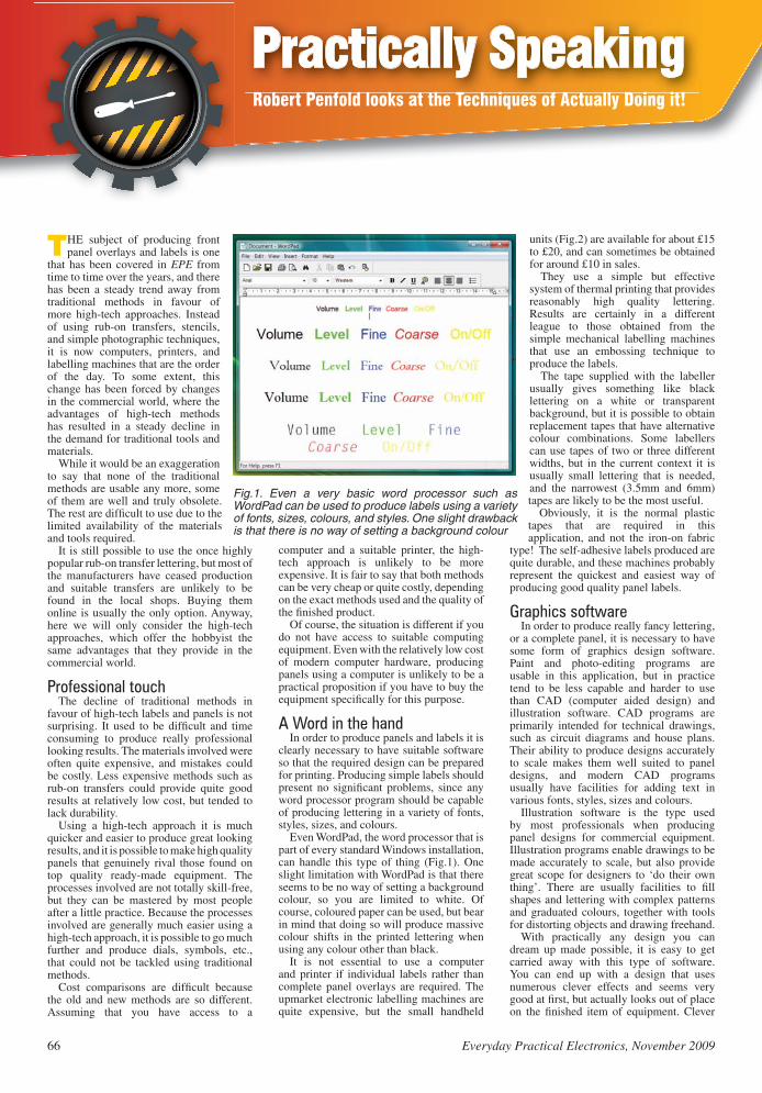
66 Everyday Practical Electronics, November 2009
Practically SpeakingRobert Penfold looks at the Techniques of Actually Doing it!
THE subject of producing front panel overlays and labels is one
that has been covered in EPE from time to time over the years, and there has been a steady trend away from traditional methods in favour of more high-tech approaches. Instead of using rub-on transfers, stencils, and simple photographic techniques, it is now computers, printers, and labelling machines that are the order of the day. To some extent, this change has been forced by changes in the commercial world, where the advantages of high-tech methods has resulted in a steady decline in the demand for traditional tools and materials.
While it would be an exaggeration to say that none of the traditional methods are usable any more, some of them are well and truly obsolete. The rest are difficult to use due to the limited availability of the materials and tools required.
It is still possible to use the once highly popular rub-on transfer lettering, but most of the manufacturers have ceased production and suitable transfers are unlikely to be found in the local shops. Buying them online is usually the only option. Anyway, here we will only consider the high-tech approaches, which offer the hobbyist the same advantages that they provide in the commercial world.
Professional touchThe decline of traditional methods in
favour of high-tech labels and panels is not surprising. It used to be difficult and time consuming to produce really professional looking results. The materials involved were often quite expensive, and mistakes could be costly. Less expensive methods such as rub-on transfers could provide quite good results at relatively low cost, but tended to lack durability.
Using a high-tech approach it is much quicker and easier to produce great looking results, and it is possible to make high quality panels that genuinely rival those found on top quality ready-made equipment. The processes involved are not totally skill-free, but they can be mastered by most people after a little practice. Because the processes involved are generally much easier using a high-tech approach, it is possible to go much further and produce dials, symbols, etc., that could not be tackled using traditional methods.
Cost comparisons are difficult because the old and new methods are so different. Assuming that you have access to a
computer and a suitable printer, the high-tech approach is unlikely to be more expensive. It is fair to say that both methods can be very cheap or quite costly, depending on the exact methods used and the quality of the finished product.
Of course, the situation is different if you do not have access to suitable computing equipment. Even with the relatively low cost of modern computer hardware, producing panels using a computer is unlikely to be a practical proposition if you have to buy the equipment specifically for this purpose.
A Word in the handIn order to produce panels and labels it is
clearly necessary to have suitable software so that the required design can be prepared for printing. Producing simple labels should present no significant problems, since any word processor program should be capable of producing lettering in a variety of fonts, styles, sizes, and colours.
Even WordPad, the word processor that is part of every standard Windows installation, can handle this type of thing (Fig.1). One slight limitation with WordPad is that there seems to be no way of setting a background colour, so you are limited to white. Of course, coloured paper can be used, but bear in mind that doing so will produce massive colour shifts in the printed lettering when using any colour other than black.
It is not essential to use a computer and printer if individual labels rather than complete panel overlays are required. The upmarket electronic labelling machines are quite expensive, but the small handheld
units (Fig.2) are available for about £15 to £20, and can sometimes be obtained for around £10 in sales.
They use a simple but effective system of thermal printing that provides reasonably high quality lettering. Results are certainly in a different league to those obtained from the simple mechanical labelling machines that use an embossing technique to produce the labels.
The tape supplied with the labeller usually gives something like black lettering on a white or transparent background, but it is possible to obtain replacement tapes that have alternative colour combinations. Some labellers can use tapes of two or three different widths, but in the current context it is usually small lettering that is needed, and the narrowest (3.5mm and 6mm) tapes are likely to be the most useful.
Obviously, it is the normal plastic tapes that are required in this application, and not the iron-on fabric
type! The self-adhesive labels produced are quite durable, and these machines probably represent the quickest and easiest way of producing good quality panel labels.
Graphics softwareIn order to produce really fancy lettering,
or a complete panel, it is necessary to have some form of graphics design software. Paint and photo-editing programs are usable in this application, but in practice tend to be less capable and harder to use than CAD (computer aided design) and illustration software. CAD programs are primarily intended for technical drawings, such as circuit diagrams and house plans. Their ability to produce designs accurately to scale makes them well suited to panel designs, and modern CAD programs usually have facilities for adding text in various fonts, styles, sizes and colours.
Illustration software is the type used by most professionals when producing panel designs for commercial equipment. Illustration programs enable drawings to be made accurately to scale, but also provide great scope for designers to ‘do their own thing’. There are usually facilities to fill shapes and lettering with complex patterns and graduated colours, together with tools for distorting objects and drawing freehand.
With practically any design you can dream up made possible, it is easy to get carried away with this type of software. You can end up with a design that uses numerous clever effects and seems very good at first, but actually looks out of place on the finished item of equipment. Clever
Fig.1. Even a very basic word processor such as WordPad can be used to produce labels using a variety of fonts, sizes, colours, and styles. One slight drawback is that there is no way of setting a background colour
Practically Speaking.indd 66 23/09/2009 15:06:45

Everyday Practical Electronics, November 2009 67
effects are all well and good in the right context, but are likely to look out of place on the more staid projects such as items of test equipment. It is also easy to end up with a design that most users will find confusing rather than helpful.
A down-to-earth approach generally gives the best result. Try to produce panel designs that are well matched to their projects.
Cheap or freeIllustration and CAD software tends to
be aimed at professional users, and this is reflected in the prices you have to pay. A CAD program such as AutoCAD costs thousands of pounds, and an illustration program, such as CorelDRAW or Adobe Illustrator, can cost a few hundred pounds. A lower cost alternative has to be found if you only need the software to produce a front panel design from time to time.
Fortunately, there are some good low cost and free alternatives. While these will not give the full range of features available from expensive illustration or CAD software, they should still be more than adequate for producing good quality front panel designs. In general, they are slightly less straightforward to use than the commercial alternatives, but it should not take long to learn the basics, which are all that is required for producing most panel designs.
RenaissanceAfter dwindling somewhat, the range
of free drawing programs has undergone something of a renaissance. A careful search of the Internet should locate several useful CAD and illustration programs that are available as free downloads.
Some of the old favourites are still available, including a free version of DrawPlus (DrawPlus SE), which has been featured in a least one previous article in this series. It is an illustration program from the British company Serif. This download is available from www.freeserifsoftware.com and not the main Serif site (www.serif.com).
Inkscape is probably the most powerful illustration program that is available as a free download, and it is produced as part of the Open Source Project. Versions for computers running under Windows, Linux, and Mac OS X are available. At around 34
megabytes, it will download in less than a minute using a good broadband connection, and it is a practical proposition using a 56k dial-up connection. No minimum hardware requirements are specified, but it seems to work quite well with panel designs and other fairly simple drawings when running on an old PC with a very basic specification.
The screen layout used is the standard one for this type of software (Fig.3), with the usual menu bar at the top. The toolbar down the left-hand side of the screen provides access to the drawing and editing tools that are used most frequently. These are used to draw shapes and text on the screen, to zoom in and out, to apply fancy fills to text and other objects, to draw freehand, and so on. The menu bar and the toolbar beneath it are used for the basic file and editing tasks and setting the text defaults.
The normal first step is to draw the outline of the front panel using the rectangular shape tool. Any holes or other cutouts in the panel are then added. There are rulers above and to the left of the drawing area that are useful when drawing accurately to scale, and an optional grid can be brought up on the screen.
There is a Snap facility that constrains objects so that they can only be drawn on the grid. This provides a quick and easy way of
getting everything drawn and aligned very accurately.
All objects, including text have an outline (stroke) and a fill colour. The bottom section of the screen gives quick access to a wide range of colours, and also to dialogue boxes that permit fancy fills such as patterned and graduated types to be added. It is possible
Fig.2. The smaller electronic labelling machines probably represent the simplest way of producing good quality panel legends. Tapes offering various combinations of text and background colour are available
to effectively get rid of outlines by setting a width of zero, and fills can be removed by using the ‘None’ option.
Having completing the scale drawing of the panel and adding any required fills or other effects, it is time to add the text. It is possible to use any font installed on the computer, with a full range of sizes and colours. The full range of stroke and fill facilities are available for text, so it is possible to add clever effects. In Fig.3 a graduated fill has been used for the line of large text near the bottom of the dummy panel design.
When adding text it is probably a good idea to switch off the Snap facility and position things ‘by eye’. With text it is sometimes the case that the mathematically correct position actually looks slightly out of kilter. In these situations it is better to use your judgement, and go with what looks right.
FinallyWhen designing a panel using a computer
it is very easy to overlook the practicalities and produce a great looking design that is useless in the real world. This can be avoided by making careful measurements to ensure that there is sufficient room for the actual controls, knobs, sockets, lights, displays, or whatever. On the front side of the panel, ensure that the labels will not be partially hidden under control knobs.
Double-check everything, and try to avoid the classic mistake of omitting a control or socket! Remember that there will be controls and other components on the rear of the panel, and that the layout must leave sufficient space for them. It is a good idea to include drilling marks in the design. It can then be printed on ordinary paper, temporarily glued to the front panel, and used as a drilling guide.
Modern graphics programs, including the better free ones, are quite complex. Be prepared to take some time to learn the range of facilities available from whatever drawing program you select. Some time spent reading through the tutorials and producing some dummy panel designs will make life much easier when you start work on the genuine article.
Fig.3. Inkscape uses a standard Windows screen layout with a menu bar and toolbars at the top. The toolbar down the left side of the screen gives access to the facilities that are likely to be used quite frequently
Practically Speaking.indd 67 23/09/2009 15:06:59

68 Everyday Practical Electronics, November 2009
We continue this month with an exploration of real time operating systems that can (or might be
able to) run on some of the PIC range of microcontrollers. Having covered the terminology around RTOSs last month, we can now take a look under the hood at several freely available versions that can be downloaded from the Internet. We shall be looking at:
Microchip’s PIC16 OS (AN585)FreeRTOSeCosSalvoucLinuxContiki
This isn’t an exhaustive list of OSs, and there are a few other RTOSs of interest available, but this list covers an interesting range of offerings. The website of each one (listed in the References section at the end of this article) provides a wealth of information and you will find many tutorials and introductions to how small operating systems are designed and used.
Don’t forget that many of the terms used to describe operating system features can be looked up on the Internet – Wikipedia has some excellent pages covering all aspects of operating system design. So, if you missed last month’s article, or have found a term used that you do not recognise, turn to your favorite Internet search engine.
We will pick one of these operating systems for our example project next month, and will cover installation, setup and use. We haven’t decided which OS to use yet; this article is being written over a number of days as we evaluate each operating system, so at this point your guess is as good as ours!
Let’s dive in, in no particular order.
SalvoSalvo is produced by Pumpkin Inc, based
in the US. It’s a commercial product, but the company provides a freely downloadable ‘Lite’ version that is fully functional, and appears quite useable. It’s limited to just three tasks within the system, so it’s really only useful as a learning aid. The user manual is very detailed and they provide some clear, easy-to-follow examples and tutorials.
The limitations mean that we won’t be using this OS in our example next month – after all, one of the main reasons for using an OS is to support the development of large, complex applications – but it is worth taking a look at, reading the user manual and examining the tutorials. Studying a diverse range of OS designs is interesting,
as it shows the different ways in which an OS can be designed, and it’s always nice to see a different ‘angle’ on how it’s done.
Salvo uses a form of ‘cooperative multitasking’, which means that the currently executing task will continue to run until it gives up its processing time to the OS, usually by calling an OS delay routine, or waiting for a message from another task. This is the simplest type of operating system design, but has the downside that if you have a section of code that takes a long time to execute then all other tasks will have to wait until the current task finishes. That’s not always a problem, but it does mean you have to think harder about your design, and sometimes make a compromise or two.
The OS is supplied as a library file that you include into your application build script. It’s designed for applications written in C, and fits easily into the Hi-Tech or Microchip compilers. If combined with the Hitech C compiler, it will work with some of the tiniest PICs available – including the PIC12F. That’s quite an achievement!
If you are using the Microchip C compiler, however, the smallest PIC processor supported is the PIC18F. This is due to the limitation of the Microchip compiler itself, and not the Salvo operating system. Microchip, in their wisdom, have decided that it is not worth bothering with supporting the C language with these smaller parts, which is a bit of a shame.
Microchip’s AN585Microchip have produced their own
simple OS, aimed at the PIC16 family processors. It’s over ten years old now and quite dated, but once again it makes interesting reading. Unlike all the other examples, this OS is written completely in assembler, and targeted at the PIC16C64.
Although antiquated, the principles are still interesting and the code is portable to other processors (with some considerable effort.) The design is covered in a 13-page application note AN585, and the full source code is provided as a download.
The source code shows why writing an OS in assembly language is not a great idea. The code is very difficult to read, and not easy to adjust to different use. So we won’t say anything more about it, other than to suggest reading the application note.
ucLinuxMany people will be familiar with
Linux, the free server and desktop PC operating system first developed by Linus Torvalds in 1991, and now supported by an army of volunteer software developers. Linux is a huge system and completely
unsuitable for small microcontrollers, but ucLinux has been developed as a cut down version suitable for microcontrollers that don’t have memory management hardware built in.
Memory management is a feature of the larger processors, such as the Pentium and AMD chips, but rarely found in microcontrollers and certainly not in Microchip devices. Memory management allows the processor to isolate each process within its own virtual memory address space, and to use hard disk storage to extend the amount of virtual memory available to the whole system.
ucLinux supports many of the hundreds of free programs and device drivers developed for Linux (including a TCP/IP stack) and so it’s no surprise that it is very popular. Many consumer electronic products are based on ucLinux, and the chances are you have something in your home running it – a broadband router, set top box or PVR to name a few. One of the big attractions is that it is completely free – there are no royalty payments or license fees to pay – but from an engineering perspective it’s simply the most suitable embedded operating system available.
ucLinux is not a true realtime OS, and cannot respond to interrupts or other events with a defined response time, but in most commercial applications that’s not an issue. If your router drops a data packet, or your TV skips a frame, it’s no real loss. One couldn’t say the same of the control of an aircraft elevator during take off, but those designs are in another league to ours.
Now you might think this is going to be an ideal choice for us, but sadly it’s not to be. ucLinux is a fully featured, high specification OS, and makes significant demands on the underlying hardware. Not processor speed, oddly enough; you can run ucLinux on a 16MHz processor, and Microchip processors run at up to 80MHz.
Unfortunately, however, the OS requires a large amount of memory, by small microcontroller standards. A few MBytes of RAM, and about the same of Flash at least. We are looking for an OS that can comfortably sit within a few hundred KBytes of Flash and tens of KBytes of RAM, while still leaving enough space for our own application. So, we must look elsewhere. If you find yourself playing with an ARM micrcontroller, however, it’s worth considering.
eCosSome people consider eCos to be a variant
of Linux, but in fact it’s very different. Like Linux, it’s completely free, although produced under a license that allows you
Real Time Operating Systems – Part 2
Our periodic column for PIC programming enlightenment
Mike Hibbett
Pic n Mix.indd 68 23/09/2009 15:03:17
Everyday Practical Electronics, November 2009 69
to use it in conjunction with your own software without requiring you to release that software under an identical license. Linux is released under the GPL, which forces you to release any software that you compile with the Linux kernel (or it’s associated GNU libraries) under the same terms, a restriction that can be difficult for commercial companies to accept.
eCos is effectively a runtime system that you link in with your application, somewhat like a library. It implements a single process with the ability to create multiple threads, and like ucLinux does not support memory management – all threads run in the same address space. However, it does provide a rich runtime environment, allowing you to make use of Unix like library and system features, just as ucLinux does.
At the moment, there is no support for any of the Microchip processors, but work is underway for providing a port to the PIC32. Once this is available, it will certainly be worth taking a look. Bear in mind, however, that eCos is a very complex RTOS and is really only suited to experienced software engineers.
ContikiThe previous two operating systems
have been relatively ‘high end’ systems, aimed more at the larger microcontrollers than our humble PIC. Contiki, on the other hand, has been designed with smaller processors in mind, and can operate with just 2KB of RAM and 40KB of Flash.
It started off as a university research project for tiny wireless sensors, and the list of processors that it currently operates
on reflects this aim. Unfortunately, the Microchip processors are yet to be supported, which is rather strange, as many other similar types of processor, such as the MSP430, are included. It’s a very well designed OS and very clearly documented. There are several network protocol stacks available for it and many wireless device drivers.
Due to it’s bias towards small wire-less sensors, it is ideal for low power applications and will be perfect for a battery-powered PIC project. Some work has been done informally on supporting Microchip processes; once again, it’s a case of waiting and watching.
FreeRTOSSo we come to the final operating system
that we will look at this month. FreeRTOS has been designed as a general purpose real time operating system for embedded systems using very small microcontrollers. The OS can fit in 4KBytes of Flash, which will fit easily inside a Microchip processor. The PIC18, PIC24, dsPIC30 and PIC32 parts are already supported too, using the freely available Microchip C compiler.
FreeRTOS can be configured to operate either preemptive or cooperative multitasking. The OS is written in the C language and is contained in just four source files, with a further two files provided for the device-specific code, mostly written in assembly language.
It’s probably one of the simplest OSs to understand, and yet provides all the RTOS features that one needs. Just enough, so you are not overwhelmed with complex, confusing features. Despite this, the OS is deployed in many commercial products, and
a version of it has been certified for use in safety critical systems – so this is no toy OS.
Although FreeRTOS has evolved into a commercial product, SafeRTOS, FreeRTOS is still an actively supported project in it’s own right and remains frequently updated – when we last looked, an update was released ten days earlier. The development team are very supportive and returned emails within a few minutes of our contacting them, and there is a very active user community on their web forum. There are online tutorials, a video that can be downloaded, and books available for sale.
ConclusionAs you might guess, it’s the FreeRTOS
operating system that we will be playing with next month. While there are other interesting and more powerful free OS’s out there, they don’t yet support any of the Microchip processors. Their documentation does make for interesting reading, however, and may help fill in the gaps of your understanding of how an embedded OS works.
For now, we are off to find an interesting problem to test FreeRTOS with!
ReferencesMicrochip PIC16 Application Note: AN585
FreeRTOS: www.freertos.orgeCos: ecos.sourceware.orgSalvo: www.pumpkininc.comucLinux: www.uclinux.orgContiki: www.sics.se/contikiPicoOS: picoos.sourceforge.net
Pic n Mix.indd 69 24/09/2009 11:01:43

70 Everyday Practical Electronics, November 2009
EPE IS PLEASED TO BE ABLE TO OFFER YOU THESE
ELECTRONICS CD-ROMS
Hobbyist/Student . . . . . . . . . . . . . . . . . . . . . . . . . . . . . . £44 inc VATInstitutional (Schools/HE/FE/Industry) . . . . . . . . . . . . £99 plus VATInstitutional 10 user (Network Licence) . . . . . . . . . . . . £249 plus VATSite licence . . . . . . . . . . . . . . . . . . . . . . . . . . . . . . . . . . . £499 plus VAT
PRICESPrices for each of the CD-ROMs above are:
(Order form on third page)
(UK and EU customers add VAT at 15% to ‘plus VAT’ prices)
Case study of the Milford Instruments Spider
Robotics and Mechatronics is designed to enable hobbyists/students with little previous experience of electronics to design and build electromechanical systems. The CD-ROM deals with all aspects of robotics from the control systems used, the transducers available, motors/actuators and the circuits to drive them. Case study material (including the NASA Mars Rover, the Milford Spider and the Furby) is used to show how practical robotic systems are designed. The result is a highly stimulating resource that will make learning, and building robotics and mechatronic systems easier. The Institutional versions have additional worksheets and multiple choice questions.
Interactive Virtual LaboratoriesLittle previous knowledge requiredMathematics is kept to a minimum and
all calculations are explainedClear circuit simulations
ROBOTICS &MECHATRONICS
Electronic Projects is split into two main sections: Building Electronic Projects contains comprehensive information about the components, tools and techniques used in developing projects from initial concept through to final circuit board production. Extensive use is made of video presentations showing soldering and construction techniques. The second section contains a set of ten projects for students to build, ranging from simple sensor circuits through to power amplifiers. A shareware version of Matrix’s CADPACK schematic capture, circuit simulation and p.c.b. design software is included.The projects on the CD-ROM are: Logic Probe; Light, Heat and Moisture Sensor; NE555 Timer; Egg Timer; Dice Machine; Bike Alarm; Stereo Mixer; Power Amplifier; Sound Activated Switch; Reaction Tester. Full parts lists, schematics and p.c.b. layouts are included on the CD-ROM.
ELECTRONICS PROJECTS
Logic Probe testing
Analogue Electronics is a complete learning resource for this most difficult branch of electronics. The CD-ROM includes a host of virtual laboratories, animations, diagrams, photographs and text as well as a SPICE electronic circuit simulator with over 50 pre-designed circuits.Sections on the CD-ROM include: Fundamentals – Analogue Signals (5 sections),Transistors (4 sections), Waveshaping Circuits (6 sections). Op Amps – 17 sections covering everything from Symbols and Signal Connections to Differentiators. Amplifiers – Single Stage Amplifiers (8 sections), Multi-stage Amplifiers (3 sections). Filters – Passive Filters (10 sections), Phase Shifting Networks (4 sections), Active Filters (6 sections). Oscillators – 6 sections from Positive Feedback to Crystal Oscillators. Systems – 12 sections from Audio Pre-Amplifiers to 8-Bit ADC plus a gallery showing representative p.c.b. photos.
ANALOGUE ELECTRONICS
Complimentary output stage
Analogue Filters is a complete course in designing active and passive filters that makes use of highly interactive virtual laboratories and simulations to explain how filters are designed. It is split into five chapters: Revision which provides underpinning knowledge required for those who need to design filters. Filter Basics which is a course in terminology and filter characterization, important classes of filter, filter order, filter impedance and impedance matching, and effects of different filter types. Advanced Theory which covers the use of filter tables, mathematics behind filter design, and an explanation of the design of active filters. Passive Filter Design which includes an expert system and filter synthesis tool for the design of low-pass, high-pass, band-pass, and band-stop Bessel, Butterworth and Chebyshev ladder filters. Active Filter Design which includes an expert system and filter synthesis tool for the design of low-pass, high-pass, band-pass, and band-stop Bessel, Butterworth and Chebyshev op.amp filters.
ANALOGUE FILTERS
Filter synthesis
Electronics Circuits & Components V2.0 provides an introduction to the principles and application of the most common types of electronic components and shows how they are used to form complete circuits. The virtual laboratories, worked examples and pre-designed circuits allow students to learn, experiment and check their understanding. Version 2 has been considerably expanded in almost every area following a review of major syllabuses (GCSE, GNVQ, A level and HNC). It also contains both European and American circuit symbols. Sections include: Fundamentals: units and multiples, electricity, electric circuits, alternating circuits. Passive Components: resistors, capacitors, inductors, transformers. Semiconductors: diodes, transistors, op amps, logic gates. Passive Circuits. Active Circuits. The Parts Gallery will help students to recognise common electronic components and their corresponding symbols in circuit diagrams.Included in the Institutional Versions are multiple choice questions, exam style questions, fault finding virtual laboratories and investigations/worksheets.
ELECTRONIC CIRCUITS & COMPONENTS V2.0
Circuit simulation screen
CVersion 2
Digital Electronics builds on the knowledge of logic gates covered in Electronic Circuits & Components (above), and takes users through the subject of digital electronics up to the operation and architecture of microprocessors. The virtual laboratories allow users to operate many circuits on screen.Covers binary and hexadecimal numbering systems, ASCII, basic logic gates, monostable action and circuits, and bistables – including JK and D-type flip-flops. Multiple gate circuits, equivalent logic functions and specialised logic functions. Introduces sequential logic including clocks and clock circuitry, counters, binary coded decimal and shift registers. A/D and D/A converters, traffic light controllers, memories and microprocessors – architecture, bus systems and their arithmetic logic units. Sections on Boolean Logic and Venn diagrams, displays and chip types have been expanded in Version 2 and new sections include shift registers, digital fault finding, programmable logic controllers, and microcontrollers and microprocessors. The Institutional versions now also include several types of assessment for supervisors, including worksheets, multiple choice tests, fault finding exercises and examination questions.
DIGITAL ELECTRONICS V2.0
Virtual laboratory - Traffic Lights
Version 2
CD-ROMs Pages.indd 70 23/09/2009 14:55:41

Everyday Practical Electronics, November 2009 71
PICmicro TUTORIALS AND PROGRAMMING
VERSION 3 PICmicro MCU development board
Suitable for use with the three software packageslisted below.
This flexible development board allows students to learn both how to program PICmicro microcontrollers as well as program a range of 8, 18, 28 and 40-pin devices from the 12, 16 and 18 series PICmicro ranges. For experienced programmers all programming software is included in the PPP utility that comes with the development board. For those who want to learn, choose one or all of the packages below to use with the Development Board.
Makes it easier to develop PICmicro projectsSupports low cost Flash-programmable PICmicro devicesFully featured integrated displays – 16 individual l.e.d.s, quad 7-segment
display and alphanumeric l.c.d. displaySupports PICmicro microcontrollers with A/D convertersFully protected expansion bus for project workUSB programmableCan be powered by USB (no power supply required)
ASSEMBLY FOR PICmicro V3
(Formerly PICtutor)Assembly for PICmicro microcontrollers V3.0 (previously known as PICtutor) by John Becker contains a complete course in programming the PIC16F84 PICmicro microcontroller from Arizona Microchip. It starts with fundamental concepts and extends up to complex programs including watchdog timers, interrupts and sleep modes.
The CD makes use of the latest simulation techniques which provide a superb tool for learning: the Virtual PICmicro micro-controller. this is a simulation tool that allows users to write and execute MPASM assembler code for the PIC16F84 microcontroller on-screen. Using this you can actually see what happens inside the PICmicro MCU as each instruction is executed which enhances understanding.
Comprehensive instruction through 45 tutorial sections Includes Vlab, a Virtual PICmicro microcontroller: a fully functioning simulator Tests, exercises and projects covering a wide range of PICmicro MCU applications Includes MPLAB assembler Visual representation of a PICmicro showing architecture and functions Expert system for code entry helps first time users
Shows data flow and fetch execute cycle and has challenges (washing machine, lift, crossroads etc.)
Imports MPASM files.
‘C’ FOR 16 Series PICmicroVersion 4
The C for PICmicro microcontrollers CD-ROM is designed for students and professionals who need to learn how to program embedded microcontrollers in C. The CD contains a course as well as all the software tools needed to create Hex code for a wide range of PICmicro devices – including a full C compiler for a wide range of PICmicro devices.
Although the course focuses on the use of the PICmicro microcontrollers, this CD-ROM will provide a good grounding in C programming for any microcontroller.
Complete course in C as well as C programming for PICmicro microcontrollers Highly interactive course Virtual C PICmicro improves understanding Includes a C compiler for a wide range of PICmicro devices Includes full Integrated Development Environment Includes MPLAB software Compatible with most PICmicro programmers Includes a compiler for all the PICmicro devices.
FLOWCODE FOR PICmicro V3
Flowcode is a very high level language programming system for PICmicro microcontrollers based on flowcharts. Flowcode allows you to design and simulate complex systems in a matter of minutes. A Powerful language that uses macros to facilitate the control of devices like 7-segment displays, motor controllers and l.c.d.’s. The use of macros allows you to control these devices without getting bogged down in understanding the programming.
Flowcode produces MPASM code which is compatible with virtually all PICmicro programmers. When used in conjunction with the Version 3 development board this provides a seamless solution that allows you to program chips in minutes.
Requires no programming experience Allows complex PICmicro applications to be designed quickly Uses international standard flow chart symbols Full on-screen simulation allows debugging and speeds up the development process.
Facilitates learning via a full suite of demonstration tutorials Produces ASM code for a range of 18, 28 and 40-pin devices New features in Version 3 include 16-bit arithmetic, strings and string manipulation, improved graphical user interface and printing, support for 18 series devices, pulse width modulation, I2C, new ADC component etc. The Hobbyist/Student version is limited to 4K of code (8K on 18F devices)
£155 including VAT and postage, supplied with USB cable and programming software
£40 OFF Buy the Development Board together with any Hobbyist/Student or Institutional versions of the software CD-ROMs listed below and take £40 off the total (including VAT) price.
HARDWARE
SOFTWARE
Hobbyist/Student . . . . . . . . . . . . . . . . . . . . . . . . . . . . . . £44 inc VATInstItutional (Schools/HE/FE/Industry) . . . . . . . . . . . . £99 plus VATInstitutional/Professional 10 user (Network Licence) £300 plus VATSite licence . . . . . . . . . . . . . . . . . . . . . . . . . . . . . . . . . . . £599 plus VATFlowcode 10 user (Network Licence) . . . . . . . . . . . . . . £350 plus VATFlowcode 50 user (Network Licence) . . . . . . . . . . . . . . £699 plus VAT
PRICESPrices for each of the CD-ROMs above are:
(Order form on next page)
(UK and EU customers add VAT at 15% to ‘plus VAT’ prices)
Minimum system requirements for these items: Pentium PC running Windows 98, NT, 2000, ME, XP; CD-ROM drive; 64MB
RAM; 10MB hard disk space.Flowcode will run on XP or later
operating systems
£155 including VAT and postage, supplied
ARDWARE
SPECIALOFFER
CD-ROMs Pages.indd 71 23/09/2009 14:55:54

72 Everyday Practical Electronics, November 2009
Counter projectDigital Works Version 3.0 is a graphical design tool that enables you to construct digital logic circuits and analyze their behaviour. It is so simple to use that it will take you less than 10 minutes to make your first digital design. It is so powerful that you will never outgrow its capability Software for simulating digital logic circuits Create your own macros – highly scalable Create your own circuits, components, and i.c.s Easy-to-use digital interface Animation brings circuits to life Vast library of logic macros and 74 series i.c.s with data sheets
Powerful tool for designing and learning.
Hobbyist/Student £44 inc. VAT. Institutional £99 plus VAT.Institutional 10 user £249 plus VAT.Site Licence £599 plus VAT.
A high quality selection of over 200 jpg images of electronic components. This selection of high resolution photos can be used to enhance projects and presentations or to help with training and educational material. They are royalty free for use in commercial or personal printed projects, and can also be used royalty free in books, catalogues, magazine articles as well as worldwide web pages (subject to restrictions – see licence for full details).
Now contains Irfan View image software for Windows, with quick-start notes included.
Price £19.95 inc. VAT
DIGITAL WORKS 3.0
TINA Analogue, Digital, Symbolic, RF, MCU and Mixed-Mode Circuit Simulation, Testing and PCB DesignTINA Design Suite is a powerful yet affordable software package for analysing, designing and real time testing analogue, digital, MCU, and mixed electronic circuits and their PCB layouts. You can also analyse RF, communication, optoelectronic circuits, test and debug microcontroller applications.
Enter any circuit (up to 100 nodes) within minutes with TINA’s easy-to-use schematic editor. Enhance your schematics by adding text and graphics. Choose components from the large library containing more than 10,000 manufacturer models. Analyse your circuit through more than 20 different analysis modes or with 10 high tech virtual instruments. Present your results in TINA’s sophisticated diagram windows, on virtual instruments, or in the live interactive mode where you can even edit your circuit during operation.
Customise presentations using TINA’s advanced drawing tools to control text, fonts, axes, line width, colour and layout. You can create, and print documents directly inside TINA or cut and paste your results into your favourite word- procesing or DTP package.
TINA includes the following Virtual Instruments: Oscilloscope, Function Generator, Multimeter, Signal Analyser/Bode Plotter, Network Analyser, Spectrum Analyser, Logic Analyser, Digital Signal Generator, XY Recorder.
Flowcode V3 (Hobbyist/Student) – For details on Flowcode, see the previous page.
This offer gives you two seperate CD-ROMs in DVD style cases – the software will need registering (FREE) with Designsoft (TINA) and Matrix Multimedia (Flowcode), details are given within the packages.
Get TINA + Flowcode for a total of just £50, including VAT and postage.
SPECIAL PACKAGE OFFERTINA Pro V7 (Basic) + Flowcode V3 (Hobbyist/Student)
p
A high qualityl i f
ELECTRONIC COMPONENTS PHOTOS
An interactive CD-ROM to guide you through the process of circuit design. Choose from an extensive range of input, process and output modules, including CMOS Logic, Op-Amps, PIC/PICAXE, Remote Control Modules (IR and Radio), Transistors, Thyristors, Relays and much more.Click Data for a complete guide to the pin layouts of i.c.s, transistors etc. Click More Information for detailed background information with many animated diagrams.Nearly all the circuits can be instantly simulated in Crocodile Technology* (not included on the CD-ROM) and you can customise the designs as required.
WHAT’S INCLUDEDLight Modules, Temperature Modules, Sound Modules, Moisture Modules, Switch Modules, Astables including 555, Remote Control (IR & Radio), Transistor Amplifiers, Thyristor, Relay, Op-Amp Modules, Logic Modules, 555 Timer, PIC/PICAXE, Output Devices, Transistor Drivers, Relay Motor Direction & Speed Control, 7 Segment Displays.Data sections with pinouts etc., Example Projects, Full Search Facility, Further Background Information and Animated Diagrams.Runs in Microsoft Internet Explorer*All circuits can be viewed, but can only be simulated if your computer has Crocodile Technoloy version 410 or later. A free trial version of Crocodile Technology can be downloaded from: www.crocodile-clips.com. Animated diagrams run without Crocodile Technology.
Single User £39.00 inc. VAT. Multiple Educational Users (under 500 students) £59.00 plus VAT. Over 500 students £79.00 plus VAT.
(UK and EU customers add VAT at 15% to “plus VAT’’ prices)
PROJECT DESIGN WITH CROCODILE TECHNOLOGYAn Interactive Guide to Circuit Design
Please send me: CD-ROM ORDER FORM� Electronic Projects� Electronic Circuits & Components V2.0� Analogue Electronics Version required:� Digital Electronics V2.0 � Hobbyist/Student� Analogue Filters � Institutional� Electronics CAD Pack � Institutional/Professional 10 user� Robotics & Mechatronics � Site licence� Assembly for PICmicro V3� ‘C’ for 16 Series PICmicro V4� Flowcode V3 for PICmicro � Digital Works 3.0
� PICmicro Development Board V3 (hardware)
� TINA Pro V7 Basic + Flowcode V3 Hobbyist/Student� Electronic Components Photos; Version 1.1� Project Design – Single User� Project Design – Multiple User (under 500 students)� Project Design – Multiple User (over 500 students)
Full name: . . . . . . . . . . . . . . . . . . . . . . . . . . . . . . . . . . . . . . . . . . . . . . . . . . . . . . . . . . . . . . . . .Address: . . . . . . . . . . . . . . . . . . . . . . . . . . . . . . . . . . . . . . . . . . . . . . . . . . . . . . . . . . . . . . . . . .. . . . . . . . . . . . . . . . . . . . . . Post code: . . . . . . . . . . . . . . . . . Tel. No: . . . . . . . . . . . . . . . . . . . Signature: . . . . . . . . . . . . . . . . . . . . . . . . . . . . . . . . . . . . . . . . . � I enclose cheque/PO in £ sterling payable to WIMBORNE PUBLISHING LTD for £ . . . . . . . . . � Please charge my Visa/Mastercard/Maestro: £ . . . . . . . . . . Valid From: . . . . . . . . . . Card expiry date: . . . . . . . . . . . . . Card No: . . . . . . . . . . . . . . . . . . . . . . . . . . . . . . . . . . . . . . . . Maestro Issue No. . . . . . . . . .Card Security Code . . . . . . . . . . (The last 3 digits on or just under the signature strip)
Note: The software on each version is the same, only the licence for use varies.
Minimum system requirements for these CD-ROMs: Pentium PC, CD-ROM drive, 32MB RAM, 10MB hard disk space. Windows 95/98/NT/2000/ME/XP, mouse, sound card, web browser.
ORDERINGALL PRICES INCLUDE UK
POSTAGE
Student/Single User/Standard Version price includes postage to most countries in the worldEU residents outside the UK add £5 for airmail
postage per order
Institutional, Multiple User and Deluxe Versions – overseas readers add £5 to the basic price of each order for airmail postage (do not add VAT unless you live in an EU (European Union) country, then add 15% VAT or provide your official VAT registration number).
Send your order to:Direct Book Service
Wimborne Publishing LtdSequoia House, 398a Ringwood Road
Ferndown, Dorset BH22 9AUTo order by phone ring
01202 873872. Fax: 01202 874562Goods are normally sent within seven days
E-mail: [email protected] shop:
www.epemag.com
Over 150 pagesOver 600 images
£50.00inc. VAT
and p&p
NEW VERSION
CD-ROMs Pages.indd 72 23/09/2009 14:56:05

Everyday Practical Electronics, November 2009 73
What should we do when electronic products reach the end of their useful life? Binning them is not environmentally friendly and other disposal solutions are downright criminal.
It’s all rather problematic, as Mark Nelson explains.
Mark Nelson
Ratters And Rotters
In lots of parts of the world, the reclamation takes place by the side of ditches and rivers and poisonous chemicals leach into the environment. In China, children are already being found with high levels of chemicals in their blood.”
Ugly pictureNeedless to say, environmentally-hostile
recovery processes of this kind do not take place in Britain, but therein lies the crisis. Exporting the problem elsewhere is ethically criminal and a really ugly picture of what’s happening on a massive scale, according to Ted Smith. He claims that between 50 and 80 per cent of all of electrical waste material collected in the USA makes its way abroad, as well as significant amounts from the UK and Europe.
Although exporting waste electrical and electronic equipment (WEEE) is prohibited by the EU’s WEEE Directive (and by the Electronic Waste Recycling Act of California), criminals are flouting this legislation by declaring their scrap as functional apparatus. This is then exported for ‘reuse’ in developing countries, where in fact it is broken up for the materials worth recovering.
In this way it leaves the country illegally by the container load, often camouflaged by outer layers of working (but unsalable) equipment surrounding the scrap stuff. Earlier this year, police and Environment Agency (EA) officials raided two industrial sites in Essex, where they found some 360 shipping containers full of electrical and computer equipment destined for west Africa. Also discovered during the raid were other signs of organised crime: £80,000 worth of vodka and cigarettes, illicit import documentation and other stolen goods.
Since its clampdown initiative started last year, the Agency has made 10 arrests of suspected organised criminals involved in the illegal export of WEEE, stating that it is becoming an increasing problem, with materials being stripped down under appalling conditions. According to intelligence manager Trevor Parish, the EA is determined to crack down on the “big, the bad and the nasty”.
Are you a criminal too?Ultra-ecologists might argue ‘you are a
criminal’ if you have ever put spent batteries or ‘dead’ gadgets in the dustbin, particularly when you consider that every year British households throw away around one million tonnes of WEEE, including some 1.5 million PCs alone. This figure is set to grow as more and more electrical goods have inbuilt obsolescence, and prices make it more
economical for consumers to throw goods away rather than repair them.
Although we have a tolerably good record of recycling large kitchen appliances, many other items are not treated or recycled, but instead get buried in landfill sites, wasting resources and putting a major strain on the environment. For this reason, an increasing number of products are marked with the crossed-out wheelie bin symbol, which means ‘don’t bin this’. You’ll find this marking on an increasing range of electrical goods, such as televisions, batteries, phones, fridges, household gadgets and even light bulbs.
Is it a crime then to dump these items in the bin? Not if you are a householder, but this doesn’t absolve you from disposing of this equipment responsibly. The government’s initiative has created a network of collection points for WEEE and you should find it easier to recycle your old equipment using separate bins at local authority civic amenity sites and new take-back facilities provided by retailers.
It’s the lawWhile slipping a worn-out computer
keyboard in the bin won’t land you in jail, the law is completly different for traders. Retailers, distributors and manufacturers have a specific legal obligation to dispose of these goods responsibly. Shops that sell electrical goods must either offer to take back waste themselves or else take part in a distributor take-back scheme (and tell you how to participate).
Since July 2007, retailers have been obliged to take back defunct products at no charge when you make a like-for-like purchase (for example, take back your old television when you buy a new one), no matter where you bought the item originally. Holding them to this might be tricky but this is what the regulations say.
You can find out more at two websites: www.environment-agency.gov.uk/weee and http://myzerowaste.com/, or alternatively call the Environment Agency helpline 08708 506506.
Many of the gadgets we might junk need not be binned in fact, at least not if they are in working order. Computers and mobile phones, even outdated ones, have a value for recycling or export to third-world countries and will be collected free. Take a look at the websites: www.envirophone.com and www.computeraid.org. Another very worthy organisation is Freecycle, which is an ingenious network of local websites on which you can advertise unwanted goods and have them removed for nothing (http://www.freecycle.org/groups/unitedkingdom/).
ONE of the endearing features of this magazine is its support for ‘ratting’, the recycling of electronic and
electrical gadgets that otherwise would be consigned to the dustbin. Enlightened ratters display great ingenuity in extracting useful components from apparent junk, a skill set that should earn praise from ecologists and indeed from all thrifty folk.
Of course, I aspire to be a ratter as well, although I suspect I’m more of a pack rat. On this score Wikipedia warns that pack rats are people who engage in compulsive hoarding, in reference to the rat’s apparent fondness for material objects.
Rather worryingly, the article also shows photographs of the homes of compulsive hoarders and ends by stating that hoarding unnecessary possessions may be referred to as syllogomania or disposophobia. As this looks rather serious, I think it’s time to move on rapidly, especially as the dividing line between hoarding and thoughtful provision for possible future need is probably quite easy to cross!
Rotters versus rattersPraiseworthy as the recycling movement
most definitely is, it also attracts less desirable creatures (and I don’t mean the rats that may be found at recycling establishments). These absolute rotters are the criminals who are abusing the European Union (EU) directive on the reuse of unwanted electrical and electronic equipment. Organised crime has moved into this field on both sides of the Atlantic, putting both the environment and human health at risk. But how can this happen when we have crystal-clear compliance schemes? And how can low-cost recycling be a problem?
Let’s examine the facts. Despite the downturn in the economy, there’s plenty of money to be made from recycling electrical and electronic waste. Gold-plated connectors, copper wire from transformers and steel from equipment cases are well worth extracting if the recovery process is cheap enough. Unfortunately, the cheapest method is shipping the waste to countries with low labour costs, where the equipment is stripped and then burnt.
‘In Africa, China and India, young children are used to recover tiny amounts of metal,’ stated an article in The Guardian a couple of months ago. This quoted American environmental activist Ted Smith as saying: “Chips are removed from circuit boards over open fires and give off lead fumes in the process. Children are digging out carbon black from toner cartridges. Other components are put into acid baths in sweat shops.
TechnoTalk.indd 73 24/09/2009 15:02:45

74 Everyday Practical Electronics, November 2009
Mac and Linux interfacingDear EPEI found EPE in the local newsagent
recently and was very pleased to find a magazine that focuses on practical electronic projects. I was further pleased to read your editorial in the June 2009 issue, where you indicate that you want to support projects on Macintosh and Linux as well as Windows.
I have worked with interfaces for Macintosh computers for many years when building robots for research. Often, I had to find my own solutions to interface problems. To make these solutions available to others, I developed a
website on ‘Input, Output and Embedded Systems for Macintosh’, www.uow.edu.au/~phillip/MacInOut/index.html.
We have found the website a useful way of documenting our projects and often refer to it when designing a new interface.
Also, at WWDC’09 in San Francisco in June, Paul Holden presented a session (Session 507) on ‘Creating iPhone Apps that communicate with accessories’. An accessory is a piece of hardware that is external to your phone. It can be connected through Bluetooth or through the USB and UART in the dock connector. Accessories are supported by the EA-Framework in the iPhone 3 SDK. Information is available
for developers on the developer website http://developer.apple.com.
iPhone and session videos can be purchased through the iTunes store http://developer.apple.com/products/videos.html.
I look forward to some practical electronic projects for both the Mac and the iPhone in future editions of EPE.
Dr Phillip McKerrow, Australia, by email
Thanks for your warm comments Phillip, and the links to your fascinating website – perhaps we can find a way to persuade you to get the Mac ball rolling with an interface project!
READOUTMatt Pulzer addresses some of the general points readers have raised. Have you anything interesting to say?Drop us a line!
Email: [email protected]
All letters quoted here have previously been replied to directly
MgHD
EE
All letters q oted here
?WIN AN ATLAS LCR ANALYSER WORTH £79
An Atlas LCR Passive Component Analyser, kindly
donated by Peak Electronic Design Ltd, will be
awarded to the author of the Letter Of The Month.
The Atlas LCR automatically measures inductance
from 1mH to 10H, capacitance from 1pF to
10,000�F and resistance from 1� to 2M� with
a basic accuracy of 1%. www.peakelec.co.uk
� LETTER OF THE MONTH �TV modification
Dear EPEI picked up a copy of EPE quite by chance a couple of weeks ago when I was
getting the Saturday newspaper. I hadn’t realised that a magazine like yours was still published, thinking that the likes of Everyday Electronics, Practical Wireless, Practical Electronics and Electronics Today International, which I grew up with, had long been dislodged by the various computing and gaming titles.
From the mid-70s until a few years ago, I had subscribed to Television magazine (I stopped when a change of editor sent it spinning off course) so your magazine could fill a gap in my reading – although there isn’t really much of a gap, as I don’t seem to have enough time to read my Which? and Computing Which? magazines, despite being retired (or possibly on a career break).
I left Imperial College in 1979 with a 2.2 in electronics and spent eight years working at BBC TV Centre and Lime Grove, West London in engineering operations and maintenance, before moving to Channel 4 in 1987, from which I took voluntary redundancy in 2006. As well as working on the full range of professional broadcast equipment, I designed and built my own electronics projects and modified or repaired a wide range of consumer products.
As an example, I’ve just modified our Panasonic TV (which uses the very common Euro 4 chassis) so that when it powers-up, or comes out of standby, it automatically selects its AV1 input, since we now watch using our Freeview PVR, rather than the TV’s analogue tuner. I’ve attached some photos (including some of other projects) in case you think this might be suitable for an Ingenuity Unlimited item; I could easily write a supporting text referencing the way the TV selects its inputs and mention other possible uses. A ‘dos-and-don’ts’ article on general repair/construction methods (based on 35 years’ experience) is another possibility (‘Why desoldering braid beats a solder-sucker’).
Anyway, congratulations on a high quality publication – it has a clean, fresh feel with much better graphics and photographs than I remember from those earlier titles!
Steve Burgess, by email
We’re always pleased to be ‘rediscovered’, and while many of our former competitors have fallen by the wayside, I am pleased to report that EPE is flourishing. Your professional history and TV projects sound fascinating, and I would certainly encourage you to consider writing for us on the topics you suggested.
Readout.indd 74 23/09/2009 15:04:51

75 Everyday Practical Electronics, November 2009
Surfing The Internet
Net WorkAlan Winstanley
Google, the dominant search engine, continues to roll out more features, mainly because it can. The fuss about Google Street
View peeping over the garden fence has subsided, and it is only a matter of time before the integration of the panoramic photo-realistic imagery is complete, with villages and even tiny hamlets falling under the withering gaze of Google’s photo cars.
The shock of having one’s ‘neck of the woods’ available on Google for all to see may unbalance the sensibilities of some, but it is not as though the whole world is suddenly looking through the window, though it may feel that way at first. In the US, fire departments use Google Street View to see how large a building is, to help assess what sort of firefighting equipment or ladders they will need when called out on duty.
Doing more businessThe search aspect of Google now includes links, maps and graphics
for local enterprises, powered through Google Local Business Center. A Google account is needed to utilise it. I feel it is important that businesses check out this service and ‘claim’ their business in Google Maps, setting up descriptions of their firm (with a healthy sprinkling of keywords) along with a thumbnail graphic or two, so that when your firm’s website is flagged up in keyword search results, your own ‘business card’ can be shown, with no chance of your links being hijacked by rivals.
During the registration process, Google sends you an automated phone-based PIN number: type this into your online account page to validate the setup. Then continue to enter descriptions about your business, including opening hours, brand names, photos and more, and Google will update its database in a few hours.
As mobile bandwidth improves and phone handsets become more accessible, there is an increasing drive towards using mobile search. It will become routine to ‘Google’ on a mobile phone for, say, the nearest pizza shop or brideswear boutique: Google Maps will show the way. Couple this with mobile step-by-step satellite navigation such as Tom Tom, and you have a fully automated way of steering customers right to your door. All businesses should become familiar with Google Local Business Center and register their business straight away. For more information, see www.google.com/local/add
Meanwhile, Microsoft continues to pick up the pace with Bing, its answer to Google that I mentioned briefly in last month’s column. Bing has some attractive features that makes it more appealing to use, and it has now added Visual Search as a means of displaying results in thumbnail pictures rather than wading through lists of hyperlinks. Bing is gaining some ground on Google and is set to become a major rival in a maturing search engine world.
Safe and F-SecureMy Carbonite online backup
recently expired, so I decided to brandish my credit card for another year. I was charged $220 for a $55 renewal, which did not enhance my
confidence in Carbonite’s renewals process, and a month passed before I had sight of my cash once again. (You can read more of this saga in my Net Work column at EPE Online.) Carbonite is also starting to show some technical black holes, including the discovery that it cannot back up some key directories manually, the backup of USB external hard drives has still not been addressed, and it cannot access network drives either. Carbonite’s exclusion list also contains the Windows Application Data folder, as well as .exe and .dll files.
Apart from online backups, I take local backups to a Netgear SAN drive using my preferred choice of Vision Backup Pro from www.vwsolutions.com which, unlike Carbonite, takes my networked drives in its stride. Carbonite Pro was touted last year as addressing network backup needs, with costs tiered by a storage amount which can be shared among an unrestricted number of networked PCs. You can download a beta tryout at www.carbonitepro.com.
For the past thirty days, I have also been faced with daily nagware popups on my laptop and PCs reminding me that my F-Secure Anti Virus was due to expire: it’s that time of year when I consider what’s on offer in the world of anti-virus software. F-Secure 2010 from www.f-secure.com has received a total makeover, maintaining an attractive and appealing front-end without bombarding the user with too many choices. It is unobtrusive and slick, though the initial cost is about £58 for three PCs; thereafter the annual renewal/upgrade cost is just £19.95 for three licences. A hot rival contender is Kaspersky (www.kasperksy.com) which is £39.99 for three anti-virus licences per year, while others to consider are produced by Symantec, McAfee, Panda and Avast. You can often download free trials, but it is very unwise to try running several anti-virus products in tandem, as they will often uninstall any existing products beforehand.
For home and non-commercial use, probably the best choice is the free AVG Anti Virus from http://free.avg.com/download. If you have an old Windows 98 machine, then antivirus protection is fast becoming a problem because Avast will stop supporting Windows 98 at the end of this year, and none of the major brands seem to support Windows 98 any longer.
Online bonusI hope regular Net Work readers are
following the bonus material on EPE Online – simply visit www.epemag3.com and click the Net-Work link along the top menu. You can view the extra content, with various hyperlinks already made for you to click through. In the September online column, I described problems renewing my Carbonite subscription, how to access your router settings and also outlined my chequered history of taking backups, suggesting a simpler but very robust backup program that I have now adopted.
You can email me at [email protected]. It’s great to receive your feedback, but due to the volume of mail I don’t always manage to reply personally.
F-Secure Anti-Virus 2010 has had a complete overhaul, but remains unobtrusive and easy to use
Network.indd 75 23/09/2009 15:06:11

76 Everyday Practical Electronics, November 2009
DIRECT BOOK SERVICE
Mike TooleyA broad-based introduction to electronics – find out how circuits work and what goes on inside them. The CD-ROM contains the whole Teach-In 2006 series (originally published in EPE) in PDF form, plus interactive quizzes to test your knowledge, TINA circuit simulation software (a limited version – plus a specially written TINA Tutorial), together with simulations of the circuits in the Teach-In series, plus Flowcode (a limited version) a high level programming system for PIC microcontrollers based on flowcharts.
The Teach-In series covers everything from Electric Current through to Microprocessors and Microcontrollers and each part includes demonstration circuits to build on breadboards or to simulate on your PC. There is also a MW/LW Radio project in the Teach-In series.
The interactive Review tests will help you to check your knowledge at the end of each part of Electronics Teach-In. You can take these tests as many times as you like, improving your score with each attempt.
The final test covers all aspects of Electronics Teach-In and will provide you with a means of checking your overall knowledge of electronics. Once again, you can take the test as many times as you like.
WINDOWS XP EXPLAINEDN. Kantaris and P. R. M. Oliver
If you want to know what to do next when confronted with Microsoft’s Windows XP screen, then this book is for you. It applies to both the Professional and home editions.The book was written with the non-expert, busy person in mind. it explains what hardware requirements you need in order to run Windows XP successfully, and gives an overview of the Windows XP environment.
The book explains: How to manipulate Windows, and how to use the Control Panel to add or change your printer, and control your display; How to control information using WordPad, notepad and paint, and how to use the Clipboard facility to transfer information between Windows applications; How to be in control of your filing system using Windows Explorer and My Computer; How to control printers, fonts, characters, multimedia and images, and how to add hardware and software to your system; How to configure your system to communicate with the outside world, and use Outlook Express for all your email requirements; how to use the Windows Media Player 8 to play your CDs, burn CDs with your favourite tracks, use the Radio Tuner, transfer your videos to your PC, and how to use the Sound Recorder and Movie Maker; How to use the System Tools to restore your system to a previously working state, using Microsoft’s Website to update your Windows set-up, how to clean up, defragment and scan your hard disk, and how to backup and restore your data; How to successfully transfer text from those old but cherished MS-DOS programs.
264 pages Order code BP514 £7.99
INTRODUCING ROBOTICS WITH LEGO MINDSTORMSRobert PenfoldShows the reader how to build a variety of increasingly sophisticated computer controlled robots using the brilliant Lego Mindstorms Robotic Invention System (RIS). Initially covers fundamental building techniques and mechanics needed to construct strong and efficient robots using the various “click-together’’ components supplied in the basic RIS kit. explains in simple terms how the “brain’’ of the robot may be programmed on screen using a PC and “zapped’’ to the robot over an infra-red link. Also, shows how a more sophisticated Windows programming language such as Visual BASIC may be used to control the robots.
Detailed building and programming instructions provided, including numerous step-by-step photographs.
288 pages + Large Format Order code BP901 £14.99
MORE ADVANCED ROBOTICS WITH LEGOMINDSTORMS – Robert PenfoldShows the reader how to extend the capabilities of the brilliant Lego Mindstorms Robotic Invention System (RIS) by using lego’s own accessories and some simple home constructed units. You will be able to build robots that can provide you with ‘waiter service’ when you clap your hands,
EASY PC CASE MODDINGR.A PenfoldWhy not turn that anonymous grey tower, that is the heart of your computer system, into a source of visual wonderment and fascination. To start, you need to change the case or some case panels for ones that are transparent. This will then allow the inside of your computer and it’s working parts to be clearly visible.
There are now numerous accessories that are relatively inexpensive and freely available, for those wishing to customise their PC with added colour and light. Cables and fans can be made to glow, interior lights can be added, and it can all be seen to good effect through the transparent case. Exterior lighting and many other attractive accessories may also be fitted.
This, in essence, is case modding or PC Customising as it is sometimes called and this book provides all the practical details you need for using the main types of case modding components including:- Electro luminescent (EL) ‘go-faster’ stripes: Internal lighting units: Fancy EL panels: Data cables with built-in lighting: Data cables that glow with the aid of ‘black’ light from an ultraviolet (UV) tube: Digital display panels: LED case and heatsink fans: Coloured power supply covers.
192 pages + CD-ROM Order code BP542 £8.99
ROBOT BUILDERS COOKBOOKOwen BishopThis is a project book and guide for anyone who wants to build and design robots that work first time.
With this book you can get up and running quickly, building fun and intriguing robots from step-by-step instructions. Through hands-on project work, Owen introduces the programming, electronics and mechanics involved in practical robot design-and-build. The use of the PIC microcontroller throughout provides a painless introduction to programming – harnessing the power of a highly popular microcontroller used by students, hobbyists and design engineers worldwide.
Ideal for first-time robot builders, advanced builders wanting to know more about programming robots, and students tackling microcontroller-based practical work and labs.
The book’s companion website at http://books.elsevier.com/companions/9780750665568 contains: downloadable files of all the programs and subroutines; program listings for the Quester and the Gantry robots that are too long to be included in the book.
366 pages Order code NE46 £21.99
NEWNES INTERFACING COMPANIONTony Fischer-CrippsA uniquely concise and practical guide to the hardware, applications and design issues involved in computer interfacing and the use of transducers and instrumentation.Newnes Interfacing Companion presents the essential information needed to design a PC-based interfacing system from the selection of suitable transducers, to collection of data, and the appropriate signal processing and conditioning.Contents: Part 1 – Transducers; Measurement systems; Temperature; Light; Position and motion; Force, pressure and flow. Part 2 – Interfacing; Number systems; Computer architecture; Assembly language; Interfacing; A to D and D to A conversions; Data communications; Programmable logic controllers; Data acquisition project. Part 3 – Signal processing; Transfer function; Active filters; Instrumentation amplifier; Noise; Digital signal processing.
295 pages Order code NE38 £35.99
perform tricks, ‘see’ and avoid objects by using ‘bats radar’, or accurately follow a line marked on the floor. Learn to use additional types of sensors including rotation, light, temperature, sound and ultrasonic and also explore the possibilities provided by using an additional (third) motor. For the less experienced, RCX code programs accompany most of the featured robots. However, the more adventurous reader is also shown how to write programs using Microsoft’s VisualBASIC running with the ActiveX control (Spirit.OCX) that is provided with the RIS kit.
Detailed building instructions are provided for the featured robots, including numerous step-by-step photographs. The designs include rover vehicles, a virtual pet, a robot arm, an ‘intelligent’ sweet dispenser and a colour conscious robot that will try to grab objects of a specific colour.
298 pages Order code BP902 £14.99
THE PIC MICROCONTROLLERYOUR PERSONAL INTRODUCTORY COURSE – THIRD EDITION John MortonDiscover the potential of the PIC microcontroller through graded projects – this book could revolutionise your electronics construction work!
A uniquely concise and practical guide to getting up and running with the PIC Microcontroller. The PIC is one of the most popular of the microcontrollers that are transforming electronic project work and product design.
Assuming no prior knowledge of microcontrollers and introducing the PICs capabilities through simple projects, this book is ideal for use in schools and colleges. It is the ideal introduction for students, teachers, technicians and electronics enthusiasts. The step-by-step explanations make it ideal for self-study too: this is not a reference book – you start work with the PIC straight away.
The revised third edition covers the popular reprogrammable Flash PICs: 16F54/16F84 as well as the 12F508 and 12F675.
270 pages Order code NE36 £20.99 INTRODUCTION TO MICROPROCESSORS AND MICROCONTROLLERS – SECOND EDITIONJohn CrispIf you are, or soon will be, involved in the use of microprocessors and microcontrollers, this practical introduction is essential reading. This book provides a thoroughly readable introduction to microprocessors and micrcontrollers. Assuming no previous knowledge of the subject, nor a technical or mathematical background. It is suitable for students, technicians, engineers and hobbyists, and covers the full range of modern micros.
After a thorough introduction to the subject, ideas are developed progressively in a well-structured format. All technical terms are carefully introduced and subjects which have proved difficult, for example 2’s complement, are clearly explained. John Crisp covers the complete range of microprocessors from the popular 4-bit and 8-bit designs to today’s super-fast 32-bit and 64-bit versions that power PCs and engine management systems etc.
222 pages Order code NE31 £22.00
COMPUTING AND ROBOTICS
CIRCUITS AND DESIGN
A BEGINNER’S GUIDE TO TTL DIGITAL ICsR. A. PenfoldThis book first covers the basics of simple logic circuits in general, and then progresses to specific TTL logic integrated circuits. The devices covered include gates, oscillators, timers, flip/flops, dividers, and decoder circuits. Some practical circuits are used to illustrate the use of TTL devices in the “real world’’.142 pages Order code BP332 £5.45
PRACTICAL ELECTRONICS CALCULATIONS AND FORMULAEF. A. Wilson, C.G.I.A., C.Eng., F.I.E.E., F.I.E.R.E., F.B.I.M.Bridges the gap between complicated technical theory, and “cut-and-tried’’ methods which may bring success in design but leave the experimenter unfulfilled. A strong practical bias – tedious and higher mathematics have been avoided where possible and many tables have been included.
The book is divided into six basic sections: Units and Constants, Direct-Current Circuits, Passive Components, Alternating-Current Circuits, Networks and Theorems, Measurements.256 pages Order code BP53 £5.49
MICROCONTROLLER COOKBOOKMike JamesThe practical solutions to real problems shown in this cookbook provide the basis to make PIC and 8051 devices really work. Capabilities of the variants are examined, and ways to enhance these are shown. A survey of common interface devices, and a description of programming models, lead on to a section on development techniques. The cookbook offers an introduction that will allow any user, novice or experienced, to make the most of microcontrollers.
240 pages Order code NE26 £25.99S C C S O G
The books listed have been selected by Everyday Practical Electronics editorial staff as being of special interest to everyone involved in electronics and computing. They are supplied by mail order direct to your door. Full ordering details are given on the last book page.
All prices include UK postage
FOR A FURTHER SELECTION OF BOOKS AND CDROMS
SEE THE SHOP ON OUR UK WEBSITE
www.epemag.com
ories and some simple home
Covers the Visioncommand system
2
n utd.
n
i
Electronics Teach-In CD-ROM
CD-ROM Order code ETI – CD-ROM £8.50
Books2 -2 PAGE .indd 76 23/09/2009 14:53:49

Everyday Practical Electronics, November 2009 77
GETTING THE MOST FROM YOUR MULTIMETERR. A. PenfoldThis book is primarily aimed at beginners and those of limited experience of electronics. Chapter 1 covers the basics of analogue and digital multimeters, discussing the relative merits and the limitations of the two types. In Chapter 2 various methods of component checking are described, including tests for transistors, thyristors, resistors, capacitors and diodes. Circuit testing is covered in Chapter 3, with subjects such as voltage, current and continuity checks being discussed.
In the main little or no previous knowledge or experience is assumed. Using these simple component and circuit testing techniques the reader should be able to confidently tackle servicing of most electronic projects.
STARTING ELECTRONICS Third EditionKeith brindleyA punchy practical introduction to self-build electronics. The ideal starting point for home experimenters, technicians and students who want to develop the real hands-on skills of electronics construction.
A highly practical introduction for hobbyists, students, and technicians. Keith Brindley introduces readers to the functions of the main component types, their uses, and the basic principles of building and designing electronic circuits.
Breadboard layouts make this very much a ready-to-run book for the experimenter, and the use of multimeter, but not oscilloscopes, and readily available, inexpensive components makes the practical work achievable in a home or school setting as well as a fully equiped lab.
288 pages Order code NE42 £12.99
PROJECT BUILDING
ELECTRONIC PROJECTS FOR EXPERIMENTERS R. A. PenfoldMany electronic hobbyists who have been pursuing their hobby for a number of years seem to suffer from the dreaded “seen it all before’’ syndrome. This book is fairly and squarely aimed at sufferers of this complaint, plus any other electronics enthusiasts who yearn to try something a bit different.The subjects covered include:- Magnetic field detector, Basic Hall effect compass, Hall effect audio isolator, Voice scrambler/descrambler, Bat detector, Bat style echo location, Noise cancelling, LED stroboscope, Infra-red “torch’’, Electronic breeze detector, Class D power amplifier, Strain gauge amplifier, Super hearing aid.
138 pages Order code BP371 £5.45
BUILDING VALVE AMPLIFIERSMorgan JonesThe practical guide to building, modifying, fault-finding and repairing valve amplifiers. A hands-on approach to valve electronics – classic and modern – with a minimum of theory. Planning, fault-finding, and testing are each illustrated by step-by-step examples.A unique hands-on guide for anyone working with valve (tube in USA) audio equipment – as an electronics experimenter, audiophile or audio engineer. Particular attention has been paid to answering questions commonly asked by newcomers to the world of the vacuum tube, whether audio enthusiasts tackling their first build, or more experienced amplifier designers seeking to learn the ropes of working with valves. The practical side of this book is reinforced by numerous clear illustrations throughout.
368 pages Order code NE40 £23.99
PRACTICAL FIBRE-OPTIC PROJECTS R. A. PenfoldWhile fibre-optic cables may have potential advantages over ordinary electric cables, for the electronics enthusiast it is probably their novelty value that makes them worthy of exploration. Fibre-optic cables provide an innovative interesting alternative to electric cables, but in most cases they also represent a practical approach to the problem. This book provides a number of tried and tested circuits for projects that utilize fibre-optic cables. The projects include:- Simple audio links, F.M. audio link, P.W.M. audio links, Simple d.c. links, P.W.M. d.c. link, P.W.M. motor speed control, RS232C data links, MIDI link, Loop alarms, R.P.M. meter. All the components used in these designs are readily available, none of them require the constructor to take out a second mortgage.
132 pages Order code BP374 £5.45
STARTING ELECTRONICS, THIRD EDITIONKeith BrindleyA punchy practical introduction to self-build electronics. The ideal starting point for home experimenters, technicians and students who want to develop the real hands-on skills of electronics construction.A highly practical introduction for hobbyists, students, and technicians. Keith Brindley introduces readers to the functions of the main component types, their uses, and the basic principles of building and designing electronic circuits.Breadboarding layouts make this very much a ready-to-run book for the experimenter, and the use of multimeter, but not oscilloscopes, and readily available, inexpensive components makes the practical work achievable in a home or school setting as well as a fully equiped lab.
288 pages Order code NE42 £12.99
VIDEO PROJECTS FOR THE ELECTRONICSCONSTRUCTORR. A. Penfold Written by highly respected author R. A. Penfold, this book contains a collection of electronic projects specially designed for video enthusiasts. All the projects can be simply constructed, and most are suitable for the newcomer to project construction, as they are assembled on stripboard.There are faders, wipers and effects units which will add sparkle and originality to your video recordings, an audio mixer and noise reducer to enhance your soundtracks and a basic computer control interface. Also, there’s a useful selection on basic video production techniques to get you started. Circuits include: video enhancer, improved video enhancer, video fader, horizontal wiper, improved video wiper, negative video unit, fade to grey unit, black and white keyer, vertical wiper, audio mixer, stereo headphone amplifier, dynamic noise reducer, automatic fader, pushbutton fader, computer control interface, 12 volt mains power supply.
124 pages Order code PC115 £5.45
All prices include UK postage. for postage to Europe (air) and the rest of the world (surface) please add £2 per book. For the rest of the world airmail add £3 per book. Note: Overseas surface mail postage can take up to 10 weeks. CD-ROM prices include VAT and/or postage to anywhere in the world. Send a PO, cheque, international money order (£ sterling only) made payable to Direct Book Service or card details, Visa, Mastercard or Maestro to:
DIRECT BOOK SERVICE, WIMBORNE PUBLISHING LIMITED, SEQUOIA HOUSE, 398a RINGWOOD ROAD, FERNDOWN, DORSET BH22 9AU.
Books are normally sent within seven days of receipt of order, but please allow 28 days for delivery – more for overseas orders. Please check price and availability (see latest issue of Everyday Practical Electronics) before ordering from old lists.
For a further selection of books see the next two issues of EPE. Tel 01202 873872 Fax 01202 874562. Email: [email protected]
Order from our online shop at: www.epemag.com
BOOK ORDERING DETAILS
Full name: .......................................................................................................................................
Address: ..........................................................................................................................................
.........................................................................................................................................................
.........................................................................................................................................................
.............................................. Post code: ........................... Telephone No: ....................................
Signature: ........................................................................................................................................
� I enclose cheque/PO payable to DIRECT BOOK SERVICE for £ ..............................................
� Please charge my card £ ....................................... Card expiry date.........................................
Card Number ....................................................................... Maestro Issue No...................
Card Security Code ............................... Card valid from date .....................................(the last three digits on or just below the signature strip)
Please send book order codes: .......................................................................................................
.......................................................................................................................................................... Please continue on separate sheet of paper if necessary
BOOK ORDER FORM
THEORY ANDREFERENCE
96 pages Order code BP239 £5.49
PRACTICAL FIBRE OPTIC PPROJECTS
Books2 -2 PAGE .indd 77 23/09/2009 14:54:05

78 Everyday Practical Electronics, November 2009
Printed circuit boards for most recent EPE constructional projects are available from the PCB Service, see list. These are fabricated in glass fibre, and are fully drilled and roller tinned. Double-sided boards are NOT plated through hole and will require ‘vias’ and some components soldering to both sides. All prices include VAT and postage and packing. Add £1 per board for airmail outside of Europe. Remittances should be sent to The PCB Service, Everyday Practical Electronics, Wimborne Publishing Ltd., Sequoia House, 398a Ringwood Road, Ferndown, Dorset BH22 9AU. Tel: 01202 873872; Fax 01202 874562; Email: [email protected]. On-line Shop: www.epemag.com. Cheques should be crossed and made payable to Everyday Practical Electronics (Payment in £ sterling only).NOTE: While 95% of our boards are held in stock and are dispatched within seven days of receipt of order, please allow a maximum of 28 days for delivery – overseas readers allow extra if ordered by surface mail.Back numbers or photocopies of articles are available if required – see the Back Issues page for details. WE DO NOT SUPPLY KITS OR COMPONENTS FOR OUR PROJECTS.
Please check price and availability in the latest issue. A large number of older boards are listed on, and can be ordered from, our website.
Boards can only be supplied on a payment with order basis.
PCB SERVICE
PROJECT TITLE ORDER CODE COST
PROJECT TITLE ORDER CODE COST
JULY ’09� Solar Water Heating System Controller – Main Board 712 – Display Board 713� PIC Probe (double-sided) 717 £9.50� Simple Data-Logging Weather Station – Main Board 718 – RS232 Board 719
AUGUST ’09�Fast Charger For NiMH Batteries 720 £6.66�Rolling Code Keyless Entry System – Main Board 721 £7.29 – Transmitter (2off) 722 (2off) £6.18
SEPTEMBER ’09PIC Programmer SOIC Converter 723 £5.07� Random Mains Timer 724 £9.51
OCTOBER ’091pps Driver for Quartz Clocks 725 £5.71Minispot 455kHz Modulated Oscillator 726 £5.87
Prog. Ignition System for Cars – Ignition Unit 727 – Ignition Coil Driver 728 – LCD Hand Controller 729
�Guitar-To-MIDI System 730 £6.66
NOVEMBER ’09Class-A Headphone Amplifier – Main (pair) 731 – PSU 732Emergency 12V Lighting Controller 733 £7.20
�Digital VFO With LCD Graphics Display (doubled sided) 734 £13.00
EPE SOFTWARE� All software programs for EPE Projects marked with a star, and others previously published can be downloaded free from the Library on our website, accessible via our
home page at: www.epemag.com
PCB MASTERSPCB masters for boards published from the March ’06 issue onwards can also be downloaded from our website (www.
epemag.com); go to the ‘Library’ section.
EPE PRINTED CIRCUIT BOARD SERVICEOrder Code Project Quantity Price
. . . . . . . . . . . . . . . . . . . . . . . . . . . . . . . . . . . . . . . . . . . . . .
Name . . . . . . . . . . . . . . . . . . . . . . . . . . . . . . . . . . . . . . . .
Address . . . . . . . . . . . . . . . . . . . . . . . . . . . . . . . . . . . . . .
. . . . . . . . . . . . . . . . . . . . . . . . . . . . . . . . . . . . . . . . . . . . . .
Tel. No. . . . . . . . . . . . . . . . . . . . . . . . . . . . . . . . . . . . . . . .
I enclose payment of £ . . . . . . . . . . . . . . (cheque/PO in £ sterling only) to:
Everyday PracticalElectronics
Card No. . . . . . . . . . . . . . . . . . . . . . . . . . . . . . . . . . . . . .
Valid From . . . . . . . . . . . . . Expiry Date . . . . . . . . . . . .
Card Security No. . . . . . . . Maestro Issue No. . . . . . .
Signature . . . . . . . . . . . . . . . . . . . . . . . . . . . . . . . . . . . . .
Note: You can also order PCBs by phone, Fax or Email or via the Shop on our website on a secure server:
http://www.epemag.com
set £15.00
set £9.99
set £9.20
SEPTEMBER ’08Magnetic Cartridge Preamplifier 681 £7.45� Super Speedo Corrector 682 £6.66Ultrasonic Eavesdropper 683 £6.82S-Video To Composite Video Converter (double-sided) 684 £9.98
OCTOBER ’08� Inteligent Car Air-Conditioner Controller 685 £6.66� Cordless Power Tool Charger Controller 686 £6.1820W Class-A Amplifier Module – Left Channel 687 £7.29 – Right Channel 688 £7.29 – PSU 689 £6.50
NOVEMBER ’08� 50MHz Frequency Meter – Mk. 2 – Version 1 581 £6.66 – Version 2 582 £6.66 – Version 3 583 £6.66Variable Turbo Boost Control 690Fuel Cut Defeater 691
DECEMBER ’08� Christmas Star 692 £6.9720W Class-A Amplifier – Speaker Protector & Muting 693 £6.66Radar Speed Gun – Head 694 – Display 695
JANUARY ’0920W Class-A Amplifier – Preamplifier and Remote Volume Control 696 £7.931000:1 UHF Prescaler (double sided) 697 £12.05
FEBRUARY ’091.3V To 22V Regulated Power Supply 698 £5.39
� LED Tachometer – Control Board 699 – Display Board 700
MARCH ’09Tank Water Level Indicator 701 £6.34
� Digital Stereo VU/Peak Meter – Main Board 702 – Switch Board 703
APRIL ’09Versatile 4-Input Mixer 704 £10.31� Oscar Noughts & Crosses Machine 705 £7.29� GPS-Based Frequency Reference – Main Board 706 – Display Board 707
MAY ’09Infrared Audio Headphone Link 708 709Microstepping Unipolar Stepping Motor Driver 710 £7.49
JUNE ’09� Spectacular Bike Wheel POV Display 711 (set of 3) £23.73 (double-sided)� Remote Volume Control & Preamplifier Module – Main Board 714 – Display Board 715 – Power Supply Board 716
set £9.52
set £8.24
set £6.34
set £14.95
set £11.10
set £9.20
set £11.10
set £6.66
PCB Service.indd 78 24/09/2009 10:21:06

If you want your advertisements to be seen by the largest readership at the most economical price our classified page offers excellent value. The rate for semi-display space is £10 (+VAT) per centimetre high, with a minimum height of 2·5cm. All semi-display adverts have a width of 5.5cm. The prepaid rate for classified adverts is 40p (+VAT) per word (minimum 12 words).
All cheques, postal orders, etc., to be made payable to Everyday Practical Electronics. VAT must be added. Advertisements, together with remittance, should be sent to Everyday Practical Electronics Advertisements, Sequoia House, 398a Ringwood Road, Ferndown, Dorset BH22 9AU. Phone: 01202 873872. Fax: 01202 874562. Email: [email protected]. For rates and information on display and classified advertising please contact our Advertisement Manager, Stewart Kearn as above.
CLASSIFIED ADVERTISEMENTS
Everyday Practical Electronics reaches more UK readers than any other UK monthly hobby electronics magazine, our sales figures prove it. We have been the leading monthly magazine in this market for the last twenty-four years.
BTEC ELECTRONICSTECHNICIAN TRAINING
LONDON ELECTRONICS COLLEGE20 PENYWERN ROAD
EARLS COURT, LONDON SW5 9SUTEL: (020) 7373 8721
www.lec.org.uk
NATIONAL ELECTRONICSVCE ADVANCED ICT
HNC AND HND ELECTRONICSFOUNDATION DEGREES
NVQ ENGINEERING AND ITDESIGN AND TECHNOLOGY
Everyday Practical Electronics, November 2009 79
Miscellaneous
ELECTRONICS TEACH-IN CD-ROMBY MIKE TOOLEY
See our Direct Book Service – pages 76 to 77
INCLUDING P&P FROM OUR DIRECT BOOK SERVICE
INCLCLUDUDININGG PP&PP FRFROMOM OOURUR
ONLY £8.50
www.partridgeelectronics.co.ukFor The Electronic Components &
Hardware You Have Been Looking For
Archive Website. Archiving extracts for 140+ Newsletters from
1966-2002. Currently have interesting and useful selected articles from 19
Newsletters.
The British Amateur
Electronics Club
Also a section about built electronics projects with schematics and photos.
Plus useful info., downloads and links. “NO ADVERTS!”
Website Address: http://baec.tripod.com
BOWOOD ELECTRONICS LTDSuppliers of Electronic Components
Place a secure order on our website or call our sales lineAll major credit cards accepted
Web: www.bowood-electronics.co.ukUnit 10, Boythorpe Business Park, Dock Walk, Chesterfield,
Derbyshire S40 2QR. Sales: 01246 200222Send 60p stamp for catalogue
VALVES AND ALLIED COMPONENTS IN STOCK. Phone for free list. Valves, books and magazines wanted. Geoff Davies (Radio), tel. 01788 574774.
cgsng.com
������
�
������������ ������������ ������ ����� �� ���������������������������� �������������� �� ������������������������� ������� !�������� �� "���� ��#���
�������������$ ���%��������$�� ��������� �����&
���'(�)*+�������,��'()�������-.�/��0�����.�"�
�����������������������
CPS SolarSolar panels, solar cells, and many
more alternative energy products for battery charging etc, please visit our
website for further info or callTel: 0870 765 2334.
www.solarpanelsonline.co.uk
KITS, TOOLS, COMPONENTS. S.A.E. Catalogue. SIR-KIT ELECTRONICS, 52 Severn Road, Clacton, CO15 3RB, http://sir-kit.webs.com
classified ads.indd 1 24/09/2009 12:07:21

Published on approximately the second Thursday of each month by Wimborne Publishing Ltd., Sequoia House, 398a Ringwood Road, Ferndown, Dorset BH22 9AU. Printed in England by Acorn Web Offset Ltd., Normanton, WF6 1TW. Distributed by Seymour, 86 Newman St., London W1T 3EX. Subscriptions INLAND: £19.95 (6 months); £37.90 (12 months); £70.50 (2 years). OVERSEAS: standard air service, £23.00 (6 months); £44.00 (12 months); £83.00 (2 years). Express airmail, £32.00 (6 months); £62.00 (12 months); £119.00 (2 years). Payments payable to “Everyday Practical Electronics’’, Subs Dept, Wimborne Publishing Ltd. Email: [email protected]. EVERYDAY PRACTICAL ELECTRONICS is sold subject to the following conditions, namely that it shall not, without the written consent of the Publishers first having been given, be lent, resold, hired out or otherwise disposed of by way of Trade at more than the recommended selling price shown on the cover, and that it shall not be lent, resold, hired out or otherwise disposed of in a mutilated condition or in any unauthorised cover by way of Trade or affixed to or as part of any publication or advertising, literary or pictorial matter whatsoever.
quoia House, 398a Ringwood Road, Ferndown, Dorset BH22 9AU. Printed in England by Acorn
ADVERTISERS INDEXALLENDALE ELECTRONICS LTD. . . . . . . . . . . . . . . . 69AREXX ENGINEERING . . . . . . . . . . . . . . . . . . . . . . . . 65AUDON ELECTRONICS . . . . . . . . . . . . . . . . . . . . . . . 61BETA LAYOUT . . . . . . . . . . . . . . . . . . . . . . . . . . . . . . . 61BRUNNING SOFTWARE . . . . . . . . . . . . . . . . . Cover (iii)COOL COMPONENTS. . . . . . . . . . . . . . . . . . . . . . . . . 57CRICKLEWOOD . . . . . . . . . . . . . . . . . . . . . . . . . . . . . 31DISPLAY ELECTRONICS . . . . . . . . . . . . . . . . . . . . . . 80ESR ELECTRONIC COMPONENTS . . . . . . . . . . . . . . . 6JAYCAR ELECTRONICS . . . . . . . . . . . . . . . . . . . . . . .4/5JPG ELECTRONICS . . . . . . . . . . . . . . . . . . . . . . . . . . 80LABCENTER . . . . . . . . . . . . . . . . . . . . . . . . . . Cover (iv)LASER BUSINESS SYSTEMS . . . . . . . . . . . . . . . . . . 57MAGENTA ELECTRONICS . . . . . . . . . . . . . . . . . . . . . 61MICROCHIP . . . . . . . . . . . . . . . . . . . . . . . . . . . . Cover (ii)NURVE NETWORKS LLC . . . . . . . . . . . . . . . . . . . . . . 61PEAK ELECTRONIC DESIGN. . . . . . . . . . . . . . . . . . . 41PICO TECHNOLOGY. . . . . . . . . . . . . . . . . . . . . . . . . . 31QUASAR ELECTRONICS . . . . . . . . . . . . . . . . . . . . . .2/3SHERWOOD ELECTRONICS . . . . . . . . . . . . . . . . . . . 31STEWART OF READING. . . . . . . . . . . . . . . . . . . . . . . 17
ADVERTISEMENT OFFICES:Sequoia House, 398a Ringwood Road, Ferndown, Dorset BH22 9AUPHONE: 01202 873872 Fax: 01202 874562EMAIL: [email protected]
For Editorial address and phone numbers see page 7
NEXT MONTHCD-ROM DRIVE PLAYBACK Here’s a great project to kick off November. Have you ever wanted to turn a CD-ROM drive into a CD player? If so, then this in-depth project is just what you’ve been waiting for. We’ve even thrown in an LCD display to provide track information.
SAFE-T-FLASHModern cameras can be badly damaged with an external flash system, so we’ve produced a flash trigger to ensure your DSLR’s delicate circuitry is kept safe; just the thing for all you studio photographers.
KNOCK DETECTOR No programmable ignition system would be complete without an engine knock detector – so here it is! A simple add-on board with five knock intensity levels displayed.
HIGH CURRENT DC MOTOR CONTROLLER – PART 1 There are some projects, which simply demand a big, current-thirsty DC motor with fine speed control. This 12V to 24V, 40A PIC-based design will satisfy the most demanding applications and ensure your speed and torque are exactly right.
SALVAGE IT! – FLATBED SCANNERS There’s all sorts of goodies inside discarded flatbed scanners – sensors, stepping motors and a cold cathode fluorescent light. Plenty to keep you busy, and your stock of must-keep bits and pieces replenished.
DECEMBER ’09 ISSUE ON SALE 12 NOVEMBER
Content may be subject to change
���������� �������������
�����������������������������������������
Established for over 25 years, UK companyDisplay Electronics prides itself on offering amassive range of electronic and associatedelectro-mechanical equipment and parts tothe Hobbyist, Educational and Industrialuser. Many current and obsolete hard to getparts are available from our vast stocks,which include:� 6,000,000 Semiconductors � 5,000 Power Supplies� 25,000 Electric Motors� 10,000 Connectors� 100,000 Relays & Contactors� 2000 Rack Cabinets & Accessories� 4000 Items of Test Equipment� 5000 Hard Disk Drives
���������� ���!"�������� ����� �#$%&�'����(���)*������+���*������,-.(/01"
)����*���2334���05&%%%%%6�72334���05&%0000
���*�����������
������������
Rechargeable Batteries With Solder Tags
NIMH
AA 2000mAh ......................£2.82C 4Ah ...................................£4.70D 9Ah ...................................£7.60PP3 150mAh ..................... £4.95
Instrument case with edge connector and screw terminals
Size 112mm x 52mm x 105mm tall
This box consists of a cream base with a PCB slot, a cover plate to pro-tect your circuit, a black lid with a 12 way edge connector and 12 screwterminals built in (8mm pitch) and 2 screws to hold the lid on. The creambases have minor marks from dust and handling price £2.00 +VAT(=£2.35) for a sample or £44.00+VAT (=£51.70) for a box of 44.
866 battery pack originally intended to beused with an orbitel mobile telephone itcontains 10 1·6Ah sub C batteries (42 x22 dia. the size usually used in cordlessscrewdrivers etc.) the pack is new andunused and can be broken open quiteeasily £7.46 + VAT = £8.77
Please add £1.66 + VAT = £1.95 postage & packing per order
JPG ElectronicsShaws Row, Old Road, Chesterfield, S40 2RB.
Tel 01246 211202 Fax 01246 550959www.JPGElectronics.com
Mastercard/Visa/Switch Callers welcome 9.30 a.m. to 5.30 p.m. Monday to Saturday
NICAD
AA 650mAh...................... £1.41C 2.5Ah ...............................£3.60D 4Ah ...................................£4.95
Carry Over.indd 1 23/09/2009 15:05:38
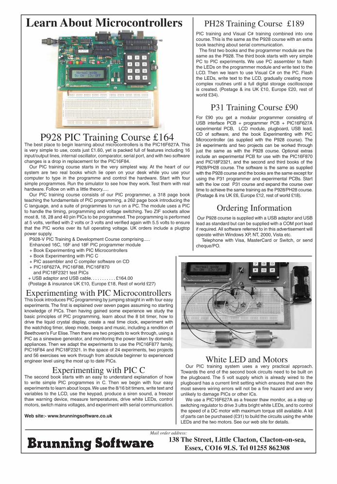
P928 PIC Training Course £164The best place to begin learning about microcontrollers is the PIC16F627A. This is very simple to use, costs just £1.60, yet is packed full of features including 16 input/output lines, internal oscillator, comparator, serial port, and with two software changes is a drop in replacement for the PIC16F84.
Our PIC training course starts in the very simplest way. At the heart of our system are two real books which lie open on your desk while you use your computer to type in the programme and control the hardware. Start with four simple programmes. Run the simulator to see how they work. Test them with real hardware. Follow on with a little theory.....
Our PIC training course consists of our PIC programmer, a 318 page book teaching the fundamentals of PIC programming, a 262 page book introducing the C language, and a suite of programmes to run on a PC. The module uses a PIC to handle the timing, programming and voltage switching. Two ZIF sockets allow most 8, 18, 28 and 40 pin PICs to be programmed. The programming is performed at 5 volts, verified with 2 volts or 3 volts and verified again with 5.5 volts to ensure that the PIC works over its full operating voltage. UK orders include a plugtop power supply.
P928-V PIC Training & Development Course comprising..... Enhanced 16C, 16F and 18F PIC programmer module + Book Experimenting with PIC Microcontrollers + Book Experimenting with PIC C + PIC assembler and C compiler software on CD + PIC16F627A, PIC16F88, PIC16F870 and PIC18F2321 test PICs + USB adaptor and USB cable. . . . . . . . . . . £164.00 (Postage & insurance UK £10, Europe £18, Rest of world £27)
Experimenting with PIC MicrocontrollersThis book introduces PIC programming by jumping straight in with four easy experiments. The first is explained over seven pages assuming no starting knowledge of PICs. Then having gained some experience we study the basic principles of PIC programming, learn about the 8 bit timer, how to drive the liquid crystal display, create a real time clock, experiment with the watchdog timer, sleep mode, beeps and music, including a rendition of Beethoven’s Fur Elise. Then there are two projects to work through, using a PIC as a sinewave generator, and monitoring the power taken by domestic appliances. Then we adapt the experiments to use the PIC16F877 family, PIC16F84 and PIC18F2321. In the space of 24 experiments, two projects and 56 exercises we work through from absolute beginner to experienced engineer level using the most up to date PICs.
Experimenting with PIC CThe second book starts with an easy to understand explanation of how to write simple PIC programmes in C. Then we begin with four easy experiments to learn about loops. We use the 8/16 bit timers, write text and variables to the LCD, use the keypad, produce a siren sound, a freezer thaw warning device, measure temperatures, drive white LEDs, control motors, switch mains voltages, and experiment with serial communication.
Web site:- www.brunningsoftware.co.uk
PH28 Training Course £189 PIC training and Visual C# training combined into one course. This is the same as the P928 course with an extra book teaching about serial communication. The first two books and the programmer module are the same as the P928. The third book starts with very simple PC to PIC experiments. We use PC assembler to flash the LEDs on the programmer module and write text to the LCD. Then we learn to use Visual C# on the PC. Flash the LEDs, write text to the LCD, gradually creating more complex routines until a full digital storage oscilloscope is created. (Postage & ins UK £10, Europe £20, rest of world £34).
P31 Training Course £90For £90 you get a modular programmer consisting of USB interface PCB + programmer PCB + PIC16F627A experimental PCB, LCD module, plugboard, USB lead, CD of software, and the book Experimenting with PIC Microcontroller (as supplied with the P928 course). The 24 experiments and two projects can be worked through just the same as with the P928 course. Optional extras include an experimental PCB for use with the PIC16F870 and PIC18F2321, and the second and third books of the P928/PH28 course. The software is the same as supplied with the P928 course and the books are the same except for using the P31 programmer and experimental PCBs. Start with the low cost P31 course and expand the course over time to achieve the same training as the P928/PH28 course. (Postage & ins UK £6, Europe £12, rest of world £18).
Ordering Information Our P928 course is supplied with a USB adaptor and USB lead as standard but can be supplied with a COM port lead if required. All software referred to in this advertisement will operate within Windows XP, NT, 2000, Vista etc. Telephone with Visa, MasterCard or Switch, or send cheque/PO.
Learn About Microcontrollers
White LED and MotorsOur PIC training system uses a very practical approach.
Towards the end of the second book circuits need to be built on the plugboard. The 5 volt supply which is already wired to the plugboard has a current limit setting which ensures that even the most severe wiring errors will not be a fire hazard and are very unlikely to damage PICs or other ICs.
We use a PIC16F627A as a freezer thaw monitor, as a step up switching regulator to drive 3 ultra bright white LEDs, and to control the speed of a DC motor with maximum torque still available. A kit of parts can be purchased (£31) to build the circuits using the white LEDs and the two motors. See our web site for details.
138 The Street, Little Clacton, Clacton-on-sea,Essex, CO16 9LS. Tel 01255 862308
Mail order address:
Brunning NOV 09.indd 1 23/09/2009 15:14:07

Related Documents