INDIANA UNIVERSITY Laboratory Chemical Fume Hoods Selection Guidelines and Design Standard 2016 Office of Environmental Health and Safety Management Office of Sustainability Fume Hood Efficiency and Labs 21 Pilot Project

Welcome message from author
This document is posted to help you gain knowledge. Please leave a comment to let me know what you think about it! Share it to your friends and learn new things together.
Transcript

INDIANA UNIVERSITY
Laboratory Chemical Fume Hoods
Selection Guidelines and
Design Standard
2016
Office of Environmental Health and Safety Management Office of Sustainability
Fume Hood Efficiency and Labs 21 Pilot Project

Table of Contents
1.0 Introduction
2.0 Chemical Fume Hoods
3.0 Types of Chemical Fume Hoods and Exhaust Characteristics
4.0 Fume Hood Accessories
5.0 Energy Recovery Systems
6.0 Fume Hood Selection Criteria
7.0 Cost Analysis
8.0 References
Appendix A Laboratory Ventilation and Fume Hood Equipment Design Standard

1.0 Introduction
Chemical fume hoods are an important means of protecting workers from chemical exposure. By drawing air away from a workers breathing zone, fume hoods offer protection from hazardous contaminants released by the chemicals being utilized. Ultimately this air is discharged into the atmosphere which results in a loss of energy used to heat or air-condition the building. Over time, technological advancements in fume hood design have improved the overall performance of the equipment and also reduced the loss of energy. Additional advancements in the design of energy recovery systems have also added to the energy efficiency of these research buildings. Because chemical fume hoods are important hazard controls used to protect worker safety these technological advancements cannot sacrifice worker safety at the cost of energy efficiency. A thorough understanding of the various types of chemical fume hoods and other ventilation control equipment is essential to ensure the maximum safety of the workers while maximizing efficiency. The purpose of this document is to set the requirements for the installation and selection of new fume hood equipment for new or remodeled laboratory designs. This standard is to be considered the minimum requirement; more stringent requirements may be necessary, depending on the specific laboratory procedures or the contaminants generated. Please note Appendix A also contains guidance on laboratory ventilation requirements.

2.0 Chemical Fume Hoods
Original chemical fume hoods were constructed of very simple designs consisting of a cabinet, a fan, an exhaust plenum, perhaps without even a sash. As technology improved fume hood design incorporated new features to improve the performance of the equipment. Today we recognize two basic types of fume hoods known as 1) conventional fume hoods, and 2) high performance fume hoods.
2.1 Conventional Fume Hoods
Conventional fume hoods draw a constant volume of air through the sash opening. They have no other features to vary the velocity or volume of air entering the fume hood.
Early models lacked some of the modern features such as baffles or even a sash window. Most conventional hoods have a two panel baffle system and a moveable sash.
2.2 High Performance Fume Hoods
High performance fume hoods are more energy efficient than conventional hoods because of their lower total exhaust volumes. They are designed to take air entering through the sash opening and form a roll in the upper chamber called a vortex. This vortex enhances the hood’s containment capability and has been engineered so that the vortex will not break down and collapse.
Many high performance hoods have sash doors that slide side to side (horizontally) and vertically. Only open the vertical moving sash to load/unload the hood. Use the horizontal sash doors to create a splash and blast shield while working in the hood.
Typically, high performance hoods have audible and visual alarms that will indicate if the air-flow is above or below preset alarm levels.
Some fume hoods are equipped with a manual on/off switch. Some may be equipped with either manual or automatic variable air velocity (VAV) controls that allow the user to turn the velocity down during periods of inactivity.
Figure 2. High performance fume hood showing vortex roll, baffle slots, andgeneral flow pattern.
Figure 1. Conventional fume hood flow pattern.

3.0 Types of Chemical Fume Hoods and Exhaust Characteristics
Hoods are categorized according to their exhaust characteristics as either 1) constant volume (CV) fume hoods or 2) variable air volume (VAV) fume hoods. Constant volume hoods draw the same volume of air out of the room at all times. Constant volume fume hoods can be further subdivided into several types known as 1) conventional, 2) bypass, and 3) auxiliary air fume hoods. Variable air volume hoods reduce or increase the volume of air being exhausted as the sash is lowered or raised respectively.
3.1 Conventional Fume Hood with Constant Volume Exhaust
Conventional fume hoods draw the same volume of air out of the room regardless of the sash height. As the sash is closed the area of the sash opening is reduced and the face velocity increases.
Note that because of these high velocities at the sash opening materials placed near the front of the hood can adversely affected, become airborne, or be blown over as the sash is closed.
Conversely, as the sash is raised the face velocity decreases. Because face velocity changes dramatically it is important to use the hood at the optimal sash opening or operating height.
The optimal sash opening is the point at which the average face velocity is between 80 and 120 feet per minute (0.4-0.6 m/s) and is typically set at 18 inches or the half sash opening position.
3.2 Bypass with Constant Volume Exhaust
Bypass fume hoods incorporate an opening above the sash for air to enter the hood as the sash is lowered.
This allows the velocity below the sash to remain nearly constant and not disturb materials placed in the hood.
It also serves to maintain a balance between the room air supply and the fume hood exhaust.
Open Closed
Figure 3. Conventional fume hood showing velocity increase.
Figure 4. Bypass fume hood.

3.3 Auxiliary Air with Constant Volume Exhaust
Auxiliary air fume hoods also incorporate an opening above the sash for air to enter the hood as the sash is lowered, but provide an auxiliary air supply from outside.
This feature reduces the amount of conditioned air lost
from the room though the fume hood exhaust. The auxiliary air may come directly from the outside and may or may not be conditioned to room temperature.
3.4 Variable Air Volume Exhaust Fume Hood
Variable air volume (VAV) fume hoods have the capability to adjust the volume and velocity of air entering the hood. This can be accomplished by adjusting the fan speed or the damper opening in the exhaust plenum.
Variable volume hoods provide an energy efficiency advantage because, as the volume is reduced, the amount of conditioned air (whether heated or cooled) lost from the fume hood exhaust is reduced.
They also provide the additional advantage that as the volume is reduced the velocity decreases and this reduces the adverse affect that high velocities may have on objects and items placed inside the fume hood. This is especially true for automatic volume controls because as the sash is lowered the face velocity is reduced at the sash opening.
These high performance fume hoods are equipped with either 1) manual controls or 2) automatic controls to adjust the volume of air entering the fume hood.
3.4.1 Manual Volume Controls
Manual controls allow the user to turn the volume and velocity down during periods of inactivity. Typically the user may select 25, 50, 75, 100, 125, 150 feet per minute or emergency “purge” velocity settings.
Under ordinary operating conditions the velocity setting should be set to 100 feet per minute for a standard hood and 70 feet per minute for an approved low volume hood. After adjusting these hoods, ensure that the air-flow velocity has been restored to the appropriate setting before use.
3.4.2 Automatic Volume Controls
Automatic controls adjust the volume as the sash is raised or lowered. These high performance hoods adjust a damper in the exhaust plenum to open or close to increase or decrease the volume and hence, the face velocity, as necessary.
During the volume adjustment the system may take 3-6 seconds to recover as the sash is opened. While the system adjusts, a momentary loss of containment may occur after which contaminants are drawn back into the hood.
Figure 5. Auxiliary air fume hood.
Figure 6. Variable air volume hood.
Open Closed
Open Closed

Because of the momentary delay, users should only raise the sash to the operating position if chemicals or contaminants are present and protect the breathing zone with the sash as much as possible while the system responds. Open the sash to the fully open (set-up) position only when contaminants are not present within the fume hood containment.
3.4.3 Low Flow Alarms and Emergency Purge
Both manual and automatic controls are typically equipped with audible and visual alarms to indicate low flow conditions if the velocity or volume is below preset alarm thresholds.
Hoods are now equipped with emergency “purge” setting that can be activated manually in the event of an emergency or spill to quickly increase the volume of the discharge. This can be used in the event of a spill to evacuate vapors whether they are released inside or outside the fume hood.
3.5 Low Volume Chemical Fume Hoods
Low volume (LV) chemical fume hoods save energy by reducing the volume of conditioned air discharged to the atmosphere. By reducing the volume of air being discharged the face velocity of the fume hood is also reduced. Considering that typical face velocities are set at 100 feet per minute, a decrease in velocity to 80 feet per minute would feasibly result in 20% less air being discharged to the atmosphere and a 20% savings in the energy required to heat or air-condition the air.
LV hoods are able to operate at lower volumes due to the aerodynamic design of their airfoil sills and baffles while maintaining a safe containment of pollutants within the device. When tested against a standard hood, the LV hood maintains the containment equally well.
Note that the air empties out of LV hoods slower than that of a standard hood because of the reduced velocity. The hoods must have purge controls to increase the exhaust volume during a spill.
There are several concerns that must be addressed during the laboratory design process to maintain user safety. Due to the lower exhaust rate, LV hoods are more susceptible to external air disturbances so they should not be placed in high traffic areas, next to doors that are frequently opened, and air supply or exhaust diffusers should not be installed in close proximity to the hoods.
While the LV hood contains and removes vapors just as well as the conventional hood, users need to keep the hood from becoming overcrowded with equipment and clutter because this will disturb air flow and lower the fume hoods ability to maintain the containment of the hazardous vapors away from the user’s breathing zone.
It is due to this need for a clear workspace that LV hoods may not be suitable for certain laboratories, such as those that perform organic synthesis due to the fact that the hoods usually become crowded with glass apparatus and large equipment necessary to perform the experiments. However, these LV hoods will perform well in teaching laboratories or other research laboratories where the hood is cleaned out daily.
It should be noted that bypass hoods are sometimes referred to as “low flow” chemical fume hoods. They are not to be confused with low volume chemical hoods. A low flow hood reduces the amount of exhausted air by operating with a smaller sash opening and providing makeup air above the sash in the bypass.

3.6 Ductless Fume Hoods
Ductless fume hoods use a filter to remove hazardous vapors and do not exhaust to the outside. Ductless hoods have found limited use because of the filters. The filter is selected based on its ability to remove the chemical being used. Therefore ductless fume hoods were restricted to only those chemicals that could be effectively removed by the filter.
Recent improvements in filtration systems can remove 99.99% of commonly used laboratory chemicals. This new filter is able to handle liquids, solids, gases and vapors (even acids, bases, solvents, and powders). They eliminate CO2 emissions and their low operating costs basically eliminate installation costs. They also exhaust almost 100 times fewer contaminants into the air than is allowed by the official Threshold Limit Value (TLV). A big advantage for this type of fume hood is they discharge no heated or air-conditioned air to the outside. This energy efficient alternative can cut energy costs by 96% and reduce the operating cost by 70%.2
Another advantage to the use of ductless fume hoods is that they can be portable. They can be used as temporary installations or permanent equipment. They also can be used in buildings and rooms without the need to install fixed ventilation fans and plumb the exhaust ventilation to the outside.
Ductless fume hoods are restricted use hoods and must be approved by the Office of Environmental Health and Safety (EHS) before installation. EHS must review the chemicals used in the hood as well as the work being performed inside the hood before approval.

4.0 Fume Hood Accessories
Fume hood accessories can be selected to further enhance the overall efficiency of the performance. These items include such features as timers, proximity sensors, and self closing sashes.
4.1 Automatic Sash Positioning
Fume hoods can now be equipped with automatic sash positioners. When the sash is fully open the operator can pull a lever and the sash will automatically return to ideal working height of 18 inches.
4.2 Timers
Timers can be installed that are able to automatically decrease the face velocity of a fume hood. They are usually set to decrease the face velocity at night when workers are generally not in the laboratory and to increase the face velocity again in the morning.
Advantages for the timers would be the increased energy savings. If the face velocity is decreased every day when the laboratory is not in use this will result in significant energy savings.
The disadvantage is determining when the timers should decrease the face velocity of the hoods in a building. A common occurrence, especially in a University setting, is workers staying in the laboratory after hours to finish experiments. If a timer decreased the face velocity of a hood that was still in use a safety hazard could arise. This must be considered prior to installation to avoid this occurrence.
4.3 Proximity Sensors
Passive infrared movement detectors (PIR) are now available to detect the presence of a worker at the hood. When the front of the hood is not occupied by a worker, the detector will trigger an automatic sash position to close the sash. This system is also equipped with an infrared light barrier on the sash plate that will stop the sash from closing if there is an obstacle blocking the face of the hood.
Proximity sensors can also be utilized in variable air volume systems to decrease the volume of the discharge when a person is not present.
Advantages of the proximity sensors are the increased energy savings. However, they are expensive to install and they pose a hazard risk if there is an unattended experiment running in a hood.

5.0 Energy Recovery Systems
Energy recovery systems are also utilized to collect energy from the heating, ventilation and air conditioning (HVAC) systems in buildings that would otherwise be discharged to the atmosphere.
These systems are utilized in general clean air exhaust from rooms, laboratories and offices to recover energy as well as air from fume hood exhaust that may contain chemical pollutants. Because of this, consideration of the facilities existing energy recovery system must be included in the selection of laboratory fume hood equipment. The energy recovery systems utilized in facilities include the following technologies known as: fixed plate, rotary “enthalpy” wheels, heat pipe, runaround coil loops, and thermosiphons.
5.1 Fixed Plate
Fixed plate systems have alternating layers of exhaust and supply airstreams that are separated by a non-moving plate. For maximum heat transfer the airflow is usually arranged in a cross-flow pattern. Standard fixed plate systems have no contact between the exhaust air and supply air streams.
Fixed plate systems also have the ability to recover latent heat (of enthalpy in water) but only when the plate separating the airstreams is made of a hygroscopic material. When hygroscopic materials are used to recover latent heat there may be transfer of contaminants from the exhaust to the supply air stream. Consideration to the quality of the exhaust air should be given in these applications.
5.2 Rotating “Enthalpy” Wheels
Rotating “enthalpy” wheels are the most efficient energy recovery system, with a typical efficiency of about 70%. Enthalpy wheels are coated with silicate (SiO2) minerals known as zeolites that have very precise 3-4 angstrom diameter pores in their molecular structure (depending on the zeolite used). Zeolites are also used as molecular sieves because of this feature. Water molecules with a diameter of about 2.641 angstroms are small enough to be captured in the zeolite pores.
Most of the heat discharged from building HVAC systems is contained in the latent heat (of enthalpy) within the humidity in the air. The enthalpy wheel rotates between the exhaust air stream and supply air stream of the building. As the wheel rotates the zeolites capture the water molecules from the exhaust air stream and transports them to the supply air stream where the incoming air picks up the water and carries it back into the building. By capturing the water from the building exhaust and transferring it back to the building supply a higher efficiency of energy recovery can be achieved.
The silicate (SiO2) zeolite minerals are inert and will not react with contaminants in the air except for hydrogen fluoride (HF) or hydrofluoric acid which will dissolve silicates. Additionally, the wheels will also capture other small molecules such as ammonia and transport them to the building supply air. For this reason, consideration must be given to the use and application of these rotary wheels prior to installation.
Enthalpy wheels are typically used to recover energy form standard clean room exhaust air and cannot be used to recover energy from fume hood exhaust. Most organic pollutants are too large to be captured by the zeolite minerals, however some small molecules may be captured and re-entrained in the supply.
.
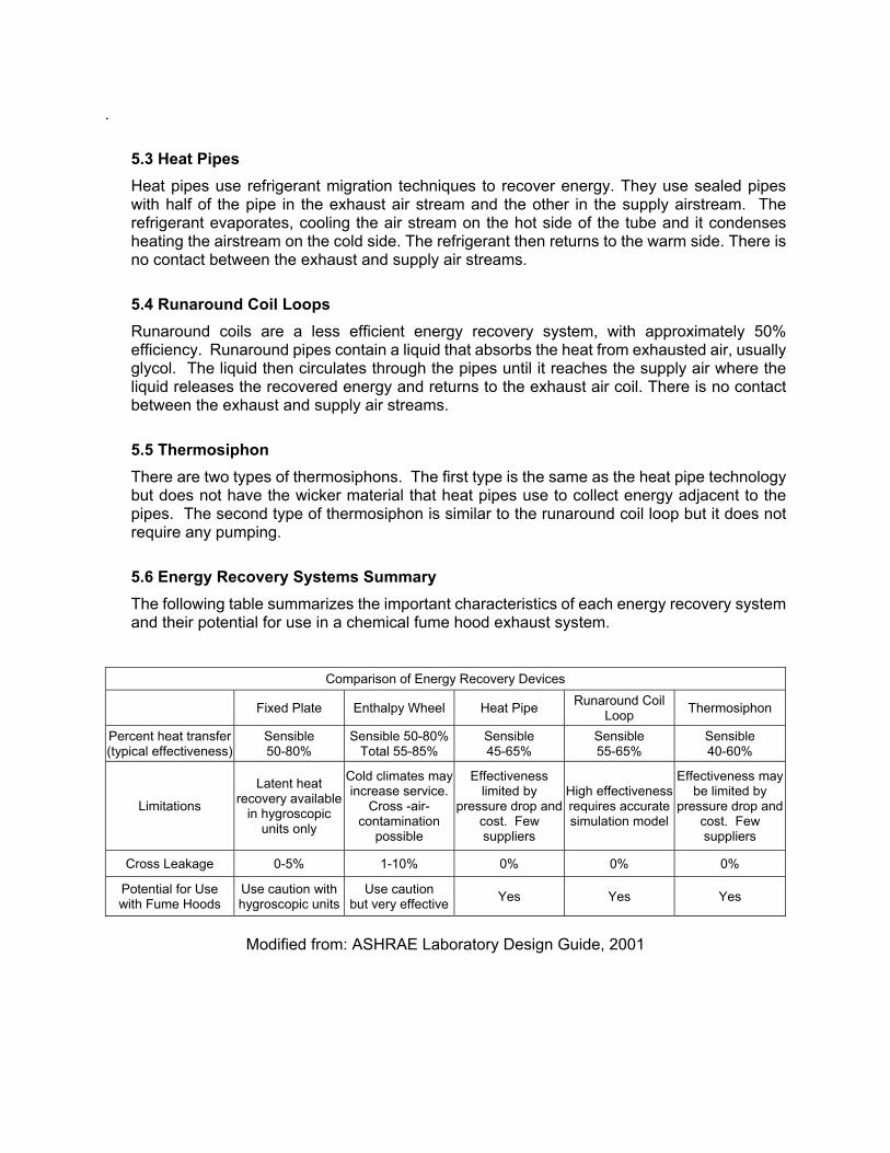
5.3 Heat Pipes
Heat pipes use refrigerant migration techniques to recover energy. They use sealed pipes with half of the pipe in the exhaust air stream and the other in the supply airstream. The refrigerant evaporates, cooling the air stream on the hot side of the tube and it condenses heating the airstream on the cold side. The refrigerant then returns to the warm side. There is no contact between the exhaust and supply air streams.
5.4 Runaround Coil Loops
Runaround coils are a less efficient energy recovery system, with approximately 50% efficiency. Runaround pipes contain a liquid that absorbs the heat from exhausted air, usually glycol. The liquid then circulates through the pipes until it reaches the supply air where the liquid releases the recovered energy and returns to the exhaust air coil. There is no contact between the exhaust and supply air streams.
5.5 Thermosiphon
There are two types of thermosiphons. The first type is the same as the heat pipe technology but does not have the wicker material that heat pipes use to collect energy adjacent to the pipes. The second type of thermosiphon is similar to the runaround coil loop but it does not require any pumping.
5.6 Energy Recovery Systems Summary
The following table summarizes the important characteristics of each energy recovery system and their potential for use in a chemical fume hood exhaust system.
Comparison of Energy Recovery Devices
Fixed Plate Enthalpy Wheel Heat Pipe Runaround Coil
Loop Thermosiphon
Percent heat transfer (typical effectiveness)
Sensible 50-80%
Sensible 50-80% Total 55-85%
Sensible 45-65%
Sensible 55-65%
Sensible 40-60%
Limitations
Latent heat recovery available
in hygroscopic units only
Cold climates may increase service.
Cross -air-contamination
possible
Effectiveness limited by
pressure drop and cost. Few suppliers
High effectiveness requires accurate simulation model
Effectiveness may be limited by
pressure drop and cost. Few suppliers
Cross Leakage 0-5% 1-10% 0% 0% 0%
Potential for Use with Fume Hoods
Use caution with hygroscopic units
Use caution but very effective
Yes Yes Yes
Modified from: ASHRAE Laboratory Design Guide, 2001

6.0 Fume Hood Selection Criteria
Laboratory design is a critical aspect in the recommendation of fume hood equipment. When considering the installation of any chemical fume hoods, five criteria should be considered before installation:
Permanent or temporary installation. The intended purpose of the laboratory (research or instructional) The hazard level of the activity performed in the fume hood (high hazard or low hazard). Existing energy recovery systems installed to recover energy from fume hood exhaust. Interference caused by the proximity of doors, windows, supply and exhaust diffusers
located in the laboratory. Traffic patterns of personnel at the proposed hood location (high or low traffic pathway).
Temporary installations may be required to accommodate visiting scientists or short term projects. The location of the project may not provide a means to install standard ventilation equipment and alternatives may be considered. Long term plans for buildings (demolition) can also influence the need for temporary installations as well.
Instructional equipment may be used on a fixed schedule whereas research equipment may be used at any day of the week at any time of day. This can impact the decisions regarding operation and energy efficiency.
The hazard level of the work includes consideration of the variety, quantity, and hazard category of the chemicals used. It also includes consideration of the equipment, apparatus, and materials used or stored in the fume hood to support the operation that may interfere with flow characteristics.
The existing energy recovery systems within the building ventilation systems will have an impact on the decision to install more expensive energy efficient devices instead of typical fume hood equipment.
The location of the fume hood must be considered. The close proximity of doors, windows, exhaust, and supply diffusers can create drafts near the face of the hood and cause a loss of containment.
High traffic areas must also be considered. The draft caused by people moving past the face of the hood can also cause a loss of containment and allow contaminants to spill out into the room.
6.1 Conventional Constant Volume
Conventional fume hoods exhaust 100% of the air with no energy efficiency provided at the laboratory level. Although the safety of personnel may be provided by this equipment, these devices should be avoided unless facility level energy recovery systems are in place. Conventional hoods can be utilized for high hazard applications generating increased volumes of hazardous contaminants or areas where interference from traffic patterns or other equipment is a concern.
6.2 Bypass Constant Volume
Bypass fume hoods exhaust 100% of the air with no energy efficiency provided at the laboratory level. Although the safety of personnel may be provided by this equipment, these devices should be avoided unless facility level energy recovery systems are in place. Bypass hoods can be utilized for high hazard applications generating increased volumes of hazardous contaminants or areas where interference from traffic patterns or other equipment is a concern.

6.3 Auxiliary Air Constant Volume
Auxiliary air fume hoods provide unconditioned make-up air as the sash is closed so can be utilized for energy efficiency at the laboratory level. Auxiliary air or variable volume hoods are preferred for high hazard applications generating increased volumes of hazardous contaminants or areas where interference from traffic patterns or other equipment is a concern.
Note that auxiliary air hoods may cause potential discomfort to users because cold or warm unconditioned outside air is circulated in the hood where the person’s arms are located.
6.4 Variable Air Volume
Variable air volume (VAV) fume hoods reduce the volume of air being discharged as the sash is closed or manually at the fume hood control. These fume hoods may be utilized to provide energy efficiency at the laboratory level. Variable volume hoods or auxiliary air fume hoods are preferred for high hazard applications generating increased volumes of hazardous contaminants or areas where interference from traffic patterns or other equipment is a concern.
6.5 Low Volume
Because low volume hoods operate at a low face velocity they are susceptible to interference from air disturbances and turbulence outside the hood. The draft from a person walking past is strong enough to reverse the flow momentarily and pull contaminants out of the hood.
These types of fume hoods should be installed in low traffic areas, as far away as possible from room supply and exhaust diffusers, and away from commonly used doors and windows to ensure that hazardous vapors are contained in the hood.
Low volume hoods do not exhaust the room air as rapidly as a standard fume hood. Therefore an emergency purge mechanism to increase the flow should be installed. In case of a chemical spill the fume hood purge can be used to evacuate vapors released into the atmosphere.
The benefit of the low volume hoods are found in the energy savings. However, if a building already has an energy recovery system then the additional cost of installing a low volume hood should be compared to the additional energy savings from the investment.
For example, if a building is already recovering 50-70 percent of its energy by using an energy recovery system then there may not be a substantial gain from installing a single low volume fume hood and it may be more practical to install a standard VAV hood instead. Conversely, if a program is implemented to replace numerous existing low efficiency hoods with low volume hoods then the savings may be more significant.
The hazard level of the work that will be performed in the hood must also be taken into consideration. There are two main categories of activities 1) low hazard work with small quantities of less hazardous, non-volatile compounds and minimal equipment or apparatus and 2) high hazard work with larger quantities of toxic, reactive, or volatile compounds and more apparatus and equipment.
For example, a biology laboratory with small quantities of chemicals in cold aqueous or non-volatile solutions would be considered less hazardous and if the location was away from traffic and interference, it would be a suitable location for a low volume fume hood. Then laboratory workers would be instructed in the operation of the equipment and the limitations of the design to ensure proper operation at or near the fume hood.
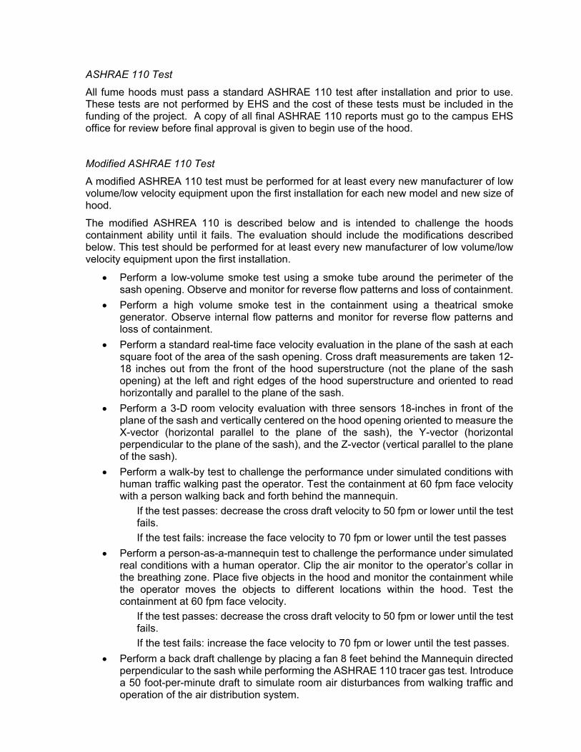
ASHRAE 110 Test
All fume hoods must pass a standard ASHRAE 110 test after installation and prior to use. These tests are not performed by EHS and the cost of these tests must be included in the funding of the project. A copy of all final ASHRAE 110 reports must go to the campus EHS office for review before final approval is given to begin use of the hood.
Modified ASHRAE 110 Test
A modified ASHREA 110 test must be performed for at least every new manufacturer of low volume/low velocity equipment upon the first installation for each new model and new size of hood.
The modified ASHREA 110 is described below and is intended to challenge the hoods containment ability until it fails. The evaluation should include the modifications described below. This test should be performed for at least every new manufacturer of low volume/low velocity equipment upon the first installation.
Perform a low-volume smoke test using a smoke tube around the perimeter of the sash opening. Observe and monitor for reverse flow patterns and loss of containment.
Perform a high volume smoke test in the containment using a theatrical smoke generator. Observe internal flow patterns and monitor for reverse flow patterns and loss of containment.
Perform a standard real-time face velocity evaluation in the plane of the sash at each square foot of the area of the sash opening. Cross draft measurements are taken 12-18 inches out from the front of the hood superstructure (not the plane of the sash opening) at the left and right edges of the hood superstructure and oriented to read horizontally and parallel to the plane of the sash.
Perform a 3-D room velocity evaluation with three sensors 18-inches in front of the plane of the sash and vertically centered on the hood opening oriented to measure the X-vector (horizontal parallel to the plane of the sash), the Y-vector (horizontal perpendicular to the plane of the sash), and the Z-vector (vertical parallel to the plane of the sash).
Perform a walk-by test to challenge the performance under simulated conditions with human traffic walking past the operator. Test the containment at 60 fpm face velocity with a person walking back and forth behind the mannequin.
If the test passes: decrease the cross draft velocity to 50 fpm or lower until the test fails.
If the test fails: increase the face velocity to 70 fpm or lower until the test passes
Perform a person-as-a-mannequin test to challenge the performance under simulated real conditions with a human operator. Clip the air monitor to the operator’s collar in the breathing zone. Place five objects in the hood and monitor the containment while the operator moves the objects to different locations within the hood. Test the containment at 60 fpm face velocity.
If the test passes: decrease the cross draft velocity to 50 fpm or lower until the test fails.
If the test fails: increase the face velocity to 70 fpm or lower until the test passes.
Perform a back draft challenge by placing a fan 8 feet behind the Mannequin directed perpendicular to the sash while performing the ASHRAE 110 tracer gas test. Introduce a 50 foot-per-minute draft to simulate room air disturbances from walking traffic and operation of the air distribution system.

If the test passes: increase the draft velocity incrementally until the test fails.
If the test fails: decrease the draft velocity incrementally until the test passes.
Perform a cross draft challenge placing a fan blowing parallel to, and 18 inches from the sash and 8 feet to the side while performing the ASHRAE 110 tracer gas test. Introduce a 50 foot-per-minute draft to simulate room air disturbances from walking traffic and operation of the air distribution system.
If the test passes: increase the draft velocity incrementally until the test fails.
If the test fails: decrease the draft velocity incrementally until the test passes.
The sash should be cycled open and closed in 30 second intervals while testing at the static (naturally occurring) cross drafts and again with the highest cross draft that passes to perform the sash movement effect (SME) test.
The door to the room should be cycled open and closed in 30 second intervals while testing at the static (naturally occurring) cross draft and again with the highest cross draft that passes to simulate the space pressure effect (SPE).
6.6 Filtered Ductless Fume Hoods
Filtered ductless fume hoods do not exhaust any air out of the building and are another energy efficient option. Early ductless fume hoods used chemical specific filters therefore it was necessary to know the exact chemical and concentration that were being utilized and limits the potential applications.
New filters in ductless fume hoods are capable of removing multiple chemical contaminants. However, the lifespan of the filter is still based on the chemical and concentration of the contaminant as well as the duration that the filters are exposed to the contaminant. Therefore, knowing the chemicals to be used, the concentrations, and frequency of use is still important to determine if ductless fume hoods can be utilized.
Proper maintenance and filter changes must be performed on schedule or worker safety could be compromised. Owners and operators of ductless fume hoods must have a maintenance budget and predetermined schedule of filter changes to ensure that the maintenance is performed on schedule without fail.
Ductless fume hoods can be used in temporary situations, for example, to accommodate a visiting scientist or in a temporary laboratory or building. Initially, ductless fume hoods are more expensive to purchase and maintain compared to a standard or low volume fume hood but offer savings in energy efficiency by not discharging conditioned air to the outside.
Ductless fume hoods are restricted use hoods and must be approved by the Office of Environmental Health and Safety (EHS) before installation. EHS must review the chemicals used in the hood as well as the work being performed inside the hood before approval.

Fume Hood Type
Selection Criteria
Installation Purpose Activity Facility Energy
Recovery System Interference Traffic
Tem
porary
Perm
anent
Teaching
(Fixed T
ime S
chedule)
Rese
arch (F
lexible time schedule)
High H
azard Activity
Low H
azard Activity
Existing
Energy R
ecovery System
P
resent
No E
xisting E
nergy Recovery S
ystem
Present
Aw
ay From
D
oors, Window
s, Supply
and Exhaust D
iffusers
Close to
Doors, W
indows, S
upply and E
xhaust Diffusers
High T
raffic Pattern
Low T
raffic Pattern
Conventional (Constant Volume) NR1 NR2 NR2 NR2 NR2 NR2 Yes3 NR2 NR2 NR2 NR2 NR2
Bypass (Constant Volume) NR1 NR2 NR2 NR2 NR2 NR2 Yes3 NR2 NR2 NR2 NR2 NR2
Auxiliary Air (Constant Volume) NR1 Yes Yes Yes Yes Yes Yes Yes Yes Yes Yes Yes
Variable Air Volume NR1 Yes Yes Yes Yes Yes Yes Yes Yes Yes Yes Yes
Low Volume NR1 Yes Yes Yes NR1 Yes Yes3 Yes Yes NR1 NR1 Yes
Ductless Yes3 NR1 Yes3 Yes3 NR1 Yes3 Yes3 Yes3 Yes3 NR1 NR1 Yes3
Table 1. Recommendations for fume hood selection based on hood type and selection criteria.
Notes: 1. NR1 - Not Recommended. 2. NR2 - Not Recommended. Provides no energy efficiency but does provide worker protection. 3. Yes3 - Consider the cost/benefit return prior to design and installation.

7.0 Cost Analysis
Initial purchase cost comparisons of three major manufacturers of low volume and ductless fume hoods are shown in Table 2.
While low volume chemical fume hoods are more expensive than traditional fume hoods they can provide operational savings directly related to the decreased quantity of conditioned air being discharged.
Ductless fume hoods are generally more expensive to purchase and have required maintenance expenses but do not discharge any conditioned air during operation.
Note: The cost of labor and ancillary equipment such as cabinetry, utilities, and ductwork is not included in this cost analysis. The cost of demolition and disposal for replacement projects is also not included in this cost analysis. These will increase the overall cost and lower the rate of return on investment and should be considered prior to laboratory design and selection of equipment.
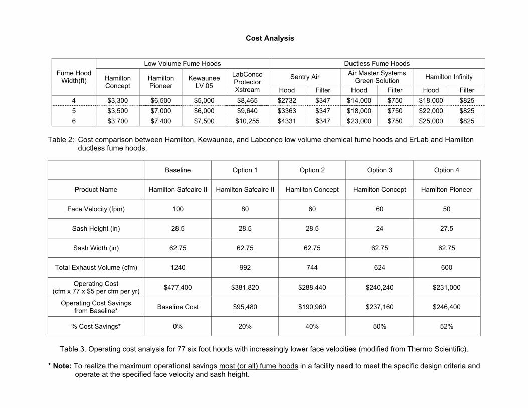
Cost Analysis
Table 2: Cost comparison between Hamilton, Kewaunee, and Labconco low volume chemical fume hoods and ErLab and Hamilton
ductless fume hoods.
Baseline Option 1 Option 2 Option 3 Option 4
Product Name Hamilton Safeaire II Hamilton Safeaire II Hamilton Concept Hamilton Concept Hamilton Pioneer
Face Velocity (fpm) 100 80 60 60 50
Sash Height (in) 28.5 28.5 28.5 24 27.5
Sash Width (in) 62.75 62.75 62.75 62.75 62.75
Total Exhaust Volume (cfm) 1240 992 744 624 600
Operating Cost (cfm x 77 x $5 per cfm per yr)
$477,400 $381,820 $288,440 $240,240 $231,000
Operating Cost Savings from Baseline*
Baseline Cost $95,480 $190,960 $237,160 $246,400
% Cost Savings* 0% 20% 40% 50% 52%
Table 3. Operating cost analysis for 77 six foot hoods with increasingly lower face velocities (modified from Thermo Scientific).
* Note: To realize the maximum operational savings most (or all) fume hoods in a facility need to meet the specific design criteria and
operate at the specified face velocity and sash height.
Fume Hood Width(ft)
Low Volume Fume Hoods Ductless Fume Hoods
Hamilton Concept
Hamilton Pioneer
Kewaunee LV 05
LabConco Protector Xstream
Sentry Air Air Master Systems
Green Solution Hamilton Infinity
Hood Filter Hood Filter Hood Filter
4 $3,300 $6,500 $5,000 $8,465 $2732 $347 $14,000 $750 $18,000 $825
5 $3,500 $7,000 $6,000 $9,640 $3363 $347 $18,000 $750 $22,000 $825
6 $3,700 $7,400 $7,500 $10,255 $4331 $347 $23,000 $750 $25,000 $825

8.0 References American Society of Heating Refrigeration and Air-Conditioning Engineers, ASHRAE Handbook - HVAC Systems and Equipment, 2000. Bernard Bhati, University of Texas, and Kevin Fox, Jacobs Engineering Group, Side By Side Evaluation of High Performance Fume Hoods, Labs 21 Annual Conference, San Jose California, 2008 Diberardinis, L.J., Baum, J.S., First, M.W., Gatwood, G.T., Groden, Edward, Seth, A.K., Guidelines for Laboratory Design: Health and Safety Considerations, 1993. Hitchings, D.T., Detailed Fume Hood Performance Testing Methods, SafeLab Protocol 2010-009A.2, SafeLab Corporation, 5350 West 79th St. Indianapolis, IN 46268, 2011. Kewaunee Scientific Corporation, Supreme Air Laboratory Fume Hoods, 2009 Kohler, C.E., Chemical Fume Hoods, Laboratory Safety Guideline, Indiana University, Office of Environmental Health and Safety Management, 2008 Kohler, C.E., Enthalpy Wheels and Zeolites, E542 Hazardous Materials, Class Handout, 2010 Kolkerbeck, Ken, Low Flow Fume Hoods: Tips and Tricks for Critical Control, Facility Diagnostics, 2002 Labconco Corporation, Protector Laboratory Fume Hoods and Ductless Enclosures, 2010 Lawrence Berkeley National Laboratory, High Performance Fume Hood, 2002 Macintosh, Ian .B.D., Dorgan, C.B., Dorgan, C.E., ASHRAE Laboratory Design Guide, 2001 Poling, B.E., Prausnitz, J.M., O'Connell, J.P., The Properties of Gases and Liquids, 2001 National Research Council, Prudent Practices in the Laboratory, Handling and Disposal of Chemicals, 1995, National Academies Press, (www.nap.edu/catalog.php?record_id=4911). Semco Incorporated, Desiccant Wheel Products, Energy Recover Wheel Technical Guide, 2007 SEMCO Incorporated, Georgia Institute of Technology, Results of Cross-Contamination Testing on Desiccants: The Importance of the Desiccant, 2006 Stone, K.L., High Efficiency Fume Hoods: Do They Work?, Indiana University Purdue University Indianapolis, Environmental Health and Safety, 2010 Thermo Scientific Corporation, Hamilton Air Flow Products, Product Catalog, 2010 University of California, Environmental Health and Safety, Laboratory Safety Design Guide, Second Edition, 2007
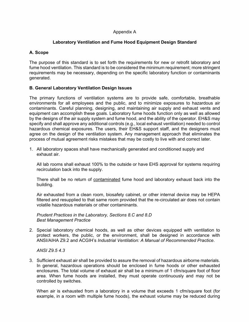
Appendix A
Laboratory Ventilation and Fume Hood Equipment Design Standard A. Scope
The purpose of this standard is to set forth the requirements for new or retrofit laboratory and fume hood ventilation. This standard is to be considered the minimum requirement; more stringent requirements may be necessary, depending on the specific laboratory function or contaminants generated.
B. General Laboratory Ventilation Design Issues
The primary functions of ventilation systems are to provide safe, comfortable, breathable environments for all employees and the public, and to minimize exposures to hazardous air contaminants. Careful planning, designing, and maintaining air supply and exhaust vents and equipment can accomplish these goals. Laboratory fume hoods function only as well as allowed by the designs of the air supply system and fume hood, and the ability of the operator. EH&S may specify and shall approve any additional controls (e.g., local exhaust ventilation) needed to control hazardous chemical exposures. The users, their EH&S support staff, and the designers must agree on the design of the ventilation system. Any management approach that eliminates the process of mutual agreement risks mistakes that may be costly to live with and correct later.
1. All laboratory spaces shall have mechanically generated and conditioned supply and exhaust air.
All lab rooms shall exhaust 100% to the outside or have EHS approval for systems requiring recirculation back into the supply.
There shall be no return of contaminated fume hood and laboratory exhaust back into the building.
Air exhausted from a clean room, biosafety cabinet, or other internal device may be HEPA filtered and resupplied to that same room provided that the re-circulated air does not contain volatile hazardous materials or other contaminants.
Prudent Practices in the Laboratory, Sections 8.C and 8.D Best Management Practice
2. Special laboratory chemical hoods, as well as other devices equipped with ventilation to protect workers, the public, or the environment, shall be designed in accordance with ANSI/AIHA Z9.2 and ACGIH’s Industrial Ventilation: A Manual of Recommended Practice.
ANSI Z9.5 4.3
3. Sufficient exhaust air shall be provided to assure the removal of hazardous airborne materials. In general, hazardous operations should be enclosed in fume hoods or other exhausted enclosures. The total volume of exhaust air shall be a minimum of 1 cfm/square foot of floor area. When fume hoods are installed, they must operate continuously and may not be controlled by switches.
When air is exhausted from a laboratory in a volume that exceeds 1 cfm/square foot (for example, in a room with multiple fume hoods), the exhaust volume may be reduced during

periods when the room is unoccupied, provided that sufficient volume is maintained to exhaust hazardous materials, and the reduced volume does not fall below 1 cfm/square foot.
Historically, the measurement “air changes per hour (ach)” has been used as a design criterion for laboratory ventilation, with recommended values between 6 and 12 ach. This is not an appropriate concept for designing contaminant control systems, as it implies that general laboratory ventilation will be utilized to remove contaminants. Contaminants must be controlled at the source. 1 cfm/square foot of floor area is equivalent to 6 ach for a room with a 10-foot ceiling. Lacking other information, floor area is a rough surrogate for intensity of activity.
Best Management Practice ASHRAE Handbook of Fundamentals, Chapter 13 NFPA Article 80 Prudent Practices in the Laboratory, Section 8.C.11
4. Laboratory exhaust systems should be designed with at least 25% excess capacity for future expansion.
5. Avoid generation of excessive noise in laboratory ventilation systems. Fan location and noise treatment shall provide for sound pressure level (SPL) in conformance with local ambient noise criteria. Noise generated by the functioning fume hood within 6 inches of the plane of the sash and bypass opening in any position shall not exceed 60 dBA. The noise level in the general laboratory space should not exceed 55 dBA, which is consistent with good office design, to allow for easy verbal communication.
ANSI Z9.5 5.1.3 Best Management Practice
The primary references for acoustic design criteria and methods will be found in ASHRAE publications such as the ASHRAE 1997 Handbook of Fundamentals, and from the ASHRAE 1999 HVAC Applications.
6. The airflow velocity in each duct shall be sufficient to prevent settlement of liquid or condensable solids on the walls of the ducts. A duct velocity of 1,000 fpm seems to be adequate to prevent condensation in fume hood ducts without excessive noise. However, higher velocities are needed to entrain solids.
ACGIH, Industrial Ventilation: A Manual of Recommended Practice (latest edition)
7. Exhaust from hoods used for teaching should be routed to blowers different from those used to exhaust air from research areas. This allows energy savings for those times when the teaching labs are not being used.
Best Management Practice
8. Operable windows in laboratories are strongly discouraged. Drafts from open windows can seriously disrupt fume hood containment, and open windows destroy negative pressure containment that should be provided in laboratories (see Section D, below).
9. Flexible local exhaust devices (e.g., “snorkels” or “elephant trunks”) shall be designed to adequately control exposures to hazardous chemicals. An exhausted manifold or manifolds with connections to a local exhaust may be provided as needed to collect potentially

hazardous exhausts from gas chromatographs, vacuum pumps, excimer lasers, atomic absorption instruments, or other equipment that can produce potentially hazardous air pollutants. Instrument ventilation systems must meet manufacturer’s recommendations.
The contaminant source needs to be enclosed as much as possible, consistent with operational needs, to maximize control effectiveness and minimize air handling difficulties and costs. Enclosure minimizes the volume of airflow needed to attain any desired degree of contaminant control. This reduces fan size, motor horsepower, makeup air volume, and makeup air-conditioning costs.
ACGIH, Industrial Ventilation: A Manual of Recommended Practice (latest edition)
10. Fume hoods shall not be located adjacent to an exit unless a second exit or another means for exiting is provided.
A fire, explosion, or chemical release, any one of which may start in a fume hood, can block an exit, rendering it impassible. Pedestrian traffic can also interfere with the functioning of a hood.
NFPA 45, Chapter 6-9.2 NFPA 45, Chapter 3-4.1(d)
11. Hoods shall be labeled to show the fan or ventilation system to which they are connected.
C. Variable Air Volume (VAV) Systems
1. Variable Air Volume (VAV) systems should be considered to
Reduce laboratory operating costs, including energy use, while providing adequate ventilation to protect workers; and
Maintain a constant air velocity into the hood, regardless of sash height.
If a VAV supply system is not feasible, EHS may approve several options to provide worker protection, constant face velocity, and some energy efficiency if possible:
1. Auxiliary air bypass using unconditioned outside air 2. Low volume hood that meets the installation criteria of Section M. 3. Local air bypass using conditioned room air 4. Filtered ductless fume hood that meets the installation criteria of Section M.
2. Selection and approval of fume hood equipment and accessories will be based upon the unique characteristics and needs of the installation. Decisions concerning system diversity shall be based on:
Use patterns of hoods. Type, size, and operating times of facility Quantity of hoods and researchers Sash management (sash habits of users) Requirements to maintain a minimum exhaust volume for each hood on the system Type of ventilation system and existing energy recovery system Type of laboratory chemical hood controls Minimum and maximum ventilation rates for each laboratory
Capacity of any existing equipment Expansion considerations Thermal loads Facilities ability to perform periodic maintenance
An alarm system shall be installed to warn users when the system is operating beyond the capabilities allowed by system diversity.
ANSI Z9.5 5.1.2
3. Pressure independent constant volume or variable volume air valves for supply and exhaust shall be provided for pressurization control and continuous air balance control. The air balance shall also be maintained during the night setback/unoccupied schedule.
Best Management Practice
5. The mechanism that controls the exhaust fan speed or damper position to regulate the hood exhaust volume shall be designed to ensure a minimum exhaust volume equal to the larger of 50 cfm/ft of hood width, or 25 cfm/ft2 of hood work surface area, except where a written hazard characterization indicates otherwise, or if the hood is not in use.
ANSI Z9.5 3.3.1
6. VAV hoods shall be provided with an emergency switch (purge) that allows the hood exhaust volume to go to a maximum flow velocity.
ANSI Z9.5 5.3.2.4
D. Negative Pressurization
1. Airflow shall be from low-hazard to high-hazard areas.
Anterooms may be necessary for certain applications, such as clean rooms or tissue culture rooms. Potentially harmful aerosols can escape from the containment of the laboratory room unless the room air pressure to adjacent non-laboratory areas is negative.
Best Management Practice CDC-NIH Biosafety in Microbiological and Biomedical Laboratories Prudent Practices in the Laboratory, Sections 8.C and 8.D NFPA 45, 6.4.4
2. The laboratory airflow control system shall continuously determine supply airflow and exhaust airflow, and by comparing these values, shall ensure design lab pressurization is maintained. A room offset value of 10% of the maximum air value to the room is recommended or 100 cfm, whichever is greater. See Section B(1) of this chapter.
NFPA 45, 6–4.4
3. If laboratory pressurization becomes critical to prevent undesirable airflow from one area to another in high-hazardous applications, an airlock may be necessary. Consult EH&S for guidance.
ANSI Z9.5 5.1.1.1

4. A corridor shall not be used as a plenum.
E. Manifolding
1. General fume hood exhausts may be manifolded together.
Perchloric/hot acid and other hoods exhausting highly reactive, incompatible or highly toxic materials shall not be manifolded; they shall be exhausted directly to the outside. Hoods requiring HEPA filtration or other special exhaust cleaning shall have a dedicated exhaust system. Radioisotope hoods may be manifolded with non-radioisotope hoods at the discretion of the Radiation Safety Officer.
2. Exhaust streams that may contain flammable or explosive vapors at concentrations above the Lower Explosion Limit (LEL) as well as those that might form explosive compounds (i.e., perchloric acid hood exhaust) shall not be connected to a centralized exhaust system. If any exhaust stream may contain greater than 20% of the lower flammable limit of a flammable/combustible vapor or dust, hood sprinklers may be required (See E.5.).
ANSI Z9.5 5.3.2.3
3. Unless all individual exhausts connected to the centralized exhaust system can be completely stopped without creating a hazardous situation, provision shall be made for continuous maintenance of adequate negative static pressure (suction) in all parts of the system.
This requirement could be satisfied by one or both of the following provisions:
Multiple operating fans so the loss of a single fan does not result in the loss of total system negative static pressure.
Spare centralized system exhaust fan(s) that will rapidly and automatically be put into service upon failure of an operating fan by repositioning isolation dampers, and energizing the standby fan motor.
Emergency backup power should be provided to all exhaust fans and the associated control system.
ANSI Z9.5 5.3.2.4
4. For systems with multiple hoods and exhaust fans, adequate redundancy shall be built into the design. This shall be done by either providing 75% capacity with the largest exhaust fan out of service; or providing a redundant fan equal to the capacity of the largest unit.
Best Management Practice
5. Neither fire dampers nor fire sprinklers shall be installed in chemical hood exhaust system manifolds. Sprinklers may be installed at the fume hood.
Studies of actual exhaust systems have demonstrated that the spray cone produced by sprinkler heads can actually act as a damper and reduce or prevent airflow in the duct past the sprinkler head. Like a fire damper, this may produce a lack of flow at one or more laboratory chemical hoods at the moment when it is needed most.
ANSI Z9.5 5.3.2.9 and 5.3.2.10

F. Room Airflow/Pressure Control Devices and Control Systems
1. All laboratories should contain a fully integrated laboratory variable air volume (VAV) airflow/pressure control system to control room temperature, ventilation rate and room pressurization. The control system should constantly monitor the amount of supply and exhaust air for the laboratory rooms, and regulate the flow to maintain a net negative pressurization.
Best Management Practice
2. The control system shall allow easy, remote adjustment of laboratory airflow, and shall be sufficiently flexible to provide timed schedules, local override, reduction of setbacks, or increase of room ventilation if needed for proposed future laboratory operations.
Best Management Practice
3. Automatic VAV control systems shall perform the following functions:
Monitor the hood sash opening and control the cfm volumetric flow rate of that hood to maintain a constant face velocity.
If an unoccupied mode of operation is desired, it shall be controlled by a room occupancy (not a hood occupancy) sensor, and shall supply not less than 60% of occupied operational levels of volumetric flow rate.
Monitor the fume hood exhaust airflow, the general exhaust airflow and the supply (makeup) airflow, and maintain a net negative airflow so the volume of fresh air entering the space is equal to 90% of the maximum exhaust airflow. Alternatively, a direct pressure control may be used to maintain the laboratory negative pressure at –0.02 to –0.05” wc relative to non-laboratory spaces.
Delay throttling back room air supply for 10 (or more) minutes after the room occupancy sensor no longer detects people in the room (see above).
The fume hood motion sensor time delay (from attended mode to standby mode) shall be 5–10 minutes to alleviate the nuisance noise and wear and tear from opening/closing the VAV venturi valve/control device too frequently.
Best Management Practice
4. The associated laboratory airflow control system shall be able to maintain the average fume hood face velocity at the specified set point, typically 100 fpm. Loer velocities are acceptable under certain conditions and approval by EHS.
See Section N of this chapter for face velocity specifications.
Best Management Practice
5. Fume hood controls shall be arranged so that shutting down one fume hood for maintenance will not reduce the exhaust capacity or create an imbalance between exhaust and supply for any other hood manifolded to the same system.
Best Management Practice
7. Redundant airflow monitoring devices may be necessary when airflow direction is critical, such as Biosafety Level 3 laboratories or radiological Type III workplaces.

Best Management Practice
8. All fan controls for the laboratory VAV control system and hoods shall be stable, reliable, and easily maintained, and readily accessible to facility management, maintenance, and emergency personnel. Sensor measurement range, accuracy, and positioning shall accurately reflect system performance.
NFPA 45 Chapter 6–10.3 Best Management Practice
9. Per NFPA 45, fume hood exhaust fans shall not be shut down automatically when a smoke-alert signal is detected in the supply air system.
NFPA 45 Chapter 6-10.3 Best Management Practice
G. Supply Air Arrangements
1. Air intake (and exhaust) grilles shall not be located within an architectural screen or mask unless it is demonstrated to be acceptable. Any architectural structure that protrudes to a height close to the stack-top elevation (i.e., architectural structure to mask unwanted appearance of stacks, penthouses, mechanical equipment, nearby buildings, trees, or other structures) shall be evaluated for its effects on re-entrainment. This may require wind engineering calculations or flow simulation studies; see Section J of this chapter for information about wind engineering.
ANSI Z9.5 5.3.5
2. In laboratories maintained with a negative pressurization and directional airflow into the laboratory, supply air volume to the lab shall be less than the exhaust from the laboratory.
In laboratories maintained with a positive pressurization (clean rooms) and directional airflow supply, supply air volume shall be more than the exhaust from the laboratory.
Return air from nonhazardous areas (offices) may be used as makeup air in laboratories, but air exhausted from laboratories may not be returned as supply air to any space (see Section B of this chapter).
ANSI Z9.5 5.2.1
3. Room air currents at the fume hood should not exceed 25 fpm (or 20% of the specified face velocity) to ensure fume hood containment. Low volume/low velocity fume hoods are more susceptible to external interference from room air currents and caution should be exercised.
ANSI Z9.5 suggests that air velocities up to 50 fpm are acceptable, but lower room air velocities around hoods cause less interference with the operation of the hood. Makeup air should be introduced at low velocity through an opening with large dimensions to avoid creating jets of airflow. An alternative is to direct air towards the ceiling that will allow the air velocity to decrease by the time it approaches a hood.
Prudent Practices in the Laboratory, Section 8.C ANSI Z9.5 5.2.2 Best Management Practice

4. Locate hoods away from activities or facilities that produce air currents or turbulence, e.g., high pedestrian or vehicular traffic areas, air supply diffusers, doors. Air supplied to a laboratory space shall keep temperature gradients and air turbulence to a minimum, especially near the face of the laboratory fume hoods and biological safety cabinets. The air supply shall not discharge on a smoke detector, as this slows its response.
5. Makeup air shall be introduced at the opposite end of the laboratory room from the fume hood(s), and flow paths for room HVAC systems shall be kept away from hood locations, to the extent practical.
Air turbulence defeats the capability of hoods to contain and exhaust contaminated air.
NFPA 45, Chapter 6-3.4 and 6-9.1 NIH Research Laboratory Design Policy and Guidelines D.7.7 ANSI Z9.5
6. Makeup air shall be introduced in such a way that negative pressurization is maintained in all laboratory spaces and does not create a disruptive air pattern.
Best Management Practice
7. Cabinetry or other structures or equipment shall not block or reduce the effectiveness of supply or exhaust air.
Best Management Practice
8. Supply system air should meet the technical requirements of the laboratory work, and the requirements of the latest version of ASHRAE, Standard 62, Ventilation for Acceptable Indoor Air Quality. Non-laboratory air or air from nonhazardous building areas adjacent to the laboratory may be used as part of the supply air to the laboratory if its quality is adequate.
ANSI Z9.5 5.2.3 and 5.3.6 Best Management Practice
H. Ducting
1. Systems and ductwork shall be designed to maintain negative pressure within all portions of the ductwork inside the building when the system is in operation.
2. Exhaust ductwork shall be designed in accordance with ANSI/AIHA Z9.2-2001, Chapter 32 of the ASHRAE 1997 Handbook of Fundamentals, and Section 6-5 of NFPA 45-2000.
3. Laboratory exhaust system ductwork shall comply with the appropriate sections of Sheet Metal and Air Conditioning Contractors’ National Association (SMACNA, 1985) standards.
4. Exhaust ductwork shall be fire- and corrosion-resistant and selected based on its resistance to the primary corrosive present. Exhaust system materials shall be noncombustible if perchloric acid or similar oxidizing agents that pose a fire or explosion hazard are used.
Refer to the design criteria for specific fume hood fan and motor requirements. Welded Type 316L stainless steel is often used, but may be attacked by some corrosive materials. Stainless steel is particularly inappropriate where vapors of hydrochloric acid will be present due to a chloride attack, or where vapors of nitric acid may be present. Galvanized steel coated inside
and out with a 4 mL thick coating of polyvinyl chloride, or a corrosion-resistant epoxy coating, may be an acceptable material for fume exhaust ductwork; under certain circumstances, fiberglass-reinforced plastic (UL rated) may be used as an alternative.
ANSI Z9.5 5.3.1.2 NFPA 45, Chapter 6-5.1 ASHRAE Handbook of Fundamentals, Ch. 32 ACGIH Industrial Ventilation: A Manual of Recommended Practice, Ch. 5
5. Exhaust ductwork joints shall be sealed to protect against a chemical attack.
6. Slope all horizontal ducting down towards the fume hood (recommended guideline: slope equals 1 inch to 10 feet).
Liquid pools and residue buildup that can result from condensation may create a hazardous condition if allowed to collect. In cases where dust or high concentrations of solids might accumulate, such accumulation within the duct system may be prevented by providing water spray nozzles in the duct at frequent intervals and sloping the duct down to an appropriate receptor (e.g., a wet dust collector).
ANSI Z9.5 5.3.1.1 Best Management Practice
7. The exhaust ducting shall be grounded to dissipate any static electricity. Lengths of electrically conductive ductwork on both sides of a flex connection or other insulating section in the airflow path shall be electrically bonded and grounded.
Best Management Practice
8. Laboratory supply ventilation system ductwork shall not be internally insulated. Sound baffles or external acoustical insulation at the source should be used for noise control.
Fiberglass duct liner deteriorates with aging and sheds into the space resulting in indoor air quality (IAQ) complaints, adverse health effects, maintenance problems, and significant economic impact. Glass wool and refractory ceramic fibers are classified as possible carcinogens by the National Toxicology Program.
AIHA, Occupational Exposure, Toxic Properties, & Work Practices Guidelines for Fiberglass Best Management Practice
9. Exhaust airflow volume shall be sufficient to keep the temperature in the duct below 400°F (205°C) under all foreseeable circumstances.
This includes the ignition of a flammable liquid spill that in turn requires an estimate of the maximum credible accident that would generate heat.
If variable air volume (VAV) laboratory chemical hoods are used, satisfying these criteria might require a heat sensor arrangement to signal the VAV controls system to increase the exhaust airflow. An alternative solution would be to provide a higher-temperature exhaust system design or a high-temperature combustion flue design for the portions of the exhaust system in which temperatures might exceed 400°F (205°C) in conjunction with NFPA 86–1999.
ANSI Z9.5 5.3.1.1

I. Exhaust Fans and Systems
1. Treatment (i.e., filtration, scrubbing, etc.) is generally not required for laboratory and fume hood exhaust systems due to high dilution within the systems.
Exceptions include:
Perchloric/hot acid digestion hoods where a water wash system is required, and Systems conveying radioactive or biological exhaust streams where HEPA filtration is
required.
When modeling or use estimates show that airborne levels of hazardous chemicals would exceed exposure limits at the point of discharge or exceed applicable community exposure levels at ground level, exhaust stream treatment may be required. Note that a source control may also be necessary when modeling catastrophic releases of gases classified as “toxic” or “highly toxic”
2. Exhaust fans shall be oriented in an up-blast orientation. Rain caps, bird screens, and goosenecks are prohibited.
Any other type of fan orientation increases the fan workload and increases the risk of exhaust emission re-entrainment. See the above ASHRAE reference for more guidance about rain protection that does not interfere with exhaust fan function.
ASHRAE Handbook of Fundamentals, Chapter 14 Best Management Practice
3. Laboratory ventilation exhaust fans shall be spark-proof and constructed of materials or coated with corrosion-resistant materials for the chemicals being transported. V-belt drives shall be conductive.
Corrosion-resistant materials reduce the cost of ownership and should be used for this reason alone. In addition, they can prevent the development of unsafe situations due to loss of structural integrity, leakage into or out of ductwork, etc.
NFPA 45
Best Management Practice
5. Fans should be provided with:
Outboard bearings, A shaft seal, An access door, and Multiple 150-percent-rated belts or direct drives, unless there are demonstrated sound
reasons not to use them.
Best Management Practice
6. Laboratory exhaust fans shall be located as follows:
Physically outside of the laboratory building and preferably on the highest-level roof of the building served. This is the preferred location since it generally minimizes the risk of personnel coming into contact with the exhaust airflow.
In a roof penthouse or a roof mechanical equipment room that is always maintained at a negative static pressure with respect to the rest of the facility, providing direct fan discharge into the exhaust stack(s).
Each fan shall be the last element of the system so that the ductwork through the building is under negative pressure.
NFPA 45 ANSI Z9.5 Best Management Practice
7. All laboratory exhaust fans shall include provisions to allow periodic shutdown for inspection and maintenance. Such provisions include:
Ready access to all fans, motors, belts, drives, isolation dampers, associated control equipment, and the connecting ductwork. It shall not be necessary for workers to enter a plenum.
Isolation dampers on the inlet side of all centralized exhaust system fans that have individual discharge arrangements or their own individual exhaust stacks.
Isolation dampers on both the inlet and outlet sides of all centralized exhaust system fans that discharge into a common exhaust stack or plenum.
Sufficient space to allow removal and replacement of a fan, its motor, and all other associated exhaust system components and equipment by personnel using PPE without affecting other mechanical equipment or the need to alter the building structure.
If a centralized exhaust system has multiple fans, and a fan replacement is necessary, the process should not require disconnecting piping or removing other building encumbrances that might lead to an indefinite postponement of the required work.
ANSI Z9.5 5.3.3 NFPA 45
8. Vibration isolators shall be used to mount fans. Flexible connection sections to ductwork, such as neoprene-coated glass-fiber cloth, shall be used between the fan and its intake duct when such material is compatible with hood chemical use factors.
Best Management Practice
9. Each exhaust fan assembly shall be individually matched (cfm, static pressure, brake horsepower, etc.) to each laboratory ventilation system.
ACGIH Industrial Ventilation: A Manual of Recommended Practice
J. Building Discharge and Wind Engineering
1. Building discharges shall be located and designed in accordance with Chapter 14 of the ASHRAE Handbook of Fundamentals. Contaminated supply air or contaminated fume hood exhaust shall not be re-circulated into the building air supply. Interactions with adjacent buildings and their supply air intake requirements shall be carefully evaluated.

Considerations must be given to a wind-tunnel study to assure that re-entrainment of exhaust will not occur, and that potentially hazardous exhaust will not impact nearby buildings.
ANSI Z9.5 5.3.4 ASHRAE 1999 Handbook — HVAC Applications, Chapter 43 ASHRAE Handbook of Fundamentals, Chapter 14 Best Management Practice
2. Fume hood exhaust should have vertical stacks that terminate at least 10 feet above the roof deck or two feet above the top of any parapet wall, whichever is greater. Higher stacks may be found to be necessary, using the guidance in the ASHRAE Handbook of Fundamentals, Chapter 14, and/or based on wind tunnel studies.
The basic challenge in locating the hood discharge is to avoid re-entrainment of effluent into any building air intake or opening and to minimize exposure of the public. The selection of stack height is dependent on the building geometry and airflow pattern around the building and is as variable as meteorological conditions.
The 10 ft (3 m) height above the adjacent roof line called for by this standard is primarily intended to protect maintenance workers from direct exposure from the top of the stack. However, this minimum 10 ft (3 m) height may be insufficient to guarantee that harmful contaminants won’t enter the outside air intake of the building or of nearby buildings.
Among the factors to consider in establishing stack configuration, design, and height are: toxicity, corrosivity, and relative humidity of the exhaust, meteorological conditions, geometry of the building, type of stack head and cap design, adjacency of other discharged stacks and building intake, discharge velocity, and receptor population.
ANSI Z9.5 5.3.5 ASHRAE 1999 Handbook, HVAC Applications. Ch 43
3. A minimum discharge velocity of 3,000 fpm is required unless it can be demonstrated that a specific design meets the dilution criteria necessary to reduce the concentration of hazardous materials in the exhaust to safe levels at all potential receptors.
A discharge velocity of 2,500 fpm (12.75 m/s) prevents downward flow of condensed moisture within the exhaust stack. It is Best Management Practice to make the terminal velocity at least 3,000 fpm (15.3 m/s) to encourage plume rise and dilution. These factors affect the dilution of the exhaust stream and the plume trajectory. High-discharge velocity and temperature increase plume rise, but high velocity is generally less effective than increased stack height. Augmented exhausters can be used, e.g., Strobic Air blowers, but the conditions of service need to be considered to avoid subjecting such equipment to conditions that could rapidly damage them.
ANSI Z9.5 5.3.4 ASHRAE Handbook of Fundamentals, Chapter 14
4. Wind engineering evaluations should be conducted for all wind directions striking all walls of a building. Actual height and placement shall be confirmed via 3-D modeling in a wind tunnel where building exhaust is likely to have significant ground level impact, or is likely to affect air intake for nearby buildings. Modeling should also be performed when radioactive or carcinogenic materials will be exhausted by the ventilation system.
Best Management Practice
5. Emergency generator exhaust and vehicle exhaust at loading dock areas shall be considered in the wind-engineering study.
Combustion product odor from internal combustion engines is a significant nuisance. Emergency generators shall be located remotely or have tall-enough stacks to clear adjacent building air intakes and windows using the one in five rule of thumb mentioned in Chapter 14 of the ASHRAE Handbook of Fundamentals.
Best Management Practice ASHRAE Handbook of Fundamentals, Chapter 14
6. Aesthetic conditions concerning external appearance shall not supersede the requirements of this Section.
ANSI Z9.5 5.3.5
K. Emergency Ventilation
1. When the type and quantity of chemicals or compressed gases that are present in a laboratory room could pose a significant toxic or fire hazard, the room shall be equipped with provision(s) to initiate emergency notification and initiate the operation of the ventilation system in a mode consistent with accepted safety practices.
2. A means such as a clearly marked wall switch, pull station, or other readily accessible device shall be installed to enable the room occupants to initiate appropriate emergency notification and simultaneously activate the ventilation system’s chemical emergency (chemical spill, eyewash or emergency shower activation, flammable gas release, etc.) mode of operation if one exists.
For rooms served by VAV ventilation systems, the Chemical Emergency mode of operation should maximize the room ventilation rate and, if appropriate, increase negative room pressurization. For rooms served by constant air volume (CAV) ventilation systems that utilize a reduced ventilation level for energy savings, the Chemical Emergency mode of operation should ensure that the room ventilation and negative pressurization are at the maximum rate.
Operation of the room ventilation system in a chemical emergency mode should not reduce the room ventilation rate, room negative pressurization level, or hood exhaust airflow rate.
3. A means such as a wall-mounted “FIRE ALARM” pull station or equivalent shall be installed to enable the room occupants to initiate a fire alarm signal and simultaneously activate an appropriate fire emergency mode of operation for the room and/or building ventilation system.
For rooms served by VAV ventilation systems, the fire emergency mode of operation should maximize the exhaust airflow rate from the hoods and other room exhaust provisions, and also reduce the room supply makeup air. For rooms served by CAV ventilation systems that utilize a reduced ventilation level for energy savings, the fire emergency mode of operation should ensure that the maximum exhaust airflow rate from the hoods and other room exhaust provisions are in effect, and should also reduce the room supply makeup air.
Note, however, that ventilation supply/exhaust imbalance can make the doors extremely difficult

to open. Consider programming in a short delay into the fire alarm system (30–60 sec or more) between activation of building evacuation alarms, and shifting the ventilation system to the fire-emergency mode of operation. This delay will allow occupants to evacuate prior to making the doors difficult to operate. The sequence of operations of the emergency ventilation response must take into account the possible conflicting needs of smoke containment and emergency egress. The local Fire Department and EH&S office must concur on the configuration of the fire emergency mode of operation.
ANSI Z9.5 5.1.4 Best Management Practice
L. Emergency Power
1. Air handlers for chemical fume hoods should be connected to an emergency power system to maintain flow after a power outage. The fans must be configured to auto-restart so that fans will automatically restart upon shifting to emergency power. The overall ventilation system shall provide at least half of the normal airflow during an electrical power failure.
Prudent Practices in the Laboratory, Section 8.C.4.5 Best Management Practice
2. Losses of power shall not change or affect any of the control system’s set points, calibration settings, or emergency status. After power returns, the system shall continue operation, exactly as before, without the need for any manual intervention. Alarms shall require manual reset, should they indicate a potentially hazardous condition.
M. Fume Hood Construction and Installation
1. Laboratory hoods shall not have a user-controlled on/off switch. Exhaust fans shall run continuously without direct local control from laboratories (to prevent personnel from accidentally turning off the fan).
Best Management Practice.
2. New fume hoods shall be from a manufacturer acceptable to the University and specifically approved by the area Industrial Hygienist. All fume hood designs shall demonstrate containment of tracer gas less than 4.0AM0.01 and 4.0AI0.05 when tested according to ASHRAE Test Standard 110-1995.
ANSI Z9.5
3. Variable air volume (VAV) hoods should be used, unless there are sound reasons to not use VAV hoods (e.g., if there are only a few hoods or dedicated single-ducted hoods). In those cases where VAV hoods cannot be used, CAV hoods with bypass air (auxiliary air or local), low volume hoods, or ductless hoods may be used with EHS approval.
4. All hoods shall be equipped with sash stops on vertical rising sashes allowing the sash height to be set at 18 inches during routine use, unless there are sound reasons to use another sash height. Hoods equipped with sash stops should be furnished with an alarm to indicate openings in excess of the design sash opening area.
ANSI Z9.5 3.1.1.1

5. Where CAV hoods are used, the bypass air opening shall not be uncovered until the sash has been lowered to 2/3 of the full opening height. The opening shall progressively and proportionally uncover as the sash is lowered to its lowest point. The face velocity at the lowest sash opening should not exceed three times the nominal face velocity with the sash open to the operating height. The hood exhaust volume shall remain essentially unchanged (<5% change) when the sash is fully closed.
AIHA Z9.5 3.2.1
6. New hoods may be mounted on a chemical storage cabinet.
Best Management Practice
7. Under hood storage units are acceptable. Flammable cabinets must be labeled appropriately and meet the construction standards of 29 CFR 1910.106. Corrosives cabinets must be corrosion resistant and labeled appropriately.
8. Interior fume hood surfaces shall be rigid and safe, and be constructed of corrosion-resistant, nonporous, noncombustible materials appropriate for the intended use.
9. The interiors of hoods shall have smooth and impermeable interior surfaces with rounded corners. Interior surfaces should be free of cracks and crevices to provide for easy cleaning.
10. Laboratory hood work surfaces shall be provided with a means of containing minor spills. Generally, a 3/8-inch indentation in the work surface provides adequate containment. Any openings in the work surface, for example, chases for routing hoses to under hood vacuum pumps, shall extend above the top of the work surface containment and be caulked liquid-tight to the work surface.
11. Hoods shall have airfoils and sidewall designs that reduce leakage, and airflow eddies at the front edge of the work area. Airfoils shall not interfere with the hood’s ability to meet the criteria of performance testing.
The airfoil at the front of the hood floor assures a good sweep of air across the work surface toward the back of the hood. This minimizes the generation of turbulence or eddy currents at the entrance to the hood.
Best Management Practice AIHA Z9.5 3.1
12. The rear and top interior of the hood shall be furnished with baffles to provide at least two, preferably three, slots to ensure circulation across the deck to the rear corner of the enclosure and maintain a reasonably uniform face velocity under various conditions of hood use. Baffles should be continuous across the back of the fume hood. Externally adjustable baffles shall not be used.
NFPA 45, Chapter 6-8.1.2 Best Management Practice
13. All hoods shall be equipped with a flow indicator, flow alarm, or face velocity alarm indicator to alert users to high- and low-exhaust flow. The flow-measuring device shall be capable of indicating airflows at the design flow and ±20% of the design flow. The means of alarm or warning chosen should be provided in a manner readily visible or audible to the hood user.

The alarm should warn when the flow is 20% low (80% of the set-point value). The choice of audible vs. visible alarms shall be made considering the potential needs of a physically disabled user.
Excessive face velocity (greater than approximately 120 fpm) can create turbulence and instability within the fume hood. Under no circumstances should the face velocity exceed 150 fpm.
Low face velocity can cause the fume hood to spill contaminants under use conditions. The flow monitor selected should be easily checked for calibration and, if necessary, adjusted. Manufacturer’s procedures should be obtained and followed concerning calibration of the flow indicators and alarms.
ANSI Z9.5 3.3.3 8 CCR 5154.1(e)(3) NFPA 45, Chapter 6-8.7.1
14. Light fixtures should be of the fluorescent type, and replaceable from outside the hood. Light fixtures should be displaced or covered by a transparent, impact-resistant, vapor-tight shield to prevent vapor contact. Hood lighting shall be provided by UL listed fixtures. If located within the hood interior, the fixtures shall meet the requirements of NFPA 70 (National Electrical Code) sections appropriate for hazardous atmospheres.
NFPA 45, Chapter 3-6 NFPA 70 National Electrical Code
15. The valves, electrical outlets, and switches for utilities serving hoods shall be placed at readily accessible locations outside the hood. Shutoff valves shall be clearly labeled. Plumbing (e.g., vacuum lines) should exit the sides of the fume hood and not the bench top.
ANSI Z9.5 3.1 NFPA 45, Chapter 6-8.5.1 Best Management Practice
16. Hood electrical switches shall have indicator lights.
17. Hoods shall have an individually trapped sink or cup sink, when needed. Backflow preventers or vacuum breakers shall be used to protect domestic water supplies, in accordance with local policies.
18. Drying ovens shall not be placed under fume hoods
Best Management Practice
19. Supply or auxiliary air hoods are not recommended unless the supply and exhaust can be properly balanced and maintained. Note that un-tempered supply air may cause discomfort for those working in the hot or cold air stream. Supply vents must not be shut or blocked off which eliminates any potential benefit of this type of hood. The presence and movement of the user's body in the stream of supply air creates turbulence that may degrade the performance of the hood.
Best Management Practice
20. Low volume (low velocity) hoods are not recommended for high-hazard work that generates high volumes or continuous quantities of hazardous contaminants or those that contain large amounts of equipment or apparatus that interferes with the air flow. They are not recommended for use of chemicals with a high degree of acute toxicity. They may be installed under the following conditions and with EHS approval:
As a temporary or permanent installation. In laboratories used for teaching or research activities. For low hazard work only. Away from doors, windows, and air diffusers. In low traffic areas.
21. Portable, filtered, non-ducted (ductless) fume hoods are not recommended for high-hazard work that generates high volumes or continuous quantities of hazardous contaminants or those that contain large amounts of equipment or apparatus that interferes with the air flow. They are not recommended for use of chemicals with a high degree of acute toxicity. They are permitted under certain circumstances and with EHS approval:
Temporary installations. In laboratories for teaching or research For low hazard work only. For use of single, or limited number, of chemicals with known concentrations and
known frequency of use. Away from doors, windows, and air diffusers. In low traffic areas.
Filters/sorbent beds used with these units shall be changed frequently, and vary in filtration effectiveness from chemical to chemical. Contaminants adsorbed on carbon will also tend to desorb with the passage of time, and the lifetimes of the sorbent beds cannot be readily predicted when used for multiple contaminants. Experience has demonstrated that monitoring of hood exhaust may be necessary to demonstrate the effectiveness of the filtration in the given application and the corresponding protection of the workers occupying the space. These hoods are susceptible to misuse and mismanagement by not being properly maintained.
Best Management Practice
22. Floor-mounted hoods are used when the vertical working space of a bench hood is inadequate for the work or apparatus to be contained in the hood. The base of the hood shall provide for the containment of spills by means of a base contiguous with the sidewalls, and a vertical lip of at least 1 in. (2.54 cm) or equivalent. The lip can be replaced by a ramp to allow wheeled carts to enter the hood. The hood must be furnished with distribution ductwork or interior baffles to provide uniform face velocity. Doors and panels on the lower portion shall be capable of being opened for the installation of apparatus.
ANSI Z9.5 2.3.5
N. Face Velocities
The average air velocity face of a hood intended for standard use shall be 100 linear feet per minute (fpm) with a minimum of 70 fpm at any measured point. Maximum face velocity should not

exceed 120 fpm. Manufacturers typically design equipment to a specified face velocity ±10% to allow a margin of error for balancing.
AIHA Z9.5 Best Management Practice
O. Hood Sashes
1. Hoods shall have transparent movable sashes constructed of shatter-resistant, flame-resistant material that is compatible with the materials and processes to be used in the hood, and capable of being moved to close the entire front face.
2. Vertical-rising sashes are preferred. If three or more horizontally sliding sash panels are provided, the panels should be no more than 10 in. (25.4 cm) wide to allow them to serve as a barrier to protect the breathing zone or safety shield narrow enough for a person to reach around to manipulate equipment. Multiple sashes may be installed within the same track.
ANSI Z9.5 3.1.1 Best Management Practice
3. A force of five pounds shall be sufficient to move vertically and/or horizontally moving doors and sashes. Sticky sashes and doors that do not move are useless and must be maintained.
AIHA Z9.5 3.1.1
4. Automatic sash closers with proximity sensors may be considered to allow for energy savings when the hood is not in operation. Note that a user’s training program may be more effective in achieving this desirable end.
5. The speed of response for VAV controls shall be no more than 3 seconds upon opening the sash to accommodate for a momentary loss of containment while the control valve adjusts to the sash movement.
P. Perchloric/Hot Acid Use
1. Where perchloric or other acids will be heated above ambient temperature, a dedicated acid hood shall be installed. Nitric, hydrochloric, hydrofluoric, sulfuric and other mineral acids are also used in digestion procedures at high temperatures.
If perchloric acid is heated above ambient temperature, it will the vapors will condense in the ventilation system and form explosive organometallic perchlorates.Trapping or scrubbing the vapors at the point of origin is very limited in effectiveness and should be avoided. Use standard perchloric acid fume hoods. Perchloric acid hoods must be equipped with wash down capabilities to rinse the condensed vapors out of the complete ventilation system.
NFPA 45, Chapter 6-11.1
2. Acid hoods and exhaust ductwork shall be constructed of materials that are acid-resistant, nonreactive, and impervious to the acid being used. No organic materials, including gaskets, shall be used in the hood construction unless they are known not to react with perchloric or other hot acids and/or their by-products.

Perchloric acid digestion may over time result in the condensation and consequential formation of metal perchlorate crystals, which can pose an explosion hazard, especially if combined with organic chemical condensate. Typically, 316 stainless steel or un-plasticized PVC has been used. 316 stainless steel may not be appropriate for other hot acid applications, particularly hydrochloric acid. Consult with EHS for guidance on the appropriate materials of construction of perchloric/hot acid digestion exhaust systems.
ANSI Z9.5 3.2.4 NFPA 45, Chapter 6-11.2 and 6-11.5
3. A water spray system shall be provided for washing down the hood interior behind the baffle and the entire exhaust system, including the stack and exhaust fan. It is not necessary to wash down the interior of the fume hood work area. The hood work surface shall be watertight with a minimum depression of 13 mm (1/2 in) at the front and sides. An integral trough shall be provided at the rear of the hood to collect wash-down water.
Perchloric/hot acid digestion hoods should be washed down after each use to minimize accumulations of potentially explosive perchlorate salts and other highly corrosive by-products. Wash down equipment may be manually or automatically controlled.
NFPA 45, Chapter 6-11.6
4. Wash-down spray nozzles shall be installed in the ducts no more than 5 ft apart. The ductwork shall provide a positive drainage slope back into the hood. Ductwork shall consist of sealed sections, and no flexible connectors shall be used.
NFPA, Chapter 6-11.4
5. The hood baffle shall be removable for inspection and cleaning.
NFPA 45, Chapter 6-11.7
6. Ductwork for perchloric/hot acid hoods and exhaust systems shall take the shortest and straightest path to the outside of the building and shall not be manifolded with other exhaust systems. Preference shall be given to a routing that is as vertical as possible.
NFPA, Chapter 6-11.4
7. The exhaust fan shall be acid-resistant and spark-resistant. The exhaust fan motor shall not be located within the ductwork. Drive belts shall be conductive.
NFPA 45, Chapter 6-11.3
Q. Air Cleaning
1. Air-cleaning systems for laboratory exhaust systems, where required, shall be designed or specified by a responsible person to ensure that air-cleaning systems will meet the performance criteria necessary for regulatory compliance.
ASHRAE 1997 Handbook of Fundamentals, Ch 14.
2. The flow rate through the filters shall be maintained at design specifications and shall not exceed the rated flow capacity of the filters.

3. Adsorption or other filtration media used for the collection or retention of gases and vapors shall be specified for a limited use. Specific hazardous materials to be collected, airflow rate, temperature, and other relevant physical properties of the system shall be incorporated into the selection of filtration media.
4. A reliable and adequately sensitive monitoring system shall be utilized to indicate adsorbent breakthrough, when such technology exists and is required. The sensitivity of the monitoring system shall be a predetermined fraction of the Threshold Limit Value (TLV®) or appropriate alternative health standard of the contaminant being adsorbed, but shall not be more than 25% of the TLV®. EHS will determine alternative health standards, if necessary.
5. The breakthrough time of the contaminant, before the effluent reaches no more than 50% of the TLV®, shall be sufficient, based upon system capacity design to allow a work operation shutdown or switch-over to a parallel air cleaner, thus providing a fresh air cleaner.
6. For toxic gases and vapors, the filtration system shall be designed and sized for capacity to ensure adequate collection and retention for a worst-case scenario; when in the event of a spill or other major release, adequate warning is provided for personnel to stop work or enact other emergency procedures.
7. Exhaust streams conveying radioactive particulate materials shall be equipped with HEPA filters that meet DOE-STD-3020-2004 specifications if potential emissions of radioactive or highly toxic particulate chemical materials are deemed to present a hazard. The filters should be installed in bag-out housings meeting the requirements of Section HA of ASME AG-1 before being connected to a centralized exhaust system. These housings should be installed with built-in challenge aerosol injection ports as well as up- and downstream challenge aerosol sampling sections. Biological exhaust hoods shall be equipped with HEPA filters to remove all hazardous biological substances prior to connection to a centralized exhaust system. Biological Safety Cabinets use filters complying with NSF-49 and IEST-RP- CC001.3, Type C requirements, while additional building HEPA filters, if used, shall meet IEST-RP- CC001.3, Type E requirements.
8. HEPA filters shall be protected by prefilters to avoid the cost and hazards associated with frequent replacement.
9. HEPA filters shall be installed in a manner that allows for safely testing and replacing them. HEPA filters used to remove radioactive or highly toxic particulate chemical materials shall be installed in a manner that allows them to be quantitatively tested in accordance with Section TA of ASME AG-1 by means of a filter housing with built-in test sections. Biological filters other than those installed in biological safety cabinets shall be installed so they can be tested in accordance with IEST-RP-CC034.1.
ANSI Z9.5 DOE-STD-3020-97 ASME AG-1 NSF-49
Note: Section 5.3.2.3 of ANSI Z9.5 requires that exhaust streams be “adequately filtered” for ducts conveying radioactive or biological materials before entering a combined system. Highly hazardous aerosols are customarily removed by HEPA filters. References to HEPA filter standards are given to implement this requirement of ANSI Z9.5. HEPA filters need to meet established standards and be placed in housings or systems that allow for reproducible and quantitative leak testing in accordance with recognized standards. HEPA

filters for radioactive material service are often replaced using “bag-in/bag-out” methods, and biological filters are customarily vapor-sterilized before replacement and/or replaced using “bag-in/bag-out” methods. The quantitative testability requirements do not apply if there are additional HEPA filters downstream of these filters, but do apply to the last filter or pair of filters in any ventilation system equipped with HEPA filters used to protect workers, the public, or the environment.
R. Specialty, Controlled Climate, and Cold Rooms
1. EHS shall be consulted to review and approve arrangements for providing fresh and exhaust air during periods of occupancy of cold rooms.
2. Specialty rooms, designed for human occupancy, shall have latches that can be operated from the inside to allow for escape.
3. Latches and frames shall be designed to allow actuation under all design conditions, such as freezing. Magnetic latches are recommended.
4. Doors of walk-in specialty rooms shall have viewing windows and external light switches.
S. Commissioning and Performance Testing
1. Commissioning specifications shall accompany design documents and be approved by the commissioning authority or EHS in advance of construction activities. The commissioning specifications shall be available to all potential suppliers and contractors prior to bid. The commissioning specifications shall address the operation of the entire ventilation system where the hoods, laboratories, and associated exhaust and air supply ventilation systems are considered subsystems. The specifications shall include written procedures to verify or validate the proper operation of all system components:
Laboratory Chemical Hood Specification and Performance Tests Preoccupancy Hood and Ventilation System Commissioning Tests Preoccupancy Laboratory Commissioning Tests
ANSI Z9.5 6.2.2 ANSI/ASHRAE 110 1995
2. Preliminary and final commissioning documents shall be provided to EHS and all the appropriate parties by the University representative. The documents shall include:
Design Flow Specifications Laboratory and System Drawings for Final System Design Copy of Test and Balance Report Commissioning Test Data List of Ventilation System Deficiencies uncovered and the details of how (and if) they
were satisfactorily resolved
Operational deficiencies and other problems uncovered by the commissioning process shall be communicated to the responsible party (i.e., installer, subcontractor, etc.) for prompt correction.
ANSI Z9.5 6.2.3

3. The volumetric flow exhausted from a laboratory chemical hood shall be determined by measuring the flow in the exhaust duct, using industry-approved methods.
ANSI Z9.5 6.3.1
4. The hood static pressure shall be measured above the outlet collar of the hood at the flows required to achieve the design average face velocity.
ANSI Z9.5 6.3.2
5. The average face velocity, cross draft, response time, smoke containment, and tracer gas containment shall be determined by the methods described in the ANSI/ASHRAE 110-1995 Method of Testing Performance of Laboratory Fume Hoods.
At least 10% of multiple new installations shall be tested according to ASHREA 110. EHS shall approve the results of the fume hood commissioning tests.
6. Low volume fume hoods provided from new manufacturers shall be tested once upon installation of the first unit according to a modified ASHRAE 110 test to challenge the containment ability and verify the acceptability of the performance.
The sulfur hexafluoride (SF6) tracer gas flow rate should be increased to eight liters per minute, or twice that of the standard 110 test, to simulate a chemical boiling experiment.
Two mannequin heights with breathing zones at 18 inches and 26 inches above the hood work surface should be used to simulate different user heights.
Introduction of 30- and 75-foot-per-minute cross drafts across the face of the fume hood to simulate room air disturbances from walking traffic and operation of the air distribution system.
The sash should be cycled open and closed in two minute intervals conducted at both mannequin heights with the two different cross drafts to perform the sash movement effect (SME) test.
The door to the room should be cycled open and closed in two minute intervals while testing at both mannequin heights with the two different cross drafts to simulate the space pressure effect (SPE).
Best Management Practice

T. Facility Energy Recovery Systems
1. Energy recovery systems may be utilized for laboratory room airexhaust systems. Systems utilized in facilities include the following technologies: fixed plate, rotary “enthalpy” wheels, heat pipe, runaround coil loops, and thermosiphons. Energy recovery systems with the potential for cross contamination, such as enthalpy wheels, must not be utilized for fume hood exhaust systems.
2. Laboratory room air exhaust may utilize any available technology provided that contaminated exhaust is not re-entrained in to the building supply air.
3. Contaminated fume hood exhaust must not be re-entrained into the building supply. Heat pipes, runaround coil loops, and thermosiphons have no potential for cross contamination and may be utilized. Cross contamination of supply air are possible using rotating “enthalpy” wheels and fixed plates utilizing hygroscopic technology.
Enthalpy wheels may not be utilized to recover energy from any exhaust (laboratory or fume hood) that contains chemical contaminants with diameters less than the pore space of the zeolite mineral used on the wheel (i.e. 3 or 4 angstroms as specified be the manufacturer.). For example, enthalpy wheels may not be utilized for animal facilities that exhaust air contaminated with ammonia. The molecular diameter of ammonia at 2.9 angstroms may be captured by the rotating wheel utilizing 3 angstrom zeolites and transported to the supply.
Related Documents