www.etas.com LABCAR-MODEL V4.1 User‘s Guide

Welcome message from author
This document is posted to help you gain knowledge. Please leave a comment to let me know what you think about it! Share it to your friends and learn new things together.
Transcript
www.etas.com
LABCAR-MODEL V4.1 User‘s Guide

Copyright
The data in this document may not be altered or amended without special noti-fication from ETAS GmbH. ETAS GmbH undertakes no further obligation in relation to this document. The software described in it can only be used if the customer is in possession of a general license agreement or single license. Using and copying is only allowed in concurrence with the specifications stipu-lated in the contract.
Under no circumstances may any part of this document be copied, reproduced, transmitted, stored in a retrieval system or translated into another language without the express written permission of ETAS GmbH.
© Copyright 2019 ETAS GmbH, Stuttgart
The names and designations used in this document are trademarks or brands belonging to the respective owners. MATLAB and SIMULINK are registered trade-marks of The MathWorks, Inc.. Windows is a registered trademark of Microsoft Corporation.
LABCAR-MODEL V4.1 - User´s Guide R01 EN - 11.2019

ETAS Contents
ContentsContents
1 Introduction. . . . . . . . . . . . . . . . . . . . . . . . . . . . . . . . . . . . . . . . . . . . . . . . . . . . . . . . . . . 61.1 About this manual . . . . . . . . . . . . . . . . . . . . . . . . . . . . . . . . . . . . . . . . . . . . . . . . . . . . . . . . 61.2 Safety Information. . . . . . . . . . . . . . . . . . . . . . . . . . . . . . . . . . . . . . . . . . . . . . . . . . . . . . . . 6
1.3 Privacy . . . . . . . . . . . . . . . . . . . . . . . . . . . . . . . . . . . . . . . . . . . . . . . . . . . . . . . . . . . . . . . . . . 71.3.1 Data Processing . . . . . . . . . . . . . . . . . . . . . . . . . . . . . . . . . . . . . . . . . . . . . . . . . 71.3.2 Data and Data Categories. . . . . . . . . . . . . . . . . . . . . . . . . . . . . . . . . . . . . . . . . 71.3.3 Technical and Organizational Measures . . . . . . . . . . . . . . . . . . . . . . . . . . . . 7
1.4 Conventions . . . . . . . . . . . . . . . . . . . . . . . . . . . . . . . . . . . . . . . . . . . . . . . . . . . . . . . . . . . . . 71.4.1 Documentation Conventions . . . . . . . . . . . . . . . . . . . . . . . . . . . . . . . . . . . . . . 71.4.2 Typographic Conventions. . . . . . . . . . . . . . . . . . . . . . . . . . . . . . . . . . . . . . . . . 8
2 LABCAR-MODEL Family. . . . . . . . . . . . . . . . . . . . . . . . . . . . . . . . . . . . . . . . . . . . . . . . . 92.1 Overview of Models . . . . . . . . . . . . . . . . . . . . . . . . . . . . . . . . . . . . . . . . . . . . . . . . . . . . . . . 9
2.2 General Model Parametrization . . . . . . . . . . . . . . . . . . . . . . . . . . . . . . . . . . . . . . . . . . . . 92.2.1 Obtaining the Data for Parametrization . . . . . . . . . . . . . . . . . . . . . . . . . . . . . 92.2.2 Model Parametrization Process . . . . . . . . . . . . . . . . . . . . . . . . . . . . . . . . . . 10
2.2.2.1 General Parametrization Process . . . . . . . . . . . . . . . . . . . . . . 102.2.2.2 Offline Parametrization . . . . . . . . . . . . . . . . . . . . . . . . . . . . . . . 112.2.2.3 Online Parametrization . . . . . . . . . . . . . . . . . . . . . . . . . . . . . . . 11
2.3 Technical Aspects . . . . . . . . . . . . . . . . . . . . . . . . . . . . . . . . . . . . . . . . . . . . . . . . . . . . . . . 132.3.1 LABCAR Port Blocks . . . . . . . . . . . . . . . . . . . . . . . . . . . . . . . . . . . . . . . . . . . . 132.3.2 Simulink Model - Code Generation Process . . . . . . . . . . . . . . . . . . . . . . . . 142.3.3 MEX File Version Information . . . . . . . . . . . . . . . . . . . . . . . . . . . . . . . . . . . . 15
3 Installation . . . . . . . . . . . . . . . . . . . . . . . . . . . . . . . . . . . . . . . . . . . . . . . . . . . . . . . . . 163.1 User Privileges Required for Installation . . . . . . . . . . . . . . . . . . . . . . . . . . . . . . . . . . . . 16
3.2 Contents of the DVD . . . . . . . . . . . . . . . . . . . . . . . . . . . . . . . . . . . . . . . . . . . . . . . . . . . . . 16
3.3 Program Installation . . . . . . . . . . . . . . . . . . . . . . . . . . . . . . . . . . . . . . . . . . . . . . . . . . . . . 16
3.4 Contents of the Installation . . . . . . . . . . . . . . . . . . . . . . . . . . . . . . . . . . . . . . . . . . . . . . . 17
4 LABCAR-MODEL-VVTB . . . . . . . . . . . . . . . . . . . . . . . . . . . . . . . . . . . . . . . . . . . . . . . 194.1 Project and Experiment Creation . . . . . . . . . . . . . . . . . . . . . . . . . . . . . . . . . . . . . . . . . . 19
4.1.1 Project Creation in LABCAR-OPERATOR . . . . . . . . . . . . . . . . . . . . . . . . . . . 194.1.2 Experiment Creation with LABCAR-OPERATOR . . . . . . . . . . . . . . . . . . . . . 23
4.2 Getting Started with the Tutorial Project . . . . . . . . . . . . . . . . . . . . . . . . . . . . . . . . . . . . 284.2.1 Overview . . . . . . . . . . . . . . . . . . . . . . . . . . . . . . . . . . . . . . . . . . . . . . . . . . . . . . 294.2.2 Cycle Driving . . . . . . . . . . . . . . . . . . . . . . . . . . . . . . . . . . . . . . . . . . . . . . . . . . . 30
4.2.2.1 Predefined Cycles . . . . . . . . . . . . . . . . . . . . . . . . . . . . . . . . . . . . 304.2.2.2 User-Defined Cycle . . . . . . . . . . . . . . . . . . . . . . . . . . . . . . . . . . . 31
4.3 Signal Interface . . . . . . . . . . . . . . . . . . . . . . . . . . . . . . . . . . . . . . . . . . . . . . . . . . . . . . . . . 354.3.1 Driver . . . . . . . . . . . . . . . . . . . . . . . . . . . . . . . . . . . . . . . . . . . . . . . . . . . . . . . . . 354.3.2 SoftECU . . . . . . . . . . . . . . . . . . . . . . . . . . . . . . . . . . . . . . . . . . . . . . . . . . . . . . . 354.3.3 Vehicle/Drivetrain. . . . . . . . . . . . . . . . . . . . . . . . . . . . . . . . . . . . . . . . . . . . . . . 364.3.4 Vehicle/CombustionEngine . . . . . . . . . . . . . . . . . . . . . . . . . . . . . . . . . . . . . . 374.3.5 Driver/BodyComponents . . . . . . . . . . . . . . . . . . . . . . . . . . . . . . . . . . . . . . . . 37
4.4 User Interface . . . . . . . . . . . . . . . . . . . . . . . . . . . . . . . . . . . . . . . . . . . . . . . . . . . . . . . . . . . 38
LABCAR-MODEL V4.1 - User´s Guide 3

ETAS Contents
4.4.1 Overview . . . . . . . . . . . . . . . . . . . . . . . . . . . . . . . . . . . . . . . . . . . . . . . . . . . . . . 384.4.2 Driver Modes. . . . . . . . . . . . . . . . . . . . . . . . . . . . . . . . . . . . . . . . . . . . . . . . . . . 394.4.3 Controlling the Vehicle . . . . . . . . . . . . . . . . . . . . . . . . . . . . . . . . . . . . . . . . . . 42
4.4.3.1 Driving Test Cycles . . . . . . . . . . . . . . . . . . . . . . . . . . . . . . . . . . . 44
5 LABCAR-MODEL-ICE . . . . . . . . . . . . . . . . . . . . . . . . . . . . . . . . . . . . . . . . . . . . . . . . . 465.1 Project and Experiment Creation . . . . . . . . . . . . . . . . . . . . . . . . . . . . . . . . . . . . . . . . . . 46
5.1.1 Project Creation in LABCAR-OPERATOR . . . . . . . . . . . . . . . . . . . . . . . . . . . 465.1.2 Experiment Creation with LABCAR-OPERATOR . . . . . . . . . . . . . . . . . . . . . 50
5.2 Getting Started with the Tutorial Project . . . . . . . . . . . . . . . . . . . . . . . . . . . . . . . . . . . . 565.2.1 Overview . . . . . . . . . . . . . . . . . . . . . . . . . . . . . . . . . . . . . . . . . . . . . . . . . . . . . . 565.2.2 Model Control Modes . . . . . . . . . . . . . . . . . . . . . . . . . . . . . . . . . . . . . . . . . . . 575.2.3 Manipulation of Air Mass Flow into Cylinder Through Throttle Plate. . . 58
5.3 Signal Interface . . . . . . . . . . . . . . . . . . . . . . . . . . . . . . . . . . . . . . . . . . . . . . . . . . . . . . . . . 615.3.1 Combustion Engine/Top Level . . . . . . . . . . . . . . . . . . . . . . . . . . . . . . . . . . . 615.3.2 Combustion Engine/Injection . . . . . . . . . . . . . . . . . . . . . . . . . . . . . . . . . . . . 625.3.3 Combustion Engine/Lambda Sensor . . . . . . . . . . . . . . . . . . . . . . . . . . . . . . 625.3.4 Combustion Engine/Throttle Plate . . . . . . . . . . . . . . . . . . . . . . . . . . . . . . . . 635.3.5 Combustion Engine/Engine Torque . . . . . . . . . . . . . . . . . . . . . . . . . . . . . . . 63
6 LABCAR-MODEL-PMSM . . . . . . . . . . . . . . . . . . . . . . . . . . . . . . . . . . . . . . . . . . . . . . 646.1 Overview . . . . . . . . . . . . . . . . . . . . . . . . . . . . . . . . . . . . . . . . . . . . . . . . . . . . . . . . . . . . . . . 64
6.2 Project and Experiment Creation . . . . . . . . . . . . . . . . . . . . . . . . . . . . . . . . . . . . . . . . . . 646.2.1 Flashing LABCAR-MODEL-PMSM to ES5340.2-M . . . . . . . . . . . . . . . . . . . 646.2.2 Project Creation in LABCAR-OPERATOR . . . . . . . . . . . . . . . . . . . . . . . . . . . 666.2.3 Experiment Creation with LABCAR-OPERATOR . . . . . . . . . . . . . . . . . . . . . 74
6.3 Getting Started with Tutorial Project . . . . . . . . . . . . . . . . . . . . . . . . . . . . . . . . . . . . . . . 786.3.1 Overview . . . . . . . . . . . . . . . . . . . . . . . . . . . . . . . . . . . . . . . . . . . . . . . . . . . . . . 786.3.2 Active Short-Circuit Operation Mode . . . . . . . . . . . . . . . . . . . . . . . . . . . . . . 78
6.4 Nonlinear Maps and Parameter Maps Downloader . . . . . . . . . . . . . . . . . . . . . . . . . . 81
6.5 Signal Interface . . . . . . . . . . . . . . . . . . . . . . . . . . . . . . . . . . . . . . . . . . . . . . . . . . . . . . . . . 826.5.1 Drivetrain Interfaces . . . . . . . . . . . . . . . . . . . . . . . . . . . . . . . . . . . . . . . . . . . . 826.5.2 Parameters . . . . . . . . . . . . . . . . . . . . . . . . . . . . . . . . . . . . . . . . . . . . . . . . . . . . 836.5.3 Inverter Interfaces . . . . . . . . . . . . . . . . . . . . . . . . . . . . . . . . . . . . . . . . . . . . . . 836.5.4 PMSM Motor Interfaces . . . . . . . . . . . . . . . . . . . . . . . . . . . . . . . . . . . . . . . . . 886.5.5 DAC Interfaces . . . . . . . . . . . . . . . . . . . . . . . . . . . . . . . . . . . . . . . . . . . . . . . . . 896.5.6 Digital Interfaces . . . . . . . . . . . . . . . . . . . . . . . . . . . . . . . . . . . . . . . . . . . . . . . 91
6.6 User Interfaces . . . . . . . . . . . . . . . . . . . . . . . . . . . . . . . . . . . . . . . . . . . . . . . . . . . . . . . . . . 916.6.1 PMSM Runtime License . . . . . . . . . . . . . . . . . . . . . . . . . . . . . . . . . . . . . . . . . 926.6.2 PMSM Simulation Control . . . . . . . . . . . . . . . . . . . . . . . . . . . . . . . . . . . . . . . 936.6.3 PMSM DAC . . . . . . . . . . . . . . . . . . . . . . . . . . . . . . . . . . . . . . . . . . . . . . . . . . . . 936.6.4 PMSM Failure Simulations . . . . . . . . . . . . . . . . . . . . . . . . . . . . . . . . . . . . . . . 946.6.5 PMSM Parameters. . . . . . . . . . . . . . . . . . . . . . . . . . . . . . . . . . . . . . . . . . . . . . 95
7 Licensing . . . . . . . . . . . . . . . . . . . . . . . . . . . . . . . . . . . . . . . . . . . . . . . . . . . . . . . . . . . 977.1 FPGA-Based Simulation Models . . . . . . . . . . . . . . . . . . . . . . . . . . . . . . . . . . . . . . . . . . . 97
7.1.1 License Status Information . . . . . . . . . . . . . . . . . . . . . . . . . . . . . . . . . . . . . . 977.2 Simulink-Based Simulation Models . . . . . . . . . . . . . . . . . . . . . . . . . . . . . . . . . . . . . . . . 97
7.2.1 License Status Information (Windows) . . . . . . . . . . . . . . . . . . . . . . . . . . . . 987.2.2 License Status Information (RTPC) . . . . . . . . . . . . . . . . . . . . . . . . . . . . . . . 98
Glossary . . . . . . . . . . . . . . . . . . . . . . . . . . . . . . . . . . . . . . . . . . . . . . . . . . . . . . . . . . . 99
LABCAR-MODEL V4.1 - User´s Guide 4
ETAS Contents
References . . . . . . . . . . . . . . . . . . . . . . . . . . . . . . . . . . . . . . . . . . . . . . . . . . . . . . . . 101
Figures . . . . . . . . . . . . . . . . . . . . . . . . . . . . . . . . . . . . . . . . . . . . . . . . . . . . . . . . . . . 102
ETAS Contact Addresses . . . . . . . . . . . . . . . . . . . . . . . . . . . . . . . . . . . . . . . . . . . . 103
LABCAR-MODEL V4.1 - User´s Guide 5
ETAS Introduction
1 IntroductionThis manual addresses qualified personnel working in the fields of automobile ECU development and testing. Specialized knowledge in the areas of embed-ded systems and simulation is required.
1.1 About this manualThis manual describes the handling and the licensing of the LABCAR-MODEL simulation models. This manual contains the following chapters:
• “LABCAR-MODEL Family” on page 9
• “Installation” on page 16
• “LABCAR-MODEL-VVTB” on page 19
• “LABCAR-MODEL-ICE” on page 46
• “LABCAR-MODEL-PMSM” on page 64
• “Licensing” on page 97
• “Abbreviations” on page 99 and “Terms” on page 100
• “References” on page 101
1.2 Safety InformationThe safety messages contained in this manual are identified with the danger symbol shown below:
The safety messages shown below are used for this purpose. They provide notes to extremely important information. Please read this information care-fully.
DANGERIndicates an immediate danger with a high risk of death or serious physical injury if not avoided.
WARNINGIndicates a possible danger with moderate risk of death or (serious) physical injury if not avoided.
CAUTIONIdentifies a hazard with low risk of minor or moderate physical injury.
LABCAR-MODEL V4.1 - User´s Guide 6

ETAS Introduction
1.3 PrivacyYour privacy is important to ETAS. We have created the following privacy state-ment that informs you, which data are processed in LABCAR-MODEL, which data categories LABCAR-MODEL uses, and which technical measure you have to take to ensure the privacy of the users. Additionally, we provide further instructions where this product stores and where you can delete personal or person-related data.
1.3.1 Data ProcessingNote that personal or person-related data respectively data categories are pro-cessed when using this product. The purchaser of this product is responsible for the legal conformity of processing the data in accordance with Article 4 No. 7 of the General Data Protection Regulation (GDPR). As the manufacturer, ETAS GmbH is not liable for any mishandling of this data.
1.3.2 Data and Data CategoriesWhen using the ETAS License Manager in combination with user-based licenses, particularly the following personal or person-related data respectively data categories can be recorded for the purposes of license management:
• Communication data: IP address
• User data: UserID, WindowsUserID
1.3.3 Technical and Organizational MeasuresThis product does not itself encrypt the personal or person-related data respec-tively data categories that it records. Please ensure the data security of the recorded data by suitable technical or organizational measures of your IT sys-tem, e.g., by classical anti-theft and access protection on the hardware.
Personal or person-related data in log files can be deleted by tools in the oper-ating system.
1.4 Conventions
1.4.1 Documentation ConventionsAll actions to be performed by the user are presented in a so-called "use-case" format. This means that the objective to be reached is first briefly defined in the title, and the steps required to reach the objective are then provided in a list.
This presentation appears as follows:
Definition of ObjectiveAny preliminary information...
1. Execute action 1.
Any explanation for action 1...
NOTICEIdentifies practices with risk of damage to property it not avoided.
LABCAR-MODEL V4.1 - User´s Guide 7
ETAS Introduction
2. Execute action 2.
Any explanation for action 2...
3. Execute action 3.
Any explanation for action 3
Any concluding remarks...
A specific example:
To create a new fileWhen creating a new file, no other file may be open.
1. Choose File → New.
The "Create file" dialog box appears.
2. Type the name of the new file in the "File name" field.
The file name must not exceed 8 characters.
3. Click OK.
-> The new file will be created and saved under the name you specified. You can now work with the file.
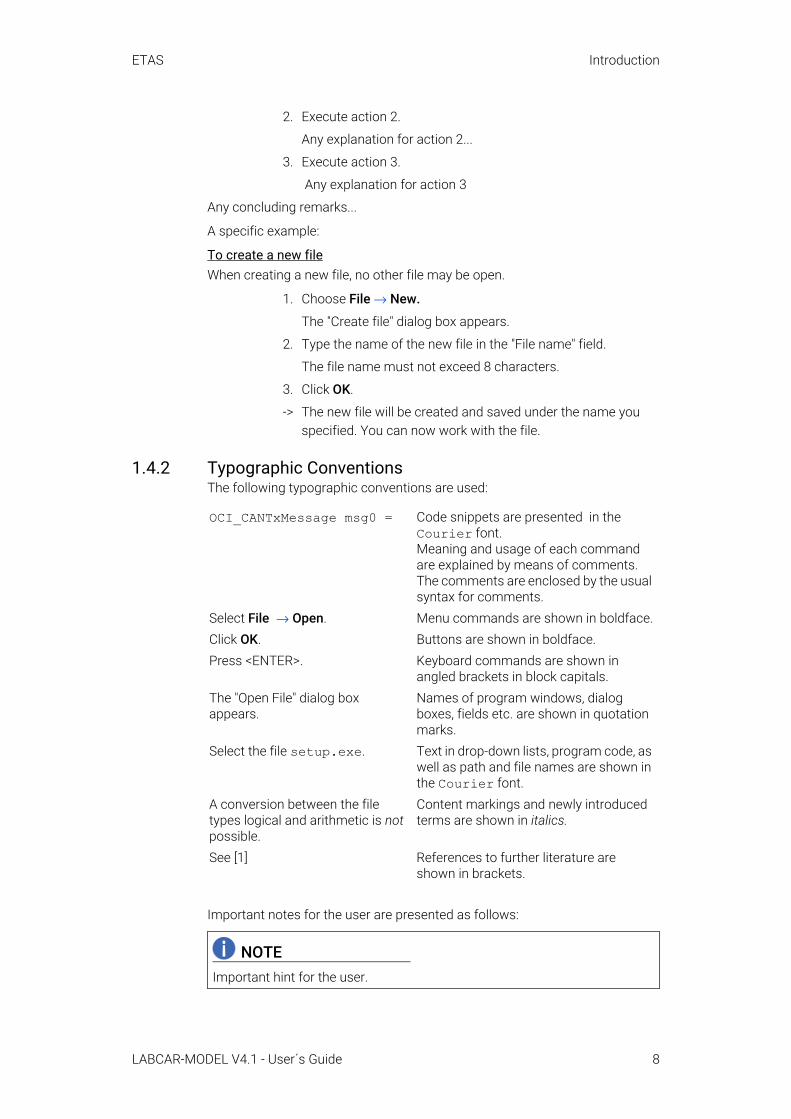
1.4.2 Typographic ConventionsThe following typographic conventions are used:
Important notes for the user are presented as follows:
OCI_CANTxMessage msg0 = Code snippets are presented in the Courier font.Meaning and usage of each command are explained by means of comments. The comments are enclosed by the usual syntax for comments.
Select File → Open. Menu commands are shown in boldface.Click OK. Buttons are shown in boldface.Press <ENTER>. Keyboard commands are shown in
angled brackets in block capitals.The "Open File" dialog box appears.
Names of program windows, dialog boxes, fields etc. are shown in quotation marks.
Select the file setup.exe. Text in drop-down lists, program code, as well as path and file names are shown in the Courier font.
A conversion between the file types logical and arithmetic is not possible.
Content markings and newly introduced terms are shown in italics.
See [1] References to further literature are shown in brackets.
NOTEImportant hint for the user.
LABCAR-MODEL V4.1 - User´s Guide 8
ETAS LABCAR-MODEL Family
2 LABCAR-MODEL Family
2.1 Overview of ModelsThe ETAS LABCAR solutions provide ways for testing and validating (TV) a wide range of automotive ECUs. The usage of numerical simulation models, which mimic the physical behavior of the System under test (SUT), is a widely known method. It offers many advantages over using real equipment as SUT, like reproducibility of results, parallel execution, access to all physical and aux-iliary quantities, and the possibility of reconfiguration when a different SUT is needed. Frequently, such models do not resemble all the details of the SUT, but cover only the relevant aspects needed for a closed-loop operation. Thus, the simulation models are a vital part of the entire TV solution; without a model, no closed-loop operation is possible.
The ETAS LABCAR-MODEL product family encompasses several domain-spe-cific simulation models and the virtual vehicle test bench. The former models mimic the functionality of a SUT for a single domain. Currently, the following models are available:
• ETAS LABCAR-MODEL-ICE is a generic model of a Diesel, gasoline, and CNG internal combustion engine (ICE) and its subsystems. It includes detailed models of the combustion system, the fuel system, the intake and exhaust system, and the aftertreatment system. This model allows you to do test and validation of an engine management system (EMS).
• ETAS LABCAR-MODEL-PMSM is an FPGA-based model for a permanent magnet synchronous electrical motor. It offers high performance and low latency computations. This model allows you to do test and valida-tion of an e-motor control unit (MCU).
• ETAS LABCAR-MODEL-VVTB is the virtual vehicle test-bench (VVTB). It contains simplistic models for all the components that make up a virtual vehicle. It serves as the integration platform with generic interfaces for all other - typically more sophisticated - plant models. You can extend LABCAR-MODEL-VVTB by your own domain-specific simulation models or you can extend it by one of the domain-specific simulation models of the ETAS LABCAR-MODEL family.
2.2 General Model Parametrization
2.2.1 Obtaining the Data for ParametrizationThe most important point for every parametrization is the determination of the correct data.
The first step in the model parametrization is collecting parametrization data. For this purpose, each LABCAR-MODEL product comes with a detailed model reference guide including a parameter list. You can query the availability of each parameter.
LABCAR-MODEL V4.1 - User´s Guide 9
ETAS LABCAR-MODEL Family
There are several sources of the data. You can take model parameters directly from an ECU. The prerequisite for this is a calibrated ECU software. It is essen-tial that the ECU data used for the model parametrization is consistent with the data used in the ECU.
The second possibility involves the parameters for the parametrization of the open-loop model. This guarantees the correct generation and measurement of signals. This is the foundation of a LABCAR operation.
The actual model parameters are addressed in the third step. This part con-tains the most important parameters of the standard model variants.
The last step is for other tasks, which depend on the project in terms of the parametrization. Further sources of information for the parametrization are data sheets for special vehicle components, measurement protocols from the engine test bench, or other accessible data.
2.2.2 Model Parametrization ProcessThe model parametrization distinguishes between offline and online parametri-zation. The two ways are described in the following chapters.
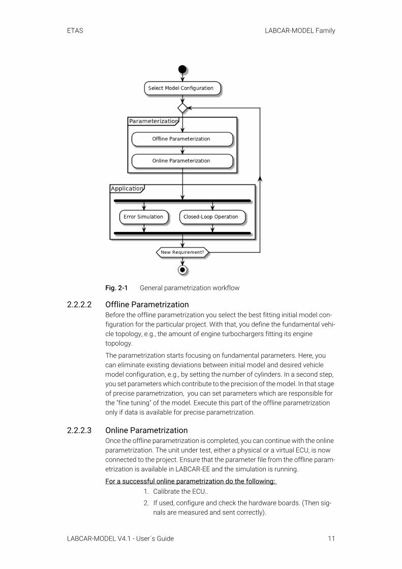
2.2.2.1 General Parametrization ProcessLABCAR-MODEL products provide several predefined configurations, e.g., dif-ferent engine configurations, which include plausible default values for param-etrization. In the context of the parametrization process, these default data sets define the starting point for individual adaptations to suit the respective project. This takes place in two main steps, the offline and the online parame-trization. Once the parametrization is completed, the model can be productively used to test a real or virtual ECU by modifying the parameters, using their inter-faces. Furthermore, you can modify the model to execute error simulations. While the model is in use for test and validation, new demands for adjusting parameters arise or additional data for parametrization is supplied. In that case, the parametrization has to be re-applied following the same parametriza-tion strategy as initially. This procedure is depicted in Fig. 2-1.
NOTEIf you have an existing LABCAR-OPERATOR project, you may reduce the amount of work needed for the parametrization by using your old parameters as a starting point. The release notes of LABCAR-MODEL list all changes in the meaning of the parameters between the different versions.
LABCAR-MODEL V4.1 - User´s Guide 10
ETAS LABCAR-MODEL Family
Fig. 2-1 General parametrization workflow
2.2.2.2 Offline ParametrizationBefore the offline parametrization you select the best fitting initial model con-figuration for the particular project. With that, you define the fundamental vehi-cle topology, e.g., the amount of engine turbochargers fitting its engine topology.
The parametrization starts focusing on fundamental parameters. Here, you can eliminate existing deviations between initial model and desired vehicle model configuration, e.g., by setting the number of cylinders. In a second step, you set parameters which contribute to the precision of the model. In that stage of precise parametrization, you can set parameters which are responsible for the "fine tuning" of the model. Execute this part of the offline parametrization only if data is available for precise parametrization.
2.2.2.3 Online ParametrizationOnce the offline parametrization is completed, you can continue with the online parametrization. The unit under test, either a physical or a virtual ECU, is now connected to the project. Ensure that the parameter file from the offline param-etrization is available in LABCAR-EE and the simulation is running.
For a successful online parametrization do the following: 1. Calibrate the ECU..
2. If used, configure and check the hardware boards. (Then sig-nals are measured and sent correctly).
LABCAR-MODEL V4.1 - User´s Guide 11

ETAS LABCAR-MODEL Family
3. Correctly set the parameters in the open-loop model.
Like the offline parametrization, the online basic parametrization involves the parameters being modified in the same order, i.e., according to the model func-tionalities. See figure Fig. 2-2 on page 12. You only select insufficiently parame-trized model functionalities iteratively and deactivate the model or the ECU functionality, which is not in focus. If available, all the switch parameters are checked. This could actually solve the problem of insufficient parametrization. If not, steady-state operating points are set in the model at which the simula-tion results are compared with target values, e.g., the engine test bench mea-surements. You adapt the relevant parameters until the model precision is sufficient and passes different steady state operation points. With finishing the parametrization, the process repeats for the next insufficiently parametrized model functionality until the overall model matches the expected behavior.
.
Fig. 2-2 Online parametrization workflow
LABCAR-MODEL V4.1 - User´s Guide 12
ETAS LABCAR-MODEL Family
2.3 Technical AspectsThis chapter comprises various technical points.
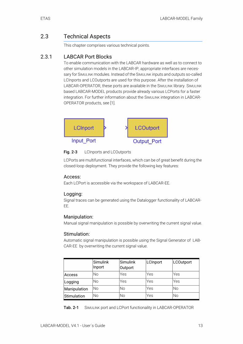
2.3.1 LABCAR Port BlocksTo enable communication with the LABCAR hardware as well as to connect to other simulation models in the LABCAR-IP, appropriate interfaces are neces-sary for SIMULINK modules. Instead of the SIMULINK inputs and outputs so-called LCInports and LCOutports are used for this purpose. After the installation of LABCAR-OPERATOR, these ports are available in the SIMULINK library. SIMULINK based LABCAR-MODEL products provide already various LCPorts for a faster integration. For further information about the SIMULINK integration in LABCAR-OPERATOR products, see [1].
Fig. 2-3 LCInports and LCOutports
LCPorts are multifunctional interfaces, which can be of great benefit during the closed-loop deployment. They provide the following key features:
Access:Each LCPort is accessible via the workspace of LABCAR-EE.
Logging:Signal traces can be generated using the Datalogger functionality of LABCAR-EE.
Manipulation:Manual signal manipulation is possible by overwriting the current signal value.
Stimulation:Automatic signal manipulation is possible using the Signal Generator of LAB-CAR-EE by overwriting the current signal value.
Tab. 2-1 SIMULINK port and LCPort functionality in LABCAR-OPERATOR
Simulink Inport
Simulink Outport
LCInport LCOutport
Access No Yes Yes Yes
Logging No Yes Yes Yes
Manipulation No No Yes No
Stimulation No No Yes No
LABCAR-MODEL V4.1 - User´s Guide 13

ETAS LABCAR-MODEL Family
2.3.2 SIMULINK Model - Code Generation ProcessSIMULINK-based simulation models have to go through a code generation pro-cess when:
• You add a model to a project.
• You change the model *.mdl file.
• You explicitly request the code generation.
Since the code generation is crucial for the operation of LABCAR-MODEL, the following section briefly describes the technical fundamentals.
During the code generation, the SIMULINK *.mdl file is translated into ANSI c-code for a particular target, e.g., the LABCAR RTPC. This translation takes place in two steps. First, the model *.mdl file is translated into a model description file *.rtw. The *.rtw file represents the original model in a high-level lan-guage and is input for the subsequent Target Language Compiler. In that sec-ond step, c-code is specified for each SIMULINK block, based on a rule set described in a particular *.tlc file. As result, the Target Language Compiler generates target compatible c-code. Simulink based LABCAR-MODEL products officially support code generation with the lcrt.tlc file that is shipped with LABCAR-OPERATOR.
Fig. 2-4 Code generation process for SIMULINK models
NOTEThe grt.tlc file is not officially supported by LABCAR-MODEL products.
LABCAR-MODEL V4.1 - User´s Guide 14
ETAS LABCAR-MODEL Family
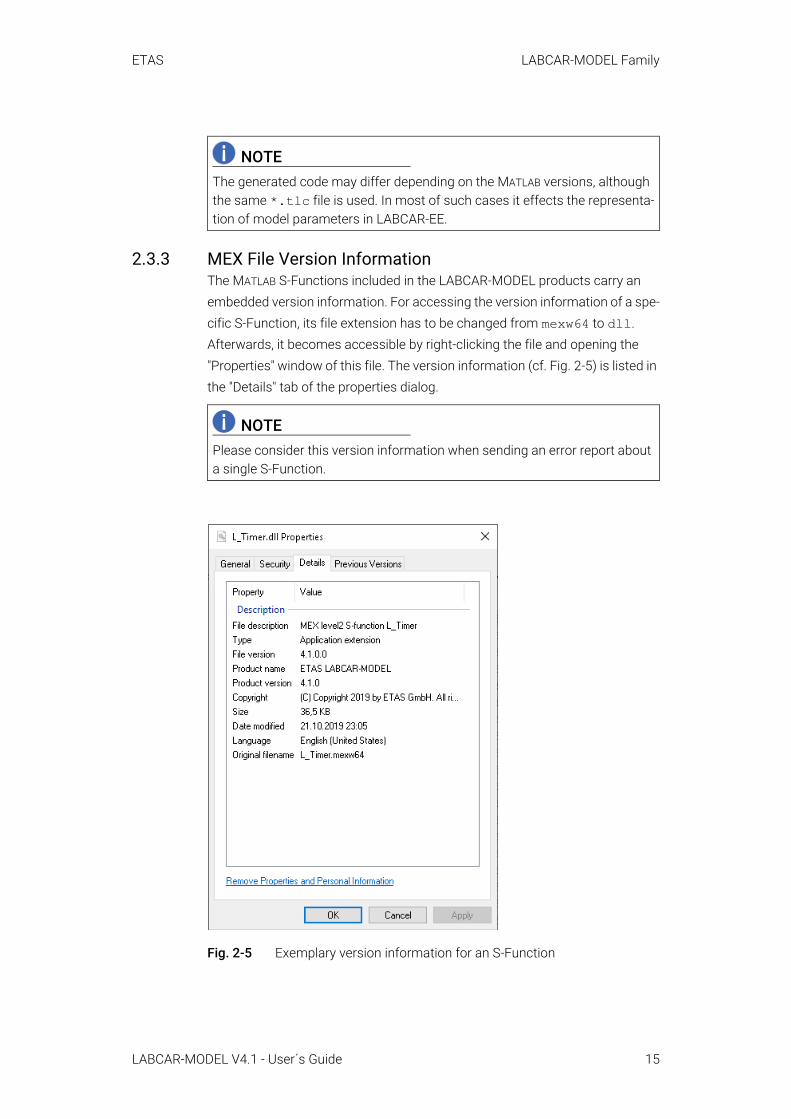
2.3.3 MEX File Version InformationThe MATLAB S-Functions included in the LABCAR-MODEL products carry an embedded version information. For accessing the version information of a spe-cific S-Function, its file extension has to be changed from mexw64 to dll. Afterwards, it becomes accessible by right-clicking the file and opening the "Properties" window of this file. The version information (cf. Fig. 2-5) is listed in the "Details" tab of the properties dialog.
Fig. 2-5 Exemplary version information for an S-Function
NOTEThe generated code may differ depending on the MATLAB versions, although the same *.tlc file is used. In most of such cases it effects the representa-tion of model parameters in LABCAR-EE.
NOTEPlease consider this version information when sending an error report about a single S-Function.
LABCAR-MODEL V4.1 - User´s Guide 15

ETAS Installation
3 InstallationThis chapter contains information on the scope of delivery and on how to pre-pare for the installation.
3.1 User Privileges Required for InstallationYou must have administrator privileges to install products of LABCAR-MODEL on a PC. If in doubt, ask your system administrator.
3.2 Contents of the DVDThe products of LABCAR-MODEL are delivered as a DVD with the following con-tents:
• ETAS_Safety_Advice.pdf
• Release_Notes.pdf
• Documentation:
Contains the User's Guide for LABCAR-MODEL products and Open Source Scan (OSS) attribution documents.
• Installation:
Contains installer executable including all required installation packages.
3.3 Program InstallationThis section describes how to install LABCAR-MODEL products.
1. Insert the product DVD in your DVD-ROM drive.
The DVD-Browser is launched.
2. Run Installation/setup.exe to start the installer manually.
LABCAR-MODEL V4.1 - User´s Guide 16

ETAS Installation
3. Click Next and follow the instructions of the installation wiz-ard.
4. To complete the installation click Finish.
3.4 Contents of the InstallationThe contents of the installation consists of the following:
• SIMULINK Models:
There are pre-build SIMULINK models including compiled S-Fcns in the form of mexw64 files for windows and o-files for the RTPC execution.
• FPGA Models:
There are FPGA programming file (euf) and interface description files (adf) for flashing the ES5340.2.
• Project Items:
These are additional LABCAR-OPERATOR compatible items provided as a bundle. The items comprise– C-modules (cmod), – connection files (conn), – layer (gui), – images (img), – mapping files (mapping), – rt-plugins (rtp), – and specific user-data (userdata). The bundles are specific for particular model variants, e.g. connection files between automatic transmission model (VVBT_AT) and manual transmission model (VVTB_MT) differ and are individually stored.
LABCAR-MODEL V4.1 - User´s Guide 17

ETAS Installation
• LicenseConfigurationInfo:
These are files for the ETAS License Manager.• Example Project:
Here you find pre-build LABCAR-OPERATOR example projects.• Documentation:
This area contains the user's guide, safety advices as well as individual model reference guides.
NOTEPlease do not open or manipulate the files in the installation folder directly. Instead create a working copy from the installation folder in a location of your choice.
LABCAR-MODEL V4.1 - User´s Guide 18
ETAS LABCAR-MODEL-VVTB
4 LABCAR-MODEL-VVTBETAS LABCAR-MODEL-VVTB is the virtual vehicle test bench. On the one hand it serves as the top-level vehicle model and allows for an easy integration of all those sophisticated, domain-specific component models that you need to describe the full SUT. On the other hand it provides simplistic default imple-mentations for all subsystems, where no sophisticated component models are needed.
4.1 Project and Experiment CreationIn the following, a step-by-step guide is given, which describes the generation of a LABCAR-OPERATOR project using LABCAR-MODEL-VVTB. For the execu-tion of the project, no physical ECU is needed. Instead, a SoftECU controls the engine model. The project to be created contains a manual transmission vehi-cle model that is predefined by the VVTB_MT model configuration.
4.1.1 Project Creation in LABCAR-OPERATORThis chapter addresses qualified personnel with knowledge in using LABCAR-OPERATOR. If you do not have any experience in using LABCAR-OPERATOR, please read first [1].
For the manual project creation using LABCAR-MODEL-VVTB with LABCAR-OPERATOR follow the steps described in this chapter.
To set up the LABCAR-OPERATOR project, do the following:1. Open the LABCAR-IP application.
2. Click File → New Project.
3. Choose the location for the file and name the project.
4. Use "RTPC" as "Target Name".
5. Click Finish.
-> The project explorer contains an empty hardware configura-tion.
The full vehicle model consists out of a single SIMULINK module. This module also contains driver, environment, vehicle and SoftECU, which mimics the behavior of an EMS.
To add a Simulink module1. Choose Project → Add Module.
2. Select "Add Simulink (TM) Module".
3. Select "Use existing Simulink (TM) Model (will be copied)".
4. Select the model configuration VVTB_MT. The corresponding model VVTB.mdl is located in the install folder
.\VVTB\Project Items\_Lib\VVTB_MT\mdl\Simulink_VVTB\src.
5. Activate the checkbox "Copy Model Directory into Project".
6. Click Finish.
-> The Project Explorer shows the added module.
LABCAR-MODEL V4.1 - User´s Guide 19

ETAS LABCAR-MODEL-VVTB
Per default, the SoftECU is not connected to the vehicle or driver model, although it is part of the already integrated SIMULINK module VVTB.mdl. Pre-defined connection files couple the SoftECU and the vehicle model internally.
To add connection files1. Open "Connection Manager" and right-click.
2. Select Import Connection.
3. Import each connection file stored in the install folder at .\VVTB\Project Items\_Lib\VVTB_MT\conn.
-> After the connection files are added, many connections are vis-ible in the "Connection Manager".
NOTECheck each connection file and ensure that you added all connection files. Otherwise the model might not work properly.
LABCAR-MODEL V4.1 - User´s Guide 20
ETAS LABCAR-MODEL-VVTB
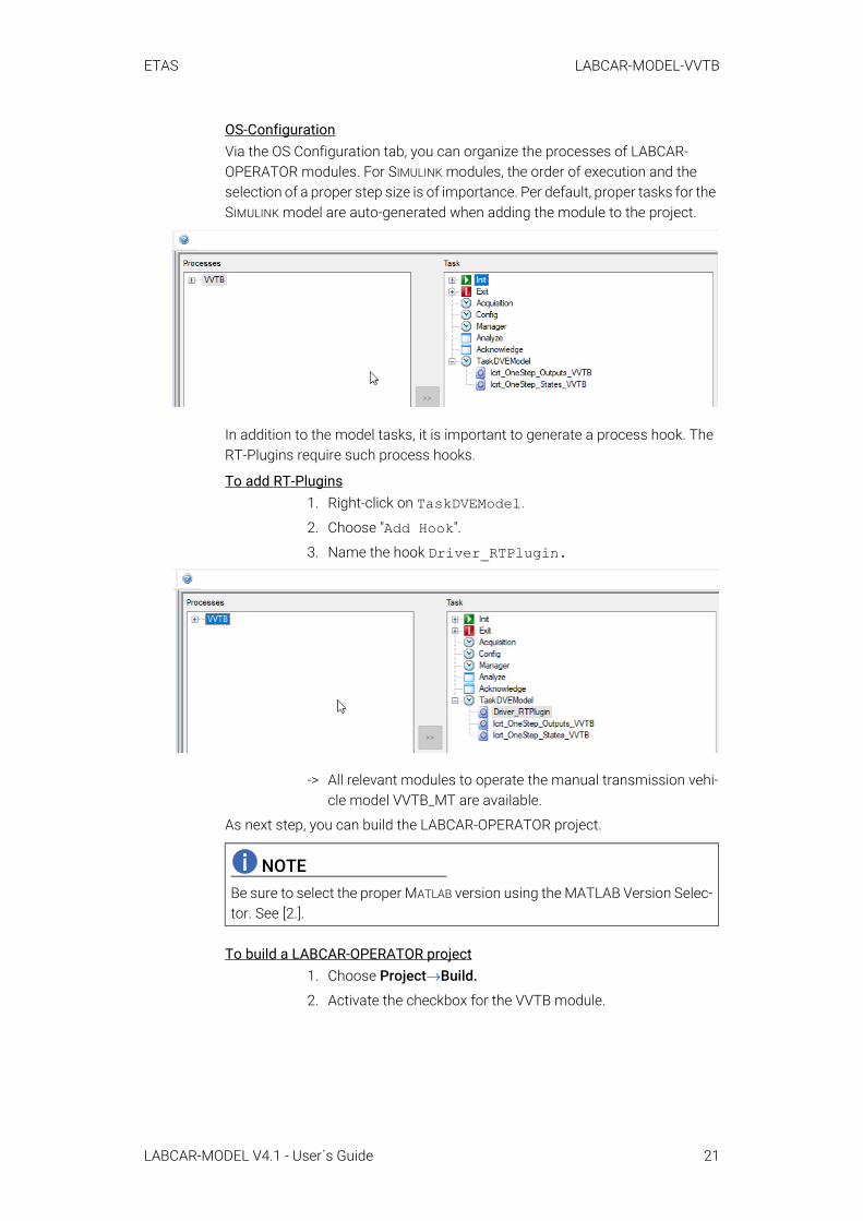
OS-ConfigurationVia the OS Configuration tab, you can organize the processes of LABCAR-OPERATOR modules. For SIMULINK modules, the order of execution and the selection of a proper step size is of importance. Per default, proper tasks for the SIMULINK model are auto-generated when adding the module to the project.
In addition to the model tasks, it is important to generate a process hook. The RT-Plugins require such process hooks.
To add RT-Plugins1. Right-click on TaskDVEModel.
2. Choose "Add Hook".
3. Name the hook Driver_RTPlugin.
-> All relevant modules to operate the manual transmission vehi-cle model VVTB_MT are available.
As next step, you can build the LABCAR-OPERATOR project.
To build a LABCAR-OPERATOR project1. Choose Project→Build.
2. Activate the checkbox for the VVTB module.
NOTEBe sure to select the proper MATLAB version using the MATLAB Version Selec-tor. See [2.].
LABCAR-MODEL V4.1 - User´s Guide 21
ETAS LABCAR-MODEL-VVTB
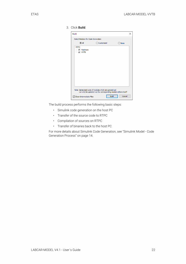
3. Click Build.
The build process performs the following basic steps:
• Simulink code generation on the host PC
• Transfer of the source code to RTPC
• Compilation of sources on RTPC
• Transfer of binaries back to the host PC
For more details about Simulink Code Generation, see “Simulink Model - Code Generation Process” on page 14.
LABCAR-MODEL V4.1 - User´s Guide 22
ETAS LABCAR-MODEL-VVTB
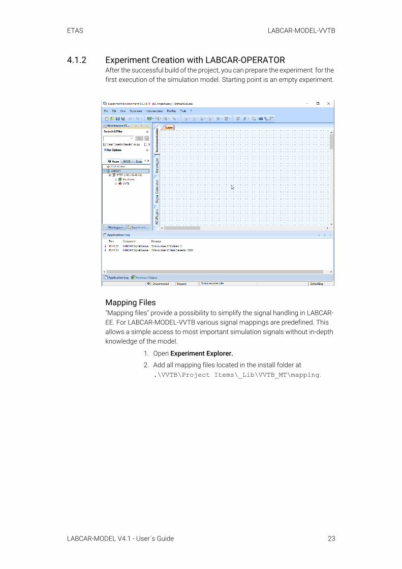
4.1.2 Experiment Creation with LABCAR-OPERATORAfter the successful build of the project, you can prepare the experiment for the first execution of the simulation model. Starting point is an empty experiment.
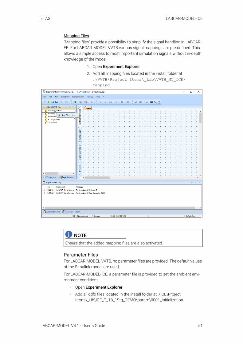
Mapping Files"Mapping files" provide a possibility to simplify the signal handling in LABCAR-EE. For LABCAR-MODEL-VVTB various signal mappings are predefined. This allows a simple access to most important simulation signals without in-depth knowledge of the model.
1. Open Experiment Explorer.
2. Add all mapping files located in the install folder at.\VVTB\Project Items\_Lib\VVTB_MT\mapping.
LABCAR-MODEL V4.1 - User´s Guide 23
ETAS LABCAR-MODEL-VVTB
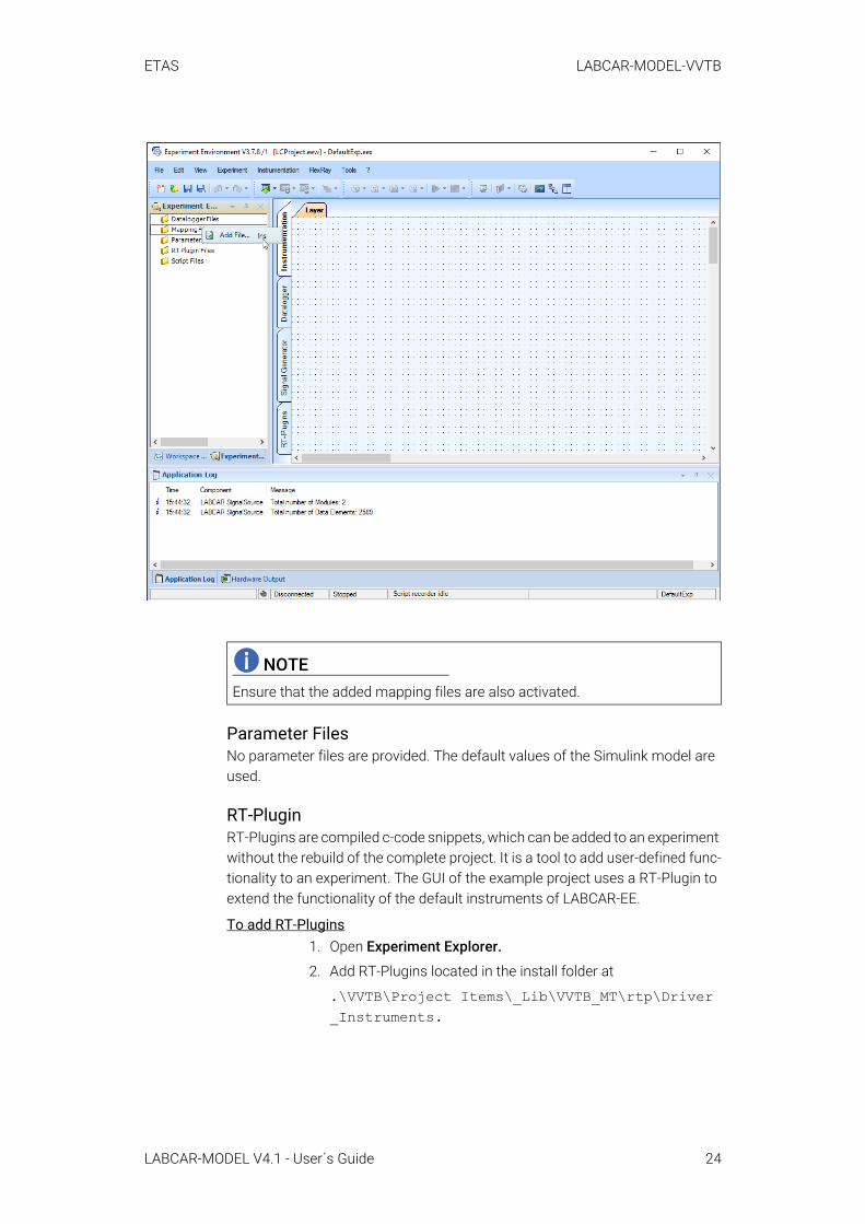
Parameter FilesNo parameter files are provided. The default values of the Simulink model are used.
RT-PluginRT-Plugins are compiled c-code snippets, which can be added to an experiment without the rebuild of the complete project. It is a tool to add user-defined func-tionality to an experiment. The GUI of the example project uses a RT-Plugin to extend the functionality of the default instruments of LABCAR-EE.
To add RT-Plugins1. Open Experiment Explorer.
2. Add RT-Plugins located in the install folder at
.\VVTB\Project Items\_Lib\VVTB_MT\rtp\Driver_Instruments.
NOTEEnsure that the added mapping files are also activated.
LABCAR-MODEL V4.1 - User´s Guide 24
ETAS LABCAR-MODEL-VVTB
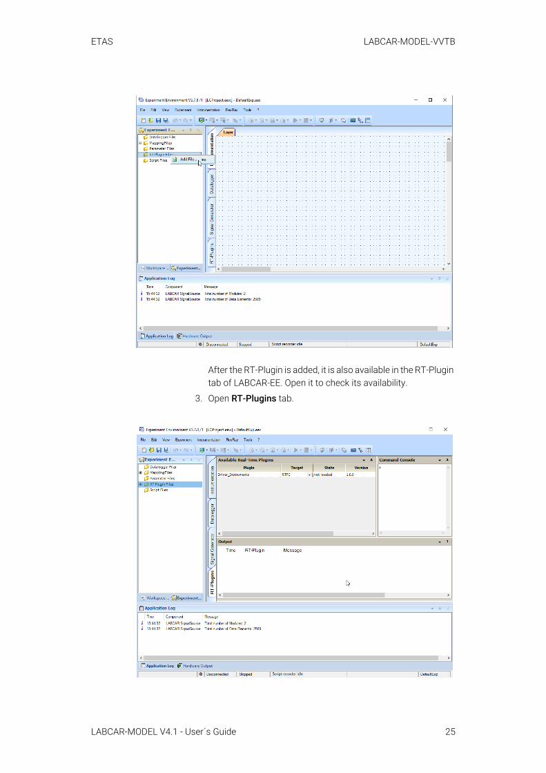
After the RT-Plugin is added, it is also available in the RT-Plugin tab of LABCAR-EE. Open it to check its availability.
3. Open RT-Plugins tab.
LABCAR-MODEL V4.1 - User´s Guide 25

ETAS LABCAR-MODEL-VVTB
LayersThe layer provides the basic interface to handle the vehicle model. It allows the setting of the driver mode and the selection of predefined cycles. As prelimi-nary step you can copy images for the layer from the installation folder.
To import layers1. Copy images from
.\VVTB\Project Items\_Lib\VVTB_MT\img.
2. Create the target folder if it does not already exist.
3. Import the Driver.layer file as located in .\VVTB\Project Items\_Lib\VVTB_MT\gui.
-> After the successful import of the Driver layer, basic dash-boards for handling the VVTB model exist.
NOTEEach RT-Plugin requires a process hook for execution. Ensure that the pro-cess hook "Driver_RTPlugin" is available in the OS-settings. See the paragraph “To add RT-Plugins” on page 21.
LABCAR-MODEL V4.1 - User´s Guide 26
ETAS LABCAR-MODEL-VVTB
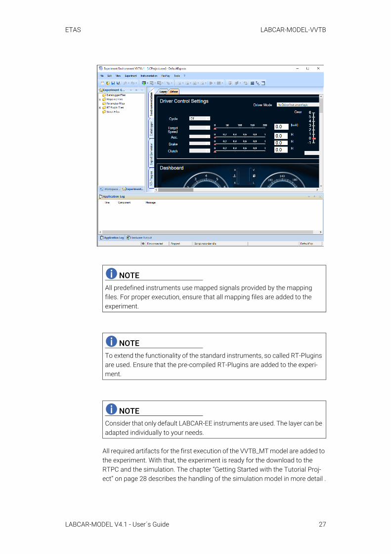
All required artifacts for the first execution of the VVTB_MT model are added to the experiment. With that, the experiment is ready for the download to the RTPC and the simulation. The chapter “Getting Started with the Tutorial Proj-ect” on page 28 describes the handling of the simulation model in more detail .
NOTEAll predefined instruments use mapped signals provided by the mapping files. For proper execution, ensure that all mapping files are added to the experiment.
NOTETo extend the functionality of the standard instruments, so called RT-Plugins are used. Ensure that the pre-compiled RT-Plugins are added to the experi-ment.
NOTEConsider that only default LABCAR-EE instruments are used. The layer can be adapted individually to your needs.
LABCAR-MODEL V4.1 - User´s Guide 27
ETAS LABCAR-MODEL-VVTB
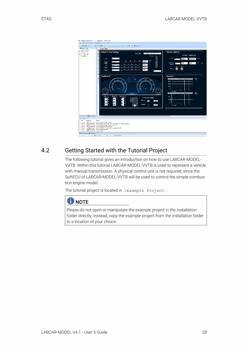
4.2 Getting Started with the Tutorial ProjectThe following tutorial gives an introduction on how to use LABCAR-MODEL-VVTB. Within this tutorial LABCAR-MODEL-VVTB is used to represent a vehicle with manual transmission. A physical control unit is not required, since the SoftECU of LABCAR-MODEL-VVTB will be used to control the simple combus-tion engine model.
The tutorial project is located in .\Example Project.
NOTEPlease do not open or manipulate the example project in the installation folder directly. Instead, copy the example project from the installation folder to a location of your choice.
LABCAR-MODEL V4.1 - User´s Guide 28

ETAS LABCAR-MODEL-VVTB
4.2.1 OverviewThe "Driver" tab in LABCAR-EE contains four windows as shown in the following figure.
Driver Control SettingsMenu to set the operation mode of the longitudinal driver. Especially, following settings are available:
• Select Driver Mode, e.g. velocity tracking or manual operation
• Select Cycle
• Select inputs for accelerator, clutch, brake, and gear
• Set manual values for accelerator, clutch, brake, and gear
DashboardThe dashboard shows the current status of the vehicle. It provides typical nee-dle instruments for engine speed and vehicle velocity. Furthermore, it presents the driver output, i.e. the clutch, accelerator, and brake pedal position as well as the gear lever position.
Testbed SettingsLABCAR-MODEL-VVTB provides two engine testbed modes to bring the engine in a particular operation point defined by engine speed and engine torque. The testbed settings allow the parametrization of the desired operation point.
SimulationTwo oscilloscopes provide information about desired and measured engine and vehicle speed.
LABCAR-MODEL V4.1 - User´s Guide 29

ETAS LABCAR-MODEL-VVTB
4.2.2 Cycle DrivingCycle driving is one of the most common tests in ECU development. The fol-lowing guide shows how to drive a pre-defined cycle and a user-defined cycle with LABCAR-MODEL-VVTB.
4.2.2.1 Predefined CyclesLABCAR-MODEL-VVTB provides a set of predefined cycles. They can be accessed by the driver dashboards. In general cycle driving can be defined in two ways:
• For following a pure velocity profile, select:
Set Driver Mode → Target Speed - Internal Gear (MT)• For following a velocity and gear profile, select:
Set Driver Mode → Target Speed - External Gear (MT)
In the given example, the driver determines the gear. • After that, choose the desired cycle in the drop-down menu:
The Target Speed mode of the driver is automatically set to Cycle. Herewith, the driver's reference speed is that one coming from the cycle.
NOTEIf a different MATLAB version is used than defined in the release note of LAB-CAR-MODEL, the structure of the LABCAR-EE workspace might differ.
LABCAR-MODEL V4.1 - User´s Guide 30

ETAS LABCAR-MODEL-VVTB
4.2.2.2 User-Defined CycleUser-defined cycles are often used for testing individual functions of an ECU. Such individual cycles are defined via workspace parameters or the signal gen-erator of LABCAR-EE.
Via Setting Workspace ParametersThe driver model of LABCAR-MODEL-VVTB provides a dedicated location for user-defined cycles. When using that approach, set the desired driver mode.
• For following a pure velocity profile, select:
Set Driver Mode → Target Speed - Internal Gear (MT)• For following a velocity and gear profile, select:
Set Driver Mode → Target Speed - External Gear (MT)
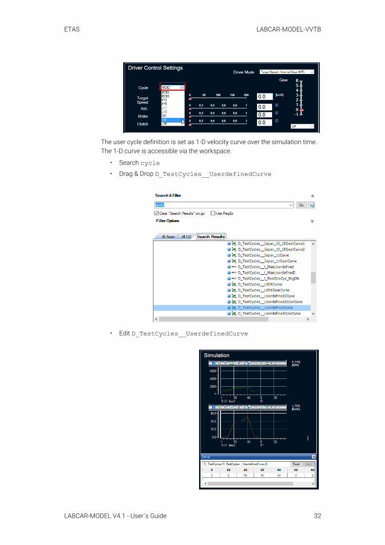
• After that, choose the user cycle in the drop-down menu:
Set Cycle Mode → Usr
NOTEWhen the mode Target Speed - Internal Gear (MT) is set, then no manual input for accelerator, brake, or clutch pedal position is possible. The driver model regulates all pedal positions.
LABCAR-MODEL V4.1 - User´s Guide 31
ETAS LABCAR-MODEL-VVTB
The user cycle definition is set as 1-D velocity curve over the simulation time. The 1-D curve is accessible via the workspace.
• Search cycle• Drag & Drop D_TestCycles__UserdefinedCurve
• Edit D_TestCycles__UserdefinedCurve
LABCAR-MODEL V4.1 - User´s Guide 32
ETAS LABCAR-MODEL-VVTB
The user-defined cycle is defined by the parameter D_TestCycles__UserdefinedCurve, which can be adapted accordingly. Start the simulation and the user-defined cycle will be followed by the driver.
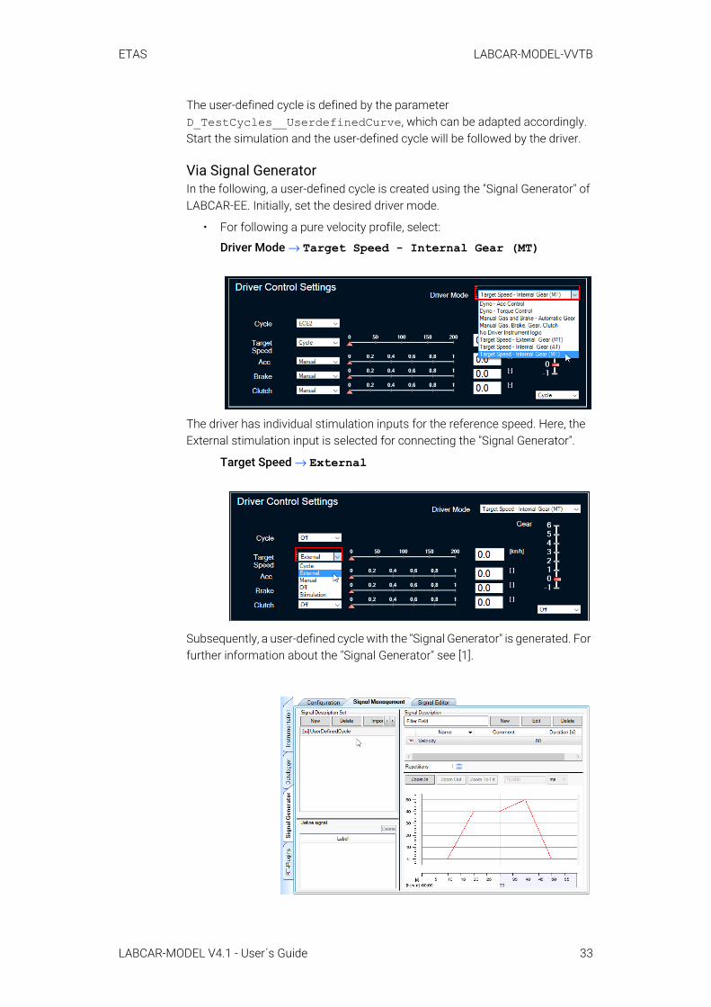
Via Signal GeneratorIn the following, a user-defined cycle is created using the "Signal Generator" of LABCAR-EE. Initially, set the desired driver mode.
• For following a pure velocity profile, select:
Driver Mode → Target Speed - Internal Gear (MT)
The driver has individual stimulation inputs for the reference speed. Here, the External stimulation input is selected for connecting the "Signal Generator".
Target Speed → External
Subsequently, a user-defined cycle with the "Signal Generator" is generated. For further information about the "Signal Generator" see [1].
LABCAR-MODEL V4.1 - User´s Guide 33
ETAS LABCAR-MODEL-VVTB
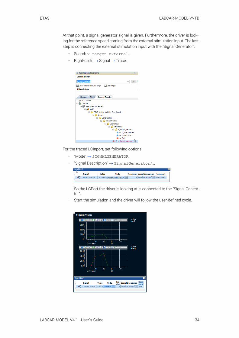
At that point, a signal generator signal is given. Furthermore, the driver is look-ing for the reference speed coming from the external stimulation input. The last step is connecting the external stimulation input with the "Signal Generator".
• Search v_target_external.
• Right-click → Signal → Trace.
For the traced LCInport, set following options:
• "Mode" → SIGNALGENERATOR• "Signal Description" → SignalGenerator/…
So the LCPort the driver is looking at is connected to the "Signal Genera-tor".
• Start the simulation and the driver will follow the user-defined cycle.
LABCAR-MODEL V4.1 - User´s Guide 34
ETAS LABCAR-MODEL-VVTB
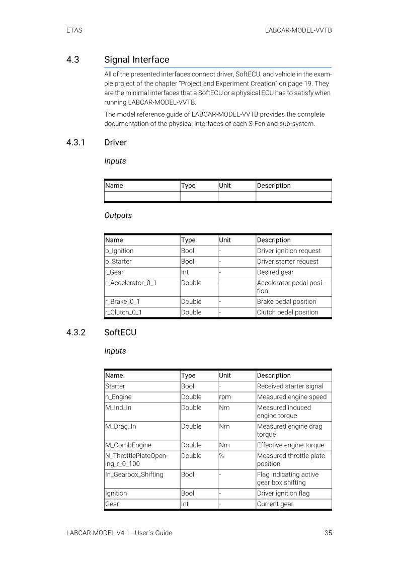
4.3 Signal InterfaceAll of the presented interfaces connect driver, SoftECU, and vehicle in the exam-ple project of the chapter “Project and Experiment Creation” on page 19. They are the minimal interfaces that a SoftECU or a physical ECU has to satisfy when running LABCAR-MODEL-VVTB.
The model reference guide of LABCAR-MODEL-VVTB provides the complete documentation of the physical interfaces of each S-Fcn and sub-system.
4.3.1 Driver
Inputs
Outputs
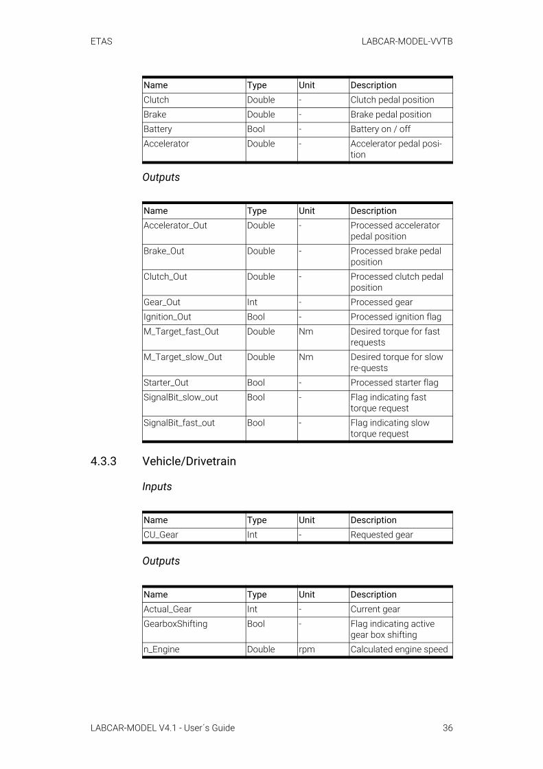
4.3.2 SoftECU
Inputs
Name Type Unit Description
Name Type Unit Descriptionb_Ignition Bool - Driver ignition requestb_Starter Bool - Driver starter request i_Gear Int - Desired gearr_Accelerator_0_1 Double - Accelerator pedal posi-
tionr_Brake_0_1 Double - Brake pedal positionr_Clutch_0_1 Double - Clutch pedal position
Name Type Unit DescriptionStarter Bool - Received starter signaln_Engine Double rpm Measured engine speedM_Ind_In Double Nm Measured induced
engine torqueM_Drag_In Double Nm Measured engine drag
torqueM_CombEngine Double Nm Effective engine torqueN_ThrottlePlateOpen-ing_r_0_100
Double % Measured throttle plate position
In_Gearbox_Shifting Bool - Flag indicating active gear box shifting
Ignition Bool - Driver ignition flagGear Int - Current gear
LABCAR-MODEL V4.1 - User´s Guide 35
ETAS LABCAR-MODEL-VVTB
Outputs
4.3.3 Vehicle/Drivetrain
Inputs
Outputs
Clutch Double - Clutch pedal positionBrake Double - Brake pedal positionBattery Bool - Battery on / offAccelerator Double - Accelerator pedal posi-
tion
Name Type Unit DescriptionAccelerator_Out Double - Processed accelerator
pedal positionBrake_Out Double - Processed brake pedal
positionClutch_Out Double - Processed clutch pedal
positionGear_Out Int - Processed gearIgnition_Out Bool - Processed ignition flagM_Target_fast_Out Double Nm Desired torque for fast
requestsM_Target_slow_Out Double Nm Desired torque for slow
re-questsStarter_Out Bool - Processed starter flagSignalBit_slow_out Bool - Flag indicating fast
torque requestSignalBit_fast_out Bool - Flag indicating slow
torque request
Name Type Unit DescriptionCU_Gear Int - Requested gear
Name Type Unit DescriptionActual_Gear Int - Current gearGearboxShifting Bool - Flag indicating active
gear box shiftingn_Engine Double rpm Calculated engine speed
Name Type Unit Description
LABCAR-MODEL V4.1 - User´s Guide 36
ETAS LABCAR-MODEL-VVTB
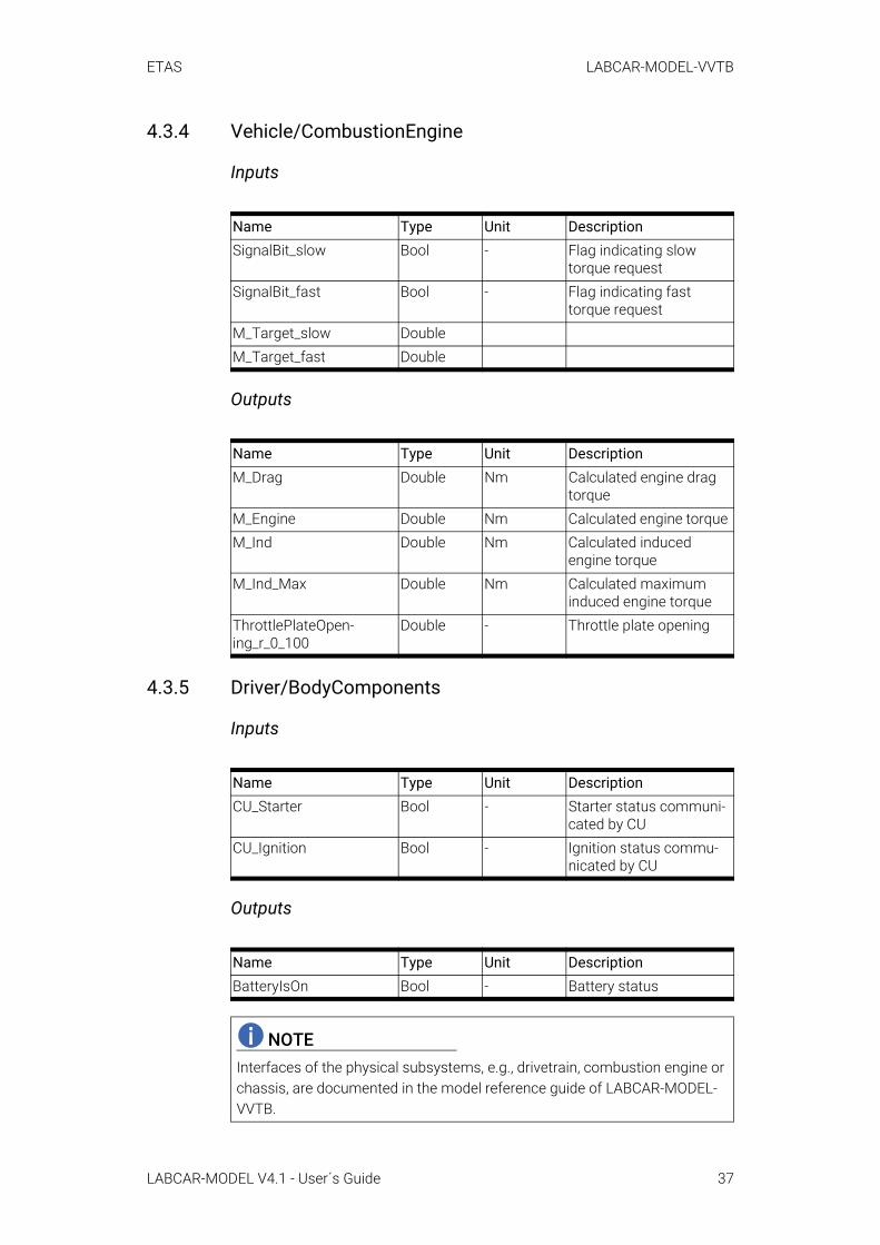
4.3.4 Vehicle/CombustionEngine
Inputs
Outputs
4.3.5 Driver/BodyComponents
Inputs
Outputs
Name Type Unit DescriptionSignalBit_slow Bool - Flag indicating slow
torque requestSignalBit_fast Bool - Flag indicating fast
torque requestM_Target_slow DoubleM_Target_fast Double
Name Type Unit DescriptionM_Drag Double Nm Calculated engine drag
torqueM_Engine Double Nm Calculated engine torqueM_Ind Double Nm Calculated induced
engine torqueM_Ind_Max Double Nm Calculated maximum
induced engine torqueThrottlePlateOpen-ing_r_0_100
Double - Throttle plate opening
Name Type Unit DescriptionCU_Starter Bool - Starter status communi-
cated by CUCU_Ignition Bool - Ignition status commu-
nicated by CU
Name Type Unit DescriptionBatteryIsOn Bool - Battery status
NOTEInterfaces of the physical subsystems, e.g., drivetrain, combustion engine or chassis, are documented in the model reference guide of LABCAR-MODEL-VVTB.
LABCAR-MODEL V4.1 - User´s Guide 37
ETAS LABCAR-MODEL-VVTB
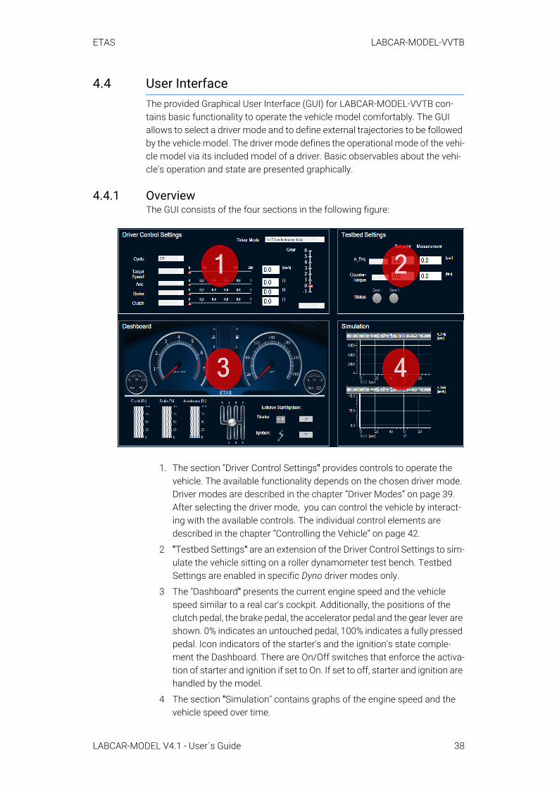
4.4 User InterfaceThe provided Graphical User Interface (GUI) for LABCAR-MODEL-VVTB con-tains basic functionality to operate the vehicle model comfortably. The GUI allows to select a driver mode and to define external trajectories to be followed by the vehicle model. The driver mode defines the operational mode of the vehi-cle model via its included model of a driver. Basic observables about the vehi-cle's operation and state are presented graphically.
4.4.1 OverviewThe GUI consists of the four sections in the following figure:
1. The section "Driver Control Settings" provides controls to operate the vehicle. The available functionality depends on the chosen driver mode. Driver modes are described in the chapter “Driver Modes” on page 39. After selecting the driver mode, you can control the vehicle by interact-ing with the available controls. The individual control elements are described in the chapter “Controlling the Vehicle” on page 42.
2 "Testbed Settings" are an extension of the Driver Control Settings to sim-ulate the vehicle sitting on a roller dynamometer test bench. Testbed Settings are enabled in specific Dyno driver modes only.
3 The "Dashboard" presents the current engine speed and the vehicle speed similar to a real car's cockpit. Additionally, the positions of the clutch pedal, the brake pedal, the accelerator pedal and the gear lever are shown. 0% indicates an untouched pedal, 100% indicates a fully pressed pedal. Icon indicators of the starter's and the ignition's state comple-ment the Dashboard. There are On/Off switches that enforce the activa-tion of starter and ignition if set to On. If set to off, starter and ignition are handled by the model.
4 The section "Simulation" contains graphs of the engine speed and the vehicle speed over time.
LABCAR-MODEL V4.1 - User´s Guide 38
ETAS LABCAR-MODEL-VVTB
For the GUI to function as expected, its RT-Plugin Driver_Instru-ments.rtp and the mappings Driver_Instruments.txt need to be acti-vated as described in the chapter “Project and Experiment Creation” on page 19.
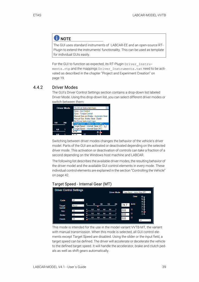
4.4.2 Driver ModesThe GUI's Driver Control Settings section contains a drop-down list labeled Driver Mode. Using this drop-down list, you can select different driver modes or switch between them:
Switching between driver modes changes the behavior of the vehicle's driver model. Parts of the GUI are activated or deactivated depending on the selected driver mode. This activation or deactivation of controls can take a fraction of a second depending on the Windows host machine and LABCAR.
The following list describes the available driver modes, the resulting behavior of the driver model and the available GUI control elements in every mode. These individual control elements are explained in the section “Controlling the Vehicle” on page 42.
Target Speed - Internal Gear (MT)
This mode is intended for the use in the model variant VVTB-MT, the variant with manual transmission. When this mode is selected, all GUI control ele-ments except Target Speed are disabled. Using the slider or the input field, a target speed can be defined. The driver will accelerate or decelerate the vehicle to the defined target speed. It will handle the accelerator, brake and clutch ped-als as well as shift gears automatically.
NOTEThe GUI uses standard instruments of LABCAR-EE and an open-source RT-Plugin to extend the instruments' functionality. This can be used as template for individual GUIs easily.
LABCAR-MODEL V4.1 - User´s Guide 39
ETAS LABCAR-MODEL-VVTB
Target Speed - Internal Gear (AT)This mode is intended for the use in the model variant VVTB-AT, the variant with automatic transmission. The GUI functionality is identical to Target Speed - Internal Gear (MT).
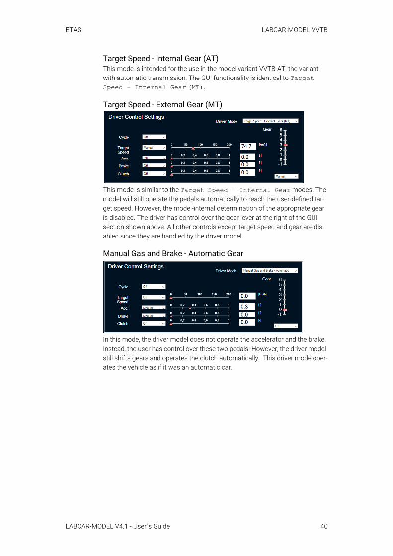
Target Speed - External Gear (MT)
This mode is similar to the Target Speed - Internal Gear modes. The model will still operate the pedals automatically to reach the user-defined tar-get speed. However, the model-internal determination of the appropriate gear is disabled. The driver has control over the gear lever at the right of the GUI section shown above. All other controls except target speed and gear are dis-abled since they are handled by the driver model.
Manual Gas and Brake - Automatic Gear
In this mode, the driver model does not operate the accelerator and the brake. Instead, the user has control over these two pedals. However, the driver model still shifts gears and operates the clutch automatically. This driver mode oper-ates the vehicle as if it was an automatic car.
LABCAR-MODEL V4.1 - User´s Guide 40
ETAS LABCAR-MODEL-VVTB
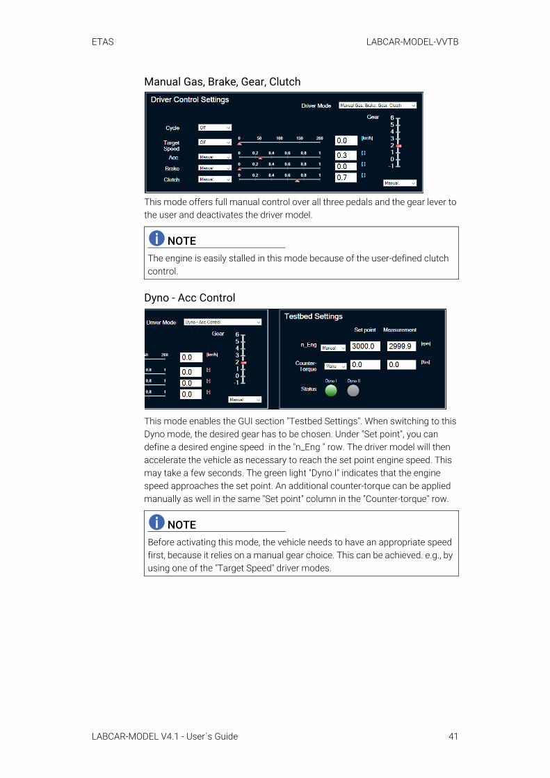
Manual Gas, Brake, Gear, Clutch
This mode offers full manual control over all three pedals and the gear lever to the user and deactivates the driver model.
Dyno - Acc Control
This mode enables the GUI section "Testbed Settings". When switching to this Dyno mode, the desired gear has to be chosen. Under "Set point", you can define a desired engine speed in the "n_Eng " row. The driver model will then accelerate the vehicle as necessary to reach the set point engine speed. This may take a few seconds. The green light "Dyno I" indicates that the engine speed approaches the set point. An additional counter-torque can be applied manually as well in the same "Set point" column in the "Counter-torque" row.
NOTEThe engine is easily stalled in this mode because of the user-defined clutch control.
NOTEBefore activating this mode, the vehicle needs to have an appropriate speed first, because it relies on a manual gear choice. This can be achieved. e.g., by using one of the "Target Speed" driver modes.
LABCAR-MODEL V4.1 - User´s Guide 41
ETAS LABCAR-MODEL-VVTB
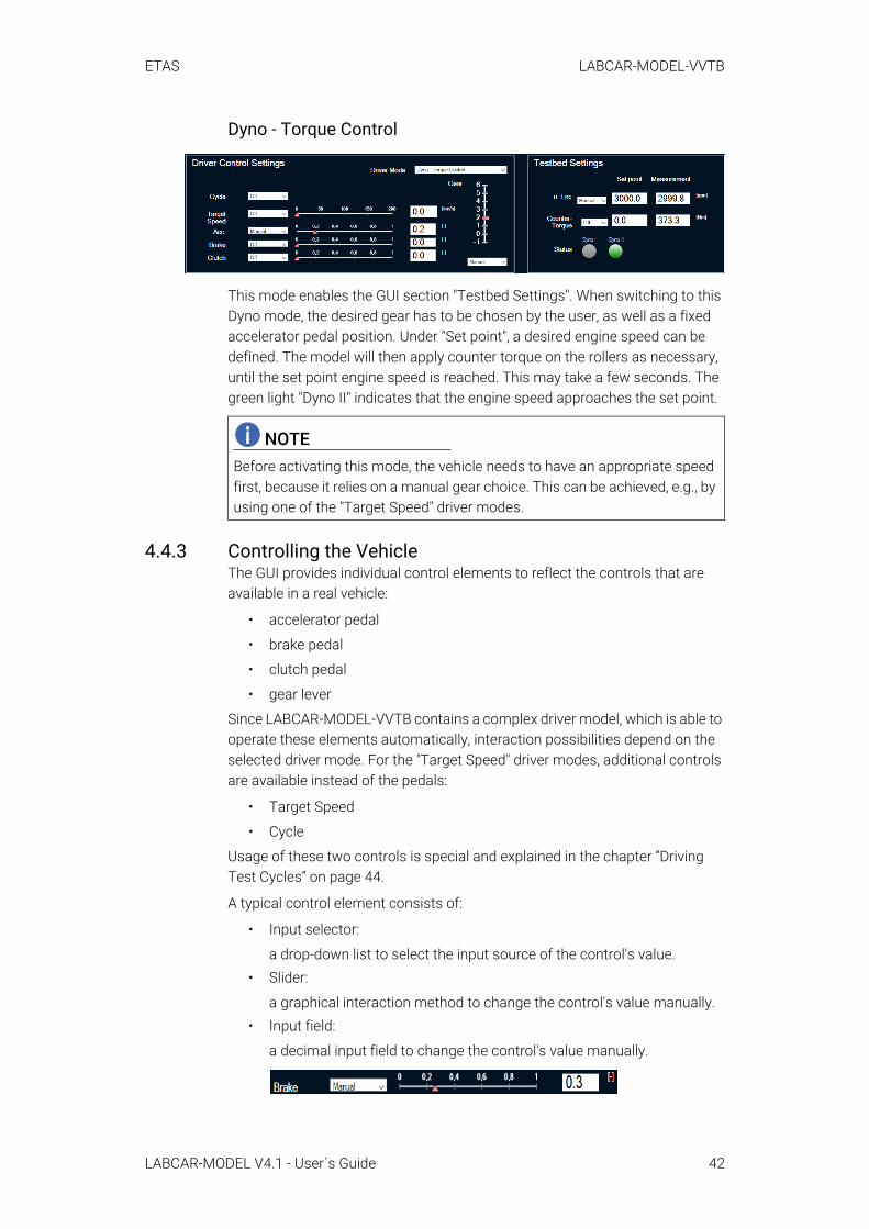
Dyno - Torque Control
This mode enables the GUI section "Testbed Settings". When switching to this Dyno mode, the desired gear has to be chosen by the user, as well as a fixed accelerator pedal position. Under "Set point", a desired engine speed can be defined. The model will then apply counter torque on the rollers as necessary, until the set point engine speed is reached. This may take a few seconds. The green light "Dyno II" indicates that the engine speed approaches the set point.
4.4.3 Controlling the VehicleThe GUI provides individual control elements to reflect the controls that are available in a real vehicle:
• accelerator pedal
• brake pedal
• clutch pedal
• gear lever
Since LABCAR-MODEL-VVTB contains a complex driver model, which is able to operate these elements automatically, interaction possibilities depend on the selected driver mode. For the "Target Speed" driver modes, additional controls are available instead of the pedals:
• Target Speed
• Cycle
Usage of these two controls is special and explained in the chapter “Driving Test Cycles” on page 44.
A typical control element consists of:
• Input selector:
a drop-down list to select the input source of the control's value.• Slider:
a graphical interaction method to change the control's value manually.• Input field:
a decimal input field to change the control's value manually.
NOTEBefore activating this mode, the vehicle needs to have an appropriate speed first, because it relies on a manual gear choice. This can be achieved, e.g., by using one of the "Target Speed" driver modes.
LABCAR-MODEL V4.1 - User´s Guide 42
ETAS LABCAR-MODEL-VVTB
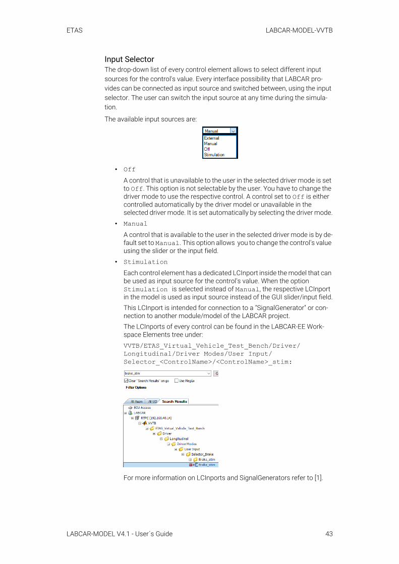
Input SelectorThe drop-down list of every control element allows to select different input sources for the control's value. Every interface possibility that LABCAR pro-vides can be connected as input source and switched between, using the input selector. The user can switch the input source at any time during the simula-tion.
The available input sources are:
• OffA control that is unavailable to the user in the selected driver mode is set to Off. This option is not selectable by the user. You have to change the driver mode to use the respective control. A control set to Off is either controlled automatically by the driver model or unavailable in the selected driver mode. It is set automatically by selecting the driver mode.
• ManualA control that is available to the user in the selected driver mode is by de-fault set to Manual. This option allows you to change the control's value using the slider or the input field.
• StimulationEach control element has a dedicated LCInport inside the model that can be used as input source for the control's value. When the option Stimulation is selected instead of Manual, the respective LCInport in the model is used as input source instead of the GUI slider/input field.This LCInport is intended for connection to a "SignalGenerator" or con-nection to another module/model of the LABCAR project.The LCInports of every control can be found in the LABCAR-EE Work-space Elements tree under:VVTB/ETAS_Virtual_Vehicle_Test_Bench/Driver/Longitudinal/Driver Modes/User Input/Selector_<ControlName>/<ControlName>_stim:
For more information on LCInports and SignalGenerators refer to [1].
LABCAR-MODEL V4.1 - User´s Guide 43

ETAS LABCAR-MODEL-VVTB
• ExternalLike Stimulation, the option External uses an LCInport as input source. It is available next to the Stimulation LCInport:
When the Stimulation LCInport is already connected to a SignalGen-erator, this External LCInport could be used to connect to a hardware controller or another controller as well. The drop-down option External can then be used to switch the input source from Manual or Stimulation to External "on-the-fly".
SliderThe slider can be used to change the control's value using the mouse cursor. For the accelerator, brake and clutch pedals, 0 represents an untouched pedal and 1 represents a fully pressed pedal.
The slider's value is only respected by the model when the input selector is set to Manual.
Input FieldThe input field can be used to define a precise decimal value. The display is rounded by default, but the number of displayed decimals can be changed using the LABCAR-EE "Properties" window.
The input field's value is only respected by the model when the input selector is set to Manual.
4.4.3.1 Driving Test CyclesThe driver model of LABCAR-MODEL-VVTB is able to follow predefined test cycles or a user-defined test cycle without any user interaction. A test cycle is defined as a target vehicle speed trajectory over time. The following test cycles are available:
• ECE2
• ECE3
• F72
• F75
• J11
• J15
• Usr
LABCAR-MODEL V4.1 - User´s Guide 44

ETAS LABCAR-MODEL-VVTB
Usr does not contain a test cycle by default. This allows you to define a test cycle that can then be executed in the same fashion as the predefined test cycles.
Test cycles can be executed when one of the Target Speed driver modes is selected. The Target Speed's input selector is similar to the other controls' input selectors, but offers the additional option Cycle:
When "Target Speed" is set to Cycle, the drop-down list labeled "Cycle" can be used to select one of the test cycles listed above. The driver will then drive that test cycle.
When "Target Speed" is set to any other input source than Cycle, the drop-down list "Cycle" is disabled and labeled Off. A previously selected test cycle will be remembered when switching "Target Speed" back to Cycle.
The chapter “Getting Started with the Tutorial Project” on page 28 contains a tutorial showing the process of defining and executing test cycles.
NOTEThe functionality uses a model-internal clock, which starts running at simula-tion start. To execute a test cycle from its start, it is recommended to select the test cycle directly after simulation start.
LABCAR-MODEL V4.1 - User´s Guide 45
ETAS LABCAR-MODEL-ICE
5 LABCAR-MODEL-ICEETAS LABCAR-MODEL-ICE is a detailed model of an internal combustion engine (ICE) and of its main subsystems. These are the combustion system, the fuel system, the intake and exhaust system, and the aftertreatment system. The model includes several preconfigured standard variants for Diesel, CNG, and Gasoline engines.
5.1 Project and Experiment CreationIn the following, a step-by-step guide is given, which describes the generation of a LABCAR-OPERATOR project using LABCAR-MODEL-ICE. For the execution of the project, no physical ECU is needed. Instead, a SoftECU controls the inter-nal combustion engine model. The project to be created contains the manual transmission vehicle model LABCAR-MODEL-VVTB given by the VVTB_MT_ICE model configuration that is combined with the gasoline variant of LABCAR-MODEL-ICE given by the ICE_G_1B_1Stg_DEMO model configuration.
5.1.1 Project Creation in LABCAR-OPERATORThis chapter addresses qualified personnel with knowledge in using LABCAR-OPERATOR. If you do not have any experience in using LABCAR-OPERATOR, please read first [1].
For the manual project creation using LABCAR-MODEL-ICE with LABCAR-OPERATOR follow the steps described in this chapter.
To set up the LABCAR-OPERATOR project1. Open the LABCAR-IP application.
2. Click File → New Project.
3. Choose the location for the file and name the project.
4. Use "RTPC" as "Target Name".
5. Click Finish.
-> The project explorer contains an empty hardware configura-tion.
The full vehicle model as well as the internal combustion engine model consist each out of a single SIMULINK module. This module also contains driver, envi-ronment, vehicle and SoftECU, which mimics the behavior of an EMS and will control the internal combustion engine model.
To add the virtual vehicle testbench model:1. Choose Project → Add Module.
2. Select "Add Simulink (TM) Module".
3. Select "Use existing Simulink (TM) Model (will be copied)".
4. Select the full vehicle model configuration VVTB_MT_ICE. The according model VVTB.mdl is located in the install folder .\VVTB\Project Items\_Lib\VVTB_MT_ICE\mdl\Simulink_VVTB\src.
5. Click Finish.
-> The Project Explorer shows the added module.
LABCAR-MODEL V4.1 - User´s Guide 46

ETAS LABCAR-MODEL-ICE
To add the internal combustion engine model 1. Choose Project → Add Module.
2. Select "Add Simulink (TM) Module".
3. Select "Use existing Simulink (TM) Model (will be copied)".
4. Select the internal combustion engine model configuration ICE_G_1B_1Stg_DEMO. The according model VVTB_ICE_LC.mdl is located in the install folder.\ICE\Project Items\_Lib\ICE_G_1B_1Stg_DEMO\mdl\Simulink_VVTB_ICE_LC\src .
5. Activate the checkbox "Copy Model Directory into Project".
6. Click Finish.
-> The Project Explorer shows the added model.
The internal combustion engine model requires initial environment conditions for proper simulation. For this purpose, C-Code modules are used for tempera-ture and pressure initialization.
To add a C-Code module
1. Choose Project → Add Module.
2. Select "Add C-Code Module".
3. Select "Use existing Module (will be copied)".
4. Select the C-Code module within the internal combustion engine model configuration ICE_G_1B_1Stg_DEMO for ambi-ent pressure initialization. The according module Init_p_Ambient.lmd is located in the install folder .\ICE\Project Items\_Lib\ICE_G_1B_1Stg_DEMO\cmod\Init_p_Ambient.
5. Click Finish.
-> The Project Explorer shows the added C-Code module.
To add the C-Code module for temperature initialization1. Choose Project → Add Module.
2. Select "Add C-Code Module".
3. Select "Use existing Module (will be copied)".
4. Select the C-Code module within the internal combustion en-gine model configuration ICE_G_1B_1Stg_DEMO for ambient temperature initialization. The according module Init_T_Ambient.lmd is located in the install folder .\ICE\Project Items\_Lib\ICE_G_1B_1Stg_DEMO\cmod \Init_T_Ambient.
5. Click Finish.
6. The Project Explorer shows the added C-Code module.
Per default, no model connections are established. For example the SoftECU is not connected to the vehicle, driver model or engine model, although it is part of the already integrated SIMULINK module VVTB.mdl. Pre-defined connection files couple the vehicle model, the engine model and the SoftECU.
LABCAR-MODEL V4.1 - User´s Guide 47

ETAS LABCAR-MODEL-ICE
To add connection files1. Open "Connection Manager" and right-click.
2. Select Import Connection.
3. Import each connection file stored in the install folder at .\VVTB\Project Items\_Lib\VVTB_MT_ICE\connand at .\ICE\Project Items\_Lib\ICE_G_1B_1Stg_DEMO\conn.
-> After the connection files are added, many connections are vis-ible in the "Connection Manager".
OS-ConfigurationVia the OS Configuration tab, you can organize the processes of LABCAR-OPERATOR modules. For SIMULINK modules, the order of execution and the selection of a proper step size is of importance. Per default, proper tasks for the SIMULINK model are auto-generated when adding the module to the project. For added C-Code modules you have to assign the execute process manually.
NOTECheck each connection file and ensure that you added all connection files. Otherwise the model might not work properly.
LABCAR-MODEL V4.1 - User´s Guide 48
ETAS LABCAR-MODEL-ICE
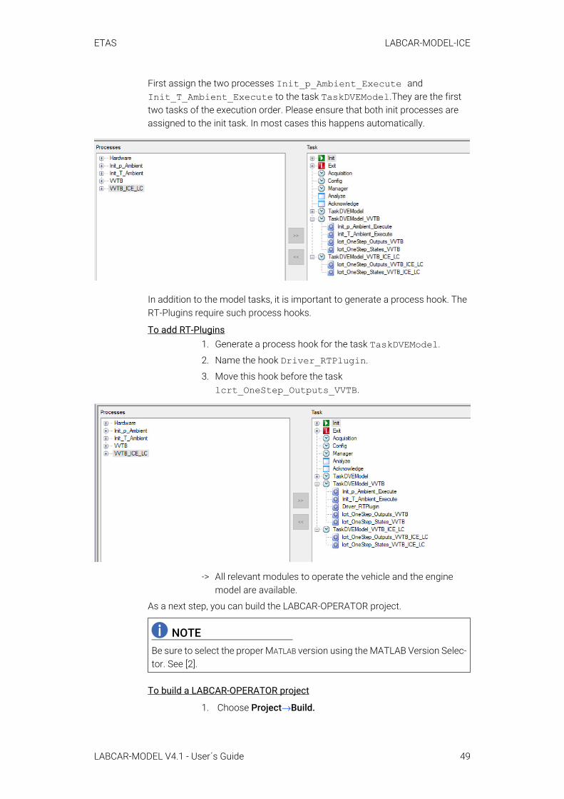
First assign the two processes Init_p_Ambient_Execute and Init_T_Ambient_Execute to the task TaskDVEModel.They are the first two tasks of the execution order. Please ensure that both init processes are assigned to the init task. In most cases this happens automatically.
In addition to the model tasks, it is important to generate a process hook. The RT-Plugins require such process hooks.
To add RT-Plugins1. Generate a process hook for the task TaskDVEModel.
2. Name the hook Driver_RTPlugin.
3. Move this hook before the task lcrt_OneStep_Outputs_VVTB.
-> All relevant modules to operate the vehicle and the engine model are available.
As a next step, you can build the LABCAR-OPERATOR project.
To build a LABCAR-OPERATOR project
1. Choose Project→Build.
NOTEBe sure to select the proper MATLAB version using the MATLAB Version Selec-tor. See [2].
LABCAR-MODEL V4.1 - User´s Guide 49
ETAS LABCAR-MODEL-ICE
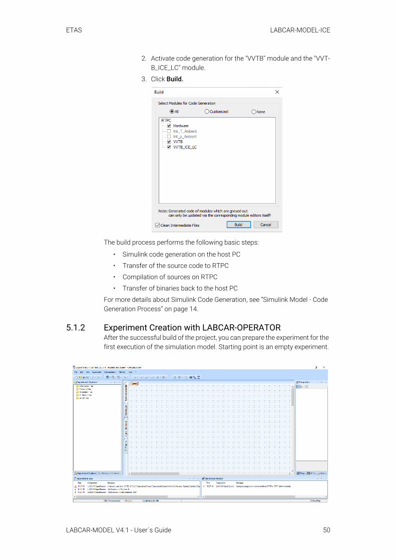
2. Activate code generation for the "VVTB" module and the "VVT-B_ICE_LC" module.
3. Click Build.
The build process performs the following basic steps:
• Simulink code generation on the host PC
• Transfer of the source code to RTPC
• Compilation of sources on RTPC
• Transfer of binaries back to the host PC
For more details about Simulink Code Generation, see “Simulink Model - Code Generation Process” on page 14.
5.1.2 Experiment Creation with LABCAR-OPERATORAfter the successful build of the project, you can prepare the experiment for the first execution of the simulation model. Starting point is an empty experiment.
LABCAR-MODEL V4.1 - User´s Guide 50
ETAS LABCAR-MODEL-ICE
Mapping Files"Mapping files" provide a possibility to simplify the signal handling in LABCAR-EE. For LABCAR-MODEL-VVTB various signal mappings are pre-defined. This allows a simple access to most important simulation signals without in-depth knowledge of the model.
1. Open Experiment Explorer
2. Add all mapping files located in the install folder at .\VVTB\Project Items\_Lib\VVTB_MT_ICE\mapping.
Parameter FilesFor LABCAR-MODEL-VVTB, no parameter files are provided. The default values of the Simulink model are used.
For LABCAR-MODEL-ICE, a parameter file is provided to set the ambient envi-ronment conditions.
• Open Experiment Explorer
• Add all cdfx files located in the install folder at .\ICE\Project Items\_Lib\ICE_G_1B_1Stg_DEMO\param\0001_Initialization.
NOTEEnsure that the added mapping files are also activated.
LABCAR-MODEL V4.1 - User´s Guide 51
ETAS LABCAR-MODEL-ICE
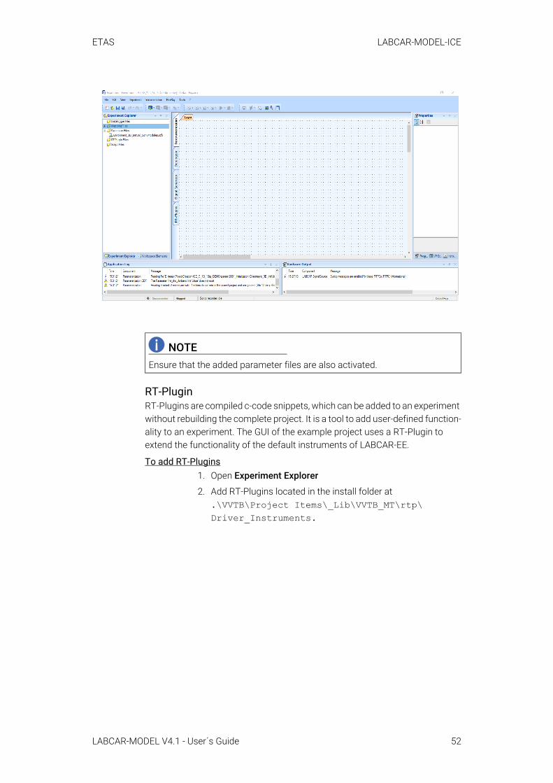
RT-PluginRT-Plugins are compiled c-code snippets, which can be added to an experiment without rebuilding the complete project. It is a tool to add user-defined function-ality to an experiment. The GUI of the example project uses a RT-Plugin to extend the functionality of the default instruments of LABCAR-EE.
To add RT-Plugins1. Open Experiment Explorer
2. Add RT-Plugins located in the install folder at .\VVTB\Project Items\_Lib\VVTB_MT\rtp\ Driver_Instruments.
NOTEEnsure that the added parameter files are also activated.
LABCAR-MODEL V4.1 - User´s Guide 52

ETAS LABCAR-MODEL-ICE
-> After the RT-Plugin is added, it is also available in the RT-Plugin tab of LABCAR-EE. Open it to check its availability.
3. Open RT-Plugins tab.
LABCAR-MODEL V4.1 - User´s Guide 53
ETAS LABCAR-MODEL-ICE
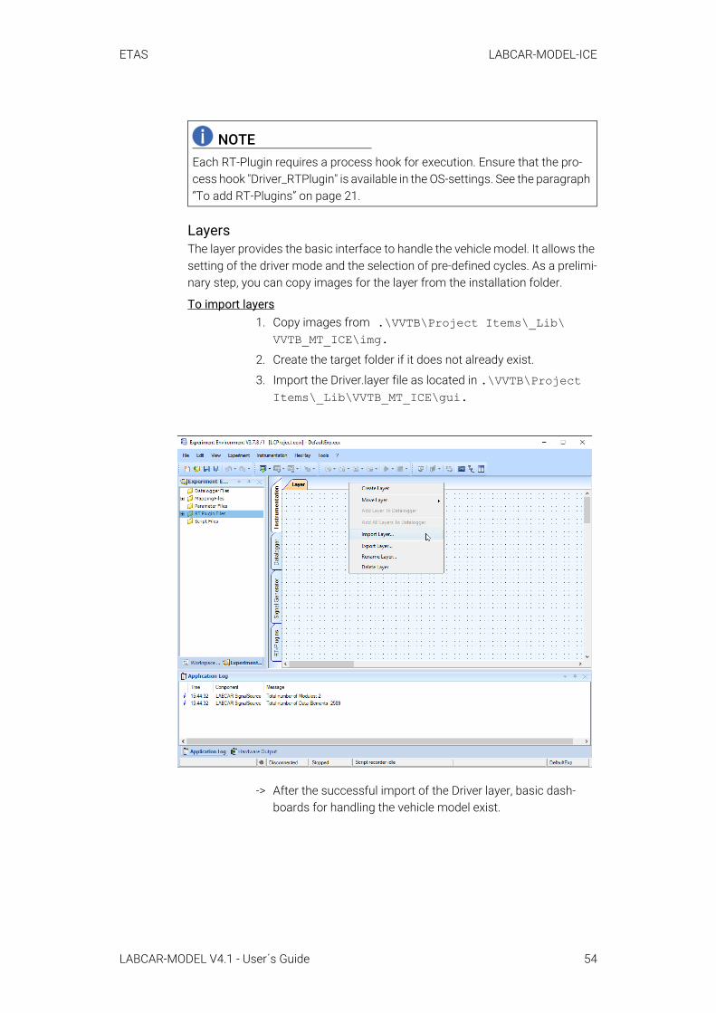
LayersThe layer provides the basic interface to handle the vehicle model. It allows the setting of the driver mode and the selection of pre-defined cycles. As a prelimi-nary step, you can copy images for the layer from the installation folder.
To import layers1. Copy images from .\VVTB\Project Items\_Lib\
VVTB_MT_ICE\img.2. Create the target folder if it does not already exist.
3. Import the Driver.layer file as located in .\VVTB\Project Items\_Lib\VVTB_MT_ICE\gui.
-> After the successful import of the Driver layer, basic dash-boards for handling the vehicle model exist.
NOTEEach RT-Plugin requires a process hook for execution. Ensure that the pro-cess hook "Driver_RTPlugin" is available in the OS-settings. See the paragraph “To add RT-Plugins” on page 21.
LABCAR-MODEL V4.1 - User´s Guide 54

ETAS LABCAR-MODEL-ICE
All required artifacts for the first execution of the models are added to the experiment. With that, the experiment is ready for the download to the RTPC and the simulation. The chapter “Getting Started with the Tutorial Project” on page 56 describes the handling of the simulation model in more detail.
NOTEAll pre-defined instruments use mapped signals provided by the mapping files. For proper execution, ensure that all mapping files are added to the experiment.
NOTETo extend the functionality of the standard instruments, so called RT-Plugins are used. Ensure that the pre-compiled RT-Plugins are added to the experi-ment.
NOTEConsider that only default LABCAR-EE instruments are used. The layer can be adapted individually to your needs.
LABCAR-MODEL V4.1 - User´s Guide 55
ETAS LABCAR-MODEL-ICE
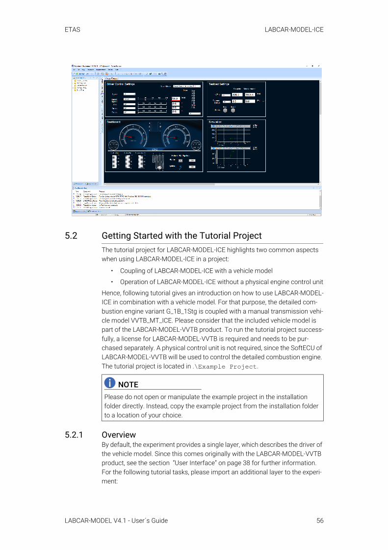
5.2 Getting Started with the Tutorial ProjectThe tutorial project for LABCAR-MODEL-ICE highlights two common aspects when using LABCAR-MODEL-ICE in a project:
• Coupling of LABCAR-MODEL-ICE with a vehicle model
• Operation of LABCAR-MODEL-ICE without a physical engine control unit
Hence, following tutorial gives an introduction on how to use LABCAR-MODEL-ICE in combination with a vehicle model. For that purpose, the detailed com-bustion engine variant G_1B_1Stg is coupled with a manual transmission vehi-cle model VVTB_MT_ICE. Please consider that the included vehicle model is part of the LABCAR-MODEL-VVTB product. To run the tutorial project success-fully, a license for LABCAR-MODEL-VVTB is required and needs to be pur-chased separately. A physical control unit is not required, since the SoftECU of LABCAR-MODEL-VVTB will be used to control the detailed combustion engine. The tutorial project is located in .\Example Project.
5.2.1 OverviewBy default, the experiment provides a single layer, which describes the driver of the vehicle model. Since this comes originally with the LABCAR-MODEL-VVTB product, see the section “User Interface” on page 38 for further information. For the following tutorial tasks, please import an additional layer to the experi-ment:
NOTEPlease do not open or manipulate the example project in the installation folder directly. Instead, copy the example project from the installation folder to a location of your choice.
LABCAR-MODEL V4.1 - User´s Guide 56
ETAS LABCAR-MODEL-ICE
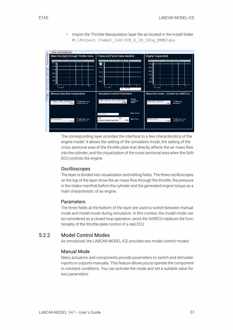
• Import the Throttle Manipulation layer file as located in the install folder in .\Project Items\_Lib\ICE_G_1B_1Stg_DEMO\gui.
The corresponding layer provides the interface to a few characteristics of the engine model. It allows the setting of the simulation mode, the setting of the cross sectional area of the throttle plate that directly affects the air mass flow into the cylinder, and the visualization of the cross sectional area when the Soft-ECU controls the engine.
Oscilloscopes The layer is divided into visualization and editing fields. The three oscilloscopes on the top of the layer show the air mass flow through the throttle, the pressure in the intake manifold before the cylinder and the generated engine torque as a main characteristic of an engine.
ParametersThe three fields at the bottom of the layer are used to switch between manual mode and model mode during simulation. In this context, the model mode can be considered as a closed loop operation, since the SoftECU replaces the func-tionality of the throttle plate control of a real ECU.
5.2.2 Model Control ModesAs introduced, the LABCAR-MODEL-ICE provides two model control modes:
Manual ModeMany actuators and components provide parameters to switch and stimulate inports or outports manually. This feature allows you to operate the component in constant conditions. You can activate the mode and set a suitable value for two parameters.
LABCAR-MODEL V4.1 - User´s Guide 57

ETAS LABCAR-MODEL-ICE
Model ModeThe same actuators and components as mentioned in the section "manual mode" provide parameters to switch back to the model mode. Within this mode the engine or, more precisely, the components will be controlled by an ECU and will appear in dynamic conditions.
5.2.3 Manipulation of Air Mass Flow into Cylinder Through Throt-tle PlateThe manual operation is the suitable starting point to close the different control loops of a model. It is recommended to start with parametrization of stationary behavior and move iteratively to transient behavior.
In this tutorial, the air mass flow will be directly manipulated via the cross sec-tion area of the throttle plate. By increasing the cross section area, more air mass will flow through. By decreasing the cross section area, less air is sup-plied to the engine for combustion.
Constant Vehicle SpeedAt first, after starting the simulation, the engine will be in idle operation. To see modeled phenomena without any side effects, the vehicle will be manually accelerated until it reaches a constant vehicle speed of 60 km/h.
To set the target speed, do the following:1. Switch to the drivers layer.
2. Set Cycle → Off.
3. Chose Target Speed → Manual.
4. Set the slider for vehicle speed target → 60 km/h.
Air Mass Flow Manipulation in Model ModeThe simulation is already started in the model mode. After the vehicle reaches the desired constant velocity, switch back to the throttle manipulation layer. The oscilloscopes show a constant air mass flow, intake pressure and engine
LABCAR-MODEL V4.1 - User´s Guide 58
ETAS LABCAR-MODEL-ICE
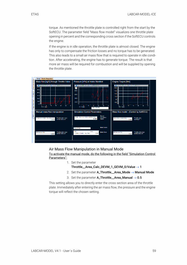
torque. As mentioned the throttle plate is controlled right from the start by the SoftECU. The parameter field "Mass flow model" visualizes one throttle plate opening in percent and the corresponding cross section if the SoftECU controls the engine.
If the engine is in idle operation, the throttle plate is almost closed. The engine has only to compensate the friction losses and no torque has to be generated. This also leads to a small air mass flow that is required to operate in idle condi-tion. After accelerating, the engine has to generate torque. The result is that more air mass will be required for combustion and will be supplied by opening the throttle plate.
Air Mass Flow Manipulation in Manual ModeTo activate the manual mode, do the following in the field "Simulation Control Parameters":
1. Set the parameter Throttle__Area_Calc_DEVM_1_GEVM_0/Value → 1
2. Set the parameter A_Throttle__Area_Mode → Manual Mode
3. Set the parameter A_Throttle__Area_Manual → 0.5
This setting allows you to directly enter the cross section area of the throttle plate. Immediately after entering the air mass flow, the pressure and the engine torque will reflect the chosen setting.
LABCAR-MODEL V4.1 - User´s Guide 59
ETAS LABCAR-MODEL-ICE
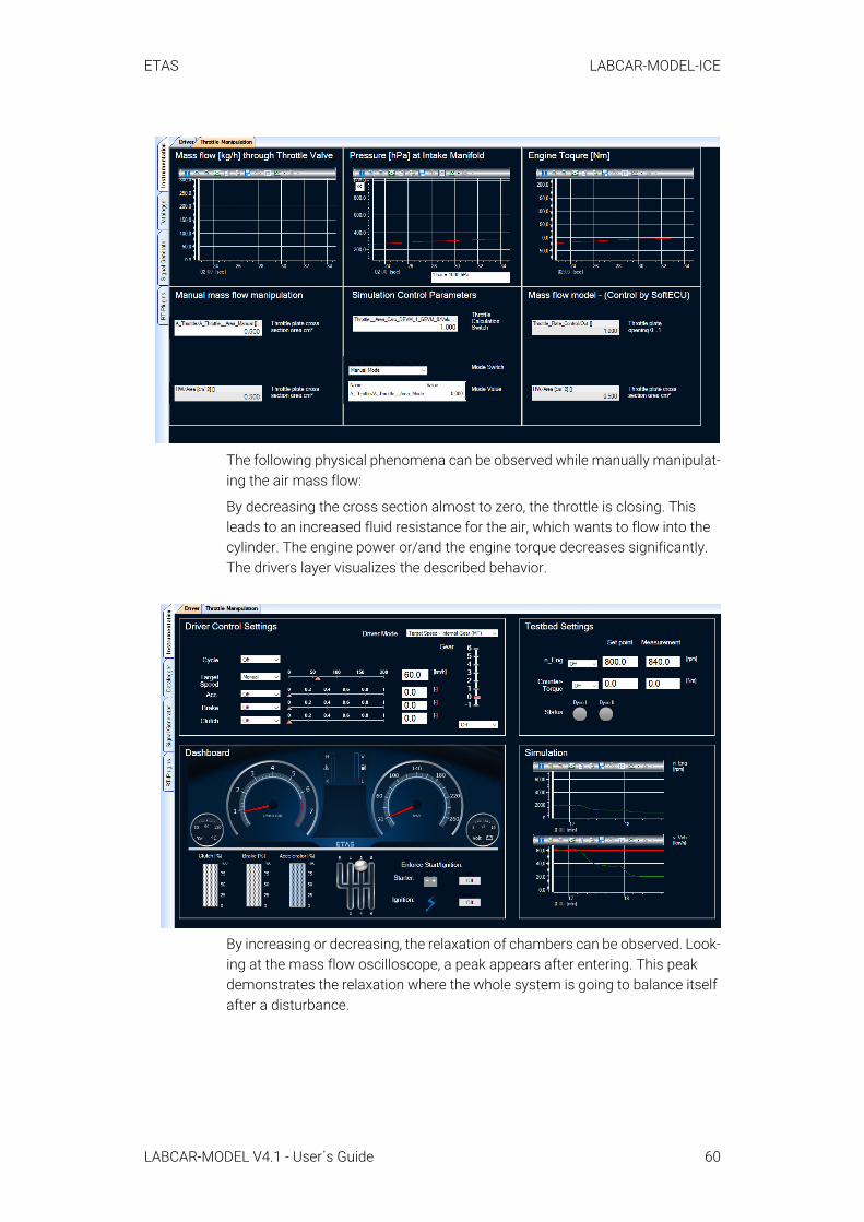
The following physical phenomena can be observed while manually manipulat-ing the air mass flow:
By decreasing the cross section almost to zero, the throttle is closing. This leads to an increased fluid resistance for the air, which wants to flow into the cylinder. The engine power or/and the engine torque decreases significantly. The drivers layer visualizes the described behavior.
By increasing or decreasing, the relaxation of chambers can be observed. Look-ing at the mass flow oscilloscope, a peak appears after entering. This peak demonstrates the relaxation where the whole system is going to balance itself after a disturbance.
LABCAR-MODEL V4.1 - User´s Guide 60

ETAS LABCAR-MODEL-ICE
5.3 Signal InterfaceThe basic interface to operate LABCAR-MODEL-ICE, as used in the chapter “Getting Started with the Tutorial Project” on page 56, is listed in the following table. LABCAR-MODEL-VVTB is used in combination with LABCAR-MODEL-ICE. All required connections of VVTB and its components can be found within the connections files of VVTB. Since LABCAR-MODEL-ICE is considered as an add-on in the tutorial, the table contains all required connections to satisfy when running LABCAR-MODEL-ICE in combination with LABCAR-MODEL-VVTB. If using LABCAR-MODEL-ICE with other drivetrain and driver models, the required connections will differ.
5.3.1 Combustion Engine/Top Level
Inputs
NOTEThe table only contains a small excerpt from all available input and output ports of the engine model. The model reference guide of LABCAR-MODEL-ICE provides the complete documentation of the physical interfaces of each S-Function and subsystem.
Name Type Unit Descriptionphi_CAModel Double CA Crankshaft angleFlywheelStandstill Bool - Engine operation statusIgnition Bool - Ignition statusp_Ambient Double Pa Ambient pressureT_Ambient Double K Ambient temperatureAccelerator Double - Accelerator positionn_Engine Double rpm Engine speed
LABCAR-MODEL V4.1 - User´s Guide 61

ETAS LABCAR-MODEL-ICE
Outputs
5.3.2 Combustion Engine/Injection
Inputs
5.3.3 Combustion Engine/Lambda Sensor
Inputs
U_Batt Double V Battery voltageM_Engage Double Nm Torque of auxiliary sys-
temsv_Vehicle Double km/h Vehicle speedv_Distance Double m Traveled distance of
vehicleClutch Double - Clutch pedal positionGear Int - Gear position
Name Type Unit DescriptionM_Engine Double Nm Engine torqueJ_Engine Double kgm² Moment of inertia of
engineM_EngineStick Double Nm Engine stick torque of
resting engine
Name Type Unit Descriptiont_Injection1 Double µs Injection time cylinder 1t_Injection2 Double µs Injection time cylinder 2t_Injection3 Double µs Injection time cylinder 3t_Injection4 Double µs Injection time cylinder 4t_Injection5 Double µs Injection time cylinder 5t_Injection6 Double µs Injection time cylinder 6
Name Type Unit DescriptionLambda Double - Lambda sensor before
catalyst
Name Type Unit Description
LABCAR-MODEL V4.1 - User´s Guide 62
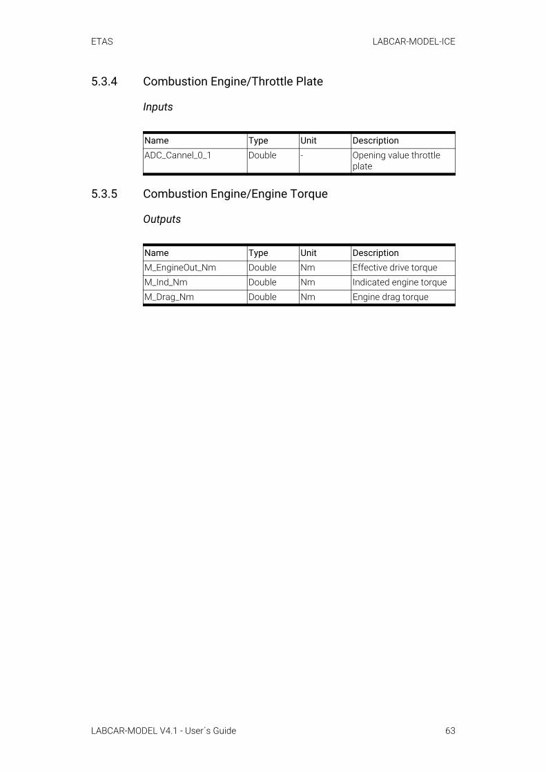
ETAS LABCAR-MODEL-ICE
5.3.4 Combustion Engine/Throttle Plate
Inputs
5.3.5 Combustion Engine/Engine Torque
Outputs
Name Type Unit DescriptionADC_Cannel_0_1 Double - Opening value throttle
plate
Name Type Unit DescriptionM_EngineOut_Nm Double Nm Effective drive torqueM_Ind_Nm Double Nm Indicated engine torqueM_Drag_Nm Double Nm Engine drag torque
LABCAR-MODEL V4.1 - User´s Guide 63
ETAS LABCAR-MODEL-PMSM
6 LABCAR-MODEL-PMSMETAS LABCAR-MODEL-PMSM is a simulation model of a 3-phase permanent magnet synchronous e-motor (PMSM). The model includes a model of an inverter, of the PMSM e-motor, and of a simple drivetrain. It is an FPGA-based model so that low latency small cycle times are possible.
6.1 OverviewThe LABCAR-MODEL-PMSM is implemented to use the FPGA of the ES5340. Therefore the LABCAR-MODEL-PMSM is an FPGA simulation model, which has been implemented using the ETAS tool FlexibleFPGA V3.0.0 and can run on this specific ETAS hardware board. For detailed information see [3].
The LABCAR-MODEL-PMSM supports the 8 analog outputs of the ES5340.2-M board. The slave board is not used. (The ES5340.2-M acts as a master board. It can be connected to the ES5340.1-S slave board to offer more analog and dig-ital output channels. This connection can be configured inside an ETAS RTPC. For more detailed information, see the ES5340.2 Electric Drive Simulation Board User's Guide.)
LABCAR-MODEL-PMSM exists in two variants, Basic and Advanced. The Basic variant consists of three main components: an ideal inverter, a PMSM e-motor, and a simplistic drivetrain model. In addition, the Advanced variant offers some more parameters. These are iron losses in the e-motor and ohmic resistances in the inverter.
6.2 Project and Experiment CreationThis chapter describes flashing LABCAR-MODEL-PMSM to ES5340.2-M board and creating a LABCAR-OPERATOR project.
6.2.1 Flashing LABCAR-MODEL-PMSM to ES5340.2-MThis section describes the procedure for flashing the LABCAR-MODEL-PMSM to the ES5340.2-M. The prerequisite for using a LABCAR-OPERATOR project is flashing the model to the ES5340.2-M. It is required to ensure that the ES5340.2-M board is inserted to the RTPC and the host PC is connected with the RTPC.
The following two steps are required to program the LABCAR-MODEL-PMSM to the FPGA.
• Run the "FlexFPGACopy.exe" file.
You find more details on this tool in [4].
NOTEThe HSP update tool is delivered with LABCAR-OPERATOR until version 5.4.7. Newer versions of LABCAR-OPERATOR need a separate installation of the HSP update tool. Please consider [2] to install the correct version of the HSP update tool.
LABCAR-MODEL V4.1 - User´s Guide 64
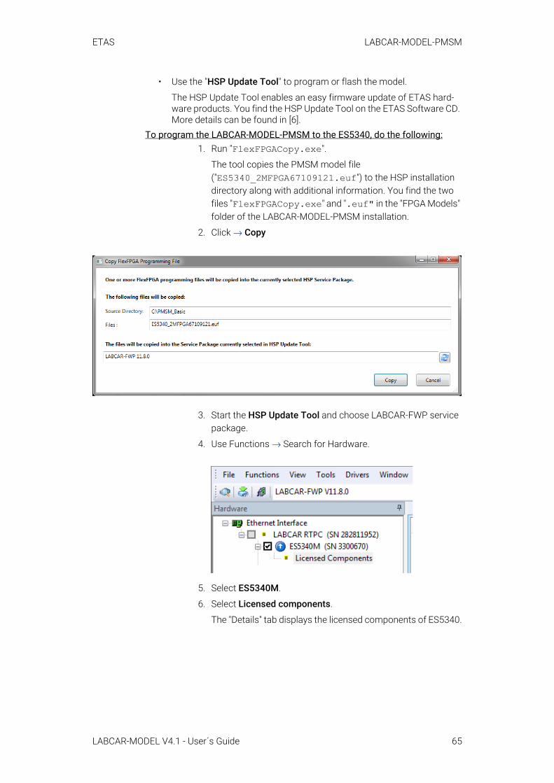
ETAS LABCAR-MODEL-PMSM
• Use the "HSP Update Tool" to program or flash the model.
The HSP Update Tool enables an easy firmware update of ETAS hard-ware products. You find the HSP Update Tool on the ETAS Software CD. More details can be found in [6].
To program the LABCAR-MODEL-PMSM to the ES5340, do the following:1. Run "FlexFPGACopy.exe".
The tool copies the PMSM model file ("ES5340_2MFPGA67109121.euf") to the HSP installation directory along with additional information. You find the two files "FlexFPGACopy.exe" and ".euf" in the "FPGA Models" folder of the LABCAR-MODEL-PMSM installation.
2. Click → Copy
3. Start the HSP Update Tool and choose LABCAR-FWP service package.
4. Use Functions → Search for Hardware.
5. Select ES5340M.
6. Select Licensed components.
The "Details" tab displays the licensed components of ES5340.
LABCAR-MODEL V4.1 - User´s Guide 65
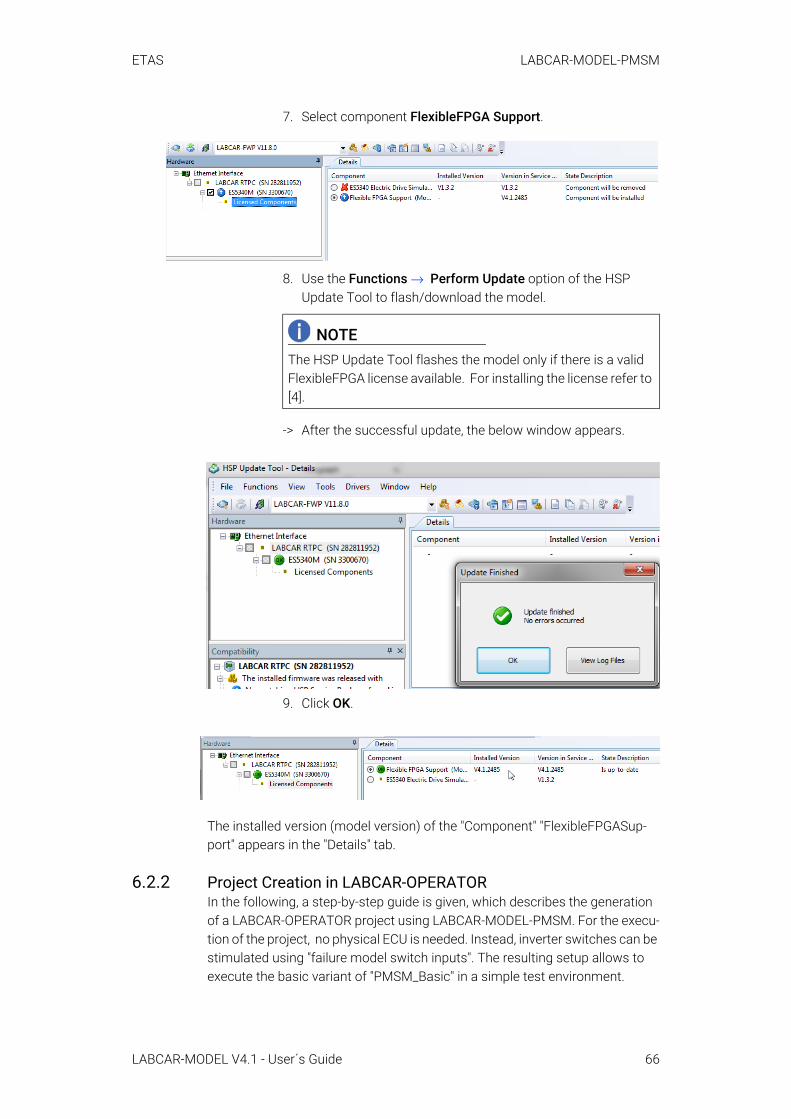
ETAS LABCAR-MODEL-PMSM
7. Select component FlexibleFPGA Support.
8. Use the Functions → Perform Update option of the HSP Update Tool to flash/download the model.
-> After the successful update, the below window appears.
9. Click OK.
The installed version (model version) of the "Component" "FlexibleFPGASup-port" appears in the "Details" tab.
6.2.2 Project Creation in LABCAR-OPERATORIn the following, a step-by-step guide is given, which describes the generation of a LABCAR-OPERATOR project using LABCAR-MODEL-PMSM. For the execu-tion of the project, no physical ECU is needed. Instead, inverter switches can be stimulated using "failure model switch inputs". The resulting setup allows to execute the basic variant of "PMSM_Basic" in a simple test environment.
NOTEThe HSP Update Tool flashes the model only if there is a valid FlexibleFPGA license available. For installing the license refer to [4].
LABCAR-MODEL V4.1 - User´s Guide 66

ETAS LABCAR-MODEL-PMSM
This chapter addresses qualified personnel with knowledge in using LABCAR-OPERATOR. If you do not have any experience in using LABCAR-OPERATOR, please read first [1].
For the manual project creation using LABCAR-MODEL-PMSM with LABCAR-OPERATOR, follow the steps described in this chapter.
As a preliminary step, you successfully flashed the latest LABCAR-MODEL-PMSM software to the ES5340.2-M board as described in chapter “Flashing LABCAR-MODEL-PMSM to ES5340.2-M” on page 64.
To set up the LABCAR-OPERATOR project, do the following:1. Open LABCAR-OPERATOR
2. Create a new Project called "PMSM_Basic".
-> After creation, the LABCAR-OPERATOR project environment looks as follows:
The LABCAR-MODEL-PMSM model is integrated into the LABCAR-OPERATOR project using the hardware configuration.
To integrate the LABCAR-MODEL-PMSM model, do the following:1. In the Project Explorer, right-click on "Hardware" and select
Edit.
2. Right-click on "ES1130" and choose Delete Item.
3. Right-click on "RTPC::Rtpc" and chooseAdd item → ES5340-Hybrid.
LABCAR-MODEL V4.1 - User´s Guide 67

ETAS LABCAR-MODEL-PMSM
4. Click Ok.
5. Right click on "ES5340-Hybrid" and chooseAdd Item → ES5340-Master.
6. Click Ok.
7. Right-click on "ES5340-Master" and choose Add Item → ES5340-FlexibleFPGA.
8. Click Ok.
A window pops up.
9. Select "PMSM_3Phase_dut.adf".
-> Now the LABCAR-MODEL-PMSM appears on LABCAR-RTC.
LABCAR-MODEL V4.1 - User´s Guide 68
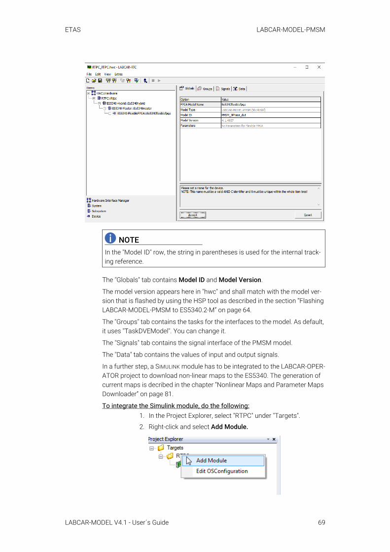
ETAS LABCAR-MODEL-PMSM
The "Globals" tab contains Model ID and Model Version.
The model version appears here in "hwc" and shall match with the model ver-sion that is flashed by using the HSP tool as described in the section “Flashing LABCAR-MODEL-PMSM to ES5340.2-M” on page 64.
The "Groups" tab contains the tasks for the interfaces to the model. As default, it uses "TaskDVEModel". You can change it.
The "Signals" tab contains the signal interface of the PMSM model.
The "Data" tab contains the values of input and output signals.
In a further step, a SIMULINK module has to be integrated to the LABCAR-OPER-ATOR project to download non-linear maps to the ES5340. The generation of current maps is decribed in the chapter “Nonlinear Maps and Parameter Maps Downloader” on page 81.
To integrate the Simulink module, do the following:1. In the Project Explorer, select "RTPC" under "Targets".
2. Right-click and select Add Module.
NOTEIn the "Model ID" row, the string in parentheses is used for the internal track-ing reference.
LABCAR-MODEL V4.1 - User´s Guide 69

ETAS LABCAR-MODEL-PMSM
3. Choose "Add Simulink(TM) Module" and click Next.
4. Select "Use existing Simulink (TM) Model (will be copied)" and click Next.
5. Use browse to .\Project Items\_Lib\PMSM_Param_Download\mdl\Simulink_PMSM_Map_Download\src in the install folder.
6. Choose "PMSM_Parameter_Maps_Download.mdl" to add the SIMULINK module.
7. Click Finish.
-> After successfully adding the SIMULINK module, the Project Explorer will look like this:
The next step is to integrate a C-code module in order to be able to consider the temperate effect of coils.
To add a C-code module, do the following:1. In the Project Explorer, select "RTPC" under "Targets"
2. Right-click and select Add Module.
3. Choose "Add C-Code Module" and click Next.
4. Select "Use existing C-Code Module (will be copied)" and click Next.
5. Click Browse and go to .\Project Items\_Lib\PMSM_T2R_Coil\cmod\PMSM_T2R_Coil in the install folder.
6. Choose "PMSM_T2R_Coil.lmd" to add the C-Code module.
7. Click Finish.
LABCAR-MODEL V4.1 - User´s Guide 70
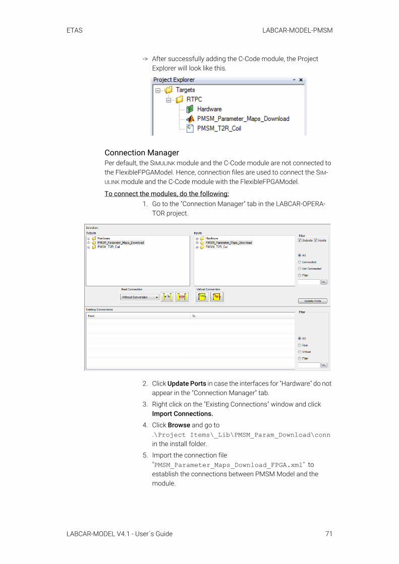
ETAS LABCAR-MODEL-PMSM
-> After successfully adding the C-Code module, the Project Explorer will look like this.
Connection ManagerPer default, the SIMULINK module and the C-Code module are not connected to the FlexibleFPGAModel. Hence, connection files are used to connect the SIM-ULINK module and the C-Code module with the FlexibleFPGAModel.
To connect the modules, do the following:1. Go to the "Connection Manager" tab in the LABCAR-OPERA-
TOR project.
2. Click Update Ports in case the interfaces for "Hardware" do not appear in the "Connection Manager" tab.
3. Right click on the "Existing Connections" window and click Import Connections.
4. Click Browse and go to .\Project Items\_Lib\PMSM_Param_Download\conn in the install folder.
5. Import the connection file "PMSM_Parameter_Maps_Download_FPGA.xml" to establish the connections between PMSM Model and the module.
LABCAR-MODEL V4.1 - User´s Guide 71
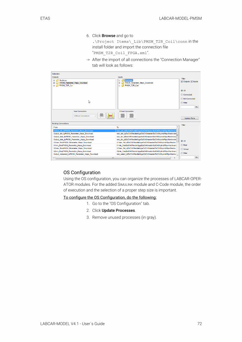
ETAS LABCAR-MODEL-PMSM
6. Click Browse and go to .\Project Items\_Lib\PMSM_T2R_Coil\conn in the install folder and import the connection file "PMSM_T2R_Coil_FPGA.xml".
-> After the import of all connections the "Connection Manager" tab will look as follows:
OS ConfigurationUsing the OS configuration, you can organize the processes of LABCAR-OPER-ATOR modules. For the added SIMULINK module and C-Code module, the order of execution and the selection of a proper step size is important.
To configure the OS Configuration, do the following:1. Go to the "OS Configuration" tab.
2. Click Update Processes.
3. Remove unused processes (in gray).
LABCAR-MODEL V4.1 - User´s Guide 72
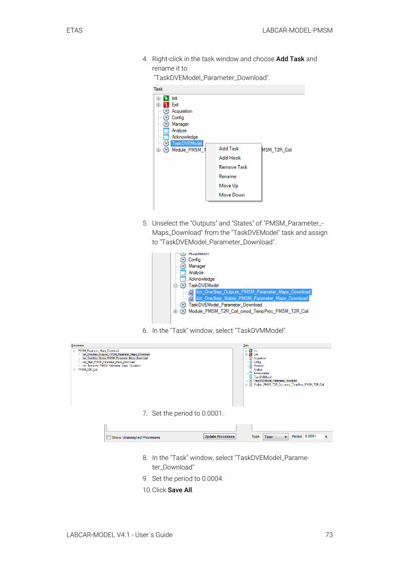
ETAS LABCAR-MODEL-PMSM
4. Right-click in the task window and choose Add Task and rename it to "TaskDVEModel_Parameter_Download".
5. Unselect the "Outputs" and "States" of "PMSM_Parameter_-Maps_Download" from the "TaskDVEModel" task and assign to "TaskDVEModel_Parameter_Download".
6. In the "Task" window, select "TaskDVMModel".
7. Set the period to 0.0001.
8. In the "Task" window, select "TaskDVEModel_Parame-ter_Download"
9. Set the period to 0.0004.
10.Click Save All.
LABCAR-MODEL V4.1 - User´s Guide 73
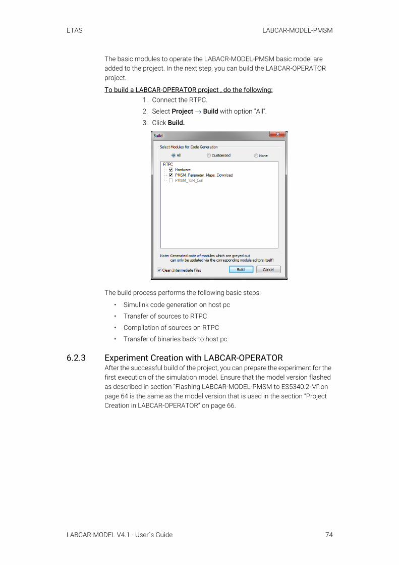
ETAS LABCAR-MODEL-PMSM
The basic modules to operate the LABACR-MODEL-PMSM basic model are added to the project. In the next step, you can build the LABCAR-OPERATOR project.
To build a LABCAR-OPERATOR project , do the following:1. Connect the RTPC.
2. Select Project → Build with option "All".
3. Click Build.
The build process performs the following basic steps:
• Simulink code generation on host pc
• Transfer of sources to RTPC
• Compilation of sources on RTPC
• Transfer of binaries back to host pc
6.2.3 Experiment Creation with LABCAR-OPERATORAfter the successful build of the project, you can prepare the experiment for the first execution of the simulation model. Ensure that the model version flashed as described in section “Flashing LABCAR-MODEL-PMSM to ES5340.2-M” on page 64 is the same as the model version that is used in the section “Project Creation in LABCAR-OPERATOR” on page 66.
LABCAR-MODEL V4.1 - User´s Guide 74
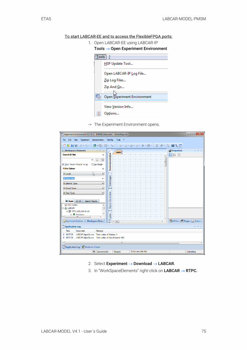
ETAS LABCAR-MODEL-PMSM
To start LABCAR-EE and to access the FlexibleFPGA ports:1. Open LABCAR-EE using LABCAR-IP
Tools → Open Experiment Environment
-> The Experiment Environment opens.
2. Select Experiment → Download → LABCAR.
3. In “WorkSpaceElements” right-click on LABCAR → RTPC.
LABCAR-MODEL V4.1 - User´s Guide 75

ETAS LABCAR-MODEL-PMSM
4. Click Show All HW Ports.
-> All the ports to the PMSM model are visible.
Parameter FilesNo parameter files are provided. The default values of the FlexibleFPGAModel are used.
LayersThe layer provides the basic interface to handle the PMSM model. It allows the setting of the driver mode and the selection of predefined cycles..
The following layers must be installed.
• PMSM_01_Simulation_Control.layer• PMSM_Failure_Simulations.layer• PMSM_Parameters_Ideal.layer• PMSM_Runtime_License. Layer
NOTEPlease consider that only default LABCAR-EE instruments are used. The layer can be adapted individually to your needs.
LABCAR-MODEL V4.1 - User´s Guide 76
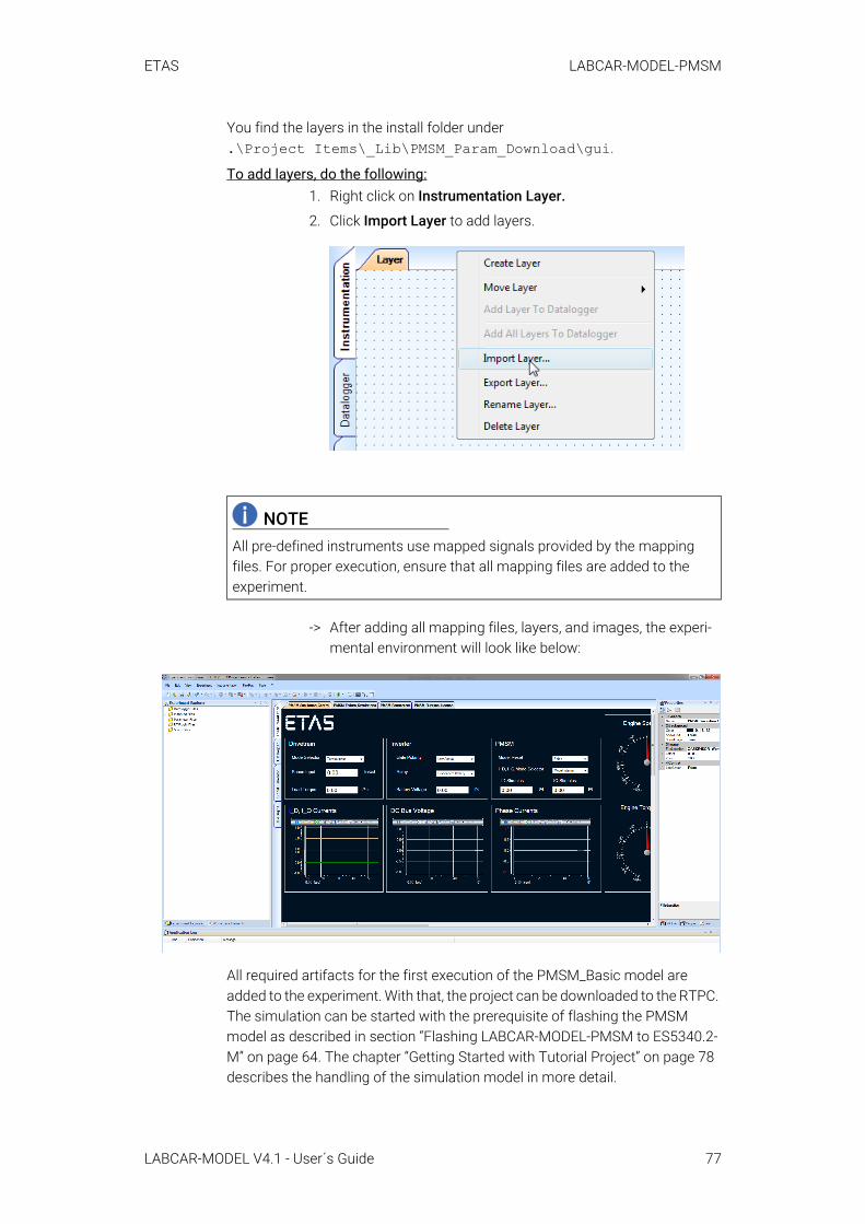
ETAS LABCAR-MODEL-PMSM
You find the layers in the install folder under .\Project Items\_Lib\PMSM_Param_Download\gui.
To add layers, do the following:1. Right click on Instrumentation Layer.
2. Click Import Layer to add layers.
-> After adding all mapping files, layers, and images, the experi-mental environment will look like below:
All required artifacts for the first execution of the PMSM_Basic model are added to the experiment. With that, the project can be downloaded to the RTPC. The simulation can be started with the prerequisite of flashing the PMSM model as described in section “Flashing LABCAR-MODEL-PMSM to ES5340.2-M” on page 64. The chapter “Getting Started with Tutorial Project” on page 78 describes the handling of the simulation model in more detail.
NOTEAll pre-defined instruments use mapped signals provided by the mapping files. For proper execution, ensure that all mapping files are added to the experiment.
LABCAR-MODEL V4.1 - User´s Guide 77
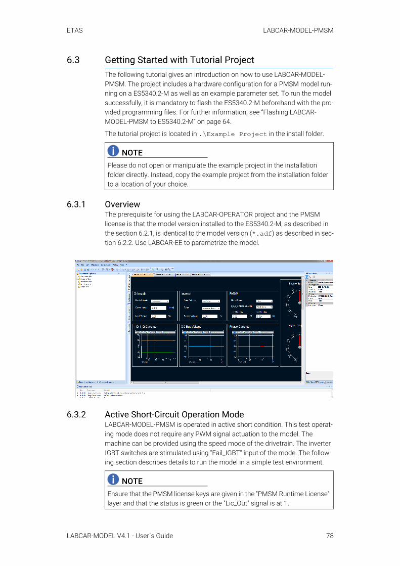
ETAS LABCAR-MODEL-PMSM
6.3 Getting Started with Tutorial ProjectThe following tutorial gives an introduction on how to use LABCAR-MODEL-PMSM. The project includes a hardware configuration for a PMSM model run-ning on a ES5340.2-M as well as an example parameter set. To run the model successfully, it is mandatory to flash the ES5340.2-M beforehand with the pro-vided programming files. For further information, see “Flashing LABCAR-MODEL-PMSM to ES5340.2-M” on page 64.
The tutorial project is located in .\Example Project in the install folder.
6.3.1 OverviewThe prerequisite for using the LABCAR-OPERATOR project and the PMSM license is that the model version installed to the ES5340.2-M, as described in the section 6.2.1, is identical to the model version (*.adf) as described in sec-tion 6.2.2. Use LABCAR-EE to parametrize the model.
6.3.2 Active Short-Circuit Operation ModeLABCAR-MODEL-PMSM is operated in active short condition. This test operat-ing mode does not require any PWM signal actuation to the model. The machine can be provided using the speed mode of the drivetrain. The inverter IGBT switches are stimulated using "Fail_IGBT" input of the mode. The follow-ing section describes details to run the model in a simple test environment.
NOTEPlease do not open or manipulate the example project in the installation folder directly. Instead, copy the example project from the installation folder to a location of your choice.
NOTEEnsure that the PMSM license keys are given in the "PMSM Runtime License" layer and that the status is green or the "Lic_Out" signal is at 1.
LABCAR-MODEL V4.1 - User´s Guide 78
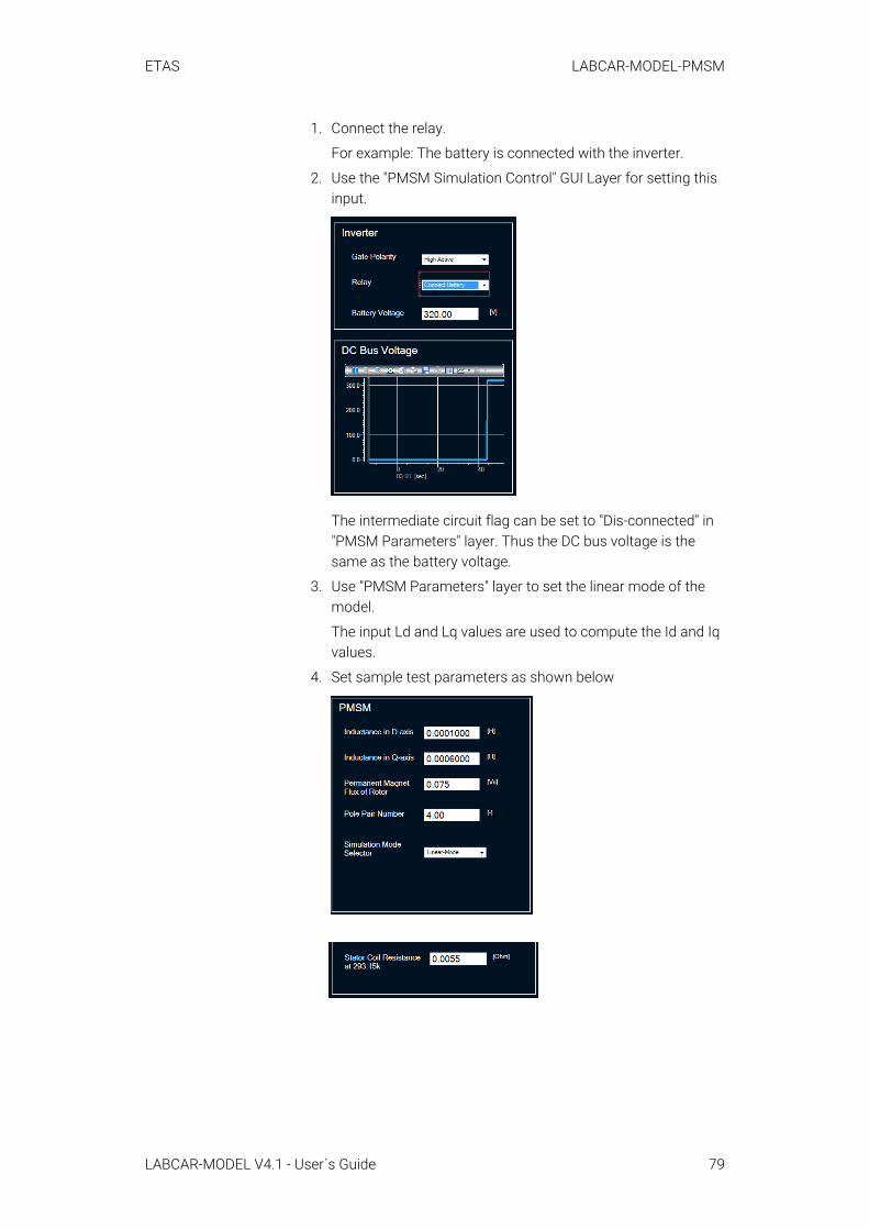
ETAS LABCAR-MODEL-PMSM
1. Connect the relay.
For example: The battery is connected with the inverter.
2. Use the "PMSM Simulation Control" GUI Layer for setting this input.
The intermediate circuit flag can be set to "Dis-connected" in "PMSM Parameters" layer. Thus the DC bus voltage is the same as the battery voltage.
3. Use "PMSM Parameters" layer to set the linear mode of the model.
The input Ld and Lq values are used to compute the Id and Iq values.
4. Set sample test parameters as shown below
LABCAR-MODEL V4.1 - User´s Guide 79
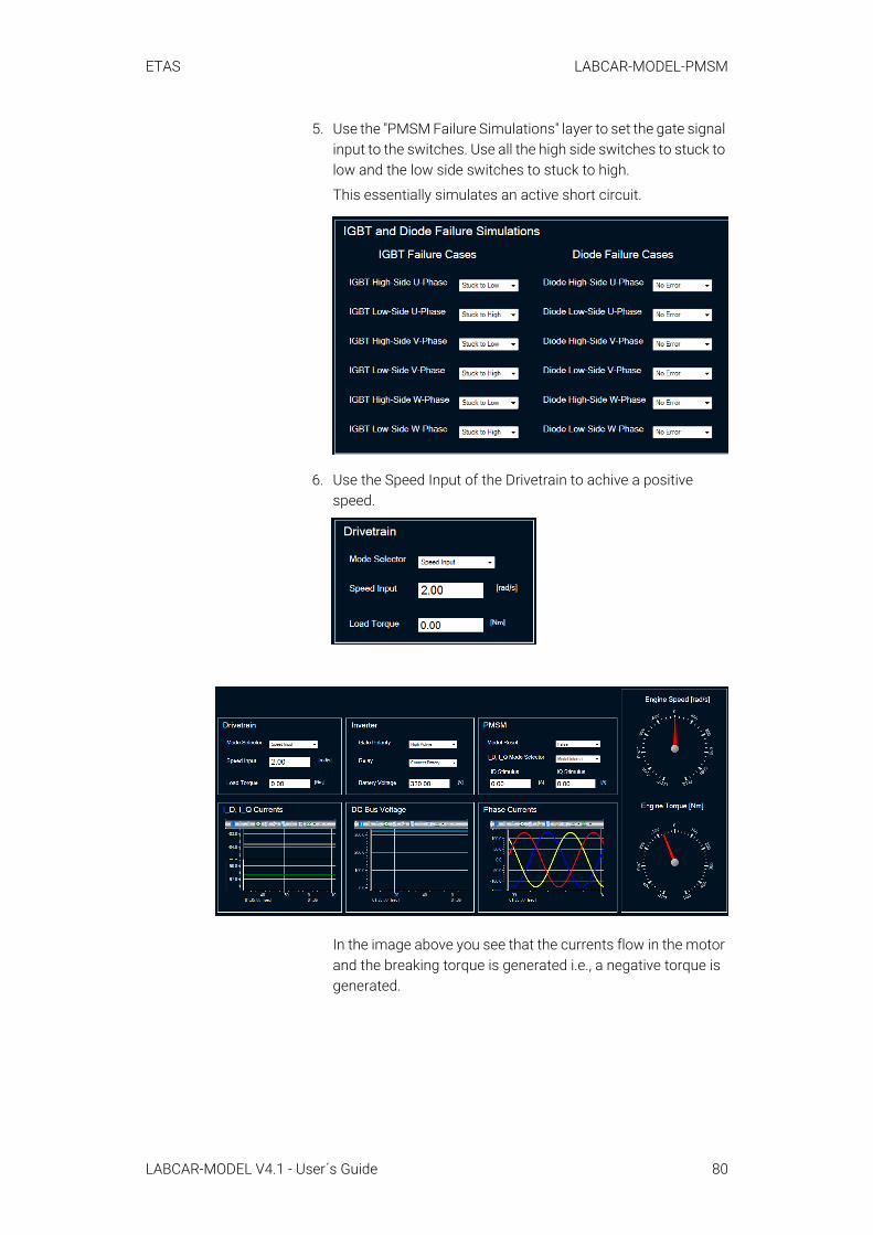
ETAS LABCAR-MODEL-PMSM
5. Use the "PMSM Failure Simulations" layer to set the gate signal input to the switches. Use all the high side switches to stuck to low and the low side switches to stuck to high.
This essentially simulates an active short circuit.
6. Use the Speed Input of the Drivetrain to achive a positive speed.
In the image above you see that the currents flow in the motor and the breaking torque is generated i.e., a negative torque is generated.
LABCAR-MODEL V4.1 - User´s Guide 80
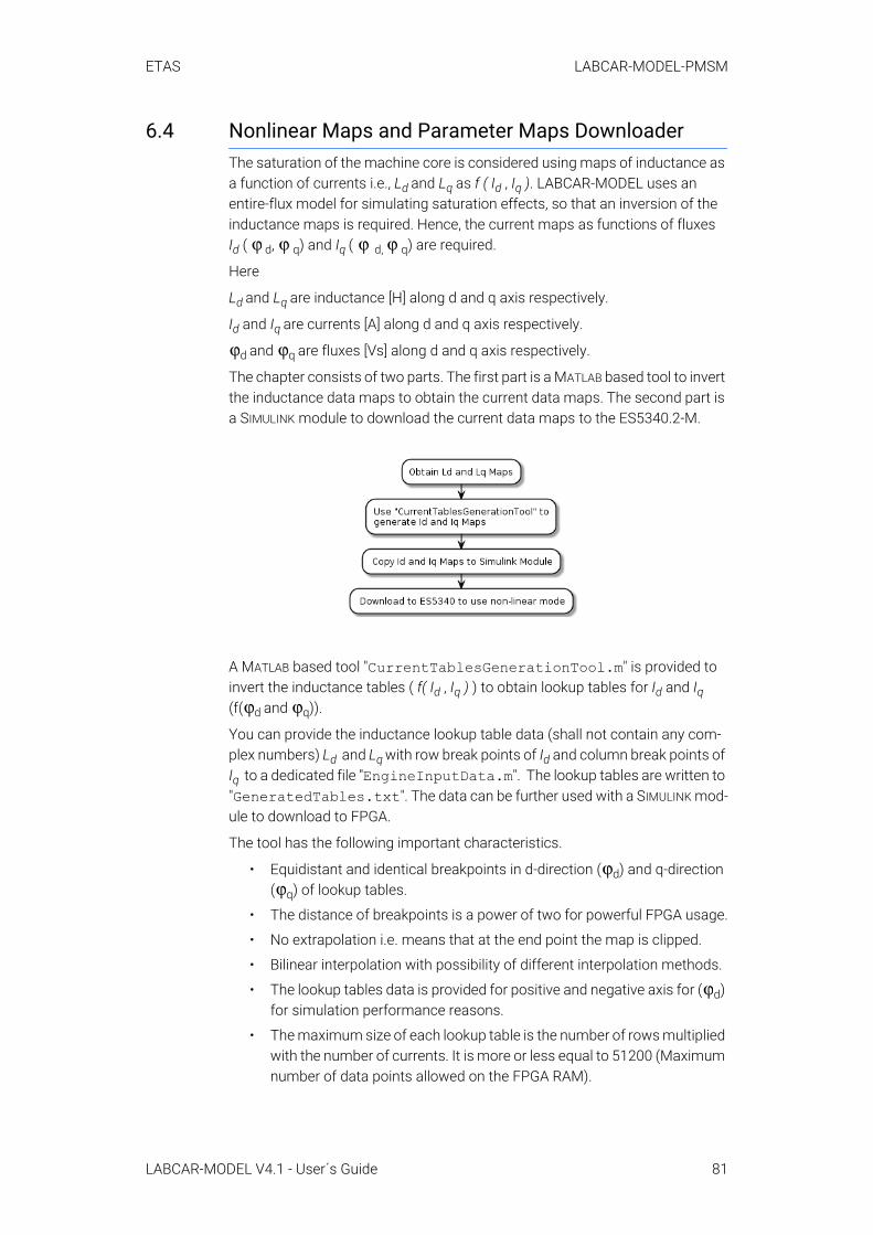
ETAS LABCAR-MODEL-PMSM
6.4 Nonlinear Maps and Parameter Maps DownloaderThe saturation of the machine core is considered using maps of inductance as a function of currents i.e., Ld and Lq as f ( Id , Iq ). LABCAR-MODEL uses an entire-flux model for simulating saturation effects, so that an inversion of the inductance maps is required. Hence, the current maps as functions of fluxes Id ( d, q) and Iq ( d, q) are required.
Here
Ld and Lq are inductance [H] along d and q axis respectively.
Id and Iq are currents [A] along d and q axis respectively.
d and q are fluxes [Vs] along d and q axis respectively.
The chapter consists of two parts. The first part is a MATLAB based tool to invert the inductance data maps to obtain the current data maps. The second part is a SIMULINK module to download the current data maps to the ES5340.2-M.
A MATLAB based tool "CurrentTablesGenerationTool.m" is provided to invert the inductance tables ( f( Id , Iq ) ) to obtain lookup tables for Id and Iq (f( d and q)).
You can provide the inductance lookup table data (shall not contain any com-plex numbers) Ld and Lq with row break points of Id and column break points of Iq to a dedicated file "EngineInputData.m". The lookup tables are written to "GeneratedTables.txt". The data can be further used with a SIMULINK mod-ule to download to FPGA.
The tool has the following important characteristics.
• Equidistant and identical breakpoints in d-direction ( d) and q-direction ( q) of lookup tables.
• The distance of breakpoints is a power of two for powerful FPGA usage.
• No extrapolation i.e. means that at the end point the map is clipped.
• Bilinear interpolation with possibility of different interpolation methods.
• The lookup tables data is provided for positive and negative axis for ( d) for simulation performance reasons.
• The maximum size of each lookup table is the number of rows multiplied with the number of currents. It is more or less equal to 51200 (Maximum number of data points allowed on the FPGA RAM).
ϕ ϕ ϕ ϕ
ϕ ϕ
ϕ ϕ
ϕϕ
ϕ
LABCAR-MODEL V4.1 - User´s Guide 81
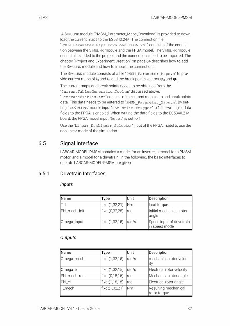
ETAS LABCAR-MODEL-PMSM
A SIMULINK module "PMSM_Parameter_Maps_Download" is provided to down-load the current maps to the ES5340.2-M. The connection file "PMSM_Parameter_Maps_Download_FPGA.xml" consists of the connec-tion between the SIMULINK module and the FPGA model. The SIMULINK module needs to be added to the project and the connections need to be imported. The chapter “Project and Experiment Creation” on page 64 describes how to add the SIMULINK module and how to import the connections.
The SIMULINK module consists of a file "PMSM_Parameter_Maps.m" to pro-vide current maps of Id and Iq and the break points vectors d and q.
The current maps and break points needs to be obtained from the "CurrentTablesGenerationTool.m" discussed above. "GeneratedTables.txt" consists of the current maps data and break points data. This data needs to be entered to "PMSM_Parameter_Maps.m". By set-ting the SIMULINK module input "RAM_Write_Trigger" to 1, the writing of data fields to the FPGA is enabled. When writing the data fields to the ES5340.2-M board, the FPGA model input "Reset" is set to 1.
Use the "Linear_NonLinear_Selector" input of the FPGA model to use the non-linear mode of the simulation.
6.5 Signal InterfaceLABCAR-MODEL-PMSM contains a model for an inverter, a model for a PMSM motor, and a model for a drivetrain. In the following, the basic interfaces to operate LABCAR-MODEL-PMSM are given.
6.5.1 Drivetrain Interfaces
Inputs
Outputs
Name Type Unit DescriptionT_L fixdt(1,32,21) Nm load torquePhi_mech_Init fixdt(0,32,28) rad Initial mechanical rotor
angleOmega_Input fixdt(1,32,15) rad/s Speed input of drivetrain
in speed mode
Name Type Unit DescriptionOmega_mech fixdt(1,32,15) rad/s mechanical rotor veloc-
ityOmega_el fixdt(1,32,15) rad/s Electrical rotor velocityPhi_mech_rad fixdt(0,18,15) rad Mechanical rotor anglePhi_el fixdt(1,18,15) rad Electrical rotor angleT_mech fixdt(1,32,21) Nm Resulting mechanical
rotor torque
ϕ ϕ
LABCAR-MODEL V4.1 - User´s Guide 82
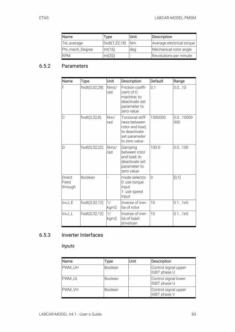
ETAS LABCAR-MODEL-PMSM
6.5.2 Parameters
6.5.3 Inverter Interfaces
Inputs
Tel_average fixdt(1,32,18) Nm Average electrical torquePhi_mech_Degree Int(16) deg Mechanical rotor angleRPM Int(32) - Revolutions per minute
Name Type Unit Description Default Rangef fixdt(0,32,28) Nms/
radFriction coeffi-cient of E-machine; to deactivate set parameter to zero value
0.1 0.0...10
C fixdt(0,32,8) Nm/rad
Torsional stiff-ness between rotor and load; to deactivate set parameter to zero value
1500000 0.0...10000000
D fixdt(0,32,22) Nms/rad
Damping between rotor and load; to deactivate set parameter to zero value
100.0 0.0...100
Direct Feed through
Boolean - mode selector0: use torque input1: use speed input
0 [0,1]
invJ_E fixdt(0,32,12) 1/kgm2
Inverse of iner-tia of rotor
10 0.1...1e5
invJ_L fixdt(0,32,12) 1/kgm2
Inverse of iner-tia of load/drivetrain
10 0.1...1e5
Name Type Unit DescriptionPWM_UH Boolean - Control signal upper
IGBT phase UPWM_UL Boolean - Control signal lower
IGBT phase UPWM_VH Boolean - Control signal upper
IGBT phase V
Name Type Unit Description
LABCAR-MODEL V4.1 - User´s Guide 83
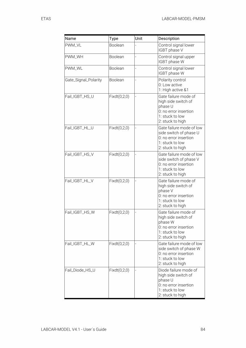
ETAS LABCAR-MODEL-PMSM
PWM_VL Boolean - Control signal lower IGBT phase V
PWM_WH Boolean - Control signal upper IGBT phase W
PWM_WL Boolean - Control signal lower IGBT phase W
Gate_Signal_Polarity Boolean - Polarity control0: Low active1: High active &1
Fail_IGBT_HS_U Fixdt(0,2,0) - Gate failure mode of high side switch of phase U0: no error insertion1: stuck to low2: stuck to high
Fail_IGBT_HL_U Fixdt(0,2,0) - Gate failure mode of low side switch of phase U0: no error insertion1: stuck to low2: stuck to high
Fail_IGBT_HS_V Fixdt(0,2,0) - Gate failure mode of low side switch of phase V0: no error insertion1: stuck to low2: stuck to high
Fail_IGBT_HL_V Fixdt(0,2,0) - Gate failure mode of high side switch of phase V0: no error insertion1: stuck to low2: stuck to high
Fail_IGBT_HS_W Fixdt(0,2,0) - Gate failure mode of high side switch of phase W 0: no error insertion 1: stuck to low 2: stuck to high
Fail_IGBT_HL_W Fixdt(0,2,0) - Gate failure mode of low side switch of phase W 0: no error insertion 1: stuck to low 2: stuck to high
Fail_Diode_HS_U Fixdt(0,2,0) - Diode failure mode of high side switch of phase U 0: no error insertion 1: stuck to low 2: stuck to high
Name Type Unit Description
LABCAR-MODEL V4.1 - User´s Guide 84

ETAS LABCAR-MODEL-PMSM
Fail_Diode_HL_U Fixdt(0,2,0) - Diode failure mode of low side switch of phase U 0: no error insertion 1: stuck to low 2: stuck to high
Fail_Diode_HS_V Fixdt(0,2,0) - Diode failure mode of high side switch of phase V 0: no error insertion 1: stuck to low 2: stuck to high
Fail_Diode_HL_V Fixdt(0,2,0) - Diode failure mode of low side switch of phase V 0: no error insertion 1: stuck to low 2: stuck to high
Fail_Diode_HS_W Fixdt(0,2,0) - Diode failure mode of high side switch of phase W 0: no error insertion 1: stuck to low 2: stuck to high
Fail_Diode_HL_W Fixdt(0,2,0) - Diode failure mode of low side switch of phase W 0: no error insertion 1: stuck to low 2: stuck to high
U_Batt0 Fixdt(0,16,5) V Input voltage of batteryRC_Ckt_Disable_Flag Boolean - RC circuit/Intermediate
circuit disable flag of Inverter 0: Normal 1: RC Circuit would be disabled
Relay_Switch Boolean - Switch to connect/dis-connect to battery 0: Not connects to bat-tery 1: Connect to battery
ShortCircuit_Flag_Re-set
Boolean - Input for resetting short circuit error flags
Name Type Unit Description
LABCAR-MODEL V4.1 - User´s Guide 85
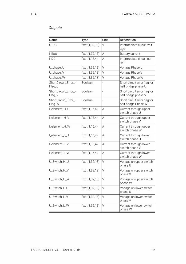
ETAS LABCAR-MODEL-PMSM
Outputs
Name Type Unit DescriptionU_DC fixdt(1,32,18) V Intermediate circuit volt-
ageI_Batt fixdt(1,32,18) A Battery currentI_DC fixdt(1,18,4) A Intermediate circuit cur-
rentU_phase_U fixdt(1,32,18) V Voltage Phase UU_phase_V fixdt(1,32,18) V Voltage Phase VU_phase_W fixdt(1,32,18) V Voltage Phase WShortCircuit_Error_-Flag_U
Boolean - Short circuit error flag for half bridge phase U
ShortCircuit_Error_-Flag_V
Boolean - Short circuit error flag for half bridge phase V
ShortCircuit_Error_-Flag_W
Boolean - Short circuit error flag for half bridge Phase W
I_element_H_U fixdt(1,16,4) A Current through upper switch phase U
I_element_H_V fixdt(1,16,4) A Current through upper switch phase V
I_element_H_W fixdt(1,16,4) A Current through upper switch phase W
I_element_L_U fixdt(1,16,4) A Current through lower switch phase U
I_element_L_V fixdt(1,16,4) A Current through lower switch phase V
I_element_L_W fixdt(1,16,4) A Current through lower switch phase W
U_Switch_H_U fixdt(1,32,18) V Voltage on upper switch phase U
U_Switch_H_V fixdt(1,32,18) V Voltage on upper switch phase V
U_Switch_H_W fixdt(1,32,18) V Voltage on upper switch phase W
U_Switch_L_U fixdt(1,32,18) V Voltage on lower switch phase U
U_Switch_L_V fixdt(1,32,18) V Voltage on lower switch phase V
U_Switch_L_W fixdt(1,32,18) V Voltage on lower switch phase W
LABCAR-MODEL V4.1 - User´s Guide 86
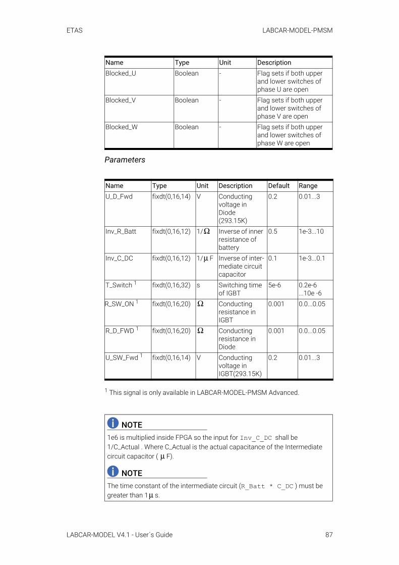
ETAS LABCAR-MODEL-PMSM
Parameters
1 This signal is only available in LABCAR-MODEL-PMSM Advanced.
Blocked_U Boolean - Flag sets if both upper and lower switches of phase U are open
Blocked_V Boolean - Flag sets if both upper and lower switches of phase V are open
Blocked_W Boolean - Flag sets if both upper and lower switches of phase W are open
Name Type Unit Description Default RangeU_D_Fwd fixdt(0,16,14) V Conducting
voltage in Diode (293.15K)
0.2 0.01...3
Inv_R_Batt fixdt(0,16,12) 1/ Inverse of inner resistance of battery
0.5 1e-3...10
Inv_C_DC fixdt(0,16,12) 1/ F Inverse of inter-mediate circuit capacitor
0.1 1e-3...0.1
T_Switch 1 fixdt(0,16,32) s Switching time of IGBT
5e-6 0.2e-6 ...10e -6
R_SW_ON 1 fixdt(0,16,20) Conducting resistance in IGBT
0.001 0.0...0.05
R_D_FWD 1 fixdt(0,16,20) Conducting resistance in Diode
0.001 0.0...0.05
U_SW_Fwd 1 fixdt(0,16,14) V Conducting voltage in IGBT(293.15K)
0.2 0.01...3
NOTE1e6 is multiplied inside FPGA so the input for Inv_C_DC shall be 1/C_Actual . Where C_Actual is the actual capacitance of the Intermediate circuit capacitor ( F).
NOTEThe time constant of the intermediate circuit (R_Batt * C_DC ) must be greater than 1 s.
Name Type Unit Description
Ω
μ
Ω
Ω
μ
μ
LABCAR-MODEL V4.1 - User´s Guide 87

ETAS LABCAR-MODEL-PMSM
6.5.4 PMSM Motor Interfaces
Inputs
2 This signal is only available in LABCAR-MODEL-PMSM Advanced.
Name Type Unit DescriptionRs Single Stator coil resistanceRiron 2 Single Resistance represents
iron losses of machineL_d Single H Inductance in d axisL_q Single H Inductance in q axisPsi_Rotor Single Vs Permanent Magnetic
flux in rotorLinear_NonLinear_Selec-tor
Boolean - 0: linear mode (Inputs L_d and L_q would be considered)1: Non-linear mode (loaded parameter fields to FPGA Id and Iq f(Psi_d ,Psi_q) to FPGA would be considered)
Current_DQ_Selector Boolean - 0: Internal calculated val-ues for Id and Iq would be considered1: Stimulus inputs, ID_-Stimulate and IQ_Stimu-late would be considered
ID_Stimulate Single A Stimulating input for IdIQ_Stimulate Single A Stimulating input for IqReset Boolean - Input for resetting inter-
nal states of modelAngleCorrectionSam-ples
fixdt(0,8,2) - Number of samples con-sidered for angle correc-tion of Id and Iq calculations
FixPointOverflow_Reset Boolean - Input to clear fix point overflow state
NOTE"FixPointOverflow_Status" and "FixPointOverflow_Reset" are used for advanced support.
ΩΩ
LABCAR-MODEL V4.1 - User´s Guide 88

ETAS LABCAR-MODEL-PMSM
Outputs
Parameters
6.5.5 DAC InterfacesThe LABCAR-MODEL-PMSM supports the 8 analog outputs of the ES5340.2-M board. You can configure the outputs. The resolver sensor which is also imple-mented in the FPGA on the ES5340.2-M uses the analog outputs #6 and #7. When it is intended to use a resolver sensor, the analog outputs #6 and #7 are unavailable to the FPGA model. Each electrical output channel of the ES5340.2-M can be connected to any one of the signals of the simulation model by using
Name Type Unit DescriptionVd Single V Voltage in d axisVq Single V Voltage in q axisPsi_d Single V Flux in d axisPsi_q Single V Flux in q axisTorque Single Nm Motor Electromagnetic
TorqueI_Stator_X(X=U,V,W) Single A Stator currentsU_Ind_X (X=U,V,W) Single V Induced back EMFld Single A Current in d axislq Single A Current in q axisPLoss_CopperId Single W Copper loss of MotorPLoss_Core Single W Core loss of MotorIcd Single A Current in core loss
branch of d axisIcq Single A Current in core loss
branch q axisImd Single A Current in magnetization
branch of d axisImq Single A Current in magnetization
branch of q axisFixPointOverflow_Status fixdt(0,45,0) - Debug Signal for fixed
point overflow detection. This is used for internal purpose.
Name Type Unit Description Default RangePPN Uint8 - Number of pole
pairs1 1...32
NOTEFor a closed loop operation, LABCAR-MODEL-PMSM DAC and PWM digital input channel interfaces have to be connected.
LABCAR-MODEL V4.1 - User´s Guide 89
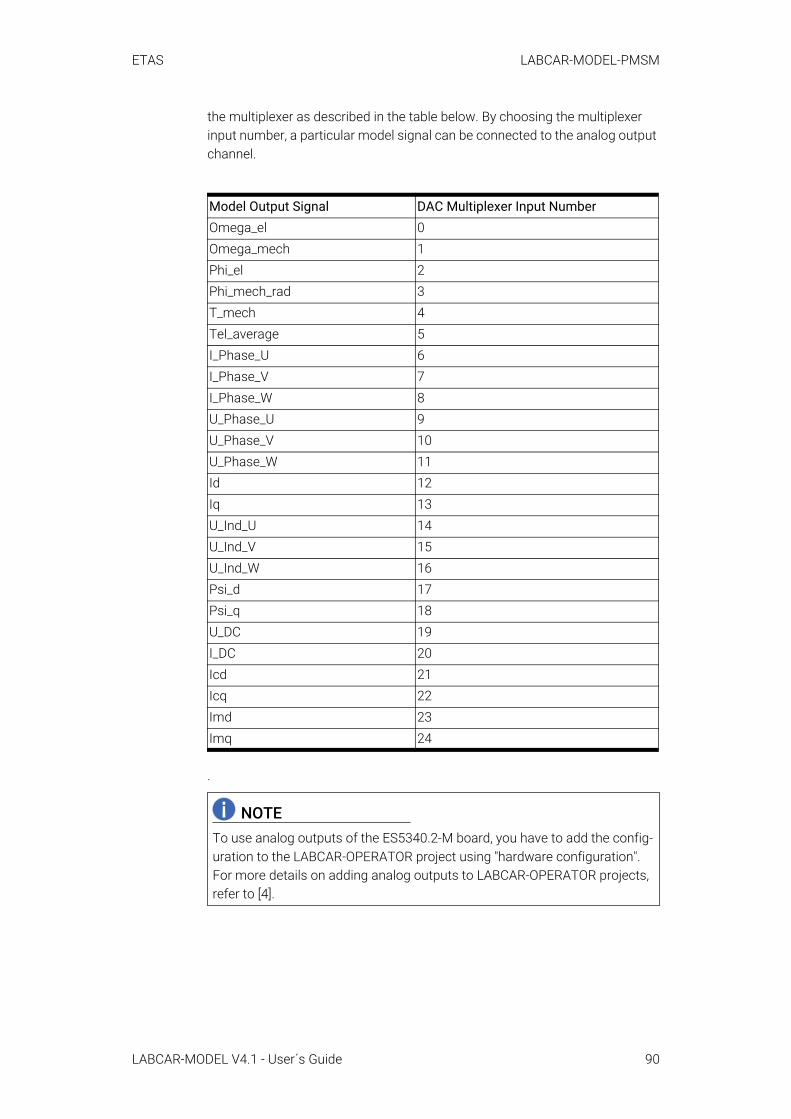
ETAS LABCAR-MODEL-PMSM
the multiplexer as described in the table below. By choosing the multiplexer input number, a particular model signal can be connected to the analog output channel.
.
Model Output Signal DAC Multiplexer Input NumberOmega_el 0Omega_mech 1Phi_el 2Phi_mech_rad 3T_mech 4Tel_average 5I_Phase_U 6I_Phase_V 7I_Phase_W 8U_Phase_U 9U_Phase_V 10U_Phase_W 11Id 12Iq 13U_Ind_U 14U_Ind_V 15U_Ind_W 16Psi_d 17Psi_q 18U_DC 19I_DC 20Icd 21Icq 22Imd 23Imq 24
NOTETo use analog outputs of the ES5340.2-M board, you have to add the config-uration to the LABCAR-OPERATOR project using "hardware configuration". For more details on adding analog outputs to LABCAR-OPERATOR projects, refer to [4].
LABCAR-MODEL V4.1 - User´s Guide 90
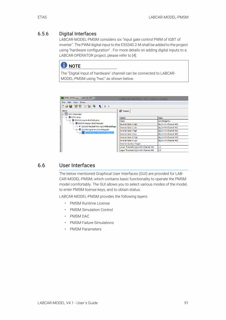
ETAS LABCAR-MODEL-PMSM
6.5.6 Digital InterfacesLABCAR-MODEL-PMSM considers six "input gate control PWM of IGBT of inverter". The PWM digital input to the ES5340.2-M shall be added to the project using "hardware configuration" . For more details on adding digital inputs to a LABCAR-OPERATOR project, please refer to [4].
6.6 User InterfacesThe below mentioned Graphical User Interfaces (GUI) are provided for LAB-CAR-MODEL-PMSM, which contains basic functionality to operate the PMSM model comfortably. The GUI allows you to select various modes of the model, to enter PMSM license keys, and to obtain status.
LABCAR-MODEL-PMSM provides the following layers:
• PMSM Runtime License
• PMSM Simulation Control
• PMSM DAC
• PMSM Failure Simulations
• PMSM Parameters
NOTEThe "Digital Input of hardware" channel can be connected to LABCAR-MODEL-PMSM using "hwc" as shown below.
LABCAR-MODEL V4.1 - User´s Guide 91
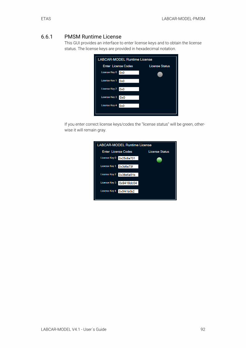
ETAS LABCAR-MODEL-PMSM
6.6.1 PMSM Runtime LicenseThis GUI provides an interface to enter license keys and to obtain the license status. The license keys are provided in hexadecimal notation.
If you enter correct license keys/codes the "license status" will be green, other-wise it will remain gray.
LABCAR-MODEL V4.1 - User´s Guide 92
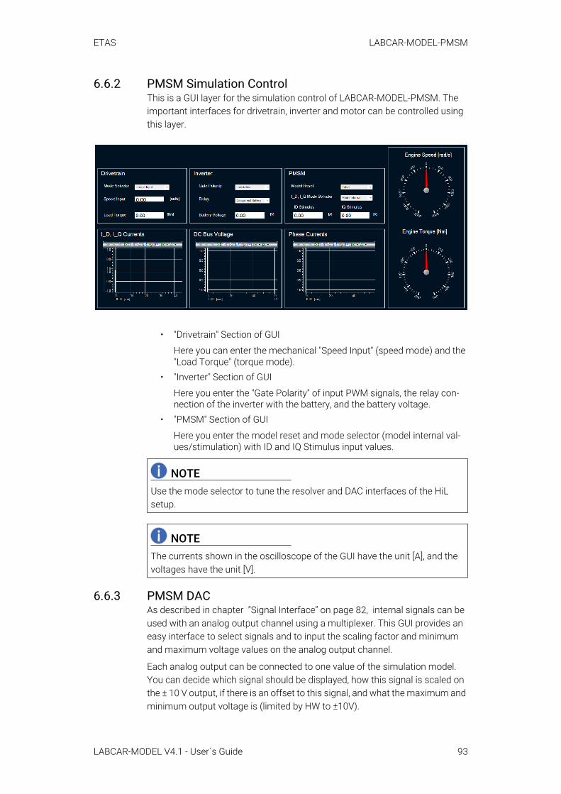
ETAS LABCAR-MODEL-PMSM
6.6.2 PMSM Simulation ControlThis is a GUI layer for the simulation control of LABCAR-MODEL-PMSM. The important interfaces for drivetrain, inverter and motor can be controlled using this layer.
• "Drivetrain" Section of GUI
Here you can enter the mechanical "Speed Input" (speed mode) and the "Load Torque" (torque mode).
• "Inverter" Section of GUI
Here you enter the "Gate Polarity" of input PWM signals, the relay con-nection of the inverter with the battery, and the battery voltage.
• "PMSM" Section of GUI
Here you enter the model reset and mode selector (model internal val-ues/stimulation) with ID and IQ Stimulus input values.
6.6.3 PMSM DACAs described in chapter “Signal Interface” on page 82, internal signals can be used with an analog output channel using a multiplexer. This GUI provides an easy interface to select signals and to input the scaling factor and minimum and maximum voltage values on the analog output channel.
Each analog output can be connected to one value of the simulation model. You can decide which signal should be displayed, how this signal is scaled on the ± 10 V output, if there is an offset to this signal, and what the maximum and minimum output voltage is (limited by HW to ±10V).
NOTEUse the mode selector to tune the resolver and DAC interfaces of the HiL setup.
NOTEThe currents shown in the oscilloscope of the GUI have the unit [A], and the voltages have the unit [V].
LABCAR-MODEL V4.1 - User´s Guide 93
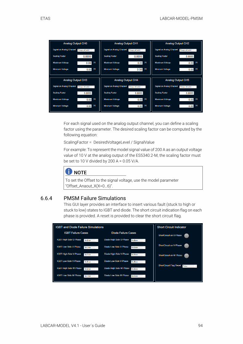
ETAS LABCAR-MODEL-PMSM
For each signal used on the analog output channel, you can define a scaling factor using the parameter. The desired scaling factor can be computed by the following equation:
ScalingFactor = DesiredVoltageLevel / SignalValue
For example: To represent the model signal value of 200 A as an output voltage value of 10 V at the analog output of the ES5340.2-M, the scaling factor must be set to 10 V divided by 200 A = 0.05 V/A.
6.6.4 PMSM Failure Simulations This GUI layer provides an interface to insert various fault (stuck to high or stuck to low) states to IGBT and diode. The short circuit indication flag on each phase is provided. A reset is provided to clear the short circuit flag.
NOTETo set the Offset to the signal voltage, use the model parameter "Offset_Anaout_X(X=0…6)".
LABCAR-MODEL V4.1 - User´s Guide 94
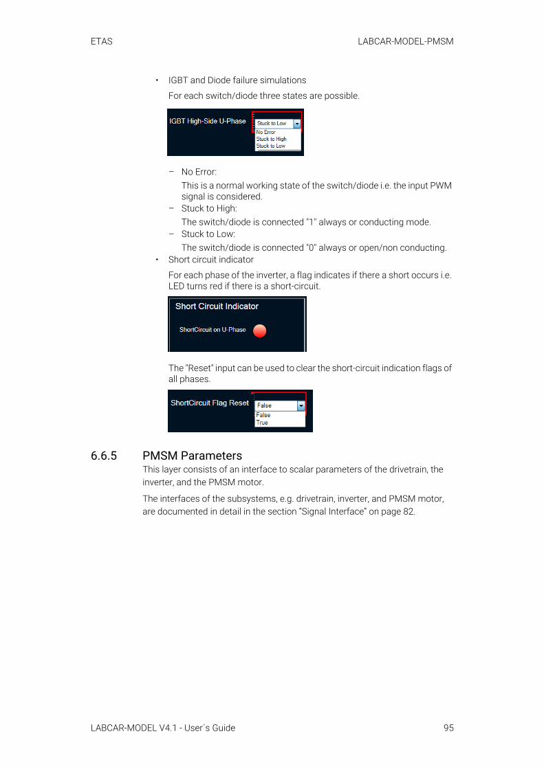
ETAS LABCAR-MODEL-PMSM
• IGBT and Diode failure simulations
For each switch/diode three states are possible.
– No Error:This is a normal working state of the switch/diode i.e. the input PWM signal is considered.
– Stuck to High:The switch/diode is connected "1" always or conducting mode.
– Stuck to Low:The switch/diode is connected "0" always or open/non conducting.
• Short circuit indicator
For each phase of the inverter, a flag indicates if there a short occurs i.e. LED turns red if there is a short-circuit.
The "Reset" input can be used to clear the short-circuit indication flags of all phases.
6.6.5 PMSM ParametersThis layer consists of an interface to scalar parameters of the drivetrain, the inverter, and the PMSM motor.
The interfaces of the subsystems, e.g. drivetrain, inverter, and PMSM motor, are documented in detail in the section “Signal Interface” on page 82.
LABCAR-MODEL V4.1 - User´s Guide 95
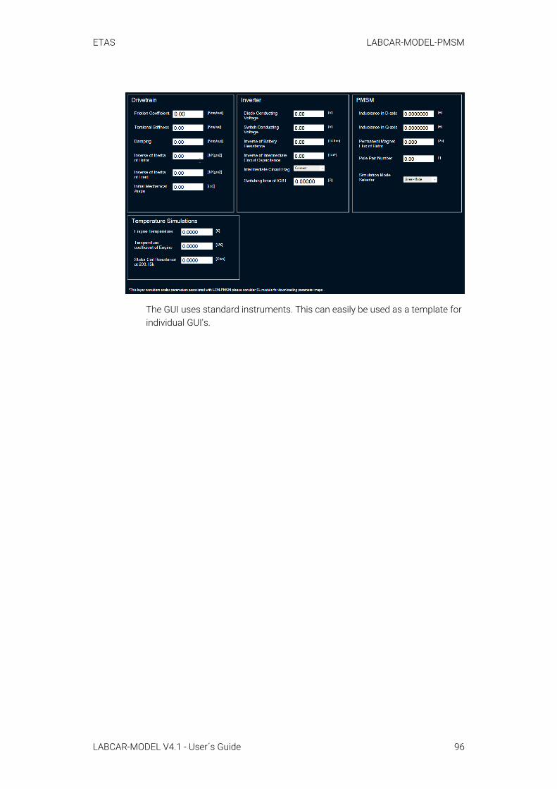
ETAS LABCAR-MODEL-PMSM
The GUI uses standard instruments. This can easily be used as a template for individual GUI's.
LABCAR-MODEL V4.1 - User´s Guide 96

ETAS Licensing
7 LicensingThe simulation models of the LABCAR-MODEL product family possess a license protection. Each product of the LABCAR-MODEL family requires its own license and refers to a specific version. The actual mechanism differs between FPGA-based and Simulink-based models; they are described in the following sections.
7.1 FPGA-Based Simulation ModelsThe LABCAR-MODEL-PMSM runtime license is generated based on the serial number of the ES5340.2M board. The serial number can be obtained from the "HSP" tool using the "Hardware" window. A Runtime license file consists of val-ues (Hexadecimal) for the model license inputs "Lic_0", "Lic_1", "Lic_2", "Lic_3" and "Lic_4". A LABCAR-EE layer "PMSM_Runtime_License" is available to enter runtime license keys. Nevertheless the following mechanism can be used to apply license values.
• Browse "RTPC/Hardware/_.../Es5340flexiblefpga" in LABCAR-EE to access the model license inputs.
• Use the "Signal-Calibrate Constant Value"option to edit input values.
• Change the data representation from decimal to hexadecimal for "Edit Box" of every model license input.
• Provide the license values given in the runtime license file for "Lic_0" to "Lic_4".
7.1.1 License Status InformationYou can retrieve the licensing status in the LABCAR-EE from model license out-put "Lic_out". "Lic_out" is "1" or "License Status" is green in "PMSM_Runtime_Li-cense" layer if correct license values are set for model license inputs. Otherwise it is "0" or the "License Status" is Grey.
7.2 Simulink-Based Simulation ModelsTwo types of licenses exist for the Simulink-based simulation models. They are:
• A Runtime License ("RT-License") permits the execution of a model con-taining one or more S-Function blocks from LABCAR- MODEL, irrespec-tive of the underlying platform (e.g., Windows or ETAS RTPC).
• An Operator License permits the code-generation of a model containing one or more S-Function blocks from LABCAR-MODEL. In addition, it per-mits the execution of a model.
On Windows machines, the ETAS License Manager is used to verify the LAB-CAR-MODEL license.
You find the procedure to install license files on ETAS RTPC in the LABCAR-OPERATOR documentation [5].
LABCAR-MODEL V4.1 - User´s Guide 97

ETAS Licensing
7.2.1 License Status Information (Windows)The license status is given in the ETAS License Manager. The MATLAB com-mand window also reports the licensing status. An error occurs, if the ETAS License Manager is not able to find a valid license or when the license checkout fails. In this case, the error message is written to the MATLAB command win-dow. The error message includes details about the S-Function, which caused the error.
7.2.2 License Status Information (RTPC)When using ETAS RTPC as simulation target, the license status is printed to the hardware output of LABCAR-EE during the model initialization. The level of detail of the printed messages is determined by the logging level of the RTPC. Please see [5] for further information.
LABCAR-MODEL V4.1 - User´s Guide 98
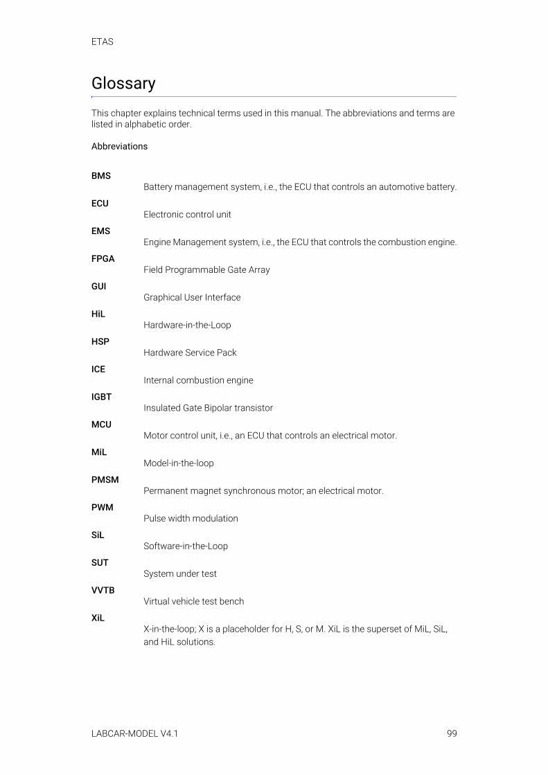
ETAS
GlossaryThis chapter explains technical terms used in this manual. The abbreviations and terms are listed in alphabetic order.
Abbreviations
BMSBattery management system, i.e., the ECU that controls an automotive battery.
ECUElectronic control unit
EMSEngine Management system, i.e., the ECU that controls the combustion engine.
FPGAField Programmable Gate Array
GUIGraphical User Interface
HiLHardware-in-the-Loop
HSPHardware Service Pack
ICEInternal combustion engine
IGBTInsulated Gate Bipolar transistor
MCUMotor control unit, i.e., an ECU that controls an electrical motor.
MiLModel-in-the-loop
PMSMPermanent magnet synchronous motor; an electrical motor.
PWMPulse width modulation
SiLSoftware-in-the-Loop
SUTSystem under test
VVTBVirtual vehicle test bench
XiLX-in-the-loop; X is a placeholder for H, S, or M. XiL is the superset of MiL, SiL, and HiL solutions.
LABCAR-MODEL V4.1 99

ETAS
Terms
Offline Parametrization:Executing the simulation in LABCAR-EE. The unit under test, either a physical or a virtual ECU, is disconnected (hence "offline"). The set with the parametrization is stored in a supported parameter file.
Online Parametrization:The unit under test, either a physical or a virtual ECU, is connected (hence "online"). The project is linked to the parameter file from the offline parametri-zation. The simulation is running.
LABCAR-MODEL V4.1 100
ETAS References
LABCAR-MODEL V4.1 101
ReferencesFor more information refer to the following documents that are part of the doc-umentation package of LABCAR-OPERATOR.
[1] LABCAR-OPERATOR V5.4.9 User´s Guide[2] LABCAR-OPERATOR V5.4.9 Software Compatibility List[3] ES5340.2 Electric Drive Simulation Board User's Guide[4] FlexibleFPGA V3.0.0 - Workflow Description: Tutorial[5] ETAS RTPC User´s Guide[6] HSP Hardware Service Pack Getting Started
ETAS Figures
Figures
Fig. 2-1 General parametrization workflow . . . . . . . . . . . . . . . . . . . . . . . . . . . . . . . . . . . . . .11Fig. 2-2 Online parametrization workflow . . . . . . . . . . . . . . . . . . . . . . . . . . . . . . . . . . . . . . .12
Fig. 2-3 LCInports and LCOutports . . . . . . . . . . . . . . . . . . . . . . . . . . . . . . . . . . . . . . . . . . . . .13
Fig. 2-4 Code generation process for Simulink models . . . . . . . . . . . . . . . . . . . . . . . . . . . .14
Fig. 2-5 Exemplary version information for an S-Function . . . . . . . . . . . . . . . . . . . . . . . . .15
LABCAR-MODEL V4.1 - User´s Guide 102
ETAS Contacts
LABCAR-MODEL V4.1 - User´s Guide 103
ETAS Contact Addresses
ETAS HeadquartersETAS GmbH
ETAS Subsidiaries and Technical SupportFor details of your local sales office as well as your local technical support team and product hotlines, take a look at the ETAS website:
Borsigstraße 24 Phone: +49 711 3423-070469 Stuttgart Fax: +49 711 3423-2106Germany Internet: www.etas.com
ETAS subsidiaries Internet: www.etas.com/en/contact.php
ETAS technical support Internet: www.etas.com/en/hotlines.php
Related Documents