LAB VHDL-programing William Sandqvist [email protected] With a breakoutboard one can use the breadboard with components that actually is intended for surface mounting on circuit boards. One can then easily try different couplings. In this way, we use the same technique as in the previous lab - even though we now move on to more complex so- called CPLD circuitry and are programming them with the VHDL language.

Welcome message from author
This document is posted to help you gain knowledge. Please leave a comment to let me know what you think about it! Share it to your friends and learn new things together.
Transcript
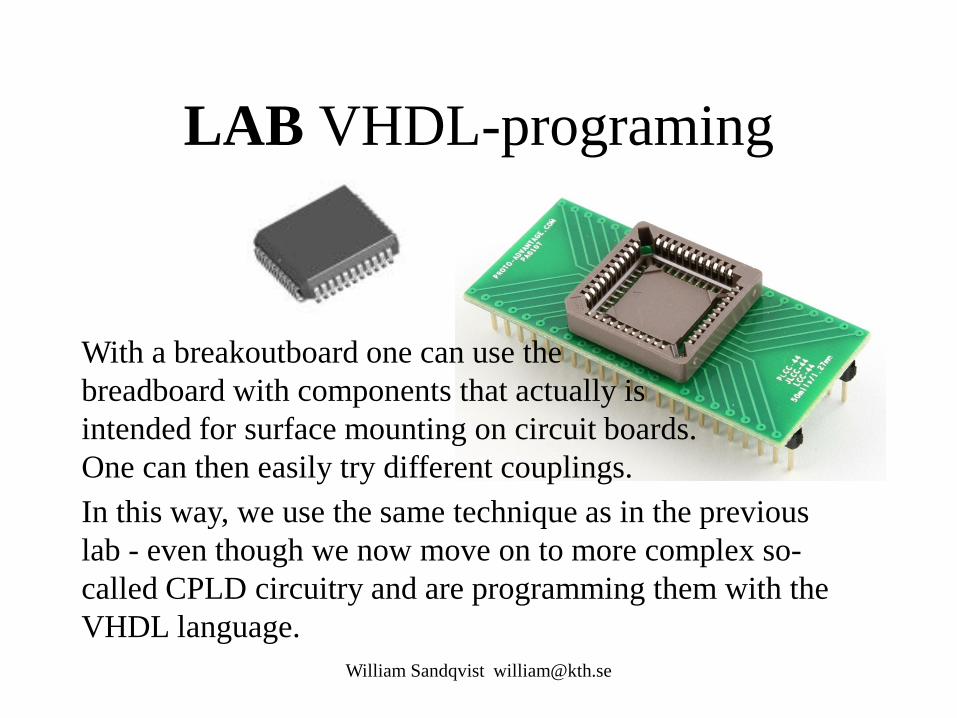
LAB VHDL-programing
William Sandqvist [email protected]
With a breakoutboard one can use the breadboard with components that actually is intended for surface mounting on circuit boards. One can then easily try different couplings. In this way, we use the same technique as in the previous lab - even though we now move on to more complex so-called CPLD circuitry and are programming them with the VHDL language.
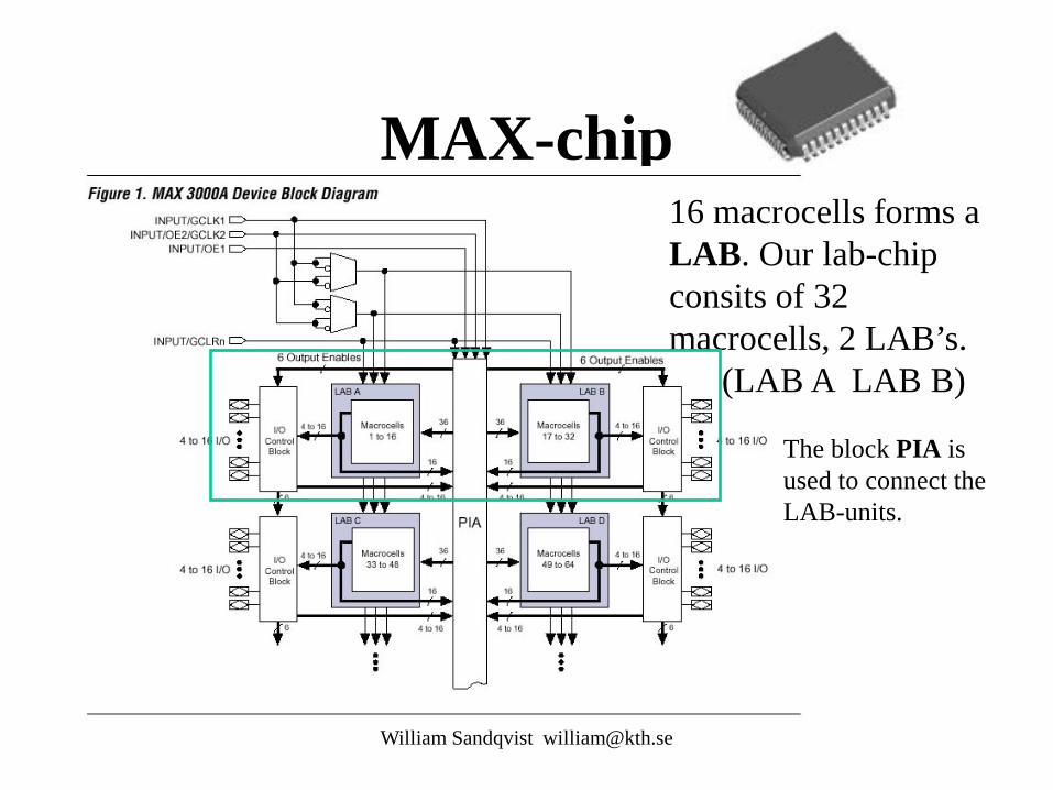
MAX-chip
William Sandqvist [email protected]
16 macrocells forms a LAB. Our lab-chip consits of 32 macrocells, 2 LAB’s. (LAB A LAB B)
The block PIA is used to connect the LAB-units.

Laboration task - codelock • Task: to write VHDL code for a code lock that opens with the code "the last four digits of your social security number". • Help: a VHDL ”template” for a simplified code lock that opens with the code "number one".
William Sandqvist [email protected]
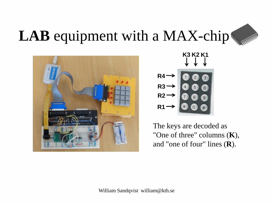
LAB equipment with a MAX-chip
William Sandqvist [email protected]
The keys are decoded as "One of three" columns (K), and "one of four" lines (R).
K1 K2 K3
R4 R3 R2
R1
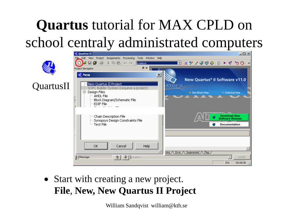
Quartus tutorial for MAX CPLD on school centraly administrated computers
William Sandqvist [email protected]
QuartusII
• Start with creating a new project. File, New, New Quartus II Project
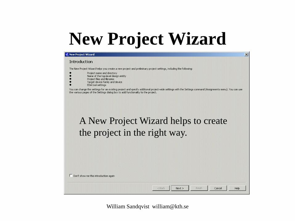
New Project Wizard
William Sandqvist [email protected]
A New Project Wizard helps to create the project in the right way.

Project Name and Directory
William Sandqvist [email protected]
At school the whole project must be on your H:\ • Name: codelock • Top-Level Entity: codelock (NOTE codelock must ”match” the name you later on is using for entity in your VHDL-file)
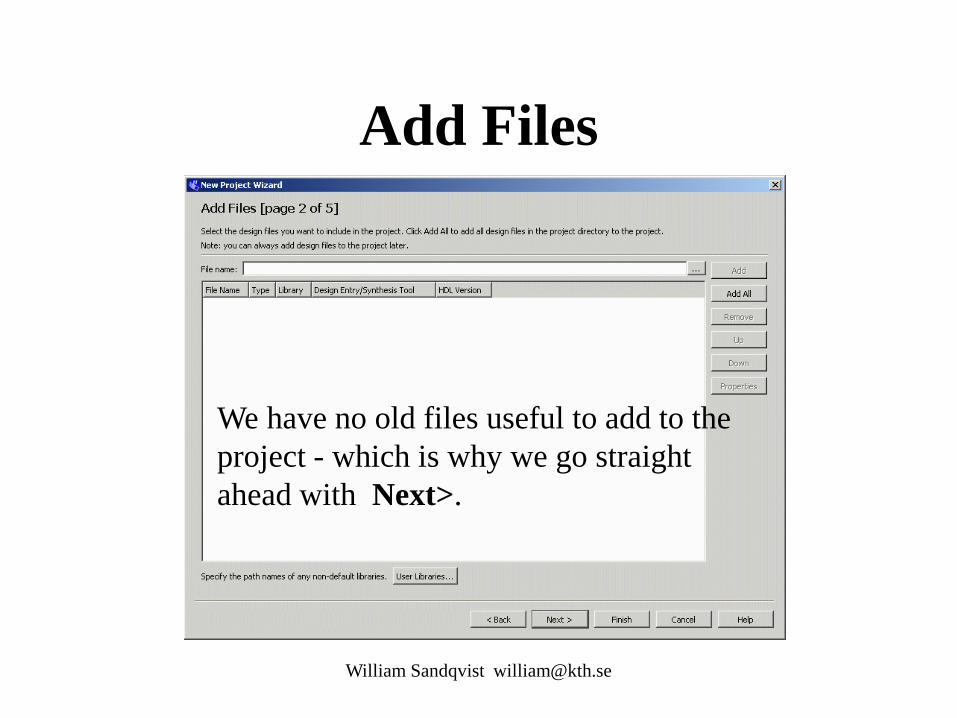
Add Files
William Sandqvist [email protected]
We have no old files useful to add to the project - which is why we go straight ahead with Next>.
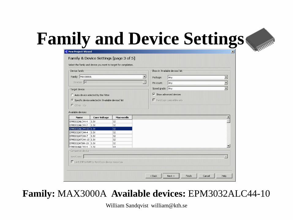
Family and Device Settings
William Sandqvist [email protected]
Family: MAX3000A Available devices: EPM3032ALC44-10

EDA Tool Settings
William Sandqvist [email protected]
We will not use any other programming tool than Quartus - so we go straight ahead with Next>.

Summary
William Sandqvist [email protected]
This summarizes your selections. Check, and then exit "Wizard" with Finish

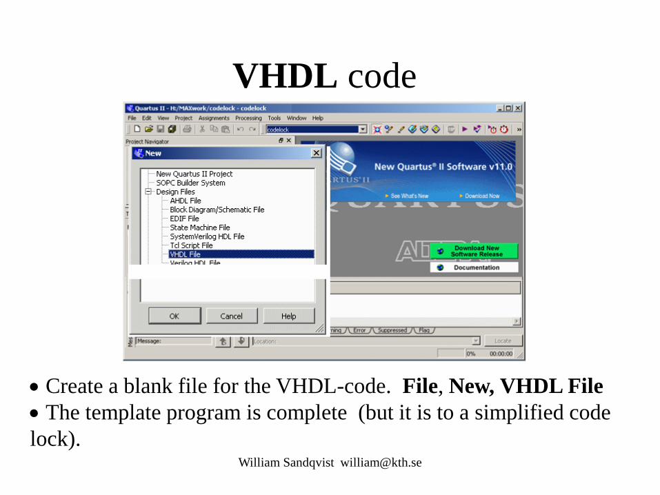
VHDL code
William Sandqvist [email protected]
• Create a blank file for the VHDL-code. File, New, VHDL File • The template program is complete (but it is to a simplified code lock).
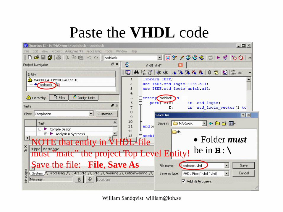
Paste the VHDL code
William Sandqvist [email protected]
NOTE that entity in VHDL-file must ”matc” the project Top Level Entity! Save the file: File, Save As
• Folder must be in H:\

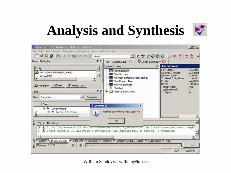
Analysis and Synthesis
William Sandqvist [email protected]
When you have newly written code, it is unnecessary to run the entire tool chain - the chances are that there are errors along the way ... • From start run only Analysis & Synthesis.
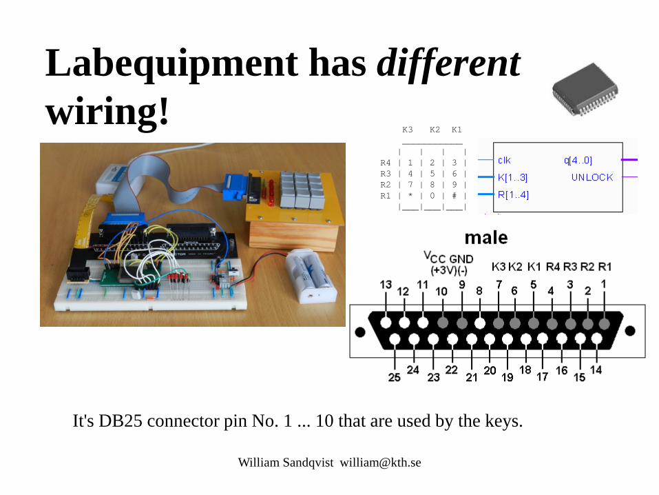
Labequipment has different wiring!
K3 K2 K1 ___________ | | | | R4 | 1 | 2 | 3 | R3 | 4 | 5 | 6 | R2 | 7 | 8 | 9 | R1 | * | 0 | # | |___|___|___|
William Sandqvist [email protected]
It's DB25 connector pin No. 1 ... 10 that are used by the keys.
William Sandqvist [email protected]
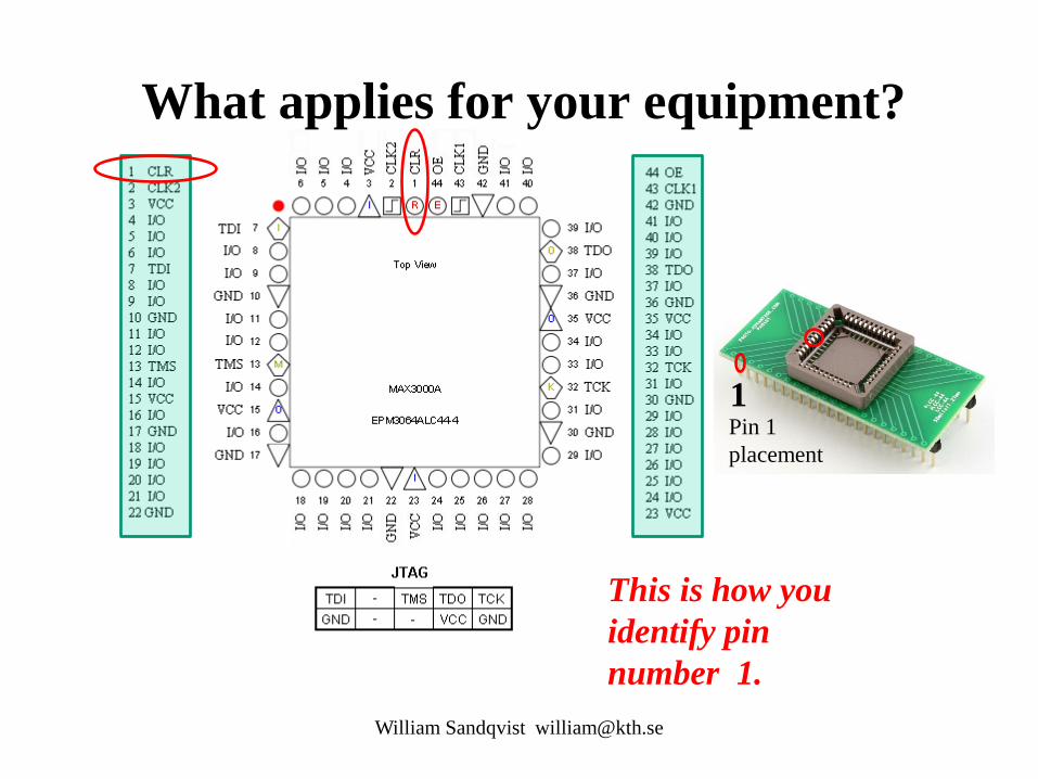
What applies for your equipment?
1 Pin 1 placement
This is how you identify pin number 1.
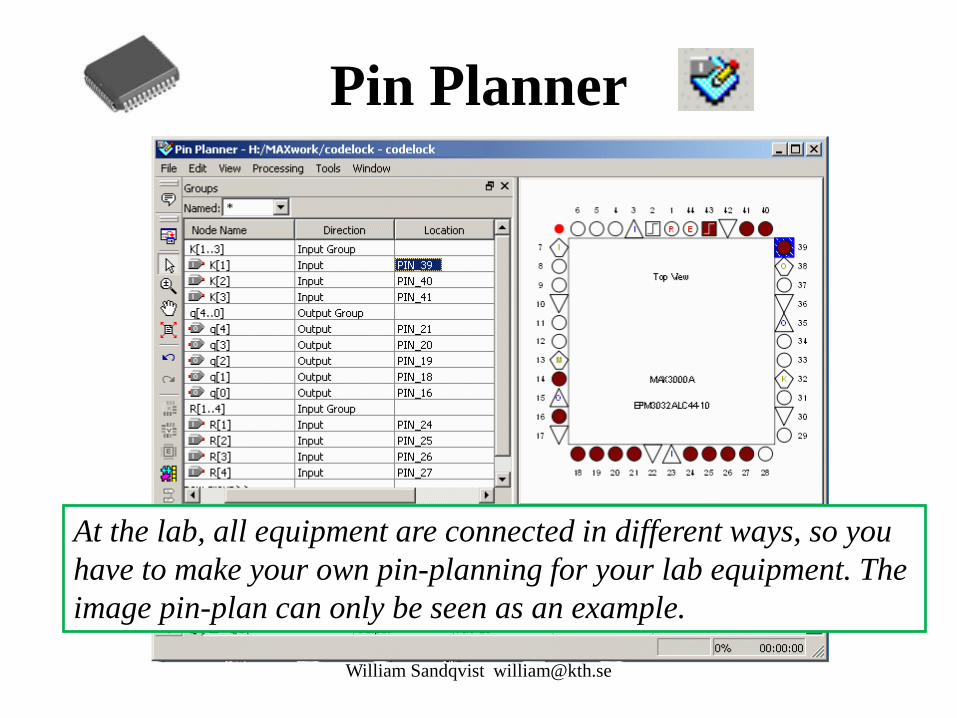
Pin Planner
William Sandqvist [email protected]
At the lab, all equipment are connected in different ways, so you have to make your own pin-planning for your lab equipment. The image pin-plan can only be seen as an example.
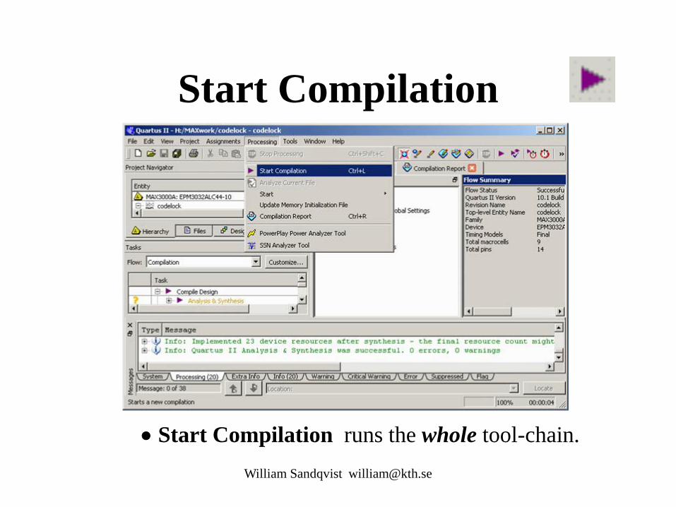
Start Compilation
William Sandqvist [email protected]
• Start Compilation runs the whole tool-chain.
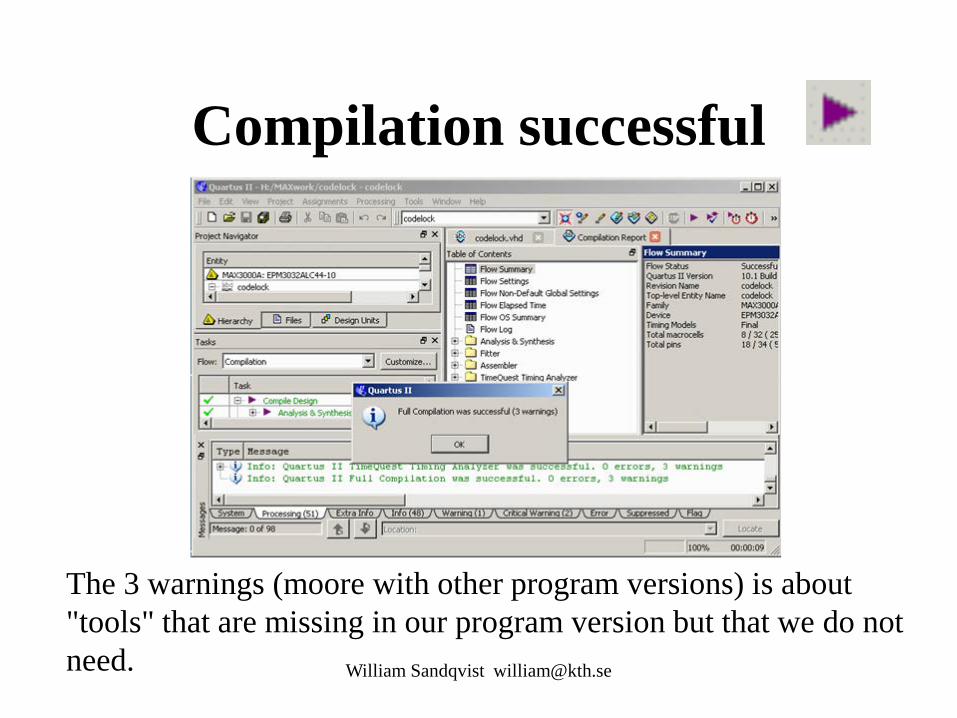
Compilation successful
William Sandqvist [email protected]
The 3 warnings (moore with other program versions) is about "tools" that are missing in our program version but that we do not need.
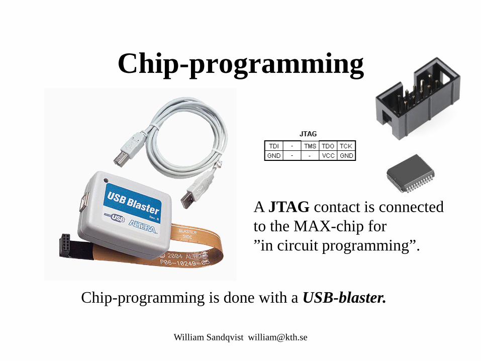
Chip-programming
William Sandqvist [email protected]
A JTAG contact is connected to the MAX-chip for ”in circuit programming”.
Chip-programming is done with a USB-blaster.

Try out the functioning!
William Sandqvist [email protected]
Template application is for a simplified code lock that opens to the key "1", a little too easy it seems ...!
Power On/Off

Open the lock with your social security number!
William Sandqvist [email protected]
• Now it's time to rewrite the VHDL code so that the lock opens to the last four digits of your social security number!
( If you prepare the code for your social security number, then two in a group can contribute with half of the code at the lab ).

William Sandqvist [email protected]
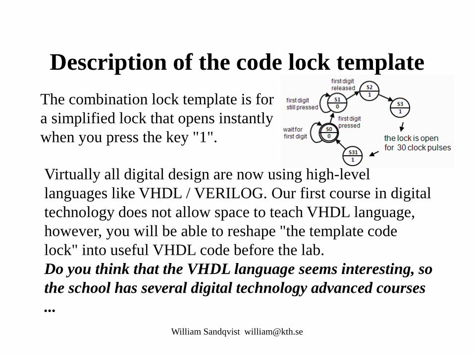
Description of the code lock template The combination lock template is for a simplified lock that opens instantly when you press the key "1".
Virtually all digital design are now using high-level languages like VHDL / VERILOG. Our first course in digital technology does not allow space to teach VHDL language, however, you will be able to reshape "the template code lock" into useful VHDL code before the lab. Do you think that the VHDL language seems interesting, so the school has several digital technology advanced courses ...
William Sandqvist [email protected]

Moore machine
The different blocks in the code are identified with ”labels”
William Sandqvist [email protected]
next_state_decoder: output_decoder: state_register:
VHDL process
William Sandqvist [email protected]
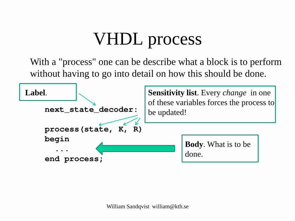
next_state_decoder: process(state, K, R) begin ... end process;
With a "process" one can be describe what a block is to perform without having to go into detail on how this should be done.
Body. What is to be done.
Sensitivity list. Every change in one of these variables forces the process to be updated!
Label.
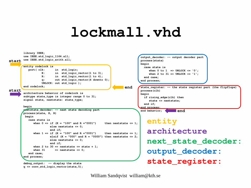
lockmall.vhd
William Sandqvist [email protected]
library IEEE; use IEEE.std_logic_1164.all; use IEEE.std_logic_arith.all; entity codelock is port( clk: in std_logic; K: in std_logic_vector(1 to 3); R: in std_logic_vector(1 to 4); q: out std_logic_vector(4 downto 0); UNLOCK: out std_logic ); end codelock; architecture behavior of codelock is subtype state_type is integer range 0 to 31; signal state, nextstate: state_type; begin nextstate_decoder: -- next state decoding part process(state, K, R) begin case state is when 0 => if (K = "100" and R ="0001") then nextstate <= 1; else nextstate <= 0; end if; when 1 => if (K = "100" and R ="0001") then nextstate <= 1; elsif (K = "000" and R = "0000") then nextstate <= 2; else nextstate <= 0; end if; when 2 to 30 => nextstate <= state + 1; when 31 => nextstate <= 0; end case; end process; debug_output: -- display the state q <= conv_std_logic_vector(state,5);
output_decoder: -- output decoder part process(state) begin case state is when 0 to 1 => UNLOCK <= '0'; when 2 to 31 => UNLOCK <= '1'; end case; end process; state_register: -- the state register part (the flipflops) process(clk) begin if rising_edge(clk) then state <= nextstate; end if; end process; end behavior;
entity architecture next_state_decoder: output_decoder: state_register:
start
end start
end
Codelock VHDL
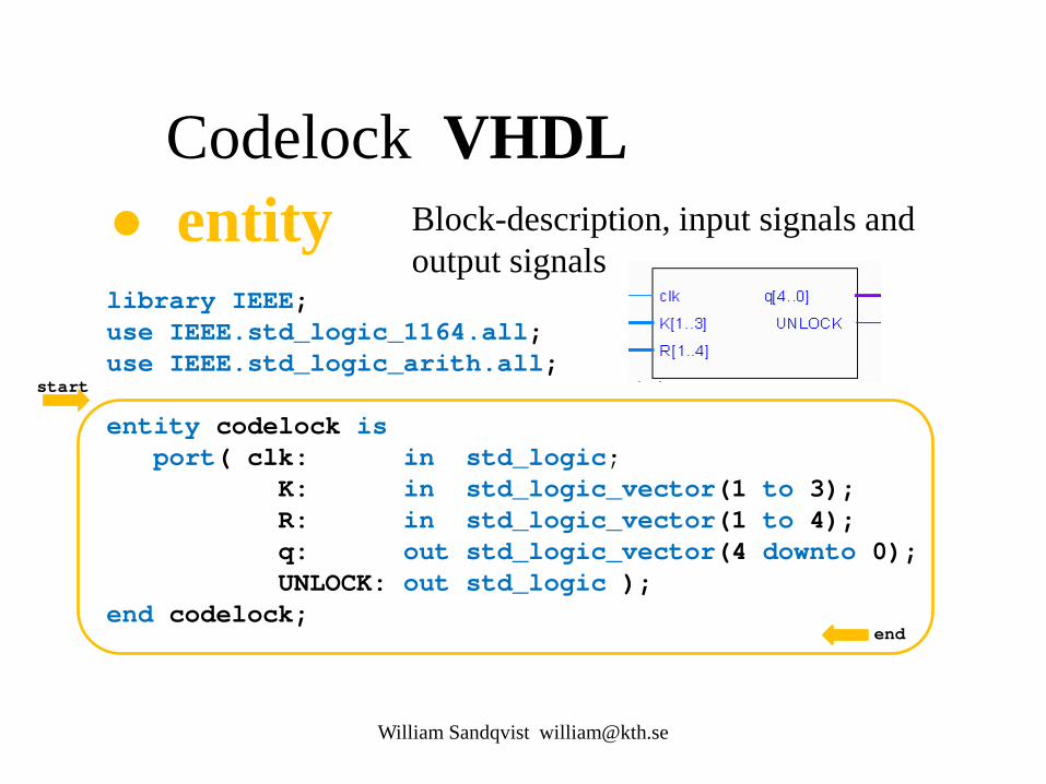
library IEEE; use IEEE.std_logic_1164.all; use IEEE.std_logic_arith.all; entity codelock is port( clk: in std_logic; K: in std_logic_vector(1 to 3); R: in std_logic_vector(1 to 4); q: out std_logic_vector(4 downto 0); UNLOCK: out std_logic ); end codelock;
• entity Block-description, input signals and output signals
William Sandqvist [email protected]
start
end
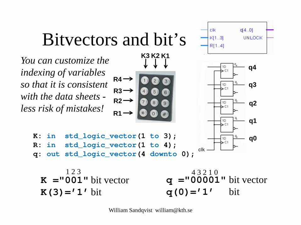
Bitvectors and bit’s
K: in std_logic_vector(1 to 3); R: in std_logic_vector(1 to 4); q: out std_logic_vector(4 downto 0);
William Sandqvist [email protected]
K1 K2 K3
R4
R3 R2
R1
q4
q3
q2
q1
q0
K ="001" K(3)=’1’
bit vector bit
1 2 3 q ="00001" q(0)=’1’
bit vector bit
4 3 2 1 0
You can customize the indexing of variables so that it is consistent with the data sheets - less risk of mistakes!
Codelock VHDL …
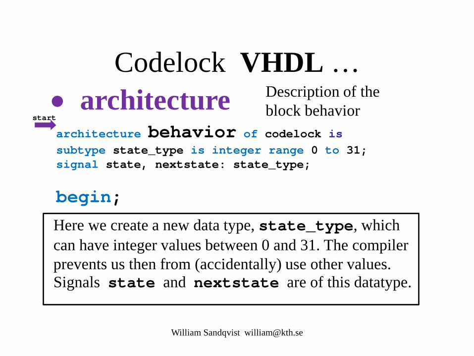
architecture behavior of codelock is subtype state_type is integer range 0 to 31; signal state, nextstate: state_type;
begin;
• architecture Description of the block behavior
Here we create a new data type, state_type, which can have integer values between 0 and 31. The compiler prevents us then from (accidentally) use other values. Signals state and nextstate are of this datatype.
William Sandqvist [email protected]
start
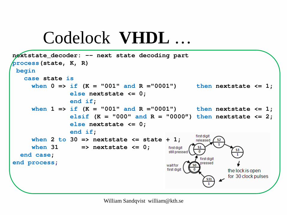
Codelock VHDL … nextstate_decoder: -- next state decoding part process(state, K, R) begin case state is when 0 => if (K = "001" and R ="0001") then nextstate <= 1; else nextstate <= 0; end if; when 1 => if (K = "001" and R ="0001") then nextstate <= 1; elsif (K = "000" and R = "0000”) then nextstate <= 2; else nextstate <= 0; end if; when 2 to 30 => nextstate <= state + 1; when 31 => nextstate <= 0; end case; end process;
William Sandqvist [email protected]
Codelock VHDL …
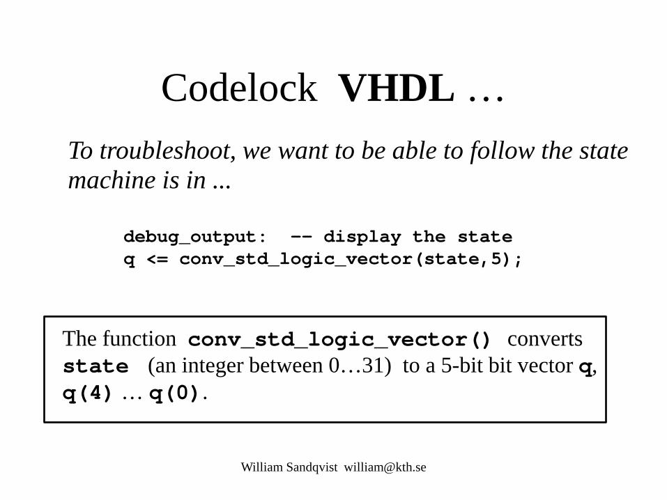
debug_output: -- display the state q <= conv_std_logic_vector(state,5);
The function conv_std_logic_vector() converts state (an integer between 0…31) to a 5-bit bit vector q, q(4) … q(0).
William Sandqvist [email protected]
To troubleshoot, we want to be able to follow the state machine is in ...

Codelock VHDL …
output_decoder: -- output decoder part process(state) begin case state is when 0 to 1 => UNLOCK <= '0'; when 2 to 31 => UNLOCK <= '1'; end case; end process;
William Sandqvist [email protected]

Codelock VHDL … state_register: -- the state register part (the flipflops) process(clk) begin if rising_edge(clk) then state <= nextstate; end if; end process;
end behavior;
William Sandqvist [email protected]
end

William Sandqvist [email protected]
Open the lock with your social security number!
• Now it's time to rewrite the VHDL code so that the lock opens to the last four digits of your social security number!

William Sandqvist [email protected]
Simulate with ModelSim
William Sandqvist [email protected]
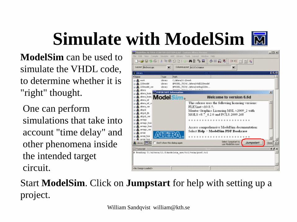
ModelSim can be used to simulate the VHDL code, to determine whether it is "right" thought. One can perform simulations that take into account "time delay" and other phenomena inside the intended target circuit. Start ModelSim. Click on Jumpstart for help with setting up a project.
Create a project
William Sandqvist [email protected]
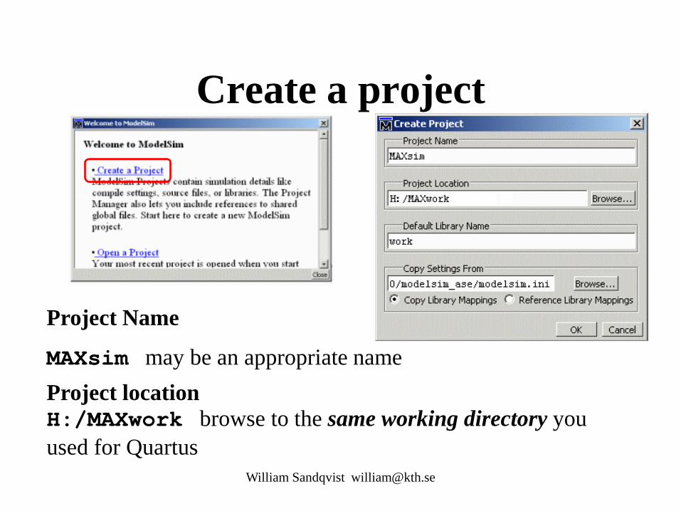
Project Name
MAXsim may be an appropriate name Project location H:/MAXwork browse to the same working directory you used for Quartus
Add a VHDL-file
William Sandqvist [email protected]
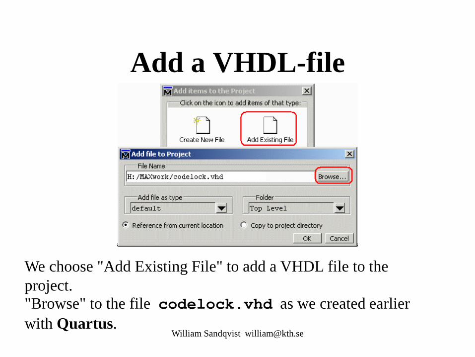
We choose "Add Existing File" to add a VHDL file to the project. "Browse" to the file codelock.vhd as we created earlier with Quartus.


Compile for simulation
William Sandqvist [email protected]
ModelSim has its own compiler to produce the VHDL code for simulation. Though we have compiled the VHDL code in Quartus we must nevertheless compile it again with ModelSim.
Choose Compile menu, alternative Compile All.
Now the VHDL code is also compiled for modelsim. The status symbol changes from a blue question mark to a green check!

Simulate the codelock template
William Sandqvist [email protected]
Download The design to the simulator. Select the Library tab, and open the folder work. Double click on the "Entity" codelock.
Transcript-window
William Sandqvist [email protected]
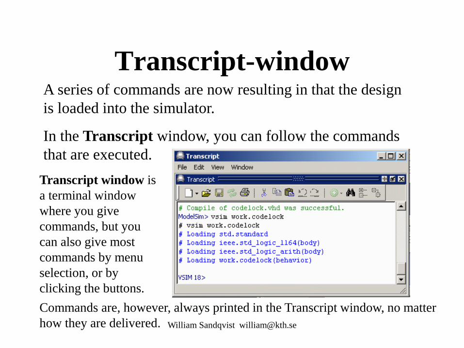
A series of commands are now resulting in that the design is loaded into the simulator.
In the Transcript window, you can follow the commands that are executed.
Transcript window is a terminal window where you give commands, but you can also give most commands by menu selection, or by clicking the buttons. Commands are, however, always printed in the Transcript window, no matter how they are delivered.

Prepare the simulation
William Sandqvist [email protected]
We need to have a number of windows open in order to follow the simulation. Give commands in the Transcript window. Or click on the View menu. VSIM> view objects VSIM> view locals VSIM> view source VSIM> view wave -undock Modelsim consists of "windows". It can be difficult to see everything at the same time. The Zoom / Unzoom enlarges the window. With the button Dock / Undock the window can be moved to any location. The Close button closes the window.

Signals in Wave-window
William Sandqvist [email protected]
Signals in Wave If you have many signals, it is a good idea to select the signals you are interested to join in the Wave window, but here we choose to follow all:
add wave *
• Choose signals in Object-window and “drag and drop” the selection to the Wave window.
• Right click in the Object-window and choose Add to Wave.
There are several ways to add signals to the Wave window:
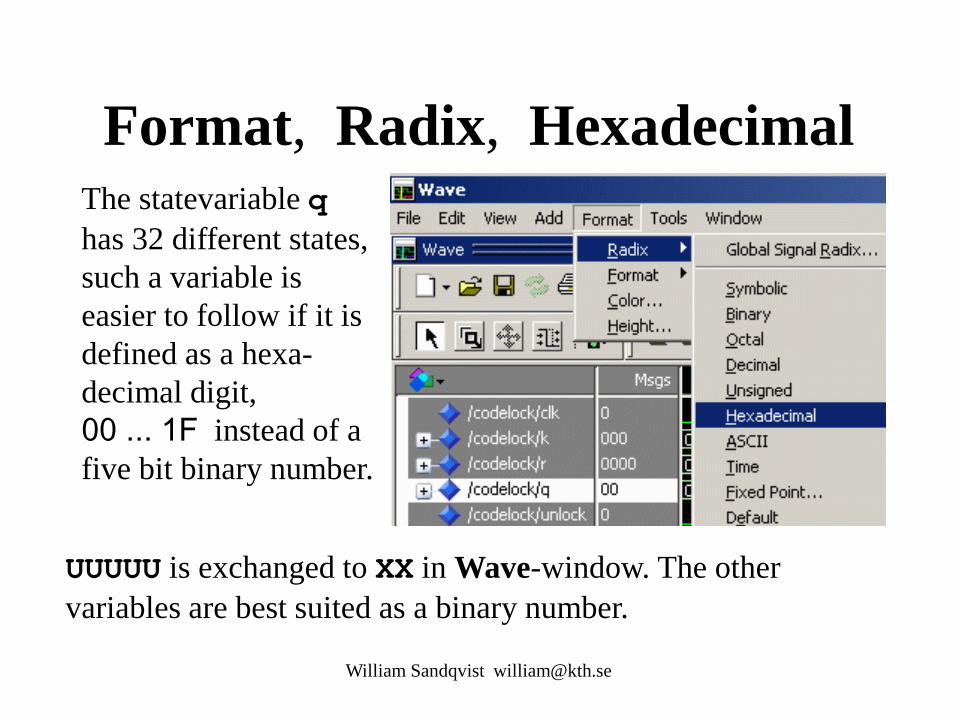
Format, Radix, Hexadecimal
William Sandqvist [email protected]
UUUUU is exchanged to XX in Wave-window. The other variables are best suited as a binary number.
The statevariable q has 32 different states, such a variable is easier to follow if it is defined as a hexa-decimal digit, 00 ... 1F instead of a five bit binary number.
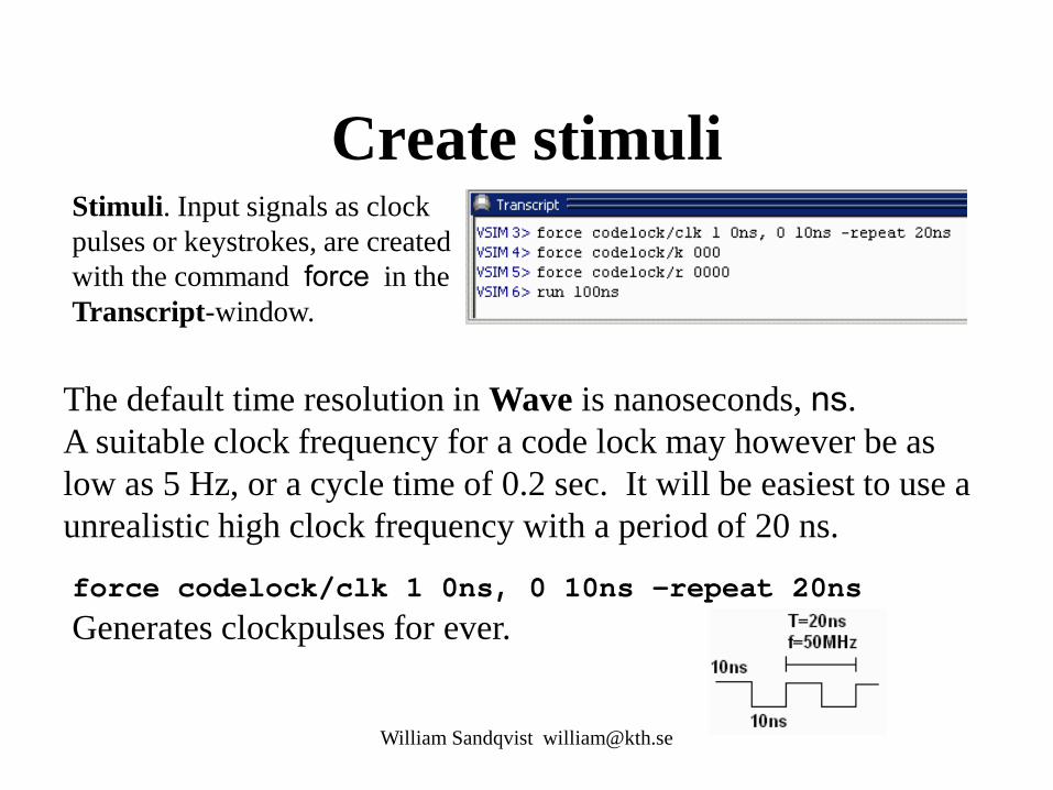
Create stimuli
William Sandqvist [email protected]
The default time resolution in Wave is nanoseconds, ns. A suitable clock frequency for a code lock may however be as low as 5 Hz, or a cycle time of 0.2 sec. It will be easiest to use a unrealistic high clock frequency with a period of 20 ns.
Stimuli. Input signals as clock pulses or keystrokes, are created with the command force in the Transcript-window.
force codelock/clk 1 0ns, 0 10ns -repeat 20ns Generates clockpulses for ever.
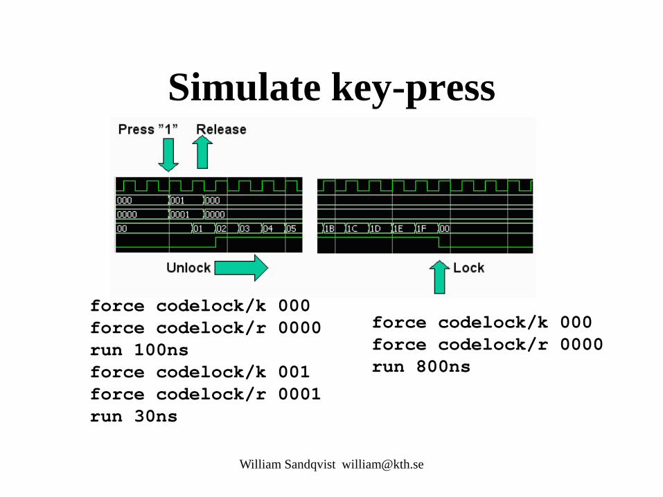
Simulate key-press
William Sandqvist [email protected]
force codelock/k 000 force codelock/r 0000 run 100ns force codelock/k 001 force codelock/r 0001 run 30ns
force codelock/k 000 force codelock/r 0000 run 800ns

Find in the Wave-window
William Sandqvist [email protected]
Add a Cursor. Search for "Signal Value".
Practice at home for the lab!


VHDL testbench
William Sandqvist [email protected]
Template program - state diagram
The lock opens when the key "1" is pressed and then released.
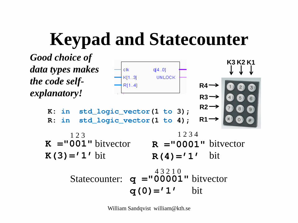
Keypad and Statecounter
K: in std_logic_vector(1 to 3); R: in std_logic_vector(1 to 4);
William Sandqvist [email protected]
K1 K2 K3
R4 R3 R2
R1
R ="0001" R(4)=’1’
bitvector bit
1 2 3 4 K ="001" K(3)=’1’
bitvector bit
1 2 3
Statecounter: q ="00001" q(0)=’1’
bitvector bit
4 3 2 1 0
Good choice of data types makes the code self-explanatory!

lockmall.vhd
William Sandqvist [email protected]
library IEEE; use IEEE.std_logic_1164.all; use IEEE.std_logic_arith.all; entity codelock is port( clk: in std_logic; K: in std_logic_vector(1 to 3); R: in std_logic_vector(1 to 4); q: out std_logic_vector(4 downto 0); UNLOCK: out std_logic ); end codelock; architecture behavior of codelock is subtype state_type is integer range 0 to 31; signal state, nextstate: state_type; begin nextstate_decoder: -- next state decoding part process(state, K, R) begin case state is when 0 => if (K = "100" and R ="0001") then nextstate <= 1; else nextstate <= 0; end if; when 1 => if (K = "100" and R ="0001") then nextstate <= 1; elsif (K = "000" and R = "0000") then nextstate <= 2; else nextstate <= 0; end if; when 2 to 30 => nextstate <= state + 1; when 31 => nextstate <= 0; end case; end process; debug_output: -- display the state q <= conv_std_logic_vector(state,5);
output_decoder: -- output decoder part process(state) begin case state is when 0 to 1 => UNLOCK <= '0'; when 2 to 31 => UNLOCK <= '1'; end case; end process; state_register: -- the state register part (the flipflops) process(clk) begin if rising_edge(clk) then state <= nextstate; end if; end process; end behavior;
This code is given
It’s easy to see that this is correct!
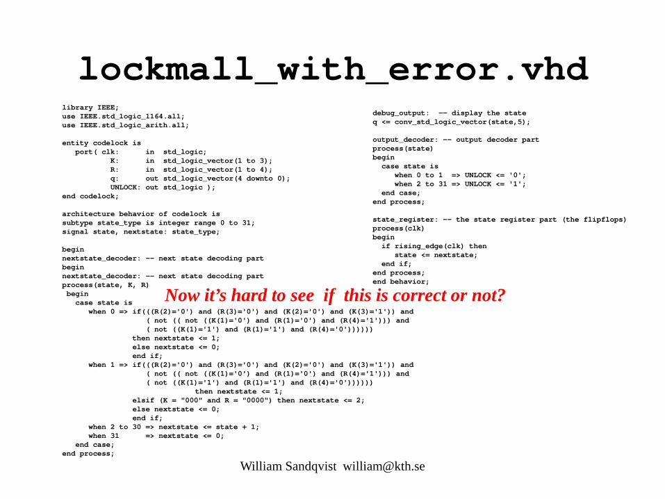
lockmall_with_error.vhd library IEEE; use IEEE.std_logic_1164.all; use IEEE.std_logic_arith.all; entity codelock is port( clk: in std_logic; K: in std_logic_vector(1 to 3); R: in std_logic_vector(1 to 4); q: out std_logic_vector(4 downto 0); UNLOCK: out std_logic ); end codelock; architecture behavior of codelock is subtype state_type is integer range 0 to 31; signal state, nextstate: state_type; begin nextstate_decoder: -- next state decoding part begin nextstate_decoder: -- next state decoding part process(state, K, R) begin case state is when 0 => if(((R(2)='0') and (R(3)='0') and (K(2)='0') and (K(3)='1')) and ( not (( not ((K(1)='0') and (R(1)='0') and (R(4)='1'))) and ( not ((K(1)='1') and (R(1)='1') and (R(4)='0')))))) then nextstate <= 1; else nextstate <= 0; end if; when 1 => if(((R(2)='0') and (R(3)='0') and (K(2)='0') and (K(3)='1')) and ( not (( not ((K(1)='0') and (R(1)='0') and (R(4)='1'))) and ( not ((K(1)='1') and (R(1)='1') and (R(4)='0')))))) then nextstate <= 1; elsif (K = "000" and R = "0000") then nextstate <= 2; else nextstate <= 0; end if; when 2 to 30 => nextstate <= state + 1; when 31 => nextstate <= 0; end case; end process;
debug_output: -- display the state q <= conv_std_logic_vector(state,5); output_decoder: -- output decoder part process(state) begin case state is when 0 to 1 => UNLOCK <= '0'; when 2 to 31 => UNLOCK <= '1'; end case; end process; state_register: -- the state register part (the flipflops) process(clk) begin if rising_edge(clk) then state <= nextstate; end if; end process; end behavior;
Now it’s hard to see if this is correct or not?
William Sandqvist [email protected]

lockmall_with_error.vhd
(((R(2)='0') and (R(3)='0') and (K(2)='0') and (K(3)='1')) and ( not (( not ((K(1)='0') and (R(1)='0') and (R(4)='1'))) and ( not ((K(1)='1') and (R(1)='1') and (R(4)='0'))))))
Means both expressions the same thing? ( K = "100" and R ="0001" )
Is this really the same thing?
Someone "promises" that the code is correct - but how can you know if this is absolutely true?
William Sandqvist [email protected]

tb_lockmall.vhd
William Sandqvist [email protected]
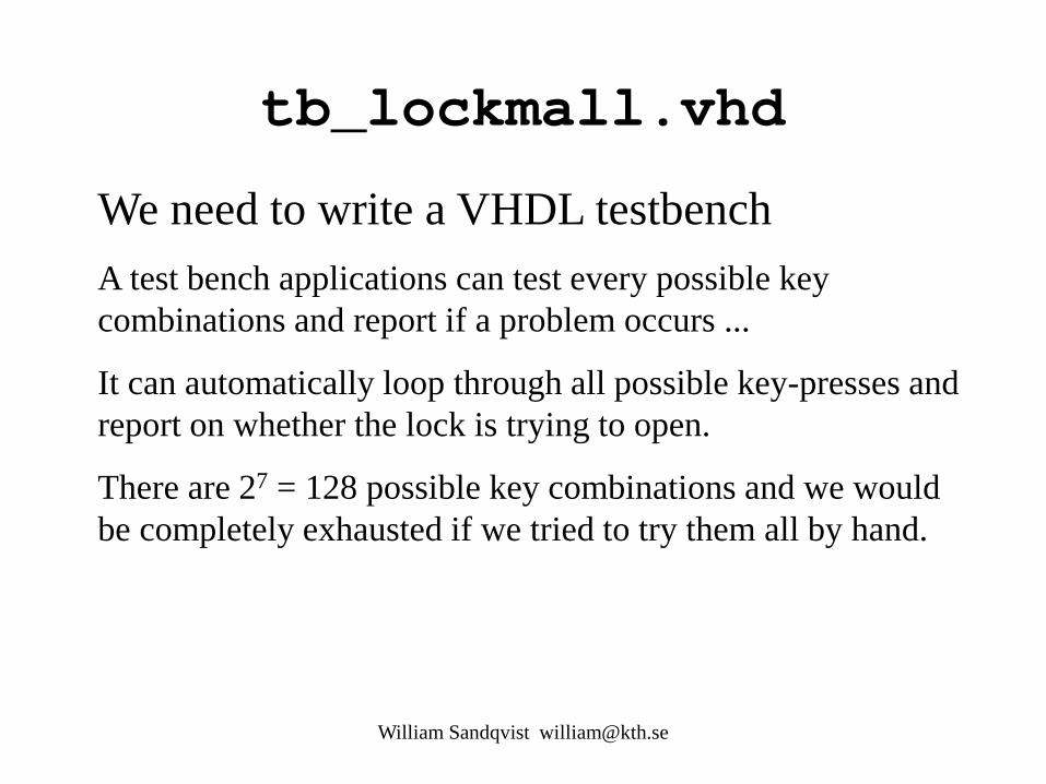
We need to write a VHDL testbench A test bench applications can test every possible key combinations and report if a problem occurs ...
It can automatically loop through all possible key-presses and report on whether the lock is trying to open.
There are 27 = 128 possible key combinations and we would be completely exhausted if we tried to try them all by hand.
entity – a testbench has no ports
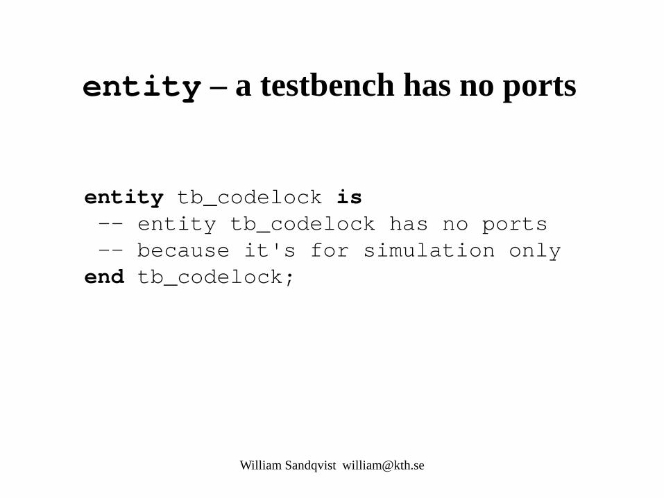
entity tb_codelock is -- entity tb_codelock has no ports -- because it's for simulation only end tb_codelock;
William Sandqvist [email protected]
Some internal signals are needed
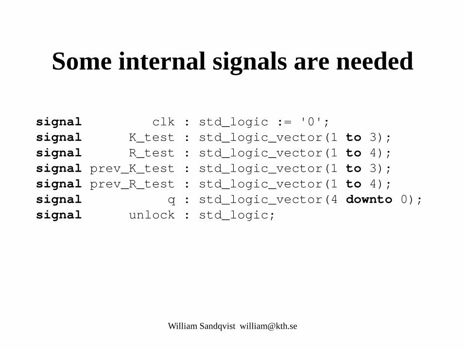
signal clk : std_logic := '0'; signal K_test : std_logic_vector(1 to 3); signal R_test : std_logic_vector(1 to 4); signal prev_K_test : std_logic_vector(1 to 3); signal prev_R_test : std_logic_vector(1 to 4); signal q : std_logic_vector(4 downto 0); signal unlock : std_logic;
William Sandqvist [email protected]

Our codelock is used as a component
-- we use our codelock as a component component codelock port( clk : in std_logic; K : in std_logic_vector(1 to 3); R : in std_logic_vector(1 to 4); q : out std_logic_vector(4 downto 0); UNLOCK : out std_logic ); end component;
William Sandqvist [email protected]

Generate a simulation clock
-- generate a simulation clock clk <= not clk after 10 ns;
William Sandqvist [email protected]
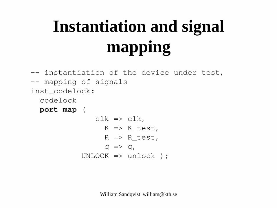
Instantiation and signal mapping
-- instantiation of the device under test, -- mapping of signals inst_codelock: codelock port map ( clk => clk, K => K_test, R => R_test, q => q, UNLOCK => unlock );
William Sandqvist [email protected]

A nested loop creates keystrokes
process begin for k in 0 to 7 loop K_test <= conv_std_logic_vector(k,3); for r in 0 to 15 loop prev_K_test <= K_test; prev_R_test <= R_test; R_test <= conv_std_logic_vector(r,4); wait until CLK='1'; end loop; end loop; end process;
8⋅16=128 turns
William Sandqvist [email protected]
8
16

report, severity note, severity error
check: process(q) begin if ((q = "00001") and (prev_K_test = conv_std_logic_vector(1,3)) and (prev_R_test = conv_std_logic_vector(1,4))) then assert false report "Lock tries to open for the right sequence!” severity note; else if ((q = "00001")) then assert false report "Lock tries to open with the wrong sequence!” severity error; else report "Lock closed!" severity note; end if; end if; end process check; William Sandqvist [email protected]
Tests if state q = ”00001” will be reached by any combination.
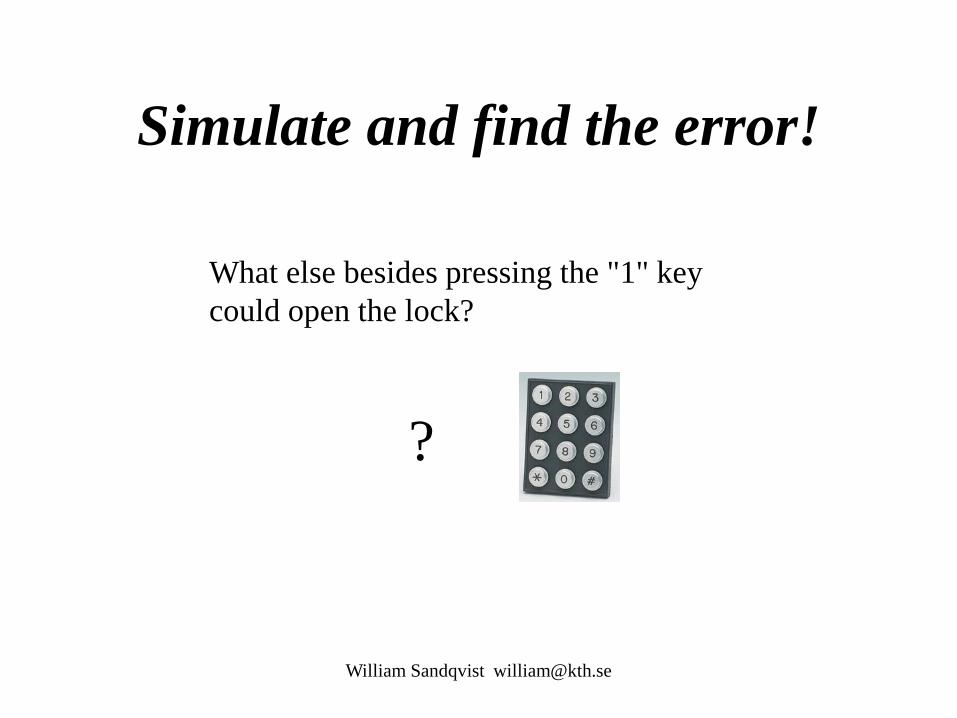
Simulate and find the error!
What else besides pressing the "1" key could open the lock?
?
William Sandqvist [email protected]

William Sandqvist [email protected]
Related Documents


