MATERI MAHARASHTRA DEPARTMENT O LAB MANUAL IALS AND METALLURGY (MED 322) G.S. Mandal’s A INSTITUTE OF TECHNOL AURANGABAD OF MECHANICAL ENGINEE LOGY, ERING

Welcome message from author
This document is posted to help you gain knowledge. Please leave a comment to let me know what you think about it! Share it to your friends and learn new things together.
Transcript
MATERIALS AND METALLURGY
MAHARASHTRA INSTITUTE OF TECHNOLOGY,
DEPARTMENT OF MECHANICAL ENGINEERING
LAB MANUAL
MATERIALS AND METALLURGY
(MED 322)
G.S. Mandal’s
MAHARASHTRA INSTITUTE OF TECHNOLOGY,
AURANGABAD
DEPARTMENT OF MECHANICAL ENGINEERING
MAHARASHTRA INSTITUTE OF TECHNOLOGY,
DEPARTMENT OF MECHANICAL ENGINEERING
G.S. Mandal’s
MAHARASHTRA INSTITUTE OF TECHNOLOGY,AURANGABADDEPARTMENT OF MECHANICAL
ENGINEERING
NAME OF LABORATORY:MATERIALS AND METALLURGY
LABORATORY MANUAL
CLASS: THIRD YEAR PART: I COURSE CODE :MED 322
NAME OF COURSE : MATERIALS AND METALLURGY
PREPARED BY: Prof. P. A. Lad APPROVED BY: Dr., A. J. Keche (HMED) 2
INDEX
Sr. No.
Contents Page No.
1 Vision & Mission of Institute 3
2 Vision & Mission of Department 4
3 Program Educational Objectives 5
4 Program Outcomes 6
5 Program Specific Outcomes 8
6 Course Objectives & Course Outcomes 9
7 University Syllabus 10
8 Lab Instructions 11
9 Measurement of hardness by Rockwell hardness test. 12
10 Study of mechanical properties like tensile strength, impact strength and wear
resistance of materials. 18
11 Study of metallurgical microscope 24
12 Study of preparation of the specimen for microscopic examination. 30
13 Observation of microstructure of various types of Plain carbon steels and
Alloy steels. 35
14 Observation of microstructure of various types of Cast Iron. 41
15 Observation of microstructure of various types of Nonferrous Alloys 44
16 Study of changes in material properties and microstructures after Heat
treatments like Annealing, Hardening, Tempering, Cryogenic Treatment, etc. 48
17 Study of Jominy end quench test to understand the concept of Hardenability. 53
18 Study of Nanomaterials and Nanocomposites. 57
G.S. Mandal’s
MAHARASHTRA INSTITUTE OF TECHNOLOGY,AURANGABADDEPARTMENT OF MECHANICAL
ENGINEERING
NAME OF LABORATORY:MATERIALS AND METALLURGY
LABORATORY MANUAL
CLASS: THIRD YEAR PART: I COURSE CODE :MED 322
NAME OF COURSE : MATERIALS AND METALLURGY
PREPARED BY: Prof. P. A. Lad APPROVED BY: Dr., A. J. Keche (HMED) 3
Vision:
MIT aspires to be a leader in Techno-Managerial education at national level by developing
students as technologically superior and ethically strong multidimensional personalities
with a global mindset.
Mission:
We are committed to provide wholesome education in Technology and Management to
enable aspiring students to utilize their fullest potential and become professionally
competent and ethically strong by providing,
Well qualified, experienced and Professionally trained faculty
State-of-the-art infrastructural facilities and learning environment
Conducive environment for research and development.
Delight to all stakeholders.
G.S. Mandal’s
MAHARASHTRA INSTITUTE OF TECHNOLOGY,AURANGABADDEPARTMENT OF MECHANICAL
ENGINEERING
NAME OF LABORATORY:MATERIALS AND METALLURGY
LABORATORY MANUAL
CLASS: THIRD YEAR PART: I COURSE CODE :MED 322
NAME OF COURSE : MATERIALS AND METALLURGY
PREPARED BY: Prof. P. A. Lad APPROVED BY: Dr., A. J. Keche (HMED) 4
Vision of Mechanical Engineering Department
To be a center of excellence in the field of Mechanical Engineering where the best of
teaching, learning and research synergize and serve the society through innovation and
excellence in teaching.
Mission of Mechanical Engineering Department
To provide world-class under-graduate and graduate education in Mechanical
Engineering by imparting quality techno-managerial education and training to meet current
and emerging needs of the industry and society at large.
G.S. Mandal’s
MAHARASHTRA INSTITUTE OF TECHNOLOGY,AURANGABADDEPARTMENT OF MECHANICAL
ENGINEERING
NAME OF LABORATORY:MATERIALS AND METALLURGY
LABORATORY MANUAL
CLASS: THIRD YEAR PART: I COURSE CODE :MED 322
NAME OF COURSE : MATERIALS AND METALLURGY
PREPARED BY: Prof. P. A. Lad APPROVED BY: Dr., A. J. Keche (HMED) 5
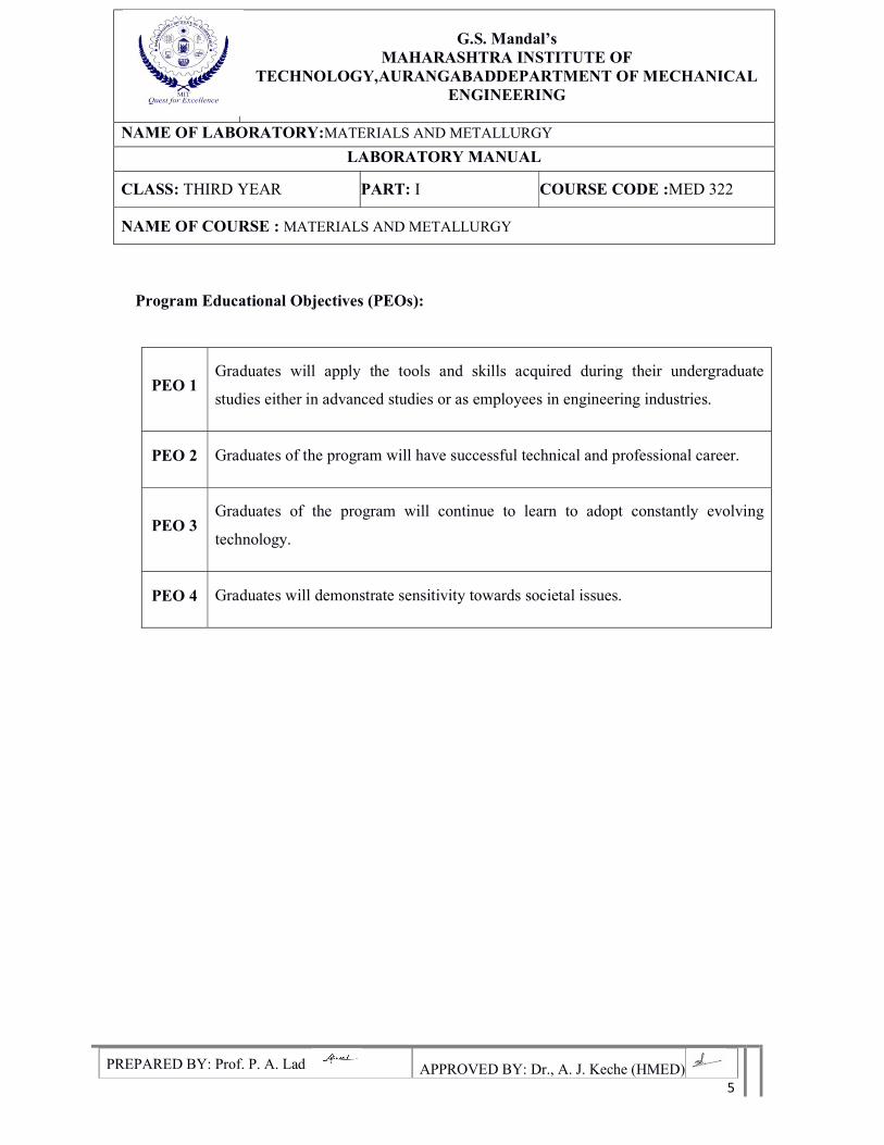
Program Educational Objectives (PEOs):
PEO 1 Graduates will apply the tools and skills acquired during their undergraduate
studies either in advanced studies or as employees in engineering industries.
PEO 2 Graduates of the program will have successful technical and professional career.
PEO 3 Graduates of the program will continue to learn to adopt constantly evolving
technology.
PEO 4 Graduates will demonstrate sensitivity towards societal issues.
G.S. Mandal’s
MAHARASHTRA INSTITUTE OF TECHNOLOGY,AURANGABADDEPARTMENT OF MECHANICAL
ENGINEERING
NAME OF LABORATORY:MATERIALS AND METALLURGY
LABORATORY MANUAL
CLASS: THIRD YEAR PART: I COURSE CODE :MED 322
NAME OF COURSE : MATERIALS AND METALLURGY
PREPARED BY: Prof. P. A. Lad APPROVED BY: Dr., A. J. Keche (HMED) 6
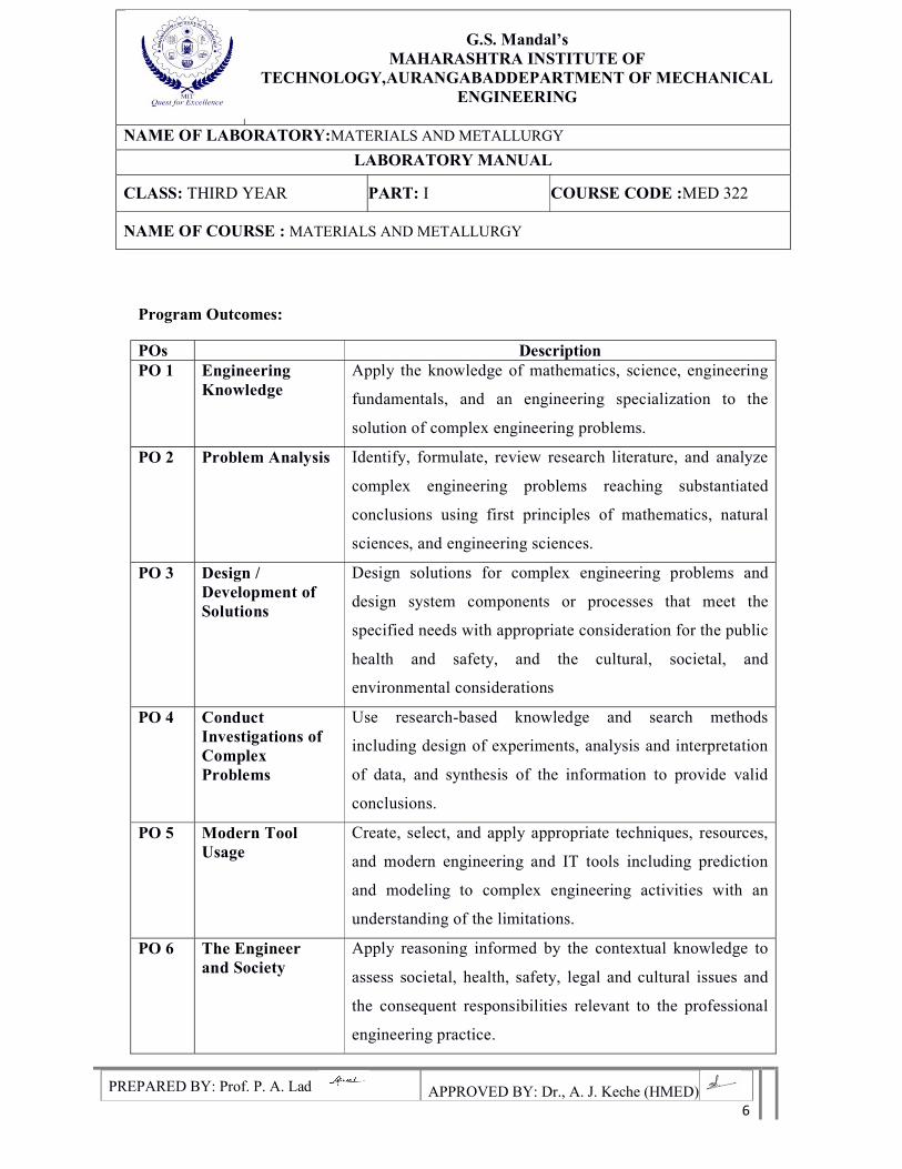
Program Outcomes:
POs Description PO 1 Engineering
Knowledge Apply the knowledge of mathematics, science, engineering
fundamentals, and an engineering specialization to the
solution of complex engineering problems.
PO 2 Problem Analysis Identify, formulate, review research literature, and analyze
complex engineering problems reaching substantiated
conclusions using first principles of mathematics, natural
sciences, and engineering sciences.
PO 3 Design / Development of Solutions
Design solutions for complex engineering problems and
design system components or processes that meet the
specified needs with appropriate consideration for the public
health and safety, and the cultural, societal, and
environmental considerations
PO 4 Conduct Investigations of Complex Problems
Use research-based knowledge and search methods
including design of experiments, analysis and interpretation
of data, and synthesis of the information to provide valid
conclusions.
PO 5 Modern Tool Usage
Create, select, and apply appropriate techniques, resources,
and modern engineering and IT tools including prediction
and modeling to complex engineering activities with an
understanding of the limitations.
PO 6 The Engineer and Society
Apply reasoning informed by the contextual knowledge to
assess societal, health, safety, legal and cultural issues and
the consequent responsibilities relevant to the professional
engineering practice.
G.S. Mandal’s
MAHARASHTRA INSTITUTE OF TECHNOLOGY,AURANGABADDEPARTMENT OF MECHANICAL
ENGINEERING
NAME OF LABORATORY:MATERIALS AND METALLURGY
LABORATORY MANUAL
CLASS: THIRD YEAR PART: I COURSE CODE :MED 322
NAME OF COURSE : MATERIALS AND METALLURGY
PREPARED BY: Prof. P. A. Lad APPROVED BY: Dr., A. J. Keche (HMED) 7
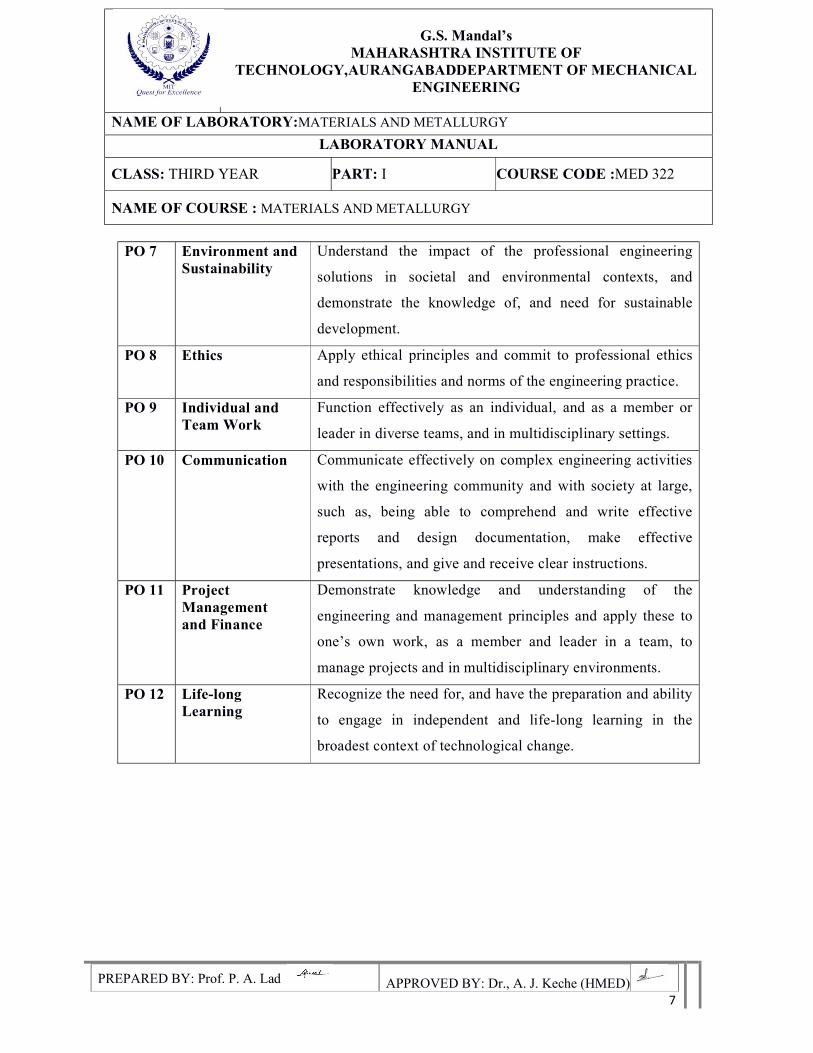
PO 7 Environment and Sustainability
Understand the impact of the professional engineering
solutions in societal and environmental contexts, and
demonstrate the knowledge of, and need for sustainable
development.
PO 8 Ethics Apply ethical principles and commit to professional ethics
and responsibilities and norms of the engineering practice.
PO 9 Individual and Team Work
Function effectively as an individual, and as a member or
leader in diverse teams, and in multidisciplinary settings.
PO 10 Communication Communicate effectively on complex engineering activities
with the engineering community and with society at large,
such as, being able to comprehend and write effective
reports and design documentation, make effective
presentations, and give and receive clear instructions.
PO 11 Project Management and Finance
Demonstrate knowledge and understanding of the
engineering and management principles and apply these to
one’s own work, as a member and leader in a team, to
manage projects and in multidisciplinary environments.
PO 12 Life-long Learning
Recognize the need for, and have the preparation and ability
to engage in independent and life-long learning in the
broadest context of technological change.
G.S. Mandal’s
MAHARASHTRA INSTITUTE OF TECHNOLOGY,AURANGABADDEPARTMENT OF MECHANICAL
ENGINEERING
NAME OF LABORATORY:MATERIALS AND METALLURGY
LABORATORY MANUAL
CLASS: THIRD YEAR PART: I COURSE CODE :MED 322
NAME OF COURSE : MATERIALS AND METALLURGY
PREPARED BY: Prof. P. A. Lad APPROVED BY: Dr., A. J. Keche (HMED) 8
Program Specific Outcomes:
PSO 1 Ability to design &analyze components & systems for mechanical performance
PSO 2 Ability to apply and solve the problems of heat power and thermal systems
PSO 3 Ability to solve real life problems with the exposure to manufacturing industries
G.S. Mandal’s
MAHARASHTRA INSTITUTE OF TECHNOLOGY,AURANGABADDEPARTMENT OF MECHANICAL
ENGINEERING
NAME OF LABORATORY:MATERIALS AND METALLURGY
LABORATORY MANUAL
CLASS: THIRD YEAR PART: I COURSE CODE :MED 322
NAME OF COURSE : MATERIALS AND METALLURGY
PREPARED BY: Prof. P. A. Lad APPROVED BY: Dr., A. J. Keche (HMED) 9
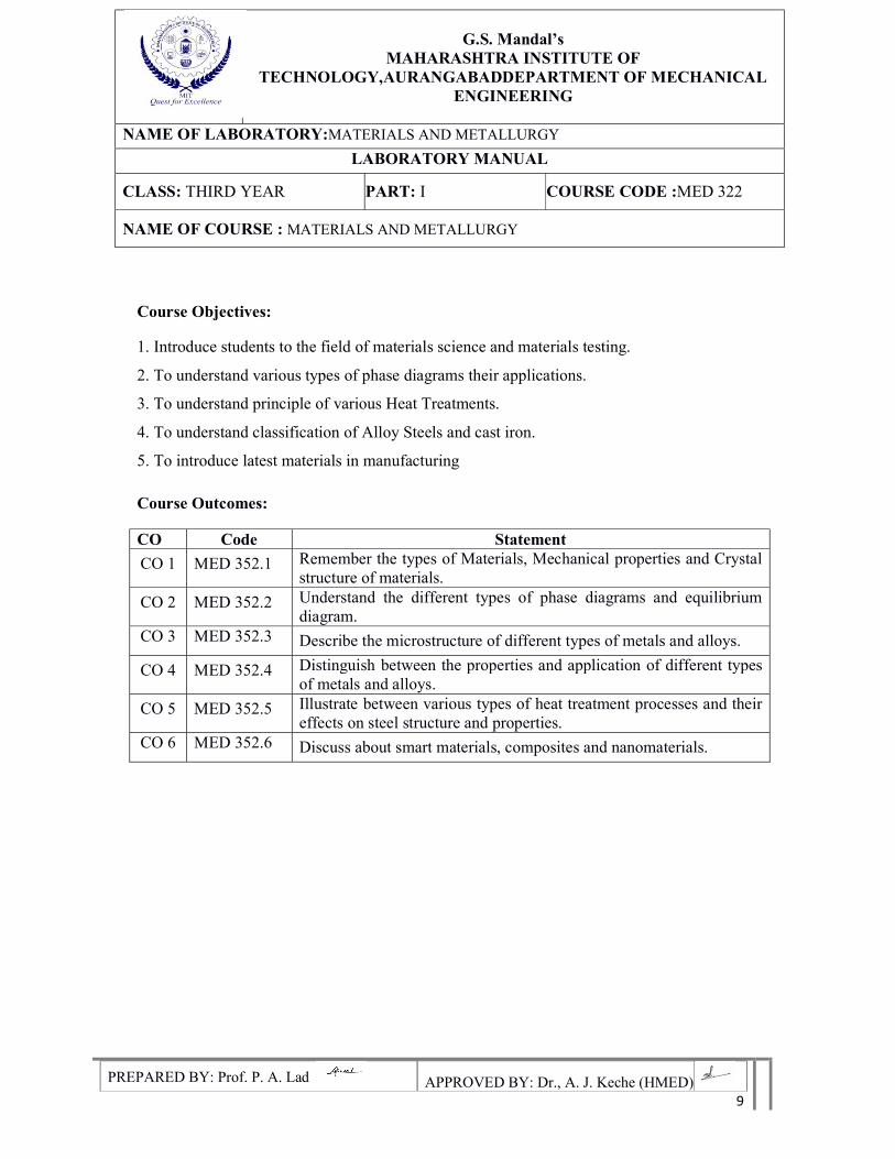
Course Objectives:
1. Introduce students to the field of materials science and materials testing.
2. To understand various types of phase diagrams their applications.
3. To understand principle of various Heat Treatments.
4. To understand classification of Alloy Steels and cast iron.
5. To introduce latest materials in manufacturing
Course Outcomes:
CO Code Statement
CO 1 MED 352.1 Remember the types of Materials, Mechanical properties and Crystal structure of materials.
CO 2 MED 352.2 Understand the different types of phase diagrams and equilibrium diagram.
CO 3 MED 352.3 Describe the microstructure of different types of metals and alloys.
CO 4 MED 352.4 Distinguish between the properties and application of different types of metals and alloys.
CO 5 MED 352.5 Illustrate between various types of heat treatment processes and their effects on steel structure and properties.
CO 6 MED 352.6 Discuss about smart materials, composites and nanomaterials.
G.S. Mandal’s
MAHARASHTRA INSTITUTE OF TECHNOLOGY,AURANGABADDEPARTMENT OF MECHANICAL
ENGINEERING
NAME OF LABORATORY:MATERIALS AND METALLURGY
LABORATORY MANUAL
CLASS: THIRD YEAR PART: I COURSE CODE :MED 322
NAME OF COURSE : MATERIALS AND METALLURGY
PREPARED BY: Prof. P. A. Lad APPROVED BY: Dr., A. J. Keche (HMED) 10
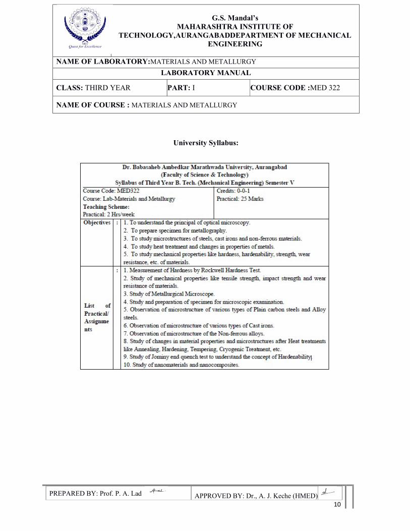
University Syllabus:
G.S. Mandal’s
MAHARASHTRA INSTITUTE OF TECHNOLOGY,AURANGABADDEPARTMENT OF MECHANICAL
ENGINEERING
NAME OF LABORATORY:MATERIALS AND METALLURGY
LABORATORY MANUAL
CLASS: THIRD YEAR PART: I COURSE CODE :MED 322
NAME OF COURSE : MATERIALS AND METALLURGY
PREPARED BY: Prof. P. A. Lad APPROVED BY: Dr., A. J. Keche (HMED) 11
Lab Instructions
1. College uniform, shoes are compulsory in the lab.
2. Student should wear college ID-card and must carry record and observation.
3. Take signature of lab in charge after completion of observation and record.
4. If any equipment fails in the experiment report it to the supervisor immediately.
5. Students should come to the lab with thorough theoretical knowledge.
6. Don't touch the equipment without instructions from lab supervisor.
7. Don't crowd around the experiment and behave in-disciplinary.
8. Students should carry their own stationary and required things.
9. Using the mobile phone in the laboratory is strictly prohibited.
G.S. Mandal’s
MAHARASHTRA INSTITUTE OF TECHNOLOGY,AURANGABADDEPARTMENT OF MECHANICAL
ENGINEERING
NAME OF LABORATORY:MATERIALS AND METALLURGY
LABORATORY MANUAL
CLASS: THIRD YEAR PART: I COURSE CODE :MED 322
NAME OF COURSE : MATERIALS AND METALLURGY
PREPARED BY: Prof. P. A. Lad APPROVED BY: Dr., A. J. Keche (HMED) 12
EXPERIMENT NO. 1
Aim: Measurement of Hardness by Rockwell Hardness test
Objectives:-
1. To understand the concept of hardness.
2. To conduct and measure typical engineering hardness tests on different materials.
3. To study behavior of materials using hardness test.
Apparatus: Rockwell hardness tester, Indenters, etc.
Table no 1.1 Standard Rockwell hardness scale and their specification
Scale
Symbol
Indenter Major
Load(kg)
Dial
Numerical
Typical Application of Scale
Remark
B 1/6" Ball 100 Red Brass, Low and medium carbon
steel in annealed and normalized
condition.
C Blade 150 Black Hardened steel, Hard C.I., Deep
case hard steel.
A Blade 60 Black Hard thin material like blade, Case
hardened steel and surface centered
carbide.
D Blade 100 Black Used where major load is desired
between those required for A and C.
F 1/8" Ball
(32mm)
100 Red Used for measuring hardness of
very safe material such as ferrite
material, aluminum and its alloy etc.
G.S. Mandal’s
MAHARASHTRA INSTITUTE OF TECHNOLOGY,AURANGABADDEPARTMENT OF MECHANICAL
ENGINEERING
NAME OF LABORATORY:MATERIALS AND METALLURGY
LABORATORY MANUAL
CLASS: THIRD YEAR PART: I COURSE CODE :MED 322
NAME OF COURSE : MATERIALS AND METALLURGY
PREPARED BY: Prof. P. A. Lad APPROVED BY: Dr., A. J. Keche (HMED) 13
Theory:
In this method hardness of metal is correlated with the depth of indentation and does
not with area of indentation as in Brinell hardness and vice versa. The dial is calibrated in an
inverse fashion, so that the hardness number becomes directly proportional to hardness of
material. In this test there are 2 types of indenters are used:
1. Hard steel ball of 1/6", 1/8", 1/4" and 1/2" diameter
2. Brale indenter made of diamond in form of cone with include angle of 120O, the tip of
indenter is accurately grounded to radius of 0.2mm.
Loads are applied in 2 stages:
1. A constant minor load of 10kg is applied.
2. Then major loads are applied of 60, 100 or 150kg.
The Various combination of indenters and loads are indicated by letter such as a, b, c etc. The
complete list is given in table. In all there are 15 combinations. A letter indicates 60kg load
and Brale indenter. B letter indicates C letter indicates 150kg load and Brale indenter and so
on. Few of application of each scale are given in table 1.1.
Procedure:-
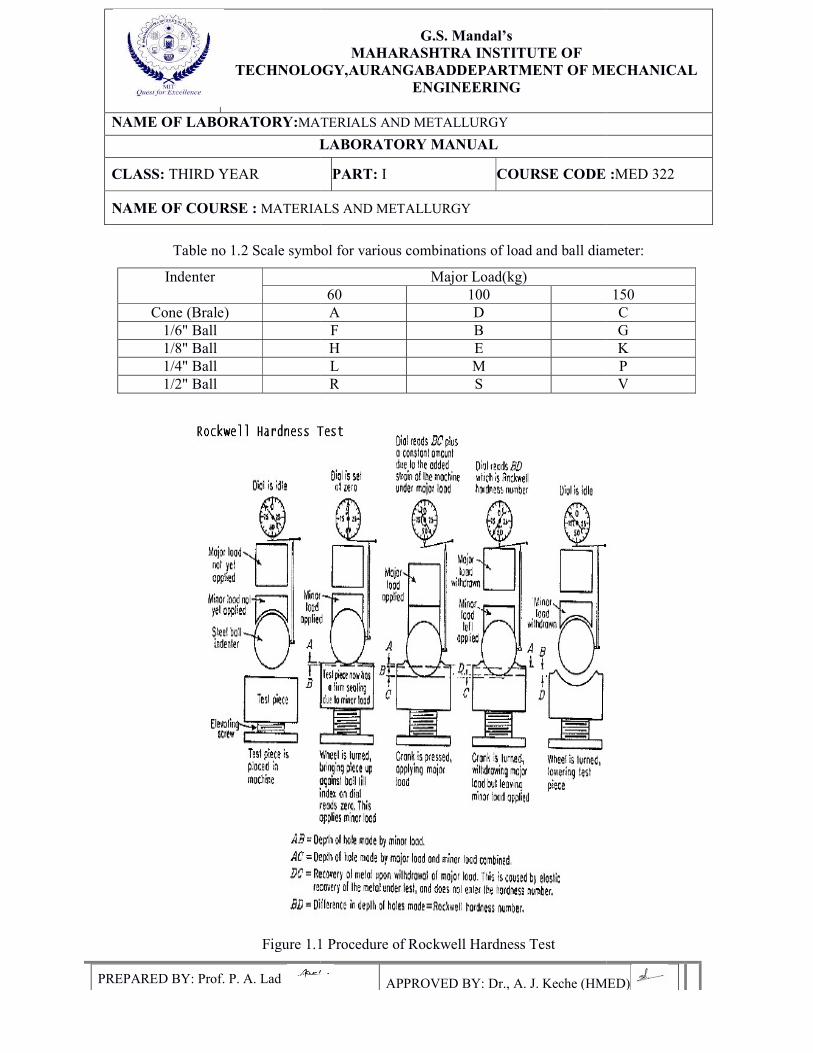
The method of testing is illustrated in figure by taking a standard 1/6" diameter ball
indenter and 100kg major load "B-scale". The size of ball is exaggerated in the figure for
better illustration of penetration distance by minor and major load.
The test is carried out as bellow:
1. The specimen surface on which hardness is to be measure should be free from dust
and surface defects. The specimen is placed on the anvil, the dial pointers are ideal major or
minor load is applied. The anvil along with the specimen is raised, then so that the specimen
touches the indenter. By further raising the anvil slowly, the minor load of 10kh is applied. At
this stage the small pointer on dial co-inside with number 3 and big dial co-inside with zero
pointed with black ink or 30 mark pointer in red ink or set point marked on dial.
G.S. Mandal’s
MAHARASHTRA INSTITUTE OF TECHNOLOGY,AURANGABADDEPARTMENT OF MECHANICAL
ENGINEERING
NAME OF LABORATORY:MATERIALS AND METALLURGY
LABORATORY MANUAL
CLASS: THIRD YEAR PART: I COURSE CODE :MED 322
NAME OF COURSE : MATERIALS AND METALLURGY
PREPARED BY: Prof. P. A. Lad APPROVED BY: Dr., A. J. Keche (HMED) 14
If the large pointer is not at this position, the barrel of dial is then rotated until zero or 30 or
set point mark co-inside with large pointer. The minor load of 10k has forced the indenter into
the specimen to a depth up to B (A to B).
2. In this step, since load is an opposite direction, the large pointer moves in clockwise
direction during the penetration of indenter.
3. Major load of 100kg is applied by means of a release handle provided on right side of the
instrument. This load is applied gradually by means of a dashpot arrangement. The major load
of 100kg consists of original minor load of 10kg plus an additional load of 90kg. The
application of major load forced the ball into specimen to additional depth up to C (B to C).
Due to this large pointer move in counter clockwise direction from set point, corresponding to
(B to C) the depth of penetration
(100-40) X 0.002 =0.12 mm
4. Without removing the minor load of 10kg, the major load of 90 out of 100kg is removed.
Due to this elastic recovery depth comes to D point.
5. Without removal of minor load hardness No. read directly from dial which is 60 in figure.
This hardness is designation of RB = 60 RHN.
6. The minor load of 10kg is removed and next reading is taken on same specimen at different
place in way similar to above. The scale of dial with respect to the motion of pointer is
reversed so that shallow and deeper indication indicate a lower hardness No.
The calibration is according to the following equation:
A) For Brale indenter: RHN = 100 - (Depth of penetration in mm/0.002)
B) For ball indenter: RHN = 130-(Depth of penetration in mm/0.002)
TECHNOLOGY,AURANGABAD
NAME OF LABORATORY:MATERIALS AND METALLURGY
LABORATORY MANUAL
CLASS: THIRD YEAR
NAME OF COURSE : MATERIALS
PREPARED BY: Prof. P. A. Lad
Table no 1.2 Scale symbol for various combinations of load and
Indenter
Cone (Brale) 1/6" Ball 1/8" Ball 1/4" Ball 1/2" Ball
Figure 1.1 Procedure of Rockwell Hardness Test
G.S. Mandal’s
MAHARASHTRA INSTITUTE OF TECHNOLOGY,AURANGABADDEPARTMENT OF MECHANICAL
ENGINEERING
MATERIALS AND METALLURGY
LABORATORY MANUAL
PART: I COURSE CODE :
MATERIALS AND METALLURGY
APPROVED BY: Dr., A. J. Keche (HMED)
Scale symbol for various combinations of load and ball diameter:
Major Load(kg) 60 100 A D F B H E L M R S
Figure 1.1 Procedure of Rockwell Hardness Test
DEPARTMENT OF MECHANICAL
RSE CODE :MED 322
APPROVED BY: Dr., A. J. Keche (HMED)
ball diameter:
150 C G K P V
G.S. Mandal’s
MAHARASHTRA INSTITUTE OF TECHNOLOGY,AURANGABADDEPARTMENT OF MECHANICAL
ENGINEERING
NAME OF LABORATORY:MATERIALS AND METALLURGY
LABORATORY MANUAL
CLASS: THIRD YEAR PART: I COURSE CODE :MED 322
NAME OF COURSE : MATERIALS AND METALLURGY
PREPARED BY: Prof. P. A. Lad APPROVED BY: Dr., A. J. Keche (HMED) 16
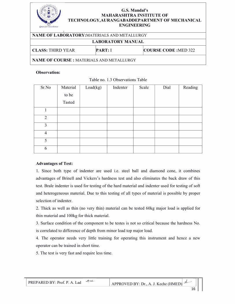
Observation:
Table no. 1.3 Observations Table
Sr.No Material
to be
Tasted
Load(kg) Indenter Scale Dial Reading
1
2
3
4
5
6
Advantages of Test:
1. Since both type of indenter are used i.e. steel ball and diamond cone, it combines
advantages of Brinell and Vickers’s hardness test and also eliminates the back draw of this
test. Brale indenter is used for testing of the hard material and indenter used for testing of soft
and heterogeneous material. Due to this testing of all types of material is possible by proper
selection of indenter.
2. Thick as well as thin (no very thin) material can be tested 60kg major load is applied for
thin material and 100kg for thick material.
3. Surface condition of the component to be testes is not so critical because the hardness No.
is correlated to difference of depth from minor load top major load.
4. The operator needs very little training for operating this instrument and hence a new
operator can be trained in short time.
5. The test is very fast and require less time.
G.S. Mandal’s
MAHARASHTRA INSTITUTE OF TECHNOLOGY,AURANGABADDEPARTMENT OF MECHANICAL
ENGINEERING
NAME OF LABORATORY:MATERIALS AND METALLURGY
LABORATORY MANUAL
CLASS: THIRD YEAR PART: I COURSE CODE :MED 322
NAME OF COURSE : MATERIALS AND METALLURGY
PREPARED BY: Prof. P. A. Lad APPROVED BY: Dr., A. J. Keche (HMED) 17
Precautions:
1. For testing cylindrical test specimen, use V-type platform.
2. Calibrate the machine occasionally using standard test blocks.
3. After applying Major load, wait for some time to allow the needle to come to rest.
4. The waiting time vary from 2 to 8 seconds.
5. The surface of the test piece should be smooth and even and free from oxide scale
and foreign matter.
6. Test specimen should not be subjected to any heating or cold working.
7. The thickness of test piece or of the layer under test should be at least 8 times the
permanent increase of depth of “E”.
8. The distance between the centers of two adjacent indentations should be at least 4
indentations to the edge of the test piece should be at least 2.5 times the diameter of
the indentation.
Results: -
Conclusions:
G.S. Mandal’s
MAHARASHTRA INSTITUTE OF TECHNOLOGY,AURANGABADDEPARTMENT OF MECHANICAL
ENGINEERING
NAME OF LABORATORY:MATERIALS AND METALLURGY
LABORATORY MANUAL
CLASS: THIRD YEAR PART: I COURSE CODE :MED 322
NAME OF COURSE : MATERIALS AND METALLURGY
PREPARED BY: Prof. P. A. Lad APPROVED BY: Dr., A. J. Keche (HMED) 18
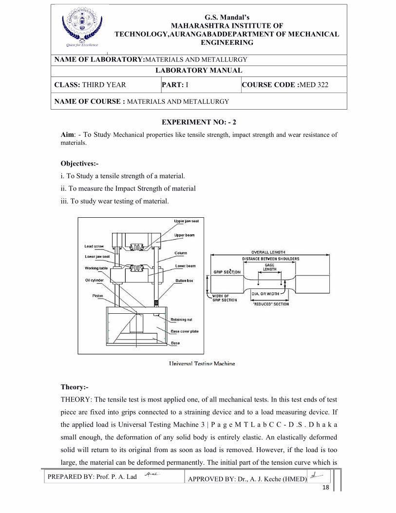
EXPERIMENT NO: - 2
Aim: - To Study Mechanical properties like tensile strength, impact strength and wear resistance of materials.
Objectives:-
i. To Study a tensile strength of a material.
ii. To measure the Impact Strength of material
iii. To study wear testing of material.
Theory:-
THEORY: The tensile test is most applied one, of all mechanical tests. In this test ends of test
piece are fixed into grips connected to a straining device and to a load measuring device. If
the applied load is Universal Testing Machine 3 | P a g e M T L a b C C - D .S . D h a k a
small enough, the deformation of any solid body is entirely elastic. An elastically deformed
solid will return to its original from as soon as load is removed. However, if the load is too
large, the material can be deformed permanently. The initial part of the tension curve which is
G.S. Mandal’s
MAHARASHTRA INSTITUTE OF TECHNOLOGY,AURANGABADDEPARTMENT OF MECHANICAL
ENGINEERING
NAME OF LABORATORY:MATERIALS AND METALLURGY
LABORATORY MANUAL
CLASS: THIRD YEAR PART: I COURSE CODE :MED 322
NAME OF COURSE : MATERIALS AND METALLURGY
PREPARED BY: Prof. P. A. Lad APPROVED BY: Dr., A. J. Keche (HMED) 19
recoverable immediately after unloading is termed. As elastic and the rest of the curve which
represents the manner in which solid undergoes plastic deformation is termed plastic. A
tensile test, also known as a tension test, is one of the most fundamental and common types of
mechanical testing. A tensile test applies tensile (pulling) force to a material and measures the
specimen's response to the stress. By doing this, tensile tests determine how strong a material
is and how much it can elongate. Tensile tests are typically conducted on universal testing
instruments, are simple to perform, and are fully standardized. By measuring the material
while it is being pulled, we can obtain a complete profile of its tensile properties. When
plotted on a graph, this data results in a stress/strain curve which shows how the material
reacted to the forces being applied. The point of break or failure is of much interest, but other
important properties include the modulus of elasticity, yield strength, and strain.
Ultimate Tensile Strength
One of the most important properties we can determine about a material is its ultimate
tensile strength (UTS). This is the maximum stress that a specimen sustains during the test.
The UTS may or may not equate to the specimen's strength at break, depending on whether
the material is brittle, ductile, or exhibits properties of both. Sometimes a material may be
ductile when tested in a lab, but, when placed in service and exposed to extreme cold
temperatures; it may transition to brittle behavior.
Hooke's Law
For most materials, the initial portion of the test will exhibit a linear relationship
between the applied force or load and the elongation exhibited by the specimen. In this linear
region, the line obeys the relationship defined as "Hooke's Law" where the ratio of stress to
strain is a constant, or . E is the slope of the line in this region where stress (σ) is proportional
to strain (ε) and is called the "Modulus of Elasticity" or "Young's Modulus."
Modulus of Elasticity
The modulus of elasticity is a measure of the material's stiffness which only applies in the
initial linear region of the curve. Within this linear region the tensile load can be removed
from the a specimen and the material will return to the exact same condition it had been in
G.S. Mandal’s
MAHARASHTRA INSTITUTE OF TECHNOLOGY,AURANGABADDEPARTMENT OF MECHANICAL
ENGINEERING
NAME OF LABORATORY:MATERIALS AND METALLURGY
LABORATORY MANUAL
CLASS: THIRD YEAR PART: I COURSE CODE :MED 322
NAME OF COURSE : MATERIALS AND METALLURGY
PREPARED BY: Prof. P. A. Lad APPROVED BY: Dr., A. J. Keche (HMED) 20
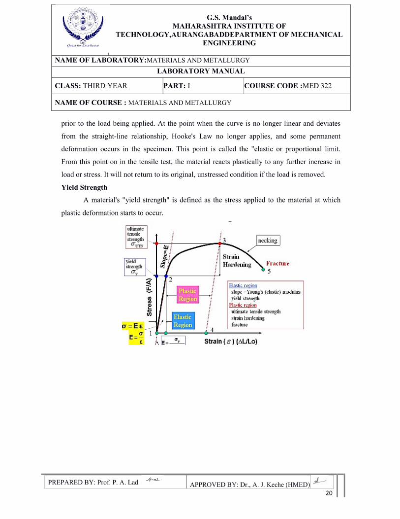
prior to the load being applied. At the point when the curve is no longer linear and deviates
from the straight-line relationship, Hooke's Law no longer applies, and some permanent
deformation occurs in the specimen. This point is called the "elastic or proportional limit.
From this point on in the tensile test, the material reacts plastically to any further increase in
load or stress. It will not return to its original, unstressed condition if the load is removed.
Yield Strength
A material's "yield strength" is defined as the stress applied to the material at which
plastic deformation starts to occur.
G.S. Mandal’s
MAHARASHTRA INSTITUTE OF TECHNOLOGY,AURANGABADDEPARTMENT OF MECHANICAL
ENGINEERING
NAME OF LABORATORY:MATERIALS AND METALLURGY
LABORATORY MANUAL
CLASS: THIRD YEAR PART: I COURSE CODE :MED 322
NAME OF COURSE : MATERIALS AND METALLURGY
PREPARED BY: Prof. P. A. Lad APPROVED BY: Dr., A. J. Keche (HMED) 21
Impact Test
THEORY: - In manufacturing locomotive wheels, coins, connecting rods etc. the
components are subjected to impact (shock) loads. These loads are applied suddenly. The
stress induced in these components are many times more than the stress produced by gradual
loading. Therefore, impact tests are performed to determine shock absorbing capacity of
materials subjected to suddenly applied loads. These capabilities are expressed as (i) Rupture
energy (ii) Modulus of rupture and (iii) Notch impact strength.
Two types of notch impact tests are commonly
1. Charpy test
2. Izod test
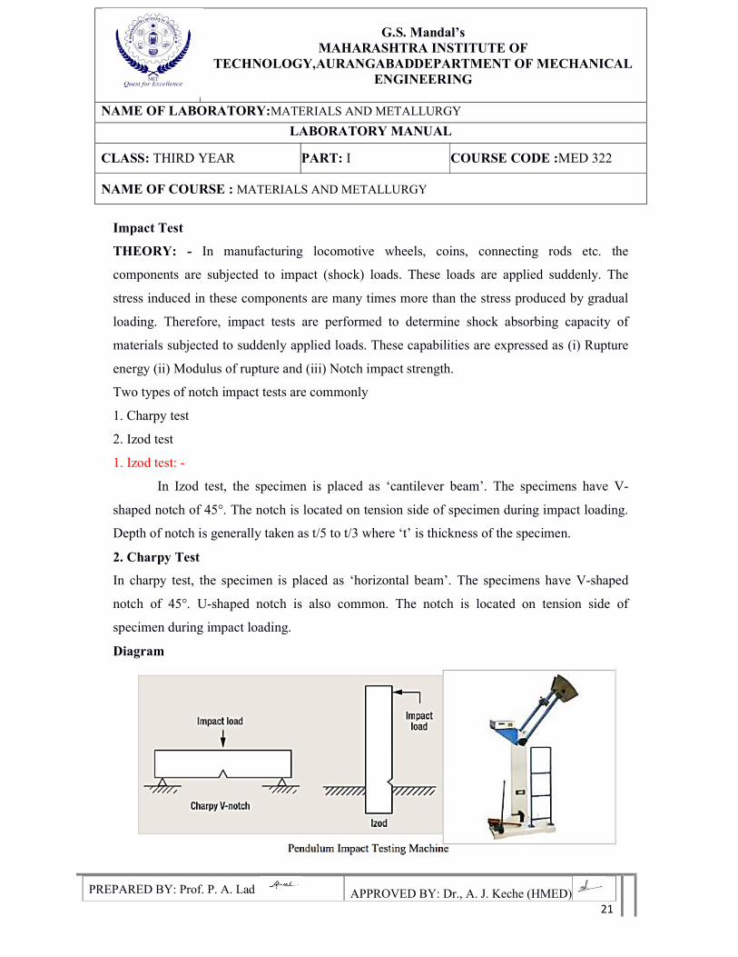
1. Izod test: -
In Izod test, the specimen is placed as ‘cantilever beam’. The specimens have V-
shaped notch of 45°. The notch is located on tension side of specimen during impact loading.
Depth of notch is generally taken as t/5 to t/3 where ‘t’ is thickness of the specimen.
2. Charpy Test
In charpy test, the specimen is placed as ‘horizontal beam’. The specimens have V-shaped
notch of 45°. U-shaped notch is also common. The notch is located on tension side of
specimen during impact loading.
Diagram
G.S. Mandal’s
MAHARASHTRA INSTITUTE OF TECHNOLOGY,AURANGABADDEPARTMENT OF MECHANICAL
ENGINEERING
NAME OF LABORATORY:MATERIALS AND METALLURGY
LABORATORY MANUAL
CLASS: THIRD YEAR PART: I COURSE CODE :MED 322
NAME OF COURSE : MATERIALS AND METALLURGY
PREPARED BY: Prof. P. A. Lad APPROVED BY: Dr., A. J. Keche (HMED) 22
Wear Test:
Aim: To study the wear resistance property of materials-steel, brass and aluminum using pin-
on disc wear testing machine.
Theory: Wear is the progressive loss of substance from the operating surface. The usual
classification of types of wear is abrasive wear ; most examples in practice are a combination
of two or more of these. “Abrasive wear”– abrasion is virtually a cutting action which may
result from loose, hard particles sliding between two mating surfaces. It can also arise when
one pair of rubbing surfaces is itself rough. The loose particles may be dirt from the
environment or wear debris.
Adhesive wear:
If a tangential force is applied between two sliding blocks, shearing can take place
either at the original interface or along a path below or above it, causing adhesive wear.
Adhesive wear arises when junctions weld together, becomes broken by relative motion and
wear particle result . In the case of a steel shaft rotating in a broken bearing , it is not
uncommon to find traces of broken film on the shaft thus indicating adhesive wear. Fretting
wear: When a small relative slipping motion takes between two surfaces the result is an
amount of fine wear debris and this wear is designated as fretting wear.
Fatigue wear:
Wear due to dynamic loading is called fatigue wear. Balls and rollers are subject to
very high alternating stresses and when these are above the endurance limit, small cracks will
result followed by pitting and spalling. Erosive wear: Wear due to impact of particles is called
erosive wear. A popular example is sand blasting
There are several testing materials for measure of wear. The simplest is pin on disc machine in
which a loaded pin is pressed on to rotating disc. The amount of wear after a given amount of
rubbing is measured either by loss of weight of specimen or dimensional changes.
G.S. Mandal’s
MAHARASHTRA INSTITUTE OF TECHNOLOGY,AURANGABADDEPARTMENT OF MECHANICAL
ENGINEERING
NAME OF LABORATORY:MATERIALS AND METALLURGY
LABORATORY MANUAL
CLASS: THIRD YEAR PART: I COURSE CODE :MED 322
NAME OF COURSE : MATERIALS AND METALLURGY
PREPARED BY: Prof. P. A. Lad APPROVED BY: Dr., A. J. Keche (HMED) 23
Practical Importance:
The primary object of most wear studies is to reduce wear . Wear may result whenever
there is relative sliding. The rate at which material is removed will depend on working
conditions. E.g. Loading, lubrication and environment.
Wear studies are of immense use in study of:
1) Wear in reciprocating engine.
2) Wear in sleeve bearing, ball bearing and roller bearings
3) Wear in cam and tappet wear.
4) Wear of tires.
5) Wear of gears of machinery.
6) Wear of cutting tools etc., Surface treatment like plating, nitriding , carburizing and
hardening and etc., are given to reduce wear , wear may also be reduced by good design and
proper selection of materials.
Results:-
Conclusion:-
G.S. Mandal’s
MAHARASHTRA INSTITUTE OF TECHNOLOGY,AURANGABADDEPARTMENT OF MECHANICAL
ENGINEERING
NAME OF LABORATORY:MATERIALS AND METALLURGY
LABORATORY MANUAL
CLASS: THIRD YEAR PART: I COURSE CODE :MED 322
NAME OF COURSE : MATERIALS AND METALLURGY
PREPARED BY: Prof. P. A. Lad APPROVED BY: Dr., A. J. Keche (HMED) 24
EXPERIMENT NO: - 3
Aim: - To Study Metallurgical Microscope
Objectives:-
To be acquainted with the Operation, Construction, application and capabilities of a
Metallurgical Microscope.
Apparatus: - Optical Microscope
Specification Inverted Metallurgical Microscope
Objective Plan Achromatic(up to 40x)objective 10x/0.25 (W.D = 8.9mm) 20x/0.40 (W.D = 0.72mm) 40x/0.60 (W.D = 0.67mm) 60x/0.75 (W.D = 0.35mm) 100x/0.85 (W.D = 0.25mm)
Plan eyepieces 10x (field of view : 16mm) 16x (field of view : 11mm) 20x (field of view :9mm)
Stage Square movable mechanical stage, size : 200m x 152mm Movable range 15mm x 15mm
Illumination system
Koehler illumination system with 6v. 20W halogen build or LED light intensity are adjustable
Filter With yellow, green and Blue filters Other Coaxial coarse and fine adjustment system with security stopper.
Eyepiece with micrometer (optional) 10x with minimum division 0.1mm
Theory: -
The metallurgical microscope is the most important tool of the metallurgist. It consists
of an objective & an eye-piece. Its primary function is to reveal the details of the object. he
clarity & the extent to which their optical system are created.
G.S. Mandal’s
MAHARASHTRA INSTITUTE OF TECHNOLOGY,AURANGABADDEPARTMENT OF MECHANICAL
ENGINEERING
NAME OF LABORATORY:MATERIALS AND METALLURGY
LABORATORY MANUAL
CLASS: THIRD YEAR PART: I COURSE CODE :MED 322
NAME OF COURSE : MATERIALS AND METALLURGY
PREPARED BY: Prof. P. A. Lad APPROVED BY: Dr., A. J. Keche (HMED) 25
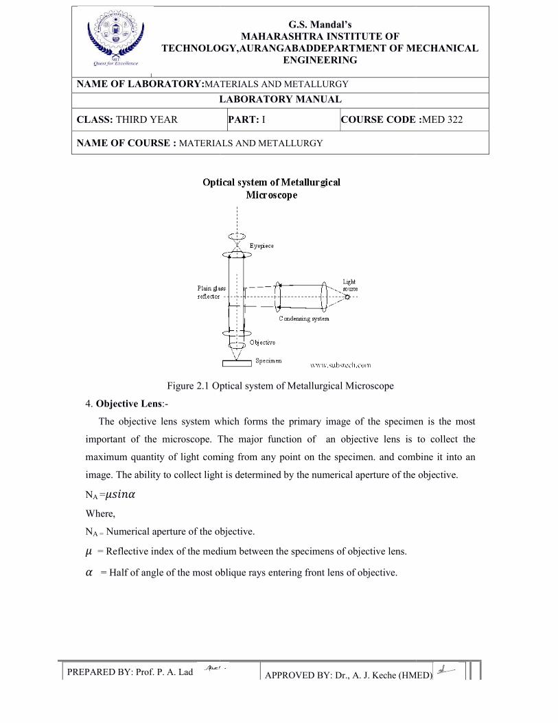
Principle: -
A Horizontal beam of light froth light source is reflected by means of a plane gas
reflector downwards through the microscope objective on the surface of the specimen some of
this incident light reflected from the specimen surface will be magnified & passing through
the plane glass reflector & magnified again by upper lens system of the eye-piece.
Construction Details: -
Parts of Metallurgical Microscope
1. Stage: A flat movable table supporting specimen. This can be moved up or down by knobs
2. Tubes: The vertically movable tube containing eye-piece, objective & plane reflector. The
tube length varies from 160mm to 250mm.
3. Illuminating System: It used to light up the surface of the specimen under examination. It
consists of a light source/aperture, diaphragm a slot for fillers & a plane glass reflector. A
horizontal beam of light from the source is divided by the pain glass reflect downwards &
through microscope objective to the surfaces of specimen. A certain amount of this incident
light is reflected from the specimen surface and passes through the objective in the eyepiece
an enlarge ass the illuminated area of the specimen surface is observed by looking through the
eyepiece. The aperture diagram in the illuminating system controls the angular aperture of the
cone of light rays which is used to illuminate the specimen from the image. The optimum
opening of the diaphragm should be used, which depends upon the objectives being used for
satisfactory illumination; the angle of the plane glans reflector should be adjusted.
TECHNOLOGY,AURANGABAD
NAME OF LABORATORY:MATERIALS AND METALLURGY
LABORATORY MANUAL
CLASS: THIRD YEAR
NAME OF COURSE : MATERIALS
PREPARED BY: Prof. P. A. Lad
Figure 2.1 Optical system of Metallurgical Microscope
4. Objective Lens:-
The objective lens system which forms the primary image of
important of the microscope. The major function of an objective lens is to collect the
maximum quantity of light coming from any point on the specimen. and combine it into an
image. The ability to collect light is determined by t
NA =𝜇𝑠𝑖𝑛𝛼
Where,
NA = Numerical aperture of the objective.
𝜇 = Reflective index of the medium between the sp
𝛼 = Half of angle of the most oblique rays entering front lens of objective.
G.S. Mandal’s
MAHARASHTRA INSTITUTE OF TECHNOLOGY,AURANGABADDEPARTMENT OF MECHANICAL
ENGINEERING
MATERIALS AND METALLURGY
LABORATORY MANUAL
PART: I COURSE CODE :
MATERIALS AND METALLURGY
APPROVED BY: Dr., A. J. Keche (HMED)
Figure 2.1 Optical system of Metallurgical Microscope
The objective lens system which forms the primary image of the specimen is the most
important of the microscope. The major function of an objective lens is to collect the
maximum quantity of light coming from any point on the specimen. and combine it into an
image. The ability to collect light is determined by the numerical aperture of the objective.
Numerical aperture of the objective.
= Reflective index of the medium between the specimens of objective lens.
= Half of angle of the most oblique rays entering front lens of objective.
DEPARTMENT OF MECHANICAL
RSE CODE :MED 322
APPROVED BY: Dr., A. J. Keche (HMED)
the specimen is the most
important of the microscope. The major function of an objective lens is to collect the
maximum quantity of light coming from any point on the specimen. and combine it into an
he numerical aperture of the objective.
Numerical aperture of the objective.
G.S. Mandal’s
MAHARASHTRA INSTITUTE OF TECHNOLOGY,AURANGABADDEPARTMENT OF MECHANICAL
ENGINEERING
NAME OF LABORATORY:MATERIALS AND METALLURGY
LABORATORY MANUAL
CLASS: THIRD YEAR PART: I COURSE CODE :MED 322
NAME OF COURSE : MATERIALS AND METALLURGY
PREPARED BY: Prof. P. A. Lad APPROVED BY: Dr., A. J. Keche (HMED) 27
Numerical aperture of the objective increase𝜇 &𝛼 . The value of refractive index for an air
objective lens is 1.0 and 1.5. Numerical aperture for the objective varies from 0.5 to 1.32.
The most important property of an objectives lateral solution which may be defined as
the ability to see very small object or to revolve to objects very close together. The limit of
resolutions i.e. the minimum distance which may be just resolved is given by.
Resolution limit = 0.5 to 0.61 λ
NA
Where,
λ = Wavelength of radiation.
Therefore, the resolution of an optical microscope is directly dependent upon the numerical
aperture of objective once this limit of resolution has been reached, there is no use in
increasing the magnification of system since, no extra details will be revealed. Another term
used has a measure of resolution is the resolving power which is the reciprocal of the limit of
the resolution.
Hence,
Resolving Power = 2NA / λ
Another important property of an objective is its magnification. All objective lenses
are positive lens system i.e. they passes the ability to magnify an object without any additional
optical accessories. The magnifying power of an objective is written on the less mount along
the numerical aperture.
The total magnification of the objective lens and eyepiece i.e. (Mt = Mo. Me)
Where,
Mt = Total magnification.Mo = Objective magnification Me = Eyepiece magnification.
Ideally, all that an optical microscope resolves can be seen at magnification of about 500.
Higher magnification makes the detail easier to see but does not increase the resolution.
G.S. Mandal’s
MAHARASHTRA INSTITUTE OF TECHNOLOGY,AURANGABADDEPARTMENT OF MECHANICAL
ENGINEERING
NAME OF LABORATORY:MATERIALS AND METALLURGY
LABORATORY MANUAL
CLASS: THIRD YEAR PART: I COURSE CODE :MED 322
NAME OF COURSE : MATERIALS AND METALLURGY
PREPARED BY: Prof. P. A. Lad APPROVED BY: Dr., A. J. Keche (HMED) 28
5. Eyepiece: - A removable eyepiece is fitted to an adjustable draw tube of the microscope.
By approximately positioning the primary real image with respect to the eyepiece the primary
image upon can be further enlarged depending upon the magnifying power of eyepiece
magnification are 5x, 7x, 10x, 5x, etc.
Microscope Technique: - Most of the microscopic studies of metal are made using bright
filled illumination. In addition to these types of illumination, several special techniques, such
as oblique illumination dark -field illumination, opaque-stop microscopy, and phase contrast
microscopy and polarized contrast microscopy and have particular application for
metallographic studies. In addition to these techniques 10W, high temperature microscope
work can also be done using different attachments to the microscope.
Electron Microscope: - A breakthrough in metallographic has been achieved through the
development of an electron microscope. It is capable of achieving much greater resolution
power and higher magnification then that obtains in optical microscope. A modern electron
microscope is capable of giving magnification from 104 to 106 diameters for optical
microscope. The resolution obtainable with electron microscope is of order of 0.0002μ.
Working Principle:-
The electron microscope uses electron to illuminate the specimen in an electron
microscope, an image of the contour of specimen surface is formed by converging a stream of
rapidly moving electron after passing through a thin section of specimen or of transparent
replica. The beam of electron trade incident on specimen originates from cathode ray
discharge tube operated at 50 to 1000 KW. The beam of electron is focused by passing
through a series of electron magnetic lens. It is used in vacuum to give sufficiently long free
path for electrons.
Results:-
Conclusions:-
G.S. Mandal’s
MAHARASHTRA INSTITUTE OF TECHNOLOGY,AURANGABADDEPARTMENT OF MECHANICAL
ENGINEERING
NAME OF LABORATORY:MATERIALS AND METALLURGY
LABORATORY MANUAL
CLASS: THIRD YEAR PART: I COURSE CODE :MED 322
NAME OF COURSE : MATERIALS AND METALLURGY
PREPARED BY: Prof. P. A. Lad APPROVED BY: Dr., A. J. Keche (HMED) 29
EXPERIMENT NO: - 4
Aim: Study of preparation of the specimen for Microscopic Examination
Objective:
To learn the preparation of specimen for Microscopic examination
Apparatus:
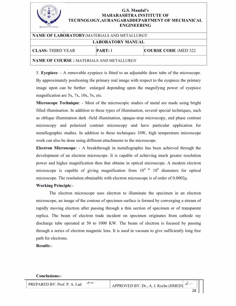
1. Abrasive cut off wheel
Absolute minimal deformation, cool & burn-free sample production
Effortless cutting by lever mechanism, counter balancing
Robust construction and rigid clamping minimizing wheel breakage.
Large and Effective coolant delivery by unique design of casted wheel guard
with focused vains.
Control Panel incorporates door limit switch, emergency stop, illumination
on/off & machine-on, switches.
Indications of door open, power on pump on. Covering other safety norms.
Dedicated wheels for very hard, medium hard, soft components and universal
wheel, in 10 “, 12 " & 14 ", thickness 1.5mm,2mm,3mm,hole sizes 1" or
1.25",(Al2O3).
2. Specimen
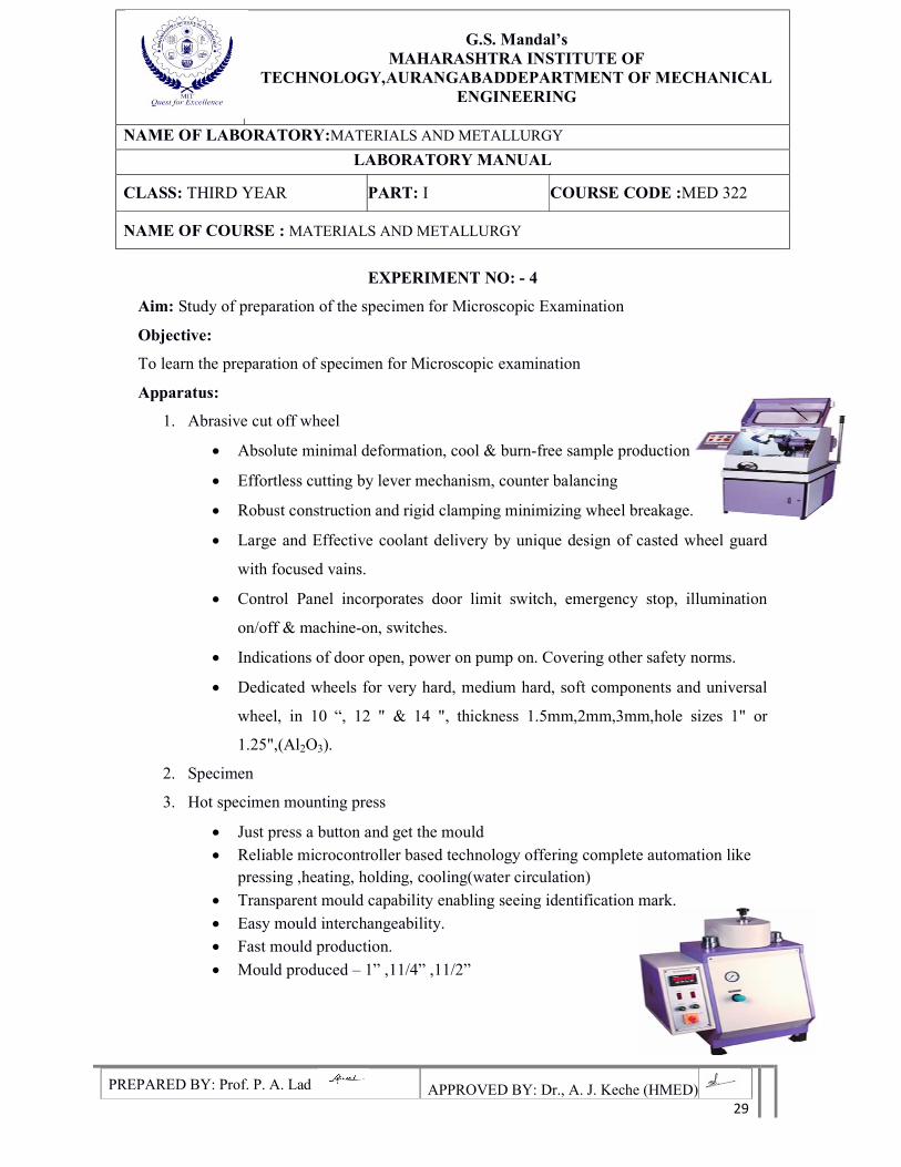
3. Hot specimen mounting press
Just press a button and get the mould
Reliable microcontroller based technology offering complete automation like pressing ,heating, holding, cooling(water circulation)
Transparent mould capability enabling seeing identification mark.
Easy mould interchangeability.
Fast mould production.
Mould produced – 1” ,11/4” ,11/2”
G.S. Mandal’s
MAHARASHTRA INSTITUTE OF TECHNOLOGY,AURANGABADDEPARTMENT OF MECHANICAL
ENGINEERING
NAME OF LABORATORY:MATERIALS AND METALLURGY
LABORATORY MANUAL
CLASS: THIRD YEAR PART: I COURSE CODE :MED 322
NAME OF COURSE : MATERIALS AND METALLURGY
PREPARED BY: Prof. P. A. Lad APPROVED BY: Dr., A. J. Keche (HMED) 30
Heater – 1000 Watts
Cooling automatic water circulation.
Air pressure required 150 PSI
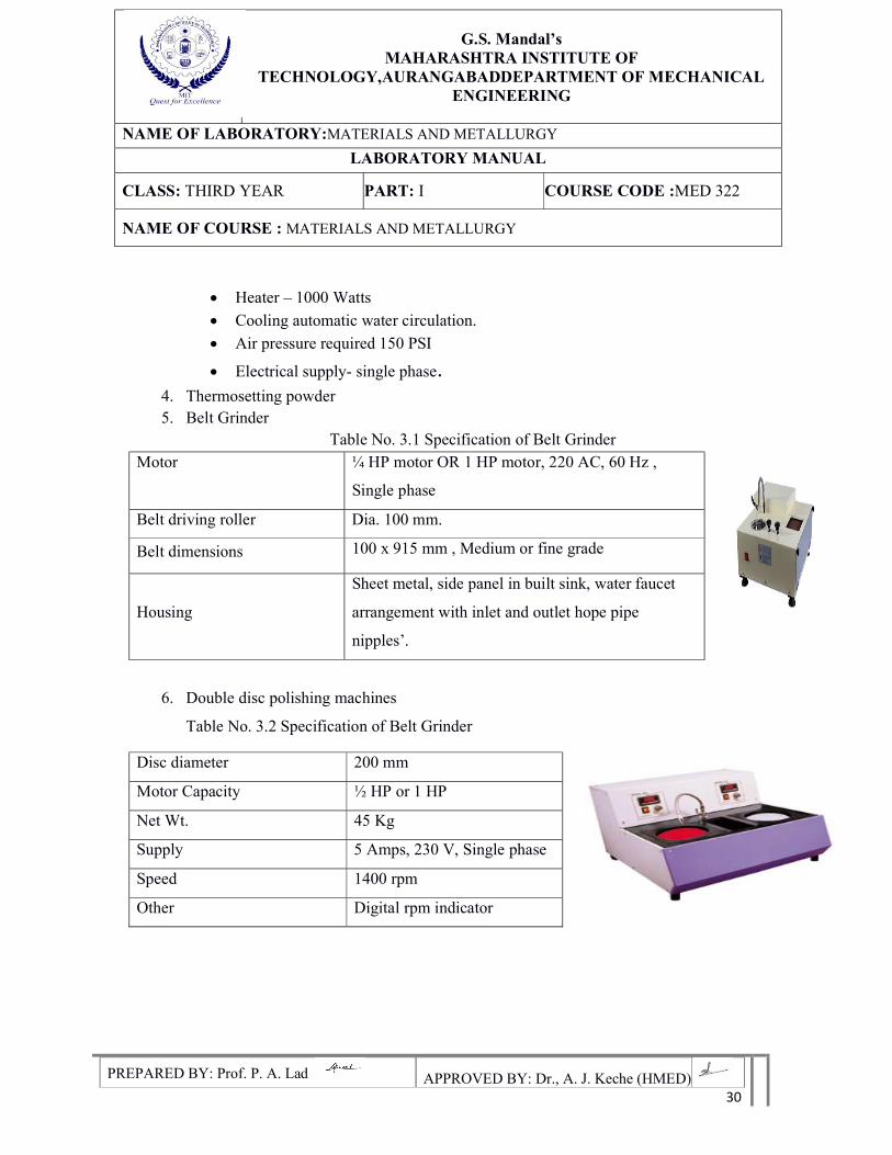
Electrical supply- single phase. 4. Thermosetting powder 5. Belt Grinder
Table No. 3.1 Specification of Belt Grinder Motor ¼ HP motor OR 1 HP motor, 220 AC, 60 Hz ,
Single phase
Belt driving roller Dia. 100 mm.
Belt dimensions 100 x 915 mm , Medium or fine grade
Housing
Sheet metal, side panel in built sink, water faucet
arrangement with inlet and outlet hope pipe
nipples’.
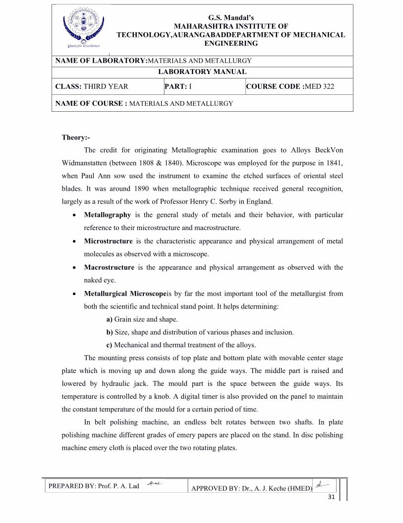
6. Double disc polishing machines
Table No. 3.2 Specification of Belt Grinder
Disc diameter 200 mm
Motor Capacity ½ HP or 1 HP
Net Wt. 45 Kg
Supply 5 Amps, 230 V, Single phase
Speed 1400 rpm
Other Digital rpm indicator
G.S. Mandal’s
MAHARASHTRA INSTITUTE OF TECHNOLOGY,AURANGABADDEPARTMENT OF MECHANICAL
ENGINEERING
NAME OF LABORATORY:MATERIALS AND METALLURGY
LABORATORY MANUAL
CLASS: THIRD YEAR PART: I COURSE CODE :MED 322
NAME OF COURSE : MATERIALS AND METALLURGY
PREPARED BY: Prof. P. A. Lad APPROVED BY: Dr., A. J. Keche (HMED) 31
Theory:-
The credit for originating Metallographic examination goes to Alloys BeckVon
Widmanstatten (between 1808 & 1840). Microscope was employed for the purpose in 1841,
when Paul Ann sow used the instrument to examine the etched surfaces of oriental steel
blades. It was around 1890 when metallographic technique received general recognition,
largely as a result of the work of Professor Henry C. Sorby in England.
Metallography is the general study of metals and their behavior, with particular
reference to their microstructure and macrostructure.
Microstructure is the characteristic appearance and physical arrangement of metal
molecules as observed with a microscope.
Macrostructure is the appearance and physical arrangement as observed with the
naked eye.
Metallurgical Microscopeis by far the most important tool of the metallurgist from
both the scientific and technical stand point. It helps determining:
a) Grain size and shape.
b) Size, shape and distribution of various phases and inclusion.
c) Mechanical and thermal treatment of the alloys.
The mounting press consists of top plate and bottom plate with movable center stage
plate which is moving up and down along the guide ways. The middle part is raised and
lowered by hydraulic jack. The mould part is the space between the guide ways. Its
temperature is controlled by a knob. A digital timer is also provided on the panel to maintain
the constant temperature of the mould for a certain period of time.
In belt polishing machine, an endless belt rotates between two shafts. In plate
polishing machine different grades of emery papers are placed on the stand. In disc polishing
machine emery cloth is placed over the two rotating plates.
G.S. Mandal’s
MAHARASHTRA INSTITUTE OF TECHNOLOGY,AURANGABADDEPARTMENT OF MECHANICAL
ENGINEERING
NAME OF LABORATORY:MATERIALS AND METALLURGY
LABORATORY MANUAL
CLASS: THIRD YEAR PART: I COURSE CODE :MED 322
NAME OF COURSE : MATERIALS AND METALLURGY
PREPARED BY: Prof. P. A. Lad APPROVED BY: Dr., A. J. Keche (HMED) 32
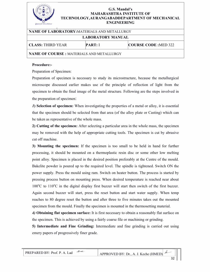
Procedure:-
Preparation of Specimen:
Preparation of specimen is necessary to study its microstructure, because the metallurgical
microscope discussed earlier makes use of the principle of reflection of light from the
specimen to obtain the final image of the metal structure. Following are the steps involved in
the preparation of specimen:
1) Selection of specimen: When investigating the properties of a metal or alloy, it is essential
that the specimen should be selected from that area (of the alloy plate or Casting) which can
be taken as representative of the whole mass.
2) Cutting of the specimen: After selecting a particular area in the whole mass, the specimen
may be removed with the help of appropriate cutting tools. The specimen is cut by abrasive
cut off machine.
3) Mounting the specimen: If the specimen is too small to be held in hand for further
processing, it should be mounted on a thermoplastic resin disc or some other low melting
point alloy. Specimen is placed in the desired position preferably at the Centre of the mould.
Bakelite powder is poured up to the required level. The spindle is tightened. Switch ON the
power supply. Press the mould using ram. Switch on heater button. The process is started by
pressing process button on mounting press. When desired temperature is reached near about
100oC to 110oC in the digital display first buzzer will start then switch of the first buzzer.
Again second buzzer will start, press the reset button and start water supply. When temp
reaches to 80 degree reset the button and after three to five minutes takes out the mounted
specimen from the mould. Finally the specimen is mounted in the thermosetting material.
4) Obtaining flat specimen surface: It is first necessary to obtain a reasonably flat surface on
the specimen. This is achieved by using a fairly coarse file or machining or grinding.
5) Intermediate and Fine Grinding: Intermediate and fine grinding is carried out using
emery papers of progressively finer grade.
G.S. Mandal’s
MAHARASHTRA INSTITUTE OF TECHNOLOGY,AURANGABADDEPARTMENT OF MECHANICAL
ENGINEERING
NAME OF LABORATORY:MATERIALS AND METALLURGY
LABORATORY MANUAL
CLASS: THIRD YEAR PART: I COURSE CODE :MED 322
NAME OF COURSE : MATERIALS AND METALLURGY
PREPARED BY: Prof. P. A. Lad APPROVED BY: Dr., A. J. Keche (HMED) 33
6) Rough polishing:A very small quantity of diamond powder (particle size about 6microns)
carried in a paste that is oil-soluble is placed on the nylon cloth-covered surface of a rotating
polishing wheel. The specimen is pressed against the cloth of the rotating wheel with
considerable pressure and is moved around the wheel in the direction opposite to rotation of
the wheel to ensure a more uniform action.
7) Fine polishing: The polishing compound used is alumina (Al2O3) powder placed on a cloth
covered rotating wheel. Distilled water is used as a lubricant. Fine polishing removes fine
scratches and very thin distorted layer remaining from the rough polishing stage.
8) Etching:Necessity-Even after fine polishing, the granular structure in a specimen
usuallycannot be seen under the microscope; because grain boundaries in a metal have a
thickness of the order of a few atom diameters at best, and the resolving power of
amicroscope is much too low to reveal their presence.In order to make the grain boundaries
visible, after polishing the metal
Specimens are usually etched. Etching imparts unlike appearances to the metal constituents
and thus makes metal structure apparent under the microscope. Method- Before etching, the
polished specimen is thoroughly washed in running water. Then, the etching is done either by,
(i) Immersing the polished surface of the specimen in the etching reagent or by
(ii) Rubbing the polished surface gently with a cotton swab wetted with the etching reagent.
After etching, the specimen is again washed thoroughly and dried. Now, the specimen can be
studied under the microscope.
Precautions:
Pressure should be applied uniformly
The specimen should be placed at the Centre of the mould
Heat the specimen uniformly
Results:
Conclusions:
G.S. Mandal’s
MAHARASHTRA INSTITUTE OF TECHNOLOGY,AURANGABADDEPARTMENT OF MECHANICAL
ENGINEERING
NAME OF LABORATORY:MATERIALS AND METALLURGY
LABORATORY MANUAL
CLASS: THIRD YEAR PART: I COURSE CODE :MED 322
NAME OF COURSE : MATERIALS AND METALLURGY
PREPARED BY: Prof. P. A. Lad APPROVED BY: Dr., A. J. Keche (HMED) 34
EXPERIMENT NO: 5
Aim: Preparation and Study of Microstructures of Plain Carbon Steel.
Objectives:
1. To learn the preparation of specimen for microscopic observation.
2. To understand the microstructures of different steels.
3. To study the microstructures of different steels.
4. To study the differences in microstructure of different type of cast irons.
Apparatus: (Specifications details given in Exp.No.2 &3)
Given specimen
Consumables
Belt grinder
Emery papers (80,120,240,400,600)
Disc polishing machine
Microscope
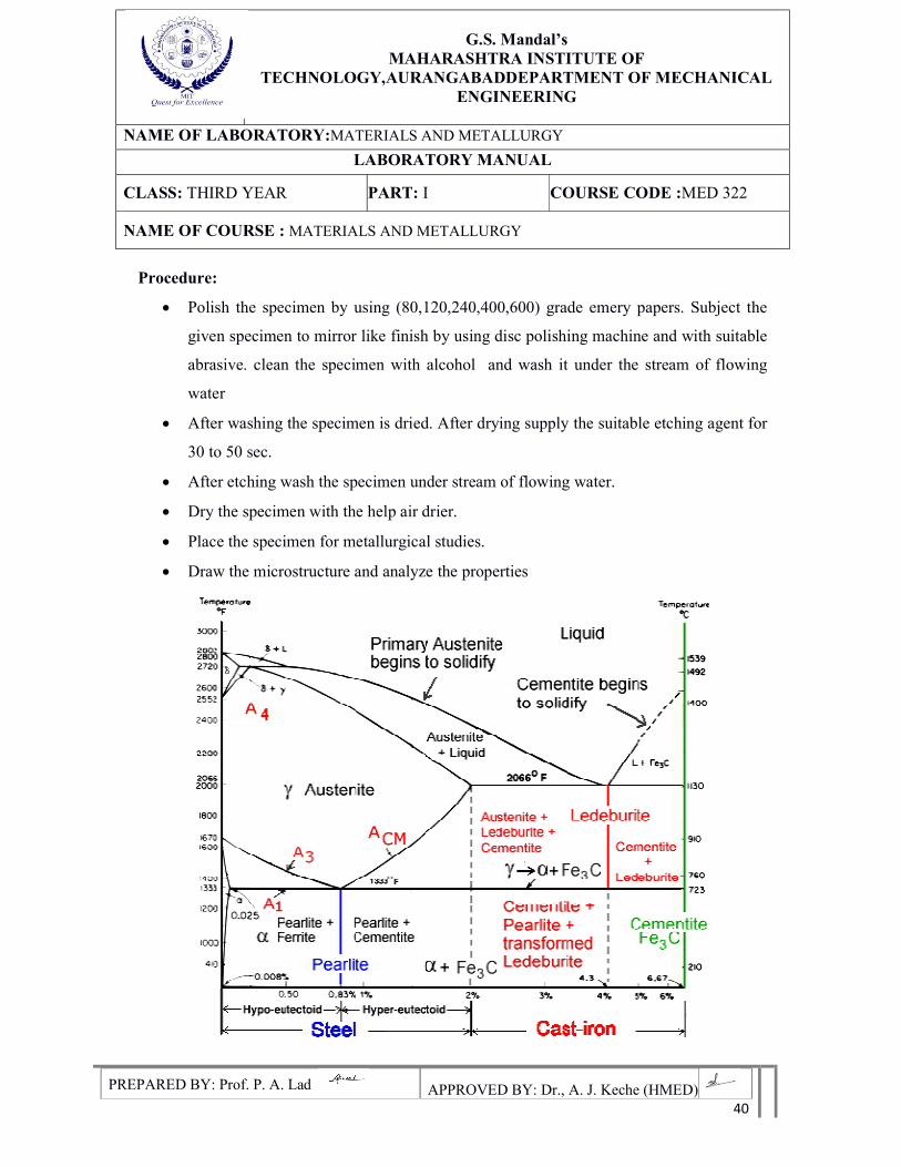
Theory:
Iron-Carbon Diagram
In their simplest form, steels are alloys of Iron (Fe) and Carbon (C). The Fe-C phase diagram
is a fairly complex one, but we will only consider the steel part of the diagram, up to around
7% Carbon.
Phases in Fe–Fe3C Phase Diagram
1. α-ferrite -solid solution of C in BCC Fe
• Stable form of iron at room temperature.
• The maximum solubility of C is 0.022 wt.%
• Transforms to FCC γ-austenite at 912 °C
G.S. Mandal’s
MAHARASHTRA INSTITUTE OF TECHNOLOGY,AURANGABADDEPARTMENT OF MECHANICAL
ENGINEERING
NAME OF LABORATORY:MATERIALS AND METALLURGY
LABORATORY MANUAL
CLASS: THIRD YEAR PART: I COURSE CODE :MED 322
NAME OF COURSE : MATERIALS AND METALLURGY
PREPARED BY: Prof. P. A. Lad APPROVED BY: Dr., A. J. Keche (HMED) 35
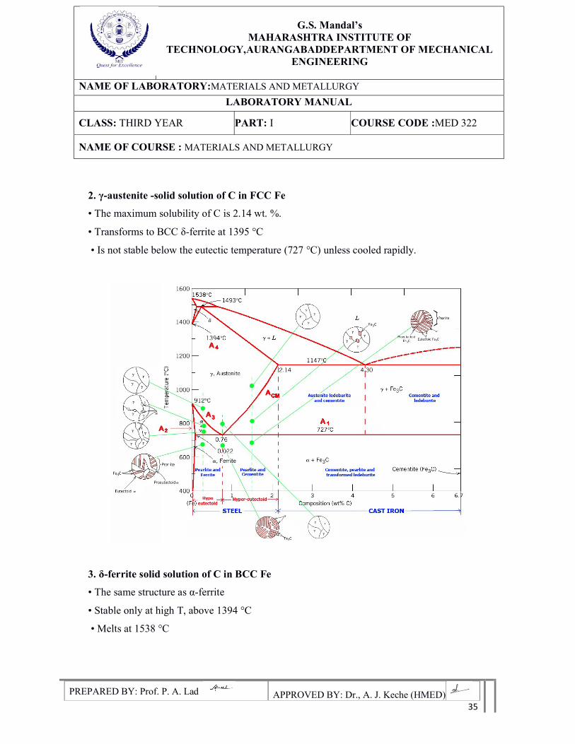
2. γ-austenite -solid solution of C in FCC Fe
• The maximum solubility of C is 2.14 wt. %.
• Transforms to BCC δ-ferrite at 1395 °C
• Is not stable below the eutectic temperature (727 °C) unless cooled rapidly.
3. δ-ferrite solid solution of C in BCC Fe
• The same structure as α-ferrite
• Stable only at high T, above 1394 °C
• Melts at 1538 °C
G.S. Mandal’s
MAHARASHTRA INSTITUTE OF TECHNOLOGY,AURANGABADDEPARTMENT OF MECHANICAL
ENGINEERING
NAME OF LABORATORY:MATERIALS AND METALLURGY
LABORATORY MANUAL
CLASS: THIRD YEAR PART: I COURSE CODE :MED 322
NAME OF COURSE : MATERIALS AND METALLURGY
PREPARED BY: Prof. P. A. Lad APPROVED BY: Dr., A. J. Keche (HMED) 36
4. Fe3C (iron carbide or cementite)
This intermetallic compound is metastable, it remains as a compound indefinitely at
room T, but decomposes (very slowly, within several years) into α-Fe and C (graphite) at 650
-700 °C
5. Fe-C liquid solution
A few comments on Fe–Fe3C system C is an interstitial impurity in Fe. It forms a
solid solution with α, γ, δ phases of iron Maximum solubility in BCC α-ferrite is limited
(max. 0.022 wt.% at 727 °C) -BCC has relatively small interstitial positions Maximum
solubility in FCC austenite is 2.14 wt.% at 1147 °C-FCC has larger interstitial positions
Mechanical properties: Cementite is very hard and brittle can strengthen steels. Mechanical
properties also depend on the microstructure, that is, how ferrite and cementite are mixed.
Magnetic properties: α -ferrite is magnetic below 768 °C, austenite is non-magnetic.
Plain carbon steels are steels having carbon as the predominant alloying element and
the other alloying elements are either Nil or negligible though some amount of Sulphur and
phosphorous are present. Normally the amounts are less than 0.05 percent and hence they are
not considered. The plain carbon steels are broadly classified in to low carbon steels with
carbon content less than 0.3 percent and medium carbon steels contains Carbon with 0.3 to
0.7. The high carbon steels contain carbon from 0.7 to 1.5 percent.
Procedure:
Step 1: The specimens of pure metals like Mild steel, Low carbon steel and high carbon steels
are mounted in a thermosetting material as explained in the experiment no. 1.
Step 2: Polish the specimen by using (80,120,240,400and 600) grade emery papers. Subject
the given specimen to mirror like finish by using disc polishing machine and with suitable
abrasive.
G.S. Mandal’s
MAHARASHTRA INSTITUTE OF TECHNOLOGY,AURANGABADDEPARTMENT OF MECHANICAL
ENGINEERING
NAME OF LABORATORY:MATERIALS AND METALLURGY
LABORATORY MANUAL
CLASS: THIRD YEAR PART: I COURSE CODE :MED 322
NAME OF COURSE : MATERIALS AND METALLURGY
PREPARED BY: Prof. P. A. Lad APPROVED BY: Dr., A. J. Keche (HMED) 37
Step 3: Clean the specimen with alcohol and wash it under the stream of flowing water. After
washing the specimen is dried.
Step 4: After drying apply the suitable etching agent for 30 to 60 sec.
Step 5: After etching wash the specimen under the stream of flowing water. Dry the specimen
with the help of air blower.
Step 6: Place the specimen under the microscope for metallurgical studies. Draw the micro
structure and identify the material for the given specimen.
Low Carbon Steel:
As the microstructure shows the structure of the mild steel, it contains 25% pearlite
and 75% ferrite. The dark region defines the pearlite and bright portion is of ferrite. The
properties of low carbon steels are the material is soft and ductile It is easily weld able. It is
cold workable.The tensile strength varies from 390 to 550 N/ mm^2 The Brinell hardness
number varies from115 to 140. The application includes making steel wire, sheets, rivets,
screws, pipe chain and structural parts.
Medium Carbon Steel:
The microstructure reveals two phases are to be about 50% each. Hence the carbon
content can be accessed to be equal to it. The properties of medium carbon steels are
invariably between low and high carbon steels. The tensile strength varies between 75 to 800
N/ mm2 The medium carbon steels are used in manufacture of drop forging dies, die block
plates, punches, screws and valve springs etc.
High Carbon Steel:
Microstructure of high carbon steels consists of continuous network of cementite in
matrix to pearlite. This cementite structure is hard and brittle and hence has poor
machinability. As carbon content increases weldability, cold working decreases. They have
high strength and hardness. Its Tensile strength is up to 1400 N/mm2 hardness varies from
450 to 500 BHW. High carbon steels are used in cutting machine tools, manufacturing cold
dies and wheels for railways.
G.S. Mandal’s
MAHARASHTRA INSTITUTE OF TECHNOLOGY,AURANGABADDEPARTMENT OF MECHANICAL
ENGINEERING
NAME OF LABORATORY:MATERIALS AND METALLURGY
LABORATORY MANUAL
CLASS: THIRD YEAR PART: I COURSE CODE :MED 322
NAME OF COURSE : MATERIALS AND METALLURGY
PREPARED BY: Prof. P. A. Lad APPROVED BY: Dr., A. J. Keche (HMED) 38
Observations:
Precautions:
1. Polishing should be slow, sooth and flat.
2. Uniform pressure is applied throughout the polishing.
3. CLEANLINESS!!! Keep the room and the work areas.
4. Don't touch etched and polished surface of the specimen.
5. Don't touch the lances of eyepiece with dirty hand.
6. Use clean clothes only to clean the lenses of eyepieces.
7. Handle the microscope with gently.
8. Return the standard specimen to the Lab Technician after observation.
9. Switch off the microscope after the observation.
Results:
Conclusions:
G.S. Mandal’s
MAHARASHTRA INSTITUTE OF TECHNOLOGY,AURANGABADDEPARTMENT OF MECHANICAL
ENGINEERING
NAME OF LABORATORY:MATERIALS AND METALLURGY
LABORATORY MANUAL
CLASS: THIRD YEAR PART: I COURSE CODE :MED 322
NAME OF COURSE : MATERIALS AND METALLURGY
PREPARED BY: Prof. P. A. Lad APPROVED BY: Dr., A. J. Keche (HMED) 39
EXPERIMENT NO: 6
Aim: To identify and draw the microstructures of Cast Iron specimens like Grey Cast Iron,
White Cast Iron, Malleable Cast iron, and S.G. Cast iron etc.
Objectives:
1. To learn the preparation of specimen for microscopic observation.
2. To understand the microstructures of different cast irons.
3. To study the microstructures of different cast irons.
4. To learn the differences in microstructure of different type of cast irons.
Apparatus :( Specifications details given in Exp.No.2 &3)
Given specimen
Specially designed files
Belt grinder
Emery papers (80,120,240,400,600)
Disc polishing machine
Microscope
Theory:
Cast irons contain 2 to 6.67 % of carbon. Since high carbon of 2.5 to 4% of carbon, the
ductility of Carbon is very low and it cannot be rolled, drawn or worked at room temperature.
However they melt readily and can be cast to complicated shapes which are usually machined
to final dimensions. Since the casting is only the suitable process applied to these alloys, they
are known as cast irons.
Although the common cast irons are brittle and have lower strength properties than
most steels, they are cheap, can cast more readily than steel and have other useful properties.
In addition by proper alloying good foundry control and appropriate heat treatment is
possible. The properties of any cast iron can be varied over a wide range.
G.S. Mandal’s
MAHARASHTRA INSTITUTE OF TECHNOLOGY,AURANGABADDEPARTMENT OF MECHANICAL
ENGINEERING
NAME OF LABORATORY:MATERIALS AND METALLURGY
LABORATORY MANUAL
CLASS: THIRD YEAR PART: I COURSE CODE :MED 322
NAME OF COURSE : MATERIALS AND METALLURGY
PREPARED BY: Prof. P. A. Lad APPROVED BY: Dr., A. J. Keche (HMED) 40
Procedure:
Polish the specimen by using (80,120,240,400,600) grade emery papers. Subject the
given specimen to mirror like finish by using disc polishing machine and with suitable
abrasive. clean the specimen with alcohol and wash it under the stream of flowing
water
After washing the specimen is dried. After drying supply the suitable etching agent for
30 to 50 sec.
After etching wash the specimen under stream of flowing water.
Dry the specimen with the help air drier.
Place the specimen for metallurgical studies.
Draw the microstructure and analyze the properties
G.S. Mandal’s
MAHARASHTRA INSTITUTE OF TECHNOLOGY,AURANGABADDEPARTMENT OF MECHANICAL
ENGINEERING
NAME OF LABORATORY:MATERIALS AND METALLURGY
LABORATORY MANUAL
CLASS: THIRD YEAR PART: I COURSE CODE :MED 322
NAME OF COURSE : MATERIALS AND METALLURGY
PREPARED BY: Prof. P. A. Lad APPROVED BY: Dr., A. J. Keche (HMED) 41
White Cast Iron:
In white cast iron most of the carbon is present in the combed forms as cementite.This
is obtained by rapid cooling of the iron. White cast irons contains large amount of cementite
as continuous inter dendritic network. It makes the cast iron hard, wear resistance but
extremely brittle and difficult to machine. White cast irons are limited in engineering
applications because of brittleness and lack of machinability. They are used where resistant to
wear is important and service does not require, such as cement mixer, ball mills certain types
of drawing dies and extrusion nozzle. A large tonnage of white cast iron is used as a raw
material for manufacture of malleable cast iron. The composition of typical malleable cast
iron is as follows
Carbon: 2.9% Silicon: 1.15% Manganese: 0.6% Phosphorous: 0.15%Sulphur: 0.5%
Malleable Cast Iron:
In which most of the carbon is uncombined form of irregular particles known as
tempered carbon. This is obtained by heating the white cast iron to 920 to 1000 degree
centigrade for about 50 hours followed by slow cooling to room temperature. While on
heating, the cementite structure tends to decompose in to ferrite plus tempered carbon
(Graphite). The lubrication action of the graphite imports high machinability to malleable cast
iron and lower the melting point makes it much easier to cast than steel. Malleable cast irons
are tough, strong and shock resistant. The addition of copper and molybdenum in combination
produces malleable cast iron of superior corrosion resistance and mechanical properties. The
malleable cast iron is used for wide applications such as agricultural implements, automobile
parts, man whole covers, rail road equipment gears, cams and pipe fittings etc.
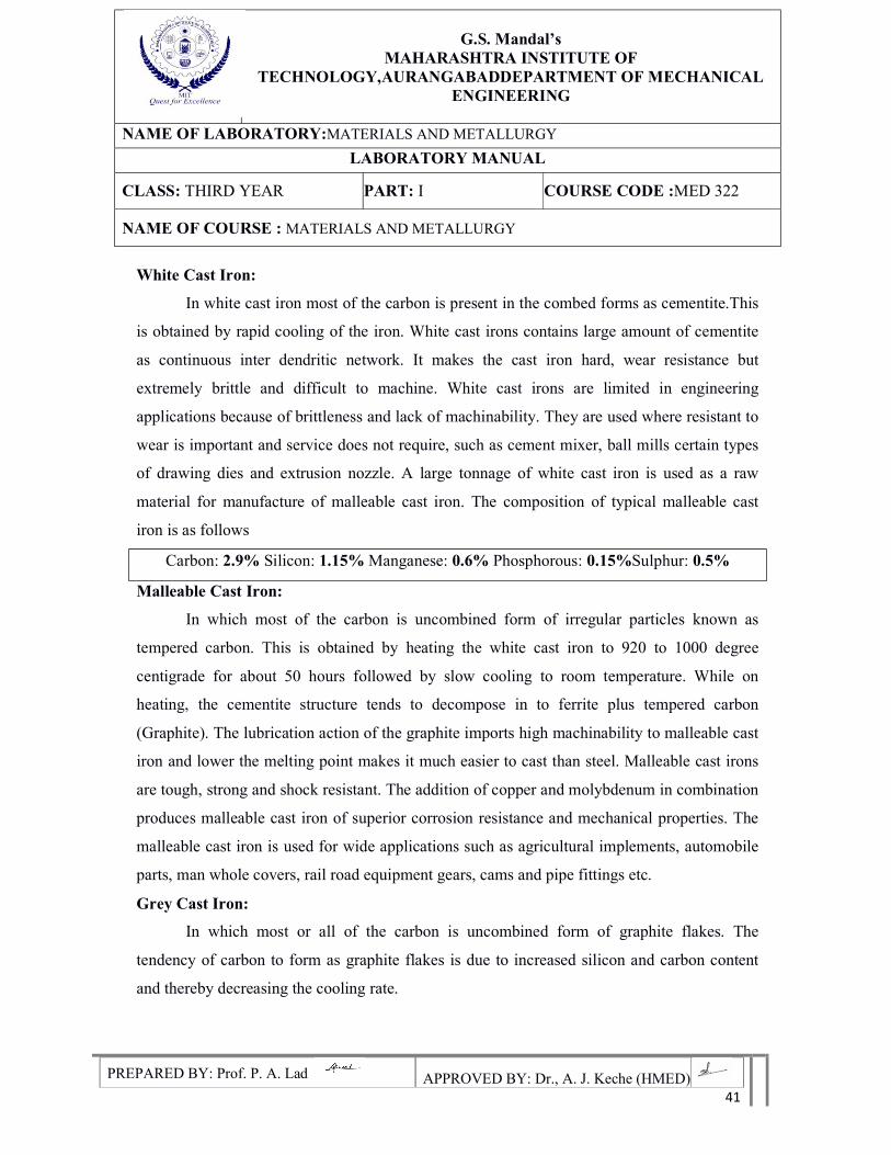
Grey Cast Iron:
In which most or all of the carbon is uncombined form of graphite flakes. The
tendency of carbon to form as graphite flakes is due to increased silicon and carbon content
and thereby decreasing the cooling rate.
G.S. Mandal’s
MAHARASHTRA INSTITUTE OF TECHNOLOGY,AURANGABADDEPARTMENT OF MECHANICAL
ENGINEERING
NAME OF LABORATORY:MATERIALS AND METALLURGY
LABORATORY MANUAL
CLASS: THIRD YEAR PART: I COURSE CODE :MED 322
NAME OF COURSE : MATERIALS AND METALLURGY
PREPARED BY: Prof. P. A. Lad APPROVED BY: Dr., A. J. Keche (HMED) 42
It is a low melting alloy, having good cast ability and machinability. It has low tensile
strength, high compression strength and very low ductility. Grey cast iron has excellent
damping capacity and is often used as base for machinery or any equipment subject to
vibration. It is also used for machine tool bodies, pipes and agricultural implements. The
presence of graphite flakes provides lubricating effect to sliding bodies.
The composition of typical grey cast iron is as follows
Carbon: 2.8 to 3.6%
Silicon: 1 to 2.75%
Manganese: 0.4 to 1%
Phosphorous: 0.1 to 1%
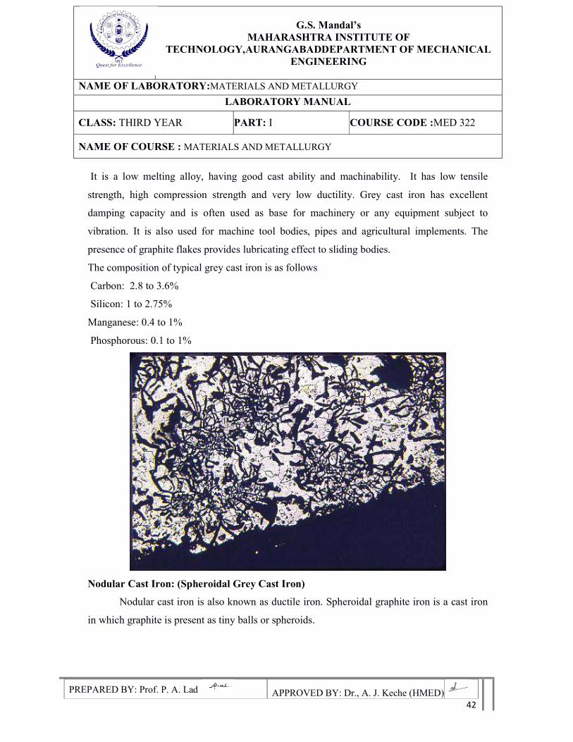
Nodular Cast Iron: (Spheroidal Grey Cast Iron)
Nodular cast iron is also known as ductile iron. Spheroidal graphite iron is a cast iron
in which graphite is present as tiny balls or spheroids.
G.S. Mandal’s
MAHARASHTRA INSTITUTE OF TECHNOLOGY,AURANGABADDEPARTMENT OF MECHANICAL
ENGINEERING
NAME OF LABORATORY:MATERIALS AND METALLURGY
LABORATORY MANUAL
CLASS: THIRD YEAR PART: I COURSE CODE :MED 322
NAME OF COURSE : MATERIALS AND METALLURGY
PREPARED BY: Prof. P. A. Lad APPROVED BY: Dr., A. J. Keche (HMED) 43
The compact spheroids interrupt the continuity of the matrix much less than graphite flakes.
This result in higher strength and toughness compared with a similar structure of grey cast
iron. Nodular cast iron differs from malleable cast iron in that it is usually obtained as a result
of solidification and does not require heat treatment. The spheroids are more rounded than
irregular aggregates of temper carbon found in malleable cast iron. The formation of
spherical graphite is due to addition of magnesium to the molten grey iron.
The composition of typical S.G.cast iron is as follows Carbon: 3 to 3.5% Silicon: 2 to
2.5% Manganese: 0.15 to 0.6% Phosphorous: 0.025 to 0.4% Sulphur: 0.015 to 0.04 %
Applications:
Agricultural tractor and implement parts, automotive and diesel crank shafts, piston and
cylinder heads, electrical fittings, motor frames, hoist drums, flywheels and elevator buckets,
steel mill, furnace doors and bearings wrenches levers and handles.
Observations:
G.S. Mandal’s
MAHARASHTRA INSTITUTE OF TECHNOLOGY,AURANGABADDEPARTMENT OF MECHANICAL
ENGINEERING
NAME OF LABORATORY:MATERIALS AND METALLURGY
LABORATORY MANUAL
CLASS: THIRD YEAR PART: I COURSE CODE :MED 322
NAME OF COURSE : MATERIALS AND METALLURGY
PREPARED BY: Prof. P. A. Lad APPROVED BY: Dr., A. J. Keche (HMED) 44
Precautions:
1. Polishing should be slow, sooth and flat.
2. Uniform pressure is applied throughout the polishing.
3. CLEANLINESS!!! Keep the room and the work areas.
4. Don't touch etched and polished surface of the specimen.
5. Don't touch the lances of eyepiece with dirty hand.
6. Use clean clothes only to clean the lenses of eyepieces.
7. Handle the microscope with gently.
8. Return the standard specimen to the Lab Technician after observation.
9. Switch off the microscope after the observation.
Results:-
Conclusions:-
G.S. Mandal’s
MAHARASHTRA INSTITUTE OF TECHNOLOGY,AURANGABADDEPARTMENT OF MECHANICAL
ENGINEERING
NAME OF LABORATORY:MATERIALS AND METALLURGY
LABORATORY MANUAL
CLASS: THIRD YEAR PART: I COURSE CODE :MED 322
NAME OF COURSE : MATERIALS AND METALLURGY
PREPARED BY: Prof. P. A. Lad APPROVED BY: Dr., A. J. Keche (HMED) 45
EXPERIMENT NO. 7
Aim: Study of Microstructures of Non-Ferrous Alloys
Objectives:
1. To learn the preparation of specimen for microscopic observation.
2. To understand the microstructures of different Non -ferrous alloys.
3. To study the microstructures of different Non -ferrous alloys
4. To learn the differences in microstructure of different type of Non -ferrous alloys.
Apparatus :( Specifications details given in Exp.No.2 &3)
Given Al, Cu alloy specimens
Metallurgical microscope
Suitable etchants
Specially designed files
Belt grinder
Emery papers (80,120,240,400,600)
Double disk polishing machine
Theory:
Nonferrous metals ad alloys contain other than iron as a main constituent. They exhibit
different properties compared to ferrous metals and alloys. Hence their application also differs
from ferrous metals. We shall study the microstructures of Al, Cu, and alloys.
Procedure:
Polish the specimen by using (1/0, 2/0, 3/0, 4/0,) grade emery papers. Subject thegiven
specimen to mirror like finish by using disc polishing machine and with suitable
abrasive. Clean the specimen with alcohol and wash it under the stream of flowing
water.
G.S. Mandal’s
MAHARASHTRA INSTITUTE OF TECHNOLOGY,AURANGABADDEPARTMENT OF MECHANICAL
ENGINEERING
NAME OF LABORATORY:MATERIALS AND METALLURGY
LABORATORY MANUAL
CLASS: THIRD YEAR PART: I COURSE CODE :MED 322
NAME OF COURSE : MATERIALS AND METALLURGY
PREPARED BY: Prof. P. A. Lad APPROVED BY: Dr., A. J. Keche (HMED) 46
After washing the specimen is dried. After drying supply the suitable etching agent for
30 to 50 sec.
After etching wash the specimen under stream of flowing water.
Dry the specimen with the help air drier.
Place the specimen for metallurgical studies.
Draw the microstructure and analyze the properties
Cu- Alloys
Brass:
Brasses are the copper alloys containing zinc up to 30% they possess relatively good
corrosion resistance and good working properties. They also possess high ductility hence they
are suitable for drastic cold working. In common to relieve the stresses annealing is done.
Most normally used brass contains 30% zinc and 70% copper which isknown as cartridge
brass. This shows higher ductility and malleability. The microstructure shows a typical
equiaxed grain structure with twins in annealed structure. This brass is used for making
cartridge cases. Other applications include4s radiator cases, head light reflectors, hardware,
and plumbing accessories.
Al-Alloys:
Aluminum alloy contains silicon up to 12 %. Aluminum- silicon is also called as
silumin. There are two types of aluminum silicon alloys are there.
LM-6:
It contains above 12% silicon due to its higher corrosion resistance and fluidity. It is
Used in water cooled marine tools for pump parts
LM-13
It contains silicon up to 12.5%, Ni 2.5%, ca 1% and Mg 12%. This shows goodforge
ability and low coefficient of thermal expansion. It is used in automobile pistons.
G.S. Mandal’s
MAHARASHTRA INSTITUTE OF TECHNOLOGY,AURANGABADDEPARTMENT OF MECHANICAL
ENGINEERING
NAME OF LABORATORY:MATERIALS AND METALLURGY
LABORATORY MANUAL
CLASS: THIRD YEAR PART: I COURSE CODE :MED 322
NAME OF COURSE : MATERIALS AND METALLURGY
PREPARED BY: Prof. P. A. Lad APPROVED BY: Dr., A. J. Keche (HMED) 47
Bearing Metal:
Bearing metal has high compressive strength and high wear resistance, highfatigue
strength and better thermal conductivity for heat dissipation, corrosion resistance and good
machinability. They have hard and soft phases. Most widely used bearing metal is a Babbitt
metal. They are called as low melting bearing alloy. Lead based ad tin based Babbitt contain
Antimony as most popular this group.
Observations:
Precautions:
1. Polishing should be slow, sooth and flat.
2. Uniform pressure is applied throughout the polishing.
3. CLEANLINESS!!! Keep the room and the work areas.
4. Don't touch etched and polished surface of the specimen.
5. Don't touch the lances of eyepiece with dirty hand.
6. Use clean clothes only to clean the lenses of eyepieces.
7. Handle the microscope with gently.
8. Return the standard specimen to the Lab Technician after observation.
9. Switch off the microscope after the observation
Results:
Conclusions:
G.S. Mandal’s
MAHARASHTRA INSTITUTE OF TECHNOLOGY,AURANGABADDEPARTMENT OF MECHANICAL
ENGINEERING
NAME OF LABORATORY:MATERIALS AND METALLURGY
LABORATORY MANUAL
CLASS: THIRD YEAR PART: I COURSE CODE :MED 322
NAME OF COURSE : MATERIALS AND METALLURGY
PREPARED BY: Prof. P. A. Lad APPROVED BY: Dr., A. J. Keche (HMED) 48
EXPERIMENT NO. 08
Aim: Study of changes in material properties and microstructures after Heat treatments like Annealing, Hardening, Tempering, Cryogenic Treatment, etc. Objectives:-
1. To study the different types of the heat treatment process.
2. To study the changes in macrostructure due to heat Treatment.
3. To study the changes in properties of materials after heat treatment process.
Apparatus: Furnace, polish paper, lapping paste, polymeric solution, microscope.
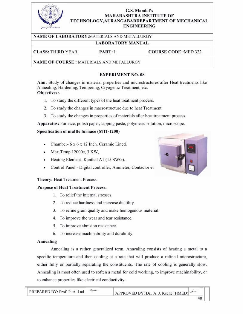
Specification of muffle furnace (MTI-1200)
Chamber- 6 x 6 x 12 Inch. Ceramic Lined.
Max.Temp.12000c, 3 KW,
Heating Element- Kanthal A1 (15 SWG).
Control Panel - Digital controller, Ammeter, Contactor etc.
Theory: Heat Treatment Process
Purpose of Heat Treatment Process:
1. To relief the internal stresses.
2. To reduce hardness and increase ductility.
3. To refine grain quality and make homogenous material.
4. To improve the wear and tear resistance.
5. To improve abrasion resistance.
6. To increase machinability and durability.
Annealing
Annealing is a rather generalized term. Annealing consists of heating a metal to a
specific temperature and then cooling at a rate that will produce a refined microstructure,
either fully or partially separating the constituents. The rate of cooling is generally slow.
Annealing is most often used to soften a metal for cold working, to improve machinability, or
to enhance properties like electrical conductivity.
G.S. Mandal’s
MAHARASHTRA INSTITUTE OF TECHNOLOGY,AURANGABADDEPARTMENT OF MECHANICAL
ENGINEERING
NAME OF LABORATORY:MATERIALS AND METALLURGY
LABORATORY MANUAL
CLASS: THIRD YEAR PART: I COURSE CODE :MED 322
NAME OF COURSE : MATERIALS AND METALLURGY
PREPARED BY: Prof. P. A. Lad APPROVED BY: Dr., A. J. Keche (HMED) 49
Normalizing
Normalizing is a technique used to provide uniformity in grain size and composition
throughout an alloy. The term is often used for ferrous alloys that have been austenitized and
then cooled in open air. Normalizing not only produces pearlite, but also Martensite and
sometimes bainite, which gives harder and stronger steel, but with less ductility for the same
composition than full annealing.
Stress relieving
Stress relieving is a technique to remove or reduce the internal stresses created in a
metal. These stresses may be caused in a number of ways, ranging from cold working to non-
uniform cooling. Stress relieving is usually accomplished by heating a metal below the lower
critical temperature and then cooling uniformly.
Quenching
Quenching is a process of cooling a metal at a rapid rate. This is most often done to
produce a Martensite transformation. In ferrous alloys, this will often produce a harder metal,
while non-ferrous alloys will usually become softer than normal.
To harden by quenching, a metal (usually steel or cast iron) must be heated above the
upper critical temperature and then quickly cooled. Depending on the alloy and other
considerations (such as concern for maximum hardness vs. cracking and distortion), cooling
may be done with forced air or other gases, (such as nitrogen). Liquids may be used, due to
their better thermal conductivity, such as oil, water, a polymer dissolved in water, or a brine.
Upon being rapidly cooled, a portion of austenite (dependent on alloy composition) will
transform to Martensite, a hard, brittle crystalline structure. The quenched hardness of a metal
depends on its chemical composition and quenching method. Cooling speeds, from fastest to
slowest, go from fresh water, brine, polymer (i.e. mixtures of water + glycol polymers), oil,
and forced air. However, quenching certain steel too fast can result in cracking, which is why
high-tensile steels such as AISI 4140 should be quenched in oil.
G.S. Mandal’s
MAHARASHTRA INSTITUTE OF TECHNOLOGY,AURANGABADDEPARTMENT OF MECHANICAL
ENGINEERING
NAME OF LABORATORY:MATERIALS AND METALLURGY
LABORATORY MANUAL
CLASS: THIRD YEAR PART: I COURSE CODE :MED 322
NAME OF COURSE : MATERIALS AND METALLURGY
PREPARED BY: Prof. P. A. Lad APPROVED BY: Dr., A. J. Keche (HMED) 50
Tool steels such as ISO 1.2767 or H13 hot work tool steel should be quenched in forced air,
and low alloy or medium-tensile steels such as XK1320 or AISI 1040 should be quenched in
brine.
Tempering
Untampered martensitic steel, while very hard, is too brittle to be useful for most
applications. A method for alleviating this problem is called tempering. Most applications
require that quenched parts be tempered. Tempering consists of heating steel below the lower
critical temperature, (often from 400 to 1105 ˚F or 205 to 595 ˚C, depending on the desired
results), to impart some toughness. Higher tempering temperatures (may be up to 1,300 ˚F or
700 ˚C, depending on the alloy and application) are sometimes used to impart further
ductility, although some yield strength is lost.
Tempering may also be performed on normalized steels. Other methods of tempering
consist of quenching to a specific temperature, which is above the Martensite start
temperature, and then holding it there until pure bainite can form or internal stresses can be
relieved. These include Austempering and martempering
Flame hardening
Flame hardening is used to harden only a portion of a metal. Unlike differential
hardening, where the entire piece is heated and then cooled at different rates, in flame
hardening, only a portion of the metal is heated before quenching. This is usually easier than
differential hardening, but often produces an extremely brittle zone between the heated metal
and the unheated metal, as cooling at the edge of this heat affected zone is extremely rapid.
Induction hardening
Induction hardening is a surface hardening technique in which the surface of the metal is
heated very quickly, using a no-contact method of induction heating. The alloy is then
quenched, producing a Martensite transformation at the surface while leaving the underlying
metal unchanged.
G.S. Mandal’s
MAHARASHTRA INSTITUTE OF TECHNOLOGY,AURANGABADDEPARTMENT OF MECHANICAL
ENGINEERING
NAME OF LABORATORY:MATERIALS AND METALLURGY
LABORATORY MANUAL
CLASS: THIRD YEAR PART: I COURSE CODE :MED 322
NAME OF COURSE : MATERIALS AND METALLURGY
PREPARED BY: Prof. P. A. Lad APPROVED BY: Dr., A. J. Keche (HMED) 51
This creates a very hard, wear resistant surface while maintaining the proper toughness in the
majority of the object. Crankshaft journals are a good example of an induction hardened
surface.
Case hardening
Case hardening is a thermo chemical diffusion process in which an alloying element, most
commonly carbon or nitrogen, diffuses into the surface of a monolithic metal. The resulting
interstitial solid solution is harder than the base material, which improves wear resistance
without sacrificing toughness.
Laser surface engineering is a surface treatment with high versatility, selectivity and novel
properties. Since the cooling rate is very high in laser treatment, metastable even metallic
glass can be obtained by this method.
Procedure:-
Step 1: Measure the mechanical properties of sample before doing heat treatment process.
Step 2: Observe the microstructure of sample before doing heat treatment process.
Step 3: Place the sample in the furnace and heat the sample in the furnace according to the
heat treatment process.
Step 4: Take out sample from furnace and quench as per heat treatment process.
Step 5: Measure the mechanical properties of sample after heat treatment process.
Step 6: Observe the microstructure of sample after heat treatment process.
Observations:
Results:-
Conclusions:
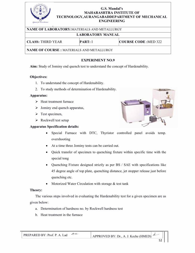
G.S. Mandal’s
MAHARASHTRA INSTITUTE OF TECHNOLOGY,AURANGABADDEPARTMENT OF MECHANICAL
ENGINEERING
NAME OF LABORATORY:MATERIALS AND METALLURGY
LABORATORY MANUAL
CLASS: THIRD YEAR PART: I COURSE CODE :MED 322
NAME OF COURSE : MATERIALS AND METALLURGY
PREPARED BY: Prof. P. A. Lad APPROVED BY: Dr., A. J. Keche (HMED) 52
EXPERIMENT NO.9
Aim: Study of Jominy end quench test to understand the concept of Hardenability.
Objectives:
1. To understand the concept of Hardenability.
2. To study methods of determination of Hardenability.
Apparatus:
Heat treatment furnace
Jominy end quench apparatus,
Test specimen,
Rockwell test setup
Apparatus Specification details:
Special Furnace with DTC, Thyristor controlled panel avoids temp.
overshooting
At a time three Jominy tests can be carried out.
Quick transfer of specimen to quenching fixture within specific time with the
special tong
Quenching Fixture designed strictly as per BS / SAE with specifications like
45 degree angle of top plate, quenching distance, jet stopper release just before
quenching etc.
Motorized Water Circulation with storage & test tank
Theory:
The various steps involved in evaluating the Hardenability test for a given specimen are as
given below:
a. Determination of hardness no. by Rockwell hardness test
b. Heat treatment in the furnace
G.S. Mandal’s
MAHARASHTRA INSTITUTE OF TECHNOLOGY,AURANGABADDEPARTMENT OF MECHANICAL
ENGINEERING
NAME OF LABORATORY:MATERIALS AND METALLURGY
LABORATORY MANUAL
CLASS: THIRD YEAR PART: I COURSE CODE :MED 322
NAME OF COURSE : MATERIALS AND METALLURGY
PREPARED BY: Prof. P. A. Lad APPROVED BY: Dr., A. J. Keche (HMED) 53
c. Quenching the specimen in Jominy end quench apparatus
a. Determination of hardness No. by Rockwell Hardness Test
The method of determining the hardness consists of measuring the depth of a diamond
cone penetrant that was forced into a metal by applying primary and secondary loads. This
method of measuring hardness significant because errors due to mechanical defects on the
system such as backlash are eliminated ad as well as errors resulting from slight surface
imperfections. The specimen is placed on a suitable anvil on the upper end of the elevation
screw. A minor load of 10 kg is applied by raising the anvil by using elevation screw. Then
apply the major load by using the leaver. After applying the load for a period of 20 sec,
remove the load by turning the lever. Note down the reading on the Rockwell scale.
b. Heat Treatment in the Furnace
Heat treatment is a combination of heating and cooled operations timed and applied to
a metal or alloy so as to produce the desired properties. Heat treated steels amount to about 5
percent of total steel production, but it is indispensable for tools, dies, and a variety of special
purpose steels.
SPECIMEN: Medium carbon (plain Carbon) steel. The percentage of composition is
Carbon 0.35% to 0.45%
Silicon 0.35 %( max)
Manganese 0.60% to 0.8%
Sulphur 0.05 %( max)
Phosphorus 0.05 %( max
c. Quenching the specimen in Jominy end quench apparatus
Take the specimen, place it I the furnace and supply the power. Wait till the
temperature reaches to the Austeniizing temperature. Heat the specimen at the Austeniizing
temperature until it is completely transformed in to Austenite. Remove the specimen from the
furnace with the help of tongs and gloves and place it in the Jominy end quench apparatus and
allow the jet of water to strike one end of the specimen.
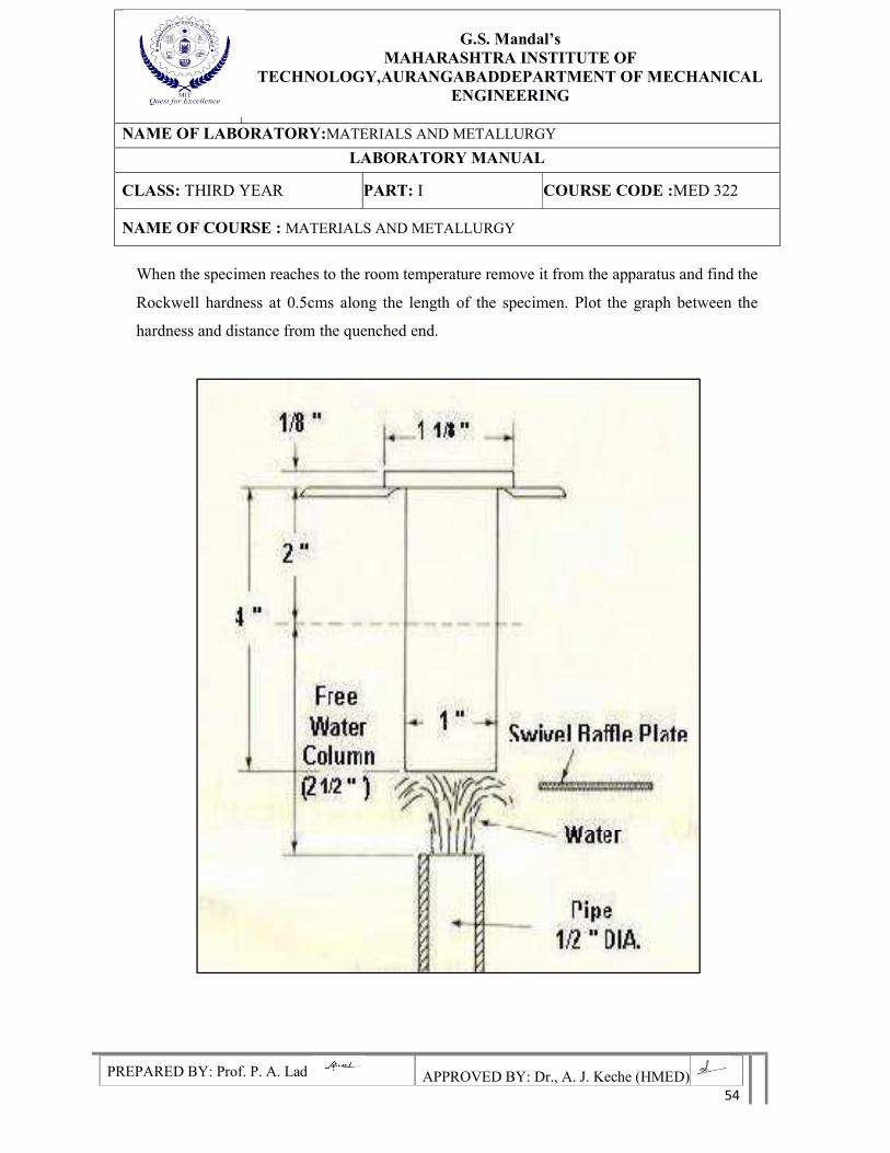
G.S. Mandal’s
MAHARASHTRA INSTITUTE OF TECHNOLOGY,AURANGABADDEPARTMENT OF MECHANICAL
ENGINEERING
NAME OF LABORATORY:MATERIALS AND METALLURGY
LABORATORY MANUAL
CLASS: THIRD YEAR PART: I COURSE CODE :MED 322
NAME OF COURSE : MATERIALS AND METALLURGY
PREPARED BY: Prof. P. A. Lad APPROVED BY: Dr., A. J. Keche (HMED) 54
When the specimen reaches to the room temperature remove it from the apparatus and find the
Rockwell hardness at 0.5cms along the length of the specimen. Plot the graph between the
hardness and distance from the quenched end.
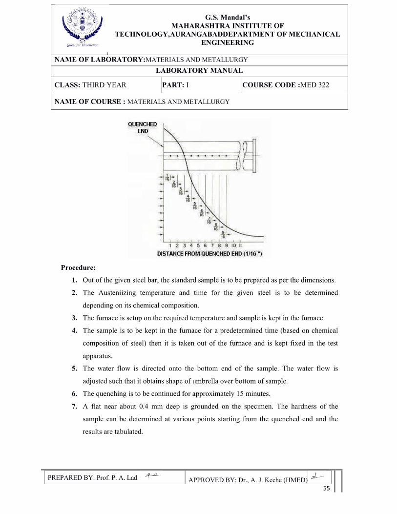
G.S. Mandal’s
MAHARASHTRA INSTITUTE OF TECHNOLOGY,AURANGABADDEPARTMENT OF MECHANICAL
ENGINEERING
NAME OF LABORATORY:MATERIALS AND METALLURGY
LABORATORY MANUAL
CLASS: THIRD YEAR PART: I COURSE CODE :MED 322
NAME OF COURSE : MATERIALS AND METALLURGY
PREPARED BY: Prof. P. A. Lad APPROVED BY: Dr., A. J. Keche (HMED) 55
Procedure:
1. Out of the given steel bar, the standard sample is to be prepared as per the dimensions.
2. The Austeniizing temperature and time for the given steel is to be determined
depending on its chemical composition.
3. The furnace is setup on the required temperature and sample is kept in the furnace.
4. The sample is to be kept in the furnace for a predetermined time (based on chemical
composition of steel) then it is taken out of the furnace and is kept fixed in the test
apparatus.
5. The water flow is directed onto the bottom end of the sample. The water flow is
adjusted such that it obtains shape of umbrella over bottom of sample.
6. The quenching is to be continued for approximately 15 minutes.
7. A flat near about 0.4 mm deep is grounded on the specimen. The hardness of the
sample can be determined at various points starting from the quenched end and the
results are tabulated.
G.S. Mandal’s
MAHARASHTRA INSTITUTE OF TECHNOLOGY,AURANGABADDEPARTMENT OF MECHANICAL
ENGINEERING
NAME OF LABORATORY:MATERIALS AND METALLURGY
LABORATORY MANUAL
CLASS: THIRD YEAR PART: I COURSE CODE :MED 322
NAME OF COURSE : MATERIALS AND METALLURGY
PREPARED BY: Prof. P. A. Lad APPROVED BY: Dr., A. J. Keche (HMED) 56
8. The graph is plotted with hardness values versus distance from quenched end. From
the results and graph plotted the depth of hardening of the given steel sample can be
determined.
Observations:
Table 8.1 Observation table for hardness values
Sr.No. Distance from quenched end Hardness
Precautions:
1. The specimen is to be handled carefully while transferring from furnace to test
apparatus.
2. Don’t use the hard water as it leads to formation of scales in nozzles and copper
conduits.
3. Proper water flow (at high pressure) over the bottom end of specimen is to be ensured.
Results:
Conclusions:
G.S. Mandal’s
MAHARASHTRA INSTITUTE OF TECHNOLOGY,AURANGABADDEPARTMENT OF MECHANICAL
ENGINEERING
NAME OF LABORATORY:MATERIALS AND METALLURGY
LABORATORY MANUAL
CLASS: THIRD YEAR PART: I COURSE CODE :MED 322
NAME OF COURSE : MATERIALS AND METALLURGY
PREPARED BY: Prof. P. A. Lad APPROVED BY: Dr., A. J. Keche (HMED) 57
EXPERIMENT NO: - 10
Aim: -Study of properties of Nanomaterials and Nanocomposites.
Theory: -
Nanomaterials can be defined as those materials whose structural element clusters, crystallites
or molecules—have minimum one dimension in the 1 to 100 nm range. Clusters of atoms
consisting of typically hundreds to thousands on nanometer (nm) scale are commonly called
as Nanomaterials. These small groups of atoms, in general, also go by different names such as
nanoparticles, nanocrystals, nanostructures, quantum dotsand quantum boxes. Nanomaterials
can occur naturally, can be created as by-products of combustion reactions or can be produced
purposefully through engineering to perform a specialized function. These materials can have
different physical and chemical properties to their bulk-form counterparts.
Classification of Nanomaterials:
One way to classify Nanomaterials is often dependent upon the number of their dimensions
that are in nanoscale.
1. Zero-Dimensional (0-D): The Nanomaterials with all three dimensions in nanoscale, i.e.
< 100 nm are Zero-Dimensional or 0-D Nanomaterials. These include nanospheres and
nanoclusters.
2. One-Dimensional (1-D): Materials with their two dimensions in the nanoscale are One-
Dimensional or 1-D nanomaterials. This leads to needle shaped materials, however in
nanoscale. Nanofibers, nanotubes, nanorods and nanowires fall under this category.
3. Two-Dimensional (2-D): Here, only one dimension is in nanoscale and other two
dimensions are outside nanoscale. These includenanofilms, nanolayers and nanocoatings
having nanometric thickness.
4. Three-Dimensional (3-D): These are the nanomaterials that are not confined to the
nanoscale in any dimension. These materials have three arbitrary dimensions above 100
nm. The bulk (3D) nanomaterials are composed of a multiple arrangement of nanosize
crystals in different orientations. It includes dispersions of nanoparticles, bundles of
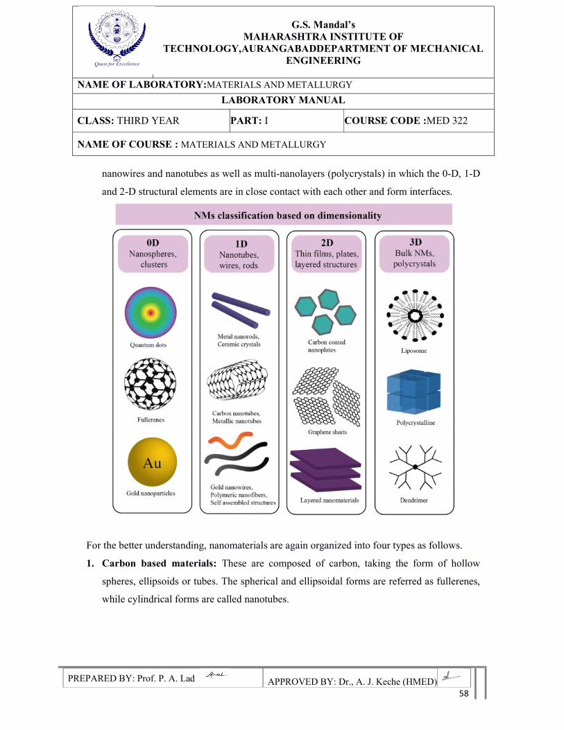
G.S. Mandal’s
MAHARASHTRA INSTITUTE OF TECHNOLOGY,AURANGABADDEPARTMENT OF MECHANICAL
ENGINEERING
NAME OF LABORATORY:MATERIALS AND METALLURGY
LABORATORY MANUAL
CLASS: THIRD YEAR PART: I COURSE CODE :MED 322
NAME OF COURSE : MATERIALS AND METALLURGY
PREPARED BY: Prof. P. A. Lad APPROVED BY: Dr., A. J. Keche (HMED) 58
nanowires and nanotubes as well as multi-nanolayers (polycrystals) in which the 0-D, 1-D
and 2-D structural elements are in close contact with each other and form interfaces.
For the better understanding, nanomaterials are again organized into four types as follows.
1. Carbon based materials: These are composed of carbon, taking the form of hollow
spheres, ellipsoids or tubes. The spherical and ellipsoidal forms are referred as fullerenes,
while cylindrical forms are called nanotubes.
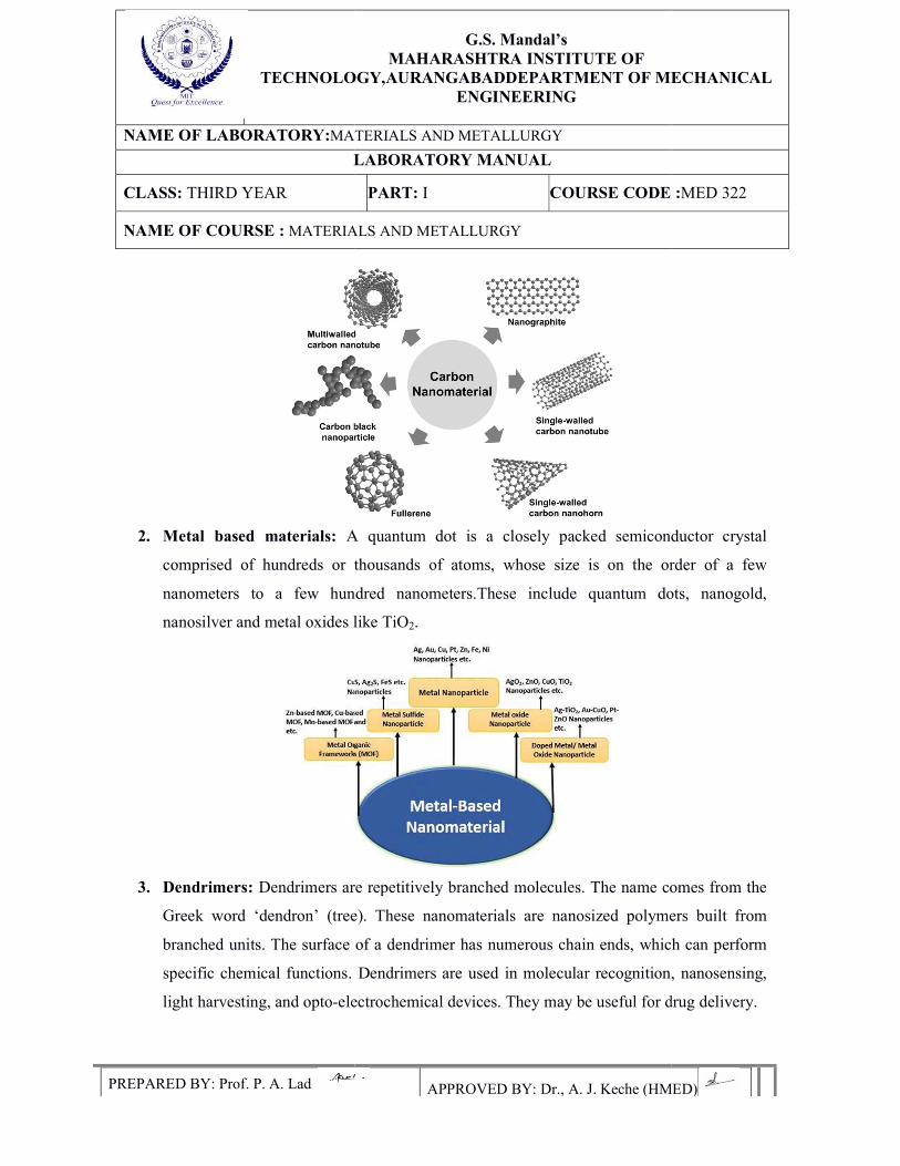
TECHNOLOGY,AURANGABAD
NAME OF LABORATORY:MATERIALS AND METALLURGY
LABORATORY MANUAL
CLASS: THIRD YEAR
NAME OF COURSE : MATERIALS
PREPARED BY: Prof. P. A. Lad
2. Metal based materials: A quantum dot is a closely packed semiconductor crystal
comprised of hundreds or thousands of atoms, whose size is on the order of a few
nanometers to a few hundred nanometers.These include quantum dots, nanogold,
nanosilver and metal oxides like TiO
3. Dendrimers: Dendrimers are repetitively branched molecules. The name comes from the
Greek word ‘dendron’ (tree). These nanomaterials are nanosized polymers built from
branched units. The surface of a dendrimer has numerous chain ends,
specific chemical functions. Dendrimers are used in molecular recognition, nanosensing,
light harvesting, and opto-electrochemical devices. They may be useful for drug deliver
G.S. Mandal’s
MAHARASHTRA INSTITUTE OF TECHNOLOGY,AURANGABADDEPARTMENT OF MECHANICAL
ENGINEERING
MATERIALS AND METALLURGY
LABORATORY MANUAL
PART: I COURSE CODE :
MATERIALS AND METALLURGY
APPROVED BY: Dr., A. J. Keche (HMED)
A quantum dot is a closely packed semiconductor crystal
comprised of hundreds or thousands of atoms, whose size is on the order of a few
nanometers to a few hundred nanometers.These include quantum dots, nanogold,
l oxides like TiO2.
Dendrimers are repetitively branched molecules. The name comes from the
Greek word ‘dendron’ (tree). These nanomaterials are nanosized polymers built from
branched units. The surface of a dendrimer has numerous chain ends, which can perform
specific chemical functions. Dendrimers are used in molecular recognition, nanosensing,
electrochemical devices. They may be useful for drug deliver
DEPARTMENT OF MECHANICAL
RSE CODE :MED 322
APPROVED BY: Dr., A. J. Keche (HMED)
A quantum dot is a closely packed semiconductor crystal
comprised of hundreds or thousands of atoms, whose size is on the order of a few
nanometers to a few hundred nanometers.These include quantum dots, nanogold,
Dendrimers are repetitively branched molecules. The name comes from the
Greek word ‘dendron’ (tree). These nanomaterials are nanosized polymers built from
which can perform
specific chemical functions. Dendrimers are used in molecular recognition, nanosensing,
electrochemical devices. They may be useful for drug delivery.
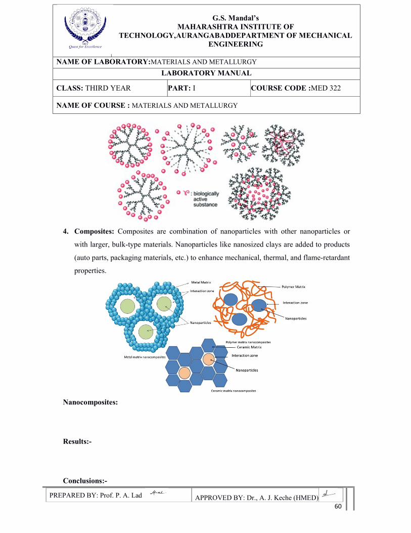
G.S. Mandal’s
MAHARASHTRA INSTITUTE OF TECHNOLOGY,AURANGABADDEPARTMENT OF MECHANICAL
ENGINEERING
NAME OF LABORATORY:MATERIALS AND METALLURGY
LABORATORY MANUAL
CLASS: THIRD YEAR PART: I COURSE CODE :MED 322
NAME OF COURSE : MATERIALS AND METALLURGY
PREPARED BY: Prof. P. A. Lad APPROVED BY: Dr., A. J. Keche (HMED) 60
4. Composites: Composites are combination of nanoparticles with other nanoparticles or
with larger, bulk-type materials. Nanoparticles like nanosized clays are added to products
(auto parts, packaging materials, etc.) to enhance mechanical, thermal, and flame-retardant
properties.
Nanocomposites:
Results:-
Conclusions:-
Related Documents