Eastern Mediterranean University Faculty of Engineering Department of Electrical and Electronic Engineering EENG 360 Communication System I Laboratory LAB 9 FREQUENCY MODULATION & DEMODULATION Objectives: Understanding the principle of frequency modulation (FM) and demodulation Understanding the waveforms of modulated and demodulated signals Designing frequency modulator and demodulator using Simulink Theory Phase modulation (PM) and frequency modulation (FM) are special cases of angle-modulated signaling. FM is a process in which the carrier frequency is varied by the amplitude of the modulating signal (i.e. intelligence signal). Angle modulated signal can be expressed by the following equation: () [ ()] (1) For FM, the phase is proportional to the integral of message signal (), therefore () [ ∫ () ] (2)

Welcome message from author
This document is posted to help you gain knowledge. Please leave a comment to let me know what you think about it! Share it to your friends and learn new things together.
Transcript

Eastern Mediterranean University
Faculty of Engineering
Department of Electrical and Electronic Engineering
EENG 360 Communication System I Laboratory
LAB 9
FREQUENCY MODULATION & DEMODULATION
Objectives:
Understanding the principle of frequency modulation (FM) and
demodulation
Understanding the waveforms of modulated and demodulated signals
Designing frequency modulator and demodulator using Simulink
Theory
Phase modulation (PM) and frequency modulation (FM) are special cases of
angle-modulated signaling. FM is a process in which the carrier frequency is
varied by the amplitude of the modulating signal (i.e. intelligence signal).
Angle modulated signal can be expressed by the following equation:
( ) [ ( )] (1)
For FM, the phase is proportional to the integral of message signal ( ),
therefore
( ) [ ∫ ( )
] (2)
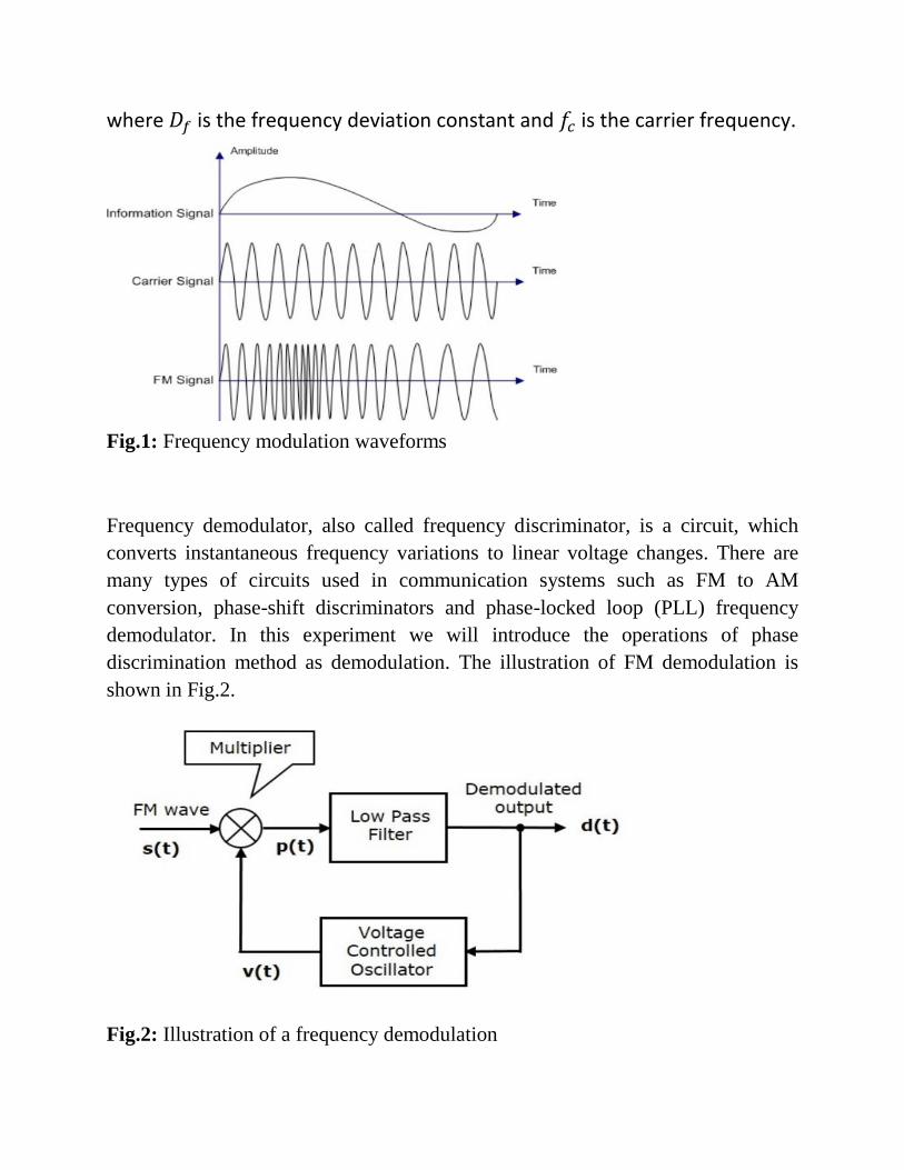
where is the frequency deviation constant and is the carrier frequency.
Fig.1: Frequency modulation waveforms
Frequency demodulator, also called frequency discriminator, is a circuit, which
converts instantaneous frequency variations to linear voltage changes. There are
many types of circuits used in communication systems such as FM to AM
conversion, phase-shift discriminators and phase-locked loop (PLL) frequency
demodulator. In this experiment we will introduce the operations of phase
discrimination method as demodulation. The illustration of FM demodulation is
shown in Fig.2.
Fig.2: Illustration of a frequency demodulation
Procedure
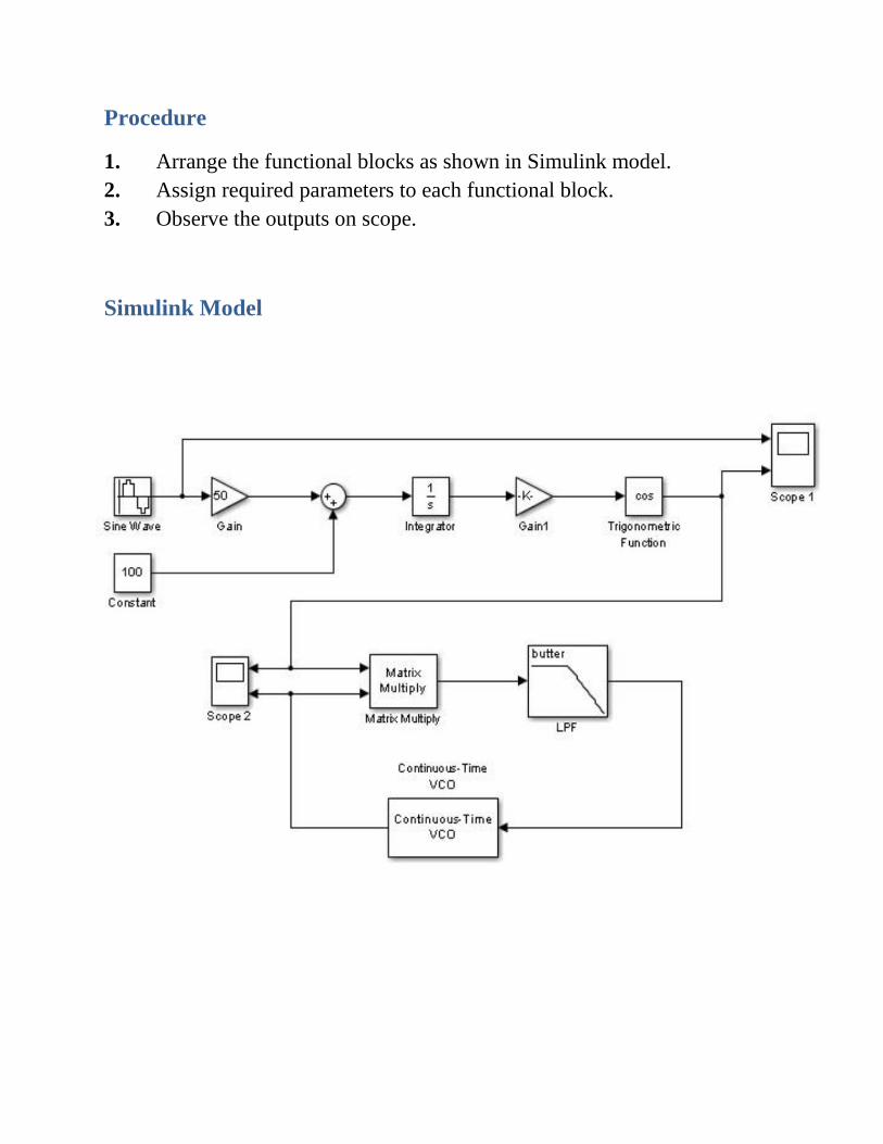
1. Arrange the functional blocks as shown in Simulink model.
2. Assign required parameters to each functional block.
3. Observe the outputs on scope.
Simulink Model
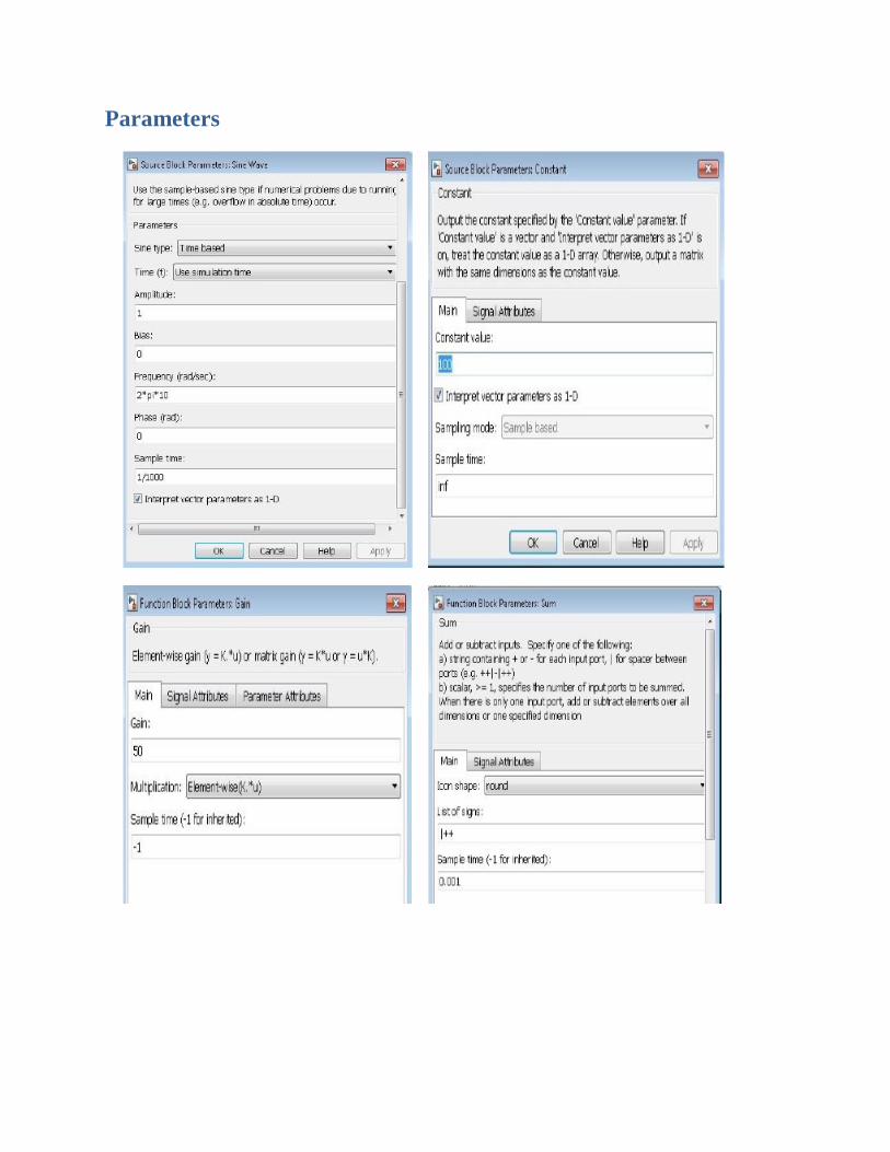
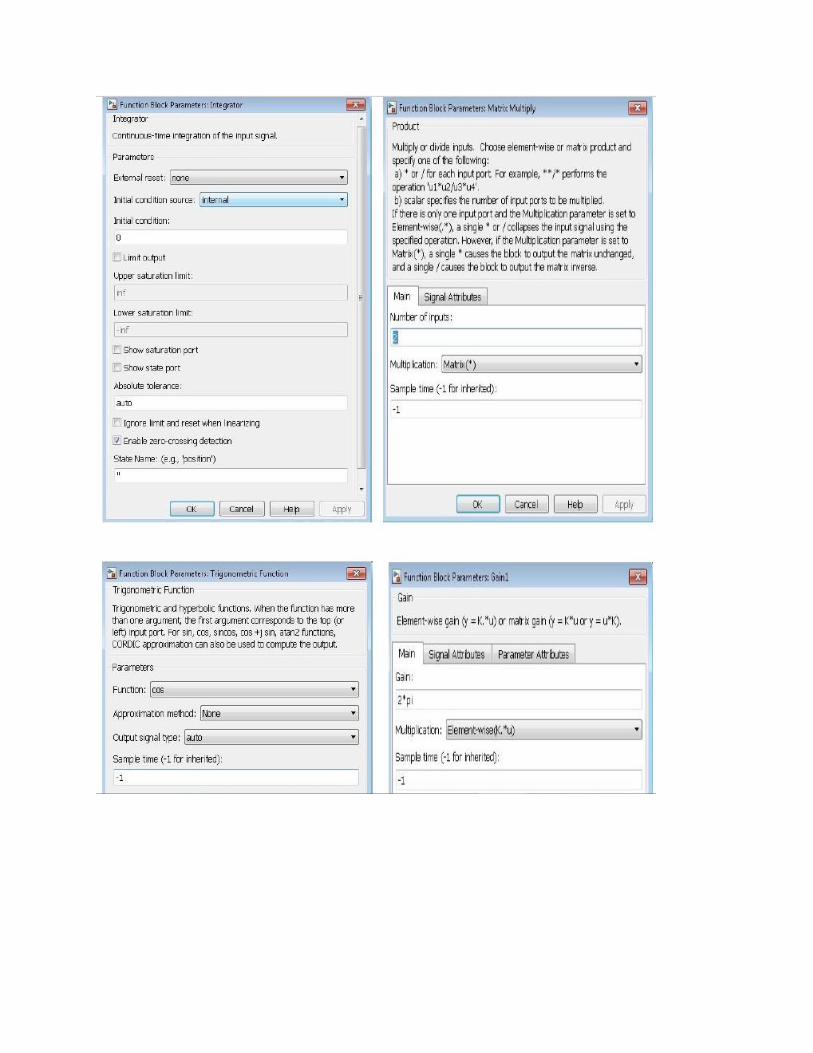
Parameters
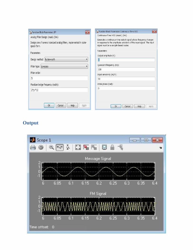
Output
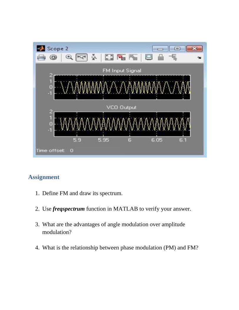
Assignment
1. Define FM and draw its spectrum.
2. Use freqspectrum function in MATLAB to verify your answer.
3. What are the advantages of angle modulation over amplitude
modulation?
4. What is the relationship between phase modulation (PM) and FM?
Related Documents