Lab 7 Sensors Programmable Logic Controllers

Welcome message from author
This document is posted to help you gain knowledge. Please leave a comment to let me know what you think about it! Share it to your friends and learn new things together.
Transcript

Chapter
Lab 7
Sensors
Programmable Logic Controllers

What is a Sensors ?
A sensor is a device that measures a physical quantity and converts it into a signal which can be read by an observer or by an instrument.
A sensor is a device which receives and responds to a signal and converts the signal into an electrical form which can be used by electronic devices.
A sensor differs from a transducer in the way that a transducer converts one form of energy into other form whereas a sensor converts the received signal into electrical form only.
http://en.wikipedia.org/wiki/Sensor
Importance of Sensors
Without sensors most electronic applications would not exist. They perform a vital function, namely providing an interface to the real world. The importance of sensors requires an understanding of the types available and how to use them for a particular application. Today's smart sensors, wireless sensors, and micro technologies are revolutionizing sensor design and applications.
http://www.isa.org/Template.cfm?Section=Books3&template=/Ecommerce/ProductDisplay.cfm&ProductID=7945

Categories of Sensors
Acceleration, Shock and Vibration SensorsBiosensorsChemical SensorsCapacitive and Inductive Displacement SensorsElectromagnetism in SensingFlow and Level SensorsForce, Load and Weight SensorsHumidity SensorsMachinery Vibration Monitoring SensorsOptical and Radiation SensorsPosition and Motion SensorsPressure SensorsSensors for Mechanical ShockTemperature SensorsStrain GagesNanotechnology-Enabled SensorsWireless Sensor Networks
Within each category there are many types
of sensors

Sensor ApplicationsBrowse Products by Application:
Bar Code ReadingColor Mark and Registration DetectionClear or Reflective Object DetectionCountingDetectionInspectionLabelingLevel MonitoringLoop ControlMeasurementMetal StampingTemperature MonitoringWeb MonitoringWirelessVehicle Detection
http://www.bannerengineering.com/en-US/products
Browse Products by Industry:
AgricultureAutomotiveCar WashFood & BeverageMaterial HandlingPackagingPharmaceutical & MedicalSemiconductor
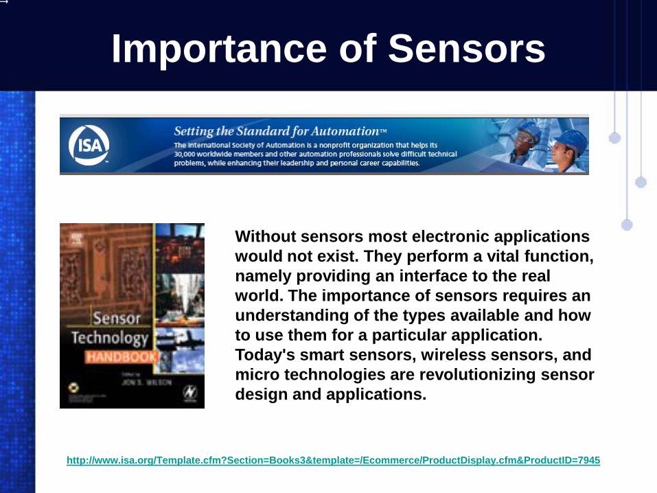
Most Common Sensors for Detection , Positioning, and Counting
http://info.bannersalesforce.com/xpedio/groups/public/documents/literature/142025.pdf
Limit Switches Photo Sensors
Proximity Sensors Ultrasonic Sensors

Banner is #1 in Sensors
http://www.bannerengineering.com/en-US/products
For 20 consecutive years, Banner Engineering has placed first in more than 50 independent studies of the purchasing preference of engineers.
With more than 22,000 different products across 40 industries, Banner offers you the industry's most complete, integrated and advanced line of photo eyes, sensors, wireless sensors, vision sensors, vision lighting, machine safety, and indicator lights. Choose the worldwide leader.Banner is preferred nearly four to one over the closest competitor
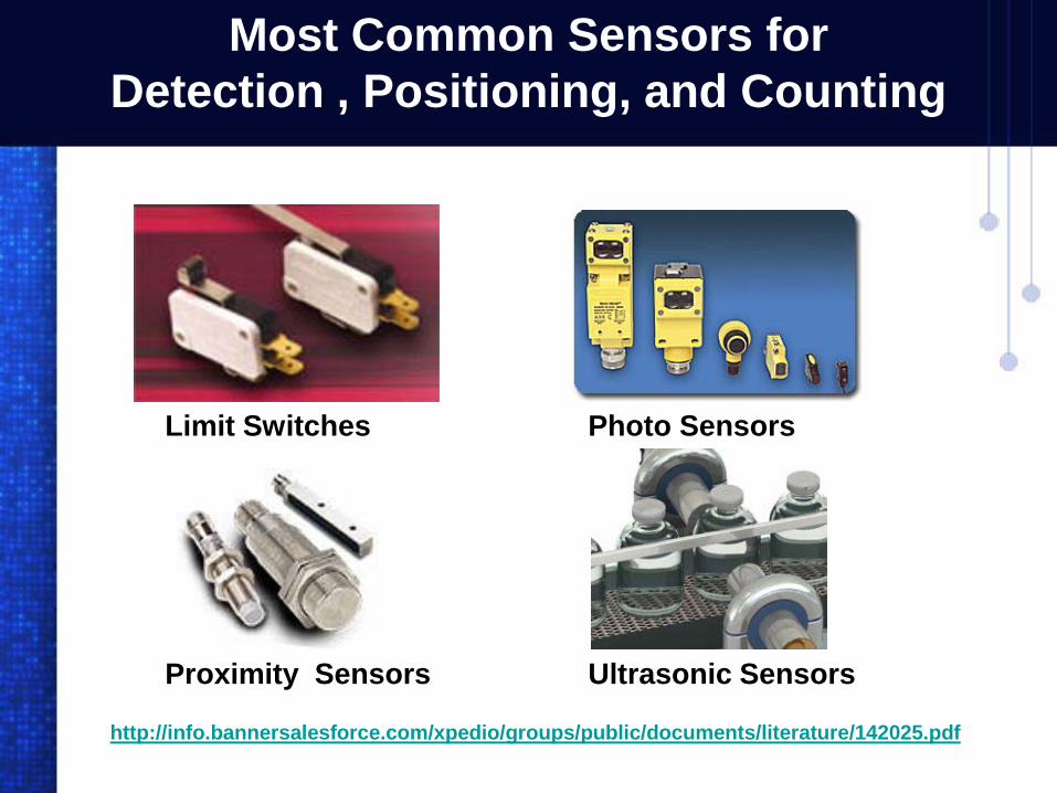
Ultrasonic Sensors
Inverted Clear ObjectDetection
Bottle DetectionLiquid Level Monitoring
http://info.bannersalesforce.com/xpedio/groups/public/documents/literature/142025.pdf
Ultrasonic sensors solve applications that photo electrics can’t. Ultrasonic sensors are versatile, accurate and an effective solution for the toughest applications challenges. Ultrasonic sensors use sound waves, not light, and this makes them ideal for problematic clear material sensing applications. Use ultrasonics to effectively and accurately sense liquids, clear objects and targets in dirty environments. Ultrasonics are inherently impervious to color differences, high reflectivity and glare, all of which are application challenges for photoelectrics.

More Sensors
Temperature Switches
Pressure Sensor4-20 ma output
Float Switches
Magnetic Reed SwitchesPressure Switches
Vibration Sensor

Chapter
Lab 7
Proximity Sensors
Programmable Logic Controllers
Inductive Proximity Sensors
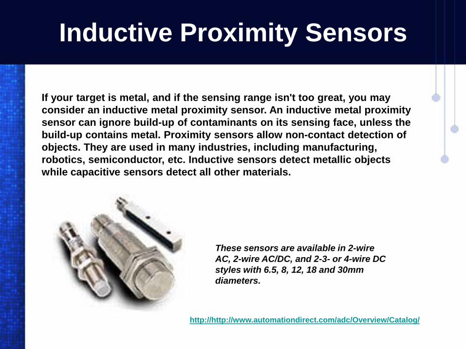
If your target is metal, and if the sensing range isn't too great, you may consider an inductive metal proximity sensor. An inductive metal proximity sensor can ignore build-up of contaminants on its sensing face, unless the build-up contains metal. Proximity sensors allow non-contact detection of objects. They are used in many industries, including manufacturing, robotics, semiconductor, etc. Inductive sensors detect metallic objects while capacitive sensors detect all other materials.
http://http://www.automationdirect.com/adc/Overview/Catalog/
These sensors are available in 2-wire AC, 2-wire AC/DC, and 2-3- or 4-wire DC styles with 6.5, 8, 12, 18 and 30mm diameters.
Inductive Proximity Sensors
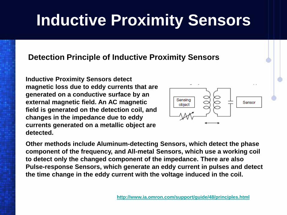
Inductive Proximity Sensors detect magnetic loss due to eddy currents that are generated on a conductive surface by an external magnetic field. An AC magnetic field is generated on the detection coil, and changes in the impedance due to eddy currents generated on a metallic object are detected.
http://www.ia.omron.com/support/guide/48/principles.html
Detection Principle of Inductive Proximity Sensors
Other methods include Aluminum-detecting Sensors, which detect the phase component of the frequency, and All-metal Sensors, which use a working coil to detect only the changed component of the impedance. There are also Pulse-response Sensors, which generate an eddy current in pulses and detect the time change in the eddy current with the voltage induced in the coil.
Capacitive Proximity Sensors
http://www.ia.omron.com/
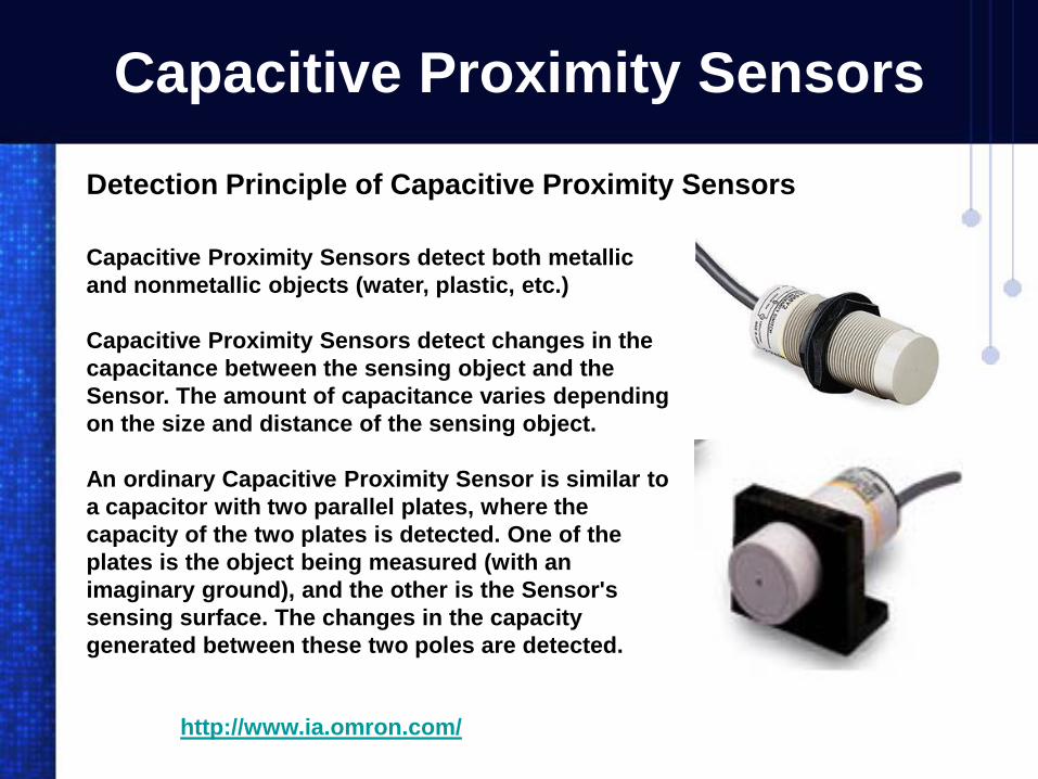
Capacitive Proximity Sensors detect both metallic and nonmetallic objects (water, plastic, etc.)
Capacitive Proximity Sensors detect changes in the capacitance between the sensing object and the Sensor. The amount of capacitance varies depending on the size and distance of the sensing object.
An ordinary Capacitive Proximity Sensor is similar to a capacitor with two parallel plates, where the capacity of the two plates is detected. One of the plates is the object being measured (with an imaginary ground), and the other is the Sensor's sensing surface. The changes in the capacity generated between these two poles are detected.
Detection Principle of Capacitive Proximity Sensors
Proximity Sensors – Block Diagram
L1 L2
TRIAC
GATE
ANODE 1
ANODE 2
POWER
SUPPLY
TRANSFORMER
120VAC
BUFFER
LOAD
RECTIFIEROSCILLATOR
TANK CIRCUIT
Inductive
Capacitive
OSCILLATOR
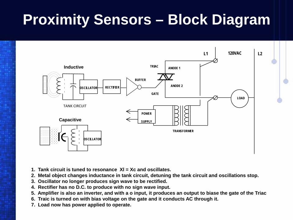
1. Tank circuit is tuned to resonance Xl = Xc and oscillates.2. Metal object changes inductance in tank circuit, detuning the tank circuit and oscillations stop.3. Oscillator no longer produces sign wave to be rectified.4. Rectifier has no D.C. to produce with no sign wave input.5. Amplifier is also an inverter, and with a o input, it produces an output to biase the gate of the Triac6. Traic is turned on with bias voltage on the gate and it conducts AC through it.7. Load now has power applied to operate.
Chapter
Lab 7
Photo Sensors
Programmable Logic Controllers
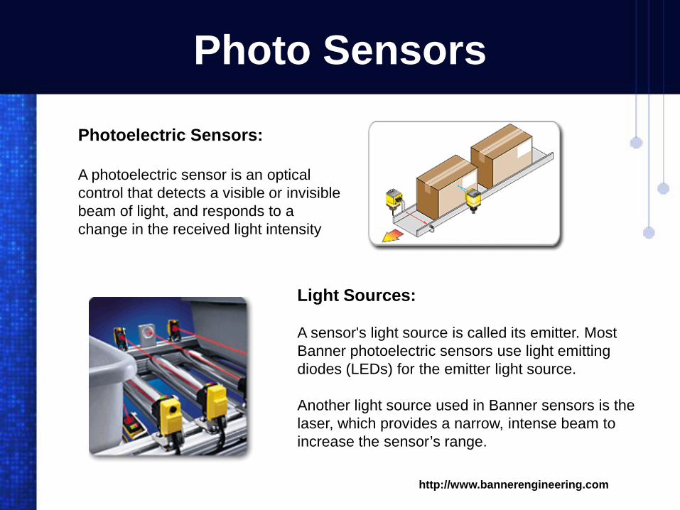
Photo Sensors
Photoelectric Sensors:
A photoelectric sensor is an optical control that detects a visible or invisible beam of light, and responds to a change in the received light intensity
Light Sources:
A sensor's light source is called its emitter. Most Banner photoelectric sensors use light emitting diodes (LEDs) for the emitter light source.
Another light source used in Banner sensors is the laser, which provides a narrow, intense beam to increase the sensor’s range.
http://www.bannerengineering.com
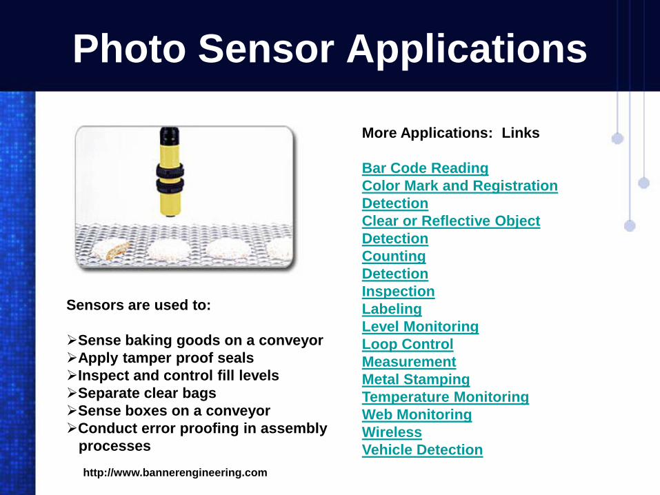
Photo Sensor Applications
Sensors are used to:
Sense baking goods on a conveyor Apply tamper proof seals Inspect and control fill levels Separate clear bags Sense boxes on a conveyor Conduct error proofing in assembly
processes
More Applications: Links
Bar Code ReadingColor Mark and Registration DetectionClear or Reflective Object DetectionCountingDetectionInspectionLabelingLevel MonitoringLoop ControlMeasurementMetal StampingTemperature MonitoringWeb MonitoringWirelessVehicle Detection
http://www.bannerengineering.com

3 Categories of Photo Sensors
http://www.bannerengineering.com
Self-contained, which contain the optical and electrical components of a sensor system.
Remote, where the optical and electrical components are separated.
Fiber Optics, which only pipe the light beam into and out of the sensing location.

3 Categories of Photo Sensors
http://www.bannerengineering.com
Self Contained:
A self-contained photoelectric sensor contains the optics, along with the electronics.
It requires only a power source.
The sensor performs its own modulation, demodulation, amplification, and output switching.
3 Categories of Photo Sensors
http://www.bannerengineering.com
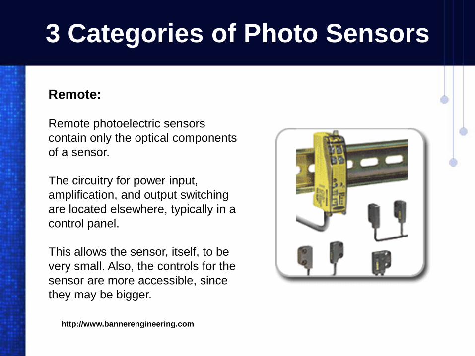
Remote:
Remote photoelectric sensors contain only the optical components of a sensor.
The circuitry for power input, amplification, and output switching are located elsewhere, typically in a control panel.
This allows the sensor, itself, to be very small. Also, the controls for the sensor are more accessible, since they may be bigger.

3 Categories of Photo Sensors
http://www.bannerengineering.com
Fiber optics:
When space is restricted or the environment too hostile even for remote sensors, fiber optics may be used.
Fiber optics are passive mechanical sensing components. They may be used with either remote or self-contained sensors.
They have no electrical circuitry and no moving parts, and can safely pipe light into and out of hostile environments.

Photo Sensors – Sensing Modes
http://www.bannerengineering.com/training/subtopic.php?topicID=A1_00
Sensing mode is one of the most important criteria when selecting a photo sensor. The best sensing mode for your application will be a reliably detection of your object without being confused by factors in the environment.
There are 6 sensing modes
What are the pros and cons of each mode ?
Which sensing mode suits an application ?
Banner Tutorials
Opposed (11 pages)Retroreflective (13 pages)Diffuse (13 pages)Divergent (10 pages)Convergent (11 pages)Background Suppression (13 pages)

Photo Sensors – Sensing Modes
http://www.bannerengineering.com/training/subtopic.php?topicID=A1_01
1. Opposed Mode:
An opposed-mode sensor will have a separate emitter and receiver pair. The emitter sends the light beam to the receiver, which is positioned opposite the emitter.
For an object to be detected, it must pass between the two, and interrupt or "break" the beam of light.
Opposed-mode sensing is highly reliable, provides a high amount emitted energy, is impervious to surface reflectivity, and is excellent for parts counting.
However, opposed-mode sensing may not be the best solution for sensing clear materials.

Photo Sensors – Sensing Modes
http://www.bannerengineering.com/training/subtopic.php?topicID=A1_02_010
2. Retroreflective Mode:
A retroreflective sensor contains both the emitter and receiver element.
The effective beam is established when the emitter sends a light beam which is bounced off a retroreflector, back to the emitter. An object is detected when it breaks this effective beam.
Retroreflective-mode sensors offer reliability, and are convenient in applications where sensors can be mounted only on one side of a process.
However, retroreflective sensors can lose gain twice as fast as opposed mode sensors, and they aren't always the best choice for sensing shiny, clear, or very small objects.
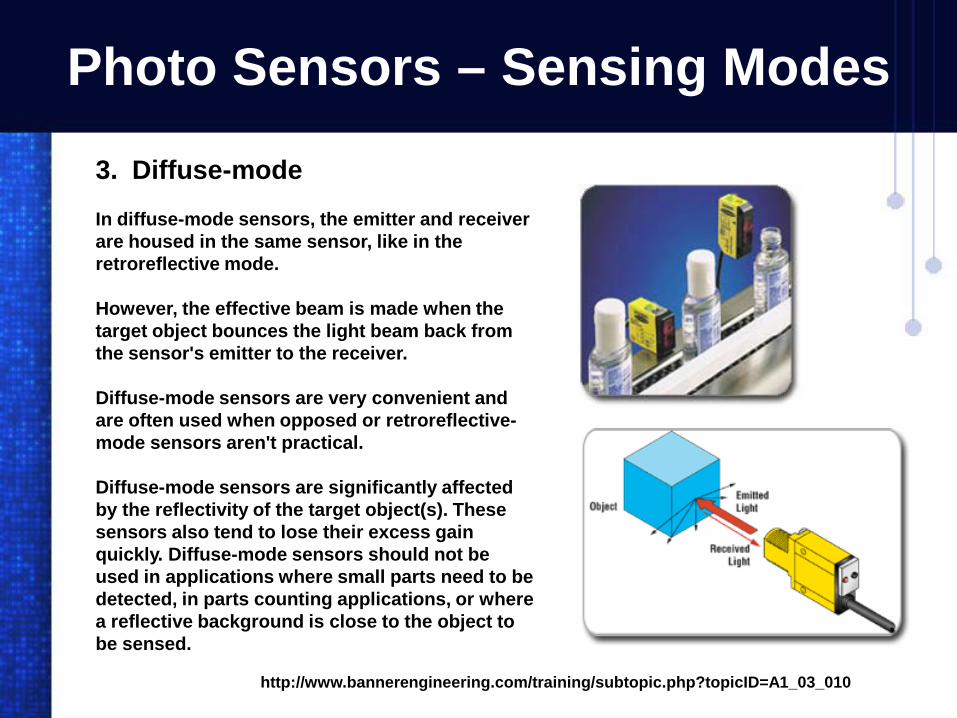
Photo Sensors – Sensing Modes
http://www.bannerengineering.com/training/subtopic.php?topicID=A1_03_010
3. Diffuse-mode
In diffuse-mode sensors, the emitter and receiver are housed in the same sensor, like in the retroreflective mode.
However, the effective beam is made when the target object bounces the light beam back from the sensor's emitter to the receiver.
Diffuse-mode sensors are very convenient and are often used when opposed or retroreflective-mode sensors aren't practical.
Diffuse-mode sensors are significantly affected by the reflectivity of the target object(s). These sensors also tend to lose their excess gain quickly. Diffuse-mode sensors should not be used in applications where small parts need to be detected, in parts counting applications, or where a reflective background is close to the object to be sensed.

Photo Sensors – Sensing Modes
http://www.bannerengineering.com/training/subtopic.php?topicID=A1_04
4. Divergent-mode
Like diffuse-mode sensors, divergent-mode sensors detect an object when that object bounces light back from the sensor's emitter to the receiver. However in the divergent mode, the sensor casts a much wider angle of light.
Divergent-mode sensors are excellent in applications which involve detection of clear materials, small objects, shiny surfaces, and where background rejection is necessary.
By design, divergent-mode sensors make inefficient use of sensing light energy, and offer only low levels of excess gain. Also, they have a very wide field of view, and caution should be used in applications where an object on the side of the sensor may be detected.
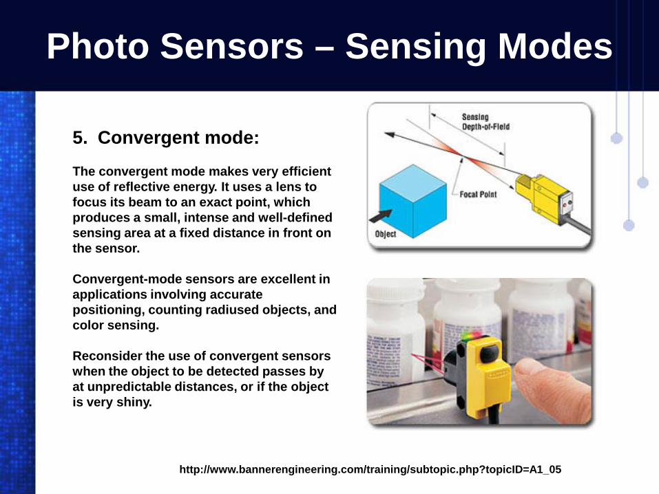
Photo Sensors – Sensing Modes
http://www.bannerengineering.com/training/subtopic.php?topicID=A1_05
5. Convergent mode:
The convergent mode makes very efficient use of reflective energy. It uses a lens to focus its beam to an exact point, which produces a small, intense and well-defined sensing area at a fixed distance in front on the sensor.
Convergent-mode sensors are excellent in applications involving accurate positioning, counting radiused objects, and color sensing.
Reconsider the use of convergent sensors when the object to be detected passes by at unpredictable distances, or if the object is very shiny.

Photo Sensors – Sensing Modes
http://www.bannerengineering.com/training/subtopic.php?topicID=A1_06
6. Background suppression:
Background suppression sensors such as adjustable-field and fixed-field mode have a definite limit to their sensing range, and are able to ignore objects beyond that range.
These sensors are especially good in applications where highly-reflective backgrounds need to be ignored, to accurately detect height differentials, and for low contrast applications.
With background suppression sensors, shiny background objects can affect how light is reflected back to the sensor. Additionally, if the object to be detected is not properly oriented to the sensor, you could get a false output.

Photo Sensors - Aligning the Beam.
Source
-24 vdc Grd.
Relay
+24vdc
LED
While observing the light (LED) on the sensor, move the reflector vertically and horizontally to determine the center of the reflector.
The reflector then must be aligned properly and mounted secure.
Block the beam temporally to see if the load is energized and de-energized.

Photo Sensors - Dark & Light Operate
Light OperateDark Operate
Source
-24 vdc Grd.
Relay
+24vdc
When the beam is broken there is no light back to the receiver (dark) so the sensor switches power (operates) the load.
Source
-24 vdc Grd.
Relay
+24vdc
When the beam is clear and not broken there is light back to the receiver (light) so the sensor switches power (operates) the load.
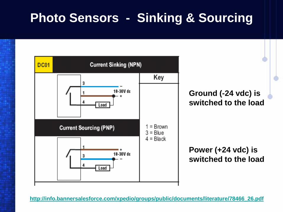
Photo Sensors - Sinking & Sourcing
Ground (-24 vdc) is switched to the load
Power (+24 vdc) is switched to the load
http://info.bannersalesforce.com/xpedio/groups/public/documents/literature/78466_26.pdf

Photo Sensors - Sinking & Sourcing (Relay)
Sinking a relaySourcing a relay
Source
-24 vdc Grd.
Relay
+24vdc
Sink
Relay
+24vdc -24 vdc Grd.
Sourcing:
When the beam is broken, The sensor switches the source (+24vdc) to the output lead. The relay is wired from the sensor output to ground.
Sinking:
When the beam is broken, The sensor switches the ground (-24vdc) to the output lead. The relay is wired from the sensor output to +24vdc.
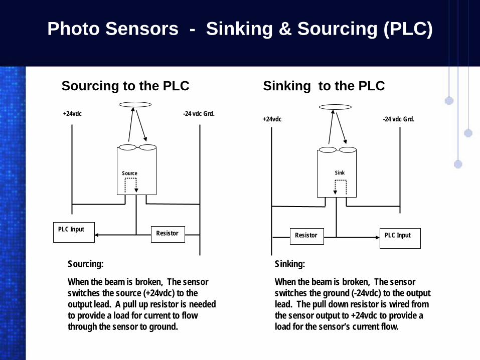
Photo Sensors - Sinking & Sourcing (PLC)
Sinking to the PLCSourcing to the PLC
Source
-24 vdc Grd.+24vdc
ResistorPLC Input
Sink
+24vdc -24 vdc Grd.
Resistor PLC Input
Sinking:
When the beam is broken, The sensor switches the ground (-24vdc) to the output lead. The pull down resistor is wired from the sensor output to +24vdc to provide a load for the sensor’s current flow.
Sourcing:
When the beam is broken, The sensor switches the source (+24vdc) to the output lead. A pull up resistor is needed to provide a load for current to flow through the sensor to ground.

Photo Sensors – Block Diagram
1. Oscillator produces square wave pulses2. Modulator turns inferred LED on at high frequency pulse rate3. Light bounces off reflector to receiver (Photo Transistor)4. Photo transistor picks up light pulses and sends out pulses to de-modulator5. De-modulator is sensitive to only the pulse rate produced by oscillator. (rejecting light flashes & noise)6. Demodulator turns on buffer amplifier to bias the gate of the triac on7. Traic turns on conducting current to load to operate load device
CR1
L1L2
TRIAC
GATE
ANODE 1
ANODE 2
POWER
SUPPLY
TRANSFORMER
24VAC
REFLECTOR
MODULATOR
INFERRED LIGHTOSC.
I-R
PHOTOTRANSISTOR
DE-
MODULATOR
BUFFER
AMP
BLACK
RED
WHITE

Chapter
Lab 7-1
Proximity Sensors Lab
Programmable Logic Controllers

Proximity Sensor used on PLC Trainer

Proximity Sensor used on PLC Trainer
Relay+24 vdc
Ground
Omron E2E-X2D1-N Proximity Sensor wired to a Relay
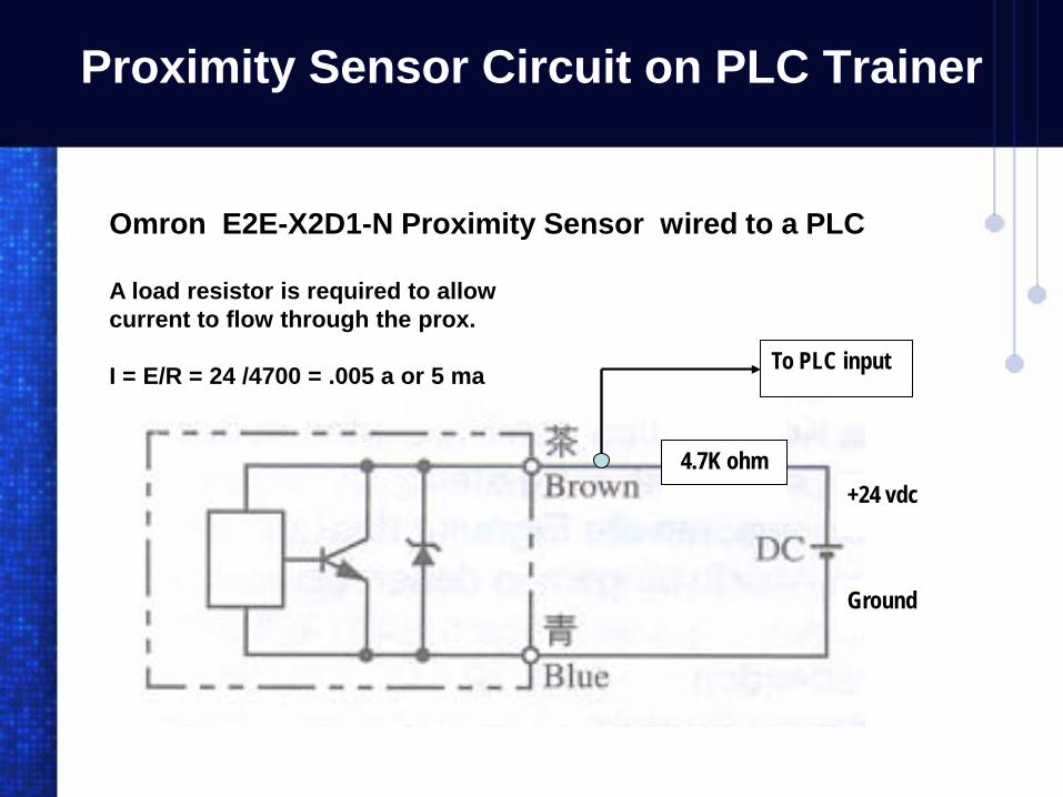
Proximity Sensor Circuit on PLC Trainer
Ground
+24 vdc4.7K ohm
To PLC input
Omron E2E-X2D1-N Proximity Sensor wired to a PLC
A load resistor is required to allow current to flow through the prox.
I = E/R = 24 /4700 = .005 a or 5 ma

Chapter
Lab 7-2
Photo Sensors Lab
Programmable Logic Controllers
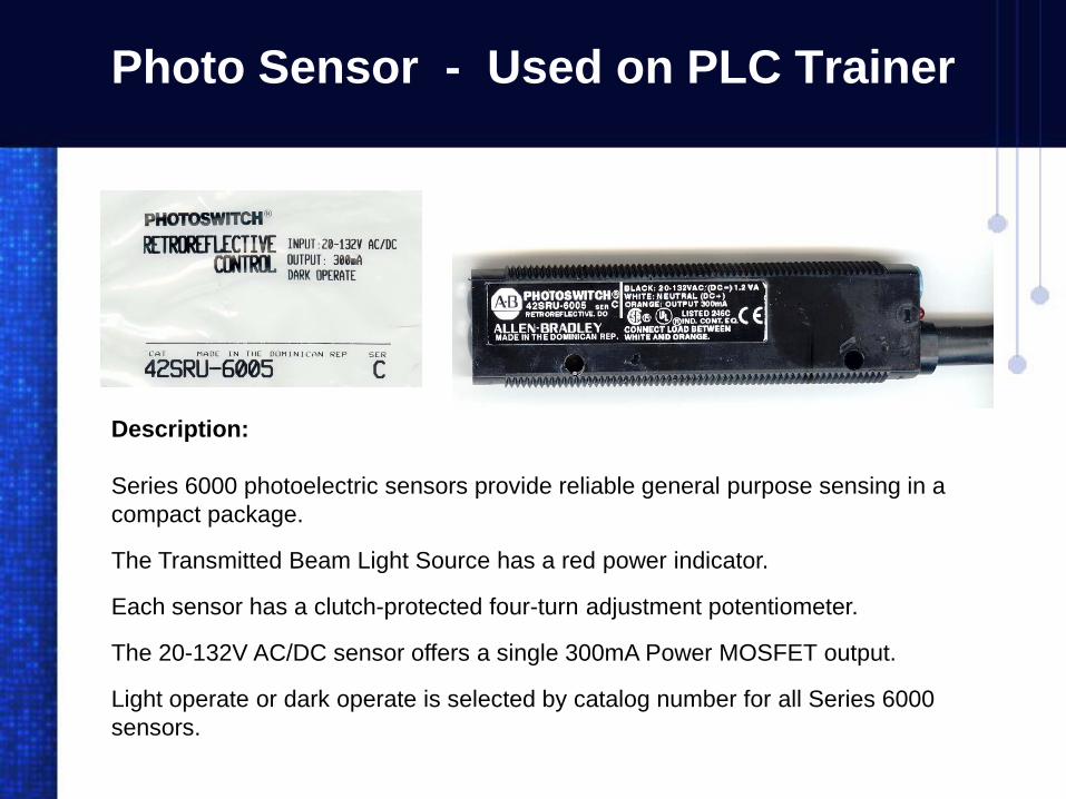
Photo Sensor - Used on PLC Trainer
Description:
Series 6000 photoelectric sensors provide reliable general purpose sensing in a compact package.
The Transmitted Beam Light Source has a red power indicator.
Each sensor has a clutch-protected four-turn adjustment potentiometer.
The 20-132V AC/DC sensor offers a single 300mA Power MOSFET output.
Light operate or dark operate is selected by catalog number for all Series 6000 sensors.

Photo Sensors - Trainer Lab Circuit
Retroreflective Alignment:
Adjust the sensitivity to the maximum setting, by turning the sensitivity potentiometer clockwise. Aim the sensor on the reflector until the alignment indicator on the sensor turns On (light operate) or Off (dark operate).
To be certain that the beam is centered, sweep the beam on the reflector in the horizontal plane and determine the position the alignment indicator turns On and then Off. Set the beam halfway between both positions. Do the same in the vertical plane. Break the beam with the object to be detected and check to see if the alignment indicator turns Off.
It may be necessary to reduce the sensitivity or change to a smaller sized reflector to detect small, translucent or transparent objects. Restore the beam by removing the object and check to see if the alignment indicator turns On again. For shiny objects angle the sensor so that the beam is not perpendicular to the object. For highly reflective materials use a polarized retroreflective sensor.

Photo Sensors - Trainer Lab Circuit
Relay
Photo Sensor driving a relay direct.
The 42SRU-6005 Photo Sensor is a Dark Operate with a SINK output. The load is connected to ground when beam is broken.
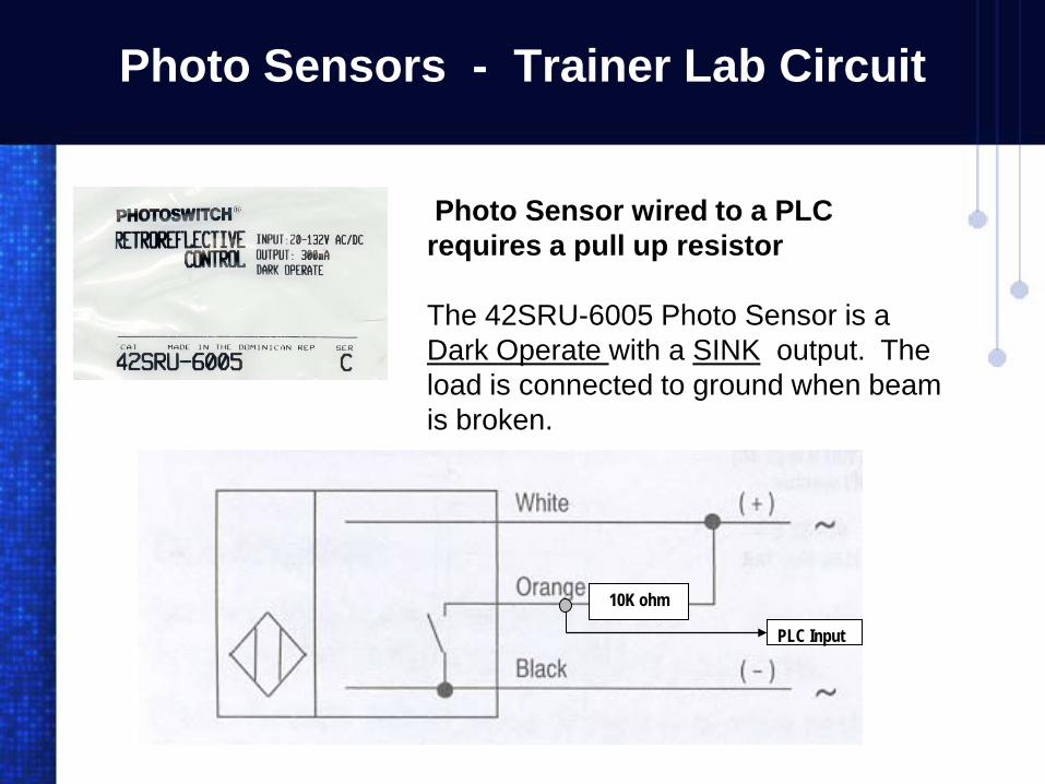
Photo Sensors - Trainer Lab Circuit
10K ohm
PLC Input
Photo Sensor wired to a PLC requires a pull up resistor
The 42SRU-6005 Photo Sensor is a Dark Operate with a SINK output. The load is connected to ground when beam is broken.
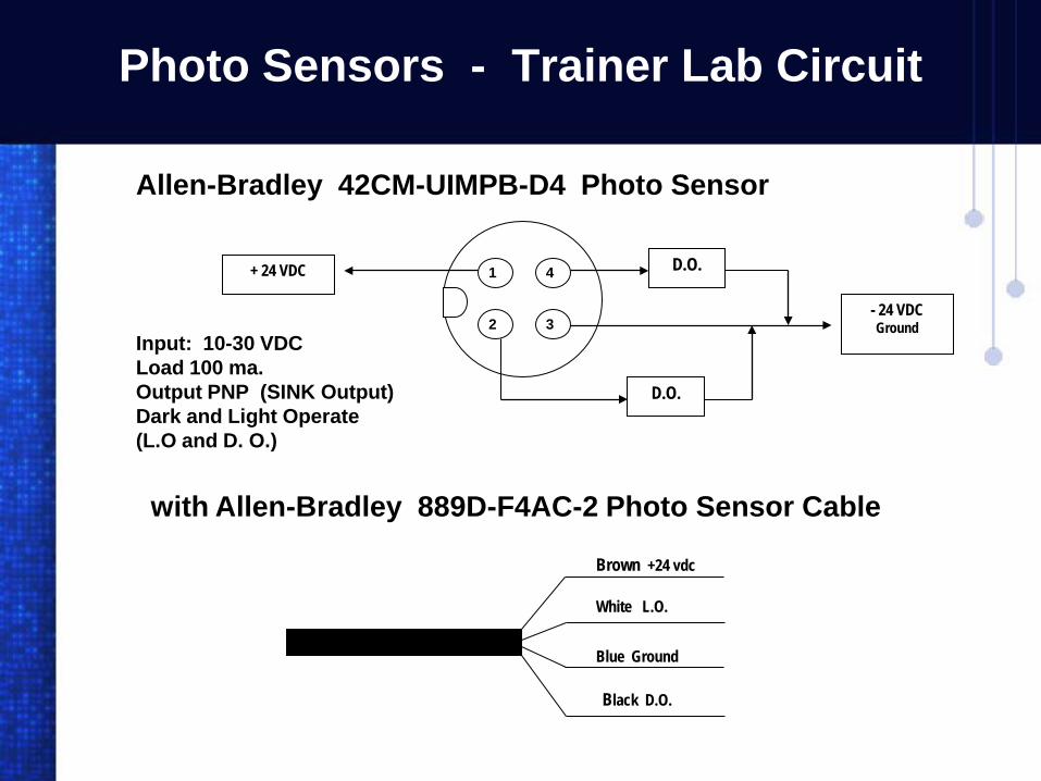
Photo Sensors - Trainer Lab Circuit
Allen-Bradley 42CM-UIMPB-D4 Photo Sensor
1 4
2 3
D.O.
D.O.
+ 24 VDC
- 24 VDCGround
Input: 10-30 VDCLoad 100 ma.Output PNP (SINK Output)Dark and Light Operate (L.O and D. O.)
with Allen-Bradley 889D-F4AC-2 Photo Sensor Cable
White L.O.
Blue Ground
Black D.O.
Brown +24 vdc
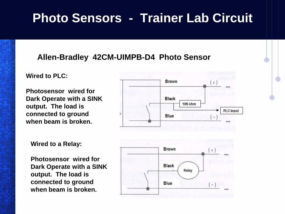
Photo Sensors - Trainer Lab Circuit
Allen-Bradley 42CM-UIMPB-D4 Photo Sensor
Wired to PLC:
Photosensor wired for Dark Operate with a SINK output. The load is connected to ground when beam is broken.
Wired to a Relay:
Photosensor wired for Dark Operate with a SINK output. The load is connected to ground when beam is broken.
Chapter
Lab 7THE END
Sensors
Related Documents