Lab 3: Implementing Functions with the Simon Board CpE 214: Digital Engineering Lab II Last revised: January 25, 2013 (CAC) You will extend your knowledge of the original 8051 reference design to that of newer 80C51 derivatives. The Simon Board, developed here at Rolla, which features a more modern 8051-based architecture will be introduced. The student will learn in assembly language (ASM) how to congure the port modes, enable/disable Special Function Registers, learn to debounce signals and perform a simple timing program. Upon completing the lab, a broader understanding of embedded hardware implementations, and how to write software for them, is achieved. 0.1 Outline and Concepts 1. Intro to the Simon Board, clock sources 2. Port mode congurations 3. How the timers work, generating frequencies 4. Writing the ASM program 5. Flashing and testing 1 Intro to the Simon Board, clock sources The Simon Board, pictured in Figure 1, will be used in your course projects, and sometimes make their way into other lab/course/senior projects here in the department. In the 213 lecture, you spend most of your time learning the generalized features/functions of the original 8051 reference design (and for good reason). However, one of the most common mistakes that students typically make in their projects is to attempt to use certain special functions (that are hardware-specic to the individual chip) with code congurations straight out of the textbook. Some things work exactly the same, and some things dont. In this lab you will learn how read a chips datasheet to determine this information: a critical skill you need to develop as an ECE. FIG. 1: Simon Board 1

Welcome message from author
This document is posted to help you gain knowledge. Please leave a comment to let me know what you think about it! Share it to your friends and learn new things together.
Transcript

Lab 3: Implementing Functions with the Simon Board
CpE 214: Digital Engineering Lab II
Last revised: January 25, 2013 (CAC)
You will extend your knowledge of the original 8051 reference design to that of newer 80C51 derivatives. The SimonBoard, developed here at Rolla, which features a more modern 8051-based architecture will be introduced. The studentwill learn in assembly language (ASM) how to configure the port modes, enable/disable Special Function Registers, learnto debounce signals and perform a simple timing program. Upon completing the lab, a broader understanding of embeddedhardware implementations, and how to write software for them, is achieved.
0.1 Outline and Concepts
1. Intro to the Simon Board, clock sources
2. Port mode configurations
3. How the timers work, generating frequencies
4. Writing the ASM program
5. Flashing and testing
1 Intro to the Simon Board, clock sources
The Simon Board, pictured in Figure 1, will be used in your course projects, and sometimes make their way into otherlab/course/senior projects here in the department. In the 213 lecture, you spend most of your time learning the generalizedfeatures/functions of the original 8051 reference design (and for good reason). However, one of the most common mistakesthat students typically make in their projects is to attempt to use certain special functions (that are hardware-specific tothe individual chip) with code configurations straight out of the textbook. Some things work exactly the same, and somethings don’t. In this lab you will learn how read a chip’s datasheet to determine this information: a critical skill you need todevelop as an ECE.
FIG. 1: Simon Board
1

What features does it have? What can it do?
• 4 LED’s, 4 push button inputs
• 2 different oscillator clocks (7.3728MHz RC internal, 11.0592MHz PLL external).
• Philips LPC932A1, which features onboard Flash ROM, 2 GP timers, I2C interface, and 1 ded. serial port timer
• Serial port for bidirectional communication and flashing of ROM
• External jumpers for P0, P1, and P2 buses, as well as XTAL, 3.3V and GND rails.
• The Most Important Thing you need to be aware of: Clock oscillator options
In the 8051 context you’re used to, there is a single oscillator, and it drives all functions of the device. In modern designslike the LPC932A1, this is not the case. There is a buffet of options at your disposal to choose from. Typically for mostpeople, you never need to change from the default configurations at reset, but IT IS IMPORTANT TO KNOW WHAT ARETHE DEFAULTS. The oscillator schematic for the Simon Board is shown below in Figure 2.
FIG. 2: Oscillator diagram taken from p.21 of datasheet
Take note of CCLK and PCLK. These are the two most important Clock lines. Both come from OSCCLK, which canuse the DIVM register to divide down (slow down) the clock frequency.
• CCLK goes to your main CPU functions: i.e. exectution of your ASM instructions in your routines
• PCLK is just CCLK/2, and is the clock provided to the special function Timers, and the Serial Port (UART), etc.
OSCCLK is chosen by a 4:1 MUX with the select lines determined by a few different registers. Let’s look at them brieflyin Figure 3.
2

FIG. 3: OSCCLK select bit options
FOSC2:0 is located in the flash bit register UCFG1. RCCLK is located in TRIM register, and RTCS1:0 is located in theRTCCON register. All can be found in the datsheet if you need to look them up.
The Default Configuration
CCLK, RTC = INTERNAL RC OSCILLATOR/DIVMWe have preconfigured the Simon Board (in the flash bootloader) with the internal RC oscillator/DIVM as the CCLK
line. If you ever need to change it (unlikely), you can with the information above.
2 Port mode configurations
One area that is typically undercovered in the lecture is how to deal practically with port mode configurations. This requiressome basic electrical knowledge, none of which is diffi cult. For the Simon Board’s LPC932A1, every single Port (P0-P3) areinitialized upon reset as an input only, as shown in Figure 4.
FIG. 4: Input only default for P0-P3
However, many times you want to work with the LED, for example. This is going to require some form of output modefor these pins (P2.7-2.4). There are two possiblities to achieve this, Bi-directional mode and Open drain mode.
• Let’s look at Open Drain mode first in Figure 5. If the Port bit (say P2.7) is set to a "0", then the NMOS transistorprovides a path to GND. The LED’s on the board are biased in such a way where this NMOS acts as a switch for them.However the current is limited to the impedances in the KVL path.
3

FIG. 5: Open Drain mode
• The other choice is Bi-directional. This is a popular choice, and probably what you will want to work with primarilyin your projects. It has the ability to be both an input, and an output pin. This is shown in Figure 6.
FIG. 6: Bi-directional mode
So what’s the catch to this mode? In a nutshell, you give up not being able to drive as much output current. Here is aconcise description of the 3 PMOS transistors from the datasheet:
• Quasi-bidirectional outputs can be used both as an input and output without the need to
reconfigure the port. This is possible because when the port outputs a logic high, it isweakly driven, allowing an external device to pull the pin low. When the pin is driven low, itis driven strongly and able to sink a large current. There are three pull-up transistors in thequasi-bidirectional output that serve different purposes.
4

• One of these pull-ups, called the ‘very weak’pull-up, is turned on whenever the port latchfor the pin contains a logic 1. This very weak pull-up sources a very small current that willpull the pin high if it is left floating.
• A second pull-up, called the ‘weak’pull-up, is turned on when the port latch for the pincontains a logic 1 and the pin itself is also at a logic 1 level. This pull-up provides theprimary source current for a quasi-bidirectional pin that is outputting a 1. If this pin ispulled low by an external device, the weak pull-up turns off, and only the very weak pull-upremains on. In order to pull the pin low under these conditions, the external device has tosink enough current to overpower the weak pull-up and pull the port pin below its inputthreshold voltage.
• The third pull-up is referred to as the ‘strong’pull-up. This pull-up is used to speed uplow-to-high transitions on a quasi-bidirectional port pin when the port latch changes from alogic 0 to a logic 1. When this occurs, the strong pull-up turns on for two CPU clocksquickly pulling the port pin high.
Will I ever need more current on the Simon Board?For LED’s, and the Speaker (P1.7), a very small current is needed (microamps range), therefore Bi-directional mode is
just fine. The Serial Port (UART) is the only interface that typically needs more current, and that is easily rectified with analternate mode called Push-Pull.
• Push-Pull modePush-pull mode provides a continuous strong pull-up when the port pin has output a latched "1". This is shown in Figure
7. The "strong" meaning that the PMOS is very wide (thus having a smaller resistance), which allows via Voltage Dividerprinciple to drop more Voltage (and drive more current) through the load. Since the UART (serial port) typically requiresan external IC to convert 0 and VDD signals of our microcontroller into the RS-232 voltage signaling (which are highervoltages), it is expected that more current is likely needed.
FIG. 7: Push-pull mode for more current
5

How do I set the Modes?
This is pretty simple. There are two registers you need to work with to set a particular port to your given mode of choice:PxM1, and PxM2. the x stands for the Port number. Figure 8 shows the Table from the datasheet for how to set the modesto what you want. REMEMBER: ALL PORTS START AS INPUT ONLY.
FIG. 8: Port Mode configuration bits
3 How the timers work, generating frequencies
We won’t cover intimately how the timers work. You will cover this in detail in the lecture. In short, there are two primarymodes that are frequently used:
• 16-bit mode, which uses two registers, THx, and TLx to load with the count value
• 8-bit auto reload mode. THx holds the load(reload) value, and TLx is the timer itself.
Once the timer values are loaded, and the timer is turned on, then the timer begins to count upward until it overflows(in unsigned binary) to 0H. When the overflow is detected, it throws the flag TFx.
This TFx can be periodically checked in your program to determine when it has overflowed. This can help us create verytight delays, and thus generate actions that operate at given intervals/frequencies.
• TIMERS ON THE SIMON BOARD ARE CONFIGURED EXACTLY THE SAME AS THE REFER-ENCE 8051.
Generating a Frequency
One of the first concepts you will learn is how to determine how long an instruction, or a timer’s tick, takes in time space.
Two variables:
1. Clock oscillator
2. Clock cycles per Machine Cycle. A Machine Cycle can be thought of as going through Fetch/Decode/Execute.
• THE SIMON BOARD’s LPC932A1 USES 2 CLOCK CYCLES/MACHINE CYCLE.
6
Square wave assumption: For the most pure frequency, it is assumed that you will be generating an action with a 50%duty cycle. This is particular important when considering the signal processing, and electromagnetic effects in transmissionline circuits found on your typical PCB.
Suppose we have an action we’d like to do at a 5KHz rate. Let us take the two variables mentioned earlier, and do a unitmultiplication/division to determine what is needed:
Fosc clock cyclessec
∗ 1 machine cycleX clock cycles
=Y machine cycles
sec, or Z sec/machine cycle (1)
• A clock tick takes a single machine cycle.
Therefore, for a 5KHz action, you would need to perform it every 1/5000 seconds. IF YOU ARE GENERATING AWAVE, YOU MUST COMPLEMENT THE SIGNAL EVERY HALF-PERIOD, or 1/10000 seconds.
Do I need 16-bit or 8-bit auto-reload mode?
Good question. A typical rule is that low frequencies generally need the full 16-bits (since they are "slower") to delay longenough. However in many cases, 8-bit auto reload is suffi cient. Remember, from the previous section, PCLK is the oscillatorfor the Timers, which by default is (7.3728MHz / 2). You need to work the math out to be certain.
4 Writing the ASM program
For your program, you need to use the Keil Microvision software. It is an assembler and compiler for the generalized 8051platform (often called 80C51). Appendix C can be used as a reference for Keil, and below outlines a general walkthrough forgetting a new project going:
1. Open Keil - > Project -> Create New Project
2. On Device ID, choose Generic -> 8051
3. On the left hand side, Right-click on Target1 -> Target Options -> Output tab -> Check "Create Hex File"
4. on A51 Tab, uncheck "Define 8051 SFR’s". Don’t skip this step or you will get compiler redefinition errors!
5. Close out, and Then go to File - > New. Create a new file and save it in your project’s folder with a "filename.a51"extension.
6. On the left-hand side, right click on Source Group (under Target1), and choose "Add Files"
7. Add your file you just saved. This is needed so it will be included in the compiler.
8. Finally, at the top of your file you need to include (just like in C) a header: #include <reg932.inc>
This file can be found on Blackboard, and needs to be copied into your project’s folder. Don’t add it to your source grouplist in Keil itself.
PROGRAM REQUIREMENTS
7
1. Setup the Push buttons and LED’s to light up when their respective button below each is pushed. The Simon Boardschematic on Blackboard can be helpful for this.
2. Develop a way to debounce the push buttons (where the signal is only recognized a single time). You may need toexperiment with this to ensure reliability.
3. Each time a button is pressed, generate a square wave of 10KHz on the speaker P1.7. You can use any timer mode.Your textbook can also be useful for the Timer portion for examples.
NOTE THAT THE BUTTONS AND LED’S ARE ACTIVE LOW.
5 Flashing and testing
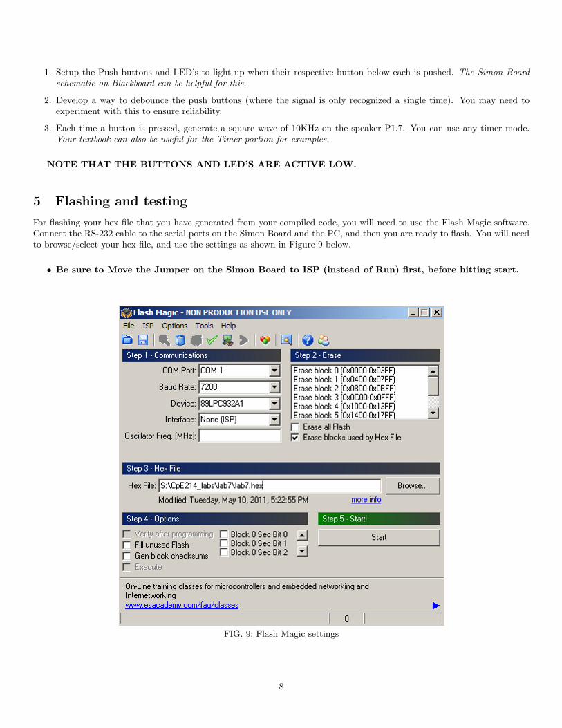
For flashing your hex file that you have generated from your compiled code, you will need to use the Flash Magic software.Connect the RS-232 cable to the serial ports on the Simon Board and the PC, and then you are ready to flash. You will needto browse/select your hex file, and use the settings as shown in Figure 9 below.
• Be sure to Move the Jumper on the Simon Board to ISP (instead of Run) first, before hitting start.
FIG. 9: Flash Magic settings
8

6 Questions (attach at end of your report)
1. Discuss what you should consider before choosing a port mode configuration (push-pull, bi-directional, open-drain,input only).
2. List a few things you should always check before writing software routines for an 8051 (or any platform) embeddeddevice.
3. Discuss how you would implement a function that sends different tones through the speaker on the board, based upona given button press.
Reference: P89LPC932A1 User Manual. c© Koninklijke Philips Electronics N.V. 2004. All rights reserved.
9
Related Documents