Lab 13: Controls (Part 2)

Welcome message from author
This document is posted to help you gain knowledge. Please leave a comment to let me know what you think about it! Share it to your friends and learn new things together.
Transcript
Lab 13: Controls (Part 2)
Controller SYSTEMSET
OPEN LOOP
OUTPUT

CLOSED LOOP
Controller SYSTEM
Sensor
Errorsignal
Reference
MEASURE
COMPARE
COMPUTE & CORRECT
T
F

HYSTERETIC CONTROLLER: ON or OFF

The control signal does not have to be Boolean T/F or ON/OFF
Error signal has magnitude/phase information
Controller SYSTEM
Sensor
Errorsignal
Reference
MEASURE
COMPARE
COMPUTE & CORRECT
DBL
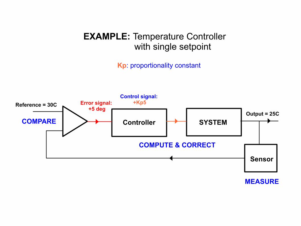
EXAMPLE: Temperature Controller with single setpoint
Controller SYSTEM
Sensor
Error signal: +5 deg
Reference = 30C
MEASURE
COMPARE
COMPUTE & CORRECT
Output = 25C
Control signal: +Kp5
Kp: proportionality constant

Controller SYSTEM
Sensor
Error signal: −2 deg
Reference = 30C
MEASURE
COMPARE
COMPUTE & CORRECT
Output = 32C
Kp: proportionality constant
Control signal: −Kp2
EXAMPLE: Temperature Controller with single setpoint
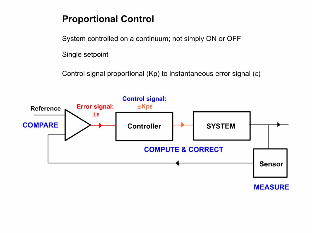
Proportional Control
System controlled on a continuum; not simply ON or OFF
Single setpoint
Control signal proportional (Kp) to instantaneous error signal (ε)
Controller SYSTEM
Sensor
Error signal: ±ε
Reference
MEASURE
COMPARE
COMPUTE & CORRECT
Control signal: ±Kpε
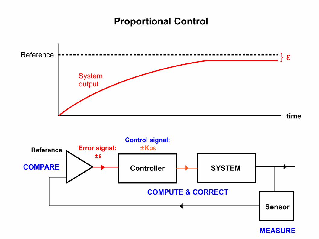
Proportional Control
Controller SYSTEM
Sensor
Error signal: ±ε
Reference
MEASURE
COMPARE
COMPUTE & CORRECT
Control signal: ±Kpε
time
Reference
Systemoutput
ε
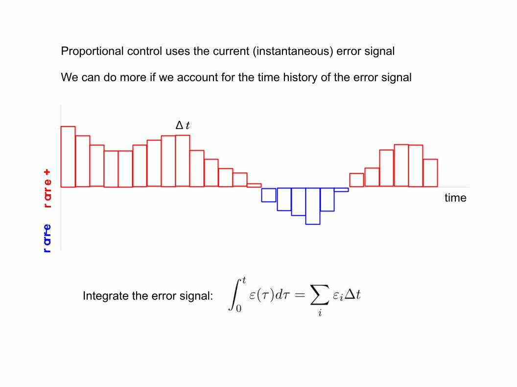
Proportional control uses the current (instantaneous) error signal
We can do more if we account for the time history of the error signal
time
+ erro
r− erro
r
Integrate the error signal:
∆ t

time
Reference
Control Signal: Proportional + Integral
Example system output
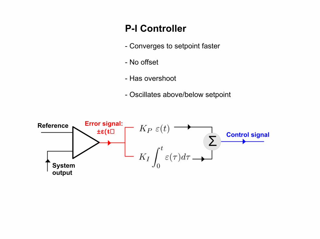
P-I Controller
- Converges to setpoint faster
- No offset
- Has overshoot
- Oscillates above/below setpoint
Error signal: ±ε(t)
Reference
Systemoutput
Σ Control signal
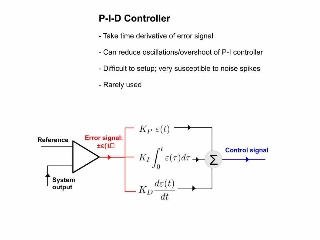
P-I-D Controller
- Take time derivative of error signal
- Can reduce oscillations/overshoot of P-I controller
- Difficult to setup; very susceptible to noise spikes
- Rarely used
Error signal: ±ε(t)
Reference
Systemoutput
ΣControl signal
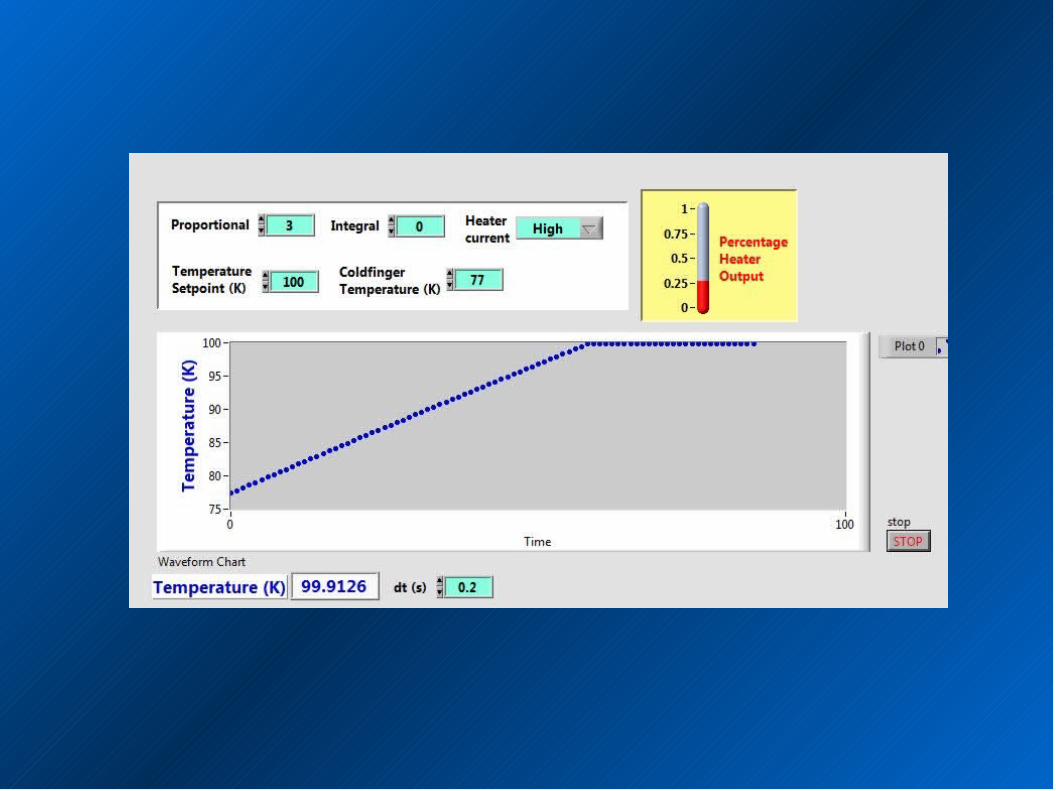
Next LabView assignment: Modify the Thermostat VI to do P-I control
Use the same heater2.vi from the class website inside While Loop (Wait time = dt)Heater current now controlled by P-IOne temperature setpointUse shift-register summation for integralHeater current has 3 selectable levels: 0.1 (Low), 0.5 (Medium), or 1 (High)Display real-time temperature data on Waveform ChartInclude heater current indicator
Program logic must handle two new issues due to P-I control:1) Negative control signal ⇒ Force heater current to zero2) Control signal greater than current capacity ⇒ Clamp at max current
This VI will perform P-I temperature control in next week's lab
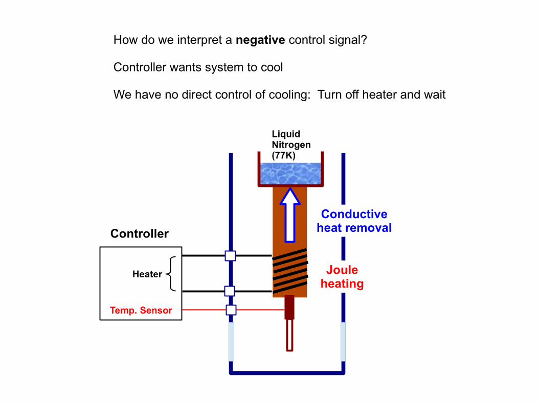
LiquidNitrogen (77K)
Controller
Heater
Temp. Sensor
Jouleheating
Conductiveheat removal
How do we interpret a negative control signal?
Controller wants system to cool
We have no direct control of cooling: Turn off heater and wait

About this week's lab
Assigned LabView program will control a resistive heater
VI will be heavily modified for DAQmx input and output
Remove heater2.vi, shift register, ambient temperature, etc
Change units from degrees K to degrees C
Cooling will be primarily convective, but not ideal
Ohmicheating

Convective cooling
About this week's lab
Assigned LabView program will control a resistive heater
VI will be heavily modified for DAQmx input and output
Remove heater2.vi, shift register, ambient temperature, etc
Change units from degrees K to degrees C
Cooling will be primarily convective, but not ideal
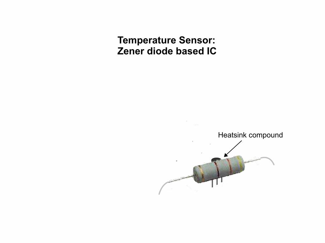
Temperature Sensor:Zener diode based IC
Heatsink compound
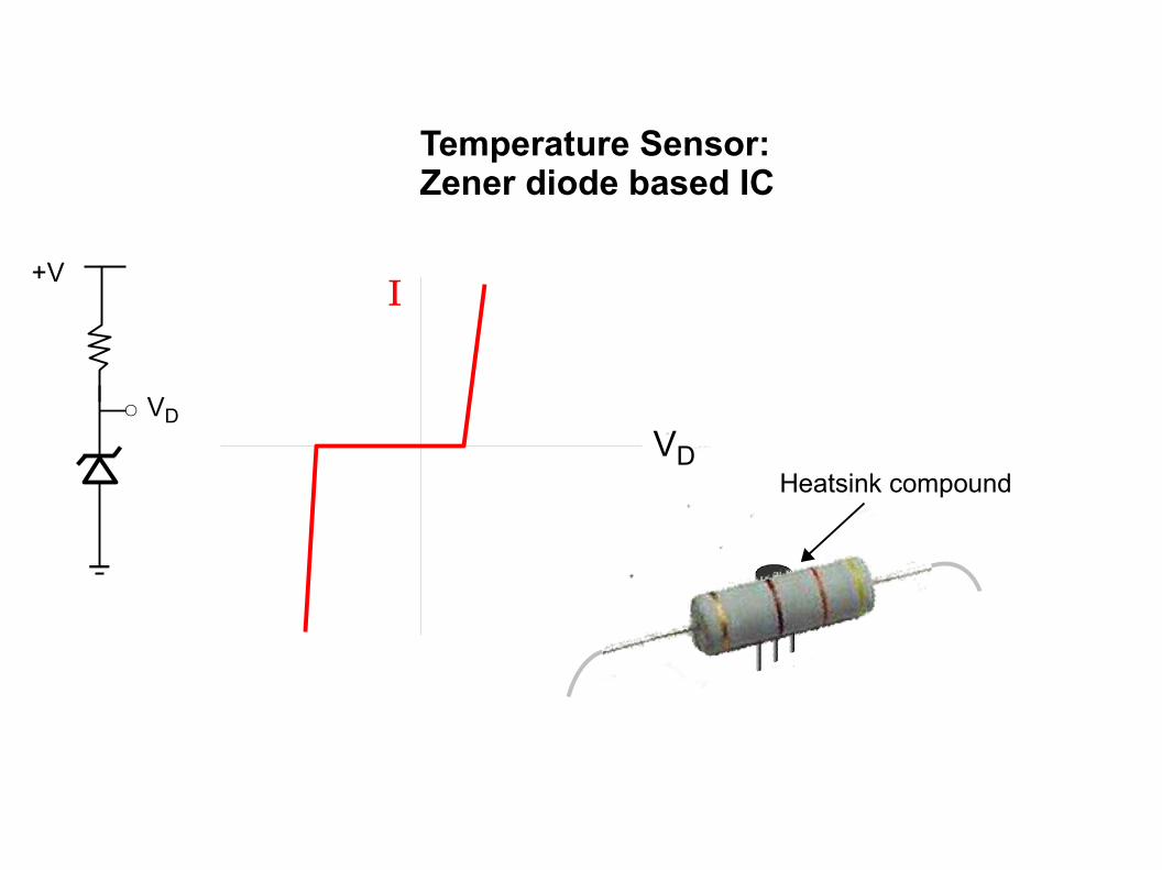
Temperature Sensor:Zener diode based IC
Heatsink compound
+V
VD
I
VD
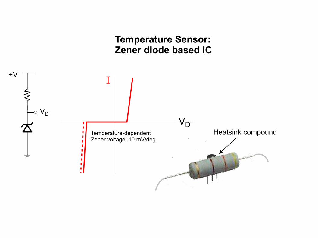
Temperature Sensor:Zener diode based IC
Heatsink compound
+VI
Temperature-dependentZener voltage: 10 mV/deg
VD
VD
Related Documents