December 2013 DocID18343 Rev 2 1/22 AN3327 Application note L9942 back EMF stall detection algorithm Introduction The L9942 is an integrated stepper motor driver for bipolar stepper motors used primarily in automotive head lamp leveling. The L9942 can easily be used for other stepper motor type operations as well. Anything from adaptive head lamp leveling and HVAC blend door actuator control to EGR valve and throttle control applications can take advantage of the features found in the L9942. In each of these applications, stall detection is desired to determine the extreme end of travel positions or severe fault situations. This application note explains the advantages of sensing Back Electro-Motive Force (back EMF or BEMF) as a method for determining rotor or armature stall conditions. While this method can be used in all methods of driving a stepper motor (full, half, and microstepping), the focus of this application note is on sensing a stalled rotor during microstepping. An overview and detailed discussion on the implementation of the L9942 (application schematics and so on) can be found in the ST Microelectronics ® application note AN2650 (see Appendix A: Reference document). www.st.com

Welcome message from author
This document is posted to help you gain knowledge. Please leave a comment to let me know what you think about it! Share it to your friends and learn new things together.
Transcript

December 2013 DocID18343 Rev 2 1/22
AN3327Application note
L9942 back EMF stall detection algorithm
IntroductionThe L9942 is an integrated stepper motor driver for bipolar stepper motors used primarily in automotive head lamp leveling. The L9942 can easily be used for other stepper motor type operations as well. Anything from adaptive head lamp leveling and HVAC blend door actuator control to EGR valve and throttle control applications can take advantage of the features found in the L9942.
In each of these applications, stall detection is desired to determine the extreme end of travel positions or severe fault situations. This application note explains the advantages of sensing Back Electro-Motive Force (back EMF or BEMF) as a method for determining rotor or armature stall conditions. While this method can be used in all methods of driving a stepper motor (full, half, and microstepping), the focus of this application note is on sensing a stalled rotor during microstepping.
An overview and detailed discussion on the implementation of the L9942 (application schematics and so on) can be found in the ST Microelectronics® application note AN2650 (see Appendix A: Reference document).
www.st.com

Contents AN3327
2/22 DocID18343 Rev 3
Contents
1 The L9942 microstepping . . . . . . . . . . . . . . . . . . . . . . . . . . . . . . . . . . . . . 5
2 Universal motor concepts . . . . . . . . . . . . . . . . . . . . . . . . . . . . . . . . . . . . 7
2.1 Universal motor concepts applied to stepper motors . . . . . . . . . . . . . . . . . 8
3 L9942 stall detection methods . . . . . . . . . . . . . . . . . . . . . . . . . . . . . . . . 10
3.1 Current sensing . . . . . . . . . . . . . . . . . . . . . . . . . . . . . . . . . . . . . . . . . . . . 10
3.2 BEMF detection explained . . . . . . . . . . . . . . . . . . . . . . . . . . . . . . . . . . . . .11
3.2.1 BEMF on a stepper motor . . . . . . . . . . . . . . . . . . . . . . . . . . . . . . . . . . . 13
3.2.2 BEMF in a stalled motor . . . . . . . . . . . . . . . . . . . . . . . . . . . . . . . . . . . . 14
4 Statistical analysis of BEMF detection . . . . . . . . . . . . . . . . . . . . . . . . . 15
5 Limitations . . . . . . . . . . . . . . . . . . . . . . . . . . . . . . . . . . . . . . . . . . . . . . . . 18
6 Conclusion . . . . . . . . . . . . . . . . . . . . . . . . . . . . . . . . . . . . . . . . . . . . . . . . 19
Appendix A Reference document . . . . . . . . . . . . . . . . . . . . . . . . . . . . . . . . . . . . . 20
Revision history . . . . . . . . . . . . . . . . . . . . . . . . . . . . . . . . . . . . . . . . . . . . . . . . . . . . 21

DocID18343 Rev 3 3/22
Document alternate name List of tables
3
List of tables
Table 1. Document revision history . . . . . . . . . . . . . . . . . . . . . . . . . . . . . . . . . . . . . . . . . . . . . . . . . 21
List of figures Document alternate name
4/22 DocID18343 Rev 3
List of figures
Figure 1. L9942 microstepping mode . . . . . . . . . . . . . . . . . . . . . . . . . . . . . . . . . . . . . . . . . . . . . . . . . 5Figure 2. L9942 current regulation block diagram . . . . . . . . . . . . . . . . . . . . . . . . . . . . . . . . . . . . . . . . 6Figure 3. Phase shift in an unloaded motor . . . . . . . . . . . . . . . . . . . . . . . . . . . . . . . . . . . . . . . . . . . . . 8Figure 4. A partially loaded motor note the phase shift of the BEMF. . . . . . . . . . . . . . . . . . . . . . . . . . 9Figure 5. A fully loaded motor . . . . . . . . . . . . . . . . . . . . . . . . . . . . . . . . . . . . . . . . . . . . . . . . . . . . . . . 9Figure 6. Typical motor phase winding components . . . . . . . . . . . . . . . . . . . . . . . . . . . . . . . . . . . . . 10Figure 7. Back EMF and phase current . . . . . . . . . . . . . . . . . . . . . . . . . . . . . . . . . . . . . . . . . . . . . . . 11Figure 8. Back EMF waveforms on an active stepper motor . . . . . . . . . . . . . . . . . . . . . . . . . . . . . . . 12Figure 9. Unloaded motor driven in full step mode . . . . . . . . . . . . . . . . . . . . . . . . . . . . . . . . . . . . . . 13Figure 10. A loaded motor driven in full step mode . . . . . . . . . . . . . . . . . . . . . . . . . . . . . . . . . . . . . . . 13Figure 11. Motor in hard stall . . . . . . . . . . . . . . . . . . . . . . . . . . . . . . . . . . . . . . . . . . . . . . . . . . . . . . . . 14Figure 12. Two instances where the motor is in stall but allowed to "vibrate" . . . . . . . . . . . . . . . . . . . 14Figure 13. Simplified block diagram of back EMF detection circuit . . . . . . . . . . . . . . . . . . . . . . . . . . . 15Figure 14. BEMF histogram of an unloaded motor at 20C . . . . . . . . . . . . . . . . . . . . . . . . . . . . . . . . . 15Figure 15. Combined histograms of an unloaded and stalled motor at both hot and cold. . . . . . . . . . 16Figure 16. Histogram of stall detection times in one motor (right is a zoom of the left) . . . . . . . . . . . . 17

DocID18343 Rev 3 5/22
AN3327 The L9942 microstepping
19
1 The L9942 microstepping
The L9942 stepper motor controller has full step, half step and micro-stepping modes. The micro-stepping mode provides for 32 programmable current regulated steps over 360° electrical. That translates to 8 different levels of current per quadrant.
Figure 1. L9942 microstepping mode
Each step current is regulated by PWM control. The PWM on-time is fixed by an oscillator. The off-time is set by the current measured. An internal current mirror feedback provided from the high side switches is compared to a preset (programmable) current value through a look-up table. When the current in the phase matches the value in the look-up table the phase is turned off until the next PWM on-time. As a result a current sine wave is approximated in 32 steps through PWM control of the outputs. This also applies to half step and full step modes of operation as well.

The L9942 microstepping AN3327
6/22 DocID18343 Rev 3
Figure 2. L9942 current regulation block diagram

DocID18343 Rev 3 7/22
AN3327 Universal motor concepts
19
2 Universal motor concepts
Motor voltage can be expressed in an equation consisting of three components, Resistive, Electro-motive, and Inductive.
Equation 1
The Resistive component (RWindings) plays a big part in determining what stall current to expect. When the motor is not spinning the only thing limiting the current is the winding resistance.
The inductance of a motor (LWindings) is taken advantage of when PWM signal is applied. The inductance allows for a constant or smooth phase current when the PWM frequency is set such that the inductance supports the current in the windings during the PWM off-time.
The BEMF is the voltage that is generated by the motor as the permanent magnet armature spins inside (or around) the stator. As the rotor spins the windings experience a changing magnetic field. This changing magnetic field generates the BEMF voltage that is directly related to the speed of the changing field.
There are two universal concepts in motors that are always true The first is that BEMF is directly proportional to armature speed and really, nothing else. The back EMF equations spell this out quite clearly:
Equation 2
Where:
• N is the number of coil turns
• B represents the magnetic field
• A the area encompassed by the motor magnetic field
• ω is the angular speed
Notice that N, B, and A are all constants specific to the motor construction. They do not change. The end result is that Back EMF (emf) is directly proportional to motor speed (ωt).
The next universal concept is the relationship between motor torque and motor current. Again, the equations describe this clearly:
Equation 3
VMotor iMotor RWindings BEMF LWindings
diMotor
dt-----------------+ +⋅=
bemf N– B A ω ωt( )sin⋅ ⋅ ⋅ ⋅=
T pN2π--------θI=

Universal motor concepts AN3327
8/22 DocID18343 Rev 3
Where:
• N is the number of coil turns
• P is the number of poles
• θ is the flux
Note again that current (I) and torque (T) are directly proportional to each other. There are other factors that affect current like the temperature and resistivity of copper. Copper resistivity improves the torque potential (at cold) or limit the torque potential (at hot) but it does not change the torque-to-current relationship.
2.1 Universal motor concepts applied to stepper motorsA stepper motor is typically a fixed current system. That is, the controller feeds a fixed set of currents at a rotational velocity that is directly reflected by the rotor. If a fixed current into a motor produce a fixed torque how can a stepper motor have a fixed current and rotate at a fixed speed for a wide range of loads or torques? The answer is in the phasing, automatically, of the back EMF with respect to the drive current.
The current generates the torque based on the aforementioned equations. What direction that torque are applied depend on the external load. A lightly loaded stepper motor has a small portion of the torque actually driving the load. A good portion of the motor torque is used trying to slow the motor down. To never go above the commanded rotational speed the current is first driving the motor to go faster and then braking it to go slower. The overall torque coming out the output shaft is zero for an unloaded motor.
In Figure 3 the back EMF is representing Rotor position. Rotor position is also an indication of where the rotor magnetic field is in relation to the stator magnetic field. The rotor magnetic field is fixed to the rotor and rotates with it. The stator field is related to the current in the stator. A "positive" current creates a "positive" field and vice versa.
Figure 3. Phase shift in an unloaded motor
As the motor is loaded the Back EMF shifts to convert more of the torque to forward motion.

DocID18343 Rev 3 9/22
AN3327 Universal motor concepts
19
Figure 4. A partially loaded motor note the phase shift of the BEMF
In a partially loaded motor, the back EMF has shifted to increase the percentage of driving torque over the braking torque. This shift continues as external loading is increased until the loading exceeds the potential torque capability. At that point the synchronization between electrical rotation and mechanical rotation ceases and the motor stalls.
Figure 5. A fully loaded motor
1. Note the complete alignment of current and BEMF.
In a fully loaded motor the moment that the torque demand causes the back EMF to shift any further, the output torque decreases. Then the motor stops rotating.

L9942 stall detection methods AN3327
10/22 DocID18343 Rev 3
3 L9942 stall detection methods
3.1 Current sensingThe L9942 has as part of its feature set the ability to detect stall by looking at motor current rise time.
During stall, the motor current rises because the BEMF is absent. Lack of BEMF results in two effects. First, it increases the potential current in a winding at a given voltage per Ohm's law. Secondly, it increases the rate of change of the current in the windings because the rate of change of current in an inductor is proportional to the voltage across the inductor. With little or no BEMF in a motor winding the current both raises and raises quickly.
Figure 6. Typical motor phase winding components
However, the L9942 regulates the motor phase current by turning off the phase when the preprogrammed current threshold is reached. As a result the motor current does not spike when the motor is stalled. The duty cycle reduces to something fairly small as the current control algorithm compensates for the loss of BEMF. So then the L9942 detects a loss of BEMF by observing and reporting an abnormally low duty cycle for a given commanded current.
The difficulty with this method is that there are many motor current related parameters that can move around in the normal operating space of a stepper motor. Things like temperature, battery voltage and loading or torque can have a dramatic affect on the current regulation duty cycle. Unfortunately, the operating point at one end of the normal spectrum can look like a stalled motor at the other end. Overlapping parameters makes it difficult at best to safely discern a stalled rotor.
To minimize the effects of motor resistance, battery voltage, and temperature the stall detection algorithm can look directly at BEMF.

DocID18343 Rev 3 11/22
AN3327 L9942 stall detection methods
19
3.2 BEMF detection explainedComparing the coil current and the induced BEMF voltage of one stepper phase during non-stalled operation, it can be seen that there is a phase difference of 90° in between the current and the BEMF voltage.
Figure 7. Back EMF and phase current
The BEMF stall detection algorithm takes advantage of this phenomenon. When the motor current is transitioning from one polarity to the other there is one step that is typically programmed at zero Amps. As a result checking for BEMF when the step current is zero does not interfere with the control of the motor.

L9942 stall detection methods AN3327
12/22 DocID18343 Rev 3
Figure 8. Back EMF waveforms on an active stepper motor
In an unloaded motor winding at the points where the current is at or near zero the BEMF is the strongest.
The concern comes when you consider the effects of motor loading on the phasing of the BEMF. Since this algorithm only looks for BEMF when the phase is not being driven there is a very short window to "look". As the motor is loaded the BEMF shifts such that it is more in line with the driving voltage/current. As a result, motor loading adds some variation to the BEMF detection. A fully loaded motor just on the edge of stall looks to be the same as a fully stalled motor. Fortunately a stepper motor is not intended to be driven with that much load.

DocID18343 Rev 3 13/22
AN3327 L9942 stall detection methods
19
3.2.1 BEMF on a stepper motor
To more easily see the effects of torque on back EMF the following is a look at a motor driven in full step mode. Figure 9 below illustrates an unloaded motor being driven in full step mode. The red is the current while the purple is the voltage on the phase. The thin black line estimates the back EMF.
Figure 9. Unloaded motor driven in full step mode
In an unloaded motor (Figure 9) the Back EMF leads the phase current. This indicates that there is more energy provided by the rotating magnetic field, than is mandatory to keep the rotation of the rotor. The irregular shape of the back EMF voltage indicates that there is rotational acceleration and deceleration through a 360° cycle.
In a motor with a higher load level (Figure 10) the Back EMF signal is more aligned to the actual driver signal. In other words the phase difference in between the cause and the effect is smaller. If the load is increased above a certain level there may occur step loss while driving the motor.
Figure 10. A loaded motor driven in full step mode
Systems that use stepper motors severely overdrive their motors to ensure that they never, under all normal operating conditions, stall.

L9942 stall detection methods AN3327
14/22 DocID18343 Rev 3
3.2.2 BEMF in a stalled motor
Comparing Figure 9 and Figure 10 with a stalled rotor waveform (Figure 11) illustrates the difference between a stalled and a running motor. Again these figures are done using a full stepped motor to better illustrate the BEMF during these conditions.
Figure 11. Motor in hard stall
Figure 11 shows virtually no back EMF during the non driven intervals. This is understood, as BEMF is a direct result of rotor movement. If there is some movement in the stalled rotor then the BEMF becomes visible (Figure 12). Figure 12 illustrates the irregular nature of the BEMF in a "loosely" stalled motor.
Figure 12. Two instances where the motor is in stall but allowed to "vibrate"
Comparing these waveforms with the previous running waveforms we can see that there is some overlap. Of course Figure 12 shows the behavior of a full step mode driven motor.

DocID18343 Rev 3 15/22
AN3327 Statistical analysis of BEMF detection
19
4 Statistical analysis of BEMF detection
The following simplified block diagram (Figure 13) illustrates a BEMF detection system for a given motor in micro-step mode. This system checks for BEMF synchronously with the stepper motor phasing.
Figure 13. Simplified block diagram of back EMF detection circuit
With a microprocessor Analog to Digital sampling several thousand BEMF readings could be obtained in a short period of time. From that information a histogram of the values was generated. This provided an understanding as to what to expect.
For the following histograms the L9942 was used as shown with an 8 bit microcontroller. The step clock frequency for the L9942 was set at 2 kHz, and the peak current in micro-stepping mode was set to 400 mA.
Each ADC sample was taken right at the end of the zero current step. This ensured the most consistent BEMF readings.
Figure 14. BEMF histogram of an unloaded motor at 20C
Statistical analysis of BEMF detection AN3327
16/22 DocID18343 Rev 3
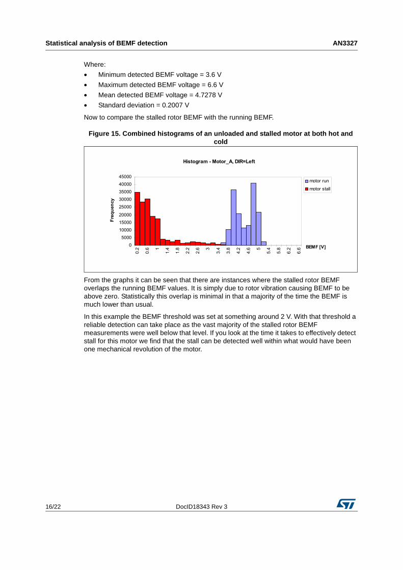
Where:
• Minimum detected BEMF voltage = 3.6 V
• Maximum detected BEMF voltage = 6.6 V
• Mean detected BEMF voltage = 4.7278 V
• Standard deviation = 0.2007 V
Now to compare the stalled rotor BEMF with the running BEMF.
Figure 15. Combined histograms of an unloaded and stalled motor at both hot and cold
From the graphs it can be seen that there are instances where the stalled rotor BEMF overlaps the running BEMF values. It is simply due to rotor vibration causing BEMF to be above zero. Statistically this overlap is minimal in that a majority of the time the BEMF is much lower than usual.
In this example the BEMF threshold was set at something around 2 V. With that threshold a reliable detection can take place as the vast majority of the stalled rotor BEMF measurements were well below that level. If you look at the time it takes to effectively detect stall for this motor we find that the stall can be detected well within what would have been one mechanical revolution of the motor.

DocID18343 Rev 3 17/22
AN3327 Statistical analysis of BEMF detection
19
Figure 16. Histogram of stall detection times in one motor (right is a zoom of the left)
A "current period" is defined as the time duration to make one full 360° electrical rotation. For this example that translates to stepping 32 times at 2 kHz or 16 ms. Within 10 half periods, or 80 ms, stall was detected 100% of the time.
Limitations AN3327
18/22 DocID18343 Rev 3
5 Limitations
These cases compare an unloaded motor with a stalled motor. The differences between these two states are dramatic and easily detectable. From the above analysis we can see that a loaded motor causes the detected BEMF thresholds to droop as the BEMF shifts to be more aligned with current. This drooping must be taken into account when considering an acceptable stall threshold. For every application there is a maximum expected torque requirement for an application. This maximum torque requirement must be taken into account when determining the BEMF stall threshold.
Other things that might limit this method include a loose or spongy transmission or “soft” stall where the rotor is allowed to "bounce". These limitations are even more difficult to overcome in the current / duty cycle methodology. Because the BEMF sensing is done externally to the IC this limitation can be overcome to some extent with a statistical method discerning the stall threshold.

DocID18343 Rev 3 19/22
AN3327 Conclusion
19
6 Conclusion
The BEMF method for detecting stall can be reliable and cost effective. This method uses motor parameters that change little with time or temperature. As a result it overcomes many of the limitations found in the more traditional stall detection method of current / duty cycle sensing.

Reference document AN3327
20/22 DocID18343 Rev 3
Appendix A Reference document
• L9942 stepper motor driver for bipolar stepper motors (AN2650, Doc ID 14109).

DocID18343 Rev 3 21/22
AN3327 Revision history
21
Revision history
Table 1. Document revision history
Date Revision Changes
03-Feb-2012 1 Initial release.
19-Sep-2013 2 Updated Disclaimer.
04-Dec-2013 3 Updated Chapter 4.

AN3327
22/22 DocID18343 Rev 3
Please Read Carefully:
Information in this document is provided solely in connection with ST products. STMicroelectronics NV and its subsidiaries (“ST”) reserve the right to make changes, corrections, modifications or improvements, to this document, and the products and services described herein at any time, without notice.
All ST products are sold pursuant to ST’s terms and conditions of sale.
Purchasers are solely responsible for the choice, selection and use of the ST products and services described herein, and ST assumes no liability whatsoever relating to the choice, selection or use of the ST products and services described herein.
No license, express or implied, by estoppel or otherwise, to any intellectual property rights is granted under this document. If any part of this document refers to any third party products or services it shall not be deemed a license grant by ST for the use of such third party products or services, or any intellectual property contained therein or considered as a warranty covering the use in any manner whatsoever of such third party products or services or any intellectual property contained therein.
UNLESS OTHERWISE SET FORTH IN ST’S TERMS AND CONDITIONS OF SALE ST DISCLAIMS ANY EXPRESS OR IMPLIED WARRANTY WITH RESPECT TO THE USE AND/OR SALE OF ST PRODUCTS INCLUDING WITHOUT LIMITATION IMPLIED WARRANTIES OF MERCHANTABILITY, FITNESS FOR A PARTICULAR PURPOSE (AND THEIR EQUIVALENTS UNDER THE LAWS OF ANY JURISDICTION), OR INFRINGEMENT OF ANY PATENT, COPYRIGHT OR OTHER INTELLECTUAL PROPERTY RIGHT.
ST PRODUCTS ARE NOT DESIGNED OR AUTHORIZED FOR USE IN: (A) SAFETY CRITICAL APPLICATIONS SUCH AS LIFE SUPPORTING, ACTIVE IMPLANTED DEVICES OR SYSTEMS WITH PRODUCT FUNCTIONAL SAFETY REQUIREMENTS; (B) AERONAUTIC APPLICATIONS; (C) AUTOMOTIVE APPLICATIONS OR ENVIRONMENTS, AND/OR (D) AEROSPACE APPLICATIONS OR ENVIRONMENTS. WHERE ST PRODUCTS ARE NOT DESIGNED FOR SUCH USE, THE PURCHASER SHALL USE PRODUCTS AT PURCHASER’S SOLE RISK, EVEN IF ST HAS BEEN INFORMED IN WRITING OF SUCH USAGE, UNLESS A PRODUCT IS EXPRESSLY DESIGNATED BY ST AS BEING INTENDED FOR “AUTOMOTIVE, AUTOMOTIVE SAFETY OR MEDICAL” INDUSTRY DOMAINS ACCORDING TO ST PRODUCT DESIGN SPECIFICATIONS. PRODUCTS FORMALLY ESCC, QML OR JAN QUALIFIED ARE DEEMED SUITABLE FOR USE IN AEROSPACE BY THE CORRESPONDING GOVERNMENTAL AGENCY.
Resale of ST products with provisions different from the statements and/or technical features set forth in this document shall immediately void any warranty granted by ST for the ST product or service described herein and shall not create or extend in any manner whatsoever, any liability of ST.
ST and the ST logo are trademarks or registered trademarks of ST in various countries.Information in this document supersedes and replaces all information previously supplied.
The ST logo is a registered trademark of STMicroelectronics. All other names are the property of their respective owners.
© 2013 STMicroelectronics - All rights reserved
STMicroelectronics group of companies
Australia - Belgium - Brazil - Canada - China - Czech Republic - Finland - France - Germany - Hong Kong - India - Israel - Italy - Japan - Malaysia - Malta - Morocco - Philippines - Singapore - Spain - Sweden - Switzerland - United Kingdom - United States of America
www.st.com
Related Documents