L800/L801 Color Inkjet Printer SEMF10-008 SERVICE MANUAL Confidential

Welcome message from author
This document is posted to help you gain knowledge. Please leave a comment to let me know what you think about it! Share it to your friends and learn new things together.
Transcript

0/L801
or Inkjet Printer
SE MANUAL
L80
Col
RVICE
SEMF10-008Confidential

Confidential
A eans, electronic, mechanical, photocopying, rA EPSON would greatly appreciate being iTT onsequences thereof.
EPS
Note ks of their respective owners. EPSON dis-
Cop
Notice:ll rights reserved. No part of this manual may be reproduced, stored in a retrieval system, or transmitted in any form or by any m
ecording, or otherwise, without the prior written permission of SEIKO EPSON CORPORATION.ll effort have been made to ensure the accuracy of the contents of this manual. However, should any errors be detected, SEIKO
nformed of them.he contents of this manual are subject to change without notice.he above not withstanding SEIKO EPSON CORPORATION can assume no responsibility for any errors in this manual or the c
ON is a registered trademark of SEIKO EPSON CORPORATION.
:Other product names used herein are for identification purpose only and may be trademarks or registered trademarclaims any and all rights in those marks.
yright 2011 SEIKO EPSON CORPORATIONI&I CS Quality Assurance Department

Confidential
All s .
Stricserio1. A
d2. W
pcctc
ARNINGautions. Failure to comply may lead to personal
gles for disassembly and reassembly to protect ng. If any ink gets in your eyes, wash your eyes lt a doctor immediately. products; such as air duster, for cleaning ce, the use of such products containing .
Safety Precautionsafety procedures described here shall be strictly adhered to by all parties servicing and maintaining this product
DANGERtly observe the following cautions. Failure to comply could result in us bodily injury or loss of life.lways disconnect the product from the power source and peripheral evices when servicing the product or performing maintenance.hen performing works described in this manual, do not connect to a
ower source until instructed to do so. Connecting to a power source auses high voltage in the power supply unit and some electronic omponents even if the product power switch is off. If you need to perform he work with the power cable connected to a power source, use extreme aution to avoid electrical shock.
WStrictly observe the following cinjury or loss of life.1. Always wear protective gog
your eyes from ink in workiwith clean water and consu
2. When using compressed airduring repair and maintenanflammable gas is prohibited

Confidential
Stric
1. Rr
2. Nb
3. Tpd
4. RoaE
5. Idi
6. Dpfc
7. Nch
8. Wt
9. Ut
10. O
ratch or contaminate the following parts.
ler
han those specified in this manual. Use of may damage the component or give bad n.
grease described in this manual.
s when you disassemble the printer.
llow the procedure described in this manual.
t after filling the ink in the printhead, pack he ink cartridges in order to prevent the
oftware in the computers used for the
ntivirus software up-to-date.
PRECAUTIONS
tly observe the following cautions. Failure to comply may lead to personal injury or damage of the product.
epairs on Epson product should be performed only by an Epson certified epair technician.o work should be performed on this product by persons unfamiliar with asic safety knowledge required for electrician.he power rating of this product is indicated on the serial number/rating late. Never connect this product to the power source whose voltages is ifferent from the rated voltage.eplace malfunctioning components only with those components provided r approved by Epson; introduction of second-source ICs or other non-pproved components may damage the product and void any applicable pson warranty.
n order to protect sensitive microprocessors and circuitry, use static ischarge equipment, such as anti-static wrist straps, when accessing nternal components.o not tilt this product immediately after initial ink charge, especially after erforming the ink charge several times. Doing so may cause ink to leak rom the product because it may take some time for the waste ink pads to ompletely absorb ink wasted due to the ink charge.ever touch the ink or wasted ink with bare hands. If ink comes into
ontact with your skin, wash it off with soap and water immediately. If you ave a skin irritation, consult a doctor immediately.hen disassembling or assembling this product, make sure to wear gloves
o avoid injuries from metal parts with sharp edges.se only recommended tools for disassembling, assembling or adjusting
he printer.bserve the specified torque when tightening screws.
11. Be extremely careful not to sc
Nozzle plate of the printhead
CR Scale
PF Scale
Coated surface of the PF Rol
Gears
Rollers
Exterior parts
12. Never use oil or grease other tdifferent types of oil or greaseinfluence on the printer functio
13. Apply the specified amount of
14. Make the specified adjustment
15. When cleaning this product, fo
16. When transporting this producthe printer without removing tprinthead from drying out.
17. Make sure to install antivirus sservice support activities.
18. Keep the virus pattern file of a
Confidential
This sary for properly performing maintenance and
CHDthp
CHD
CHD
CHP
•
•
•
ed in this Manual
out this manual either to provide additional o warn of possible danger present during a on to all symbols when they are used, and y and follow the instructions.
or maintenance procedure, practice or trictly observed, could result in serious
or maintenance procedure, practice, or trictly observed, could result in bodily
lfunction of equipment.
ting or maintenance procedure, practice or sary to accomplish a task efficiently. It may l information that is related to a specific n the results achieved through a previous
embly”, symbols other than indicated above ation for disassembly/reassembly. For the Disassembly/Reassembly Procedures
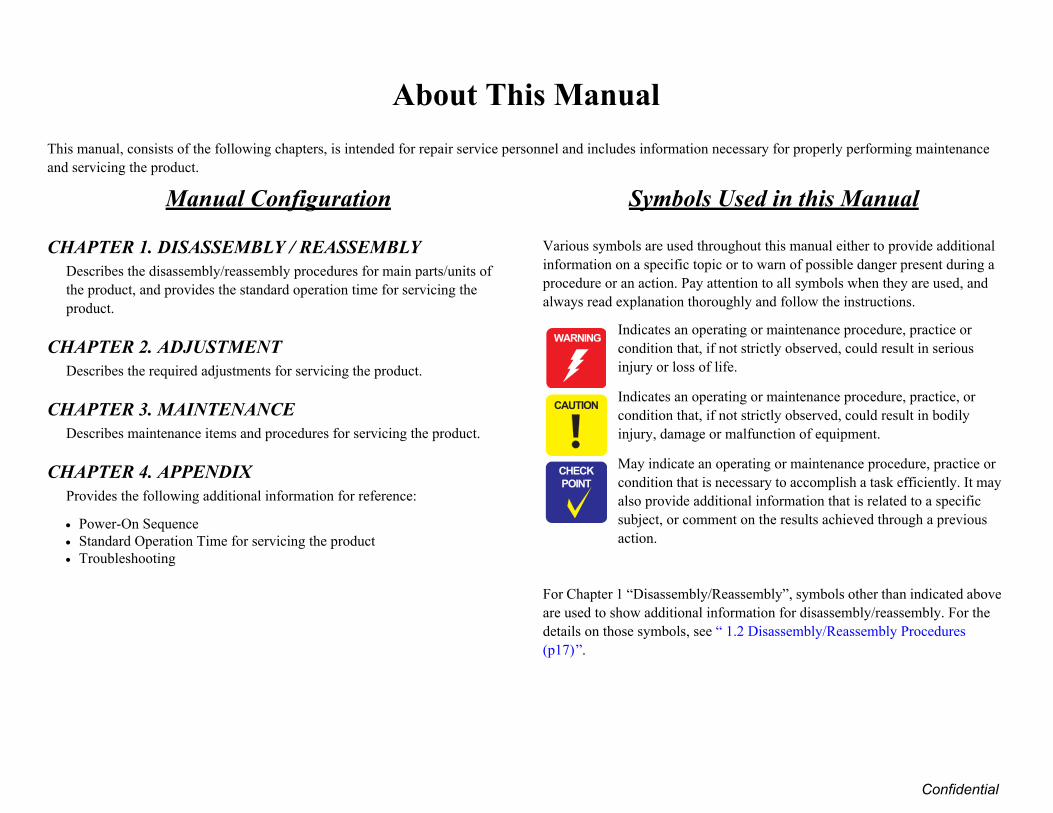
About This Manual manual, consists of the following chapters, is intended for repair service personnel and includes information necesservicing the product.
Manual Configuration
APTER 1. DISASSEMBLY / REASSEMBLYescribes the disassembly/reassembly procedures for main parts/units of e product, and provides the standard operation time for servicing the
roduct.
APTER 2. ADJUSTMENTescribes the required adjustments for servicing the product.
APTER 3. MAINTENANCEescribes maintenance items and procedures for servicing the product.
APTER 4. APPENDIXrovides the following additional information for reference:
Power-On SequenceStandard Operation Time for servicing the productTroubleshooting
Symbols Us
Various symbols are used throughinformation on a specific topic or tprocedure or an action. Pay attentialways read explanation thoroughl
Indicates an operatingcondition that, if not sinjury or loss of life.
Indicates an operatingcondition that, if not sinjury, damage or ma
May indicate an operacondition that is necesalso provide additionasubject, or comment oaction.
For Chapter 1 “Disassembly/Reassare used to show additional informdetails on those symbols, see “ 1.2(p17)”.
� � � � � � �
� � � � �
� � � �
� � �

Confidential
Revision StatusRevision Date of Issue Description
A April 6, 2011 First Release

L80 Revision A
7Confidential
Cha1.1 O
1.2 D
1.3 R
1.4 R
1.5 D
....................................................................... 52
....................................................................... 54
....................................................................... 56
....................................................................... 57
....................................................................... 57
....................................................................... 60
....................................................................... 61 Position Label ............................................. 61....................................................................... 61 Rear.............................................................. 62....................................................................... 62 / Right Cover / Cover Joint ......................... 63....................................................................... 64y .................................................................... 64....................................................................... 65....................................................................... 65e Sheet ........................................................... 66 Guide Sheet Sub........................................... 66....................................................................... 67....................................................................... 68....................................................................... 68
....................................................................... 70 List .............................................................. 70....................................................................... 74....................................................................... 77....................................................................... 77....................................................................... 77....................................................................... 78Position Adjustment ...................................... 79....................................................................... 80....................................................................... 81
0/L801
CONTENTSpter 1 Disassembly/Reassemblyverview ............................................................................................................ 10
1.1.1 Tools ........................................................................................................ 101.1.2 Checks and Precautions before Disassembling ....................................... 101.1.3 Protection for Transportation .................................................................. 141.1.4 Making a Special Tool for Holder Contact ............................................. 151.1.5 Orientation Definition ............................................................................. 161.1.6 How to Unlock the Carriage.................................................................... 16isassembly/Reassembly Procedures ................................................................ 17
1.2.1 Overview ................................................................................................. 171.2.2 Disassembly Flowchart ........................................................................... 18emoving Exterior Parts/Components ............................................................... 24
1.3.1 Printer Cover ........................................................................................... 241.3.2 Paper Support Assy ................................................................................. 241.3.3 Stacker Assy / Stacker Cover .................................................................. 251.3.4 Housing Upper Assy................................................................................ 25emoving Control Boards.................................................................................. 27
1.4.1 Main Board Unit...................................................................................... 271.4.2 Panel Assy/ Cover Open Sensor.............................................................. 301.4.3 P/S Assy................................................................................................... 34isassembling the Printer Mechanism ............................................................... 35
1.5.1 Removing the Printer Mechanism ........................................................... 351.5.2 Printhead.................................................................................................. 371.5.3 CR Scale .................................................................................................. 401.5.4 APG Unit ................................................................................................. 411.5.5 Waste Ink Tray ........................................................................................ 421.5.6 Waste Ink Pad Lower / Waste Ink Pad Cap Lower ................................. 431.5.7 Left & Right Guide Stackers / CDR Guide Sensor ................................. 441.5.8 Ink System ............................................................................................... 451.5.9 EJ Frame Assy ......................................................................................... 461.5.10 PF Encoder / PF Scale ........................................................................... 491.5.11 PF Motor................................................................................................ 491.5.12 CR Motor............................................................................................... 50
1.5.13 CR Unit...........................1.5.14 ASF Unit.........................1.5.15 Upper Paper Guide .........1.5.16 APG Sensor Assy ...........1.5.17 Front Paper Guide Assy .1.5.18 CDR Tray Sensor ...........
1.6 Disassembling the CISS section..1.6.1 Refilling Ink Label / Valve1.6.2 Top Cover.........................1.6.3 Tube Valve Holder Front /1.6.4 Valve Lever ......................1.6.5 Bottom Cover / Left Cover1.6.6 Ink Supply Tank Assy ......1.6.7 Ink Supply Tank Tube Ass1.6.8 Joint ..................................1.6.9 Cover Case .......................1.6.10 PF Scale Cover / PF Scal1.6.11 Tube Guide Sheet / Tube1.6.12 Ink Supply Tube Assy ....1.6.13 Adapter Cover ................1.6.14 Adapter ...........................
Chapter 2 Adjustment2.1 Adjustment Items and Overview.
2.1.1 Servicing Adjustment Item2.1.2 Required Adjustments ......
2.2 Using the Adjustment Program ...2.2.1 Top Margin Adjustment ...2.2.2 Head Angular Adjustment2.2.3 Bi-D Adjustment ..............2.2.4 PW Adjustment/First Dot 2.2.5 PF Adjustment ..................2.2.6 PG Adjustment .................

L80 Revision A
8Confidential
2.3 BC
Cha3.1 O
Cha4.1 P4.2 S4.3 T
0/L801
anding Reduction System (BRS) Adjustment / Paper Feed Amount Profile (PFP) orrection............................................................................................................ 832.3.1 Overview ................................................................................................. 832.3.2 Adjustment Procedure ............................................................................. 85
pter 3 Maintenanceverview ............................................................................................................ 89
3.1.1 Cleaning................................................................................................... 893.1.2 Service Maintenance ............................................................................... 893.1.3 Lubrication .............................................................................................. 90
pter 4 Appendixower-On Sequence ........................................................................................... 97tandard Operation Time for servicing the product ........................................... 99roubleshooting................................................................................................ 102
4.3.1 Troubleshooting Workflow ................................................................... 1024.3.2 Fatal Error Code .................................................................................... 104

Confidential
C H A P T E R
1DISAS BLY/REASSEMBLY
SEM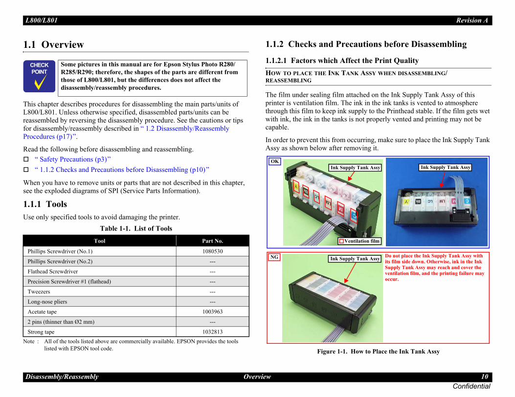
L80 Revision A
Dis 10Confidential
1.1
ThisL800reassfor dProc
Read““
Whesee t
1.1.Use
Note
tions before Disassembling
he Print QualitySSY WHEN DISASSEMBLING/
ed on the Ink Supply Tank Assy of this in the ink tanks is vented to atmosphere y to the Printhead stable. If the film gets wet properly vented and printing may not be
ing, make sure to place the Ink Supply Tank ng it.
to Place the Ink Tank Assy
� �
�
Phi
Phi
Fla
Pre
Tw
Lon
Ace
2 pi
Stro
k Assy
Ink Supply Tank Assyk Assy
on film
Do not place the Ink Supply Tank Assy with its film side down. Otherwise, ink in the Ink Supply Tank Assy may reach and cover the ventilation film, and the printing failure may occur.
0/L801
assembly/Reassembly Overview
Overview
chapter describes procedures for disassembling the main parts/units of /L801. Unless otherwise specified, disassembled parts/units can be embled by reversing the disassembly procedure. See the cautions or tips isassembly/reassembly described in “ 1.2 Disassembly/Reassembly edures (p17)”.
the following before disassembling and reassembling. Safety Precautions (p3)” 1.1.2 Checks and Precautions before Disassembling (p10)”
n you have to remove units or parts that are not described in this chapter, he exploded diagrams of SPI (Service Parts Information).
1 Toolsonly specified tools to avoid damaging the printer.
: All of the tools listed above are commercially available. EPSON provides the tools listed with EPSON tool code.
1.1.2 Checks and Precau
1.1.2.1 Factors which Affect tHOW TO PLACE THE INK TANK AREASSEMBLING
The film under sealing film attachprinter is ventilation film. The ink through this film to keep ink supplwith ink, the ink in the tanks is notcapable.
In order to prevent this from occurrAssy as shown below after removi
Figure 1-1. How
� �
� �
Some pictures in this manual are for Epson Stylus Photo R280/R285/R290; therefore, the shapes of the parts are different from those of L800/L801, but the differences does not affect the disassembly/reassembly procedures.
Table 1-1. List of Tools
Tool Part No.
llips Screwdriver (No.1) 1080530
llips Screwdriver (No.2) ---
thead Screwdriver ---
cision Screwdriver #1 (flathead) ---
eezers ---
g-nose pliers ---
tate tape 1003963
ns (thinner than Ø2 mm) ---
ng tape 1032813
Ink Supply Tan
Ink Supply Tan
Ventilati
OK
NG
L80 Revision A
Dis 11Confidential
1.1.2Ink Ink mThismini
THE
Note
SPILL
t the printer is in the following condition.
sure to close the Choke Valve.te:form the print inspection.o the user after repairing:ever up to the choke position to close the Choke
nter.
ng/closing the Choke Valve
oints described in this section, ink may situations. Therefore, be careful not to de of the printer or its surroundings by ner to receive the leaked ink, or the like. the Ink Supply Tank Tube Assy (w/e ink will spill from both ends of the lve Lever is closed.
the Ink Supply Tube Assy, all the ink in l.
e Lever too much when closing the ise, the Valve Lever and/or Valve Assy
alve Lever
on Choke position (When checking with the Valve Lever removed.)
Valve shaft
Choke Valve shaft is secured more tightly in Choke position than in Open position.
0/L801
assembly/Reassembly Overview
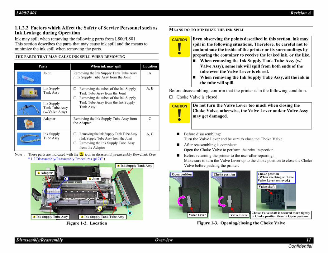
.2 Factors which Affect the Safety of Service Personnel such as Leakage during Operationay spill when removing the following parts from L800/L801.
section describes the parts that may cause ink spill and the means to mize the ink spill when removing the parts.
PARTS THAT MAY CAUSE INK SPILL WHEN REMOVING
: These parts are indicated with the icon in disassembly/reassembly flowchart. (See “ 1.2 Disassembly/Reassembly Procedures (p17)”.)
Figure 1-2. Location
MEANS DO TO MINIMIZE THE INK
Before disassembling, confirm thaChoke Valve is closed
Before disassembling:Turn the Valve Lever and beAfter reassembling is compleOpen the Choke Valve to perBefore returning the printer tMake sure to turn the Valve LValve before packing the pri
Figure 1-3. Openi
Parts When ink may spill Location
Joint Removing the Ink Supply Tank Tube Assy / Ink Supply Tube Assy from the Joint
A
Ink Supply Tank Assy
Removing the tubes of the Ink Supply Tank Tube Assy from the JointRemoving the tubes of the Ink Supply Tank Tube Assy from the Ink Supply Tank Assy
A, B
Ink Supply Tank Tube Assy(w/Valve Assy)
Adapter Removing the Ink Supply Tube Assy from the Adapter
C
Ink Supply Tube Assy
Removing the Ink Supply Tank Tube Assy / Ink Supply Tube Assy from the JointRemoving the Ink Supply Tube Assy from the Adapter
A, C
A
C
B
Joint
Ink Supply Tank Assy
Ink Supply Tank Tube Assy Ink Supply Tube Assy
Adapter
� � � � � Even observing the pspill in the followingcontaminate the insipreparing the contai
When removingValve Assy), somtube even the VaWhen removingthe tube will spil
� � � � � Do not turn the ValvChoke Valve, otherwmay get damaged.
Valve Lever
Open position
Valve Lever
Open position
V
Choke positi

L80 Revision A
Dis 12Confidential
A
Befois re
SUPPLY TANK
nly when disconnecting the Ink Supply Tank nk. Before performing the above he Ink Supply Tank as follows.
charged inkm)d to the joint)
per Assy. (p.25)sed (p.11), place the Ink Supply Tank Assy on a
s higher than the top of the Printhead.nk to discharge, then disconnect the Ink Supply put its tip into the container for the ink. discharge the ink in the Ink Supply Tank Assy to
. Discharging Ink (1)
� �
�
following procedure are for L200/L201, but L800/L801 is the same; the numbers of the ion of the Ink Supply Tank Assy in the nt from those of L800/L801, though.ing steps, connect the injector with the tube, e ink according to the procedure.
Supply Tank Assy
0/L801
assembly/Reassembly Overview
dapter is removed
re disconnecting the joint parts of the ink path, make sure that the Adapter moved from the Carriage.
Figure 1-4. Adapter
DISCHRGING INK FROM THE INK
Discharging ink is recommended oTube Assy from the Ink Supply Tadisconnection, discharge ink from t
Necessary tools• Containers (x 6) for each dis• Injector (with a tip of φ3.2 m• Tube (capable to be connecte
Discharging procedure1. Remove the Housing Up2. With the choke value clo
place where its bottom i3. Prepare a container for i
Tube from the joint and 4. Open the choke valve to
the container.
Figure 1-5
� �
� �
The Adapter has an ink valve which cuts off the ink path when removing the Adapter from the Carriage.
Carriage
Ink valve
Adapter
Ink path
� � � �
� � �
The photos in the the procedure for tube and the locatphotos are differePrior to the followand then discharg
Ink
Ink Supply Tube
Container for discharged ink Joint

L80 Revision A
Dis 13Confidential
that the ink in the Ink Supply Tank should pletely before proceeding to disassembling/
mbling work is complete, the discharged ink ld be refilled back to the Ink Supply Tank the adjustment. Confirm the colors lm of the Ink Supply Tank so as not to make sure to refill each ink back to the the corresponding ink supply hole.
Ink Supply Tank Assy
0/L801
assembly/Reassembly Overview
5. When the ink stops flowing from the tube, close the choke valve, and then connect the Ink Supply Tube back to the joint.
6. Disconnect the Ink Supply Tube of the same color connected to the opposite side of the joint.
7. Connect the tube from the injector.8. Open the choke valve again, and suck up the remaining ink in the Ink
Supply Tank into the injector.9. Disconnect the tube from the injector, and connect the Ink Supply Tube
of the same color back to the joint.
Figure 1-6. Discharging Ink (2)
10. Repeat Step 3 to Step 10 for all ink tanks to discharge all ink in the Ink Supply Tank.
Injector(tip of φ 3.2 mm)
Tube
Joint
� � � �
� � �
It is recommendedbe discharged comreassembling.After all the reasseof each color shoubefore performingindicated on the fimistake them, andcorrect tank from
Ink supply hole

L80 Revision A
Dis 14Confidential
1.1.Befopointrans
A
SSecu
Top Cover with strong tape (x2).f strong tape (x5) with the edge of the ch the tape along the shape of the Housing Assy through the openings between the Air
g the Ink Supply Tank Assy
A
Top Cover
Fold over the tape edge by 10 mm
pe (80 mm x 22 mm)
Strong tape (60 mm x 22 mm)
Release Hole Cap
0/L801
assembly/Reassembly Overview
3 Protection for Transportationre packing the printer for returning it to the user, secure it at the specified ts with strong tape to avoid damaging the printer or ink leakage during port, and make sure to check the points as follows.ttaching the Air Release Hole Caps
To prevent the ventilation film from getting wet, attach the Air Release Hole Caps (part number: 1556135) to the air release holes of the Ink Supply Tank Assy.
Figure 1-7. Attaching the Air Release Hole Capsecuring each partsre the following parts with strong tape (width: 22 mm).
Securing the CR Unit1. Confirm that the CR Unit is locked in the home position.2. Attach the unfolded end of strong tape (fold the other end back 10 mm)
on the bottom left of the Adapter Cover.3. Pull the tape to the right side of the housing and attach it tightly.
Figure 1-8. Securing the CR Unit
Securing the Ink Tank
• Secure both sides of the• Align the unfolded end o
Housing Upper, and attaUpper/Ink Supply Tank Release Hole Caps.
Figure 1-9. Securin
Ink Supply Tank Assy
Air Release Hole Cap
ir Release Hole Cap Air release hole
Strong tapeCR Unit
Ink Supply Tank Assy
Strong tape (60 mm x 22 mm)
Strong ta
Air

L80 Revision A
Dis 15Confidential
P ool for Holder Contact can be easily removed by using a special ol is described below.
a similar metal wire piece.
pecial Tool for Holder Contact (1)
low.
pecial Tool for Holder Contact (2)
Handle part
7mm
Special Tool
0/L801
assembly/Reassembly Overview
oints to be checked before packing the printer 1.1.4 Making a Special TThe Holder Contact (refer to p.38)tool. The method for making the to
1. Prepare a handle part of a clip, or
Figure 1-10. Making S
2. Bend the metal wire as shown be
Figure 1-11. Making S
The Valve Lever is on the position shown below (the Choke Valve is closed). (See Figure 1-3.)
All the caps of the Ink Supply Tank Assy are securely closed.
The hooks (x2) of the Ink Supply Tank Assy are securely engaged with the Housing Upper Assy.
The opened ink bottle is not included in the box.
Valve Lever
Cap
Ink Supply Tank Assy
Housing Upper Assy
Clip
25mm
50mm
L80 Revision A
Dis 16Confidential
1.1.Oriefollo
Carriage for disassembly of some parts or following operations to unlock the carriage n its home position.
off forcedly by disconnecting the power cable d and moved away from the home position.
e left side of the printer in the direction of the locked.
w to Unlock the Carriage
not to damage the EJ Roller gear. Extra care d injury from sharp metal edges.
Carriage Lock
Unlocked
Gear
is gear
0/L801
assembly/Reassembly Overview
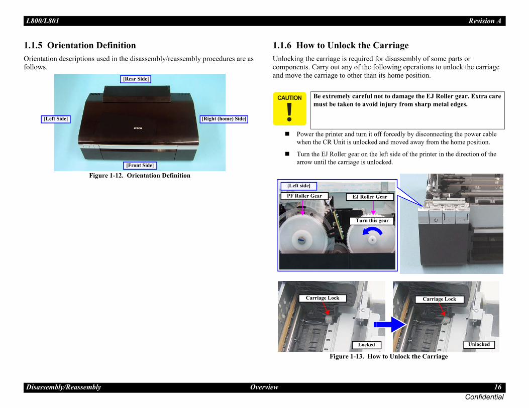
5 Orientation Definitionntation descriptions used in the disassembly/reassembly procedures are as ws.
Figure 1-12. Orientation Definition
1.1.6 How to Unlock the Unlocking the carriage is requiredcomponents. Carry out any of the and move the carriage to other tha
Power the printer and turn it when the CR Unit is unlocke
Turn the EJ Roller gear on tharrow until the carriage is un
Figure 1-13. Ho
[Left Side] [Right (home) Side]
[Rear Side]
[Front Side]
� � � � � Be extremely careful must be taken to avoi
Carriage Lock
Locked
[Left side]
PF Roller Gear EJ Roller
Turn th
L80 Revision A
Dis 17Confidential
1.21.2.ThisflowprovexpldisasParts
The
14. Example Chart
Partsname
I
n Board Unit
3
---
S7 S15
Supply Tank ube Assy
---
---
(p 20)
Front Paper Guide Assy
2
1
S15S9
“ 1.5.8 Ink System (p45)”
Reference page (A)
Adapter
---
1
(p 18)
eference page
0/L801
assembly/Reassembly Disassembly/Reassembly Procedures
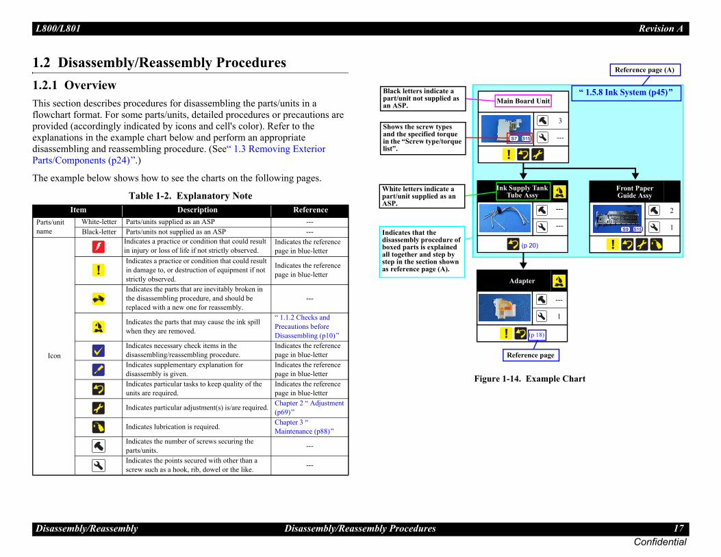
Disassembly/Reassembly Procedures1 Overview section describes procedures for disassembling the parts/units in a chart format. For some parts/units, detailed procedures or precautions are ided (accordingly indicated by icons and cell's color). Refer to the anations in the example chart below and perform an appropriate sembling and reassembling procedure. (See“ 1.3 Removing Exterior /Components (p24)”.)
example below shows how to see the charts on the following pages.
Figure 1-
Table 1-2. Explanatory NoteItem Description Reference
/unit White-letter Parts/units supplied as an ASP ---Black-letter Parts/units not supplied as an ASP ---
con
Indicates a practice or condition that could result in injury or loss of life if not strictly observed.
Indicates the reference page in blue-letter
Indicates a practice or condition that could result in damage to, or destruction of equipment if not strictly observed.
Indicates the reference page in blue-letter
Indicates the parts that are inevitably broken in the disassembling procedure, and should be replaced with a new one for reassembly.
---
Indicates the parts that may cause the ink spill when they are removed.
“ 1.1.2 Checks and Precautions before Disassembling (p10)”
Indicates necessary check items in the disassembling/reassembling procedure.
Indicates the reference page in blue-letter
Indicates supplementary explanation for disassembly is given.
Indicates the reference page in blue-letter
Indicates particular tasks to keep quality of the units are required.
Indicates the reference page in blue-letter
Indicates particular adjustment(s) is/are required. Chapter 2 “ Adjustment (p69)”
Indicates lubrication is required. Chapter 3 “ Maintenance (p88)”
Indicates the number of screws securing the parts/units. ---
Indicates the points secured with other than a screw such as a hook, rib, dowel or the like. ---
Mai
Ink T
White letters indicate a part/unit supplied as an ASP.
Black letters indicate a part/unit not supplied as an ASP.
Shows the screw types and the specified torque in the “Screw type/torque list”.
Indicates that the disassembly procedure of boxed parts is explained all together and step by step in the section shown as reference page (A).
R
L80 Revision A
ConfidentialDisa ssembly Disassembling/Reassembling Flowchart 18
Cover OpenSensor
---
2
(p 30)
CR Scale
---
2
(p 40)
Adapter Cover
1
3
(p 68)
S6
Joint
---
2
(p 65) (p 69)
APG Unit
2
---
(p 41) (p 88)
S15
Cover
---
2
4)
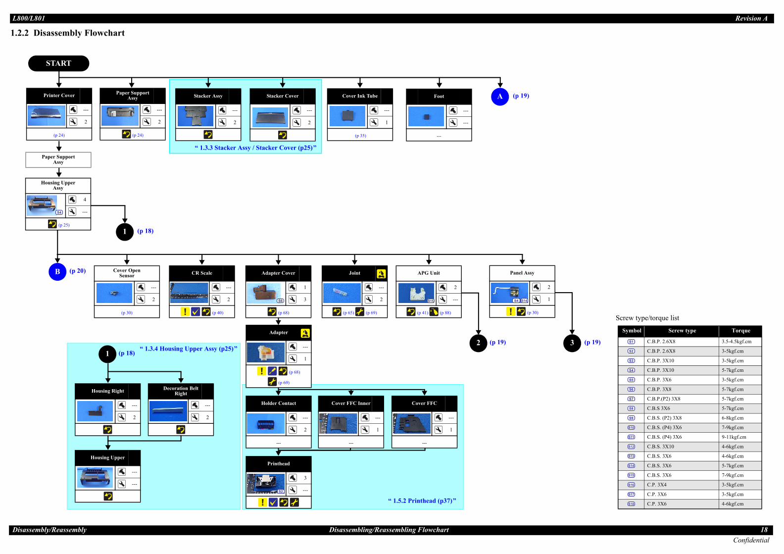
1.2. mbly Flowchart
RT
Stacker Assy
---
2
Cover Ink Tube
---
1
(p 35)
APaper Support Assy
---
2
(p 24)
Stacker Cover
---
2
pport y
Housing Right
---
2
Decoration Belt Right
---
2
Upper y
4
---
25)
“ 1.3.3 Stacker Assy / Stacker Cover (p25)”
“ 1.3.4 Housing Upper Assy (p25)”
Screw type/torque list
Symbol Screw type Torque
C.B.P. 2.6X8 3.5-4.5kgf.cm
C.B.P. 2.6X8 3-5kgf.cm
C.B.P. 3X10 3-5kgf.cm
C.B.P. 3X10 5-7kgf.cm
C.B.P. 3X6 3-5kgf.cm
C.B.P. 3X8 5-7kgf.cm
C.B.P.(P2) 3X8 5-7kgf.cm
C.B.S 3X6 5-7kgf.cm
C.B.S. (P2) 3X8 6-8kgf.cm
C.B.S. (P4) 3X6 7-9kgf.cm
C.B.S. (P4) 3X6 9-11kgf.cm
C.B.S. 3X10 4-6kgf.cm
C.B.S. 3X6 4-6kgf.cm
C.B.S. 3X6 5-7kgf.cm
C.B.S. 3X6 7-9kgf.cm
C.P. 3X4 3-5kgf.cm
C.P. 3X6 3-5kgf.cm
C.P. 3X6 4-6kgf.cm
S1
S2
S3
S4
S5
S6
S7
S8
S9
S10
S11
S12
S13
S14
S15
S16
S17
S18
Foot
---
---
---
Adapter
---
1
(p 68)
(p 69)
2
1
1
Housing Upper
---
---
Holder Contact
---
2
---
Cover FFC Inner
---
1
---
Printhead
3
---
S2
“ 1.5.2 Printhead (p37)”
(p 20)
(p 18)
(p 18)
(p 19)
y
2
1
30)
3 (p 19)
Cover FFC
---
1
---
0/L801
ssembly/Rea
Printer
(p 2
2 Disasse
STA
B
Paper SuAss
Housing Ass
(p
S4
(p 19)
Panel Ass
(p
S4 S14
L80 Revision A
ConfidentialDisa ly/Reassembly Disassembling/Reassembling Flowchart 19
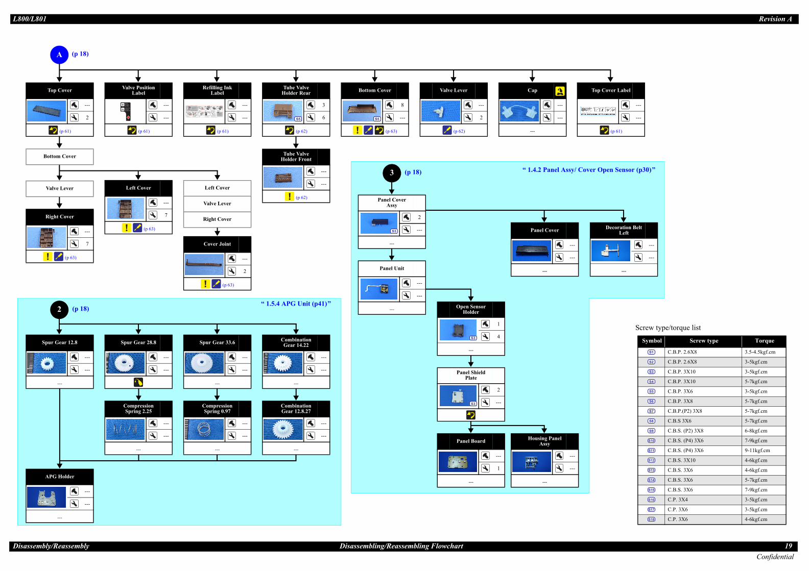
Cover Joint
---
2
(p 63)
Right Cover
Valve Lever
Left Cover
Screw type/torque list
Symbol Screw type Torque
C.B.P. 2.6X8 3.5-4.5kgf.cm
C.B.P. 2.6X8 3-5kgf.cm
C.B.P. 3X10 3-5kgf.cm
C.B.P. 3X10 5-7kgf.cm
C.B.P. 3X6 3-5kgf.cm
C.B.P. 3X8 5-7kgf.cm
C.B.P.(P2) 3X8 5-7kgf.cm
C.B.S 3X6 5-7kgf.cm
C.B.S. (P2) 3X8 6-8kgf.cm
C.B.S. (P4) 3X6 7-9kgf.cm
C.B.S. (P4) 3X6 9-11kgf.cm
C.B.S. 3X10 4-6kgf.cm
C.B.S. 3X6 4-6kgf.cm
C.B.S. 3X6 5-7kgf.cm
C.B.S. 3X6 7-9kgf.cm
C.P. 3X4 3-5kgf.cm
C.P. 3X6 3-5kgf.cm
C.P. 3X6 4-6kgf.cm
S1
S2
S3
S4
S5
S6
S7
S8
S9
S10
S11
S12
S13
S14
S15
S16
S17
S18
Decoration Belt Left
---
---
---
over
---
---
Panel y
---
---
Panel Board
---
1
---
Panel Shield Plate
2
---S3
Panel Cover Assy
2
---
---
S3
Compression Spring 0.97
---
---
---
Compression Spring 2.25
---
---
---
Combination Gear 12.8.27
---
---
---
CombinationGear 14.22
---
---
---
Spur Gear 33.6
---
---
---
Spur Gear 28.8
---
---
ottom Cover Tube ValveHolder Front
---
---
(p 62)
Right Cover
---
7
(p 63)
Left Cover
---
7
(p 63)
Tube ValveHolder Rear
3
6
(p 62)
S5
Valve Lever
---
2
(p 62)
---
---
Bottom Cover
8
---
(p 63)
S5
Valve Position Label
---
---
(p 61)
Refilling Ink Label
---
---
(p 61)
2
A
Top Cover
---
2
(p 61)
“ 1.5.4 APG Unit (p41)”
APG Holder
---
---
---
3 anel Assy/ Cover Open Sensor (p30)”
(p 18)
(p 18)
(p 18)
Valve Lever
Open Sensor Holder
1
4
---
S3
Panel Unit
---
---
---
Top Cover Label
---
---
(p 61)
pur Gear 12.8
---
---
---
0/L801
ssemb
B
S
Panel C
---
HousingAss
---
Cap
---
“ 1.4.2 P

L80 Revision A
ConfidentialDisa ly/Reassembly Disassembling/Reassembling Flowchart 20
C (p 21)
ube Guide Sheet/Tube ide Sheet Sub
Adapter
apter Cover
Tube Guide
---
4
---
Tube Guide Sheet Sub
---
1
(p 66)
Screw type/torque list
Symbol Screw type Torque
C.B.P. 2.6X8 3.5-4.5kgf.cm
C.B.P. 2.6X8 3-5kgf.cm
C.B.P. 3X10 3-5kgf.cm
C.B.P. 3X10 5-7kgf.cm
C.B.P. 3X6 3-5kgf.cm
C.B.P. 3X8 5-7kgf.cm
C.B.P.(P2) 3X8 5-7kgf.cm
C.B.S 3X6 5-7kgf.cm
C.B.S. (P2) 3X8 6-8kgf.cm
C.B.S. (P4) 3X6 7-9kgf.cm
C.B.S. (P4) 3X6 9-11kgf.cm
C.B.S. 3X10 4-6kgf.cm
C.B.S. 3X6 4-6kgf.cm
C.B.S. 3X6 5-7kgf.cm
C.B.S. 3X6 7-9kgf.cm
C.P. 3X4 3-5kgf.cm
C.P. 3X6 3-5kgf.cm
C.P. 3X6 4-6kgf.cm
S1
S2
S3
S4
S5
S6
S7
S8
S9
S10
S11
S12
S13
S14
S15
S16
S17
S18
Tube Guide Sheet
---
3
(p 66)
Adapter CoverAdapter CInk Supply Tank Assy
---
---
(p 64) (p 69) Ink Supply Tank Tube Assy
---
---
(p 64) (p 69)
Top Cover
Tube ValveHolder Front
Ink Supply Tank
---
---
(p 64) (p 69)
Tube Holder*
1
1
---
S6
Upper Shield Plate M/B
7
---S14 S18
Shield Plate M/B Sub
2
---S13
Main Board
1
---S12
PF Encoder
1
---S1
PF Scale
---
---
Supply Tank Assy
ver Ink Tube
Photo Interrupter
---
2
---
APG Sensor Assy
---
2
---
B
in Board Unit
3
---
S7 S15
“ 1.4.1 Main Board Unit (p27)”
“ 1.5.16 APG Sensor Assy (p57)”
“ 1.5.10 PF Encoder / PF Scale (p49)”
ube Holder
Ink SupplyAssy (W/Cl
(p 67)
Adapte
Joint
Bottom Cover
Valve Lever
Right Cover
Left Cover
Cover Joint
Tube ValveHolder Rear
*: There are four Tube Holders insta this printer. Depending on the target parts or units, the number of Tube Holders you should remove
When removing the Ink Supply T y: The Tube Holder on the home position side (on the Cover Case)When removing the Printer Mec All Tube Holders
(p 18)
Panel Assy
Lower Shield Plate M/B
2
---S13
0/L801
ssemb
T
Gu
Ad
Ink
Co
Ma
T
over
Tube amp)
---
---
(p 69)
r
lled in differs.ank Ass
hanism:

L80 Revision A
ConfidentialDisa ly/Reassembly Disassembling/Reassembling Flowchart 21
us Pad Guide ont
---
---
(p 57)
Waste Ink Tray
2
1
(p 42) (p 69)
S4
PF Motor
2
---
(p 49) (p 69)
S17
PF Encoder/PF Scale
Driven Pulley Shaft
---
---
Driven Pulley Holder
---
---
P/S As
-
(p 34)
S4
Waste Ink Pad Lower
---
---
Guide Stacker Right
---
---
---
Label CDR
---
---
---
Guide Stacker Right Assy
1
---
S6 CDR GuideSensor
---
2
---
Guide Stacker Left
1
---
S6
Stacker Cover
Stacker Assy
ousing Lower (W/Foot)
---
---
---
P/S Assy
aste Ink Pad Cap
aste Ink Pad Lower
CR Motor
2
---
S16
Driven Pulley Assy
---
---
Extension Spring
---
2
---
ousing Lower Assy
---
---
---
PrinterMechanism
5
4
(p 35) (p 69)
S6
Cover Case
1
---
(p 65)
S6
C
4
4
“ 1.5.7 Left & Right Guide Stackers / CDR Guide Sensor (p44)”
Driven Pulley
---
---
“ 1.5.12 CR Motor (p50)”D
Screw type/torque list
Symbol Screw type Torque
C.B.P. 2.6X8 3.5-4.5kgf.cm
C.B.P. 2.6X8 3-5kgf.cm
C.B.P. 3X10 3-5kgf.cm
C.B.P. 3X10 5-7kgf.cm
C.B.P. 3X6 3-5kgf.cm
C.B.P. 3X8 5-7kgf.cm
C.B.P.(P2) 3X8 5-7kgf.cm
C.B.S 3X6 5-7kgf.cm
C.B.S. (P2) 3X8 6-8kgf.cm
C.B.S. (P4) 3X6 7-9kgf.cm
C.B.S. (P4) 3X6 9-11kgf.cm
C.B.S. 3X10 4-6kgf.cm
C.B.S. 3X6 4-6kgf.cm
C.B.S. 3X6 5-7kgf.cm
C.B.S. 3X6 7-9kgf.cm
C.P. 3X4 3-5kgf.cm
C.P. 3X6 3-5kgf.cm
C.P. 3X6 4-6kgf.cm
S1
S2
S3
S4
S5
S6
S7
S8
S9
S10
S11
S12
S13
S14
S15
S16
S17
S18
(p 20) (p 21)
(p 21)
(p 22)
“ 1.5.6 Waste Ink Pad Lower / Waste Ink Pad Cap Lower (p43)”
Waste Ink Pad Cap Lower
---
---
0/L801
ssemb
H
W
W
H
PoroPaper
Fr
sy
1
--
(p 69)

L80 Revision A
ConfidentialDisa ly/Reassembly Disassembling/Reassembling Flowchart 22
PF Scale Cover
1
1
(p 66)
S6
PF Scale Sheet
---
---
(p 66)
Cable Holder Frame
Tube Guide
Cable Holder Frame
PF Encoder FFC
---
---
---
ETors R
---
---
EJ FrameTorsion Spring L
---
---
EJ Frame Assy
---
---
Front Frame
2
---
S15
H
---
---
Timing Belt
---
---
CR Guide Shaft
---
---
CR Unit
---
2
Holder Contact
Cover FFC Inner
Cover FFC
Adapter
Adapter Cover
J Frame Assy
pper Paper Guide
---
---
(p 56)
(p 69)
ASF Unit
2
2
S10 S11
LD RollerGuide Assy
1
5S10
CR Lock
---
---
---
Compression Spring 0.98
---
---
---
Extension Spring 0.8
---
2
---
Ink System
2
---
S15
D
5
6
ront Frame
able Holder Frame
Tube Guide
E
CR Scale
Driven Pulley Assy
Extension Spring
APG Unit
Printhead
“ 1.5.8 Ink System (p45)” “ 1.5.9 EJ Fram (p46)”
“ 1.5.13 C p52)”Screw type/torque list
Symbol Screw type Torque
C.B.P. 2.6X8 3.5-4.5kgf.cm
C.B.P. 2.6X8 3-5kgf.cm
C.B.P. 3X10 3-5kgf.cm
C.B.P. 3X10 5-7kgf.cm
C.B.P. 3X6 3-5kgf.cm
C.B.P. 3X8 5-7kgf.cm
C.B.P.(P2) 3X8 5-7kgf.cm
C.B.S 3X6 5-7kgf.cm
C.B.S. (P2) 3X8 6-8kgf.cm
C.B.S. (P4) 3X6 7-9kgf.cm
C.B.S. (P4) 3X6 9-11kgf.cm
C.B.S. 3X10 4-6kgf.cm
C.B.S. 3X6 4-6kgf.cm
C.B.S. 3X6 5-7kgf.cm
C.B.S. 3X6 7-9kgf.cm
C.P. 3X4 3-5kgf.cm
C.P. 3X6 3-5kgf.cm
C.P. 3X6 4-6kgf.cm
S1
S2
S3
S4
S5
S6
S7
S8
S9
S10
S11
S12
S13
S14
S15
S16
S17
S18
(p 21)
(p 23)
(p 23)
(p 23)
Cable Holder Frame
2
2
---
S15
Tube Guide
“ 1.5.14 ASF Unit (p54)”
0/L801
ssemb
E
U
F
C
J Frameion Spring
ead FFC
---
e Assy
R Unit (
L80 Revision A
ConfidentialDisa ly/Reassembly Disassembling/Reassembling Flowchart 23
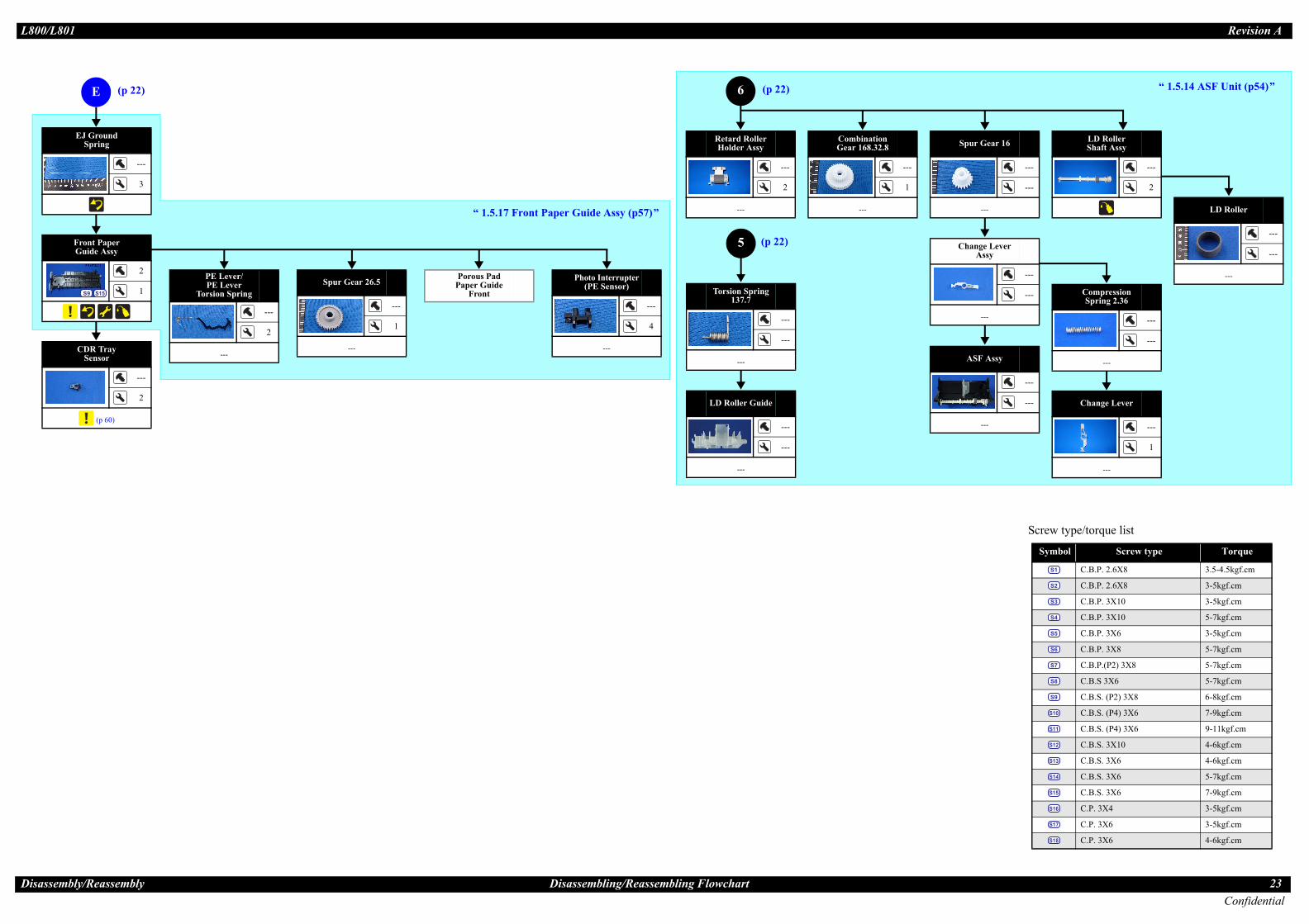
LD Roller
---
---
---
LD RollerShaft Assy
---
2
Change Lever
---
1
---
Compression Spring 2.36
---
---
---ASF Assy
---
---
---
Change Lever Assy
---
---
---
Spur Gear 16
---
---
---
Retard RollerHolder Assy
---
2
---
Co Ge
---
1
LD Roller Guide
---
---
---
Torsion Spring 137.7
---
---
---CDR Tray
Sensor
---
2
(p 60)
Photo Interrupter(PE Sensor)
---
4
---
Porous Pad Paper Guide
FrontSpur Gear 26.5
---
1
---
PE Lever/PE Lever
Torsion Spring
---
2
---
Front Paper Guide Assy
2
1
S9 S15
EJ Ground Spring
---
3
E
“ 1.5.17 Front Paper Guide Assy (p57)”
5
6 “ 1.5.14 ASF Unit (p54)”
Screw type/torque list
Symbol Screw type Torque
C.B.P. 2.6X8 3.5-4.5kgf.cm
C.B.P. 2.6X8 3-5kgf.cm
C.B.P. 3X10 3-5kgf.cm
C.B.P. 3X10 5-7kgf.cm
C.B.P. 3X6 3-5kgf.cm
C.B.P. 3X8 5-7kgf.cm
C.B.P.(P2) 3X8 5-7kgf.cm
C.B.S 3X6 5-7kgf.cm
C.B.S. (P2) 3X8 6-8kgf.cm
C.B.S. (P4) 3X6 7-9kgf.cm
C.B.S. (P4) 3X6 9-11kgf.cm
C.B.S. 3X10 4-6kgf.cm
C.B.S. 3X6 4-6kgf.cm
C.B.S. 3X6 5-7kgf.cm
C.B.S. 3X6 7-9kgf.cm
C.P. 3X4 3-5kgf.cm
C.P. 3X6 3-5kgf.cm
C.P. 3X6 4-6kgf.cm
S1
S2
S3
S4
S5
S6
S7
S8
S9
S10
S11
S12
S13
S14
S15
S16
S17
S18
(p 22)
(p 22)
(p 22)
0/L801
ssemb
mbinationar 168.32.8
---

L80 Revision A
Dis 24Confidential
1.3
1.3.R
1
.he Paper Support Assy from the bushing of the hing outward. Then remove the Paper Support aft preventing the Edge Guide projection from .
ving the Paper Support Assy
Paper Support Assy, match the projection uide, then attach the right shaft and the left
ut the shafts at the front side in the bushing earward.) After reinstalling, check that the oves smoothly.
Reinstalling the Paper Support Assy
ASF
Edge Guide Projection
:Shaft
onvex Portion
Hole
1
: Shaftn
r side)
Paper Support Assy
0/L801
assembly/Reassembly Printer Cover
Removing Exterior Parts/Components
1 Printer Coveremoval procedure
. Pull out the left shaft and right shaft of the Printer Cover, and remove the Printer Cover.
Figure 1-15. Removing the Printer Cover
1.3.2 Paper Support AssyRemoval procedure
1. Open the Paper Support Assy2. Disengage the right shaft of t
ASF Unit by pushing the busAssy, disengaging the left shhitting against the other parts
Figure 1-16. Remo
Printer Cover
Shaft (right)Shaft (left)
When reinstalling theand hole of the Edge Gshaft in that order. (Pand then push them rPaper Support Assy m
Figure 1-17.
Push
Bushing of the
Paper Support Assy
C2
Mounting Directio(from front side to rea

L80 Revision A
Dis 25Confidential
1.3.R123
y
remove the Upper Housing upward.tening torque: 5-7 kgf.cm) re indicate the order of tightening the screws.)
moving the Upper Housing
3
Groove
2
pper Housing
0/L801
assembly/Reassembly Stacker Assy / Stacker Cover
3 Stacker Assy / Stacker Coveremoval procedure. Open the Stacker Cover.. Remove the Stacker Assy.. Release the Stacker Cover from the two shafts and remove the Stacker Cover.
Figure 1-18. Removing the Stacker Assy / Stacker Cover
1.3.4 Housing Upper AssRemoval procedure
1. Remove the four screws and • Screw : C.B.P. M3x10 (tigh
(The numbers shown in the figu
Figure 1-20. Re
When installing the Stacker Assy, insert the guide pins of the Stacker Assy into the lower grooves of the Guide Stacker Assy. (The upper grooves are used when CDR is printed.)
Figure 1-19. Installing the Stacker Assy
Stacker Assy Stacker Cover
Shaft Shaft
Groove
Guide Pin Guide Pin
Groove
[Rear Side]
4
Groove
1
U

L80 Revision A
Dis 26Confidential
2
0/L801
assembly/Reassembly Housing Upper Assy
. Slide the Front Housing in the direction of the arrow and remove the Front Housing from the Upper Housing.
Figure 1-21. Removing the Front Housing
When installing the Upper Housing, be careful of the following:Do not pinch the cables.Tighten the screws in the order given in Fig.1-20 (p.25).Match the ribs of the Upper Housing shown in Fig.1-20 (p.25) with the grooves of the Housing Lower.As shown in Fig.1-22, match the A part of the Front Housing with the screw box of the Housing Lower.
Figure 1-22. Installing Upper Housing
[Rear Side]
Ribs
Front HousingGrooves
Front Housing
Screw box of Housing Lower
A part of Front Housing

L80 Revision A
Dis 27Confidential
1.4
1.4.R
12
s that secures the following cables on the back of
ving the Main Board Unit (1)
Main Board Unit
Acetate Tape
0/L801
assembly/Reassembly Main Board Unit
Removing Control Boards
1 Main Board Unitemoval procedure
Main Board Unit removal. Disconnect all connectors on the Main Board Unit.. Peel off the double-sided tape that secures the Panel FFC to the Holder Frame
and release the Panel FFC. (Fig.1-29 (p.30))
Figure 1-23. Connector layout of the Main Board
3. Peel off the four acetate tapethe Main Board Unit.
• Power Supply Cable• CR Motor Cable• PF Motor Cable• PE Motor Cable• APG Sensor Cable
Figure 1-24. Remo
Table 1-3. List of Connectors and their DestinationsCN No.@ Color Destination Number of pins
CN3 White P/S Assy 3pinCN4 White CDR Guide Sensor / CDR Tray Sensor 4pinCN5 FFC Panel Board 8pinCN6 White PE Sensor 3pinCN7 Black APG Sensor 3pinCN8 FFC PF Encoder 5pinCN10 FFC
Head FFC13pin
CN11 FFC 13pinCN12 FFC 9pinCN13 Black PF Motor 2pinCN14 White CR Motor 2pinCN16 FFC PW Sensor / CR Encoder Sensor 6pinCN17 White Cover Open Sensor 2pin
CN6 CN7CN3
CN4
CN5CN8
CN17
CN13
CN10
CN11
CN16CN14
CN12
Main Board Unit Acetate Tape

L80 Revision A
Dis 28Confidential
4
� � � �
� � �
Positand G
ables, secure them with acetate tape res below.Supply Cable closely along the Lower Shield cure the cable with acetate tapes at the d C (30 mm each) as shown in Fig.1-26.p edge shown in Fig.1-26, secure the ith the acetate tape D (50 mm).able
e
eble
re 1-26. Routing the Cables
A
BC
D
Power Supply Cable Main Board Unit
Lower Shield Plate M/B
Sharp edge
Align the upper left end of acetate tape D with the edge of the Lower Shield Plate M/B.
0/L801
assembly/Reassembly Main Board Unit
. Remove the three screws and remove the Main Board Unit.• Screw (2 pcs.): C.B.P.(P2) M3x8 (tightening torque: 5-7 kgf.cm) • Screw (1 pc.): C.B.S. M3x6 (tightening torque: 7-9 kgf.cm)
(The numbers shown in the figure indicate the order of tightening the screws.)
Figure 1-25. Removing the Main Board Unit (2)
� � � �
� � � � �
Whenever the Main Board Unit is replaced, the required adjustment must be carried out.
• Refer to "2.1.2 Required Adjustments" (p.74)
When installing the Main Board Unit, be careful of the following:Match the positioning holes with guide pins shown in Fig.1-25.Insert the rib of the Main Board Unit into the positioning hole of the Cable Holder Frame as shown in Fig.1-25.Tighten the screws in the order given in Fig.1-25.
Rib
3
[Left Side]
Main Board Unit
1
2ioning Holes
uide Pins
[Upper Side]
After connecting the cfollowing the procedu1. Route the Power
Plate M/B, and sepositions A, B, an
2. Avoiding the sharfollowing cables w
• Power Supply C• CR Motor Cabl• PF Motor Cable• PE Motor Cabl• APG Sensor Ca
Figu
D
Edge of Lower Shield Plate M/B
Positions of Acetate tape A, B, C
A
B
C

L80 Revision A
Dis 29Confidential
1
2
remove the Shield Plate M/B Sub.3x6 (tightening torque: 4-6 kgf.cm) re indicate the order of tightening the screws.)e the Main Board Unit.htening torque: 4-6 kgf.cm)
emoving the Main Board
� �
Sc
p edges shown in the figure below when bling.
he Main Board, match the positioning hole shown in Fig.1-28.s in the order given in Fig.1-27 (p.29),
[Rear Side]1
2
Shield Plate M/B Sub
e and
0/L801
assembly/Reassembly Main Board Unit
Disassembling the Main Board Unit. Remove the Main Board Unit (p.27).
. Remove the seven screws and remove the Upper Shield Plate M/B.• Screw (6 pcs.): C.B.S. M3x6 (tightening torque: 5-7 kgf.cm) • Screw (1 pc.): C.P. M3x6 (tightening torque: 4-6 kgf.cm)
(The numbers shown in the figure indicate the order of tightening the screws.)
Figure 1-27. Removing the Upper Shield Plate M/B
3. Remove the two screws and • Screw (2 pcs.): C.B.S. M
(The numbers shown in the figu4. Remove the screw and remov
• Screw C.B.S. M3x10 (tig
Figure 1-28. R
� � � Do not apply unnecessary force on the screw receiving parts of the Lower Shield Plate M/B, as they are easy to deform.When assembling or disassembling the Upper Shield Plate M/B, be careful of its sharp edges.
rew Receiving Part
3
Upper Shield Plate M/B
2
5
1
6
47
Lower Shield Plate M/B
Screw Receiving Part
� � � � � Be careful of the sharassembling or reassem
When installing twith the guide pinTighten the screwFig.1-28.
Upper Side: Main BoardLower Side: Lower Shield Plate M/B
Sharp edge Positioning HolGuide Pin

L80 Revision A
Dis 30Confidential
1.4.R
1
2
3
4
3x6 (tightening torque: 5-7 kgf.cm) 3x10 (tightening torque: 5-7 kgf.cm) er, insert a flathead screwdriver into the hole to e the Panel Assy.
moving the Panel Assy (2)
crew (2) shown in Fig.1-30, be careful not to en Sensor Cable and CDR Sensor Cable.
Open Sensor Holder
Housing Lower
Tab
[Front side]
Disengage direction
0/L801
assembly/Reassembly Panel Assy/ Cover Open Sensor
2 Panel Assy/ Cover Open Sensoremoval procedure
Panel Assy removal. Disconnect the Panel FFC from the connector (CN5) on the Main Board and
peel the Panel FFC off the Cable Holder Frame.. Disconnect the CDR Sensor Cable and Cover Open Sensor Cable from the
connectors (CN4, CN17) on the Main Board.. Release the CDR Sensor Cable and Cover Open Sensor Cable from the two
hooks of the Cable Holder Frame.. Peel off the acetate tape A, B to separate the CDR Sensor Cable from the
Cover Open Sensor Cable.
Figure 1-29. Removing the Panel Assy (1)
5. Remove the two screws.• Screw (3 pcs.): C.B.P. M• Screw (3 pcs.): C.B.P. M
6. From the bottom of the Printdisengage the tab, and remov
Figure 1-30. Re
Cover Open Sensor and CDR Sensor Cable
Hooks and Acetate Tape A, B
Double sided Tape
Main Board Cable Holder Frame
Panel FFC
CN4CN17
CN5
� � � � � When removing the sdamage the Cover Op
Panel Assy
1
2

L80 Revision A
Dis 31Confidential
-32, route the CDR Sensor Cable and Cover le through the gap between the two ribs of Holder.
32. Installing the Panel Assy (1)
-30 (p.30) and Fig.1-33, match the of the Open Sensor Holder with the guide g Lower, and secure the Open Sensor Holder
33. Installing the Panel Assy (2)
Cable
Ribs
Open Sensor Holder
Positioning Hole and Guide Pin
0/L801
assembly/Reassembly Panel Assy/ Cover Open Sensor
When Installing the Panel Assy, be careful of the following:Tighten the screws in the order given in Fig.1-30.When routing the FFCs and cables, follow the procedures below referring to Fig.1-31.1. Route the Panel FFC aligning its upper edge with the
reference line marked on the Cable Holder Frame, and secure the FFC with double-sided tape.
2. Attach the acetate tape C along with the edge of the Cable Holder Frame to secure the Panel FFC and Head FFC.
3. Tie the two cables together using two pieces of acetate tape (20 mm each) so that the two tape positions come to the two hooks of the Cable Holder Frame respectively. The cables orientation must be as follows;CDR cable: faces its black side upwardCover Open Sensor cable: faces its gray side upward
4. Route the cables through the two hooks of the Cable Holder Frame aligning the center of the tapes with the hooks.
Figure 1-31. Routing the Cables
Upper Side : CDR Sensor CableLower Side : Cover Open Sensor Cable
Hook
A B
Ref. Line
Do not route the Panel FFC over the screw of the Cable Holder Frame.
Fold the Panel FFC along the corner of the Upper Shield Plate M/B.
Panel FFC
As shown in Fig.1Open Sensor Cabthe Open Sensor
Figure 1-
As shown in Fig.1positioning holes pins of the Housinwith the tab.
Figure 1-
Cover Open Sensor CDR Sensor Cable
Housing Lower

L80 Revision A
Dis 32Confidential
12
3
4
5
ack of the Panel Board and remove the Panel
g the Panel Board / Buttons (3)
remove the PS button, the Ink button, and the g Panel B.
on, the Ink button, and the Paper button in the ove it.
g the Panel Board / Buttons (4)
P
Panel Board
Positioning Hole and Guide Pin
Hook
[Back Side]
B
s
Lens
Step 8
Housing Panel B
0/L801
assembly/Reassembly Panel Assy/ Cover Open Sensor
Panel Board / Buttons Removal
. Remove the Panel Assy. (p.30)
. Remove the two screws on the back of the Panel Assy, and remove the Panel Cover.
• Screw : C.B.P. M3x10 (tightening torque: 3-5 kgf.cm) . Remove the screw on the front of the Panel Unit, and remove the Panel Unit
from the Open Sensor Holder by sliding it in the upper right direction.• Screw : C.B.P. M3x10 (tightening torque: 3-5 kgf.cm)
Figure 1-34. Removing the Panel Board / Buttons (1)
. Disconnect the connector (CN1) on the Panel Board, peel the Panel FFC off the back of the Panel Shield Plate, and remove the Panel FFC.
. Remove the two screws and remove the Panel Shield Plate from the Panel Unit.
• Screw : C.B.P. M3x10 (tightening torque: 3-5 kgf.cm)
Figure 1-35. Removing the Panel Board / Buttons (2)
6. Disengage the hook on the bBoard.
Figure 1-36. Removin
7. Release the three hooks and Paper button from the Housin
8. Slide the Lens of the PS buttdirection of the arrow to rem
Figure 1-37. Removin
[Front side]
Hook of the Panel Shield Plate
[Back Side]
Panel Unit
anel Cover
Open Sensor Holder
Panel Shield Plate [Back Side]
CN1 Panel FFC
Panel Unit[Front side]
Double-sided Tape
Reference Line
Hook
[Back Side]
Housing Panel
Paper Button
Ink Button
PS Button
Len
[Front side]

L80 Revision A
Dis 33Confidential
l
0)ensor Holder, disengage the hook of the Cover Cover Open Sensor pulling its rib out of the the direction of the arrow.m the Cover Open Sensor to remove the Cover
ving the Cover Open Sensor
over Open Sensor, insert the rib shown in of the Open Sensor Holder, and secure the ith the hook.
Open Sensor Holder
Connector
Cover Open Sensor
0/L801
assembly/Reassembly Panel Assy/ Cover Open Sensor
Cover Open Sensor Remova
1. Remove the Panel Assy. (p.32. From the back of the Open S
Open Sensor, and remove thehole by rotating the sensor in
3. Disconnect the connector froOpen Sensor.
Figure 1-39. Remo
When installing the Panel Unit, be careful of the following:When installing the Panel Shield Plate to the Open Sensor Holder, match the hook and guide pins with the positioning holes shown in Fig.1-38 and insert the Panel Shield Plate into the groove of the Open Sensor Holder to secure the Panel Shield Plate.
Figure 1-38. Installing the Panel Unit
Attach the Panel FFC with double-sided tape along with the reference line shown in Fig.1-35 (p.32).When installing the Panel Board, match the guide pin with the positioning hole shown in Fig.1-36.Install the PS button, Ink button, and Paper button as shown in Fig.1-37.
[Upper Side]
Guide Pin and Positioning HoleHook and Positioning HoleGrooveOpen Sensor Holder
Panel Shield Plate
When installing the CFig.1-39 into the holeCover Open Sensor w
Hook
Rib
[Back Side]

L80 Revision A
Dis 34Confidential
1.4.R
1
2
� � � �
� � �
0/L801
assembly/Reassembly P/S Assy
3 P/S Assyemoval procedure
. Peel off the acetate tape and remove the ferrite core from the groove of the Housing Lower.
. Remove the screw that secures the P/S Assy, and remove the P/S Assy from the Housing Lower.
• Screw : C.B.P M3x10 (tightening torque: 5-7 kgf.cm)
Figure 1-40. Removing the P/S Assy
When installing the P/S Assy, put the ferrite core into the groove of the Housing Lower and secure it with acetate tape as shown in Fig.1-40.
� � � �
� � � � �
Whenever the P/S Assy is replaced, the required adjustment must be carried out.
• Refer to "2.1.2 Required Adjustments" (p.74)
Housing Lower P/S Assy
Acetate Tape
L80 Revision A
Dis 35Confidential
1.5
1.5.R
by hand.
oving the Waste Ink Tube
� �
F Scale with bare hands or damage it.chanism is tilted leftward about 15°, the PF the desk surface and can break. After nter Mechanism, take extra care to protect
ter Mechanism Handling Precaution (2)
he Waste Ink Tube, take care not to rinter and surroundings with ink.e exercised not to scratch or damage the
Printer Mechanism
About15°
Do not tilt more than 15 degrees, or drag it while tilting.
0/L801
assembly/Reassembly Removing the Printer Mechanism
Disassembling the Printer Mechanism
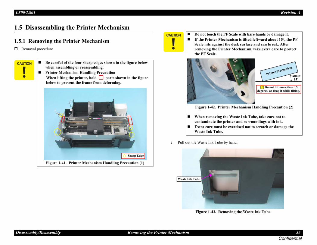
1 Removing the Printer Mechanismemoval procedure
1. Pull out the Waste Ink Tube
Figure 1-43. Rem
� � � Be careful of the four sharp edges shown in the figure below when assembling or reassembling.Printer Mechanism Handling PrecautionWhen lifting the printer, hold parts shown in the figure below to prevent the frame from deforming.
Figure 1-41. Printer Mechanism Handling Precaution (1)
Sharp Edge
� � � � � Do not touch the PIf the Printer MeScale hits againstremoving the Prithe PF Scale.
Figure 1-42. Prin
When removing tcontaminate the pExtra care must bWaste Ink Tube.
Waste Ink Tube

L80 Revision A
Dis 36Confidential
23
4
remove the Printer Mechanism.ightening torque:5-7 kgf.cm) re indicate the order of tightening the screws.)
ing the Printer Mechanism (3)
45
31
sitioning Hole and ide Pin
0/L801
assembly/Reassembly Removing the Printer Mechanism
. Release the Waste Ink Tube from the groove of the Waste Ink Tray.
. Release the CR Motor Cable from the two ribs of the Waste Ink Tray.
Figure 1-44. Removing the Printer Mechanism (1)
. Disconnect the connector of the CDR Guide Sensor.
Figure 1-45. Removing the Printer Mechanism (2)
5. Remove the five screws and Screw : C.B.P.(P2) M3x8 (t(The numbers shown in the figu
Figure 1-46. Remov
CR Motor Cable
Waste Ink Tube Waste Ink TrayWaste Ink Tube
CDR Guide Sensor
CDR Guide Sensor Cable Opening
2
PoGu

L80 Revision A
Dis 37Confidential
ter, open the Cartridge Cover and remove all Ink
of the Head FFC Cover with a flathead FC Cover downward and remove it.
oving the Head FFC Cover
� � � �
� � �
he Head FFC Cover and the Head FFC ot use tools with sharp ends as the FFC may
damage the FFC and cables when ook of the Holder Contact.
below on how to unlock the carriage.Unlock the Carriage”
Head FFC Cover
Hook
Removal Direction
0/L801
assembly/Reassembly Printhead
1.5.2 Printhead
Removal procedure
1. Move the CR Unit to the cenCartridges.
2. While disengaging the hook screwdriver, slide the Head F
Figure 1-48. Rem
When installing the Printer Mechanism, be careful of the following:
Wipe off any ink on the joint portion of the Waste Ink Tube before reconnecting the tube. Ink on the joint portion makes the tube likely to get disconnected.As shown in Fig.1-47, insert the Waste Ink Tube over the tube of the Waste Ink Tray until the top end of the Waste Ink Tube contacts with the rib.
Figure 1-47. Cautions of inserting the Waste Ink Tube
Match the positioning holes with guide pins (two pairs) shown in Fig.1-46 (p.36).Tighten the screws in the order given in Fig.1-46 (p.36).Make sure the Waste Ink Tube or cables are not pinched between the Printer Mechanism and the Housing Lower.Route the CDR Guide Sensor Cable through the opening as shown in Fig.1-45.
� � � �
� � � � �
Whenever the Printer Mechanism is replaced, the requiredadjustments must be carried out.
• Refer to "2.1.2 Required Adjustments" (p.74)
Top end of Waste Ink Tube
Waste Ink Tray
Waste Ink Tube
Tube of Waste Ink Tray
Rib
Tube of Waste Ink Tray
� � � � � When removing tCover Inner, do nget damaged. Be careful not to disengaging the h
� � � �
� � �
See the section given • “1.1.6 How to
Screwdriver

L80 Revision A
Dis 38Confidential
3
4
15) disengage the hook B of the Holder Contact age Unit.ard and remove the Holder Contact.
oving the Holder Contact (2)
spill ink and contaminate the surroundings. not to touch the nozzle surface, the ink supply Cover, otherwise the nozzles may get
-52. Handling of the Printhead
Hook B[Back Side]
Special Tool
ead
Nozzle surface
Head Cover
0/L801
assembly/Reassembly Printhead
. While disengaging the hook of the Head FFC Cover Inner with a flathead screwdriver, slide the Head FFC Cover Inner upward and remove it.
Figure 1-49. Removing the Head FFC Cover Inner
. Using the special tool (see p.15) disengage the hook A of the Holder Contact on the left back of the Carriage Unit.
Figure 1-50. Removing the Holder Contact (1)
5. Using the special tool (see p.on the right back of the Carri
6. Slide the Holder Contact upw
Figure 1-51. Rem
Removal Direction
ScrewdriverHook
Head FFC Cover Inner
Hook A[Back Side]
Holder Contact
Special Tool
� � � � � Take extra care not toBe extremely careful needles and the Headclogged.
Figure 1
Holder Contact
Removal Direction
Printh

L80 Revision A
Dis 39Confidential
7
8
the order given in Fig.1-53.
ead is removed/replaced, the required carried out. Required Adjustments" (p.74)
0/L801
assembly/Reassembly Printhead
. Remove the three screws and remove the Printhead.• Screw : C.B.P. M2.6x8 (tightening torque: 3-5 kgf.cm)
(The numbers shown in the figure indicate the order of tightening the screws.)
Figure 1-53. Removing the Printhead (1)
. Remove the two Head FFCs from the connectors on the back, and remove the Printhead.
Figure 1-54. Removing the Printhead (2)
Printhead
1
23
Connectors
Printhead
Head FFC
Tighten the screws in
� � � � � � � �
� � � � � � � �
Whenever the Printhadjustments must be
• Refer to "2.1.2

L80 Revision A
Dis 40Confidential
1.5.
R
12
3
45
� �
� �
�
ith its cut-corner facing upward. Hitch one end o the hole of the CR Scale from the back side of
1-56. Reinstalling the CR Scale
Cut-corner
Hook
0/L801
assembly/Reassembly CR Scale
3 CR Scale
emoval procedure
. Unlock the carriage and move the CR Unit to the center.
. Remove the Torsion Spring from the hook ( ) on the left side of the Main Frame.
. Remove the CR Scale from the hook ( ) on the right side of the Main Frame.
. Pull out the CR Scale from the slit of the CR Unit.
. Turn the CR Scale 90 degrees in the direction of the arrow, and remove the CR Scale from the hook.
Figure 1-55. Removing the CR Scale
� � � During the disassembly/reassembly of the Printer Mechanism, take extra care not to touch the CR Scale with bare hands, and not to contaminate or scratch it.
� �
� �
See the section given below on how to unlock the carriage.• “1.1.6 How to Unlock the Carriage”
CR Scale
Turn 90°
Extension Spring
Slit
Hook
Install the CR Scale wof the Torsion Spring tthe CR Scale.
Figure
Hitch from the back side

L80 Revision A
Dis 41Confidential
1.5.R1
2
uired. See the page given below for the ation.G Unit (p.93)nit following the procedure below.
ner than Ø2mm) through the positioning in Frame and the right PG Cam on the CR
9. Reinstalling the APG Unit (1)
ough the positioning holes of the Spur gear PG Unit.
0. Reinstalling the APG Unit (2)
le
Right PG Cam
Spur Gear 28.8APG Unit
Pin
Front: Positioning Hole of Spur Gear 28.8Back: Positioning Hole of APG Unit
0/L801
assembly/Reassembly APG Unit
4 APG Unitemoval procedure. Remove the two screws taking care not to lose the gears, and remove the APG
Unit.• Screw : C.B.S. M3x6 (tightening torque: 7-9 kgf.cm)
(The numbers shown in the figure indicate the order of tightening the screws.)
Figure 1-57. Removing the APG Unit
. Remove the Combination Gear (10, 15.2).
Figure 1-58. Removing the Combination Gear (10, 15.2)
1
2
APG Unit
Combination Gear (10,15.2)
Lubrication is reqlubrication informLubrication of APInstall the APG U1. Put a pin (thin
holes of the MaShaft.
Figure 1-5
2. Put the pin thr28.8 and the A
Figure 1-6
Pin (1)
Positioning Ho

L80 Revision A
Dis 42Confidential
ngage the hook, and remove the Waste Ink Tray.tightening torque: 5-7 kgf.cm)
oving the Waste Ink Tray
aste Ink Tray, take extra care not to spill the printer and surroundings.
Ink Tray is replaced, the required carried out. Required Adjustments" (p.74)
0/L801
assembly/Reassembly Waste Ink Tray
1.5.5 Waste Ink TrayRemoval procedure
1. Remove the two screws, dise• Screw : C.B.P. M3x10 (
Figure 1-63. Rem
3. Install the APG Unit to the Main Frame.
Figure 1-61. Reinstalling the APG Unit (3)
4. Check that the hooks ( ) are attached to the positioning holes of the Main Frame, then screw the APG Unit.
Figure 1-62. Reinstalling the APG Unit (4)
Tighten the screws in the order given in Fig.1-57 (p.41).
APG UnitPin
Main Frame
� � � � � When removing the Wink and contaminate
� � � � � � � �
� � � � � � � �
Whenever the Waste adjustments must be
• Refer to "2.1.2
Waste Ink Tray
Hook

L80 Revision A
Dis 43Confidential
1.5.R
1
� �
Ink Pad Lower is replaced, the required carried out. Required Adjustments" (p.74)
0/L801
assembly/Reassembly Waste Ink Pad Lower / Waste Ink Pad Cap Lower
6 Waste Ink Pad Lower / Waste Ink Pad Cap Loweremoval procedure
. Remove the four Waste Ink Pad Lowers and Waste Ink Pad Cap Lower from the Housing Lower.
Figure 1-64. Removing the Waste Ink Pad
� � � When removing the Waste Ink Pad Lower and Waste Ink Pad Cap Lower, take extra care not to contaminate the printer and surroundings with ink.Be careful of the seven sharp edges shown in Fig.1-64 when disassembling or reassembling.
Insert the Waste Ink Pad Lowers into the Housing Lower inserting the slits of the pads over the tabs on the Housing Lower. Make sure to push the pads as far as they will go (until their top surface locate lower than the top surface of the Housing Lower edges).
Figure 1-65. Installing the Waste Ink Pad Lower
Sharp edge
Waste Ink Pad Lower (x1)
Waste Ink Pad Lower (x3)
Waste Ink Pad Cap Lower (x1)
Slit
Tab
� � � � � � � �
� � � � � � � �
Whenever the Waste adjustments must be
• Refer to "2.1.2

L80 Revision A
Dis 44Confidential
1.5.R
1
2
the back of the CDR Guide Sensor and remove
oving the CDR Guide Sensor
� �
e Left Guide Stacker, insert the rib indicated -67 and match the positioning holes and guide h (two pairs).e Right Guide Stacker, match the
and guide pins indicated with (two
stalling the Left / Right Guide Stacker
Right Guide Stacker
[Back Side]
Hooks
Guide Sensor
0/L801
assembly/Reassembly Left & Right Guide Stackers / CDR Guide Sensor
7 Left & Right Guide Stackers / CDR Guide Sensoremoval procedure
Left / Right Guide Stacker Removal
. Remove the screw and remove the Left Guide Stacker.• Screw : C.B.P. M3x8 (tightening torque: 5-7 kgf.cm)
. Remove the screw and remove the Right Guide Stacker.• Screw : C.B.P. M3x8 (tightening torque: 5-7 kgf.cm)
Figure 1-66. Removing the Left / Right Guide Stacker
CDR Guide Sensor Removal
1. Disengage the two hooks on the CDR Guide Sensor.
Figure 1-68. Rem
� � � Be careful of the seven sharp edges shown in Fig.1-66 when assembling or reassembling.
Left Guide StackerLeft Guide Stacker
Right Guide StackerSharp edge
When installing thwith in Fig.1pins indicated witWhen installing thpositioning holes pairs) in Fig.1-67.
Figure 1-67. In
Left Guide Stacker
Right Guide Stacker
CDR

L80 Revision A
Dis 45Confidential
1.5.
R
ter. cures the Cap section.htening torque: 7-9 kgf.cm) re indicate the order of tightening the screws.)the hole of the Main Frame and remove the screw tion.
htening torque: 7-9 kgf.cm) re indicate the order of tightening the screws.)
moving the Ink System (1)
irection of the arrow and disengage the Ink the ASF Unit.
moving the Ink System (2)
� �
� �
�
2
Hole
Pump
[Rear Side]
Guide Pin
0/L801
assembly/Reassembly Ink System
8 Ink System
emoval procedure
1. Move the CR Unit to the cen2. Remove the screw (1) that se
• Screw : C.B.S. M3x6 (tig(The numbers shown in the figu
3. Insert a screwdriver through (2) that secures the Pump sec
• Screw : C.B.S. M3x6 (tig(The numbers shown in the figu
Figure 1-70. Re
4. Slide the Ink System to the dSystem from the guide pin of
Figure 1-71. Re
� � � Take extra care not to spill ink and contaminate the surroundings. Also, when removing the Waste Ink Tube, be careful not to spill the ink. Extra care must be taken to avoid injury from sharp edges of the rib of the Main Frame.Be careful not to drop and damage the shaft of the Carriage Lock and the Torsion Spring, as they easily come off.
Figure 1-69. Ink System
� �
� �
See the section given below on how to unlock the carriage.• “1.1.6 How to Unlock the Carriage”
Shaft of the Carriage Lock
Torsion SpringPump SectionPump Section
1
Cap section
Cap

L80 Revision A
Dis 46Confidential
5
e position side.67)then release the Head FFC from the two hooks of pull out the Head FFC through the cutout.the three hooks of the Front Frame and peel off
emoving the Head FFC
d TapeAcetate Tape PositionHook
Cable Holder Frame Cutout
Acetate Tape
ont Frame
0/L801
assembly/Reassembly EJ Frame Assy
. Remove the Ink System in the following procedures.1.Slide it to the right.2.Rotate it in the direction of the arrow (1) and release the pump part from
the Main Frame.3.Pull it out toward you (arrow (2)).
Figure 1-72. Removing the Ink System (2)
1.5.9 EJ Frame AssyRemoval procedure1. Move the CR Unit to the hom2. Remove the Tube Guide. (p.3. Peel off the acetate tape, and
the Cable Holder Frame and 4. Release the Head FFC from
the double-sided tape.
Figure 1-74. R
When installing the Ink System, be careful of the following:Lubrication is required. See the page given below for the lubrication information.Lubrication of Ink System (p.93)Insert the shafts of the Ink System into the positioning holes ( ) of the Frame.
Figure 1-73. Reinstalling the Ink System (1)
Tighten the screws in the order given in Fig.1-70.After installing the Ink System, check the Carriage Lock for proper operation referring to the section given below.
• “1.1.6 How to Unlock the Carriage”Insert the positioning hole of the Ink System shown in Fig.1-71 over the guide pin of the ASF Unit.
1
2
Pump
Double-sideHead FFC
[Rear Side] Fr

L80 Revision A
Dis 47Confidential
56
7
8
lease the CDR Sensor Cable, and then remove ft sides, and remove the Front Frame.
htening torque: 7-9 kgf.cm) re indicate the order of tightening the screws.)
emoving the Front Frame
le from the cable guide of the EJ Frame Assy.
moving the EJ Frame Assy
Front Frame
Positioning hole and Guide Pin
2
EJ Frame Assy
de
DR Sensor Cable
0/L801
assembly/Reassembly EJ Frame Assy
. Disconnect the PF Encoder FFC from the PF Encoder.
. Remove the two screws, disengage the two hooks of the Cable Holder Frame from the Front Frame and Main Frame, and remove the Cable Holder Frame.
. Screw : C.B.S. M3x6 (tightening torque: 7-9 kgf.cm) (The numbers shown in the figure indicate the order of tightening the screws.)
Figure 1-75. Removing the Cable Holder Frame
. Peel off the PF Encoder FFC from the back of the Cable Holder Frame.
Figure 1-76. Removing the PF Encoder FFC
9. Peel off the acetate tape to rethe screws on the right and le
• Screw : C.B.S. M3x6 (tig(The numbers shown in the figu
Figure 1-77. R
10. Release the CDR Sensor Cab11. Remove the EJ Frame Assy.
Figure 1-78. Re
Hook
[Back Side] Cable Holder Frame
1
2
PF Encoder FFC
[Back Side]Cable Holder Frame
PF Encoder FFCReference Line
Cable Holder Frame
1
Acetate Tape
Removal Direction
Cable Gui
C

L80 Revision A
Dis 48Confidential
e Front Frame, screw it after securing the foot e Springs to the slits as shown in the figure.
he EJ Frame as the springs come off easily.
. Reinstalling the Front Frame (2)
e Cable Holder Frame, match the two hooks er Frame with the positioning holes of the Front Frame as shown in Fig.1-75 (p.47), and in the order given in the figure.e Cable Holder Frame, attach the PF g with the reference line shown in Fig.1-76
e Front Frame, match the positioning holes e with the guide pins of the Main Frame (two the screws in the order given in Fig.1-77
me Assy is removed or replaced, the required carried out. Required Adjustments" (p.74)
ing Right EJ Frame Spring
[Right Side]HP Side
0/L801
assembly/Reassembly EJ Frame Assy
When installing the EJ Frame Assy, be careful of the following:Lubrication is required. See the page given below for the lubrication information.Lubrication of EJ Frame Assy (p.91)As shown in Fig.1-79, insert the two bearings of the EJ Frame Assy over the EJ Roller Shaft.
Figure 1-79. Reinstalling the EJ Frame Assy
When installing the EJ Frame Assy, make sure that the Left/Right EJ Frame Springs are attached as shown in Fig.1-80. Carefully handle the EJ Frame Assy as the springs come off easily.
Figure 1-80. Reinstalling the Front Frame (1)
Bearing
Bearing
EJ Roller Shaft
EJ Frame Assy
Shorter Left EJ Frame Spring Right EJ Frame Spring Longer
[Left Side]Opposite
to HP
[Right Side]HP Side
When installing thof the two EJ FramCarefully handle t
Figure 1-81
When installing thof the Cable HoldMain Frame and tighten the screwsWhen installing thEncoder FFC alon(p.47).When installing thof the Front Frampairs), and tighten(p.47).
� � � � � � � �
� � � � � � � �
Whenever the EJ Fraadjustments must be
• Refer to "2.1.2
Left EJ Frame Spr
[Left Side]Opposite
to HP
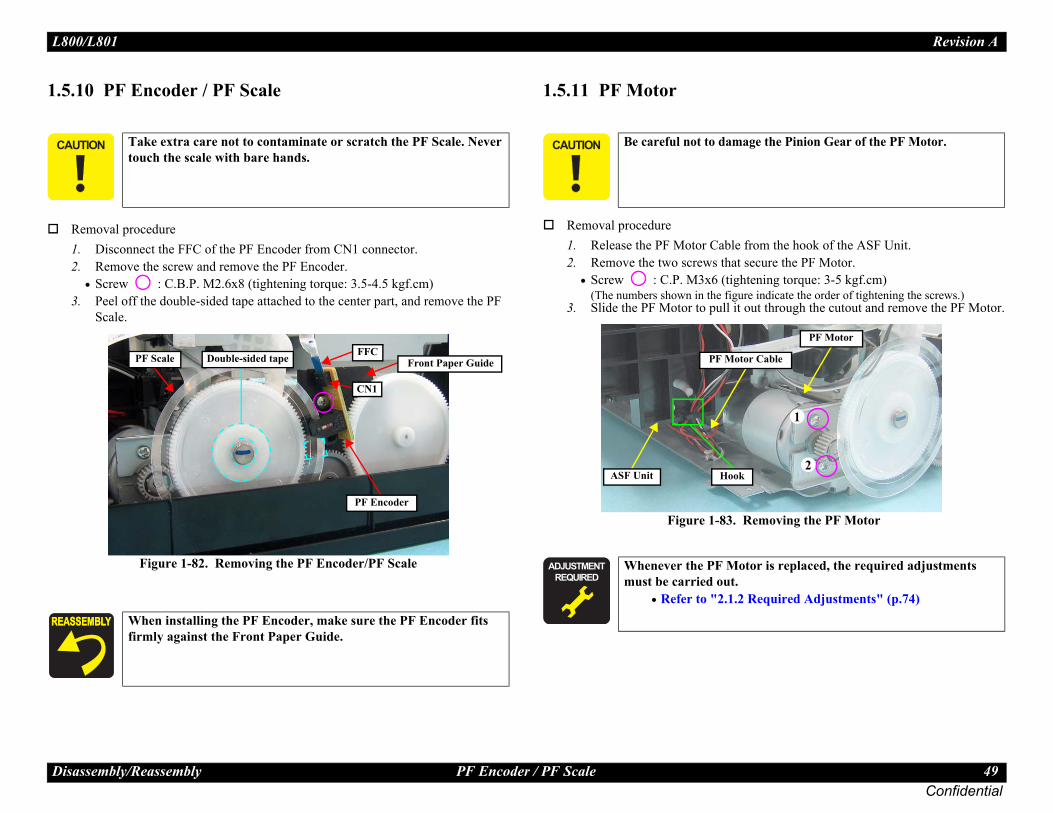
L80 Revision A
Dis 49Confidential
1.5.
R12
3
from the hook of the ASF Unit.secure the PF Motor.tening torque: 3-5 kgf.cm) re indicate the order of tightening the screws.)out through the cutout and remove the PF Motor.
Removing the PF Motor
� � age the Pinion Gear of the PF Motor.
tor is replaced, the required adjustments
Required Adjustments" (p.74)
PF Motor
1
2
or Cable
0/L801
assembly/Reassembly PF Encoder / PF Scale
10 PF Encoder / PF Scale
emoval procedure. Disconnect the FFC of the PF Encoder from CN1 connector.. Remove the screw and remove the PF Encoder.
• Screw : C.B.P. M2.6x8 (tightening torque: 3.5-4.5 kgf.cm) . Peel off the double-sided tape attached to the center part, and remove the PF
Scale.
Figure 1-82. Removing the PF Encoder/PF Scale
1.5.11 PF Motor
Removal procedure1. Release the PF Motor Cable 2. Remove the two screws that
• Screw : C.P. M3x6 (tigh(The numbers shown in the figu
3. Slide the PF Motor to pull it
Figure 1-83.
� � � Take extra care not to contaminate or scratch the PF Scale. Never touch the scale with bare hands.
When installing the PF Encoder, make sure the PF Encoder fits firmly against the Front Paper Guide.
PF Scale Double-sided tape FFC
PF Encoder
CN1
Front Paper Guide
� � � � � Be careful not to dam
� � � � � � � �
� � � � � � � �
Whenever the PF Momust be carried out.
• Refer to "2.1.2
ASF Unit
PF Mot
Hook
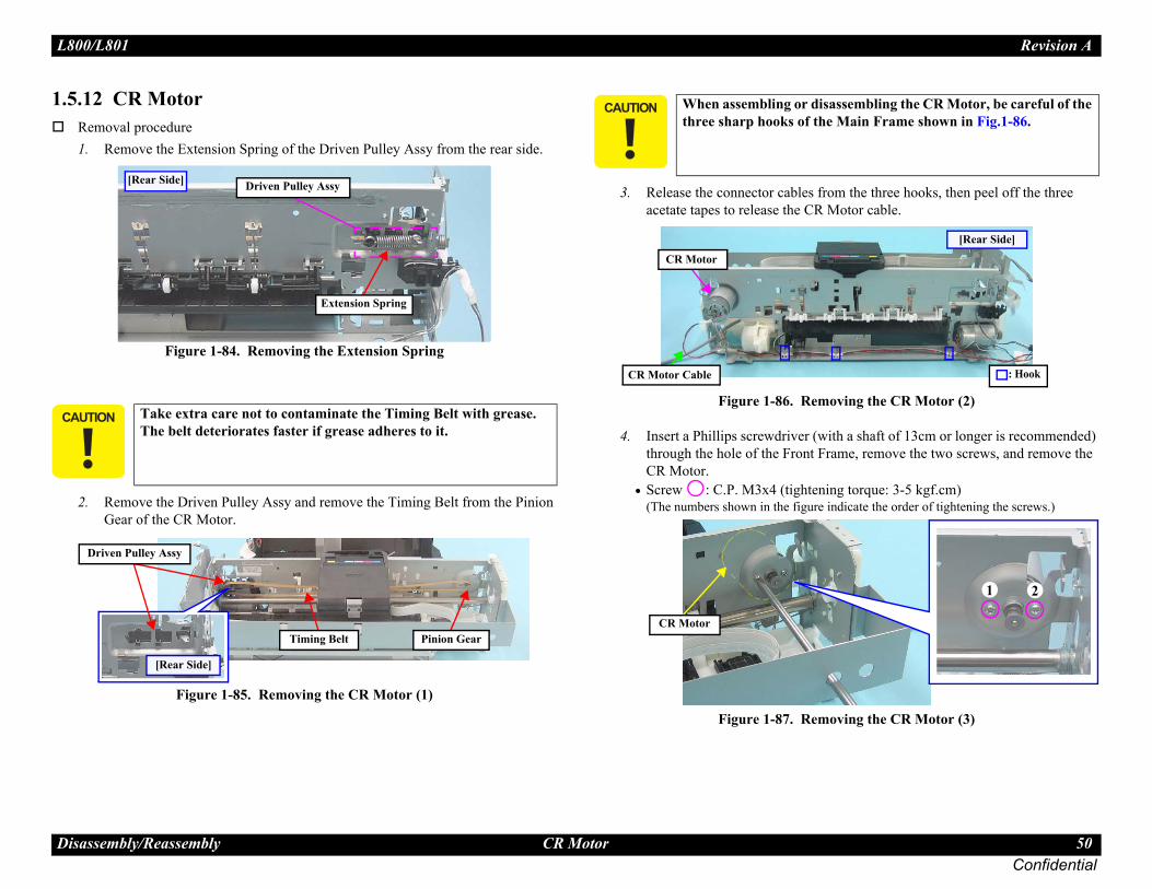
L80 Revision A
Dis 50Confidential
1.5.R1
2
from the three hooks, then peel off the three R Motor cable.
moving the CR Motor (2)
(with a shaft of 13cm or longer is recommended) Frame, remove the two screws, and remove the
ning torque: 3-5 kgf.cm) re indicate the order of tightening the screws.)
moving the CR Motor (3)
� �
isassembling the CR Motor, be careful of the the Main Frame shown in Fig.1-86.
: Hook
[Rear Side]
1 2
0/L801
assembly/Reassembly CR Motor
12 CR Motoremoval procedure. Remove the Extension Spring of the Driven Pulley Assy from the rear side.
Figure 1-84. Removing the Extension Spring
. Remove the Driven Pulley Assy and remove the Timing Belt from the Pinion Gear of the CR Motor.
Figure 1-85. Removing the CR Motor (1)
3. Release the connector cablesacetate tapes to release the C
Figure 1-86. Re
4. Insert a Phillips screwdriver through the hole of the FrontCR Motor.
• Screw : C.P. M3x4 (tighte(The numbers shown in the figu
Figure 1-87. Re
� � � Take extra care not to contaminate the Timing Belt with grease. The belt deteriorates faster if grease adheres to it.
Driven Pulley Assy
Extension Spring
[Rear Side]
[Rear Side]
Driven Pulley Assy
Pinion GearTiming Belt
� � � � � When assembling or dthree sharp hooks of
CR Motor
CR Motor Cable
CR Motor

L80 Revision A
Dis 51Confidential
d. See the page given below for the n. Pulley (p.90) Motor, install it so that the print side
Reinstalling the CR Motor
is replaced, the required adjustments
uired Adjustments" (p.74)
0/L801
assembly/Reassembly CR Motor
When routing the CR Motor Cable and PE Sensor Cable, refer to Fig.1-88 and follow the steps below.1. Wrap the CR Motor Cable with the acetate tape A (30 mm)
at the position of 100 mm away from the acetate tape that is on the CR Motor side.
2. Tie the two cables together with the acetate tape B (20 mm) at the position 60mm/40mm away from the acetate tape A/PE Sensor connector.
3. Route the center of the acetate tape A behind the convex portion of the Main Frame, and secure the tied cables with the hook (1) at the center of the acetate tape B so that the CR Motor Cable faces toward you.
4. Wrap the CR Motor Cable and PE Sensor Cable with acetate tapes (20 mm) at the positions of the hooks (2) (3), then secure the center of the acetate tapes with Hooks (2) (3).
Figure 1-88. Routing the Cable
: Hook
PE Sensor
100mm (between both ends of acetate tapes)
60mm (between both ends of acetate tapes)
PE Sensor Cable40 mm (from connector to end of acetate tape)
2 3
Convex Portion of Main Frame
A
CR Motor
B1
Lubrication is requirelubrication informatioLubrication of DrivenWhen installing the CRfaces upwards.
Figure 1-89.
� � � � � � � �
� � � � � � � �
Whenever the CR Motor must be carried out.
• Refer to "2.1.2 Req
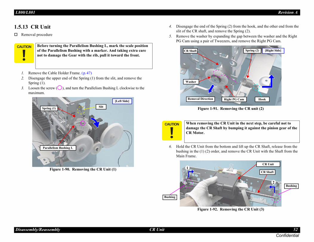
L80 Revision A
Dis 52Confidential
1.5.R
12
3
ing (2) from the hook, and the other end from the ve the Spring (2). ding the gap between the washer and the Right
ezers, and remove the Right PG Cam.
emoving the CR unit (2)
ottom and lift up the CR Shaft, release from the nd remove the CR Unit with the Shaft from the
emoving the CR Unit (3)
� �
R Unit in the next step, be careful not to by bumping it against the pinion gear of the
Right PG Cam
Spring (2)
Hook
[Right Side]
2
CR Shaft
CR Unit
Bushing
0/L801
assembly/Reassembly CR Unit
13 CR Unitemoval procedure
. Remove the Cable Holder Frame. (p.47)
. Disengage the upper end of the Spring (1) from the slit, and remove the Spring (1).
. Loosen the screw ( ), and turn the Parallelism Bushing L clockwise to the maximum.
Figure 1-90. Removing the CR Unit (1)
4. Disengage the end of the Sprslit of the CR shaft, and remo
5. Remove the washer by expanPG Cam using a pair of Twe
Figure 1-91. R
6. Hold the CR Unit from the bbushing in the (1) (2) order, aMain Frame.
Figure 1-92. R
� � � Before turning the Parallelism Bushing L, mark the scale position of the Parallelism Bushing with a marker. And taking extra care not to damage the Gear with the rib, pull it toward the front.
Spring (1)
Parallelism Bushing L
Slit
[Left Side]
� � � � � When removing the Cdamage the CR ShaftCR Motor.
CR Shaft
Washer
Removal Direction
1
Bushing

L80 Revision A
Dis 53Confidential
7
8
9
uired. See the page given below for the ation. Unit (p.92)he right PG cam, remove the APG Unit and tching its phase with the APG Unit.ling the APG Unit (p.41))e spring (2) and the washer for the Right PG aft, make sure to attach them to the
n the CR Shaft. (See Fig.1-91 (p.52))e Timing Belt, make sure that it is not
mpy side comes to the inner side.
96. Reinstalling the Timing Belt
e CR Unit, hook the Guide part to the Main
1-97. Reinstalling the CR Unit
it is removed or replaced, the required carried out. Required Adjustments" (p.74)
Lumpy side (Inner side)
Flat side (Outer side)
py on both inner/outer side
CR Unit
Guide Part
0/L801
assembly/Reassembly CR Unit
. Remove the CR Shaft from the CR Unit.
Figure 1-93. Removing the CR Unit (4)
. Remove the Timing Belt from the CR Unit.
Figure 1-94. Removing the CR Unit (5)
. Disconnect the FFC from the CR Encoder connector, pull out the FFC from the slit of the CR Unit, and remove the Head FFC.
Figure 1-95. Removing the CR Unit (6)
CR Shaft CR Unit
Timing Belt
CR UnitCR Unit
Head FFC CR Unit
Lubrication is reqlubrication informLubrication of CRBefore attaching tinstall the cam ma(Refer to ReinstalWhen attaching thCam to the CR Shpositioning slits oWhen installing thtwisted and the lu
Figure 1-
When installing thFrame.
Figure
� � � � � � � �
� � � � � � � �
Whenever the CR Unadjustments must be
• Refer to "2.1.2
Up
Lum
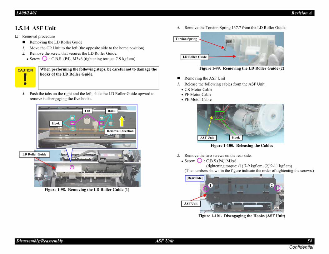
L80 Revision A
Dis 54Confidential
1.5.R
12
3
37.7 from the LD Roller Guide.
ving the LD Roller Guide (2)
from the ASF Unit.
. Releasing the Cables
e rear side.x6 ue: (1) 7-9 kgf.cm, (2) 9-11 kgf.cm) igure indicate the order of tightening the screws.)
gaging the Hooks (ASF Unit)
� �
Hook
2
0/L801
assembly/Reassembly ASF Unit
14 ASF Unitemoval procedure
Removing the LD Roller Guide. Move the CR Unit to the left (the opposite side to the home position). . Remove the screw that secures the LD Roller Guide.
• Screw : C.B.S. (P4), M3x6 (tightening torque: 7-9 kgf.cm)
. Push the tabs on the right and the left, slide the LD Roller Guide upward to remove it disengaging the five hooks.
Figure 1-98. Removing the LD Roller Guide (1)
4. Remove the Torsion Spring 1
Figure 1-99. Remo
Removing the ASF Unit1. Release the following cables
• CR Motor Cable• PF Motor Cable• PE Motor Cable
Figure 1-100
2. Remove the two screws on th• Screw : C.B.S.(P4), M3
(tightening torq(The numbers shown in the f
Figure 1-101. Disen
� � � When performing the following steps, be careful not to damage the hooks of the LD Roller Guide.
LD Roller Guide
Removal Direction
Hook
HookTab
Torsion Spring
LD Roller Guide
ASF Unit
1
ASF Unit
[Rear Side]

L80 Revision A
Dis 55Confidential
3
4
Co
uired. See the page given below for the ation.F Unit (p.94)e ASF Unit, make sure that the Combination
hange Lever and the two hooks are securely ke sure that there is appropriate space at ight of the Change Lever.s in the order given in Fig.1-101 (p.54).ller following the procedure below. Make se referring to the page given below. ASF Unit (p.94)
ller aligning the arrow on the LD Roller with lade of the shaft. Make sure the LD Roller is
without gap or misalignment.
-103. Reinstalling the LD Roller
nit is removed or replaced, the required carried out. Required Adjustments" (p.74)
ASF Unit
Blade LD Roller Shaft
LD Roller
0/L801
assembly/Reassembly ASF Unit
. Disengage the two hooks (1) (2) that secure the ASF Unit from the Main Frame.
. Remove the Combination Gear (10,15.2), then remove the ASF Unit while releasing the edge of the Change Lever from the hole of the Main Frame.
Figure 1-102. Removing the ASF Unit
Change Lever
Hook (2)
Hook (1)
mbination Gear
ASF Unit
Removal Direction
[Rear Side]
Lubrication is reqlubrication informLubrication of ASWhen installing thGear, tip of the Cattached. Also maboth the left and rTighten the screwInstall the LD Rosure to apply greaLubrication of the
1. Install the LD Rothe arrow on the bsecurely attached
Figure 1
� � � � � � � �
� � � � � � � �
Whenever the ASF Uadjustments must be
• Refer to "2.1.2
Align the arrows

L80 Revision A
Dis 56Confidential
1.5.
R1
2
� �
Up
R
e Upper Paper Guide. The two thin shafts ows are likely to break, however, the Upper need to be replaced even if the shafts become hafts do not go on the bushings of the Printer
ree springs, secure the ends of the springs on Frame as shown in Fig.1-106.
1-106. Installing the Springs
aper Guide Assy is removed or replaced, the must be carried out. Required Adjustments" (p.74)
Do not touch with bare hands.
Spring Hook
0/L801
assembly/Reassembly Upper Paper Guide
15 Upper Paper Guide
emoval procedure. Remove the three springs from the rear side, disengage the three hooks and
remove the Upper Paper Guide from the Main Frame.
Figure 1-104. Removing the Upper Paper Guide (1). Remove the Upper paper Guide pressing part to lower the tip of the PE
Sensor Lever.
Figure 1-105. Removing the Upper Paper Guide
� � � Be sure to follow the procedure below to remove the Upper Paper Guide to avoid damaging the PE Sensor Lever. It is recommended to place a transparent sheet between the Upper and Front Paper Guides to avoid scratching the roller.Do not touch the roller surface with bare hands as it can adversely affect the print quality.
Spring
Hook
[Rear Side]
per Paper Guide
emoval Direction
Press
Tip
PE Sensor Lever
� � � �
� � �
The figure below is thindicated with the arrPaper Guide does notbroken. Because the sFrame.
When installing the ththe hooks of the Main
Figure
� � � � � � � �
� � � � � � � �
Whenever the Front Prequired adjustments
• Refer to "2.1.2
Main Frame

L80 Revision A
Dis 57Confidential
1.5.R1
Assy
e the Parallelism Bushing L.8 (tightening torque: 6-8 kgf.cm)
ving the Parallelism Bushing L
ace of the rubber roller of the EJ Roller Assy f the PF Roller Assy as it can adversely affect
Parallelism Bushing L
Front Paper Guide Assy
0/L801
assembly/Reassembly APG Sensor Assy
16 APG Sensor Assyemoval procedure. Disengage the two hooks and remove the APG Sensor Assy.
Figure 1-107. Removing the APG Sensor
1.5.17 Front Paper Guide
Removal procedure1. Remove the screw and remov
• Screw : C.B.S.(P2) M3x
Figure 1-108. Remo
APG Sensor Assy
:Hook
� � � � � Do not touch the surfand the coated part othe print quality.
[Rear Side]
Positioning Hole and Guide Pin

L80 Revision A
Dis 58Confidential
2
3
4
de Assy, following the steps below. the left side of the Front Paper Guide Assy.e by little to disengage the right side of the assy. uide Assy while releasing its shaft from the cutout the Main Frame.
ing the Front Paper Guide Assy
uired. See the page given below for the ation.
ont Paper Guide Assy (p.91)
n
Front Paper Guide Assyt
2
0/L801
assembly/Reassembly Front Paper Guide Assy
. Disconnect the connector of the PE Sensor Cable on the rear side of the printer.
. Remove the screw that secures the Front Paper Guide Assy.• Screw : C.B.S. M3x6 (tightening torque: 7-9 kgf.cm)
Figure 1-109. Removing the PE Sensor Cable
. Pull out the EJ Ground Spring to the front side.
Figure 1-110. Removing the EJ Ground Spring
5. Remove the Front Paper Gui(1) Lift part to disengage (2) Slide the assy leftward littl(3) Remove the Front Paper G
of the rib on the left side of
Figure 1-111. Remov
PE Sensor Cable
Connector Front Paper Guide Assy
Front Paper Guide Assy EJ Ground Spring
Lubrication is reqlubrication informLubrication of Fr
12
Removal Directio
Cutou

L80 Revision A
Dis 59Confidential
s of the Front Paper Guide Pad on the Waste
. Installing Front Paper Guide Pad
arallelism Bushing L, match the positioning e pin shown in Fig.1-108 (p.57).
aper Guide Assy is removed or replaced, the must be carried out. Required Adjustments" (p.74)
r
Waste Ink Pad Position
Tip Tip
0/L801
assembly/Reassembly Front Paper Guide Assy
When installing the Front Paper Guide Assy, pull out the CDR Tray Sensor cable as shown below.
Figure 1-112. Routing the CDR Tray Sensor Cable
Attach the long foot of the EJ Ground Spring as follows; (1) put it through the gap under the portion contacts with the EJ Roller, (2) let it contact with the Main Frame, (3) let it contact with the PF Roller shaft, (4) put it through the hole on the frame. When finished, make sure the spring properly contacts with (1), (2), (3), and (4) points.
Figure 1-113. Attaching the EJ Ground Spring
Be careful not to deform the EJ Ground Spring.
[Left Front Bottom Side]
Pull out the cable from here
CDR Tray Sensor Cable
12
Contacts with PF Roller Shaft Long foot of EJ Ground Spring
Contacts with Main Frame
4
3
Contacts with EJ Roller shaft
4
Hole
Gap
1
Place the four tipInk Pad.
Figure 1-114
When installing Phole with the guid
� � � � � � � �
� � � � � � � �
Whenever the Front Prequired adjustments
• Refer to "2.1.2
[Bottom Side]
Tip of Front PapeGuide Pad

L80 Revision A
Dis 60Confidential
1.5.R
12
� �
0/L801
assembly/Reassembly CDR Tray Sensor
18 CDR Tray Sensoremoval procedure
. Disengage the hook of the CDR Tray Sensor.
. Turn the CDR Tray Sensor 90 degrees in the direction of the arrow to disengage its another hook, and pull it out from the hole to remove it together with the CDR Guide Sensor.
Figure 1-115. Removing the CDR Tray Sensor
� � � Always follow the steps below to remove the CDR Tray Sensor, or one of its hooks can be broken.
90-degrees Turn
Hook
CDR Tray Sensor

L80 Revision A
Dis 61Confidential
1.6
1.6.
el, align it with the markings on the Top Cover as
Marking
0/L801
assembly/Reassembly Refilling Ink Label / Valve Position Label
Disassembling the CISS section
1 Refilling Ink Label / Valve Position Label
1.6.2 Top Cover
Attach the Refilling Ink Label and Valve Position Label according to the standards shown in the figure above.
103 mm
67 mm
6.4 mm
7.5 mm 7.5 mm
Refilling Ink Label
Valve Position LabelWhen attaching the Top Cover Labshown in the figure above.
Marking

L80 Revision A
Dis 62Confidential
1.6.
TH
emoving the Valve Lever.ssy from the printer.driver or the like into the gap between the Right er Rear to release the hook of the Valve Lever, and
Flathead precision screwdriver
Right Cover
k
Tube Valve Holder Rear
0/L801
assembly/Reassembly Tube Valve Holder Front / Rear
3 Tube Valve Holder Front / Rear 1.6.4 Valve Lever
When routing the Ink Supply Tank Tubes, align them with their red lines facing the Tube Valve Holder Front without any twist.
Follow the procedure below when installing the Tube Valve Holder Rear.1. Insert the ribs (x2) of the Tube Valve Holder Rear under the hooks (x2) of the Valve
Case.2. Align the dowels (x4) of the Tube Valve Holder Rear with the positioning holes (x2)
of the Ink Supply Tank and the positioning holes (x2) of the Tube Valve Holder Front.3. Make sure no Ink Supply Tank Tubes are caught, then secure it with the screws (x3) in
the order shown in the above figure.
Hook
CBP. 3X6 (3-5kgf.cm)
Valve Case Tube Valve Holder Rear
Tube Valve Holder Front
Ink Supply Tank Tube
1 2
3
Rib
Back side Tube Valve Holder Rear
Valve Case
Ink Supply Tank
Tube Valve Holder Front
Positioning Hole Dowelube Valve older Rear
Ink Supply Tank Tube
Follow the procedure below when r1. Remove the Ink Supply Tank A2. Insert a flathead precision screw
Cover and the Tube Valve Holdthen remove the Valve Lever.
Ink Supply Tank Assy
Valve Lever
Hoo

L80 Revision A
Dis 63Confidential
1.6.
nk Assy when disassembling/reassembling” (p.10).)
Right Cover
Cover Joint
0/L801
assembly/Reassembly Bottom Cover / Left Cover / Right Cover / Cover Joint
5 Bottom Cover / Left Cover / Right Cover / Cover Joint
Be careful about how to place the Ink Supply Tank Assy in order to prevent printing failure from occurring. (See “How to place the Ink Ta
The figures above indicate the hooks and ribs that secure the parts.Remove the exterior parts of the Ink Supply Tank Assy in the following order.
1. Remove the screws (x8) of the Bottom Cover, and remove the Bottom Cover.2. Remove the Left Cover and Right Cover.3. Remove the Cover Joint.
Tighten the screws in the order indicated in the figure above.
Ink Supply Tank Assy
HookRib
Left Cover
Bottom Cover
C.B.P. 3X6 (3-5kgf.cm)
1
2 3 4 5 6 7
8

L80 Revision A
Dis 64Confidential
1.6. Assy
the red lines facing upward (as viewed when on the printer) and connect them to the Ink
Tubes to the Ink Supply Tank, confirm the upply Tank, and take care not to connect them
Tubes to the Ink Supply Tank, insert the tubes een the end of tubes and the tank are 0.5 mm
Black
Magenta
Yellow
Cyan
120 ± 1 mm
359 ± 4 mm
280 ± 3 mmLight Magenta 310 ± 3 mm
388 ± 4 mm
258 ± 3 mm
Light Cyan 333 ± 3 mm
211 ± 1 mm
lamp Joint
Valve CaseInk Supply Tank Tubes
CMLM
k
0/L801
assembly/Reassembly Ink Supply Tank Assy
6 Ink Supply Tank Assy 1.6.7 Ink Supply Tank Tube
Be careful not to damage or peel off the film of the Ink Supply Tank.Be careful about how to place the Ink Supply Tank Assy in order to prevent printing failure from occurring. (See “How to place the Ink Tank Assy when disassembling/reassembling” (p.10).)
Film
Ink Supply Tank
Route the Ink Supply Tank Tubes withthe Ink Supply Tank Assy is installed Supply Tank Assy without any twist.When connecting the Ink Supply Tankcolor indicated on the film of the Ink Swith wrong joints.When connecting the Ink Supply Tankto the full and make sure the gaps betwlong or less.
Ink Supply Tank Tube
0.5 mm or less
Valve Case Tube C
LCBkY
Ink Supply Tan

L80 Revision A
Dis 65Confidential
1.6.
with the edges of the front frame.
ing the Cover Case.
the dowels (x2) on the bottom of the Cover
of the arrow (1) to avoid the section A and B of the Front Frame.n of the arrow (2) while avoiding the section C st the Front Frame.
Section A
Section B
Cover Case
Section C
f.cm)
Cover Case
nt Frame
owel
1
2
n where Front Frame may interfere.
0/L801
assembly/Reassembly Joint
8 Joint 1.6.9 Cover Case
Make sure the red lines of the Ink Supply Tank Tube and Ink Supply Tube facing upward.When attaching the Joint, align the cutout of the Joint with the rib of the Cover Case.Make sure the gaps between the end of Ink Supply Tank Tubes or Ink Supply Tubes and the Joint are 0.5 mm long or less.
0.5 mm or less
Ink Supply Tube
Ink Supply Tank Tube
Joint
0.5 mm or less
Front
Adapter Side
Tank Side
Joint
Back
Adapter Side
Tank Side
Joint
Joint
Rib
Ink Supply Tube
Cover Case
JointCutout
Be careful not to damage the Cover Case
Follow the procedure below when remov1. Remove the screw (x1).2. Lift the Cover Case slightly to release
Case.3. Rotate the Cover Case in the direction
the Cover Case from bumping against 4. Remove the Cover Case in the directio
of the Cover Case from bumping again
C.B.P. 3X8 (5-7kg
Cover Case
Fro
Front FrameD
1
The location where Front Frame may interfere.
The locatio

L80 Revision A
Dis 66Confidential
1.6. / Tube Guide Sheet Sub
PF
w the procedure below when attaching the Tube ide Sheet.
be Guide Sheet Sub into the hole 1 of the Tube Guide
be Guide Sheet Sub into the hole 2 of the Tube Guide
Sheet to the Tube Guide, while keeping the Tube Tube Guide Sheet, align the holes of the Tube Guide
e Tube Guide.
Hole 2
Section A
Tube Guide Sheet Sub
Hole 2Tube Guide Sheet Sub
Tube Guide Sheet
Tube Guide Sheet
Tube Guide
0/L801
assembly/Reassembly PF Scale Cover / PF Scale Sheet
10 PF Scale Cover / PF Scale Sheet 1.6.11 Tube Guide Sheet
Follow the procedure below when attaching the PF Scale Cover/PF Scale Sheet.1. Wipe off the area on the Main Frame shown above using a cloth moistened with
alcohol.2. Align the PF Scale Cover with the rib of the Front Paper Guide Assy, and attach the
PF Scale Cover.3. Align the screw holes of the PF Scale Cover and Front Paper Guide Assy, and secure
the PF Scale Cover with the screw (x1).4. After the alcohol dried out completely, insert the section A of the PF Scale Sheet into
the groove of the Front Paper Guide Assy, and then attach it with double-sided tape.
Wiping Area
Main Frame
CBP. 3X8 (5-7kgf.cm)
PF Scale Cover
PF Scale Cover PF Scale Sheet
Groove
Front Paper Guide Assy
Rib
Double-sided tapeattachment position
Double-sided tape
attachment position
Section A
Scale Sheet
Refer the figure above and folloGuide Sheet Sub to the Tube Gu
1. Insert the section A of the TuSheet from the bottom.
2. Insert the section A of the TuSheet from the top.
When attaching the Tube GuideGuide Sheet Sub attached on theSheet with the protrusions of th
Hole 1
Tube Guide Sheet
OK
Cross Section
NG
Hole 1
Tube Guide Sheet

L80 Revision A
Dis 67Confidential
1.6.
ube 70 mm from the Tube Clamp nearest to the Adapter.
rooves as shown in the figure above.
Tube Holders
Ink Supply Tube
1
23
CBP. 3X8 (5-7kgf.cm)
Joint
St
NG
Ink Supply Tube
Tube Guide Sheet Sub
Section A Hole
k Supply Tube
Hole
In
0/L801
assembly/Reassembly Ink Supply Tube Assy
12 Ink Supply Tube Assy
Make sure the Tube Clamps (with Porous Pad Tube attached) (x3) are attached on the positions on the Ink Supply Tube shown above.
Follow the procedure below when installing the Ink Supply Tube Assy.1. Place the Ink Supply Tube onto the Tube Guide Sheet with its Tube Porous Pad side down.2. Connect the Ink Supply Tubes (x6) to the Joint.3. Insert the section A of the Tube Guide Sheet Sub from the top into the hole of the Tube Guide Sheet Sub to secure it.4. Attach the Tube Holders (x3) and secure them with the screws in the order shown in the figure above.5. Hold the Ink Supply Tube by the Adapter side and flip it over as shown in the figure, then put a marking on the bottom side of the Ink Supply T6. Connect the Ink Supply Tube to the Adapter, and install the Adapter to the CR Unit. (p.68)7. Route the Ink Supply Tubes through the grooves of the CR Unit, and align the markings on the Ink Supply Tubes with the edge of the g
CR UnitStep1-2,4
Ink Supply Tube
Tube Porous Pad
Tube Clamps
ep5Markings
70 mm
Adapter
Ink Supply TubeAlign markings with
edge of grooves.
CR UnitStep7
Grooves
OK
In
Section A
Tube Guide Sheet Sub
90 mm 70 mm 75 mm 55 mm
Black
MagentaLight Magenta
Yellow
Cyan
Light Cyan
Joint sideAdapter Assy side Markings (on the back) Tube ClampsInk Supply Tube
k Supply Tube Assy
Step3

L80 Revision A
Dis 68Confidential
1.6.
f the film of the Adapter.
eleasing the hooks of the Adapter.
bes to the Adapter, make sure the red lines on the Ink shown in the figure above.
Ink Supply Tube
Connection of Ink Supply Tubes
Hook
0/L801
assembly/Reassembly Adapter Cover
13 Adapter Cover 1.6.14 Adapter
Follow the procedure below when installing the Adapter Cover to the CR Unit.1. Attach the Tube Guide Sheet to the Adapter Cover.2. Insert the dowels (x2) of the Adapter Cover into the holes (x2) of the CR Unit and
engage the hook of the Adapter Cover to the CR Unit.3. Make sure no Ink Supply Tubes are caught, then secure the Adapter Cover with the
screw (x1).After installing the Adapter Cover to the CR Unit, move the CR Unit from side to side while holding the Timing Belt to make sure that the Ink Supply Tube Assy does not apply extra load of the CR Unit movement.
CBP. 3X8 (5-7kgf.cm)
CR Unit
Adapter Cover
Ink Supply Tube Assy Hole
Dowel
Hook
Adapter Cover
Tube Guide Sheet
Timing Belt
Be careful not to damage or peel of
Use a precision screwdriver when r
When connecting the Ink Supply TuSupply Tubes are facing upward as
Adapter
Film
Hook
Adapter

Confidential
C H A P T E R
2JUSTMENT
AD
L80 Revision A
Adj 70Confidential
2.1Thisof th
2.1.The
n how to carry out the adjustments and r the adjustments, see the instructions djustment Program.his manual are for Epson Stylus Photo R280/fore, the shapes of the parts are different 0/L801, but the differences does not affect the
ures.
e Tool
PG a
gauges. Make a proper the manually-moved st the gauges placed on the
• Thickness Gauge1.15 mm, 1.3 mm
EEP
board before removing it. d load the EEPROM data to
• Adjustment Program
Initi
et settings are automatically
re-enter (for confirmation) ut button.
• Adjustment Program
Healabel attached on the atically written to the main
• Adjustment Program
Initioffse
• Adjustment Program
Diseoffse
0). • Adjustment Program
TOP. Examine the lines printed the value for the line that is
• Adjustment Program• Ruler
0/L801
ustment Adjustment Items and Overview
Adjustment Items and Overview chapter describes adjustments necessary after the disassembly/reassembly e printer.
1 Servicing Adjustment Item Listadjustment items of this product are as follows.
� � � �
� � �
For information omedia required fodisplayed by the ASome pictures in tR285/R290; therefrom those of L80adjustment proced
Table 2-1. Adjustment ItemsAdjustment Item Purpose Method Outlin
djustment
Install the Head Nozzle surface parallel to the printing surface and set the gap between the paper and the Head Nozzle surface to the specified value.
Mechanical adjustment using the thicknessadjustment according to the result whethercarriage (printhead) runs over or hits againplaten.
ROM data copy
When the main board needs to be replaced, use this to copy adjustment values stored on the old main board to the new board. If this copy is completed successfully, all the other adjustments required after replacing the main board are no longer be necessary.
Readout the EEPROM data from the mainThen replace the board with a new one, anthe new board.
al setting
This must be carried out after replacing the main board to apply settings for the target market. When this function is performed, the upper limit value of the ink tube counter is automatically set. With this function, the serial number written on the main board can be checked, and also writing the serial number to the main board can be performed when replacing the board.
Select the target market. The selected markwritten to the main board.When writing the serial number, enter and the printer serial number, then press the inp
d ID inputThis must be carried out after replacing the printhead in order to enter the new printhead ID (Head ID) that reduces variation between printheads.
Enter the ID printed on the Head QR code printhead. The correction values are automboard.
alize PF deterioration t
Resets the counter to maintain paper feed accuracy which decreases due to paper dust.
Reset the counter to its default.
nable PF deterioration t
When reading the counter value from the old main board is impossible in the case of replacing the board, use this to set the counter to its maximum value.
Set the counter to its maximum value (300
margin adjustmentThis corrects top margin of printout. A top margin adjustment pattern is printed
near the top edge of the printout, and enterexactly 3 mm away from the top edge.

L80 Revision A
Adj 71Confidential
Hea d. Examine the printed lines es.
• Adjustment Program
Bi-D ine the patterns and enter verlap for each mode.
• Adjustment Program
Firstadju
amine the lines printed near alue for the line that is
• Adjustment Program• Ruler
PW ine the printout patterns and mm away from the paper om.
PF a e the printout patterns and rrection value is registered.
• Adjustment Program
BRS
by a specified scanner. n value is automatically OM on the main board.
ing in the corresponding ales are required. See “2.3 ent / Paper Feed Amount
• Specified Scanner• PFP base scale
CR cont
ection values are • Adjustment Program
e Tool
0/L801
ustment Adjustment Items and Overview
d angular adjustment This must be carried out after replacing the printhead in order to correct tilt of the printhead by software.
A head angular adjustment pattern is printeand enter the value for the most straight lin
adjustment Corrects print start timing in bi-directional printing to improve the print quality.
A Bi-D adjustment pattern is printed. Examthe value for the pattern with no gap and o
dot position stment
Corrects left margin of printout. The print start position in the carriage moving direction is corrected by software.
A first dot adjustment pattern is printed. Exthe left edge of the printout and enter the vexactly 5 mm away from the left edge.
adjustmentThis adjustment is made to correct the mounting position of the PW Sensor on a software basis to adjust the detection position and Nozzle position dispersion.
A PW adjustment pattern is printed. Examenter the value for the line that is exactly 5edge for each of the left, right, top and bott
djustment Corrects variations in paper feed accuracy when using the Microweave to achieve higher print quality.
A PF adjustment pattern is printed. Examinselect the value for the best pattern. The co
/PFP adjustment
This adjustment is made to ensure high print quality at high print speed. Print the adjustment pattern to be scanned According to the scanned result, a correctiocalculated and stored into the serial flash RThe correction value is applied when printmode. For some scanners, two PFP base scBanding Reduction System (BRS) AdjustmProfile (PFP) Correction (p.83)”.
motor heat protection rol
This must be carried out for efficient heat control of the CR motor. Electrical variation of the motor and the power supply board are measured to acquire correction values for them.
Select the parts that you replaced. The corrautomatically written to the main board.
Table 2-1. Adjustment ItemsAdjustment Item Purpose Method Outlin

L80 Revision A
Adj 72Confidential
M e Tool
Head
al cleaning or the power ink amount to the waste ink option. The head cleaning is , print a nozzle check pattern ly.
• Adjustment Program
Main
sponding counters. • Adjustment Program
Ink
arge to Printhead only or the ead. Whether to reflect the counter or not can also be
and then press the execute cted range automatically.rn to check if all nozzles are
• Adjustment Program
Sma
nter value is automatically message which says the reset will be made.
• Adjustment Program
e Tool
Finalprint
matically. • Adjustment Program
EEPR dout and stored as a file. • Adjustment Program
0/L801
ustment Adjustment Items and Overview
Table 2-2. Maintenance Itemsaintenance Item Purpose Method Outlin
cleaning
This function is used to execute Cleaning efficiently when ink is not delivered from the Head properly, e.g. dot missing.
The cleaning can be selected from the normcleaning. Whether to reflect the discharged pad counter or not can also be selected as anperformed automatically. After the cleaningto check if all nozzles are firing ink proper
tenance counter
The printer causes a maintenance error when the maintenance counter (for the Waste Ink Tray, Waste Ink Pad Lower) reaches its maximum. Use this to reset the counter after replacing the Waste Ink Pad and Waste Ink Pad Lower, and use this to reset the ink tube counter when replacing the Ink Supply Tube. If you find the counter is close to the maximum during servicing, carry out the pad replacement and the counter reset to avoid the printer returned from the user due to the maintenance error.
Select the replaced parts, and reset the corre
charge
This function is used to charge ink to the components composing the ink path such as Printhead after replacing them.
The ink charge can be selected from the chcharge through Ink Tube, Adapter to Printhdischarged ink amount to the waste ink padselected as an option.Select the range to charge ink and options,button to execute the ink charge to the seleAfter ink charge, print a nozzle check pattefiring ink properly.
ll ink counter reset
When an ink out error occurs even though some ink is still in the Ink Supply Tank Assy (in the case when the ink counter in the printer and the actual ink remaining amount do not match), this function can decrease the ink counter (resetting the counter partially) to adjust the counter with the actual ink remaining amount.
If the execute button is pressed, the ink couset. But if no ink out error is occurring, the function cannot be executed appears and no
Table 2-3. Additional FunctionsAdditional Functions Purpose Method Outlin
check pattern A4 size Use this to check if the all adjustments have been properly made.
The all adjustment patterns are printed auto
US Letter size
OM dump Use this to readout the EEPROM data for analysis. The all EEPROM data is automatically rea
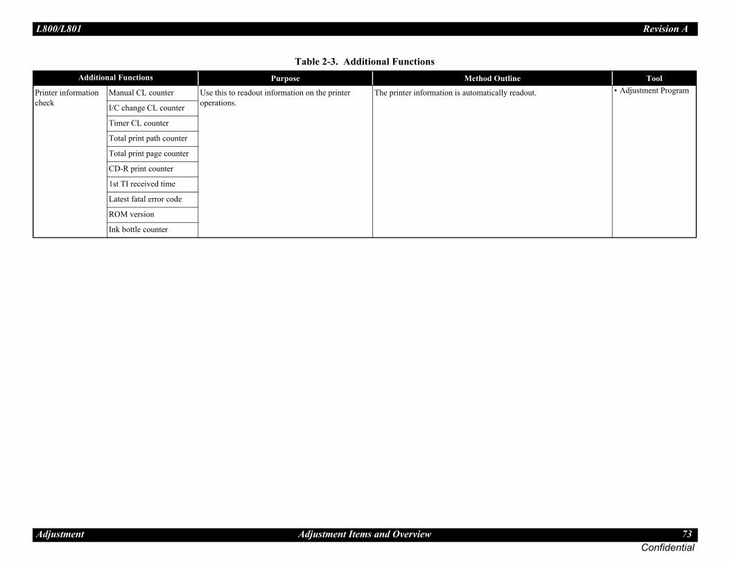
L80 Revision A
Adj 73Confidential
Printchec
adout. • Adjustment Programe Tool
0/L801
ustment Adjustment Items and Overview
er information k
Manual CL counter Use this to readout information on the printer operations.
The printer information is automatically re
I/C change CL counter
Timer CL counter
Total print path counter
Total print page counter
CD-R print counter
1st TI received time
Latest fatal error code
ROM version
Ink bottle counter
Table 2-3. Additional FunctionsAdditional Functions Purpose Method Outlin

L80 Revision A
Adj 74Confidential
2.1.The removed or replaced, and check which adjuNote
ent is not required.ents must be carried out, be sure to carry out them in
11 12 13 14 15 16 17
Bi-D
adj
ustm
ent
Firs
t dot
pos
ition
adj
ustm
ent
PW a
djus
tmen
t
PF a
djus
tmen
t
BR
S ad
just
men
t
PFP
adju
stm
ent
CR
mot
or h
eat
prot
ectio
n co
ntro
l
ASF-- O -- O -- O --
-- O -- O -- O --
CR O* -- -- -- -- -- --
O* -- -- -- -- -- O
Upp-- -- -- O O O --
-- -- -- O O O --
PrinO O O O O O --
O O O O O O --
Mai
-- -- -- -- -- -- --
-- -- -- -- -- -- O
O O O O O O O
P/S -- -- -- -- -- -- --
-- -- -- -- -- -- O
0/L801
ustment Adjustment Items and Overview
2 Required Adjustmentstable below lists the required adjustments depending upon the parts being repaired or replaced. Find the part(s) youstment(s) must be carried out.: <Meaning of the marks in the table>
“O” indicates that the adjustment must be carried out. “O*” indicates that the adjustment is recommended. “---” indicates that the adjustmIf you have removed or replaced multiple parts, make sure to check the required adjustments for the all parts. And when multiple adjustmthe order given in the “Priority” row.
Table 2-4. Adjustment ItemsPriority 1 2 3 4 5 6 7 8 9 10
PG a
djus
tmen
t
EE
PRO
M d
ata
copy
Initi
al se
ttin
g
Hea
d ID
inpu
t
Mai
nten
ance
cou
nter
Ink
char
ge
Initi
aliz
e PF
det
erio
ratio
n of
fset
Dis
enab
le
PF d
eter
iora
tion
offs
et
Top
mar
gin
adju
stm
ent
Hea
d an
gula
r ad
just
men
t
UnitRemove -- -- -- -- -- -- -- -- O --
Replace -- -- -- -- -- -- -- -- O --
MotorRemove -- -- -- -- -- -- -- -- -- --
Replace -- -- -- -- -- -- -- -- -- --
er Paper Guide Remove -- -- -- -- -- -- -- -- O --
Replace -- -- -- -- -- -- -- -- O --
theadRemove O -- -- -- -- -- -- -- O O
Replace O -- -- O -- O -- -- O O
n Board
Remove -- -- -- -- -- -- -- -- -- --Replace(Read OK)
-- O -- -- -- -- -- -- -- --
Replace(Read NG)
-- -- O OO
(Ink Pads must be replaced)
-- -- O O O
AssyRemove -- -- -- -- -- -- -- -- -- --
Replace -- -- -- -- -- -- -- -- -- --
Adjustment Item
Part Name
Adjustment Item
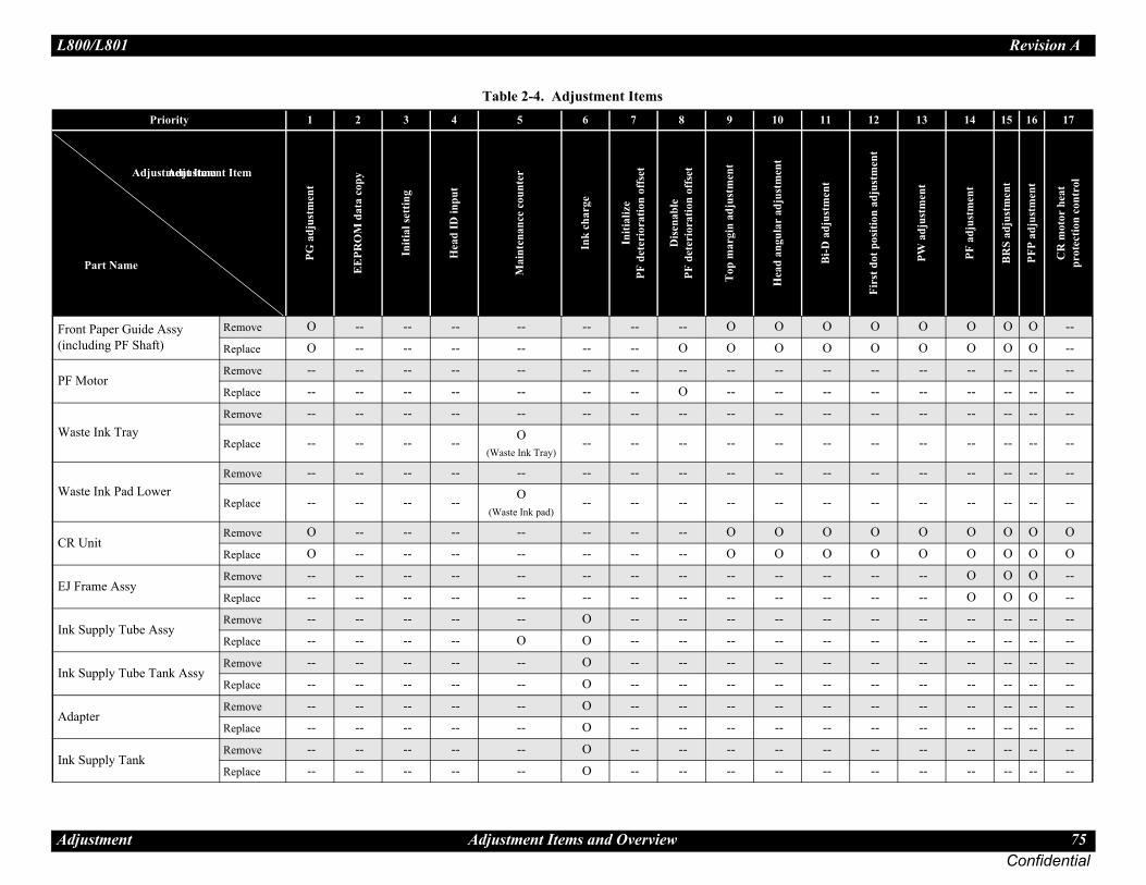
L80 Revision A
Adj 75Confidential
Fron(incl
O O O O O O --
O O O O O O --
PF M-- -- -- -- -- -- --
-- -- -- -- -- -- --
Was-- -- -- -- -- -- --
-- -- -- -- -- -- --
Was-- -- -- -- -- -- --
-- -- -- -- -- -- --
CR O O O O O O O
O O O O O O O
EJ F-- -- -- O O O --
-- -- -- O O O --
Ink -- -- -- -- -- -- --
-- -- -- -- -- -- --
Ink -- -- -- -- -- -- --
-- -- -- -- -- -- --
Ada-- -- -- -- -- -- --
-- -- -- -- -- -- --
Ink -- -- -- -- -- -- --
-- -- -- -- -- -- --
11 12 13 14 15 16 17
Bi-D
adj
ustm
ent
Firs
t dot
pos
ition
adj
ustm
ent
PW a
djus
tmen
t
PF a
djus
tmen
t
BR
S ad
just
men
t
PFP
adju
stm
ent
CR
mot
or h
eat
prot
ectio
n co
ntro
l
0/L801
ustment Adjustment Items and Overview
t Paper Guide Assy uding PF Shaft)
Remove O -- -- -- -- -- -- -- O O
Replace O -- -- -- -- -- -- O O O
otorRemove -- -- -- -- -- -- -- -- -- --
Replace -- -- -- -- -- -- -- O -- --
te Ink TrayRemove -- -- -- -- -- -- -- -- -- --
Replace -- -- -- -- O(Waste Ink Tray)
-- -- -- -- --
te Ink Pad LowerRemove -- -- -- -- -- -- -- -- -- --
Replace -- -- -- -- O(Waste Ink pad)
-- -- -- -- --
UnitRemove O -- -- -- -- -- -- -- O O
Replace O -- -- -- -- -- -- -- O O
rame AssyRemove -- -- -- -- -- -- -- -- -- --
Replace -- -- -- -- -- -- -- -- -- --
Supply Tube AssyRemove -- -- -- -- -- O -- -- -- --
Replace -- -- -- -- O O -- -- -- --
Supply Tube Tank AssyRemove -- -- -- -- -- O -- -- -- --
Replace -- -- -- -- -- O -- -- -- --
pterRemove -- -- -- -- -- O -- -- -- --
Replace -- -- -- -- -- O -- -- -- --
Supply TankRemove -- -- -- -- -- O -- -- -- --
Replace -- -- -- -- -- O -- -- -- --
Table 2-4. Adjustment ItemsPriority 1 2 3 4 5 6 7 8 9 10
PG a
djus
tmen
t
EE
PRO
M d
ata
copy
Initi
al se
ttin
g
Hea
d ID
inpu
t
Mai
nten
ance
cou
nter
Ink
char
ge
Initi
aliz
e PF
det
erio
ratio
n of
fset
Dis
enab
le
PF d
eter
iora
tion
offs
et
Top
mar
gin
adju
stm
ent
Hea
d an
gula
r ad
just
men
t
Adjustment Item
Part Name
Adjustment Item

L80 Revision A
Adj 76Confidential
Join-- -- -- -- -- -- --
-- -- -- -- -- -- --
Prin-- -- -- -- -- -- --
O O O O O O O
11 12 13 14 15 16 17
Bi-D
adj
ustm
ent
Firs
t dot
pos
ition
adj
ustm
ent
PW a
djus
tmen
t
PF a
djus
tmen
t
BR
S ad
just
men
t
PFP
adju
stm
ent
CR
mot
or h
eat
prot
ectio
n co
ntro
l
0/L801
ustment Adjustment Items and Overview
tRemove -- -- -- -- -- O -- -- -- --
Replace -- -- -- -- -- O -- -- -- --
ter MechanismRemove -- -- -- -- -- O -- -- -- --
Replace O -- -- -- -- O O -- O O
Table 2-4. Adjustment ItemsPriority 1 2 3 4 5 6 7 8 9 10
PG a
djus
tmen
t
EE
PRO
M d
ata
copy
Initi
al se
ttin
g
Hea
d ID
inpu
t
Mai
nten
ance
cou
nter
Ink
char
ge
Initi
aliz
e PF
det
erio
ratio
n of
fset
Dis
enab
le
PF d
eter
iora
tion
offs
et
Top
mar
gin
adju
stm
ent
Hea
d an
gula
r ad
just
men
t
Adjustment Item
Part Name
Adjustment Item

L80 Revision A
Adj 77Confidential
2.2ThisAdjuProg
2.2.Patte
How
Meaany
stment below.
he lines below “0 >> 80” are printed while to the other side, and lines below “80 >> 0” ns to the home.
ular Adjustment (Band) Pattern
enter the value (-16 to 16) for the most
ght lines, it indicates that the printhead is not rinthead and carry out this adjustment again.
t
2
4
6
-16
-14
-12
80 to 0 column
NG OK
0/L801
ustment Using the Adjustment Program
Using the Adjustment Program section describes how to judge the adjustment patterns printed by the stment Program. For information on how to operate the Adjustment ram, see the instructions displayed by the Adjustment Program.
1 Top Margin Adjustmentrns are printed as shown below.
Figure 2-1. Top Margin Adjustment Pattern
to Judge
sure the distance from the top edge of paper to the printed line, and enter one of the “-”, “0”, “+” according to the judging standard.
2.2.2 Head Angular AdjuTwo patterns are printed as shown
Band pattern
The following pattern is printed. Tthe carriage moves from the homeare printed while the carriage retur
Figure 2-2. Head Ang
How to JudgeExamine the printout patterns and straight lines.Additional informationWhen “16” or “-16” is the most straiinstalled correctly. Reassemble the p
[Judging Standard]
The distance from a paper top edge to a line is:• 4 mm or more: Choose the “-” from a combobox.• 2 mm or less: Choose the “+” from a combobox.
� � � �
� � �
Example for judgemen
2
4
6
-16
-14
-12
0 to 80 column

L80 Revision A
Adj 78Confidential
M
How
Examwhic
Add
If no
for each of the 7 print modes.
i-D Adjustment Pattern
erleaps of the left and right pattern, and
ted, enter the nearest value and then print the
� �
�
nt
6
27
28 30 32
25
OK NG
Gapp
0/L801
ustment Using the Adjustment Program
icroweave Pattern
Figure 2-3. Head Angular Adjustment (Microweave) Pattern to Judge
ine the printout +3 to -3 patterns and select the value for the group of h the gaps between the 2 color bars are the smallest.
itional information
appropriate pattern is found, reassemble/replace the Printhead.
2.2.3 Bi-D AdjustmentThe pattern shown below is printed
Figure 2-4. B
How to Judge
Find the pattern with no gaps or oventer the value of that pattern.
Additional information
If an appropriate pattern is not prinpatterns again.
� �
� �
Example for judgement
+3 +2 +1 0 -1 -2 -3
NGOK
Gap
� � � �
� � �
Example for judgeme
220 22 24
NG
Overla

L80 Revision A
Adj 79Confidential
2.2.Patte
xactly 5mm away from the paper edge for m.
0” (top), “0” (right), “5” (bottom) and “-3”
the PW adjustment pattern line and the First e overlap on the left of the paper.
2” since the lines overlap at “2” position.
0/L801
ustment Using the Adjustment Program
4 PW Adjustment/First Dot Position Adjustmentrns are printed as shown below.
Figure 2-5. PW/First Dot Position Adjustment Pattern
PW adjustment
How to Judge
Enter the value for the line that is eeach of the left, right, top and botto
Example: In the left figure, enter “(left).
First dot position adjustment
How to Judge
Enter the value for the point wheredot position adjustment pattern lin
Example: In the left figure, enter “
-8-7-6-5-4-3-2-1012345678910111213141516171819
-5 -4 -3 -2 -1 0 1 2 3 4 5 6 7 8 9 10 11 12 13 14 15
-5-4-3-2-10123456789101112131415
-8-7-6-5-4-3-2-1012345678910111213141516171819
5 mm
Area where A and B overlap
A: PW adjustment pattern line (left)
B: First dot position adjustment pattern line
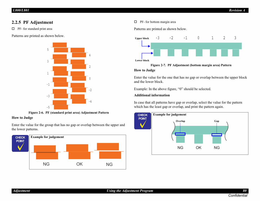
L80 Revision A
Adj 80Confidential
2.2.P
Patte
How
Entethe l
w.
ent (bottom margin area) Pattern
no gap or overlap between the upper block
should be selected.
r overlap, select the value for the pattern and print the pattern again.
� �
�
nt
-1 0 1 2 3
OK NG
Gapp
0/L801
ustment Using the Adjustment Program
5 PF AdjustmentF- for standard print area
rns are printed as shown below.
Figure 2-6. PF (standard print area) Adjustment Pattern to Judge
r the value for the group that has no gap or overlap between the upper and ower patterns.
PF- for bottom margin area
Patterns are printed as shown belo
Figure 2-7. PF AdjustmHow to Judge
Enter the value for the one that hasand the lower block.
Example: In the above figure, “0”
Additional information
In case that all patterns have gap owhich has the least gap or overlap,
� �
� �
Example for judgement
4
2
0
-2
-4
5
3
1
-1
-3
-5
OK NGNG
� � � �
� � �
Example for judgeme
-2-3
Lower block
Upper block
NG
Overla

L80 Revision A
Adj 81Confidential
2.2.Desc
PA(cOwd
T
Position at PG Adjustment
PG-<AP
PG t<Medefa
PG+
PG+
ge to be used must be free from dust and dirt tion. Be sure to clean it before use. Print Head is not soiled or scratched.curacy of adjustment, install the Adapters in
ove the carriage right and left by pulling the ng the carriage.
ent after installing the Printer Mechanism (Install the Linear Scale after adjustment.)sassembly Flowchart” (p.18).four stages of PG setting are available by Mechanism. However, make this adjustment m in the minimum PG position (PG-: 1.2 .5.4 APG Unit” (p.41) and below.)
Locating hole
Locating hole
0/L801
ustment Using the Adjustment Program
6 PG Adjustmentribed below is the platen gap (PG) adjustment.
urpose:djust the distance between the head surface and the Paper Guide Front Assy
platen) properly and adjust the parallelism on the 0th column side and on the 80th olumns side to ensure reliable print quality.nce the Carriage Assy and/or Adjustment Bushes have been removed or henever necessary for any other reason, make this adjustment to correct the eviation of the platen gap.
hings to be used
Thickness gauge: 1.15 mm (x2)1.3 mm (x2)
Phillips screwdriver
Figure 2-8. PG
Table 2-5. PG Positions
Position PG Size(mm)
Application for Printing(selected from PG flag list for
normal/head rubbing)
Sequence Application
G Home> 1.2 EPSON special thick paperPGPP, Postcards, Matte, etc.
CleaningCR measurement, VH detectionCR home position seek
yp.chanical ult>
1.7Plain paperEPSON special thin paper, SF, etc.Rubbing with PG1.2 is avoided
2.35EnvelopesRubbing with PG1.2 and 1.7 is avoided
+ 4.2 CD-R printing At ink replacement
� � � � � The thickness gauand from deformaTake care that theTo ensure high acthe carriage, and mbelt without holdi
� � � �
� � �
Make this adjustmand CISS section.Refer to “1.2.2 DiWith L800/L801, means of the APGwith the mechanismm). (Refer to “1

L80 Revision A
Adj 82Confidential
A
1. I
2. R
3. C
4. Mopr
NOT
5. P
6. Irg
7. P
8. Itw
9. Mg
10. P
11. Ia
12. P
13. Ia
14. Mt(
. PG Adjustment 1
0. PG Adjustment 2
ome in contact with the 1.3 mm thickness ome in contact with the 1.15 mm thickness
Pull the belt to move the carriage
CR Guide Shaft
CR Guide Shaft UP
CR Guide Shaft
DOWN
~Right side~
0/L801
ustment Using the Adjustment Program
djustment procedure
Specified PG value: 1.2 ± 0.1 mm
nstall new ink cartridges in the carriage.
emove the Cable Holder Frame. (Fig. 1-75)
heck that the APG Assy and the carriage are in the PG-position. (Fig. 2-8)
ove the carriage to the center of the platen, and place 1.15 mm thickness gauge n the left aligning its left edge with the second rib of the Front Paper Guide. And lace another 1.15 mm thickness gauge on the right aligning its right edge with the ightmost rib of the Front Paper Guide. (Fig. 2-9)
E: The thickness gauge must not be set over the leftmost rib on the Front Paper Guide.
ull the Timing Belt to move the carriage to the left end.
f the carriage comes in contact with the gauge, adjust the Left Parallelism Bush to aise the carriage to a position where the Printhead does not come in contact with auge.
ull the Timing Belt to move the carriage to the right end.
f the carriage comes in contact with the gauge, adjust the Right Parallelism Bush o raise the carriage to a position where the Printhead does not come in contact ith gauge.
ove the carriage to the middle area of the platen, and place 1.3 mm thickness auges at the left and right ends of the platen.
ull the Timing Belt to move the carriage to the left end.
f the carriage does not come in contact with the gauge, make the adjustment gain.
ull the Timing Belt to move the carriage to the right end.
f the carriage does not come in contact with the gauge, make the adjustment gain.
ark the indicated graduation position of the right and left Parallelism Bush, and ighten the screws.Screw tightening torque: 0.8±0.1 N•m)
Figure 2-9
Figure 2-1
� � � � � The Printhead must cgauges but must not cgauges.
Gauge (1.15 or 1.3mm)
CR Guide ShaftUP
CR Guide Shaft
DOWN
~Left side~

L80 Revision A
Adj Correction 83Confidential
2.3Pap2.3.This
T
Note
adjustment
t can be used for scanning the pattern in g up the adjustment program, select the
� �
�
T
f the scanner to the PC in advance. ired for the adjustment is not prepared for n the ones specified below, BRS/PFP
ot be carried out by the other scanners.
canner for BRS/PFP AdjustmentSensor
type Remarks
CCD
CCD
CIS Use the internal scanner.
X800FW CIS Use the internal scanner.
700W CIS Use the internal scanner.
X810FW CIS Use the internal scanner.
710W CIS Use the internal scanner.
CIS Use the internal scanner.
CIS Use the internal scanner.
CIS Use the internal scanner.
CIS Use the internal scanner.
/TX820FWD CIS Use the internal scanner.
X720WD CIS Use the internal scanner.
X620FWD/ CIS Use the internal scanner.
X525WD/ CIS Use the internal scanner.
0/L801
ustment Banding Reduction System (BRS) Adjustment / Paper Feed Amount Profile (PFP)
Banding Reduction System (BRS) Adjustment / er Feed Amount Profile (PFP) Correction
1 Overview section explains how to carry out BRS/PFP adjustments.
ools and paper required to perform the adjustment
: When using the following scanners for PFP adjustment, two PFP Base scales are required because they should be set on the origin side and also on right side of the PFP Adjustment Pattern. For the details on their setting positions and such, see “2.3.2 Adjustment Procedure (p.85)”.
• Epson Stylus Photo PX650/TX650/PX660• Artisan 810/Epson Stylus Photo PX810FW/TX810FW• Artisan 710/Epson Stylus Photo PX710W/TX710W• Artisan 835/Epson Stylus Photo PX820FWD/TX820FWD• Artisan 725/Epson Stylus Photo PX720WD/TX720WD• Epson WorkForce 630/Epson Stylus Office TX620FWD/ME Office 960FWD• Epson WorkForce 625/Epson Stylus Office BX525WD/Epson Stylus SX525WD
Figure 2-11. System Configuration
Specified Scanner to perform the
The following are the scanners thaBRS/PFP adjustment. When startinscanner to use.
� �
� �
Be sure to have a specified scanner ready beforehand as it is necessary to carry out the adjustment. Before scanning, confirm that the document table is free from any dirt or stain.
Table 2-6. Tools and Paper for BRS/PFP Adjustment
Tools/Paper Product Code
Common PFP Base scale 1453980
BRS Matte Paper-Heavyweight (A4) ---
PFP Premium Glossy Photo Paper (4 x 6) ---
Calculate correction
value
est Pattern Scanner PC Printer
� � � � � Install the driver oAs the profile requscanners other thaAdjustment can n
Table 2-7. Specified S
Model Name
Epson Perfection 4990 Photo
Epson Perfection V700 Photo
Epson Stylus Photo PX650/TX650
Artisan 800/Epson Stylus Photo PX800FW/T
Artisan 700/Epson Stylus Photo PX700W/TX
Artisan 810/Epson Stylus Photo PX810FW/T
Artisan 710/Epson Stylus Photo PX710W/TX
Epson Stylus Photo RX680/RX685/RX690
Epson Stylus Photo RX585/RX595/RX610
Epson Stylus Photo RX560/RX580/RX590
Epson Stylus Photo PX660
Artisan 835/Epson Stylus Photo PX820FWD
Artisan 725/Epson Stylus Photo PX720WD/T
Epson WorkForce 630/Epson Stylus Office TME Office 960FWD
Epson WorkForce 625/Epson Stylus Office BEpson Stylus SX525WD

L80 Revision A
Adj Correction 84Confidential
the adjustment flow below.
RS/PFP Adjustment FlowNG, repeat the steps as described below.p ep
� �
�
layed in the Adjustment program, check the ry out the adjustment again. If an error king the points below, change the scanner
nd carry out the adjustment again.inter that printed the pattern and the printer ustment value is the same.inted pattern is placed on the document table rectly.
is no gap between the PFP Base Scale and the eet.nner glass surface and the PFP Base Scale is
t or dust.
END
*
Judge it is mechanism’s failure. Remove it to
locate the defective part and replace, then
reassemble it.
NG
OK
Printing the PFP Check Pattern
Judging the Check Pattern
0/L801
ustment Banding Reduction System (BRS) Adjustment / Paper Feed Amount Profile (PFP)
Adjustment Flow
Carry out the adjustment following
Figure 2-12. BNote*: When a PFP pattern is judged as
First time NG: retry from steSecond time NG:retry from stThird time NG: perform step
� �
� �
Depending on the sensor type of the scanner to use for the adjustment, drying time required after the BRS adjustment pattern has been printed differs. For PFP adjustment pattern/PFP check pattern, drying time is not required.
For “CCD” sensor:Printed pattern can be scanned straight away. (Drying time of about 2 minutes is recommended.)For “CIS” sensor:Printed pattern needs to be dried more than 5 minutes.
� � � �
� � �
When an error is disppoints below, then caroccurs even after checwith a different one a1. Check that the pr
to register the adj2. Check that the pr
of the scanner cor3. Check that there
pattern printed sh4. Check that the sca
free from any dir
START
Error?
Error?
NG
NG
OK
OK
Printing the BRS Adjustment Pattern
Scanning the BRS Adjustment Pattern
Printing the PFP Adjustment Pattern
Scanning the PFP Adjustment Pattern

L80 Revision A
Adj Correction 85Confidential
2.3.
2.3.2P
1. L2. S3. C
a4. L
s
ttern
P Base Scale on the document table and click the t Pattern” column.
RS calibration values are automatically erial flash ROM. If an error occurs, check that scale is clean, and the scale/adjustment pattern is .
and BRS Adjustment Pattern Positionocument glass of the scanner)
� �
�
wing when setting the PFP Base Scale, and n on the scanner. the document glass aligning the scale corner origin position. printed sheet along the scale as shown in the e sure to place it parallel to the scale, with
BRS Adjustment Pattern (A4)
Scanner Document Table
0/L801
ustment Banding Reduction System (BRS) Adjustment / Paper Feed Amount Profile (PFP)
2 Adjustment Procedure
.1 BRS (Banding Reduction System) Adjustmentrinting the BRS Adjustment Pattern
oad A4 size Matte Paper-Heavyweight on the paper support. elect [BRS Adjustment] in the adjustment program.lick the [Print] button on the “1. Print Test Pattern” column to print the djustment pattern. et the printed pattern dry for more than 5 minutes if using CIS sensor type canner.
Figure 2-13. BRS Test Pattern
Scanning the BRS Adjustment Pa
5. Set the printed pattern and the PF[Scan] button on the “3. Scan Tes
6. According to the scanned result, Bcalculated and are written to the sthe document table glass and the not tilted, then repeat from step 5
Figure 2-14. PFP Base Scale(Viewed from the d
� �
� �
In the Adjustment program, the identification code is used to distinguish whether the printer that printed the pattern and the printer to register the adjustment value is the same. Make sure to let the printed pattern dry for more than 5 minutes if using CIS sensor type scanner. When using CCD sensor type scanner, the printed pattern does not need to be dried before scanning. Refer to “Table 2-7. Specified Scanner for BRS/PFP Adjustment” (p.83)
Printer Identification Code
� � � � � Be careful of the follothe adjustment patter
Place the scale onwith the scanner Place the pattern-figure below. Makno gaps.
PFP Base Scale
Scanner Origin Position

L80 Revision A
Adj Correction 86Confidential
2.3.2P
1. L2. S3. C
a
ttern
FP test pattern on the document table and click Test Pattern” column.
FP calibration values are automatically erial flash ROM. If an error occurs, check that scale is clean, and the scale/adjustment pattern is .
and PFP Adjustment Pattern Positione document glass of the scanner)
� �
�
wing when setting the PFP Base Scale and n on the scanner. the document glass aligning the scale corner origin position. printed sheet along the scale as shown in the e sure to place it parallel to the scale, with
Scanner Document Table
Position of the other PFP Base Scale when using the scanner for which two PFP Base scales for the adjustment are required.
0/L801
ustment Banding Reduction System (BRS) Adjustment / Paper Feed Amount Profile (PFP)
.2 PFP Adjustment rinting the PFP Adjustment Pattern
oad 4 x 6 Premium Glossy Photo Paper on the paper support. elect [PFP Adjustment] in the adjustment program.lick the [Print] button on the “1. Print Test Pattern” column to print the djustment pattern.
Figure 2-15. PFP Test Pattern
Scanning the PFP Adjustment Pa
4. Set the PFP Base Scale and the Pthe [Scan] button on the “3. Scan
5. According to the scanned result, Pcalculated and are written to the sthe document table glass and the not tilted, then repeat from step 4
Figure 2-16. PFP Base Scale(When viewed from th
� �
� �
In the Adjustment program, the identification code is used to distinguish whether the printer that printed the pattern and the printer to register the adjustment value is the same.
Printer Identification Code
� � � � � Be careful of the follothe adjustment patter
Place the scale onwith the scanner Place the pattern-figure below. Makno gaps.
PFP Adjustment Pattern
(4 x 6 size)
PFP Base Scale
Scanner Origin Position

L80 Revision A
Adj Correction 87Confidential
P
6. SB
there is no white or overlapped bands in all the ound, carry out the steps below. see if the bands appear again. , try the PFP adjustment again from the
r the re- adjustment in step 2, determine that it is rry out check/reassemble of the parts that was
eck Pattern Judging Standard
OKno bands
Bottom Edge Area Check Pattern
NGhite band
NGrlapped band
0/L801
ustment Banding Reduction System (BRS) Adjustment / Paper Feed Amount Profile (PFP)
rinting the PFP Check Pattern
et 4 x 6 Premium Glossy Photo Paper on the paper support and click the [Print] utton on the “4. Print Check Pattern” column.
Figure 2-17. PFP Check Pattern
Judging the Check Pattern
7. Referring to Fig. 2-18 check thatcheck patterns. If any bands are f1. Re-print the check pattern to2. When bands appear in Step 1
beginning.3. When bands appear even afte
the mechanism failure and caremoved/replaced.
Figure 2-18. PFP Ch
Normal Area Check Pattern
Bottom Edge Area Check Pattern
Normal Area Check Pattern
w
ove

Confidential
C H A P T E R
3INTENANCE
MA
L80 Revision A
Ma 89Confidential
3.1Thiscond
3.1.Excerequobse
I
I
e, white line, etc.) has occurred or the printer t error”, take the following actions to clear
Status Monitor 3 and with LED.)
ars on images, run the Printhead cleaning rom the control panel, the printer driver
cleaning modes. The appropriate cleaning mode is formed according to various conditions. The ink al cleaning varies depending on the mode.
rror
nd flashing operations. When the ink is used s, the ink is drained to the Waste Ink Pads aste ink is stored as the waste ink counter
e ink counter has reached the limit of the Ink Pads, the maintenance request error is k evaporation amount into consideration, epending on how often printing is made.
r appears, replace the Waste ink pads with a unter using the Adjustment program. If the it, recommend that the Waste ink pads will ecause the “Maintenance request error” will red product to the customer.
� �
0/L801
intenance Overview
Overview section provides information to maintain the printer in its optimum ition.
1 Cleaningpt for the printhead, there are no other mechanical parts or units that ire periodic cleaning. However, if need arises, clean the component rving the following instructions.
nstructions for cleaning
Exterior parts such as housingWipe dirt off with a soft clean cloth moistened with water.For glossy or transparent parts, use of unwoven cloth is recommended to avoid scratching those parts.
Inside of the printerRemove paper dust with a vacuum cleaner.
Rubber or plastic rollers such as an LD roller used to feed paperIf paper dust adhered to the rollers decreases the frictional force of the rollers and the rollers cannot properly feed paper, wipe off the paper dust with a soft cloth moistened with diluted alcohol.
nstructions for cleaning ink stains
Wipe the stains off with a cloth wrung out of diluted alcohol.
3.1.2 Service MaintenancIf any abnormal print (dot missingindicates the “Maintenance requesthe error.(This error is displayed in EPSON
3.1.2.1 Printhead cleaning
When dot missing or banding appecycle.* The cleaning be activated futility or the Adjustment program.Note * : This printer has three manual
automatically selected and perconsumption amount for manu
3.1.2.2 Maintenance request e
Ink is consumed also for cleaning afor cleaning and flashing operationvia the Pump. The amount of the winto the EEPROM. When the wastabsorbing capability of the Waste displayed. This printer takes the intherefore the counter limit differs d
When the maintenance request erronew one and reset the waste ink cowaste ink counter is close to its limbe replaced with new one. This is bmay occur after returning the repai
� � � Do not use alcohol for cleaning the transparent parts. Doing so may cause them to get cloudy.When wiping paper dust off the LD roller, be careful not to rub against the surface asperity.To minimize the effect on the parts, use diluted alcohol such as 70% diluted ether.After using alcohol for cleaning, make sure to wipe the part off with a soft dry dust-free cloth to remove alcohol traces fully.

L80 Revision A
Ma 90Confidential
3.1.The deterspecmen
W
A
Refe
LUB
ion of Driven Pulley (2)
ion of Driven Pulley (3)
� � �
<Lubrication Points>Two points on bushings for the Pulley ShaftOne point at the center of the Pulley Shaft
<Type>G-71
<Application Amount>ø 1 x 1 mm x 3 points
<Application Timing>Apply before installing the Driven Pulley
<Remarks>Apply with Injector
<Lubrication Points>Two points on the side of the Pulley
<Type>G-71
<Application Amount>ø 1 x 1 mm x 2 points
<Application Timing>Apply after installing the Driven Pulley
<Remarks>Apply with Injector
oint
haft
lder
0/L801
intenance Overview
3 Lubricationtype and amount of the grease used to lubricate the printer parts are mined based on the results of the internal evaluations. Be sure to apply the ified type and amount of the grease to the specified parts during servicing tioned below.
hen parts that need lubrication is been replaced
s the need arises during disassembly/reassembly of the printer
r to the following figures for the lubrication points.
RICATION OF DRIVEN PULLEY
Figure 3-1. Lubrication of Driven Pulley (1)
Figure 3-2. Lubricat
Figure 3-3. Lubricat
� � Never use oil or grease other than those specified in this manual. Use of different types of oil or grease may damage the component and adversely affect the printer operation.Observe the specified amount. Never apply excess.
Table 3-1. Specified LubricantType Name EPSON code Supplier
Grease G-71 1304682 EPSONGrease G-77 1455324 EPSON
<Lubrication Points>Four points where contact with the Main Frame
<Type>G-71
<Application Amount>ø 1 x 4 mm x 4 points
<Application Timing>Apply before installing the Driven Pulley
<Remarks>Apply with InjectorApplication Point
Driven Pulley Holder
Application P
Driven Pulley S
Driven Pulley
Driven Pulley Ho
Driven Pulley
Application Point
Driven Pulley Holder
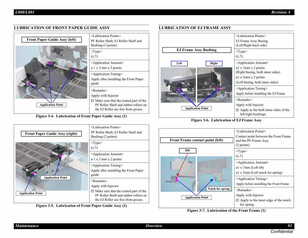
L80 Revision A
Ma 91Confidential
LUB SSY
tion of EJ Frame Assy
on of the Front Frame (1)
A
<Lubrication Points>EJ Frame Assy Busing(Left/Right back side)
<Type>G-71
<Application Amount>ø1 x 1mm x 2 points(Right busing, both inner sides)ø1 x 3mm x 2 points(Left busing, both inner sides)
<Application Timing>Apply before installing the EJ Frame
<Remarks>Apply with Injector
Apply to the both inner sides of the left/right bushings.
<Lubrication Points>Contact point between the Front Frame and the PE Frame Assy (2 points)
<Type>G-71
<Application Amount>ø1 x 7mm (Left rib)ø1 x 3mm (Left notch for spring)
<Application Timing>Apply before installing the Front Frame
<Remarks>Apply with Injector
Apply to the inner edge of the notch for spring.
ring
0/L801
intenance Overview
RICATION OF FRONT PAPER GUIDE ASSY
Figure 3-4. Lubrication of Front Paper Guide Assy (1)
Figure 3-5. Lubrication of Front Paper Guide Assy (2)
LUBRICATION OF EJ FRAME A
Figure 3-6. Lubrica
Figure 3-7. Lubricati
<Lubrication Points>PF Roller Shaft, EJ Roller Shaft and Bushing (3 points)
<Type>G-71
<Application Amount>ø 1 x 3 mm x 3 points
<Application Timing>Apply after installing the Front Paper guide
<Remarks>Apply with Injector
Make sure that the coated part of the PF Roller Shaft and rubber rollers on the EJ Roller are free from grease.
<Lubrication Points>PF Roller Shaft, EJ Roller Shaft and Bushing (2 points)
<Type>G-71
<Application Amount>ø 1 x 3 mm x 2 points
<Application Timing>Apply after installing the Front Paper guide
<Remarks>Apply with Injector
Make sure that the coated part of the PF Roller Shaft and rubber rollers on the EJ Roller are free from grease.
Front Paper Guide Assy (left)
Application Point
Application Point
Front Paper Guide Assy (right)
pplication Point
Left Right
EJ Frame Assy Bushing
Application Point
Notch for sp
Front Frame contact point (left)
Rib
Application Point

L80 Revision A
Ma 92Confidential
LUB
the CR Guide Shaft PG Cam
CR Guide Shaft Retaining Spring
A
<Lubrication Points>On the PG Cams attached to the both ends of the CR Guide Shaft
<Type>G-71
<Application Amount>ø 1 x 5mm x 3 points
<Application Timing>Apply after installing the CR Guide Shaft
<Remarks>Apply with Injector
<Lubrication Points>On the both ends of the CR Guide Shaft to where its retaining springs are attached.
<Type>G-71
<Application Amount>ø 1 x 5 mm x 2 points
<Application Timing>Apply before installing the Spring
<Remarks>Apply with Injector
haft
0/L801
intenance Overview
Figure 3-8. Lubrication of the Front Frame (2)
RICATION OF CR UNIT
Figure 3-9. Lubrication of the Main Frame (1)
Figure 3-10. Lubrication of
Figure 3-11. Lubrication for the
<Lubrication Points>Contact position of the Front Frame and the PE Frame Assy (2 points)
<Type>G-71
<Application Amount>ø1 x 7mm (Right rib)ø1 x 3mm (Right Spring Bushing)
<Application Timing>Apply before installing the Front Frame
<Remarks>Apply with Injector
Apply to the inner edge of the notch for spring.
<Lubrication Points>On the back of the Main Frame where contact with the CR Unit
<Type>G-71
<Application Amount>160 ± 20mg
<Application Timing>Apply after installing the CR Unit
<Remarks>Apply with Injector
Do not apply to the both ends (40mm from edge)Move the CR Unit the left/right to spread the grease evenly.
Rib
Notch for spring
Front Frame contact point (right)
pplication Point
2
(1) 5 mm from the top edge(2) 10 mm from the top edge
1
Main Frame (upper rear)
Except both ends (40mm)
Application Point
Left Right
PG Cam on both ends of CR Guide S
Application Point
Left Right
CR Guide Shaft Retaining Spring
Application Point

L80 Revision A
Ma 93Confidential
brication of the I/S
tion of the APG Unit (1)
<Lubrication Points>On the Main Frame where the clutch gear and spring of the Ink System contact
<Type>G-71
<Application Amount>ø 1 x 1 circle
<Application Timing>Apply before installing the Ink System
<Remarks>Apply with Injector
<Lubrication Points>Around the upper part of the shafts on the APG Unit. (5 points)
<Type>G-71
<Application Amount>ø 1 x 1 circle x 5 points
<Application Timing>Disassemble the APG Unit to apply the grease before installing it.
<Remarks>Apply with Injector
n
0/L801
intenance Overview
Figure 3-12. Lubrication of the CR Guide Shaft (1)
Figure 3-13. Lubrication of the CR Guide Shaft (2)
LUBRICATION OF INK SYSTEM
Figure 3-14. Lu
LUBRICATION OF APG UNIT
Figure 3-15. Lubrica
<Lubrication Points>Contact point between CR Unit and the CR Guide Shaft
<Type>G-71
<Application Amount>210 ± 20mg x 2 points
<Application Timing>Apply before installing the CR Unit
<Remarks>Apply with Injector
After lubrication, move the CR Guide Shaft to left and right by 60mm while rotating it, to spread the grease evenly. Make sure that the Timing Belt is free from grease.
<Lubrication Points>Lubrication holes of the CR Unit
<Type>G-71
<Application Amount>210 ± 20mg x 2 points
<Application Timing>Apply before installing the CR Unit
<Remarks>Apply with Injector
Apply grease from the two lubrication holes.Make sure that the Timing Belt is free from grease.
Contact point between CR Unit and CR Guide Shaft (1)
CR Shaft
Application Point
CR Shaft
Contact point between CR Unit and CR Guide Shaft (2)
Application Point: Apply from the holes
Contact point between Main Frame and I/S
Application Point
Shaft
Application Point
ApplicatioPoint
Shafts on APG Unit

L80 Revision A
Ma 94Confidential
LUB
ation of the LD Roller Shaft (1)
ation of the LD Roller Shaft (2)
R<Lubrication Points>Contact point between the LD Roller Shaft and the Hopper, ASF Gear
<Type>G-71
<Application Amount>ø 1 x 10mm x 3 points
<Application Timing>Apply before installing the ASF Unit
<Remarks>Apply with Injector
Rotate the LD Roller Shaft so that the Curved/Flat surface face up, then apply grease to the specified parts.
<Lubrication Points>Contact point between the LD Roller Shaft and the Hopper, ASF Gear
<Type>G-71
<Application Amount>(1) :ø 1 x 20mm x 2 points(2) :ø 1 x 10mm
<Application Timing>Apply before installing the ASF Unit
<Remarks>Apply with Injector
Rotate the LD Roller Shaft so that the Curved/Flat surface face up, then apply grease to the specified parts.
ace)
ide
on Point
e)
side
point (2)
0/L801
intenance Overview
Figure 3-16. Lubrication of the APG Unit (2)
RICATION OF ASF UNIT
Figure 3-17. Lubrication of the ASF Unit
Figure 3-18. Lubric
Figure 3-19. Lubric
<Lubrication Points>Around the rim of the Spur Gear 28.8
<Type>G-71
<Application Amount>ø 1 x 1 circle
<Application Timing>Apply before installing the APG Unit
<Remarks>Apply with Injector
<Lubrication Points>Inner edge of the hole on the ASF Unit where the LD Roller Shaft is put through
<Type>G-71
<Application Amount>1 to 2 circles (inner edge) x 2 points
<Application Timing>Apply before installing the LD Roller Assy
<Remarks>Apply with Cotton bud
im of the APG Unit Spur Gear 28.8
Application Point
Hole for LD Roller on ASF Unit
Application Point
Clutch side
LD Roller Shaft (Curved surf
Clutch sUSB I/F side
Application Point Applicati
Application point (1)
LD Roller Shaft (Flat surfac
Clutch USB I/F side
Application

L80 Revision A
Ma 95Confidential
0/L801
intenance Overview
Figure 3-20. Lubrication of the LD Roller Shaft (3)
<Lubrication Points>Contact point between the LD Roller and Hopper, ASF Gear
<Type>G-71
<Application Amount>ø 1 x 1/4-circle x 4 points
<Application Timing>Apply before assembling the LD Roller Holder
<Remarks>Apply with Injector
Rotate the LD Roller Shaft so that the Curved/Flat surface face up, then apply grease to the specified parts.
LD Roller Shaft (Curved surface)(Ribs beside the LD Roller)
Application Point

Confidential
C H A P T E R
4PPENDIX
A
L80 Revision A
App 97Confidential
4.1This
C
1. C1-1
2. A2-1
2-2
2-3
2-4
2-5
3. C3-1
3-2
d releases the Any
position
0-digit side. ↓
ide slowly and e. ↓
R lock set ↓
d releases the ↓
wise and sets ↓
ide slowly and ↓
-digit side to ↓
d releases the ↓
ide slowly and ock. ↓
riginal .
monitored R Encoder.
↓
ight Frame and ↓
(Continue to the next page)
ion of the power-on sequence
Carriage/PF roller movement and position*2 PG*3
0/L801
endix
Power-On Sequence section describes the power-on sequences.
ondition
Completing ink charge.
No CDR Tray and no paper on the paper path.
The stacker is not set on the CDR printing position.
The Printhead is capped with the Cap of the Ink System.
The Carriage is locked by the CR lock.
Table 4-1. Operation of the power-on sequence
Operation*1 Carriage/PF roller movement and position*2 PG*3
hecking waste ink overflow.Reads out the protection counter value to check waste ink overflow
Any position
voiding deadlock sequence*4
.The carriage moves to the 0-digit side slowly and confirms it touches the Right Frame.
↓
.The carriage slightly moves to the 80-digit side.↓
.The PF Motor rotates clockwise and releases the CR lock. ↓
.The carriage moves to the 0-digit side slowly and confirms it touches the Right Frame. ↓
.The carriage returns to its home position.↓
DR Tray Sensor check.Checks with the CDR Tray Sensor if the CDR Tray is not set.
↓
.The PF Motor rotates clockwise to eject the CDR Tray. ↓
CR lock CR
CR lockis released
4. Releasing the CR lock4-1.The PF Motor rotates clockwise an
CR lock.5. Seeking the home position
5-1.The carriage slowly moves to the 8
5-2.The carriage moves to the 0-digit sconfirms it touches the Right Fram
5-3.The carriage slowly moves to the Cposition.
5-4.The PF Motor rotates clockwise anCR lock.
5-5.The PF Motor rotates counterclockthe CR lock.
5-6.The carriage moves to the 80-digit sconfirms it touches the CR lock.
5-7.The carriage slowly moves to the 0the CR lock set position.
5-8.The PF Motor rotates clockwise anCR lock.
5-9.The carriage moves to the 80-digit sconfirms it does not touch the CR l
5-10.The carriage slowly moves to its oposition, and home position is fixedAfterward, the carriage position is according to the signals from the C
6. Resetting APG6-1.The carriage slowly moves to the R
stops there.
Table 4-1. Operat
Operation*1
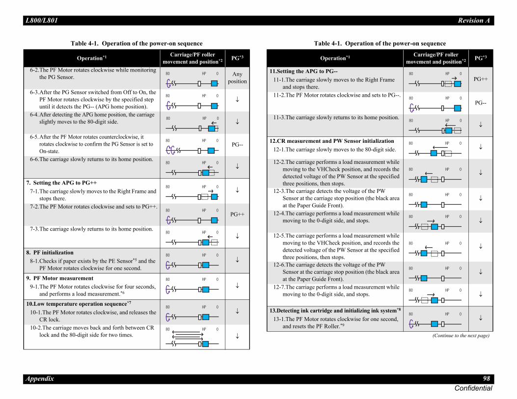
L80 Revision A
App 98Confidential
6-2
6-3
6-4
6-5
6-6
7. S7-1
7-2
7-3
8. P8-1
9. P9-1
10.L10
10
Right Frame PG++
nd sets to PG--.PG--
home position.↓
itialization80-digit side. ↓
urement while nd records the t the specified ↓
f the PW (the black area ↓
urement while s. ↓
urement while nd records the t the specified ↓
f the PW (the black area ↓
urement while s. ↓
g ink system*8
r one second, ↓
(Continue to the next page)
ion of the power-on sequence
Carriage/PF roller movement and position*2 PG*3
0/L801
endix
.The PF Motor rotates clockwise while monitoring the PG Sensor. Any
position
.After the PG Sensor switched from Off to On, the PF Motor rotates clockwise by the specified step until it detects the PG-- (APG home position).
↓
.After detecting the APG home position, the carriage slightly moves to the 80-digit side. ↓
.After the PF Motor rotates counterclockwise, it rotates clockwise to confirm the PG Sensor is set to On-state.
PG--
.The carriage slowly returns to its home position.↓
etting the APG to PG++.The carriage slowly moves to the Right Frame and stops there.
↓
.The PF Motor rotates clockwise and sets to PG++.PG++
.The carriage slowly returns to its home position.↓
F initialization.Checks if paper exists by the PE Sensor*5 and the PF Motor rotates clockwise for one second.
↓
F Motor measurement.The PF Motor rotates clockwise for four seconds, and performs a load measurement.*6
↓
ow temperature operation sequence*7
-1.The PF Motor rotates clockwise, and releases the CR lock.
↓
-2.The carriage moves back and forth between CR lock and the 80-digit side for two times.
↓
Table 4-1. Operation of the power-on sequence
Operation*1 Carriage/PF roller movement and position*2 PG*3
11.Setting the APG to PG--11-1.The carriage slowly moves to the
and stops there.11-2.The PF Motor rotates clockwise a
11-3.The carriage slowly returns to its
12.CR measurement and PW Sensor in12-1.The carriage slowly moves to the
12-2.The carriage performs a load measmoving to the VHCheck position, adetected voltage of the PW Sensor athree positions, then stops.
12-3.The carriage detects the voltage oSensor at the carriage stop position at the Paper Guide Front).
12-4.The carriage performs a load measmoving to the 0-digit side, and stop
12-5.The carriage performs a load measmoving to the VHCheck position, adetected voltage of the PW Sensor athree positions, then stops.
12-6.The carriage detects the voltage oSensor at the carriage stop position at the Paper Guide Front).
12-7.The carriage performs a load measmoving to the 0-digit side, and stop
13.Detecting ink cartridge and initializin13-1.The PF Motor rotates clockwise fo
and resets the PF Roller.*9
Table 4-1. Operat
Operation*1

L80 Revision A
App 99Confidential
Note
Time for servicing the productration time for servicing the product. Those sured using a prototype.
lied as After Service Parts.
13
13
14.C14
14
14
ndard Operation TimeTime (second)
Replacement Adjustment Total
9 0 9
13 0 13
10 0 10
7 0 7
8 0 8
49 0 49
132 0 132
138 0 138
146 0 146
138 0 138
161 0 161
340 0 340
327 0 327
337 0 337
506 3219 3725
232 0 232
294 0 294
483 0 483
528 0 528
K 558 105 663
G 558 2003 2561
0/L801
endix
*1: The rotation direction of the PF Motor is as follows.Clockwise: Paper is fed normallyCounterclockwise: Paper is fed backward
*2: The condition of the CR lock is as follows.Red: CR lock is setWhite: CR lock is released
*3: Indicates the PG position. “Any position” means that the PG position is not recognized because APG is not reset yet.
*4: Checks if the carriage is not deadlock such as the CR lock is caught in the gap of the carriage.
*5: Eject the paper if any.*6: When paper exists, the existing measurement value saved in EEPROM is read out;
therefore, the PF Motor does not rotate.*7: Executes when the detected temperature is under 5 oC (41oF) by the thermistor on
the Printhead.*8: The empty sanction operation may occur depending on the situation.*9: If paper remains in the printer, the PF Roller rotates by steps enough to eject the
paper forcibly.
4.2 Standard OperationThe following are the standard opeare based on the MTTR result mea
The underlined parts/units are supp
-2.The carriage slowly moves to the 0-digit side.PG--
-3.The carriage slowly returns to its home position.↓
R lock setting-1.The carriage slowly moves to the CR lock set
position.↓
-2.The PF Motor rotates counterclockwise, and sets the CR lock. ↓
-3.The carriage slowly returns to its home position.↓
Table 4-1. Operation of the power-on sequence
Operation*1 Carriage/PF roller movement and position*2 PG*3
Table 4-2. Sta
Parts/Unit
Printer Cover
Paper Support Assy
Stacker Cover
Stacker Assy
Cover Ink Tube
Foot
Housing Upper Assy
Housing Right
Decoration Belt Right
Housing Upper
Cover open sensor
Cover FFC
Cover FFC Inner
Holder contact
Printhead
CR Scale
Main Board Unit
Upper Shield Plate M/B
Shield Plate M/B Sub
Main Board Read O
Read N

L80 Revision A
App 100Confidential
APG
S
C
S
S
C
C
C
A
Pane
P
P
D
P
O
P
P
H
APG
P
PF E
PF S
Prin
Exte
Driv
Driv
Driv
1178 0 1178
1193 394 1587
1237 13 1250
1260 0 1260
1255 0 1255
1315 0 1315
1375 0 1375
1259 0 1259
1223 0 1223
1223 0 1223
1348 0 1348
1571 1188 2759
1574 0 1574
1574 0 1574
1228 0 1228
1250 0 1250
1303 0 1303
1307 0 1307
1307 0 1307
1980 2018 3998
1990 0 1990
2055 0 2055
1985 0 1985
2589 1977 4566
2609 0 2609
2596 0 2596
2596 0 2596
ndard Operation TimeTime (second)
Replacement Adjustment Total
0/L801
endix
Unit 226 0 226
pur Gear 28.8 242 0 242
ompression Spring 2.25 244 0 244
pur Gear 12.8 242 0 242
pur Gear 33.6 242 0 242
ompression Spring 0.97 244 0 244
ombination Gear 12.8,27 258 0 258
ombination Gear 14,22 242 0 242
PG Holder 310 0 310
l assy 224 0 224
anel Cover Assy 260 0 260
anel Cover 267 0 267
ecoration Belt Left 267 0 267
anel Unit 224 0 224
pen Sensor Holder 301 0 301
anel Shield Plate 316 0 316
anel Board 362 0 362
ousing Panel Assy 362 0 362
Sensor Assy 326 0 326
hoto Interrupter 338 0 338
ncoder 323 0 323
cale 304 0 304
ter Mechanism 1111 3232 4343
nsion Spring 1133 0 1133
en pulley Assy 1150 0 1150
en Pulley 1176 0 1176
en Pulley Shaft 1152 0 1152
Table 4-2. Standard Operation Time
Parts/UnitTime (second)
Replacement Adjustment Total
Driven Pulley Holder
CR Motor
PF Motor
Porous Pad Paper Guide Front
Ink System Assy
Extension Spring 0.8
CR Lock
Compression Spring 0.98
Cable Holder Frame
PF Encoder FFC
Front Frame
EJ Frame Assy
EJ Frame Torsion Spring L
EJ Frame Torsion Spring R
PF Scale Sheet
PF Scale Cover
LD Roller Guide Assy
Torsion Spring 137.7
LD Roller Guide
CR Unit
CR Guide Shaft
Timing Belt
Head FFC
Paper Guide Front Assy
PE Lever / PE Lever Torsion Spring
Super Gear 26.5
Photo Interrupter (PE Sensor)
Table 4-2. Sta
Parts/Unit

L80 Revision A
App 101Confidential
ASF
H
C
S
C
C
A
L
Pape
EJ G
CDR
Hou
W
W
W
P
G
G
H
Ada
Shee
S
176 1200 1376
320 1200 1520
702 1229 1931
286 1200 1486
642 1200 1842
931 1200 2131
61 0 61
76 0 76
142 0 142
8 0 8
174 0 174
169 0 169
14 0 14
494 0 494
36 0 36
12 0 12
918 0 918
263 0 263
46 0 46
46 0 46
37 0 37
ndard Operation TimeTime (second)
Replacement Adjustment Total
0/L801
endix
Unit 1397 559 1956
older Roller Retard Assy 1484 0 1484
ombination Gear 16.8,32.8 1403 0 1403
pur Gear 16 1405 0 1405
hange Lever Assy 1409 0 1409
Compression Spring 2.36 1419 0 1419
hange Lever 1419 0 1419
SF Assy 1409 0 1409
D Shaft Roller Assy 1428 0 1428
LD Roller 1501 0 1501
r Guide Upper Assy 1437 1224 2661
round Spring 2529 0 2529
Tray Sensor 2596 0 2596
sing Lower Assy 1304 0 1304
aste Ink Pad Lower 1338 29 1367
aste Ink Pad Cap Lower 1309 29 1338
aste Ink Tray 1347 29 1376
/S Assy 1339 54 1393
uide Stacker Left 1336 0 1336
uide Stacker Right Assy 1335 0 1335
CDR Guide Sensor 1341 0 1341
Label CDR 1354 0 1354
Guide Stacker Right 1354 0 1354
ousing Lower 1430 0 1430
pter cover 247 0 247
t Guide Tube 483 0 483
heet Guide Tube Sub 529 0 529
Table 4-2. Standard Operation Time
Parts/UnitTime (second)
Replacement Adjustment Total
Joint
Adapter
Ink Supply Tube Assy
Ink Supply Tank Assy
Ink Supply Tank Tube Assy
Ink Supply Tank
Tube Valve holder rear
Tube Valve holder front
Bottom Cover
Valve Lever
Right Cover
Left Cover
Top Cover
Tube Guide
Cover Joint
Cap
Cover Case
Tube Holder
Valve Position Label
Top Cover Label
Refilling Ink Label
Table 4-2. Sta
Parts/Unit
L80 Revision A
App 102Confidential
4.3Thisinfor
4.3.The when
0/L801
endix Troubleshooting Workflow
Troubleshooting section describes the troubleshooting workflow and fatal error mation.
1 Troubleshooting Workflowfollowing page describes the troubleshooting workflow. Follow the flow troubleshooting problems.

L80 Revision A
ConfidentialApp Troubleshooting Workflow 103
3
2
�
� �
This flowchart is compiled based on the following contents. Our experience regarding the quality problem.ESK’s repair data on FY08 / FY09 models.Printer Mechanism specification for L800/L801.
Fatal error
Please refer to “ 4.3.2 Fatal Error Code (p104)”for troubleshooting.
Maintenance error
[Occurrence Condition]This error occurs when maintenance counter in EEPROM exceeds the specified value.(It also occurs when running the power cleaning too many times.)
[Major Occurrence Timing]• Power-on timing• Print start timing• Cleaning timing
[Troubleshooting]• Waste Ink Tray replacement• Waste Ink Pad Lower
replacement• Ink Supply Tube Assy
replacement• Maintenance counter reset
Ink End error
rence Condition]rror occurs when ink in Ink
ly Tank(s) is/are empty.
Occurrence Timing]wer-on timingint start timingeaning timingint timing
leshooting]fill the ink(s)
Card error
[Occurrence Condition]This error occurs when a paper (business card size) remains stuck inside the printer because it is not inserted vertically.
[Major Occurrence Timing]• Power-on timing• Print timing
[Troubleshooting]• Push the “Paper” button to
eject a paper.• If the error occurs again after
performing above, check foreign material / PE Sensor / PE Sensor Lever / PW Sensor.
Paper Jam error
[Occurrence Condition]This error occurs when top/bottom of paper is not detected by PE Sensor in the specified steps of paper feeding operation correctly.
[Major Occurrence Timing]• Power-on timing• Paper loading timing• Paper eject timing
[Major Troubleshooting]1 Push the “Paper” button to
eject the paper.• Success
Starts paper feeding operation again if printer has print job.
• FailPaper jam error occurs again.
2 If fail in the above 1), remove the paper.
3 Push “Paper” button again.• Success
Starts paper feeding operation again if printer has print job.
• FailPaper jam error occurs again.
• If fail in the above 3), check foreign material / part come-off / EJ Frame Assy / PE Sensor / PE Sensor Lever / Porous Pad on Paper Guide Front / PW Sensor / Main board.
No Paper error
[Occurrence Condition]This error occurs when top of paper is not detected by PE Sensor in the specified steps of paper loading operation correctly.(No paper / No loading / large paper skew)
[Major Occurrence Timing]• Paper loading timing
[Major Troubleshooting]1 Put papers in paper support and
push the “Paper” button.2 If a paper stops before reaching
PE Sensor, remove it and check the paper condition.
3 A) If no damage in the above 2),set edge guide correctly afterputting papers in papersupport and retry.
B) If damage in the above 2),check foreign materials / parts come-off / partstransformation in paperpath.
4 If not resolved by 3-A) & 3-B), check foreign material / part come-off / surface condition of LD Roller and Retard Roller/ PE Sensor / PE Sensor Lever / Main Board / PF Motor /Change Lever.
ouble Feed error*3
rence Condition]rror occurs on the following
paper is ejected without inting during paper loading eration.tual paper length is longer n theoretical one.
Occurrence Timing]per loading timingper feed timingper eject timing
leshooting] Sensor Lever replacement Sensor replacement Sensor replacement
ain Board replacement
No Power*1
[Presumable Cause]• Power Supply Board damage• Main Board damage
[Major Troubleshooting]• Power Supply Board
replacement• Main Board replacement
Poor Printing
[Phenomenon]• Poor printing quality• Ink stain on paper• Dot missing• Paper eject without printing
[Presumable Cause]• Driver mis-setting• Contamination of CR Scale• Contamination of Printhead cover• Printhead damage• Ink clogging of Printhead• Contamination on Cap Unit /
Wiper of Ink System Assy• Ink System Assy damage• Float of Porous Pad on Paper
Guide Front• Incorrect PG• PE Sensor Lever damage• PE Sensor damage• Contamination of PF Roller / LD
Roller / EJ Roller / EJ Frame Assy
[Major Troubleshooting]• Driver re-setting• CR Scale replacement• Printhead cover cleaning• Printhead cleaning• Adapter replacement• Ink Supply Tube replacement• Open valve of Ink Supply Tank• Printhead replacement• Rubber cleaning of Cap Unit• Ink System Assy replacement• Porous Pad re-installation• PG readjustment• PE Sensor replacement• PE Sensor Lever replacement• PF Roller / LD Roller / EJ Roller
/ Star Wheel on EJ Frame Assy cleaning
• Printer Mechanism replacement
Poor Paper Loading
[Presumable Cause]• Use of 3rd party media• Edge guide mis-setting• Foreign material• Part come-off• LD Roller damage• Retard Roller damage• Change Lever damage
[Major Troubleshooting]• Recommendation of EPSON
media• Edge guide re-setting• Foreign material removal• Part re-installation• LD Roller replacement• Retard Roller replacement• Change Lever replacement
Abnormal Noise
[Presumable Cause]• Foreign material• Insufficient grease• Gear damage
[Major Troubleshooting]• Foreign material removal• Lubrication of grease• Gear replacement
nish*4
the printer
1
1
Major problem without error message
ng operation f ithout trouble?
tart
No
No
No
No
ng operation ithout error?
he printer can turn on but turns off right away, the protection circuit may cut off the power due to an error such as a uit failure.
e total number of printing (TP) and CD-R printing (CP) are printed on the check pattern. If any of the two counts eeds the specified value, make sure to replace the required parts.ly for manual duplex printcase of “Not Trouble Found”, check fatal error code.
Major problem with e age
Major problem without error message
-on sequence ithout error?
y condition
D er turn on the ower?
ck pattern*2
Blank Printing
[Presumable Cause]• Valve closes• Ink tank ventilation film gets
wet• Ink tube crumples• Ink tube connection is
incomplete.• Adapter damage
[Major Troubleshooting]• Open valve of Ink Supply Tank• Ink tank replacement• Ink tube re-installation• Adapter replacement
3
CD-R Guide error
[Occurrence Condition]This error occurs on the following case.• The CD-R guide (stacker) is in
the CD-R printing position at power-ON.
• The CD-R guide (stacker) position does not match with the print job.
[Major Occurrence Timing]• Power-on timing• Print start timing• Print timing
[Troubleshooting]• When the error occurs at
turning on the printer, set the CD-R guide (stacker) in the lower paper position.
• When the error occurs at printing, set the CD-R guide (stacker) in correct position according to the print job.
• If the error occurs again though confirming two of the above, check CD-R Guide Sensor / Main Board.
Paper Jam error
Please refer to “ Paper Jam error” of “Error occurs in printing operation”.
CD-R Tray error
[Occurrence Condition]This error occurs when CD-R Tray is not detected.
[Major Occurrence Timing]• CD-R Tray loading timing
[Troubleshooting]1 Set the CD-R Tray with a
medium correctly and then push the “Paper” button to load the tray.
• SuccessStarts the CD-R Tray loading operation again if printer has print job.
• FailCD-R Tray error occurs again.
2 If fail in the above 1), check CD-R Tray / CD-R Tray Sensor / PW Sensor / Main Board.
CD-R Guide error
Please refer to “ CD-R Guide error” of “Error occurs in printing operation”.
2
Soiled printing surface
[Presumable Cause]• Contamination of the LD
Roller or LD Roller Shaft by ink mist
[Major Troubleshooting]• LD Roller replacement• LD Roller Shaft cleaning
0/L801
endix
Fi
Turn on
Is printiinished w
S
Yes
Yes
Yes
Yes
Is printifinished w
Is Powerfinished w
Standb
oes printp
Print che
� � �
�
[OccurThis eSupp
[Major• Po• Pr• Cl• Pr
[Troub• Re
D
[OccurThis ecase.• A
prop
• Actha
[Major• Pa• Pa• Pa
[Troub• PE• PE• PW• M
*1: If tcirc
*2: Thexc
*3: On*4: In
rror mess

L80 Revision A
App 104Confidential
4.3.Thisprod
Erro
DC erro
ock • PF Motor failure• PF drive mechanism overload (paper jam/
foreign object)
error • PF Encoder failure (contaminated/detached scale, Encoder Board failure)
• Motor driver failure (Main Board failure)• PF drive mechanism overload
(paper jam/foreign object)• Cable disconnection
rror
ent • PF drive mechanism overload (paper jam/foreign object)
ning • PF Motor failure• Motor driver failure (Main Board failure)
max • PF Motor failure• PF drive mechanism overload (paper jam/
foreign object)
• Foreign object• APG Unit failure (incorrect reassembling)• APG Sensor failure• Cable disconnection
---*
e error
• Main Board failure)
e error
error
r ---*
. Fatal Error List
Possible cause
0/L801
endix Fatal Error Code
2 Fatal Error Code section describes the fatal error code and the possible cause for this uct.
Table 4-3. Fatal Error List
r type Error code Error name Possible cause
motor r
01H CR PID excess speed error
• CR Encoder failure (contaminated/detached scale, Encoder Board failure)
• Motor driver failure (Main Board failure)• Carriage overload (paper jam/foreign object)• Cable disconnection
02H CR load positioning lock error
• CR Encoder failure (contaminated/detached scale, Encoder Board failure)
• CR Motor failure• Carriage overload (paper jam/foreign object)• Cable disconnection
08H CR PID reverse error
• CR Encoder failure (contaminated/detached scale, Encoder Board failure)
• Tooth skip of the CR Timing Belt• Improper tension of the CR Timing Belt• Carriage overload (paper jam/foreign object)
0AHCR load positioning cumulative movement distance error
• CR Motor failure• Motor driver failure (Main Board failure)
0BH CR load positioning excess speed error
• CR Encoder failure (contaminated/detached scale, Encoder Board failure)
• Motor driver failure (Main Board failure)• Carriage overload (paper jam/foreign object)• Cable disconnection
0CH CR PID lock error
• CR Encoder failure (contaminated/detached scale, Encoder Board failure)
• CR Motor failure• Carriage overload (paper jam/foreign object)• Cable disconnection
0DH CR PID aveTi max error
• CR Motor failure• Motor driver failure (Main Board failure)• Improper tension of the CR Timing Belt• Carriage overload (paper jam/foreign object)
DC motor error
FBH PF PID acceleration lerror
FEH PF PID excess speed
FCH PF BS excess speed e
FAH PF excess measuremerror
EFH PF BS control positioerror
F0H PF BS control DTY_error
APG motor error
70H APG error (normal drive error)
71H APG home position seeking error
72H APG drive error (by command)
Motor drive time error
D1H CR (PID) driving tim
D2H CR (load positioningdriving time error
D3H PF (PID) driving tim
D4H PF (BS) driving time
Command error 30H EEPROM verify erro
(by command)
Table 4-3
Error type Error code Error name

L80 Revision A
App 105Confidential
g process.
Prinsysteerro
Sequerro
Senserro
Erro
• The maintenance counter has reached a limit. (Waste Ink Tray or Waste Ink Pad Lower)
• Foreign object• CDR Tray Sensor failure• Main Board failure
ror
• Paper jam• Foreign object• Deformation of the frame• PF Motor failure• PF drive mechanism overload (paper jam/
foreign object)
. Fatal Error List
Possible cause
0/L801
endix Fatal Error Code
Note "*": Not occurs except in manufacturin
thead m
r
40H Transistor temperature error • Main Board failure
41H X-Hot detection error (before printing)
• Printhead failure• Main Board failure42H X-Hot detection error
(before flushing)
43H Head temperature error
ence r
50H Home position seeking error • Paper jam
• Foreign object• Deformation of the frame
51H CR lock release error
52H CR lock error
53H Card error (before initial ink charge) • Foreign object
56H Impossible contact error (at powering off) ---*
or r
60H PW sensor error (Hi check error) • PW Sensor failure
• Main Board failure61H PW sensor error
(Low check error)
62H Tray sensor error• CDR Tray Sensor failure• Main Board failure
63H PE sensor error• PE Sensor failure• PE Sensor Lever failure• Main Board failure
Table 4-3. Fatal Error List
r type Error code Error name Possible cause
Mainte-nance error A0H Waste ink overflow
Abnormal operation
88H Tray insertion error (during cleaning)
89H Impossible contact er(during cleaning)
Table 4-3
Error type Error code Error name
Related Documents