VARISPEED L7 The frequency inverter for the lifts USER´S MANUAL Cat. No. TOEPC71067605-03-OY

Welcome message from author
This document is posted to help you gain knowledge. Please leave a comment to let me know what you think about it! Share it to your friends and learn new things together.
Transcript
VARISPEED L7The frequency inverter for the lifts
USER S MANUAL
Cat. No.
OMRON YASKAWA MOTION CONTROL B.V. – Wegalaan 65 – 2132 JD Hoofddorp – The Netherlands
phone: + 31 (0) 23 568 74 00 – fax: + 31 (0) 23 568 74 88 – www.omronyaskawa.com
Note: Specifications subject to change without notice.Cat. No. TOEPC71067605-02-OY
VAR
ISPEED L7
USER´S M
AN
UA
LCat. No. TOEPC71067605-02-OY
TOMCC71067600AA-OY.qxd 01.10.2003 10:32 Seite 1
TOEPC71067605-03-OY
I
Table of Contents
Warnings .......................................................................................................VIISafety Precautions and Instructions ............................................................ VIIIEMC Compatibility ......................................................................................... XLine Filters ....................................................................................................XIIRegistered Trademarks ............................................................................... XIII
1 Handling Inverters ................................................................. 1-1
Varispeed L7 Models ...................................................................................1-2
Confirmations upon Delivery .......................................................................1-3Checks ...........................................................................................................................1-3
Nameplate Information ..................................................................................................1-3
Inverter Software Version ..............................................................................................1-4Component Names ........................................................................................................1-5
Exterior and Mounting Dimensions ..............................................................1-7IP00 Inverters ................................................................................................................1-7
IP20 / NEMA 1 Inverters ................................................................................................1-7
Checking and Controlling the Installation Site .............................................1-9Installation Site ..............................................................................................................1-9
Controlling the Ambient Temperature ............................................................................1-9
Protecting the Inverter from Foreign Matter ...................................................................1-9
Installation Orientation and Space .............................................................1-10
Removing and Attaching the Terminal Cover ............................................1-11Removing the Terminal Cover ..................................................................................... 1-11
Attaching the Terminal Cover .......................................................................................1-12
Removing/Attaching the Digital Operator/LED Monitor and Front Cover ....................................................................1-13
Inverters of 18.5 kW or Less ........................................................................................1-13
Inverters of 22 kW or More ..........................................................................................1-15
2 Wiring ...................................................................................... 2-1
Connection Diagram ....................................................................................2-2Circuit Descriptions ........................................................................................................2-3
Terminal Block Configuration .......................................................................2-4
II
Wiring Main Circuit Terminals ...................................................................... 2-5Applicable Wire Sizes and Crimp Terminals .................................................................. 2-5Main Circuit Terminal Functions .................................................................................... 2-9Main Circuit Configurations ......................................................................................... 2-10Standard Connection Diagrams .................................................................................. 2-11Wiring the Main Circuits .............................................................................................. 2-12
Wiring Control Circuit Terminals ................................................................ 2-17Wire Sizes ................................................................................................................... 2-17Control Circuit Terminal Functions .............................................................................. 2-18Control Circuit Terminal Connections .......................................................................... 2-20
EN81-1 Conform Wiring with One Motor Contactor .................................. 2-21Control Circuit Wiring Precautions .............................................................................. 2-22
Wiring Check ............................................................................................. 2-23Checks ........................................................................................................................ 2-23
Installing and Wiring Option Cards ............................................................ 2-24Option Card Models and Specifications ...................................................................... 2-24
Installation ................................................................................................................... 2-24
PG Speed Control Card Terminals and Specifications ................................................ 2-25 Wiring the Terminal Blocks ......................................................................................... 2-31
3 LED Monitor / Digital Operator and Modes ..........................3-1
LED Monitor JVOP-163 ............................................................................... 3-2LED Monitor .................................................................................................................. 3-2
LED Display Examples .................................................................................................. 3-2
Digital Operator JVOP-160-OY ................................................................... 3-3Digital Operator Display ................................................................................................ 3-3
Digital Operator Keys .................................................................................................... 3-3Inverter Modes .............................................................................................................. 3-5Switching Modes ........................................................................................................... 3-6Drive Mode .................................................................................................................... 3-7Quick Programming Mode ............................................................................................. 3-8Advanced Programming Mode ...................................................................................... 3-9Verify Mode ................................................................................................................. 3-11Autotuning Mode ......................................................................................................... 3-12
4 Start Up Procedure .................................................................4-1
General Start Up Routine ............................................................................ 4-2Start Up ......................................................................................................................... 4-2
Power Up .................................................................................................... 4-3Before Power Up ........................................................................................................... 4-3
Display after Power Up .................................................................................................. 4-3
Control Mode Selection ................................................................................................. 4-3
Autotuning ................................................................................................... 4-4
III
Autotuning Mode Selection ............................................................................................4-4
Auto Tuning Precautions ...............................................................................................4-5
Autotuning Procedure with Induction Motors .................................................................4-6
Autotuning Procedure with PM Motors ..........................................................................4-7
PM Motor Encoder Offset Tuning ..................................................................................4-8
Precautions for Induction Motor Autotuning ...................................................................4-9Autotuning Alarms and Faults ......................................................................................4-10
Performance Optimization .........................................................................4-11
5 User Parameters .................................................................... 5-1
User Parameter Descriptions ......................................................................5-2Description of User Parameter Tables ...........................................................................5-2
Digital Operation Display Functions and Levels ..........................................5-3User Parameters Available in Quick Programming Mode .............................................5-4
User Parameter Tables ................................................................................5-8Setup Settings: A ...........................................................................................................5-8Application Parameters: b ............................................................................................5-10Tuning Parameters: C ..................................................................................................5-12Reference Parameters: d .............................................................................................5-18Motor Parameters: E ....................................................................................................5-21Option Parameters: F ..................................................................................................5-26Terminal Function Parameters: H ................................................................................5-32Protection Function Parameters: L ..............................................................................5-37Special Adjustments: n2 / n5 .......................................................................................5-43PM Motor Adjustments: n8 / n9 ...................................................................................5-44Digital Operator/LED Monitor Parameters: o ...............................................................5-45Lift Function Parameters: S .........................................................................................5-47Motor Autotuning: T .....................................................................................................5-53Monitor Parameters: U .................................................................................................5-55Settings which change with the Control Mode (A1-02) ................................................5-61Factory Settings Changing with Inverter Capacity (o2-04) ..........................................5-63
6 Parameter Settings by Function ........................................... 6-1
Carrier Frequency Derating and Current Limitation ........................................................................................6-2
Carrier Frequency Setting ..............................................................................................6-2
Current limitation level at low speeds ............................................................................6-2
Control / Brake Sequence ...........................................................................6-3Up and Down Commands ..............................................................................................6-3Speed Reference Source Selection ...............................................................................6-4Speed Selection Sequence Using Digital Inputs ...........................................................6-5Emergency Stop ..........................................................................................................6-10Inspection RUN ............................................................................................................6-11Brake Sequence ..........................................................................................................6-13Short Floor Operation ..................................................................................................6-17
IV
Acceleration and Deceleration Characteristics ......................................... 6-20Setting Acceleration and Deceleration Times .............................................................. 6-20
Acceleration and S-curve Settings .............................................................................. 6-22
Output Speed Hold (Dwell Function) ........................................................................... 6-22
Stall Prevention During Acceleration ........................................................................... 6-23
Adjusting Analog Input Signals ................................................................. 6-25Adjusting Analog Frequency References .................................................................... 6-25
Speed Detection and Speed Limitation ..................................................... 6-26Speed Agreement Function ......................................................................................... 6-26
Limiting the Elevator Speed to the Leveling Speed (d1-17) ........................................ 6-28
Improving the Operation Performance ...................................................... 6-29Reducing the Motor Speed Fluctuation (Slip Compensation Function) ....................... 6-29
Torque Compensation Function Adjustments .............................................................. 6-30Starting Torque Compensation Function (C4-03 to C4-05) ......................................... 6-32Automatic Speed Regulator (ASR) (Closed Loop Vector only) ................................... 6-32
Stabilizing Speed (Automatic Frequency Regulator) (Open Loop Vector) ................... 6-34
Inertia Compensation (Closed Loop Vector Only) ....................................................... 6-35
Automatic Current Regulator (ACR) Tuning ................................................................ 6-36A/D Conversion Delay Time Tuning ............................................................................ 6-37Improving the Leveling Accuracy by Leveling Speed Slip Compensation ................... 6-37
Field Forcing ................................................................................................................ 6-38Adjusting the DC Injection Current .............................................................................. 6-39Adjusting the DC Injection Current Levels (S1-02/03) ................................................. 6-39
Protective Functions .................................................................................. 6-40Preventing Motor Stalling During Operation ................................................................ 6-40
Motor Torque Detection / Car Stuck Detection ............................................................ 6-40
Limiting the Motor Torque (Torque Limit Function) ...................................................... 6-43
Motor Overload Protection .......................................................................................... 6-44Output Current Observation ........................................................................................ 6-46Over Acceleration Detection (“DV6” Fault Detection) .................................................. 6-46
Inverter Protection ..................................................................................... 6-47Inverter Overheat Protection ....................................................................................... 6-47
Input Open Phase Protection* ..................................................................................... 6-47Output Open Phase Detection .................................................................................... 6-48Ground Fault Detection ............................................................................................... 6-48Cooling Fan Control .................................................................................................... 6-49Setting the Ambient Temperature ................................................................................ 6-49
Input Terminal Functions ........................................................................... 6-50Disable the Inverter Output (Baseblock) ..................................................................... 6-50
Stopping the Inverter on External Device Errors (External Fault Function) ................. 6-51
Using the Timer Function ............................................................................................ 6-52
Motor Contactor Answer Back Detection ..................................................................... 6-53
Changing the PG direction .......................................................................................... 6-54Motor 2 Selection ........................................................................................................ 6-55

V
Output Terminal Functions .........................................................................6-56
Motor and V/f Pattern Setup ......................................................................6-59Setting Motor Parameters for Induction Motors (Motor 1 and 2) .................................6-59
Setting Motor Parameters for PM Motors ....................................................................6-62
Motor Rotation Direction Change ................................................................................6-63
Digital Operator/LED Monitor Functions ....................................................6-64Setting Digital Operator/LED Monitor Functions ..........................................................6-64
Copying Parameters (JVOP-160-OY only) ..................................................................6-66
Prohibiting Overwriting of Parameters .........................................................................6-70
Setting a Password ......................................................................................................6-70Displaying User-set Parameters Only ..........................................................................6-71
PG Option Cards .......................................................................................6-72PG Setup .....................................................................................................................6-72
Fault Detection .............................................................................................................6-74
Machine Data Copy Function ......................................................................................6-75
Rescue System .........................................................................................6-77
Automatic Fault Reset ...............................................................................6-81
Memobus Communications .......................................................................6-83MEMOBUS Communications Configuration ................................................................6-83
Message Content .........................................................................................................6-83Inverter Error Codes ....................................................................................................6-92ENTER Command .......................................................................................................6-92
Communication Error Codes .......................................................................................6-93
7 Troubleshooting .................................................................... 7-1
Protective and Diagnostic Functions ...........................................................7-2Fault Detection ...............................................................................................................7-2Alarm Detection .............................................................................................................7-9Operator Programming Errors .....................................................................................7-12 Auto-tuning Faults .......................................................................................................7-14Digital Operator Copy Function Faults .........................................................................7-16Machine Data Copy Function Faults ............................................................................7-17
Troubleshooting .........................................................................................7-18If A Parameter Cannot Be Set .....................................................................................7-18If the Motor Does Not Operate Properly ......................................................................7-19If the Direction of the Motor Rotation is Reversed .......................................................7-19
If the Motor Stalls or Acceleration is Slow ....................................................................7-19If Motor Deceleration is Slow .......................................................................................7-20Motor torque is insufficient. ..........................................................................................7-20
If the Motor Overheats .................................................................................................7-20If Peripheral Devices are Influenced by the Starting or Running Inverter ....................7-21If the Earth Leakage Breaker Operates When the Inverter is Running .......................7-21
If There is Mechanical Oscillation ................................................................................7-21
VI
8 Maintenance and Inspection .................................................8-1
Maintenance and Inspection ....................................................................... 8-2Periodic Inspection ........................................................................................................ 8-2Periodic Maintenance of Parts ...................................................................................... 8-3Cooling Fan Replacement ............................................................................................. 8-4Removing and Mounting the Terminal Card .................................................................. 8-6
9 Specifications .........................................................................9-1
Inverter Specifications ................................................................................. 9-2Specifications by Model ................................................................................................. 9-2Common Specifications ................................................................................................. 9-4
Derating ....................................................................................................... 9-6Ambient Temperature Derating ..................................................................................... 9-6
Carrier Frequency Derating ........................................................................................... 9-6Altitude Derating ............................................................................................................ 9-7
AC Reactors for EN 12015 Compatibility .................................................... 9-8
EN 954-1 / EN81-1 Certificates ................................................................... 9-9
10 Appendix ...............................................................................10-1
Inverter Application Precautions ............................................................... 10-2Selection ...................................................................................................................... 10-2
Installation ................................................................................................................... 10-2
Settings ....................................................................................................................... 10-2
Handling ...................................................................................................................... 10-3
Motor Application Precautions .................................................................. 10-4Using the Inverter for an Existing Standard Motor ....................................................... 10-4
Using the Inverter for Special Motors .......................................................................... 10-4
User Constants .......................................................................................... 10-5

VII
Warnings
CAUTION
Cables must not be connected or disconnected, nor signal tests carried out, while the power is switched on.
The Varispeed L7 DC bus capacitor remains charged even after the power has been switched off. To avoid an electric shock hazard, disconnect the frequency inverter from the mains before carrying out maintenance. Then wait for at least 5 minutes after all LEDs have gone out.Do not perform a withstand voltage test on any part of the inverter. It contains semiconductors, which are not designed for such high voltages.
Do not remove the digital operator while the mains supply is switched on. The printed circuit board must also not be touched while the inverter is connected to the power.
Never connect general LC/RC interference suppression filters, capacitors or overvoltage protection devices to the inverter input or output.
To avoid unnecessary over current faults, etc., being displayed, the signaling contacts of any contac-tor or switch fitted between inverter and motor must be integrated into the inverter control logic (e.g. baseblock).
This is absolutely imperative!
This manual must be read thoroughly before connecting and operating the inverter. All safety pre-cautions and instructions for use must be followed.
The inverter must be operated with the appropriate line filters, following the installation instructions in this manual and with all covers closed and terminals covered.Only then will adequate protection be provided. Please do not connect or operate any equipment with visible damage or missing parts. The operating company is responsible for any injuries or equipment damage resulting from failure to heed the warnings in this manual.

VIII
Safety Precautions and Instructions
1. GeneralPlease read these safety precautions and instructions for use thoroughly before installing and operating thisinverter. Also read all of the warning signs on the inverter and ensure they are never damaged or removed.
Live and hot inverter components may be accessible during operation. Removal of housing components, thedigital operator or terminal covers runs the risk of serious injuries or damage in the event of incorrect installa-tion or operation. The fact that frequency inverters control rotating mechanical machine components can giverise to other dangers.
The instructions in this manual must be followed. Installation, operation and maintenance may only be carriedout by qualified personnel. For the purposes of the safety precautions, qualified personnel are defined as indi-viduals who are familiar with the installation, starting, operation and maintenance of frequency inverters andhave the proper qualifications for this work. Safe operation of these units is only possible if they are usedproperly for their intended purpose.
The DC bus capacitors can remain live for about 5 minutes after the inverter is disconnected from the power. Itis therefore necessary to wait for this time before opening its covers. All of the main circuit terminals may stillcarry dangerous voltages.
Children and other unauthorized persons must not be allowed access to these inverters.
Keep these Safety Precautions and Instructions for Use readily accessible and supply them to all persons withany form of access to the inverters.
2. Intended UseFrequency inverters are intended for installation in electrical systems or machines. The systems and machinesmust be correspondent wiht the relevant directives and standards. Relevant guidelines like Low Voltage Direc-tives , Machinery Directives , Emc Directives and other s are to be kept.
The Inverters may be put into operation, when the systems and machines in whitch they are inrested to theguidelines and laws correspondent.
CE marking is carried out to EN 50178, using the line filters specified in this manual and following the appro-priate installation instructions.
3. Transportation and storageThe instructions for transportation, storage and proper handling must be followed in accordance with the tech-nical data.
4. InstallationInstall and cool the inverters as specified in the documentation. The cooling air must flow in the specifieddirection. The inverter may therefore only be operated in the specified position (e.g. upright). Maintain thespecified clearances. Protect the inverters against impermissible loads. Components must not be bent nor insu-lation clearances changed. To avoid damage being caused by static electricity, do not touch any electroniccomponents or contacts.
5. Electrical ConnectionCarry out any work on live equipment in compliance with the national safety and accident prevention regula-tions. Carry out electrical installation in compliance with the relevant regulations. In particular, follow theinstallation instructions ensuring electromagnetic compatibility (EMC), e.g. shielding, grounding, filter
IX
arrangement and laying of cables. This also applies to equipment with the CE mark. It is the responsibility ofthe manufacturer of the system or machine to ensure conformity with EMC limits.
Contact your supplier or Omron-Yaskawa Motion Control representative when using leakage current circuitbreaker in conjunction with frequency inverters.
In certain systems it may be necessary to use additional monitoring and safety devices in compliance with therelevant safety and accident prevention regulations. The frequency inverter hardware must not be modified.
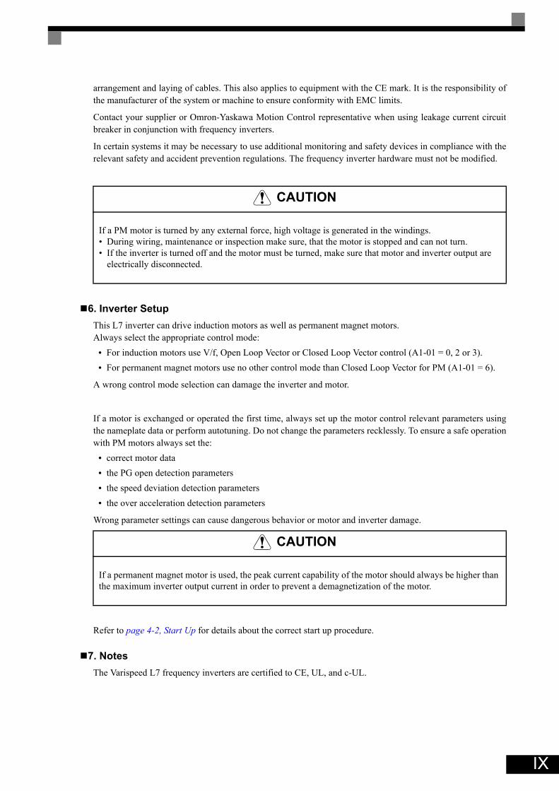
6. Inverter SetupThis L7 inverter can drive induction motors as well as permanent magnet motors. Always select the appropriate control mode:
• For induction motors use V/f, Open Loop Vector or Closed Loop Vector control (A1-01 = 0, 2 or 3).• For permanent magnet motors use no other control mode than Closed Loop Vector for PM (A1-01 = 6).
A wrong control mode selection can damage the inverter and motor.
If a motor is exchanged or operated the first time, always set up the motor control relevant parameters usingthe nameplate data or perform autotuning. Do not change the parameters recklessly. To ensure a safe operationwith PM motors always set the:
• correct motor data• the PG open detection parameters • the speed deviation detection parameters • the over acceleration detection parameters
Wrong parameter settings can cause dangerous behavior or motor and inverter damage.
Refer to page 4-2, Start Up for details about the correct start up procedure.
7. NotesThe Varispeed L7 frequency inverters are certified to CE, UL, and c-UL.
CAUTION
If a PM motor is turned by any external force, high voltage is generated in the windings. • During wiring, maintenance or inspection make sure, that the motor is stopped and can not turn.• If the inverter is turned off and the motor must be turned, make sure that motor and inverter output are
electrically disconnected.
CAUTION
If a permanent magnet motor is used, the peak current capability of the motor should always be higher than the maximum inverter output current in order to prevent a demagnetization of the motor.
X
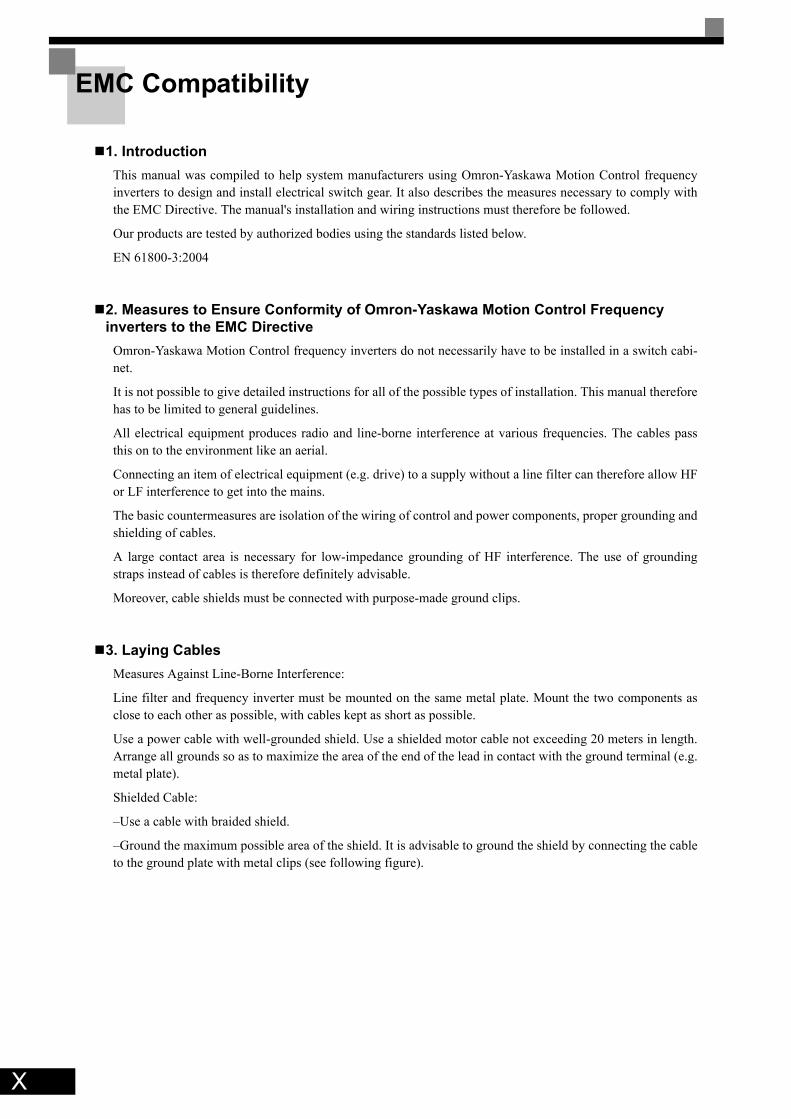
EMC Compatibility
1. IntroductionThis manual was compiled to help system manufacturers using Omron-Yaskawa Motion Control frequencyinverters to design and install electrical switch gear. It also describes the measures necessary to comply withthe EMC Directive. The manual's installation and wiring instructions must therefore be followed.
Our products are tested by authorized bodies using the standards listed below.
EN 61800-3:2004
2. Measures to Ensure Conformity of Omron-Yaskawa Motion Control Frequency inverters to the EMC Directive
Omron-Yaskawa Motion Control frequency inverters do not necessarily have to be installed in a switch cabi-net.
It is not possible to give detailed instructions for all of the possible types of installation. This manual thereforehas to be limited to general guidelines.
All electrical equipment produces radio and line-borne interference at various frequencies. The cables passthis on to the environment like an aerial.
Connecting an item of electrical equipment (e.g. drive) to a supply without a line filter can therefore allow HFor LF interference to get into the mains.
The basic countermeasures are isolation of the wiring of control and power components, proper grounding andshielding of cables.
A large contact area is necessary for low-impedance grounding of HF interference. The use of groundingstraps instead of cables is therefore definitely advisable.
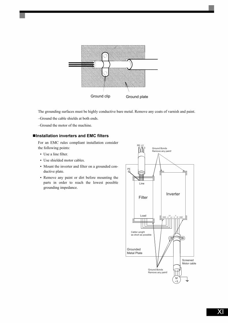
Moreover, cable shields must be connected with purpose-made ground clips.
3. Laying CablesMeasures Against Line-Borne Interference:
Line filter and frequency inverter must be mounted on the same metal plate. Mount the two components asclose to each other as possible, with cables kept as short as possible.
Use a power cable with well-grounded shield. Use a shielded motor cable not exceeding 20 meters in length.Arrange all grounds so as to maximize the area of the end of the lead in contact with the ground terminal (e.g.metal plate).
Shielded Cable:
–Use a cable with braided shield.
–Ground the maximum possible area of the shield. It is advisable to ground the shield by connecting the cableto the ground plate with metal clips (see following figure).
XI
The grounding surfaces must be highly conductive bare metal. Remove any coats of varnish and paint.
–Ground the cable shields at both ends.
–Ground the motor of the machine.
Installation inverters and EMC filtersFor an EMC rules compliant installation considerthe following points:
• Use a line filter.• Use shielded motor cables.• Mount the inverter and filter on a grounded con-
ductive plate.• Remove any paint or dirt before mounting the
parts in order to reach the lowest possiblegrounding impedance.
Ground clip Ground plate
Ground Bonds
Remove any paint!
PEL1
L2L3
PE
Line
Filter
Ground Bonds
Remove any paint!
LoadGND L1
L2L3 GNDU
VW
M
~3
Screened
Motor cable
Cable Lenght
as short as possible
Grounded
Metal Plate
Inverter
XII
Line Filters
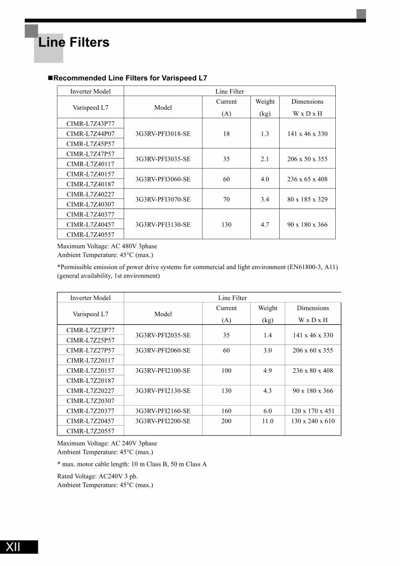
Recommended Line Filters for Varispeed L7
Maximum Voltage: AC 480V 3phaseAmbient Temperature: 45°C (max.)
*Permissible emission of power drive systems for commercial and light environment (EN61800-3, A11)(general availability, 1st environment)
Maximum Voltage: AC 240V 3phaseAmbient Temperature: 45°C (max.)
* max. motor cable length: 10 m Class B, 50 m Class A
Rated Voltage: AC240V 3 ph.Ambient Temperature: 45°C (max.)
Inverter Model Line Filter
Varispeed L7 ModelCurrent
(A)
Weight
(kg)
Dimensions
W x D x HCIMR-L7Z43P77
3G3RV-PFI3018-SE 18 1.3 141 x 46 x 330CIMR-L7Z44P07CIMR-L7Z45P57CIMR-L7Z47P57
3G3RV-PFI3035-SE 35 2.1 206 x 50 x 355CIMR-L7Z40117CIMR-L7Z40157
3G3RV-PFI3060-SE 60 4.0 236 x 65 x 408CIMR-L7Z40187CIMR-L7Z40227
3G3RV-PFI3070-SE 70 3.4 80 x 185 x 329CIMR-L7Z40307CIMR-L7Z40377
3G3RV-PFI3130-SE 130 4.7 90 x 180 x 366CIMR-L7Z40457CIMR-L7Z40557
Inverter Model Line Filter
Varispeed L7 ModelCurrent
(A)
Weight
(kg)
Dimensions
W x D x HCIMR-L7Z23P77
3G3RV-PFI2035-SE 35 1.4 141 x 46 x 330CIMR-L7Z25P57CIMR-L7Z27P57 3G3RV-PFI2060-SE 60 3.0 206 x 60 x 355CIMR-L7Z20117CIMR-L7Z20157 3G3RV-PFI2100-SE 100 4.9 236 x 80 x 408CIMR-L7Z20187CIMR-L7Z20227 3G3RV-PFI2130-SE 130 4.3 90 x 180 x 366CIMR-L7Z20307CIMR-L7Z20377 3G3RV-PFI2160-SE 160 6.0 120 x 170 x 451CIMR-L7Z20457 3G3RV-PFI2200-SE 200 11.0 130 x 240 x 610CIMR-L7Z20557

XIII
Registered Trademarks
The following registered trademarks are used in this manual.• DeviceNet is a registered trademark of the ODVA (Open DeviceNet Vendors Association, Inc.).• InterBus is a registered trademark of Phoenix Contact Co. • Profibus is a registered trademark of Siemens AG.
• Hiperfacey is a registered trademark of Sick Stegmann GmbH
• Klaukey is a registered trademark of Klauke Textron

XIV
1Handling Inverters
This chapter describes the checks required upon receiving or installing an Inverter.
Varispeed L7 Models ..........................................................1-2Confirmations upon Delivery...............................................1-3Exterior and Mounting Dimensions .....................................1-7Checking and Controlling the Installation Site ....................1-9Installation Orientation and Space ....................................1-10Removing and Attaching the Terminal Cover ...................1-11Removing/Attaching the Digital Operator/ LED Monitor and Front Cover .......................................................................1-13
1-2
1
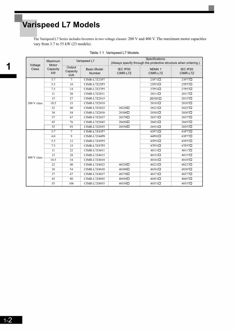
Varispeed L7 ModelsThe Varispeed L7 Series includes Inverters in two voltage classes: 200 V and 400 V. The maximum motor capacitiesvary from 3.7 to 55 kW (23 models).
Table 1.1 Varispeed L7 Models
Voltage Class
Maximum Motor
Capacity kW
Varispeed L7 Specifications (Always specify through the protective structure when ordering.)
Output Capacity
kVA
Basic Model Number
IEC IP00CIMR-L7Z
NEMA 1CIMR-L7Z
IEC IP20CIMR-L7Z
200 V class
3.7 7 CIMR-L7Z23P7 23P71 23P775.5 10 CIMR-L7Z25P5 25P51 25P577.5 14 CIMR-L7Z27P5 27P51 27P5711 20 CIMR-L7Z2011 20111 2011715 27 CIMR-L7Z2015 20151 20157
18.5 33 CIMR-L7Z2018 20181 2018722 40 CIMR-L7Z2022 20220 20221 2022730 54 CIMR-L7Z2030 20300 20301 2030737 67 CIMR-L7Z2037 20370 20371 2037745 76 CIMR-L7Z2045 20450 20451 2045755 93 CIMR-L7Z2055 20550 20551 20557
400 V class
3.7 7 CIMR-L7Z43P7 43P71 43P774.0 9 CIMR-L7Z44P0 44P01 43P775.5 12 CIMR-L7Z45P5 45P51 45P577.5 15 CIMR-L7Z47P5 47P51 47P5711 22 CIMR-L7Z4011 40111 4011715 28 CIMR-L7Z4015 40151 40157
18.5 34 CIMR-L7Z4018 40181 4018722 40 CIMR-L7Z4022 40220 40221 4022730 54 CIMR-L7Z4030 40300 40301 4030737 67 CIMR-L7Z4037 40370 40371 4037745 80 CIMR-L7Z4045 40450 40451 4045755 106 CIMR-L7Z4055 40550 40551 40557

1-3
1
Confirmations upon Delivery
Checks
Check the following items as soon as the Inverter is delivered.
In case of any irregularities in the above items, contact the agency from which the Inverter was purchased oryour Omron-Yaskawa Motion Control representative immediately.
Nameplate Information
The nameplate attached to the side of each Inverter showing the model number, specifications, lot number,serial number and other information about the Inverter.
Example NameplateThe following nameplate is an example for a standard European Inverter: 3-phase, 400 VAC, 3.7 kW, IEC IP20 standards
Fig 1.1 Nameplate
Inverter Model NumbersThe model number of the Inverter on the nameplate indicates the specification, voltage class, and maximummotor capacity of the Inverter in alphanumeric codes.
Fig 1.2 Inverter Model Numbers
Table 1.2 Checks
Item Method
Has the correct model of Inverter been delivered? Check the model number on the nameplate on the side of the Inverter.
Is the Inverter damaged in any way? Inspect the entire exterior of the Inverter to see if there are any scratches or other damage resulting from shipping.
Are any screws or other components loose? Use a screwdriver or other tools to check for tightness.
Inverter model Inverterspecifications
Mass
Input specification
Output specification
Serial number
UL file number
Lot number
MADE IN JAPANYASKAWA ELECTRIC CORPORARION
SPEC: 43P77A
PRG:
Ms
MASS: 4.0 kg
CIMR-L7Z43P7
AC3PH 380-480V 50/60Hz 10.2A
AC3PH 0-480V 0-120Hz 8.5A 3min. 50%ED 8.5kVA
FILE NO E131457
INPUT
OUTPUTO/NS/N
MODEL
CIMR – L7 Z 2 3P7 InverterVarispeed L7
No.Z
SpecificationOYMC European Std.
No. Voltage Class24
AC Input, 3-phase, 200 V
AC Input, 3-phase, 400 V
No. Max. Motor Capacity3P7 3.7 kW5P5 5.5 kWto to55 55 kW
“P” Indicates the decimal point.

1-4
1
Inverter SpecificationsThe Inverter specifications (“SPEC”) on the nameplate indicate the voltage class, maximum motor capacity,the protective structure, and the revision of the Inverter in alphanumeric codes.
Fig 1.3 Inverter Specifications
Inverter Software Version
The inverter software version can be read out from the monitor parameter U1-14. The parameter shows thelast for digits of the software number (e.g. display is “2031” for the software version VSL702031).
IMPORTANT
This manual describes the functionality of the inverter software version VSL702031Older software versions may not support all described functions. Check the software versionbefore start working with this manual!
2 3P7 1 BNo.24
Voltage ClassAC Input, 3-phase, 200 VAC Input, 3-phase 400 V
No. Max. Motor Capacity3P7 3.7 kW5P5 5.5 kWto to55 55 kW
No. Protective Structure0 IP001 NEMA 1
“P” Indicates the decimal point7 IP20
No.AB
Hardware RevisionSpec ASpec B

1-5
1
Component Names
Inverters of 18.5 kW or LessThe external appearance and component names of the Inverter are shown in Fig 1.4. The Inverter with the ter-minal cover removed is shown in Fig 1.5.
Fig 1.4 Inverter Appearance (18.5 kW or Less)
Fig 1.5 Terminal Arrangement (18.5 kW or Less)
Front cover
Digital Operator
Terminal cover
Nameplate
Heatsink
Mounting holes
Bottom Protective Cover
Control circuit terminals
Main circuit terminals
Ground terminal
Charge indicator

1-6
1
Inverters of 22 kW or MoreThe external appearance and component names of the Inverter are shown in Fig 1.6. The Inverter with the ter-minal cover removed is shown in Fig 1.7.
Fig 1.6 Inverter Appearance (22 kW or More)
Fig 1.7 Terminal Arrangement (22 kW or More)
Front cover
Inveter cover
Digital Operator
Terminal cover
Nameplate
Cooling fan
Mounting holes
Control circuit terminals
Charge indicator
Ground terminals
Main circuit terminals
1-7
1
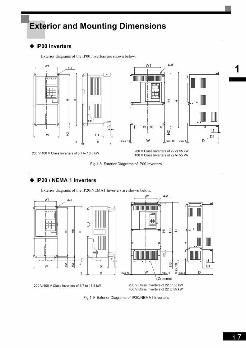
Exterior and Mounting Dimensions
IP00 Inverters
Exterior diagrams of the IP00 Inverters are shown below.
Fig 1.8 Exterior Diagrams of IP00 Inverters
IP20 / NEMA 1 Inverters
Exterior diagrams of the IP20/NEMA1 Inverters are shown below.
Fig 1.9 Exterior Diagrams of IP20/NEMA1 Inverters
W
W1
3
H1
H2
D
H
D1
4-d
t1
W
W1 4-d
H2
max. 5D1
D
H1 H
t1
max. 10max. 10
200 V Class Inverters of 22 or 55 kW400 V Class Inverters of 22 to 55 kW200 V/400 V Class Inverters of 3.7 to 18.5 kW
W
W1
3
H1
H2
D
H0
D1H3 4
H
4-d
t1
W
W1
H3
H0
H1
H2
D1
D
4-d
t1
H
Grommet
Max
.10
max. 5max. 10max. 10
200 V Class Inverters of 22 or 55 kW400 V Class Inverters of 22 to 55 kW
200 V/400 V Class Inverters of 3.7 to 18.5 kW
1-8
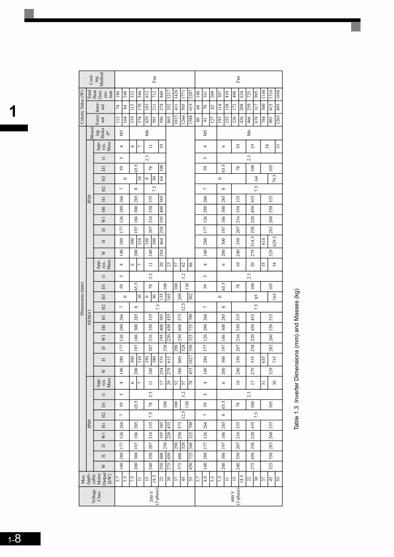
1Vo
ltage
C
lass
Max
. A
ppli-
cabl
e M
otor
O
utpu
t[k
W]
Dim
ensi
ons (
mm
)C
alor
ic V
alue
(W)
Coo
l-in
g M
etho
d
IP00
NEM
A1
IP20
Mou
ntin
g H
oles
d*
Exte
rna
lIn
ter-
nal
Tota
l H
eat
Gen
-er
a-tio
nW
HD
W1
H1
H2
D1
t1A
pp-
rox
Mas
sW
HD
W1
H0
H1
H2
H3
D1
t1A
pp-
rox.
M
ass
WH
DW
1H
0H
1H
2H
3D
1t1
App
-ro
x.
Mas
s
200
V(3
-pha
se)
3.7
140
280
177
126
266
759
54
140
280
177
126
280
266
70
595
414
028
017
712
628
026
67
059
54
M5
112
7418
6
Fan
5.5
164
8424
87.
520
030
019
718
628
5
7.5
65.5
2.3
620
030
019
718
630
028
58
65.5
2.3
620
030
019
718
630
028
58
65.5
2.3
6
M6
219
113
332
117
310
107
310
107
374
170
544
1524
035
020
721
633
578
1124
035
020
721
635
033
57.
5
078
1124
035
020
721
635
033
57.
50
7811
429
183
612
18.5
380
3038
030
501
211
712
2225
040
025
819
538
510
017
254
535
258
195
400
385
135
100
2025
446
425
819
540
038
564
100
1958
627
486
030
275
450
220
435
2027
961
522
045
043
516
523
865
352
1217
3737
560
029
825
057
512
.510
03.
252
380
809
298
250
600
575
12.5
209
100
3.2
5710
1541
114
2645
328
130
5732
813
062
1266
505
1771
5545
072
534
832
570
078
453
1027
350
325
725
700
302
8615
8861
922
07
400
V(3
-pha
se)
3.7
140
280
177
126
266
759
54
140
280
177
126
280
266
7
0
595
414
028
017
712
628
026
67
0
595
4M
580
6814
8
Fan
4.0
9170
161
5.5
127
8220
97.
520
030
019
718
628
58
65.5
2.3
620
030
019
718
630
028
58
65.5
2.3
620
030
019
718
630
028
58
65.5
2.3
6
M6
193
114
307
1125
215
841
015
240
350
207
216
335
7.5
7810
240
350
207
216
350
335
7.5
7810
240
350
207
216
350
335
7.5
7810
326
172
498
18.5
426
208
634
2227
545
025
822
043
510
017
279
535
258
220
450
435
8510
020
279
514.
525
822
045
043
564
100
1946
625
972
530
678
317
995
3732
555
028
326
053
510
531
329
635
283
260
550
535
105
3532
961
428
326
055
053
510
534
784
360
1144
4530
715
165
3462
9.5
79.5
901
415
1316
5533
1203
495
1698
Tabl
e 1.
3 In
verte
r Dim
ensi
ons
(mm
) and
Mas
ses
(kg)

1-9
1
Checking and Controlling the Installation Site
Install the Inverter in the installation site described below and maintain optimum conditions.
Installation Site
Install the Inverter under the following conditions in a pollution degree 2 environment.
Protection covers are attached to the top and bottom of the Inverter. Be sure to remove the protection coversbefore installing a 200 or 400 V Class Inverter with an output of 18.5 kW or less in a panel.
Observe the following precautions when mounting the Inverter.• Install the Inverter in a clean location which is free from oil mist and dust. It can be installed in a totally
enclosed panel that is completely shielded from floating dust.• When installing or operating the Inverter, always take special care so that metal powder, oil, water, or other
foreign matter does not get into the Inverter.• Do not install the Inverter on combustible material, such as wood.• Install the Inverter in a location free from radioactive materials and combustible materials.• Install the Inverter in a location free from harmful gasses and liquids.• Install the Inverter in a location without excessive oscillation.• Install the Inverter in a location free from chlorides.• Install the Inverter in a location not in direct sunlight.
Controlling the Ambient Temperature
To enhance the reliability of operation, the Inverter should be installed in an environment free from extremetemperature increases. If the Inverter is installed in an enclosed environment, such as a cabinet, use a coolingfan or air conditioner to maintain the internal air temperature below 45°C.
Protecting the Inverter from Foreign Matter
Place a cover over the Inverter during installation to shield it from metal power produced by drilling.
Always remove the cover from the Inverter after the completion of the installation. Otherwise, ventilation willbe reduced, causing the Inverter to overheat.
Table 1.4 Installation Site
Type Ambient Operating Temperature Humidity
NEMA1 / IP20 -10 to + 40 °C 95% RH or less (no condensation)
IEC IP00 -10 to + 45 °C 95% RH or less (no condensation)
1-10
1
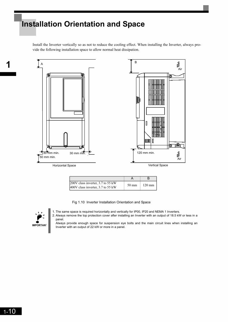
Installation Orientation and Space
Install the Inverter vertically so as not to reduce the cooling effect. When installing the Inverter, always pro-vide the following installation space to allow normal heat dissipation.
Fig 1.10 Inverter Installation Orientation and Space
IMPORTANT
1. The same space is required horizontally and vertically for IP00, IP20 and NEMA 1 Inverters.2. Always remove the top protection cover after installing an Inverter with an output of 18.5 kW or less in a
panel.Always provide enough space for suspension eye bolts and the main circuit lines when installing anInverter with an output of 22 kW or more in a panel.
A
50 mm min.30 mm min. 30 mm min.
B
120 mm min.
Air
Air
Vertical SpaceHorizontal Space
A B200V class inverter, 3.7 to 55 kW400V class inverter, 3.7 to 55 kW 50 mm 120 mm

1-11
1
Removing and Attaching the Terminal Cover
Remove the terminal cover to wire cables to the control circuit and main circuit terminals.
Removing the Terminal Cover
Inverters of 18.5 kW or LessLoosen the screw at the bottom of the terminal cover, press in on the sides of the terminal cover in the direc-tions of arrows 1, and then lift up on the terminal in the direction of arrow 2.
Fig 1.11 Removing the Terminal Cover (Model CIMR-L7Z43P7 Shown Above)
Inverters of 22 kW or MoreLoosen the screws on the left and right at the top of the terminal cover, pull out the terminal cover in the direc-tion of arrow 1 and then lift up on the terminal in the direction of arrow 2.
Fig 1.12 Removing the Terminal Cover (Model CIMR-L7Z4022 Shown Above)
IMPORTANT
Before opening the terminal cover, switch off the power supply and wait at least 5 min. to make sure, that the DC bus is discharged!
1
2 1
12

1-12
1
Attaching the Terminal Cover
When the terminal block wiring has been completed, attach the terminal cover by reversing the removal proce-dure.
For Inverters with an output of 18.5 kW or less, insert the tab on the top of the terminal cover into the grooveon the Inverter and press in on the bottom of the terminal cover until it clicks into place.
1-13
1
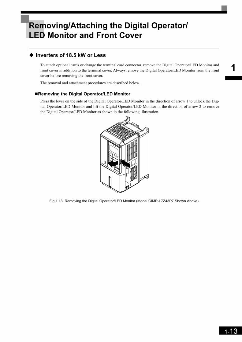
Removing/Attaching the Digital Operator/LED Monitor and Front Cover
Inverters of 18.5 kW or Less
To attach optional cards or change the terminal card connector, remove the Digital Operator/LED Monitor andfront cover in addition to the terminal cover. Always remove the Digital Operator/LED Monitor from the frontcover before removing the front cover.
The removal and attachment procedures are described below.
Removing the Digital Operator/LED MonitorPress the lever on the side of the Digital Operator/LED Monitor in the direction of arrow 1 to unlock the Dig-ital Operator/LED Monitor and lift the Digital Operator/LED Monitor in the direction of arrow 2 to removethe Digital Operator/LED Monitor as shown in the following illustration.
Fig 1.13 Removing the Digital Operator/LED Monitor (Model CIMR-L7Z43P7 Shown Above)
12
1-14
1
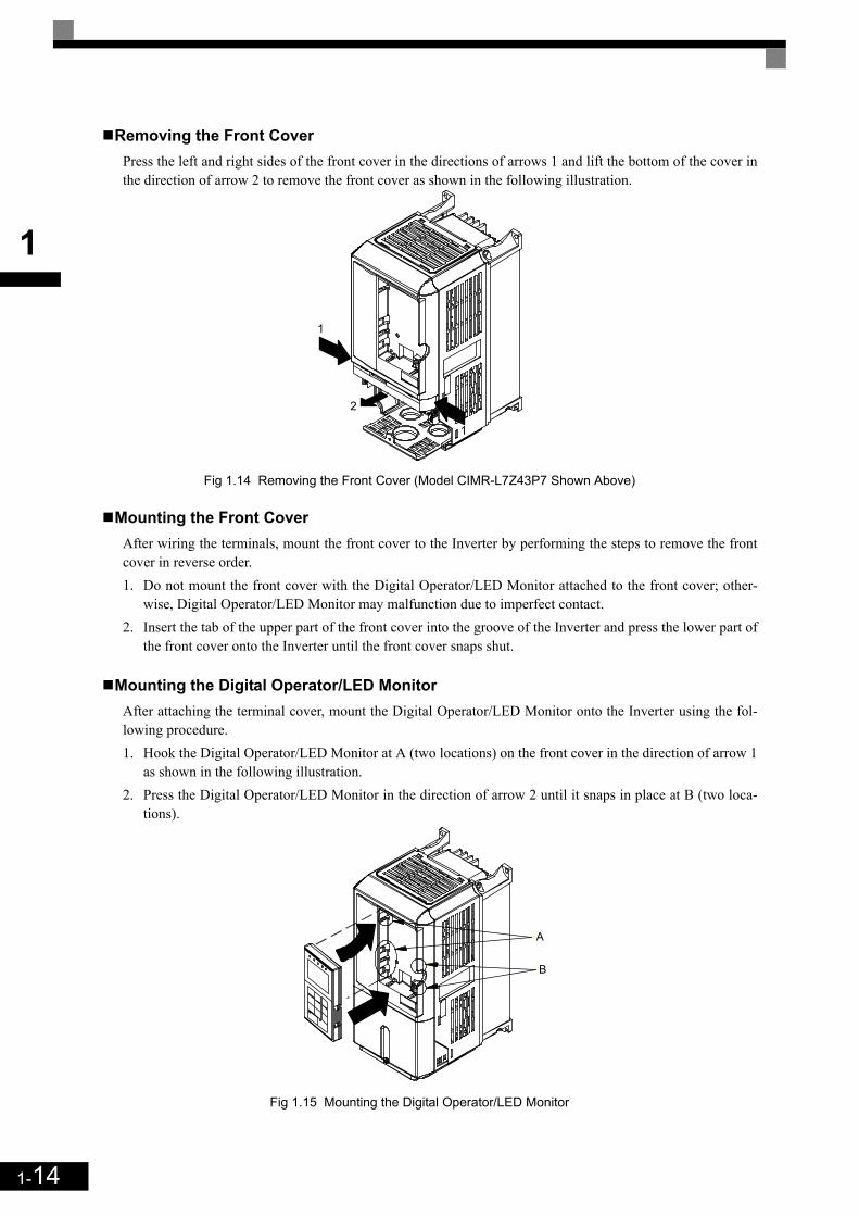
Removing the Front CoverPress the left and right sides of the front cover in the directions of arrows 1 and lift the bottom of the cover inthe direction of arrow 2 to remove the front cover as shown in the following illustration.
Fig 1.14 Removing the Front Cover (Model CIMR-L7Z43P7 Shown Above)
Mounting the Front CoverAfter wiring the terminals, mount the front cover to the Inverter by performing the steps to remove the frontcover in reverse order.1. Do not mount the front cover with the Digital Operator/LED Monitor attached to the front cover; other-
wise, Digital Operator/LED Monitor may malfunction due to imperfect contact.2. Insert the tab of the upper part of the front cover into the groove of the Inverter and press the lower part of
the front cover onto the Inverter until the front cover snaps shut.
Mounting the Digital Operator/LED MonitorAfter attaching the terminal cover, mount the Digital Operator/LED Monitor onto the Inverter using the fol-lowing procedure.1. Hook the Digital Operator/LED Monitor at A (two locations) on the front cover in the direction of arrow 1
as shown in the following illustration.2. Press the Digital Operator/LED Monitor in the direction of arrow 2 until it snaps in place at B (two loca-
tions).
Fig 1.15 Mounting the Digital Operator/LED Monitor
1
1
2
A
B

1-15
1
Inverters of 22 kW or More
For inverters with an output of 22 kW or more, remove the terminal cover and then use the following proce-dures to remove the Digital Operator/LED Monitor and front cover.
Removing the Digital Operator/LED MonitorUse the same procedure as for Inverters with an output of 18.5 kW or less.
Removing the Front CoverLift up at the location label 1 at the top of the control circuit terminal card in the direction of arrow 2.
Fig 1.16 Removing the Front Cover (Model CIMR-L7Z4022 Shown Above)
Attaching the Front CoverAfter completing the required work, such as mounting an optional card or setting the terminal card, attach thefront cover by reversing the procedure to remove it.1. Confirm that the Digital Operator/LED Monitor is not mounted on the front cover. Contact faults can occur
if the cover is attached while the Digital Operator/LED Monitor is mounted to it. 2. Insert the tab on the top of the front cover into the slot on the Inverter and press in on the cover until it
clicks into place on the Inverter.
Attaching the Digital Operator/LED MonitorUse the same procedure as for Inverters with an output of 18.5 kW or less.
IMPORTANT
1. Do not remove or attach the Digital Operator/LED Monitor or mount or remove the front cover using meth-ods other than those described above, otherwise the Inverter may break or malfunction due to imperfectcontact.
2. Never attach the front cover to the Inverter with the Digital Operator/LED Monitor attached to the frontcover. Imperfect contact can result.Always attach the front cover to the Inverter by itself first, and then attach the Digital Operator/LED Moni-tor to the front cover.
1
2

1-16
1

2 Wiring
This chapter describes the terminals, main circuit terminal connections, main circuit terminal wiring specifica-tions, control circuit terminals, and control circuit wiring specifications.
Connection Diagram ...........................................................2-2Terminal Block Configuration..............................................2-4Wiring Main Circuit Terminals .............................................2-5Wiring Control Circuit Terminals .......................................2-17EN81-1 Conform Wiring with One Motor Contactor..........2-21Wiring Check.....................................................................2-23Installing and Wiring Option Cards ...................................2-24

2-2
2
Connection Diagram
The connection diagram of the Inverter is shown in Fig 2.1.
When using the Digital Operator, the motor can be operated by wiring only the main circuits.
Fig 2.1 Connection Diagram (Model CIMR-L7Z43P7 Shown Above)
1
3
2
1
Voltage adjust-ment
DC reactor to improve inputpower factor (optional)
Braking Resistorunit (optional)
LinkMagneticContactor
3-phase power380 to 480V50/60Hz
L1
L2
L3
PE
LineFilter
L1(R)
L2(S)
L3(T)
(+1) (+2) (-) B1 B2
U/T1
V/T2
W/T3
TA1
PG-X2
(Optional)
Motor
IM/PM
TA3
TA2
P
P
PG
S1
S3
S2
S4
S5
S6
S7
BB
BB1
Multi function Inputs(Factory setting)
Forward run/stop
Reverse run/stop
Nominal Speed
Inspection Run
Intermediate Speed
Leveling Speed
Not used
Hardware Baseblock (note 3)
SC
+24V, 8mA
IP24V (24V)
CN5(NPN setting)
A Pulse
B Pulse
Z Pulse
Pulse Monitor OutputRS-422 (100m or less)
E(G)MA
MB
MC
Fault contact output250VAC, max. 1A 30VDC, max. 1A
M1
M2
M3
M5
M4
M6
Brake Command(Factory setting)
Contactor Control(Factory setting)
Inverter Ready(Factory setting)
Multi-functioncontact output250VAC, max. 1A 30VDC, max. 1A
Analog input powersupply +15V, 20mA
Master speedreference 0 to 10V
+V
A1
AC
0 V
P
2CN
2kOhmAnalog input(Speed reference)
2kOhm0 to 10 V
Input option cards
Optional control power supply input for Rescue
Operation
to terminal B1
to terminal -
Control PowerSupply Input
P0
N0
Twisted-pairwires
Shieldedwires
Note:1. Main circuit terminals are indicatied with double circles and
control circuit terminals are indicatied with a single circles2. The CN5 factory setting is NPN3. To enable the inverter both inputs, BB and BB1 must be closed. If
only one of the inputs is closed, “BB” will be displayed in the operator panel and the inverter will not start.
Output option cards
3CN
2
2-3
2
Circuit Descriptions
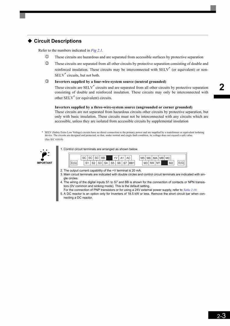
Refer to the numbers indicated in Fig 2.1.
1 These circuits are hazardous and are separated from accessible surfaces by protective separation
2 These circuits are separated from all other circuits by protective separation consisting of double andreinforced insulation. These circuits may be interconnected with SELV* (or equivalent) or non-SELV* circuits, but not both.
3 Inverters supplied by a four-wire-system source (neutral grounded)These circuits are SELV* circuits and are separated from all other circuits by protective separationconsisting of double and reinforced insulation. These circuits may only be interconnected withother SELV* (or equivalent) circuits.
Inverters supplied by a three-wire-system source (ungrounded or corner grounded)These circuits are not separated from hazardous circuits other circuits by protective separation, butonly with basic insulation. These circuits must not be interconnected with any circuits which areaccessible, unless they are isolated from accessible circuits by supplemental insulation
* SELV (Safety Extra Low Voltage) circuits have no direct connection to the primary power and are supplied by a transformer or equivalent isolating device. The circuits are designed and protected, so that, under normal and single fault condition, its voltage does not exceed a safe value. (See IEC 61010)
IMPORTANT
1. Control circuit terminals are arranged as shown below.
2. The output current capability of the +V terminal is 20 mA.3. Main circuit terminals are indicated with double circles and control circuit terminals are indicated with sin-
gle circles.4. The wiring of the digital inputs S1 to S7 and BB is shown for the connection of contacts or NPN transis-
tors (0V common and sinking mode). This is the default setting. For the connection of PNP transistors or for using a 24V external power supply, refer to Table 2.10.
5. A DC reactor is an option only for Inverters of 18.5 kW or less. Remove the short circuit bar when con-necting a DC reactor.
+VSC SC SC BB A1 AC
E(G) S1 S2 S3 S4 S5 S6 S7 BB1
M5 M6
M3 M4
MA MB MC
M1 M2 E(G)

2-4
2
Terminal Block Configuration
The terminal arrangements are shown in Fig 2.2 and Fig 2.3.
Fig 2.2 Terminal Arrangement (200 V/400 V Class Inverter of 3.7 kW)
Fig 2.3 Terminal Arrangement (200 V/400 V Class Inverter of 22 kW or more)
Control circuit terminals
Main circuit terminals
Ground terminal
Charge indicator
Controlcircuit
terminals Charge indicator
Ground terminals
Maincircuit
terminals

2-5
2
Wiring Main Circuit Terminals
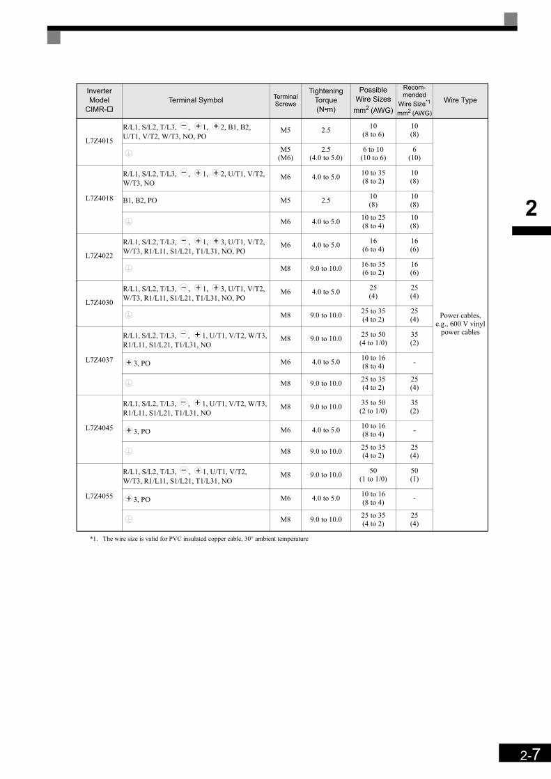
Applicable Wire Sizes and Crimp Terminals
Select the appropriate wires and crimp terminals using Table 2.1 to Table 2.3. Refer to instruction manualTOE-C726-2 for wire sizes for Braking Resistor Units and Braking Units.
Wire Sizes
Table 2.1 200 V Class Wire SizesInverter Model
CIMR-Terminal Symbol Terminal
Screws
Tightening Torque(N•m)
Possible Wire Sizesmm2(AWG)
Recom-mended
Wire Size*1 mm2 (AWG)
Wire Type
L7Z23P7R/L1, S/L2, T/L3, , 1, 2, B1, B2, U/T1, V/T2, W/T3, PO, NO M4 1.2 to 1.5 4
(12 to 10)4
(12)
Power cables, e.g., 600 V vinyl
power cables
L7Z25P5R/L1, S/L2, T/L3, , 1, 2, B1, B2, U/T1, V/T2, W/T3, PO, NO M4 1.2 to 1.5 6
(10)6
(10)
L7Z27P5R/L1, S/L2, T/L3, , 1, 2, B1, B2, U/T1, V/T2, W/T3, PO, NO M5 2.5 10
(8 to 6)10(8)
L7Z2011R/L1, S/L2, T/L3, , 1, 2, B1, B2, U/T1, V/T2, W/T3, PO, NO M5 2.5 16
(6 to 4)16(6)
L7Z2015
R/L1, S/L2, T/L3, , 1, 2, U/T1, V/T2, W/T3, NO
M6 4.0 to 5.0 25(4 to 2)
25(4)
B1, B2, PO M5 2.5 10(8 to 6) -
M6 4.0 to 5.0 25(4)
25(4)
L7Z2018
R/L1, S/L2, T/L3, , 1, 2, U/T1, V/T2, W/T3, NO
M8 9.0 to 10.0 25 to 35(3 to 2)
25(3)
B1, B2, PO M5 2.5 10 to 16(8 to 6) -
M6 4.0 to 5.0 25(4)
25(4)
L7Z2022
R/L1, S/L2, T/L3, , 1, U/T1, V/T2, W/T3, R1/L11, S1/L21, T1/L31, NO
M8 9.0 to 10.0 25 to 35(3 to 1)
25(3)
3, PO M6 4.0 to 5.0 10 to 16(8 to 4) -
M8 9.0 to 10.0 25 to 35(4 to 2)
25(4)
L7Z2030
R/L1, S/L2, T/L3, , 1 U/T1, V/T2, W/T3, R1/L11, S1/L21, T1/L31, NO
M8 9.0 to 10.0 50(1 to 1/0)
50(1)
3, PO M6 4.0 to 5.0 10 to 16(8 to 4) -
M8 9.0 to 10.0 25 to 35(4 to 2)
25(4)

2-6
2
Table 2.2 400 V Class Wire Sizes
L7Z2037
R/L1, S/L2, T/L3, , 1 U/T1, V/T2, W/T3, R1/L11, S1/L21, T1/L31, NO
M10 17.6 to 22.5 70 to 95(2/0 to 4/0)
70(2/0)
Power cables, e.g., 600 V vinyl
power cables
3, PO M8 8.8 to 10.8 6 to 16(10 to 4) –
M10 17.6 to 22.5 35 to 70(2 to 2/0)
35(2)
r/l1, Δ/l2 M4 1.3 to 1.4 0.5 to 4(20 to 10)
1.5(16)
L7Z2045
R/L1, S/L2, T/L3, , 1 U/T1, V/T2, W/T3, R1/L11, S1/L21, T1/L31, NO
M10 17.6 to 22.5 95(3/0 to 4/0)
95(3/0)
3, PO M8 8.8 to 10.8 6 to 16(10 to 4) –
M10 17.6 to 22.5 50 to 70(1 to 2/0)
50(1)
r/l1, Δ/l2 M4 1.3 to 1.4 0.5 to 4(20 to 10)
1.5(16)
L7Z2055
R/L1, S/L2, T/L3, , 1, NO M12 31.4 to 39.2 50 to 95(1/0 to 4/0)
50 × 2P(1/0 × 2P)
U/T1, V/T2, W/T3, R1/L11, S1/L21, T1/L31 M10 17.6 to 22.5 90(4/0)
90(4/0)
3, PO M8 8.8 to 10.8 6 to 70(10 to 2/0) –
M10 17.6 to 22.5 35 to 95(3 to 4/0)
50(1/0)
r/l1, Δ/l2 M4 1.3 to 1.4 0.5 to 4(20 to 10)
1.5(16)
*1. The wire size is valid for PVC insulated copper cable, 30° ambient temperature
Inverter Model
CIMR-Terminal Symbol Terminal
Screws
Tightening Torque(N•m)
Possible Wire Sizes
mm2 (AWG)
Recom-mended
Wire Size*1 mm2 (AWG)
Wire Type
L7Z43P7
R/L1, S/L2, T/L3, , 1, 2, B1, B2, U/T1, V/T2, W/T3, NO, PO M4 1.2 to 1.5 2.5 to 4
(14 to 10)
4(12)
Power cables, e.g., 600 V vinyl
power cables
2.5(14)
L7Z44P0
R/L1, S/L2, T/L3, , 1, 2, B1, B2, U/T1, V/T2, W/T3, NO, PO M4 1.2 to 1.5 2.5 to 4
(14 to 10)
4(12)
2.5(14)
L7Z45P5
R/L1, S/L2, T/L3, , 1, 2, B1, B2, U/T1, V/T2, W/T3, NO, PO M4 1.2 to 1.5
4(12 to 10)
4(12)
2.5 to 4(14 to 10)
2.5(14)
L7Z47P5
R/L1, S/L2, T/L3, , 1, 2, B1, B2, U/T1, V/T2, W/T3, NO, PO M4 1.2 to 1.5 6 to 10
(10 to 6)
6(10)
4(12)
L7Z4011
R/L1, S/L2, T/L3, , 1, 2, B1, B2, U/T1, V/T2, W/T3, NO, PO M5 2.5 6 to 10
(10 to 6)
10(8)
6(10)
Inverter Model
CIMR-Terminal Symbol Terminal
Screws
Tightening Torque(N•m)
Possible Wire Sizesmm2(AWG)
Recom-mended
Wire Size*1 mm2 (AWG)
Wire Type
2-7
2
L7Z4015
R/L1, S/L2, T/L3, , 1, 2, B1, B2, U/T1, V/T2, W/T3, NO, PO
M5 2.5 10(8 to 6)
10(8)
Power cables, e.g., 600 V vinyl
power cables
M5(M6)
2.5(4.0 to 5.0)
6 to 10(10 to 6)
6(10)
L7Z4018
R/L1, S/L2, T/L3, , 1, 2, U/T1, V/T2, W/T3, NO
M6 4.0 to 5.0 10 to 35(8 to 2)
10(8)
B1, B2, PO M5 2.5 10(8)
10(8)
M6 4.0 to 5.0 10 to 25(8 to 4)
10(8)
L7Z4022
R/L1, S/L2, T/L3, , 1, 3, U/T1, V/T2, W/T3, R1/L11, S1/L21, T1/L31, NO, PO
M6 4.0 to 5.0 16(6 to 4)
16(6)
M8 9.0 to 10.0 16 to 35(6 to 2)
16(6)
L7Z4030
R/L1, S/L2, T/L3, , 1, 3, U/T1, V/T2, W/T3, R1/L11, S1/L21, T1/L31, NO, PO
M6 4.0 to 5.0 25(4)
25(4)
M8 9.0 to 10.0 25 to 35(4 to 2)
25(4)
L7Z4037
R/L1, S/L2, T/L3, , 1, U/T1, V/T2, W/T3, R1/L11, S1/L21, T1/L31, NO
M8 9.0 to 10.0 25 to 50(4 to 1/0)
35(2)
3, PO M6 4.0 to 5.0 10 to 16(8 to 4) -
M8 9.0 to 10.0 25 to 35(4 to 2)
25(4)
L7Z4045
R/L1, S/L2, T/L3, , 1, U/T1, V/T2, W/T3, R1/L11, S1/L21, T1/L31, NO
M8 9.0 to 10.0 35 to 50(2 to 1/0)
35(2)
3, PO M6 4.0 to 5.0 10 to 16(8 to 4) -
M8 9.0 to 10.0 25 to 35(4 to 2)
25(4)
L7Z4055
R/L1, S/L2, T/L3, , 1, U/T1, V/T2, W/T3, R1/L11, S1/L21, T1/L31, NO
M8 9.0 to 10.0 50(1 to 1/0)
50(1)
3, PO M6 4.0 to 5.0 10 to 16(8 to 4) -
M8 9.0 to 10.0 25 to 35(4 to 2)
25(4)
*1. The wire size is valid for PVC insulated copper cable, 30° ambient temperature
Inverter Model
CIMR-Terminal Symbol Terminal
Screws
Tightening Torque(N•m)
Possible Wire Sizes
mm2 (AWG)
Recom-mended
Wire Size*1 mm2 (AWG)
Wire Type

2-8
2
Recommended Crimp Terminal Sizes (Ring type)
Table 2.3 Crimp Terminal Sizes
Wire Cross Section (mm2) Terminal ScrewsCrimp Terminal Type
Klaukey JSTA B
0.5 - 1.0 M4 620/4 1620/4 GS4-1
1.5 M4 630/4 1620/4 GS4-1
2.5 M4 630/4 1630/4 GS4-2.5
4 M4 650/4 1650/4 GS4-6
6
M4 650/4 1650/4 GS4-6
M5 101 R/5 1650/5 GS5-6
M6 101 R/6 1650/6 GS6-6
M8 101 R/8 1650/8 GS6-8
10
M5 102 R/5 1652/5 GS5-10
M6 102 R/6 1652/6 GS6-10
M8 102 R/8 1652/8 GS8-10
16
M5 103 R/5*1
*1. Not applicable for L7Z2011
1653/5 GS5-16
M6 103 R/6 1653/6 GS6-16
M8 103 R/8 1653/8 GS8-16
25M6 104 R/6 1654/6 GS6-25
M8 104 R/8 1654/8 GS8-25
35
M6 105 R/6 1655/6 GS6-35
M8 105 R/8 1655/8 GS8-35
M10 105 R/10 1655/10 GS10-35
50
M8 106 R/8 1656/8 GS8-50
M10 106 R/10 1656/10 GS10-50
M12 106 R/12 1656/12 GS12-50
70
M8 107 R/8 1657/8 GS8-70
M10 107 R/10 1657/10 GS10-70
M12 107 R/12 1657/12 GS12-70
95M10 108 R/10 1658/10 GS10-95
M12 108 R/12 1658/12 GS12-95
IMPORTANT
Select the wire size for the main circuit so that line voltage drop is within 2% of the rated voltage. Line voltage drop is calculated as follows:
Line voltage drop (V) = x wire resistance (Ω/km) x wire length (m) x current (A) x 10-33
2-9
2
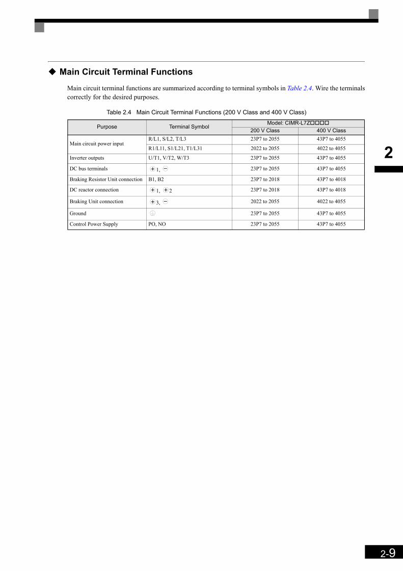
Main Circuit Terminal Functions
Main circuit terminal functions are summarized according to terminal symbols in Table 2.4. Wire the terminalscorrectly for the desired purposes.
Table 2.4 Main Circuit Terminal Functions (200 V Class and 400 V Class)
Purpose Terminal SymbolModel: CIMR-L7Z
200 V Class 400 V Class
Main circuit power inputR/L1, S/L2, T/L3 23P7 to 2055 43P7 to 4055
R1/L11, S1/L21, T1/L31 2022 to 2055 4022 to 4055
Inverter outputs U/T1, V/T2, W/T3 23P7 to 2055 43P7 to 4055
DC bus terminals 1, 23P7 to 2055 43P7 to 4055
Braking Resistor Unit connection B1, B2 23P7 to 2018 43P7 to 4018
DC reactor connection 1, 2 23P7 to 2018 43P7 to 4018
Braking Unit connection 3, 2022 to 2055 4022 to 4055
Ground 23P7 to 2055 43P7 to 4055
Control Power Supply PO, NO 23P7 to 2055 43P7 to 4055
2-10
2
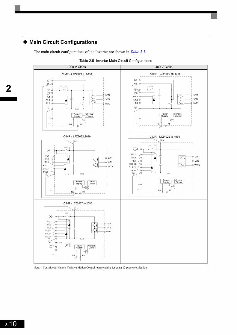
Main Circuit Configurations
The main circuit configurations of the Inverter are shown in Table 2.5.
Table 2.5 Inverter Main Circuit Configurations
Note: Consult your Omron-Yaskawa Motion Control representative for using 12-phase rectification.
200 V Class 400 V Class
ControlCircuit
R/L1S/L2T/L3
-
U/T1
V/T2
W/T3
CIMR - L7Z23P7 to 2018
P0N0
PowerSupply
+
B1B2
2+1
ControlCircuit
R/L1S/L2T/L3
-
U/T1
V/T2
W/T3
CIMR - L7Z43P7 to 4018
P0N0
PowerSupply
+
B1B2
2+1
ControlCircuit
+
R/L1S/L2T/L3
R1/L11S1/L21T1/L31
-
+ 3
U/T1
V/T2
W/T3
CIMR - L7Z2022,2030
P0N0
PowerSupply
1
ControlCircuit
+ 1
R/L1S/L2T/L3
R1/L11S1/L21T1/L31
-
+ 3
U/T1
V/T2
W/T3
CIMR - L7Z4022 to 4055
P0N0
PowerSupply
ControlCircuit
+ 1
R/L1S/L2T/L3
R1/L11S1/L21T1/L31
-
+ 3
U/T1
V/T2
W/T3
CIMR - L7Z2037 to 2055
r/l1
P0N0
PowerSupply
Δ200/l200
2-11
2
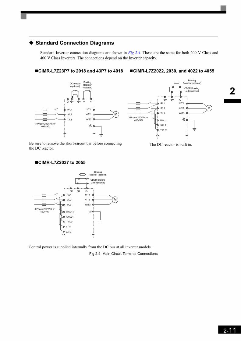
Standard Connection Diagrams
Standard Inverter connection diagrams are shown in Fig 2.4. These are the same for both 200 V Class and400 V Class Inverters. The connections depend on the Inverter capacity.
Control power is supplied internally from the DC bus at all inverter models. Fig 2.4 Main Circuit Terminal Connections
CIMR-L7Z23P7 to 2018 and 43P7 to 4018
Be sure to remove the short-circuit bar before connecting the DC reactor.
CIMR-L7Z2022, 2030, and 4022 to 4055
The DC reactor is built in.
CIMR-L7Z2037 to 2055
+ 1- + 2 B1 B2
R/L1
S/L2
T/L3
U/T1
V/T2
W/T3
M
3 Phase 200VAC or 400VAC
Braking Resistor (optional)
DC reactor(optional)
+ 1 -+ 3
R/L1
S/L2
T/L3
U/T1
V/T2
W/T3
M
3 Phase 200VAC or 400VAC
CDBR Braking Unit (optional)
Braking Resistor (optional)
R1/L11
S1/L21
T1/L31
+ 1 -+ 3
R/L1
S/L2
T/L3
U/T1
V/T2
W/T3
M
3 Phase 200VAC or 400VAC
CDBR Braking Unit (optional)
Braking Resistor (optional)
R1/L11
S1/L21
T1/L31
r / l1
/ l2
2-12
2
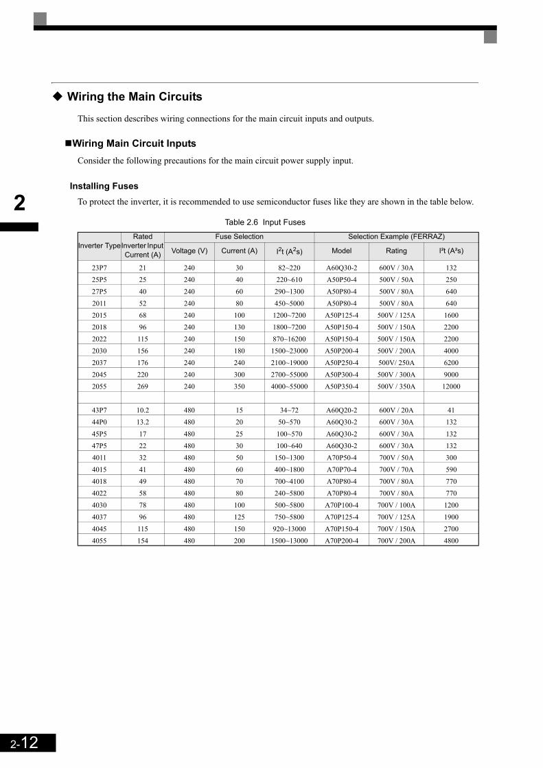
Wiring the Main Circuits
This section describes wiring connections for the main circuit inputs and outputs.
Wiring Main Circuit InputsConsider the following precautions for the main circuit power supply input.
Installing FusesTo protect the inverter, it is recommended to use semiconductor fuses like they are shown in the table below.
Table 2.6 Input Fuses
Inverter TypeRated
Inverter Input Current (A)
Fuse Selection Selection Example (FERRAZ)
Voltage (V) Current (A) I2t (A2s) Model Rating I²t (A²s)
23P7 21 240 30 82~220 A60Q30-2 600V / 30A 13225P5 25 240 40 220~610 A50P50-4 500V / 50A 25027P5 40 240 60 290~1300 A50P80-4 500V / 80A 6402011 52 240 80 450~5000 A50P80-4 500V / 80A 6402015 68 240 100 1200~7200 A50P125-4 500V / 125A 16002018 96 240 130 1800~7200 A50P150-4 500V / 150A 22002022 115 240 150 870~16200 A50P150-4 500V / 150A 22002030 156 240 180 1500~23000 A50P200-4 500V / 200A 40002037 176 240 240 2100~19000 A50P250-4 500V/ 250A 62002045 220 240 300 2700~55000 A50P300-4 500V / 300A 90002055 269 240 350 4000~55000 A50P350-4 500V / 350A 12000
43P7 10.2 480 15 34~72 A60Q20-2 600V / 20A 4144P0 13.2 480 20 50~570 A60Q30-2 600V / 30A 13245P5 17 480 25 100~570 A60Q30-2 600V / 30A 13247P5 22 480 30 100~640 A60Q30-2 600V / 30A 1324011 32 480 50 150~1300 A70P50-4 700V / 50A 3004015 41 480 60 400~1800 A70P70-4 700V / 70A 5904018 49 480 70 700~4100 A70P80-4 700V / 80A 7704022 58 480 80 240~5800 A70P80-4 700V / 80A 7704030 78 480 100 500~5800 A70P100-4 700V / 100A 12004037 96 480 125 750~5800 A70P125-4 700V / 125A 19004045 115 480 150 920~13000 A70P150-4 700V / 150A 27004055 154 480 200 1500~13000 A70P200-4 700V / 200A 4800

2-13
2
Installing a Moulded-Case Circuit BreakerIf a moulded case circuit breaker is used for the power supply connection (R/L1, S/L2, and T/L3) it must besuitable for the Inverter.
• The MCCB should have a capacity of 1.5 to 2 times of the inverter's rated current.• For the MCCB's time characteristics selection the inverter's overload protection (one minute at 150% of
the rated output current) must be considered.
Installing an Earth Leakage BreakerAn earth leakage breaker which is able to detect all kinds of current should be used in order to ensure a safeearth leakage current detection.
• If a special-purpose earth leakage breaker for Inverters is used, it should have an actuating current of atleast 30 mA per Inverter.
• If a standard earth leakage breaker is used, it should have an actuating current of 200 mA or more perInverter and a actuating time of 0.1 s or more.
Installing a Magnetic Contactor at the InputIf the power supply for the main circuit is shut off by a control circuit, a magnetic contactor can be used.
The following things should be considered:• The Inverter can be started and stopped by opening and closing the magnetic contactor on the primary side.
Frequently opening and closing the magnetic contactor may cause an Inverter fault. Do not exceed onepower up per hour.
• When the Inverter is operated using the Digital Operator, automatic operation cannot be performed afterrecovery from a power interruption.
Connecting Input Power Supply to the Terminal BlockThe input power supply can be connected in any sequence to the terminals R, S or T on the terminal block; theinput phase sequence is irrelevant to the output phase sequence.
Installing an Input AC Reactor If the Inverter is connected to a large-capacity power transformer (600 kW or more) or a phase advancingcapacitor is switched nearby, an excessive peak current could flow through the input power circuit, causing aninverter damage. As a countermeasure an optional AC Reactor the inverter input or a DC reactor at the DCreactor connection terminals can be installed.
In order to fulfill the EN12015 an AC reactor has to be installed. Refer to Chapter 9, AC Reactors for EN12015 Compatibility for the available reactors. The AC reactor has to be installed between the power supplyand the EMC filter (like shown in Fig 2.5)
Fig 2.5 AC reactor installation
Installing a Surge AbsorberAlways use a surge absorber or diode for inductive loads near the Inverter. Inductive loads include magneticcontactors, electromagnetic relays, solenoid valves, solenoids, and magnetic brakes.
FilterL7Z
Inverter
L1
L2
L3
M
Power
Supply
AC
Reactor

2-14
2
Wiring the Output Side of the Main CircuitThe following precautions should be considered for the output circuit wiring.
Connecting the Inverter and MotorThe output terminals U/T1, V/T2 and W/T3 must be connected according to the motor lead wires U, V and W.
The motor should rotate forward with the forward run command. If not, two of the motor cable wires can beswitched.
Never Connect a Power Supply to Output TerminalsA power supply must never be connected to the output terminals U/T1, V/T2, and W/T3. Otherwise the inter-nal circuits of the Inverter will be damaged.
Never Short or Ground Output TerminalsIf the output terminals are touched with bare hands or the output wires come into contact with the Invertercase, an electric shock or a short circuit may occur.
Do Not Use a Phase Advancing CapacitorA phase advancing capacitor must never be connected to the inverter output circuit. The high-frequency com-ponents of the Inverter output may overheat and be damaged and may cause other parts to burn.
Using a Magnetic ContactorA magnetic contactor (MC) between the Inverter and motor must not be turned ON or OFF during inverteroperation. If the MC is turned ON during the Inverter is operation, a large inrush current will be created andthe inverter’s over current protection may operate.
Ground WiringThe following precautions should be considered for the ground connection.
• Always use the ground terminal of the 200 V Inverter with a ground resistance of less than 100 Ω and thatof the 400 V Inverter with a ground resistance of less than 10 Ω.
• Ground wires should not be shared with other devices, such as welding machines or power tools.• A ground wire, that complies with technical standards on electrical equipment must be used. The length of
the ground wire should be as low as possible.Leakage current flows through the Inverter. Therefore, if the distance between the ground electrode and theground terminal is too long, potential on the ground terminal of the Inverter will become unstable.
• When more than one Inverter is used the ground wires should not be looped.
Fig 2.6 Ground Wiring
OK NO
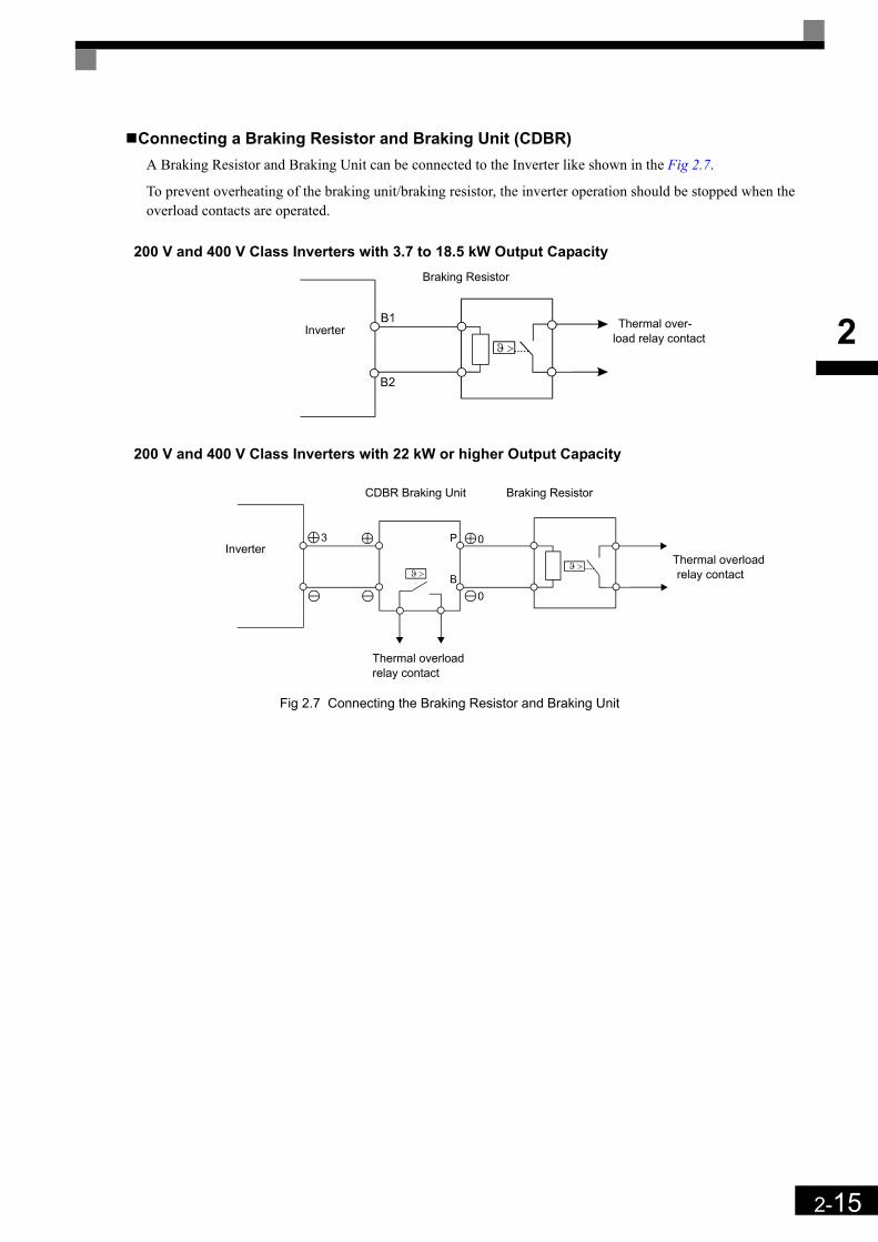
2-15
2
Connecting a Braking Resistor and Braking Unit (CDBR)A Braking Resistor and Braking Unit can be connected to the Inverter like shown in the Fig 2.7.
To prevent overheating of the braking unit/braking resistor, the inverter operation should be stopped when theoverload contacts are operated.
200 V and 400 V Class Inverters with 3.7 to 18.5 kW Output Capacity
200 V and 400 V Class Inverters with 22 kW or higher Output Capacity
Fig 2.7 Connecting the Braking Resistor and Braking Unit
Inverter
Braking Resistor
Thermal over-load relay contact
Inverter
Braking Resistor
Thermal overload relay contact
CDBR Braking Unit
Thermal overload relay contact
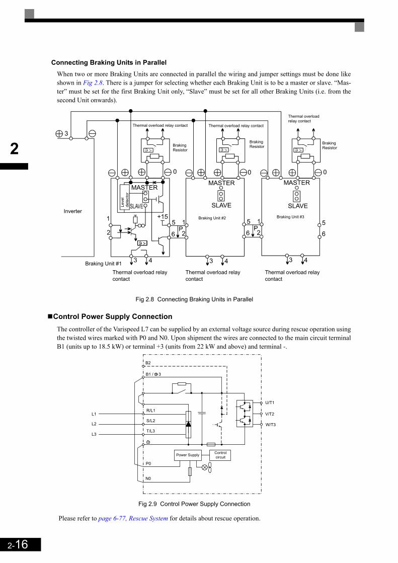
2-16
2
Connecting Braking Units in ParallelWhen two or more Braking Units are connected in parallel the wiring and jumper settings must be done likeshown in Fig 2.8. There is a jumper for selecting whether each Braking Unit is to be a master or slave. “Mas-ter” must be set for the first Braking Unit only, “Slave” must be set for all other Braking Units (i.e. from thesecond Unit onwards).
Fig 2.8 Connecting Braking Units in Parallel
Control Power Supply ConnectionThe controller of the Varispeed L7 can be supplied by an external voltage source during rescue operation usingthe twisted wires marked with P0 and N0. Upon shipment the wires are connected to the main circuit terminalB1 (units up to 18.5 kW) or terminal +3 (units from 22 kW and above) and terminal -.
Fig 2.9 Control Power Supply Connection
Please refer to page 6-77, Rescue System for details about rescue operation.
Inverter
Thermal overload relay contact Thermal overload relay contact
Thermal overload relay contact
Braking Resistor
Braking Resistor
Braking Resistor
Leve
l de
tect
or
Braking Unit #2 Braking Unit #3
Braking Unit #1Thermal overload relay contact
Thermal overload relay contact
Thermal overload relay contact
L1
L2
L3
R/L1
S/L2
T/L3
-
P0
N0
W/T3
V/T2
U/T1
Control circuitPower Supply
B1 /
B2
+ 3

2-17
2
Wiring Control Circuit Terminals
Wire Sizes
For remote operation using analog signals, the control line length between the Analog Operator or operationsignals and the Inverter should be less than 30 m. The controller wires should always be separated from mainpower lines or other control circuits in order to avoid disturbances.
It is recommended to use shielded twisted-pair wires and ground the shield for the largest area of contactbetween shield and ground.
The terminal numbers and the appropriate wire sizes are shown in Table 2.7.
Table 2.7 Terminal Numbers and Wire Sizes (Same for all Models)
Ferrules for Signal LinesModels and sizes of ferrules with plastic sleeves for the signal lines are shown in the following table.
Table 2.8 Ferrule Sizes
Fig 2.10 Ferrule Sizes
Terminals Terminal Screws
Tightening Torque(N•m)
Possible Wire Sizes
mm2(AWG)
Recom-mended Wire
Size mm2(AWG)
Wire Type
AC, SC, A1, +V, S1, S2, S3, S4, S5, S6, S7, BB, MA,
MB, MC, M1, M2, M3, M4, M5, M6
Phoenix type 0.5 to 0.6
Solid wire*1:
0.5 to 2.5Stranded wire:
0.5 to 1.5(26 to 14)
*1. Ferrules with plastic sleeves should be used for the signal lines to simplify wiring and improve reliability.
0.75(18) • Shielded, twisted-pair wire
• Shielded, polyethylene-covered, vinyl sheath cable
E (G) M3.5 0.8 to 1.0 0.5 to 2.5 (20 to 14)
1.0(12)
Wire Size mm2 (AWG) Model d1 d2 L Manufacturer0.25 (24) AI 0.25 - 8YE 0.8 2 12.5
Phoenix Contact
0.5 (20) AI 0.5 - 8WH 1.1 2.5 14
0.75 (18) AI 0.75 - 8GY 1.3 2.8 14
1.5 (16) AI 1.5 - 8BK 1.8 3.4 14
2 (14) AI 2.5 - 8BU 2.3 4.2 14
L
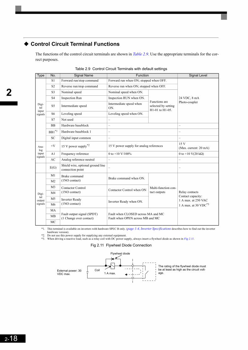
2-18
2
Control Circuit Terminal Functions
The functions of the control circuit terminals are shown in Table 2.9. Use the appropriate terminals for the cor-rect purposes.
Table 2.9 Control Circuit Terminals with default settings
Fig 2.11 Flywheel Diode Connection
Type No. Signal Name Function Signal Level
Digi-tal
input signals
S1 Forward run/stop command Forward run when ON; stopped when OFF.
24 VDC, 8 mAPhoto-coupler
S2 Reverse run/stop command Reverse run when ON; stopped when OFF.
S3 Nominal speed Nominal speed when ON.
Functions are selected by setting H1-01 to H1-05.
S4 Inspection Run Inspection RUN when ON.
S5 Intermediate speed Intermediate speed when ON.
S6 Leveling speed Leveling speed when ON.
S7 Not used –
BB Hardware baseblock – –
BB1*1
*1. This terminal is available on inverters with hardware SPEC B only. (page 1-4, Inverter Specifications describes how to find out the inverterhardware version).
Hardware baseblock 1 – –
SC Digital input common – –
Ana-log
input signals
+V 15 V power supply*2
*2. Do not use this power supply for supplying any external equipment.
15 V power supply for analog references 15 V (Max. current: 20 mA)
A1 Frequency reference 0 to +10 V/100% 0 to +10 V(20 kΩ)
AC Analog reference neutral – –
E(G) Shield wire, optional ground line connection point – –
Digi-tal
output signals
M1 Brake command(1NO contact) Brake command when ON.
Multi-function con-tact outputs Relay contacts
Contact capacity: 1 A max. at 250 VAC 1 A max. at 30 VDC*3
*3. When driving a reactive load, such as a relay coil with DC power supply, always insert a flywheel diode as shown in Fig 2.11.
M2
M3 Contactor Control(1NO contact) Contactor Control when ON
M4
M5 Inverter Ready(1NO contact) Inverter Ready when ON.
M6
MAFault output signal (SPDT)(1 Change over contact)
Fault when CLOSED across MA and MCFault when OPEN across MB and MCMB
MC
External power: 30 VDC max.
Coil
Flywheel diode
1 A max.
The rating of the flywheel diode must be at least as high as the circuit volt-age.

2-19
2
Sinking/Sourcing Mode (NPN/PNP Selection)The input terminal logic can be switched over between sinking mode (0-V common, NPN) and sourcing mode(+24V common, PNP) by using the jumper CN5. An external power supply is also supported, providing morefreedom in signal input methods.
Table 2.10 Sinking/Sourcing Mode and Input Signals
Internal Power Supply – Sinking Mode (NPN)
S1
S2
SC
IP24V(+24V)
CN5A1 A3
B1 B3B2
A2
External Power Supply – Sinking Mode (NPN)
S1
S2
SC
IP24V(+24V)
CN5A1 A3
B1 B3B2
A2
24 VDC
+
Internal Power Supply – Sourcing Mode (PNP)
S1
S2
SC
IP24V(+24V)
CN5A1 A3
B1 B3B2
A2
External Power Supply – Sourcing Mode (PNP)
S1
S2
SC
IP24V(+24V)
CN5A1 A3
B1 B3B2
A2
24 VDC
-

2-20
2
Control Circuit Terminal Connections
Connections to Inverter control circuit terminals are shown in Fig 2.12.
Fig 2.12 Control Circuit Terminal Connections
INFO
The base block circuit is a two channel circuit, i.e. always both channels (terminal BB and BB1) have to be enabled to enable the inverter output.Generally the terminals BB and BB1 can be linked directly at the terminals. However, if an EN81-1 con-form one motor contactor solution is required, the recommended BB and BB1 terminal wiring depends on the installation:1. If the controller and inverter are mounted in the same cabinet the terminals BB and BB1 can be linked
directly at the inverter terminal board. Only one wire from the controller to the inverter base block input is necessary.
2. If the inverter is mounted separated from the controller cabinet, two physically separated wires for the BB and BB1 terminal should be used in order to keep redundancy in case of a fault of one of the signal lines.
Voltage adjust-ment
S1
S3
S2
S4
S5
S6
S7
BB
BB1
Multi function Inputs(Factory setting)
Forward run/stop
Reverse run/stop
Nominal Speed
Inspection Run
Intermediate Speed
Leveling Speed
Not used
Hardware Baseblock (note 2)
SC
+24V, 8mA
IP24V (24V)
CN5(NPN setting)
E(G)MA
MB
MC
Fault contact output250VAC, max. 1A 30VDC, max. 1A
M1
M2
M3
M5
M4
M6
Brake Command(Factory setting)
Contactor Control(Factory setting)
Inverter Ready(Factory setting)
Multi-functioncontact output250VAC, max. 1A 30VDC, max. 1A
Analog input powersupply +15V, 20mA
Master speedreference 0 to 10V
+V
A1
AC
0 V
P
2kOhmAnalog input(Speed reference)
2kOhm0 to 10 V
Twisted-pairwires
Shieldedwires
Note:1. The CN5 factory setting is NPN2. To enable the inverter both inputs, BB and BB1 must be closed. If
only one of the inputs is closed, “BB” will be displayed in the operator panel and the inverter will not start.

2-21
2
EN81-1 Conform Wiring with One Motor Contac-tor
In order to use the L7Z with one motor contactor instead of two while keeping compliance to the EN81-1:1998, the following rules have to be followed:
• The hardware base block function using the terminals BB and BB1 must be used to enable / disable thedrive. The input logic must be PNP.
• If the elevator safety chain is opened, the inverter output must be cut. This means that the base block sig-nals at the terminals BB and BB1 must be opened, e.g. via an interposing relay.
• The base block monitor function must be programmed for one of the multi-function outputs (H2- =46/47). The regarding digital output contact must be implemented in the contactor supervision circuit ofthe controller in order to prevent a restart in case of an inverter base block or motor contactor malfunction.
• All contactors must be conform to the EN81-1:1998, paragraph 13.2.
Fig 2.13 shows an EN81-1:1998 wiring example.
Fig 2.13 EN81-1 Conform Wiring with One Motor Contactor (Example)
The wiring rules and the wiring example are approved by the TUEV Sued, Germany. For more details pleasecontact your OYMC sales representative.
Safety Chain
Circuit
Elevator Controller
Contactor Close
Command
Contactor Check
(Restart Permission)
K01
24VDC *1
K1
BB BB1 Up/Down; Speed
selection; ...
BB Monitor
(NC)Yaskawa
CIMR-L7xxxx
K2
M
2-22
2
Control Circuit Wiring Precautions
The following precautions for wiring the control circuits must be considered. • Control circuit and main circuit wiring should be separated (terminals R/L1, S/L2, T/L3, B1, B2, U/T1, V/
T2, W/T3, , 1, 2, and 3, PO, NO) and other high-power lines.• The wiring for control circuit terminals MA, MB, MC, M1, M2, M3, M4, M5, and M6 (contact outputs)
should be separated from wiring to other control circuit terminals.• If an optional external power supply is used, it should be a UL Listed Class 2 power supply.• Twisted-pair or shielded twisted-pair cables should be used for control circuits to prevent operating faults. • The cable shields should be connected to the ground with the maximum contact area.• Cable shields have to be grounded on both cable ends.

2-23
2
Wiring Check
Checks
Check all wiring after wiring has been completed. Do not perform continuity check on control circuits. Per-form the following checks on the wiring.
• Is all wiring correct?• Have no wire clippings, screws, or other foreign material been left?• Are all screws tight?• Are any wire ends contacting other terminals?

2-24
2
Installing and Wiring Option Cards
Option Card Models and Specifications
Up to three option cards can be mounted simultaneously in the Inverter. Each of the three option board socketson the controller card (A, C and D) can take up one option card like shown in Fig 2.14.
Table 2.11 shows the available option cards and their specifications.
Table 2.11 Option Card Specifications
Installation
Before mounting an Option Card, remove the terminal cover and be sure that the charge indicator inside theInverter is OFF. After that, remove the Digital Operator/LED Monitor and front cover and mount the OptionCard.
Refer to documentation provided with the Option Card for the mounting instructions.
Card Model Specifications MountingLocation
PG speed control cards
PG-B2 Two phase (phase A and B), +12V inputs, max. response frequency: 50 kHz A
PG-X2 Three phase (phase A, B, Z), line driver inputs (RS422), max. response frequency: 300 kHz A
PG-F2 Hiperfacey or EnDat 2.1 interface card A
Communications cards
3G3RV-PDRT2 Intelligent DeviceNet option card C
SI-P1 Option card for Profibus-DP fieldbus C
SI-R1 Option card for InterBus-S fieldbus C
SI-S1 Option card for CANOpen fieldbus C
S1-J Option card for LONworks C
PLC option card3G3RV-P10ST8-E PLC option card C
3G3RV-P10ST8-DRT-E PLC option card with DeviceNet communications port (Slave) C
Analog Input card AI-14B3 Channel analog input cardSignal level: -10 to 10 V or 0 to 10VResolution: 13 Bit + sign
C
Analog Output Cards
AO-082 channel analog output cardSignal level: 0 to 10 VResolution: 8 Bit
D
AO-122 channel high resolution analog output cardSignal level: -10 to +10 VResolution: 11 Bit + sign
D
Digital Output CardsDO-08 6 channel digital output card for monitoring the
inverter status (fault, zero speed, running, etc.) D
DO-02C 2 channel relay contact output D
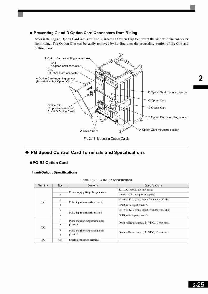
2-25
2
Preventing C and D Option Card Connectors from Rising After installing an Option Card into slot C or D, insert an Option Clip to prevent the side with the connectorfrom rising. The Option Clip can be easily removed by holding onto the protruding portion of the Clip andpulling it out.
Fig 2.14 Mounting Option Cards
PG Speed Control Card Terminals and Specifications
PG-B2 Option Card
Input/Output Specifications
Table 2.12 PG-B2 I/O Specifications
Terminal No. Contents Specifications
TA1
1Power supply for pulse generator
12 VDC (±5%), 200 mA max.
2 0 VDC (GND for power supply)
3Pulse input terminals phase A
H: +8 to 12 V (max. input frequency: 50 kHz)
4 GND pulse input phase A
5Pulse input terminals phase B
H: +8 to 12 V (max. input frequency: 50 kHz)
6 GND pulse input phase B
TA2
1 Pulse monitor output terminals phase A Open collector output, 24 VDC, 30 mA max.
2
3 Pulse monitor output terminals phase B Open collector output, 24 VDC, 30 mA max.
4
TA3 (E) Shield connection terminal -
A Option Card mounting spacer holeCN4A Option Card connector
CN2C Option Card connector
A Option Card mounting spacer(Provided with A Option Card)
Option Clip(To prevent raising ofC and D Option Card)
A Option Card A Option Card mounting spacer
C Option Card mounting spacer
C Option Card
D Option Card mounting spacer
D Option Card

2-26
2
Wiring the PG-B2 cardThe following illustrations show wiring examples for the PG-B2 using the option cards power supply or anexternal power source for supplying the PG.
Fig 2.15 PG-B2 Wiring Using the Option Cards Power Supply
Fig 2.16 PG-B2 Wiring Using a 12 V External Power Supply
Precautions:• The length of the pulse generator's wiring must not be more than 100 meters.• The direction of rotation of the PG can be set in user parameter F1-05. The factory setting is A-phase
leading in forward direction (motor shaft turning counterclockwise seen from motor shaft side).
• The pulse monitor output factor can be changed using parameter F1-05.• Refer to page 2-31, Wiring Precautions for general precautions.
Three-phase 200 VAC (400 VAC)
Inverter
Power supply +12 V
Power supply 0 V
Pulse input phase A
GND pulse input phase A
Pulse input phase B
GND pulse input phase B
Pulse monitor output phase A
Pulse monitor output phase B
CN4CN4
R/L1
S/L2
T/L3
Forward rotation of standard motor (PG)
Forward command
Motor output axis rotates counter-clockwise during In-verter forward command.
Rotation (CCW)
A-phaseB-phase
The A-phase leads (CCW) when motor rotation is forward.

2-27
2
PG-X2 Option Card
Input/Output Specifications
Table 2.13 PG-X2 I/O Specifications
Terminal No. Contents Specifications
TA1
1
Power supply for pulse generator
12 VDC (±5%), 200 mA max.*1
*1. The 5V and 12V power supply should not be used at the same time.
2 0 VDC (GND for power supply)
3 5 VDC (±5%), 200 mA max.*1
4 Pulse input terminal phase A (+)
Line driver input (RS422 level)(maximum input frequency: 300 kHz)
5 Pulse input terminal phase A (–)
6 Pulse input terminal phase B (+)
7 Pulse input terminal phase B (–)
8 Pulse input terminal phase Z (+)
9 Pulse input terminal phase Z (–)
10 Common terminal inputs –
TA2
1 Pulse monitor output terminal phase A (+)
Line driver output (RS422 level output)
2 Pulse monitor output terminal phase A (–)
3 Pulse monitor output terminal phase B (+)
4 Pulse monitor output terminal phase B (–)
5 Pulse monitor output terminal phase Z (+)
6 Pulse monitor output terminal phase Z (–)
7 Common terminal monitor outputs –
TA3 (E) Shield connection terminal –

2-28
2
Wiring the PG-X2 cardThe following illustrations show wiring examples for the PG-X2 using the option cards power supply or anexternal power source for supplying the PG.
Fig 2.17 PG-X2 Wiring Using the Option Cards Power Supply
Fig 2.18 PG-X2 Wiring Using a 5 V External Power Supply
Precautions:• The length of the pulse generator's wiring must not be more than 100 meters.• The direction of rotation of the PG can be set in user parameter F1-05. The factory setting is A-phase
leading in forward direction (motor shaft turning counterclockwise seen from motor shaft side).• Refer to page 2-31, Wiring Precautions for general precautions.
PG-X2
0V+5 VDCA+ Phase InputA- Phase InputB+ Phase InputB- Phase InputZ+ Phase InputZ- Phase Input
A Phase Output
B Phase Output
Z Phase Output
Three-phase 200 VAC
(400 VAC)
P
P
P
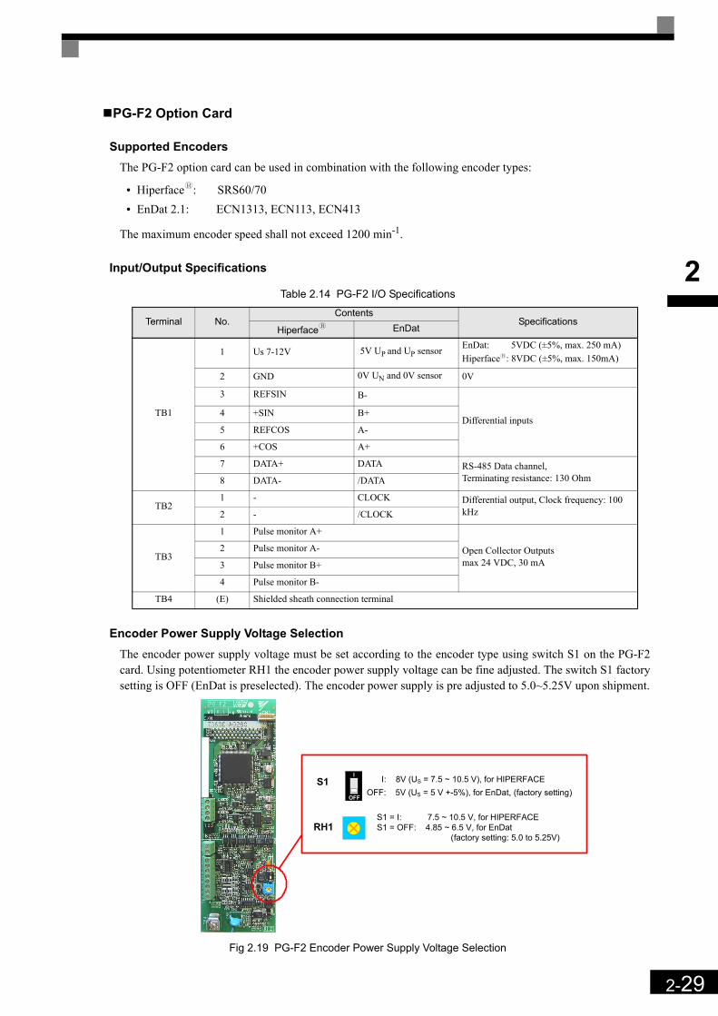
2-29
2
PG-F2 Option Card
Supported EncodersThe PG-F2 option card can be used in combination with the following encoder types:
• Hiperfacey: SRS60/70• EnDat 2.1: ECN1313, ECN113, ECN413
The maximum encoder speed shall not exceed 1200 min-1.
Input/Output Specifications
Table 2.14 PG-F2 I/O Specifications
Encoder Power Supply Voltage SelectionThe encoder power supply voltage must be set according to the encoder type using switch S1 on the PG-F2card. Using potentiometer RH1 the encoder power supply voltage can be fine adjusted. The switch S1 factorysetting is OFF (EnDat is preselected). The encoder power supply is pre adjusted to 5.0~5.25V upon shipment.
Fig 2.19 PG-F2 Encoder Power Supply Voltage Selection
Terminal No.Contents
SpecificationsHiperfacey EnDat
TB1
1 Us 7-12V 5V UP and UP sensor EnDat: 5VDC (±5%, max. 250 mA) Hiperfacey: 8VDC (±5%, max. 150mA)
2 GND 0V UN and 0V sensor 0V
3 REFSIN B-
Differential inputs4 +SIN B+
5 REFCOS A-
6 +COS A+
7 DATA+ DATA RS-485 Data channel, Terminating resistance: 130 Ohm8 DATA- /DATA
TB21 - CLOCK Differential output, Clock frequency: 100
kHz2 - /CLOCK
TB3
1 Pulse monitor A+
Open Collector Outputsmax 24 VDC, 30 mA
2 Pulse monitor A-
3 Pulse monitor B+
4 Pulse monitor B-
TB4 (E) Shielded sheath connection terminal
I: 8V (US = 7.5 ~ 10.5 V), for HIPERFACEOFF: 5V (US = 5 V +-5%), for EnDat, (factory setting)
I
OFF
S1
RH1 S1 = I: 7.5 ~ 10.5 V, for HIPERFACE S1 = OFF: 4.85 ~ 6.5 V, for EnDat
(factory setting: 5.0 to 5.25V)
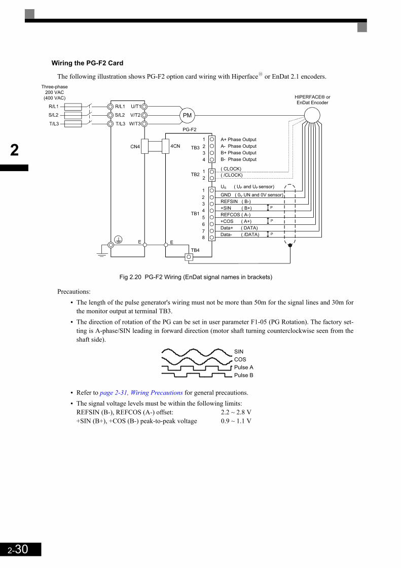
2-30
2
Wiring the PG-F2 Card
The following illustration shows PG-F2 option card wiring with Hiperfacey or EnDat 2.1 encoders.
Fig 2.20 PG-F2 Wiring (EnDat signal names in brackets)
Precautions:• The length of the pulse generator's wiring must not be more than 50m for the signal lines and 30m for
the monitor output at terminal TB3.• The direction of rotation of the PG can be set in user parameter F1-05 (PG Rotation). The factory set-
ting is A-phase/SIN leading in forward direction (motor shaft turning counterclockwise seen from theshaft side).
• Refer to page 2-31, Wiring Precautions for general precautions.• The signal voltage levels must be within the following limits:
REFSIN (B-), REFCOS (A-) offset: 2.2 ~ 2.8 V+SIN (B+), +COS (B-) peak-to-peak voltage 0.9 ~ 1.1 V
PM
PG-F2
US ( UP and UP sensor)
Three-phase 200 VAC
(400 VAC)
TB3
12
12345678
TB2
TB1
TB4
A+ Phase OutputA- Phase OutputB+ Phase OutputB- Phase Output
GND ( 0V UN and 0V sensor)REFSIN ( B-)+SIN ( B+)REFCOS ( A-)+COS ( A+)Data+ ( DATA)Data- ( /DATA)
P
P
P
( CLOCK)( /CLOCK)
HIPERFACE® or EnDat Encoder
SINCOSPulse APulse B
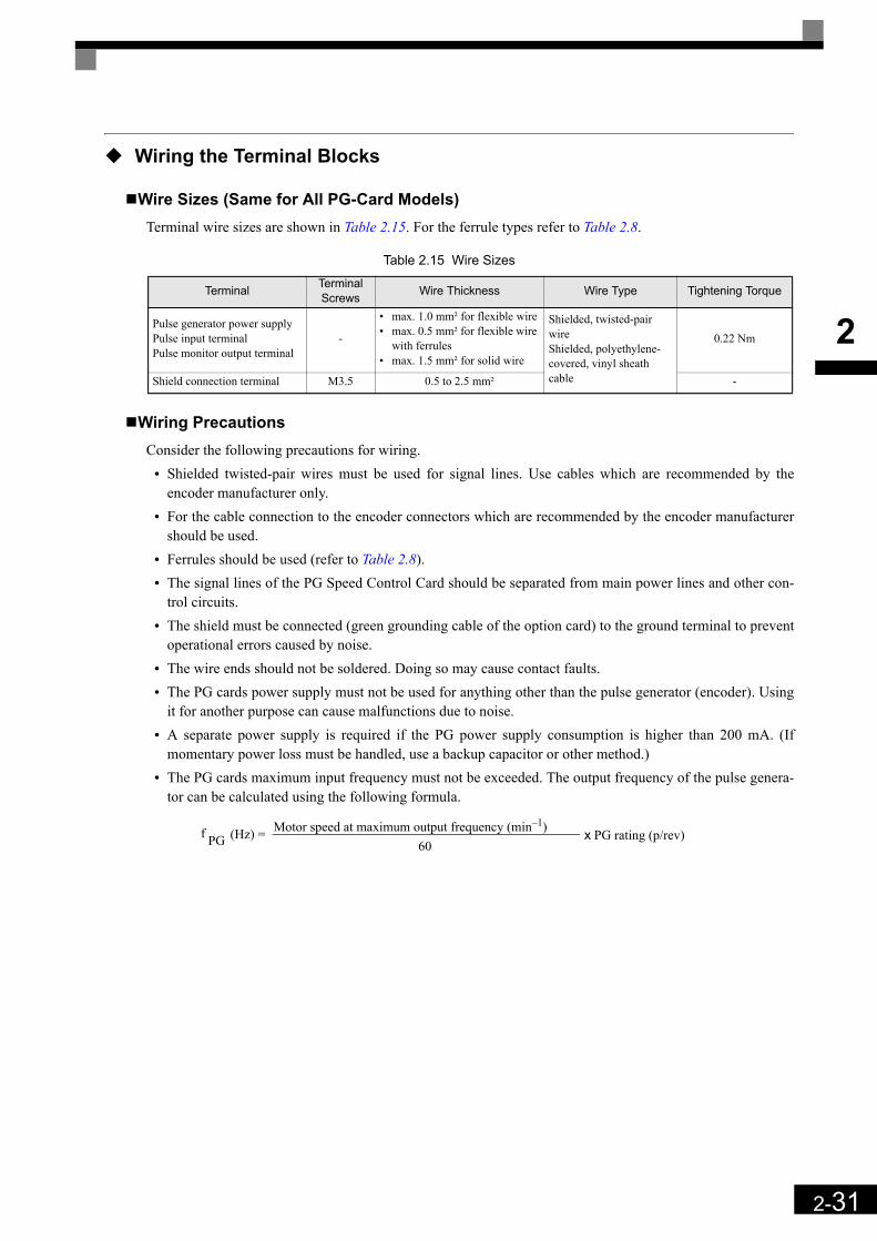
2-31
2
Wiring the Terminal Blocks
Wire Sizes (Same for All PG-Card Models)Terminal wire sizes are shown in Table 2.15. For the ferrule types refer to Table 2.8.
Table 2.15 Wire Sizes
Wiring PrecautionsConsider the following precautions for wiring.
• Shielded twisted-pair wires must be used for signal lines. Use cables which are recommended by theencoder manufacturer only.
• For the cable connection to the encoder connectors which are recommended by the encoder manufacturershould be used.
• Ferrules should be used (refer to Table 2.8).• The signal lines of the PG Speed Control Card should be separated from main power lines and other con-
trol circuits.• The shield must be connected (green grounding cable of the option card) to the ground terminal to prevent
operational errors caused by noise.• The wire ends should not be soldered. Doing so may cause contact faults. • The PG cards power supply must not be used for anything other than the pulse generator (encoder). Using
it for another purpose can cause malfunctions due to noise.• A separate power supply is required if the PG power supply consumption is higher than 200 mA. (If
momentary power loss must be handled, use a backup capacitor or other method.)• The PG cards maximum input frequency must not be exceeded. The output frequency of the pulse genera-
tor can be calculated using the following formula.
Terminal Terminal Screws Wire Thickness Wire Type Tightening Torque
Pulse generator power supplyPulse input terminalPulse monitor output terminal
-
• max. 1.0 mm² for flexible wire• max. 0.5 mm² for flexible wire
with ferrules• max. 1.5 mm² for solid wire
Shielded, twisted-pair wireShielded, polyethylene-covered, vinyl sheath cable
0.22 Nm
Shield connection terminal M3.5 0.5 to 2.5 mm² -
f PG (Hz) = Motor speed at maximum output frequency (min–1)60
x PG rating (p/rev)

2-32
2
3LED Monitor / DigitalOperator and Modes
The Varispeed L7 is equipped with the LED Monitor JVOP-163 which shows the drive status. The optional Digi-tal Operator JVOP-160-OY can be used to adjust parameters as required.This chapter describes Digital Operator displays and functions, and provides an overview of operating modes andswitching between modes.
LED Monitor JVOP-163 ......................................................3-2Digital Operator JVOP-160-OY...........................................3-3
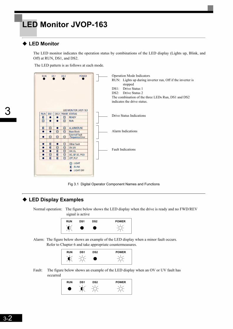
3-2
3
LED Monitor JVOP-163
LED Monitor
The LED monitor indicates the operation status by combinations of the LED display (Lights up, Blink, andOff) at RUN, DS1, and DS2.
The LED pattern is as follows at each mode.
Fig 3.1 Digital Operator Component Names and Functions
LED Display Examples
Normal operation: The figure below shows the LED display when the drive is ready and no FWD/REV signal is active
Alarm: The figure below shows an example of the LED display when a minor fault occurs. Refer to Chapter 6 and take appropriate countermeasures.
Fault: The figure below shows an example of the LED display when an OV or UV fault has occurred
Operation Mode IndicatorsRUN: Lights up during inverter run, Off if the inverter is
stoppedDS1: Drive Status 1DS2: Drive Status 2The combination of the three LEDs Run, DS1 and DS2 indicates the drive status.
Drive Status Indications
Alarm Indications
Fault Indications
RUN DS1 DS2 POWER
RUN DS1 DS2 POWER
RUN DS1 DS2 POWER
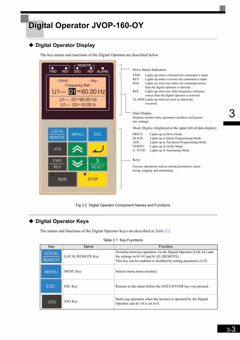
3-3
3
Digital Operator JVOP-160-OY
Digital Operator Display
The key names and functions of the Digital Operator are described below
Fig 3.2 Digital Operator Component Names and Functions
Digital Operator Keys
The names and functions of the Digital Operator Keys are described in Table 3.1.
Table 3.1 Key Functions
Key Name Function
LOCAL/REMOTE KeySwitches between operation via the Digital Operator (LOCAL) and the settings in b1-01 and b1-02 (REMOTE).This key can be enabled or disabled by setting parameter o2-01.
MENU Key Selects menu items (modes).
ESC Key Returns to the status before the DATA/ENTER key was pressed.
JOG Key Starts jog operation when the inverter is operated by the Digital Operator and d1-18 is set to 0.
Drive Status IndicatorsFWD: Lights up when a forward run command is input.REV: Lights up when a reverse run command is input.SEQ: Lights up when any other run command source
than the digital operator is selectedREF: Lights up when any other frequency reference
source than the digital operator is selectedALARM:Lights up when an error or alarm has
occurred.
Data DisplayDisplays monitor data, parameter numbers and param-eter settings.
Mode Display (displayed at the upper left of data display)
DRIVE: Lights up in Drive Mode.QUICK: Lights up in Quick Programming Mode.ADV: Lights up in Advanced Programming Mode.VERIFY: Lights up in Verify Mode.A. TUNE: Lights up in Autotuning Mode.
Keys
Execute operations such as setting parameters, moni-toring, jogging, and autotuning.
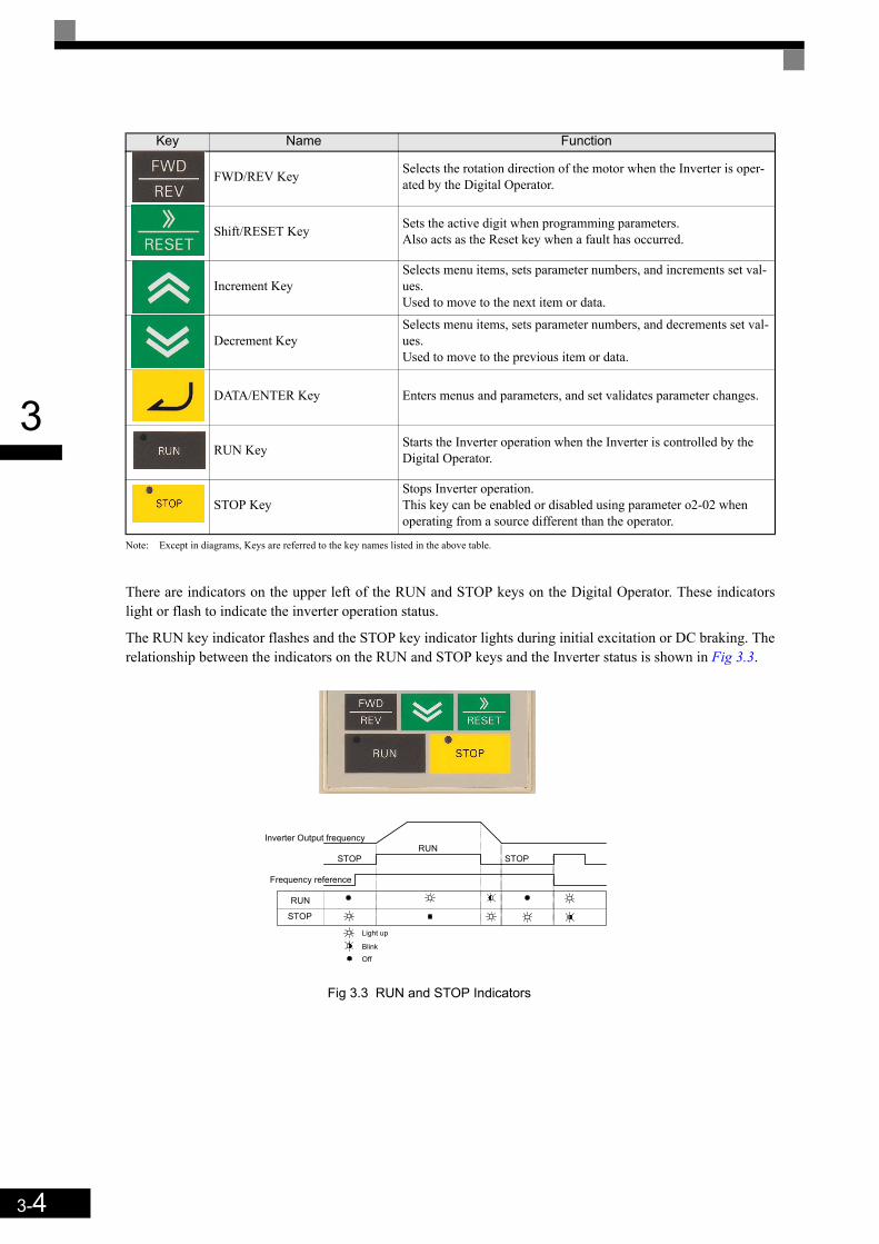
3-4
3
Note: Except in diagrams, Keys are referred to the key names listed in the above table.
There are indicators on the upper left of the RUN and STOP keys on the Digital Operator. These indicatorslight or flash to indicate the inverter operation status.
The RUN key indicator flashes and the STOP key indicator lights during initial excitation or DC braking. Therelationship between the indicators on the RUN and STOP keys and the Inverter status is shown in Fig 3.3.
Fig 3.3 RUN and STOP Indicators
FWD/REV Key Selects the rotation direction of the motor when the Inverter is oper-ated by the Digital Operator.
Shift/RESET Key Sets the active digit when programming parameters.Also acts as the Reset key when a fault has occurred.
Increment KeySelects menu items, sets parameter numbers, and increments set val-ues. Used to move to the next item or data.
Decrement KeySelects menu items, sets parameter numbers, and decrements set val-ues. Used to move to the previous item or data.
DATA/ENTER Key Enters menus and parameters, and set validates parameter changes.
RUN Key Starts the Inverter operation when the Inverter is controlled by the Digital Operator.
STOP KeyStops Inverter operation.This key can be enabled or disabled using parameter o2-02 when operating from a source different than the operator.
Key Name Function
RUN
Inverter Output frequency
STOP
Frequency reference
STOPRUN
STOP
Light up
Blink
Off
3-5
3
Inverter Modes
The Inverter's parameters and monitoring functions are organized in five groups which make it easy to readand adjust parameters.
The 5 modes and their primary functions are shown in the Table 3.2.
Table 3.2 Modes
Mode Primary function(s)
Drive mode Use this mode to start/stop the inverter, to monitor values such as the frequency ref-erence or output current and to read out fault informations or the fault history.
Quick programming mode Use this mode to read and set the basic parameters.
Advanced programming mode Use this mode to read and set all parameters.
Verify mode Use this mode to read and set parameters that have been changed from their factory-set values.
Autotuning mode*1
*1. Always perform autotuning with the motor before operating in the vector control modes.
Use this mode when using a motor with unknown motor data in the vector control modes. The motor data are measured/calculated and set automatically.This mode can also be used to measure the motor line-to-line resistance only.

3-6
3
Switching Modes
The mode selection display appears when the MENU key is pressed. Press the MENU key from the modeselection display to switch through the modes in sequence.
Press the DATA/ENTER key to enter a mode and to switch from a monitor display to the setting display.
Fig 3.4 Mode Transitions
INFO
To run the inverter after viewing/changing parameters press the MENU key and the DATA/ENTER key in sequence to enter the Drive mode. A Run command is not accepted as long as the drive is in any other mode. To enable Run commands from the terminals during programming set parameter b1-08 to “1”.
Frequency Ref-DRIVE-
U1-02=50.00HzU1-03=10.05A
** Main Menu **-DRIVE-
Operation
** Main Menu **-QUICK-
Quick Setting
** Main Menu **-ADV-
Programming
** Main Menu **-VERIFY-
Modified Consts
** Main Menu **-A.TUNE-
Auto-Tuning
Rdy
U1- 01=50.00Hz
Monitor-DRIVE-
U1-02=50.00HzU1-03=10.05A
Rdy
U1 - 01=50.00Hz
Control Method-QUICK-
A1-02 = 0
Initialization-ADV-
A1 - 00=0Select Language
None Modified
-VERIFY-
Frequency Ref-DRIVE-
U1-02=50.00HzU1-03=10.05A
U1- 01=50.00Hz
Select Language-ADV-
English
The constant number will be displayed if aconstant has been changed. Press theDATA/ENTER key to enable the change.
Monitor Display Setting DisplayMode SelectionDisplay
Display During Run
V/f Control
Tuning Mode Sel-A.TUNE-
Standard Tuning"0"
Tuning Mode Sel-A.TUNE-
Standard Tuning"0"
Rdy
T1- 01 = 0 *0* T1- 01= 0 *0*
*0*
MENU
MENU
MENU
MENU
MENU
RESET
RESET
ESC
ESC ESC
ESC ESC ESC
ESC
ESC ESC
"0"
Control Method-QUICK-
A1-02 = 0V/f Control
*0*
"0"
A1-00 = 0 *0*
"0"
Select Language-ADV-
EnglishA1-00 = 0 *0*
"0"

3-7
3
Drive Mode
In the Drive mode the Inverter can be operated. All monitor parameters (U1- ), fault informations and thefault history can be displayed in this mode
When b1-01 (Reference selection) is set to 0, 1 or 3, the selected frequency reference value (d1- ) can bechanged from the frequency setting display using the Increment, Decrement, Shift/RESET and Enter keys.After confirming the change by pressing the ENTER key, the display returns to the Monitor display.
Example Operations Example key operations in drive mode are shown in the following figure.
Fig 3.5 Operations in Drive Mode
Note: When changing the display with the Increment/Decrement keys, after the last monitor parameter the display jumps back to the first monitor parameter and vice versa (e.g. U1-55 is followed by U1-01).The display for the first monitor parameter (frequency reference) will be displayed when power is turned ON. The monitor item displayed at startup can be set in o1-02 (Monitor Selection after Power Up).
Frequency Ref-DRIVE-
U1-02=50.00HzU1-03=10.05A
** Main Menu **-DRIVE-
Operation
** Main Menu **-QUICK-
Quick Setting
** Main Menu **-ADV-
Programming
** Main Menu **-VERIFY-
Modified Consts
** Main Menu **-A.TUNE-
Auto-Tuning
U1- 01=50.00Hz
Monitor-DRIVE-
U1-02=50.00HzU1-03=10.05A
U1 - 01=50.00HzFrequency Ref
-DRIVE-
U1-02=50.00HzU1-03=10.05A
U1- 01=50.00HzFrequency Ref
-DRIVE-
U1 - 01= 050.00Hz
Monitor Display Frequency Setting DisplayMode SelectionDisplay
Display During Running
Fault Trace-DRIVE-
U2-02= OVU2-03=50.00Hz
U2 - 01=OC
Fault History-DRIVE-
U3-02= OVU3-03= OH
U3 - 01= OC
Output Freq-DRIVE-
U1-04= 2U1-03=10.05A
U1- 02=50.00Hz
No of Travels-DRIVE-
U1-01=50.00HzU1-02=50.00Hz
U1- 55 = 11
1 2
1 2
Last Fault-DRIVE-
U3-02=OVU3-03=OH
U3 - 01 = OC
Fault Message 2-DRIVE-
U3-03= OHU3-04= UV
U3 - 02 = OV
5 6
5 6
A B
A B
Current Fault-DRIVE-
U2-02=OVU2-03=50.00Hz
U2 - 01 = OC
Last Fault-DRIVE-
U3-03=50.00HzU3-04=50.00Hz
U2 - 02 = OV
3 4
3 4
U2 - 01= OC
U2 - 02= OV
Over Current
DC Bus Overvolt
U3 - 01= OCOver Current
U3 - 02= OVDC Bus Overvolt
The fault name will bedisplayed if the DATA/ENTERKey is pressed while a constantis being displayed for which afault code is being displayed.
Rdy
Rdy
Rdy
Rdy
Rdy
Rdy
Rdy
Rdy
Rdy Rdy
Rdy
Rdy
The Frequency SettingDisplay will not bedisplayed when using ananalog reference.
Monitor-DRIVE-
U1-04= 2U1-03=10.05A
U1 - 02=50.00HzRdy
Monitor-DRIVE-
U1-01=50.00HzU1-02=50.00Hz
U1 - 55 = 11Rdy
Rdy
Rdy
Rdy
Fault Trace-DRIVE-
U3-03=50.00HzU3-04=50.00Hz
U2 - 02 = OV
Rdy
Fault Message 2-DRIVE-
U3-03= OHU3-04= UV
U3 - 02 = OV
Rdy
MENU
RESET
ESC
MENU
ESCESC
MENU
MENU
MENU
RESET
RESET
RESET
RESET
RESET
RESET
ESC
ESC
ESC ESC
ESC ESC
ESC ESC
ESC ESC
(0.00 ~ 50.00)" 00.00Hz "

3-8
3
Quick Programming Mode
In quick programming mode the basic parameters required for the elevator operation like speeds, acceleration/deceleration times etc. can be monitored and set.
The parameters can be changed from the setting displays. Use the Increment, Decrement, and Shift/RESETkeys to change the frequency. The parameter is written and the display returns to the monitor display when theDATA/ENTER key is pressed.
Refer to page 5-4, User Parameters Available in Quick Programming Mode for details.
Example Operations Example key operations in quick programming mode are shown in the following figure.
Fig 3.6 Operations in Quick Programming Mode
** Main Menu **
-DRIVE-
Operation
** Main Menu **-QUICK-
Quick Setting
** Main Menu **
-ADV-
Programming
** Main Menu **-VERIFY-
Modified Consts
** Main Menu **-A.TUNE-
Auto-Tuning
Control Method-QUICK-
A1-02 = 0 *0*V/f Control
Accel Time 1-QUICK-
C1-01 = 1.50sec
-QUICK-
Monitor Display Setting DisplayMode Selection Display
MOL Fault Select-QUICK-
L1-01=1 *1*Std Fan Cooled
Mtr Rated Power-QUICK-
E2-11 = 4.00kW
A B
A B
-QUICK-
E2-11 = 004.00kW
MENU
MENU
MENU
MENU
MENU
ESC ESC
ESC
ESC
ESC
ESC
(0.00 ~ 650.00)"4.00kW"
(0.00 ~ 650.00)"4.00kW"
Mtr Rated Power
"1"
MOL Fault Select-QUICK-
L1-01 = 1 *1*Std Fan Cooled
"1"
"0"
Control Method-QUICK-
A1-02 = 0 *0*V/f Control
"0"
"1.50"
-QUICK-
(0.00 ~ 600.00)
Decel Time 1 C1-02 = 1.50sec
"1.50"(0.00 ~ 600.00)
Accel Time 1 C1-01 =001.50sec
"1.50"(0.00 ~ 600.00)
-QUICK-
Decel Time 1 C1-02 =001.50sec
"1.50"(0.00 ~ 600.00)

3-9
3
Advanced Programming Mode
In the advanced programming mode all Inverter parameters can be monitored and set.
A parameter can be changed from the setting displays using the Increment, Decrement, and Shift/RESETkeys. The parameter is saved and the display returns to the monitor display when the DATA/ENTER key ispressed.
Refer to page 5-1, User Parameters for details about the parameters.
Example Operations Example key operations in advanced programming mode are shown in the following figure.
Fig 3.7 Operations in Advanced Programming Mode
** Main Menu **-DRIVE-
Operation
** Main Menu **-QUICK-
Quick Setting
** Main Menu **-ADV-
Programming
** Main Menu **-VERIFY-
Modified Consts
** Main Menu **-A.TUNE-
Auto-Tuning
Initialization-ADV-
A1-00=0Select Language
Select Language-ADV-
English
Monitor Display Setting DisplayMode Selection Display
Control Method-ADV-
A1- 02 = 0V/f Control
*0*
*0*
1 2
1 2
3 4
3 4
A B
A B
Initialization-ADV-
A1- 02 =0Control Method
ESC
MENU
MENU
MENU
MENU
MENU
ESC
ESC
ESC
ESC
ESCESC
ESC ESC
RESET
RESET
RESET
RESET
"0"
Select Language
-ADV-
English*0*
"0"
"0"
Control Method
-ADV-
A1-02 = 0V/f Control
*0*
"0"
A1- 00 = 0 A1-00 = 0
Accel/Decel
-ADV-
C1- 01 = 1.50secAccel Time 1
Accel Time 1
-ADV-
C1- 01 = 1.5sec(0.00 ~ 600.00)
"1.50sec"
Accel Time 1
-ADV-
(0.00 ~ 600.00)"1.50sec"
C1- 01 = 001.5sec
Accel/Decel
-ADV-
C1- 02 = 1.50secAccel Time 1
Decel Time 1
-ADV-
(0.00 ~ 600.00)"1.50sec"
C1- 02 = 1.5secDecel Time 1
-ADV-
(0.00 ~ 600.00)"1.50sec"
C1- 02 = 001.5sec
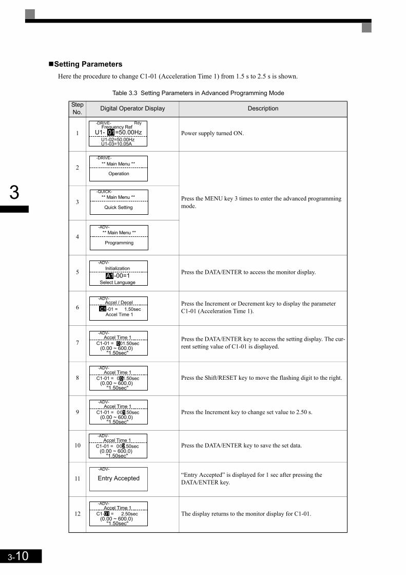
3-10
3
Setting ParametersHere the procedure to change C1-01 (Acceleration Time 1) from 1.5 s to 2.5 s is shown.
Table 3.3 Setting Parameters in Advanced Programming Mode
Step No. Digital Operator Display Description
1 Power supply turned ON.
2
Press the MENU key 3 times to enter the advanced programming mode.3
4
5 Press the DATA/ENTER to access the monitor display.
6 Press the Increment or Decrement key to display the parameter C1-01 (Acceleration Time 1).
7 Press the DATA/ENTER key to access the setting display. The cur-rent setting value of C1-01 is displayed.
8 Press the Shift/RESET key to move the flashing digit to the right.
9 Press the Increment key to change set value to 2.50 s.
10 Press the DATA/ENTER key to save the set data.
11 “Entry Accepted” is displayed for 1 sec after pressing the DATA/ENTER key.
12 The display returns to the monitor display for C1-01.
Frequency Ref-DRIVE-
U1-02=50.00HzU1-03=10.05A
Rdy
U1- 01=50.00Hz
** Main Menu **-DRIVE-
Operation
** Main Menu **-QUICK-
Quick Setting
** Main Menu **-ADV-
Programming
Initialization-ADV-
A1-00=1Select Language
Accel / Decel-ADV-
Accel Time 1C1-01 = 1.50sec
Accel Time 1-ADV-
C1-01 = 0 01.50sec(0.00 ~ 600.0)
"1.50sec"
Accel Time 1-ADV-
C1-01 = 0 01.50sec(0.00 ~ 600.0)
"1.50sec"
Accel Time 1-ADV-
C1-01 = 0 01.50sec(0.00 ~ 600.0)
"1.50sec"
Accel Time 1-ADV-
C1-01 = 0 02.50sec(0.00 ~ 600.0)
"1.50sec"
Entry Accepted-ADV-
Accel Time 1-ADV-
C1-01 = 2.50sec(0.00 ~ 600.0)
"1.50sec"

3-11
3
Verify Mode
The Verify mode is used to display the parameters that have been changed from their default settings, either byprogramming or by autotuning. “None” will be displayed if no settings have been changed.
The parameter A1-02 is the only parameter from the A1- group, which will be displayed in the modifiedconstant list if it has been changed before. The other parameters will not be displayed, even if they are differ-ent from the default setting.
In the verify mode, the same procedures as used in the programming mode can be used to change settings. Usethe Increment, Decrement, and Shift/RESET keys to change a setting. When the DATA/ENTER key is pressedthe parameter setting are written and the display returns to the Monitor display.
Example OperationsIn the example below the following settings have been changed from their default settings:
• C1-01 (Acceleration Time 1)• C1-02 (Acceleration Time 2)• E1-01 (Input Voltage Setting)• E2-01 (Motor Rated Current).
Fig 3.8 Operations in Verify Mode
** Main Menu **-DRIVE-
Operation
** Main Menu **-QUICK-
Quick Setting
** Main Menu **-ADV-
Programming
** Main Menu **-VERIFY-
Modified Consts
** Main Menu **-A.TUNE-
Auto-Tuning
Monitor Display Setting DisplayMode Selection Display
ESC
Decel Time 2-VERIFY-
C1-02 = 002.0sec
A B
A B
Input Voltage-VERIFY-
E1-01=390VAC
Motor Rated FLA-VERIFY-
E2-01= 7.20AMotor Rated FLA
-VERIFY-
E2-01 = 007.20A
Input Voltage-VERIFY-
E1-01= 390VAC
Decel Time 2-VERIFY-
C1-02 = 002.0sec
MENU
ESC
MENU
MENU
MENU
MENU
MENU
ESC
ESC
ESC
(0.00 ~ 600.0)"1.50sec"
(0.00 ~ 600.0)"1.50sec"
(310~510)"380VAC"
(310~510)"380VAC"
(0.80 ~ 16.00)"7.00A"
(0.80 ~ 16.00)"7.00A"
Accel Time 1-VERIFY-
C1-01 = 002.0sec(0.00 ~ 600.0)
"1.50sec"
Accel Time 1-VERIFY-
C1-01 = 002.0sec(0.00 ~ 600.00)
"1.50sec"
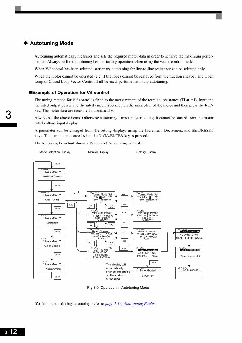
3-12
3
Autotuning Mode
Autotuning automatically measures and sets the required motor data in order to achieve the maximum perfor-mance. Always perform autotuning before starting operation when using the vector control modes.
When V/f control has been selected, stationary autotuning for line-to-line resistance can be selected only.
When the motor cannot be operated (e.g. if the ropes cannot be removed from the traction sheave), and OpenLoop or Closed Loop Vector Control shall be used, perform stationary autotuning.
Example of Operation for V/f controlThe tuning method for V/f control is fixed to the measurement of the terminal resistance (T1-01=1). Input thethe rated output power and the rated current specified on the nameplate of the motor and then press the RUNkey. The motor data are measured automatically.
Always set the above items. Otherwise autotuning cannot be started, e.g. it cannot be started from the motorrated voltage input display.
A parameter can be changed from the setting displays using the Increment, Decrement, and Shift/RESETkeys. The parameter is saved when the DATA/ENTER key is pressed.
The following flowchart shows a V/f control Autotuning example.
Fig 3.9 Operation in Autotuning Mode
If a fault occurs during autotuning, refer to page 7-14, Auto-tuning Faults.
START GOAL
** Main Menu **-DRIVE-
Operation
** Main Menu **-QUICK-
Quick Setting
** Main Menu **-ADV-
Programming
** Main Menu **-VERIFY-
Modified Consts
** Main Menu **-A.TUNE-
Auto-Tuning
Monitor Display Setting DisplayMode Selection Display
Tuning Mode Sel-A.TUNE-
T1- 01 =2 *2*
Auto-Tuning-A.TUNE-
Press RUN keyTuning Ready ?
Tune Proceeding-A.TUNE-
40.0Hz/10.5A
Term Resistance
Tuning Mode Sel-A.TUNE-
01 = 2 *2*
Mtr Rated Power-A.TUNE-
T1- 02 = 4.00kW
Rated Current-A.TUNE-
T1- 04 = 7.00A
Mtr Rated Power-A.TUNE-
T1-02 = 004.00kW
Rdy
Tune Aborted-A.TUNE-
STOP key
The display willautomaticallychange dependingon the status ofautotuning.
Term Resistance
START GOAL
Tune Proceeding-A.TUNE-
40.0Hz/10.5A
Tune Successful-A.TUNE-
Tune Successful
Tune Proceeding-A.TUNE-
"2" "2"
0.0Hz/0.0A
MENU
ESC
MENU
MENU
MENU
MENU
MENU
ESC
ESC
ESC
RUN
STOP
(0.00~650.00)"4.00kW"
(0.0~400.0)"4.00kW"
(0.80 ~ 16.00A)"7.00A"
Rated Current-A.TUNE-
T1-04 = 007.00A(0.80 ~ 16.00A)
"7.00A"
4Start Up Procedure
This chapter describes the basic setup procedure, the motor data autotuning for each control mode and givesadvices if problems occur.
General Start Up Routine....................................................4-2Power Up ............................................................................4-3Autotuning...........................................................................4-4Auto Tuning Precautions.....................................................4-5Autotuning Procedure with Induction Motors ......................4-6Autotuning Procedure with PM Motors ...............................4-7PM Motor Encoder Offset Tuning .......................................4-8Performance Optimization ................................................4-11

4-2
4
General Start Up Routine
Start Up
The following chart shows the basic start up sequence.
Fig 4.1 Basic Start Up Sequence
* V/f control
* Open Loop Vector Control
* Closed Loop Vector Control
* Closed Loop Vector Control for PM
START
Mechanical installation
Main and control circuit wiring
Check the encoder power supply selection* (Closed Loop only)
Switch on the power supply
Perform motor data / encoder offset auto tuning
Speed reference
source
Analog Input
Digital operator (b1-02 = 0)
Set up the analog/digital I/O’s in the H1-xx,
H2-xx and H3-xx parameters
Set up the
* Acceleration / Deceleration times (C1-xx)
* S-Curves (Jerk) (C2-x)
Make test runs
Fine Tuning
* Brake sequence tuning
* Special functions setup
FINISH
Set up the
* Preset speed values (d1-xx)
* Acceleration / Deceleration times (C1-xx)
* S-Curves (Jerk) (C2-xx)
Set up the digital I/O’s in the H1-xx
and H2-xx parameters
Select the control sequence in
paramerter d1-18
Select the control mode in parameter A1-02
page 4-6, Autotuning Procedure with Induction Motors
page 4-7, Autotuning Procedure with PM Motors
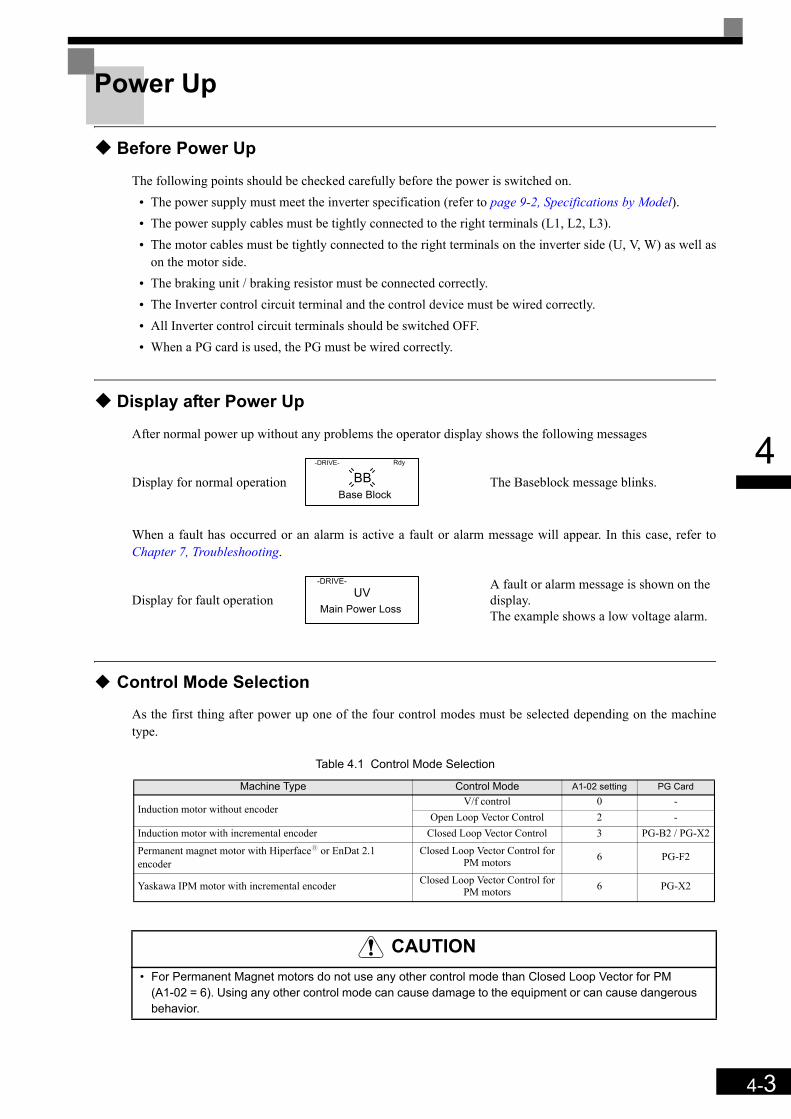
4-3
4
Power Up
Before Power Up
The following points should be checked carefully before the power is switched on.• The power supply must meet the inverter specification (refer to page 9-2, Specifications by Model).• The power supply cables must be tightly connected to the right terminals (L1, L2, L3).• The motor cables must be tightly connected to the right terminals on the inverter side (U, V, W) as well as
on the motor side.• The braking unit / braking resistor must be connected correctly.• The Inverter control circuit terminal and the control device must be wired correctly.• All Inverter control circuit terminals should be switched OFF.• When a PG card is used, the PG must be wired correctly.
Display after Power Up
After normal power up without any problems the operator display shows the following messages
When a fault has occurred or an alarm is active a fault or alarm message will appear. In this case, refer toChapter 7, Troubleshooting.
Control Mode Selection
As the first thing after power up one of the four control modes must be selected depending on the machinetype.
Table 4.1 Control Mode Selection
Display for normal operation The Baseblock message blinks.
Display for fault operationA fault or alarm message is shown on the display.The example shows a low voltage alarm.
Machine Type Control Mode A1-02 setting PG Card
Induction motor without encoderV/f control 0 -
Open Loop Vector Control 2 -Induction motor with incremental encoder Closed Loop Vector Control 3 PG-B2 / PG-X2
Permanent magnet motor with Hiperfacey or EnDat 2.1 encoder
Closed Loop Vector Control for PM motors 6 PG-F2
Yaskawa IPM motor with incremental encoder Closed Loop Vector Control for PM motors 6 PG-X2
CAUTION• For Permanent Magnet motors do not use any other control mode than Closed Loop Vector for PM
(A1-02 = 6). Using any other control mode can cause damage to the equipment or can cause dangerousbehavior.
-DRIVE-
Base Block
Rdy
BB
-DRIVE-UV
Main Power Loss

4-4
4
AutotuningThe motor data autotuning function sets the V/f pattern parameters (E1- ), motor data parameters (E2- , E5- ) and the encoder data (F1-01) automatically. The steps which have to be performed duringthe autotuning depend on the tuning mode selection. Refer to page 5-53, Motor Autotuning: T for an overviewof the autotuning parameters.
Autotuning Mode Selection
The autotuning mode has to be selected according to selected control mode and the mechanical system (motorno load rotation possible or not). Table 4.1 shows the selectable tuning mode for each control mode.
Table 4.2 Motor Data Autotuning Modes
Autotuning Modes
Autotuning with Rotating Motor (T1-01 = 0)This autotuning mode can be used in any Vector control mode. After the motor nameplate data have beeninput, the inverter will operate the motor for approximately 1~2 minutes and set the required motor parametersautomatically.
Autotuning with Not Rotating Motor (T1-01 = 1)This autotuning mode can be used for Open Loop and Closed Loop Vector control for IM only. The invertersupplies power to the motor for approximately 1 minute and some of the motor parameters are set automati-cally while the motor does not turn. The motor no-load current and the rated slip value will automatically befine tuned during the first time operation.Verify the rated slip value (E2-02) and the no-load current (E2-03) after the first run with nominal speed.
Autotuning for Line-to-Line Resistance (T1-01 = 2)Non-rotating autotuning for line-to-line resistance can be used in V/f control, Open Loop Vector control andClosed loop Vector control. The Inverter supplies power to the motor for approximately 20 seconds to measurethe motor line-to-line resistance and cable resistance. The motor does not turn during this tuning procedure.
Autotuning Mode Function
Tuning Mode
Selection (T1-01)
Control Mode
V/fOpen
Loop Vec-tor
Closed Loop Vec-
tor
Closed Loop Vec-tor (PM)
Standard tuning with rotating motor Tunes all motor parameters. 0 No Yes Yes Yes
IM tuning with not rotationg motor Tunes the basic motor parame-ters. 1 No Yes Yes No
IM Line-to-line resistance tuning Tunes the line-to-line resistance only 2 Yes Yes Yes No
Encoder offset tuningTunes the offset between the encoder and magnetic zero posi-tion.
4 No No No Yes
IMPORTANT
Use this tuning mode only, if the motor can rotate freely which means that the ropes must be removed and the brake must be open. The gearbox can remain connected to the motor.

4-5
4
Encoder Offset Tuning (T1-01=4)This tuning mode is available in Closed Loop Vector control for PM motors only. It automatically sets the off-set between the magnetic pole and the encoder zero postion. It can be used to retune the offset after an encoderchange without changing the motor data settings.
Auto Tuning Precautions
IMPORTANT
General Precautions:1. Use rotating autotuning whenever high precision is required or for a motor that is not connected to a
load.2. Use not rotating autotuning whenever the load cannot be disconnected from the motor (e.g. the ropes
can’t be removed).3. Make sure, that the mechanical brake is not open for not rotating autotuning. 4. During autotuning the motor contactors have to be closed.5. For autotuning the BB and BB1 signals must be ON (Inverter must not be in base block condition).6. Confirm, that the motor is mechanically fixed and can not move.7. Power is supplied during auto tuning, even though the motor does not turn. Do not touch the motor
until autotuning has been completed.8. Remove the feather key from the motor shaft before performing a tuning with rotating motor with a
stand alone motor (no traction sheave or gear mounted).9. To cancel autotuning, press the STOP key on the Digital Operator.
Precautions for rotating and encoder offset autotuning:1. The load should be disconnected which means, that the ropes have to be removed and the brake
must be open.2. If the load can’t be removed, the tuning can be done with a balanced car. The tuning result accuracy
will be lower which can result in a performance loss.3. Make sure that the brake is open during autotuning.4. During autotuning the motor can be started and stopped repeatedly. When the tuning is
finished, “END” will be displayed in the operator panel. Do not touch the motor until thisdisplay is shown and the motor has completely stopped.
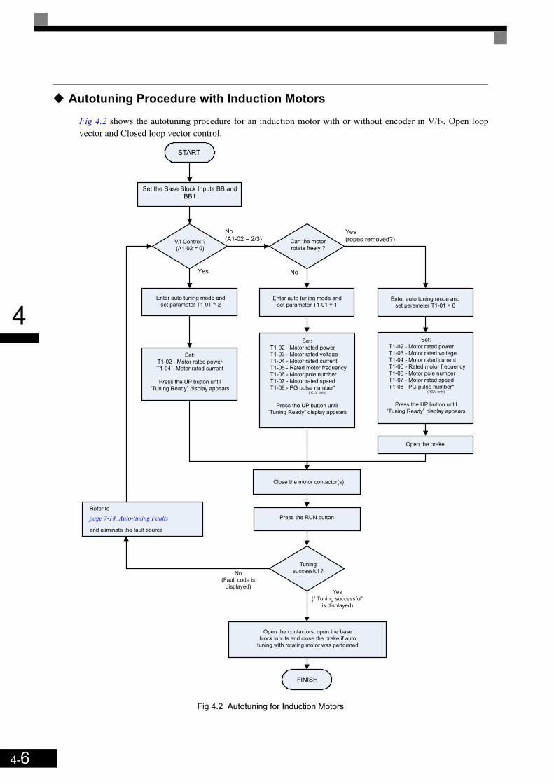
4-6
4
Autotuning Procedure with Induction Motors
Fig 4.2 shows the autotuning procedure for an induction motor with or without encoder in V/f-, Open loopvector and Closed loop vector control.
Fig 4.2 Autotuning for Induction Motors
Set:
T1-02 - Motor rated power
T1-03 - Motor rated voltage
T1-04 - Motor rated current
T1-05 - Rated motor frequency
T1-06 - Motor pole number
T1-07 - Motor rated speed
T1-08 - PG pulse number*(*CLV only)
Press the UP button until
“Tuning Ready” display appears
Enter auto tuning mode and
set parameter T1-01 = 0
START
Set the Base Block Inputs BB and
BB1
V/f Control ?
(A1-02 = 0)
Can the motor
rotate freely ?
No
(A1-02 = 2/3)
Yes
Enter auto tuning mode and
set parameter T1-01 = 2
Set:
T1-02 - Motor rated power
T1-04 - Motor rated current
Press the UP button until
“Tuning Ready” display appears
Set:
T1-02 - Motor rated power
T1-03 - Motor rated voltage
T1-04 - Motor rated current
T1-05 - Rated motor frequency
T1-06 - Motor pole number
T1-07 - Motor rated speed
T1-08 - PG pulse number*(*CLV only)
Press the UP button until
“Tuning Ready” display appears
Enter auto tuning mode and
set parameter T1-01 = 1
Open the brake
Close the motor contactor(s)
Press the RUN button
No
Yes
(ropes removed?)
Refer to
and eliminate the fault source
Tuning
successful ?No
(Fault code is
displayed)Yes
(” Tuning successful”
is displayed)
Open the contactors, open the base
block inputs and close the brake if auto
tuning with rotating motor was performed
FINISH
page 7-14, Auto-tuning Faults

4-7
4
Autotuning Procedure with PM Motors
Fig 4.3 shows the autotuning procedure for permanent magnet motors. Before tuning make sure that the con-trol mode is set to PM Closed Loop Vector (A1-02 = 6).
Fig 4.3 Autotuning for Permanent Magnet Motors
T2-04 - Motor rated current
T2-05 - Motor pole number
T2-09 - Encoder resolution
T2-10 - Motor voltage constant
START
* Remove the ropes so that the motor can rotate freely
* Set the Base Block inputs BB and BB1
T1-01 = 0 - Rotational Tuning
T2-01 - Motor rated power
T2-02 - Motor base frequency
T2-03 - Motor rated voltage
Press the UP button until the “Tuning Ready” display appears
Set the autotuning parameters:
Set mechanical constants:
S3-13 - Traction sheave diameter
S3-14 - Roping
S3-15 - Gear ratio
Close the motor contactor(s) and press the RUN button
Wait until tuning is finsihed
Tuning successful?
Yes
(”Tuning successful” is displayed)
No
(Fault code is displayed)
Open the contactors, open the baseblock
inputs and close the brake
FINISH
Refer to
and eliminate the fault source
Does a CPF24 fault
occur?
Switch ON the power supply if it is OFF
* Check parameter n8-35
* If EnDat / Hiperface is used
- check the encoder power supply
- check the CLOCK and DATA signal wiring
* Switch off the power supply.
No
Yes
Does a OPE06 fault
occur?
Check parameter
* F1-01
* n8-35
Switch off the power supply
and check if the right PG card
is correctley installedYes
No
Does a OPE02 fault
occur?
* Check if the correct PG constant (F1-01) and
absolute encoder resolution (F1-21) has been set.
* Refer to:
and eliminate the fault sourceNo
Yes
* Check the wiring
* Check/readjust the encoder
power supply
* Check the encoder wiring
* Change parameter F1-05
Does PGO (no
encoder feedback)
occur?
Is the sign of the
U1-05 value positive
(not -)?
No
Yes
No
Yes
Open the brake, close the motor contactor,
turn the motor slowly in Forward direction*1 and check monitor U1-05.
page 7-14, Auto-tuning Faults
page 7-12, Operator Programming Errors
* 1. Forward direction means: The direction the motor turns with an UP command at terminal S1 (i.e. with a clockwise rotating 3 phase supply and U-U, V-V, W-W wiring between inverter and motor). Usually the direction is clockwise seen from the motor shaft (traction sheave) side.Refer to the motor instruction manual or consult the manufac-turer for details about the rotation direction.
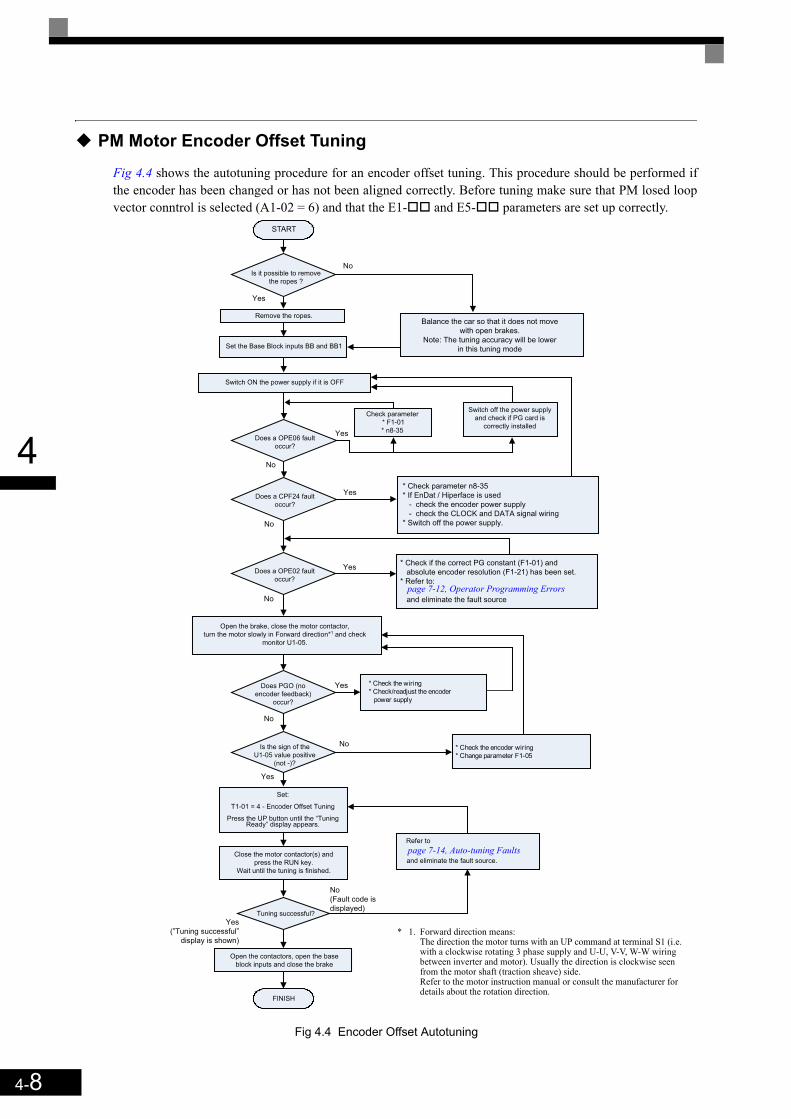
4-8
4
PM Motor Encoder Offset Tuning
Fig 4.4 shows the autotuning procedure for an encoder offset tuning. This procedure should be performed ifthe encoder has been changed or has not been aligned correctly. Before tuning make sure that PM losed loopvector conntrol is selected (A1-02 = 6) and that the E1- and E5- parameters are set up correctly.
Fig 4.4 Encoder Offset Autotuning
* Check the wiring
* Check/readjust the encoder
power supply
Yes
* Check the encoder wiring
* Change parameter F1-05
START
Remove the ropes.
Does PGO (no
encoder feedback)
occur?
Set the Base Block inputs BB and BB1
Open the brake, close the motor contactor,
turn the motor slowly in Forward direction*1 and check
monitor U1-05.
Is the sign of the
U1-05 value positive
(not -)?
No
Yes
No
Yes
Set:
T1-01 = 4 - Encoder Offset Tuning
Press the UP button until the “TuningReady” display appears.
Close the motor contactor(s) and
press the RUN key.
Wait until the tuning is finished.
Tuning successful?
No
(Fault code is
displayed)
Yes
(”Tuning successful”
display is shown)
Refer to
and eliminate the fault source.
Open the contactors, open the base
block inputs and close the brake
FINISH
Is it possible to remove
the ropes ?
Does a CPF24 fault
occur?
Balance the car so that it does not move
with open brakes.
Note: The tuning accuracy will be lower
in this tuning mode
* Check parameter n8-35
* If EnDat / Hiperface is used
- check the encoder power supply
- check the CLOCK and DATA signal wiring
* Switch off the power supply.
No
No
Yes
Does a OPE06 fault
occur?
Check parameter
* F1-01
* n8-35
Switch off the power supply
and check if PG card is
correctly installedYes
No
Does a OPE02 fault
occur?
* Check if the correct PG constant (F1-01) and
absolute encoder resolution (F1-21) has been set.
* Refer to:
and eliminate the fault sourceNo
Yes
Switch ON the power supply if it is OFF
page 7-14, Auto-tuning Faults
page 7-12, Operator Programming Errors
* 1. Forward direction means: The direction the motor turns with an UP command at terminal S1 (i.e. with a clockwise rotating 3 phase supply and U-U, V-V, W-W wiring between inverter and motor). Usually the direction is clockwise seen from the motor shaft (traction sheave) side.Refer to the motor instruction manual or consult the manufacturer for details about the rotation direction.
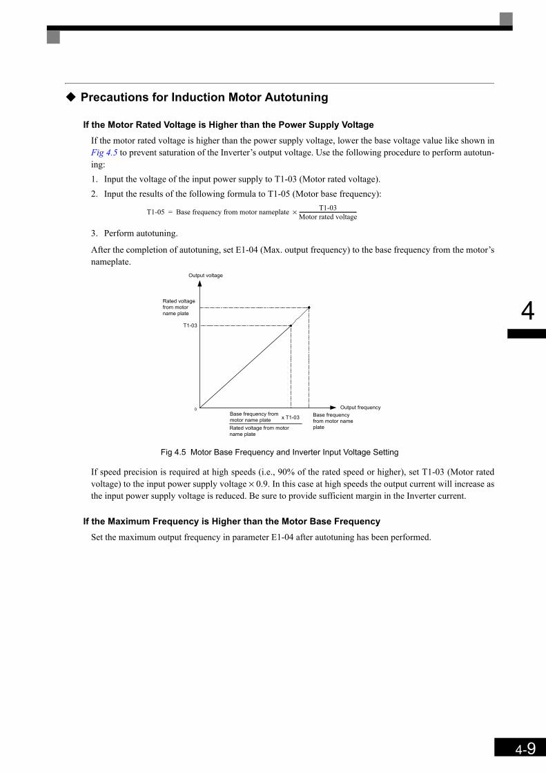
4-9
4
Precautions for Induction Motor Autotuning
If the Motor Rated Voltage is Higher than the Power Supply VoltageIf the motor rated voltage is higher than the power supply voltage, lower the base voltage value like shown inFig 4.5 to prevent saturation of the Inverter’s output voltage. Use the following procedure to perform autotun-ing:1. Input the voltage of the input power supply to T1-03 (Motor rated voltage).2. Input the results of the following formula to T1-05 (Motor base frequency):
3. Perform autotuning.
After the completion of autotuning, set E1-04 (Max. output frequency) to the base frequency from the motor’snameplate.
Fig 4.5 Motor Base Frequency and Inverter Input Voltage Setting
If speed precision is required at high speeds (i.e., 90% of the rated speed or higher), set T1-03 (Motor ratedvoltage) to the input power supply voltage × 0.9. In this case at high speeds the output current will increase asthe input power supply voltage is reduced. Be sure to provide sufficient margin in the Inverter current.
If the Maximum Frequency is Higher than the Motor Base FrequencySet the maximum output frequency in parameter E1-04 after autotuning has been performed.
T1-05 Base frequency from motor nameplate T1-03Motor rated voltage-----------------------------------------------×=
0 Output frequencyBase frequencyfrom motor nameplate
T1-03
Rated voltagefrom motorname plate
Output voltage
Base frequency frommotor name plate x T1-03
Rated voltage from motorname plate

4-10
4
Autotuning Alarms and Faults
Data Input ErrorsThe inverter will show a “Data Invalid” message and will not perform autotuning if:
• the motor speed, rated frequency and pole pair number do not correspond.
• the rated current does not correspond to the rated power valueThe inverter calculates the motor power using the input current value and data from the internal motor datatable. The calculated value must be between 50% and 150% of the input value for the rated power.
Other Alarms and Faults During AutotuningFor an overview of possible autotuning alarms or faults and corrective actions refer to page 7-14, Auto-tuningFaults.
Motor Speed Base Frequency 60⋅2 Motor pole⋅
-------------------------------------------------<
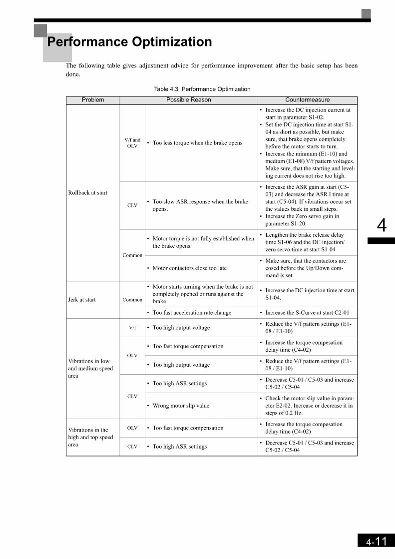
4-11
4
Performance OptimizationThe following table gives adjustment advice for performance improvement after the basic setup has beendone.
Table 4.3 Performance Optimization
Problem Possible Reason Countermeasure
Rollback at start
V/f and OLV • Too less torque when the brake opens
• Increase the DC injection current at start in parameter S1-02.
• Set the DC injection time at start S1-04 as short as possible, but make sure, that brake opens completely before the motor starts to turn.
• Increase the minmum (E1-10) and medium (E1-08) V/f pattern voltages. Make sure, that the starting and level-ing current does not rise too high.
CLV• Too slow ASR response when the brake
opens.
• Increase the ASR gain at start (C5-03) and decrease the ASR I time at start (C5-04). If vibrations occur set the values back in small steps.
• Increase the Zero servo gain in parameter S1-20.
Common
• Motor torque is not fully established when the brake opens.
• Lengthen the brake release delay time S1-06 and the DC injection/ zero servo time at start S1-04
• Motor contactors close too late• Make sure, that the contactors are
cosed before the Up/Down com-mand is set.
Jerk at start Common
• Motor starts turning when the brake is not completely opened or runs against the brake
• Increase the DC injection time at start S1-04.
• Too fast acceleration rate change • Increase the S-Curve at start C2-01
Vibrations in low and medium speed area
V/f • Too high output voltage • Reduce the V/f pattern settings (E1-08 / E1-10)
OLV
• Too fast torque compensation • Increase the torque compesation delay time (C4-02)
• Too high output voltage • Reduce the V/f pattern settings (E1-08 / E1-10)
CLV
• Too high ASR settings • Decrease C5-01 / C5-03 and increase C5-02 / C5-04
• Wrong motor slip value• Check the motor slip value in param-
eter E2-02. Increase or decrease it in steps of 0.2 Hz.
Vibrations in the high and top speed area
OLV • Too fast torque compensation • Increase the torque compesation delay time (C4-02)
CLV • Too high ASR settings • Decrease C5-01 / C5-03 and increase C5-02 / C5-04
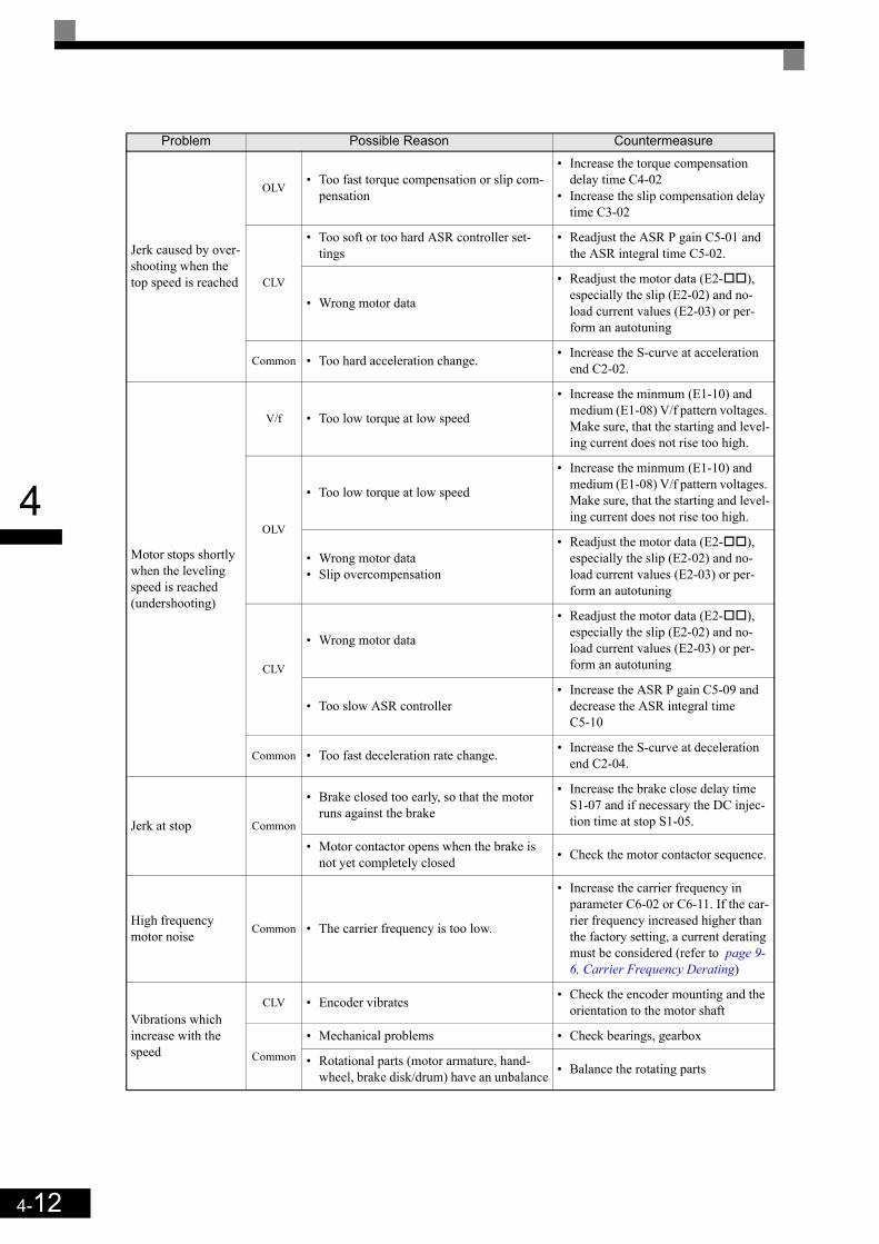
4-12
4
Jerk caused by over-shooting when the top speed is reached
OLV• Too fast torque compensation or slip com-
pensation
• Increase the torque compensation delay time C4-02
• Increase the slip compensation delay time C3-02
CLV
• Too soft or too hard ASR controller set-tings
• Readjust the ASR P gain C5-01 and the ASR integral time C5-02.
• Wrong motor data
• Readjust the motor data (E2- ), especially the slip (E2-02) and no-load current values (E2-03) or per-form an autotuning
Common • Too hard acceleration change. • Increase the S-curve at acceleration end C2-02.
Motor stops shortly when the leveling speed is reached (undershooting)
V/f • Too low torque at low speed
• Increase the minmum (E1-10) and medium (E1-08) V/f pattern voltages. Make sure, that the starting and level-ing current does not rise too high.
OLV
• Too low torque at low speed
• Increase the minmum (E1-10) and medium (E1-08) V/f pattern voltages. Make sure, that the starting and level-ing current does not rise too high.
• Wrong motor data• Slip overcompensation
• Readjust the motor data (E2- ), especially the slip (E2-02) and no-load current values (E2-03) or per-form an autotuning
CLV
• Wrong motor data
• Readjust the motor data (E2- ), especially the slip (E2-02) and no-load current values (E2-03) or per-form an autotuning
• Too slow ASR controller• Increase the ASR P gain C5-09 and
decrease the ASR integral time C5-10
Common • Too fast deceleration rate change. • Increase the S-curve at deceleration end C2-04.
Jerk at stop Common
• Brake closed too early, so that the motor runs against the brake
• Increase the brake close delay time S1-07 and if necessary the DC injec-tion time at stop S1-05.
• Motor contactor opens when the brake is not yet completely closed • Check the motor contactor sequence.
High frequency motor noise Common • The carrier frequency is too low.
• Increase the carrier frequency in parameter C6-02 or C6-11. If the car-rier frequency increased higher than the factory setting, a current derating must be considered (refer to page 9-6, Carrier Frequency Derating)
Vibrations which increase with the speed
CLV • Encoder vibrates • Check the encoder mounting and the orientation to the motor shaft
Common
• Mechanical problems • Check bearings, gearbox
• Rotational parts (motor armature, hand-wheel, brake disk/drum) have an unbalance • Balance the rotating parts
Problem Possible Reason Countermeasure

5User Parameters
This chapter describes all user parameters that can be set in the Inverter.
User Parameter Descriptions..............................................5-2Digital Operation Display Functions and Levels .................5-3User Parameter Tables.......................................................5-8Setup Settings: A ................................................................5-8Application Parameters: b.................................................5-10Tuning Parameters: C.......................................................5-12Reference Parameters: d..................................................5-18Motor Parameters: E.........................................................5-21Option Parameters: F........................................................5-26Terminal Function Parameters: H .....................................5-32Protection Function Parameters: L ...................................5-37Special Adjustments: n2 / n5 ............................................5-43PM Motor Adjustments: n8 / n9.........................................5-44Lift Function Parameters: S ..............................................5-47Motor Autotuning: T ..........................................................5-53Monitor Parameters: U......................................................5-55Settings which change with the Control Mode (A1-02) .....5-61Factory Settings Changing with Inverter Capacity (o2-04)5-63
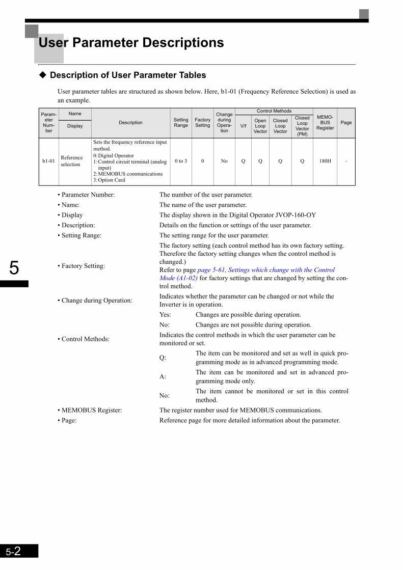
5-2
5
User Parameter Descriptions
Description of User Parameter Tables
User parameter tables are structured as shown below. Here, b1-01 (Frequency Reference Selection) is used asan example.
Param-eter
Num-ber
Name
Description Setting Range
Factory Setting
Change during Opera-
tion
Control MethodsMEMO-
BUS Register
PageV/f
Open Loop
Vector
Closed Loop
Vector
Closed Loop
Vector (PM)
Display
b1-01 Reference selection
Sets the frequency reference input method.0:Digital Operator1:Control circuit terminal (analog
input)2:MEMOBUS communications3:Option Card
0 to 3 0 No Q Q Q Q 180H -
• Parameter Number: The number of the user parameter.• Name: The name of the user parameter.• Display The display shown in the Digital Operator JVOP-160-OY• Description: Details on the function or settings of the user parameter.• Setting Range: The setting range for the user parameter.
• Factory Setting:
The factory setting (each control method has its own factory setting. Therefore the factory setting changes when the control method is changed.)Refer to page page 5-61, Settings which change with the Control Mode (A1-02) for factory settings that are changed by setting the con-trol method.
• Change during Operation: Indicates whether the parameter can be changed or not while the Inverter is in operation.Yes: Changes are possible during operation.No: Changes are not possible during operation.
• Control Methods: Indicates the control methods in which the user parameter can be monitored or set.
Q:The item can be monitored and set as well in quick pro-gramming mode as in advanced programming mode.
A: The item can be monitored and set in advanced pro-gramming mode only.
No: The item cannot be monitored or set in this controlmethod.
• MEMOBUS Register: The register number used for MEMOBUS communications.• Page: Reference page for more detailed information about the parameter.
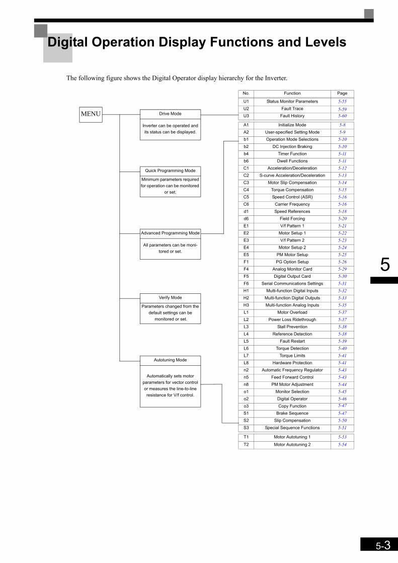
5-3
5
Digital Operation Display Functions and Levels
The following figure shows the Digital Operator display hierarchy for the Inverter.
MENU Drive Mode
Inverter can be operated and its status can be displayed.
Quick Programming Mode
Minimum parameters required for operation can be monitored
or set.
Advanced Programming Mode
All parameters can be moni-tored or set.
Verify Mode
Parameters changed from the default settings can be
monitored or set.
Autotuning Mode
Automatically sets motor parameters for vector control or measures the line-to-line resistance for V/f control.
No. Function Page
U1 Status Monitor Parameters 5-55U2 Fault Trace 5-59U3 Fault History 5-60
A1 Initialize Mode 5-8A2 User-specified Setting Mode 5-9b1 Operation Mode Selections 5-10b2 DC Injection Braking 5-10b4 Timer Function 5-11b6 Dwell Functions 5-11C1 Acceleration/Deceleration 5-12C2 S-curve Acceleration/Deceleration 5-13C3 Motor Slip Compensation 5-14C4 Torque Compensation 5-15C5 Speed Control (ASR) 5-16C6 Carrier Frequency 5-16d1 Speed References 5-18d6 Field Forcing 5-20E1 V/f Pattern 1 5-21E2 Motor Setup 1 5-22E3 V/f Pattern 2 5-23E4 Motor Setup 2 5-24E5 PM Motor Setup 5-25F1 PG Option Setup 5-26F4 Analog Monitor Card 5-29F5 Digital Output Card 5-30F6 Serial Communications Settings 5-31H1 Multi-function Digital Inputs 5-32H2 Multi-function Digital Outputs 5-33H3 Multi-function Analog Inputs 5-35L1 Motor Overload 5-37L2 Power Loss Ridethrough 5-37L3 Stall Prevention 5-38L4 Reference Detection 5-38L5 Fault Restart 5-39L6 Torque Detection 5-40L7 Torque Limits 5-41L8 Hardware Protection 5-41n2 Automatic Frequency Regulator 5-43n5 Feed Forward Control 5-43n8 PM Motor Adjustment 5-44o1 Monitor Selection 5-45o2 Digital Operator 5-46o3 Copy Function 5-47
S1 Brake Sequence 5-47S2 Slip Compensation 5-50S3 Special Sequence Functions 5-51
T1 Motor Autotuning 1 5-53T2 Motor Autotuning 2 5-54

5-4
5
User Parameters Available in Quick Programming Mode
The minimum user parameters required for Inverter operation can be monitored and set in quick programmingmode. The user parameters displayed in quick programming mode are listed in the following table. These, andall other user parameters, are also displayed in advanced programming mode.
Param-eter
Num-ber
Name
Description Setting Range
Factory Setting
Change during Opera-
tion
Control MethodsMEMOBUS
Regis-ter
V/fOpen Loop
Vector
Closed Loop
Vector
Closed Loop
Vector (PM)
Display
A1-01
Parameter access level
Used to set the parameter access level (set/read.)0:Monitoring only (Monitoring drive
mode and setting A1-01 and A1-04.)1:Used to select user parameters (Only
parameters set in A2-01 to A2-32 can be read and set.)
2:Advanced(Parameters can be read and set in both, quick programming mode (Q) and advanced programming mode (A).)
0 to 2 2 Yes Yes Yes Yes Yes 101H
Access Level
A1-02
Control method selection
Sets the control method for the Inverter.0:V/f control2:Open-Loop Vector control3:Closed Loop Vector control6:Closed Loop Vector for PM motors
0 to 6 0 No Yes Yes Yes Yes 102H
Control Method
C1-01Acceleration time 1 Sets the acceleration time to accelerate
from 0 Hz to the maximum output fre-quency. 0.0 to
600.00*1
1.50 s Yes Yes Yes Yes Yes
200HAccel Time 1
C1-02Deceleration time 1 Sets the deceleration time to decelerate
from the maximum output frequency to 0 Hz.
201HDecel Time 1
C2-01
S-curve character-istic time at accel-eration start
When the S-curve characteristic time is set, the accel/decel times will increase by only half of the S-curve characteris-tic times at start and end.
0.00 to 2.50 0.50 s No Yes Yes Yes Yes 20BH
S-Crv Acc @ Start
C2-02
S-curve character-istic time at accel-eration end
0.00 to 2.50 0.50 s No Yes Yes Yes Yes 20CH
S-Crv Acc @ End
C2-03
S-curve character-istic time at decel-eration start
0.00 to 2.50 0.50 s No Yes Yes Yes Yes 20DH
S-Crv Dec @ Start
C2-04
S-curve character-istic time at decel-eration end
0.00 to 2.50 0.50 s No Yes Yes Yes Yes 20EH
S-Crv Dec @ End
C2-05
S-curve Character-istic time below leveling speed
0.00 to 2.50 0.50 s No Yes Yes Yes Yes 232H
Scurve @ leveling
C5-01
ASR proportional (P) gain 1
Set the proportional gain 1 and the inte-gral time 1 of the speed control loop (ASR) for the minimum frequency.The settings becomes active for acceler-ation only.
0.00 to 300.00 i Yes - -
40.00 -21BH
ASR P Gain 1 - 12.00
C5-02
ASR integral time 1 0.000
to 10.000
i Yes - -
0.500 s -
21CHASR I Time 1 - 0.300 s
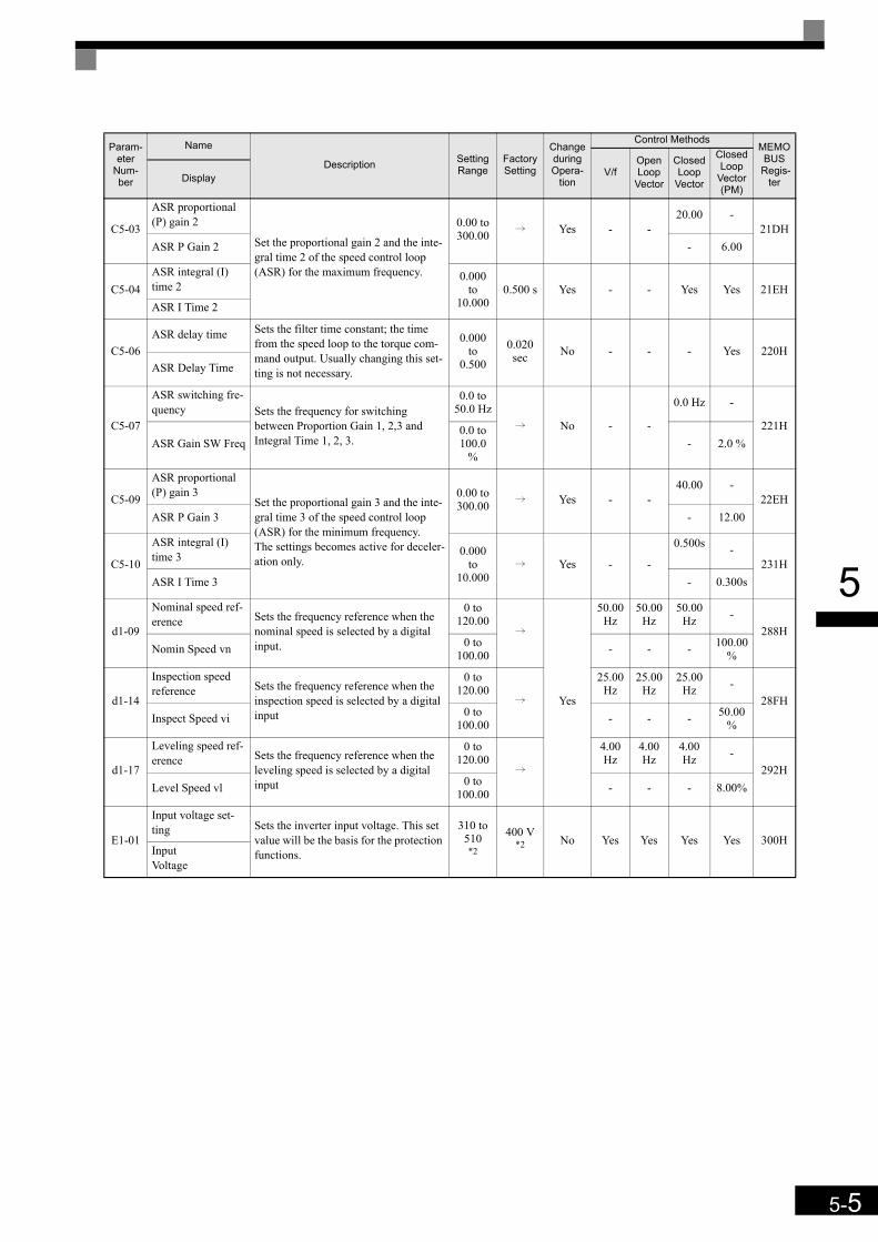
5-5
5
C5-03
ASR proportional (P) gain 2
Set the proportional gain 2 and the inte-gral time 2 of the speed control loop (ASR) for the maximum frequency.
0.00 to 300.00 i Yes - -
20.00 -21DH
ASR P Gain 2 - 6.00
C5-04ASR integral (I) time 2
0.000 to
10.0000.500 s Yes - - Yes Yes 21EH
ASR I Time 2
C5-06ASR delay time Sets the filter time constant; the time
from the speed loop to the torque com-mand output. Usually changing this set-ting is not necessary.
0.000 to
0.500
0.020 sec No - - - Yes 220H
ASR Delay Time
C5-07
ASR switching fre-quency Sets the frequency for switching
between Proportion Gain 1, 2,3 and Integral Time 1, 2, 3.
0.0 to 50.0 Hz
i No - -
0.0 Hz -
221HASR Gain SW Freq
0.0 to 100.0
%- 2.0 %
C5-09
ASR proportional (P) gain 3
Set the proportional gain 3 and the inte-gral time 3 of the speed control loop (ASR) for the minimum frequency.The settings becomes active for deceler-ation only.
0.00 to 300.00 i Yes - -
40.00 -22EH
ASR P Gain 3 - 12.00
C5-10
ASR integral (I) time 3 0.000
to 10.000
i Yes - -
0.500s -231H
ASR I Time 3 - 0.300s
d1-09
Nominal speed ref-erence Sets the frequency reference when the
nominal speed is selected by a digital input.
0 to 120.00
i
Yes
50.00 Hz
50.00 Hz
50.00 Hz -
288HNomin Speed vn 0 to
100.00 - - - 100.00 %
d1-14
Inspection speed reference Sets the frequency reference when the
inspection speed is selected by a digital input
0 to 120.00
i
25.00 Hz
25.00 Hz
25.00 Hz -
28FHInspect Speed vi 0 to
100.00 - - - 50.00%
d1-17
Leveling speed ref-erence Sets the frequency reference when the
leveling speed is selected by a digital input
0 to 120.00
i
4.00 Hz
4.00 Hz
4.00 Hz -
292HLevel Speed vl 0 to
100.00 - - - 8.00%
E1-01
Input voltage set-ting Sets the inverter input voltage. This set
value will be the basis for the protection functions.
310 to 510*2
400 V*2 No Yes Yes Yes Yes 300H
Input Voltage
Param-eter
Num-ber
Name
Description Setting Range
Factory Setting
Change during Opera-
tion
Control MethodsMEMOBUS
Regis-ter
V/fOpen Loop
Vector
Closed Loop
Vector
Closed Loop
Vector (PM)
Display
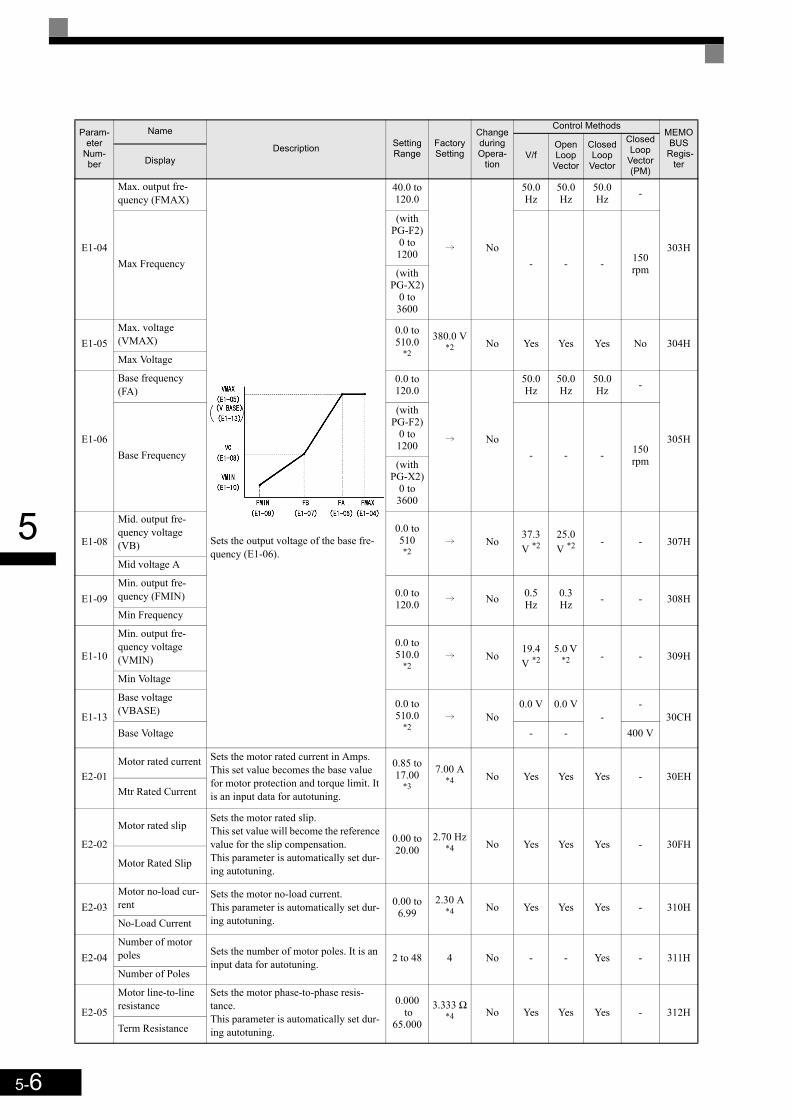
5-6
5
E1-04
Max. output fre-quency (FMAX)
Sets the output voltage of the base fre-quency (E1-06).
40.0 to 120.0
i No
50.0 Hz
50.0 Hz
50.0 Hz -
303HMax Frequency
(with PG-F2)
0 to 1200
- - - 150 rpm(with
PG-X2)0 to 3600
E1-05Max. voltage (VMAX)
0.0 to 510.0
*2
380.0 V*2 No Yes Yes Yes No 304H
Max Voltage
E1-06
Base frequency (FA)
0.0 to 120.0
i No
50.0 Hz
50.0 Hz
50.0 Hz -
305HBase Frequency
(with PG-F2)
0 to 1200
- - - 150 rpm(with
PG-X2)0 to 3600
E1-08
Mid. output fre-quency voltage (VB)
0.0 to 510 *2
i No37.3 V *2
25.0 V *2 - - 307H
Mid voltage A
E1-09Min. output fre-quency (FMIN) 0.0 to
120.0 i No 0.5 Hz
0.3 Hz - - 308H
Min Frequency
E1-10
Min. output fre-quency voltage (VMIN)
0.0 to 510.0
*2i No
19.4 V *2
5.0 V *2 - - 309H
Min Voltage
E1-13
Base voltage (VBASE) 0.0 to
510.0*2
i No0.0 V 0.0 V
--
30CHBase Voltage - - 400 V
E2-01Motor rated current Sets the motor rated current in Amps.
This set value becomes the base value for motor protection and torque limit. It is an input data for autotuning.
0.85 to 17.00
*3
7.00 A*4 No Yes Yes Yes - 30EH
Mtr Rated Current
E2-02
Motor rated slipSets the motor rated slip.This set value will become the reference value for the slip compensation.This parameter is automatically set dur-ing autotuning.
0.00 to 20.00
2.70 Hz*4 No Yes Yes Yes - 30FH
Motor Rated Slip
E2-03Motor no-load cur-rent
Sets the motor no-load current.This parameter is automatically set dur-ing autotuning.
0.00 to 6.99
2.30 A*4 No Yes Yes Yes - 310H
No-Load Current
E2-04Number of motor poles Sets the number of motor poles. It is an
input data for autotuning. 2 to 48 4 No - - Yes - 311HNumber of Poles
E2-05
Motor line-to-line resistance
Sets the motor phase-to-phase resis-tance.This parameter is automatically set dur-ing autotuning.
0.000 to
65.000
3.333 Ω*4 No Yes Yes Yes - 312H
Term Resistance
Param-eter
Num-ber
Name
Description Setting Range
Factory Setting
Change during Opera-
tion
Control MethodsMEMOBUS
Regis-ter
V/fOpen Loop
Vector
Closed Loop
Vector
Closed Loop
Vector (PM)
Display

5-7
5
E2-11
Motor rated output power
Sets the rated output power of the motor.This parameter is an input data for auto-tuning.
0.00 to 650.00
3.70 kW*4
No Yes Yes Yes No 318HMtr Rated Power
E5-02Motor rated output power Sets the rated output power of the
motor.0.00 to 300.00
3.70 kW*4
No - - - Yes 0C2HRated Power
E5-03Rated Motor Cur-rent Sets the rated motor current. 0.00 to
200.007.31 A*4
No - - - Yes 0C3HRated Current
E5-04Number of motor poles Sets the motor pole number. 4 to 48 4 No - - - Yes 0C4HNumber of poles
E5-05Motor terminal resistance Sets the motor line-to-line resistance
0.000 to
65.000
1.326 Ohm *4 No - - - Yes 0C5H
Term resistance
E5-06d-Axis Inductance
Sets the D-axis inductance. 0.00 to 300.00
19.11 mH*4
No - - - Yes 0C6Hd-ax inductance
E5-07q-Axis Inductance
Sets the Q-axis inductance. 0.00 to 600.00
26.08 mH*4
No - - - Yes 0C7Hq-ax inductance
E5-09Motor voltage con-stant Sets the voltage constant of the motor. 50.0 to
4000.0
478.6 mV*4
No - - - Yes 0C9HVoltage constant
F1-01PG constant
Sets the number of PG pulses per revo-lution
0 to 60000 i No - -
Yes1024 -
380HPG Pulses/Rev - Yes
2048
F1-05
PG rotation0:Phase A leads with forward run com-
mand. (Phase B leads with reverse run command.)
1:Phase B leads with forward run com-mand. (Phase A leads with reverse run command.)
0 or 1 i No - -
0 -
384H
PG Rotation Sel - 1
L1-01
Motor protection selection
Set to enable or disable the motor over-load protection function using the elec-tronic thermal relay.0:Disabled1:Protection for general purpose motor
(fan cooled)2:Protection for frequency converter
motor (external cooled)3:Protection for special vector control
motor5:Permanent magnet constant torque
motor
0 to 3 1
No
Yes Yes Yes -
480H
MOL Select 0 or 5 5 Yes
n8-35
Magnetic pole position detection
Sets the detection method for magnetic pole position of a PM motor.0:Automatic detection (applicable for
Yaskawa IPM motor only)4:Hiperfacey Data5:EnDat Data
0, 4 or 5 5 No - - - Yes 192H
Mag det sel
*1. The setting ranges for acceleration/deceleration times depends on the setting of C1-10 (Acceleration/deceleration Time Setting Unit). If C1-10 is set to 0,the setting range is 0.00 to 600.00 (s).
*2. The given values are for a 400 V class Inverter.*3. The setting range is from 10% to 200% of the Inverter rated output current. The given values are for a 3.7 kW 400 V Class Inverter.*4. The factory setting depends on the Inverter capacity. The given value is for a 3.7 kW 400 V Class Inverter.
Param-eter
Num-ber
Name
Description Setting Range
Factory Setting
Change during Opera-
tion
Control MethodsMEMOBUS
Regis-ter
V/fOpen Loop
Vector
Closed Loop
Vector
Closed Loop
Vector (PM)
Display
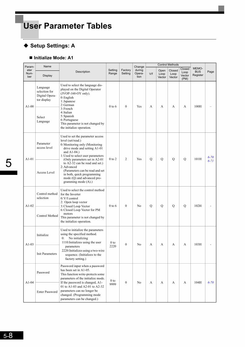
5-8
5
User Parameter Tables
Setup Settings: A
Initialize Mode: A1
Param-eter
Num-ber
Name
Description Setting Range
Factory Setting
Change during Opera-
tion
Control MethodsMEMO-
BUSRegister
PageV/f
Open Loop
Vector
Closed Loop
Vector
Closed Loop
Vector (PM)
Display
A1-00
Language selection for Digital Opera-tor display
Used to select the language dis-played on the Digital Operator (JVOP-160-OY only).0:English1:Japanese2:German3:French4: Italian5:Spanish6:PortugueseThis parameter is not changed by the initialize operation.
0 to 6 0 Yes A A A A 100H –
Select Language
A1-01
Parameter access level
Used to set the parameter access level (set/read.)0:Monitoring only (Monitoring
drive mode and setting A1-01 and A1-04.)
1:Used to select user parameters (Only parameters set in A2-01 to A2-32 can be read and set.)
2:Advanced(Parameters can be read and set in both, quick programming mode (Q) and advanced pro-gramming mode (A).)
0 to 2 2 Yes Q Q Q Q 101H 6-706-71
Access Level
A1-02
Control method selection
Used to select the control method for the Inverter0:V/f control2: Open loop vector3:Closed Loop Vector6:Closed Loop Vector for PM
motorsThis parameter is not changed by the initialize operation.
0 to 6 0 No Q Q Q Q 102H -
Control Method
A1-03
InitializeUsed to initialize the parameters using the specified method.0: No initializing1110:Initializes using the user
parameters2220:Initializes using a two-wire
sequence. (Initializes to the factory setting.)
0 to 2220 0 No A A A A 103H -
Init Parameters
A1-04
Password
Password input when a password has been set in A1-05. This function write-protects some parameters of the initialize mode.If the password is changed, A1-01 to A1-03 and A2-01 to A2-32 parameters can no longer be changed. (Programming mode parameters can be changed.)
0 to 9999 0 No A A A A 104H 6-70
Enter Password

5-9
5
User-set Parameters: A2The parameters set by the user are listed in the following table.
A1-05
Password set-ting
Used to set a four digit number as the password.Usually this parameter is not dis-played. When the Password (A1-04) is displayed, hold down the RESET key and press the Menu key. The password will be dis-played.
0 to 9999 0 No A A A A 105H 6-70
Select Pass-word
Param-eter
Num-ber
Name
Description Setting Range
Factory Setting
Change during Opera-
tion
Control MethodsMEMO-
BUSRegister
PageV/f
Open Loop
Vector
Closed Loop
Vector
Closed Loop
Vector (PM)
Display
A2-01 to
A2-32
User specified parameters
Used to select the function for each of the user specified param-eters. User parameters are the only accessible parameters if Parameter Access Level is set to user parameters (A1-01=1)
b1-01 to
S3-24– No A A A A 106H to
125H 6-71User Param 1 to 32
Param-eter
Num-ber
Name
Description Setting Range
Factory Setting
Change during Opera-
tion
Control MethodsMEMO-
BUSRegister
PageV/f
Open Loop
Vector
Closed Loop
Vector
Closed Loop
Vector (PM)
Display

5-10
5
Application Parameters: b
Operation Mode Selections: b1
DC Injection Braking: b2
Param-eter
Num-ber
Name
Description Setting Range
Factory Setting
Change during Opera-
tion
Control MethodsMEMO-
BUSRegister
PageV/f
Open Loop
Vector
Closed Loop
Vector
Closed Loop
Vector (PM)
Display
b1-01
Reference source selec-tion
Sets the frequency reference input method.0:Digital Operator1:Control circuit terminal (ana-
log input)3:Option Card
0, 1 or 3 0 No A A A A 180H 6-4
Reference Source
b1-02
RUN com-mand source selection
Sets the run command input method.0:Digital Operator1:Control circuit terminal (digital
multifunction inputs)3:Option Card
0, 1 or 3 1 No A A A A 181H 6-3
Run Source
b1-06
Control input scan
Used to set the responsiveness of the control inputs (forward/reverse and multi-function inputs.)0:Fast reading1:Normal reading (Can be used
for possible malfunction due to noise.)
0 or 1 1 No A A A A 185H -
Cntl Input Scans
b1-08
Run com-mand selec-tion in programming modes
Used to set an operation prohibi-tion in programming modes.0:Operation prohibited.1:Operation permitted (Disabled
when Digital Operator is the selected Run command source (b1-02 = 0)).
0 or 1 1 No A A A A 187H -
RUN CMD at PRG
Param-eter
Num-ber
Name
Description Setting Range
Factory Setting
Change during Opera-
tion
Control MethodsMEMO-
BUSRegister
PageV/f
Open Loop
Vector
Closed Loop
Vector
Closed Loop
Vector (PM)
Display
b2-08
Magnetic flux compensation volume
Sets the magnetic flux compensa-tion as a percentage of the no-load current.
0 to1000 0% No - A - - 190H -
Field Comp

5-11
5
Timer Function: b4
Dwell Functions: b6
Torque Monitor: b8
Parameter
Num-ber
Name
Description Setting Range
Factory Setting
Change during Opera-
tion
Control MethodsMEMO-
BUSRegister
PageV/f
Open Loop
Vector
Closed Loop
Vector
Closed Loop
Vector (PM)
Display
b4-01
Timer function ON-delay time
Sets the timer function output ON-delay time (dead band) for the timer function input, in 1-second units.Enabled when a timer function is set in H1- or H2- .
0.0 to 300.0 0.0 s No A A A A 1A3H 6-52
Delay-ON Timer
b4-02
Timer function OFF-delay time
Sets the timer function output OFF-delay time (dead band) for the timer function input, in 1-second units.Enabled when a timer function is set in H1- or H2- .
0.0 to 300.0 0.0 s No A A A A 1A4H 6-52
Delay-OFF Timer
Parameter
Num-ber
Name
Description Setting Range
Factory Setting
Change during Opera-
tion
Control MethodsMEMO-
BUSRegister
PageV/f
Open Loop
Vector
Closed Loop Vector
Closed Loop
Vector (PM)
Display
b6-01
Dwell fre-quency at start
The dwell function can be used to hold the output frequency tempo-rarily.
0.0 to 120.0 0.0 Hz No A A A A 1B6H 6-22
Dwell Ref @ Start
b6-02
Dwell time at start 0.0 to
10.0 0.0 s No A A A A 1B7H 6-22Dwell Time @ Start
b6-03
Dwell fre-quency at stop 0.0 to
120.0 0.0 Hz No A A A A 1B8H 6-22Dwell Ref @ Stop
b6-04
Dwell time at stop 0.0 to
10.0 0.0 s No A A A A 1B9H 6-22Dwell Time @ Stop
Parameter
Num-ber
Name
Description Setting Range
Factory Setting
Change during Opera-
tion
Control MethodsMEMO-
BUSRegister
PageV/f
Open Loop
Vector
Closed Loop Vector
Closed Loop
Vector (PM)
Display
b8-17
Torque monitor gain 0 to
2.00 1.00 No - - - A 1F9H 6-22Torque Mon Gain
Run command
Output frequency
Time
ON
b6-03
OFF
b6-01
b6-04b6-02
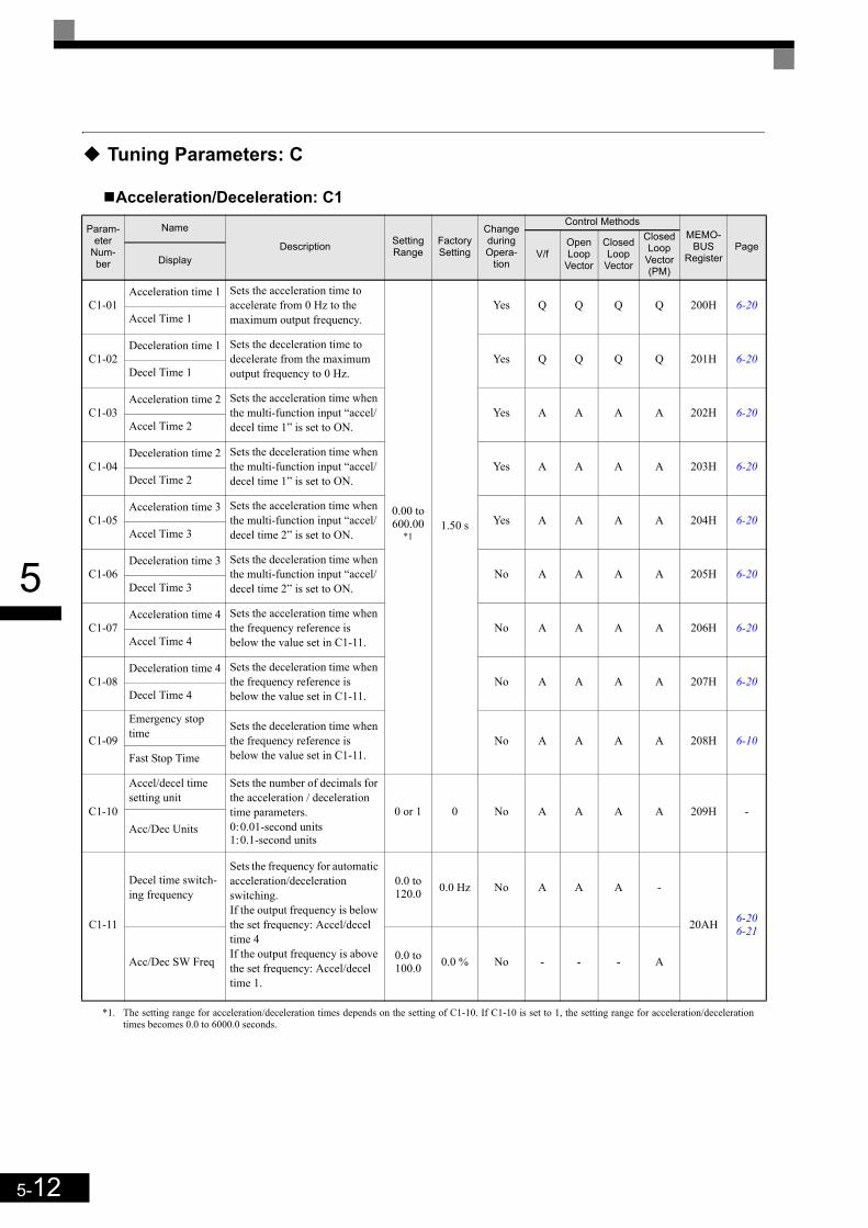
5-12
5
Tuning Parameters: C
Acceleration/Deceleration: C1
Param-eter
Num-ber
Name
Description Setting Range
Factory Setting
Change during Opera-
tion
Control MethodsMEMO-
BUSRegister
PageV/f
Open Loop
Vector
Closed Loop
Vector
Closed Loop
Vector (PM)
Display
C1-01Acceleration time 1 Sets the acceleration time to
accelerate from 0 Hz to the maximum output frequency.
0.00 to 600.00
*1
*1. The setting range for acceleration/deceleration times depends on the setting of C1-10. If C1-10 is set to 1, the setting range for acceleration/decelerationtimes becomes 0.0 to 6000.0 seconds.
1.50 s
Yes Q Q Q Q 200H 6-20Accel Time 1
C1-02Deceleration time 1 Sets the deceleration time to
decelerate from the maximum output frequency to 0 Hz.
Yes Q Q Q Q 201H 6-20Decel Time 1
C1-03Acceleration time 2 Sets the acceleration time when
the multi-function input “accel/decel time 1” is set to ON.
Yes A A A A 202H 6-20Accel Time 2
C1-04Deceleration time 2 Sets the deceleration time when
the multi-function input “accel/decel time 1” is set to ON.
Yes A A A A 203H 6-20Decel Time 2
C1-05Acceleration time 3 Sets the acceleration time when
the multi-function input “accel/decel time 2” is set to ON.
Yes A A A A 204H 6-20Accel Time 3
C1-06Deceleration time 3 Sets the deceleration time when
the multi-function input “accel/decel time 2” is set to ON.
No A A A A 205H 6-20Decel Time 3
C1-07Acceleration time 4 Sets the acceleration time when
the frequency reference is below the value set in C1-11.
No A A A A 206H 6-20Accel Time 4
C1-08Deceleration time 4 Sets the deceleration time when
the frequency reference is below the value set in C1-11.
No A A A A 207H 6-20Decel Time 4
C1-09
Emergency stop time Sets the deceleration time when
the frequency reference is below the value set in C1-11.
No A A A A 208H 6-10Fast Stop Time
C1-10
Accel/decel time setting unit
Sets the number of decimals for the acceleration / deceleration time parameters.0:0.01-second units1:0.1-second units
0 or 1 0 No A A A A 209H -Acc/Dec Units
C1-11
Decel time switch-ing frequency
Sets the frequency for automatic acceleration/deceleration switching.If the output frequency is below the set frequency: Accel/decel time 4If the output frequency is above the set frequency: Accel/decel time 1.
0.0 to 120.0 0.0 Hz No A A A -
20AH 6-206-21
Acc/Dec SW Freq 0.0 to 100.0 0.0 % No - - - A
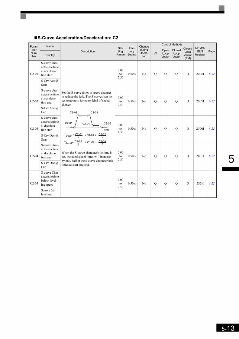
5-13
5
S-Curve Acceleration/Deceleration: C2
Parameter
Num-ber
Name
DescriptionSet-ting
Range
Fac-tory
Setting
Change during Opera-
tion
Control MethodsMEMO-
BUSRegister
PageV/f
Open Loop
Vector
Closed Loop
Vector
Closed Loop
Vector (PM)
Display
C2-01
S-curve char-acteristic time at accelera-tion start
Set the S-curve times at speed changes to reduce the jerk. The S-curves can be set separately for every kind of speed change.
When the S-curve characteristic time is set, the accel/decel times will increase by only half of the S-curve characteristic times at start and end.
0.00 to
2.500.50 s No Q Q Q Q 20BH 6-22
S-Crv Acc @ Start
C2-02
S-curve char-acteristic time at accelera-tion end
0.00 to
2.500.50 s No Q Q Q Q 20CH 6-22
S-Crv Acc @ End
C2-03
S-curve char-acteristic time at decelera-tion start
0.00 to
2.500.50 s No Q Q Q Q 20DH 6-22
S-Crv Dec @ Start
C2-04
S-curve char-acteristic time at decelera-tion end
0.00 to
2.500.50 s No Q Q Q Q 20EH 6-22
S-Crv Dec @ End
C2-05
S-curve Char-acteristic time below level-ing speed
0.00 to
2.500.50 s No Q Q Q Q 232H 6-22
Scurve @ leveling
Time
C2-02 C2-03
C2-04C2-01
accelT = C2-012
+ C1-01 + C2-022
decelT = C2-032
+ C1-02 + C2-042
C2-05
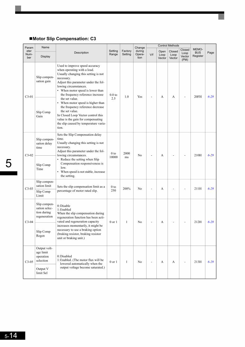
5-14
5
Motor Slip Compensation: C3
Parameter
Num-ber
Name
Description Setting Range
Factory Setting
Change during Opera-
tion
Control MethodsMEMO-
BUSRegister
PageV/f
Open Loop
Vector
Closed Loop
Vector
Closed Loop
Vector (PM)
Display
C3-01
Slip compen-sation gain
Used to improve speed accuracy when operating with a load.Usually changing this setting is not necessary.Adjust this parameter under the fol-lowing circumstances.• When motor speed is lower than
the frequency reference increase the set value.
• When motor speed is higher than the frequency reference decrease the set value.
In Closed Loop Vector control this value is the gain for compensating the slip caused by temperature varia-tion.
0.0 to 2.5 1.0 Yes - A A - 20FH 6-29
Slip Comp Gain
C3-02
Slip compen-sation delay time
Sets the Slip Compensation delay time.Usually changing this setting is not necessary.Adjust this parameter under the fol-lowing circumstances.• Reduce the setting when Slip
Compensation responsiveness is low.
• When speed is not stable, increase the setting.
0 to 10000
2000 ms No - A - - 210H 6-29
Slip Comp Time
C3-03
Slip compen-sation limit Sets the slip compensation limit as a
percentage of motor rated slip.0 to 250 200% No - A - - 211H 6-29
Slip Comp Limit
C3-04
Slip compen-sation selec-tion during regeneration
0:Disable1:EnabledWhen the slip compensation during regeneration function has been acti-vated and regeneration capacity increases momentarily, it might be necessary to use a braking option (braking resistor, braking resistor unit or braking unit.)
0 or 1 1 No - A - - 212H 6-29
Slip Comp Regen
C3-05
Output volt-age limit operation selection
0:Disabled1:Enabled. (The motor flux will be
lowered automatically when the output voltage become saturated.)
0 or 1 1 No - A A - 213H 6-29
Output V limit Sel
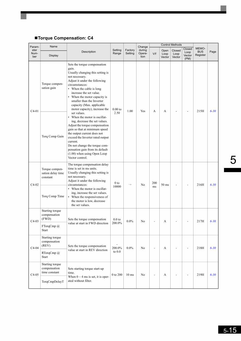
5-15
5
Torque Compensation: C4
Param-eter
Num-ber
Name
Description Setting Range
Factory Setting
Change during Opera-
tion
Control MethodsMEMO-
BUSRegister
PageV/f
Open Loop
Vector
Closed Loop
Vector
Closed Loop
Vector (PM)
Display
C4-01
Torque compen-sation gain
Sets the torque compensation gain.Usually changing this setting is not necessary.Adjust it under the following circumstances:• When the cable is long
increase the set value.• When the motor capacity is
smaller than the Inverter capacity (Max. applicable motor capacity), increase the set values.
• When the motor is oscillat-ing, decrease the set values.
Adjust the torque compensation gain so that at minimum speed the output current does not exceed the Inverter rated output current. Do not change the torque com-pensation gain from its default (1.00) when using Open Loop Vector control.
0.00 to 2.50 1.00 Yes A A - - 215H 6-30
Torq Comp Gain
C4-02
Torque compen-sation delay time constant
The torque compensation delay time is set in ms units.Usually changing this setting is not necessary.Adjust it under the following circumstances:• When the motor is oscillat-
ing, increase the set values.• When the responsiveness of
the motor is low, decrease the set values.
0 to 10000 i No 200
ms 50 ms - - 216H 6-30
Torq Comp Time
C4-03
Starting torque compensation (FWD) Sets the torque compensation
value at start in FWD direction0.0 to
200.0% 0.0% No - A - - 217H 6-30FTorqCmp @ Start
C4-04
Starting torque compensation (REV) Sets the torque compensation
value at start in REV direction
-200.0% to 0.0
0.0% No - A - - 218H 6-30RTorqCmp @ Start
C4-05
Starting torque compensation time constant
Sets starting torque start-up time.When 0 ~ 4 ms is set, it is oper-ated without filter.
0 to 200 10 ms No - A - - 219H 6-30
TorqCmpDelayT

5-16
5
Speed Control (ASR): C5
Carrier Frequency: C6
Parameter
Num-ber
Name
DescriptionSet-ting
Range
Fac-tory
Setting
Change during Opera-
tion
Control MethodsMEMO-
BUSRegister
PageV/f
Open Loop
Vector
Closed Loop
Vector
Closed Loop
Vector (PM)
Display
C5-01
ASR propor-tional (P) gain 1
Set the proportional gain 1 and the integral time 1 of the speed control loop (ASR) for the maximum fre-quency.
0.00 to 300.00 i Yes - -
Q40.00 -
21BH 6-32ASR P Gain 1 - Q
3.00
C5-02
ASR integral (I) time 1
0.000 to
10.000 sec
i Yes - -
Q0.500 -
21CH 6-32ASR I Time 1 - Q
0.300
C5-03
ASR propor-tional (P) gain 2 Set the proportional gain 2 and the
integral time 2 of the speed control loop (ASR) for the minimum fre-quency.The setting is active only for accel-eration.
0.00 to 300.00 i Yes - -
Q20.00 -
21DH 6-32ASR P Gain 2 - Q
3.00
C5-04
ASR integral (I) time 2
0.000 to
10.000 sec
0.500 s Yes - - Q Q 21EH 6-32ASR I Time 2
C5-06ASR delay time
Sets the ASR output delay time.0.000
to 0.500
0.020 s No - - - A 220H 6-32ASR Gain SW Freq
C5-07
ASR switching frequency Sets the frequency for switching
between Proportion Gain 1, 2,3 and Integral Time 1, 2, 3.
0.0 to 120.0
i No - -
Q0.0 Hz -
221H 6-32ASR Gain SW Freq
0.0 to 100.0 - Q
2.0 %
C5-08
ASR integral (I) limit
Set the parameter to a small value to prevent any radical load change. A setting of 100% is equal to the max-imum output frequency.
0 to 400 400% No - - A A 222H 6-32
ASR I Limit
C5-09
ASR propor-tional (P) gain 3 Set the proportional gain 3 and the
integral time 3 of the speed control loop (ASR) for the minimum fre-quency.The settings is active for decelera-tion only.
0.00 to 300.00 i Yes - -
Q40.00 -
22EH 6-32ASR P Gain 3 - Q
3.00
C5-10
ASR integral (I) time 3
0.000 to
10.000 sec
i Yes - -
Q0.500 -
231H 6-32ASR I Time 3 - Q
0.300
C5-15
ASR gain for encoder offset tuning
Sets the ASR P gain which is used for the encoder offset tuning if Hip-erface or EnDat encoders are used.
0.00 to 300.00 5.00 No - - - A 238H 6-32
Pullin ASR Pgain
Parameter
Num-ber
Name
DescriptionSet-ting
Range
Fac-tory
Setting
Change during Opera-
tion
Control MethodsMEMO-
BUSRegister
PageV/f
Open Loop
Vector
Closed Loop
Vector
Closed Loop
Vector (PM)
Display
C6-02
Carrier fre-quency selec-tion 1
Selects the carrier frequency for Induction motor control modes.1:2 kHz2:5 kHz3:8 kHz4:10 kHz5:12.5 kHz6:15 kHz
1 to 6 3 No A A A - 224H 6-2
CarrierFreq Sel

5-17
5
C6-11
Carrier fre-quency selec-tion 2
Selects the carrier frequency for PM motor control modes1:2 kHz2:4 kHz3:6 kHz4:8 kHz5:12 kHz6:15 kHz
1 to 6 4 No - - - A 22DH 6-2
CarrierFreq Sel
Parameter
Num-ber
Name
DescriptionSet-ting
Range
Fac-tory
Setting
Change during Opera-
tion
Control MethodsMEMO-
BUSRegister
PageV/f
Open Loop
Vector
Closed Loop
Vector
Closed Loop
Vector (PM)
Display

5-18
5
Reference Parameters: d
Preset Reference: d1
Param-eter
Num-ber
Name
Description Setting Range
Fac-tory
Setting
Change during Opera-
tion
Control MethodsMEMO-
BUSRegis-
ter
PageV/f
Open Loop
Vector
Closed Loop
Vector
Closed Loop
Vector (PM)
Display
d1-01
Frequency refer-ence 1
Sets the frequency reference.
0 to 120.00*1,*2
i Yes
A0.00 Hz
A0.00 Hz
A0.00 Hz
-
280H 6-5
Reference 10 to
100.00 %
- - - A0.00 %
d1-02
Frequency refer-ence 2 Sets the frequency reference
when multi-step speed command 1 is ON for a multi-function input.
0 to 120.00
*1,*2i Yes
A0.00 Hz
A0.00 Hz
A0.00 Hz
-
281H 6-5
Reference 20 to
100.00 %
- - - A0.00 %
d1-03
Frequency refer-ence 3 Sets the frequency reference
when multi-step speed command 2 is ON for a multi-function input.
0 to 120.00
*1,*2i Yes
A0.00 Hz
A0.00 Hz
A0.00 Hz
-
282H 6-50 to
100.00 %
- - - A0.00 %Reference 3
d1-04
Frequency refer-ence 4 Sets the frequency reference
when multi-step speed com-mands 1 and 2 are ON for multi-function inputs.
0 to 120.00
*1,*2i Yes
A0.00 Hz
A0.00 Hz
A0.00 Hz
-
283H 6-5
Reference 40 to
100.00 %
- - - A0.00 %
d1-05
Frequency refer-ence 5 Sets the frequency when multi-
step speed command 3 is ON for a multi-function input.
0 to 120.00
*1,*2i Yes
A0.00 Hz
A0.00 Hz
A0.00 Hz
-
284H 6-5
Reference 50 to
100.00 %
- - - A0.00 %
d1-06
Frequency refer-ence 6 Sets the frequency reference
when multi-step speed com-mands 1 and 3 are ON for multi-function inputs.
0 to 120.00
*1,*2i Yes
A0.00 Hz
A0.00 Hz
A0.00 Hz
-
285H 6-5
Reference 60 to
100.00 %
- - - A0.00 %
d1-07
Frequency refer-ence 7 Sets the frequency reference
when multi-step speed com-mands 2 and 3 are ON for multi-function inputs.
0 to 120.00
*1,*2i Yes
A0.00 Hz
A0.00 Hz
A0.00 Hz
-
286H 6-5
Reference 70 to
100.00 %
- - - A0.00 %
d1-08
Frequency refer-ence 8 Sets the frequency reference
when multi-step speed com-mands 1, 2, and 3 are ON for multi-function inputs.
0 to 120.00
*1,*2i Yes
A0.00 Hz
A0.00 Hz
A0.00 Hz
-
287H 6-5
Reference 80 to
100.00 %
- - - A0.00 %
d1-09
Nominal speedSets the frequency reference when the nominal speed is selected by a digital input.
0 to 120.00
*1,*2i Yes
Q50.00
Hz
Q50.00
Hz
Q50.00
Hz-
288H 6-76-8
Nomin Speed vn0 to
100.00 %
- - -Q
100.00 %
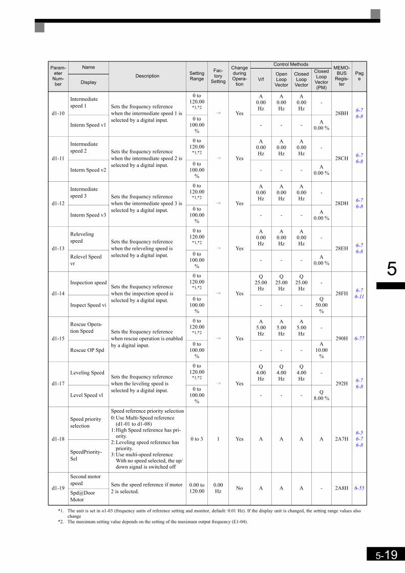
5-19
5
d1-10
Intermediate speed 1 Sets the frequency reference
when the intermediate speed 1 is selected by a digital input.
0 to 120.00
*1,*2i Yes
A0.00 Hz
A0.00 Hz
A0.00 Hz
-
28BH 6-76-8
Interm Speed v10 to
100.00 %
- - - A0.00 %
d1-11
Intermediate speed 2 Sets the frequency reference
when the intermediate speed 2 is selected by a digital input.
0 to 120.00
*1,*2i Yes
A0.00 Hz
A0.00 Hz
A0.00 Hz
-
28CH 6-76-8
Interm Speed v20 to
100.00 %
- - - A0.00 %
d1-12
Intermediate speed 3 Sets the frequency reference
when the intermediate speed 3 is selected by a digital input.
0 to 120.00
*1,*2i Yes
A0.00 Hz
A0.00 Hz
A0.00 Hz
-
28DH 6-76-8
Interm Speed v30 to
100.00 %
- - - A0.00 %
d1-13
Releveling speed Sets the frequency reference
when the releveling speed is selected by a digital input.
0 to 120.00
*1,*2i Yes
A0.00 Hz
A0.00 Hz
A0.00 Hz
-
28EH 6-76-8
Relevel Speed vr
0 to 100.00
%- - - A
0.00 %
d1-14
Inspection speedSets the frequency reference when the inspection speed is selected by a digital input.
0 to 120.00
*1,*2i Yes
Q25.00
Hz
Q25.00
Hz
Q25.00
Hz-
28FH 6-76-11
Inspect Speed vi0 to
100.00 %
- - -Q
50.00 %
d1-15
Rescue Opera-tion Speed Sets the frequency reference
when rescue operation is enabled by a digital input.
0 to 120.00
*1,*2i Yes
A5.00 Hz
A5.00 Hz
A5.00 Hz
-
290H 6-77
Rescue OP Spd0 to
100.00 %
- - -A
10.00 %
d1-17
Leveling Speed Sets the frequency reference when the leveling speed is selected by a digital input.
0 to 120.00
*1,*2i Yes
Q4.00 Hz
Q4.00 Hz
Q4.00 Hz
-
292H 6-76-8
Level Speed vl0 to
100.00 %
- - - Q8.00 %
d1-18
Speed priority selection
Speed reference priority selection0:Use Multi-Speed reference
(d1-01 to d1-08)1:High Speed reference has pri-
ority.2:Leveling speed reference has
priority.3:Use multi-speed reference
With no speed selected, the up/ down signal is switched off
0 to 3 1 Yes A A A A 2A7H6-56-76-8
SpeedPriority-Sel
d1-19
Second motor speed Sets the speed reference if motor
2 is selected.0.00 to 120.00
0.00 Hz No A A A - 2A8H 6-55
Spd@Door Motor
*1. The unit is set in o1-03 (frequency units of reference setting and monitor, default: 0.01 Hz). If the display unit is changed, the setting range values alsochange
*2. The maximum setting value depends on the setting of the maximum output frequency (E1-04).
Param-eter
Num-ber
Name
Description Setting Range
Fac-tory
Setting
Change during Opera-
tion
Control MethodsMEMO-
BUSRegis-
ter
PageV/f
Open Loop
Vector
Closed Loop
Vector
Closed Loop
Vector (PM)
Display
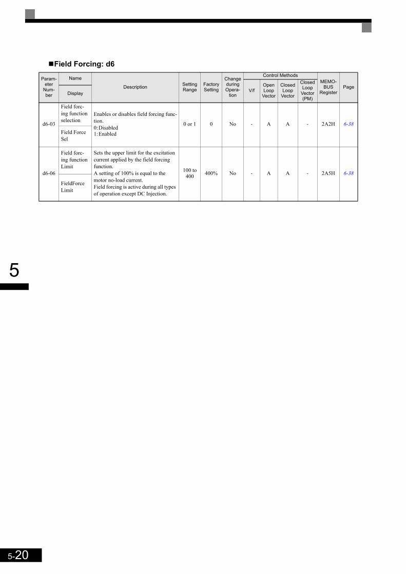
5-20
5
Field Forcing: d6
Param-eter
Num-ber
Name
Description Setting Range
Factory Setting
Change during Opera-
tion
Control MethodsMEMO-
BUSRegister
PageV/f
Open Loop
Vector
Closed Loop
Vector
Closed Loop
Vector (PM)
Display
d6-03
Field forc-ing function selection
Enables or disables field forcing func-tion.0:Disabled1:Enabled
0 or 1 0 No - A A - 2A2H 6-38Field Force Sel
d6-06
Field forc-ing function Limit
Sets the upper limit for the excitation current applied by the field forcing function.A setting of 100% is equal to the motor no-load current.Field forcing is active during all types of operation except DC Injection.
100 to 400 400% No - A A - 2A5H 6-38
FieldForce Limit
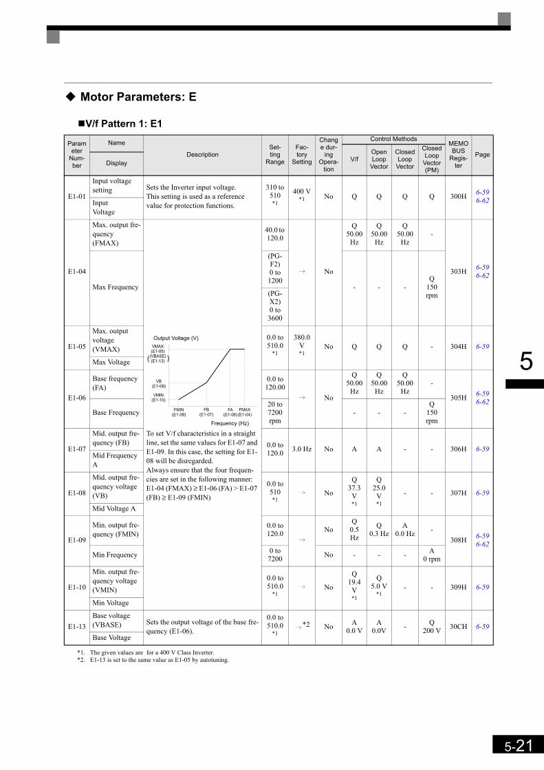
5-21
5
Motor Parameters: E
V/f Pattern 1: E1
Parameter
Num-ber
Name
DescriptionSet-ting
Range
Fac-tory
Setting
Change dur-
ing Opera-
tion
Control MethodsMEMOBUS
Regis-ter
PageV/f
Open Loop
Vector
Closed Loop
Vector
Closed Loop
Vector (PM)
Display
E1-01
Input voltage setting Sets the Inverter input voltage.
This setting is used as a reference value for protection functions.
310 to 510*1
*1. The given values are for a 400 V Class Inverter.
400 V*1 No Q Q Q Q 300H 6-59
6-62Input Voltage
E1-04
Max. output fre-quency (FMAX)
To set V/f characteristics in a straight line, set the same values for E1-07 and E1-09. In this case, the setting for E1-08 will be disregarded.Always ensure that the four frequen-cies are set in the following manner:E1-04 (FMAX) ≥ E1-06 (FA) > E1-07 (FB) ≥ E1-09 (FMIN)
40.0 to 120.0
i No
Q50.00
Hz
Q50.00
Hz
Q50.00
Hz-
303H 6-596-62
Max Frequency
(PG-F2)0 to 1200
- - -Q
150 rpm(PG-
X2)0 to 3600
E1-05
Max. output voltage (VMAX)
0.0 to 510.0
*1
380.0 V*1
No Q Q Q - 304H 6-59
Max Voltage
E1-06
Base frequency (FA)
0.0 to 120.00
i No
Q50.00
Hz
Q50.00
Hz
Q50.00
Hz-
305H 6-596-62
Base Frequency20 to 7200 rpm
- - -Q
150 rpm
E1-07
Mid. output fre-quency (FB) 0.0 to
120.0 3.0 Hz No A A - - 306H 6-59Mid Frequency A
E1-08
Mid. output fre-quency voltage (VB)
0.0 to 510 *1
i No
Q37.3
V*1
Q25.0
V*1
- - 307H 6-59
Mid Voltage A
E1-09
Min. output fre-quency (FMIN)
0.0 to 120.0
iNo
Q0.5 Hz
Q0.3 Hz
A0.0 Hz -
308H 6-596-62
Min Frequency 0 to 7200 No - - - A
0 rpm
E1-10
Min. output fre-quency voltage (VMIN)
0.0 to 510.0
*1i No
Q19.4
V*1
Q5.0 V
*1- - 309H 6-59
Min Voltage
E1-13Base voltage (VBASE) Sets the output voltage of the base fre-
quency (E1-06).
0.0 to 510.0
*1i*2
*2. E1-13 is set to the same value as E1-05 by autotuning.
No A0.0 V
A0.0V - Q
200 V 30CH 6-59Base Voltage
Output Voltage (V)
Frequency (Hz)
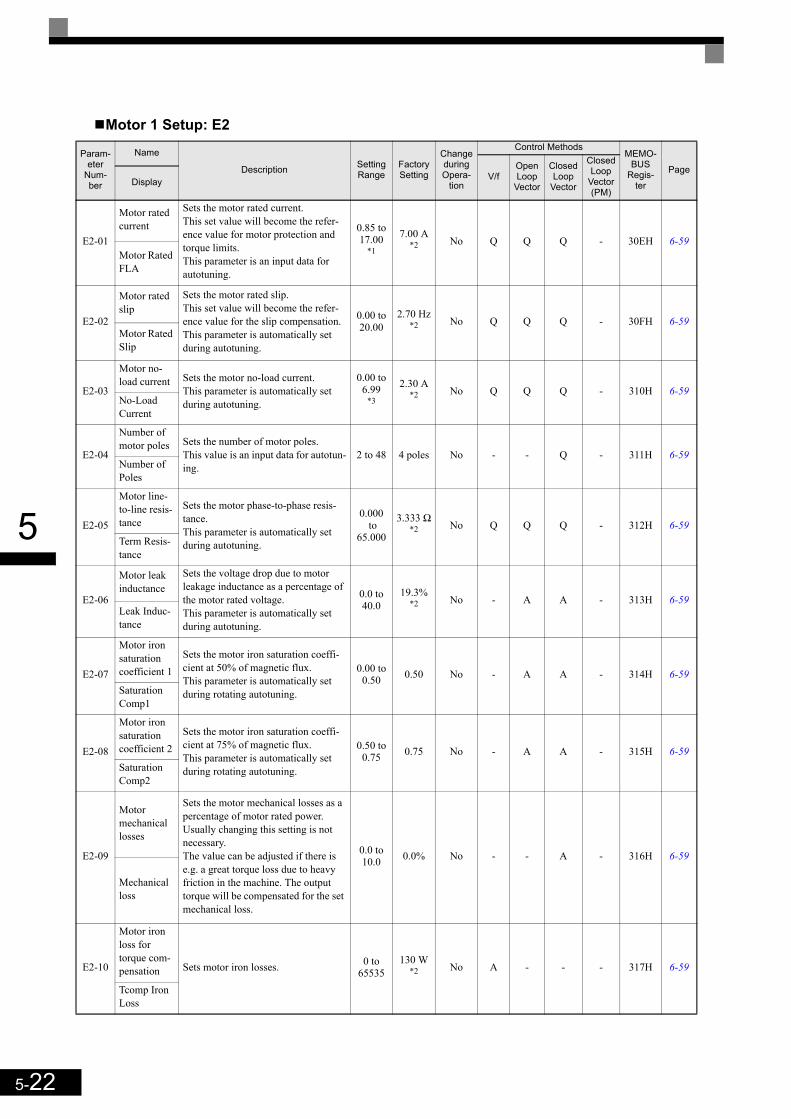
5-22
5
Motor 1 Setup: E2
Param-eter
Num-ber
Name
Description Setting Range
Factory Setting
Change during Opera-
tion
Control MethodsMEMO-
BUSRegis-
ter
PageV/f
Open Loop
Vector
Closed Loop
Vector
Closed Loop
Vector (PM)
Display
E2-01
Motor rated current
Sets the motor rated current.This set value will become the refer-ence value for motor protection and torque limits.This parameter is an input data for autotuning.
0.85 to 17.00
*1
7.00 A*2 No Q Q Q - 30EH 6-59
Motor Rated FLA
E2-02
Motor rated slip
Sets the motor rated slip.This set value will become the refer-ence value for the slip compensation.This parameter is automatically set during autotuning.
0.00 to 20.00
2.70 Hz*2 No Q Q Q - 30FH 6-59
Motor Rated Slip
E2-03
Motor no-load current Sets the motor no-load current.
This parameter is automatically set during autotuning.
0.00 to 6.99
*3
2.30 A*2 No Q Q Q - 310H 6-59
No-Load Current
E2-04
Number of motor poles Sets the number of motor poles.
This value is an input data for autotun-ing.
2 to 48 4 poles No - - Q - 311H 6-59Number of Poles
E2-05
Motor line-to-line resis-tance
Sets the motor phase-to-phase resis-tance.This parameter is automatically set during autotuning.
0.000 to
65.000
3.333 Ω*2 No Q Q Q - 312H 6-59
Term Resis-tance
E2-06
Motor leak inductance
Sets the voltage drop due to motor leakage inductance as a percentage of the motor rated voltage.This parameter is automatically set during autotuning.
0.0 to 40.0
19.3%*2 No - A A - 313H 6-59
Leak Induc-tance
E2-07
Motor iron saturation coefficient 1
Sets the motor iron saturation coeffi-cient at 50% of magnetic flux.This parameter is automatically set during rotating autotuning.
0.00 to 0.50 0.50 No - A A - 314H 6-59
Saturation Comp1
E2-08
Motor iron saturation coefficient 2
Sets the motor iron saturation coeffi-cient at 75% of magnetic flux.This parameter is automatically set during rotating autotuning.
0.50 to 0.75 0.75 No - A A - 315H 6-59
Saturation Comp2
E2-09
Motor mechanical losses
Sets the motor mechanical losses as a percentage of motor rated power.Usually changing this setting is not necessary.The value can be adjusted if there is e.g. a great torque loss due to heavy friction in the machine. The output torque will be compensated for the set mechanical loss.
0.0 to 10.0 0.0% No - - A - 316H 6-59
Mechanical loss
E2-10
Motor iron loss for torque com-pensation Sets motor iron losses. 0 to
65535130 W
*2 No A - - - 317H 6-59
Tcomp Iron Loss
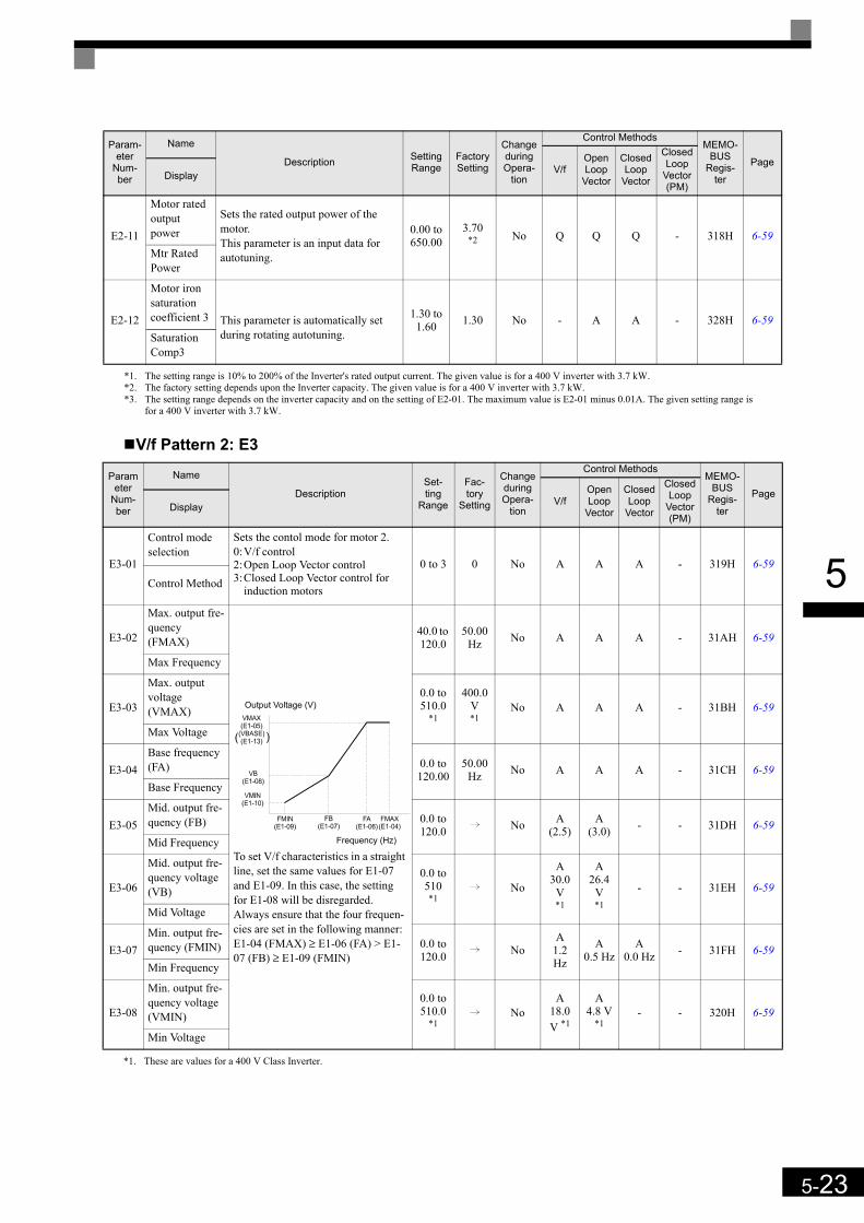
5-23
5
V/f Pattern 2: E3
E2-11
Motor rated output power
Sets the rated output power of the motor.This parameter is an input data for autotuning.
0.00 to 650.00
3.70*2 No Q Q Q - 318H 6-59
Mtr Rated Power
E2-12
Motor iron saturation coefficient 3 This parameter is automatically set
during rotating autotuning.
1.30 to 1.60 1.30 No - A A - 328H 6-59
Saturation Comp3
*1. The setting range is 10% to 200% of the Inverter's rated output current. The given value is for a 400 V inverter with 3.7 kW.*2. The factory setting depends upon the Inverter capacity. The given value is for a 400 V inverter with 3.7 kW.*3. The setting range depends on the inverter capacity and on the setting of E2-01. The maximum value is E2-01 minus 0.01A. The given setting range is
for a 400 V inverter with 3.7 kW.
Parameter
Num-ber
Name
DescriptionSet-ting
Range
Fac-tory
Setting
Change during Opera-
tion
Control MethodsMEMO-
BUSRegis-
ter
PageV/f
Open Loop
Vector
Closed Loop
Vector
Closed Loop
Vector (PM)
Display
E3-01
Control mode selection
Sets the contol mode for motor 2.0:V/f control2:Open Loop Vector control3:Closed Loop Vector control for
induction motors
0 to 3 0 No A A A - 319H 6-59
Control Method
E3-02
Max. output fre-quency (FMAX)
To set V/f characteristics in a straight line, set the same values for E1-07 and E1-09. In this case, the setting for E1-08 will be disregarded.Always ensure that the four frequen-cies are set in the following manner:E1-04 (FMAX) ≥ E1-06 (FA) > E1-07 (FB) ≥ E1-09 (FMIN)
40.0 to 120.0
50.00 Hz No A A A - 31AH 6-59
Max Frequency
E3-03
Max. output voltage (VMAX)
0.0 to 510.0
*1
*1. These are values for a 400 V Class Inverter.
400.0 V*1
No A A A - 31BH 6-59
Max Voltage
E3-04Base frequency (FA) 0.0 to
120.00 50.00
Hz No A A A - 31CH 6-59Base Frequency
E3-05Mid. output fre-quency (FB) 0.0 to
120.0 i No A(2.5)
A(3.0) - - 31DH 6-59
Mid Frequency
E3-06
Mid. output fre-quency voltage (VB)
0.0 to 510 *1
i No
A30.0
V*1
A26.4
V*1
- - 31EH 6-59
Mid Voltage
E3-07Min. output fre-quency (FMIN) 0.0 to
120.0 i NoA
1.2 Hz
A0.5 Hz
A0.0 Hz - 31FH 6-59
Min Frequency
E3-08
Min. output fre-quency voltage (VMIN)
0.0 to 510.0
*1i No
A18.0 V *1
A4.8 V
*1- - 320H 6-59
Min Voltage
Param-eter
Num-ber
Name
Description Setting Range
Factory Setting
Change during Opera-
tion
Control MethodsMEMO-
BUSRegis-
ter
PageV/f
Open Loop
Vector
Closed Loop
Vector
Closed Loop
Vector (PM)
Display
Output Voltage (V)
Frequency (Hz)

5-24
5
Motor 2 Setup: E4
Param-eter
Num-ber
Name
Description Setting Range
Factory Setting
Change during Opera-
tion
Control MethodsMEMO-
BUSRegister
PageV/f
Open Loop
Vector
Closed Loop
Vector
Closed Loop
Vector (PM)
Display
E4-01
Motor rated current
Sets the motor rated current.This set value will become the refer-ence value for motor protection and torque limits.This parameter is an input data for autotuning.
0.85 to 17.00
*1
*1. The setting range is 10% to 200% of the Inverter's rated output current. The given value is for a 400 V inverter with 3.7 kW.
7.00 A*2
*2. The factory setting depends upon the Inverter capacity. The given value is for a 400 V inverter with 3.7 kW.
No A A A - 321H 6-59Motor Rated FLA
E4-02
Motor rated slip
Sets the motor rated slip.This set value will become the refer-ence value for the slip compensation.This parameter is automatically set during autotuning.
0.00 to 20.00
2.70 Hz*2 No A A A - 322H 6-59
Motor Rated Slip
E4-03
Motor no-load current Sets the motor no-load current.
This parameter is automatically set during autotuning.
0.00 to 13.99
*3
*3. The setting range depends on the inverter capacity and on the setting of E2-01. The maximum value is E2-01 minus 0.01A. The given setting range is for a400 V inverter with 3.7 kW.
2.30 A*2 No A A A - 323H 6-59
No-Load Current
E4-04
Number of motor poles Sets the number of motor poles.
This value is an input data for autotun-ing.
2 to 48 4 poles No - - A - 324H 6-59Number of Poles
E4-05
Motor line-to-line resis-tance
Sets the motor phase-to-phase resis-tance.This parameter is automatically set during autotuning.
0.000 to
65.000
3.333 Ω*2 No A A A - 325H 6-59
Term Resis-tance
E4-06
Motor leak inductance
Sets the voltage drop due to motor leakage inductance as a percentage of the motor rated voltage.This parameter is automatically set during autotuning.
0.0 to 40.0
19.3%*2 No - A A - 326H 6-59
Leak Induc-tance
E4-07
Motor rated power
Sets the motor rated power. 0.00 to 650.00
3.70 kW No A A A - 327H 6-59
Mtr Rated Power
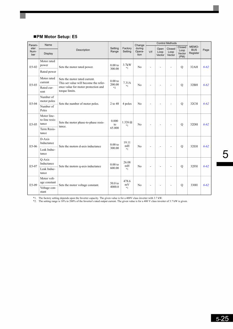
5-25
5
PM Motor Setup: E5
Param-eter
Num-ber
Name
Description Setting Range
Factory Setting
Change during Opera-
tion
Control MethodsMEMO-
BUSRegister
PageV/f
Open Loop
Vector
Closed Loop
Vector
Closed Loop
Vector (PM)
Display
E5-02
Motor rated power Sets the motor rated power. 0.00 to
300.003.7kW
*1
*1. The factory setting depends upon the Inverter capacity. The given value is for a 400V class inverter with 3.7 kW.
No - - - Q 32AH 6-62Rated power
E5-03
Motor rated current
Sets the motor rated current.This set value will become the refer-ence value for motor protection and torque limits.
0.00 to 200.00
*2
*2. The setting range is 10% to 200% of the Inverter's rated output current. The given value is for a 400 V class inverter of 3.7 kW is given.
7.31A*1 No - - - Q 32BH 6-62
Rated cur-rent
E5-04
Number of motor poles
Sets the number of motor poles. 2 to 48 4 poles No - - - Q 32CH 6-62Number of Poles
E5-05
Motor line-to-line resis-tance Sets the motor phase-to-phase resis-
tance.
0.000 to
65.000
1.326 Ω*1 No - - - Q 32DH 6-62
Term Resis-tance
E5-06
D-Axis Inductance
Sets the motors d-axis inductance 0.00 to 300.00
19.11 mH*1
No - - - Q 32EH 6-62Leak Induc-tance
E5-07
Q-Axis Inductance
Sets the motors q-axis inductance 0.00 to 600.00
26.08 mH*1
No - - - Q 32FH 6-62Leak Induc-tance
E5-09
Motor volt-age constant
Sets the motor voltage constant. 50.0 to 4000.0
478.6mV*1
No - - - Q 330H 6-62Voltage con-stant

5-26
5
Option Parameters: F
PG Option Setup: F1
Param-eter
Num-ber
Name
Description Setting Range
Factory Setting
Change during Opera-
tion
Control MethodsMEMO-
BUSRegister
PageV/f
Open Loop
Vector
Closed Loop
Vector
Closed Loop
Vector (PM)
Display
F1-01
PG constantSets the number of PG pulses per revolution
0 to 60000
i No - -
Q1024 -
380H 6-72PG Pulses/Rev
512, 1024*1,
2048- Q
2048
F1-02
Operation selection at PG open circuit (PGO)
Sets the PG disconnection stopping method.0:Ramp to stop (Deceleration to
stop using the deceleration time 1, C1-02.)
1:Coast to stop2:Fast stop (Emergency stop using
the deceleration time in C1-09.)3:Continue operation (To protect
the motor or machinery, avoid to use this setting.)
0 to 3 1 No - - A A 381H 6-74
PG Fdbk Loss Sel
F1-03
Operation selection at overspeed (OS)
Sets the stopping method when an overspeed (OS) fault occurs.0:Ramp to stop (Deceleration to
stop using the deceleration time 1, C1-02.)
1:Coast to stop2:Fast stop (Emergency stop using
the deceleration time in C1-09.)3:Continue operation (To protect
the motor or machinery, avoid to use this setting.)
0 to 3 1 No - - A A 382H 6-74
PG Overspeed Sel
F1-04
Operation selection at speed deviation
Sets the stopping method when a speed deviation (DEV) fault occurs.0:Ramp to stop (Deceleration to
stop using the deceleration time 1, C1-02.)
1:Coast to stop2:Fast stop (Emergency stop using
the deceleration time in C1-09.)3:Continue operation (DEV is dis-
played and operation continued.)
0 to 3 3 No - - A A 383H 6-74
PG Deviation Sel
F1-05
PG rotation direction
0:Phase A leads with forward run command. (Phase B leads with reverse run command; Counter Clockwise rotation)
1:Phase B leads with forward run command. (Phase A leads with reverse run command; Clock-wise rotation)
0 or 1 0 No - - Q Q 384H6-636-73
PG Rotation Sel
F1-06
PG division rate (PG pulse mon-itor)
Sets the division ratio for the PG speed control card pulse output.Division ratio = (1+ n) /m (n=0 or 1 m=1 to 32)The first digit of the value of F1-06 stands for n, the second and the third stands for m.This parameter is effective only when a PG-B2 is used.The possible division ratio settings are: 1/32 ≤ F1-06 ≤ 1.
1 to 132 1 No - - A A 385H 6-73
PG Output Ratio
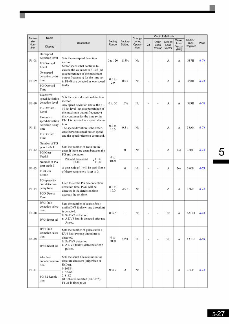
5-27
5
F1-08
Overspeed detection level Sets the overspeed detection
method.Motor speeds that continue to exceed the value set in F1-08 (set as a percentage of the maximum output frequency) for the time set in F1-09 are detected as overspeed faults.
0 to 120 115% No - - A A 387H 6-74PG Overspd Level
F1-09
Overspeed detection delay time 0.0 to
2.0 0.0 s No - - A A 388H 6-74PG Overspd Time
F1-10
Excessive speed deviation detection level
Sets the speed deviation detection method.Any speed deviation above the F1-10 set level (set as a percentage of the maximum output frequency) that continues for the time set in F1-11 is detected as a speed devia-tion.The speed deviation is the differ-ence between actual motor speed and the speed reference command.
0 to 50 10% No - - A A 389H 6-74PG Deviate Level
F1-11
Excessive speed deviation detection delay time
0.0 to 10.0 0.5 s No - - A A 38AH 6-74
PG Deviate Time
F1-12
Number of PG gear teeth 1 Sets the number of teeth on the
gears if there are gears between the PG and the motor.
A gear ratio of 1 will be used if one of these parameters is set to 0.
0 to 1000
0 No - - A No 38BH 6-73PG#Gear Teeth1
F1-13
Number of PG gear teeth 2
0 No - - A No 38CH 6-73PG#Gear Teeth2
F1-14
PG open-cir-cuit detection delay time
Used to set the PG disconnection detection time. PGO will be detected if the detection time exceeds the set time.
0.0 to 10.0 2.0 s No - - A A 38DH 6-73
PGO Detect Time
F1-18
DV3 fault detection selec-tion
Sets the number of scans (5ms) until a DV3 fault (wrong direction) is detected.0:No DV3 detectionn: A DV3 fault is detected after n x
5msec.
0 to 5 1 No - - No A 3ADH 6-74
DV3 detect sel
F1-19
DV4 fault detection selec-tion
Sets the number of pulses until a DV4 fault (wrong direction) is detected.0:No DV4 detectionn: A DV3 fault is detected after n
pulses.
0 to 5000 1024 No - - No A 3AEH 6-74
DV4 detect sel
F1-21
Absolute encoder resolu-tion
Sets the serial line resolution for absolute encoders (Hiperface or EnDat).0:163841:327682:8192(if EnDat is selected (n8-35=5), F1-21 is fixed to 2)
0 to 2 2 No - - - A 3B0H 6-73
PG-F2 Resolu-tion
Param-eter
Num-ber
Name
Description Setting Range
Factory Setting
Change during Opera-
tion
Control MethodsMEMO-
BUSRegister
PageV/f
Open Loop
Vector
Closed Loop
Vector
Closed Loop
Vector (PM)
Display
PG Input Pulses x 60F1-01
F1-13F1-12
x

5-28
5
F1-22
Magnet posi-tion offset Sets the Offset between the rotor
magnet and encoder zero position. 0 to 360 60 ° No - - - A 3B1H 6-73Mag Theta Comp
F1-25
Encoder copy selection
Used to memorize encoder and motor data in the encoder memory(for Hiperface and EnDat encod-ers)0:Normal operation1:WRITE (Inverter to encoder)2:COPY (Encoder to inverter)3:VERIFY
0 to 3 0 No - - - A 3B4H 6-75
Enc Copy Sel
F1-26
Encoder copy write permis-sion selection
Sets wether saving parameters in the encoder is permitted or not.0:Write prohibited1:Write permitted
0 or 1 0 No - - - A 3B5H 6-75Write Allow-able
*1. Can be set only if HIPEFACEy is selected as encoder type.
Param-eter
Num-ber
Name
Description Setting Range
Factory Setting
Change during Opera-
tion
Control MethodsMEMO-
BUSRegister
PageV/f
Open Loop
Vector
Closed Loop
Vector
Closed Loop
Vector (PM)
Display

5-29
5
Analog Monitor Cards: F4
Parameter
Num-ber
Name Description Setting Range
Factory Setting
Change during Opera-
tion
Control MethodsMEMOBUS
Regis-ter
PageV/f
Open Loop
Vector
Closed Loop
Vector
Closed Loop
Vector (PM)
F4-01
Channel 1 monitor selection Using an AO-08 option card the
possible outputs signal is 0 to +10V only. The setting of F4-07 and F4-08 has no effect.Sets the channel 1 item bias to 100%/10 V when the analog moni-tor card is used.This function is enabled when the analog monitor card is used.
Monitor selection: Sets the number of the monitor item to be output. (Numerical portion of U1-
)4, 10, 11, 12, 13, 14, 25, 28, 34, 35, 39 and 40 cannot be set.
Gain: Sets the percentage of the monitor item, which is equal to 10V output.
Bias: Sets the percentage of the monitor item, which is equal to 0V output.
1 to 56i No
A2
A2
A2 -
391H 6-25AO Ch1 Select 1 to 75 - - A
5
F4-02Channel 1 gain 0.0 to
1000.0 100.0% Yes A A A A 392H 6-25AO Ch1 Gain
F4-03Channel 2 monitor selection 1 to 56
3 NoA A A -
393H 6-25AO Ch2 Select 1 to 75 - - - A
F4-04Channel 2 gain 0.0 to
1000.0 50.0% Yes A A A A 394H 6-25AO Ch2 Gain
F4-05Channel 1 output monitor bias
-110.0 to
110.00.0% Yes A A A A 395H 6-25
AO Ch1 Bias
F4-06
Channel 2 output monitor bias
-110.0 to
110.00.0% Yes A A A A 396H 6-25
AO Ch2 Bias
F4-07
Analog output sig-nal level for chan-nel 1
Selects the analog output signal level for channel 1 (effective for the AO-12 option card only).0: 0 to 10V1: -10 to +10Using an AO-08 option card the possible outputs signal is 0 to +10V only. The setting of F4-07 and F4-08 has no effect.
0 or 1 0 No A A A A 397H 6-25
AO Opt Level Sel
F4-08
Analog output sig-nal level for chan-nel 2
0 or 1 0 No A A A A 398H 6-25
AO Opt Level Sel
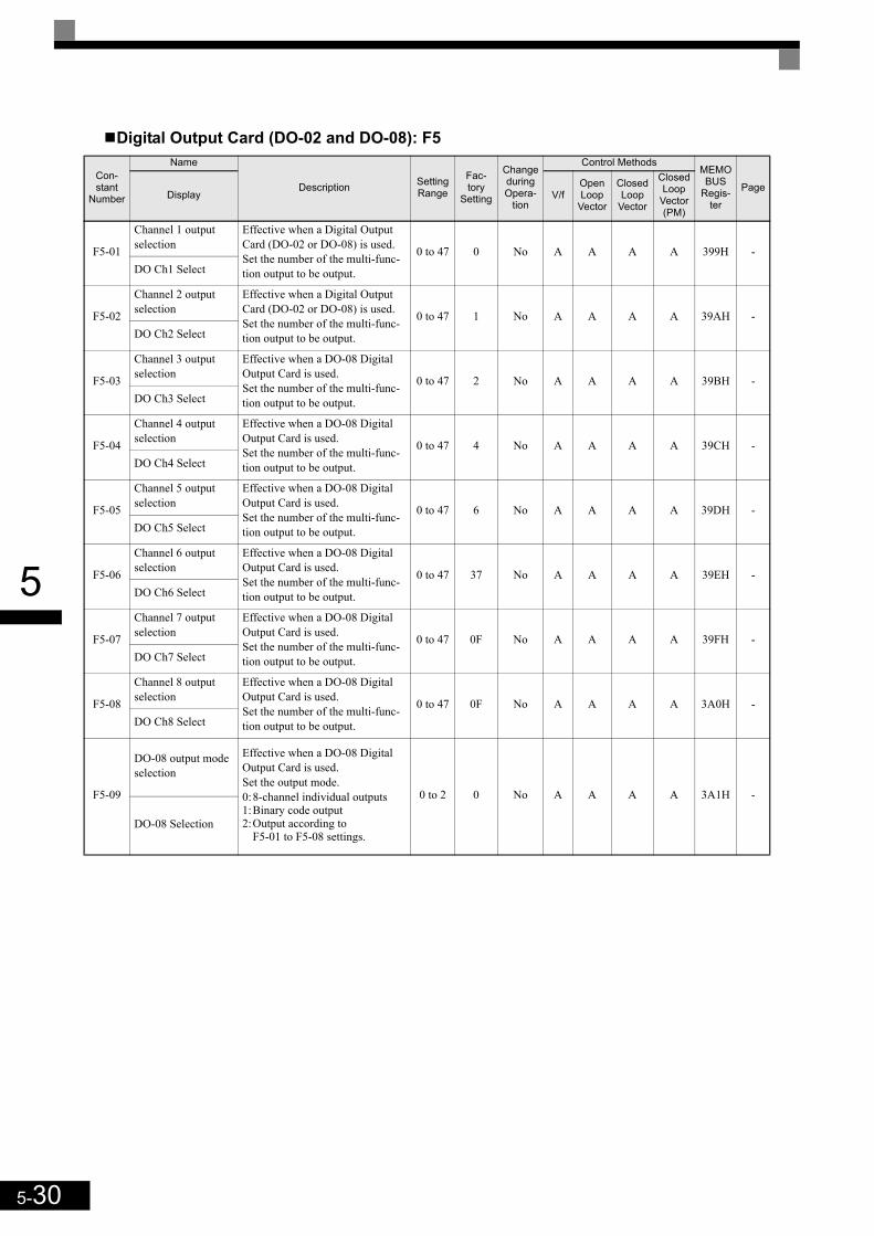
5-30
5
Digital Output Card (DO-02 and DO-08): F5
Con-stant
Number
Name
Description Setting Range
Fac-tory
Setting
Change during Opera-
tion
Control MethodsMEMOBUS
Regis-ter
PageDisplay V/f
OpenLoop
Vector
Closed Loop
Vector
Closed Loop
Vector (PM)
F5-01
Channel 1 output selection
Effective when a Digital Output Card (DO-02 or DO-08) is used.Set the number of the multi-func-tion output to be output.
0 to 47 0 No A A A A 399H -DO Ch1 Select
F5-02
Channel 2 output selection
Effective when a Digital Output Card (DO-02 or DO-08) is used.Set the number of the multi-func-tion output to be output.
0 to 47 1 No A A A A 39AH -DO Ch2 Select
F5-03
Channel 3 output selection
Effective when a DO-08 Digital Output Card is used.Set the number of the multi-func-tion output to be output.
0 to 47 2 No A A A A 39BH -DO Ch3 Select
F5-04
Channel 4 output selection
Effective when a DO-08 Digital Output Card is used.Set the number of the multi-func-tion output to be output.
0 to 47 4 No A A A A 39CH -DO Ch4 Select
F5-05
Channel 5 output selection
Effective when a DO-08 Digital Output Card is used.Set the number of the multi-func-tion output to be output.
0 to 47 6 No A A A A 39DH -DO Ch5 Select
F5-06
Channel 6 output selection
Effective when a DO-08 Digital Output Card is used.Set the number of the multi-func-tion output to be output.
0 to 47 37 No A A A A 39EH -DO Ch6 Select
F5-07
Channel 7 output selection
Effective when a DO-08 Digital Output Card is used.Set the number of the multi-func-tion output to be output.
0 to 47 0F No A A A A 39FH -DO Ch7 Select
F5-08
Channel 8 output selection
Effective when a DO-08 Digital Output Card is used.Set the number of the multi-func-tion output to be output.
0 to 47 0F No A A A A 3A0H -DO Ch8 Select
F5-09
DO-08 output mode selection
Effective when a DO-08 Digital Output Card is used.Set the output mode.0:8-channel individual outputs1:Binary code output2:Output according to
F5-01 to F5-08 settings.
0 to 2 0 No A A A A 3A1H -
DO-08 Selection

5-31
5
Serial Communications Settings: F6
Param-eter
Num-ber
Name
DescriptionSet-ting
Range
Fac-tory
Setting
Change during Opera-
tion
Control MethodsMEMO-
BUSRegister
PageV/f
Open Loop
Vector
Closed Loop
Vector
Closed Loop
Vector (PM)
Display
F6-01
Operation selection after communica-tions error
Sets the stopping method for communications errors.0:Deceleration to stop using the
deceleration time in C1-021:Coast to stop2:Emergency stop using the
deceleration time in C1-093:Continue operation
0 to 3 1 No A A A A 3A2H -
Comm Bus Fault Sel
F6-02
Input level of exter-nal error from Com-munications Option Card
0:Always detect1:Detect during operation 0 or 1 0 No A A A A 3A3H -
EF0 Detection
F6-03
Stopping method for external error from Communica-tions Option Card
0:Deceleration to stop using the deceleration time in C1-02
1:Coast to stop2:Emergency stop using the
deceleration time in C1-093:Continue operation
0 to 3 1 No A A A A 3A4H -
EF0 Fault Action
F6-04Trace Sampling Time - 0 to
60000 0 No A A A A 3A5H -Trace Sample Tim
F6-05Current monitor unit selection
Sets the unit of current monitor0:Ampere1:100%/8192
0 or 1 0 No A A A A 3A6H -Current Unit Sel
F6-06
Torque reference/torque limit selec-tion from communi-cations option card
0:Torque reference/torque limit by communications option disabled.
1:Torque reference/torque limit by communications option enabled.
0 or 1 0 No - - A A 3A7H -
Torque Ref/Lmt Sel
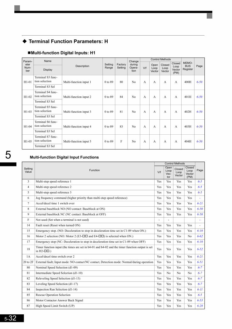
5-32
5
Terminal Function Parameters: H
Multi-function Digital Inputs: H1
Multi-function Digital Input Functions
Param-eter
Num-ber
Name
Description Setting Range
Factory Setting
Change during Opera-
tion
Control MethodsMEMO-
BUSRegister
PageV/f
Open Loop
Vector
Closed Loop
Vector
Closed Loop
Vector (PM)
Display
H1-01Terminal S3 func-tion selection Multi-function input 1 0 to 89 80 No A A A A 400H 6-50Terminal S3 Sel
H1-02Terminal S4 func-tion selection Multi-function input 2 0 to 89 84 No A A A A 401H 6-50Terminal S3 Sel
H1-03Terminal S5 func-tion selection Multi-function input 3 0 to 89 81 No A A A A 402H 6-50Terminal S3 Sel
H1-04Terminal S6 func-tion selection Multi-function input 4 0 to 89 83 No A A A A 403H 6-50Terminal S3 Sel
H1-05Terminal S7 func-tion selection Multi-function input 5 0 to 89 F No A A A A 404H 6-50Terminal S3 Sel
Setting Value Function
Control Methods
PageV/f
Open Loop Vec-tor
Closed Loop
Vector
Closed Loop
Vector (PM)
3 Multi-step speed reference 1 Yes Yes Yes Yes 6-5
4 Multi-step speed reference 2 Yes Yes Yes Yes 6-5
5 Multi-step speed reference 3 Yes Yes Yes Yes 6-5
6 Jog frequency command (higher priority than multi-step speed reference) Yes Yes Yes Yes -
7 Accel/decel time 1 switch over Yes Yes Yes Yes 6-21
8 External baseblock NO (NO contact: Baseblock at ON) Yes Yes Yes Yes 6-50
9 External baseblock NC (NC contact: Baseblock at OFF) Yes Yes Yes Yes 6-50
F Not used (Set when a terminal is not used) - - -
14 Fault reset (Reset when turned ON) Yes Yes Yes Yes -
15 Emergency stop. (NO: Deceleration to stop in deceleration time set in C1-09 when ON.) Yes Yes Yes Yes 6-10
16 Motor 2 selection (NO: Motor 2 (E3- and E4- ) is selected when ON.) Yes Yes Yes No 6-62
17 Emergency stop (NC: Deceleration to stop in deceleration time set in C1-09 when OFF) Yes Yes Yes Yes 6-10
18 Timer function input (the times are set in b4-01 and b4-02 and the timer function output is set in H2- .) Yes Yes Yes Yes 6-52
1A Accel/decel time switch over 2 Yes Yes Yes Yes 6-21
20 to 2F External fault; Input mode: NO contact/NC contact, Detection mode: Normal/during operation Yes Yes Yes Yes 6-51
80 Nominal Speed Selection (d1-09) Yes Yes Yes Yes 6-7
81 Intermediate Speed Selection (d1-10) Yes No No No 6-7
82 Releveling Speed Selection (d1-13) Yes Yes Yes Yes 6-7
83 Leveling Speed Selection (d1-17) Yes Yes Yes Yes 6-7
84 Inspection Run Selection (d1-14) Yes Yes Yes Yes 6-11
85 Rescue Operation Selection Yes Yes Yes Yes 6-5
86 Motor Contactor Answer Back Signal Yes Yes Yes Yes 6-53
87 High Speed Limit Switch (UP) Yes Yes Yes Yes 6-28
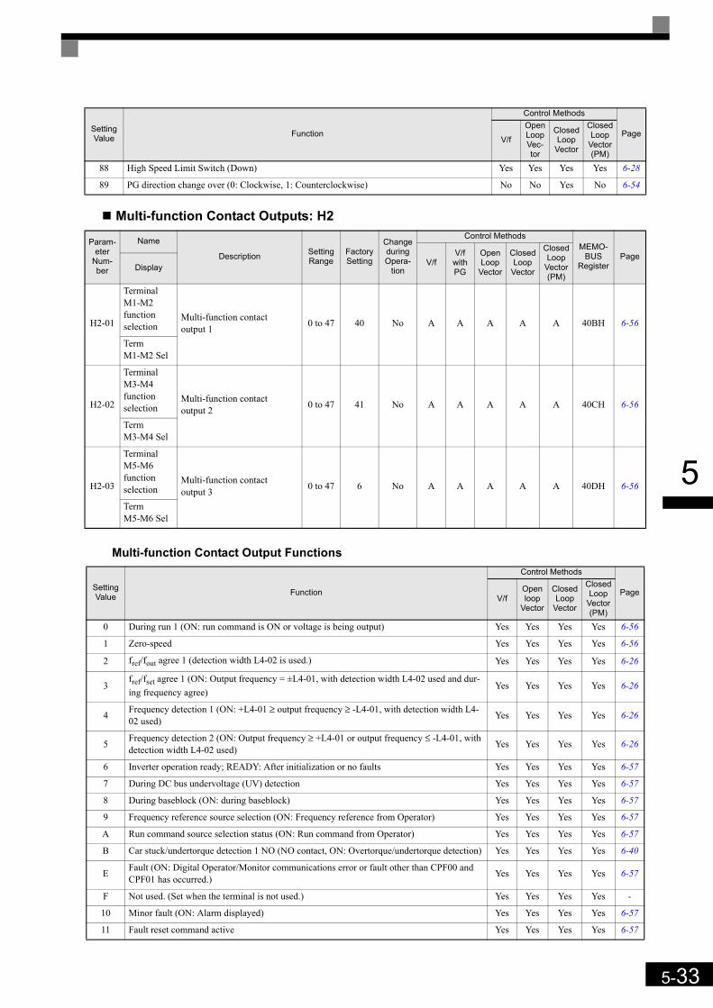
5-33
5
Multi-function Contact Outputs: H2
Multi-function Contact Output Functions
88 High Speed Limit Switch (Down) Yes Yes Yes Yes 6-28
89 PG direction change over (0: Clockwise, 1: Counterclockwise) No No Yes No 6-54
Param-eter
Num-ber
Name
Description Setting Range
Factory Setting
Change during Opera-
tion
Control MethodsMEMO-
BUSRegister
PageV/f
V/f with PG
Open Loop
Vector
Closed Loop
Vector
Closed Loop
Vector (PM)
Display
H2-01
Terminal M1-M2 function selection
Multi-function contact output 1 0 to 47 40 No A A A A A 40BH 6-56
Term M1-M2 Sel
H2-02
Terminal M3-M4 function selection
Multi-function contact output 2 0 to 47 41 No A A A A A 40CH 6-56
Term M3-M4 Sel
H2-03
Terminal M5-M6 function selection
Multi-function contact output 3 0 to 47 6 No A A A A A 40DH 6-56
Term M5-M6 Sel
Setting Value Function
Control Methods
PageV/f
Open loop
Vector
Closed Loop
Vector
Closed Loop
Vector (PM)
0 During run 1 (ON: run command is ON or voltage is being output) Yes Yes Yes Yes 6-56
1 Zero-speed Yes Yes Yes Yes 6-56
2 fref/fout agree 1 (detection width L4-02 is used.) Yes Yes Yes Yes 6-26
3fref/fset agree 1 (ON: Output frequency = ±L4-01, with detection width L4-02 used and dur-ing frequency agree)
Yes Yes Yes Yes 6-26
4 Frequency detection 1 (ON: +L4-01 ≥ output frequency ≥ -L4-01, with detection width L4-02 used) Yes Yes Yes Yes 6-26
5 Frequency detection 2 (ON: Output frequency ≥ +L4-01 or output frequency ≤ -L4-01, with detection width L4-02 used) Yes Yes Yes Yes 6-26
6 Inverter operation ready; READY: After initialization or no faults Yes Yes Yes Yes 6-57
7 During DC bus undervoltage (UV) detection Yes Yes Yes Yes 6-57
8 During baseblock (ON: during baseblock) Yes Yes Yes Yes 6-57
9 Frequency reference source selection (ON: Frequency reference from Operator) Yes Yes Yes Yes 6-57
A Run command source selection status (ON: Run command from Operator) Yes Yes Yes Yes 6-57
B Car stuck/undertorque detection 1 NO (NO contact, ON: Overtorque/undertorque detection) Yes Yes Yes Yes 6-40
E Fault (ON: Digital Operator/Monitor communications error or fault other than CPF00 and CPF01 has occurred.) Yes Yes Yes Yes 6-57
F Not used. (Set when the terminal is not used.) Yes Yes Yes Yes -
10 Minor fault (ON: Alarm displayed) Yes Yes Yes Yes 6-57
11 Fault reset command active Yes Yes Yes Yes 6-57
Setting Value Function
Control Methods
PageV/f
Open Loop Vec-tor
Closed Loop
Vector
Closed Loop
Vector (PM)
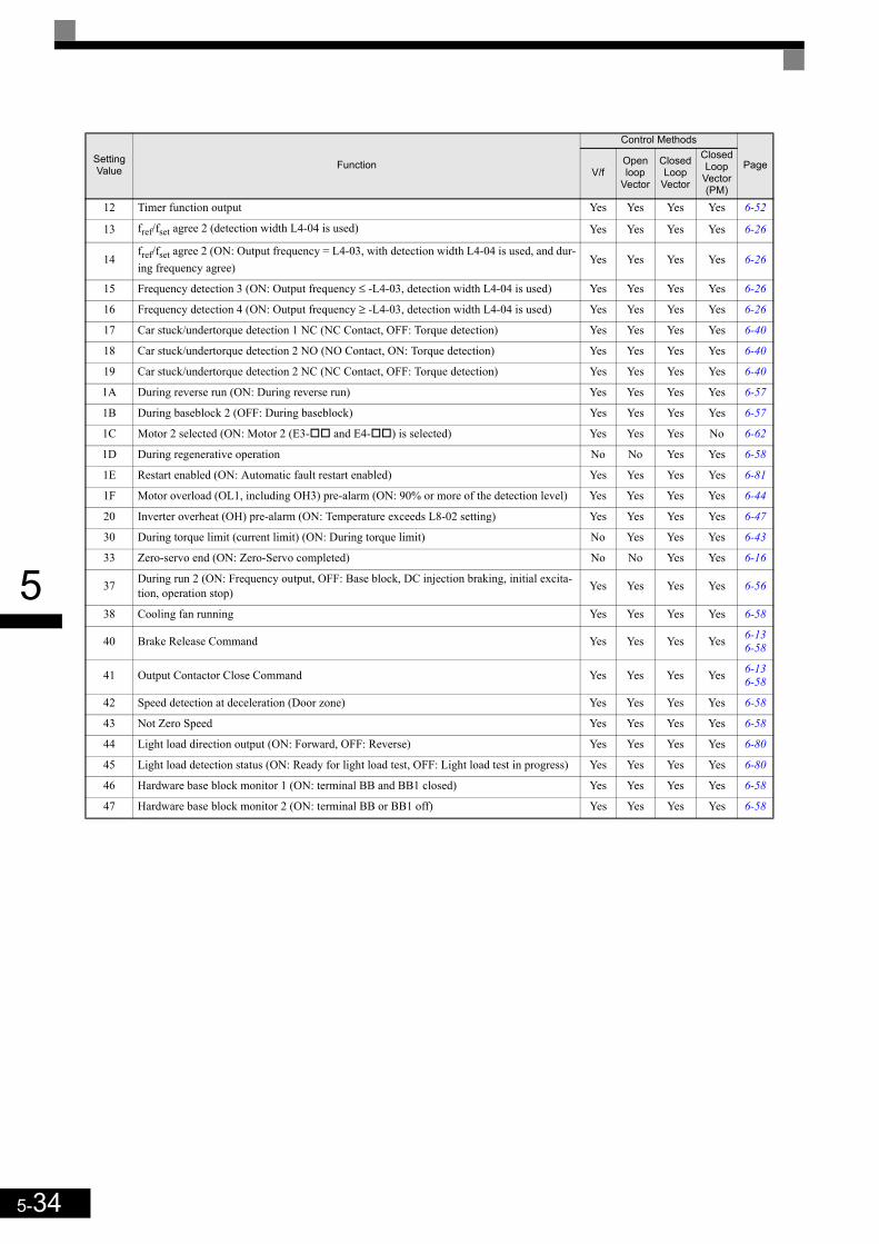
5-34
5
12 Timer function output Yes Yes Yes Yes 6-52
13 fref/fset agree 2 (detection width L4-04 is used) Yes Yes Yes Yes 6-26
14fref/fset agree 2 (ON: Output frequency = L4-03, with detection width L4-04 is used, and dur-ing frequency agree)
Yes Yes Yes Yes 6-26
15 Frequency detection 3 (ON: Output frequency ≤ -L4-03, detection width L4-04 is used) Yes Yes Yes Yes 6-26
16 Frequency detection 4 (ON: Output frequency ≥ -L4-03, detection width L4-04 is used) Yes Yes Yes Yes 6-26
17 Car stuck/undertorque detection 1 NC (NC Contact, OFF: Torque detection) Yes Yes Yes Yes 6-40
18 Car stuck/undertorque detection 2 NO (NO Contact, ON: Torque detection) Yes Yes Yes Yes 6-40
19 Car stuck/undertorque detection 2 NC (NC Contact, OFF: Torque detection) Yes Yes Yes Yes 6-40
1A During reverse run (ON: During reverse run) Yes Yes Yes Yes 6-57
1B During baseblock 2 (OFF: During baseblock) Yes Yes Yes Yes 6-57
1C Motor 2 selected (ON: Motor 2 (E3- and E4- ) is selected) Yes Yes Yes No 6-62
1D During regenerative operation No No Yes Yes 6-58
1E Restart enabled (ON: Automatic fault restart enabled) Yes Yes Yes Yes 6-81
1F Motor overload (OL1, including OH3) pre-alarm (ON: 90% or more of the detection level) Yes Yes Yes Yes 6-44
20 Inverter overheat (OH) pre-alarm (ON: Temperature exceeds L8-02 setting) Yes Yes Yes Yes 6-47
30 During torque limit (current limit) (ON: During torque limit) No Yes Yes Yes 6-43
33 Zero-servo end (ON: Zero-Servo completed) No No Yes Yes 6-16
37 During run 2 (ON: Frequency output, OFF: Base block, DC injection braking, initial excita-tion, operation stop) Yes Yes Yes Yes 6-56
38 Cooling fan running Yes Yes Yes Yes 6-58
40 Brake Release Command Yes Yes Yes Yes 6-136-58
41 Output Contactor Close Command Yes Yes Yes Yes 6-136-58
42 Speed detection at deceleration (Door zone) Yes Yes Yes Yes 6-58
43 Not Zero Speed Yes Yes Yes Yes 6-58
44 Light load direction output (ON: Forward, OFF: Reverse) Yes Yes Yes Yes 6-80
45 Light load detection status (ON: Ready for light load test, OFF: Light load test in progress) Yes Yes Yes Yes 6-80
46 Hardware base block monitor 1 (ON: terminal BB and BB1 closed) Yes Yes Yes Yes 6-58
47 Hardware base block monitor 2 (ON: terminal BB or BB1 off) Yes Yes Yes Yes 6-58
Setting Value Function
Control Methods
PageV/f
Open loop
Vector
Closed Loop
Vector
Closed Loop
Vector (PM)

5-35
5
Analog Inputs: H3
Con-stant
Number
Name
Description Setting Range
Factory Setting
Change during Opera-
tion
Control MethodsMEMOBUS
Regis-ter
PageDisplay V/f
OpenLoop
Vector
Closed Loop
Vector
Closed Loop
Vector (PM)
H3-01*1
AI-14B Channel 1 signal level selection
Selects the input signal level of Channel 1 if an AI-14B option card is installed.0:0 to +10V 1: -10 to +10V
0 or 1 0 No A A A A 410H 6-25
AI-14 CH1 LvlSel
H3-02*1
AI-14B Channel 1 gain
Sets the frequency reference value when 10 V is input as a per-centage of the maximum output frequency set in E1-04.
0.0 to 1000.0 100.0% Yes A A A A 411H 6-25
AI-14 CH1 Gain
H3-03*1
AI-14B Channel 1 bias
Sets the frequency reference value when 0 V is input as a per-centage of the maximum output frequency set in E1-04.
-100.0 to
+100.00.0% Yes A A A A 412H 6-25
AI-14 CH1 Bias
H3-04*1
AI-14B Channel 3 signal level selection
Selects the input signal level of Channel 3 if an AI-14B option card is installed.0:0 to 10V1: -10 to +10V
0 or 1 0 No A A A A 413H 6-25
AI-14 CH3 LvlSel
H3-05*1
AI-14B Channel 3 function selection
Selects the function for the chan-nel 3 input if an AI-14B option card is installed. See the table below for the available functions.
2,3,14 2 No A A A A 414H 6-25AI-14 CH3FuncSel
H3-06*1
AI-14B Channel3 gain
Sets the input level according to the 100% value of the function set in parameter H3-05 when the voltage at channel 3 of the AI-14B option card is 10 V.
0.0 to 1000.0 100.0% Yes A A A A 415H 6-25
AI-14 CH3 Gain
H3-07*1
AI-14B Channel 3 Bias
Sets the input level according to the 0% value of the function set in parameter H3-05 when the voltage at channel 3 of the AI-14B option card is 0 V.
-100.0 to
+100.00.0% Yes A A A A 416H 6-25
AI-14 CH3 Bias
H3-08*1
AI-14B Channel 2 signal level selection
Selects the input signal level of Channel 2 if an AI-14B option card is installed.0:0 to 10V 1: -10 to +10V2:4 to 20 mA.If current input is selected, chan-nel 2 must be set to current input by hardware as well. Refer to the AI-14B manual.
0 to 2 0 No A A A A 417H 6-25
AI-14 CH2 LvlSel
H3-09*1
AI-14B Channel 2 function selection
Selects the function for the chan-nel 2 input if an AI-14B option card is installed. See the table below for the available functions.
2, 3, 14 3 No A A A A 418H 6-25AI-14 CH2FuncSel
H3-10*1
AI-14B Channel 2 Gain
Sets the input level according to the 100% value of the function set in parameter H3-09 when the voltage/current at channel 2 of the AI-14B option card is 10V/20mA.
0.0 to 1000.0 100.0% Yes A A A A 419H 6-25
AI-14 CH2 Gain
H3-11*1
AI-14B Channel 2 Bias
Sets the input level according to the 0% value of the function set in parameter H3-09 when the voltage/current at channel 2 of the AI-14B option card is 0V/0mA.
-100.0 to
+100.00.0% Yes A A A A 41AH 6-25
AI-14 CH2 Bias
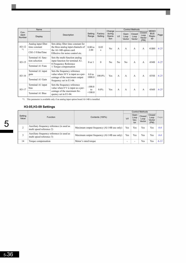
5-36
5
H3-05,H3-09 Settings
H3-12*1
Analog input filter time constant
Sets delay filter time constant for the three analog input channels of the AI-14B option card.Effective for noise control etc.
0.00 to 2.00
0.03s No A A A A 41BH 6-25
CH1-3 FilterTime
H3-15
Terminal A1 func-tion selection
Sets the multi-function analog input function for terminal A1.0:Frequency Reference1:Torque compensation
0 or 1 0 No No No A A 434H 6-25Terminal A1 Func
H3-16
Terminal A1 input gain
Sets the frequency reference value when 10 V is input as a per-centage of the maximum output frequency set in E1-04.
0.0 to 1000.0 100.0% Yes A A A A 435H 6-25
Terminal A1 Gain
H3-17
Terminal A1 input bias
Sets the frequency reference value when 0 V is input as a per-centage of the maximum fre-quency set in E1-04.
-100.0 to
+100.00.0% Yes A A A A 436H 6-25
Terminal A1 Bias
*1. This parameter is available only if an analog input option board AI-14B is installed.
Setting Value Function Contents (100%)
Control Methods
PageV/f
Open Loop Vec-tor
Closed Loop
Vector
Closed Loop
Vector (PM)
2 Auxiliary frequency reference (is used as multi speed reference 2) Maximum output frequency (AI-14B use only) Yes Yes Yes Yes 6-6
3 Auxiliary frequency reference (is used as multi speed reference 3) Maximum output frequency (AI-14B use only) Yes Yes Yes Yes 6-6
14 Torque compensation Motor’s rated torque - - Yes Yes 6-13
Con-stant
Number
Name
Description Setting Range
Factory Setting
Change during Opera-
tion
Control MethodsMEMOBUS
Regis-ter
PageDisplay V/f
OpenLoop
Vector
Closed Loop
Vector
Closed Loop
Vector (PM)

5-37
5
Protection Function Parameters: L
Motor Overload: L1
Power Loss Settings: L2
Para-meter Num-ber
Name
Description Setting Range
Factory Setting
Change during Opera-
tion
Control MethodsMEMO-
BUSRegister
PageV/f
Open Loop
Vector
Closed Loop
Vector
Closed Loop
Vector (PM)
Display
L1-01
Motor pro-tection selec-tion
Sets whether the motor thermal over-load protection function is enabled or disabled.0:Disabled1:General-purpose motor protection
(fan cooled motor)2: Inverter motor protection (exter-
nally cooled motor)3:Vector motor protection
When the Inverter power supply is turned off, the thermal value is reset, so even if this parameter is set to 1, protection may not be effective.
5:Permanent magnet constant torque motor protection
0 to 3
i No
Q1
Q1
Q1 -
480H 6-44
MOL Fault Select 0 or 5 - - - A
5
L1-02
Motor pro-tection time constant
Sets the electric thermal detection time in seconds units.Usually changing this setting is not necessary.The factory setting is 150% overload for one minute. When the motor's overload capabil-ity is known, also set the overload resistance protection time for when the motor is hot started.
0.1 to5.0 1.0 min No A A A -A 481H 6-44
MOL Time Const
Para-meter Num-ber
Name
Description Setting Range
Factory Setting
Change during Opera-
tion
Control MethodsMEMO-
BUSRegister
PageV/f
Open Loop
Vector
Closed Loop
Vector
Closed Loop
Vector (PM)
Display
L2-05
Undervoltage detection level Sets the DC bus undervoltage
(UV) detection level (DC bus voltage).
150 to210*1
*1. These are values for a 200 V class Inverter. The value for a 400 V class Inverter is the double.
190 VDC*1 No A A A A 489H -
PUV Det Level
L2-11
Rescue Opera-tion DC bus Voltage Sets the DC bus voltage during
rescue operation.0 to
400*1 0 VDC No A A A A 4CBH 6-77
Volt@batterydr

5-38
5
Stall Prevention: L3
Reference Detection: L4
Para-meter Num-ber
Name
Description Setting Range
Factory Setting
Change during Opera-
tion
Control MethodsMEMO-
BUSRegister
PageV/f
Open Loop
Vector
Closed Loop
Vector
Closed Loop
Vector (PM)
Display
L3-01
Stall prevention selection dur-ing accel
0:Disabled (Acceleration as set. With a too heavy load, the motor may stall.)
1:Enabled (Acceleration stopped when L3-02 level is exceeded. Acceleration starts again when the current has fallen below the stall prevention level).
2: Intelligent acceleration mode (Using the L3-02 level as a basis, acceleration is automatically adjusted. The set acceleration time is disregarded.)
0 to 2 1 No A A - - 48FH 6-23
StallP Accel Sel
L3-02
Stall prevention level during accel
Sets the stall prevention during acceleration operation current level as a percentage of Inverter rated current.Effective when L3-01 is set to 1 or 2.Usually changing this setting is not necessary. Reduce the setting when the motor stalls.
0 to 200 150% No A A - - 490H 6-23
StallP Accel Lvl
L3-05
Stall prevention selection dur-ing running
Selects the stall prevention during running.0:Disabled (Runs as set. With a
heavy load, the motor may stall.)1:Deceleration using deceleration
time 1 (C1-02.)2:Deceleration using deceleration
time 2 (C1-04.)
0 to 2 1 No A - - - 493H 6-40
StallP Run Sel
L3-06
Stall prevention level during running
Set the stall prevention during run-ning operation current level as a percentage of the Inverter rated cur-rent.Effective when L3-05 is 1 or 2.Usually changing this setting is not necessary.Reduce the setting when the motor stalls.
30 to 200 150% No A - - - 494H 6-40
StallP Run Level
Parameter
Num-ber
Name
Description Setting Range
Factory Setting
Change during Opera-
tion
Control MethodsMEMO-
BUSRegister
PageV/f
Open Loop
Vector
Closed Loop
Vector
Closed Loop
Vector (PM)
Display
L4-01
Speed agreement detection level
Effective when "fout/fset agree 1", "Frequency detection 1" or "Frequency detection 2" is set for a multi-function output.
0.0 to 120.0
i No
A0.0Hz
A0.0Hz
A0.0Hz -
499H 6-26Spd Agree Level 0.0 to
100.0 - - - A0.0%
L4-02
Speed agreement detection width
Effective when "fref/fout agree 1", "fout/fset agree 1" or "Fre-quency detection 1" or "Fre-quency detection 2" is set for a multi-function output.
0.0 to 20.0
i No
A2.0Hz
A2.0Hz
A2.0Hz -
49AH 6-26
Spd Agree Width 0.0 to 40.0% - - - A
4.0%
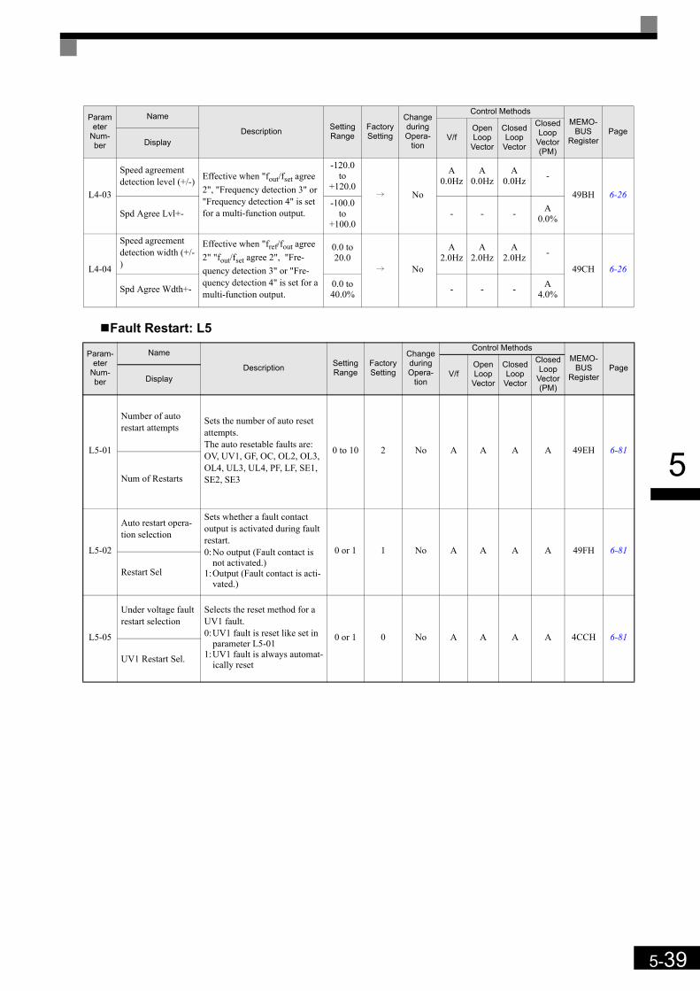
5-39
5
Fault Restart: L5
L4-03
Speed agreement detection level (+/-) Effective when "fout/fset agree
2", "Frequency detection 3" or "Frequency detection 4" is set for a multi-function output.
-120.0 to
+120.0i No
A0.0Hz
A0.0Hz
A0.0Hz -
49BH 6-26
Spd Agree Lvl+--100.0
to +100.0
- - - A0.0%
L4-04
Speed agreement detection width (+/-)
Effective when "fref/fout agree 2" "fout/fset agree 2", "Fre-quency detection 3" or "Fre-quency detection 4" is set for a multi-function output.
0.0 to 20.0
i No
A2.0Hz
A2.0Hz
A2.0Hz -
49CH 6-26
Spd Agree Wdth+- 0.0 to 40.0% - - - A
4.0%
Param-eter
Num-ber
Name
Description Setting Range
Factory Setting
Change during Opera-
tion
Control MethodsMEMO-
BUSRegister
PageV/f
Open Loop
Vector
Closed Loop
Vector
Closed Loop
Vector (PM)
Display
L5-01
Number of auto restart attempts
Sets the number of auto reset attempts.The auto resetable faults are:OV, UV1, GF, OC, OL2, OL3, OL4, UL3, UL4, PF, LF, SE1, SE2, SE3
0 to 10 2 No A A A A 49EH 6-81
Num of Restarts
L5-02
Auto restart opera-tion selection
Sets whether a fault contact output is activated during fault restart.0:No output (Fault contact is
not activated.)1:Output (Fault contact is acti-
vated.)
0 or 1 1 No A A A A 49FH 6-81
Restart Sel
L5-05
Under voltage fault restart selection
Selects the reset method for a UV1 fault.0:UV1 fault is reset like set in
parameter L5-011:UV1 fault is always automat-
ically reset
0 or 1 0 No A A A A 4CCH 6-81
UV1 Restart Sel.
Parameter
Num-ber
Name
Description Setting Range
Factory Setting
Change during Opera-
tion
Control MethodsMEMO-
BUSRegister
PageV/f
Open Loop
Vector
Closed Loop
Vector
Closed Loop
Vector (PM)
Display
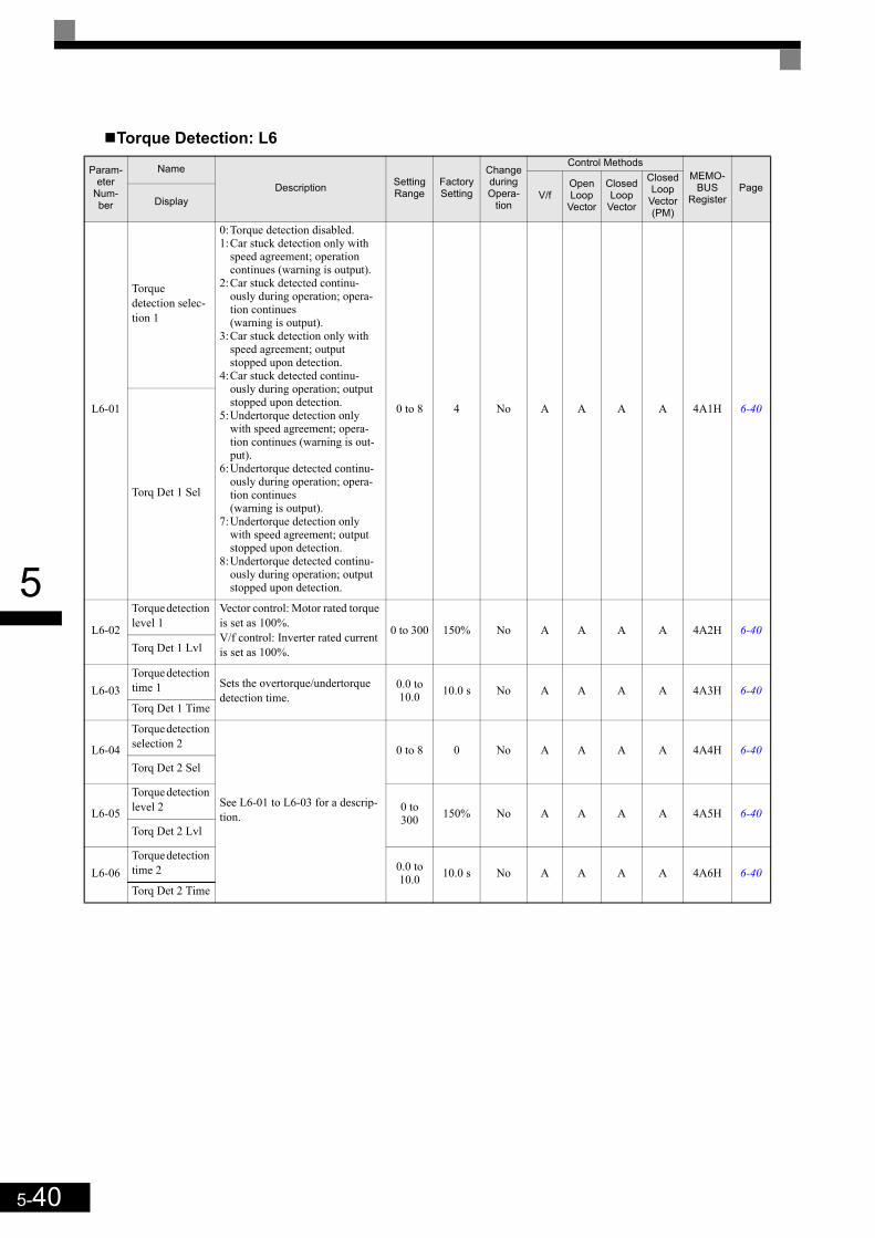
5-40
5
Torque Detection: L6
Param-eter
Num-ber
Name
Description Setting Range
Factory Setting
Change during Opera-
tion
Control MethodsMEMO-
BUSRegister
PageV/f
Open Loop
Vector
Closed Loop
Vector
Closed Loop
Vector (PM)
Display
L6-01
Torque detection selec-tion 1
0:Torque detection disabled.1:Car stuck detection only with
speed agreement; operation continues (warning is output).
2:Car stuck detected continu-ously during operation; opera-tion continues (warning is output).
3:Car stuck detection only with speed agreement; output stopped upon detection.
4:Car stuck detected continu-ously during operation; output stopped upon detection.
5:Undertorque detection only with speed agreement; opera-tion continues (warning is out-put).
6:Undertorque detected continu-ously during operation; opera-tion continues (warning is output).
7:Undertorque detection only with speed agreement; output stopped upon detection.
8:Undertorque detected continu-ously during operation; output stopped upon detection.
0 to 8 4 No A A A A 4A1H 6-40
Torq Det 1 Sel
L6-02
Torque detection level 1
Vector control: Motor rated torque is set as 100%.V/f control: Inverter rated current is set as 100%.
0 to 300 150% No A A A A 4A2H 6-40Torq Det 1 Lvl
L6-03Torque detection time 1 Sets the overtorque/undertorque
detection time.0.0 to 10.0 10.0 s No A A A A 4A3H 6-40
Torq Det 1 Time
L6-04
Torque detection selection 2
See L6-01 to L6-03 for a descrip-tion.
0 to 8 0 No A A A A 4A4H 6-40Torq Det 2 Sel
L6-05
Torque detection level 2 0 to
300 150% No A A A A 4A5H 6-40Torq Det 2 Lvl
L6-06Torque detection time 2 0.0 to
10.0 10.0 s No A A A A 4A6H 6-40Torq Det 2 Time

5-41
5
Torque Limits: L7
Parameter
Num-ber
Name
DescriptionSet-ting
Range
Fac-tory
Setting
Change during Opera-
tion
Control MethodsMEMO-
BUSRegister
PageV/f
Open Loop
Vector
Closed Loop
Vector
Closed Loop
Vector (PM)
Display
L7-01Forward drive torque limit
Sets the torque limit value as a per-centage of the motor rated torque.Four individual regions can be set.
0 to 300 300% No - A A A 4A7H 6-43
Torq Limit Fwd
L7-02Reverse drive torque limit 0 to
300 300% No - A A A 4A8H 6-43Torq Limit Rev
L7-03
Forward regener-ative torque limit 0 to
300 300% No - A A A 4A9H 6-43Torq Lmt Fwd Rgn
L7-04
Reverse regener-ative torque limit 0 to
300 300% No - A A A 4AAH 6-43Torq Lmt Rev Rgn
L7-06
Torque limit integral time constant Sets the torque limit integration time
constant5 to
10000 200 ms No - A - - 4ACH 6-43Torque Limit Time
L7-07
Torque limit integral opera-tion selection during accel/decel
Sets the torque limit operation during acceleration and deceleration.0:P-control (I control is added at con-
stant speed operation)1: I-controlNormally changing this setting is not necessary. If the torque limitation accuracy dur-ing accel/decel. has preference, I con-trol should be selected. This may result in an increased accel./decel. time and speed deviations from the reference value.
0 or 1 0 No - A - - 4C9H 6-44
Torque Limit Sel
Output torquePositive torque
Reverse
Negative torque
Motor speedRegenera-
tive state
Regenerativestate
Forward
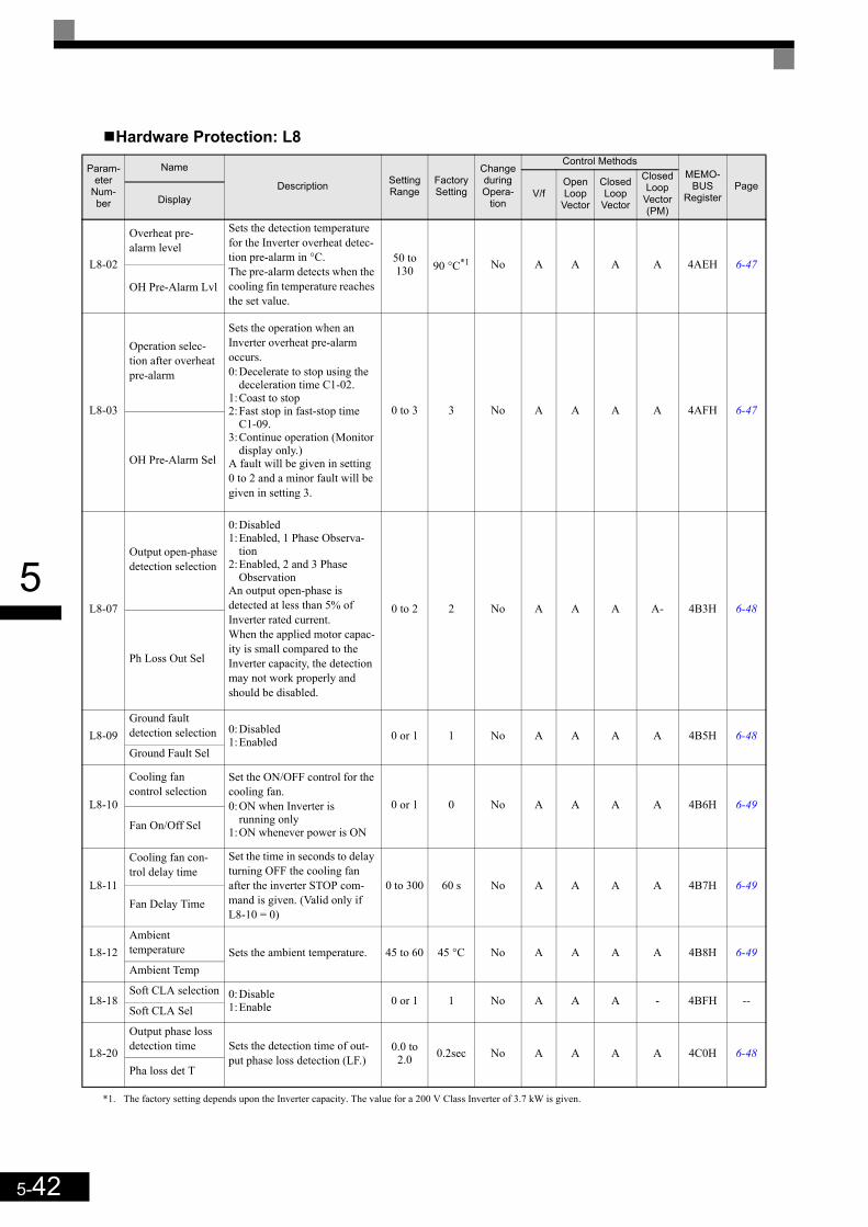
5-42
5
Hardware Protection: L8
Param-eter
Num-ber
Name
Description Setting Range
Factory Setting
Change during Opera-
tion
Control MethodsMEMO-
BUSRegister
PageV/f
Open Loop
Vector
Closed Loop
Vector
Closed Loop
Vector (PM)
Display
L8-02
Overheat pre-alarm level
Sets the detection temperature for the Inverter overheat detec-tion pre-alarm in °C.The pre-alarm detects when the cooling fin temperature reaches the set value.
50 to 130 90 °C*1
*1. The factory setting depends upon the Inverter capacity. The value for a 200 V Class Inverter of 3.7 kW is given.
No A A A A 4AEH 6-47
OH Pre-Alarm Lvl
L8-03
Operation selec-tion after overheat pre-alarm
Sets the operation when an Inverter overheat pre-alarm occurs.0:Decelerate to stop using the
deceleration time C1-02.1:Coast to stop 2:Fast stop in fast-stop time
C1-09.3:Continue operation (Monitor
display only.)A fault will be given in setting 0 to 2 and a minor fault will be given in setting 3.
0 to 3 3 No A A A A 4AFH 6-47
OH Pre-Alarm Sel
L8-07
Output open-phase detection selection
0:Disabled1:Enabled, 1 Phase Observa-
tion 2:Enabled, 2 and 3 Phase
ObservationAn output open-phase is detected at less than 5% of Inverter rated current.When the applied motor capac-ity is small compared to the Inverter capacity, the detection may not work properly and should be disabled.
0 to 2 2 No A A A A- 4B3H 6-48
Ph Loss Out Sel
L8-09Ground fault detection selection 0:Disabled
1:Enabled 0 or 1 1 No A A A A 4B5H 6-48Ground Fault Sel
L8-10
Cooling fan control selection
Set the ON/OFF control for the cooling fan.0:ON when Inverter is
running only1:ON whenever power is ON
0 or 1 0 No A A A A 4B6H 6-49
Fan On/Off Sel
L8-11
Cooling fan con-trol delay time
Set the time in seconds to delay turning OFF the cooling fan after the inverter STOP com-mand is given. (Valid only if L8-10 = 0)
0 to 300 60 s No A A A A 4B7H 6-49Fan Delay Time
L8-12Ambient temperature Sets the ambient temperature. 45 to 60 45 °C No A A A A 4B8H 6-49Ambient Temp
L8-18Soft CLA selection 0:Disable
1:Enable 0 or 1 1 No A A A - 4BFH --Soft CLA Sel
L8-20
Output phase loss detection time Sets the detection time of out-
put phase loss detection (LF.)0.0 to
2.0 0.2sec No A A A A 4C0H 6-48Pha loss det T
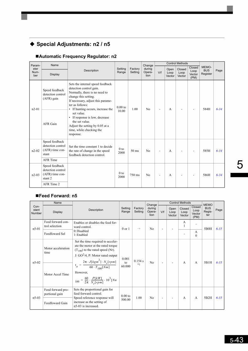
5-43
5
Special Adjustments: n2 / n5
Automatic Frequency Regulator: n2
Feed Forward: n5
Param-eter
Num-ber
Name
Description Setting Range
Factory Setting
Change during Opera-
tion
Control MethodsMEMO-
BUSRegister
PageV/f
Open Loop
Vector
Closed Loop
Vector
Closed Loop
Vector (PM)
Display
n2-01
Speed feedback detection control (AFR) gain
Sets the internal speed feedback detection control gain.Normally, there is no need to change this setting.If necessary, adjust this parame-ter as follows:• If hunting occurs, increase the
set value.• If response is low, decrease
the set value.Adjust the setting by 0.05 at a time, while checking the response.
0.00 to 10.00 1.00 No - A - - 584H 6-34
AFR Gain
n2-02
Speed feedback detection control (AFR) time con-stant
Set the time constant 1 to decide the rate of change in the speed feedback detection control.
0 to 2000 50 ms No - A - - 585H 6-34
AFR Time
n2-03
Speed feedback detection control (AFR) time con-stant 2
0 to 2000 750 ms No - A - - 586H 6-34
AFR Time 2
Con-stant
Number
Name
Description Setting Range
Factory Setting
Change during Opera-
tion
Control MethodsMEMOBUS
Regis-ter
PageDisplay V/f
OpenLoop
Vector
Closed Loop
Vector
Closed Loop
Vector (PM)
n5-01
Feed forward con-trol selection
Enables or disables the feed for-ward control.0:Disabled1:Enabled
0 or 1 i No - -
A1 -
5B0H 6-35Feedfoward Sel - A
0
n5-02
Motor acceleration time
Set the time required to acceler-ate the motor at the rated torque (T100) to the rated speed (Nr).
J: GO2/4, P: Motor rated output
However,
0.001 to
60.0000.154 s
*1No - - A A 5B1H 6-35
Motor Accel Time
n5-03
Feed forward pro-portional gain
Sets the proportional gain for feed forward control.Speed reference response will increase as the setting of n5-03 is increased.
0.00 to 500.00 1.00 No - - A A 5B2H 6-35
Feedfoward Gain
ta2π J kgm2[ ] Nr rpm[ ]⋅ ⋅
60 T100 Nm[ ]⋅-----------------------------------------------------------=
100602π------ P kW[ ]
Nr rpm[ ]---------------------- 103 Nm[⋅ ⋅=
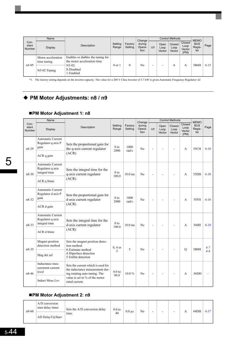
5-44
5
PM Motor Adjustments: n8 / n9
PM Motor Adjustment 1: n8
PM Motor Adjustment 2: n9
n5-05
Motor acceleration time tuning
Enables or diables the tuning for the motor acceleration time N5-02.0:Disabled1:Enabled
0 or 1 0 No - - A A 5B4H 6-35N5-02 Tuning
*1. The factory setting depends on the inverter capacity. The value for a 200 V Class Inverter of 3.7 kW is given.Automatic Frequency Regulator: n2
Con-stant
Number
Name
Description Setting Range
Factory Setting
Change during Opera-
tion
Control MethodsMEMOBUS
Regis-ter
PageDisplay V/f
OpenLoop
Vector
Closed Loop
Vector
Closed Loop
Vector (PM)
n8-29
Automatic Current Regulator q axis P gain
Sets the proportional gain for the q-axis current regulator (ACR)
0 to 2000
1000 rad/s No - - - A 55CH 6-36
ACR q gain
n8-30
Automatic Current Regulator q axis integral time
Sets the integral time for the q-axis current regulator (ACR)
0 to 100.0 10.0 ms No - - - A 55DH 6-36
ACR q Itime
n8-32
Automatic Current Regulator d axis P gain
Sets the proportional gain for d-axis current regulator (ACR)
0 to 2000
1000 rad/s No - - - A 55FH 6-36
ACR d gain
n8-33
Automatic Current Regulator q axis integral time
Sets the integral time for the d-axis current regulator (ACR)
0 to 100.0 10.0 ms No - - - A 560H 6-36
ACR d Itime
n8-35
Magnet position detection method
Sets the magnet position detec-tion method.0:Estimate method4:Hiperface detection5:EnDat detection
0, 4 or 5 5 No - - - Q 5B0H 4-7
4-8Mag det sel
n8-46
Inductance mea-surement current level
Sets the current which is used for the inductance measurement dur-ing rotating auto tuning. The value is set in % of the motor rated current.
0.0 to 99.9 10.0 % No - - - A .56DH -
Induct Meas Lev
n9-60
A/D conversion start delay timer Sets the A/D conversion delay
time.0.0 to
40 0.0 µs No - - - A 64DH 6-37
AD DelayT@Start
Con-stant
Number
Name
Description Setting Range
Factory Setting
Change during Opera-
tion
Control MethodsMEMOBUS
Regis-ter
PageDisplay V/f
OpenLoop
Vector
Closed Loop
Vector
Closed Loop
Vector (PM)
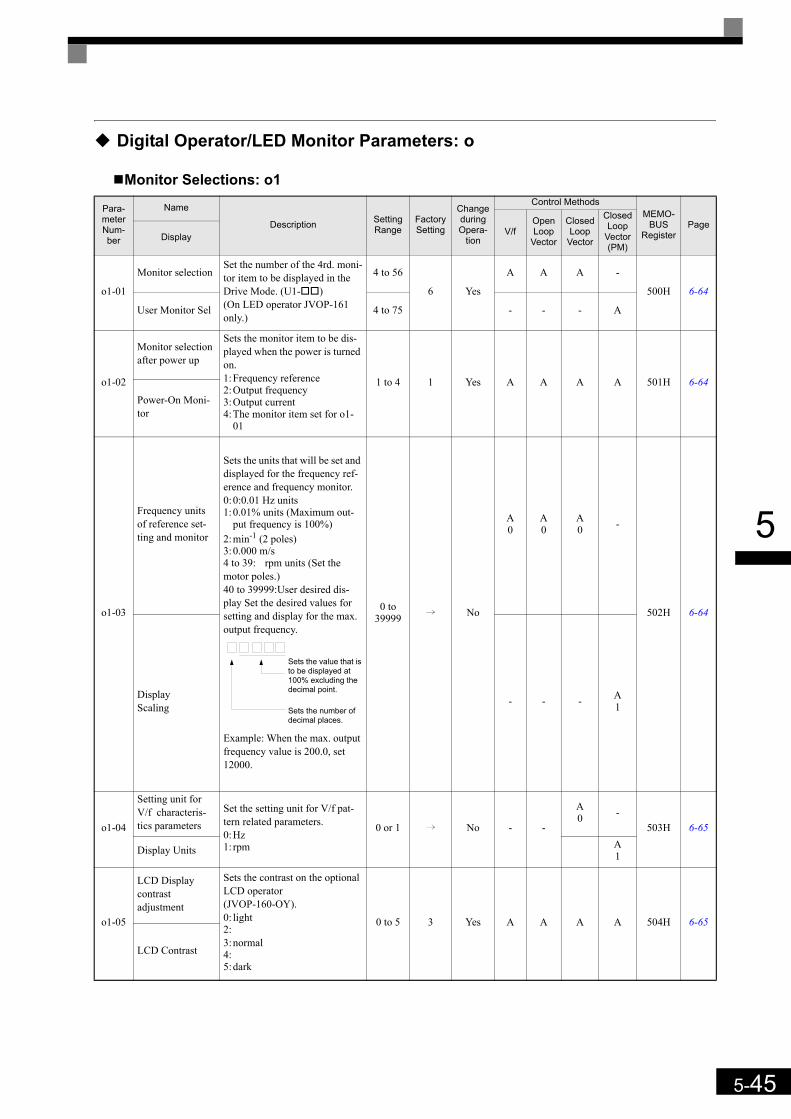
5-45
5
Digital Operator/LED Monitor Parameters: o
Monitor Selections: o1
Para-meter Num-ber
Name
Description Setting Range
Factory Setting
Change during Opera-
tion
Control MethodsMEMO-
BUSRegister
PageV/f
Open Loop
Vector
Closed Loop
Vector
Closed Loop
Vector (PM)
Display
o1-01
Monitor selectionSet the number of the 4rd. moni-tor item to be displayed in the Drive Mode. (U1- )(On LED operator JVOP-161 only.)
4 to 56
6 Yes
A A A -
500H 6-64
User Monitor Sel 4 to 75 - - - A
o1-02
Monitor selection after power up
Sets the monitor item to be dis-played when the power is turned on.1:Frequency reference2:Output frequency3:Output current4:The monitor item set for o1-
01
1 to 4 1 Yes A A A A 501H 6-64
Power-On Moni-tor
o1-03
Frequency units of reference set-ting and monitor
Sets the units that will be set and displayed for the frequency ref-erence and frequency monitor.0:0:0.01 Hz units1:0.01% units (Maximum out-
put frequency is 100%)2:min-1 (2 poles)3:0.000 m/s4 to 39: rpm units (Set the motor poles.)40 to 39999:User desired dis-play Set the desired values for setting and display for the max. output frequency.
Example: When the max. output frequency value is 200.0, set 12000.
0 to 39999 i No
A0
A0
A0 -
502H 6-64
Display Scaling - - - A
1
o1-04
Setting unit for V/f characteris-tics parameters
Set the setting unit for V/f pat-tern related parameters.0:Hz1: rpm
0 or 1 i No - -
A0 -
503H 6-65
Display Units A1
o1-05
LCD Display contrastadjustment
Sets the contrast on the optional LCD operator (JVOP-160-OY).0: light2:3:normal4:5:dark
0 to 5 3 Yes A A A A 504H 6-65
LCD Contrast
Sets the value that is to be displayed at 100% excluding the decimal point.
Sets the number of decimal places.

5-46
5
Digital Operator: o2
Param-eter
Num-ber
Name
Description Setting Range
Factory Setting
Change during Opera-
tion
Control MethodsMEMO-
BUSRegister
PageV/f
Open Loop
Vector
Closed Loop
Vector
Closed Loop
Vector (PM)
Display
o2-01
LOCAL/REMOTE key enable/disable
Enables/Disables the Digital Operator Local/Remote key0:Disabled1:Enabled (Switches between
the Digital Operator and the parameter settingsb1-01, b1-02.)
0 or 1 0 No A A A A 505H 6-65
Local/Remote Key
o2-02
STOP key during control circuit ter-minal operation
Enables/Disables the Stop key in the run mode.0:Disabled (When the run com-
mand is issued from an exter-nal terminal, the Stop key is disabled.)
1:Enabled (Effective even dur-ing run.)
0 or 1 0 No A A A A 506H 6-65
Oper Stop Key
o2-03
User parameter initial value
Clears or stores user initial val-ues.0:Stores/not set1:Begins storing (Records the
set parameters as user initial values.)
2:All clear (Clears all recorded user initial values)
When the set parameters are recorded as user initial values, 1110 will be set in A1-03.
0 to 2 0 No A A A A 507H 6-65
User Defaults
o2-04kVA selection Do not set unless after replacing
the control board. (Refer to page 5-61 for the setting values).
0 to FF 0 No A A A A 508H 6-65Inverter Model #
o2-05
Frequency refer-ence setting method selection
Sets whether the ENTER key is needed for a frequency refer-ence change or not when the Digital Operator is selected as frequency reference source.0:Enter key needed1:Enter key not neededIf “1” is selected, a frequency reference change is accepted without the need of pressing the Enter key.
0 or 1 0 No A A A A 509H 6-66
Operator M.O.P.
o2-06
Operation selec-tion when digital operator is dis-connected
Sets the operation when the Dig-ital Operator/LED Monitor is disconnected.0:Operation continues even if
the Digital Operator/LED Monitor is disconnected.
1:OPR is detected at Digital Operator/LED Monitor dis-connection. Inverter output is switched off, and the fault con-tact is operated.
0 or 1 0 No A A A A 50AH 6-66
Oper Detection
o2-07Cumulative oper-ation time setting Sets the cumulative operation
time in hour units.0 to
65535 0 hr. No A A A A 50BH 6-66Elapsed Time Set
o2-08
Cumulative oper-ation time selec-tion
0:Accumulated inverter power on time.
1:Accumulated inverter run time.
0 or 1 1 No A A A A 50CH 6-66Elapsed Time Run
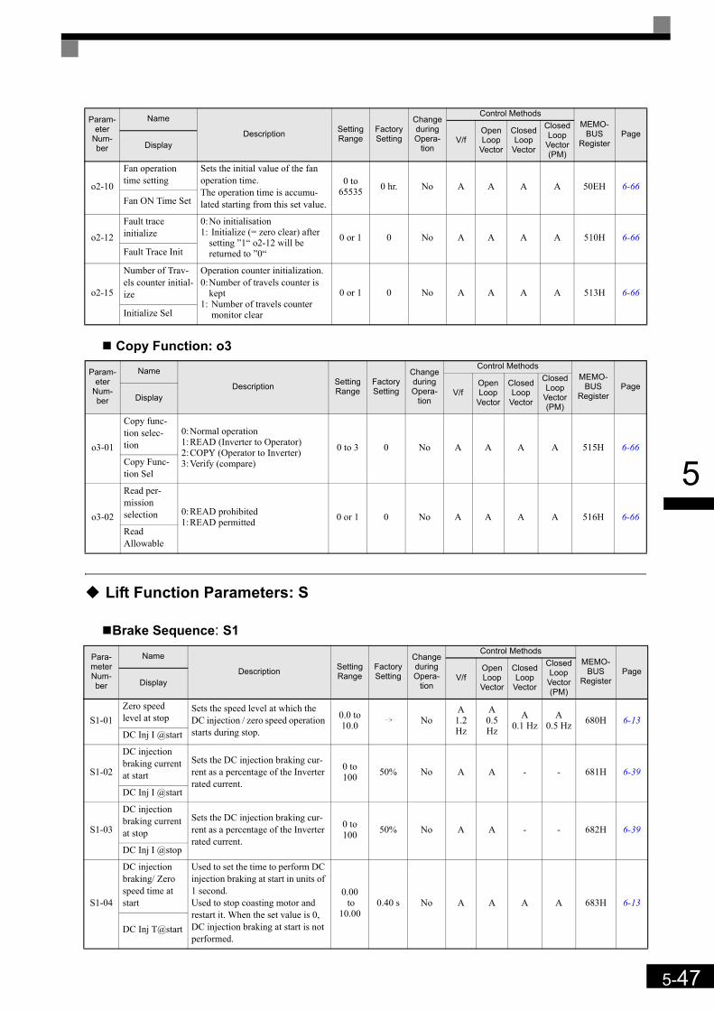
5-47
5
Copy Function: o3
Lift Function Parameters: S
Brake Sequence: S1
o2-10
Fan operation time setting
Sets the initial value of the fan operation time.The operation time is accumu-lated starting from this set value.
0 to 65535 0 hr. No A A A A 50EH 6-66
Fan ON Time Set
o2-12
Fault trace initialize
0:No initialisation1: Initialize (= zero clear) after
setting ”1“ o2-12 will be returned to ”0“
0 or 1 0 No A A A A 510H 6-66Fault Trace Init
o2-15
Number of Trav-els counter initial-ize
Operation counter initialization.0:Number of travels counter is
kept1: Number of travels counter
monitor clear
0 or 1 0 No A A A A 513H 6-66
Initialize Sel
Param-eter
Num-ber
Name
Description Setting Range
Factory Setting
Change during Opera-
tion
Control MethodsMEMO-
BUSRegister
PageV/f
Open Loop
Vector
Closed Loop
Vector
Closed Loop
Vector (PM)
Display
o3-01
Copy func-tion selec-tion
0:Normal operation1:READ (Inverter to Operator)2:COPY (Operator to Inverter)3:Verify (compare)
0 to 3 0 No A A A A 515H 6-66Copy Func-tion Sel
o3-02
Read per-mission selection 0:READ prohibited
1:READ permitted 0 or 1 0 No A A A A 516H 6-66Read Allowable
Para-meter Num-ber
Name
Description Setting Range
Factory Setting
Change during Opera-
tion
Control MethodsMEMO-
BUSRegister
PageV/f
Open Loop
Vector
Closed Loop
Vector
Closed Loop
Vector (PM)
Display
S1-01Zero speed level at stop
Sets the speed level at which the DC injection / zero speed operation starts during stop.
0.0 to 10.0 i No
A1.2 Hz
A0.5 Hz
A0.1 Hz
A0.5 Hz 680H 6-13
DC Inj I @start
S1-02
DC injection braking current at start
Sets the DC injection braking cur-rent as a percentage of the Inverter rated current.
0 to 100 50% No A A - - 681H 6-39
DC Inj I @start
S1-03
DC injection braking current at stop
Sets the DC injection braking cur-rent as a percentage of the Inverter rated current.
0 to 100 50% No A A - - 682H 6-39
DC Inj I @stop
S1-04
DC injection braking/ Zero speed time at start
Used to set the time to perform DC injection braking at start in units of 1 second.Used to stop coasting motor and restart it. When the set value is 0, DC injection braking at start is not performed.
0.00 to
10.000.40 s No A A A A 683H 6-13
DC Inj T@start
Param-eter
Num-ber
Name
Description Setting Range
Factory Setting
Change during Opera-
tion
Control MethodsMEMO-
BUSRegister
PageV/f
Open Loop
Vector
Closed Loop
Vector
Closed Loop
Vector (PM)
Display
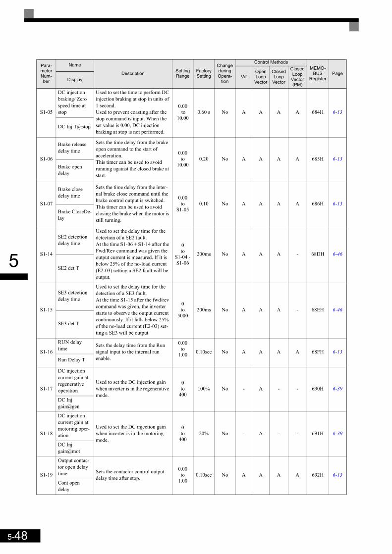
5-48
5
S1-05
DC injection braking/ Zero speed time at stop
Used to set the time to perform DC injection braking at stop in units of 1 second.Used to prevent coasting after the stop command is input. When the set value is 0.00, DC injection braking at stop is not performed.
0.00 to
10.000.60 s No A A A A 684H 6-13
DC Inj T@stop
S1-06
Brake release delay time
Sets the time delay from the brake open command to the start of acceleration.This timer can be used to avoid running against the closed brake at start.
0.00to
10.000.20 No A A A A 685H 6-13
Brake open delay
S1-07
Brake close delay time
Sets the time delay from the inter-nal brake close command until the brake control output is switched.This timer can be used to avoid closing the brake when the motor is still turning.
0.00to
S1-050.10 No A A A A 686H 6-13
Brake CloseDe-lay
S1-14
SE2 detection delay time
Used to set the delay time for the detection of a SE2 fault.At the time S1-06 + S1-14 after the Fwd/Rev command was given the output current is measured. If it is below 25% of the no-load current (E2-03) setting a SE2 fault will be output.
0to
S1-04 -S1-06
200ms No A A A - 68DH 6-46
SE2 det T
S1-15
SE3 detection delay time
Used to set the delay time for the detection of a SE3 fault.At the time S1-15 after the fwd/rev command was given, the inverter starts to observe the output current continuously. If it falls below 25% of the no-load current (E2-03) set-ting a SE3 will be output.
0to
5000200ms No A A A - 68EH 6-46
SE3 det T
S1-16
RUN delay time Sets the delay time from the Run
signal input to the internal run enable.
0.00to
1.00 0.10sec No A A A A 68FH 6-13Run Delay T
S1-17
DC injection current gain at regenerative operation
Used to set the DC injection gain when inverter is in the regenerative mode.
0to
400100% No - A - - 690H 6-39
DC Inj gain@gen
S1-18
DC injection current gain at motoring oper-ation
Used to set the DC injection gain when inverter is in the motoring mode.
0to
40020% No - A - - 691H 6-39
DC Inj gain@mot
S1-19
Output contac-tor open delay time Sets the contactor control output
delay time after stop.
0.00to
1.000.10sec No A A A A 692H 6-13
Cont open delay
Para-meter Num-ber
Name
Description Setting Range
Factory Setting
Change during Opera-
tion
Control MethodsMEMO-
BUSRegister
PageV/f
Open Loop
Vector
Closed Loop
Vector
Closed Loop
Vector (PM)
Display

5-49
5
S1-20
Zero-servo gain
Adjust the strength of the zero-servo lock.When Closed Loop Vector control is selected, a position control loop is created at start and stop. Increas-ing the zero-servo gain increases the strength of the lock. Increasing it too much can cause oscillation.
0 to 100 5 No - - A A 693H 6-13
Zero Servo Gain
S1-21
Zero-servo completion width
Sets the bandwidth of the Zero Servo completion output.Enabled when the “zero-servo completion (end)” is set for a multi-function output. The zero-servo completion signal is ON when the current position is within the range (the zero-servo position + zero-servo completion width.)Set S1-21 to 4 times of the allow-able displacement pulse amount at the PG.
0 to 16383 10 No - - A A 694H 6-13
Zero Servo Count
S1-22
Starting torque compensation increase time
Sets the increase time for the ana-log input torque compensation sig-nal. Sets the time the torque reference needs to reach 300% torque reference.
0to
5000500ms No - - A A 695H 6-13
Torque incr T
S1-23
Torque com-pensation gain during lowering
Sets the torque compensation gain at lowering when the torque com-pensation at start function is used.
0.500to
10.0001.000 No - - A A 696H 6-13
TorqComp-gain@low
S1-24
Torque com-pensation bias during raising
Sets the torque compensation bias at raising when the torque compen-sation at start function is used.
-200.0to
+200.00.0% No - - A A 697H 6-13
TorqComp-Bias@ri
S1-25
Torque com-pensation bias during lowering
Sets the torque compensation bias at lowering when the torque com-pensation at start function is used.
-200.0to
+200.00.0% No - - A A 698H 6-13
TorqComp-Bias@red
S1-26
Dwell speed reference
Hold speed reference when the load is heavy.The frequency refer-ence follows the C1-07 accelera-tion 4 setting time.Acceleration time will be changed when the motor speed exceeds the C1-11 setting frequency.
0.0to
120.00.0Hz No - - A A 699H 6-21
DWELL speed
S1-27
Door zone speed level
Sets the door zone speed level.If the motor speed (in CLV and OLV) or the output frequency (in V/f control) falls below S1-27 and a multifunction output is set for the “Door zone” signal (H2- =42), this output will be closed.
0.0to
120.00.0Hz No A A A A 69AH 6-58
Door Zone Level
S1-28
SE1 detection Selection
Sets how a SE1 fault is reset.0:Manual Reset1:Automatic reset at stop2:No SE1 detection
0 to 2 0 No A A A A 69BH 6-53SE1 Selection
Para-meter Num-ber
Name
Description Setting Range
Factory Setting
Change during Opera-
tion
Control MethodsMEMO-
BUSRegister
PageV/f
Open Loop
Vector
Closed Loop
Vector
Closed Loop
Vector (PM)
Display
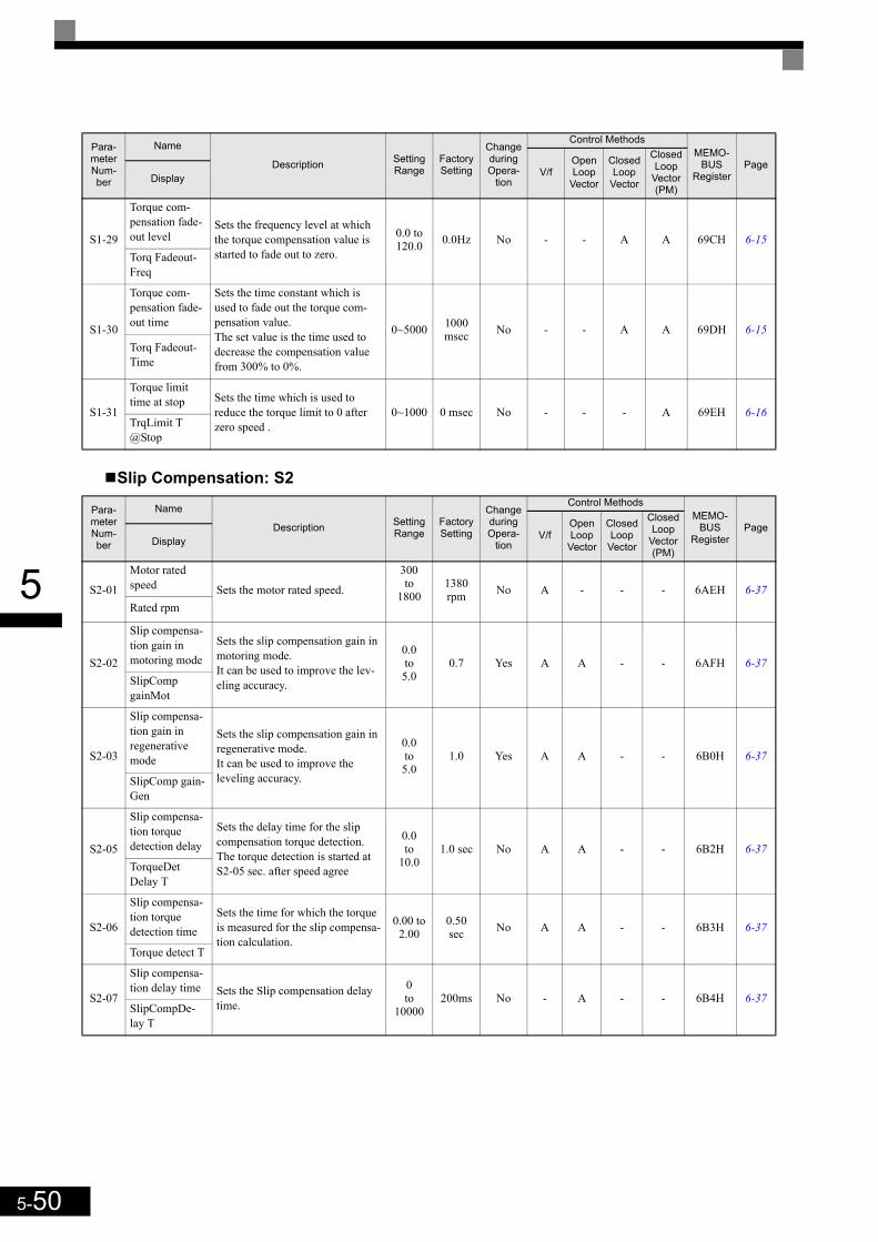
5-50
5
Slip Compensation: S2
S1-29
Torque com-pensation fade-out level
Sets the frequency level at which the torque compensation value is started to fade out to zero.
0.0 to 120.0 0.0Hz No - - A A 69CH 6-15
Torq Fadeout-Freq
S1-30
Torque com-pensation fade-out time
Sets the time constant which is used to fade out the torque com-pensation value.The set value is the time used to decrease the compensation value from 300% to 0%.
0~5000 1000 msec No - - A A 69DH 6-15
Torq Fadeout-Time
S1-31
Torque limit time at stop Sets the time which is used to
reduce the torque limit to 0 after zero speed .
0~1000 0 msec No - - - A 69EH 6-16TrqLimit T @Stop
Para-meter Num-ber
Name
Description Setting Range
Factory Setting
Change during Opera-
tion
Control MethodsMEMO-
BUSRegister
PageV/f
Open Loop
Vector
Closed Loop
Vector
Closed Loop
Vector (PM)
Display
S2-01
Motor rated speed Sets the motor rated speed.
300to
18001380rpm No A - - - 6AEH 6-37
Rated rpm
S2-02
Slip compensa-tion gain in motoring mode
Sets the slip compensation gain in motoring mode. It can be used to improve the lev-eling accuracy.
0.0to5.0
0.7 Yes A A - - 6AFH 6-37SlipComp gainMot
S2-03
Slip compensa-tion gain in regenerative mode
Sets the slip compensation gain in regenerative mode. It can be used to improve the leveling accuracy.
0.0to5.0
1.0 Yes A A - - 6B0H 6-37
SlipComp gain-Gen
S2-05
Slip compensa-tion torque detection delay
Sets the delay time for the slip compensation torque detection. The torque detection is started at S2-05 sec. after speed agree
0.0to
10.01.0 sec No A A - - 6B2H 6-37
TorqueDetDelay T
S2-06
Slip compensa-tion torque detection time
Sets the time for which the torque is measured for the slip compensa-tion calculation.
0.00 to 2.00
0.50 sec No A A - - 6B3H 6-37
Torque detect T
S2-07
Slip compensa-tion delay time Sets the Slip compensation delay
time.
0to
10000200ms No - A - - 6B4H 6-37
SlipCompDe-lay T
Para-meter Num-ber
Name
Description Setting Range
Factory Setting
Change during Opera-
tion
Control MethodsMEMO-
BUSRegister
PageV/f
Open Loop
Vector
Closed Loop
Vector
Closed Loop
Vector (PM)
Display
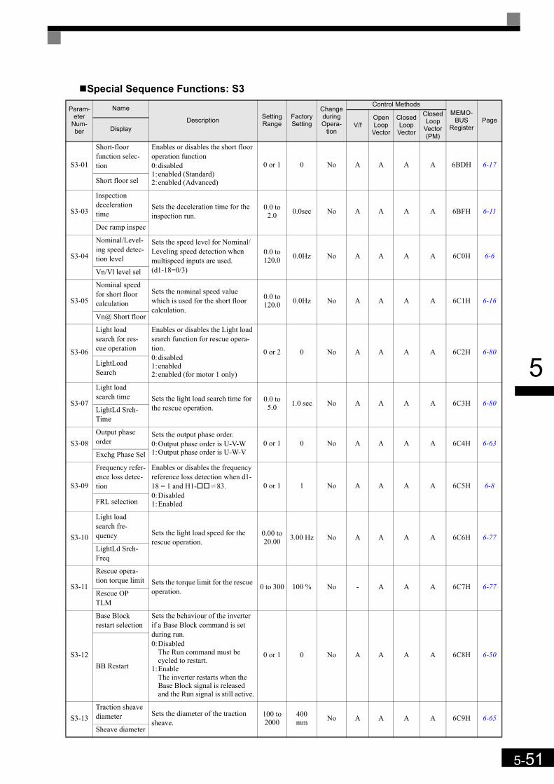
5-51
5
Special Sequence Functions: S3
Param-eter
Num-ber
Name
Description Setting Range
Factory Setting
Change during Opera-
tion
Control MethodsMEMO-
BUSRegister
PageV/f
Open Loop
Vector
Closed Loop
Vector
Closed Loop
Vector (PM)
Display
S3-01
Short-floor function selec-tion
Enables or disables the short floor operation function0:disabled1:enabled (Standard)2:enabled (Advanced)
0 or 1 0 No A A A A 6BDH 6-17
Short floor sel
S3-03
Inspection deceleration time
Sets the deceleration time for the inspection run.
0.0 to 2.0 0.0sec No A A A A 6BFH 6-11
Dec ramp inspec
S3-04
Nominal/Level-ing speed detec-tion level
Sets the speed level for Nominal/Leveling speed detection when multispeed inputs are used.(d1-18=0/3)
0.0 to 120.0 0.0Hz No A A A A 6C0H 6-6
Vn/Vl level sel
S3-05
Nominal speed for short floor calculation
Sets the nominal speed value which is used for the short floor calculation.
0.0 to 120.0 0.0Hz No A A A A 6C1H 6-16
Vn@ Short floor
S3-06
Light load search for res-cue operation
Enables or disables the Light load search function for rescue opera-tion.0:disabled1:enabled2:enabled (for motor 1 only)
0 or 2 0 No A A A A 6C2H 6-80LightLoad Search
S3-07
Light load search time Sets the light load search time for
the rescue operation.0.0 to
5.0 1.0 sec No A A A A 6C3H 6-80LightLd Srch-Time
S3-08Output phase order
Sets the output phase order.0:Output phase order is U-V-W1:Output phase order is U-W-V
0 or 1 0 No A A A A 6C4H 6-63Exchg Phase Sel
S3-09
Frequency refer-ence loss detec-tion
Enables or disables the frequency reference loss detection when d1-18 = 1 and H1- K83.0:Disabled1:Enabled
0 or 1 1 No A A A A 6C5H 6-8
FRL selection
S3-10
Light load search fre-quency Sets the light load speed for the
rescue operation.0.00 to 20.00 3.00 Hz No A A A A 6C6H 6-77
LightLd Srch-Freq
S3-11
Rescue opera-tion torque limit Sets the torque limit for the rescue
operation. 0 to 300 100 % No - A A A 6C7H 6-77Rescue OP TLM
S3-12
Base Block restart selection
Sets the behaviour of the inverter if a Base Block command is set during run.0:Disabled
The Run command must be cycled to restart.
1:EnableThe inverter restarts when the Base Block signal is released and the Run signal is still active.
0 or 1 0 No A A A A 6C8H 6-50BB Restart
S3-13Traction sheave diameter Sets the diameter of the traction
sheave.100 to 2000
400 mm No A A A A 6C9H 6-65
Sheave diameter

5-52
5
S3-14
Roping Sets the roping ratio of the eleva-tor1:1:12:1:2
1 or 2 2 No A A A A 6CAH 6-65Roping Ratio
S3-15Gear Ratio
Sets the mechanical gear ratio. 0.10 to 10.00 1.000 No A A A A 6CBH 6-65
Gear Ratio
S3-16
Over accelera-tion detection level
Sets the maximum car accelera-tion value. If the acceleration rate is higher that this value the inverter trips with an over acceleration fault (DV6)
0.0 to 50.0 1.5 m/s² No - - - A 6CCH 6-46
Over Acc Det Lvl
S3-17
Over accelera-tion decelera-tion time constant
Sets the time for which an over acceleration must be detected before the inverter stops with an over acceleration fault (DV6)
0.000 to
5.000
0.05 sec No - - - A 6CDH 6-46
Over Acc Det Fil
S3-18
Over accelera-tion detection method selec-tion
Selects wether the over accelera-tion detection is always active or during run only.0:Detection during power on1:Detection during run only
0 or 1 0 No - - - A 6CEH 6-46
Over Acc Det Sel
S3-19
Inspection speed upper limit
Sets the upper frequency limit for the inspection speed detection if multi speed operation is selected (d1-18 = 0 or 3)
S3-04 to
120.0 Hz
25.0 Hz No A A A A 6CFH 6-11Inspection UpLmt
S3-20
Short floor min-imum constant speed time
Sets the minimal constant speed time for the advanced short floor function. The parameter is effec-tive only if paramter S3-01is set to “2” (Advanced short floor opera-tion enabled)
0.0 to 2.0 0.0 sec No A A A A 6D0H 6-18
ShortF2 MinTime
S3-21
Distance calcu-lation accelera-tion time gain
Sets the acceleration time gain for the optimal speed calculation of the advanced short floor function.
50.0 to 200.0 150.0% No A A A A 6D1H 6-18
Tacc Gain
S3-22
Distance calcu-lation decelera-tion time gain
Sets the deceleration time gain for the optimal speed calculation of the advanced short floor function.
50.0 to 200.0 150.0% No A A A A 6D2H 6-18
Tdec Gain
S3-23
Distance calcu-lation decelera-tion time gain
Sets the deceleration time gain for the optimal speed calculation of the advanced short floor function.
50.0 to 200.0 150.0% No A A A A 6D3H 6-18
S3-24
Light Load Direction Search Method
Selects the light load direction search method.0:Motor Current comparison1:Regenerative direction detec-
tion
0 or 1 0 No A A - - 6D4H 6-77
LLS method sel
Param-eter
Num-ber
Name
Description Setting Range
Factory Setting
Change during Opera-
tion
Control MethodsMEMO-
BUSRegister
PageV/f
Open Loop
Vector
Closed Loop
Vector
Closed Loop
Vector (PM)
Display

5-53
5
Motor Autotuning: T
T1: Autotuning 1
Param-eter
Num-ber
Name
Description Setting Range
Factory Setting
Change during Opera-
tion
Control MethodsMEMO-
BUSRegister
PageV/f
Open Loop
Vector
Closed Loop
Vector
Closed Loop
Vector (PM)
Display
T1-01
Autotuning mode selection
Sets the autotuning mode.0:Rotating autotuning1:Non-rotating autotuning2:Non-rotating autotuning for
line-to-line resistance only4:Encoder offset tuning
0 to 2
i No
Yes(2)
Yes(1)
Yes(1) -
701H 4-4
Tuning Mode Sel 0 or 4 - - - Yes (4)
T1-02Motor output power Sets the output power of the
motor in kilowatts.0.00 to 650.00
3.70 kW*1
*1. The factory setting depends on the Inverter capacity. (The value for a 200 V Class Inverter for 3.7 kW is given.)
No Yes Yes Yes - 702H 4-4Mtr Rated Power
T1-03Motor rated volt-age Sets the rated voltage of the
motor.
0 to 255.0
*2
*2. These are values for a 200 V class Inverter. Values for a 400 V class Inverter are double.
190.0 V*2 No - Yes Yes - 703H 4-4
Rated Voltage
T1-04
Motor rated cur-rent Sets the rated current of the
motor.
1.75 to 35.00
*3
*3. The setting range is from 10% to 200% of the Inverter rated output current. (The value for a 200 V Class Inverter for 0.4 kW is given.)
14.00 A*1 No Yes Yes Yes - 704H 4-4
Rated Current
T1-05Motor rated fre-quency Sets the rated frequency of the
motor.0 to
120.0 50.0 Hz No - Yes Yes - 705H 4-4Rated Frequency
T1-06Number of motor poles Sets the number of motor poles. 2 to 48
poles 4 poles No - Yes Yes - 706H 4-4Number of Poles
T1-07Motor base speed Sets the base speed of the motor
in r/min.0 to
240001450r/min No - Yes Yes - 707H -4-4
Rated Speed
T1-08Number of PG pulses Sets the number of PG pulses
per revolution. 0 to
60000 1024 No - - Yes - 708H 4-4PG Pulses/Rev
T1-09No load current Sets the no load current of
motor.
0.0 to 13.99
*1E2-03 No - Yes Yes - 709H 4-4
No load current
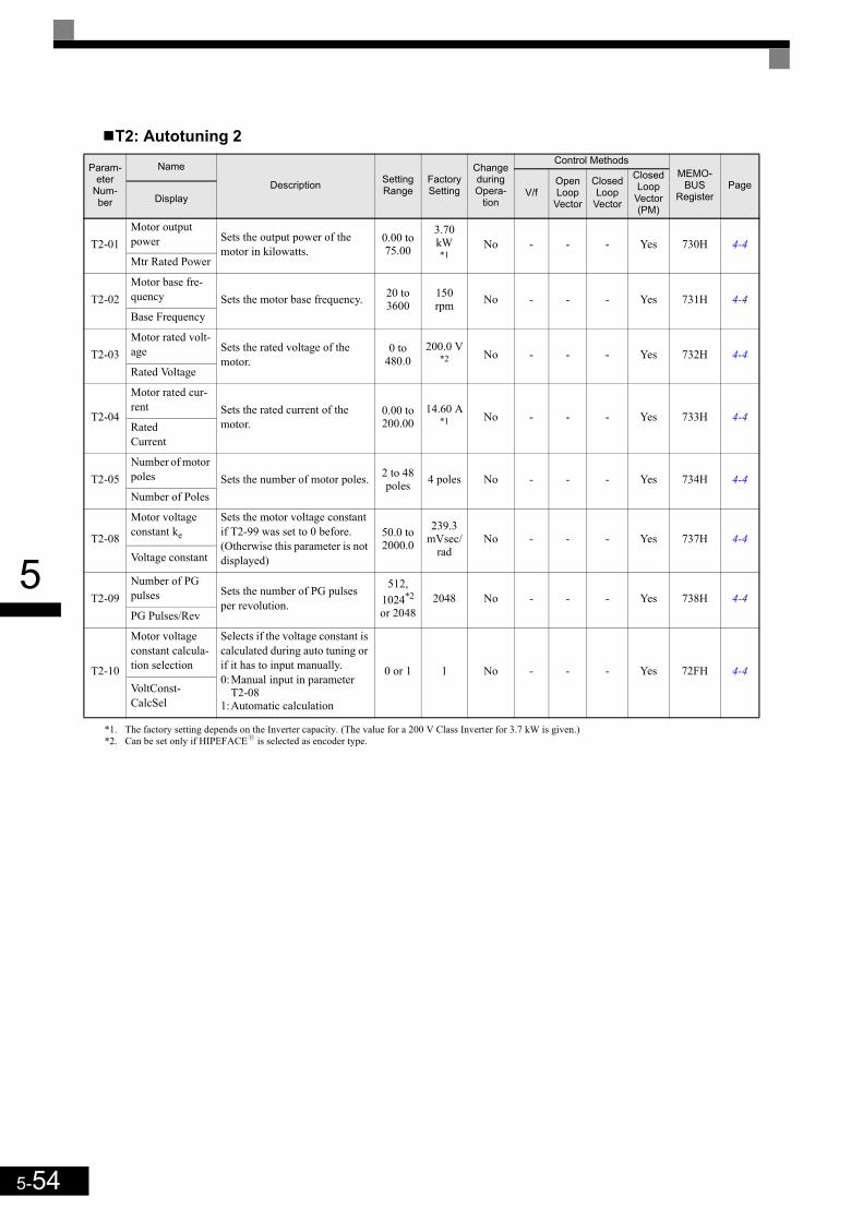
5-54
5
T2: Autotuning 2
Param-eter
Num-ber
Name
Description Setting Range
Factory Setting
Change during Opera-
tion
Control MethodsMEMO-
BUSRegister
PageV/f
Open Loop
Vector
Closed Loop
Vector
Closed Loop
Vector (PM)
Display
T2-01Motor output power Sets the output power of the
motor in kilowatts.0.00 to 75.00
3.70 kW*1
*1. The factory setting depends on the Inverter capacity. (The value for a 200 V Class Inverter for 3.7 kW is given.)
No - - - Yes 730H 4-4Mtr Rated Power
T2-02Motor base fre-quency Sets the motor base frequency. 20 to
3600150 rpm No - - - Yes 731H 4-4
Base Frequency
T2-03Motor rated volt-age Sets the rated voltage of the
motor.0 to
480.0200.0 V
*2 No - - - Yes 732H 4-4Rated Voltage
T2-04
Motor rated cur-rent Sets the rated current of the
motor.0.00 to 200.00
14.60 A*1 No - - - Yes 733H 4-4
Rated Current
T2-05Number of motor poles Sets the number of motor poles. 2 to 48
poles 4 poles No - - - Yes 734H 4-4Number of Poles
T2-08
Motor voltage constant ke
Sets the motor voltage constant if T2-99 was set to 0 before. (Otherwise this parameter is not displayed)
50.0 to 2000.0
239.3 mVsec/
radNo - - - Yes 737H 4-4
Voltage constant
T2-09Number of PG pulses Sets the number of PG pulses
per revolution.
512, 1024*2 or 2048
*2. Can be set only if HIPEFACEy is selected as encoder type.
2048 No - - - Yes 738H 4-4PG Pulses/Rev
T2-10
Motor voltage constant calcula-tion selection
Selects if the voltage constant is calculated during auto tuning or if it has to input manually.0:Manual input in parameter
T2-081:Automatic calculation
0 or 1 1 No - - - Yes 72FH 4-4VoltConst-CalcSel
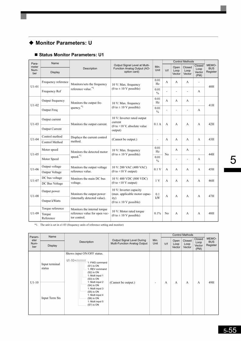
5-55
5
Monitor Parameters: U
Status Monitor Parameters: U1
Para-meter Num-ber
Name
DescriptionOutput Signal Level at Multi-Function Analog Output (AO-
option card)
Min. Unit
Control MethodsMEMO-
BUSRegisterV/f
Open Loop
Vector
Closed Loop
Vector
Closed Loop
Vector (PM)
Display
U1-01Frequency reference
Monitors/sets the frequency reference value.*1
*1. The unit is set in o1-03 (frequency units of reference setting and monitor)
10 V: Max. frequency (0 to ± 10 V possible)
0.01Hz A A A -
40HFrequency Ref 0.01
% - - - A
U1-02Output frequency
Monitors the output fre-quency.*1
10 V: Max. frequency (0 to ± 10 V possible)
0.01Hz A A A -
41HOutput Freq 0.01
% - - - A
U1-03Output current
Monitors the output current.
10 V: Inverter rated output current(0 to +10 V, absolute value output)
0.1 A A A A A 42HOutput Current
U1-04Control method Displays the current control
method. (Cannot be output.) - A A A A 43HControl Method
U1-05Motor speed
Monitors the detected motor speed.*1
10 V: Max. frequency (0 to ± 10 V possible)
0.01Hz
NoA A -
44HMotor Speed 0.01
% - - A
U1-06Output voltage Monitors the output voltage
reference value.10 V: 200 VAC (400 VAC)(0 to +10 V output) 0.1 V A A A A 45H
Output Voltage
U1-07DC bus voltage Monitors the main DC bus
voltage.10 V: 400 VDC (800 VDC)(0 to +10 V output) 1 V A A A A 46H
DC Bus Voltage
U1-08Output power
Monitors the output power (internally detected value).
10 V: Inverter capacity (max. applicable motor capac-ity)(0 to ± 10 V possible)
0.1 kW A A A A 47H
Output kWatts
U1-09Torque reference Monitors the internal torque
reference value for open vec-tor control.
10 V: Motor rated torque(0 to ± 10 V possible) 0.1% No A A A 48HTorque
Reference
Param-eter
Num-ber
Name
Description Output Signal Level During Multi-Function Analog Output
Min. Unit
Control MethodsMEMO-
BUSRegisterV/f
Open Loop
Vector
Closed Loop
Vector
Closed Loop
Vector (PM)
Display
U1-10
Input terminal status
Shows input ON/OFF status.
(Cannot be output.) - A A A A 49H
Input Term Sts
1: FWD command(S1) is ON1: REV command(S2) is ON1: Multi input 1(S3) is ON1: Multi input 2(S4) is ON1: Multi input 3(S5) is ON1: Multi input 4(S6) is ON1: Multi input 5(S7) is ON
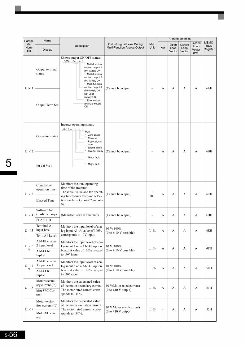
5-56
5
U1-11
Output terminal status
Shows output ON/OFF status.
(Cannot be output.) - A A A A 4AH
Output Term Sts
U1-12
Operation status
Inverter operating status.
(Cannot be output.) - A A A A 4BH
Int Ctl Sts 1
U1-13
Cumulative operation time
Monitors the total operating time of the Inverter.The initial value and the operat-ing time/power ON time selec-tion can be set in o2-07 and o2-08.
(Cannot be output.) 1hr. A A A A 4CH
Elapsed Time
U1-14Software No. (flash memory) (Manufacturer’s ID number) (Cannot be output.) - A A A A 4DHFLASH ID
U1-15Terminal A1 input level
Monitors the input level of ana-log input A1. A value of 100% corresponds to 10V input.
10 V: 100%(0 to ± 10 V possible) 0.1% A A A A 4EH
Term A1 Level
U1-16*1
AI-14B channel 2 input level
Monitors the input level of ana-log input 2 on a AI-14B option board. A value of 100% is equal to 10V input.
10 V: 100%(0 to ± 10 V possible) 0.1% A A A A 4FH
AI-14 Ch2 InpLvl
U1-17*1
AI-14B channel 3 input level
Monitors the input level of ana-log input 3 on a AI-14B option board. A value of 100% is equal to 10V input.
10 V: 100%(0 to ± 10 V possible) 0.1% A A A A 50H
AI-14 Ch3 InpLvl
U1-18
Motor second-ary current (Iq)
Monitors the calculated value of the motor secondary current.The motor rated current corre-sponds to 100%.
10 V:Motor rated current)(0 to ±10 V output) 0.1% A A A A 51H
Mot SEC Cur-rent
U1-19
Motor excita-tion current (Id)
Monitors the calculated value of the motor excitation current.The motor rated current corre-sponds to 100%.
10 V:Motor rated current)(0 to ±10 V output) 0.1% - A A A 52H
Mot EXC cur-rent
Param-eter
Num-ber
Name
Description Output Signal Level During Multi-Function Analog Output
Min. Unit
Control MethodsMEMO-
BUSRegisterV/f
Open Loop
Vector
Closed Loop
Vector
Closed Loop
Vector (PM)
Display
1: Multi-functioncontact output 1(M1-M2) is ON1: Multi-functioncontact output 2(M3-M4) is ON1: Multi-functioncontact output 3(M5-M6) is ONNot used (Always 0).1: Error output(MA/MB-MC) is ON
Run1: Zero speed1: Reverse1: Reset signal input1: Speed agree1: Inverter ready
1: Minor fault
1: Major fault

5-57
5
U1-20
Frequency refer-ence after soft-starter
Monitors the frequency refer-ence after the soft starter.This frequency value does not include compensations, such as slip compensation.The unit is set in o1-03.
10 V: Max. frequency (0 to ± 10 V possible)
0.01Hz A A A -
53H
SFS Output 0.01% - - - A
U1-21ASR input Monitors the input to the speed
control loop.The maximum frequency corre-sponds to 100%.
10 V: Max. frequency (0 to ± 10 V possible) 0.01% - - A A 54H
ASR Input
U1-22ASR output Monitors the output from the
speed control loop.The maximum frequency corre-sponds to 100%.
10 V:Max. frequency(0 to ± 10 V possible) 0.01% - - A A 55H
ASR output
U1-25
DI-16H2 input status
Monitors the reference value from a DI-16H2 Digital Refer-ence Card.The value will be displayed in binary or BCD depending on user constant F3-01.
(Cannot be output.) - A A A A 58H
DI-16 Reference
U1-26Output voltage reference (Vq)
Monitors the Inverter internal voltage reference for motor sec-ondary current control.
10 V: 200 VAC (400 VAC)(0 to ± 10 V possible) 0.1 V - A A A 59H
Voltage Ref(Vq)
U1-27Output voltage reference (Vd)
Monitors the Inverter internal voltage reference for motor excitation current control.
10 V: 200 VAC (400 VAC)(0 to ± 10 V possible) 0.1 V - A A A 5AH
Voltage Ref(Vd)
U1-28Software No. (CPU) (Manufacturer’s CPU software
No.) (Cannot be output.) - A A A A 5BHCPU ID
U1-32
ACR output of q axis Monitors the current control
output value for the motor sec-ondary current.
10 V: 100%(0 to ± 10 V possible)
0.1% - A A A 5FH
ACR(q) Output
U1-33ACR output of d axis
Monitors the current control output value for the motor exci-tation current.
10 V: 100%(0 to ± 10 V possible)
0.1% - A A A 60H
ACR(d) axis
U1-34OPE fault parameter
Shows the first parameter num-ber when an OPE fault is detected.
(Cannot be output.) - A A A A 61HOPE Detected
U1-35
Zero servo movement pulses
Shows the number of PG pulses of the movement range when zero servo was activated. The shown value is the actual pulse number times 4.
(Cannot be output.) - - - A A 62HZero Servo Pulse
U1-40
Cooling fan operating time
Monitors the total operating time of the cooling fan. The time can be set in 02-10.
(Cannot be output.) 1hr. A A A A 67H
FAN Elapsed Time
U1-41
Inverter Heat-sink Tempera-ture
Shows the inverter heatsink temperature measured by the IGBT thermal protection sen-sor.
(Cannot be output) °C A A A A 68H
Actual Fin Temp
Param-eter
Num-ber
Name
Description Output Signal Level During Multi-Function Analog Output
Min. Unit
Control MethodsMEMO-
BUSRegisterV/f
Open Loop
Vector
Closed Loop
Vector
Closed Loop
Vector (PM)
Display

5-58
5
U1-44
ASR output without filter Monitors the output from the
speed control loop (i.e., the pri-mary filter input value). 100% is displayed for rated second-ary current of the motor.
10 V: Rated secondary cur-rent of motor(-10 V to 10 V)
0.01% - - A A 6BH
ASR Out w/o Fil
U1-45
Feed forward control output
Monitors the output from feed forward control. 100% is dis-played for rated secondary cur-rent of the motor.
10 V: Rated secondary cur-rent of motor(-10 V to 10 V)
0.01% - - A A 6CHFF Cout Output
U1-50
Slip compensa-tion value
Monitors the slip compensation value.100% is displayedfor rated slip
10 V: Rated slip of motor(-10 V to 10 V) 0.01% A A - - 71H
Slip comp value
U1-51
Max Current during accelera-tion Monitors the maximum current
during acceleration.10 V: Rated current of motor(0 V to 10 V) 0.1 A A A A A 72H
MaxCur-rent@Acc
U1-52
Max Current during decelera-tion Monitors the maximum current
during deceleration.10 V: Rated current of motor(0 V to 10 V) 0.1 A A A A A 73H
MaxCur-rent@Dec
U1-53
Max Current during Top speed Monitors the maximum current
at top speed.10 V: Rated current of motor(0 V to 10 V) 0.1 A A A A A 74H
MaxCur-retn@Run
U1-54
Max Current during leveling speed Monitors the maximum current
at Vl speed.10 V: Rated current of motor(0 V to 10 V) 0.1 A A A A A 75H
Max Ampat Vl sped
U1-55
Number of trav-els
Monitors the lift operation counter.Using parameter O2-15 the counter can be cleared.
(Cannot be output.) - A A A A 76HNo of travels
U1-56*1
AI-14B channel 1 input level
Monitors the input level of ana-log input 1 on a AI-14B option board. A value of 100% is equal to 10V input.
10 V: 100%(-10 to 10 V) 0.1% A A A A 77H
AI-14 Ch1 InpLvl
U1-57Car acceleration rate Shows the elevator car acceler-
ation rate value.10V: 9.8 m/s²(-10V to 10 V)
0.01m/s² A A A A 57H
Cage accel
U1-74
q-axis motor current refer-ence
Monitors the q-axis current ref-erence.
10 V: Motor rated current(-10 to 10 V) 0.1% A A A A 7C6H
Iq Reference
U1-75
d-axis motor current refer-ence
Monitors the d-axis current ref-erence.
10 V: Motor rated current(-10 to 10 V) 0.1% A A A A 7C7H
Id Reference
*1. The parameter is displayed only if a AI-14B option board is installed.
Param-eter
Num-ber
Name
Description Output Signal Level During Multi-Function Analog Output
Min. Unit
Control MethodsMEMO-
BUSRegisterV/f
Open Loop
Vector
Closed Loop
Vector
Closed Loop
Vector (PM)
Display
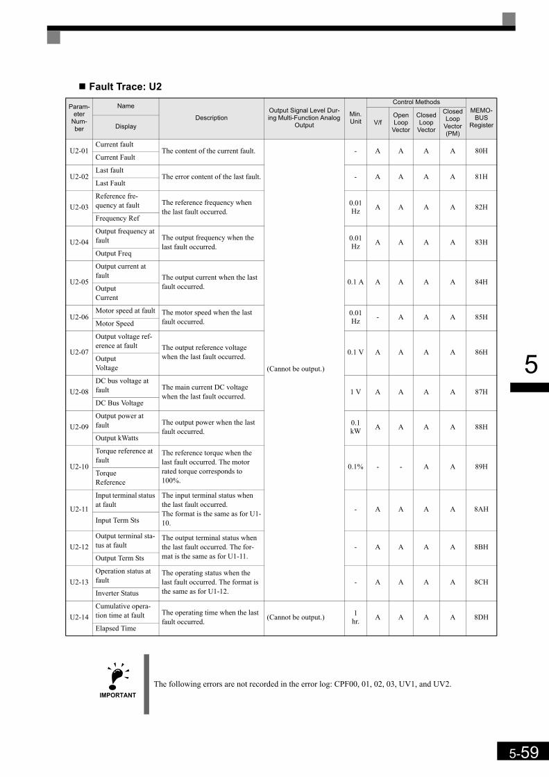
5-59
5
Fault Trace: U2
Param-eter
Num-ber
Name
DescriptionOutput Signal Level Dur-ing Multi-Function Analog
Output
Min. Unit
Control MethodsMEMO-
BUSRegisterV/f
Open Loop
Vector
Closed Loop
Vector
Closed Loop
Vector (PM)
Display
U2-01Current fault
The content of the current fault.
(Cannot be output.)
- A A A A 80HCurrent Fault
U2-02Last fault
The error content of the last fault. - A A A A 81HLast Fault
U2-03Reference fre-quency at fault The reference frequency when
the last fault occurred.0.01Hz A A A A 82H
Frequency Ref
U2-04Output frequency at fault The output frequency when the
last fault occurred.0.01Hz A A A A 83H
Output Freq
U2-05
Output current at fault The output current when the last
fault occurred. 0.1 A A A A A 84HOutput Current
U2-06Motor speed at fault The motor speed when the last
fault occurred.0.01 Hz - A A A 85H
Motor Speed
U2-07
Output voltage ref-erence at fault The output reference voltage
when the last fault occurred. 0.1 V A A A A 86HOutput Voltage
U2-08DC bus voltage at fault The main current DC voltage
when the last fault occurred. 1 V A A A A 87HDC Bus Voltage
U2-09Output power at fault The output power when the last
fault occurred.0.1 kW A A A A 88H
Output kWatts
U2-10
Torque reference at fault
The reference torque when the last fault occurred. The motor rated torque corresponds to 100%.
0.1% - - A A 89HTorque Reference
U2-11
Input terminal status at fault
The input terminal status when the last fault occurred.The format is the same as for U1-10.
- A A A A 8AHInput Term Sts
U2-12Output terminal sta-tus at fault
The output terminal status when the last fault occurred. The for-mat is the same as for U1-11.
- A A A A 8BHOutput Term Sts
U2-13Operation status at fault
The operating status when the last fault occurred. The format is the same as for U1-12.
- A A A A 8CHInverter Status
U2-14Cumulative opera-tion time at fault The operating time when the last
fault occurred. (Cannot be output.) 1hr. A A A A 8DH
Elapsed Time
IMPORTANTThe following errors are not recorded in the error log: CPF00, 01, 02, 03, UV1, and UV2.
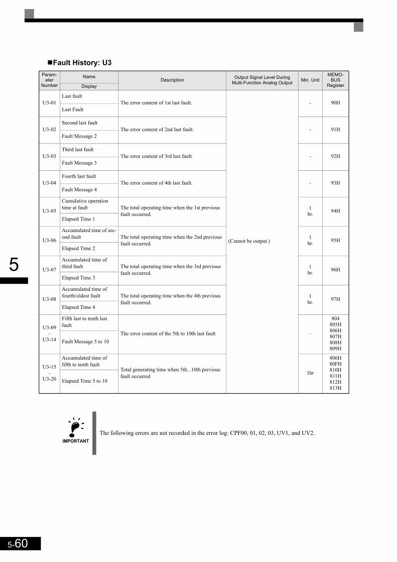
5-60
5
Fault History: U3Param-
eter Number
NameDescription Output Signal Level During
Multi-Function Analog Output Min. UnitMEMO-
BUSRegisterDisplay
U3-01Last fault
The error content of 1st last fault.
(Cannot be output.)
- 90HLast Fault
U3-02Second last fault
The error content of 2nd last fault. - 91HFault Message 2
U3-03Third last fault
The error content of 3rd last fault. - 92HFault Message 3
U3-04Fourth last fault
The error content of 4th last fault. - 93HFault Message 4
U3-05
Cumulative operation time at fault The total operating time when the 1st previous
fault occurred.1
hr. 94HElapsed Time 1
U3-06
Accumulated time of sec-ond fault The total operating time when the 2nd previous
fault occurred.1
hr. 95HElapsed Time 2
U3-07
Accumulated time of third fault The total operating time when the 3rd previous
fault occurred.1
hr. 96HElapsed Time 3
U3-08
Accumulated time of fourth/oldest fault The total operating time when the 4th previous
fault occurred. 1
hr. 97HElapsed Time 4
U3-09 –
U3-14
Fifth last to tenth last fault
The error content of the 5th to 10th last fault –
804805H806H807H808H809H
Fault Message 5 to 10
U3-15 –
U3-20
Accumulated time of fifth to tenth fault
Total generating time when 5th...10th previous fault occurred 1hr
806H80FH810H811H812H813H
Elapsed Time 5 to 10
IMPORTANTThe following errors are not recorded in the error log: CPF00, 01, 02, 03, UV1, and UV2.
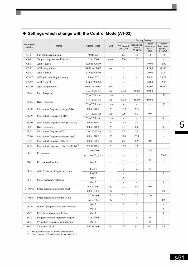
5-61
5
Settings which change with the Control Mode (A1-02)
Parameter Number Name Setting Range Unit
Factory Setting
V/f ControlA1-02=0
Open Loop Vector
A1-02=2
Closed Loop Vec-
tor A1-02=3
Closed Loop Vec-tor (PM) A1-02=5
C3-01 Slip compensation gain 0.0 to 2.5 - 1.0 1.0 1.0 1.0
C4-02 Torque compensation delay time 0 to 10000 msec 200 20 - -
C5-01 ASR P gain 1 1.00 to 300.00 - - - 40.00 12.00
C5-02 ASR Integral time 1 0.000 to 10.000 sec - - 0.500 0.300
C5-03 ASR P gain 2 1.00 to 300.00 - - - 20.00 6.00
C5-07 ASR gain switching frequency 0.0to 120.0 i - - 0.0 Hz 2.0 %
C5-09 ASR P gain 3 1.00 to 300.00 - - - 40.00 12.00
C5-10 ASR Integral time 3 0.000 to 10.000 sec - - 0.500 0.300
E1-04 Max. Frequency0 to 120.00 Hz Hz 50.00 50.00 50.00 -
20 to 7200 rpm rpm - - - 150
E1-06 Base Frequency0 to 120.00 Hz Hz 50.00 50.00 50.00 -
20 to 7200 rpm rpm - - - 150
E1-08 Mid. output frequency voltage (VB)*1
*1. The given values are for a 400 V class Inverter.
0.0 to 510.0 V 37.4 25.0 - -
E1-09 Min. output frequency (FMIN)0 to 120.00 Hz Hz 0.5 0.3 0.0 -
20 to 7200 rpm rpm - - - 0
E1-10 Min. output frequency voltage (VMIN) 0.0 to 510.0 V 19.4 5.0 - -
E1-13 Base Frequency 0.0 to 510.0 V 0.0 0.0 - 400
E2-05 Mid. output frequency (FB) 0 to 120.00 Hz Hz 2.5 3.0 - -
E3-06 Mid. output frequency voltage (VB)*1 0.0 to 510.0 V 30.0 26.4 - -
E3-07 Min. output frequency (FMIN) 0.0 to 120.0 Hz 1.2 0.5 0.0 -
E3-08 Min. output frequency voltage (VMIN)*1 0.0 to 510.0 V 18.0 4.8 - -
F1-01 PG constant0 to 60000 - - - 1024 -
512, 1024*2, 2048
*2. Can be set only if Hiperface is selected as interface.
- - - - 2048
F1-05 PG rotation direction 0 or 1 -- - 0 -
- - - 1
F1-04 AO-12 Channel 1 Signal selection1 to 56
-2 2 2 -
1 to 75 - - - 5
L1-01 Motor protection selection0 to 3
-1 1 1 -
0 or 5 - - - 5
L4-01/03 Speed agreement detection level0 to 120.00 Hz 0.0 0.0 0.0 -
0.0 to 100.0 % - - - 0.0
L4-02/04 Speed agreement detection width0.0 to 20.0 Hz 2.0 2.0 2.0 -
0.0 to 40.o % - - - 4.0
L8-09 Output open phase detection selection0 to 2 - 2 2 2 -
0 or 1 - - - - 0
n5-01 Feed forward control selection 0 or 1 - - - 1 0
o1-03 Frequency monitor/reference display 0 to 39999 - 0 0 0 1
o1-04 V/f pattern frequency parameter unit 0 or 1 - - - 0 1
S1-01 Zero speed level 0.00 to 10.00 Hz 1.2 0.5 0.1 0.5
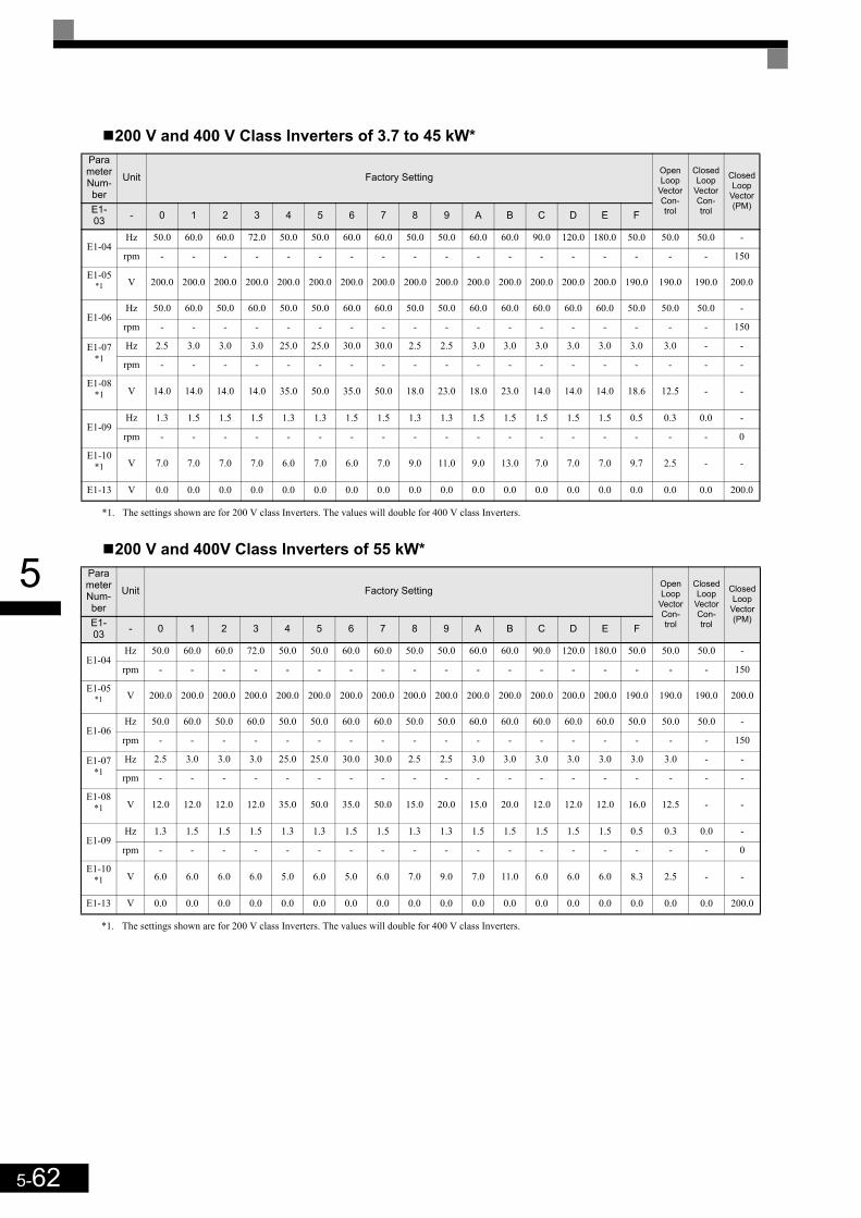
5-62
5
200 V and 400 V Class Inverters of 3.7 to 45 kW*
200 V and 400V Class Inverters of 55 kW*
Parameter Num-ber
Unit Factory SettingOpen Loop
Vector Con-trol
Closed Loop
Vector Con-trol
Closed Loop
Vector (PM) E1-
03 - 0 1 2 3 4 5 6 7 8 9 A B C D E F
E1-04Hz 50.0 60.0 60.0 72.0 50.0 50.0 60.0 60.0 50.0 50.0 60.0 60.0 90.0 120.0 180.0 50.0 50.0 50.0 -
rpm - - - - - - - - - - - - - - - - - - 150
E1-05*1
*1. The settings shown are for 200 V class Inverters. The values will double for 400 V class Inverters.
V 200.0 200.0 200.0 200.0 200.0 200.0 200.0 200.0 200.0 200.0 200.0 200.0 200.0 200.0 200.0 190.0 190.0 190.0 200.0
E1-06Hz 50.0 60.0 50.0 60.0 50.0 50.0 60.0 60.0 50.0 50.0 60.0 60.0 60.0 60.0 60.0 50.0 50.0 50.0 -
rpm - - - - - - - - - - - - - - - - - - 150
E1-07*1
Hz 2.5 3.0 3.0 3.0 25.0 25.0 30.0 30.0 2.5 2.5 3.0 3.0 3.0 3.0 3.0 3.0 3.0 - -
rpm - - - - - - - - - - - - - - - - - - -
E1-08*1 V 14.0 14.0 14.0 14.0 35.0 50.0 35.0 50.0 18.0 23.0 18.0 23.0 14.0 14.0 14.0 18.6 12.5 - -
E1-09Hz 1.3 1.5 1.5 1.5 1.3 1.3 1.5 1.5 1.3 1.3 1.5 1.5 1.5 1.5 1.5 0.5 0.3 0.0 -
rpm - - - - - - - - - - - - - - - - - - 0
E1-10*1 V 7.0 7.0 7.0 7.0 6.0 7.0 6.0 7.0 9.0 11.0 9.0 13.0 7.0 7.0 7.0 9.7 2.5 - -
E1-13 V 0.0 0.0 0.0 0.0 0.0 0.0 0.0 0.0 0.0 0.0 0.0 0.0 0.0 0.0 0.0 0.0 0.0 0.0 200.0
Parameter Num-ber
Unit Factory SettingOpen Loop
Vector Con-trol
Closed Loop
Vector Con-trol
Closed Loop
Vector (PM) E1-
03 - 0 1 2 3 4 5 6 7 8 9 A B C D E F
E1-04Hz 50.0 60.0 60.0 72.0 50.0 50.0 60.0 60.0 50.0 50.0 60.0 60.0 90.0 120.0 180.0 50.0 50.0 50.0 -
rpm - - - - - - - - - - - - - - - - - - 150
E1-05*1
*1. The settings shown are for 200 V class Inverters. The values will double for 400 V class Inverters.
V 200.0 200.0 200.0 200.0 200.0 200.0 200.0 200.0 200.0 200.0 200.0 200.0 200.0 200.0 200.0 190.0 190.0 190.0 200.0
E1-06Hz 50.0 60.0 50.0 60.0 50.0 50.0 60.0 60.0 50.0 50.0 60.0 60.0 60.0 60.0 60.0 50.0 50.0 50.0 -
rpm - - - - - - - - - - - - - - - - - - 150
E1-07*1
Hz 2.5 3.0 3.0 3.0 25.0 25.0 30.0 30.0 2.5 2.5 3.0 3.0 3.0 3.0 3.0 3.0 3.0 - -
rpm - - - - - - - - - - - - - - - - - - -
E1-08*1 V 12.0 12.0 12.0 12.0 35.0 50.0 35.0 50.0 15.0 20.0 15.0 20.0 12.0 12.0 12.0 16.0 12.5 - -
E1-09Hz 1.3 1.5 1.5 1.5 1.3 1.3 1.5 1.5 1.3 1.3 1.5 1.5 1.5 1.5 1.5 0.5 0.3 0.0 -
rpm - - - - - - - - - - - - - - - - - - 0
E1-10*1 V 6.0 6.0 6.0 6.0 5.0 6.0 5.0 6.0 7.0 9.0 7.0 11.0 6.0 6.0 6.0 8.3 2.5 - -
E1-13 V 0.0 0.0 0.0 0.0 0.0 0.0 0.0 0.0 0.0 0.0 0.0 0.0 0.0 0.0 0.0 0.0 0.0 0.0 200.0
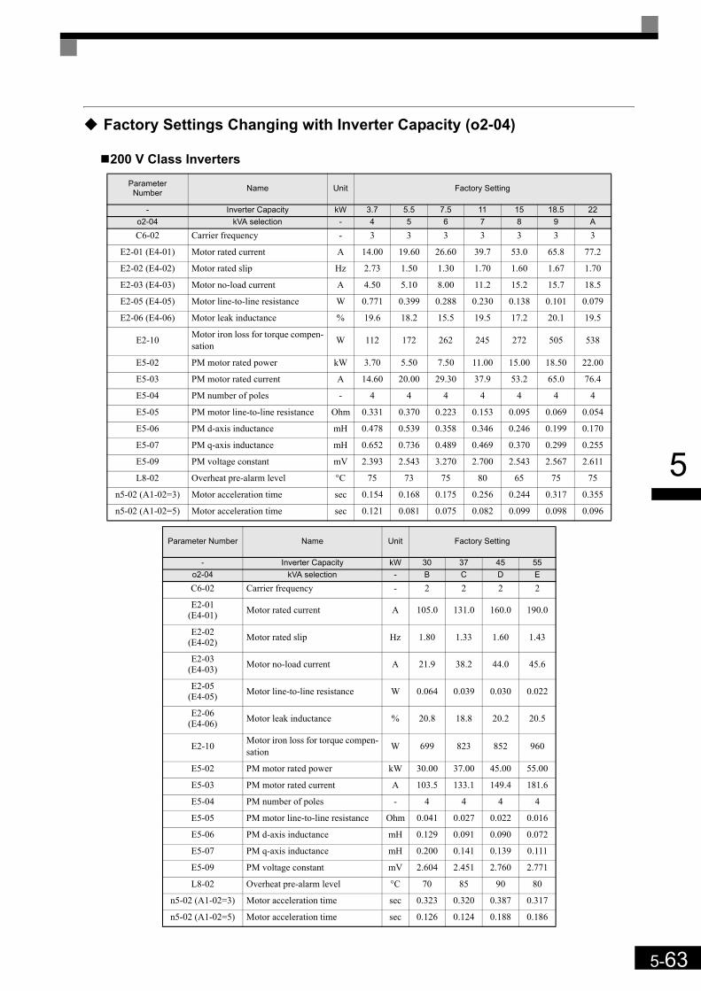
5-63
5
Factory Settings Changing with Inverter Capacity (o2-04)
200 V Class Inverters
ParameterNumber Name Unit Factory Setting
- Inverter Capacity kW 3.7 5.5 7.5 11 15 18.5 22o2-04 kVA selection - 4 5 6 7 8 9 A
C6-02 Carrier frequency - 3 3 3 3 3 3 3
E2-01 (E4-01) Motor rated current A 14.00 19.60 26.60 39.7 53.0 65.8 77.2
E2-02 (E4-02) Motor rated slip Hz 2.73 1.50 1.30 1.70 1.60 1.67 1.70
E2-03 (E4-03) Motor no-load current A 4.50 5.10 8.00 11.2 15.2 15.7 18.5
E2-05 (E4-05) Motor line-to-line resistance W 0.771 0.399 0.288 0.230 0.138 0.101 0.079
E2-06 (E4-06) Motor leak inductance % 19.6 18.2 15.5 19.5 17.2 20.1 19.5
E2-10 Motor iron loss for torque compen-sation W 112 172 262 245 272 505 538
E5-02 PM motor rated power kW 3.70 5.50 7.50 11.00 15.00 18.50 22.00
E5-03 PM motor rated current A 14.60 20.00 29.30 37.9 53.2 65.0 76.4
E5-04 PM number of poles - 4 4 4 4 4 4 4
E5-05 PM motor line-to-line resistance Ohm 0.331 0.370 0.223 0.153 0.095 0.069 0.054
E5-06 PM d-axis inductance mH 0.478 0.539 0.358 0.346 0.246 0.199 0.170
E5-07 PM q-axis inductance mH 0.652 0.736 0.489 0.469 0.370 0.299 0.255
E5-09 PM voltage constant mV 2.393 2.543 3.270 2.700 2.543 2.567 2.611
L8-02 Overheat pre-alarm level °C 75 73 75 80 65 75 75
n5-02 (A1-02=3) Motor acceleration time sec 0.154 0.168 0.175 0.256 0.244 0.317 0.355
n5-02 (A1-02=5) Motor acceleration time sec 0.121 0.081 0.075 0.082 0.099 0.098 0.096
Parameter Number Name Unit Factory Setting
- Inverter Capacity kW 30 37 45 55o2-04 kVA selection - B C D E
C6-02 Carrier frequency - 2 2 2 2
E2-01(E4-01) Motor rated current A 105.0 131.0 160.0 190.0
E2-02(E4-02) Motor rated slip Hz 1.80 1.33 1.60 1.43
E2-03(E4-03) Motor no-load current A 21.9 38.2 44.0 45.6
E2-05(E4-05) Motor line-to-line resistance W 0.064 0.039 0.030 0.022
E2-06(E4-06) Motor leak inductance % 20.8 18.8 20.2 20.5
E2-10 Motor iron loss for torque compen-sation W 699 823 852 960
E5-02 PM motor rated power kW 30.00 37.00 45.00 55.00
E5-03 PM motor rated current A 103.5 133.1 149.4 181.6
E5-04 PM number of poles - 4 4 4 4
E5-05 PM motor line-to-line resistance Ohm 0.041 0.027 0.022 0.016
E5-06 PM d-axis inductance mH 0.129 0.091 0.090 0.072
E5-07 PM q-axis inductance mH 0.200 0.141 0.139 0.111
E5-09 PM voltage constant mV 2.604 2.451 2.760 2.771
L8-02 Overheat pre-alarm level °C 70 85 90 80
n5-02 (A1-02=3) Motor acceleration time sec 0.323 0.320 0.387 0.317
n5-02 (A1-02=5) Motor acceleration time sec 0.126 0.124 0.188 0.186
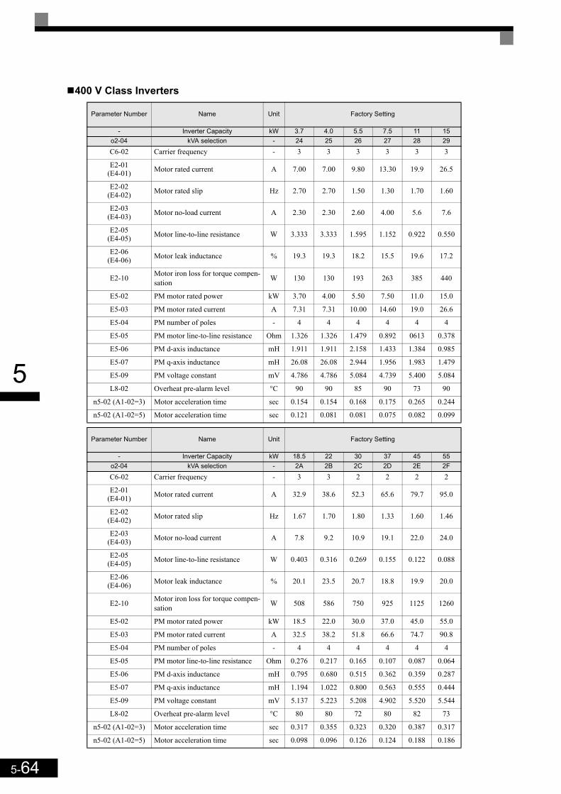
5-64
5
400 V Class Inverters
Parameter Number Name Unit Factory Setting
- Inverter Capacity kW 3.7 4.0 5.5 7.5 11 15o2-04 kVA selection - 24 25 26 27 28 29
C6-02 Carrier frequency - 3 3 3 3 3 3
E2-01(E4-01) Motor rated current A 7.00 7.00 9.80 13.30 19.9 26.5
E2-02(E4-02) Motor rated slip Hz 2.70 2.70 1.50 1.30 1.70 1.60
E2-03(E4-03) Motor no-load current A 2.30 2.30 2.60 4.00 5.6 7.6
E2-05(E4-05) Motor line-to-line resistance W 3.333 3.333 1.595 1.152 0.922 0.550
E2-06(E4-06) Motor leak inductance % 19.3 19.3 18.2 15.5 19.6 17.2
E2-10 Motor iron loss for torque compen-sation W 130 130 193 263 385 440
E5-02 PM motor rated power kW 3.70 4.00 5.50 7.50 11.0 15.0
E5-03 PM motor rated current A 7.31 7.31 10.00 14.60 19.0 26.6
E5-04 PM number of poles - 4 4 4 4 4 4
E5-05 PM motor line-to-line resistance Ohm 1.326 1.326 1.479 0.892 0613 0.378
E5-06 PM d-axis inductance mH 1.911 1.911 2.158 1.433 1.384 0.985
E5-07 PM q-axis inductance mH 26.08 26.08 2.944 1.956 1.983 1.479
E5-09 PM voltage constant mV 4.786 4.786 5.084 4.739 5.400 5.084
L8-02 Overheat pre-alarm level °C 90 90 85 90 73 90
n5-02 (A1-02=3) Motor acceleration time sec 0.154 0.154 0.168 0.175 0.265 0.244
n5-02 (A1-02=5) Motor acceleration time sec 0.121 0.081 0.081 0.075 0.082 0.099
Parameter Number Name Unit Factory Setting
- Inverter Capacity kW 18.5 22 30 37 45 55o2-04 kVA selection - 2A 2B 2C 2D 2E 2F
C6-02 Carrier frequency - 3 3 2 2 2 2
E2-01(E4-01) Motor rated current A 32.9 38.6 52.3 65.6 79.7 95.0
E2-02(E4-02) Motor rated slip Hz 1.67 1.70 1.80 1.33 1.60 1.46
E2-03(E4-03) Motor no-load current A 7.8 9.2 10.9 19.1 22.0 24.0
E2-05(E4-05) Motor line-to-line resistance W 0.403 0.316 0.269 0.155 0.122 0.088
E2-06(E4-06) Motor leak inductance % 20.1 23.5 20.7 18.8 19.9 20.0
E2-10 Motor iron loss for torque compen-sation W 508 586 750 925 1125 1260
E5-02 PM motor rated power kW 18.5 22.0 30.0 37.0 45.0 55.0
E5-03 PM motor rated current A 32.5 38.2 51.8 66.6 74.7 90.8
E5-04 PM number of poles - 4 4 4 4 4 4
E5-05 PM motor line-to-line resistance Ohm 0.276 0.217 0.165 0.107 0.087 0.064
E5-06 PM d-axis inductance mH 0.795 0.680 0.515 0.362 0.359 0.287
E5-07 PM q-axis inductance mH 1.194 1.022 0.800 0.563 0.555 0.444
E5-09 PM voltage constant mV 5.137 5.223 5.208 4.902 5.520 5.544
L8-02 Overheat pre-alarm level °C 80 80 72 80 82 73
n5-02 (A1-02=3) Motor acceleration time sec 0.317 0.355 0.323 0.320 0.387 0.317
n5-02 (A1-02=5) Motor acceleration time sec 0.098 0.096 0.126 0.124 0.188 0.186

6Parameter Settings by
FunctionCarrier Frequency Derating and Current Limitation ............6-2Control / Brake Sequence...................................................6-3Acceleration and Deceleration Characteristics .................6-20Adjusting Analog Input Signals .........................................6-25Speed Detection and Speed Limitation.............................6-26Improving the Operation Performance..............................6-29Protective Functions .........................................................6-40Inverter Protection.............................................................6-47Input Terminal Functions ..................................................6-50Output Terminal Functions................................................6-56Motor and V/f Pattern Setup .............................................6-59Digital Operator/LED Monitor Functions ...........................6-64PG Option Cards...............................................................6-72Rescue System.................................................................6-77Automatic Fault Reset.......................................................6-81Memobus Communications ..............................................6-83
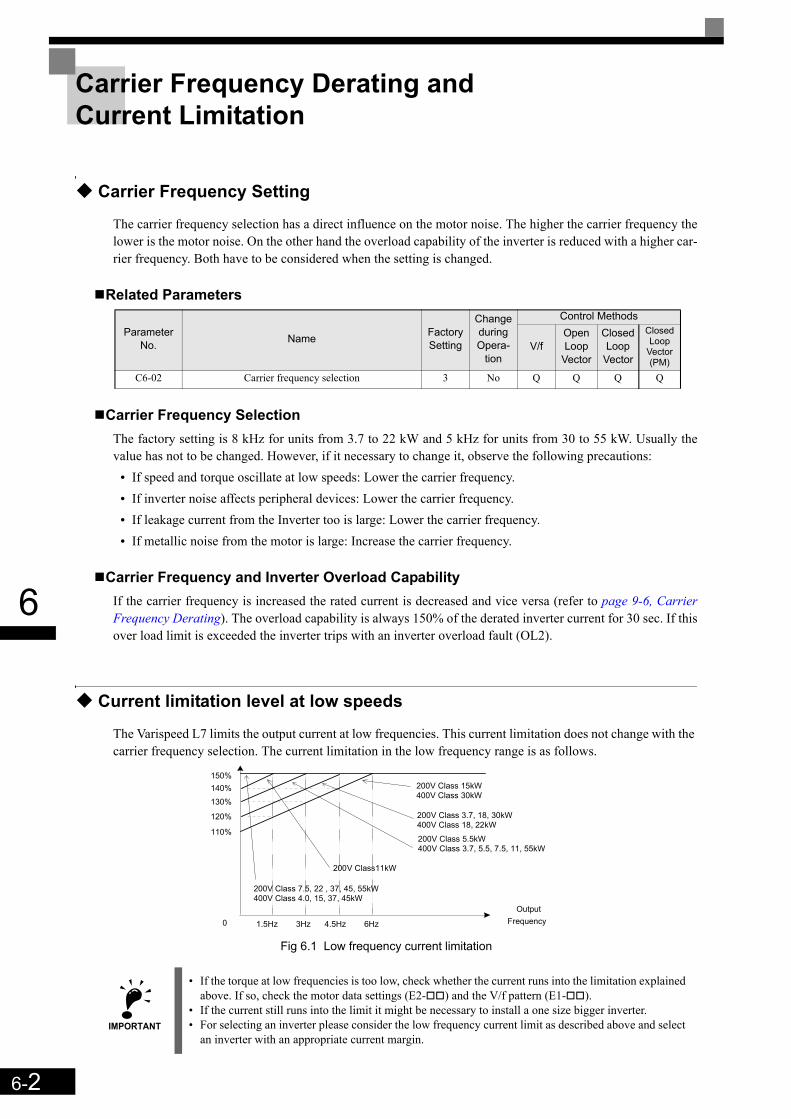
6-2
6
Carrier Frequency Derating and Current Limitation
Carrier Frequency Setting
The carrier frequency selection has a direct influence on the motor noise. The higher the carrier frequency thelower is the motor noise. On the other hand the overload capability of the inverter is reduced with a higher car-rier frequency. Both have to be considered when the setting is changed.
Related Parameters
Carrier Frequency SelectionThe factory setting is 8 kHz for units from 3.7 to 22 kW and 5 kHz for units from 30 to 55 kW. Usually thevalue has not to be changed. However, if it necessary to change it, observe the following precautions:
• If speed and torque oscillate at low speeds: Lower the carrier frequency.• If inverter noise affects peripheral devices: Lower the carrier frequency.• If leakage current from the Inverter too is large: Lower the carrier frequency.• If metallic noise from the motor is large: Increase the carrier frequency.
Carrier Frequency and Inverter Overload CapabilityIf the carrier frequency is increased the rated current is decreased and vice versa (refer to page 9-6, CarrierFrequency Derating). The overload capability is always 150% of the derated inverter current for 30 sec. If thisover load limit is exceeded the inverter trips with an inverter overload fault (OL2).
Current limitation level at low speeds
The Varispeed L7 limits the output current at low frequencies. This current limitation does not change with the carrier frequency selection. The current limitation in the low frequency range is as follows.
Fig 6.1 Low frequency current limitation
Parameter No. Name Factory
Setting
Change during Opera-
tion
Control Methods
V/fOpen Loop
Vector
Closed Loop
Vector
Closed Loop
Vector (PM)
C6-02 Carrier frequency selection 3 No Q Q Q Q
IMPORTANT
• If the torque at low frequencies is too low, check whether the current runs into the limitation explained above. If so, check the motor data settings (E2- ) and the V/f pattern (E1- ).
• If the current still runs into the limit it might be necessary to install a one size bigger inverter.• For selecting an inverter please consider the low frequency current limit as described above and select
an inverter with an appropriate current margin.
150%
6Hz0
OutputFrequency
140% 200V Class 15kW400V Class 30kW
130%
120%
110%
4.5Hz3Hz1.5Hz
200V Class11kW
200V Class 5.5kW400V Class 3.7, 5.5, 7.5, 11, 55kW
200V Class 3.7, 18, 30kW400V Class 18, 22kW
200V Class 7.5, 22 , 37, 45, 55kW400V Class 4.0, 15, 37, 45kW

6-3
6
Control / Brake Sequence
Up and Down Commands
Travel start in Up or Down directionUP and Down commands are the travel direction information.
To start in the elevator in Up or Down direction the following conditions have to be fulfilled:• At least one speed reference must be selected if digital inputs are used for speed reference selection.• The hardware base block signal must be set (not base block condition).• When a digital input is set as contactor confirmation input, the contactor confirmation signal must be
present before the travel starts.• To start in the Up direction the Up signal must be set. To start in the Down direction the Down signal must
be set.
Travel stopThe inverter can be stopped as follows:
• The direction command (UP or Down) signal is removed.• The speed reference selection signal is removed if digital inputs are used for speed reference selection.• If d1-18 is set to 3 and all speed inputs are removed
Up / Down Command Source SelectionThe input source for the Up and Down signal can be selected in parameter b1-02.
Related Parameters
Up/Down Commands Using the Digital Operator (b1-02=0)When b1-02 is set to 0 the Up/Down command must be input using the Digital Operator keys (RUN, STOP,and FWD/REV). For details on the Digital Operator refer to page 3-1, LED Monitor / Digital Operator andModes. This operation can be used for test purposes only.
Up/Down Commands Using Control Circuit Terminals (b1-02=1, factory setting)When b1-02 is set to 1 the Up/Down command is input at the control circuit terminals S1 and S2. This is thefactory setting and the most common configuration.
Up/Down Commands Using an Input Option Card (b1-02=3)When b1-02 is set to 2 the Up/Down command can be set using an input option card, for example a field buscommunications card.
Parameter No. Name Factory
Setting
Change during
Operation
Control Methods
V/fOpen Loop
Vector
Closed Loop
Vector
Closed Loop
Vector (PM)
b1-02 RUN command source selection 1 No Q Q Q Q
6-4
6
Speed Reference Source Selection
Speed Reference Source SelectionThe speed reference source can be selected using parameter b1-01.
Related Parameters
Input the Speed Reference from the Digital Inputs (b1-01=0)When b1-01 is set to 0 the speed reference can be selected from preset speeds using the digital inputs of theinverter. Refer to page 6-5, Speed Selection Sequence Using Digital Inputs for details.
Input the Speed Reference Using a Voltage Signal (b1-01=1)When b1-01 is set to 1 the speed reference can be input at terminal A1 as a 0 to +10V signal. If an analogoption card AI-14B is installed, the A1 signal is replaced by the Channel 1 input of the AI card.The analog reference signal can also be used as 1st speed if multispeed operation is selected (d1-18=0, refer topage 6-5, Speed Selection Sequence Using Digital Inputs for details).If parameter d1-18 is set to 0 and b1-01 is set to 1, the analog input value replaces any speed selected by thedigital inputs except the service speed.
Input the Speed Reference Using an Input Option Card (b1-01=3)When b1-01 is set to 2 the speed reference can be input using an input option card, for example a field buscommunications card.
Parameter No. Name Factory
Setting
Change during Opera-
tion
Control Methods
V/fOpen Loop
Vector
Closed Loop
Vector
Closed Loop
Vector(PM)
b1-01 Frequency reference source selection 0 No Q Q Q Q

6-5
6
Speed Selection Sequence Using Digital Inputs
If the digital inputs are used for speed selection, the speed selection method and the speed priority depends onthe setting of parameter d1-18.
Multi-Step Speed Operation 1/2 (Binary Input) (d1-18=0/3)
If d1-18 = 08 preset speed steps (defined in the parameters d1-01 to d1-08) can be selected using 3 binary coded digitalinputs. The Up/Down command starts the inverter. It stops when the Up/Down command is removed.
If d1-18 = 37 preset speed steps (defined in the parameters d1-02 to d1-08) can be selected using 3 binary coded digitalinputs. The Up/Down command starts the inverter. It is stopped when the Up/Down command is removed orwhen no speed is selected (all D/Is off).
Related Parameters
Multi-function Digital Input Settings (H1-01 to H1-05) (Example)
Parameter No. Name Factory
Setting
Change during
Operation
Control Methods
V/fOpen Loop
Vector
Closed Loop
Vector
Closed Loop
Vector (PM)
d1-18 Speed Priority Selection 1 No Q Q Q Q
Parameter No. Name Factory
Setting
Change during
Operation
Control Methods
V/fOpen Loop
Vector
Closed Loop
Vector
Closed Loop
Vector (PM)
d1-01 to d1-08 Multi-Step speed 1 to 8 reference value
0.00 HzYes
A A A -
0.00% - - - A
Terminal Parameter Number Set Value Details
S4 H1-02 3 Multi-step speed command 1
S5 H1-03 4 Multi-step speed command 2
S6 H1-04 5 Multi-step speed command 3
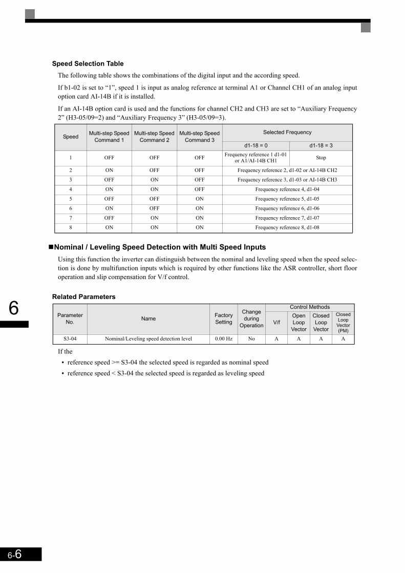
6-6
6
Speed Selection TableThe following table shows the combinations of the digital input and the according speed.
If b1-02 is set to “1”, speed 1 is input as analog reference at terminal A1 or Channel CH1 of an analog inputoption card AI-14B if it is installed.
If an AI-14B option card is used and the functions for channel CH2 and CH3 are set to “Auxiliary Frequency2” (H3-05/09=2) and “Auxiliary Frequency 3” (H3-05/09=3).
Nominal / Leveling Speed Detection with Multi Speed InputsUsing this function the inverter can distinguish between the nominal and leveling speed when the speed selec-tion is done by multifunction inputs which is required by other functions like the ASR controller, short flooroperation and slip compensation for V/f control.
Related Parameters
If the• reference speed >= S3-04 the selected speed is regarded as nominal speed• reference speed < S3-04 the selected speed is regarded as leveling speed
Speed Multi-step Speed Command 1
Multi-step Speed Command 2
Multi-step Speed Command 3
Selected Frequency
d1-18 = 0 d1-18 = 3
1 OFF OFF OFF Frequency reference 1 d1-01 or A1/AI-14B CH1 Stop
2 ON OFF OFF Frequency reference 2, d1-02 or AI-14B CH2
3 OFF ON OFF Frequency reference 3, d1-03 or AI-14B CH3
4 ON ON OFF Frequency reference 4, d1-04
5 OFF OFF ON Frequency reference 5, d1-05
6 ON OFF ON Frequency reference 6, d1-06
7 OFF ON ON Frequency reference 7, d1-07
8 ON ON ON Frequency reference 8, d1-08
Parameter No. Name Factory
Setting
Change during
Operation
Control Methods
V/fOpen Loop
Vector
Closed Loop
Vector
Closed Loop
Vector (PM)
S3-04 Nominal/Leveling speed detection level 0.00 Hz No A A A A
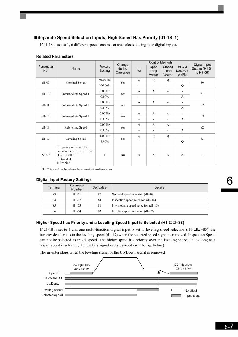
6-7
6
Separate Speed Selection Inputs, High Speed Has Priority (d1-18=1)If d1-18 is set to 1, 6 different speeds can be set and selected using four digital inputs.
Related Parameters
Digital Input Factory Settings
Higher Speed has Priority and a Leveling Speed Input is Selected (H1- =83)If d1-18 is set to 1 and one multi-function digital input is set to leveling speed selection (H1- =83), theinverter decelerates to the leveling speed (d1-17) when the selected speed signal is removed. Inspection Speedcan not be selected as travel speed. The higher speed has priority over the leveling speed, i.e. as long as ahigher speed is selected, the leveling signal is disregarded (see the fig. below)
The inverter stops when the leveling signal or the Up/Down signal is removed.
Parameter No. Name Factory
Setting
Change during
Operation
Control MethodsDigital Input
Setting (H1-01 to H1-05)V/f
Open Loop
Vector
Closed Loop
Vector
Closed Loop Vec-tor (PM)
d1-09 Nominal Speed50.00 Hz
YesQ Q Q -
80100.00% - - - Q
d1-10 Intermediate Speed 10.00 Hz
YesA A A -
810.00% - - - A
d1-11 Intermediate Speed 20.00 Hz
YesA A A -
-*1
*1. This speed can be selected by a combination of two inputs
0.00% - - - A
d1-12 Intermediate Speed 30.00 Hz
YesA A A -
-*10.00% - - - A
d1-13 Releveling Speed0.00 Hz
YesA A A -
820.00% - - - A
d1-17 Leveling Speed4.00 Hz
YesQ Q Q -
838.00% - - - Q
S3-09
Frequency reference loss detection when d1-18 = 1 and H1- K83.0:Disabled1:Enabled
1 No A A A A -
Terminal Parameter Number Set Value Details
S3 H1-01 80 Nominal speed selection (d1-09)
S4 H1-02 84 Inspection speed selection (d1-14)
S5 H1-03 81 Intermediate speed selection (d1-10)
S6 H1-04 83 Leveling speed selection (d1-17)
Up/Donw
Leveling speedSelected speed
Speed
DC Injection/zero servo
DC Injection/zero servo
Input is setNo effect
Hardware BB
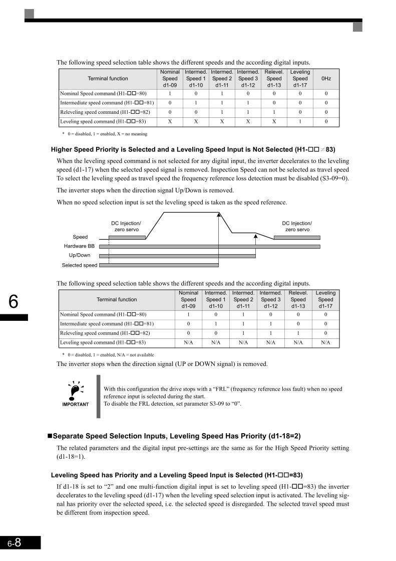
6-8
6
The following speed selection table shows the different speeds and the according digital inputs.
* 0 = disabled, 1 = enabled, X = no meaning
Higher Speed Priority is Selected and a Leveling Speed Input is Not Selected (H1- K83)When the leveling speed command is not selected for any digital input, the inverter decelerates to the levelingspeed (d1-17) when the selected speed signal is removed. Inspection Speed can not be selected as travel speedTo select the leveling speed as travel speed the frequency reference loss detection must be disabled (S3-09=0).
The inverter stops when the direction signal Up/Down is removed.
When no speed selection input is set the leveling speed is taken as the speed reference.
The following speed selection table shows the different speeds and the according digital inputs.
* 0 = disabled, 1 = enabled, N/A = not available
The inverter stops when the direction signal (UP or DOWN signal) is removed.
Separate Speed Selection Inputs, Leveling Speed Has Priority (d1-18=2)The related parameters and the digital input pre-settings are the same as for the High Speed Priority setting(d1-18=1).
Leveling Speed has Priority and a Leveling Speed Input is Selected (H1- =83)If d1-18 is set to “2” and one multi-function digital input is set to leveling speed (H1- =83) the inverterdecelerates to the leveling speed (d1-17) when the leveling speed selection input is activated. The leveling sig-nal has priority over the selected speed, i.e. the selected speed is disregarded. The selected travel speed mustbe different from inspection speed.
Terminal functionNominal Speedd1-09
Intermed. Speed 1
d1-10
Intermed. Speed 2
d1-11
Intermed. Speed 3
d1-12
Relevel. Speedd1-13
Leveling Speedd1-17
0Hz
Nominal Speed command (H1- =80) 1 0 1 0 0 0 0
Intermediate speed command (H1- =81) 0 1 1 1 0 0 0
Releveling speed command (H1- =82) 0 0 1 1 1 0 0
Leveling speed command (H1- =83) X X X X X 1 0
Terminal functionNominal Speedd1-09
Intermed. Speed 1d1-10
Intermed. Speed 2
d1-11
Intermed. Speed 3
d1-12
Relevel. Speedd1-13
Leveling Speedd1-17
Nominal Speed command (H1- =80) 1 0 1 0 0 0
Intermediate speed command (H1- =81) 0 1 1 1 0 0
Releveling speed command (H1- =82) 0 0 1 1 1 0
Leveling speed command (H1- =83) N/A N/A N/A N/A N/A N/A
IMPORTANT
With this configuration the drive stops with a “FRL” (frequency reference loss fault) when no speed reference input is selected during the start.To disable the FRL detection, set parameter S3-09 to “0”.
Up/Down
Selected speed
Speed
DC Injection/zero servo
DC Injection/zero servo
Hardware BB
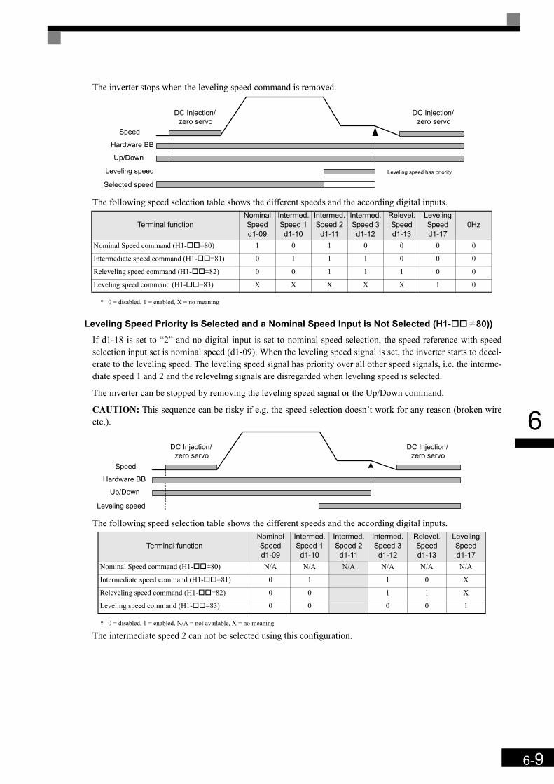
6-9
6
The inverter stops when the leveling speed command is removed.
The following speed selection table shows the different speeds and the according digital inputs.
* 0 = disabled, 1 = enabled, X = no meaning
Leveling Speed Priority is Selected and a Nominal Speed Input is Not Selected (H1- K80))If d1-18 is set to “2” and no digital input is set to nominal speed selection, the speed reference with speedselection input set is nominal speed (d1-09). When the leveling speed signal is set, the inverter starts to decel-erate to the leveling speed. The leveling speed signal has priority over all other speed signals, i.e. the interme-diate speed 1 and 2 and the releveling signals are disregarded when leveling speed is selected.
The inverter can be stopped by removing the leveling speed signal or the Up/Down command.
CAUTION: This sequence can be risky if e.g. the speed selection doesn’t work for any reason (broken wireetc.).
The following speed selection table shows the different speeds and the according digital inputs.
* 0 = disabled, 1 = enabled, N/A = not available, X = no meaning
The intermediate speed 2 can not be selected using this configuration.
Terminal functionNominal Speedd1-09
Intermed. Speed 1d1-10
Intermed. Speed 2
d1-11
Intermed. Speed 3d1-12
Relevel. Speedd1-13
Leveling Speedd1-17
0Hz
Nominal Speed command (H1- =80) 1 0 1 0 0 0 0
Intermediate speed command (H1- =81) 0 1 1 1 0 0 0
Releveling speed command (H1- =82) 0 0 1 1 1 0 0
Leveling speed command (H1- =83) X X X X X 1 0
Terminal functionNominal Speedd1-09
Intermed. Speed 1
d1-10
Intermed. Speed 2
d1-11
Intermed. Speed 3
d1-12
Relevel. Speedd1-13
Leveling Speedd1-17
Nominal Speed command (H1- =80) N/A N/A N/A N/A N/A N/A
Intermediate speed command (H1- =81) 0 1 1 0 X
Releveling speed command (H1- =82) 0 0 1 1 X
Leveling speed command (H1- =83) 0 0 0 0 1
Up/Down
Leveling speed
Selected speed
Speed
DC Injection/zero servo
DC Injection/zero servo
Hardware BB
Leveling speed has priority
Up/Down
Speed
DC Injection/zero servo
DC Injection/zero servo
Hardware BB
Leveling speed
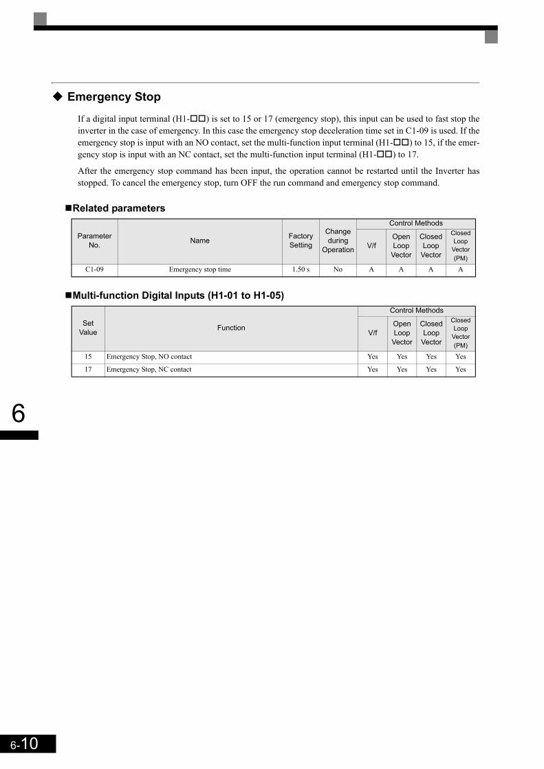
6-10
6
Emergency Stop
If a digital input terminal (H1- ) is set to 15 or 17 (emergency stop), this input can be used to fast stop theinverter in the case of emergency. In this case the emergency stop deceleration time set in C1-09 is used. If theemergency stop is input with an NO contact, set the multi-function input terminal (H1- ) to 15, if the emer-gency stop is input with an NC contact, set the multi-function input terminal (H1- ) to 17.
After the emergency stop command has been input, the operation cannot be restarted until the Inverter hasstopped. To cancel the emergency stop, turn OFF the run command and emergency stop command.
Related parameters
Multi-function Digital Inputs (H1-01 to H1-05)
Parameter No. Name Factory
Setting
Change during
Operation
Control Methods
V/fOpen Loop
Vector
Closed Loop
Vector
Closed Loop
Vector (PM)
C1-09 Emergency stop time 1.50 s No A A A A
Set Value Function
Control Methods
V/fOpen Loop
Vector
Closed Loop
Vector
Closed Loop
Vector (PM)
15 Emergency Stop, NO contact Yes Yes Yes Yes
17 Emergency Stop, NC contact Yes Yes Yes Yes

6-11
6
Inspection RUN
The inspection run can be activated in two ways:1. A digital input can be used if parameter d1-18 = 1 or 2. Therefore a inspection speed must be set and any of
the digital inputs must be set to “Inspection Run Selection” (H1- =84) (see below).2. A speed reference comparison value (parameter S3-19) decides if inspection run is activated or not. This
function work only if parameter d1-18 = 0 or 3 and if the inspection speed command is not assigned to anydigital input (H1- K84).
Related parameters
Multi-function Digital Inputs (H1-01 to H1-05)
Inspection Run Selection by Digital InputThe inspection run digital input must be set before the Up/Down signal is set. During the start of the inspec-tion RUN, the normal brake sequence is used and the inverter accelerates to the inspection speed (d1-14). Thestop method depends on the setting of parameter S3-03.
Inspection Speed Selection by Comparison ValueUsing this function the inverter can detect the inspection speed by the selected speed reference. The speedmust be selected before the Up/Down signal is set. If S3-04 < selected speed O S3-19 the selected speed isregarded as inspection speed. The normal start sequence is used, the stop method depends on the setting ofparameter S3-03.
Inspection Run Stop Behavior
S3-03 = 0.0 sec., Stop without deceleration rampThe inverter stops when the Inspection Speed command or the Up/Down command is removed. In this case:
• The inverter output is cut by baseblock immediately• The brake open signal is removed immediately• The contactor control output is removed immediately
Parameter No. Name Factory
Setting
Change during
Operation
Control Methods
V/fOpen Loop
Vector
Closed Loop
Vector
Closed Loop
Vector (PM)
d1-14 Inspection Speed25.00 Hz
NoA A A -
50.00% - - - A
S3-03 Inspection Deceleration time 0.0 sec No A A A A
S3-19 Inspection speed detection upper level 0.00 Hz No A A A A
Set Value Function
Control Methods
V/fOpen Loop
Vector
Closed Loop
Vector
Closed Loop
Vector (PM)
84 Inspection Run Selection Yes Yes Yes Yes
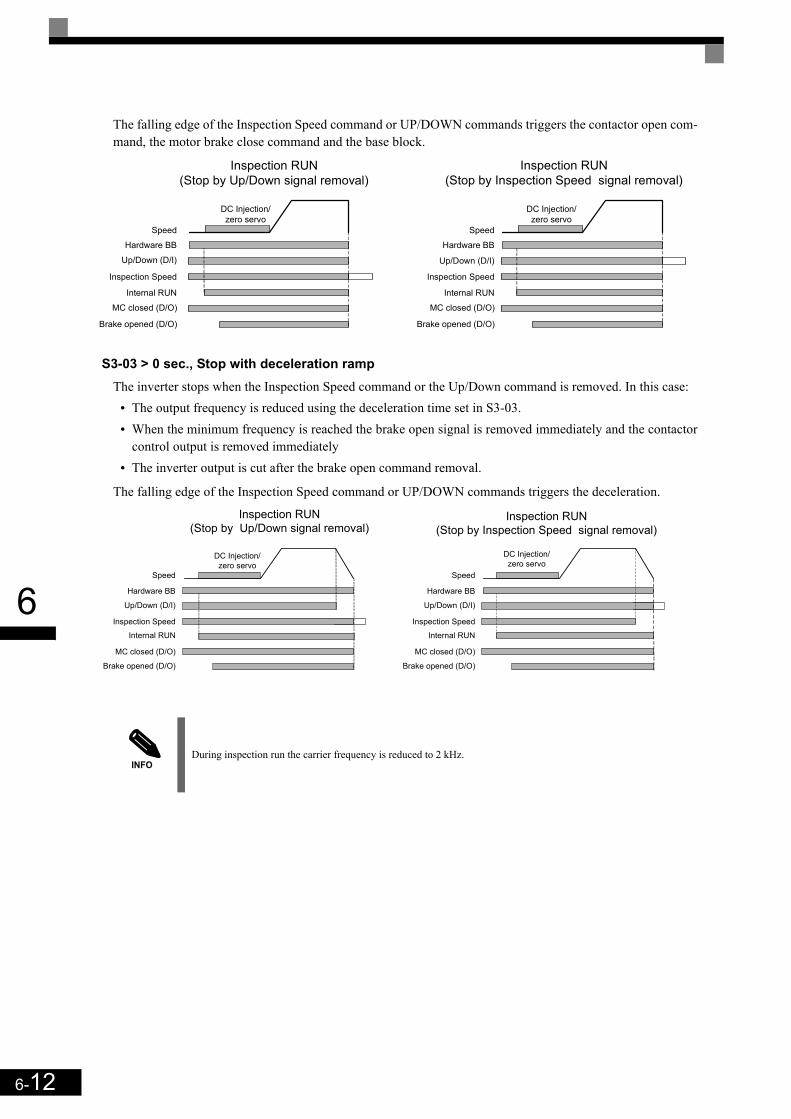
6-12
6
The falling edge of the Inspection Speed command or UP/DOWN commands triggers the contactor open com-mand, the motor brake close command and the base block.
S3-03 > 0 sec., Stop with deceleration rampThe inverter stops when the Inspection Speed command or the Up/Down command is removed. In this case:
• The output frequency is reduced using the deceleration time set in S3-03. • When the minimum frequency is reached the brake open signal is removed immediately and the contactor
control output is removed immediately• The inverter output is cut after the brake open command removal.
The falling edge of the Inspection Speed command or UP/DOWN commands triggers the deceleration.
INFODuring inspection run the carrier frequency is reduced to 2 kHz.
Up/Down (D/I)
MC closed (D/O)
Inspection Speed
Speed
DC Injection/zero servo
Internal RUN
Brake opened (D/O)
Inspection RUN(Stop by Up/Down signal removal)
Hardware BB
Inspection RUN(Stop by Inspection Speed signal removal)
DC Injection/zero servo
Up/Down (D/I)
MC closed (D/O)
Inspection Speed
Speed
Internal RUN
Brake opened (D/O)
Hardware BB
Up/Down (D/I)
MC closed (D/O)
Inspection Speed
Speed
DC Injection/zero servo
Internal RUN
Brake opened (D/O)
Inspection RUN(Stop by Up/Down signal removal)
Hardware BB
Inspection RUN(Stop by Inspection Speed signal removal)
Up/Down (D/I)
MC closed (D/O)
Inspection Speed
Speed
Internal RUN
Brake opened (D/O)
Hardware BB
DC Injection/zero servo
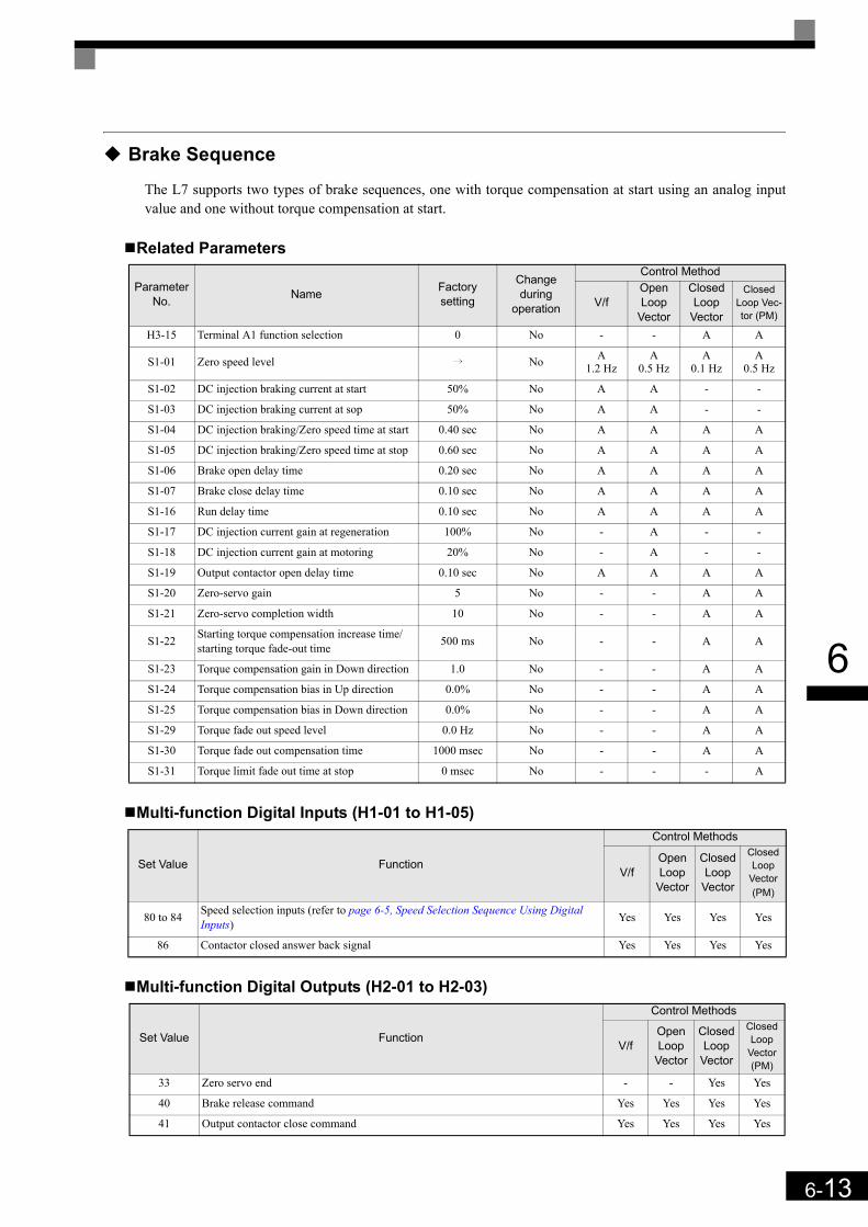
6-13
6
Brake Sequence
The L7 supports two types of brake sequences, one with torque compensation at start using an analog inputvalue and one without torque compensation at start.
Related Parameters
Multi-function Digital Inputs (H1-01 to H1-05)
Multi-function Digital Outputs (H2-01 to H2-03)
ParameterNo. Name Factory
setting
Change during
operation
Control Method
V/fOpen Loop
Vector
Closed Loop
Vector
Closed Loop Vec-tor (PM)
H3-15 Terminal A1 function selection 0 No - - A A
S1-01 Zero speed level i No A1.2 Hz
A0.5 Hz
A0.1 Hz
A0.5 Hz
S1-02 DC injection braking current at start 50% No A A - -
S1-03 DC injection braking current at sop 50% No A A - -
S1-04 DC injection braking/Zero speed time at start 0.40 sec No A A A A
S1-05 DC injection braking/Zero speed time at stop 0.60 sec No A A A A
S1-06 Brake open delay time 0.20 sec No A A A A
S1-07 Brake close delay time 0.10 sec No A A A A
S1-16 Run delay time 0.10 sec No A A A A
S1-17 DC injection current gain at regeneration 100% No - A - -
S1-18 DC injection current gain at motoring 20% No - A - -
S1-19 Output contactor open delay time 0.10 sec No A A A A
S1-20 Zero-servo gain 5 No - - A A
S1-21 Zero-servo completion width 10 No - - A A
S1-22 Starting torque compensation increase time/ starting torque fade-out time 500 ms No - - A A
S1-23 Torque compensation gain in Down direction 1.0 No - - A A
S1-24 Torque compensation bias in Up direction 0.0% No - - A A
S1-25 Torque compensation bias in Down direction 0.0% No - - A A
S1-29 Torque fade out speed level 0.0 Hz No - - A A
S1-30 Torque fade out compensation time 1000 msec No - - A A
S1-31 Torque limit fade out time at stop 0 msec No - - - A
Set Value Function
Control Methods
V/fOpen Loop
Vector
Closed Loop
Vector
Closed Loop
Vector (PM)
80 to 84 Speed selection inputs (refer to page 6-5, Speed Selection Sequence Using Digital Inputs) Yes Yes Yes Yes
86 Contactor closed answer back signal Yes Yes Yes Yes
Set Value Function
Control Methods
V/fOpen Loop
Vector
Closed Loop
Vector
Closed Loop
Vector (PM)
33 Zero servo end - - Yes Yes
40 Brake release command Yes Yes Yes Yes
41 Output contactor close command Yes Yes Yes Yes
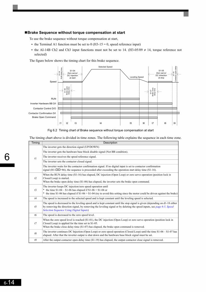
6-14
6
Brake Sequence without torque compensation at startTo use the brake sequence without torque compensation at start,
• the Terminal A1 function must be set to 0 (H3-15 = 0, speed reference input)• the AI-14B Ch2 and Ch3 input functions must not be set to 14. (H3-05/09 ≠ 14, torque reference not
selected)
The figure below shows the timing chart for this brake sequence.
Fig 6.2 Timing chart of Brake sequence without torque compensation at start
The timing chart above is divided in time zones. The following table explains the sequence in each time zone.Timing Description
t1
The inverter gets the direction signal (UP/DOWN)
The inverter gets the hardware base block disable signal (Not BB condition).
The inverter receives the speed reference signal.
The inverter sets the contactor closed signal.
The inverter waits for the contactor confirmation signal. If no digital input is set to contactor confirmation signal (H1- =86), the sequence is proceeded after exceeding the operation start delay time (S1-16).
t2When the RUN delay time (S1-16) has elapsed, DC injection (Open Loop) or zero servo operation (position lock in Closed Loop) is started.When the brake open delay time (S1-06) has elapsed, the inverter sets the brake open command.
t3The inverter keeps DC injection/zero speed operation until * the time S1-04 – S1-06 has elapsed if S1-06 < S1-04 or* the time S1-06 has elapsed if S1-06 > S1-04 (try to avoid this setting since the motor could be driven against the brake)
t4 The speed is increased to the selected speed and is kept constant until the leveling speed is selected.
t5The speed is decreased to the leveling speed and is kept constant until the stop signal is given (depending on d1-18 either by removing the direction signal, by removing the leveling signal or by deleting the speed inputs, see page 6-5, Speed Selection Sequence Using Digital Inputs)
t6 The speed is decreased to the zero speed level.
t7When the zero speed level is reached (S1-01), the DC injection (Open Loop) or zero servo operation (position lock in Closed Loop) is applied for the time set in S1-05.When the brake close delay time (S1-07) has elapsed, the brake open command is removed.
t8 The inverter continues DC Injection (Open Loop) or zero speed operation (Closed Loop) until the time S1-06 – S1-07 has elapsed. After that the inverter output is shut down and the hardware base block signal must be set.
t9 After the output contactor open delay time (S1-19) has elapsed, the output contactor close signal is removed.
RUN
Inverter Hardware BB D/I
Contactor Control D/O
Contactor Confirmation D/I
Brake Open Command
t1 t2 t3 t4 t5 t6 t7 t8 t9
Speed
S1-04
Zero servo/
DC Injection
at start
S1
-16
RU
N d
ela
y tim
e
Selected Speed
Leveling Speed
S1-05
Zero servo/
DC inhection
at stop
S1
-07
Bra
ke
clo
se
de
lay t
ime
S1
-19
Co
nta
cto
r o
pe
n d
ela
y
S1
-06
Bra
ke
op
en
De
lay t
ime
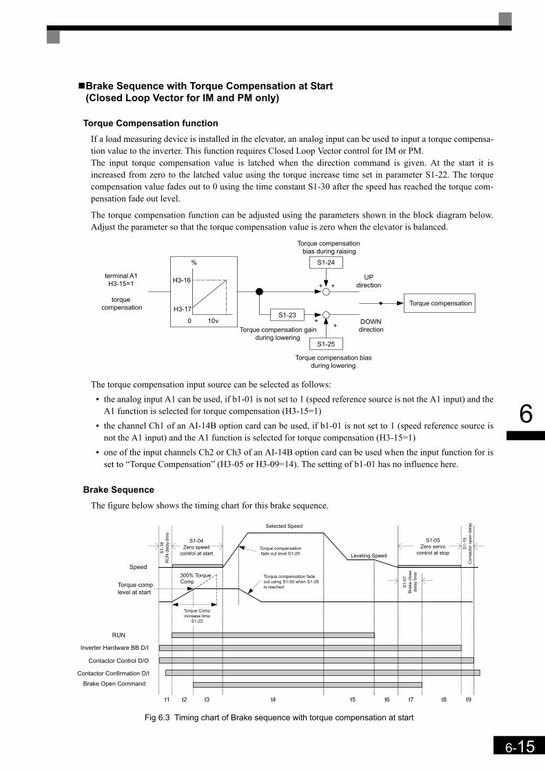
6-15
6
Brake Sequence with Torque Compensation at Start (Closed Loop Vector for IM and PM only)
Torque Compensation functionIf a load measuring device is installed in the elevator, an analog input can be used to input a torque compensa-tion value to the inverter. This function requires Closed Loop Vector control for IM or PM.The input torque compensation value is latched when the direction command is given. At the start it isincreased from zero to the latched value using the torque increase time set in parameter S1-22. The torquecompensation value fades out to 0 using the time constant S1-30 after the speed has reached the torque com-pensation fade out level.
The torque compensation function can be adjusted using the parameters shown in the block diagram below.Adjust the parameter so that the torque compensation value is zero when the elevator is balanced.
The torque compensation input source can be selected as follows:• the analog input A1 can be used, if b1-01 is not set to 1 (speed reference source is not the A1 input) and the
A1 function is selected for torque compensation (H3-15=1)• the channel Ch1 of an AI-14B option card can be used, if b1-01 is not set to 1 (speed reference source is
not the A1 input) and the A1 function is selected for torque compensation (H3-15=1)• one of the input channels Ch2 or Ch3 of an AI-14B option card can be used when the input function for is
set to “Torque Compensation” (H3-05 or H3-09=14). The setting of b1-01 has no influence here.
Brake SequenceThe figure below shows the timing chart for this brake sequence.
Fig 6.3 Timing chart of Brake sequence with torque compensation at start
H3-16
H3-17
0 10v
terminal A1H3-15=1
torquecompensation
S1-25
S1-23
S1-24
+ +
++
UPdirection
DOWNdirection
Torque compensation
%
Torque compensationbias during raising
Torque compensation biasduring lowering
Torque compensation gainduring lowering
RUN
Inverter Hardware BB D/I
Contactor Control D/O
Contactor Confirmation D/I
Brake Open Command
t1 t2 t3 t4 t5 t6 t7 t8 t9
Torque comp
level at start
Speed
S1-04
Zero speed
control at startS1
-16
RU
N d
ela
y t
ime
300% Torque
Comp
Selected Speed
Torque compensation
fade out level S1-29
Torque compensation fade
out using S1-30 when S1-29
is reached
Leveling Speed
S1-05
Zero servo
control at stop
S1
-07
Bra
ke
clo
se
de
lay t
ime
S1
-19
Co
nta
cto
r o
pe
n d
ela
y
Torque Comp
increase time
S1-22
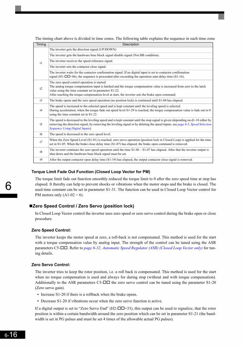
6-16
6
The timing chart above is divided in time zones. The following table explains the sequence in each time zone
Torque Limit Fade Out Function (Closed Loop Vector for PM)The torque limit fade out function smoothly reduced the torque limit to 0 after the zero speed time at stop haselapsed. It thereby can help to prevent shocks or vibrations when the motor stops and the brake is closed. Theused time constant can be set in parameter S1-31. The function can be used in Closed Loop Vector control forPM motors only (A1-02 = 6).
Zero Speed Control / Zero Servo (position lock)In Closed Loop Vector control the inverter uses zero speed or zero servo control during the brake open or closeprocedure.
Zero Speed Control:The inverter keeps the motor speed at zero, a roll-back is not compensated. This method is used for the startwith a torque compensation value by analog input. The strength of the control can be tuned using the ASRparameters C5- . Refer to page 6-32, Automatic Speed Regulator (ASR) (Closed Loop Vector only) for tun-ing details.
Zero Servo Control:The inverter tries to keep the rotor position, i.e. a roll back is compensated. This method is used for the startwhen no torque compensation is used and always for during stop (without and with torque compensation).Additionally to the ASR parameters C5- the zero servo control can be tuned using the parameter S1-20(Zero servo gain).
• Increase S1-20 if there is a rollback when the brake opens.• Decrease S1-20 if vibrations occur when the zero servo function is active.
If a digital output is set to “Zero Servo End” (H2- =33), this output can be used to signalize, that the rotorposition is within a certain bandwidth around the zero position which can be set in parameter S1-21 (the band-width is set in PG pulses and must be set 4 times of the allowable actual PG pulses).
Timing Description
t1
The inverter gets the direction signal (UP/DOWN)
The inverter gets the hardware base block signal disable signal (Not BB condition).
The inverter receives the speed reference signal.
The inverter sets the contactor close signal.
The inverter waits for the contactor confirmation signal. If no digital input is set to contactor confirmation signal (H1- =86), the sequence is proceeded after exceeding the operation start delay time (S1-16).
t2
The zero speed control operation is started.The analog torque compensation input is latched and the torque compensation value is increased from zero to the latch value using the time constant set in parameter S1-22.After reaching the torque compensation level at start, the inverter sets the brake open command.
t3 The brake opens and the zero speed operation (no position lock) is continued until S1-04 has elapsed.
t4The speed is increased to the selected speed and is kept constant until the leveling speed is selected.During acceleration, when the torque fade out speed level S1-29 is reached, the torque compensation value is fade out to 0 using the time constant set in S1-22.
t5The speed is decreased to the leveling speed and is kept constant until the stop signal is given (depending on d1-18 either by removing the direction signal, by removing the leveling signal or by deleting the speed inputs, see page 6-5, Speed Selection Sequence Using Digital Inputs).
t6 The speed is decreased to the zero speed level.
t7 When the Zero Speed Level (S1-01) is reached, zero servo operation (position lock in Closed Loop) is applied for the time set in S1-05. When the brake close delay time (S1-07) has elapsed, the brake open command is removed.
t8 The inverter continues the zero speed operation until the time S1-06 – S1-07 has elapsed. After that the inverter output is shut down and the hardware base block signal must be set.
t9 After the output contactor open delay time (S1-19) has elapsed, the output contactor close signal is removed.

6-17
6
Short Floor Operation
The short floor operation is activated if the leveling speed command is set before the nominal speed wasreached. The L7 inverter supports 2 methods of short floor operation:
• Simple short floor operation which can be enabled by setting S3-01 = 1.When the leveling speed input is set and the reached speed is higher than 40% of the nominal speed, theinverter decelerates to 40% and keeps this speed for a calculated time before it decelerates to the levelingspeed and finally stops. If the reached speed is below 40% of the nominal speed, the inverter accelerates to40% speed and keeps it for a calculated time before it decelerates to the leveling speed.If the leveling input is set during constant speed run and the speed reference is lower than 40% of the nom-inal speed, the speed is hold for a calculated time in order to minimize the leveling distance. If the speedreference is higher than 40% but lower than the nominal speed, the speed is decreased to t 40% first, ishold for a calculated time an then decreased to the leveling speed.
• Advanced short floor operation which can be enabled by setting S3-01 = 2.If the leveling speed command is set the inverter calculates the optimal speed using the speed reference,two gain factors (S3-21/22) and a time constant (S3-20). If the leveling input is set before the optimalspeed has been reached, the inverter accelerates to the optimal speed and keeps it for the time constant S3-20. If the leveling input is set when the optimal speed was exceeded, the inverter keeps the reached speedfor a certain time before it decelerates to the leveling speed.
The table below shows the behavior of the short floor functions under different conditions.
Condition Standard Short Floor Advanced Short Floor
During Acceleration
Leveling Signal before 40% of the nominal speed has been reached
Leveling speed signal before VOpt is reached
Leveling Signal after 40% of the nominal speed has been reached.
Leveling speed signal after VOpt has been reached
vNominal
VLeveling
fout
Levelingcommand
40% xVNominal
S3-20
VNominal
VOpt
VLeveling
fout
Leveling
command
vNominal
VLeveling
fout
Leveling
command
40% x
VNominal
VNominal
VOpt
VLeveling
fout
Leveling
command
Optimal speed profile
(S2-20 calculated)
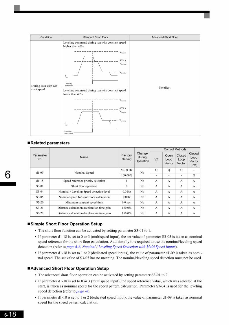
6-18
6
Related parameters
Simple Short Floor Operation Setup• The short floor function can be activated by setting parameter S3-01 to 1.• If parameter d1-18 is set to 0 or 3 (multispeed input), the set value of parameter S3-05 is taken as nominal
speed reference for the short floor calculation. Additionally it is required to use the nominal/leveling speeddetection (refer to page 6-6, Nominal / Leveling Speed Detection with Multi Speed Inputs).
• If parameter d1-18 is set to 1 or 2 (dedicated speed inputs), the value of parameter d1-09 is taken as nomi-nal speed. The set value of S3-05 has no meaning. The nominal/leveling speed detection must not be used.
Advanced Short Floor Operation Setup• The advanced short floor operation can be activated by setting parameter S3-01 to 2.• If parameter d1-18 is set to 0 or 3 (multispeed input), the speed reference value, which was selected at the
start, is taken as nominal speed for the speed pattern calculation. Parameter S3-04 is used for the levelingspeed detection (refer to page -6).
• If parameter d1-18 is set to 1 or 2 (dedicated speed input), the value of parameter d1-09 is taken as nominalspeed for the speed pattern calculation.
During Run with con-stant speed
Leveling command during run with constant speed higher than 40%
No effectLeveling command during run with constant speed lower than 40%
Parameter No. Name Factory
Setting
Change during
Operation
Control Methods
V/fOpen Loop
Vector
Closed Loop
Vector
Closed Loop
Vector(PM)
d1-09 Nominal Speed50.00 Hz
NoQ Q Q -
100.00% - - - Q
d1-18 Speed reference priority selection 1 No A A A A
S3-01 Short floor operation 0 No A A A A
S3-04 Nominal / Leveling Speed detection level 0.0 Hz No A A A A
S3-05 Nominal speed for short floor calculation 0.0Hz No A A A A
S3-20 Minimum constant speed time 0.0 sec. No A A A A
S3-21 Distance calculation acceleration time gain 150.0% No A A A A
S3-22 Distance calculation deceleration time gain 150.0% No A A A A
Condition Standard Short Floor Advanced Short Floor
vNominal
VLeveling
fout
Leveling
command
40% x
VNominal
vNominal
VLeveling
fout
Leveling
command
40% x
VNominal

6-19
6
Setup the Acceleration and Deceleration Gain (S3-21, S3-22)These parameters are used for the optimal speed calculation to compensate the S-curves (S-curves are not con-sidered in the optimal speed calculation).
• Increase the gains S3-21 and S3-22 if the leveling time is too short or the calculated optimal speed is toohigh.
• Decreases the gains S3-21 and S3-22 if the leveling time is too short of the calculated optimal speed is toolow.
IMPORTANT
1. S-Curves are not considered in the optimal speed calculation and have to be compensated by thegains S3-21 and S3-22.
2. A too low gain setting can result in a too high optimal speed and too short leveling time. Very lowsettings can lead to an overrun. Do not set the values lower than 100% (100% means, that the S-curve is not compensated.
3. If parameter d1-18 is set to 0 or 3 and the leveling speed input is released during short floor oper-ation, the inverter accelerates or decelerates to the selected reference speed.
4. If the Dwell function (b6- parameters) is activated, the dwell function is performed during shortfloor operation but it is not considered in the optimal speed calculation. The influence of the Dwellfunction must be compensated using the gains S3-21 and S3-22.
5. The advanced short floor function does not work during rescue operation and inspection run.6. If the speed reference is input using an analog input the advanced short floor function should not
be used.7. If the advanced short floor function is used, the following parameter settings should be in given
range:9.6 Hz O E1-04 O 100 Hz4.8 Hz O d1-08 O 100Hz0.1 sec. O C1- O 50 sec.
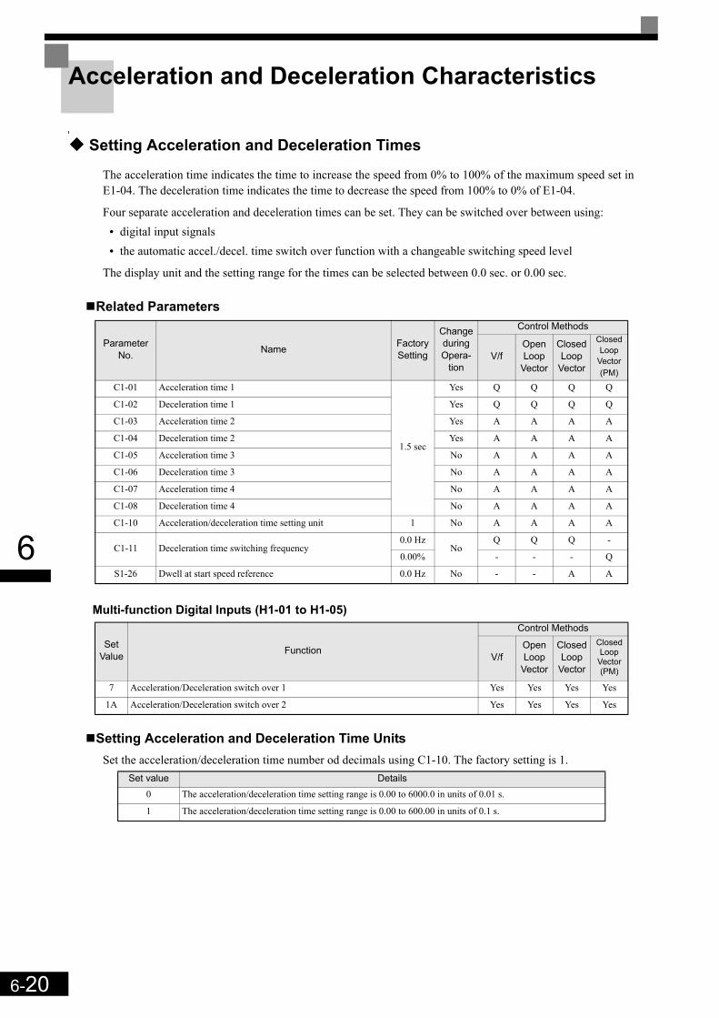
6-20
6
Acceleration and Deceleration Characteristics
Setting Acceleration and Deceleration Times
The acceleration time indicates the time to increase the speed from 0% to 100% of the maximum speed set inE1-04. The deceleration time indicates the time to decrease the speed from 100% to 0% of E1-04.
Four separate acceleration and deceleration times can be set. They can be switched over between using:• digital input signals• the automatic accel./decel. time switch over function with a changeable switching speed level
The display unit and the setting range for the times can be selected between 0.0 sec. or 0.00 sec.
Related Parameters
Multi-function Digital Inputs (H1-01 to H1-05)
Setting Acceleration and Deceleration Time UnitsSet the acceleration/deceleration time number od decimals using C1-10. The factory setting is 1.
Parameter No. Name Factory
Setting
Change during Opera-
tion
Control Methods
V/fOpen Loop
Vector
Closed Loop
Vector
Closed Loop
Vector (PM)
C1-01 Acceleration time 1
1.5 sec
Yes Q Q Q Q
C1-02 Deceleration time 1 Yes Q Q Q Q
C1-03 Acceleration time 2 Yes A A A A
C1-04 Deceleration time 2 Yes A A A A
C1-05 Acceleration time 3 No A A A A
C1-06 Deceleration time 3 No A A A A
C1-07 Acceleration time 4 No A A A A
C1-08 Deceleration time 4 No A A A A
C1-10 Acceleration/deceleration time setting unit 1 No A A A A
C1-11 Deceleration time switching frequency0.0 Hz
NoQ Q Q -
0.00% - - - Q
S1-26 Dwell at start speed reference 0.0 Hz No - - A A
Set Value Function
Control Methods
V/fOpen Loop
Vector
Closed Loop
Vector
Closed Loop
Vector (PM)
7 Acceleration/Deceleration switch over 1 Yes Yes Yes Yes
1A Acceleration/Deceleration switch over 2 Yes Yes Yes Yes
Set value Details0 The acceleration/deceleration time setting range is 0.00 to 6000.0 in units of 0.01 s.
1 The acceleration/deceleration time setting range is 0.00 to 600.00 in units of 0.1 s.

6-21
6
Switching Over the Acceleration and Deceleration Time Using Multi-Function Input Commands
When two digital input terminals are set to “Accel./Decel. time switch over 1 and 2” (H1- =7 and 1A), theacceleration/deceleration times can be switched over even during operation by a binary combination of theinputs. The following table shows the acceleration/deceleration time switching combinations.
Automatic Deceleration Time Switch Over Using a Speed LevelThe deceleration times C1-02 and C1-08 can be switched over automatically at a certain speed which can beset in parameter C1-11. Fig 6.4 shows the working principle of the function.
Set C1-11 to a value other than 0.0 Hz. If C1-11 is set to 0.0 Hz, the function will be disabled.
Fig 6.4 Acceleration/deceleration Time Switching Frequency
Dwell at Start Function (Closed Loop Vector only)The Dwell function can be used to reduce a staring jerk caused by high static friction.After a start command, the output frequency is increased up to the Dwell speed set in parameter S1-26 usingthe acceleration time C1-07. As soon as the motor starts turning and the motor speed (PG feedback) reachesthe acceleration time switching level C1-11, the acceleration is continued using the selected acceleration timestarting with the S-curve set in parameter C2-01.
Fig 6.5 Dwell at start function
Note: When C1-11 is set much higher than S1-26, the motor speed cannot reach C1-11 and the motor can not accelerate to the selected speed. Therefore always set C1-11 equal or lower than S1-26!
Acceleration/Deceleration Time Selection 1 Terminal
Acceleration/Deceleration Time Selection 2 Terminal Acceleration Time Deceleration Time
OFF OFF C1-01 C1-02
ON OFF C1-03 C1-04
OFF ON C1-05 C1-06
ON ON C1-07 C1-08
OutputFrequency
Decel. timeSwitching Freq.
C1-11
C1-01 C1-02 C1-08
When output frequency ≥ C1-11the deceleration time 1 (C1-02) is used.When output frequency < C1-11the deceleration time 4 (C1-08) is used.
No S-CurveC1-07
C1-11
C2-01
C1-02
RUN
S1-26
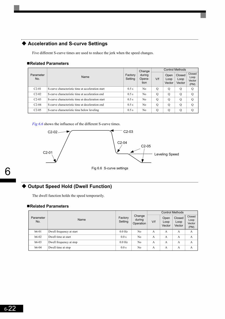
6-22
6
Acceleration and S-curve Settings
Five different S-curve times are used to reduce the jerk when the speed changes.
Related Parameters
Fig 6.6 shows the influence of the different S-curve times.
Fig 6.6 S-curve settings
Output Speed Hold (Dwell Function)
The dwell function holds the speed temporarily.
Related Parameters
Parameter No. Name Factory
Setting
Change during Opera-
tion
Control Methods
V/fOpen Loop
Vector
Closed Loop
Vector
Closed Loop
Vector (PM)
C2-01 S-curve characteristic time at acceleration start 0.5 s No Q Q Q Q
C2-02 S-curve characteristic time at acceleration end 0.5 s No Q Q Q Q
C2-03 S-curve characteristic time at deceleration start 0.5 s No Q Q Q Q
C2-04 S-curve characteristic time at deceleration end 0.5 s No Q Q Q Q
C2-05 S-curve characteristic time below leveling 0.5 s No Q Q Q Q
Parameter No. Name Factory
Setting
Change during
Operation
Control Methods
V/fOpen Loop
Vector
Closed Loop
Vector
Closed Loop
Vector (PM)
b6-01 Dwell frequency at start 0.0 Hz No A A A A
b6-02 Dwell time at start 0.0 s No A A A A
b6-03 Dwell frequency at stop 0.0 Hz No A A A A
b6-04 Dwell time at stop 0.0 s No A A A A
C2-05
C2-01
C2-02
C2-04
C2-03
Leveling Speed
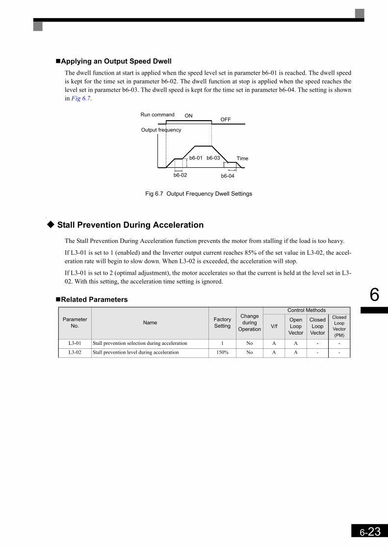
6-23
6
Applying an Output Speed DwellThe dwell function at start is applied when the speed level set in parameter b6-01 is reached. The dwell speedis kept for the time set in parameter b6-02. The dwell function at stop is applied when the speed reaches thelevel set in parameter b6-03. The dwell speed is kept for the time set in parameter b6-04. The setting is shownin Fig 6.7.
Fig 6.7 Output Frequency Dwell Settings
Stall Prevention During Acceleration
The Stall Prevention During Acceleration function prevents the motor from stalling if the load is too heavy.
If L3-01 is set to 1 (enabled) and the Inverter output current reaches 85% of the set value in L3-02, the accel-eration rate will begin to slow down. When L3-02 is exceeded, the acceleration will stop.
If L3-01 is set to 2 (optimal adjustment), the motor accelerates so that the current is held at the level set in L3-02. With this setting, the acceleration time setting is ignored.
Related Parameters
Parameter No. Name Factory
Setting
Change during
Operation
Control Methods
V/fOpen Loop
Vector
Closed Loop
Vector
Closed Loop
Vector (PM)
L3-01 Stall prevention selection during acceleration 1 No A A - -
L3-02 Stall prevention level during acceleration 150% No A A - -
Run command
Output frequency
Time
ON
b6-03
OFF
b6-01
b6-04b6-02
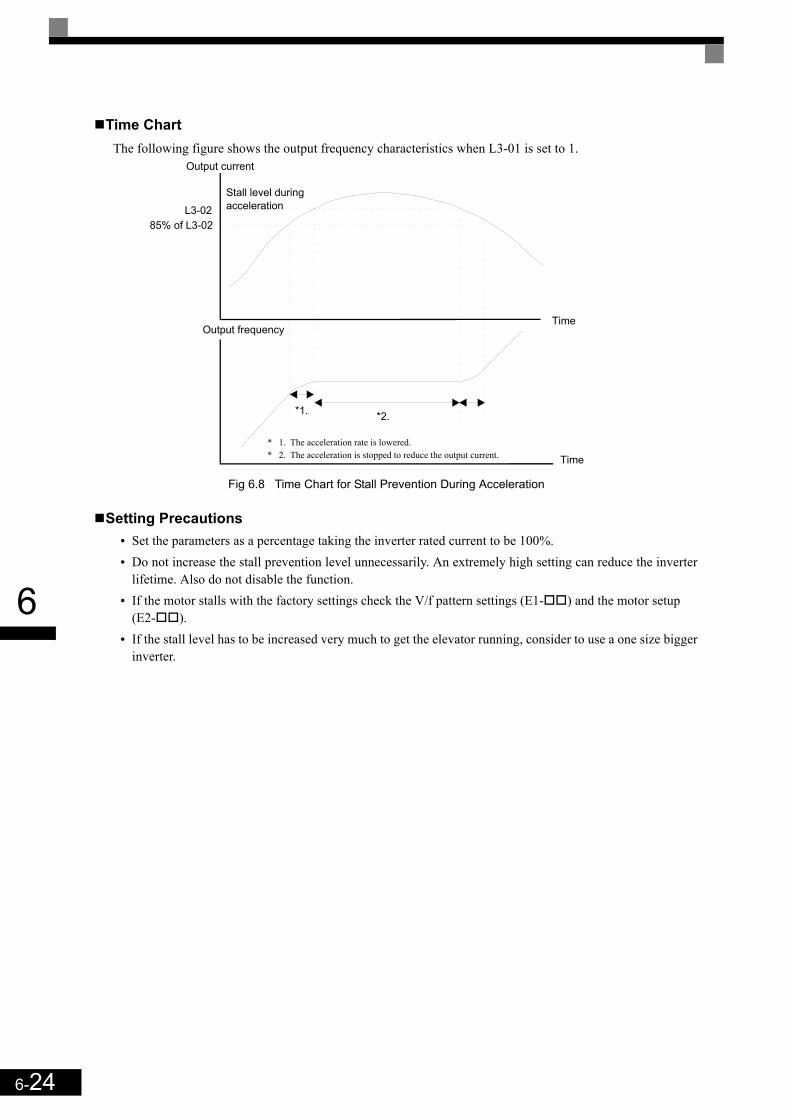
6-24
6
Time ChartThe following figure shows the output frequency characteristics when L3-01 is set to 1.
Fig 6.8 Time Chart for Stall Prevention During Acceleration
Setting Precautions• Set the parameters as a percentage taking the inverter rated current to be 100%.• Do not increase the stall prevention level unnecessarily. An extremely high setting can reduce the inverter
lifetime. Also do not disable the function.• If the motor stalls with the factory settings check the V/f pattern settings (E1- ) and the motor setup
(E2- ).• If the stall level has to be increased very much to get the elevator running, consider to use a one size bigger
inverter.
Output current
Stall level during acceleration
Time
Time
Output frequency
* 1. The acceleration rate is lowered.* 2. The acceleration is stopped to reduce the output current.
*1. *2.
L3-0285% of L3-02

6-25
6
Adjusting Analog Input Signals
Adjusting Analog Frequency References
Using the H3- parameters, the analog input values of terminal A1 or the Channels 1 to 3 of the optionalanalog input card AI-14B can be adjusted.
Related Parameters
Adjusting Analog Input SignalsThe frequency reference can be input from the control circuit terminals using analog voltage. The voltagelevel at terminal A1 is 0 to +10V. The analog input channels of the AI-14B option card can be used with 0 to+10V or -10 to +10V.
The input signal levels can be selected using,• H3-01 for AI-14B CH1• H3-04 for AI-14B CH3• H3-08 for AI-14B CH2
The signals can be adjusted using the parameters:• H3-02 (Gain) and H3-03 (Bias) for Channel 1 of the AI-14B option card• H3-06 (Gain) and H3-07 (Bias) for Channel 3 of the AI-14B option card• H3-10 (Gain) and H3-11 (Bias) for Channel 2 of the AI-14B option card• H3-16 (Gain) and H3-17 (Bias) for analog input A1
The gain sets the level of the selected input value if 10V is input, the bias sets the level of the selected inputvalue if 0V is input.
Parameter No. Name Factory
Setting
Change during
Operation
Control Methods
V/fOpen Loop
Vector
Closed Loop
Vector
Closed Loop
Vector (PM)
H3-01 Frequency reference AI-14B CH1signal level selection 0 No A A A A
H3-02 Frequency reference AI-14B CH1 input gain 100.0% Yes A A A A
H3-03 Frequency reference AI-14B CH1 input bias 0.0% Yes A A A A
H3-04 AI-14B CH3 signal level selection 0 No A A A A
H3-05 AI-14B CH3 function selection 2 No A A A A
H3-06 AI-14B CH3 input gain 100.0% Yes A A A A
H3-07 AI-14B CH3 input bias 0.0% Yes A A A A
H3-08 AI-14B CH2 signal level selection 3 No A A A A
H3-09 AI-14B CH2 function selection 0 No A A A A
H3-10 AI-14B CH2 input gain 100.0% Yes A A A A
H3-11 AI-14B CH2 input bias 0.0% Yes A A A A
H3-12 Analog input filter time constant for the AI-14B 0.03 s No A A A A
H3-15 Terminal A1 function selection 0 No - - A A
H3-16 Terminal A1 input gain 100.0% Yes A A A A
H3-17 Terminal A1 input bias 0.0% Yes A A A A

6-26
6
Speed Detection and Speed Limitation
Speed Agreement Function
There are eight different types of frequency detection methods available. The digital outputs M1 to M6 can beset to this function and can be used to indicate a frequency detection or agreement to any external equipment.
Related Parameters
Multifunction Output Settings: H2-01 to H2-03 (M1 – M6 function selection)The table below shows the necessary H2-01 to H2-03 parameter setting for each of the speed agreement func-tions. Refer to the timing charts on the following page for details.
Setting Precautions• With L4-01 an absolute speed agreement level is set, i.e. a speed agreement is detected in both directions
(Up and Down).• With L4-03 a signed speed agreement level is set, i.e. a speed agreement is detected only in the set direc-
tion (positive level → Up direction, negative level → Down direction).
Parameter No. Name Factory
Setting
Change during Opera-
tion
Control Methods
V/fOpen Loop
Vector
Closed Loop
Vector
Closed Loop
Vector (PM)
L4-01 Speed agreement detection level 0.0 Hz No A A A A
L4-02 Speed agreement detection width 2.0 Hz No A A A A
L4-03 Speed agreement detection level (±) 0.0 Hz No A A A A
L4-04 Speed agreement detection width (±) 2.0 Hz No A A A A
Function Settingfref/fout Agree 1 2
fout/fset Agree 1 3
Frequency detection 1 4
Frequency detection 2 5
fref/fout Agree 2 13
fout/fset Agree 2 14
Frequency detection 3 15
Frequency detection 4 16
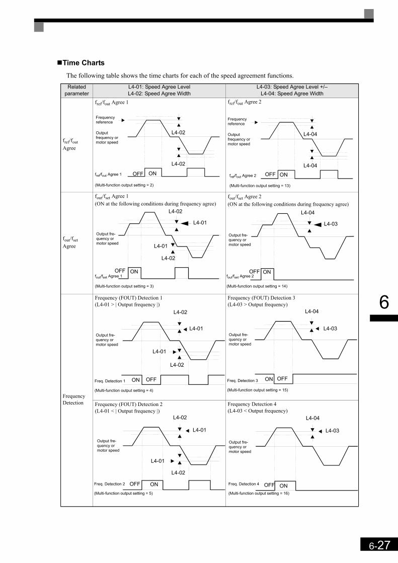
6-27
6
Time ChartsThe following table shows the time charts for each of the speed agreement functions.Related
parameterL4-01: Speed Agree Level L4-02: Speed Agree Width
L4-03: Speed Agree Level +/–L4-04: Speed Agree Width
fref/fout Agree
fref/fout Agree 1 fref/fout Agree 2
fout/fset Agree
fout/fset Agree 1(ON at the following conditions during frequency agree)
fout/fset Agree 2(ON at the following conditions during frequency agree)
Frequency Detection
Frequency (FOUT) Detection 1(L4-01 > | Output frequency |)
Frequency (FOUT) Detection 3(L4-03 > Output frequency)
Frequency (FOUT) Detection 2(L4-01 < | Output frequency |)
Frequency Detection 4(L4-03 < Output frequency)
Frequency reference
fref/fout Agree 1
(Multi-function output setting = 2)
Output frequency or motor speed
ON
L4-02
L4-02
OFF
Frequency reference
fref/fout Agree 2
(Multi-function output setting = 13)
Outputfrequency or motor speed
OFFL4-04
L4-04
ON
Output fre-quency or motor speed
L4-01
L4-02
OFF
L4-01
L4-02
ONfout/fset Agree 1
(Multi-function output setting = 3)
Output fre-quency or motor speed
L4-03
L4-04
OFF ONfout/fset Agree 2
(Multi-function output setting = 14)
L4-01
L4-02
OFF
L4-01
L4-02
ON
Output fre-quency or motor speed
Freq. Detection 1
(Multi-function output setting = 4)
L4-03
L4-04
OFFON
Output fre-quency or motor speed
Freq. Detection 3
(Multi-function output setting = 15)
L4-01
L4-02
OFF
L4-01
L4-02
ON
Output fre-quency or motor speed
Freq. Detection 2
(Multi-function output setting = 5)
L4-03
L4-04
OFF ON
Output fre-quency or motor speed
Freq. Detection 4
(Multi-function output setting = 16)
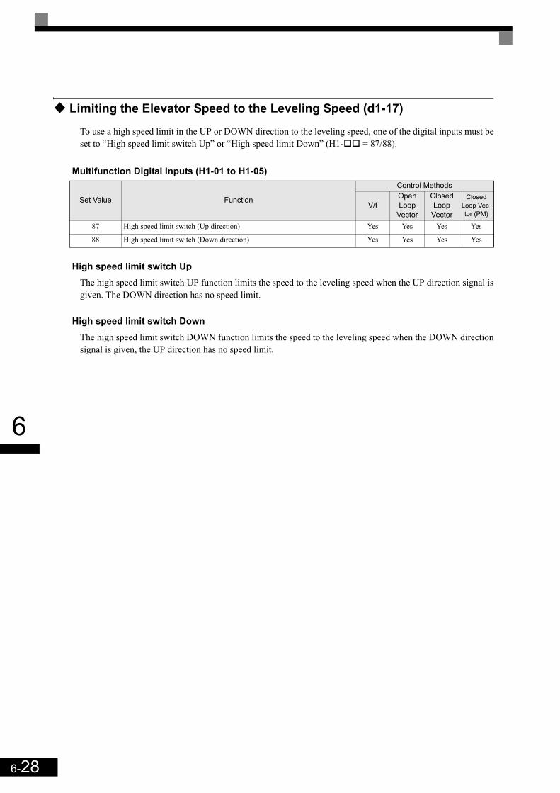
6-28
6
Limiting the Elevator Speed to the Leveling Speed (d1-17)
To use a high speed limit in the UP or DOWN direction to the leveling speed, one of the digital inputs must beset to “High speed limit switch Up” or “High speed limit Down” (H1- = 87/88).
Multifunction Digital Inputs (H1-01 to H1-05)
High speed limit switch UpThe high speed limit switch UP function limits the speed to the leveling speed when the UP direction signal isgiven. The DOWN direction has no speed limit.
High speed limit switch DownThe high speed limit switch DOWN function limits the speed to the leveling speed when the DOWN directionsignal is given, the UP direction has no speed limit.
Set Value Function
Control Methods
V/fOpen Loop
Vector
Closed Loop
Vector
Closed Loop Vec-tor (PM)
87 High speed limit switch (Up direction) Yes Yes Yes Yes
88 High speed limit switch (Down direction) Yes Yes Yes Yes

6-29
6
Improving the Operation Performance
Reducing the Motor Speed Fluctuation (Slip Compensation Function)
When the load is large, the motor slip also increases and the motor speed decreases. The slip compensationfunction keeps the motor speed constant, regardless of changes in load. When the motor is operating at therated load, parameter E2-02 (Motor Rated Slip) × the slip compensation gain value in parameter C3-01 isadded to the output frequency. The function can be used in V/f control or Open Loop Vector control.
Related Parameters
Adjusting Slip Compensation Gain (C3-01)If C3-01 is set to 1.0, the slip compensation value at 100% load is equal to the rated slip set in parameter E2-02.
If necessary (motor speed is too high or too low) adjust the slip compensation gain as follows:1. With Open Loop Vector control set E2-02 (Motor Rated Slip) and E2-03 (Motor No-load Current). The
motor rated slip can be calculated using the values on the motor nameplate and the following formula:
The motor data can be set automatically using the autotuning function.2. With V/f control set C3-01 to 1.0. 3. Apply a load and compare the speed reference and the actual motor speed during run with constant speed.
Adjust the slip compensation gain by 0.1 at a time. If the speed is less than the target value, increase theslip compensation gain, if the speed is higher than the target value, reduce the slip compensation gain.
4. Setting C3-01 to 0.0 disables the slip compensation function.
Adjusting Slip Compensation Primary Delay Time Constant (C3-02)The slip compensation delay time constant is set in ms. The setting value of C3-02 is 2000ms. Normally, thereis no need to change these settings. When the slip compensation responsiveness is low, lower the set value.When the speed is unstable, increase the set value.
Parameter No. Name Factory
Setting
Change during
Operation
Control Methods
V/fOpen Loop
Vector
Closed Loop
Vector
Closed Loop Vec-tor (PM)
C3-01 Slip compensation gain 1.0 Yes A A - -
C3-02 Slip compensation delay time 2000 ms No A A - -
C3-03 Slip compensation limit 200% No A A - -
C3-04 Slip compensation during regeneration 1 No - A - -
C3-05 Output voltage limit operation selection 0 No - A A -
slip (Hz) Motor rated frequency (Hz) Rated motor speed (rpm) Number of motor poles×120
----------------------------------------------------------------------------------------------------------------------------–=

6-30
6
Adjusting Slip Compensation Limit (C3-03)Using parameter C3-03 the upper limit for the slip compensation can be set as a percentage, taking the motorrated slip as 100%.
If the speed is lower than the target value but does not change even after adjusting the slip compensation gain,the slip compensation limit may have been reached. Increase the limit, and check the speed again. Alwaysmake sure that the value of the slip compensation limit and reference frequency does not exceed the toleranceof the machine.
The following diagram shows the slip compensation limit for the constant torque range and fixed output range.
Fig 6.9 Slip Compensation Limit
Enable the Slip Compensation Function During Regeneration (C3-04)Enables or disables the slip compensation function during regenerative operation. The factory setting isenabled.
Operation Selection when the Output Voltage is Saturated (C3-05)Generally the Inverter cannot output a voltage that is higher than the input voltage. If in the high-speed rangethe output voltage reference for the motor (monitor parameter U1-06) exceeds the input voltage, the outputvoltage becomes saturated, and inverter cannot respond to speed or load changes. This function automaticallyreduces the output voltage to avoid voltage saturation.Thereby the speed control accuracy can be maintained even at high speeds (around the rated speed of themotor). By the lowered voltage the current can be around 10% higher compared to the operation without volt-age limiter.
Torque Compensation Function Adjustments
The torque compensation function detects a rising motor load, and increases the output torque.
In V/f control the inverter calculates the motor primary loss voltage using the terminal resistance value (E2-05) and adjusts the output voltage (V) to compensate insufficient torque at startup and during low-speed oper-ation.The compensation voltage is calculated by the calculated Motor primary voltage loss × parameter C4-01.
In Open Loop Vector control the motor excitation current and the torque producing current are calculated andcontrolled separately. The torque compensation affects the torque producing current only.The torque producing current is calculated by the calculated torque reference × C4-01.
Slip compensation limit
Output frequency
E1-06: Base frequencyE1-04: Maximum output frequency

6-31
6
Related Parameters
Adjusting Torque Compensation Gain (C4-01)Normally, there is no need to change this setting. If adjustments are necessary do the following:
Open Loop Vector control• If the torque response is slow increase the set value.• If vibrations occur decrease the set value.
V/f control• If the cable is very long, increase the set value.• If the motor capacity is smaller than the Inverter capacity (max. applicable motor capacity), increase the
set value.• If the motor vibrates, reduce the set value.
Setting precautions• Adjust this parameter so that the output current during low-speed rotation does not exceed the Inverter
rated output current range.• Adjust the value in steps of 0.05 only.
Adjusting the Torque Compensation Delay Time Constant (C4-02)The factory setting depends on the control mode. The factory settings are:
• V/f control: 200 ms• Open loop vector control: 20 ms
Normally, there is no need to change this setting. If adjustments are necessary do the following:• If the motor vibrates or if overshooting occurs, increase the set value.• If the torque response is slow, decrease the set value.
Parameter No. Name Factory
Setting
Change during
Operation
Control Methods
V/fOpen Loop
Vector
Closed Loop
Vector
Closed Loop
Vector (PM)
C4-01 Torque compensation gain 1.00 Yes A A - -
C4-02 Torque compensation delay time constant 2000 ms No A A - -
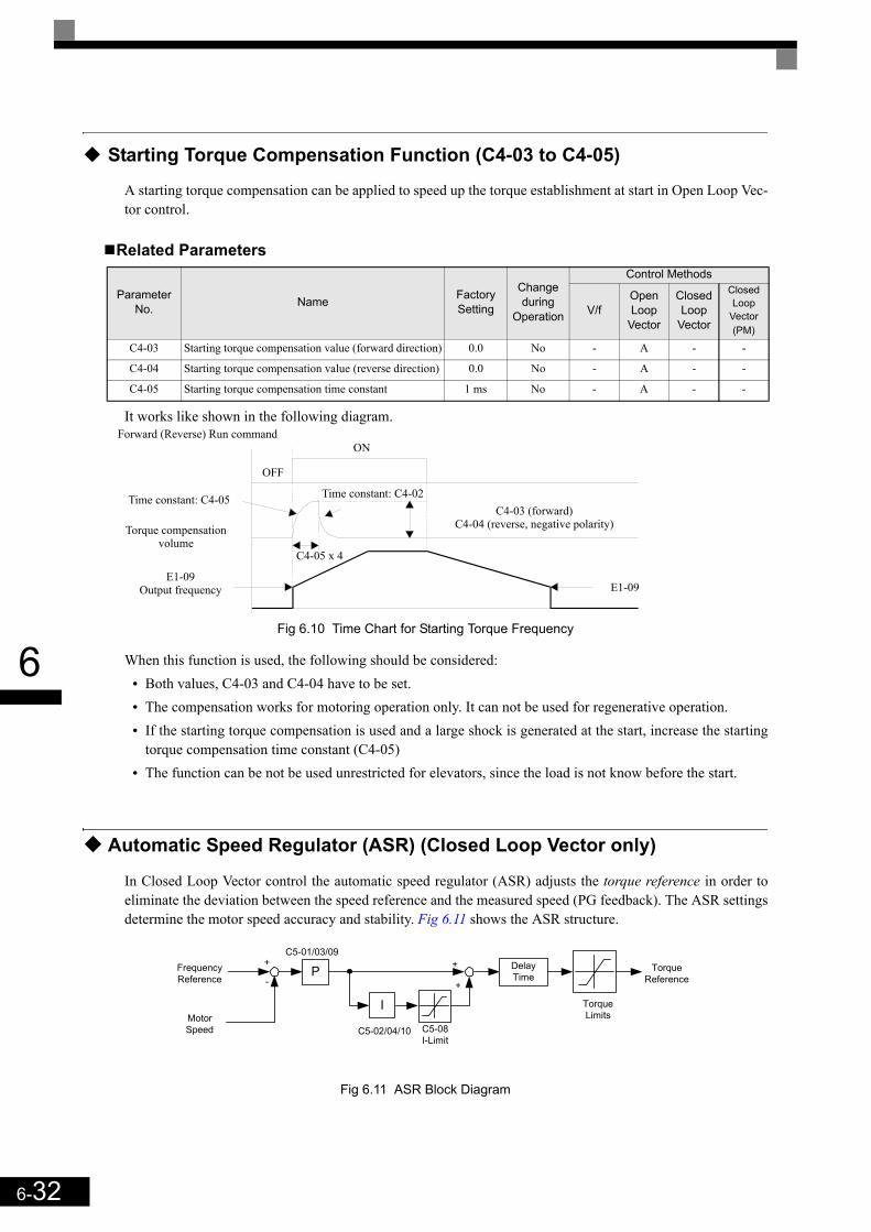
6-32
6
Starting Torque Compensation Function (C4-03 to C4-05)
A starting torque compensation can be applied to speed up the torque establishment at start in Open Loop Vec-tor control.
Related Parameters
It works like shown in the following diagram.
Fig 6.10 Time Chart for Starting Torque Frequency
When this function is used, the following should be considered:• Both values, C4-03 and C4-04 have to be set.• The compensation works for motoring operation only. It can not be used for regenerative operation.• If the starting torque compensation is used and a large shock is generated at the start, increase the starting
torque compensation time constant (C4-05)• The function can be not be used unrestricted for elevators, since the load is not know before the start.
Automatic Speed Regulator (ASR) (Closed Loop Vector only)
In Closed Loop Vector control the automatic speed regulator (ASR) adjusts the torque reference in order toeliminate the deviation between the speed reference and the measured speed (PG feedback). The ASR settingsdetermine the motor speed accuracy and stability. Fig 6.11 shows the ASR structure.
Fig 6.11 ASR Block Diagram
Parameter No. Name Factory
Setting
Change during
Operation
Control Methods
V/fOpen Loop
Vector
Closed Loop
Vector
Closed Loop
Vector (PM)
C4-03 Starting torque compensation value (forward direction) 0.0 No - A - -
C4-04 Starting torque compensation value (reverse direction) 0.0 No - A - -
C4-05 Starting torque compensation time constant 1 ms No - A - -
OFF
ONForward (Reverse) Run command
Time constant: C4-05 Time constant: C4-02
C4-05 x 4
Torque compensation volume
E1-09Output frequency E1-09
C4-03 (forward)C4-04 (reverse, negative polarity)
P
I
+
-
+
+
Delay Time
Frequency Reference
Motor Speed
C5-01/03/09
C5-02/04/10 C5-08I-Limit
TorqueLimits
TorqueReference

6-33
6
Related Parameters
ASR Gain and Integral Time AdjustmentsThere are three sets of ASR gain and integral times, one for the maximum speed (C5-01/02), one for the mini-mum speed at acceleration (C5-03/04) and one for the minimum speed at deceleration (C5-09/10) (see the fig-ure below).
When the ride starts with the nominal speed selected, the ASR P gain and I time change from C5-03/04 to C1-01/02 at nominal speed. When the speed selection changes to leveling speed, the P gain and I time are changedfrom C1-01/02 to C1-09/10.
If parameter d1-18 is set to 0 or 3, the nominal/leveling speed detection function must be enabled (refer topage 6-6, Nominal / Leveling Speed Detection with Multi Speed Inputs) in order to use the ASR 3 settings.
Adjusting ASR Proportional Gains (C5-01/03/09)The gain settings determine how much the ASR input (= speed deviation) is amplified in order to eliminate thespeed deviation. The responsiveness of the ASR is increased when the gain setting is increased but oscillationscan occur when this setting is too high.
• Increase C5-03 if the ASR is too slow at start or very low frequencies, decrease it if vibrations occur.• Increase C5-01 if the ASR is too slow at high speed or if overshooting occurs at speed changes in the high
speed area, decrease it if vibrations occur
Parameter No. Name Factory
Setting
Change during
Operation
Control Methods
V/fOpen Loop
Vector
Closed Loop
Vector
Closed Loop
Vector (PM)
C5-01 ASR proportional (P) gain 140.00
Yes - -Q -
12.00 - Q
C5-02 ASR integral (I) time 10.500 sec.
Yes - -Q -
0.300 sec. - Q
C5-03 ASR proportional (P) gain 220.00
Yes - -Q -
6.00 - Q
C5-04 ASR integral (I) time 2 0.500 sec. Yes - - Q Q
C5-07 ASR switching frequency 0.0 Hz
No - -Q -
2.0% - Q
C5-08 ASR integral limit 400% No - - A A
C5-09 ASR proportional (P) gain 340.00
Yes - -Q -
12.00 - Q
C5-10 ASR integral (I) time 30.500 sec.
Yes - -Q -
0.300 sec. - Q
C5-11 ASR gain for encoder offset tuning 5.00 No - - - A
C5-070Hz E1-04
C5-01 ASR Gain 1 C5-02 ASR I time 1
C5-03 ASR Gain 2 C5-04 ASR I time 2
Speed
ASR P, I
C5-070Hz E1-04
C5-01 ASR Gain 1 C5-02 ASR I time 1
C5-09 ASR Gain 3 C5-10 ASR I time 3
Speed
ASR P, I
During Acceleration During Deceleration
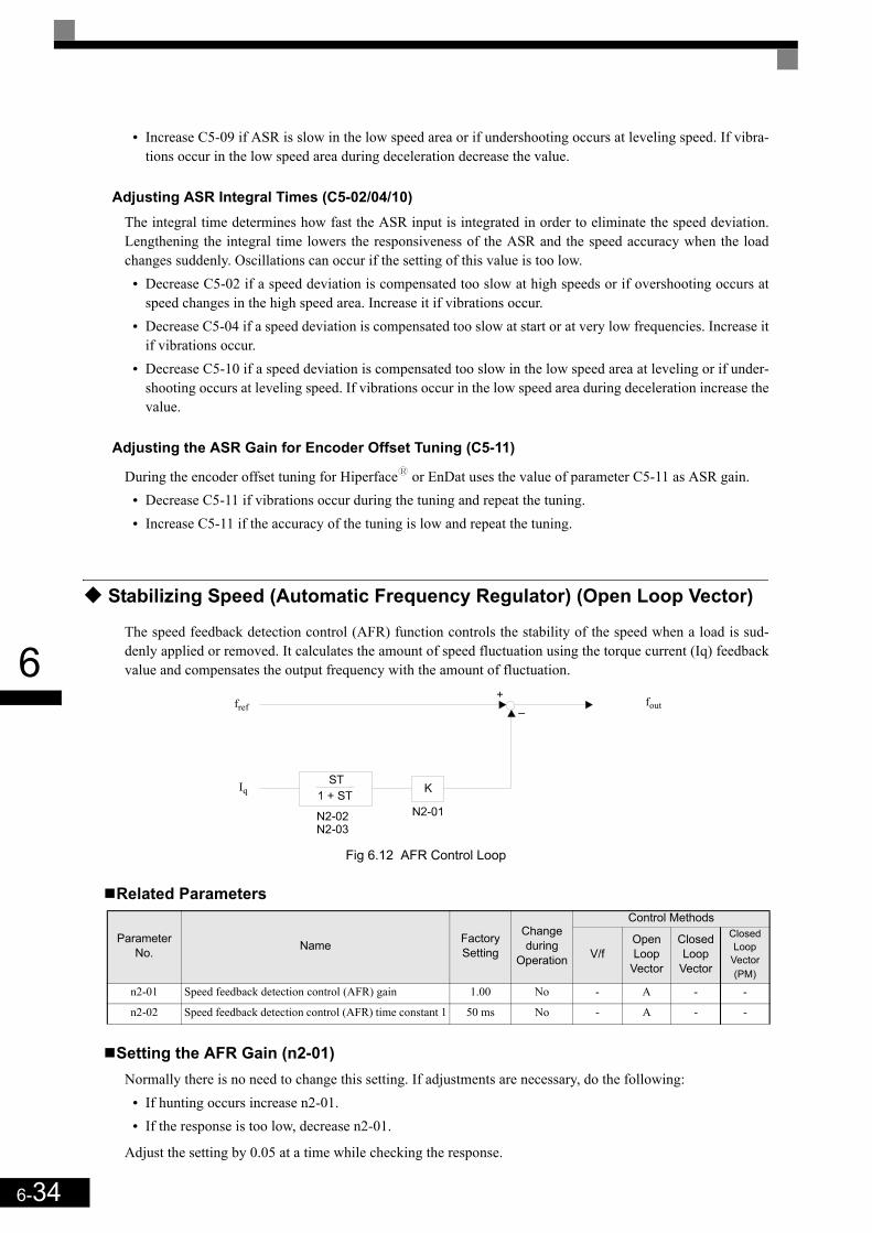
6-34
6
• Increase C5-09 if ASR is slow in the low speed area or if undershooting occurs at leveling speed. If vibra-tions occur in the low speed area during deceleration decrease the value.
Adjusting ASR Integral Times (C5-02/04/10)The integral time determines how fast the ASR input is integrated in order to eliminate the speed deviation.Lengthening the integral time lowers the responsiveness of the ASR and the speed accuracy when the loadchanges suddenly. Oscillations can occur if the setting of this value is too low.
• Decrease C5-02 if a speed deviation is compensated too slow at high speeds or if overshooting occurs atspeed changes in the high speed area. Increase it if vibrations occur.
• Decrease C5-04 if a speed deviation is compensated too slow at start or at very low frequencies. Increase itif vibrations occur.
• Decrease C5-10 if a speed deviation is compensated too slow in the low speed area at leveling or if under-shooting occurs at leveling speed. If vibrations occur in the low speed area during deceleration increase thevalue.
Adjusting the ASR Gain for Encoder Offset Tuning (C5-11)
During the encoder offset tuning for Hiperfacey or EnDat uses the value of parameter C5-11 as ASR gain.• Decrease C5-11 if vibrations occur during the tuning and repeat the tuning.• Increase C5-11 if the accuracy of the tuning is low and repeat the tuning.
Stabilizing Speed (Automatic Frequency Regulator) (Open Loop Vector)
The speed feedback detection control (AFR) function controls the stability of the speed when a load is sud-denly applied or removed. It calculates the amount of speed fluctuation using the torque current (Iq) feedbackvalue and compensates the output frequency with the amount of fluctuation.
Fig 6.12 AFR Control Loop
Related Parameters
Setting the AFR Gain (n2-01)Normally there is no need to change this setting. If adjustments are necessary, do the following:
• If hunting occurs increase n2-01.• If the response is too low, decrease n2-01.
Adjust the setting by 0.05 at a time while checking the response.
Parameter No. Name Factory
Setting
Change during
Operation
Control Methods
V/fOpen Loop
Vector
Closed Loop
Vector
Closed Loop
Vector (PM)
n2-01 Speed feedback detection control (AFR) gain 1.00 No - A - -
n2-02 Speed feedback detection control (AFR) time constant 1 50 ms No - A - -
Iq
foutfref
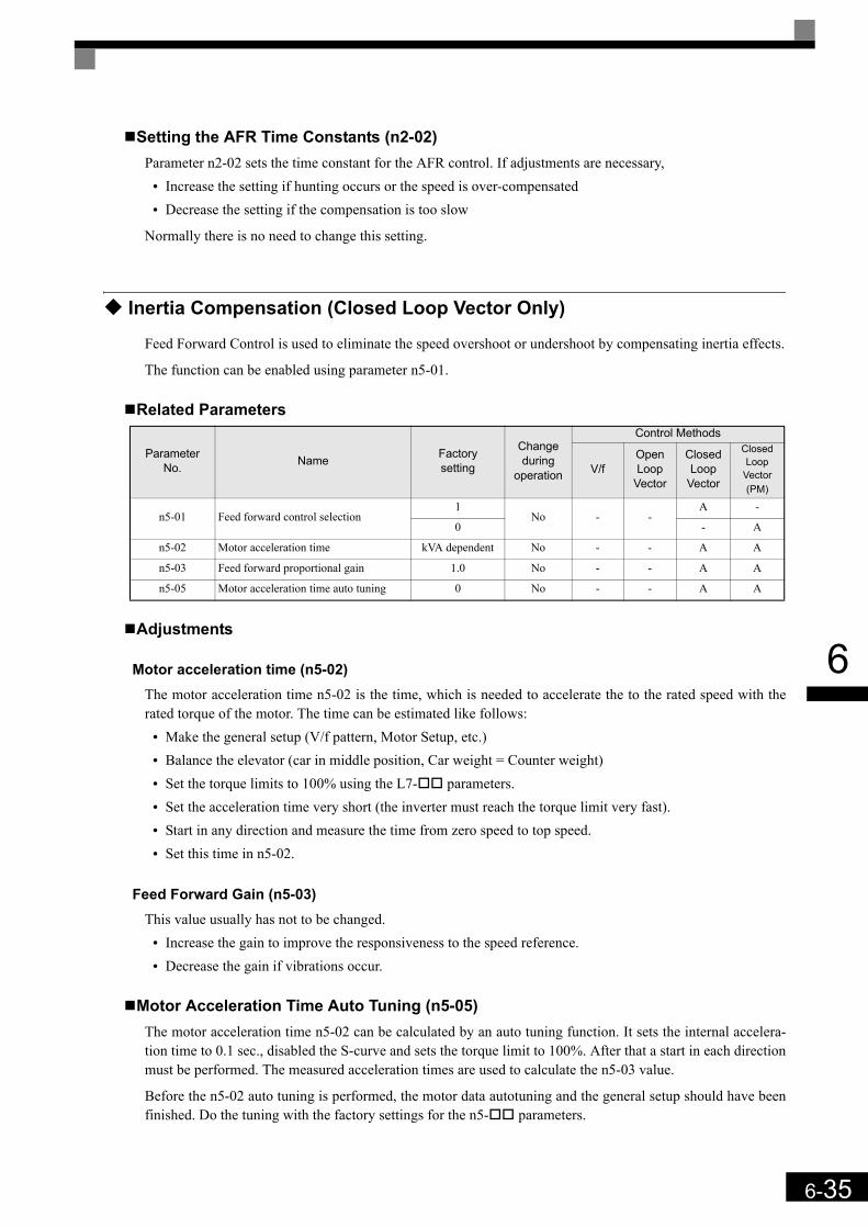
6-35
6
Setting the AFR Time Constants (n2-02)Parameter n2-02 sets the time constant for the AFR control. If adjustments are necessary,
• Increase the setting if hunting occurs or the speed is over-compensated• Decrease the setting if the compensation is too slow
Normally there is no need to change this setting.
Inertia Compensation (Closed Loop Vector Only)
Feed Forward Control is used to eliminate the speed overshoot or undershoot by compensating inertia effects.
The function can be enabled using parameter n5-01.
Related Parameters
Adjustments
Motor acceleration time (n5-02)The motor acceleration time n5-02 is the time, which is needed to accelerate the to the rated speed with therated torque of the motor. The time can be estimated like follows:
• Make the general setup (V/f pattern, Motor Setup, etc.)• Balance the elevator (car in middle position, Car weight = Counter weight)• Set the torque limits to 100% using the L7- parameters.• Set the acceleration time very short (the inverter must reach the torque limit very fast).• Start in any direction and measure the time from zero speed to top speed.• Set this time in n5-02.
Feed Forward Gain (n5-03)This value usually has not to be changed.
• Increase the gain to improve the responsiveness to the speed reference.• Decrease the gain if vibrations occur.
Motor Acceleration Time Auto Tuning (n5-05)The motor acceleration time n5-02 can be calculated by an auto tuning function. It sets the internal accelera-tion time to 0.1 sec., disabled the S-curve and sets the torque limit to 100%. After that a start in each directionmust be performed. The measured acceleration times are used to calculate the n5-03 value.
Before the n5-02 auto tuning is performed, the motor data autotuning and the general setup should have beenfinished. Do the tuning with the factory settings for the n5- parameters.
ParameterNo. Name Factory
setting
Change during
operation
Control Methods
V/fOpen Loop
Vector
Closed Loop
Vector
Closed Loop
Vector (PM)
n5-01 Feed forward control selection1
No - -A -
0 - A
n5-02 Motor acceleration time kVA dependent No - - A A
n5-03 Feed forward proportional gain 1.0 No - - A A
n5-05 Motor acceleration time auto tuning 0 No - - A A
6-36
6
Use the following procedure:1. Set n5-05 to “1” to enable the auto tuning and go back to the speed reference display. 2. Set the base block input.3. Enable the inspection speed input. “FFCAL” will blink in the display to signalize that the calculation is
active.4. Set an UP command. The inverter will accelerate the motor up to the nominal speed. Release the UP com-
mand a few seconds after the top speed has been reached.5. When the motor has stopped, apply a DOWN command. The inverter will accelerate the motor in the
opposite direction to the nominal speed. Release the DOWN command a few seconds after the nominalspeed has been reached.
To abort the tuning set parameter n5-05 to “0”.
Automatic Current Regulator (ACR) Tuning
The ACR controller consists of two PI control loops, one for the d-axis and one for the q-axis current. TheACR parameters can be accessed in the Closed Loop Vector control for PM mode only.
Related Parameters
AdjustmentsNormally there is no need to change these values. However, if short cycle vibrations occur which can’t beeliminated by the ASR controller setup, it might help to adjust ACR values like follows:
• If the motor generates very strange high frequency noise (not carrier frequency related), reduce both ACRgains (n8-29 and n8-32) for the same value. If the gain is reduced too much, the performance will bereduced.
• If vibrations occur, reduce both integral times (n9-30 and n9-33) for the same value.
IMPORTANT
1. The order of giving the UP or DOWN command has no influence.2. n5-01 should not be changed from the factory value for the tuning.3. After the run in both directions is finished, parameter n5-05 is automatically set back to “0”.4. The autotuning will be performed only if the inspection speed input is set.5. Do not change the mechanical constants (load, inertia) between the runs.
ParameterNo. Name Factory
setting
Change during
operationV/f
Open Loop
Vector
Closed Loop
Vector
Closed Loop
Vector (PM)
n8-29 ACR q axis proportional gain 1000 rad/s No - - - A
n8-30 ACR q axis integral time 10.0 ms No - - - A
n8-32 ACR d axis proportional gain 1000 rad/s No - - - A
n8-33 ACR d axis integral time 10.0 ms No - - - A
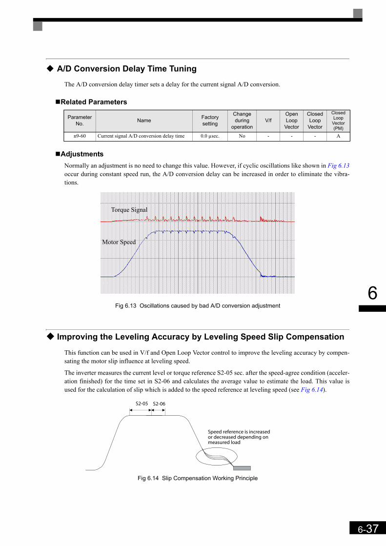
6-37
6
A/D Conversion Delay Time Tuning
The A/D conversion delay timer sets a delay for the current signal A/D conversion.
Related Parameters
AdjustmentsNormally an adjustment is no need to change this value. However, if cyclic oscillations like shown in Fig 6.13occur during constant speed run, the A/D conversion delay can be increased in order to eliminate the vibra-tions.
Fig 6.13 Oscillations caused by bad A/D conversion adjustment
Improving the Leveling Accuracy by Leveling Speed Slip Compensation
This function can be used in V/f and Open Loop Vector control to improve the leveling accuracy by compen-sating the motor slip influence at leveling speed.
The inverter measures the current level or torque reference S2-05 sec. after the speed-agree condition (acceler-ation finished) for the time set in S2-06 and calculates the average value to estimate the load. This value isused for the calculation of slip which is added to the speed reference at leveling speed (see Fig 6.14).
Fig 6.14 Slip Compensation Working Principle
ParameterNo. Name Factory
setting
Change during
operationV/f
Open Loop
Vector
Closed Loop
Vector
Closed Loop
Vector (PM)
n9-60 Current signal A/D conversion delay time 0.0 µsec. No - - - A
Motor Speed
Torque Signal
S2-05 S2-06
Speed reference is increasedor decreased depending onmeasured load

6-38
6
Related Parameters
AdjustmentsThe Slip compensation values can be set separately for motoring and regenerative operation. Before adjustingthis function the general setup should have been done (Motor Setup, V/f pattern, Speeds, ASR settings etc.).To adjust the Slip compensation function do the following in motoring and regenerative mode:
• Set the motor speed in S2-01 if V/f control is used.• Try to measure the actual motor speed during leveling.• If the motor speed is lower than the leveling speed reference increase S2-02 in motoring mode or decrease
S2-03 in regenerative mode.• If the motor speed is higher than the leveling speed reference decrease S2-02 in motoring mode or increase
S2-03 in regenerative mode.• S2-05 and S2-06 should not be modified, except if the stop accuracy is poor and the constant speed time
after the speed agree is shorter than S2-05 + S2-06.
Field Forcing
The field forcing function controls the motor flux and compensates the flux establishment delay of the motor.Thereby it improves the motor responsiveness to changes in the speed reference or the load. Field forcing is applied during all operation conditions except DC Injection.
Using parameter d6-06 a field forcing limit can be applied. A setting of 100% is equal to the no-load currentset in parameter E2-03.
Related Parameters
ParameterNo. Name Factory
setting
Change during
operationV/f
Open Loop
Vector
Closed Loop
Vector
Closed Loop
Vector (PM)
S2-01 Motor Rated rpm 1380rpm No A - - -
S2-02 Slip Compensation Gain at Motoring 0.7 No A A - -
S2-03 Slip Compensation Gain at Regenerating 1.0 No A A - -
S3-05 Slip Compensation Torque Detection Delay 1.0 sec. No A A - -
S3-06 Slip Compensation Torque Detection Time 0.5 sec. No A A -
S2-07 Slip Compensation primary Delay Time 200ms No - A - -
Parameter No. Name Factory
Setting
Change during
Operation
Control Methods
V/fOpen Loop
Vector
Closed Loop
Vector
Closed Loop
Vector (PM)
d6-03 Field forcing selection 0 No - A A -
d6-06 Field forcing limit 400% No - A A -

6-39
6
Adjusting the DC Injection Current
The DC current injection is used in V/f and Open Loop Vector Control in order to hold the motor when thebrake is opened or closed.
Related Parameters
Adjusting the DC Injection Current Levels (S1-02/03)
Two different DC injection current levels can be set to start and stop.• Increase the corresponding set value when the holding torque during brake open or brake close is too low.• Decrease the corresponding set value when the holding torque is enough but e.g. the DC injection noise is
too loud.
Adjusting the DC Injection Gains for Stop (S1-17/18)In Open Loop Vector control two different DC injection current gains for motoring and regenerative operationcan be adjusted in order to improve the stopping behavior. The gains are related to the S1-03 set value. Thefunction can be used to equalize jerk effects if the DC injection is too low with motoring load and too highwith regenerative load. The load condition (regenerative or motoring) is detected when the inverter is runningat another speed than the leveling speed.
• If the DC injection is ok with motoring load but not with regenerative load adjust parameter S1-17.• If the DC injection is ok with regenerative load but not with motoring load adjust parameter S1-18.
Parameter No. Name Factory
Setting
Change during
Operation
Control Methods
V/fOpen Loop
Vector
Closed Loop
Vector
Closed Loop
Vector (PM)
S1-02 DC injection current level at start 50% No A A - -
S1-03 DC injection current level at stop 50% No A A - -
S1-17 DC injection gain at stop in regenerative operation 100% No - A - -
S1-18 DC injection gain at stop in motoring operation 20% No - A - -

6-40
6
Protective Functions
Preventing Motor Stalling During Operation
Stall prevention during operation prevents the motor from stalling by automatically lowering the inverter out-put frequency when a transient overload occurs while the motor is operating at a constant speed.
Stall prevention during operation can be enabled in V/f control only. If the Inverter output current continues toexceed the setting in parameter L3-06 for 100 ms or longer, the motor speed is reduced. Enable or disable thestall prevention using parameter L3-05. Set the according deceleration times using C1-02 (Deceleration time1) or C1-04 (Deceleration Time 2).
If the Inverter output current reaches the set value in L3-06 – 2%, the motor will accelerate again to the set fre-quency.
Related Parameters
PrecautionsIf the motor capacity is smaller than the Inverter capacity or the motor stalls when operating at the factory set-tings, lower the stall prevention level during operation.
Setting Precautions• Set the parameters as a percentage taking the inverter rated current to be 100%.• Do not increase the stall prevention level unnecessarily. An extremely high setting can reduce the inverter
lifetime. Also do not disable the function.• If the motor stalls with the factory settings check the V/f pattern (E1- ) and the motor setup (E2- ).• If the stall level has to be increased very much to get the elevator running, check the mechanical system or
consider using a one size bigger inverter.
Motor Torque Detection / Car Stuck Detection
The inverter provides a torque detection function to detect overtorque (Car stuck) or undertorque. An alarmsignal can be output to the digital output terminals M1-M2, M3-M4, or M5-M6.
To use the overtorque/undertorque detection function, set B, 17, 18, 19 (overtorque/undertorque detection NO/NC) in one of the parameter H2-01 to H2-03 (digital output terminals M1 to M6 function selection).
Overtorque/undertorque is detected by:• observing the output current in V/f control (the inverter rated output current is equal to 100%).• observing the torque reference value in Open Loop and Closed Loop Vector control (the motor rated torque
is equal to 100%).
Parameter No. Name Factory
Setting
Change during
Operation
Control Methods
V/fOpen Loop
Vector
Closed Loop
Vector
Closed Loop
Vector (PM)
L3-05 Stall prevention selection during running function selection 1 No A - - -
L3-06 Stall prevention level during running 150% No A - - -
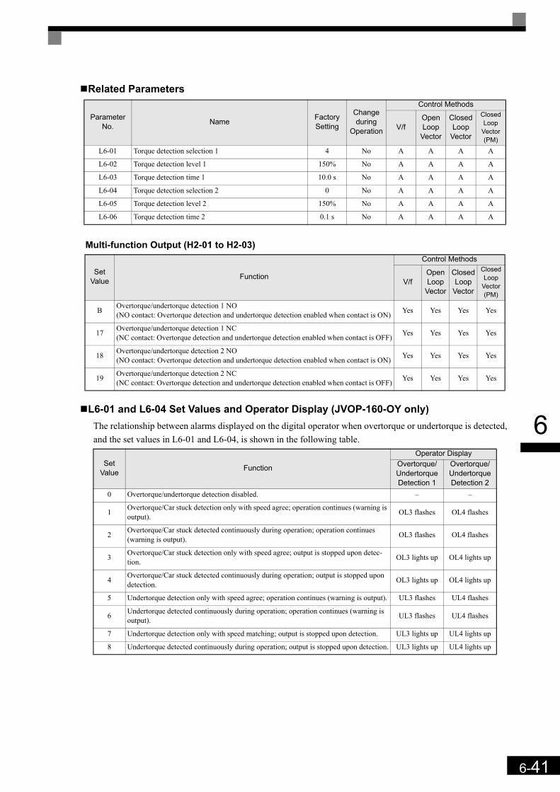
6-41
6
Related Parameters
Multi-function Output (H2-01 to H2-03)
L6-01 and L6-04 Set Values and Operator Display (JVOP-160-OY only)The relationship between alarms displayed on the digital operator when overtorque or undertorque is detected,and the set values in L6-01 and L6-04, is shown in the following table.
Parameter No. Name Factory
Setting
Change during
Operation
Control Methods
V/fOpen Loop
Vector
Closed Loop
Vector
Closed Loop
Vector (PM)
L6-01 Torque detection selection 1 4 No A A A A
L6-02 Torque detection level 1 150% No A A A A
L6-03 Torque detection time 1 10.0 s No A A A A
L6-04 Torque detection selection 2 0 No A A A A
L6-05 Torque detection level 2 150% No A A A A
L6-06 Torque detection time 2 0.1 s No A A A A
Set Value Function
Control Methods
V/fOpen Loop
Vector
Closed Loop
Vector
Closed Loop
Vector (PM)
B Overtorque/undertorque detection 1 NO(NO contact: Overtorque detection and undertorque detection enabled when contact is ON) Yes Yes Yes Yes
17 Overtorque/undertorque detection 1 NC(NC contact: Overtorque detection and undertorque detection enabled when contact is OFF) Yes Yes Yes Yes
18 Overtorque/undertorque detection 2 NO(NO contact: Overtorque detection and undertorque detection enabled when contact is ON) Yes Yes Yes Yes
19 Overtorque/undertorque detection 2 NC(NC contact: Overtorque detection and undertorque detection enabled when contact is OFF) Yes Yes Yes Yes
Set Value Function
Operator DisplayOvertorque/ Undertorque Detection 1
Overtorque/ Undertorque Detection 2
0 Overtorque/undertorque detection disabled. – –
1 Overtorque/Car stuck detection only with speed agree; operation continues (warning is output). OL3 flashes OL4 flashes
2 Overtorque/Car stuck detected continuously during operation; operation continues (warning is output). OL3 flashes OL4 flashes
3 Overtorque/Car stuck detection only with speed agree; output is stopped upon detec-tion. OL3 lights up OL4 lights up
4 Overtorque/Car stuck detected continuously during operation; output is stopped upon detection. OL3 lights up OL4 lights up
5 Undertorque detection only with speed agree; operation continues (warning is output). UL3 flashes UL4 flashes
6 Undertorque detected continuously during operation; operation continues (warning is output). UL3 flashes UL4 flashes
7 Undertorque detection only with speed matching; output is stopped upon detection. UL3 lights up UL4 lights up
8 Undertorque detected continuously during operation; output is stopped upon detection. UL3 lights up UL4 lights up

6-42
6
Timing ChartsFig 6.15 and Fig 6.16 show the timing charts for over torque and under torque detection.
Fig 6.15 Overtorque Detection
Fig 6.16 Undertorque Detection
Car Stuck Detection (OL3, Using the Overtorque detection)The Over torque detection function can be used to detect a stuck car. The torque detection function 1 can beused for this. Therefore a digital output has to be set to “Over torque detection 1” (H2- = B or 17). Usingthis with the factory settings a car stuck is detected (output is switched) when the torque/current is higher than150% for 10 sec. The level can be adjusted in L6-02, the time in L6-03. The output is switched of and an OL3fault will be indicated (see Fig 6.17)
Fig 6.17 Car Stuck fault detection
Motor current (output torque)
L6-02 or L6-05
L6-03 orL6-06
L6-03 orL6-06Over torque detection 1 NO
or over torque detection 2 NO
*Overtorque detection switch off bandwidth is approximately 10% of the Inverter rated output current (or motor rated torque).
Motor current (output torque)
L6-02 or L6-05
L6-03 orL6-06
L6-03 orL6-06Under torque detection 1 NO
or under torque detection 2 NO
*Undertorque detection switch off bandwidth is approximately 10% of the Inverter rated output current (or motor rated torque).
Up/Down (D/I)
Selected Speed (D/I)
speed
DC Injection/zero servo
Fault
Inverter enable (D/I)
detect. time L6-03
Torque is higherthan L6-02
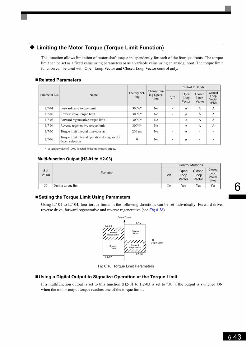
6-43
6
Limiting the Motor Torque (Torque Limit Function)
This function allows limitation of motor shaft torque independently for each of the four quadrants. The torquelimit can be set as a fixed value using parameters or as a variable value using an analog input. The torque limitfunction can be used with Open Loop Vector and Closed Loop Vector control only.
Related Parameters
* A setting value of 100% is equal to the motor rated torque.
Multi-function Output (H2-01 to H2-03)
Setting the Torque Limit Using ParametersUsing L7-01 to L7-04, four torque limits in the following directions can be set individually: Forward drive,reverse drive, forward regenerative and reverse regenerative (see Fig 6.18)
Fig 6.18 Torque Limit Parameters
Using a Digital Output to Signalize Operation at the Torque LimitIf a multifunction output is set to this function (H2-01 to H2-03 is set to “30”), the output is switched ONwhen the motor output torque reaches one of the torque limits.
Parameter No. Name Factory Set-ting
Change dur-ing Opera-
tion
Control Methods
V/fOpen Loop Vector
Closed Loop Vector
Closed Loop
Vector (PM)
L7-01 Forward drive torque limit 300%* No - A A A
L7-02 Reverse drive torque limit 300%* No - A A A
L7-03 Forward regenerative torque limit 300%* No - A A A
L7-04 Reverse regenerative torque limit 300%* No - A A A
L7-06 Torque limit integral time constant 200 ms No - A - -
L7-07 Torque limit integral operation during accel./decel. selection 0 No - A - -
Set Value Function
Control Methods
V/fOpen Loop
Vector
Closed Loop
Vector
Closed Loop
Vector (PM)
30 During torque limit No Yes Yes Yes
L7-01
Output Torque
Output Speed
L7-03L7-02
L7-04
ForwardDrive
ReverseDrive
ReverseRegenerative
ForwardRegenerative

6-44
6
Adjusting the Torque Limit Integral Time (L7-06)In Open Loop Vector control, during constant speed the limit function works with an integral control part (dur-ing acceleration and deceleration just a P-control is used). Normally there is no need to change this setting.
• Increase the setting if vibrations or short cycle oscillations occur when the motor is running at the settorque limit
• Decrease the setting if long cycle oscillations occur when the motor is running at the set torque limit.
Enabling the Torque Limit Integral Operation during Accel./Decel. (L7-07)In Open Loop Vector control an integral operation can be applied to the torque limit function (P-control isstandard). This improves the torque limit responsiveness and smoothes the torque limit operation. To enablethe integral operation set parameter L7-07 to 1. The integral time set in parameter L7-07 is used.
Setting Precautions• When the output torque reaches the torque limit, control and compensation of the motor speed is disabled
to prevent the output torque from exceeding the torque limit. The torque limit has the priority.• The torque limit accuracy is ±5% at an output frequency of 10 Hz or above. When output frequency is
lower than 10 Hz, the accuracy is lower.
Motor Overload Protection
The motor can be protected from overload using the built-in electronic thermal overload relay function.
Related Parameters
Multi-Function Outputs (H2-01 to H2-03)
Setting the Motor Rated Current (E2-01, E4-01 or E5-02))Set the rated current value on the motor nameplate in parameters E2-01 (for motor 1), E4-01 (for motor 2) orE5-02 (PM motor). This set value is the base current for the internal thermal overload calculation.
Parameter No. Name Factory
Setting
Change during
Operation
Control Methods
V/fOpen Loop
Vector
Closed Loop
Vector
Closed Loop
Vector (PM)
E2-01 Motor 1 rated current 7.00 A *1
*1. Factory settings depend on Inverter capacity. (The given value is for a 400 V Class Inverter with 3.7 kW.)
No Q Q Q -
E4-01 Motor 2 rated current 7.00 A *1 No Q Q Q -
E5-02 PM Motor rated current 7.31 A *1 No Q Q Q -
L1-01 Motor protection selection 1 No Q Q Q A
L1-02 Motor protection time constant 1.0 min No A A A -
Set Value Function
Control Methods
V/fOpen Loop
Vector
Closed Loop
Vector
Closed Loop
Vector (PM)
1F Motor overload (OL1, including OH3) pre-alarm (ON: 90% or more of the detection level) Yes Yes Yes Yes
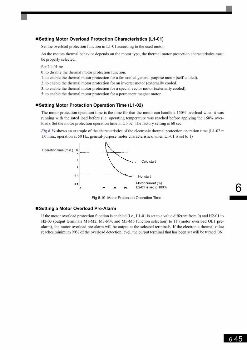
6-45
6
Setting Motor Overload Protection Characteristics (L1-01)Set the overload protection function in L1-01 according to the used motor.
As the motors thermal behavior depends on the motor type, the thermal motor protection characteristics mustbe properly selected.
Set L1-01 to:0: to disable the thermal motor protection function.1: to enable the thermal motor protection for a fan cooled general purpose motor (self-cooled).2: to enable the thermal motor protection for an inverter motor (externally cooled).3: to enable the thermal motor protection for a special vector motor (externally cooled).5: to enable the thermal motor protection for a permanent magnet motor
Setting Motor Protection Operation Time (L1-02)The motor protection operation time is the time for that the motor can handle a 150% overload when it wasrunning with the rated load before (i.e. operating temperature was reached before applying the 150% over-load). Set the motor protection operation time in L1-02. The factory setting is 60 sec.
Fig 6.19 shows an example of the characteristics of the electronic thermal protection operation time (L1-02 =1.0 min., operation at 50 Hz, general-purpose motor characteristics, when L1-01 is set to 1)
Fig 6.19 Motor Protection Operation Time
Setting a Motor Overload Pre-AlarmIf the motor overload protection function is enabled (i.e., L1-01 is set to a value different from 0) and H2-01 toH2-03 (output terminals M1-M2, M3-M4, and M5-M6 function selection) to 1F (motor overload OL1 pre-alarm), the motor overload pre-alarm will be output at the selected terminals. If the electronic thermal valuereaches minimum 90% of the overload detection level, the output terminal that has been set will be turned ON.
Operation time (min.)
Cold start
Hot start
Motor current (%)E2-01 is set to 100%

6-46
6
Output Current Observation
The inverter can observe the output current and thereby detect e.g a wrong motor contactor sequence or badmotor connection. There are two observation functions, one for the start and one during run.
Related Parameters
SE2 fault (SE2, Current observation at start)The current is measured for the time S1-06 + S1-14 (Brake open delay plus SE2 detection time) after the Up/Down command input. If it is/falls below 25% of the motor no-load current (E2-03) a SE2 fault is output. S1-06 + S1-14 must be smaller than S1-04 (DC injection at start).
SE3 fault (SE3, Current observation during Run)When the acceleration is started (DC injection/Zero Speed time S1-04 after the Up/Down command input), theinverter observes the output current continuously. If it falls below 25% of the motor no-load current (E2-03) aSE3 fault is output.
Over Acceleration Detection (“DV6” Fault Detection)
Using this function an over acceleration of the car caused by too high load or wrong settings can be detected.The function works in Closed Loop Vector for PM motors only (A1-02 = 6). If an over acceleration isdetected, the inverter stops and a “DV6” fault is displayed.
Related Parameters
Adjusting the Over Acceleration DetectionOver acceleration is detected when the acceleration of the car exceeds the value set in S3-16 for longer thanthe time set in S3-17. The setting of parameter S3-18 decides the over acceleration is always activate if thepower supply is on (S3-16 = 0) or only during run (S3-16 = 1).
Setting parameter S3-16 to 0.0 m/s² disables the over acceleration detection.
Parameter No. Name Factory
Setting
Change during
Operation
Control Methods
V/fOpen Loop
Vector
Closed Loop
Vector
Closed Loop
Vector (PM)
S1-14 SE2 detection time 200 ms No A A A -
S1-15 SE3 detection time 200 ms No A A A -
Parameter No. Name Factory
Setting
Change during
Operation
Control Methods
V/fOpen Loop
Vector
Closed Loop
Vector
Closed Loop
Vector (PM)
S3-16 Over acceleration detection level 1.5 m/s² No - - - A
S3-17 Over acceleration time constant 0.05 sec. No - - - A
S3-18 Over acceleration detection method 0 No - - - A
IMPORTANT
It is imperative to set up the parameters S3-13, S3-14 and S3-15 (traction sheave diameter, roping and gear ratio) in order to make this function working properly!
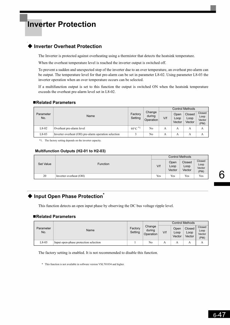
6-47
6
Inverter Protection
Inverter Overheat Protection
The Inverter is protected against overheating using a thermistor that detects the heatsink temperature.
When the overheat temperature level is reached the inverter output is switched off.
To prevent a sudden and unexpected stop of the inverter due to an over temperature, an overheat pre-alarm canbe output. The temperature level for that pre-alarm can be set in parameter L8-02. Using parameter L8-03 theinverter operation when an over temperature occurs can be selected.
If a multifunction output is set to this function the output is switched ON when the heatsink temperatureexceeds the overheat pre-alarm level set in L8-02.
Related Parameters
Multifunction Outputs (H2-01 to H2-03)
Input Open Phase Protection*
This function detects an open input phase by observing the DC bus voltage ripple level.
Related Parameters
The factory setting is enabled. It is not recommended to disable this function.
* This function is not available in software version VSL701034 and higher.
Parameter No. Name Factory
Setting
Change during
Operation
Control Methods
V/fOpen Loop
Vector
Closed Loop
Vector
Closed Loop
Vector (PM)
L8-02 Overheat pre-alarm level 95°C *1
*1. The factory setting depends on the inverter capacity.
No A A A A
L8-03 Inverter overheat (OH) pre-alarm operation selection 3 No A A A A
Set Value Function
Control Methods
V/fOpen Loop
Vector
Closed Loop
Vector
Closed Loop
Vector (PM)
20 Inverter overheat (OH) Yes Yes Yes Yes
Parameter No. Name Factory
Setting
Change during
Operation
Control Methods
V/fOpen Loop
Vector
Closed Loop
Vector
Closed Loop
Vector (PM)
L8-05 Input open-phase protection selection 1 No A A A A
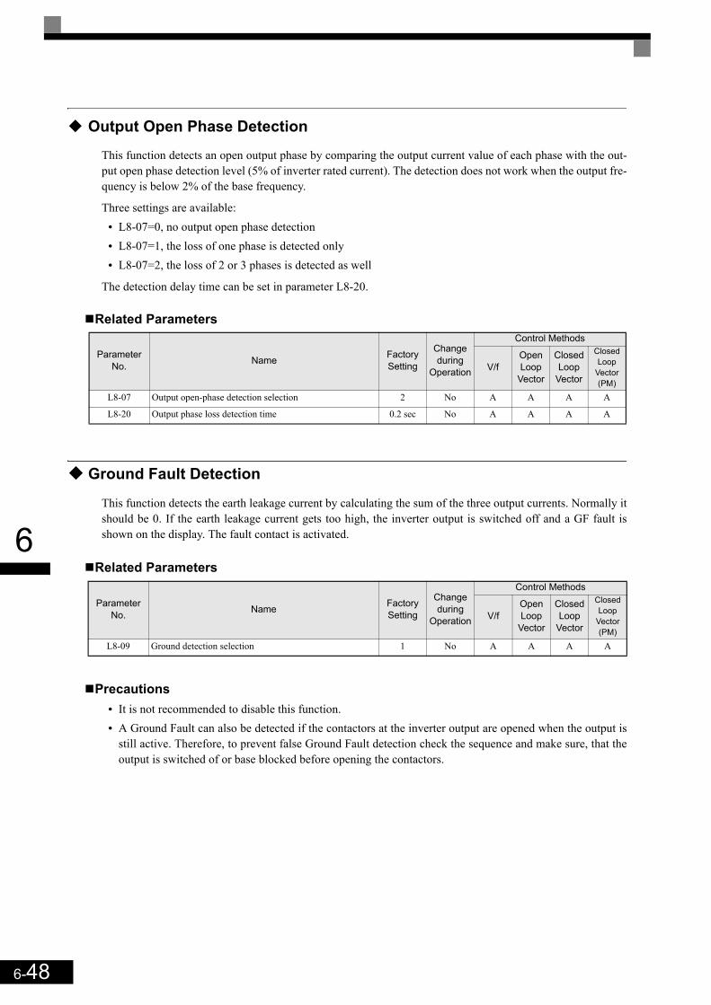
6-48
6
Output Open Phase Detection
This function detects an open output phase by comparing the output current value of each phase with the out-put open phase detection level (5% of inverter rated current). The detection does not work when the output fre-quency is below 2% of the base frequency.
Three settings are available:• L8-07=0, no output open phase detection• L8-07=1, the loss of one phase is detected only• L8-07=2, the loss of 2 or 3 phases is detected as well
The detection delay time can be set in parameter L8-20.
Related Parameters
Ground Fault Detection
This function detects the earth leakage current by calculating the sum of the three output currents. Normally itshould be 0. If the earth leakage current gets too high, the inverter output is switched off and a GF fault isshown on the display. The fault contact is activated.
Related Parameters
Precautions• It is not recommended to disable this function.• A Ground Fault can also be detected if the contactors at the inverter output are opened when the output is
still active. Therefore, to prevent false Ground Fault detection check the sequence and make sure, that theoutput is switched of or base blocked before opening the contactors.
Parameter No. Name Factory
Setting
Change during
Operation
Control Methods
V/fOpen Loop
Vector
Closed Loop
Vector
Closed Loop
Vector (PM)
L8-07 Output open-phase detection selection 2 No A A A A
L8-20 Output phase loss detection time 0.2 sec No A A A A
Parameter No. Name Factory
Setting
Change during
Operation
Control Methods
V/fOpen Loop
Vector
Closed Loop
Vector
Closed Loop
Vector (PM)
L8-09 Ground detection selection 1 No A A A A

6-49
6
Cooling Fan Control
This function controls the fan which is mounted to the inverters heatsink.
Related Parameters
Selecting the Cooling Fan ControlUsing parameter L8-10 two modes can be selected:
0: The fan is ON only when the inverter output is ON, i.e. a voltage is output. This is the factory setting. Theturn OFF delay time for the fan can be set in parameter L8-11. After a stop command the inverter waits forthis time before switching OFF the cooling fan. The factory setting is 60 sec.
1. The fan is ON whenever the inverter power supply is switched ON.
Setting the Ambient Temperature
Related Parameters
At high ambient temperatures an output current derating has to be considered. The derating depends on theambient temperature. The derating curve is shown in Fig 6.20. To ensure a safe inverter protection at highambient temperatures, always set parameter L8-15 to the actual ambient temperature.
Fig 6.20 Ambient Temperature Derating Curve
Parameter No. Name Factory
Setting
Change during
Operation
Control Methods
V/fOpen Loop
Vector
Closed Loop
Vector
Closed Loop
Vector (PM)
L8-10 Cooling fan control selection 0 No A A A A
L8-11 Cooling fan control delay time 60 s No A A A A
Parameter No. Name Factory
Setting
Change during
Operation
Control Methods
V/fOpen Loop
Vector
Closed Loop
Vector
Closed Loop
Vector (PM)
L8-12 Ambient Temperature 45° C No A A A A
0
2 0
4 0
6 0
8 0
10 0
0 10 2 0 3 0 4 0 50 6 0
Temperature (°C)
Out
put C
urre
nt in
% o
f the
Rat
ed C
urre
nt
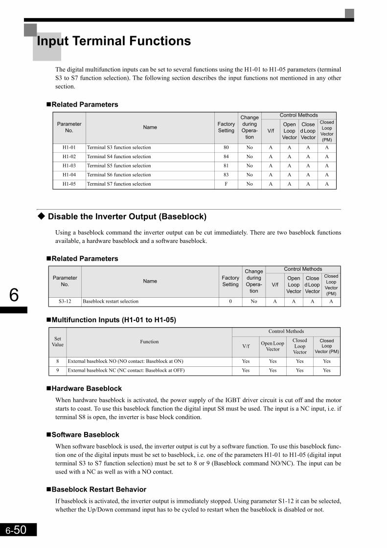
6-50
6
Input Terminal Functions
The digital multifunction inputs can be set to several functions using the H1-01 to H1-05 parameters (terminalS3 to S7 function selection). The following section describes the input functions not mentioned in any othersection.
Related Parameters
Disable the Inverter Output (Baseblock)
Using a baseblock command the inverter output can be cut immediately. There are two baseblock functionsavailable, a hardware baseblock and a software baseblock.
Related Parameters
Multifunction Inputs (H1-01 to H1-05)
Hardware BaseblockWhen hardware baseblock is activated, the power supply of the IGBT driver circuit is cut off and the motorstarts to coast. To use this baseblock function the digital input S8 must be used. The input is a NC input, i.e. ifterminal S8 is open, the inverter is base block condition.
Software BaseblockWhen software baseblock is used, the inverter output is cut by a software function. To use this baseblock func-tion one of the digital inputs must be set to baseblock, i.e. one of the parameters H1-01 to H1-05 (digital inputterminal S3 to S7 function selection) must be set to 8 or 9 (Baseblock command NO/NC). The input can beused with a NC as well as with a NO contact.
Baseblock Restart BehaviorIf baseblock is activated, the inverter output is immediately stopped. Using parameter S1-12 it can be selected,whether the Up/Down command input has to be cycled to restart when the baseblock is disabled or not.
Parameter No. Name Factory
Setting
Change during Opera-
tion
Control Methods
V/fOpen Loop
Vector
Closed Loop Vector
Closed Loop
Vector (PM)
H1-01 Terminal S3 function selection 80 No A A A A
H1-02 Terminal S4 function selection 84 No A A A A
H1-03 Terminal S5 function selection 81 No A A A A
H1-04 Terminal S6 function selection 83 No A A A A
H1-05 Terminal S7 function selection F No A A A A
Parameter No. Name Factory
Setting
Change during Opera-
tion
Control Methods
V/fOpen Loop
Vector
Closed Loop Vector
Closed Loop
Vector (PM)
S3-12 Baseblock restart selection 0 No A A A A
Set Value Function
Control Methods
V/f Open Loop Vector
Closed Loop Vector
Closed Loop
Vector (PM)
8 External baseblock NO (NO contact: Baseblock at ON) Yes Yes Yes Yes
9 External baseblock NC (NC contact: Baseblock at OFF) Yes Yes Yes Yes
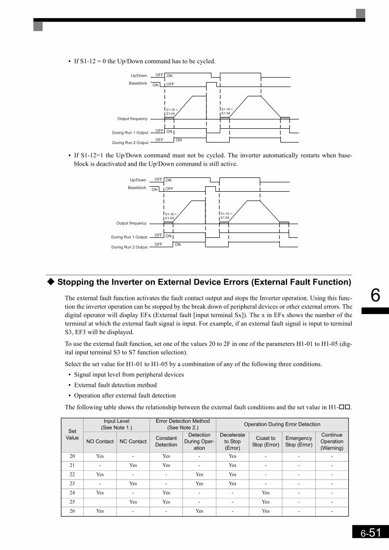
6-51
6
• If S1-12 = 0 the Up/Down command has to be cycled.
• If S1-12=1 the Up/Down command must not be cycled. The inverter automatically restarts when base-block is deactivated and the Up/Down command is still active.
Stopping the Inverter on External Device Errors (External Fault Function)
The external fault function activates the fault contact output and stops the Inverter operation. Using this func-tion the inverter operation can be stopped by the break down of peripheral devices or other external errors. Thedigital operator will display EFx (External fault [input terminal Sx]). The x in EFx shows the number of theterminal at which the external fault signal is input. For example, if an external fault signal is input to terminalS3, EF3 will be displayed.
To use the external fault function, set one of the values 20 to 2F in one of the parameters H1-01 to H1-05 (dig-ital input terminal S3 to S7 function selection).
Select the set value for H1-01 to H1-05 by a combination of any of the following three conditions.• Signal input level from peripheral devices• External fault detection method• Operation after external fault detection
The following table shows the relationship between the external fault conditions and the set value in H1- .
Set Value
Input Level (See Note 1.)
Error Detection Method (See Note 2.) Operation During Error Detection
NO Contact NC Contact Constant Detection
Detection During Oper-
ation
Decelerate to Stop (Error)
Coast to Stop (Error)
Emergency Stop (Error)
Continue Operation (Warning)
20 Yes - Yes - Yes - - -
21 - Yes Yes - Yes - - -
22 Yes - - Yes Yes - - -
23 - Yes - Yes Yes - - -
24 Yes - Yes - - Yes - -
25 Yes Yes - - Yes - -
26 Yes - - Yes - Yes - -
Up/Down
Baseblock
OFF ON
ON OFF
Output frequency
During Run 1 Output
During Run 2 Output
OFF ON
OFF ON
S1-16 +
S1-04
S1-16 +
S1-04
Up/Down
Baseblock
OFF ON
ON OFF
Output frequency
During Run 1 Output
During Run 2 Output
OFF ON
OFF ON
S1-16 +
S1-04
S1-16 +
S1-04

6-52
6
* 1. Sets the input level at which errors are detected. (NO contact: External error when ON; NC contact: External error when OFF).* 2. Set the detection method to detect errors using either constant detection or detection during operation.
Constant detection: Detects while power is supplied to the Inverter.Detection during operation: Detects only during Inverter operation.
Using the Timer Function
The multi-function digital input terminals S3 to S7 can be used as a timer function input and the multi-func-tion output terminals M1-M2, M3-M4, and M5-M6 can be used as a timer function output.
Related Parameters
Multi-function Digital Inputs (H1-01 to H1-05)
Multifunction Outputs (H2-01 to H2-03)
27 - Yes - Yes - Yes - -
28 Yes - Yes - - - Yes -
29 - Yes Yes - - - Yes -
2A Yes - - Yes - - Yes -
2B - Yes - Yes - - Yes -
2C Yes - Yes - - - - Yes
2D - Yes Yes - - - - Yes
2E Yes - - Yes - - - Yes
2F - Yes - Yes - - - Yes
Parameter No. Name Factory
Setting
Change during
Operation
Control Methods
V/fOpen Loop Vector
Closed Loop
Vector
Closed Loop
Vector (PM)
b4-01 Timer function ON-delay time 0.0 s No A A A A
b4-02 Timer function OFF-delay time 0.0 s No A A A A
Set Value Function
Control Methods
V/fOpen Loop
Vector
Closed Loop Vector
Closed Loop
Vector (PM)
18 Timer function input Yes Yes Yes Yes
Set Value Function
Control Methods
V/fOpen Loop Vector
Closed Loop Vector
Closed Loop
Vector (PM)
12 Timer function output Yes Yes Yes Yes
Set Value
Input Level (See Note 1.)
Error Detection Method (See Note 2.) Operation During Error Detection
NO Contact NC Contact Constant Detection
Detection During Oper-
ation
Decelerate to Stop (Error)
Coast to Stop (Error)
Emergency Stop (Error)
Continue Operation (Warning)
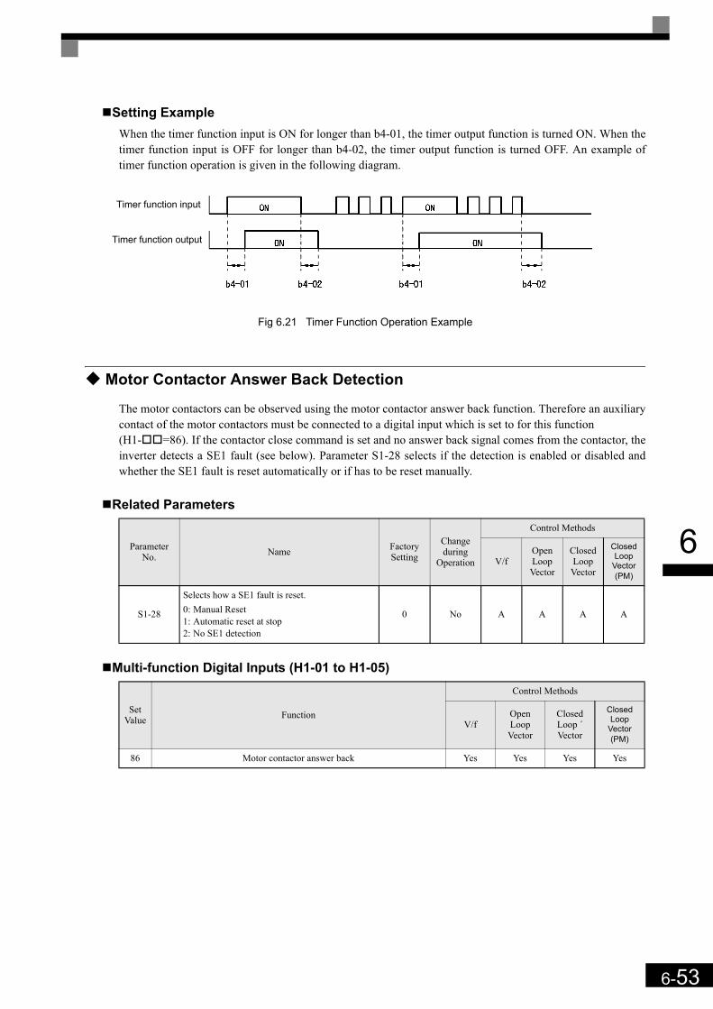
6-53
6
Setting ExampleWhen the timer function input is ON for longer than b4-01, the timer output function is turned ON. When thetimer function input is OFF for longer than b4-02, the timer output function is turned OFF. An example oftimer function operation is given in the following diagram.
Fig 6.21 Timer Function Operation Example
Motor Contactor Answer Back Detection
The motor contactors can be observed using the motor contactor answer back function. Therefore an auxiliarycontact of the motor contactors must be connected to a digital input which is set to for this function (H1- =86). If the contactor close command is set and no answer back signal comes from the contactor, theinverter detects a SE1 fault (see below). Parameter S1-28 selects if the detection is enabled or disabled andwhether the SE1 fault is reset automatically or if has to be reset manually.
Related Parameters
Multi-function Digital Inputs (H1-01 to H1-05)
Parameter No. Name Factory
Setting
Change during
Operation
Control Methods
V/fOpen Loop Vector
Closed Loop Vector
Closed Loop
Vector (PM)
S1-28
Selects how a SE1 fault is reset.0: Manual Reset1: Automatic reset at stop2: No SE1 detection
0 No A A A A
Set Value Function
Control Methods
V/fOpen Loop
Vector
Closed Loop ´Vector
Closed Loop
Vector (PM)
86 Motor contactor answer back Yes Yes Yes Yes
Timer function input
Timer function output

6-54
6
SE1 fault (SE1:Contactor Feed-back Faults)There are 3 possible fault conditions.
Case 1: The motor contactor was closed (Contactor feedback input was on) before the contactor close command was output.
Case 2: The motor contactor cannot be closed within the contactor close delay time.
Case 3: The motor contactor is opened during inverter run.
Case 4: The contactor confirmation input was enabled before the contactor close output was set.
Changing the PG direction
A digital input can be used to change over the PG feedback signal direction. Therefore one of the parametersH1- must be set to 89.
The PG direction is clockwise (CW) when the input is open and counterclockwise (CCW) when the input isclosed. The parameter F1-05 has no effect if this function is activated.
Multi-function Digital Inputs (H1-01 to H1-05)
Set Value Function
Control Methods
V/fOpen Loop Vector
Closed Loop ´Vector
Closed Loop
Vector (PM)
89 PG direction change over No No Yes Yes
Contactor Control (D/O)
Speed
Up/DownSpeed
Case 1
Contactor confirmation (D/I)
Speed Selection
Inverter enable (D/I)
Case 2
Case 3
Case 4
Run Delay
DC Injection/
Zero Servo
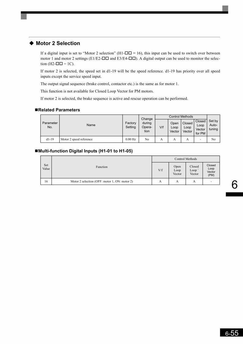
6-55
6
Motor 2 Selection
If a digital input is set to “Motor 2 selection” (H1- = 16), this input can be used to switch over betweenmotor 1 and motor 2 settings (E1/E2- and E3/E4- ). A digital output can be used to monitor the selec-tion (H2- = 1C).
If motor 2 is selected, the speed set in d1-19 will be the speed reference. d1-19 has priority over all speedinputs except the service speed input.
The output signal sequence (brake control, contactor etc.) is the same as for motor 1.
This function is not available for Closed Loop Vector for PM motors.
If motor 2 is selected, the brake sequence is active and rescue operation can be performed.
Related Parameters
Multi-function Digital Inputs (H1-01 to H1-05)
Parameter No. Name Factory
Setting
Change during Opera-
tion
Control MethodsSet by Auto-tuningV/f
Open Loop
Vector
Closed Loop
Vector
Closed Loop
Vector for PM
d1-19 Motor 2 speed reference 0.00 Hz No A A A - No
Set Value Function
Control Methods
V/fOpen Loop
Vector
Closed Loop ´Vector
Closed Loop
Vector (PM)
16 Motor 2 selection (OFF: motor 1, ON: motor 2) A A A -

6-56
6
Output Terminal Functions
The digital multifunction outputs can be set to several functions using the H2-01 to H2-03 parameters (termi-nal M1 to M6 function selection). These functions are described in the following section.
Related Parameters
During Run (Setting: 0) and During Run 2 (Setting: 37)
During Run (Setting: 0)
During Run 2 (Setting: 37)
These outputs can be used to indicate the inverter’s operating status.
Fig 6.22 Timing Chart for “During RUN” Output
Zero Speed (Setting: 1)
Fig 6.23 Timing Chart for Zero-speed
* The Zero Speed Level depends on the control mode. It is 0.1 Hz for Closed Loop Vector, 0.5 Hz for Open Loop Vector and 1.2 Hz for V/f control.
Parameter No. Name Factory
Setting
Change during Opera-
tion
Control Methods
V/fOpen Loop
Vector
Closed Loop
Vector
Closed Loop
Vector (PM)
H2-01 Terminal M1-M2 function selection 0 No A A A A
H2-02 Terminal M3-M4 function selection 1 No A A A A
H2-03 Terminal M5-M6 function selection 2 No A A A A
OFF The Run command is OFF and there is not output voltage.
ON The Run command is ON or a voltage is being output.
OFF The inverter is not outputting a frequency. (Baseblock, DC injection braking or stopped)
ON The inverter is outputting a frequency.
OFF The output frequency is higher than the zero speed level*.
ON The output frequency is lower than the zero speed level*.
Run
Baseblock
Output frequency
During Run 1 Output
During Run 2 Output
OFF ON
DC Inj DC Inj
OFFON
OFF ON
OFF ON
Zero Speed Level*
Zero Speed Output
Output Frequency
OFF ON
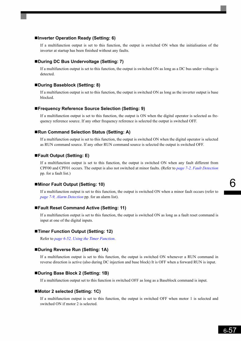
6-57
6
Inverter Operation Ready (Setting: 6)If a multifunction output is set to this function, the output is switched ON when the initialisation of theinverter at startup has been finished without any faults.
During DC Bus Undervoltage (Setting: 7)If a multifunction output is set to this function, the output is switched ON as long as a DC bus under voltage isdetected.
During Baseblock (Setting: 8)If a multifunction output is set to this function, the output is switched ON as long as the inverter output is baseblocked.
Frequency Reference Source Selection (Setting: 9)If a multifunction output is set to this function, the output is ON when the digital operator is selected as fre-quency reference source. If any other frequency reference is selected the output is switched OFF.
Run Command Selection Status (Setting: A)If a multifunction output is set to this function, the output is switched ON when the digital operator is selectedas RUN command source. If any other RUN command source is selected the output is switched OFF.
Fault Output (Setting: E)If a multifunction output is set to this function, the output is switched ON when any fault different fromCPF00 and CPF01 occurs. The output is also not switched at minor faults. (Refer to page 7-2, Fault Detectionpp. for a fault list.)
Minor Fault Output (Setting: 10)If a multifunction output is set to this function, the output is switched ON when a minor fault occurs (refer topage 7-9, Alarm Detection pp. for an alarm list).
Fault Reset Command Active (Setting: 11)If a multifunction output is set to this function, the output is switched ON as long as a fault reset command isinput at one of the digital inputs.
Timer Function Output (Setting: 12)Refer to page 6-52, Using the Timer Function.
During Reverse Run (Setting: 1A)If a multifunction output is set to this function, the output is switched ON whenever a RUN command inreverse direction is active (also during DC injection and base block) It is OFF when a forward RUN is input.
During Base Block 2 (Setting: 1B)If a multifunction output set to this function is switched OFF as long as a Baseblock command is input.
Motor 2 selected (Setting: 1C)If a multifunction output is set to this function, the output is switched OFF when motor 1 is selected andswitched ON if motor 2 is selected.
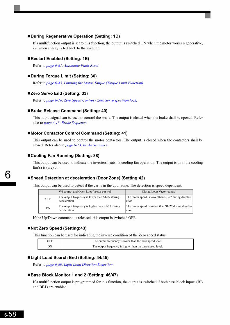
6-58
6
During Regenerative Operation (Setting: 1D)If a multifunction output is set to this function, the output is switched ON when the motor works regenerative,i.e. when energy is fed back to the inverter.
Restart Enabled (Setting: 1E)Refer to page 6-81, Automatic Fault Reset.
During Torque Limit (Setting: 30)Refer to page 6-43, Limiting the Motor Torque (Torque Limit Function).
Zero Servo End (Setting: 33)Refer to page 6-16, Zero Speed Control / Zero Servo (position lock).
Brake Release Command (Setting: 40)This output signal can be used to control the brake. The output is closed when the brake shall be opened. Referalso to page 6-13, Brake Sequence.
Motor Contactor Control Command (Setting: 41)This output can be used to control the motor contactors. The output is closed when the contactors shall beclosed. Refer also to page 6-13, Brake Sequence.
Cooling Fan Running (Setting: 38)This output can be used to indicate the inverters heatsink cooling fan operation. The output is on if the coolingfan(s) is (are) on.
Speed Detection at deceleration (Door Zone) (Setting:42)This output can be used to detect if the car is in the door zone. The detection is speed dependent.
If the Up/Down command is released, this output is switched OFF.
Not Zero Speed (Setting:43)This function can be used for indicating the inverse condition of the Zero speed status.
Light Load Search End (Setting: 44/45)Refer to page 6-80, Light Load Direction Detection.
Base Block Monitor 1 and 2 (Setting: 46/47)If a multifunction output is programmed for this function, the output is switched if both base block inputs (BBand BB1) are enabled.
V/f control and Open Loop Vector control Closed Loop Vector control
OFF The output frequency is lower than S1-27 during deceleration
The motor speed is lower than S1-27 during deceler-ation
ON The output frequency is higher than S1-27 during deceleration
The motor speed is higher than S1-27 during deceler-ation
OFF The output frequency is lower than the zero speed level.
ON The output frequency is higher than the zero speed level.

6-59
6
Motor and V/f Pattern Setup
The L7 inverter supports 2 motor settings (main motor and door motor, E2/E4- parameters) for V/f con-trol, Open Loop Vector and Closed Loop Vector for IM. The active motor setup can be selected by a digitalinput.
Closed Loop Vector Control for PM supports 1 motor setting (main motor, E5- parameters) only.
Setting Motor Parameters for Induction Motors (Motor 1 and 2)
In order to achieve the maximum performance the V/f pattern and the motor data must be set correctly.The number of motor parameters which can be set, depend on the selected control mode.In the vector control methods the motor parameters can be set automatically by using the autotuning function
(refer to page 4-4, Autotuning). However, if autotuning does not complete normally, the parameters must be set manually like describedbelow.
Related Parameters
Parameter No. Name Factory
Setting
Change during
Operation
Control MethodsSet by Auto-tuningV/f
Open Loop
Vector
Closed Loop
Vector
Closed Loop
Vector for PM
d1-19 Motor 2 speed reference 0.00 Hz No A A A - No
E1-01 Input voltage setting 400 V *1 No Q Q Q Q No
E3-01 Motor 2 control mode selection 0 No A A A A No
E1-04/E3-02 Max. output frequency (FMAX) 50.0 Hz No Q/
AQ/A
Q/A
Q/A Yes
E1-05/E3-03 Max. voltage (VMAX) 380.0 V *1 No Q/
AQ/A
Q/A
Q/A Yes
E1-06/E3-04 Base frequency (FA) 50.0 Hz No Q/
AQ/A
Q/A
Q/A Yes
E1-07/E3-05 Mid. output frequency (FB) 3.0 Hz *1 No A A - - Yes
E1-08/E3-06 Mid. output frequency voltage (VB) 37.3 V
*1,*2No Q/
AQ/A - - Yes
E1-09/E3-07 Min. output frequency (FMIN) 0.5 Hz *2 No Q/
AQ/A A A Yes
E1-10/E3-08 Min. output frequency voltage (VMIN) 19.4 V
*1,*2 No Q/A
Q/A - - Yes
E1-13 Base voltage (VBASE) 0.0 V No A A - Q Yes
E2-01/E4-01 Motor rated current 7.00 A *3 No Q/
AQ/A
Q/A - Yes
E2-02E4-02 Motor rated slip 2.70 Hz *3 No A A A - Yes
E2-03/E4-03 Motor no-load current 2.30 A *3 No A A A - Yes
Up/Down command
Base Block Input(Term BB & BB1)
BB Monitor 1
BB Monitor 2

6-60
6
Multi-function Digital Inputs (H1-01 to H1-05)
Multi-function Digital Outputs (H2-01 to H2-03)
Setting Inverter Input Voltage (E1-01)Set the Inverter input voltage correctly in E1-01 so that it matches the power supply voltage.
E2-04/E4-04 Number of motor poles (Number of poles) 4 poles No - Q/
AQ/A - Yes
E2-05/E2-05 Motor line-to-line resistance 3.333 Ω *3 No A A A - Yes
E2-06/E4-06 Motor leak inductance 19.3% No - A A - Yes
E2-07 Motor iron saturation coefficient 1 0.50 No - A A - Yes*4
E2-08 Motor iron saturation coefficient 2 0.75 No - A A - Yes*4
E2-09 Motor mechanical losses 0.0% No - - A - No
E2-10 Motor iron loss for torque compensation 130 W *3 No A - - - No
E2-11/E4-07 Motor rated output power 3.70 kW*3 No Q/
AQ/A
Q/A - Yes
E2-12 Motor iron saturation coefficient 3 1.30 No - A A - Yes*4
F1-01 PG constant 1024 No - - Q Q Yes
*1. The value is valid for a 400V, 3.7kW inverter*2. The value depends on the control mode. The given value is valid if V/f control is selected.*3. All factory-set parameters are for a Yaskawa standard 4-pole motor. The factory settings depend on Inverter capacity (the values shown are for a 400 V Class Inverter for 3.7 kW).*4. Rotating tuning only
Set Value Function
Control Methods
V/fOpen Loop Vector
Closed Loop ´Vector
Closed Loop
Vector (PM)
16 Motor 2 selection (OFF: Motor 1, ON: Motor 2) A A A -
Set Value Function
Control Methods
V/fOpen Loop Vector
Closed Loop ´Vector
Closed Loop
Vector (PM)
1C Motor selection (OFF: Motor 1, ON: Motor 2) A A A -
Parameter No. Name Factory
Setting
Change during
Operation
Control MethodsSet by Auto-tuningV/f
Open Loop
Vector
Closed Loop
Vector
Closed Loop
Vector for PM

6-61
6
Setting the V/f PatternIf E1-03 is set to F, the V/f pattern can be set individually using the parameters E1-04 to E1-10 (see Fig 6.24).
Fig 6.24 V/f pattern setting
Setting PrecautionsWhen a user-defined V/f pattern is used, consider the following points:
• By changing the control method, the parameters E1-07 to E1-10 are changed to the factory settings for theselected control method.
• Be sure to set the four frequencies as follows:E1-04 (FMAX) ≥ E1-06 (FA) > E1-07 (FB) ≥ E1-09 (FMIN)
Manual Setting of the Motor Parameters
Motor Rated Current Setting (E2-01, E4-01)Set E2-01 to the rated current value as written on the motor nameplate.
Motor Rated Slip Setting (E2-02, E4-02)Set E2-02 to the motor rated slip calculated from the number of rated rotations on the motor nameplate.
Motor No-Load Current Setting (E2-03, E4-03)Set E2-03 to the motor no-load current at the rated voltage and rated frequency. Normally, the motor no-loadcurrent is not written on the motor nameplate. The following formula can be taken as an indication:
Number of Motor Poles Setting (E2-04, E4-04)E2-04 is displayed only when Closed Loop Vector control method is selected. Set the number of motor polesas written on the motor nameplate.
INFOTo set the V/f characteristics linear, set E1-07 and E1-09 to the same value. In this case, E1-08 will be ignored.
Output voltage (V)
Frequency (Hz)
Motor rated slip Motor rated frequency (Hz) Rated speed (Rpm) No. motor poles×120
-------------------------------------------------------------------------------------------–=
I0 ϕcosacos( )sin=
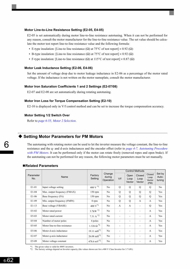
6-62
6
Motor Line-to-Line Resistance Setting (E2-05, E4-05)E2-05 is set automatically during motor line-to-line resistance autotuning. When it can not be performed forany reason, consult the motor manufacturer for the line-to-line resistance value. The set value should be calcu-late the motor test report line-to-line resistance value and the following formula:
• E-type insulation: [Line-to line resistance (Ω) at 75°C of test report] × 0.92 (Ω)• B-type insulation: [Line-to line resistance (Ω) at 75°C of test report] × 0.92 (Ω)• F-type insulation: [Line-to line resistance (Ω) at 115°C of test report] × 0.87 (Ω)
Motor Leak Inductance Setting (E2-06, E4-06)Set the amount of voltage drop due to motor leakage inductance in E2-06 as a percentage of the motor ratedvoltage. If the inductance is not written on the motor nameplate, consult the motor manufacturer.
Motor Iron Saturation Coefficients 1 and 2 Settings (E2-07/08)E2-07 and E2-08 are set automatically during rotating autotuning.
Motor Iron Loss for Torque Compensation Setting (E2-10)E2-10 is displayed only in V/f control method and can be set to increase the torque compensation accuracy.
Motor Setting 1/2 Switch OverRefer to page 6-55, Motor 2 Selection.
Setting Motor Parameters for PM Motors
The autotuning with rotating motor can be used to let the inverter measure the voltage constant, the line-to-lineresistance and the q- and d-axis inductances and the encoder offset (refer to page 4-7, Autotuning Procedurewith PM Motors. It can be performed only if the motor can rotate freely (removed ropes and open brake). Ifthe autotuning can not be performed for any reason, the following motor parameters must be set manually.
Related Parameters
Parameter No. Name Factory
Setting
Change during
Operation
Control MethodsSet by Auto-tuningV/f
Open Loop
Vector
Closed Loop
Vector
Closed Loop
Vector (PM)
E1-01 Input voltage setting 400 V *1
*1. The given value is valid for 400V inverters.
No Q Q Q Q No
E1-04 Max. output frequency (FMAX) 150 rpm No Q Q Q Q Yes
E1-06 Base frequency (FA) 150 rpm No Q Q Q Q Yes
E1-09 Min. output frequency (FMIN) 0 rpm No Q Q A A Yes
E1-13 Base voltage (VBASE) 400 V*1 No A A - Q Yes
E5-02 Motor rated power 3.7kW *2
*2. The factory settings depend on Inverter capacity (the values shown are for a 400 V Class Inverter for 3.7 kW).
No - - - A Yes
E5-03 Motor rated current 7.31 A *2 No - - - A Yes
E5-04 Number of motor poles 4 poles No - - - A Yes
E5-05 Motor line-to-line resistance 1.326 Ω *2 No - - - A Yes
E5-06 Motor d-axis inductance 19.11 mH*2 No - - - A Yes
E2-07 Motor q-axis inductance 26.08 mH*2 No - - - A Yes
E5-09 Motor voltage constant 478.6 mV*2 No - - - A Yes
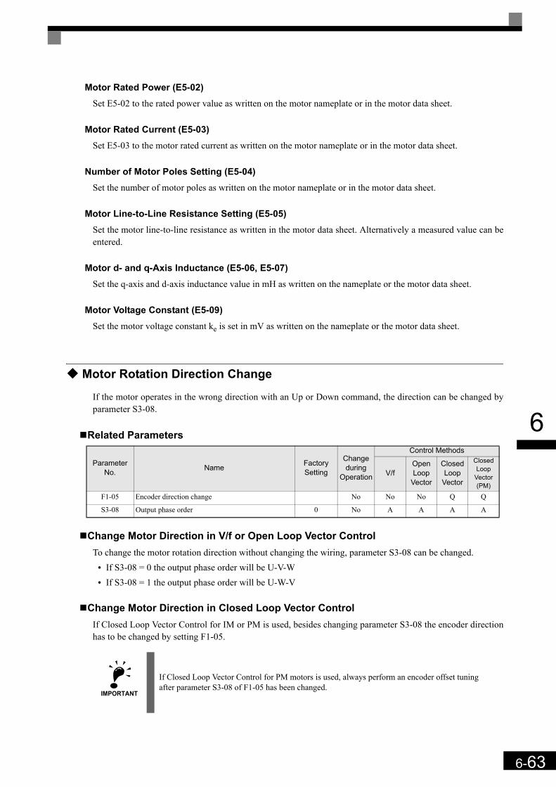
6-63
6
Motor Rated Power (E5-02)Set E5-02 to the rated power value as written on the motor nameplate or in the motor data sheet.
Motor Rated Current (E5-03)Set E5-03 to the motor rated current as written on the motor nameplate or in the motor data sheet.
Number of Motor Poles Setting (E5-04)Set the number of motor poles as written on the motor nameplate or in the motor data sheet.
Motor Line-to-Line Resistance Setting (E5-05)Set the motor line-to-line resistance as written in the motor data sheet. Alternatively a measured value can beentered.
Motor d- and q-Axis Inductance (E5-06, E5-07)Set the q-axis and d-axis inductance value in mH as written on the nameplate or the motor data sheet.
Motor Voltage Constant (E5-09)Set the motor voltage constant ke is set in mV as written on the nameplate or the motor data sheet.
Motor Rotation Direction Change
If the motor operates in the wrong direction with an Up or Down command, the direction can be changed byparameter S3-08.
Related Parameters
Change Motor Direction in V/f or Open Loop Vector ControlTo change the motor rotation direction without changing the wiring, parameter S3-08 can be changed.
• If S3-08 = 0 the output phase order will be U-V-W• If S3-08 = 1 the output phase order will be U-W-V
Change Motor Direction in Closed Loop Vector ControlIf Closed Loop Vector Control for IM or PM is used, besides changing parameter S3-08 the encoder directionhas to be changed by setting F1-05.
Parameter No. Name Factory
Setting
Change during
Operation
Control Methods
V/fOpen Loop
Vector
Closed Loop
Vector
Closed Loop
Vector (PM)
F1-05 Encoder direction change No No No Q Q
S3-08 Output phase order 0 No A A A A
IMPORTANT
If Closed Loop Vector Control for PM motors is used, always perform an encoder offset tuning after parameter S3-08 of F1-05 has been changed.

6-64
6
Digital Operator/LED Monitor Functions
Setting Digital Operator/LED Monitor Functions
Related Parameters
Monitor Selection (o1-01)Using parameter o1-01 the third monitor item that is displayed in drive mode can be selected. This functionhas no effect on the LCD-operator (JVOP-160-OY).
Monitor Display when the Power Supply is Turned ON (o1-02)The parameter o1-02 selects the monitor item (U1- ), which is to be displayed in the first line on the Digi-tal Operator when the power supply is turned ON.
Changing Frequency Reference and Display Units (o1-03)Parameter o1-03 sets the display units of some frequency/speed related parameters on the Digital Operator.The setting in o1-03 affects the display units of the following monitor items:
• U1-01 (Frequency Reference)• U1-02 (Output Frequency)• U1-05 (Motor Speed)
Parameter No. Name Factory
Setting
Change during Opera-
tion
Control Methods
V/fOpen Loop
Vector
Closed Loop Vector
Closed Loop
Vector (PM)
o1-01 Monitor selection 6 Yes A A A A
o1-02 Monitor selection after power up 1 Yes A A A A
o1-03 Frequency units of reference setting and monitor i No
A0
A0
A0 -
- - - A1
o1-04 Setting unit for frequency reference related parameters i No- - A
0 -
- - - A1
o1-05 LCD Display contrast 3 Yes A A A A
o2-02 STOP key during control circuit terminal operation 0 No A A A A
o2-03 User parameter initial value 0 No A A A A
o2-04 Inverter kVA selection 0*1
*1. Depends on the inverter capacity
No A A A A
o2-05 Frequency reference setting method selection 0 No A A A A
o2-06 Operation selection when digital operator/LED Monitor is dis-connected 0 No A A A A
o2-07 Cumulative operation time setting 0 No A A A A
o2-08 Cumulative operation time selection 0 No A A A A
o2-09 Initialize Mode 2 No A A A A
o2-10 Fan operation time setting 0 No A A A A
o2-12 Fault trace initialize 0 No A A A A
o2-15 “Number of Travels” monitor initialize 0 No A A A A
S3-13 Traction sheave diameter 400 mm No A A A A
S3-14 Roping ratio 2 No A A A A
S3-15 Gear ratio 1.000 No A A A A
6-65
6
• U1-20 (Output Frequency after Soft Start)• d1-01 to d1-17 (Frequency references)
Display in HzSet o1-03 to “0” to change the display unit of the above mentioned parameters to Hz.
Display in%Set o1-03 to “1” to change the display unit for the above mentioned parameters to % related to the maximalfrequency/speed set in parameter E1-04.
Display in rpmSet o1-03 to the number of poles of the used motor to display the mentioned parameters in rpm.
Display in m/sSet o1-03 to 3 to enable the display in m/s. The inverter uses the parameters S3-13 (traction sheave diameter),S3-14 (roping ratio) and S3-15 (gear ratio) to calculate the m/s display. To achieve an accurate display valuethese parameters must be set accurately.
Changing the Units for Frequency Parameters Related to V/f settings (o1-04)Using parameter o1-04 the unit of the frequency parameters for the V/f setting can be set. If o1-04 is set to 0the unit is “Hz”. If o1-04 is set to 1 it is “rpm”. The parameter is available in Closed Loop Vector control only.
Changing the Display Contrast (o1-05)Using o1-05 the contrast of the LCD display on the digital operator can be raised or lowered. Lowering the o1-05 value decreases the contrast and vice versa.
Enable/Disable the LOCAL/REMOTE Key (o2-01)Set o2-01 to 1 to enable the LOCAL/REMOTE Key on the Digital Operator.
If the key is enabled, the frequency reference source and the RUN command source can be switched overbetween LOCAL (Operator) and REMOTE (b1-01/02 setting).
Disabling the STOP Key (o2-02)This parameter is used to set if the STOP key on the operator is active during remote control (b1-02 ≠ 0) ornot.
If o2-02 is set to 1, a STOP command from the operators STOP key is accepted. If o2-02 is set to 0 it is disre-garded.
Saving User Parameters (o2-03)The Inverter parameter setting values can be saved as user-set parameter initial values by setting parameter o2-03 to 1.
To initialize the inverter using the user-set initial values, set parameter A1-03 to 1110. To clear the user-set ini-tial values set o2-03 to 2.
Changing the Inverter Capacity Setting (o2-04)The inverter capacity setting can be set using parameter o2-04. Refer to page 5-63, Factory Settings Changingwith Inverter Capacity (o2-04) to see parameters that depend on this setting.
Normally it is not necessary to change this setting, unless the control card has been changed.

6-66
6
Setting the Frequency Reference using the UP and DOWN Keys without Using the Enter Key (o2-05)
This function is active when frequency references are input from the Digital Operator. When o2-05 is set to 1,the selected frequency reference can be incremented and decremented the UP and DOWN keys without usingthe Enter key. The function work only if parameter b1-01 is set to 0.
Operation Selection when the Digital Operator/LED Monitor is Disconnected (o2-06)This function selects the operation when the digital operator/LED Monitor gets disconnected when a RUNcommand is active.
If o2-06 is set to 0 the operation is continued.If o2-06 is set to 1 the output is switched off and the motor coasts to stop. The fault contact is operated. Whenthe operator is reconnected an OPR (Operator disconnected) is shown.
Cumulative Operation Time (o2-07 and o2-08)The inverter has a function that counts the operation time of the inverter cumulatively.
Using parameter o2-07 the accumulated operation time can be changed, e.g. after a replacement of the controlboard. If parameter o2-08 is set to 0, the inverter accumulates the time, whenever the power supply is switchedON. If o2-08 is set to 1, the time when a RUN command is active is counted only. The factory setting is 0.
Cooling Fan Operation Time (o2-10)This function counts the operating time of the inverter mounted fan cumulatively.
Using parameter o2-10 the counter can be reset, e.g. when the fan has been replaced.
Fault Trace Initialize (o2-12)This function can be used to initialize the fault trace by setting parameter o2-12 to 1.
“Number of Travels” counter Initialize (o2-15)Using this parameter the lift operation counter monitor (U1-55) can be initialized.
Copying Parameters (JVOP-160-OY only)
The following three digital operator functions can be used in order to copy/verify parameter settings:• Store Inverter parameter set values in the Digital Operator by setting o3-01 to 1 (READ)• Write parameter set values stored in the Digital Operator to the Inverter by setting o3-01 to 2 (COPY)• Compare parameter set values stored in the Digital Operator with Inverter parameters settings by setting
o3-01 to 3 (VERIFY)
The data saved in the operator can be protected from overwriting by setting parameter o3-02 to 0. In this casea READ command can not be executed. If it is nevertheless still done, “PrE” will be displayed at the operator.
Related Parameters
Parameter No. Name Factory
Setting
Change during Opera-
tion
Control Methods
V/fOpen Loop
Vector
Closed Loop
Vector
Closed Loop
Vector (PM)
o3-01 Copy function selection 0 No A A A A
o3-02 Read permitted selection 0 No A A A A

6-67
6
Storing Inverter set values in the Digital Operator (READ)To store Inverter set values in the Digital Operator use the following method.
If an error is displayed, press any key to cancel the error display and return to the o3-01 display. Refer to page 7-16, Digital Operator Copy Function Faults for corrective actions.
Writing Parameter Set Values Stored in the Digital Operator to the Inverter (COPY)To write parameter set values stored in the Digital Operator to the Inverter, use the following method.
Step No. Explanation Digital Operator Display
1 Press the Menu Key and select advanced programming mode.
2 Press the DATA/ENTER Key.
3 Press the Increment and Decrement Key until parameter o3-01 is displayed (Copy Function Selection).
4 Press the DATA/ENTER Key and select the constants setting display.
5 Change the set value to 1 using the Increment Key.
6 Set the changed data using the DATA/ENTER Key. The READ function starts.
7 If the READ function ends normally, “End” is displayed on the Digital Operator.
8 The display returns to o3-01 when a key is pressed.
Step No. Explanation Digital Operator Display
1 Press the MENU Key and select advanced programming mode.
2 Press the DATA/ENTER Key.
** Main Menu **-ADV-
Programming
Initialization-ADV-
A1 - 00=1Select Language
COPY Function-ADV-
o3 - 01=0Copy Funtion Sel
Copy Function Sel-ADV-
o3-01= 0COPY SELECT
*0*
Copy Function Sel-ADV-
o3-01= 1 *0*
INV OP READ
READ-ADV-
INV OP READING
READ-ADV-
READ COMPLETE
Copy Function Sel-ADV-
o3 - 01=0COPY SELECT
*0*
** Main Menu **-ADV-
Programming
Initialization-ADV-
A1 - 00 = 1Select Language
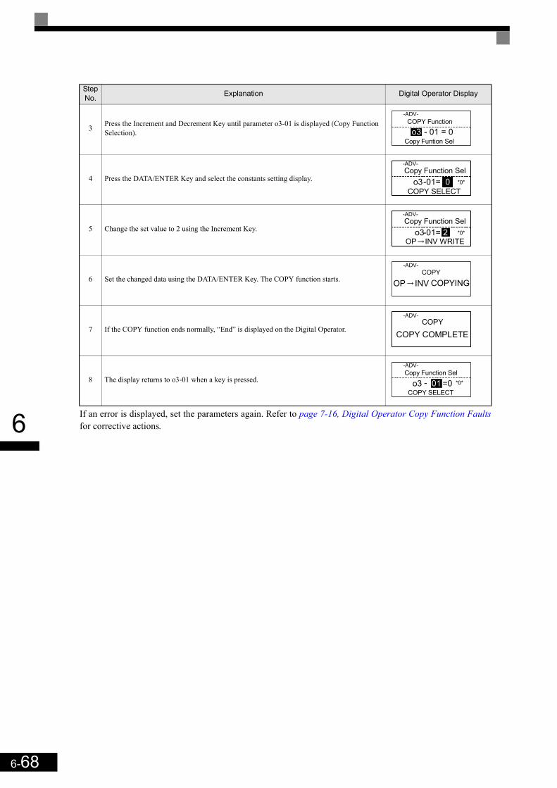
6-68
6 If an error is displayed, set the parameters again. Refer to page 7-16, Digital Operator Copy Function Faultsfor corrective actions.
3 Press the Increment and Decrement Key until parameter o3-01 is displayed (Copy Function Selection).
4 Press the DATA/ENTER Key and select the constants setting display.
5 Change the set value to 2 using the Increment Key.
6 Set the changed data using the DATA/ENTER Key. The COPY function starts.
7 If the COPY function ends normally, “End” is displayed on the Digital Operator.
8 The display returns to o3-01 when a key is pressed.
Step No. Explanation Digital Operator Display
COPY Function-ADV-
o3 - 01 = 0Copy Funtion Sel
Copy Function Sel-ADV-
o3-01= 0COPY SELECT
*0*
Copy Function Sel-ADV-
o3-01= 2OP INV WRITE
*0*
COPY-ADV-
OP INV COPYING
COPY-ADV-
COPY COMPLETE
Copy Function Sel-ADV-
o3 - 01 =0COPY SELECT
*0*

6-69
6
Comparing Inverter Parameters and Digital Operator Parameter Set Values (VERIFY)To compare Inverter parameters and Digital Operator parameter set values, use the following method.
If an error is displayed, press any key to cancel the error display and return to the o3-01 display. Refer to page 7-16, Digital Operator Copy Function Faults for corrective actions.
Application Precautions
Step No. Explanation Digital Operator Display
1 Press the MENU Key and select advanced programming mode.
2 Press the DATA/ENTER Key.
3 Press the Increment and Decrement Key until the parameter o3-01 is displayed (Copy Func-tion Selection).
4 Press the DATA/ENTER Key and select the function setting display.
5 Change the set value to 3 using the Increment Key.
6 Set the changed data using the DATA/ENTER Key. The VERIFY function starts.
7 If the VERIFY function ends normally, “End” is displayed on the Digital Operator.
8 The display returns to o3-01 when a key is pressed.
INFO
When using the copy function, check that the following settings are the same between the Inverter data and the Digital• Inverter product and type• Software number• Inverter capacity and voltage class• Control method
** Main Menu **-ADV-
Programming
Initialization-ADV-
A1 - 00 = 1Select Language
COPY Function-ADV-
o3 - 01=0Copy Funtion Sel
Copy Function Sel-ADV-
o3-01= 0COPY SELECT
*0*
Copy Funtion Sel-ADV-
o3-01= 3 *0*
OP INV VERIFY
VERIFY-ADV-
DATA VERIFYING
VERIFY-ADV-
VERIFY COMPLETE
Copy Function Sel-ADV-
o3 - 01 = 0COPY SELECT
*0*
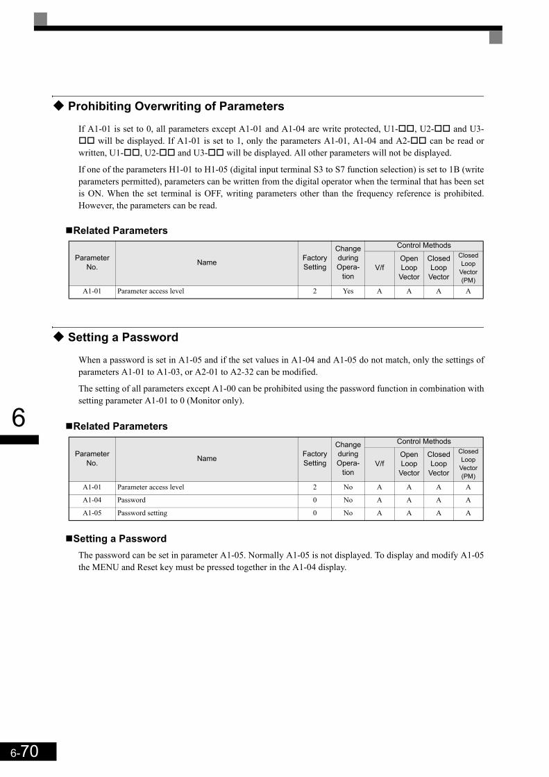
6-70
6
Prohibiting Overwriting of Parameters
If A1-01 is set to 0, all parameters except A1-01 and A1-04 are write protected, U1- , U2- and U3- will be displayed. If A1-01 is set to 1, only the parameters A1-01, A1-04 and A2- can be read or
written, U1- , U2- and U3- will be displayed. All other parameters will not be displayed.
If one of the parameters H1-01 to H1-05 (digital input terminal S3 to S7 function selection) is set to 1B (writeparameters permitted), parameters can be written from the digital operator when the terminal that has been setis ON. When the set terminal is OFF, writing parameters other than the frequency reference is prohibited.However, the parameters can be read.
Related Parameters
Setting a Password
When a password is set in A1-05 and if the set values in A1-04 and A1-05 do not match, only the settings ofparameters A1-01 to A1-03, or A2-01 to A2-32 can be modified.
The setting of all parameters except A1-00 can be prohibited using the password function in combination withsetting parameter A1-01 to 0 (Monitor only).
Related Parameters
Setting a PasswordThe password can be set in parameter A1-05. Normally A1-05 is not displayed. To display and modify A1-05the MENU and Reset key must be pressed together in the A1-04 display.
Parameter No. Name Factory
Setting
Change during Opera-
tion
Control Methods
V/fOpen Loop
Vector
Closed Loop
Vector
Closed Loop
Vector (PM)
A1-01 Parameter access level 2 Yes A A A A
Parameter No. Name Factory
Setting
Change during Opera-
tion
Control Methods
V/fOpen Loop
Vector
Closed Loop
Vector
Closed Loop
Vector (PM)
A1-01 Parameter access level 2 No A A A A
A1-04 Password 0 No A A A A
A1-05 Password setting 0 No A A A A

6-71
6
Displaying User-set Parameters Only
The A2 parameters (user-set parameters) and A1-01 (parameter access level) can be used to establish a param-eter set that contains only the most important parameters.
Set the number of the parameter to which should appear in the A2- parameters, and then set A1-01 to 1.The advanced programming mode now allows to read and modify A1-01 to A1-03 and the parameters set inA2-01 to A2-32 only.
Related Parameters
Parameter No. Name Factory
Setting
Change during
Operation
Control Methods
V/fOpen Loop
Vector
Closed Loop
Vector
Closed Loop
Vector (PM)
A2-01to
A2-32User setting parameters - No A A A
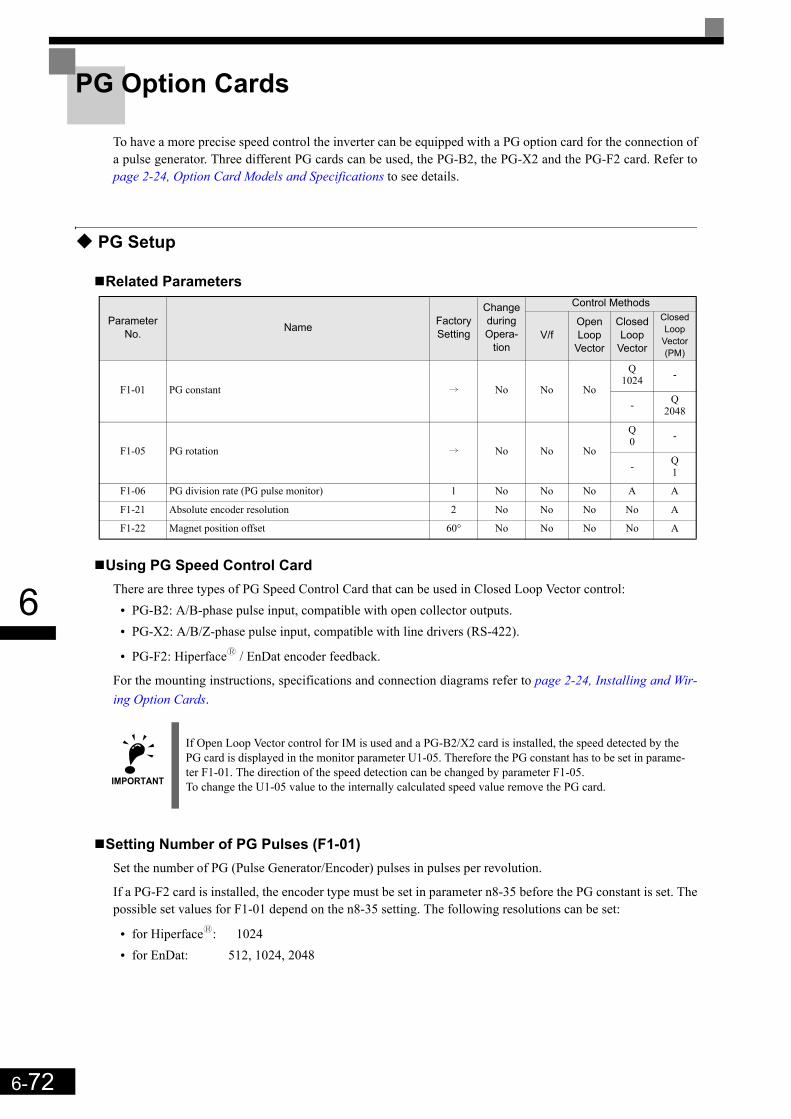
6-72
6
PG Option Cards
To have a more precise speed control the inverter can be equipped with a PG option card for the connection ofa pulse generator. Three different PG cards can be used, the PG-B2, the PG-X2 and the PG-F2 card. Refer topage 2-24, Option Card Models and Specifications to see details.
PG Setup
Related Parameters
Using PG Speed Control CardThere are three types of PG Speed Control Card that can be used in Closed Loop Vector control:
• PG-B2: A/B-phase pulse input, compatible with open collector outputs.• PG-X2: A/B/Z-phase pulse input, compatible with line drivers (RS-422).
• PG-F2: Hiperfacey / EnDat encoder feedback.
For the mounting instructions, specifications and connection diagrams refer to page 2-24, Installing and Wir-ing Option Cards.
Setting Number of PG Pulses (F1-01)Set the number of PG (Pulse Generator/Encoder) pulses in pulses per revolution.
If a PG-F2 card is installed, the encoder type must be set in parameter n8-35 before the PG constant is set. Thepossible set values for F1-01 depend on the n8-35 setting. The following resolutions can be set:
• for Hiperfacey: 1024• for EnDat: 512, 1024, 2048
Parameter No. Name Factory
Setting
Change during Opera-
tion
Control Methods
V/fOpen Loop
Vector
Closed Loop
Vector
Closed Loop
Vector (PM)
F1-01 PG constant i No No No
Q1024 -
- Q2048
F1-05 PG rotation i No No No
Q0 -
- Q1
F1-06 PG division rate (PG pulse monitor) 1 No No No A A
F1-21 Absolute encoder resolution 2 No No No No A
F1-22 Magnet position offset 60° No No No No A
IMPORTANT
If Open Loop Vector control for IM is used and a PG-B2/X2 card is installed, the speed detected by the PG card is displayed in the monitor parameter U1-05. Therefore the PG constant has to be set in parame-ter F1-01. The direction of the speed detection can be changed by parameter F1-05.To change the U1-05 value to the internally calculated speed value remove the PG card.
6-73
6
Suit the PG Rotation Direction and Motor Rotation Direction (F1-05)Parameter F1-05 can be used to change the encoder signal direction if it is wrong.
• If F1-05 is set to 0 the inverter expects channel A to lead 90° before channel B (Sin-channel leads 90°before Cos-channel on PG-F2 card) if a forward command is applied (FWD means counterclockwise rota-tion seen from the shaft side).
• If F1-05 is set to 1 the inverter expects channel B to lead 90° before channel B (Cos-channel leads 90°before Sin-channel on PG-F2 card) if a forward command is applied.
Setting PG Pulse Monitor Output Division Ratio (F1-06)This function is enabled only when a PG-B2 speed feedback card is used. Set the division ratio for the PGpulse monitor output. The set value is expressed as n for the higher place digit, and m for the two lower placedigits. The dividing ratio is calculated as follows:
The division ratio can be set within the following range: 1/32 ≤ F1-06 ≤ 1. For example, if the division ratio is1/2 (set value 2), half of the number of pulses from the PG are output at the pulse monitor.
Setting Number of Gear Teeth Between PG and Motor (F1-12 and F1-13)If there are gears between the motor and PG, the gear ratio can be set using F1-12 and F1-13.
When the number of gear teeth has been set, the number of motor rotations within the Inverter is calculatedusing the following formula.
No. of motor rotations (r/min.) = No. of input pulses from PG × 60 / F1-01 × F1-13 (No. of gear teeth on PGside) / F1-12 (No. of gear teeth on motor side)
Setting the Absolute Encoder Resolution (F1-21)
If a Hiperfacey encoder is used, the serial line resolution must be selected by parameter F1-21 according tothe encoder data sheet. The possible resolution setting depends on the encoder selection (n8-35=5):
• Hiperfacey: 0, 1 or 2 (16384, 32768, 8192)• EnDat: 2 (fixed to 8192)
Setting the Magnet Position Offset (F1-22)Parameter F1-22 can be used to set the offset between the magnet and the encoder zero position. The value isautomatically set during the PM motor autotuning or encoder offset auto tuning (refer to page 4-8, PM MotorEncoder Offset Tuning).
IMPORTANT
If Closed Loop Vector Control for PM motors is used, an encoder offset autotuning must be per-formed if parameter F1-05 is changed.
Dividing ratio = (1 + n)/m (Setting range) n: 0 or 1, m: 1 to 32
F1-06 = n m

6-74
6
Fault Detection
Related Parameters
Detecting PG Open Circuit During Run (F1-02 and F1-14)Parameter F1-02 selects the stopping method when a PG disconnection is detected.
PG open (PGO) is detected only when the inverter is running at least with a frequency reference higher than1% of the maximum output frequency or above the minimum frequency (E1-09) and the PG feedback signal ismissing for the time set in F1-14 or longer.
Detecting Motor Overspeed (F1-03, F1-08 and F1-09)An overspeed (OS) is detected when the motor speed continues to exceed the set frequency value in F1-08 fora time longer than set in F1-09. After detecting an overspeed (OS), the Inverter stops according to the settingin F1-03.
Detecting a Speed Deviation between the Motor and Speed Reference (F1-04, F1-10 and F1-11)
A speed deviation fault is detected when the speed deviation (i.e., the difference between the speed referenceand the actual motor speed) is too large. Speed deviation (DEV) is detected only after a speed agreement(speed reference and actual motor speed are within the setting range of L4-02) and if a speed deviation higherthan the set value in F1-10 continues for longer than the time set in F1-11. After a speed deviation is detected,the Inverter stops according to the setting in F1-04.
Detecting a Wrong Rotation Direction DV3 (F1-18, Closed Loop Vector for PM only)A DV3 fault indicates a wrong motor rotation direction. It is detected if
• the speed deviation is higher than 30% and • the internal torque reference value and the acceleration have opposite signs
The fault is detected after the time F1-18 x 5 ms.
Parameter No. Name Factory
Setting
Change during Opera-
tion
Control Methods
V/fOpen Loop
Vector
Closed Loop
Vector
Closed Loop
Vector (PM)
F1-02 Operation selection at PG open circuit (PGO) 1 No - - A A
F1-03 Operation selection at overspeed (OS) 1 No - - A A
F1-04 Operation selection at deviation (DEV) 3 No - - A A
F1-08 Overspeed detection level 115% No - - A A
F1-09 Overspeed detection time 0.0 sec. No - - A A
F1-10 Speed deviation detection level 10% No - - A A
F1-11 Speed deviation detection time 0.5 sec. No - - A A
F1-14 PG open-circuit detection delay time 2.0 s No - - A A
F1-18 DV3 detection selection 1 No - - - A
F1-19 DV4 detection selection 1024 No - - - A
F1-21 Absolute encoder resolution 2 No - - - A
F1-22 Magnet position offset 60° No - - - A
F1-24 PGO detection Level at stop 20% No - - - A

6-75
6
Detecting a Wrong Rotation Direction DV4 (F1-19, Closed Loop Vector for PM only)A DV4 fault indicates a wrong motor rotation direction. It is detected if
• the reference direction and the motor rotation direction have opposite signs and• the deviation is higher than the value of parameter F1-19 (set in encoder pulses).
Machine Data Copy Function
If a Hiperfacey or an EnDat encoder is used, the motor and encoder data can be saved in the encoder memoryand can be read out later, e.g. if a motor has been replaced to an equal type or if the inverter is replaced.
Related Parameters
Saved ParametersThe following parameters are saved in the encoder memory:
Saving Parameters Into the Encoder MemoryTo save parameters in the encoder memory, the Encoder write protection must be off (F1-26 = 1) and theparameter F1-25 has to be set to 1 (“ERED, INViENC WRITING” is displayed during the save process).The display of F1-25 automatically returns to 0 when the operation is finished (“ERED, WRITE COM-PLETE” is displayed). If any fault occurs the fault code will be displayed (refer to page 7-17, Machine DataCopy Function Faults).
Parameters which had been stored in the encoder before will be overwritten.
Read Parameters From the Encoder MemoryTo read parameters form the encoder memory the parameter F1-25 must be set to 2. Before reading the param-eters make sure, that the correct control mode and encoder type are selected in the parameters A1-02 and n8-35. If parameter n8-35 has to be changed, cycle the power supply after changing it and set parameter F1-25to 2 afterwards (“ECPY, ENCiINV COPIYING” is displayed during the read process). The display of F1-25automatically returns to 0 when the operation is finished (“ECPY, COPY COMPLETE” is displayed). If anyfault occurs the fault code will be displayed (refer to page 7-17, Machine Data Copy Function Faults).
Parameter No. Name Factory
Setting
Change during Opera-
tion
Control Methods
V/fOpen Loop
Vector
Closed Loop
Vector
Closed Loop
Vector (PM)
F1-25 Encoder copy selection 0 No No No No A
F1-26 Encoder write protection 0 No No No No A
• E1-04 Motor maximal speed • E5-06 Motor d axis inductance Ld
• E1-06 Motor rated speed • E5-07 Motor q axis inductance Lq
• E1-13 Motor rated voltage • E5-09 Motor voltage constant Ke
• E5-02 Motor rated power • F1-01 PG pulse constant
• E5-03 Motor rated current • F1-05 PG rotation direction
• E5-04 Motor pole number • F1-21 Absolute encoder selection
• E5-05 Motor line-to-line resistance • F1-22 Magnet position offset
6-76
6
Verify Saved ParametersTo compare the parameters stored in the inverter and encoder the parameter F1-23 must be set to 3 (“EVRFY,DATA VERIFYING” is displayed during the verify process).If the data are identically, the display will show “EVRFY, VERIFY COMPLETE”.If the data do not match, “EVRFY, VERIFY ERROR” will be displayed.
IMPORTANT
In order to perform the WRITE/COPY function:• The motor must not turn and the drive must be in baseblock condition• for EnDat the OEM1 area1 of the EEPROM must be available (address 64 to 255)• for Hiperfacey the data field DF#0 must be available.• A CPF03/24 must not be active.
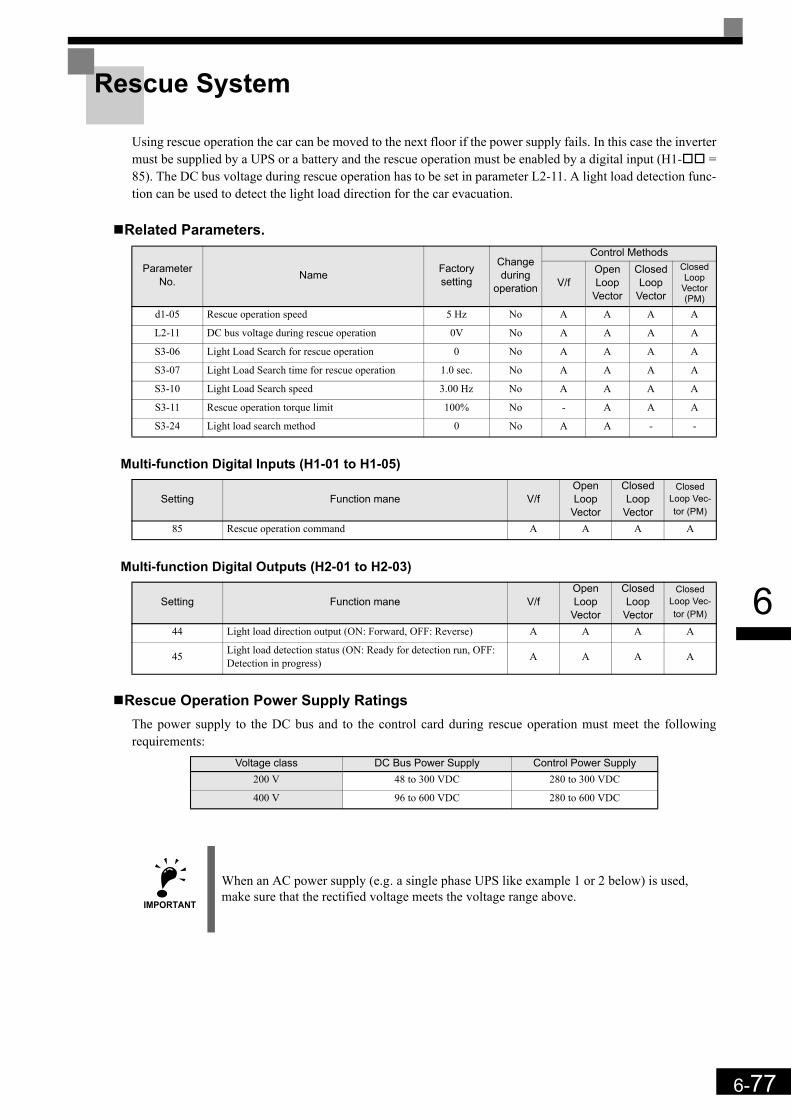
6-77
6
Rescue System
Using rescue operation the car can be moved to the next floor if the power supply fails. In this case the invertermust be supplied by a UPS or a battery and the rescue operation must be enabled by a digital input (H1- =85). The DC bus voltage during rescue operation has to be set in parameter L2-11. A light load detection func-tion can be used to detect the light load direction for the car evacuation.
Related Parameters.
Multi-function Digital Inputs (H1-01 to H1-05)
Multi-function Digital Outputs (H2-01 to H2-03)
Rescue Operation Power Supply RatingsThe power supply to the DC bus and to the control card during rescue operation must meet the followingrequirements:
ParameterNo. Name Factory
setting
Change during
operation
Control Methods
V/fOpen Loop
Vector
Closed Loop
Vector
Closed Loop
Vector (PM)
d1-05 Rescue operation speed 5 Hz No A A A A
L2-11 DC bus voltage during rescue operation 0V No A A A A
S3-06 Light Load Search for rescue operation 0 No A A A A
S3-07 Light Load Search time for rescue operation 1.0 sec. No A A A A
S3-10 Light Load Search speed 3.00 Hz No A A A A
S3-11 Rescue operation torque limit 100% No - A A A
S3-24 Light load search method 0 No A A - -
Setting Function mane V/fOpen Loop
Vector
Closed Loop
Vector
Closed Loop Vec-tor (PM)
85 Rescue operation command A A A A
Setting Function mane V/fOpen Loop
Vector
Closed Loop
Vector
Closed Loop Vec-tor (PM)
44 Light load direction output (ON: Forward, OFF: Reverse) A A A A
45 Light load detection status (ON: Ready for detection run, OFF: Detection in progress) A A A A
Voltage class DC Bus Power Supply Control Power Supply200 V 48 to 300 VDC 280 to 300 VDC
400 V 96 to 600 VDC 280 to 600 VDC
IMPORTANT
When an AC power supply (e.g. a single phase UPS like example 1 or 2 below) is used, make sure that the rectified voltage meets the voltage range above.

6-78
6
Rescue operation wiring examplesThe following diagrams show some wirings examples for rescue operation.
Example 1: 1 Phase, 230 V UPS Power Supply
The contactors must be operated, so that contactor B is always opened, before A is closed. When the rescueoperation is finished, the contactor A must be opened, before B is closed.
If the UPS power is weak or Light load detection is not used, it can happen that the inverter trips with a UV2fault. In this case increase the UPS power, use the light load detection function or use the configuration inexample 2.
Example 2: 1 Phase, 230 V UPS Power Supply, Low power UPS or Light Load detection not used
The contactors must be operated, so that contactor B is always opened, before A and C are closed. Contactor Ccan be closed after A but not before. When the rescue operation is disabled, the contactors A and C must beopened, before B is closed.
UPS1x230 VAC
L1
L2
L3
N
Elevator Control System Inverter
R/L1
S/L2
T/L3
-
P0
N0
Sx
SC
W/T3
V/T2
U/T1
Control circuitPower Supply
B1
B2A
B
Rescue Operation Enable Input
Contactor A
Contactor B
Contactor SequenceWiring
UPS1x230 VAC
L1
L2
L3
N
Inverter
R/L1
S/L2
T/L3
-
P0
N0
Sx
SC
W/T3
V/T2
U/T1
Control circuitPower Supply
B1
B2A
B
Rescue Operation Enable Input
Contactor SequenceWiring
Rectifier Diodeand Capacity
C
Contactor A
Contactor C
Contactor B

6-79
6
Example 3: Two Batteries, Main battery voltage lower than 280 VDC.
The contactors must be operated, so that contactor B is always opened, before A and C are closed. Contactor Ccan be closed after A but not before. When the rescue operation is disabled, the contactors A and C must beopened, before B is closed.
Example 4: Main battery voltage higher than 280 VDC.
The contactors must be operated, so that contactor B is always opened, before A is closed. When the rescueoperation is disabled, the contactor A must be opened, before B is closed.
Rescue Operation SpeedDuring rescue operation the speed is limited by the battery voltage using the following formula:
• for the 200 V class:
• for the 400 V class:
If the rescue speed reference (d1-15) is higher than the rescue operation speed limit, the output frequency isautomatically limited to the calculated limit. It prevents a voltage saturation and a possible motor stalling.
PrecautionsBecause of the possibly low DC bus voltage during rescue operation, the heatsink cooling fans may not work.A continuous operation under this condition can result in over heat faults and inverter damage.
Main Battery
R/L1
S/L2
T/L3
+1
-
P0
N0
Sx
SC
Inverter
Main power
Controller Supply Battery
A
B
C
Rescue Operation Enable Input
Wiring
W/T3
V/T2
U/T1
Control circuitPower Supply
B1
+2
B2
Contactor A
Contactor C
Contactor B
Contactor Sequence
L1
L2
L3
Inverter
Main power B
Rescue Operation Enable Input
Main Battery
A
Wiring
Contactor A
Contactor B
Contactor Sequence
R/L1
S/L2
T/L3
-
P0
N0
Sx
SC
W/T3
V/T2
U/T1
Control circuitPower Supply
B1
B2
L1
L2
L3
Rescue Operation Speed Limit DC Bus Voltage L2-11 Base frequency E1-04×300 V 2×
---------------------------------------------------------------------------------------------------------------------=
Rescue Operation Speed Limit DC Bus Voltage L2-11 Base frequency E1-04×600 V 2×
----------------------------------------------------------------------------------------------------------------------=
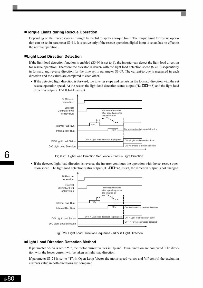
6-80
6
Torque Limits during Rescue OperationDepending on the rescue system it might be useful to apply a torque limit. The torque limit for rescue opera-tion can be set in parameter S3-11. It is active only if the rescue operation digital input is set an has no effect tothe normal operation.
Light Load Direction DetectionIf the light load detection function is enabled (S3-06 is set to 1), the inverter can detect the light load directionfor rescue operation. Therefore the elevator is driven with the light load detection speed (S3-10) sequentiallyin forward and reverse direction for the time set in parameter S3-07. The current/torque is measured in eachdirection and the values are compared to each other.
• If the detected light direction is forward, the inverter stops and restarts in the forward direction with the setrescue operation speed. At the restart the light load detection status output (H2- =45) and the light loaddirection output (H2- =44) are set.
Fig 6.25 Light Load Direction Sequence - FWD is Light Direction
• If the detected light load direction is reverse, the inverter continues the operation with the set rescue oper-ation speed. The light load detection status output (H1- =45) is set, the direction output is not changed.
Fig 6.26 Light Load Direction Sequence - REV is Light Direction
Light Load Direction Detection MethodIf parameter S3-24 is set to “0”, the motor current values in Up and Down direction are compared. The direc-tion with the lower current will be taken as light load direction.
If parameter S3-24 is set to “1”, in Open Loop Vector the motor speed values and V/f control the excitationcurrents value in both directions are compared.
.
DI Rescue
operation
External
Controller Fwd
or Rev Run
Internal Fwd Run
Internal Rev Run
D/O Light Load Status
D/O Light Load Direction
OFF = Light load detection in progress ON = Light load detection done
ON = Forward direction selected
Car evacuation in forward directionREV
FWD
Torque is measured
after speed agree for
the time S3-07
.
DI Rescue
operation
External
Controller Fwd
or Rev Run
Internal Fwd Run
Internal Rev Run
D/O Light Load Status
D/O Light Load Direction
OFF = Light load detection in progress ON = Light load detection done
OFF = Reverse direction selected
Car evacuation in reverse directionREV
FWD
Torque is measured
after speed agree for
the time S3-07
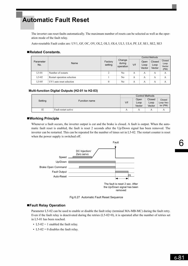
6-81
6
Automatic Fault Reset
The inverter can reset faults automatically. The maximum number of resets can be selected as well as the oper-ation mode of the fault relay.
Auto-resetable Fault codes are: UV1, GF, OC, OV, OL2, OL3, OL4, UL3, UL4, PF, LF, SE1, SE2, SE3
Related Constants.
Multi-function Digital Outputs (H2-01 to H2-03)
Working PrincipleWhenever a fault occurs, the inverter output is cut and the brake is closed. A fault is output. When the auto-matic fault reset is enabled, the fault is reset 2 seconds after the Up/Down signal has been removed. Theinverter can be restarted. This can be repeated for the number of times set in L5-02. The restart counter is resetwhen the power supply is switched off.
Fig 6.27 Automatic Fault Reset Sequence
Fault Relay OperationParameter L5-02 can be used to enable or disable the fault relay (terminal MA-MB-MC) during the fault retry.Even if the fault relay is deactivated during the retries (L5-02=0), it is operated after the number of retries setin L5-01 has been reached.
• L5-02 = 1 enabled the fault relay.• L5-02 = 0 disables the fault relay.
ParameterNo. Name Factory
setting
Change during
operation
Control Methods
V/fOpen Loop
Vector
Closed Loop
Vector
Closed Loop
Vector (PM)
L5-01 Number of restarts 2 No A A A A
L5-02 Restart operation selection 1 No A A A A
L5-05 UV1 auto reset selection 0 No A A A A
Setting Function name
Control Methods
V/fOpen Loop
Vector
Closed Loop
Vector
Closed Loop Vec-tor (PM)
1E Fault restart active A A A A
Up/Down
Speed
DC Injection/Zero servo
Brake Open Command
Fault Output
Fault
Auto-Reset
The fault is reset 2 sec. After the Up/Down signal has been
removed

6-82
6
Fault Restart IndicationWhen the fault retry function is used, the inverter tries to reset the fault every 5 ms. If a digital output is pro-grammed for the “Restart enable” function (H2- =1E), the output is set as long as the inverter tries to resetthe fault. After a successful fault reset the output is cleared.
UV1 Fault Restart SelectionUsing parameter L5-05 the auto reset method for a UV1 (DC bus under voltage) fault can be selected.
• If L5-05 = 0 the UV1 fault is treated like set in parameter L5-01, i.e. the inverter tries to reset UV1 for thenumber of times set in L5-01 like described above.
• If L5-05 = 1 the UV1 fault is always automatically reset, regardless to the L5-01 setting.
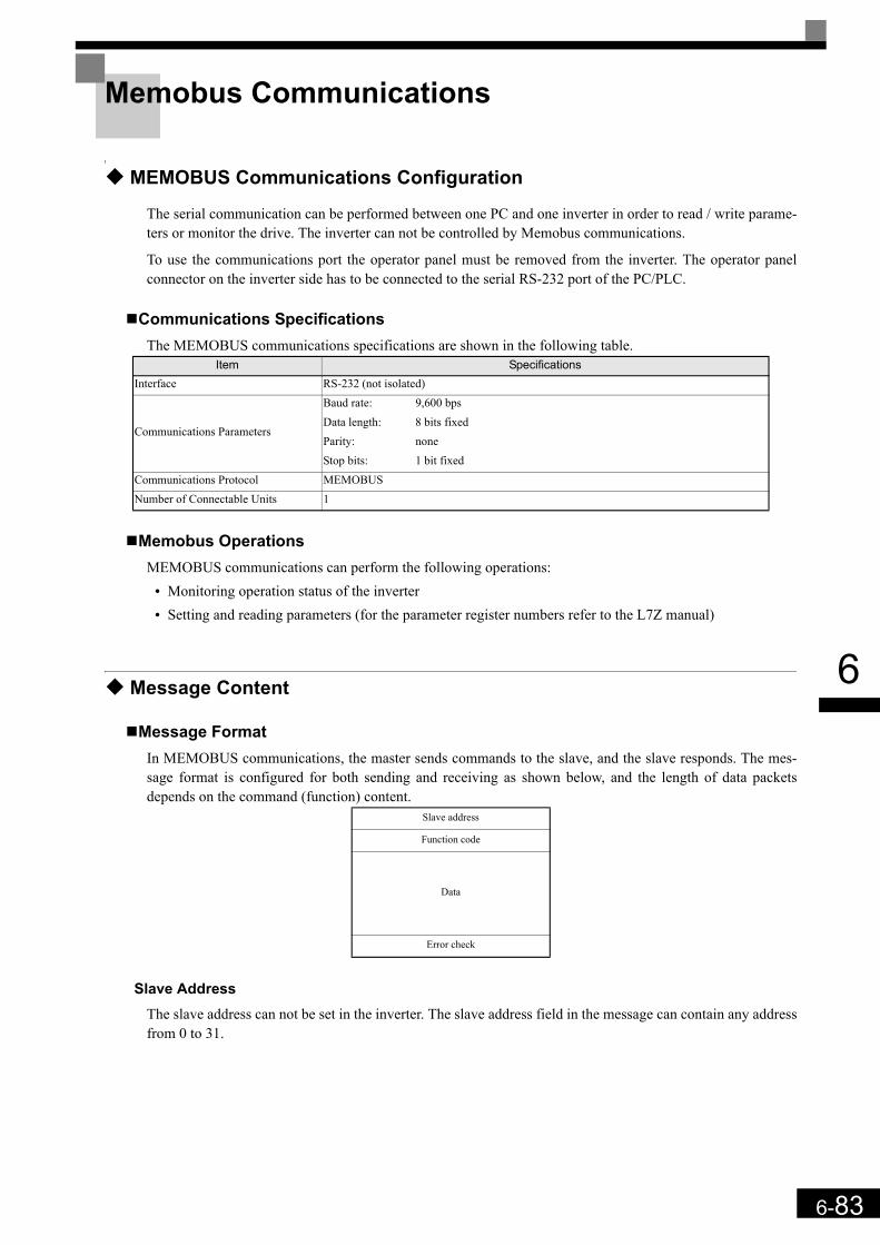
6-83
6
Memobus Communications
MEMOBUS Communications Configuration
The serial communication can be performed between one PC and one inverter in order to read / write parame-ters or monitor the drive. The inverter can not be controlled by Memobus communications.
To use the communications port the operator panel must be removed from the inverter. The operator panelconnector on the inverter side has to be connected to the serial RS-232 port of the PC/PLC.
Communications SpecificationsThe MEMOBUS communications specifications are shown in the following table.
Memobus OperationsMEMOBUS communications can perform the following operations:
• Monitoring operation status of the inverter• Setting and reading parameters (for the parameter register numbers refer to the L7Z manual)
Message Content
Message FormatIn MEMOBUS communications, the master sends commands to the slave, and the slave responds. The mes-sage format is configured for both sending and receiving as shown below, and the length of data packetsdepends on the command (function) content.
Slave AddressThe slave address can not be set in the inverter. The slave address field in the message can contain any addressfrom 0 to 31.
Item SpecificationsInterface RS-232 (not isolated)
Communications Parameters
Baud rate: 9,600 bpsData length: 8 bits fixedParity: noneStop bits: 1 bit fixed
Communications Protocol MEMOBUSNumber of Connectable Units 1
Slave address
Function code
Data
Error check

6-84
6
Function CodeThe function code specifies commands. The three function codes shown in the table below are available.
DataConfigure consecutive data by combining the memory register address (test code for a loop back address) andthe data the register contains. The data length changes depending on the command details.
Error CheckErrors during communications are detected using CRC-16 (cyclic redundancy check, checksum method).
The result of the checksum calculation is stored in a data-word (16 bit), which starting value is FFFH. Thevalue of this word is manipulated using Exclusive OR- and SHIFT operations together with the data packagethat should be sent (slave address, function code, data) and the fixed value A001H. At the end of the calcula-tion the data-word contains the checksum value.
The checksum is calculated in the following way:1. The starting value of the 16 Bit data-word, that is used for the calculation, has to be set to FFFFH.2. An Exclusive OR operation has to be performed with the starting value and the slave address.3. The result has to be shifted to the right until the overflow bit becomes 1.4. When this bit becomes 1, an Exclusive OR operation with the result of step 3 and the fix value A001H has
to be performed.5. After 8 shift operations (every time when the overflow bit becomes 1, an Exclusive OR like in step 4 has to
be done), perform an Exclusive OR operation with the result of the former operations and the next datapackage (8 bit function code). Again the result of this operation has to be shifted 8 times and if needed ithas to be interconnected with the fix value A001H using an Exclusive OR operation.
6. The same steps have to be performed with the data, first with the higher byte and then with the lower byteuntil all data are proceeded.
7. The result of these operations is the checksum. It consists of a high and a low byte.
Function Code (Hexadecimal) Function
Command Message Response Message
Min. (Bytes) Max. (Bytes) Min. (Bytes) Max. (Bytes)
03H Read memory register contents 8 8 7 3708H Loop back test 8 8 8 810H Write multiple memory registers 11 41 8 8
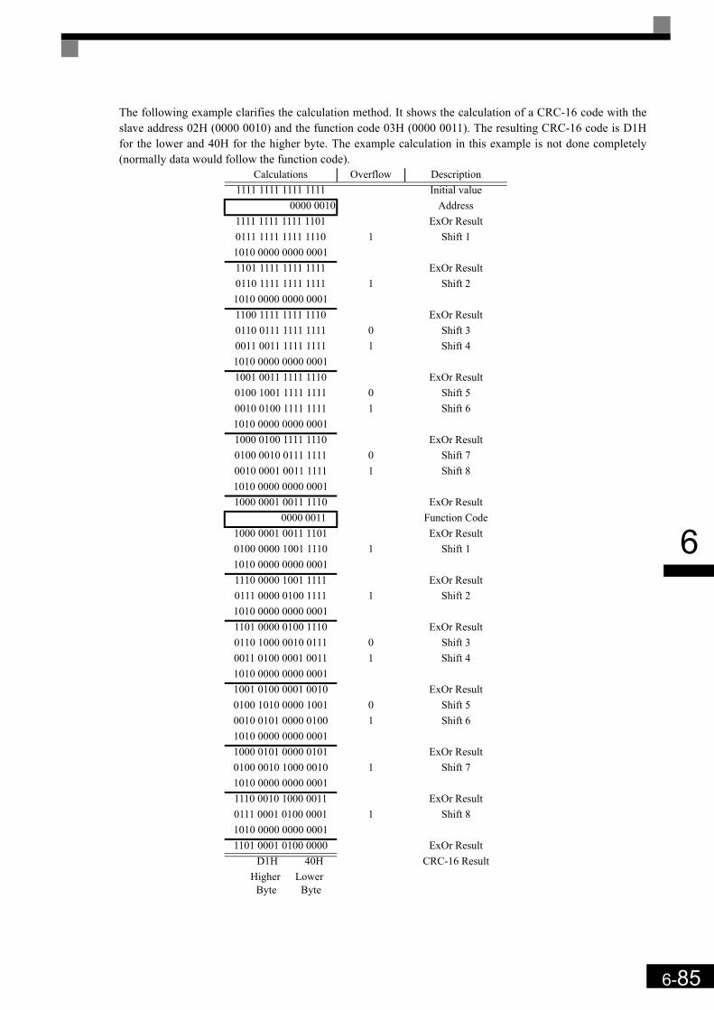
6-85
6
The following example clarifies the calculation method. It shows the calculation of a CRC-16 code with theslave address 02H (0000 0010) and the function code 03H (0000 0011). The resulting CRC-16 code is D1Hfor the lower and 40H for the higher byte. The example calculation in this example is not done completely(normally data would follow the function code).
Calculations Overflow Description1111 1111 1111 1111 Initial value
0000 0010 Address1111 1111 1111 1101 ExOr Result0111 1111 1111 1110 1 Shift 11010 0000 0000 00011101 1111 1111 1111 ExOr Result0110 1111 1111 1111 1 Shift 21010 0000 0000 00011100 1111 1111 1110 ExOr Result0110 0111 1111 1111 0 Shift 30011 0011 1111 1111 1 Shift 41010 0000 0000 00011001 0011 1111 1110 ExOr Result0100 1001 1111 1111 0 Shift 50010 0100 1111 1111 1 Shift 61010 0000 0000 00011000 0100 1111 1110 ExOr Result0100 0010 0111 1111 0 Shift 70010 0001 0011 1111 1 Shift 81010 0000 0000 00011000 0001 0011 1110 ExOr Result
0000 0011 Function Code1000 0001 0011 1101 ExOr Result0100 0000 1001 1110 1 Shift 11010 0000 0000 00011110 0000 1001 1111 ExOr Result0111 0000 0100 1111 1 Shift 21010 0000 0000 00011101 0000 0100 1110 ExOr Result0110 1000 0010 0111 0 Shift 30011 0100 0001 0011 1 Shift 41010 0000 0000 00011001 0100 0001 0010 ExOr Result0100 1010 0000 1001 0 Shift 50010 0101 0000 0100 1 Shift 61010 0000 0000 00011000 0101 0000 0101 ExOr Result0100 0010 1000 0010 1 Shift 71010 0000 0000 00011110 0010 1000 0011 ExOr Result0111 0001 0100 0001 1 Shift 81010 0000 0000 00011101 0001 0100 0000 ExOr Result D1H 40H CRC-16 Result Higher Lower Byte Byte

6-86
6
MEMOBUS Message ExampleAn example of MEMOBUS command/response messages is given below.
Reading Inverter Memory Register ContentsThe content of maximum 16 inverter memory registers can be read out at a time.
Among other things the command message must contain the start address of the first register to read out andthe quantity of registers. The response message will contain the content of the first and the consecutive num-ber of registers that has been set for the quantity.
The contents of the memory register are separated into higher 8 bits and lower 8 bits.
The following tables show message examples when reading status signals, error details, data link status, andfrequency references from the slave 2 Inverter.
Loop back TestThe loop back test returns command messages directly as response messages without changing the contents tocheck the communications between the master and slave.
The following table shows a message example for performing a loop back test with the slave no. 1.
Command Message Response Message (During Normal Operation)
Response Message (During Error)
Slave Address 02H Slave Address 02H Slave Address 02HFunction Code 03H Function Code 03H Function Code 83H
Start AddressHigher 00H Data quantity 08H Error code 03HLower 20H 1st storage
registerHigher 00H
CRC-16Higher F1H
QuantityHigher 00H Lower 65H Lower 31HLower 04H Next storage
registerHigher 00H
CRC-16Higher 45H Lower 00HLower F0H Next storage
registerHigher 00HLower 00H
Next storage register
Higher 01HLower F4H
CRC-16Higher AFHLower 82H
Command Message Response Message (During Normal Operation)
Response Message (During Error)
Slave address 01H Slave address 01H Slave address 01HFunction code 08H Function code 08H Function code 89H
Test CodeHigher 00H
Test CodeHigher 00H Error Code 01H
Lower 00H Lower 00HCRC-16
Higher 86H
DataHigher A5H
DataHigher A5H Lower 50H
Lower 37H Lower 37H
CRC-16Higher DAH
CRC-16Higher DAH
Lower 8DH Lower 8DH
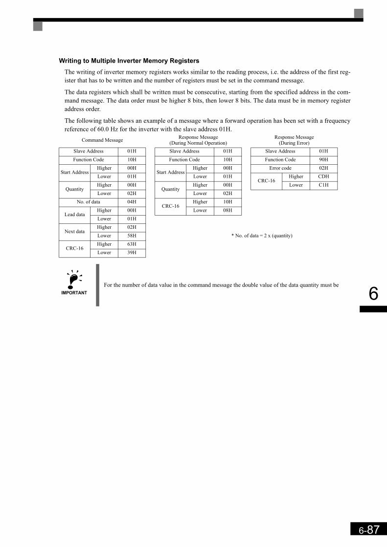
6-87
6
Writing to Multiple Inverter Memory RegistersThe writing of inverter memory registers works similar to the reading process, i.e. the address of the first reg-ister that has to be written and the number of registers must be set in the command message.
The data registers which shall be written must be consecutive, starting from the specified address in the com-mand message. The data order must be higher 8 bits, then lower 8 bits. The data must be in memory registeraddress order.
The following table shows an example of a message where a forward operation has been set with a frequencyreference of 60.0 Hz for the inverter with the slave address 01H.
Command Message Response Message (During Normal Operation)
Response Message (During Error)
Slave Address 01H Slave Address 01H Slave Address 01HFunction Code 10H Function Code 10H Function Code 90H
Start AddressHigher 00H
Start AddressHigher 00H Error code 02H
Lower 01H Lower 01HCRC-16
Higher CDH
QuantityHigher 00H
QuantityHigher 00H Lower C1H
Lower 02H Lower 02HNo. of data 04H
CRC-16Higher 10H
Lead dataHigher 00H Lower 08HLower 01H
Next dataHigher 02HLower 58H * No. of data = 2 x (quantity)
CRC-16Higher 63HLower 39H
IMPORTANT For the number of data value in the command message the double value of the data quantity must be
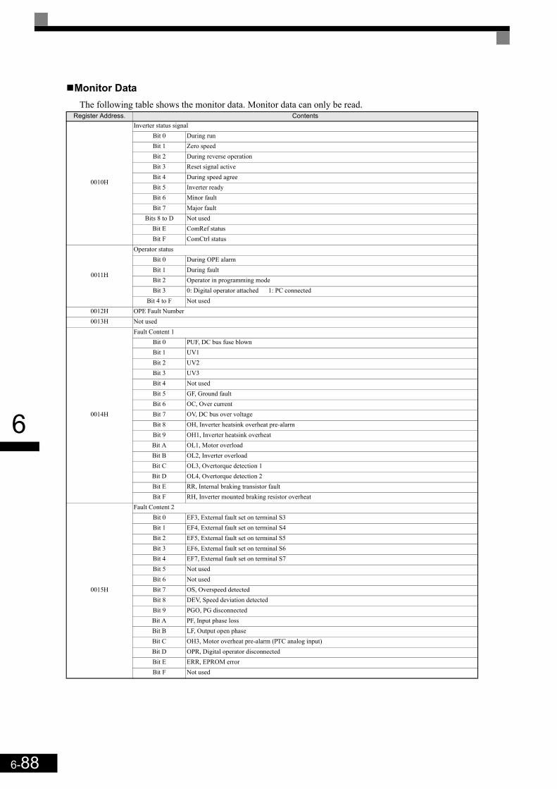
6-88
6
Monitor DataThe following table shows the monitor data. Monitor data can only be read.
Register Address. Contents
0010H
Inverter status signalBit 0 During runBit 1 Zero speedBit 2 During reverse operationBit 3 Reset signal activeBit 4 During speed agreeBit 5 Inverter readyBit 6 Minor faultBit 7 Major fault
Bits 8 to D Not usedBit E ComRef statusBit F ComCtrl status
0011H
Operator statusBit 0 During OPE alarmBit 1 During fault Bit 2 Operator in programming modeBit 3 0: Digital operator attached 1: PC connected
Bit 4 to F Not used0012H OPE Fault Number0013H Not used
0014H
Fault Content 1Bit 0 PUF, DC bus fuse blownBit 1 UV1Bit 2 UV2Bit 3 UV3Bit 4 Not usedBit 5 GF, Ground faultBit 6 OC, Over currentBit 7 OV, DC bus over voltageBit 8 OH, Inverter heatsink overheat pre-alarmBit 9 OH1, Inverter heatsink overheatBit A OL1, Motor overloadBit B OL2, Inverter overloadBit C OL3, Overtorque detection 1Bit D OL4, Overtorque detection 2Bit E RR, Internal braking transistor faultBit F RH, Inverter mounted braking resistor overheat
0015H
Fault Content 2Bit 0 EF3, External fault set on terminal S3Bit 1 EF4, External fault set on terminal S4Bit 2 EF5, External fault set on terminal S5Bit 3 EF6, External fault set on terminal S6Bit 4 EF7, External fault set on terminal S7Bit 5 Not usedBit 6 Not usedBit 7 OS, Overspeed detectedBit 8 DEV, Speed deviation detectedBit 9 PGO, PG disconnectedBit A PF, Input phase lossBit B LF, Output open phaseBit C OH3, Motor overheat pre-alarm (PTC analog input)Bit D OPR, Digital operator disconnectedBit E ERR, EPROM errorBit F Not used

6-89
6
0016H
Fault Content 3Bit 0 CE, Memobus communications errorBit 1 BUS, Bus option communications error
Bit 2/3 Not usedBit 4 CF, Control faultBit 5 SVE, Zero servo faultBit 6 EF0, External fault from optional input cardBit 7 Not usedBit 8 UL3, Undertorque detection 1Bit 9 UL4, Undertorque detection 2
Bit A to F Not used
0017H
CPF Fault Content 1Bit 0/1 Not usedBit 2 CPF02Bit 3 CPF03Bit 4 Not usedBit 5 CPF05Bit 6 CPF06
Bit 7 to F Not used
0018H
CPF Fault Content 2Bit 0 CPF20Bit 1 CPF21Bit 2 CPF22Bit 3 CPF23
Bit 4 to F Not used
0019H
Alarm Content 1Bit 0 UV, DC bus undervoltageBit 1 OV, DC bus overvoltageBit 2 OH, Inverter heatsink overheat pre-alarmBit 3 OH2, Inverter overheat alarm input by a digital inputBit 4 OL3, Overtorque detection 1Bit 5 OL4, Overtorque detection 2Bit 6 EF, Forward/Reverse input set at the same timeBit 7 BB, Baseblock activeBit 8 EF3, External alarm set on terminal S3Bit 9 EF4, External alarm set on terminal S4Bit A EF5, External alarm set on terminal S5Bit B EF6, External alarm set on terminal S6Bit C EF7, External alarm set on terminal S7
Bit D/E Not usedBit F OS, Overspeed alarm
001AH
Alarm Content 2Bit 0 DEV, Speed deviationBit 1 PGO, PG disconnectedBit 2 OPR, Digital operator disconnectedBit 3 CE, Memobus communications errorBit 4 BUS, Communications errorBit 5 CALL, Memobus communications on standbyBit 6 OL1, Motor overloadBit 7 OL2, Inverter overload
Bit 8 to B Not usedBit C CALL, Communications on standbyBit D UL3, Undertorque detection 1Bit E UL4, Undertorque detection 2Bit F Not used
001BH Not used
Register Address. Contents
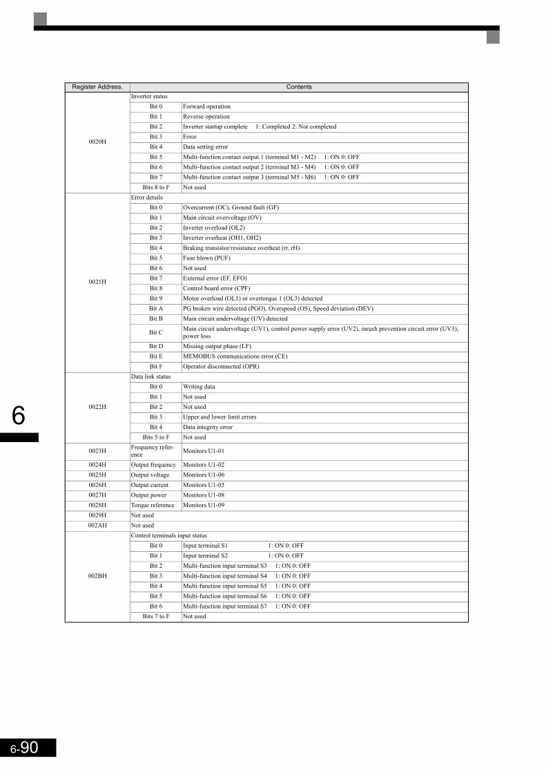
6-90
6
0020H
Inverter statusBit 0 Forward operationBit 1 Reverse operationBit 2 Inverter startup complete 1: Completed 2: Not completedBit 3 ErrorBit 4 Data setting error Bit 5 Multi-function contact output 1 (terminal M1 - M2) 1: ON 0: OFFBit 6 Multi-function contact output 2 (terminal M3 - M4) 1: ON 0: OFFBit 7 Multi-function contact output 3 (terminal M5 - M6) 1: ON 0: OFF
Bits 8 to F Not used
0021H
Error detailsBit 0 Overcurrent (OC), Ground fault (GF)Bit 1 Main circuit overvoltage (OV)Bit 2 Inverter overload (OL2)Bit 3 Inverter overheat (OH1, OH2)Bit 4 Braking transistor/resistance overheat (rr, rH)Bit 5 Fuse blown (PUF)Bit 6 Not usedBit 7 External error (EF, EFO)Bit 8 Control board error (CPF)Bit 9 Motor overload (OL1) or overtorque 1 (OL3) detectedBit A PG broken wire detected (PGO), Overspeed (OS), Speed deviation (DEV)Bit B Main circuit undervoltage (UV) detected
Bit C Main circuit undervoltage (UV1), control power supply error (UV2), inrush prevention circuit error (UV3), power loss
Bit D Missing output phase (LF)Bit E MEMOBUS communications error (CE)Bit F Operator disconnected (OPR)
0022H
Data link statusBit 0 Writing dataBit 1 Not usedBit 2 Not usedBit 3 Upper and lower limit errorsBit 4 Data integrity error
Bits 5 to F Not used
0023H Frequency refer-ence Monitors U1-01
0024H Output frequency Monitors U1-020025H Output voltage Monitors U1-060026H Output current Monitors U1-030027H Output power Monitors U1-080028H Torque reference Monitors U1-090029H Not used002AH Not used
002BH
Control terminals input statusBit 0 Input terminal S1 1: ON 0: OFFBit 1 Input terminal S2 1: ON 0: OFFBit 2 Multi-function input terminal S3 1: ON 0: OFFBit 3 Multi-function input terminal S4 1: ON 0: OFFBit 4 Multi-function input terminal S5 1: ON 0: OFFBit 5 Multi-function input terminal S6 1: ON 0: OFFBit 6 Multi-function input terminal S7 1: ON 0: OFF
Bits 7 to F Not used
Register Address. Contents

6-91
6
Note: Communications error details are stored until an error reset is input.
002CH
Inverter statusBit 0 Operation 1: OperatingBit 1 Zero speed 1: Zero speedBit 2 Frequency agree 1: AgreementBit 3 User-defined speed agree 1: AgreementBit 4 Frequency detection 1: 1: Output frequency ≤ L4-01Bit 5 Frequency detection 2: 1: Output frequency ≥ L4-01Bit 6 Inverter startup completed 1: Startup completedBit 7 Undervoltage detection 1: DetectedBit 8 Baseblock 1: Inverter output baseblockBit 9 Frequency reference mode 1: Not communication 0: Communication optionBit A Run command mode 1: Not communication 0: Communication optionBit B Overtorque detection 1: DetectedBit C Frequency reference lost 1: LostBit D Restart enabled 1: RestartingBit E Error (including MEMOBUS communications time-out) 1:Error occurredBit F MEMOBUS communications time-out1: Timed out
002DH
Multi-function contact output statusBit 0 Multi-function contact output 1 (terminal M1-M2) 1: ON 0: OFFBit 1 Multi-function contact output 2 (terminal M3-M4) 1: ON 0: OFFBit 2 Multi-function contact output 3 (terminal M5-M6) 1: ON 0: OFF
Bits 3 to F Not used002EH - 0030H Not used
0031H Main circuit DC voltage0032H Torque Monitor U1-090033H Power Monitor U1-08
0034H - 003AH Not used003BH CPU software number003CH Flash software number
003DH
Communications error detailsBit 0 CRC errorBit 1 Invalid data lengthBit 2 Not usedBit 3 Parity errorBit 4 Overrun errorBit 5 Framing errorBit 6 Time-out
Bits 7 to F Not used003EH kVA setting003FH Control method
Register Address. Contents
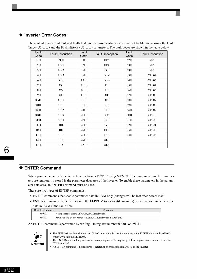
6-92
6
Inverter Error Codes
The content of a current fault and faults that have occurred earlier can be read out by Memobus using the FaultTrace (U2- ) and the Fault History (U3- ) parameters. The fault codes are shown in the table below.
ENTER Command
When parameters are written in the Inverter from a PC/PLC using MEMOBUS communications, the parame-ters are temporarily stored in the parameter data area of the Inverter. To enable these parameters in the param-eter data area, an ENTER command must be used.
There are two types of ENTER commands: • ENTER commands that enable parameter data in RAM only (changes will be lost after power loss)• ENTER commands that write data into the EEPROM (non-volatile memory) of the Inverter and enable the
data in RAM at the same time.
An ENTER command is performed by writing 0 to register number 0900H or 0910H.
Fault Code Fault Description Fault
Code Fault Description Fault Code Fault Description
01H PUF 14H EF6 37H SE1
02H UV1 15H EF7 38H SE2
03H UV2 18H OS 39H SE3
04H UV3 19H DEV 83H CPF02
06H GF 1AH PGO 84H CPF03
07H OC 1BH PF 85H CPF04
08H OV 1CH LF 86H CPF05
09H OH 1DH OH3 87H CPF06
0AH OH1 1EH OPR 88H CPF07
0BH OL1 1FH ERR 89H CPF08
0CH OL2 21H CE 8AH CPF09
0DH OL3 22H BUS 8BH CPF10
0EH OL4 25H CF 91H CPF20
0FH RR 26H SVE 92H CPF21
10H RH 27H EF0 93H CPF22
11H EF3 28H FBL 94H CPF23
12H EF4 29H UL3
13H EF5 2AH UL4
Register Address. Contents0900H Write parameter data to EEPROM, RAM is refreshed
0910H Parameter data are not written to EEPROM, but refreshed in RAM only.
IMPORTANT
• The EEPROM can be written up to 100,000 times only. Do not frequently execute ENTER commands (0900H) which write into the EEPROM.
• The ENTER command registers are write-only registers. Consequently, if these registers are read out, error code 02H is returned.
• An ENTER command is not required if reference or broadcast data are sent to the inverter.
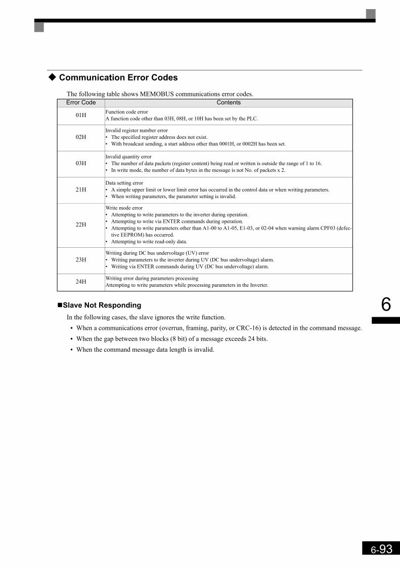
6-93
6
Communication Error Codes
The following table shows MEMOBUS communications error codes.
Slave Not RespondingIn the following cases, the slave ignores the write function.
• When a communications error (overrun, framing, parity, or CRC-16) is detected in the command message.• When the gap between two blocks (8 bit) of a message exceeds 24 bits.• When the command message data length is invalid.
Error Code Contents
01H Function code errorA function code other than 03H, 08H, or 10H has been set by the PLC.
02HInvalid register number error• The specified register address does not exist.• With broadcast sending, a start address other than 0001H, or 0002H has been set.
03HInvalid quantity error• The number of data packets (register content) being read or written is outside the range of 1 to 16.• In write mode, the number of data bytes in the message is not No. of packets x 2.
21HData setting error• A simple upper limit or lower limit error has occurred in the control data or when writing parameters.• When writing parameters, the parameter setting is invalid.
22H
Write mode error• Attempting to write parameters to the inverter during operation.• Attempting to write via ENTER commands during operation.• Attempting to write parameters other than A1-00 to A1-05, E1-03, or 02-04 when warning alarm CPF03 (defec-
tive EEPROM) has occurred.• Attempting to write read-only data.
23HWriting during DC bus undervoltage (UV) error• Writing parameters to the inverter during UV (DC bus undervoltage) alarm.• Writing via ENTER commands during UV (DC bus undervoltage) alarm.
24H Writing error during parameters processingAttempting to write parameters while processing parameters in the Inverter.

6-94
6

7Troubleshooting
This chapter describes the fault displays and countermeasures for Inverter and motor problems.
Protective and Diagnostic Functions...................................7-2Troubleshooting ................................................................7-18
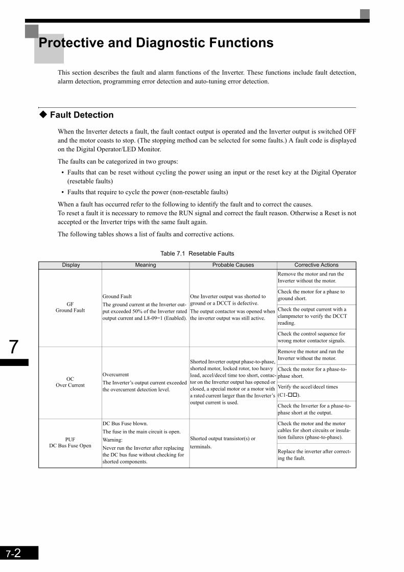
7-2
7
Protective and Diagnostic Functions
This section describes the fault and alarm functions of the Inverter. These functions include fault detection,alarm detection, programming error detection and auto-tuning error detection.
Fault Detection
When the Inverter detects a fault, the fault contact output is operated and the Inverter output is switched OFFand the motor coasts to stop. (The stopping method can be selected for some faults.) A fault code is displayedon the Digital Operator/LED Monitor.
The faults can be categorized in two groups:• Faults that can be reset without cycling the power using an input or the reset key at the Digital Operator
(resetable faults)• Faults that require to cycle the power (non-resetable faults)
When a fault has occurred refer to the following to identify the fault and to correct the causes. To reset a fault it is necessary to remove the RUN signal and correct the fault reason. Otherwise a Reset is notaccepted or the Inverter trips with the same fault again.
The following tables shows a list of faults and corrective actions.
Table 7.1 Resetable Faults
Display Meaning Probable Causes Corrective Actions
GFGround Fault
Ground FaultThe ground current at the Inverter out-put exceeded 50% of the Inverter rated output current and L8-09=1 (Enabled).
One Inverter output was shorted to ground or a DCCT is defective.The output contactor was opened when the inverter output was still active.
Remove the motor and run the Inverter without the motor.
Check the motor for a phase to ground short.
Check the output current with a clampmeter to verify the DCCT reading.
Check the control sequence for wrong motor contactor signals.
OCOver Current
OvercurrentThe Inverter’s output current exceeded the overcurrent detection level.
Shorted Inverter output phase-to-phase, shorted motor, locked rotor, too heavy load, accel/decel time too short, contac-tor on the Inverter output has opened or closed, a special motor or a motor with a rated current larger than the Inverter’s output current is used.
Remove the motor and run the Inverter without the motor.
Check the motor for a phase-to-phase short.
Verify the accel/decel times (C1- ).
Check the Inverter for a phase-to-phase short at the output.
PUFDC Bus Fuse Open
DC Bus Fuse blown.The fuse in the main circuit is open.Warning: Never run the Inverter after replacing the DC bus fuse without checking for shorted components.
Shorted output transistor(s) or terminals.
Check the motor and the motor cables for short circuits or insula-tion failures (phase-to-phase).
Replace the inverter after correct-ing the fault.
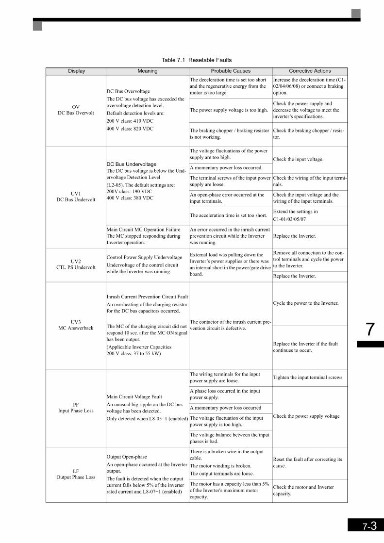
7-3
7
OVDC Bus Overvolt
DC Bus OvervoltageThe DC bus voltage has exceeded the overvoltage detection level.Default detection levels are: 200 V class: 410 VDC400 V class: 820 VDC
The deceleration time is set too short and the regenerative energy from the motor is too large.
Increase the deceleration time (C1-02/04/06/08) or connect a braking option.
The power supply voltage is too high.Check the power supply and decrease the voltage to meet the inverter’s specifications.
The braking chopper / braking resistor is not working.
Check the braking chopper / resis-tor.
UV1DC Bus Undervolt
DC Bus UndervoltageThe DC bus voltage is below the Und-ervoltage Detection Level (L2-05). The default settings are:200V class: 190 VDC400 V class: 380 VDC
The voltage fluctuations of the power supply are too high. Check the input voltage. A momentary power loss occurred.
The terminal screws of the input power supply are loose.
Check the wiring of the input termi-nals.
An open-phase error occurred at the input terminals.
Check the input voltage and the wiring of the input terminals.
The acceleration time is set too short. Extend the settings inC1-01/03/05/07
Main Circuit MC Operation FailureThe MC stopped responding during Inverter operation.
An error occurred in the inrush current prevention circuit while the Inverter was running.
Replace the Inverter.
UV2CTL PS Undervolt
Control Power Supply UndervoltageUndervoltage of the control circuit while the Inverter was running.
External load was pulling down the Inverter’s power supplies or there was an internal short in the power/gate drive board.
Remove all connection to the con-trol terminals and cycle the power to the Inverter.
Replace the Inverter.
UV3MC Answerback
Inrush Current Prevention Circuit FaultAn overheating of the charging resistor for the DC bus capacitors occurred.
The MC of the charging circuit did not respond 10 sec. after the MC ON signal has been output. (Applicable Inverter Capacities200 V class: 37 to 55 kW)
The contactor of the inrush current pre-vention circuit is defective.
Cycle the power to the Inverter.
Replace the Inverter if the fault continues to occur.
PFInput Phase Loss
Main Circuit Voltage FaultAn unusual big ripple on the DC bus voltage has been detected. Only detected when L8-05=1 (enabled)
The wiring terminals for the input power supply are loose. Tighten the input terminal screws
A phase loss occurred in the input power supply.
Check the power supply voltageA momentary power loss occurred
The voltage fluctuation of the input power supply is too high.
The voltage balance between the input phases is bad.
LFOutput Phase Loss
Output Open-phaseAn open-phase occurred at the Inverter output.The fault is detected when the output current falls below 5% of the inverter rated current and L8-07=1 (enabled)
There is a broken wire in the output cable.The motor winding is broken.The output terminals are loose.
Reset the fault after correcting its cause.
The motor has a capacity less than 5% of the Inverter's maximum motor capacity.
Check the motor and Inverter capacity.
Table 7.1 Resetable Faults
Display Meaning Probable Causes Corrective Actions
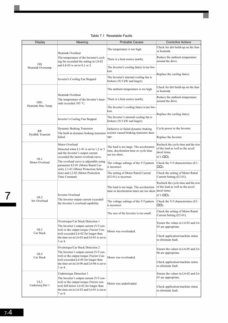
7-4
7
OH Heatsink Overtemp
Heatsink OverheatThe temperature of the Inverter's cool-ing fin exceeded the setting in L8-02 and L8-03 is set to 0,1 or 2.
The temperature is too high. Check for dirt build-up on the fans or heatsink.
There is a heat source nearby. Reduce the ambient temperature around the drive.
The Inverter's cooling fan(s) is/are bro-ken.
Replace the cooling fan(s).Inverter's Cooling Fan Stopped The Inverter's internal cooling fan is
broken (18.5 kW and larger).
OH1Heatsink Max Temp
Heatsink OverheatThe temperature of the Inverter’s heat-sink exceeded 105 °C.
The ambient temperature is too high. Check for dirt build-up on the fans or heatsink.
There is a heat source nearby. Reduce the ambient temperature around the drive.
The Inverter’s cooling fan(s) is/are bro-ken.
Replace the cooling fan(s).Inverter’s Cooling Fan Stopped The Inverter’s internal cooling fan is
broken (18.5 kW and larger).
RRDynBrk Transistr
Dynamic Braking TransistorThe built-in dynamic braking transistor failed.
Defective or failed dynamic braking resistor caused braking transistor dam-age.
Cycle power to the Inverter.
Replace the Inverter.
OL1Motor Overload
Motor OverloadDetected when L1-01 is set to 1,2 or 3 and the Inverter’s output current exceeded the motor overload curve. The overload curve is adjustable using parameter E2-01 (Motor Rated Cur-rent), L1-01 (Motor Protection Selec-tion) and L2-02 (Motor Protection Time Constant)
The load is too large. The acceleration time, deceleration time or cycle time are too short.
Recheck the cycle time and the size of the load as well as the accel/decel times (C1- ).
The voltage settings of the V/f pattern is incorrect.
Check the V/f characteristics (E1-).
The setting of Motor Rated Current (E2-01) is incorrect.
Check the setting of Motor Rated Current Setting (E2-01).
OL2Inv Overload
Inverter OverloadThe Inverter output current exceeded the Inverter’s overload capability.
The load is too large. The acceleration time or deceleration times are too short.
Recheck the cycle time and the size of the load as well as the accel/decel times(C1- ).
The voltage settings of the V/f pattern is incorrect.
Check the V/f characteristics (E1-).
The size of the Inverter is too small. Check the setting of Motor Rated Current Setting (E2-01).
OL3Car Stuck
Overtorque/Car Stuck Detection 1The Inverter’s output current (V/f con-trol) or the output torque (Vector Con-trol) exceeded L6-02 for longer than the time set in L6-03 and L6-01 is set to 3 or 4.
Motor was overloaded.
Ensure the values in L6-02 and L6-03 are appropriate.
Check application/machine status to eliminate fault.
OL4Car Stuck
Overtorque/Car Stuck Detection 2The Inverter’s output current (V/f con-trol) or the output torque (Vector Con-trol) exceeded L6-05 for longer than the time set in L6-06 and L6-04 is set to 3 or 4.
Motor was overloaded.
Ensure the values in L6-05 and L6-06 are appropriate.
Check application/machine status to eliminate fault.
UL3Undertorq Det 1
Undertorque Detection 1The Inverter’s output current (V/f con-trol) or the output torque (Vector con-trol) fell below L6-02 for longer than the time set in L6-03 and L6-01 is set to 7 or 8.
Motor was underloaded.
Ensure the values in L6-02 and L6-03 are appropriate.
Check application/machine status to eliminate fault.
Table 7.1 Resetable Faults
Display Meaning Probable Causes Corrective Actions

7-5
7
UL4Undertorq Det 2
Undertorque Detection 2The Inverter’s output current (V/f con-trol) or the output torque (Vector con-trol) fell below L6-05 for longer than the time set in L6-06 and L6-04 is set to 7 or 8.
Motor was underloaded.
Ensure the values in L6-05 and L6-06 are appropriate.
Check application/machine status to eliminate fault.
OSOverspeed Det
Motor OverspeedDetected when F1-03 is set to 0, 1 or 2 and A1-02 is set to 3.The motor speed feedback (U1-05) exceeded the setting in F1-08 for a time longer than the setting of F1-09.
Overshooting/Undershooting occurs. Adjust the ASR settings in the C5 parameter group.
The reference was too high. Check the reference circuit and ref-erence gain.
The settings in F1-08 and F1-09 are not appropriate.
Check the settings in F1-08 and F1-09.
PGOPG Open
PG Disconnection Detected when F1-02 is set to 0, 1 or 2 and A1-02 is set to 3 or 6Detected when no PG (encoder) pulses are received for a time longer than the setting of F1-14.
The PG wiring is broken. Fix the broken/disconnected wir-ing.
The PG is wired incorrectly. Fix the wiring.
Power is not supplied to the PG.Supply power to the PG properly.
Wrong brake control sequence. The motor runs against the closed brake.
Check the sequence and if the brake is opened when the inverter starts to increase the speed.
DEVSpeed Deviation
Excessive Speed DeviationDetected when F1-04 is set to 0, 1 or 2 and A1-02 is set to 3 or 6The speed deviation is higher than the setting of F1-10 for a time longer than the setting of F1-11.
The load is too large. Reduce the load.
The acceleration time and deceleration time are too short.
Lengthen the acceleration time and deceleration time.
The load is locked. Check the mechanical system.
The settings of F1-10 and F1-11 are not appropriate.
Check the settings of F1-10 and F1-11.
Wrong brake control sequence. The motor runs against the closed brake.
Check the sequence and if the brake is opened when the inverter starts to increase the speed.
DV3
Wrong rotation directionDetected when the speed deviation is higher than 30% and the torque refer-ence and acceleration have opposite signs.
PG wire broken Check the PG wiring
Incorrect PG wiring Correct the wiring
Wrong magnet position compensation value (F1-22)
Verify the PG direction and execute an encoder offset auto tuning
The load is too large Reduce the load and check the brake
DV4
Wrong rotation directionDetected when F1-19 is not 0, the speed reference and motor speed have opposite signs and the detection thresh-old set in F1-19 is exceeded.
The magnet position offset setting in F1-22 is wrong
Verify the PG direction and execute an encoder offset auto tuning
The load is too large Reduce the load and check the brake
DV6Over Acceleration
An over acceleration of the car was detected (A1-02 = 6 only)
The load is too large Reduce the load
Magnet position offset is wrongCheck the PG direction, check F1-22 and perform an encoder offset tuning.
Sheave diameter, gear ratio or roping setting incorrect
Verify the settings of S3-13, S3-14 and S3-15.
Too short acceleration or deceleration time.
Adjust the acceleration and deceler-ation times.
SVEZero Servo Fault
Zero Servo FaultThe motor position moved during Zero Servo Operation.
The torque limit is too small. Increase the torque limit.
The load torque is too large. Decrease the load torque.
- Check for signal noise.
Table 7.1 Resetable Faults
Display Meaning Probable Causes Corrective Actions

7-6
7
CFOut of Control
Control FaultA torque limit was reached continu-ously for 3 seconds or longer during a deceleration stop in Open Loop Vector control.
Motor parameters were not set prop-erly. Check the motor parameters.
EF0Opt External Flt
External fault input from Communica-tions Option Card
An external fault condition was present, input from a communication option card.
Check for an external fault condi-tion.
Verify the parameters.
Verify communication signals
EF3Ext Fault S3 External fault at terminal S3
An “external fault” was input from a multi-function input terminal (S3 to S7).
Eliminate the cause of the external fault condition.
EF4Ext Fault S4 External fault at terminal S4
EF5Ext Fault S5 External fault at terminal S5
EF6Ext Fault S6 External fault at terminal S6
EF 7Ext Fault S7 External fault at terminal S7
CEMemobus Com Err
MEMOBUS Communication ErrorDetected when control data was not received correctly for two seconds, H5-04 is set to 0,1 or 2 and H5-05 is set to 1.
Connection is broken and/or the master has stopped the communication.
Check the connections and all PLC-side software configurations.
BUSOption Com Err
Option Communication ErrorAfter initial communication has been established, the connection got lost.
Connection is broken and/or the master has stopped the communication.
Check the connections and all PLC-side software configurations.
SE1Sequence Error 1
Detected no output contactor answer back for S1-16 time setting.
The output contactor or auxiliaryswitch has a malfunction.
Check the output contactor.
SE2Sequence Error 2
The output current at start was below 25% of no-load current.
The output contactor was not closed at start. Check the output contactor.
SE3Sequence Error 3
The output current during run was below 25% of no-load current.
The output contactor was opened dur-ing run. Check the output contactor.
Ref MissingFRL
No speed was selected before the inverter start.
A start signal was given and no speed was selected when d1-18 = 1 and H1- K83.
Check the speed selection/start sequence.
Table 7.2 Not Resetable Faults
CPF00COM-ERR(OP&INV)
Digital Operator/LED Monitor Com-munication Fault 1Communication with the digital opera-tor could not be established within 5 seconds after the power was supplied to the Inverter.
Digital operator cable was not securely connected or digital operator is defec-tive and/or control board is defective
Disconnect the Digital Operator/LED Monitor and then connect it again.
Replace the Inverter.
CPU External RAM Fault The control board is damaged.Cycle the Inverter power supply.
Replace the Inverter.
CPF01COM-ERR(OP&INV)
Digital Operator/LED Monitor Com-munication Fault 2After communications with the digital operator was established, the communi-cation stopped for 2 seconds or more.
Digital operator cable is not properly connected or the digital operator is defective
Disconnect the Digital Operator/LED Monitor and then connect it again.
The control board is damaged.Cycle the Inverter power supply.
Replace the Inverter.
Table 7.1 Resetable Faults
Display Meaning Probable Causes Corrective Actions
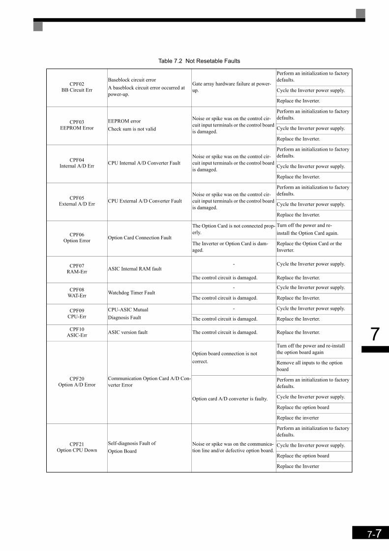
7-7
7
CPF02BB Circuit Err
Baseblock circuit errorA baseblock circuit error occurred at power-up.
Gate array hardware failure at power-up.
Perform an initialization to factory defaults.
Cycle the Inverter power supply.
Replace the Inverter.
CPF03EEPROM Error
EEPROM errorCheck sum is not valid
Noise or spike was on the control cir-cuit input terminals or the control board is damaged.
Perform an initialization to factory defaults.
Cycle the Inverter power supply.
Replace the Inverter.
CPF04Internal A/D Err CPU Internal A/D Converter Fault
Noise or spike was on the control cir-cuit input terminals or the control board is damaged.
Perform an initialization to factory defaults.
Cycle the Inverter power supply.
Replace the Inverter.
CPF05External A/D Err CPU External A/D Converter Fault
Noise or spike was on the control cir-cuit input terminals or the control board is damaged.
Perform an initialization to factory defaults.
Cycle the Inverter power supply.
Replace the Inverter.
CPF06Option Error Option Card Connection Fault
The Option Card is not connected prop-erly.
Turn off the power and re-install the Option Card again.
The Inverter or Option Card is dam-aged.
Replace the Option Card or the Inverter.
CPF07RAM-Err ASIC Internal RAM fault
- Cycle the Inverter power supply.
The control circuit is damaged. Replace the Inverter.
CPF08WAT-Err Watchdog Timer Fault
- Cycle the Inverter power supply.
The control circuit is damaged. Replace the Inverter.
CPF09CPU-Err
CPU-ASIC Mutual Diagnosis Fault
- Cycle the Inverter power supply.
The control circuit is damaged. Replace the Inverter.
CPF10ASIC-Err ASIC version fault The control circuit is damaged. Replace the Inverter.
CPF20Option A/D Error
Communication Option Card A/D Con-verter Error
Option board connection is not correct.
Turn off the power and re-install the option board again
Remove all inputs to the option board
Option card A/D converter is faulty.
Perform an initialization to factory defaults.
Cycle the Inverter power supply.
Replace the option board
Replace the inverter
CPF21Option CPU Down
Self-diagnosis Fault of Option Board
Noise or spike was on the communica-tion line and/or defective option board.
Perform an initialization to factory defaults.
Cycle the Inverter power supply.
Replace the option board
Replace the Inverter
Table 7.2 Not Resetable Faults

7-8
7
CPF22Option Type Err Option Board Code Number Fault An unrecognizable option board is con-
nected to the control board.
Remove any option boards
Perform an initialization to factory defaults
Cycle the Inverter power supply.
Replace the option board
Replace the Inverter
CPF23Option DPRAM Err
Option BoardInterconnection Fault
An option board was not correctly con-nected to the control board, or an option board which is not made for the Inverter has been attached to the con-trol board.
Turn off the power and reinstall the option board again
Perform an initialization to factory defaults
Cycle the Inverter power supply.
Replace the option board
Replace the Inverter
CPF24Option Comm Err
PG-F2 (Hiperfacey/ EnDat) serial com-munication error Detected when no data were received from the encoder for 200 msec
Encoder connection wiring broken or encoder broken
Check the encoder connection or replace the encoder if necessary
Table 7.2 Not Resetable Faults
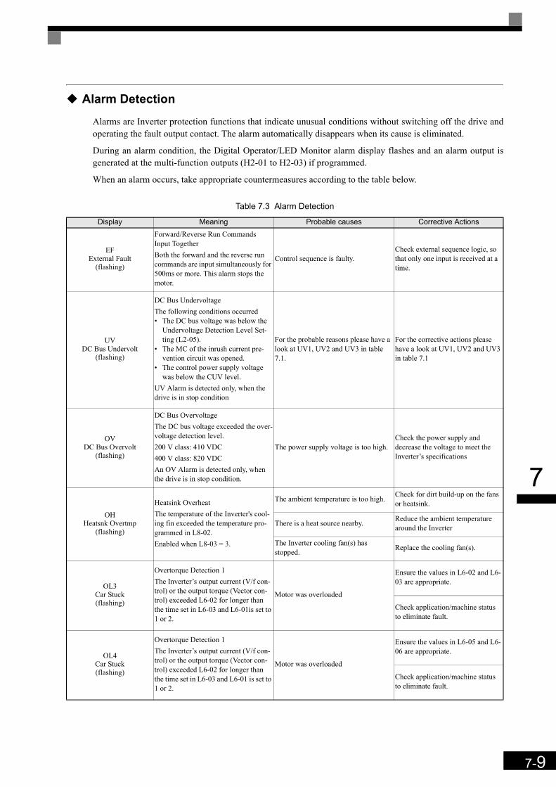
7-9
7
Alarm Detection
Alarms are Inverter protection functions that indicate unusual conditions without switching off the drive andoperating the fault output contact. The alarm automatically disappears when its cause is eliminated.
During an alarm condition, the Digital Operator/LED Monitor alarm display flashes and an alarm output isgenerated at the multi-function outputs (H2-01 to H2-03) if programmed.
When an alarm occurs, take appropriate countermeasures according to the table below.
Table 7.3 Alarm Detection
Display Meaning Probable causes Corrective Actions
EFExternal Fault
(flashing)
Forward/Reverse Run Commands Input TogetherBoth the forward and the reverse run commands are input simultaneously for 500ms or more. This alarm stops the motor.
Control sequence is faulty.Check external sequence logic, so that only one input is received at a time.
UVDC Bus Undervolt
(flashing)
DC Bus UndervoltageThe following conditions occurred • The DC bus voltage was below the
Undervoltage Detection Level Set-ting (L2-05).
• The MC of the inrush current pre-vention circuit was opened.
• The control power supply voltage was below the CUV level.
UV Alarm is detected only, when the drive is in stop condition
For the probable reasons please have a look at UV1, UV2 and UV3 in table 7.1.
For the corrective actions please have a look at UV1, UV2 and UV3 in table 7.1
OVDC Bus Overvolt
(flashing)
DC Bus OvervoltageThe DC bus voltage exceeded the over-voltage detection level.200 V class: 410 VDC400 V class: 820 VDCAn OV Alarm is detected only, when the drive is in stop condition.
The power supply voltage is too high.Check the power supply and decrease the voltage to meet the Inverter’s specifications
OH Heatsnk Overtmp
(flashing)
Heatsink OverheatThe temperature of the Inverter's cool-ing fin exceeded the temperature pro-grammed in L8-02.Enabled when L8-03 = 3.
The ambient temperature is too high. Check for dirt build-up on the fans or heatsink.
There is a heat source nearby. Reduce the ambient temperature around the Inverter
The Inverter cooling fan(s) has stopped. Replace the cooling fan(s).
OL3Car Stuck(flashing)
Overtorque Detection 1The Inverter’s output current (V/f con-trol) or the output torque (Vector con-trol) exceeded L6-02 for longer than the time set in L6-03 and L6-01is set to 1 or 2.
Motor was overloaded
Ensure the values in L6-02 and L6-03 are appropriate.
Check application/machine status to eliminate fault.
OL4Car Stuck(flashing)
Overtorque Detection 1The Inverter’s output current (V/f con-trol) or the output torque (Vector con-trol) exceeded L6-02 for longer than the time set in L6-03 and L6-01 is set to 1 or 2.
Motor was overloaded
Ensure the values in L6-05 and L6-06 are appropriate.
Check application/machine status to eliminate fault.

7-10
7
UL3Undertorque Det 1
(flashing)
Undertorque Detection 1The Inverter’s output current (V/f con-trol) or the output torque (Vector con-trol) fell below L6-02 for longer than the time set in L6-03 and L6-01 is set to 5 or 6.
Motor was underloaded
Ensure the values in L6-02 and L6-03 are appropriate.
Check application/machine status to eliminate fault.
UL4Undertorque Det 2
(flashing)
Undertorque Detection 2The Inverter’s output current (V/f con-trol) or the output torque (Vector con-trol) fell below L6-05 for longer than the time set in L6-06 and L6-04 is set to 5 or 6.
Motor was underloaded
Ensure the values in L6-05 and L6-06 are appropriate.
Check application/machine status to eliminate fault.
OSOverspeed Det
(flashing)
Overspeed AlarmDetected when A1-02 is set to 1 or 3 and F1-03 is set to 3.The motor speed feedback (U1-05) exceeded the value set in F1-08 for a time longer than the setting of F1-09.
Overshooting/undershooting occurs. Adjust the ASR settings in the C5 parameter group.
The reference was too high. Check the reference circuit and ref-erence gain.
The settings in F1-08 and F1-09 are not appropriate.
Check the settings in F1-08 and F1-09.
PGOPG Open(flashing)
PG DisconnectionDetected when F1-02 is set to 3 and A1-02 is set to 1 or 3.Detected when no PG (encoder) pulses are received for a time longer than the setting of F1-14
The PG wiring is broken. Fix the broken/disconnected wir-ing.
The PG is wired incorrectly. Check the wiring
Power is not supplied to the PG. Supply the correct power to the PG.
DEVSpeed Deviation
(flashing)
Excessive Speed DeviationDetected when F1-04 is set to 3 and A1-02 is set to 1 or 3.The speed deviation is higher than the setting of F1-10 for longer than the set-ting of F1-11.
The load is too large. Reduce the load.
The acceleration time and deceleration time are too short.
Lengthen the acceleration time and deceleration time.
The load is locked. Check the mechanical system.
The settings in F1-10 and F1-11 are not appropriate.
Check the settings in F1-10 and F1-11.
An over acceleration of the car was detected (A1-02 = 6 only)
The load is too large Reduce the load
Magnet position offset is wrongCheck the PG direction, check F1-22 and perform an encoder off-set tuning.
Sheave diameter, gear ratio or roping setting incorrect
Verify the settings of S3-13, S3-14 and S3-15.
Too short acceleration or deceleration time.
Adjust the acceleration and deceler-ation times.
EF0Opt External Flt
(flashing)
Communication Option Card External Fault
An external fault condition was input from by communication option card.
Check for an external fault condi-tion.
Verify the parameters.
Verify communication signals
Table 7.3 Alarm Detection
Display Meaning Probable causes Corrective Actions

7-11
7
EF3Ext Fault S3
(flashing)External fault at terminal S3
An external fault was input by a multi-function input terminal (S3 to S7) which is programmed for the external fault function alarm output.
Eliminate the cause of the external fault condition
EF4Ext Fault S4
(flashing)External fault at terminal S4
EF5Ext Fault S5
(flashing)External fault at terminal S5
EF6Ext Fault S6
(flashing)External fault at terminal S6
EF7Ext Fault S7
(flashing)External fault at terminal S7
BUSOption Com Err
(flashing)
Option Communications AlarmAfter initial communication was estab-lished, the connection was lost.
Connection is broken and/or the master has stopped the communication.
Check the connections and all user-side software configurations.
Ext Run ActiveCannot Reset
Detected after a fault when a RESET command is input while the RUN com-mand is still active
The RUN command has not been removed and a RESET command is input by digital input or by the RESET button on the digital operator.
Remove the RUN signal first and reset the error.
Ext Run ActiveCannot Reset An inverter fault can’t be reset.
The fault was tried to be reset when a direction signal (Up/Down) was still active.
Remove the direction signal and retry to reset the fault.If the fault reset is handled by a PLC, check the sequence.
FF_CAL Feed forward motor acceleration time active
Motor acceleration time calculation was activated by setting n5-05 = 1 and enabling the inspection input
• Perform the complete tuning pro-cedure
• Abort the tuning by setting n5-05 = 0.
Table 7.3 Alarm Detection
Display Meaning Probable causes Corrective Actions
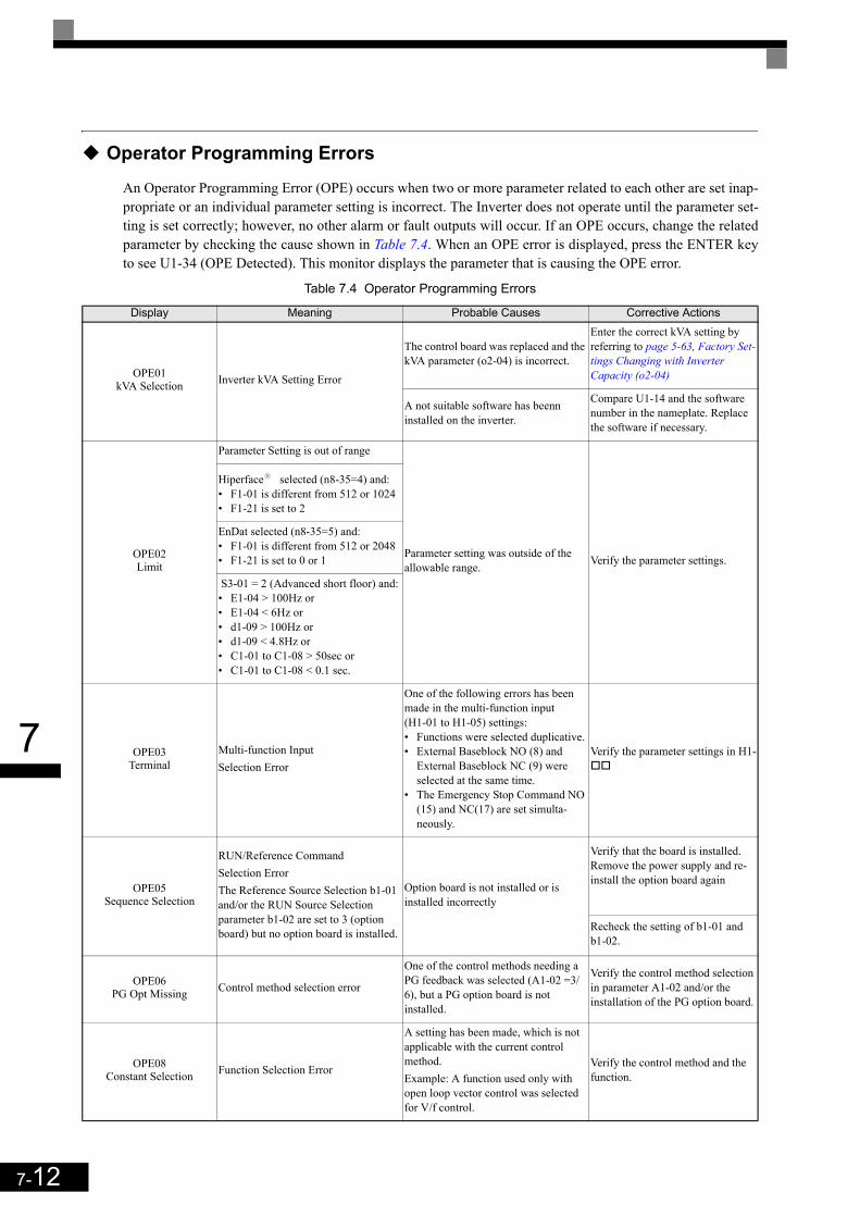
7-12
7
Operator Programming Errors
An Operator Programming Error (OPE) occurs when two or more parameter related to each other are set inap-propriate or an individual parameter setting is incorrect. The Inverter does not operate until the parameter set-ting is set correctly; however, no other alarm or fault outputs will occur. If an OPE occurs, change the relatedparameter by checking the cause shown in Table 7.4. When an OPE error is displayed, press the ENTER keyto see U1-34 (OPE Detected). This monitor displays the parameter that is causing the OPE error.
Table 7.4 Operator Programming Errors
Display Meaning Probable Causes Corrective Actions
OPE01kVA Selection Inverter kVA Setting Error
The control board was replaced and the kVA parameter (o2-04) is incorrect.
Enter the correct kVA setting by referring to page 5-63, Factory Set-tings Changing with Inverter Capacity (o2-04)
A not suitable software has beenn installed on the inverter.
Compare U1-14 and the software number in the nameplate. Replace the software if necessary.
OPE02Limit
Parameter Setting is out of range
Parameter setting was outside of the allowable range. Verify the parameter settings.
Hiperfacey selected (n8-35=4) and:• F1-01 is different from 512 or 1024• F1-21 is set to 2
EnDat selected (n8-35=5) and:• F1-01 is different from 512 or 2048• F1-21 is set to 0 or 1
S3-01 = 2 (Advanced short floor) and:• E1-04 > 100Hz or• E1-04 < 6Hz or• d1-09 > 100Hz or• d1-09 < 4.8Hz or• C1-01 to C1-08 > 50sec or• C1-01 to C1-08 < 0.1 sec.
OPE03Terminal
Multi-function InputSelection Error
One of the following errors has been made in the multi-function input (H1-01 to H1-05) settings:• Functions were selected duplicative.• External Baseblock NO (8) and
External Baseblock NC (9) were selected at the same time.
• The Emergency Stop Command NO (15) and NC(17) are set simulta-neously.
Verify the parameter settings in H1-
OPE05Sequence Selection
RUN/Reference Command Selection ErrorThe Reference Source Selection b1-01 and/or the RUN Source Selection parameter b1-02 are set to 3 (option board) but no option board is installed.
Option board is not installed or is installed incorrectly
Verify that the board is installed. Remove the power supply and re-install the option board again
Recheck the setting of b1-01 and b1-02.
OPE06PG Opt Missing Control method selection error
One of the control methods needing a PG feedback was selected (A1-02 =3/6), but a PG option board is not installed.
Verify the control method selection in parameter A1-02 and/or the installation of the PG option board.
OPE08Constant Selection Function Selection Error
A setting has been made, which is not applicable with the current control method.Example: A function used only with open loop vector control was selected for V/f control.
Verify the control method and the function.

7-13
7
OPE10V/f Ptrn Setting V/f Parameter Setting Error V/f parameter settings were out of
range.
Check parameters (E1- ). A fre-quency/voltage value may be set higher than the maximum fre-quency/voltage.
ERREEPROM R/W Err
EEPROM write errorThe NV-RAM data does not match the EEPROM data.
A verification error occurred when writing EEPROM.
Cycle power to the Inverter.
Do a factory initialization (A1-03)
Table 7.4 Operator Programming Errors
Display Meaning Probable Causes Corrective Actions
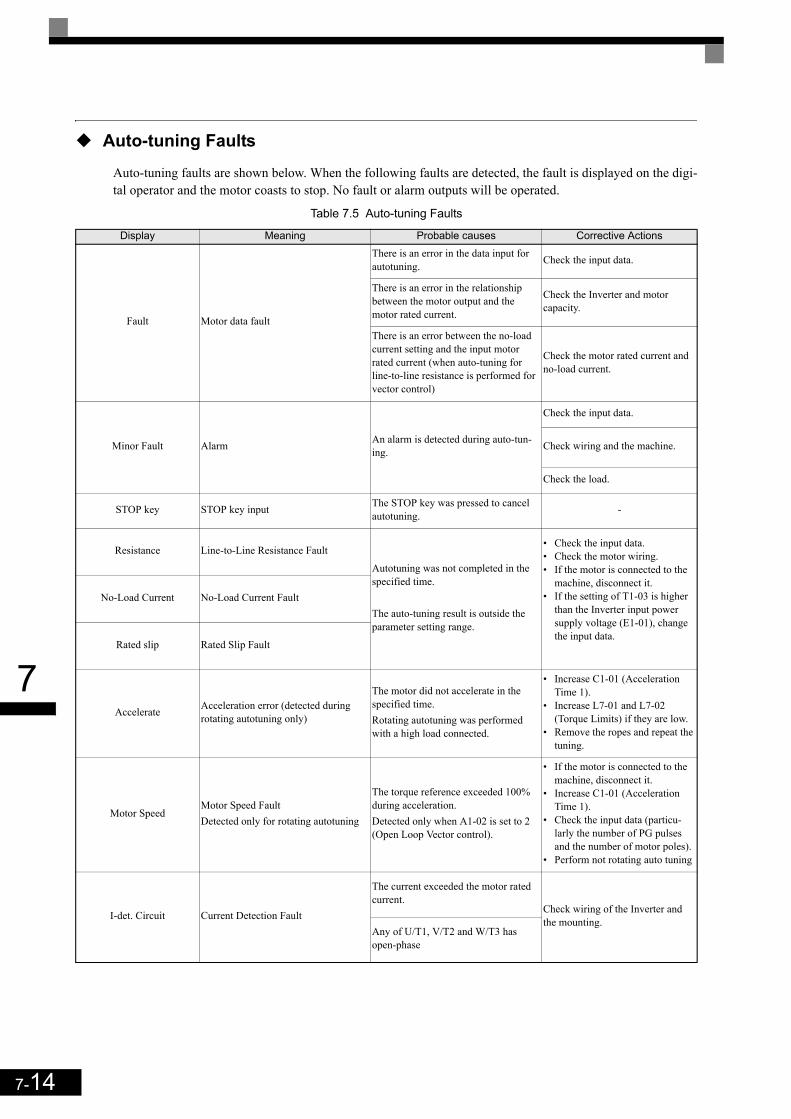
7-14
7
Auto-tuning Faults
Auto-tuning faults are shown below. When the following faults are detected, the fault is displayed on the digi-tal operator and the motor coasts to stop. No fault or alarm outputs will be operated.
Table 7.5 Auto-tuning Faults
Display Meaning Probable causes Corrective Actions
Fault Motor data fault
There is an error in the data input for autotuning. Check the input data.
There is an error in the relationship between the motor output and the motor rated current.
Check the Inverter and motor capacity.
There is an error between the no-load current setting and the input motor rated current (when auto-tuning for line-to-line resistance is performed for vector control)
Check the motor rated current and no-load current.
Minor Fault Alarm An alarm is detected during auto-tun-ing.
Check the input data.
Check wiring and the machine.
Check the load.
STOP key STOP key input The STOP key was pressed to cancel autotuning. -
Resistance Line-to-Line Resistance Fault
Autotuning was not completed in the specified time.
The auto-tuning result is outside the parameter setting range.
• Check the input data.• Check the motor wiring.• If the motor is connected to the
machine, disconnect it.• If the setting of T1-03 is higher
than the Inverter input power supply voltage (E1-01), change the input data.
No-Load Current No-Load Current Fault
Rated slip Rated Slip Fault
Accelerate Acceleration error (detected during rotating autotuning only)
The motor did not accelerate in the specified time.Rotating autotuning was performed with a high load connected.
• Increase C1-01 (Acceleration Time 1).
• Increase L7-01 and L7-02 (Torque Limits) if they are low.
• Remove the ropes and repeat the tuning.
Motor SpeedMotor Speed FaultDetected only for rotating autotuning
The torque reference exceeded 100% during acceleration.Detected only when A1-02 is set to 2 (Open Loop Vector control).
• If the motor is connected to the machine, disconnect it.
• Increase C1-01 (Acceleration Time 1).
• Check the input data (particu-larly the number of PG pulses and the number of motor poles).
• Perform not rotating auto tuning
I-det. Circuit Current Detection Fault
The current exceeded the motor rated current.
Check wiring of the Inverter and the mounting.
Any of U/T1, V/T2 and W/T3 has open-phase

7-15
7
Leakage Induc-tance Fault
The leakage inductance measurement caused an error.
Auto-tuning was not completed in the specified time. • Check the motor wiring.
• Check the motor rated current input valueAuto-tuning result is outside the
parameter setting range.
The leakage inductance tuning current was too high or too low (Closed Loop Vector for PM only)
Reduce or increase the current level for leakage inductance tuning by changing parameter n8-46.
Z_SRCH_ERR(PM motor tuning only)
All encoders
The motor speed exceeded 20 rpm at the auto tuning start.The magnetic pole position tuning could not be performed in the specified time. • Remove the ropes and repeat the
tuning• Check the encoder rotation direc-
tion and if necessary change F1-05.
Encoder with Z-pulseThe difference between two measure-ments of the magnet pole position was higher than 3°.
Serial encoders
The difference between two measure-ments of the magnet pole position was higher than 5°.
An encoder serial communication error has occurred during the tuning.
• Check the encoder wiring (order, shield etc.)
• Check the encoder power supply.• Replace the encoder.
LD_ERR(PM motor tuning only) Inductance error
The inductance could not be measured in the specified time during the motor rotation.
Check the motor wiring
RS_ERR(PM motor tuning only) Line-to-line resistance error
The resistance could not be measured in the specified time during the motor rotation or the calculated value was out of range.
• Check the motor wiring• Check the motor input data
KE_ERR(PM motor tuning only) Voltage constant error
The voltage constant could not be mea-sured in the specified time during the motor rotation.
Check the motor wiring
End - 1V/f Over Setting
V/f Settings AlarmDisplayed after auto-tuning is complete
The torque reference exceeded 100% and the no-load current exceeded 70% during auto-tuning.
Check and correct the motor set-tings
If the motor and the machine are connected, disconnect the motor from the machine.
End - 2Saturation
Motor Core Saturation FaultDisplayed after auto-tuning is com-plete. Detected only for rotating autotuning
During auto-tuning, the measured val-ues of motor iron-core saturation coef-ficient 1 and 2 (E2-07 and E2-08) exceeded its setting range.
Check the input data.
Check the motor wiring.
If the motor and the machine are connected, disconnect the motor from the machine.
End - 3Rated FLA Alm
Rated Current Setting AlarmDisplayed after auto-tuning is complete
During auto-tuning, the measured value of motor rated current (E2-01) was higher than the set value.
Check the motor rated current value.
Table 7.5 Auto-tuning Faults
Display Meaning Probable causes Corrective Actions

7-16
7
Digital Operator Copy Function Faults
These faults can occur during the digital operator COPY function. When a fault occurs, the fault content is dis-played on the operator. The fault or alarm contact output is not operated.
Table 7.6 Operator Copy Function Faults
Function Digital Operator Display Probable Causes Corrective Actions
READ Function
PREREAD IMPOSSIBLE
o3-01 was set to 1 to write parameter into the Digi-tal Operator when the Operator was write-protected (o3-02 = 0).
Set o3-02 to enable writing parameters into the Operator’s memory.
IFE READ DATA ERROR
The data file read from the Inverter was of the wrong size indicating corrupted data.
Retry the READ command (o3-01 = 1).
Check the Digital Operator’s cable.
Replace the Digital Operator.
RDEDATA ERROR
An attempted writing of the Inverter data to the Digital Operator’s EEPROM failed.
A low Inverter voltage has been detected.
Retry the READ command (o3-01 = 1).
Replace the Digital Operator.
COPY Function
CPEID UNMATCHED
The Inverter type or software number was different from the stored data in the digital operator
Use stored data of the same product (L7) and soft-ware number (U1-14) only.
VAE INV. KVA UNMATCH
The capacity of the Inverter and the capacity of the stored data in the Digital Operator are different.
Use stored data for the same Inverter capacity only (o2-04).
CRECONTROL UNMATCHED
The control method of the Inverter and the control method of the stored data in the Digital Operator are different.
Use stored data for the same control method (A1-02).
CYE COPY ERROR
A parameter setting written to the Inverter was dif-ferent from the setting stored in the Digital Opera-tor.
Retry the COPY function (o3-01 = 2)
CSESUM CHECK ERROR
Upon completion of the COPY function, the Inverter’s data checksum was different to the digital operator’s data checksum.
Retry the COPY function (o3-01 = 2)
VerifyFunction
VYEVERIFY ERROR
The set value of the digital operator and the Inverter do not match Retry the Verify function (o3-01 = 3)

7-17
7
Machine Data Copy Function Faults
These faults can occur during the machine data (encoder) COPY function. When a fault occurs, the fault con-tent is displayed on the operator. The fault or alarm contact output is not operated.
Table 7.7 Machine Data Copy Function Faults
Function Digital Operator Display Probable Causes Corrective Actions
WRITE from inverter to encoder
EREDATA ERROR
A write to encoder command could not be performed since the drive is in UV (under voltage) condition.
Make sure that no fault and no alarm is active and retry.
COPY from Encoder to
Inverter
EDEWRITE IMPOSSIBLE The write to encoder command is prohibited. Set parameter F1-26 to 1 to permit a write to
encoder command.
EIFWRITE DATA ERROR
A communication error occurred during the write to encoder process. Retry the write to encoder command.
ECECOPY ERROR
A read to encoder command could not be performed since the drive is in UV (under voltage) condition.
Make sure that no fault and no alarm is active and retry.
EPEID MISMATCH
The data in the encoder do not fit to the L7Z data format. -
ECSSUM CHECK ERROR
The check sum of the data, which were writ-ten into the inverter is wrong. Retry the COPY command.
VERFIY EVEVERIFY ERROR
The data in the encoder and inverter data do not match. -
7-18
7
Troubleshooting
Due to parameter setting errors, faulty wiring etc., the Inverter and motor may not operate as expected whenthe system is started. If that occurs, use this section as a reference and perform the appropriate countermea-sures.
If a fault code is displayed, refer to page 7-2, Protective and Diagnostic Functions.
If A Parameter Cannot Be Set
Use the following information if a parameter cannot be set.
The display does not change when the Increment and Decrement keys are pressed.The following causes are possible:
The Inverter is operating (drive mode).There are some parameters that cannot be set during operation. Turn off the RUN command and then set theparameters.
Passwords do not match. (Only when a password is set.)If the parameter A1-04 (Password) and A1-05 (Password Setting) settings are different, the parameters for theinitialize mode cannot be changed. Enter the correct password in A1-04.
If the password got lost, check parameter A1-05 (Password Setting) by pressing the Shift/RESET key and theMENU key simultaneously in the A1-04 display. Read the password and set it in parameter A1-04.
OPE01 through OPE11 is displayed.The set value for the parameter is wrong. Refer to Table 7.4 in this chapter and correct the settings.
CPF00 or CPF01 is displayed.This is a Digital Operator/LED Monitor communication error. The connection between the Digital Operator/LED Monitor and the Inverter may be faulty. Remove the Digital Operator/LED Monitor and then re-install it.

7-19
7
If the Motor Does Not Operate Properly
The following causes are possible:
The motor does not operate when an external operation signal is input.The frequency reference is 0.00 Hz or a no speed is selected by the digital inputs. Check the input signals andthe frequency reference settings.Also make sure to set the Baseblock signal. The inverter does not accept any input if it is base blocked.
The load is too heavyCheck the motor current. If it is at the limit of the inverter rated current the load might be too high. Check theinverter size and the mechanical system. Check also if the brake is working or not to make sure, that the motoris not running against the closed brake.
If the Direction of the Motor Rotation is Reversed
If the motor rotates in the wrong direction, the motor output wiring may be incorrect.
The direction of the motor rotation can be reversed by switching two wires among U, V, and W. If an encoderis used, the polarity has to be switched over as well. If the Inverter is operated in V/f mode parameter b1-04can be used to change the rotation direction.
If the Motor Stalls or Acceleration is Slow
The torque limit has been reached.When a torque limit has been set in parameters L7-01 to L7-04, the output torque will be limited according tothese settings. Therefore the motor may not develop enough torque to accelerate or the acceleration time mightbe very long.
The stall prevention level during acceleration is too low.If the value set in L3-02 (Stall Prevention Level during Acceleration) is too low, the acceleration time will beincreased. Check that the set value is suitable and that the load is not too large for the motor.
The stall prevention level during running is too low.If the value set in L3-06 (Stall Prevention Level during Running) is too low, the motor speed and torque willbe limited. Check that the set value is suitable and that the load is not too large for the motor.
Auto-tuning has not been performed for vector controlVector control does not work properly, if auto-tuning has not been performed. Perform auto-tuning, or set themotor parameters manually.
7-20
7
If Motor Deceleration is Slow
The following causes are possible:
The deceleration time is too longThe following causes are possible:
The deceleration time setting is too long.Check the deceleration time setting (parameters C1-02, C1-04, C1-06, and C1-08).
Motor torque is insufficient.
If the parameters are correct and there is no fault but the torque is insufficient, consider increasing the motorand inverter capacity.
The torque limit has been reached.When a torque limit is reached (L7-01 to L7-04), the motor torque will be limited. This can lengthen the decel-eration time. Check the L7- parameters to be sure that the torque limit values are suitable.
If the Motor Overheats
The following causes are possible:
The load is too large.If the motor load is too large and the torque exceeds the motor’s rated torque, the motor may overheat. Eitherreduce the load or increase the acceleration/deceleration times. Also consider increasing the motor size.
The ambient temperature is too high.The motor rating is determined by a particular ambient operating temperature range. The motor will overheatif it is run continuously at the rated torque in an environment where the maximum ambient operating tempera-ture is exceeded. Lower the motor's ambient temperature to an acceptable value.
Auto-tuning has not been performed for vector controlThe Vector control performance may not be optimal, if auto-tuning has not been performed. Perform auto-tun-ing, or set the motor parameters manually. For induction motors alternatively the V/f control mode can be used.

7-21
7
If Peripheral Devices are Influenced by the Starting or Running Inverter
The following solutions are possible: • Change the Inverter's Carrier Frequency Selection (C6-02) to lower the carrier frequency. This will help to
reduce the amount of transistor switching noise.• Install an Input Noise Filter at the Inverter's input power terminals.• Install an Output Noise Filter at the Inverter's motor terminals.• Use shielded motor cables or a conduit. Metal shields electrical noise. • Check the grounding of the Inverter and motor.• Separate main circuit wires from control circuit wires.
If the Earth Leakage Breaker Operates When the Inverter is Running
The Inverter’s output is pulse modulated, i.e. the output voltage consists of high frequency pulses (PWM).This high frequency signal causes a certain amount of leakage current which may cause the earth leakagebreaker to operate and cut off the power supply. Change to a ground fault interrupter with a high leakagedetection level (i.e., a sensitivity current of 200 mA or higher, with an operating time of 0.1 s or more), andone, which incorporates high frequencies countermeasures (i.e., one designed for use with Inverters). Lower-ing the Inverter's Carrier Frequency Selection (C6-02) can also help, since the leakage current increases withthe cable length.
If There is Mechanical Oscillation
Use the following information when there is mechanical vibration:
Oscillation and hunting occur with V/f controlThe torque compensation parameter settings may be incorrect for the machine. Adjust parameters C4-01(Torque Compensation Gain) and C4-02 (Torque Compensation Delay Time). Decrease C4-01 carefully insteps of 0.05 and/or increase C4-02.
Furthermore the Slip Compensation Delay Time (C3-02) can be increased or decreased.
Oscillation and hunting occur with Open Loop Vector control. The torque compensation parameter settings may be incorrect for the machine. Adjust parameters C4-01(Torque Compensation Gain), C4-02 (Torque Compensation Delay Time Parameter) and C3-02 (Slip Com-pensation Delay Time) in order. Lower the gain parameters and raise the delay time parameters.
If auto-tuning has not been performed, proper performance may not be achieved for Vector Control. Performauto-tuning or set the motor parameters manually.
Oscillation and hunting occur with Closed Loop Vector control for IM and PMThe gain adjustment may be insufficient. Adjust the speed control loop (Automatic Speed Regulator, ASR) bychanging the C5- parameters. If the oscillation points overlap with those of the machine and cannot beeliminated, increase the ASR Delay Time, and then readjust the ASR gains.
If auto-tuning has not been performed, proper performance may not be achieved for Closed Loop Vector Con-trol. Perform auto-tuning or set the motor parameters manually.
7-22
7
8Maintenance and
InspectionThis chapter describes basic maintenance and inspection for the Inverter
Maintenance and Inspection ...............................................8-2
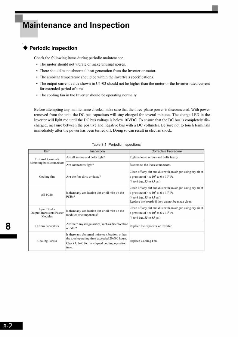
8-2
8
Maintenance and Inspection
Periodic Inspection
Check the following items during periodic maintenance.• The motor should not vibrate or make unusual noises.• There should be no abnormal heat generation from the Inverter or motor. • The ambient temperature should be within the Inverter’s specifications.• The output current value shown in U1-03 should not be higher than the motor or the Inverter rated current
for extended period of time. • The cooling fan in the Inverter should be operating normally.
Before attempting any maintenance checks, make sure that the three-phase power is disconnected. With powerremoved from the unit, the DC bus capacitors will stay charged for several minutes. The charge LED in theInverter will light red until the DC bus voltage is below 10VDC. To ensure that the DC bus is completely dis-charged, measure between the positive and negative bus with a DC voltmeter. Be sure not to touch terminalsimmediately after the power has been turned off. Doing so can result in electric shock.
Table 8.1 Periodic Inspections
Item Inspection Corrective Procedure
External terminals Mounting bolts connectors
Are all screws and bolts tight? Tighten loose screws and bolts firmly.
Are connectors tight? Reconnect the loose connectors.
Cooling fins Are the fins dirty or dusty?Clean off any dirt and dust with an air gun using dry air at a pressure of 4 x 10⁵ to 6 x 10⁵ Pa (4 to 6 bar, 55 to 85 psi).
All PCBs Is there any conductive dirt or oil mist on the PCBs?
Clean off any dirt and dust with an air gun using dry air at a pressure of 4 x 10⁵ to 6 x 10⁵ Pa (4 to 6 bar, 55 to 85 psi).Replace the boards if they cannot be made clean.
Input DiodesOutput Transistors Power
Modules
Is there any conductive dirt or oil mist on the modules or components?
Clean off any dirt and dust with an air gun using dry air at a pressure of 4 x 10⁵ to 6 x 10⁵ Pa (4 to 6 bar, 55 to 85 psi).
DC bus capacitors Are there any irregularities, such as discoloration or odor? Replace the capacitor or Inverter.
Cooling Fan(s)
Is there any abnormal noise or vibration, or has the total operating time exceeded 20,000 hours. Check U1-40 for the elapsed cooling operation time.
Replace Cooling Fan
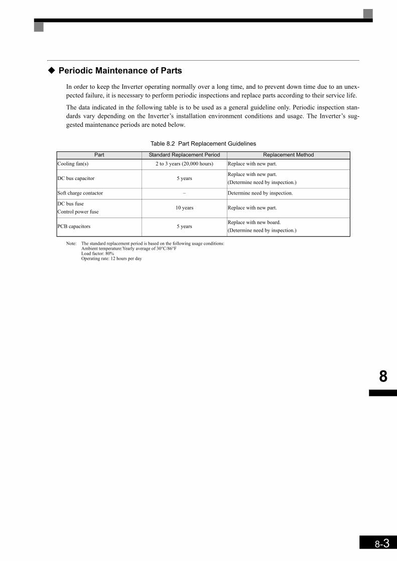
8-3
8
Periodic Maintenance of Parts
In order to keep the Inverter operating normally over a long time, and to prevent down time due to an unex-pected failure, it is necessary to perform periodic inspections and replace parts according to their service life.
The data indicated in the following table is to be used as a general guideline only. Periodic inspection stan-dards vary depending on the Inverter’s installation environment conditions and usage. The Inverter’s sug-gested maintenance periods are noted below.
Note: The standard replacement period is based on the following usage conditions:Ambient temperature:Yearly average of 30°C/86°FLoad factor: 80%Operating rate: 12 hours per day
Table 8.2 Part Replacement Guidelines
Part Standard Replacement Period Replacement MethodCooling fan(s) 2 to 3 years (20,000 hours) Replace with new part.
DC bus capacitor 5 yearsReplace with new part. (Determine need by inspection.)
Soft charge contactor – Determine need by inspection.
DC bus fuseControl power fuse
10 years Replace with new part.
PCB capacitors 5 yearsReplace with new board. (Determine need by inspection.)
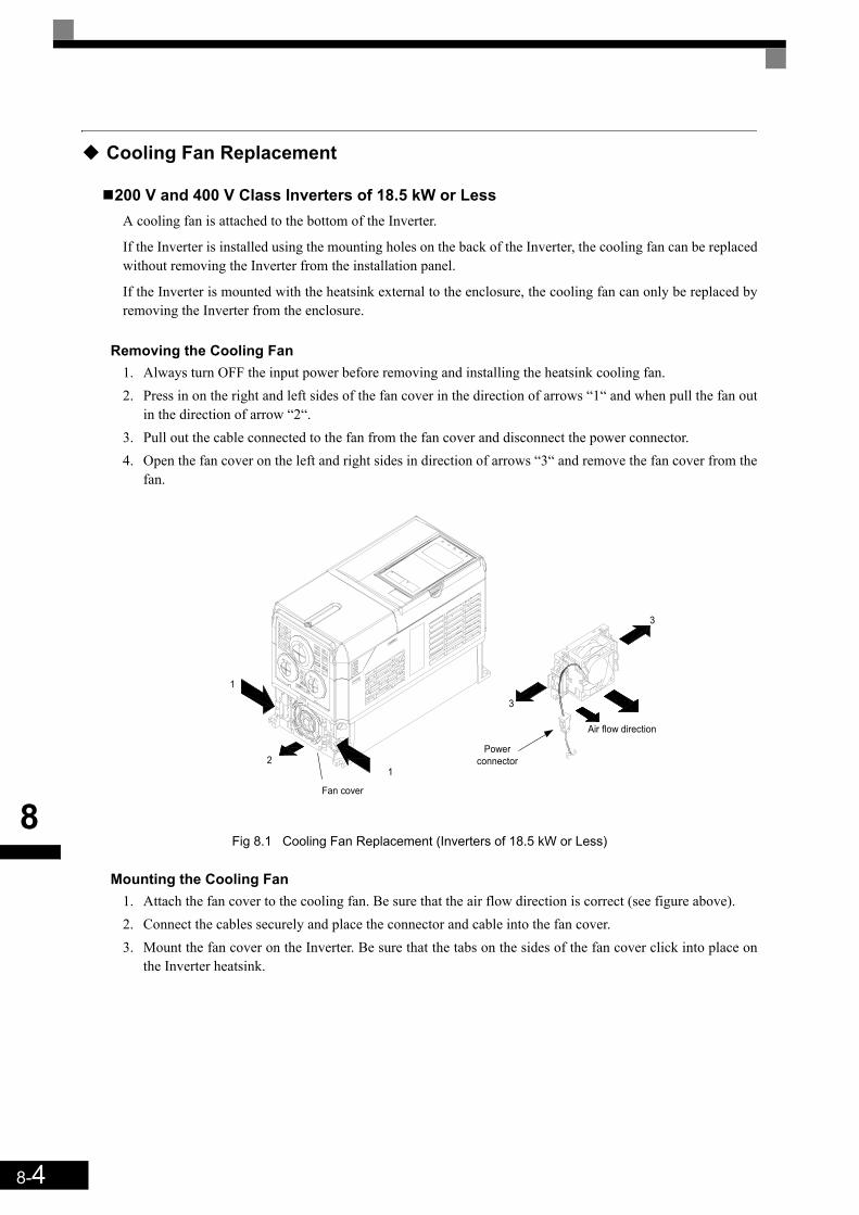
8-4
8
Cooling Fan Replacement
200 V and 400 V Class Inverters of 18.5 kW or LessA cooling fan is attached to the bottom of the Inverter.
If the Inverter is installed using the mounting holes on the back of the Inverter, the cooling fan can be replacedwithout removing the Inverter from the installation panel.
If the Inverter is mounted with the heatsink external to the enclosure, the cooling fan can only be replaced byremoving the Inverter from the enclosure.
Removing the Cooling Fan 1. Always turn OFF the input power before removing and installing the heatsink cooling fan.2. Press in on the right and left sides of the fan cover in the direction of arrows “1“ and when pull the fan out
in the direction of arrow “2“.3. Pull out the cable connected to the fan from the fan cover and disconnect the power connector.4. Open the fan cover on the left and right sides in direction of arrows “3“ and remove the fan cover from the
fan.
Fig 8.1 Cooling Fan Replacement (Inverters of 18.5 kW or Less)
Mounting the Cooling Fan1. Attach the fan cover to the cooling fan. Be sure that the air flow direction is correct (see figure above).2. Connect the cables securely and place the connector and cable into the fan cover.3. Mount the fan cover on the Inverter. Be sure that the tabs on the sides of the fan cover click into place on
the Inverter heatsink.
1
1
2
Fan cover
Powerconnector
3
Air flow direction
3
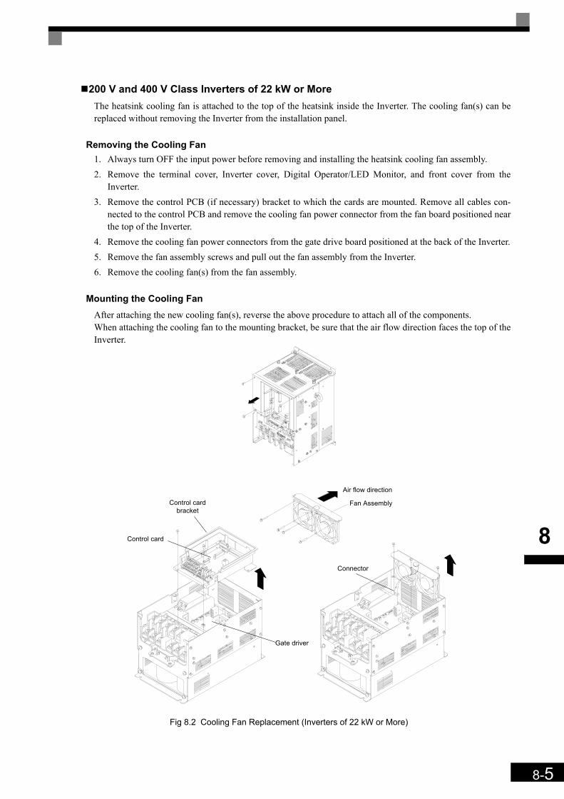
8-5
8
200 V and 400 V Class Inverters of 22 kW or MoreThe heatsink cooling fan is attached to the top of the heatsink inside the Inverter. The cooling fan(s) can bereplaced without removing the Inverter from the installation panel.
Removing the Cooling Fan1. Always turn OFF the input power before removing and installing the heatsink cooling fan assembly. 2. Remove the terminal cover, Inverter cover, Digital Operator/LED Monitor, and front cover from the
Inverter.3. Remove the control PCB (if necessary) bracket to which the cards are mounted. Remove all cables con-
nected to the control PCB and remove the cooling fan power connector from the fan board positioned nearthe top of the Inverter.
4. Remove the cooling fan power connectors from the gate drive board positioned at the back of the Inverter.5. Remove the fan assembly screws and pull out the fan assembly from the Inverter.6. Remove the cooling fan(s) from the fan assembly.
Mounting the Cooling FanAfter attaching the new cooling fan(s), reverse the above procedure to attach all of the components.When attaching the cooling fan to the mounting bracket, be sure that the air flow direction faces the top of theInverter.
Fig 8.2 Cooling Fan Replacement (Inverters of 22 kW or More)
Control card
Control cardbracket
Gate driver
Connector
Fan Assembly
Air flow direction
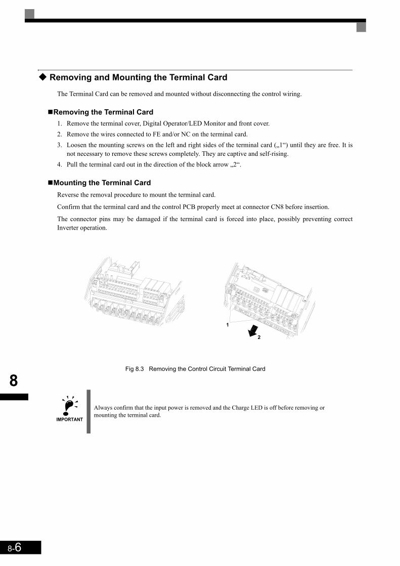
8-6
8
Removing and Mounting the Terminal Card
The Terminal Card can be removed and mounted without disconnecting the control wiring.
Removing the Terminal Card1. Remove the terminal cover, Digital Operator/LED Monitor and front cover.2. Remove the wires connected to FE and/or NC on the terminal card. 3. Loosen the mounting screws on the left and right sides of the terminal card („1“) until they are free. It is
not necessary to remove these screws completely. They are captive and self-rising.4. Pull the terminal card out in the direction of the block arrow „2“.
Mounting the Terminal CardReverse the removal procedure to mount the terminal card.
Confirm that the terminal card and the control PCB properly meet at connector CN8 before insertion.
The connector pins may be damaged if the terminal card is forced into place, possibly preventing correctInverter operation.
Fig 8.3 Removing the Control Circuit Terminal Card
IMPORTANT
Always confirm that the input power is removed and the Charge LED is off before removing or mounting the terminal card.
1
2

9Specifications
This chapter describes the basic specifications of the Inverter.
Specifications by Model ......................................................9-2Derating ..............................................................................9-6AC Reactors for EN 12015 Compatibility............................9-8EN 954-1 / EN81-1 Certificates...........................................9-9
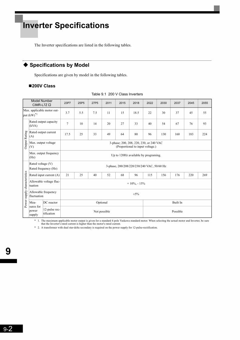
9-2
9
Inverter Specifications
The Inverter specifications are listed in the following tables.
Specifications by Model
Specifications are given by model in the following tables.
200V Class
* 1. The maximum applicable motor output is given for a standard 4-pole Yaskawa standard motor. When selecting the actual motor and Inverter, be sure that the Inverter's rated current is higher than the motor's rated current.
* 2. A transformer with dual star-delta secondary is required on the power supply for 12-pulse-rectification.
Table 9.1 200 V Class Inverters
Model Number CIMR-L7Z 23P7 25P5 27P5 2011 2015 2018 2022 2030 2037 2045 2055
Max. applicable motor out-put (kW)*1 3.7 5.5 7.5 11 15 18.5 22 30 37 45 55
Out
put R
atin
g
Rated output capacity (kVA) 7 10 14 20 27 33 40 54 67 76 93
Rated output current (A) 17.5 25 33 49 64 80 96 130 160 183 224
Max. output voltage (V)
3-phase; 200, 208, 220, 230, or 240 VAC (Proportional to input voltage.)
Max. output frequency (Hz) Up to 120Hz available by programing.
Pow
er su
pply
cha
ract
eris
tics
Rated voltage (V)Rated frequency (Hz)
3-phase, 200/208/220/230/240 VAC, 50/60 Hz
Rated input current (A) 21 25 40 52 68 96 115 156 176 220 269
Allowable voltage fluc-tuation + 10%, - 15%
Allowable frequency fluctuation ±5%
Mea-sures for power supply
DC reactor Optional Built In
12-pulse rec-tification Not possible Possible

9-3
9
400 V Class
* 1. The maximum applicable motor output is given for a standard 4-pole Yaskawa standard motor. When selecting the actual motor and Inverter, be sure that the Inverter's rated current is higher than the motor's rated current.
* 2. A transformer with dual star-delta secondary is required on the power supply for 12-pulse-rectification.
Table 9.2 400 V Class Inverters
Model Number CIMR-L7Z 43P7 44P0 45P5 47P5 4011 4015 4018 4022 4030 4037 4045 4055
Max. applicable motor out-put (kW) *1 3.7 4.0 5.5 7.5 11 15 18.5 22 30 37 45 55
Out
put R
atin
g
Rated output capacity (kVA) 7 9 12 15 22 28 34 40 54 67 80 106
Rated output current (A) 8.5 11 14 18 27 34 41 48 65 80 96 128
Max. output voltage (V) 3-phase; 380, 400, 415, 440, 460, or 480 VAC (Proportional to input voltage.)
Max. output frequency (Hz) 120 Hz max.
Pow
er su
pply
cha
ract
eris
tics
Rated voltage (V)Rated frequency (Hz)
3-phase, 380, 400, 415, 440, 460 or 480 VAC, 50/60 Hz
Rated input current (A) 10.2 13.2 17 22 32 41 49 58 78 96 115 154
Allowable voltage fluctuation + 10%, - 15%
Allowable frequency fluctuation ±5%
Mea-sures for power supply
DC reactor Optional Built In
12-phase rectification Not possible Possible

9-4
9
Common Specifications
The following specifications apply to both 200 V and 400 V class Inverters.Table 9.3 Common Specifications
Model NumberCIMR-L7Z Specification
Con
trol C
hara
cter
istic
s
Control method Sine wave PWMClosed Loop Vector control for IM and PM motors, Open Loop Vector control, V/f control
Carrier Frequency 8 kHzhigher carrier frequency possible with current derating (refer to page 9-6, Carrier Frequency Derating)
Speed control range1:40 (V/f control)
1:100 (Open Loop Vector control)1:1000 (Closed Loop Vector control)
Speed control accuracy
± 3% (V/f control)± 0.2% (Open Loop Vector control)
± 0.02% (Closed Loop Vector control) (25°C ± 10°C)
Speed control response 5 Hz (control without PG)30 Hz (control with PG)
Torque limits Provided (4 quadrant steps can be changed by constant settings.) (Vector control)
Torque accuracy ± 5%
Frequency range 0.01 to 120 Hz
Frequency accuracy (temperature character-istics)
Digital references: ± 0.01% (-10°C to +40°C)
Analog references: ± 0.1% (25°C ±10°C)
Frequency setting resolution
Digital references: 0.01 Hz
Analog references: 0.025/50 Hz (11 bits plus sign)
Output frequency reso-lution 0.01 Hz
Overload capacity and maximum current 150% of rated output current for 30 sec.
Frequency setting signal 0 to +10V
Acceleration/Decelera-tion time 0.01 to 600.00 s (4 selectable combinations of independent acceleration and deceleration time settings)
Main control functions
Over torque/under torque detection, torque limits, 8-speed control (maximum), 4 acceleration and deceleration times, S-curve acceleration/deceleration, auto-tuning (rotational or stationary), dwell function, cooling fan ON/OFF control, slip compensation, torque compensation, auto-restart after fault, DC braking for starting and stop-ping, automatic fault reset and parameter copy function, special Lift functions and sequences, short floor operation, rescue operation with light load direction search, machine data copy function (save in encoder memory)
Prot
ectiv
e Fu
nctio
ns
Motor protection Protection by electronic thermal overload relay.
Instantaneous overcur-rent protection Stops at approximately 200% of rated output current.
Fuse blown protection Stops for fuse blown.
Overload protection OL2 fault at 150% of rated output current for 30 sec
Overvoltage protection 200 Class Inverter: Stops when main-circuit DC voltage is above 410 V.400 Class Inverter: Stops when main-circuit DC voltage is above 820 V.
Undervoltage protection 200 Class Inverter: Stops when main-circuit DC voltage is below 190 V.400 Class Inverter: Stops when main-circuit DC voltage is below 380 V.
Cooling fin overheating Protection by thermistor.
Stall prevention Stall prevention during acceleration, deceleration and running independently.
Grounding protection Protection by electronic circuits.
Charge indicator Glows when the main circuit DC voltage is approximately 10 VDC or more.
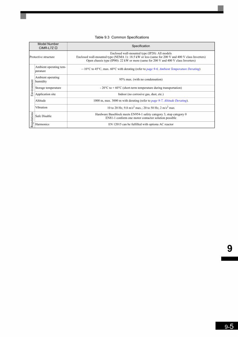
9-5
9
Protective structureEnclosed wall-mounted type (IP20): All models
Enclosed wall-mounted type (NEMA 1): 18.5 kW or less (same for 200 V and 400 V class Inverters)Open chassis type (IP00): 22 kW or more (same for 200 V and 400 V class Inverters)
Envi
ronm
ent
Ambient operating tem-perature -–10°C to 45°C, max. 60°C with derating (refer to page 9-6, Ambient Temperature Derating)
Ambient operating humidity 95% max. (with no condensation)
Storage temperature - 20°C to + 60°C (short-term temperature during transportation)
Application site Indoor (no corrosive gas, dust, etc.)
Altitude 1000 m, max. 3000 m with derating (refer to page 9-7, Altitude Derating).
Vibration 10 to 20 Hz, 9.8 m/s2 max.; 20 to 50 Hz, 2 m/s2 max
Reg
ulat
ions
Safe Disable Hardware Baseblock meets EN954-1 safety category 3, stop category 0EN81-1 conform one motor contactor solution possible
Harmonics EN 12015 can be fulfilled with optiona AC reactor
Table 9.3 Common Specifications
Model NumberCIMR-L7Z Specification
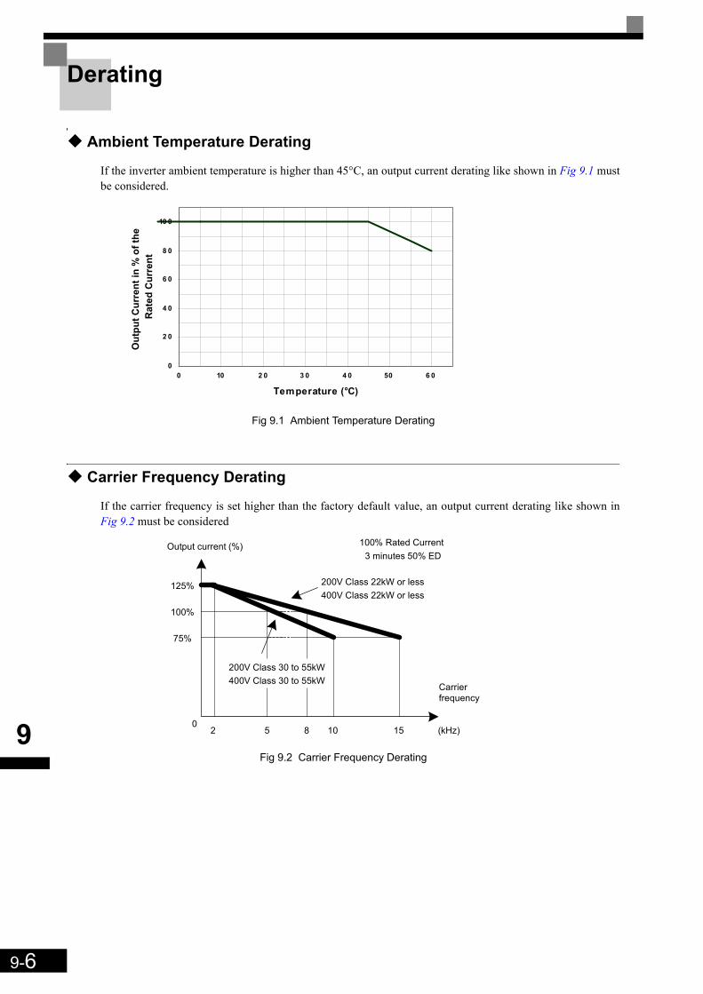
9-6
9
Derating
Ambient Temperature Derating
If the inverter ambient temperature is higher than 45°C, an output current derating like shown in Fig 9.1 mustbe considered.
Fig 9.1 Ambient Temperature Derating
Carrier Frequency Derating
If the carrier frequency is set higher than the factory default value, an output current derating like shown inFig 9.2 must be considered
Fig 9.2 Carrier Frequency Derating
0
2 0
4 0
6 0
8 0
10 0
0 10 2 0 3 0 4 0 50 6 0
Temperature (°C)
Out
put C
urre
nt in
% o
f the
Rat
ed C
urre
nt
125%
100%
75%
05 8 15 (kHz)
Carrierfrequency
200V Class 22kW or less400V Class 22kW or less
200V Class 30 to 55kW400V Class 30 to 55kW
2 10
100% Rated Current3 minutes 50% ED
Output current (%)
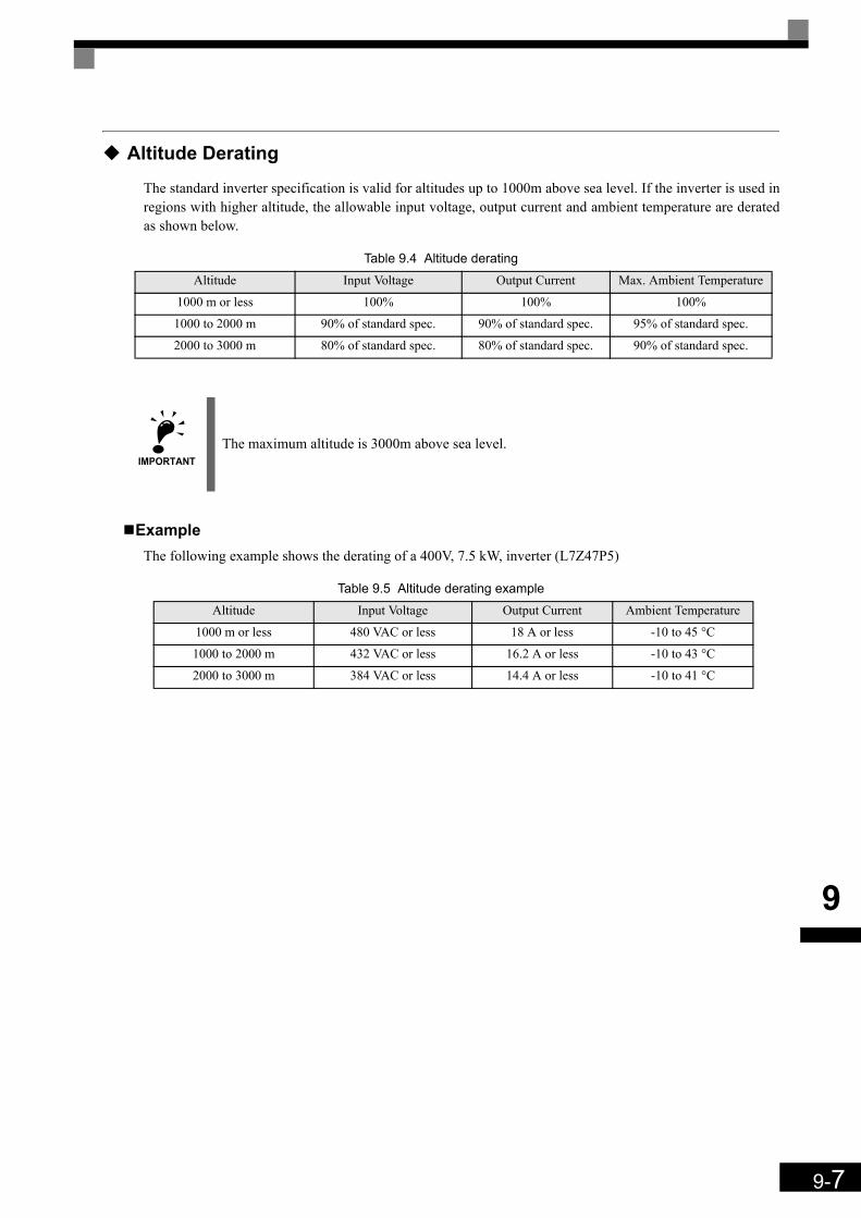
9-7
9
Altitude Derating
The standard inverter specification is valid for altitudes up to 1000m above sea level. If the inverter is used inregions with higher altitude, the allowable input voltage, output current and ambient temperature are deratedas shown below.
Table 9.4 Altitude derating
ExampleThe following example shows the derating of a 400V, 7.5 kW, inverter (L7Z47P5)
Table 9.5 Altitude derating example
Altitude Input Voltage Output Current Max. Ambient Temperature
1000 m or less 100% 100% 100%
1000 to 2000 m 90% of standard spec. 90% of standard spec. 95% of standard spec.
2000 to 3000 m 80% of standard spec. 80% of standard spec. 90% of standard spec.
IMPORTANTThe maximum altitude is 3000m above sea level.
Altitude Input Voltage Output Current Ambient Temperature
1000 m or less 480 VAC or less 18 A or less -10 to 45 °C
1000 to 2000 m 432 VAC or less 16.2 A or less -10 to 43 °C
2000 to 3000 m 384 VAC or less 14.4 A or less -10 to 41 °C
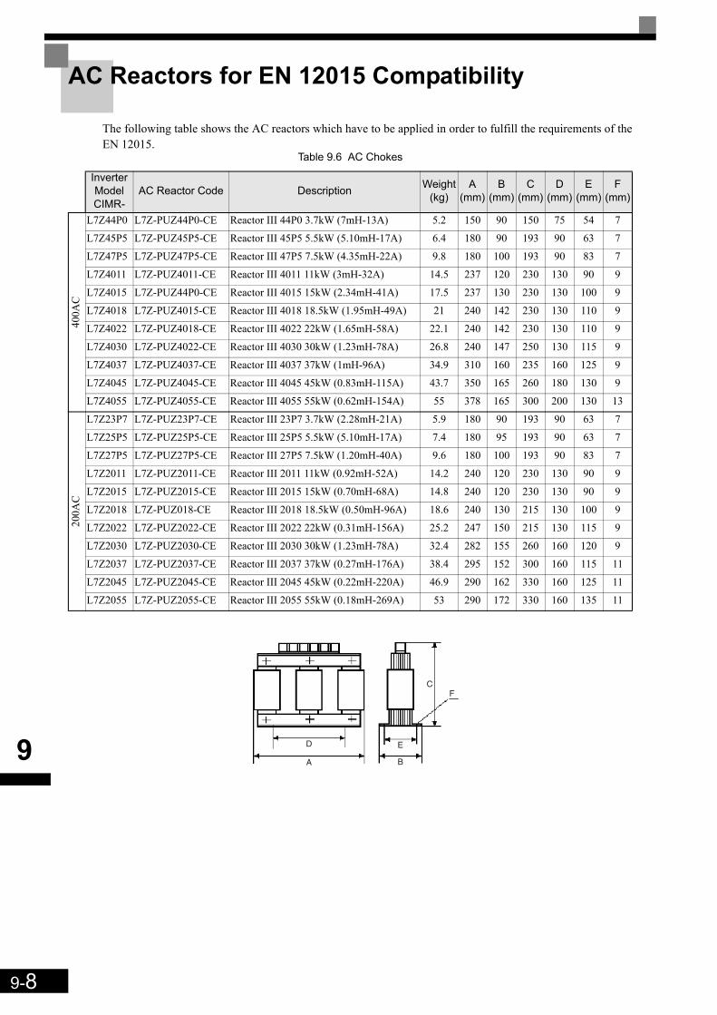
9-8
9
AC Reactors for EN 12015 Compatibility
The following table shows the AC reactors which have to be applied in order to fulfill the requirements of theEN 12015.
Table 9.6 AC Chokes
Inverter ModelCIMR-
AC Reactor Code Description Weight(kg)
A(mm)
B(mm)
C(mm)
D(mm)
E(mm)
F(mm)
400A
C
L7Z44P0 L7Z-PUZ44P0-CE Reactor III 44P0 3.7kW (7mH-13A) 5.2 150 90 150 75 54 7
L7Z45P5 L7Z-PUZ45P5-CE Reactor III 45P5 5.5kW (5.10mH-17A) 6.4 180 90 193 90 63 7
L7Z47P5 L7Z-PUZ47P5-CE Reactor III 47P5 7.5kW (4.35mH-22A) 9.8 180 100 193 90 83 7
L7Z4011 L7Z-PUZ4011-CE Reactor III 4011 11kW (3mH-32A) 14.5 237 120 230 130 90 9
L7Z4015 L7Z-PUZ44P0-CE Reactor III 4015 15kW (2.34mH-41A) 17.5 237 130 230 130 100 9
L7Z4018 L7Z-PUZ4015-CE Reactor III 4018 18.5kW (1.95mH-49A) 21 240 142 230 130 110 9
L7Z4022 L7Z-PUZ4018-CE Reactor III 4022 22kW (1.65mH-58A) 22.1 240 142 230 130 110 9
L7Z4030 L7Z-PUZ4022-CE Reactor III 4030 30kW (1.23mH-78A) 26.8 240 147 250 130 115 9
L7Z4037 L7Z-PUZ4037-CE Reactor III 4037 37kW (1mH-96A) 34.9 310 160 235 160 125 9
L7Z4045 L7Z-PUZ4045-CE Reactor III 4045 45kW (0.83mH-115A) 43.7 350 165 260 180 130 9
L7Z4055 L7Z-PUZ4055-CE Reactor III 4055 55kW (0.62mH-154A) 55 378 165 300 200 130 13
200A
C
L7Z23P7 L7Z-PUZ23P7-CE Reactor III 23P7 3.7kW (2.28mH-21A) 5.9 180 90 193 90 63 7
L7Z25P5 L7Z-PUZ25P5-CE Reactor III 25P5 5.5kW (5.10mH-17A) 7.4 180 95 193 90 63 7
L7Z27P5 L7Z-PUZ27P5-CE Reactor III 27P5 7.5kW (1.20mH-40A) 9.6 180 100 193 90 83 7
L7Z2011 L7Z-PUZ2011-CE Reactor III 2011 11kW (0.92mH-52A) 14.2 240 120 230 130 90 9
L7Z2015 L7Z-PUZ2015-CE Reactor III 2015 15kW (0.70mH-68A) 14.8 240 120 230 130 90 9
L7Z2018 L7Z-PUZ018-CE Reactor III 2018 18.5kW (0.50mH-96A) 18.6 240 130 215 130 100 9
L7Z2022 L7Z-PUZ2022-CE Reactor III 2022 22kW (0.31mH-156A) 25.2 247 150 215 130 115 9
L7Z2030 L7Z-PUZ2030-CE Reactor III 2030 30kW (1.23mH-78A) 32.4 282 155 260 160 120 9
L7Z2037 L7Z-PUZ2037-CE Reactor III 2037 37kW (0.27mH-176A) 38.4 295 152 300 160 115 11
L7Z2045 L7Z-PUZ2045-CE Reactor III 2045 45kW (0.22mH-220A) 46.9 290 162 330 160 125 11
L7Z2055 L7Z-PUZ2055-CE Reactor III 2055 55kW (0.18mH-269A) 53 290 172 330 160 135 11
A
D
B
E
FC

9-9
9
EN 954-1 / EN81-1 Certificates

9-10
9
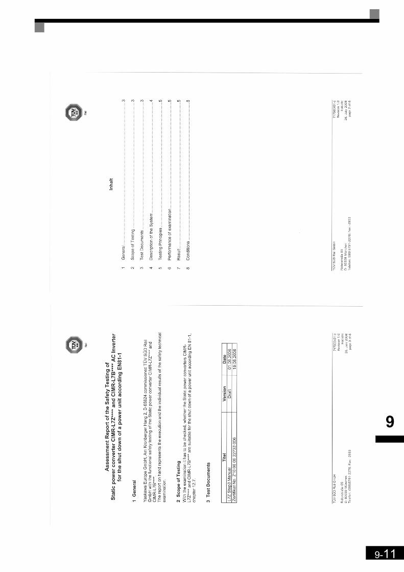
9-11
9
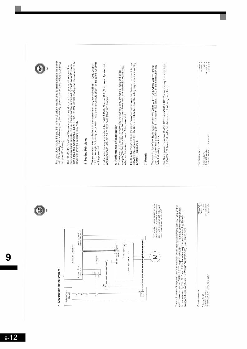
9-12
9
9-13
9

9-14
9

10Appendix
This chapter provides precautions for the Inverter, motor, and peripheral devices and also provides lists of con-stants.
Inverter Application Precautions .......................................10-2Motor Application Precautions ..........................................10-4User Constants .................................................................10-5

10-2
10
Inverter Application Precautions
Selection
Observe the following precautions when selecting an Inverter.
Installing ReactorsA large peak current can flow in the power input circuit when the Inverter is connected to a large-capacitypower transformer (600 kVA or higher) or when switching a phase shifting capacitor. Excessive peak currentcan destroy the converter section. To prevent this, install a DC or AC reactor to improve the power supplypower factor.
If a thyristor converter, such as a DC drive, is connected in the same power supply system, connect a DC orAC reactor regardless of the power supply conditions shown in the following diagram.
Installation
Observe the following precautions when installing an Inverter.
Installation in EnclosuresInstall the Inverter in a clean location where it is not subjected to oil mist, dust, and other contaminants, orinstall the Inverter in a completely enclosed panel. Provide cooling measures and sufficient panel space so thatthe temperature surrounding the Inverter does not exceed the allowable temperature. Do not install the Inverteron wood or other combustible materials.
Installation DirectionMount the Inverter vertically to a wall or other vertical surface.
Settings
Observe the following precautions when making settings for an Inverter.
Upper LimitsThe maximum output frequency can be set up to 120Hz. Setting the output frequency too high can damage themachine. So pay attention to the mechanical system and observe required limits for the output frequency.
DC Injection BrakingIf the DC Injection Braking Current or the Braking Time are set too high the motor can overheat what candamage the motor
Power supply (kVA)
DC or AC reactor required
DC or AC reactor not required
Inverter capacity (kVA)
10-3
10
Acceleration/Deceleration TimesThe motor's acceleration and deceleration times are determined by the torque generated by the motor, the loadtorque, and the load's inertial moment (GD2/4). If the stall prevention functions are activated during accelera-tion or deceleration, it might be necessary to increase the acceleration or deceleration time.
To reduce the acceleration or deceleration times, increase the capacity of the motor and Inverter.
Handling
Observe the following precautions during wiring or maintenance of an Inverter.
Wiring CheckThe Inverter will be internally damaged if the power supply voltage is applied to output terminal U, V, or W.Check wiring for any mistakes before supplying power. Check all wiring and control sequences carefully.
Magnetic Contactor InstallationIf a magnetic contactor is installed in the power supply line, do not exceed one start per hour. Switching moreoften can damage the inrush current prevention circuit.
Maintenance and InspectionsAfter turning OFF the main circuit power supply it can take several minutes before the DC bus is dischargedcompletely. The CHARGE LED, indicating if the DC bus is charged, glows above a voltage of 10VDC.

10-4
10
Motor Application Precautions
Using the Inverter for an Existing Standard Motor
Observe the following precautions when using an Inverter for an existing standard motor.
Low Speed RangesIf a standard cooled motor is used at low speed the cooling effects are diminished. If the motor is used in con-stant torque applications in low speed area the motor may overheat. If full torque is required at low speed con-tinuously an externally cooled motor must be used.
Installation Withstand VoltageIf the inverter is used with an input voltage of 440 V or higher and long motor cables, voltage spikes at themotor terminals may occur which can damage the motor windings. Please ensure that the motor insulationclass is sufficient.
NoiseThe noise generated in the motor depends on the carrier frequency. The higher the setting, the less is the gen-erated noise.
Using the Inverter for Special Motors
Observe the following precautions when using a special motor.
Pole-changing MotorThe rated input current of pole-changing motors differs from that of standard motors. Select an appropriateInverter according to the maximum current of the motor.
Single-phase MotorDo not use an Inverter for a single-phase motor. These motors are often equipped with capacitors Any capaci-tor directly connected to the inverter output may damage the Inverter.

10-5
10
User Constants
The factory settings of each parameter are given in the following table. They are for a 200 V Class Inverterwith 3.7 kW.No. Name Factory
Setting Setting
A1-00 Language selection for Digital Operator display 0
A1-01 Parameter access level 2
A1-02 Control method selection 0
A1-03 Initialize 0
A1-04 Password 0
A1-05 Password setting 0
A2-01 to A2-32 User specified parameters –
b1-01 Reference source selection 0
b1-02 RUN command source selection 1
b1-06 Control input scan 1
b1-08 Run command selection in programming modes 1
b2-08 Magnetic flux compensation volume 0%
b4-01 Timer function ON-delay time 0.0 sec.
b4-02 Timer function OFF-delay time 0.0 sec.
b6-01 Dwell frequency at start 0.0 Hz
b6-02 Dwell time at start 0.0 sec.
b6-03 Dwell frequency at stop 0.0 Hz
b6-04 Dwell time at stop 0.0 sec.
C1-01 Acceleration time 1 10.0 sec.
C1-02 Deceleration time 1
1.5 s
C1-03 Acceleration time 2
C1-04 Deceleration time 2
C1-05 Acceleration time 3
C1-06 Deceleration time 3
C1-07 Acceleration time 4
C1-08 Deceleration time 4
C1-09 Emergency stop time
C1-10 Accel/decel time setting unit 1
C1-11 Accel/decel time switching frequency 0.0 Hz
C2-01 S-curve characteristic time at acceleration start 0.5 sec.
C2-02 S-curve characteristic time at acceleration end 0.5 sec.
C2-03 S-curve characteristic time at deceleration start 0.5 sec.
C2-04 S-curve characteristic time at deceleration end 0.5 sec.
C2-05 S-curve Characteristic time below leveling speed 0.50 sec.
C3-01 Slip compensation gain 1.0
C3-02 Slip compensation delay time 2000 msec
C3-03 Slip compensation limit 200%
C3-04 Slip compensation selection during regeneration 1
C3-05 Output voltage limit operation selection 1
C4-01 Torque compensation gain 1.00
C4-02 Torque compensation delay time constant 200 msec *1
C4-03 Starting torque compensation (FWD) 0.0%
C4-04 Starting torque compensation (REV) 0.0%
C4-05 Starting torque compensation time constant 10 msec

10-6
10
C5-01 ASR proportional (P) gain 1 40 *1
C5-02 ASR integral (I) time 1 0.5 *1
C5-03 ASR proportional (P) gain 2 20 *1
C5-04 ASR integral (I) time 2 0.5 *1
C5-06 ASR delay time 0.004 msec
C5-07 ASR switching frequency 0.0 Hz
C5-08 ASR integral (I) limit 400%
C5-09 ASR proportional (P) gain 3 40.00
C5-10 ASR integral (I) time 3 0.500 sec.
C5-15 ASR gain (P) during encoder offset tuning 5.00
C6-02 Carrier frequency selection 1
C6-06 PWM method selection 0
C6-11 Carrier frequency for PM motor control 4
d1-01 Frequency reference 1 0.00 Hz
d1-02 Frequency reference 2 0.00 Hz
d1-03 Frequency reference 3 0.00 Hz
d1-04 Frequency reference 4 0.00 Hz
d1-05 Frequency reference 5 0.00 Hz
d1-06 Frequency reference 6 0.00 Hz
d1-07 Frequency reference 7 0.00 Hz
d1-08 Frequency reference 8 0.00 Hz
d1-09 Frequency reference 9 Vn 50.00 Hz
d1-10 Frequency reference 10 V1 0.00 Hz
d1-11 Frequency reference 11 V2 0.00 Hz
d1-12 Frequency reference 12 V3 0.00 Hz
d1-13 Frequency reference 13 Vr 0.00 Hz
d1-14 Frequency reference 14 Inspection 25 Hz
d1-17 Jog frequency reference / Leveling speed 4.00 Hz
d1-18 Speed priority selection 1
d1-19 Second motor speed 0.00 Hz
d6-03 Field forcing function selection 0
d6-06 Field forcing function Limit 400%
E1-01 Input voltage setting *1
E1-04 Max. output frequency (FMAX) 50.0 Hz
E1-05 Max. output voltage (VMAX) *1
E1-06 Base frequency (FA) 50.0 Hz
E1-07 Mid. output frequency (FB) *1
E1-08 Mid. output frequency voltage (VB) *1
E1-09 Min. output frequency (FMIN) *1
E1-10 Min. output frequency voltage (VMIN) *1
E1-13 Base voltage (VBASE) 0.0 V
E2-01 Motor rated current *1
E2-02 Motor rated slip *1
E2-03 Motor no-load current *1
E2-04 Number of motor poles 4 poles
E2-05 Motor line-to-line resistance *1
E2-06 Motor leak inductance *1
No. Name FactorySetting Setting

10-7
10
E2-07 Motor iron saturation coefficient 1 0.50
E2-08 Motor iron saturation coefficient 2 0.75
E2-09 Monitor mechanical losses 0.0%
E2-10 Motor iron loss for torque compensation *1
E2-11 Motor rated output power *1
E2-12 Motor iron saturation coefficient 3 1.30
E3-01 Motor 2 control mode selection 0
E3-02 Motor 2 Max. output frequency (FMAX) 50.00 Hz
E3-03 Motor 2 Max. output voltage (VMAX) 400.0 V
E3-04 Motor 2 Base frequency (FA) 50.00 Hz
E3-05 Motor 2 Mid. output frequency (FB) *1
E3-06 Motor 2 Mid. output frequency voltage (VB) *1
E3-07 Motor 2 Min. output frequency (FMIN) *1
E3-08 Min. output frequency voltage (VMIN) *1
E4-01 Motor 2 rated current *1
E4-02 Motor 2 rated slip *1
E4-03 Motor 2 no-load current *1
E2-04 Motor 2 number of motor poles 4
E4-05 Motor 2 line-to-line resistance *1
E4-06 Motor 2 leak inductance *1
E4-07 Motor 2 iron saturation coefficient 1 *1
E5-02 PM motor rated power *1
E5-03 PM motor rated current *1
E5-04 PM motor number of poles 4 poles
E5-06 PM motor d-axis inductance *1
E5-07 PM motor q-axis inductance *1
E5-09 PM Motor voltage constant *1
F1-01 PG constant 1024
F1-02 Operation selection at PG open circuit (PGO) 1
F1-03 Operation selection at overspeed (OS) 1
F1-04 Operation selection at deviation 3
F1-05 PG rotation 0
F1-06 PG division rate (PG pulse monitor) 1
F1-08 Overspeed detection level 115%
F1-09 Overspeed detection delay time 0.0 sec.
F1-10 Excessive speed deviation detection level 10%
F1-11 Excessive speed deviation detection delay time 0.5 sec.
F1-12 Number of PG teeth 1 0
F1-13 Number of PG teeth 2 0
F1-14 PG open-circuit detection delay time 1.0 sec.
F1-18 DV3 fault detection selection 1
F1-19 DV4 fault detection selection 1024
F1-21 Absolute encoder resolution 2
F1-22 Magnet position offset 60 deg
F1-24 PGO Detection level at stop 20%
F1-25 Encoder copy function selection 0
No. Name FactorySetting Setting
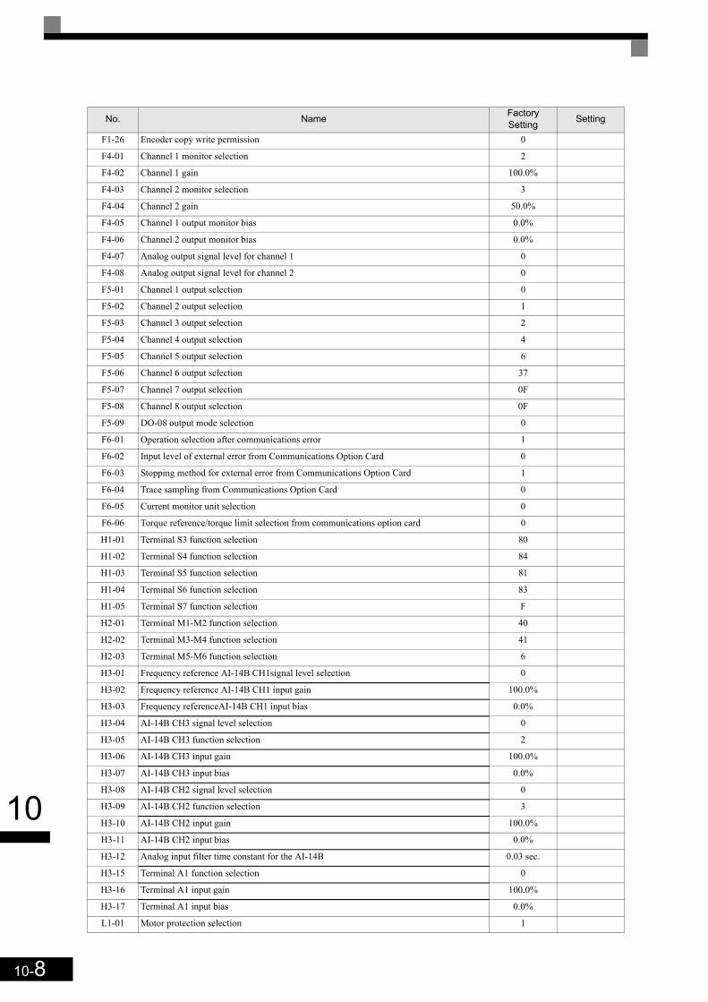
10-8
10
F1-26 Encoder copy write permission 0
F4-01 Channel 1 monitor selection 2
F4-02 Channel 1 gain 100.0%
F4-03 Channel 2 monitor selection 3
F4-04 Channel 2 gain 50.0%
F4-05 Channel 1 output monitor bias 0.0%
F4-06 Channel 2 output monitor bias 0.0%
F4-07 Analog output signal level for channel 1 0
F4-08 Analog output signal level for channel 2 0
F5-01 Channel 1 output selection 0
F5-02 Channel 2 output selection 1
F5-03 Channel 3 output selection 2
F5-04 Channel 4 output selection 4
F5-05 Channel 5 output selection 6
F5-06 Channel 6 output selection 37
F5-07 Channel 7 output selection 0F
F5-08 Channel 8 output selection 0F
F5-09 DO-08 output mode selection 0
F6-01 Operation selection after communications error 1
F6-02 Input level of external error from Communications Option Card 0
F6-03 Stopping method for external error from Communications Option Card 1
F6-04 Trace sampling from Communications Option Card 0
F6-05 Current monitor unit selection 0
F6-06 Torque reference/torque limit selection from communications option card 0
H1-01 Terminal S3 function selection 80
H1-02 Terminal S4 function selection 84
H1-03 Terminal S5 function selection 81
H1-04 Terminal S6 function selection 83
H1-05 Terminal S7 function selection F
H2-01 Terminal M1-M2 function selection 40
H2-02 Terminal M3-M4 function selection 41
H2-03 Terminal M5-M6 function selection 6
H3-01 Frequency reference AI-14B CH1signal level selection 0
H3-02 Frequency reference AI-14B CH1 input gain 100.0%
H3-03 Frequency referenceAI-14B CH1 input bias 0.0%
H3-04 AI-14B CH3 signal level selection 0
H3-05 AI-14B CH3 function selection 2
H3-06 AI-14B CH3 input gain 100.0%
H3-07 AI-14B CH3 input bias 0.0%
H3-08 AI-14B CH2 signal level selection 0
H3-09 AI-14B CH2 function selection 3
H3-10 AI-14B CH2 input gain 100.0%
H3-11 AI-14B CH2 input bias 0.0%
H3-12 Analog input filter time constant for the AI-14B 0.03 sec.
H3-15 Terminal A1 function selection 0
H3-16 Terminal A1 input gain 100.0%
H3-17 Terminal A1 input bias 0.0%
L1-01 Motor protection selection 1
No. Name FactorySetting Setting

10-9
10
L1-02 Motor protection time constant 1.0 min
L2-05 Undervoltage detection level 190 V
L2-11 Battery Voltage 0V
L3-01 Stall prevention selection during accel 1
L3-02 Stall prevention level during accel 150%
L3-05 Stall prevention selection during running 1
L3-06 Stall prevention level during running 150%
L4-01 Speed agreement detection level 0.0 Hz
L4-02 Speed agreement detection width 2.0 Hz
L4-03 Speed agreement detection level (+/-) 0.0 Hz
L4-04 Speed agreement detection width (+/-) 2.0 Hz
L5-01 Number of auto restart attempts 2
L5-02 Auto restart operation selection 0
L5-05 Under voltage fault (UV1) restart selection 1
L6-01 Torque detection selection 1 0
L6-02 Torque detection level 1 150%
L6-03 Torque detection time 1 0.1 sec.
L6-04 Torque detection selection 2 0
L6-05 Torque detection level 2 150%
L6-06 Torque detection time 2 0.1 sec.
L7-01 Forward drive torque limit 300%
L7-02 Reverse drive torque limit 300%
L7-03 Forward regenerative torque limit 300%
L7-04 Reverse regenerative torque limit 300%
L7-06 Torque limit time constant 200 ms
L7-07 Torque Limit Operation during accel/decel 0
L8-02 Overheat pre-alarm level 75 °C*1
L8-03 Operation selection after overheat pre-alarm 3
L8-07 Output open-phase protection selection 2
L8-09 Ground protection selection 1
L8-10 Cooling fan control selection 0
L8-11 Cooling fan control delay time 60 sec.
L8-12 Ambient temperature 45 °C
L8-18 Soft CLA selection 1
L8-20 LF detection time 0.2 sec.
n2-01 Speed feedback detection control (AFR) gain 1.00
n2-02 Speed feedback detection control (AFR) time constant 50 msec
n5-01 Feed forward control selection 1
n5-02 Motor Accel Time 0.178 sec.
n5-03 Feed forward proportional gain 1.00
n5-05 Motor acceleration time tuning 0
n8-29 Current regulator q-axis P gain 1000 rad/sec.
n8-30 Current regulator q-axis I time 10.0 ms
n8-32 Current regulator d-axis P gain 1000 rad/sec.
n8-33 Current regulator d-axis I gain 10.0 ms
n8-35 Magnet position detection method 5
n8-46 Inductance measurement current level 10.0%
n9-60 A/D converter start delay time 0.0 µsec.
No. Name FactorySetting Setting
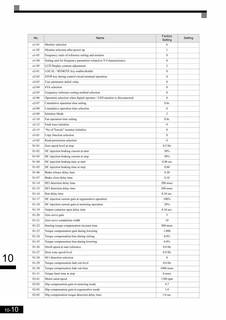
10-10
10
o1-01 Monitor selection 6
o1-02 Monitor selection after power up 1
o1-03 Frequency units of reference setting and monitor 0
o1-04 Setting unit for frequency parameters related to V/f characteristics 0
o1-05 LCD Display contrast adjustment 3
o2-01 LOCAL / REMOTE key enable/disable 0
o2-02 STOP key during control circuit terminal operation 0
o2-03 User parameter initial value 0
o2-04 kVA selection 0
o2-05 Frequency reference setting method selection 0
o2-06 Operation selection when digital operator / LED monitor is disconnected 0
o2-07 Cumulative operation time setting 0 hr.
o2-08 Cumulative operation time selection 0
o2-09 Initialize Mode 2
o2-10 Fan operation time setting 0 hr.
o2-12 Fault trace initialize 0
o2-15 “No of Travels” monitor initialize 0
o3-01 Copy function selection 0
o3-02 Read permission selection 0
S1-01 Zero speed level at stop 0.5 Hz
S1-02 DC injection braking current at start 50%
S1-03 DC injection braking current at stop 50%
S1-04 DC injection braking time at start 0.40 sec
S1-05 DC injection braking time at stop 0.60
S1-06 Brake release delay time 0.20
S1-07 Brake close delay time 0.10
S1-14 SE2 detection delay time 200 msec
S1-15 SE3 detection delay time 200 msec
S1-16 Run delay time 0.10 sec.
S1-17 DC injection current gain at regenerative operation 100%
S1-18 DC injection current gain at motoring operation 20%
S1-19 Output contactor open delay time 0.10 sec.
S1-20 Zero servo gain 5
S1-21 Zero servo completion width 10
S1-22 Starting torque compensation increase time 500 msec
S1-23 Torque compensation gain during lowering 1.000
S1-24 Torque compensation bias during raising 0.0%
S1-25 Torque compensation bias during lowering 0.0%
S1-26 Dwell speed at start reference 0.0 Hz
S1-27 Door zone speed level 0.0 Hz
S1-28 SE1 detection selection 0
S1-29 Torque compensation fade out level 0.0 Hz
S1-30 Torque compensation fade out time 1000 msec
S1-31 Torque limit time at stop 0 msec
S2-01 Motor rated speed 1380 rpm
S2-02 Slip compensation gain in motoring mode 0.7
S2-03 Slip compensation gain in regenerative mode 1.0
S2-05 Slip compensation torque detection delay time 1.0 sec.
No. Name FactorySetting Setting
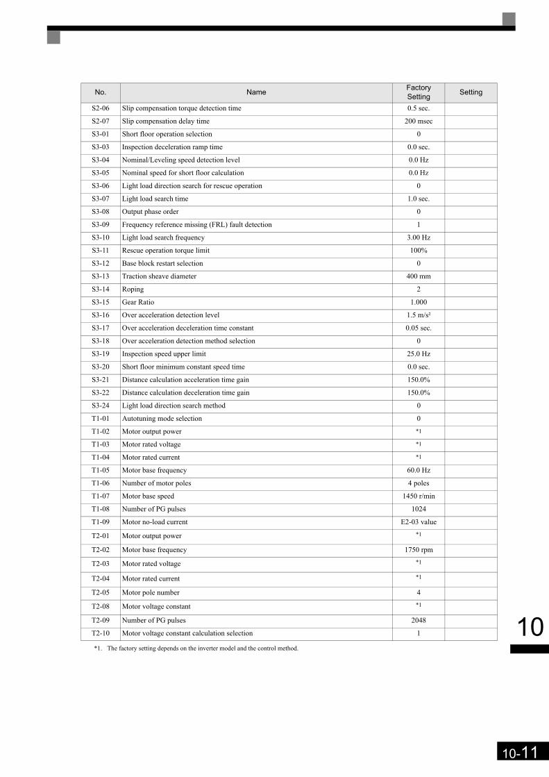
10-11
10
S2-06 Slip compensation torque detection time 0.5 sec.
S2-07 Slip compensation delay time 200 msec
S3-01 Short floor operation selection 0
S3-03 Inspection deceleration ramp time 0.0 sec.
S3-04 Nominal/Leveling speed detection level 0.0 Hz
S3-05 Nominal speed for short floor calculation 0.0 Hz
S3-06 Light load direction search for rescue operation 0
S3-07 Light load search time 1.0 sec.
S3-08 Output phase order 0
S3-09 Frequency reference missing (FRL) fault detection 1
S3-10 Light load search frequency 3.00 Hz
S3-11 Rescue operation torque limit 100%
S3-12 Base block restart selection 0
S3-13 Traction sheave diameter 400 mm
S3-14 Roping 2
S3-15 Gear Ratio 1.000
S3-16 Over acceleration detection level 1.5 m/s²
S3-17 Over acceleration deceleration time constant 0.05 sec.
S3-18 Over acceleration detection method selection 0
S3-19 Inspection speed upper limit 25.0 Hz
S3-20 Short floor minimum constant speed time 0.0 sec.
S3-21 Distance calculation acceleration time gain 150.0%
S3-22 Distance calculation deceleration time gain 150.0%
S3-24 Light load direction search method 0
T1-01 Autotuning mode selection 0
T1-02 Motor output power *1
T1-03 Motor rated voltage *1
T1-04 Motor rated current *1
T1-05 Motor base frequency 60.0 Hz
T1-06 Number of motor poles 4 poles
T1-07 Motor base speed 1450 r/min
T1-08 Number of PG pulses 1024
T1-09 Motor no-load current E2-03 value
T2-01 Motor output power *1
T2-02 Motor base frequency 1750 rpm
T2-03 Motor rated voltage *1
T2-04 Motor rated current *1
T2-05 Motor pole number 4
T2-08 Motor voltage constant *1
T2-09 Number of PG pulses 2048
T2-10 Motor voltage constant calculation selection 1
*1. The factory setting depends on the inverter model and the control method.
No. Name FactorySetting Setting

10-12
10
Related Documents