L100 Inverter L100 Inverter Specifications Model-specific tables for 200V and 400V class inverters The following tables are specific to L100 inverters for the 200V and 400V class model groups. Note that “General Specifications” on page 1–9 apply to both voltage class groups. Footnotes for all specifications tables follow the table below. Item 200V Class Specifications L100 inverters, 200V models CE version 002NFE 004NFE 005NFE 007NFE 011NFE UL version 002NFU 004NFU — 007NFU — Applicable motor size *2 kW 0.2 0.4 0.55 0.75 1.1 HP 1/4 1/2 3/4 1 1 1/2 Rated capacity (240V) kVA *10 0.5 1.0 1.2 1.6 2.0 Rated input voltage 1-phase: 200 to 240V +5/-10%, 50/60 Hz ±5%, 3-phase: 200 to 240V +5/-10%, 50/60 Hz ±5%, (037LFU, 055LFU & 075LFU 3-phase only) Rated input current (A) 1-phase 3.1 5.8 6.7 9.0 11.2 3-phase 1.8 3.4 3.9 5.2 6.5 Rated output voltage *3 3-phase: 200 to 240V (corresponding to input voltage) Rated output current (A) 1.4 2.6 3.0 4.0 5.0 Efficiency at 100% rated output (%) 91.5 92.8 93.6 94.1 95.4 Watt loss, approximate (W) at 70% output 13 21 25 31 38 at 100% output 17 29 32 41 51 Braking Dynamic braking, approx. % torque, (short time stop from 50 / 60 Hz) *5 100%: ≤ 50 Hz, 50%: ≤ 60 Hz Capacitive feedback type, dynamic braking unit and braking resistor optional, individually installed DC braking Variable operating frequency, time, and braking force Weight kg 0.85 0.85 1.3 1.3 2.2 lb 1.87 1.87 2.87 2.87 4.85 Call 1(800)985-6929 for Sales hitachiacdrive.com [email protected] Call 1(800)985-6929 for Sales hitachiacdrive.com [email protected]

Welcome message from author
This document is posted to help you gain knowledge. Please leave a comment to let me know what you think about it! Share it to your friends and learn new things together.
Transcript
L100 Inverter
L100 Inverter SpecificationsModel-specific tables for 200V and 400V class inverters
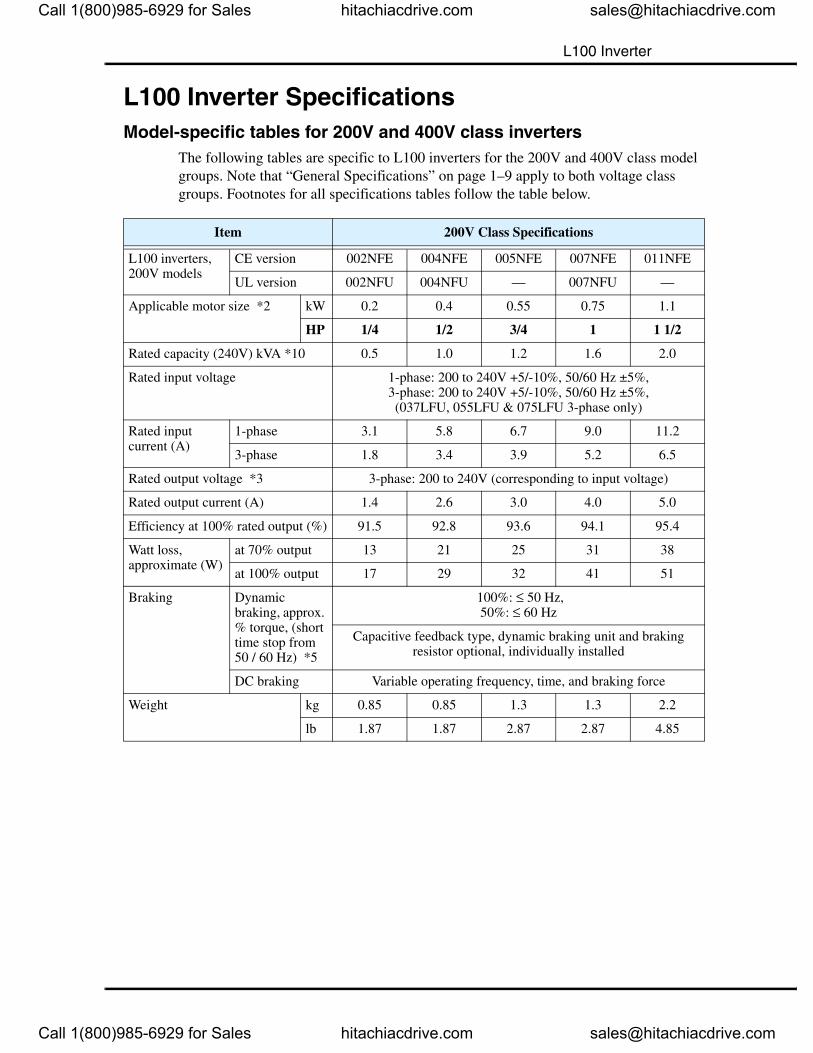
The following tables are specific to L100 inverters for the 200V and 400V class model groups. Note that “General Specifications” on page 1–9 apply to both voltage class groups. Footnotes for all specifications tables follow the table below.
Item 200V Class Specifications
L100 inverters, 200V models
CE version 002NFE 004NFE 005NFE 007NFE 011NFE
UL version 002NFU 004NFU — 007NFU —
Applicable motor size *2 kW 0.2 0.4 0.55 0.75 1.1
HP 1/4 1/2 3/4 1 1 1/2
Rated capacity (240V) kVA *10 0.5 1.0 1.2 1.6 2.0
Rated input voltage 1-phase: 200 to 240V +5/-10%, 50/60 Hz ±5%,3-phase: 200 to 240V +5/-10%, 50/60 Hz ±5%,(037LFU, 055LFU & 075LFU 3-phase only)
Rated input current (A)
1-phase 3.1 5.8 6.7 9.0 11.2
3-phase 1.8 3.4 3.9 5.2 6.5
Rated output voltage *3 3-phase: 200 to 240V (corresponding to input voltage)
Rated output current (A) 1.4 2.6 3.0 4.0 5.0
Efficiency at 100% rated output (%) 91.5 92.8 93.6 94.1 95.4
Watt loss,approximate (W)
at 70% output 13 21 25 31 38
at 100% output 17 29 32 41 51
Braking Dynamic braking, approx. % torque, (short time stop from 50 / 60 Hz) *5
100%: ≤ 50 Hz,50%: ≤ 60 Hz
Capacitive feedback type, dynamic braking unit and braking resistor optional, individually installed
DC braking Variable operating frequency, time, and braking force
Weight kg 0.85 0.85 1.3 1.3 2.2
lb 1.87 1.87 2.87 2.87 4.85
Call 1(800)985-6929 for Sales hitachiacdrive.com [email protected]
Call 1(800)985-6929 for Sales hitachiacdrive.com [email protected]
L100 Inverter Specifications
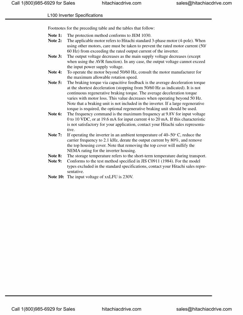
Footnotes for the preceding table and the tables that follow:
Note 1: The protection method conforms to JEM 1030.Note 2: The applicable motor refers to Hitachi standard 3-phase motor (4-pole). When
using other motors, care must be taken to prevent the rated motor current (50/60 Hz) from exceeding the rated output current of the inverter.
Note 3: The output voltage decreases as the main supply voltage decreases (except when using the AVR function). In any case, the output voltage cannot exceed the input power supply voltage.
Note 4: To operate the motor beyond 50/60 Hz, consult the motor manufacturer for the maximum allowable rotation speed.
Note 5: The braking torque via capacitive feedback is the average deceleration torque at the shortest deceleration (stopping from 50/60 Hz as indicated). It is not continuous regenerative braking torque. The average deceleration torque varies with motor loss. This value decreases when operating beyond 50 Hz. Note that a braking unit is not included in the inverter. If a large regenerative torque is required, the optional regenerative braking unit should be used.
Note 6: The frequency command is the maximum frequency at 9.8V for input voltage 0 to 10 VDC, or at 19.6 mA for input current 4 to 20 mA. If this characteristic is not satisfactory for your application, contact your Hitachi sales representa-tive.
Note 7: If operating the inverter in an ambient temperature of 40–50° C, reduce the carrier frequency to 2.1 kHz, derate the output current by 80%, and remove the top housing cover. Note that removing the top cover will nullify the NEMA rating for the inverter housing.
Note 8: The storage temperature refers to the short-term temperature during transport.Note 9: Conforms to the test method specified in JIS C0911 (1984). For the model
types excluded in the standard specifications, contact your Hitachi sales repre-sentative.
Note 10: The input voltage of xxLFU is 230V.
Call 1(800)985-6929 for Sales hitachiacdrive.com [email protected]
Call 1(800)985-6929 for Sales hitachiacdrive.com [email protected]
L100 Inverter
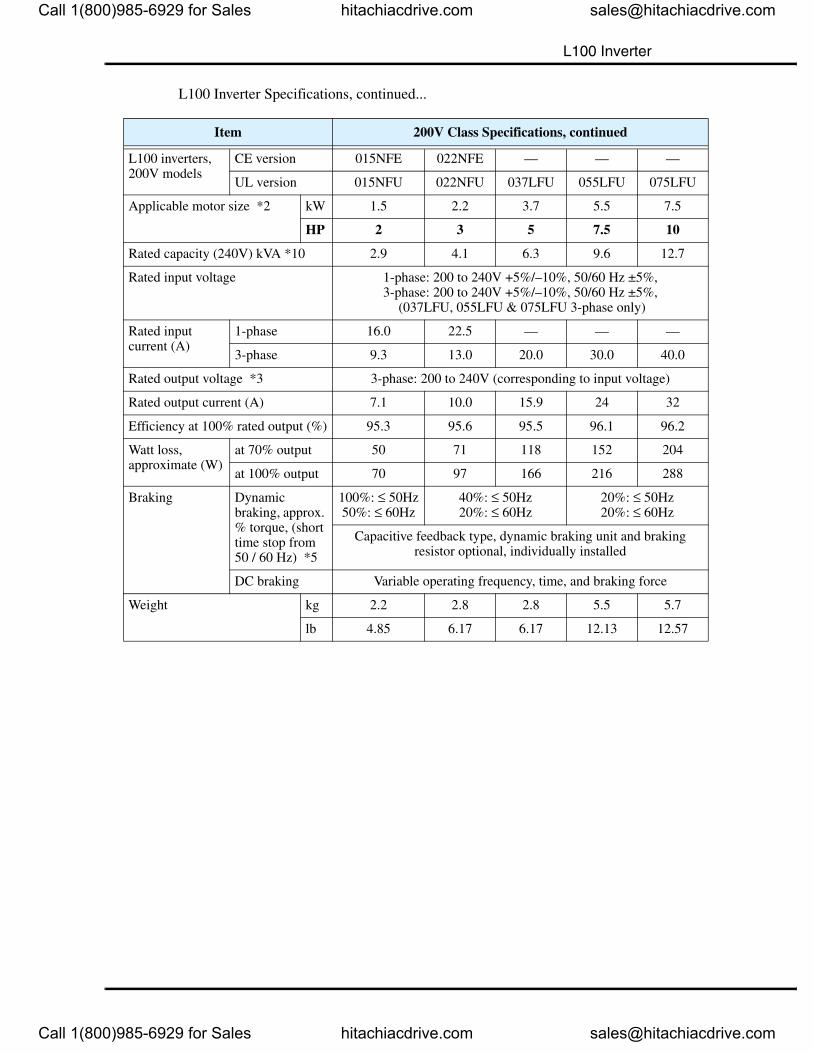
L100 Inverter Specifications, continued...
Item 200V Class Specifications, continued
L100 inverters, 200V models
CE version 015NFE 022NFE — — —
UL version 015NFU 022NFU 037LFU 055LFU 075LFU
Applicable motor size *2 kW 1.5 2.2 3.7 5.5 7.5
HP 2 3 5 7.5 10
Rated capacity (240V) kVA *10 2.9 4.1 6.3 9.6 12.7
Rated input voltage 1-phase: 200 to 240V +5%/–10%, 50/60 Hz ±5%,3-phase: 200 to 240V +5%/–10%, 50/60 Hz ±5%,
(037LFU, 055LFU & 075LFU 3-phase only)
Rated input current (A)
1-phase 16.0 22.5 — — —
3-phase 9.3 13.0 20.0 30.0 40.0
Rated output voltage *3 3-phase: 200 to 240V (corresponding to input voltage)
Rated output current (A) 7.1 10.0 15.9 24 32
Efficiency at 100% rated output (%) 95.3 95.6 95.5 96.1 96.2
Watt loss,approximate (W)
at 70% output 50 71 118 152 204
at 100% output 70 97 166 216 288
Braking Dynamic braking, approx. % torque, (short time stop from 50 / 60 Hz) *5
100%: ≤ 50Hz50%: ≤ 60Hz
40%: ≤ 50Hz20%: ≤ 60Hz
20%: ≤ 50Hz20%: ≤ 60Hz
Capacitive feedback type, dynamic braking unit and braking resistor optional, individually installed
DC braking Variable operating frequency, time, and braking force
Weight kg 2.2 2.8 2.8 5.5 5.7
lb 4.85 6.17 6.17 12.13 12.57
Call 1(800)985-6929 for Sales hitachiacdrive.com [email protected]
Call 1(800)985-6929 for Sales hitachiacdrive.com [email protected]
L100 Inverter Specifications
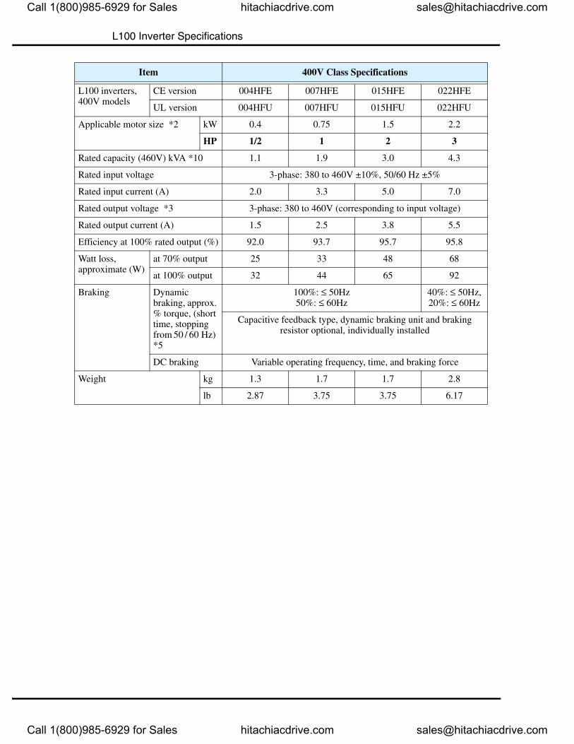
Item 400V Class Specifications
L100 inverters, 400V models
CE version 004HFE 007HFE 015HFE 022HFE
UL version 004HFU 007HFU 015HFU 022HFU
Applicable motor size *2 kW 0.4 0.75 1.5 2.2
HP 1/2 1 2 3
Rated capacity (460V) kVA *10 1.1 1.9 3.0 4.3
Rated input voltage 3-phase: 380 to 460V ±10%, 50/60 Hz ±5%
Rated input current (A) 2.0 3.3 5.0 7.0
Rated output voltage *3 3-phase: 380 to 460V (corresponding to input voltage)
Rated output current (A) 1.5 2.5 3.8 5.5
Efficiency at 100% rated output (%) 92.0 93.7 95.7 95.8
Watt loss,approximate (W)
at 70% output 25 33 48 68
at 100% output 32 44 65 92
Braking Dynamic braking, approx. % torque, (short time, stopping from 50 / 60 Hz) *5
100%: ≤ 50Hz50%: ≤ 60Hz
40%: ≤ 50Hz,20%: ≤ 60Hz
Capacitive feedback type, dynamic braking unit and braking resistor optional, individually installed
DC braking Variable operating frequency, time, and braking force
Weight kg 1.3 1.7 1.7 2.8
lb 2.87 3.75 3.75 6.17
Call 1(800)985-6929 for Sales hitachiacdrive.com [email protected]
Call 1(800)985-6929 for Sales hitachiacdrive.com [email protected]
L100 Inverter
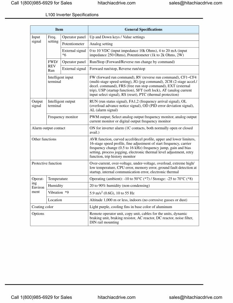
General SpecificationsThe following table applies to all L100 inverters.
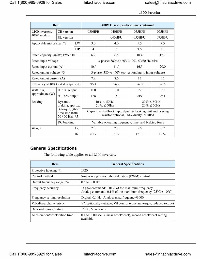
Item 400V Class Specifications, continued
L100 inverters, 400V models
CE version 030HFE 040HFE 055HFE 075HFE
UL version — 040HFU 055HFU 075HFU
Applicable motor size *2 kW 3.0 4.0 5.5 7.5
HP 4 5 7.5 10
Rated capacity (460V) kVA *10 6.2 6.8 10.4 12.7
Rated input voltage 3-phase: 380 to 460V ±10%, 50/60 Hz ±5%
Rated input current (A) 10.0 11.0 16.5 20.0
Rated output voltage *3 3-phase: 380 to 460V (corresponding to input voltage)
Rated output current (A) 7.8 8.6 13 16
Efficiency at 100% rated output (%) 95.4 96.2 96.0 96.5
Watt loss,approximate (W)
at 70% output 100 108 156 186
at 100% output 138 151 219 261
Braking Dynamic braking, approx. % torque, (short time stop from 50 / 60 Hz) *5
40%: ≤ 50Hz,20%: ≤ 60Hz
20%: ≤ 50Hz20%: ≤ 60Hz
Capacitive feedback type, dynamic braking unit and braking resistor optional, individually installed
DC braking Variable operating frequency, time, and braking force
Weight kg 2.8 2.8 5.5 5.7
lb 6.17 6.17 12.13 12.57
Item General Specifications
Protective housing *1 IP20
Control method Sine wave pulse-width modulation (PWM) control
Output frequency range *4 0.5 to 360 Hz
Frequency accuracy Digital command: 0.01% of the maximum frequencyAnalog command: 0.1% of the maximum frequency (25°C ± 10°C)
Frequency setting resolution Digital: 0.1 Hz; Analog: max. frequency/1000
Volt./Freq. characteristic V/f optionally variable, V/f control (constant torque, reduced torque)
Overload current rating 150%, 60 seconds
Acceleration/deceleration time 0.1 to 3000 sec., (linear accel/decel), second accel/decel setting available
Call 1(800)985-6929 for Sales hitachiacdrive.com [email protected]
Call 1(800)985-6929 for Sales hitachiacdrive.com [email protected]
L100 Inverter Specifications
Inputsignal
Freq.setting
Operator panel Up and Down keys / Value settings
Potentiometer Analog setting
External signal *6
0 to 10 VDC (input impedance 10k Ohms), 4 to 20 mA (input impedance 250 Ohms), Potentiometer (1k to 2k Ohms, 2W)
FWD/REV Run
Operator panel Run/Stop (Forward/Reverse run change by command)
External signal Forward run/stop, Reverse run/stop
Intelligent inputterminal
FW (forward run command), RV (reverse run command), CF1~CF4 (multi-stage speed setting), JG (jog command), 2CH (2-stage accel./decel. command), FRS (free run stop command), EXT (external trip), USP (startup function), SFT (soft lock), AT (analog current input select signal), RS (reset), PTC (thermal protection)
Outputsignal
Intelligent output terminal
RUN (run status signal), FA1,2 (frequency arrival signal), OL (overload advance notice signal), OD (PID error deviation signal), AL (alarm signal)
Frequency monitor PWM output; Select analog output frequency monitor, analog output current monitor or digital output frequency monitor
Alarm output contact ON for inverter alarm (1C contacts, both normally open or closed avail.)
Other functions AVR function, curved accel/decel profile, upper and lower limiters, 16-stage speed profile, fine adjustment of start frequency, carrier frequency change (0.5 to 16 kHz) frequency jump, gain and bias setting, process jogging, electronic thermal level adjustment, retry function, trip history monitor
Protective function Over-current, over-voltage, under-voltage, overload, extreme high/low temperature, CPU error, memory error, ground fault detection at startup, internal communication error, electronic thermal
Operat-ingEnvironment
Temperature Operating (ambient): -10 to 50°C (*7) / Storage: -25 to 70°C (*8)
Humidity 20 to 90% humidity (non-condensing)
Vibration *9 5.9 m/s2 (0.6G), 10 to 55 Hz
Location Altitude 1,000 m or less, indoors (no corrosive gasses or dust)
Coating color Light purple, cooling fins in base color of aluminum
Options Remote operator unit, copy unit, cables for the units, dynamic braking unit, braking resistor, AC reactor, DC reactor, noise filter, DIN rail mounting
Item General Specifications
Call 1(800)985-6929 for Sales hitachiacdrive.com [email protected]
Call 1(800)985-6929 for Sales hitachiacdrive.com [email protected]
L100 Inverter
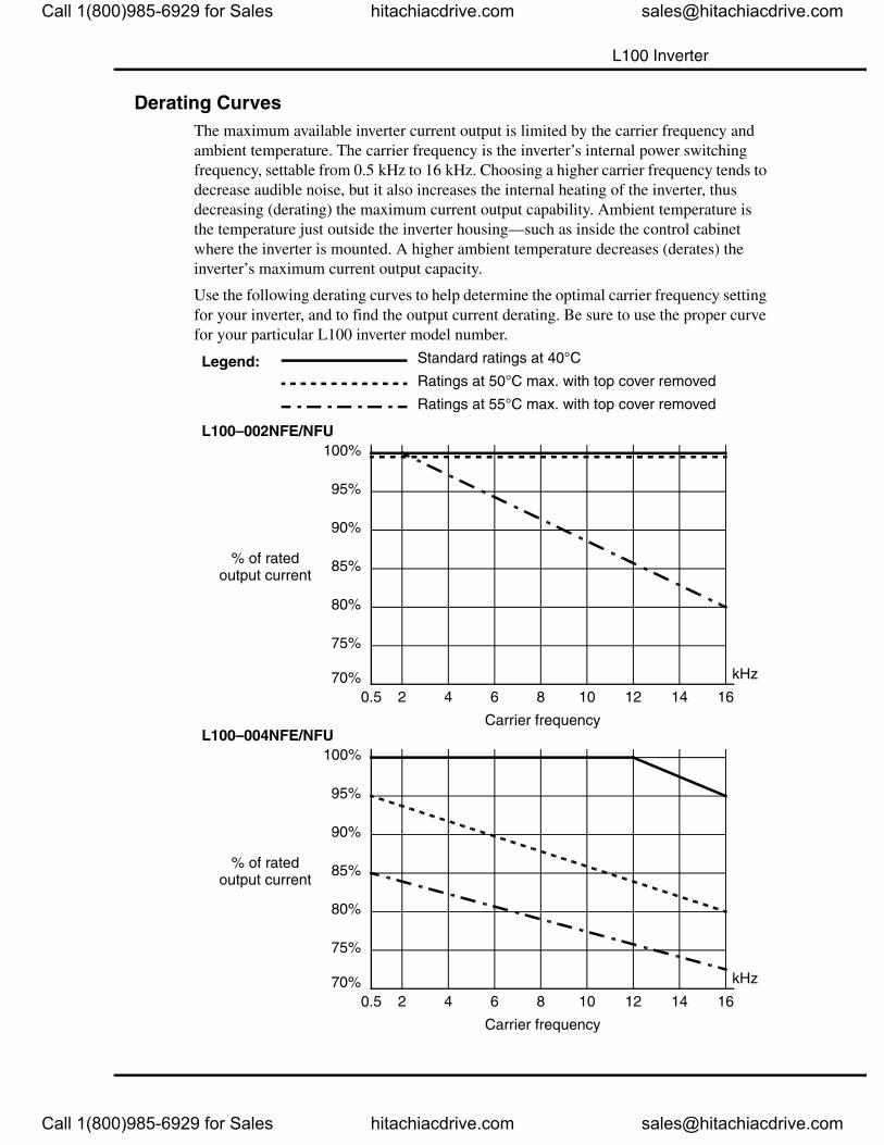
Derating CurvesThe maximum available inverter current output is limited by the carrier frequency and ambient temperature. The carrier frequency is the inverter’s internal power switching frequency, settable from 0.5 kHz to 16 kHz. Choosing a higher carrier frequency tends to decrease audible noise, but it also increases the internal heating of the inverter, thus decreasing (derating) the maximum current output capability. Ambient temperature is the temperature just outside the inverter housing—such as inside the control cabinet where the inverter is mounted. A higher ambient temperature decreases (derates) the inverter’s maximum current output capacity.
Use the following derating curves to help determine the optimal carrier frequency setting for your inverter, and to find the output current derating. Be sure to use the proper curve for your particular L100 inverter model number.
L100–002NFE/NFU
0.5 2 4 6 8 10 12 14 1670%
80%
90%
100%
95%
85%
75%
% of rated output current
Carrier frequency
kHz
L100–004NFE/NFU
0.5 2 4 6 8 10 12 14 1670%
80%
90%
100%
95%
85%
75%
% of rated output current
Carrier frequency
kHz
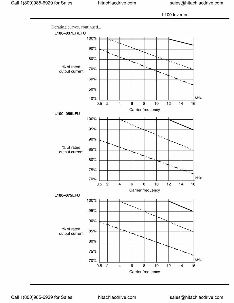
Standard ratings at 40°C
Ratings at 50°C max. with top cover removed
Ratings at 55°C max. with top cover removed
Legend:
Call 1(800)985-6929 for Sales hitachiacdrive.com [email protected]
Call 1(800)985-6929 for Sales hitachiacdrive.com [email protected]
L100 Inverter Specifications
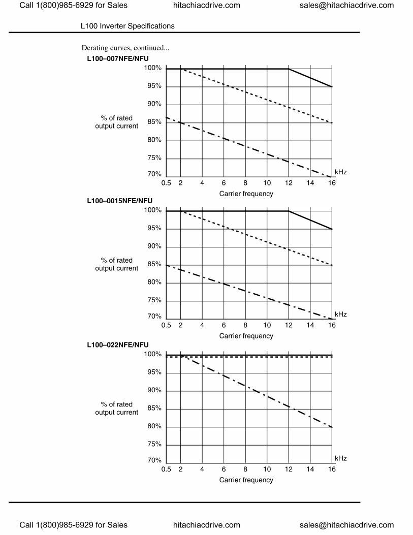
Derating curves, continued...
L100–007NFE/NFU
0.5 2 4 6 8 10 12 14 1670%
80%
90%
100%
95%
85%
75%
% of rated output current
Carrier frequency
kHz
L100–0015NFE/NFU
0.5 2 4 6 8 10 12 14 1670%
80%
90%
100%
95%
85%
75%
% of rated output current
Carrier frequency
kHz
L100–022NFE/NFU
0.5 2 4 6 8 10 12 14 1670%
80%
90%
100%
95%
85%
75%
% of rated output current
Carrier frequency
kHz
Call 1(800)985-6929 for Sales hitachiacdrive.com [email protected]
Call 1(800)985-6929 for Sales hitachiacdrive.com [email protected]
L100 Inverter
Derating curves, continued...
L100–037LF/LFU
0.5 2 4 6 8 10 12 14 1640%
60%
80%
100%
90%
70%
50%
% of rated output current
Carrier frequency
kHz
L100–055LFU
0.5 2 4 6 8 10 12 14 1670%
80%
90%
100%
95%
85%
75%
% of rated output current
Carrier frequency
kHz
L100–075LFU
0.5 2 4 6 8 10 12 14 1670%
80%
90%
100%
95%
85%
75%
% of rated output current
Carrier frequency
kHz
Call 1(800)985-6929 for Sales hitachiacdrive.com [email protected]
Call 1(800)985-6929 for Sales hitachiacdrive.com [email protected]
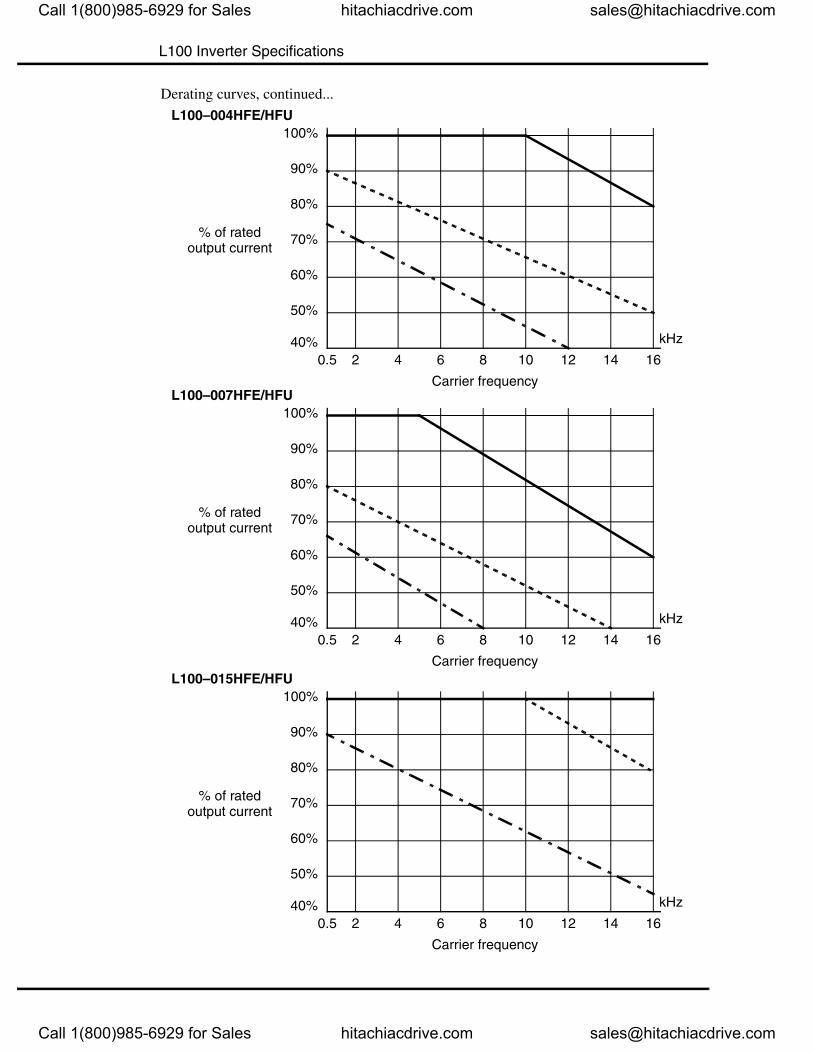
L100 Inverter Specifications
Derating curves, continued...
L100–004HFE/HFU
0.5 2 4 6 8 10 12 14 1640%
60%
80%
100%
90%
70%
50%
% of rated output current
Carrier frequency
kHz
L100–007HFE/HFU
0.5 2 4 6 8 10 12 14 1640%
60%
80%
100%
90%
70%
50%
% of rated output current
Carrier frequency
kHz
L100–015HFE/HFU
0.5 2 4 6 8 10 12 14 1640%
60%
80%
100%
90%
70%
50%
% of rated output current
Carrier frequency
kHz
Call 1(800)985-6929 for Sales hitachiacdrive.com [email protected]
Call 1(800)985-6929 for Sales hitachiacdrive.com [email protected]
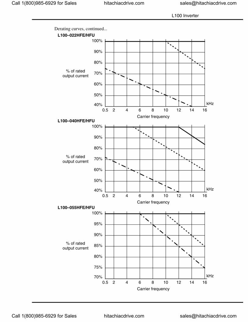
L100 Inverter
Derating curves, continued...
L100–022HFE/HFU
0.5 2 4 6 8 10 12 14 1640%
60%
80%
100%
90%
70%
50%
% of rated output current
Carrier frequency
kHz
L100–040HFE/HFU
0.5 2 4 6 8 10 12 14 1640%
60%
80%
100%
90%
70%
50%
% of rated output current
Carrier frequency
kHz
L100–055HFE/HFU
0.5 2 4 6 8 10 12 14 1670%
80%
90%
100%
95%
85%
75%
% of rated output current
Carrier frequency
kHz
Call 1(800)985-6929 for Sales hitachiacdrive.com [email protected]
Call 1(800)985-6929 for Sales hitachiacdrive.com [email protected]
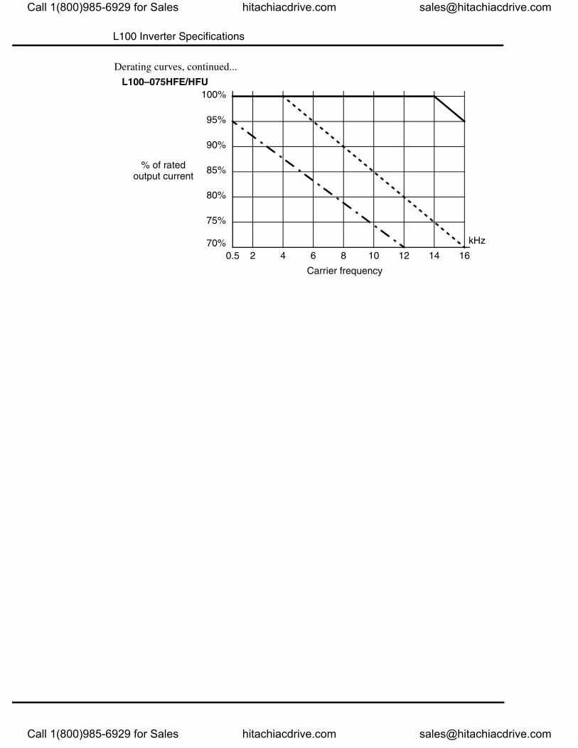
L100 Inverter Specifications
Derating curves, continued...
L100–075HFE/HFU
0.5 2 4 6 8 10 12 14 1670%
80%
90%
100%
95%
85%
75%
% of rated output current
Carrier frequency
kHz
Call 1(800)985-6929 for Sales hitachiacdrive.com [email protected]
Call 1(800)985-6929 for Sales hitachiacdrive.com [email protected]
Related Documents


