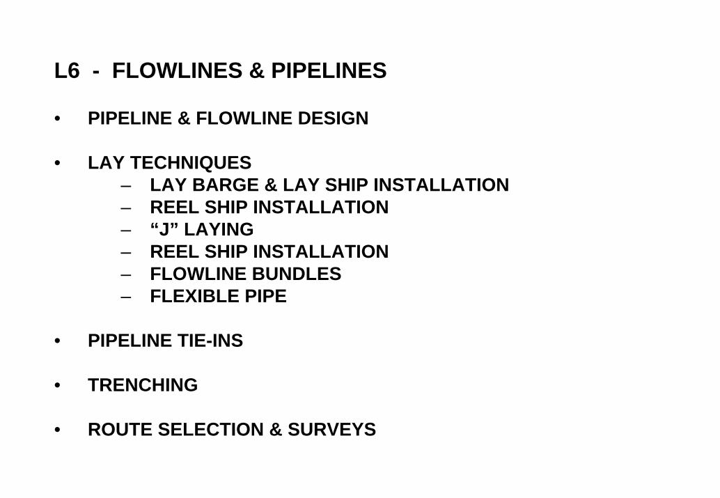
L6 - FLOWLINES & PIPELINES • PIPELINE & FLOWLINE DESIGN • LAY TECHNIQUES – LAY BARGE & LAY SHIP INSTALLATION – REEL SHIP INSTALLATION – “J” LAYING – REEL SHIP INSTALLATION – FLOWLINE BUNDLES – FLEXIBLE PIPE • PIPELINE TIE-INS • TRENCHING • ROUTE SELECTION & SURVEYS

L06 - PIPELINES & FLOWLINES
Oct 14, 2014
Welcome message from author
This document is posted to help you gain knowledge. Please leave a comment to let me know what you think about it! Share it to your friends and learn new things together.
Transcript
L6 - FLOWLINES & PIPELINES
• PIPELINE & FLOWLINE DESIGN
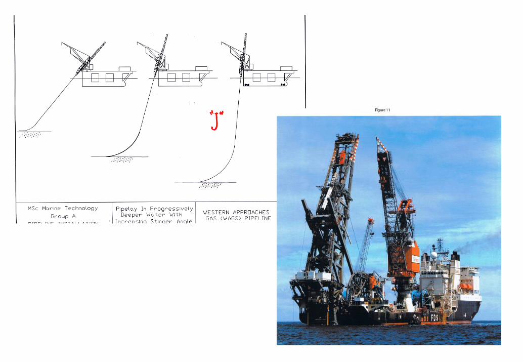
• LAY TECHNIQUES– LAY BARGE & LAY SHIP INSTALLATION– REEL SHIP INSTALLATION– “J” LAYING– REEL SHIP INSTALLATION– FLOWLINE BUNDLES– FLEXIBLE PIPE
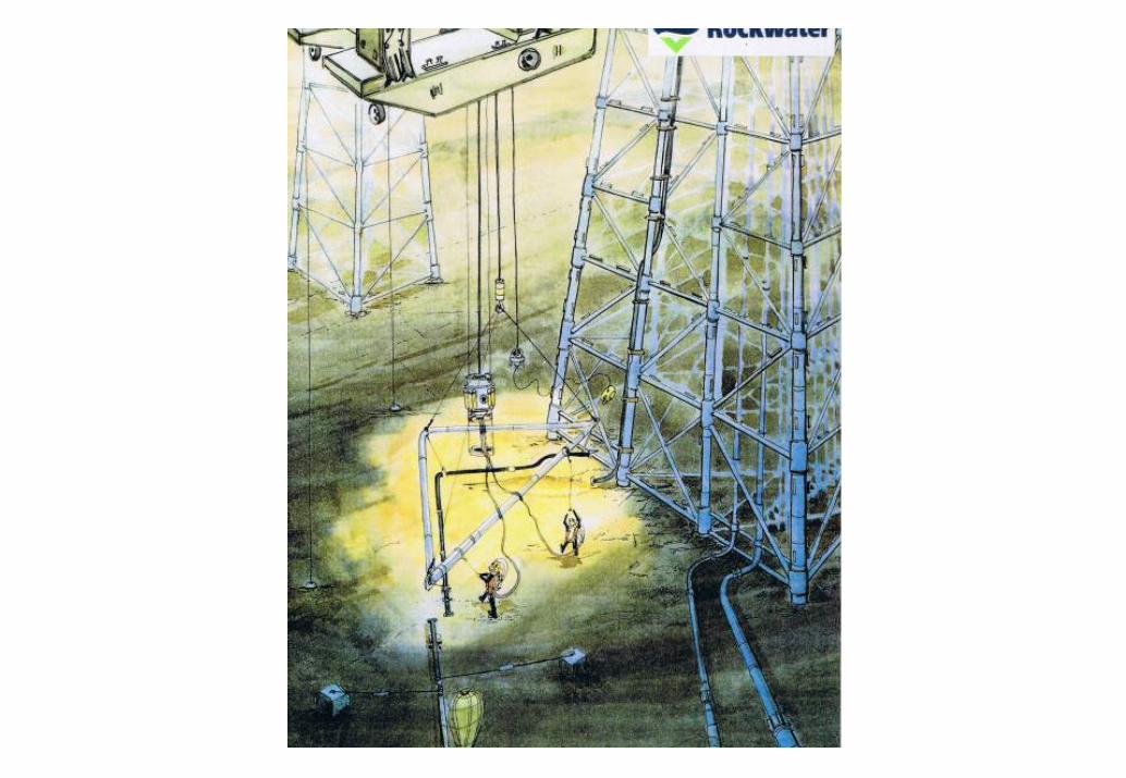
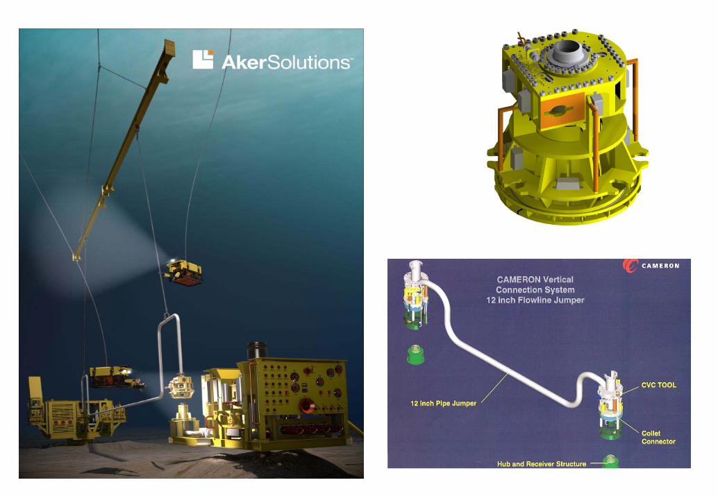
• PIPELINE TIE-INS
• TRENCHING
• ROUTE SELECTION & SURVEYS
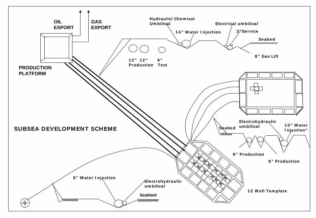
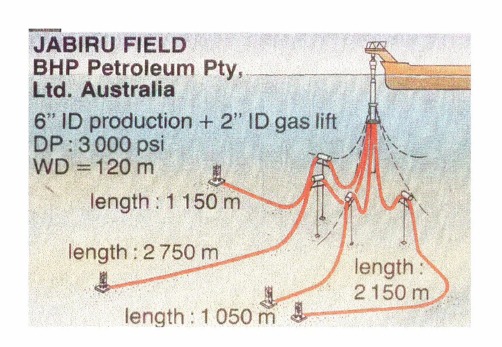
SUBSEA DEVELOPMENT SCHEME
12” 12” 6”Production Test
Hydraulic/Chemical Umbilical
14” Water Injection
Electrical umbilical
3”Service
Seabbed
8” Gas Lift
Seabed
Electrohydraulicumbilical 10” Water
Injection”
8” Production
12 Well Template
8” Production
8” Water InjectionElectrohydraulicumbilical
Seabed
GAS EXPORT
OIL EXPORT
PRODUCTION PLATFORM
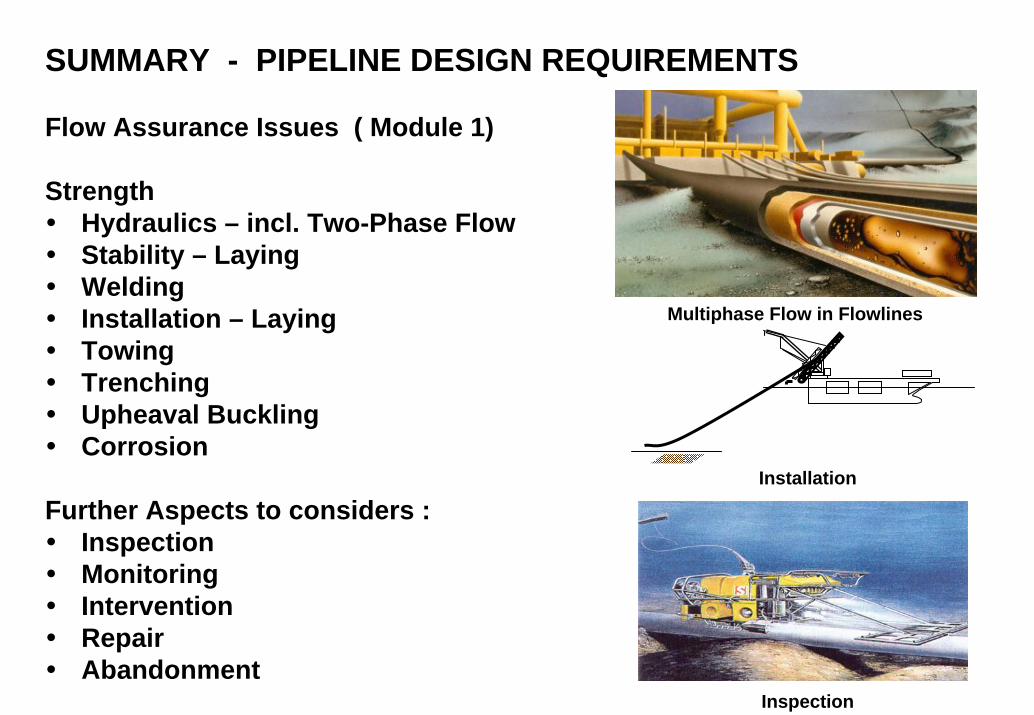
SUMMARY - PIPELINE DESIGN REQUIREMENTS
Flow Assurance Issues ( Module 1)
StrengthHydraulics – incl. Two-Phase FlowStability – LayingWeldingInstallation – LayingTowingTrenchingUpheaval BucklingCorrosion
Further Aspects to considers :InspectionMonitoringInterventionRepairAbandonment
Multiphase Flow in Flowlines
Inspection
Installation
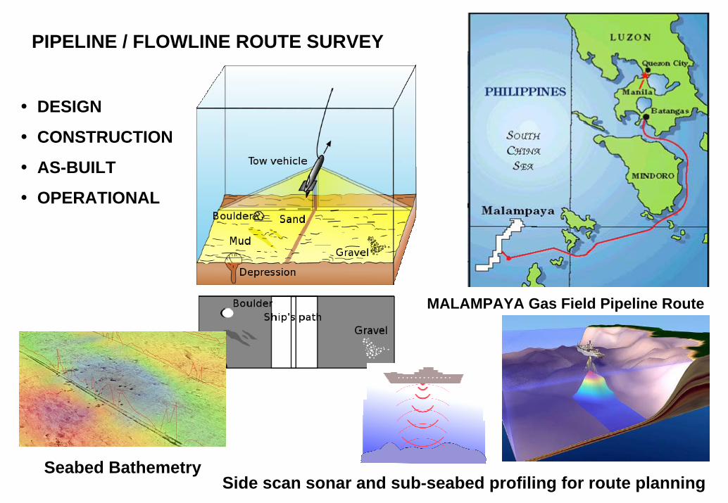
DESIGN
CONSTRUCTION
AS-BUILT
OPERATIONAL
PIPELINE / FLOWLINE ROUTE SURVEY
MALAMPAYA Gas Field Pipeline Route
Seabed BathemetrySide scan sonar and sub-seabed profiling for route planning
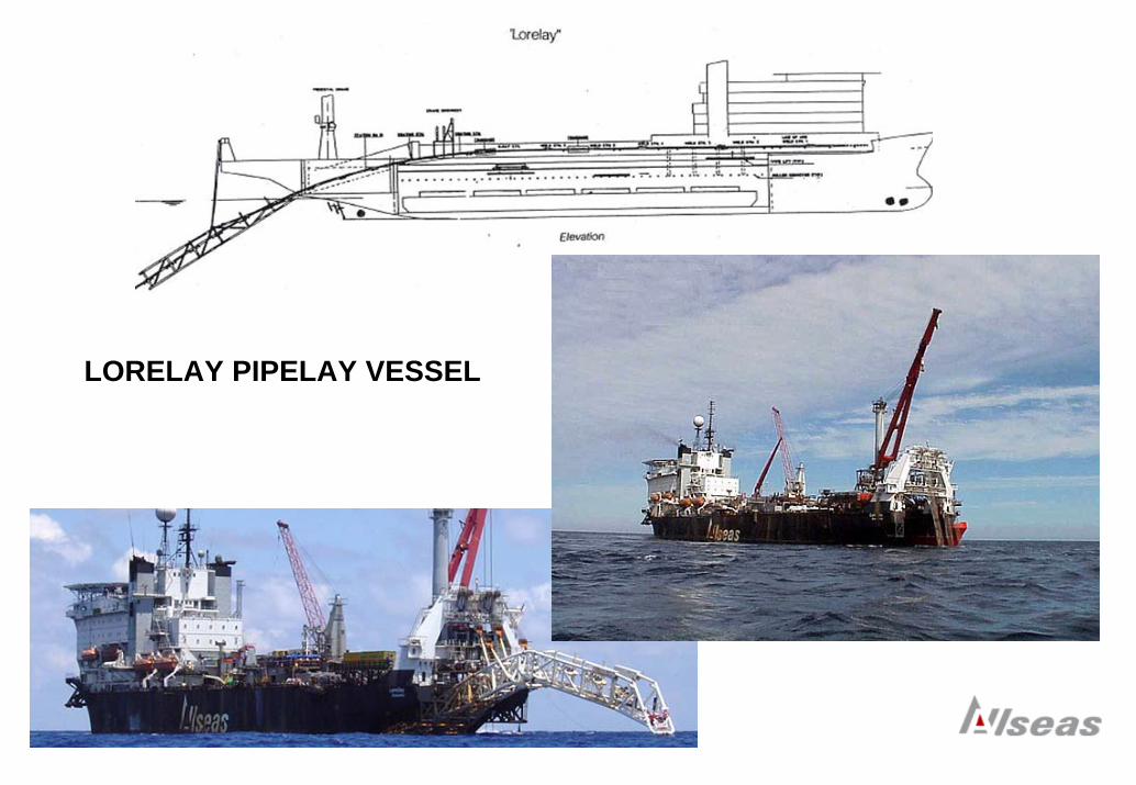
LORELAY PIPELAY VESSEL
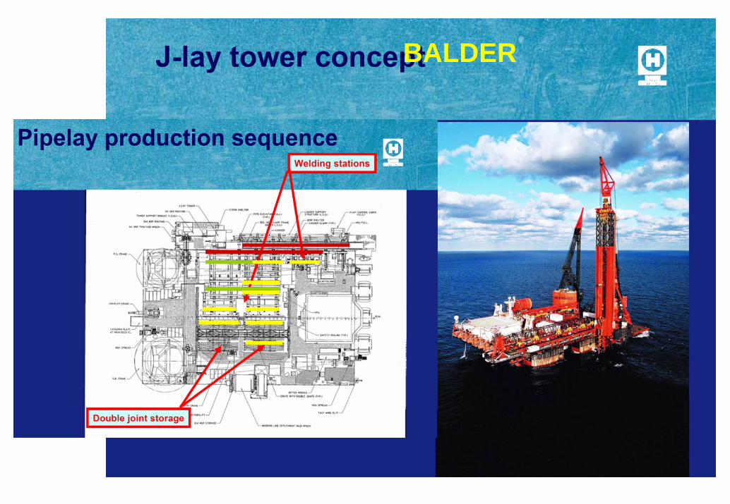
BALDER
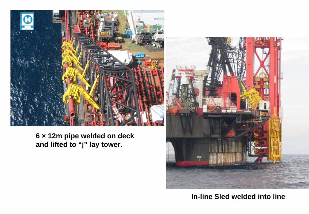
6 × 12m pipe welded on deck and lifted to “j” lay tower.
In-line Sled welded into line
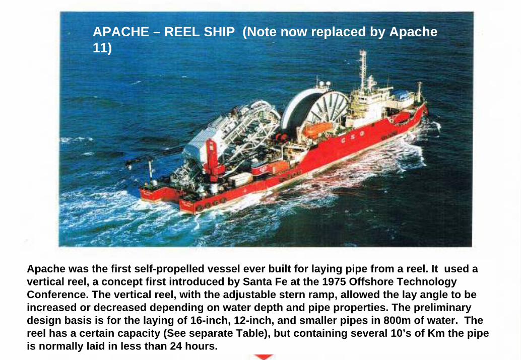
APACHE – REEL SHIP (Note now replaced by Apache 11)
Apache was the first self-propelled vessel ever built for laying pipe from a reel. It used a vertical reel, a concept first introduced by Santa Fe at the 1975 Offshore TechnologyConference. The vertical reel, with the adjustable stern ramp, allowed the lay angle to beincreased or decreased depending on water depth and pipe properties. The preliminarydesign basis is for the laying of 16-inch, 12-inch, and smaller pipes in 800m of water. The reel has a certain capacity (See separate Table), but containing several 10’s of Km the pipe is normally laid in less than 24 hours.
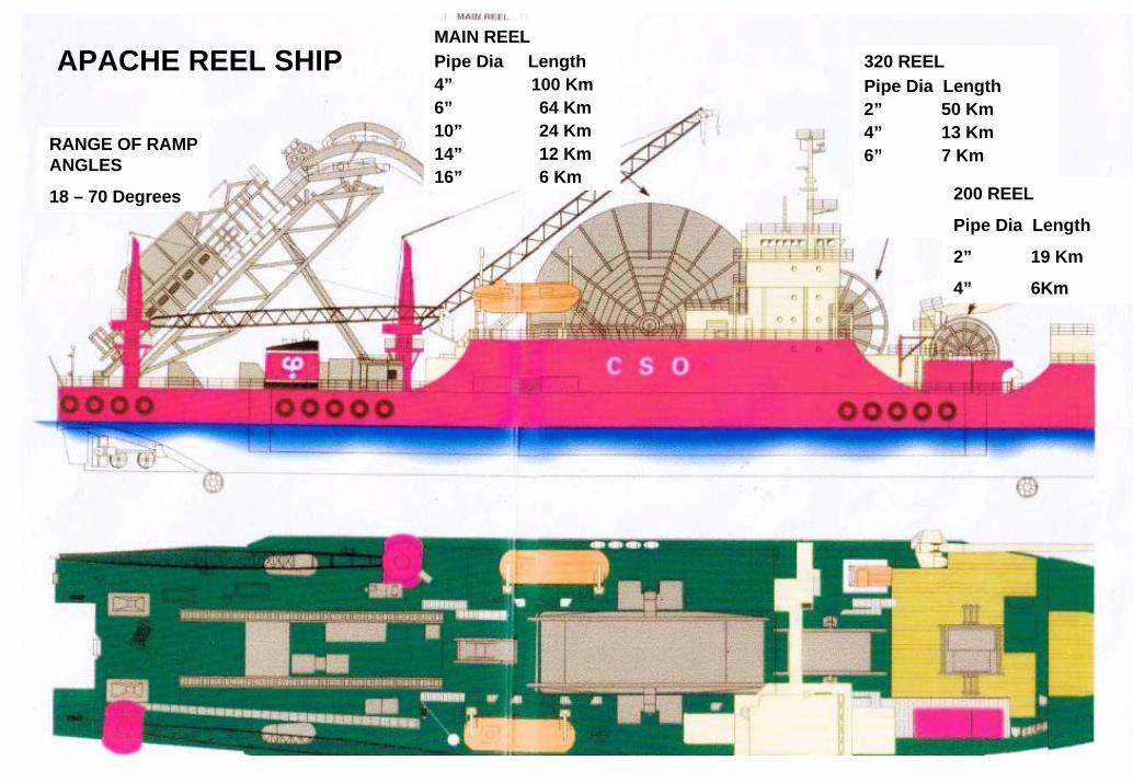
MAIN REELPipe Dia Length 4” 100 Km6” 64 Km10” 24 Km14” 12 Km16” 6 Km
320 REELPipe Dia Length2” 50 Km4” 13 Km6” 7 Km
200 REEL
Pipe Dia Length
2” 19 Km
4” 6Km
RANGE OF RAMP ANGLES
18 – 70 Degrees
APACHE REEL SHIP
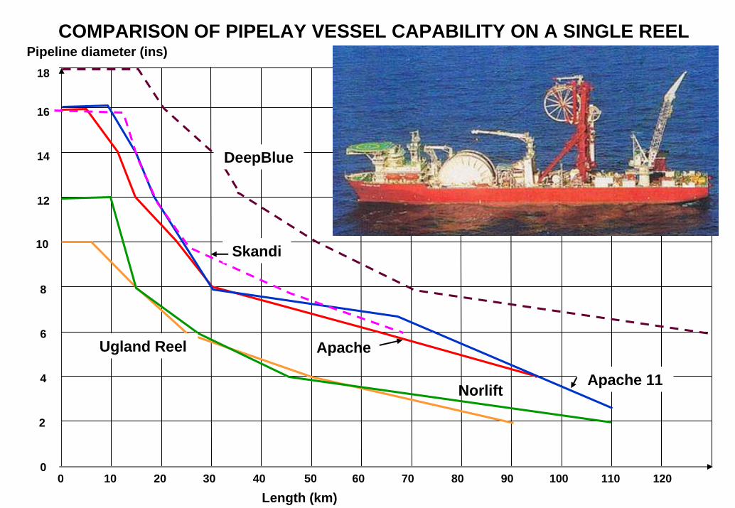
Pipeline diameter (ins)COMPARISON OF PIPELAY VESSEL CAPABILITY ON A SINGLE REEL
0 10 20 30 40 60 70 80 90 100 110 120
Length (km)50
16
14
10
12
6
2
4
0
8
18
DeepBlue
Skandi
Apache 11
Ugland Reel
Norlift
Apache
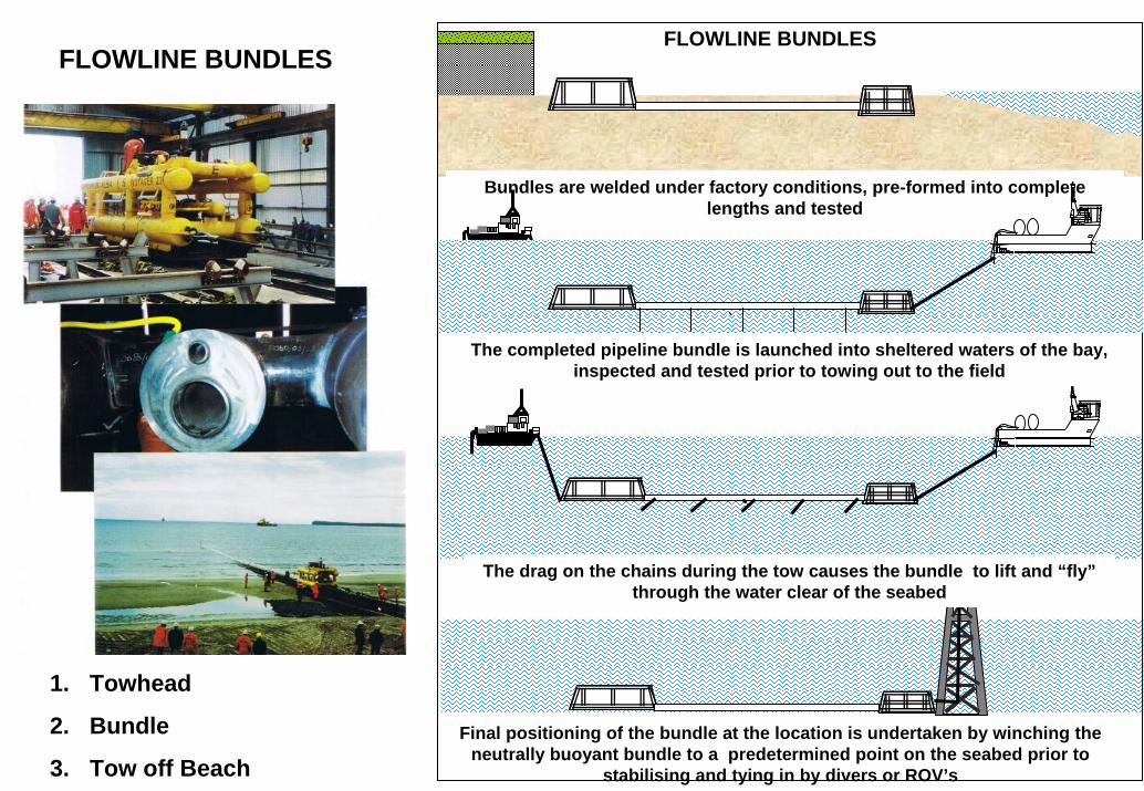
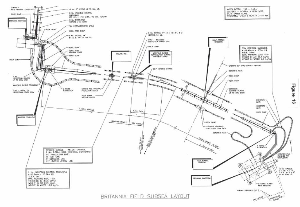
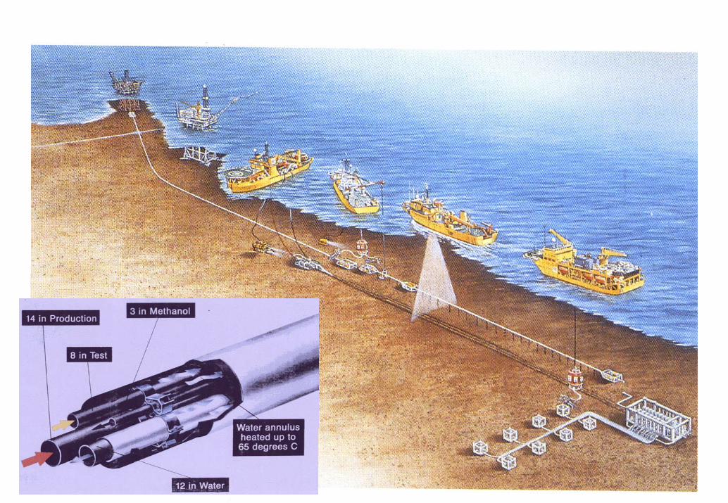
FLOWLINE BUNDLES
Bundles are welded under factory conditions, pre-formed into complete lengths and tested
The completed pipeline bundle is launched into sheltered waters of the bay, inspected and tested prior to towing out to the field
The drag on the chains during the tow causes the bundle to lift and “fly”through the water clear of the seabed
Final positioning of the bundle at the location is undertaken by winching the neutrally buoyant bundle to a predetermined point on the seabed prior to
stabilising and tying in by divers or ROV’s
FLOWLINE BUNDLES
1. Towhead
2. Bundle
3. Tow off Beach
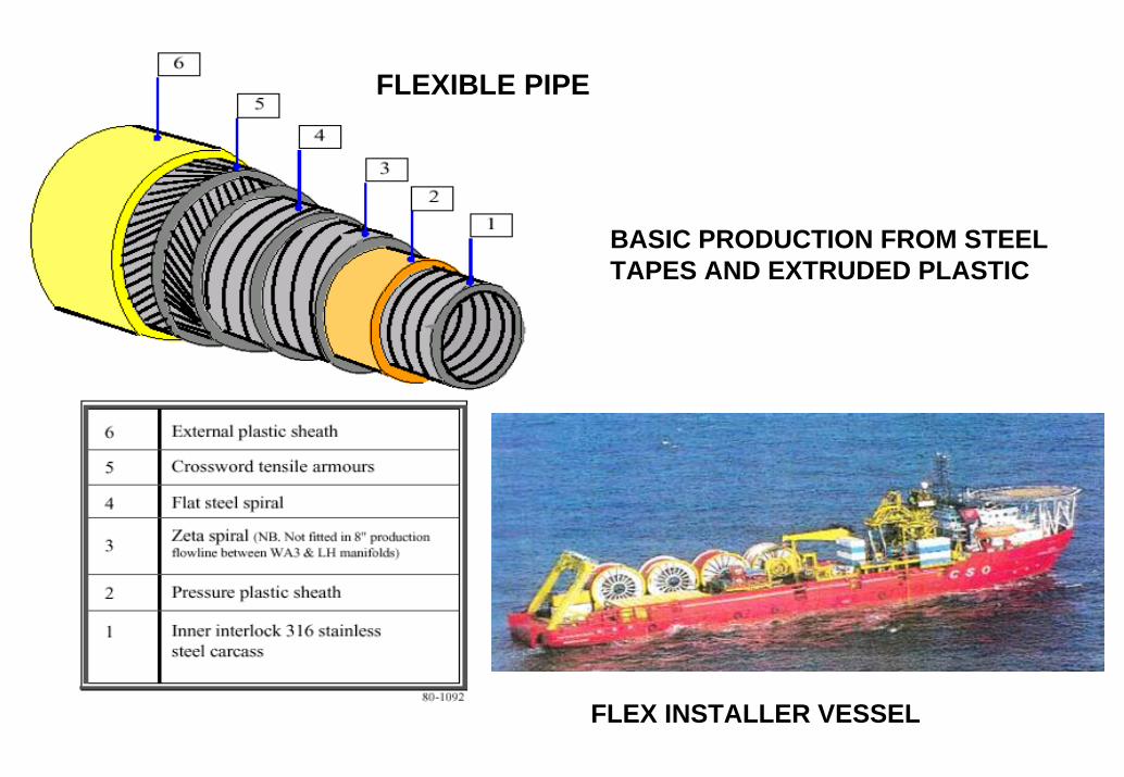
BASIC PRODUCTION FROM STEEL TAPES AND EXTRUDED PLASTIC
FLEXIBLE PIPE
FLEX INSTALLER VESSEL
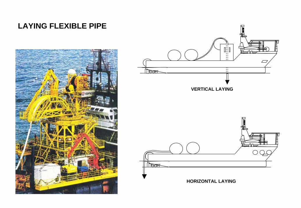
LAYING FLEXIBLE PIPE
VERTICAL LAYING
HORIZONTAL LAYING
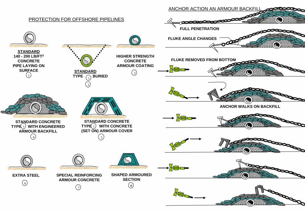
HIGHER STRENGTHCONCRETE
ARMOUR COATING
3
EXTRA STEEL
STANDARD140 - 200 LB/FT3
CONCRETEPIPE LAYING ON
SURFACE1
STANDARDTYPE BURIED1
2
STANDARD CONCRETETYPE WITH ENGINEERED
ARMOUR BACKFILL4
1
76
STANDARD CONCRETETYPE WITH CONCRETE(SET ON) ARMOUR COVER
1
5
SPECIAL REINFORCINGARMOUR CONCRETE
SHAPED ARMOUREDSECTION
B
PROTECTION FOR OFFSHORE PIPELINES
ANCHOR ACTION AN ARMOUR BACKFILL
FULL PENETRATION
FLUKE ANGLE CHANGES
FLUKE REMOVED FROM BOTTOM
ANCHOR WALKS ON BACKFILL
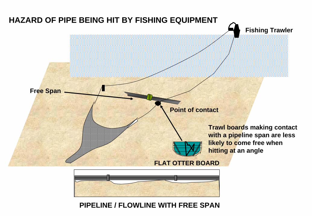
FLAT OTTER BOARD
HAZARD OF PIPE BEING HIT BY FISHING EQUIPMENT
Trawl boards making contact with a pipeline span are less likely to come free when hitting at an angle
Free Span
Fishing Trawler
Point of contact
PIPELINE / FLOWLINE WITH FREE SPAN
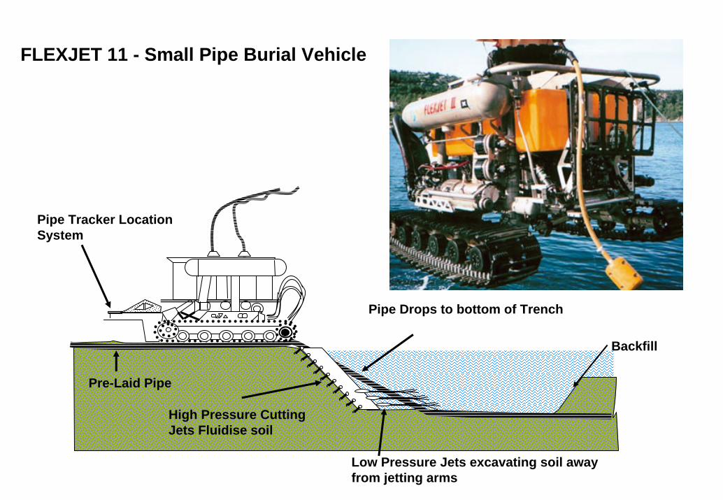
FLEXJET 11 - Small Pipe Burial Vehicle
Pipe Tracker Location System
Pre-Laid Pipe
Pipe Drops to bottom of Trench
Backfill
High Pressure Cutting Jets Fluidise soil
Low Pressure Jets excavating soil away from jetting arms
ROCK DUMPING
Related Documents