L2 - FLOW ASSURANCE ISSUES • BASIS PRINCIPLES OF SUBSEA PRODUCTION SYSTEMS • FLOW ASSURANCE & SYSTEMS DESIGN ISSUES - FLOW HYDRAULICS - MULTIPHASE FLOW - HYDRATES - WAX DEPOSITION - PIGGING - THERMAL ISSUES & COLD POINTS - CORROSION / EROSION - EMULSIONS - SAND - NEW TECHNOLOGIES • IFP FACILITIES

L02 - FLOW ASSURANCE
Oct 14, 2014
Welcome message from author
This document is posted to help you gain knowledge. Please leave a comment to let me know what you think about it! Share it to your friends and learn new things together.
Transcript

L2 - FLOW ASSURANCE ISSUES
• BASIS PRINCIPLES OF SUBSEA PRODUCTION SYSTEMS
• FLOW ASSURANCE & SYSTEMS DESIGN ISSUES
- FLOW HYDRAULICS
- MULTIPHASE FLOW
- HYDRATES
- WAX DEPOSITION
- PIGGING
- THERMAL ISSUES & COLD POINTS
- CORROSION / EROSION
- EMULSIONS
- SAND
- NEW TECHNOLOGIES
• IFP FACILITIES

BASIC PRINCIPLES OF SUBSEA PRODUCTION - FLOW ASSURANCE ISSUES
SEPARATOR
PLATFORM OR FLOATER
GAS
RISER BASE
FLOWLINES
SUPPLY LINES
DISTRIBUTECHEMICALS
TREE
2 - 100 km
SEA BED
1000 -
10000 m
OIL
WATER
50 -
2000 m
RISERPROCESS FACILITIES
FLOW ASSURANCE
1) HYDRAULICS - Is there enough energy in the flow to reach the processing host?
2) CORROSIVE COMPONENTS in the oil i.e.. H2S and CO2 - It can be corrected by chemical injection.
3) Is there any WAX in the oil that may block the lines on cooling.
4) Combinations of Gas and Water may form HYDRATES which block the line.

Flow Assurance Design Issues
FLOW ASSURANCE DESIGN
Paraffin/Asphaltenes
Gas Hydrates
Liquid Slugging
Scale
Corrosion
Sand/Erosion
Emulsion/Foam

FLOW ASSURANCE
- H y d r a te s - F o rm a t io n o f ic e c ry s ta ls in c o rp a ra t in g m e th a n e a n d o th e rh y d ro c a rb o n s in lo w te m p e ra tu re s , h ig h p re s s u re , w e t s y s te m s p ro d u c in gg a s , c o n d e n s a te o r o il.
- W a x / A s p h a lte n e s - T h e d e p o s it io n o f s o lid s in s id e th e f lo w lin e s a n dr is e rs re d u c in g f lo w c a p a c ity a n d u lt im a te ly b lo c k in g th e lin e .
- S lu g g in g - T h e p h e n o m e n a c a u s e d b y th e in s ta b il it ie s o f th e g a s a n dliq u id in te r fa c e s a n d liq u id s w e e p -o u t b y g a s in e r t ia l e f fe c ts .
- C o r r o s io n - W e a r in g o f th e p ip e w o rk a n d f lo w lin e w a ll th ic k n e s s d u e toc h e m is try o f th e p ro d u c e d f lu id s .
- E m u ls io n s - O il a n d w a te r m ix tu re s a t a p p ro x im a te ly 4 0 to 6 0 % w a te r c u tth a t c a u s e e x c e s s iv e p re s s u re lo s s e s in th e w e lls o r th e S P S s y s te m .
- S c a lin g - S o lid s b u ild u p , e s p e c ia lly o n to th e w e ll b o re tu b in g d u e to th ec h e m is try o f th e p ro d u c e d w a te r .
- S a n d P r o d u c t io n - S a n d p ro d u c t io n f ro m th e re s e rv o ir c a u s in g b lo c k a g eo f s y s te m c o m p o n e n ts s u c h a s f lo w lin e s .
- E r o s io n - W e a r in g o f th e m a n ifo ld p ip e w o rk a n d th e f lo w lin e w a lls d u e tos o lid p a r t ic le s s u c h a s s a n d o r l iq u id s im p in g e m e n t p a s s in g a t h ig hv e lo c it ie s .
- C o ld P o in ts - M u lt ip le n o n in s u la te d d e v ic e s in th e s y s te m in c o n ta c t w ithth e s u r ro u n d in g c o ld w a te r a c t in g a s fa s t h e a t e x c h a n g e rs in p a r t ic u la rd u r in g w e ll s h u t d o w n a n d o th e r o p e ra t in g m o d e s .

The successful design and operation of a multiphase production system must consider design parameters and issues for the entire system, from the reservoir to the processing and export facilities. To assure that the entire system can be designed to operate successfully and economically, system designers must consider flow assurance fundamentals such as reservoir characteristics, production profiles, produced fluid chemistry, and environmental conditions as well as mechanical, operational, risk, and economic issues for all parts of the system.
Important system parameters established as part of the design effort include tubing and flowline diameters, insulation (on wellbore tubing, trees, jumpers, manifolds, flowlines and risers), chemical injection requirements, flow blockage intervention provisions, host facility requirements, capital and operating costs, operating boundaries (e.g. maximum and minimum production rates), and risk mitigation. All production modes including startup, normal steady state operation, rate change, and shutdown must be considered throughout the system life-cycle.

Flow assurance encompasses the thermal-hydraulic design and assessment of multiphase production/transport systems as well as the prediction, prevention, and remediation of flow stoppages due to solids deposition (particularly due to hydrates and waxes). In all cases, flow assurance designs must consider the capabilities and requirements for all parts of the system throughout the entire production life ofthe system to reach a successful solution.
Operating philosophies, strategies, and procedures for successful system designs must be robust. They must be developed with system unknowns and uncertainties in mind and should be readily adapted to work with the system that is found to exist after production starts, even when that system is different from what was assumed during design (which often happens).
System Design is the synthesis of Flow Assurance and Operability features and attributes with those of all other aspects of the system. These include Reservoir, Completions, Subsea Hardware, Controls, Pipelines, Facilities, Production Operations, Transportation, Economics, and others. The successful flow assurance design will represent a system solution that best meets the needs of all groups.
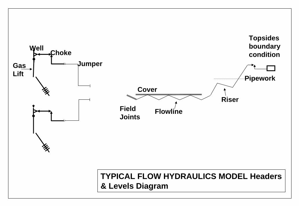
Gas Lift
Topsides boundarycondition
Well ChokeJumper
Field Joints
Cover
FlowlineRiser
Pipework
TYPICAL FLOW HYDRAULICS MODEL Headers & Levels Diagram

ANNULAR-DISPERSED FLOW SLUG FLOW DISPERSED-BUBBLE FLOW
100
103
102
104
101
10-3 101100 10210-110-2 103 104
ANNULAR-DISPERSEDLIQUID
DISPERSED-BUBBLE
SLUG
INTERMITTENT
PLUG
STRATIFIED-WAVE
STRATIFIED-SMOOTH
STRATIFIED-WAVY FLOW STRATIFIED FLOW PLUG FLOW
LIQUID PHASE MOMENTUM FLUX
GA
S PH
ASE
MO
MEN
TUM
FLU
X
MULTI-PHASE FLOW REGIMES

MULTIPHASE FLOW REGIMES
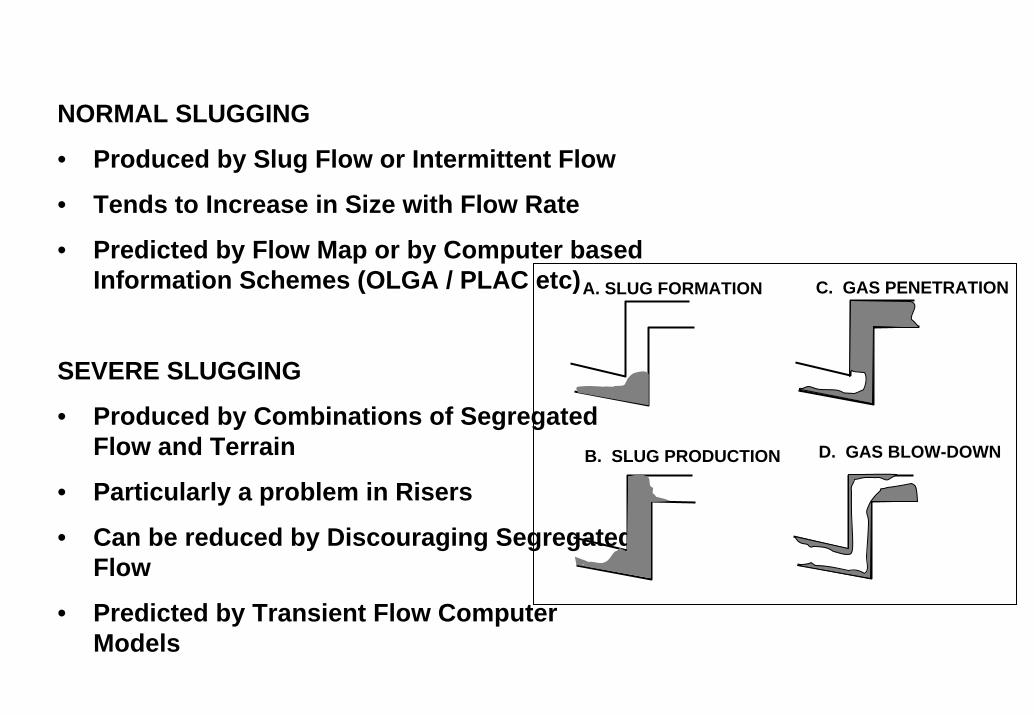
NORMAL SLUGGING
• Produced by Slug Flow or Intermittent Flow
• Tends to Increase in Size with Flow Rate
• Predicted by Flow Map or by Computer based Information Schemes (OLGA / PLAC etc)
SEVERE SLUGGING
• Produced by Combinations of Segregated Flow and Terrain
• Particularly a problem in Risers
• Can be reduced by Discouraging Segregated Flow
• Predicted by Transient Flow Computer Models
A. SLUG FORMATION C. GAS PENETRATION
B. SLUG PRODUCTION D. GAS BLOW-DOWN

Hydrates are snow-like crystals which form at low temperatures and high pressures. They are a combination of water and methane (gas) molecules. Once formed they are quite stable.
If formed in pipelines they can cause a total blockage.
Their formation can be predicted from temperature –pressure data
GAS HYDRATES
Methane hydrate phase diagram. The horizontal axis shows temperature from -15 to 33 Celsius, the vertical axis shows pressure from 0 to 120,000 kilopascals (0 to 1,184 atmospheres). For example, at 4 Celsius hydrate forms above a pressure of about 50 atmospheres

HYDRATES PREVENTION
• OPERATING PIPELINES AT LOW PRESSURE
• OPERATING OR MAINTAINING PIPELINES AT HIGH TEMPERATURES
- Insulation of Lines- Active heating of lines (hot Water or Electrical Heating)
• INHIBITION BY CHEMICAL ADDITION
- Use of Methanol or Glycol Chemicals
- Other Chemicals which block Hydrates Initiation
• REMOVAL OF WATER (Dehydration)
- Liquid or Solid Desiccants
- Subsea Separation
Hydrate Plug

DIPSIS - SUBSEA WATER SEPARATION AND RE-INJECTION
Diagrammatic Representation
SEPARATOR PUMPS
UMBILICAL
SUBSEA CONTROL SYSTEM
ELECTRIC POWER CONNECTOR

WAX DEPOSITION• 10% to 20% of Crudes are considered Waxy
• The Formation of Wax can completely Block Flow
• Waxy Crude is characterised by one or more of the following :-
- Cloud Temperature
- Pour Point Temperature
- Inversion Temperature (melting)
• Wax Deposition Prediction
- By Models and Predictions based on Fluid Properties
WAX PREVENTION• Insulation to Maintain Temperature
• Scraper Pigging
• Heating using Steam or Electricity
• Hot Oil Flushing
• Chemical Injection of Wax Inhibitors
Wax Plug

PIGGING
CLEANING PIG
SUBSEA PIG LAUNCHER

POSSIBLE COLD POINTS IN SUBSEA PRODUCTION SYSTEM
Poor Insulated Riser
Non-Insulated connection between Tree or Manifold & flow Jumper or Flowline
Non-Insulated connection between or Flowline & Riser BasePressure Drop in Chokes or Flow
Path leading to Joule-Thompson Cooling
Poor Insulation of Trees and Manifolds

INCREASED USE OF INSULATION ON SUBSEA EQUIPMENT

FLOWLINE INSULATION
SIMPLE PIPE PIPE IN PIPESTEEL PIPE INSIDE ANOTHER WITH PU FOAM BETWEEN
CONDUCTIVITY =
0.2 – 0.4 W/m/K
STEEL PIPE DESIGNED FOR PRESSURE CONTAINMENT
CONDUCTIVITY = 1.4 W/m/K
INSULATED FLOW BUNDLEFLOWLINE BUNDLE
INDIVIDUAL PIPES INSIDE A CARRIER PIPE.
CAN HAVE HOT WATER CIRCULATED
BUNDLE BUT WITH INSULATION FOAM SURROUNDING CARRIER PIPES

6” ID pipe 20 m long
24 heat tracing armours
16 electrical cables
7 SS tubes
+ Optical Fibres for monitoring
(Distributed Temperature Sensing)
FLEXIBLE PIPEDeepwater Solution - Integrated
Production Bundle – Heat Traced


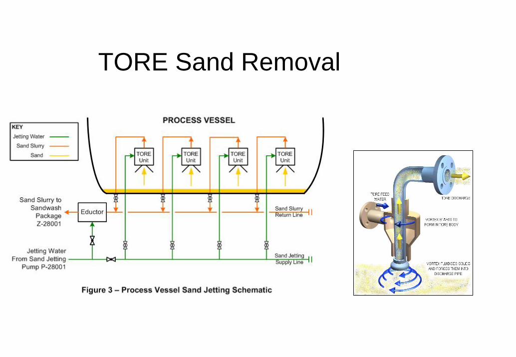
TORE Sand Removal


Related Documents


