General Information 2 Installation Information 8 Controls & Operation 15 Component Access & Removal 37 Troubleshooting Guide 53 Technical Data 62 Wiring Diagrams 64 subzero.com 800.222.7820 L Series Wall Oven Service Manual

Welcome message from author
This document is posted to help you gain knowledge. Please leave a comment to let me know what you think about it! Share it to your friends and learn new things together.
Transcript

General Information 2
Installation Information 8
Controls & Operation 15
Component Access & Removal 37
Troubleshooting Guide 53
Technical Data 62
Wiring Diagrams 64
subzero.com 800.222.7820
L Series Wall OvenService Manual
Page 2
General Information Wall OOvens
1-2
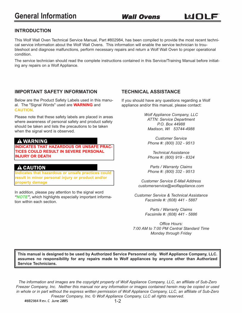
INTRODUCTION
This Wolf Wall Oven Technical Service Manual, Part #802984, has been compiled to provide the most recent techni-cal service information about the Wolf Wall Ovens. This information will enable the service technician to trou-bleshoot and diagnose malfunctions, perform necessary repairs and return a Wolf Wall Oven to proper operationalcondition.The service technician should read the complete instructions contained in this Service/Training Manual before initiat-ing any repairs on a Wolf Appliance.
IMPORTANT SAFETY INFORMATIONBelow are the Product Safety Labels used in this manu-al. The "Signal Words" used are WARNING andCAUTION.
Please note that these safety labels are placed in areaswhere awareness of personal safety and product safetyshould be taken and lists the precautions to be takenwhen the signal word is observed.
TECHNICAL ASSISTANCE
If you should have any questions regarding a Wolfappliance and/or this manual, please contact:
Wolf Appliance Company, LLCATTN: Service Department
P.O. Box 44988Madison, WI 53744-4988
Customer Service Phone #: (800) 332 - 9513
Technical AssistancePhone #: (800) 919 - 8324
Parts / Warranty ClaimsPhone #: (800) 332 - 9513
Customer Service E-Mail [email protected]
Customer Service & Technical AssistanceFacsimile #: (608) 441 - 5887
Parts / Warranty ClaimsFacsimile #: (608) 441 - 5886
Office Hours:7:00 AM to 7:00 PM Central Standard Time
Monday through Friday
This manual is designed to be used by Authorized Service Personnel only. Wolf Appliance Company, LLC.assumes no responsibility for any repairs made to Wolf appliances by anyone other than AuthorizedService Technicians.
INDICATES THAT HAZARDOUS OR UNSAFE PRAC-TICES COULD RESULT IN SEVERE PERSONALINJURY OR DEATH
Indicates that hazardous or unsafe practices couldresult in minor personal injury or product and/orproperty damage
In addition, please pay attention to the signal word“NOTE”, which highlights especially important informa-tion within each section.
The information and images are the copyright property of Wolf Appliance Company, LLC, an affiliate of Sub-ZeroFreezer Company, Inc. Neither this manual nor any information or images contained herein may be copied or usedin whole or in part without the express written permission of Wolf Appliance Company, LLC, an affiliate of Sub-Zero
Freezer Company, Inc. © Wolf Appliance Company, LLC all rights reserved.

Page 3
General InformationWall OOvens
1-5
Serial Tag Location
WARRANTY INFORMATION
This page contains a summary of the 2 & 5 Year Warranty that is supplied with every Wolf product, followed bydetails and notes about the warranties.
TWO & FIVE YEAR Warranty Summary
• Two year TOTAL PRODUCT warranty, *parts and labor.• Limited Parts Only Warranty for the 3rd through 5th year on the following parts only:
Electric heating elementsElectronic Control Boards
Warranty Details:
The warranty applies only to products installed for normal residential use. The warranty applies only to productinstalled in the United States or Canada.
Warranty Notes:
• All warranties begin at the time of the unit’s initial installation.• All Warranty and Service information collected by Wolf Appliance Company, LLC. is arranged and
stored under the unit serial number and/or the customer’s name. Please note that Wolf Appliance Company LLC. requests that you have the model serial number available whenever contacting the factory or parts distributor.
• See Figure 1-1 for serial tag layout.• See Figure 1-2 for serial tag location.
Wolf Appliance Company, LLC VOLTS :
Hz :
MODEL# : WALL OVENFOR HOUSEHOLD USE ONLY
240
60
"DO NOT IMMERSE IN WATER" "NE PAS PLONGE DANS L'EAU"
70FN
Fitchburg, WI
SERIAL# :
KW :
Figure 1-1. Typical Serial Tag Layout
Figure 1-2. The serial tag is located underneath the control panel.

Page 4
General Information Wall OOvens
1-6
MODEL NUMBER KEY
Refer to this key for an example of the model numbers.
Model: SO 30 F / S
Product Type
Size
FuelFeature (If Applicable)
Finish
Product Type
SO Single Oven
DO Double Oven
CT Cooktop
Size
30 30 - inch wide unit
36 36 - inch wide unit
Fuel
E Electric
Oven Door
F Framed
U Unframed
Finish
S Classic Stainless Steel
P Platinum Stainless Steel
B Carbon Stainless Steel
Page 5
General InformationWall OOvens
1-7
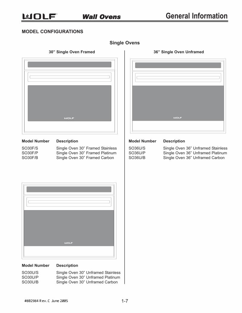
MODEL CONFIGURATIONS
30” Single Oven Framed
Model Number Description
SO30F/S Single Oven 30” Framed StainlessSO30F/P Single Oven 30” Framed PlatinumSO30F/B Single Oven 30” Framed Carbon
Model Number Description
SO30U/S Single Oven 30” Unframed StainlessSO30U/P Single Oven 30” Unframed PlatinumSO30U/B Single Oven 30” Unframed Carbon
Single Ovens
36” Single Oven Unframed
Model Number Description
SO36U/S Single Oven 36” Unframed StainlessSO36U/P Single Oven 36” Unframed PlatinumSO36U/B Single Oven 36” Unframed Carbon

Page 6
General Information Wall OOvens
1-8
30” Double Oven Framed
Double Ovens
30” Double Oven Unframed
Model Number Description
DO30F/S Double Oven 30” Framed StainlessDO30F/P Double Oven 30” Framed PlatinumDO30F/B Double Oven 30” Framed Carbon
Model Number Description
DO30U/S Double Oven 30” Unframed StainlessDO30U/P Double Oven 30” Unframed PlatinumDO30U/B Double Oven 30” Unframed Carbon

Page 7
General InformationWall OOvens
1-9
• Two door styles Traditional Framed (30”)Contemporary Unframed (30” & 36”)
• Framed door finish Classic Stainless Steel
• Unframed door finishes Classic Stainless SteelPlatinum Stainless SteelCarbon Stainless Steel
• Dual Convection Logic Control System• Rotating Control Panel• Touch Control Panel• Door Hinge with Hydraulic Damper System• Large Viewing Window• Triple Pane Window• Dual Halogen Lighting• Temperature Probe and Receptacle• Six Level Rack Guide• Full Extension Bottom Rack• Hidden Bake Element• Broil Element• Bake Mode• Convection Mode• Convection Bake Mode• Broil Mode• Convection Broil Mode• Roast Mode• Convection Roast Mode• Bake Stone Mode (Bake Stone Optional)• Self-Clean Mode• Sabbath Mode
OVEN FEATURES

Page 8
Installation Information Wall OOvens
2-2
INSTALLATION INFORMATON
This section of the manual covers some of the installation issues a service technician may need to know when serv-icing a Wolf Wall Oven. If additional information is needed after reviewing this section of the manual, please refer tothe Installation Guide or contact the Wolf Appliance Customer Service Department.
Electrical Requirements:
Single Oven• 208/220-240 volts AC, 60 Hertz, 30 Ampere fused electrical supply.
Double Oven• 208/220-240 volts AC, 60 Hertz, 50 Ampere fused electrical supply.
Minimum Wire Size:
• L1, L2 and Ground: 10 AWG• Neutral: 12 AWG
This appliance must be properly grounded. This appliance is equipped with a 60” conduit consisting of two insulatedhot lead copper conductors, one insulated neutral copper conductor and one uninsulated ground copper conductor.
THIS APPLIANCE MUST BE PROPERLY GROUNDED AT ALL TIMES WHEN ELECTRICAL POWER ISAPPLIED.
DO NOT GROUND THE APPLIANCE WITH THE NEUTRAL (WHITE) HOUSE SUPPLY WIRE. A SEPERATEGROUND WIRE MUST BE UTILIZED.
IF ALUMINUM HOUSE SUPPLY WIRING IS UTILIZED, SPLICE THE APPLIANCE COPPER WIRE TO THE ALU-MINUM HOUSE WIRING USING SPECIAL CONNECTORS DESIGNED AND CERTIFIED FOR JOINING COPPERAND ALUMINUM. FOLLOW THE CONNECTORS MANUFACTURERS RECOMMENDED PROCEDURE CARE-FULLY. IMPROPER CONNECTION CAN RESULT IN A FIRE HAZARD.

Page 9
Installation InformationWall OOvens
2-3
Flat Washers
2x3/4"8-32crewSc
x1/2"8-18xrewScr
6-18x1"Mounting Screw
Figure 2-1. Trim Installation
Figure 2-2. Cabinet Mounting Screws
Oven Installation
Use the upper edge of the cavity opening and the bot-tom of the oven chassis side as gripping points to liftthe oven into the cabinet cutout. Slide the oven into therecessed area until the unit is approximately six inchesfrom being fully installed. This will allow for installationof the oven trim kit.
NOTE: The oven door(s) may be removed to reducethe weight of the oven when lifting into cabinet opening.
Trim Installation
Attach the left and right side trim to the bottom and mid-dle trim prior to installing on the oven. (See Figure 2-1).
NOTE: The middle trim is for double ovens only.
Peel off the adhesive backing on the flat washers.Attach the flat washers centered over the holes of theraised sides of the oven cavity frame.
NOTE: Four washers for single oven and eight wash-ers for double oven.
Install the trim to the oven using the screws provided inthe trim kit. Now, locate the mounting holes found onthe sides of the oven trim. Then, use a drill with a 1/16”drill bit and drill four pilot holes for the cabinet mountingscrews. Install the mounting screws through the ovenside trim and into the cabinet. (See figure 2-2).
NOTE: Do not overtighten the mounting screws.
FAILURE TO INSTALL THE MOUNTING SCREWSMAY RESULT IN MOVEMENT OR TIPPING OF THEOVEN DURING USE.
Do not block the oven air exhaust located at thebottom of the oven. Blocking the exhaust mayresult in cabinet damage and poor baking perform-ance.
Do not lift or carry the oven door(s) by the doorhandle.

Page 10
Installation Information Wall OOvens
2-4
50"(1269mm)
24"(610mm) 29 7/8"
(759mm)
Figure 2-5. 30” Double Oven Overall Dimensions
27 1/2"(699mm)
24"(610mm) 29 7/8"
(759mm)
Figure 2-3. 30” Single Oven Overall Dimensions
24 3/8"(619mm)
24"(610mm)
35 5/8"(905mm)
Figure 2-4. 36” Single Oven Overall Dimensions
WALL OVEN DIMENSIONS

Page 11
Wall OOvens
2-5
Installation InformationCABINET CUTOUT DIMENSIONS
Single 30 Inch Wall Oven
27 3/16"(691)
4 3/4" min (121)
3 3/4" min (95)
28 1/2"(724)
E 5"
(127)
4"(102)
4 3/4" min (121)
24" min(610)
E5"
(127)
ELECTRICALLOCATION IN
ADJACENT RIGHTSIDE CABINET
4"(102)
33" (838)
RECOMMENDED CABINET WIDTH
30" min (762)
NOTE: Dimensions in parentheses are in millimeters .
27 3/16"(691)
3 3/4" min(95)
36" (914)
STANDARD
FLOOR TO
COUNTER
HEIGHT
27 3/16"(691)
28 1/2"(724)
5"(127)
4"(102)
E
33" (838)
RECOMMENDED CABINET WIDTH
30" min (762)
Figure 2-6. Undercounter Cutout Dimensions and Electrical Placement
24" min(610)
67" max(1702)
NOTE: Dimensions in
parentheses are in
millimeters.
RIGHT SIDE
CABINET VIEW
Figure 2-7. Front Cutout Dimensions and Electrical Placement Figure 2-8. Side View

Page 12
Installation Information Wall OOvens
2-6
CABINET CUTOUT DIMENSIONS
Single 36 Inch Wall Oven
24 1/16"(611)
24 1/16"(611)
3 3/4" min (95)
E 5"
(127)
4"(102)
24" min(610)
E5"
(127)
3 3/4" min(95)
39" (991)
RECOMMENDED CABINET WIDTH
36" min (914)
34 1/2"(876 )
ELECTRICALLOCATION IN
ADJACENT RIGHTSIDE CABINET
4"(102)
NOTE: Dimensions in parentheses are in millimeters .
36" (914)
STANDARD
FLOOR TO
COUNTER
HEIGHT
7 3/4" (197) rec
4 3/4" (121) min
7 3/4" (197) rec
4 3/4" (121) min
24 1/16"(611)
34 1/2"(876 )
5"(127)
4"(102)
E
39" (991)
RECOMMENDED CABINET WIDTH
36" min (914)
Figure 2-9. Undercounter Cutout Dimensions and Electrical Placement
24" min(610)
67" max(1702)
Dimensions in
parentheses are in
millimeters.
RIGHT SIDE
CABINET VIEW
NOTE:
Figure 2-10. Front Cutout Dimensions and Electrical Placement Figure 2-11. Side View

Page 13
Installation InformationWall OOvens
2-7
CABINET CUTOUT DIMENSIONS
Double 30 Inch Wall Oven
24" min(610)
67" max(1702)
NOTE: Dimensions in
parentheses are in
millimeters.
RIGHT SIDE
CABINET VIEW
49 5/8"(1260)
28 1/2"(724)
33" (838)
RECOMMENDED CABINET WIDTH
30" min (762)
5"(127)
4"(102)
E
Figure 2-12. Front Cutout Dimensions and Electrical Placement Figure 2-13. Side View

Page 14
Installation Information Wall OOvens
2-8
CABINET CUTOUT DIMENSIONS
Side-by-Side Wall Oven
27 3/16"(691)
E 5"
(127)
4"(102)
4 3/4" min (121)
24" min(610)
E5"
(127)
ELECTRICALLOCATION IN
ADJACENT RIGHTSIDE CABINET
4"(102)
28 1/2"(724)
30" OVEN CUT-OUT
27 3/16"(691)
4 3/4" min (121)
E 5"
(127)
4"(102)
28 1/2"(724)
30" OVEN CUT-OUT
27 3/16"(691)
3 3/4" min(95)
7 1/2"(191)
3 3/4" min (95)
36" (914)
STANDARD
FLOOR TO
COUNTER
HEIGHT
NOTE: Dimensions in parentheses are in millimeters .
24 1/16"
(611)
E 5"
(127)
4"(102)
24" min
(610)
E5"
(127)
34 1/2"
(876)
36" OVEN CUT-OUT
24 1/16"
(611)
E 5"
(127)
4"(102)
34 1/2"
(876)
36" OVEN CUT-OUT
3 3/4" min (95)3 3/4" min (95)
7 1/2"(191)
24 1/16"(611)
ELECTRICAL
LOCATION IN
ADJACENT RIGHT
SIDE CABINET
4"(102)
36" (914)
STANDARD
FLOOR TO
COUNTER
HEIGHT
7 3/4" (197) rec
4 3/4" (121) min
7 3/4" (197) rec
4 3/4" (121) min
NOTE: Dimensions in parentheses are in millimeters .
Figure 2-14. Undercounter Cutout Dimensions and Electrical Placement for SO30
Figure 2-15. Undercounter Cutout Dimensions and Electrical Placement for SO36

Page 15
Wall OOvensElectronic Control System
3-2
ELECTRONIC CONTROL TERMINOLOGY & COMPONENT DESCRIPTIONS
All Wolf wall ovens utilize an electronic control system. The electronic control system monitors, regulates and con-trols a variety of functions. The control system also displays error codes to identify possible problems with the unit.The table below defines some of the basic electronic control system terminology and describes some of the elec-tronic system components. An understanding of the following information is needed in order to comprehend theinput operations and functions of the electronic control system.
Term / Component Definition / Description
Oven Controller.......................................The printed circuit board containing the microprocessor and logic inputs which communicates with the oven display, keyboard, stepper motor controlboard.
Relay Board............................................The printed circuit board containing the microprocessor, relays and electricalconnections which control and monitor functions and operations of the unit.
Oven Display...........................................A vacuum fluorescent display which shows oven temperature, cooking modes, error codes, cook times and stop time.
Stepper Motor Control Board..................The printed circuit board containing a transformer and logic control to drive the stepper motor.
Control Panel Assembly..........................The head assembly containing the oven display(s) and keyboard.
Relays.....................................................The electrical components on the relay board that switch other components in the unit ON and OFF when instructed to do so by the microprocessor.
Microprocessor........................................An electrical component on the control board which receives electrical sig-nals from other components, processes that information, then sends an electrical signal to the relays on the board to open or close, and other com-ponents in the unit to switch on or off.
Keyboard.................................................An assembly of glass and mylar which connects into the upper oven display.
Error Codes.............................................Number or word description which appears on the oven display if the unit experiences specific problems related to electrical signals supplied by the electrical components.
MDL.........................................................Motor door latch assembly which incorporates the latch motor drive, unlatchswitch, latch switch and door switch.
RTD.........................................................The oven(s) temperature sensing device.
dlb............................................................A component on the relay board which is a relay that connects and discon-nects the L2 line to the elements when energized by logic from the oven controller.

Page 16
Electronic Control SystemWall OOvens
3-3
UNIQUE ELECTRONIC CONTROL INPUT OPERATIONS
The following few pages illustrate electronic control input operations that you would not expect a customer to perform everyday.The input operations described are: Field Option Mode, Sabbath Mode, Delayed Start Mode, Probe Mode and Self-Clean Mode.
Field Option Mode Field option mode allows for the user to adjust specific options of the oven controller, such as User Preference Offset (adjustingtemperature ± 35°) and Temperature Display Preference (choosing between °F, Fahrenheit or °C, Celsius).
NOTE: Field Option Mode must be entered with the oven(s) turned OFF.
To initiate the Field Option Mode for the Upper Oven, press and hold the TEMPERATURE key for the Upper Oven for five sec-onds.To initiate the Field Option Mode for the Lower Oven, press and hold the TEMPERATURE key for the Lower Oven for five sec-onds.To initiate the Field Option Mode for the Single Oven, press and hold the TEMPERATURE key for five seconds.
NOTE: Pressing the CLEAR key will cancel the Field Option Mode.
User Preference Offset
This option allows the user to offset a specific oven temperature ±35° in 1°F (Fahrenheit) increments. Once in Field OptionMode, press the number keys to input the numeric value of the offset and press the TEMPERATURE key to toggle between ±.The new offset is accepted ten seconds after the last key stroke or by pressing the ENTER key. (See Figure 3-1). Pressing theCLEAR key will cancel the Field Option Mode.
NOTE: User Preference Offset will only work for °F (Fahrenheit).
OFF ONTIMERCLOCK TEMPERATURE
BAKE
OVEN
ROAST
BROIL
BAKE STONE
CONV. BAKE
CONV. ROAST
CONV. BROIL
CONVECTION
1 2 3
4 5 6
7 8 9
ENTER 0 CLEAR
LIGHT
PROBE
COOK TIME
SELF CLEAN
STOP TIME
PANEL LOCK
ON/OFF
ON/OFF
3 00.. 0 °
f
set upo
OFF ONTIMERCLOCK TEMPERATURE
BAKE
OVEN
ROAST
BROIL
BAKE STONE
CONV. BAKE
CONV. ROAST
CONV. BROIL
CONVECTION
1 2 3
4 5 6
7 8 9
ENTER 0 CLEAR
LIGHT
PROBE
COOK TIME
SELF CLEAN
STOP TIME
PANEL LOCK
ON/OFF
ON/OFF
3 00.. °
F
OFF ONTIMERCLOCK TEMPERATURE
BAKE
OVEN
ROAST
BROIL
BAKE STONE
CONV. BAKE
CONV. ROAST
CONV. BROIL
CONVECTION
1 2 3
4 5 6
7 8 9
ENTER 0 CLEAR
LIGHT
PROBE
COOK TIME
SELF CLEAN
STOP TIME
PANEL LOCK
ON/OFF
ON/OFF
3 00.. °
c
Figure 3-1. User Preference Offset. Press and HOLD the TEMPERATURE key for five seconds. Then, press the numberkeys to enter a new numeric value up to 35. Now, press the TEMPERATURE key to toggle between ±.
Figure 3-2. Temperature Display Preference. Must be in Field Option Mode. Now, press the COOK TIME key to togglebetween °C and °F.
Temperature Display Preference
This option allows the user to choose how the temperature is displayed, °F (Fahrenheit) or °C (Celsius), and/or back again.Once in Field Option Mode, press the COOK TIME key to toggle between °C and °F. The new display, °C or °F is accepted tenseconds after the last key stroke or by pressing the ENTER key. See Figure 3-2. Pressing the CLEAR key will cancel the FieldOption Mode.

Page 17
Wall OOvensElectronic Control System
3-4
Sabbath Feature
Sabbath Feature was incorporated into the electronic control system for the observance of certain religious holidays.Once Sabbath Mode has been entered, all of the oven functions have been disabled except the OFF key.
To initiate Sabbath feature, the oven must be OFF. Press UPPER or LOWER OVEN ON key for a double oven orOVEN ON key for a single oven. (See Figure 3-3). Turn on the interior oven lights by pressing the OVEN LIGHTON key (Optional). Press the BAKE key. A preset temperature of 350° will be shown in the display. To change tem-perature, immediately enter another temperature using the number keys, then press ENTER. (See Figure 3-4).Now, press and hold the ENTER key for five seconds. The oven will chime twice and the word SABBATH appearsin the display window. (See Figure 3-5). Repeat these steps above for each oven(s).
To exit the Sabbath Mode, press the UPPER or LOWER OVEN OFF key or the OVEN OFF key, depending on themodel. (See Figure 3-6).
NOTE: The oven(s) will remain on until the Sabbath Mode is cancelled.
Figure 3-4. Press the BAKE key. A preset temperature of 350°F will be shown in the display. To change temperature, immediately enter another temperature using the number keys. Then, press ENTER.
Figure 3-6. To exit Sabbath Mode. Press the Oven OFF key.For Double Ovens select either Upper Oven OFF key or Lower Oven OFF key.
OFF ONTIMERCLOCK TEMPERATURE
BAKE
OVEN
ROAST
BROIL
BAKE STONE
CONV. BAKE
CONV. ROAST
CONV. BROIL
CONVECTION
1 2 3
4 5 6
7 8 9
ENTER 0 CLEAR
LIGHT
PROBE
COOK TIME
SELF CLEAN
STOP TIME
PANEL LOCK
ON/OFF
ON/OFF
..select mode
f
f
3 00
Figure 3-3. To initiate Sabbath Mode, the oven must be OFF. Press Oven ON key.For Double Ovens select either Upper Oven ON key or Lower Oven ON key.
OFF ONTIMERCLOCK TEMPERATURE
BAKE
OVEN
ROAST
BROIL
BAKE STONE
CONV. BAKE
CONV. ROAST
CONV. BROIL
CONVECTION
1 2 3
4 5 6
7 8 9
ENTER 0 CLEAR
LIGHT
PROBE
COOK TIME
SELF CLEAN
STOP TIME
PANEL LOCK
ON/OFF
ON/OFF
OVEN ON
3 00..
TEMPERATURE
350°f
bake setpoint
f
OFF ONTIMERCLOCK TEMPERATURE
BAKE
OVEN
ROAST
BROIL
BAKE STONE
CONV. BAKE
CONV. ROAST
CONV. BROIL
CONVECTION
1 2 3
4 5 6
7 8 9
ENTER 0 CLEAR
LIGHT
PROBE
COOK TIME
SELF CLEAN
STOP TIME
PANEL LOCK
ON/OFF
ON/OFF
f
OVEN ON
..TEMPERATURE
350°f
sabbath setpoint
3 00
OFF ONTIMERCLOCK TEMPERATURE
BAKE
OVEN
ROAST
BROIL
BAKE STONE
CONV. BAKE
CONV. ROAST
CONV. BROIL
CONVECTION
1 2 3
4 5 6
7 8 9
ENTER 0 CLEAR
LIGHT
PROBE
COOK TIME
SELF CLEAN
STOP TIME
PANEL LOCK
ON/OFF
ON/OFF
f
..
f
3 00
Figure 3-5. Now, press and HOLD THE ENTER key for 5 seconds. The oven will chime twice and the word Sabbath appears in the display.

Page 18
Electronic Control SystemWall OOvens
3-5
Time Cook Feature
Time Cook Feature controls the automatic timing of the oven(s) ON and OFF function by setting the cooking time tostart immediately and turn off when the desired cooking is complete. To accomplish time cook, the time of day clockis used and therefore the correct time must be displayed prior to programming.
To initiate Time Cook, the oven must be OFF. First press the Oven ON key. (See Figure 3-7). For Double Ovenspress the Upper Oven ON key or the Lower Oven ON key. Now, press a desired cooking mode (example BakeMode). A preset temperature of 350°F is shown in the display. To change the temperature from 350°F, immediatelyenter another temperature using the number keys. (See Figure 3-8). Then, press the COOK TIME key. Then, enterthe hours/minutes desired for cooking. The oven(s) will start heating after a five second delay or by pressing theENTER key. (See Figure 3-9). To exit TIME COOK feature, pess the Oven OFF key. (See Figure 3-10). For theDouble Oven, press the Upper Oven OFF key or the Lower Oven Off key.
NOTE: The oven should always be preheated in this mode. The oven will chime after the oven reaches preheattemperature.
Figure 3-8. Press a desired Cooking Mode. (Example: Bake Mode). A preset temperature of 350°F will be shown in thedisplay. To change temperature, immediately enter another temperature using the number keys.
Figure 3-10. To exit the Cook Time Feature. Press the Oven OFF key.For Double Ovens select either Upper Oven OFF key or Lower Oven OFF key.
OFF ONTIMERCLOCK TEMPERATURE
BAKE
OVEN
ROAST
BROIL
BAKE STONE
CONV. BAKE
CONV. ROAST
CONV. BROIL
CONVECTION
1 2 3
4 5 6
7 8 9
ENTER 0 CLEAR
LIGHT
PROBE
COOK TIME
SELF CLEAN
STOP TIME
PANEL LOCK
ON/OFF
ON/OFF
f
3 00..
select mode
f
Figure 3-7. To initiate Time Cook Feature, the oven must be OFF. Press Oven ON key.For Double Ovens select either Upper Oven ON key or Lower Oven ON key.
OFF ONTIMERCLOCK TEMPERATURE
BAKE
OVEN
ROAST
BROIL
BAKE STONE
CONV. BAKE
CONV. ROAST
CONV. BROIL
CONVECTION
1 2 3
4 5 6
7 8 9
ENTER 0 CLEAR
LIGHT
PROBE
COOK TIME
SELF CLEAN
STOP TIME
PANEL LOCK
ON/OFF
ON/OFF
OVEN ON
3:00
TEMPERATURE
350°f
SETPOINT
f
Bake
OFF ONTIMERCLOCK TEMPERATURE
BAKE
OVEN
ROAST
BROIL
BAKE STONE
CONV. BAKE
CONV. ROAST
CONV. BROIL
CONVECTION
1 2 3
4 5 6
7 8 9
ENTER 0 CLEAR
LIGHT
PROBE
COOK TIME
SELF CLEAN
STOP TIME
PANEL LOCK
ON/OFF
ON/OFF
f
OVEN ON
3:00bake
TEMPERATURE
350°f
SETPOINT
COOK TIME
2:30
HOURS MINUTES
STOP TIME
5:30
MINUTESHOURS
OFF ONTIMERCLOCK TEMPERATURE
BAKE
OVEN
ROAST
BROIL
BAKE STONE
CONV. BAKE
CONV. ROAST
CONV. BROIL
CONVECTION
1 2 3
4 5 6
7 8 9
ENTER 0 CLEAR
LIGHT
PROBE
COOK TIME
SELF CLEAN
STOP TIME
PANEL LOCK
ON/OFF
ON/OFF
f
f
3:00
Figure 3-9. Now, press the Cook Time key. Now, enter the hours/minutes desired for cooking. The Stop Time will auto-matically be entered in the display. Then, press the ENTER key. The oven(s) will now start heating and then turn off
when the cooking times has completed.

Page 19
Wall OOvensElectronic Control System
3-6
Delayed Start Feature
This feature controls the automatic timing of the oven(s) ON and OFF function by setting the cooking mode to start laterin the day and turn off when the cooking is complete. It can also be set to turn off at a preset time. To accomplishdelayed start and/or stop, the time of day clock is used and therefore the correct time must be displayed prior to pro-gramming.NOTE: This mode will work for all cooking modes except Broil, Convection Broil and Bake Stone Mode.To initiate Delayed Start Mode, the oven must be OFF. Press the Upper or Lower Oven ON key or the Oven ON key,depending on the model. (See Figure 3-11). Press the desired cooking mode key. (See Figure 3-12). To change pre-set temperature, immediately enter another temperature using the number keys, then press Enter. Next, press StopTime. Then, using the number keys, enter the time for which the oven needs to turns off. Example: Set 6:00 for thetime of day the oven turns off. (See Figure 3-13). Then, enter the Cook Time using the number keys to set thehours/minutes the oven will stay on. Example: Set 3:30 for the oven to remain on for 3-1/2 hours. Now, press theENTER key. (See Figure 3-14). The display appears as if the oven is on. To exit Delayed Start Mode, press Upper orLower Oven OFF or Oven OFF key. (See Figure 3-15).NOTE: With the example used above, heating will not start for 3-1/2 hours prior to 6 o’clock which will be 2:30 on the timeof day clock.
OFF ONTIMERCLOCK TEMPERATURE
BAKE
OVEN
ROAST
BROIL
BAKE STONE
CONV. BAKE
CONV. ROAST
CONV. BROIL
CONVECTION
1 2 3
4 5 6
7 8 9
ENTER 0 CLEAR
LIGHT
PROBE
COOK TIME
SELF CLEAN
STOP TIME
PANEL LOCK
ON/OFF
ON/OFF
f
..select mode
f
8 00
f
f
Figure 3-11. To initiate Delayed Start Mode, Press Oven ON key.For Double Ovens select either Upper Oven ON key or Lower Oven ON key.
OFF ONTIMERCLOCK TEMPERATURE
BAKE
OVEN
ROAST
BROIL
BAKE STONE
CONV. BAKE
CONV. ROAST
CONV. BROIL
CONVECTION
1 2 3
4 5 6
7 8 9
ENTER 0 CLEAR
LIGHT
PROBE
COOK TIME
SELF CLEAN
STOP TIME
PANEL LOCK
ON/OFF
ON/OFF
f
..TEMPERATURE
350°f
bake setpoint
8 00
f
f
Figure 3-12. Press desired Cooking Mode. Bake, Roast, Convection Bake, Convection Roast or Convection. NOTE: Broil, Convection Broil and Bake Stone will not work in this mode.
OFF ONTIMERCLOCK TEMPERATURE
BAKE
OVEN
ROAST
BROIL
BAKE STONE
CONV. BAKE
CONV. ROAST
CONV. BROIL
CONVECTION
1 2 3
4 5 6
7 8 9
ENTER 0 CLEAR
LIGHT
PROBE
COOK TIME
SELF CLEAN
STOP TIME
PANEL LOCK
ON/OFF
ON/OFF
set stop time
8 00..
STOP TIMEMINUTESHOURS
TEMPERATURE
350°f
setpoint
f
f
: 6 00
f
Figure 3-13. Press Stop Time. Then, using number keys, enter time of day to turn oven off. Example 6:00
OFF ONTIMERCLOCK TEMPERATURE
BAKE
OVEN
ROAST
BROIL
BAKE STONE
CONV. BAKE
CONV. ROAST
CONV. BROIL
CONVECTION
1 2 3
4 5 6
7 8 9
ENTER 0 CLEAR
LIGHT
PROBE
COOK TIME
SELF CLEAN
STOP TIME
PANEL LOCK
ON/OFF
ON/OFF
f
f
8 00..
COOK TIME STOP TIMEHOURS MINUTES MINUTESHOURS
TEMPERATURE
350°f
set cook time setpoint
: 6 00: 3 30
f
Figure 3-14. Press Cook Time. Then, using number keys, enter hours/minutes the oven will stay on. Example 3:30. Now, press ENTER.
f
f
f
OFF ONTIMERCLOCK TEMPERATURE
BAKE
OVEN
ROAST
BROIL
BAKE STONE
CONV. BAKE
CONV. ROAST
CONV. BROIL
CONVECTION
1 2 3
4 5 6
7 8 9
ENTER 0 CLEAR
LIGHT
PROBE
COOK TIME
SELF CLEAN
STOP TIME
PANEL LOCK
ON/OFF
ON/OFF
8 00..
COOK TIME STOP TIMEHOURS MINUTES MINUTESHOURS
TEMPERATURE
350°f
bake setpoint
: 6 00: 3 30
Figure 3-15. Display appears as if oven is on.

Page 20
Electronic Control SystemWall OOvens
3-7
Temperature Probe Feature
The Temperature Probe Feature is used to measure internal temperatures of the food being cooked. It is an accu-rate way to achieve the perfect doneness regardless of the type, cut or weight of food. When using the TemperatureProbe Mode, program the recommended internal carving temperature, as found in the Use and Care InformationGuide. (See Figure 3-16). The temperature should be reduced by five degrees when setting the TemperatureProbe Mode.
145°F Medium Rare 170°F Breast160°F Medium 180°F Thigh170°F Well Done 165°F Stuffing
USDA Internal Temperature Recommendations
Beef, Lamb, Pork and Veal Poultry
Figure 3-16. USDA Internal Temperature RecommendationsTo initiate Temperature Probe Mode, first preheat the oven. Now, the probe should be inserted into the thickest partof the product being cooked. Plug the probe connector into the oven receptacle (located on the top right side of theoven cavity), all the way until it snaps into place. Next, press the PROBE key. (See Figure 3-17). Now, using thenumber keys enter the recommended internal cooking temperature minus five degrees. (See Figure 3-18). Then,press ENTER. The word “Lo” appears in the display as the probe temperature, until the probe registers 100°F.(See Figure 3-19). Once the probe has registered 100°F, the display will start showing the degrees rising up to theprogrammed setting for the probe temperature. Once the probe temperature has been reached the oven will chimethree times signaling the item being cooked is done. Now, unplug the probe connector from the oven receptacle. Toexit the Temperature Probe Mode, press the Oven OFF key. For the double oven, press the Upper Oven OFF keyor Lower Oven OFF key.
NOTE: The oven will continue to chime every thirty seconds until the probe has been removed from the ovenreceptacle.
NOTE: Oven temperature remains on even when temperature probe is unplugged.
OFF ONTIMERCLOCK TEMPERATURE
BAKE
OVEN
ROAST
BROIL
BAKE STONE
CONV. BAKE
CONV. ROAST
CONV. BROIL
CONVECTION
1 2 3
4 5 6
7 8 9
ENTER 0 CLEAR
LIGHT
PROBE
COOK TIME
SELF CLEAN
STOP TIME
PANEL LOCK
ON/OFF
ON/OFF
OVEN ON
3 00..
TEMPERATURE
350°f
probe
f
BAKE
f
OFF ONTIMERCLOCK TEMPERATURE
BAKE
OVEN
ROAST
BROIL
BAKE STONE
CONV. BAKE
CONV. ROAST
CONV. BROIL
CONVECTION
1 2 3
4 5 6
7 8 9
ENTER 0 CLEAR
LIGHT
PROBE
COOK TIME
SELF CLEAN
STOP TIME
PANEL LOCK
ON/OFF
ON/OFF
f
OVEN ON
..TEMPERATURE
888°f
probe
f
3 00BAKE
OFF ONTIMERCLOCK TEMPERATURE
BAKE
OVEN
ROAST
BROIL
BAKE STONE
CONV. BAKE
CONV. ROAST
CONV. BROIL
CONVECTION
1 2 3
4 5 6
7 8 9
ENTER 0 CLEAR
LIGHT
PROBE
COOK TIME
SELF CLEAN
STOP TIME
PANEL LOCK
ON/OFF
ON/OFF
f
f
OVEN ON
..TEMPERATURE
lo°f 3 00
probeBAKE
Figure 3-17. To initiate Temperature Probe Mode, press PROBE key.
Figure 3-18. Using number keys, enter internal cooking temperature minus five degrees.
Figure 3-19. Press ENTER, the word Lo appears in the oven display.

Page 21
Wall OOvensElectronic Control System
3-8
Self-Clean Mode
In Self-Clean Mode, the oven is heated in graduated stages to a preset high temperature. In Stage One, the bakeelement cycles for 0 - 36 seconds and the broil element cycles for 18 - 60 seconds. The cycling of the bake andbroil elements in Stage One last for the first twelve minutes. In Stage Two, the bake element cycles for 0 - 12 sec-onds and the broil element cycles for 12 - 60 seconds. The cycling of the elements in Stage Two continues until thehigh preset temperature of 850°F is obtained. During this process, food soil is burned off leaving some white ashresidue.
Once the Self-Clean Mode has been initiated the oven door locks, unless the Self-Clean Mode is used with theDelayed Start Mode. The oven door will remain locked until the oven temperature drops below 300°F.
NOTE: If the Self-Clean Mode is stopped once it has been started, the door will remain locked until the temperatureinside has cooled below 300°F.
NOTE: The average time for the Self-Clean Mode is three hours plus one hour to cool down.
NOTE: Only one oven can be self-clean at a time, if using a double oven.
NOTE: If self-cleaning one oven of a double oven, other oven is non-fuctional until self-clean is finished.
To initiate Self-Clean Mode, first the oven must be OFF. Press the Oven ON key. (See Figure 3-20). For DoubleOvens, press the Upper Oven ON key or Lower Oven ON key. Next, press the SELF-CLEAN key. Then, press theENTER key. (See Figure 3-21). To exit the Self-Clean Mode, press the Oven OFF key. (See Figure 3-22). ForDouble Oven press the Upper Oven OFF key or the Lower Oven OFF key.
NOTE: To use Self-Clean Mode with Delayed Start Mode, follow the instruction for Delayed Start Mode.
To change the Self-Clean time for 2 to 4 hours. Press the Oven ON key. Next, press the SELF-CLEAN key. Then,press the COOKTIME key. Now, using the number keys enter the desired self-cleaning time. (Example: 3 hours 15minutes). As long as the self-clean time is between 2 to 4 hours, the time can be entered. Then, press ENTER.
OFF ONTIMERCLOCK TEMPERATURE
BAKE
OVEN
ROAST
BROIL
BAKE STONE
CONV. BAKE
CONV. ROAST
CONV. BROIL
CONVECTION
1 2 3
4 5 6
7 8 9
ENTER 0 CLEAR
LIGHT
PROBE
COOK TIME
SELF CLEAN
STOP TIME
PANEL LOCK
ON/OFF
ON/OFF
3..
SElf cleanoven on00
COOK TIME
4:00
HOURS MINUTES
Figure 3-21. Press the SELF-CLEAN key. Then, press the ENTER key.
OFF ONTIMERCLOCK TEMPERATURE
BAKE
OVEN
ROAST
BROIL
BAKE STONE
CONV. BAKE
CONV. ROAST
CONV. BROIL
CONVECTION
1 2 3
4 5 6
7 8 9
ENTER 0 CLEAR
LIGHT
PROBE
COOK TIME
SELF CLEAN
STOP TIME
PANEL LOCK
ON/OFF
ON/OFF
3..
select modeoven on00
Figure 3-20. To initiate Self-Clean Mode, Press the Oven ON key. For Double Oven, press the Upper Oven ON key or the Lower Oven ON key.
OFF ONTIMERCLOCK TEMPERATURE
BAKE
OVEN
ROAST
BROIL
BAKE STONE
CONV. BAKE
CONV. ROAST
CONV. BROIL
CONVECTION
1 2 3
4 5 6
7 8 9
ENTER 0 CLEAR
LIGHT
PROBE
COOK TIME
SELF CLEAN
STOP TIME
PANEL LOCK
ON/OFF
ON/OFF
3..00
Figure 3-22. To exit the Self-Clean Mode, press the Oven OFF key.For Double oven, press the Upper Oven OFF key or the Lower Oven OFF key.

Page 22
Electronic Control SystemWall OOvens
3-9
ELECTRONIC CONTROL INPUT OPERATIONS
The following few pages illustrate electronic control input operations that you might expect a customer to performeveryday. The input operations described are: Bake, Convection, Convection Bake, Broil, Convection Broil, Roast,Convection Roast and Bake Stone Mode.
Bake Mode
In Bake Mode both the hidden bake element and the broil element are used to heat the air and cycle to maintaintemperature. The hidden bake element operates 80 percent of the time and the broil element operates 10 percentof the time. The oven(s) should always be preheated when using Bake Mode.
To initiate Bake Mode, the oven must be OFF. First press the Oven ON key. (See Figure 3-23). For Double Ovenspress the Upper Oven ON key or the Lower Oven ON key. Now, press the BAKE key. A preset temperature of350°F is shown in the display. The oven begins to heat after 5 seconds or by pressing the ENTER key. (See Figure 3-24). To change the temperature from 350°F, immediately enter another temperature using the numberkeys. Then, press the ENTER key. (See Figure 3-25). To exit the Bake Mode, press the Oven OFF key. (See Figure 3-26). For the Double Oven, press the Upper Oven OFF key or the Lower Oven Off key.
NOTE: The oven should always be preheated in this mode. The oven will chime after the oven reaches preheattemperature.
OFF ONTIMERCLOCK TEMPERATURE
BAKE
OVEN
ROAST
BROIL
BAKE STONE
CONV. BAKE
CONV. ROAST
CONV. BROIL
CONVECTION
1 2 3
4 5 6
7 8 9
ENTER 0 CLEAR
LIGHT
PROBE
COOK TIME
SELF CLEAN
STOP TIME
PANEL LOCK
ON/OFF
ON/OFF
f
3 00..
select mode
f
Figure 3-23. To initiate Bake Mode, Press the Oven ON key. For Double Oven, press the Upper Oven ON key or the Lower Oven ON key.
OFF ONTIMERCLOCK TEMPERATURE
BAKE
OVEN
ROAST
BROIL
BAKE STONE
CONV. BAKE
CONV. ROAST
CONV. BROIL
CONVECTION
1 2 3
4 5 6
7 8 9
ENTER 0 CLEAR
LIGHT
PROBE
COOK TIME
SELF CLEAN
STOP TIME
PANEL LOCK
ON/OFF
ON/OFF
OVEN ON
3:00
TEMPERATURE
350°f
bake SETPOINT
f
Figure 3-24. Press the BAKE key. A preset temperature of 350°F will be shown in the display. The oven begins to heat after 5 seconds or by pressing the ENTER key.
OFF ONTIMERCLOCK TEMPERATURE
BAKE
OVEN
ROAST
BROIL
BAKE STONE
CONV. BAKE
CONV. ROAST
CONV. BROIL
CONVECTION
1 2 3
4 5 6
7 8 9
ENTER 0 CLEAR
LIGHT
PROBE
COOK TIME
SELF CLEAN
STOP TIME
PANEL LOCK
ON/OFF
ON/OFF
f
OVEN ON
3:00bake
TEMPERATURE
375°f
SETPOINT
Figure 3-25. To change the preset temperature, immediately press the number keys to enter a new temperature. Then, press the ENTER key.
OFF ONTIMERCLOCK TEMPERATURE
BAKE
OVEN
ROAST
BROIL
BAKE STONE
CONV. BAKE
CONV. ROAST
CONV. BROIL
CONVECTION
1 2 3
4 5 6
7 8 9
ENTER 0 CLEAR
LIGHT
PROBE
COOK TIME
SELF CLEAN
STOP TIME
PANEL LOCK
ON/OFF
ON/OFF
f
f
3:00
Figure 3-26. To exit the Bake Mode, press the Oven OFF key.For Double oven, press the Upper Oven OFF key or the Lower Oven OFF key.

Page 23
Wall OOvensElectronic Control System
3-10
Convection Mode
The Convection Mode uses dual convection fans, each with heating elements mounted on the back wall of the ovencavity. The convection fans move air sequential, throughout the entire oven cavity creating uniform air movement.This air movement makes it possible to cook on all six levels of the cooking racks simultaneously. The heating ele-ments and convection fans are cycled sequentially (on and off), resulting in even browning.
NOTE: In Convection Mode, standard recipe temperature should be reduced by 25°F.
NOTE: The oven should always be preheated in this mode. The oven will chime after the oven reaches preheattemperature.
To initiate Convection Mode, the oven must be OFF. First, press the Oven ON key. (See Figure 3-27). For theDouble Ovens, press the Upper Oven ON key or the Lower Oven ON key. Now, press the CONVECTION key. Apreset temperature of 325°F will appear in the display. The oven begins to heat after 5 seconds or by pressing theENTER key. (See Figure 3-28). To change the temperature from the preset 325°F, immediately enter another tem-perature using the number keys. Then, press the ENTER key. (See Figure 3-29). To exit the Convection Mode,press the Oven OFF key. (See Figure 3-30). For Double Ovens press the Upper Oven OFF key or the Lower OvenOFF key.
OFF ONTIMERCLOCK TEMPERATURE
BAKE
OVEN
ROAST
BROIL
BAKE STONE
CONV. BAKE
CONV. ROAST
CONV. BROIL
CONVECTION
1 2 3
4 5 6
7 8 9
ENTER 0 CLEAR
LIGHT
PROBE
COOK TIME
SELF CLEAN
STOP TIME
PANEL LOCK
ON/OFF
ON/OFF
f
3 00..
f
select mode
Figure 3-27. To initiate Convection Mode, Press the Oven ON key. For Double Oven, press the Upper Oven ON key or the Lower Oven ON key.
OFF ONTIMERCLOCK TEMPERATURE
BAKE
OVEN
ROAST
BROIL
BAKE STONE
CONV. BAKE
CONV. ROAST
CONV. BROIL
CONVECTION
1 2 3
4 5 6
7 8 9
ENTER 0 CLEAR
LIGHT
PROBE
COOK TIME
SELF CLEAN
STOP TIME
PANEL LOCK
ON/OFF
ON/OFF
3 00..
TEMPERATURE
325°f
convection setpoint
f
OVEN ON
Figure 3-28. Press the CONVECTION key. A preset temperature of 325°F will be shown in the display. The oven begins to heat after 5 seconds or by pressing the ENTER key.
OFF ONTIMERCLOCK TEMPERATURE
BAKE
OVEN
ROAST
BROIL
BAKE STONE
CONV. BAKE
CONV. ROAST
CONV. BROIL
CONVECTION
1 2 3
4 5 6
7 8 9
ENTER 0 CLEAR
LIGHT
PROBE
COOK TIME
SELF CLEAN
STOP TIME
PANEL LOCK
ON/OFF
ON/OFF
f
3 00..
TEMPERATURE
400°f
convection setpointOVEN ON
Figure 3-29. To change the preset temperature, immediately press the number keys to enter a new temperature. Then, press the ENTER key.
OFF ONTIMERCLOCK TEMPERATURE
BAKE
OVEN
ROAST
BROIL
BAKE STONE
CONV. BAKE
CONV. ROAST
CONV. BROIL
CONVECTION
1 2 3
4 5 6
7 8 9
ENTER 0 CLEAR
LIGHT
PROBE
COOK TIME
SELF CLEAN
STOP TIME
PANEL LOCK
ON/OFF
ON/OFF
f
f
3 00..
Figure 3-30. To exit the Convection Mode, press the Oven OFF key.For Double oven, press the Upper Oven OFF key or the Lower Oven OFF key.

Page 24
Electronic Control SystemWall OOvens
3-11
Convection Bake Mode
Convection Bake Mode combines heat from two convection heating elements with some heat from the hidden bakeelement. The two convection fans and convection elements operate sequentially (on and off), to circulate the heatwithin the oven cavity. The added heat from the hidden bake element make this an ideal cooking mode for pie bak-ing. In this mode the convection elements are on 45 percent of the time and the hidden bake element is on 90 per-cent of the time. NOTE: In Convection Bake Mode, standard recipe temperature should be reduced by 25°F.NOTE: The oven should always be preheated in this mode. The oven will chime after the oven reaches preheattemperature.
To initiate Convection Bake Mode, the oven must be OFF. First, press the Oven ON key. (See Figure 3-31). Forthe Double Ovens, press the Upper Oven ON key or the Lower Oven ON key. Now, press the CONVECTION BAKEkey. A preset temperature of 375°F will appear in the display. The oven begins to heat after 5 seconds or by press-ing the ENTER key. (See Figure 3-32). To change the temperature from the preset 375°F, immediately enter anoth-er temperature using the number keys. Then, press the ENTER key. (See Figure 3-33). To exit the ConvectionMode, press the Oven OFF key. (See Figure 3-34). For Double Ovens press the Upper Oven OFF key or theLower Oven OFF key.
OFF ONTIMERCLOCK TEMPERATURE
BAKE
OVEN
ROAST
BROIL
BAKE STONE
CONV. BAKE
CONV. ROAST
CONV. BROIL
CONVECTION
1 2 3
4 5 6
7 8 9
ENTER 0 CLEAR
LIGHT
PROBE
COOK TIME
SELF CLEAN
STOP TIME
PANEL LOCK
ON/OFF
ON/OFF
f
3 00..
f
select mode
Figure 3-31. To initiate Convection Bake Mode, Press the Oven ON key. For Double Oven, press the Upper Oven ON key or the Lower Oven ON key.
OFF ONTIMERCLOCK TEMPERATURE
BAKE
OVEN
ROAST
BROIL
BAKE STONE
CONV. BAKE
CONV. ROAST
CONV. BROIL
CONVECTION
1 2 3
4 5 6
7 8 9
ENTER 0 CLEAR
LIGHT
PROBE
COOK TIME
SELF CLEAN
STOP TIME
PANEL LOCK
ON/OFF
ON/OFF
3 00..
TEMPERATURE
375°f
convection bake setpoint
f
OVEN ON
Figure 3-32. Press the CONVECTION BAKE key. A preset temperature of 375°F will be shown in the display.The oven begins to heat after 5 seconds or by pressing the ENTER key.
OFF ONTIMERCLOCK TEMPERATURE
BAKE
OVEN
ROAST
BROIL
BAKE STONE
CONV. BAKE
CONV. ROAST
CONV. BROIL
CONVECTION
1 2 3
4 5 6
7 8 9
ENTER 0 CLEAR
LIGHT
PROBE
COOK TIME
SELF CLEAN
STOP TIME
PANEL LOCK
ON/OFF
ON/OFF
f
3 00..
TEMPERATURE
400°f
convection bake setpointOVEN ON
Figure 3-33. To change the preset temperature, immediately press the number keys to enter a new temperature. Then, press the ENTER key.
OFF ONTIMERCLOCK TEMPERATURE
BAKE
OVEN
ROAST
BROIL
BAKE STONE
CONV. BAKE
CONV. ROAST
CONV. BROIL
CONVECTION
1 2 3
4 5 6
7 8 9
ENTER 0 CLEAR
LIGHT
PROBE
COOK TIME
SELF CLEAN
STOP TIME
PANEL LOCK
ON/OFF
ON/OFF
f
f
3 00..
Figure 3-34. To exit the Convection Bake Mode, press the Oven OFF key.For Double oven, press the Upper Oven OFF key or the Lower Oven OFF key.

Page 25
Wall OOvensElectronic Control System
3-12
Broil Mode
In Broil Mode the top broil element is used to conduct an intense radiant heat which browns one side of the foodbeing cooked. Food cooked in any of the Broil Modes must be turned to finish cooking and browning the other side.There are three Broil Level temperatures that can be used in this mode, Hi Broil, Medium Broil and Lo Broil.
NOTE: Preheat is never used in Broil Mode.
NOTE: The oven door MUST be closed during this mode.
To initiate Broil Mode, the oven must be OFF. First, press the Oven ON key. (See Figure 3-35). For the DoubleOvens, press the Upper Oven ON key or the Lower Oven ON key. Now, press the BROIL key. A preset tempera-ture of 550° and the number “1” and the word HI will appear in the display. The broiler begins to heat after 5 sec-onds or by pressing the ENTER key. (See Figure 3-36). To change the preset temperature, immediately press the“2” key for Medium Broil at 450° or press the “3” key for Lo Broil at 350°F. Then, press the ENTER key. (See Figure 3-37). To exit the Broil Mode, press the Oven OFF key. (See Figure 3-38). For Double Ovens pressthe Upper Oven OFF key or the Lower Oven OFF key.
OFF ONTIMERCLOCK TEMPERATURE
BAKE
OVEN
ROAST
BROIL
BAKE STONE
CONV. BAKE
CONV. ROAST
CONV. BROIL
CONVECTION
1 2 3
4 5 6
7 8 9
ENTER 0 CLEAR
LIGHT
PROBE
COOK TIME
SELF CLEAN
STOP TIME
PANEL LOCK
ON/OFF
ON/OFF
3 00..
select mode
Figure 3-35. To initiate Broil Mode, Press the Oven ON key. For Double Oven, press the Upper Oven ON key or the Lower Oven ON key.
OFF ONTIMERCLOCK TEMPERATURE
BAKE
OVEN
ROAST
BROIL
BAKE STONE
CONV. BAKE
CONV. ROAST
CONV. BROIL
CONVECTION
1 2 3
4 5 6
7 8 9
ENTER 0 CLEAR
LIGHT
PROBE
COOK TIME
SELF CLEAN
STOP TIME
PANEL LOCK
ON/OFF
ON/OFF
3 00..
OFF ONTIMERCLOCK TEMPERATURE
BAKE
OVEN
ROAST
BROIL
BAKE STONE
CONV. BAKE
CONV. ROAST
CONV. BROIL
CONVECTION
1 2 3
4 5 6
7 8 9
ENTER 0 CLEAR
LIGHT
PROBE
COOK TIME
SELF CLEAN
STOP TIME
PANEL LOCK
ON/OFF
ON/OFF
OVEN ON
TEMPERATURE
3broil lo
3 00..
OFF ONTIMERCLOCK TEMPERATURE
BAKE
OVEN
ROAST
BROIL
BAKE STONE
CONV. BAKE
CONV. ROAST
CONV. BROIL
CONVECTION
1 2 3
4 5 6
7 8 9
ENTER 0 CLEAR
LIGHT
PROBE
COOK TIME
SELF CLEAN
STOP TIME
PANEL LOCK
ON/OFF
ON/OFF
3 00..
TEMPERATURE
1broil hiOVEN ON
Figure 3-36. Press the BROIL key. A preset temperature of 550°F is selected and the number “1” and HI will be shownin the display. The oven begins to heat after 5 seconds or by pressing the ENTER key.
Figure 3-37. To change the preset temperature, immediately press the “2” key for Medium Broil at 450°F. Press the “3” key for Low Broil at 350°F Then, press the ENTER key.
Figure 3-38. To exit the Broil Mode, press the Oven OFF key.For Double oven, press the Upper Oven OFF key or the Lower Oven OFF key.

Page 26
Electronic Control SystemWall OOvens
3-13
Convection Broil Mode
Convection Broil Mode uses intense radiant heat from the top broil element. The convection fans also operate con-tinuously to maintain air movement. Convection Broil Mode shortens broiling times for thicker cuts of meat. Theintense radiant heat browns and sears the surface of the meat, while the convection fans keep the interior of themeat moist.NOTE: Preheat is never used in Convection Broil Mode.NOTE: The oven door MUST be closed during this mode.
To initiate Convection Broil Mode, the oven must be OFF. First, press the Oven ON key. (See Figure 3-39). For theDouble Ovens, press the Upper Oven ON key or the Lower Oven ON key. Now, press the CONVECTION BROILkey. A preset temperature of 550° and the number “1” and the word HI will appear in the display. The broilerbegins to heat after 5 seconds or by pressing the ENTER key. (See Figure 3-40). To change the preset tempera-ture, immediately press the “2” key for Medium Broil at 450° or press the “3” key for Lo Broil at 350°F. Then, pressthe ENTER key. (See Figure 3-41). To exit the Convection Broil Mode, press the Oven OFF key. (See Figure 3-42). For Double Ovens press the Upper Oven OFF key or the Lower Oven OFF key.
OFF ONTIMERCLOCK TEMPERATURE
BAKE
OVEN
ROAST
BROIL
BAKE STONE
CONV. BAKE
CONV. ROAST
CONV. BROIL
CONVECTION
1 2 3
4 5 6
7 8 9
ENTER 0 CLEAR
LIGHT
PROBE
COOK TIME
SELF CLEAN
STOP TIME
PANEL LOCK
ON/OFF
ON/OFF
3 00..
select mode
Figure 3-39. To initiate Convection Broil Mode, Press the Oven ON key. For Double Oven, press the Upper Oven ON key or the Lower Oven ON key.
OFF ONTIMERCLOCK TEMPERATURE
BAKE
OVEN
ROAST
BROIL
BAKE STONE
CONV. BAKE
CONV. ROAST
CONV. BROIL
CONVECTION
1 2 3
4 5 6
7 8 9
ENTER 0 CLEAR
LIGHT
PROBE
COOK TIME
SELF CLEAN
STOP TIME
PANEL LOCK
ON/OFF
ON/OFF
3 00..
OFF ONTIMERCLOCK TEMPERATURE
BAKE
OVEN
ROAST
BROIL
BAKE STONE
CONV. BAKE
CONV. ROAST
CONV. BROIL
CONVECTION
1 2 3
4 5 6
7 8 9
ENTER 0 CLEAR
LIGHT
PROBE
COOK TIME
SELF CLEAN
STOP TIME
PANEL LOCK
ON/OFF
ON/OFF
OVEN ON
TEMPERATURE
3broil lo
3 00..
OFF ONTIMERCLOCK TEMPERATURE
BAKE
OVEN
ROAST
BROIL
BAKE STONE
CONV. BAKE
CONV. ROAST
CONV. BROIL
CONVECTION
1 2 3
4 5 6
7 8 9
ENTER 0 CLEAR
LIGHT
PROBE
COOK TIME
SELF CLEAN
STOP TIME
PANEL LOCK
ON/OFF
ON/OFF
3 00..
TEMPERATURE
1broil hiOVEN ON
Figure 3-42. To exit the Convection Bake Mode, press the Oven OFF key.For Double oven, press the Upper Oven OFF key or the Lower Oven OFF key.
Figure 3-40. Press the CONVECTION BROIL key. A preset temperature of 550°F is selected and the number “1” and HIwill be shown in the display. The oven begins to heat after 5 seconds or by pressing the ENTER key.
Figure 3-41. To change the preset temperature, immediately press the “2” key for Medium Broil at 450°F. Press the “3” key for Low Broil at 350°F Then, press the ENTER key.

Page 27
Wall OOvensElectronic Control System
3-14
Roast Mode
In Roast Mode both the hidden bake element and the broil element are cycled to maintain the desired temperature.The hidden bake element operates 75 percent of the time and the broil element operates 25 percent of the time.This mode is especially designed for roasting tender cuts of meat that need to be covered.
NOTE: The oven should always be preheated in this mode. The oven will chime after the oven reaches preheattemperature.
To initiate Roast Mode, the oven must be OFF. First press the Oven ON key. (See Figure 3-43). For Double Ovenspress the Upper Oven ON key or the Lower Oven ON key. Now, press the ROAST key. A preset temperature of350°F is shown in the display. The oven begins to heat after 5 seconds or by pressing the ENTER key. (See Figure 3-44). To change the temperature from 350°F, immediately enter another temperature using the numberkeys. Then, press the ENTER key. (See Figure 3-45). To exit the Roast Mode, press the Oven OFF key. (See Figure 3-46). For the Double Oven, press the Upper Oven OFF key or the Lower Oven Off key.
OFF ONTIMERCLOCK TEMPERATURE
BAKE
OVEN
ROAST
BROIL
BAKE STONE
CONV. BAKE
CONV. ROAST
CONV. BROIL
CONVECTION
1 2 3
4 5 6
7 8 9
ENTER 0 CLEAR
LIGHT
PROBE
COOK TIME
SELF CLEAN
STOP TIME
PANEL LOCK
ON/OFF
ON/OFF
..
f
f
3 00
OFF ONTIMERCLOCK TEMPERATURE
BAKE
OVEN
ROAST
BROIL
BAKE STONE
CONV. BAKE
CONV. ROAST
CONV. BROIL
CONVECTION
1 2 3
4 5 6
7 8 9
ENTER 0 CLEAR
LIGHT
PROBE
COOK TIME
SELF CLEAN
STOP TIME
PANEL LOCK
ON/OFF
ON/OFF
OVEN ON
..TEMPERATURE
425°f
roast setpoint
f
3 00
OFF ONTIMERCLOCK TEMPERATURE
BAKE
OVEN
ROAST
BROIL
BAKE STONE
CONV. BAKE
CONV. ROAST
CONV. BROIL
CONVECTION
1 2 3
4 5 6
7 8 9
ENTER 0 CLEAR
LIGHT
PROBE
COOK TIME
SELF CLEAN
STOP TIME
PANEL LOCK
ON/OFF
ON/OFF
f
OVEN ON
..TEMPERATURE
350°f
roast setpoint
3 00
OFF ONTIMERCLOCK TEMPERATURE
BAKE
OVEN
ROAST
BROIL
BAKE STONE
CONV. BAKE
CONV. ROAST
CONV. BROIL
CONVECTION
1 2 3
4 5 6
7 8 9
ENTER 0 CLEAR
LIGHT
PROBE
COOK TIME
SELF CLEAN
STOP TIME
PANEL LOCK
ON/OFF
ON/OFF
3 00..
select mode
f
f
Figure 3-43. To initiate Roast Mode, Press the Oven ON key. For Double Oven, press the Upper Oven ON key or the Lower Oven ON key.
Figure 3-46. To exit the Roast Mode, press the Oven OFF key.For Double oven, press the Upper Oven OFF key or the Lower Oven OFF key.
Figure 3-44. Press the ROAST key. A preset temperature of 350°F will be shown in the display.The oven begins to heat after 5 seconds or by pressing the ENTER key.
Figure 3-45. To change the preset temperature, immediately press the number keys to enter a new temperature. Then, press the ENTER key.

Page 28
Electronic Control SystemWall OOvens
3-15
Convection Roast Mode
In Convection Roast Mode the dual convection fans with each convection element operate sequentially (on and off),along with the cycling of the top broil element. The convection elements are on 46 percent of the time and the broilelement is on 16 percent of the time. The convection fans are on 100 percent of the time. This mode intensifies theconvective and radiant heating. This combination gently browns the exterior and seals in juices making it perfect forroasting tender cuts of meat. NOTE: The oven should always be preheated in this mode. The oven will chime after the oven reaches preheattemperature.
To initiate Convection Roast Mode, the oven must be OFF. First press the Oven ON key. (See Figure 3-47). ForDouble Ovens press the Upper Oven ON key or the Lower Oven ON key. Now, press the CONVECTION ROASTkey. A preset temperature of 325°F is shown in the display. The oven begins to heat after 5 seconds or by press-ing the ENTER key. (See Figure 3-48). To change the temperature from 325°F, immediately enter another tempera-ture using the number keys. Then, press the ENTER key. (See Figure 3-49). To exit the Convection Roast Mode,press the Oven OFF key. (See Figure 3-50). For the Double Oven, press the Upper Oven OFF key or the LowerOven Off key.
OFF ONTIMERCLOCK TEMPERATURE
BAKE
OVEN
ROAST
BROIL
BAKE STONE
CONV. BAKE
CONV. ROAST
CONV. BROIL
CONVECTION
1 2 3
4 5 6
7 8 9
ENTER 0 CLEAR
LIGHT
PROBE
COOK TIME
SELF CLEAN
STOP TIME
PANEL LOCK
ON/OFF
ON/OFF
..
f
f
3 00
OFF ONTIMERCLOCK TEMPERATURE
BAKE
OVEN
ROAST
BROIL
BAKE STONE
CONV. BAKE
CONV. ROAST
CONV. BROIL
CONVECTION
1 2 3
4 5 6
7 8 9
ENTER 0 CLEAR
LIGHT
PROBE
COOK TIME
SELF CLEAN
STOP TIME
PANEL LOCK
ON/OFF
ON/OFF
OVEN ON
..TEMPERATURE
400°f
setpoint
f
3 00convection roast
OFF ONTIMERCLOCK TEMPERATURE
BAKE
OVEN
ROAST
BROIL
BAKE STONE
CONV. BAKE
CONV. ROAST
CONV. BROIL
CONVECTION
1 2 3
4 5 6
7 8 9
ENTER 0 CLEAR
LIGHT
PROBE
COOK TIME
SELF CLEAN
STOP TIME
PANEL LOCK
ON/OFF
ON/OFF
f
OVEN ON
..TEMPERATURE
325°f
convection roast setpoint
3 00
OFF ONTIMERCLOCK TEMPERATURE
BAKE
OVEN
ROAST
BROIL
BAKE STONE
CONV. BAKE
CONV. ROAST
CONV. BROIL
CONVECTION
1 2 3
4 5 6
7 8 9
ENTER 0 CLEAR
LIGHT
PROBE
COOK TIME
SELF CLEAN
STOP TIME
PANEL LOCK
ON/OFF
ON/OFF
3 00..
select mode
f
f
Figure 3-47. To initiate Convection Roast Mode, Press the Oven ON key. For Double Oven, press the Upper Oven ON key or the Lower Oven ON key.
Figure 3-48. Press the CONVECTION ROAST key. A preset temperature of 325°F will be shown in the display. The oven begins to heat after 5 seconds or by pressing the ENTER key.
Figure 3-49. To change the preset temperature, immediately press the number keys to enter a new temperature. Then, press the ENTER key.
Figure 3-50. To exit the CONVECTION Roast Mode, press the Oven OFF key.For Double oven, press the Upper Oven OFF key or the Lower Oven OFF key.

Page 29
Wall OOvensElectronic Control System
3-16
Bake Stone Mode
In the Bake Stone Mode a specially designed oven rack and heating element are used along with a ceramic stone.Mounted directly underneath the ceramic bake stone is a heating element. This bake stone element along with theconvection fans and the broil element help produce a hot enough environment necessary to cook on the ceramicstone. In this mode the bake stone element is on 58 percent of the time and the broil element is on 42 percent ofthe time. The convection fans are on 42 percent of the time, sequential in this mode. To use the Bake Stone,remove all oven racks from the oven. Remove the bake stone element plug, located on the back wall of the ovencavity and just below the convection fan baffle plate. Insert the bake stone element into the receptacle. Slide thebake stone rack onto the rack guide number one position. Place the bake stone on the rack with its lip hanging overthe front edge of the rack. NOTE: The oven should always be preheated in this mode. The oven will chime after the oven reaches preheattemperature.
To initiate Bake Stone Mode, the oven must be OFF. First press the Oven ON key. (See Figure 3-51). For DoubleOvens press the Upper Oven ON key or the Lower Oven ON key. Now, press the BAKE STONE key. A preset tem-perature of 400°F is shown in the display. The oven begins to heat after 5 seconds or by pressing the ENTER key.(See Figure 3-52). To change the temperature from 400°F, immediately enter another temperature using the numberkeys. Then, press the ENTER key. (See Figure 3-53). To exit the Bake Stone Mode, press the Oven OFF key.(See Figure 3-54). For the Double Oven, press the Upper Oven OFF key or the Lower Oven Off key.
OFF ONTIMERCLOCK TEMPERATURE
BAKE
OVEN
ROAST
BROIL
BAKE STONE
CONV. BAKE
CONV. ROAST
CONV. BROIL
CONVECTION
1 2 3
4 5 6
7 8 9
ENTER 0 CLEAR
LIGHT
PROBE
COOK TIME
SELF CLEAN
STOP TIME
PANEL LOCK
ON/OFF
ON/OFF
f
f
.. 3 00
OFF ONTIMERCLOCK TEMPERATURE
BAKE
OVEN
ROAST
BROIL
BAKE STONE
CONV. BAKE
CONV. ROAST
CONV. BROIL
CONVECTION
1 2 3
4 5 6
7 8 9
ENTER 0 CLEAR
LIGHT
PROBE
COOK TIME
SELF CLEAN
STOP TIME
PANEL LOCK
ON/OFF
ON/OFF
f
OVEN ON
..TEMPERATURE
350°f
bake stone setpoint
3 00
OFF ONTIMERCLOCK TEMPERATURE
BAKE
OVEN
ROAST
BROIL
BAKE STONE
CONV. BAKE
CONV. ROAST
CONV. BROIL
CONVECTION
1 2 3
4 5 6
7 8 9
ENTER 0 CLEAR
LIGHT
PROBE
COOK TIME
SELF CLEAN
STOP TIME
PANEL LOCK
ON/OFF
ON/OFF
..select mode
f
f
3 00
Figure 3-51. To initiate Bake Stone Mode, Press the Oven ON key. For Double Oven, press the Upper Oven ON key or the Lower Oven ON key.
Figure 3-52. Press the BAKE STONE key. A preset temperature of 400°F will be shown in the display.The oven begins to heat after 5 seconds or by pressing the ENTER key.
Figure 3-53. To change the preset temperature, immediately press the number keys to enter a new temperature. Then, press the ENTER key.
Figure 3-54. To exit the BAKE STONE Mode, press the Oven OFF key.For Double oven, press the Upper Oven OFF key or the Lower Oven OFF key.
OFF ONTIMERCLOCK TEMPERATURE
BAKE
OVEN
ROAST
BROIL
BAKE STONE
CONV. BAKE
CONV. ROAST
CONV. BROIL
CONVECTION
1 2 3
4 5 6
7 8 9
ENTER 0 CLEAR
LIGHT
PROBE
COOK TIME
SELF CLEAN
STOP TIME
PANEL LOCK
ON/OFF
ON/OFF
OVEN ON
..TEMPERATURE
400°f
bake stone setpoint
f
3 00

Page 30
Electronic Control SystemWall OOvens
3-17
OFF ONTIMERCLOCK TEMPERATURE
BAKE
UPPER OVEN
ROAST
BROIL
BAKE STONE
CONV. BAKE
CONV. ROAST
CONV. BROIL
CONVECTION
1 2 3
4 5 6
7 8 9
ENTER 0 CLEAR
UPPER LIGHT LOWER
UPPER LOWERPROBE
COOK TIME
SELF CLEAN
STOP TIME
PANEL LOCK
TEMPERATURE OFF ONLOWER OVEN TIMER
.. 0 75°
None 1.073 00
OFF ONTIMERCLOCK TEMPERATURE
BAKE
OVEN
ROAST
BROIL
BAKE STONE
CONV. BAKE
CONV. ROAST
CONV. BROIL
CONVECTION
1 2 3
4 5 6
7 8 9
ENTER 0 CLEAR
LIGHT
PROBE
COOK TIME
SELF CLEAN
STOP TIME
PANEL LOCK
ON/OFF
ON/OFF
.. 0 75°
None 1.073 00
Figure 3-55. Double Wall Oven Keyboard
Figure 3-56. Single Wall Oven Keyboard
DIAGNOSTIC MODEDiagnostic Mode allows the Service Technician to inspect the functionality of the Oven Controller and Relay boards.Entering a key combination on the oven touch pad will allow the Service Technician to enter Diagnostic Mode. InDiagnostic Mode the last seven errors that have occurred to the oven controlling all the relays on the relay board andcontroller feedback of temperature and switches will be displayed.
NOTE: The Double Oven stores a total of fourteen errors. Seven errors for the Upper Oven and seven errors forthe Lower Oven.
NOTE: Diagnostic Mode will end two minutes after last key stroke or by pressing the CLEAR key.
Double Wall Oven Keyboard:The Double Wall Oven controls consist of 1 double oven controller, 2 relay boards, 1 upper oven display, 1 lower ovendisplay, 1 double wall oven keyboard, 1 stepper motor control board, 1 MRCP Drive Plate.
Single Wall Oven Keyboard:
The Single Wall Oven controls consist of 1 single oven controller, 1 relay board, 1 upper oven display, 1 single walloven keyboard, 1 stepper motor control board, 1 MRCP Drive Plate.
Panel Lock
When the electronic control panel is visible, the oven is operational. When initiating the panel lock feature all modesand key pads will be non functional except oven OFF touch pad and PANEL LOCK touch pad. This keeps it childsafe and prevents oven from accidentally being turned on.Setting Panel Lock:
• Press and hold Panel Lock touch pad for 3 seconds. Two beeps will be heard and oven display will show PANEL LOCKED for 5 seconds.
• To exit Panel Lock, press and hold Panel Lock touch pad for 3 seconds. A beep will be heard and oven displaywill read PANEL UNLOCKED for 5 seconds.
Time of Day Clock
Immediately after the oven is powered up, set the 12-hour clock to the current time of day. It must be reset after apower failure. The clock is visible on the panel during all modes. If the timer is set, the clock will not be visible inthe display window. Setting the time of day:
• Touch Clock pad.• Touch Number pads to set current time of day.• Touch Clock or Enter to start clock.

Page 31
Wall OOvensElectronic Control System
3-18
OFF ONTIMERCLOCK TEMPERATURE
BAKE
UPPER OVEN
ROAST
BROIL
BAKE STONE
CONV. BAKE
CONV. ROAST
CONV. BROIL
CONVECTION
1 2 3
4 5 6
7 8 9
ENTER 0 CLEAR
UPPER LIGHT LOWER
UPPER LOWERPROBE
COOK TIME
SELF CLEAN
STOP TIME
PANEL LOCK
TEMPERATURE OFF ONLOWER OVEN TIMER
.. 0 75°
None 1.073 00
Figure 3-57. Initiate Diagnostic Mode Upper Oven - Press and hold the TEMPERATURE key and the “0” key.
OFF ONTIMERCLOCK TEMPERATURE
BAKE
UPPER OVEN
ROAST
BROIL
BAKE STONE
CONV. BAKE
CONV. ROAST
CONV. BROIL
CONVECTION
1 2 3
4 5 6
7 8 9
ENTER 0 CLEAR
UPPER LIGHT LOWER
UPPER LOWERPROBE
COOK TIME
SELF CLEAN
STOP TIME
PANEL LOCK
TEMPERATURE OFF ONLOWER OVEN TIMER
.. 075°
None1.073 00
Figure 3-58. Initiate Diagnostic Mode Lower Oven - Press and hold the TEMPERATURE key and the “0” key.
OFF ONTIMERCLOCK TEMPERATURE
BAKE
OVEN
ROAST
BROIL
BAKE STONE
CONV. BAKE
CONV. ROAST
CONV. BROIL
CONVECTION
1 2 3
4 5 6
7 8 9
ENTER 0 CLEAR
LIGHT
PROBE
COOK TIME
SELF CLEAN
STOP TIME
PANEL LOCK
ON/OFF
ON/OFF
.. 0 75°
None 1.073 00
INITIATING DIAGNOSTIC MODE
UPPER OVENTo initiate Diagnostic Mode for the Upper Oven, the oven must be OFF. Then press and hold the TEMPERATUREkey and the 0 “ZERO” key for 3 seconds, then release both keys. (See Figure 3-57).
NOTE: Diagnostic Mode will end 2 minutes after last key stroke or when the CLEAR key is pressed.
LOWER OVENTo initiate Diagnostic Mode for the Lower Oven, the oven must be OFF. Then press and hold the TEMPERATUREkey and the 0 “ZERO” key for 3 seconds, then release both keys. (See Figure 3-58).
NOTE: Diagnostic Mode will end 2 minutes after last key stroke or when the CLEAR key is pressed.
SINGLE OVENTo initiate Diagnostic Mode for the Single Oven, the oven must be OFF. Then press and hold the TEMPERATUREkey and the 0 “ZERO” key for 3 seconds, then release both key (See Figure 3-59).
NOTE: Diagnostic Mode will end 2 minutes after last key stroke or when the CLEAR key is pressed.
To clear any error codes, the oven must be in diagnostic mode. Pressing the COOK TIME and STOP TIME key, at thesame time will clear the error codes recorded. This must be performed after the unit is serviced.
To toggle from one error code to another, the ENTER key must be pressed. The ENTER key will need to be pressedseven times to make sure there are no other codes.

Page 32
Electronic Control SystemWall OOvens
3-19
POSSIBLE ERROR INDICATORS
The last occurring error will be shown in the text area of the Display board. Pressing the ENTER key will cycle throughthe last occurring seven errors for the oven. The Double Wall Oven stores a total of 14 errors, seven for the upperoven and seven for the lower oven. Pressing the COOK TIME and STOP TIME keys will clear the last seven errorsfor the oven.
OFF ONTIMERCLOCK TEMPERATURE
BAKE
OVEN
ROAST
BROIL
BAKE STONE
CONV. BAKE
CONV. ROAST
CONV. BROIL
CONVECTION
1 2 3
4 5 6
7 8 9
ENTER 0 CLEAR
LIGHT
PROBE
COOK TIME
SELF CLEAN
STOP TIME
PANEL LOCK
ON/OFF
ON/OFF
3 00 0 75°
f1 1.07
:
Figure 3-60. F1 - Door lock or unlock switches not sensed within 60 seconds while driving the door lock motor.This error indicates a motor door lock (MDL) failure.
OFF ONTIMERCLOCK TEMPERATURE
BAKE
OVEN
ROAST
BROIL
BAKE STONE
CONV. BAKE
CONV. ROAST
CONV. BROIL
CONVECTION
1 2 3
4 5 6
7 8 9
ENTER 0 CLEAR
LIGHT
PROBE
COOK TIME
SELF CLEAN
STOP TIME
PANEL LOCK
ON/OFF
ON/OFF
3 00 0 75°
over temp 1.07
:
Figure 3-61. Over Temperature Alarm - Over temperature occurs when the oven reaches a temperature of 630°Ffor an unlocked door and 930°F for a locked door. This error indicates a runaway temperature.
OFF ONTIMERCLOCK TEMPERATURE
BAKE
OVEN
ROAST
BROIL
BAKE STONE
CONV. BAKE
CONV. ROAST
CONV. BROIL
CONVECTION
1 2 3
4 5 6
7 8 9
ENTER 0 CLEAR
LIGHT
PROBE
COOK TIME
SELF CLEAN
STOP TIME
PANEL LOCK
ON/OFF
ON/OFF
3 00 0 75°
rtd open 1.07
:
Figure 3-62. Open Circuit Detected on RTD Oven Sensor - This error may indicate an RTD failure.
OFF ONTIMERCLOCK TEMPERATURE
BAKE
OVEN
ROAST
BROIL
BAKE STONE
CONV. BAKE
CONV. ROAST
CONV. BROIL
CONVECTION
1 2 3
4 5 6
7 8 9
ENTER 0 CLEAR
LIGHT
PROBE
COOK TIME
SELF CLEAN
STOP TIME
PANEL LOCK
ON/OFF
ON/OFF
3 00 0 75°
rtd shorted 1.07
:
Figure 3-63. Shorted Circuit Detected on RTD Oven Sensor - This error may indicate an RTD failure.
OFF ONTIMERCLOCK TEMPERATURE
BAKE
OVEN
ROAST
BROIL
BAKE STONE
CONV. BAKE
CONV. ROAST
CONV. BROIL
CONVECTION
1 2 3
4 5 6
7 8 9
ENTER 0 CLEAR
LIGHT
PROBE
COOK TIME
SELF CLEAN
STOP TIME
PANEL LOCK
ON/OFF
ON/OFF
3 00 0 75°
keyboard error 1.07
:
Figure 3-64. Key Communications Error - This error is reported by display board.

Page 33
Wall OOvensElectronic Control System
3-20
OFF ONTIMERCLOCK TEMPERATURE
BAKE
OVEN
ROAST
BROIL
BAKE STONE
CONV. BAKE
CONV. ROAST
CONV. BROIL
CONVECTION
1 2 3
4 5 6
7 8 9
ENTER 0 CLEAR
LIGHT
PROBE
COOK TIME
SELF CLEAN
STOP TIME
PANEL LOCK
ON/OFF
ON/OFF
3 00 0 75°
key comm 1.07
:
Figure 3-65. Keyboard Reporting Errors on Key(s) - This error indicates a failure between the Oven Controller andthe Head Assembly. (Reported by Display)
OFF ONTIMERCLOCK TEMPERATURE
BAKE
OVEN
ROAST
BROIL
BAKE STONE
CONV. BAKE
CONV. ROAST
CONV. BROIL
CONVECTION
1 2 3
4 5 6
7 8 9
ENTER 0 CLEAR
LIGHT
PROBE
COOK TIME
SELF CLEAN
STOP TIME
PANEL LOCK
ON/OFF
ON/OFF
3 00 0 75°
comm err 1.07
:
Figure 3-66. Communication Lost with the Oven Controller Board - This error indicates a Head Assembly failure.(Reported by Oven Controller)
OFF ONTIMERCLOCK TEMPERATURE
BAKE
OVEN
ROAST
BROIL
BAKE STONE
CONV. BAKE
CONV. ROAST
CONV. BROIL
CONVECTION
1 2 3
4 5 6
7 8 9
ENTER 0 CLEAR
LIGHT
PROBE
COOK TIME
SELF CLEAN
STOP TIME
PANEL LOCK
ON/OFF
ON/OFF
3 00 0 75°
checksum 1.07
:
Figure 3-67. Eeprom Checksum is incorrect - Checked at power up, and when OVEN OFF key is pressed. This error indicates an Oven Controller failure.
OFF ONTIMERCLOCK TEMPERATURE
BAKE
OVEN
ROAST
BROIL
BAKE STONE
CONV. BAKE
CONV. ROAST
CONV. BROIL
CONVECTION
1 2 3
4 5 6
7 8 9
ENTER 0 CLEAR
LIGHT
PROBE
COOK TIME
SELF CLEAN
STOP TIME
PANEL LOCK
ON/OFF
ON/OFF
3 00 0 75°
probe shorted 1.07
:
Figure 3-68. Meat Probe Sensed as being Shorted - This error occurs if the meat probe is not inserted all of theway. This error may indicate a meat probe failure.
OFF ONTIMERCLOCK TEMPERATURE
BAKE
OVEN
ROAST
BROIL
BAKE STONE
CONV. BAKE
CONV. ROAST
CONV. BROIL
CONVECTION
1 2 3
4 5 6
7 8 9
ENTER 0 CLEAR
LIGHT
PROBE
COOK TIME
SELF CLEAN
STOP TIME
PANEL LOCK
ON/OFF
ON/OFF
3 00 0 75°
eeprom 1.07
:
Figure 3-69. Cannot Read or Write to the Eeprom - This error indicates an Oven Controller failure.

Page 34
Electronic Control SystemWall OOvens
3-21
OFF ONTIMERCLOCK TEMPERATURE
BAKE
OVEN
ROAST
BROIL
BAKE STONE
CONV. BAKE
CONV. ROAST
CONV. BROIL
CONVECTION
1 2 3
4 5 6
7 8 9
ENTER 0 CLEAR
LIGHT
PROBE
COOK TIME
SELF CLEAN
STOP TIME
PANEL LOCK
ON/OFF
ON/OFF
3 00 0 75°
sensor cal 1.07
:
Figure 3-70. Analog to Digital Error during Calibration Phase - This error indicates an Oven Controller failure.
OFF ONTIMERCLOCK TEMPERATURE
BAKE
OVEN
ROAST
BROIL
BAKE STONE
CONV. BAKE
CONV. ROAST
CONV. BROIL
CONVECTION
1 2 3
4 5 6
7 8 9
ENTER 0 CLEAR
LIGHT
PROBE
COOK TIME
SELF CLEAN
STOP TIME
PANEL LOCK
ON/OFF
ON/OFF
3 00 0 75°
cool fan 1.07
:
Figure 3-74. Cooling Fan Apparency Switch is Reporting Cooling Fan Failure - This error indicates a failure ofeither the Fan Apparency Switch or Cooling Fan.
OFF ONTIMERCLOCK TEMPERATURE
BAKE
OVEN
ROAST
BROIL
BAKE STONE
CONV. BAKE
CONV. ROAST
CONV. BROIL
CONVECTION
1 2 3
4 5 6
7 8 9
ENTER 0 CLEAR
LIGHT
PROBE
COOK TIME
SELF CLEAN
STOP TIME
PANEL LOCK
ON/OFF
ON/OFF
3 00 0 75°
control com 1.07
:
Figure 3-71. Communication Lost with the Oven Control Board - This error indicates a Oven Controller failure.(Reported by the Display)
OFF ONTIMERCLOCK TEMPERATURE
BAKE
OVEN
ROAST
BROIL
BAKE STONE
CONV. BAKE
CONV. ROAST
CONV. BROIL
CONVECTION
1 2 3
4 5 6
7 8 9
ENTER 0 CLEAR
LIGHT
PROBE
COOK TIME
SELF CLEAN
STOP TIME
PANEL LOCK
ON/OFF
ON/OFF
3 00 0 75°
relay cal 1.07
:
Figure 3-72. Relay Phase Calibration Failed - This error indicates a relay timing problem with the relay board.
OFF ONTIMERCLOCK TEMPERATURE
BAKE
OVEN
ROAST
BROIL
BAKE STONE
CONV. BAKE
CONV. ROAST
CONV. BROIL
CONVECTION
1 2 3
4 5 6
7 8 9
ENTER 0 CLEAR
LIGHT
PROBE
COOK TIME
SELF CLEAN
STOP TIME
PANEL LOCK
ON/OFF
ON/OFF
3 00 0 75°
relay stuck 1.07
:
Figure 3-73. Power Relay Shorted - Sensed as being closed when it should be open by current sensor on theoven controller. This error indicates a failure of a Relay Board.

Page 35
Wall OOvensElectronic Control System
3-22
TESTING THE OVEN RELAY BOARD
Element Testing
First access Diagnostic Mode. Once in Diagnostic Mode, the Technician can press a key to activate an element. Theelement relay and the double line breaker(dlb) will close to complete a 240/208 VAC circuit through a specific element.If the Oven Controller detects the current running through the closed circuit, OVEN ON will be illuminated on the cor-responding display.
NOTE: Diagnostic Mode will end 2 minutes after last key stroke or when the CLEAR key is pressed.
* Note: The current sensor only detects the element circuits, not the Fans.
Bake Inner Bake Element Oven On Illuminatedand Right Convection Fan*
Broil Broil Element Oven On IlluminatedBake Stone Bake Stone Element Oven On IlluminatedConvection Bake Outer Bake Element and Oven On Illuminated
Left Convection Fan*Convection Broil Right Convection Element Oven On IlluminatedConvection Left Convection Element Oven On Illuminated
Key Pressed Relay(s) activated Display Response
Fans and Motors
First access Diagnostic Mode. Once in Diagnostic Mode, the technician can press a key to activate a fan or amotor. The fan and motor relays will close to complete a 120 VAC circuit through a specific fan or motor. If theOven Controller detects the functionality through switches, an indicator will be illuminated on the corresponding dis-play.
NOTE: Diagnostic Mode will end 2 minutes after last key stroke or when the CLEAR key is pressed.
Key Pressed Relay(s) activated Action Display Response
Roast Motor Door Lock (MDL) MDL switch in open position Degree Icon (°) IlluminatedMDL in transition Degree and Centigrade
Icon OffMDL switch in closed position Centigrade Icon (°C)
IlluminatedConvection Roast Oven Light Light turns on Not applicableSelf Clean Cool Fan Low Fan Apparency Switch Fahrenheit Icon °(F)
activated IlluminatedFan Apparency Switch not Fahrenheit Icon Offactivated
0 Cool Fan High Fan Apparency Switch Fahrenheit Icon (°F)activated IlluminatedFan Apparency Switch not Fahrenheit Icon Offactivated
Bake Inner Bake Element and Right Convection Fan activated, Oven On IlluminatedRight Convection Fan Inner Bake Element activated
Convection Bake Outer Bake Element and Left Convection Fan activated Oven On IlluminatedLeft Convection Fan Outer Bake Element activated
Figure 3-75. Element Testing Chart
Figure 3-76. Fans and Motors Testing Chart

Page 36
Electronic Control SystemWall OOvens
3-23
RTD Testing
First access Diagnostic Mode. Once in Diagnostic Mode, the RTD temperature as read by the Oven Controller isshown in the corresponding display.
NOTE: Diagnostic Mode will end 2 minutes after last key stroke or when the CLEAR key is pressed.
Probe Testing
First access Diagnostic Mode. Once in Diagnostic Mode, the Probe temperature as read by the Oven Controller isshown in the Stop Cook digits in the corresponding display. If the Probe has not been inserted, “0” will be shown asthe Probe temperature. If the Probe has not been completely inserted creating a short circuit of the Probe, “998” willbe shown as the Probe temperature.
NOTE: Diagnostic Mode will end 2 minutes after last key stroke or when the CLEAR key is pressed.

Page 37
Component Access and Removal Wall OOvens
4-2
COMPONENT ACCESS AND REMOVAL
This section explains how to access and remove components from a Wolf wall oven. Depending on which compo-nent you are going to access or remove in the following sections, you may have to remove other components first.Refer to the appropriate section in this manual that explains how to access and remove those various components.When reassembling, just reverse the steps that were used to access and remove the components.
NOTE: Before attempting to access or remove any components from a Wolf appliance, take note of the WARN-INGS and CAUTIONS below.
TO AVOID ELECTRIC SHOCK, POWER TO THE UNIT MUST BE DISCONNECTED WHENEVER SERVICINGAND/OR ACCESSING COMPONENTS.
KEEP IN MIND THAT OVEN SURFACES AND COMPONENTS GET HOT DURING USE OF THE APPLIANCE.
IF IT IS NECESSARY TO REMOVE A UNIT FROM ITS INSTALLATION, REMEMBER THAT THE UNIT COULDTIP FORWARD WHEN PULLED BEYOND ITS INSTALLATION, RESULTING IN SERIOUS INJURY OR DEATH.PULLING A UNIT FROM ITS INSTALLATION SHOULD ONLY BE PERFORMED BY AN AUTHORIZED SERVICETECHNICIAN OR INSTALLER.
When working on the oven and components, be careful when handling sheet metal parts. There may besharp edges present.
If removing or disconnecting the door hinges, remember it could recoil quickly when released.

Page 38
Component Access and RemovalWall OOvens
4-3
CONTROL PANEL COMPONENTS:
Control Panel Assembly RemovalUnplug the control panel flex strip from the oven con-troller. Extract the screws that secure the right sidecontrol panel mounting plate and remove the plate.(See Figure 4-1). Now, slide the control panel assembly with flex strip outfrom the c-channels. (See Figure 4-2). NOTE: Make sure you don’t loose the plastic flangebearings located on each end of the control panelassembly.
Control Panel Drive Motor Assembly RemovalUnplug the wire harness connector for the drive motorfrom the stepper motor control board. Now, extract thescrews that secure the drive motor assembly to the c-channels. (See Figure 4-3). Now, slide the drivemotor assembly from the unit. (See Figure 4-4).
TURN OFF THE ELECTRICAL POWER GOING TOTHE OVEN BEFORE SERVICING.
IN ORDER TO REMOVE THE CONTROL PANELAND COMPONENTS BEHIND IT, THE OVEN WILLHAVE TO BE PULLED OUT APPROXIMATELY 12INCHES FROM ITS INSTALLATION AND THEFRONT OVEN TOP PANEL WILL NEED TO BEREMOVED.
Figure 4-1. Control Panel Removal.
Figure 4-2. Control Panel Removal.
Figure 4-3. Control Panel Drive Motor Removal.
Figure 4-4. Control Panel Drive Motor Removal.

Page 39
Component Access and Removal Wall OOvens
4-4
C-Channel Top and Bottom RemovalUnplug the switch actuator wire harness connector fromthe stepper motor control board and pull the wire har-ness out from its routing. Next, extract the screws thatsecure the c-channels to the mounting bracket.(See Figure 4-5). Now, tilt the c-channels down slightlyand lift off the mounting pins and remove from the unit.(See Figure 4-6). Now, you can separate the top andbottom c-channel by sliding the two apart.
Switch Actuator and Plunger RemovalThe switch actuator and plunger is mounted to the bot-tom c-channel. Once the c-channels have beenremoved, extract the two screws from the switch actua-tor bracket and remove. (See Figure 4-7). Now, slidethe plunger out from the c-channel. (See Figure 4-8).
Figure 4-5. C-Channel Top and Bottom Removal.
Figure 4-6. C-Channel Top and Bottom Removal.
Figure 4-7. Switch Actuator Removal.
Figure 4-8. Switch Actuator Plunger Removal.

Page 40
Component Access and RemovalWall OOvens
4-5
COMPONENTS BEHIND CONTROL PANEL:
Latch Cover RemovalExtract the two screws that mount the latch cover to themounting plate. (See Figure 4-9). Now, lift latch coverfrom unit.
Motorized Door Latch Assembly RemovalBegin by opening the oven door. Extract the screwsand remove the face plate. Now, extract the twoscrews that secure the latch assembly to the mountingbracket (located just below the control panel). (SeeFigure 4-10). Now, lift the rear of the latch assembly upfrom the mounting slots. Then, slide the latch assemblyout so you can unplug the wires from the micro switch-es and lock motor. (See Figure 4-11).
Limit Switch RemovalTo remove the limit switch you need to remove the latchcover. Now, extract the two screws that secure the limitswitch to the mounting plate. Lift the limit switch outand disconnect the wires. (See Figure 4-12).
TURN OFF THE ELECTRICAL POWER GOING TOTHE OVEN BEFORE SERVICING.
IN ORDER TO REMOVE THE CONTROL PANELAND COMPONENTS BEHIND IT, THE OVEN WILLHAVE TO BE PULLED OUT APPROXIMATELY 12INCHES FROM ITS INSTALLATION AND THEFRONT OVEN TOP PANEL WILL NEED TO BEREMOVED.
Figure 4-9. Latch Cover Removal.
Figure 4-12. Limit Switch Removal.
Figure 4-11. Motorized Door Latch Removal.
Figure 4-10. Motorized Door Latch Removal.

Page 41
Component Access and Removal Wall OOvens
4-6
Oven Controller RemovalThe oven control board is located next to the controlpanel drive motor assembly. Remove all wire connec-tors mounted to the control board.NOTE: You may want to mark the wire connectors toensure their proper location when reattaching to theboard.Now, extract the four screws that secure the controlboard and lift out. (See Figure 4-13).
Stepper Motor Control Board RemovalExtract the screws that secure the oven control board tothe mounting plate. (See Figure 4-14). Now, lift theboard up slightly (where the screw was located) andslide the board towards the center unit. Doing this willrelease the board mounting tabs from the mountingplate. Next, remove all of the wire connectors from theboard and remove. (See Figure 4-15).NOTE: You may want to mark the location of the wiringto ensure proper placement when reassembling.
Figure 4-13. Oven Control Board Removal.
Figure 4-14. Stepper Motor Screw Removal>
Figure 4-15. Stepper Motor Removal.

Page 42
Component Access and RemovalWall OOvens
4-7
Relay Board RemovalExtract the screw located at the front of the relay board.(See Figure 4-16). Then, lift the front of the relay boardup slightly and slide the relay board towards the front ofthe unit. This will disengage the tabs of the relay mount-ing bracket from the mounting plate. (See Figure 4-17).NOTE: If working on a double oven, you may have toremove both relay boards to have enough room to dis-connect the wiring.Now, disconnect the wiring from the relay board andremove.NOTE: The rear top oven panel will also need to beremoved for access to the following components.
Light Transformer RemovalDisconnect the wiring for the transformer at the molexconnectors. Now, extract the two screws that securethe transformer to the mounting plate and lift out fromunit. (See Figure 4-18).
Light Fuse RemovalThe light fuse is located just behind the molex connec-tor for the light transformer. To remove, push and turnthe fuse holder together and separate the two halves ofthe fuse holder. Now, remove the fuse from the fuseholder. (See Figure 4-19).
IN ORDER TO REMOVE THE FOLLOWING COMPO-NENTS, THE ENTIRE OVEN WILL HAVE TO BEREMOVED FROM ITS INSTALLATION.
Figure 4-16. Relay Board Removal.
Figure 4-17. Relay Board Removal.
Figure 4-18. Light Transformer Removal.
Figure 4-19. Light Fuse Removal.

Page 43
Component Access and Removal Wall OOvens
4-8
Upper Cooling Fan RemovalFirst, remove the air diverter bracket located in front ofthe cooling fan. (See Figure 4-20). Next, extract thethree screws at the rear of the unit which secures thecooling fan to the unit. (See Figure 4-21). Now, lift thecooling fan up and disconnect the wiring from the fanmotor terminals and remove. (See Figure 4-22).
Terminal Block RemovalNOTE: You may want to mark the location of the wiringto ensure proper placement when reassembling.Disconnect the wires from the power cord at the termi-nal block. Now, disconnect the wiring from the terminalconnectors on the block. Next, extract the two screwswhich secure the terminal block to the mounting plateand remove. (See Figure 4-23).
Figure 4-20. Air Diverter Removal.
Figure 4-21. Upper Cooling Fan Removal.
Figure 4-22. Disconnecting Wires from Cooling Fan.
Figure 4-23. Terminal Block Removal .

Page 44
Component Access and RemovalWall OOvens
4-9
OVEN CAVITY COMPONENTS:
Left and Right Rack Guide RemovalFirst, remove oven racks. Then, extract the screws ineach corner, top and bottom of the rack guide and liftguide out. (See Figure 4-24).
Oven Lights RemovalTo remove the oven lights you will need to remove theoven racks and guides. Next, the light cover will needto be removed by gently pulling the light cover off thelight housing. (See Figure 4-25). Now, to remove thelight bulb, lift the bulb straight up and out of the lightbulb socket. NOTE: When replacing the light bulb with a new one,wrap a clean cloth around the new bulb so fingerprintsare not left on the new bulb. The greasy residue fromfingerprints may cause the new bulb to burn out prema-turely.
Convection Baffle Plate RemovalFirst, the racks and rack guides will need to beremoved. Now, extract the screws in each corner, thetop and bottom of the convection baffle plate andremove. (See Figure 4-26).
TURN OFF THE ELECTRICAL POWER GOING TOTHE OVEN BEFORE SERVICING.
Figure 4-24. Rack Guide Removal.
Figure 4-25. Oven Light Removal.
Figure 4-26. Convection Baffle Removal.

Page 45
Component Access and Removal Wall OOvens
4-10
Probe Cover and Probe Switch RemovalTo remove the probe cover, first you will need to raisethe probe cover up. Now, using a wrench, loosen andremove the nut. Now, the cover can be removed.(See Figure 4-27). NOTE: To remove the probe switch the unit will needto be pulled from its installation approximately 8 inches. Next, extract the screw and remove the access panelfor the probe switch. Now, pull the switch from theoven cavity and disconnect the wires from the switchterminals. (See Figure 4-28).
Temperature Sensor RemovalExtract the two screws which secure the sensor to theoven cavity. (See Figure 4-29). Next, carefully pull thesensor with wire leads straight out from the oven cavity,until the molex connector is inside the oven cavity.(See Figure 4-30). Now, unplug the molex connectorand remove the temperature sensor.NOTE: When the molex connector is disconnected,make sure the male end of the connector doesn’t fallback into the hole. If it does, the unit may have to bepulled out from its installation in order to reconnect themolex connectors for the sensor.
Figure 4-27. Probe Cover Removal.
Figure 4-28. Probe Switch Removal.
Figure 4-30. Temperature Sensor Removal.
Figure 4-29. Temperature Sensor Removal.

Page 46
Component Access and RemovalWall OOvens
4-11
Convection Fan Assembly RemovalThe racks, rack guides and convection baffle plate willneed to be removed first. Then, extract the sevenscrews around the convection fan and the top screwlocated between the element (where the element goesthrough the oven cavity). (See Figure 4-31). Now, pullfan assembly into oven cavity and disconnect wiringand remove.
Broil Element and Broil Pan RemovalTo have more room when removing the broil element,remove the racks from the unit. Next, extract the fourscrews that secure the element and broil pan to theceiling of the oven cavity. (See Figure 4-32). Now,extract the two screws that secure the element leadsthrough the oven cavity. Then, pull the element forwardand down into the oven cavity until the terminals andwires are exposed. (See Figure 4-33). Now, discon-nect the wires and remove the element and broil pan.
Smoke Catalyst RemovalThe catalyst is located in the rear ceiling of the ovencavity. To remove, extract the two screws and pull cata-lyst straight down and remove. (See Figure 4-34).
DO NOT remove convection fan by pulling on thefan blade. The fan blade may bend resulting inmisalignment. To remove the convection fan, pullfan assenbly out by the heating element. Figure 4-31. Convection Fan Removal.
Figure 4-34. Smoke Catalyst Removal.
Figure 4-32. Broil Element Removal.
Figure 4-33. Broil Element Removal.

Page 47
Component Access and Removal Wall OOvens
4-12
Bake Stone Receptacle RemovalFirst remove the ceramic receptacle plug from insidethe oven cavity. Now, from the rear of the oven, extractthe two nuts which secure the receptacle to the cavityand remove. (See Figure 4-35). The retainer plate cannow be removed from the inside oven cavity.
IN ORDER TO REMOVE THE FOLLOWING COMPO-NENTS, THE ENTIRE OVEN WILL HAVE TO BEREMOVED FROM ITS INSTALLATION.
Figure 4-35. Bake Stone Receptacle Removal.

Page 48
Component Access and RemovalWall OOvens
4-13
Figure 4-36. Hinge Pin Installation.
Plate
Hinge pin
Screw
Figure 4-37. Door Gasket Removal.
Figure 4-38. Outer Door Skin Removal.
OVEN DOOR COMPONENTS:
Oven Door RemovalFirst, open the door to its fully opened position. Next,extract the screw and remove the plate from each sideof the door hinges. Now, install the pin (this pin is ini-tially shipped with the unit and taped to the inside of theoven door) through the hole in the left hinge arm. (Seefigure 4-36).
Lift the oven door to about a 60 degree angle from thehorizontal. Now, pull the door away from the oven whilecontinuing to lift and remove.
To reinstall oven door(s), grasp the oven door on oppo-site sides and lift the door until the hinges are alignedwith the openings in the oven frame. Hold the door atabout a 30 degree angle from the vertical. Slide thehinges into the openings until the bottom hinge armsdrop fully into the hinge receptacles. Lower the door tothe fully opened position and remove the pin from theleft hinge arm. Open and close the door completely toensure it is properly installed.
Door Adjustments
To adjust doors for height. Loosen the screws on thehinge pocket. Now, raise or lower the oven door to thedesired height. Next, retighten the hinge pocketscrews. Do this procedure for each side of the ovendoor until the desired height is obtained.
Door Gasket RemovalFirst, open the oven door. Now, locate the small clipsattached to the underside of the gasket and gently pullthe clips from the oven door liner. Next, pull the ends ofthe gasket out from the bottom of the door liner andremove. (See Figure 3-37).
Outer Door Skin Assembly Removal
First, remove the oven door assembly and lay on front.Extract the two screws on the inside top of the doorliner. Next, extract the three screws at the bottom ofthe outer door skin. Then, remove the outer door skinwith handle and lay on front. Now, extract the fourscrews from the door handle assembly and remove.Remove the heat shield and insulation from the outerdoor skin. (See Figure 4-38).
If the pin devise is too long, it will rub against theinner door liner and chip the porcelain.

Page 49
Component Access and Removal Wall OOvens
4-14
Glass Pack RemovalNOTE: There are different screws sizes. Make surethe proper length screws are in the correct places whenreassembling.To begin, remove oven door assembly and outer doorskin assembly. Now, extract the screw at the bottomcenter of the door liner. Next, extract the seven screwsat the top of the heat shield and remove. (See Figure4-39). Now, carefully remove insulation from aroundglass pack. Then, extract the screws from the top ofthe inner heat shield and remove. (See Figure 4-40).Now, lift the top of the glass pack up slightly whilepulling it out from under the bottom tabs and remove.(See Figure 4-41).
Hinge Removal
To begin, remove the oven door assembly and outerdoor skin assembly. Next, extract the two screws at thebottom corner of the door liner. (See Figure 4-42).Raise the bottom of the door hinge assembly from thedoor liner. Then, using a small flat bladed screwdriver,carefully raise the tab at the top of the hinge and slidethe hinge out from under tab and remove. (See Figure4-43).
Hydraulic Hinge Removal
To begin, remove the oven door assembly and outerdoor skin assembly. Next, extract the two screws at thebottom corner of the door liner. (See Figure 4-42).Now, raise the bottom of the hydraulic hinge assemblyfrom the door liner. Then, using a small flat bladedscrewdriver carefully raise the tab at the top of thehydraulic hinge and slide the hinge out from under taband remove. (See Figure 4-43).
When removing or disconnecting the door hinge,remember it could recoil quickly when released.
Figure 4-39. Extracting Screws from Heat Shield.
Figure 4-42. Extracting Screws for Hinge Removal.
Figure 4-40. Removing Inner Heat Shield.
Figure 4-41. Removing Glass Pack Assembly.
Figure 4-43. Raising Tab for Hinge Removal.

Page 50
Component Access and RemovalWall OOvens
4-15
COMPONENTS BEHIND BACK PANEL:
Back Panel Removal
Extract all the screws that secure the back panel to theunit and remove. (See Figure 4-44).
Divider Channels
Disconnect and remove any wiring which is routedthrough the channels. Now, extract the screws whichsecure the channels to the unit and remove. (See Figure 4-45).
NOTE: When disconnecting the wiring, make sure tomark the wire locations. This will ensure proper place-ment when reinstalling.
Lower Cooling Fan and Cover Removal
The back panel will need to be removed. Now, extractthe screws from the left and right side off the coolingfan cover. Then, extract the screw from inside the fancover which is secured to the divider channel andremove fan and cover together. (See Figure 4-46). Toremove the cover, extract the screws which secure thecover to the fan and separate the fan from the cover.
Bake Element Removal
Remove the back panel. Now, disconnect the wiringwhich is routed through the divider channels and dis-connect the bake element harness connector. Extractthe screws from the bake pan assembly. Then, pull thebake element from the unit. (See Figure 4-47).
NOTE: The wiring may have to be routed around thebake element to fully remove it from the unit.
NOTE: When disconnecting the wiring, make sure tomark the wire locations. This will ensure proper place-ment when reinstalling.
NOTE: It may also be necessary to cut some of thewire ties from the electrical wiring in order to gain morespace for the bake element to be pulled out.
IT IS NECESSARY TO REMOVE THE UNIT FROMITS INSTALLATION, REMEMBER THAT THE UNITCOULD TIP FORWARD WHEN PULLED BEYONDITS INSTALLATION.
TO AVOID ELECTRIC SHOCK, POWER TO THEUNIT MUST BE DISCONNECTED WHENEVER SER-VICING AND/OR ACCESSING COMPONENTS.
The insulation is around the hidden bake elementis very fragile. Removal of the bake elementshould be done with great care.
Figure 4-44. Back Panel Removal.
Figure 4-47. Hidden Bake Element Removal.
Figure 4-45. Divider Channel Removal.
Figure 4-46. Lower Cooling Fan and Cover Removal.

Page 51
Component Access and Removal Wall OOvens
4-16
OVEN SIDE COMPONENTS:
Channel Venting Removal
The channel is held in place by tabs at the rear andscrews at the front. To remove, extract the screwsaround the channel. Now, lift the front of the channelout slightly while disengaging the tabs on the channelfrom the side enclosure. (See Figure 4-48).
Hinge Pocket Removal
The oven door will need to be removed first. Now,extract the screw from below the hinge slot at the frontbottom of the oven cavity. Extract the screws aroundthe hinge pocket and remove. (See Figure 4-49).
Enclosure Removal
First remove the channel venting and the hinge pocket.Now, extract the screws from the hold down bracketsand remove. Then, extract the screws from around theenclosure. Next, slide the enclosure towards the rear,so that the front of the enclosure is out from behind theoven cavity. Now, pull the top of the enclosure out fromunder the pan module. Then, lift the enclosure from theside of the unit. (See Figure 4-50).
Insulation Removal
First, the channel venting, hinge pocket and enclosureneed to be removed. Now the hinge cavity insulation,light insulation and cavity side insulation can beremoved. (See Figure 4-51).
IT IS NECESSARY TO REMOVE THE UNIT FROMITS INSTALLATION, REMEMBER THAT THE UNITCOULD TIP FORWARD WHEN PULLED BEYONDITS INSTALLATION. TO AVOID ELECTRIC SHOCK, POWER TO THEUNIT MUST BE DISCONNECTED WHENEVER SER-VICING AND/OR ACCESSING COMPONENTS.
Figure 4-48. Channel Venting Removal.
Figure 4-51. Insulation Removal.
Figure 4-49. Hinge Pocket Removal.
Figure 4-50. Enclosure Removal.

Page 52
Component Access and RemovalWall OOvens
4-17
OVEN BASE COMPONENTS:
Fan Apparency Switch Removal
First, remove the bottom trim from under the door.Extract the screws which secure the fan apparencyswitch to its mounting bracket. (See Figure 4-52).Next, slide the fan switch over to clear it from themounting bracket and remove. (See Figure 4-53).
Figure 4-52. Fan Apparency Switch Removal.
Figure 4-52. Fan Apparency Switch Removal.

Page 53
Troubleshooting Guide Wall OOvens
5-2
TROUBLESHOOTING GUIDE
This section of the manual contains the General Troubleshooting Guide which will help the Service Technician trou-bleshoot a Wolf Wall Oven.
How to Use the Troubleshooting GuideThe troubleshooting guide table of contents shows how the troubleshooting guide is laid out. The troubleshootingguide is organized into component areas with the most common problems listed first. On the table of contents below, identify the description of the problem that the unit is experiencing. To the left of theproblem description is a letter. Locate that letter in the left column of the Troubleshooting Guide. The center col-umn of the troubleshooting guide will identify the possible causes for the problem. The information to the right of thepossible causes will explain what tests to perform in order to determine if what you are checking is the cause, and/orwhat action to take to correct the problem.
Troubleshooting Guide Table of Contentspage #
Diagnostic Mode
Initiating Diagnostic Mode................................................... 5-3Possible Error Codes.......................................................... 5-4Testing the Oven Relay Boards
Element Testing........................................................... 5-5Element Testing at the Relay Board........................... 5-5Fans and Motors......................................................... 5-6
RTD Testing........................................................................ 5-6Probe Testing..................................................................... 5-6
Problems Associated with the Control PanelA. Oven Display NOT Working........................................ 5-7B. Unresponsive Key Pad................................................ 5-7C. Control Panel Does NOT Rotate................................. 5-7
Problems Associated with TemperatureD. Long Preheat Time...................................................... 5-7E. No Preheat................................................................... 5-7F. Oven Temperatures Too High or Too Low................... 5-7G. Temperature Probe NOT Working............................... 5-7
Problems Associated with the Door LockH. Door Will NOT Lock In Self-Clean Mode..................... 5-8
page #
Problems Associated with the Cooling Fan
I. Cooling Fan Does NOT Work...................................... 5-8J. Cooling Fan Noisy........................................................ 5-8
Problems Associated with the Convection Fan
K. Convection Fan Does NOT Work................................ 5-8L. Noisy Convection Fan................................................. 5-8M. Convection Fan Does NOT Shut Off
When Door Open......................................................... 5-8
Problems Associated with the Oven Light
N. Oven Light Does NOT Work........................................ 5-8Problems Associated with the BeepingO. Random beeping.......................................................... 5-8P. Random beeping occurs when head
is in the closed position............................................... 5-8
No Display Troubleshooting Flow Chart........................ 5-9
Head Assembly Doesn’t Rotate Troubleshooting Flow Chart.......................................... 5-10

Page 54
Troubleshooting GuideWall OOvens
5-3
OFF ONTIMERCLOCK TEMPERATURE
BAKE
UPPER OVEN
ROAST
BROIL
BAKE STONE
CONV. BAKE
CONV. ROAST
CONV. BROIL
CONVECTION
1 2 3
4 5 6
7 8 9
ENTER 0 CLEAR
UPPER LIGHT LOWER
UPPER LOWERPROBE
COOK TIME
SELF CLEAN
STOP TIME
PANEL LOCK
TEMPERATURE OFF ONLOWER OVEN TIMER
.. 0 75°
None 1.073 00
Figure 6-1. Initiate Diagnostic Mode Upper Oven - Press and hold the TEMPERATURE key and the “0” key.
OFF ONTIMERCLOCK TEMPERATURE
BAKE
UPPER OVEN
ROAST
BROIL
BAKE STONE
CONV. BAKE
CONV. ROAST
CONV. BROIL
CONVECTION
1 2 3
4 5 6
7 8 9
ENTER 0 CLEAR
UPPER LIGHT LOWER
UPPER LOWERPROBE
COOK TIME
SELF CLEAN
STOP TIME
PANEL LOCK
TEMPERATURE OFF ONLOWER OVEN TIMER
.. 075°
None1.073 00
Figure 6-2. Initiate Diagnostic Mode Lower Oven - Press and hold the TEMPERATURE key and the “0” key.
OFF ONTIMERCLOCK TEMPERATURE
BAKE
OVEN
ROAST
BROIL
BAKE STONE
CONV. BAKE
CONV. ROAST
CONV. BROIL
CONVECTION
1 2 3
4 5 6
7 8 9
ENTER 0 CLEAR
LIGHT
PROBE
COOK TIME
SELF CLEAN
STOP TIME
PANEL LOCK
ON/OFF
ON/OFF
.. 0 75°
None 1.073 00
Figure 6-3. Initiate Diagnostic Mode Single Oven - Press and hold the TEMPERATURE key and the “0” key.
INITIATING DIAGNOSTIC MODE
Diagnostic Mode allows the Service Technician to inspect the functionality of the Oven Controller and Relay boards.Entering a key combination on the oven touch pad will allow the Service Technician to enter Diagnostic Mode. InDiagnostic Mode the last seven errors that have occurred to the oven controlling all the relays on the relay board andcontroller feedback of temperature and switches will be displayed. NOTE: The Double Oven stores a total of fourteen errors. Seven errors for the Upper Oven and seven errors forthe Lower Oven.NOTE: Diagnostic Mode will end two minutes after last key stroke or by pressing the CLEAR key.
Double Wall Oven Keyboard:
The Double Wall Oven controls consist of 1 double oven controller, 2 relay boards, 1 upper oven display, 1 lower ovendisplay, 1 double wall oven keyboard, 1 stepper motor control board, 1 MRCP Drive Plate.To initiate Diagnostic Mode for the Upper Oven, the oven must be OFF. Then press and hold the TEMPERATUREkey and the 0 “ZERO” key for 3 seconds, then release both keys. (See Figure 6-1).NOTE: Diagnostic Mode will end 2 minutes after last key stroke or when the CLEAR key is pressed.To initiate Diagnostic Mode for the Lower Oven, the oven must be OFF. Then press and hold the TEMPERATUREkey and the 0 “ZERO” key for 3 seconds, then release both keys. (See Figure 6-2).NOTE: Diagnostic Mode will end 2 minutes after last key stroke or when the CLEAR key is pressed.To initiate Diagnostic Mode for the Single Oven, the oven must be OFF. Then press and hold the TEMPERATUREkey and the 0 “ZERO” key for 3 seconds, then release both keys. (See Figure 6-3).NOTE: Diagnostic Mode will end 2 minutes after last key stroke or when the CLEAR key is pressed.
To toggle from one error code to another, the ENTER key must be pressed. The ENTER key will need to be pressedseven times to make sure there are no other codes.
To clear any error codes, the oven must be in diagnostic mode. Pressing the COOK TIME and STOP TIME key, at thesame time will clear the error codes recorded. This must be performed after the unit is serviced.

Page 55
Troubleshooting Guide Wall OOvens
5-4
ERROR CODE POSSIBLE CAUSE TEST / ACTION
F1
OVER TEMP
RTD OPEN
RTD SHORTED
KEYBOARD ERROR
KEY COMM
COMM ERR
CHECKSUM
PROBE SHORTED
EEPROM
SENSOR CAL
CONTROL COM
RELAY CAL
RELAY STUCK
COOL FAN
SPI COMM
LOWER RELAY
Door Lock or Unlock Switches not sensedwithin 60 seconds while driving the doorlock motor
Over temperature occurs when the ovenreaches a temperature of 630 °F for anunlocked door and 930°F for a locked door
Open circuit detected on RTD Oven Sensor
Shorted circuit detected on the RTD Sensor
Key communication error
Failure between the Oven Controller andthe Control Panel Assembly
Communication lost with the oven controller
Self check done at power up, and when theoven off key is pressed.
Temperature probe failure
Cannot read or write to Eeprom
Analog to Digital error during calibrationphase
Communication lost with the oven controller
Relay phase calibration failed the timingproblem with the relay on the relay board
Power relay shorted - sensed as beingclosed when it should be open by currentsensor on the oven controller
Cooling fan apparency switch is reportingcooling fan failure. Could be a failure eitherof the cooling fan or fan apparency switch
Communication lost with the oven controlboard
Lower oven shift register feedback has indi-cated a failure
Ohm door lock switches. Replace MDL (MotorDoor Lock) Assembly
Ohm RTD sensor, replace if bad. If RTD goodreplace Relay board.
Replace RTD Sensor
Replace RTD Sensor
Replace Control Panel Assembly
Check flat flex cable between control panelassembly and oven controller for bad connec-tion. Replace Oven Controller.
Replace Control Panel Assembly
Replace Oven Controller
Replace Temperature Probe
Replace Oven Controller
Replace Oven Controller
Check flat flex cable between control panelassembly and oven controller for bad connec-tion. Replace Oven Controller.
Replace relay board ONLY if the error is notedfour consecutive times when in diagnostic mode
Replace Relay Board
Check fan apparency switch, may have to makean adjustment. Ohm cooling fan, replace ifdefective.
Check flex ribbon cable from head assembly tooven control board, unplug and replug.Troubleshoot using flow chart and end ofSection 6
Perform troubleshooting using flow chart at endof Section 6
ERROR CODE CHART

Page 56
Troubleshooting GuideWall OOvens
5-5
TESTING THE OVEN RELAY BOARD
Element Testing
First access Diagnostic Mode. Once in Diagnostic Mode, the Technician can press a key to activate an element. Theelement relay and the double line breaker(dlb) will close to complete a 240/208 VAC circuit through a specific element.If the Oven Controller detects the current running through the closed circuit, OVEN ON will be illuminated on the cor-responding display.
NOTE: Diagnostic Mode will end 2 minutes after last key stroke or when the CLEAR key is pressed.
* Note: The current sensor only detects the element circuits, not the Fans.
Bake Inner Bake Element Oven On Illuminatedand Right Convection Fan*
Broil Broil Element Oven On IlluminatedBake Stone Bake Stone Element Oven On IlluminatedConvection Bake Outer Bake Element and Oven On Illuminated
Left Convection Fan*Convection Broil Right Convection Element Oven On IlluminatedConvection Left Convection Element Oven On Illuminated
Key Pressed Relay(s) activated Display Response
Figure 3-71. Element Testing Chart
Ohm Testing Elements at Relay Board
This procedure will allow the service technician to ohm any of the elements directly at the relay board.
At the relay board, pull the wire off of the terminal DLBL/E11. This is done to keep from ohming the relay board. Itdoes not take the High Limit out of the equation, but if the technician DOES NOT get an ohm reading from the DLBlead to all of the element leads, then, there is a problem with the High Limit.
To eliminate the High Limit when taking ohm readings, the MDL cover will need to be removed. Then, remove thewire from High Limit switch that goes to the elements. Now, take the ohm reading from that wire at the High Limit tothe desired element wire at the relay board.
Right Convection Element: PR5/E5 to DLB/E11 wire
Left Convection Element: PR2/E5 to DLB/E11 wire
Outer Bake Element: PR4/E8 to DLB/E11 wire
Inner Bake Element: PR3/E6 to DLBL/E11 wire
Bake Stone Element: PR6/E10 to DLB/E11 wire
Broil Element: PR1/E4 to DLB/E11 wire

Page 57
Troubleshooting Guide Wall OOvens
5-6
RTD Testing
First access Diagnostic Mode. Once in Diagnostic Mode, the RTD temperature as read by the Oven Controller isshown in the corresponding display.
NOTE: Diagnostic Mode will end 2 minutes after last key stroke or when the CLEAR key is pressed.
Probe Testing
First access Diagnostic Mode. Once in Diagnostic Mode, the Probe temperature as read by the Oven Controller isshown in the Stop Cook digits in the corresponding display. If the Probe has not been inserted, “0” will be shown asthe Probe temperature. If the Probe has not been completely inserted creating a short circuit of the Probe, “998” willbe shown as the Probe temperature.
NOTE: Diagnostic Mode will end 2 minutes after last key stroke or when the CLEAR key is pressed.
Fans and Motors
First access Diagnostic Mode. Once in Diagnostic Mode, the technician can press a key to activate a fan or amotor. The fan and motor relays will close to complete a 120 VAC circuit through a specific fan or motor. If theOven Controller detects the functionality through switches, an indicator will be illuminated on the corresponding dis-play.
NOTE: Diagnostic Mode will end 2 minutes after last key stroke or when the CLEAR key is pressed.
Key Pressed Relay(s) activated Action Display Response
Roast Motor Door Lock (MDL) MDL switch in open position Degree Icon (°) IlluminatedMDL in transition Degree and Centigrade
Icon OffMDL switch in closed position Centigrade Icon (°C)
IlluminatedConvection Roast Oven Light Light turns on Not applicableSelf Clean Cool Fan Low Fan Apparency Switch Fahrenheit Icon °(F)
activated IlluminatedFan Apparency Switch not Fahrenheit Icon Offactivated
0 Cool Fan High Fan Apparency Switch Fahrenheit Icon (°F)activated IlluminatedFan Apparency Switch not Fahrenheit Icon Offactivated
Bake Inner Bake Element and Right Convection Fan activated, Oven On IlluminatedRight Convection Fan Inner Bake Element activated
Convection Bake Outer Bake Element and Left Convection Fan activated Oven On IlluminatedLeft Convection Fan Outer Bake Element activated
Figure 3-72. Fans and Motors Testing Chart

Page 58
Troubleshooting GuideWall OOvens
5-7
PROBLEM POSSIBLE CAUSE TEST / ACTIONA. OVEN DISPLAY NOT
WORKING
B. UNRESPONSIVE KEYPAD(S)
C. CONTROL PANEL DOES NOT ROTATE
D. LONG PREHEAT(In all modes except broil)
E. NO HEAT(In all modes)
F. OVEN TEMPERATURE TOOHIGH OR TOO LOW
G. TEMPERATURE PROBE NOTWORKING
No power, circuit breaker tripped
Loose or defective wire connection(s)Defective relay board
Defective control board
Defective head assembly assembly
Key panel in locked mode
Oven in sabbath modeLoose connection to flat flex cable fromcontrol panel assembly to oven controlboardIn Self-Clean Mode or cooking mode
Actuator Switch defectiveJumper wire between oven control andstepper motor loose/defectiveDefective stepper motor
Drive motor assembly defectiveDefective hidden bake element
Loose or defective wire connection(s)Shorted or open element
Defective relay board
Hi limit tripped or open
Customer using wrong temperatureUser Preference Offset miscalibrated
Defective RTD Sensor
Wrong cooking mode for probeProbe not inserted all the way into thereceptacle
Reset circuit breaker. May have to call an elec-tricianRepair or replace wiringPerform testing procedure located at end ofsection 6 Perform testing procedure located at end ofsection 6Perform testing procedure located at end ofsection 6 Press and hold lock key for three seconds tounlockPress Off key to exit sabbath modeCheck cable connections. Unplug and reseat.Test key again, still not working replace headassemblyControl panel will not rotate when in cookingmodesCheck continutiy of switch, replace if defectiveCheck continuity of wire. Repair or replacejumper wire if defectivePerform testing procedure located at end ofsection 6Replace drive motor assemblyCheck for error codes in diagnostic mode.Perform element testing procedure. Replace ifdefectiveRepair or replace wiringCheck for error codes in diagnostic mode.Perform element testing procedure. Replace ifdefectiveCheck for error codes in diagnostic mode.Perform testing procedure located at end ofsection 6 Check temperature reading of limit, should be350°F. If not, rep[lace limit with correct part.ResetRefer to Use/Care Guide for operationCheck UPO setting. Refer to instructions onpage 3-3. Before making any temperaturechanges to UPO, check oven temperature withthermometer. UPO setting can be ±35°F.Check ohms of RTD Sensor according to tech-nical data. Replace if out of specificationRefer to Use/Care Guide for operationCheck for error codes in diagnostic mode.Insert probe into receptacle first before initiatingdiagnostic mode

Page 59
Troubleshooting Guide Wall OOvens
5-8
PROBLEM POSSIBLE CAUSE TEST / ACTIONH. DOOR WILL NOT LOCK
IN SELF-CLEAN MODE
I. COOLING FAN DOES NOTWORK
J. COOLING FAN NOISY
K. CONVECTION FAN DOES NOT WORK
L. NOISY CONVECTION FAN
M. CONVECTION FAN DOES NOT SHUT OFF WHEN OVEN DOOR OPEN
N. OVEN LIGHT DOES NOTWORK
O. RANDOM BEEPING
P. RANDOM BEEPING OCCURS WHEN HEAD IS INTHE CLOSED POSITION
Loose or defective wiring
Defective MDL (Motor Door Lock)Air flow not hitting fan apparacly switch
Fan apparency switch out of adjustmentDefective fan apparency switch
Loose or defective wiringAir diverter bracket loose
Defective cooling fan motor
Loose or defective wire connectionDefective convection motor
Fan blade out of balanceLoose fan bladeLoose mountingDefective door switch
Defective bulb (if only one bulb out)Loose or defective wiringDefective fuse (if both bulbs out)Defective door switch (if both bulbs out)
Defective key pad (if both bulbs out)Defective transformer (if both bulbs out)Defective relay boardNoisy Input PowerDisplay Case Plastic BushingLow Input PowerBad VFDChange of the Pal chip on the displayboard
Check for error codes in diagnostic mode.Perform testing procedure. Repair or replacewiringOhm switches and motor. Replace if defectiveCheck for bowing bottom pan. Install enhanceror deflector service package Adjust switchCheck for error codes in diagnostic mode.Perform element procedure. Replace if defec-tiveRepair or replace wiringTighten air diverter bracket screws or replacerivotsCheck for error codes in diagnostic mode.Perform testing procedure. Ohm motor, replaceif out of specificatons according to technicaldata. Repair or replace wiringCheck for error codes in diagnostic mode.Perform testing procedure. Replace convectionfan assemblyReplace convection motor assemblyTighten nut for fan bladeTighten screws for mounting Check continutity of door switch. Replace ifdefective
Replace bulbRepair or replace wiringReplace fuseCheck continutity of door switch. Replace ifdefectiveReplace control panel assemblyReplace transformerReplace relay boardCheck grounding wire. Install if missing If plastic bushing is there, remove itReplace relay board.Replace the head assembly.Replace the head assembly.

Page 60
Troubleshooting GuideWall OOvens
5-9
No Display Troubleshooting Flow Chart
Step 4. Testing Oven Controller
Using a volt/ohm meter set to read DC voltage, at the J2 connector of the stepper motor control board, place one meter probe to
pin 1 and one meter probe to pin 2.
With harness connected and unit
in OFF Mode, do you have
1 to 3 VDC at J2 from pin 1 to pin 2?
Yes
No Replace oven controller.
Step 3. Testing Relay Board
Using a volt/ohm meter set to read DC voltage, at the J11A connector, place one meter probe to pin 1 and one meter probe to pin2.
Do you have 36 to 41 VDC
at J11A from pin 1 to pin 2?
Yes
No Remove flex ribbon cable from J11A.
Unplug and reseat ribbon cable.
Step 2. Testing Voltage to Relay Board
Using a volt/ohm meter set to read AC voltage, place one meter probe to E1 (L1) and one meter probe to E2 (N).
Do you have 120 VAC
from E1 (L1) to E2 (N)?
Yes
No Check voltage at unit terminal block at L1 and N.
Do you have 120 VAC
from L1 to N?
Yes
Unit has loose or defective wire(s) between L1 of
terminal block and E1(L1) on relay board or N of
terminal block and E2 (N) on relay board.
Repair/Replace wires.
Go to step 3
No Check for loose or defective wiring to unit
from terminal block to junction box/power
cord. May have to call an electrician
Step 1. Check Wire Connections
Check wire connections J4 and J5 on oven controller
to J1 connector of relay board, unplug both ends and reseat.
Check flex ribbon cable at J11A connector on oven controller,
unplug at oven controller and reseat.
Check wire connections at E1 (L1) and E2 (N) connector on
relay board, unplug both ends and reseat.
Do you have 7 to 11 VAC
at J11A from pin 8 to pin 9?
Yes
No Check continutiy of cables.
Cable check okay?
Yes
Replaces cables
Go to step 4
With harness disconnected and unit
in OFF Mode, do you have
4 to 6 VDC at J2 from pin 1 to pin 2? No Replace oven controller.
Replace head assembly
DISCONNECT POWER TO UNIT BEFORE
UNPLUGGING WIRE(S) AND CONNECTOIONS
WHEN PERFORMING CONTINUTIY CHECKS,
POWER TO THE UNIT MUST BE DISCONNECTED
Yes
Replace relay board

Page 61
Troubleshooting Guide Wall OOvens
5-10
Head Assembly Doesn’t Rotate Troubleshooting Flow Chart
Using a volt/ohm meter set to read DC voltage, at the J2 connector of the stepper motor control board, place one meter probe to
pin 1 and one meter probe to pin 2.
Using a volt/ohm meter set to read ohms. Unplug the J5 connector at stepper motor control board, and check continutyiy of switch.
Do you have continuity
of switch?
Yes
No
Using a volt/ohm meter set to read AC voltage, at connector J1 on the Stepper Motor Control Board, place one meter probe to pin 1 and
one meter probe to pin 3.
Do you have 120 VAC
from pin1 to pin 3?
Yes
No Check voltage at unit terminal block at L1 and N.
Do you have 120 VAC
from L1 to N?
Yes
Unit has loose or defective wire(s) between L1 and
N of terminal block to J1 connector on stepper motor control board.
Repair/Replace wires.
No Check for loose or defective wiring to unit
from terminal block to junction box/power
cord. May have to call an electrician
No
Replace defective actuator switch
With the wires connected,
do you have 2 VDC
from pin 1 and pin 2 ?
Yes
With the wires disconnected,
do you have 5 VDC
from pin 1 and pin 2 ?
Replace oven controller
No Replace oven controller
Yes
At the J4 connector of the stepper motor control board, check from pin 6 to any of the first four pins.
If you don' see 11 VDC cycling replace the stepper motor.
WHEN PERFORMING CONTINUTIY CHECKS, POWER TO THE UNIT MUST BE DISCONNECTED

Page 62
Technical Data WWaallll OOvveennss
6-2
Technical Data Chart
Part Description Voltage OhmsPart Number
Motorized Latch
Temperature Sensor
Oven Light
Element, Convection
Element, Convection
Fan, Convection CCW
Fan, Convection CW
Element, Bake Outer
Element, Bake Inner
Element, Bake Outer
Element, Bake Inner
Upper Cooling Fan
Lower Cooling Fan
Temperature Probe
Element, Bake Stone
Element, Bake Stone
Transformer
Element, Broil 30”
Element, Broil 30”
Element, Broil 36”
Element, Broil 36”
120
12
240
208
120
120
240
240
208
208
120
120
240
208
120 to 12
240
208
240
208
2900
1091 @ 75°F
.6
22.80 to 26.39
22.80 to 26.39
8.8
8.8
33.16 to 36.64
29.58 to 32.69
33.16 to 36.64
29.58 to 32.69
HI 9.7 / LO 12.8
HI 7.8 / LO 10.0
34,000 @ 90°F
15.68 to 17.14
15.68 to 18.14
16
15.19 to 17.59
15.19 to 17.59
15.84 to 13.67
13.67 to 15.84
4
20
2182 to 2526
1638 to 1897
55
55
1572 to 1737
1762 to 1947
1180.75 to 1304.68
1323.46 to 1462.41
65
80
3174 to 3673
2384.03 to 2758.83
3600
3273 to 3790
2458.39 to 2846.71
3636 to 4211
2731.04 to 3162.93
800263
800306
800307
800341
800345
800350
800360
801143
800529
800717
800950
801120
Amperage Watts
9.09 to 10.52
7.87 to 9.12
6.55 to 7.23
7.34 to 8.11
5.67 to 6.27
6.36 to 7.03
13.22 to 15.30
11.46 to 13.26
13.63 to 15.79
11.81 to 13.68
15.15 to 17.54
13.13 to 15.20
Ohm Testing Elements at Relay Board
This procedure will allow the service technician to ohm any of the elements directly at the relay board.
At the relay board, pull the wire off of the terminal DLB/E11. This is done to keep from ohming the relay board. It
does not take the High Limit out of the equation, but if the technician DOES NOT get an ohm reading from the DLB
lead to all of the element leads, then, there is a problem with the High Limit.
To eliminate the High Limit when taking ohm readings, the MDL cover will need to be removed. Then, remove the
wire from High Limit switch that goes to the elements. Now, take the ohm reading from that wire at the High Limit to
the desired element wire at the relay board.
Right Convection Element: PR5/E5 to DLB/E11 wire
Left Convection Element: PR2/E5 to DLB/E11 wire
Outer Bake Element: PR4/E8 to DLB/E11 wire
Inner Bake Element: PR3/E6 to DLB/E11 wire
Bake Stone Element: PR6/E10 to DLB/E11 wire
Broil Element: PR1/E4 to DLB/E11 wire

Page 63
Technical DataWall OOven
6-3
Operation Time Chart
Bake
Convection*
Convection Bake*
BroilConvection BroilRoast*
Convection Roast*
Bake Stone*
Hidden BakeBroil
Convection (2)
Hidden BakeConvection (2)
BroilBroil
Hidden BakeBroil
Convection (2)Broil
Bake StoneBroil
80%10%
100%Sequential
90%45%
Sequential100%100%75%25%46%16%58%42%
100%Sequential
100%Sequential
100%
100%
42%Sequential
Mode Element(s) Operation Time Convection Fan
* Pre Heat Required
Operation Time Chart
Mode Elements Operation Time Duration
Self Clean Stage 1Hidden BakeBroil
Stage 2Hidden BakeBroil
0 - 36 seconds18 - 60 seconds
0 -12 seconds12 - 60 seconds
12 minutes
Until Oven Reaches 850°F
NOTE: Door locks at start. Unlocks at 300°F.
Cooling Fan Operational TemperaturesLo Speed - ON @ 300°F Lo Speed - OFF @ 250°F
High Speed - ON @ 430°F High Speed - OFF @ 380°F
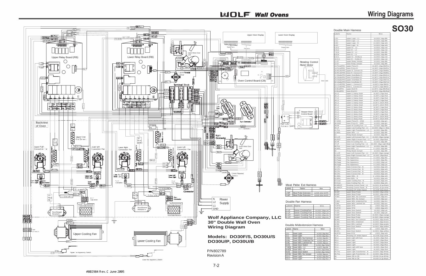
Page 64
WWaallll OOvveennss Wiring Diagrams
7-2
1
11
22
3
3
4J4
J5
J2
112345678 12
J2J3
J1J1
E1
4E
14
L1
-A
12345678 12
J2J2J3J3
Lower Oven DisplayUpper Oven Display
Flat CableDisplay Cable
Motor Cable
3
67
-I6
7-Inn
87
-I8
7Inn
1 2
1 2
ector
Outer Bake Element
Inner Bake Element
Pizza Elem
Receptac
pper Cooling Fan
L Cooling Fan
Pizza Element
Receptacl e
Outer Bake Elemen t
Inner Bake Elemen t
Upper R
ConvecLower Right
Convection Fan
me
ntper Left
nvection FanLowerLo Left
Convection Fan
Lower Fan Apparenc y Switch
an Apparency Switch
Lower Motor Door
Lock
ched
witch
Upper Motor Door
Lock
1-1
3-3
55
9696
9696
7-E
14
7E
144
52-RC52 RCFFCFCF51-LC51-LCFF
26
-L2
26
-L2
32
-L2
32
L2
33-L33-L
34-L2
34-L34 L
34
-L2
34
L2
22
28
-L2
28
L2
55-55-
LFLF
MDLMDL
42
42
13--
Pi azzazaiz
Pr66r6
16-6
Rcvtc
5EPR5PEPR5
93-Lt93-Lt LtLtLt 92-Lt92 Lt92 Lt
MMPP
DD74-RTD74 RTDD75-RTD75 RTDD
77
-7
7
FFFFFFFF FFFFF
FF3-UF3 UFF
FFFFF
FF4-UF4 UFF
2-Lt2 Lt
Upper Relay Board (RB) Lower Relay Board (RB)
Oven Control Board (CB)
Rotating Control
Panel Motor
Stepper Motor
Control Board
itch
L1
L2
N
GND
Power
Supply
Bimetal
La be ls Nam e W ire
1-LF lower CoolingFan UL3321 18ga yel
2-LF lower Cooling Fan UL3321 18ga yel
3-UF upper Cooling Fan UL3321 18ga blu
4-UF upper Cooling Fan UL3321 18ga blu
La be ls Nam e W ire
1-E1 upper Logic - L1 UL3321 14ga Blk
2-E1 lower Logic - L1 UL3321 14ga Blk
3-E2 upper Logic - N U L3321 14ga wht
4-E2 lower Logic - N UL3321 14ga wht
5-E12 upper E l. - L2 UL3321 14ga red
6-E12 lower El. - L2 UL3321 14ga red
7-E14 upper E l. - L1 UL3321 14ga Blk
8-E14 lower El. - L1 UL3321 14ga Blk
9-E11 upper E l. - DLB(L2) UL3321 14ga red
10-E11 lower El. - DLB(L2) UL3321 14ga red
11-E7 upper Relay Jum per UL3321 14ga Blk
12-E7 lower Relay Jum per UL3321 14ga Blk
13-P izzaPR6 upper Pizza El. UL3071 14ga Blk/Pur
14-P izzaPR6 lower Pizza El. UL3071 14ga Blk/Pur
15-RCvtEPR5 upper R. Convect E l. UL3071 14ga Blk/B lu
16-RCvtEPR5 lower R. Convect E l. UL3071 14ga Blk/B lu
17-ObakePR4 upper OuterBake El. UL3071 14ga Blk/Grn
18-ObakePR4 lower OuterBake El. UL3071 14ga Blk/Grn
19-InbakePR3 upper InnerBake El. UL3071 14ga Blk/Yel
20-InbakePR3 lower InnerBake El. UL3071 14ga Blk/Yel
21-LCvtEPR2 upper L. Convect E l. UL3071 14ga Blk/Or
22-LCvtEPR2 lower L. Convect E l. UL3071 14ga Blk/Or
23-BroilPR1 upper Broil E l. UL3071 14ga Blk/Red
24-BroilPR1 lower Broil E l. UL3071 14ga Blk/Red
25-L2 upper L2 daisy chain UL3071 14ga Red
26-L2 upper L2 daisy chain UL3071 14ga Red
27-L2 upper L2 daisy chain UL3071 14ga Red
28-L2 upper L2 daisy chain UL3071 14ga Red
29-L2 upper L2 daisy chain UL3071 16GA RED
30-L2 upper L2 daisy chain UL3071 16GA RED
31-L2 lower L2 daisy chain UL3071 14ga Red
32-L2 lower L2 daisy chain UL3071 14ga Red
33-L2 lower L2 daisy chain UL3071 14ga Red
34-L2 lower L2 daisy chain UL3071 14ga Red
35-L2 lower L2 daisy chain UL3071 16GA RED
36-L2 lower L2 daisy chain UL3071 16GA RED
37-GND upper P izza El. - GND UL3321 14ga grn
38-GND lower Pizza El. - GND UL3321 14ga grn
39-HF upper Hi Cooling Fan - L1 UL3321 18ga Blk
40-LF upper Low Cooling Fan - L1 UL3321 18ga Lt. B lue
41-Tns upper Light Transform er - L1 UL3321 18ga Blk
42-MDL upper MDL - L1 UL3321 18ga Blk
43 Relay Board Jum per UL3321 18ga Blk
44-LCF upper Left Convect Fan - L1 UL3321 18ga orange
45-RCF upper Right Convect Fan - L1 UL3321 18ga Blue
46-HF lower Hi Cooling Fan - L1 UL3321 18ga Blk
47-LF lower Low Cooling Fan - L1 UL3321 18ga Light B lue
48-Tns lower Light Transform er - L1 UL3321 18ga Blk
49-MDL lower MDL - L1 U L3321 18ga Blk
50 Relay Board Jum per UL3321 18ga Blk
51-LCF lower Left Convect Fan - L1 UL3321 18ga orange
52-RCF lower Right Convect Fan - L1 UL3321 18ga Blue
53-Fapp Fan Apparency U L3321 18ga Blu
54-Fapp Fan Apparency U L3321 18ga Blu
55-Fapp Fan Apparency U L3321 18ga yel
56-Fapp Fan Apparency U L3321 18ga yel
57-CFn lower Convect fan - N UL3321 18ga wht
58-CFn lower Convect fan - N UL3321 18ga wht
59-CFn lower Convect fan - N UL3321 18ga wht
60-CFn lower Convect fan - N UL3321 18ga wht
61-MDL upper MDL - N U L3321 18ga wht
62-MDL lower MDL - N UL3321 18ga wht
63-Cool upper Cooling Fan - N UL3321 18ga wht
64-Cool lower Cooling Fan - N UL3321 18ga wht
65-MRCP Rotating Control Panel - L1 UL3321 18 ga Black
66-MRCP Rotating Control Panel - N UL3321 18 ga white
67-In Rotating CP Inhibit S ignal UL1430 22ga black
68-MP upper Meat Probe UL3321 18ga white
69-MP upper Meat Probe UL3321 18ga white
70-Mn upper MDL Sw Com m on UL3321 18ga brn
71 upper MDL Sw Jum per UL3321 18ga pur
72-MU upper MDL Unlatched Sw UL3321 18ga brn
73-ML upper MDL Latched Sw UL3321 18ga pur
74-RTD upper RTD U L3321 18ga wht
75-RTD upper RTD U L3321 18ga wht
76-DS upper Door Switch UL3321 18ga yel
77-DS upper Door Switch UL3321 18ga yel
78-MP lower Meat Probe UL3321 18ga orange
79-MP lower Meat Probe UL3321 18ga orange
80-Mn lower MDL Sw Com m on UL3321 18ga brown
81-MU lower MDL Unlatched UL3321 18ga brown
82-ML lower MDL Latched UL3321 18ga purple
83-DS lower Door Switch UL3321 18ga yellow
84-RTD lower RTD U L3321 18ga wht
85-DS lower Door Switch UL3321 18ga yellow
86-RTD lower RTD U L3321 18ga wht
87-In Rotating CP Inhibit S ignal UL1430 22ga white
88-Lt lower Light with fuse UL3321 18ga Red
89-Lt lower Light UL3321 18ga Blue
90-Lt upper Light UL3321 18ga Blue
91-Lt upper Light UL3321 18ga Blue
92-Lt upper Light with fuse UL3321 18ga Red
93-Lt upper Light UL3321 18ga Red
94-Tns upper Light Transform er - N UL3321 18ga W hite
95-Tns upper Light Transform er - N UL3321 18ga W hite
96 Upper RB to CB Ul1430 24 ga W hite
97 Lower RB to CB Ul1430 24 ga Black
Labels Name Wire
1-MP Meat Probe Extension UL5335 18GA WHITE
2-MP Meat Probe Extension UL5335 18GA WHITE
Labels Name Wire
1-Lt lower Light UL3321 18ga Red
2-Lt lower Light UL3321 18ga Blue
3-Mn lower MDL Sw Common UL3321 18ga Brn
4-Mu lower MDL Unlatched Sw UL3321 18ga brn
5-ML lower MDL Latched Sw UL3321 18ga pur
6-DS lower Door Switch UL3321 18ga Yellow
7-MDL lower MDL - L1 UL3071 18ga Blk
8-MDL lower MDL - N UL3071 18ga White
9-DS lower Door Switch UL3321 18ga Yellow
10-Mn lower MDL Sw Jumper UL3321 18ga pur
11-Lt lower Light UL3321 18ga Red
12-Lt lower Light UL3321 18ga Blue
P/N802789
RevisionA
Double Main Harness
Double Midextension Harness
Double Fan Harness
Meat Probe Ext. Harness
1-M
1M
PPP2
-M2
MPPP
Backview
of Oven
Wolf Appliance Company, LLC
30" Double Wall Oven
Wiring Diagram
Models: DO30F/S, DO30U/S
DO30U/P, DO30U/B
SO30

Page 65
WWaallll OOvveennss Wiring Diagrams
7-3
L1
L2
Oven
Relay
Board
K1
NO
K2
NO
K3K4K5K6
NONONONO
K7
NO
Relay Board
Logic
K9K10K11K12K13K14
NONONONONONO
1
22
1
22
1
1
2
2
3
3
4
4
5
5
6
6
7
7
8
8
9
9
J3J21
1
2
2
123413
Molex Sabre
Connector
Pizza
Element
Receptacl e
Pizza El.
3500W
240V
Outer Bake El.
1650W
240V
Inner Bake El.
1850W
240V
BroilEl.
3600W
240V
R Cvt El.
2400W
240V
L Cvt El
2400W
240V
Bi-metal
Thermal
cutout
1
4 2
Cooling
Fan Motor
L.Cvt
Fan
R.Cvt
Fan
Motor
Door
Lock
20W Oven Light
20W Oven Light
NEUTRAL
1 2 3 4 6
1
1
22
22
1
1
3
3
1 3
1 3
1 2
J4
J1
Stepper
Motor
J2 J5
Push Button
Activation
Switch
1
1
9
9
1
2
3
4
5
67
89
1
2
3
4
5
6
8
9
7
G
GND
1
2
3
4 4
5
6
8
9
10
1
2
3
4
5
6
8
9
101
6
10
3
2
95
8
12
Meat
Probe
Sensor
Meat
Probe
Receptica l
J2
RTD
Sensor
12Molex
Connector
12
2 1
Amp
Connecto r
MDL
Unlatched
Switch
MDL
Latched
Switch
Door
Switch
1 2
1 2
2 pin
Amp Conn.
2 pin
Amp
Conn
1
1
2
2
1234
Oven
Sensors
Fan Apparency
Switch
L1L1 2L22 BL1-BB L1-A-A
Oven
Controller
Upper
Oven
Display
Motor
Control
Logic
UNEUU BDLBB Pr6 Pr6 r5Pr Pr4 Pr4 r3Pr Pr2 Pr2 r11Pr
J11A
J11B
J4
J1
NO NO NO
Stepper
Motor
Control
Board
Wolf Appliance Company, LLC
30" Single Wall Oven
Schematic Diagram
Models: SO30F/S, SO30U/S
SO30U/P, SO30U/B
P/N 802787
Revision A
SO30

Page 66
WWaallll OOvveennss Wiring Diagrams
7-4
1
11
22
3
3
4J4
J5J2
112345678 12
J2J3
J1J1
E1
4E
14
L1
-A
12345678 12
J2J2J3J3
Lower Oven DisplayUpper Oven Display
Flat CableDisplay Cable
Motor Cable
3
67
-I6
7-Inn
87
-I8
7Inn
1 2
1 2
ector
Outer Bake Element
Inner Bake Element
Pizza Elem
Receptac
pper Cooling Fan
L Cooling Fan
Pizza Element
Receptacl e
Outer Bake Elemen t
Inner Bake Elemen t
Upper R
ConvecLower Right
Convection Fan
me
ntper Left
nvection FanLowerLo Left
Convection Fan
Lower Fan Apparenc y Switch
an Apparency Switch
Lower Motor Door
Lock
ched
witch
Upper Motor Door
Lock
1-1
3-3
55
9696
9696
7-E
14
7E
144
52-RC52 RCFFCFCF51-LC51-LCFF
26
-L2
26
-L2
32
-L2
32
L2
33-L33-L
34-L2
34-L34 L
34
-L2
34
L2
22
28
-L2
28
L2
55-55-
LFLF
MDLMDL
42
42
13--
Pi azzazaiz
Pr66r6
16-6
Rcvtc
5EPR5PEPR5
93-Lt93-Lt LtLtLt 92-Lt92 Lt92 Lt
MMPP
DD74-RTD74 RTDD75-RTD75 RTDD
77
-7
7
FFFFFFFF FFFFF
FF3-UF3 UFF
FFFFF
FF4-UF4 UFF
2-Lt2 Lt
Upper Relay Board (RB) Lower Relay Board (RB)
Oven Control Board (CB)
Rotating Control
Panel Motor
Stepper Motor
Control Board
itch
L1
L2
N
GND
Power
Supply
Bimetal
La be ls Nam e W ire
1-LF lower CoolingFan UL3321 18ga yel
2-LF lower Cooling Fan UL3321 18ga yel
3-UF upper Cooling Fan UL3321 18ga blu
4-UF upper Cooling Fan UL3321 18ga blu
La be ls Nam e W ire
1-E1 upper Logic - L1 UL3321 14ga Blk
2-E1 lower Logic - L1 UL3321 14ga Blk
3-E2 upper Logic - N U L3321 14ga wht
4-E2 lower Logic - N UL3321 14ga wht
5-E12 upper E l. - L2 UL3321 14ga red
6-E12 lower El. - L2 UL3321 14ga red
7-E14 upper E l. - L1 UL3321 14ga Blk
8-E14 lower El. - L1 UL3321 14ga Blk
9-E11 upper E l. - DLB(L2) UL3321 14ga red
10-E11 lower El. - DLB(L2) UL3321 14ga red
11-E7 upper Relay Jum per UL3321 14ga Blk
12-E7 lower Relay Jum per UL3321 14ga Blk
13-P izzaPR6 upper Pizza El. UL3071 14ga Blk/Pur
14-P izzaPR6 lower Pizza El. UL3071 14ga Blk/Pur
15-RCvtEPR5 upper R. Convect E l. UL3071 14ga Blk/B lu
16-RCvtEPR5 lower R. Convect E l. UL3071 14ga Blk/B lu
17-ObakePR4 upper OuterBake El. UL3071 14ga Blk/Grn
18-ObakePR4 lower OuterBake El. UL3071 14ga Blk/Grn
19-InbakePR3 upper InnerBake El. UL3071 14ga Blk/Yel
20-InbakePR3 lower InnerBake El. UL3071 14ga Blk/Yel
21-LCvtEPR2 upper L. Convect E l. UL3071 14ga Blk/Or
22-LCvtEPR2 lower L. Convect E l. UL3071 14ga Blk/Or
23-BroilPR1 upper Broil E l. UL3071 14ga Blk/Red
24-BroilPR1 lower Broil E l. UL3071 14ga Blk/Red
25-L2 upper L2 daisy chain UL3071 14ga Red
26-L2 upper L2 daisy chain UL3071 14ga Red
27-L2 upper L2 daisy chain UL3071 14ga Red
28-L2 upper L2 daisy chain UL3071 14ga Red
29-L2 upper L2 daisy chain UL3071 16GA RED
30-L2 upper L2 daisy chain UL3071 16GA RED
31-L2 lower L2 daisy chain UL3071 14ga Red
32-L2 lower L2 daisy chain UL3071 14ga Red
33-L2 lower L2 daisy chain UL3071 14ga Red
34-L2 lower L2 daisy chain UL3071 14ga Red
35-L2 lower L2 daisy chain UL3071 16GA RED
36-L2 lower L2 daisy chain UL3071 16GA RED
37-GND upper P izza El. - GND UL3321 14ga grn
38-GND lower Pizza El. - GND UL3321 14ga grn
39-HF upper Hi Cooling Fan - L1 UL3321 18ga Blk
40-LF upper Low Cooling Fan - L1 UL3321 18ga Lt. B lue
41-Tns upper Light Transform er - L1 UL3321 18ga Blk
42-MDL upper MDL - L1 UL3321 18ga Blk
43 Relay Board Jum per UL3321 18ga Blk
44-LCF upper Left Convect Fan - L1 UL3321 18ga orange
45-RCF upper Right Convect Fan - L1 UL3321 18ga Blue
46-HF lower Hi Cooling Fan - L1 UL3321 18ga Blk
47-LF lower Low Cooling Fan - L1 UL3321 18ga Light B lue
48-Tns lower Light Transform er - L1 UL3321 18ga Blk
49-MDL lower MDL - L1 U L3321 18ga Blk
50 Relay Board Jum per UL3321 18ga Blk
51-LCF lower Left Convect Fan - L1 UL3321 18ga orange
52-RCF lower Right Convect Fan - L1 UL3321 18ga Blue
53-Fapp Fan Apparency U L3321 18ga Blu
54-Fapp Fan Apparency U L3321 18ga Blu
55-Fapp Fan Apparency U L3321 18ga yel
56-Fapp Fan Apparency U L3321 18ga yel
57-CFn lower Convect fan - N UL3321 18ga wht
58-CFn lower Convect fan - N UL3321 18ga wht
59-CFn lower Convect fan - N UL3321 18ga wht
60-CFn lower Convect fan - N UL3321 18ga wht
61-MDL upper MDL - N U L3321 18ga wht
62-MDL lower MDL - N UL3321 18ga wht
63-Cool upper Cooling Fan - N UL3321 18ga wht
64-Cool lower Cooling Fan - N UL3321 18ga wht
65-MRCP Rotating Control Panel - L1 UL3321 18 ga Black
66-MRCP Rotating Control Panel - N UL3321 18 ga white
67-In Rotating CP Inhibit S ignal UL1430 22ga black
68-MP upper Meat Probe UL3321 18ga white
69-MP upper Meat Probe UL3321 18ga white
70-Mn upper MDL Sw Com m on UL3321 18ga brn
71 upper MDL Sw Jum per UL3321 18ga pur
72-MU upper MDL Unlatched Sw UL3321 18ga brn
73-ML upper MDL Latched Sw UL3321 18ga pur
74-RTD upper RTD U L3321 18ga wht
75-RTD upper RTD U L3321 18ga wht
76-DS upper Door Switch UL3321 18ga yel
77-DS upper Door Switch UL3321 18ga yel
78-MP lower Meat Probe UL3321 18ga orange
79-MP lower Meat Probe UL3321 18ga orange
80-Mn lower MDL Sw Com m on UL3321 18ga brown
81-MU lower MDL Unlatched UL3321 18ga brown
82-ML lower MDL Latched UL3321 18ga purple
83-DS lower Door Switch UL3321 18ga yellow
84-RTD lower RTD U L3321 18ga wht
85-DS lower Door Switch UL3321 18ga yellow
86-RTD lower RTD U L3321 18ga wht
87-In Rotating CP Inhibit S ignal UL1430 22ga white
88-Lt lower Light with fuse UL3321 18ga Red
89-Lt lower Light UL3321 18ga Blue
90-Lt upper Light UL3321 18ga Blue
91-Lt upper Light UL3321 18ga Blue
92-Lt upper Light with fuse UL3321 18ga Red
93-Lt upper Light UL3321 18ga Red
94-Tns upper Light Transform er - N UL3321 18ga W hite
95-Tns upper Light Transform er - N UL3321 18ga W hite
96 Upper RB to CB Ul1430 24 ga W hite
97 Lower RB to CB Ul1430 24 ga Black
Labels Name Wire
1-MP Meat Probe Extension UL5335 18GA WHITE
2-MP Meat Probe Extension UL5335 18GA WHITE
Labels Name Wire
1-Lt lower Light UL3321 18ga Red
2-Lt lower Light UL3321 18ga Blue
3-Mn lower MDL Sw Common UL3321 18ga Brn
4-Mu lower MDL Unlatched Sw UL3321 18ga brn
5-ML lower MDL Latched Sw UL3321 18ga pur
6-DS lower Door Switch UL3321 18ga Yellow
7-MDL lower MDL - L1 UL3071 18ga Blk
8-MDL lower MDL - N UL3071 18ga White
9-DS lower Door Switch UL3321 18ga Yellow
10-Mn lower MDL Sw Jumper UL3321 18ga pur
11-Lt lower Light UL3321 18ga Red
12-Lt lower Light UL3321 18ga Blue
P/N802789
RevisionA
Double Main Harness
Double Midextension Harness
Double Fan Harness
Meat Probe Ext. Harness
1-M
1M
PPP2
-M2
MPPP
Backview
of Oven
Wolf Appliance Company, LLC
30" Double Wall Oven
Wiring Diagram
Models: DO30F/S, DO30U/S
DO30U/P, DO30U/B
DO30

Page 67
WWaallll OOvveennss Wiring Diagrams
7-5
L1
L2
Upper
Oven
Relay
Board
Lower
Oven
Relay
Board
K1K1
NONO
K2K2
NONO
K3K3 K4K4 K5K5 K6K6
NONO NONO NONO NONO
K7K7
NONO
Relay Board
Logic
Relay Board
Logic
K9K9 K10K10 K11K11 K12K12 K13K13 K14K14
NONO NONO NONO NONO NONO NONO
1
22
1
22
1
22
1
11
1 2
22
2 3
33
3 4
44
4 5
55
5 6
66
6 7
77
7 8
88
8 9
99
9 J3J3 J2J2 11
11
22
22
11 22 33 441
13
3Molex Sabre
Connector
Molex Sabre
Connector
Pizza
Element
Receptacle
Pizza
Element
Receptacle
Pizza El.
3500W
240V
PizzaEl.
3500W
240V
Outer Bake El.
1650W
240V
Outer Bake El.
1650W
240V
Inner Bake El.
1850W
240V
Inner Bake El.
1850W
240V
Broil El.
3600W
240V
Broil El.
3600W
240V
R Cvt El.
2400W
240V
R Cvt El.
2400W
240V
L Cvt El
2400W
240V
L Cvt El
2400W
240V
Bi-metal
Thermal
cutout
Bi-metal
Thermal
cutout
1
4 2Upper
Cooling
Fan Motor
1
4 2Lower
Cooling
Fan Motor
L.Cvt
Fan
L.Cvt
Fan
R.Cvt
Fan
R.Cvt
Fan
Motor
Door
Lock
Motor
Door
Lock
20W Oven Light20W Oven Light
20W Oven Light20W Oven Light
NEUTRAL
1
12
1
12
1
12
1
12
1 2 3 4 6
1
1
1 1
22
22
22 22
11
33
1 3
1 3
1 2
J4
J1
Stepper
Motor
J2 J5
Push Button
Activation
Switch
1
1
9
9
1
2
3
4
5
67
89
1
22
1
2
3
4
5
6
8
9
7
GGND
G
GND
1
2
3
4
5
6
8
9
10
1
2
3
4
5
6
8
9
10
1
2
3
4
5
6
8
9
10
1
2
3
4
5
6
8
9
10
1
1
10
6
10
4
3
2
95
8
2
3
5
6
84
9
1 12 2
Meat
Probe
Sensor
Meat
Probe
Sensor
Meat
Probe
Receptica l
Meat
Probe
Receptical
J2
J3
RTD
Sensor
RTD
Sensor
1 12 2Molex
Connector
Molex
Connector
1 12 2
2 21 1
Amp
Connector
Amp
Connecto r
MDL
Unlatched
Switch
MDL
Unlatched
Switch
MDL
Latche d
Switch
MDL
Latched
Switch
9 pin Amp Connector
Door
Switch
Door
Switch
11 22
11 22 8
87
7
2 pin
Amp Conn.
9 pin
Amp Conn.
2 pin
Amp
Conn
9 pin
Amp
Conn
2 pin
Amp
Conn
1
12
23
3
1
1
2
2
1
1
2
2
3 pin Molex
Saber Conn.
12341234
Lower
Oven
Sensors
Upper
Oven
Sensors
P/N802789
Revision A
Fan Apparency
Switch
Fan Apparency
Switch
L1 L1 L1L12L22 2L22 BL1-BBBL1-BB L1-A-AL1-A-A
Oven
Controller
Upper
Oven
Display
Lower
Oven
Display
Motor
Control
Logic
UNEUU BDLBB Pr6 Pr6 r5Pr Pr4 Pr4 r3Pr Pr2 Pr2 r11Pr UNEUU BDLBB Pr6 Pr6 r5Pr Pr4 Pr4 r3Pr Pr2 Pr2 r11Pr
J11A
J11B
J5
J4
J1 J1
NONONONO
NO NO
Stepper
Motor
Control
Board
Wolf Appliance Company, LLC
30" Double Wall Oven
Schematic Diagram
Models: DO30F/S, DO30U/S
DO30U/P, DO30U/B
DO30

Page 68
WWaallll OOvveennss Wiring Diagrams
7-6
P/N802788
Revision A
Single Main Harness
Labels Name Wire
1-E1 Relay Board Logic - L1 UL3321 14ga Blk
2-E2 Relay Board Logic - N UL3321 14ga wht
3-E12 Element - L2 UL3321 14ga red
4-E11 El. DLB(L2) UL3321 14ga red
5-E7 Relay Board Jumper UL3321 14ga Blk
6-PizzaPR6 Pizza El. UL3071 14ga Blk/Pur
7-RCvtEPR5 R. Convect El. UL3071 14ga Blk/Blu
8-ObakePR4 OuterBake El. UL3071 14ga Blk/Grn
9-InbakePR3 InnerBake El. UL3071 14ga Blk/Yel
10-LCvtPR2 L. Convect El. UL3071 14ga Blk/Or
11-BroilPR1 Broil El. UL3071 14ga Blk/Red
12-E14 Element - L1 UL3321 14ga Blk
13-L2 L2 daisy chain UL3071 14ga Red
14-L2 L2 daisy chain UL3071 14ga Red
15-L2 L2 daisy chain UL3071 14ga Red
16-L2 L2 daisy chain UL3071 14ga Red
17-L2 L2 daisy chain UL3071 16 GA RED
18-L2 L2 daisy chain UL3071 16 GA RED
19-MP Meat Probe UL5335 18ga white
20-MP Meat Probe UL5335 18ga white
21-Mn MDL Sw Common UL3321 18ga brn
22-MU MDL Unlatched Sw UL3321 18ga brn
23-ML MDL Latched Sw UL3321 18ga pur
24-RTD RTD UL3321 18ga wht
25-RTD RTD UL3321 18ga wht
26-DS Door Switch UL3321 18ga yel
27-DS Door Switch UL3321 18ga yel
28-HF Hi speed Cooling Fan - L1 UL3321 18ga Blk
29 Relay Board Jumper UL3321 18ga Blk
30-LF Low speed Cooling Fan - L1 UL3321 18ga Lt. Blue
31-Tns Light Transformer - L1 UL3321 18ga Blk
32-MDL MDL - L1 UL3321 18ga Blk
33-LCF Left Convect Fan UL3321 18ga Orange
34-RCF Right Convect Fan UL3321 18ga Blue
35-MDL MDL - N UL3321 18ga wht
36-Cool Cooling Fan - N UL3321 18ga wht
37 MDL Sw Jumper UL3321 18ga pur
38-MRCP Rotating Control Panel - L1 UL3321 18 ga Black
39-MRCP Rotating Control Panel - N UL3321 18 ga white
40-In Rotating CP Inhibit Signal UL1430 Black
41-Lt Light with fuse UL3321 18ga Red
42-Lt Light UL3321 18ga Red
43-Lt Light UL3321 18ga Blue
44-Lt Light UL3321 18ga Blue
45-CFn Convect fan - N UL3321 18ga wht
46-CFn Convect fan - N UL3321 18ga wht
47-In Rotating CP Inhibit Signal UL1430 W hite
48-Tns Light Transformer - N UL3321 18ga W hite
49-Gnd Pizza Ground UL3321 14ga grn
50 RBtoOC UL1430 24ga Black
Single Fan Harness
Meat Probe Ext. Harness
L a b e l s N a m e W i r e
1 - S F S i n g l e F a n U L 3 3 2 1 1 8 g a b l u e
2 - S F S i n g l e F a n U L 3 3 2 1 1 8 g a b l u e
L a b e ls N a m e W i re
1 -M P M e a t P ro b e E x te n s io n U L 5 3 3 5 1 8 G A W H IT E
2 -M P M e a t P ro b e E x te n s io n U L 5 3 3 5 1 8 G A W H IT E
1
11
22
3
3 46
7J4
J5J2
12345678 12
J2J3
J1J1
Upper Oven Display
Flat Cable
Motor Cable
Fu
N
47-I
47-Inn
47-In47-In40-In40 In
4 pin
Connector234
4 3 2 1
1
Outer Bake Element
nner Bake Element
Pizza Element
Receptacl e
Cooling Fan
Rig
htC
hton
vect
ion
Elem
entRight
Convection Fan
LeftLe
Convection Fan
Oven
Broi Eil lementEl
Rig
Ove
Fan Apparency Switch
122
onn.
Motor Door
Lock
LigLigTT
5656
5050
12-E1412
E144
13-L213-L2
13-13-
14-L214-L2
15-L15-L15-L215 L216-L16-L
18-L2
22
32-MD
L32-M
DL
6-
Pi azzazaiz
Pr66r6
7-
Rcvtc
5EPR5P 5
8-Oba8 Ob kek PrP44r44
2210-LCvtEPR10 LCvtEPR2
11-1
Broir il
Prr1r1
4-E4 E4 E
45-CFn45-CFn
tt
-MMLL
DD24-RTD24 RTDD25-RTD25 RTDD
26-D26 DSS27-D27 DSS
27-27
12-E1412 E14
1-E11
E1 223-E123-E122
32-MD
L32
MD
L
38-MRC38 MRCPPPPPCPCP
PPPPP
Relay Board (RB)
ntrol Board (CB)
Rotating Control
Panel Motor
Stepper Motor
Control Board
Push button
Activation Switch
Block
L1
L2
N
GND
Power
Supply
2-M2
MPPP
Backview
of Oven
Wolf Applaince Company, LLC
36" Single Wall Oven
Wiring Diagram
Models: SO36U/S
SO36U/P, SO36U/B
SO36

Page 69
WWaallll OOvveennss Wiring Diagrams
7-7
L1
L2
Oven
Relay
Board
K1
NO
K2
NO
K3K4K5K6
NONONONO
K7
NO
Relay Board
Logic
K9K10K11K12K13K14
NONONONONONO
1
22
1
22
1
1
2
2
3
3
4
4
5
5
6
6
7
7
8
8
9
9
J3J21
1
2
2
123413
Molex Sabre
Connector
Pizza
Element
Receptacl e
Pizza El.
3500W
240V
Outer Bake El.
1650W
240V
Inner Bake El.
1850W
240V
BroilEl.
4000W
240V
R Cvt El.
2400W
240V
L Cvt El
2400W
240V
Bi-metal
Thermal
cutout
1
4 2
Cooling
Fan Motor
L.Cvt
Fan
R.Cvt
Fan
Motor
Door
Lock
20W Oven Light
20W Oven Light
NEUTRAL
1 2 3 4 6
1
1
22
22
11
33
1 3
1 3
1 2
J4
J1
Stepper
Motor
J2 J5
Push Button
Activation
Switch
1
1
9
9
1
2
3
4
5
67
89
1
2
3
4
5
6
8
9
7
G
GND
1
2
3
4 4
5
6
8
9
10
1
2
3
4
5
6
8
9
10
16
10
3
2
95
8
12
Meat
Probe
Sensor
Meat
Probe
Receptica l
J2
RTD
Sensor
12Molex
Connector
12
2 1
Amp
Connecto r
MDL
Unlatched
Switch
MDL
Latched
Switch
Door
Switch
1 2
1 2
2 pin
Amp Conn.
2 pin
Amp
Conn
1
1
2
2
1234
Oven
Sensors
P/N802788
Revision A
Fan Apparency
Switch
L1L1 2L22 BL1-BB L1-A-A
Oven
Controller
Upper
Oven
Display
Motor
Control
Logic
UNEUU BDLBB Pr6 Pr6 r5Pr Pr4 Pr4 r3Pr Pr2 Pr2 r11Pr
J11A
J11B
J4
J1
NO NO NO
Stepper
Motor
Control
Board
Wolf Appliance Company, LLC
36" Single Wall Oven
Schematic Diagram
Models: SO36U/S
SO36U/P, SO36U/B
SO36

Page 70
Wall Ovens
8-2
Wiring Diagrams
Single Main Harness
Labels Name Wire
1-E1 Relay Board Logic - L1 UL3321 14ga Blk
2-E2 Relay Board Logic - N UL3321 14ga wht
3-E12 Element - L2 UL3321 14ga red
4-E11 El. DLB(L2) UL3321 14ga red
5-E7 Relay Board Jumper UL3321 14ga Blk
6-PizzaPR6 Pizza El. UL3071 14ga Blk/Pur
7-RCvtEPR5 R. Convect El. UL3071 14ga Blk/Blu
8-ObakePR4 OuterBake El. UL3071 14ga Blk/Grn
9-InbakePR3 InnerBake El. UL3071 14ga Blk/Yel
10-LCvtPR2 L. Convect El. UL3071 14ga Blk/Or
11-BroilPR1 Broil El. UL3071 14ga Blk/Red
12-E14 Element - L1 UL3321 14ga Blk
13-L2 L2 daisy chain UL3071 14ga Red
14-L2 L2 daisy chain UL3071 14ga Red
15-L2 L2 daisy chain UL3071 14ga Red
16-L2 L2 daisy chain UL3071 14ga Red
17-L2 L2 daisy chain UL3071 16 GA RED
18-L2 L2 daisy chain UL3071 16 GA RED
19-MP Meat Probe UL5335 18ga white
20-MP Meat Probe UL5335 18ga white
21-Mn MDL Sw Common UL3321 18ga brn
22-MU MDL Unlatched Sw UL3321 18ga brn
23-ML MDL Latched Sw UL3321 18ga pur
24-RTD RTD UL3321 18ga wht
25-RTD RTD UL3321 18ga wht
26-DS Door Switch UL3321 18ga yel
27-DS Door Switch UL3321 18ga yel
28-HF Hi speed Cooling Fan - L1 UL3321 18ga Blk
29 Relay Board Jumper UL3321 18ga Blk
30-LF Low speed Cooling Fan - L1 UL3321 18ga Lt. Blue
31-Tns Light Transformer - L1 UL3321 18ga Blk
32-MDL MDL - L1 UL3321 18ga Blk
33-LCF Left Convect Fan UL3321 18ga Orange
34-RCF Right Convect Fan UL3321 18ga Blue
35-MDL MDL - N UL3321 18ga wht
36-Cool Cooling Fan - N UL3321 18ga wht
37 MDL Sw Jumper UL3321 18ga pur
38-MRCP Rotating Control Panel - L1 UL3321 18 ga Black
39-MRCP Rotating Control Panel - N UL3321 18 ga white
40-In Rotating CP Inhibit Signal UL1430 Black
41-Lt Light with fuse UL3321 18ga Red
42-Lt Light UL3321 18ga Red
43-Lt Light UL3321 18ga Blue
44-Lt Light UL3321 18ga Blue
45-CFn Convect fan - N UL3321 18ga wht
46-CFn Convect fan - N UL3321 18ga wht
47-In Rotating CP Inhibit Signal UL1430 W hite
48-Tns Light Transformer - N UL3321 18ga W hite
49-Gnd Pizza Ground UL3321 14ga grn
50 RBtoOC UL1430 24ga Black
1
11
22
3
3
4J4
J5J2
123 12
J2J2J3J3
J1J1
E14E14
Upper Oven Display
Flat Cable
Motor Cable
C
NO
1 3
FuseFu
NL2L1
47-I
47-Inn
47-In47-In
40-I
40Inn
40-In40 In
Unlatched
Switch
ctor2 pin
Connec
4 pin
Connector2
4 3 2 12
1
Outer Bake Element
Inner Bake Element
Pizza Element
Receptacl e
Cooling Fan
Rig
htC
hton
vect
ion
Elem
entRightht
ction Fan
Left
LeC
onve
ctio
nEl
emen
t LeftLe
Convection Fan
Oven
Broi Eil lementEl
Right
Oven Light
LeftLe
Oven Light
Fan Apparency Switch
111122
12 22 2
22
11
2 pin
Conn.
n Conn.
Doo
r
witc
h
Motor Door
Lock
LightLigTrTransform
em
e
Tran
r
11
22
5656
5050
12-E1412
E144
34-RC34-RCFFCFCF
34-RC34-R FCF
33-LC33 LCFF
33-LC33-LCFF
13-L213-L2
13-L213-L2
14-L214-L2
15-L215-L215-L215 L2
16-L216
L2
16-L216-L2
2-2- FFS FS FF
2-2 FFS FS FF
1-1- FFS FS FF
1-1- FFS FS FF
FF28-HF28-HFF
FFHFHFF
30-LF30 LF
30-LF30 LF
32-MDL32 MDL
32-MD
L32-M
DL
31-31- ssTnsTnss
31-31- ssTnsTnss
6-
Pi azzazaiz
Pr66r6
7-
Rcvtc
5EPR5P 5
8-Oba8 Ob kek PrP44r44
r3r3r
2210-LCvtEPR10 LCvtEPR2
11-1
Broir il
Prr1r1
114-E114 E111
CoolCool
45-CFn45-CFn46-CFn46-CFn 46-CFn46 CFn
22
444444LtLt 424242
43-Lt43 Lt43 Lt41-Lt41 Lt41 Lt
48-48- ssTnsTnss
43-L43 L
9-M9
MPP
19-M1
20-M20
MPP
21-M121 M
22
-MMLL
DD24-RTD24 RTDD
DD74-R
TD74
RTDD
DD25-RTD25 RTDD
DD75-R
TD75
RTDD
26-D26 DSS
26-D26
DSS
27-D27 DSS
27-D27
DSS
4412-E1412 E144
1-E11
E1 223-E123-E122
48-48 ssTnsTnss
32-MD
L32
MD
L
3737
38-MRC38 MRCPPPPPCPCP
38-MRC38 MRCPPPPPCPCP
39-MRC39 MRCPPPPPCPCP
PPPPP
Relay Board (RB)
Oven Control Board (CB)
Rotating Control
Panel Motor
Stepper Motor
Control Board
Push button
Activation Switch
TerminalTe Block
Bimetal
Cutout
L1
L2
N
GND
Power
Supply
PPP
2-M2
MPPP
Backview
of Oven
Wolf Appliance Company, LLC
30" Single Wall Oven
Wiring Diagram
Models: SO30F/S, SO30U/S,
SO30U/P, SO30U/B
P/N 802787
Revision A
WireName
Meat Probe Extension UL 5335 18 ga White
UL 5335 18 ga WhiteMeat Probe Extension
Meat Probe Ext HarnessLabels
1 - MP
2 - MP
Single Fan Harness
Labels Name Wire
1 - SF
2 - SF
Single Fan
Single Fan
UL3321 18 ga Blue
UL3321 18 ga Blue
SO30

Page 71
Wall Ovens
8-3
Wiring Diagrams
L1
L2
Oven
Relay
Board
K1
NO
K2
NO
K3K4K5K6
NONONONO
K7
NO
Relay Board
Logic
K9K10K11K12K13K14
NONONONONONO
1
22
1
22
1
1
2
2
3
3
4
4
5
5
6
6
7
7
8
8
9
9
J3J21
1
2
2
123413
Molex Sabre
Connector
Pizza
Element
Receptacl e
Pizza El.
3500W
240V
Outer Bake El.
1650W
240V
Inner Bake El.
1850W
240V
BroilEl.
3600W
240V
R Cvt El.
2400W
240V
L Cvt El
2400W
240V
Bi-metal
Thermal
cutout
1
4 2
Cooling
Fan Motor
L.Cvt
Fan
R.Cvt
Fan
Motor
Door
Lock
20W Oven Light
20W Oven Light
NEUTRAL
1 2 3 4 6
1
1
22
22
1
1
3
3
1 3
1 3
1 2
J4
J1
Stepper
Motor
J2 J5
Push Button
Activation
Switch
1
1
9
9
1
2
3
4
5
67
89
1
2
3
4
5
6
8
9
7
G
GND
1
2
3
4 4
5
6
8
9
10
1
2
3
4
5
6
8
9
101
6
10
3
2
95
8
12
Meat
Probe
Sensor
Meat
Probe
Receptica l
J2
RTD
Sensor
12Molex
Connector
12
2 1
Amp
Connecto r
MDL
Unlatched
Switch
MDL
Latched
Switch
Door
Switch
1 2
1 2
2 pin
Amp Conn.
2 pin
Amp
Conn
1
1
2
2
1234
Oven
Sensors
Fan Apparency
Switch
L1L1 2L22 BL1-BB L1-A-A
Oven
Controller
Upper
Oven
Display
Motor
Control
Logic
UNEUU BDLBB Pr6 Pr6 r5Pr Pr4 Pr4 r3Pr Pr2 Pr2 r11Pr
J11A
J11B
J4
J1
NO NO NO
Stepper
Motor
Control
Board
Wolf Appliance Company, LLC
30" Single Wall Oven
Schematic Diagram
Models: SO30F/S, SO30U/S
SO30U/P, SO30U/B
P/N 802787
Revision A
SO30

Page 72
Wall Ovens
8-4
Wiring Diagrams
1
11
22
3
3
4J4
J5J2
112345678 12
J2J3
J1J1
E1
4E
14
L1
-A
12345678 12
J2J2J3J3
Lower Oven DisplayUpper Oven Display
Flat CableDisplay Cable
Motor Cable
3
67
-I6
7-Inn
87
-I8
7Inn
1 2
1 2
ector
Outer Bake Element
Inner Bake Element
Pizza Elem
Receptac
pper Cooling Fan
L Cooling Fan
Pizza Element
Receptacl e
Outer Bake Elemen t
Inner Bake Elemen t
Upper R
ConvecLower Right
Convection Fan
me
ntper Left
nvection FanLowerLo Left
Convection Fan
Lower Fan Apparenc y Switch
an Apparency Switch
Lower Motor Door
Lock
ched
witch
Upper Motor Door
Lock
1-1
3-3
55
9696
9696
7-E
14
7E
144
52-RC52 RCFFCFCF51-LC51-LCFF
26
-L2
26
-L2
32
-L2
32
L2
33-L33-L
34-L2
34-L34 L
34
-L2
34
L2
22
28
-L2
28
L2
55-55-
LFLF
MDLMDL
42
42
13--
Pi azzazaiz
Pr66r6
16-6
Rcvtc
5EPR5PEPR5
93-Lt93-Lt LtLtLt 92-Lt92 Lt92 Lt
MMPP
DD74-RTD74 RTDD75-RTD75 RTDD
77
-7
7
FFFFFFFF FFFFF
FF3-UF3 UFF
FFFFF
FF4-UF4 UFF
2-Lt2 Lt
Upper Relay Board (RB) Lower Relay Board (RB)
Oven Control Board (CB)
Rotating Control
Panel Motor
Stepper Motor
Control Board
itch
L1
L2
N
GND
Power
Supply
Bimetal
La be ls Nam e W ire
1-LF lower CoolingFan UL3321 18ga yel
2-LF lower Cooling Fan UL3321 18ga yel
3-UF upper Cooling Fan UL3321 18ga blu
4-UF upper Cooling Fan UL3321 18ga blu
La be ls Nam e W ire
1-E1 upper Logic - L1 UL3321 14ga Blk
2-E1 lower Logic - L1 UL3321 14ga Blk
3-E2 upper Logic - N U L3321 14ga wht
4-E2 lower Logic - N UL3321 14ga wht
5-E12 upper E l. - L2 UL3321 14ga red
6-E12 lower El. - L2 UL3321 14ga red
7-E14 upper E l. - L1 UL3321 14ga Blk
8-E14 lower El. - L1 UL3321 14ga Blk
9-E11 upper E l. - DLB(L2) UL3321 14ga red
10-E11 lower El. - DLB(L2) UL3321 14ga red
11-E7 upper Relay Jum per UL3321 14ga Blk
12-E7 lower Relay Jum per UL3321 14ga Blk
13-P izzaPR6 upper P izza El. UL3071 14ga Blk/Pur
14-P izzaPR6 lower Pizza El. UL3071 14ga Blk/Pur
15-RCvtEPR5 upper R. Convect E l. UL3071 14ga Blk/B lu
16-RCvtEPR5 lower R. Convect E l. UL3071 14ga Blk/B lu
17-ObakePR4 upper OuterBake El. UL3071 14ga Blk/Grn
18-ObakePR4 lower OuterBake El. UL3071 14ga Blk/Grn
19-InbakePR3 upper InnerBake El. UL3071 14ga Blk/Yel
20-InbakePR3 lower InnerBake El. UL3071 14ga Blk/Yel
21-LCvtEPR2 upper L. Convect E l. UL3071 14ga Blk/Or
22-LCvtEPR2 lower L. Convect E l. UL3071 14ga Blk/Or
23-BroilPR1 upper Broil E l. UL3071 14ga Blk/Red
24-BroilPR1 lower Broil E l. UL3071 14ga Blk/Red
25-L2 upper L2 daisy chain UL3071 14ga Red
26-L2 upper L2 daisy chain UL3071 14ga Red
27-L2 upper L2 daisy chain UL3071 14ga Red
28-L2 upper L2 daisy chain UL3071 14ga Red
29-L2 upper L2 daisy chain UL3071 16GA RED
30-L2 upper L2 daisy chain UL3071 16GA RED
31-L2 lower L2 daisy chain UL3071 14ga Red
32-L2 lower L2 daisy chain UL3071 14ga Red
33-L2 lower L2 daisy chain UL3071 14ga Red
34-L2 lower L2 daisy chain UL3071 14ga Red
35-L2 lower L2 daisy chain UL3071 16GA RED
36-L2 lower L2 daisy chain UL3071 16GA RED
37-GND upper P izza El. - GND UL3321 14ga grn
38-GND lower Pizza El. - GND UL3321 14ga grn
39-HF upper Hi Cooling Fan - L1 UL3321 18ga Blk
40-LF upper Low Cooling Fan - L1 UL3321 18ga Lt. B lue
41-Tns upper Light Transform er - L1 UL3321 18ga Blk
42-MDL upper MDL - L1 UL3321 18ga Blk
43 Relay Board Jum per UL3321 18ga Blk
44-LCF upper Left Convect Fan - L1 UL3321 18ga orange
45-RCF upper Right Convect Fan - L1 UL3321 18ga Blue
46-HF lower Hi Cooling Fan - L1 UL3321 18ga Blk
47-LF lower Low Cooling Fan - L1 UL3321 18ga Light B lue
48-Tns lower Light Transform er - L1 UL3321 18ga Blk
49-MDL lower MDL - L1 U L3321 18ga Blk
50 Relay Board Jum per UL3321 18ga Blk
51-LCF lower Left Convect Fan - L1 UL3321 18ga orange
52-RCF lower Right Convect Fan - L1 UL3321 18ga Blue
53-Fapp Fan Apparency U L3321 18ga Blu
54-Fapp Fan Apparency U L3321 18ga Blu
55-Fapp Fan Apparency U L3321 18ga yel
56-Fapp Fan Apparency U L3321 18ga yel
57-CFn lower Convect fan - N UL3321 18ga wht
58-CFn lower Convect fan - N UL3321 18ga wht
59-CFn lower Convect fan - N UL3321 18ga wht
60-CFn lower Convect fan - N UL3321 18ga wht
61-MDL upper MDL - N U L3321 18ga wht
62-MDL lower MDL - N UL3321 18ga wht
63-Cool upper Cooling Fan - N UL3321 18ga wht
64-Cool lower Cooling Fan - N UL3321 18ga wht
65-MRCP Rotating Control Panel - L1 UL3321 18 ga Black
66-MRCP Rotating Control Panel - N UL3321 18 ga white
67-In Rotating CP Inhibit S ignal UL1430 22ga black
68-MP upper Meat Probe UL3321 18ga white
69-MP upper Meat Probe UL3321 18ga white
70-Mn upper MDL Sw Com m on UL3321 18ga brn
71 upper MDL Sw Jum per UL3321 18ga pur
72-MU upper MDL Unlatched Sw UL3321 18ga brn
73-ML upper MDL Latched Sw UL3321 18ga pur
74-RTD upper RTD U L3321 18ga wht
75-RTD upper RTD U L3321 18ga wht
76-DS upper Door Switch UL3321 18ga yel
77-DS upper Door Switch UL3321 18ga yel
78-MP lower Meat Probe UL3321 18ga orange
79-MP lower Meat Probe UL3321 18ga orange
80-Mn lower MDL Sw Com m on UL3321 18ga brown
81-MU lower MDL Unlatched UL3321 18ga brown
82-ML lower MDL Latched UL3321 18ga purple
83-DS lower Door Switch UL3321 18ga yellow
84-RTD lower RTD U L3321 18ga wht
85-DS lower Door Switch UL3321 18ga yellow
86-RTD lower RTD U L3321 18ga wht
87-In Rotating CP Inhibit S ignal UL1430 22ga white
88-Lt lower Light with fuse UL3321 18ga Red
89-Lt lower Light UL3321 18ga Blue
90-Lt upper Light UL3321 18ga Blue
91-Lt upper Light UL3321 18ga Blue
92-Lt upper Light with fuse UL3321 18ga Red
93-Lt upper Light UL3321 18ga Red
94-Tns upper Light Transform er - N UL3321 18ga W hite
95-Tns upper Light Transform er - N UL3321 18ga W hite
96 Upper RB to CB Ul1430 24 ga W hite
97 Lower RB to CB Ul1430 24 ga Black
Labels Name Wire
1-MP Meat Probe Extension UL5335 18GA WHITE
2-MP Meat Probe Extension UL5335 18GA WHITE
Labels Name Wire
1-Lt lower Light UL3321 18ga Red
2-Lt lower Light UL3321 18ga Blue
3-Mn lower MDL Sw Common UL3321 18ga Brn
4-Mu lower MDL Unlatched Sw UL3321 18ga brn
5-ML lower MDL Latched Sw UL3321 18ga pur
6-DS lower Door Switch UL3321 18ga Yellow
7-MDL lower MDL - L1 UL3071 18ga Blk
8-MDL lower MDL - N UL3071 18ga White
9-DS lower Door Switch UL3321 18ga Yellow
10-Mn lower MDL Sw Jumper UL3321 18ga pur
11-Lt lower Light UL3321 18ga Red
12-Lt lower Light UL3321 18ga Blue
P/N802789
RevisionA
Double Main Harness
Double Midextension Harness
Double Fan Harness
Meat Probe Ext. Harness
1-M
1M
PPP2
-M2
MPPP
Backview
of Oven
Wolf Appliance Company, LLC
30" Double Wall Oven
Wiring Diagram
Models: DO30F/S, DO30U/S
DO30U/P, DO30U/B
DO30

Page 73
Wall Ovens
8-5
Wiring Diagrams
L1
L2
Upper
Oven
Relay
Board
Lower
Oven
Relay
Board
K1K1
NONO
K2K2
NONO
K3K3 K4K4 K5K5 K6K6
NONO NONO NONO NONO
K7K7
NONO
Relay Board
Logic
Relay Board
Logic
K9K9 K10K10 K11K11 K12K12 K13K13 K14K14
NONO NONO NONO NONO NONO NONO
1
22
1
22
1
22
1
11
1 2
22
2 3
33
3 4
44
4 5
55
5 6
66
6 7
77
7 8
88
8 9
99
9 J3J3 J2J2 11
11
22
22
11 22 33 441
13
3Molex Sabre
Connector
Molex Sabre
Connector
Pizza
Element
Receptacle
Pizza
Element
Receptacle
Pizza El.
3500W
240V
PizzaEl.
3500W
240V
Outer Bake El.
1650W
240V
Outer Bake El.
1650W
240V
Inner Bake El.
1850W
240V
Inner Bake El.
1850W
240V
Broil El.
3600W
240V
Broil El.
3600W
240V
R Cvt El.
2400W
240V
R Cvt El.
2400W
240V
L Cvt El
2400W
240V
L Cvt El
2400W
240V
Bi-metal
Thermal
cutout
Bi-metal
Thermal
cutout
1
4 2Upper
Cooling
Fan Motor
1
4 2Lower
Cooling
Fan Motor
L.Cvt
Fan
L.Cvt
Fan
R.Cvt
Fan
R.Cvt
Fan
Motor
Door
Lock
Motor
Door
Lock
20W Oven Light20W Oven Light
20W Oven Light20W Oven Light
NEUTRAL
1
12
1
12
1
12
1
12
1 2 3 4 6
1
1
1 1
22
22
22 22
11
33
1 3
1 3
1 2
J4
J1
Stepper
Motor
J2 J5
Push Button
Activation
Switch
1
1
9
9
1
2
3
4
5
67
89
1
22
1
2
3
4
5
6
8
9
7
GGND
G
GND
1
2
3
4
5
6
8
9
10
1
2
3
4
5
6
8
9
10
1
2
3
4
5
6
8
9
10
1
2
3
4
5
6
8
9
10
1
1
10
6
10
4
3
2
95
8
2
3
5
6
84
9
1 12 2
Meat
Probe
Sensor
Meat
Probe
Sensor
Meat
Probe
Receptica l
Meat
Probe
Receptical
J2
J3
RTD
Sensor
RTD
Sensor
1 12 2Molex
Connector
Molex
Connector
1 12 2
2 21 1
Amp
Connector
Amp
Connecto r
MDL
Unlatched
Switch
MDL
Unlatched
Switch
MDL
Latche d
Switch
MDL
Latched
Switch
9 pin Amp Connector
Door
Switch
Door
Switch
11 22
11 22 8
87
7
2 pin
Amp Conn.
9 pin
Amp Conn.
2 pin
Amp
Conn
9 pin
Amp
Conn
2 pin
Amp
Conn
1
12
23
3
1
1
2
2
1
1
2
2
3 pin Molex
Saber Conn.
12341234
Lower
Oven
Sensors
Upper
Oven
Sensors
P/N802789
Revision A
Fan Apparency
Switch
Fan Apparency
Switch
L1 L1 L1L12L22 2L22 BL1-BBBL1-BB L1-A-AL1-A-A
Oven
Controller
Upper
Oven
Display
Lower
Oven
Display
Motor
Control
Logic
UNEUU BDLBB Pr6 Pr6 r5Pr Pr4 Pr4 r3Pr Pr2 Pr2 r11Pr UNEUU BDLBB Pr6 Pr6 r5Pr Pr4 Pr4 r3Pr Pr2 Pr2 r11Pr
J11A
J11B
J5
J4
J1 J1
NONONONO
NO NO
Stepper
Motor
Control
Board
Wolf Appliance Company, LLC
30" Double Wall Oven
Schematic Diagram
Models: DO30F/S, DO30U/S
DO30U/P, DO30U/B
DO30

Page 74
Wall Ovens
8-6
Wiring Diagrams
P/N802788
Revision A
Single Main Harness
Labels Name Wire
1-E1 Relay Board Logic - L1 UL3321 14ga Blk
2-E2 Relay Board Logic - N UL3321 14ga wht
3-E12 Element - L2 UL3321 14ga red
4-E11 El. DLB(L2) UL3321 14ga red
5-E7 Relay Board Jumper UL3321 14ga Blk
6-PizzaPR6 Pizza El. UL3071 14ga Blk/Pur
7-RCvtEPR5 R. Convect El. UL3071 14ga Blk/Blu
8-ObakePR4 OuterBake El. UL3071 14ga Blk/Grn
9-InbakePR3 InnerBake El. UL3071 14ga Blk/Yel
10-LCvtPR2 L. Convect El. UL3071 14ga Blk/Or
11-BroilPR1 Broil El. UL3071 14ga Blk/Red
12-E14 Element - L1 UL3321 14ga Blk
13-L2 L2 daisy chain UL3071 14ga Red
14-L2 L2 daisy chain UL3071 14ga Red
15-L2 L2 daisy chain UL3071 14ga Red
16-L2 L2 daisy chain UL3071 14ga Red
17-L2 L2 daisy chain UL3071 16 GA RED
18-L2 L2 daisy chain UL3071 16 GA RED
19-MP Meat Probe UL5335 18ga white
20-MP Meat Probe UL5335 18ga white
21-Mn MDL Sw Common UL3321 18ga brn
22-MU MDL Unlatched Sw UL3321 18ga brn
23-ML MDL Latched Sw UL3321 18ga pur
24-RTD RTD UL3321 18ga wht
25-RTD RTD UL3321 18ga wht
26-DS Door Switch UL3321 18ga yel
27-DS Door Switch UL3321 18ga yel
28-HF Hi speed Cooling Fan - L1 UL3321 18ga Blk
29 Relay Board Jumper UL3321 18ga Blk
30-LF Low speed Cooling Fan - L1 UL3321 18ga Lt. Blue
31-Tns Light Transformer - L1 UL3321 18ga Blk
32-MDL MDL - L1 UL3321 18ga Blk
33-LCF Left Convect Fan UL3321 18ga Orange
34-RCF Right Convect Fan UL3321 18ga Blue
35-MDL MDL - N UL3321 18ga wht
36-Cool Cooling Fan - N UL3321 18ga wht
37 MDL Sw Jumper UL3321 18ga pur
38-MRCP Rotating Control Panel - L1 UL3321 18 ga Black
39-MRCP Rotating Control Panel - N UL3321 18 ga white
40-In Rotating CP Inhibit Signal UL1430 Black
41-Lt Light with fuse UL3321 18ga Red
42-Lt Light UL3321 18ga Red
43-Lt Light UL3321 18ga Blue
44-Lt Light UL3321 18ga Blue
45-CFn Convect fan - N UL3321 18ga wht
46-CFn Convect fan - N UL3321 18ga wht
47-In Rotating CP Inhibit Signal UL1430 W hite
48-Tns Light Transformer - N UL3321 18ga W hite
49-Gnd Pizza Ground UL3321 14ga grn
50 RBtoOC UL1430 24ga Black
Single Fan Harness
Meat Probe Ext. Harness
L a b e l s N a m e W i r e
1 - S F S i n g l e F a n U L 3 3 2 1 1 8 g a b l u e
2 - S F S i n g l e F a n U L 3 3 2 1 1 8 g a b l u e
L a b e ls N a m e W i re
1 -M P M e a t P ro b e E x te n s io n U L 5 3 3 5 1 8 G A W H IT E
2 -M P M e a t P ro b e E x te n s io n U L 5 3 3 5 1 8 G A W H IT E
1
11
22
3
3 46
7J4
J5J2
12345678 12
J2J3
J1J1
Upper Oven Display
Flat Cable
Motor Cable
Fu
N
47-I
47-Inn
47-In47-In40-In40 In
4 pin
Connector234
4 3 2 1
1
Outer Bake Element
nner Bake Element
Pizza Element
Receptacl e
Cooling Fan
Rig
htC
hton
vect
ion
Elem
entRight
Convection Fan
LeftLe
Convection Fan
Oven
Broi Eil lementEl
Rig
Ove
Fan Apparency Switch
122
onn.
Motor Door
Lock
LigLigTT
5656
5050
12-E1412
E144
13-L213-L2
13-13-
14-L214-L2
15-L15-L15-L215 L216-L16-L
18-L2
22
32-MD
L32-M
DL
6-
Pi azzazaiz
Pr66r6
7-
Rcvtc
5EPR5P 5
8-Oba8 Ob kek PrP44r44
2210-LCvtEPR10 LCvtEPR2
11-1
Broir il
Prr1r1
4-E4 E4 E
45-CFn45-CFn
tt
-MMLL
DD24-RTD24 RTDD25-RTD25 RTDD
26-D26 DSS27-D27 DSS
27-27
12-E1412 E14
1-E11
E1 223-E123-E122
32-MD
L32
MD
L
38-MRC38 MRCPPPPPCPCP
PPPPP
Relay Board (RB)
ntrol Board (CB)
Rotating Control
Panel Motor
Stepper Motor
Control Board
Push button
Activation Switch
Block
L1
L2
N
GND
Power
Supply
2-M2
MPPP
Backview
of Oven
Wolf Applaince Company, LLC
36" Single Wall Oven
Wiring Diagram
Models: SO36U/S
SO36U/P, SO36U/B
SO36

Page 75
Wall Ovens
8-7
Wiring Diagrams
L1
L2
Oven
Relay
Board
K1
NO
K2
NO
K3K4K5K6
NONONONO
K7
NO
Relay Board
Logic
K9K10K11K12K13K14
NONONONONONO
1
22
1
22
1
1
2
2
3
3
4
4
5
5
6
6
7
7
8
8
9
9
J3J21
1
2
2
123413
Molex Sabre
Connector
Pizza
Element
Receptacl e
Pizza El.
3500W
240V
Outer Bake El.
1650W
240V
Inner Bake El.
1850W
240V
BroilEl.
4000W
240V
R Cvt El.
2400W
240V
L Cvt El
2400W
240V
Bi-metal
Thermal
cutout
1
4 2
Cooling
Fan Motor
L.Cvt
Fan
R.Cvt
Fan
Motor
Door
Lock
20W Oven Light
20W Oven Light
NEUTRAL
1 2 3 4 6
1
1
22
22
11
33
1 3
1 3
1 2
J4
J1
Stepper
Motor
J2 J5
Push Button
Activation
Switch
1
1
9
9
1
2
3
4
5
67
89
1
2
3
4
5
6
8
9
7
G
GND
1
2
3
4 4
5
6
8
9
10
1
2
3
4
5
6
8
9
10
16
10
3
2
95
8
12
Meat
Probe
Sensor
Meat
Probe
Receptica l
J2
RTD
Sensor
12Molex
Connector
12
2 1
Amp
Connecto r
MDL
Unlatched
Switch
MDL
Latched
Switch
Door
Switch
1 2
1 2
2 pin
Amp Conn.
2 pin
Amp
Conn
1
1
2
2
1234
Oven
Sensors
P/N802788
Revision A
Fan Apparency
Switch
L1L1 2L22 BL1-BB L1-A-A
Oven
Controller
Upper
Oven
Display
Motor
Control
Logic
UNEUU BDLBB Pr6 Pr6 r5Pr Pr4 Pr4 r3Pr Pr2 Pr2 r11Pr
J11A
J11B
J4
J1
NO NO NO
Stepper
Motor
Control
Board
Wolf Appliance Company, LLC
36" Single Wall Oven
Schematic Diagram
Models: SO36U/S
SO36U/P, SO36U/B
SO36
Related Documents