United States Patent [191 Rumbaugh et al. 4,979,235 Dec. 18, 1990 [11] Patent Number: [45] Date of Patent: [54] POLARIZATION CONTROLLER FOR USE IN OPTICAL FIBER COMMUNICATION SYSTEM [75] Inventors: Scott H. Rumbaugh, Lake Oswego; Michael D. Jones, Portland; Philip J. Bus, Beaverton, all of Oreg. [73] Assignee: [21] Appl. N0.: 339,281 [22] Filed: Apr. 17, 1989 [51] Int. cu ........................................... .. H04B 10/06 [52] US. (:1. .................................. .. 455/616; 455/619; 350/372 [58] Field Of Search ............... .. 455/616, 619; 350/372 [56] References Cited U.S. PATENT DOCUMENTS 4,752,120 6/1988 Shimizu ............................. .. 455/616 FOREIGN PATENT DOCUMENTS 0250819 l/l988 European Pat. Off. .......... .. 455/616 OTHER PUBLICATIONS Rysdale, “Method of Overcoming Finite Range Limita tion of Certain State of PC devices in Automatic Polar ization Control Schemes”, Electronic Letters l-l6-86, vol. #2. Okoshi, “Recent Advances in Coherent Optical Fiber Communications Systems”, Journal of Lightwave Tech, vol. LT-S, No. 1, 1-87, pp. 44-52. Mahon, “Compensation Deformation, New Endless Control Schemes for Hot/Homodyne Receiver which Require no Mechanical Drives” 12th European Confer Tektronix, Inc., Beaverton, Oreg. 1o 14\ input signal U0 fiber L 12 28 38 36 / SOP controller local oscillator ’ ‘ _ is 16/68 22 7o detector 66 / 24 ence on Optical Communications Tech Digest, 9-2 2-87, vol. 1, pp. 267-270. Alferness, “Electrooptic Guided-Wave Device for General Polarization Transformations”, Journal of Quantum Electronics, vol. QE-17, No. 6, Jun. 1981, pp. 965-969. Siddiqui et al., “Liquid Crystal Polarization Controller for Use in Fiber Communication Systems,” OFC ’89/Wednesday Poster/ 122. Walker et al., “Endless Polarization Control Using Four Fibre Squeezers”, Electronic Letters, vol. 22, No. 6, 1987. Primary Examiner-Joseph A. Orsino Assistant Examiner—L. Van Beek Attorney, Agent, or Firm—.lohn D. Winkelman; Alan K. Aldous [57] ABSTRACT A state-of-polarization (SOP) control system (10) uses a SOP controller (28) that is responsive to a CPU (24) to perform endless and complete polarization signal detec tion for a ?ber optic communication system. The SOP controller (28) comprises liquid crystal variable optical retarders (40, 42 and 44) that adjust the polarization state of local optical signal (36) in response to voltages provided by the CPU (24). The CPU (24) adjusts the voltage applied to the retarders (40, 42, and 44) sepa rately in response to the magnitude of an interference signal (70), which corresponds to the degree to which the polarization of the local optical signal (36) and an input optical signal (12) are different. , 15 Claims, 6 Drawing Sheets l lF signal 5W CPU

Welcome message from author
This document is posted to help you gain knowledge. Please leave a comment to let me know what you think about it! Share it to your friends and learn new things together.
Transcript
United States Patent [191 Rumbaugh et al.
4,979,235 Dec. 18, 1990
[11] Patent Number:
[45] Date of Patent:
[54] POLARIZATION CONTROLLER FOR USE IN OPTICAL FIBER COMMUNICATION SYSTEM
[75] Inventors: Scott H. Rumbaugh, Lake Oswego; Michael D. Jones, Portland; Philip J. Bus, Beaverton, all of Oreg.
[73] Assignee: [21] Appl. N0.: 339,281 [22] Filed: Apr. 17, 1989
[51] Int. cu ........................................... .. H04B 10/06
[52] US. (:1. .................................. .. 455/616; 455/619; 350/372
[58] Field Of Search ............... .. 455/616, 619; 350/372
[56] References Cited U.S. PATENT DOCUMENTS
4,752,120 6/1988 Shimizu ............................. .. 455/616
FOREIGN PATENT DOCUMENTS
0250819 l/l988 European Pat. Off. .......... .. 455/616
OTHER PUBLICATIONS
Rysdale, “Method of Overcoming Finite Range Limita tion of Certain State of PC devices in Automatic Polar ization Control Schemes”, Electronic Letters l-l6-86, vol. #2. Okoshi, “Recent Advances in Coherent Optical Fiber Communications Systems”, Journal of Lightwave Tech, vol. LT-S, No. 1, 1-87, pp. 44-52. Mahon, “Compensation Deformation, New Endless Control Schemes for Hot/Homodyne Receiver which Require no Mechanical Drives” 12th European Confer
Tektronix, Inc., Beaverton, Oreg.
1o
14\ input signal U0 fiber
L 12
28 38 36 /
SOP controller
local oscillator ’ ‘ _
is
16/68 22 7o
detector
66
/ 24
ence on Optical Communications Tech Digest, 9-2 2-87, vol. 1, pp. 267-270. Alferness, “Electrooptic Guided-Wave Device for General Polarization Transformations”, Journal of Quantum Electronics, vol. QE-17, No. 6, Jun. 1981, pp. 965-969. Siddiqui et al., “Liquid Crystal Polarization Controller for Use in Fiber Communication Systems,” OFC ’89/Wednesday Poster/ 122. Walker et al., “Endless Polarization Control Using Four Fibre Squeezers”, Electronic Letters, vol. 22, No. 6, 1987.
Primary Examiner-Joseph A. Orsino Assistant Examiner—L. Van Beek Attorney, Agent, or Firm—.lohn D. Winkelman; Alan K. Aldous
[57] ABSTRACT
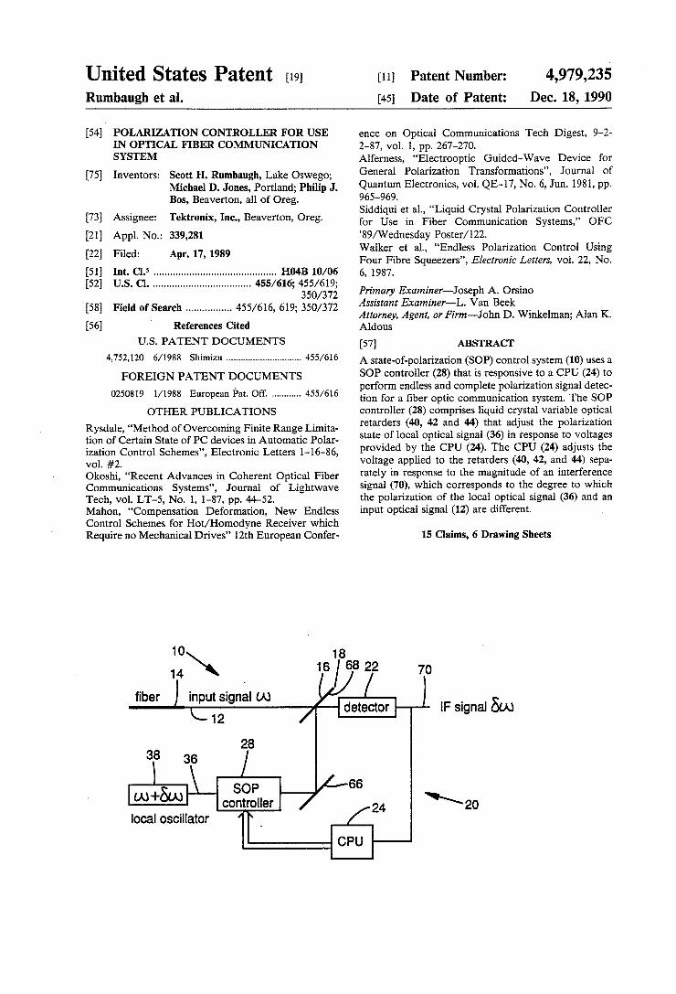
A state-of-polarization (SOP) control system (10) uses a SOP controller (28) that is responsive to a CPU (24) to perform endless and complete polarization signal detec tion for a ?ber optic communication system. The SOP controller (28) comprises liquid crystal variable optical retarders (40, 42 and 44) that adjust the polarization state of local optical signal (36) in response to voltages provided by the CPU (24). The CPU (24) adjusts the voltage applied to the retarders (40, 42, and 44) sepa rately in response to the magnitude of an interference signal (70), which corresponds to the degree to which the polarization of the local optical signal (36) and an input optical signal (12) are different. ,
15 Claims, 6 Drawing Sheets
l lF signal 5W
CPU
US. Patent Dec. 18, 1990 Sheet 1 of6 4,979,235
FIG. 1 1O 18
14\ 16 / 68 7 70 ?ber J inputsignal w detector ) IF sl nal 50k)
\-12 g
' 28
3)8 3i / SOP 66 4
W +50“ controller 24 \ 20 local oscillator ’ F /
CPU
US. ‘Patent Dec. 18, 1990 Sheet 2 0f 6 4,979,235
FIG. 3
HG. 4b a Z ‘5%’;
time=t0
Input
US. Patent Dec. 18,1990 Sheet 3 0f 6 4,979,235
Z * FIG. 6b FIG. 6a
v.9; FIG. 7b
time=t3
FIG. 7a
Z FIG. 8b
Input
FIG. 8a Y; ;
US. Patent
FIG. 9
Dec. 18, 1990 Sheet 4 0f 6 4,979,235
150
186
) Goto Reset Mode
4,979,235 1
POLARIZATION CONTROLLER FOR USE IN OPTICAL FIBER COMMUNICATION SYSTEM
TECHNICAL FIELD
The present invention relates to optical communica tion systems and, in particular, to a polarization control ler comprising multiple liquid crystal devices to provide endless polarization control in the coherent detection of an optical signal propagating through an optical com munication system.
BACKGROUND OF THE INVENTION
State-of—polarization control systems have applica tions with ?ber sensors, interferometry and optical communications systems. The following background information is presented herein only by way of example with reference to a polarization controller for use in an optical ?ber communication system. One type of conventional optical ?ber communica
tion system employs a single-mode ?ber that transmits a light beam emitted by a narrow spectral linewidth semi conductor laser. An optical modulator modulates the light beam in accordance with an electrical message signal at baseband frequencies to form a modulated optical signal that propagates through the single-mode ?ber. The polarization state of the modulated optical signal typically changes over time at the communica tion system receiver as a result of thermal or mechanical disturbances or stresses undergone by the ?ber or as a result of inherent birefringence of the ?ber. For exam ple, a linearly polarized transmitted optical signal typi cally becomes generally elliptically polarized by the time it reaches the receiver. Such changes in polariza tion state require compensation to enable the use of a coherent detection receiver. The cost and drawbacks of using conventional polarization-maintaining ?ber pre clude its use in practical communication systems and plain coherent detection schemes. However, the polar ization state of a signal in a single-mode ?ber varies slowly enough to permit polarization compensation. A state-of-polarization matching scheme may be im~
plemented in a variety of ways and can be incorporated into existing ?ber optic networks. Two basic ap proaches for controlling the polarization state of a sig nal are (1) matching the polarization state of a locally generated signal with that of the received communica tion signal and (2) separately detecting the two orthogo nal polarization components of the received communi cation signal and adding them together after appropri ate polarization compensation.
Combinations of these approaches generally employ two or more controlling elements to compensate for the number of degrees freedom of a polarization state, i.e., the ellipticity and tilt angle. The controlling elements previously employed in polarization controllers include electromagnetic ?ber squeezers, electrooptic crystals, rotatable ?ber coils, rotatable quarter-wave and half wave plates, Faraday rotators, and rotatable ?ber cranks. Each of these polarization controllers suffers from
varying degrees of insertion loss, mechanical fatigue, 'and other disadvantages, which are more fully de scribed by Okoshi, “Polarization-State Control Schemes for Heterodyne or Homodyne Optical Fiber Communications,” Journal of Lightwave Technology,
10
20
35
45
55
IEEE Vol. LT-3, No. 6, December, 1985. Other disad
2 vantages associated with the polarization controllers are their high cost and need for high operating voltages. Two polarization controllers that are capable of pro
viding endless control are rotatable wave plates and rotatable ?ber cranks. Endless control is important be cause the fluctuation of the polarization state of a signal in a single-mode ?ber is unpredictable. Thus, a state-of polarization control element having a limited control range might require resetting. The resetting in conven tional systems is generally accompanied by loss of the polarization state of the local optical signal and a conse quent loss of information because of an inability to maintain continuous coherent detection. This loss can be substantial if the polarization state of the received optical signal is near to or ?uctuates about the critical range points of the polarization controller elements.
SUMMARY OF THE INVENTION
An object of the present invention is, therefore, to provide a polarization state controller for use in a opti cal communication system employing coherent detec tion. Another object of this invention is to provide such a
polarization controller that is capable of endless con trol. A further object of this invention is to provide such a
polarization controller that is relatively low cost and requires a relatively low operating voltage. The present invention relates to a state-of-polariza
tion control system for an optical system in which a detector develops a difference signal that is indicative of a difference between polarization states of an input optical signal and a local optical signal. The control system includes a polarization controller that controls the polarization of the local signal to control the differ ence in polarization between the local signal and input signal. The polarization controller includes ?rst, sec ond, and third liquid crystal devices that provide retard ance values 1111, 0p, and 0y, respectively. A signal proces sor computes polarization data for the liquid crystal devices in response to the difference signal. The liquid crystal devices respond to the polarization data to mini mize the difference between the polarization state of the input signal and local signal. The control system operates in a normal mode and
?rst and second reset modes. In normal mode, the ?rst and second liquid crystal devices cooperate to change the polarization of the horizontally polarized local sig nal to any linear tilt polarization. In the normal mode, the third liquid crystal device provides any elliptical polarization state to the output of the second liquid crystal device. Further, the third liquid crystal device generally changes the tilt of the output of the second liquid crystal device. In the ?rst and second reset modes, the third liquid crystal device is reset from an upper and lower limit, respectively, while the ?rst and second liquid crystal devices provide an elliptical polar ization state to the local signal. The control system is endless in that during reset modes no change occurs in the state-of-polarization of the local signal as it emerges from the third liquid crystal device. The tracking sys tem of the present invention is explained with reference to the Poincare sphere.
Liquid crystal devices provide polarization control at a relatively low operating voltage and can be easily implemented in existing systems at a very low cost.
Additional objects and advantages of the present invention will be apparent from the following detailed
4,979,235 3
description of a preferred embodiment thereof, which proceeds with reference to the accompanying draw ings.
BRIEF DESCRIPTION OF THE DRAWINGS
FIG. 1 is a system block diagram of a coherent detec tion receiver in which the polarization controller of the present invention minimizes the difference between an input optical signal and a locally generated optical source signal.
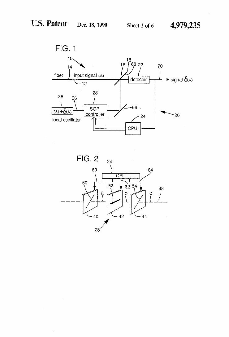
FIG. 2 is a diagram showing three liquid crystal cells forming a polarization controller that imparts a con trolled amount of retardation to the locally generated signal to maintain coherent detection of the input signal. FIG. 3 shows the Poincare sphere, which is useful for
describing the operation of the polarization controller of the invention. FIGS. 40 and 4b, through FIGS. 80 and 8b show
examples of polarization displacement paths of the 10 cally generated optical signal on the surface of the Poin care sphere as the polarization controller functions to achieve a minimum polarization difference between the input and locally generated optical signals. FIGS. 4a, 5a, 6a, 7a, and 80 show plan views of the Poincare sphere. FIGS. 4b. 5b, 6b, 7b, and 8b show side views of the Poincare sphere. FIG. 9 is a ?owchart of the processing steps associ
ated with the normal operating mode of the invention. FIG. 10 is a ?owchart of the processing steps associ
ated with a ?rst reset mode of the invention. FIG. 11 is a ?owchart of the processing steps associ
ated with a second reset mode of the invention.
DETAILED DESCRIPTION OF PREFERRED EMBODIMENT
Referring to FIG. 1, a preferred embodiment of a state-of-polarization (SOP) control system 10 forms a portion of an optical communication receiver that per forms coherent detection of an input optical signal 12 propagating from the output end of an optical ?ber 14. SOP control system 10 is of the heterodyne type. The present invention may be used in any system that uses interference, such as an interferometer system. A pre ferred embodiment includes a communication receiver. The input signal 12 exits optical ?ber 14 and strikes a
surface 16 of a half-silvered mirror 18, which functions as the input of a control loop 20. Control loop 20 in cludes a detector 22, a central processing unit (CPU) 24, and a SOP controller 28 that receives a local optical signal 36 from a local oscillator 38.
Input signal 12 has angular frequency w and an arbi trary SOP. Local signal 36 has an angular frequency w+8w and a nominally horizontal polarization. Alter natively, local signal 36 could be vertically polarized. The angular frequency 50) is de?ned as the offset fre quency of the local signal 36 relative to the angular frequency w'of input signal 12.
Referring to FIG. 2, SOP controller 28 preferably includes three nematic liquid crystal variable optical retarders 40, 42, and 44 that are of the variable birefrin gent type. Local signal 36 propagates along optic axis 48, which intersects and is normal to the light communi cating surfaces of retarders 40, 42, and 44. Points a, b, and c are used as reference points in describing the SOP of local signal 36 as it emerges from retarders 40, 42, and 44, respectively. The relative alignment of fast axis 50, fast axis 52, and
fast axis 54 is shown on retarders 40, 42, and 44, respec
5
30
35
40
45
60
65
4 tively. Alternatively, axes 50, 52, and 54 could be the slow axes of retarders 40, 42, and 44. Fast axes 50 and 54 are aligned 45° with respect to fast axis 52 and horizon tally polarized local signal 36. The retardance of liquid crystal retarders is a function
of the alignment of the liquid crystal molecules, which is controlled by the intensity of an applied electric ?eld. The retardance of retarder 40 is denominated 1112. The retardance of retarder 42 is denominated tip. The retard ance of retarder 44 is denominated By. The intensities of the electric fields applied to retarders 40, 42, and 44 change in response to voltage signals appearing at the respective outputs 60, 62, and 64 of CPU 24. Any com bination of values of retardance llllz, 9p, and By may be obtained by varying the magnitudes of the applied volt age signals. To achieve coherent detection of input signal 12,
SOP control system 10 tracks the polarization of input signal 12 by changing the retardance imparted to local signal 36 by retarders 40, 42, and 44. The polarization of local signal 36 may be any desired value by producing a corresponding combination of retardances i112, 6p, and 0y. This change in polarization of local signal 36 is achieved in the following manner.
Referring again to FIG. 1, local signal 36 propagates through SOP controller 28, reflects off a mirror 66, and strikes the surface 68 of half-silvered mirror 18. As an alternative to the con?guration of FIG. 1, mirrors 18 and 66 could be replaced by a ?ber optic directional coupler. Input signal 12 propagates through mirror 18, and local signal 36 re?ects off mirror 18. Both input signal 12 and local signal 36 strike detector 22, which is preferably a photo-detector. Photodetectors are inher ently square law devices such that the only time-vary ing signal detected is the interference (IF) signal 70 of frequency 61». The amplitude of IF signal 70 is deter mined by the amplitude of local signal 36 and how closely the polarization of local signal 36 matches the polarization of input signal 12. The amplitude of IF signal 70 increases as the polarization difference be tween input signal 12 and local signal 36 decreases. SOP controller 28 minimizes the polarization differ
ence between input signal 12 and local signal 36 by systematically varying the SOP of local signal 36 until the voltage of IF signal 70 is a maximum. Once the voltage of IF signal 70 is a maximum, SOP controller 10 continues to vary the SOP of local signal 36 to follow changes in input signal 12. SOP control system 10 continuously modi?es the
SOP of local signal 36 to minimize the difference be tween the SOP of input signal 12 and local signal 36. Changes in the amplitude of IF signal 70 are the only feedback used to determine how to modify the SOP of local signal 36. SOP control system 10 is complete in that SOP controller 28 can produce all possible polar ization states in local signal 36 as it emerges from re tarder 44 at point e. SOP control system 10 is endless in that no change in the SOP at point c occurs during the reset of any of ?nite range retarders 40, 42, and 44. The method of varying the polarization of local sig
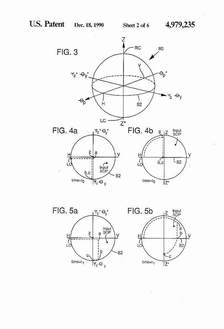
nal 36 may be explained in connection with the Poin care sphere 80, which is shown in FIG. 3. Referring to FIG. 3, the Poincare sphere 80 is a unit-radius spherical surface on which each point represents a different p0 larization form. Every point on the equator 82 repre sents linear polarization in a different polarization direc tion. Point H on the equator represents horizontally polarized light, and point V, which is diametrically
4,979,235 5
opposed to point H, represents vertically polarized light. Elliptical polarization is represented by any point on the sphere located off the equator 82. The north pole and south pole represent right-circular (RC) and left circular (LC) polarization, respectively. The Poincare Sphere is described in W. A. Shurcliff and S. S. Ballard, Polarized Light, 1964, pp. 71-76, and Born & Wolf, Principles of Optics, 1980, section 1.4, p. 31. In FIG. 3, the z-z * , 1l1z—tl1z* , and tip-0f axes are perpendicu lar to each other. The symbol * denominates a conju gate, i.e., an orthogonal counterpart. For example, 2* is a conjugate of z. The 0y—0y* axis is collinear with the \l1z—\lJz* axis. _a The Jones vector EC, which describes the SOP of the
electric ?eld of local signal 36 at point 0, is determined by multiplying the Jones vector of the SOP of local signal 36 as it emerges from local oscillator 38 by the Jones matrices for each device in an order opposite to that in which they appear in the system. EC is described with linear algebraic matrix multiplication in equation 1 below:
(1)
cosPcos(Z + Y) + lsinPcos(Z — Y) sinPsin(Z — Y) + icosPsin(Z + Y)
Jones vector and jones calculus are described in W. A. Shurcliff, Polarized Light: Production and Use, 1966, pp. 23-29, 91, and 118-123, and W. A. Shurcliff and S. S. Ballard, Polarized Light, 1964, pp. 80-82 and 93-95. Three control algorithms (normal mode and two
reset modes) are used to endlessly maintain the polariza tion match between input signal 12 and local signal 36, and determine the values of r112, 01,, and 0}) to use in equation (1). Equation (1) may be used to explicitly determine the polarization state at point 0. Determining the polarization state at point 0 is not necessary in using the invention. CPU 24 calculates voltages in the manner described in connection with the ?owcharts of FIGS. 9, 10, and 11.
Normal Mode of Operation
Under normal operation of a preferred embodiment, 0p=i1r/2, which is an illustrative case of (4nil)rr/2 where n is any integer. Liquid devices do not switch between positive and negative values of retardance. However, 7r/2 is a special case of (4n+ l)1r/ 2 and -rr/2 is a special case of (4n — l)rr/ 2. The use of irr/ 2 is for mathematical simplicity. When the invention is implemented with liquid crystals, other values such as 0p=1r/2 and 31r/2 are preferred. The polarization matching is accomplished by altering ill, and 1%. Since their axes 50 and 52 are displaced by 45°, retarders 40 and 42 operate as a single unit that effectively rotates the SOP of local signal 36 as it propagates between local oscillator 38 and point b. This changes the SOP in rota tional directions about the z-z* axis of the Poincare sphere 80. Retarders 40 and 42 are referred to as the rotator analog. Retarder 44 controls the ellipticity and additional tilt of local signal 36 by changing the SOP in
6 rotational directions about the 0y—6y* axis on the Poin care sphere 80. The Jones vector for local signal 36 exiting retarder
42 at point b in FIG. 2 is described with linear algebraic 5 matrix multiplication in equation (2) below:
(2)
15 where Flbb represents the electric ?eld vector of local signal 36 at point b. The e‘l’p/2 term is an absolute phase term that has no
effect on the polarization and will be disregarded. For 6p=1'r/2, the Jones vector at point b is described in equation (3) below: 20
E. _ cos(1lJZ/2) (3) b _ SinQbZ/Z) '
25 . . .
For 01;: -rr/2, the Jones vector at point b is described in equation (4) below:
COS(llJz/2) (4) 30
Equations (3) and (4) above indicate, therefore, that restricting the voltage signal at output 62 of CPU 24 to binary values corresponding to retardation values of 6p=i-1r/2, provides a linear SOP at point b. Under these conditions, the value of ill, determines the polar ization direction or tilt of local signal 36 exiting retarder 44. Whenever liJZ=I11T, where n is any integer, the polar ization at point a matches one of the two eigenstates of 01,, which are linear polarizations in the same plane as the fast and slow axes of retarder 42. In the case where tlJZ=m-r, changes in GP have no effect on the SOP of local signal 36 at point b. The polarization tilt at point b may be rotated end
lessly and continuously if the direction of control of Ill; is reversed at its range limit (0 or 17') and 6;, is switched to its complementary value. The range limits may be de?ned as mr and (n+ l)1r where n is any integer. In a preferred embodiment, 0 and 11' are chosen as range limits for illustrative purposes. During normal opera tion, therefore, the combination of retarders 40 and 42 function as a polarization rotator with in?nite range. The polarization tilt at point b is 1112/2 for 9p=1r/2, and —\l!;/ 2 for 6p: —1r/ 2. The combination of retarders 40 and 42 together with retarder 44 provide complete control of the polarization so that any SOP of local signal 36 can be produced at the output of SOP control ler 28. During the normal mode of operation, SOP control
system 10 maximizes the voltage of IF signal 70 by minimizing the polarization difference between input signal 12 and local signal 36. The SOP of input signal 12 typically changes extremely slowly relative to the rate at which the SOP of local signal 36 may be changed by CPU 24.
In a preferred embodiment, the polarization differ ence of input signal 12 and local signal 36 is minimized
45
55
4,979,235 7
in the following manner. The SOP oflocal signal 36 can be represented by a point at a particular location on the Poincare sphere 80. A change in location on the Poin care sphere 80 corresponds to a change in the SOP of local signal 36. The SOP of input signal 12 is repre sented on the Poincare sphere 80 as a single point. The voltage signals provided at outputs 60 and 62 of CPU 24 change the retardation amounts of the respective re tarders 40 and 42 and thereby change the position of the SOP of local signal 36 by incremental amounts on the Poincare sphere 80. During normal mode, the voltage on output 62 is either one of two voltage corresponding to 6p: i'zr/ 2.
If this change in SOP results in an increase in the magnitude of IF signal 70, then the change took place in the correct direction on the Poincare sphere 80. If this change in SOP results in a decrease in the magnitude of IF signal 70, then the position of the SOP of local signal 36 should be moved in the opposite direction. The posi tion is incrementally changed until a change results in a decrease in the magnitude of IF signal 70. The position is then changed by one increment point in the opposite direction. In a preferred embodiment, CPU 22 alter nates changes in the control voltages on outputs 60 and 64 in order to track the SOP of input signal 12. The control voltage on output 62 is either one of two volt ages corresponding to 0p=irr/ 2 in order to maintain endless rotation of the linear polarization at point b. The voltage signal provided at output 64 of CPU 24
changes the retardation amount of retarder 44 and thereby changes the position of the SOP of local signal 36 by incremental amounts on the Poincare sphere 80. The direction of change in retardation of retarder 44 remains the same as long as the magnitude of IF signal 70 increases as a result of the change. If a change in the position results in a decrease in the magnitude of IF signal 70, then the position is changed in the opposite direction. An example of the operation of SOP control system
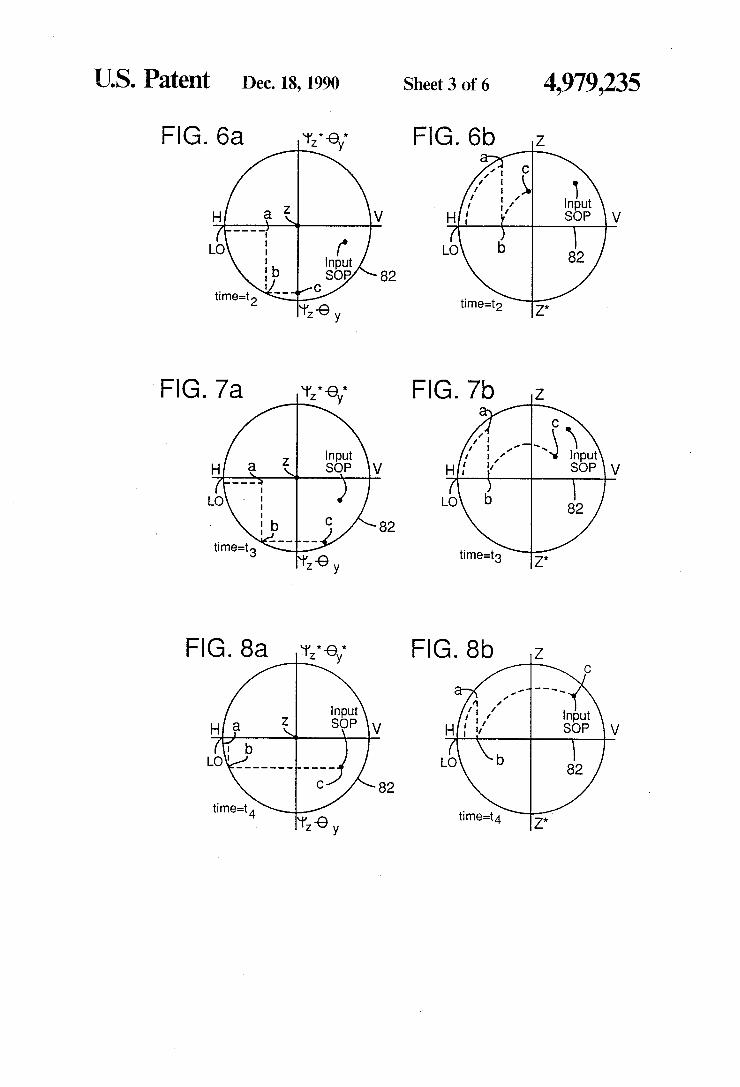
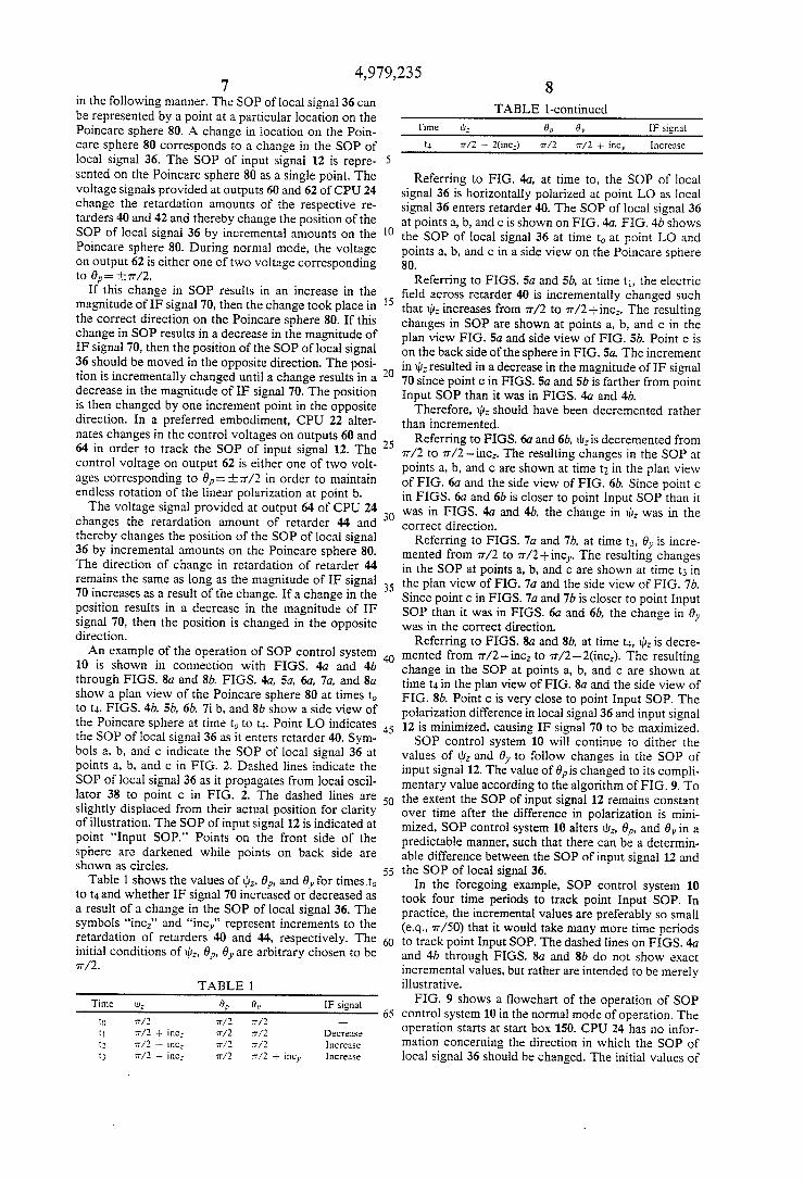
10 is shown in connection with FIGS. 40 and 4b through FIGS. 80 and 8b. FIGS. 40, 5a, 6a, 7a, and 80 show a plan view of the Poincare sphere 80 at times to to t4. FIGS. 4b, 5b, 6b, 7i b, and 8b show a side view of the Poincare sphere at time to to t4. Point LO indicates the SOP of local signal 36 as it enters retarder 40. Sym bols a, b, and c indicate the SOP of local signal 36 at points a, b, and c in FIG. 2. Dashed lines indicate the SOP of local signal 36 as it propagates from local oscil lator 38 to point e in FIG. 2. The dashed lines are slightly displaced from their actual position for clarity of illustration. The SOP of input signal 12 is indicated at point “Input SOP.” Points on the front side of the sphere are darkened while points on back side are shown as circles.
Table 1 shows the values of 111;, By, and 0,, for times to to t4 and whether IF signal 70 increased or decreased as a result of a change in the SOP of local signal 36. The symbols “incz” and “incy" represent increments to the retardation of retarders 40 and 44, respectively. The initial conditions of lllz, 6p, 0}; are arbitrary chosen to be rr/ 2.
TABLE l
Time U1; 0p 9}, IF signal to rr/Z rr/Z rr/Z -—
t1 rr/Z + inc; rr/Z rr/Z Decrease t3 rr/Z — inc; 7/2 Increase t3 rr/Z —- inc; rr/Z Increase
20
25
45
55
60
TABLE l-continued Time ‘U: 0,, 0,, IF signal
t4 rr/Z —- 2(inc=) 77/2 n'/2 + incy Increase
Referring to FIG. 40, at time to, the SOP of local signal 36 is horizontally polarized at point L0 as local signal 36 enters retarder 40. The SOP of local signal 36 at points a, b, and c is shown on FIG. 4a. FIG. 4b shows the SOP of local signal 36 at time to at point L0 and points a, b, and c in a side view on the Poincare sphere 80.
Referring to FIGS. 5a and 5b, at time t1, the electric ?eld across retarder 40 is incrementally changed such that Ll]; increases from 1r/2 to 1r/2+incz. The resulting changes in SOP are shown at points a, b, and c in the plan view FIG. 5a and side view of FIG. 5b. Point 0 is on the back side of the sphere in FIG. 5a. The increment in II]; resulted in a decrease in the magnitude of IF signal 70 since point 0 in FIGS. 5a and 5b is farther from point Input SOP than it was in FIGS. 40 and 4b.
Therefore, lllz should have been decremented rather than incremented.
Referring to FIGS. 60 and 6b, III: is decremented from 11/2 to 1r/2—-incz. The resulting changes in the SOP at points a, b, and c are shown at time t; in the plan view of FIG. 6a and the side view of FIG. 6b. Since point c in FIGS. 6a and 6b is closer to point Input SOP than it was in FIGS. 40 and 4b, the change in tllz was in the correct direction.
Referring to FIGS. 70 and 7b, at time t3, 6y is incre mented from rr/2 to w/2+incy. The resulting changes in the SOP at points a, b, and c are shown at time t3 in the plan view of FIG. 7a and the side view of FIG. 7b. Since point c in FIGS. 7a and 7b is closer to point Input SOP than it was in FIGS. 60 and 6b, the change in 0y was in the correct direction.
Referring to FIGS. 8a and 8b, at time t4, i112 is decre mented from rr/2-incz to 7T/2—2(incz). The resulting change in the SOP at points a, b, and c are shown at time t4 in the plan view of FIG. 8a and the side view of FIG. 8b. Point c is very close to point Input SOP. The polarization difference in local signal 36 and input signal 12 is minimized, causing IF signal 70 to be maximized. SOP control system 10 will continue to dither the
values of ti]; and by to follow changes in the SOP of input signal 12. The value of 6pis changed to its compli— mentary value according to the algorithm of FIG. 9. To the extent the SOP of input signal 12 remains constant over time after the difference in polarization is mini mized, SOP control system 10 alters 111:, 0p, and 9,, in a predictable manner, such that there can be a determin able difference between the SOP of input signal 12 and the SOP of local signal 36.
In the foregoing example, SOP control system 10 took four time periods to track point Input SOP. In practice, the incremental values are preferably so small (e.q., 1r/ 50) that it would take many more time periods to track point Input SOP. The dashed lines on FIGS. 40 and 4b through FIGS. 80 and 8b do not show exact incremental values, but rather are intended to be merely illustrative.
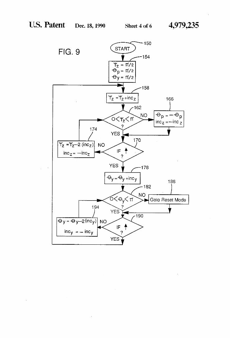
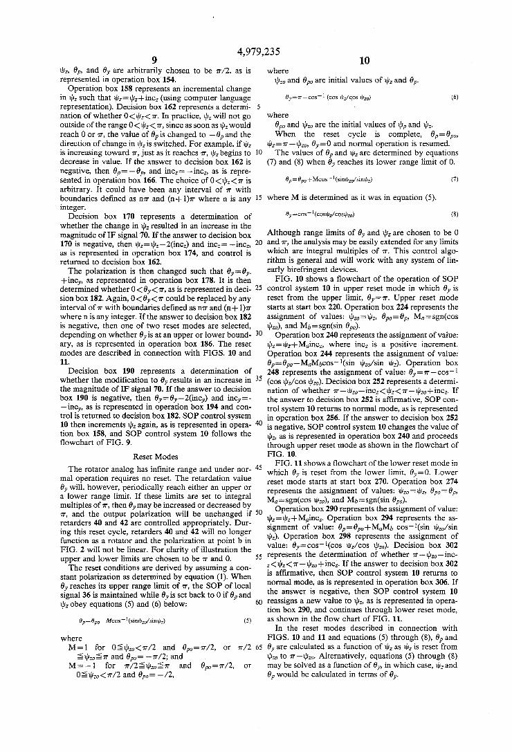
FIG. 9 shows a ?owchart of the operation of SOP control system 10 in the normal mode of operation. The operation starts at start box 150. CPU 24 has no infor mation concerning the direction in which the SOP of local signal 36 should be changed. The initial values of
4,979,235
L111, 61,, and 0y are arbitrarily chosen to be 7T/2, as is represented in operation box 154.
Operation box 158 represents an incremental change in \liz such that lliz=lllz+incz (using computer language representation). Decision box 162 represents a determi nation of whether O<tl1z<1'r. In practice, 11!; will not go outside of the range 0<tl1z<1r, since as soon as 1112 would reach 0 or 1r, the value of 01, is changed to —0,, and the direction of change in tllz is switched. For example, if tllz is increasing toward 11', just as it reaches 11', ll}; begins to decrease in value. If the answer to decision box 162 is negative, then 0p=—6p, and incz= —incz, as is repre sented in operation box 166. The choice of 0<1l1z<1r is arbitrary. It could have been any interval of 1r with boundaries de?ned as Mr and (n+ l)1r where n is any integer.
Decision box 170 represents a determination of whether the change in 1112 resulted in an increase in the magnitude of IF signal 70. If the answer to decision box 170 is negative, then xllz=xllz—2(incz) and incz= —incz, as is represented in operation box 174, and control is returned to decision box 162. The polarization is then changed such that 6y=0y.
+incy, as represented in operation box 178. It is then determined whether 0 < 0y<1r, as is represented in deci sion box 182. Again, 0 < 0y<1r could be replaced by any interval of 1r with boundaries de?ned as mr and (n+ l)1r where n is any integer. If the answer to decision box 182 is negative, then one of two reset modes are selected, depending on whether 0,, is at an upper or lower bound ary, as is represented in operation box 186. The reset modes are described in connection with FIGS. 10 and 11.
Decision box 190 represents a determination of whether the modi?cation to 6y results in an increase in the magnitude of IF signal 70. If the answer to decision box 190 is negative, then 0y=0y—2(incy) and incy= —incy, as is represented in operation box 194 and con trol is returned to decision box 182. SOP control system 10 then increments 1112 again, as is represented in opera tion box 158, and SOP control system 10 follows the ?owchart of FIG. 9.
Reset Modes
The rotator analog has in?nite range and under nor mal operation requires no reset. The retardation value 0;, will, however, periodically reach either an upper or a lower range limit. If these limits are set to integral multiples of 11', then 0}, may be increased or decreased by 77, and the output polarization will be unchanged if retarders 4-0 and 42 are controlled appropriately. Dur ing this reset cycle, retarders 40 and 42 will no longer function as a rotator and the polarization at point b in FIG. 2 will not be linear. For clarity of illustration the upper and lower limits are chosen to be 11 and O. The reset conditions are derived by assuming a con
stant polarization as determined by equation (1). When 0}, reaches its upper range limit of 11, the SOP of local signal 36 is maintained while 0}; is set back to 0 if 6p and lit, obey equations (5) and (6) below:
0p=6p0—Mcos_ ‘(swam/sine» (5)
where
35
45
55
.10 where
1102,, and 9P0 are initial values of til, and 0p.
9y=7r—cos_'1 (cos llIz/QOS 11120) (6)
where 0P0 and lllzo are the initial values of Lily and 1112. When the reset cycle is complete, 0p=0pm
lllz=1r—tllm, 9y=O and normal operation is resumed. The values of 0p and 1b; are determined by equations
(7) and (8) when 0y reaches its lower range limit of 0.
0p: 0,,,,+ Mcos - ‘(emu/5mm) (7)
where M is determined as it was in equation (5).
0y=cos _ ‘(cowl/cowl”) (8)
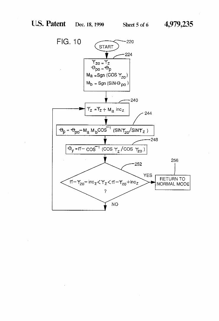
Although range limits of 0y and Illz are chosen to be 0 and 71', the analysis may be easily extended for any limits which are integral multiples of 77'. This control algo rithm is general and will work with any system of lin early birefringent devices. FIG. 10 shows a ?owchart of the operation of SOP
control system 10 in upper reset mode in which 9}; is reset from the upper limit, 0y=rr. Upper reset mode starts at start box 220. Operation box 224 represents the assignment of values: lllzo=tllz, 0po=0p, Ma=sgn(cos Ill”), and Mb=sgn(sin 0P0).
Operation box 240 represents the assignment of value: 1lIz=tl1z+Maincz, Where inc; is a positive increment. Operation box 244 represents the assignment of value: 0p=0pa—MaMbcos-1(sin lllzo/ sin 1112). Operation box 248 represents the assignment of value: 9y=n'—cos-1 (cos illz/cos lllzo). Decision box 252 represents a determi nation of whether n'—tllz,,—incz<illz<vr—tllzo+incz. If the answer to decision box 252 is affirmative, SOP con trol system 10 returns to normal mode, as is represented in operation box 256. If the answer to decision box 252 is negative, SOP control system 10 changes the value of 1112, as is represented in operation box 240 and proceeds through upper reset mode as shown in the ?owchart of FIG. 10. FIG. 11 shows a flowchart of the lower reset mode in
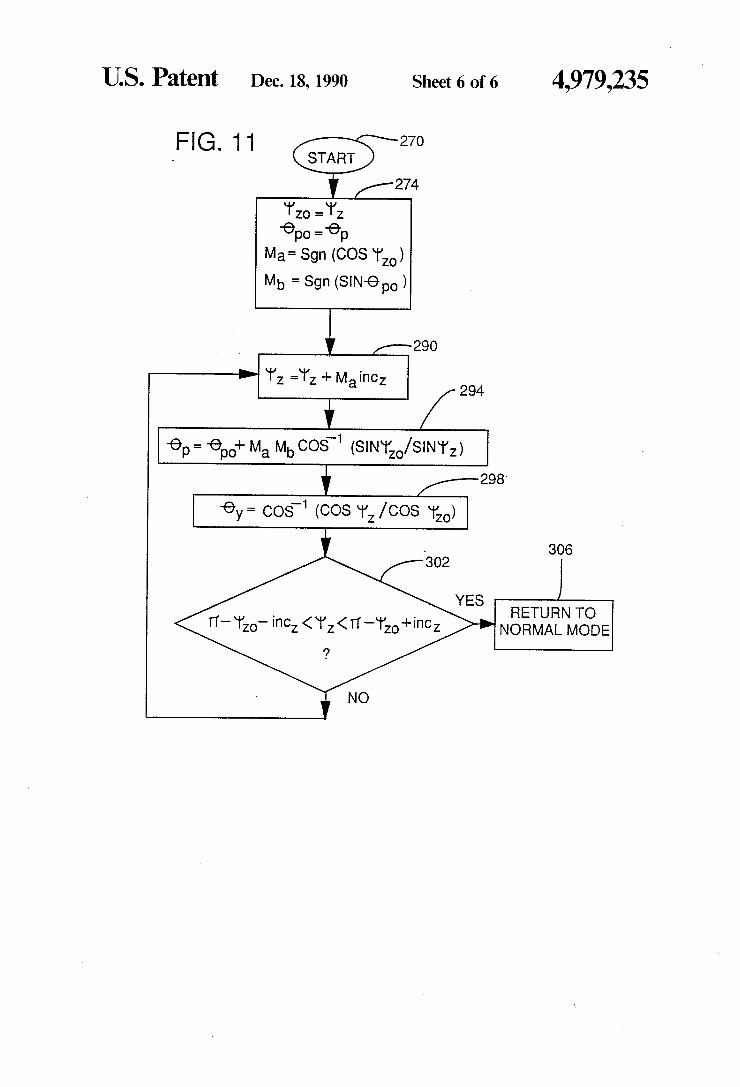
which 6), is reset from the lower limit, 0y=O. Lower reset mode starts at start box 270. Operation box 274 represents the assignment of values: lllzo=llllz, 0po=0p, a=sgn(cos dim), and Mb=sgn(sin 01",). Operation box 290 represents the assignment of value:
zllz=tltz+Maincz. Operation box 294 represents the as signment of value: 0p=0po+MaMb cos—1(sin lllzo/ sin 41,). Operation box 298 represents the assignment of value: 0y=cos"'1(cos \lJz/COS 11120). Decision box 302 represents the determination of whether 1r—-1l;z0—inc z<illz<rr—lllza+incz. If the answer to decision box 302 is affirmative, then SOP control system 10 returns to normal mode, as is represented in operation box 306. If the answer is negative, then SOP control system 10 reassigns a new value to 41;, as is represented in opera tion box 290, and continues through lower reset mode, as shown in the flow chart of FIG. 11.
In the reset modes described in connection with FIGS. 10 and 11 and equations (5) through (8), 0p and 6}; are calculated as a function of ti]; as 1112 is reset from lllza to 71-11120. Alternatively, equations (5) through (8) may be solved as a function of 0):, in which case, Ill; and 0” would be calculated in terms of 6y.
4,979,235 11
In the preferred embodiment, the SOP of local signal 36 is altered by SOP controller 28 and compared with input signal 12. Alternatively, SOP controller 28 may be arranged to alter the SOP of input signal 12. In this case, the altered SOP of input signal 12 would be com pared with unaltered local signal 36. In the alternative con?guration, the order of retarders 4-0, 42, and 44 would be reversed since the system is reciprocal.
It will be obvious to those having skill in the art that many changes may be made in the above described details of the preferred embodiment of the present in vention without departing from the underlying princi ples thereof. The scope of the present invention should be determined, therefore, only by the following claims. We claim: 1. A state-of-polarization control system for an opti
cal system in which a detector develops a difference signal that is indicative of a difference between a ?rst polarization state of a ?rst optical signal and a second polarization state of a second optical signal, comprising:
polarization control means including ?rst, second, and third retarding devices for controlling the dif ference between the ?rst polarization state of the ?rst optical signal and the second polarization state of the second optical signal; and
signal processing means responsive to the difference signal for computing polarization data to which the retarding devices of the polarization control means respond to minimize the difference between the ?rst and second polarization states, the system including in a normal mode of operation during which the ?rst retarding device provides a retard ance dig, and the second retarding device provides a retardance 9p=(4n1il)1r/2, where n1 is any integer, whenever n2rr<tb:<(n1+l)1r, where n; is any integer.
2. The system of claim 1 in which the second optical signal propagates through the ?rst and second retarding devices, and the ?rst and second retarding devices are of the variable optical retardation type and respond to the polarization data so that the ?rst retarding device provides a ?rst retardance value within one of plural ranges of retardation values and the second retarding device provides a second retardation value that deter mines the range within which the ?rst retardation value lies to impart a corresponding polarization direction to the second optical signal propagating through the ?rst and second retarding devices.
3. The system of claim 2 in which the second retard ing device provides one of relatively few values of retardation to determine the range within which the ?rst retardation value lies, and the ?rst retarding device provides one of relatively many values of retardation to determine the ?rst retardation value within the range.
4. The system of claim 2 in which the second retard ing device provides two values of retardation and the ?rst retarding device provides retardation lllz where nrr<t|l1z<(n+ l)1r, where n is any integer, to impart continuous rotation in either of two directions.
5. The system of claim 1 in which the third retarding device cooperates with the ?rst and second retarding devices to provide a polarization state ellipticity and tilt control.
6. The system of claim 5 in which the ?rst and second retarding devices cooperate to provide linearly polar ized light to the third retarding device.
7. The system of claim 1 in which the ?rst retarding device provides a retardance of value lit; and the third
0
25
45
60
65
12 retarding device provides a retardance 0y, and the po larization data are electrical signals that cause an incre mental change in the value of Ill; and an incremental change in the value of 0}).
8. The system of claim 1 whereby the polarization control means and the signal processing means cooper ate to provide tracking of the ?rst polarization state so that there is a determinable difference between them.
9. The system of claim 1 in which the optical system is a communication system.
10. The system of claim 1 in which the ?rst, second, and third retarding devices are liquid crystal devices.
11. A method for controlling the polarization of a ?rst optical signal of an optical system, comprising the steps of:
generating the ?rst optical signal; propagating the ?rst optical signal through ?rst and
second retarding devices; de?ning a ?rst polarization state of the ?rst optical
signal; receiving a second optical signal having a polariza
tion state; combining the second optical signal with the ?rst
optical signal on a detector; generating from the detector a difference signal indic
ative of a difference between the ?rst polarization state of the ?rst optional signal and the polarization state of the second optical signal;
generating retardation signals that represent a change in the polarization state of the ?rst optical signal from the ?rst polarization state to a second polar ization state in response to the difference signal;
changing the retardances of the retarding devices in response to the retardation signals, the ?rst retard ing device providing a retardance dig, and the sec ond retarding device providing a retardance 9p=(4n1il)1r/2, where n1 is any integer, when ever nzrr<rbz<(nz+ l)rr, where n; is any integer; and
adjusting the polarization state of the ?rst optical signal propagating through the retarding devices.
12. A state-of-polarization control system for an opti cal system in which a detector develops a difference signal that is indicative of a difference between a ?rst polarization state of a ?rst optical signal and a second polarization state of a second optical signal, comprising:
polarization control means including ?rst, second, and third retarding devices for controlling the dif ference between the ?rst polarization state of the ?rst optical signal and the second polarization state of the second optical signal; and
signal processing means responsive to the difference signal for computing polarization data to which the retarding devices of the polarization control means respond to minimize the difference between the ?rst and second polarization states, the system operating in a normal mode and ?rst and second reset modes, such that in the normal mode the ?rst and second retarding devices function to provide linear polarization and the third retarding device provides a retardance value 0),, where n1r< 6y<(n+ 1)1r where n equals any integer; in the ?rst reset mode, the ?rst and second retarding devices provide elliptical polarization, and the third retard ing device resets from a retardance value of (n+11r, where n is the integer used in normal mode; and in the second reset mode, the ?rst and second retarding devices provide elliptical polar
4,979,235 13
ization, and the third retarding device provides a retardance value of mr, where n is the integer used
in normal mode.
13. The system of claim 12 in which the second re
tarding device provides two values of retardation and the ?rst retarding device provides retardation \lrz where mr <1l1z<(n+l)1r, where n is any integer, to impart continuous rotation in either of two directions.
15
25
30
35
45
55
65
14 14. The system of claim 12 in which the ?rst retarding
device provides a retardance of value 1112, and the polar ization data are electrical signals that cause an incre mental change in the value of 1112 and an incremental change in the value of 6y
15. The system of claim 12 whereby the polarization control means and the signal processing means cooper ate to provide tracking of the ?rst polarization state so that there is a determinable difference between them.
Ill * Ill * *
Related Documents