TJ UC-NRLF ) vr-> V.VMP u u ui EACH PAMPHLET IS ONE UNIT IN A COMPLETE LIBRARY OF MACHINE DE- SIGN AND SHOP PRACTICE REVISED AND REPUBLJSHED FROM MACHINERY No. 10 EXAMPLES OF MACHINE SHOP PRACTICE By H, P. FAIRFIELD SECOND EDITION CONTENTS Cutting Bevel Gears with a Rotary Cutter Making a Worm -Gear Spindle Construction 33 Copyright 1910, The Industrial Press, Publishers of MACHINERY, 49-55 Lafayette Street, New York City

Welcome message from author
This document is posted to help you gain knowledge. Please leave a comment to let me know what you think about it! Share it to your friends and learn new things together.
Transcript
7/29/2019 (L) Examples of Machine Shop Practice (1910)
http://slidepdf.com/reader/full/l-examples-of-machine-shop-practice-1910 1/54
TJUC-NRLF
) vr-> V.VMP u u ui
EACH PAMPHLET IS ONE UNIT IN A COMPLETE LIBRARY OF MACHINE DE-
SIGN AND SHOP PRACTICE REVISED AND REPUBLJSHED FROM MACHINERY
No. 10
EXAMPLES OF MACHINE
SHOP PRACTICE
By H, P. FAIRFIELD
SECOND EDITION
CONTENTS
Cutting Bevel Gears with a Rotary Cutter
Making a Worm-Gear
Spindle Construction 33
Copyright 1910, The Industrial Press, Publishers of MACHINERY,49-55 Lafayette Street, New York City

7/29/2019 (L) Examples of Machine Shop Practice (1910)
http://slidepdf.com/reader/full/l-examples-of-machine-shop-practice-1910 2/54
7/29/2019 (L) Examples of Machine Shop Practice (1910)
http://slidepdf.com/reader/full/l-examples-of-machine-shop-practice-1910 3/54

7/29/2019 (L) Examples of Machine Shop Practice (1910)
http://slidepdf.com/reader/full/l-examples-of-machine-shop-practice-1910 4/54
7/29/2019 (L) Examples of Machine Shop Practice (1910)
http://slidepdf.com/reader/full/l-examples-of-machine-shop-practice-1910 5/54
MACHINERY'SREFERENCE SERIES
EACH NUMBER IS ONE UNIT IN A COMPLETELIBRARY OF MACHINE DESIGN AND SHOP
PRACTICE REVISED AND REPUB-
LJSHED FROM MACHINERY
NUMBER 10
EXAMPLES OF MACHINESHOP PRACTICE
ByH. P. FAIRFIELD
SECOND EDITION
CONTENTS
Cutting Bevel Gears with a Rotary Cutter -3
Making a Worm-Gear -17
Spindle Construction - - -'
-..-.- 33
Copyright, 1910, The Industrial Press, Publishers of MACHINEKY,49-55 Lafayette Street, New York City

7/29/2019 (L) Examples of Machine Shop Practice (1910)
http://slidepdf.com/reader/full/l-examples-of-machine-shop-practice-1910 6/54
7/29/2019 (L) Examples of Machine Shop Practice (1910)
http://slidepdf.com/reader/full/l-examples-of-machine-shop-practice-1910 7/54
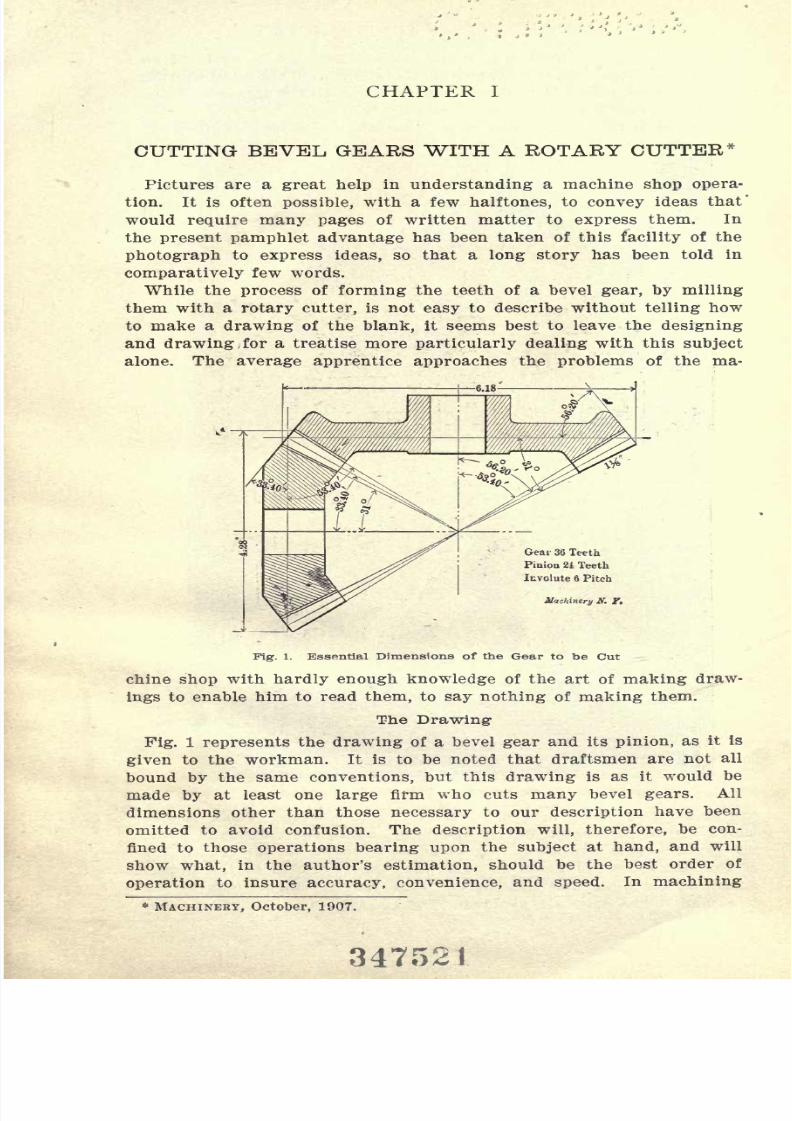
CHAPTER I
CUTTING BEVEL GEARS WITH A ROTARY CUTTER*Pictures are a great help in understanding a machine shop opera-
tion. It is often possible, with a few halftones, to convey ideas that'
would require many pages of written matter to express them. In
the present pamphlet advantage has been taken of this facility of the
photograph to express ideas, so that a long story has been told in
comparatively few words.
While the process of forming the teeth of a bevel gear, by milling
them with a rotary cutter, is not easy to describe without telling how
to make a drawing of the blank, it seems best to leave the designing
and drawing for a treatise more particularly dealing with this subject
alone. The average apprentice approaches the problems of the ma-
Gear 36 Teeth
Pinion 21 Teeth
Involute 6 Pitch
hinery ff. f.
Fig. 1. Essential Dimensions of the Gear to be Cut
chine shop with hardly enough knowledge of the art of making draw-
ings to enable him to read them, to say nothing of making them.
The Drawing-
Fig. 1 represents the drawing of a bevel gear and its pinion, as it is
given to the workman. It is to be noted that draftsmen are not all
bound by the same conventions, but this drawing is as it would be
made by at least one large firm who cuts many bevel gears. All
dimensions other than those necessary to our description have been
omitted to avoid confusion. The description will, therefore, be con-
fined to those operations bearing upon the subject at hand, and will
show what, in the author's estimation, should be the best order of
operation to insure accuracy, convenience, and speed. In machining
* MACHINERY, October, 1907.
7/29/2019 (L) Examples of Machine Shop Practice (1910)
http://slidepdf.com/reader/full/l-examples-of-machine-shop-practice-1910 8/54
6 No. 10 EXAMPLES OF SHOP PRACTICE
has been taken in reading the figures on the drawing and the gradu-
ations on the compound slide, the blank must agree with the drawing.
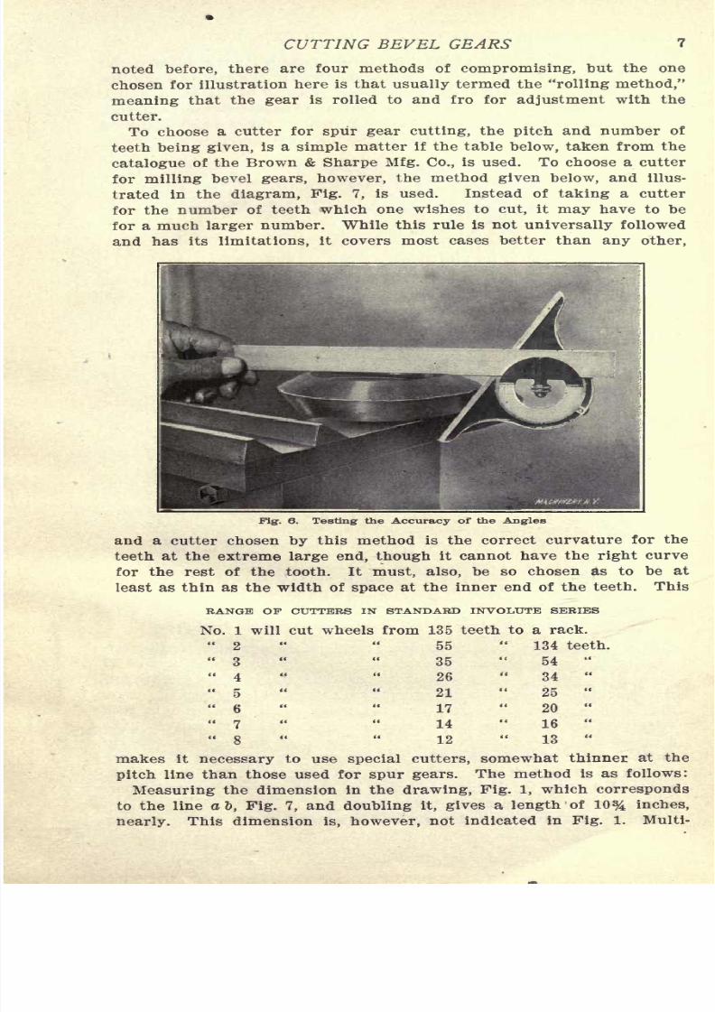
It is well, however, to check the angles with a protractor, and Fig. 6
shows this. While the blank and the tool v, ould ordinarily be held
in the hands when making this test, for convenience in photographing
they are placed as shown.
With the drawing dimensioned as shown, and the operations followed
as numbered, it will be noted that so far the greatest simplicity has
resulted in the setting of the machine and in the measurements made.
Selecting- the Cutter
The tooth-cutting operations are made in the milling machine, but
the points to be brought out will apply to gear-cutting machines as
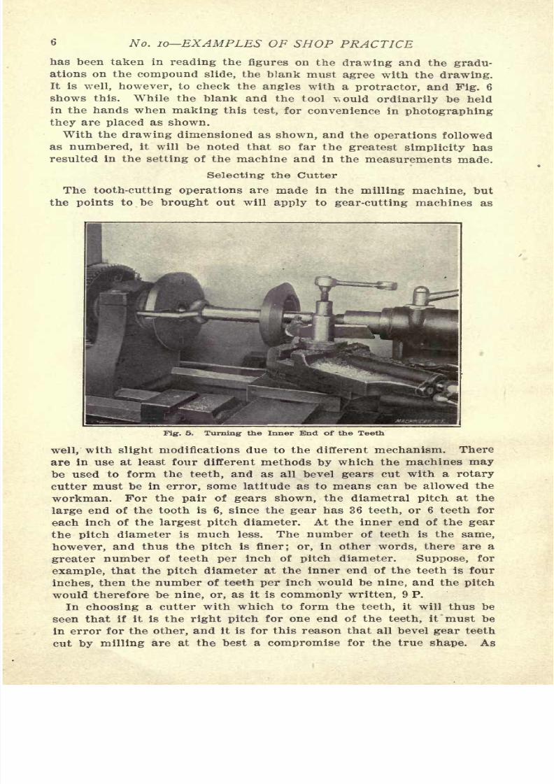
Fig. 5. Turning the Inner End of the Teeth
well, with slight modifications due to the different mechanism. There
are in use at least four different methods by which the machines may
be used to form the teeth, and as all bevel gears cut with a rotary
cutter must be in error, some latitude as to means can be allowed the
workman. For the pair of gears shown, the diametral pitch at the
large end of the tooth is 6, since the gear has 36 teeth, or 6 teeth for
each inch of the largest pitch diameter. At the inner end of the gear
the pitch diameter is much less. The number of teeth is the same,
however, and thus the pitch is finer; or, in other words, there are a
greater number of teeth per inch of pitch diameter. Suppose, for
example, that the pitch diameter at the inner end of the teeth is four
inches, then the number of teeth per inch would be nine, and the pitch
would therefore be nine, or, as it is commonly written, 9 P.
In choosing a cutter with which to form the teeth, it will thus be
seen that if it is the right pitch for one end of the teeth, it must be
7/29/2019 (L) Examples of Machine Shop Practice (1910)
http://slidepdf.com/reader/full/l-examples-of-machine-shop-practice-1910 9/54
CUTTING BEVEL GEARS 7
noted before, there are four methods of compromising, but the one
chosen for illustration here is that usually termed the "rolling method,"
meaning that the gear is rolled to and fro for adjustment with the
cutter.
To choosea cutter for
spur gear cutting,the
pitchand number of
teeth being given, is a simple matter if the table below, taken from the
catalogue of the Brown & Sharpe Mfg. Co., is used. To choose a cutter
for milling bevel gears, however, the method given below, and illus-
trated in the diagram, Fig. 7, is used. Instead of taking a cutter
for the number of teeth which one wishes to cut, it may have to be
for a much larger number. While this rule is not universally followed
and has its limitations, it covers most cases better than any other,
Fig. 6. Testing the Accuracy of the Angles
and a cutter chosen by this method is the correct curvature for the
teeth at the extreme large end, though it cannot have the right curve
for the rest of the tooth. It must, also, be so chosen as to be at
least as thin as the width of space at the inner end of the teeth. This
RANGE OF CUTTERS IN STANDARD INVOLUTE SERIES
No. 1 will cut wheels from 135 teeth to a rack.
"2
" "55
"134 teeth.
"3
" "35
"54
"
"4
" "26
"34
"
" 5 " " 21 " 25 "
"6
" "17
"20
"
"7 " "14
"16
"
"8
" "12
"13
"
makes it necessary to use special cutters, somewhat thinner at the
pitch line than those used for spur gears. The method is as follows:
Measuring the dimension in the drawing, Pig. 1, which corresponds
7/29/2019 (L) Examples of Machine Shop Practice (1910)
http://slidepdf.com/reader/full/l-examples-of-machine-shop-practice-1910 10/54
8 No. 10 EXAMPLES OF SHOP PRACTICE
plying this by the pitch, gives the number of teeth for which the cutter
must be chosen, or sixty-four, approximately. In the table on the pre-
vious page, a No. 2 cutter is listed to cut from 55 to 134 teeth, and is
the one selected. When it is inconvenient to measure the back cone
radius,use is made of the
following formulas, taken from Brown &Sharpe Mfg. Co.'s catalogue (see Fig. 7 for notations) :
A'.
= (1)
No. of teeth for whichto select cutter for gear
~~
No. of teeth for which _to select cutter for pinion
~~
sin aIf the gears are miters, or alike, only one cutter is needed,
is larger than the other two cutters may be needed.
(2)
(3)
If one
Setting-up the Work for Trial Cuts
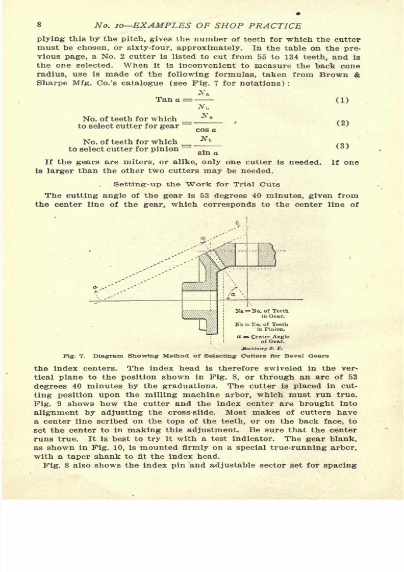
The cutting angle of the gear is 53 degrees 40 minutes, given from
the center line of the gear, which corresponds to the center line of
Nb = No. of Teeth
in Pinion.
tt = Centre Angleof Gear.
Machinery A. f.
Fig. 7. Diagram Showing Method of Selecting Cutters for Bevel Gears
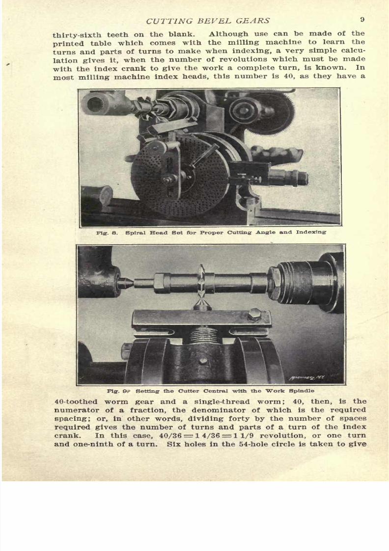
the index centers. The index head is therefore swiveled in the ver-
tical plane to the position shown in Fig. 8, or through an arc of 53
degrees40 minutes
bythe
graduations.The cutter is
placedin cut-
ting position upon the milling machine arbor, which must run true.
Fig. 9 shows how the cutter and the index center are brought into
alignment by adjusting the cross-slide. Most makes of cutters have
a center line scribed on the tops of the teeth, or on the back face, to
set the center to in making this adjustment. Be sure that the center
runs true. It is best to try it with a test indicator. The gear blank,
as shown in Fig. 10, is mounted firmly on a special true-running arbor,
7/29/2019 (L) Examples of Machine Shop Practice (1910)
http://slidepdf.com/reader/full/l-examples-of-machine-shop-practice-1910 11/54
CUTTING BEVEL GEARS
thirty-sixth teeth on the blank. Although use can be made of the
printed table which comes with the milling machine to learn the
turns and parts of turns to make when indexing, a very simple calcu-
lation gives it, when the number of revolutions which must be made
with the index crank to give the work a complete turn, is known. In
most milling machine index heads, this number is 40, as they have a
Fig. 8. Spiral Head Set for Proper Cutting Angle and Indexing
Fig. 9:- Setting the Cutter Central with the Work Spindle
40-toothed worm gear and a single-thread worm; 40, then, is the
numerator of a fraction, the denominator of which is the required
spacing; or, in other words, dividing forty by the number of spaces
required gives the number of turns and parts of a turn of the index
crank. In this = 1 = 1 1/9 revolution, or one turn
7/29/2019 (L) Examples of Machine Shop Practice (1910)
http://slidepdf.com/reader/full/l-examples-of-machine-shop-practice-1910 12/54
10 No. 10 EXAMPLES OF SHOP PRACTICE
the one-ninth of a turn required. Any circle of holes evenly divisible
by nine, can, of course, be used.
With the blank set to the required cutting angle, the next step is
to make a line on its back edge showing, as in Fig. 10, the depth of
the teeth at this point. This is done with a "depth of gear tooth"
gage of the proper pitch. Such gages may be bought in different sizes
for different pitches. Be careful to hold it parallel to the back edgeof the blank when scribing the line.
Fig. 11 shows the machine and work completely set up, and adjusted
for the trial cut. This cut must not be so carelessly made as to be
Fig:. 1O. Marking: the Depth of Tooth with Depth Gage
deeper than the tooth depth line marked out in Fig. 10, and several
trial cuts, each deeper than the other, may well be made in gettingthe required depth for the first space.
Approximating the Correct Tooth-form by Rolling
Fig. 12 shows the first space cut to depth. The work is then indexed
for another cut. Fig. 13 shows the trial tooth left by the two trial cuts
completed. It is noticeable that the tooth is much wider on the pitch
line than it should be, at the outer end. This may also be true of
the inner ends at the pitch lines, and is certain to be true of the
innerends above the
pitchline when the
gearis
finished,unless this
part of the tooth is afterward filed somewhat. The coarser the pitch
and the longer the tooth face, the more this latter shows. The rolling
method of approximating the true tooth shape starts by making sev-
eral central cuts, such as shown in Fig. 14, giving teeth which maybe used to test adjustments by as they are made. With the cross-feed
index set at zero, the table is moved off center toward the column of
the machine a trial distance, and then clamped immovably. By means
7/29/2019 (L) Examples of Machine Shop Practice (1910)
http://slidepdf.com/reader/full/l-examples-of-machine-shop-practice-1910 13/54
CUTTING BEVEL GEARS 11
teeth. Do not disturb the adjustable sector v.hen doing this, but leave
it to mark the hole which is correct for the central position.
Rolling the gear is equivalent to swiveling the tooth about the apex
of the cone, and allows the cutter to take a heavier shaving or chip
Fig. 11. "Work in Place on Machine, ready for Trial Cut
PigT. 12. Trial Cut Completed
at the outer end of the tooth than it does at the inner end. The
greater the adjustment off center and the more the blank is rolled,
the greater this difference.
If, for example, the cutter leaves the trial teeth accurate in thick-
7/29/2019 (L) Examples of Machine Shop Practice (1910)
http://slidepdf.com/reader/full/l-examples-of-machine-shop-practice-1910 14/54
12 No. 10 EXAMPLES OF SHOP PRACTICE
end without thinning the teeth. Exceptions to this will be noted fur-
ther along.
After the trial cut has been taken upon one side of the tooth, the
index pin and the cross-slide should be returned to their original
central position, and the blank indexed one tooth, to bring the cutter
to the side opposite to that already thinned off. Afterward set the
cross-slide off center away from the column, and roll the blank toward
the cutter again, the same amount as before, until the cutter just
enters the space at the inner end. Thin off this side. If the larger
end of the tooth is still too thick, it shows that the cross-slide was not
set off from its central position a great enough distance, and another
trial cut must be made on each side of the tooth, carefully duplicating
the operations just noted, but giving additional movement to the cross-
pig. 13. Trial Tooth Formed by Two Trial Cuts
slide and the rolling of the blank, repeating this until the gage shows
the right thickness at the outer end of the teeth as in Fig. 14. The
gage shown is one of a form common in gear-cutting practice. The
notch in the end of it has a depth equal to the addendum, and a width
equal to the tooth thickness of the pitch for .which it is intended
6 in this case.
As previously stated, all this has been done on the supposition that
the thickness of the cut left the space and teeth at their inner ends
the right width. If the cutter is too thin to do this, the teeth must be
shaved on their sides at the smaller as well as at the larger ends.
It is then necessary to observe that neither end is cut too narrow,
and the cross-slide adjustments, as well as the rolling of the blank,
must allow for the tooth its entire
7/29/2019 (L) Examples of Machine Shop Practice (1910)
http://slidepdf.com/reader/full/l-examples-of-machine-shop-practice-1910 15/54
CUTTING BEVEL GEARS 13
slide was offset 0.010 inch, and the blank rolled four holes in the
54-hole circle, and- the trial tooth shaved upon both its sides. These
amounts were afterward increased to an offset of the cross-slide to
0.015 inch each side of the zero line, and seven holes in the 54-hole
circle. This gave a tooth that gaged up as desired at its inner and
outer ends on the pitch line.
If the teeth of the pinion are not to be filed at their inner end above
the pitch line to bring that portion of the tooth more nearly to correct
shape than the cutter will leave it, it may be necessary to widen the
space at the inner ends of the gear to give additional room. On the
finer pitches, the cutter leaves the teeth so nearly correct that they
need not be filed; but in the coarser pitches, filing is quite necessary.
Cutting1 the Teeth
Having established the amount off center, and the angle to roll the
blank, proceed to cut the rest of the teeth. If the pitch is rather
Fig. 14. Testing Accuracy of Settings for Approximatingthe True Tooth-form
coarse, three cuts may be necessary all the way around each blank.
In the finer pitches, however, two cuts around are sufficient. In the
case of three cuts, the first is a central cut made as already shown
with the standard cutter, all the way around, and then the two thin-
ning cuts follow. Some gear-makers use a so-called "stocking cutter"
in making the central cuts* afterward thinning the teeth with a stand-
ard cutter as noted. This undoubtedly leads to less sharpening of the
standard cutter.
If the pitch allows two cuts around the blank to be sufficient, the
first is, of course, made with the table offset and the work rolled to
shape one side of the teeth, and the second, with the machine and
7/29/2019 (L) Examples of Machine Shop Practice (1910)
http://slidepdf.com/reader/full/l-examples-of-machine-shop-practice-1910 16/54
14 No. 10 EXAMPLES OF SHOP PRACTICE
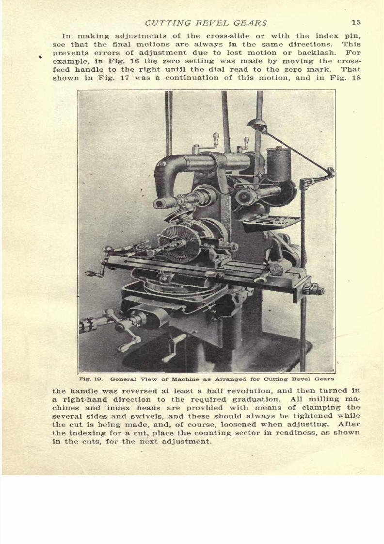
Figs. 16, 17 and 18 show the cross-feed screw index dial, as adjusted
for the central cuts, and afterward the thinning cuts.
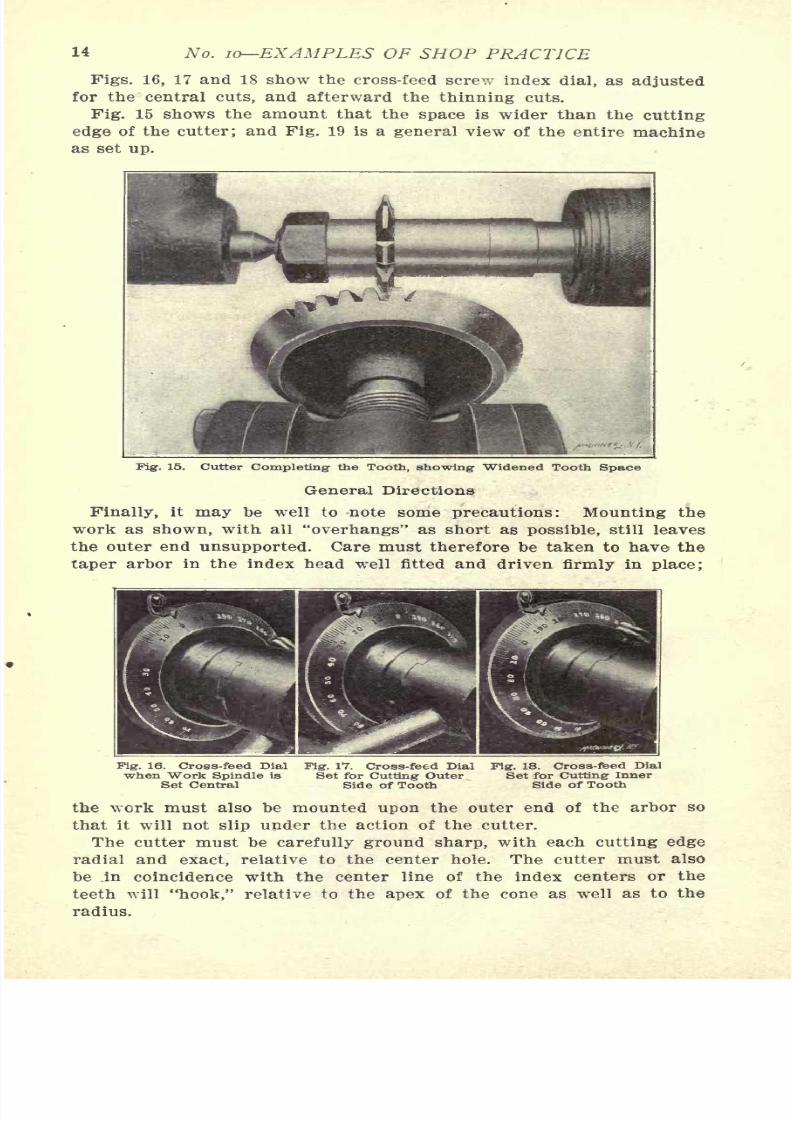
Fig. 15 shows the amount that the space is wider than the cutting
edge of the cutter; and Fig. 19 is a general view of the entire machine
as set up.
Fig. 15. Cutter Completing the Tooth, showing Widened Tooth Space
General Directions
Finally, it may be well to -note some precautions: Mounting the
work as shown, with all "overhangs" as short as possible, still leaves
the outer end unsupported. Care must therefore be taken to have the
taper arbor in the index head well fitted and driven firmly in place;
Fig. 16. Cross-feed Dial Fig. 17. Cross-feed Dial Fig. 18. Cross-feed Dialwhen "Work Spindle is Set for Cutting Outer Set for Cutting Inner
Set Central Side of Tooth Side of Tooth
the work must also be mounted upon the outer end of the arbor so
that it will not slip under the action of the cutter.
The cutter must be carefully ground sharp, with each cutting edge
radial and exact, relative to the center hole. The cutter must also
be .in coincidence with the center line of the index centers or the
7/29/2019 (L) Examples of Machine Shop Practice (1910)
http://slidepdf.com/reader/full/l-examples-of-machine-shop-practice-1910 17/54
CUTTING BEVEL GEARS 15
In making adjustments of the cross-slide or with the index pin,
see that the final motions are always in the same directions. This
prevents errors of adjustment due to lost motion or backlash. For
example, in Fig. 16 the zero setting was made by moving the cross-
feed handle to the right until the dial read to the zero mark. That
shown in Fig. 17 was a continuation of this motion, and in Fig. 18
Fig. 19. General View of Machine as Arranged for Cutting Bevel Gears
the handle was reversed at least a half revolution, and then turned in
a right-hand direction to the required graduation. All milling ma-
chines and index heads are provided with means of clamping the
several sides and swivels, and these should always be tightened while
the cut is being made, and, of course, loosened when adjusting. After
7/29/2019 (L) Examples of Machine Shop Practice (1910)
http://slidepdf.com/reader/full/l-examples-of-machine-shop-practice-1910 18/54
16 No. 10 EXAMPLES OF SHOP PRACTICE
In turning up the blanks, machine an extra one to use as a "dummy"for setting the machine. This dummy may be used until cut up.
Finally, settle upon a regular order of operations, follow it until' a
habit is formed, and fewer errors will result.
As has been intimated, the method of cutting bevel gears just de-
scribed, is only an approximate one. There is no possible way of
cutting them to the theoretically perfect shape with formed milling
cutters. There are probably more gears cut in the way we have
described, however, than by any other method, as it requires the sim-
plest outfit of tools, and can be done in any ordinary milling machine
which is provided with an indexing head. This method should not
be used on large gears especially those which are to run at a high
rate of speed and transmit considerable power. Under these condi-
tions, bevel gears cut with rotary cutters will be inefficient and noisy,
and will be far from durable. For such service, the teeth should be
planed by some one of the various machines made for the purpose,
either by the templet or generating processes.
There are so many gears cut with this method, however, that the
ability to use it should be a part of the training of all machinists who
class themselves as "all-around" workmen.

7/29/2019 (L) Examples of Machine Shop Practice (1910)
http://slidepdf.com/reader/full/l-examples-of-machine-shop-practice-1910 19/54
CHAPTER II
MAKING A "WORM-GEAR*
The machinist is apt to concern himself but little with the steps
taken by others to produce the castings which he is given to finish into
machine parts. He seldom gives the designer or draftsman a thought,
WORM 1 5 DIAMETER
6 THREADS PER INCH,R.H.2. 75 C. T. C.
WORM GEAR, 4.006 THROAT DIAMETER
TEETH 61
RAD. TURNING TOOL 0.747
14"X 6"ENGINE LATHE
DETAIL OF WORM GEAR
WASHBURN SHOPS WORCESTER MASS-U.S.A.
Fig. 2O. Drawing of the Worm-gear to be MadeMachinery, N.r.
and the patternmaker or molder gets less. It may therefore be of in-
terest to follow along the path a piece has taken, from its first incep-
tion in the designer's brain, to the point where it becomes a finished
Fig. 21. Gluingr Up the Patternfor the Worm-gear
Fig. 22. The Hub and Finished Faceof the Pattern
part of a useful machine, and to count the footsteps. Take, for ex-
ample, a worm-gear such as that shown in Pig. 20, which is part of a
7/29/2019 (L) Examples of Machine Shop Practice (1910)
http://slidepdf.com/reader/full/l-examples-of-machine-shop-practice-1910 20/54
18 , TO EXAMPLES OF SHOP PRACTICE
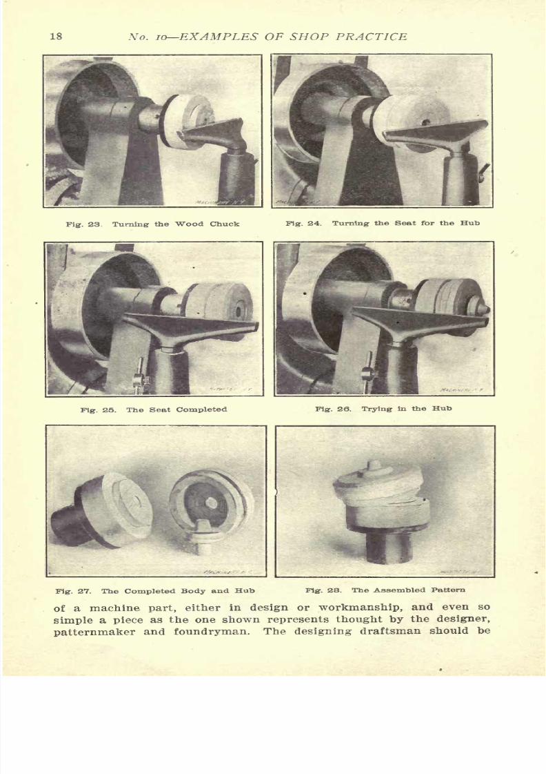
Fig. 23. Turning the Wood Chuck Pig. 24. Turning the Seat for the Hub
Pig. 25. The Seat Completed Fig. 26. Trying in the Hub
Fig. 27. The Completed Body and Hub Fig. 28. The Assembled Pattern
of a machine part, either in design or workmanship, and even so

7/29/2019 (L) Examples of Machine Shop Practice (1910)
http://slidepdf.com/reader/full/l-examples-of-machine-shop-practice-1910 21/54
MAKING A WORM-GEAR 19
something of a patternmaker, foundryman and machinist, in addition
to his ability to assign proper values to form, strength, velocity ra-
tios, position, etc. On the work of the draftsman depends largely the
possibility of economic production in the shop, and if the machine
Fig. 29. Tools Used by Patternmaker
details he designs cannot be easily and cheaply made, it is, in most
cases, his lack of proper understanding of shop processes -which is
to blame for this condition.
The patternmaker is concerned with questions of shrinkage and
warping of the materials used in making the pattern. He is also
Fig-. SO. Pattern Finished and Shellaced
concerned with the foundry and machine shop problems of shrinkage,
draft, finish, ease of molding and machining. Fig. 21 shows the best
7/29/2019 (L) Examples of Machine Shop Practice (1910)
http://slidepdf.com/reader/full/l-examples-of-machine-shop-practice-1910 22/54
20 No. 10 EXAMPLES OF SHOP PRACTICE
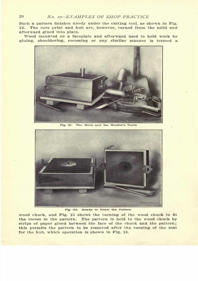
Such a pattern finishes nicely under the cutting tool, as shown in Fig.
22. The core print and hub are, however, turned from the solid and
afterward glued into place.
Wood mounted on afaceplate
and afterward used to hold workby
gluing, shouldering, recessing or any similar manner is termed a
Fig. 32. Beady to Draw the Pattern
wood chuck, and Fig. 23 shows the turning of the wood chuck to fit
the recess in the pattern. The pattern is held to the wood chuck by
7/29/2019 (L) Examples of Machine Shop Practice (1910)
http://slidepdf.com/reader/full/l-examples-of-machine-shop-practice-1910 23/54
MAKING A WORM-GEAR 21
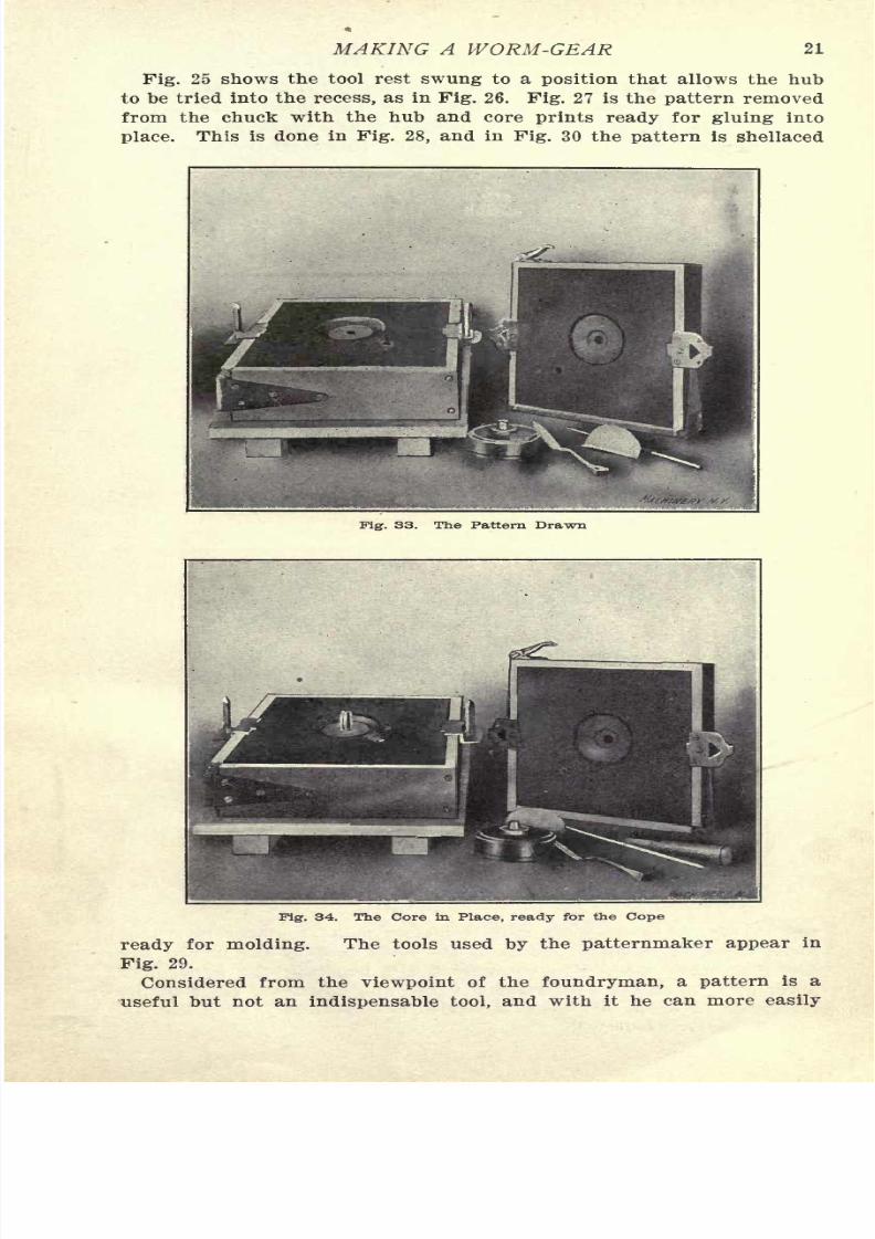
Pig. 25 shows the tool rest swung to a position that allows the hub
to be tried into the recess, as in Fig. 26. Fig. 27 is the pattern removed
from the chuck with the hub and core prints ready for gluing into
place. This is done in Fig. 28, and In Fig. 30 the pattern is shellaced
Fig. 33. The Pattern Drawn
Pig. 34. The Core in Place the Cope
ready for molding. The tools used by the patternmaker appear in
Fig. 29.
a is a
7/29/2019 (L) Examples of Machine Shop Practice (1910)
http://slidepdf.com/reader/full/l-examples-of-machine-shop-practice-1910 24/54
22 No. 10 EXAMPLES OF SHOP PRACTICE
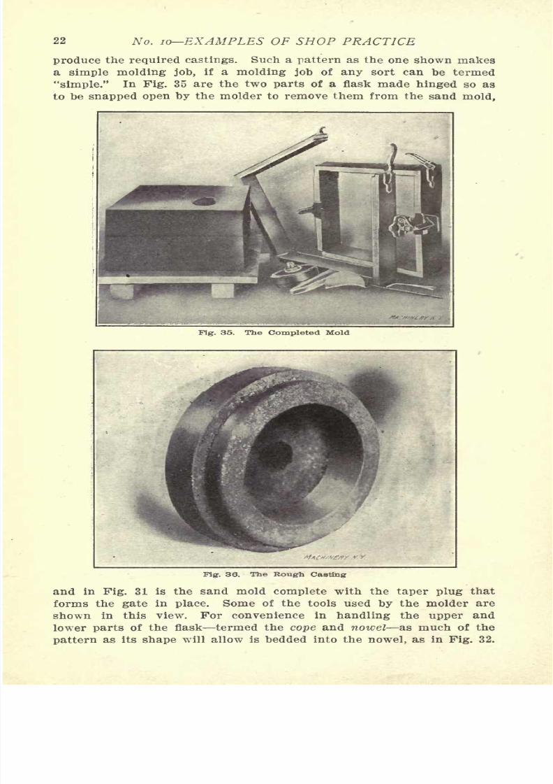
produce the required castings. Such a pattern as the one shown makes
a simple molding job, if a molding job of any sort can be termed
"simple." In Fig. 35 are the two parts of a flask made hinged so as
to be snapped open by the molder to remove them from the sand mold,
Pig. 35. The Completed Mold
Fig. 36. The Rough Casting
and in Fig. 31 is the sand mold complete with the taper plug that
forms the gate in place. Some of the tools used by the molder are
shown in this view. For convenience in handling the upper and
7/29/2019 (L) Examples of Machine Shop Practice (1910)
http://slidepdf.com/reader/full/l-examples-of-machine-shop-practice-1910 25/54
MAKING A WORM-GEAR 23
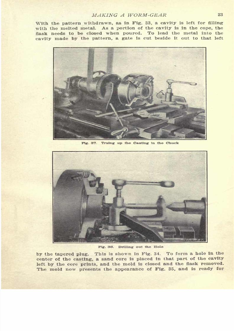
With the pattern withdrawn, as in Pig. 33, a cavity is left for filling
with the melted metal. As a portion of the cavity is in the cope, the
flask needs to be closed when poured. To lead the metal into the
cavity made by the pattern, a gate is cut beside it out to that left
Fig. 37. Truing up the Casting in the Chuck
Fig. 38. Drilling out the Hole
by the tapered plug. This is shown in Fig. 34. To form a hole in the
center of the casting, a sand core is placed in that part of the cavity
7/29/2019 (L) Examples of Machine Shop Practice (1910)
http://slidepdf.com/reader/full/l-examples-of-machine-shop-practice-1910 26/54
24 10 EXAMPLES OF SHOP PRACTICE
pouring. It will be seen from this figure that the outer part of the
gate has been enlarged to form a basin into which the molten metal
can be conveniently poured. After the mold is poured, the sand is
broken apart, and the casting is allowed to cool until it is ready to be
Fig. 39. Reaming the Bore
Fig. 4O. Roughing the Bottom of the Recess
placed upon the pickling bed and prepared for the machine shop pro-
cesses, and appears as in Fig. 36.
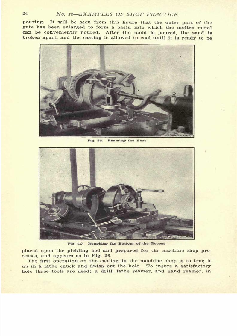
The first operation on the casting in the machine shop is to true it
in chuck and finish out the hole. To insure a
7/29/2019 (L) Examples of Machine Shop Practice (1910)
http://slidepdf.com/reader/full/l-examples-of-machine-shop-practice-1910 27/54
MAKING A WORM-GEAR 25
the order named, each tool leaving the correct amount of stock for the
succeeding one. To indicate the position of eccentricity when truing
up the piece in a chuck, either chalk or a lathe tool may be used. Fig.
37 shows the piece ready to be drilled and lathe reamed, Fig. 38 and
Fig. 41. Finishing the Recess
Fig. 42. Finishing the Inner Circumference
Fig. 39 completing the operation. If the drill tends to wabble when it
is being started, the butt end of a lathe tool held as in Fig. 38 steadies
it. finished when
7/29/2019 (L) Examples of Machine Shop Practice (1910)
http://slidepdf.com/reader/full/l-examples-of-machine-shop-practice-1910 28/54
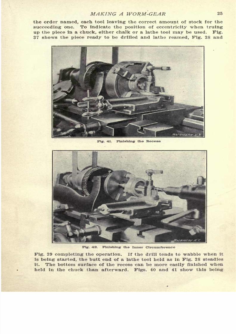
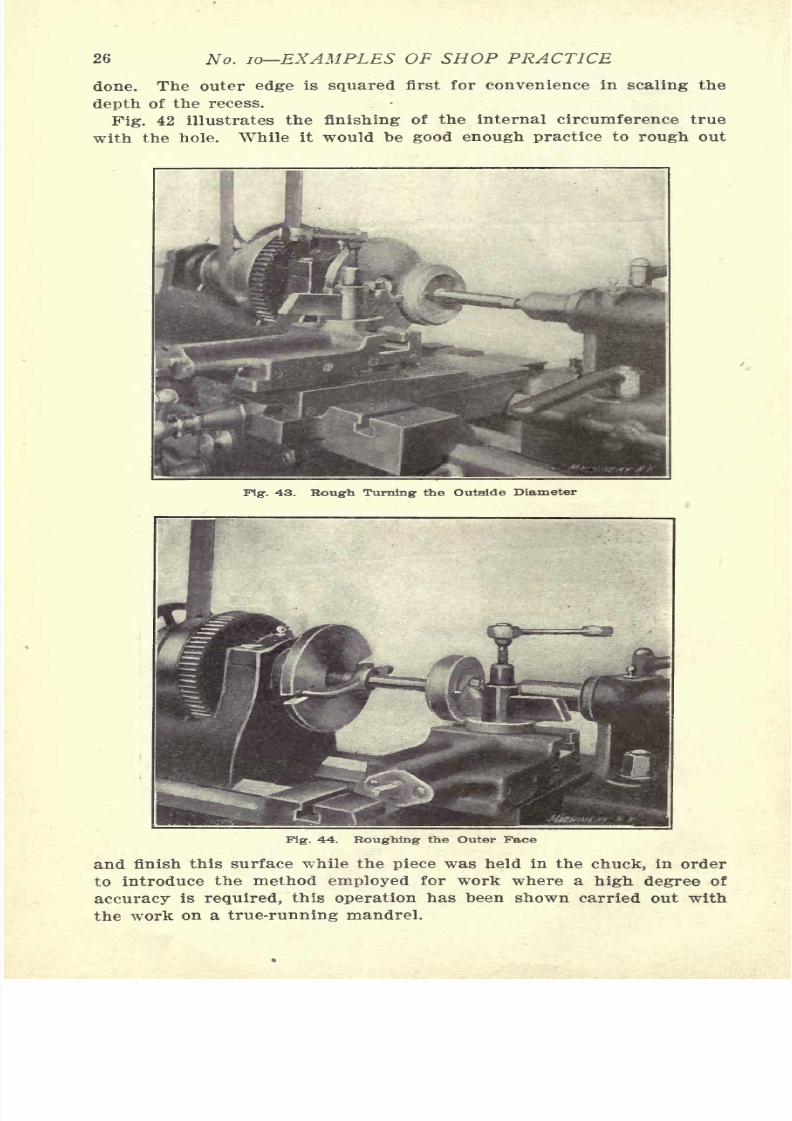
26 No. 10 EXAMPLES OF SHOP PRACTICE
done. The outer edge is squared first for convenience in scaling the
depth of the recess.
Pig. 42 illustrates the finishing of the internal circumference true
with the hole. While it would he good enough practice to rough out
Fig. 43. Rough Turning the Outside Diameter
Fig. 44. Roughing the Outer Face
and finish this surface while the piece was held in the chuck, in order
to introduce the method employed for work where a high degree of
7/29/2019 (L) Examples of Machine Shop Practice (1910)
http://slidepdf.com/reader/full/l-examples-of-machine-shop-practice-1910 29/54
MAKING A WORM-GEAR 27
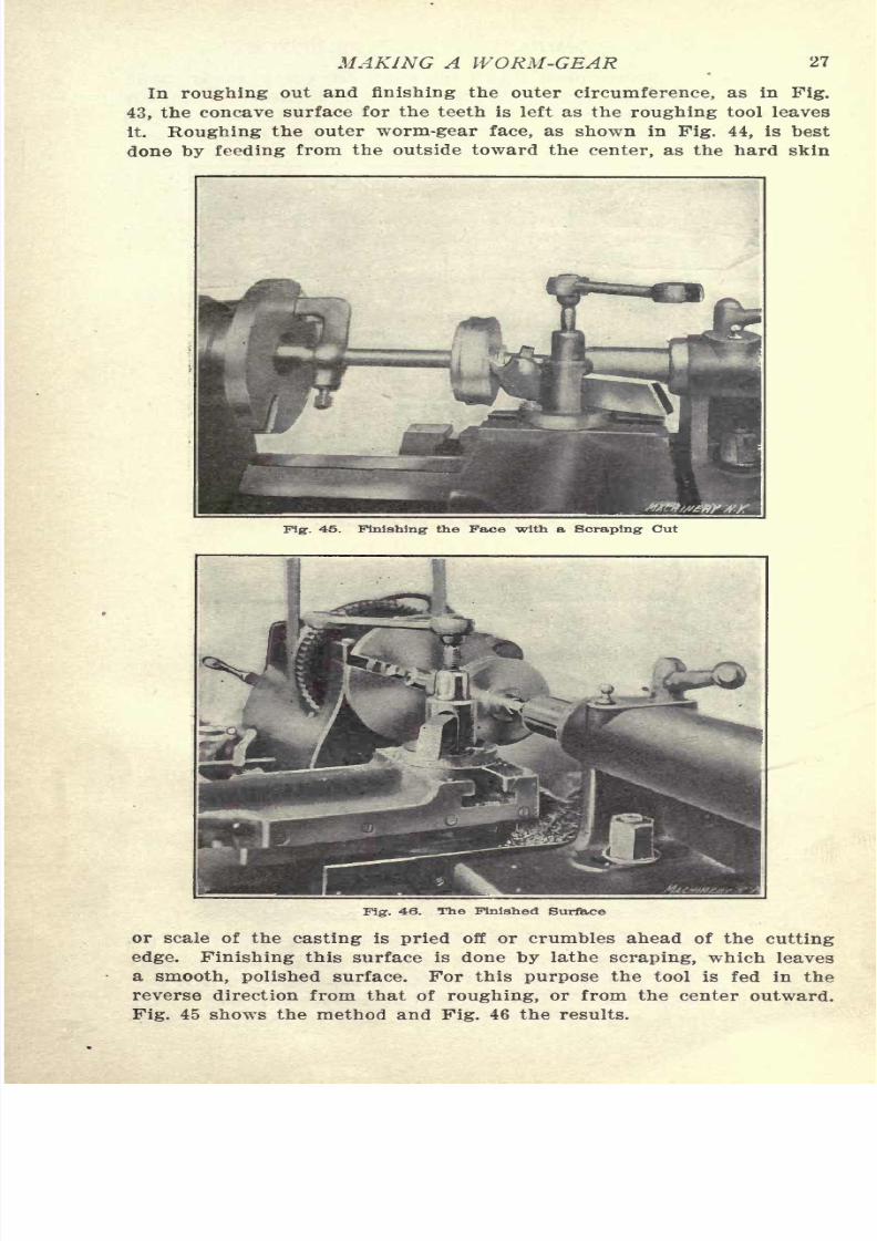
In roughing out and finishing the outer circumference, as in Fig.
43, the concave surface for the teeth is left as the roughing tool leaves
it. Roughing the outer worm-gear face, as shown in Fig. 44, is best
done by feeding from the outside toward the center, as the hard skin
Fig. 45. Finishing the Face with a Scraping Cut
Fig. 46. The Finished Surface
or scale of the casting is pried off or crumbles ahead of the cutting
edge. Finishing this surface is done by lathe scraping, which leaves
a smooth, polished surface. For this purpose the tool is fed in the
7/29/2019 (L) Examples of Machine Shop Practice (1910)
http://slidepdf.com/reader/full/l-examples-of-machine-shop-practice-1910 30/54
28 No. 10 EXAMPLES OF SHOP PRACTICE
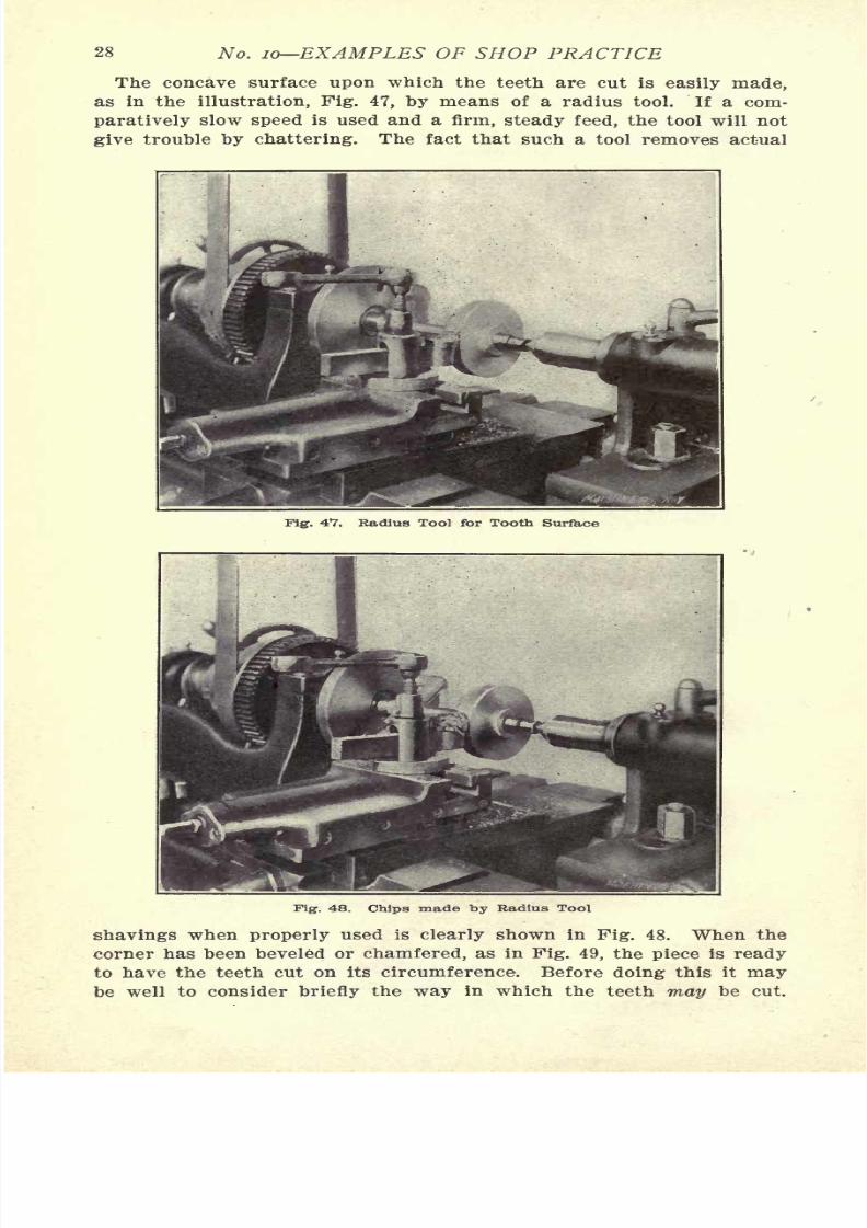
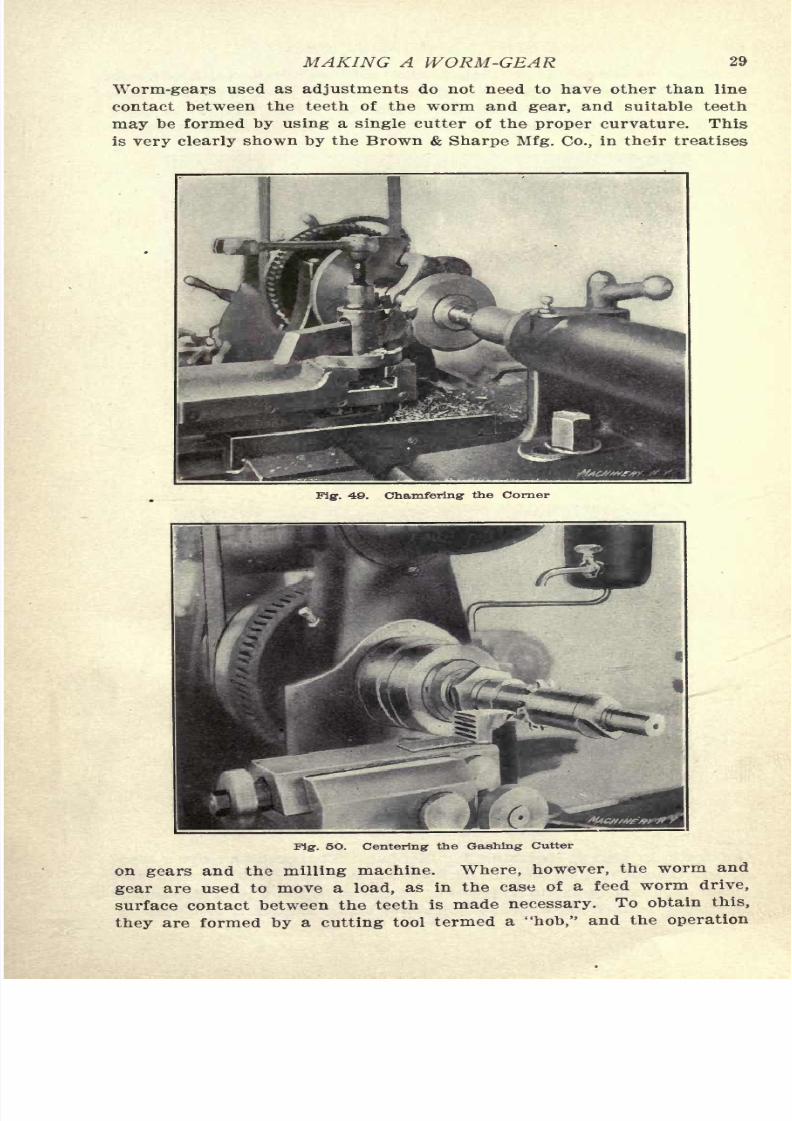
The concave surface upon which the teeth are cut is easily made,
as in the illustration, Pig. 47, by means of a radius tool. If a com-
paratively slow speed is used and a firm, steady feed, the tool will not
give trouble by chattering. The fact that such a tool removes actual
Fig. 47, Radius Tool for Tooth Surface
Pig. 48. Chips made by Radius Tool
shavings when properly used is clearly shown in Fig. 48. When the
corner has been beveled or chamfered, as in Fig. 49, the piece is ready
have the teeth cut on its circumference. Before this it
7/29/2019 (L) Examples of Machine Shop Practice (1910)
http://slidepdf.com/reader/full/l-examples-of-machine-shop-practice-1910 31/54
MAKING A WORM-GEAR 29
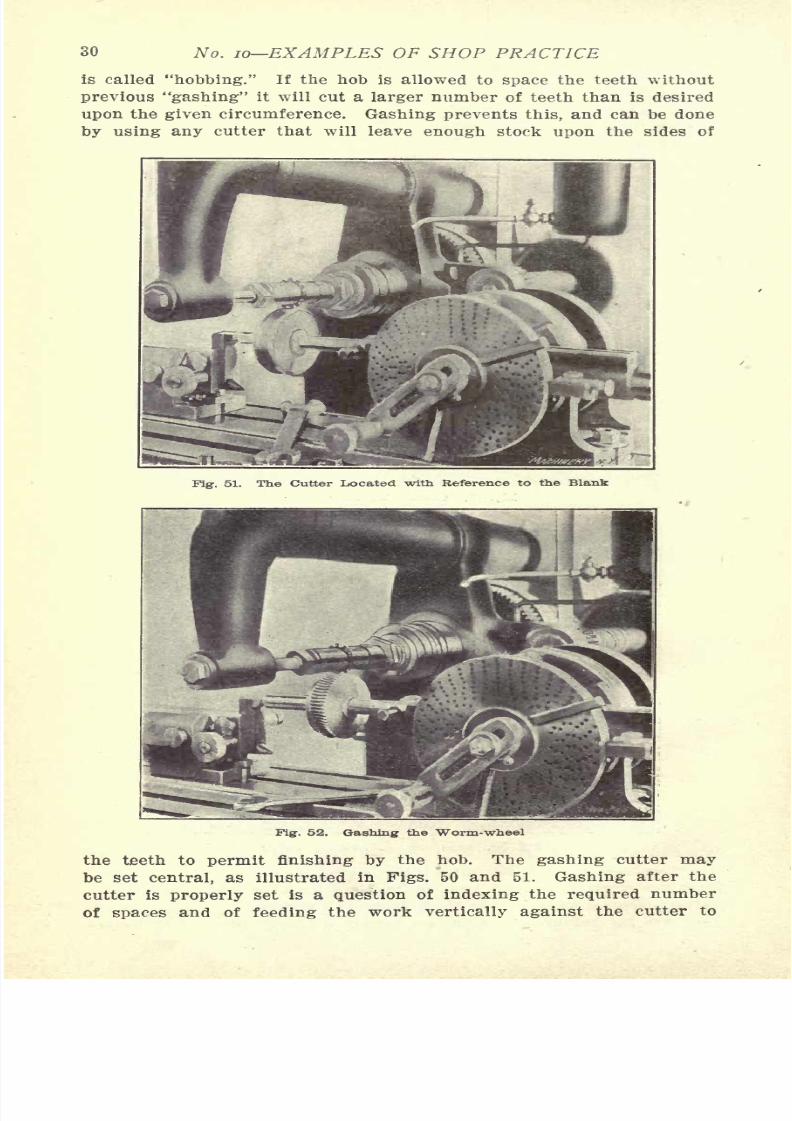
Worm-gears used as adjustments do not need to have other than line
contact between the teeth of the worm and gear, and suitable teeth
may be formed by using a single cutter of the proper curvature. This
is very clearly shown by the Brown & Sharpe Mfg. Co., in their treatises
Fig. 49. Chamfering the Corner
Fig. 5O. Centering the Gashing Cutter
on gears and the milling machine. Where, however, the worm and
as in the case of a feed worm drive,
7/29/2019 (L) Examples of Machine Shop Practice (1910)
http://slidepdf.com/reader/full/l-examples-of-machine-shop-practice-1910 32/54
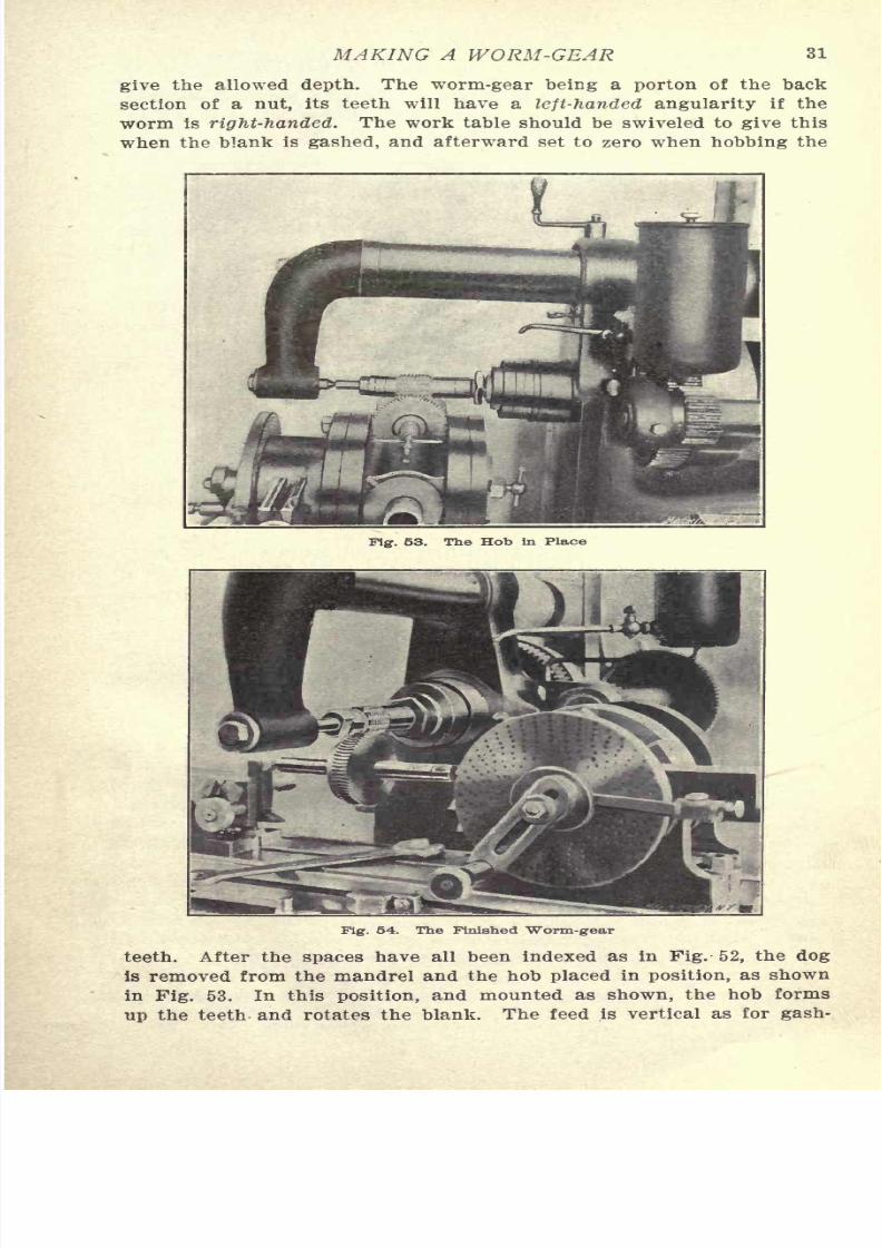
30 No. 10 EXAMPLES OF SHOP PRACTICE
is called "hobbing." If the hob is allowed to space the teeth without
previous "gashing" it will cut a larger number of teeth than is desired
upon the given circumference. Gashing prevents this, and can be done
by using any cutter that will leave enough stock upon the sides of
Fig. 51. The Cutter Located with Reference to the Blank
Pig. 52. Gashing the Worm-wheel
the teeth to permit finishing by the hob. The gashing cutter maybe set central, as illustrated in Figs. 50 and 51. Gashing after the
7/29/2019 (L) Examples of Machine Shop Practice (1910)
http://slidepdf.com/reader/full/l-examples-of-machine-shop-practice-1910 33/54
MAKING A WORM-GEAR 31
give the allowed depth. The worm-gear being a porton of the back
section of a nut, its teeth will have a left-handed angularity if the
worm is right-handed. The work table should be swiveled to give this
when the blank is gashed, and afterward set to zero when hobbing the
Fig. 53. The Hob in Place
Fig. 54. The Finished Worm-gear
teeth. After the spaces have all been indexed as in Fig. 52, the dog
is removed from the mandrel and the hob placed in position, as shown
7/29/2019 (L) Examples of Machine Shop Practice (1910)
http://slidepdf.com/reader/full/l-examples-of-machine-shop-practice-1910 34/54
32 No. 10 EXAMPLES OF SHOP PRACTICE
ing, and to such a depth as necessary to give the required distance
"center to center" of worm and gear. The finished job is shown in
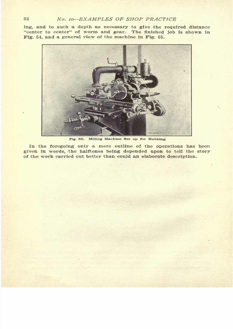
Fig. 54, and a general view of the machine in Fig. 55.
Fig. 55. Milling Machine Set up for Robbing
In the foregoing only a mere outline of the operations has been
given in words, the halftones being depended upon to tell the story
of the work carried out better than could an elaborate description.
7/29/2019 (L) Examples of Machine Shop Practice (1910)
http://slidepdf.com/reader/full/l-examples-of-machine-shop-practice-1910 35/54
CHAPTER III
SPINDLE CONSTRUCTION*
The spindles used in boring mills, drill presses, milling machines4
,
and lathes are usually fitted with a threaded nose, and a tapered hole
to hold a collet, an arbor, or a pointed center. Milling machine and
lathe spindles are also made with a hole throughout their entire
length in addition to the other features. This hole is a convenience
in many ways, as it is possible to pass stock to be operated upon
throughthe hole. In the fiat turret lathe and in the different makes
of screw machines this is the principal method of feeding stock to the
several tools held in the turret of the machine.
The spindles of the above-mentioned machines are either made from
a good bar of machine or 20-point carbon steel, or they are made
from crucible steel forgings of about 50-point carbon, and are com-
monly spoken of as hammered crucible steel spindles. High carbon
or tool steel is used at times for spindle work, but this can be classed
as special spindle work, and its use is rare. The requirements of
spindle construction are that the spindle be perfectly straight, thatthe journals be round, straight, and true running, that the nose be
threaded to run true with the journals, and that the tapered center
hole also run perfectly true with the journals. The spindles in any
of the first-class machines are constructed to fulfill all these require-
ments to a remarkable degree. Several makers, for example, test the
truth of the tapered hole with a test bar of at least one foot in length,
and allow a variation of less than 0.001 of an inch from truth at the
outer end of this test bar, a severe test when one considers that these
are not special machines, but are regular commercial products.
Tools Used in Spindle Boring
The producing of holes throughout the length of spindles and shafts
has led to the devising of machines and appliances for deep drilling
that are peculiar to such work. To commercially drill spindles at a
profit requires that the maximum feed be maintained. It is a matter
largely of furnishing a free-cutting tool, amply lubricated and cooled,
and keeping the hole free from the cuttings or chips. No method that
does not fulfill the above conditions can be said to be a complete suc-
cess. Where, however, but few spindles are to be drilled, and when
the number does not warrant the purchase or construction of special
spindle drilling machinery, the engine lathe or a drill press can be
used to do the work. Owing, however, to the difficulty of keeping the
hole freed from chips when the work is held vertically, the lathe is the
tool or machine mostly used for this drilling job. The drills used in
deep drilling of this kind are the ordinary twist drill, Pig. 56, the oil

7/29/2019 (L) Examples of Machine Shop Practice (1910)
http://slidepdf.com/reader/full/l-examples-of-machine-shop-practice-1910 36/54
34 No. 10 EXAMPLES OF SHOP PRACTICE
the half-round drill or hog-nose drill, Fig. 60, and the special hollow
drill, shown in Fig. 59. This last drill is used in a special drilling
machine, as a rule, and not in ordinary lathe drilling.
Where only a few spindles or shafts are to be drilled, the common
twist drill, shown in Fig. 56, or the straight-fluted drill, shown in Fig.
58 are used. As they are ordinarily made of much shorter lengths than
the hole to be drilled is likely to be, some means must be used to
lengthen them sufficiently to allow of the reach desired. This can be
accomplished by first turning the shank end of the drill below size.
The stem or shaft to lengthen the drill can be a piece of cold rolled
steel of the same diameter as the drill. A hole is made in one end of
this stem of a size that will closely fit the reduced shank of the drill.
The turned down shank of the drill is then "tinned" with solder and
Fig. 56,
Fig- 57.
itiuttrial Prit*,N f-
M.T. & M. CO.
Industrial Prat,*, f.
Fig. 58..
rr J7.
M.T. D. &.
CO1
. l\
^" \: V
Fig. 59.
Figs. 56 to 59. Tools Used in Spindle Boring
some of the soldering acid is dropped into the hole in the stem. To
put the two parts together, grasp the drill next to the reduced end
with a pair of gas pipe pliers, and by holding the tinned end of the
drill and the drilled end of the stem in a Bunsen flame, they can,
when heated sufficiently to make the solder run, be forced together.
When cool they will be capable of withstanding great stress. This
process is termed in the shop "sweating in" a drill.
Where the hole which is to be drilled is of such a depth relative to
its diameter as to make the length of shaft or stem so great that it
will be too slender to use when the hole is first started, several stems
of varying lengths may be provided. The process of sweating on these
stems is so simple that one stem when used to its depth can be unsol-
7/29/2019 (L) Examples of Machine Shop Practice (1910)
http://slidepdf.com/reader/full/l-examples-of-machine-shop-practice-1910 37/54
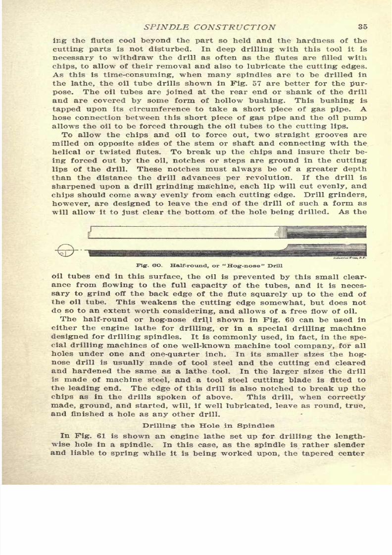
SPINDLE CONSTRUCTION 35
ing the flutes cool beyond the part so held and the hardness of the
cutting parts is not disturbed. In deep drilling with this tool it is
necessary to withdraw the drill as often as the flutes are filled with
chips, to allow of their removal and also to lubricate the cutting edges.
As this is time-consuming, when many spindles are to be drilled in
the lathe, the oil tube drills shown in Fig. 57 are better for the pur-
pose. The oil tubes are joined at the rear end or shank of the drill
and are covered by some form of hollow bushing. This bushing is
tapped upon its circumference to take a short piece of gas pipe. Ahose connection between this short piece of gas pipe and the oil pumpallows the oil to be forced through the oil tubes to the cutting lips.
To allow the chips and oil to force out, two straight grooves are
milled on opposite sides of the stem or shaft and connecting with the
helical or twisted flutes. To break up the chips and insure their be-
ing forced out by the oil, notches or steps are ground in the cutting
lips of the drill. These notches must always be of a greater depth
than the distance the drill advances per revolution. If the drill is
sharpened upon a drill grinding machine, each lip will cut evenly, and
chips should come away evenly from each cutting edge. Drill grinders,
however, are designed to leave the end of the drill of such a form as
will allow it to just clear the bottom of the hole being drilled. As the
Fig. 6O. Half-round, or "Hog-nose" Drill
oil tubes end in this surface, the oil is prevented by this small clear-
ance from flowing to the full capacity of the tubes, and it is neces-
sary to grind off the back edge of the flute squarely up to the end of
the oil tube. This weakens the cutting edge somewhat, but does notdo so to an extent worth considering, and allows of a free flow of oil.
The half-round or hog-nose drill shown in Fig. 60 can be used in
either the engine lathe for drilling, or in a special drilling machine
designed for drilling spindles. It is commonly used, in fact, in the spe-
cial drilling machines of one well-known machine tool company, for all
holes under one and one-quarter inch. In its smaller sizes the hog-
nose drill is usually made of tool steel and the cutting end cleared
and hardened the same as a lathe tool. In the larger sizes the drill
is made of machine steel, and a tool steel cutting blade is fitted to
the leading end. The edge of this drill is also notched to break up the
chips as in the drills spoken of above. This drill, when correctly
made, ground, and started, will, if well lubricated, leave as round, true,
and finished a hole as any other drill.
Drilling- the Hole in Spindles
In Fig. 61 is shown an engine lathe set up for drilling the length-

7/29/2019 (L) Examples of Machine Shop Practice (1910)
http://slidepdf.com/reader/full/l-examples-of-machine-shop-practice-1910 38/54
36 No. 10 EXAMPLES OF SHOP PRACTICE
hole is made the last operation in the construction, the bearings being
ground just previously. This order should always be followed for slen-
der spindles to insure the truth of the tapered hole with relation to
the bearings. The spindle is first roughed to a finishing allowance, and
short bearings are turned upon the ends to a high degree of accuracy
Fig. 61. Lathe Arranged for Spindle Drilling
Fig. 62. Drilling for the Taper Hole
for center rest support. The larger end or nose of the spindle is
placed upon the live center, which is supposed to be trued up nicely,
and is held in place on the center by a "hold-back" as shown. The
7/29/2019 (L) Examples of Machine Shop Practice (1910)
http://slidepdf.com/reader/full/l-examples-of-machine-shop-practice-1910 39/54
SPINDLE CONSTRUCTION 37
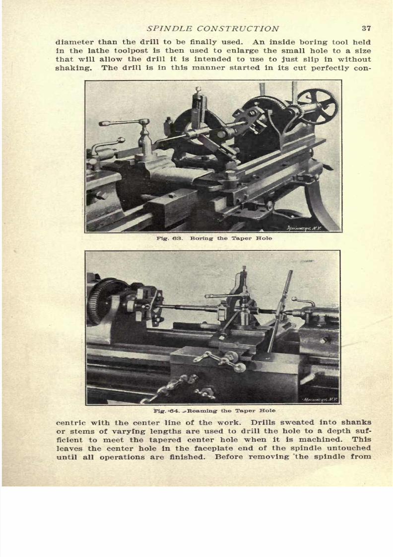
diameter than the drill to be finally used. An inside boring tool held
in the lathe toolpost is then used to enlarge the small hole to a size
that will allow the drill it is intended to use to just slip in without
shaking. The drill is in this manner started in its cut perfectly con-
rig-. 63. Boring the Taper Hole
Fig. '64. *Reaming the Taper Hole
centric with the center line of the work. Drills sweated into shanks
or stems of varying lengths are used to drill the hole to a depth suf-
ficient to meet the tapered center hole when it is machined. This
7/29/2019 (L) Examples of Machine Shop Practice (1910)
http://slidepdf.com/reader/full/l-examples-of-machine-shop-practice-1910 40/54
38 No. 10 EXAMPLES OF SHOP PRACTICE
the center rest, the edges of the hole are chamfered to an angle of 60
degrees and to a sufficiently broad surface to form a bearing for the
centers when finishing and grinding. If the spindle is stiff enough
to warrant finishing the tapered center hole before grinding and
finishing the spindle, it must be held with the small end trued up in
Fig. 65. Use of Test Bar and Indicator
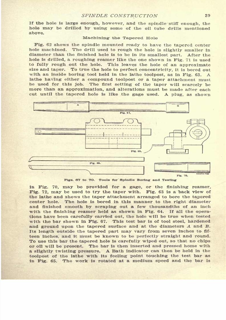
Fig. 66. Testing at the Inner End of Bar
a chuck instead of on the live center. This brings the work in the
reverse of the position shown. The nose is held in the center rest, a
bearing having been turned where it is to bear in the
7/29/2019 (L) Examples of Machine Shop Practice (1910)
http://slidepdf.com/reader/full/l-examples-of-machine-shop-practice-1910 41/54
SPINDLE CONSTRUCTION 39
If the hole is large enough, however, and the spindle stiff enough, the
hole may be drilled by using some of the oil tube drills mentioned
above.
Machining- the Tapered Hole
Fig. 62 shows the spindle mounted ready to have the tapered center
hole machined. The drill used to rough the hole is slightly smaller in
diameter than the finished hole is to be in its smallest part. After the
hole is drilled, a roughing reamer like the one shown in Fig. 71 is used
to fully rough out the hole. This leaves the hole of an approximate
size and taper. To true the hole to perfect concentricity, it is bored out
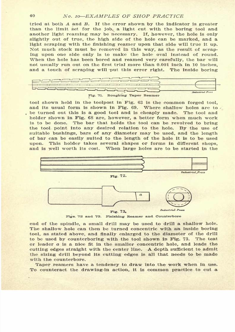
with an inside boring tool held in the lathe toolpost, as in Fig. 63. Alathe having either a compound toolpost or a taper attachment must
be used for this job. The first setting of the taper will scarcely be
more than an approximation, and alterations must be made after each
cut until the tapered hole is like the gage used. A plug, as shown
Ffg. 70.
Figs. 67 to 7O. Tools for"Spindle Boring and Testing
in Fig. 70, may be provided for a gage, or the finishing reamer,
Fig. 72, may be used to try the taper with. Fig. 63 is a back view of
the lathe and shows the taper attachment arranged to bore the tapered
center hole. The hole is bored in this manner to the right diameter
and finished smooth by scraping out a few thousandths of an inch
with the finishing reamer held as shown in Fig. 64. If all the opera-
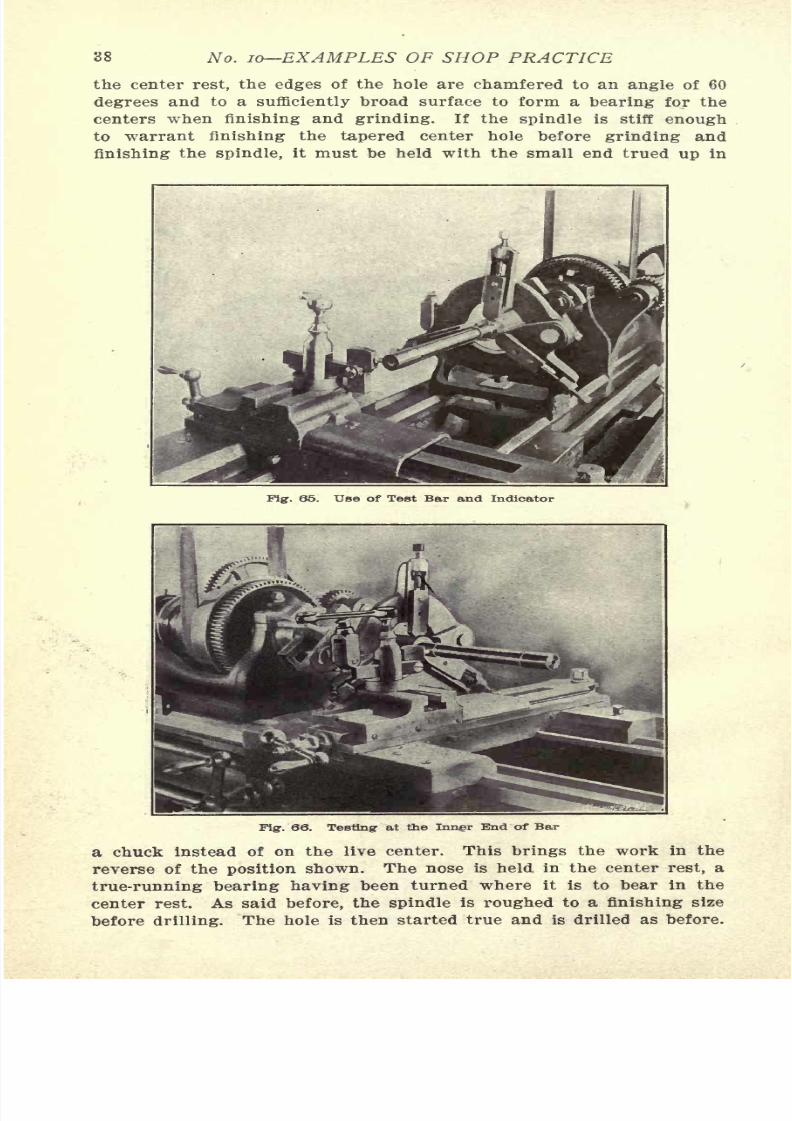
tions have been carefully carried out, the hole will be true when testedwith the bar shown in Fig. 67. This test bar is of tool steel, hardened
and ground upon the tapered surface and at the diameters A and B.
Its length outside the tapered part may vary from seven inches to fif-
teen inches, and it must be known to be perfectly straight and round.
To use this bar the tapered hole is carefully wiped out, so that no chips
or oil will be present. The bar is then inserted and pressed home with
a slightly twisting pressure. A Bath indicator can then be held in the
7/29/2019 (L) Examples of Machine Shop Practice (1910)
http://slidepdf.com/reader/full/l-examples-of-machine-shop-practice-1910 42/54
40 No. 10-EXAMPLES OF SHOP PRACTICE
tried at both A and B. If the error shown by the indicator is greater
than the limit set for the job, a light cut with the boring tool and
another light reaming may be necessary. If, however, the hole is only
slightly out of true, the high side of the hole can be marked, and a
light scraping with the finishing reamer upon that side will true it up.
Not much stock must be removed in this way, as the result of scrap-
ing upon one side only is to make the hole oval instead of round.
When the hole has been bored and reamed very carefully, the bar will
not usually run out on the first trial more than 0.001 inch in 10 inches,
and a touch of scraping will put this error right. The inside boring
-iPig. 71. Roughing Taper Reamer
tool shown held in the toolpost in Fig. 63 is the common forged tool,
and its usual form is shown in Fig. 69. Where shallow holes are to
be turned out this is a good tool and is cheaply made. The tool and
holder shown in Fig. 68 are, however, a better form when much work
is to be done. The bar that holds the tool can be revolved to bring
the tool point into any desired relation to the hole. By the use of
suitable bushings, bars of any diameter
maybe used, and the
lengthof bar can be easily suited to the length of the hole it is to be used
upon. This holder takes several shapes or forms in different shops,
and is well worth its cost. When large holes are to be started in the
pig. 72.
Industrial .Press
Industrial Press
Fig. 73,
Pigs. 72 and 73. Finishing Reamer and Counterbore
end of the spindle, a small drill
maybe used to drill a shallow hole.
The shallow hole can then be turned concentric with an inside boring
tool, as stated above, and finally enlarged to the diameter of the drill
to be used by counterboring with the tool shown in Fig. 73. The teat
or leader a is a nice fit in the smaller concentric hole, and leads the
cutting edges straight with the center line. A depth sufficient to admit
the sizing drill beyond its cutting edges is all that needs to be made
with the counterbore.
7/29/2019 (L) Examples of Machine Shop Practice (1910)
http://slidepdf.com/reader/full/l-examples-of-machine-shop-practice-1910 43/54
SPINDLE CONSTRUCTION 41
left-hand helix upon the reamer. Finishing reamers are, however,
seldom treated in this manner, as their use is just to scrape the hole
to a perfect surface.
It may be mentioned here that there are several errors that one is
apt to make in finishing a tapered hole in a spindle. 1. If the spindle is
slender, care must be taken that the hold-back or clamp does not spring
the work by being tightened up too hard. Anything more than enough
to hold the work to the center is too much. 2. In turning out the hole
with the boring tool, set the cutting point at the height of the center
Indust
Pig. 74. Bath Test 'indicator
.line of the lathe spindle to get a true tapered hole. 3. Be sure that the
center line of the work and the live and dead centers are coincident
with the center line of the spindle. Fig. 74 shows the interior of theBath indicator and the several feeling points used. This is a very
sensitive tool. A movement of one-half of a thousandth of an inch of
the feeling point moves the indicator finger a distance of l-12th inch.
Boring- Crucible Steel Forging Spindles
Crucible steel forgings for lathe spindles, as delivered to the work-
man, are usually somewhat crooked and may be enough so as to re-
quire straightening, but there is usually an excess of stock to finish,
and if the
centersare located with judgment, the forging will finish
n
Fig. 75.
Industrial Prett, X.T.
Simple Method for Locating Centers
out. Various ways of locating the centers are in use in different shops.
The engraving, Fig. 75, illustrates the method in use in one shop. Two
"ways," similar to those used in balancing pulleys, are provided, and
the forging is laid across these. Care must be exercised to have the
"ways" placed so that the center of what is to be the journal bearing is
central with them. The journals are, of course, the most impor-
tant parts of the spindle and must clean out when to size. The
7/29/2019 (L) Examples of Machine Shop Practice (1910)
http://slidepdf.com/reader/full/l-examples-of-machine-shop-practice-1910 44/54
42 No. 10 EXAMPLES OF SHOP PRACTICE
located with a center punch. The center drilling and reaming is
afterwards done under a drill press, and the forging is ready for the
reduction lathe. With high-speed steel tools the forgings are roughed
to approximate sizes and shapes at a rapid rate. A feed of 1/16
inch per revolution is a common standard, with a depth of cut of
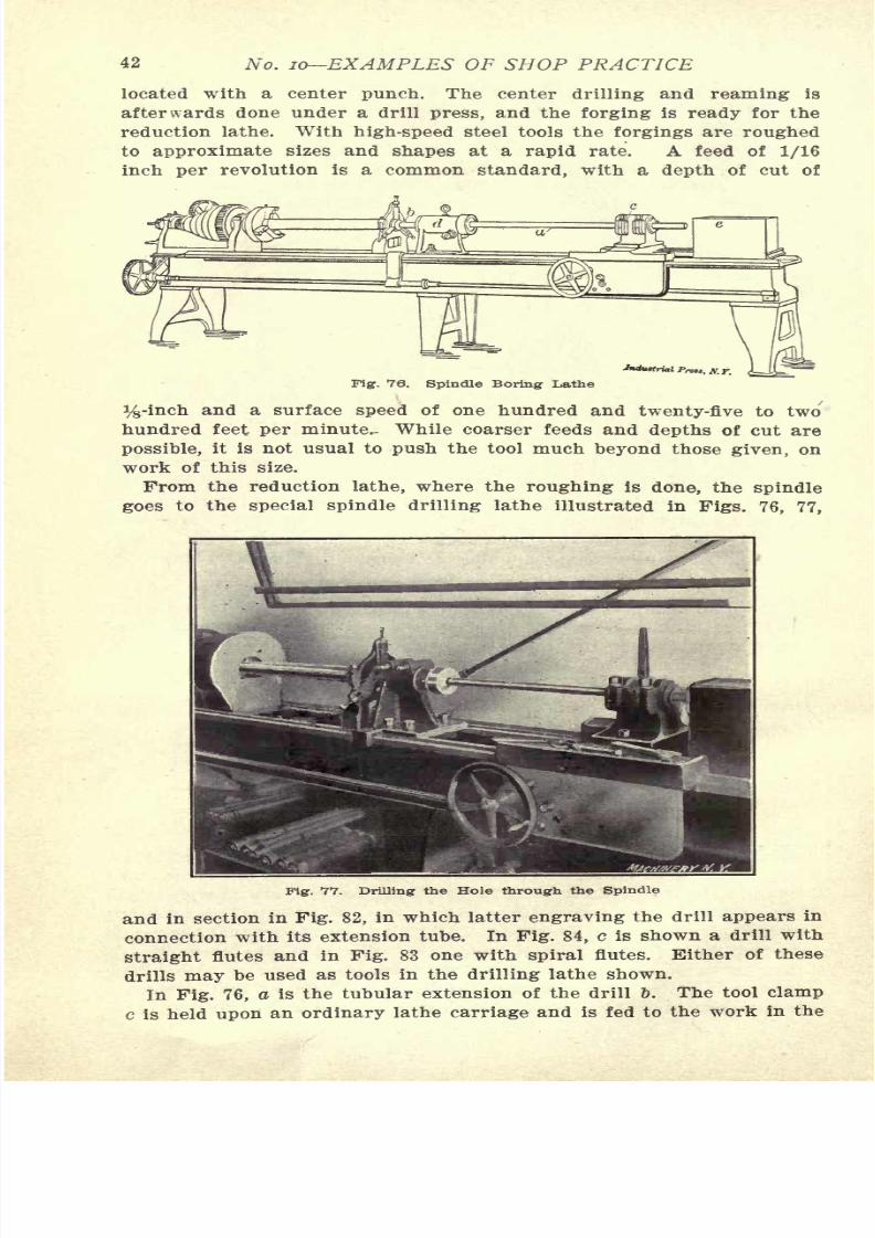
Fig. 76. Spindle Boring Lathe
%-inch and a surface speed of one hundred and twenty-five to two
hundred feet per minute.- While coarser feeds and depths of cut are
possible, it is not usual to push the tool much beyond those given, on
work of this size.
From the reduction lathe, where the roughing is done, the spindle
goes to the special spindle drilling lathe illustrated in Figs. 76, 77,
Fig. 77. Drilling the Hole through the Spindle
and in section in Fig. 82, in which latter engraving the drill appears in
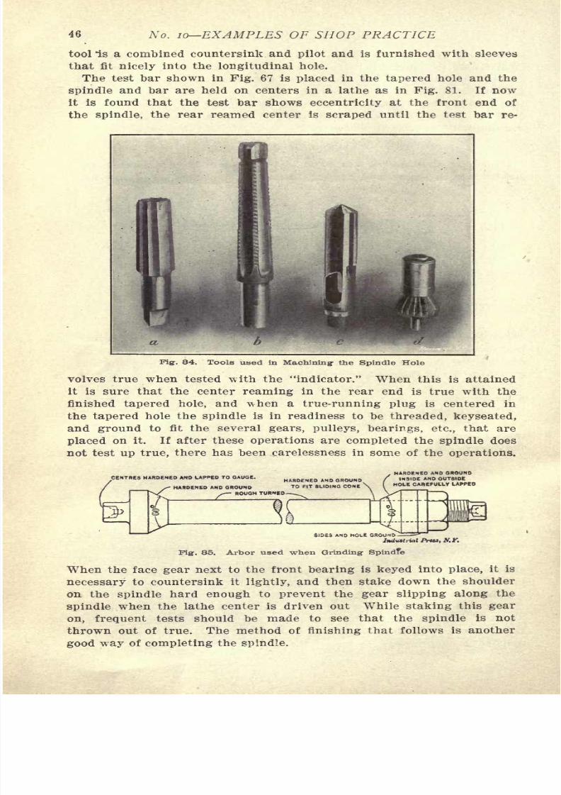
connection with its extension tube. In Fig. 84, c is shown a drill with
straight flutes and in Fig. 83 one with spiral flutes. Either of these
drills may be used as tools in the drilling lathe shown.
7/29/2019 (L) Examples of Machine Shop Practice (1910)
http://slidepdf.com/reader/full/l-examples-of-machine-shop-practice-1910 45/54
SPINDLE CONSTRUCTION 43
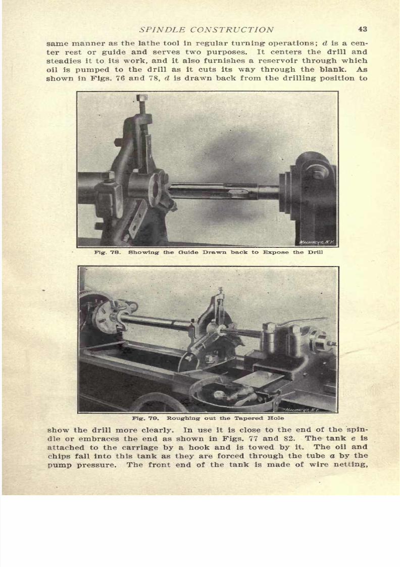
same manner as the lathe tool in regular turning operations; d is a cen-
ter rest or guide and serves two purposes. It centers the drill and
steadies it to its work, and it also furnishes a reservoir through which
oil is pumped to the drill as it cuts its way through the blank. As
shown in Figs. 76 and 78, d is drawn back from the drilling position to
Fig. 78. Showing the Guide Drawn back to Expose the Drill
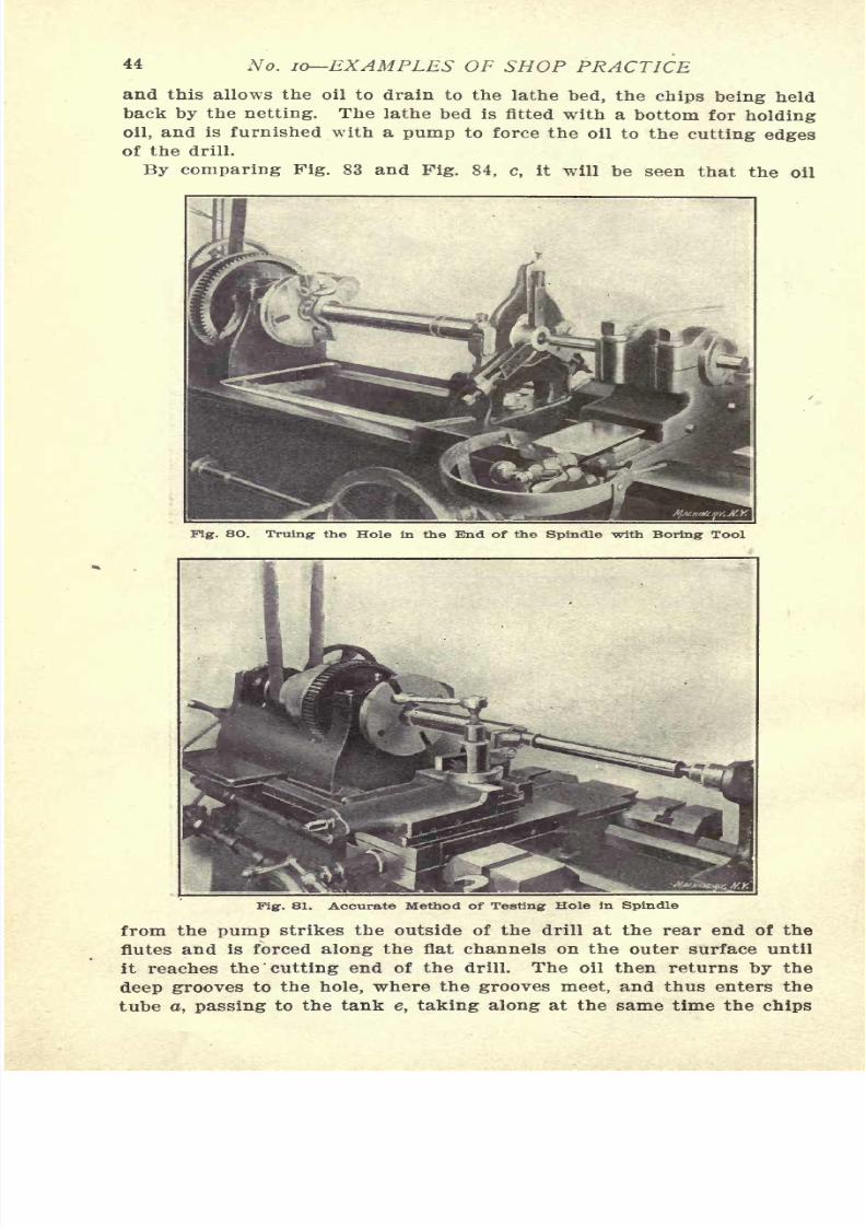
Fig. 79. Roughing out the Tapered Hole
show the drill more clearly. In use it is close to the end of the spin-
dle or embraces the end as shown in Figs. 77 and 82. The tank e is
attached to the carriage by a hook and is towed by it. The oil and
7/29/2019 (L) Examples of Machine Shop Practice (1910)
http://slidepdf.com/reader/full/l-examples-of-machine-shop-practice-1910 46/54
44 No. 10 EXAMPLES OF SHOP PRACTICE
and this allows the oil to drain to the lathe bed, the chips being held
back by the netting. The lathe bed is fitted with a bottom for holding
oil, and is furnished with a pump to force the oil to the cutting edges
of the drill.
By comparing Pig. 83 and Fig. 84, c, it will be seen that the oil
Fig. 8O. Truing the Hole in the End of the Spindle with Boring Tool
Fig. 81. Accurate Method of Testing Hole in Spindle
from the pump strikes the outside of the drill at the rear end of the
flutes and is forced along the flat channels on the outer surface until
it reaches the 'cutting end of the drill. The oil then returns by the
7/29/2019 (L) Examples of Machine Shop Practice (1910)
http://slidepdf.com/reader/full/l-examples-of-machine-shop-practice-1910 47/54
SPINDLE CONSTRUCTION 45
as they are cut from the stock. To ensure a free flow of oil past 'the
cleared end of the drill, the backing at the end of the flute must be
ground sharply away, as previously mentioned. Small grooves are
ground or milled along the cutting lips to break the chips to a size
that can bemade
to force out with the oil.
While Fig. 76 and Pig. 82show details of the several parts, Fig. 77 is from a photograph of a
spindle drilling lathe in actual use.
Finishing- the Spindle
When the drilling is completed, several methods of finishing the
spindle are in vogue, and some of these methods may be of interest.
Jf
OIL PIPE FROM PUMP
ifPACKING
II
//
GLAN
7/29/2019 (L) Examples of Machine Shop Practice (1910)
http://slidepdf.com/reader/full/l-examples-of-machine-shop-practice-1910 48/54
46 No. 10 EXAMPLES OF SHOP PRACTICE
tool *is a combined countersink and pilot and is furnished with sleeves
that fit nicely into the longitudinal hole.
The test bar shown in Pig. 67 is placed in the tapered hole and the
spindle and bar are held on centers in a lathe as in Fig. 81. If now
it is found that the test bar showseccentricity
at the front end of
the spindle, the rear reamed center is scraped until the test bar re-
84. Tools used in Machining1 the Spindle Hole
volves true when tested with the "indicator." When this is attained
it is sure that the center reaming in the rear end is true with the
finished tapered hole, and \vhen a true-running plug is centered in
the tapered hole the spindle is in readiness to be threaded, keyseated,
andground
to fit the severalgears, pulleys, bearings, etc.,
that are
placed on it. If after these operations are completed the spindle does
not test up true, there has been carelessness in some of the operations.
CENTRES HARDENED AND LAPPED TO GAUGE.
Ifr
HARDENED AND GROUND
HARDENED AND GROUND TO FIT SLIDING CONE
> ROUGH TURNED
HARDENED AND GROUNDINSIDE AND OUTSIDE
CAREFULLY LAPPED
Pig. 85. Arbor used when Grinding Spindfe
When the face gear next to the front bearing is keyed into place, it is
necessary to countersink it lightly, and then stake down the shoulder
on the spindle hard enough to prevent the gear slipping along the
spindle when the lathe center is driven out While staking this gear
on, frequent tests should be made to see that the spindle is not
7/29/2019 (L) Examples of Machine Shop Practice (1910)
http://slidepdf.com/reader/full/l-examples-of-machine-shop-practice-1910 49/54
SPINDLE CONSTRUCTION 47
After the long hole is drilled, the edges of the hole at each end are
chamfered to a 60-degree bearing, using as before the special counter-
sink shown in Fig. 84, d, and the spindle is turned to leave 0.007 of
an inch on all diameters for grinding, and all keyways and threads
are cutexcept
the thread on the nose of the spindle. An arbor such
as the one shown in Fig. 85 is then passed through the spindle and
tightened into place by the nut shown. This arbor being a standard
upon which many pieces may be ground, no pains should be spared
to make sure that all surfaces are square and true with the center line.
All the grinding is done with the spindle mounted upon this arbor,
and as the centers in the arbor are lapped to as near perfection as
possible, and are so hard that the wear is small, this method would
seem to give almost perfectly ground surfaces. The tapered hole is
finally finished by holding the spindle uponthe live center
andin a
center rest, as formerly described. The truth of the tapered hole
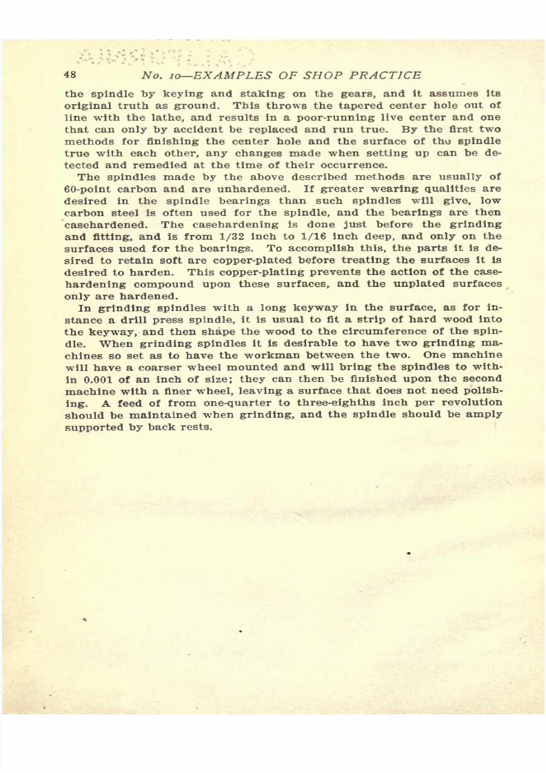
Fig. 86. Method of Testing Taper Hole
can be tested with the "Bath" indicator as in Fig. 65, or the indicator
point may be used against the inside of the tapered hole if it is de-
sired. This latter method of testing is shown in Fig. 86, but the one
shown in Fig. 65 is to be preferred if the greatest accuracy is desired.
Still another method is to rough-ream the center hole, and then grind
the several bearings upon plugs driven into the ends of the spindle.
When the gears and the cone pulley are in place, the spindle is
scraped and fitted into its bearings. After this is done the headstock
is mounted on the bed of the machine, and the tapered center hole is
bored out true with a tool held in the tool block, and then reamed
lightly and tested as before until it is true running within the limit
of error set. This method is a very good one if the spindle has not
changed after it was ground. It is quite likely, however, that some
changes have taken place when the gears- were keyed on, and the
spindle is out of true. If the center hole is then bored with the
7/29/2019 (L) Examples of Machine Shop Practice (1910)
http://slidepdf.com/reader/full/l-examples-of-machine-shop-practice-1910 50/54
48 No. 10 EXAMPLES OF SHOP PRACTICE
the spindle by keying and staking on the gears, and it assumes its
original truth as ground. This throws the tapered center hole out of
line with the lathe, and results in a poor-running live center and one
that can only by accident be replaced and run true. By the first two
methods for finishing the center hole and the surface of the spindletrue with each other, any changes made when setting up can be de-
tected and remedied at the time of their occurrence.
The spindles made by the above described methods are usually of
60-point carbon and are unhardened. If greater wearing qualities are
desired in the spindle bearings than such spindles will give, low
carbon steel is often used for the spindle, and the bearings are then
casehardened. The casehardening is done just before the grinding
and fitting, and is from 1/32 inch to 1/16 inch deep, and only on the
surfaces used for the bearings. To accomplish this, the parts it is de-
sired to retain soft are copper-plated before treating the surfaces it is
desired to harden. This copper-plating prevents the action of the case-
hardening compound upon these surfaces, and the unplated surfaces
only are hardened.
In grinding spindles with a long keyway in the surface, as for in-
stance a drill press spindle, it is usual to fit a strip of hard wood into
the keyway, and then shape the wood to the circumference of the spin-
dle. When grinding spindles it is desirable to have two grinding ma-
chines so set as to have the workman between the two. One machinewill have a coarser wheel mounted and will bring the spindles to with-
in 0.001 of an inch of size; they can then be finished upon the second
machine with a finer wheel, leaving a surface that does not need polish-
ing. A feed of from one-quarter to three-eighths inch per revolution
should be maintained when grinding, and the spindle should be amply
supported by back rests.

7/29/2019 (L) Examples of Machine Shop Practice (1910)
http://slidepdf.com/reader/full/l-examples-of-machine-shop-practice-1910 51/54

7/29/2019 (L) Examples of Machine Shop Practice (1910)
http://slidepdf.com/reader/full/l-examples-of-machine-shop-practice-1910 52/54
7/29/2019 (L) Examples of Machine Shop Practice (1910)
http://slidepdf.com/reader/full/l-examples-of-machine-shop-practice-1910 53/54
-TJ7
'
UNIVERSITY OF CALIFORNIA LIBRARY

7/29/2019 (L) Examples of Machine Shop Practice (1910)
http://slidepdf.com/reader/full/l-examples-of-machine-shop-practice-1910 54/54
Related Documents


![The Open Orthopaedics Journal - benthamopen.com · Fig. (2). Scoliosis brace examples: past to present: From left, Abbott 1910, Milwaukee Brace, ... balanced posture [5]. ... group](https://static.cupdf.com/doc/110x72/5b8a042a7f8b9aa81a8da80f/the-open-orthopaedics-journal-fig-2-scoliosis-brace-examples-past-to.jpg)

![1910. - UK Treaties Onlinetreaties.fco.gov.uk/docs/fullnames/pdf/1910/TS0018 (1910) CD-5125... · [British Ratification deposited at Paris;March 1; 1910.]' (Translation.) Convention](https://static.cupdf.com/doc/110x72/5ae5aa1f7f8b9a87048ce4fd/1910-uk-treaties-1910-cd-5125british-ratification-deposited-at-parismarch.jpg)