k ..... // !" i' ,, NASA CR 180702 -- 42.. ,' ; / t/ _ L SP.AYN0zzLe 0eSmNs eo. o , AGRICULTURAL AVIATION APPLICATioN8 ,'(" :,.'\ j :.,-r Ill. ilP I'AI A Ihd,..... / Itlu._. ,:,,.... M.N. Golovin and j. A..,_.:la -- . o_ ,c BAI"rELLE • , _: ,4 COLUMBU8 LABOItATOItlE8 ".i ¢-_O=U ', I,d,,,,,*= :' lu t,,,e •.. _11_ I_ • I_1_ -- " ", 0 _,.,1 ,e"_ e__ID0 r__,._ , NATIONAL AEi_OltiAUTIC8 AND 8PACE ADMINUlilRATiON r- c_ T ¢:) c_"I NA8A _ RommrohO_mt(mw '_" =' Contm_ NAI $-21881 https://ntrs.nasa.gov/search.jsp?R=19800002217 2018-09-28T00:20:24+00:00Z

Welcome message from author
This document is posted to help you gain knowledge. Please leave a comment to let me know what you think about it! Share it to your friends and learn new things together.
Transcript
k
.....// !" i' ,, NASA CR 180702-- 42.. , '
; /
t/ _ LSP.AYN0zzLe0eSmNseo.
o ,AGRICULTURAL AVIATION APPLICATioN8,'(" :,.'\ j :.,-r
Ill. ilP I'AI A Ihd,..... / Itlu._.
,:,,.... M.N. Golovin and j. A..,_.:la --
. o _ ,c BAI"rELLE• , _: ,4 COLUMBU8 LABOItATOItlE8
".i ¢-_O=U', I,d,,,,,*=
:' lu t,,,e•.. _11_ I_
• I_1_-- " ", 0 _,.,1,e" _
e_ _ID0
r_ _,._ , NATIONAL AEi_OltiAUTIC8 AND 8PACE ADMINUlilRATiONr- c_
T ¢:)c_"I NA8A _ RommrohO_mt(mw
'_" =' Contm_ NAI $-21881
' ' - _.......... _o .... ._ ..... " " .t_..........,_ _ ;.... " '..... ":_;__
-- _"_° °° ° _° : ""..... " .................. 00000001
https://ntrs.nasa.gov/search.jsp?R=19800002217 2018-09-28T00:20:24+00:00Z

.._i_,
i_-""+i:_,, 1' Rlpor( Ni_.ptASACR159702 I _+o_...m _m,. N_ a.,,_,._, C,.m+_o, •_' 4. _,e _ S,lxh_ ' " 5. I_m_ert_te '
r. i.*
F i:: SPRAY NOZ2LE DESIGNS FOR AGRICULTURALAVIATION ._EPT 18, ]_7_i i+ . APPLICATIONS lL I_fom,_ Or_w,_ado,Co_
i j ii i
_"! 1. _t_(,I K, H. LEE, A, A. PUTNAH, J. As GIESEKE, It. Perforl_InllOrgln|llttonnlpottNo.
M, N, GOLOVIN AND J, A, HALE '1o wk. or UnitNo.
i _i O. P_orm_lOqp_mk_Name_ _m BATTELLE "
__, _OLUMBUSLABORATORIES 11, c_tr_t g OmitNo. '
_;, 505 KING AVENUE NAS 3-21581i" COLUPZUSOHIOq3201 13. Type of RIIDorl Im<:lPeriodCoverld: i • t
'+, FINAL 10178- 9/79:._.. NATIONAL AERONAUTICSAND SPACEADMINISTRATION_ LEHIS RESEARCHCENTER 14.,_om_i_ AeencvCod+
-t: C.I.+EVELAND..oHiO 44135,+_ IlL S,l_ementm_Note+
-+++++_',
....._, _lLA_
L i:.+ + ONE OF THE DIFFICULT PROBLEHSIN THE FIELD OF AGRICULTURALAVIATION IS T.Oi "!': ACCURATELYAND UNIFORMLYAPPLY CHEMICALSTO TARGETAREAS. AN ATOMIZER CAPABLE
_i OF PRODUCINGUNIFORMDROPS HAS A HIGH PROBABILITY OF OVERCOMINGTHIS PROBLEM,• _ COMPREHENSIVELITERATURE SURVEYWAS PERFORMEDON EXI_TIH_ TECHNIQUES FOR
_., GENERATINGA SPRAY OF UNIFORMLYSIZED DROPSAND ON INFORMATION REGARDING+/
:-+_. CHEMICALS CURRENTLYUSED IN AGRICULTURALAVIATION SPRAY APPLICATIONS, IN ADDI-
_-+t+- TIOK_ NEWCONCEPTSFOR PRODUCINGA UNIFORM SPRAY WEREGENERATEDAND CONCEPTUALLY
i b DESIGNED. THERESULT OF THE LITERATURE SURVEYSHOWSTHAT AHONGTHE AVAILABLE
! _,' TECHNIQUES, PERIODIC DISPERSION OF LIQUID JET, SPINNING DISK METHOD_AND ULTRA-
i!i +o,,: ,, ,. IDEAS POR
_:. THREE ADDITIONAL, PREVIOUSLY UNTRIED TECHNIQUESWEREGENERATFJ_. THESE ARE BASED
ON CLASSIFICATIOK-OF THE DROPSUSING CENTRIFUGALFORCE, ON USING TWOOPPOSING
+_: LIQUID-LADEN AIR JETS, AND ON OPERATING A SPINNI_S DISK AT AN OVERLO/_ED FLOW.
_,_i,: ESTIHATESOF OPERATIONALCHARACTERISTICS NERE HADE, _UT DUE TO THE PREDICTIVE
_'j, AND EXPLORATORYNATUREOF THE PROPOSE])TECHNIQUES, EVENTUALVERIFICATION OF THEr_
_,1=.!." SOUNDNESSAND PROBABILITY OF EXTENDING THE PROPOSEDTECHNIQUES INTO A PRACTICALE_.!_.+ ATOMIZER MAY REQUIRE EXPERIMENTALTESTS ON A LABORATORYSCALE,!_..
_ _: 11. Key Wordt (S_Kmted 13+/Author(sl) IlL Dtwil_lon Statement
__+,;+. MONODISPERSESPRAY+ UNIFORM DROPS, UNLIMITED +
: _,,. ' AGRICULTURALAVIATION, ATOMIZERS_! _*_" SPRAY NOZZLESi _', °
i',L
....+' UNCLASSIF I ED UNCI..ASSi I_IEl__+
_ "ForsalebytheNationalTechhicalInformationService,Sptinsfi_td.V.sinta22161!i:
_!!:,,. + NA_A-t-I_(R.. iO._)
00000001-TSA03
FINALIU_ORT
on
SPRAY NOZZLE DESIGNS FORAGRICULTURAL AVIATION APPLICATIONS
TO
NASA, LEWIS RESEARCH CEh_ERContract NAS3-21581
September 18, 1979
by
K. W. Lee, A. A. Putnam, J. A. Gieseke,M. N. Golovln and J. A. Hale
SATTELI
Columbus Laboratories505 King Avenue
ColUmbus, Ohio 43201
i
00000001-TSA04

v!+,,• +_,
: '!l!
'/.!
. EXECUTIVE SUI_/ARY
Zc was proposed chac an atomization cechniqua be developedfor producing a spray og uniformly Jized drops in order to avoid theusual drift of agricultural pesticide chemicals Co nearby _rops orsusceptible auhnals if applied aerially from an aircraft. As afirst step co pursue this approach, comprehensive literature surveyswere performed on both existing techniques for generating such a
}ii unigorm spray developed for ocher applications and the informationregarding chemicals currently used in agricultural aviation spray
! applications. Subsequently, the surveyed information was techni-• _ tally a_sessed. In addition, new concepts for producing a uniform
I: Spray were generated and conceptually designed.L I,
:.t-i As a result of the literature surveys, approximately 15_++:+, digferent te_hniques were identified. Among those techniques," ++:!!+! periodic dispersio_ of liquid Jet, spinnins disk method, and ultra-z _ sonic atomization were assessed to be most promising, in that order.
"'+ While these techniques have a high probability of being developed++/+ into the one for agricultural purposes, all of them were found to
i_: require Some extension of their flow rate capabilities Co matchi _/. those required in current agrlculcural aviation appllcaClons.
,-_. AS a second phase of the study, ideas for three additional!+_ previouSly untried techniques were generated and developed into_-_..t;: conceptual designs. The flrsc cechnlque would operate on _he prlncl-IL_" ple under which the drop sizes of an initial spray with a wlde drop_'_, size distribution are truncated to produce a more uniform size dis-k'i_ trlbutlou. A classlficatlon of the drops using a centrlfugal force
• " predicting the drop size wlth respect to design parameters andii_._ operaclns conditions was given. The second concept is based on _wo_ opposing llquld-laden air Jets colliding in an acoustlcally active
i_i. region. Due co decelerated and accelerated flows resulting inthis region, large d+ops have to undeuso more breakup stages than
_ small drops• This _nproves the size distribution. The third ideais to design a device similar to the conv_ntlonal spinning disk
_i acomlzer but operate It at an overloaded glow. The Sheet of liquid
_i initially produced this way is to be broken up by imposing an ex-ternal sonic vibration.
i predictive exploratory nature the p:+e-
Due co the and ofsent study, it _ould be rather prentature to predict the actual
_,: p_rforniattce of th@ conceptual designs _rlchouc any supporting ex--;.:+! perim_nCai data. Consequently, eventual verification og the sound-
hess and probability of extending the _roposed kechniques into ai?+__: real atomizer for a practical use may have to be achieved only by_ experimental tests on a laboratory scale.
_+-"' o _, , +"t. "_"; .. ......+ f +
O0000001-TBA05
TABLE OF CONTENTS
INTRODUCTION............................ 1
_ PERFORMANCE REQUIREMENTS FOR SPRAY NOZZLES ............. 2
ii:, MONODXSPEESPRAYPRODUCINGTE IQUES............... 4
Periodic Vibration of Liquid Jet ................ 4
Electrostricttve DiSk Type Generator ........... 5Vibrating Tube Using Audio Signal ............. 6
_i: Vibrating Tuba USing Mechanical Means ........... 8
Other Types of Vibrating Tube ............... 9
_i Periodic Vibracion of Liquid ReserVoir ............ 9
_, ElectroStatic Atomization lO_ oeeooooeo6oeooeeoeo.
_._: Ultrasonic Atomization ................ 13
_ _pinning Disk Method 14oeeoeeeooeeeeeeeeoeoee
_" Vaporlzatlon-Condensatlon Technique • • • • • • • • • • • • • • 15
_: Mis_ellaneous Techniques 16. **eoooooo*oooo*oooeo
" Atomization of Solution 16a oeoe_eoeoee_e_eee
ii" Aerodynamic Atomization 17eeo_e_eo_o_eeoe
_; S_Irl Atomizers ................ 19
C,: Liqu _i;d G; _ 19•. Atomization Using e s .............
_,_ Whistle Type Atomizers .................. 20} Atomization Using Spark Discharge 21
i: AGRICULTURAL AVIATION SPRAY APPLICATIONS .............. 22
/ Pesticide For_ulatlon Types 22_;,_ eoooeee_eeooo_oeee
Dro_ Size ........................... 24
_J Application Rate 28,. e_ee_eee_e__eeeeee_6
_" Liquid Properties 29
Summary ..... , ...................... 31
:11
'/.
©o._
00000001-TSA06

TABLEOF CONTENTS(continued)
ASSESSMENTOF THE CURRENTSTATE OF THE ART ............. 32
: Periodic Vibracion of Liquid JeC or Reservoir ......... 33
ElecCrosCaCic Acomizacion .............. . .... 38
Ulcrasonic AComizaCion .................... 42
Spinning Disk ......................... 47
Vapor izacion-Condensacion Technique .............. 51
COMPAEISONOF VARIOUS EXISTINC TECHNIQUES............. 53
56NEW CANDIDATE TECHNIQUES ......................
58CenCrlfuge Type Chamber ....................
Background ........................ 59Conceptual Design ..................... 63Assessmenc of the Design ................. 69Suggesced DevelopmenC Work ................ 70
Two OppOsed Liquid-Laden Air Jets ............... 71
Background ........................ 72Concepcual Design ..................... 77AssessmenC of che Design ................. 78SusBesCed DevelopmenC Work ................ 79
!
Spinn/ng Disk Coupled wfch Ultrasonic Field .......... 79
Background ........................ 80Conceptual Design ..................... 82AssessmenC of the DesiEn ................. 82SuuesCed DevelopmenC Work ................ 84
COMPARISONOF PROPOSEDTECHNIQUES.. ................ 85
CONCLUDING REMARKS. . . . ..................... 86
BIBLIOGRAPHY .... , ..... • ............... . • 87
iii
00000001-TSA07
List of Tables
_ Table i. Most Com_nly Used Pesticides in U.S .... • ...... 23
ii Table 2. RanSes o_ the Average Drop Sizes Commonly USed ..... 27.t
Table 3. Eangee of Ap.licatiOn Rates Commonly Used ........ 29
Table 4. Properties of Some LiqUid Used in Agriculturall Applications ...................... 30
li_"il! Table 5. Summary of Various E_erimental Studies Employ_.ng the
Spiflning Disk Technique ................. 49
Table 6. Comparison of Various Spraying Techniques ........ 54
Table 7. List of Requirements for Spray Nozzles and TheirPriority Level ..................... 55
if" Table 8. Evaluation of Various Spraying Techniques........ 55
Table 9. Summer-/of Capabilltles for PropoSed Techniques..... 85
List of Figures
....._. Figure 1. Schematic Diagram of Electrost_ictlve Disk
2!11. Type Generator ..................... 6_ Figure 2. Schematlc Diagram of Vibrating-Tube Sprayer Using::i; Audio Signal ..... 7..................::i Figure 3. Schematic Diagram of Vibrating Tube Sprayer Using°X: a Whls "........................
;_ Figure 4 Schematic Diagram of Vibrating Reservoir Atontlzer. I0
o, Figure 5 Electzostatic Atomization of Liquid Showing Dispersioni_ of Liquid at Different Applied Voltages......... ii
_" Figure 6. Schematic Diagram of Ultrasonic Atomizer ........ 13
i! Figure 7. Schematic Diagram of Spinning Disk with e Secondary_:_/!. FlOw for RemoVing Satelllte Droplets .......... 15
_- Figure 8. Sche_atlc Diagram of the Whistle Type Atomizer_._!} Showing the Sound Resonance Cavity .......... ' . 20
_;" Figure 9. Effe_tlve Dro_ Sizes as Reported by Various Studies. 25°/, • •
2:" FigUre 10. Performance Regimes for Vibrating Orifice Sprayer• . . . 35o',_
-;i Figure ll. Range of Average Drop Sizes Covered by Sprayers Using• _ Various Periodic Jet Vibration Frequencies ....... ...7
_-: Figure 12, Design Flow Rate Plotted Against Drop Size _t,," VarioUs Frequencies ........ . .......... 39
iv
I
-- '2,
00000001-TsAr}P, '
List of Fibres(continued)
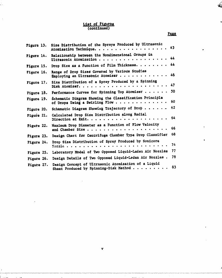
Figure 13. Size Distribution of the Sprays P_oduced by UltrasonicAto_ization Tedhnique....... ..... . ..... 63
Figure 14. _elatiouship between the Nondimensional Groups inUltrasonic Atomization ................. 44
Pigure 15. Drop Size as a Function of Film Thickness ........ 44
Pisure 16. Range of Drop SiZeS Covered by VarioUs StudiesEmploying an Ultrasonic Atoe_zer ............ 45
Fisure 17. Size Distribution o5 a Spray Produced by a SpinningDisk Atomize_ ...................... 47
Figure 18. Performance Curves for Spinning Top Atomizer ...... 50
Figure 19. _chematic Diagram Sho_lng the Classification Principleof Drops Using a Swirling Flow ............. 60
Figure 20. Schematic Diagram Showing Trajectory of Drop ....... 62
Figure 21. Calculated Drop Size Distribution along RadialDirection at Exit .................... 64
Figure 22. Maximum Drop Diameter as a Function of Flow Velocityand Chamber Size .................... 66
_igure 23. Design Chart for Centrifuge Chamber Type Drop Classifier 68
Figure 24. Drop Size Distribution of Spray Produced by Sonlcore_ozzle ......................... 74
Figure 25. Laboratory Model of Two Opposed Liquid-Laden Air Nozzlas 77
Figure 26. Design Details of Two Opposed Liquld-L_den Air Nozzles . 78
FigUre 27. Design Concept of Ultrasonic Atomization of a LiquidSheet Produced by Splnnlng-Disk Method ......... 83
v
t .--- , .-
00000001-TSA09

on
SPRAY NOZZLE DES%GNS FORAGRZCULTURAL AVZATZON APPLZCATIONS
to
NASA, LEW_S RESEARCH CE_£ERContractNAS3-21581
_rom
_ BATTELLE_ Columbus Laboratories!)i o
_i September 18, 1979
_ INTRODUCTION
_,_ The use of aircraft for applying the chemical formulations tO
_: control agricultural pests is considered cost competitive when compared
_: to other application methods and is usually the best method when time
restrictions exist. However, one of the difficult problems in the field
_!.! of agricultural aviation is the accurate and ufllfor_ application of
i_' chemicals to the target areas while avoiding the drift of chemicals which
might da_ge nearby crops or present hazards to susceptible animals and
_i people in the vicinity. ConslderlnS the size distribution of these drop-
} lets or particles, a loss of material occurs at both the large and small
i! size ends. While excessively large drops settle dir-qtly on the ground_._,. resultlng in a nonunlform deposit, s_all droplets can drlgt away. In
=_' order to _liminate these problems, the drop size has been controlled in
_:r the past by changing the llquld propertles such as viscosity, density,_-
=_; and surface tension by use of chemical additives. While the size of
__' individual drops themselves can be varied to a certain extent, this approach
_: does riot p_ovlde a uniformity of drop sizes. One of the logical solutions
=_ " to this problem is then to develop an atomization technique that can pro-
"_.: duce monodlsperse sprays. Considering that Various dynamics of spray
.lli
O0000001-TSA10

2
i
drops such as settling, drifting a_d vaporization are strongly dependent
upon their size, this approach has a high potential for overcoming
many spray application problems.
The objective of the first phase of the present program was to
perform comprehensive literature surveys on the techniques of generating
monodispa_se sprays end on the information concerning liquids used in
agriculturai aviation spray applications. The objective of the secofld
phase of thd prograawas to conceptually design and assess spray nozzles
for generating monodisperse sprays. Major emphasis was given to generating
new atomization coflcepts that have n_t been used previously in any applica-
tion. Thus, any generated concepts were to be conceptual rather than ex-
tensions of existing spraying techniques to agricultural applications.
This report cove_s technical efforts for both the literature
survey and conceptual design phases of the program which were conducted
during the period fro_ October, 1978 to FebruatT, 1979, and from March to
August, 1979, respectively. The pertinent literature references identified
during the first phase are listed alphabetically in the Bibliography regard-
less of whether or not they are cited in this report.
PERFORMANCE REQUIREMENTS FOR SPRAY NOZZLES
The ulti_ate objective of the current program is to identify
or to generate a new concept _or prcducing monodisperse sprays. Through-
out the program, eaphasis has been given to the fundamentals or
basic principles that can satisfy the requirement of producing a mono-
dis_rse spray. Other important requtreaents have been the ranges of
drop size and physical pro_rtles of sprays. Liquid flo_ fetes that can
be covered by each technique have also been given important consideration.
In establishing criteria got the above requirements, _esults of a liter_-
ture survey of agricultural aviation industry are to be used. Finally
extension of the range of applicability of the technique and eventual
development for agricultural application are to be assessed based on the
collected information on the current state of the art for each technique.
Specific requirements to be met by the extended ability of the
identified techniques are_
3
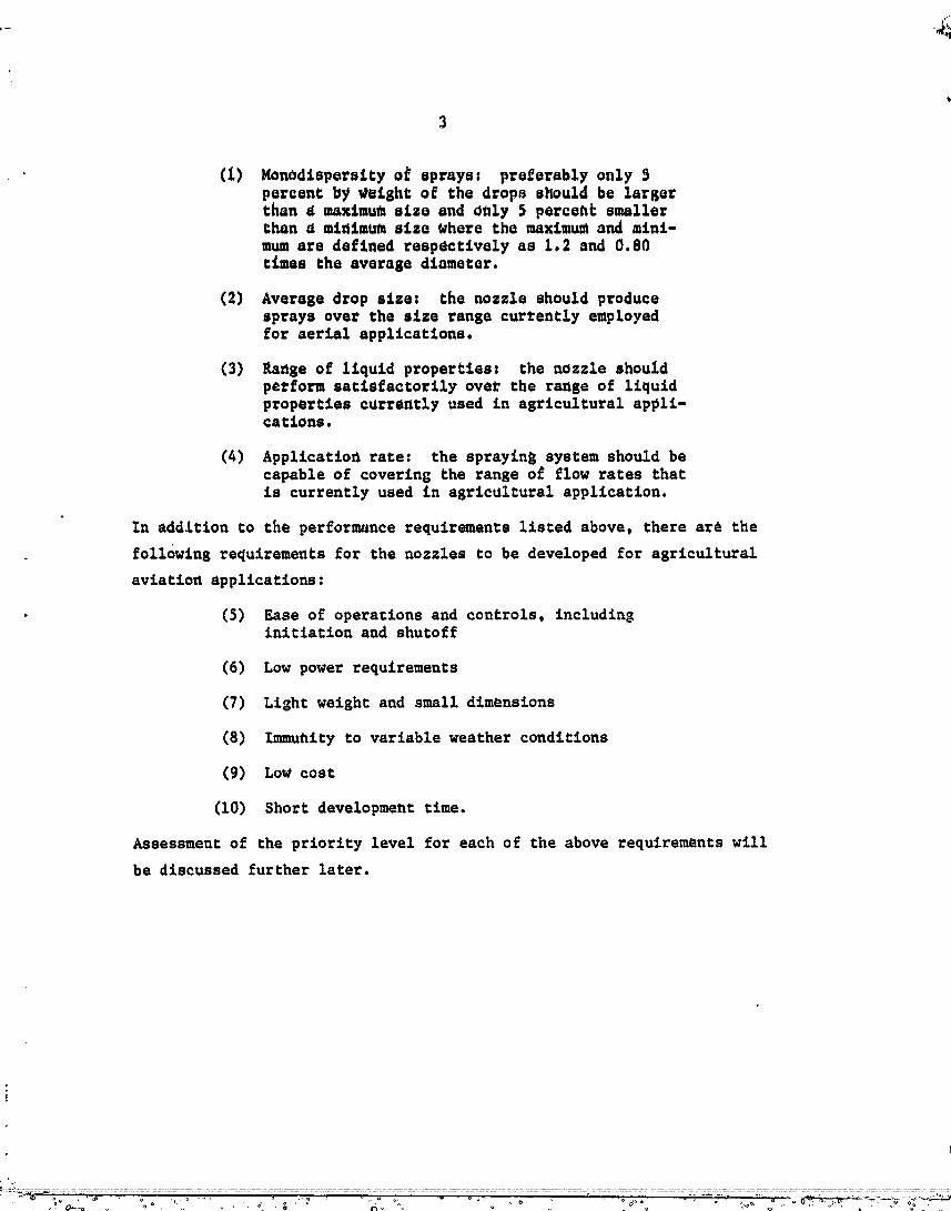
(1) Mon_dispersity o5 eprays: preferably only 5percent by weight of the drops should be largerthan a maximumsize and only 5 percent smallerthan a minimum size where the maximum and _ini-mumace defined respectively as 1.2 and 0.80rimes the average diameter.
(2) Average drop size: the nozzle should producesprays over the size range currently employedfor aerial applications.
(3) Ra_ge of liquid properties: the nozzle shouXdperform satisfactorily over the range of liquidproperties c_rrently used in agricultural appli-cations.
(4) Applicatiofl rate: the sprayin8 system should becapable of covering the range o£ flow rates that
is currently used in agricultural application.
In addition to the performance requirements listed above, there are the
following requirements for the nozzles to be developed for agricultural
aviation applications:
• (5) Ease of operaclons and controls, includinginitiation and shutoff
(6) Low power requirements
(7) Light weight and small dimensions
(8) Immufllty to variable weather conditions
(9) LoW cost
(i0) Short development time.
Assessment of the priority level for each of the above requlrem_uts will
be discussed further later.
00000001-TSA12
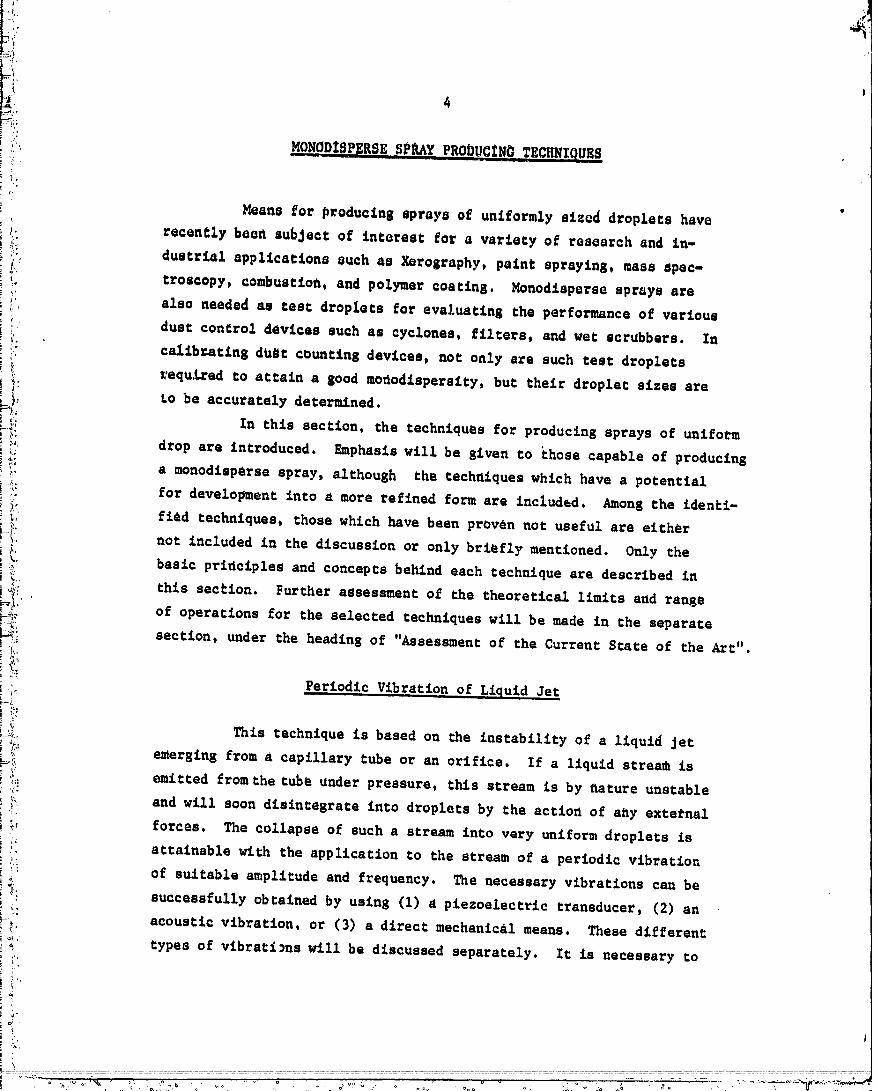
FMON pZSP SESe AYP.0DUCZ EC.N,qUES
if:i!"_: Means for producing sprays of uniformly sizQd d_oplcts have
i_.: recently beon subject of interest for a variety of research and in-
i)." dustrial applications such as Xorography, paint spraying, mass spec-_ troscopy, combustion, and polymer coating, Monodisperse sprays are
,. also needed as test droplets for evaluating the performance of various
_ dust control devices such as cyclones, filters, and wet scrubbers. In
i; calibrating dUgt counting devices, not only a_e such test dropletsI_ _equ.tred to attain a good mo_odtsperstty, but their droplet sizes are
_ to be accurately determined; •
i_ In this section, the techniques for producing sprays of uniform
f_: drop are introduced. Emphasis will be given to chose capable of producingL; !
_:: a monodisperse spray, although the techniques which have a potential
_:_. for development into a more refined form are included. Among the identi-
i, find techniques, those which have been proven not useful are etth_r
!=I:, not included in the discussion or only briefly mentioned. Only the
basic principles and concepts behind each technique are described in
i-_. this section. Further assessment of the theoretical limits and range
i-_,__ of operations for the selected techniques will be made in the separate
_i: section, under the heading of "Assessment of the Current State of the Art".
,,;:_ Periodic Vibration o_ Liquid Jet
This technique is based on _he instability of a liquid Jet
,_;" emerging from a capillary tube or an orifice. If a liquid strea_ is
!:i: emitted from the tube under pressure, this stream is by flature unstable
_ and will soon disintegrate into droplets by the action of a_y external
_, forces. The collapse of such a stream into very uniform droplets is
!. attainable wi_h the application to the stream of a periodic vibration
_: of suitable amplitude and frequency, The necessary vibrations can be
_,? successfully obtained by using (I) a piezoelectric transducer, (2) an
-_/, acoustic vibration, or (5) a direct mechanic&l means. These different.... types of vibraci_ns will be discussed separately. It is necessary co
..... °°0" ° 00000001TSA13
.... L
_ divide this technique into the t_¢ee categories because each of the_ three categor_e_ or typee differe not only in deeiSn but aleo £n the
.-_ drop s_._e t'ange that ten be ¢ove_ed.
_;'_ Eleet_ostrictive Oisk Type C_nerator
_:_: Disintegration of liquid stream emerging from an orifice can
_::" be precisely controlled if the orifice is vibrated periodically. Such
_-;_ a periodic vibration of _he orifice can be achieved by "_mplanttr_ the
-_% orifice into a disk made of electrostrictive material (piezoelec,.cicN i_2_,,:, cl:ystal} and by applying an electrical signal to the piezoelectr.c
::_ crystal. The performance of apparatus based on this typ_ " de:.
' has been experimentally studied by Str_ (1969) _ a,,." _ '..,t and Liu
_: (1973).
i_'i' Figure 1 is a schematic diagram of the droplet generating
":': system. The system consists of a liquid feeding line, a vibrating
:i:'_ orifice and a signal generator which provMes the necessary disturbanc_
._ to the orifice. As will be further discussed, size of the droplets
_ generated by the apparatus depends upon the orifice size, liquid
_ " velocity, and the signal frequency..._
The frequencies of piezoelectric crystals generally range
;i:: from about 10 to 1000 kHz and the sizes of the droplets produced
_: in this frequency range are about 3 to 50 _m. The orifice diameter
normally ranges fro_ 3 to 20 microns.
_ }} When a monodisperse spray of relatively small droplets are to
_. be produced, small orifices are needed. One of th_ operational problems
_i" in using such small orifices is that the orifice is easily clogged
_ even by a small amount of solid particulates present in the liquid.
/) _n order to avoid this problem, it is usually required to purify the
_?' liquid before feeding into the orifice. For this purpose, membrane
_' filters are installed as illustrated in Figure I. In this case, these
_is filters have to be periodically replaced. Another problem is that
droplets initially very uniform in size can agglomerate soon after
;_ * Na_es and dates in parentheses refer to Bibliography at end of report.
UOUOUOUI IOl-_I@

6
leavin$ Ctw o_fice. Ic Ls therefore necessary co provide a dilution
air_l_w around Ch_ orifice such clmc the produced droplecs are
iaznedLaCely dispersed.
.mxv_r
FIGURE 1. SCHEMATICDIACRAMOF EI_CTROSTRICTIVEDISK TYPE GENERATOR
Vibracin_ Tube Usin S Audio SiAnal
Instead of using the eleccroscrictive oriI;ice vibrated periodi-
cally by an electrical signal, s liquid Jet can be passed through a tube
of relatively large diameter. The vibratio, can be imparted onto the
cube in the form of an acoustic wave using an audio speaker. This type
_--'_" .............................. :...... ; ............... =_ .................................. _ ; i
00000001-TSB01
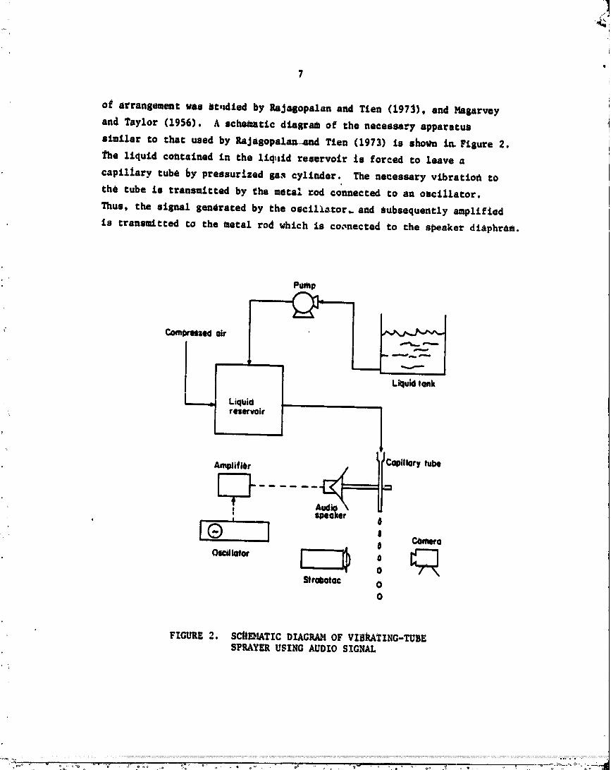
of_ arransemenc vu _c,_lLed by l_JaBopalan and TLen (1973), and _prvey
and Taylor (1956). A sche_cic diasrmU of che necessa._y apparacua
limilar co chac used by RaJasopal_d Tien (1973) is shorn _ Fisure 2. I
The liquid contained in the 1iq_nid reservoir is forced Co leave u
capillary cube by pressur_.zed sa.q cylinder. The necessary vibraCimt co
the cube Ls cransmtcced by the meca2 cod connected co an oscillacor.
Thus, Che si_;nal seneraced by the oscil_._cor_ and subsequencly amplified
is cransm&cced co che mecal rod vh&ch is co_necced Co che speaker diAphraat.
POmp
F--2-'--Liquid tank
Liquid ,r (lll_'_rvoir
AmplifiOr illory tube
t
° Speaker• ,, | 4
Strobotec 00
FIGURE 2. SCnI_IATICDIAGRAMOF VIBRATING-TUBESPRAYERUSING AUDIOSIGNAL
_:_'"°" " .....:° ...." " """ .... '_:' ° " .... °_" "_ " " ' ' " "............ O0000001--"'""'/,'..'5_uz
_' 8 4_b
_i The diameter of the capillary tube normally ranges from 50 to
_ 1500 um, thus, much larger than chac _or the electroscriccive disk. Theii resulCtn$ droplet _ize %£e_ bet_ee_ 100 to 3000 _m in diameter. The .
signal frequency is in the range of 0.5 co 30 kHz. Ic is reported chat
the observed drop size always agrees with the calculated drop size.
i The f_rmula for this calculation will be discussed l&Cer. The mono-
_ dispersiCy of the sprays as reported by the investigators £s exceptionally
good. For example, _hgarvey and Taylor (1956) report chaC the standard
deviation of the droplets from the mean value is less than 0.5 perceflti
for the mean size up to 10,000 um.
Vibrating Tube Using Hechantcal Means
Another way Co produce a periodic disturbance in the liquid
Jec is the use of some sort of mechanical means. Btnek and DohnalovA (1967)
used a fine whisker dipped periodically into the liquid reservoir. The
schematic design of the generator is shown in Figure 3. The whisker
shown in the figure is conhected co a flat spring of silicon iron which
is vibrated by an electromagnetic field. The 50 Hz AC current was used co
create the magnetic field. The whisker has a round shaped tip of 0.015 mm
in diameter. They observed chac when c_ whisker emerges above the liq_d
surface, initially a "liquid bridge" is _ormed across the whisker tip and
the liquid surface. As the whisker moves up further, this bridge is
separated co _o_n a droplet. They found chac the immersion depth of the
whisker as well as liquid surface tension and viscosity can determine the
droplet size.
A similar attempt maF be made by employing a periodically
rotating needle which can beeak up the liquid Jec emerging from a
capillary _Jbe.i
O0000001-TSB03

9
Silicon iron barFine whisker
Liquid reservior-- ,.., w Liquid
FIGURE 3. SCHEMATIC DIAGRAM OF VIBRATING
TUBE SPRAYER USING A WH$SKER
Other Types of Vibrating Tube_
There can be many other types of variations of the periodic
diSperSion of llquid Jet depending upon the particular applications. Erln
and Hendrlck (1968) utilized the vibrating tube configuration coupled with
an earphone to produce the electrlcally charged solid particles. In
order to obtain uniform liquid dropl_ts in the form of suspension in
another llquld system, Fulwyler, et al (1973) introduced a sheath llquld
around the liquid droplets which were p!oduced by a plezoelectrlc
transducer.
Periodic Vibration of Liquid Reservoir
Disintegration of liquids in a manner similar to that descrlb_d
above can also be n_hleved when the vibrations are applied to the liquld
reservoir rather than to the o_iflce or tube, as demonstrated by
Fulwyler and Raabe (1970). ThUs, the reservoir wall or the bottom could
be made of piezoelectric crystal such that the pressurized liquid con-
tained in this type of reservoir can be squirted out through an orifice
to produce uniform droplet at each frequency. L schematic diagram of
this type of nozzle is shown in Figure 4.
00000001-TSB04
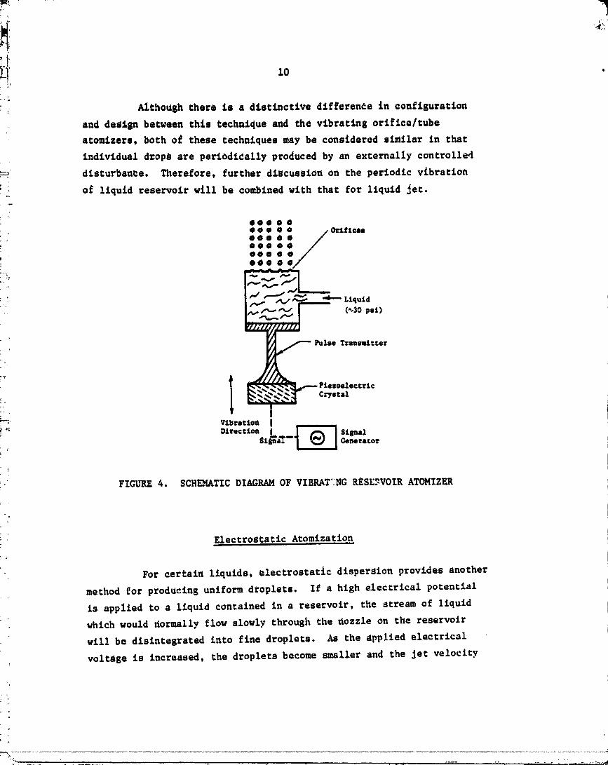
'+_ Althoush there is a distinctive d£fferen_e in configuration
and des_Su between this technique and the vibrating orifice/tube
atomizers, both og these techniques may be considered similar in that
individual d_op_ are periodi_ally produced by an externally controlle4
-_ disturbance. Therefore, further discussio_ on the periodic vibration
o5 liquid reservoir will be combined with that for liquid Jet.
eoooO
• i/OrJ.ficu
: :::1:oo. O:O0
+"_ O000
.. L£quidf,_+
[--"---" (_3o psi)
_ Pulse Transtt tierPiezoelectric
Crystal'----: Vibrltton I
+: Direct:ton _a'r _ StSnal$t -- Generator
FIGURE 4. SCHEMATTC DL%CEAM OF VIBRAT'_NGRESE."-VOIRATOMIZER
Electrostatic Atomization
For certain liquids, electrostatic dispersion provides another
method for producins uniform droplets. If a hish electrical potential
is applied to a liquid contained in s reservoir, the stream of liquid
which would normally flow slowly through the nozzle on the reservoir
will be disintegrated into fine droplets. As the applied electrical
voltage is increased, the droplets become smaller and the Jet velocity
'_'_" '+.t!................ J ...... -.. ............ , ._
00000001-TSB05
,
11
i +_i also increases. In general, if the voltage 18 increased further, the I
liquid Jet would disappear forming a spontaneous atomization of liquid
_; to form a fine ._sc at the nozzle•
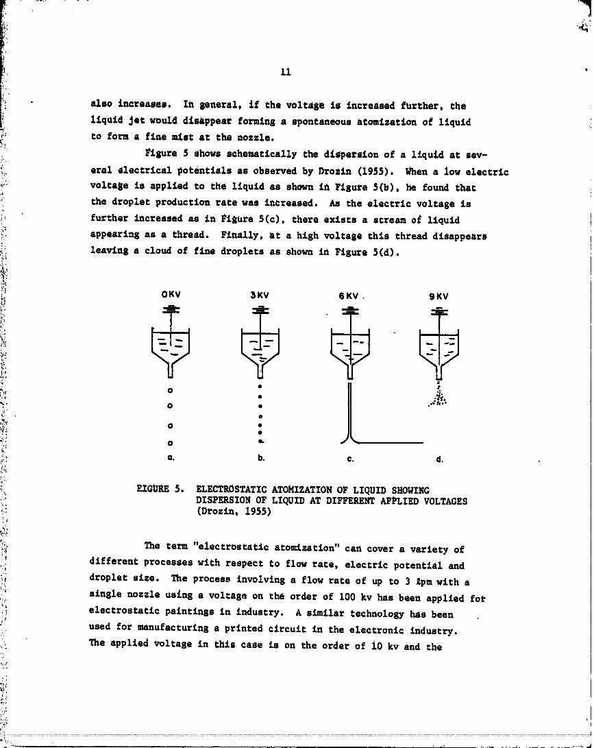
Figure $ Shows schematically the diape_sion of a liquid ac sev-
_ eral electrical pokentfals as observed by DroZin (1955) When a low electric
_," voltage is applied to the liquid as shown in Figure 5(b), he found that
_: the droplet production rate was increased. As che electric voltage is
,_, further _creased as in Ft_ore 5(c), there exists a stream o_ liquid
_i.: appearing as a thread. Finally, at a high "_ltal_e this thread disappear_
_i 1cawing a cloud of fine droplets as shown in Figure 5(d).
!i/l;: 0 KV 3 KV 6 KV , 9 KV
J_ _=. - _ _-+L. _ _"e. "!=-
+;' r _ i I I I i I
.%+,
._ _
o .. JL ""t: o •+.o_,+ II,
•,*, •
+:' O e-
_:'" O. b. C. d.++.
_,:+ EIGURE 5. ELECTROSTATIC ATOMIZATION OF LIQUID SHOWING_"+ DISPERSION OF LIQUID AT DIFFERENT APPLIED VOLTAGES
_.:: (Drozln, 1955)
,_;'. The term "electrosCatic atomization" can cover a variety of
i+ different procesaes with respet:t to flc_ rate, electric potential and
)_ droplet slze. The process involving a flow rate of up to 3 £pm with a
_ single nozzle _stng a voltag_ on th_ order of 100 kv has been applied for
!; electrostatic paintings in industry. A similar technology has been
°_. used for manufacturing a printed circuit in the electronic Industry.
_, The applied voltage in this case is on the order of i0 kv and the
e,/,
00000001-TSB06

12
correspnndin8 flow rate £S extre_y small. Th£s process £m senerally
per£ormed in a vacuum. SiSutf£cant Work on electrostatic a_omizatton
has alaO been done _or oil burner applications.
Many different observations have been made which may be uSed to
e_platn the droplet formation mechanisms associated v£th electrostatic
; atomisation. Vonnesut and Neubauer (1932) atomized water, susar solutions,
lubricating otl, and alcohol. They observed that there was an upper l£mit
of liquid electrical cofiductivity beyond which no atomization could be
achieved. Also Chey found that monodisperse sprays were not formed with
: the negative potential_on the ltqutd. A similar experimental observation
: has been utade by many invescisaCors such as Zeleny (1914), Macky (1931),
Bolllnl, ecal. (1974), and Nawab and Mason (1958). Generally, they
observed that the electrlcal voltase required to dislnteErate the liquld
Jet depends on the electrlcal property of the liquid. For example,
fine mists can be produced using liquids such as water, alcohol and dibutyl
phthalate, all of which have a relatlvely low electrical conductivity.
However, some organic liquids such as benzene and carbon tetrachloride,
which have low dlelectric constants were found difficult to disperse by
this method.
The basle mechani_n of liquid disintegration by electrostatic
charge is that when a high electrlcal voltage is applled, the liquid
becomes hiShly charEedand pressure due to the electrostatlc forces
increases. When this pressure exceeds the Surface tension, the liquid
surgace becomes unstable. Because of the rather complex physics involved
in the droplet dispersion mechanisms, no firm theotetlcal models have been
established yet. Pfeiffer'S (1973) model is such that the dispersion of
the liquid by electrostatic atomization takes place due to the detachment
; of a _Ingle drop from the capillary tip. HoWever, this model has not been
proven experlmentally.
|
" ....... 00060001-TS B-07
,1
) '
-_!. 13 '
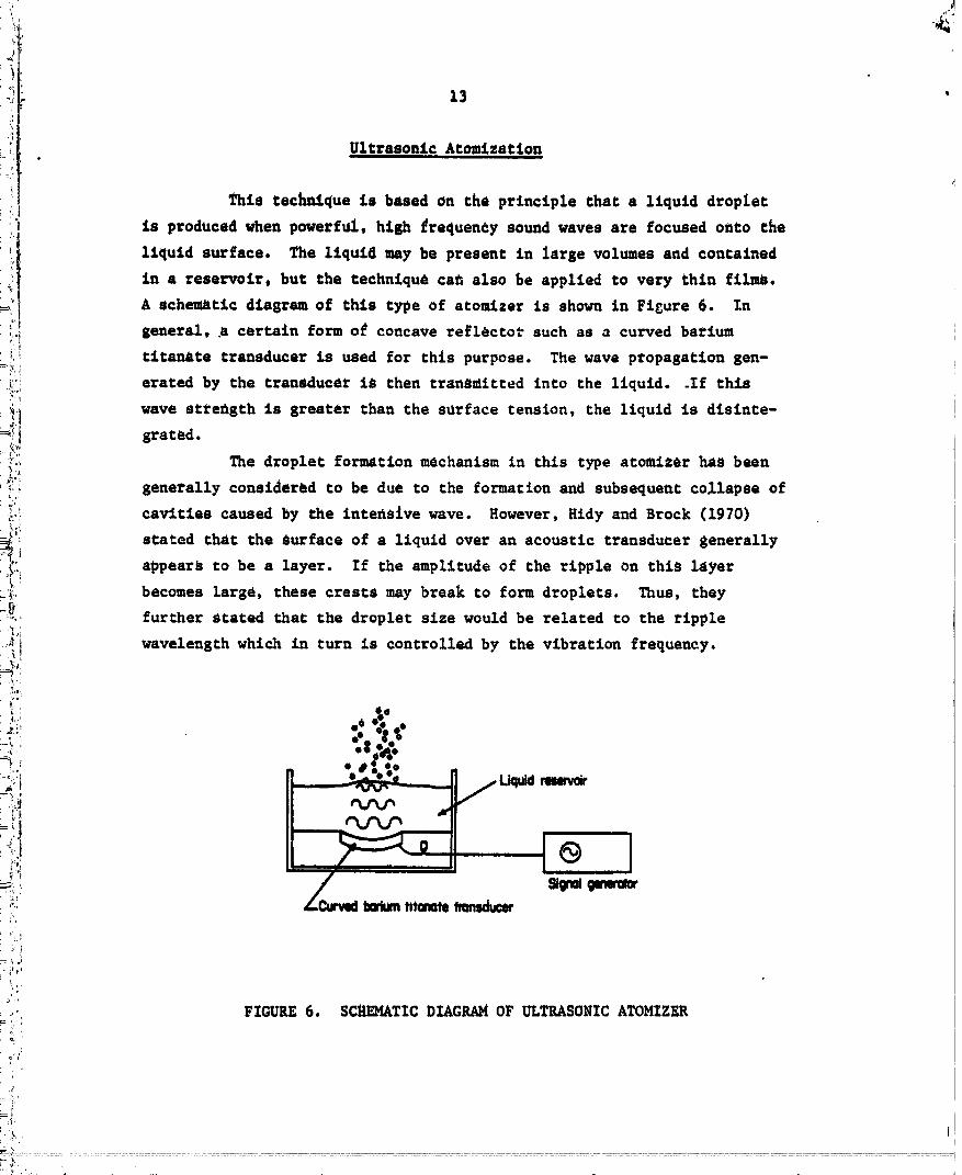
{ Ultrasonic Atomization
(1 This technique is based on the principle thac a liquid droplet_ is produced when powerful, high frequency sound waves are focused onto the
liquid surface. The liquid may be present in large volumes and contained
_!! in a reservoir, but the technique ca_ also be applied to very thin films.A schematic diagram of this type of atomizer is shown in Figure 6. In
'_,'i general, .a certain form og concave reflecto_ such as a curved barium
_ i titanate transducer is used for this purpose. The wave propagation sen-=k i
"_ erated by the transducer is then transmitted into the liquid..If this
_i] wave streflgth is greater than the surface tension, the liquid is disinte-r!. grated.
:,_i_ The droplet formation mechanism in chls type atomizer has been
_ _ generally considered Co be due to the formation and Subsequent collapse of
_:! cavities caused by the Inte_slve wave. However, Hidy and Brock (1970)_,._
_i stated that the Surface of a liquid over an acoustic transducer generally
_' appears to be a layer. If the amplitude of the ripple on this layer;il becomes large, these crests may break co form droplets. Thus, they=__ further Stated chat the droplet size would be related to the ripple
._i_I wavelength which in turn is controlled by the vibration frequency.
o". go
--yl
i '
/;'
={," FIGURE 6. SCHEMATIC DIAGRAM OF ULTRASONIC ATOMIZER
4,
" 00000001-TSB08
14
Spinn£n S Disk Method
Spitlnin$ dielks and tops produce droplets of moderately uniform
size by feeding a liquid onto a rotating disk from which the l_.quid is
dispersed radially into renal1 droplets by the centrifugal force. In
general, liquid is fed to the center of the disk and flows to the edge
_he_e it acc_ulates until tt:e centrifugal force, which increases with
increasing liquid at the edge, overcomes the surface tension and disperses
the liquid. A schematic diagram of the spinning disk is depicted in
Figure ?.
The spinning disk and top have probably been the most generally
succestful methods for producing monodisperse sprays. One operating
problem is that thls dispersion produces undesirable secondary sprays
(satellite dropletS) as shown in the figure. However, these satellite
droplets can be separated dynamically from the larger primary droplets.
This is usually done by a separate Glow of air near the disk, into which
the satellites move but beyond which the larger primary droplets are
thrown.
The spinning disk method is capable of producing a moderacely
monodisperse spray over a wide range of drop size. The mean drop size
depends upon the surface tension of liquid_ liquid density, disk
diameter and rotational velocity of the disk. The averaSe drop size
ranges approxlmately from 10 to over 200 um.
----, 00000001 -TSB09

15
+
I _ /-- sp*_,.s rusk
°oj. o.o ,,,-./ /..In oo
3 II1;'. ;III6" llLb *III:' lip _11
"" • •
t'=4 ' i
,. Rec_.rculat:Lon!
Z:,_ oo
i--;'
i . - _tellite gpray+- Collection Flow
i+-)::
_+: FIGURE 7. SCHEMATIC DIAGRAM OF SPINNING DISK WITH A
.... SECONDARY FLOW FOR P.EM._)VINGSATELLITE DROPLETS+'t++
' Vapor t_at ion-Condensation Technique
t Thls technique involves atomizing the liquid, vaporizing it,
_ and then subsequently condenSinO the vapor. The liquid formed is generallyi
;?+ atomized by a pressure atomizer. Si_e the spray initially produced ini ,:+i
: this way iS polydisperse, the spray Is vaporized by heating it above the
- boiling point of {:he liquid, usually by a combustor or an electrical
heater. Then th,_ vapor is mixed with a stream of hot air containing a
- regulated number of condensation nuclei. The mixture of air vapor and
nuclei passes through a section in which it is slowly cooled, becoming
'- supersakurated and coddensing u_igormly upon the nuclei to form uniform
droplets.
L
i :I
+ ,., ....
O0000001-TSBq 0

16 '
This technique is currently in use for spraying certain
insecticide chemicals. As a heating source, a pulge Jet or a recipro-
caring _ngine is used. The liquid capacity rangeb up to 40 gallons per
hour. No data on droplet size or monodispersity are available, however.
Another application of this technique is for producing a cloud of smoke4.
:i__'. for the military purpose of camouflage in the battlefield. For ob-,!i;
_, _cUration i_ the light wavelength range of 0.4 to 0.8 _m, the droplet
:_',_ 81ze is desired to be in the same range.
!_ A qualitative size estimat_ may be made for droplets produced
_;, by the evaporation/condensation teehn£cue bv usinl the following experssio___n
'1',i Of Lansmuir (1942).
D3 38.4 Zqt/2)3/2 3/2_" (i + m° v
_2 whereI.i D - particle diameter, cm
•_. Q - liquid mass flow rate, g/seet',
_. mo - mass of admixed air per unit mass of liquidi_I__! Z - function of the heat content o_ the vapor
.[_ escaping from the nozzle
_, v - velocity, em/sec.
i::_: It should be noted that the drop size depends on the heat content of the
.': vapor. His expression, however, does not include the number of nuclei
._: which is generally known to be an important factor in determining the
_": drop size._in the condensation process.
!ii Miscellaneous Techn%que s
2:1Atomization of a Solution
' If a relatively nonvolatile liquid is dissolved in a volatile
i solvent and the solution is atomized, the solvent material will evaporate
':+::': upon encountering the surroundin_ air, thus, leaving only the nucleus
h,
f,:
O0000001-TSB11
4
17 '
droplets _oneistinS of tha nonvolatile solute. _Is technique requires
that the liquid to be dispersed be mixed or dissolved in a solvent,
thus being li,ttted to the use under the above requirement. If the original
droplet diameter before evaporation is do and the solutto_ deneity i_
0 o, the final nucleus droplet size is calculated by the followin$ mass
balance equation
d3 .. 'e6' Oo o X ._. D30 (2)
so chat
D- do 1/3 (3)
where X is mass concentration.of the solution and P is the density o£
final droplets. It should be noted that this technique in general does
not provide a_good monodisperse spray although the mean size may be
changed.
A similar technique has been applied to the atomization of mono-
disperse suspensions in water. This type of method first used in the
medical field is now widely used to spray monodisperse solid particles
such as polystyrene latex particles manufactured by the Dow Chemical
Company. Salt, sugar and methyl_ne blue dye dissolved in water also have
been used to form aerosols of the solute material. One precaution if:at
should be taken is to keep the concentration of such solid partlcles
in the solvent relatlvely low to avoid possible a_lomeration of suspen-
sions in the solvent.
Aerodynamic Atomization
In this type of atomization, compressed air is used to break up
the liquid into droplets. For this reason it is often called the air-blast
type atomizer or the two-fluid nozzle. This method is probably one of the
simplest and the most commonly used for producing droplets for nee in
many areas such as medicine, combustion, and agriculture. Breakup of
liquid is primarily achieved by the complex interaction between liquid and
air. Green and La_e (1957)qualltatlvely explained the llquld breakup
' ° ' O0000001-TSB12

!
18
mechanism involved in aerodynamic acomi_ion by dividing it into three9'
stages. The first stage is an instability of liquid _urface d.e to
various aerodynamic and shear forces creating s_il ripples. Then these
ripples are transformed further into fine ligament which are separated from
)" the main stream of liquid. Finally, these l£sa_ents ewngually form
droplets due to the surface tension.
Although these qualitative explanations appear simple, the
, nature of the actual disintegration is very much complex and it is very,-v_,: difficult, if not impossible, to model the complete picture of the
_i disintegration mechanism even for a simple configuration. Due to the
_' complexi_y, the size off the droplets formed by the aerodynamic
; atomization is very widely dispersed.
!i There are many theoretical analyses for predicting the mean
_ droplet size (Rizkalla and Lefebvre, 1975; Ga_ner and Henry, 1953;
_i Ingebo and Foster, 1957; Wigg, 1964; Nuklyama and Tanasawa° 1939).
_ Based on _any experimental test results for small alr-blast atomizers,. 2i;
_° Nuklyama and Tanasawa suggested that the mean volume/surface diameter,
_' D in microu, can be written aso
_34={i D - 585 u )1/2 (U)9120 IO00QL 3/2
-_ o (u-v) C_ +397 --_ ( % ) , (4)
v. where
:," u = air velocity, m/set
._:. v = liquid veloclty, m/sec
:. a - liquid surface tension, dyne/cm
_ cm3_" 0 " liquid density, g/
U - liquid viscosity, g/cm sec
_.--._:_ QL/QG = flow rate ratio of liquid to gas.
_" The conditions under which Equation (4) is valid are known to be as
follows
_' 20 < o _ 70 dyne/cm
0.005 < _ < 0.5 poise
cm3_. 0.7 < 0 < 1.2 8/ •
/.'
2
$,
Y
......•°,_ °,...... ..o . , "o .._,'_ ,..,_,,o " _. _" _'_-_-__:'--'_-_'-_-,
O000000]-TS8] 3
A rather LarSa numbQyo_ Qq_t_on_ to e_prQsent dy_p Q_ze dlscribu_Ion
_,_ haVo alao boon susBested by v_rious InveoCigators. However, most eE the
work was based on e_forts to obtain seed flts be_ecn experimental
sets of data and emplrlcaleq_ntions. Further, both the predicted andI
the m_asured dispersion o_ the sprays produced by aerodynamic atomization
_ is quic_ poor. _or this roaoon, no further discussions will be maOe
_ regarding this type of technique.
_. Swirl Atomizers
_:, In addition to the spinning disk atomizer, the swirl chamber...._: type makes use of centrifugal forces. This type of atomizer consists
i of a conical chamber with a small orifice at the vertex. Generally,
_., liquid is introduced tangentially and allowed to swirl. If liquid
_i!, pressure is high enough, a vortex is created and the liquid leaves the_" chamber as an unbroken film with a tulip or cone shape, de'pending on
_! the pressure. If pressure is sufficiently high, the liquid breaks up-E!_,_. inca droplets. Green and Lane (1957) stated chat surface tension,
_I viscous forces and the interaction of the liquid with surrounding air
__t are the main controlling parameters to disintegrate the liquid intodroplets.
Watson (1948) showed the e_fects of pressure and chamber
dimensions on the droplet size. According to his data, the smeller the
swirl chamber becomes, the finer the droplets that result. However,
the flow limits are quite restrictive if small drops are to be formed.
Another undesirabie characteristic is the inability co get sharp cutoff
of spray due to dribbling.
AtomizationUslns LiouefledGas
Sprays of fine mists can also be generated by first mixing a
liquid wlth liquefied gas under pressure and then expanding the mixture
through a nozzle as used in many applications such as for commercial
aerosol cans. Despite the wide use of this technique, very few
.............. ' ' ' 00000001 TSB14

2O
systematic studies ere available reSsrdin$ the mean drop]Let size s_d the
monodispersity. Liu (1967) measured the size distribution of sprays
obtained on several samples of cans _ontainins mnall amounts of dioccyl-
phthalace and freon gag, The measured size distribution was found co be
spread rather widely. Further. he found that the mean droplet size was -
below 1 _m. He also found chac the mean droplet size cannot be con-
trolled by the pressure. It is noc known how the droplet Size can be
increased if an increased amount of l£quid is mixed with a gas propellant
or iX the nozzle design iS changed,
_Thistle Type AtomiZers
Although similar to the ultrasonic atomizers using a transducer,
liquid can also be disintegrated by directlns high p_essure gas into the
center of a llquid Jet, thus creating Strong sound waves inside the nozzle,
as shown in Figure 8. Due to the sound field created by the focusing
air flow, this type of atomizer is frequently called the whistle or stem-
cavity type aton_Lze_. This type of atomizer is generally operated at a
sound frequency of about 10 kHz with a resultlng liquid droplet size on
the order of 50 _m.
tzpdd
--d,. .w--J " _'-'_-'''_p" I•TM _. ooOo Oo ego
-'" "*"
•,.,. •.,,, -#o'o°o
• •ql, 4DQ
II
FIGURE 8. SCH_qATIC DIAGP_I OF THE WHISTLE TYPE ATOMIZERSHOWINGTHE SOUNDRESONANCECAVITY
i... O0000001-TSC01
21
_ny commerci411y manufactured scom£zers of ch$8 type are
available £nclud£_g chose by Ascrobeam, Inc., Sonic Development Corp.,
and VApo Productt, _r£ch fiow rates up to 1200 sph. One of the disadvan-
tages in these atomizers ts chac the drop size cannot be easily ControLled
unless the nozzle dimension is changed. W£1¢ox and Tats (1985) studied
this type stozzle systematically and concluded that the sound field _as
not an important variable in the atomizing process. Topp and EiSenklam
(Z972) therefore, suspected that all the whistle atomizers simply
operate on a s£m£1ar principle used in cvo-fluid types. AS discussed
previously, a liquid is integrated primarily by the aerodynamic in-
teractions becveen gas and liquid in the twin-fluid acom£zers. _o
reliable or proven theoretical analyses on the performance of the vhistle
atomizers seem co be available.
Atoa_zation Us_na Spark-Discharge
By introducing electrodes inside the liquid level and applying
a high pote_tial across the electrodes, the liquid is knovn Co disintegrate
into fine droplets due co the spark-discharge.---A small scale experiment
was performed by Andrus and _alkup (1963) co investigate this phenomen_
pri_arily for a-domestic burner application. Droplets having the mass
median diameter of about 100 ,m droplets could be produced. However°
the results were reported to be cachet erratic and-not repr Jductble-_
The sizes of the produced sprays were also found to be quite _ide_y
dispersed.
0OOOOO01
=i'_
__:_ 22
/,
; AGRXL_/LTU_L AVZATZON SPRAY APPLICATIONS
This Section reports the information collected from the literature
survey on the properties o_ liquid ,utterial, and the ranges of drop size
_ and application rate commonly employed in agricultural aviation spray appli-
cations. The type of chemicals, drop size, application rate and properties
of the liquid will be discussed in that order.
!.
.... Pesticide Formulation Ty_es
_i PesClcldes as a generml term is used to d_scribe & number of
_:_: dlffer_nt insecticid. , herbicideS, fungicides, etc, Most of the original
=: chemicalb used for pesticides take the form of either solid or liquid and
: then are dissolved or mixed in a liquid. Depending upon the phases of the
_. original material, they could be grouped into concentrated solutions, water
_ soluble powders, water dlSper_Ible powders, and emulslfiable concentrates.
The _oncentrated solutions are the liquid chemicals which are
i dissolved in water. One advantage to the solution formulations is that
_" _hey are always considered to be homogeneous. Chemlcal powders which are
-_ soluble in water can be £ormulated into concentrated aqueous solutions with
_ the same advantages as the solutions JuSt described. _ettable or water
;. dispersible chemical powders ate those that are not considered to be solu---
!: ble in.water. Therefore, wettable chemical powders generally require agita-
-i tlon after mixing, until they are sprayed.- Some po_d_rs come in the form
of very fine or colloidal size and, therefore, will remain in suspension
j" and require no agitation. Pesticides aS emul_iflable concentrates usually
iii__:. consist of organic solvents containing the active ingredients which are
-; then combined with emulsifiers before being added to water. Concentrations
of this form will not separate, requiring no agitation before they are
,i. applied.
Most pesticide chemicals which come in one of the above forms are
further dil_ted wit_ a_ inert carrier. Carriers offer the advantage of
_., easy addition of spreading agents to the pesticide as well as wetting
UUUUUUUI lOk._UO

23
aSents _d-deposit builders. A carrier also reduces the amount of act£ve
chemical insred£ent required to obtain the same level of efficiency, and
_avors dilution to as sreat a degree as is reasonably possible.
Water is _ound to be the most common carrier used owing to its
lo_ cost, safety and _aSe of application. Another common carrier is oil;
and with the many different types available, a variety of solutions may be
developed. Foam sprays are sometimes used for pesticide application,
providing add/tional advantages over common carrie_s. The pesticide is
dispersed or dissolved in an aqueous alkali metal silt_ate foam and can
be applied as droplets or as a continuous layer. The advantages of the
foam sprays include a low liquid volume requirement, accurate placement
of the pesticide, the reduction of drift, clear visibility on the target,
and 8ood adherence (Hanson, 1973).
As already discussed, formulations may also contain supplemental
additives such as adjuvants and diluents. Some adjuvants, that is emulsi-
fiers, that are largely inert but will often influence physical properties,
include wetting and spreading agents, adhesives, and emulsifiers. These
additives are used for lowering the surgace tension of the liquid, allowing
for easy disper_iOn and easier spreadinE (DeOng, 1953).
Considering major crops being produced across the United States,
the prohibitively large number of currently available pesticide types
have been narrowed to those most commonly used. _qith the aid of statistics
from the National Agricultural Aviation Association (Collins, 1979), Table 1
was co_piled.
TABLE i. MOST COMMONLY USED PESTICIDES IN U.S.
Insecticides Herbicides Fungicides
Toxaphene Trifluralin BalanMethyl parathion DSMAand MSMA SulfurEPN PropyleneCarbofura_ OrdramDisulfoton 2,4-DParthlon A_razlne
Carbaryl PropachlorMalathlon Alachlor
Toxaphene
00000001-TSC04
24
Drop Size
Adequate drop size which is desired for aerial applications is
found to be dependent on many factors, such as the type of insects, plant
or fungus. In addition, aircraft speed and altitude, toxicity of the
chemicals, and weather conditions contribute to determining the optimum
drop size. All these factors can, however, be further narrowed down into
two general categories, one for maxin_Lzing the effectivehess of pesticides
which is primarily governed by the types of insects or c_ops, and the
other for _Ln_Lzing the drift which otherwise can cause da_ges to any_-.
susceptible species nearby. The drift also results in a loss of the
chemicals.
Fo_-an obvious reason, _pray effectiveness is largely determined
by drop size. Many studies on the optimunt drop size under various conditions
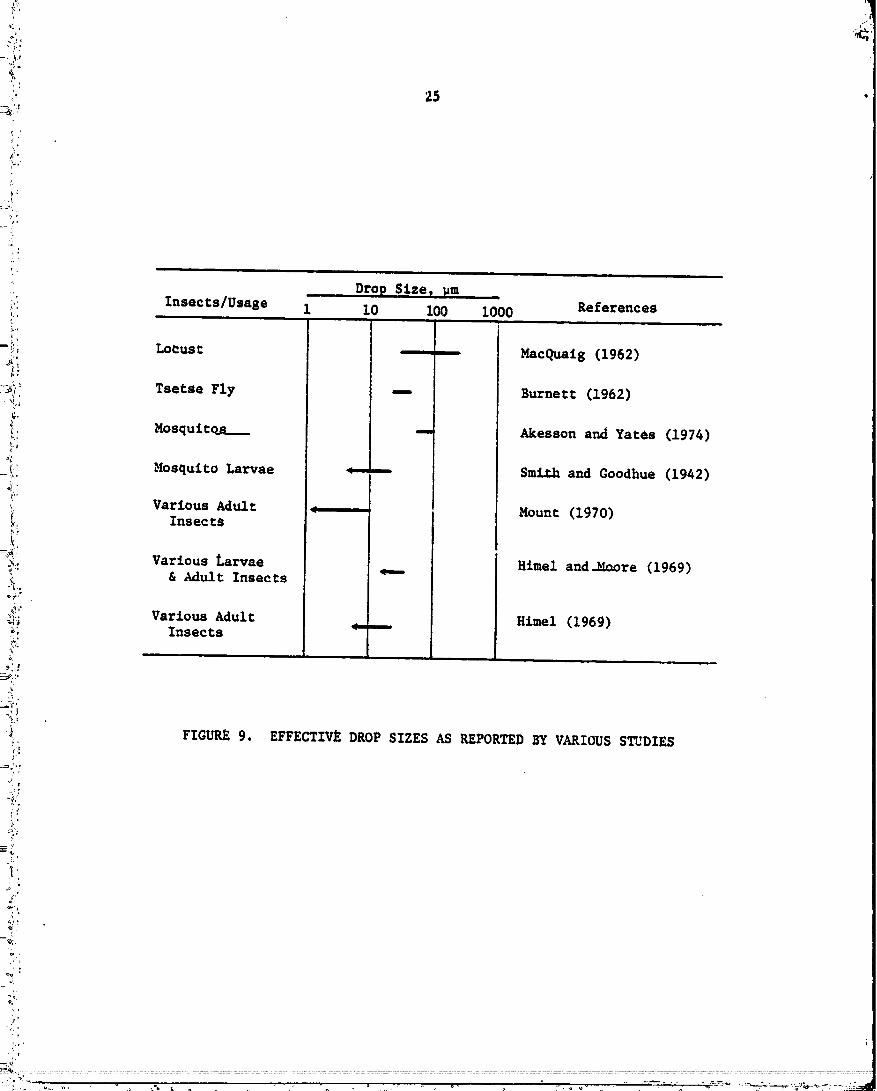
have been performed (MacQuaig, 1962; Burnett, 1962; Mount, 1970). Akesson
and Yates (1974) stated that the most effective drop size for insecticides
: depends on the insect size. Smaller droplets are ,_re active in the gut of
insects and also in external contact. Smith and Goodhue (1942) found that
: droplets of less than 25 _m are most effective for controlling small instar
of mosquito larvae. For larger insects llke locusts, drops of about 100 _m
were found to be more effective (MacQualg, 1962). The drop sizes that were
found effective from some selected research for several insects ar_hn_
in Figure 9.--
Another importa_t consideration for spray effectiveness is the
:..... depth of penetration inside crops or forests, or the abillty of drops to
;- be deposited on breeding sites or plant foliage. According to the particle
dynamics, the dro_ inertia should be minimized for maximizing the effects.
Therefore, drop size is preferred to be smaller than about i00 _m. Espe-
: cially this is found to be true for the forest applications regardless of
the type of insects. Indeed, a recent test (NASA, 1977) indicates that for
a pesticide which depends upon contact for effectiveness, droplets or
partlcles should range from about 75 to 100 _m in diameter. For appllcatlo_
of pesticides by "ultra low volume rates" under which formulated pesticides
00000001-TSC05
i"
'. Drop S:Lze I, _m .
__i Insects/Usage 1 10 100 1000 References
!o,.
= :_"_ Locust _ _ MacQualg (1962)
_}_ Tsetse Fly -- Burnett (1962)
_. Mosqultq£__ --- Akesson and Yacks (1974)
°¢!i' Mosquito Larvae _----- Smlr.h and Goodhue (1942)
!" Various Adult _ Mount (1970)
._. Insects
-_o_._ Various Larvae q-- Himel and-_core (1969)_"" & Adult Insects;.'_,,
_" Himel (1969)l,i Various Adult _.---_; Insects
} FIGURE 9. EFFECTIVE DROP SIZES AS REPORTED BY VARIOUS STUDIES
1'
=_i',o, ,
e_" ;¢,
=
y,,
.....;'.......... 00000001-TSC06
26
are sprayed without bein$ diluted wi_h _aCer_ the size og particles tenses
from 50 co 100 _m in size. Actually, the smaller the size the more desirable
for leu wasteFUl distribution, coverage, and ef_ectiveness of the chemical.
As drop siz_ decreases the drop inertia becomes too small to
settle on the ground rapidly. Thus, these drops tan drigc away before
settling ouc. Extremely small droplets would remain suspended in the air
for a prolonged period of time or even evaporate. These small droplets
which do noc readily settle ouc are defined as an aerosol. The extent to
which these droplets drift depends upon the aircraft altitude and the
weather conditions, in addition to the drop size. Although iC may depend
upon the degree_ tolerance for drift, the upper size limit for aerosols
may lie in the neighborhood of. lO0 _m. From the discussion on the effective
drop siz_ and on th_ minimi_ation of drift, it is obvious that the drop
Size to be used has to be compromised between these two contradicting
characteristics.
The drop _izes currently employed in the aerial application of
_estlcideS are found to be primarily dependent upon the toxicity of chemi _
cals, the area to be covered, and th_ period of chemical degradation.
Akesson and Yates (19Y4) stated Chat fine sprays whose Sizes range from
100 to 300 _m in diameter are currently used for most forest pesticides and
large area applications. This size range is also used for agricultural
insect pathogens. This small size range insures a good coverage and also
rapid reeu%ts d_e to large surface area for a given amount ofmaterial_
Moderately toxic materials are, however, sprayed with particle sizes of
about 300 to 500 _m. For highly toxic materials which require a maximum
drift control, drops up to 1000 _m are used. However, drops larger than
lO00 _m are no_ commonly used owing to their inability to provide unifor_
coverage and avoid waste.
Table 2 summari_es the average drop size currently used in agri-
cultural aviation applications. The listed drop size can, however, be
somewhat varied by the material density, wind velocity and altitude of
the airplane. It is noted that many of the most ef_ecCive drop sizes for
various insects, as shown in _igute 9, and the sizes listed in Table 2
. - -.............. O0000001-TSC07
, 27
},
TABLE 2. RANGES OF THE AVERAGE DROP SIZECOMMONLY USED
Z, ,l
:: Drop Sizei., Co_dition or Usage Examples Range, _m
::* s Large Area Application Forest pesticide•- Agricultural Insecticides:_ • Low Application Rate Vector and other low,;;' 100 - 300:,! • Low Toxicity toxicity material -- --
_. • Rapid DeEradationi',
-_*" • Moderately Toxic Most moderately toxic__: 300 - 500
-i_ • Good Coverage Desired agricultural chemicals
3;- • Toxic Restricted herbicide,_ 500 - 800_., • Good _overa_ got_: Essential
.._ • Highly Toxic Phenoxy acids or other_ highly toxic material 800 - lO00_! • Small Area Application
°.
_:: '
,q; ,
"' "-:' "_':-_':-.......:-........................ +-_=............:......................................................" 00000001-TSC08
26
cover the entire size range from the eubmicron size up to 1000 _m, Consi-
dering that most _hemicalt uJed for aSricultural purposes are moderately
toxic and that uniform coverage is g_nerally a primary requirement for most
applications, the drop size most commonly used seems to be in the range of
25 to 500 _m in diameter.
Application Rate
Like the drop size range, the application rate also varies very
widely in usual agricultunal aviation applications, in general, the_ap_=
cation rate is found to depend upon the type of pesticides, the type of
formulation, the type of aircraft, toxicity of che_icals, and even the drop
size employed. The lower limit of application na_e occurs when small
amounts of low toxic substance is sprayed over a large area using a small
drop size. A typical application rate for this so-called "ultra low volume"
iS on the order of 1 oz/acre. However, the application "ate can be as high
as 20 gal./acreo typically when very coarse drops are sprayed over a small
area. The drop size dependence of the application rate is primarily due
to the fact that a spray of _mall drops can cover a wide swath while coarse
drops would settle in a very narrow swath width, thus requir_,ngan increased
application per unit coverage area. In order to incorporate th_ above
application rateg into the current progrem, information on the spraying
rate is also requi_ed. It is _ound that an aerial spraying is done over a
large area typically at a rate of about 10,000 acre/hr, while for the case
in which a small area is covered u_in8 coarse sprays, the rate is about
30 acre/hr.
In conjunction with the drop size ranges shown in Table 2 the
collected information on application rate has been summrized in Table 3.
The _iow rates as listed in the table have been obtained by multiplying
the application rate by the spraying rate. It is interesting to note that
while both application rate and coverage rate are widely varied, the
calculated flow rate falls into a narrow range of 5 to 40 _pmwith an
average rate of 30 _pm or 450 gph.

29
• TABLE 3. RANGESOF APPLICATION RATES CO.ONLY USED
Calculated TypicalApplication Race, Spraying Rate, Flow Rate, Drop Size,
gal./acre acre/hr gal./h_ (_pm) pm
1/128 I0,000 78 (5) < i00
I 300 300 (20) 100 - 300
5 i00 500 (33) 300 - 500
i0 75 _ 750 (50) 500 - 800
20 30 600 (40) 800 - 1000
Liquid Properties
A_ discussed previously, most pesticides have been found to be
sprayed combined with carriers such as water o_oil. Therefore, properties
of the liquid chemicals and the application rate can vary widely depending
upon the degree of dilution. Generalization of the liquid properties is
further complicated by the fact that supplemental additives such as
spre_ading agents, adhesives and emulsifiers are often added to the solution.
Physical properties of some carrier liquid materials quoted by Butler, et al.
(1969) are listed in Table 4. It can be noted that density of most carrier
liquids ranges from 0.8 to about 1.25 g/cm 3. Surface tension is found to
be between 20 to 30 dyne/cm. A wide range o_ viscosity, however, exists
ranging from 0.3 to abo_t 10,000 cp. With the t_o llquids having an extremely
high viscosity exclvded, the viscosity for a typical liquid would range
from 0.3 to about 500 cp.
Although intrinsic properties of the original chemicals do not
greatly affect the overall combined properties of the final solutions,
vapor pressure of the material can be important especially in relation to
its toxicity. For example, the vapor pressure of Malathion as listed in
O0000-O01-TSClO

.2'{4
3o
...._:_, TABLE 4. PROPEITIES OF SOMELZQUIDS USED IN AGKICULTURALAPPLICATIONS
F'g i.,
......................... ' •_ Surface
:,4 Density, Tension, Viscosity,
i_._,_! Liquld S/cm 3 dynes/cm cp at 20 C Vapor Pressure
,. (20 C) mm.Hs at Cemp, ¢
:,_ Acetone O. 79 24 O. 32 195 20
° ":'"_ Mechanol 0.8 22 0.6 100 20
= ;_ B_nzene O. 9 30 O. 65 80 20.it',, Water I.0 72.8 i.0 18 20
;_ Ethanol O. 79 22 i.2 47 20
°_: Gas_llue 0.68 -- O.35 -- --
!:_:_ Turpentine 0.867 -- 1.49 3 20,x-"
_i" Kerosene 0.82 25 2.5 7 30
;'_: Diesel Fuel 0.89 30 i0 ....
:_,,:_. Ethylene Glycol -- 47 20 .....
_ Cottonseed Oil 0.92 35.4 70 _ --
.... Lube Oil SAEIO 0.9 36 i00 ....
_ _7 Lube OIl SAE30 0.9 36 300 1 30
; Castor 011 0.9_ 39 1,000 ....
o, Cort_ _,up --- 78 10,000 ....
._'_ Halathion (95 g) 1.23 32 45 4.0 x i0"s 30
_ : Lindane ...... 9.4 x I0"6 20_.o• Pacathion 1.35 -- -- 4.0 x 10⁻⁵ 20
,,,: 2,_-D ..... i.i x 10-2 25
_; Dursban (75 ?.) 0.97 .... 1.87 x10 -5 25
i:ii Haled (85 g) 1.965 ........
.:7 Fenth_on (93 _) i.25 .... 2.15 x 10⁻⁶ 20
_:' Captan 1.73 .... 1.0 x 10⁻⁵ 25
? _ .........
L- .:, 'i
m
' °" 00000001-TSC 11

31
Table 4 ie about 4 x 10 -5 mmHS at 20 C. 2,4-D, on _he other ha_d, has a
" rather high vapor pressure of about 10"2 _nHg (Butler, et a£., 1969).
_ntri_Sic _terial density of most chemicals is found to be approximately
between 1,2 and 2 g/cm 3. In£ormat£on on the intrinsic viscosity and surface
tension o5 these materials, however, is not readily available.
In relation to the overall effective viscosity of a certain type
of u_Lxture, it should be mentioned that this type of formu_ation can have
characteristics of a non-Newtonian-_uid.---.T.hus, viscosity of the mixture
is no longer proportional to the raze of shear stress. Especially water-
in-oil_and some thickeners respond.as nOn-Newtonian liquids, and the
viscosity will decrease as the shear rates increase. For example, a
mixture of 10 percent diese% fuel and 85 percent water is found to have
a viscosity of about 700 cp at a rate of 1/50 second while the value
decreases to about 15 cp at 1/4000 sec. In any case, the viscosity of this
material appears to fall within the viscosity range shown in Table 4.
Sun--at 7
The results o£ literature sut'veys on the drop size, appllcation
rate and properties of liquid material revealed that the formulation type
varies from one type of chemical to the next, and that they are used with
a carrier. Water, oils and foams are commonly used as carriers. Also, a
wide variety of ranges in each of the above _ategories is currently
employed.
The drop sizes currently used range from i00 to 1000 _m in diameter.
If the _ost effective drop size is included and highly toxic materlals to
be applied in a relatlvely small area are excluded,the most commonly used
d_op size can be further narrowed down to the range of 25 to 500 _m. The
average flow rate of the materlal is found to be about 30_pm, with the range
of 5 to 50 _pm. Various formulatio_s have been found to be applied combined
with a large dose of carrier llquld. The ranges of the llquld properties
of the materials are as follow_
Density: 0.8 - 1.25 g/cm 3
Viscosity: 0.3 - 500 centipoise
Surface TenSion: 20 - 80 dyne/cm
Vapor Pressure: 1 - 200 mm Hg.
00000001-TSC12
32
ASSESSMENT OF THE CURRENT STATE OF THE ART
Althoush a _onodispersQ spray can be defined mathematically as a
spray consisting of drops of one size, such a spray in reality seldom
exists and is nearly impossible to produce. Generally, a monOdisperse spray
is referred to a spray whose drops ere very narrowly distributed. Thus,
the definition, "nearly monodisperse" is a relative term since a size dis-
cribution of drops which _-aufficiently narrow in one application _y be
considered not monodisperse in another. For that reason, the terms such as
"nearly monodispersa" or "moderately monodisperse" are often used. In
._ this case the choice of the exact criterion for this s_te is sometimes
arbitrary. As already described, a monodisperse spray for _his study is
defined as a spray containing drops 95 percent of which are smaller than
i 1.2 times the average drop size and wlth 5 percent of the dTops smaller
i than 0.8 times the average size.
_ It should be pointed out that even if there exist available
cechnlq_es or devices for producing a spray which meets the moDodisper-
sity criterion, some addiCional problems might have to _e considered.
'_ One is that uniform drops initially produced by such devices can coalesce
quickly to create doublets or triplets. In general, such coagulations
occur when there are a large number of drops occupying a smai_l space.
Air turbulence or other means, such as Bro_mlan diffusion or unequal se_-.
i: cling rates can also cause the primary drops to coalesce. If such coagu-
i; lation takes place to a severe extent, monodisperslty of the drops would
i quickly deteriorate. This problem can be eliminated or lessened by proper
!_"; operation of the devices such as employing appropc_te dispersion air
around the spray. Another problem is that some of the droplets can have
i_ shapes different from sphericity causing estimations of monodispersity
, to be rather difficult. Therefore, it is sometimes necessary to tolerate
a small portion of odd-shaped droplets in such a case.
_: Using th_ background informer±on on the range of drop sizes,
liquid properties and application rates that are currently employed in
the agrlcultural aviation field, and by considering the prlnciples of,L
im
0000000]-TSC] 3

I !!
:;' 331
! operation f_r ex_glng geghnique_ £o_ p_oducing monodl_p_r_e _pr_ys, ig
' 1_ possible _o as_ea_ the probability of developing ouch Cechnique_ lngo _n
_it: operatio.al _ysgem appropriate Eor the u_e in agricul, CU_al aviation appli-
/ catione. Thi_ eeccion followe thie procedure and as_eo_es the _tace of ehe.%
, art for each identified techniquQ wigh respect to the requirements. The
specific requirements considered in this program a_ _onodtsperstty of the
"" drop size distrtbutionp range oE the average drop sJ, ze, and ability tot.
cover the required range of application rates. Among the £dentiEied tech-:?i"
.... niqUes, only those which produce a monodisperse or nearly monodisperse
,_. spray will be considered; these are: (1) periodic vibration of liquidi.'i
_: Jet or reservoir, (2) electrostatic atomization, (3) ultrasonic atomization,
_: (4) spinning disk or top, and (5) vaporization-condensation.
_; Periodic Vibration of Liquid Jet{_: or Reservoir
L
Sprays produced using periodic vibrations generally have excel-
i" len_ monodispersitv whether the technique employs a piezoelectric crystal,
,,: a sound speaker, or some sort of mechanical means. Since each individual
_ drop is produced one at a time by means of a period_c disturbance in this
r'_'i technique, the resulting drop size is not greatly dependent upon the
_. liquid properties. Among the reported dlsperslty, Magarvey and Taylor (1956)
=_: found that only G.2 to 1.5 percent of the drops produced using an earphone-
_ llke vibrator have sizes diffferent than the rest. The converted standard
deviation on a weight basis was then between 0.o00g to 0.0022 which is
_ equivalent to a geometri¢ standard deviation of 1.001 - 1.002. Berglund
,;'! and Liu (1973) measured the geometric standard deviation of the fine
_ sprays produced using a piezoelectric _rystal to be about 1.01. This is
also well within the criterion established for the present program. The¢:
Ii_ droplets produced by ginek and Dohnalov_ (1967) using a Whisker, as pre-
_! viously described, have a 8eometrlc standard deviation ranging from 1.005,I
_;_ to 1.08.
!il!..... = =........................... ............ : ,: :: ................ =2:E_2 2 = _=:
O0000001-TSC1
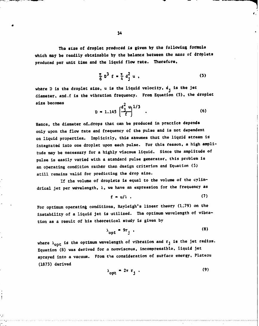
The e_ze of droplet prod.cad ls siren by the foll_ing formula
which may be readily obtainable by the balance between the mass of dropXets
produced per unit time and the Liquid flow rate. Therefore,
_ D3 "_ 2e dj u , (5)
where D is the droplet size, u is the liquid velocity, dj is the Jetdiameter, and.f is the vibration frequency. From Equation (5), the droplet
size becomes
D- 1.145 . (e)
Hence, the diameter o__drops chat can be produced in practice depends
only upon the flow _ate and frequency of the pulse arid is not dependent
on liquid properties. Implicitly, this assumes that the liquid stream is
integrated into one droplet upon each pulse. For chls reason, a high ampli-
tude may be necessary for a highly viscous liquid. Since the amplitude of
pulse is easily varied with a standard pulse generator, thls problem is
an operatfns condition rather than design criterion and Equation (5)
still remains valid £or predicting the drop size.
If the volume of droplets is equal to the volume of the cylin-
drical Jet per wavelength, _, we have an expression for the frequency as
f - u/_ . (7)
For opt_num operating conditions, Rayletsh's Linear theory (L'79) on the
instability of a liquid Jet is utilized. The optimum wavelength of vibra-
tion as a result of his theoretical study is given by
'_opc a 9rj , (8)
where _opC iS the optimum wavelength og vibration and rj is the Jet radius.Equation (8) was derived for a nonviscous, incompressible, liquid Jet
sprayed into a vacuum. From t_le consideration of surface energy, Plateau
(1873) derived
_opt m 2_ rj . (9)
00000001-TSD01

Schneider and 8ev_rtcks (1964) experimentally determined that monodisperse
sprays can be produced in the wavelength range of
7rj < _ < 14rj .
Berglund and Liu (1973) also found a similar range of wavelength chat can
produce uniform droplets as shown in Figure 10. P,aJagopalan and Tien (1973)
experimentally found that there is always a Certain minimum threshold
frequency required below which no uniform droplets were foraed and above
which unifocm droplets were produced. For a high viscosity liquid, they
found the threshold frequency to be
fth = 0"7lope ' (i0)
and for low viscosity liquid,
fth = 0"4fopt ' (ii)
where fch is the threshold frequency. They also found that mnpllcude of
dlscurbance has very little effect on the production of monodisperse drop-
lets. This can also be shown in Figure i0 in which uniform droplets can be
generated over an amplitude of several orders of magnitude while the opti-
mamwavelensch range is very. narrow.
_igure ll Sunmarizes the drop size range chac could be covered
by the periodic vibration technique showing that essentially a _ide range
of drop sizes has been already ex_erimentally demonstrated. It is important
to note in the figure that drop sizes smaller than about 50 um can be best
produced using an eleccrostrictive transducer such as piezoelectric crystal._
A periodic acoustic sisnal produced with a sound-speaker type vibration is
well suited for producing drops larger than 50 am. Of course, these two
dis¢inccively Separate ranges are due co the difference in the vibration
frequency which in turn determines the drop size.
The flow rate obtained in the atomization using a periodic vibra-
tion of a liquid Jet or a liquid reservoir is extremely low. For example,
a combination of frequency, 700 kHz, and drop size, 10 _m, yields a flow
rate of only 0.022 cc/min and a combination of 10 kHz and 200 um results
00000001-TSD02

_oo, I ', I I I2 3 4 5 6 ? 8
X/dj
FXGUP_i0. PERFO_L_ICEREGII_S FOR VIBRATINGORIFICESPRAYER(Berglund and Liu, 1973)
!
00000001-TSD03

37
Drop Size, _m
Inves _tsators 10.. 100 1000
PIEZOELECTRICCRYSTALS I70-700 kHz
Berglund and L£u (1973) ' '
20-._00 kHz
St:r_m(1969) I I i
2-20 kHz
Fulwyler, ec al. (1973) , l
ACOUSTIC SIGNAL ), 0.3-2 kHz
Dabora (1967) ' '
_0.4 kH_
Magarvey and Taylor (1956)
0.3-30 kHzLindbald _nd Schneider (1965) , !
9-11kHz
Erln and Hendrlcks (1968) JI
FIGURE 11. RANGEOF AVERAGEDROP SIZES COVEREDBY SPRAYERS USINGVARIOUS PERIODIC JET VIBRATION FREQUENCIES
00000001-TSD04
38
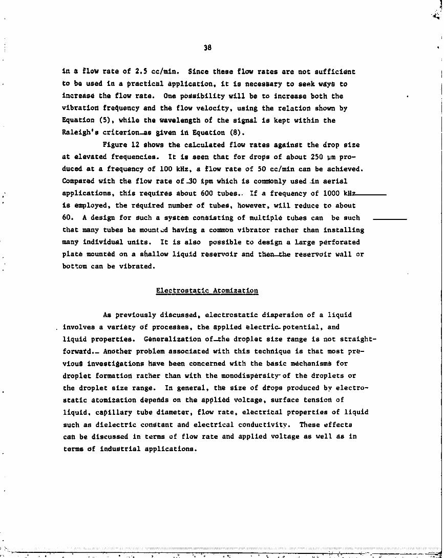
in a flow rate of 2.5 cc/m£n. Since these flow rates are not sufficient
to be used in a practical application, it is necessary to seek ways to
increase the flow rate. One possibility will be to increase both the
vibration frequency and thQ flow velocity, using the relation shown by
Equation (5), while the wavelength of the signal is kept within the
Raleigh's crlterlon_as given in Equation (8).
Figure 12 shows the calculated flow rates against the drop size
at elevated frequencies. It is seen that for drops of about 250 _m pro-
duced at a frequency of i00 kHz, a flow rate of 50 cc/mln can be achieved.
Compared with the flow rate of_30 gpmwhlch is commonly used in aerlal
applications, this requires about 600 tubes. If a frequency of i000 kH7
is employed, the required number of tubes, however, will reduce to about
60. A design for such a system consisting of multiple tubes can be such
that many tubes he mount_ having a common vibrator rather than installlng
many individual units. It is also possible to design a Large perforated
plate mounted on a shallow llquld reservoir and t_e_ _he reservoir wall or
bottom can be vibrated.
Electrostatic Atomization
As previously discussed, electrostatic dispersion of a liquid
involves a variety of processes, the applied electri_ potential, and
liquid properties. Generalization of-_he droplet size _ange is not straight-
forward._ Another problem associated with this technique is that most pre-
vious investigations have been concerned with the basic mechanisms for
droplet formatio_ rather than with the monodisp_rsity-of the droplets or
the droplet size range. In general, the size of d_ops produced by electro-
static atomization depegds on the applied voltage, surface tensiofl of
liquid, capillary tube diameter, flow rate, electrical p_operties of liquid
such as dielectric constant and electrical conductivity. These effects
can be discussed in terms of flow rate and applied voltage as well as in
terms of industrial applications.
_" ......... o o o _3 ,,o'o .... _.-,-o--,- ::
. ........... ,.. , ,,° ..... " " ".............. 00000001-T 'SD05

4O
The electrostatic a_omization methods commonly used in the elec-
trostatic painting industries uses the painting surface aS one electrode, and
involve a relatively high liquid flo_ rate wich_ high voltage. _low rates
up co about 1 gal./mln, can be sprayed using voltages of up to 100kv. The
liquid iS generally pressurlzedand fed into the atomizer. Droplet size dis-
tribution Of the Sprays produced under these conditions are rather broadly
dispersed, although no quantitative experimental data are available.
When the liquid is fed into the nozzle at the atmospheric pres-
sure, the liquid flow rate is usually very much smaller than that dis-
cussed above. The typical voltage required in this case is on the order
o£ 10 kv. This process, however, produces a wide range of the average
droplet Size between 0.1 to 1000 _m in diameter and their disperstty is
known to be relatively narrow as confirmed by a high order Tyndall Spectra.
This type of atomizing method has been widely adopted for most laboratory
research.
In mlcroelectronlc circuit Industrlas, a similar t_chnlque is
used. In general, the liquid mat_rlals, or often times molten metals,
are sprayed onto circuit board under vacuum conditions. The llquid flow
rate is extremely small, ranging only up to 4 cm3/hr. The applied voltage
is typlcally about i0 kv. The reported droplet size ranges from 300 to
600 _m in diameter (Bolllnl, et al., 1975) with no available information
on th_monodlspersity.
For a theoretical_nalySlS, Zeleny (1914) calculated the electro-
static pressure exerted by a liquid. For a spherical drop, he gave an
equilibrium _quation of various pressures as
2o V2
F p"P ' (12)8_rp
where V is the applied voltaSe, rp is the droplet radius, o is the surfacetensio_ of the droplet, and P is the excess pressur_ inside the droplet.
As the electric voltage increases, an equilibrium nO longer exists.
Although calculation of the exact number of electrical charges in terms
of the applied voltage is complicated due to the nonspherical shape of the
......... 00000001 -TSD07

Fii
41
r
• droplec aC Che end of che tip, Zeleny said _nsCa_iltcy Cakes place when
che follow,aS condtCiou is meC: V2 - Crp_; where c is a consCauc depending! on the shape of the droplet. Thus, if the electric volcaSe becomes exces-i
i-" siva, the liquid surface starts disintegrating.Later, Vonneguc and Neubauer (1952) predicted the _ollow_ns
particle size by considerinS the balance between the electrical energy and
the surface energy, si_Llar co Equation (12):
i= rgk_kq! li/3_:i_ D- aL4_ q2J ' (131
I where q is the coral number of electrical charSes, q is the volu_e of-the
!_ liquid reseZ_roir, and k is a constant. The number of p_rticles produced,
n, was given by_ 2n - _9.__ (14)
i_ 3kVo "
i Although E_uaClons (13) and (14) are one step above Zeleny's analysis,ib they still contain an ad_ustlng constant, k. Further, these equaclons!
have noC been experimentally verified.
Due Co relaClvely few quantitative studies and lack of compre-
ss. hensive understanding of the basic principle, Ic is rather dlfficul£ at
present Co assess the flow rate chat can be achieved. For a reasonably,_
monodiSperSe spray, the flow race should be maintained aC an _xCremely
b-i, small _ate and a scale-up for such devices can pose some difficulties.
Another drawback of chls technlque le that both the operations and charac-
teristics o£ the produced sprays are slgnlflcantly dependent on the elec-
•_ Crlcal property o£ the liquid. AS already discussed, some orSanlc materials
_ such as benzene which is currently used a_ a carrier _or aerial appllca-
_-_i: Cton, cannot be dispersed into drops• No further consideracionwill be
given Co this technique _or these reasons.ze
| ,,
iI
} ..
"---'-' • • "i'-'._-_-._._-
.................... 00000001-TSDO8

Ultrasonic Atomization
Sprays produced based on the principle of ultrasonic atomize-
tion technique seem to attain a relatively narrow dispersity, although it
might be less satisfactory than chat provided by the vibrating tube method.
For example, Lens (1962) stated that 90 percent of the droplets produced
were smaller than twice the average size. Compared to the present criterion
that the size of 95 percent of the drofo should be smaller than 1.2 times
the average size, the quality of sprays quoted by Lens is not quite saris-
factory. One way to measure the dispersity of droplet size is to plot the
cumulative percent against the drop size. Figure 13 shows the size distri-
butions of the sprays produced by Doyle, et al. (1967), using the ultrasonic
atomization technique. Based on the original size distributionS, the geome-
tric standard devlaCions for these sprays have been calculated and included
in the figure. The following equation has been used for this calculation:
D84% V50 Z [D84z] 1/2as -- - -- = (15)" D50% DI6X _D-_6ZJ
where
J = the geometric standard deviationS
DiZ = the drop size below which there are i percent ofthe coral drops on a weight basis.
For a theoretical prediction-for the droplet size, Peskin and
Raco (1963) found chac the acoustic atomization process can be governed
by several nondimensional parameters. Figure 14 gives the droplet size
in te_ms of transducer amplitude a, frequency _o, liquid film thickness h,
surface tension o, and fluid d_flsity 0. The drop size is seen to be a
function of frequency and the film thicknass. For high frequencies, the
drop size becomes a function of film thickness as shown in Figure 15. For
large film thickness, their analytical result reduces Co
,, 3. 2.1/3D = _ o/0_ o) • (16)
...... ': ........... 00000001-TSD09
_
I , ! , If i ,I,IlO 20 30 40 50 60 80 I00 200
DropSize, F.m
FIGURE 13. SIZE DISTRIBUTION OF THE SPRAYS PRODUCED
_¥ ULTRASONIC ATOMIZATION TECHNIQUE
ooooo0ol-TsDI-O

i 4_,'
_ 44
t:
_-_g_
)
_. .50 h/a = 2.00, .40t = .go.;*:; .30 h/a = .40•!';" h/n = .20
t=
•:. = .20 h/a = • I0"' h/a = .06
_. _"O= .05
' In i ,ii v
':' tO I00 I000
•_" 2a3.,':,: p_ /20
,;%
_ FIGURE 14. RELATIONSHIPBET_EENTHE NONDIMENSIONAL_ GROUPS IN ULTRASONIC ATOMIZATION (Peskln and Raco, 1963)
!i.: , ,
• ._. 40
i:'!_':' _0 #'w2°a3:_'. • > I000-"_' _ 2 _ '
_;: _.2 0
o_
: .I 0
_.;. 0 ' ' •,_!. 0 0.5 :1.0_, h/a.L'
....' FIGURE 15. DROP SIZE AS A FUNCTIONOF FILM THICKNESS_,. (Peskinand Raco, 1963)
•.. 'D
O0000001-TSD11
45
• &1though She relationship 8ivan ia Figures 14 and 15 has not been
ex_erimentally proven, Equation (16) has been confirmed by ma_y experi_ental
studies such as Lens (1962) and Crawford (1955). For a large value of
_a3/2o, Equation (16) is further approximat_d by
V - 0.42 _a . (17)
A wide eange of the average size has teen experime_tally covered
using the ultrasonic atomtza=ion technique. Figure 16 summarizes the drop
size range covered by various investigators. The operating frequency used
in the studies ranged from lO to 2000 kHz. It can be concluded that the
ultrasonic atomization carl cover the low size range of the drops currently
used in agricultural aviation applications.
Ultrasonic atomizers can, however, handle a relatively small
amount of liquid primarily due to the low amplitude of oscillations that
ultrasonic transducers ge_erate. A typical value for the maximum liquid
flow rate for an ultrasonic atomize_ currently in use iS about 1 gph. The
corresponding frequency in this type of atomizer is typically 40 kHz. One
way to increase the flow rate is to combine the principle of ultrasonic
atomization with that for the whistle type atomization as employed for some
industrial purposes. Thus, the amplitude of signals produced initially
by ultrasonic transducers is further amplified due to the resonant effects
created by the hollow space of the horn shape. While this design allows
the capacity to be increased substantially, it will restrict the operating
frequency of the transducer to ofle value. Since the d_op size produced
using ultrasonic atomizers is dependent upon the transducer frequency as
showfl in Equation (16), this arrangement is restricted to producing one
drop size. Obviously, a series of different sets are necessary to cover
the required size range.
Another way to increase the flow rate is again to install many
atomizers in parallel. It is, ho_,_ver, expected that there would be
mutual interference effects of oscillations produced by these transducers.
Since this interference can produce an unwanted spray of polydisperse
drops, it might be necessary to install a transducer in a separate chamber.
00000001-TSD12

46
Investisators 1 10..100 1000
Nilcox and Tare (1965) --=--==--=_
i- Crawford (1955) ------
An_onevlch (1959) ,,
Lang (1962) .....0
Bisa, e_ al. (1954) ......
McCubbin (1953) ---
Top_ (1973)
' Muroms_ev and ,i_ Nenashev (1960) "=
FIGURE 16. RANGE OF DROP SIZES COVERED BY VARIOUS STUDIESEMPLOYING AN ULTRASONIC ATOMIZER
!-/
i
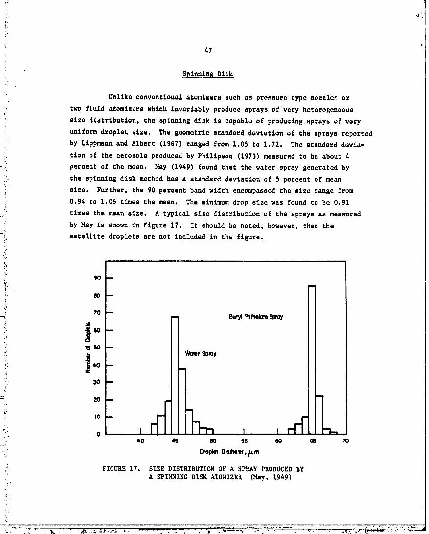
/
¢ _7"i
/,i
.' Unlike conventional agomizer_ such as pressure typ_ nozzle_ or
two fluid atomizers which invariably produce sprays of very heterogeneous
Size 41strlbut_on, the splnnlng dlsk is capable of producing sprays og very
uniform droplet size. The geometric standard deviation off the sprays reported
by Lippmann and Albert (1967) ranged from 1.05 to 1.72. The standard devla-
;. tlon of the aerosols produced by Phillpson (1973) measured to be about 4
_ 0ercent of the mean. _y (1949) found that the water spray generated by
i: the spinning disk method has a standard deviation off 5 percent of mean
2 size. Further, the 90 percent band width encompassed the size range _rom
_ 0.94 to 1.06 times the mean. The minimum drop size was found to be 0.91
times the mean size. A typical size distribution of the sprays as measured
by May is shown in Figure 17. It should be noted, however, that the
i, satellite droplets are not included in the figure.
i. W --
.'_, ?O ---_., - Butyl"_tl_lateSWay
_: 40 --mm
;. I0
=_ o I , I , I
- _ Oro_etOlamel_',Fm
,: FIGURE 17. SIZE DISTRIBUTION OF A SPRAY PRODUCED BYA SPINNING DISK ATOMIZE_ (May_ 1949)
O0000001-TSD14
48
For the size range and the operating conditions of the spifintng
disk method, a welL-eseablished correlation exiscs. Assuming the disk is
uniformly wetted, the liquid flows as a thid film from the center o5 the
disk to the edge and accumn_ates until the centrifugal force of the liquid
becomes equal to the attraction force due to surface tension.
The centrifugal force, F, is
v2 = m_ 2_" * m T , (18)wh_re
It
m = the mass of aAroplet (= _0D 3)
R = the disk radius
G = the-angular velocity of the disk.
The attraction force is proportional to the surface tension. Therefore,
F - koD , (19)
where k is a constant to be experimentally determined. From Equations (18)
and (19), the drop size can ba written as
k (20)D=_,
Various investigators determined experimentally the proportion-
ality constant appearing in Equation (20). For e._ample, Walton and Prewett
(1949) found that uniformly sized droplets can he successfully produced in
the range of
< _D(_-_)1/2""- < _.44 ,2.67
and Philipson (1972) gave
< QD(2o-_)1/2 < 3.06 .2.64
Equation (20) indicates that the droplet size ca_ be varied by using a
different di_k size or by altering the rotational speed. For obvious
convenience, the latter method is commonly used to vary the droplet size.
Results from several of the available experimental studies are
summarized in Table 5. Amo_tg these experimental investigations, Nalt_,n ano
Prewett experimentally cover the widest range of droplet diameters, rh_
average droplet diameters in their experiments ranged from 180 to ]000 _,
- - 00000001-TSE01
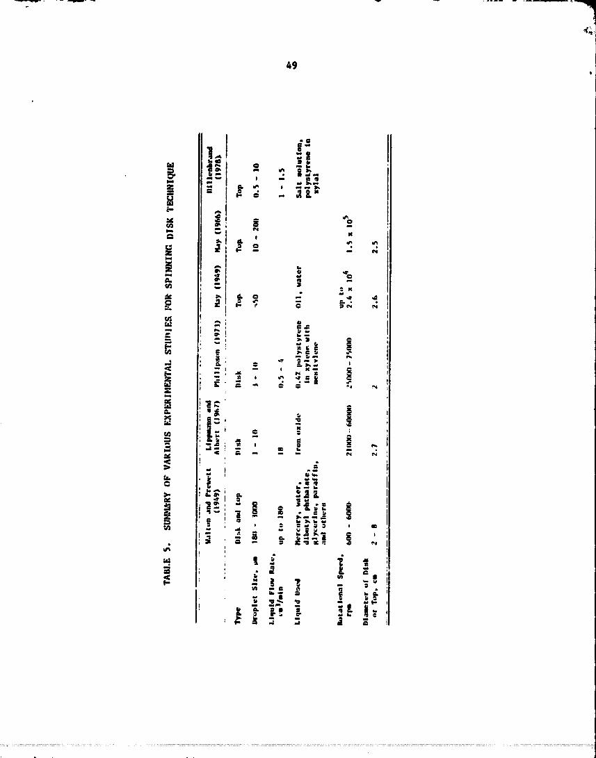
49
-a
1,, i_
"_ _o• ,4
x
= ",
"#. t
m I_ m ,,u ---
ii I,..! ! _.o
00000001-TSE02

: SO
w£ch the splnn£n8 disk diam_ter _ansinS from 2 co 8 ¢m. The rocac£onal
speed was var£ed between 600 to 4000 rp_. The ranges of the liqu£d proper-
ties tested were: viscos£cy, from 0.01 to 15 po£se; density, _rom 0.9 co
13.6 g/cm3; and surface cens£on, 20 to 450 dyne/cm, He also studied experi-
menCally the performance o5 a spinning cop of 3 c_ £n diameter. A droplet
s£ze range of 10 co 100 _m was produced. May (1949) studied the spinning
top onto which a pressurized-liquid was fed.-- The liqu£d._he adopted were
water and oil. The mean drople¢ size as _ function of the air.pressure
for his atomizer £s shown in Figure 18. The size of the cop was about
1 inch___n diameter and the ro_aCional speed, wa.s.-ap.proxtmately 4000 rps.
2OO 2O0
_OWMer
IO0 leo
_- Olll
..
I0 I0
FIGURE 18. PERFORMANCE CURVES FOR SPINNING TOP ATOMIZER(May, 1949)
O0000001-TSE03
• t= ,
_ • The Liquid flow tare onto the disk shoold be kept r_lactVely
=_ lc.a. When an excessive amount of liquid is attempted co be fed. the fluid
£_erc£a force beGomes important, caus£ns the liquid leaving the edge in
-_: the form of a thin sheet. This sheet of liquid later breaks up into
ill!! various sized droplets, thus. eesult£ng in the unwanted _tde size distribu-
=.!" rich. Assuming chat flow rate _an be increased proportional to the square
_" Of the rad£us, a disk diameter o5 50 inches would be necessary to meec-C :.,_,.
i; the required flow rate of about 30 _pm. Since no syste_atic studies have
been made _or the actual performance of such a large scale spinning disk
ato_zer, various operating conditions and quality of the produced spray
=i. have to be evaluated. Another way to increase the capacity is to design5)i!-;._., a system of stacked spinners hav£_g a relatively large diameter. As pre-
_. viouSly discussed, one problem which seems co occur most often with
_:" spinning disks is the production o_ unwanted satellite droplets. Alch_ugh
arrangement of a Secondary .flow can eliminate these droplets co a certain _
-_:. extent, iC might be difficult co design such a secondary flow-chat could
_: operate properly under the variable wind conditions caused by the aircraft
_ speed.
i:
;:i_' Vaporization-Condensation Technique
i" If well controlled on a small scale, the vaporlzatlan-condensacion
technique provides a moderately monodisperse spray whose geo_ecric standardo '
_:_ deviation.ranges from about 1.2 co 1.8 (Le_, 1978). However, it is
4. expected chac the drop size discribu£ion of the sprays produced by this
'!. type of Cechntqu_ would strongly depend upon the chemical composition of
=_'_o_ the liquid.- Therefore, the above estimations might be different from
:_'_ liquid to liqgld. -
::_: Theoretically, the mean size of the droplet produced by the con-
densacion method is prtmerily deter_ined by the condensation race which,
_n Cur_, is controlled by the vapor velocity and the liquid-_ir ratio.
When the vapo_ Jet emerges into ambient air, a large amoOnt of air is drawn
into the Jet. At the sa_e time, turbulence causes the vapor to be _txed
.. rapidly with the air. Thus, the mixing zone of the vapor and air is formed
e
.... O000000-TSE04

52
where the vapor condenses on nucle_whi_h proceed to grow inco drop_ecs.
As the discance from the nozzle increasea° che droplecs encounter more
air and the vapor pressure decreases until che $rowch rate of the droplecs
iS n_slisible. Theoretical prediction of the drop size has already been
siren by Equacion (1). Since che sprays produced by this cechnique are
based on condenaacion of_material on nuclei, the size-ccLChe drop is
r_ther dif_cul_ co concrol. In general, the number o_ nuclei, vapor t_m- m
peraCure and pressure, and-flow races of vapor and admixed a_r musc be
carefully controlled. In addition, che resulting spray drop sizes sen-
erally _re less chan__t__m. For these reasons, nO furcher consideracion
will be given-Co this-technique.
00000001-TSE05
53
COMPARISON07 VARIOUS2XIST G TEC IqUES
Based on the information and discussions from the three previous
sections, the techniques which could be further developed into the un£c
for agricultural-aviation application are now Co'be raced. Table 6 sum-
marizes the advantages and li_Ltacions of the techniques with respect co
their ability to produce a monod£sper_e spray, to cover the required range
of drop size, to accommodate various liquid properties, and to achieve
sufficient flow races. In order to compare these techniques more compre-
hensively, the requirements for the spraying nozzle that is to be developed
! are llsced in Table 7. Since not_all the requirements are of equal impoT-
tance, welghCins factors or priority levels have been assigned to each
requirement with the maximum value of 3 points being given co the most im-
portant requirement. It should be noted that the impor.tancelevels shown
in the table are those which are assigned for the purpgse of the current
_, dev_lop_ent program and drop size dlstrlbuCion parameters such as mono-
-- dlspersity, average drop size and flow rate age the factors which have
been chose_ for comparing atomization techniques. Some of the require-
ments dlscus_ed previously have been omitted since they are not considered
,_i, important for the--present evaluation purpose.
Table 7 is now applied to the candidate techniques. FoT this
purpose, Table 8 ha_ been prepared using the current state of the art of
each technique using A, B, and C. Thus, A indicates the technique
already capable of achieving the nequirement, while C i_dlcaces that the
Item should be furthe_ extended for the final version of nozzles. Then,
., each of the levels ha_ been multiplied by the _eighting point. This
product is shown in parentheses. For this purpose, A has been given 3
" polnCS, B 2 points, and C 1 point. Finally, these points have been summed
for each technique.
Depending upon the priority levels of each requirement, the
results shown in Table 8 can be altered somewhat. However, it is inter-
esting to note that periodic dlsperslofl of llquld Jet and spinning disk
have shown about the same probability to be extended to the prototype
design with ultrasonlc atomlzaClon technique following closely. Electro-
static atomization and vaporlzdtlon-condensatlon technique are, however,
,, found not to be adequate for further consideration.
O000000 -TSE06

54

TABLE7. LISTOFUQUIR_NTS FORSPRAYINGNOZZLESA_DTHEIRPRIORITYLEVEL
i|
Requir_ments Weighcin_ Point*
Capability of achieving a goodmonodispersity of sprayed drops 3
Ability to produce the requiredrange of average drop size 2
Probability Of extending the liquid
application rate 2
Ability to accommodate the currentran__of liquid properties 2.
* Key: 3 -- high importance2 -- medium importance
1 -- low importance
Weighting point may or may not coincide wlth the
intrinsic requirements for spraylnE nozzles.
L
TABLE 8. EVALUATIONOF VARIOUS SPRAYING TECHNIQUES
Periodic SpinntnsRequir___ent Vibratioh ElectrOstatic Ultrasonic Disk Vaporiution-
(Weishtins Points) of Liquid Acomlzatioo Atomization Method Condensation
Monodispersity (3) &*(9) 8 (6) S (6) B (6) B (6)
Ranse of Drop Size (2) A (6) B (4) B (&) A (6) C (2)
Application P_tte (2) C (2) C (2) 9 (4) S (4) A (6)
i_snse of LiquidPropertied (2) A (6) C (2) A (6) A (6) C (2)
TOTALS 23 14 20 22 16
* Keys k-- 3 points; B--2 points; C-- 1 point.
00000001-TSEO8

,,+,
_+o,,
,?, 56
..,:., _ CANDZDATE TECHNZ_E$
, As a £t_st step to generating a new means for producing a mono-
2 disperse spray, various possible approaches were _tudied. As reported in
j: previous sections, there are many spraying principles and techniques which
_ have been used in areas of pa__nt spraying, mass spectroscopy, combustion,.,.
_. app.ltcation and basic spray and aerosol research. The most pram/singt
f_. techniques were ide£_fied to be those based on periodic vibration of
=_' liquid Jet, spinning disk or top, ultrasonic atomization and electrostatic
+_" atomization. These techniques were _f_und to be very e£fectiv_mnd_appearedS"_, promising for refinement, modiffication and development into forms suitable
;_ for agricultural aviation purposes in terms of the range of average drop
_" size, monodisperslty and ability to operate over a range of liquid pro-_;,r
_} perti_S. However, since major e_phasis of the Second phase of the present
_. program was to be given to untried concepts rather than refinement of the
.+_r above existing principles, it was decided that these techniques were not
to be pursued any further under this study, Therefore, some additional
:++ techniques or principles that had not been investigated in laboratory_
_:o_+_ studies were first generated._.Among the generated ideas which emerged as
_,. a result of this pursuit, pertinent ones are briefly discussed below._
:_ As will be stated later, three of the following ideas were further analyzed
_. ffor _onceptual designs:.... ?:,
I (i) Centrifuge type chamber Polydisperse spray p_o-_, •°,. duced by a conventional atomizer can be passed,:_ through a centrifuge type chamber such that large
=_: drops leave the chamber exit from the outer part-_ while small drops leave frOa the center. If only
_: those drops from an intermediate annular section+:, are allowed to leave the exit and the remaining_" excessively large and small drops ate recirculated,P' a spray of uniform drops would result.!
_2) Atomization by two opposing alr-llquld Jets. By_i operating two twin fluid nozzles placed in opposl-_:" tion, liquid drops are allowed to experience a}_: sudden accelerated or decelerated flow as they pass: through shock waves set up in a tuned interspace.
-++ .......... - ....... ,i; /+ ..................................................................................................................................................................................+NNNNNNNJ-T. na

57
• Since acceleration of the droplets depends on chel_sized large drops vould So chroush more sta_eu of
breakup than small d_oplets. Based on this prin-ciple, the droplets leavins radially from the twoopposed nozzles become relatively uniform i_ size.
(3) Spinntns disk coupled with an ultrasonic field.
In order to overcome the intrinsic problem of lowcapacity associated with a spinning disk, cup, coneor similar shape, it was proposed that a spinningdisk be operated ac a high flow race and then anultrasonic field be imposed on the fluid sheet toconvert the fluid sheet into droplets of uuiforttl
(4) Rocket nozzle chamber. A rocket shaped combustionchamber has natural spinning acoustic modes. Al-though +quiva_enC modes can be generated iu smallchambers o_ a similar shape, the frequency in that
case would become very high. One alternative Wayis Co make use of the flow itself to chop liquidJets as they emerge into the chamber. A modifiedfluidic device could be employed in place of a_combustion process co drive such a system.
(5) Frozen particles. Another somewhat unusual but
interesting idea that came up during the study isthe possibillty of converting the llquldmaterlalinto the solid form whlch is more convenlenc for
producing nnifo_npartlcles. By initially freezingthe llquldmacerlal of interest Into the form of
fine solid parClcles and then separating those
solid particles into an arrow size range using anappropriate method, a Spray of uniform sized frozen
partlclesmay be obtained.
Other ideas included a rotatlnE brush, rotating wheels, atomization using
a vortex flow and periodic vibration using sawtooth wave.
As revealed in the first phase of fiheprogram, one of the most
important requirements for asrlcultural spray nozzles is the ability to
produce a monodlsperse spray. Preferably the produced spray would be such
that only 5 percent by weight of the drops are larger than a maximu_ size
and only 5 percent small_r than a minimum size, where the maximum and
" mifllm_m are defined respectively as 1.2 and 0.80 times the average diameter.
Secondly, the nozzle Should produce sprays over the size range currently
O0000001-TSEIO

• ,' tl
_ employed for aerial applications. This range was found to be be_aeen 25
and 500 Um. AlSo, the nozzle should perform sati_factorily over the range
_i of liquid propertie_ currently used in agricultural applications. Ranges
uf the liquid properties are: density, from 0.8 to 1.25 g/cm3; viscosity,
_* from 0.3 to 500 cent£poise; and turface tension, from 20 to 80 dyne/cm.
_' Finally, the designed nozzle shouldbe capable of covering the range of
liquid flow rates, 5 to 50 _pm (80 to 800 gph) as discussed in a previous
i section.
The priority level for each of these requirements was already
}i' discussed.
_' Con$idering the above performance requirements, the first three_______
_!i' of the generated ideas were pursued further. Conceptual designs using(/
.... each of these prln_£ples are described subsequently.j,!
[ ,,
_,, Centrifuge Type Chamber,,,,,,. •
i_._' In the presence of centrifugal forcO, drops of different sizes
_ move to the radial direction according to their size. Due to the dependence
_' of the centrifugal force on the drop mass, large drops tend to move rapidly
_, in the radial direction compared to small drops. Thus, if a polydlsperSe
i-_, spray is Subject to a flow having a swirling motion, it is possible to
_" distribute the drops in different radial positlons as a function of its
ii, slze. I_hile numerous devices guch as centrifuges and cyclones have been
i developed using a similar principle for removing particulates or measuring_'r the size distribution of a__spray,this technique has not been used for
r', producing a monodisperSe spray.
_i'*'" If the excessively large and small drops among the drops dis-
_ trlbut_d at a cross section can be removed, a spray of uniformly sized
_*" drops can be obtained. This section describes a conceptual design for
::_ such a nozzle.
//
i /.,
?
O0000001-TSEll

Background
An initially polydisperee spray consisting of large and fine
drops is introduced into a section near the axis in a Cube in which a
swirling flow is created by a rotor, as illustrated in Figure 19. Swirls
can also be created by introducing the clean air radially. Thus, large
drops are forced co the periphery of the cube while fine drops which are
relatively little affected by the centrifugal force remain more or less in
the center. By allowing the drops from an intermediate annular section to
leave the exic and the renminins excessively large and small drops co be
:_ re_irculated, a spray of uniform drops would result.
_. SWirling flows are a very complex phenomenon and it is rather
': difficult to perform an exact calculatlon of drop trajectories in such a
flow. However, if some si_npllfyingassumptions are made, as in the case
of cyclones (Fuchs, 1964), iC is possible to derive an analytlc expression
which can serve as a basis for the conceptual design for producing a mono-r
_. disperse spray.
The motion of a drop in a Swirling flow is subject to the
following centrifugal force:
_ii_ £-m v2 _- v2_' r =60d3- r (21)_, where
': f - Centrifugal force in the radlal direction
m - mass of the drop
v = tangentlal velocity of the swirllng flow
r = radial .positionof the drop
,, 0 " drop density
:: d - drop diameter.
_'_, The spray drop under this force then tends co move radially at such a
velocity chat the resistance due to the drag force becomes equal co this
centrifugal force. According Co the Stokes law, the resistance of a drop; is expressed as follows:
.i: f " 3_du r (22)
O0000001-TSE12

"i. ¸ o ._ o .°_ ° ,_'__, o ...................... . r"==,_,._- o':
O00000'bi-TSE13

w_ere
W _ ga_ visco_ity
ur - radial velocity of _ha drop (- dr/d_)
tet_.
For a tangential velocity distzibution of a swirling flow in a tube, the
following simple axpression, given previously by Shepherd and Lapple (1939)
is used hera z
v = kuo ¢E7_ (23)where
k = proportionality constant
uo incoming flow velocity
R = tube radius.
Balaucing the forces given by Equations (21) and (22), after substituting
Equation (23) into Equation (21) we have the following differential equation:
dt = 18Fr 2 dr .k2d2 2pu o R
i.
Subsequently, we integrate the above equation with an Inlclal condition of!,
__ r-0 at t=0 and obtain
_--'! r3" t = 6 F , (24)22 2 '
_.._ k d PUoR
If the drop is swirled S times within the air flow (schematically shown in
Figure 20) during the period of time, the t_tal travel distance can be
approximately assumed to be wrS. It should be noticed that half of r was
used to calculate the distance. The average tangentlal velocity of the
drop is estimated to be v(r/2) in a similar f_shion. Therefore we have
_rS _rS/_
t - v(_--WW= ,_kUo,_" (2s),|
ii where S is the number of swirls.
El_ninating t from Equations (24) and (25) we have an expte_sipn
• for drop size:
i
Ti"
oO ..... O0000001-TSE14

7: .__ If 1 ,
62 "

63
rk
Equation 126) represents the drop size in terms of the radial position,
gas properties, man of the drop a_d operating velocity. There are
several Interesting points co be noted In Equation (26) as follows. Drop
size_ are found to be distributed nearly proportional co the radial posi-
tion (i.e., d_,rO.7$). Further, the deri_ed correlation equation does
ll[ predict the depenee_cy of the average drop size upon the device dimension --
R aad the flma characteristics Such as air velocity Uo and the number of
swirls inSide the cube, $.
It should be pointed out that instead of. us£ng the number of
swirls, S, Included In Equation 125), one can also utilize the chamber'r
i. length, L. In chat case, the flow residence rime in the chamber becomes
LIe, where w is the axial floe velocity. In general, the axial velocity
In a _irling flma decreases with an increasing radial position. ThuS,
_ the calculation results for this residence time would also yield an expres-
sion similar Co Equation (2.5) In thac the time spent by a drop Increases
with the Increasing radial distance it travels. Thus, the chamber length,
iI which i9 considered to be a more explicit design parameter, can replace
the number of m_irls If an analytic expression for the axial flow In a
swirl flow is known.
Conceptual Design
Before incorporating the derived Equation (26) into a conceptual
i desIsn, several assumptions that have been employed in the foregoinganalysis should be noted. In order to sacisfy an assumpclon of a point
liquid Source at the inlet aS implicitly _mployed in the analysis. It is
desirable to introduce a liquid Jet through a small nozzle near the axis.i
Ic is anticipated chaca very uniform and Idealized swirling flow pattern
f_ In a real device may also be difficult to achieve. OCher condideractonsCo be given in the design include chac the flow upstream of the S_irler be
p_ kept close co a laminar flow _o avoid any turbulence effects which would
..... 00000001 TSF02

64
25Ok=0.5
uo = 10 cmlsec
2O0 R= 15 cmS=3
........ 12din. .......
IE IS0 I
Imb 1 1 qmb 1 dm4m_ 1
!---o.8 d.T--- o
i I00 I
III o
I II
I I I----_ I I J
50 I 0"74 rm rm 1"28 rmI Io I
ml I I I
I I i I 000 _ I0 __ 15
Radial Posilion,cm
FIGURE21. CALCULATEDDROPSIZE DISTRIBUTIO,_ALONG_I&L DIRECTIO._AT EXIT
" " ....... i_ " i mll lm i n f ........ ...................... -........
00000001-TSF03
rT i ,1
65
' • interfere wJ.th the CraJeccory of drops. As _d.ll be discussed lace_, dis-
_'. permity of the drop size distribution of the Spray will d6pend upon che
chot_:e of the annular section area from which the spray t_ ejected. For
example, i_ a very narrow annular section i_ chosen, otse _ould obtain a
good monodisperse spray, _tile a spray chosen from a relatively large
annular section would include a rather widely dispersed spray.
Based on the present principle, a prelt_aary calculation was
made using the follosrLns data co examine the drop size of the spray pro-
__ duced by the technique:
• ;. S - 3 0 i g/cm3 (water)
-. Uo " i0 c_sec _ - 1.84 x 10⁻⁴ dyne-sec/cm 2"(air).k-0.5
The calculated drop size distribution as a function of radial
__ position at the outlet is shown in Figure 21. IC iS seen chat the average
drop size ranges from 0 Co 220 _m in dimnecer. Since the range of average
drop Size Chac is currently used in agricultural aviation application is
about 25 co $00 ,m, ic is necessary co extend further the above size.
For this purpose, we can _rrice an equation predicting the maxi-
mum parCicZe slge by setting r = R in Equation (26):5
d ,, 1.643 (27)=" max OUo
_ where dmax i8 the maximum drop size. Noting chat _ and 0 in Equacio_ (27)
are the properties of air and liquid, respectively, one can increase che
cube Size it, decrease the velocity uo, or decrease the numker_of swirls S
!_. tn order co extend the maximum drop size. Using the data of S-3, o = 1 g/cc,
_ arid _ s 1.84 x 10 °4 d.vue-sec/cm 2, che dependency of the largest drop size
upoh flow velocity and cube dimension is shown in Figure 22.
Although Equation (27) can be used for a design criteria for
" extending the drop size range, the equation iS noc alone satisfaccory if
an excended flow race is co be considered simultaneously. Therefore, a
certain opti_tzation becomes necessary. Effects of tube dimension and flow
velocity on the flow race, Q, are readily avail4ble from the following
-=' equation:
00000001-TSF04
66

J
i! 67
i q ,' • (26)
Equation (28) suggests that in extending the drop size, an increase in the
tube dimensiou is more beneficial than a reduction in flow velocity.
However, such an ificrease may have to be restricted such that the resulting
Reynolds number be kept small where possible.
Despite the above discussions on optimization, the tube size ig
further restricted since an excessively large tube cannot be mounted in
an airplane. A tube radius of 30 cm is considered to be the largest dimen-
sion that can_be realistically designed. If.such a _estricted increase
in.dimension does not extend the drop size sufficiently to meet the requira-
men£, the large drop size has to be obtained by operatlnK the device at a
reduced veloclty. EfLects of--reduced velncltles and Increasad-x_menslon-
on the max_num drop diameter are shown in Figure 13.
In the present desiEn, applicatlon rate of liquid material depends
more_or lass upon the air flow rate which is determined by operating velocity
and tube radius. Since a conv6ntlonal twin fluid or llquld Jet atomizer is
to be uBed as a polydiSperse spray source and located in a position near the
center, the application problem also becomes a choice of a suitable atomi-
zer. Another consldera£1on to be given associated with the liquid applica-
tion rate is that only a portion of the liquid dlssemiflated from the
atomizer is sprayed and_ the rest of the-llquid drops which are not desiEa-
ble in si_e are recLrcula_ed. Further detailed discussion will be made
L_er.
Dis_ersion o_ drop size distribution og the spray produced by
the current design can be controlled by adJustin_ the area o_ the selected
annular cross sectio-.. The required drop si_e dispersion is such that
90 percent of the drops be within the ranBe o_ 80 percent to 120 percent
of the mean drop size. Since the dro;D size is distributed with a rela-
tion proportional to r 3/& as shown in Equation (26), the outer and inner
radii of the annular section should be (0.8) 4/3 and (1.2) _/3 times the mean
radius rm or 0.74 r m and 1.28 rm, respectively. This is illustrated in
Figures 21 and 23. However, if the incoming spray is nearly monodisperse,
the above criterion would become less restrictive.
O0000001-TSF06

..,';
=. L,o
00000001-TSF07

The only ltq_td property whlCh a_feccs size of the drops pro-
duced by the present destSn is the liquid density, as shown in Equation (26).
As d_scuSsed previously, it was known chat density o_ the commonly used _ • I •
liquid material in aSricultural aviation application causes from 0.8 to
1.25 S/cc. boring chat the drop size iS inversely proportional to the
square of the liquid density, the rather narrow density ranse of the liquid
material that is currently used does noC impose a sisnigicanc problem.
Assessment of the Desi|n
In this section, the p_oppsed desisn is assessed in terms of its
ability co cover the tense of the averase drop size, dispersion of chadrop
size distribution, app!icacion race and operactns tense of liquid properties.
Average Drop Size Ranse. As discussed p_eviously, the present
desisn concept covers a wide tense of averase droop size depending upon
suitable operatin8 conditions and device dimensionS. The parCicular design
with 20 cm radius cube would produce an averase drop diameter ransine from
0 Co 300 _m, as demonstrated in Fisure 23. _or larser dr_p sizeS, a 30 cm
device, if operaCins aC an air velocity of about 4 cm/sec, can achieve an
average drop si_e up Co 50C _m.
DisperSion of che Drop Size DiStribution. As evident in the pra-
cedtns analysis got the design, the dispersion of the drop size distribution
can be controlled by adJusCinB the annular section froawhich a liquid
spray is Co be extracted. Since drop sizes are distributed alon$ the radial
direction proportionally to r3/4, the monodispersity _equiremenc can be
Sattsgied by alloying the drops co leave an annular section whose outer and
inner radii are 0.74 rm and 1.28 rm, respectively, where rm is the radial
position f_om which drops having averase diameter, dm, leave. It should be
further noted chat dispersion of drop sizes would not vary with chanseS in flow
velocity or in liquid properties. According to the principle used in the
design, the above aeeeesmeflt is theoretically correct. It is, however,
expected that there would be some drop si_e rcsolution problem primarily
• 00000001 TSF08"%--- _' O---o-_ .................. "
" 70
-:i/ due to ex_ect+d non-ideal characteristics of a slrirling floe. Only fabrI-+.,_,,: cation and testing of the device can resolve the question regarding the
_: real dispersion of the drop size distribution.++"'_b
_ Application Rate. Although it is not known exactly how the
.. device would perform, qualitative assessment of the application rate can __
_, be made aS follows using engineering Judpent. The liquid application rate_::: Of the present devi_e depends primarily On the actual performance and opera-
'-!i; rich, such as the application rate of the primary nozzle to be used and the_: operating air veiocity. Further, the application race ts further affected
_. by the cross sectional area of the annular section at the outlet. In_": general, it.seemS Co be advantaSeous to use a liquid pressure type atomizer
'- as a primary spray SOurce due to its large capacity co.-,_ared to C_n fluid
_: ato_Lzers. Also, it i_ important to telect an atomizer or operate the atomi-
C:; zer.:Ln _uch a way Co produce a spray whose mean size closely matches the
_!_: desired drop diameter. In other words, iff a spray of r_lative_y fi_e drops '
ili, is desired to be produced using the present design, • primary ato_Lzer5, prodoclng a spray containing drops of such Size Is to be selected to
ii increase the application rat_.
_._ Liquid _operties. Due to the principle of classifying liquid
-_[ drops Co different size categories using a centrifugal force, operation of.' the present design is not affected by any liquid properties (such as liquid
_: viscosity, density and surface tension). Although operation i_ not affected
!_i: by an_ liquid properties, the average drop size is affected by the liquid
_" density, as shown in Equation (26). However, this is an operational con-
::-_", 'ditionrather than capability of the current device.
.il
-',.,.. Suggested Development Work
; Sihce the design of the centrifuge-type chamber t_ conceptual in ne-
_ Cure, and since ho supporting experimental data or performance information are
2_i available on the actual performance, it is onl.y possible to discuss q_alt-;i
tatively the feasibility of extending this principle into a real means for
._<,.' producing a monodispetse spray,
ONNNNNN1-T na
71
Although the principle a_d the theoretical analysis have been
established, one of the un_ettaintiee associated with the present concept
. is an establishment or study of a uniform swirling flow as needed. A selec-
tion of a st_ttable rotates vane or the desiSn of radially introduced air flow
create • most desirable swirling flo_ needs to be studied. In conJunctioa
with' this, the simple formula shown in Equation (23) that was used in pre-
dicting a tangential velocity distribution as a function of the radial
position must also be verified experimen_ally. The number of swirls that
has been assumed for the purpose of theoretical development in this study
is expected to vary depending upon the tube length add the type of rotating
element to be used. Again this number of swirls should be studied in con-
nection with flow patterns.
Although average drop size, range, dispersion of drop size dis-
tribution of the spray and effects of liquid properties were analytically
well established, one uncertainty in actual performance of the present
device i_ the liquid £1ow rate that can be covered. As already assessed,
a selection of suitable atomizer and detailed geo_etrlc and fluid dynamic
match e._perlmentally between the atomizer and the current design remain aS
an area of further development.
Two Opposed Liquid-Laden Air Jets
_hen t_o air-liquid Jets facing each other are operated, it is
expected that there occurs an air flow staKnation region near the center
and that flows are eventually directed radially. In addition, some insta-
bilities can be expected in the flow. If the Jets emerge from fading sur-
faces, one can expect Standing waves to be set up such that wave frequencies
are coupled with flow instabilities. As a result, liquid drops would
experience sudden decelerated and a_celerated flow while passing through
air waves. Due to the difference in their inertia, large drops unde:_Ko
more breakup stages than small drops. AS a result, the drop size distr_-
bution of the spray will be made more narrow.
This concept can be considered an extension of the Hartmann
whistle (1927,1939) or o_ another atomizer called the "Sonicore" nozzle.
O0000001-TSFIO

P2
In the Harcmann CTPe atomizer, a Jet of air ie impacted on _.. axially posi-
tioned cup. With the cup _chin the proper _anse o_ distances from the
nozzle, an incense first mode _requ_ncy is produced when the flow is sonic
at the Jet orifice. In the Sonicore nozzle (_nteruational Flame Research
Eoundatiofl, 1978), the Jet orifice is replaced w_th a conSergent-divergent
nozzle, and the liquid is injected in the direction normal to the flow
through several orifices at the nozzle throat. In the present concept, two
such nozzles are directed toward each other without a cup. It is expected that
with the proper spacing of the Jets and contour around each Jet, a sonic gen-
erator will also result which is capable of breakinB up tha-liquid spray.
Sacksr0uud
The lack o£ detailed a_alysis of this complex combination of a
sonic generation and a liquid breakup_has hindered both the use and
improvement of the design. Studies over two decades ago found no sig-
nificaflt change in spray size distribution whefl the sonic cup was filledv
in. That is, there was an indication that the sonic aspect of the nozzle
might have no effect on the spray. HoWever, in the absence of the specific
_," report ia which this widely reported study was made, it is not known to
what air pressure level the data were taken.
Khandwawala, et al. (1974) reported results on mean drop size
using the Hartmann acoustic generator to atom/ze three lisht oils, for
pressures from 2 to 5 atomoepheres and frequency from 5 to 22 k_z. There
are some questions about their final correlation since the differences in
_ density, viscosity, and surface tension were ignored. The Jet exit diame-
ter (equal to the cup diameter) was varied from 4 to 6 mm and included in
the correlation, and the fuel burette was held constant in size. Neverthe-
less, the d_pth of the cup was varied in order to vary the frequency, and
a wide range of pressures was used. The_e data showed that the Sauter mean
diameter decreased with increasing frequency to about the 1/4 power, and
de_reased with increasing absolute pressure to the 4/3 power. The range of
mean drop sizes obtained was 12 to 60 microns.
J " " " -- " 00000001-TSF11

Ii i ..t_,L ,
,_
[' 73i,i/ °
i Recent tests of a $onicore nozzle as reported by the IncerngCionalil Flame a_search Foundation (1978) using fuel otl at 9 to 19 centistokes showed
t ' the no,nelly expected type o_ drop size distr£but£on Ear gage pressures
_, of 0.28, 0.35, end 0.71 bar, with mean drop size decreasing with £ncreosin$
Ii air pressure. However, at the Sage pressure 1.41 bar the size distribution
' narrowed drastically, as £1iustrated in Figure 24. It is seen in the
_" figure chat the size distribution obtained at a pressure of 1.41 bar is
i sufficiently narrow to satisfy the requirements for an atomizer to be
i):_'' developed in this study. There appears to be a critical pressure at about
I. 1 bar beyond which the drop size distribution suddenly becomes monodisperse,
_Ii although this could not be positively ascertained.' In another recent study, _ot yet a_ailable in the open literature,_: the noise of Sonlcore nozzles Nos. 035H and 052H were determined using wateri'
il as the liquid. Up to 1.5 kilopascals, the noise output varied in a manner
!. slm41ar to that of usual Jet noise (power _ pressure3). However, when the,_. pressure_as further increased, there was a sudden break in the pressure-
! power data beyond which the noise power increased llnearlywlth pressure•
Measurements of linear mean diameter and Saucer mean diameter showed a sl8-
i: nlflcant decrease in the ratios for the two nozzles in going to the higher_L
_" pressure region. The absolute values are not considered to be significant
_! since there could be a consistent error in either underslzlng the linear
_' mean diameter or oversizing the SauCer mean diameter
_ There _ppear to be two types of mechanisms Chat can enter into
the spray production. For droplet distribution from the cross current
_ breakup of a liquid Jet of diameter d, in an airstream of velocity V, thef
following correlation _quatlon fo_ the volume median droplet diameter d30,
_ given by Ingebo and Foster (1957), is applicable for capillary wave breakup:_ -i/4,._' d30/d j - 3.9(We.Re) , (29)_, where
_' V2i,__ We - the Weber number - Ogdj /o
Re - the Reynolds number - djV/v!.
a - surface tension
pg - gas density
V - kinematic viscosity of liquid•
i:
O0000001-TSF12

74
70-- Fq
I
Ltqutd flow ,, 1.8 kg/h60 -- Viscosity • 14.2 ¢St
0 m
40--1.41 bar
30 --
2O
I0 _0I00 I000
Drol_Olometer,/zm
FIGURE 24. DROP SIZE DISTRIBUTION OF _PRA¥ PRODUCED BY SONICORE NOZZLE(International Flame Research Foundation, 1978)
O0000001-TSF13
75
• A ,ub_equon_ _udy _howed _h_ the _bove correl,_ion w_ _ill v_lld _wn in an
o_eillatory Ba_ flow at frequ_ncle_ of abou_ 100 _nd I_00 Uz provldlng the
average value of th_ ab_olut_ relatlw velocity o_ gas and drop was u_ed
(Ingebo. 1966).
If a drop sur£ace is exposed to an ultrasonic field, waves a_e
set up in _he surface. At sufflclently intense amplltudes, the waves will
peak and tear off. Tans (1962) s_udi_d high frequency (9 to 80 kHz) atomi-
zation of both ell (27 mN/m, 850 kg/m3) and water from deep pools and thin
sheets on vlbra_in8 plates. From Kelvin's equation he notes that the wave-
length, _. of capillary waves is glven by
A3 , 2_a/pf 2 , (30)
where o is the surface tension, O is the liquid density, and f is the fre-
quency of the waves. In terms of the sound generating frequency, F, we
have
13 . 8_o/oF 2 . (31)
Measurements agreed with these equations. The particle term from the wave
tips correlated wi_h
dl0 . 0.34(8_o/pF2) I/3 (32)
where dl0 is the number median drop size. Analyzing Lang's one set of size
data at 130 kHz for the mass median (50 percent mass) diameter, the constant
appearing in Equation (32) is to be 0.43 rather than 0.34. Data were pre-
sented for 13, 130, 390 and 780 kHz.
When a drop is injected into a high veloclty stream (which may
be a shock wave or an acoustic wave), the drop is shattered. Studies have
• shown that this breakup comes from the distortion of the droplet by the
drag forces, and this takes some time. Simpkins and Bales (1972) reviewed
the work in this area. They pointed out that the droplets may break up
by forming a bag-like shape at lower critical values of the Weber number
or by viscous shear effects at higher values. However, a critical time is
involved for the distortion to take place before the breakup starts. These
authors use the Bond number [Be - par2/_, where a is the acceleration and
O0000001-TSF14

76
r is the drop radius] to analyze their shock tube data. Obviously, So is
related to We through Ne_tonfs law and the drag coefficient of the drop.
They estimate the timeforonset of unstable surface waves as given by
1/2 u( 0 ) _ t = 22(_ar2/o) "1/4""
22(pU2r/1.25a) "1/4 (33)
or
; t - l_16(2r/U2) 3/4 for water ,
where r and U are in-_ and m/s, respectively. For _reakup, about three times
this time is estimate_.--On_oztunately, the drop size distribution of-the
breakup products is not reported in the literature.
The abov_ phenomenon is related to the breakup of drops ia a
sound wave. A large draplet :'_uld flatten normal to the oscillation as the
v_locity oscillated in direction abou_ the droplet. The flattened droplet
woula have waves built up in it that would result in a breakup i_ a controlled
size range.
To summarize, there is no complete treatment og the Hartmann
atomizing phenomenon. The Sonicore-type nozzle produces a broad, normal
type of spray distribur._on at low pressure ancLa..uarrow spray distribution
at higher pressures. It is considered that the change £rom one type to the
other is related to a change in the noise output, which shifts £rom a Jet
no@se to a monopole source-type noise. The ineffectiveness of the cup
resonator may be a Eesul_ of the rather low pressures _mployed in those
experiments.
Therefore, if a critical oscillating shock wave system is built
up and large dcops are fed into it, these drops would be disintegrated into
smaller droplets which would move out of the atomlzlng region with the
general flow. The change in sharpness of the spray size distribution and
the apparent coincidence with change in noise output characteristic suggests
that the passage of the droplets through a small number of, or a sln81e,
shock front would not give the required narrow size dlstrlbutlon.
! There is no doubt that a concentrated effort to understand the
droplet breakup in this type of spray nozzle would result in a more useful
and flexible design. For instance, one might control mean drop size by
; controllin_ the depth of the cavity.
_" ":...... " '" - ' _ I .... _:_:_I _ ' ,_;_: _ ,...:..L ,.JW,_j__. -- ........ " .... ".... " .......... - .... :" •
O0000001-TSG01

+_ .,-
• ConCeptual Design
:. • Figure 25 shove a conceptual design developed based on Che pre-
i cedin$ d£scussions. This desisn can be used as a laboratory device for
i,' CesC purposes. TWo £dencical, opposed nozzles a_e mounted so as co beadjustable in discance. T.lith thi-_ arransemenc, a sonic field will be set
up between the facing plates surrounding the Jets, and the frequency will
be controlled by the spacing between the plates.
_isure 26 shows an enlarged view of the core of a Jet system.
EtSht dttcts feed liquid into the hilh pressure jet co eliminate any pattern
of liquid _low. For the dimensions siren, it is expected that the capacity
would be of the order of 100 ks/hr, with mean droplet sizes adjustable
from 20 to 80 microns.
r
!_il F_GURE 25. LABORATORY MODEL OF TWO OPPOSED
LIQUID-LADEN AIR NOZZLES
'_.
-=ii '!,'L
00000001-TSG02
78
FIGURE 26. DESIGN DETAILS OF TWOOPPOSEDLIQUID-LADEN AIR NOZZLES(Unit: tin)
Assessment of the Design
The assessment of the design concept is based on logical extra-
polation of an array of _perimencal data as already discussed rather than
o_ any basic theory o_ operation. On this basis, it appears that the range
of mean diameter might be from 10 to 100 ur, with a possible 4:1 change in
diameter for a single nozzle, The dispersion should be approximately
00000001-TSGO3

I!
79
cofuJtant, with 5 per©en_ above and 5 percent below _he 80 percen_ to 120
percent of meen drop-s/le range. The available data ind/cate that kinetic
viscosity from 0.25 m2/sec to 20 mm2/sec can be handled. This covers
from water to heavy, o11. The design capacity of the proposed design is
100 kg/hr. SQaLler cspactttes should afford no problems. However, larger
capacities may be difficult to obtain, a_i multlpte nozzles would be needed.
Susgested Development, _ork
The next logical etep would be to build an experimenta! unit
similar to that shown in Figure 25. First, the concept would have to be
proved, and second, after proving the concept. _ork would.proceed to exa-
mlde the effect of the spray variables (air pressure, air flow rate. gap
width) and fluld variables (viscosity, density, surface tension). Third,
the effect._f size changes in the new spray nozzle design would be
examined. Fourth, one could concenr, ra_e on optimization by changes in
fuel Jet size. number and location, throat contour, and s£=ilar details.--
_ _g DiSk Coupled with Eltrasonic Field
Zt is well known that a very uniformly sized spray can be pro-
duced by a spinning disk, cup. cone or similar shape (Putnam, 1957, and
Dunskll, 1965). However, as alneady discussed, one problem with this tech-
nique associated with the agricultural aviation applications is its limite_
: application rate while maintaining good atomization characteristics. As
the llmi_ed flow rate is increased, there is a range in which ligaments
.= are produced from the disk rather than droplets. Thege ligaments then
break up into more or less random lengths. At an even higher liquid rate,
a sheet o£ fluld is formed. This eventually breaks up into drops o5 many
different _Izes. However, if these llg_m_nts are subjected to an ultra-
sonic field or an electrostatic field they would break up into a spray of
drops having uniform sizes. The exact breakup size depends on the llgament
- -- ,--:. .... I 000U0001-TSG04
i 8o
Ii dia_cer, the velocity, and the ultrasonic f_equeney in relation to the
Itayleigh breakup og the 1Lsam_nts. This procedure could provide a method
of producLn$ a more compact and htsher flov race 1pray of unL_m-m size
than could be achieved with a bank of spidnInS disks each operating at the
typical low flow races.
.
;i__ Although this concept originates from the concept of a conven-
il' tionaI spinning disk. the two concepts are different In that _he present: concept concerns the region of Liquid sheet formation and sheet breakup
into unlfo_m slze droplets by use of an ultrasonic field. Thls can be done
i, by tmposInS_one frequency directly, or by using one frequency to produceLigaments above the normal l_a=ent Loading and then using a second _re-
_! quency to break up the ligaments.l2
!.il In conjunction w:Lch the present concept, i__ahould also be men-tioned that it Is possible to use the sheet generated by two impinging
_ Jets. Huang (1970) shoved that a a_xlmum radius of the sheet before!
_
]
81
For water, rich a $-cm cup rocactn$ ac w - !03/sec or 9500 rpm, supply
rates abOve about 6 8ph v111 8tve a sheet type flow. The averaTe radial
velocity Is derived In the form
Ur " (ow2Q 2 stne/6_2_dc )1/3 m (35)
where the angle _ is between the edge surface of the cup and the axis
(i.e., a disk gives 90 degrees). The manner in which waves are formed _y
the interaction of the high tangential velocity, low radial velocity, and
the interaction with the air is noc entirely clear. -Further treatment of
these phenomena is given by Fraser, et al. (1963) and reviewed by
Dombcmeski and Munday (1968).
In a related.problem, the disintegration of liquid sheets from
swirl chamber sl_ray nozzleS, both experimental and-theoretlcal work have
been r_ported. -York, ec al (1953) derived the growth rate equaclon for
various wavelengths in a Sheet _ovlng relative to the surroundings and pre-
sented cur_-es for alr/wacer systems over a range of Weber numbers.
Dombrowskl (1968) reviewed thls and other related work and found the wave-
length of maximum growth, _w_x, was given by
_max " k_°/_g U2 ' (36)
where 3 < k < 4 over the entire range of conditions.
Clark an_-Dombrowskl (1972) solved the same type of problem but
emphasized the breakup of the sheet. Their theoretical relatlou-generally
predicted values o_ distance co the breakup region significantly below the
observed valuee. This indlcaces chat more surface might be available for
controlled breakup than chat expected from any present theory.
Concerning the breakup of this Surface by an ultrasonic field,
the work of Lang (1962) was already reviewed lu a previous section. It is
Inceresclng co _ote, however, chat if one llmics the ultr_sonlc range Co
frequencies of 20 kHz or more and considers water (o- 73 x 10-3 kg/sec2),
the maximum val_e of the number median droplet size is 56 microns. If a
larger median dlameter is desired, either the frequency will have to be
reduced and muffled, or an alternative approach such as the use of elecCro-
static effects would have to be used.
00000001-TSG06

82
Conceptual Desisn
Fiaure 27 shows the conceptual des£an _or the ultrasonic atomi-
zation of a liquid film. Tha liquid _ilm. exposed co the ultrasonic field
!i on both stdu. is produced by a spinning overloaded considerably beyondtrip,
!/,. the usual ranze in which droplets or l£$amencS are produced but not suffi-_ ciently co prevent a larae free sheet area from bein$ formed. The ulcra-
_i,_ sonic field is produced by a horn in the arransemanc sho_ in the fisure.A rod rich a flexinK annular ring miaht also be considered. An intense
_ standing wave is set up between the horn surface and the reflecting plate.
Adjustment is necessary to optimize the system experimentally for the
__ drivins frequency and the appropriate location of the fluid film in t.,e
_' interspace. A small.-amOunt of air is to be supplied (natural aspiration
_ might be suffici_.nt) to prevent a pressure buildup that could produce anr
_;- instability in the _luid film.!
,_ It iS difficult to estimate the load capacity of this design
-_ primarily due co lack of e_iSCins experimental data on the variation ofL_
free liquid sheet size as a _unction of loadins, cup size and rpm. It is
felt that the above design should be good co 10 $pi_, and possibly a much ...........
i larger capacity.
__ Assessment of the Design
_/ In this design concept, the median drop size is determined byi
:_. Lane's (19f_2) _elation. For rater, the drop size is 56 _m aC 20 kHz, and
decreases tKth increasing frequency; Lans shows data to l_ss than 4 um.i l,_; Ig an acoustic silencing means is adopted, then the low frequency end
i_ could be extended. The median drop diameter, which varies with g-2/3,
_ could be increased co larger sizes. The median drop diameter is affected
: less by surface tension and density, varying with (_/0) 1/3.
i iiiiiI It is rather difficult to predict a dispersion of drop sizedistribution of the spray obteined without operating the optimized device.
i_ Lang's data indicate a dispersion larger than that desired. In one set of
00000001-TSG07
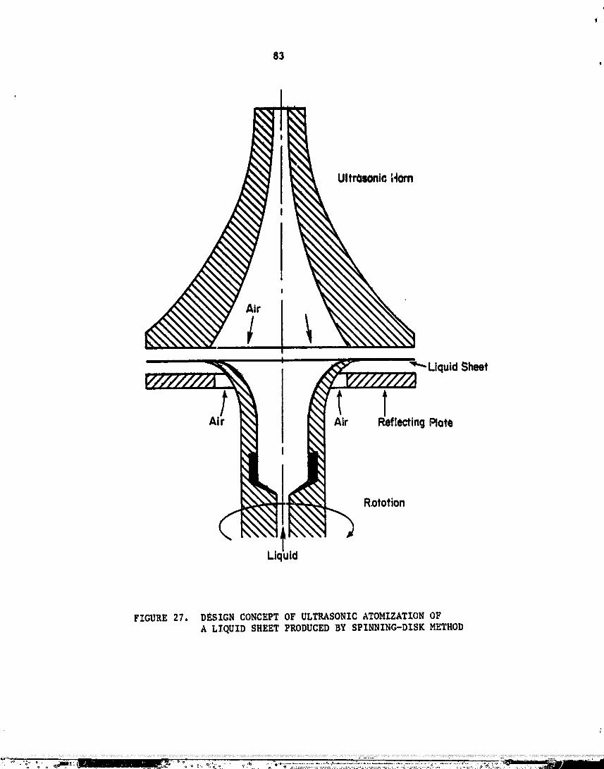
83
I
UltrOsOnicHorn
Liquid Sheet
A,! t tAir Reflecting Rate
Rototion
Li( uid
FIGURE 27. DESIGN CONCEPT OF ULTRASONIC ATOMIZATION OF
A LIQUID SHEET PRODUCED BY SPINNING-DISK METHOD
00000001-TSG08

data, for instance, only 80 percent of the spray wes _rithin a 2:1 diameter
range. However, 1_ is expected that this range of disperSiOn can be
reduced.
The lXqu£ds thac can be sprayed should cover properties typical
of water, 115hC oil, and heavy oils.---The amount Chac can be sprayed cannot
be deduced from the available data. It will certainly be greater, and
probably by a considerable amount, than the amount ac which a sheet starts
forming in preference co ligaments. With the particular design given above,
ch£s is 6 gph for water. If the extent of the liquid _heet before normal
breakup could be obtained from the literature, the mazimum load would then
!_ be equal Co the number of wave cells on the two surfaces times the drop
....: size and the frequency.
Suggested Development _'ork
Once the concept for the present approach has been established,
the next logical stQp is to fill in the gap in the literature concerning
the spray sheet produced by a spinning disk. A small number of spinning
disks would suffice. It is suggested chac they would be run mainly with
one fluid, with bhort tests on a few additional fluids tc determine the
effects of surface t_n_ion, viscosity, and density. The main tests should
_elate breakup sheet diameter to flow rate, disk size, and speed of rota-
tion. Mean drop size of the spray a_ter breakup would _lso be determined.
This would be related to the mean drop size expected when the ultrasonic
(or electrostatic) field was imposed.
Upon obtaining these data, the effect of ultrasonic fields of
} various strengths and frequencies on the median size and si2e distribution
should be experimQntally determined.
00000001-TSG09

85
• COMPARISONOF PROPOSEDTECHNIQUES
_, As already aSseSsed, the three proposed deexsns ace exploratory
_i!_ innatureprimarilyduetolackofsupportin, experimentsldataoroperatia.experience. Consequently, it would not be very meaninSful to attempt to
iii evaluate or directly compare these theoretica£ techniques. For this reason.only the desree to which each ef the proposed desisns is expected to meet
:i_ the specified perfotlqance requirements is summarized in Table 9.
ii"oFCAPASV..ITZESPRO EDTEC IQUES
_s_bilitlvs for Proposed Techni,_ues_i_ ,'V_ opposed Liquid-ludun Sptnnin_ Disk 2ith_'?, Rvquireoente for Techniques Ccntrifuae Type Chamber Air Jets Uttrasoni_ Field
_' Sprays, neatly mm3dieperseta) Can produce a very. narrow 90 percent within 80 to 1ZO Setter than chat obtain-_ii drop size distribution percent of mean diameter able bY _n exiettn8
N_'_ Averase Drop Size, I$ - 500 u_ o - 600 un tO- lO0 um for an expert- Up to _00 ,A; could bemental unit extemled
_i Application Rata. 5- 50 Ipm Dependsupon flay rate of Lo_ rate_ for an initial 10 sph for laboratory
(Single unit) primary atomizer uned; experf_entai unlit can be scale.! expected ¢o be _¢tsfeccory extended
Liquid Properttes__, Liquid properties have no Operates ,m most liquid Surface tension _d densityi,, De,airy, 0.8o 1._$ I/co effect on operation materials are important parameters
i Viacoeity. 0.3-_o cpSurface Tom*lama 20 - 80 dyne/am
!_- Future DeVelopment Area Flay pattern in the chain- Feasibility study and per- Experimental verificationbet needs to be studied; form_nce evahmtione needed needed; experimentalu_tch between aircraft ,m a laboratory scale, match between liquid sheet
_i speed and operettas air dine and frequency to be_i_ floe desirable, deterttined.f_
iI (a) Five percent by welKht of the drop6 can be terser then a maxfJmmsize and only $ percent shallot than aminimum sine where the eutxtunm and mtfliuam are 1.2 and 0.80 time the averase dAaumter, respectively.
o;' '
o
g':L
O0000001-TSGIO
86
CONCLUDING _S
As a result of the first phase of the present program, abouc fif-
teen different kechniques For producln$ sprays have bean identified, Amens
: the identified techniques, five techniques which were found to be capable
of producin$ a monodisper_e or nearly monodisperse spray have been closely
studied and compared with each other. The resul_ of this comparison is
that periodic di_persion of liqu!d Jet, spinfltn8 disk method, and ultra-
sonic atomization have been found to be most promising. While these tech-
niques can-provide a monodisperse spray over a reasonable range of average
drop size, all of them require some extensio, of their flow rate capabiiities
to match those required for the purpose of agricultu_al aviation applica-
tions.
Additiona£1y, three conceptual designs of atomizers for producing
a monodisperse spray have been generated. Where possible, a theoretical
equation which predicts the performance of each device has been obtained
employing certaifl simplifying assumptions. Due to the exploratory nature
of _he present program, no available experimental data or test experience
: associated wi_h these new concepts exist. Consequently, it is considered
difficult to evaluate these concepts definitively at _he present time.
For further development of the senerated conceptual techniques
into a practlcal unit, it is considered necessary to evaluate the sound-
ness of each approach by means of experlmen_al-tes_s. Since each of the
proposed de, lEns is based on a new conce_t, such expe_Iments should be
aimed at validatLon and further development of the basic prlnci_les rather
than at a direct application for use. TherefoEe, laboratory scale experl-
ments would be more meaningful than full scale experiments.
_ conJunction with the results of the first phase of the study,
the existing techniques that were identified aQ very promising should also
be given consideration. Of these identified te_hnlques, the principle of
periodic dispersion of a liquid Jet is recommended for _evelopment into an
atomizer for eve.Ltual agricultural aviation use.

i
87
_BLZOGS_P_
, "Low Volumu Oil _ptayin8 by _Lrcra_ for theAdam, A. V. (July 1962),Conr.rol of Slllatoka Dlsease off Bananas", hpo_t of the 4Oh Alriculcural
ii Aviation hsea:ch Conference, pp 8-12.
i,: Akeseon, N. D. and Yates, W. E. (1974), The Use of Aircraft in ASriculcure ,FAO of United Nations Development, Rome [FAO ASriculcural Series No. 2,FAO Asr. Devel. Paper No. 94].
Amsden, R. C. (1972), 'qJind Velocity in Relation co Aerial Spray/ms ofCrops", Asr. Aviat., 1_4(4), pp 103-107.
_il: Andrus, P. G. and Walkup, L. E. (1963), "FeaSibility of a Spark-_ Discharse AtomiZer for Small 011 Burners", Battelle Memorial
InSclcuCe Report to American Petroleum Institute.
Anconevich, J. (1959), "Ultrasonic Atomization of Liquids", IRE Trans PGUE_r ' ( 7 ) ' pp 6-15.
Bals, E. J. (1970), "Rotary Atomisation", Asr. Aviac., 12(3), pp 85-89.
Berglund, R. N. and Liu, B.Y.H. (1973), "Generation of Monodisperse AerosolStandards", Environ. Scl. Te_hnol., 7, pp 147-153.
l. BiJsterbosch, B. H. (1978), "Preparation and Characterization of_; Detergent-free Monodisperse Polystyrene LatiCes of Small Particle
I_ Size", Colloid• PolFm_r Sci., 256, pp 343-349.
: Binek, B. Fnd Dohnalovg, B. (1967), "A Generator for Manufacture of Mono-• dispersed Aerosols fnom_the Liquid Phase " Scaub-Reinhalt. Lufc, 27(11),,_ pp 31-33.
: Bisa, K., Dirnagl, K., and Esche, R. (1954), "Zerst_ubung yon Flussigke.iten: miC Ulcraschall", Simens Ze/cschrifc, 28(8), pp 341-347.>
_.: Boguslavskii, Y. Y. and _knadiosyants, O. K. (1969), "Physical_: Mechanism of thQ AcoUstic Atomization of a Liquid", Soviet
Physics-Acoustics, 15 (I), pp 14-21.
Bogy, D. B. (1978), "Wave Propagation and Instability io a Circular Semi-Infinite Liquid .Te_Harmonically Forced at the Nozzle", J. Appl. Mech.,4.__5.5(3),pp 469-47_.
Bollini, R., Sample, B., Seigal, S. D., and Boarman, J. H. (1975),"Production of Monodisperse Charged Metal Particles by Harmonic Elec-trical Spraying", J. Colloid Interface Sci., 51(2), pp 272-277.
Brown, A.W.A. (July, 1976), "Some Uses of Aircraft in Public-Health_* Entomology Outside the United States", Report of the 4th Agricultural
Aviation Research Conference, pp 20-26.
00000001-TSG12

88
Buotctker, R. and Basel, A. G• (1977). "P_oductlo_ o5 Uniform 6..pens$onDroplets and Their Drytn$ to Honod_sp_rs_d Granules", Chimia, _i(8),pp 301-306.
BurSoyae, W• £•, ColleCt, G. C., N_olson, L. T., and DavQnport, D. D•(1973), "Application _ce and Droplet Size: ThoLt Effect on PesticidesDispensed by Air Ovo_ Heavy Vegetation Cover", ksr• hviaC., 1_5(3),pp 70-79.
Burneec, G• F• (1962), "Research in East Africa on the Control ofTsetse TLies Yro_ the Air", ASr. Avtat., _ (3), pp 79-87.
Butler, J., Akesson, N. B., and Yaces, W. E. (1969), '_se of SprayAdjuvants to Reduce Dr_fC", Trans• ASAE, pp L82-Zg6.
Cadle, D. (1965), Particle Size, Reinhold Publishing Corp., New York, N. ¥.
Calliger, R. J., Turnbpll, R. J•, and Hendrieks, C• D. (1977), "HollowDrop Production by InJecclon of Gas Bubbles Znco a Liquld Jec"taev. Scient. Znstrum., 48(7), pp 846-851.
Clark, C. J. and Dombrowski, _. (1972), "Aerodynamic Instability and Disin-tegration of Znviscid Liquid Sheets", Prec. Roy. SAC., London, A 32..._9,pp 467-478.
Collins, H. (1979), _aCional Agricultural AviaCionAssociation,personal communication.
Cona_ay, J. E., Graham, J. A., and Rogers, L. B. (1978), "Effects ofPreSsure, Temperature, Adsorbent Surface, and Mobile Phase Compositionon the Supercrittcal _luid Chromatographic Fractionation of HonodtspersePolystyrenes", J. Chromatographic Sci., 1_5, pp 102-110.
Crane, L., Birch, S., and McCormack, P. D. (1964), '*The Effect ofMechanical Vibration on the Breakup of a Cylindrical Water Jet inAir" Bric J Appl _hys•, 15, pp 743-750
Cra_'ford, A. E. (1955), "Production of Spray by High Power MagnetostrictionTransducers'*, J. Acous¢. Soc. Am., 27, p 176.
Cutkomp, L. K., Hess, A. D., and Keener, G. G. (L950), "FactorsZnfluanclng Spray and Thermal Aerosol'Appllcaclon by Airplane", J. ofEcon. Encomology, 43(4), pp 456-462.
Dabora, £. K. (1967), "Production o_ Honodisperse Sprays", gev. Scient.InsCrum., 38(4), pp 502-506.
"A New Liquid Aerosol GeneratorDavis, E. J., and Nicolaon, G. (lq71),III. Operatlng Characteristics and Theoretlcal Analysis", J. ColloldInterface Sci., 3__7(4),pp 768-778.
DeOng, E. R. (1960), Chemical and Natural Control of Pests, ReinholdPublishing Corp., New York, New York.
DeOng, E. R. (1956), Chemlstr_ and Uses of Pestlcldes, Reinhold PublishingCorp., New York, New York.
• DeOns, £, R, (2953), Zas_c_ Fungus, andW¢.d Co , _e_Le_l.Publlshin8 Co., Znc., NewYork, Nov York.
gazal£c, N., PoCtas, J. J., and ga;al£e, G_.(_977), "Pt_p&tgt£on otMonod£sp_so PolysCyro.a Latex", Mgcrc_olecula_ Synthases, _, pp 85-89,
Dombrowsk£, N. and Hunday, G. (1968), "Spray Dryin_", Chapcor 16,Btochomical and D¢olo_ical Engineering Scioncot vol. 2, (Editor,N._Blakobrough), Acudom£c Pro_,, pp 209-320.
Dosoud_l, H. (1971), "Erzeugon 81eichsrosser Tropfsn nach denAbcropfverfahren", Chemi-Zni.-Tochn., _ (21), pp 1172-1176.
Doyle, A. W., Patron, R. _., and Shanley, E. S. (1967), "A Study ofNew Means for Atomization of Distillate Fuel Oil", American PetroleumInstitute, Publ. _o. 1725.
Droz£n, Vad£m G. (1955), "The Electrical Dispersion of Liquids asAerosols", J. Colloid Sci., 10(2), pp 158-164.
Dunskii, V. F. and KikiCin, N. V. (1965), "Atomization of a LSquid by aRotating Disk and 'Secondary' Breakup of Droplets", J. Eng. Phys., _,pp 41-45.
E_senmens_r, _. (1959), "Dynmnic Properties o£ the Surface Tension of_acer and Aqueous Solutions of Surface Active Agents with StandingCapillary Waves in the Frequency Range from l0 kc/s Co 1.5 Mc/s",Acuscica, _ (4), pp 327-340.
Erln, T., and Hendricks, C. D. (1968), "Uniform Charged Solid ParticleProduction", Rev. Scient. Znstrum., 39(9), pp 1269-1271.
q
E_ans, E. (1972), "Methods of Application'*, Systemic Fun_icides,R. _. _arsh (Edlcor), John _iley & Sons, New York, New York.
Ford, R. E., and Fuz_£d_e, C. G. L. (1969), "The Formacion of SprayDrops From Viscous Flulds", Pes_icldal Formu!a_i?n_ Research--Physical& Colloldal Chemical Aspects, Advances in Chemlsc_y Series 86,American Chem. Soc._ _ashln_con, D. C.
Foster, C. A., Hendrlcks, C. D., and Turabull, E. J. (1975), "HollowHFdrosen S_heres for Laser-fuslon Tarsecs"_ Appl. Phys. Le_t., 26 (i0),pp 580-581.
Fraser, R. P. (1958), "The Fluid KineClcs of ApplicaClon o£ _esticidalChemicals", Advances in Pest Cc.,crolRe#e_rch--Volo ZI., R. L. Meccalf(Edicor), In_ersclence Publlshe_s_ Inc., New York, New York.
Fraser, _. P., Dombrowdki, N., and Routley, J. H. (1963), '*TheProduccionof Uniform Liquid Sheets from Spinning Cups", Chem. Eng. Sci,, I_/_3,pp 315-321 (also pp 323- 353).

l Frear, D.E.H. (1942 & 1948), ChemiStr7 of _nsectictdes t F.unmicides I andRetbicides, b. Van Nostrand C_., Inc., New Yd_k, _Y.I
i+ Frear, D.E.H. (1970), Pesticide Handbook--Entoma, College Science Publishers, ,
il State College, PA.Puchs, N. A. (1964), The Mechanics of Aerosols, MacMillan Company, NewYork, New York.
Fu_imoto, T., Nagaeawa, M. (1975), "Preparation ot Monodlsperse Polyetyreneswlnh ELgh M_lecular Weights", Polymer J., _7(3),pp 397-401.
Fulwyler, M. J., Perrlngs, J. D_, and Cram, L. g. (1973), "Production ofUniform Microspheres", Rev. Sclent. Instrum., 4__4(2),pp 204-206.
Fulwyler, M. J., and Eaabe, O. C. (1970), '_rhe Ultrasonic Generation ofMonodisperse Aerosols"p paper presenced ac AIHA Co=ference, May 11-15_ •
Garner, F. H., and Henny, V_ E. (1953), '_ehav/or of Sprays Under HighAlclcude Conditions", Fuel, 32, pp I_I-156.
Gei!, A. F., I_aak, L_ W., Anderson, W. A.: and Hoag, V. M. (July 1962),"Experiencem With Aerial Application of Granular Mosquito Larvlcidesin the _ern _squito Abatement Distrlct", Report o_ the 4th ASriculturalAviation RQsearch Conference, pp 100-106.
Gershenzon, E. L., and Eknadlosyants, O. K. (1964)_ *_he Nature ofLiquid Atomization in an Ultrmsonlc Fountaln"_ Soviet Physlcs--Acoust_csji0(2),pp127-1n.
Green, H. L., and Lane, W. R. (1957), Partlculate CloudS: Dusts_ _Smokes and ,V_LstS, D. Van Nostrand Co., ._ew York, New York.
Green, M. B. _ Hartley, G. S., and West, T. F. (1977), Che_Lcels for_,ro_ Prote_tio_, Pergamon Press.
Haas, Paul A. (1975), "_ormatlon of Liquld D_ops wlth _nlfo_m andControlled D_a_eters at Rates of I0_ to I0D Dr_s per Minute",AIChE J., 21 (2), pp 383-385.
!Hamaker, J. W., and Kerlinser, H. O. (1969)_ "Vapor Pressure of
Pesticides", PeS._cidal Formulation.s R_search--PhvSital,& CO.110idalCheu,_cal AspeCts, Advances in Chemi_try Seri_s 86, American Chemical
!!' Socket)', _ash_ngton_ D. C.
"_i_:_ "An F.xperimancal scudy of DropletHan, C. D., and KazLmori_ F. (1978),
_ Deformation and Breakup in Pre_Sure-Driven Flows Through Conver_ins_ and _niform Channels", J. Rheolo_y, 22(_), pp 113-133.
!i_!__ Hanson, L. P. (1973), Plane. Growth Regulators, Noyes Data Corp., Park
o "}'_'.
00000002
91
• Hart=ann, J. an_ Txolle, B. (1927), "A New Acoustic Generator: The Air JetGeneral'% J. Sc£. Inst_., 4, p 101.
. Ha_r_nann, J. (1939), "Construction, Performance and DeSign of the AcouSticAir-Jet Generator", J. Sci. Inst=., 1_66, pp 140-149.
H£dy, G. M., and Brock, J. R.(1970), The D.vuemics of AerocolloidalSystems, ?srsamon Press, New York.
Hillenbrand, yon Christe_, and Porstend6rfer, J. (1978), "Herstellun8monodispers_r Fest- und Flussigteilchen mit de= Spinning-Top-Generator"(German), Staub-Reinhalt. LuSt, 3_88(2), p 52.
Htmel, C. M. (1969), **The Opt_num Size for Insecticide Spray DropletS",J. Econ. Entomol., 62(4), pp 919-925.
Himel, C. M. and Moore, D. (1969), '*Spray Droplet Size in the Control of.Spruce Budworm, Boll Weevil, Bollworm, and Cabbage Looper".J. _eon.Entomol., 62(4), pp 916-918 ....
Hinze, J. O. and Milborn, H. (1950), "Atomization of Liquids by Means ofa Rotating Cup", J. Applied Mechanics, 17, pp 145-153.
HOffman, R. A. and LindquiSt, A. W. (1949), "Fumigating Properties ofSeveral New Insecticides", J. E_on. Entomol., 4_2(3), pp 436-438.
Hoffsommer, A. (1973), Agricultural Aviation Guide, Modern Aircra£t Series(Div. o_ Sports Car PreS_), Ne_ York•
Huang, J.C.P. (1970), "The Breakup of A._isyun_etric Liquid Sheets", J. FluidMech., 4__3, pp 305-319.
ll'In, B. I., Eknadlosyants, O. K. (1967), I_ature of the Atomizationof Liquids in an Ultrasonic Founta/n", Soviet PhLq_tics,12 (3), pp 269-275.
ll'in, B. I., EknadioSyants, O. K. (1969), "Influence o£ Static Pressureon the Ultraso_ic Fountain Effect in a Liquid", Soviet Physlcs--Acoustlcs,1__4(4), pp 452-455.
lngebo, R. D., and Foster, H. M. (1957), "Drop-Size Distribution _or Cross-Current Breakup o£ Liquid Jets in Air Streams", NACATN 4087.
lngebo, R. D. (1966), "Atomization of Ethanol Jets in a Combustor withOscillatory Combustlon-Gas Flow", NASA TN D-3513.
International ?lame Research Foundation (1978), "Sonlcore Atomizers--t!
Measurement of Droplet-Size DistributiOn , Doc Nr 513i/1 (June 2), andDoc Rr 3131/2 (June 12, 1978).
...... oo6oooo2TSA03
!_ i 92
_r, J
_: Isler_ D A. (July, 1962), "Some Ya_ors Affectin6 the Atom£¢at£o_ of
Aerial Sprays"_ Report of the 4th Agricultural Aviation P_sea_chr: Conference, pp 31-32.i
_: Keller, J. B., and l_l_dner, I. (1954), "Instab_lity of Liquid St, traces
_: and the Focmation of Drops", J. Appl. Phys., 25(7), pp 918-921.
.--_ Khandwawala, A. I., NatarasJan, R. and Gupta, M. C. (1974), "Exp_rlmental
=: Investlgatlon of Liquid Fuel Atomlz_tlon Using Hartmann Acou_tlc Genera-
;iI tot", Fuel, 53, pp 268-273.
_!:: KO_henkov, V. I., and Fu_hs, N. A. (1976), "Electrohydrodynamic Atomlza-
_ tion of Liquids", Russian Chem. Eev., 4--5(12),P9 1179-1184.
_ Lafrance, P. (June, 1977), "The Breakup Length of Turbulent Liquid Jets",
- ._ J. Fluids Engr., pp 414-415.._.
x_! Lafrance, P., and RiOter, R. C. (Sept, 1977), "Capillary Breakup of a_ Liquid Jet with a Random Initial Perturbation", J. Appl. Mech., pp 385-388•
; Lane, 14. R. (1951), "Shatter of Drop.p____Streams of Air", Ind. Engr. Chem.,
i, 4.3.3(6). pp 1312-1317.
Lang, R. J. (1962), "Ultr_asonic Ator_Ization of Liquids", J. Acoust. Soc. Am.,_ 3_44(i),pp 6-B.
_' Langer, G. and Yamate, G. (1969) "Encapsulation of Liquid and Solid•_,.: • ,
_i," Aerosol Particles to Form Dry Powders", J. Colloid Inter£ace Sci. ,__29(3),_: pp 450-455.
i_G Langmuir, I. (1942), Office of Scientific Eesearch and Develo_ent,
_, _.ept. No. 865.
_"_ Lee, K. W. (19_8), '_Filtration Of Suhn_ron Aerosols by Fibrous Filters_
!-',_'i Thesi_, Univ. of M_Jnnesota.! =_;_ Ltndblad, N. _., and Schneider, J. M. (1965), "Production of Uniform-
,__:i Sized Liquid Droplets", J. Sct. lnstrum, 42, pp 635-638.i _
_"ii_ Ltppmmn, M., and Albert, i. E. (1967), Compact Electric-Motor: _::- Driven Spinnin_ Disc Aerosol Generator", Am. Ind. HYS. A_soc. J.=_ ' 28, pp _01-506.
_,:' Liu, B.Y.H. (1_67), P&rticle Tech. Lab., Univ. of Minnesota_ ReportI_o. 112.
_i_; Lobdell, D. D. (1967), "Particle Size-Amplitude R_lations for the=_, Ultrasonic Ato_zer", J. of the Acoustical _ociety of America, 4-3 (2),
,,_ .... pp 229-231.
" _"_., _:-=._~_.............._--_ .... .=_ -_........._ .....,... _ &._:.... ..............:........_=...............=_::_==.:= .,,="....... _" ...... ...... __-_-_....__-y"-_._. _; ......... __'-:"__"_.........
O0000002-TSA04

93
LanK, R. J. _1962), '*Ultrason_Lc _£on of.Liquids", J. Acoust. Soc.Am., 34, pp 6-8.
Maas, W., and deLanie, W. (1970), "The Influence of the V£scoRity of' Spray Liquids on the Droplet Size in ULV Aerial Application",
ASr. AviaC., 12(1), pp 21-24.
Mass, W. (1970), "The Influence of the Viscosity o_ ULV Spray Liquidson the Droplet Distribution in Cotton", ASrieu!tural Aviation, 12 (3),pp 83-84.
._acky, N. A. (1931), "Some Invescisacions on the Deformation andBreakins of Water Drops in Serous Electric Fields", Proc. Roy. Soc.,A 133_, pp 565-587.
Macquaig, R. D. (1962), "The Collection o_ Spray Droplets by FlyinsLocusts", J. Appl. Phys., 20 (10), pp 932-938.
Magarvey, R. H., and Taylor, B. N. (1956), "Apparatus for the Productionof Large Water Drops", Review o_ Scientific Instruments, 2./7 (11),pp 944-947.
May, _. R. (1949), "An ImprOved Spinning Top HomoSeneous. Spray Apparatus",J. Appl. Phys., 20, pp 932-938.
May, K. R. (1966), "Spinning-Top HomOgeneous Aerosol Generator with_hockproof ._uncing"_ J. Sci. InsCrum., 4_3, pp 841-842.
Mayer, E. (December 1961), "Theory of Liquid Acom_zaCion in Htsh VelocityGas Screams"_ ARS J., pp 1783-1785.
MeCubbin, Jr., T. (1953), "The Particle Size Distribution in FogProduced by Ultrasonic Radikc_on", J. Accoustieal Soc. of America,pp 1013-1014.
Metes'f, R. L. (1958), Advanceq in Pest Control Research, IntersciencePublishers, Inc., New York, New York.
Misses, C. C. (1955), "The Effect of Ambient Pressure Oscillations onthe Disintesrac£on and Dispersion of a Liquid Jet", Jet Pr_pulsion,pp _25-534.
Monn, H.A.U. (1969), Manual of _utLsat_on for Iusec t Control, Food& ASriculture OrIanization of the U.N., Rome, Italy.
Mount, C. A. (1970), "Optimum Droplet Size for Adult Mosquito ControlWith Spade Sprays or Aerosols Of InseCticide_", Mosq. News, 3_ (_),pp 70-75.
Mulla, M. S. (July 1962), '+The _le of SOme Phylico-Che_ical FectorJ,!
' in the Performance Of _ranular Mojqu£to Larvicides p Report of the4ch _ricultural AViation kJsearch Conference, pp &07-i12.
00000002-TSA05
94

96
SerUm, L. (1969), "The GenetaCio_ of Monodisperse Aerosols by Means ofa Dis_Cesra_ed JeC o_ Liquid", Ray. Sctenc. ZnScrum., 40(6), pp 77S-782.
Topp, H. N. (1973), '_lcrasonic AcomizaCion--A Phocosr_phic Study o5 theMechanism of Disintesracio_", Aerosol Sci., 4, pp 17-25.
Topp, M. N., and Eiseuklam, P. (lg72), "Induscrtal and Medical Usesof UZcraSon_c Ac_tz4rs", UZCrasontcs, 10 (3), pp 127-133.
U. S. Government Prtnc_nS Office (1978), U. S. ZncernaCtonaZ TradeCo_nission--S_chec,_c OrSenic Che_ioals U. S. Pro'ducCi0_ a Sales ti977, USITC Pub1. 920, Washinscon, D.C.
Vonneguc, 3. (1947), "The Nucleation of Ice Formation by S£1verIodide", J. Appl. Phys.___18(7), pp 593-595.
Vonuesuc, B,, and Neubauer, R. L. (1952), "Production of t4onodtspe_seL_quid Particles by Electrical Ato_LzaCion", J. Colloid Set., 7,pp 616-622.
Wachcel, R. Z., and Victor, K. (1962), "The Preparation and SizeDistribution of Some MonodtsperSe Emulsions", Journal of CollotcScf., 17, pp $31-564.
Walcon, W. H., and PrewecC, W. C. (1949), "The ProduCtion of Sproys and•XfLscs of Uniform Drop S_ze by Means bf Spinntns Disc Type Sprayers",Proc. PhyS. Soc., 62 (6), pp 341-350.
_aCson, E. A. (1968), Prec. Znscn. Mech. EngrS., 158, p 187.
_eiss, M. A., and Wors_, C. H° (April 1959), "ACoucLzaciou in l_igh_eloc._.__A_rsCrea_s ", _ Journals pp 252-259.
_iSS, L. D. (_6), '_rop-Size Prediction for-T_f:_-Fluid Atomizers"J. ZnaC. Fuel, 37, pp 500-505.
_;ilce, S. E., Akesson, N. B., ¥aCes, W. S., Chr_sCensen, P., Co_den,_. E., Hudson, D. C., and Weisc, O. I. (1974), "Drop-Size Concroland _Lccrafc Spray Equip_enC", Agr. Aviat., 16(1), pp 7-14.
_ilcOx, _. L., and Tare, R. W. (1965), "Liquid AconcLzacion in a Hish_' Intensity Sound Field", AZChE J., _1 (1)_ p..p69-72.
:' Wolf, W. R. (1961), "Study og che Vtbracin_ Reed in the Production ofSmall Droplacs and Solid P&rcicles of Unifor_ Size", Rev. ScienC.Instrum., 3__2(I0),pp 1126-1129.
_oosl_y, J. P., and Turnbull, R. 3. (1977), "Technique for Produc; 4Uniform Charsed Drops of Cryosenic Liquids", Rev. Set. ZnsCrum.,48 (3), pp 254-260.
IL
a, 00000002-TSA08

Related Documents