L-5 KU-BAND V-SAT & IDR EQUIPMENT

Welcome message from author
This document is posted to help you gain knowledge. Please leave a comment to let me know what you think about it! Share it to your friends and learn new things together.
Transcript

L-5
KU-BAND V-SAT & IDR EQUIPMENT

KU-Band VSAT & IDR
Ku Band VSAT
The Ku band ("kay-yoo" K-under band) is a portion of the electromagnetic
spectrum in the microwave range of frequencies from 11 to 18 GHz. BSNL Ku band
service works on:
- 11.637 GHz downlink frequency
- 14.437 GHz uplink frequency
Presently Ku Band Hub (Gateway) uses INSAT-3B satellite to provide
broadband packet-switched communications to a large number of user terminals.
VSAT technology is a secure and reliable medium to connect geographically
dispersed locations and represents a cost effective solution for users seeking an
independent communication network connecting to the global network. In a situation
where other connectivity options are not feasible, Ku Band VSAT offer value added
satellite based services capable of supporting internet, Local Area Network, voice,
Fax and can also provide powerful dependable private communication solutions.
What is VSAT?VSAT stands for Very Small Aperture Terminal. VSAT is a small earth station
which provides a communication link required to setup a satellite based
communication network. It is a small satellite dish diameter is typically 1.2-1.8 meters
for Ku-band systems that is capable of both receiving and sending satellite signals.
VSAT systems can be designed to serve both broadcast and interactive applications
whether data, voice or video, which are now being served by terrestrial lines.
VSAT Equipment is mainly consist of-
ODU ( Outdoor Unit )
IDU ( Indoor Unit )
Outdoor Unit (ODU):The outdoor unit system is specifically optimized for use with the Indoor Unit and
consists of:
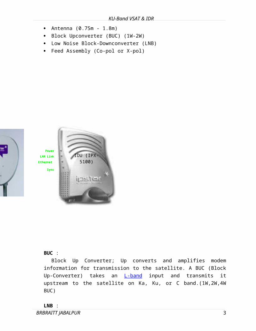
Antenna (0.75m - 1.8m)
Block Upconverter (BUC) (1W-2W)
Low Noise Block-Downconverter (LNB)
Feed Assembly (Co-pol or X-pol)
BRBRAITT JABALPUR 1

IDU (IPX-5100)
Power
LAN Link
Ethernet
Sync
KU-Band VSAT & IDR
BUC :
Block Up Converter; Up converts and amplifies modem information for
transmission to the satellite. A BUC (Block Up-Converter) takes an L- band input
and transmits it upstream to the satellite on Ka, Ku, or C band.(1W,2W,4W BUC)
LNB :
Low Noise Block Down Converter; Down converts and amplifies signals
received from the satellite to the modem or receiver. In addition to amplifying the
signal, the LNB also converts the signal to a frequency usable by the In-Door-
Unit.
IDU ( Indoor Unit )• High Performance Satellite Terminal:
• Download speeds of up to 4 Mbps
• Upload speeds of up to 2 Mbps
• Flexible Interfaces:
• Ethernet 10/100 BaseT (RJ45)
• USB 1.1
• 100-240 V AC Power Supply
• -48 V DC,12 VDC Power Supply
BRBRAITT JABALPUR 2
NE
KU-Band VSAT & IDR
VSAT ARCHITECTURE
VSAT networks can be arranged in point to point, star, mesh, star/mesh, and
broadcast configurations. The preferred arrangement depends on the kind of
information flow the network will service. VSAT networks come in various shapes and
sizes ranging from star data system users with one site connected to an operator's
shared hub to many thousands based on a dedicated facility located at their own site.
Mesh systems have traditionally been somewhat smaller in size than star systems
- 5 to 30 sites used to be a good rule of thumb - but the average size of orders has
risen as prices have come down and some rural telephony networks now comprise
as many as several hundred or even thousands of sites.
A point to point network allows two-way communications between two VSAT
sites. A star network allows any number of VSAT sites to have two-way
communication with a central hub. A mesh network allows two-way communications
BRBRAITT JABALPUR 3

KU-Band VSAT & IDR
between any VSAT sites in a network. A central hub is not necessary. Each site
communicates to another site with a single satellite hop.
There are three basic VSAT transmission types: TDMA, time-division multiple
access; DAMA, demand-assigned multiple access; and SPCP/MCPC, single/multiple
channels per carrier. Interactive VSAT systems come in two main network topologies
- star and mesh. The former tends to be based either on a shared access scheme
(TDM/TDMA), which is designed to support transactional processing applications, or
on a dedicated link (the satellite equivalent to a leased line). The latter usually uses
links which are set-up and torn-down on request to establish a direct link between
two sites on a demand assigned basis. Ku Band HUB (Earth Station) at
BANGALORE consists of :
1. Satellite antenna of 8.1 m – Cassegrain feed type.
2. Ku Band RF equipment and its control systems.
3. GATEWAY Networking Equipment with interfaces to Terrestrial Networks like
MLLN, MPLS and NIB.
VSAT SERVICES OFFERED
VSAT is an ideal satellite network that provides communications support for a
wide range of applications:
-Voice Application
-Facsimile
-E-learning
- Financial Management
- Data processing
- Reservation System
- Telemetry & Data Collection
- News Wire Services
- Private-Line Voice
- Virtual Private Networks
- Distance Education
- High Speed Internet Access
- Telemedicine
-Voice over IP Telephony
-Broadcast and Multicast
BRBRAITT JABALPUR 4
KU-Band VSAT & IDR
High speed Broadband Internet
Satellite Terminals provides robust Broadband/Internet network of BSNL by
providing high speed Internet directly to the users with a nationwide coverage.
It delivers bandwidth on demand allowing efficient use of bandwidth making it
ideal for broadband access rollout to Small and Medium Enterprises (SMEs), public
Internet users (such as Internet Cafes / Browsing Centres), Apartments and
individual users.
It provides similar broadband and high speed Internet capabilities available on
BSNL
BRBRAITT JABALPUR 5

KU-Band VSAT & IDR
Video Conferencing
based networks. By delivering these attributes BSNL's video conferencing
solution is unmatched. Video conferencing solution can be used for corporate
meetings, technical support functions, distance learning, telemedicine, job recruiting
interviews, direct-sales, legal work, telecommuting, and manufacturing.
Supports Client/Server based video conferencing with MPEG-4 protocol.
Flexible data speeds ranging from 64, 128, 256, 384 kbps and above
Broadcast and Multicast features - Supports both Point-to-Point and Point-to-
Multipoint conferencing.
Ideal for mass corporate training, internal corporate TV Broadcasting and e-
learning using Broadcast and Multicast features
VSAT TERMINAL FEATURES
Maximum Trans / Receive Data upto 2 Mbps with 10/100 Mbps Base-T
SERVICES OFFERED
Leased Lines through VSAT on IP platform: 4Kbps onwards
High speed Broadband Internet
VPN Networking
VoIP Telephony
Facsimile
Telemedicine
E-learning
IP multicasting, Video Conferencing, Video Streaming
BRBRAITT JABALPUR 6

KU-Band VSAT & IDR
DIGITAL SATELLITE PHONE TERMINAL (DSPT)
Introduction:
Digital Satellite Phone Terminal System (DSPT system or DSPS) project involves
setting up a VSAT (Very Small Aperture Terminal) Based network for BSNL. The
system consists of HUB Station and Remote Digital Satellite Phone Terminals
working in Ku-Band (Transmit Frequency is 13.75-14.5 GHz and Receive is 10.7-
12.75 GHz). DSPT Network provides PSTN connectivity to rural, remote,
inaccessible and hilly areas via INSAT (Indian National Satellite) or leased
transponder for DTS network. The VSAT system works in a star topology using
DAMA (Demand Assigned Multiple Access) technology. For BSNL VSAT network the
Hub shall be located at Sikanderabad (A.P.), adjoining Delhi, in Uttar-Pradesh and
there shall be 15000 DSPT remotes located over several states in India with higher
proportions being in North, North East and East provinces.
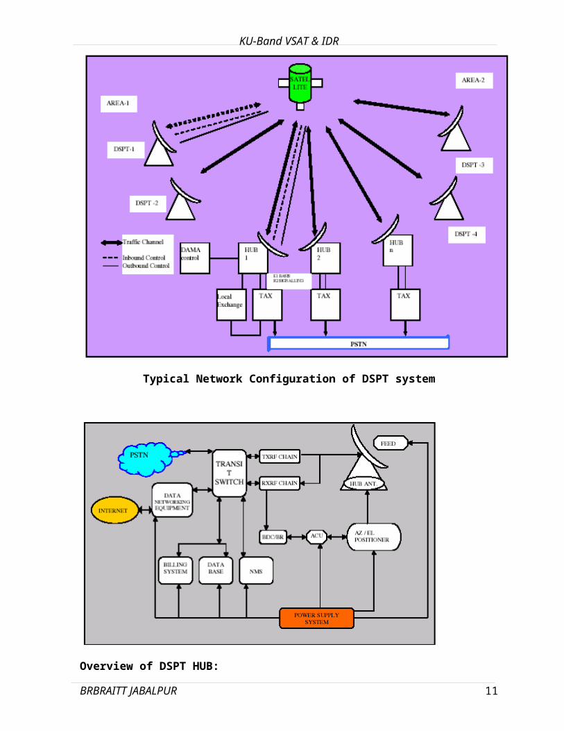
Typical Network Configuration of DSPT system
BRBRAITT JABALPUR 7

KU-Band VSAT & IDR
Overview of DSPT HUB:
The Hub of DSPT system will be composed of Indoor and Outdoor facilities. The
outdoor facility is a complete Antenna and RF path while the indoor comprises the
Hub Base-band and the other equipments:
The Hub of DSPT system comprises of Indoor facilities and Outdoor facilities.
Indoor facilities: Indoor facilities has following components,
a. Hub Base-band
b. Transit switch.
In the Indoor facility consists of redundant Hub-base band unit, a Transit switch to
provide connectivity to PSTN network, associated Data-Base servers, Billing system
consisting of Billing system Hardware and software, the data networking equipment
consisting Firewall, web-server, Authentication server and router to provide backend
connectivity to the Internet. The base-band and remotes have a NMS and its
database to configure and manage the entire VSAT-based network.
Outdoor facilities:
a. Antenna (8.1 Meter antenna assembly): In the Outdoor facility has an Extended
motion antenna assembly, which is controlled by 3-phase Elevation and Azimuth
motors. The Antenna consists of a Cass-grain Feed Horn with Hyperbolic dish at
focus of antenna.
b. RF path: RF path consists of Transmit chain and Receive chain.
BRBRAITT JABALPUR 8

KU-Band VSAT & IDR
Transmit chain consists of
-ULPC (Up Link Power Control),
- Up Converter and
- SSPA (Solid State Power Amplifier) and
Receive chain consists of
- Trance reject filter,
- Radar reject filter,
- LNA (Low Noise Amplifier),
- Power divider and Down converter.
BRBRAITT JABALPUR 9

KU-Band VSAT & IDR
BRBRAITT JABALPUR
IDR (Intermediate Data Rate)
10
KU-Band VSAT & IDR
IDR
( Intermediate Data Rate )
INTRODUCTION:
With the rapid digitization of telecom networks , telephone switching and terrestrial links, INTELSAT (International Telecommunications satellite Organization) planned to introduce IDR carriers into the system , to provide interconnection of these networks with high quality digital communication with information rates from 64 kb/s to 44.736 mbps between different type of earth stations.
Summary of INTELSAT Standard Earth Stations
StandardType
FrequencyBand (GHz)
G/T(dB/K)
ApproximateDiameter(M) Services used for
A6/4 35.0
(earlier 40.7)15-18(30-32)
All
B 6/4 31.7 10-12 All except FDM / FM and TDMA/DSI
C 14/11,12 37.0 10-12 FDM / FM CFDM/FM IDR,IRS
D1 6/4 22.7 4.5-6 VISTA
D2 6/4 31.7 11 VISTA
K1 14/11,12 25.0 3.5-4.5 IRS
K2 14/11,12 29.0 5.5-6.5 IRS
K3 14/11,12 34.0 5-10 IRS , IDR
F1 6/4 22.7 4.5-5.0 IRS
F2 6/4 22.0 7-8 IRS , IDR
F3 6/4 29.0 9-10 IRS , IDR, CFDM/FM
G 6/4 or 14/11,12
- All sizes International leased services
X 6/4 or 14/11,12
- All sizes Domestic leased services
BRBRAITT JABALPUR 11

KU-Band VSAT & IDR
Modes of Satellite services
Closed Net - Any data rate,- No over head
Intermediate data Rate(IDR) - 2 Mbps,8Mbps & 34 Mbps Data rate - 96 k OH
Intelsat Business Service - Any data rate for data transmission (IBS) 16/15 OH
Drop & Insert - Fractional N x 64 Kbps- Supports Multi-destination communication
Intermediate data Rate (IDR)
IDR system provides Trunk connectivity between Telephone exchanges for Digital Telephony data via satellite.
Data rate : 64 kbps to 44.736 mbps
E1- 2.048 Mbps
E2- 8.448 Mbps
E3- 34.368 Mbps
Supports Engineering Service Channel (ESC) of 96 Kbps
The 96 Kbps overhead (ESC) channel consists of :
32 Kbps ADPCM two audio channel
or 64 Kbps Data channel 8 Kbps Data channel
Four independent Backward alarms
BRBRAITT JABALPUR 12
KU-Band VSAT & IDR
IDR Framing
Frame period 125 micro Sec12 Bits OH 256 Bits DATA
(2048 Kb/s)
1 2 3 4 5* 6 7 8 9 * 10 11 12
FRAME AND MULTIFRAME TWO 32 kbps ESC VOICE Chls or one 64 Kbps ALIGNMENT,BACKWARD DATA CHANNEL.ALARM, ESD DATA (FA,A,d)
VI = ESC voice channel I Bits (I = 1,2) : (Set to 1 if not used)AI = Backward Alarm to destination : (I = 1,2 ,3 ,4) NO alarm = 0 , Alarm = 1DI = ESC Digital Data (I = 1 to 8) ,(Set to 1 if not used )8 Frames = 1 Multiframe = 1msOH Rate = 12 Bits / 125 micro sec = 96 Kbps
*Bits 5&9 in the overhead Frame correspond to the first bit transmitted in the ESC voice channels .
**d1 correspond to the first bit transmitted in the ESC data channel.
The frame structure is derived by adding 12 bits every 125 micro sec resulting in a 96 Kb/s overhead rate. The overhead rate is allocated as below:
a. 20 Kb/s for frame & multi frame alignment.b. 4 Kb/s for backward alarm up to four destinations.c. 8 Kb/s for ESC data.d. 8 bits for two 32 Kb/s ESC voice channels for total rate of 64 Kb/s.
FIGURE - OVERHEAD STRUCTURE FOR 2048 Kbits/s IDR CARRIERS
BRBRAITT JABALPUR
01000111
0d10d30d50d7
0d20d40d60d8
V1V!V1V1V1V1V1V1
V2V2V2V2V2V2V2V2
1A11A21A31A4
12345678
Frame
13

KU-Band VSAT & IDR
IDR System
Other Sub-Systems:Redundancy SwitchEqualizerESC SwitchIF/RF Power Combiner/Divider
Technical Features
G703 E1,E2,E3 Interface
96 kbps Overhead Framing
Operates in C-band
Low Phase Noise Synthesizer
Freq. Resolution Of 125 KHz
IESS 308/310 Compliant
QPSK &8PSK Modulation
Viterbi, Reed Solomon &Trellis FEC Coding
BRBRAITT JABALPUR
ECHOCANCELLER
MODEM
UPCONVERTER
DOWNCONVERTER
SSPA
LNA
E1/E2 DATAFROM / TOEXCHANGE
14

KU-Band VSAT & IDR
System Features
Star connectivity between Hub &Remote
REMOTE-1
2Mbps/ 8MbpsHUB DATA
HUB REMOTE-2
REMOTE-3
MODEM
MODULATOR
DEMODULATOR
BRBRAITT JABALPUR
SAT
EARTHSTATION
EARTHSTATION
EARTHSTATION
EARTHSTATION
OVERHEADFRAMING SCRAMBLER
RSENCODER
INTERLEAVERUNIQUEWORD
CONV.ENCODER
OVERHEADDEFRAMER DESCRAMB
LER
DEINTERLEAVER
UNIQUEWORD
VITERBI.DE-CODER
RSDECODER
2MBPS/ 8MBPS DATA
2MBPS/ 8MBPS DATA
2MBPS/ 8MBPS DATA
96Kbps CR-2144Kbps RS-2370Kbps TR-4740Kbps
I & Q to IF Card2048Kbps
96Kbps
CR-2144Kbps RS-2370Kbps
I & Q to IF Card
2048Kbps
15

SYNTHESIZER OCXO10MHz
MICROCONTROLLER
RS232 I/F
TO PC
BACKUPSWITCHING
NVRAM
KEYPAD & LCDDISPLAY
~~~~~~
RF
IF RF
IF Input 70± 18 MHz
IFLO1112.5MHz
RFLO4662.5 -5242.5MHz
SYNTHESIZER OCXO10MHz
MICROCONTROLLER
RS232 I/FTO PC
BACKUPSWITCHING
NVRAM
KEYPAD & LCDDISPLAY
~~~~~~
~~~
1042.5 ± 18 MHz
RF
IF RF
C-BANDRF I/P
IFLO1112.5MHz
RFLO4662.5 -5242.5MHz
KU-Band VSAT & IDR
UpConverter
1182.5 ±18MHz C-BAND RF O/P
5845-6425 MH z
DownConverter
BRBRAITT JABALPUR
IF Input
70± 18 MHz
16

1:1 LNA System
OP
SW
IP
SW
TRANSREJECTFILTER
RADERCUTOFFFILTER
CONTROL UNIT
LNA
LNA
LNA
KU-Band VSAT & IDR
30Mtr ½” Foamdielectric cable
TO I/P & O/P SWITCHES
BRBRAITT JABALPUR 17

KU-Band VSAT & IDR
ANTENNA:
C-Band Transponders Beacon frequency Uplink & Downlink frequency INSAT 3E Longitude = 55 East Satellite Foot Print Polarization VSWR/Return Loss
BRBRAITT JABALPUR 18

MODEMRACK
RFRACK
SSPARACK
LNA systemECHOCANCELLER
KU-Band VSAT & IDR
HUB EARTH STATION
HUB EARTH STATION:
Hub communicates with geographically co-located remotes.
The subsystems at Hub are mounted in Modem Rack and RF Rack.
Accepts 2 Mbps/ 8Mbps Data from exchange, performs digital Modulation.
Performs 70 MHz IF to C-band frequency.
The RF system is interfaced to Antenna (7Mtr) and Amplifiers.
Easy expandable.
Redundancy at every stage provides reduction of system down time.
BRBRAITT JABALPUR 19

MODEM-R
MODEM-1
MODEM-2
MODEM-3
MODEM-4
MODEM-5
MODEM-6
MODEM-7
MODEM-8
MODEMSWITCH
DDSSWITCH IF
SWITCH
8:1 IFPWR
COMB
1:8 IFPWR DIV.
ESCSWITCHH
KU-Band VSAT & IDR
MODEM RACK
Function of Modem Rack Accepts 2048/8.448 Mbps terrestrial data from echo canceller Modem performs IDR framing, Forward error correction, Digital Modulation &
conversion to 70 Mhz IF output. ESC orderwire audio used for earth station maintenance is interfaced to
Modem. All terrestrial data & IF are routed to Modem switch to provide change over to
back up modem during filure. IF carriers are combined in IF Power combiner in uplink & divided in
downlink.
Maximum voice channel communication supported by 8:1 system is 240 for 2Mbps 960 voice channels for 8 Mbps.
The IF signal is routed to RF rack for frequency translation.
Features of Modem Rack:
Provision of DDF Panel for 2 Mbps / 8 Mbps data.
Provision for IF interface at top of rack.
Provision of separate Earth for Rack.
Smooth flow of all signals (E1, IF, ESC and Control)
Line filter reduces EMI/EMC
BRBRAITT JABALPUR 20

KU-Band VSAT & IDR
System is engineered for 8:1 configuration to cater future traffics.
Easily expanded by plugging the modem for higher configuration.
Function of RF Rack
Transmit Chain
Accepts 70 MHz IF from Modem rack.
Equalizer compensates delay distortion & amplitude slope.
Upconverter converts IF input to C-band RF output without frequency invertion.
Up converter implements dual conversion.
Provision for IF & RF Monitoring at front panel.
Prime & backup modules plugged to converter provides switching of IF & RF .
The Output of the RF Rack is interfaced with Amplifier Rack.
The amplified output is switched to antenna Tx feed via waveguide run which offers min. attenuation frequency translation.
Receive Chain
Accepts receive C-band RF signal after amplification.
Downconverter converts C-band RF input to IF output w/o frequency inversion.
Downconverter implements dual conversion.
Provision for IF & RF Monitoring at front panel of converter.
Prime & backup modules plugged to converter provides switching of IF & RF.
Features of RF Rack
Provision for IF & RF interface at top of rack.
Provision of separate Earth for Rack.
Smooth flow of all signals (IF & RF)
Line filter reduces EMI/EMC.
BRBRAITT JABALPUR 21

KU-Band VSAT & IDR
System is engineered for 4:1 Upconverter and 8:1 configuration for downconverter to cater future traffics.
Easily expandable to higher configurations by plugging Up /Down converters.
BLOCK DIAGRAM FOR 2 MBPS IDR EQUIPMENT
BRBRAITT JABALPUR 22
Related Documents