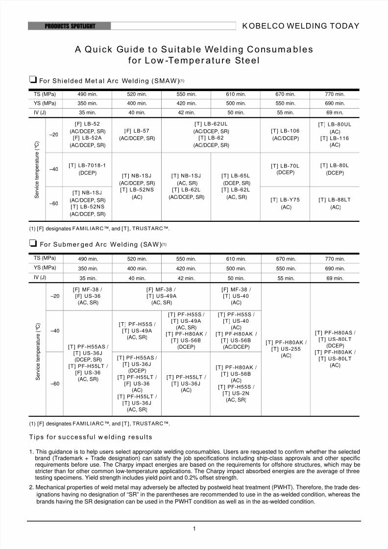
KOBELCO WELDING TODAY 1 PRODUCTS SPOTLIGHT A Quick Guide to Suitable Welding Con suma bles for Low-T emper ature S teel For Shielded Met al Arc Welding (SMAW) (1) (1) [ F] designates FAMILIARC™, and [ T ] , TRUSTARC™. For Submer ged Arc Welding (SAW) (1) (1) [ F] designates FAMILIARC™, and [ T] , TRUSTARC™. Tips for successful w elding results 1. This guidance is to help users select appropriate welding consumables. Users are requested to confirm whether the selected brand (Trademark + Trade designation) can satisfy the job specifications including ship-class approvals and other specific requirements before use. The Charpy impact energies are based on the requirements for offshore structures, which may be stricter than for other common low-temperature applications. The Charpy impact absorbed energies are the average of three testing specimens. Yield strength includes yield point and 0.2% offset strength. 2. Mechanical properties of weld metal may adversely be affected by postweld heat treatment (PWHT). Therefore, the trade des- ignations having no designation of “SR” in the parentheses are recommended to use in the as-welded condition, whereas the brands having the SR designation can be used in the PWHT condition as well as in the as-welded condition. TS (MPa) 490 min. 520 min. 550 min. 610 min. 670 min. 770 min. YS (MPa) 350 min. 400 min. 420 min. 500 min. 550 min. 690 min. IV (J) 35 min. 40 min. 42 min. 50 min. 55 min. 69 min. S e r v i c e t e m p e r a t u r e ( C ) –20 [ F] LB-52 (AC/DCEP, SR) [ F] LB-52A (AC/DCEP, SR) [ F] LB-57 (AC/DCEP, SR) [ T ] LB-62UL (AC/DCEP, SR) [ T ] LB-62 (AC/DCEP, SR) [ T ] LB-106 (AC/DCEP) [ T ] LB-80UL (AC) [T ] LB-116 (AC) –40 [ T ] LB-7018-1 (DCEP) [ T ] NB-1SJ (AC/DCEP, SR) [ T ] LB-52NS (AC) [ T ] NB-1SJ (AC, SR) [ T ] LB-62L (AC/DCEP, SR) [ T ] LB-65L (DCEP, SR) [ T ] LB-62L (AC, SR) [ T ] LB-70L (DCEP) [ T ] LB-80L (DCEP) –60 [ T ] NB-1SJ (AC/DCEP, SR) [ T ] LB-52NS (AC/DCEP, SR) [ T ] LB-Y75 (AC) [ T ] LB-88LT (AC) TS (MPa) 490 min. 520 min. 550 min. 610 min. 670 min. 770 min. YS (MPa) 350 min. 400 min. 420 min. 500 min. 550 min. 690 min. IV (J) 35 min. 40 min. 42 min. 50 min. 55 min. 69 min. S e r v i c e t e m p e r a t u r e ( ° C ) –20 [ F] MF-38 / [ F] US-36 (AC, SR) [ F] MF-38 / [ T ] US-49A (AC, SR) [ F] MF-38 / [ T ] US-40 (AC) [ T ] PF-H80AK / [ T ] US-255 (AC) [ T ] PF-H80AS / [ T ] US-80LT (DCEP) [ T ] PF-H80AK / [ T ] US-80LT (AC) –40 [ T ] PF-H55AS / [ T ] US-36J (DCEP, SR) [ T] PF-H55LT / [ F] US-36 (AC, SR) [ T ] PF-H55S / [ T ] US-49A (AC, SR) [ T ] PF-H55S / [ T ] US-49A (AC, SR) [ T ] PF-H80AK / [ T ] US-56B (DCEP) [ T ] PF-H55S / [ T ] US-40 (AC) [ T ] PF- H80AK / [ T ] US-56B (AC/DCEP) –60 [ T ] PF-H55AS / [T ] US-36J (DCEP) [ T] PF-H55LT / [F] US-36 (AC) [ T ] PF-H55LT / [ T ] US-36J (AC, SR) [ T ] PF-H55LT / [ T ] US-36J (AC) [ T] PF-H80AK / [ T] US-56B (AC) [ T ] PF-H55S / [ T ] US-2N (AC, SR)

Welcome message from author
This document is posted to help you gain knowledge. Please leave a comment to let me know what you think about it! Share it to your friends and learn new things together.
Transcript
8/8/2019 KWT LowTemp 4Ed
http://slidepdf.com/reader/full/kwt-lowtemp-4ed 1/18
K OBELCO WELDING TODAY
1
PRODUCTS SPOTLIGHT
A Quick Guide t o Sui tab le Weld ing Consuma bles
for Low -Temper ature Stee l
For Shie lded Met al Arc Welding (SMAW)(1)
(1) [F] designates FAMILIARC™, and [T ] , TRUSTARC™.
For Submer ged Arc Welding (SAW)(1)
(1) [F] designates FAMILIARC™, and [T ] , TRUSTARC™.
Tips fo r success fu l w e ld ing resu l ts
1. This guidance is to help users select appropriate welding consumables. Users are requested to confirm whether the selectedbrand (Trademark + Trade designation) can satisfy the job specifications including ship-class approvals and other specificrequirements before use. The Charpy impact energies are based on the requirements for offshore structures, which may bestricter than for other common low-temperature applications. The Charpy impact absorbed energies are the average of threetesting specimens. Yield strength includes yield point and 0.2% offset strength.
2. Mechanical properties of weld metal may adversely be affected by postweld heat treatment (PWHT). Therefore, the trade des-
ignations having no designation of “SR” in the parentheses are recommended to use in the as-welded condition, whereas the
brands having the SR designation can be used in the PWHT condition as well as in the as-welded condition.
TS (MPa) 490 min. 520 min. 550 min. 610 min. 670 min. 770 min.YS (MPa) 350 min. 400 min. 420 min. 500 min. 550 min. 690 min.
IV (J) 35 min. 40 min. 42 min. 50 min. 55 min. 69 min.
S e r v i c e t e m p e r a t u r e ( ° C )
–20
[F] LB-52
(AC/DCEP, SR)
[F] LB-52A
(AC/DCEP, SR)
[F] LB-57
(AC/DCEP, SR)
[T ] LB-62UL
(AC/DCEP, SR)
[T ] LB-62
(AC/DCEP, SR)
[T ] LB-106
(AC/DCEP)
[T ] LB-80UL
(AC)
[T ] LB-116
(AC)
–40[T ] LB-7018-1
(DCEP)[T ] NB-1SJ
(AC/DCEP, SR)
[T] LB-52NS
(AC)
[T ] NB-1SJ
(AC, SR)
[T] LB-62L
(AC/DCEP, SR)
[T ] LB-65L
(DCEP, SR)
[T ] LB-62L
(AC, SR)
[T ] LB-70L
(DCEP)
[T ] LB-80L
(DCEP)
–60
[T ] NB-1SJ(AC/DCEP, SR)
[T ] LB-52NS
(AC/DCEP, SR)
[T] LB-Y75
(AC)
[T ] LB-88LT
(AC)
TS (MPa) 490 min. 520 min. 550 min. 610 min. 670 min. 770 min.
YS (MPa) 350 min. 400 min. 420 min. 500 min. 550 min. 690 min.
IV (J) 35 min. 40 min. 42 min. 50 min. 55 min. 69 min.
S e r v i c e t e m p e r a t u r e ( ° C )
–20[F] MF-38 / [F] US-36
(AC, SR)
[F] MF-38 / [T ] US-49A
(AC, SR)
[F] MF-38 / [T ] US-40
(AC)
[T ] PF-H80AK /
[T] US-255
(AC)
[T] PF-H80AS /
[T] US-80LT
(DCEP)
[T] PF-H80AK /
[T] US-80LT
(AC)
–40
[T ] PF-H55AS /
[T ] US-36J
(DCEP, SR)
[T ] PF-H55LT /
[F] US-36
(AC, SR)
[T] PF-H55S /
[T] US-49A
(AC, SR)
[T ] PF-H55S / [T ] US-49A
(AC, SR)
[T ] PF-H80AK /
[T ] US-56B
(DCEP)
[T ] PF-H55S /
[T ] US-40
(AC)
[T ] PF-H80AK /
[T ] US-56B
(AC/DCEP)
–60
[T ] PF-H55AS /
[T] US-36J
(DCEP)
[T ] PF-H55LT /
[F] US-36(AC)
[T ] PF-H55LT / [T ] US-36J
(AC, SR)
[T ] PF-H55LT / [T ] US-36J
(AC)
[T ] PF-H80AK /
[T ] US-56B
(AC)
[T ] PF-H55S / [T ] US-2N
(AC, SR)
8/8/2019 KWT LowTemp 4Ed
http://slidepdf.com/reader/full/kwt-lowtemp-4ed 2/18
K OBELCO WELDING TODAY
2
PRODUCTS SPOTLIGHT
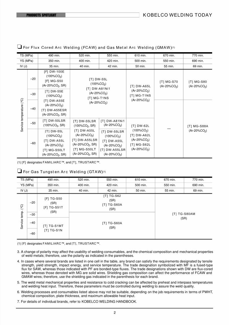
For Flux Cored Arc Welding (FCAW) and Gas Met al Arc Welding (GMAW)(1)
(1) [F] designates FAMILIARC™, and [T ] , TRUSTARC™.
For Gas Tungst en Ar c Welding (GTAW) (1)
(1) [F] designates FAMILIARC™, and [T ] , TRUSTARC™.
3. A change of polarity may affect the usability of welding consumables, and the chemical composition and mechanical propertiesof weld metals; therefore, use the polarity as indicated in the parentheses.
4. In cases where several brands are listed in one cell in the table, any brand can satisfy the requirements designated by tensilestrength, yield strength, impact energy, and service temperature. The trade designation symbolized with MF is a fused-typeflux for SAW, whereas those indicated with PF are bonded-type fluxes. The trade designations shown with DW are flux-coredwires, whereas those denoted with MG are solid wires. Shielding gas composition can affect the performance of FCAW andGMAW wires; therefore, use the shielding gas indicated in the parenthesis for each brand.
5. The weld metal mechanical properties and resistance to cold cracking can be affected by preheat and interpass temperaturesand welding heat input. Therefore, these parameters must be controlled during welding to assure the weld quality.
6. Welding processes and consumables listed above may not be suitable, depending on the job requirements in terms of PWHT,chemical composition, plate thickness, and maximum allowable heat input.
7. For details of individual brands, refer to KOBELCO WELDING HANDBOOK.
TS (MPa) 490 min. 520 min. 550 min. 610 min. 670 min. 770 min.YS (MPa) 350 min. 400 min. 420 min. 500 min. 550 min. 690 min.
IV (J) 35 min. 40 min. 42 min. 50 min. 55 min. 69 min.
S e r v i c e t e m p e
r a t u r e ( ° C )
–20
[F] DW-100E
(100%CO2)
[F] MG-S50
(Ar-20%CO2, SR)
[T ] DW-55L
(100%CO2)
[T ] DW-A81Ni1
(Ar-20%CO2)
[T ] MG-T1NS
(Ar-20%CO2)
[T] DW-A65L
(Ar-20%CO2)
[T ] MG-T1NS
(Ar-20%CO2)
[T ] MG-S70
(Ar-20%CO2)
[T ] MG-S80
(Ar-20%CO2)
–30[T ] DW-55E
(100%CO2)
[T ] DW-A55E
(Ar-20%CO2)
[T ] DW-A55ESR
(Ar-20%CO2, SR)
–40
—[T ] MG-S88A
(Ar-20%CO2)
–50[T ] DW-50LSR
(100%CO2, SR)
[T] DW-55LSR
(100%CO2, SR)
[T ] DW-A55L
(Ar-20%CO2)
[T ] DW-A55LSR
(Ar-20%CO2, SR)
[T] MG-S50LT
(Ar-20%CO2, SR)
[T ] DW-A81Ni1
(Ar-20%CO2) [T ] DW-62L
(100%CO2)
[T] DW-A62L
(Ar-20%CO2)
[T ] MG-S62L
(Ar-20%CO2)
–60
[T ] DW-55L
(100%CO2)
[T] DW-A55L
(Ar-20%CO2)
[T ] MG-S50LT
(Ar-20%CO2, SR)
[T ] DW-55LSR
(100%CO2)
[T ] DW-A55L
(Ar-20%CO2)
[T ] DW-A55LSR
(Ar-20%CO2)
TS (MPa) 490 min. 520 min. 550 min. 610 min. 670 min. 770 min.
YS (MPa) 350 min. 400 min. 420 min. 500 min. 550 min. 690 min.
IV (J) 35 min. 40 min. 42 min. 50 min. 55 min. 69 min.
S
e r v i c e t e m p .
( ° C )
–20
[F] TG-S50
(SR)
[F] TG-S51T
(SR)
[T] TG-S62
(SR)
[T ] TG-S60A
(SR)
[T ] TG-S80AM
(SR)
–30
[T ] TG-S60A
(SR)
–40[T] TG-S1MT
[T] TG-S1N –60
8/8/2019 KWT LowTemp 4Ed
http://slidepdf.com/reader/full/kwt-lowtemp-4ed 3/18
K OBELCO WELDING TODAY
3
PRODUCTS SPOTLIGHT
LB-52NS is a highly reputed, dependable electrode
for various low temperature applications such as
LPG carriers and storage tanks, offshore structures,
and heat exchangers, when the service temperature
is down to –60°C.
What charact er is t i cs of LB-52NSdo the users count on?
The most important quality of the electrodes used
in low-temperature applications is weld notch
toughness sufficient enough to prevent brittle frac-
tures in the component materials under severe ser-
vice conditions. Notch toughness, however, is
commonly affected by such variables in welding as
heat input, plate thickness, cooling speed, welding
position, and postweld heat treatment.
LB-52NS ensures adequate notch toughness over a
wide range of these variables. In addition, specifictechnical data such as Crack Tip Opening Dis-
placement (CTOD) and Sulfide Stress Corrosion
Cracking (SSCC) are available, which are some-
times required for special applications. Such
dependable performance and technical data helps
users control the welding quality.
LB-52NS acc omm odateshigher heat input
Heat input is electric energy applied to a weld,
which is determined by welding current, arc volt-
age, and carriage speed. Higher heat input com-
monly causes coarse microstructure, thereby
decreasing notch toughness. LB-52NS, however,
can maintain fine microstructure with higher heat
input compared to conventional electrodes, due to
the specific chemical composition (Si-Mn-0.5Ni-
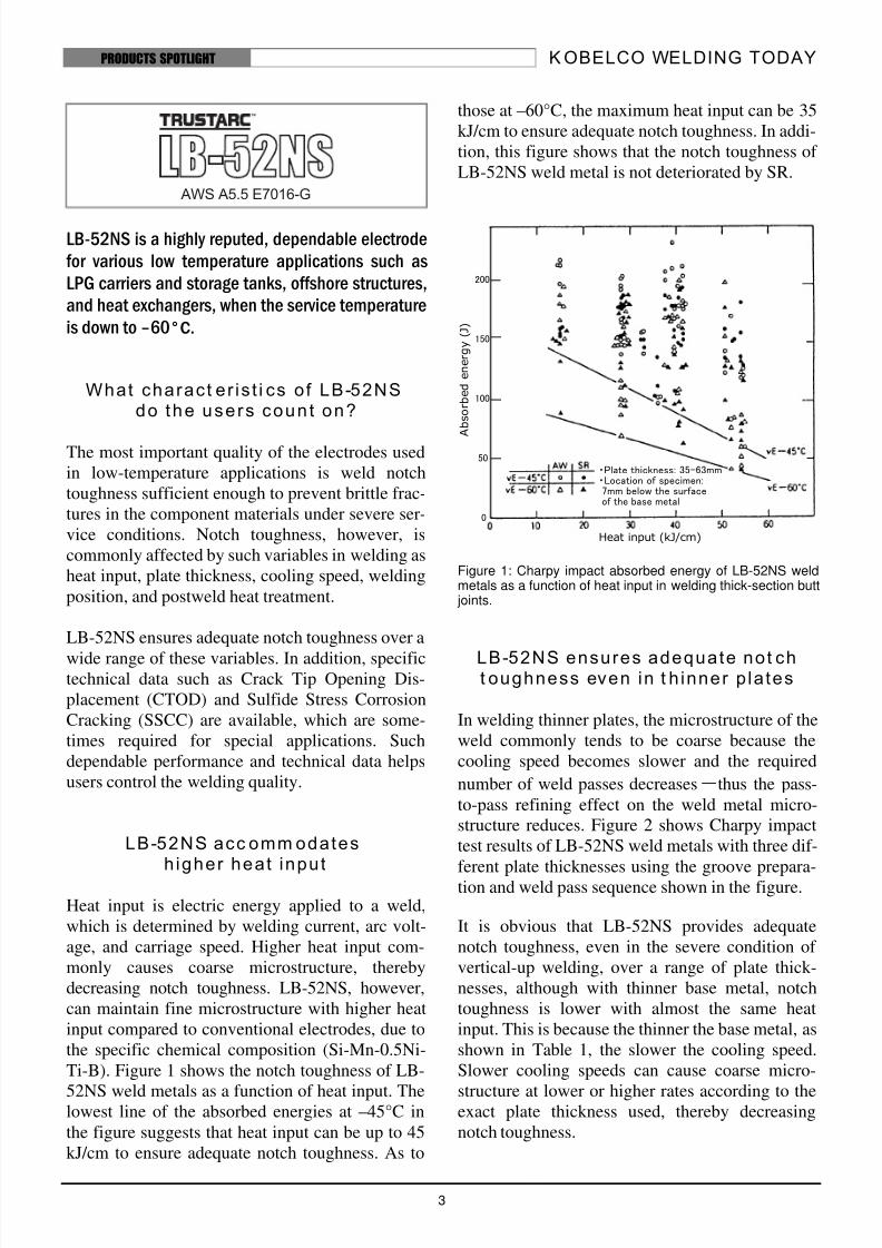
Ti-B). Figure 1 shows the notch toughness of LB-
52NS weld metals as a function of heat input. Thelowest line of the absorbed energies at –45°C in
the figure suggests that heat input can be up to 45
kJ/cm to ensure adequate notch toughness. As to
those at –60°C, the maximum heat input can be 35
kJ/cm to ensure adequate notch toughness. In addi-
tion, this figure shows that the notch toughness of
LB-52NS weld metal is not deteriorated by SR.
Figure 1: Charpy impact absorbed energy of LB-52NS weldmetals as a function of heat input in welding thick-section butt joints.
LB-52NS ensures adequate not cht oughness even in t h inner p la tes
In welding thinner plates, the microstructure of the
weld commonly tends to be coarse because the
cooling speed becomes slower and the required
number of weld passes decreases―thus the pass-
to-pass refining effect on the weld metal micro-
structure reduces. Figure 2 shows Charpy impact
test results of LB-52NS weld metals with three dif-
ferent plate thicknesses using the groove prepara-tion and weld pass sequence shown in the figure.
It is obvious that LB-52NS provides adequate
notch toughness, even in the severe condition of
vertical-up welding, over a range of plate thick-
nesses, although with thinner base metal, notch
toughness is lower with almost the same heat
input. This is because the thinner the base metal, as
shown in Table 1, the slower the cooling speed.
Slower cooling speeds can cause coarse micro-
structure at lower or higher rates according to theexact plate thickness used, thereby decreasing
notch toughness.
Heat input (kJ/cm)
A b s o r b e d
e n e r g y
( J )
・Plate thickness: 35-63mm・Location of specimen:7mm below the surfaceof the base metal
200
150
100
50
0
8/8/2019 KWT LowTemp 4Ed
http://slidepdf.com/reader/full/kwt-lowtemp-4ed 4/18
K OBELCO WELDING TODAY
4
PRODUCTS SPOTLIGHT
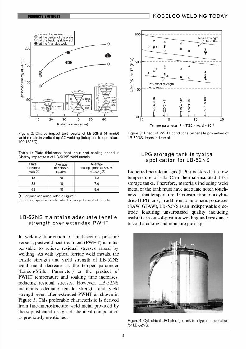
Figure 2: Charpy impact test results of LB-52NS (4 mmØ)weld metals in vertical-up AC welding (interpass temperature:100-150°C).
Table 1: Plate thickness, heat input and cooling speed inCharpy impact test of LB-52NS weld metals
(1) For pass sequence, refer to Figure 2.
(2) Cooling speed was calculated by using a Rosenthal formula.
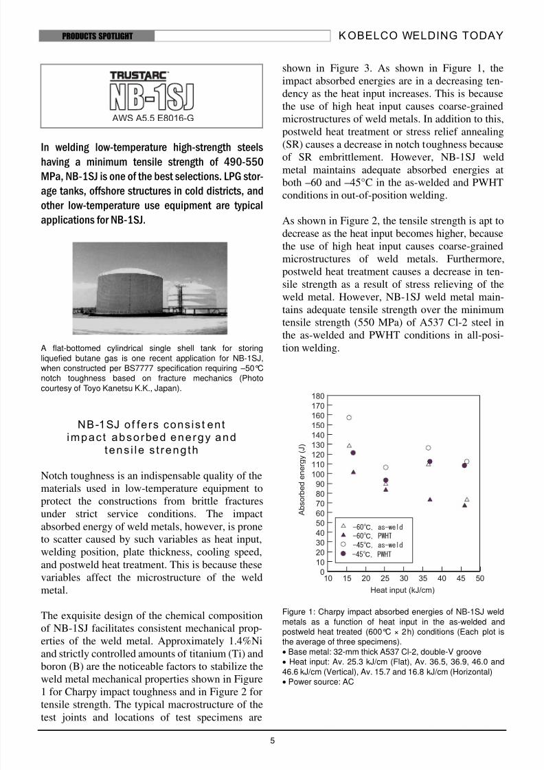
LB-52NS mainta ins adequat e t ens i les tr ength over ext ended PWHT
In welding fabrication of thick-section pressure
vessels, postweld heat treatment (PWHT) is indis-pensable to relieve residual stresses raised by
welding. As with typical ferritic weld metals, the
tensile strength and yield strength of LB-52NS
weld metal decrease as the temper parameter
(Larson-Miller Parameter) or the product of
PWHT temperature and soaking time increases,
reducing residual stresses. However, LB-52NS
maintains adequate tensile strength and yield
strength even after extended PWHT as shown in
Figure 3. This preferable characteristic is derived
from fine-microstructure weld metal provided bythe sophisticated design of chemical composition
as previously mentioned.
Figure 3: Effect of PWHT conditions on tensile properties ofLB-52NS deposited metal.
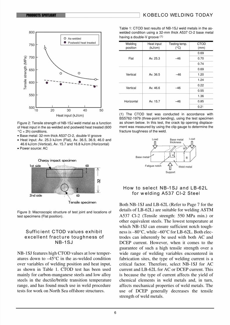
LPG s to rage tank is typ ica lappl icat ion for LB-52NS
Liquefied petroleum gas (LPG) is stored at a low
temperature of –45°C in thermal-insulated LPG
storage tanks. Therefore, materials including weldmetal of the tank must have adequate notch tough-
ness at that temperature. In construction of a cylin-
drical LPG tank, in addition to automatic processes
(SAW, GTAW), LB-52NS is an indispensable elec-
trode featuring unsurpassed quality including
usability in out-of-position welding and resistance
to cold cracking and moisture pick-up.
Figure 4: Cylindrical LPG storage tank is a typical application
for LB-52NS.
Platethickness
(mm) (1)
Averageheat input
(kJ/cm)
Averagecooling speed at 540°C
(°C/sec.) (2)
12 38 1.2
32 40 7.6
63 40 9.6
17 18 19 20
600
500
400
300
Temper parameter: P = T(20 + log t)×10 -3
0 . 2
% O
S a n d T S ( M P a )
6 0 0 ℃ × 1 h
6 2 0 ℃ × 1 h
6 2 0 ℃ × 5 h
6 2 5 ℃ × 8 h
6 5 0 ℃ × 1 0 h
0.2% offset strength
Tensile strength
: AC : DC
: AC : DC
8/8/2019 KWT LowTemp 4Ed
http://slidepdf.com/reader/full/kwt-lowtemp-4ed 5/18
K OBELCO WELDING TODAY
5
PRODUCTS SPOTLIGHT
In welding low-temperature high-strength steels
having a minimum tensile strength of 490-550
MPa, NB-1SJ is one of the best selections. LPG stor-
age tanks, offshore structures in cold districts, and
other low-temperature use equipment are typical
applications for NB-1SJ.
A flat-bottomed cylindrical single shell tank for storing
liquefied butane gas is one recent application for NB-1SJ,
when constructed per BS7777 specification requiring –50°C
notch toughness based on fracture mechanics (Photo
courtesy of Toyo Kanetsu K.K., Japan).
NB-1SJ of fers cons is t entimpac t absorbed energy and
tens i le s t reng th
Notch toughness is an indispensable quality of the
materials used in low-temperature equipment to
protect the constructions from brittle fractures
under strict service conditions. The impact
absorbed energy of weld metals, however, is prone
to scatter caused by such variables as heat input,welding position, plate thickness, cooling speed,
and postweld heat treatment. This is because these
variables affect the microstructure of the weld
metal.
The exquisite design of the chemical composition
of NB-1SJ facilitates consistent mechanical prop-
erties of the weld metal. Approximately 1.4%Ni
and strictly controlled amounts of titanium (Ti) and
boron (B) are the noticeable factors to stabilize the
weld metal mechanical properties shown in Figure
1 for Charpy impact toughness and in Figure 2 for
tensile strength. The typical macrostructure of the
test joints and locations of test specimens are
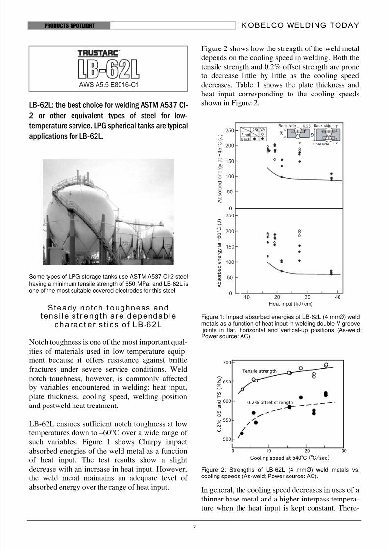
shown in Figure 3. As shown in Figure 1, the
impact absorbed energies are in a decreasing ten-
dency as the heat input increases. This is because
the use of high heat input causes coarse-grained
microstructures of weld metals. In addition to this,
postweld heat treatment or stress relief annealing(SR) causes a decrease in notch toughness because
of SR embrittlement. However, NB-1SJ weld
metal maintains adequate absorbed energies at
both –60 and –45°C in the as-welded and PWHT
conditions in out-of-position welding.
As shown in Figure 2, the tensile strength is apt to
decrease as the heat input becomes higher, because
the use of high heat input causes coarse-grained
microstructures of weld metals. Furthermore,
postweld heat treatment causes a decrease in ten-sile strength as a result of stress relieving of the
weld metal. However, NB-1SJ weld metal main-
tains adequate tensile strength over the minimum
tensile strength (550 MPa) of A537 Cl-2 steel in
the as-welded and PWHT conditions in all-posi-
tion welding.
Figure 1: Charpy impact absorbed energies of NB-1SJ weld
metals as a function of heat input in the as-welded and
postweld heat treated (600°C × 2h) conditions (Each plot is
the average of three specimens).
• Base metal: 32-mm thick A537 Cl-2, double-V groove
• Heat input: Av. 25.3 kJ/cm (Flat), Av. 36.5, 36.9, 46.0 and
46.6 kJ/cm (Vertical), Av. 15.7 and 16.8 kJ/cm (Horizontal)• Power source: AC
8/8/2019 KWT LowTemp 4Ed
http://slidepdf.com/reader/full/kwt-lowtemp-4ed 6/18
K OBELCO WELDING TODAY
6
PRODUCTS SPOTLIGHT
Figure 2: Tensile strength of NB-1SJ weld metal as a function
of Heat input in the as-welded and postweld heat treated (600
°C × 2h) conditions.
• Base metal: 32-mm thick A537 Cl-2, double-V groove
• Heat input: Av. 25.3 kJ/cm (Flat), Av. 36.5, 36.9, 46.0 and
46.6 kJ/cm (Vertical), Av. 15.7 and 16.8 kJ/cm (Horizontal)
• Power source: AC
Figure 3: Macroscopic structure of test joint and locations of
test specimens (Flat position).
Suff ic ient CTOD values exhib i texce l len t f rac t u re toughness o f
NB-1SJ
NB-1SJ features high CTOD values at low temper-
atures down to –45°C in the as-welded condition
over variables of welding position and heat input,
as shown in Table 1. CTOD test has been used
mainly for carbon-manganese steels and low alloy
steels in the ductile/brittle transition temperature
range, and has found much use in weld proceduretests for work on North Sea offshore structures.
Table 1: CTOD test results of NB-1SJ weld metals in the as-
welded condition using a 32-mm thick A537 Cl-2 base metal
having a double-V groove (1)
(1) The CTOD test was conducted in accordance withBS5762-1979 (three-point bending), using the test specimen
as shown below. In this test, the crack tip opening displace-
ment was measured by using the clip gauge to determine the
fracture toughness of the weld.
How to se lect NB-1SJ and LB-62Lfor w elding A537 Cl-2 Steel
Both NB-1SJ and LB-62L (Refer to Page 7 for the
details of LB-62L) are suitable for welding ASTM
A537 Cl-2 (Tensile strength: 550 MPa min.) or
other equivalent steels. The lowest temperature at
which NB-1SJ can ensure sufficient notch tough-ness is –80°C, while –60°C for LB-62L. Both elec-
trodes can inherently be used with both AC and
DCEP current. However, when it comes to the
guarantee of such a high tensile strength over a
wide range of welding variables encountered in
fabrication sites, the type of welding current is a
critical factor. Therefore, select NB-1SJ for AC
current and LB-62L for AC or DCEP current. This
is because the type of current affects the yield of
chemical elements in weld metals and, in turn,
affects mechanical properties of weld metals. Theuse of DCEP generally decreases the tensile
strength of weld metals.
3 2
81st side
2nd side 8
Tensile specimen
Charpy impact specimen
Welding
position
Heat input
(kJ/cm)
Testing temp.
(°C)
CTOD
(mm)
Flat Av. 25.3 –46
0.69
0.70
0.74
Vertical Av. 36.5 –46
0.69
1.20
1.24
Vertical Av. 46.6 –460.22
0.55
Horizontal Av. 15.7 –46
1.36
0.85
0.21
8/8/2019 KWT LowTemp 4Ed
http://slidepdf.com/reader/full/kwt-lowtemp-4ed 7/18
K OBELCO WELDING TODAY
7
PRODUCTS SPOTLIGHT
LB-62L: the best choice for welding ASTM A537 Cl-
2 or other equivalent types of steel for low-
temperature service. LPG spherical tanks are typical
applications for LB-62L.
Some types of LPG storage tanks use ASTM A537 Cl-2 steelhaving a minimum tensile strength of 550 MPa, and LB-62L is
one of the most suitable covered electrodes for this steel.
Steady notch t oughness andtens i le s t r eng th a re dependab le
charac t e r is t ics o f LB-62L
Notch toughness is one of the most important qual-
ities of materials used in low-temperature equip-
ment because it offers resistance against brittle
fractures under severe service conditions. Weld
notch toughness, however, is commonly affected
by variables encountered in welding: heat input,plate thickness, cooling speed, welding position
and postweld heat treatment.
LB-62L ensures sufficient notch toughness at low
temperatures down to –60°C over a wide range of
such variables. Figure 1 shows Charpy impact
absorbed energies of the weld metal as a function
of heat input. The test results show a slight
decrease with an increase in heat input. However,
the weld metal maintains an adequate level of absorbed energy over the range of heat input.
Figure 2 shows how the strength of the weld metal
depends on the cooling speed in welding. Both the
tensile strength and 0.2% offset strength are prone
to decrease little by little as the cooling speed
decreases. Table 1 shows the plate thickness and
heat input corresponding to the cooling speedsshown in Figure 2.
Figure 1: Impact absorbed energies of LB-62L (4 mmØ) weldmetals as a function of heat input in welding double-V groove joints in flat, horizontal and vertical-up positions (As-weld;Power source: AC).
Figure 2: Strengths of LB-62L (4 mmØ) weld metals vs.cooling speeds (As-weld; Power source: AC).
In general, the cooling speed decreases in uses of a
thinner base metal and a higher interpass tempera-
ture when the heat input is kept constant. There-
0 10 20 30
700
650
600
550
500
0 . 2
% O
S a n d T S ( M P a )
Cooling speed at 540℃ (℃/sec)
Tensile strength
0.2% offset st rength
8/8/2019 KWT LowTemp 4Ed
http://slidepdf.com/reader/full/kwt-lowtemp-4ed 8/18
K OBELCO WELDING TODAY
8
PRODUCTS SPOTLIGHT
fore, in order to attain the targeted weld quality, the
heat input and interpass temperature should prop-
erly be controlled according to the thickness of the
base metal and the required qualities for the weld.
Table 1: Welding conditions (No preheat)
LB-62L maint a ins adequate t ens i les tr ength over ext ended PWHT
Some weld joints where residual stresses are prone
to concentrate (e.g. a crown plate to nozzle weld
joint of a spherical tank) require postweld heat
treatment (PWHT). As usual with ferritic weld
metal, the strength of LB-62L weld metal
decreases as PWHT temperature and soaking time
increase. However, LB-62L weld metal maintainsadequate tensile strength over the minimum tensile
strength (550N/mm2) of A537 Cl-2 steel even after
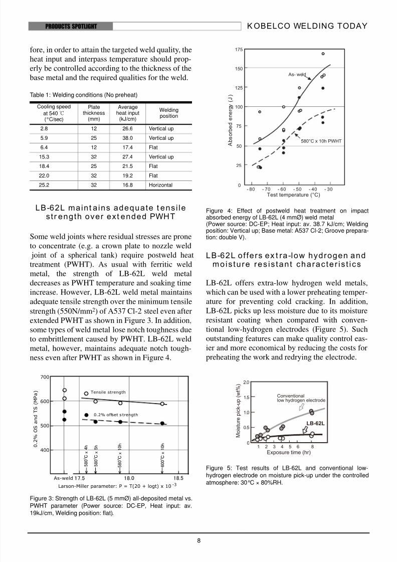
extended PWHT as shown in Figure 3. In addition,
some types of weld metal lose notch toughness due
to embrittlement caused by PWHT. LB-62L weld
metal, however, maintains adequate notch tough-
ness even after PWHT as shown in Figure 4.
Figure 3: Strength of LB-62L (5 mmØ) all-deposited metal vs.
PWHT parameter (Power source: DC-EP, Heat input: av.19kJ/cm, Welding position: flat).
Figure 4: Effect of postweld heat treatment on impactabsorbed energy of LB-62L (4 mmØ) weld metal(Power source: DC-EP; Heat input: av. 38.7 kJ/cm; Weldingposition: Vertical up; Base metal: A537 Cl-2; Groove prepara-tion: double V).
LB-62L of fers ex t ra-low hydrogen andmois tu re res is tan t charac te r is t ics
LB-62L offers extra-low hydrogen weld metals,
which can be used with a lower preheating temper-ature for preventing cold cracking. In addition,
LB-62L picks up less moisture due to its moisture
resistant coating when compared with conven-
tional low-hydrogen electrodes (Figure 5). Such
outstanding features can make quality control eas-
ier and more economical by reducing the costs for
preheating the work and redrying the electrode.
Figure 5: Test results of LB-62L and conventional low-hydrogen electrode on moisture pick-up under the controlledatmosphere: 30°C × 80%RH.
Cooling speed
at 540℃(°C/sec)
Platethickness
(mm)
Averageheat input
(kJ/cm)
Weldingposition
2.8 12 26.6 Vertical up
5.9 25 38.0 Vertical up
6.4 12 17.4 Flat
15.3 32 27.4 Vertical up
18.4 25 21.5 Flat
22.0 32 19.2 Flat
25.2 32 16.8 Horizontal
700
600
500
400
17.5 18.0 18.5
5 8 0 ℃ x
4 h
5 8 0 ℃ x
5 h
5 8 0 ℃ x
1 0 h
6 0 0 ℃ x
1 0 h
Larson-Miller parameter: P = T(20 + logt) x 10 -3
As-weld
0 . 2
% O
S a n d T S ( M P a
)Tensile strength
0.2% offset s trength
8/8/2019 KWT LowTemp 4Ed
http://slidepdf.com/reader/full/kwt-lowtemp-4ed 9/18
K OBELCO WELDING TODAY
9
PRODUCTS SPOTLIGHT
LB-65L: The best selection for DC-spec. electrode
for 610-MPa class high strength steel for low tem-
perature applications such as offshore structures
and storage tanks.
LB-65L of fers cons is tent t ens i les tr ength, notc h toughness and CTOD
LB-65L is an extra-low hydrogen covered elec-trode for the direct current electrode positive
(DCEP) polarity, depositing 2.5%Ni-Ti-B weld
metals with fine microstructure. It assures consis-
tent tensile strength, impact absorbed energy and
crack-tip opening displacement (CTOD) in both
the as-welded and postweld heat treated (PWHT)
conditions.
Figure 1 shows the yield strength (0.2% offset
strength) and tensile strength of LB-65L weld
metal at room temperature as a function of the tem-
per parameter of PWHT. It is obvious that LB-65L
displays sufficient tensile strengths exceeding 610
MPa in the PWHT range tested.
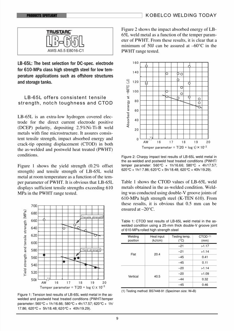
Figure 1: Tension test results of LB-65L weld metal in the as-
welded and postweld heat treated conditions (PWHT/temper
parameter: 560°C × 1h/16.66; 580°C × 4h/17.57; 620°C × 1h/
17.86; 620°C × 5h/18.48; 620°C × 40h/19.29).
Figure 2 shows the impact absorbed energy of LB-
65L weld metal as a function of the temper param-
eter of PWHT. From these results, it is clear that a
minimum of 50J can be assured at –60°C in the
PWHT range tested.
Figure 2: Charpy impact test results of LB-65L weld metal in
the as-welded and postweld heat treated conditions (PWHT/
temper parameter: 560°C × 1h/16.66; 580°C × 4h/17.57;
620°C × 1h/17.86; 620°C × 5h/18.48; 620°C × 40h/19.29).
Table 1 shows the CTOD values of LB-65L weld
metals obtained in the as-welded condition. Weld-
ing was conducted using double-V groove joints of
610-MPa high strength steel (K-TEN 610). From
these results, it is obvious that 0.5 mm can be
ensured at –20°C.
(1) Testing method: BS7448-91 (Specimen size: W=B)
Table 1: CTOD test results of LB-65L weld metal in the as-
welded condition using a 25-mm thick double-V groove joint
of 610-MPa rolled high strength steel
Welding
position
Heat input
(kJ/cm)
Testing temp.
(°C)
CTOD (1)
(mm)
Flat 20.4
–21 >1.17
–21 >1.14
–45 0.41
–45 0.11
Vertical 40.5
–20 >1.14
–20 >1.09
–44 0.32
–45 0.46
8/8/2019 KWT LowTemp 4Ed
http://slidepdf.com/reader/full/kwt-lowtemp-4ed 10/18
K OBELCO WELDING TODAY
10
PRODUCTS SPOTLIGHT
Spherical storage tanks, penstock, offshore struc-
tures, and bridges of 780 MPa high strength steel
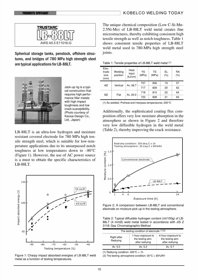
are typical applications for LB-88LT.
LB-88LT is an ultra-low hydrogen and moisture
resistant covered electrode for 780 MPa high ten-
sile strength steel, which is suitable for low-tem-
perature applications due to its unsurpassed notchtoughness at low temperatures down to –80°C
(Figure 1). However, the use of AC power source
is a must to obtain the specific characteristics of
LB-88LT.
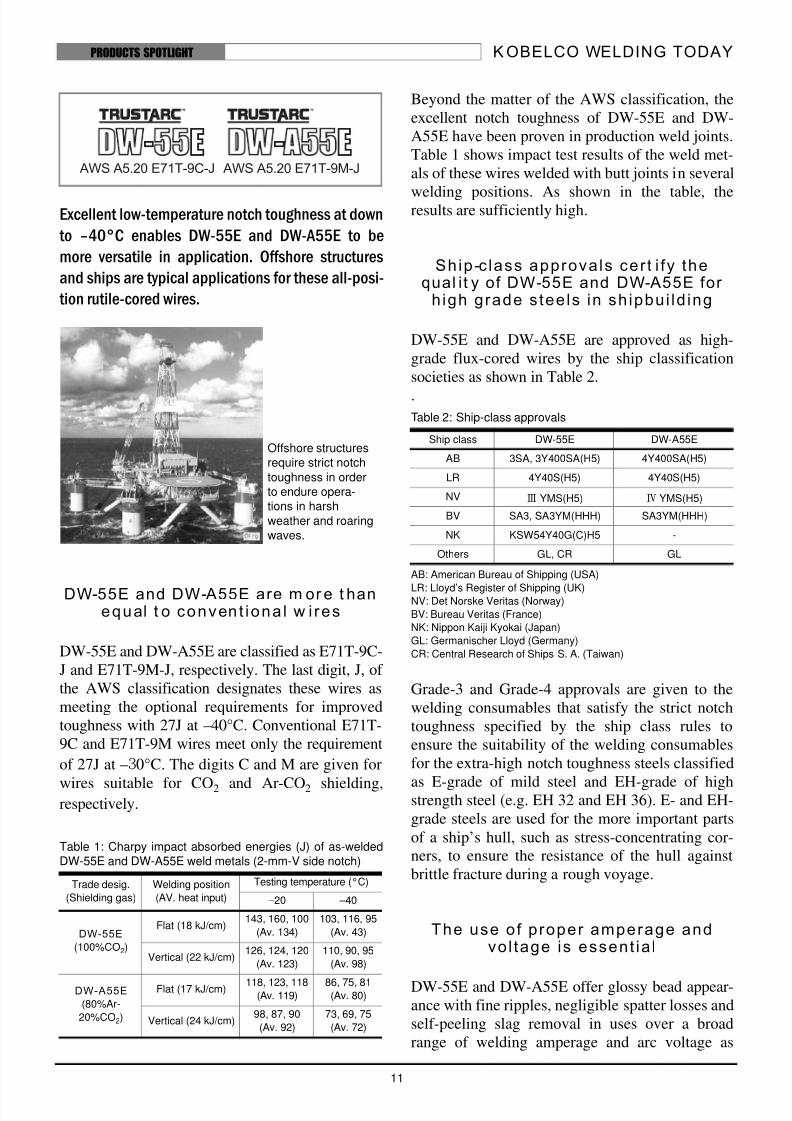
Figure 1: Charpy impact absorbed energies of LB-88LT weldmetal as a function of testing temperatures.
The unique chemical composition (Low C-Si-Mn-
2.5Ni-Mo) of LB-88LT weld metal creates fine
microstructures, thereby exhibiting consistent high
tensile strength as well as notch toughness. Table 1
shows consistent tensile properties of LB-88LT
weld metal used in 780-MPa high strength steel joints.
(1) As-welded; Preheat and interpass temperatures: 200°C
Additionally, the sophisticated coating flux com-
position offers very low moisture absorption in the
atmosphere as shown in Figure 2 and therefore
very low diffusible hydrogen in the weld metal
(Table 2), thereby improving the crack resistance.
Figure 2: A comparison between LB-88LT and conventionalelectrode on moisture pick up in the testing atmosphere.
(1) Redrying condition: 400°C × 1h
(2) The testing atmosphere condition: 30°C × 80%RH
150
100
50
-90 -80 -70 -60 -50 -40Testing temperature
I m p a c t a b s o r b e d e n e r g y ( J )
5.0 mmΦ
4.0 mmΦ
(℃)
Table 1: Tensile properties of LB-88LT weld metal (1)
Elec-
trode
size
(mm)
Welding
position
Heat
input
(kJ/cm)
YS
(MPa)
TS
(MPa)
EL
(%)
RA
(%)
4Ø Vertical Av. 38.7707 836 19 57
717 839 20 62
5Ø Flat Av. 25.0718 810 22 64
723 828 21 63
Table 2: Typical diffusible hydrogen content (ml/100g) of LB-
88LT (4 mmØ) weld metal tested in accordance with JIS Z3118: Gas Chromatographic Method
The testing condition of electrode (1)(2)
Right after
Redrying
1-hour exposure to
the testing atm.
after redrying
4-hour exposure to
the testing atm.
after redrying
Av. 5.0 Av. 5.2 Av. 5.7
1.5
1.0
0.5
01 4 6 24
Exposure time (h)
M o i s t u r e c o n t e n t ( % )
Redrying condition: 350 deg.C x 1h
Testing atmosphere: 30 deg.C x 80%RH
LB-88LT
Conventional electrode
Jack-up rig is a typi-cal construction that
requires high perfor-
mance filler metalswith high impact
toughness and lowcrack susceptibility.(Photo courtesy of
Kansai Design Co.,Ltd., Japan)
8/8/2019 KWT LowTemp 4Ed
http://slidepdf.com/reader/full/kwt-lowtemp-4ed 11/18
K OBELCO WELDING TODAY
11
PRODUCTS SPOTLIGHT
Excellent low-temperature notch toughness at down
to –40°C enables DW-55E and DW-A55E to be
more versatile in application. Offshore structures
and ships are typical applications for these all-posi-
tion rutile-cored wires.
DW-55E and DW-A55E are m or e t hanequal t o convent iona l w i res
DW-55E and DW-A55E are classified as E71T-9C-
J and E71T-9M-J, respectively. The last digit, J, of
the AWS classification designates these wires as
meeting the optional requirements for improved
toughness with 27J at –40°C. Conventional E71T-
9C and E71T-9M wires meet only the requirement
of 27J at –30°C. The digits C and M are given for
wires suitable for CO2 and Ar-CO2 shielding,respectively.
Beyond the matter of the AWS classification, the
excellent notch toughness of DW-55E and DW-
A55E have been proven in production weld joints.
Table 1 shows impact test results of the weld met-
als of these wires welded with butt joints in several
welding positions. As shown in the table, theresults are sufficiently high.
Ship-c lass approvals cer t i fy thequal it y of DW-55E and DW-A55E for
h igh grade s tee ls in sh ipbui ld ing
DW-55E and DW-A55E are approved as high-
grade flux-cored wires by the ship classification
societies as shown in Table 2.
.
AB: American Bureau of Shipping (USA)
LR: Lloyd’s Register of Shipping (UK)NV: Det Norske Veritas (Norway)
BV: Bureau Veritas (France)
NK: Nippon Kaiji Kyokai (Japan)
GL: Germanischer Lloyd (Germany)
CR: Central Research of Ships S. A. (Taiwan)
Grade-3 and Grade-4 approvals are given to the
welding consumables that satisfy the strict notch
toughness specified by the ship class rules to
ensure the suitability of the welding consumables
for the extra-high notch toughness steels classified
as E-grade of mild steel and EH-grade of highstrength steel (e.g. EH 32 and EH 36). E- and EH-
grade steels are used for the more important parts
of a ship’s hull, such as stress-concentrating cor-
ners, to ensure the resistance of the hull against
brittle fracture during a rough voyage.
The use of proper amperage andvol tage is essent ia l
DW-55E and DW-A55E offer glossy bead appear-ance with fine ripples, negligible spatter losses and
self-peeling slag removal in uses over a broad
range of welding amperage and arc voltage as
Table 1: Charpy impact absorbed energies (J) of as-weldedDW-55E and DW-A55E weld metals (2-mm-V side notch)
Trade desig.
(Shielding gas)
Welding position
(AV. heat input)
Testing temperature (°C)
–20 –40
DW-55E
(100%CO2)
Flat (18 kJ/cm)143, 160, 100
(Av. 134)
103, 116, 95
(Av. 43)
Vertical (22 kJ/cm)126, 124, 120
(Av. 123)
110, 90, 95
(Av. 98)
DW-A55E
(80%Ar-
20%CO2)
Flat (17 kJ/cm) 118, 123, 118(Av. 119)
86, 75, 81(Av. 80)
Vertical (24 kJ/cm)98, 87, 90
(Av. 92)
73, 69, 75
(Av. 72)
Offshore structuresrequire strict notch
toughness in orderto endure opera-tions in harsh
weather and roaringwaves.
Table 2: Ship-class approvals
Ship class DW-55E DW-A55E
AB 3SA, 3Y400SA(H5) 4Y400SA(H5)
LR 4Y40S(H5) 4Y40S(H5)
NV Ⅲ YMS(H5) Ⅳ YMS(H5)
BV SA3, SA3YM(HHH) SA3YM(HHH)
NK KSW54Y40G(C)H5 -
Others GL, CR GL
8/8/2019 KWT LowTemp 4Ed
http://slidepdf.com/reader/full/kwt-lowtemp-4ed 12/18
K OBELCO WELDING TODAY
12
PRODUCTS SPOTLIGHT
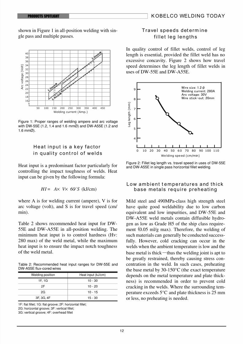
shown in Figure 1 in all-position welding with sin-
gle pass and multiple passes.
Figure 1: Proper ranges of welding ampere and arc voltagewith DW-55E (1.2, 1.4 and 1.6 mmØ) and DW-A55E (1.2 and1.6 mmØ).
Heat inpu t is a key fac to r
in qual i ty con t ro l o f we lds
Heat input is a predominant factor particularly for
controlling the impact toughness of welds. Heat
input can be given by the following formula:
(kJ/cm)
where A is for welding current (ampere), V is for
arc voltage (volt), and S is for travel speed (cm/
min).
Table 2 shows recommended heat input for DW-
55E and DW-A55E in all-position welding. The
minimum heat input is to control hardness (Hv:
280 max) of the weld metal, while the maximumheat input is to ensure the impact notch toughness
of the weld metal.
1F: flat fillet; 1G: flat groove; 2F: horizontal fillet;
2G: horizontal groove; 3F: vertical fillet;
3G: vertical groove; 4F: overhead fillet
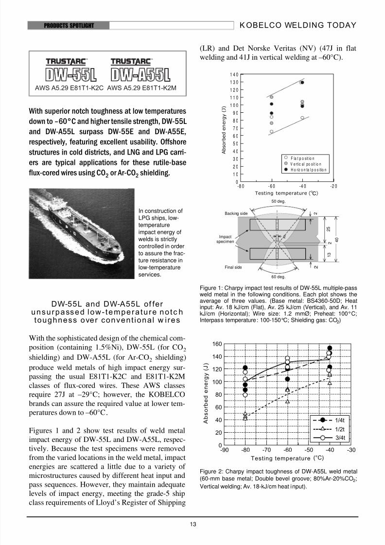
Travel speeds det erm ine
f i l le t leg leng ths
In quality control of fillet welds, control of leg
length is essential, provided the fillet weld has no
excessive concavity. Figure 2 shows how travelspeed determines the leg length of fillet welds in
uses of DW-55E and DW-A55E.
Figure 2: Fillet leg length vs. travel speed in uses of DW-55Eand DW-A55E in single pass horizontal fillet welding.
Low ambien t t empera tu res and th ickbase meta ls require preheat ing
Mild steel and 490MPa-class high strength steel
have quite good weldability due to low carbon
equivalent and low impurities, and DW-55E and
DW-A55E weld metals contain diffusible hydro-
gen as low as Grade H5 of the ship class require-
ment (0.05 ml/g max). Therefore, the welding of
such materials can generally be conducted success-
fully. However, cold cracking can occur in thewelds when the ambient temperature is low and the
base metal is thick ―thus the welding joint is apt to
be greatly restrained, thereby causing stress con-
centration in the weld. In such cases, preheating
the base metal by 30-150°C (the exact temperature
depends on the metal temperature and plate thick-
ness) is recommended in order to prevent cold
cracking in the welds. Where the surrounding tem-
perature exceeds 5°C and plate thickness is 25 mm
or less, no preheating is needed.
Table 2: Recommended heat input ranges for DW-55E andDW-A55E flux-cored wires
Welding position Heat input (kJ/cm)
1F, 1G 10 - 30
2F 10 - 20
2G 10 - 15
3F, 3G, 4F 15 - 30
HI A V 60× S ⁄ ×=
Wire size: 1.2φWelding current: 280AArc voltage: 30VWire stick-out: 20mm
Welding speed (cm/min)
L e g l e n g t h ( m m )
0 10 20 30 40 50 60 70 80 90 100 110
9
8
7
6
5
4
8/8/2019 KWT LowTemp 4Ed
http://slidepdf.com/reader/full/kwt-lowtemp-4ed 13/18
K OBELCO WELDING TODAY
13
PRODUCTS SPOTLIGHT
With superior notch toughness at low temperatures
down to –60°C and higher tensile strength, DW-55L
and DW-A55L surpass DW-55E and DW-A55E,
respectively, featuring excellent usability. Offshore
structures in cold districts, and LNG and LPG carri-
ers are typical applications for these rutile-base
flux-cored wires using CO2 or Ar-CO2 shielding.
DW-55L and DW-A55L of fer unsurpassed low- tempera tu re no tc htoughness over convent ional w ires
With the sophisticated design of the chemical com-position (containing 1.5%Ni), DW-55L (for CO2
shielding) and DW-A55L (for Ar-CO2 shielding)
produce weld metals of high impact energy sur-passing the usual E81T1-K2C and E81T1-K2Mclasses of flux-cored wires. These AWS classesrequire 27J at –29°C; however, the KOBELCObrands can assure the required value at lower tem-peratures down to –60°C.
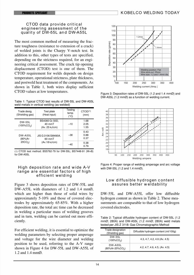
Figures 1 and 2 show test results of weld metalimpact energy of DW-55L and DW-A55L, respec-tively. Because the test specimens were removedfrom the varied locations in the weld metal, impactenergies are scattered a little due to a variety of
microstructures caused by different heat input andpass sequences. However, they maintain adequatelevels of impact energy, meeting the grade-5 shipclass requirements of Lloyd’s Register of Shipping
(LR) and Det Norske Veritas (NV) (47J in flatwelding and 41J in vertical welding at –60°C).
Figure 1: Charpy impact test results of DW-55L multiple-passweld metal in the following conditions. Each plot shows theaverage of three values. (Base metal: BS4360-50D; Heatinput: Av. 18 kJ/cm (Flat), Av. 25 kJ/cm (Vertical), and Av. 11kJ/cm (Horizontal); Wire size: 1.2 mmØ; Preheat: 100°C;Interpass temperature: 100-150°C; Shielding gas: CO2)
Figure 2: Charpy impact toughness of DW-A55L weld metal
(60-mm base metal; Double bevel groove; 80%Ar-20%CO2;Vertical welding; Av. 18-kJ/cm heat input).
In construction ofLPG ships, low-temperature
impact energy ofwelds is strictlycontrolled in order
to assure the frac-ture resistance inlow-temperature
services.
4 0
2 5
1 3
2
2
50 deg.
60 deg.
2
2
Backing side
Final side
Impactspecimen
C
h a r p y
i m
p a c t e n e r g y
( J )
T e s tin g te m p e ra tu re (d e g .C )
F la t p o sit io n
V e rtic al po sit io n
H o riz o n ta l p o s itio n
-8 0 - 6 0 -4 0 -2 00
1 0
2 0
3 0
4 0
5 0
6 0
7 0
8 0
9 0
1 0 0
1 1 0
1 2 0
1 3 0
1 4 0
Testing temperature (℃)
A b s o r b e d
e n e r g y
( J )
8/8/2019 KWT LowTemp 4Ed
http://slidepdf.com/reader/full/kwt-lowtemp-4ed 14/18
K OBELCO WELDING TODAY
14
PRODUCTS SPOTLIGHT
CTOD data prov ide cr i t ic a lengineer ing assessment o f t hequal it y of DW-55L an d DW-A55L
The most common method of measuring the frac-ture toughness (resistance to extension of a crack)of welded joints is the Charpy V-notch test. Inaddition to this, other types of tests are specified,depending on the strictness required, for an engi-neering critical assessment. The crack tip openingdisplacement (CTOD) test is one of them. TheCTOD requirement for welds depends on designtemperature, operational strictness, plate thickness,and postweld heat treatment of the components. Asshown in Table 1, both wires display sufficientCTOD values at low temperatures.
(1) CTOD test method: BS5762-79 for DW-55L; BS7448-91 (W=B)
for DW-A55L
High depos i t ion ra t e and w ide A-Vrange are essent ia l fac tor s of h igh
e f f ic ien t we ld ing
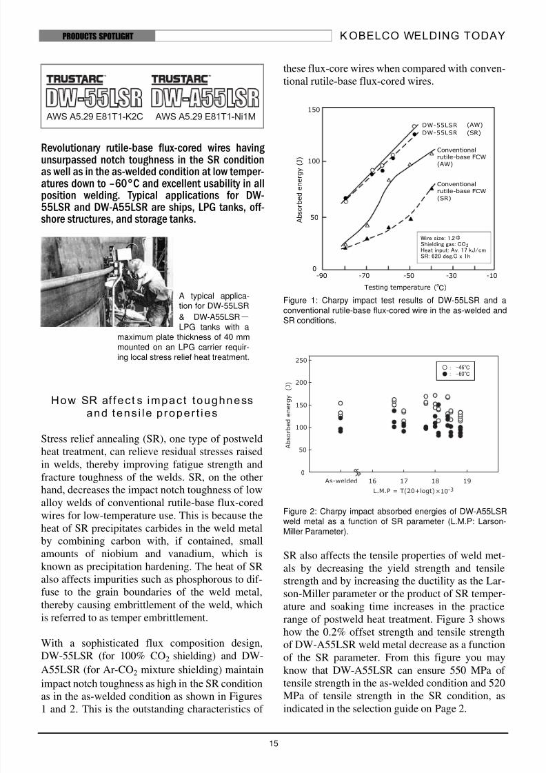
Figure 3 shows deposition rates of DW-55L andDW-A55L with diameters of 1.2 and 1.4 mmØ,
which are higher than those of solid wires byapproximately 5-10% and those of covered elec-trodes by approximately 65-85%. With a higherdeposition rate, the total arc time can be decreasedin welding a particular mass of welding groovesand in turn, welding can be carried out more effi-ciently.
For efficient welding, it is essential to optimize thewelding parameters by selecting proper amperage
and voltage for the wire diameter and weldingposition to be used, referring to the A-V rangeshown in Figure 4 for DW-55L and DW-A55L of 1.2 and 1.4 mmØ.
Figure 3: Deposition rates of DW-55L (1.2 and 1.4 mmØ) and
DW-A55L (1.2 mmØ) as a function of welding current.
Figure 4: Proper range of welding amperage and arc voltage
with DW-55L (1.2 and 1.4 mmØ).
Low d i f fus ible hydrogen c onten t
assures be t te r w e ldabi l i ty
DW-55L and DW-A55L offer low diffusiblehydrogen content as shown in Table 2. These mea-surements are comparable to that of low hydrogencovered electrodes.
Table 1: Typical CTOD test results of DW-55L and DW-A55Lweld metals in vertical welding (as-welded)
Trade desig.
(Shielding gas)
Test plate
(Heat input)
Testing
temp.
(°C)
CTOD(1)
(mm)
DW-55L
(100%CO2)
BS4360 Gr.50D,
40 mmT
(Av. 25 kJ/cm)
–10
1.68
2.05
1.55
DW-A55L
(80%Ar-
20CO2)
JIS G 3106 SM490A,
60 mmT
(Av.18 kJ/cm)
–36
0.43
0.88
0.37
–400.38
0.79
Table 2: Typical diffusible hydrogen content of DW-55L (1.2mmØ; 280A) and DW-A55L (1.2 mmØ; 280A) weld metals
tested per JIS Z 3118: Gas Chromatographic Method
Trade designation
(Shielding gas)Diffusible hydrogen content (ml/100g)
DW-55L
(100%CO2)4.3, 4.7, 4.2, 4.6 (Av. 4.5)
DW-A55L
(80%Ar-20%CO2)4.2, 4.7, 4.6, 4.5, (Av. 4.5)
8/8/2019 KWT LowTemp 4Ed
http://slidepdf.com/reader/full/kwt-lowtemp-4ed 15/18
K OBELCO WELDING TODAY
15
PRODUCTS SPOTLIGHT
Revolutionary rutile-base flux-cored wires having unsurpassed notch toughness in the SR conditionas well as in the as-welded condition at low temper-atures down to –60°C and excellent usability in allposition welding. Typical applications for DW-55LSR and DW-A55LSR are ships, LPG tanks, off-shore structures, and storage tanks.
How SR af fec t s impac t toughnessand tens i le p roper t ies
Stress relief annealing (SR), one type of postweldheat treatment, can relieve residual stresses raisedin welds, thereby improving fatigue strength andfracture toughness of the welds. SR, on the otherhand, decreases the impact notch toughness of lowalloy welds of conventional rutile-base flux-coredwires for low-temperature use. This is because theheat of SR precipitates carbides in the weld metal
by combining carbon with, if contained, smallamounts of niobium and vanadium, which isknown as precipitation hardening. The heat of SRalso affects impurities such as phosphorous to dif-fuse to the grain boundaries of the weld metal,thereby causing embrittlement of the weld, whichis referred to as temper embrittlement.
With a sophisticated flux composition design,DW-55LSR (for 100% CO2 shielding) and DW-
A55LSR (for Ar-CO2 mixture shielding) maintain
impact notch toughness as high in the SR conditionas in the as-welded condition as shown in Figures1 and 2. This is the outstanding characteristics of
these flux-core wires when compared with conven-tional rutile-base flux-cored wires.
Figure 1: Charpy impact test results of DW-55LSR and a
conventional rutile-base flux-cored wire in the as-welded andSR conditions.
Figure 2: Charpy impact absorbed energies of DW-A55LSRweld metal as a function of SR parameter (L.M.P: Larson-
Miller Parameter).
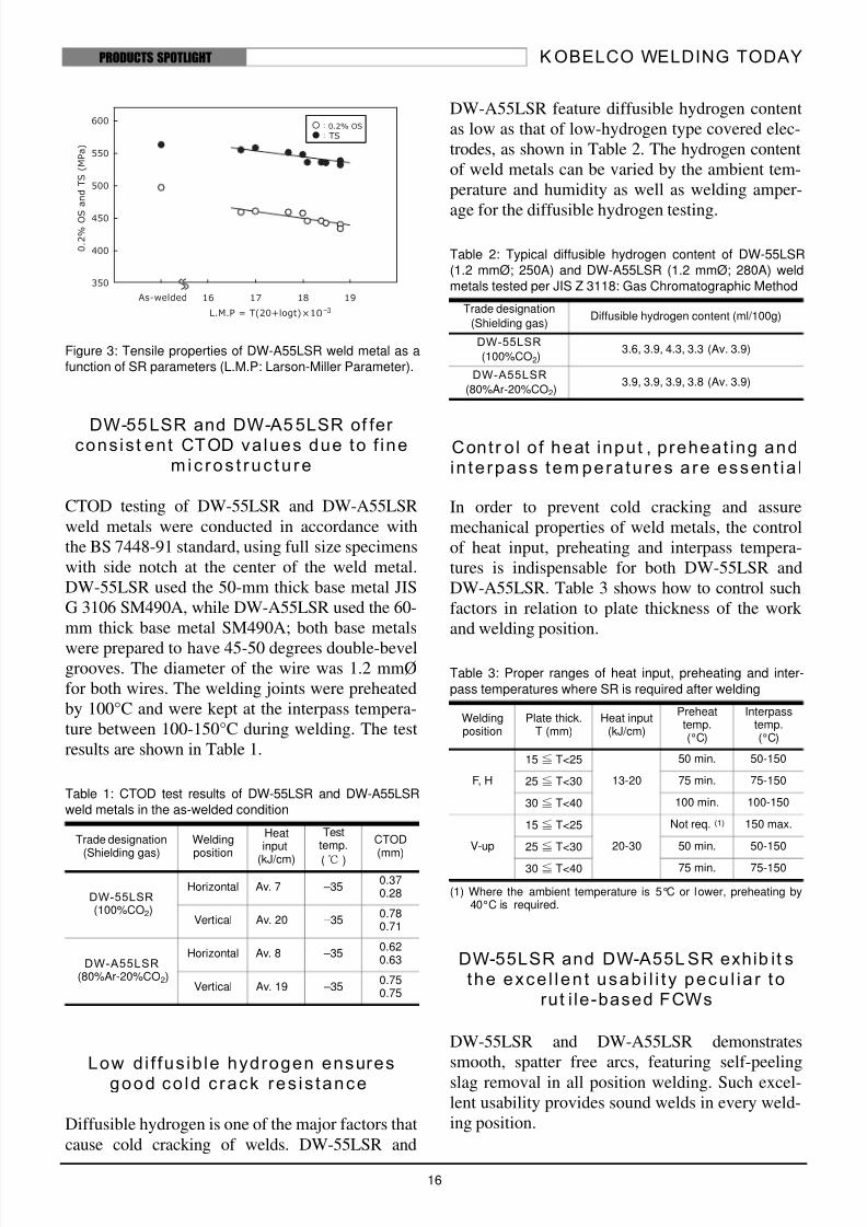
SR also affects the tensile properties of weld met-als by decreasing the yield strength and tensilestrength and by increasing the ductility as the Lar-son-Miller parameter or the product of SR temper-ature and soaking time increases in the practicerange of postweld heat treatment. Figure 3 showshow the 0.2% offset strength and tensile strengthof DW-A55LSR weld metal decrease as a functionof the SR parameter. From this figure you mayknow that DW-A55LSR can ensure 550 MPa of tensile strength in the as-welded condition and 520MPa of tensile strength in the SR condition, asindicated in the selection guide on Page 2.
A typical applica-tion for DW-55LSR
& DW-A55LSR―LPG tanks with a
maximum plate thickness of 40 mm
mounted on an LPG carrier requir-ing local stress relief heat treatment.
150
100
-90 -70 -50 -30 -10
Testing temperature
A b s o r b e d
e n e r g y
( J )
DW-55LSR
DW-55LSR
Conventional
rutile-base FCW
(AW)
Conventional
rutile-base FCW
(SR)
(AW)
(SR)
50
0
Wire size: 1.2ΦShielding gas: COHeat input: Av. 17 kJ/cmSR: 620 deg.C x 1h
2
(℃)
8/8/2019 KWT LowTemp 4Ed
http://slidepdf.com/reader/full/kwt-lowtemp-4ed 16/18
K OBELCO WELDING TODAY
16
PRODUCTS SPOTLIGHT
Figure 3: Tensile properties of DW-A55LSR weld metal as afunction of SR parameters (L.M.P: Larson-Miller Parameter).
DW-55 LSR and DW-A5 5LSR of fer cons is t ent CTOD values due to f ine
m ic ros t ruc tu re
CTOD testing of DW-55LSR and DW-A55LSRweld metals were conducted in accordance withthe BS 7448-91 standard, using full size specimenswith side notch at the center of the weld metal.DW-55LSR used the 50-mm thick base metal JISG 3106 SM490A, while DW-A55LSR used the 60-mm thick base metal SM490A; both base metals
were prepared to have 45-50 degrees double-bevelgrooves. The diameter of the wire was 1.2 mmØfor both wires. The welding joints were preheatedby 100°C and were kept at the interpass tempera-ture between 100-150°C during welding. The testresults are shown in Table 1.
Low d i f fus ib le hydrogen ensuresgood co ld c rack res is tance
Diffusible hydrogen is one of the major factors thatcause cold cracking of welds. DW-55LSR and
DW-A55LSR feature diffusible hydrogen contentas low as that of low-hydrogen type covered elec-trodes, as shown in Table 2. The hydrogen contentof weld metals can be varied by the ambient tem-perature and humidity as well as welding amper-
age for the diffusible hydrogen testing.
Contr o l o f heat input , preheat ing andin te rpass tem pera tu res a re essent ia l
In order to prevent cold cracking and assuremechanical properties of weld metals, the controlof heat input, preheating and interpass tempera-tures is indispensable for both DW-55LSR andDW-A55LSR. Table 3 shows how to control suchfactors in relation to plate thickness of the work and welding position.
(1) Where the ambient temperature is 5°C or lower, preheating by40°C is required.
DW-55LSR and DW-A55L SR exhib it sthe exce l len t usab i l i ty pecu l ia r to
rut i le-based FCWs
DW-55LSR and DW-A55LSR demonstratessmooth, spatter free arcs, featuring self-peelingslag removal in all position welding. Such excel-lent usability provides sound welds in every weld-ing position.
Table 1: CTOD test results of DW-55LSR and DW-A55LSRweld metals in the as-welded condition
Trade designation(Shielding gas)
Weldingposition
Heatinput
(kJ/cm)
Testtemp.
(℃ )
CTOD(mm)
DW-55LSR(100%CO2)
Horizontal Av. 7 –350.370.28
Vertical Av. 20 –350.780.71
DW-A55LSR(80%Ar-20%CO2)
Horizontal Av. 8 –350.620.63
Vertical Av. 19 –350.750.75
Table 2: Typical diffusible hydrogen content of DW-55LSR(1.2 mmØ; 250A) and DW-A55LSR (1.2 mmØ; 280A) weldmetals tested per JIS Z 3118: Gas Chromatographic Method
Trade designation
(Shielding gas)Diffusible hydrogen content (ml/100g)
DW-55LSR
(100%CO2)3.6, 3.9, 4.3, 3.3 (Av. 3.9)
DW-A55LSR
(80%Ar-20%CO2)3.9, 3.9, 3.9, 3.8 (Av. 3.9)
Table 3: Proper ranges of heat input, preheating and inter-
pass temperatures where SR is required after welding
Weldingposition
Plate thick.T (mm)
Heat input(kJ/cm)
Preheattemp.(°C)
Interpasstemp.(°C)
F, H
15≦ T<25
13-20
50 min. 50-150
25≦ T<30 75 min. 75-150
30≦ T<40 100 min. 100-150
V-up
15≦ T<25
20-30
Not req. (1) 150 max.
25≦ T<30 50 min. 50-150
30≦ T<40 75 min. 75-150
8/8/2019 KWT LowTemp 4Ed
http://slidepdf.com/reader/full/kwt-lowtemp-4ed 17/18
K OBELCO WELDING TODAY
17
PRODUCTS SPOTLIGHT
An innovation in flux-cored wires for low tempera-ture applications such as FPSOs.
DW-A81Ni1 resembles DW-A55L, sharing a simi-
lar rutile-based flux core, suitable shielding gas
(80%Ar-20%CO2), tensile strength and notch
toughness of as-welded weld metal. However, their
chemical compositions—and thus their AWS clas-
sifications—are different, and only DW-A81Ni1 is
suited to postweld heat treatment (PWHT). The
nickel content of DW-A81Ni1 weld metal is nomi-
nally 1% and notch toughness can be kept suffi-
cient even after PWHT.
The low Ni content and PWHT applicability can
be advantages in specific fabrications—such as
those that adhere to the NACE standard which
requires the weldment to be low in Ni content and
hardness for minimizing the susceptibility to sul-
fide stress corrosion cracking (SSCC) that tends to
occur in corrosive, aqueous H2S environments.
Such specific fabrications can be involved in off-
shore structures and floating production, storage
and offloading (FPSO) vessels. Many low-alloysteels used in such applications may require
PWHT to temper or relieve stresses in the weld to
achieve increased ductility.
Table 1 shows typical chemical composition and
tensile properties of DW-A81Ni1 welded on high
strength FH36 grade steel of the LR ship class. The
tensile properties of the weld metal meet the
requirements (0.2% OS: 355MPa min.; TS: 490-
620 MPa; El: 21% min.) for this steel grade. Ti-B
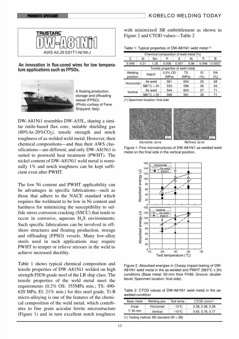
micro-alloying is one of the features of the chemi-cal composition of the weld metal, which contrib-
utes to fine grain acicular ferrite microstructure
(Figure 1) and in turn excellent notch toughness
with minimized SR embrittlement as shown in
Figure 2 and CTOD values—Table 2
(1) Specimen location: final side
Figure 1: Fine microstructures of DW-A81Ni1 as-welded weld
metal on the final side in the vertical position.
Figure 2: Absorbed energies in Charpy impact testing of DW-
A81Ni1 weld metal in the as-welded and PWHT (580°C x 2h)
conditions (Base metal: 50-mm thick FH36; Groove: double-
bevel; Specimen location: final side).
(1) Testing method: BS standard (W = 2B)
A floating production,
storage and offloading
vessel (FPSO).
(Photo curtsey of Fene
Shipyard, Italy)
Table 1: Typical properties of DW-A81Ni1 weld metal (1)
Chemical composition of weld metal (%)
C Si Mn P S Ni Ti B0.049 0.31 1.25 0.008 0.007 0.96 0.046 0.0057
Tensile properties of weld metal
Welding
positionPWHT
0.2% OS
(MPa)
TS
(MPa)
El
(%)
RA
(%)
HorizontalAs weld 581 604 25 68
580°C × 2h 533 596 26 63
VerticalAs weld 544 604 27 71
580°C × 2h 509 591 30 71
Table 2: CTOD values of DW-A81Ni1 weld metal in the as-
welded condition
Base metal Welding pos. Test temp. CTOD (mm)(1)
FH36
T: 50 mm
Horizontal –10°C 0.38, 0.38, 0.38
Vertical –10°C 0.65, 0.76, 0.77
25μ 25μ
Dendritic zone Refined zone
8/8/2019 KWT LowTemp 4Ed
http://slidepdf.com/reader/full/kwt-lowtemp-4ed 18/18
K OBELCO WELDING TODAYPRODUCTS SPOTLIGHT
DW-62L (for 100%CO2 shielding) and DW-A62L
(for Ar-CO2 shielding), innovations in rutile-based
flux-cored wires, offer excellent notch toughness
suitable for low temperature steel of the 500-MPa
yield strength class. Both wires provide high notch
toughness at –60°C or higher by Charpy impact
testing and stable fracture at –40°C or higher by
CTOD testing.
As shown in Table 1, both wires contain Ni at
around 2% and micro-alloying with Ti and B. This
sophisticated chemistry of the weld metal enables
fine microstructures even in the as-cast zone or
dendritic zone—Figure 1.
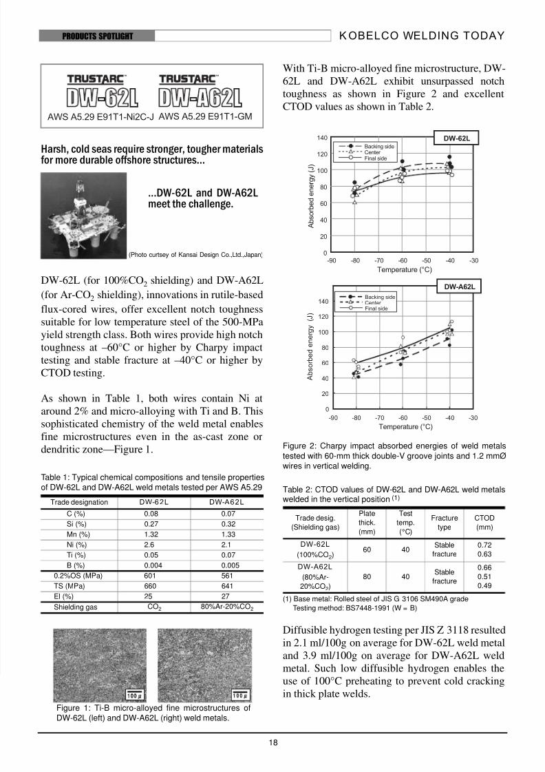
With Ti-B micro-alloyed fine microstructure, DW-
62L and DW-A62L exhibit unsurpassed notch
toughness as shown in Figure 2 and excellent
CTOD values as shown in Table 2.
Figure 2: Charpy impact absorbed energies of weld metals
tested with 60-mm thick double-V groove joints and 1.2 mmØwires in vertical welding.
(1) Base metal: Rolled steel of JIS G 3106 SM490A grade
Testing method: BS7448-1991 (W = B)
Diffusible hydrogen testing per JIS Z 3118 resulted
in 2.1 ml/100g on average for DW-62L weld metal
and 3.9 ml/100g on average for DW-A62L weld
metal. Such low diffusible hydrogen enables the
use of 100°C preheating to prevent cold cracking
in thick plate welds.
Table 1: Typical chemical compositions and tensile propertiesof DW-62L and DW-A62L weld metals tested per AWS A5.29
Trade designation DW-62L DW-A62L
C (%) 0.08 0.07
Si (%) 0.27 0.32
Mn (%) 1.32 1.33
Ni (%) 2.6 2.1
Ti (%) 0.05 0.07
B (%) 0.004 0.005
0.2%OS (MPa) 601 561
TS (MPa) 660 641
El (%) 25 27
Shielding gas CO2 80%Ar-20%CO2
Harsh, cold seas require stronger, tougher materialsfor more durable offshore structures...
...DW-62L and DW-A62Lmeet the challenge.
(Photo curtsey of Kansai Design Co.,Ltd.,Japan)
1 0 0μ00μ
Figure 1: Ti-B micro-alloyed fine microstructures ofDW-62L (left) and DW-A62L (right) weld metals.
Table 2: CTOD values of DW-62L and DW-A62L weld metalswelded in the vertical position (1)
Trade desig.
(Shielding gas)
Plate
thick.
(mm)
Test
temp.
(°C)
Fracture
type
CTOD
(mm)
DW-62L
(100%CO2)60 40
Stable
fracture
0.72
0.63
DW-A62L
(80%Ar-
20%CO2)
80 40Stable
fracture
0.66
0.51
0.49
Related Documents