REPAIR MANUAL 2004-2009 BEDIENUNGSANLEITUNGEN OWNER’S MANUAL MANUALE O’USO MANUEL D’UTILISATION MANUAL DE INSTRUCCIONES REPARATURANLEITUNG REPAIR MANUAL MANUALE DI REPARAZIONE MANUEL DE REPARATION MANUAL DE REPARACION GABEL FORK FORCELLA FOURCHE HORQUILLA FEDERBEIN SHOCK ABSORBER AMMORTIZZATORE AMMORTISSEUR AMORTIGUADOR

Welcome message from author
This document is posted to help you gain knowledge. Please leave a comment to let me know what you think about it! Share it to your friends and learn new things together.
Transcript
REPAIRMANUAL2004-2009BEDIENUNGSANLEITUNGENOWNER’S MANUALMANUALE O’USOMANUEL D’UTILISATIONMANUAL DE INSTRUCCIONES
REPARATURANLEITUNGREPAIR MANUALMANUALE DI REPARAZIONEMANUEL DE REPARATIONMANUAL DE REPARACION
GABELFORKFORCELLAFOURCHEHORQUILLA
FEDERBEINSHOCK ABSORBERAMMORTIZZATOREAMMORTISSEURAMORTIGUADOR
KTM-Sportmotorcycle AG
A–5230 Mattighofen
www.ktm.at
KTM Group Partner
5/2006 FOTO: MITTERBAU
ER
85/105 SX
OWNER’S MANUAL 2007
ART. NR. 3.211.143 EN
ENGL
ISH
ENGLISH
2
IMPORTANT INFORMATION »
INTENDED PURPOSEKTM mini-sports motorcycles are designed and constructed to resist the usual wear and tear of normaluse in competitions.The motorcycles comply with the regulations and categories currently in effect with the leading interna-tional motorcycle associations.
OWNER’S MANUALPlease read this manual thoroughly before letting your youngster ride the motorcycle for the first time.This manual contains important information and recommendations that will help you and your youngsterto operate and handle the motorcycle properly. In the interest of everybody involved, we urge you to payparticular attention to instructions and information marked as follows:
This manual contains important information on the operation and maintenance of your new KTM motor-cycle. It went to press describing your model’s latest state of development. Nevertheless, the descriptionsmay deviate slightly from the current design as our motorcycles are permanently improved.The Owner'sManual is an integral part of the motorcycle and must be handed over to the new owner when the motor-cycle is sold.
SERVICEObservance of the service, maintenance and tuning instructions for the engine and chassis specified inthe Owner's Manual is a prerequisite for faultless operation and the avoidance of premature wear. Animproperly tuned chassis can lead to damage and breakage of the chassis components (see chapter onchecking the basic chassis setting).The use of the motorcycle under extreme conditions, e.g. on extremely muddy and wet terrain, can leadto higher than average wear on components such as the drive train or the brakes. In this case it maybecome necessary to service or replace wear parts before the service limit specified in the maintenanceschedule has been reached.We expressly point out that work marked with an asterisk (*) in the chapter "Maintenance work on thechassis and engine" must be performed by a KTM workshop. If maintenance work should become neces-sary during a competition, it must be performed by a trained mechanic.Please strictly observe the prescribed running-in periods and inspection and maintenance intervals.Compliance with these instructions will significantly prolong the life of your motorcycle.
– Ignoring these instructions can be dangerous to life and limb!
– Ignoring these instructions may damage parts of the motorcycle or impair the motorcycle's traffic safety!

ENGL
ISH
3
IMPORTANT INFORMATION »
WARRANTYThe service work specified in the "Lubrication and Maintenance Schedule" must be performed by a KTMworkshop and recorded in the service manual otherwise claims under the warranty shall become void.No claims can be filed under the warranty for damage or consequential damage caused by manipulationsor conversions to the motorcycle.
AUTOMOTIVE FLUIDSThe fuels and lubricants specified in the Owner's Manual or automotive fluids with equivalent specifica-tions must be used in accordance with the maintenance schedule.
SPARE PARTS, ACCESSORIESFor the safety of your child, only use spare parts and accessories approved by KTM. KTM shall not assumeany liability for other products or consequential damage resulting from the use of such products.When special needs arise, please contact a KTM dealer, who will seek the assistance of the KTM importerif necessary.
SAFETYParents should keep in mind that the safety of their youngsters always depends on the efforts made bythe parents to ensure that the motorcycle is kept in good working order and only used on safe terrains.Nevertheless, driving the motorcycle, like driving any other vehicle, involves a potential risk. Therefore,please make sure that all fundamental precautions are taken. Please also read the „INFORMATION ONSAFE DRIVING FOR PARENTS“ on page 4.
TRANSPORTWhen transporting your motorcycle, secure it with elastic straps or other mechanical devices in an uprightposition. Be sure that the fuel tap is closed. If the motorcycle topples over, fuel can flow out of the car-buretor or fuel tank.
ENVIRONMENTRiding an off-highway motorcycle is a wonderful form of outdoor recreation and we certainly hope thatyou and your youngsters will enjoy it to the full. However, this enjoyable outdoor activity can cause envi-ronmental problems or lead to conflicts with other people. Responsible use of the motorcycle will preventsuch problems and conflicts. You can contribute to securing the future of motorcycling by making surethat you and your youngsters only use the motorcycle within the limits established by the applicable laws,making environmental protection one of your top priorities and never violating other people’s rights.
In this spirit, we hope that you and your youngsters will always safely enjoy your motorcycle!
KTM-SPORTMOTORCYCLE AG5230 MATTIGHOFEN, AUSTRIA
Attachments: 1 spare parts manual chassis & engine

ENGLISH
4
IMPORTANT INFORMATION FOR PARENTS ABOUT SAFE DRIVING »
The 85/105 SX mini motorcycles are off-road motorcycles designed for one person only. They are not allowedon public roads.
The vehicle dimensions and components are designed for children from 10 to 15 years of age with amaximum weight of 75 kg (33,98 lb).
– Have your youngster wear proper protective gear whenever he or she rides the motorcycle: helmet, eyeprotection, chest, back, arm and leg protectors, gloves and boots. To set a good example, be sure towear protective gear yourself whenever riding a motorcycle!
– Before your youngster takes his or her first ride, explain how each of the controls works and check ifyour youngster has understood what you explained. We recommend to review the entire owner’s manualwith your youngster item by item, paying particular attention to the specially marked warnings andpointing out the danger of injury.
– Instruct your youngster about riding and falling techniques, explain how the motorcycle will respondto shifting of the rider’s weight, etc.
– Before starting the motorcycle for the first time check whether the basic fork and shock absorber settings are suitable for your child's weight (see chapter on checking the basic chassis setting)
– Before using the motorcycle you should always check all components for proper operation (see mai-nenance schedule). Have your youngster perform these technical checks himself / herself as well.
– Whenever you go for a ride with your youngster, keep in mind that the speed should be adjusted toyour youngster and not the other way around.
– Your youngster must understand that all instructions he or she receives from you or any other super-vising adult must be followed.
– Your child must be physically ready to ride a motorcycle. This means that he or she must at least beable to ride a bicycle. Being good at sports that require fast reactions is an additional advantage. Youryoungster should be strong enough to pick up the motorcycle after a fall.
– Never demand too much of your youngster. Give him or her time to get used to the motorcycle and toimprove his / her riding skills. Do not even consider letting your youngster participate in a race before his / her physical condition, riding skills and motivation have sufficiently developed.
– Explain to your youngster that he / she should always adjust his / her riding speed to the local condi-tions as well as to his / her own riding skills and that excessive speed can cause falls and severe inju-ries. Always keep in mind that youngsters tend to underestimate dangers or fail to recognize themaltogether. The riding speed must be reduced, in particular, on unknown terrain.
– Never let your youngster ride the motorcycle without supervision. An adult should always be present.– The motorcycle is designed for one rider only. Your youngster is not allowed to transport a passenger.– When you go for a ride, somebody at home should always know where you are going and when you
will be back. This makes it easier to send you help, should problems occur.
ENGL
ISH
5
TABLE OF CONTENTS »Page
IMPORTANT INFORMATION FOR PARENTS ABOUT SAFE
DRIVING . . . . . . . . . . . . . . . . . . . . . . . . . . . . . . . . . . .4
SERIAL NUMBER LOCATIONS . . . . . . . . . . . . . . . . . . . .6
Chassis number . . . . . . . . . . . . . . . . . . . . . . . . . . . .6
Engine number . . . . . . . . . . . . . . . . . . . . . . . . . . . . .6
OPERATION INSTRUMENTS . . . . . . . . . . . . . . . . . . . . .6
Clutch lever . . . . . . . . . . . . . . . . . . . . . . . . . . . . . . .6
Hand brake lever . . . . . . . . . . . . . . . . . . . . . . . . . . . .6
Short circuit button . . . . . . . . . . . . . . . . . . . . . . . . . .7
Filler cap . . . . . . . . . . . . . . . . . . . . . . . . . . . . . . . . .7
Fuel tap . . . . . . . . . . . . . . . . . . . . . . . . . . . . . . . . . .7
Choke . . . . . . . . . . . . . . . . . . . . . . . . . . . . . . . . . . .7
Shift lever . . . . . . . . . . . . . . . . . . . . . . . . . . . . . . . .7
Kickstarter . . . . . . . . . . . . . . . . . . . . . . . . . . . . . . . .8
Foot brake pedal . . . . . . . . . . . . . . . . . . . . . . . . . . . .8
Plugin- Stand . . . . . . . . . . . . . . . . . . . . . . . . . . . . . .8
Compression damping of fork . . . . . . . . . . . . . . . . . . .8
Rebound damping of fork . . . . . . . . . . . . . . . . . . . . . .8
Damping action during compression of shock absorber .9
Rebound damping function of the shock absorber . . . .9
GENERAL TIPS AND WARNINGS FOR STARTING THE
MOTORCYCLE . . . . . . . . . . . . . . . . . . . . . . . . . . . . . .10
Instructions for the first ride . . . . . . . . . . . . . . . . . . .10
Running in . . . . . . . . . . . . . . . . . . . . . . . . . . . . . . .10
DRIVING INSTRUCTIONS . . . . . . . . . . . . . . . . . . . . . .11
What you should check before each start . . . . . . . . . .11
Starting when the engine is cold . . . . . . . . . . . . . . . .12
Starting when the engine is warm . . . . . . . . . . . . . . .12
What to do when the engine is “flooded“ . . . . . . . . . .12
Starting off . . . . . . . . . . . . . . . . . . . . . . . . . . . . . . .12
Shifting/Riding . . . . . . . . . . . . . . . . . . . . . . . . . . . .12
Refueling, fuel . . . . . . . . . . . . . . . . . . . . . . . . . . . .13
Braking . . . . . . . . . . . . . . . . . . . . . . . . . . . . . . . . .13
Stopping . . . . . . . . . . . . . . . . . . . . . . . . . . . . . . . .13
PERIODIC MAINTENANCE SCHEDULE . . . . . . . . . . . . .14
MAINTENANCE WORK ON CHASSIS AND ENGINE . . . .16
Checking and adjusting the steering head bearing . . .16
Breather plug front fork . . . . . . . . . . . . . . . . . . . . . .16
Cleaning the dust sleeves of the telescopic fork . . . . .17
How to change the handlebar position . . . . . . . . . . . .17
Changing the spring preloading of the shock absorber .17
Basic suspension setup for the weight of the driver . . .18
Page
Checking the shock absorber and spring . . . . . . . . . .18
Determining the static sag of the shock absorber . . . .18
Determining the riding sag of the shock absorber . . . .18
Overview of the shock absorber springs . . . . . . . . . . .19
Checking the basic setup of the telescopic fork . . . . .19
Overview of the telescopic fork springs . . . . . . . . . . .19
Checking chain tension . . . . . . . . . . . . . . . . . . . . . .20
Correct chain tension . . . . . . . . . . . . . . . . . . . . . . . .20
Chain maintenance . . . . . . . . . . . . . . . . . . . . . . . . .20
General information about KTM disc brakes . . . . . . . .21
Adjusting free travel of the hand brake lever . . . . . . .21
Checking the brake fluid level/ refilling . . . . . . . . . . .22
Checking front brake pads . . . . . . . . . . . . . . . . . . . .22
Replacing the front brake pads . . . . . . . . . . . . . . . . .22
Changing basic position of the brake pedal . . . . . . . .23
Checking the rear brake fluid level . . . . . . . . . . . . . .23
Refilling the rear brake fluid reservoir . . . . . . . . . . . .23
Checking rear brake pads . . . . . . . . . . . . . . . . . . . . .23
Dismounting and mounting the front wheel . . . . . . . .24
Dismounting and mounting the rear wheel . . . . . . . . .25
Tires, air pressure . . . . . . . . . . . . . . . . . . . . . . . . . .25
Checking spoke tension . . . . . . . . . . . . . . . . . . . . . .25
Cleaning the air filter . . . . . . . . . . . . . . . . . . . . . . . .26
Exhaust system . . . . . . . . . . . . . . . . . . . . . . . . . . . .26
Changing the original position of the clutch lever . . . .27
Checking the oil level of the hydraulic clutch . . . . . . .27
Bleeding of the hydraulic clutch . . . . . . . . . . . . . . . .27
Adjusting the throttle cable . . . . . . . . . . . . . . . . . . .27
Cooling system . . . . . . . . . . . . . . . . . . . . . . . . . . . .28
Checking coolant level . . . . . . . . . . . . . . . . . . . . . . .28
Refilling/Bleeding the cooling system . . . . . . . . . . . .28
Carburetor adjustment . . . . . . . . . . . . . . . . . . . . . . .29
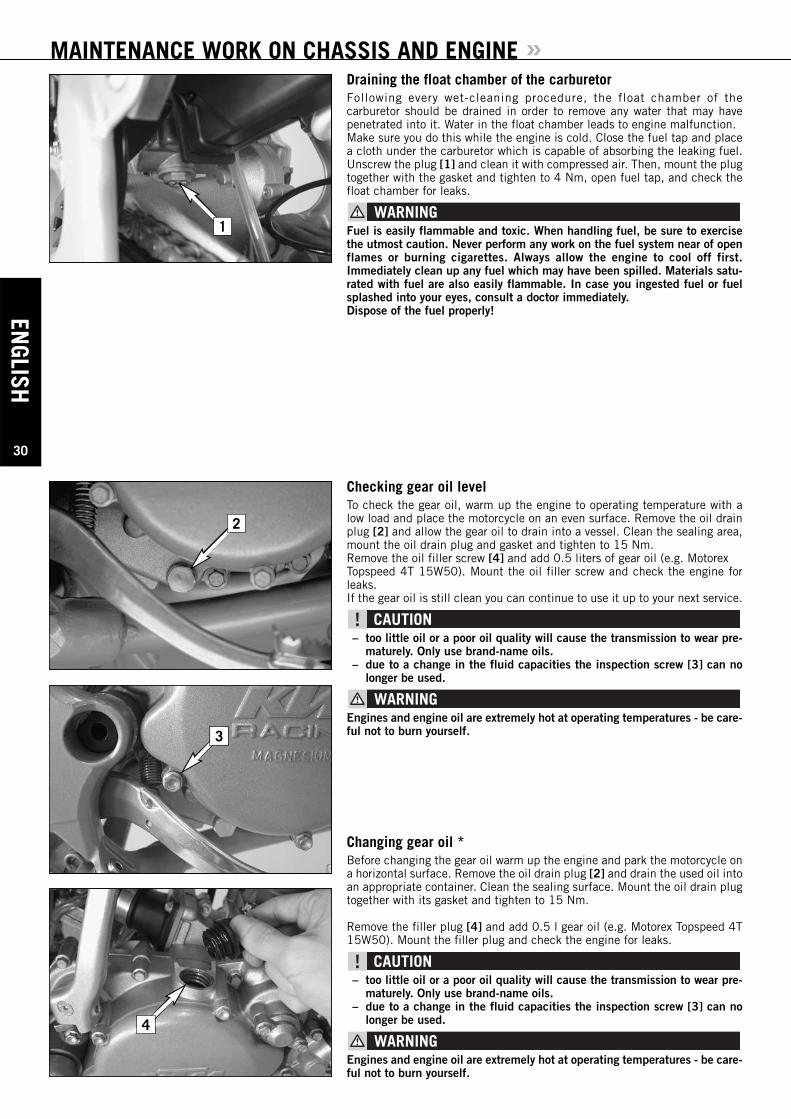
Draining the float chamber of the carburetor . . . . . . .30
Checking gear oil level . . . . . . . . . . . . . . . . . . . . . . .30
Changing gear oil . . . . . . . . . . . . . . . . . . . . . . . . . .30
TROUBLE SHOOTING . . . . . . . . . . . . . . . . . . . . . . . . .31
CLEANING . . . . . . . . . . . . . . . . . . . . . . . . . . . . . . . . .33
STORAGE . . . . . . . . . . . . . . . . . . . . . . . . . . . . . . . . . .33
Use after period of storage . . . . . . . . . . . . . . . . . . . .33
TECHNICAL SPECIFICATIONS – CHASSIS . . . . . . . . . .34
TECHNICAL SPECIFICATIONS - ENGINE . . . . . . . . . . .35
CARBURETOR SETTING . . . . . . . . . . . . . . . . . . . . . . .37
HEAD WORD INDEX . . . . . . . . . . . . . . . . . . . . . . . . . .38
ENGLISH
6
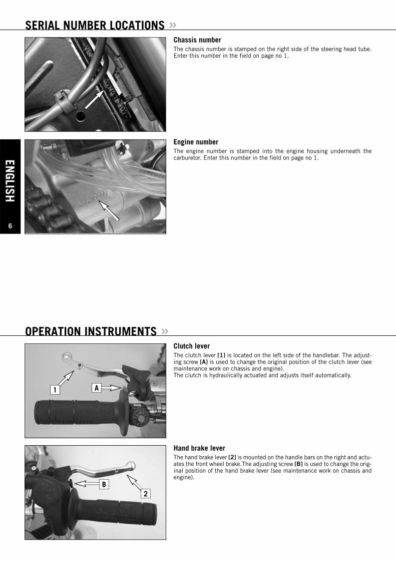
SERIAL NUMBER LOCATIONS »Chassis numberThe chassis number is stamped on the right side of the steering head tube.Enter this number in the field on page no 1.
Engine numberThe engine number is stamped into the engine housing underneath the carburetor. Enter this number in the field on page no 1.
Clutch lever The clutch lever [1] is located on the left side of the handlebar. The adjust-ing screw [A] is used to change the original position of the clutch lever (seemaintenance work on chassis and engine).The clutch is hydraulically actuated and adjusts itself automatically.
Hand brake leverThe hand brake lever [2] is mounted on the handle bars on the right and actu-ates the front wheel brake.The adjusting screw [B] is used to change the orig-inal position of the hand brake lever (see maintenance work on chassis andengine).
OPERATION INSTRUMENTS »
B
1 A
2
ENGL
ISH
7
OPERATION INSTRUMENTS »
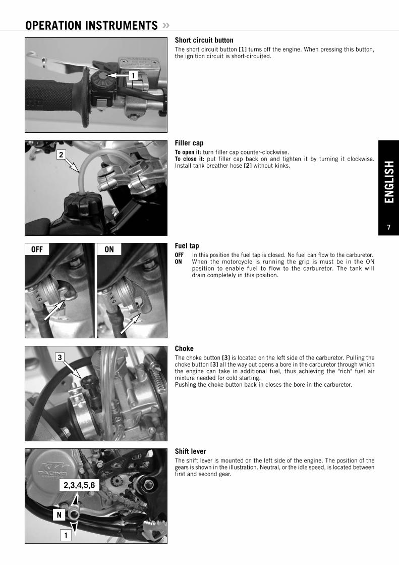
Filler capTo open it: turn filler cap counter-clockwise.To close it: put filler cap back on and tighten it by turning it clockwise. Install tank breather hose [2] without kinks.
Fuel tapOFF In this position the fuel tap is closed. No fuel can flow to the carburetor. ON When the motorcycle is running the grip is must be in the ON
position to enable fuel to flow to the carburetor. The tank will drain completely in this position.
ChokeThe choke button [3] is located on the left side of the carburetor. Pulling thechoke button [3] all the way out opens a bore in the carburetor through whichthe engine can take in additional fuel, thus achieving the "rich" fuel air mixture needed for cold starting.Pushing the choke button back in closes the bore in the carburetor.
Shift leverThe shift lever is mounted on the left side of the engine. The position of thegears is shown in the illustration. Neutral, or the idle speed, is located betweenfirst and second gear.
Short circuit buttonThe short circuit button [1] turns off the engine. When pressing this button,the ignition circuit is short-circuited.
1
3
2,3,4,5,6
1
N
2
OFF ON
ENGLISH
8
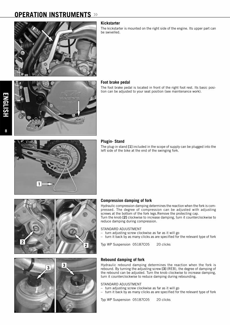
OPERATION INSTRUMENTS »KickstarterThe kickstarter is mounted on the right side of the engine. Its upper part canbe swivelled.
Foot brake pedalThe foot brake pedal is located in front of the right foot rest. Its basic posi-tion can be adjusted to your seat position (see maintenance work).
Plugin- StandThe plug-in stand [1] included in the scope of supply can be plugged into theleft side of the bike at the end of the swinging fork.
Compression damping of forkHydraulic compression damping determines the reaction when the fork is com-pressed. The degree of compression can be adjusted with adjusting screws at the bottom of the fork legs.Remove the protecting cap.Turn the knob [2] clockwise to increase damping, turn it counterclockwise toreduce damping during compression.
STANDARD ADJUSTMENT– turn adjusting screw clockwise as far as it will go– turn it back by as many clicks as are specified for the relevant type of fork
Typ WP Suspension 05187C05 20 clicks
Rebound damping of forkHydraulic rebound damping determines the reaction when the fork is rebound. By turning the adjusting screw [3] (REB), the degree of damping ofthe rebound can be adjusted. Turn the knob clockwise to increase damping,turn it counterclockwise to reduce damping during rebounding.
STANDARD ADJUSTMENT– turn adjusting screw clockwise as far as it will go– turn it back by as many clicks as are specified for the relevant type of fork
Typ WP Suspension 05187C05 20 clicks
22
3 3
1
ENGL
ISH
9
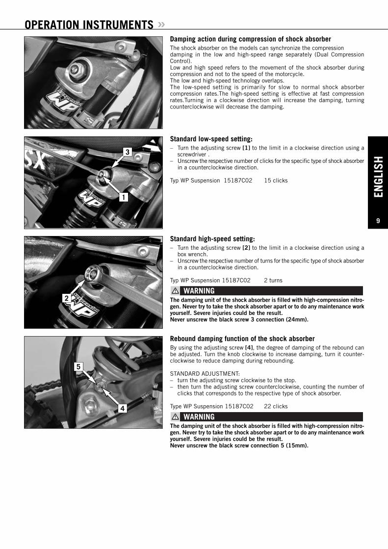
OPERATION INSTRUMENTS »Damping action during compression of shock absorberThe shock absorber on the models can synchronize the compressiondamping in the low and high-speed range separately (Dual CompressionControl).Low and high speed refers to the movement of the shock absorber during compression and not to the speed of the motorcycle.The low and high-speed technology overlaps.The low-speed setting is primarily for slow to normal shock absorber compression rates.The high-speed setting is effective at fast compressionrates.Turning in a clockwise direction will increase the damping, turning counterclockwise will decrease the damping.
Standard low-speed setting:– Turn the adjusting screw [1] to the limit in a clockwise direction using a
screwdriver . – Unscrew the respective number of clicks for the specific type of shock absorber
in a counterclockwise direction.
Typ WP Suspension 15187C02 15 clicks
Standard high-speed setting:– Turn the adjusting screw [2] to the limit in a clockwise direction using a
box wrench.– Unscrew the respective number of turns for the specific type of shock absorber
in a counterclockwise direction.
Typ WP Suspension 15187C02 2 turns
The damping unit of the shock absorber is filled with high-compression nitro-gen. Never try to take the shock absorber apart or to do any maintenance workyourself. Severe injuries could be the result.Never unscrew the black screw 3 connection (24mm).
Rebound damping function of the shock absorberBy using the adjusting screw [4], the degree of damping of the rebound canbe adjusted. Turn the knob clockwise to increase damping, turn it counter-clockwise to reduce damping during rebounding.
STANDARD ADJUSTMENT:– turn the adjusting screw clockwise to the stop.– then turn the adjusting screw counterclockwise, counting the number of
clicks that corresponds to the respective type of shock absorber.
Type WP Suspension 15187C02 22 clicks
The damping unit of the shock absorber is filled with high-compression nitro-gen. Never try to take the shock absorber apart or to do any maintenance workyourself. Severe injuries could be the result.Never unscrew the black screw connection 5 (15mm).
5
4
3
1
2
ENGLISH
10
GENERAL TIPS AND WARNINGS FOR STARTING THE MOTORCYCLE »
– Have your youngster wear proper protective gear wheneverhe or she rides the motorcycle: helmet, eye protection, chest,back, arm and leg protectors, gloves and boots. To set a goodexample, be sure to wear protective gear yourself wheneverriding a motorcycle!
– Only use accessory parts recommended by KTM.– The front and rear wheel are only allowed to be tired with
tires that have the same profile type.– Your youngster's driving speed should always be adjusted to
his/her driving skills as well as to the terrain.– Your youngster should never be allowed to ride the motorcy-
cle without supervision.– Replace the helmet visor or goggle glasses early enough. When
light shines directly on a scratched visor or goggles, you willbe practically blind.
– Never leave your motorcycle without supervision as long asthe engine is running.
– SX models are designed for one person only. Passengers arenot allowed.
– These models do not comply with the regulations and safetystandards established by the law. Therefore, they are not per-mitted on public roads.
– Always keep in mind that other people feel molested byexcessive noise.
Instructions for the first ride– Make sure the work for the "pre-delivery inspection" was per-
formed by your authorized KTM workshop. The DELIVERYCERTIFICATE and SERVICE MANUAL will be handed overwhen you pick up your vehicle.
– Before your youngster takes his or her first ride, explain howeach of the controls works and check if your youngster has understood what you explained. We recommend to review theentire owner’s manual with your youngster item by item, paying particular attention to the specially marked warnings andpointing out the danger of injury.
– Adjust the clutch lever, hand lever and foot brake pedal so your child can operate them easily!
– To prevent injury, teach your youngster the basic riding skillson soft ground, e.g. on a meadow or in the garden. Be sure that there is room enough to maneuver, and that no other riders are close.
– To ensure that your youngster gets the feel of the hand brake,have your youngster operate the hand brake while you push the motorcycle. Do not start the engine before your youngster has learned to apply hand brake with appropriate pressure.
– To familiarize your youngster with the operation of the handbrake let him or her practice to operate the hand brake whileyou are pushing the motorcycle. Do not start the engine before he or she is thoroughly familiar with the use of the hand brake.
– Initially, your youngster should ride back and forth betweentwo persons who help the young rider to stop the motorcy-cle. However, you should also teach your youngster how tostop the motorcycle himself/herself.
– To improve his/her riding skills, your youngster should practise riding the motorcycle standing on the footpegs or to riding at the slowest possible speed. Additionally, you can arrange a series of obstacles and have your youngster drive around them, etc.
– Pay attention to the running-in procedure.
Running in– Even very precisely machined sections of engine components
have rougher surfaces than components which have been sliing across one another for quite some time. Therefore, everyengine needs to be broken in. For this reason, during its first30 minutes the engine must not be revved up to its performance limits.
– Apply low but changing loads for running-in. – DO NOT DRIVE AT FULL LOAD FOR THE FIRST 30
MINUTES!

ENGL
ISH
11
DRIVING INSTRUCTIONS »
What you should check before each startWhen you start off, the motorcycle must be in a perfect technical condition.For safety reasons, you should make it a habit to perform an overall check ofyour motorcycle before each start.The following checks should be performed:
1 CHECKING THE ENGINECheck the engine for any oil leakage. Too little gear oil will lead to premature wear and consequently destroy the transmission.
2 FUELCheck that there is sufficient fuel in the tank; when closing the filler cap,check that the tank venting hose is free of kinks.
3 CHAINA loose chain was fall off the chain wheels; an extremely worn chain maytear, and insufficient lubrication may result in unnecessary wear of the chainand chain wheels.
4 TIRESCheck for damaged tires. Tires showing cuts or dents must be replaced. Also check the air pressure. Insufficient tread and incorrect air pressure deteriorate the driving performance.
5 BRAKESCheck the correct functioning of the braking system. Verify that there is sufficient brake fluid in the reservoir. The reservoirs have been designed in such a way that brake fluid does not need to be refilled even when thebrake pads are worn. If the level of brake fluid falls below the minimum value, this indicates a leak in the braking system or completely worn outbrake pads. Always have the brake system checked by a KTM workshop toavoid brake failure.Also check the state of the brake hose and the thickness of the brake linings.Check free travel at the hand brake lever and foot brake lever.
If the resistance in the hand brake lever feels “spongy” (too much play), thisis an indication that something is wrong with the brake system. Don’t let yourchild ride the motorcycle anymore without first having the brake system lookedover by a KTM dealer.
6 CABLESCheck correct setting and easy running of all control cables.
7 COOLING FLUIDCheck the level of cooling fluid when the engine is cold.

ENGLISH
12
DRIVING INSTRUCTIONS »
Starting when the engine is cold1 Open fuel tap [1] .2 Put the gear in neutral3 Activate the cold-starting aid (choke) [2].4 Leave throttle closed and kick down the kickstarter vigorously all the way.
– To avoid injury when starting the engine, always wear strong bikers boots!Youmay slip off the kickstarter, or the engine may kick back if you do not kickhart enough.
– Check for power transmission at temperatures below 0°C (32°F) beforeyou actuate the kickstarter. If you depress the kickstarter without feelingany resistance, power ist not being transmitted. This could cause injuries.
– Do not start the engine and allow it to idle in a closed area. Exhaust fumesare poisonous and can cause loss of consciousness and death. Always pro-vide adequate ventilation while the engine is running.
Do not ride your motorcycle at full load and do not rev up the engine whencold. since the piston warms up and expands faster than the water cooledcylinder, this might cause engine damage. always let engine idle until warmor drive it warm at low r.p.m. speeds.
NOTE:The highly inflammable components in modern fuels volatilize if left stand-ing for longer periods of time. If the motorcycle has not been used for over1 week, the fuel should be drained from the float chamber. The engine willstart up immediately if the float chamber is filled with fresh, ignitable fuel
Starting when the engine is warm1 Open fuel tap2 Put the gear in neutral3 Leave throttle closed and kick down kickstarter vigorously all the way.
What to do when the engine is “flooded“1 Close fuel tap2 Start engine with full throttle. If necessary, unscrew spark plug and dry it.3 Once the engine is running, open fuel tap again.
Starting offPull the clutch lever. Put the engine into first gear, slowly release the clutchlever and accelerate at the same time.
Always remove the plug-in [3] stand before your child rides the motorcycle.
Shifting/RidingYou are now in first gear, referred to as the drive or uphill gear. Depending onthe conditions (traffic, hill size, etc.), you can shift to a higher gear. Turn downthe throttle, at the same time pull clutch lever in and shift to the next highergear. Let clutch lever go again and open the throttle. If you turned on thechoke, make sure you turn it off again as soon as engine is warm.
2
3
1
ENGL
ISH
13
DRIVING INSTRUCTIONS »
40 mm
When shifting down, use the brakes if necessary and turn downat the same time. Pull clutch lever and shift down to the nextlower gear. Let the clutch lever go slowly and open throttle orshift down again.
– After falling with the motorcycle, check all its functionsthoroughly before using it again.
– A twisted handlebar must always be replaced. Do not adjustthe handlebar, it will lose stability.
– Driving a cold engine at high speed will reduce the life ofthe engine. We recommend to warm the engine up at amedium engine speed for several minutes before switchingto full load.
– Never have the throttle wide open when changing down toa lower gear. The engine will overrev, damaging the valves.In addition, the rear wheel blocks so that the motorcycle caneasily get out of control.
– If the engine runs without throttle during longer downhill travel,the engine should be accelerated occasionally to ensure that itis supplied with sufficient lubricant which is mixed in the fuel.
– In the event that, while your child is riding on the motorcy-cle, you notice any unusual operation-related noise, your childshould stop immediately, turn the engine off, and contactan authorized KTM dealer.
BrakingTurn off the gas and apply the hand and foot brakes at the sametime. When driving on sandy, wet or slippery ground use mainlythe rear wheel brake. Always brake with feeling, blocking wheelscan cause you to skid or fall. Also change down to lower gearsdepending on your speed.
– In case of rain, after washing the motorcycle, after rides throughwater and in case of rides on wet off-road tracks, humid ordirty brake discs can delay the braking effect. The brakesmust be pulled until they are dry or clean.
– Dirty brake discs cause increased tear of brake pads and brake discs.– When you brake, the brake discs, brake pads, brake caliper
and brake fluid heat up. The hotter these parts get, theweaker the breaking effect. In extreme cases, the entirebraking system can fail.
StoppingBrake motorcycle and shift gears to idling. To switch off the engine,depress short circuit switch until the engine stops. Close fuel tap.
Motorcycle engines produce a great amount of heat while running. The engine, exhaust pipe, muffler, brake rotors, andshock absorbers can become very hot.
Do not touch any of these parts after starting the motorcycle,and take care to park it where pedestrians are not likely to touchit and get burned.
– Close the fuel tap when leaving your vehicle. Otherwise thecarburetor may get flooded and fuel will enter the engine.
– The plug-in stand is designed to hold the weight of themotorcycle only. By sitting on the motorcycle, your child willput additional weight on the plug-in stand, possibly causingthe plug-in stand or swinging fork to be damaged or the motor-cycle to fall down.
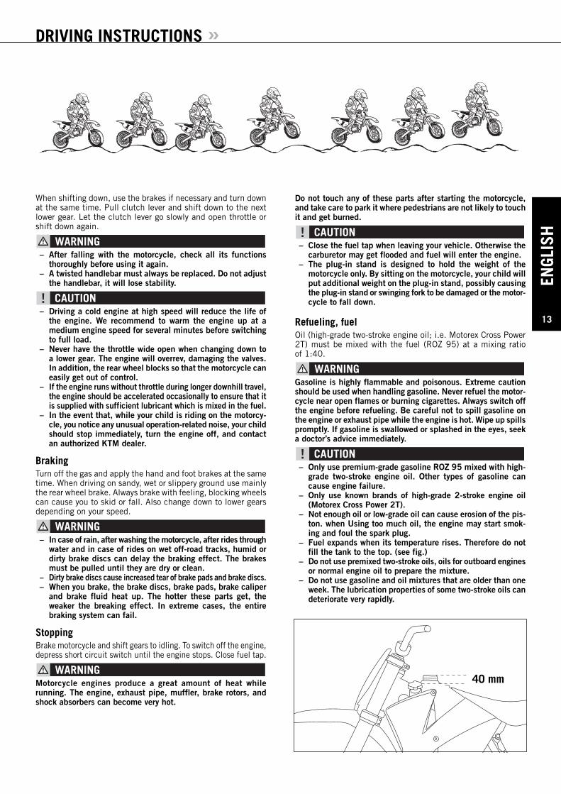
Refueling, fuelOil (high-grade two-stroke engine oil; i.e. Motorex Cross Power2T) must be mixed with the fuel (ROZ 95) at a mixing ratio of 1:40.
Gasoline is highly flammable and poisonous. Extreme cautionshould be used when handling gasoline. Never refuel the motor-cycle near open flames or burning cigarettes. Always switch offthe engine before refueling. Be careful not to spill gasoline onthe engine or exhaust pipe while the engine is hot. Wipe up spillspromptly. If gasoline is swallowed or splashed in the eyes, seeka doctor’s advice immediately.
– Only use premium-grade gasoline ROZ 95 mixed with high-grade two-stroke engine oil. Other types of gasoline cancause engine failure.
– Only use known brands of high-grade 2-stroke engine oil(Motorex Cross Power 2T).
– Not enough oil or low-grade oil can cause erosion of the pis-ton. when Using too much oil, the engine may start smok-ing and foul the spark plug.
– Fuel expands when its temperature rises. Therefore do notfill the tank to the top. (see fig.)
– Do not use premixed two-stroke oils, oils for outboard enginesor normal engine oil to prepare the mixture.
– Do not use gasoline and oil mixtures that are older than oneweek. The lubrication properties of some two-stroke oils candeteriorate very rapidly.
ENGLISH
14
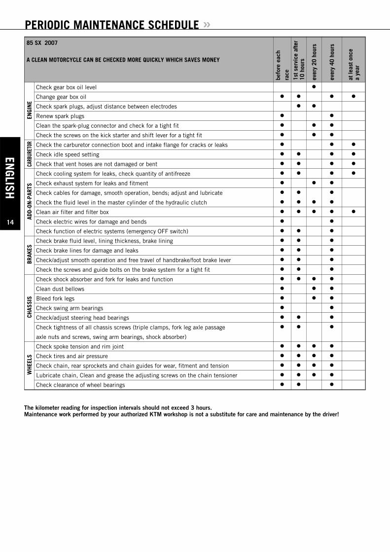
PERIODIC MAINTENANCE SCHEDULE »85 SX 2007
A CLEAN MOTORCYCLE CAN BE CHECKED MORE QUICKLY WHICH SAVES MONEY
befo
re e
ach
race
1st s
ervi
ce a
fter
10 h
ours
ever
y 20
hou
rs
ever
y 40
hou
rs
at le
ast o
nce
a ye
ar
ENGI
NE
Check gear box oil level
Change gear box oil
Check spark plugs, adjust distance between electrodes
Renew spark plugs
Clean the spark-plug connector and check for a tight fit
Check the screws on the kick starter and shift lever for a tight fit
CARB
URET
OR Check the carburetor connection boot and intake flange for cracks or leaks
Check idle speed setting
Check that vent hoses are not damaged or bent
ADD-
ON-P
ARTS
Check cooling system for leaks, check quantity of antifreeze
Check exhaust system for leaks and fitment
Check cables for damage, smooth operation, bends; adjust and lubricate
Check the fluid level in the master cylinder of the hydraulic clutch
Clean air filter and filter box
Check electric wires for damage and bends
Check function of electric systems (emergency OFF switch)
BRAK
ES
Check brake fluid level, lining thickness, brake lining
Check brake lines for damage and leaks
Check/adjust smooth operation and free travel of handbrake/foot brake lever
Check the screws and guide bolts on the brake system for a tight fit
CHAS
SIS
Check shock absorber and fork for leaks and function
Clean dust bellows
Bleed fork legs
Check swing arm bearings
Check/adjust steering head bearings
Check tightness of all chassis screws (triple clamps, fork leg axle passage
axle nuts and screws, swing arm bearings, shock absorber)
WH
EELS
Check spoke tension and rim joint
Check tires and air pressure
Check chain, rear sprockets and chain guides for wear, fitment and tension
Lubricate chain, Clean and grease the adjusting screws on the chain tensioner
Check clearance of wheel bearings
The kilometer reading for inspection intervals should not exceed 3 hours. Maintenance work performed by your authorized KTM workshop is not a substitute for care and maintenance by the driver!
ENGL
ISH
15
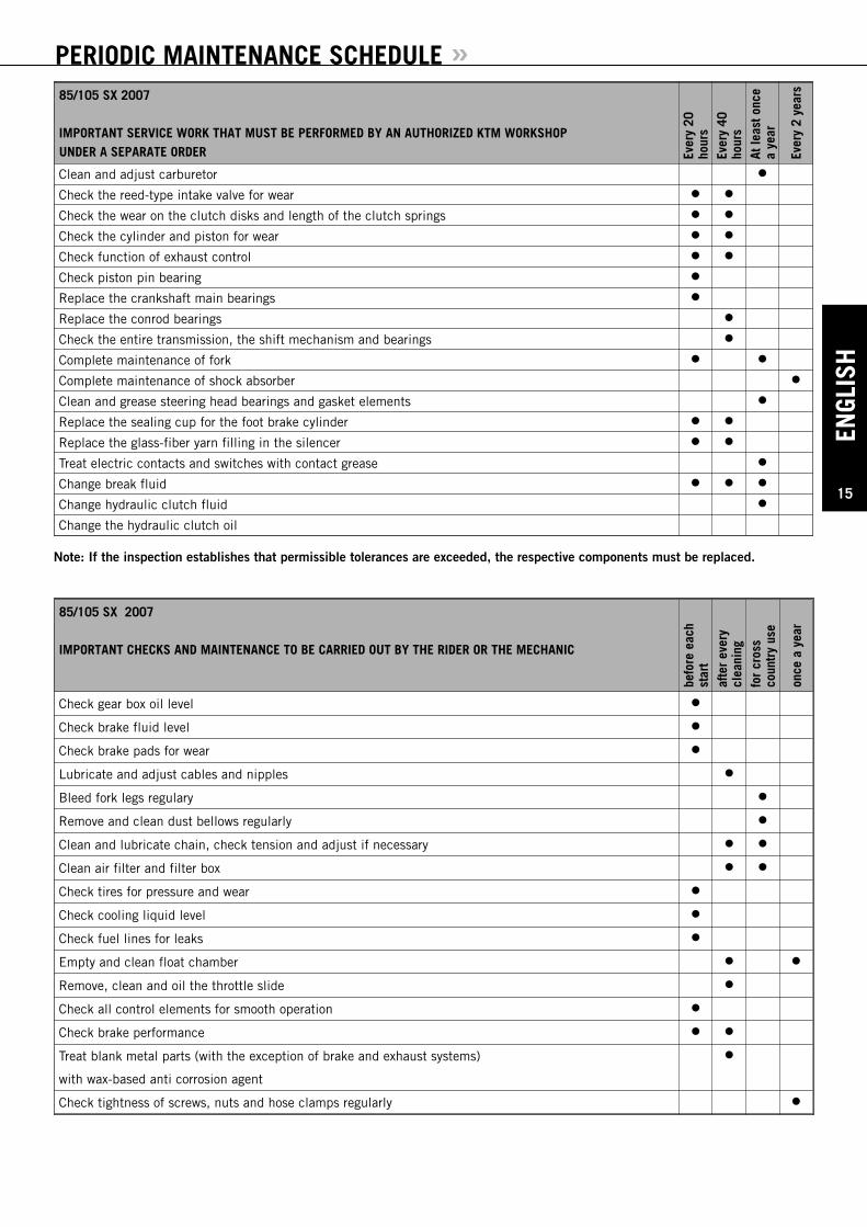
PERIODIC MAINTENANCE SCHEDULE »85/105 SX 2007
IMPORTANT SERVICE WORK THAT MUST BE PERFORMED BY AN AUTHORIZED KTM WORKSHOPUNDER A SEPARATE ORDER Ev
ery
20ho
urs
Ever
y 40
hour
sAt
leas
t onc
ea
year
Ever
y 2
year
s
Clean and adjust carburetor
Check the reed-type intake valve for wear
Check the wear on the clutch disks and length of the clutch springs
Check the cylinder and piston for wear
Check function of exhaust control
Check piston pin bearing
Replace the crankshaft main bearings
Replace the conrod bearings
Check the entire transmission, the shift mechanism and bearings
Complete maintenance of fork
Complete maintenance of shock absorber
Clean and grease steering head bearings and gasket elements
Replace the sealing cup for the foot brake cylinder
Replace the glass-fiber yarn filling in the silencer
Treat electric contacts and switches with contact grease
Change break fluid
Change hydraulic clutch fluid
Change the hydraulic clutch oil
85/105 SX 2007
IMPORTANT CHECKS AND MAINTENANCE TO BE CARRIED OUT BY THE RIDER OR THE MECHANIC
befo
re e
ach
star
taf
ter
ever
ycl
eani
ngfo
r cr
oss
coun
try
use
once
a y
ear
Check gear box oil level
Check brake fluid level
Check brake pads for wear
Lubricate and adjust cables and nipples
Bleed fork legs regulary
Remove and clean dust bellows regularly
Clean and lubricate chain, check tension and adjust if necessary
Clean air filter and filter box
Check tires for pressure and wear
Check cooling liquid level
Check fuel lines for leaks
Empty and clean float chamber
Remove, clean and oil the throttle slide
Check all control elements for smooth operation
Check brake performance
Treat blank metal parts (with the exception of brake and exhaust systems)
with wax-based anti corrosion agent
Check tightness of screws, nuts and hose clamps regularly
Note: If the inspection establishes that permissible tolerances are exceeded, the respective components must be replaced.
ENGLISH
16
MAINTENANCE WORK ON CHASSIS AND ENGINE »
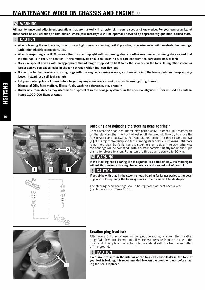
Checking and adjusting the steering head bearing *Check steering head bearing for play periodically. To check, put motorcycleon the stand so that the front wheel is off the ground. Now try to move thefork forward and backward. For readjusting, loosen the three clamp screws[1] of the top triple clamp and turn steering stem bolt [2] clockwise until thereis no more play. Don’t tighten the steering stem bolt all the way, otherwisethe bearings will be damaged. With a plastic hammer, lightly rap on the tripleclamp to release tension. Retighten the three clamp screws to 20 Nm.
If the steering head bearing is not adjusted to be free of play, the motorcyclewill exhibit unsteady driving characteristics and can get out of control.
If you drive with play in the steering head bearing for longer periods, the bear-ings and subsequently the bearing seats in the frame will be destroyed.
The steering head bearings should be regreased at least once a year (i.e. Motorex Long Term 2000).
2
1 11
All maintenance and adjustment operations that are marked with an asterisk * require specialist knowledge. For your own security, letthese tasks be carried out by a ktm-dealer where your motorcycle will be optimally serviced by appropriately qualified, skilled staff.
– When cleaning the motorcycle, do not use a high pressure cleaning unit if possible, otherwise water will penetrate the bearings,carburetor, electric connectors, etc.
– When transporting your KTM, ensure that it is held upright with restraining straps or other mechanical fastening devices and thatthe fuel tap is in the OFF position - if the motorcycle should fall over, no fuel can leak from the carburetor or fuel tank
– Only use special screws with an appropriate thread length supplied by KTM to fix the spoilers on the tank. Using other screws orlonger screws can cause leaks in the tank through which fuel can flow out.
– Do not use toothed washers or spring rings with the engine fastening screws, as these work into the frame parts and keep workingloose. Instead, use self-locking nuts.
– Let your motorcycle cool down before beginning any maintenance work in order to avoid getting burned.– Dispose of Oils, fatty matters, filters, fuels, washing detergents, etc. properly.– Under no circumstances may used oil be disposed of in the sewage system or in the open countryside. 1 liter of used oil contam-
inates 1,000,000 liters of water.
Breather plug front forkAfter every 5 hours of use for competitive racing, slacken the breather plugs [3] a few turns in order to relieve excess pressure from the inside of thefork. To do this, place the motorcycle on a stand with the front wheel liftedoff the ground.
Excessive pressure in the interior of the fork can cause leaks in the fork. Ifyour fork is leaking, it is recommended to open the breather plugs before hav-ing the seals replaced.3
ENGL
ISH
17
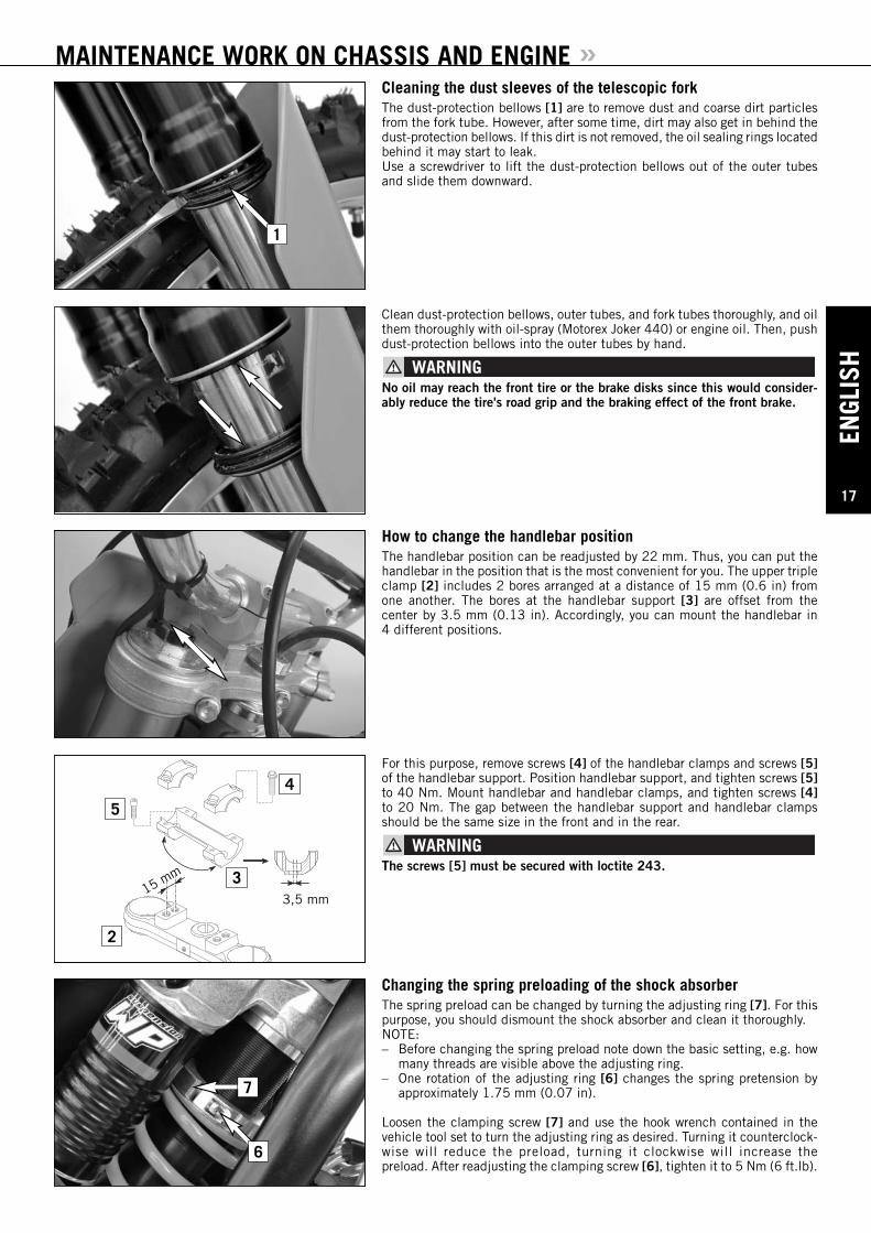
MAINTENANCE WORK ON CHASSIS AND ENGINE »Cleaning the dust sleeves of the telescopic forkThe dust-protection bellows [1] are to remove dust and coarse dirt particlesfrom the fork tube. However, after some time, dirt may also get in behind thedust-protection bellows. If this dirt is not removed, the oil sealing rings locatedbehind it may start to leak.Use a screwdriver to lift the dust-protection bellows out of the outer tubesand slide them downward.
Clean dust-protection bellows, outer tubes, and fork tubes thoroughly, and oilthem thoroughly with oil-spray (Motorex Joker 440) or engine oil. Then, pushdust-protection bellows into the outer tubes by hand.
No oil may reach the front tire or the brake disks since this would consider-ably reduce the tire's road grip and the braking effect of the front brake.
How to change the handlebar positionThe handlebar position can be readjusted by 22 mm. Thus, you can put thehandlebar in the position that is the most convenient for you. The upper tripleclamp [2] includes 2 bores arranged at a distance of 15 mm (0.6 in) fromone another. The bores at the handlebar support [3] are offset from the center by 3.5 mm (0.13 in). Accordingly, you can mount the handlebar in 4 different positions.
For this purpose, remove screws [4] of the handlebar clamps and screws [5]of the handlebar support. Position handlebar support, and tighten screws [5]to 40 Nm. Mount handlebar and handlebar clamps, and tighten screws [4]to 20 Nm. The gap between the handlebar support and handlebar clampsshould be the same size in the front and in the rear.
The screws [5] must be secured with loctite 243.
Changing the spring preloading of the shock absorberThe spring preload can be changed by turning the adjusting ring [7]. For thispurpose, you should dismount the shock absorber and clean it thoroughly.NOTE:– Before changing the spring preload note down the basic setting, e.g. how
many threads are visible above the adjusting ring.– One rotation of the adjusting ring [6] changes the spring pretension by
approximately 1.75 mm (0.07 in).
Loosen the clamping screw [7] and use the hook wrench contained in thevehicle tool set to turn the adjusting ring as desired. Turning it counterclock-wise will reduce the preload, turning it clockwise will increase the preload. After readjusting the clamping screw [6], tighten it to 5 Nm (6 ft.lb).
15 mm
3,5 mm
4
3
5
2
6
7
1

ENGLISH
18
MAINTENANCE WORK ON CHASSIS AND ENGINE »Basic suspension setup for the weight of the driverTo achieve maximum handling performance and to prevent the fork, shockabsorber, swing arm and frame from being damaged, the basic setup of thesuspension components must be suitable for your child's weight. At delivery,the fork and shock absorber are set to accommodate a driver weighing between45 and 55 kg (wearing full protective clothing). If your child's weight exceedsor falls short of this range, you will need to adjust the spring components accord-ingly.Minor deviations in weight can be compensated by adjusting the spring pre-load on the shock absorber. Other springs must be mounted on the fork andshock absorber for larger deviations.
Checking the shock absorber and springYou can establish whether or not the shock absorber spring is suitable for yourchild's weight by checking the riding sag. The static sag must be correctlyadjusted before the riding sag can be determined.
Determining the static sag of the shock absorberThe static sag should be between 30 and 35 mm. Larger deviations can stronglyinfluence the motorcycle's performance.Procedure:– Jack up the motorcycle until the rear wheel no longer touches the ground.– Measure the vertical distance between the rear wheel axle and a fixed point
(e.g. a mark on the side cover) and write it down as dimension A.– Place the motorcycle on the ground again.– Ask a helper to hold the motorcycle in vertical position.– Measure the distance between the rear axle and the fixed point again to
establish dimension B.– The static sag is the difference between dimensions A and B.
EXAMPLE:Motorcycle jacked up (dimension A) . . . . . . . . . . . . . . . . . . . . . .600 mmMotorcycle on ground, unloaded (dimension B) . . . . . . . . . . . .– 565 mmStatic sag . . . . . . . . . . . . . . . . . . . . . . . . . . . . . . . . . . . . . . . . .35 mm
If the static sag is lower, the spring preload of the shock absorber must beincreased, if the static sag is reduced, the spring preload must be higher. Seechapter "Changing the spring preload of the shock absorber."
Determining the riding sag of the shock absorber– Have a helper hold the motorcycle. Your child should sit on the bike in a
normal seating position (feet on the footrests) and bounce up and downa few times to allow the rear wheel suspension to become level.
– With your child on the bike, measure the distance between the same twopoints and write it down as dimension C.
– The riding sag is the difference between dimensions A and C.
EXAMPLE:Motorcycle jacked up (dimension A) . . . . . . . . . . . . . . . . . . . . . .600 mmMotorcycle on ground, loaded (dimension C) . . . . . . . . . . . . . .– 500 mmRiding sag . . . . . . . . . . . . . . . . . . . . . . . . . . . . . . . . . . . . . . . .100 mm
The riding sag should lie between 95 and 105 mm.If the riding sag is less than 95 mm, the spring is too hard (the spring rate istoo high). If the riding sag is more than 105 mm, the spring is too soft (thespring rate is too low).
C
B
A
ENGL
ISH
19
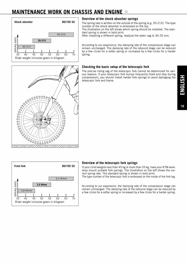
MAINTENANCE WORK ON CHASSIS AND ENGINE »Overview of the shock absorber springsThe spring rate is written on the outside of the spring (e.g. 35-215). The typenumber of the shock absorber is embossed on the top.The illustration on the left shows which spring should be installed. The stan-dard spring is shown in bold print.After installing a different spring, readjust the static sag to 30-35 mm.
According to our experience, the damping rate of the compression stage canremain unchanged. The damping rate of the rebound stage can be reducedby a few clicks for a softer spring or increased by a few clicks for a harderspring.
Checking the basic setup of the telescopic forkThe precise riding sag of the telescopic fork cannot be determined for vari-ous reasons. If your telescopic fork bumps frequently (hard end stop duringcompression), you should install harder fork springs to avoid damaging thetelescopic fork and frame.
Overview of the telescopic fork springs If your child weights less than 45 kg or more than 55 kg, have your KTM work-shop mount suitable fork springs. The illustration on the left shows the cor-rect spring rate. The standard spring is shown in bold print.The type number of the telescopic fork is embossed on the inside of the fork leg.
According to our experience, the damping rate of the compression stage canremain unchanged. The damping rate of the rebound stage can be reduced bya few clicks for a softer spring or increased by a few clicks for a harder spring.
35
SP
RIN
G R
ATE
40 45 50 55 60 65 70Rider weight inclusive gears in kilogram
Shock absorber 85/105 SX
30-215
40-215
35-215
35
SP
RIN
G R
ATE
40 45 50 55 60 65 70Rider weight inclusive gears in kilogram
Front fork 85/105 SX
2,8 N/mm
3,2 N/mm
3,0 N/mm
ENGLISH
20
MAINTENANCE WORK ON CHASSIS AND ENGINE »
A
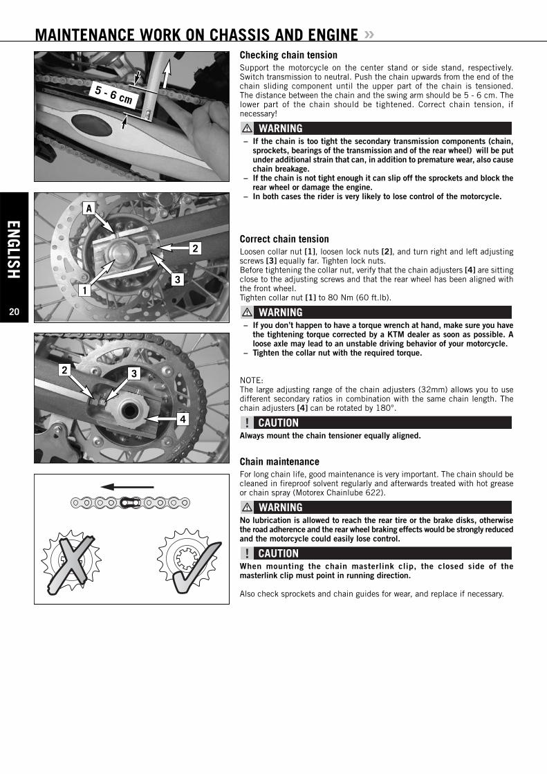
Checking chain tensionSupport the motorcycle on the center stand or side stand, respectively.Switch transmission to neutral. Push the chain upwards from the end of thechain sliding component until the upper part of the chain is tensioned.The distance between the chain and the swing arm should be 5 - 6 cm. Thelower part of the chain should be tightened. Correct chain tension, if necessary!
– If the chain is too tight the secondary transmission components (chain,sprockets, bearings of the transmission and of the rear wheel) will be putunder additional strain that can, in addition to premature wear, also causechain breakage.
– If the chain is not tight enough it can slip off the sprockets and block therear wheel or damage the engine.
– In both cases the rider is very likely to lose control of the motorcycle.
Correct chain tensionLoosen collar nut [1], loosen lock nuts [2], and turn right and left adjustingscrews [3] equally far. Tighten lock nuts.Before tightening the collar nut, verify that the chain adjusters [4] are sittingclose to the adjusting screws and that the rear wheel has been aligned withthe front wheel.Tighten collar nut [1] to 80 Nm (60 ft.lb).
– If you don’t happen to have a torque wrench at hand, make sure you havethe tightening torque corrected by a KTM dealer as soon as possible. Aloose axle may lead to an unstable driving behavior of your motorcycle.
– Tighten the collar nut with the required torque.
NOTE:The large adjusting range of the chain adjusters (32mm) allows you to usedifferent secondary ratios in combination with the same chain length. Thechain adjusters [4] can be rotated by 180°.
Always mount the chain tensioner equally aligned.
Chain maintenanceFor long chain life, good maintenance is very important. The chain should becleaned in fireproof solvent regularly and afterwards treated with hot greaseor chain spray (Motorex Chainlube 622).
No lubrication is allowed to reach the rear tire or the brake disks, otherwisethe road adherence and the rear wheel braking effects would be strongly reducedand the motorcycle could easily lose control.
When mounting the chain masterlink clip, the closed side of the masterlink clip must point in running direction.
Also check sprockets and chain guides for wear, and replace if necessary.
2 3
4
1
2
3
5 - 6 cm
ENGL
ISH
21
MAINTENANCE WORK ON CHASSIS AND ENGINE »General information about KTM disc brakes
BRAKE CALIPERS:If the front brake caliper is removed, the screws must be secured with Loctite243 when mounted and tightened to 25 Nm.
BRAKE FLUID RESERVOIRS:The brake fluid reservoirs on front and rear wheel brakes have been designed in such a way that even if the brake pads are worn it is not neces-sary to top up the brake fluid. If the brake fluid level drops below the mini-mum level either the brake system has a leak or the brake pads are completelyworn. In this case, consult an authorized KTM dealer immediately.
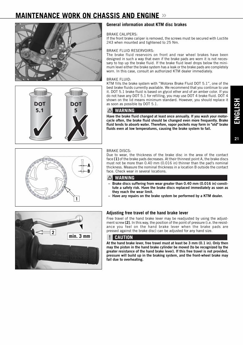
BRAKE FLUID:KTM fills the brake system with ”Motorex Brake Fluid DOT 5.1”, one of thebest brake fluids currently available. We recommend that you continue to useit. DOT 5.1 brake fluid is based on glycol ether and of an amber color. If youdo not have any DOT 5.1 for refilling, you may use DOT 4 brake fluid. DOT 4shown on the lid means minimum standard. However, you should replace itas soon as possible by DOT 5.1.
Have the brake fluid changed at least once annually. If you wash your motor-cycle often, the brake fluid should be changed even more frequently. Brakefluid tends to absorb water. Therefore, vapor pockets may form in "old" brakefluids even at low temperatures, causing the brake system to fail.
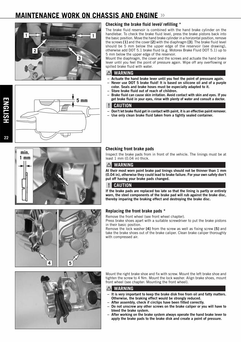
BRAKE DISCS:Due to wear, the thickness of the brake disc in the area of the contact face [1] of the brake pads decreases. At their thinnest point A, the brake discsmust not be more than 0.40 mm (0.016 in) thinner than the pad's nominalthickness. Measure the nominal thickness in a location B outside the contactface. Check wear in several locations.
– Brake discs suffering from wear greater than 0.40 mm (0.016 in) consti-tute a safety risk. Have the brake discs replaced immediately as soon asthey reach the wear limit.
– Have any repairs on the brake system be performed by a KTM dealer.
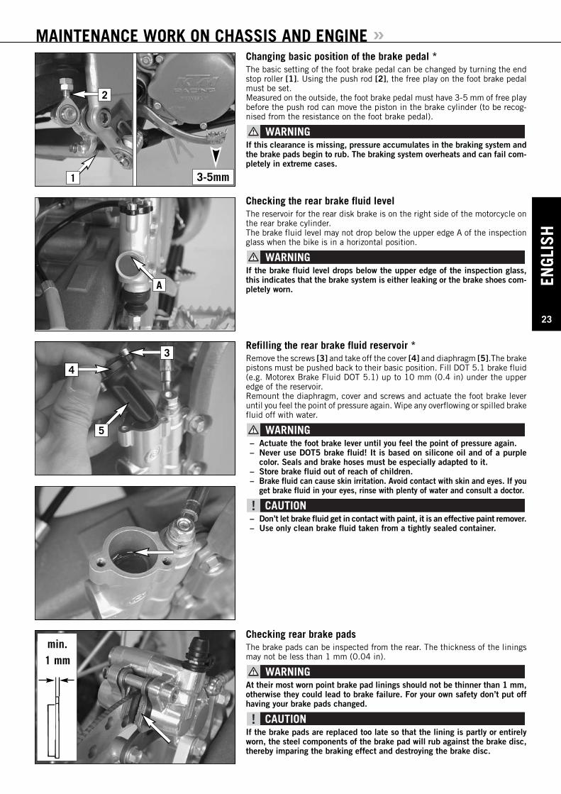
Adjusting free travel of the hand brake leverFree travel of the hand brake lever may be readjusted by using the adjust-ment screw [2]. In this way, the position of the point of pressure (i.e. the resist-ance you feel on the hand brake lever when the brake pads are pressed against the brake disc) can be adjusted for any hand size.
At the hand brake lever, free travel must at least be 3 mm (0.1 in). Only thenmay the piston in the hand brake cylinder be moved (to be recognized by thegreater resistance of the hand brake lever). If this free travel is not provided,pressure will build up in the braking system, and the front-wheel brake mayfail due to overheating.
AB
1
min. 3 mm2
ENGLISH
22
MAINTENANCE WORK ON CHASSIS AND ENGINE »
1
2
3
5 mm
min.1 mm
4 5
1
Checking the brake fluid level/ refilling *The brake fluid reservoir is combined with the hand brake cylinder on the handlebar. To check the brake fluid level, press the brake pistons back intothe basic position. Move the hand brake cylinder in a horizontal position, removethe screws [1] and the cover [2] with the diaphragm [3]. The brake fluid levelshould be 5 mm below the upper edge of the reservoir (see drawing), otherwise add DOT 5.1 brake fluid (e.g. Motorex Brake Fluid DOT 5.1) up to5 mm below the upper edge of the reservoir.Mount the diaphragm, the cover and the screws and actuate the hand brakelever until you feel the point of pressure again. Wipe off any overflowing orspilled brake fluid with water.
– Actuate the hand brake lever until you feel the point of pressure again.– Never use DOT 5 brake fluid! It is based on silicone oil and of a purple
color. Seals and brake hoses must be especially adapted to it.– Store brake fluid out of reach of children.– Brake fluid can cause skin irritation. Avoid contact with skin and eyes. If you
get brake fluid in your eyes, rinse with plenty of water and consult a doctor.
– Don’t let brake fluid get in contact with paint, it is an effective paint remover.– Use only clean brake fluid taken from a tightly sealed container.
Checking front brake padsInspect the brake pads from in front of the vehicle. The linings must be atleast 1 mm (0.04 in) thick.
At their most worn point brake pad linings should not be thinner than 1 mm(0.04 in), otherwise they could lead to brake failure. For your own safety don’tput off having your brake pads changed.
If the brake pads are replaced too late so that the lining is partly or entirelyworn, the steel components of the brake pad will rub against the brake disc,thereby imparing the braking effect and destroying the brake disc.
Replacing the front brake pads *Remove the front wheel (see front wheel chapter).Press brake shoes apart with a suitable screwdriver to put the brake pistonsin their basic position.Remove the lock washer [4] from the screw as well as fixing screw [5] andtake the brake shoes out of the brake caliper. Clean brake caliper thoroughlywith compressed air.
Mount the right brake shoe and fix with screw. Mount the left brake shoe andtighten the screw to 4 Nm. Mount the lock washer. Align brake shoes, mountfront wheel (see chapter: Mounting the front wheel).
– It is very important to keep the brake disk free from oil and fatty matters.Otherwise, the braking effect would be strongly reduced.
– After assembly, check if circlips have been fitted correctly.– Do not unscrew any other screws on the brake caliper or you will have to
bleed the brake system.– After working on the brake system always operate the hand brake lever to
apply the brake pads to the brake disk and create a point of pressure.
ENGL
ISH
23
MAINTENANCE WORK ON CHASSIS AND ENGINE »Changing basic position of the brake pedal *The basic setting of the foot brake pedal can be changed by turning the endstop roller [1]. Using the push rod [2], the free play on the foot brake pedalmust be set.Measured on the outside, the foot brake pedal must have 3-5 mm of free playbefore the push rod can move the piston in the brake cylinder (to be recog-nised from the resistance on the foot brake pedal).
If this clearance is missing, pressure accumulates in the braking system andthe brake pads begin to rub. The braking system overheats and can fail com-pletely in extreme cases.
Checking the rear brake fluid levelThe reservoir for the rear disk brake is on the right side of the motorcycle onthe rear brake cylinder.The brake fluid level may not drop below the upper edge A of the inspectionglass when the bike is in a horizontal position.
If the brake fluid level drops below the upper edge of the inspection glass,this indicates that the brake system is either leaking or the brake shoes com-pletely worn.
Checking rear brake padsThe brake pads can be inspected from the rear. The thickness of the liningsmay not be less than 1 mm (0.04 in).
At their most worn point brake pad linings should not be thinner than 1 mm,otherwise they could lead to brake failure. For your own safety don’t put offhaving your brake pads changed.
If the brake pads are replaced too late so that the lining is partly or entirelyworn, the steel components of the brake pad will rub against the brake disc,thereby imparing the braking effect and destroying the brake disc.
min.1 mm
A
Refilling the rear brake fluid reservoir *Remove the screws [3] and take off the cover [4] and diaphragm [5].The brakepistons must be pushed back to their basic position. Fill DOT 5.1 brake fluid(e.g. Motorex Brake Fluid DOT 5.1) up to 10 mm (0.4 in) under the upperedge of the reservoir. Remount the diaphragm, cover and screws and actuate the foot brake leveruntil you feel the point of pressure again. Wipe any overflowing or spilled brakefluid off with water.
– Actuate the foot brake lever until you feel the point of pressure again.– Never use DOT5 brake fluid! It is based on silicone oil and of a purple
color. Seals and brake hoses must be especially adapted to it.– Store brake fluid out of reach of children.– Brake fluid can cause skin irritation. Avoid contact with skin and eyes. If you
get brake fluid in your eyes, rinse with plenty of water and consult a doctor.
– Don’t let brake fluid get in contact with paint, it is an effective paint remover.– Use only clean brake fluid taken from a tightly sealed container.
3
4
5
3-5mm1
2
ENGLISH
24
MAINTENANCE WORK ON CHASSIS AND ENGINE »Remove the safety device [1], knock out the guide pin [2] from the brake caliperwith a drift towards the chain wheel and remove the brake pads. Carefullyclean the brake caliper with compressed air and check the sleeves of the guidepins for damage.
Press both brake shoes into the brake caliper and fix with bolt [2]. Mount thelocks [1]. Tighten bolt [2] to 5 Nm (3,7 ft.lb).
– It is very important to keep the brake disk free from oil and fatty matters.Otherwise, the braking effect would be strongly reduced.
– After assembly, check if circlips have been fitted correctly.– After working on the braking system, one must always actuate the hand
brake lever or foot brake lever, respectively so as to ensure that the brakepads will lie against the brake disk and the pressure point is established.
2
1
3
4
5
6
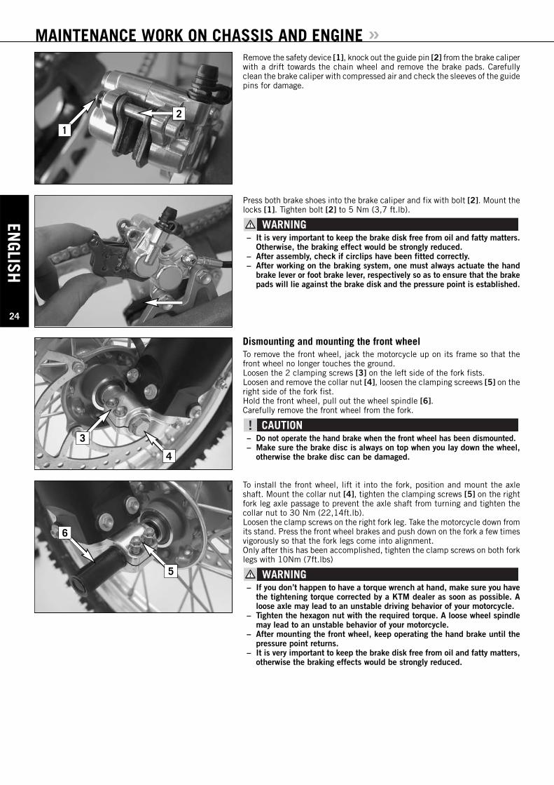
Dismounting and mounting the front wheelTo remove the front wheel, jack the motorcycle up on its frame so that thefront wheel no longer touches the ground.Loosen the 2 clamping screws [3] on the left side of the fork fists.Loosen and remove the collar nut [4], loosen the clamping screews [5] on theright side of the fork fist.Hold the front wheel, pull out the wheel spindle [6].Carefully remove the front wheel from the fork.
– Do not operate the hand brake when the front wheel has been dismounted.– Make sure the brake disc is always on top when you lay down the wheel,
otherwise the brake disc can be damaged.
To install the front wheel, lift it into the fork, position and mount the axleshaft. Mount the collar nut [4], tighten the clamping screws [5] on the rightfork leg axle passage to prevent the axle shaft from turning and tighten thecollar nut to 30 Nm (22,14ft.lb).Loosen the clamp screws on the right fork leg. Take the motorcycle down fromits stand. Press the front wheel brakes and push down on the fork a few timesvigorously so that the fork legs come into alignment.Only after this has been accomplished, tighten the clamp screws on both forklegs with 10Nm (7ft.lbs)
– If you don’t happen to have a torque wrench at hand, make sure you havethe tightening torque corrected by a KTM dealer as soon as possible. Aloose axle may lead to an unstable driving behavior of your motorcycle.
– Tighten the hexagon nut with the required torque. A loose wheel spindlemay lead to an unstable behavior of your motorcycle.
– After mounting the front wheel, keep operating the hand brake until thepressure point returns.
– It is very important to keep the brake disk free from oil and fatty matters,otherwise the braking effects would be strongly reduced.

ENGL
ISH
25
MAINTENANCE WORK ON CHASSIS AND ENGINE »Dismounting and mounting the rear wheelJack the motorcycle up on its frame so that the rear wheel no longer touchesthe ground. Loosen the collar nut [1], remove chain tensioner [2], hold the rear wheel andpull out the wheel spindle [3] until the rear wheel is free but the brake calipersupport is still held. Push the rear wheel as far forward as possible, take the chain from the chainwheel and carefully take the rear wheel out of the swingarm.
– Do not operate the rear brake when the rear wheel has been dismounted.– Make sure the brake disc is always on top when you lay down the wheel,
otherwise the brake disc can be damaged.– If the axle is dismounted, clean the thread of the wheel spindle and col-
lar nut thoroughly and apply a new coat of grease to prevent the threadfrom jamming.
The rear wheel is remounted in the reverse order. Before tightening the col-lar nut to 80 Nm (60 ft.lb), push the rear wheel forwards so that the chaintensioners lie on the tension screws.
– If you don’t happen to have a torque wrench at hand, make sure you havethe tightening torque corrected by a KTM dealer as soon as possible. Aloose axle may lead to an unstable driving behavior of your motorcycle.
– After mounting the rear wheel, keep operating the rear brake until the pres-sure point returns.
– It is very important to keep the brake disk free from oil and fatty matters,otherwise the braking effects would be strongly reduced.
– Tighten the collar nut with the required torque. A loose wheel spindle maylead to an unstable behavior of your motorcycle.
1
2
3
Tires, air pressureTire type, tire condition, and air pressure level affect the way your motorcy-cle rides, and they must therefore be checked whenever you are getting readyto go anywhere on your motorcycle. Tire size can be found in the technicalspecifications. Tire condition has to be checked every time you want to rideyour motorcycle. Before leaving, check tires for punctures and nails or othersharp objects that might have become embedded in them.Tire pressure should be checked regularly on a “cold” tire. Proper pressure(1.0 bar) ensures optimum driving comfort and extends the life of your tires.
– Damaged tires must be replaced immediately to protect your youngster.– Worn tires can have a negative effect on how the motorcycle performs,
especially on wet surfaces– Tire pressure below the normal level will lead to premature tire wear.
Checking spoke tensionThe correct spoke tension is very important for the stability of the wheels andthus for riding safety. A loose spoke causes the wheel to become unbalancedand before long other spokes will have come loose. Check spoke tension, espe-cially on a new motorcycle, at regular intervals. For checking, tap on eachspoke with the blade of a screwdriver (see photo). A clear tone must be theresult. Dull tones are indicators of loose spokes. If necessary, have the spokesretightened and the wheel centered by a KTM dealer.
– Spokes can tear if you continue to ride with them loose. This may lead toan unstable handling of your motorcycle.
– Excessively tensioned spokes may rupture due to local overloading. Thespokes must be tensioned to 5 Nm.
ENGLISH
26
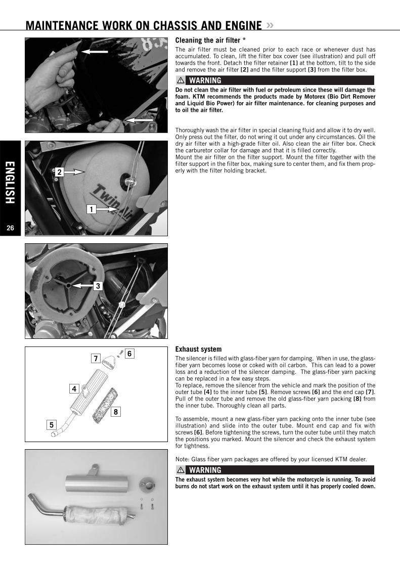
MAINTENANCE WORK ON CHASSIS AND ENGINE »Cleaning the air filter *The air filter must be cleaned prior to each race or whenever dust has accumulated. To clean, lift the filter box cover (see illustration) and pull offtowards the front. Detach the filter retainer [1] at the bottom, tilt to the sideand remove the air filter [2] and the filter support [3] from the filter box.
Do not clean the air filter with fuel or petroleum since these will damage thefoam. KTM recommends the products made by Motorex (Bio Dirt Removerand Liquid Bio Power) for air filter maintenance. for cleaning purposes andto oil the air filter.
Thoroughly wash the air filter in special cleaning fluid and allow it to dry well.Only press out the filter, do not wring it out under any circumstances. Oil thedry air filter with a high-grade filter oil. Also clean the air filter box. Checkthe carburetor collar for damage and that it is filled correctly.Mount the air filter on the filter support. Mount the filter together with thefilter support in the filter box, making sure to center them, and fix them prop-erly with the filter holding bracket.
Exhaust systemThe silencer is filled with glass-fiber yarn for damping. When in use, the glass-fiber yarn becomes loose or coked with oil carbon. This can lead to a powerloss and a reduction of the silencer damping. The glass-fiber yarn packingcan be replaced in a few easy steps.To replace, remove the silencer from the vehicle and mark the position of theouter tube [4] to the inner tube [5]. Remove screws [6] and the end cap [7].Pull of the outer tube and remove the old glass-fiber yarn packing [8] fromthe inner tube. Thoroughly clean all parts.
To assemble, mount a new glass-fiber yarn packing onto the inner tube (seeillustration) and slide into the outer tube. Mount end cap and fix withscrews [6]. Before tightening the screws, turn the outer tube until they matchthe positions you marked. Mount the silencer and check the exhaust systemfor tightness.
Note: Glass fiber yarn packages are offered by your licensed KTM dealer.
The exhaust system becomes very hot while the motorcycle is running. To avoidburns do not start work on the exhaust system until it has properly cooled down.
4
5
67
8
1
2
3
ENGL
ISH
27
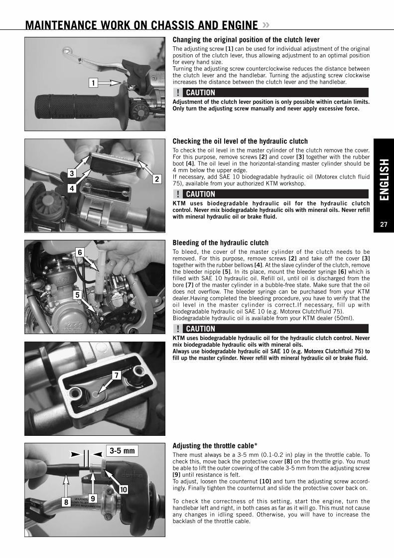
MAINTENANCE WORK ON CHASSIS AND ENGINE »Changing the original position of the clutch leverThe adjusting screw [1] can be used for individual adjustment of the originalposition of the clutch lever, thus allowing adjustment to an optimal positionfor every hand size.Turning the adjusting screw counterclockwise reduces the distance betweenthe clutch lever and the handlebar. Turning the adjusting screw clockwiseincreases the distance between the clutch lever and the handlebar.
Adjustment of the clutch lever position is only possible within certain limits.Only turn the adjusting screw manually and never apply excessive force.
Checking the oil level of the hydraulic clutchTo check the oil level in the master cylinder of the clutch remove the cover.For this purpose, remove screws [2] and cover [3] together with the rubberboot [4]. The oil level in the horizontal-standing master cylinder should be 4 mm below the upper edge. If necessary, add SAE 10 biodegradable hydraulic oil (Motorex clutch fluid75), available from your authorized KTM workshop.
KTM uses biodegradable hydraulic oil for the hydraulic clutch control. Never mix biodegradable hydraulic oils with mineral oils. Never refillwith mineral hydraulic oil or brake fluid.
Bleeding of the hydraulic clutchTo bleed, the cover of the master cylinder of the clutch needs to be removed. For this purpose, remove screws [2] and take off the cover [3]together with the rubber bellows [4]. At the slave cylinder of the clutch, removethe bleeder nipple [5]. In its place, mount the bleeder syringe [6] which isfilled with SAE 10 hydraulic oil. Refill oil, until oil is discharged from thebore [7] of the master cylinder in a bubble-free state. Make sure that the oildoes not overflow. The bleeder syringe can be purchased from your KTMdealer.Having completed the bleeding procedure, you have to verify that theoil level in the master cylinder is correct.If necessary, fill up with biodegradable hydraulic oil SAE 10 (e.g. Motorex Clutchfluid 75).Biodegradable hydraulic oil is available from your KTM dealer (50ml).
KTM uses biodegradable hydraulic oil for the hydraulic clutch control. Nevermix biodegradable hydraulic oils with mineral oils.Always use biodegradable hydraulic oil SAE 10 (e.g. Motorex Clutchfluid 75) tofill up the master cylinder. Never refill with mineral hydraulic oil or brake fluid.
3-5 mm
1
23
4
6
5
7
Adjusting the throttle cable*There must always be a 3-5 mm (0.1-0.2 in) play in the throttle cable. Tocheck this, move back the protective cover [8] on the throttle grip. You mustbe able to lift the outer covering of the cable 3-5 mm from the adjusting screw[9] until resistance is felt.To adjust, loosen the counternut [10] and turn the adjusting screw accord-ingly. Finally tighten the counternut and slide the protective cover back on.
To check the correctness of this setting, start the engine, turn the handlebar left and right, in both cases as far as it will go. This must not causeany changes in idling speed. Otherwise, you will have to increase the backlash of the throttle cable.
8 910
ENGLISH
28
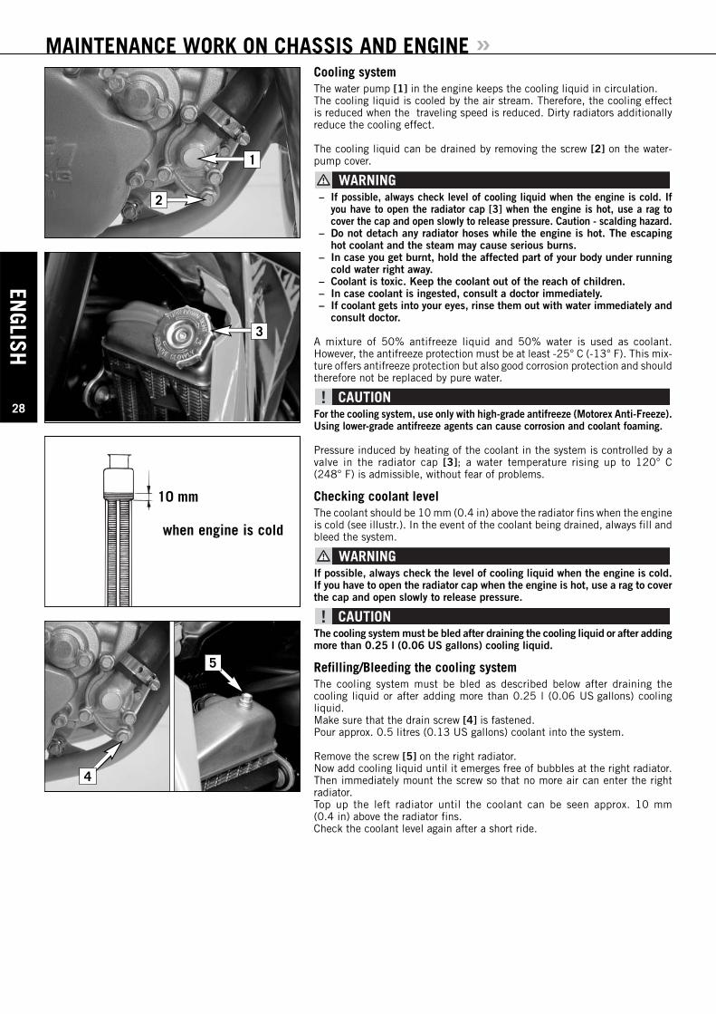
MAINTENANCE WORK ON CHASSIS AND ENGINE »Cooling systemThe water pump [1] in the engine keeps the cooling liquid in circulation. The cooling liquid is cooled by the air stream. Therefore, the cooling effectis reduced when the traveling speed is reduced. Dirty radiators additionallyreduce the cooling effect.
The cooling liquid can be drained by removing the screw [2] on the water-pump cover.
– If possible, always check level of cooling liquid when the engine is cold. Ifyou have to open the radiator cap [3] when the engine is hot, use a rag tocover the cap and open slowly to release pressure. Caution - scalding hazard.
– Do not detach any radiator hoses while the engine is hot. The escapinghot coolant and the steam may cause serious burns.
– In case you get burnt, hold the affected part of your body under runningcold water right away.
– Coolant is toxic. Keep the coolant out of the reach of children.– In case coolant is ingested, consult a doctor immediately.– If coolant gets into your eyes, rinse them out with water immediately and
consult doctor.
A mixture of 50% antifreeze liquid and 50% water is used as coolant. However, the antifreeze protection must be at least -25° C (-13° F). This mix-ture offers antifreeze protection but also good corrosion protection and shouldtherefore not be replaced by pure water.
For the cooling system, use only with high-grade antifreeze (Motorex Anti-Freeze).Using lower-grade antifreeze agents can cause corrosion and coolant foaming.
Pressure induced by heating of the coolant in the system is controlled by avalve in the radiator cap [3]; a water temperature rising up to 120° C (248° F) is admissible, without fear of problems.
Checking coolant levelThe coolant should be 10 mm (0.4 in) above the radiator fins when the engineis cold (see illustr.). In the event of the coolant being drained, always fill andbleed the system.
If possible, always check the level of cooling liquid when the engine is cold.If you have to open the radiator cap when the engine is hot, use a rag to coverthe cap and open slowly to release pressure.
The cooling system must be bled after draining the cooling liquid or after addingmore than 0.25 l (0.06 US gallons) cooling liquid.
Refilling/Bleeding the cooling systemThe cooling system must be bled as described below after draining the cooling liquid or after adding more than 0.25 l (0.06 US gallons) cooling liquid.Make sure that the drain screw [4] is fastened.Pour approx. 0.5 litres (0.13 US gallons) coolant into the system.
Remove the screw [5] on the right radiator. Now add cooling liquid until it emerges free of bubbles at the right radiator.Then immediately mount the screw so that no more air can enter the rightradiator.Top up the left radiator until the coolant can be seen approx. 10 mm (0.4 in) above the radiator fins.Check the coolant level again after a short ride.
1
2
when engine is cold
10 mm
3
5
4
ENGL
ISH
29
MAINTENANCE WORK ON CHASSIS AND ENGINE »
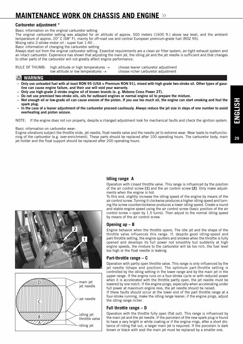
Idling range AOperation with closed throttle valve. This range is influenced by the positionof the air control screw [1] and the air control screw [2]. Only make adjust-ments when the engine is hot.To this end, slightly increase the idling speed of the engine by means of theair control screw. Turning it clockwise produces a higher idling speed and turn-ing the screw counterclockwise produces a lower idling speed. Create a roundand stable engine speed using the air control screw (basic position of the aircontrol screw = open by 1.5 turns). Then adjust to the normal idling speedby means of the air control screw.
Opening up – BEngine behavior when the throttle opens. The idle jet and the shape of thethrottle valve influences this range. If, despite good idling-speed and part-throttle setting, the engine sputters and smokes when the throttle is fullyopened and develops its full power not smoothly but suddenly at high engine speeds, the mixture to the carburetor will be too rich, the fuel leveltoo high or the float needle is leaking.
Part-throttle range – COperation with partly open throttle valve. This range is only influenced by thejet needle (shape and position). The optimum part-throttle setting is controlled by the idling setting in the lower range and by the main jet in theupper range. If the engine runs on a four-stroke cycle or with reduced powerwhen it is accelerated with the throttle partly open, the jet needle must belowered by one notch. If the engine pings, especially when accelerating underfull power at maximum engine revs, the jet needle should be raised.If these faults should occur at the lower end of the part throttle range at afour-stroke running, make the idling range leaner; if the engine pings, adjustthe idling range richer.
Full throttle range – DOperation with the throttle fully open (flat out). This range is influenced bythe main jet and the jet needle. If the porcelain of the new spark plug is foundto have a very bright or white coating or if the engine rings, after a short dis-tance of riding flat out, a larger main jet is required. If the porcelain is darkbrown or black with soot the main jet must be replaced by a smaller one.
1
2
Carburetor adjustment *Basic information on the original carburetor settingThe original carburetor setting was adapted for an altitude of approx. 500 meters (1600 ft.) above sea level, and the ambient temperature of approx. 20° C (68° F), mainly for off-road use and central European premium-grade fuel (ROZ 95). Mixing ratio 2-stroke motor oil : super fuel 1:40 .Basic information of changing the carburetor settingAlways start out from the original carburetor setting. Essential requirements are a clean air filter system, air-tight exhaust system andan intact carburetor. Experience has shown that adjusting the main jet, the idling jet and the jet needle is sufficient and that changesto other parts of the carburetor will not greatly affect engine performance.
RULE OF THUMB: high altitude or high temperatures → choose leaner carburetor adjustmentlow altitude or low temperatures → choose richer carburetor adjustment
– Only use unleaded fuel with at least RON 95 (USA = Premium RON 91), mixed with high grade two-stroke oil. Other types of gaso-line can cause engine failure, and their use will void your warranty.
– Only use high-grade 2-stroke engine oil of known brands (e. g. Motorex Cross Power 2T).– Do not use premixed two-stroke oils, oils for outboard engines or normal engine oil to prepare the mixture.– Not enough oil or low-grade oil can cause erosion of the piston. If you use too much oil, the engine can start smoking and foul the
spark plug.– In the case of a leaner adjustment of the carburetor proceed cautiously. Always reduce the jet size in steps of one number to avoid
overheating and piston seizure.
NOTE: If the engine does not run properly, despite a changed adjustment look for mechanical faults and check the ignition system.
Basic information on carburetor wear:Engine vibrations subject the throttle slide, jet needle, float needle valve and the needle jet to extreme wear. Wear leads to malfunctio-ning of the carburetor (e.g. over-enrichment). These parts should be replaced after 100 operating hours. The carburetor body, mainjet holder and the float support should be replaced after 200 operating hours.
B
C
D
A
main jetjet needle
jet needle
idling jet
idling jetthrottle valve
ENGLISH
30
MAINTENANCE WORK ON CHASSIS AND ENGINE »Draining the float chamber of the carburetorFollowing every wet-cleaning procedure, the float chamber of the carburetor should be drained in order to remove any water that may have penetrated into it. Water in the float chamber leads to engine malfunction.Make sure you do this while the engine is cold. Close the fuel tap and placea cloth under the carburetor which is capable of absorbing the leaking fuel.Unscrew the plug [1] and clean it with compressed air. Then, mount the plugtogether with the gasket and tighten to 4 Nm, open fuel tap, and check thefloat chamber for leaks.
Fuel is easily flammable and toxic. When handling fuel, be sure to exercisethe utmost caution. Never perform any work on the fuel system near of openflames or burning cigarettes. Always allow the engine to cool off first.Immediately clean up any fuel which may have been spilled. Materials satu-rated with fuel are also easily flammable. In case you ingested fuel or fuelsplashed into your eyes, consult a doctor immediately.Dispose of the fuel properly!
1
Checking gear oil levelTo check the gear oil, warm up the engine to operating temperature with alow load and place the motorcycle on an even surface. Remove the oil drainplug [2] and allow the gear oil to drain into a vessel. Clean the sealing area,mount the oil drain plug and gasket and tighten to 15 Nm. Remove the oil filler screw [4] and add 0.5 liters of gear oil (e.g. Motorex Topspeed 4T 15W50). Mount the oil filler screw and check the engine forleaks. If the gear oil is still clean you can continue to use it up to your next service.
– too little oil or a poor oil quality will cause the transmission to wear pre-maturely. Only use brand-name oils.
– due to a change in the fluid capacities the inspection screw [3] can nolonger be used.
Engines and engine oil are extremely hot at operating temperatures - be care-ful not to burn yourself.
Changing gear oil *Before changing the gear oil warm up the engine and park the motorcycle ona horizontal surface. Remove the oil drain plug [2] and drain the used oil intoan appropriate container. Clean the sealing surface. Mount the oil drain plugtogether with its gasket and tighten to 15 Nm.
Remove the filler plug [4] and add 0.5 l gear oil (e.g. Motorex Topspeed 4T15W50). Mount the filler plug and check the engine for leaks.
– too little oil or a poor oil quality will cause the transmission to wear pre-maturely. Only use brand-name oils.
– due to a change in the fluid capacities the inspection screw [3] can nolonger be used.
Engines and engine oil are extremely hot at operating temperatures - be care-ful not to burn yourself.
4
2
3
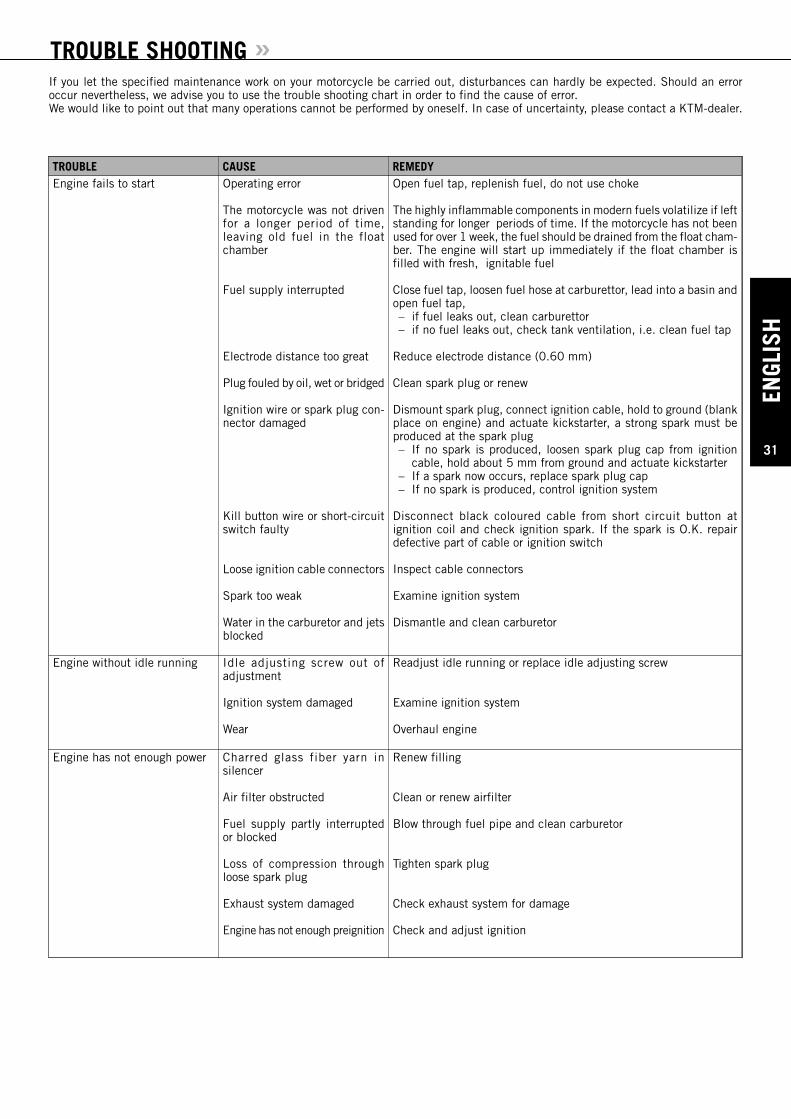
ENGL
ISH
31
TROUBLE SHOOTING »
TROUBLE CAUSE REMEDYEngine fails to start Operating error
The motorcycle was not drivenfor a longer period of time, leaving old fuel in the float chamber
Fuel supply interrupted
Electrode distance too great
Plug fouled by oil, wet or bridged
Ignition wire or spark plug con-nector damaged
Kill button wire or short-circuitswitch faulty
Loose ignition cable connectors
Spark too weak
Water in the carburetor and jetsblocked
Open fuel tap, replenish fuel, do not use choke
The highly inflammable components in modern fuels volatilize if leftstanding for longer periods of time. If the motorcycle has not beenused for over 1 week, the fuel should be drained from the float cham-ber. The engine will start up immediately if the float chamber isfilled with fresh, ignitable fuel
Close fuel tap, loosen fuel hose at carburettor, lead into a basin andopen fuel tap,– if fuel leaks out, clean carburettor– if no fuel leaks out, check tank ventilation, i.e. clean fuel tap
Reduce electrode distance (0.60 mm)
Clean spark plug or renew
Dismount spark plug, connect ignition cable, hold to ground (blankplace on engine) and actuate kickstarter, a strong spark must beproduced at the spark plug– If no spark is produced, loosen spark plug cap from ignition
cable, hold about 5 mm from ground and actuate kickstarter– If a spark now occurs, replace spark plug cap– If no spark is produced, control ignition system
Disconnect black coloured cable from short circuit button at ignition coil and check ignition spark. If the spark is O.K. repairdefective part of cable or ignition switch
Inspect cable connectors
Examine ignition system
Dismantle and clean carburetor
Engine without idle running Idle adjusting screw out of adjustment
Ignition system damaged
Wear
Readjust idle running or replace idle adjusting screw
Examine ignition system
Overhaul engine
Engine has not enough power Charred glass fiber yarn insilencer
Air filter obstructed
Fuel supply partly interruptedor blocked
Loss of compression throughloose spark plug
Exhaust system damaged
Engine has not enough preignition
Renew filling
Clean or renew airfilter
Blow through fuel pipe and clean carburetor
Tighten spark plug
Check exhaust system for damage
Check and adjust ignition
If you let the specified maintenance work on your motorcycle be carried out, disturbances can hardly be expected. Should an erroroccur nevertheless, we advise you to use the trouble shooting chart in order to find the cause of error.We would like to point out that many operations cannot be performed by oneself. In case of uncertainty, please contact a KTM-dealer.
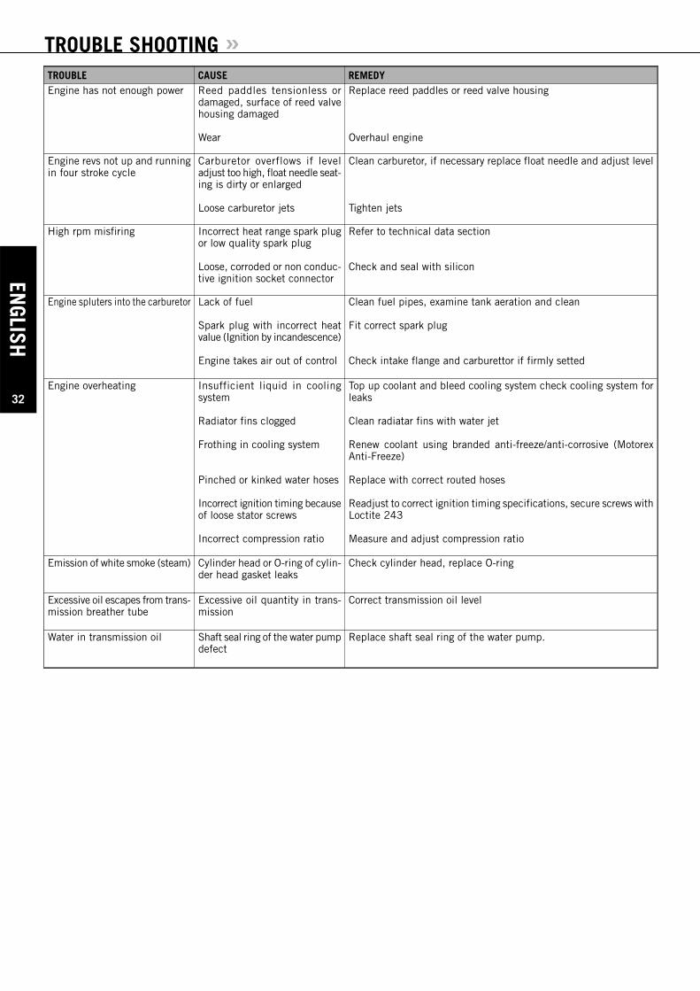
ENGLISH
32
TROUBLE SHOOTING »TROUBLE CAUSE REMEDYEngine has not enough power Reed paddles tensionless or
damaged, surface of reed valvehousing damaged
Wear
Replace reed paddles or reed valve housing
Overhaul engine
Engine revs not up and runningin four stroke cycle
Carburetor overflows if leveladjust too high, float needle seat-ing is dirty or enlarged
Loose carburetor jets
Clean carburetor, if necessary replace float needle and adjust level
Tighten jets
High rpm misfiring Incorrect heat range spark plugor low quality spark plug
Loose, corroded or non conduc-tive ignition socket connector
Refer to technical data section
Check and seal with silicon
Engine spluters into the carburetor Lack of fuel
Spark plug with incorrect heatvalue (Ignition by incandescence)
Engine takes air out of control
Clean fuel pipes, examine tank aeration and clean
Fit correct spark plug
Check intake flange and carburettor if firmly setted
Engine overheating Insufficient liquid in cooling system
Radiator fins clogged
Frothing in cooling system
Pinched or kinked water hoses
Incorrect ignition timing becauseof loose stator screws
Incorrect compression ratio
Top up coolant and bleed cooling system check cooling system forleaks
Clean radiatar fins with water jet
Renew coolant using branded anti-freeze/anti-corrosive (MotorexAnti-Freeze)
Replace with correct routed hoses
Readjust to correct ignition timing specifications, secure screws withLoctite 243
Measure and adjust compression ratio
Emission of white smoke (steam) Cylinder head or O-ring of cylin-der head gasket leaks
Check cylinder head, replace O-ring
Excessive oil escapes from trans-mission breather tube
Excessive oil quantity in trans-mission
Correct transmission oil level
Water in transmission oil Shaft seal ring of the water pumpdefect
Replace shaft seal ring of the water pump.
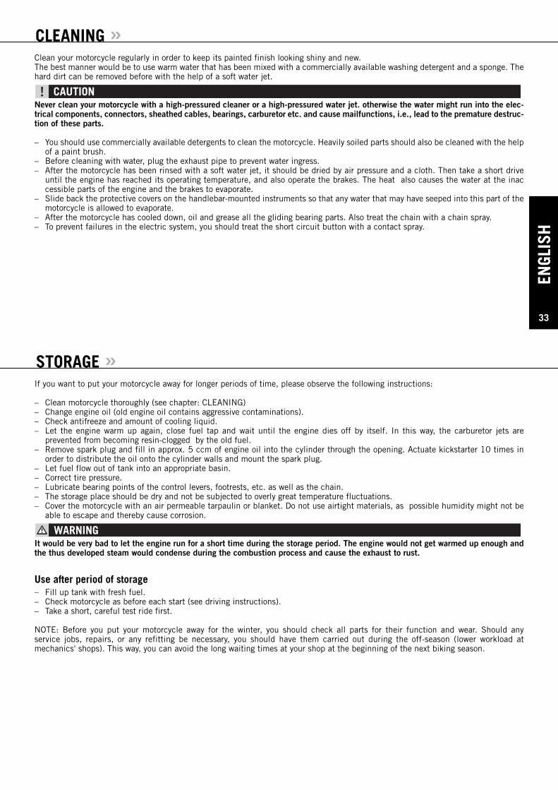
ENGL
ISH
33
CLEANING »
STORAGE »
Clean your motorcycle regularly in order to keep its painted finish looking shiny and new.The best manner would be to use warm water that has been mixed with a commercially available washing detergent and a sponge. Thehard dirt can be removed before with the help of a soft water jet.
Never clean your motorcycle with a high-pressured cleaner or a high-pressured water jet. otherwise the water might run into the elec-trical components, connectors, sheathed cables, bearings, carburetor etc. and cause mailfunctions, i.e., lead to the premature destruc-tion of these parts.
– You should use commercially available detergents to clean the motorcycle. Heavily soiled parts should also be cleaned with the helpof a paint brush.
– Before cleaning with water, plug the exhaust pipe to prevent water ingress.– After the motorcycle has been rinsed with a soft water jet, it should be dried by air pressure and a cloth. Then take a short drive
until the engine has reached its operating temperature, and also operate the brakes. The heat also causes the water at the inaccessible parts of the engine and the brakes to evaporate.
– Slide back the protective covers on the handlebar-mounted instruments so that any water that may have seeped into this part of themotorcycle is allowed to evaporate.
– After the motorcycle has cooled down, oil and grease all the gliding bearing parts. Also treat the chain with a chain spray.– To prevent failures in the electric system, you should treat the short circuit button with a contact spray.
If you want to put your motorcycle away for longer periods of time, please observe the following instructions:
– Clean motorcycle thoroughly (see chapter: CLEANING)– Change engine oil (old engine oil contains aggressive contaminations).– Check antifreeze and amount of cooling liquid.– Let the engine warm up again, close fuel tap and wait until the engine dies off by itself. In this way, the carburetor jets are
prevented from becoming resin-clogged by the old fuel.– Remove spark plug and fill in approx. 5 ccm of engine oil into the cylinder through the opening. Actuate kickstarter 10 times in
order to distribute the oil onto the cylinder walls and mount the spark plug.– Let fuel flow out of tank into an appropriate basin.– Correct tire pressure.– Lubricate bearing points of the control levers, footrests, etc. as well as the chain.– The storage place should be dry and not be subjected to overly great temperature fluctuations.– Cover the motorcycle with an air permeable tarpaulin or blanket. Do not use airtight materials, as possible humidity might not be
able to escape and thereby cause corrosion.
It would be very bad to let the engine run for a short time during the storage period. The engine would not get warmed up enough andthe thus developed steam would condense during the combustion process and cause the exhaust to rust.
Use after period of storage– Fill up tank with fresh fuel.– Check motorcycle as before each start (see driving instructions).– Take a short, careful test ride first.
NOTE: Before you put your motorcycle away for the winter, you should check all parts for their function and wear. Should any service jobs, repairs, or any refitting be necessary, you should have them carried out during the off-season (lower workload at mechanics' shops). This way, you can avoid the long waiting times at your shop at the beginning of the next biking season.

ENGLISH
34
TECHNICAL SPECIFICATIONS – CHASSIS 85/105 SX 2007»CHASSIS 85 SX (17”/14”) 85/105 SX (19”/16”)
Frame Central chrome-moly-steel frame
Fork telescopic fork WP Suspension 4357 MXMA
Wheel travel front/rear 275 mm / 300 mm (10.82/11.81 in)
Rear suspension WP PDS 4618 (Progressive Damping System) shock absorber
Front brake Disc brake Ø 220 mm (8.66 in), 4 piston
Rear brake Disc brake Ø 200 mm (7.87 in), 4 piston
Tires front 70/100-17“ Pirelli NHS 40 M 70/100-19“ Pirelli NHS 42M
Tires rear 90/100-14“ Pirelli NHS 49 90/100-16“ Pirelli NHS 51
Air pressure 1.0 bar
Fuel tank capacity 5.1 liter
Final drive ratio 14 : 46 t 14 : 49 t
Chain 1/2 x 5/16" 122 rolls
Steering angle 66 °
Wheel base 1290 mm
Seat height, unloaded 865 mm 900 mm
Ground clearance 385 mm 415 mm
Dead weight without fuel 66 kg 68 kg
Rider’s body weight max. 75 kg
Recommended age of rider 10 to 15 years
Engine CR-85
STANDARD ADJUSTMENT – FORK
WP 4357 MXMA05187C05
Compression adjuster 20
Rebound adjuster 20
Spring 3 N/mm
Spring preload 3 mm
Air chamber length 110 mm
Fork oil SAE 5
STANDARD ADJUSTMENT - SHOCK ABSORBER
WP 4618 PDS-DCC
WP 15187C02
Compression adjuster15 LS (LOW SPEED)
2 HS (HIGH SPEED)
Rebound adjuster 22
Spring 35-215
Spring preload 7 MM
TIGHTENING TORQUES - CHASSIS
Hexagon bolt - brake caliper front M 8 Loctite 243 + 25 Nm
Allan head screw - brake pads rear M6 5 Nm
Flat head bolt - brake discs M6 Loctite 243 + 14 Nm
Hexagon nut - front wheel spindle M 10x 1.5 40 Nm
Hexagon nut - rear wheel spindle M 20x1.5 80 Nm
Hexagon nut - swingarm bolt M 14/M 16x1.5 75 Nm
Clamping bolts - top triple clamp M 8 20 Nm
Clamping bolts - bottom triple clamp M 8 15 Nm
Bolt - handlebar clamp M 8 20 Nm
Spoke nipple M 4,5 5.0 Nm
Other chassis boltsM6M8M10
10 Nm25 Nm45 Nm
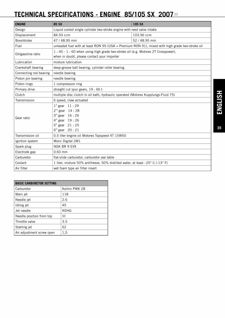
ENGL
ISH
35
TECHNICAL SPECIFICATIONS - ENGINE 85/105 SX 2007»ENGINE 85 SX 105 SX
Design Liquid cooled single cylinder two-stroke engine with reed valve intake
Displacement 84.93 ccm 103.96 ccm
Bore/stroke 47 / 48.95 mm 52 / 48.95 mm
Fuel unleaded fuel with at least RON 95 (USA = Premium RON 91), mixed with high grade two-stroke oil
Oil/gasoline ratio1 : 40 - 1 : 60 when using high grade two-stroke oil (e.g. Motorex 2T Crosspower), when in doubt, please contact your importer
Lubrication mixture lubrication
Crankshaft bearing deep-groove ball bearing, cylinder roller bearing
Connecting rod bearing needle bearing
Piston pin bearing needle bearing
Piston rings 1 compression ring
Primary drive straight cut spur gears, 19 : 66 t
Clutch multiple disc clutch in oil bath, hydraulic operated (Motorex Kupplungs-Fluid 75)
Transmission 6 speed, claw actuated
Gear ratio
1st gear 11 : 292nd gear 14 : 283rd gear 16 : 264th gear 19 : 265th gear 21 : 256th gear 20 : 21
Transmission oil 0.5 liter engine oil Motorex Topspeed 4T 15W50
Ignition system Moric Digital 2M1
Spark plug NGK BR 9 EVX
Electrode gap 0.60 mm
Carburetor flat-slide carburetor, carburetor see table
Coolant 1 liter, mixture 50% antifreeze, 50% distilled water, at least –25° C (-13° F)
Air filter wet foam type air filter insert
BASIC CARBURETOR SETTING
Carburetor Keihin PWK 28
Main jet 118
Needle jet 2.6
Idling jet 45
Jet needle N5HG
Needle position from top III
Throttle valve 3.5
Starting jet 62
Air adjustment screw open 1,5

ENGLISH
36
TECHNICAL SPECIFICATIONS - ENGINE 85/105 SX 2007»TIGHTENING TORQUES - ENGINE
Flange bolts - cylinder-head M 6 10 Nm
Nuts-cylinder base M 8 30 Nm
Flywheel collar nut M 12X1 60 Nm
Primary gear bolt M 10X1,25 Loctite 243 + 80 Nm
Nut for inner clutch hub M 14X1,25 Loctite 243 + 60 Nm
Crankcase and cover bolts M 6 8 Nm
Spark plug M 14X1,25 20 Nm
Reed valve housing M 14X1,5 75 Nm
Kickstarter M 6 6 Nm
Shift lever M 6 Loctite 243 + 12 Nm
Swingarm pivot M 6 Loctite 243 + 12 Nm
Other boltsM 5M 6
6 Nm10 Nm

ENGL
ISH
37
CARBURETOR SETTING »VERGASERREGULIERUNGCARBURETOR SETTING
KEIHIN PWK 2885/105 SX 2007
MEERESHÖHEALTITUDE
TEMPERATURTEMPERATURE
- 20°C bis -7°C
-2°F to 20°F
- 6°C bis 5°C
19°F to 41°F
6°C bis 15°C
42°F to 60°F
16°C bis 24°C
61°F to 78°F
25°C bis 38°C
79°F to 98°F
3000 m10000 ft
2301 m7501 ft
LSO ASOLD IJNADEL NEEDLEPOS POSHD MJ
1,545
N5HG2
118
1,7542
N5HH3
115
240
N5HH2
115
2,2538
N5HH1
115
2,538
N5HH1
115
2300 m7500 ft
1501 m5001 ft
LSO ASOLD IJNADEL NEEDLEPOS POSHD MJ
1,2548
N5HG3
120
1,545
N5HG2
118
1,7542
N5HH3
115
240
N5HH2
115
2,2538
N5HH1
115
1500 m5000 ft
751 m2501 ft
LSO ASOLD IJNADEL NEEDLEPOS POSHD MJ
150
N5HF3
122
1,2548
N5HG3
120
1,545
N5HG2
118
1,7542
N5HH2
115
240
N5HH2
115
750 m2500 ft
301 m1001 ft
LSO ASOLD IJNADEL NEEDLEPOS POSHD MJ
0,7550
N5HF4
125
150
N5HF3
122
1,2548
N5HG3
120
1,545
N5HG3
118
1,7542
N5HH2
115
300 m1000 ft
MeeresniveauSea level
LSO ASOLD IJNADEL NEEDLEPOS POSHD MJ
0,550
N5HF5
125
0,7550
N5HF4
125
150
N5HG3
122
1,2548
N5HG3
120
1,545
N5HG2
118
LSO = Luftregulierschraube offenLD = LeerlaufdüsePOS = Nadel Clip Position von obenHD = Hauptdüse
NICHT FÜR STRASSENBETRIEBKraftstoff: Super Bleifrei ROZ 95
ASO = Air screw open from fully-seatedIJ = Idling jetPOS = Needle clip position from topMJ = Main jet
NOT FFOR HHIGHWAY UUSEFuel: unleaded fuel with at least RON 95
USA = Premium PON 91
13
5
2
4
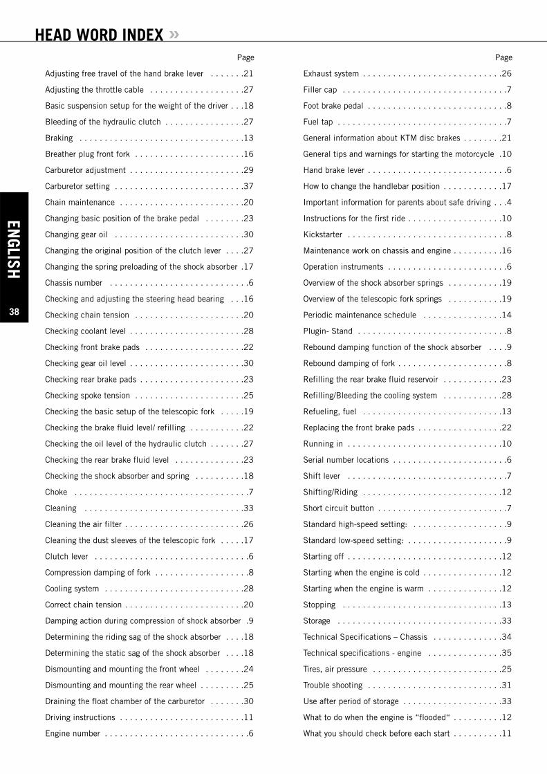
HEAD WORD INDEX »
ENGLISH
38
Page
Adjusting free travel of the hand brake lever . . . . . . .21
Adjusting the throttle cable . . . . . . . . . . . . . . . . . . .27
Basic suspension setup for the weight of the driver . . .18
Bleeding of the hydraulic clutch . . . . . . . . . . . . . . . .27
Braking . . . . . . . . . . . . . . . . . . . . . . . . . . . . . . . . .13
Breather plug front fork . . . . . . . . . . . . . . . . . . . . . .16
Carburetor adjustment . . . . . . . . . . . . . . . . . . . . . . .29
Carburetor setting . . . . . . . . . . . . . . . . . . . . . . . . . .37
Chain maintenance . . . . . . . . . . . . . . . . . . . . . . . . .20
Changing basic position of the brake pedal . . . . . . . .23
Changing gear oil . . . . . . . . . . . . . . . . . . . . . . . . . .30
Changing the original position of the clutch lever . . . .27
Changing the spring preloading of the shock absorber .17
Chassis number . . . . . . . . . . . . . . . . . . . . . . . . . . . .6
Checking and adjusting the steering head bearing . . .16
Checking chain tension . . . . . . . . . . . . . . . . . . . . . .20
Checking coolant level . . . . . . . . . . . . . . . . . . . . . . .28
Checking front brake pads . . . . . . . . . . . . . . . . . . . .22
Checking gear oil level . . . . . . . . . . . . . . . . . . . . . . .30
Checking rear brake pads . . . . . . . . . . . . . . . . . . . . .23
Checking spoke tension . . . . . . . . . . . . . . . . . . . . . .25
Checking the basic setup of the telescopic fork . . . . .19
Checking the brake fluid level/ refilling . . . . . . . . . . .22
Checking the oil level of the hydraulic clutch . . . . . . .27
Checking the rear brake fluid level . . . . . . . . . . . . . .23
Checking the shock absorber and spring . . . . . . . . . .18
Choke . . . . . . . . . . . . . . . . . . . . . . . . . . . . . . . . . . .7
Cleaning . . . . . . . . . . . . . . . . . . . . . . . . . . . . . . . .33
Cleaning the air filter . . . . . . . . . . . . . . . . . . . . . . . .26
Cleaning the dust sleeves of the telescopic fork . . . . .17
Clutch lever . . . . . . . . . . . . . . . . . . . . . . . . . . . . . . .6
Compression damping of fork . . . . . . . . . . . . . . . . . . .8
Cooling system . . . . . . . . . . . . . . . . . . . . . . . . . . . .28
Correct chain tension . . . . . . . . . . . . . . . . . . . . . . . .20
Damping action during compression of shock absorber .9
Determining the riding sag of the shock absorber . . . .18
Determining the static sag of the shock absorber . . . .18
Dismounting and mounting the front wheel . . . . . . . .24
Dismounting and mounting the rear wheel . . . . . . . . .25
Draining the float chamber of the carburetor . . . . . . .30
Driving instructions . . . . . . . . . . . . . . . . . . . . . . . . .11
Engine number . . . . . . . . . . . . . . . . . . . . . . . . . . . . .6
Page
Exhaust system . . . . . . . . . . . . . . . . . . . . . . . . . . . .26
Filler cap . . . . . . . . . . . . . . . . . . . . . . . . . . . . . . . . .7
Foot brake pedal . . . . . . . . . . . . . . . . . . . . . . . . . . . .8
Fuel tap . . . . . . . . . . . . . . . . . . . . . . . . . . . . . . . . . .7
General information about KTM disc brakes . . . . . . . .21
General tips and warnings for starting the motorcycle .10
Hand brake lever . . . . . . . . . . . . . . . . . . . . . . . . . . . .6
How to change the handlebar position . . . . . . . . . . . .17
Important information for parents about safe driving . . .4
Instructions for the first ride . . . . . . . . . . . . . . . . . . .10
Kickstarter . . . . . . . . . . . . . . . . . . . . . . . . . . . . . . . .8
Maintenance work on chassis and engine . . . . . . . . . .16
Operation instruments . . . . . . . . . . . . . . . . . . . . . . . .6
Overview of the shock absorber springs . . . . . . . . . . .19
Overview of the telescopic fork springs . . . . . . . . . . .19
Periodic maintenance schedule . . . . . . . . . . . . . . . .14
Plugin- Stand . . . . . . . . . . . . . . . . . . . . . . . . . . . . . .8
Rebound damping function of the shock absorber . . . .9
Rebound damping of fork . . . . . . . . . . . . . . . . . . . . . .8
Refilling the rear brake fluid reservoir . . . . . . . . . . . .23
Refilling/Bleeding the cooling system . . . . . . . . . . . .28
Refueling, fuel . . . . . . . . . . . . . . . . . . . . . . . . . . . .13
Replacing the front brake pads . . . . . . . . . . . . . . . . .22
Running in . . . . . . . . . . . . . . . . . . . . . . . . . . . . . . .10
Serial number locations . . . . . . . . . . . . . . . . . . . . . . .6
Shift lever . . . . . . . . . . . . . . . . . . . . . . . . . . . . . . . .7
Shifting/Riding . . . . . . . . . . . . . . . . . . . . . . . . . . . .12
Short circuit button . . . . . . . . . . . . . . . . . . . . . . . . . .7
Standard high-speed setting: . . . . . . . . . . . . . . . . . . .9
Standard low-speed setting: . . . . . . . . . . . . . . . . . . . .9
Starting off . . . . . . . . . . . . . . . . . . . . . . . . . . . . . . .12
Starting when the engine is cold . . . . . . . . . . . . . . . .12
Starting when the engine is warm . . . . . . . . . . . . . . .12
Stopping . . . . . . . . . . . . . . . . . . . . . . . . . . . . . . . .13
Storage . . . . . . . . . . . . . . . . . . . . . . . . . . . . . . . . .33
Technical Specifications – Chassis . . . . . . . . . . . . . .34
Technical specifications - engine . . . . . . . . . . . . . . .35
Tires, air pressure . . . . . . . . . . . . . . . . . . . . . . . . . .25
Trouble shooting . . . . . . . . . . . . . . . . . . . . . . . . . . .31
Use after period of storage . . . . . . . . . . . . . . . . . . . .33
What to do when the engine is “flooded“ . . . . . . . . . .12
What you should check before each start . . . . . . . . . .11
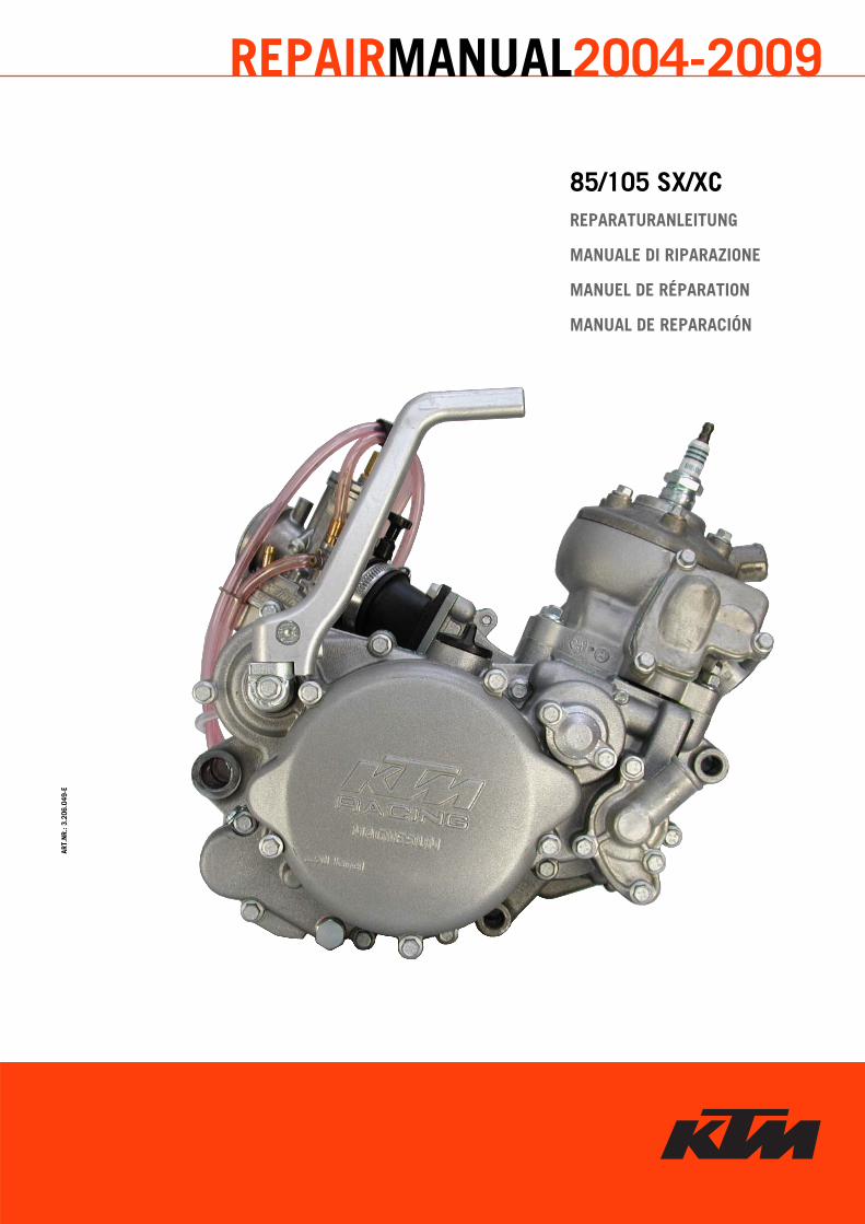
85/105 SX/XCREPARATURANLEITUNG
MANUALE DI RIPARAZIONE
MANUEL DE RÉPARATION
MANUAL DE REPARACIÓN
ART.
NR.
: 3.2
06.0
49-E
REPAIRMANUAL2004-2009
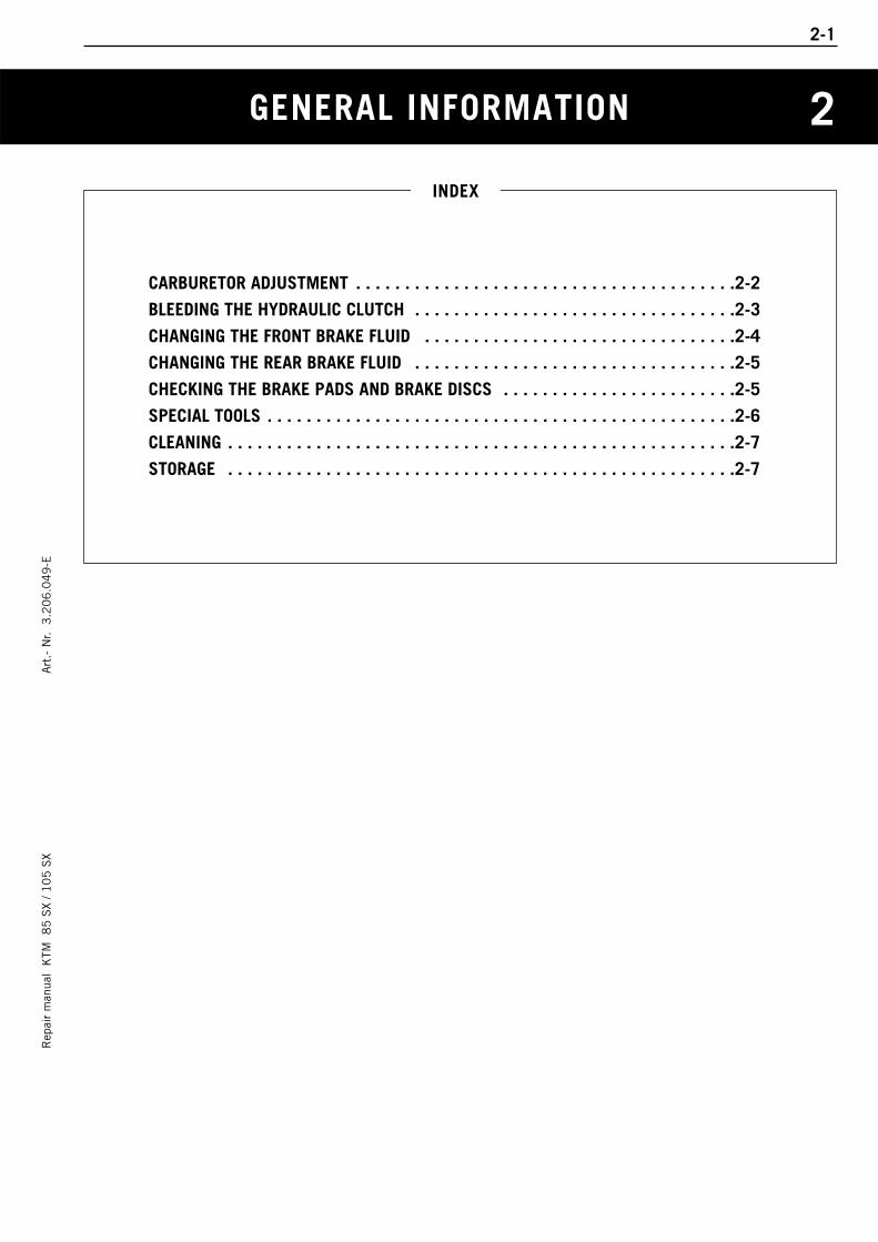
GENERAL INFORMATION
Rep
air
man
ual
KTM
8
5 S
X / 1
05
SX
Art
.- N
r. 3
.20
6.0
49
-E
CARBURETOR ADJUSTMENT . . . . . . . . . . . . . . . . . . . . . . . . . . . . . . . . . . . . . . .2-2
BLEEDING THE HYDRAULIC CLUTCH . . . . . . . . . . . . . . . . . . . . . . . . . . . . . . . . .2-3
CHANGING THE FRONT BRAKE FLUID . . . . . . . . . . . . . . . . . . . . . . . . . . . . . . . .2-4
CHANGING THE REAR BRAKE FLUID . . . . . . . . . . . . . . . . . . . . . . . . . . . . . . . . .2-5
CHECKING THE BRAKE PADS AND BRAKE DISCS . . . . . . . . . . . . . . . . . . . . . . . .2-5
SPECIAL TOOLS . . . . . . . . . . . . . . . . . . . . . . . . . . . . . . . . . . . . . . . . . . . . . . . .2-6
CLEANING . . . . . . . . . . . . . . . . . . . . . . . . . . . . . . . . . . . . . . . . . . . . . . . . . . . .2-7
STORAGE . . . . . . . . . . . . . . . . . . . . . . . . . . . . . . . . . . . . . . . . . . . . . . . . . . . .2-7
INDEX
2-1
2
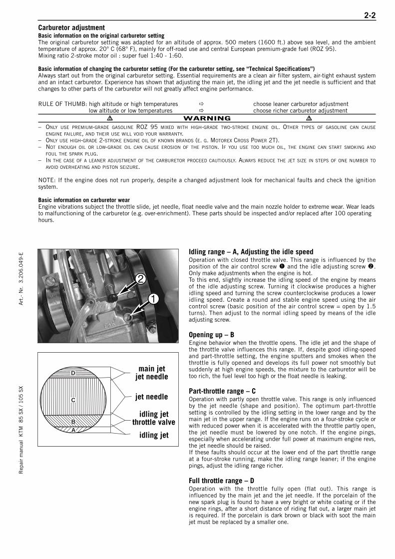
2-2R
epai
r m
anua
l K
TM 8
5 S
X / 1
05
SX
Art
.- N
r. 3
.20
6.0
49
-E
B
C
D
A
main jetjet needle
jet needle
idling jet
idling jetthrottle valve
2
1
Carburetor adjustmentBasic information on the original carburetor settingThe original carburetor setting was adapted for an altitude of approx. 500 meters (1600 ft.) above sea level, and the ambient temperature of approx. 20° C (68° F), mainly for off-road use and central European premium-grade fuel (ROZ 95).Mixing ratio 2-stroke motor oil : super fuel 1:40 - 1:60.
Basic information of changing the carburetor setting (For the carburetor setting, see “Technical Specifications”)Always start out from the original carburetor setting. Essential requirements are a clean air filter system, air-tight exhaust systemand an intact carburetor. Experience has shown that adjusting the main jet, the idling jet and the jet needle is sufficient and thatchanges to other parts of the carburetor will not greatly affect engine performance.
RULE OF THUMB: high altitude or high temperatures choose leaner carburetor adjustmentlow altitude or low temperatures choose richer carburetor adjustment
WARNING – ONLY USE PREMIUM-GRADE GASOLINE ROZ 95 MIXED WITH HIGH-GRADE TWO-STROKE ENGINE OIL. OTHER TYPES OF GASOLINE CAN CAUSE
ENGINE FAILURE, AND THEIR USE WILL VOID YOUR WARRANTY.– ONLY USE HIGH-GRADE 2-STROKE ENGINE OIL OF KNOWN BRANDS (E. G. MOTOREX CROSS POWER 2T).– NOT ENOUGH OIL OR LOW-GRADE OIL CAN CAUSE EROSION OF THE PISTON. IF YOU USE TOO MUCH OIL, THE ENGINE CAN START SMOKING AND
FOUL THE SPARK PLUG.– IN THE CASE OF A LEANER ADJUSTMENT OF THE CARBURETOR PROCEED CAUTIOUSLY. ALWAYS REDUCE THE JET SIZE IN STEPS OF ONE NUMBER TO
AVOID OVERHEATING AND PISTON SEIZURE.
NOTE: If the engine does not run properly, despite a changed adjustment look for mechanical faults and check the ignitionsystem.
Basic information on carburetor wearEngine vibrations subject the throttle slide, jet needle, float needle valve and the main nozzle holder to extreme wear. Wear leadsto malfunctioning of the carburetor (e.g. over-enrichment). These parts should be inspected and/or replaced after 100 operatinghours.
Idling range – A, Adjusting the idle speedOperation with closed throttle valve. This range is influenced by theposition of the air control screw 1 and the idle adjusting screw 2.Only make adjustments when the engine is hot.To this end, slightly increase the idling speed of the engine by meansof the idle adjusting screw. Turning it clockwise produces a higheridling speed and turning the screw counterclockwise produces a loweridling speed. Create a round and stable engine speed using the aircontrol screw (basic position of the air control screw = open by 1.5turns). Then adjust to the normal idling speed by means of the idleadjusting screw.
Opening up – BEngine behavior when the throttle opens. The idle jet and the shape ofthe throttle valve influences this range. If, despite good idling-speedand part-throttle setting, the engine sputters and smokes when thethrottle is fully opened and develops its full power not smoothly butsuddenly at high engine speeds, the mixture to the carburetor will betoo rich, the fuel level too high or the float needle is leaking.
Part-throttle range – COperation with partly open throttle valve. This range is only influencedby the jet needle (shape and position). The optimum part-throttlesetting is controlled by the idling setting in the lower range and by themain jet in the upper range. If the engine runs on a four-stroke cycle orwith reduced power when it is accelerated with the throttle partly open,the jet needle must be lowered by one notch. If the engine pings,especially when accelerating under full power at maximum engine revs,the jet needle should be raised.If these faults should occur at the lower end of the part throttle rangeat a four-stroke running, make the idling range leaner; if the enginepings, adjust the idling range richer.
Full throttle range – DOperation with the throttle fully open (flat out). This range isinfluenced by the main jet and the jet needle. If the porcelain of thenew spark plug is found to have a very bright or white coating or if theengine rings, after a short distance of riding flat out, a larger main jetis required. If the porcelain is dark brown or black with soot the mainjet must be replaced by a smaller one.
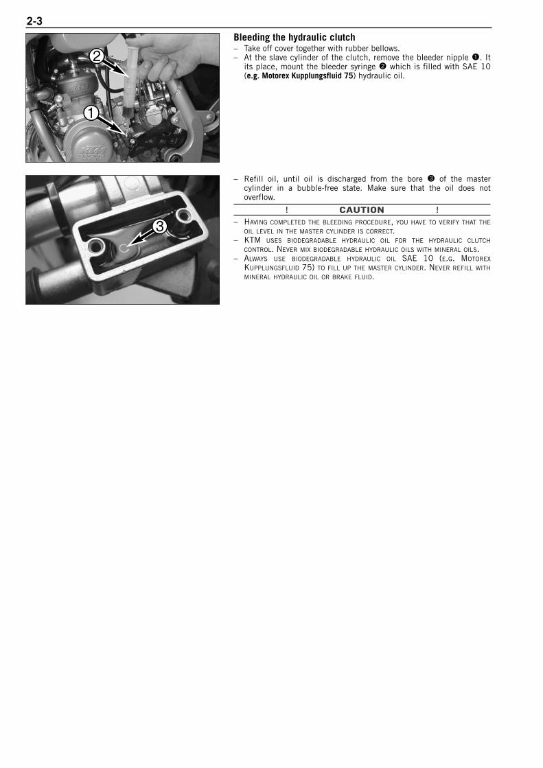
2-3Bleeding the hydraulic clutch– Take off cover together with rubber bellows.– At the slave cylinder of the clutch, remove the bleeder nipple 1. It
its place, mount the bleeder syringe 2 which is filled with SAE 10(e.g. Motorex Kupplungsfluid 75) hydraulic oil.
– Refill oil, until oil is discharged from the bore 3 of the mastercylinder in a bubble-free state. Make sure that the oil does notoverflow.
! CAUTION !– HAVING COMPLETED THE BLEEDING PROCEDURE, YOU HAVE TO VERIFY THAT THE
OIL LEVEL IN THE MASTER CYLINDER IS CORRECT.– KTM USES BIODEGRADABLE HYDRAULIC OIL FOR THE HYDRAULIC CLUTCH
CONTROL. NEVER MIX BIODEGRADABLE HYDRAULIC OILS WITH MINERAL OILS.– ALWAYS USE BIODEGRADABLE HYDRAULIC OIL SAE 10 (E.G. MOTOREX
KUPPLUNGSFLUID 75) TO FILL UP THE MASTER CYLINDER. NEVER REFILL WITH
MINERAL HYDRAULIC OIL OR BRAKE FLUID.
1
2
3
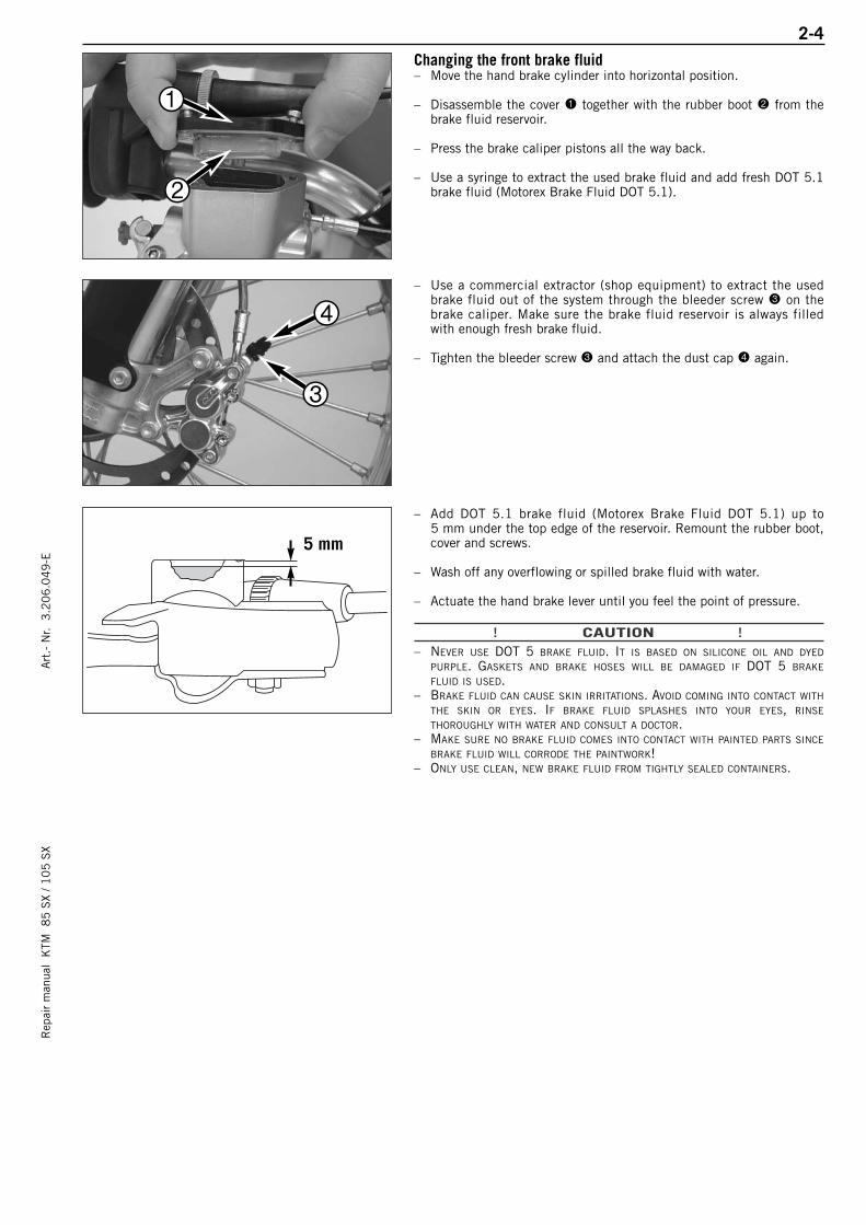
Changing the front brake fluid– Move the hand brake cylinder into horizontal position.
– Disassemble the cover 1 together with the rubber boot 2 from thebrake fluid reservoir.
– Press the brake caliper pistons all the way back.
– Use a syringe to extract the used brake fluid and add fresh DOT 5.1brake fluid (Motorex Brake Fluid DOT 5.1).
– Use a commercial extractor (shop equipment) to extract the usedbrake fluid out of the system through the bleeder screw 3 on thebrake caliper. Make sure the brake fluid reservoir is always filledwith enough fresh brake fluid.
– Tighten the bleeder screw 3 and attach the dust cap 4 again.
– Add DOT 5.1 brake fluid (Motorex Brake Fluid DOT 5.1) up to 5 mm under the top edge of the reservoir. Remount the rubber boot,cover and screws.
– Wash off any overflowing or spilled brake fluid with water.
– Actuate the hand brake lever until you feel the point of pressure.
! CAUTION !– NEVER USE DOT 5 BRAKE FLUID. IT IS BASED ON SILICONE OIL AND DYED
PURPLE. GASKETS AND BRAKE HOSES WILL BE DAMAGED IF DOT 5 BRAKE
FLUID IS USED.– BRAKE FLUID CAN CAUSE SKIN IRRITATIONS. AVOID COMING INTO CONTACT WITH
THE SKIN OR EYES. IF BRAKE FLUID SPLASHES INTO YOUR EYES, RINSE
THOROUGHLY WITH WATER AND CONSULT A DOCTOR.– MAKE SURE NO BRAKE FLUID COMES INTO CONTACT WITH PAINTED PARTS SINCE
BRAKE FLUID WILL CORRODE THE PAINTWORK!– ONLY USE CLEAN, NEW BRAKE FLUID FROM TIGHTLY SEALED CONTAINERS.
2-4R
epai
r m
anua
l K
TM 8
5 S
X / 1
05
SX
Art
.- N
r. 3
.20
6.0
49
-E
5 mm
1
2
4
3
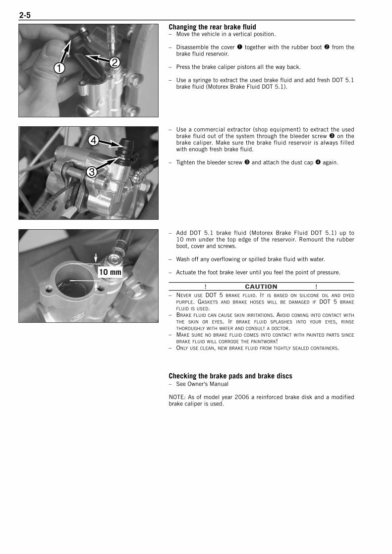
Changing the rear brake fluid– Move the vehicle in a vertical position.
– Disassemble the cover 1 together with the rubber boot 2 from thebrake fluid reservoir.
– Press the brake caliper pistons all the way back.
– Use a syringe to extract the used brake fluid and add fresh DOT 5.1brake fluid (Motorex Brake Fluid DOT 5.1).
– Use a commercial extractor (shop equipment) to extract the usedbrake fluid out of the system through the bleeder screw 3 on thebrake caliper. Make sure the brake fluid reservoir is always filledwith enough fresh brake fluid.
– Tighten the bleeder screw 3 and attach the dust cap 4 again.
– Add DOT 5.1 brake fluid (Motorex Brake Fluid DOT 5.1) up to 10 mm under the top edge of the reservoir. Remount the rubberboot, cover and screws.
– Wash off any overflowing or spilled brake fluid with water.
– Actuate the foot brake lever until you feel the point of pressure.
! CAUTION !– NEVER USE DOT 5 BRAKE FLUID. IT IS BASED ON SILICONE OIL AND DYED
PURPLE. GASKETS AND BRAKE HOSES WILL BE DAMAGED IF DOT 5 BRAKE
FLUID IS USED.– BRAKE FLUID CAN CAUSE SKIN IRRITATIONS. AVOID COMING INTO CONTACT WITH
THE SKIN OR EYES. IF BRAKE FLUID SPLASHES INTO YOUR EYES, RINSE
THOROUGHLY WITH WATER AND CONSULT A DOCTOR.– MAKE SURE NO BRAKE FLUID COMES INTO CONTACT WITH PAINTED PARTS SINCE
BRAKE FLUID WILL CORRODE THE PAINTWORK!– ONLY USE CLEAN, NEW BRAKE FLUID FROM TIGHTLY SEALED CONTAINERS.
Checking the brake pads and brake discs – See Owner's Manual
NOTE: As of model year 2006 a reinforced brake disk and a modifiedbrake caliper is used.
2-5
21
3
4
10 mm

2-6R
epai
r m
anua
l K
TM 8
5 S
X / 1
05
SX
Art
.- N
r. 3
.20
6.0
49
-E
FIG. DESCRIPTION PART NUMBER1 560.12.001.044 Universal engine work stand2 470.29.027.000 Clutch rivetting tool3 6 899 785 Loctite 243 blu 6 cm3
4 510.12.011.000 Circlip plier5 503.29.050.000 Vent syringe for hydraulic clutch6 546.29.009.044 Magneto extractor M 27x17 510.12.016.000 Protection cap8 151.12.018.200 Internal bearing puller 5-7 mm9 546.29.012.100 Holding spanner for flywheel
10 151.12.017.000 Bearing puller11 470.29.006.000 Adjusting plate 85 SX
475.29.006.000 Adjusting plate 105 SX12 584.29.037.031 Mounting tool inner ring NJ20713 470.29.003.000 Clutch/Primary gear holder14 470.29.002.000 Engine holder
140
27
175
60
HOLZGABELSELBSTGEFERTIGTWOODEN FORK PLATEHOME MADE
SPECIAL TOOLS – ENGINE 85 SX / 105 SX
32
1
5
7
12
6
4
9
10
8
13
11
13
14
2-7
Clean your motorcycle regularly in order to keep its painted finish looking shiny and new.The best manner would be to use warm water that has been mixed with a commercially available washing detergent and asponge. The hard dirt can be removed before with the help of a soft water jet.
! CAUTION !NEVER CLEAN YOUR MOTORCYCLE WITH A HIGH-PRESSURED CLEANER OR A HIGH-PRESSURED WATER JET. OTHERWISE THE WATER MIGHT RUN INTO THE
ELECTRICAL COMPONENTS, CONNECTORS, SHEATHED CABLES, BEARINGS, CARBURETOR ETC. AND CAUSE MAILFUNCTIONS, I.E., LEAD TO THE
PREMATURE DESTRUCTION OF THESE PARTS.
– You should use commercially available detergents to clean the motorcycle. Heavily soiled parts should also be cleaned withthe help of a paint brush.
– Before cleaning with water, plug the exhaust pipe to prevent water ingress.– After the motorcycle has been rinsed with a soft water jet, it should be dried by air pressure and a cloth. Then take a short
drive until the engine has reached its operating temperature, and also operate the brakes. The heat also causes the water atthe inaccessible parts of the engine and the brakes to evaporate.
– Slide back the protective covers on the handlebar-mounted instruments so that any water that may have seeped into this partof the motorcycle is allowed to evaporate.
– After the motorcycle has cooled down, oil and grease all the gliding bearing parts. Also treat the chain with a chain spray.– To prevent failures in the electric system, you should treat the short circuit button with a contact spray.
If you want to put your motorcycle away for longer periods of time, please observe the following instructions:
– Clean motorcycle thoroughly (see chapter: CLEANING)– Change engine oil (old engine oil contains aggressive contaminations).– Check antifreeze and amount of cooling liquid.– Let the engine warm up again, close fuel tap and wait until the engine dies off by itself. In this way, the carburetor jets are
prevented from becoming resin-clogged by the old fuel.– Remove spark plug and fill in approx. 5 ccm of engine oil into the cylinder through the opening. Actuate kickstarter 10 times
in order to distribute the oil onto the cylinder walls and mount the spark plug.– Let fuel flow out of tank into an appropriate basin.– Correct tire pressure.– Lubricate bearing points of the control levers, footrests, etc. as well as the chain.– The storage place should be dry and not be subjected to overly great temperature fluctuations.– Cover the motorcycle with an air permeable tarpaulin or blanket. Do not use airtight materials, as possible humidity might not
be able to escape and thereby cause corrosion.
! CAUTION !IT WOULD BE VERY BAD TO LET THE ENGINE RUN FOR A SHORT TIME DURING THE STORAGE PERIOD. THE ENGINE WOULD NOT GET WARMED UP
ENOUGH AND THE THUS DEVELOPED STEAM WOULD CONDENSE DURING THE COMBUSTION PROCESS AND CAUSE THE EXHAUST TO RUST.
USE AFTER PERIOD OF STORAGE– Fill up tank with fresh fuel.– Check motorcycle as before each start (see driving instructions).– Take a short, careful test ride first.
NOTE: Before you put your motorcycle away for the winter, you should check all parts for their function and wear. Should any service jobs, repairs, or any refitting be necessary, you should have them carried out during the off-season (lower workload at mechanics' shops). This way, you can avoid the long waiting times at your shop at the beginning of the next biking season.
CLEANING
STORAGE
REMOVING AND REFITTING THE ENGINE
Rep
air
man
ual
KTM
8
5 S
X / 1
05
SX
Art
.- N
r. 3
.20
6.0
49
-E
REMOVING THE ENGINE . . . . . . . . . . . . . . . . . . . . . . . . . . . . . . . . . . . . . . . . . .3-2
REFITTING THE ENGINE . . . . . . . . . . . . . . . . . . . . . . . . . . . . . . . . . . . . . . . . . .3-5
REFILLING/BLEEDING THE COOLING SYSTEM . . . . . . . . . . . . . . . . . . . . . . . . . . .3-7
ADJUSTING THE THROTTLE CABLE . . . . . . . . . . . . . . . . . . . . . . . . . . . . . . . . . .3-7
INDEX
3-1
3
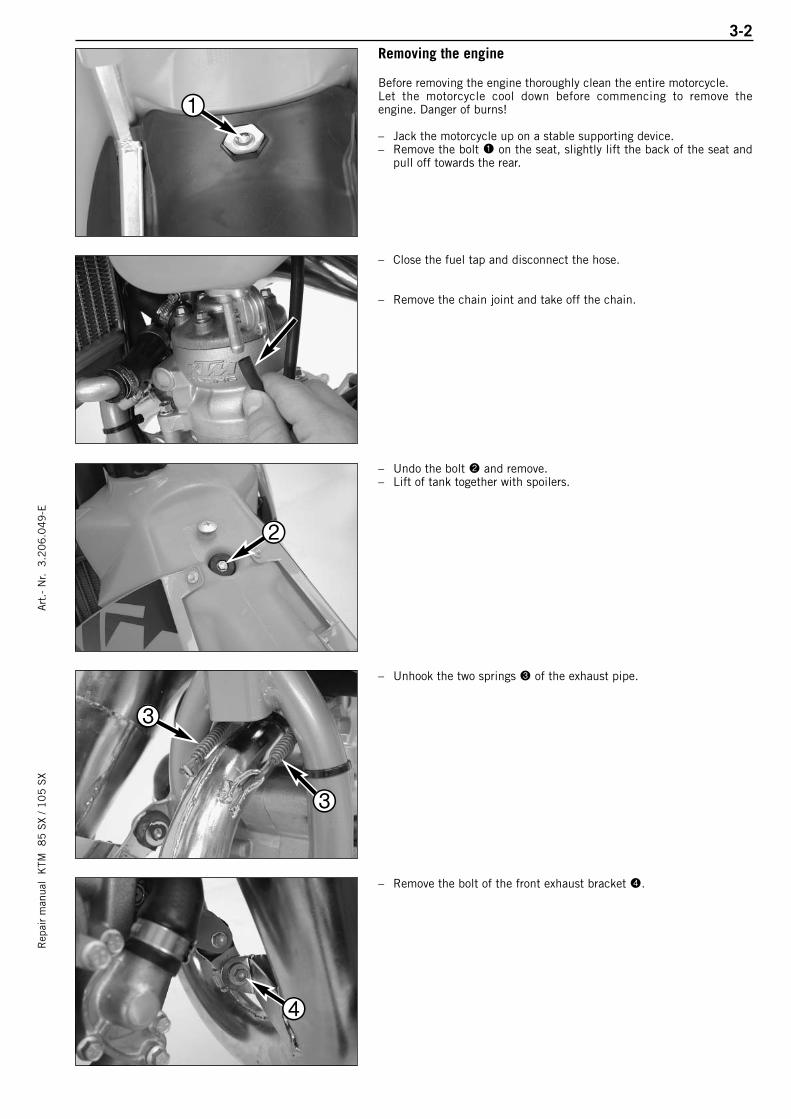
3-2R
epai
r m
anua
l K
TM 8
5 S
X / 1
05
SX
Art
.- N
r. 3
.20
6.0
49
-ERemoving the engine
Before removing the engine thoroughly clean the entire motorcycle.Let the motorcycle cool down before commencing to remove theengine. Danger of burns!
– Jack the motorcycle up on a stable supporting device.– Remove the bolt 1 on the seat, slightly lift the back of the seat and
pull off towards the rear.
– Close the fuel tap and disconnect the hose.
– Remove the chain joint and take off the chain.
– Undo the bolt 2 and remove.– Lift of tank together with spoilers.
– Unhook the two springs 3 of the exhaust pipe.
– Remove the bolt of the front exhaust bracket 4.
1
2
3
3
4
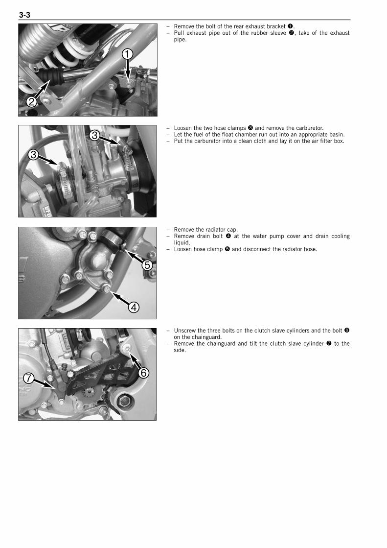
3-3– Remove the bolt of the rear exhaust bracket 1.– Pull exhaust pipe out of the rubber sleeve 2, take of the exhaust
pipe.
– Loosen the two hose clamps 3 and remove the carburetor.– Let the fuel of the float chamber run out into an appropriate basin.– Put the carburetor into a clean cloth and lay it on the air filter box.
– Remove the radiator cap.– Remove drain bolt 4 at the water pump cover and drain cooling
liquid.– Loosen hose clamp 5 and disconnect the radiator hose.
– Unscrew the three bolts on the clutch slave cylinders and the bolt 6on the chainguard.
– Remove the chainguard and tilt the clutch slave cylinder 7 to theside.
1
2
3
3
4
5
67
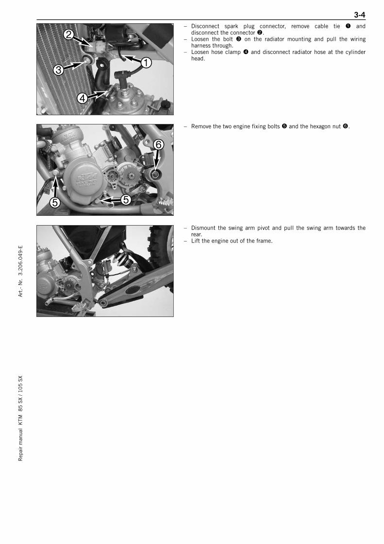
3-4R
epai
r m
anua
l K
TM 8
5 S
X / 1
05
SX
Art
.- N
r. 3
.20
6.0
49
-E– Disconnect spark plug connector, remove cable tie 1 and
disconnect the connector 2.– Loosen the bolt 3 on the radiator mounting and pull the wiring
harness through.– Loosen hose clamp 4 and disconnect radiator hose at the cylinder
head.
– Remove the two engine fixing bolts 5 and the hexagon nut 6.
– Dismount the swing arm pivot and pull the swing arm towards therear.
– Lift the engine out of the frame.
1
2
3
4
5 5
6
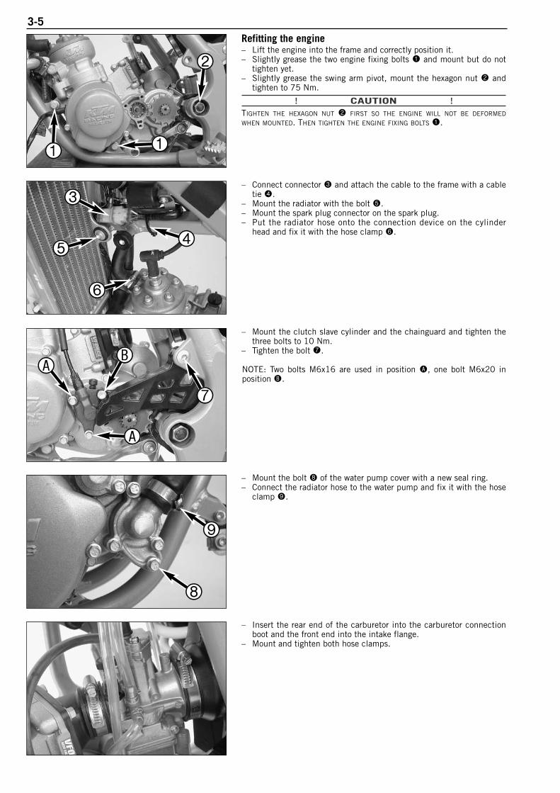
3-5Refitting the engine– Lift the engine into the frame and correctly position it.– Slightly grease the two engine fixing bolts 1 and mount but do not
tighten yet.– Slightly grease the swing arm pivot, mount the hexagon nut 2 and
tighten to 75 Nm.
! CAUTION !TIGHTEN THE HEXAGON NUT 2 FIRST SO THE ENGINE WILL NOT BE DEFORMED
WHEN MOUNTED. THEN TIGHTEN THE ENGINE FIXING BOLTS 1.
– Connect connector 3 and attach the cable to the frame with a cabletie 4.
– Mount the radiator with the bolt 5.– Mount the spark plug connector on the spark plug.– Put the radiator hose onto the connection device on the cylinder
head and fix it with the hose clamp 6.
– Mount the clutch slave cylinder and the chainguard and tighten thethree bolts to 10 Nm.
– Tighten the bolt 7.
NOTE: Two bolts M6x16 are used in position A, one bolt M6x20 in position B.
– Mount the bolt 8 of the water pump cover with a new seal ring.– Connect the radiator hose to the water pump and fix it with the hose
clamp 9.
– Insert the rear end of the carburetor into the carburetor connectionboot and the front end into the intake flange.
– Mount and tighten both hose clamps.
1 1
2
3
45
6
A
A
B
7
8
9
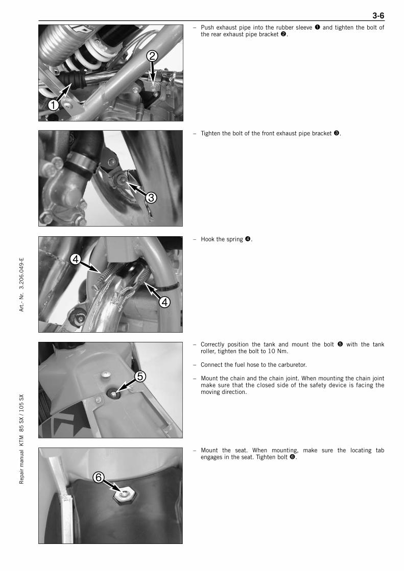
3-6R
epai
r m
anua
l K
TM 8
5 S
X / 1
05
SX
Art
.- N
r. 3
.20
6.0
49
-E– Push exhaust pipe into the rubber sleeve 1 and tighten the bolt of
the rear exhaust pipe bracket 2.
– Tighten the bolt of the front exhaust pipe bracket 3.
– Hook the spring 4.
– Correctly position the tank and mount the bolt 5 with the tankroller, tighten the bolt to 10 Nm.
– Connect the fuel hose to the carburetor.
– Mount the chain and the chain joint. When mounting the chain jointmake sure that the closed side of the safety device is facing themoving direction.
– Mount the seat. When mounting, make sure the locating tabengages in the seat. Tighten bolt 6.
1
2
3
4
4
5
6
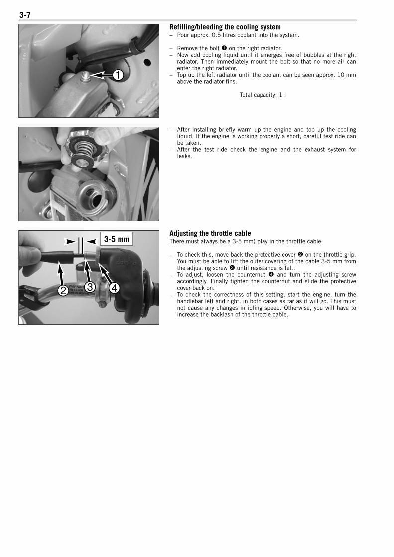
3-7Refilling/bleeding the cooling system– Pour approx. 0.5 litres coolant into the system.
– Remove the bolt 1 on the right radiator.– Now add cooling liquid until it emerges free of bubbles at the right
radiator. Then immediately mount the bolt so that no more air canenter the right radiator.
– Top up the left radiator until the coolant can be seen approx. 10 mmabove the radiator fins.
Total capacity: 1 l
– After installing briefly warm up the engine and top up the coolingliquid. If the engine is working properly a short, careful test ride canbe taken.
– After the test ride check the engine and the exhaust system forleaks.
Adjusting the throttle cableThere must always be a 3-5 mm) play in the throttle cable.
– To check this, move back the protective cover 2 on the throttle grip.You must be able to lift the outer covering of the cable 3-5 mm fromthe adjusting screw 3 until resistance is felt.
– To adjust, loosen the counternut 4 and turn the adjusting screw accordingly. Finally tighten the counternut and slide the protectivecover back on.
– To check the correctness of this setting, start the engine, turn the handlebar left and right, in both cases as far as it will go. This mustnot cause any changes in idling speed. Otherwise, you will have toincrease the backlash of the throttle cable.
3-5 mm
1
2 3 4
DISASSEMBLING THE ENGINE
Rep
air
man
ual
KTM
8
5 S
X / 1
05
SX
Art
.- N
r. 3
.20
6.0
49
-E
PREPARATION . . . . . . . . . . . . . . . . . . . . . . . . . . . . . . . . . . . . . . . . . . . . . . . . .4-2
DRAINING GEAR OIL . . . . . . . . . . . . . . . . . . . . . . . . . . . . . . . . . . . . . . . . . . . . .4-2
DISMOUNTING OF SPROCKET AND SHIFT LEVER . . . . . . . . . . . . . . . . . . . . . . . .4-2
DISMOUNTING OF CYLINDER HEAD, CYLINDER AND PISTON . . . . . . . . . . . . . . . .4-2
DISMOUNTING OF CLUTCH COVER . . . . . . . . . . . . . . . . . . . . . . . . . . . . . . . . . .4-3
DISMOUNTING THE CLUTCH . . . . . . . . . . . . . . . . . . . . . . . . . . . . . . . . . . . . . . .4-4
DISMOUNTING OF THE PRIMARY DRIVE . . . . . . . . . . . . . . . . . . . . . . . . . . . . . .4-4
DISMOUNTING THE KICKSTARTER UNIT . . . . . . . . . . . . . . . . . . . . . . . . . . . . . .4-5
DISMOUNTING THE SHIFT MECHANISM . . . . . . . . . . . . . . . . . . . . . . . . . . . . . .4-5
DISMOUNTING THE IGNITION . . . . . . . . . . . . . . . . . . . . . . . . . . . . . . . . . . . . . .4-6
DISMOUNTING OF INTAKE FLANGE AND REED VALVE HOUSING . . . . . . . . . . . . . .4-7
PARTING OF ENGINE HOUSING HALVES . . . . . . . . . . . . . . . . . . . . . . . . . . . . . . .4-7
DISMOUNTING OF GEARSHIFT MECHANISM AND TRANSMISSION . . . . . . . . . . . .4-7
DISMOUNTING THE CRANKSHAFT . . . . . . . . . . . . . . . . . . . . . . . . . . . . . . . . . . .4-8
INDEX
4-1
4

Rep
air
man
ual
KTM
8
5 S
X / 1
05
SX
Art
.- N
r. 3
.20
6.0
49
-E4-2
Preparation– Clean the engine thoroughly.– Clamp the engine into the workstand.– Remove the kickstarter.
Draining gear oil
NOTE: Drain the gear oil in a warm condition before the engine isdismounted, otherwise the gear oil may run out through the main shaftwhen the clutch slave cylinder is removed.
– Unscrew plug 1, allowing oil to drain.
Dismounting of sprocket and shift lever– Remove the circlip 2 and pull the engine sprocket off of the
countershaft together with the distance bushing and O-ring locatedbehind the engine sprocket.
– Undo the bolt 3 and remove the shift lever.– Remove the push rod 4 and the ball positioned behind the push rod
from the main shaft.
Dismounting of cylinder head, cylinder and piston– Unscrew the 6 collar bolts 5 and remove cylinder head and the two
O-rings.
NOTE: If you are replacing the spark plug, loosen it before youdismount the cylinder head.
– Undo the bolts 6 and remove the control cover together with thegasket.
1
2
3
4
5
6
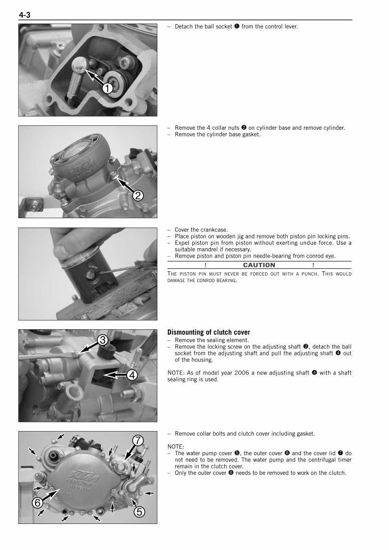
4-3– Detach the ball socket 1 from the control lever.
– Remove the 4 collar nuts 2 on cylinder base and remove cylinder.– Remove the cylinder base gasket.
– Cover the crankcase.– Place piston on wooden jig and remove both piston pin locking pins.– Expel piston pin from piston without exerting undue force. Use a
suitable mandrel if necessary.– Remove piston and piston pin needle-bearing from conrod eye.
! CAUTION !THE PISTON PIN MUST NEVER BE FORCED OUT WITH A PUNCH. THIS WOULD
DAMAGE THE CONROD BEARING.
Dismounting of clutch cover– Remove the sealing element.– Remove the locking screw on the adjusting shaft 3, detach the ball
socket from the adjusting shaft and pull the adjusting shaft 4 outof the housing.
NOTE: As of model year 2006 a new adjusting shaft 4 with a shaftsealing ring is used.
– Remove collar bolts and clutch cover including gasket.
NOTE:– The water pump cover 5, the outer cover 6 and the cover lid 7 do
not need to be removed. The water pump and the centrifugal timerremain in the clutch cover.
– Only the outer cover 6 needs to be removed to work on the clutch.
1
2
3
4
56
7
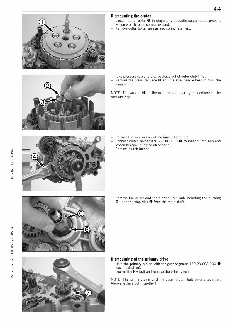
4-4R
epai
r m
anua
l K
TM 8
5 S
X / 1
05
SX
Art
.- N
r. 3
.20
6.0
49
-EDismounting the clutch– Loosen collar bolts 1 in diagonally opposite sequence to prevent
wedging of discs as springs expand.– Remove collar bolts, springs and spring retainers.
– Take pressure cap and disc package out of outer clutch hub.– Remove the pressure piece 2 and the axial needle bearing from the
main shaft.
NOTE: The washer 3 on the axial needle bearing may adhere to thepressure cap.
– Release the lock washer of the inner clutch hub.– Connect clutch holder 470.29.003.000 4 to inner clutch hub and
loosen hexagon nut (see illustration).– Remove clutch holder.
– Remove the driver and the outer clutch hub including the bushing5 and the stop disk 6 from the main shaft.
Dismounting of the primary drive– Hold the primary pinion with the gear segment 470.29.003.000 7
(see illustration).– Loosen the HH bolt and remove the primary gear.
NOTE: The primary gear and the outer clutch hub belong together.Always replace both together!
1
2
3
4
5
6
7

4-5– Pull the woodruff key 1 and the distance sleeve 2 including the
O-ring behind the distance sleeve off of the crankshaft.
Dismounting the kickstarter unit– Remove the circlip 3 and the stop disk, take off the kickstarter idler
gear and the stop disk behind the idler gear.– Carefully unscrew the collar bolt 4, relieve the kickstarter spring
and remove the kickstarter shaft from the engine case.– Take care of the stop disc, which could stay in the housing.
WARNING CAREFULLY RELEASE THE KICKSTARTER SPRING! DANGER OF INJURY!
Dismounting the shift mechanism– Press back the shift rail 5 until it no longer engages in the driver for
the shaft roller while you pull the shift shaft out of the housing.
NOTE: Watch the stop disc which remains in the housing.
– Loosen the collar bolt and remove the shift lock. To remove, slightlypress the locking lever towards the rear.
NOTE: Disassemble locating lever only if the engine case must bereplaced.
– To disassemble, remove the circlip 6 and take off the locking leverand the spring.
1
2
34
5
6
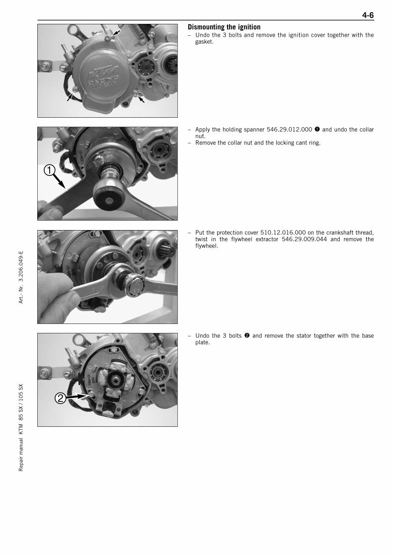
4-6R
epai
r m
anua
l K
TM 8
5 S
X / 1
05
SX
Art
.- N
r. 3
.20
6.0
49
-EDismounting the ignition– Undo the 3 bolts and remove the ignition cover together with the
gasket.
– Apply the holding spanner 546.29.012.000 1 and undo the collarnut.
– Remove the collar nut and the locking cant ring.
– Put the protection cover 510.12.016.000 on the crankshaft thread,twist in the flywheel extractor 546.29.009.044 and remove theflywheel.
– Undo the 3 bolts 2 and remove the stator together with the baseplate.
1
2
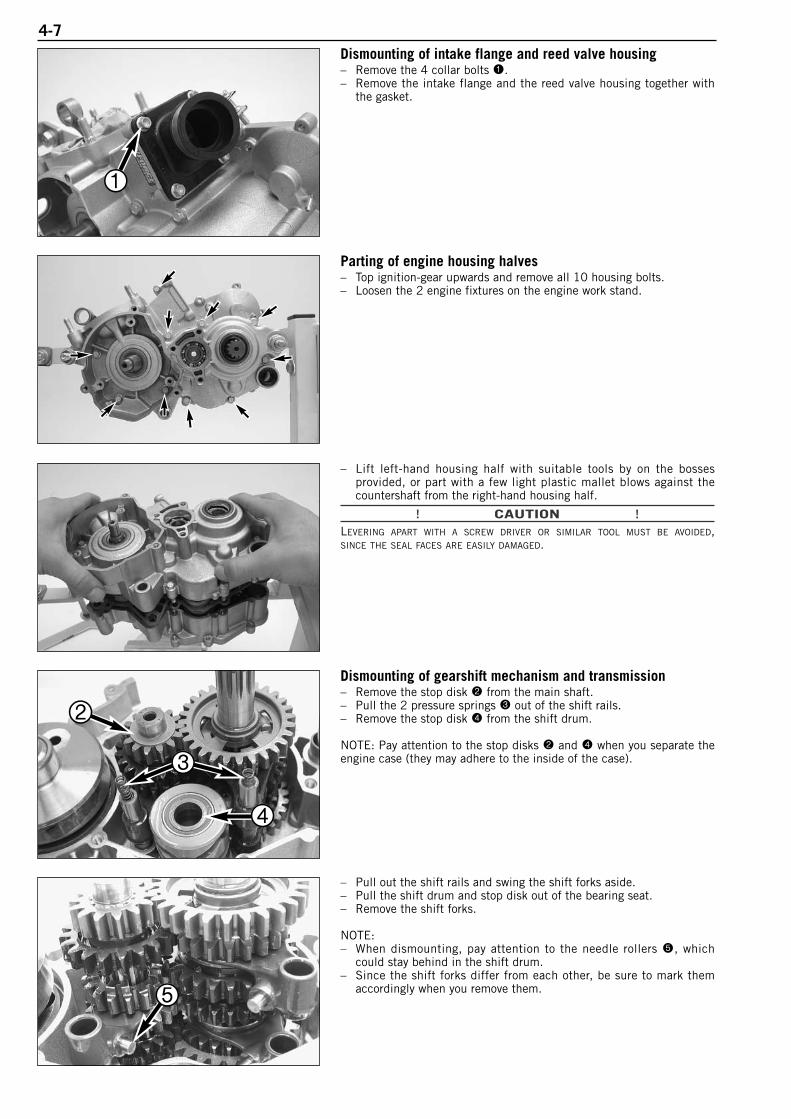
4-7Dismounting of intake flange and reed valve housing– Remove the 4 collar bolts 1.– Remove the intake flange and the reed valve housing together with
the gasket.
Parting of engine housing halves– Top ignition-gear upwards and remove all 10 housing bolts.– Loosen the 2 engine fixtures on the engine work stand.
– Lift left-hand housing half with suitable tools by on the bossesprovided, or part with a few light plastic mallet blows against thecountershaft from the right-hand housing half.
! CAUTION !LEVERING APART WITH A SCREW DRIVER OR SIMILAR TOOL MUST BE AVOIDED,SINCE THE SEAL FACES ARE EASILY DAMAGED.
Dismounting of gearshift mechanism and transmission– Remove the stop disk 2 from the main shaft.– Pull the 2 pressure springs 3 out of the shift rails.– Remove the stop disk 4 from the shift drum.
NOTE: Pay attention to the stop disks 2 and 4 when you separate theengine case (they may adhere to the inside of the case).
– Pull out the shift rails and swing the shift forks aside.– Pull the shift drum and stop disk out of the bearing seat.– Remove the shift forks.
NOTE:– When dismounting, pay attention to the needle rollers 5, which
could stay behind in the shift drum.– Since the shift forks differ from each other, be sure to mark them
accordingly when you remove them.
1
2
3
4
5
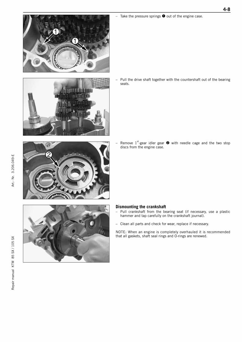
4-8R
epai
r m
anua
l K
TM 8
5 S
X / 1
05
SX
Art
.- N
r. 3
.20
6.0
49
-E– Take the pressure springs 1 out of the engine case.
– Pull the drive shaft together with the countershaft out of the bearingseats.
– Remove 1st-gear idler gear 2 with needle cage and the two stopdiscs from the engine case.
Dismounting the crankshaft– Pull crankshaft from the bearing seat (if necessary, use a plastic
hammer and tap carefully on the crankshaft journal).
– Clean all parts and check for wear, replace if necessary.
NOTE: When an engine is completely overhauled it is recommendedthat all gaskets, shaft seal rings and O-rings are renewed.
1
1
2
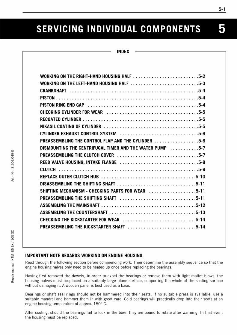
SERVICING INDIVIDUAL COMPONENTS
Rep
air
man
ual
KTM
8
5 S
X / 1
05
SX
Art
.- N
r. 3
.20
6.0
49
-E
WORKING ON THE RIGHT-HAND HOUSING HALF . . . . . . . . . . . . . . . . . . . . . . . . .5-2
WORKING ON THE LEFT-HAND HOUSING HALF . . . . . . . . . . . . . . . . . . . . . . . . . .5-3
CRANKSHAFT . . . . . . . . . . . . . . . . . . . . . . . . . . . . . . . . . . . . . . . . . . . . . . . . .5-4
PISTON . . . . . . . . . . . . . . . . . . . . . . . . . . . . . . . . . . . . . . . . . . . . . . . . . . . . . .5-4
PISTON RING END GAP . . . . . . . . . . . . . . . . . . . . . . . . . . . . . . . . . . . . . . . . . .5-4
CHECKING CYLINDER FOR WEAR . . . . . . . . . . . . . . . . . . . . . . . . . . . . . . . . . . .5-5
RECOATED CYLINDER . . . . . . . . . . . . . . . . . . . . . . . . . . . . . . . . . . . . . . . . . . . .5-5
NIKASIL COATING OF CYLINDER . . . . . . . . . . . . . . . . . . . . . . . . . . . . . . . . . . . .5-5
CYLINDER EXHAUST CONTROL SYSTEM . . . . . . . . . . . . . . . . . . . . . . . . . . . . . .5-6
PREASSEMBLING THE CONTROL FLAP AND THE CYLINDER . . . . . . . . . . . . . . . . .5-6
DISMOUNTING THE CENTRIFUGAL TIMER AND THE WATER PUMP . . . . . . . . . . .5-7
PREASSEMBLING THE CLUTCH COVER . . . . . . . . . . . . . . . . . . . . . . . . . . . . . . .5-7
REED VALVE HOUSING, INTAKE FLANGE . . . . . . . . . . . . . . . . . . . . . . . . . . . . . .5-8
CLUTCH . . . . . . . . . . . . . . . . . . . . . . . . . . . . . . . . . . . . . . . . . . . . . . . . . . . . .5-9
REPLACE OUTER CLUTCH HUB . . . . . . . . . . . . . . . . . . . . . . . . . . . . . . . . . . . .5-10
DISASSEMBLING THE SHIFTING SHAFT . . . . . . . . . . . . . . . . . . . . . . . . . . . . . .5-11
SHIFTING MECHANISM - CHECKING PARTS FOR WEAR . . . . . . . . . . . . . . . . . .5-11
PREASSEMBLING THE SHIFTING SHAFT . . . . . . . . . . . . . . . . . . . . . . . . . . . . .5-11
ASSEMBLING THE MAINSHAFT . . . . . . . . . . . . . . . . . . . . . . . . . . . . . . . . . . . .5-12
ASSEMBLING THE COUNTERSHAFT . . . . . . . . . . . . . . . . . . . . . . . . . . . . . . . . .5-13
CHECKING THE KICKSTARTER FOR WEAR . . . . . . . . . . . . . . . . . . . . . . . . . . . .5-14
PREASSEMBLING THE KICKSTARTER SHAFT . . . . . . . . . . . . . . . . . . . . . . . . . .5-14
INDEX
5-1
5
IMPORTANT NOTE REGARDS WORKING ON ENGINE HOUSINGRead through the following section before commencing work. Then determine the assembly sequence so that theengine housing halves only need to be heated up once before replacing the bearings.
Having first removed the dowels, in order to expel the bearings or remove them with light mallet blows, thehousing halves must be placed on a suitably large plane surface, supporting the whole of the sealing surfacewithout damaging it. A wooden panel is best used as a base.
Bearings or shaft seal rings should not be hammered into their seats. If no suitable press is available, use a suitable mandrel and hammer them in with great care. Cold bearings will practically drop into their seats at anengine housing temperature of approx. 150° C.
After cooling, should the bearings fail to lock in the bore, they are bound to rotate after warming. In that eventthe housing must be replaced.
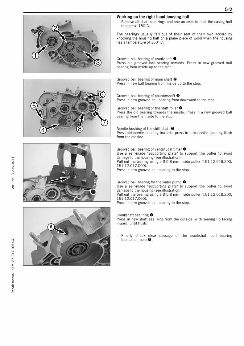
5-2R
epai
r m
anua
l K
TM 8
5 S
X / 1
05
SX
Art
.- N
r. 3
.20
6.0
49
-EWorking on the right-hand housing half– Remove all shaft seal rings and use an oven to heat the casing half
to approx. 150°C.
The bearings usually fall out of their seat of their own accord byknocking the housinq half on a plane piece of wood when the housinghas a temperature of 150° C.
Grooved ball bearing of crankshaft 1.Press old grooved ball-bearing inwards. Press in new grooved ballbearing from inside up to the stop.
Grooved ball bearing of main shaft 2Press in new ball bearing from inside up to the stop.
Grooved ball bearing of countershaft 3Press in new grooved ball bearing from downward to the stop.
Grooved ball bearing of the shift roller 4Press the old bearing towards the inside. Press in a new grooved ballbearing from the inside to the stop.
Needle bushing of the shift shaft 5Press old needle bushing inwards, press in new needle bushing flushfrom the outside.
Grooved ball bearing of centrifugal timer 6Use a self-made "supporting plate" to support the puller to avoiddamage to the housing (see illustration).Pull out the bearing using a Ø 5-8 mm inside puller (151.12.018.200,151.12.017.000).Press in new grooved ball bearing to the stop.
Grooved ball bearing for the water pump 7Use a self-made "supporting plate" to support the puller to avoiddamage to the housing (see illustration).Pull out the bearing using a Ø 5-8 mm inside puller (151.12.018.200,151.12.017.000).Press in new grooved ball bearing to the stop.
Crankshaft seal ring 8Press in new shaft seal ring from the outside, with sealing lip facinginward, until flush.
– Finally check clear passage of the crankshaft ball bearinglubrication bore A.
1
2
3
4
5
6
78
A
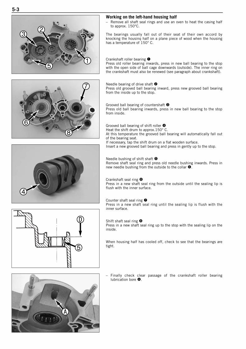
5-3Working on the left-hand housing half– Remove all shaft seal rings and use an oven to heat the casing half
to approx. 150°C.
The bearings usually fall out of their seat of their own accord byknocking the housinq half on a plane piece of wood when the housinghas a temperature of 150° C.
Crankshaft roller bearing 1Press old roller bearing inwards, press in new ball bearing to the stopwith the open side of ball cage downwards (outside). The inner ring onthe crankshaft must also be renewed (see paragraph about crankshaft).
Needle bearing of drive shaft 2Press old grooved ball bearing inward, press new grooved ball bearingfrom the inside up to the stop.
Grooved ball bearing of countershaft 3Press old ball bearing inwards, press in new ball bearing to the stopfrom inside.
Grooved ball bearing of shift roller 4Heat the shift drum to approx.150° C.At this temperature the grooved ball bearing will automatically fall outof the bearing seat.If necessary, tap the shift drum on a flat wooden surface.Insert a new grooved ball bearing and press in gently up to the stop.
Needle bushing of shift shaft 5Remove shaft seal ring and press old needle bushing inwards. Press innew needle bushing from the outside to the collar D.
Crankshaft seal ring 6Press in a new shaft seal ring from the outside until the sealing lip isflush with the inner surface.
Counter shaft seal ring 7Press in a new shaft seal ring until the sealing lip is flush with theinner surface.
Shift shaft seal ring 8Press in a new shaft seal ring up to the stop with the sealing lip on theinside.
When housing half has cooled off, check to see that the bearings aretight.
– Finally check clear passage of the crankshaft roller bearinglubrication bore A.
1
23
5
6
7
8
4
A
5
D

5-4R
epai
r m
anua
l K
TM 8
5 S
X / 1
05
SX
Art
.- N
r. 3
.20
6.0
49
-ECrankshaft– When replacing the roller bearing, the inner crankshaft ring must
also be renewed.– Heat special tool 584.29.037.031 on a heating pad up to approx.
150°C and slip it on the inner ring immediately. Press the specialtool together tightly so as to obtain a good heat transfer and pull theinner ring off the crankshaft.
– To mount the new inner ring, heat the special tool again to approx.150°C, engage the inner ring and slip it on the crankshaft journalimmediately. Make sure the inner ring is pushed back to the stop.
! CAUTION !NEVER CLAMP THE CRANKSHAFT WITH A STUD OR WEB IN THE VICE, AND NEVER
TRY TO KNOCK THE BEARING INNER RING FREE. THE CRANKSHAFT WEBS MAY BE
COMPRESSED AND THE CON-ROD PLUG AND BEARING MAY BE DAMAGES, THEREBY
MAKING THE CRANKSHAFT UNUSABLE.
NOTE:– Distance adjustment of the main bearings is not requested.– See Technical Informations!
PistonIf a used piston is to remain in service then the following should bechecked:
1. Piston running surface: Check for pressure marks (seizing marks)minor friction marks can be removed with a fine abrasive stick.
2. Piston ring groove: The piston ring may not jam in the groove. Usean old piston ring or sandpaper (400 grit) to clean the groove.
3. The piston ring anti-rotation device must fit tightly in the piston andmay not be worn.
4. Check piston rings for wear and check end gap.
– The piston is measured at the piston skirt, transverse to the pistonpin 32 mm below the top, as shown in the illustration.
– The smallest cylinder diameter minus the largest piston diameter determines the piston fitting clearance.
Piston fitting clearance: 0.045 - 0.07 mmWear limit: 0.10 mm
Piston ring end gap– Insert piston ring into the cylinder and adjust. Piston ring must be
approx. 10 mm from top of cylinder.– The end gap B can now be checked with a feeler gauge.
Piston ring end gap: max. 0.40 mm
NOTE: If the end gap is greater check piston and cylinder for wear. Ifpiston and cylinder wear are within the permitted tolerance limits,replace the piston ring.

5-5Checking cylinder for wear – To check the wear on the cylinder, measure the cylinder 20 mm
below the upper edge of the running surface using a micrometer.– Measure the cylinder diameter in the X and the Y axis to detect any
ovality.
Engine Cylinder Ø Piston size85 47.000 - 47.012 1
47.013 - 47.025 2105 52.000 - 52.012 1
52.013 - 52.025 2
Recoated cylinderNOTE: If the cylinder diameter is greater than 47.025 mm (85 SX) or52.025 (105 SX), the Nikasil cylinder must be reconditioned orreplaced.For reconditioning of the old cylinder all exhaust control componentsmust be removed. The intermediate flange 1 remains with thecylinder. The piston size is stamped into the bottom of the piston.
Nikasil coating of cylinder Nikasil is the brand name for a cylinder coating process, developed bythe piston manufacturer Mahle. The name is derived from the twomaterials used in this process - a nickel layer into which theparticularly hard silicon carbide is inbedded.
The main advantages of the Nikasil coating are:– excellent heat dissipation and thus better power output– low wear– low weight of the cylinder.
xy
20mm
1
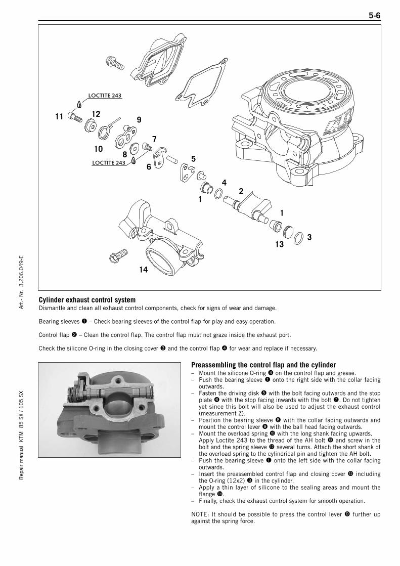
5-6R
epai
r m
anua
l K
TM 8
5 S
X / 1
05
SX
Art
.- N
r. 3
.20
6.0
49
-E
Cylinder exhaust control systemDismantle and clean all exhaust control components, check for signs of wear and damage.
Bearing sleeves 1 – Check bearing sleeves of the control flap for play and easy operation.
Control flap 2 – Clean the control flap. The control flap must not graze inside the exhaust port.
Check the silicone O-ring in the closing cover 3 and the control flap 4 for wear and replace if necessary.
Preassembling the control flap and the cylinder– Mount the silicone O-ring 4 on the control flap and grease.– Push the bearing sleeve 1 onto the right side with the collar facing
outwards.– Fasten the driving disk 5 with the bolt facing outwards and the stop
plate 6 with the stop facing inwards with the bolt 7. Do not tightenyet since this bolt will also be used to adjust the exhaust control(measurement Z).
– Position the bearing sleeve 8 with the collar facing outwards andmount the control lever 9 with the ball head facing outwards.
– Mount the overload spring bk with the long shank facing upwards.Apply Loctite 243 to the thread of the AH bolt bl and screw in thebolt and the spring sleeve bm several turns. Attach the short shank ofthe overload spring to the cylindrical pin and tighten the AH bolt.
– Push the bearing sleeve 1 onto the left side with the collar facingoutwards.
– Insert the preassembled control flap and closing cover bn includingthe O-ring (12x2) 3 in the cylinder.
– Apply a thin layer of silicone to the sealing areas and mount theflange bo.
– Finally, check the exhaust control system for smooth operation.
NOTE: It should be possible to press the control lever 9 further upagainst the spring force.
LOCTITE 243
LOCTITE 243
1
1
2
3
4
5
9
6
7
13
10
14
1211
8
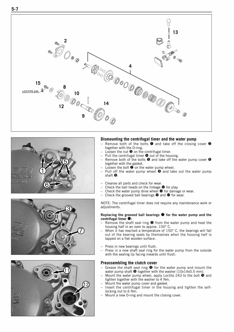
5-7
Dismounting the centrifugal timer and the water pump– Remove both of the bolts 1 and take off the closing cover 2
together with the O-ring.– Loosen the nut 3 on the centrifugal timer.– Pull the centrifugal timer 4 out of the housing.– Remove both of the bolts 5 and take off the water pump cover 6
together with the gasket.– Loosen the bolt 7 on the water pump wheel.– Pull off the water pump wheel 8 and take out the water pump
shaft 9.
– Cleanse all parts and check for wear.– Check the ball heads on the linkage bn for play.– Check the water pump drive wheel bo for damage or wear.– Check the grooved ball bearings bk and bl for wear.
NOTE: The centrifugal timer does not require any maintenance work oradjustments.
Replacing the grooved ball bearings bk for the water pump and thecentrifugal timer bl:– Remove the shaft seal ring bm from the water pump and heat the
housing half in an oven to approx. 150° C.– When it has reached a temperature of 150° C, the bearings will fall
out of the bearing seats by themselves when the housing half istapped on a flat wooden surface.
– Press in new bearings until flush.– Press in a new shaft seal ring for the water pump from the outside
with the sealing lip facing inwards until flush.
Preassembling the clutch cover– Grease the shaft seal ring bm for the water pump and mount the
water pump shaft 9 together with the washer (10x14x0.5 mm).– Mount the water pump wheel, apply Loctite 243 to the bolt bp and
tighten together with the washer to 4 Nm.– Mount the water pump cover and gasket.– Insert the centrifugal timer in the housing and tighten the self-
locking nut to 6 Nm.– Mount a new O-ring and mount the closing cover.
LOCTITE 243
12
108
9
2
13
14
15
4
1
5
6
3
7
bl
bm
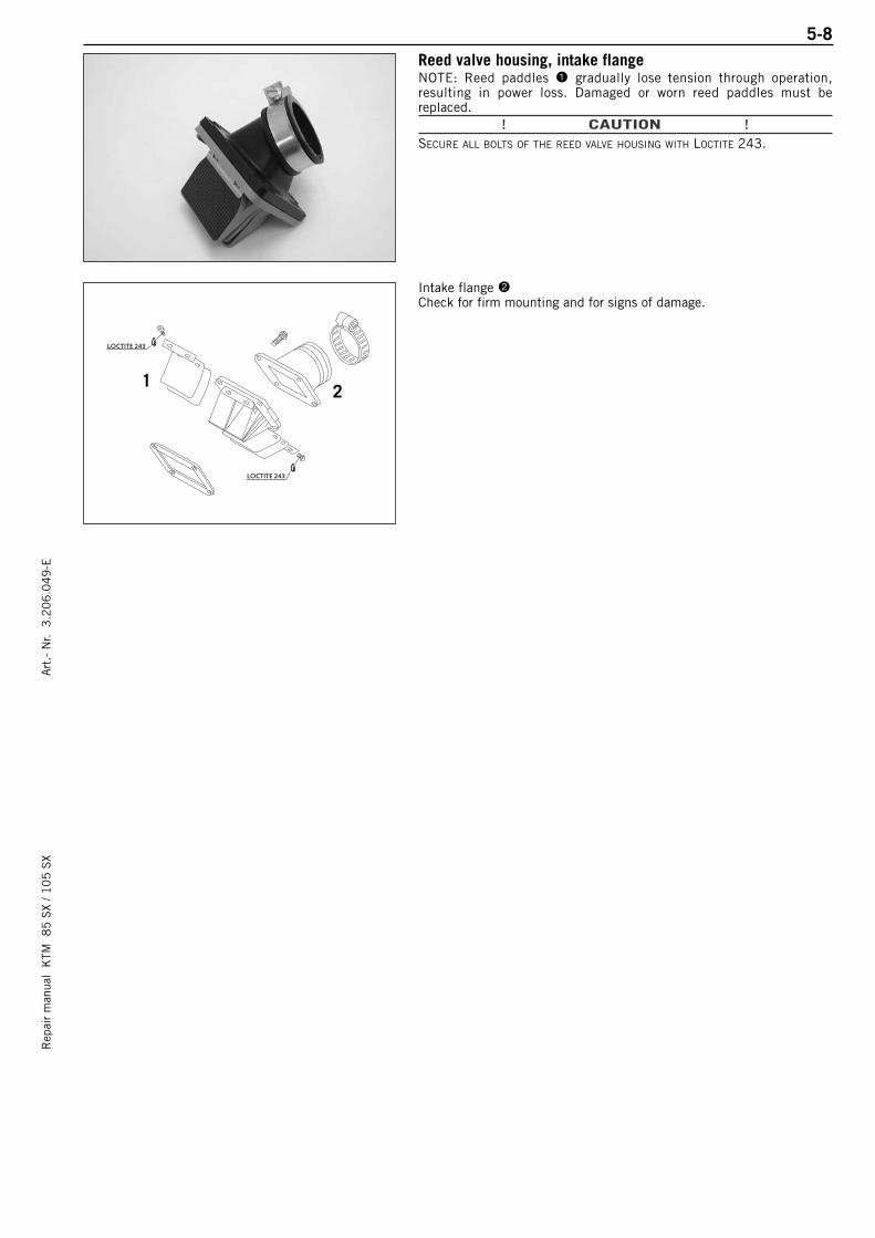
5-8R
epai
r m
anua
l K
TM 8
5 S
X / 1
05
SX
Art
.- N
r. 3
.20
6.0
49
-E
LOCTITE 243
LOCTITE 243
Reed valve housing, intake flange NOTE: Reed paddles 1 gradually lose tension through operation,resulting in power loss. Damaged or worn reed paddles must bereplaced.
! CAUTION !SECURE ALL BOLTS OF THE REED VALVE HOUSING WITH LOCTITE 243.
Intake flange 2Check for firm mounting and for signs of damage.
12
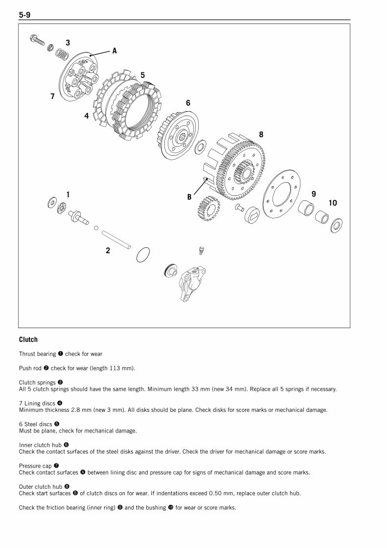
5-9
Clutch
Thrust bearing 1 check for wear
Push rod 2 check for wear (length 113 mm).
Clutch springs 3All 5 clutch springs should have the same length. Minimum length 33 mm (new 34 mm). Replace all 5 springs if necessary.
7 Lining discs 4Minimum thickness 2.8 mm (new 3 mm). All disks should be plane. Check disks for score marks or mechanical damage.
6 Steel discs 5Must be plane, check for mechanical damage.
Inner clutch hub 6Check the contact surfaces of the steel disks against the driver. Check the driver for mechanical damage or score marks.
Pressure cap 7Check contact surfaces A between lining disc and pressure cap for signs of mechanical damage and score marks.
Outer clutch hub 8Check start surfaces B of clutch discs on for wear. If indentations exceed 0.50 mm, replace outer clutch hub.
Check the friction bearing (inner ring) 9 and the bushing bk for wear or score marks.
1
A
2
3
4
5
67
8
B10
9
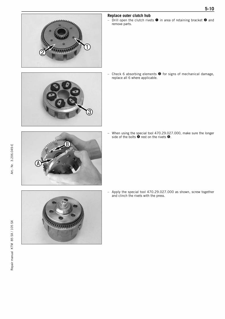
5-10R
epai
r m
anua
l K
TM 8
5 S
X / 1
05
SX
Art
.- N
r. 3
.20
6.0
49
-EReplace outer clutch hub – Drill open the clutch rivets 1 in area of retaining bracket 2 and
remove parts.
– Check 6 absorbing elements 3 for signs of mechanical damage,replace all 6 where applicable.
– When using the special tool 470.29.027.000, make sure the longerside of the bolts A rest on the rivets B.
– Apply the special tool 470.29.027.000 as shown, screw togetherand clinch the rivets with the press.
12
3
A
B
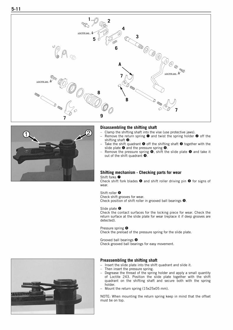
5-11
Disassembling the shifting shaft– Clamp the shifting shaft into the vise (use protective jaws).– Remove the return spring 1 and twist the spring holder 2 off the
shifting shaft 3.– Take the shift quadrant 4 off the shifting shaft 3 together with the
slide plate 5 and the pressure spring 6.– Remove the pressure spring 6, shift the slide plate 5 and take it
out of the shift quadrant 4.
Shifting mechanism - Checking parts for wearShift forks 7Check shift fork blades A and shift roller driving pin B for signs ofwear.
Shift roller 8Check shift grooves for wear. Check position of shift roller in grooved ball bearings 9.
Slide plate 5Check the contact surfaces for the locking piece for wear. Check thereturn surface at the slide plate for wear (replace it if deep grooves aredetected).
Pressure spring 6Check the preload of the pressure spring for the slide plate.
Grooved ball bearings 9Check grooved ball bearings for easy movement.
Preassembling the shifting shaft– Insert the slide plate into the shift quadrant and slide it.– Then insert the pressure spring.– Degrease the thread of the spring holder and apply a small quantity
of Loctite 243. Position the slide plate together with the shiftquadrant on the shifting shaft and secure both with the springholder.
– Mount the return spring (15x25x05 mm).
NOTE: When mounting the return spring keep in mind that the offsetmust be on top.
LOCTITE 243
LOCTITE 243
LOCTITE 243
1
7
2
5
6
7
3
4
9
8
7
A
B
1 2
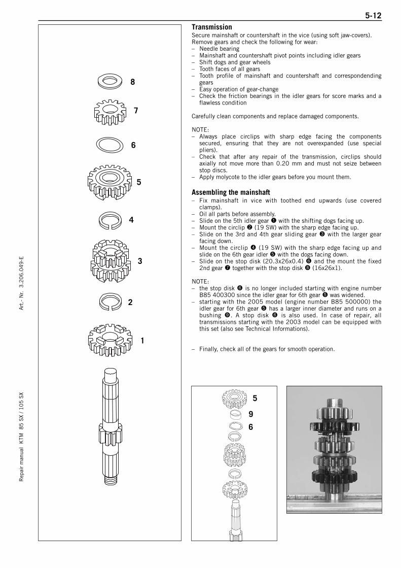
5-12R
epai
r m
anua
l K
TM 8
5 S
X / 1
05
SX
Art
.- N
r. 3
.20
6.0
49
-ETransmissionSecure mainshaft or countershaft in the vice (using soft jaw-covers).Remove gears and check the following for wear:– Needle bearing– Mainshaft and countershaft pivot points including idler gears– Shift dogs and gear wheels– Tooth faces of all gears– Tooth profile of mainshaft and countershaft and correspondending
gears– Easy operation of gear-change– Check the friction bearings in the idler gears for score marks and a
flawless condition
Carefully clean components and replace damaged components.
NOTE:– Always place circlips with sharp edge facing the components
secured, ensuring that they are not overexpanded (use specialpliers).
– Check that after any repair of the transmission, circlips shouldaxially not move more than 0.20 mm and must not seize betweenstop discs.
– Apply molycote to the idler gears before you mount them.
Assembling the mainshaft– Fix mainshaft in vice with toothed end upwards (use covered
clamps). – Oil all parts before assembly.– Slide on the 5th idler gear 1 with the shifting dogs facing up.– Mount the circlip 2 (19 SW) with the sharp edge facing up.– Slide on the 3rd and 4th gear sliding gear 3 with the larger gear
facing down.– Mount the circlip 4 (19 SW) with the sharp edge facing up and
slide on the 6th gear idler 5 with the dogs facing down.– Slide on the stop disk (20.3x26x0.4) 6 and the mount the fixed
2nd gear 7 together with the stop disk 8 (16x26x1).
NOTE:– the stop disk 6 is no longer included starting with engine number
B85 400300 since the idler gear for 6th gear 5 was widened. – starting with the 2005 model (engine number B85 500000) the
idler gear for 6th gear 5 has a larger inner diameter and runs on abushing 9. A stop disk 6 is also used. In case of repair, alltransmissions starting with the 2003 model can be equipped withthis set (also see Technical Informations).
– Finally, check all of the gears for smooth operation.1
4
7
8
6
5
3
2
5
9
6
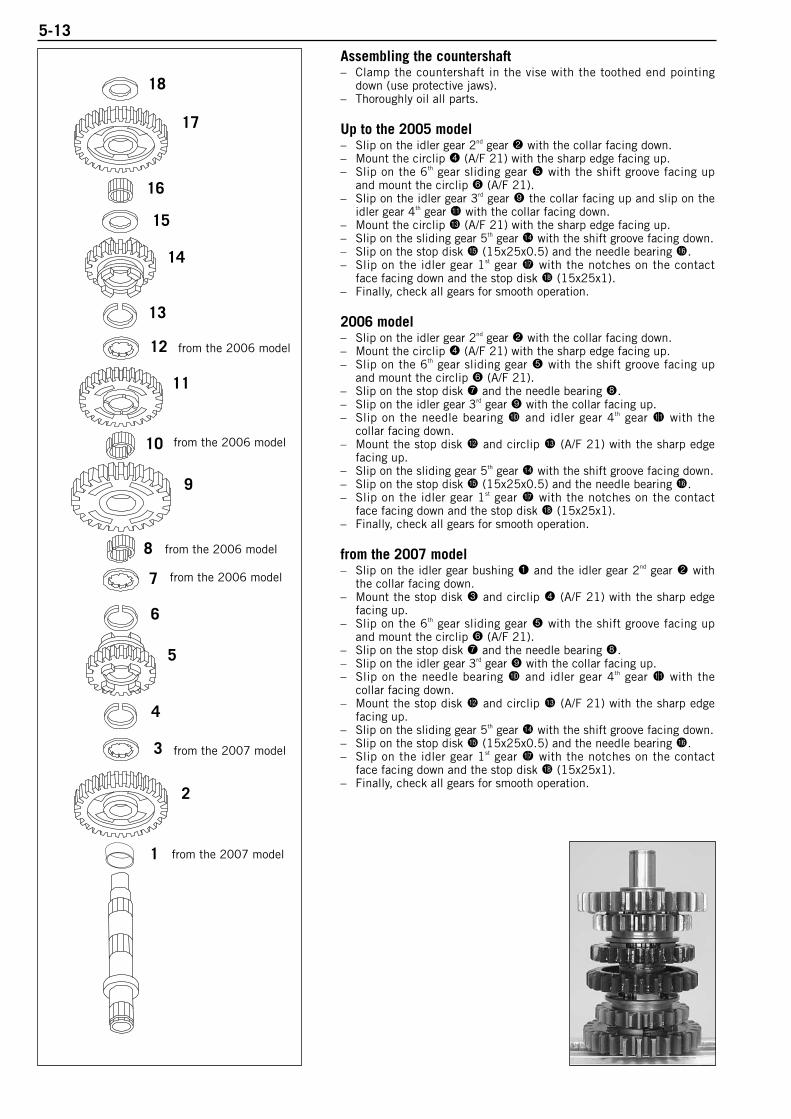
5-13
Assembling the countershaft – Clamp the countershaft in the vise with the toothed end pointing
down (use protective jaws).– Thoroughly oil all parts.
Up to the 2005 model– Slip on the idler gear 2nd gear 2 with the collar facing down.– Mount the circlip 4 (A/F 21) with the sharp edge facing up.– Slip on the 6th gear sliding gear 5 with the shift groove facing up
and mount the circlip 6 (A/F 21).– Slip on the idler gear 3rd gear 9 the collar facing up and slip on the
idler gear 4th gear bl with the collar facing down.– Mount the circlip bn (A/F 21) with the sharp edge facing up.– Slip on the sliding gear 5th gear bo with the shift groove facing down.– Slip on the stop disk bp (15x25x0.5) and the needle bearing bq.– Slip on the idler gear 1st gear br with the notches on the contact
face facing down and the stop disk bs (15x25x1).– Finally, check all gears for smooth operation.
2006 model– Slip on the idler gear 2nd gear 2 with the collar facing down.– Mount the circlip 4 (A/F 21) with the sharp edge facing up.– Slip on the 6th gear sliding gear 5 with the shift groove facing up
and mount the circlip 6 (A/F 21).– Slip on the stop disk 7 and the needle bearing 8.– Slip on the idler gear 3rd gear 9 with the collar facing up.– Slip on the needle bearing bk and idler gear 4th gear bl with the
collar facing down.– Mount the stop disk bm and circlip bn (A/F 21) with the sharp edge
facing up.– Slip on the sliding gear 5th gear bo with the shift groove facing down.– Slip on the stop disk bp (15x25x0.5) and the needle bearing bq.– Slip on the idler gear 1st gear br with the notches on the contact
face facing down and the stop disk bs (15x25x1).– Finally, check all gears for smooth operation.
from the 2007 model– Slip on the idler gear bushing 1 and the idler gear 2nd gear 2 with
the collar facing down.– Mount the stop disk 3 and circlip 4 (A/F 21) with the sharp edge
facing up.– Slip on the 6th gear sliding gear 5 with the shift groove facing up
and mount the circlip 6 (A/F 21).– Slip on the stop disk 7 and the needle bearing 8.– Slip on the idler gear 3rd gear 9 with the collar facing up.– Slip on the needle bearing bk and idler gear 4th gear bl with the
collar facing down.– Mount the stop disk bm and circlip bn (A/F 21) with the sharp edge
facing up.– Slip on the sliding gear 5th gear bo with the shift groove facing down.– Slip on the stop disk bp (15x25x0.5) and the needle bearing bq.– Slip on the idler gear 1st gear br with the notches on the contact
face facing down and the stop disk bs (15x25x1).– Finally, check all gears for smooth operation.
7
1
8
6
2
3
4
5
9
10
11
12
13
14
15
16
17
18
from the 2007 model
from the 2007 model
from the 2006 model
from the 2006 model
from the 2006 model
from the 2006 model
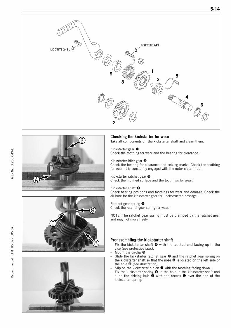
Rep
air
man
ual
KTM
8
5 S
X / 1
05
SX
5-14A
rt.-
Nr.
3.2
06
.04
9-E
Checking the kickstarter for wearTake all components off the kickstarter shaft and clean them.
Kickstarter gear 1Check the toothing for wear and the bearing for clearance.
Kickstarter idler gear 2Check the bearing for clearance and seizing marks. Check the toothingfor wear. It is constantly engaged with the outer clutch hub.
Kickstarter ratchet gear 3Check the inclined surface and the toothings for wear.
Kickstarter shaft 4Check bearing positions and toothings for wear and damage. Check theoil bore for the kickstarter gear for unobstructed passage.
Ratchet gear spring 5Check the ratchet gear spring for wear.
NOTE: The ratchet gear spring must be clamped by the ratchet gearand may not move freely.
Preassembling the kickstarter shaft– Fix the kickstarter shaft 4 with the toothed end facing up in the
vise (use protective jaws).– Mount the circlip 6.– Slide the kickstarter ratchet gear 3 and the ratchet gear spring on
the kickstarter shaft so that the nose A is located on the left side ofthe hole B (see illustration).
– Slip on the kickstarter pinion 1 with the toothing facing down.– Fix the kickstarter spring 8 in the hole in the kickstarter shaft and
slide the driving hub 9 with the recess C over the end of thekickstarter spring.
LOCTITE 243LOCTITE 243
1
2
3
6
59
8
4
A
B
8
9
C

ASSEMBLING THE ENGINE
Rep
air
man
ual
KTM
8
5 S
X / 1
05
SX
Art
.- N
r. 3
.20
6.0
49
-E
CRANKSHAFT . . . . . . . . . . . . . . . . . . . . . . . . . . . . . . . . . . . . . . . . . . . . . . . . .6-2
TRANSMISSION . . . . . . . . . . . . . . . . . . . . . . . . . . . . . . . . . . . . . . . . . . . . . . . .6-2
ASSEMBLING THE ENGINE HOUSING . . . . . . . . . . . . . . . . . . . . . . . . . . . . . . . . .6-3
MOUNTING THE SHIFT MECHANISM . . . . . . . . . . . . . . . . . . . . . . . . . . . . . . . . .6-4
MOUNTING KICKSTARTER . . . . . . . . . . . . . . . . . . . . . . . . . . . . . . . . . . . . . . . .6-4
MOUNT PRIMARY DRIVE AND CLUTCH . . . . . . . . . . . . . . . . . . . . . . . . . . . . . . .6-5
MOUNTING CLUTCH DISCS AND PRESSURE CAP . . . . . . . . . . . . . . . . . . . . . . . .6-6
MOUNTING CLUTCH COVER . . . . . . . . . . . . . . . . . . . . . . . . . . . . . . . . . . . . . . .6-6
MOUNTING PISTON AND CYLINDER . . . . . . . . . . . . . . . . . . . . . . . . . . . . . . . . . .6-7
ADJUSTING DIMENSION „X“ . . . . . . . . . . . . . . . . . . . . . . . . . . . . . . . . . . . . . . .6-8
ADJUSTING CONTROL FLAP (DIMENSION „Z“) . . . . . . . . . . . . . . . . . . . . . . . . . .6-9
MOUNTING THE IGNITION . . . . . . . . . . . . . . . . . . . . . . . . . . . . . . . . . . . . . . .6-10
ADJUSTING THE IGNITION . . . . . . . . . . . . . . . . . . . . . . . . . . . . . . . . . . . . . . .6-10
MOUNTING CYLINDER HEAD . . . . . . . . . . . . . . . . . . . . . . . . . . . . . . . . . . . . . .6-11
MOUNTING REED VALVE HOUSING AND INTAKE FLANGE . . . . . . . . . . . . . . . . . .6-11
MOUNTING ENGINE SPROCKET . . . . . . . . . . . . . . . . . . . . . . . . . . . . . . . . . . . .6-11
MOUNTING THE KICKSTARTER AND SHIFT LEVER . . . . . . . . . . . . . . . . . . . . . .6-12
FILL IN TRANSMISSION OIL . . . . . . . . . . . . . . . . . . . . . . . . . . . . . . . . . . . . . .6-12
CHECKING GEAR OIL LEVEL . . . . . . . . . . . . . . . . . . . . . . . . . . . . . . . . . . . . . .6-12
INDEX
6-1
6

6-2R
epai
r m
anua
l K
TM 8
5 S
X / 1
05
SX
Art
.- N
r. 3
.20
6.0
49
-E– Secure the right-hand housing half in the engine work stand.
Crankshaft– Insert crankshaft from above through grooved ball bearing and push
carefully as far as stop.
! CAUTION !WHEN PUSHING IN CRANKSHAFT, MAKE SURE CONROD IS FACING CYLINDER.
Transmission– Oil driving pin 1 for the shift forks and mount.– Fix the lower stop disc on the countershaft with a small amount of
grease.– Mount drive shaft together with countershaft, and insert them into
the bearings as far as they will go.– Oil shift forks prior to mounting.
– Shift fork 2 with the shorter shift dog belongs to the main shaft.– Mount the two other shift forks at the countershaft, using the marks
applied before disassembly for better orientation.
! CAUTION !ALL OF THE SHIFT FORKS ARE DIFFERENT SO GO BY THE MARKS MADE DURING
DEMOUNTING WHEN YOU MOUNT THEM AGAIN.
NOTE: If you forgot to make a mark before disassembling, mount theshift forks at the countershaft so that the greatest distance is betweenthe driving pins.
– Fit the shift forks in the sliding gears and insert the shift drum andthe spacing washer (25x32x0.5 mm) in the grooved ball bearing.
– Attach the shift forks to the shift roller.
! CAUTION !WHEN INSERTING THE SHIFT FORKS, MAKE SURE THE DRIVING PINS DO NOT FALL
OUT OF THE SHIFT FORKS.
1
2
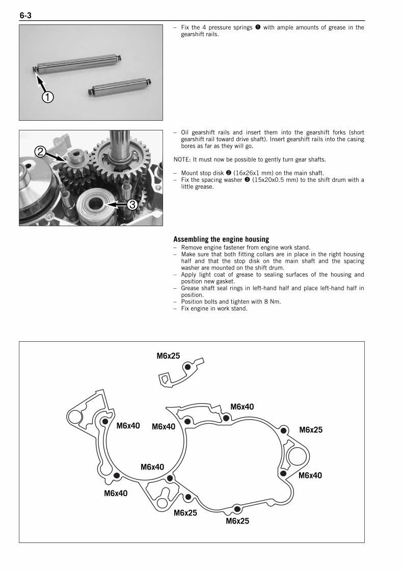
6-3– Fix the 4 pressure springs 1 with ample amounts of grease in the
gearshift rails.
– Oil gearshift rails and insert them into the gearshift forks (shortgearshift rail toward drive shaft). Insert gearshift rails into the casingbores as far as they will go.
NOTE: It must now be possible to gently turn gear shafts.
– Mount stop disk 2 (16x26x1 mm) on the main shaft.– Fix the spacing washer 3 (15x20x0.5 mm) to the shift drum with a
little grease.
Assembling the engine housing– Remove engine fastener from engine work stand.– Make sure that both fitting collars are in place in the right housing
half and that the stop disk on the main shaft and the spacingwasher are mounted on the shift drum.
– Apply light coat of grease to sealing surfaces of the housing andposition new gasket.
– Grease shaft seal rings in left-hand half and place left-hand half inposition.
– Position bolts and tighten with 8 Nm.– Fix engine in work stand.
M6x25
M6x40
M6x40
M6x25M6x25
M6x40
M6x25
M6x40
M6x40
M6x40
1
2
3
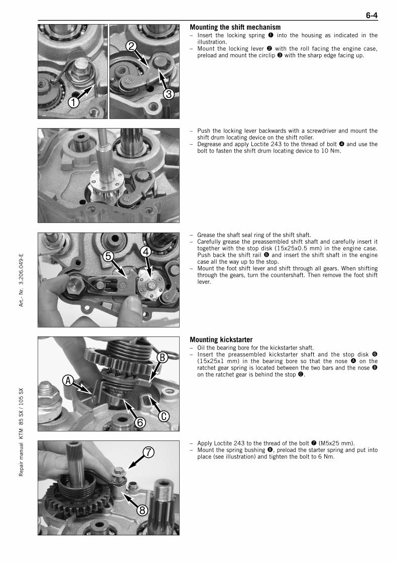
6-4R
epai
r m
anua
l K
TM 8
5 S
X / 1
05
SX
Art
.- N
r. 3
.20
6.0
49
-EMounting the shift mechanism – Insert the locking spring 1 into the housing as indicated in the
illustration.– Mount the locking lever 2 with the roll facing the engine case,
preload and mount the circlip 3 with the sharp edge facing up.
– Push the locking lever backwards with a screwdriver and mount theshift drum locating device on the shift roller.
– Degrease and apply Loctite 243 to the thread of bolt 4 and use thebolt to fasten the shift drum locating device to 10 Nm.
– Grease the shaft seal ring of the shift shaft.– Carefully grease the preassembled shift shaft and carefully insert it
together with the stop disk (15x25x0.5 mm) in the engine case.Push back the shift rail 5 and insert the shift shaft in the enginecase all the way up to the stop.
– Mount the foot shift lever and shift through all gears. When shiftingthrough the gears, turn the countershaft. Then remove the foot shiftlever.
Mounting kickstarter– Oil the bearing bore for the kickstarter shaft.– Insert the preassembled kickstarter shaft and the stop disk 6
(15x25x1 mm) in the bearing bore so that the nose A on theratchet gear spring is located between the two bars and the nose Bon the ratchet gear is behind the stop C.
– Apply Loctite 243 to the thread of the bolt 7 (M5x25 mm).– Mount the spring bushing 8, preload the starter spring and put into
place (see illustration) and tighten the bolt to 6 Nm.
1
2
3
45
6
A
B
C
7
8
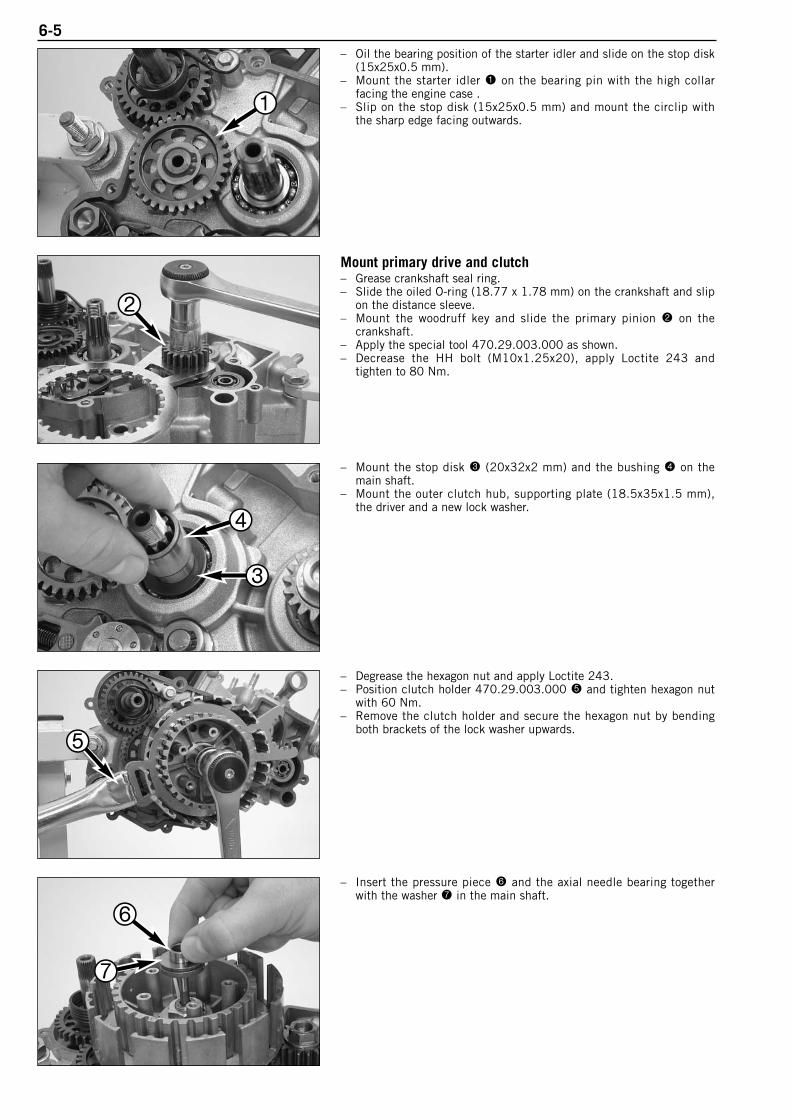
6-5– Oil the bearing position of the starter idler and slide on the stop disk
(15x25x0.5 mm).– Mount the starter idler 1 on the bearing pin with the high collar
facing the engine case .– Slip on the stop disk (15x25x0.5 mm) and mount the circlip with
the sharp edge facing outwards.
Mount primary drive and clutch– Grease crankshaft seal ring.– Slide the oiled O-ring (18.77 x 1.78 mm) on the crankshaft and slip
on the distance sleeve.– Mount the woodruff key and slide the primary pinion 2 on the
crankshaft.– Apply the special tool 470.29.003.000 as shown.– Decrease the HH bolt (M10x1.25x20), apply Loctite 243 and
tighten to 80 Nm.
– Mount the stop disk 3 (20x32x2 mm) and the bushing 4 on themain shaft.
– Mount the outer clutch hub, supporting plate (18.5x35x1.5 mm),the driver and a new lock washer.
– Degrease the hexagon nut and apply Loctite 243.– Position clutch holder 470.29.003.000 5 and tighten hexagon nut
with 60 Nm.– Remove the clutch holder and secure the hexagon nut by bending
both brackets of the lock washer upwards.
– Insert the pressure piece 6 and the axial needle bearing togetherwith the washer 7 in the main shaft.
1
2
4
3
5
6
7
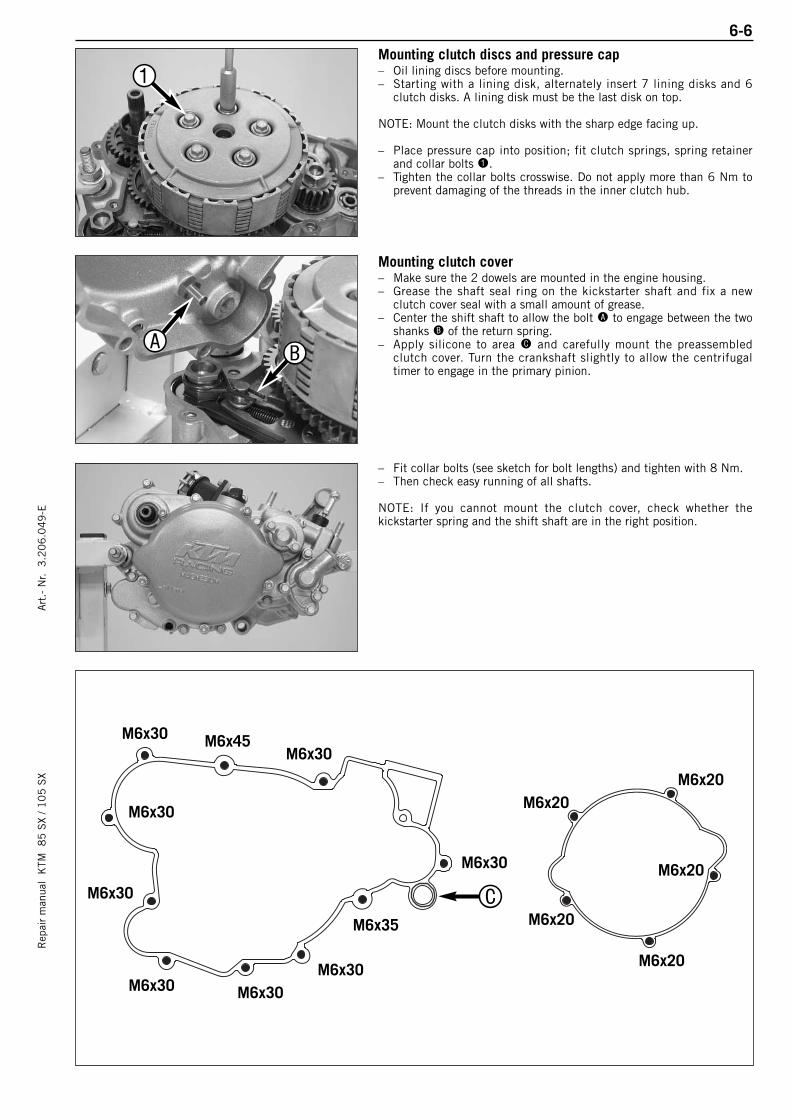
6-6R
epai
r m
anua
l K
TM 8
5 S
X / 1
05
SX
Art
.- N
r. 3
.20
6.0
49
-EMounting clutch discs and pressure cap– Oil lining discs before mounting.– Starting with a lining disk, alternately insert 7 lining disks and 6
clutch disks. A lining disk must be the last disk on top.
NOTE: Mount the clutch disks with the sharp edge facing up.
– Place pressure cap into position; fit clutch springs, spring retainerand collar bolts 1.
– Tighten the collar bolts crosswise. Do not apply more than 6 Nm toprevent damaging of the threads in the inner clutch hub.
Mounting clutch cover– Make sure the 2 dowels are mounted in the engine housing.– Grease the shaft seal ring on the kickstarter shaft and fix a new
clutch cover seal with a small amount of grease.– Center the shift shaft to allow the bolt A to engage between the two
shanks B of the return spring.– Apply silicone to area C and carefully mount the preassembled
clutch cover. Turn the crankshaft slightly to allow the centrifugaltimer to engage in the primary pinion.
– Fit collar bolts (see sketch for bolt lengths) and tighten with 8 Nm.– Then check easy running of all shafts.
NOTE: If you cannot mount the clutch cover, check whether thekickstarter spring and the shift shaft are in the right position.
M6x30M6x30
M6x30
M6x20M6x20
M6x20
M6x20
M6x20
M6x30
M6x30
M6x30 M6x30M6x30
M6x35
M6x45
1
AB
C

6-7– Position the linkage 1 with the counternut facing up, insert the
adjusting shaft 2 with the lever facing down and press the ballsocket on the ball of the lever (see illustration).
NOTE: As of model year 2006 a new adjusting shaft 2 with a shaftsealing ring is used.
– Mount the locking screw 3 and the gasket.– Slide the sealing element into area A.– Finally, check the lever for smooth operation by hand.
Mounting piston and cylinder– Before assembly, oil all parts thoroughly at the sliding points.– Insert needle bearing in conrod eye, mount piston (arrow on piston
head shows direction for exhaust duct).– Mount piston pin and wire circlips with open side showing
downwards (see sketch).– Mount cylinder base gaskets.– Place the piston on a self-made wooden stand and adjust the piston
ring.
– Place on preassembled cylinder, remove wooden stand and tightencylinder down crosswise, using two nuts.
1
2
3A
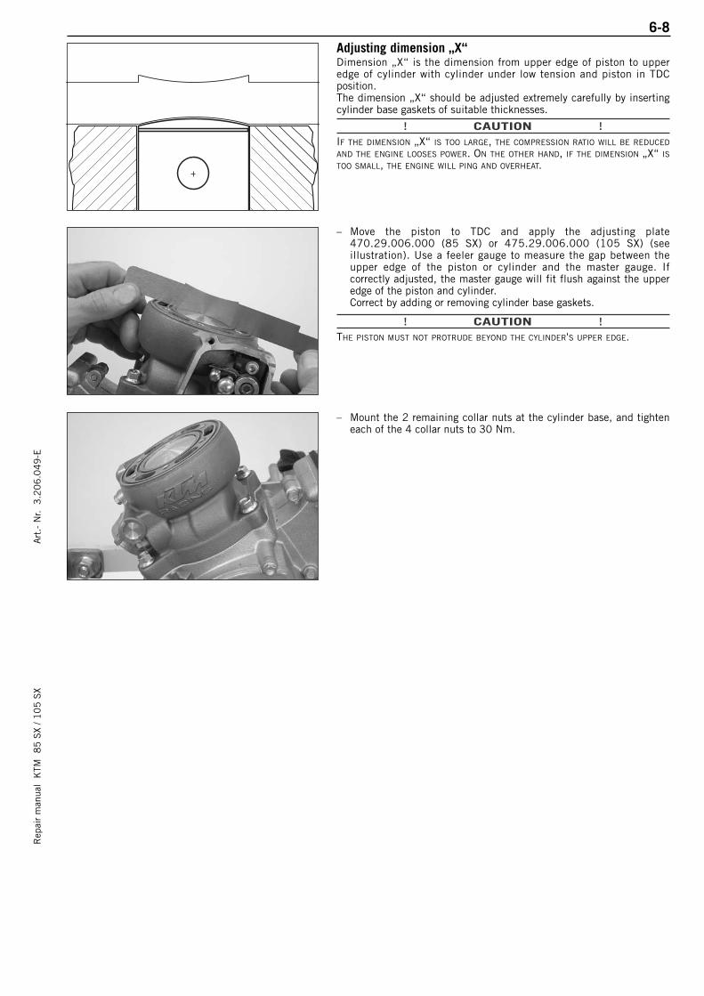
6-8R
epai
r m
anua
l K
TM 8
5 S
X / 1
05
SX
Art
.- N
r. 3
.20
6.0
49
-EAdjusting dimension „X“ Dimension „X“ is the dimension from upper edge of piston to upperedge of cylinder with cylinder under low tension and piston in TDCposition.The dimension „X“ should be adjusted extremely carefully by insertingcylinder base gaskets of suitable thicknesses.
! CAUTION !IF THE DIMENSION „X“ IS TOO LARGE, THE COMPRESSION RATIO WILL BE REDUCED
AND THE ENGINE LOOSES POWER. ON THE OTHER HAND, IF THE DIMENSION „X“ ISTOO SMALL, THE ENGINE WILL PING AND OVERHEAT.
– Move the piston to TDC and apply the adjusting plate470.29.006.000 (85 SX) or 475.29.006.000 (105 SX) (seeillustration). Use a feeler gauge to measure the gap between theupper edge of the piston or cylinder and the master gauge. Ifcorrectly adjusted, the master gauge will fit flush against the upperedge of the piston and cylinder.Correct by adding or removing cylinder base gaskets.
! CAUTION !THE PISTON MUST NOT PROTRUDE BEYOND THE CYLINDER'S UPPER EDGE.
– Mount the 2 remaining collar nuts at the cylinder base, and tighteneach of the 4 collar nuts to 30 Nm.

6-9Adjusting control flap (dimension “Z“)NOTE: Dimension “Z“ is the distance from the lower edge of thecontrol flap to the upper edge of the cylinder, as measured in thecentre of the exhaust port with the adjusting plate 470.29.006.000(85 SX) or 475.29.006.000 (105 SX).
85 SX: dimension „Z“ = 32 mm105 SX: dimension „Z“ = 31 mm
– Loosen the screw 1 on the stop plate and apply Loctite 243 to thethread. Mount the screw again but do not tighten yet.
– Fold the control flap up and hold the adjusting plate470.29.006.000 (85 SX) or 475.29.006.000 (105 SX) in thecylinder as shown in the drawing.
– Fold the control flap back down and up against the setting gauge.
– Turn the stop plate 2 until it rests against the edge of the stop 3.– Fix the stop plate by tightening the screw 1.– After the screw 1 is tightened, check dimension "Z" again and
correct if necessary.
– Press the control flap all the way down and press the ball socket 4onto the ball of the control lever.
NOTE: When you press on the ball socket, make sure there is no stresstowards the top or bottom.
– Adjust linkage length if necessary.– To do so, loosen counter nut 5 and turn ball socket accordingly.– Retighten counter nut.
– Mount the control cover 6 together with the gasket and fix with 3bolts.
controlflap
1
23
4
5
6

6-10R
epai
r m
anua
l K
TM 8
5 S
X / 1
05
SX
Art
.- N
r. 3
.20
6.0
49
-EMounting the ignition– Degrease the crankshaft and insert the woodruff key in the
crankshaft.– Fix the stator 1 with 3 collar bolts M5x16 but do not tighten yet.– Mount the cable guide in the housing opening.
– Mount the rotor on the crankshaft. Then mount the spring ring withthe hexagon nut.
– Insert the holding tool 546.29.012.000 2 into the two bores and tighten the hexagon nut with 60 Nm.
Adjusting the ignition– Set the piston to TDC and hold the adjusting plate 470.29.006.000
(85 SX) or 475.29.006.000 (105 SX) against the upper edge of thecylinder.
– Turn the rotor in a counterclockwise direction until the upper edgeof the piston rests against the setting gauge (see drawing).
– Now turn the stator until the two marks 3 coincide.
! CAUTION !BEFORE CHECKING THE IGNITION THE DIMENSION „X“ MUST BE ADJUSTED
CORRECTLY.
– Tighten the 3 collar bolts on the stator to 6 Nm.– Once again check the distance between the edge of the piston and
the upper edge of the cylinder using the adjusting plate. Ifnecessary readjust the distance by rotating the stator.
– Put on a new gasket, and fix the ignition cover by means of the 3bolts.
1
2
3

6-11Mounting cylinder head – Clean cylinder and cylinder head sealing surface, place O-rings in
grooves.– Mount cylinder head with water nozzle on the exhaust side.
– Oil the collar nuts 1 at threads and contact faces.– Mount the collar bolts with new copper gaskets and tighten them
crosswise, taking three turns to achieve the total tightening torque of10 Nm.
– In first stage, only tighten until slight resistance is felt.
Mounting the intake flange and reed valve housing– Mount a gasket and insert the reed valve housing in the intake port.– Tighten the intake flange to 6 Nm.
Mounting engine sprocket– Lubricate O-ring 2 with oil and slide over counter shaft.– Slide distance bushing 3 in position so that O-ring is in correct
position A.
– Mount the engine sprocket with the collar facing inwards on thecountershaft and fix with circlip 4.
1
23 A
4
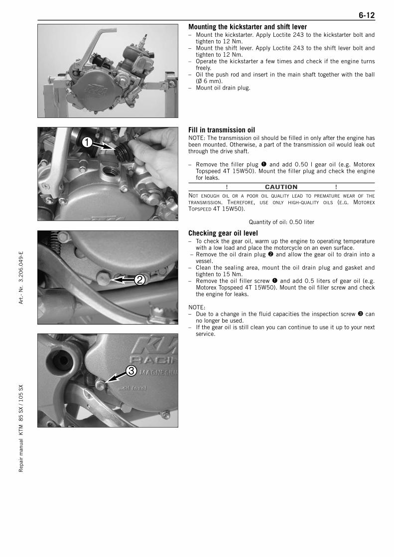
6-12R
epai
r m
anua
l K
TM 8
5 S
X / 1
05
SX
Art
.- N
r. 3
.20
6.0
49
-EMounting the kickstarter and shift lever– Mount the kickstarter. Apply Loctite 243 to the kickstarter bolt and
tighten to 12 Nm.– Mount the shift lever. Apply Loctite 243 to the shift lever bolt and
tighten to 12 Nm.– Operate the kickstarter a few times and check if the engine turns
freely.– Oil the push rod and insert in the main shaft together with the ball
(Ø 6 mm).– Mount oil drain plug.
Fill in transmission oilNOTE: The transmission oil should be filled in only after the engine hasbeen mounted. Otherwise, a part of the transmission oil would leak outthrough the drive shaft.
– Remove the filler plug 1 and add 0.50 l gear oil (e.g. MotorexTopspeed 4T 15W50). Mount the filler plug and check the enginefor leaks.
! CAUTION !NOT ENOUGH OIL OR A POOR OIL QUALITY LEAD TO PREMATURE WEAR OF THE
TRANSMISSION. THEREFORE, USE ONLY HIGH-QUALITY OILS (E.G. MOTOREX
TOPSPEED 4T 15W50).
Quantity of oil: 0.50 liter
Checking gear oil level– To check the gear oil, warm up the engine to operating temperature
with a low load and place the motorcycle on an even surface.– Remove the oil drain plug 2 and allow the gear oil to drain into a
vessel.– Clean the sealing area, mount the oil drain plug and gasket and
tighten to 15 Nm. – Remove the oil filler screw 1 and add 0.5 liters of gear oil (e.g.
Motorex Topspeed 4T 15W50). Mount the oil filler screw and checkthe engine for leaks.
NOTE:– Due to a change in the fluid capacities the inspection screw 3 can
no longer be used.– If the gear oil is still clean you can continue to use it up to your next
service.
1
2
3
ELECTRICAL
Rep
air
man
ual
KTM
8
5 S
X / 1
05
SX
Art
.- N
r. 3
.20
6.0
49
-E
RESISTOR VALUES OF THE IGNITION SYSTEM - STATOR . . . . . . . . . . . . . . . . . . .7-2
IGNITION COIL . . . . . . . . . . . . . . . . . . . . . . . . . . . . . . . . . . . . . . . . . . . . . . . . .7-2
MEASURING STATIC IGNITION VALUES WITH PEAK VOLTAGE ADAPTER . . . . . . . .7-3
SPARK PLUG . . . . . . . . . . . . . . . . . . . . . . . . . . . . . . . . . . . . . . . . . . . . . . . . . .7-3
INDEX
7-1
7
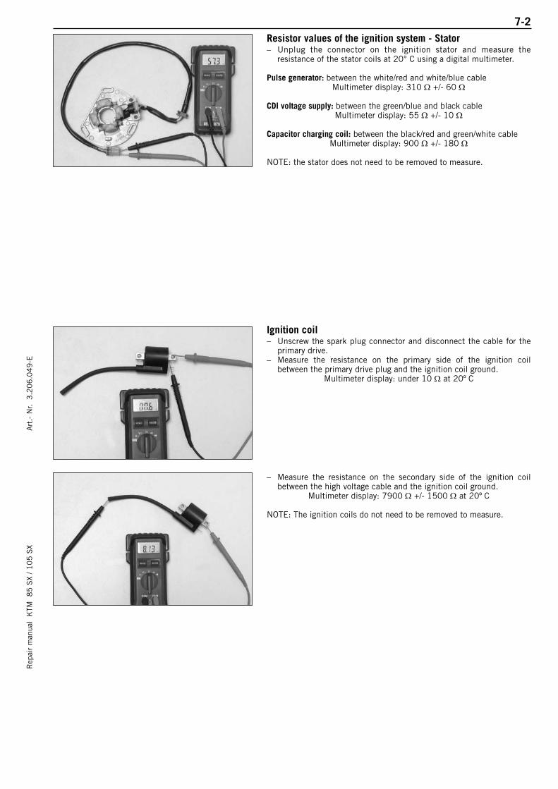
7-2R
epai
r m
anua
l K
TM 8
5 S
X / 1
05
SX
Art
.- N
r. 3
.20
6.0
49
-EResistor values of the ignition system - Stator– Unplug the connector on the ignition stator and measure the
resistance of the stator coils at 20° C using a digital multimeter.
Pulse generator: between the white/red and white/blue cableMultimeter display: 310 Ω +/- 60 Ω
CDI voltage supply: between the green/blue and black cableMultimeter display: 55 Ω +/- 10 Ω
Capacitor charging coil: between the black/red and green/white cableMultimeter display: 900 Ω +/- 180 Ω
NOTE: the stator does not need to be removed to measure.
Ignition coil– Unscrew the spark plug connector and disconnect the cable for the
primary drive.– Measure the resistance on the primary side of the ignition coil
between the primary drive plug and the ignition coil ground.Multimeter display: under 10 Ω at 20º C
– Measure the resistance on the secondary side of the ignition coil between the high voltage cable and the ignition coil ground.
Multimeter display: 7900 Ω +/- 1500 Ω at 20º C
NOTE: The ignition coils do not need to be removed to measure.
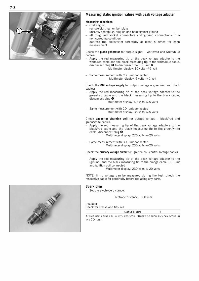
7-3
Measuring static ignition values with peak voltage adapter
Measuring conditions:– cold engine – remove starting number plate– unscrew sparkplug, plug on and hold against ground – all plug and socket connectors and ground connections in a
non-corroding condition– depress the kickstarter forcefully at least 5 times for each
measurement
Check the pulse generator for output signal – white/red and white/bluecables:– Apply the red measuring tip of the peak voltage adapter to the
white/red cable and the black measuring tip to the white/blue cable,disconnect plug 1 to disconnect the CDI unit 2
Multimeter display: 10 volts +/-1 volt
– Same measurement with CDI unit connectedMultimeter display: 6 volts +/-1 volt
Check the CDI voltage supply for output voltage – green/red and blackcables:– Apply the red measuring tip of the peak voltage adapter to the
green/red cable and the black measuring tip to the black cable,disconnect plug 1
Multimeter display: 40 volts +/-5 volts
– Same measurement with CDI unit connectedMultimeter display: 35 volts +/-5 volts
Check capacitor charging coil for output voltage – black/red andgreen/white cables:– Apply the red measuring tip of the peak voltage adapters to the
black/red cable and the black measuring tip to the green/whitecable, disconnect plug 1
Multimeter display: 270 volts +/-20 volts
– Same measurement with CDI unit connectedMultimeter display: 230 volts +/-20 volts
Check the primary voltage output for ignition coil control (orange cable):
– Apply the red measuring tip of the peak voltage adapter to the (ground) and the black measuring tip to the orange cable, CDI unitand ignition coil connected
Multimeter display: 230 volts +/-20 volts
NOTE: If no voltage can be measured during the test, check the respective cable for continuity before replacing any parts.
Spark plug– Set the electrode distance.
Electrode distance: 0.60 mm
InsulatorCheck for cracks and fissures.
! CAUTION !ALWAYS USE A SPARK PLUG WITH RESISTOR. OTHERWISE PROBLEMS CAN OCCUR IN
THE CDI UNIT.
1
2
Rep
air
man
ual
KTM
8
5 S
X / 1
05
SX
Art
.- N
r. 3
.20
6.0
49
-E8-1
TROUBLE SHOOTING
TROUBLE SHOOTING 85 SX / 105 SX . . . . . . . . . . . . . . . . . . . . . . . . . . . . . . . .8-2
INDEX
8

Rep
air
man
ual
KTM
8
5 S
X / 1
05
SX
Art
.- N
r. 3
.20
6.0
49
-E8-2
TROUBLE SHOOTING
If you let the specified maintenance work on your motorcycle be carried out, disturbances can hardly be expected.Should an error occur nevertheless, we advise you to use the trouble shooting chart in order to find the cause oferror.
TROUBLE CAUSE REMEDYEngine fails to start Operating error
The motorcycle was not drivenfor a longer period of time, leaving old fuel in the float chamber
Fuel supply interrupted
Electrode distance too great
Plug fouled by oil, wet or bridged
Ignition wire or spark plug con-nector damaged
Kill button wire or short-circuitswitch faulty
Loose ignition cable connec-tors
Spark too weak
Water in the carburetor and jetsblocked
Open fuel tap, replenish fuel, do not use choke
The highly inflammable components in modern fuels volatilize ifleft standing for longer periods of time. If the motorcycle has notbeen used for over 1 week, the fuel should be drained from thefloat chamber. The engine will start up immediately if the floatchamber is filled with fresh, ignitable fuel
Close fuel tap, loosen fuel hose at carburettor, lead into a basinand open fuel tap,– if fuel leaks out, clean carburettor– if no fuel leaks out, check tank ventilation, i.e. clean fuel tap
Reduce electrode distance (0.60 mm)
Clean spark plug or renew
Dismount spark plug, connect ignition cable, hold to ground (blankplace on engine) and actuate kickstarter, a strong spark must beproduced at the spark plug– If no spark is produced, loosen spark plug cap from ignition
cable, hold about 5 mm from ground and actuate kickstarter– If a spark now occurs, replace spark plug cap– If no spark is produced, control ignition system
Disconnect black coloured cable from short circuit button at ignition coil and check ignition spark. If the spark is O.K. repairdefective part of cable or ignition switch
Inspect cable connectors
Examine ignition system
Dismantle and clean carburetor
Engine without idle running Idle adjusting screw out of adjustment
Ignition system damaged
Wear
Readjust idle running or replace idle adjusting screw
Examine ignition system
Overhaul engine
Engine has not enough power Charred glass fiber yarn insilencer
Air filter obstructed
Fuel supply partly interruptedor blocked
Loss of compression throughloose spark plug
Exhaust system damaged
Engine has not enough preigni-tion
Renew filling
Clean or renew airfilter
Blow through fuel pipe and clean carburetor
Tighten spark plug
Check exhaust system for damage
Check and adjust ignition
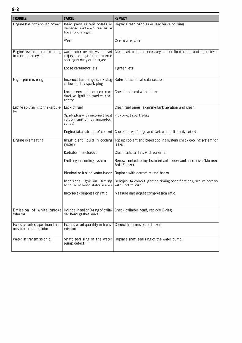
8-3
TROUBLE CAUSE REMEDY
Engine has not enough power Reed paddles tensionless ordamaged, surface of reed valvehousing damaged
Wear
Replace reed paddles or reed valve housing
Overhaul engine
Engine revs not up and runningin four stroke cycle
Carburetor overflows if leveladjust too high, float needleseating is dirty or enlarged
Loose carburetor jets
Clean carburetor, if necessary replace float needle and adjust level
Tighten jets
High rpm misfiring Incorrect heat range spark plugor low quality spark plug
Loose, corroded or non con-ductive ignition socket con-nector
Refer to technical data section
Check and seal with silicon
Engine spluters into the carbure-tor
Lack of fuel
Spark plug with incorrect heatvalue (Ignition by incandes-cence)
Engine takes air out of control
Clean fuel pipes, examine tank aeration and clean
Fit correct spark plug
Check intake flange and carburettor if firmly setted
Engine overheating Insufficient liquid in cooling system
Radiator fins clogged
Frothing in cooling system
Pinched or kinked water hoses
Incorrect ignition timingbecause of loose stator screws
Incorrect compression ratio
Top up coolant and bleed cooling system check cooling system forleaks
Clean radiatar fins with water jet
Renew coolant using branded anti-freeze/anti-corrosive (MotorexAnti-Freeze)
Replace with correct routed hoses
Readjust to correct ignition timing specifications, secure screwswith Loctite 243
Measure and adjust compression ratio
Emission of white smoke(steam)
Cylinder head or O-ring of cylin-der head gasket leaks
Check cylinder head, replace O-ring
Excessive oil escapes from trans-mission breather tube
Excessive oil quantity in trans-mission
Correct transmission oil level
Water in transmission oil Shaft seal ring of the waterpump defect
Replace shaft seal ring of the water pump.

Rep
air
man
ual
KTM
8
5 S
X / 1
05
SX
Art
.- N
r. 3
.20
6.0
49
-E9-1
TECHNICAL SPECIFICATIONS
85 SX MODEL 2004
ENGINE . . . . . . . . . . . . . . . . . . . . . . . . . . . . . . . . . . . . . . . . . . . . . . . . . . . . . .9-2
CARBURETOR . . . . . . . . . . . . . . . . . . . . . . . . . . . . . . . . . . . . . . . . . . . . . . . . .9-2
CHASSIS . . . . . . . . . . . . . . . . . . . . . . . . . . . . . . . . . . . . . . . . . . . . . . . . . . . .9-3
STANDARD ADJUSTMENT SHOCK ABSORBER / FORK . . . . . . . . . . . . . . . . . . . . .9-3
105 SX MODEL 2004
ENGINE . . . . . . . . . . . . . . . . . . . . . . . . . . . . . . . . . . . . . . . . . . . . . . . . . . . . . .9-4
CARBURETOR . . . . . . . . . . . . . . . . . . . . . . . . . . . . . . . . . . . . . . . . . . . . . . . . .9-4
CHASSIS . . . . . . . . . . . . . . . . . . . . . . . . . . . . . . . . . . . . . . . . . . . . . . . . . . . .9-5
STANDARD ADJUSTMENT SHOCK ABSORBER / FORK . . . . . . . . . . . . . . . . . . . . .9-5
85 SX MODEL 2005
ENGINE . . . . . . . . . . . . . . . . . . . . . . . . . . . . . . . . . . . . . . . . . . . . . . . . . . . . . .9-6
CARBURETOR . . . . . . . . . . . . . . . . . . . . . . . . . . . . . . . . . . . . . . . . . . . . . . . . .9-6
CHASSIS . . . . . . . . . . . . . . . . . . . . . . . . . . . . . . . . . . . . . . . . . . . . . . . . . . . .9-7
STANDARD ADJUSTMENT SHOCK ABSORBER / FORK . . . . . . . . . . . . . . . . . . . . .9-7
85 / 105 SX MODEL 2006
ENGINE . . . . . . . . . . . . . . . . . . . . . . . . . . . . . . . . . . . . . . . . . . . . . . . . . . . . . .9-6
CARBURETOR . . . . . . . . . . . . . . . . . . . . . . . . . . . . . . . . . . . . . . . . . . . . . . . . .9-6
CHASSIS . . . . . . . . . . . . . . . . . . . . . . . . . . . . . . . . . . . . . . . . . . . . . . . . . . . .9-8
STANDARD ADJUSTMENT SHOCK ABSORBER / FORK . . . . . . . . . . . . . . . . . . . . .9-8
85 / 105 SX MODEL 2007
ENGINE . . . . . . . . . . . . . . . . . . . . . . . . . . . . . . . . . . . . . . . . . . . . . . . . . . . . . .9-9
CARBURETOR . . . . . . . . . . . . . . . . . . . . . . . . . . . . . . . . . . . . . . . . . . . . . . . . .9-9
CHASSIS . . . . . . . . . . . . . . . . . . . . . . . . . . . . . . . . . . . . . . . . . . . . . . . . . . .9-10
STANDARD ADJUSTMENT SHOCK ABSORBER / FORK . . . . . . . . . . . . . . . . . . . .9-10
9
INDEX
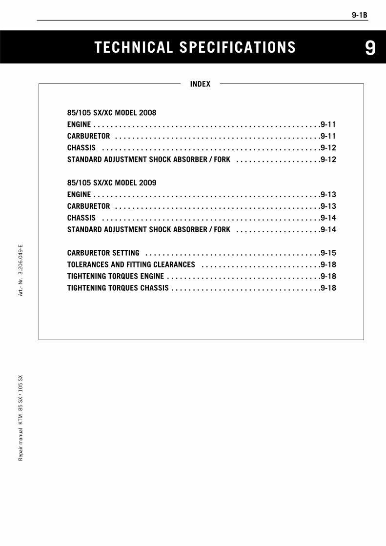
TECHNICAL SPECIFICATIONS
Rep
air
man
ual
KTM
8
5 S
X / 1
05
SX
Art
.- N
r. 3
.20
6.0
49
-E
85/105 SX/XC MODEL 2008
ENGINE . . . . . . . . . . . . . . . . . . . . . . . . . . . . . . . . . . . . . . . . . . . . . . . . . . . . .9-11
CARBURETOR . . . . . . . . . . . . . . . . . . . . . . . . . . . . . . . . . . . . . . . . . . . . . . . .9-11
CHASSIS . . . . . . . . . . . . . . . . . . . . . . . . . . . . . . . . . . . . . . . . . . . . . . . . . . .9-12
STANDARD ADJUSTMENT SHOCK ABSORBER / FORK . . . . . . . . . . . . . . . . . . . .9-12
85/105 SX/XC MODEL 2009
ENGINE . . . . . . . . . . . . . . . . . . . . . . . . . . . . . . . . . . . . . . . . . . . . . . . . . . . . .9-13
CARBURETOR . . . . . . . . . . . . . . . . . . . . . . . . . . . . . . . . . . . . . . . . . . . . . . . .9-13
CHASSIS . . . . . . . . . . . . . . . . . . . . . . . . . . . . . . . . . . . . . . . . . . . . . . . . . . .9-14
STANDARD ADJUSTMENT SHOCK ABSORBER / FORK . . . . . . . . . . . . . . . . . . . .9-14
CARBURETOR SETTING . . . . . . . . . . . . . . . . . . . . . . . . . . . . . . . . . . . . . . . . .9-15
TOLERANCES AND FITTING CLEARANCES . . . . . . . . . . . . . . . . . . . . . . . . . . . .9-18
TIGHTENING TORQUES ENGINE . . . . . . . . . . . . . . . . . . . . . . . . . . . . . . . . . . . .9-18
TIGHTENING TORQUES CHASSIS . . . . . . . . . . . . . . . . . . . . . . . . . . . . . . . . . . .9-18
INDEX
9-1B
9
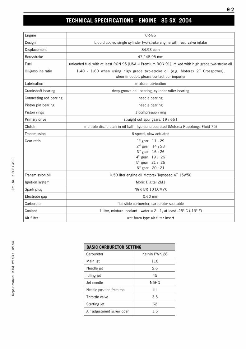
9-2R
epai
r m
anua
l K
TM 8
5 S
X / 1
05
SX
Art
.- N
r. 3
.20
6.0
49
-E
Engine CR-85
Design Liquid cooled single cylinder two-stroke engine with reed valve intake
Displacement 84.93 ccm
Bore/stroke 47 / 48.95 mm
Fuel unleaded fuel with at least RON 95 (USA = Premium RON 91), mixed with high grade two-stroke oil
Oil/gasoline ratio 1:40 - 1:60 when using high grade two-stroke oil (e.g. Motorex 2T Crosspower), when in doubt, please contact our importer
Lubrication mixture lubrication
Crankshaft bearing deep-groove ball bearing, cylinder roller bearing
Connecting rod bearing needle bearing
Piston pin bearing needle bearing
Piston rings 1 compression ring
Primary drive straight cut spur gears, 19 : 66 t
Clutch multiple disc clutch in oil bath, hydraulic operated (Motorex Kupplungs-Fluid 75)
Transmission 6 speed, claw actuated
Gear ratio 1st gear 11 : 292nd gear 14 : 283rd gear 16 : 264th gear 19 : 265th gear 21 : 256th gear 20 : 21
Transmission oil 0.50 liter engine oil Motorex Topspeed 4T 15W50
Ignition system Moric Digital 2M1
Spark plug NGK BR 10 ECMVX
Electrode gap 0.60 mm
Carburetor flat-slide carburetor, carburetor see table
Coolant 1 liter, mixture coolant : water = 2 : 1, at least -25° C (-13° F)
Air filter wet foam type air filter insert
TECHNICAL SPECIFICATIONS - ENGINE 85 SX 2004
Carburetor Keihin PWK 28
Main jet 118
Needle jet 2.6
Idling jet 45
Jet needle N5HG
Needle position from top III
Throttle valve 3.5
Starting jet 62
Air adjustment screw open 1.5
BASIC CARBURETOR SETTING
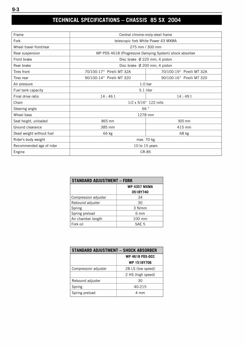
9-3
Frame Central chrome-moly-steel frame
Fork telescopic fork White Power 43 MXMA
Wheel travel front/rear 275 mm / 300 mm
Rear suspension WP PDS 4618 (Progressive Damping System) shock absorber
Front brake Disc brake Ø 220 mm, 4 piston
Rear brake Disc brake Ø 200 mm, 4 piston
Tires front 70/100-17“ Pirelli MT 32A 70/100-19“ Pirelli MT 32A
Tires rear 90/100-14“ Pirelli MT 320 90/100-16“ Pirelli MT 320
Air pressure 1.0 bar
Fuel tank capacity 5.1 liter
Final drive ratio 14 : 46 t 14 : 49 t
Chain 1/2 x 5/16" 122 rolls
Steering angle 66 °
Wheel base 1278 mm
Seat height, unloaded 865 mm 900 mm
Ground clearance 385 mm 415 mm
Dead weight without fuel 66 kg 68 kg
Rider’s body weight max. 70 kg
Recommended age of rider 10 to 15 years
Engine CR-85
TECHNICAL SPECIFICATIONS – CHASSIS 85 SX 2004
WP 4618 PDS-DCC
WP 1518Y706
Compression adjuster 28 LS (low speed)
2 HS (high speed)
Rebound adjuster 30
Spring 40-215
Spring preload 4 mm
STANDARD ADJUSTMENT – SHOCK ABSORBER
WP 4357 MXMA0518Y740
Compression adjuster 34Rebound adjuster 30Spring 3 N/mmSpring preload 6 mmAir chamber length 100 mmFork oil SAE 5
STANDARD ADJUSTMENT – FORK
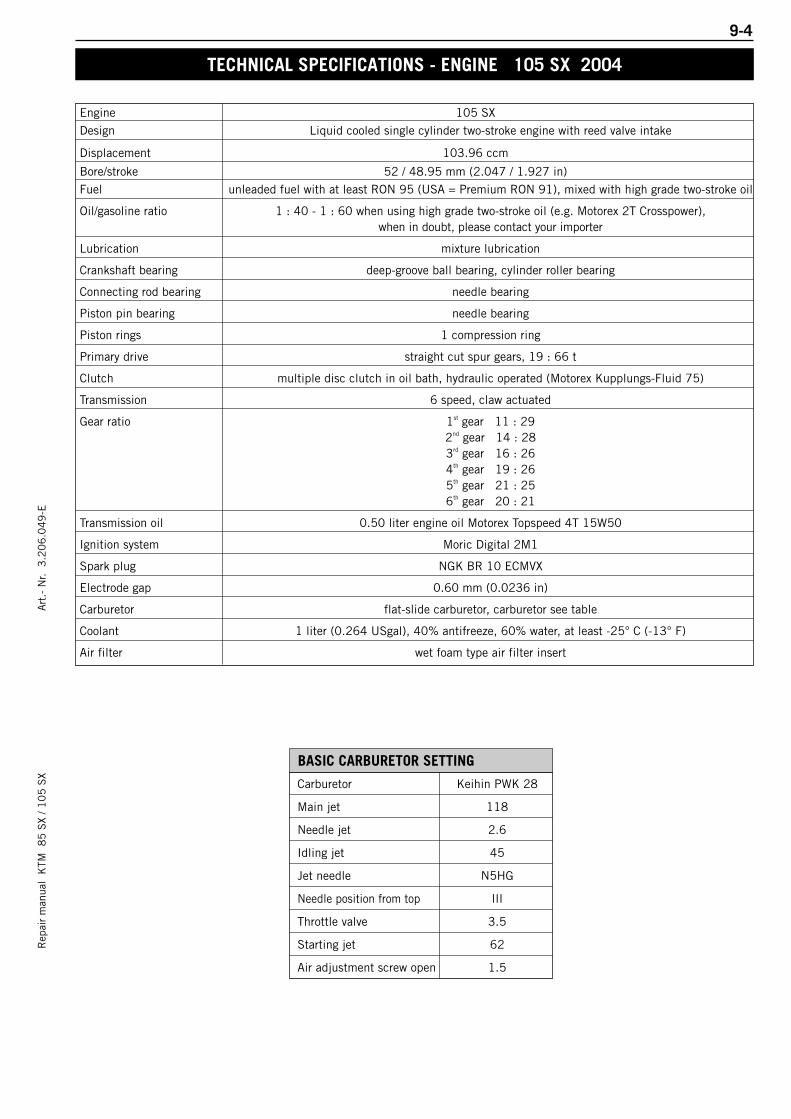
9-4R
epai
r m
anua
l K
TM 8
5 S
X / 1
05
SX
Art
.- N
r. 3
.20
6.0
49
-E
TECHNICAL SPECIFICATIONS - ENGINE 105 SX 2004
Engine 105 SX
Design Liquid cooled single cylinder two-stroke engine with reed valve intake
Displacement 103.96 ccm
Bore/stroke 52 / 48.95 mm (2.047 / 1.927 in)
Fuel unleaded fuel with at least RON 95 (USA = Premium RON 91), mixed with high grade two-stroke oil
Oil/gasoline ratio 1 : 40 - 1 : 60 when using high grade two-stroke oil (e.g. Motorex 2T Crosspower),when in doubt, please contact your importer
Lubrication mixture lubrication
Crankshaft bearing deep-groove ball bearing, cylinder roller bearing
Connecting rod bearing needle bearing
Piston pin bearing needle bearing
Piston rings 1 compression ring
Primary drive straight cut spur gears, 19 : 66 t
Clutch multiple disc clutch in oil bath, hydraulic operated (Motorex Kupplungs-Fluid 75)
Transmission 6 speed, claw actuated
Gear ratio 1st gear 11 : 292nd gear 14 : 283rd gear 16 : 264th gear 19 : 265th gear 21 : 256th gear 20 : 21
Transmission oil 0.50 liter engine oil Motorex Topspeed 4T 15W50
Ignition system Moric Digital 2M1
Spark plug NGK BR 10 ECMVX
Electrode gap 0.60 mm (0.0236 in)
Carburetor flat-slide carburetor, carburetor see table
Coolant 1 liter (0.264 USgal), 40% antifreeze, 60% water, at least -25° C (-13° F)
Air filter wet foam type air filter insert
Carburetor Keihin PWK 28
Main jet 118
Needle jet 2.6
Idling jet 45
Jet needle N5HG
Needle position from top III
Throttle valve 3.5
Starting jet 62
Air adjustment screw open 1.5
BASIC CARBURETOR SETTING
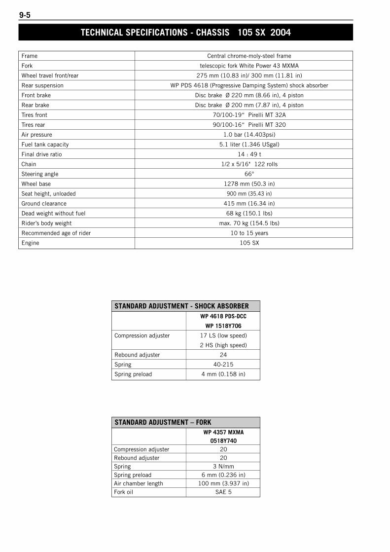
9-5
TECHNICAL SPECIFICATIONS - CHASSIS 105 SX 2004
Frame Central chrome-moly-steel frame
Fork telescopic fork White Power 43 MXMA
Wheel travel front/rear 275 mm (10.83 in)/ 300 mm (11.81 in)
Rear suspension WP PDS 4618 (Progressive Damping System) shock absorber
Front brake Disc brake Ø 220 mm (8.66 in), 4 piston
Rear brake Disc brake Ø 200 mm (7.87 in), 4 piston
Tires front 70/100-19“ Pirelli MT 32A
Tires rear 90/100-16“ Pirelli MT 320
Air pressure 1.0 bar (14.403psi)
Fuel tank capacity 5.1 liter (1.346 USgal)
Final drive ratio 14 : 49 t
Chain 1/2 x 5/16" 122 rolls
Steering angle 66°
Wheel base 1278 mm (50.3 in)
Seat height, unloaded 900 mm (35.43 in)
Ground clearance 415 mm (16.34 in)
Dead weight without fuel 68 kg (150.1 lbs)
Rider’s body weight max. 70 kg (154.5 lbs)
Recommended age of rider 10 to 15 years
Engine 105 SX
WP 4618 PDS-DCC
WP 1518Y706
Compression adjuster 17 LS (low speed)
2 HS (high speed)
Rebound adjuster 24
Spring 40-215
Spring preload 4 mm (0.158 in)
STANDARD ADJUSTMENT - SHOCK ABSORBER
WP 4357 MXMA0518Y740
Compression adjuster 20Rebound adjuster 20Spring 3 N/mmSpring preload 6 mm (0.236 in)Air chamber length 100 mm (3.937 in)Fork oil SAE 5
STANDARD ADJUSTMENT – FORK

9-6R
epai
r m
anua
l K
TM 8
5 S
X / 1
05
SX
Art
.- N
r. 3
.20
6.0
49
-E
Engine 85 SX 2005 / 2006 105 SX 2006
Design Liquid cooled single cylinder two-stroke engine with reed valve intake
Displacement 84.93 ccm 103.96 ccm
Bore/stroke 47 / 48.95 mm 52 / 48.95 mm
Fuel unleaded fuel with at least RON 95 (USA = Premium PON 91), mixed with high grade two-stroke oil
Oil/gasoline ratio1 : 40 - 1 : 60 when using high grade two-stroke oil (e.g. Motorex 2T Crosspower),
when in doubt, please contact your importer
Lubrication mixture lubrication
Crankshaft bearing deep-groove ball bearing, cylinder roller bearing
Connecting rod bearing needle bearing
Piston pin bearing needle bearing
Piston rings 1 compression ring
Primary drive straight cut spur gears, 19 : 66 t
Clutch multiple disc clutch in oil bath, hydraulic operated (Motorex Kupplungs-Fluid 75)
Transmission 6 speed, claw actuated
Gear ratio
1st gear 11 : 292nd gear 14 : 283rd gear 16 : 264th gear 19 : 265th gear 21 : 256th gear 20 : 21
Transmission oil 0.5 liter engine oil Motorex Topspeed 4T 15W50
Ignition system Moric Digital 2M1
Spark plug NGK BR 10 ECMVX
Electrode gap 0.60 mm
Carburetor flat-slide carburetor, carburetor see table
Coolant 1 liter, mixture 50% antifreeze, 50% pure water, at least –25° C (-13° F)
Air filter wet foam type air filter insert
BASIC CARBURETOR SETTING
Carburetor Keihin PWK 28
Main jet 118
Needle jet 2.6
Idling jet 45
Jet needle N5HG
Needle position from top III
Throttle valve 3.5
Starting jet 62
Air adjustment screw open 1,5
TECHNICAL SPECIFICATIONS – ENGINE 85 SX 2005 / 2006 + 105 SX 2006
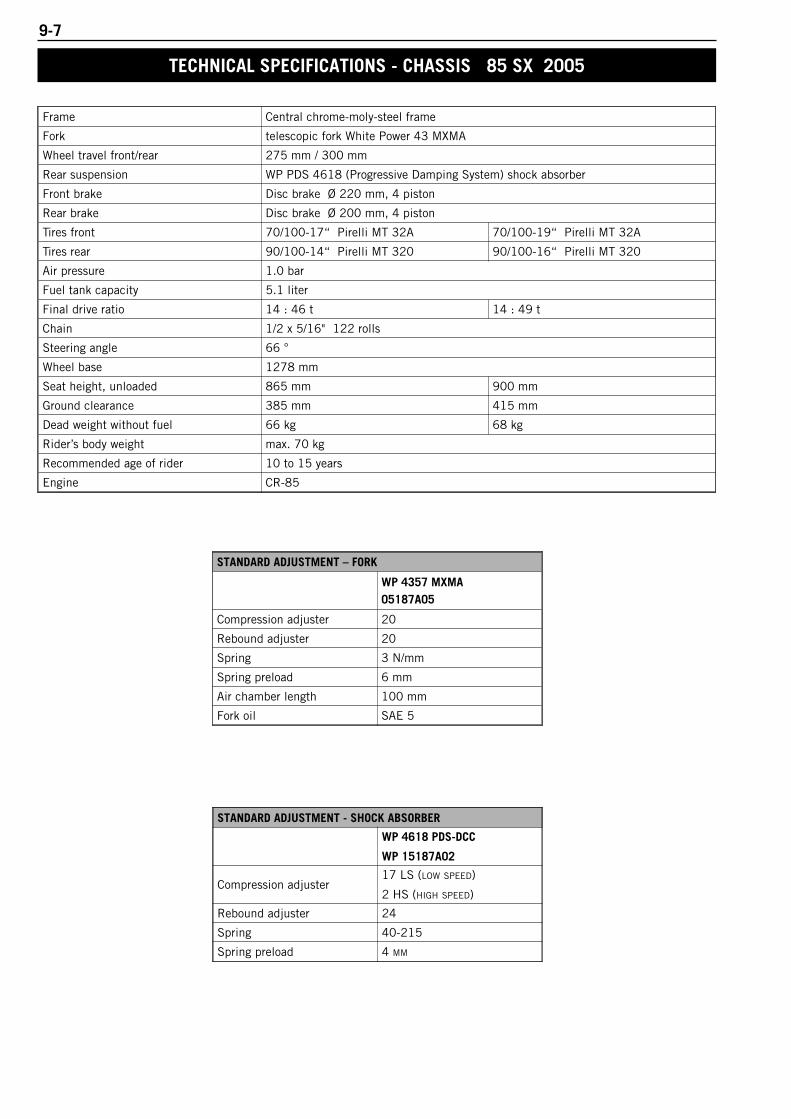
9-7
Frame Central chrome-moly-steel frame
Fork telescopic fork White Power 43 MXMA
Wheel travel front/rear 275 mm / 300 mm
Rear suspension WP PDS 4618 (Progressive Damping System) shock absorber
Front brake Disc brake Ø 220 mm, 4 piston
Rear brake Disc brake Ø 200 mm, 4 piston
Tires front 70/100-17“ Pirelli MT 32A 70/100-19“ Pirelli MT 32A
Tires rear 90/100-14“ Pirelli MT 320 90/100-16“ Pirelli MT 320
Air pressure 1.0 bar
Fuel tank capacity 5.1 liter
Final drive ratio 14 : 46 t 14 : 49 t
Chain 1/2 x 5/16" 122 rolls
Steering angle 66 °
Wheel base 1278 mm
Seat height, unloaded 865 mm 900 mm
Ground clearance 385 mm 415 mm
Dead weight without fuel 66 kg 68 kg
Rider’s body weight max. 70 kg
Recommended age of rider 10 to 15 years
Engine CR-85
STANDARD ADJUSTMENT – FORK
WP 4357 MXMA05187A05
Compression adjuster 20
Rebound adjuster 20
Spring 3 N/mm
Spring preload 6 mm
Air chamber length 100 mm
Fork oil SAE 5
STANDARD ADJUSTMENT - SHOCK ABSORBER
WP 4618 PDS-DCC
WP 15187A02
Compression adjuster17 LS (LOW SPEED)
2 HS (HIGH SPEED)
Rebound adjuster 24
Spring 40-215
Spring preload 4 MM
TECHNICAL SPECIFICATIONS - CHASSIS 85 SX 2005

9-8R
epai
r m
anua
l K
TM 8
5 S
X / 1
05
SX
Art
.- N
r. 3
.20
6.0
49
-E
85 SX (17”/14”) 85 / 105 SX (19”/16”)
Frame Central chrome-moly-steel frame
Fork telescopic fork WP Suspension 43 MXMA
Wheel travel front/rear 275 mm / 300 mm
Rear suspension WP PDS 4618 (Progressive Damping System) shock absorber
Front brake Disc brake Ø 220 mm, 4 piston
Rear brake Disc brake Ø 200 mm, 4 piston
Tires front 70/100-17“ Pirelli MT 32A 70/100-19“ Pirelli MT 32A
Tires rear 90/100-14“ Pirelli MT 320 90/100-16“ Pirelli MT 320
Air pressure 1.0 bar
Fuel tank capacity 5.1 liter
Final drive ratio 14 : 46 t 14 : 49 t
Chain 1/2 x 5/16" 122 rolls
Steering angle 66 °
Wheel base 1290 mm
Seat height, unloaded 865 mm 900 mm
Ground clearance 385 mm 415 mm
Dead weight without fuel 66 kg 68 kg
Rider’s body weight max. 75 kg
Recommended age of rider 10 to 15 years
STANDARD ADJUSTMENT – FORK
WP 4357 MXMA05.18.7B.05
Compression adjuster 20
Rebound adjuster 20
Spring 3 N/mm
Spring preload 3 mm
Air chamber length 110 mm
Fork oil SAE 5
STANDARD ADJUSTMENT - SHOCK ABSORBER
WP 4618 PDS-DCC
WP 15.18.7B.02
Compression adjuster15 LS (LOW SPEED)
2 HS (HIGH SPEED)
Rebound adjuster 22
Spring 35-215
Spring preload 4 mm
TECHNICAL SPECIFICATIONS - CHASSIS 85 / 105 SX 2006
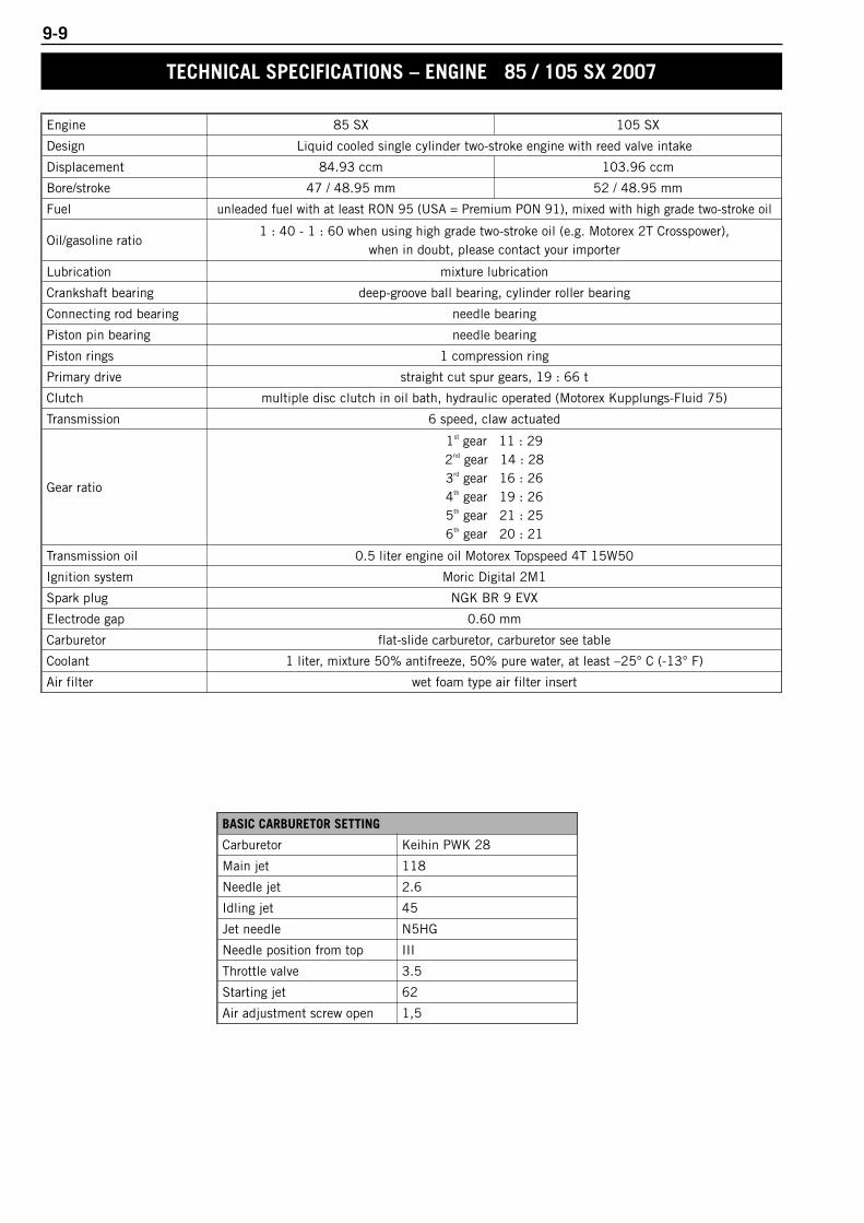
9-9
Engine 85 SX 105 SX
Design Liquid cooled single cylinder two-stroke engine with reed valve intake
Displacement 84.93 ccm 103.96 ccm
Bore/stroke 47 / 48.95 mm 52 / 48.95 mm
Fuel unleaded fuel with at least RON 95 (USA = Premium PON 91), mixed with high grade two-stroke oil
Oil/gasoline ratio1 : 40 - 1 : 60 when using high grade two-stroke oil (e.g. Motorex 2T Crosspower),
when in doubt, please contact your importer
Lubrication mixture lubrication
Crankshaft bearing deep-groove ball bearing, cylinder roller bearing
Connecting rod bearing needle bearing
Piston pin bearing needle bearing
Piston rings 1 compression ring
Primary drive straight cut spur gears, 19 : 66 t
Clutch multiple disc clutch in oil bath, hydraulic operated (Motorex Kupplungs-Fluid 75)
Transmission 6 speed, claw actuated
Gear ratio
1st gear 11 : 292nd gear 14 : 283rd gear 16 : 264th gear 19 : 265th gear 21 : 256th gear 20 : 21
Transmission oil 0.5 liter engine oil Motorex Topspeed 4T 15W50
Ignition system Moric Digital 2M1
Spark plug NGK BR 9 EVX
Electrode gap 0.60 mm
Carburetor flat-slide carburetor, carburetor see table
Coolant 1 liter, mixture 50% antifreeze, 50% pure water, at least –25° C (-13° F)
Air filter wet foam type air filter insert
BASIC CARBURETOR SETTING
Carburetor Keihin PWK 28
Main jet 118
Needle jet 2.6
Idling jet 45
Jet needle N5HG
Needle position from top III
Throttle valve 3.5
Starting jet 62
Air adjustment screw open 1,5
TECHNICAL SPECIFICATIONS – ENGINE 85 / 105 SX 2007
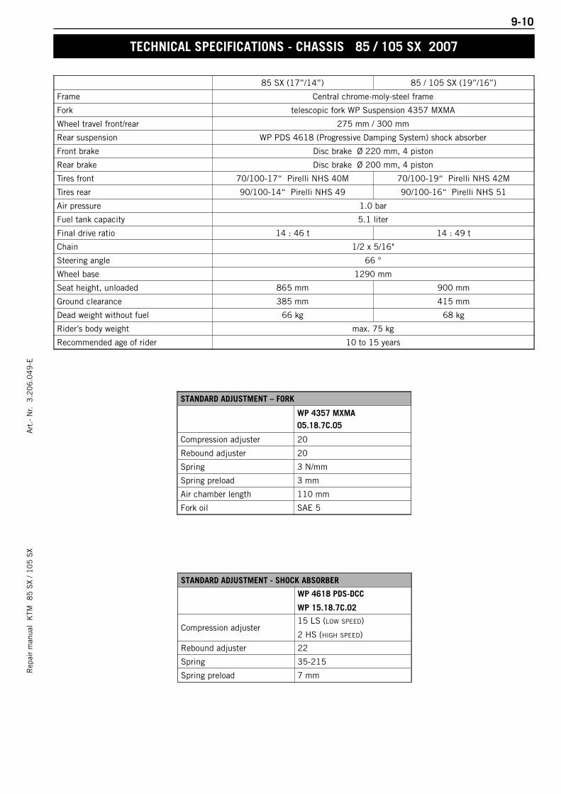
9-10R
epai
r m
anua
l K
TM 8
5 S
X / 1
05
SX
Art
.- N
r. 3
.20
6.0
49
-E
85 SX (17”/14”) 85 / 105 SX (19”/16”)
Frame Central chrome-moly-steel frame
Fork telescopic fork WP Suspension 4357 MXMA
Wheel travel front/rear 275 mm / 300 mm
Rear suspension WP PDS 4618 (Progressive Damping System) shock absorber
Front brake Disc brake Ø 220 mm, 4 piston
Rear brake Disc brake Ø 200 mm, 4 piston
Tires front 70/100-17“ Pirelli NHS 40M 70/100-19“ Pirelli NHS 42M
Tires rear 90/100-14“ Pirelli NHS 49 90/100-16“ Pirelli NHS 51
Air pressure 1.0 bar
Fuel tank capacity 5.1 liter
Final drive ratio 14 : 46 t 14 : 49 t
Chain 1/2 x 5/16"
Steering angle 66 °
Wheel base 1290 mm
Seat height, unloaded 865 mm 900 mm
Ground clearance 385 mm 415 mm
Dead weight without fuel 66 kg 68 kg
Rider’s body weight max. 75 kg
Recommended age of rider 10 to 15 years
STANDARD ADJUSTMENT – FORK
WP 4357 MXMA05.18.7C.05
Compression adjuster 20
Rebound adjuster 20
Spring 3 N/mm
Spring preload 3 mm
Air chamber length 110 mm
Fork oil SAE 5
STANDARD ADJUSTMENT - SHOCK ABSORBER
WP 4618 PDS-DCC
WP 15.18.7C.02
Compression adjuster15 LS (LOW SPEED)
2 HS (HIGH SPEED)
Rebound adjuster 22
Spring 35-215
Spring preload 7 mm
TECHNICAL SPECIFICATIONS - CHASSIS 85 / 105 SX 2007
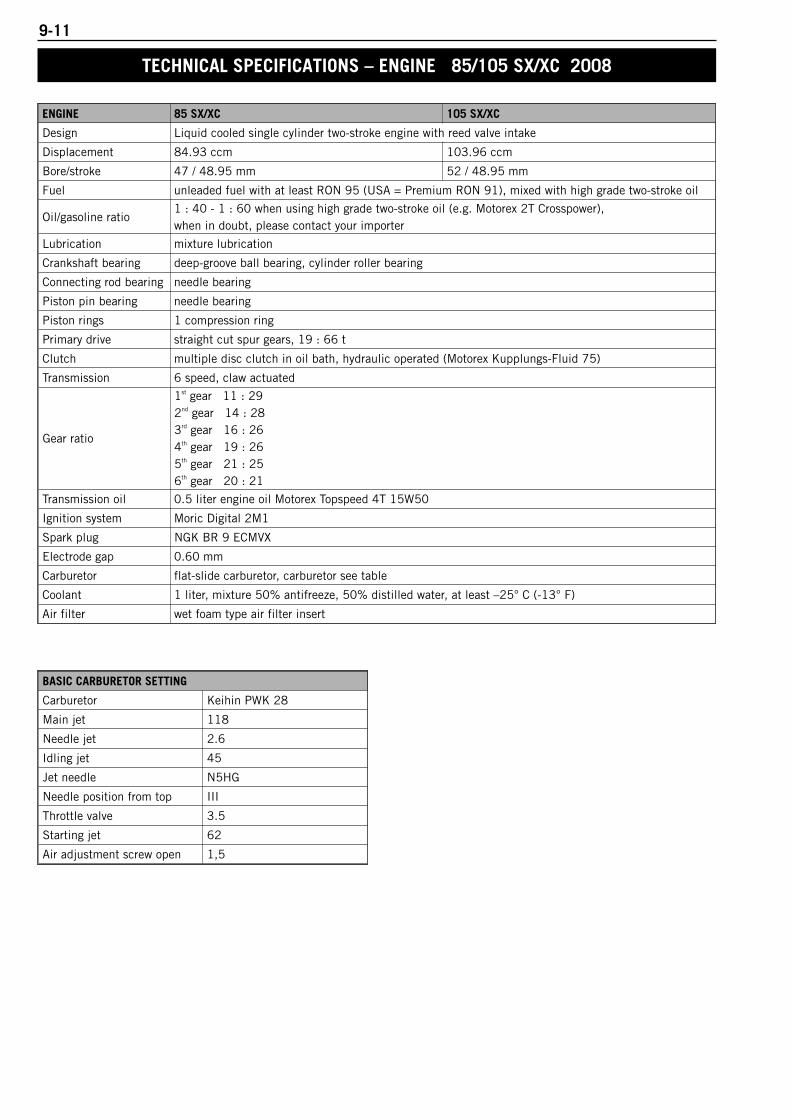
9-11
TECHNICAL SPECIFICATIONS – ENGINE 85/105 SX/XC 2008
ENGINE 85 SX/XC 105 SX/XC
Design Liquid cooled single cylinder two-stroke engine with reed valve intake
Displacement 84.93 ccm 103.96 ccm
Bore/stroke 47 / 48.95 mm 52 / 48.95 mm
Fuel unleaded fuel with at least RON 95 (USA = Premium RON 91), mixed with high grade two-stroke oil
Oil/gasoline ratio1 : 40 - 1 : 60 when using high grade two-stroke oil (e.g. Motorex 2T Crosspower), when in doubt, please contact your importer
Lubrication mixture lubrication
Crankshaft bearing deep-groove ball bearing, cylinder roller bearing
Connecting rod bearing needle bearing
Piston pin bearing needle bearing
Piston rings 1 compression ring
Primary drive straight cut spur gears, 19 : 66 t
Clutch multiple disc clutch in oil bath, hydraulic operated (Motorex Kupplungs-Fluid 75)
Transmission 6 speed, claw actuated
Gear ratio
1st gear 11 : 292nd gear 14 : 283rd gear 16 : 264th gear 19 : 265th gear 21 : 256th gear 20 : 21
Transmission oil 0.5 liter engine oil Motorex Topspeed 4T 15W50
Ignition system Moric Digital 2M1
Spark plug NGK BR 9 ECMVX
Electrode gap 0.60 mm
Carburetor flat-slide carburetor, carburetor see table
Coolant 1 liter, mixture 50% antifreeze, 50% distilled water, at least –25° C (-13° F)
Air filter wet foam type air filter insert
BASIC CARBURETOR SETTING
Carburetor Keihin PWK 28
Main jet 118
Needle jet 2.6
Idling jet 45
Jet needle N5HG
Needle position from top III
Throttle valve 3.5
Starting jet 62
Air adjustment screw open 1,5
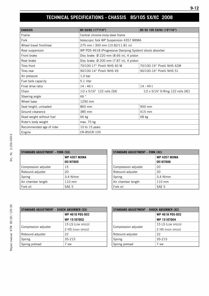
9-12R
epai
r m
anua
l K
TM 8
5 S
X / 1
05
SX
Art
.- N
r. 3
.20
6.0
49
-E
TECHNICAL SPECIFICATIONS - CHASSIS 85/105 SX/XC 2008
CHASSIS 85 SX/XC (17”/14”) 85 SX 105 SX/XC (19”/16”)
Frame Central chrome-moly-steel frame
Fork telescopic fork WP Suspension 4357 MXMA
Wheel travel front/rear 275 mm / 300 mm (10.82/11.81 in)
Rear suspension WP PDS 4618 (Progressive Damping System) shock absorber
Front brake Disc brake Ø 220 mm (8.66 in), 4 piston
Rear brake Disc brake Ø 200 mm (7.87 in), 4 piston
Tires front 70/100-17“ Pirelli NHS 40 M 70/100-19“ Pirelli NHS 42M
Tires rear 90/100-14“ Pirelli NHS 49 90/100-16“ Pirelli NHS 51
Air pressure 1.0 bar
Fuel tank capacity 5.1 liter
Final drive ratio 14 : 46 t 14 : 49 t
Chain 1/2 x 5/16" 122 rolls (SX) 1/2 x 5/16" O-Ring 122 rolls (XC)
Steering angle 66 °
Wheel base 1290 mm
Seat height, unloaded 865 mm 900 mm
Ground clearance 385 mm 415 mm
Dead weight without fuel 66 kg 68 kg
Rider’s body weight max. 75 kg
Recommended age of rider 10 to 15 years
Engine CR-85/CR-105
STANDARD ADJUSTMENT – FORK (SX)
WP 4357 MXMA05187D05
Compression adjuster 15
Rebound adjuster 20
Spring 3,4 N/mm
Air chamber length 110 mm
Fork oil SAE 5
STANDARD ADJUSTMENT – FORK (XC)
WP 4357 MXMA05187D06
Compression adjuster 20
Rebound adjuster 20
Spring 3,4 N/mm
Air chamber length 110 mm
Fork oil SAE 5
STANDARD ADJUSTMENT – SHOCK ABSORBER (SX)
WP 4618 PDS-DCC
WP 15187D02
Compression adjuster15 LS (LOW SPEED)
2 HS (HIGH SPEED)
Rebound adjuster 22
Spring 35-215
Spring preload 7 MM
STANDARD ADJUSTMENT – SHOCK ABSORBER (XC)
WP 4618 PDS-DCC
WP 15187D04
Compression adjuster15 LS (LOW SPEED)
2 HS (HIGH SPEED)
Rebound adjuster 22
Spring 35-215
Spring preload 7 MM

9-13
TECHNICAL SPECIFICATIONS – ENGINE 85/105 SX/XC 2009
ENGINE 85 SX/XC 105 SX/XC
Design Liquid cooled single cylinder two-stroke engine with reed valve intake
Displacement 84.93 ccm 103.96 ccm
Bore/stroke 47 / 48.95 mm 52 / 48.95 mm
Fuel unleaded fuel with at least RON 95 (USA = Premium RON 91), mixed with high grade two-stroke oil
Oil/gasoline ratio1 : 40 - 1 : 60 when using high grade two-stroke oil (e.g. Motorex 2T Crosspower), when in doubt, please contact your importer
Lubrication mixture lubrication
Crankshaft bearing deep-groove ball bearing, cylinder roller bearing
Connecting rod bearing needle bearing
Piston pin bearing needle bearing
Piston rings 1 compression ring
Primary drive straight cut spur gears, 19 : 66 t
Clutch multiple disc clutch in oil bath, hydraulic operated (Motorex Kupplungs-Fluid 75)
Transmission 6 speed, claw actuated
Gear ratio
1st gear 11 : 292nd gear 14 : 283rd gear 16 : 264th gear 19 : 265th gear 21 : 256th gear 20 : 21
Transmission oil 0.5 liter engine oil Motorex Topspeed 4T 15W50
Ignition system Moric Digital 2M1
Spark plug NGK BR 9 ECMVX
Electrode gap 0.60 mm
Carburetor flat-slide carburetor, carburetor see table
Coolant 1 liter, mixture 50% antifreeze, 50% distilled water, at least –25° C (-13° F)
Air filter wet foam type air filter insert
BASIC CARBURETOR SETTING
Carburetor Keihin PWK 28
Main jet 118
Needle jet 2.6
Idling jet 45
Jet needle N5HG
Needle position from top III
Throttle valve 3.5
Starting jet 62
Air adjustment screw open 1,5
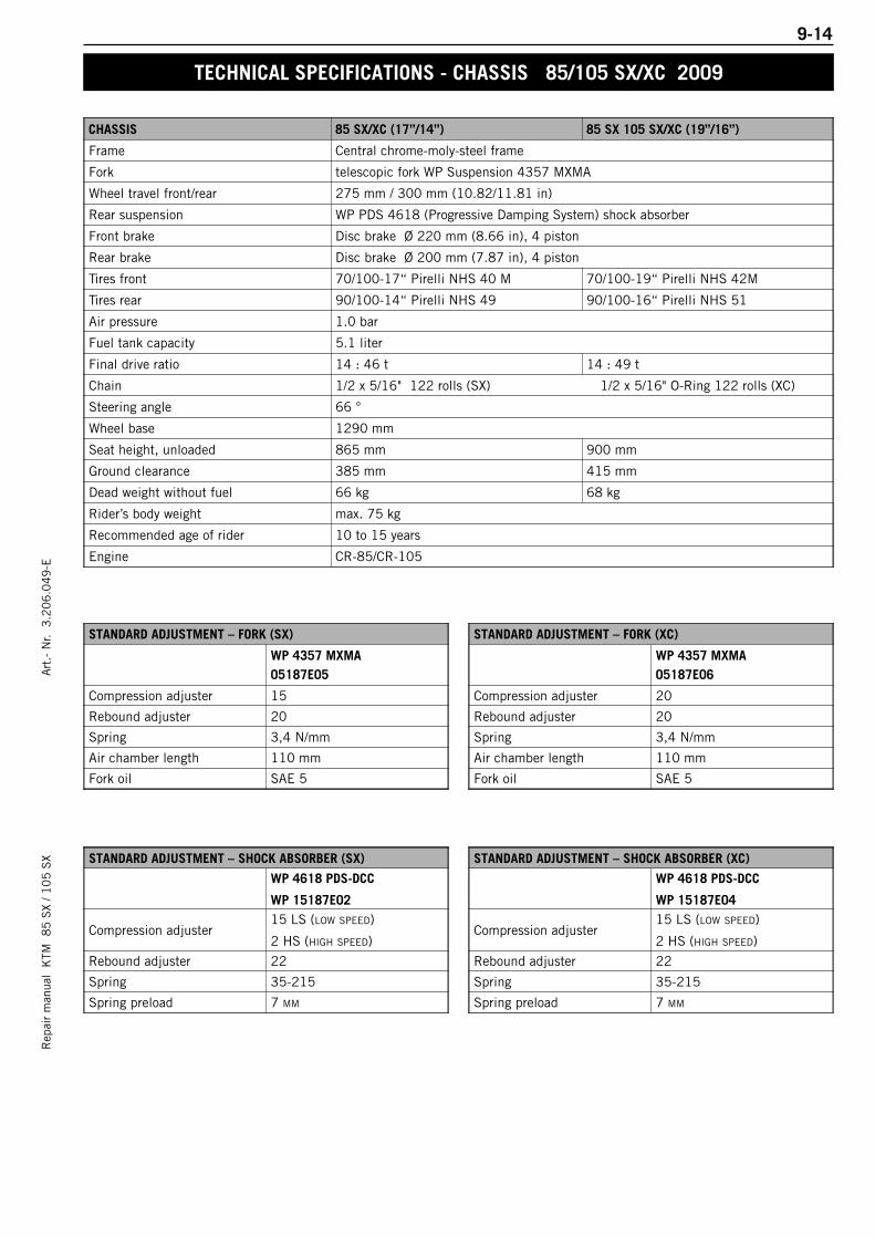
9-14R
epai
r m
anua
l K
TM 8
5 S
X / 1
05
SX
Art
.- N
r. 3
.20
6.0
49
-E
TECHNICAL SPECIFICATIONS - CHASSIS 85/105 SX/XC 2009
CHASSIS 85 SX/XC (17”/14”) 85 SX 105 SX/XC (19”/16”)
Frame Central chrome-moly-steel frame
Fork telescopic fork WP Suspension 4357 MXMA
Wheel travel front/rear 275 mm / 300 mm (10.82/11.81 in)
Rear suspension WP PDS 4618 (Progressive Damping System) shock absorber
Front brake Disc brake Ø 220 mm (8.66 in), 4 piston
Rear brake Disc brake Ø 200 mm (7.87 in), 4 piston
Tires front 70/100-17“ Pirelli NHS 40 M 70/100-19“ Pirelli NHS 42M
Tires rear 90/100-14“ Pirelli NHS 49 90/100-16“ Pirelli NHS 51
Air pressure 1.0 bar
Fuel tank capacity 5.1 liter
Final drive ratio 14 : 46 t 14 : 49 t
Chain 1/2 x 5/16" 122 rolls (SX) 1/2 x 5/16" O-Ring 122 rolls (XC)
Steering angle 66 °
Wheel base 1290 mm
Seat height, unloaded 865 mm 900 mm
Ground clearance 385 mm 415 mm
Dead weight without fuel 66 kg 68 kg
Rider’s body weight max. 75 kg
Recommended age of rider 10 to 15 years
Engine CR-85/CR-105
STANDARD ADJUSTMENT – FORK (SX)
WP 4357 MXMA05187E05
Compression adjuster 15
Rebound adjuster 20
Spring 3,4 N/mm
Air chamber length 110 mm
Fork oil SAE 5
STANDARD ADJUSTMENT – FORK (XC)
WP 4357 MXMA05187E06
Compression adjuster 20
Rebound adjuster 20
Spring 3,4 N/mm
Air chamber length 110 mm
Fork oil SAE 5
STANDARD ADJUSTMENT – SHOCK ABSORBER (SX)
WP 4618 PDS-DCC
WP 15187E02
Compression adjuster15 LS (LOW SPEED)
2 HS (HIGH SPEED)
Rebound adjuster 22
Spring 35-215
Spring preload 7 MM
STANDARD ADJUSTMENT – SHOCK ABSORBER (XC)
WP 4618 PDS-DCC
WP 15187E04
Compression adjuster15 LS (LOW SPEED)
2 HS (HIGH SPEED)
Rebound adjuster 22
Spring 35-215
Spring preload 7 MM
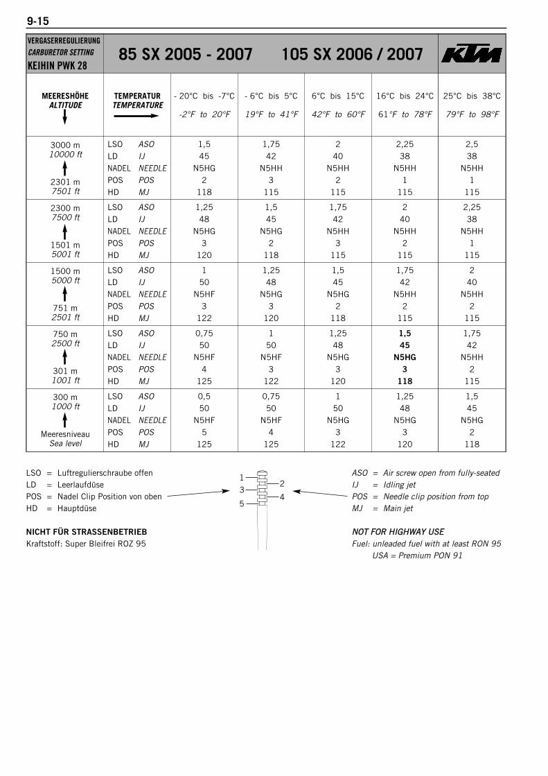
9-15
VERGASERREGULIERUNGCARBURETOR SETTING
KEIHIN PWK 2885 SX 2005 - 2007 105 SX 2006 / 2007
MEERESHÖHEALTITUDE
TEMPERATURTEMPERATURE
- 20°C bis -7°C
-2°F to 20°F
- 6°C bis 5°C
19°F to 41°F
6°C bis 15°C
42°F to 60°F
16°C bis 24°C
61°F to 78°F
25°C bis 38°C
79°F to 98°F
3000 m10000 ft
2301 m7501 ft
LSO ASOLD IJNADEL NEEDLEPOS POSHD MJ
1,545
N5HG2
118
1,7542
N5HH3
115
240
N5HH2
115
2,2538
N5HH1
115
2,538
N5HH1
115
2300 m7500 ft
1501 m5001 ft
LSO ASOLD IJNADEL NEEDLEPOS POSHD MJ
1,2548
N5HG3
120
1,545
N5HG2
118
1,7542
N5HH3
115
240
N5HH2
115
2,2538
N5HH1
115
1500 m5000 ft
751 m2501 ft
LSO ASOLD IJNADEL NEEDLEPOS POSHD MJ
150
N5HF3
122
1,2548
N5HG3
120
1,545
N5HG2
118
1,7542
N5HH2
115
240
N5HH2
115
750 m2500 ft
301 m1001 ft
LSO ASOLD IJNADEL NEEDLEPOS POSHD MJ
0,7550
N5HF4
125
150
N5HF3
122
1,2548
N5HG3
120
1,545
N5HG3
118
1,7542
N5HH2
115
300 m1000 ft
MeeresniveauSea level
LSO ASOLD IJNADEL NEEDLEPOS POSHD MJ
0,550
N5HF5
125
0,7550
N5HF4
125
150
N5HG3
122
1,2548
N5HG3
120
1,545
N5HG2
118
LSO = Luftregulierschraube offenLD = LeerlaufdüsePOS = Nadel Clip Position von obenHD = Hauptdüse
NICHT FÜR STRASSENBETRIEBKraftstoff: Super Bleifrei ROZ 95
ASO = Air screw open from fully-seatedIJ = Idling jetPOS = Needle clip position from topMJ = Main jet
NOT FFOR HHIGHWAY UUSEFuel: unleaded fuel with at least RON 95
USA = Premium PON 91
13
5
2
4

9-16R
epai
r m
anua
l K
TM 8
5 S
X / 1
05
SX
Art
.- N
r. 3
.20
6.0
49
-E
VERGASERREGULIERUNGCARBURETOR SETTING
KEIHIN PWK 2885/105 SX/XC 2008
MEERESHÖHEALTITUDE
TEMPERATURTEMPERATURE
- 20°C bis -7°C
-2°F to 20°F
- 6°C bis 5°C
19°F to 41°F
6°C bis 15°C
42°F to 60°F
16°C bis 24°C
61°F to 78°F
25°C bis 38°C
79°F to 98°F
3000 m10000 ft
2301 m7501 ft
LSO ASOLD IJNADEL NEEDLEPOS POSHD MJ
1,545
N5HG2
118
1,7542
N5HH3
115
240
N5HH2
115
2,2538
N5HH1
115
2,538
N5HH1
115
2300 m7500 ft
1501 m5001 ft
LSO ASOLD IJNADEL NEEDLEPOS POSHD MJ
1,2548
N5HG3
120
1,545
N5HG2
118
1,7542
N5HH3
115
240
N5HH2
115
2,2538
N5HH1
115
1500 m5000 ft
751 m2501 ft
LSO ASOLD IJNADEL NEEDLEPOS POSHD MJ
150
N5HF3
122
1,2548
N5HG3
120
1,545
N5HG2
118
1,7542
N5HH2
115
240
N5HH2
115
750 m2500 ft
301 m1001 ft
LSO ASOLD IJNADEL NEEDLEPOS POSHD MJ
0,7550
N5HF4
125
150
N5HF3
122
1,2548
N5HG3
120
1,545
N5HG3
118
1,7542
N5HH2
115
300 m1000 ft
MeeresniveauSea level
LSO ASOLD IJNADEL NEEDLEPOS POSHD MJ
0,550
N5HF5
125
0,7550
N5HF4
125
150
N5HG3
122
1,2548
N5HG3
120
1,545
N5HG2
118
LSO = Luftregulierschraube offenLD = LeerlaufdüsePOS = Nadel Clip Position von obenHD = Hauptdüse
NICHT FÜR STRASSENBETRIEBKraftstoff: Super Bleifrei ROZ 95
ASO = Air screw open from fully-seatedIJ = Idling jetPOS = Needle clip position from topMJ = Main jet
NOT FFOR HHIGHWAY UUSEFuel: unleaded fuel with at least RON 95
USA = Premium PON 91
13
5
2
4

9-17
VERGASERREGULIERUNGCARBURETOR SETTING
KEIHIN PWK 2885/105 SX/XC 2009
MEERESHÖHEALTITUDE
TEMPERATURTEMPERATURE
- 20°C bis -7°C
-2°F to 20°F
- 6°C bis 5°C
19°F to 41°F
6°C bis 15°C
42°F to 60°F
16°C bis 24°C
61°F to 78°F
25°C bis 38°C
79°F to 98°F
3000 m10000 ft
2301 m7501 ft
LSO ASOLD IJNADEL NEEDLEPOS POSHD MJ
1,545
N5HG2
118
1,7542
N5HH3
115
240
N5HH2
115
2,2538
N5HH1
115
2,538
N5HH1
115
2300 m7500 ft
1501 m5001 ft
LSO ASOLD IJNADEL NEEDLEPOS POSHD MJ
1,2548
N5HG3
120
1,545
N5HG2
118
1,7542
N5HH3
115
240
N5HH2
115
2,2538
N5HH1
115
1500 m5000 ft
751 m2501 ft
LSO ASOLD IJNADEL NEEDLEPOS POSHD MJ
150
N5HF3
122
1,2548
N5HG3
120
1,545
N5HG2
118
1,7542
N5HH2
115
240
N5HH2
115
750 m2500 ft
301 m1001 ft
LSO ASOLD IJNADEL NEEDLEPOS POSHD MJ
0,7550
N5HF4
125
150
N5HF3
122
1,2548
N5HG3
120
1,545
N5HG3
118
1,7542
N5HH2
115
300 m1000 ft
MeeresniveauSea level
LSO ASOLD IJNADEL NEEDLEPOS POSHD MJ
0,550
N5HF5
125
0,7550
N5HF4
125
150
N5HG3
122
1,2548
N5HG3
120
1,545
N5HG2
118
13
5
2
4
LSO = Luftregulierschraube offenLD = LeerlaufdüsePOS = Nadel Clip Position von obenHD = Hauptdüse
NICHT FÜR STRASSENBETRIEBUND SANDSTRECKEN
Kraftstoff: Super Bleifrei ROZ 95
ASO = Air screw open from fully-seatedIJ = Idling jetPOS = Needle clip position from topMJ = Main jet
NOT FFOR HHIGHWAY UUSEAND SSAND TTRACKS
Fuel: unleaded fuel with at least RON 95USA = Premium PON 91
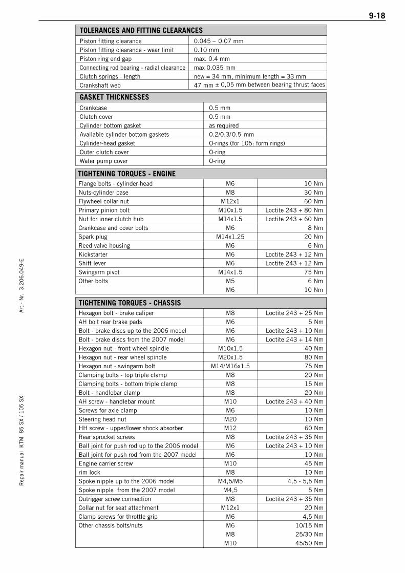
9-18R
epai
r m
anua
l K
TM 8
5 S
X / 1
05
SX
Art
.- N
r. 3
.20
6.0
49
-E
Piston fitting clearance 0.045 – 0.07 mmPiston fitting clearance - wear limit 0.10 mm Piston ring end gap max. 0.4 mmConnecting rod bearing - radial clearance max 0.035 mmClutch springs - length new = 34 mm, minimum length = 33 mmCrankshaft web 47 mm ± 0,05 mm between bearing thrust faces
TOLERANCES AND FITTING CLEARANCES
GASKET THICKNESSESCrankcase 0.5 mmClutch cover 0.5 mmCylinder bottom gasket as requiredAvailable cylinder bottom gaskets 0.2/0.3/0.5 mmCylinder-head gasket O-rings (for 105: form rings)Outer clutch cover O-ringWater pump cover O-ring
TIGHTENING TORQUES - ENGINEFlange bolts - cylinder-head M6 10 NmNuts-cylinder base M8 30 NmFlywheel collar nut M12x1 60 NmPrimary pinion bolt M10x1.5 Loctite 243 + 80 NmNut for inner clutch hub M14x1.5 Loctite 243 + 60 NmCrankcase and cover bolts M6 8 NmSpark plug M14x1.25 20 NmReed valve housing M6 6 NmKickstarter M6 Loctite 243 + 12 NmShift lever M6 Loctite 243 + 12 NmSwingarm pivot M14x1.5 75 NmOther bolts M5 6 Nm
M6 10 Nm
Hexagon bolt - brake caliper M8 Loctite 243 + 25 NmAH bolt rear brake pads M6 5 NmBolt - brake discs up to the 2006 model M6 Loctite 243 + 10 NmBolt - brake discs from the 2007 model M6 Loctite 243 + 14 NmHexagon nut - front wheel spindle M10x1,5 40 NmHexagon nut - rear wheel spindle M20x1.5 80 NmHexagon nut - swingarm bolt M14/M16x1.5 75 NmClamping bolts - top triple clamp M8 20 NmClamping bolts - bottom triple clamp M8 15 NmBolt - handlebar clamp M8 20 NmAH screw - handlebar mount M10 Loctite 243 + 40 NmScrews for axle clamp M6 10 NmSteering head nut M20 10 NmHH screw - upper/lower shock absorber M12 60 NmRear sprocket screws M8 Loctite 243 + 35 NmBall joint for push rod up to the 2006 model M6 Loctite 243 + 10 NmBall joint for push rod from the 2007 model M6 10 NmEngine carrier screw M10 45 Nmrim lock M8 10 NmSpoke nipple up to the 2006 model M4,5/M5 4,5 - 5,5 NmSpoke nipple from the 2007 model M4,5 5 NmOutrigger screw connection M8 Loctite 243 + 35 NmCollar nut for seat attachment M12x1 20 NmClamp screws for throttle grip M6 4,5 NmOther chassis bolts/nuts M6 10/15 Nm
M8 25/30 NmM10 45/50 Nm
TIGHTENING TORQUES - CHASSIS

Rep
air
man
ual
KTM
8
5 S
X / 1
05
SX
PERIODIC MAINTENANCE SCHEDULE
Art
.- N
r. 3
.20
6.0
49
-E
85 SX / 105 SX MODEL 2004 . . . . . . . . . . . . . . . . . . . . . . . . . . . . . . . . . . . .10-2
85 SX MODEL 2005 . . . . . . . . . . . . . . . . . . . . . . . . . . . . . . . . . . . . . . . . . . .10-4
85 SX / 105 SX MODEL 2006 . . . . . . . . . . . . . . . . . . . . . . . . . . . . . . . . . . . .10-6
85 SX / 105 SX MODEL 2007 . . . . . . . . . . . . . . . . . . . . . . . . . . . . . . . . . . . .10-8
85/105 SX/XC MODEL 2008 . . . . . . . . . . . . . . . . . . . . . . . . . . . . . . . . . . . .10-10
85/105 SX/XC MODEL 2009 . . . . . . . . . . . . . . . . . . . . . . . . . . . . . . . . . . . .10-12
INDEX
10-1
10
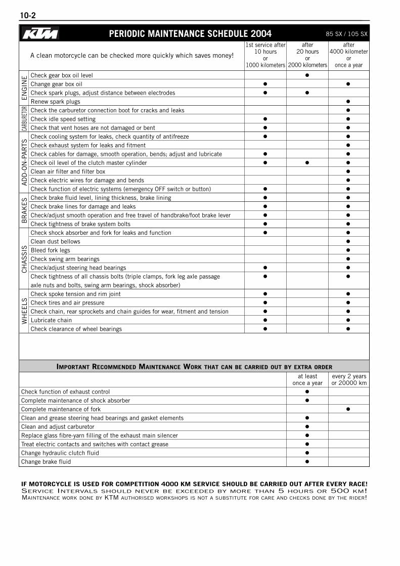
10-2
PERIODIC MAINTENANCE SCHEDULE 2004after
20 hoursor
2000 kilometers
1st service after10 hours
or1000 kilometers
after4000 kilometer
oronce a year
IF MOTORCYCLE IS USED FOR COMPETITION 4000 KM SERVICE SHOULD BE CARRIED OUT AFTER EVERY RACE!SERVICE INTERVALS SHOULD NEVER BE EXCEEDED BY MORE THAN 5 HOURS OR 500 KM!MAINTENANCE WORK DONE BY KTM AUTHORISED WORKSHOPS IS NOT A SUBSTITUTE FOR CARE AND CHECKS DONE BY THE RIDER!
A clean motorcycle can be checked more quickly which saves money!
Check gear box oil levelChange gear box oilCheck spark plugs, adjust distance between electrodesRenew spark plugsCheck the carburetor connection boot for cracks and leaksCheck idle speed settingCheck that vent hoses are not damaged or bentCheck cooling system for leaks, check quantity of antifreezeCheck exhaust system for leaks and fitmentCheck cables for damage, smooth operation, bends; adjust and lubricateCheck oil level of the clutch master cylinderClean air filter and filter boxCheck electric wires for damage and bendsCheck function of electric systems (emergency OFF switch or button)Check brake fluid level, lining thickness, brake lining Check brake lines for damage and leaksCheck/adjust smooth operation and free travel of handbrake/foot brake leverCheck tightness of brake system boltsCheck shock absorber and fork for leaks and functionClean dust bellowsBleed fork legsCheck swing arm bearingsCheck/adjust steering head bearingsCheck tightness of all chassis bolts (triple clamps, fork leg axle passageaxle nuts and bolts, swing arm bearings, shock absorber)Check spoke tension and rim jointCheck tires and air pressureCheck chain, rear sprockets and chain guides for wear, fitment and tensionLubricate chainCheck clearance of wheel bearings
IMPORTANT RECOMMENDED MAINTENANCE WORK THAT CAN BE CARRIED OUT BY EXTRA ORDER
Check function of exhaust controlComplete maintenance of shock absorberComplete maintenance of forkClean and grease steering head bearings and gasket elementsClean and adjust carburetorReplace glass fibre-yarn filling of the exhaust main silencerTreat electric contacts and switches with contact greaseChange hydraulic clutch fluidChange brake fluid
WH
EE
LSC
HA
SS
ISB
RA
KE
SA
DD
-ON
-PA
RTS
CARB
URET
ORE
NG
INE
85 SX / 105 SX
at leastonce a year
every 2 yearsor 20000 km
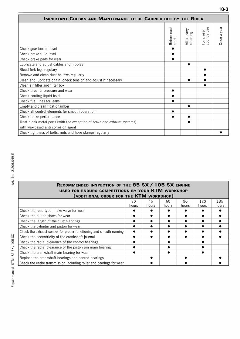
Rep
air
man
ual
KTM
8
5 S
X / 1
05
SX
10-3A
rt.-
Nr.
3.2
06
.04
9-E
IMPORTANT CHECKS AND MAINTENANCE TO BE CARRIED OUT BY THE RIDER
Check gear box oil levelCheck brake fluid levelCheck brake pads for wearLubricate and adjust cables and nipplesBleed fork legs regularyRemove and clean dust bellows regularly Clean and lubricate chain, check tension and adjust if necessaryClean air filter and filter boxCheck tires for pressure and wearCheck cooling liquid levelCheck fuel lines for leaksEmpty and clean float chamberCheck all control elements for smooth operationCheck brake performanceTreat blank metal parts (with the exception of brake and exhaust systems)with wax-based anti corrosion agentCheck tightness of bolts, nuts and hose clamps regularly
For
cros
s-co
untr
y us
e
Onc
e a
year
Aft
er e
very
clea
ning
Bef
ore
each
star
t
RECOMMENDED INSPECTION OF THE 85 SX / 105 SX ENGINE
USED FOR ENDURO COMPETITIONS BY YOUR KTM WORKSHOP
(ADDITIONAL ORDER FOR THE KTM WORKSHOP)
Check the reed-type intake valve for wearCheck the clutch shoes for wearCheck the length of the clutch springsCheck the cylinder and piston for wearCheck the exhaust control for proper functioning and smooth runningCheck the eccentricity of the crankshaft journal Check the radial clearance of the conrod bearingsCheck the radial clearance of the piston pin main bearingCheck the crankshaft main bearing for wearReplace the crankshaft bearings and conrod bearingsCheck the entire transmission including roller and bearings for wear
30hours
45hours
60hours
90hours
120hours
135hours
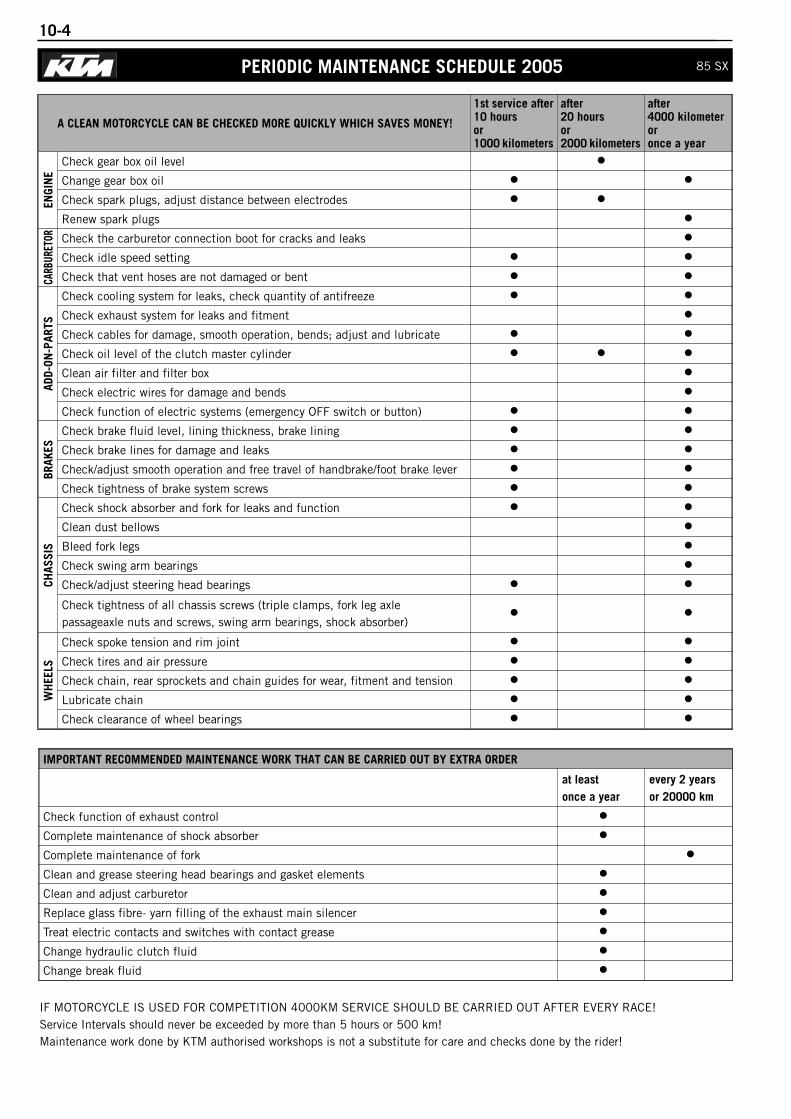
10-4
A CLEAN MOTORCYCLE CAN BE CHECKED MORE QUICKLY WHICH SAVES MONEY!
1st service after10 hoursor1000 kilometers
after20 hoursor2000 kilometers
after4000 kilometeroronce a year
ENGI
NE
Check gear box oil level
Change gear box oil
Check spark plugs, adjust distance between electrodes
Renew spark plugs
CARB
URET
OR Check the carburetor connection boot for cracks and leaks
Check idle speed setting
Check that vent hoses are not damaged or bent
ADD-
ON-P
ARTS
Check cooling system for leaks, check quantity of antifreeze
Check exhaust system for leaks and fitment
Check cables for damage, smooth operation, bends; adjust and lubricate
Check oil level of the clutch master cylinder
Clean air filter and filter box
Check electric wires for damage and bends
Check function of electric systems (emergency OFF switch or button)
BRAK
ES
Check brake fluid level, lining thickness, brake lining
Check brake lines for damage and leaks
Check/adjust smooth operation and free travel of handbrake/foot brake lever
Check tightness of brake system screws
CHAS
SIS
Check shock absorber and fork for leaks and function
Clean dust bellows
Bleed fork legs
Check swing arm bearings
Check/adjust steering head bearings
Check tightness of all chassis screws (triple clamps, fork leg axle passageaxle nuts and screws, swing arm bearings, shock absorber)
WH
EELS
Check spoke tension and rim joint
Check tires and air pressure
Check chain, rear sprockets and chain guides for wear, fitment and tension
Lubricate chain
Check clearance of wheel bearings
IMPORTANT RECOMMENDED MAINTENANCE WORK THAT CAN BE CARRIED OUT BY EXTRA ORDER
at leastonce a year
every 2 yearsor 20000 km
Check function of exhaust control
Complete maintenance of shock absorber
Complete maintenance of fork
Clean and grease steering head bearings and gasket elements
Clean and adjust carburetor
Replace glass fibre- yarn filling of the exhaust main silencer
Treat electric contacts and switches with contact grease
Change hydraulic clutch fluid
Change break fluid
IF MOTORCYCLE IS USED FOR COMPETITION 4000KM SERVICE SHOULD BE CARRIED OUT AFTER EVERY RACE!Service Intervals should never be exceeded by more than 5 hours or 500 km!Maintenance work done by KTM authorised workshops is not a substitute for care and checks done by the rider!
PERIODIC MAINTENANCE SCHEDULE 2005 85 SX

Rep
air
man
ual
KTM
8
5 S
X / 1
05
SX
10-5A
rt.-
Nr.
3.2
06
.04
9-E
IMPORTANT CHECKS AND MAINTENANCE TO BE CARRIED OUT BY THE RIDER
Before eachstart
After everycleaning
For cross-country use
Once a year
Check gear box oil level
Check brake fluid level
Check brake pads for wear
Lubricate and adjust cables and nipples
Bleed fork legs regulary
Remove and clean dust bellows regularly
Clean and lubricate chain, check tension and adjust if necessary
Clean air filter and filter box
Check tires for pressure and wear
Check cooling liquid level
Check fuel lines for leaks
Empty and clean float chamber
Check all control elements for smooth operation
Check brake performance
Treat blank metal parts (with the exception of brake and exhaust systems)with wax-based anti corrosion agent
Check tightness of screws, nuts and hose clamps regularly
RECOMMENDED INSPECTION OF THE 85 SX ENGINE USED FOR ENDURO COMPETITIONS BY YOUR KTM WORKSHOP (ADDITIONAL ORDER FOR THE KTM WORKSHOP)
30hours
45hours
60hours
90hours
120hours
135hours
Check the reed-type intake valve for wear
Check the clutch shoes for wear
Check the length of the clutch springs
Check the cylinder and piston for wear
Check the exhaust control for proper functioning and smooth running
Check the eccentricity of the crankshaft journal
Check the radial clearance of the conrod bearings
Check the radial clearance of the piston pin main bearing
Check the crankshaft main bearing for wear
Replace the crankshaft bearings and conrod bearings
Check the entire transmission including roller and bearings for wear
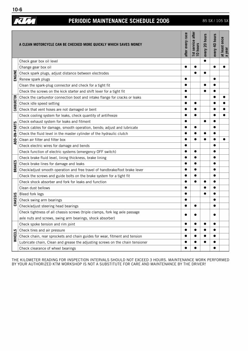
10-6
A CLEAN MOTORCYCLE CAN BE CHECKED MORE QUICKLY WHICH SAVES MONEY
afte
r ev
ery
race
1st s
ervi
ce a
fter
10 h
ours
ever
y 20
hou
rs
ever
y 40
hou
rs
at le
ast o
nce
a ye
ar
ENGI
NE
Check gear box oil level
Change gear box oil
Check spark plugs, adjust distance between electrodes
Renew spark plugs
Clean the spark-plug connector and check for a tight fit
Check the screws on the kick starter and shift lever for a tight fit
CARB
URET
OR Check the carburetor connection boot and intake flange for cracks or leaks
Check idle speed setting
Check that vent hoses are not damaged or bent
ADD-
ON-P
ARTS
Check cooling system for leaks, check quantity of antifreeze
Check exhaust system for leaks and fitment
Check cables for damage, smooth operation, bends; adjust and lubricate
Check the fluid level in the master cylinder of the hydraulic clutch
Clean air filter and filter box
Check electric wires for damage and bends
Check function of electric systems (emergency OFF switch)
BRAK
ES
Check brake fluid level, lining thickness, brake lining
Check brake lines for damage and leaks
Check/adjust smooth operation and free travel of handbrake/foot brake lever
Check the screws and guide bolts on the brake system for a tight fit
CHAS
SIS
Check shock absorber and fork for leaks and function
Clean dust bellows
Bleed fork legs
Check swing arm bearings
Check/adjust steering head bearings
Check tightness of all chassis screws (triple clamps, fork leg axle passage
axle nuts and screws, swing arm bearings, shock absorber)
WH
EELS
Check spoke tension and rim joint
Check tires and air pressure
Check chain, rear sprockets and chain guides for wear, fitment and tension
Lubricate chain, Clean and grease the adjusting screws on the chain tensioner
Check clearance of wheel bearings
THE KILOMETER READING FOR INSPECTION INTERVALS SHOULD NOT EXCEED 3 HOURS. MAINTENANCE WORK PERFORMEDBY YOUR AUTHORIZED KTM WORKSHOP IS NOT A SUBSTITUTE FOR CARE AND MAINTENANCE BY THE DRIVER!
PERIODIC MAINTENANCE SCHEDULE 2006 85 SX / 105 SX
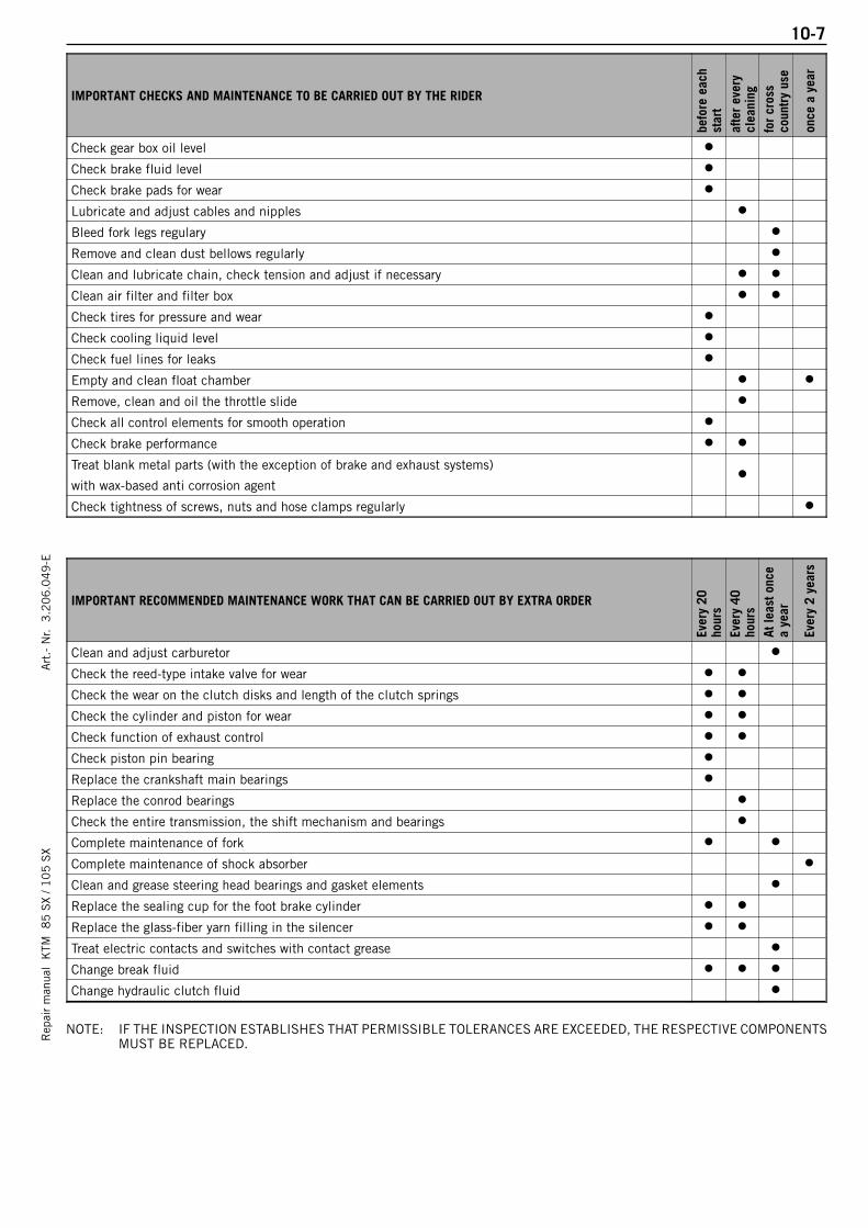
10-7R
epai
r m
anua
l K
TM 8
5 S
X / 1
05
SX
Art
.- N
r. 3
.20
6.0
49
-E
IMPORTANT CHECKS AND MAINTENANCE TO BE CARRIED OUT BY THE RIDER
befo
re e
ach
star
taf
ter
ever
ycl
eani
ngfo
r cr
oss
coun
try
use
once
a y
ear
Check gear box oil level
Check brake fluid level
Check brake pads for wear
Lubricate and adjust cables and nipples
Bleed fork legs regulary
Remove and clean dust bellows regularly
Clean and lubricate chain, check tension and adjust if necessary
Clean air filter and filter box
Check tires for pressure and wear
Check cooling liquid level
Check fuel lines for leaks
Empty and clean float chamber
Remove, clean and oil the throttle slide
Check all control elements for smooth operation
Check brake performance
Treat blank metal parts (with the exception of brake and exhaust systems)
with wax-based anti corrosion agent
Check tightness of screws, nuts and hose clamps regularly
IMPORTANT RECOMMENDED MAINTENANCE WORK THAT CAN BE CARRIED OUT BY EXTRA ORDER
Ever
y 20
hour
sEv
ery
40ho
urs
At le
ast o
nce
a ye
ar
Ever
y 2
year
s
Clean and adjust carburetor
Check the reed-type intake valve for wear
Check the wear on the clutch disks and length of the clutch springs
Check the cylinder and piston for wear
Check function of exhaust control
Check piston pin bearing
Replace the crankshaft main bearings
Replace the conrod bearings
Check the entire transmission, the shift mechanism and bearings
Complete maintenance of fork
Complete maintenance of shock absorber
Clean and grease steering head bearings and gasket elements
Replace the sealing cup for the foot brake cylinder
Replace the glass-fiber yarn filling in the silencer
Treat electric contacts and switches with contact grease
Change break fluid
Change hydraulic clutch fluid
NOTE: IF THE INSPECTION ESTABLISHES THAT PERMISSIBLE TOLERANCES ARE EXCEEDED, THE RESPECTIVE COMPONENTSMUST BE REPLACED.
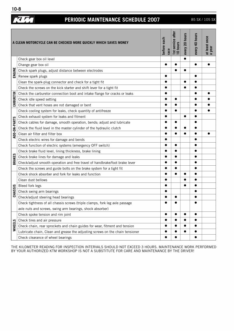
10-8
A CLEAN MOTORCYCLE CAN BE CHECKED MORE QUICKLY WHICH SAVES MONEY
befo
re e
ach
race
1st s
ervi
ce a
fter
10 h
ours
ever
y 20
hou
rs
ever
y 40
hou
rs
at le
ast o
nce
a ye
ar
ENGI
NE
Check gear box oil level
Change gear box oil
Check spark plugs, adjust distance between electrodes
Renew spark plugs
Clean the spark-plug connector and check for a tight fit
Check the screws on the kick starter and shift lever for a tight fit
CARB
URET
OR Check the carburetor connection boot and intake flange for cracks or leaks
Check idle speed setting
Check that vent hoses are not damaged or bent
ADD-
ON-P
ARTS
Check cooling system for leaks, check quantity of antifreeze
Check exhaust system for leaks and fitment
Check cables for damage, smooth operation, bends; adjust and lubricate
Check the fluid level in the master cylinder of the hydraulic clutch
Clean air filter and filter box
Check electric wires for damage and bends
Check function of electric systems (emergency OFF switch)
BRAK
ES
Check brake fluid level, lining thickness, brake lining
Check brake lines for damage and leaks
Check/adjust smooth operation and free travel of handbrake/foot brake lever
Check the screws and guide bolts on the brake system for a tight fit
CHAS
SIS
Check shock absorber and fork for leaks and function
Clean dust bellows
Bleed fork legs
Check swing arm bearings
Check/adjust steering head bearings
Check tightness of all chassis screws (triple clamps, fork leg axle passage
axle nuts and screws, swing arm bearings, shock absorber)
WH
EELS
Check spoke tension and rim joint
Check tires and air pressure
Check chain, rear sprockets and chain guides for wear, fitment and tension
Lubricate chain, Clean and grease the adjusting screws on the chain tensioner
Check clearance of wheel bearings
PERIODIC MAINTENANCE SCHEDULE 2007 85 SX / 105 SX
THE KILOMETER READING FOR INSPECTION INTERVALS SHOULD NOT EXCEED 3 HOURS. MAINTENANCE WORK PERFORMEDBY YOUR AUTHORIZED KTM WORKSHOP IS NOT A SUBSTITUTE FOR CARE AND MAINTENANCE BY THE DRIVER!
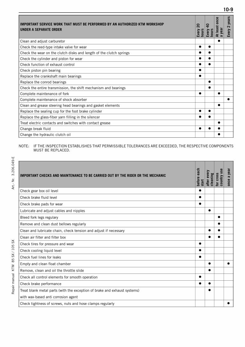
10-9R
epai
r m
anua
l K
TM 8
5 S
X / 1
05
SX
Art
.- N
r. 3
.20
6.0
49
-E
IMPORTANT SERVICE WORK THAT MUST BE PERFORMED BY AN AUTHORIZED KTM WORKSHOPUNDER A SEPARATE ORDER
Ever
y 20
hour
sEv
ery
40ho
urs
At le
ast o
nce
a ye
ar
Ever
y 2
year
s
Clean and adjust carburetor
Check the reed-type intake valve for wear
Check the wear on the clutch disks and length of the clutch springs
Check the cylinder and piston for wear
Check function of exhaust control
Check piston pin bearing
Replace the crankshaft main bearings
Replace the conrod bearings
Check the entire transmission, the shift mechanism and bearings
Complete maintenance of fork
Complete maintenance of shock absorber
Clean and grease steering head bearings and gasket elements
Replace the sealing cup for the foot brake cylinder
Replace the glass-fiber yarn filling in the silencer
Treat electric contacts and switches with contact grease
Change break fluid
Change the hydraulic clutch oil
IMPORTANT CHECKS AND MAINTENANCE TO BE CARRIED OUT BY THE RIDER OR THE MECHANIC
befo
re e
ach
star
taf
ter
ever
ycl
eani
ngfo
r cr
oss
coun
try
use
once
a y
ear
Check gear box oil level
Check brake fluid level
Check brake pads for wear
Lubricate and adjust cables and nipples
Bleed fork legs regulary
Remove and clean dust bellows regularly
Clean and lubricate chain, check tension and adjust if necessary
Clean air filter and filter box
Check tires for pressure and wear
Check cooling liquid level
Check fuel lines for leaks
Empty and clean float chamber
Remove, clean and oil the throttle slide
Check all control elements for smooth operation
Check brake performance
Treat blank metal parts (with the exception of brake and exhaust systems)
with wax-based anti corrosion agent
Check tightness of screws, nuts and hose clamps regularly
NOTE: IF THE INSPECTION ESTABLISHES THAT PERMISSIBLE TOLERANCES ARE EXCEEDED, THE RESPECTIVE COMPONENTSMUST BE REPLACED.

10-10
PERIODIC MAINTENANCE SCHEDULE 2008 85/105 SX/XC
A CLEAN MOTORCYCLE CAN BE CHECKED MORE QUICKLY WHICH SAVES MONEY
befo
re e
ach
race
1st s
ervi
ce a
fter
10 h
ours
ever
y 20
hou
rs
ever
y 40
hou
rs
at le
ast o
nce
a ye
ar
ENGI
NE
Check gear box oil level
Change gear box oil
Check spark plugs, adjust distance between electrodes
Renew spark plugs
Clean the spark-plug connector and check for a tight fit
Check the screws on the kick starter and shift lever for a tight fit
CARB
URET
OR Check the carburetor connection boot and intake flange for cracks or leaks
Check idle speed setting
Check that vent hoses are not damaged or bent
ADD-
ON-P
ARTS
Check cooling system for leaks, check quantity of antifreeze
Check exhaust system for leaks and fitment
Check cables for damage, smooth operation, bends; adjust and lubricate
Check the fluid level in the master cylinder of the hydraulic clutch
Clean air filter and filter box
Check electric wires for damage and bends
Check function of electric systems (emergency OFF switch)
BRAK
ES
Check brake fluid level, lining thickness, brake lining
Check brake lines for damage and leaks
Check/adjust smooth operation and free travel of handbrake/foot brake lever
Check the screws and guide bolts on the brake system for a tight fit
CHAS
SIS
Check shock absorber and fork for leaks and function
Clean dust bellows
Bleed fork legs
Check swing arm bearings
Check/adjust steering head bearings
Check tightness of all chassis screws (triple clamps, fork leg axle passage
axle nuts and screws, swing arm bearings, shock absorber)
WH
EELS
Check spoke tension and rim joint
Check tires and air pressure
Check chain, rear sprockets and chain guides for wear, fitment and tension
Lubricate chain, Clean and grease the adjusting screws on the chain tensioner
Check clearance of wheel bearings
The kilometer reading for inspection intervals should not exceed 3 hours. Maintenance work performed by your authorized KTM workshop is not a substitute for care and maintenance by the driver!

10-11R
epai
r m
anua
l K
TM 8
5 S
X / 1
05
SX
Art
.- N
r. 3
.20
6.0
49
-E
IMPORTANT SERVICE WORK THAT MUST BE PERFORMED BY AN AUTHORIZED KTM WORKSHOPUNDER A SEPARATE ORDER
Ever
y 20
hour
sEv
ery
40ho
urs
At le
ast o
nce
a ye
ar
Ever
y 2
year
s
Clean and adjust carburetor
Check the reed-type intake valve for wear
Check the wear on the clutch disks and length of the clutch springs
Check the cylinder and piston for wear
Check function of exhaust control
Check piston pin bearing
Replace the crankshaft main bearings
Replace the conrod bearings
Check the entire transmission, the shift mechanism and bearings
Complete maintenance of fork
Complete maintenance of shock absorber
Clean and grease steering head bearings and gasket elements
Replace the sealing cup for the foot brake cylinder
Replace the glass-fiber yarn filling in the silencer
Treat electric contacts and switches with contact grease
Change break fluid
Change hydraulic clutch fluid
Change the hydraulic clutch oil
IMPORTANT CHECKS AND MAINTENANCE TO BE CARRIED OUT BY THE RIDER OR THE MECHANIC
befo
re e
ach
star
taf
ter
ever
ycl
eani
ngfo
r cr
oss
coun
try
use
once
a y
ear
Check gear box oil level
Check brake fluid level
Check brake pads for wear
Lubricate and adjust cables and nipples
Bleed fork legs regulary
Remove and clean dust bellows regularly
Clean and lubricate chain, check tension and adjust if necessary
Clean air filter and filter box
Check tires for pressure and wear
Check cooling liquid level
Check fuel lines for leaks
Empty and clean float chamber
Remove, clean and oil the throttle slide
Check all control elements for smooth operation
Check brake performance
Treat blank metal parts (with the exception of brake and exhaust systems)
with wax-based anti corrosion agent
Check tightness of screws, nuts and hose clamps regularly
Note: If the inspection establishes that permissible tolerances are exceeded, the respective components must be replaced.
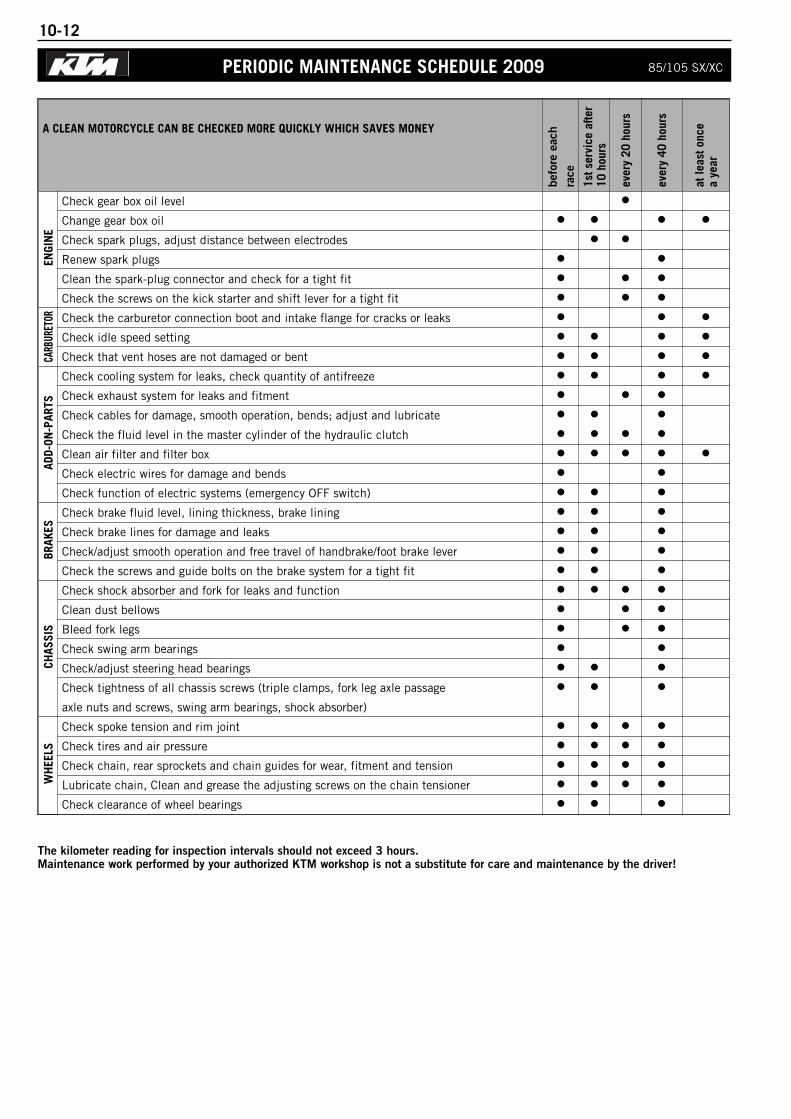
10-12
PERIODIC MAINTENANCE SCHEDULE 2009 85/105 SX/XC
A CLEAN MOTORCYCLE CAN BE CHECKED MORE QUICKLY WHICH SAVES MONEY
befo
re e
ach
race
1st s
ervi
ce a
fter
10 h
ours
ever
y 20
hou
rs
ever
y 40
hou
rs
at le
ast o
nce
a ye
ar
ENGI
NE
Check gear box oil level
Change gear box oil
Check spark plugs, adjust distance between electrodes
Renew spark plugs
Clean the spark-plug connector and check for a tight fit
Check the screws on the kick starter and shift lever for a tight fit
CARB
URET
OR Check the carburetor connection boot and intake flange for cracks or leaks
Check idle speed setting
Check that vent hoses are not damaged or bent
ADD-
ON-P
ARTS
Check cooling system for leaks, check quantity of antifreeze
Check exhaust system for leaks and fitment
Check cables for damage, smooth operation, bends; adjust and lubricate
Check the fluid level in the master cylinder of the hydraulic clutch
Clean air filter and filter box
Check electric wires for damage and bends
Check function of electric systems (emergency OFF switch)
BRAK
ES
Check brake fluid level, lining thickness, brake lining
Check brake lines for damage and leaks
Check/adjust smooth operation and free travel of handbrake/foot brake lever
Check the screws and guide bolts on the brake system for a tight fit
CHAS
SIS
Check shock absorber and fork for leaks and function
Clean dust bellows
Bleed fork legs
Check swing arm bearings
Check/adjust steering head bearings
Check tightness of all chassis screws (triple clamps, fork leg axle passage
axle nuts and screws, swing arm bearings, shock absorber)
WH
EELS
Check spoke tension and rim joint
Check tires and air pressure
Check chain, rear sprockets and chain guides for wear, fitment and tension
Lubricate chain, Clean and grease the adjusting screws on the chain tensioner
Check clearance of wheel bearings
The kilometer reading for inspection intervals should not exceed 3 hours. Maintenance work performed by your authorized KTM workshop is not a substitute for care and maintenance by the driver!
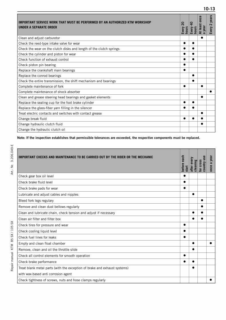
10-13R
epai
r m
anua
l K
TM 8
5 S
X / 1
05
SX
Art
.- N
r. 3
.20
6.0
49
-E
IMPORTANT SERVICE WORK THAT MUST BE PERFORMED BY AN AUTHORIZED KTM WORKSHOPUNDER A SEPARATE ORDER
Ever
y 20
hour
sEv
ery
40ho
urs
At le
ast o
nce
a ye
ar
Ever
y 2
year
s
Clean and adjust carburetor
Check the reed-type intake valve for wear
Check the wear on the clutch disks and length of the clutch springs
Check the cylinder and piston for wear
Check function of exhaust control
Check piston pin bearing
Replace the crankshaft main bearings
Replace the conrod bearings
Check the entire transmission, the shift mechanism and bearings
Complete maintenance of fork
Complete maintenance of shock absorber
Clean and grease steering head bearings and gasket elements
Replace the sealing cup for the foot brake cylinder
Replace the glass-fiber yarn filling in the silencer
Treat electric contacts and switches with contact grease
Change break fluid
Change hydraulic clutch fluid
Change the hydraulic clutch oil
IMPORTANT CHECKS AND MAINTENANCE TO BE CARRIED OUT BY THE RIDER OR THE MECHANIC
befo
re e
ach
star
taf
ter
ever
ycl
eani
ngfo
r cr
oss
coun
try
use
once
a y
ear
Check gear box oil level
Check brake fluid level
Check brake pads for wear
Lubricate and adjust cables and nipples
Bleed fork legs regulary
Remove and clean dust bellows regularly
Clean and lubricate chain, check tension and adjust if necessary
Clean air filter and filter box
Check tires for pressure and wear
Check cooling liquid level
Check fuel lines for leaks
Empty and clean float chamber
Remove, clean and oil the throttle slide
Check all control elements for smooth operation
Check brake performance
Treat blank metal parts (with the exception of brake and exhaust systems)
with wax-based anti corrosion agent
Check tightness of screws, nuts and hose clamps regularly
Note: If the inspection establishes that permissible tolerances are exceeded, the respective components must be replaced.

WIRING DIAGRAMS
Rep
air
man
ual
KTM
8
5 S
X / 1
05
SX
Art
.- N
r. 3
.20
6.0
49
-E
85/105 SX/XC . . . . . . . . . . . . . . . . . . . . . . . . . . . . . . . . . . . . . . . . . . . . . . . .11-2
INDEX
11-1
11
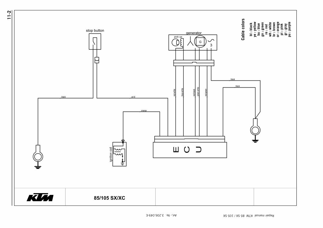
11-2
Repair manual KTM 85 SX / 105 SXArt.- Nr. 3.206.049-E
igni
tion
coil UCE
red-bl
ack
ye-bl
stop button
red-gr
een
green
-whit
e
black
black
blue-w
hite
black
orange
red-w
hite
pick upgenerator
G3
85/105 SX/XC
Cabl
e co
lors
bl :
blac
k ye
: ye
llow
bu :
blue
gn :
gree
nre
: re
dw
h : w
hite
br :
brow
nor
: or
ange
pi :
pink
gr :
gray
pu :
purp
le
Workshop manual
ProductExploded ViewDisassembly & Assembling
1
4357 / 4860 MXMA
Fron
tfor
k 43
57/4
860
MXM
A02
/200
2
Frontfork
4357 / 4860 MX Multi Adjuster
12_234
Introduction 2Exploded view 3Disassembly forkleg 4Disassembly screw-cap 15Assembling screw-cap 17Disassembly cartridge 18Disassembly compression holder 22Assembling compression holder 25Disassembly tap rebound 28Assembling tap rebound 32Assembling cartridge 35Assembling forkleg 38
ProductExploded ViewDisassembly & Assembling
Workshop manual
4357 / 4860 MXMA
2
Fron
tfor
k 43
57/4
860
MXM
A02
/200
2
Introduction
General notice:
Pay attention to the following notes, when you areworking with WP Suspension products as described inthis workshop manual.
Always use clean and professional tools.Regular you need next to the general equipment, thespecial tools of WP Suspension.These tools with a unique “T” number (available atWP Suspension) protect you from damaging the parts.
Always use aluminium protector-plates, when clampingour products or parts in the vice.
Always replace damaged or worn parts.
Clean all parts before assembling.
Caution:Many times it is necesarry to assemble parts withT131, T132 and T163.These parts must dry for at least four hours!!
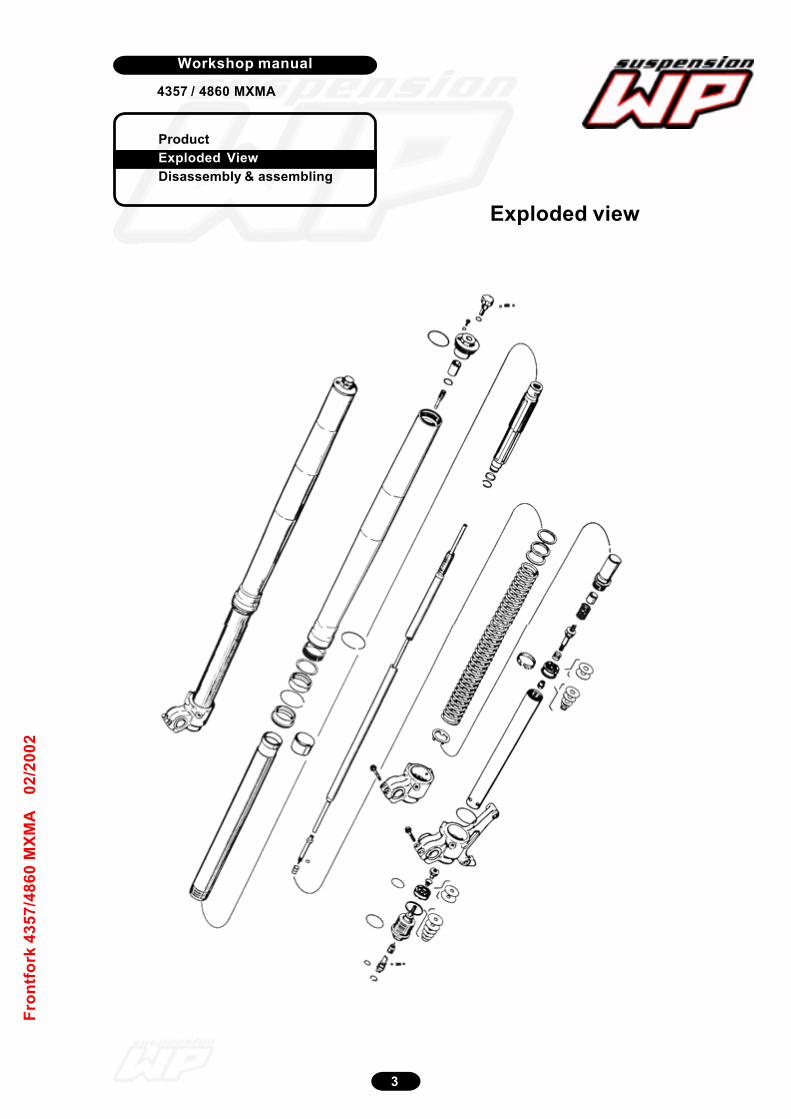
Workshop manual
ProductExploded ViewDisassembly & assembling
3
4357 / 4860 MXMA
Exploded view
Fron
tfor
k 43
57/4
860
MXM
A02
/200
2

ProductExploded ViewDisassembly & Assembling
Workshop manual
4357 / 4860 MXMA
4
Fron
tfor
k 43
57/4
860
MXM
A02
/200
2
Note the rebound position by turning theknob to the right.
After removing the rubber cap.Note the compression position byturning the screw to the right.
Clamp the outer-tube in (4357) T501S /(4860) T1403S and unscrew thescrew-cap. (size 24)Cap PA with T103.
12_063
12_064
Disassembly forkleg
12_062
12_079
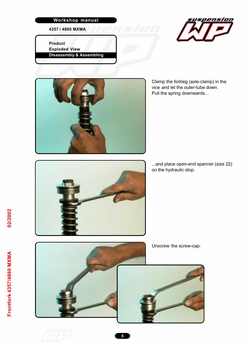
ProductExploded ViewDisassembly & Assembling
Workshop manual
4357 / 4860 MXMA
5
Fron
tfor
k 43
57/4
860
MXM
A02
/200
2
Clamp the forkleg (axle-clamp) in thevice and let the outer-tube down.Pull the spring downwards...
...and place open-end spanner (size 22)on the hydraulic stop.
Unscrew the screw-cap.
12_067
12_068
12_069
12_072
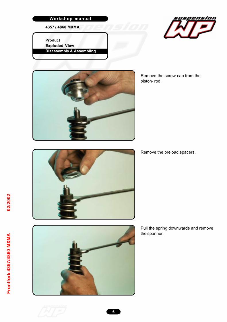
ProductExploded ViewDisassembly & Assembling
Workshop manual
4357 / 4860 MXMA
6
Fron
tfor
k 43
57/4
860
MXM
A02
/200
2
Remove the screw-cap from thepiston- rod.
12_070
Remove the preload spacers.
12_074
Pull the spring downwards and removethe spanner.
12_075
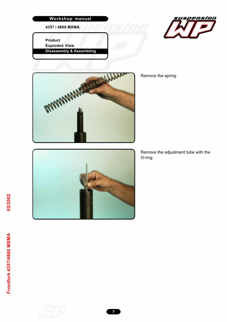
ProductExploded ViewDisassembly & Assembling
Workshop manual
4357 / 4860 MXMA
7
Fron
tfor
k 43
57/4
860
MXM
A02
/200
2
Remove the spring.
12_076
Remove the adjustment tube with theO-ring.
12_089
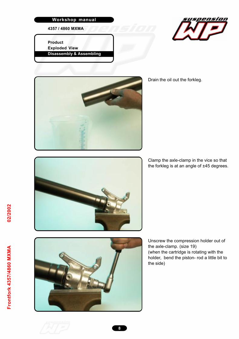
ProductExploded ViewDisassembly & Assembling
Workshop manual
4357 / 4860 MXMA
8
Fron
tfor
k 43
57/4
860
MXM
A02
/200
2
Clamp the axle-clamp in the vice so thatthe forkleg is at an angle of ±45 degrees.
12_095
Unscrew the compression holder out ofthe axle-clamp. (size 19)(when the cartridge is rotating with theholder, bend the piston- rod a little bit tothe side)
12_096
Drain the oil out the forkleg.
12_094

ProductExploded ViewDisassembly & Assembling
Workshop manual
4357 / 4860 MXMA
9
Fron
tfor
k 43
57/4
860
MXM
A02
/200
2
Remove holder compression.Caution: oil iscoming out the cartridge.
Disassemble the cartridge out theforkleg.
12_097
12_098
12_099
Disassemble the dust-wiper.
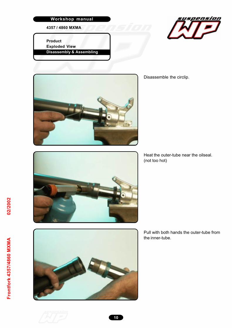
ProductExploded ViewDisassembly & Assembling
Workshop manual
4357 / 4860 MXMA
10
Fron
tfor
k 43
57/4
860
MXM
A02
/200
2
Disassemble the circlip.
Heat the outer-tube near the oilseal.(not too hot)
Pull with both hands the outer-tube fromthe inner-tube.
12_100
12_101
12_102
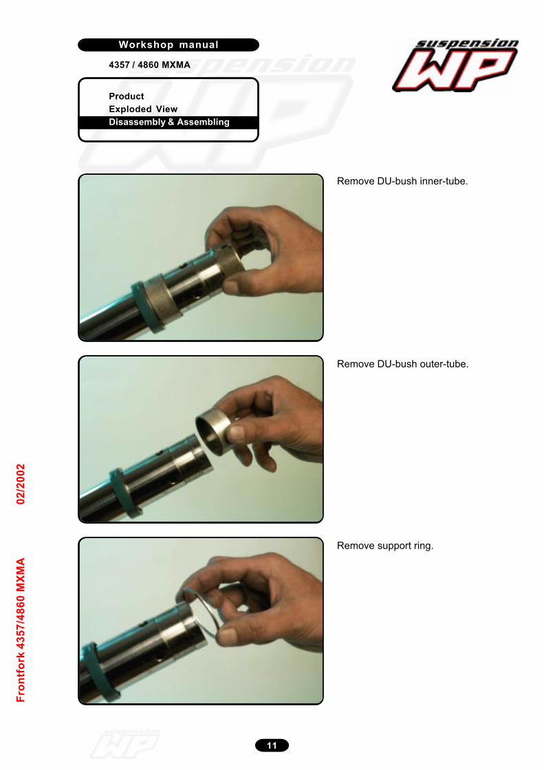
ProductExploded ViewDisassembly & Assembling
Workshop manual
4357 / 4860 MXMA
11
Fron
tfor
k 43
57/4
860
MXM
A02
/200
2
Remove DU-bush inner-tube.
Remove DU-bush outer-tube.
Remove support ring.
12_103
12_104
12_105
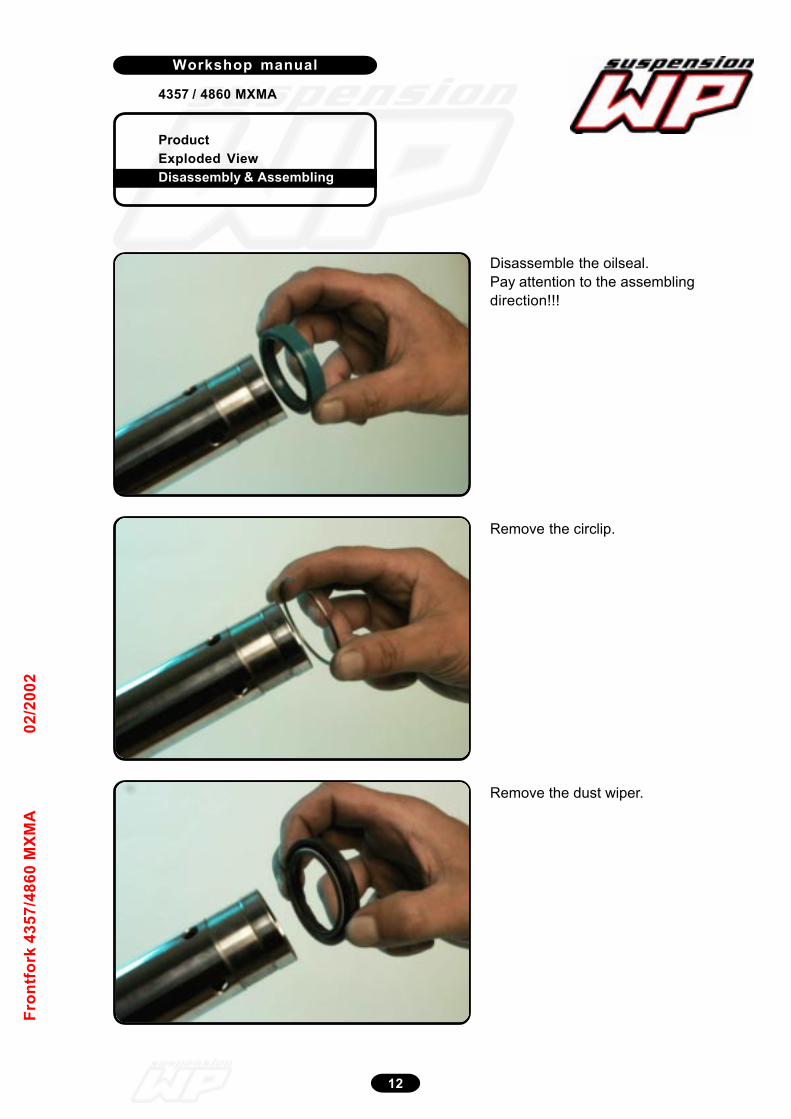
ProductExploded ViewDisassembly & Assembling
Workshop manual
4357 / 4860 MXMA
12
Fron
tfor
k 43
57/4
860
MXM
A02
/200
2
Disassemble the oilseal.Pay attention to the assemblingdirection!!!
Remove the circlip.
Remove the dust wiper.
12_106
12_107
12_108
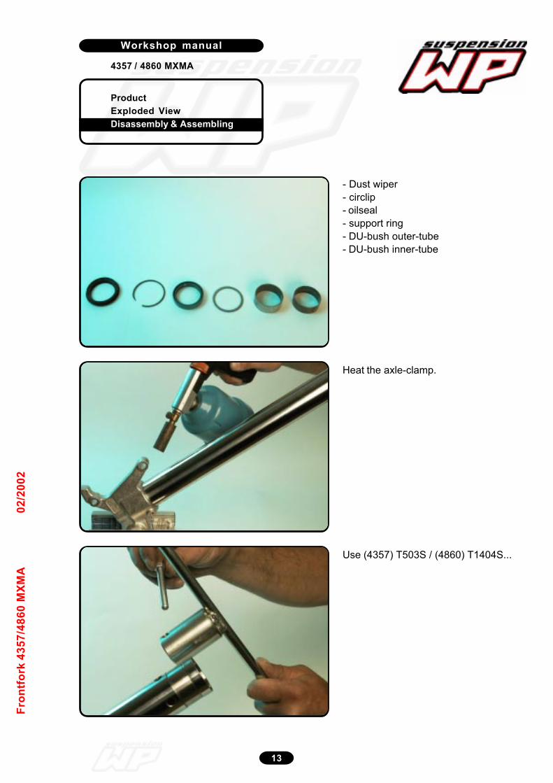
ProductExploded ViewDisassembly & Assembling
Workshop manual
4357 / 4860 MXMA
13
Fron
tfor
k 43
57/4
860
MXM
A02
/200
2
- Dust wiper- circlip- oilseal- support ring- DU-bush outer-tube- DU-bush inner-tube
Heat the axle-clamp.
Use (4357) T503S / (4860) T1404S...
12_109/110
12_111
12_112
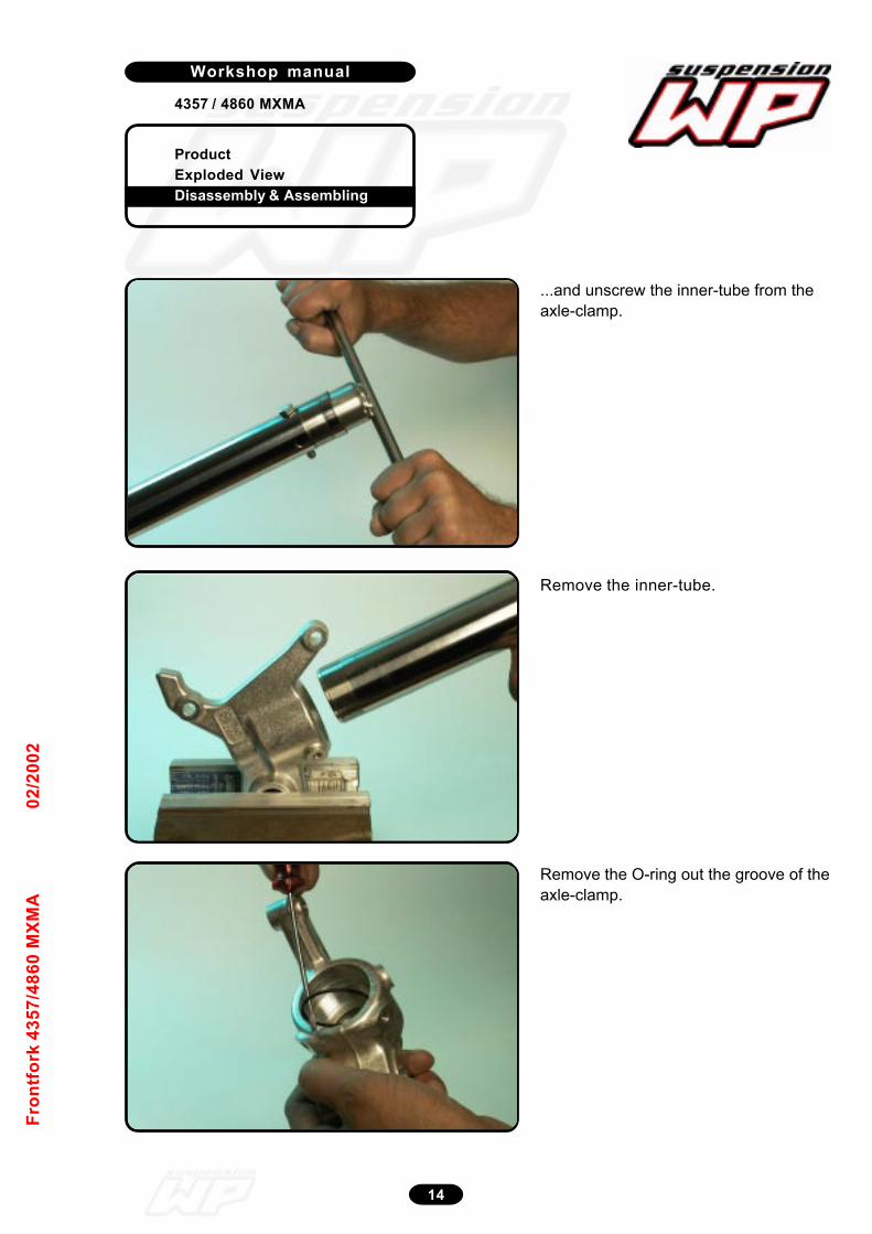
ProductExploded ViewDisassembly & Assembling
Workshop manual
4357 / 4860 MXMA
14
Fron
tfor
k 43
57/4
860
MXM
A02
/200
2
12_113
...and unscrew the inner-tube from theaxle-clamp.
Remove the O-ring out the groove of theaxle-clamp.
12_115
1 2 - 1 1 4
Remove the inner-tube.

ProductExploded ViewDisassembly & Assembling
Workshop manual
4357 / 4860 MXMA
15
Fron
tfor
k 43
57/4
860
MXM
A02
/200
2
Disassemble the adjustment knob.Pay attention to the steel balls andspring!!!
For PA version: Manual PA Front Fork2000
12_227
Unscrew plastic holder adjustment tubeout of the screw-cap.
12_228
Remove air release screw with O-ring.
12_230
Disassembly screw-cap
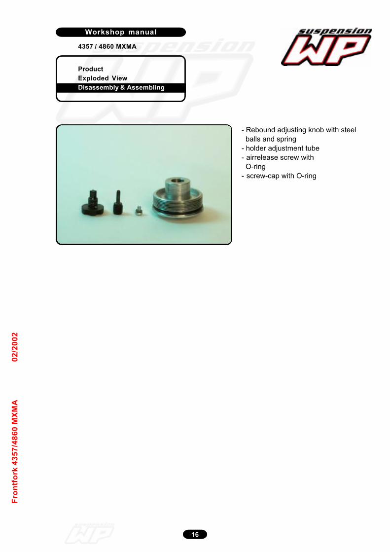
ProductExploded ViewDisassembly & Assembling
Workshop manual
4357 / 4860 MXMA
16
Fron
tfor
k 43
57/4
860
MXM
A02
/200
2
- Rebound adjusting knob with steel balls and spring- holder adjustment tube- airrelease screw with O-ring- screw-cap with O-ring
12_229
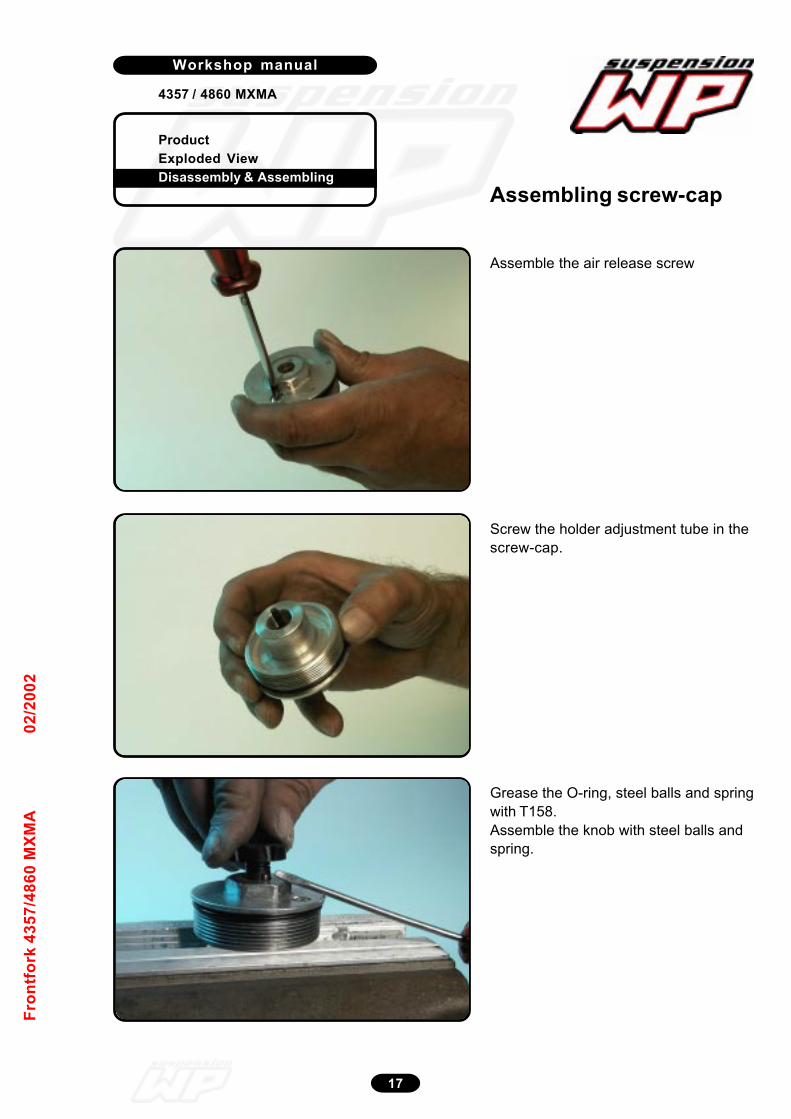
ProductExploded ViewDisassembly & Assembling
Workshop manual
4357 / 4860 MXMA
17
Fron
tfor
k 43
57/4
860
MXM
A02
/200
2
Assemble the air release screw
12_231
Screw the holder adjustment tube in thescrew-cap.
12_232
Grease the O-ring, steel balls and springwith T158.Assemble the knob with steel balls andspring.
12_233
Assembling screw-cap
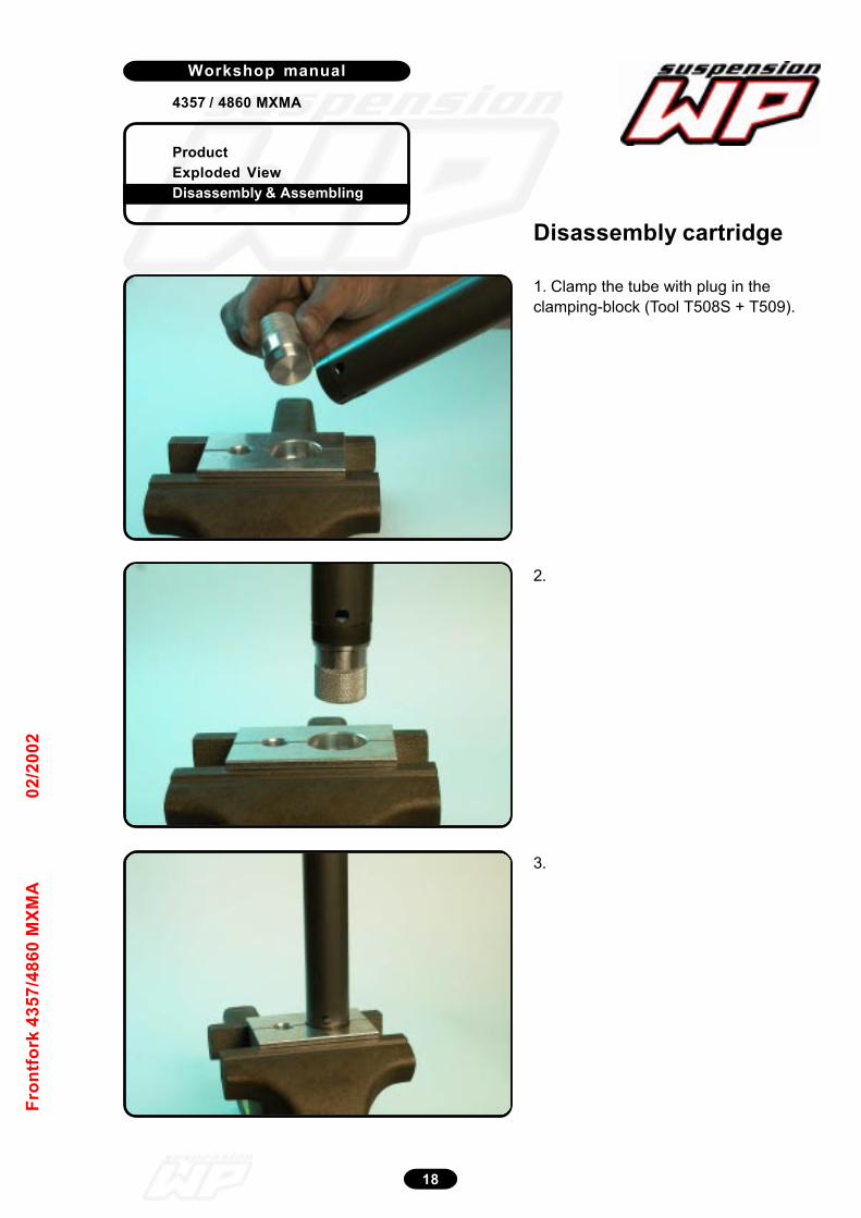
ProductExploded ViewDisassembly & Assembling
Workshop manual
4357 / 4860 MXMA
18
Fron
tfor
k 43
57/4
860
MXM
A02
/200
2
1. Clamp the tube with plug in theclamping-block (Tool T508S + T509).
2.
12_116
12_117
Disassembly cartridge
3.
12_118

ProductExploded ViewDisassembly & Assembling
Workshop manual
4357 / 4860 MXMA
19
Fron
tfor
k 43
57/4
860
MXM
A02
/200
2
Unscrew the screw sleeve (size 22).
Turn the screw sleeve out of the tube.
12_119
12_120
Disassemble the piston-rod “complete”.Pay attention to the piston ring!!!
12_121
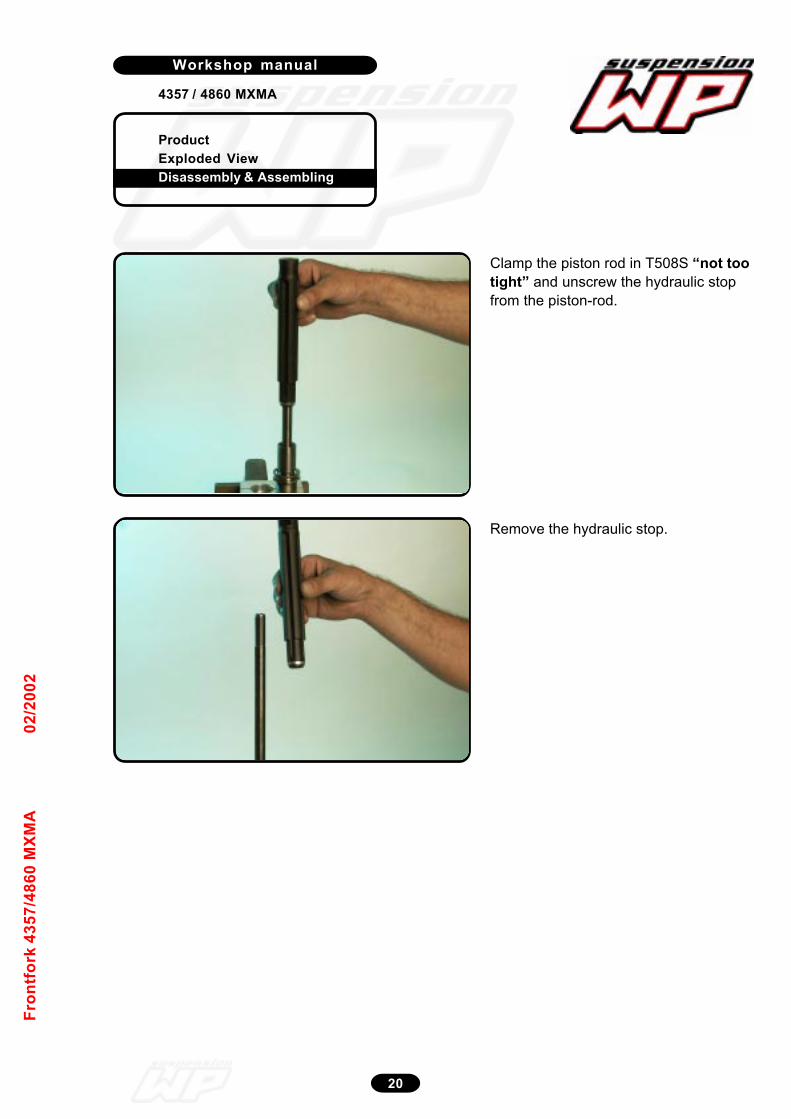
ProductExploded ViewDisassembly & Assembling
Workshop manual
4357 / 4860 MXMA
20
Fron
tfor
k 43
57/4
860
MXM
A02
/200
2
Clamp the piston rod in T508S “not tootight” and unscrew the hydraulic stopfrom the piston-rod.
12_164
Remove the hydraulic stop.
12_165
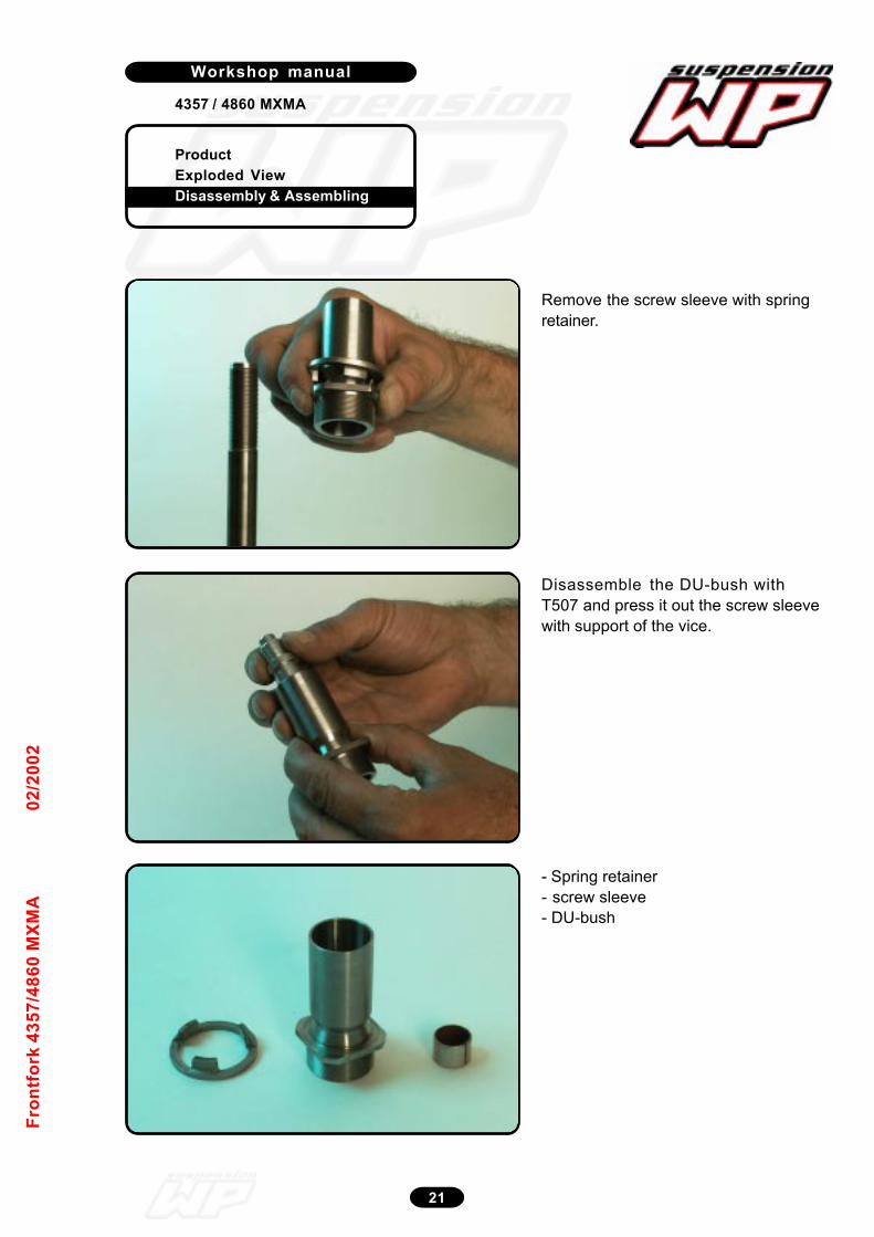
ProductExploded ViewDisassembly & Assembling
Workshop manual
4357 / 4860 MXMA
21
Fron
tfor
k 43
57/4
860
MXM
A02
/200
2
Remove the screw sleeve with springretainer.
12_167
Disassemble the DU-bush withT507 and press it out the screw sleevewith support of the vice.
12_168
- Spring retainer- screw sleeve- DU-bush
12_169
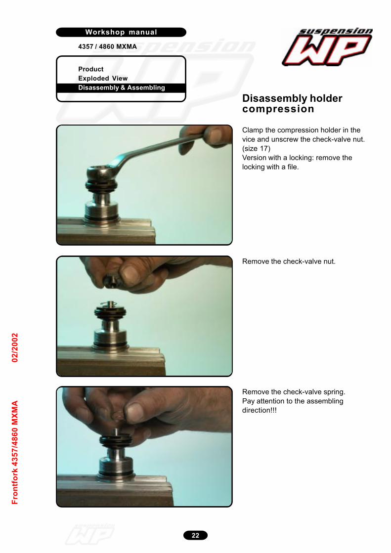
ProductExploded ViewDisassembly & Assembling
Workshop manual
4357 / 4860 MXMA
22
Fron
tfor
k 43
57/4
860
MXM
A02
/200
2
Clamp the compression holder in thevice and unscrew the check-valve nut.(size 17)Version with a locking: remove thelocking with a file.12_124
Remove the check-valve nut.
12_125
Remove the check-valve spring.Pay attention to the assemblingdirection!!!
12_126
Disassembly holdercompression

ProductExploded ViewDisassembly & Assembling
Workshop manual
4357 / 4860 MXMA
23
Fron
tfor
k 43
57/4
860
MXM
A02
/200
2
Remove the check-valve shim.
12_127
Disassemble the compressionpiston with O-ring.Pay attention to the assemblingdirection!!!
12_128
Place a screwdriver on top of the holderand remove the entire shim packet.
12_129
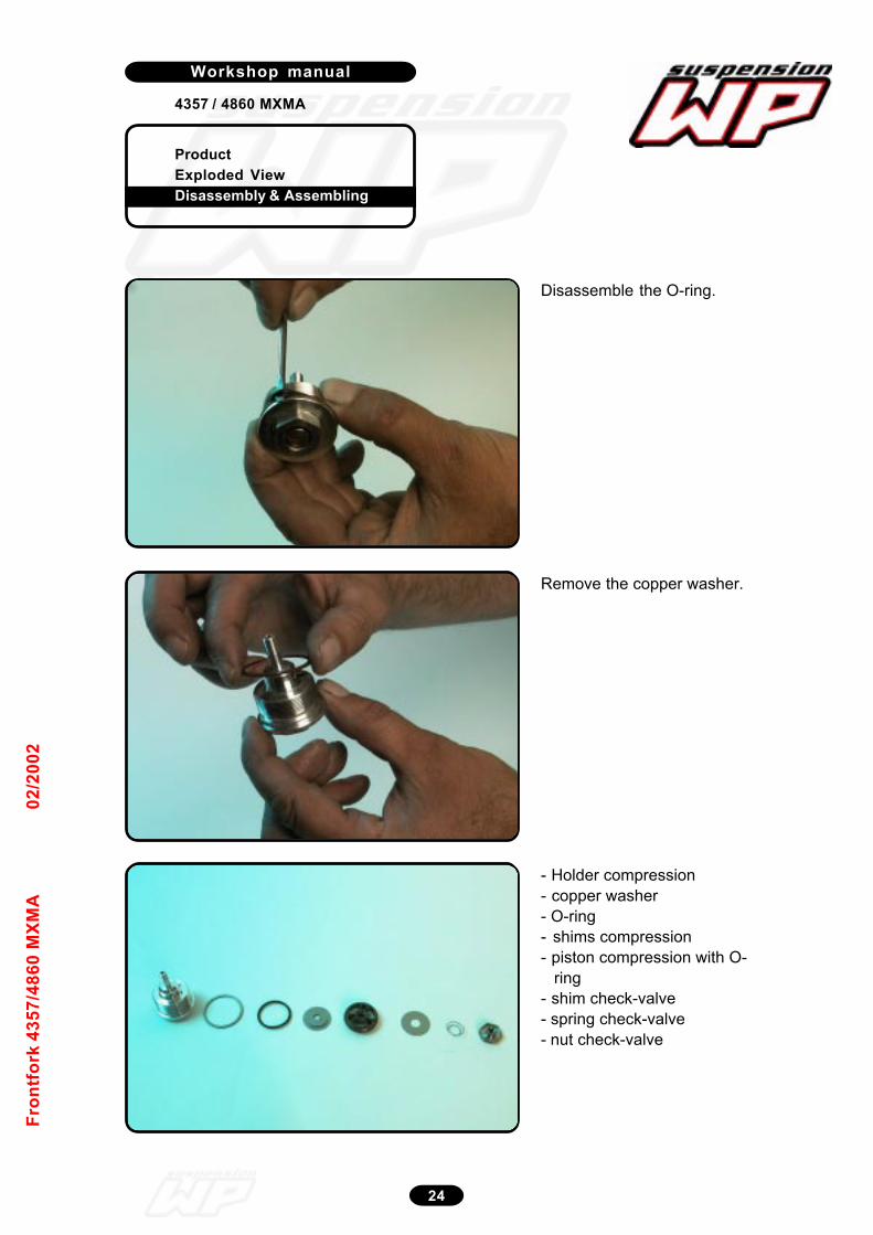
ProductExploded ViewDisassembly & Assembling
Workshop manual
4357 / 4860 MXMA
24
Fron
tfor
k 43
57/4
860
MXM
A02
/200
2
Disassemble the O-ring.
12_130
Remove the copper washer.
12_131
- Holder compression- copper washer- O-ring- shims compression- piston compression with O- ring- shim check-valve- spring check-valve- nut check-valve
12_132
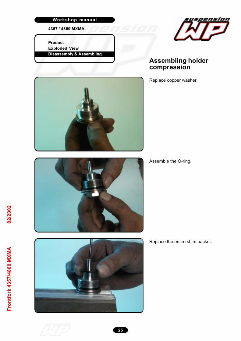
ProductExploded ViewDisassembly & Assembling
Workshop manual
4357 / 4860 MXMA
25
Fron
tfor
k 43
57/4
860
MXM
A02
/200
2
Replace copper washer.
12_133
Assemble the O-ring.
12_134
Replace the entire shim packet.
12_135
Assembling holdercompression

ProductExploded ViewDisassembly & Assembling
Workshop manual
4357 / 4860 MXMA
26
Fron
tfor
k 43
57/4
860
MXM
A02
/200
2
Replace piston.Pay attention to the assemblingdirection!!!
12_136
Replace shim check-valve.
12_137
Replace spring check-valve.Pay attention to the assemblingdirection!!!
12_138
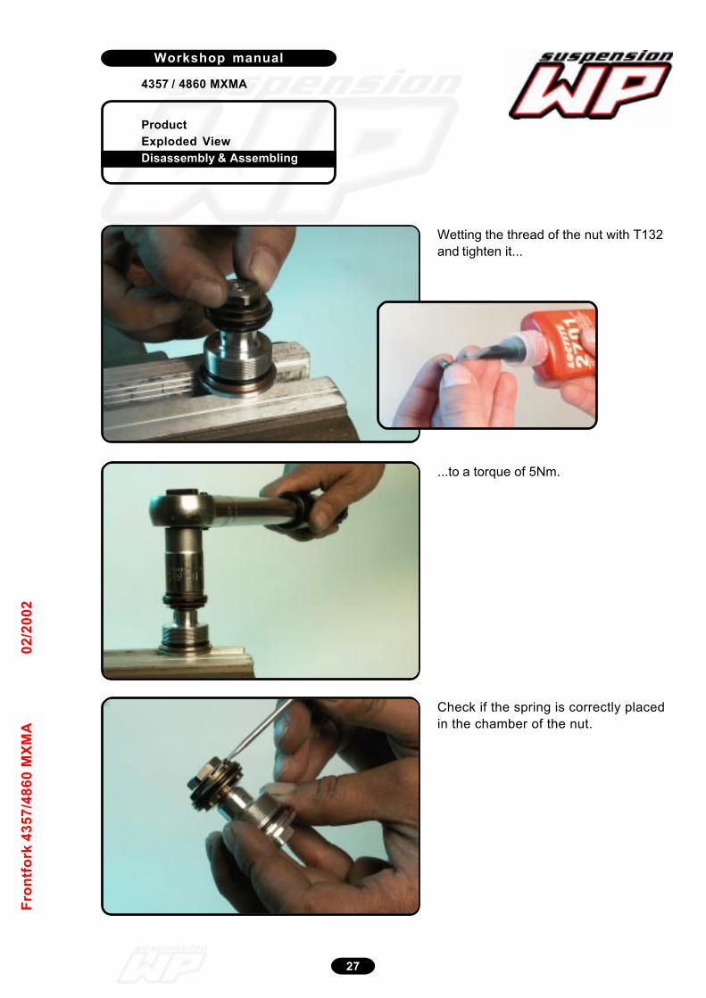
ProductExploded ViewDisassembly & Assembling
Workshop manual
4357 / 4860 MXMA
27
Fron
tfor
k 43
57/4
860
MXM
A02
/200
2
Wetting the thread of the nut with T132and tighten it...
12_140
...to a torque of 5Nm.
12_141
Check if the spring is correctly placedin the chamber of the nut.
12_142
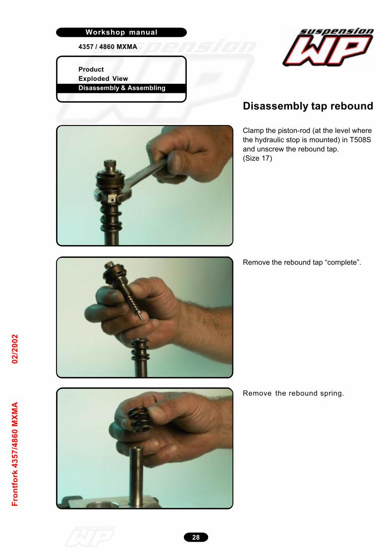
ProductExploded ViewDisassembly & Assembling
Workshop manual
4357 / 4860 MXMA
28
Fron
tfor
k 43
57/4
860
MXM
A02
/200
2
Clamp the piston-rod (at the level wherethe hydraulic stop is mounted) in T508Sand unscrew the rebound tap.(Size 17)
12_143
Remove the rebound tap “complete”.
12_144/145/146 -posterize
Remove the rebound spring.
12_147
Disassembly tap rebound
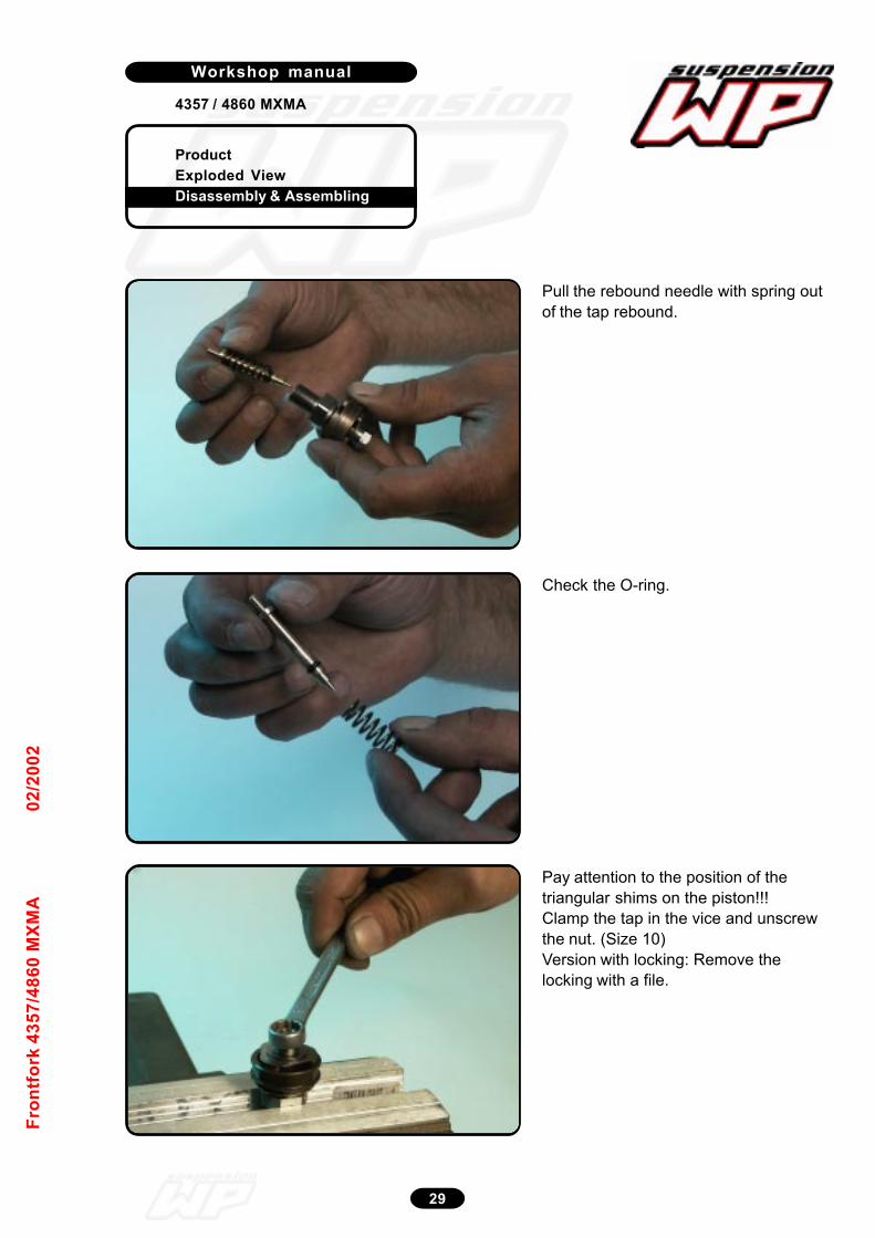
ProductExploded ViewDisassembly & Assembling
Workshop manual
4357 / 4860 MXMA
29
Fron
tfor
k 43
57/4
860
MXM
A02
/200
2
Pull the rebound needle with spring outof the tap rebound.
12_148
Check the O-ring.
12_149
Pay attention to the position of thetriangular shims on the piston!!!Clamp the tap in the vice and unscrewthe nut. (Size 10)Version with locking: Remove thelocking with a file.
12_150
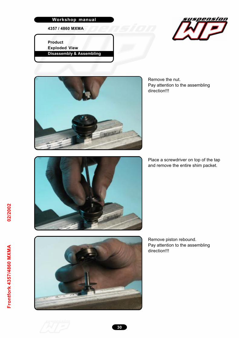
ProductExploded ViewDisassembly & Assembling
Workshop manual
4357 / 4860 MXMA
30
Fron
tfor
k 43
57/4
860
MXM
A02
/200
2
Remove the nut.Pay attention to the assemblingdirection!!!
12_151
Place a screwdriver on top of the tapand remove the entire shim packet.
12_152
Remove piston rebound.Pay attention to the assemblingdirection!!!
12_153
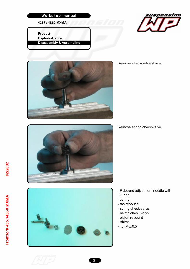
ProductExploded ViewDisassembly & Assembling
Workshop manual
4357 / 4860 MXMA
31
Fron
tfor
k 43
57/4
860
MXM
A02
/200
2
Remove check-valve shims.
12_154
Remove spring check-valve.
12_155
- Rebound adjustment needle with O-ring- spring- tap rebound- spring check-valve- shims check-valve- piston rebound- shims- nut M6x0.5
12_156

ProductExploded ViewDisassembly & Assembling
Workshop manual
4357 / 4860 MXMA
32
Fron
tfor
k 43
57/4
860
MXM
A02
/200
2
Assemble the spring and shims check-valve.
12_157
Assemble the piston rebound.Pay attention to the assemblingdirection!!!
12_158
Replace the shims.Pay attention to the position of thetriangular shims on the piston!!!
12_159
Assembling tap rebound
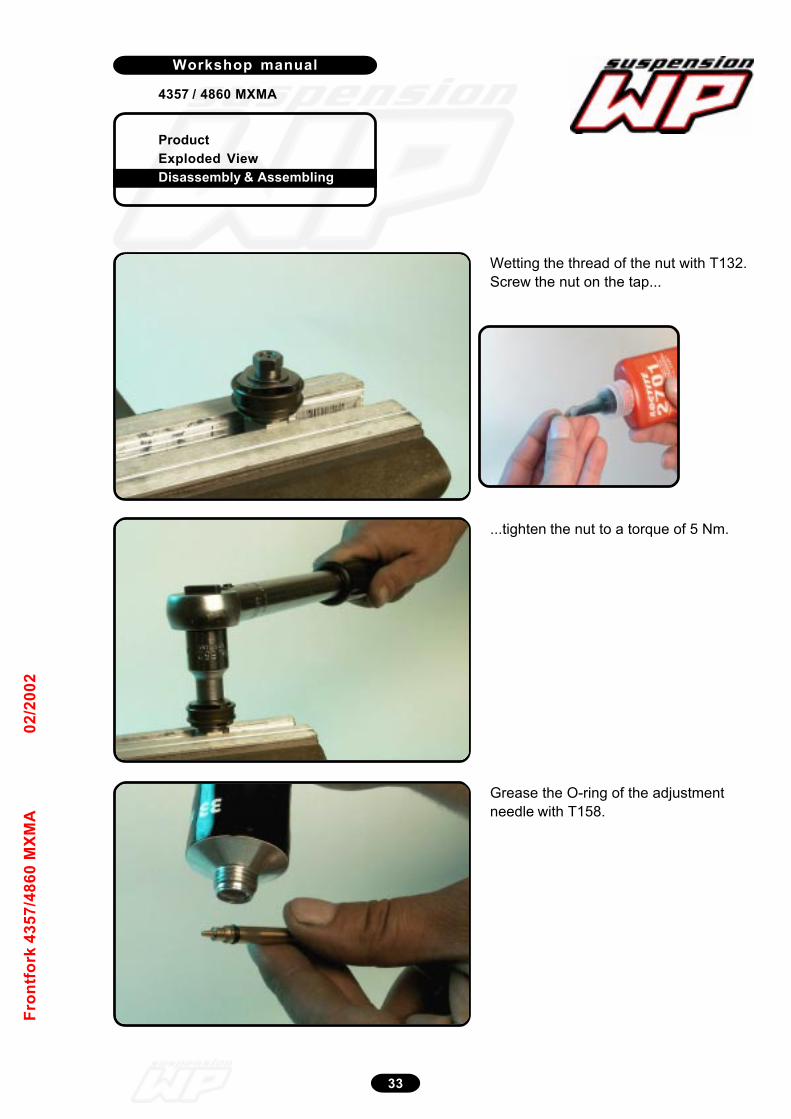
ProductExploded ViewDisassembly & Assembling
Workshop manual
4357 / 4860 MXMA
33
Fron
tfor
k 43
57/4
860
MXM
A02
/200
2
Wetting the thread of the nut with T132.Screw the nut on the tap...
12_160
...tighten the nut to a torque of 5 Nm.
12_161
Grease the O-ring of the adjustmentneedle with T158.
12_162
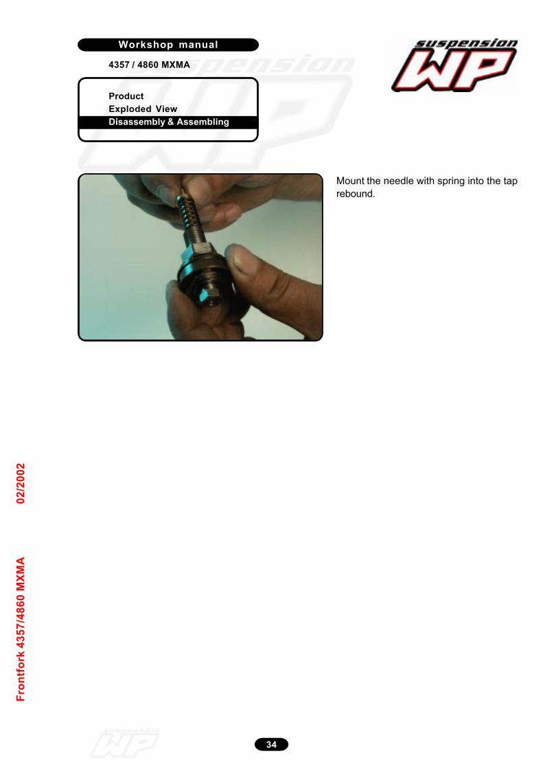
ProductExploded ViewDisassembly & Assembling
Workshop manual
4357 / 4860 MXMA
34
Fron
tfor
k 43
57/4
860
MXM
A02
/200
2
Mount the needle with spring into the taprebound.
12_163
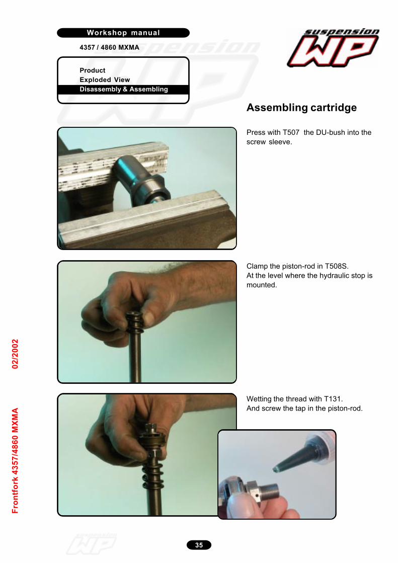
ProductExploded ViewDisassembly & Assembling
Workshop manual
4357 / 4860 MXMA
35
Fron
tfor
k 43
57/4
860
MXM
A02
/200
2
Press with T507 the DU-bush into thescrew sleeve.
12_171
Clamp the piston-rod in T508S.At the level where the hydraulic stop ismounted.
12_172
Wetting the thread with T131.And screw the tap in the piston-rod.
12_173
Assembling cartridge

ProductExploded ViewDisassembly & Assembling
Workshop manual
4357 / 4860 MXMA
36
Fron
tfor
k 43
57/4
860
MXM
A02
/200
2
Tighten the tap rebound.
12_174
Clamp the piston-rod “not too tight” inat the other side and replace the screwsleeve with spring retainer.
12_175
Screw the hydraulic stop “hand tight” tothe end of the thread of the piston-rod.
12_176

ProductExploded ViewDisassembly & Assembling
Workshop manual
4357 / 4860 MXMA
37
Fron
tfor
k 43
57/4
860
MXM
A02
/200
2
Clamp the tube with plug in theclamping block (T508S and T509) andassemble the piston-rod “cpl.” into thetube.Guide the piston ring!!!12_177
Before assembling wet the thread ofthe screw sleeve with T131.
Screw the screw sleeve into the tube.12_178
Tighten the screw sleeve.
12_179
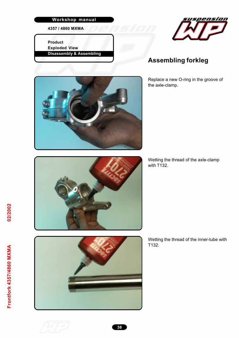
ProductExploded ViewDisassembly & Assembling
Workshop manual
4357 / 4860 MXMA
38
Fron
tfor
k 43
57/4
860
MXM
A02
/200
2
Replace a new O-ring in the groove ofthe axle-clamp.
12_180
Wetting the thread of the axle-clampwith T132.
12_181
Wetting the thread of the inner-tube withT132.
12_182
Assembling forkleg
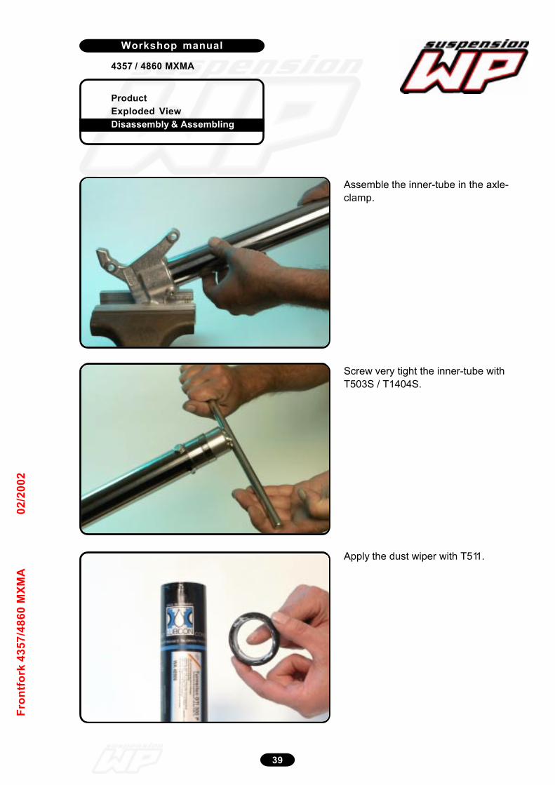
ProductExploded ViewDisassembly & Assembling
Workshop manual
4357 / 4860 MXMA
39
Fron
tfor
k 43
57/4
860
MXM
A02
/200
2
Assemble the inner-tube in the axle-clamp.
12_183
Screw very tight the inner-tube withT503S / T1404S.
12_184
Apply the dust wiper with T511.
14_0007
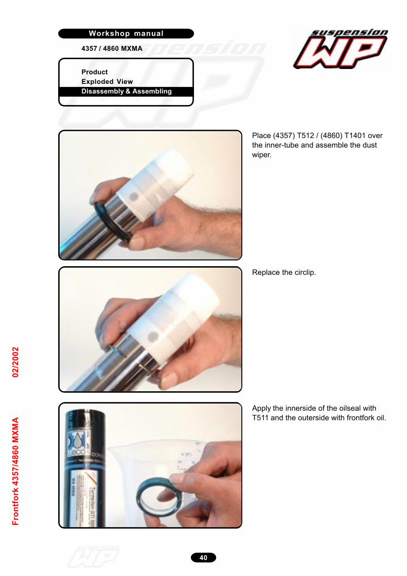
ProductExploded ViewDisassembly & Assembling
Workshop manual
4357 / 4860 MXMA
40
Fron
tfor
k 43
57/4
860
MXM
A02
/200
2
Place (4357) T512 / (4860) T1401 overthe inner-tube and assemble the dustwiper.
14_0008
Replace the circlip.
14_0011
Apply the innerside of the oilseal withT511 and the outerside with frontfork oil.
14_0010
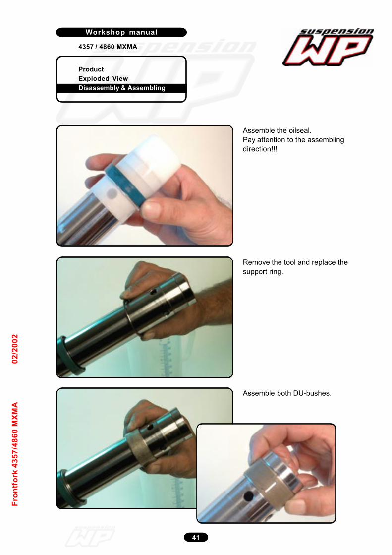
ProductExploded ViewDisassembly & Assembling
Workshop manual
4357 / 4860 MXMA
41
Fron
tfor
k 43
57/4
860
MXM
A02
/200
2
Assemble the oilseal.Pay attention to the assemblingdirection!!!
14_0012
Remove the tool and replace thesupport ring.
12_190
Assemble both DU-bushes.
12_191
14_0013
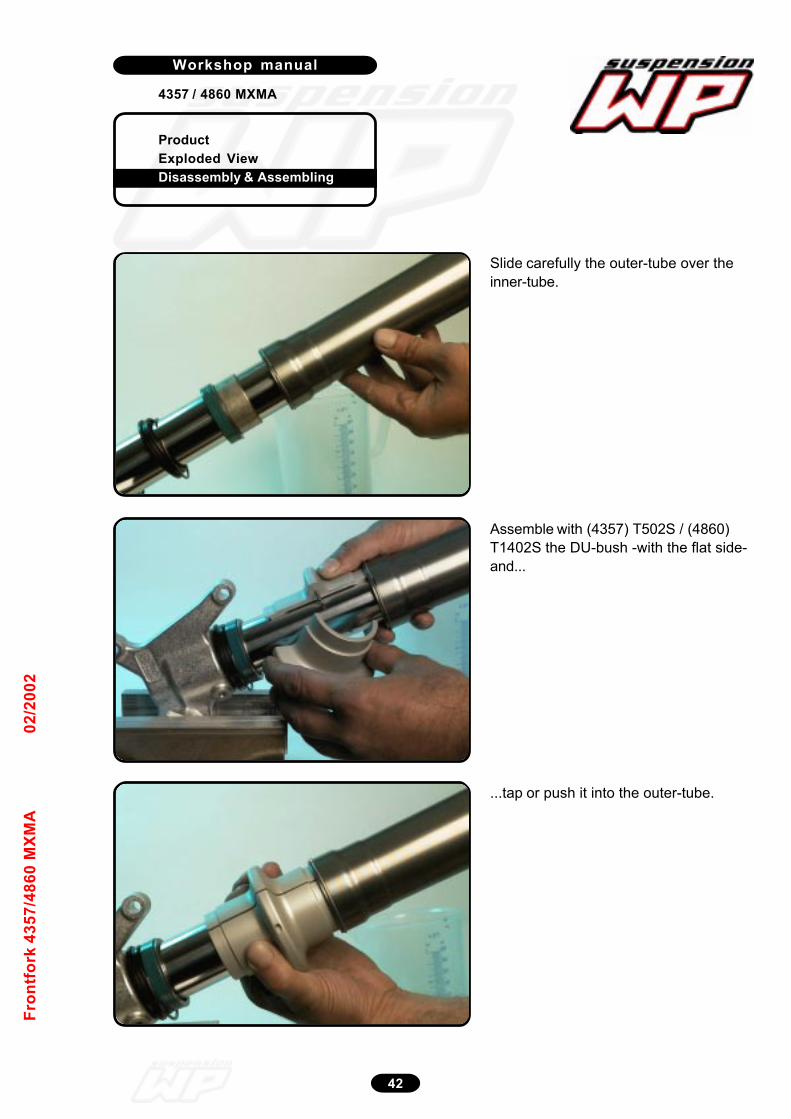
ProductExploded ViewDisassembly & Assembling
Workshop manual
4357 / 4860 MXMA
42
Fron
tfor
k 43
57/4
860
MXM
A02
/200
2
Slide carefully the outer-tube over theinner-tube.
12_193
Assemble with (4357) T502S / (4860)T1402S the DU-bush -with the flat side-and...
12_194
...tap or push it into the outer-tube.
12_195
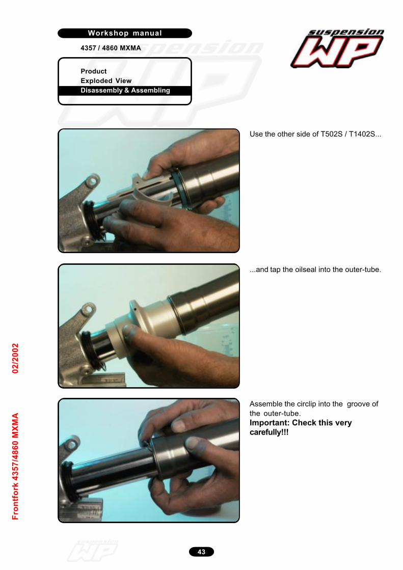
ProductExploded ViewDisassembly & Assembling
Workshop manual
4357 / 4860 MXMA
43
Fron
tfor
k 43
57/4
860
MXM
A02
/200
2
Use the other side of T502S / T1402S...
12_196
...and tap the oilseal into the outer-tube.
12_197
Assemble the circlip into the groove ofthe outer-tube.Important: Check this verycarefully!!!
12_198
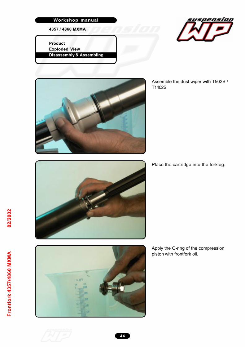
ProductExploded ViewDisassembly & Assembling
Workshop manual
4357 / 4860 MXMA
44
Fron
tfor
k 43
57/4
860
MXM
A02
/200
2
Assemble the dust wiper with T502S /T1402S.
12_199
Apply the O-ring of the compressionpiston with frontfork oil.
12_202
Place the cartridge into the forkleg.
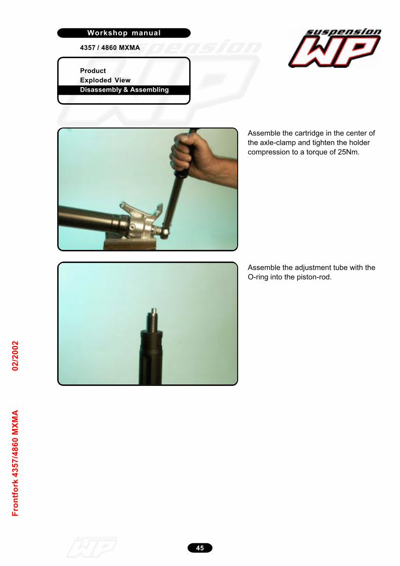
ProductExploded ViewDisassembly & Assembling
Workshop manual
4357 / 4860 MXMA
45
Fron
tfor
k 43
57/4
860
MXM
A02
/200
2
Assemble the cartridge in the center ofthe axle-clamp and tighten the holdercompression to a torque of 25Nm.
12_203
Assemble the adjustment tube with theO-ring into the piston-rod.
12_204
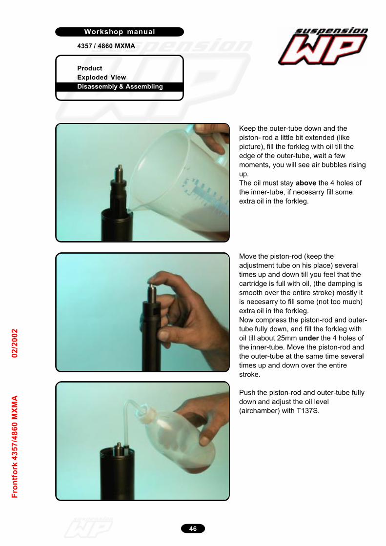
ProductExploded ViewDisassembly & Assembling
Workshop manual
4357 / 4860 MXMA
46
Fron
tfor
k 43
57/4
860
MXM
A02
/200
2
Keep the outer-tube down and thepiston- rod a little bit extended (likepicture), fill the forkleg with oil till theedge of the outer-tube, wait a fewmoments, you will see air bubbles risingup.The oil must stay above the 4 holes ofthe inner-tube, if necesarry fill someextra oil in the forkleg.
12_206
Move the piston-rod (keep theadjustment tube on his place) severaltimes up and down till you feel that thecartridge is full with oil, (the damping issmooth over the entire stroke) mostly itis necesarry to fill some (not too much)extra oil in the forkleg.Now compress the piston-rod and outer-tube fully down, and fill the forkleg withoil till about 25mm under the 4 holes ofthe inner-tube. Move the piston-rod andthe outer-tube at the same time severaltimes up and down over the entirestroke.
Push the piston-rod and outer-tube fullydown and adjust the oil level(airchamber) with T137S.
12_208
12_209

ProductExploded ViewDisassembly & Assembling
Workshop manual
4357 / 4860 MXMA
47
Fron
tfor
k 43
57/4
860
MXM
A02
/200
2
Pull the piston-rod out and assemble thespring.
12_211
Pull the spring downwards and placeopen-end spanner 22 on the hydraulicstop.
12_212
Replace first the steel washer on thespring, then the preload spacer(s).
12_213
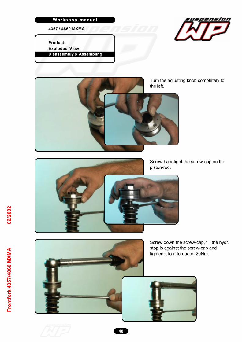
ProductExploded ViewDisassembly & Assembling
Workshop manual
4357 / 4860 MXMA
48
Fron
tfor
k 43
57/4
860
MXM
A02
/200
2
Turn the adjusting knob completely tothe left.
12_220
Screw handtight the screw-cap on thepiston-rod.
12_221
Screw down the screw-cap, till the hydr.stop is against the screw-cap andtighten it to a torque of 20Nm.
12_222
12_214
12_215
12_216
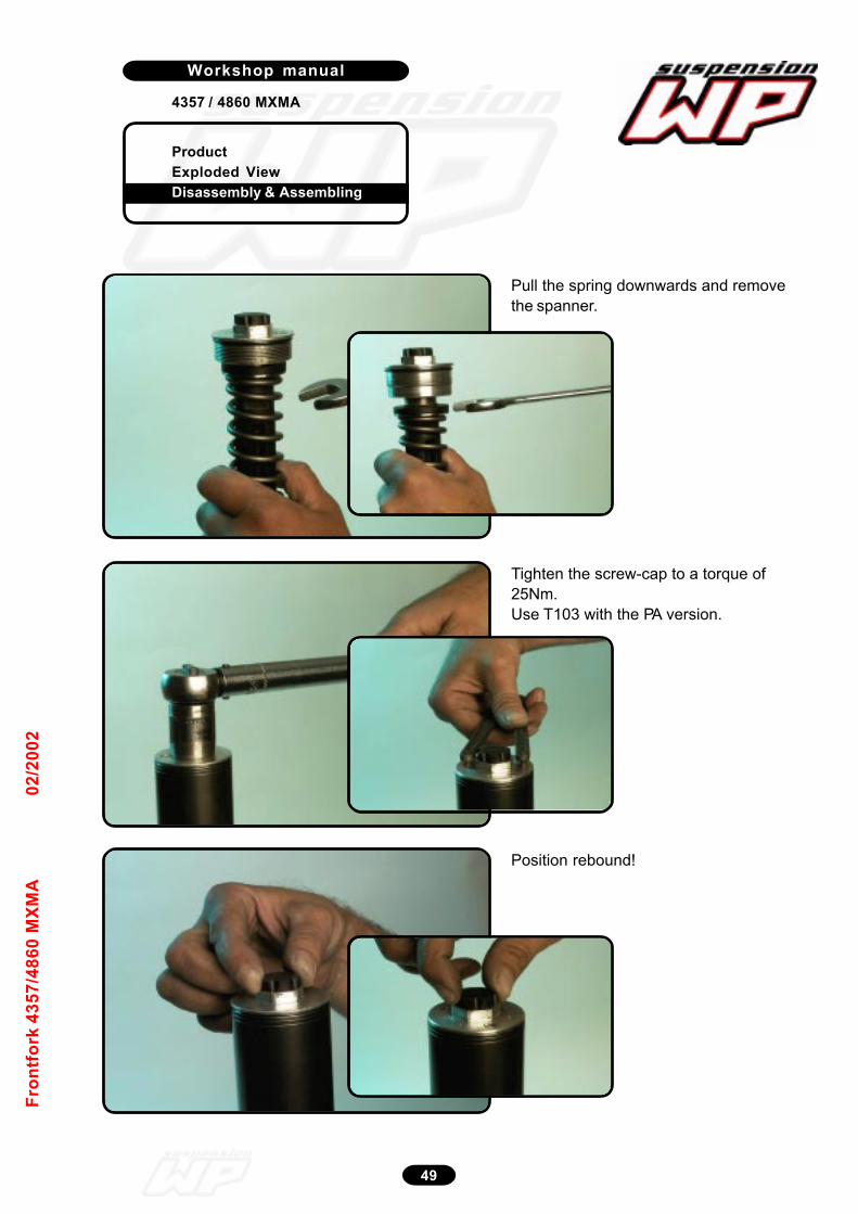
ProductExploded ViewDisassembly & Assembling
Workshop manual
4357 / 4860 MXMA
49
Fron
tfor
k 43
57/4
860
MXM
A02
/200
2
Pull the spring downwards and removethe spanner.
12_223
Tighten the screw-cap to a torque of25Nm.Use T103 with the PA version.
12_224
Position rebound!
12_225
12_217
12_218
12_219
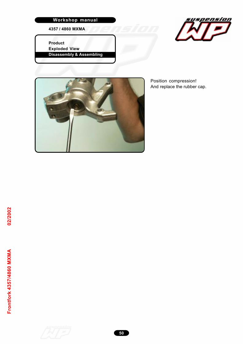
ProductExploded ViewDisassembly & Assembling
Workshop manual
4357 / 4860 MXMA
50
Fron
tfor
k 43
57/4
860
MXM
A02
/200
2
Position compression!And replace the rubber cap.
12_226

Workshop manual
Product
Exploded View
Disassembly & Assembling
1
4618 BAVP 85 SX
Sh
oc
k a
bs
orb
er
46
18
BA
VP
85
SX
09
/20
04
Schok absorber
4618 BAVP 85 SX
Introduction 2Exploded view 3Disassembly shock absorber 4Disassembly piston rod 12Assembling piston rod 23
Disassembly adaptor DU-bush 33Assembling adaptor DU-bush 36Disassembly tube side 44
Assembling tube side 54Bleeding 68On pressure with nitrogen 72Mounting spring 74Adjustments 76
Product
Exploded View
Disassembly & Assembling
Workshop manual
4618 BAVP 85 SX
Werkplaatshandboek
2
Sh
oc
k a
bs
orb
er
46
18
BA
VP
85
SX
09
/20
04
Introduction
General notice
Pay attention to the following notes, when you are working
with WP suspension products as described in this
workshop manual:
Always use clean and professional tools.
Regular you need next to the general equipment, the
special tools of WP Suspension.
These tools with a unique “T” number (available at
WP Suspension) protect you from damaging the parts.
Always use aluminium protector-plates, when clamping
our products or parts in the vice.
Always replace damaged or worn parts.
Clean all parts before assembling.
Caution:
Many times it is necesarry to assemble parts with T131,
T132 and T163.
These parts must dry for at least four hours!!
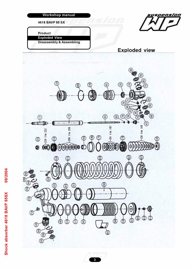
Workshop manual
Product
Exploded View
Disassembly & Assembling
3
4618 BAVP 85 SX
Sh
oc
k a
bs
orb
er
46
18
BA
VP
85
SX
09
/20
04
Exploded view

Product
Exploded View
Disassembly & Assembling
Workshop manual
4618 BAVP 85 SX
Werkplaatshandboek
4
Sh
oc
k a
bs
orb
er
46
18
BA
VP
85
SX
09
/20
04
Disassembly Shockabsorber
Measure the spring preload between the
spring retainer and lock retainer.
Take note of the angle of the position of
the Allen bolt!
Unscrew the Allen bolt.
Release the spring preload with open
spanner T106.
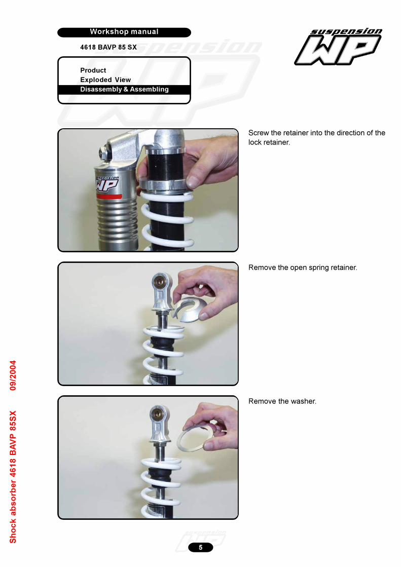
Product
Exploded View
Disassembly & Assembling
Workshop manual
4618 BAVP 85 SX
Werkplaatshandboek
5
Sh
oc
k a
bs
orb
er
46
18
BA
VP
85
SX
09
/20
04
Screw the retainer into the direction of the
lock retainer.
Remove the washer.
Remove the open spring retainer.
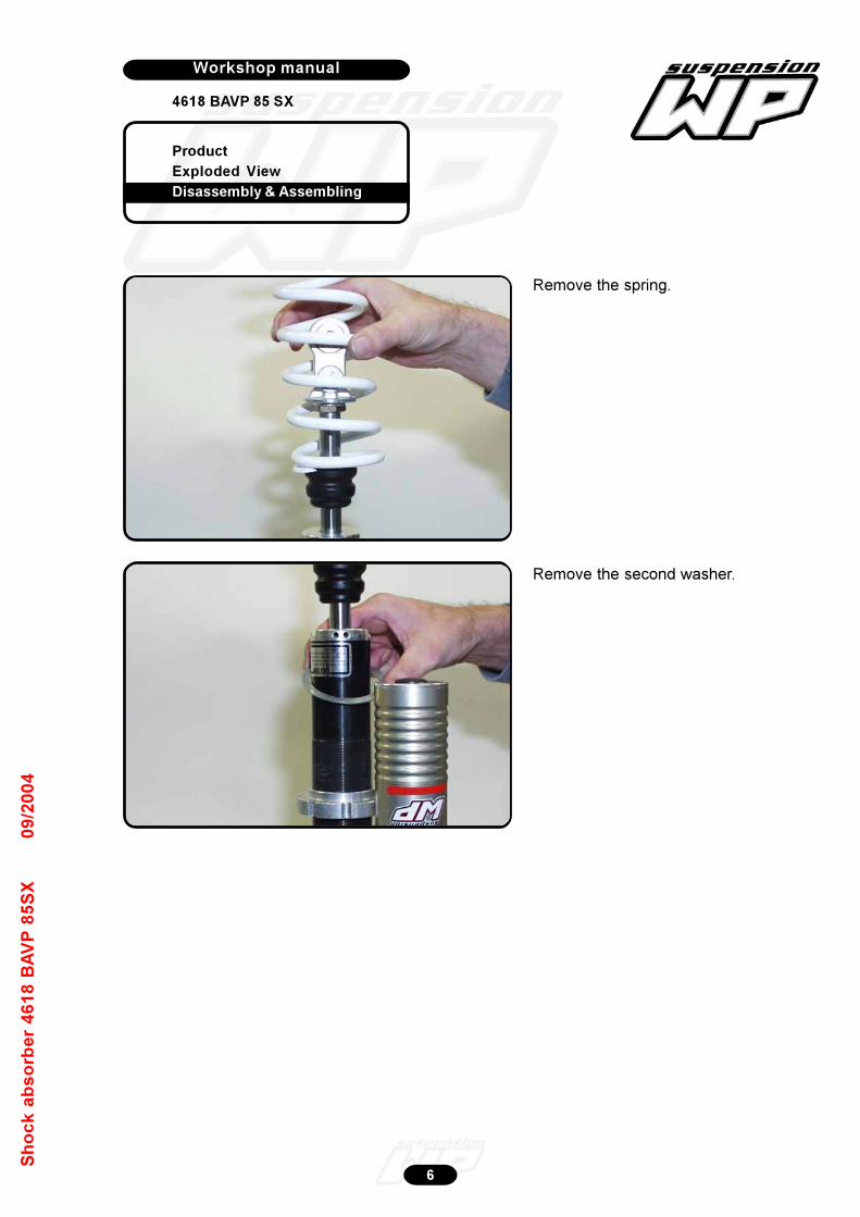
Product
Exploded View
Disassembly & Assembling
Workshop manual
4618 BAVP 85 SX
Werkplaatshandboek
6
Sh
oc
k a
bs
orb
er
46
18
BA
VP
85
SX
09
/20
04
Remove the spring.
Remove the second washer.
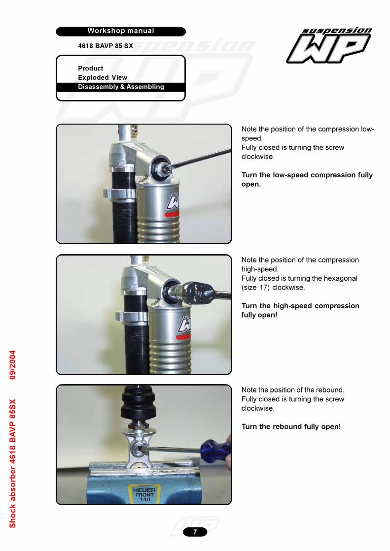
Product
Exploded View
Disassembly & Assembling
Workshop manual
4618 BAVP 85 SX
Werkplaatshandboek
7
Sh
oc
k a
bs
orb
er
46
18
BA
VP
85
SX
09
/20
04
Note the position of the compression low-
speed.
Fully closed is turning the screw
clockwise.
Turn the low-speed compression fully
open.
Note the position of the compression
high-speed.
Fully closed is turning the hexagonal
(size 17) clockwise.
Turn the high-speed compression
fully open!
Note the position of the rebound.
Fully closed is turning the screw
clockwise.
Turn the rebound fully open!
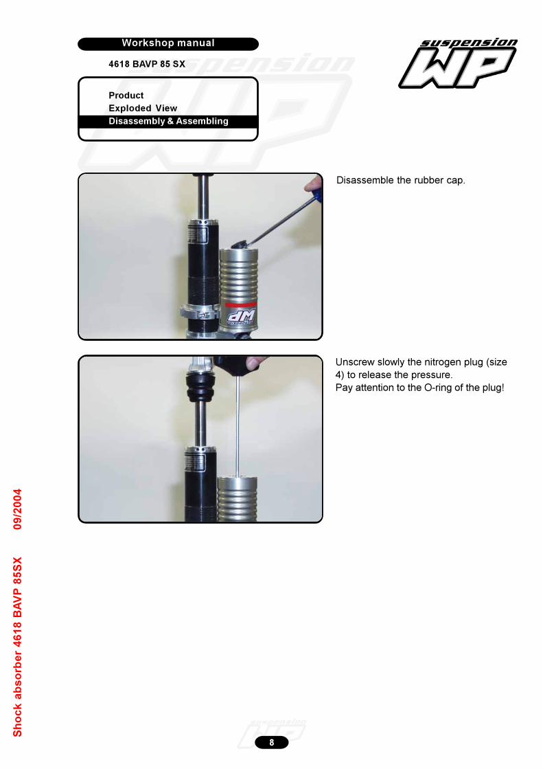
Product
Exploded View
Disassembly & Assembling
Workshop manual
4618 BAVP 85 SX
Werkplaatshandboek
8
Sh
oc
k a
bs
orb
er
46
18
BA
VP
85
SX
09
/20
04
Disassemble the rubber cap.
Unscrew slowly the nitrogen plug (size
4) to release the pressure.
Pay attention to the O-ring of the plug!
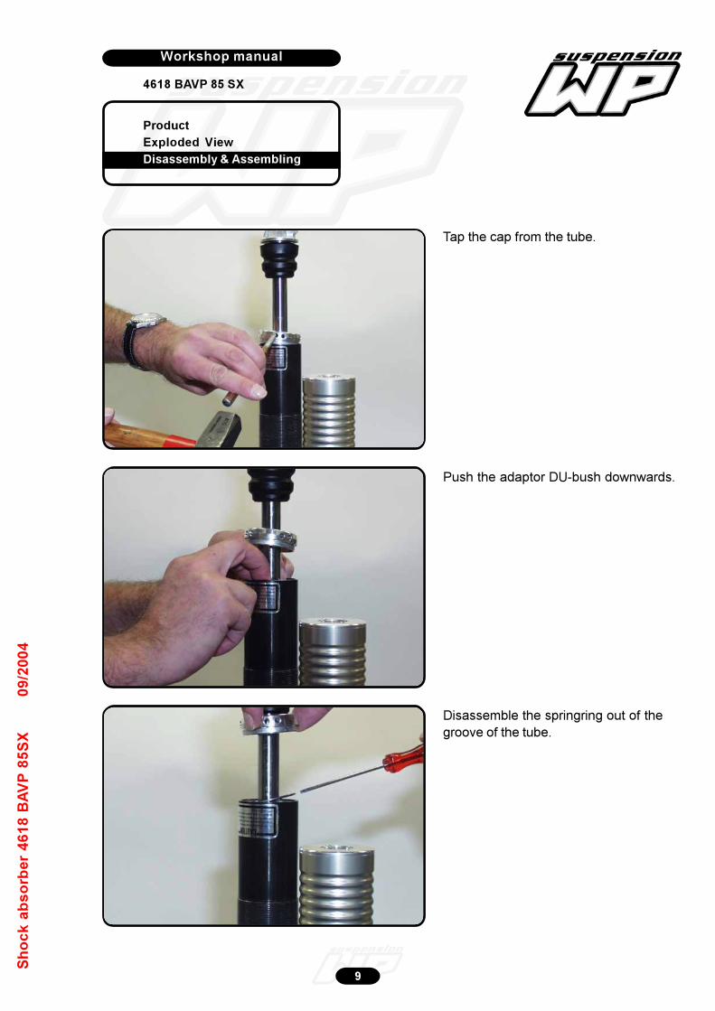
Product
Exploded View
Disassembly & Assembling
Workshop manual
4618 BAVP 85 SX
Werkplaatshandboek
9
Sh
oc
k a
bs
orb
er
46
18
BA
VP
85
SX
09
/20
04
Tap the cap from the tube.
Disassemble the springring out of the
groove of the tube.
Push the adaptor DU-bush downwards.
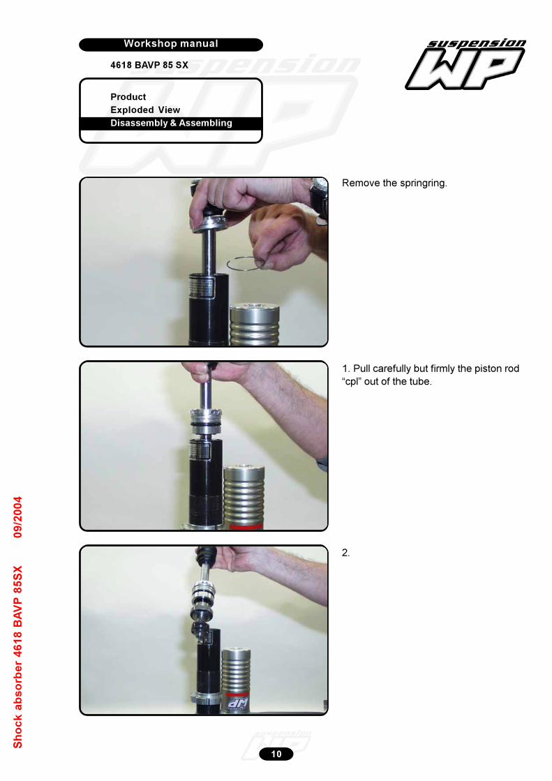
Product
Exploded View
Disassembly & Assembling
Workshop manual
4618 BAVP 85 SX
Werkplaatshandboek
10
Sh
oc
k a
bs
orb
er
46
18
BA
VP
85
SX
09
/20
04
Remove the springring.
2.
1. Pull carefully but firmly the piston rod
“cpl” out of the tube.
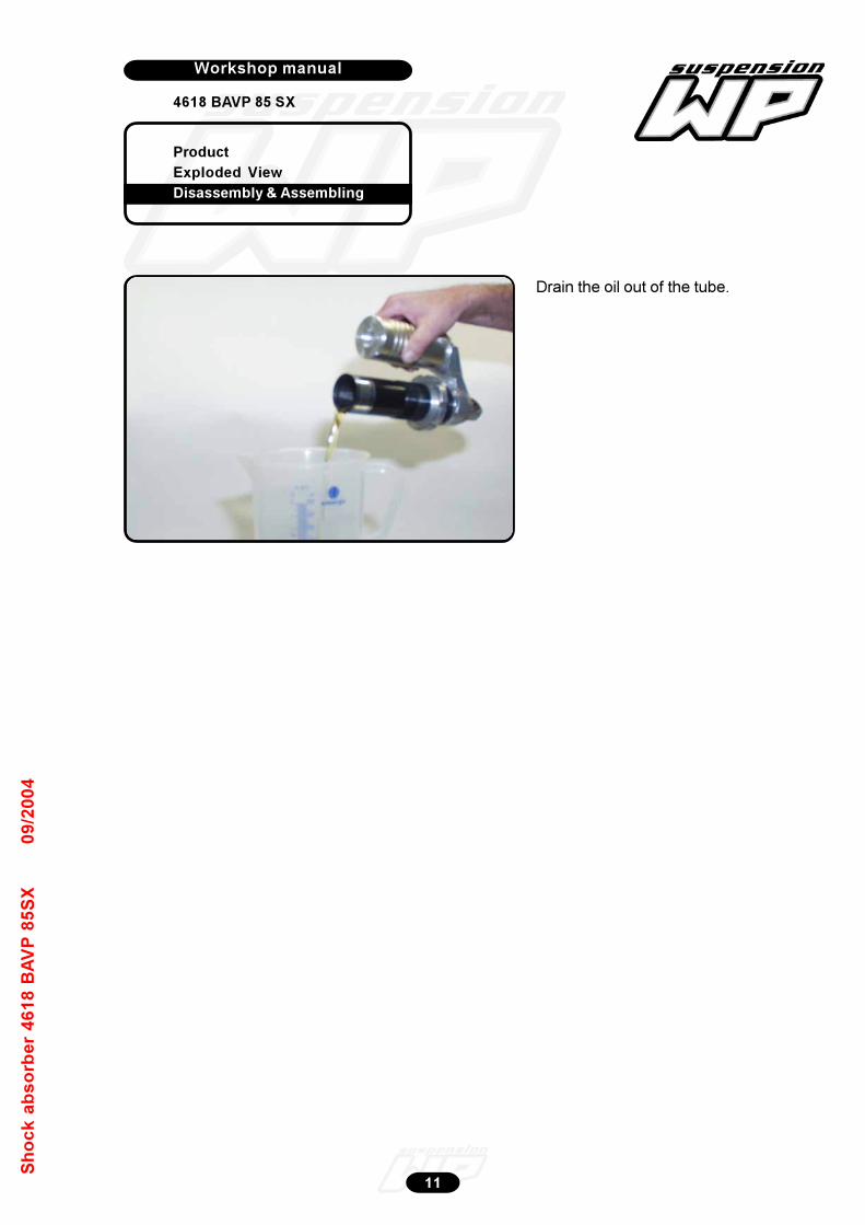
Product
Exploded View
Disassembly & Assembling
Workshop manual
4618 BAVP 85 SX
Werkplaatshandboek
11
Sh
oc
k a
bs
orb
er
46
18
BA
VP
85
SX
09
/20
04
Drain the oil out of the tube.

Product
Exploded View
Disassembly & Assembling
Workshop manual
4618 BAVP 85 SX
Werkplaatshandboek
12
Sh
oc
k a
bs
orb
er
46
18
BA
VP
85
SX
09
/20
04
Place the piston rod “cpl” in the vice.
Turn off the nut.
Disassembly piston rod
Unscrew the piston rod nut (size 17).
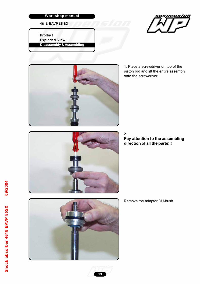
Product
Exploded View
Disassembly & Assembling
Workshop manual
4618 BAVP 85 SX
Werkplaatshandboek
13
Sh
oc
k a
bs
orb
er
46
18
BA
VP
85
SX
09
/20
04
1. Place a screwdriver on top of the
piston rod and lift the entire assembly
onto the screwdriver.
2.
Pay attention to the assemblingdirection of all the parts!!!
Remove the adaptor DU-bush
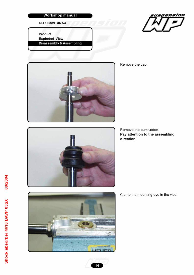
Product
Exploded View
Disassembly & Assembling
Workshop manual
4618 BAVP 85 SX
Werkplaatshandboek
14
Sh
oc
k a
bs
orb
er
46
18
BA
VP
85
SX
09
/20
04
Remove the cap.
Remove the bumrubber.
Pay attention to the assembling
direction!
Clamp the mounting-eye in the vice.

Product
Exploded View
Disassembly & Assembling
Workshop manual
4618 BAVP 85 SX
Werkplaatshandboek
15
Sh
oc
k a
bs
orb
er
46
18
BA
VP
85
SX
09
/20
04
Unscrew the screw cap out of the
mounting-eye with T1218.
Turn the screw cap with the adjustment
adaptor out of the mounting-eye.
Turn the adjustment needle out of the
mounting-eye.
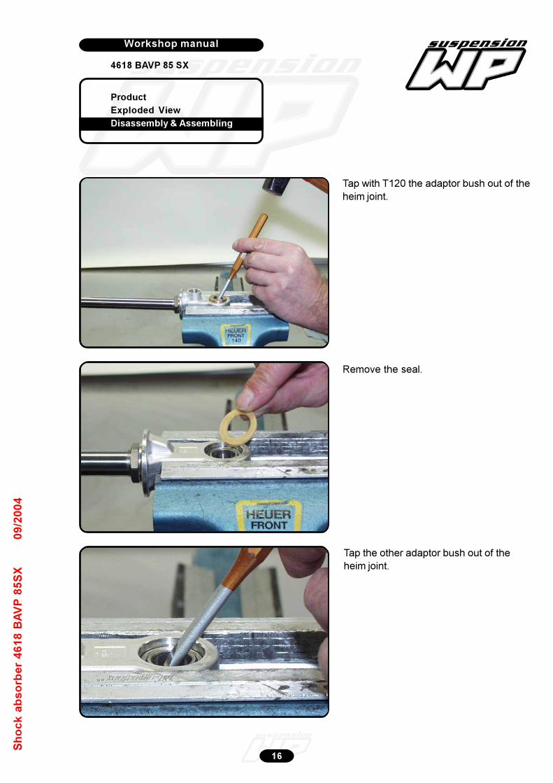
Product
Exploded View
Disassembly & Assembling
Workshop manual
4618 BAVP 85 SX
Werkplaatshandboek
16
Sh
oc
k a
bs
orb
er
46
18
BA
VP
85
SX
09
/20
04
Tap with T120 the adaptor bush out of the
heim joint.
Remove the seal.
Tap the other adaptor bush out of the
heim joint.

Product
Exploded View
Disassembly & Assembling
Workshop manual
4618 BAVP 85 SX
Werkplaatshandboek
17
Sh
oc
k a
bs
orb
er
46
18
BA
VP
85
SX
09
/20
04
Push with T1207S the heim joint against
the springring of the mounting-eye.
Disassemble the springring.
Push with T1207S the heim joint out of
the mounting-eye.
Disassemble when necessary the other
springring.
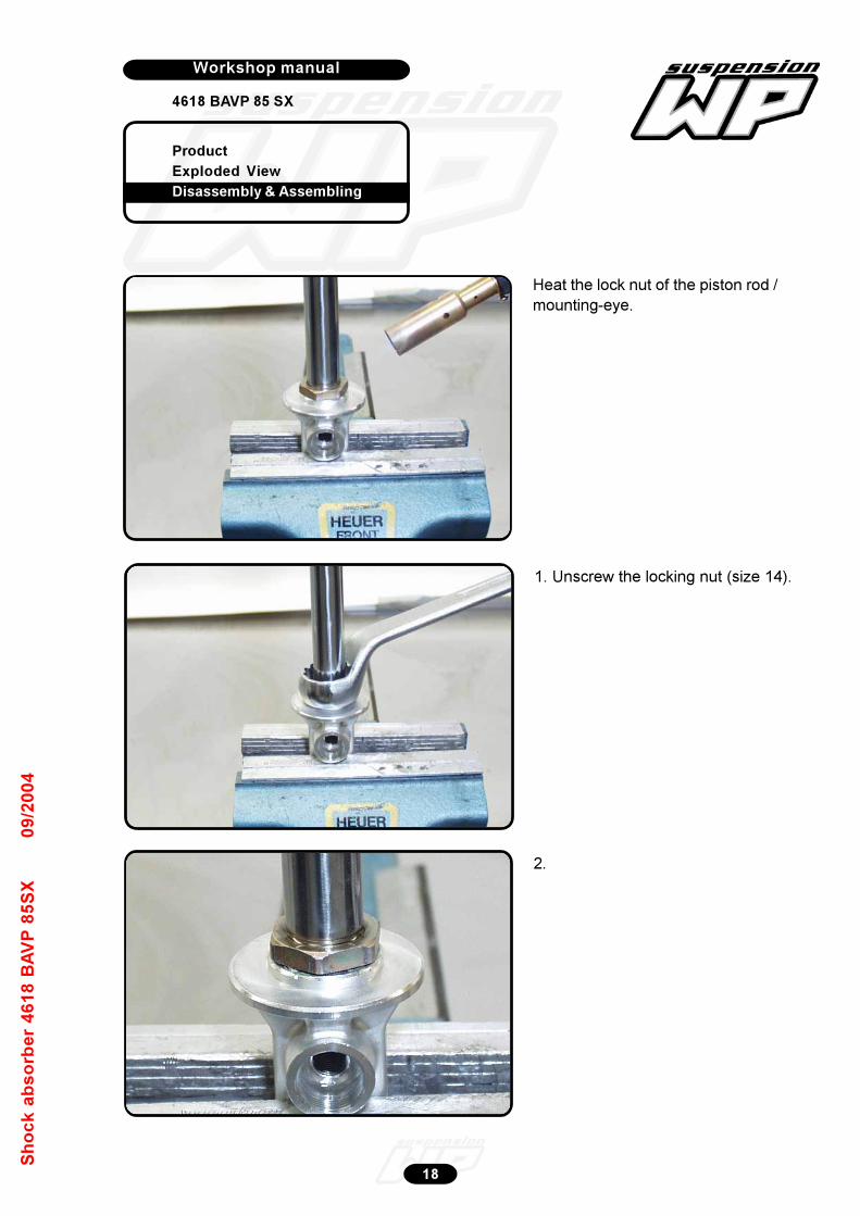
Product
Exploded View
Disassembly & Assembling
Workshop manual
4618 BAVP 85 SX
Werkplaatshandboek
18
Sh
oc
k a
bs
orb
er
46
18
BA
VP
85
SX
09
/20
04
Heat the lock nut of the piston rod /
mounting-eye.
1. Unscrew the locking nut (size 14).
2.

Product
Exploded View
Disassembly & Assembling
Workshop manual
4618 BAVP 85 SX
Werkplaatshandboek
19
Sh
oc
k a
bs
orb
er
46
18
BA
VP
85
SX
09
/20
04
Heat the mounting-eye.
Clamp the piston rod in T1202S.
Unscrew the mounting-eye.
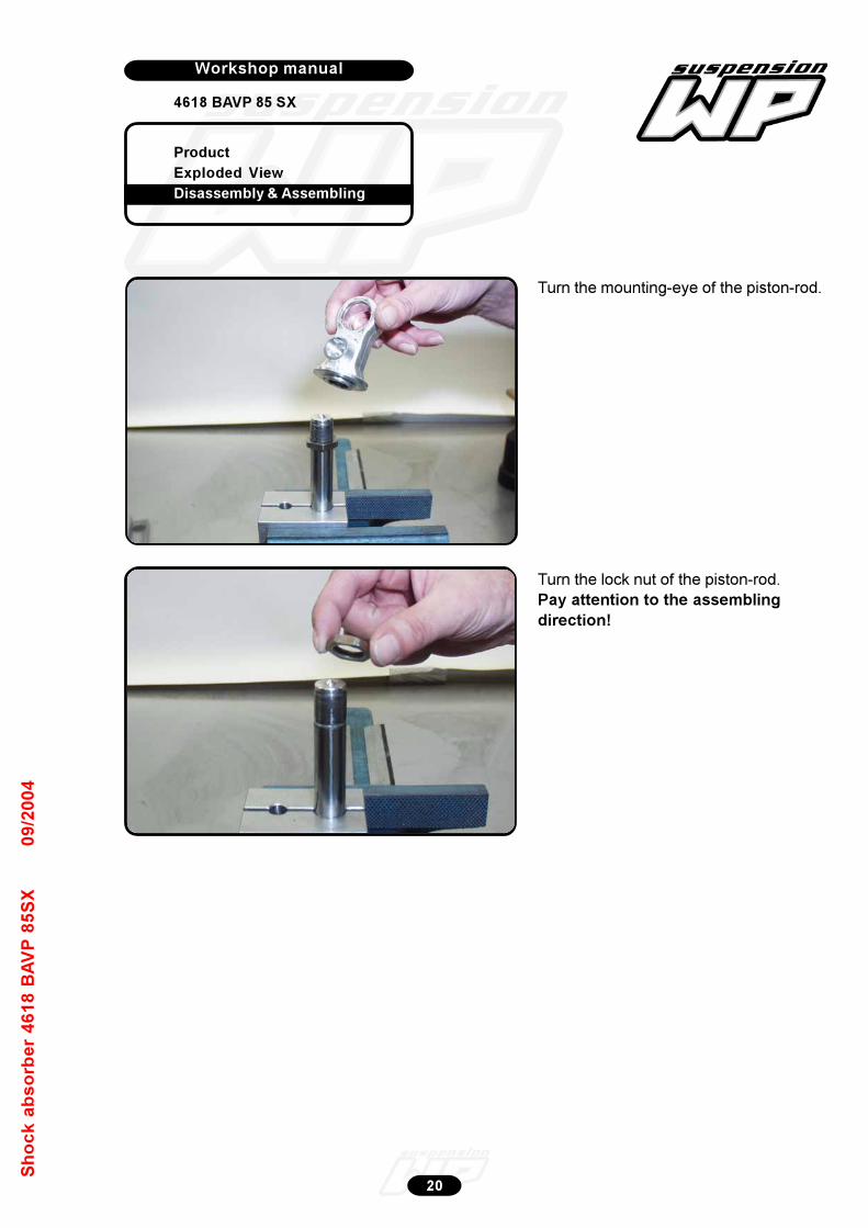
Product
Exploded View
Disassembly & Assembling
Workshop manual
4618 BAVP 85 SX
Werkplaatshandboek
20
Sh
oc
k a
bs
orb
er
46
18
BA
VP
85
SX
09
/20
04
Turn the lock nut of the piston-rod.
Pay attention to the assembling
direction!
Turn the mounting-eye of the piston-rod.
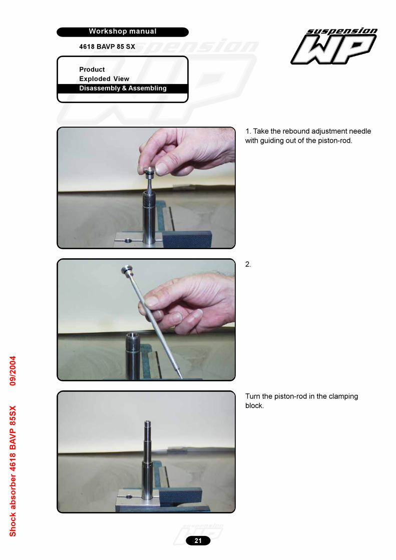
Product
Exploded View
Disassembly & Assembling
Workshop manual
4618 BAVP 85 SX
Werkplaatshandboek
21
Sh
oc
k a
bs
orb
er
46
18
BA
VP
85
SX
09
/20
04
1. Take the rebound adjustment needle
with guiding out of the piston-rod.
2.
Turn the piston-rod in the clamping
block.
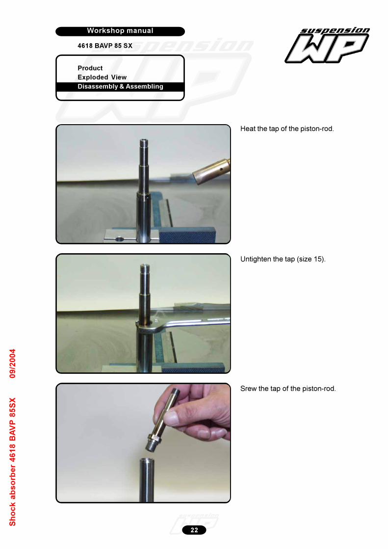
Product
Exploded View
Disassembly & Assembling
Workshop manual
4618 BAVP 85 SX
Werkplaatshandboek
22
Sh
oc
k a
bs
orb
er
46
18
BA
VP
85
SX
09
/20
04
Heat the tap of the piston-rod.
Untighten the tap (size 15).
Srew the tap of the piston-rod.
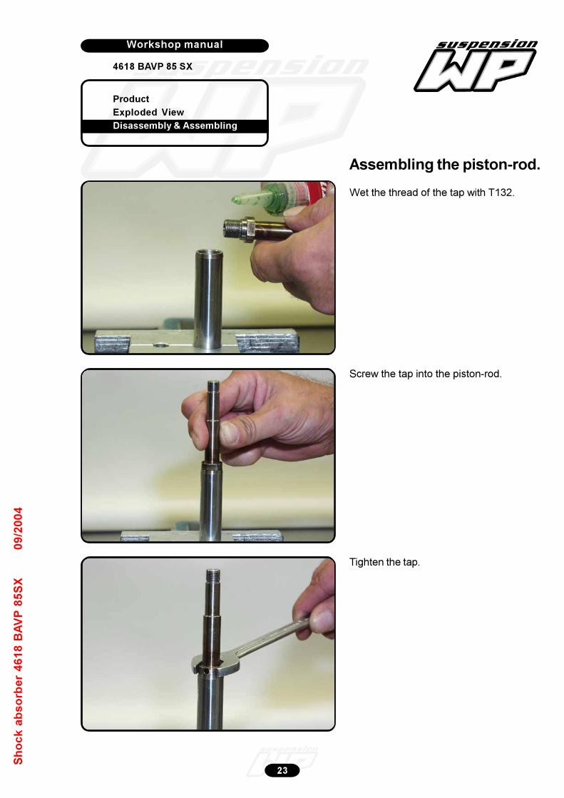
Product
Exploded View
Disassembly & Assembling
Workshop manual
4618 BAVP 85 SX
Werkplaatshandboek
23
Sh
oc
k a
bs
orb
er
46
18
BA
VP
85
SX
09
/20
04
Assembling the piston-rod.
Wet the thread of the tap with T132.
Screw the tap into the piston-rod.
Tighten the tap.
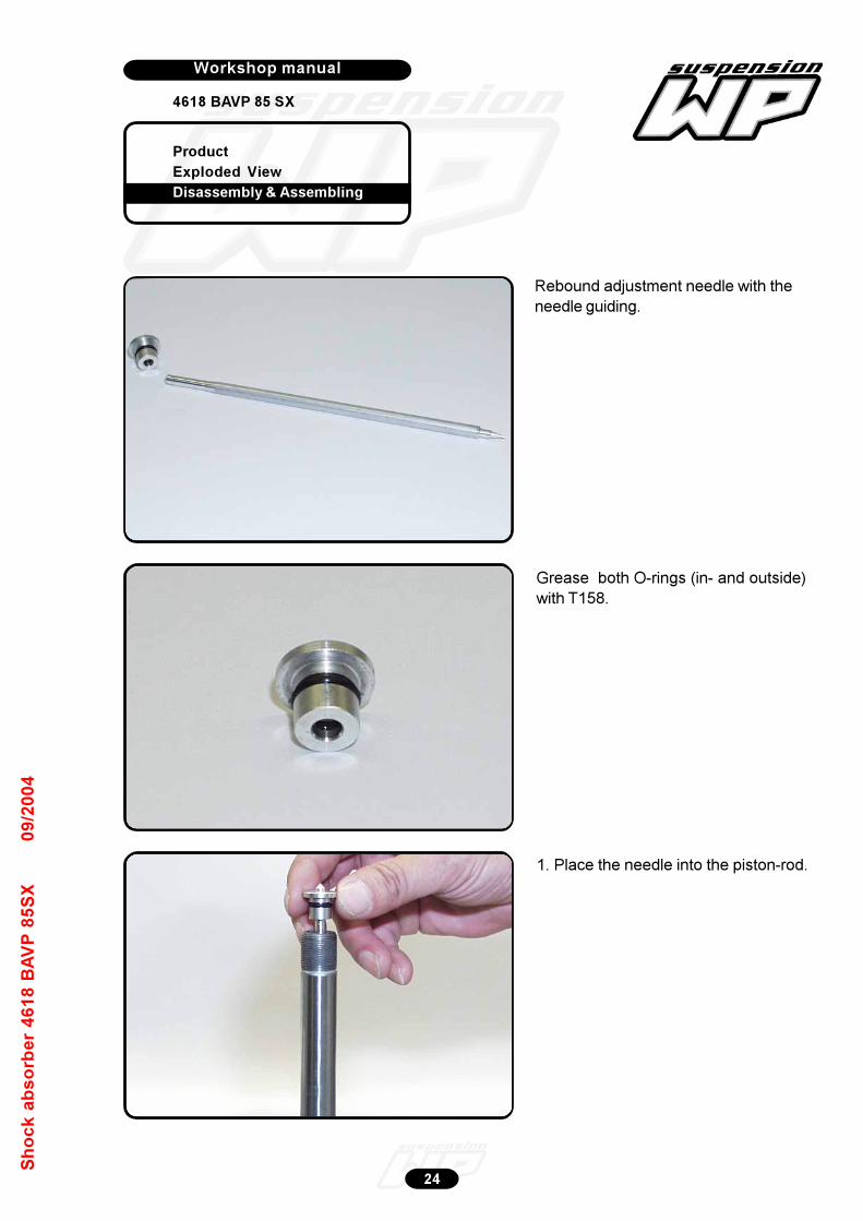
Product
Exploded View
Disassembly & Assembling
Workshop manual
4618 BAVP 85 SX
Werkplaatshandboek
24
Sh
oc
k a
bs
orb
er
46
18
BA
VP
85
SX
09
/20
04
Rebound adjustment needle with the
needle guiding.
Grease both O-rings (in- and outside)
with T158.
1. Place the needle into the piston-rod.
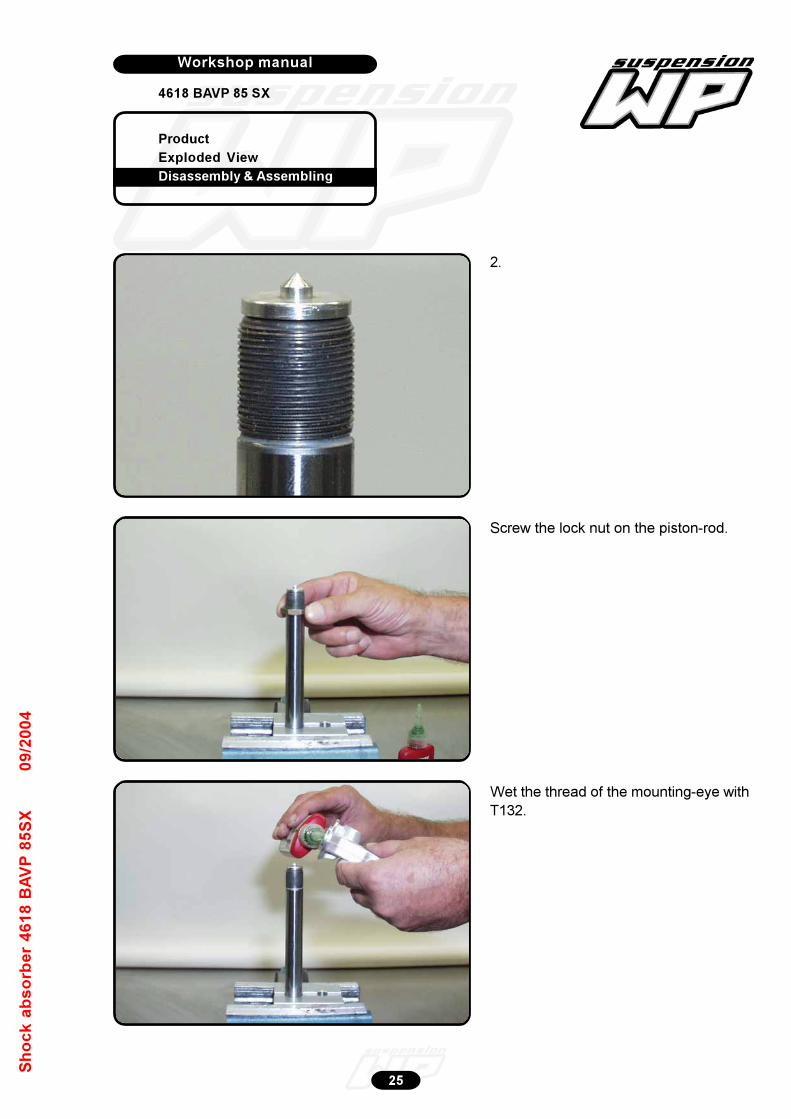
Product
Exploded View
Disassembly & Assembling
Workshop manual
4618 BAVP 85 SX
Werkplaatshandboek
25
Sh
oc
k a
bs
orb
er
46
18
BA
VP
85
SX
09
/20
04
2.
Screw the lock nut on the piston-rod.
Wet the thread of the mounting-eye with
T132.
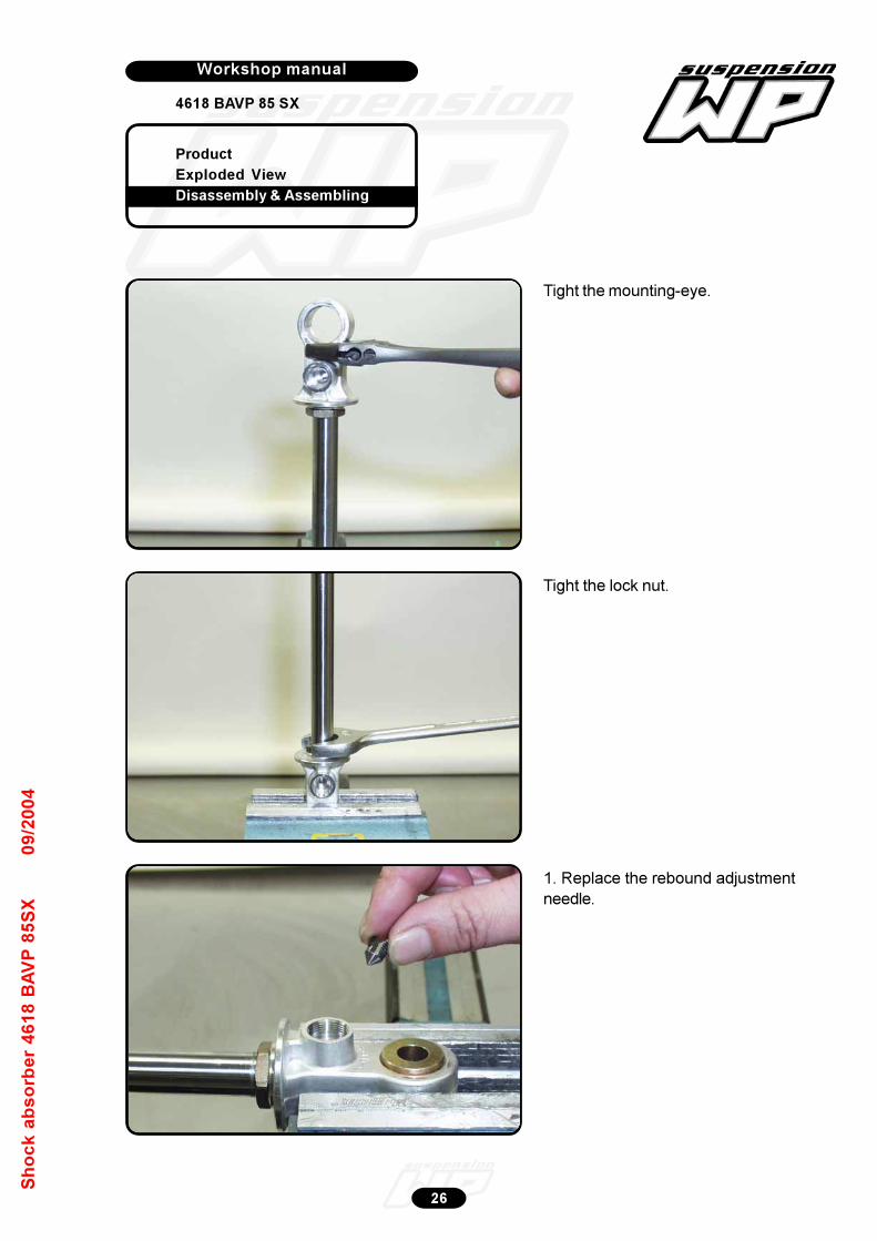
Product
Exploded View
Disassembly & Assembling
Workshop manual
4618 BAVP 85 SX
Werkplaatshandboek
26
Sh
oc
k a
bs
orb
er
46
18
BA
VP
85
SX
09
/20
04
Tight the mounting-eye.
Tight the lock nut.
1. Replace the rebound adjustment
needle.
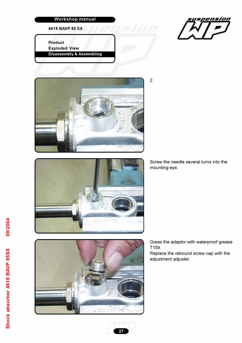
Product
Exploded View
Disassembly & Assembling
Workshop manual
4618 BAVP 85 SX
Werkplaatshandboek
27
Sh
oc
k a
bs
orb
er
46
18
BA
VP
85
SX
09
/20
04
2.
Screw the needle several turns into the
mounting-eye.
Greas the adaptor with waterproof grease
T159.
Replace the rebound screw cap with the
adjustment adjuster.
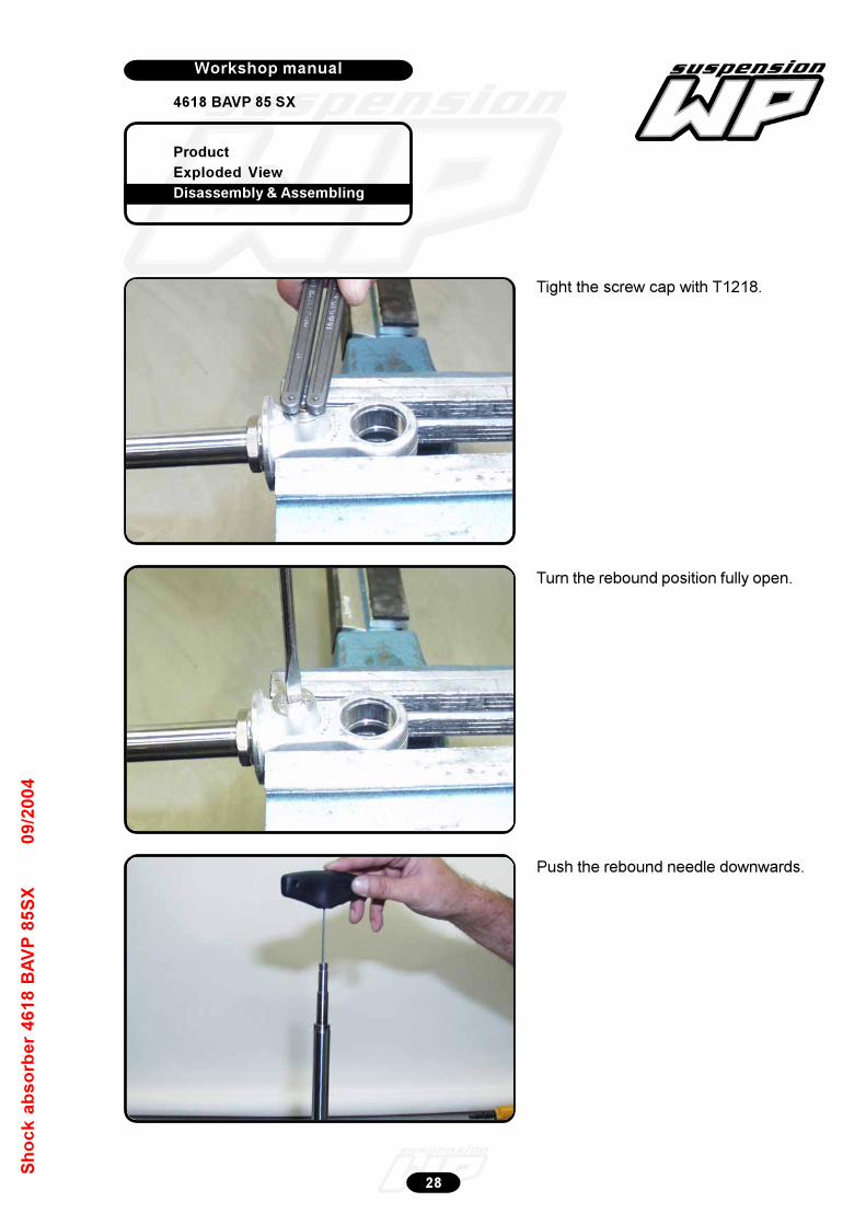
Product
Exploded View
Disassembly & Assembling
Workshop manual
4618 BAVP 85 SX
Werkplaatshandboek
28
Sh
oc
k a
bs
orb
er
46
18
BA
VP
85
SX
09
/20
04
Tight the screw cap with T1218.
Turn the rebound position fully open.
Push the rebound needle downwards.
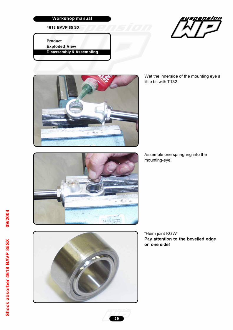
Product
Exploded View
Disassembly & Assembling
Workshop manual
4618 BAVP 85 SX
Werkplaatshandboek
29
Sh
oc
k a
bs
orb
er
46
18
BA
VP
85
SX
09
/20
04
Assemble one springring into the
mounting-eye.
Wet the innerside of the mounting eye a
little bit with T132.
“Heim joint KGW”
Pay attention to the bevelled edge
on one side!
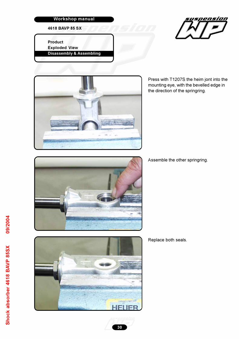
Product
Exploded View
Disassembly & Assembling
Workshop manual
4618 BAVP 85 SX
Werkplaatshandboek
30
Sh
oc
k a
bs
orb
er
46
18
BA
VP
85
SX
09
/20
04
Press with T1207S the heim jont into the
mounting eye, with the bevelled edge in
the direction of the springring.
Assemble the other springring.
Replace both seals.
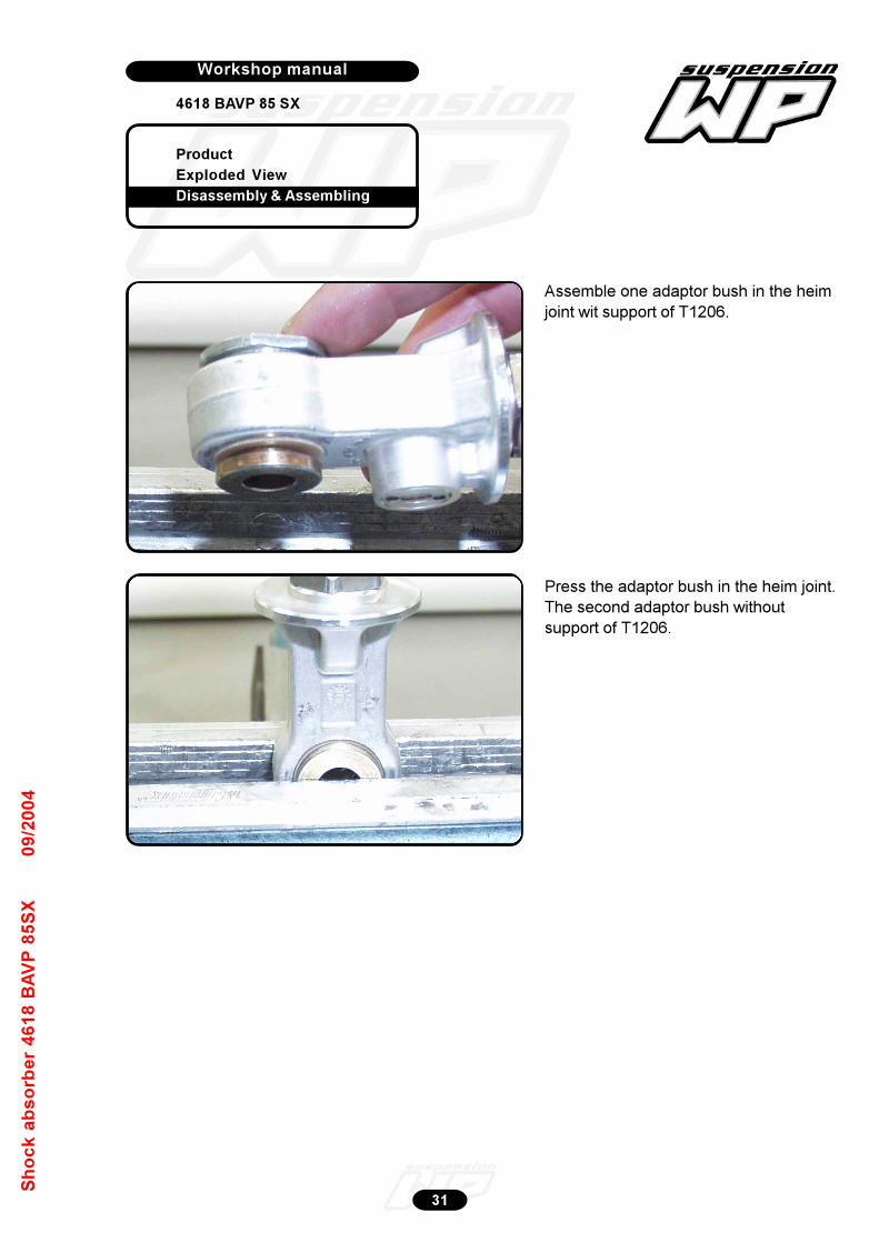
Product
Exploded View
Disassembly & Assembling
Workshop manual
4618 BAVP 85 SX
Werkplaatshandboek
31
Sh
oc
k a
bs
orb
er
46
18
BA
VP
85
SX
09
/20
04
Assemble one adaptor bush in the heim
joint wit support of T1206.
Press the adaptor bush in the heim joint.
The second adaptor bush without
support of T1206.
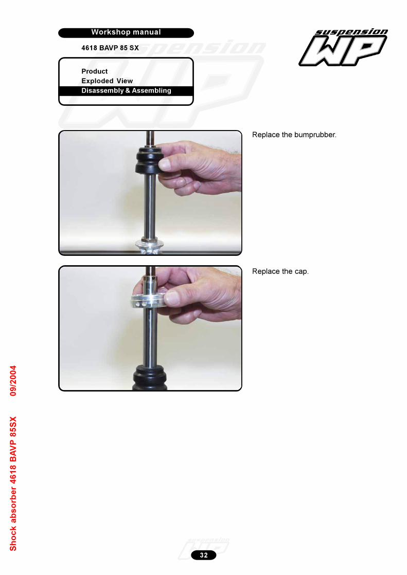
Product
Exploded View
Disassembly & Assembling
Workshop manual
4618 BAVP 85 SX
Werkplaatshandboek
32
Sh
oc
k a
bs
orb
er
46
18
BA
VP
85
SX
09
/20
04
Replace the bumprubber.
Replace the cap.

Product
Exploded View
Disassembly & Assembling
Workshop manual
4618 BAVP 85 SX
Werkplaatshandboek
33
Sh
oc
k a
bs
orb
er
46
18
BA
VP
85
SX
09
/20
04
Lift the rebound rubber out of the adaptor.
Remove the steel plate.
Disassembly adaptor DU-bush
Remove the first back-up ring.

Product
Exploded View
Disassembly & Assembling
Workshop manual
4618 BAVP 85 SX
Werkplaatshandboek
34
Sh
oc
k a
bs
orb
er
46
18
BA
VP
85
SX
09
/20
04
Remove the quad-ring.
Remove the second back-up ring.
Lift the dirt scraper out of the adaptor.
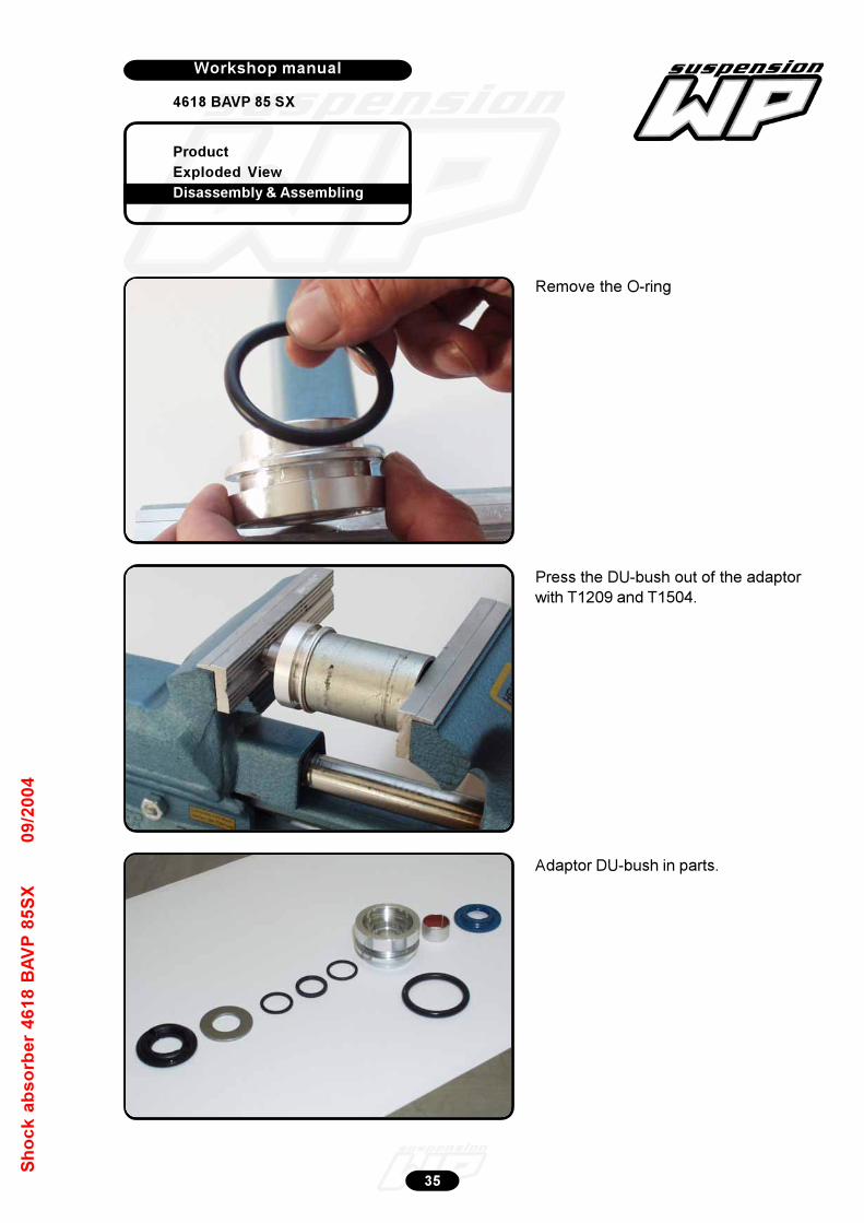
Product
Exploded View
Disassembly & Assembling
Workshop manual
4618 BAVP 85 SX
Werkplaatshandboek
35
Sh
oc
k a
bs
orb
er
46
18
BA
VP
85
SX
09
/20
04
Remove the O-ring
Press the DU-bush out of the adaptor
with T1209 and T1504.
Adaptor DU-bush in parts.
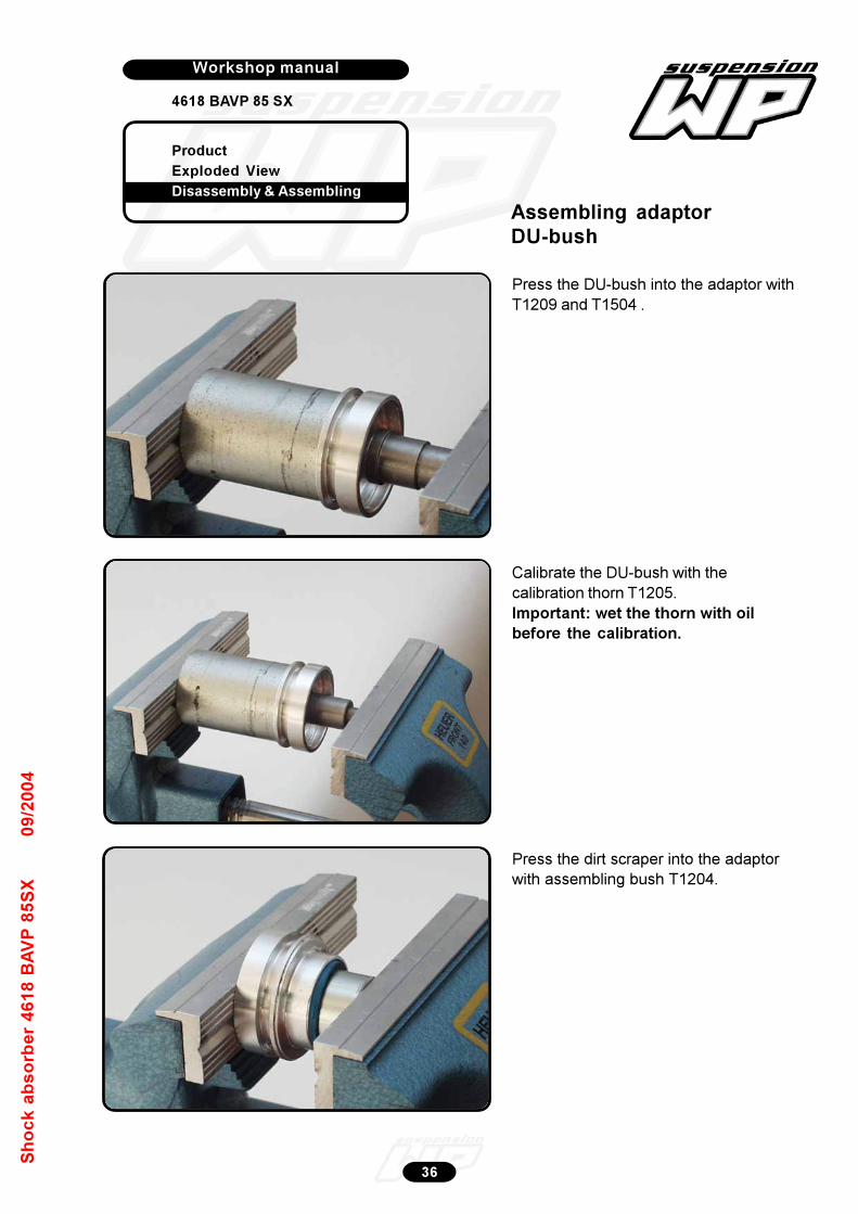
Product
Exploded View
Disassembly & Assembling
Workshop manual
4618 BAVP 85 SX
Werkplaatshandboek
36
Sh
oc
k a
bs
orb
er
46
18
BA
VP
85
SX
09
/20
04
Press the DU-bush into the adaptor with
T1209 and T1504 .
Calibrate the DU-bush with the
calibration thorn T1205.
Important: wet the thorn with oil
before the calibration.
Press the dirt scraper into the adaptor
with assembling bush T1204.
Assembling adaptorDU-bush

Product
Exploded View
Disassembly & Assembling
Workshop manual
4618 BAVP 85 SX
Werkplaatshandboek
37
Sh
oc
k a
bs
orb
er
46
18
BA
VP
85
SX
09
/20
04
Replace the quad-ring.
Replace the first back-up ring.
Grease the Groove of the adaptor with
T158 and assemble the O-ring (not on
picture).
Replace the second back-up ring.
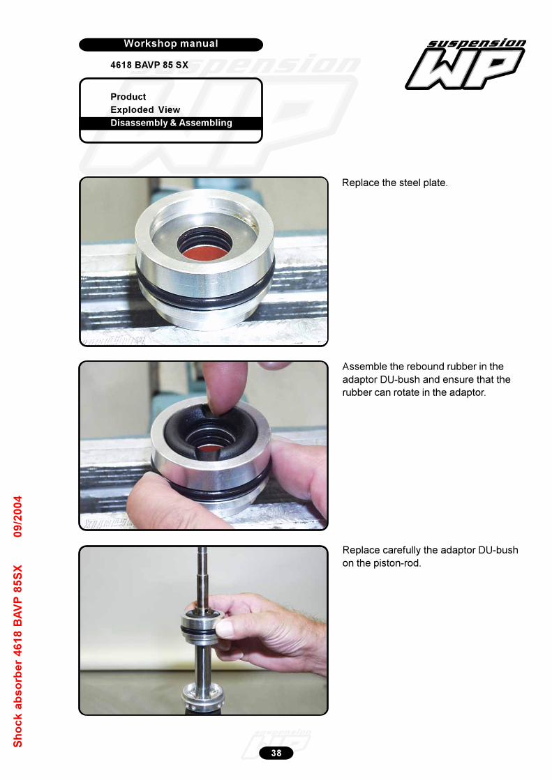
Product
Exploded View
Disassembly & Assembling
Workshop manual
4618 BAVP 85 SX
Werkplaatshandboek
38
Sh
oc
k a
bs
orb
er
46
18
BA
VP
85
SX
09
/20
04
Replace the steel plate.
Assemble the rebound rubber in the
adaptor DU-bush and ensure that the
rubber can rotate in the adaptor.
Replace carefully the adaptor DU-bush
on the piston-rod.
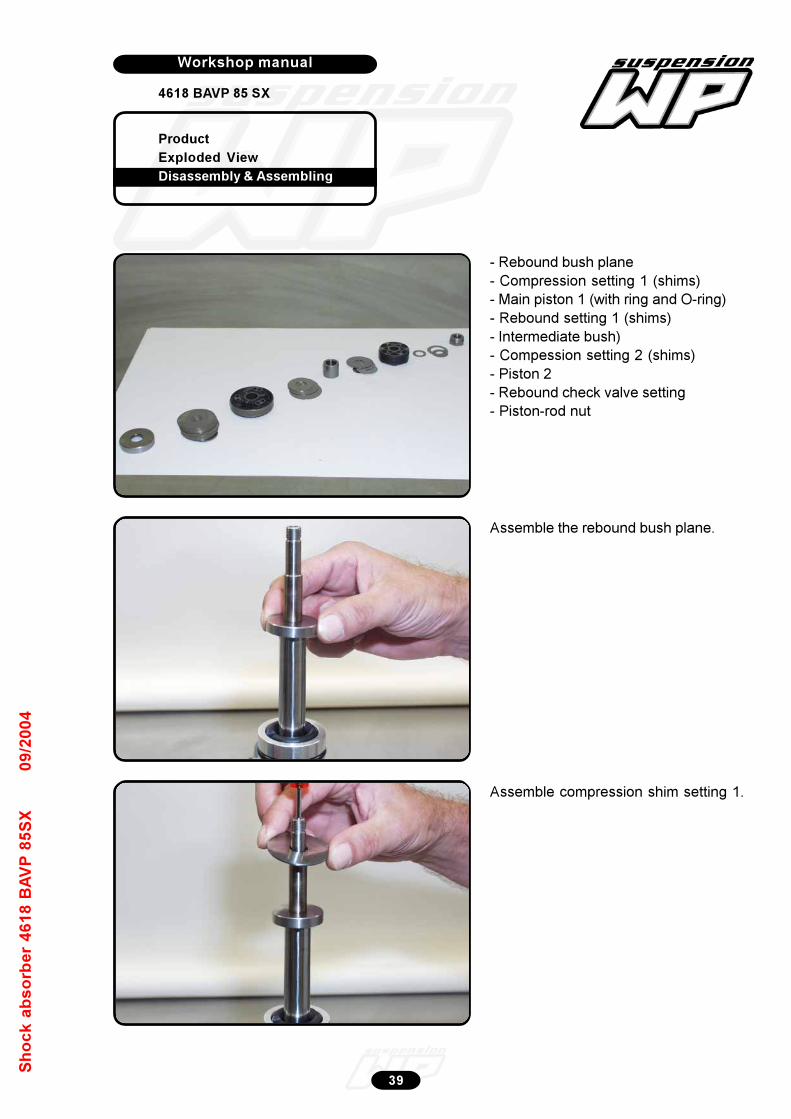
Product
Exploded View
Disassembly & Assembling
Workshop manual
4618 BAVP 85 SX
Werkplaatshandboek
39
Sh
oc
k a
bs
orb
er
46
18
BA
VP
85
SX
09
/20
04
- Rebound bush plane
- Compression setting 1 (shims)
- Main piston 1 (with ring and O-ring)
- Rebound setting 1 (shims)
- Intermediate bush)
- Compession setting 2 (shims)
- Piston 2
- Rebound check valve setting
- Piston-rod nut
Assemble the rebound bush plane.
Assemble compression shim setting 1.
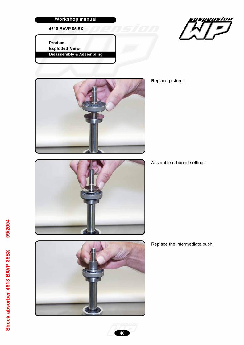
Product
Exploded View
Disassembly & Assembling
Workshop manual
4618 BAVP 85 SX
Werkplaatshandboek
40
Sh
oc
k a
bs
orb
er
46
18
BA
VP
85
SX
09
/20
04
Replace piston 1.
Assemble rebound setting 1.
Replace the intermediate bush.
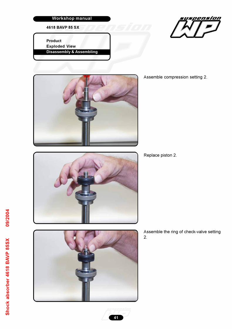
Product
Exploded View
Disassembly & Assembling
Workshop manual
4618 BAVP 85 SX
Werkplaatshandboek
41
Sh
oc
k a
bs
orb
er
46
18
BA
VP
85
SX
09
/20
04
Assemble compression setting 2.
Replace piston 2.
Assemble the ring of check-valve setting
2.
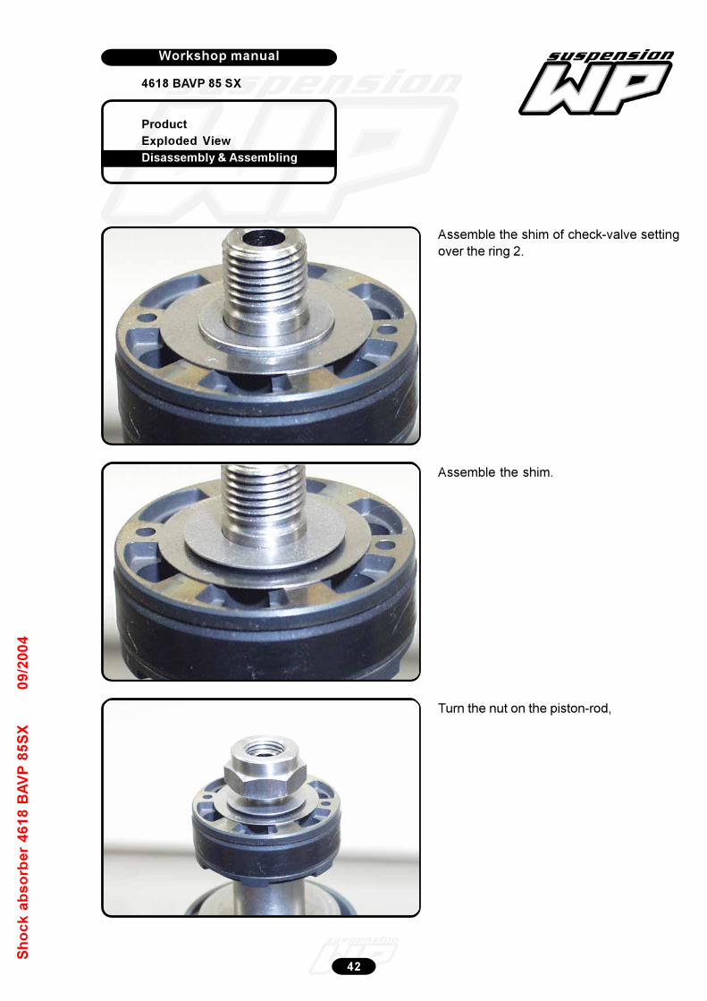
Product
Exploded View
Disassembly & Assembling
Workshop manual
4618 BAVP 85 SX
Werkplaatshandboek
42
Sh
oc
k a
bs
orb
er
46
18
BA
VP
85
SX
09
/20
04
Assemble the shim of check-valve setting
over the ring 2.
Assemble the shim.
Turn the nut on the piston-rod,
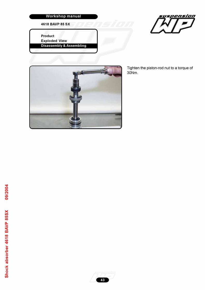
Product
Exploded View
Disassembly & Assembling
Workshop manual
4618 BAVP 85 SX
Werkplaatshandboek
43
Sh
oc
k a
bs
orb
er
46
18
BA
VP
85
SX
09
/20
04
Tighten the piston-rod nut to a torque of
30Nm.
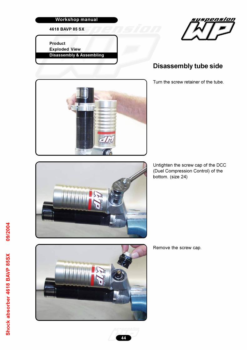
Product
Exploded View
Disassembly & Assembling
Workshop manual
4618 BAVP 85 SX
Werkplaatshandboek
44
Sh
oc
k a
bs
orb
er
46
18
BA
VP
85
SX
09
/20
04
Turn the screw retainer of the tube.
Remove the screw cap.
Untighten the screw cap of the DCC
(Duel Compression Control) of the
bottom. (size 24)
Disassembly tube side
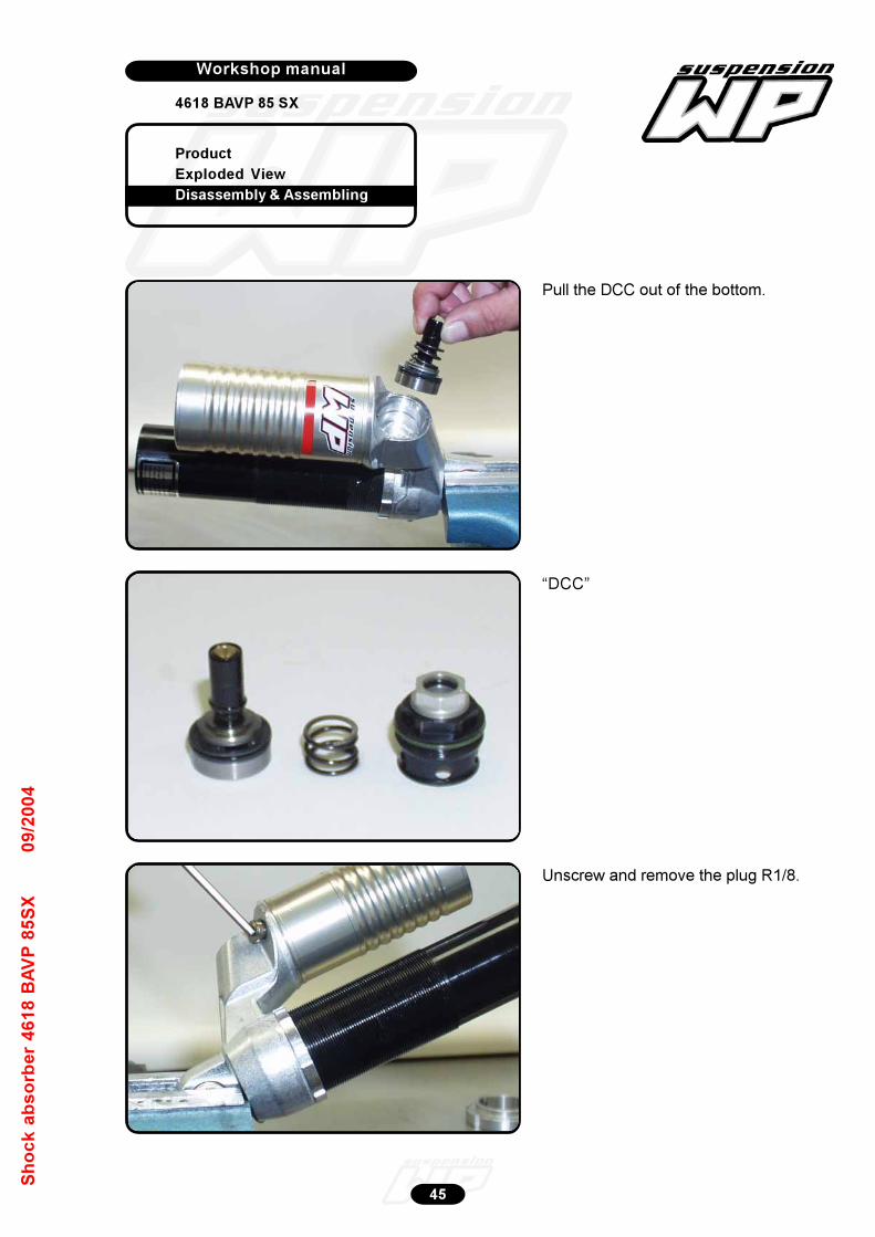
Product
Exploded View
Disassembly & Assembling
Workshop manual
4618 BAVP 85 SX
Werkplaatshandboek
45
Sh
oc
k a
bs
orb
er
46
18
BA
VP
85
SX
09
/20
04
Pull the DCC out of the bottom.
“DCC”
Unscrew and remove the plug R1/8.

Product
Exploded View
Disassembly & Assembling
Workshop manual
4618 BAVP 85 SX
Werkplaatshandboek
46
Sh
oc
k a
bs
orb
er
46
18
BA
VP
85
SX
09
/20
04
Heat the lock ring of the tube/bottom.
Untighten the lock ring with a open
spanner.
Remove the “caution” sticker.

Product
Exploded View
Disassembly & Assembling
Workshop manual
4618 BAVP 85 SX
Werkplaatshandboek
47
Sh
oc
k a
bs
orb
er
46
18
BA
VP
85
SX
09
/20
04
Heat the bottom near the tube.
Untighten the tube with slide spanner
T146 with bush T148.
Turn the tube out of the bottom.
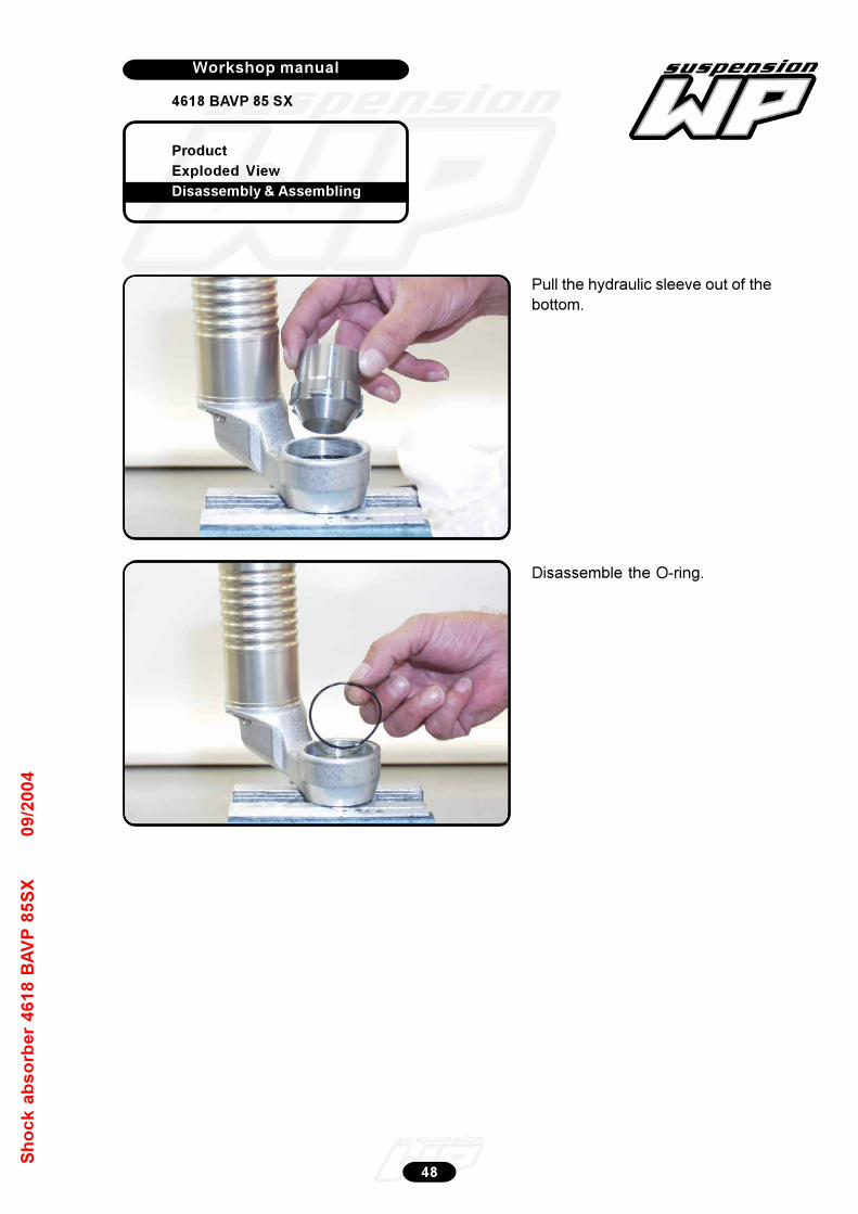
Product
Exploded View
Disassembly & Assembling
Workshop manual
4618 BAVP 85 SX
Werkplaatshandboek
48
Sh
oc
k a
bs
orb
er
46
18
BA
VP
85
SX
09
/20
04
Pull the hydraulic sleeve out of the
bottom.
Disassemble the O-ring.
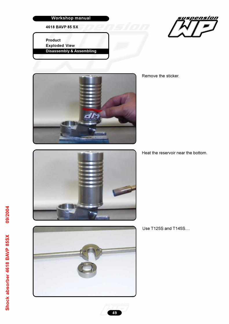
Product
Exploded View
Disassembly & Assembling
Workshop manual
4618 BAVP 85 SX
Werkplaatshandboek
49
Sh
oc
k a
bs
orb
er
46
18
BA
VP
85
SX
09
/20
04
Remove the sticker.
Heat the reservoir near the bottom.
Use T125S and T145S....
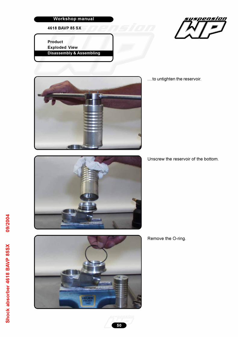
Product
Exploded View
Disassembly & Assembling
Workshop manual
4618 BAVP 85 SX
Werkplaatshandboek
50
Sh
oc
k a
bs
orb
er
46
18
BA
VP
85
SX
09
/20
04
....to untighten the reservoir.
Unscrew the reservoir of the bottom.
Remove the O-ring.
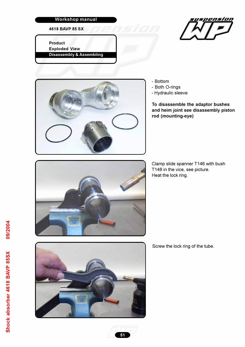
Product
Exploded View
Disassembly & Assembling
Workshop manual
4618 BAVP 85 SX
Werkplaatshandboek
51
Sh
oc
k a
bs
orb
er
46
18
BA
VP
85
SX
09
/20
04
- Bottom
- Both O-rings
- Hydraulic sleeve
To disassemble the adaptor bushes
and heim joint see disassembly piston
rod (mounting-eye)
Clamp slide spanner T146 with bush
T148 in the vice, see picture.
Heat the lock ring.
Screw the lock ring of the tube.
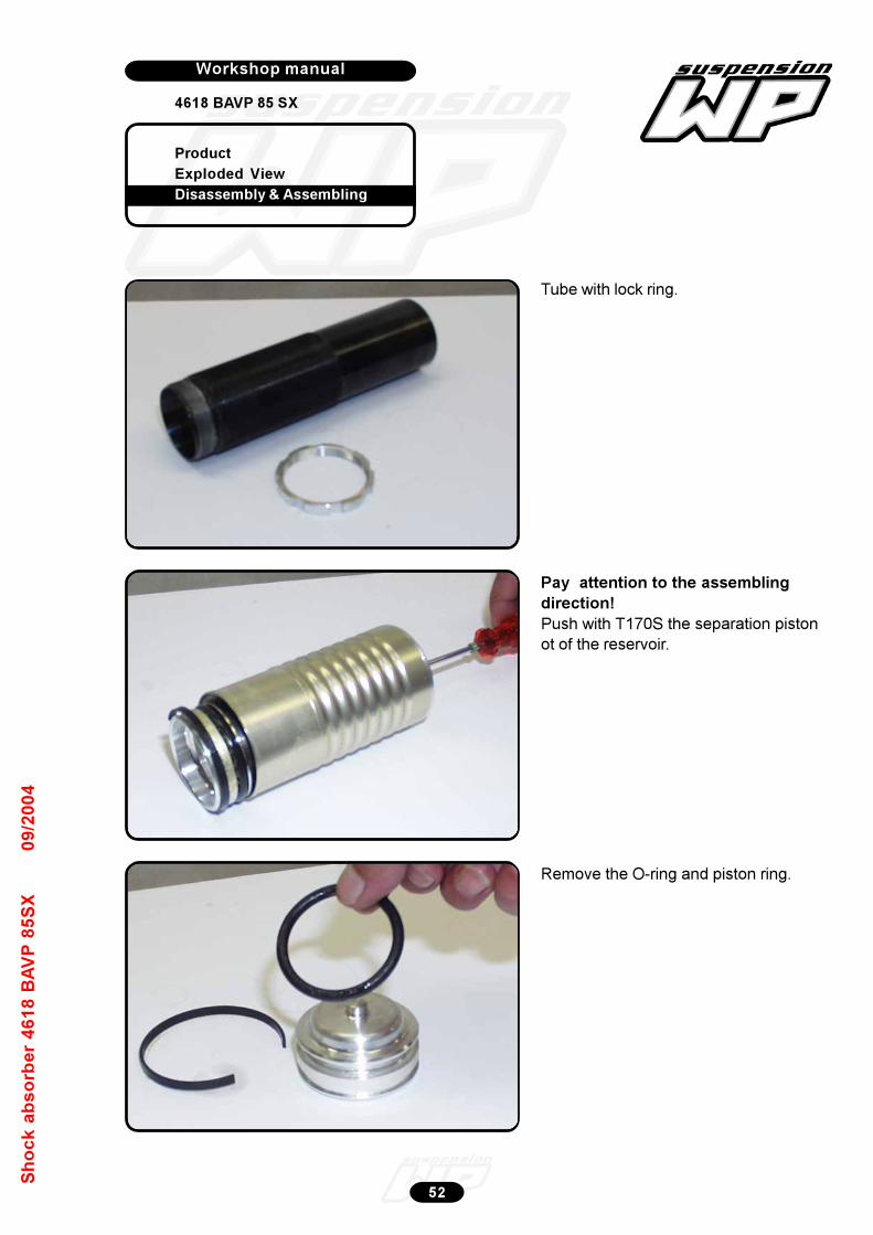
Product
Exploded View
Disassembly & Assembling
Workshop manual
4618 BAVP 85 SX
Werkplaatshandboek
52
Sh
oc
k a
bs
orb
er
46
18
BA
VP
85
SX
09
/20
04
Pay attention to the assembling
direction!
Push with T170S the separation piston
ot of the reservoir.
Remove the O-ring and piston ring.
Tube with lock ring.
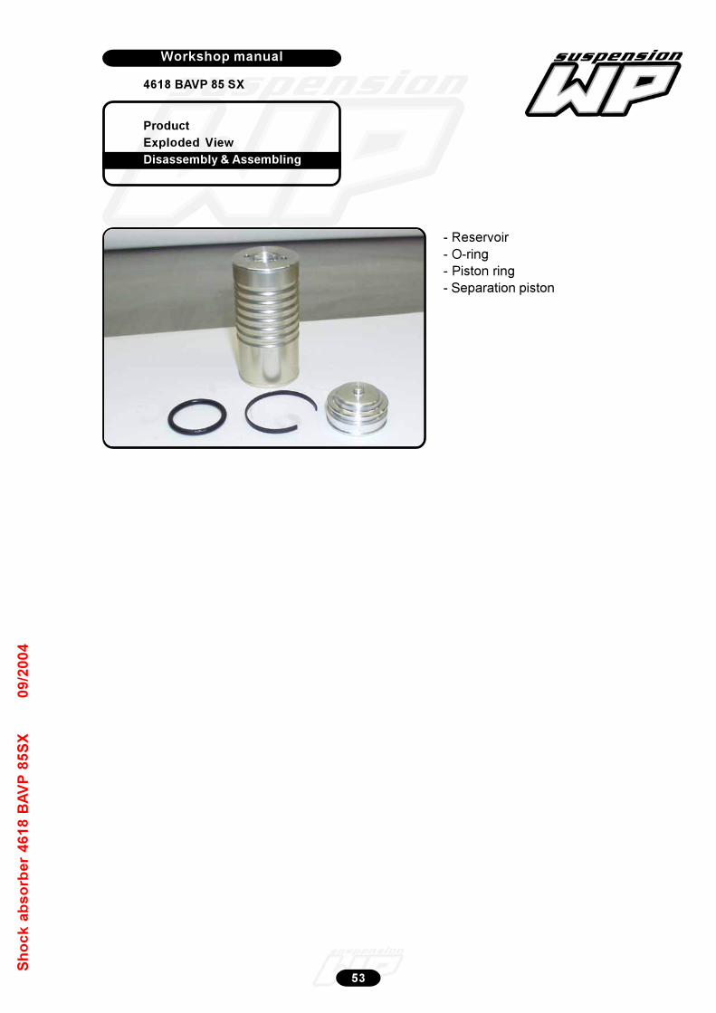
Product
Exploded View
Disassembly & Assembling
Workshop manual
4618 BAVP 85 SX
Werkplaatshandboek
53
Sh
oc
k a
bs
orb
er
46
18
BA
VP
85
SX
09
/20
04
- Reservoir
- O-ring
- Piston ring
- Separation piston
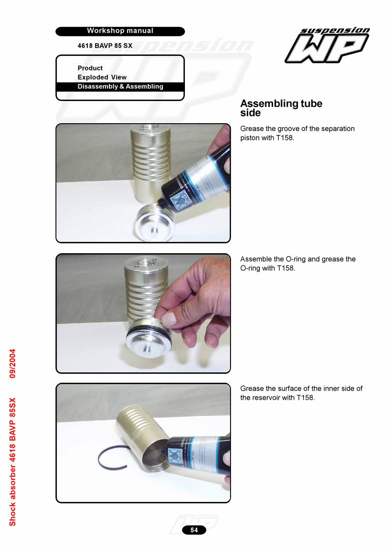
Product
Exploded View
Disassembly & Assembling
Workshop manual
4618 BAVP 85 SX
Werkplaatshandboek
54
Sh
oc
k a
bs
orb
er
46
18
BA
VP
85
SX
09
/20
04
Assemble the O-ring and grease the
O-ring with T158.
Grease the groove of the separation
piston with T158.
Grease the surface of the inner side of
the reservoir with T158.
Assembling tubeside
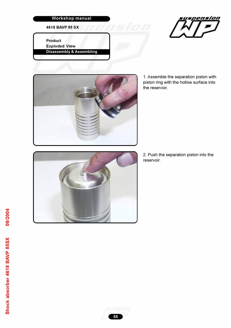
Product
Exploded View
Disassembly & Assembling
Workshop manual
4618 BAVP 85 SX
Werkplaatshandboek
55
Sh
oc
k a
bs
orb
er
46
18
BA
VP
85
SX
09
/20
04
1. Assemble the separation piston with
piston ring with the hollow surface into
the reservoir.
2. Push the separation piston into the
reservoir.
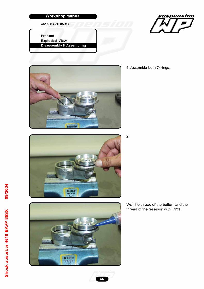
Product
Exploded View
Disassembly & Assembling
Workshop manual
4618 BAVP 85 SX
Werkplaatshandboek
56
Sh
oc
k a
bs
orb
er
46
18
BA
VP
85
SX
09
/20
04
1. Assemble both O-rings.
2.
Wet the thread of the bottom and the
thread of the reservoir with T131.
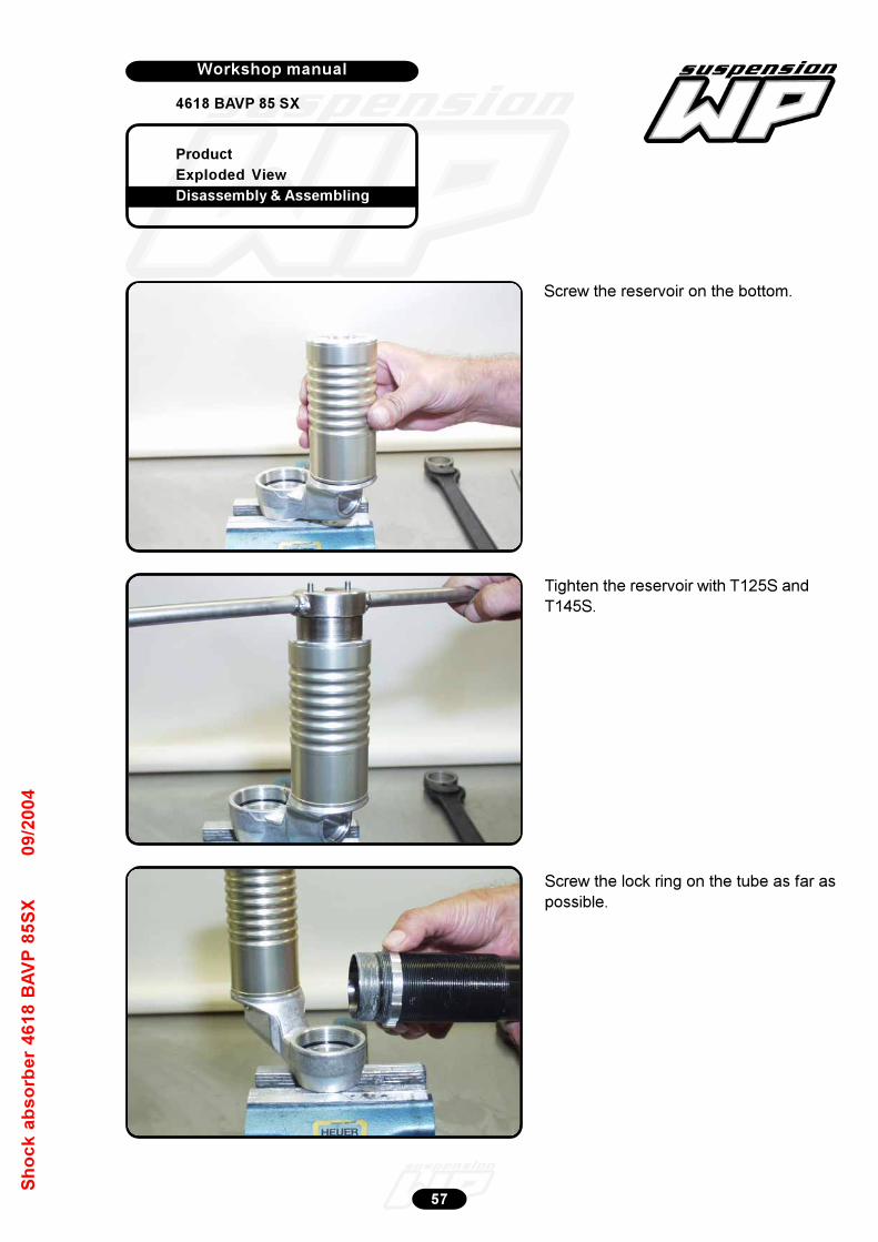
Product
Exploded View
Disassembly & Assembling
Workshop manual
4618 BAVP 85 SX
Werkplaatshandboek
57
Sh
oc
k a
bs
orb
er
46
18
BA
VP
85
SX
09
/20
04
Screw the reservoir on the bottom.
Tighten the reservoir with T125S and
T145S.
Screw the lock ring on the tube as far as
possible.
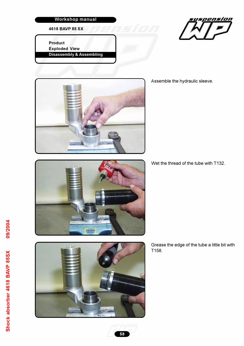
Product
Exploded View
Disassembly & Assembling
Workshop manual
4618 BAVP 85 SX
Werkplaatshandboek
58
Sh
oc
k a
bs
orb
er
46
18
BA
VP
85
SX
09
/20
04
Assemble the hydraulic sleeve.
Wet the thread of the tube with T132.
Grease the edge of the tube a little bit with
T158.
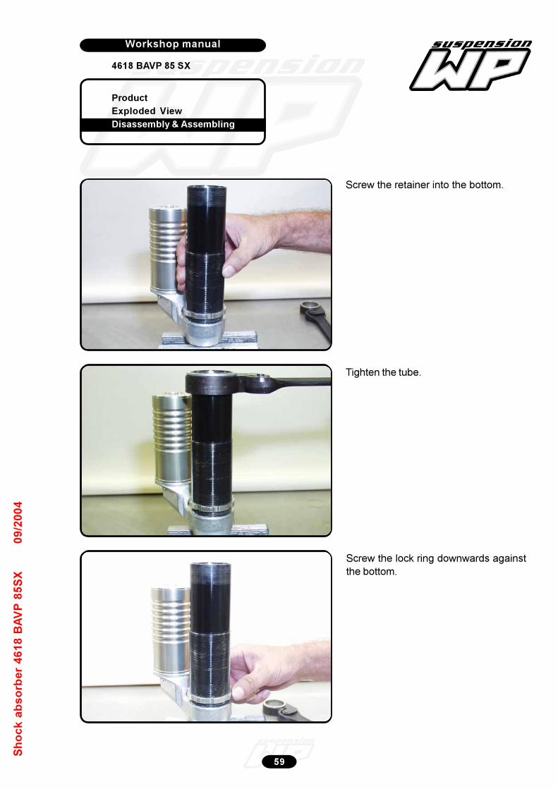
Product
Exploded View
Disassembly & Assembling
Workshop manual
4618 BAVP 85 SX
Werkplaatshandboek
59
Sh
oc
k a
bs
orb
er
46
18
BA
VP
85
SX
09
/20
04
Screw the retainer into the bottom.
Tighten the tube.
Screw the lock ring downwards against
the bottom.
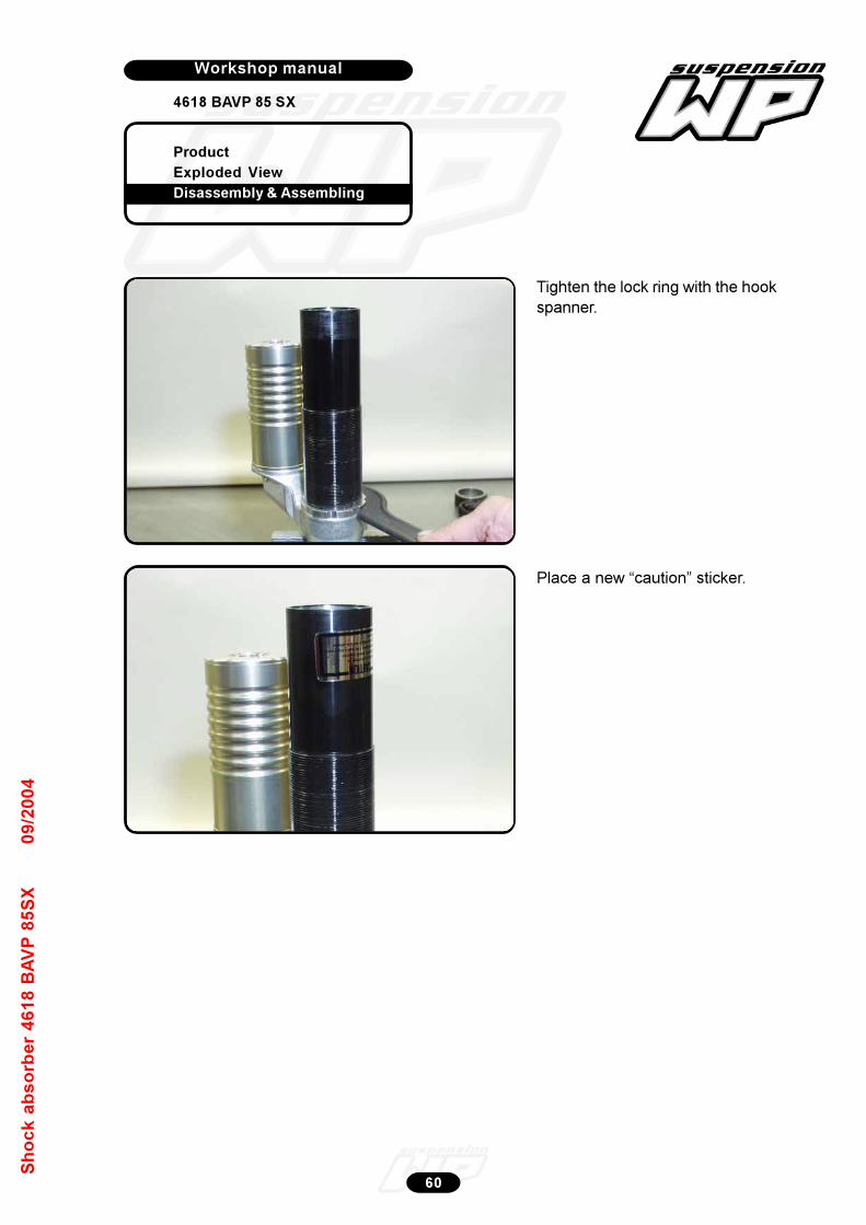
Product
Exploded View
Disassembly & Assembling
Workshop manual
4618 BAVP 85 SX
Werkplaatshandboek
60
Sh
oc
k a
bs
orb
er
46
18
BA
VP
85
SX
09
/20
04
Tighten the lock ring with the hook
spanner.
Place a new “caution” sticker.
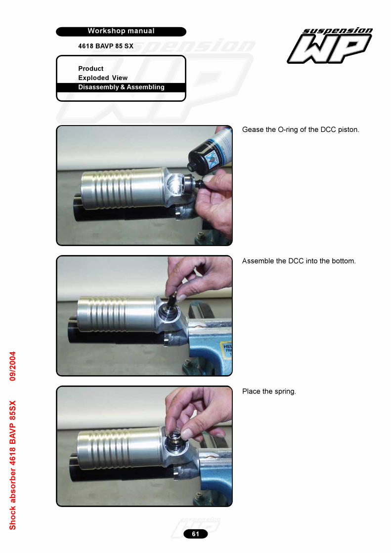
Product
Exploded View
Disassembly & Assembling
Workshop manual
4618 BAVP 85 SX
Werkplaatshandboek
61
Sh
oc
k a
bs
orb
er
46
18
BA
VP
85
SX
09
/20
04
Gease the O-ring of the DCC piston.
Assemble the DCC into the bottom.
Place the spring.

Product
Exploded View
Disassembly & Assembling
Workshop manual
4618 BAVP 85 SX
Werkplaatshandboek
62
Sh
oc
k a
bs
orb
er
46
18
BA
VP
85
SX
09
/20
04
Grease the O-ring inside of the hexagonal
with T158.
Srew the screw cap of the DCC into the
bottom.
Tighten the screw cap to a torque of
50Nm.
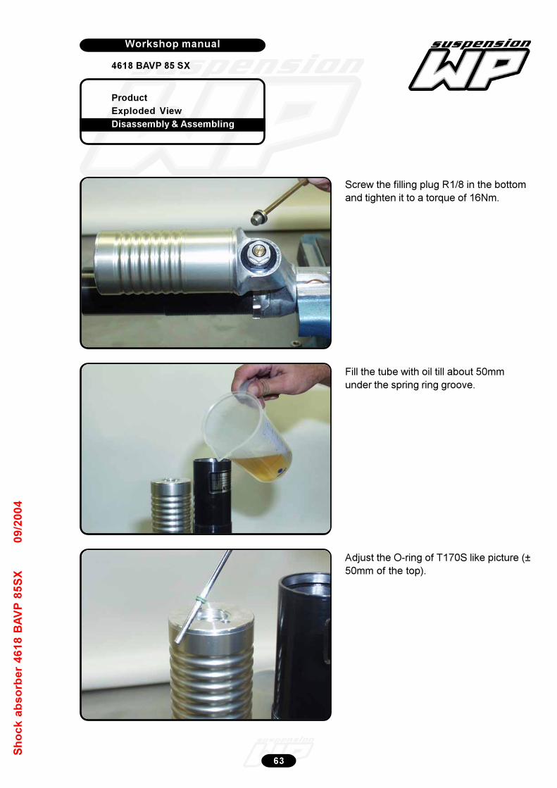
Product
Exploded View
Disassembly & Assembling
Workshop manual
4618 BAVP 85 SX
Werkplaatshandboek
63
Sh
oc
k a
bs
orb
er
46
18
BA
VP
85
SX
09
/20
04
Screw the filling plug R1/8 in the bottom
and tighten it to a torque of 16Nm.
Fill the tube with oil till about 50mm
under the spring ring groove.
Adjust the O-ring of T170S like picture (±
50mm of the top).

Product
Exploded View
Disassembly & Assembling
Workshop manual
4618 BAVP 85 SX
Werkplaatshandboek
64
Sh
oc
k a
bs
orb
er
46
18
BA
VP
85
SX
09
/20
04
Push the separation piston fully
downwards.
Use plunger T110S....
...to push the oil through the bottom.
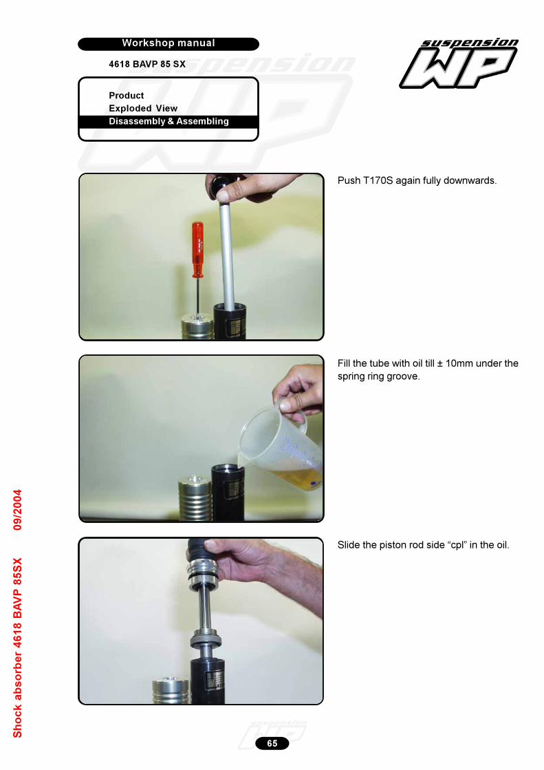
Product
Exploded View
Disassembly & Assembling
Workshop manual
4618 BAVP 85 SX
Werkplaatshandboek
65
Sh
oc
k a
bs
orb
er
46
18
BA
VP
85
SX
09
/20
04
Push T170S again fully downwards.
Fill the tube with oil till ± 10mm under the
spring ring groove.
Slide the piston rod side “cpl” in the oil.
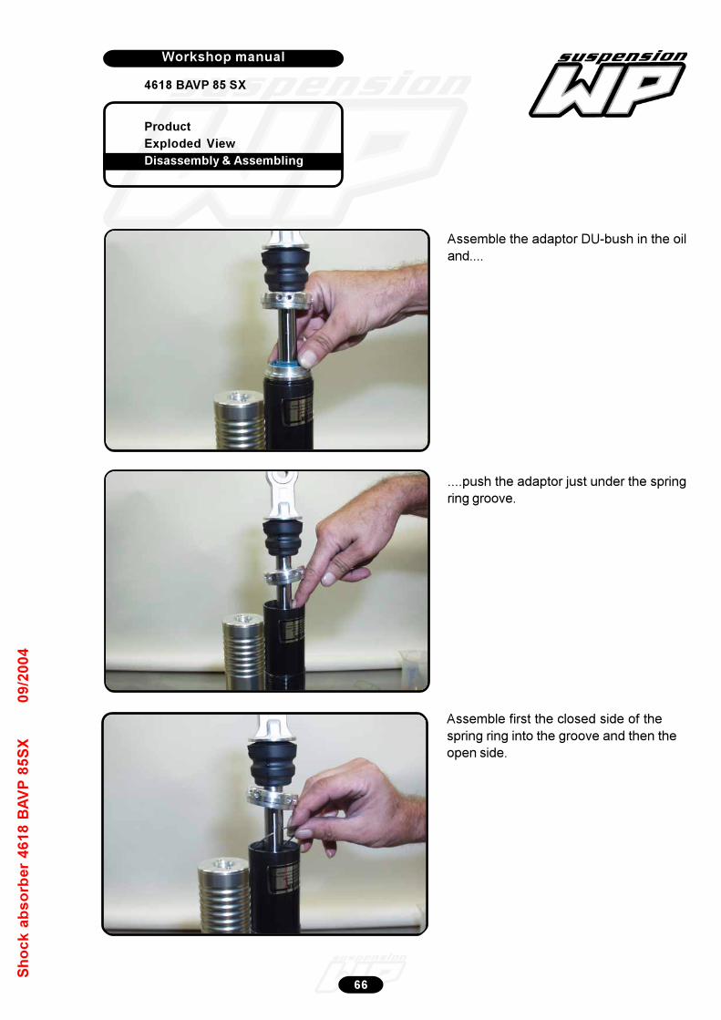
Product
Exploded View
Disassembly & Assembling
Workshop manual
4618 BAVP 85 SX
Werkplaatshandboek
66
Sh
oc
k a
bs
orb
er
46
18
BA
VP
85
SX
09
/20
04
Assemble the adaptor DU-bush in the oil
and....
....push the adaptor just under the spring
ring groove.
Assemble first the closed side of the
spring ring into the groove and then the
open side.

Product
Exploded View
Disassembly & Assembling
Workshop manual
4618 BAVP 85 SX
Werkplaatshandboek
67
Sh
oc
k a
bs
orb
er
46
18
BA
VP
85
SX
09
/20
04
Pull the piston rod “cpl” fully out.
Tap the cap into the tube.
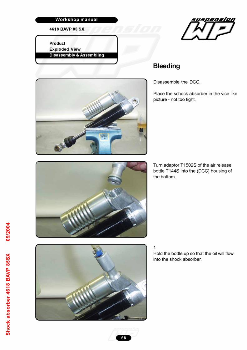
Product
Exploded View
Disassembly & Assembling
Workshop manual
4618 BAVP 85 SX
Werkplaatshandboek
68
Sh
oc
k a
bs
orb
er
46
18
BA
VP
85
SX
09
/20
04
Disassemble the DCC.
Place the schock absorber in the vice like
picture - not too tight.
Turn adaptor T1502S of the air release
bottle T144S into the (DCC) housing of
the bottom.
1.
Hold the bottle up so that the oil will flow
into the shock absorber.
Bleeding

Product
Exploded View
Disassembly & Assembling
Workshop manual
4618 BAVP 85 SX
Werkplaatshandboek
69
Sh
oc
k a
bs
orb
er
46
18
BA
VP
85
SX
09
/20
04
2.
3. Push slowly the pison rod inside.
4. Pull the piston rod completely out.
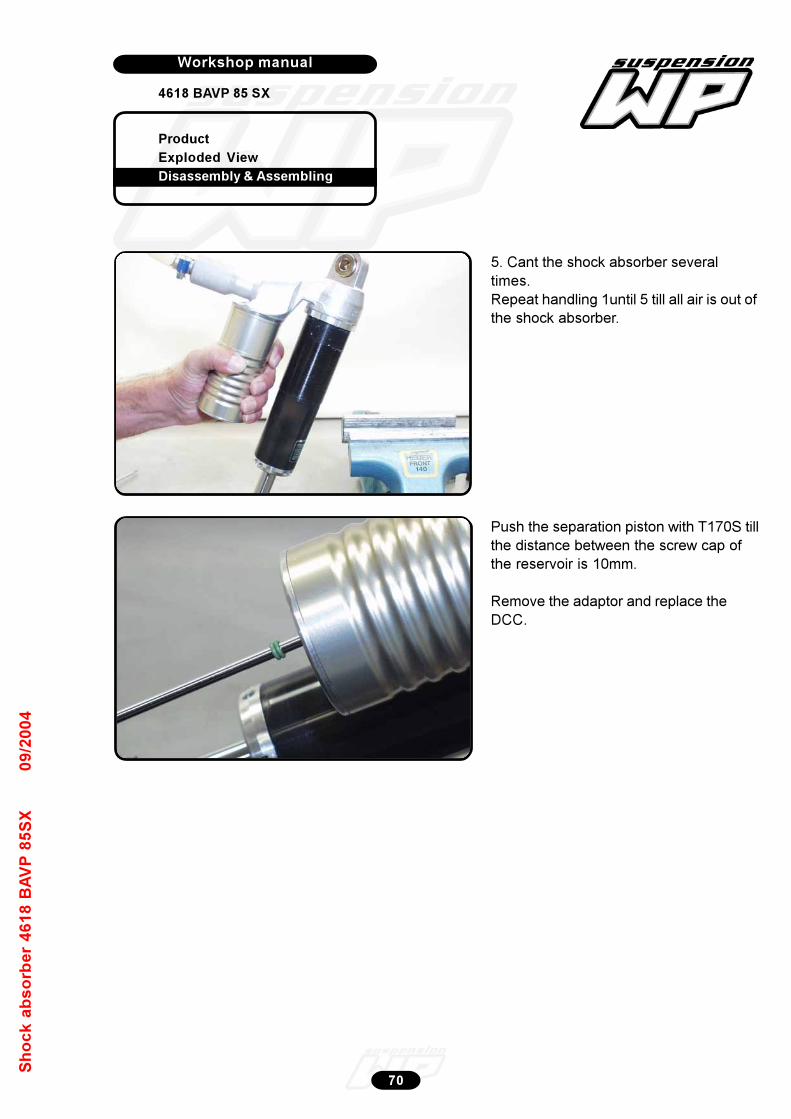
Product
Exploded View
Disassembly & Assembling
Workshop manual
4618 BAVP 85 SX
Werkplaatshandboek
70
Sh
oc
k a
bs
orb
er
46
18
BA
VP
85
SX
09
/20
04
5. Cant the shock absorber several
times.
Repeat handling 1until 5 till all air is out of
the shock absorber.
Push the separation piston with T170S till
the distance between the screw cap of
the reservoir is 10mm.
Remove the adaptor and replace the
DCC.
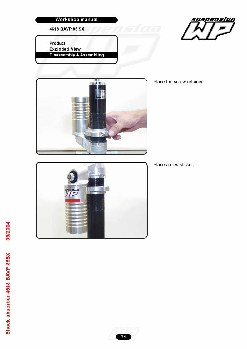
Product
Exploded View
Disassembly & Assembling
Workshop manual
4618 BAVP 85 SX
Werkplaatshandboek
71
Sh
oc
k a
bs
orb
er
46
18
BA
VP
85
SX
09
/20
04
Place the screw retainer.
Place a new sticker.
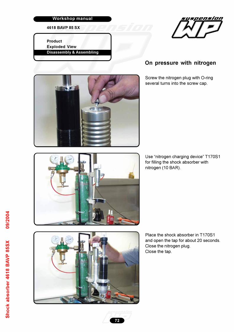
Product
Exploded View
Disassembly & Assembling
Workshop manual
4618 BAVP 85 SX
Werkplaatshandboek
72
Sh
oc
k a
bs
orb
er
46
18
BA
VP
85
SX
09
/20
04
Screw the nitrogen plug with O-ring
several turns into the screw cap.
Use “nitrogen charging device” T170S1
for filling the shock absorber with
nitrogen (10 BAR).
Place the shock absorber in T170S1
and open the tap for about 20 seconds.
Close the nitrogen plug.
Close the tap.
On pressure with nitrogen
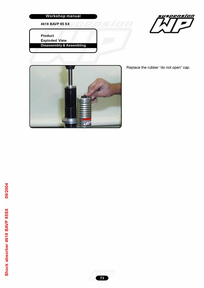
Product
Exploded View
Disassembly & Assembling
Workshop manual
4618 BAVP 85 SX
Werkplaatshandboek
73
Sh
oc
k a
bs
orb
er
46
18
BA
VP
85
SX
09
/20
04
Replace the rubber “do not open” cap.
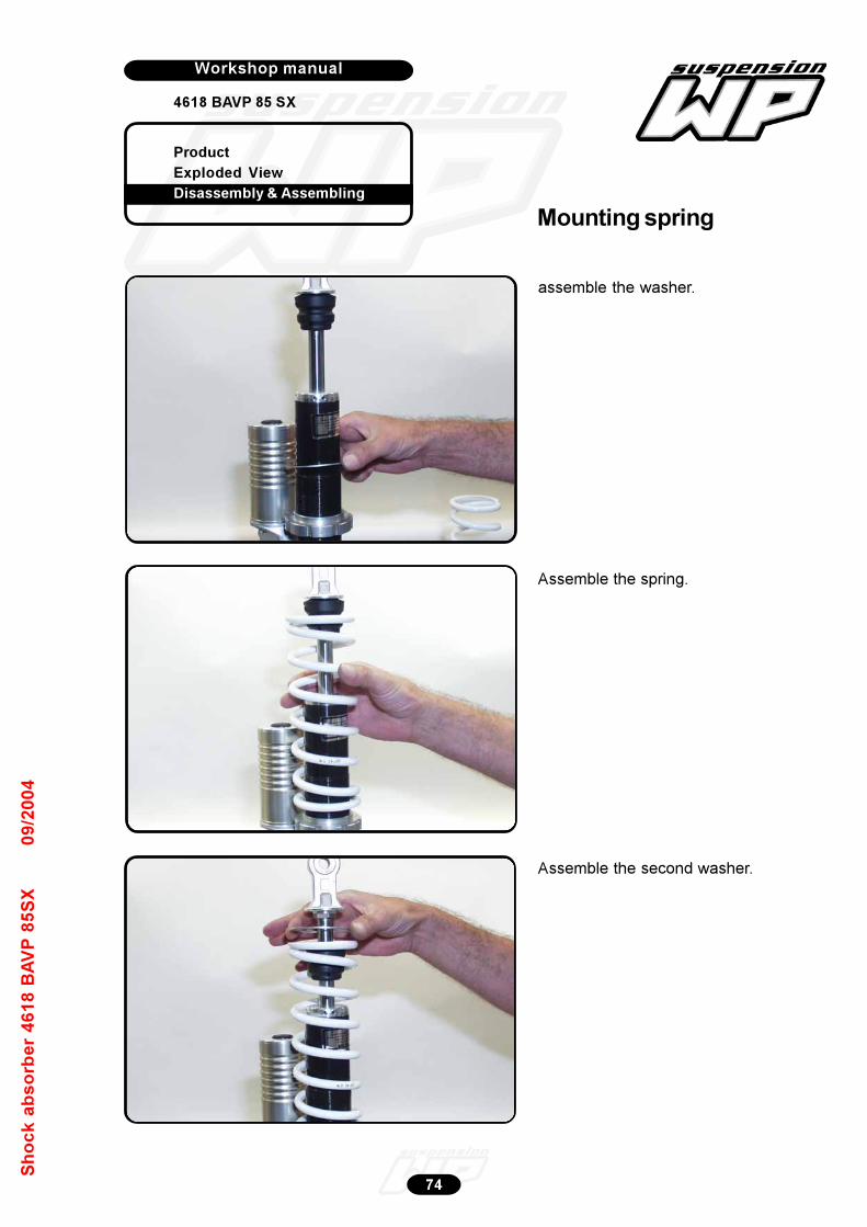
Product
Exploded View
Disassembly & Assembling
Workshop manual
4618 BAVP 85 SX
Werkplaatshandboek
74
Sh
oc
k a
bs
orb
er
46
18
BA
VP
85
SX
09
/20
04
assemble the washer.
Assemble the spring.
Assemble the second washer.
Mounting spring
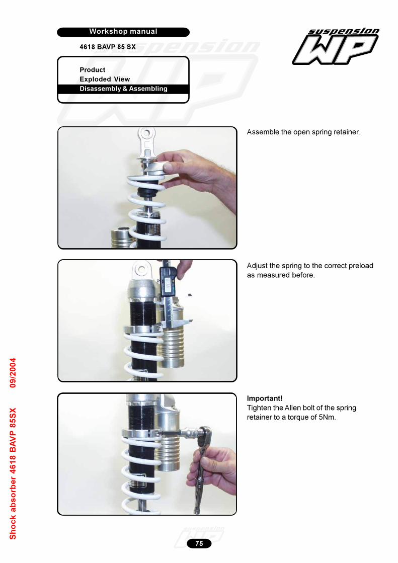
Product
Exploded View
Disassembly & Assembling
Workshop manual
4618 BAVP 85 SX
Werkplaatshandboek
75
Sh
oc
k a
bs
orb
er
46
18
BA
VP
85
SX
09
/20
04
Assemble the open spring retainer.
Adjust the spring to the correct preload
as measured before.
Important!
Tighten the Allen bolt of the spring
retainer to a torque of 5Nm.

Product
Exploded View
Disassembly & Assembling
Workshop manual
4618 BAVP 85 SX
Werkplaatshandboek
76
Sh
oc
k a
bs
orb
er
46
18
BA
VP
85
SX
09
/20
04
Compression position low-speed!
Compression position high-speed!
Rebound position!
Adjustments
Related Documents