E 5.04032.03 Manual KSR (KMO)

Welcome message from author
This document is posted to help you gain knowledge. Please leave a comment to let me know what you think about it! Share it to your friends and learn new things together.
Transcript
E 5.04032.03
Manual
KSR (KMO)
Title Manual
Product KSR - 3A (KMO)
Version 5.04032.03
Status 22.11.2010
Item no. 386638
Copyright These operating instructions may be copied by the owner in any quantity but only for internal use. For other purposes these operating instructions and extracts thereof may not be copied or reproduced. Use and disclosure of information contained in these oper-ating instructions are not permitted. Designations and company marks contained in these op-erating instructions may be brand names, the use of which by third parties for their own purposes may violate the rights of the holders.
Obligatory These operating instructions are part of the equipment/ma-chine. These operating instructions must be available to the operator at all times and must be in a legible condition. If the equipment/machine is sold or moved to a different lo-cation these operating instructions must be passed on by the owner together with the equipment/machine. After any sale of the equipment/machine this original and all copies must be handed over to the buyer. After disposal or any other end of use this original and all copies must be destroyed.
When the present operating instructions are handed over, corresponding sets of operating instructions of a previous version are automatically invalidated. Please notice that specifications/data/information are current values ac-cording to the printing date. These statements are not legally binding according to the measurement, computa-tion and calculations. Baumüller Nürnberg GmbH reserves the right, in develop-ing its products further, to change the technical specifica-tions and the handling of the products concerned without prior notice.
No liability can be accepted concerning the correctness of the operating instructions unless otherwise specified in the General Conditions of Sale and Delivery.
Manufacturer Baumüller Nürnberg GmbH Ostendstr. 80 - 90 D-90482 Nürnberg Germany Tel. +49 9 11 54 32 - 0 Fax: +49 9 11 54 32 - 1 30 www.baumueller.de
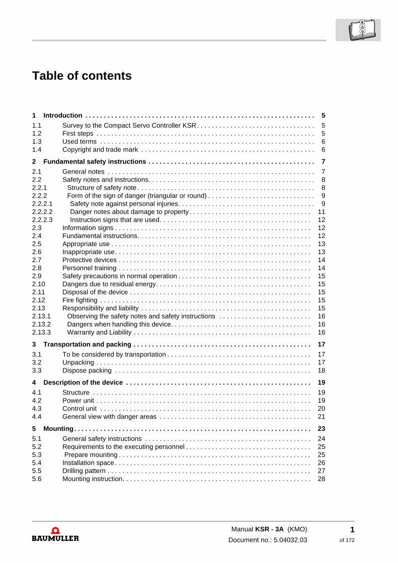
Table of contents
1 Introduction . . . . . . . . . . . . . . . . . . . . . . . . . . . . . . . . . . . . . . . . . . . . . . . . . . . . . . . . . . . . . . 5
1.1 Survey to the Compact Servo Controller KSR. . . . . . . . . . . . . . . . . . . . . . . . . . . . . . . . 51.2 First steps . . . . . . . . . . . . . . . . . . . . . . . . . . . . . . . . . . . . . . . . . . . . . . . . . . . . . . . . . . . 51.3 Used terms . . . . . . . . . . . . . . . . . . . . . . . . . . . . . . . . . . . . . . . . . . . . . . . . . . . . . . . . . . 61.4 Copyright and trade mark . . . . . . . . . . . . . . . . . . . . . . . . . . . . . . . . . . . . . . . . . . . . . . . 6
2 Fundamental safety instructions . . . . . . . . . . . . . . . . . . . . . . . . . . . . . . . . . . . . . . . . . . . . . 7
2.1 General notes . . . . . . . . . . . . . . . . . . . . . . . . . . . . . . . . . . . . . . . . . . . . . . . . . . . . . . . . 72.2 Safety notes and instructions. . . . . . . . . . . . . . . . . . . . . . . . . . . . . . . . . . . . . . . . . . . . . 82.2.1 Structure of safety note . . . . . . . . . . . . . . . . . . . . . . . . . . . . . . . . . . . . . . . . . . . . . . . . 82.2.2 Form of the sign of danger (triangular or round) . . . . . . . . . . . . . . . . . . . . . . . . . . . . . 92.2.2.1 Safety note against personal injuries. . . . . . . . . . . . . . . . . . . . . . . . . . . . . . . . . . . . . 92.2.2.2 Danger notes about damage to property . . . . . . . . . . . . . . . . . . . . . . . . . . . . . . . . . 112.2.2.3 Instruction signs that are used. . . . . . . . . . . . . . . . . . . . . . . . . . . . . . . . . . . . . . . . . 122.3 Information signs . . . . . . . . . . . . . . . . . . . . . . . . . . . . . . . . . . . . . . . . . . . . . . . . . . . . . 122.4 Fundamental instructions. . . . . . . . . . . . . . . . . . . . . . . . . . . . . . . . . . . . . . . . . . . . . . . 122.5 Appropriate use . . . . . . . . . . . . . . . . . . . . . . . . . . . . . . . . . . . . . . . . . . . . . . . . . . . . . . 132.6 Inappropriate use. . . . . . . . . . . . . . . . . . . . . . . . . . . . . . . . . . . . . . . . . . . . . . . . . . . . . 132.7 Protective devices . . . . . . . . . . . . . . . . . . . . . . . . . . . . . . . . . . . . . . . . . . . . . . . . . . . . 142.8 Personnel training . . . . . . . . . . . . . . . . . . . . . . . . . . . . . . . . . . . . . . . . . . . . . . . . . . . . 142.9 Safety precautions in normal operation . . . . . . . . . . . . . . . . . . . . . . . . . . . . . . . . . . . . 152.10 Dangers due to residual energy. . . . . . . . . . . . . . . . . . . . . . . . . . . . . . . . . . . . . . . . . . 152.11 Disposal of the device . . . . . . . . . . . . . . . . . . . . . . . . . . . . . . . . . . . . . . . . . . . . . . . . . 152.12 Fire fighting . . . . . . . . . . . . . . . . . . . . . . . . . . . . . . . . . . . . . . . . . . . . . . . . . . . . . . . . . 152.13 Responsibility and liability . . . . . . . . . . . . . . . . . . . . . . . . . . . . . . . . . . . . . . . . . . . . . . 152.13.1 Observing the safety notes and safety instructions . . . . . . . . . . . . . . . . . . . . . . . . . 162.13.2 Dangers when handling this device. . . . . . . . . . . . . . . . . . . . . . . . . . . . . . . . . . . . . . 162.13.3 Warranty and Liability . . . . . . . . . . . . . . . . . . . . . . . . . . . . . . . . . . . . . . . . . . . . . . . . 16
3 Transportation and packing . . . . . . . . . . . . . . . . . . . . . . . . . . . . . . . . . . . . . . . . . . . . . . . . 17
3.1 To be considered by transportation . . . . . . . . . . . . . . . . . . . . . . . . . . . . . . . . . . . . . . . 173.2 Unpacking . . . . . . . . . . . . . . . . . . . . . . . . . . . . . . . . . . . . . . . . . . . . . . . . . . . . . . . . . . 173.3 Dispose packing . . . . . . . . . . . . . . . . . . . . . . . . . . . . . . . . . . . . . . . . . . . . . . . . . . . . . 18
4 Description of the device . . . . . . . . . . . . . . . . . . . . . . . . . . . . . . . . . . . . . . . . . . . . . . . . . . 19
4.1 Structure . . . . . . . . . . . . . . . . . . . . . . . . . . . . . . . . . . . . . . . . . . . . . . . . . . . . . . . . . . . 194.2 Power unit . . . . . . . . . . . . . . . . . . . . . . . . . . . . . . . . . . . . . . . . . . . . . . . . . . . . . . . . . . 194.3 Control unit . . . . . . . . . . . . . . . . . . . . . . . . . . . . . . . . . . . . . . . . . . . . . . . . . . . . . . . . . 204.4 General view with danger areas . . . . . . . . . . . . . . . . . . . . . . . . . . . . . . . . . . . . . . . . . 21
5 Mounting. . . . . . . . . . . . . . . . . . . . . . . . . . . . . . . . . . . . . . . . . . . . . . . . . . . . . . . . . . . . . . . . 23
5.1 General safety instructions . . . . . . . . . . . . . . . . . . . . . . . . . . . . . . . . . . . . . . . . . . . . . 245.2 Requirements to the executing personnel . . . . . . . . . . . . . . . . . . . . . . . . . . . . . . . . . . 255.3 Prepare mounting . . . . . . . . . . . . . . . . . . . . . . . . . . . . . . . . . . . . . . . . . . . . . . . . . . . . 255.4 Installation space . . . . . . . . . . . . . . . . . . . . . . . . . . . . . . . . . . . . . . . . . . . . . . . . . . . . . 265.5 Drilling pattern . . . . . . . . . . . . . . . . . . . . . . . . . . . . . . . . . . . . . . . . . . . . . . . . . . . . . . . 275.6 Mounting instruction. . . . . . . . . . . . . . . . . . . . . . . . . . . . . . . . . . . . . . . . . . . . . . . . . . . 28
Manual KSR - 3A (KMO)
Document no.: 5.04032.03
1of 172
2of 172
Table of contents
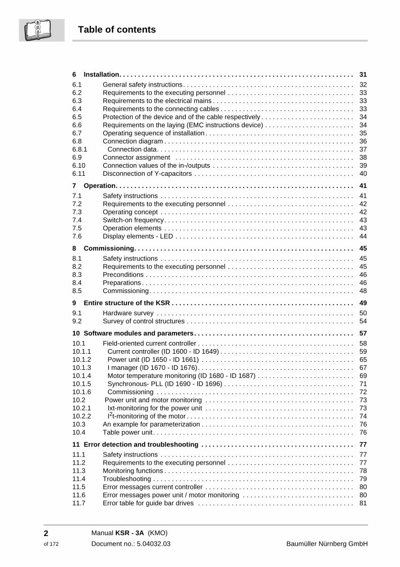
6 Installation. . . . . . . . . . . . . . . . . . . . . . . . . . . . . . . . . . . . . . . . . . . . . . . . . . . . . . . . . . . . . . . 31
6.1 General safety instructions. . . . . . . . . . . . . . . . . . . . . . . . . . . . . . . . . . . . . . . . . . . . . . 326.2 Requirements to the executing personnel . . . . . . . . . . . . . . . . . . . . . . . . . . . . . . . . . . 336.3 Requirements to the electrical mains . . . . . . . . . . . . . . . . . . . . . . . . . . . . . . . . . . . . . . 336.4 Requirements to the connecting cables . . . . . . . . . . . . . . . . . . . . . . . . . . . . . . . . . . . . 336.5 Protection of the device and of the cable respectively . . . . . . . . . . . . . . . . . . . . . . . . . 346.6 Requirements on the laying (EMC instructions device) . . . . . . . . . . . . . . . . . . . . . . . . 346.7 Operating sequence of installation . . . . . . . . . . . . . . . . . . . . . . . . . . . . . . . . . . . . . . . . 356.8 Connection diagram . . . . . . . . . . . . . . . . . . . . . . . . . . . . . . . . . . . . . . . . . . . . . . . . . . . 366.8.1 Connection data. . . . . . . . . . . . . . . . . . . . . . . . . . . . . . . . . . . . . . . . . . . . . . . . . . . . . 376.9 Connector assignment . . . . . . . . . . . . . . . . . . . . . . . . . . . . . . . . . . . . . . . . . . . . . . . . 386.10 Connection values of the in-/outputs . . . . . . . . . . . . . . . . . . . . . . . . . . . . . . . . . . . . . . 396.11 Disconnection of Y-capacitors . . . . . . . . . . . . . . . . . . . . . . . . . . . . . . . . . . . . . . . . . . . 40
7 Operation. . . . . . . . . . . . . . . . . . . . . . . . . . . . . . . . . . . . . . . . . . . . . . . . . . . . . . . . . . . . . . . . 41
7.1 Safety instructions . . . . . . . . . . . . . . . . . . . . . . . . . . . . . . . . . . . . . . . . . . . . . . . . . . . . 417.2 Requirements to the executing personnel . . . . . . . . . . . . . . . . . . . . . . . . . . . . . . . . . . 427.3 Operating concept . . . . . . . . . . . . . . . . . . . . . . . . . . . . . . . . . . . . . . . . . . . . . . . . . . . . 427.4 Switch-on frequency. . . . . . . . . . . . . . . . . . . . . . . . . . . . . . . . . . . . . . . . . . . . . . . . . . . 437.5 Operation elements . . . . . . . . . . . . . . . . . . . . . . . . . . . . . . . . . . . . . . . . . . . . . . . . . . . 437.6 Display elements - LED . . . . . . . . . . . . . . . . . . . . . . . . . . . . . . . . . . . . . . . . . . . . . . . . 44
8 Commissioning. . . . . . . . . . . . . . . . . . . . . . . . . . . . . . . . . . . . . . . . . . . . . . . . . . . . . . . . . . . 45
8.1 Safety instructions . . . . . . . . . . . . . . . . . . . . . . . . . . . . . . . . . . . . . . . . . . . . . . . . . . . . 458.2 Requirements to the executing personnel . . . . . . . . . . . . . . . . . . . . . . . . . . . . . . . . . . 458.3 Preconditions . . . . . . . . . . . . . . . . . . . . . . . . . . . . . . . . . . . . . . . . . . . . . . . . . . . . . . . . 468.4 Preparations . . . . . . . . . . . . . . . . . . . . . . . . . . . . . . . . . . . . . . . . . . . . . . . . . . . . . . . . . 468.5 Commissioning. . . . . . . . . . . . . . . . . . . . . . . . . . . . . . . . . . . . . . . . . . . . . . . . . . . . . . . 48
9 Entire structure of the KSR . . . . . . . . . . . . . . . . . . . . . . . . . . . . . . . . . . . . . . . . . . . . . . . . . 49
9.1 Hardware survey . . . . . . . . . . . . . . . . . . . . . . . . . . . . . . . . . . . . . . . . . . . . . . . . . . . . . 509.2 Survey of control structures . . . . . . . . . . . . . . . . . . . . . . . . . . . . . . . . . . . . . . . . . . . . . 54
10 Software modules and parameters. . . . . . . . . . . . . . . . . . . . . . . . . . . . . . . . . . . . . . . . . . . 57
10.1 Field-oriented current controller . . . . . . . . . . . . . . . . . . . . . . . . . . . . . . . . . . . . . . . . . . 5810.1.1 Current controller (ID 1600 - ID 1649) . . . . . . . . . . . . . . . . . . . . . . . . . . . . . . . . . . . . 5910.1.2 Power unit (ID 1650 - ID 1661) . . . . . . . . . . . . . . . . . . . . . . . . . . . . . . . . . . . . . . . . . 6510.1.3 I manager (ID 1670 - ID 1676) . . . . . . . . . . . . . . . . . . . . . . . . . . . . . . . . . . . . . . . . . . 6710.1.4 Motor temperature monitoring (ID 1680 - ID 1687) . . . . . . . . . . . . . . . . . . . . . . . . . . 6910.1.5 Synchronous- PLL (ID 1690 - ID 1696) . . . . . . . . . . . . . . . . . . . . . . . . . . . . . . . . . . . 7110.1.6 Commissioning . . . . . . . . . . . . . . . . . . . . . . . . . . . . . . . . . . . . . . . . . . . . . . . . . . . . . 7210.2 Power unit and motor monitoring . . . . . . . . . . . . . . . . . . . . . . . . . . . . . . . . . . . . . . . . 7310.2.1 Ixt-monitoring for the power unit . . . . . . . . . . . . . . . . . . . . . . . . . . . . . . . . . . . . . . . . 7310.2.2 I2t-monitoring of the motor . . . . . . . . . . . . . . . . . . . . . . . . . . . . . . . . . . . . . . . . . . . . . 7410.3 An example for parameterization . . . . . . . . . . . . . . . . . . . . . . . . . . . . . . . . . . . . . . . . . 7610.4 Table power unit . . . . . . . . . . . . . . . . . . . . . . . . . . . . . . . . . . . . . . . . . . . . . . . . . . . . . . 76
11 Error detection and troubleshooting . . . . . . . . . . . . . . . . . . . . . . . . . . . . . . . . . . . . . . . . . 77
11.1 Safety instructions . . . . . . . . . . . . . . . . . . . . . . . . . . . . . . . . . . . . . . . . . . . . . . . . . . . . 7711.2 Requirements to the executing personnel . . . . . . . . . . . . . . . . . . . . . . . . . . . . . . . . . . 7711.3 Monitoring functions . . . . . . . . . . . . . . . . . . . . . . . . . . . . . . . . . . . . . . . . . . . . . . . . . . . 7811.4 Troubleshooting . . . . . . . . . . . . . . . . . . . . . . . . . . . . . . . . . . . . . . . . . . . . . . . . . . . . . . 7911.5 Error messages current controller . . . . . . . . . . . . . . . . . . . . . . . . . . . . . . . . . . . . . . . . 8011.6 Error messages power unit / motor monitoring . . . . . . . . . . . . . . . . . . . . . . . . . . . . . . 8011.7 Error table for guide bar drives . . . . . . . . . . . . . . . . . . . . . . . . . . . . . . . . . . . . . . . . . . 81
Manual KSR - 3A (KMO)
Document no.: 5.04032.03 Baumüller Nürnberg GmbH
Table of contents
12 Maintenance . . . . . . . . . . . . . . . . . . . . . . . . . . . . . . . . . . . . . . . . . . . . . . . . . . . . . . . . . . . . . 97
12.1 Safety instructions . . . . . . . . . . . . . . . . . . . . . . . . . . . . . . . . . . . . . . . . . . . . . . . . . . . . 9712.2 Danger areas . . . . . . . . . . . . . . . . . . . . . . . . . . . . . . . . . . . . . . . . . . . . . . . . . . . . . . . . 9712.3 Environmental conditions. . . . . . . . . . . . . . . . . . . . . . . . . . . . . . . . . . . . . . . . . . . . . . . 9812.4 Inspection intervals - maintenance notes . . . . . . . . . . . . . . . . . . . . . . . . . . . . . . . . . . 98
13 Repair . . . . . . . . . . . . . . . . . . . . . . . . . . . . . . . . . . . . . . . . . . . . . . . . . . . . . . . . . . . . . . . . . . 99
14 Setting out of operation, storage . . . . . . . . . . . . . . . . . . . . . . . . . . . . . . . . . . . . . . . . . . . 101
14.1 Safety instructions . . . . . . . . . . . . . . . . . . . . . . . . . . . . . . . . . . . . . . . . . . . . . . . . . . . 10114.2 Requirements to the executing personnel . . . . . . . . . . . . . . . . . . . . . . . . . . . . . . . . . 10114.3 Set out of operation . . . . . . . . . . . . . . . . . . . . . . . . . . . . . . . . . . . . . . . . . . . . . . . . . . 10214.4 Demounting . . . . . . . . . . . . . . . . . . . . . . . . . . . . . . . . . . . . . . . . . . . . . . . . . . . . . . . . 10214.5 Storage conditions . . . . . . . . . . . . . . . . . . . . . . . . . . . . . . . . . . . . . . . . . . . . . . . . . . . 10214.6 Recommissioning . . . . . . . . . . . . . . . . . . . . . . . . . . . . . . . . . . . . . . . . . . . . . . . . . . . 102
15 Disposal . . . . . . . . . . . . . . . . . . . . . . . . . . . . . . . . . . . . . . . . . . . . . . . . . . . . . . . . . . . . . . . 103
15.1 Safety instructions . . . . . . . . . . . . . . . . . . . . . . . . . . . . . . . . . . . . . . . . . . . . . . . . . . . 10315.2 Recycling plants/offices . . . . . . . . . . . . . . . . . . . . . . . . . . . . . . . . . . . . . . . . . . . . . . . 104
Appendix A - Abbreviations . . . . . . . . . . . . . . . . . . . . . . . . . . . . . . . . . . . . . . . . . . . . . . . . . . 105
Appendix B - Accessories . . . . . . . . . . . . . . . . . . . . . . . . . . . . . . . . . . . . . . . . . . . . . . . . . . . 107
Appendix C - Declaration of Conformity/by Manufacturer . . . . . . . . . . . . . . . . . . . . . . . . . 109
C.1 What is an EU directive? . . . . . . . . . . . . . . . . . . . . . . . . . . . . . . . . . . . . . . . . . . . . . . 109C.2 What the CE symbol indicates . . . . . . . . . . . . . . . . . . . . . . . . . . . . . . . . . . . . . . . . . . 109C.3 Definition of the term Declaration of Conformity . . . . . . . . . . . . . . . . . . . . . . . . . . . . . 110C.4 Definition of the term Manufacturer’s Declaration. . . . . . . . . . . . . . . . . . . . . . . . . . . . 110C.5 Declaration of Conformity . . . . . . . . . . . . . . . . . . . . . . . . . . . . . . . . . . . . . . . . . . . . . . 111C.6 Manufacturer’s Declaration. . . . . . . . . . . . . . . . . . . . . . . . . . . . . . . . . . . . . . . . . . . . . 112
Appendix D - Technical data . . . . . . . . . . . . . . . . . . . . . . . . . . . . . . . . . . . . . . . . . . . . . . . . . 113
D.1 Requirements on the power supply . . . . . . . . . . . . . . . . . . . . . . . . . . . . . . . . . . . . . . 114D.2 Required environmental conditions . . . . . . . . . . . . . . . . . . . . . . . . . . . . . . . . . . . . . . 114D.3 Non-electrical data . . . . . . . . . . . . . . . . . . . . . . . . . . . . . . . . . . . . . . . . . . . . . . . . . . . 114D.4 Electrical data . . . . . . . . . . . . . . . . . . . . . . . . . . . . . . . . . . . . . . . . . . . . . . . . . . . . . . . 115D.5 Pin assignment between power unit and controller . . . . . . . . . . . . . . . . . . . . . . . . . . 117
Appendix E - ELTK documentation . . . . . . . . . . . . . . . . . . . . . . . . . . . . . . . . . . . . . . . . . . . . 119
E.1 Installation of program environment . . . . . . . . . . . . . . . . . . . . . . . . . . . . . . . . . . . . . . 119E.2 Install ELTK . . . . . . . . . . . . . . . . . . . . . . . . . . . . . . . . . . . . . . . . . . . . . . . . . . . . . . . . 125E.2.1 Decompressing of ELTK program . . . . . . . . . . . . . . . . . . . . . . . . . . . . . . . . . . . . . . . 125E.2.2 Start ELTK program screen . . . . . . . . . . . . . . . . . . . . . . . . . . . . . . . . . . . . . . . . . . . . 126E.3 Functions . . . . . . . . . . . . . . . . . . . . . . . . . . . . . . . . . . . . . . . . . . . . . . . . . . . . . . . . . . 127E.3.1 Writing .... . . . . . . . . . . . . . . . . . . . . . . . . . . . . . . . . . . . . . . . . . . . . . . . . . . . . . . . . . . 127E.3.2 Reading ... . . . . . . . . . . . . . . . . . . . . . . . . . . . . . . . . . . . . . . . . . . . . . . . . . . . . . . . . . 129E.3.3 Comparing ... . . . . . . . . . . . . . . . . . . . . . . . . . . . . . . . . . . . . . . . . . . . . . . . . . . . . . . . 132E.3.4 Encoder adjustment ... . . . . . . . . . . . . . . . . . . . . . . . . . . . . . . . . . . . . . . . . . . . . . . . . 134E.3.5 Description of Parameter online page . . . . . . . . . . . . . . . . . . . . . . . . . . . . . . . . . . . . 137E.3.6 Error display . . . . . . . . . . . . . . . . . . . . . . . . . . . . . . . . . . . . . . . . . . . . . . . . . . . . . . . . 144E.4 Log file . . . . . . . . . . . . . . . . . . . . . . . . . . . . . . . . . . . . . . . . . . . . . . . . . . . . . . . . . . . . 145E.4.1 Machine log file . . . . . . . . . . . . . . . . . . . . . . . . . . . . . . . . . . . . . . . . . . . . . . . . . . . . . . 145E.4.2 Serial number log file . . . . . . . . . . . . . . . . . . . . . . . . . . . . . . . . . . . . . . . . . . . . . . . . . 146E.4.3 Internal log file . . . . . . . . . . . . . . . . . . . . . . . . . . . . . . . . . . . . . . . . . . . . . . . . . . . . . . 146
Manual KSR - 3A (KMO)
Document no.: 5.04032.03
3of 172
4of 172
Table of contents
Described KSR parameters . . . . . . . . . . . . . . . . . . . . . . . . . . . . . . . . . . . . . . . . . . . . . . . . . . . 147
List of all parameters . . . . . . . . . . . . . . . . . . . . . . . . . . . . . . . . . . . . . . . . . . . . . . . . . . . . . . . . 149
List of figures . . . . . . . . . . . . . . . . . . . . . . . . . . . . . . . . . . . . . . . . . . . . . . . . . . . . . . . . . . . . . . 167
Index . . . . . . . . . . . . . . . . . . . . . . . . . . . . . . . . . . . . . . . . . . . . . . . . . . . . . . . . . . . . . . . . . . . . . 169
Revision survey . . . . . . . . . . . . . . . . . . . . . . . . . . . . . . . . . . . . . . . . . . . . . . . . . . . . . . . . . . . . 171
Manual KSR - 3A (KMO)
Document no.: 5.04032.03 Baumüller Nürnberg GmbH
1
1INTRODUCTIONThis manual is an important component of the Compact Servo Controller KSR - 3A. Last but not least on behalf of safety reasons, read through the complete manual.
In this chapter we describe the first steps, which have to be done after you have received the device. We will define terms, which are continuously used throughout this manual. We also will be giving you instructions, what should be taken into consideration when han-dling this device.
1.1 Survey to the Compact Servo Controller KSR
The device consists of a power unit and controller in one common cabinet.
In this manual we explain the „Compact Servo controller KSR - 3A“, the connection and the commissioning.
1.2 First steps
h Check delivery, see ZTransportation and packing– from page 17.
h Provide for qualified personnel for the mounting, installation and commissioning.
h Hand over this manual to the personnel for mounting, installation and commissioning. Assure that especially the safety instructions are understood and followed.
WARNING
The following can occur, if you disregard this safety note:
m serious personal injury m death
All persons, who work on and with devices KSR - 3A, must have this manual available at their work place and must follow the instructions and notes contained therein - especially the safety instructions.
5of 172
Manual KSR - 3A (KMO)
Document no.: 5.04032.03
Used terms1.3
1.3 Used terms
In this manual we will also use the term "device" for the Baumüller product "KSR - 3A“. A list of the abbreviations which are used are to be found in ZAppendix A - Abbreviations– from page 105.
1.4 Copyright and trade mark
Hiperface® is a registered trade mark of SICK/Stegmann
Manual KSR - 3A (KMO)
Document no.: 5.04032.03 Baumüller Nürnberg GmbH
6of 172
2
2FUNDAMENTAL SAFETYINSTRUCTIONS
2.1 General notes
In this chapter we describe the dangers, that can arise when working with the Baumüller-device. Dangers we point up with symbols (icons). All symbols that are used in this man-ual are listed and explained.
How you can protect yourself against the single hazards in the concrete case, we will not explain in this chapter. This chapter contains only general protective measures. Concrete protective measures we will always give directly in the subsequent chapters after the note to the hazard.
WARNING
The following can occur, if you disregard this safety note:
m serious personal injury m death
The safety note is showing you the dangers which can lead to injury or even to death.
Always follow the safety notes given in this manual.
7of 172
Manual KSR - 3A (KMO)
Document no.: 5.04032.03
Safety notes and instructions2.2
2.2 Safety notes and instructions
2.2.1 Structure of safety note
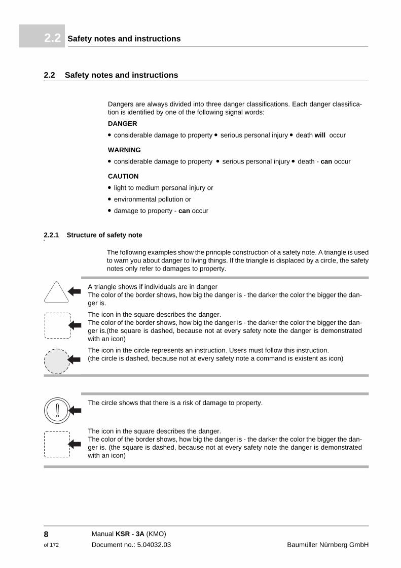
The following examples show the principle construction of a safety note. A triangle is used to warn you about danger to living things. If the triangle is displaced by a circle, the safety notes only refer to damages to property.
Dangers are always divided into three danger classifications. Each danger classifica-tion is identified by one of the following signal words:
DANGER
m considerable damage to property m serious personal injury m death will occur
WARNING
m considerable damage to property m serious personal injury m death - can occur
CAUTION
m light to medium personal injury or
m environmental pollution or
m damage to property - can occur
A triangle shows if individuals are in danger The color of the border shows, how big the danger is - the darker the color the bigger the dan-ger is.
The icon in the square describes the danger. The color of the border shows, how big the danger is - the darker the color the bigger the dan-ger is.(the square is dashed, because not at every safety note the danger is demonstrated with an icon)
The icon in the circle represents an instruction. Users must follow this instruction. (the circle is dashed, because not at every safety note a command is existent as icon)
The circle shows that there is a risk of damage to property.
The icon in the square describes the danger. The color of the border shows, how big the danger is - the darker the color the bigger the dan-ger is. (the square is dashed, because not at every safety note the danger is demonstrated with an icon)
Manual KSR - 3A (KMO)
Document no.: 5.04032.03 Baumüller Nürnberg GmbH
8of 172
Fundamental safety instructions 2
The text next to the icons is structured as follows:2.2.2 Form of the sign of danger (triangular or round)
If there is a triangular figure of danger in front of a signal word: or or , then the safety note refers to personal injury.
If there is a round danger sign in front of a signal word: then the safety note refers to damage of property.
2.2.2.1 Safety note against personal injuries
In order to differentiate optically we use for every class of safety notes an own bordering for the triangular safety notes and for the square pictographs.
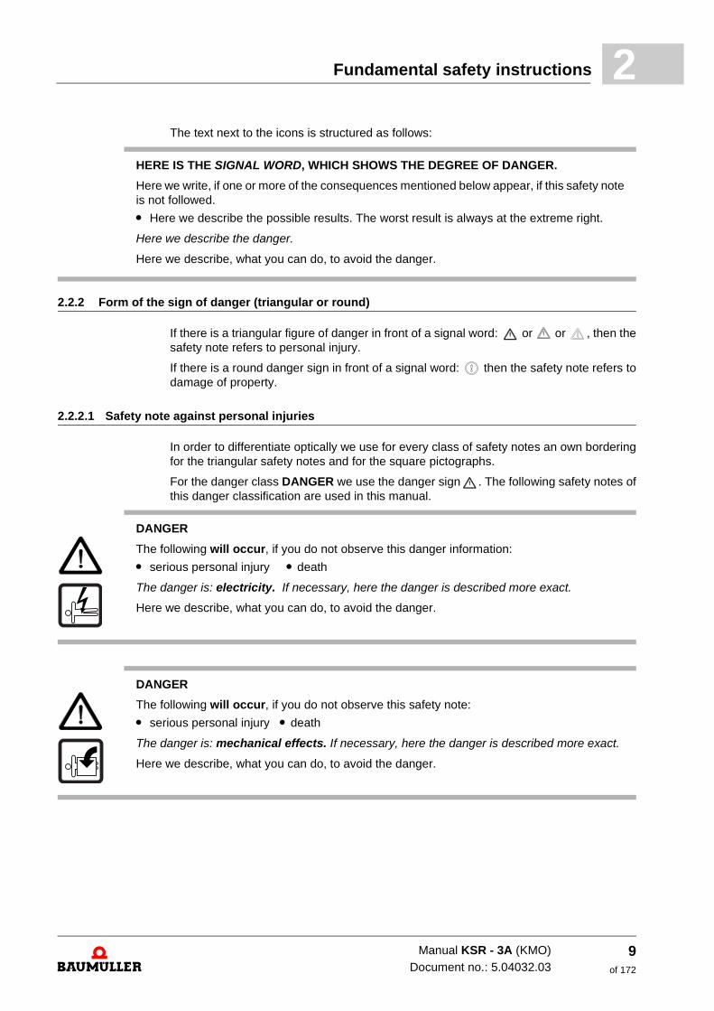
For the danger class DANGER we use the danger sign . The following safety notes of this danger classification are used in this manual.
HERE IS THE SIGNAL WORD, WHICH SHOWS THE DEGREE OF DANGER.
Here we write, if one or more of the consequences mentioned below appear, if this safety note is not followed.
m Here we describe the possible results. The worst result is always at the extreme right.
Here we describe the danger.
Here we describe, what you can do, to avoid the danger.
DANGER
The following will occur, if you do not observe this danger information:
m serious personal injury m death
The danger is: electricity. If necessary, here the danger is described more exact.
Here we describe, what you can do, to avoid the danger.
DANGER
The following will occur, if you do not observe this safety note:
m serious personal injury m death
The danger is: mechanical effects. If necessary, here the danger is described more exact.
Here we describe, what you can do, to avoid the danger.
Manual KSR - 3A (KMO)Document no.: 5.04032.03
9of 172
Safety notes and instructions2.2
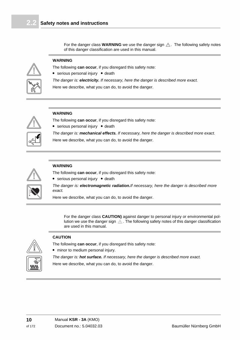
For the danger class WARNING we use the danger sign . The following safety notes of this danger classification are used in this manual.
For the danger class CAUTION) against danger to personal injury or environmental pol-lution we use the danger sign . The following safety notes of this danger classification are used in this manual.
WARNING
The following can occur, if you disregard this safety note:
m serious personal injury m death
The danger is: electricity. If necessary, here the danger is described more exact.
Here we describe, what you can do, to avoid the danger.
WARNING
The following can occur, if you disregard this safety note:
m serious personal injury m death
The danger is: mechanical effects. If necessary, here the danger is described more exact.
Here we describe, what you can do, to avoid the danger.
WARNING
The following can occur, if you disregard this safety note:
m serious personal injury m death
The danger is: electromagnetic radiation.If necessary, here the danger is described more exact.
Here we describe, what you can do, to avoid the danger.
CAUTION
The following can occur, if you disregard this safety note:
m minor to medium personal injury.
The danger is: hot surface. If necessary, here the danger is described more exact.
Here we describe, what you can do, to avoid the danger.
Manual KSR - 3A (KMO)
Document no.: 5.04032.03 Baumüller Nürnberg GmbH
10of 172
Fundamental safety instructions 2
2.2.2.2 Danger notes about damage to property
If there is a round danger sign in front of a signal word: the safety information then refers to damage to property
CAUTION
The following can occur, if you disregard this safety note:
m minor to medium personal injury.
The danger is: sharp edges.If necessary, here the danger is described more exact.
Here we describe, what you can do, to avoid the danger.
CAUTION
The following can occur, if you disregard this safety note:
m minor to medium personal injury.
The danger is: rotating parts.If necessary, here the danger is described more exact.
Here we describe, what you can do, to avoid the danger.
CAUTION
The following may occur, if you do not observe this safety note:
m Environmental pollution
The danger is: incorrect disposal.If necessary, here the danger is described more exact.
Here we describe, what you can do, to avoid the danger.
CAUTION
The following can occur, if you disregard this safety note:
m damage to property
The danger is: electrostatic discharge.If necessary, here the danger is described more ex-act.
Here we describe, what you can do, to avoid the danger.
Manual KSR - 3A (KMO)Document no.: 5.04032.03
11of 172
Information signs2.3
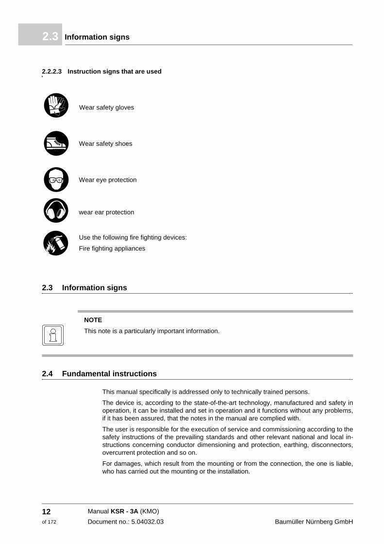
2.2.2.3 Instruction signs that are used
2.3 Information signs
2.4 Fundamental instructions
This manual specifically is addressed only to technically trained persons.
The device is, according to the state-of-the-art technology, manufactured and safety in operation, it can be installed and set in operation and it functions without any problems, if it has been assured, that the notes in the manual are complied with.
The user is responsible for the execution of service and commissioning according to the safety instructions of the prevailing standards and other relevant national and local in-structions concerning conductor dimensioning and protection, earthing, disconnectors, overcurrent protection and so on.
For damages, which result from the mounting or from the connection, the one is liable, who has carried out the mounting or the installation.
Wear safety gloves
Wear safety shoes
Wear eye protection
wear ear protection
Use the following fire fighting devices:
Fire fighting appliances
NOTE
This note is a particularly important information.
Manual KSR - 3A (KMO)
Document no.: 5.04032.03 Baumüller Nürnberg GmbH
12of 172
Fundamental safety instructions 2
2.5 Appropriate useYou must always use the device appropriately. Some important information is listed be-low. The notes stated below shall give you a feeling of the specified application of the de-vice. Besides the notes mentioned below, you must follow all of the specified notes given in this manual.
m Configure the application in such a way, that you always operate the device within its specifications.
m Make sure, that only qualified personnel work with/at this device.
m Mount this device only at an adequate carrying control cabinet.
m Install this device in the way as it is described in the manual.
m Make sure, that the mains always applies to the predetermined specifications.
m Only operate the device, if it is technical correct.
m Always operate the device in prescribed environment.
m Always operate the device in serialized status. Due to safety reasons you may not rebuild the device.
m Consider all instructions referring to this, if you intend to store the device.
You are using the device according to the terms, as soon as you regard all notes and in-formation in this operating manual.
2.6 Inappropriate use
In the following we are listing some examples of inappropriate use. The notes mentioned below shall give you a feeling, what a faulty use of the device is. However, we cannot list all possible cases of inappropriate use here. All usages, in which the instructions of this manual are disregarded are faulty and therewith forbidden, especially in the following cas-es:
m You disregarded the notes in this manual.
m You have not used the device according to the terms.
n The device has been
m mounted incorrectly,
m connected incorrectly,
m commissioned incorrectly,
m operated incorrectly,
m mounted, connected, commissioned, operated and/or maintained by not qualified or inadequately qualified personnel,
m inappropriately maintained or not maintained (also consider the descriptions of the components),
m overloaded,
m operated with
n defect safety devices,
n not in proper form installed or without safety devices,
n not operative safety- and protection devices,
n not within the required environmental conditions.
m You have reconstructed the device, without having this authorized in written form from Baumüller Nürnberg GmbH.
Manual KSR - 3A (KMO)Document no.: 5.04032.03
13of 172
Protective devices2.7
m You have insufficiently monitored the parts, which are subject to a wearing.
m You have improperly carried out a repair.
m You have improperly combined the device with products of other manufacturers.
m You have combined the device with faulty and/or faulty documented products of other manufacturers.
2.7 Protective devices
The device KSR complies with the class of protection IP 20. By mounting the device into a control cabinet you can raise the class of protection.
2.8 Personnel training
Qualified personnel (skilled person) are defined as follows:
Qualified personnel
Authorized electronic engineers and skilled persons of the customer or third persons, who have learned the installation and commissioning of Baumüller drive systems and who are authorized, to put circuits and devices into operation according to the standards of the safety technology, to earth and to label.
Qualified personnel has a training or an instruction due to the local valid standards of the safety technique in maintenance and usage of an adequate safety equipment.
Requirements to the operating per-sonnel
The operating of the drive system must only be executed by persons, who have had a training, who have been instructed and who have been authorized for this.
Troubleshooting, preventive maintenance, cleaning, maintenance and replacing parts are only to be executed by trained personnel or by personnel, who has been introduced in this. These persons must be familiar with the manual and act in accordance with this.
Commissioning and instruction must only be carried out by qualified personnel.
WARNING
The following can occur, if you disregard this safety note:
m serious personal injury m death
The danger is: electricity. The device fulfills IP 00 and resp. IP 20
Operate the device in a control cabinet, which provides a protection against a direct touching of the devices and fulfills at least the demands of the EN 50178 chapter 5.2.4/VDE 0160.
WARNING
The following can occur, if you disregard this safety note:
m serious personal injury m death
Devices of Baumüller Nürnberg GmbH may only be mounted, installed, operated and maintained by qualified personnel.
Manual KSR - 3A (KMO)
Document no.: 5.04032.03 Baumüller Nürnberg GmbH
14of 172
Fundamental safety instructions 2
2.9 Safety precautions in normal operationh at the location of your appliance regard the safety regulations for the plant, into which the appliance has been built in.
h if safety regulations require additional monitoring or safety devices supply your appli-ance with them.
2.10 Dangers due to residual energy
Electrical residual energy
After disconnecting the device from the mains, parts under voltage e. g. power connec-tions may be touched not until after ten minutes, as the capacitors in the device are dis-charged not before ten minutes. Also consider the corresponding notes on the device. If you have connected the additional capacitors at the DC link, DC link discharging can last considerably longer. In this case waiting time must be determined self.
Mechanical residual energy
The mechanical residual energy is dependent upon the application. As we don't know the application, we cannot make any exact statements. Driven parts also rotate/move after disconnection of the mains supply for a certain time. Please, provide adequate safety ar-rangements.
2.11 Disposal of the device
The accurate disposal of the device is described in ZDisposal– from page 103.
2.12 Fire fighting
2.13 Responsibility and liability
To be able to work as safe as possible with this device, you must know and follow the danger notes as well as the safety instructions.
WARNING
The following can occur, if you disregard this safety note:
m serious personal injury m death
The danger is: Electricity when using a conductive fire fighting device.
Use the following fire fighting devices:
ABC powder
Manual KSR - 3A (KMO)Document no.: 5.04032.03
15of 172
Responsibility and liability2.13
2.13.1 Observing the safety notes and safety instructions
In this manual we use visually unified safety instructions, which are intended to prevent from personal injury or damage to property.
2.13.2 Dangers when handling this device
The device was developed and manufactured according to the state-of-the-art technology and in compliance with the valid directives and standards. It is still possible that dangers can arise during use. An overview of possible dangers is to be found in chapter ZSafety notes and instructions– on page 8. We warn you against the acute danger at the respective places in this manual.
2.13.3 Warranty and Liability
All information in this manual is non-binding customer information; it is subject to ongoing further development and is updated on a continuous basis by our revision service.
Warranty- and liability claims against Baumüller Nürnberg GmbH are excluded, if partic-ularly one or more of the under ZInappropriate use– from page 13 described causes have led to the damage.
WARNING
The following can occur, if you disregard this safety note:
m serious personal injury m death
All persons, who work with this device, must know and regard the safety notes and the safety instructions in this manual.
Apart from this, any and all persons who work on this device must additionally know and re-gard to all regulations and instructions, that are valid at the location.
Manual KSR - 3A (KMO)
Document no.: 5.04032.03 Baumüller Nürnberg GmbH
16of 172
3
3TRANSPORTATION AND PACKINGIn this chapter we describe, which conditions have to be adhered to at transportation, how you check the device after receipt and what you should have to consider, if you dispose the packing.
3.1 To be considered by transportation
For the first transportation of the device, the device was packed in the manufacturer com-pany. In case you transport the device, assure, that the following conditions are fulfilled during the whole transportation:
m 2 K 3 (climatic category)
m -30 °C to +70 °C (temperature range)
m max. 1 g (vibration, shock, repetitive shock)
3.2 Unpacking
After receipt of the device, which is still packed:
h Avoid strong transportation vibrations and severe hits (max. 1 g), e. g. when setting down.
h Check, if transportation damages are visible!
If so:
h Immediately complain to the deliverer. Let the claim be confirmed in writing and imme-diately contact the substitution of Baumüller Nürnberg GmbH, which is in charge for your company.
WARNING
The following can occur, if you disregard this safety note:
m serious personal injury m death
The danger is: electricity.
Do not operate the device, if you have recognized a transportation damage or if you assume this. In this case immediately contact Baumüller Nürnberg GmbH.
17of 172
Manual KSR - 3A (KMO)
Document no.: 5.04032.03
Dispose packing3.3
If there is no transportation damage noticeable:
h Open the packing of the device.
h Check the scope of supply on basis of the delivery note.
The minimal scope of supply is:
m KSR - 3A
m This manual inclusively the copy of the declaration of conformity/declaration of manu-facturer
m Addition
h Claim at the Baumüller substitution, which is in charge, in case the delivery is not com-plete.
3.3 Dispose packing
The packing is made of cardboard, plastics, metal parts, corrugated cardboard and/or wood.
h Regard the local disposal instructions, in case you dispose the packing.
Manual KSR - 3A (KMO)
Document no.: 5.04032.03 Baumüller Nürnberg GmbH
18of 172
4
4DESCRIPTION OF THE DEVICEIn this chapter we describe the fundamental structure of the devices KSR - 3A.
4.1 Structure
A device consists of a power unit and a controller, which are in a common cabinet.
4.2 Power unit
Technical data of power unit see ZAppendix D - Technical data– from page 113.
Power connection Plug-in terminal for supply (X11), motor connection (X10) at the front side and for the con-nection of an external brake resistor or of a DC link at the top side of the cabinet.
Precharge circuit The precharge circuit limits load current of the DC link capacitors. At the moment of switch-on, the discharged capacitors act as a short circuit. With help of a NTC resistor the current is limited to a permissible value. If the DC link voltage has reached a specified value, the NTC resistor is short-circuited with a relay, in order to avoid development of heat at the NTC resistor.
Brake circuit If the servo motor runs over into braking operation, the mechanical energy supplies elec-trical energy to the DC link. Therewith the DC link voltage rises. In order to avoid, that the DC link capacitors are damaged due to overvoltage, a discharging of the capacitors must take place from a specified voltage on. For this a high-load resistance is connected to the DC link with the help of a power transistor. It converts the excessively energy into heat. If the voltage threshold is less than the brake transistor is inhibited again. This procedure occurs at longer braking procedures cyclically. If the braking time exceeds a specified val-ue, a warning is generated by the controller.
NOTE
Do not use this device KSR - 3A in residential areas (see EN 61800-3, 6.4.2.1), because the device can cause RF-interferences in residential areas.
19of 172
Manual KSR - 3A (KMO)
Document no.: 5.04032.03
Control unit4.3
Internal line filter The mains filter circuit takes effects against electrical influences from the mains to the converter and for the suppression of interferences towards the mains, which where gen-erated by converter.
4.3 Control unit
Interfaces Inputs
m Input for motor temperature sensor (KTY 84), plug-in terminal
m Digital input (24 VDC) for pulse enable, plug-in terminal m Digital input (24 VDC) freely usable, plug-in terminal
Outputs
m Freely programmable isolated relay contact, plug-in terminals
m Three GND-related analog outputs, plug-in terminal
m Optical sender and receiver for SERCOS-bus
m Serial interface RS 232 for PC connection, socket SUB D 9-pole
Encoder interface Connection via SUB D socket, 15-pole
Automatic detection of selected encoder types
m SinCos absolute value encoder (SinCos signal 1 Vss) with Hiperface® or EnDat data bus
m Square wave incremental encoder
m Resolver (in preparation)
The encoder interface is, with the help of, current limiting circuits protected against short-circuit. At encoder short-circuit the encoder remains current-free.
Manual KSR - 3A (KMO)
Document no.: 5.04032.03 Baumüller Nürnberg GmbH
20of 172
Description of the device 4
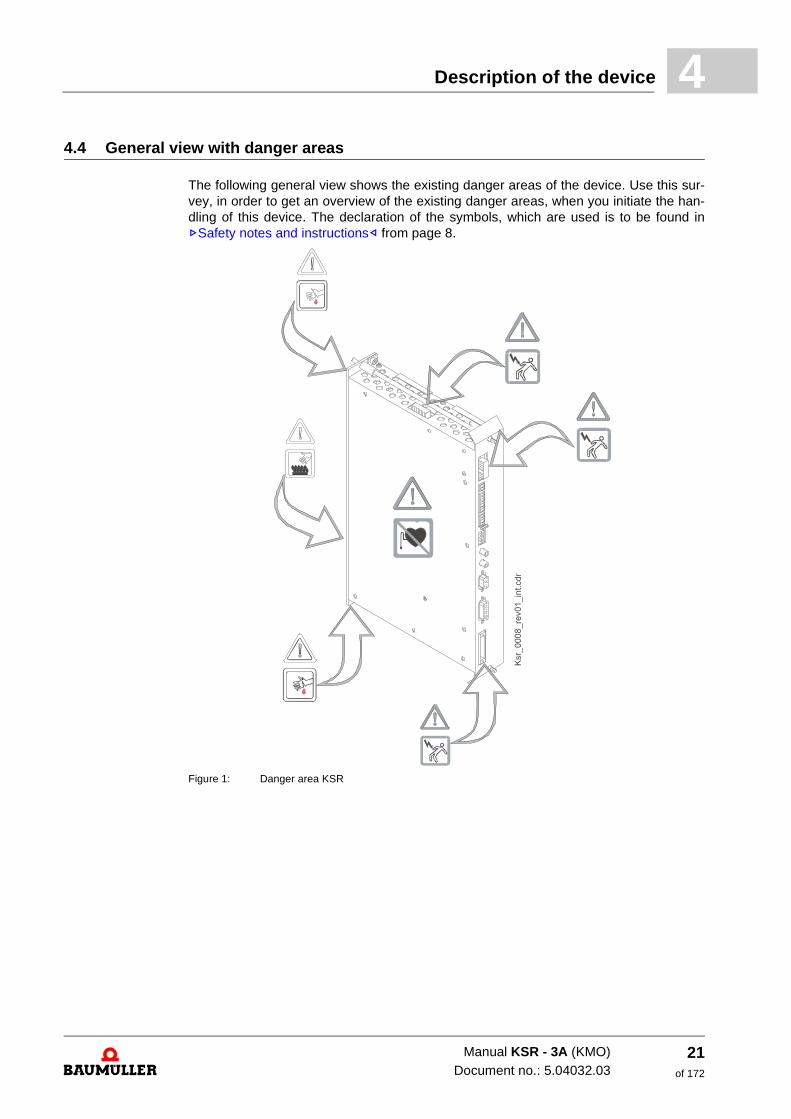
4.4 General view with danger areasThe following general view shows the existing danger areas of the device. Use this sur-vey, in order to get an overview of the existing danger areas, when you initiate the han-dling of this device. The declaration of the symbols, which are used is to be found in ZSafety notes and instructions– from page 8.
Figure 1: Danger area KSR
Manual KSR - 3A (KMO)Document no.: 5.04032.03
21of 172
General view with danger areas4.4
Manual KSR - 3A (KMO)
Document no.: 5.04032.03 Baumüller Nürnberg GmbH
22of 172
5
5MOUNTINGIn this chapter we describe the mechanical mounting of the device into a switching board. The control cabinet is projected with help of the application manual. Information to the in-stallation space are also to be found in this operating instruction (see ZInstallation space– from page 26).
Mounting consists of the following steps:
1 Prepare mounting (make the drill holes)
2 Install device
23of 172
Manual KSR - 3A (KMO)
Document no.: 5.04032.03
General safety instructions5.1
5.1 General safety instructions
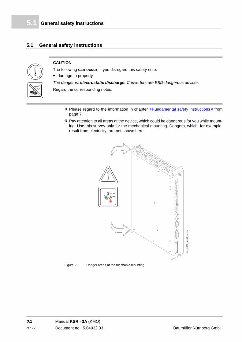
h Please regard to the information in chapter ZFundamental safety instructions– from page 7.
h Pay attention to all areas at the device, which could be dangerous for you while mount-ing. Use this survey only for the mechanical mounting. Dangers, which, for example, result from electricity are not shown here.
Figure 2: Danger areas at the mechanic mounting
CAUTION
The following can occur, if you disregard this safety note:
m damage to property
The danger is: electrostatic discharge. Converters are ESD-dangerous devices.
Regard the corresponding notes.
Manual KSR - 3A (KMO)
Document no.: 5.04032.03 Baumüller Nürnberg GmbH
24of 172
Mounting 5
5.2 Requirements to the executing personnelQualified personnel are persons, who, due to their education, experience, briefing about relevant standards and regulations and accident prevention regulations have been autho-rized to carry out the required operations and thereby are able to avoid possible dangers. They have been authorized by the person, who is responsible for the security of installa-tion. The required qualifications for the work with this unit are for example: Training or in-struction due to the standards of safety engineering in maintenance and use of appropriate safety equipment.
5.3 Prepare mounting
You can prepare the mounting with the configuring manual for your installation. With the configuring manual and the drill figures you can determine the dimensions for the cut-outs and for the fastening drills.
CAUTION
The following may occur, if you do not observe this safety note:
m minor to medium personal injury.
The danger is: sharp edges. In case, while installing, you lift a device with unprotected hands, fingers/palm can be cut. If the device falls off, your feet can be cut up.
Assure, that only qualified personnel, who is familiar with the safety- as well as with the mount-ing instructions, mount this device.
Wear safety gloves
Wear safety shoes
CAUTION
The following may occur, if you do not observe this safety note:
m minor to medium personal injury.
The danger is: Eye injury due to catapulting particles. While executing the drillings and the cut-out metal particles are catapulted.
Wear eye protection
Manual KSR - 3A (KMO)Document no.: 5.04032.03
25of 172
Installation space5.4
5.4 Installation space
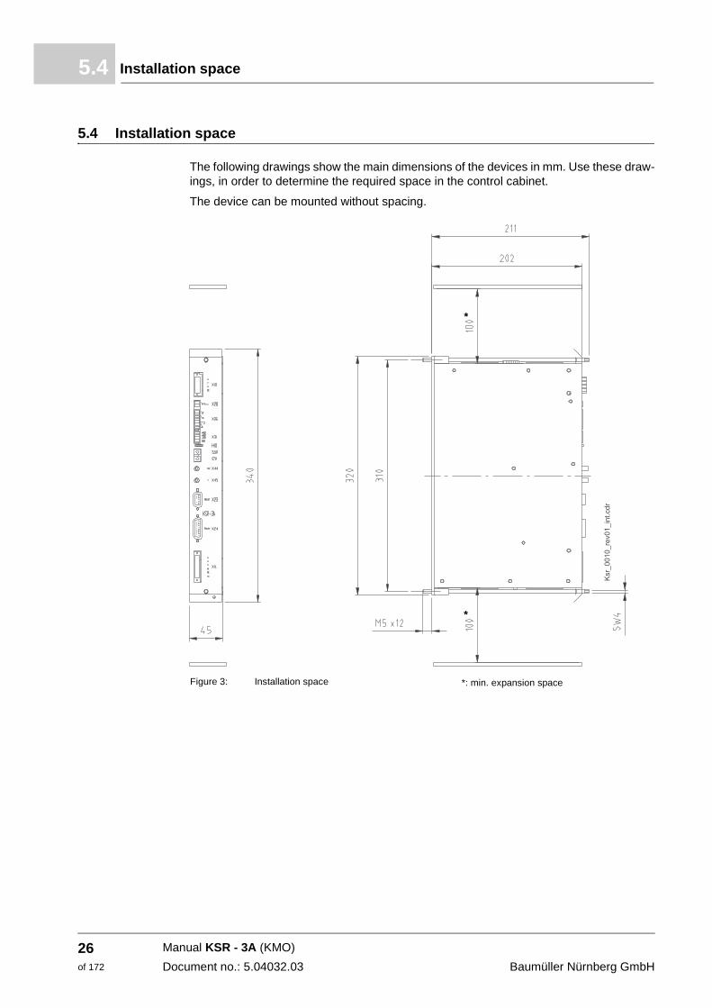
The following drawings show the main dimensions of the devices in mm. Use these draw-ings, in order to determine the required space in the control cabinet.
The device can be mounted without spacing.
*
*
Figure 3: Installation space *: min. expansion space
Manual KSR - 3A (KMO)
Document no.: 5.04032.03 Baumüller Nürnberg GmbH
26of 172
Mounting 5
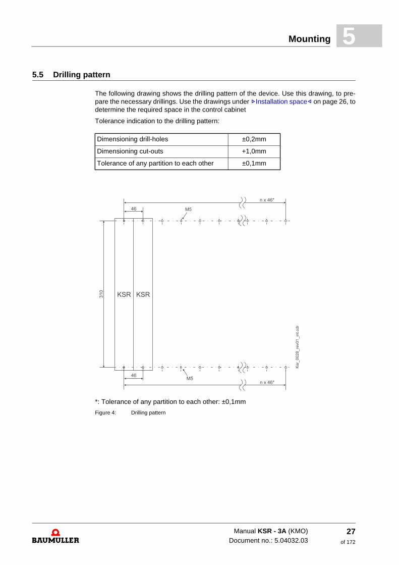
5.5 Drilling patternThe following drawing shows the drilling pattern of the device. Use this drawing, to pre-pare the necessary drillings. Use the drawings under ZInstallation space– on page 26, to determine the required space in the control cabinet
Tolerance indication to the drilling pattern:
*: Tolerance of any partition to each other: ±0,1mm
Figure 4: Drilling pattern
Dimensioning drill-holes ±0,2mm
Dimensioning cut-outs +1,0mm
Tolerance of any partition to each other ±0,1mm
Manual KSR - 3A (KMO)Document no.: 5.04032.03
27of 172
Mounting instruction5.6
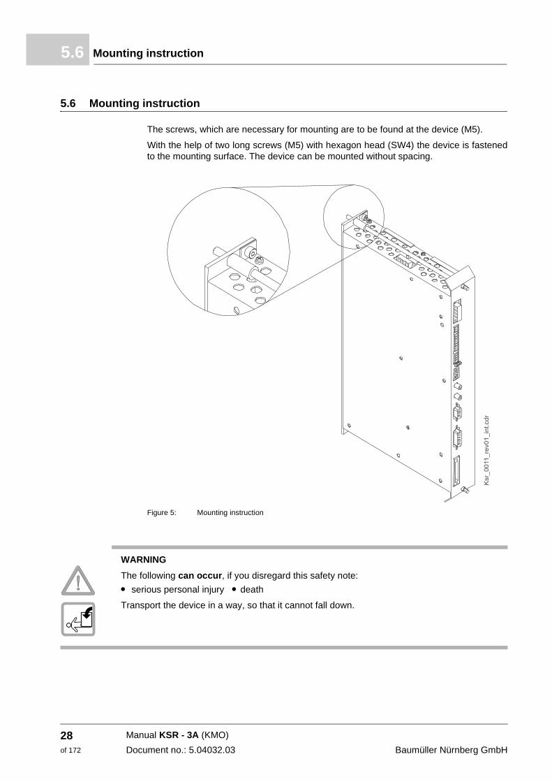
5.6 Mounting instruction
The screws, which are necessary for mounting are to be found at the device (M5).
With the help of two long screws (M5) with hexagon head (SW4) the device is fastened to the mounting surface. The device can be mounted without spacing.
Figure 5: Mounting instruction
WARNING
The following can occur, if you disregard this safety note:
m serious personal injury m death
Transport the device in a way, so that it cannot fall down.
Manual KSR - 3A (KMO)
Document no.: 5.04032.03 Baumüller Nürnberg GmbH
28of 172
Mounting 5
CAUTION
The following can occur, if you disregard this safety note:
m minor to medium personal injury.
The danger is: sharp edges. In case, while installing, you lift a device with unprotected hands, fingers/palm can be cut. If the device falls off, the feet can be cut.
Wear safety gloves
Wear safety shoes
Manual KSR - 3A (KMO)Document no.: 5.04032.03
29of 172
Mounting instruction5.6
Manual KSR - 3A (KMO)
Document no.: 5.04032.03 Baumüller Nürnberg GmbH
30of 172
6
6INSTALLATIONIn this chapter we describe the electric installation of the device. The mechanical instal-lation we described in ZMounting– from page 23.
Before installing assure that the technical preconditions are fulfilled:
1 Check the requirements to the electrical mains and check if the existing mains is suit-able.
2 Check the requirements to the electrical cables and provide the according cables.
3 Check the characteristics of the connections and configure the connections according-ly.
31of 172
Manual KSR - 3A (KMO)
Document no.: 5.04032.03
General safety instructions6.1
6.1 General safety instructions
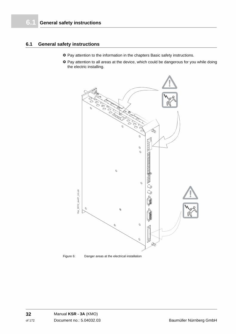
h Pay attention to the information in the chapters Basic safety instructions.
h Pay attention to all areas at the device, which could be dangerous for you while doing the electric installing.
Figure 6: Danger areas at the electrical installation
Manual KSR - 3A (KMO)
Document no.: 5.04032.03 Baumüller Nürnberg GmbH
32of 172
Installation 6
6.2 Requirements to the executing personnelAt each case qualified personnel are persons, who are authorized by the responsible per-sons, to carry out necessary actions and who recognize the possible dangers and who are able to avoid these dangers. They have had the training, the experience, they were given instructions as well as knowledge about the relevant standards and instructions, they have knowledge of the accident prevention regulations and of the operating environ-ments. The required qualifications for the work with this unit are for example:
m Training or instruction and to have the authorization to operate with circuits and devic-es according to the standards of the safety engineering, to commission, to earth and to label.
m Training or instruction due to the standards of safety engineering in maintenance and use of appropriate safety equipment.
6.3 Requirements to the electrical mains
All important data is to be found in ZD.4 Electrical data– on page 115. Small deviations of the electrical mains from the requirements can lead to malfunctions of the device. In case the mains deviates strongly from the requirements, the device can be destroyed. The destruction of the device can cause personnel injury.
6.4 Requirements to the connecting cables
h When selecting connection cables, you have to consider the IEC/EN 60204-1, chapter 13.
h Use 60°/75° copper cable, in case you have to consider the UL 508 C.
WARNING
The following can occur, if you disregard this safety note:
m serious personal injury m death
The danger is: electricity. When operating with this electrical unit, inevitably certain parts of this unit are under dangerous voltage.
Make sure, that only qualified personnel, who are familiar with the safety- as well as with mounting-, operating- and maintenance instructions, work on this unit.
WARNING
The following can occur, if you disregard this safety note:
m serious personal injury m death
The danger is: electricity. In case you do not ensure the requirements to the electrical mains, the device can be damaged/destroyed and can thereby endanger persons severely.
Assure before installation, that the requirements of the electrical mains are fulfilled.
Manual KSR - 3A (KMO)Document no.: 5.04032.03
33of 172
Protection of the device and of the cable respectively6.5
6.5 Protection of the device and of the cable respectively
In order to protect the device or the cables against damage/destruction by the mains, you must install fuses.
6.6 Requirements on the laying (EMC instructions device)
m Use Baumüller motor lines and Baumüller components.
m Mount all components to a single mounting board with well electroconductive surface (e. g. galvanized steel plate).
m Carry out the earth connection converter/earth plane as short as possible (< 30 cm) with fine-wired cables and a big cross section (> 10 mm2).
m When installing, attend to the correct order: mains - fuse - device.
m Assure, that the motor cables always consist of one piece. Do not disconnect motor cables e. g. with terminals, contactors, fuses a. s. o.
m Run the cables directly on the surface of the earthed mounting board. (smallest possible effective aerial height).
m Keep a minimum clearance of 20 cm between signal- and control wires towards electric power cables at parallel laying.
m Cross cables with different EMC categories (signal cables - mains cables or motor ca-bles) only in a 90° angle.
m Contact the external cable screens when passing through walls, which separate differ-ent EMC ranges.
m Connect the screen of the cables of the devices plane on both ends and highly conduc-tive with earth.
m On principle screen all connected cables.
NOTE
This device must be in accordance with § 6 para. 9 of the EMVG from September 18, 1998.
In this Manual you will find the most important information according an EMC-compatible in-stallation.
Manual KSR - 3A (KMO)
Document no.: 5.04032.03 Baumüller Nürnberg GmbH
34of 172
Installation 6
6.7 Operating sequence of installationInstallation exists of the following steps:
1 Lay all cables EMC-compatible.
2 Connect cables.
m Connect the motor at the terminals X10:U, V, W, PE. Attend to the in-phase connec-tion (rotational direction).
m Connect the fuses.
m Connect the mains via the terminals X11:L1, N, PE.
m Connect encoder.
WARNING
The following can occur, if you disregard this safety note:
m serious personal injury m death
The danger is: electricity. Parts, which are under tension are perilous.
Assure, that during the entire mounting the device, the mounting range and the parts, which are to be mounted (e. g. mains cables) are off-circuit.
Manual KSR - 3A (KMO)Document no.: 5.04032.03
35of 172
Connection diagram6.8
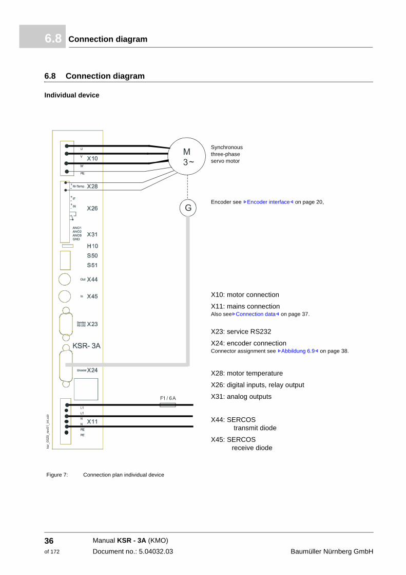
6.8 Connection diagram
Individual device
Figure 7: Connection plan individual device
Synchronous three-phase servo motor
Encoder see ZEncoder interface– on page 20,
X10: motor connection
X11: mains connection Also seeZConnection data– on page 37.
X23: service RS232
X24: encoder connection Connector assignment see ZAbbildung 6.9– on page 38.
X28: motor temperature
X26: digital inputs, relay output
X31: analog outputs
X44: SERCOS transmit diode
X45: SERCOS receive diode
Manual KSR - 3A (KMO)
Document no.: 5.04032.03 Baumüller Nürnberg GmbH
36of 172
Installation 6
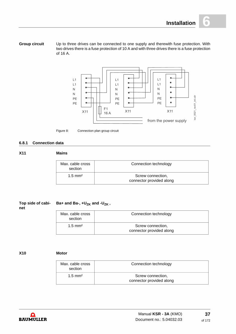
Group circuit Up to three drives can be connected to one supply and therewith fuse protection. Withtwo drives there is a fuse protection of 10 A and with three drives there is a fuse protection of 16 A.
Figure 8: Connection plan group circuit
6.8.1 Connection data
X11 Mains
Top side of cabi-net
Ba+ and Ba-, +UZK and -UZK ,
X10 Motor
Max. cable cross section
Connection technology
1.5 mm² Screw connection, connector provided along
Max. cable cross section
Connection technology
1.5 mm² Screw connection,connector provided along
Max. cable cross section
Connection technology
1.5 mm² Screw connection,connector provided along
Manual KSR - 3A (KMO)Document no.: 5.04032.03
37of 172
Connector assignment6.9
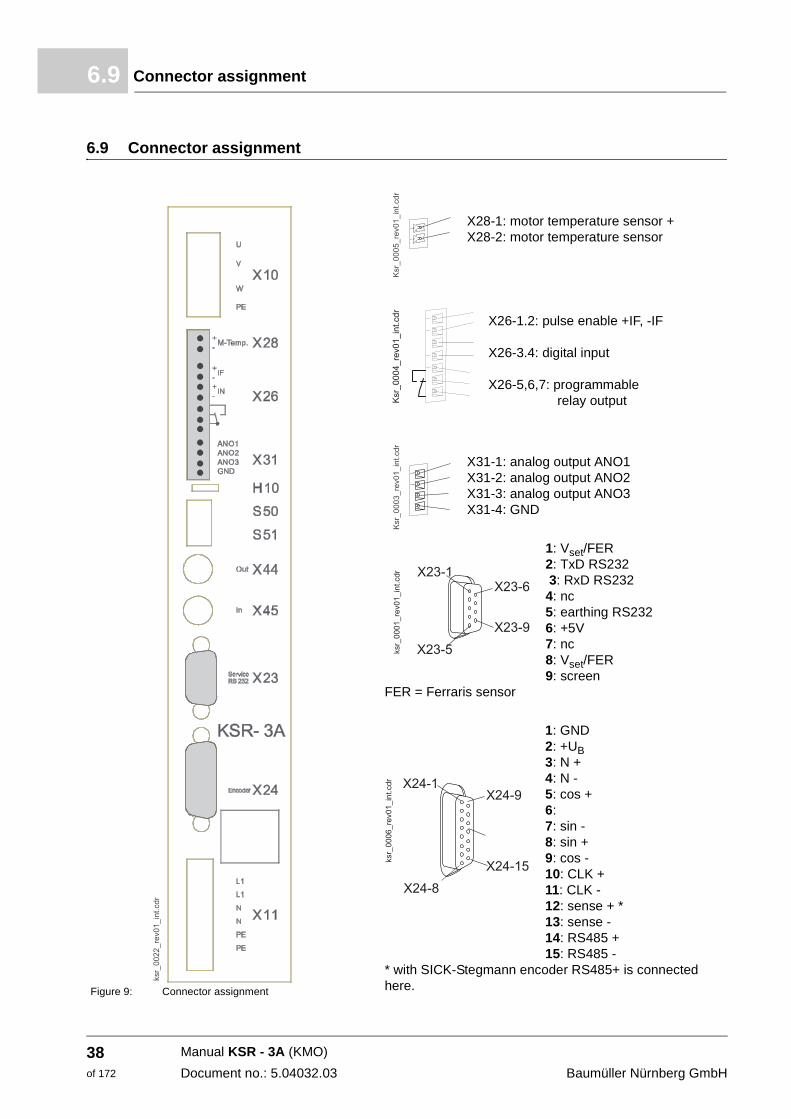
6.9 Connector assignment
Figure 9: Connector assignment
X28-1: motor temperature sensor + X28-2: motor temperature sensor
X26-1.2: pulse enable +IF, -IF
X26-3.4: digital input
X26-5,6,7: programmable relay output
X31-1: analog output ANO1 X31-2: analog output ANO2X31-3: analog output ANO3X31-4: GND
1: Vset/FER 2: TxD RS232 3: RxD RS2324: nc5: earthing RS2326: +5V7: nc8: Vset/FER9: screen
FER = Ferraris sensor
1: GND2: +UB3: N +4: N -5: cos +6: 7: sin -8: sin +9: cos -10: CLK +11: CLK -12: sense + * 13: sense - 14: RS485 +15: RS485 -
* with SICK-Stegmann encoder RS485+ is connected here.
Manual KSR - 3A (KMO)
Document no.: 5.04032.03 Baumüller Nürnberg GmbH
38of 172
Installation 6
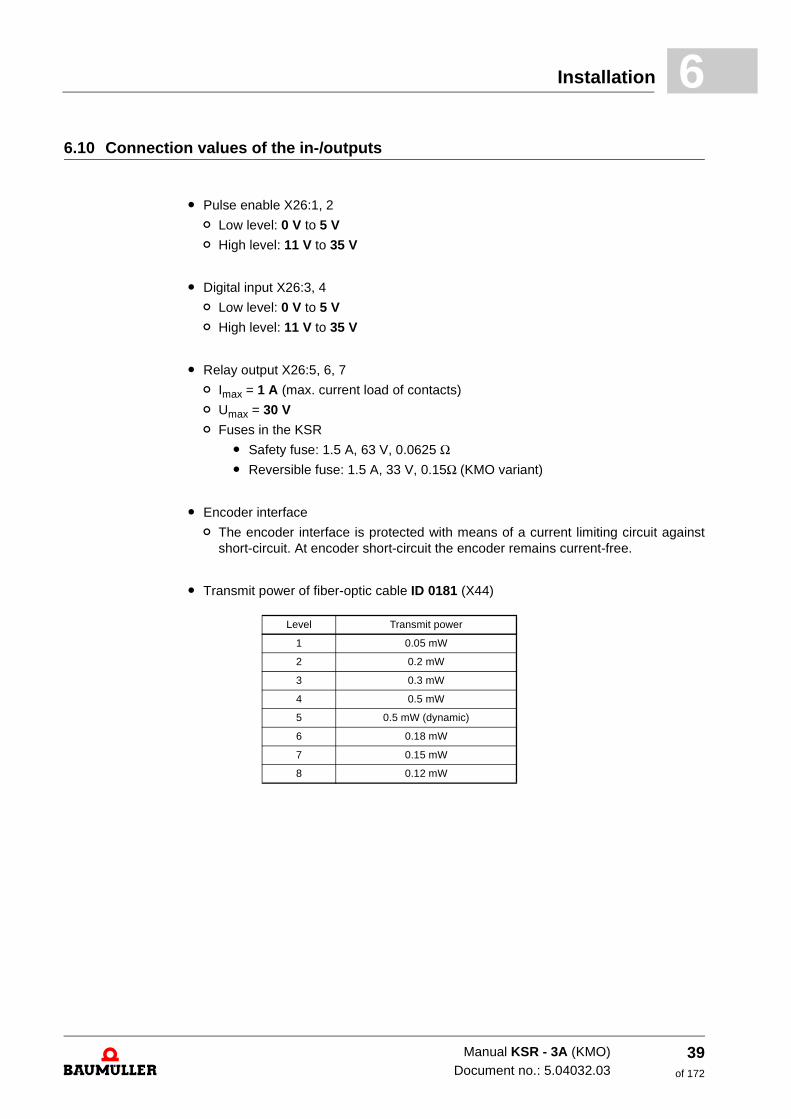
6.10 Connection values of the in-/outputsm Pulse enable X26:1, 2
n Low level: 0 V to 5 V
n High level: 11 V to 35 V
m Digital input X26:3, 4
n Low level: 0 V to 5 V
n High level: 11 V to 35 V
m Relay output X26:5, 6, 7
n Imax = 1 A (max. current load of contacts)
n Umax = 30 V
n Fuses in the KSR
m Safety fuse: 1.5 A, 63 V, 0.0625 Ω m Reversible fuse: 1.5 A, 33 V, 0.15Ω (KMO variant)
m Encoder interface
n The encoder interface is protected with means of a current limiting circuit against short-circuit. At encoder short-circuit the encoder remains current-free.
m Transmit power of fiber-optic cable ID 0181 (X44)
Level Transmit power
1 0.05 mW
2 0.2 mW
3 0.3 mW
4 0.5 mW
5 0.5 mW (dynamic)
6 0.18 mW
7 0.15 mW
8 0.12 mW
Manual KSR - 3A (KMO)Document no.: 5.04032.03
39of 172
Disconnection of Y-capacitors6.11
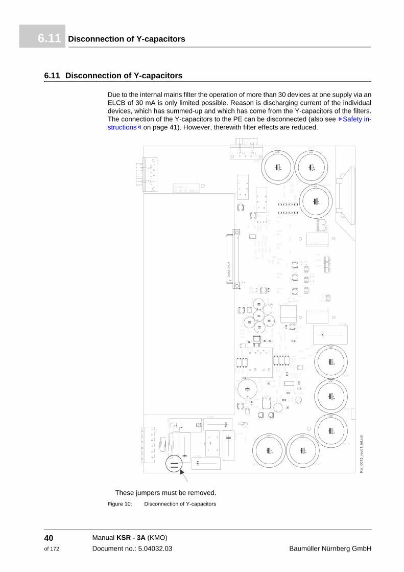
6.11 Disconnection of Y-capacitors
Due to the internal mains filter the operation of more than 30 devices at one supply via an ELCB of 30 mA is only limited possible. Reason is discharging current of the individual devices, which has summed-up and which has come from the Y-capacitors of the filters. The connection of the Y-capacitors to the PE can be disconnected (also see ZSafety in-structions– on page 41). However, therewith filter effects are reduced.
These jumpers must be removed.
Figure 10: Disconnection of Y-capacitors
Manual KSR - 3A (KMO)
Document no.: 5.04032.03 Baumüller Nürnberg GmbH
40of 172
7
7OPERATIONIn this chapter we describe, how the device works during operation and how you handle the device during operation.
7.1 Safety instructions
h Refer to the safety instructions from the chapter ZFundamental safety instructions– from page 7.
CAUTION
The following can occur, if you disregard this safety note:
m damage to property
The danger is: Environmental conditions, that do not refer to the demands.
Assure, that the environmental conditions are referred to during operation (see ZEnvironmen-tal conditions– from page 98).
WARNING
The following can occur, if you disregard this safety note:
m serious personal injury m death
The danger is: electricity. The control cabinet, in which the device is built in, shall protect against contacts with parts which are under voltage.
Assure, that during operation all doors of the control cabinet are closed.
Assure, that during operation all safety devices work.
41of 172
Manual KSR - 3A (KMO)
Document no.: 5.04032.03
Requirements to the executing personnel7.2
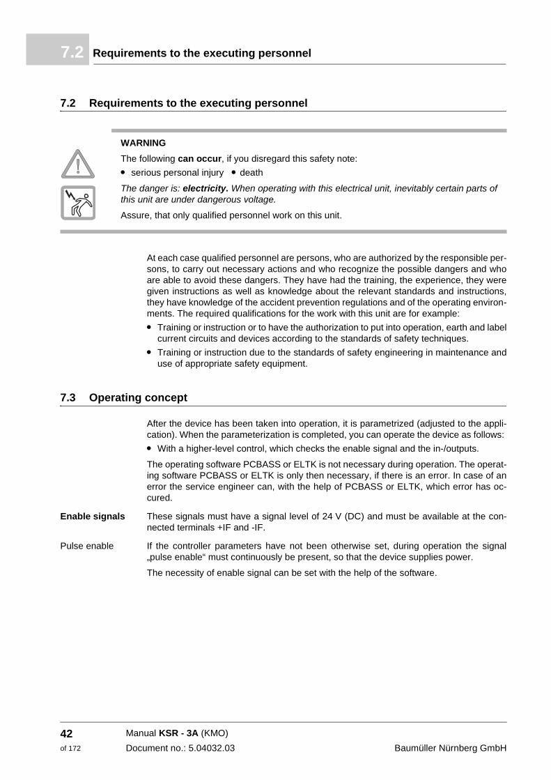
7.2 Requirements to the executing personnel
At each case qualified personnel are persons, who are authorized by the responsible per-sons, to carry out necessary actions and who recognize the possible dangers and who are able to avoid these dangers. They have had the training, the experience, they were given instructions as well as knowledge about the relevant standards and instructions, they have knowledge of the accident prevention regulations and of the operating environ-ments. The required qualifications for the work with this unit are for example:
m Training or instruction or to have the authorization to put into operation, earth and label current circuits and devices according to the standards of safety techniques.
m Training or instruction due to the standards of safety engineering in maintenance and use of appropriate safety equipment.
7.3 Operating concept
After the device has been taken into operation, it is parametrized (adjusted to the appli-cation). When the parameterization is completed, you can operate the device as follows:
m With a higher-level control, which checks the enable signal and the in-/outputs.
The operating software PCBASS or ELTK is not necessary during operation. The operat-ing software PCBASS or ELTK is only then necessary, if there is an error. In case of an error the service engineer can, with the help of PCBASS or ELTK, which error has oc-cured.
Enable signals These signals must have a signal level of 24 V (DC) and must be available at the con-nected terminals +IF and -IF.
Pulse enable If the controller parameters have not been otherwise set, during operation the signal „pulse enable“ must continuously be present, so that the device supplies power.
The necessity of enable signal can be set with the help of the software.
WARNING
The following can occur, if you disregard this safety note:
m serious personal injury m death
The danger is: electricity. When operating with this electrical unit, inevitably certain parts of this unit are under dangerous voltage.
Assure, that only qualified personnel work on this unit.
Manual KSR - 3A (KMO)
Document no.: 5.04032.03 Baumüller Nürnberg GmbH
42of 172
Operation 7
7.4 Switch-on frequencyThe device may not be switched on and off as often as you like. Between the switching off and the restarting it must be complied with a waiting time, in order to protect the de-vices and fuses.
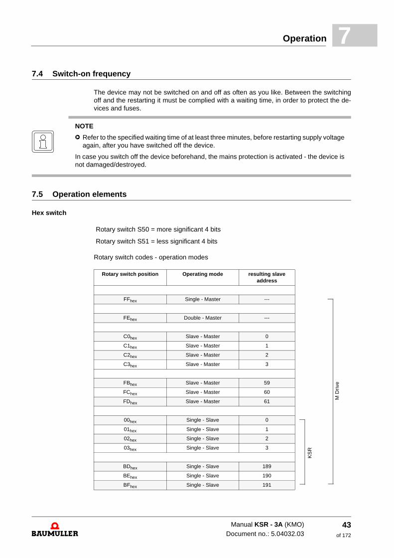
7.5 Operation elements
Hex switch
Rotary switch codes - operation modes
NOTE
h Refer to the specified waiting time of at least three minutes, before restarting supply voltage again, after you have switched off the device.
In case you switch off the device beforehand, the mains protection is activated - the device is not damaged/destroyed.
Rotary switch S50 = more significant 4 bits
Rotary switch S51 = less significant 4 bits
Rotary switch position Operating mode resulting slave address
FFhex Single - Master ---
FEhex Double - Master ---
C0hex Slave - Master 0
C1hex Slave - Master 1
C2hex Slave - Master 2
C3hex Slave - Master 3
FBhex Slave - Master 59
FChex Slave - Master 60
FDhex Slave - Master 61
00hex Single - Slave 0
01hex Single - Slave 1
02hex Single - Slave 2
03hex Single - Slave 3
BDhex Single - Slave 189
BEhex Single - Slave 190
BFhex Single - Slave 191
M D
rive
KS
R
Manual KSR - 3A (KMO)Document no.: 5.04032.03
43of 172
Display elements - LED7.6
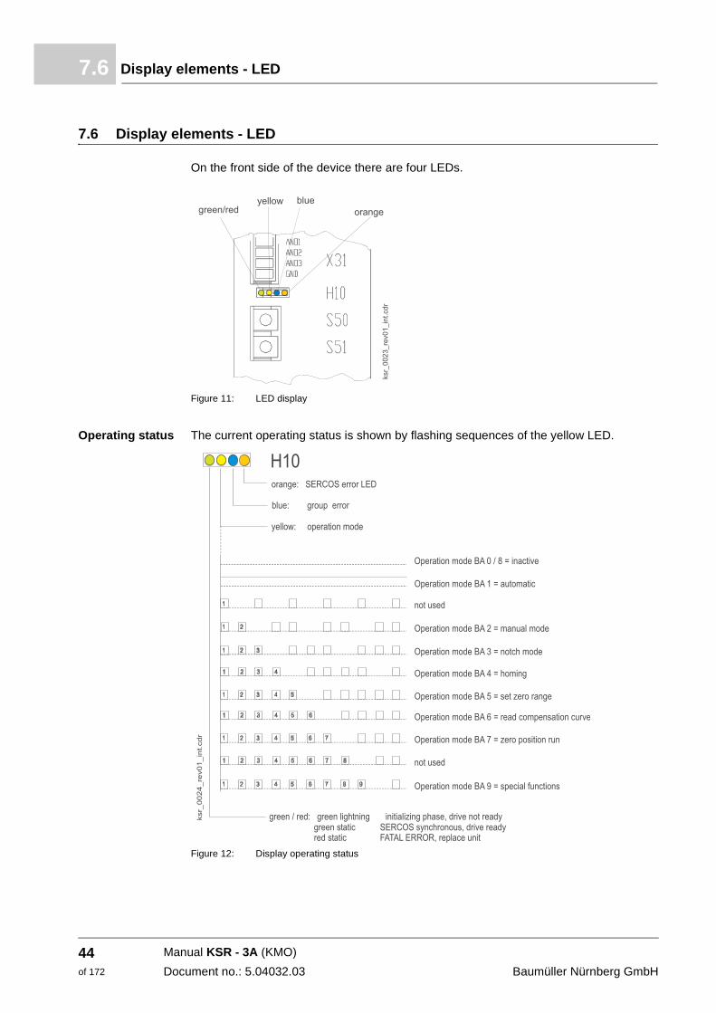
7.6 Display elements - LED
On the front side of the device there are four LEDs.
Figure 11: LED display
Operating status The current operating status is shown by flashing sequences of the yellow LED.
Figure 12: Display operating status
Operating mode
Manual KSR - 3A (KMO)
Document no.: 5.04032.03 Baumüller Nürnberg GmbH
44of 172
8
8COMMISSIONINGIn this chapter we describe a exemplary commissioning of a KSR device with a Baumüller motor DSD 28-M with SinCos encoder. Carry out the commissioning, to make sure that the delivered devices are in an accordant status. This commissioning is not for the com-plete installation of the device for your application.
8.1 Safety instructions
Please refer to the relevant information in chapter.
8.2 Requirements to the executing personnel
The personnel, who is assigned for commissioning, must have enough knowledge about:
m Safety technology
m PC-operation, especially in program PCBASS or ELTK.
m Connection and operating method of the device KSR.
DANGER
The following will occur, if you do not observe this safety note:
m serious personal injury m death
The danger is: electricity. The control cabinet is equipped with power cables which carry dan-gerous voltages.
Put all relevant cables off-circuit and protect them against accidental reactivation. Refer to the relevant safety rules when commissioning power electronics.
45of 172
Manual KSR - 3A (KMO)
Document no.: 5.04032.03
Preconditions8.3
8.3 Preconditions
The commissioning is an exemplary checking of the functionality of the device. When commissioning, make sure that the device is ready for operation.
Commissioning with Baumüller- motors
The, furthermore described, exemplary commissioning is specified to Baumüller motors.
In case you select another configuration (e.g. another encoder), you must enter the val-ues self.
8.4 Preparations
Precondition for the commissioning is that mounting and installation is correctly executed.
1 Assure, that mounting is correctly executed and especially that all safety instructions were referred to.
2 Assure, that the installation is correctly executed, and that especially all safety in-structions were referred to.
3 PCBASS/ELTK must be installed to the PC/laptop.
4 At commissioning you can, amongst other things, set motor- and encoder data in the operating software.
WARNING
The following may occur, if you do not observe this safety note:
m serious personal injury m death
The danger is: mechanical effects. With a non-free-rotating motor the motor and parts which are connected to the motor can be damaged/destroyed.
Assure, that the motor can rotate freely during commissioning.
Manual KSR - 3A (KMO)
Document no.: 5.04032.03 Baumüller Nürnberg GmbH
46of 172
Commissioning 8
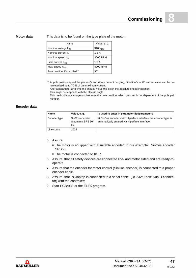
Motor data This data is to be found on the type plate of the motor,1) At pole position speed the phases V and W are current carrying, direction V -> W, current value can be pa-rameterized up to 70 % of the maximum current. After a parameterizing time the angular value 0 is set in the absolute encoder position. This angle corresponds with the electric angle. This method is advantageous, because the pole position, which was set is not dependent of the pole pair number.
.
Encoder data
5 Assure
m The motor is equipped with a suitable encoder, in our example: SinCos encoder SRS50.
m The motor is connected to KSR.
6 Assure, that all safety devices are connected line- and motor sided and are ready-to-operate.
7 Assure that the encoder for motor control (SinCos encoder) is connected to a proper encoder cable.
8 Assure, that PC/laptop is connected to a serial cable (RS232/9-pole Sub D connec-tor) with the controller!
9 Start PCBASS or the ELTK program.
Name Value, e. g.
Nominal voltage UN 310 VDC
Nominal current IN 1.5 A
Nominal speed nN 3000 RPM
Limit current Ilimit 1.9 A
Max. speed nmax. 3000 RPM
Pole position, if specified1) 90°
Name Value, e. g. is used to enter in parameter list/parameters
Encoder type SinCos encoder Stegmann SRS 50/60
at SinCos encoders with Hiperface interface the encoder type is automatically entered via Hiperface interface
Line count 1024
Manual KSR - 3A (KMO)Document no.: 5.04032.03
47of 172
Commissioning8.5
8.5 Commissioning
Preconditions m PC or notebook with PCBASS 4.01 or ELTK program
m Serial interface cable 9-pole
m Motor DSD xxx with Stegmann encoder, Hiperface
Preparation for commissioning
m Connect the motor- and encoder cables as well as the line cable to KSR - 3A.
m Generate connection to the PC.
m Start PCBASS V4.01 and load KSR_all.dat, select edit or
m Start ELTK program.
Start operation. Operation only is made with the help of PC, no hardware signals must be set.
m At usage of PCBASS proceed as follows:
n Describe parameter ID 0031 (page 3) with 4 > reset errors
n Select page 10 and set the following:
m Set parameter ID 1654 with 1
m Set parameter ID 1670 with 1 > controller enable
m Set parameter ID 0442 with 22 > find pole position
m Wait for minimum time (ID 0477)
m Then set parameter ID 0442 with 21 > motor manager on
n Then change to page 11
m Set parameter ID 0372 with 13 > speed control
n Back to page 10
m Set parameter ID 0500 with 1 > activate set value generator (central command)
m Set parameter ID 0520 with 1 > activate set value speed
m Set parameter ID 0522 with a value between 1 and 10 000 > acceleration
m Set parameter ID 0523 with a value between 1000 and 30 000 > set speed > motor shaft starts to rotate.
The ELTK program is described in ZAppendix E - ELTK documentation– from page 119.
Manual KSR - 3A (KMO)
Document no.: 5.04032.03 Baumüller Nürnberg GmbH
48of 172
9
9ENTIRE STRUCTURE OF THE KSRHere we give a survey about the structures of the KSR.
49of 172
Manual KSR - 3A (KMO)
Document no.: 5.04032.03
Hardware survey9.1
9.1 Hardware survey
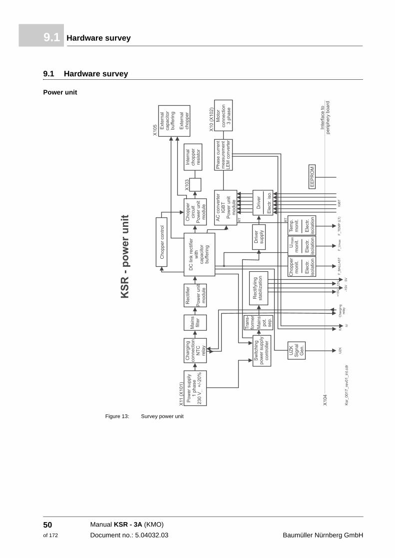
Power unit
Figure 13: Survey power unit
Manual KSR - 3A (KMO)
Document no.: 5.04032.03 Baumüller Nürnberg GmbH
50of 172
Entire structure of the KSR 9
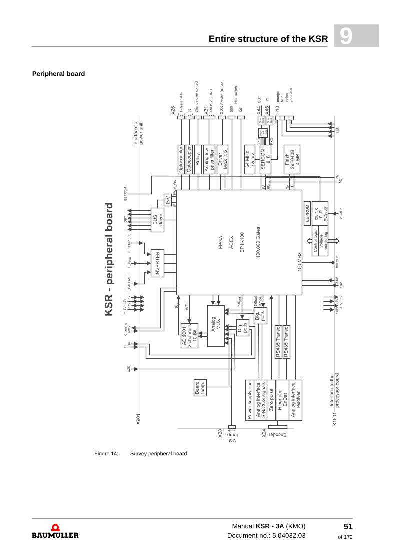
Peripheral boardFigure 14: Survey peripheral board
Manual KSR - 3A (KMO)Document no.: 5.04032.03
51of 172
Hardware survey9.1
Processor board
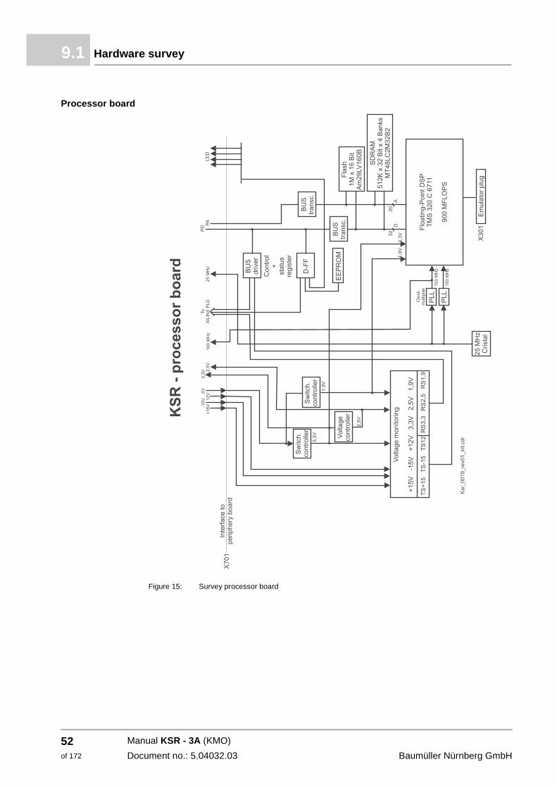
Figure 15: Survey processor board
Manual KSR - 3A (KMO)
Document no.: 5.04032.03 Baumüller Nürnberg GmbH
52of 172
Entire structure of the KSR 9
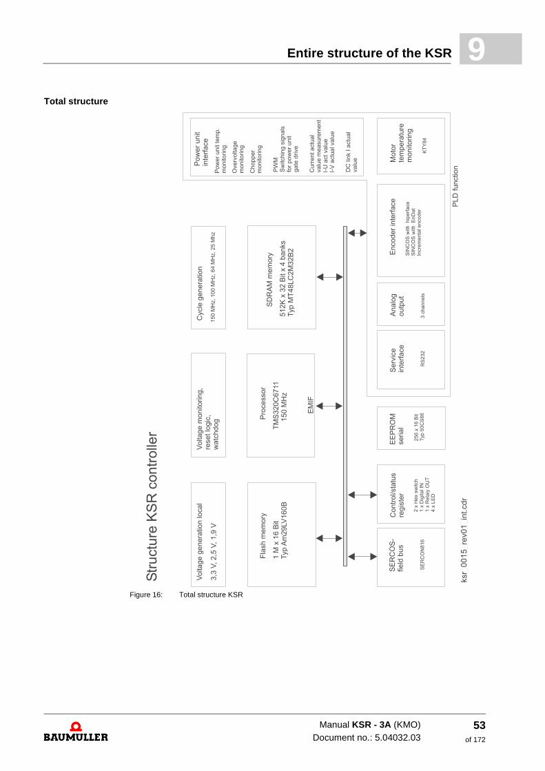
Total structureFigure 16: Total structure KSR
Manual KSR - 3A (KMO)Document no.: 5.04032.03
53of 172
Survey of control structures9.2
9.2 Survey of control structures
PLD functions
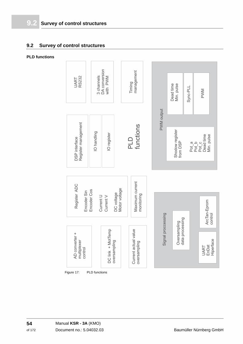
Figure 17: PLD functions
Manual KSR - 3A (KMO)
Document no.: 5.04032.03 Baumüller Nürnberg GmbH
54of 172
Entire structure of the KSR 9
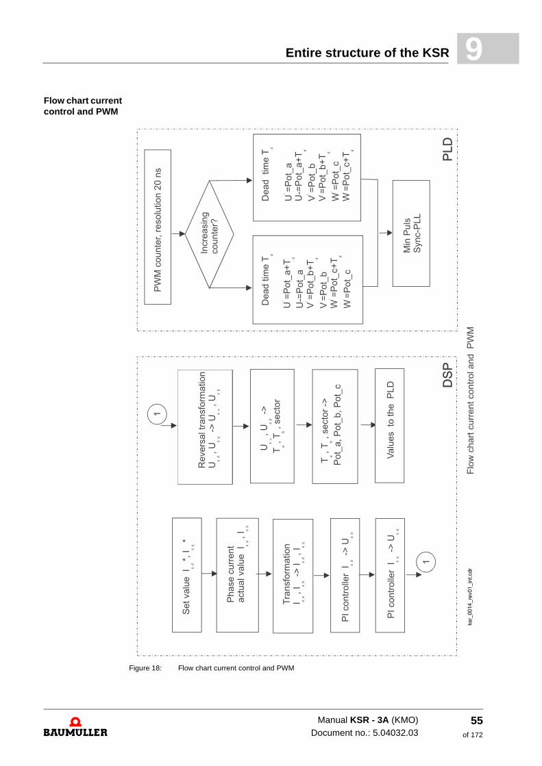
Flow chart current control and PWMFigure 18: Flow chart current control and PWM
Manual KSR - 3A (KMO)Document no.: 5.04032.03
55of 172
Survey of control structures9.2
Manual KSR - 3A (KMO)
Document no.: 5.04032.03 Baumüller Nürnberg GmbH
56of 172
10
10SOFTWARE MODULES ANDPARAMETERS
In this chapter the parameters, which are important for the KSR are described. All the oth-er parameters, which are available are described in the M-Drive parameter manual.
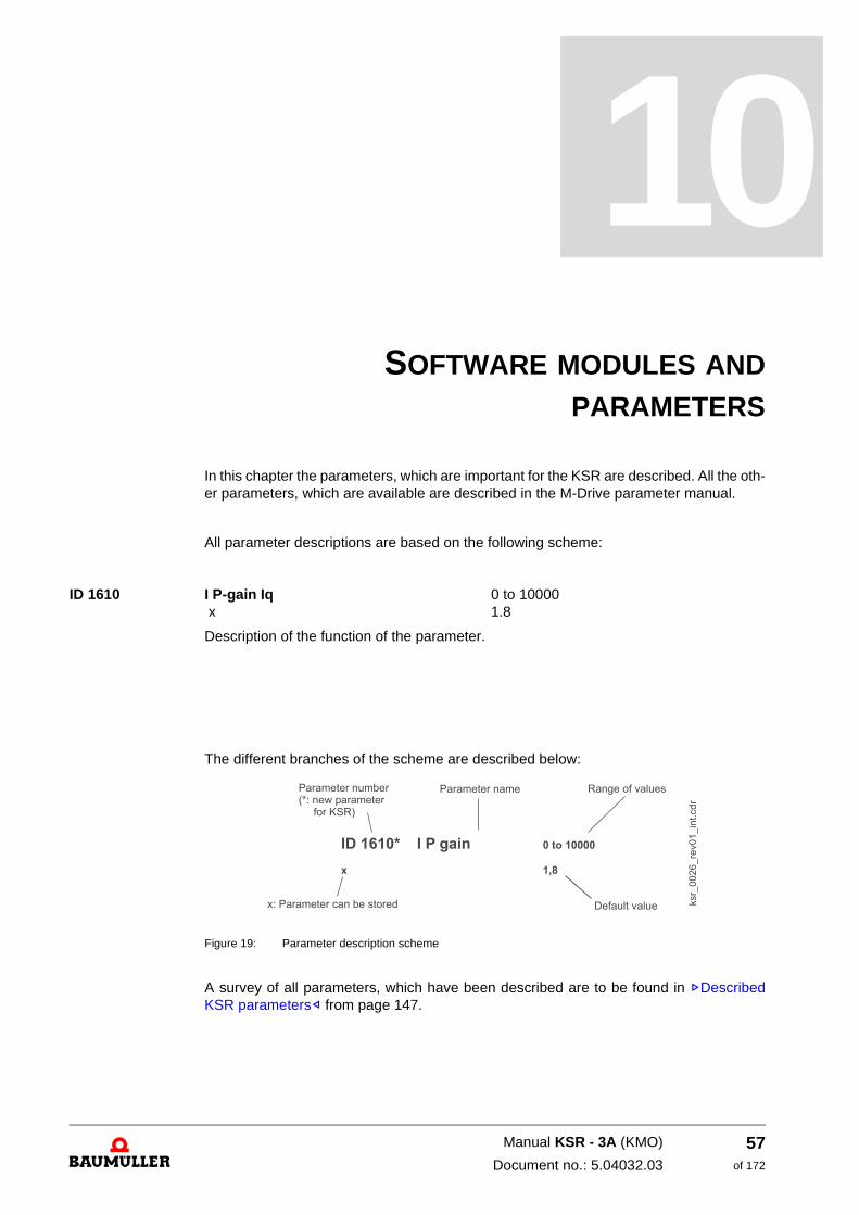
All parameter descriptions are based on the following scheme:
ID 1610 I P-gain Iq 0 to 10000 x 1.8
Description of the function of the parameter.
The different branches of the scheme are described below:
Figure 19: Parameter description scheme
A survey of all parameters, which have been described are to be found in ZDescribed KSR parameters– from page 147.
57of 172
Manual KSR - 3A (KMO)
Document no.: 5.04032.03
Field-oriented current controller10.1
10.1 Field-oriented current controller
Function blocks and parameters
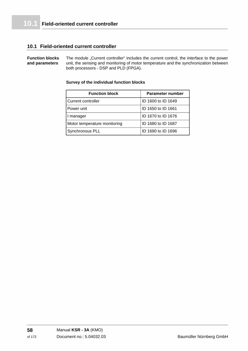
The module „Current controller“ includes the current control, the interface to the power unit, the sensing and monitoring of motor temperature and the synchronization between both processors - DSP and PLD (FPGA).
Survey of the individual function blocks
Function block Parameter number
Current controller ID 1600 to ID 1649
Power unit ID 1650 to ID 1661
I manager ID 1670 to ID 1676
Motor temperature monitoring ID 1680 to ID 1687
Synchronous PLL ID 1690 to ID 1696
Manual KSR - 3A (KMO)
Document no.: 5.04032.03 Baumüller Nürnberg GmbH
58of 172
Software modules and parameters 10
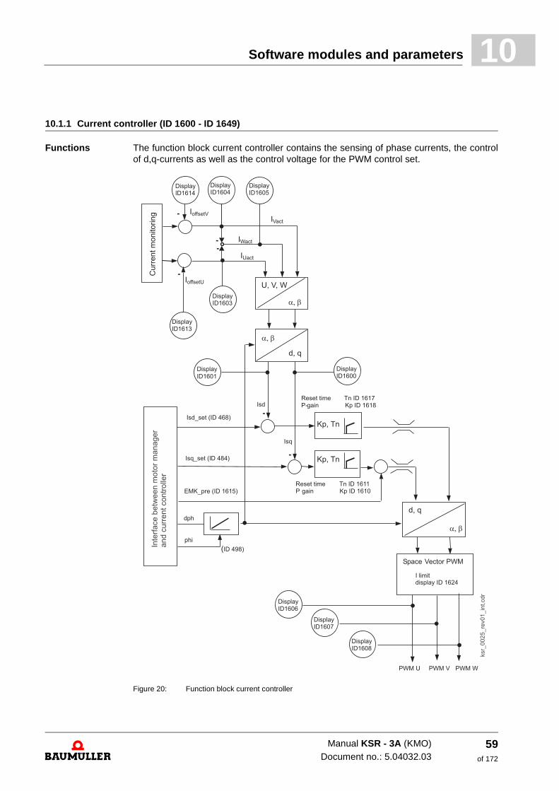
10.1.1 Current controller (ID 1600 - ID 1649)
Functions The function block current controller contains the sensing of phase currents, the control of d,q-currents as well as the control voltage for the PWM control set.
Figure 20: Function block current controller
Manual KSR - 3A (KMO)Document no.: 5.04032.03
59of 172
Field-oriented current controller10.1
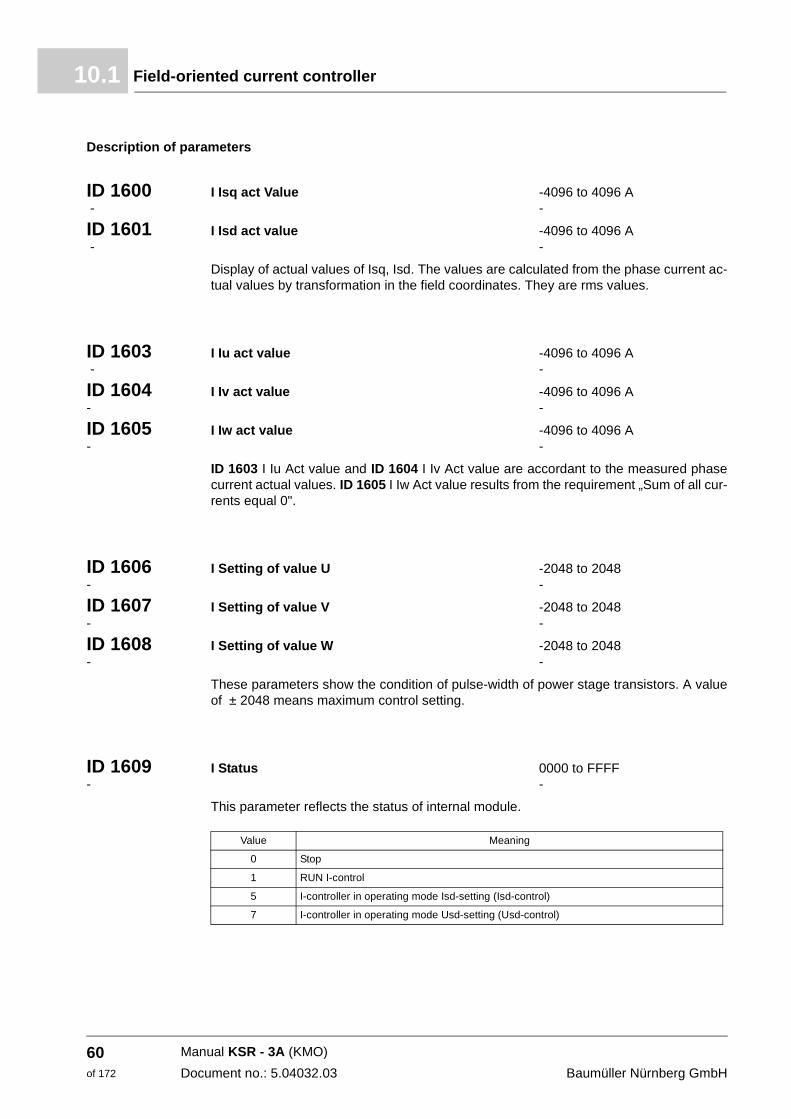
Description of parameters
ID 1600 I Isq act Value -4096 to 4096 A - -
ID 1601 I Isd act value -4096 to 4096 A - -
Display of actual values of Isq, Isd. The values are calculated from the phase current ac-tual values by transformation in the field coordinates. They are rms values.
ID 1603 I Iu act value -4096 to 4096 A - -
ID 1604 I Iv act value -4096 to 4096 A - -
ID 1605 I Iw act value -4096 to 4096 A - -
ID 1603 I Iu Act value and ID 1604 I Iv Act value are accordant to the measured phase current actual values. ID 1605 I Iw Act value results from the requirement „Sum of all cur-rents equal 0".
ID 1606 I Setting of value U -2048 to 2048 - -
ID 1607 I Setting of value V -2048 to 2048 - -
ID 1608 I Setting of value W -2048 to 2048 - -
These parameters show the condition of pulse-width of power stage transistors. A value of ± 2048 means maximum control setting.
ID 1609 I Status 0000 to FFFF - -
This parameter reflects the status of internal module.
Value Meaning
0 Stop
1 RUN I-control
5 I-controller in operating mode Isd-setting (Isd-control)
7 I-controller in operating mode Usd-setting (Usd-control)
Manual KSR - 3A (KMO)
Document no.: 5.04032.03 Baumüller Nürnberg GmbH
60of 172
Software modules and parameters 10
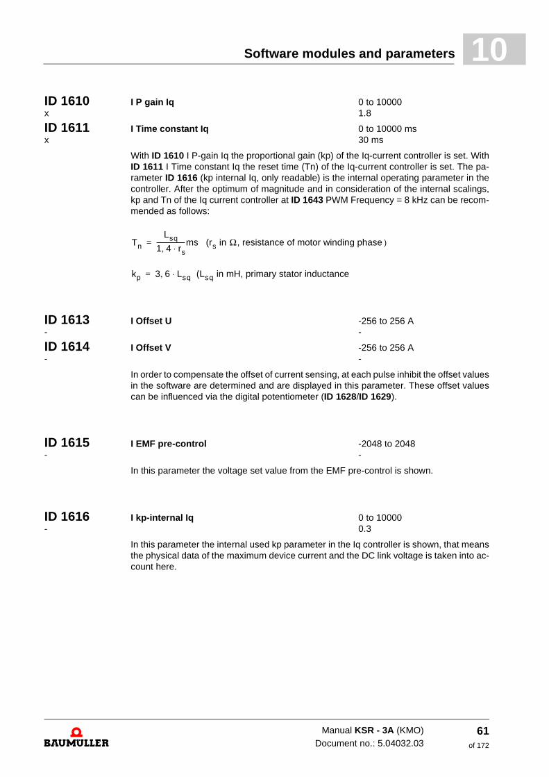
ID 1610 I P gain Iq 0 to 10000 x 1.8ID 1611 I Time constant Iq 0 to 10000 ms x 30 ms
With ID 1610 I P-gain Iq the proportional gain (kp) of the Iq-current controller is set. With ID 1611 I Time constant Iq the reset time (Tn) of the Iq-current controller is set. The pa-rameter ID 1616 (kp internal Iq, only readable) is the internal operating parameter in the controller. After the optimum of magnitude and in consideration of the internal scalings, kp and Tn of the Iq current controller at ID 1643 PWM Frequency = 8 kHz can be recom-mended as follows:
ID 1613 I Offset U -256 to 256 A - -
ID 1614 I Offset V -256 to 256 A - -
In order to compensate the offset of current sensing, at each pulse inhibit the offset values in the software are determined and are displayed in this parameter. These offset values can be influenced via the digital potentiometer (ID 1628/ID 1629).
ID 1615 I EMF pre-control -2048 to 2048 - -
In this parameter the voltage set value from the EMF pre-control is shown.
ID 1616 I kp-internal Iq 0 to 10000 - 0.3
In this parameter the internal used kp parameter in the Iq controller is shown, that means the physical data of the maximum device current and the DC link voltage is taken into ac-count here.
Tn
Lsq
1 4 rs⋅,------------------ms (rs in Ω, resistance of motor winding phase )=
kp 3 6 Lsq (Lsq in mH, primary stator inductance⋅,=
Manual KSR - 3A (KMO)Document no.: 5.04032.03
61of 172
Field-oriented current controller10.1
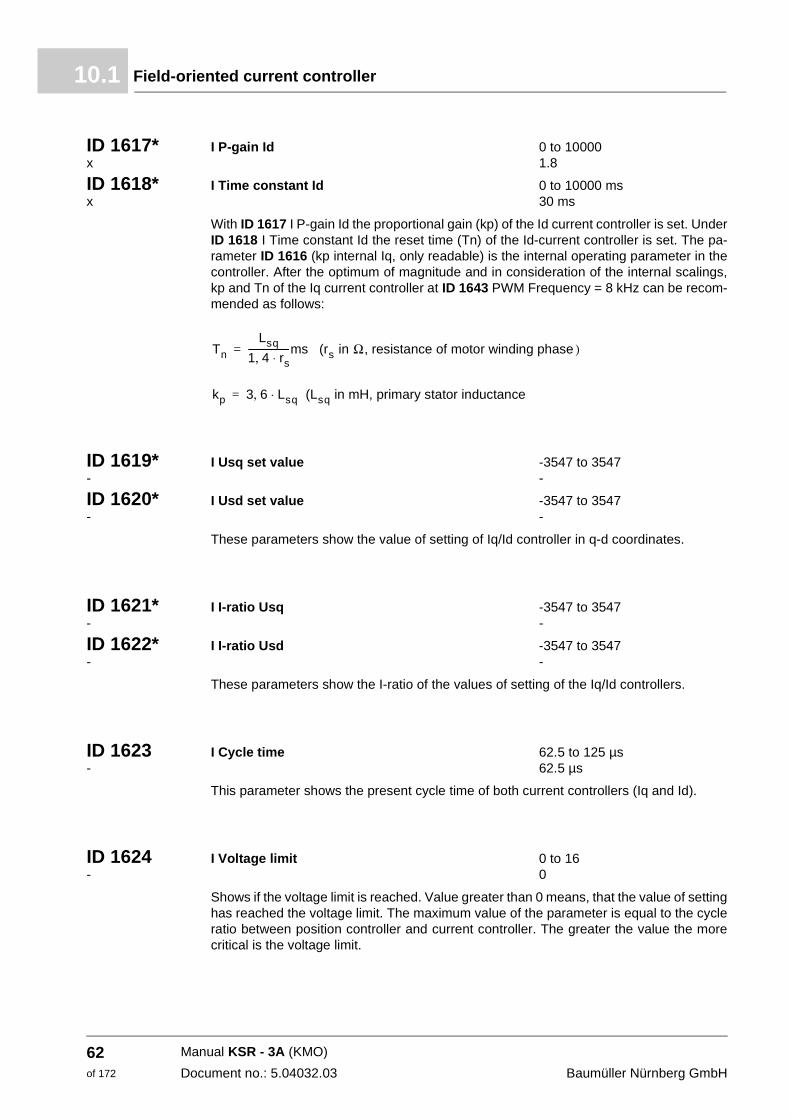
ID 1617* I P-gain Id 0 to 10000 x 1.8
ID 1618* I Time constant Id 0 to 10000 ms x 30 ms
With ID 1617 I P-gain Id the proportional gain (kp) of the Id current controller is set. Under ID 1618 I Time constant Id the reset time (Tn) of the Id-current controller is set. The pa-rameter ID 1616 (kp internal Iq, only readable) is the internal operating parameter in the controller. After the optimum of magnitude and in consideration of the internal scalings, kp and Tn of the Iq current controller at ID 1643 PWM Frequency = 8 kHz can be recom-mended as follows:
ID 1619* I Usq set value -3547 to 3547 - -
ID 1620* I Usd set value -3547 to 3547 - -
These parameters show the value of setting of Iq/Id controller in q-d coordinates.
ID 1621* I I-ratio Usq -3547 to 3547 - -
ID 1622* I I-ratio Usd -3547 to 3547 - -
These parameters show the I-ratio of the values of setting of the Iq/Id controllers.
ID 1623 I Cycle time 62.5 to 125 µs - 62.5 µs
This parameter shows the present cycle time of both current controllers (Iq and Id).
ID 1624 I Voltage limit 0 to 16 - 0
Shows if the voltage limit is reached. Value greater than 0 means, that the value of setting has reached the voltage limit. The maximum value of the parameter is equal to the cycle ratio between position controller and current controller. The greater the value the more critical is the voltage limit.
Tn
Lsq
1 4 rs⋅,------------------ms (rs in Ω, resistance of motor winding phase )=
kp 3 6 Lsq (Lsq in mH, primary stator inductance⋅,=
Manual KSR - 3A (KMO)
Document no.: 5.04032.03 Baumüller Nürnberg GmbH
62of 172
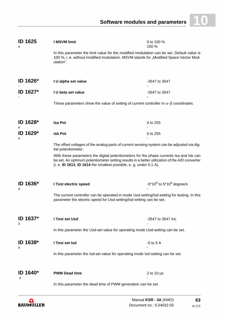
Software modules and parameters 10
ID 1625 I MSVM limit 0 to 100 % x 100 %In this parameter the limit value for the modified modulation can be set. Default value is 100 %, i. e. without modified modulation. MSVM stands for „Modified Space Vector Mod-ulation".
ID 1626* I U alpha set value -3547 to 3547 - -
ID 1627* I U beta set value -3547 to 3547 - -
These parameters show the value of setting of current controller in α−β coordinates.
ID 1628* Isa Pot 0 to 255 x -
ID 1629* Isb Pot 0 to 255 x -
The offset voltages of the analog parts of current sensing system can be adjusted via dig-ital potentiometer.
With these parameters the digital potentiometers for the phase currents Isa and Isb can be set. An optimum potentiometer setting results in a better utilization of the A/D converter (i. e. ID 1613, ID 1614 the smallest possible, e. g. under 0.1 A).
ID 1636* I Test electric speed -5*104 to 5*104 degree/s x -
The current controller can be operated in mode Usd-setting/Isd-setting for testing. In this parameter the electric speed for Usd-setting/Isd-setting can be set.
ID 1637* I Test set Usd -3547 to 3547 Inc x -
In this parameter the Usd-set value for operating mode Usd-setting can be set.
ID 1638* I Test set Isd -5 to 5 A x -
In this parameter the Isd-set value for operating mode Isd-setting can be set.
ID 1640* PWM Dead time 2 to 10 µs x -
In this parameter the dead time of PWM generation can be set.
Manual KSR - 3A (KMO)Document no.: 5.04032.03
63of 172
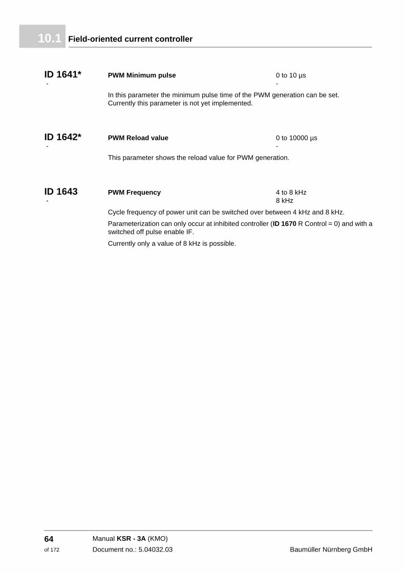
Field-oriented current controller10.1
ID 1641* PWM Minimum pulse 0 to 10 µs - -
In this parameter the minimum pulse time of the PWM generation can be set. Currently this parameter is not yet implemented.
ID 1642* PWM Reload value 0 to 10000 µs - -
This parameter shows the reload value for PWM generation.
ID 1643 PWM Frequency 4 to 8 kHz - 8 kHz
Cycle frequency of power unit can be switched over between 4 kHz and 8 kHz.
Parameterization can only occur at inhibited controller (ID 1670 R Control = 0) and with a switched off pulse enable IF.
Currently only a value of 8 kHz is possible.
Manual KSR - 3A (KMO)
Document no.: 5.04032.03 Baumüller Nürnberg GmbH
64of 172
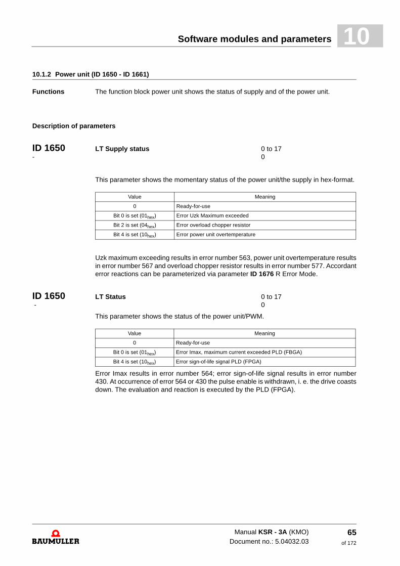
Software modules and parameters 10
10.1.2 Power unit (ID 1650 - ID 1661)Functions The function block power unit shows the status of supply and of the power unit.
Description of parameters
ID 1650 LT Supply status 0 to 17 - 0
This parameter shows the momentary status of the power unit/the supply in hex-format.
Uzk maximum exceeding results in error number 563, power unit overtemperature results in error number 567 and overload chopper resistor results in error number 577. Accordant error reactions can be parameterized via parameter ID 1676 R Error Mode.
ID 1650 LT Status 0 to 17 - 0
This parameter shows the status of the power unit/PWM.
Error Imax results in error number 564; error sign-of-life signal results in error number 430. At occurrence of error 564 or 430 the pulse enable is withdrawn, i. e. the drive coasts down. The evaluation and reaction is executed by the PLD (FPGA).
Value Meaning
0 Ready-for-use
Bit 0 is set (01hex) Error Uzk Maximum exceeded
Bit 2 is set (04hex) Error overload chopper resistor
Bit 4 is set (10hex) Error power unit overtemperature
Value Meaning
0 Ready-for-use
Bit 0 is set (01hex) Error Imax, maximum current exceeded PLD (FBGA)
Bit 4 is set (10hex) Error sign-of-life signal PLD (FPGA)
Manual KSR - 3A (KMO)Document no.: 5.04032.03
65of 172
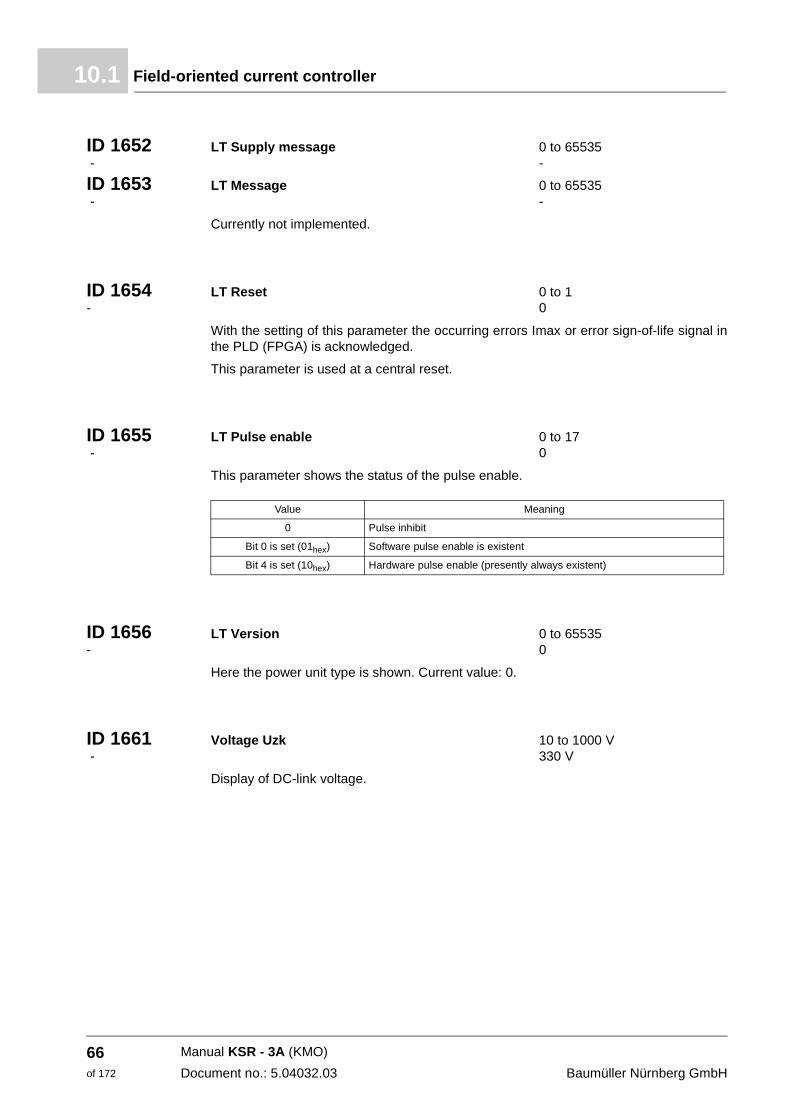
Field-oriented current controller10.1
ID 1652 LT Supply message 0 to 65535 - -
ID 1653 LT Message 0 to 65535 - -
Currently not implemented.
ID 1654 LT Reset 0 to 1 - 0
With the setting of this parameter the occurring errors Imax or error sign-of-life signal in the PLD (FPGA) is acknowledged.
This parameter is used at a central reset.
ID 1655 LT Pulse enable 0 to 17 - 0
This parameter shows the status of the pulse enable.
ID 1656 LT Version 0 to 65535 - 0
Here the power unit type is shown. Current value: 0.
ID 1661 Voltage Uzk 10 to 1000 V - 330 V
Display of DC-link voltage.
Value Meaning
0 Pulse inhibit
Bit 0 is set (01hex) Software pulse enable is existent
Bit 4 is set (10hex) Hardware pulse enable (presently always existent)
Manual KSR - 3A (KMO)
Document no.: 5.04032.03 Baumüller Nürnberg GmbH
66of 172
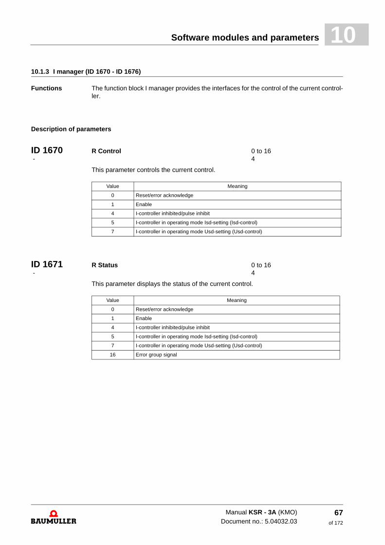
Software modules and parameters 10
10.1.3 I manager (ID 1670 - ID 1676)Functions The function block I manager provides the interfaces for the control of the current control-ler.
Description of parameters
ID 1670 R Control 0 to 16 - 4
This parameter controls the current control.
ID 1671 R Status 0 to 16 - 4
This parameter displays the status of the current control.
Value Meaning
0 Reset/error acknowledge
1 Enable
4 I-controller inhibited/pulse inhibit
5 I-controller in operating mode Isd-setting (Isd-control)
7 I-controller in operating mode Usd-setting (Usd-control)
Value Meaning
0 Reset/error acknowledge
1 Enable
4 I-controller inhibited/pulse inhibit
5 I-controller in operating mode Isd-setting (Isd-control)
7 I-controller in operating mode Usd-setting (Usd-control)
16 Error group signal
Manual KSR - 3A (KMO)Document no.: 5.04032.03
67of 172
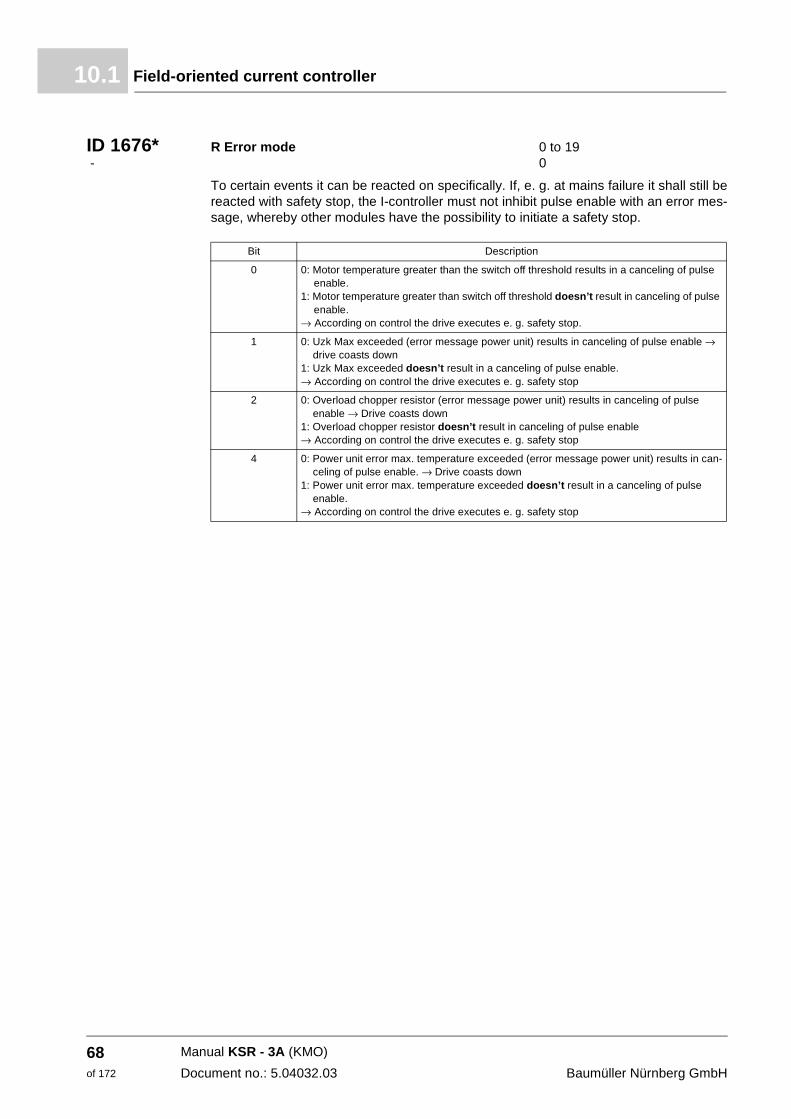
Field-oriented current controller10.1
ID 1676* R Error mode 0 to 19 - 0
To certain events it can be reacted on specifically. If, e. g. at mains failure it shall still be reacted with safety stop, the I-controller must not inhibit pulse enable with an error mes-sage, whereby other modules have the possibility to initiate a safety stop.
Bit Description
0 0: Motor temperature greater than the switch off threshold results in a canceling of pulse enable.
1: Motor temperature greater than switch off threshold doesn’t result in canceling of pulse enable.
→ According on control the drive executes e. g. safety stop.
1 0: Uzk Max exceeded (error message power unit) results in canceling of pulse enable → drive coasts down
1: Uzk Max exceeded doesn’t result in a canceling of pulse enable. → According on control the drive executes e. g. safety stop
2 0: Overload chopper resistor (error message power unit) results in canceling of pulse enable → Drive coasts down
1: Overload chopper resistor doesn’t result in canceling of pulse enable → According on control the drive executes e. g. safety stop
4 0: Power unit error max. temperature exceeded (error message power unit) results in can-celing of pulse enable. → Drive coasts down
1: Power unit error max. temperature exceeded doesn’t result in a canceling of pulse enable.
→ According on control the drive executes e. g. safety stop
Manual KSR - 3A (KMO)
Document no.: 5.04032.03 Baumüller Nürnberg GmbH
68of 172
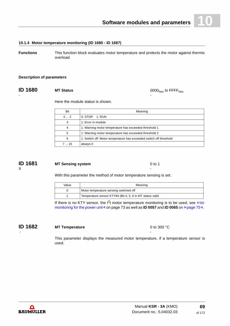
Software modules and parameters 10
10.1.4 Motor temperature monitoring (ID 1680 - ID 1687)Functions This function block evaluates motor temperature and protects the motor against thermic overload.
Description of parameters
ID 1680 MT Status 0000hex to FFFFhex - -
Here the module status is shown.
ID 1681 MT Sensing system 0 to 1 X -
With this parameter the method of motor temperature sensing is set.
If there is no KTY sensor, the I2t motor temperature monitoring is to be used, see ZIxt-monitoring for the power unit– on page 73 as well as ID 0057 and ID 0065 on Zpage 75–.
ID 1682 MT Temperature 0 to 300 °C - -
This parameter displays the measured motor temperature, if a temperature sensor is used.
Bit Meaning
0 ... 2 0: STOP 1: RUN
3 1: Error in module
4 1: Warning motor temperature has exceeded threshold 1
5 1: Warning motor temperature has exceeded threshold 2
6 1: Switch off: Motor temperature has exceeded switch off threshold
7 ... 15 always 0
Value Meaning
0 Motor temperature sensing switched off
1 Temperature sensor KTY84 (Bit 4, 5, 6 in MT status valid
Manual KSR - 3A (KMO)Document no.: 5.04032.03
69of 172
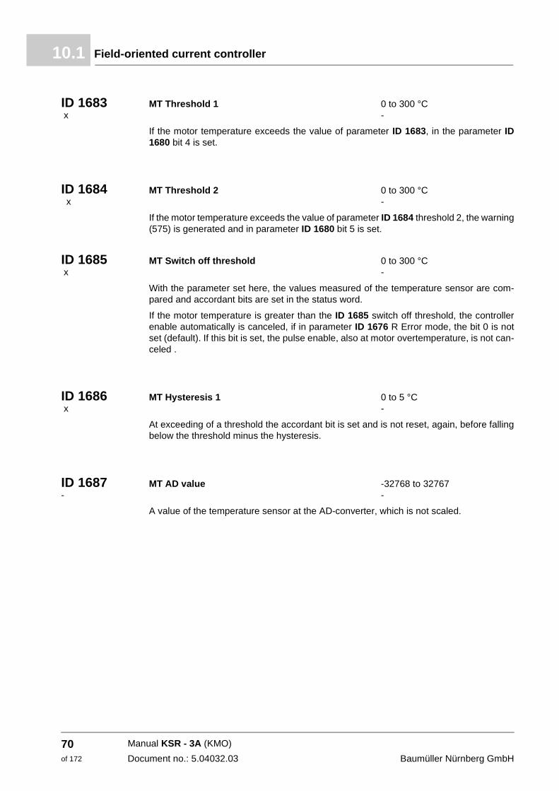
Field-oriented current controller10.1
ID 1683 MT Threshold 1 0 to 300 °C x -
If the motor temperature exceeds the value of parameter ID 1683, in the parameter ID 1680 bit 4 is set.
ID 1684 MT Threshold 2 0 to 300 °C x -
If the motor temperature exceeds the value of parameter ID 1684 threshold 2, the warning (575) is generated and in parameter ID 1680 bit 5 is set.
ID 1685 MT Switch off threshold 0 to 300 °C x -
With the parameter set here, the values measured of the temperature sensor are com-pared and accordant bits are set in the status word.
If the motor temperature is greater than the ID 1685 switch off threshold, the controller enable automatically is canceled, if in parameter ID 1676 R Error mode, the bit 0 is not set (default). If this bit is set, the pulse enable, also at motor overtemperature, is not can-celed .
ID 1686 MT Hysteresis 1 0 to 5 °C x -
At exceeding of a threshold the accordant bit is set and is not reset, again, before falling below the threshold minus the hysteresis.
ID 1687 MT AD value -32768 to 32767 - -
A value of the temperature sensor at the AD-converter, which is not scaled.
Manual KSR - 3A (KMO)
Document no.: 5.04032.03 Baumüller Nürnberg GmbH
70of 172
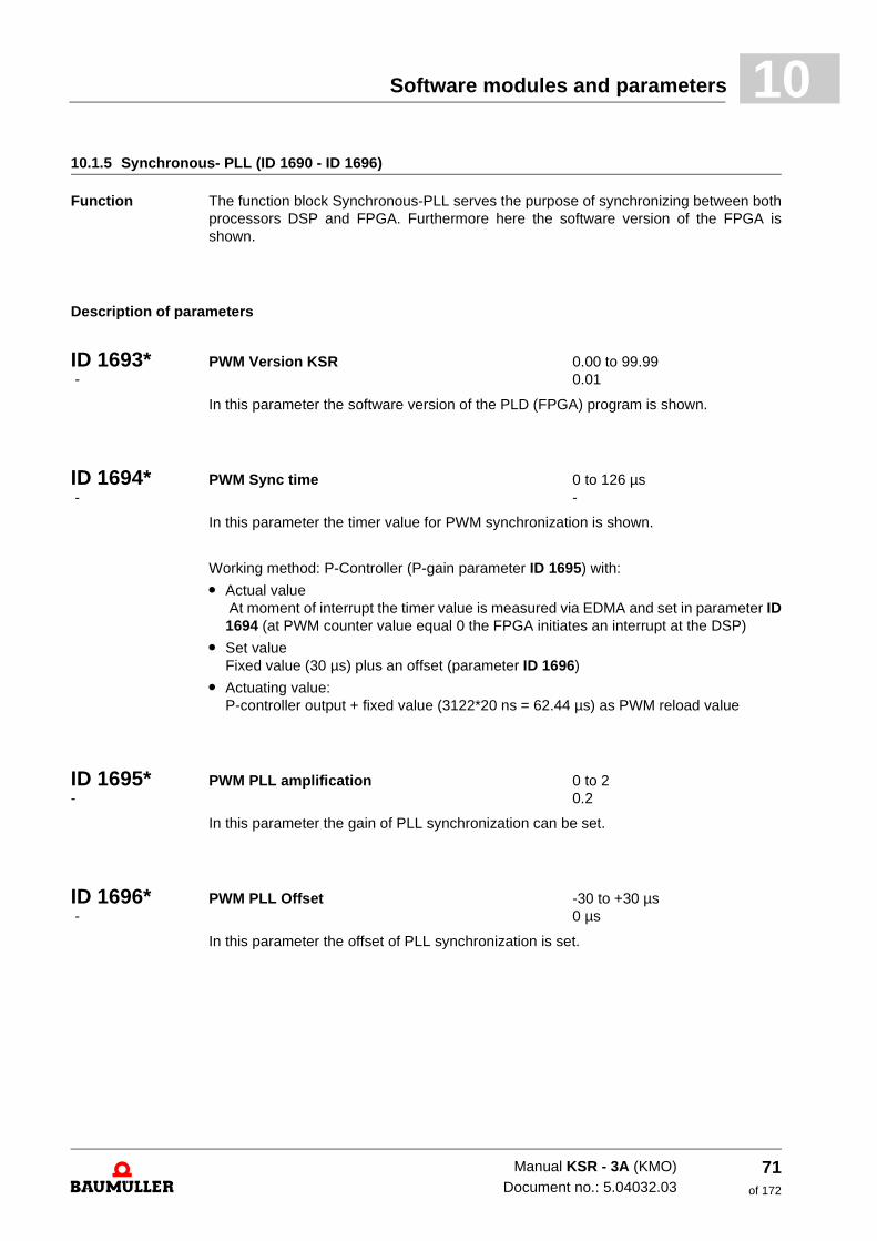
Software modules and parameters 10
10.1.5 Synchronous- PLL (ID 1690 - ID 1696)Function The function block Synchronous-PLL serves the purpose of synchronizing between both processors DSP and FPGA. Furthermore here the software version of the FPGA is shown.
Description of parameters
ID 1693* PWM Version KSR 0.00 to 99.99 - 0.01
In this parameter the software version of the PLD (FPGA) program is shown.
ID 1694* PWM Sync time 0 to 126 µs - -
In this parameter the timer value for PWM synchronization is shown.
Working method: P-Controller (P-gain parameter ID 1695) with:
m Actual value At moment of interrupt the timer value is measured via EDMA and set in parameter ID 1694 (at PWM counter value equal 0 the FPGA initiates an interrupt at the DSP)
m Set value Fixed value (30 µs) plus an offset (parameter ID 1696)
m Actuating value: P-controller output + fixed value (3122*20 ns = 62.44 µs) as PWM reload value
ID 1695* PWM PLL amplification 0 to 2 - 0.2
In this parameter the gain of PLL synchronization can be set.
ID 1696* PWM PLL Offset -30 to +30 µs - 0 µs
In this parameter the offset of PLL synchronization is set.
Manual KSR - 3A (KMO)Document no.: 5.04032.03
71of 172
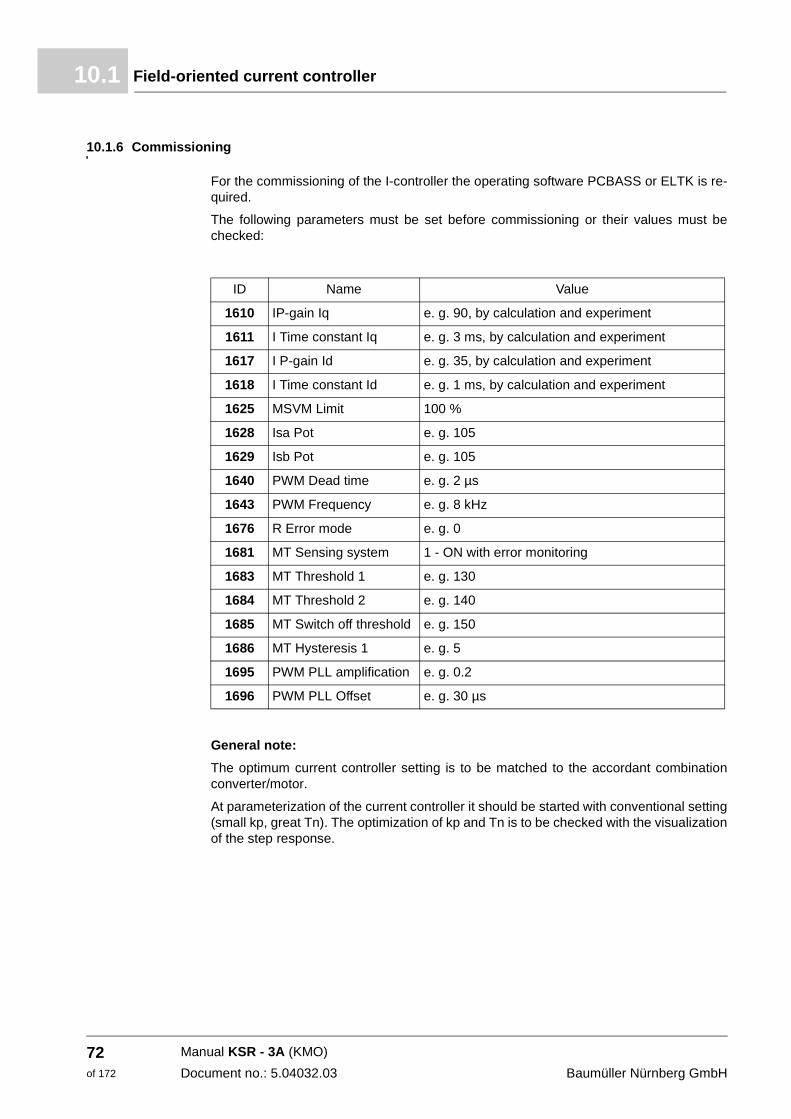
Field-oriented current controller10.1
10.1.6 Commissioning
For the commissioning of the I-controller the operating software PCBASS or ELTK is re-quired.
The following parameters must be set before commissioning or their values must be checked:
General note:
The optimum current controller setting is to be matched to the accordant combination converter/motor.
At parameterization of the current controller it should be started with conventional setting (small kp, great Tn). The optimization of kp and Tn is to be checked with the visualization of the step response.
ID Name Value
1610 IP-gain Iq e. g. 90, by calculation and experiment
1611 I Time constant Iq e. g. 3 ms, by calculation and experiment
1617 I P-gain Id e. g. 35, by calculation and experiment
1618 I Time constant Id e. g. 1 ms, by calculation and experiment
1625 MSVM Limit 100 %
1628 Isa Pot e. g. 105
1629 Isb Pot e. g. 105
1640 PWM Dead time e. g. 2 µs
1643 PWM Frequency e. g. 8 kHz
1676 R Error mode e. g. 0
1681 MT Sensing system 1 - ON with error monitoring
1683 MT Threshold 1 e. g. 130
1684 MT Threshold 2 e. g. 140
1685 MT Switch off threshold e. g. 150
1686 MT Hysteresis 1 e. g. 5
1695 PWM PLL amplification e. g. 0.2
1696 PWM PLL Offset e. g. 30 µs
Manual KSR - 3A (KMO)
Document no.: 5.04032.03 Baumüller Nürnberg GmbH
72of 172
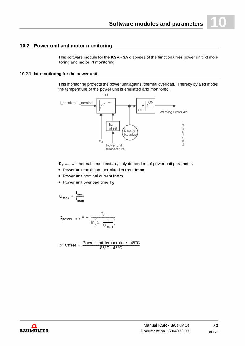
Software modules and parameters 10
10.2 Power unit and motor monitoringThis software module for the KSR - 3A disposes of the functionalities power unit Ixt mon-itoring and motor I²t monitoring.
10.2.1 Ixt-monitoring for the power unit
This monitoring protects the power unit against thermal overload. Thereby by a Ixt model the temperature of the power unit is emulated and monitored.
τ power unit: thermal time constant, only dependent of power unit parameter.
m Power unit maximum permitted current Imax
m Power unit nominal current Inom
m Power unit overload time T0
Umax
Imax
Inom-----------=
τpower unit To
11
Umax--------------–⎝ ⎠
⎛ ⎞ln-----------------------------------–=
Ixt OffsetPower unit temperature - 45°C
85°C - 45°C-----------------------------------------------------------------------------------=
Manual KSR - 3A (KMO)Document no.: 5.04032.03
73of 172
Power unit and motor monitoring10.2
Parameterization of power unit monitoring
The value of I_absolute_value considers not only ID 1600 torque current but also ID 1601field current. Values for the parameter ID 0054 (maximum allowable power unit current Imax), ID 0055 (power unit nominal current Inom) and ID 0056 (power unit overload time T0) can be taken from the table (see ZTable power unit– on page 76).
Till the automatically power unit detection is implemented and in order to use power units, which eventually are not recognizable, the values Imax, Inom and T0 must be set via oper-ating program PCBASS or ELTK.
At an Ixt-value of 100 % error code 42 is enabled. The reaction follows via the higher-level module operation manager.
The Ixt-monitoring is switched off if the parameter ID 0056 LT overload time has been set to 0.
The Ixt-monitoring is no alternative for the power unit’s temperature monitoring. The mod-ule temperature monitoring (ID 1657 - ID 1659) is not influenced.
10.2.2 I2t-monitoring of the motor
The monitoring protects the motor against thermal overload. By use of a model the motor temperature is simulated and monitored.
Monitoring is initialized by the use of momentary motor temperature.
The parameter ID 0057 Thermal time constant τmotor, is to be taken from the data sheet of motor and is to be set in seconds. The value I_absolute value considers not only ID 1600 Torque current but also ID 1601 Field current. I_nom_motor is calculated with ID 0470 Isq_nom and ID 0469 Isd_nom.
If I2t-value reaches a threshold value, error 37 is activated. If the time constant τmotor = 0 is set, this overload monitoring is switched off.
The I2t-monitoring is no alternative for the motor temperature monitoring. The module mo-tor temperature monitoring (ID 1680 - ID 1687) is not influenced.
Parameter description
ID 0052 Monitoring LT Ixt Value 0 to 1000 % - -
This parameter shows the Ixt value of the overload monitoring at the moment. At a value of 100 % the error 42 is signaled. If the Ixt value is less than 95 % and if also the I_absolute_value is less than 95 % of ILTnom, so the error message is deactivated again.
40 °C = 0 %
155 °C = 100 %
Manual KSR - 3A (KMO)
Document no.: 5.04032.03 Baumüller Nürnberg GmbH
74of 172
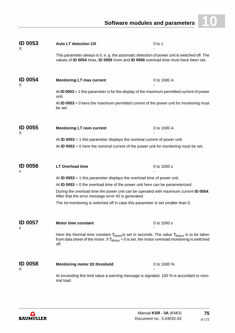
Software modules and parameters 10
ID 0053 Auto LT detection 1/0 0 to 1 X -This parameter always is 0, e. g. the automatic detection of power unit is switched off. The values of ID 0054 Imax, ID 0055 Inom and ID 0056 overload time must have been set.
ID 0054 Monitoring LT max current 0 to 1000 A X -
At ID 0053 = 1 this parameter is for the display of the maximum permitted current of power unit.
At ID 0053 = 0 here the maximum permitted current of the power unit for monitoring must be set.
ID 0055 Monitoring LT nom current 0 to 1000 A X -
At ID 0053 = 1 this parameter displays the nominal current of power unit.
At ID 0053 = 0 here the nominal current of the power unit for monitoring must be set.
ID 0056 LT Overload time 0 to 1000 s x -
At ID 0053 = 1 this parameter displays the overload time of power unit.
At ID 0053 = 0 the overload time of the power unit here can be parameterized.
During the overload time the power unit can be operated with maximum current ID 0054. After that the error message error 42 is generated.
The Ixt-monitoring is switched off in case this parameter is set smaller than 0.
ID 0057 Motor time constant 0 to 1000 s x -
Here the thermal time constant τMotoris set in seconds. The value τMotor is to be taken from data sheet of the motor. If τMotor = 0 is set, the motor overload monitoring is switched off.
ID 0058 Monitoring motor I2t threshold 0 to 1000 % X -
At exceeding this limit value a warning message is signaled. 100 % is accordant to nom-inal load.
Manual KSR - 3A (KMO)Document no.: 5.04032.03
75of 172
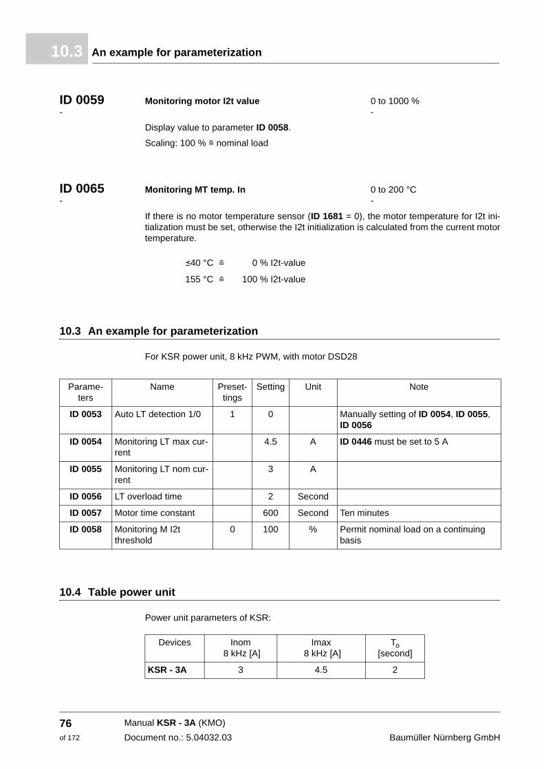
An example for parameterization10.3
ID 0059 Monitoring motor I2t value 0 to 1000 % - -
Display value to parameter ID 0058.
Scaling: 100 % = nominal load
ID 0065 Monitoring MT temp. In 0 to 200 °C - -
If there is no motor temperature sensor (ID 1681 = 0), the motor temperature for I2t ini-tialization must be set, otherwise the I2t initialization is calculated from the current motor temperature.
10.3 An example for parameterization
For KSR power unit, 8 kHz PWM, with motor DSD28
10.4 Table power unit
Power unit parameters of KSR:
b40 °C = 0 % I2t-value
155 °C = 100 % I2t-value
Parame-ters
Name Preset-tings
Setting Unit Note
ID 0053 Auto LT detection 1/0 1 0 Manually setting of ID 0054, ID 0055, ID 0056
ID 0054 Monitoring LT max cur-rent
4.5 A ID 0446 must be set to 5 A
ID 0055 Monitoring LT nom cur-rent
3 A
ID 0056 LT overload time 2 Second
ID 0057 Motor time constant 600 Second Ten minutes
ID 0058 Monitoring M I2t threshold
0 100 % Permit nominal load on a continuing basis
Devices Inom 8 kHz [A]
Imax 8 kHz [A]
To[second]
KSR - 3A 3 4.5 2
Manual KSR - 3A (KMO)
Document no.: 5.04032.03 Baumüller Nürnberg GmbH
76of 172
11
11ERROR DETECTION AND TROUBLE-SHOOTING
In this chapter we describe the error indications of the device: error- and warning messages, their meanings and how you can react.
11.1 Safety instructions
h Refer to ZFundamental safety instructions– from page 7.
11.2 Requirements to the executing personnel
The personnel, who works with the KSR - 3A device, must be introduced in the safety instruc-tions and in the operation of the device and must be familiar with the accurate operating of the device. Especially the reaction to failure indications and -conditions requires special knowledge, which the operator must have.
77of 172
Manual KSR - 3A (KMO)
Document no.: 5.04032.03
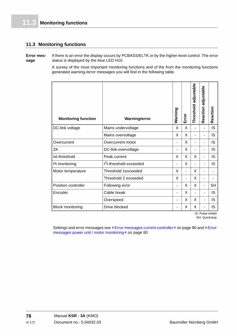
Monitoring functions11.3
11.3 Monitoring functions
Error mes-sage
If there is an error the display occurs by PCBASS/ELTK or by the higher-level control. The error status is displayed by the blue LED H10.
A survey of the most important monitoring functions and of the from the monitoring functions generated warning-/error messages you will find in the following table.
Monitoring function Warning/error
War
nin
g
Err
or
Th
resh
old
ad
just
able
Rea
ctio
n a
dju
stab
le
Rea
ctio
n
DC-link voltage Mains undervoltage X X - - IS
Mains overvoltage X X - - IS
Overcurrent Overcurrent motor - X - - IS
ZK DC-link-overvoltage - X - - IS
Ixt-threshold Peak current X X X - IS
I²t monitoring I2t-threshold exceeded - X - - IS
Motor temperature Threshold 1exceeded X - X - -
Threshold 2 exceeded X - X - -
Position controller Following error - X X - SH
Encoder Cable break - X - - IS
Overspeed - X X - IS
Block monitoring Drive blocked - X X - IS
IS: Pulse inhibitSH: Quickstop
Settings and error messages see ZError messages current controller– on page 80 and ZError messages power unit / motor monitoring– on page 80
Manual KSR - 3A (KMO)
Document no.: 5.04032.03 Baumüller Nürnberg GmbH
78of 172
Error detection and troubleshooting 11
Explanatory notesOvercurrent This monitoring function checks, if the motor current is bigger than 1.3 x output peak current (7.9 A). It serves as „disaster prevention“ in case of an output-sided short-circuit.
ZK This monitoring function checks the voltage of the DC-link. In case the voltage exceeds an cer-tain value, the error "DC-link-overvoltage“ is signaled from the controller and an immediate pulse inhibit follows.
Ixt-threshold This monitoring function checks the momentary load thereupon, if the power unit at the time can supply peak current or max. nominal current at the time. In case the peak current is not possible, the message "Ixt-threshold exceeded“ is signaled.
I²t overload This monitoring function checks the temperature of the motor. In case the I2t-threshold is ex-ceeded, the controller signals the error "I2t-overload".
Motor tem-perature
In case the adjusted temperature threshold 1 is exceeded, the warning "temperature-threshold 1 exceeded“ is generated by the controller. In case the adjusted temperature threshold 2 is exceeded, the warning "temperature threshold 2 exceeded“ is generated by the controller.
Position con-troller
This monitoring function checks the following error limit. In case the current following error is greater than the adjusted following error limit, the error message „following error“ is generated. and an immediate pulse inhibit follows.
Block moni-toring
This monitoring function checks the motor speed and the motor current. If, for the period of time "block monitoring time" the following conditions are fulfilled, the error/warning "drive blocked" is signalled to the controller and an immediate pulse inhibit operates.
m Motor speed = 0
m The motor current which is supplied by the device is the same as the adjusted motor limit cur-rent (current limit).
11.4 Troubleshooting
The devices of the series KSR - 3A signal an error status via the lighting up of the blue LED H10 (front side of the device). The error codes can be read by the operation software via PC/laptop (meaning of error codes see ZError table for guide bar drives– from page 81).
h The error number is displayed in ID 0036.
Acknowl-edge errors
If the blue error LED lights up at least one error is detected. By error acknowledge continuously all error messages are reset. An individual error acknowledge is not possible. Still existing errors cannot be acknowledged.
h Set the parameters ID 0031 (error module) or ID 0560 (operation mode BA handler module) to 4, in order to execute a general reset.
h Set the parameters ID 0031 or ID 0560 to 5, in order to reset the modules with error messag-es.
Manual KSR - 3A (KMO)Document no.: 5.04032.03
79of 172
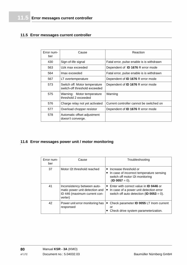
Error messages current controller11.5
11.5 Error messages current controller
11.6 Error messages power unit / motor monitoring
Error num-ber
Cause Reaction
430 Sign-of-life signal Fatal error, pulse enable is is withdrawn
563 Uzk max exceeded Dependent of ID 1676 R error mode
564 Imax exceeded Fatal error, pulse enable is is withdrawn
567 LT overtemperature Dependent of ID 1676 R error mode
573 Switch off: Motor temperature switch-off threshold exceeded
Dependent of ID 1676 R error mode
575 Warning: Motor temperature threshold 2 exceeded
Warning
576 Charge relay not yet activated Current controller cannot be switched on
577 Overload chopper resistor Dependent of ID 1676 R error mode
578 Automatic offset adjustment doesn’t converge.
Error num-ber
Cause Troubleshooting
37 Motor I2t threshold reached m Increase threshold or m In case of incorrect temperature sensing
switch off motor I2t monitoring (ID 0057 = 0).
41 Inconsistency between auto-matic power unit detection and ID 446 (maximum current con-verter)
m Enter with correct value in ID 0446 or m In case of a power unit detection error
switch off auto detection (ID 0053 = 0).
42 Power unit error monitoring has responsed
m Check parameter ID 0055 LT Inom current or
m Check drive system parameterization.
Manual KSR - 3A (KMO)
Document no.: 5.04032.03 Baumüller Nürnberg GmbH
80of 172
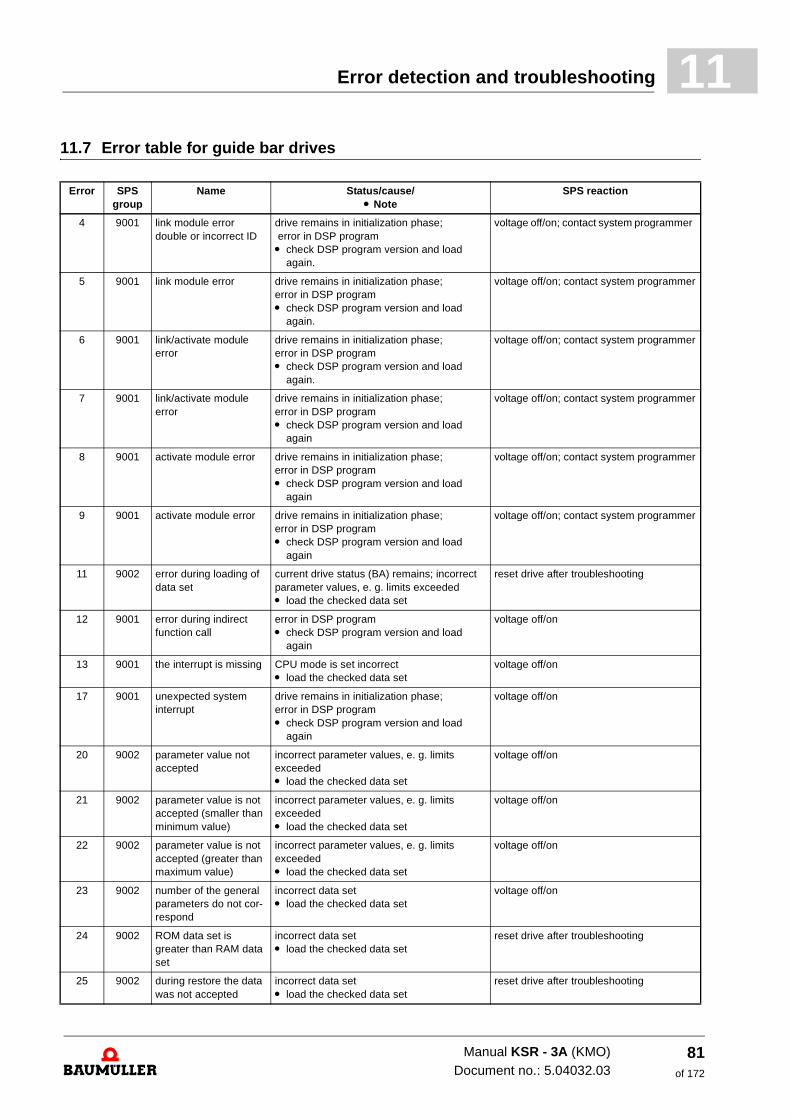
Error detection and troubleshooting 11
11.7 Error table for guide bar drivesError SPS group
Name Status/cause/m Note
SPS reaction
4 9001 link module error double or incorrect ID
drive remains in initialization phase; error in DSP program m check DSP program version and load
again.
voltage off/on; contact system programmer
5 9001 link module error drive remains in initialization phase; error in DSP programm check DSP program version and load
again.
voltage off/on; contact system programmer
6 9001 link/activate module error
drive remains in initialization phase; error in DSP programm check DSP program version and load
again.
voltage off/on; contact system programmer
7 9001 link/activate module error
drive remains in initialization phase; error in DSP programm check DSP program version and load
again
voltage off/on; contact system programmer
8 9001 activate module error drive remains in initialization phase; error in DSP programm check DSP program version and load
again
voltage off/on; contact system programmer
9 9001 activate module error drive remains in initialization phase; error in DSP programm check DSP program version and load
again
voltage off/on; contact system programmer
11 9002 error during loading of data set
current drive status (BA) remains; incorrect parameter values, e. g. limits exceeded m load the checked data set
reset drive after troubleshooting
12 9001 error during indirect function call
error in DSP programm check DSP program version and load
again
voltage off/on
13 9001 the interrupt is missing CPU mode is set incorrect m load the checked data set
voltage off/on
17 9001 unexpected system interrupt
drive remains in initialization phase; error in DSP programm check DSP program version and load
again
voltage off/on
20 9002 parameter value not accepted
incorrect parameter values, e. g. limits exceededm load the checked data set
voltage off/on
21 9002 parameter value is not accepted (smaller than minimum value)
incorrect parameter values, e. g. limits exceededm load the checked data set
voltage off/on
22 9002 parameter value is not accepted (greater than maximum value)
incorrect parameter values, e. g. limits exceededm load the checked data set
voltage off/on
23 9002 number of the general parameters do not cor-respond
incorrect data set m load the checked data set
voltage off/on
24 9002 ROM data set is greater than RAM data set
incorrect data setm load the checked data set
reset drive after troubleshooting
25 9002 during restore the data was not accepted
incorrect data setm load the checked data set
reset drive after troubleshooting
Manual KSR - 3A (KMO)Document no.: 5.04032.03
81of 172
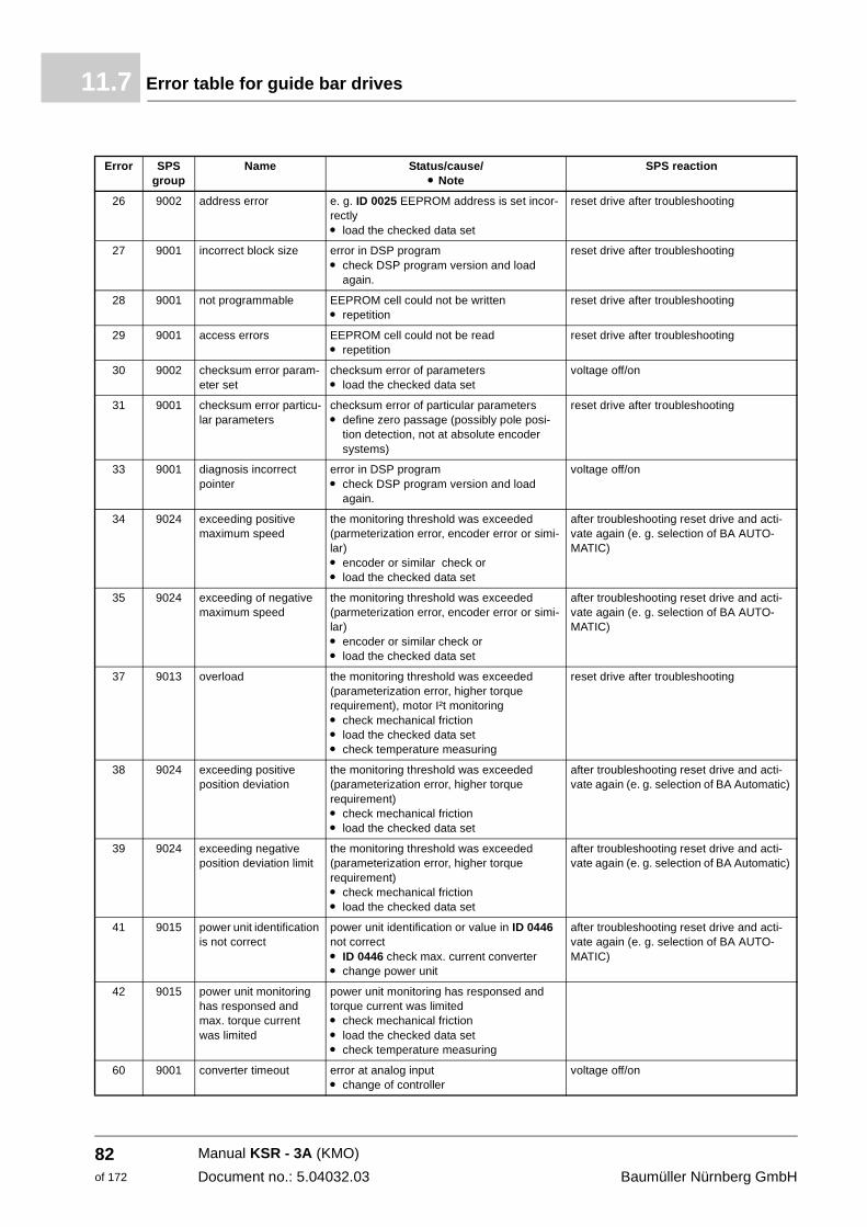
Error table for guide bar drives11.7
26 9002 address error e. g. ID 0025 EEPROM address is set incor-rectly m load the checked data set
reset drive after troubleshooting
27 9001 incorrect block size error in DSP programm check DSP program version and load
again.
reset drive after troubleshooting
28 9001 not programmable EEPROM cell could not be written m repetition
reset drive after troubleshooting
29 9001 access errors EEPROM cell could not be read m repetition
reset drive after troubleshooting
30 9002 checksum error param-eter set
checksum error of parameters m load the checked data set
voltage off/on
31 9001 checksum error particu-lar parameters
checksum error of particular parameters m define zero passage (possibly pole posi-
tion detection, not at absolute encoder systems)
reset drive after troubleshooting
33 9001 diagnosis incorrect pointer
error in DSP programm check DSP program version and load
again.
voltage off/on
34 9024 exceeding positive maximum speed
the monitoring threshold was exceeded (parmeterization error, encoder error or simi-lar) m encoder or similar check or m load the checked data set
after troubleshooting reset drive and acti-vate again (e. g. selection of BA AUTO-MATIC)
35 9024 exceeding of negative maximum speed
the monitoring threshold was exceeded (parmeterization error, encoder error or simi-lar)m encoder or similar check or m load the checked data set
after troubleshooting reset drive and acti-vate again (e. g. selection of BA AUTO-MATIC)
37 9013 overload the monitoring threshold was exceeded (parameterization error, higher torque requirement), motor I²t monitoring m check mechanical friction m load the checked data set m check temperature measuring
reset drive after troubleshooting
38 9024 exceeding positive position deviation
the monitoring threshold was exceeded (parameterization error, higher torque requirement) m check mechanical friction m load the checked data set
after troubleshooting reset drive and acti-vate again (e. g. selection of BA Automatic)
39 9024 exceeding negative position deviation limit
the monitoring threshold was exceeded (parameterization error, higher torque requirement)m check mechanical frictionm load the checked data set
after troubleshooting reset drive and acti-vate again (e. g. selection of BA Automatic)
41 9015 power unit identification is not correct
power unit identification or value in ID 0446 not correct m ID 0446 check max. current converter m change power unit
after troubleshooting reset drive and acti-vate again (e. g. selection of BA AUTO-MATIC)
42 9015 power unit monitoring has responsed and max. torque current was limited
power unit monitoring has responsed and torque current was limited m check mechanical frictionm load the checked data setm check temperature measuring
60 9001 converter timeout error at analog input m change of controller
voltage off/on
Error SPS group
Name Status/cause/m Note
SPS reaction
Manual KSR - 3A (KMO)
Document no.: 5.04032.03 Baumüller Nürnberg GmbH
82of 172
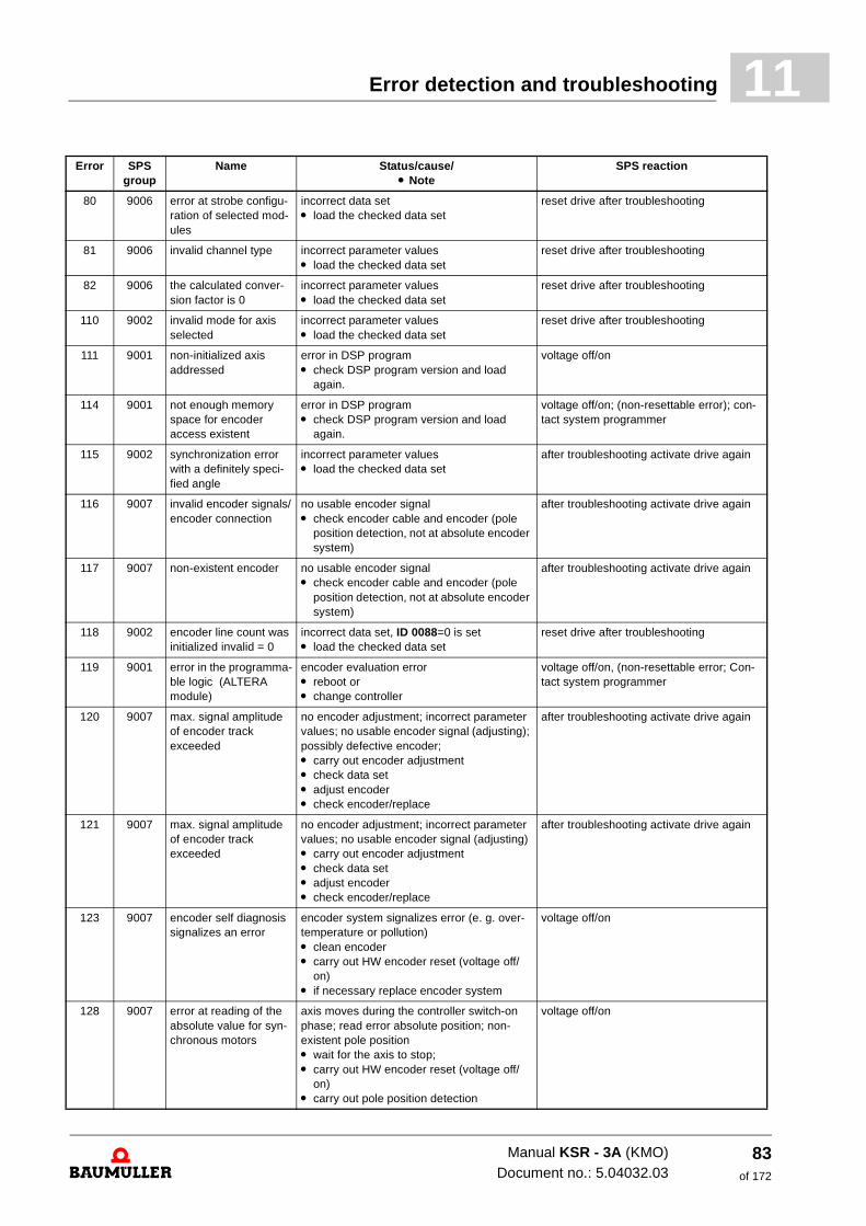
Error detection and troubleshooting 11
80 9006 error at strobe configu-ration of selected mod-ules
incorrect data setm load the checked data set
reset drive after troubleshooting
81 9006 invalid channel type incorrect parameter values m load the checked data set
reset drive after troubleshooting
82 9006 the calculated conver-sion factor is 0
incorrect parameter valuesm load the checked data set
reset drive after troubleshooting
110 9002 invalid mode for axis selected
incorrect parameter valuesm load the checked data set
reset drive after troubleshooting
111 9001 non-initialized axis addressed
error in DSP programm check DSP program version and load
again.
voltage off/on
114 9001 not enough memory space for encoder access existent
error in DSP programm check DSP program version and load
again.
voltage off/on; (non-resettable error); con-tact system programmer
115 9002 synchronization error with a definitely speci-fied angle
incorrect parameter valuesm load the checked data set
after troubleshooting activate drive again
116 9007 invalid encoder signals/encoder connection
no usable encoder signal m check encoder cable and encoder (pole
position detection, not at absolute encoder system)
after troubleshooting activate drive again
117 9007 non-existent encoder no usable encoder signalm check encoder cable and encoder (pole
position detection, not at absolute encoder system)
after troubleshooting activate drive again
118 9002 encoder line count was initialized invalid = 0
incorrect data set, ID 0088=0 is set m load the checked data set
reset drive after troubleshooting
119 9001 error in the programma-ble logic (ALTERA module)
encoder evaluation error m reboot or m change controller
voltage off/on, (non-resettable error; Con-tact system programmer
120 9007 max. signal amplitude of encoder track exceeded
no encoder adjustment; incorrect parameter values; no usable encoder signal (adjusting); possibly defective encoder; m carry out encoder adjustmentm check data set m adjust encoder m check encoder/replace
after troubleshooting activate drive again
121 9007 max. signal amplitude of encoder track exceeded
no encoder adjustment; incorrect parameter values; no usable encoder signal (adjusting) m carry out encoder adjustmentm check data set m adjust encoderm check encoder/replace
after troubleshooting activate drive again
123 9007 encoder self diagnosis signalizes an error
encoder system signalizes error (e. g. over-temperature or pollution) m clean encoder m carry out HW encoder reset (voltage off/
on) m if necessary replace encoder system
voltage off/on
128 9007 error at reading of the absolute value for syn-chronous motors
axis moves during the controller switch-on phase; read error absolute position; non-existent pole position m wait for the axis to stop; m carry out HW encoder reset (voltage off/
on) m carry out pole position detection
voltage off/on
Error SPS group
Name Status/cause/m Note
SPS reaction
Manual KSR - 3A (KMO)Document no.: 5.04032.03
83of 172
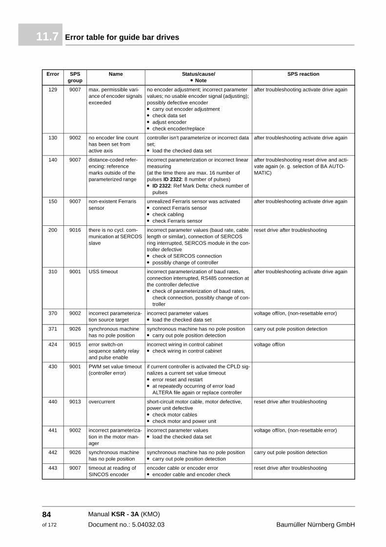
Error table for guide bar drives11.7
129 9007 max. permissible vari-ance of encoder signals exceeded
no encoder adjustment; incorrect parameter values; no usable encoder signal (adjusting); possibly defective encoder m carry out encoder adjustmentm check data setm adjust encoderm check encoder/replace
after troubleshooting activate drive again
130 9002 no encoder line count has been set from active axis
controller isn‘t parameterize or incorrect data set; m load the checked data set
after troubleshooting activate drive again
140 9007 distance-coded refer-encing: reference marks outside of the parameterized range
incorrect parameterization or incorrect linear measuring (at the time there are max. 16 number of pulses ID 2322: 8 number of pulses) m ID 2322: Ref Mark Delta: check number of
pulses
after troubleshooting reset drive and acti-vate again (e. g. selection of BA AUTO-MATIC)
150 9007 non-existent Ferraris sensor
unrealized Ferraris sensor was activated m connect Ferraris sensor m check cabling m check Ferraris sensor
after troubleshooting activate drive again
200 9016 there is no cycl. com-munication at SERCOS slave
incorrect parameter values (baud rate, cable length or similar), connection of SERCOS ring interrupted, SERCOS module in the con-troller defective m check of SERCOS connection m possibly change of controller
reset drive after troubleshooting
310 9001 USS timeout incorrect parameterization of baud rates, connection interrupted, RS485 connection at the controller defective m check of parameterization of baud rates,
check connection, possibly change of con-troller
after troubleshooting activate drive again
370 9002 incorrect parameteriza-tion source target
incorrect parameter valuesm load the checked data set
voltage off/on, (non-resettable error)
371 9026 synchronous machine has no pole position
synchronous machine has no pole position m carry out pole position detection
carry out pole position detection
424 9015 error switch-on sequence safety relay and pulse enable
incorrect wiring in control cabinet m check wiring in control cabinet
voltage off/on
430 9001 PWM set value timeout (controller error)
if current controller is activated the CPLD sig-nalizes a current set value timeout m error reset and restart m at repeatedly occurring of error load
ALTERA file again or replace controller
440 9013 overcurrent short-circuit motor cable, motor defective, power unit defective m check motor cables m check motor and power unit
reset drive after troubleshooting
441 9002 incorrect parameteriza-tion in the motor man-ager
incorrect parameter valuesm load the checked data set
voltage off/on, (non-resettable error)
442 9026 synchronous machine has no pole position
synchronous machine has no pole position m carry out pole position detection
carry out pole position detection
443 9007 timeout at reading of SINCOS encoder
encoder cable or encoder error m encoder cable and encoder check
reset drive after troubleshooting
Error SPS group
Name Status/cause/m Note
SPS reaction
Manual KSR - 3A (KMO)
Document no.: 5.04032.03 Baumüller Nürnberg GmbH
84of 172
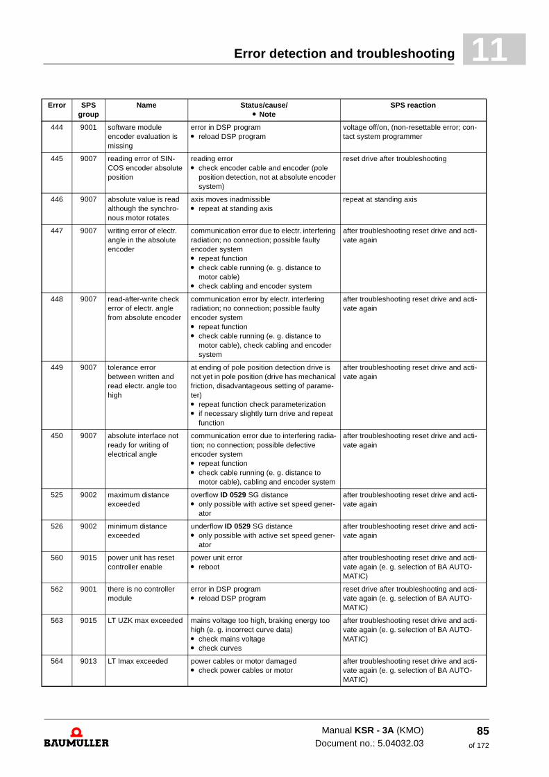
Error detection and troubleshooting 11
444 9001 software module encoder evaluation is missing
error in DSP program m reload DSP program
voltage off/on, (non-resettable error; con-tact system programmer
445 9007 reading error of SIN-COS encoder absolute position
reading error m check encoder cable and encoder (pole
position detection, not at absolute encoder system)
reset drive after troubleshooting
446 9007 absolute value is read although the synchro-nous motor rotates
axis moves inadmissible m repeat at standing axis
repeat at standing axis
447 9007 writing error of electr. angle in the absolute encoder
communication error due to electr. interfering radiation; no connection; possible faulty encoder system m repeat function m check cable running (e. g. distance to
motor cable) m check cabling and encoder system
after troubleshooting reset drive and acti-vate again
448 9007 read-after-write check error of electr. angle from absolute encoder
communication error by electr. interfering radiation; no connection; possible faulty encoder system m repeat functionm check cable running (e. g. distance to
motor cable), check cabling and encoder system
after troubleshooting reset drive and acti-vate again
449 9007 tolerance error between written and read electr. angle too high
at ending of pole position detection drive is not yet in pole position (drive has mechanical friction, disadvantageous setting of parame-ter) m repeat function check parameterization m if necessary slightly turn drive and repeat
function
after troubleshooting reset drive and acti-vate again
450 9007 absolute interface not ready for writing of electrical angle
communication error due to interfering radia-tion; no connection; possible defective encoder system m repeat functionm check cable running (e. g. distance to
motor cable), cabling and encoder system
after troubleshooting reset drive and acti-vate again
525 9002 maximum distance exceeded
overflow ID 0529 SG distance m only possible with active set speed gener-
ator
after troubleshooting reset drive and acti-vate again
526 9002 minimum distance exceeded
underflow ID 0529 SG distance m only possible with active set speed gener-
ator
after troubleshooting reset drive and acti-vate again
560 9015 power unit has reset controller enable
power unit error m reboot
after troubleshooting reset drive and acti-vate again (e. g. selection of BA AUTO-MATIC)
562 9001 there is no controller module
error in DSP program m reload DSP program
reset drive after troubleshooting and acti-vate again (e. g. selection of BA AUTO-MATIC)
563 9015 LT UZK max exceeded mains voltage too high, braking energy too high (e. g. incorrect curve data) m check mains voltage m check curves
after troubleshooting reset drive and acti-vate again (e. g. selection of BA AUTO-MATIC)
564 9013 LT Imax exceeded power cables or motor damaged m check power cables or motor
after troubleshooting reset drive and acti-vate again (e. g. selection of BA AUTO-MATIC)
Error SPS group
Name Status/cause/m Note
SPS reaction
Manual KSR - 3A (KMO)Document no.: 5.04032.03
85of 172
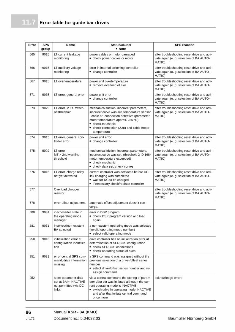
Error table for guide bar drives11.7
565 9015 LT current leakage monitoring
power cables or motor damaged m check power cables or motor
after troubleshooting reset drive and acti-vate again (e. g. selection of BA AUTO-MATIC)
566 9015 LT auxiliary voltage monitoring
error in internal switching controller m change controller
after troubleshooting reset drive and acti-vate again (e. g. selection of BA AUTO-MATIC)
567 9015 LT overtemperature power unit overtemperature m remove overload of axis
after troubleshooting reset drive and acti-vate again (e. g. selection of BA AUTO-MATIC)
571 9015 LT error, general error power unit errorm change controller
after troubleshooting reset drive and acti-vate again (e. g. selection of BA AUTO-MATIC)
573 9029 LT error, MT > switch-off threshold
mechanical friction, incorrect parameters, incorrect curve was set, temperature sensor, - cable or -connection defective (parameter motor temperature approx. 285 °C) m check mechanic m check connection (X28) and cable motor
temperature
after troubleshooting reset drive and acti-vate again (e. g. selection of BA AUTO-MATIC)
574 9015 LT error, general con-troller error
power unit errorm change controller
after troubleshooting reset drive and acti-vate again (e. g. selection of BA AUTO-MATIC)
575 9029 LT error MT > 2nd warning threshold
mechanical friction, incorrect parameters, incorrect curve was set, (threshold 2 ID 1684 motor temperature exceeded)m check mechanicm check data set, check curves
after troubleshooting reset drive and acti-vate again (e. g. selection of BA AUTO-MATIC)
576 9015 LT error, charge relay not yet activated
current controller was activated before DC link charging was completed m wait for DC to be charged m if necessary check/replace controller
after troubleshooting reset drive and acti-vate again (e. g. selection of BA AUTO-MATIC)
577 Overload chopper resistor
after troubleshooting reset drive and acti-vate again (e. g. selection of BA AUTO-MATIC)
578 error offset adjustment automatic offset adjustment doesn’t con-verge.
580 9031 inaccessible state in the operating mode manager
error in DSP programm check DSP program version and load
again
581 9031 incorrect/non-existent BA selected
a non-existent operating mode was selected (invalid operating mode number) m select valid operating mode
950 9016 initialization error at configuration identifica-tion
drive controller has an initialization error at determination of SERCOS configuration m check SERCOS connections m check operating status of axes
951 9031 error central SPS com-mand, drive information missing
a SPS command was assigned without the previous selection of a drive-/offset series number m select drive-/offset series number and re-
assign command
952 store parameter data set at BA!= INACTIVE not permitted (via DC-link);
via a central command the storing of param-eter data set was initiated although the cur-rent operating mode is INACTIVE m switch drive in operating mode INACTIVE
and after that initiate central command once more
acknowledge errors
Error SPS group
Name Status/cause/m Note
SPS reaction
Manual KSR - 3A (KMO)
Document no.: 5.04032.03 Baumüller Nürnberg GmbH
86of 172
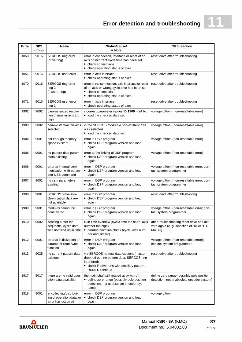
Error detection and troubleshooting 11
1050 9016 SERCOS ring error (drive ring)
error in connection, interface or reset of an axis or incorrect cycle time has been set. m check connections m check operating status of axes
reset drive after troubleshooting
1051 9016 SERCOS user error error in axis interface m check operating status of axes
reset drive after troubleshooting
1070 9016 SERCOS ring error ring 2 (master ring)
error in the connection, axis interface or reset of an axis or wrong cycle time has been set m check connectionsm check operating status of axes
reset drive after troubleshooting
1071 9016 SERCOS user error ring 2
error in axis interfacem check operating status of axes
reset drive after troubleshooting
1902 9002 parameterized resolu-tion of master axis too high
incorrect parameter values ID 1909 > 24 bit m load the checked data set
voltage off/on, (non-resettable error)
1903 9002 non-existent/active axis selected
in the SERCOS module a non-existent axis was selectedm load the checked data set
voltage off/on, (non-resettable error)
1904 9001 not enough memory space existent
error in DSP programm check DSP program version and load
again
voltage off/on, (non-resettable error)
1905 9001 no pattern data param-eters existing
error at the linking of DSP program m check DSP program version and load
again
voltage off/on, (non-resettable error)
1906 9001 error at internal com-munication with param-eter USS command
error in DSP programm check DSP program version and load
again
voltage off/on, (non-resettable error; con-tact system programmer
1907 9001 no cam parameters existing
error in DSP programm check DSP program version and load
again
voltage off/on, (non-resettable error; con-tact system programmer
1908 9001 SERCOS slave syn-chronization data are not available
error in DSP programm check DSP program version and load
again
reset drive after troubleshooting
1909 9001 modules cannot be deactivated
error in DSP programm check DSP program version and load
again
voltage off/on, (non-resettable error; con-tact system programmer
1910 9002 sending buffer for sequential cyclic data was not filled up in time
Run time overflow (cyclic time too short, axis number too high) m parameterization check (cycle, axis num-
ber and similar)
after troubleshooting reset drive and acti-vate again (e. g. selection of BA AUTO-MATIC)
1912 9001 error at initialization of parameter read-/write function
error in DSP programm check DSP program version and load
again
voltage off/on, (non-resettable error); contact system programmer
1913 9025 no current pattern data existent
via SERCOS no new data existent (master dropped out, no pattern data, SERCOS ring interfered) m check if drive runs with auxiliary pattern,
RESET, continue
reset drive after troubleshooting
1917 9017 there are no valid oper-ation data available
the main shaft still rotated at switch-off m define zero range (possibly pole position
detection, not at absolute encoder sys-tems)
define zero range (possibly pole position detection, not at absolute encoder system)
1918 9001 at collecting/distribut-ing of operation data an error has occurred
error in DSP programm check DSP program version and load
again
voltage off/on
Error SPS group
Name Status/cause/m Note
SPS reaction
Manual KSR - 3A (KMO)Document no.: 5.04032.03
87of 172
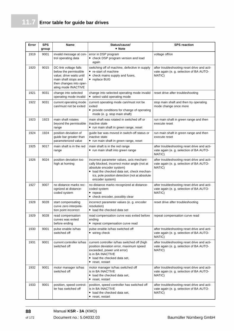
Error table for guide bar drives11.7
1919 9001 invalid message at con-trol operating data
error in DSP programm check DSP program version and load
again
voltage off/on
1920 9015 DC-link voltage falls below the permissible value; drive waits until main shaft stops and then changes into oper-ating mode INACTIVE
switching off of machine, defective in supply m re-start of machine m check mains supply and fuses, m replace BUG
after troubleshooting reset drive and acti-vate again (e. g. selection of BA AUTO-MATIC)
1921 9031 change into selected operating mode invalid
change into selected operating mode invalidm select valid operating mode
reset drive after troubleshooting
1922 9031 current operating mode can/must not be exited
current operating mode can/must not be exitedm provide conditions for change of operating
mode (e. g. stop main shaft)
stop main shaft and then try operating mode change once more
1923 1923 main shaft rotates beyond the permissible range
main shaft was rotated in switched off or inactive state m run main shaft in green range, reset
run main shaft in green range and then execute reset
1924 1924 position deviation of guide bar greater than parameterized value
guide bar was moved in switch-off status or inactive state m run main shaft in green range, reset
run main shaft in green range and then execute reset
1925 9017 main shaft is in the red range
main shaft is in the red rangem run main shaft into green range
after troubleshooting reset drive and acti-vate again (e. g. selection of BA AUTO-MATIC)
1926 9024 position deviation too high at homing
incorrect parameter values, axis mechani-cally blocked, incorrect motor angle (not at absolute encoder system) m load the checked data set, check mechan-
ics, pole position detection (not at absolute encoder system)
after troubleshooting reset drive and acti-vate again (e. g. selection of BA AUTO-MATIC)
1927 9007 no distance marks rec-ognized at distance-coded system
no distance marks recognized at distance-coded system m repeat m check encoder, possibly clear
after troubleshooting reset drive and acti-vate again (e. g. selection of BA AUTO-MATIC)
1928 9028 start compensating curve zero interpola-tion point incorrect
incorrect parameter values (e. g. encoder resolution) m load the checked data set
reset drive after troubleshooting
1929 9028 read compensation curves was exited before ending
read compensation curve was exited before ending m repeat compensation curve read
repeat compensation curve read
1930 9001 pulse enable is/has switched off
pulse enable is/has switched offm wiring check
after troubleshooting reset drive and acti-vate again (e. g. selection of BA AUTO-MATIC)
1931 9001 current controller is/has switched off
current controller is/has switched off (high position deviation error, maximum speed exceeded, power unit error) is in BA INACTIVE m load the checked data set, m reset, restart
after troubleshooting reset drive and acti-vate again (e. g. selection of BA AUTO-MATIC)
1932 9001 motor manager is/has switched off
motor manager is/has switched offis in BA INACTIVEm load the checked data set, m reset, restart
after troubleshooting reset drive and acti-vate again (e. g. selection of BA AUTO-MATIC)
1933 9001 position, speed control-ler has switched off
position, speed controller has switched offis in BA INACTIVEm load the checked data set, m reset, restart
after troubleshooting reset drive and acti-vate again (e. g. selection of BA AUTO-MATIC)
Error SPS group
Name Status/cause/m Note
SPS reaction
Manual KSR - 3A (KMO)
Document no.: 5.04032.03 Baumüller Nürnberg GmbH
88of 172
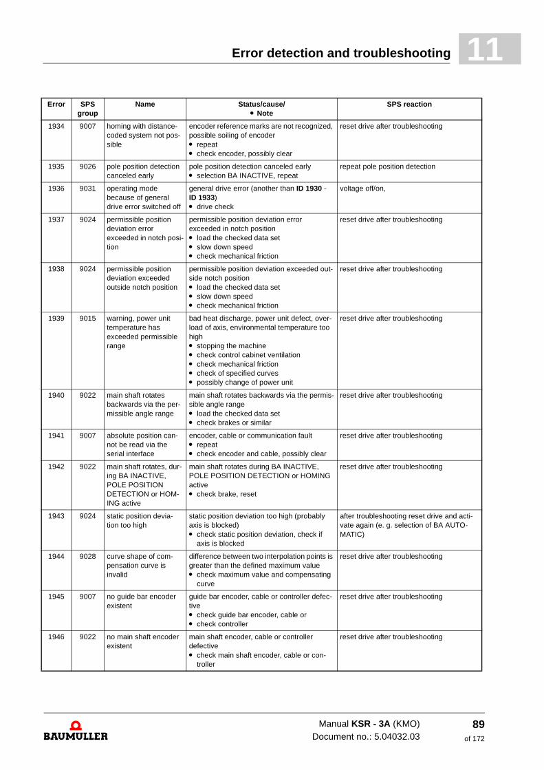
Error detection and troubleshooting 11
1934 9007 homing with distance-coded system not pos-sible
encoder reference marks are not recognized, possible soiling of encoder m repeatm check encoder, possibly clear
reset drive after troubleshooting
1935 9026 pole position detection canceled early
pole position detection canceled earlym selection BA INACTIVE, repeat
repeat pole position detection
1936 9031 operating mode because of general drive error switched off
general drive error (another than ID 1930 - ID 1933) m drive check
voltage off/on,
1937 9024 permissible position deviation error exceeded in notch posi-tion
permissible position deviation error exceeded in notch positionm load the checked data setm slow down speed m check mechanical friction
reset drive after troubleshooting
1938 9024 permissible position deviation exceeded outside notch position
permissible position deviation exceeded out-side notch positionm load the checked data setm slow down speedm check mechanical friction
reset drive after troubleshooting
1939 9015 warning, power unit temperature has exceeded permissible range
bad heat discharge, power unit defect, over-load of axis, environmental temperature too high m stopping the machine m check control cabinet ventilation m check mechanical frictionm check of specified curves m possibly change of power unit
reset drive after troubleshooting
1940 9022 main shaft rotates backwards via the per-missible angle range
main shaft rotates backwards via the permis-sible angle rangem load the checked data setm check brakes or similar
reset drive after troubleshooting
1941 9007 absolute position can-not be read via the serial interface
encoder, cable or communication fault m repeatm check encoder and cable, possibly clear
reset drive after troubleshooting
1942 9022 main shaft rotates, dur-ing BA INACTIVE, POLE POSITION DETECTION or HOM-ING active
main shaft rotates during BA INACTIVE, POLE POSITION DETECTION or HOMING active m check brake, reset
reset drive after troubleshooting
1943 9024 static position devia-tion too high
static position deviation too high (probably axis is blocked) m check static position deviation, check if
axis is blocked
after troubleshooting reset drive and acti-vate again (e. g. selection of BA AUTO-MATIC)
1944 9028 curve shape of com-pensation curve is invalid
difference between two interpolation points is greater than the defined maximum value m check maximum value and compensating
curve
reset drive after troubleshooting
1945 9007 no guide bar encoder existent
guide bar encoder, cable or controller defec-tive m check guide bar encoder, cable or m check controller
reset drive after troubleshooting
1946 9022 no main shaft encoder existent
main shaft encoder, cable or controller defective m check main shaft encoder, cable or con-
troller
reset drive after troubleshooting
Error SPS group
Name Status/cause/m Note
SPS reaction
Manual KSR - 3A (KMO)Document no.: 5.04032.03
89of 172
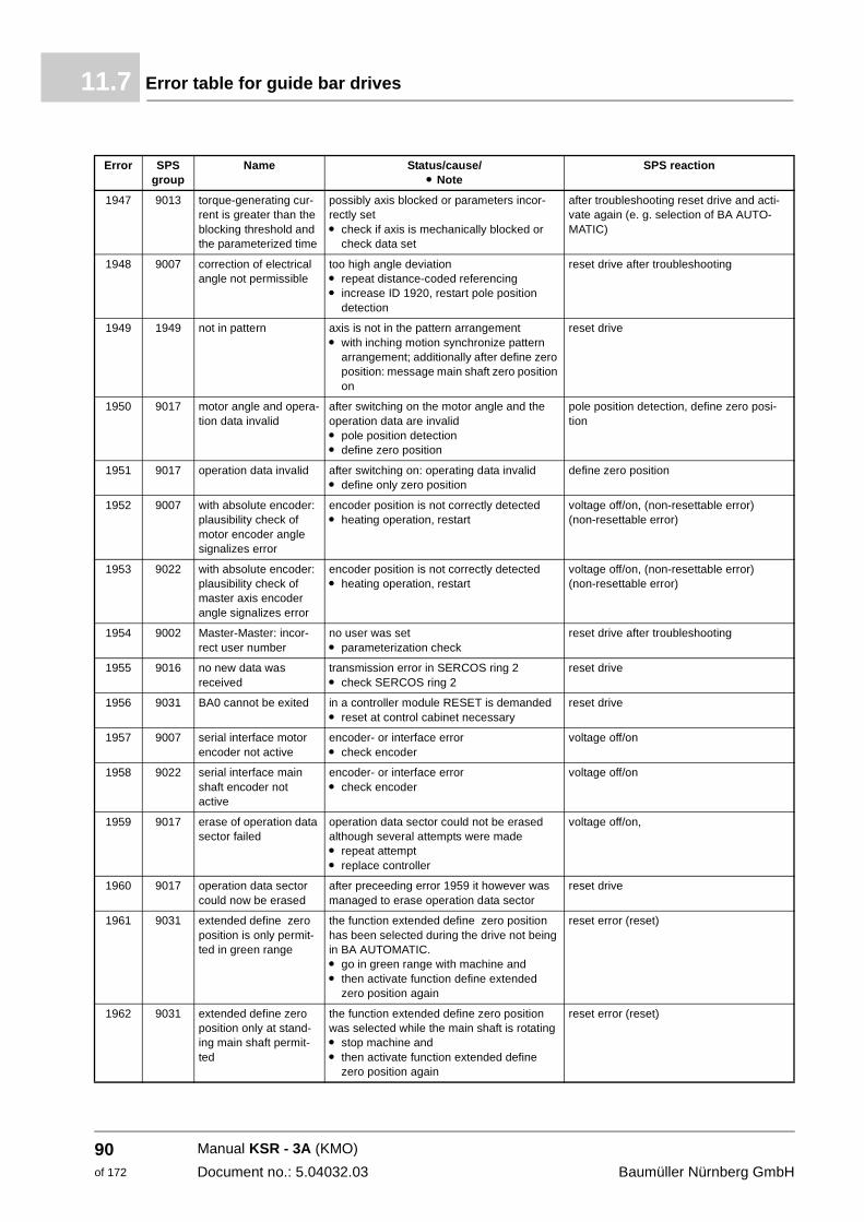
Error table for guide bar drives11.7
1947 9013 torque-generating cur-rent is greater than the blocking threshold and the parameterized time
possibly axis blocked or parameters incor-rectly set m check if axis is mechanically blocked or
check data set
after troubleshooting reset drive and acti-vate again (e. g. selection of BA AUTO-MATIC)
1948 9007 correction of electrical angle not permissible
too high angle deviation m repeat distance-coded referencing m increase ID 1920, restart pole position
detection
reset drive after troubleshooting
1949 1949 not in pattern axis is not in the pattern arrangement m with inching motion synchronize pattern
arrangement; additionally after define zero position: message main shaft zero position on
reset drive
1950 9017 motor angle and opera-tion data invalid
after switching on the motor angle and the operation data are invalid m pole position detection m define zero position
pole position detection, define zero posi-tion
1951 9017 operation data invalid after switching on: operating data invalid m define only zero position
define zero position
1952 9007 with absolute encoder: plausibility check of motor encoder angle signalizes error
encoder position is not correctly detected m heating operation, restart
voltage off/on, (non-resettable error) (non-resettable error)
1953 9022 with absolute encoder: plausibility check of master axis encoder angle signalizes error
encoder position is not correctly detectedm heating operation, restart
voltage off/on, (non-resettable error) (non-resettable error)
1954 9002 Master-Master: incor-rect user number
no user was set m parameterization check
reset drive after troubleshooting
1955 9016 no new data was received
transmission error in SERCOS ring 2 m check SERCOS ring 2
reset drive
1956 9031 BA0 cannot be exited in a controller module RESET is demanded m reset at control cabinet necessary
reset drive
1957 9007 serial interface motor encoder not active
encoder- or interface error m check encoder
voltage off/on
1958 9022 serial interface main shaft encoder not active
encoder- or interface errorm check encoder
voltage off/on
1959 9017 erase of operation data sector failed
operation data sector could not be erased although several attempts were made m repeat attempt m replace controller
voltage off/on,
1960 9017 operation data sector could now be erased
after preceeding error 1959 it however was managed to erase operation data sector
reset drive
1961 9031 extended define zero position is only permit-ted in green range
the function extended define zero position has been selected during the drive not being in BA AUTOMATIC. m go in green range with machine and m then activate function define extended
zero position again
reset error (reset)
1962 9031 extended define zero position only at stand-ing main shaft permit-ted
the function extended define zero position was selected while the main shaft is rotating m stop machine and m then activate function extended define
zero position again
reset error (reset)
Error SPS group
Name Status/cause/m Note
SPS reaction
Manual KSR - 3A (KMO)
Document no.: 5.04032.03 Baumüller Nürnberg GmbH
90of 172
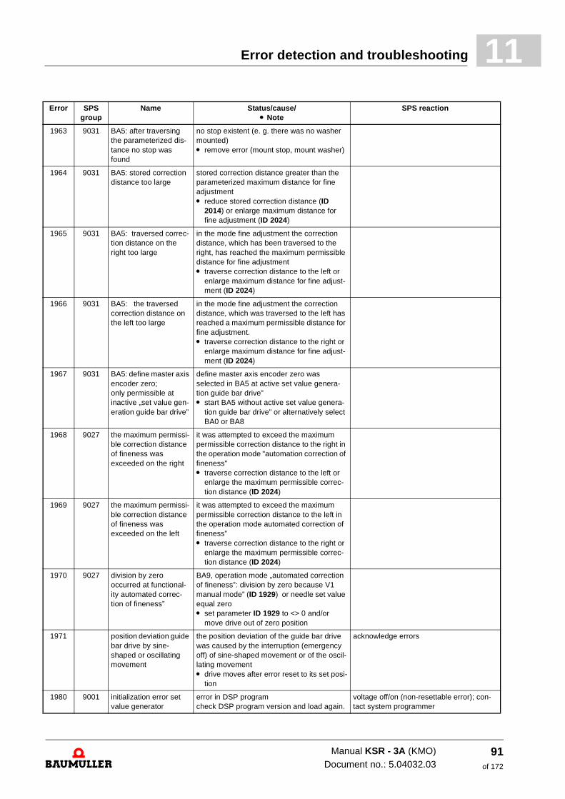
Error detection and troubleshooting 11
1963 9031 BA5: after traversing the parameterized dis-tance no stop was found
no stop existent (e. g. there was no washer mounted) m remove error (mount stop, mount washer)
1964 9031 BA5: stored correction distance too large
stored correction distance greater than the parameterized maximum distance for fine adjustment m reduce stored correction distance (ID
2014) or enlarge maximum distance for fine adjustment (ID 2024)
1965 9031 BA5: traversed correc-tion distance on the right too large
in the mode fine adjustment the correction distance, which has been traversed to the right, has reached the maximum permissible distance for fine adjustment m traverse correction distance to the left or
enlarge maximum distance for fine adjust-ment (ID 2024)
1966 9031 BA5: the traversed correction distance on the left too large
in the mode fine adjustment the correction distance, which was traversed to the left has reached a maximum permissible distance for fine adjustment. m traverse correction distance to the right or
enlarge maximum distance for fine adjust-ment (ID 2024)
1967 9031 BA5: define master axis encoder zero; only permissible at inactive „set value gen-eration guide bar drive”
define master axis encoder zero was selected in BA5 at active set value genera-tion guide bar drive” m start BA5 without active set value genera-
tion guide bar drive” or alternatively select BA0 or BA8
1968 9027 the maximum permissi-ble correction distance of fineness was exceeded on the right
it was attempted to exceed the maximum permissible correction distance to the right in the operation mode "automation correction of fineness" m traverse correction distance to the left or
enlarge the maximum permissible correc-tion distance (ID 2024)
1969 9027 the maximum permissi-ble correction distance of fineness was exceeded on the left
it was attempted to exceed the maximum permissible correction distance to the left in the operation mode automated correction of fineness” m traverse correction distance to the right or
enlarge the maximum permissible correc-tion distance (ID 2024)
1970 9027 division by zero occurred at functional-ity automated correc-tion of fineness”
BA9, operation mode „automated correction of fineness”: division by zero because V1 manual mode” (ID 1929) or needle set value equal zero m set parameter ID 1929 to <> 0 and/or
move drive out of zero position
1971 position deviation guide bar drive by sine-shaped or oscillating movement
the position deviation of the guide bar drive was caused by the interruption (emergency off) of sine-shaped movement or of the oscil-lating movement m drive moves after error reset to its set posi-
tion
acknowledge errors
1980 9001 initialization error set value generator
error in DSP programcheck DSP program version and load again.
voltage off/on (non-resettable error); con-tact system programmer
Error SPS group
Name Status/cause/m Note
SPS reaction
Manual KSR - 3A (KMO)Document no.: 5.04032.03
91of 172
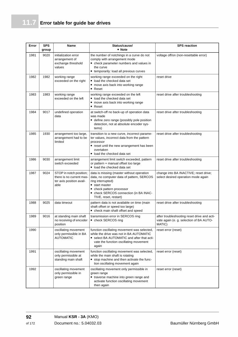
Error table for guide bar drives11.7
1981 9020 initialization error arrangement of exchange threshold values
the number of notchings in a curve do not comply with arrangement mode m check parameter numbers and values in
the curve m temporarily: load all previous curves
voltage off/on (non-resettable error)
1982 1982 working range exceeded on the right
working range exceeded on the rightm load the checked data setm move axis back into working range m Reset
reset drive
1983 1983 working range exceeded on the left
working range exceeded on the leftm load the checked data setm move axis back into working rangem Reset
reset drive after troubleshooting
1984 9017 undefined operation data
at switch-off no back-up of operation data was made m define zero range (possibly pole position
detection, not at absolute encoder sys-tems)
reset drive after troubleshooting
1985 1930 arrangement too large, arrangement had to be limited
transition to a new curve, incorrect parame-ter values, incorrect data from the pattern processor m reset until the new arrangement has been
overtaken m load the checked data set
reset drive after troubleshooting
1986 9030 arrangement limit switch exceeded
arrangement limit switch exceeded, pattern or pattern + manual offset too large m load the checked data set
reset drive after troubleshooting
1987 9024 STOP in notch position; there is no current mas-ter axis position avail-able
data is missing (master without operation data, no computer data of pattern, SERCOS ring interrupted) m start master m check pattern processor m check SERCOS connection (in BA INAC-
TIVE, reset, restart)
change into BA INACTIVE; reset drive; select desired operation mode again
1988 9025 data timeout pattern data is not available on time (main shaft offset or speed too large) m check main shaft offset and speed
reset drive after troubleshooting
1989 9016 at standing main shaft no receiving of encoder position
transmission error in SERCOS ring m check SERCOS ring
after troubleshooting reset drive and acti-vate again (e. g. selection of BA AUTO-MATIC)
1990 oscillating movement only permissible in BA AUTOMATIC
function oscillating movement was selected, while the drive was not in BA AUTOMATIC m select BA AUTOMATIC and after that acti-
vate the function oscillating movement again
reset error (reset)
1991 oscillating movement only permissible at standing main shaft
function oscillating movement was selected, while the main shaft is rotating m stop machine and then activate the func-
tion oscillating movement again
reset error (reset)
1992 oscillating movement only permissible in green range
oscillating movement only permissible in green rangem traverse machine into green range and
activate function oscillating movement then again
reset error (reset)
Error SPS group
Name Status/cause/m Note
SPS reaction
Manual KSR - 3A (KMO)
Document no.: 5.04032.03 Baumüller Nürnberg GmbH
92of 172
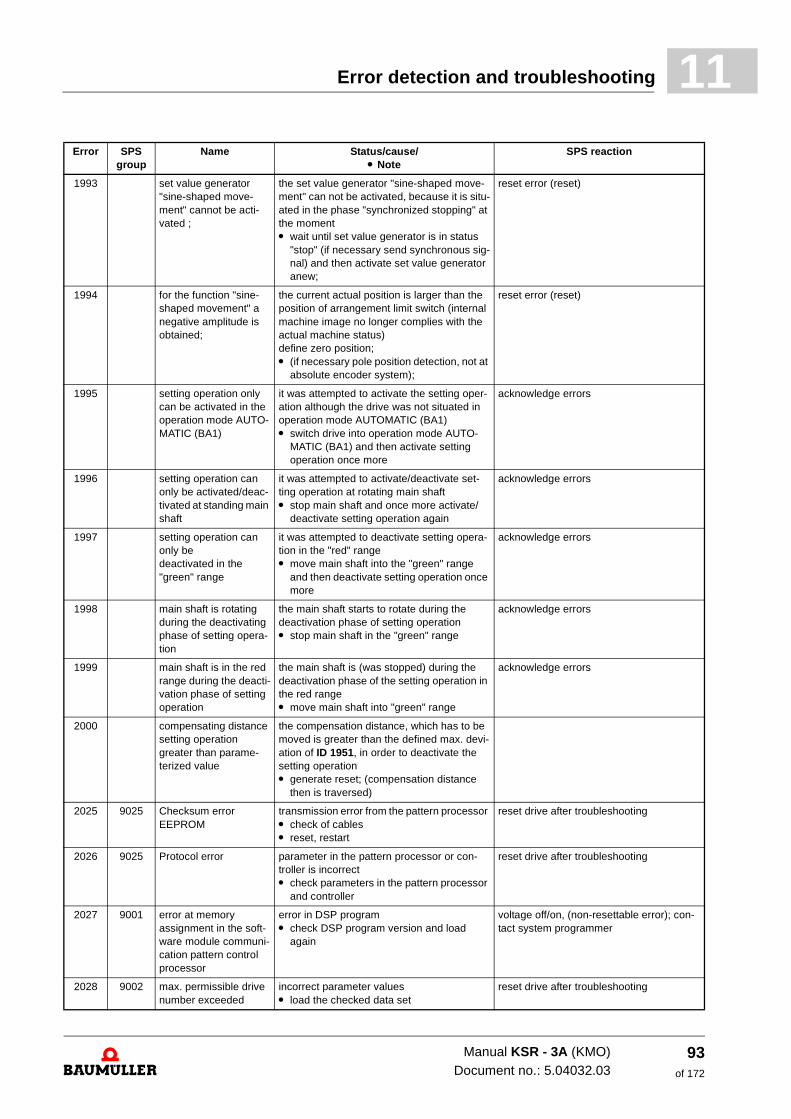
Error detection and troubleshooting 11
1993 set value generator "sine-shaped move-ment" cannot be acti-vated ;
the set value generator "sine-shaped move-ment" can not be activated, because it is situ-ated in the phase "synchronized stopping" at the moment m wait until set value generator is in status
"stop" (if necessary send synchronous sig-nal) and then activate set value generator anew;
reset error (reset)
1994 for the function "sine-shaped movement" a negative amplitude is obtained;
the current actual position is larger than the position of arrangement limit switch (internal machine image no longer complies with the actual machine status) define zero position; m (if necessary pole position detection, not at
absolute encoder system);
reset error (reset)
1995 setting operation only can be activated in the operation mode AUTO-MATIC (BA1)
it was attempted to activate the setting oper-ation although the drive was not situated in operation mode AUTOMATIC (BA1) m switch drive into operation mode AUTO-
MATIC (BA1) and then activate setting operation once more
acknowledge errors
1996 setting operation can only be activated/deac-tivated at standing main shaft
it was attempted to activate/deactivate set-ting operation at rotating main shaft m stop main shaft and once more activate/
deactivate setting operation again
acknowledge errors
1997 setting operation can only be deactivated in the "green" range
it was attempted to deactivate setting opera-tion in the "red" range m move main shaft into the "green" range
and then deactivate setting operation once more
acknowledge errors
1998 main shaft is rotating during the deactivating phase of setting opera-tion
the main shaft starts to rotate during the deactivation phase of setting operation m stop main shaft in the "green" range
acknowledge errors
1999 main shaft is in the red range during the deacti-vation phase of setting operation
the main shaft is (was stopped) during the deactivation phase of the setting operation in the red range m move main shaft into "green" range
acknowledge errors
2000 compensating distance setting operation greater than parame-terized value
the compensation distance, which has to be moved is greater than the defined max. devi-ation of ID 1951, in order to deactivate the setting operation m generate reset; (compensation distance
then is traversed)
2025 9025 Checksum error EEPROM
transmission error from the pattern processor m check of cables m reset, restart
reset drive after troubleshooting
2026 9025 Protocol error parameter in the pattern processor or con-troller is incorrect m check parameters in the pattern processor
and controller
reset drive after troubleshooting
2027 9001 error at memory assignment in the soft-ware module communi-cation pattern control processor
error in DSP programm check DSP program version and load
again
voltage off/on, (non-resettable error); con-tact system programmer
2028 9002 max. permissible drive number exceeded
incorrect parameter valuesm load the checked data set
reset drive after troubleshooting
Error SPS group
Name Status/cause/m Note
SPS reaction
Manual KSR - 3A (KMO)Document no.: 5.04032.03
93of 172
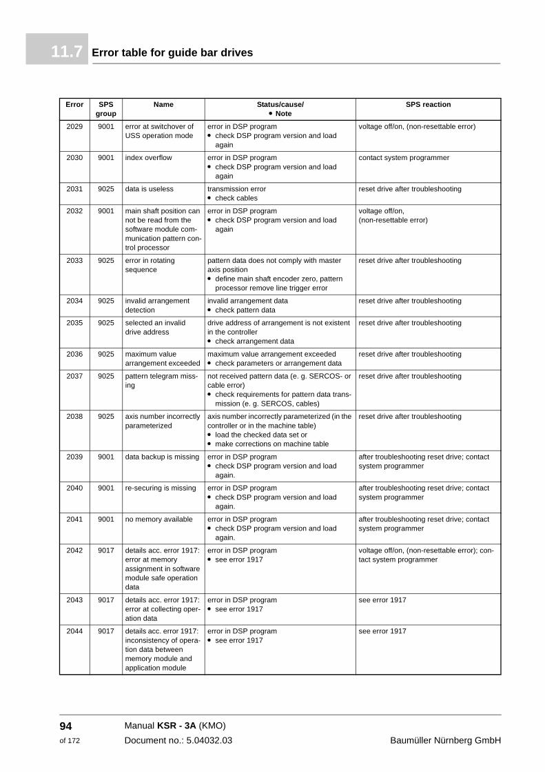
Error table for guide bar drives11.7
2029 9001 error at switchover of USS operation mode
error in DSP programm check DSP program version and load
again
voltage off/on, (non-resettable error)
2030 9001 index overflow error in DSP programm check DSP program version and load
again
contact system programmer
2031 9025 data is useless transmission error m check cables
reset drive after troubleshooting
2032 9001 main shaft position can not be read from the software module com-munication pattern con-trol processor
error in DSP programm check DSP program version and load
again
voltage off/on,(non-resettable error)
2033 9025 error in rotating sequence
pattern data does not comply with master axis position m define main shaft encoder zero, pattern
processor remove line trigger error
reset drive after troubleshooting
2034 9025 invalid arrangement detection
invalid arrangement data m check pattern data
reset drive after troubleshooting
2035 9025 selected an invalid drive address
drive address of arrangement is not existent in the controller m check arrangement data
reset drive after troubleshooting
2036 9025 maximum value arrangement exceeded
maximum value arrangement exceededm check parameters or arrangement data
reset drive after troubleshooting
2037 9025 pattern telegram miss-ing
not received pattern data (e. g. SERCOS- or cable error) m check requirements for pattern data trans-
mission (e. g. SERCOS, cables)
reset drive after troubleshooting
2038 9025 axis number incorrectly parameterized
axis number incorrectly parameterized (in the controller or in the machine table) m load the checked data set or m make corrections on machine table
reset drive after troubleshooting
2039 9001 data backup is missing error in DSP programm check DSP program version and load
again.
after troubleshooting reset drive; contact system programmer
2040 9001 re-securing is missing error in DSP programm check DSP program version and load
again.
after troubleshooting reset drive; contact system programmer
2041 9001 no memory available error in DSP programm check DSP program version and load
again.
after troubleshooting reset drive; contact system programmer
2042 9017 details acc. error 1917: error at memory assignment in software module safe operation data
error in DSP programm see error 1917
voltage off/on, (non-resettable error); con-tact system programmer
2043 9017 details acc. error 1917: error at collecting oper-ation data
error in DSP programm see error 1917
see error 1917
2044 9017 details acc. error 1917: inconsistency of opera-tion data between memory module and application module
error in DSP programm see error 1917
see error 1917
Error SPS group
Name Status/cause/m Note
SPS reaction
Manual KSR - 3A (KMO)
Document no.: 5.04032.03 Baumüller Nürnberg GmbH
94of 172
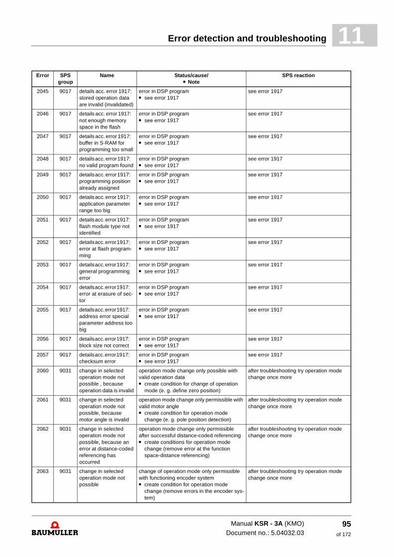
Error detection and troubleshooting 11
2045 9017 details acc. error 1917: stored operation data are invalid (invalidated)
error in DSP programm see error 1917
see error 1917
2046 9017 details acc. error 1917: not enough memory space in the flash
error in DSP programm see error 1917
see error 1917
2047 9017 details acc. error 1917: buffer in S-RAM for programming too small
error in DSP programm see error 1917
see error 1917
2048 9017 details acc. error 1917: no valid program found
error in DSP programm see error 1917
see error 1917
2049 9017 details acc. error 1917: programming position already assigned
error in DSP programm see error 1917
see error 1917
2050 9017 details acc. error 1917: application parameter range too big
error in DSP programm see error 1917
see error 1917
2051 9017 details acc. error 1917: flash module type not identified
error in DSP programm see error 1917
see error 1917
2052 9017 details acc. error 1917: error at flash program-ming
error in DSP programm see error 1917
see error 1917
2053 9017 details acc. error 1917: general programming error
error in DSP programm see error 1917
see error 1917
2054 9017 details acc. error 1917: error at erasure of sec-tor
error in DSP programm see error 1917
see error 1917
2055 9017 details acc. error 1917: address error special parameter address too big
error in DSP programm see error 1917
see error 1917
2056 9017 details acc. error 1917: block size not correct
error in DSP programm see error 1917
see error 1917
2057 9017 details acc. error 1917: checksum error
error in DSP programm see error 1917
see error 1917
2060 9031 change in selected operation mode not possible , because operation data is invalid
operation mode change only possible with valid operation data m create condition for change of operation
mode (e. g. define zero position)
after troubleshooting try operation mode change once more
2061 9031 change in selected operation mode not possible, because motor angle is invalid
operation mode change only permissible with valid motor angle m create condition for operation mode
change (e. g. pole position detection)
after troubleshooting try operation mode change once more
2062 9031 change in selected operation mode not possible, because an error at distance-coded referencing has occurred
operation mode change only permissible after successful distance-coded referencing m create conditions for operation mode
change (remove error at the function space-distance referencing)
after troubleshooting try operation mode change once more
2063 9031 change in selected operation mode not possible
change of operation mode only permissible with functioning encoder system m create condition for operation mode
change (remove errors in the encoder sys-tem)
after troubleshooting try operation mode change once more
Error SPS group
Name Status/cause/m Note
SPS reaction
Manual KSR - 3A (KMO)Document no.: 5.04032.03
95of 172
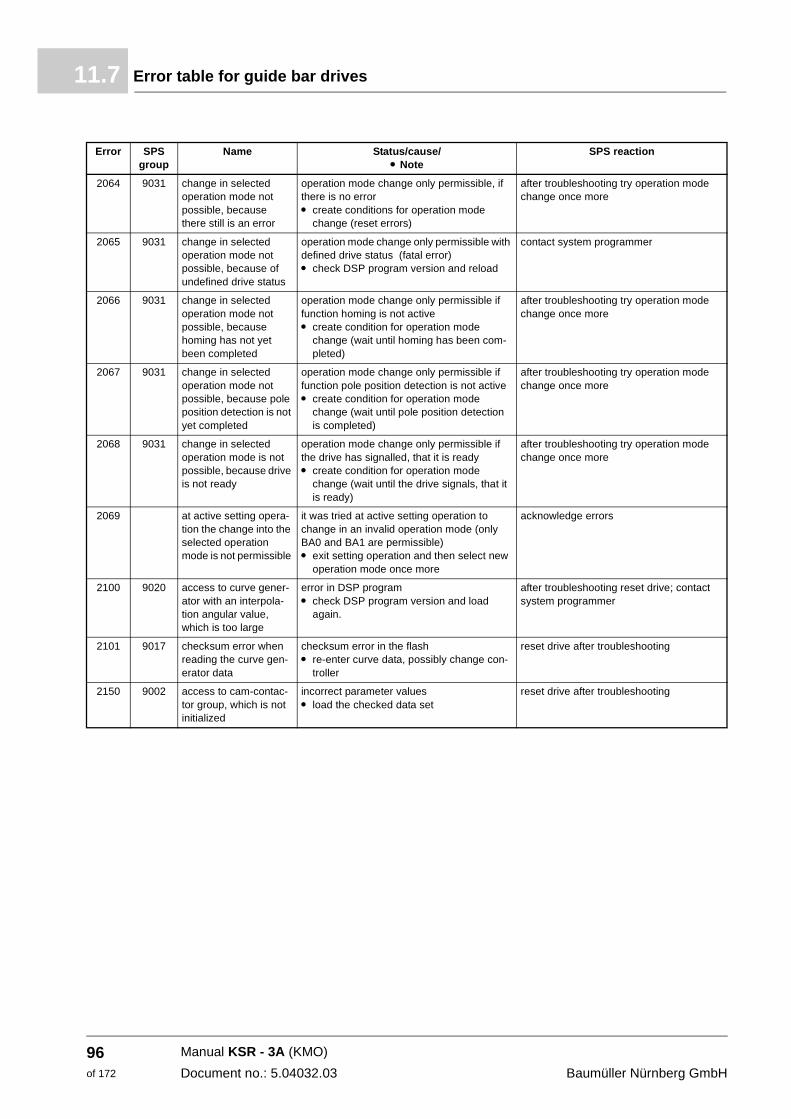
Error table for guide bar drives11.7
2064 9031 change in selected operation mode not possible, because there still is an error
operation mode change only permissible, if there is no error m create conditions for operation mode
change (reset errors)
after troubleshooting try operation mode change once more
2065 9031 change in selected operation mode not possible, because of undefined drive status
operation mode change only permissible with defined drive status (fatal error) m check DSP program version and reload
contact system programmer
2066 9031 change in selected operation mode not possible, because homing has not yet been completed
operation mode change only permissible if function homing is not active m create condition for operation mode
change (wait until homing has been com-pleted)
after troubleshooting try operation mode change once more
2067 9031 change in selected operation mode not possible, because pole position detection is not yet completed
operation mode change only permissible if function pole position detection is not active m create condition for operation mode
change (wait until pole position detection is completed)
after troubleshooting try operation mode change once more
2068 9031 change in selected operation mode is not possible, because drive is not ready
operation mode change only permissible if the drive has signalled, that it is ready m create condition for operation mode
change (wait until the drive signals, that it is ready)
after troubleshooting try operation mode change once more
2069 at active setting opera-tion the change into the selected operation mode is not permissible
it was tried at active setting operation to change in an invalid operation mode (only BA0 and BA1 are permissible) m exit setting operation and then select new
operation mode once more
acknowledge errors
2100 9020 access to curve gener-ator with an interpola-tion angular value, which is too large
error in DSP programm check DSP program version and load
again.
after troubleshooting reset drive; contact system programmer
2101 9017 checksum error when reading the curve gen-erator data
checksum error in the flash m re-enter curve data, possibly change con-
troller
reset drive after troubleshooting
2150 9002 access to cam-contac-tor group, which is not initialized
incorrect parameter valuesm load the checked data set
reset drive after troubleshooting
Error SPS group
Name Status/cause/m Note
SPS reaction
Manual KSR - 3A (KMO)
Document no.: 5.04032.03 Baumüller Nürnberg GmbH
96of 172
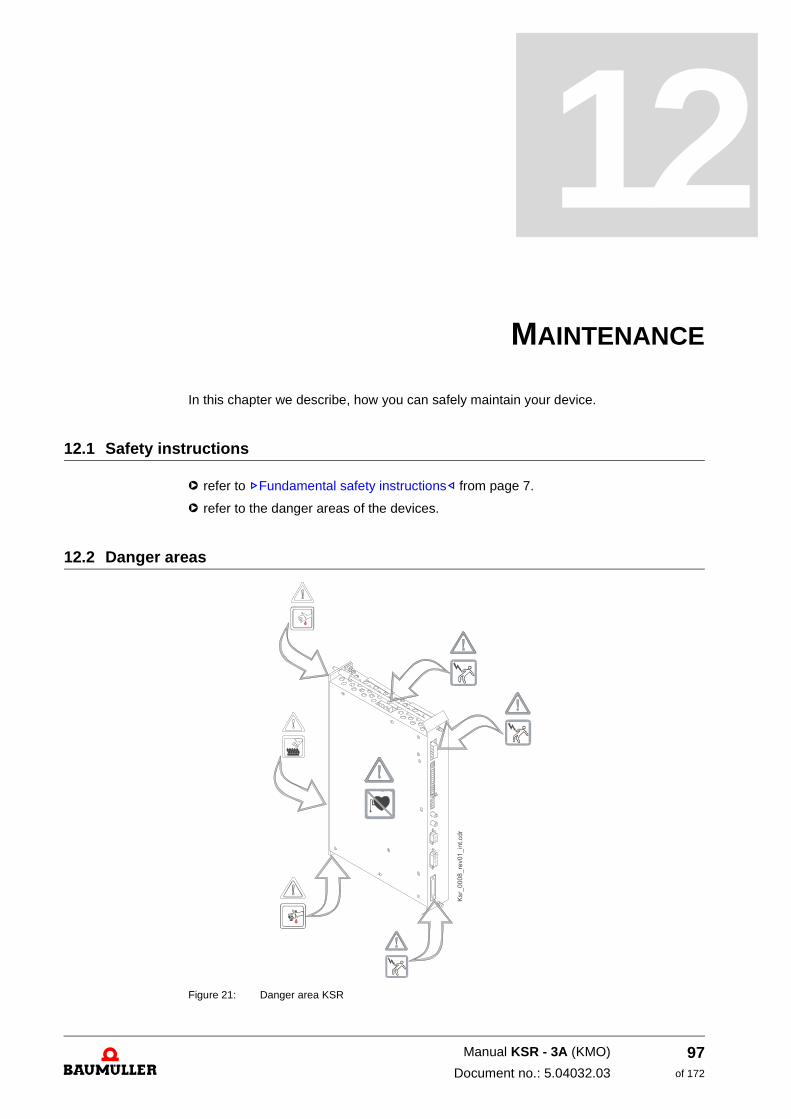
12
12MAINTENANCEIn this chapter we describe, how you can safely maintain your device.
12.1 Safety instructions
h refer to ZFundamental safety instructions– from page 7.
h refer to the danger areas of the devices.
12.2 Danger areas
Figure 21: Danger area KSR
97of 172
Manual KSR - 3A (KMO)
Document no.: 5.04032.03
Environmental conditions12.3
12.3 Environmental conditions
If the prescribed environmental conditions are complied with, the device is maintenance-free. The most important prescribed environmental conditions are:
m dustless ambient air
m Temperature: min. 5 °C to max. 55 °C
m Relative air humidity: 5 % to 85 %, no condensation
m (operational-) height: until 1000 m over mean sea level
12.4 Inspection intervals - maintenance notes
We recommend a permanent checking of the environmental conditions. Thus you will re-ceive the possibility, to react immediately, in case the actual conditions deviate from the prescribed conditions.
h check the devices at the control cabinet at least once a day, which ensure the environ-mental air (e.g. air filters)
h maintain the air filters according to the indications of the manufacturer.
In the case of polluted environmental air, the required cooling air rate can not be reached anymore, if dirt deposits narrow/block up the ventilation slots. In case the devices are pol-luted, contact Baumüller, in order to initiate a maintenance operation or send the device to the company for inspection.
WARNING
The following can occur, if you disregard this safety note:
m serious personal injury m death
The danger is: electricity. The unit carries dangerous voltages and currents, as well as re-sidual charges in the DC-link.
Assure, that when working in the control cabinet, that all devices in the control cabinet are off-circuit and are safe against re-starting.
Await the discharge of the DC-link, before you install the safety relay. The capacitors which are used in the device are 10 min. after interruption of the supply voltage automatically dis-charge so far, that the terminals can be demounted without danger. If you have additional ca-pacitors connected to the DC-link, the DC-link decharging also can last much longer. In this case you must determine the necessary waiting time self.
WARNING
The following can occur, if you disregard this safety note:
m serious personal injury m death
The danger is: electricity. The device can be damaged by incorrect maintenance in such a way, that a safe operating isn’t possible anymore.
Do not maintain the device yourself.
Never remove dirt deposits especially in the inside of the device with sharp objects or by the usage of e. g. compressed air, high-pressure cleaner
Manual KSR - 3A (KMO)
Document no.: 5.04032.03 Baumüller Nürnberg GmbH
98of 172
13
13REPAIRIn this chapter we describe the where the devices are repaired.
WARNING
The following can occur, if you disregard this safety note:
m serious personal injury m death
The danger is: electricity. After a faulty repair the device doesn't fulfill the safety instructions anymore.
have the devices only be maintained by Baumüller Nürnberg GmbH or authorized service lo-cations
99of 172
Manual KSR - 3A (KMO)
Document no.: 5.04032.03

Manual KSR - 3A (KMO)
Document no.: 5.04032.03 Baumüller Nürnberg GmbH
100of 172
14
14SETTING OUT OF OPERATION,STORAGE
In this chapter we describe, how you shutdown and store the device.
14.1 Safety instructions
h refer to ZFundamental safety instructions– from page 7.
The shutdown of the device may only be carried out by for this qualified personnel.
14.2 Requirements to the executing personnel
The personnel, who is appointed to setting out of operation, must have the required knowledge and instructions, which are necessary for an execution according to the rules. Select the personnel in such a way, that the safety instructions, which are mounted to the device and its parts as well as to the terminals, are understood and applied to.
DANGER
The following will occur, if you do not observe this safety note:
m serious personal injury m death
The danger is: electricity. Electrical connections, which are not switched current-free, carry dangerous voltage. The modules in the device (e. g. capacitors) can contain dangerous charges!
Assure, when working in the control cabinet, that all electrical connections in the control cab-inet are off-circuit and are safe against re-start.
Before working, check at the electrical connections with suitable measuring devices, that the connections are off-circuit.
Remove the connections not until you have verified yourself of the isolation from supply.
The capacitors which are used in the device are 10 min. after interruption of the supply volt-age automatically discharge so far, that the terminals can be demounted without danger. If you have additional capacitors connected to the DC-link, the DC-link decharging also can last much longer. In this case you must determine the necessary waiting time self.
101of 172
Manual KSR - 3A (KMO)
Document no.: 5.04032.03
Set out of operation14.3
14.3 Set out of operation
Carry out the setting out of operation as follows:
1 Put the device off-circuit and assure the device against unintentional switching on.
2 Check the isolation from supply of all connections (earliest 10 min. after switching off).
3 Demount the connections and protect the connections according to the safety instruc-tions.
4 Document the setting out of operation.
14.4 Demounting
The demounting assumes a completed, documented setting out of operation.
1 Secure the device against falling off/out.
2 Loosen all mechanical connections
3 Lift the device out of the control cabinet.
4 Store the device in a suitable packing.
5 At transportation pay attention to, that the device is not damaged by incorrect storage or severe shocks, also see
In case you want to dispose the device, you will find further information in chapter.
14.5 Storage conditions
The device is maintenance-free. If you keep to the environmental conditions during the entire period of storage, you can assume, that the device will not be damaged. In case the environmental conditions during storage are not kept, you should assume that the de-vice is damaged after storage.
14.6 Recommissioning
Carry out commissioning as with a new device, see ZInstallation– from page 31
CAUTION
The following may occur, if you do not observe this safety note:
m damage to property
The danger is: incorrect environmental conditions. Incorrect storage can damage/destroy the device.
Assure, that the environmental conditions are kept during the entire period of storage:
m Climatic category 1 K 4
m Temperature range - 30 °c to + 70 °c
The danger is: recommissioning without forming of the capacitors. From six months stor-age period on, the capacitors are destroyed during commissioning, if they are not formed be-forehand.
m Reform the capacitors
Manual KSR - 3A (KMO)
Document no.: 5.04032.03 Baumüller Nürnberg GmbH
102of 172
15
15DISPOSALIn this chapter we describe the correct and safe disposal of the device KSR. During the disposal you will mainly get metal parts (iron- and non-iron metal), electronical scrap and plastics.
15.1 Safety instructions
h refer to ZFundamental safety instructions– from page 7.
The device can completely be disposed as electronic scrap.
DANGER
The following will occur, if you do not observe this safety note:
m serious personal injury m death
The danger is: electricity. The containing components in the device (e. g. capacitors) can contain dangerous charges! The capacitors used in the device are discharged after 10 min. automatically so far, that they can be demounted without danger.
If you have additional capacitors connected to the DC-link, the DC-link decharging also can last much longer. In this case you must determine the necessary waiting time self.
Demount the capacitors only then, if you have verified yourself of the isolation from supply.
103of 172
Manual KSR - 3A (KMO)
Document no.: 5.04032.03
Recycling plants/offices15.2
Capacitors (E) Capacitors are to be recycled as special waste. Thereby refer to the relevant instruc-tions.
Semiconductor modules
(F) Semiconductor modules are to be recycled as special waste. Thereby refer to the rel-evant instructions.
Electronic scrap (G) The electronic scrap from PCBs, which no further can be demounted, must be recy-cled as special waste. Thereby refer to the relevant instructions.
15.2 Recycling plants/offices
Assure, that the disposal is carried out according to your company’s regulations and the regulations of the disposal companies and official administrations. In case of doubt, con-tact the local business administration, which is responsible for your company or the envi-ronmental office.
CAUTION
The following may occur, if you do not observe this safety note:
m Environmental pollution
The danger is: incorrect disposal.
You may only dispose under consideration of the safety instructions. If necessary, also refer to the local regulations. In case you cannot carry out a secure disposal, contact a certified dis-posal business.
During a fire dangerous materials may be generated or set free.
Do not expose electronic components to high temperatures.
The inner insulation e. g. various power semiconductors hold beryllium oxide. When opened, the beryllium dust is dangerous to your health.
Do not open the electronical components.
CAUTION
The following may occur, if you do not observe this safety note:
m Environmental pollution
The danger is: incorrect disposal.
Capacitors, semiconductor modules and electronic scrap is to be recycled as special waste.
Manual KSR - 3A (KMO)
Document no.: 5.04032.03 Baumüller Nürnberg GmbH
104of 172
A
APPENDIX A - ABBREVIATIONSA Ampere
AC Alternating current
BASS Baumüller drives serial link
BB Ready-to-operate
DC f Direct current f drive control
DIN Deutsches Institut für Normung e.V. (German Institute for Stan-dardization)
ELTK EL: Electrical guide bars TK: Toolkit for Perl (programming surface)
EMF Electromotive force
EMC Electromagnetic compatibility
EN European standard
ESD Electrostatic discharge
EXT, ext external
FI Residual current
IAC RMS value, alternating current
IDC RMS value, direct current
KSR Compact Servo Controller
LED Light-emitting diode
Lsq Phase inductance q-direction
LT Power unit
MSVM Modular Space Vector Modulation
n = 0 Speed = 0
nis Speed actual value
nMax Maximum speed
nmin Minimum speed
NN Altitude over sea level
nsoll Speed set value
PCBASSBaumüller operating program
PELV Protective extra-low voltage with safety separation, earthed
RA Function module relay output
RF Controller enable
RS Controller inhibit
rS Phase resistance motor winding
SE Shield earth
SELV Safety extra-low voltage with safe-ty separation
SH Quickstop
SL Protective conductor
SM Synchronous motor
U Voltage
Û Peak voltage
UAC RMS value, alternating voltage
UDC RMS value, direct-current voltage
Ueff Effective value, alternating voltage
UZK DC-link voltage
V Volt
VBG German Administerial Occupation Co-operative
VDE Union of German Technical Engi-neers
X Terminal strip
ZK DC-link
105of 172
Manual KSR - 3A (KMO)
Document no.: 5.04032.03

Manual KSR - 3A (KMO)
Document no.: 5.04032.03 Baumüller Nürnberg GmbH
106of 172

B
APPENDIX B - ACCESSORIESFor the KSR Baumüller Nürnberg GmbH up to now no accessories are available.
The cable connectors must be made self.
In case you have questions and suggestions according the accessories, do not hesitate to contact our product management.
107of 172
Manual KSR - 3A (KMO)
Document no.: 5.04032.03

Manual KSR - 3A (KMO)
Document no.: 5.04032.03 Baumüller Nürnberg GmbH
108of 172
C
APPENDIX C - DECLARATION OFCONFORMITY/BY MANUFACTURER
In this section we provide general information about EU directives, the CE symbol and the Declaration of Conformity/by Manufacturer.
C.1 What is an EU directive?
EU directives specify requirements. The directives are written by the relevant bodies with-in the EU and are implemented by all the member countries of the EU in national law. In this way the EU directives guarantee free trade within the EU.
An EU directive only contains essential minimum requirements. You will find detailed re-quirements in standards, to which references are made in the directive.
C.2 What the CE symbol indicates
a) The CE marking symbolizes conformity to all the obligations incumbent on manufacturers for the product by virtue of the Community directives providing for its affixing.…
b) The CE marking affixed to industrial products symbolizes the fact that the natural or legal person having affixed or been responsible for the affixing of the said marking has verified that the product conforms to all the Community total harmonization provisions which apply to it and has been the subject of the appropriate conformity evaluation procedures.…
Council Decision 93/465/EEC, Annex I B. a) + c)
We affix the CE mark to the equipment and to the documentation as soon as we have established that we have satisfied the requirements of the relevant directives.
All converters and control systems supplied by the Baumüller Nürnberg GmbH satisfy the requirements of 73/23/EEC (Low Voltage Directive). As all converters and control systems comply with the requirements of the harmonized standards EN50178, EN 60204-1, EN 60529 and HD625.1 S1, the protection targets of 73/23/EWG are reached.
109of 172
Manual KSR - 3A (KMO)
Document no.: 5.04032.03
Definition of the term Declaration of ConformityC.3
With specified application of this Baumüller equipment in your machinery, you can act on the assumption that the equipment satisfies the requirements of 98/37/EG (machinery directive). Therefore the equipment is developed and constructed in such a way, that the requirements of the harmonized standard EN 60204-1 can be met by the electrical installation.
Compliance with 89/336/EEC (EMC Directive) depends on how the equipment is installed. Since you are performing installation yourself, it is you who are responsible for complying with 89/336/EEC. A declaration of conformity on the EMC directive therefore cannot be issued.
We will provide you with support in the form of EMC information. You will find this information in the operating manual and in “filters for main applications”. When you have complied with all the requirements we impose in this documentation, you can assume that the drive satisfies the requirements of the EMC Directive. The limit values and requirements for variable-speed electrical drives are determined in the harmonized product standard EN61800-3. If you are erecting an installation, for which a declaration of conformity on the EMC directive must be generated, it may be necessary to specify several harmonized standards, which you have used for the compliance of the protection targets of the directive. The harmonized product standard EN 61800-3 has to be used with electrical drives.
To enable you to market your machine within the EU, you must be in possession of the following:
m Conformity mark (CE mark)
m Declaration(s) of Conformity regarding the directive(s) relevant to the machine
C.3 Definition of the term Declaration of Conformity
A Declaration of Conformity as defined by this documentation is a declaration that the electrical equipment brought into circulation conforms to all the relevant fundamental safety and health requirements.
By issuing the Declaration of Conformity in this section the Baumüller Nürnberg GmbH declares that the equipment conforms to the relevant fundamental safety and health re-quirements resulting from the directives and standards which are listed in the Declaration of Conformity.
C.4 Definition of the term Manufacturer’s Declaration
A Declaration by Manufacturer as defined by this documentation is a declaration that the machine/safety component brought into circulation conforms to all the relevant funda-mental safety and health requirements.
By issuing the Declaration of Conformity in this section the Baumüller Nürnberg GmbH declares that the equipment conforms to the relevant fundamental safety and health re-quirements resulting from the directives and standards which are listed in the Declaration of Conformity .
The Baumüller equipment is integrated into a machine. For health and safety, of the users for example, it is important for the entire machine to conform to all the relevant fundamen-tal safety and health requirements. For this reason the Baumüller Nürnberg GmbH draws attention in the Declaration by Manufacturer to the fact that it is prohibited to put the ma-chine as a whole into operation before it has been declared that the machine conforms to the provisions of the Machinery Directive.
Manual KSR - 3A (KMO)
Document no.: 5.04032.03 Baumüller Nürnberg GmbH
110of 172
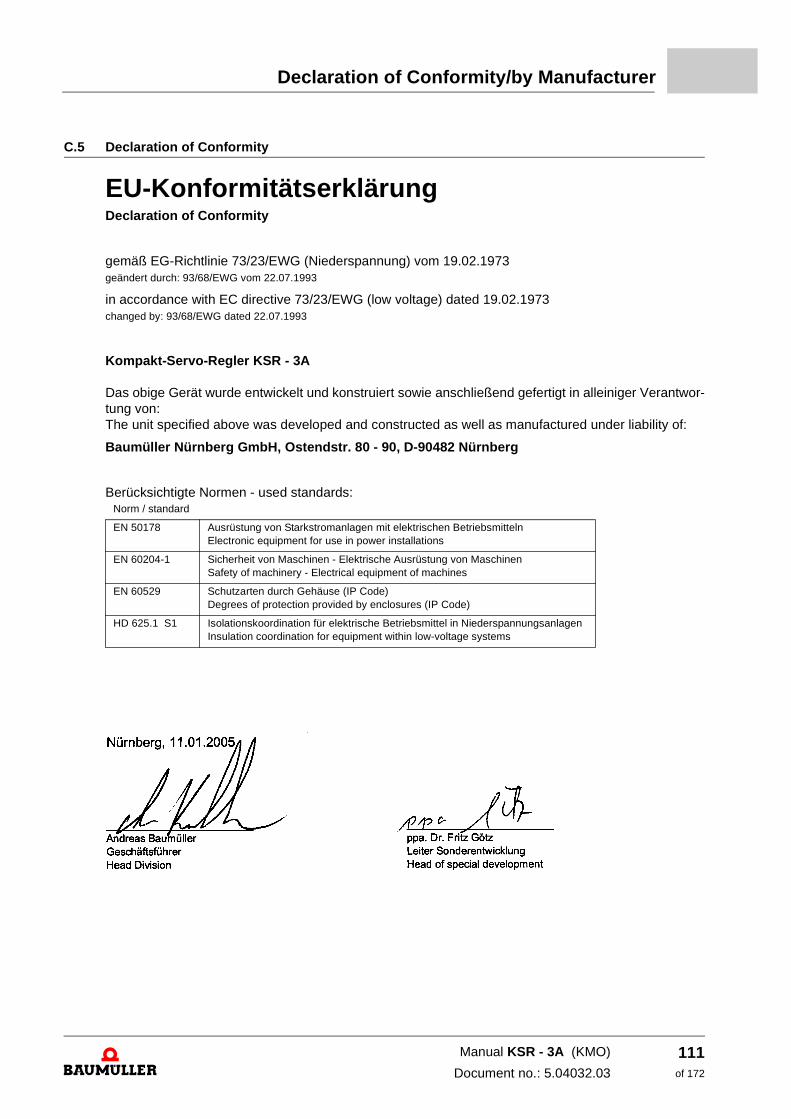
Declaration of Conformity/by Manufacturer
C.5 Declaration of Conformity
EU-KonformitätserklärungDeclaration of Conformity
gemäß EG-Richtlinie 73/23/EWG (Niederspannung) vom 19.02.1973 geändert durch: 93/68/EWG vom 22.07.1993
in accordance with EC directive 73/23/EWG (low voltage) dated 19.02.1973 changed by: 93/68/EWG dated 22.07.1993
Kompakt-Servo-Regler KSR - 3A Das obige Gerät wurde entwickelt und konstruiert sowie anschließend gefertigt in alleiniger Verantwor-tung von: The unit specified above was developed and constructed as well as manufactured under liability of:
Baumüller Nürnberg GmbH, Ostendstr. 80 - 90, D-90482 Nürnberg
Berücksichtigte Normen - used standards:
Nürnberg, 11.01.2004
_________________________ _________________________Andreas Baumüller ppa. Dr. Fritz Götz Geschäftsführer Leiter Sonderentwicklung Head Division Head of special development
Norm / standard
EN 50178 Ausrüstung von Starkstromanlagen mit elektrischen Betriebsmitteln Electronic equipment for use in power installations
EN 60204-1 Sicherheit von Maschinen - Elektrische Ausrüstung von Maschinen Safety of machinery - Electrical equipment of machines
EN 60529 Schutzarten durch Gehäuse (IP Code) Degrees of protection provided by enclosures (IP Code)
HD 625.1 S1 Isolationskoordination für elektrische Betriebsmittel in Niederspannungsanlagen Insulation coordination for equipment within low-voltage systems
Manual KSR - 3A (KMO)
Document no.: 5.04032.03
111of 172
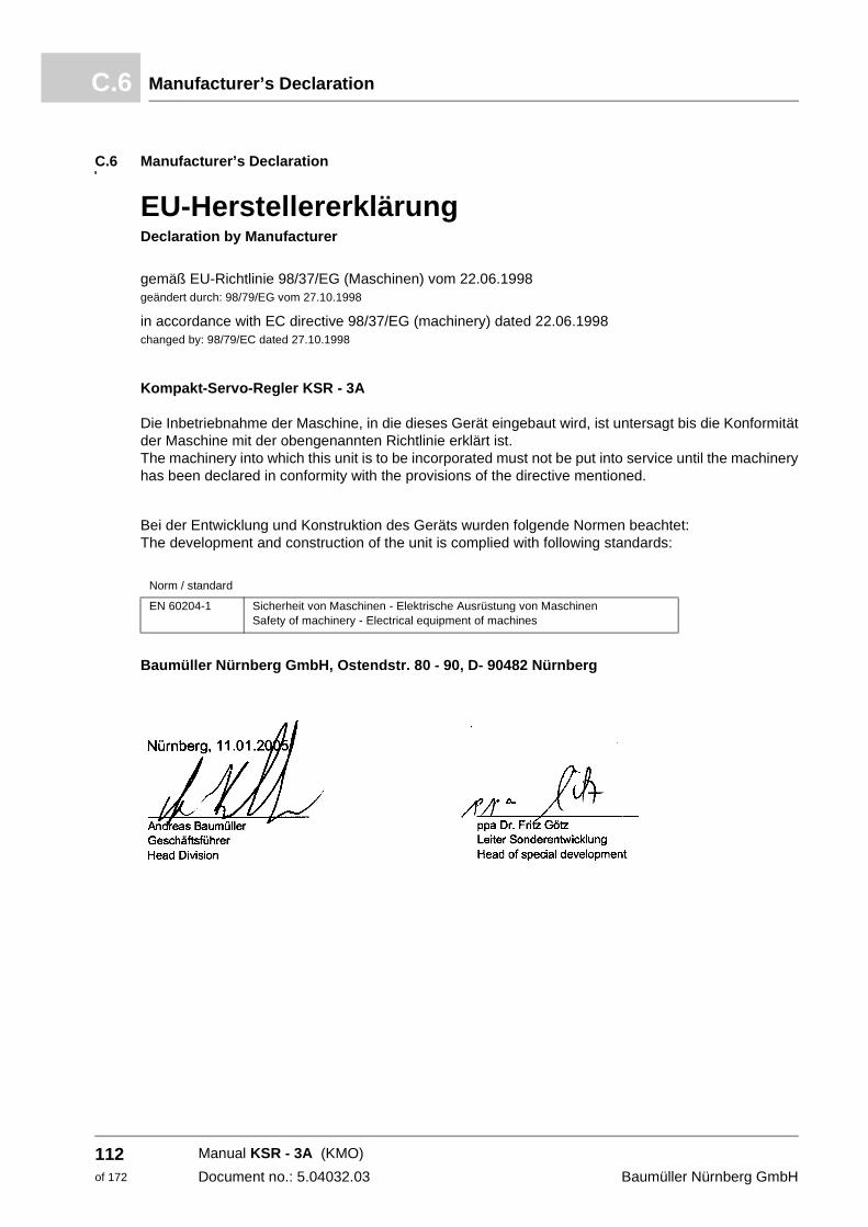
Manufacturer’s DeclarationC.6
C.6 Manufacturer’s Declaration
EU-HerstellererklärungDeclaration by Manufacturer
gemäß EU-Richtlinie 98/37/EG (Maschinen) vom 22.06.1998 geändert durch: 98/79/EG vom 27.10.1998
in accordance with EC directive 98/37/EG (machinery) dated 22.06.1998 changed by: 98/79/EC dated 27.10.1998
Kompakt-Servo-Regler KSR - 3A Die Inbetriebnahme der Maschine, in die dieses Gerät eingebaut wird, ist untersagt bis die Konformität der Maschine mit der obengenannten Richtlinie erklärt ist. The machinery into which this unit is to be incorporated must not be put into service until the machinery has been declared in conformity with the provisions of the directive mentioned.
Bei der Entwicklung und Konstruktion des Geräts wurden folgende Normen beachtet: The development and construction of the unit is complied with following standards:
Baumüller Nürnberg GmbH, Ostendstr. 80 - 90, D- 90482 Nürnberg
Nürnberg, 11.01.2005
_________________________ _________________________Andreas Baumüller ppa Dr. Fritz Götz Geschäftsführer Leiter Sonderentwicklung Head Division Head of special development
Norm / standard
EN 60204-1 Sicherheit von Maschinen - Elektrische Ausrüstung von Maschinen Safety of machinery - Electrical equipment of machines
Manual KSR - 3A (KMO)
Document no.: 5.04032.03 Baumüller Nürnberg GmbH
112of 172
D
APPENDIX D - TECHNICAL DATAIn this chapter the detailed technical data to the device series KSR - 3A.
113of 172
Manual KSR - 3A (KMO)
Document no.: 5.04032.03
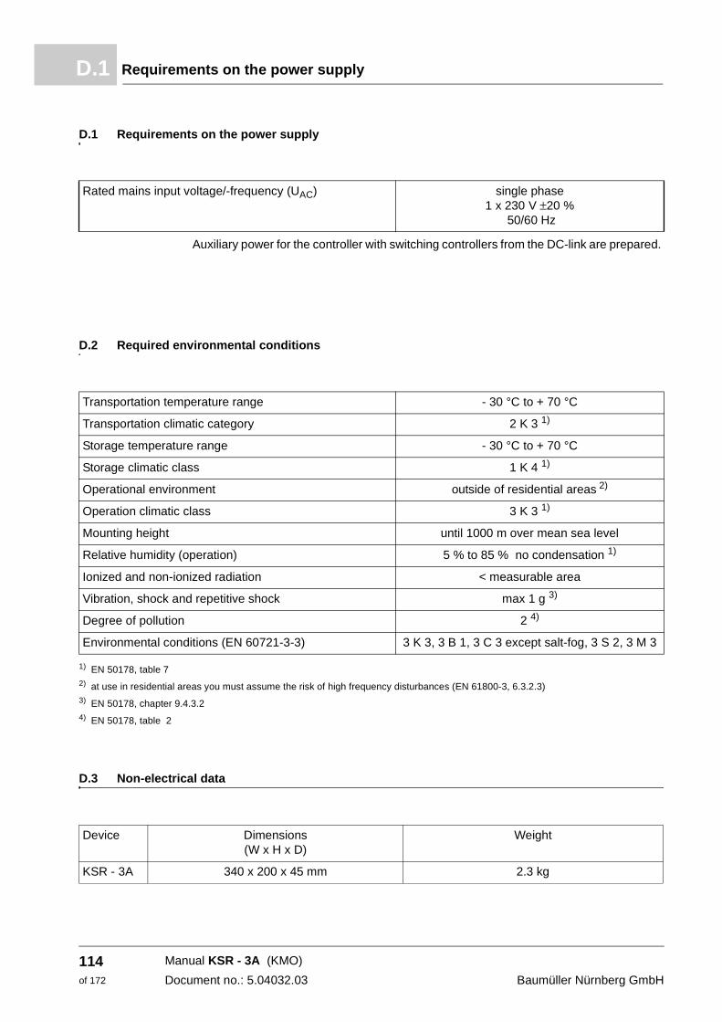
Requirements on the power supplyD.1
D.1 Requirements on the power supply
Auxiliary power for the controller with switching controllers from the DC-link are prepared.
D.2 Required environmental conditions
1) EN 50178, table 72) at use in residential areas you must assume the risk of high frequency disturbances (EN 61800-3, 6.3.2.3)3) EN 50178, chapter 9.4.3.24) EN 50178, table 2
D.3 Non-electrical data
Rated mains input voltage/-frequency (UAC) single phase 1 x 230 V ±20 %
50/60 Hz
Transportation temperature range - 30 °C to + 70 °C
Transportation climatic category 2 K 3 1)
Storage temperature range - 30 °C to + 70 °C
Storage climatic class 1 K 4 1)
Operational environment outside of residential areas 2)
Operation climatic class 3 K 3 1)
Mounting height until 1000 m over mean sea level
Relative humidity (operation) 5 % to 85 % no condensation 1)
Ionized and non-ionized radiation < measurable area
Vibration, shock and repetitive shock max 1 g 3)
Degree of pollution 2 4)
Environmental conditions (EN 60721-3-3) 3 K 3, 3 B 1, 3 C 3 except salt-fog, 3 S 2, 3 M 3
Device Dimensions(W x H x D)
Weight
KSR - 3A 340 x 200 x 45 mm 2.3 kg
Manual KSR - 3A (KMO)
Document no.: 5.04032.03 Baumüller Nürnberg GmbH
114of 172
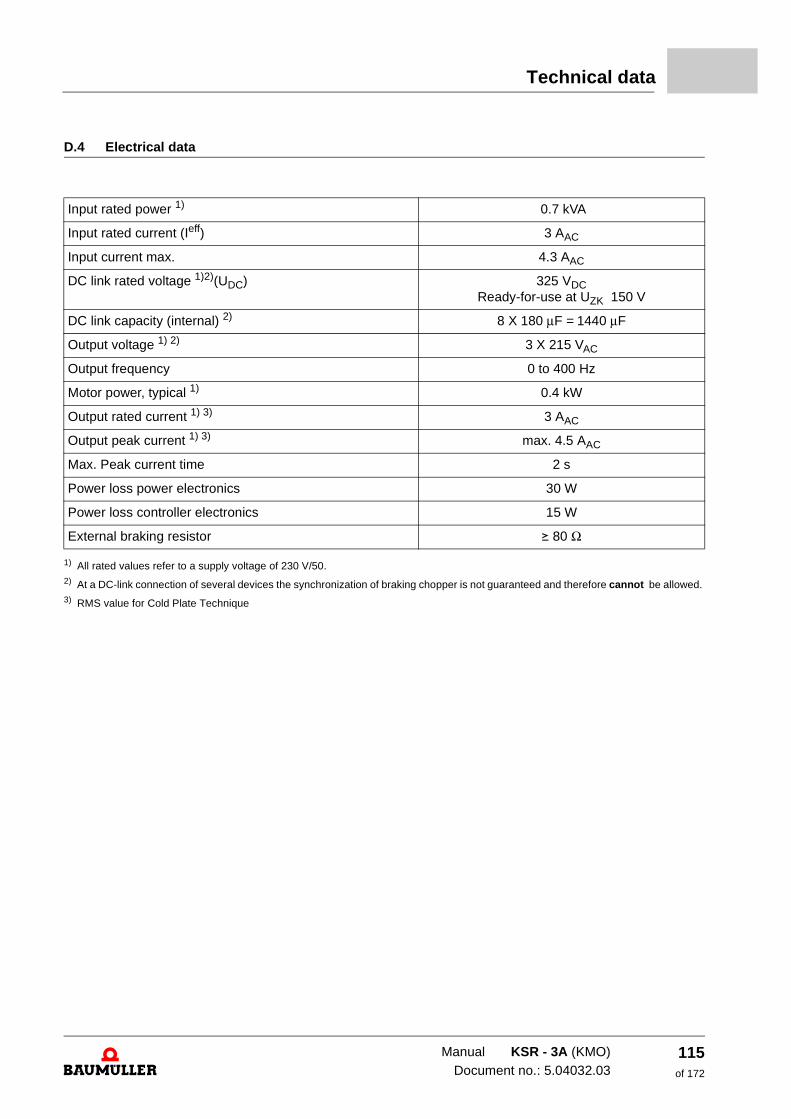
Technical data
D.4 Electrical data
1) All rated values refer to a supply voltage of 230 V/50. 2) At a DC-link connection of several devices the synchronization of braking chopper is not guaranteed and therefore cannot be allowed. 3) RMS value for Cold Plate Technique
Input rated power 1) 0.7 kVA
Input rated current (Ieff) 3 AAC
Input current max. 4.3 AAC
DC link rated voltage 1)2)(UDC) 325 VDCReady-for-use at UZK 150 V
DC link capacity (internal) 2) 8 X 180 μF = 1440 μF
Output voltage 1) 2) 3 X 215 VAC
Output frequency 0 to 400 Hz
Motor power, typical 1) 0.4 kW
Output rated current 1) 3) 3 AAC
Output peak current 1) 3) max. 4.5 AAC
Max. Peak current time 2 s
Power loss power electronics 30 W
Power loss controller electronics 15 W
External braking resistor v 80 Ω
Manual KSR - 3A (KMO)Document no.: 5.04032.03
115of 172
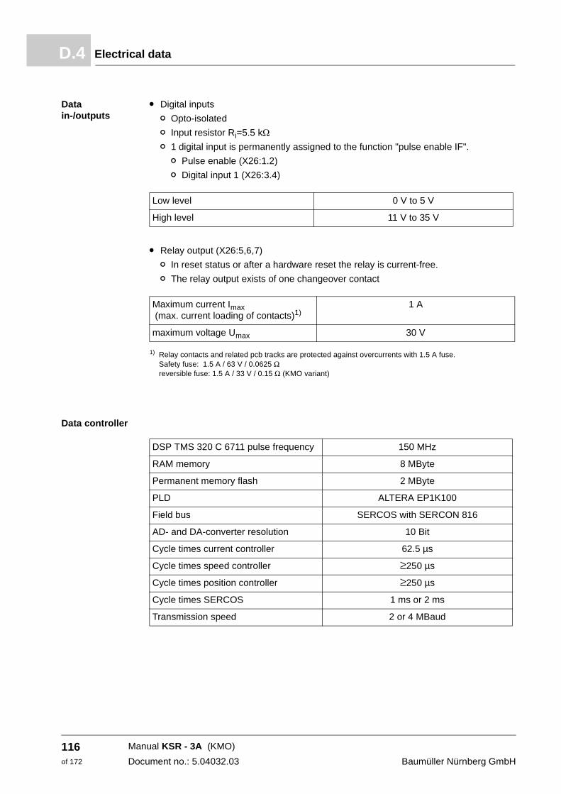
Electrical dataD.4
Data in-/outputs
m Digital inputs
n Opto-isolated
n Input resistor Ri=5.5 kΩ n 1 digital input is permanently assigned to the function "pulse enable IF".
n Pulse enable (X26:1.2)
n Digital input 1 (X26:3.4)
m Relay output (X26:5,6,7)
n In reset status or after a hardware reset the relay is current-free.
n The relay output exists of one changeover contact
1) Relay contacts and related pcb tracks are protected against overcurrents with 1.5 A fuse. Safety fuse: 1.5 A / 63 V / 0.0625 Ω reversible fuse: 1.5 A / 33 V / 0.15 Ω (KMO variant)
Data controller
Low level 0 V to 5 V
High level 11 V to 35 V
Maximum current Imax (max. current loading of contacts)1)
1 A
maximum voltage Umax 30 V
DSP TMS 320 C 6711 pulse frequency 150 MHz
RAM memory 8 MByte
Permanent memory flash 2 MByte
PLD ALTERA EP1K100
Field bus SERCOS with SERCON 816
AD- and DA-converter resolution 10 Bit
Cycle times current controller 62.5 µs
Cycle times speed controller ≥250 µs
Cycle times position controller ≥250 µs
Cycle times SERCOS 1 ms or 2 ms
Transmission speed 2 or 4 MBaud
Manual KSR - 3A (KMO)
Document no.: 5.04032.03 Baumüller Nürnberg GmbH
116of 172
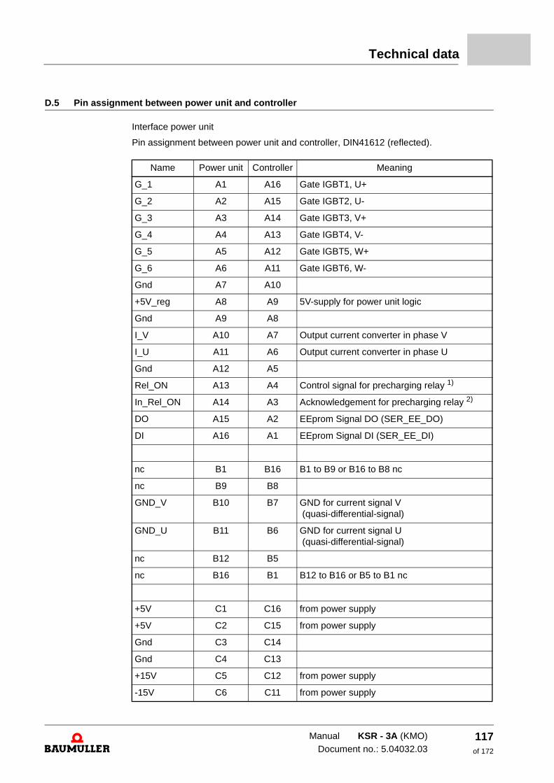
Technical data
D.5 Pin assignment between power unit and controller
Interface power unit
Pin assignment between power unit and controller, DIN41612 (reflected).
Name Power unit Controller Meaning
G_1 A1 A16 Gate IGBT1, U+
G_2 A2 A15 Gate IGBT2, U-
G_3 A3 A14 Gate IGBT3, V+
G_4 A4 A13 Gate IGBT4, V-
G_5 A5 A12 Gate IGBT5, W+
G_6 A6 A11 Gate IGBT6, W-
Gnd A7 A10
+5V_reg A8 A9 5V-supply for power unit logic
Gnd A9 A8
I_V A10 A7 Output current converter in phase V
I_U A11 A6 Output current converter in phase U
Gnd A12 A5
Rel_ON A13 A4 Control signal for precharging relay 1)
In_Rel_ON A14 A3 Acknowledgement for precharging relay 2)
DO A15 A2 EEprom Signal DO (SER_EE_DO)
DI A16 A1 EEprom Signal DI (SER_EE_DI)
nc B1 B16 B1 to B9 or B16 to B8 nc
nc B9 B8
GND_V B10 B7 GND for current signal V (quasi-differential-signal)
GND_U B11 B6 GND for current signal U (quasi-differential-signal)
nc B12 B5
nc B16 B1 B12 to B16 or B5 to B1 nc
+5V C1 C16 from power supply
+5V C2 C15 from power supply
Gnd C3 C14
Gnd C4 C13
+15V C5 C12 from power supply
-15V C6 C11 from power supply
Manual KSR - 3A (KMO)Document no.: 5.04032.03
117of 172
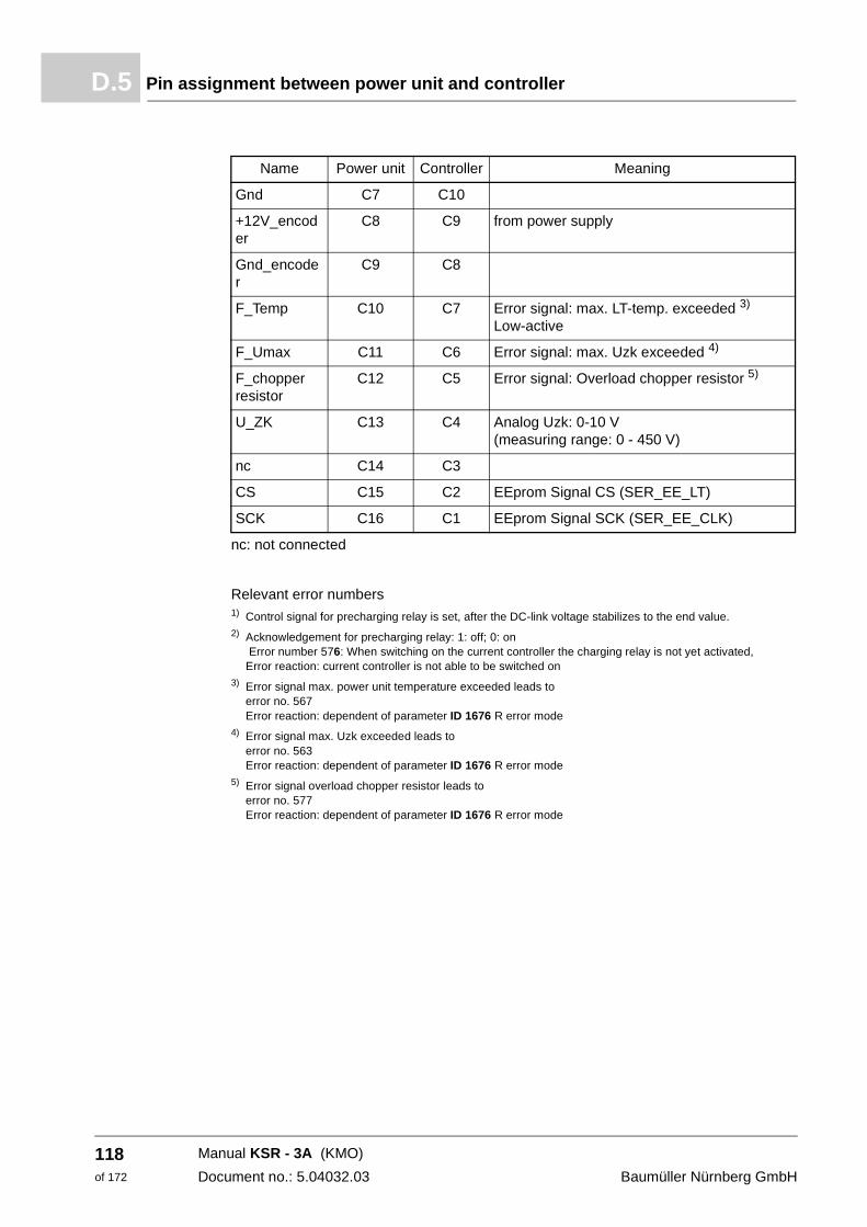
Pin assignment between power unit and controllerD.5
nc: not connected
Relevant error numbers 1) Control signal for precharging relay is set, after the DC-link voltage stabilizes to the end value. 2) Acknowledgement for precharging relay: 1: off; 0: on
Error number 576: When switching on the current controller the charging relay is not yet activated, Error reaction: current controller is not able to be switched on
3) Error signal max. power unit temperature exceeded leads to error no. 567 Error reaction: dependent of parameter ID 1676 R error mode
4) Error signal max. Uzk exceeded leads to error no. 563 Error reaction: dependent of parameter ID 1676 R error mode
5) Error signal overload chopper resistor leads to error no. 577 Error reaction: dependent of parameter ID 1676 R error mode
Gnd C7 C10
+12V_encoder
C8 C9 from power supply
Gnd_encoder
C9 C8
F_Temp C10 C7 Error signal: max. LT-temp. exceeded 3)
Low-active
F_Umax C11 C6 Error signal: max. Uzk exceeded 4)
F_chopper resistor
C12 C5 Error signal: Overload chopper resistor 5)
U_ZK C13 C4 Analog Uzk: 0-10 V (measuring range: 0 - 450 V)
nc C14 C3
CS C15 C2 EEprom Signal CS (SER_EE_LT)
SCK C16 C1 EEprom Signal SCK (SER_EE_CLK)
Name Power unit Controller Meaning
Manual KSR - 3A (KMO)
Document no.: 5.04032.03 Baumüller Nürnberg GmbH
118of 172
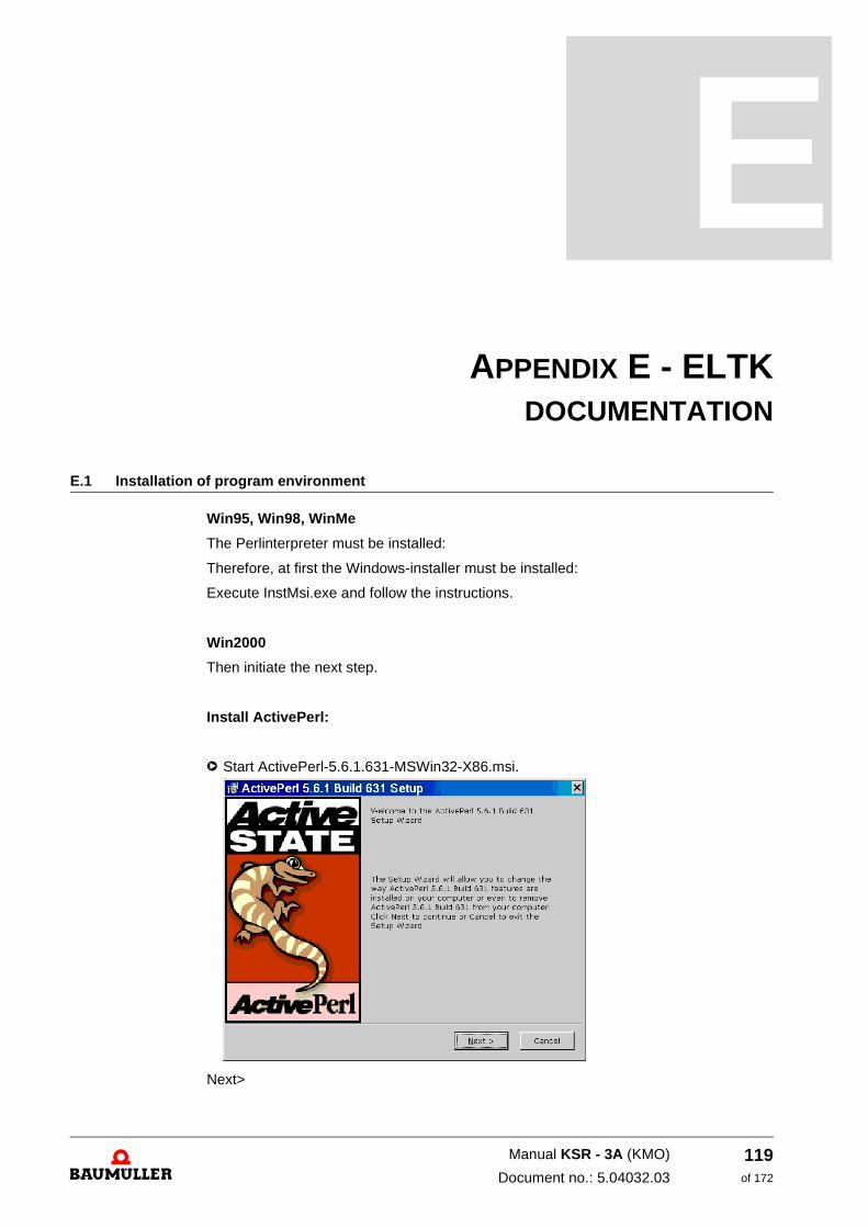
E
APPENDIX E - ELTKDOCUMENTATION
E.1 Installation of program environment
Win95, Win98, WinMe
The Perlinterpreter must be installed:
Therefore, at first the Windows-installer must be installed:
Execute InstMsi.exe and follow the instructions.
Win2000
Then initiate the next step.
Install ActivePerl:
h Start ActivePerl-5.6.1.631-MSWin32-X86.msi.
Next>
119of 172
Manual KSR - 3A (KMO)
Document no.: 5.04032.03
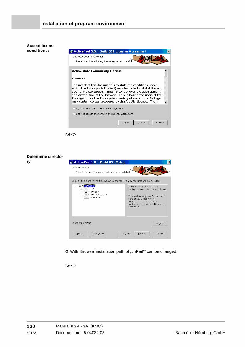
Installation of program environment
Accept license conditions:
Next>
Determine directo-ry
h With 'Browse' installation path of „c:\Perl\“ can be changed.
Next>
Manual KSR - 3A (KMO)
Document no.: 5.04032.03 Baumüller Nürnberg GmbH
120of 172
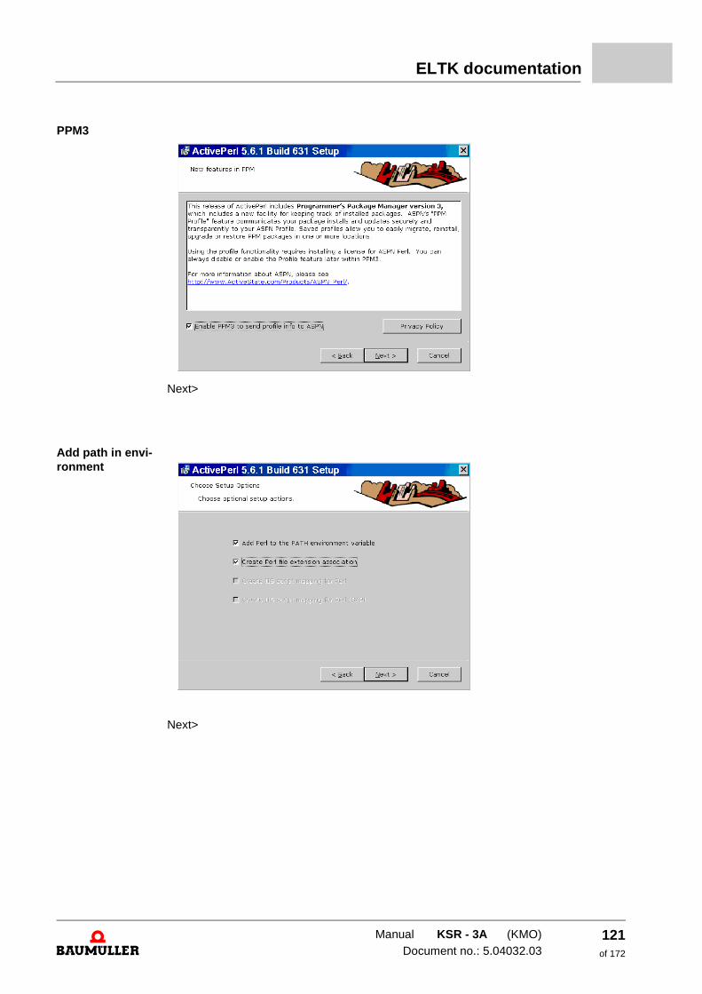
ELTK documentation
PPM3
Next>
Add path in envi-ronment
Next>
Manual KSR - 3A (KMO)Document no.: 5.04032.03
121of 172
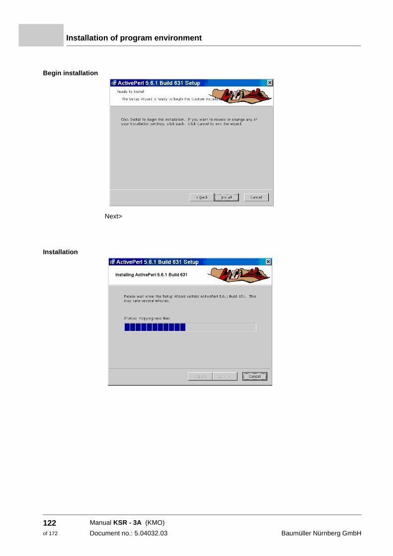
Installation of program environment
Begin installation
Next>
Installation
Manual KSR - 3A (KMO)
Document no.: 5.04032.03 Baumüller Nürnberg GmbH
122of 172
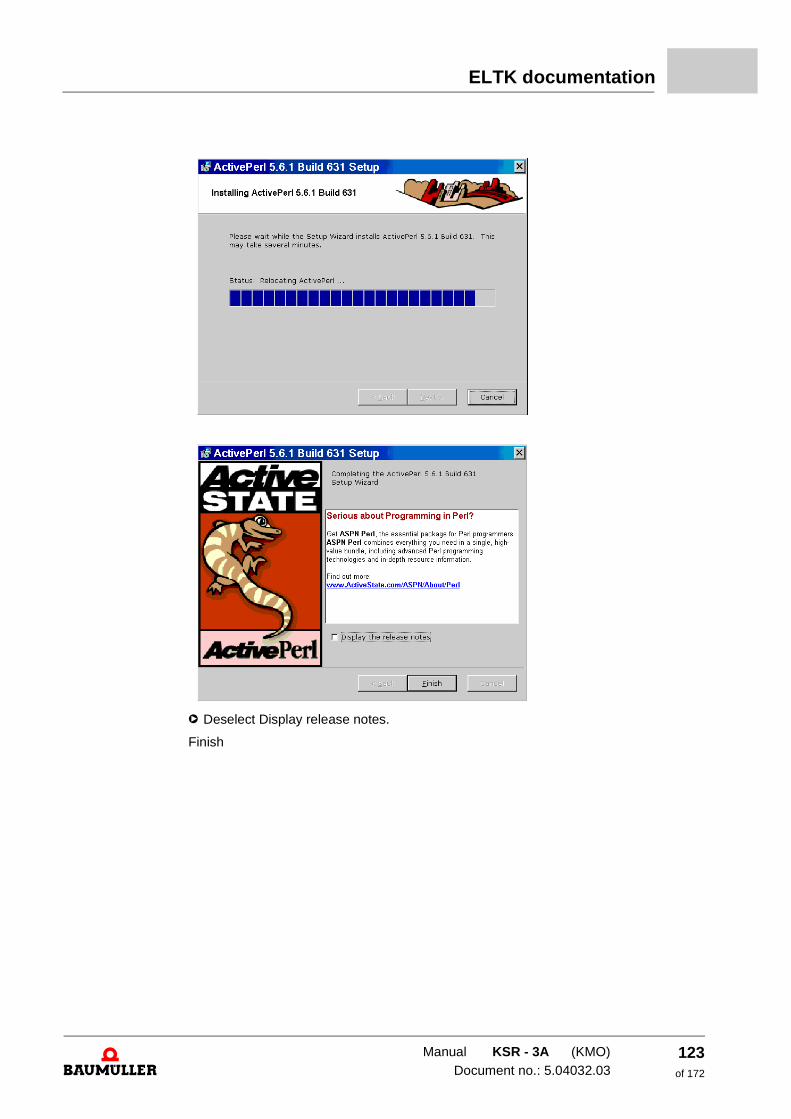
ELTK documentation
h Deselect Display release notes.
Finish
Manual KSR - 3A (KMO)Document no.: 5.04032.03
123of 172
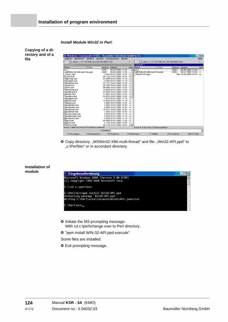
Installation of program environment
Install Module Win32 in Perl:
Copying of a di-rectory and of a file
h Copy directory: „MSWin32-X86-multi-thread" and file: „Win32-API.ppd“ to „c:\Perl\bin“ or in accordant directory.
Installation of module
h Initiate the MS-prompting message. With cd c:\perl\change over to Perl directory.
h "ppm install WIN-32-API.ppd execute"
Some files are installed.
h Exit prompting message.
Manual KSR - 3A (KMO)
Document no.: 5.04032.03 Baumüller Nürnberg GmbH
124of 172
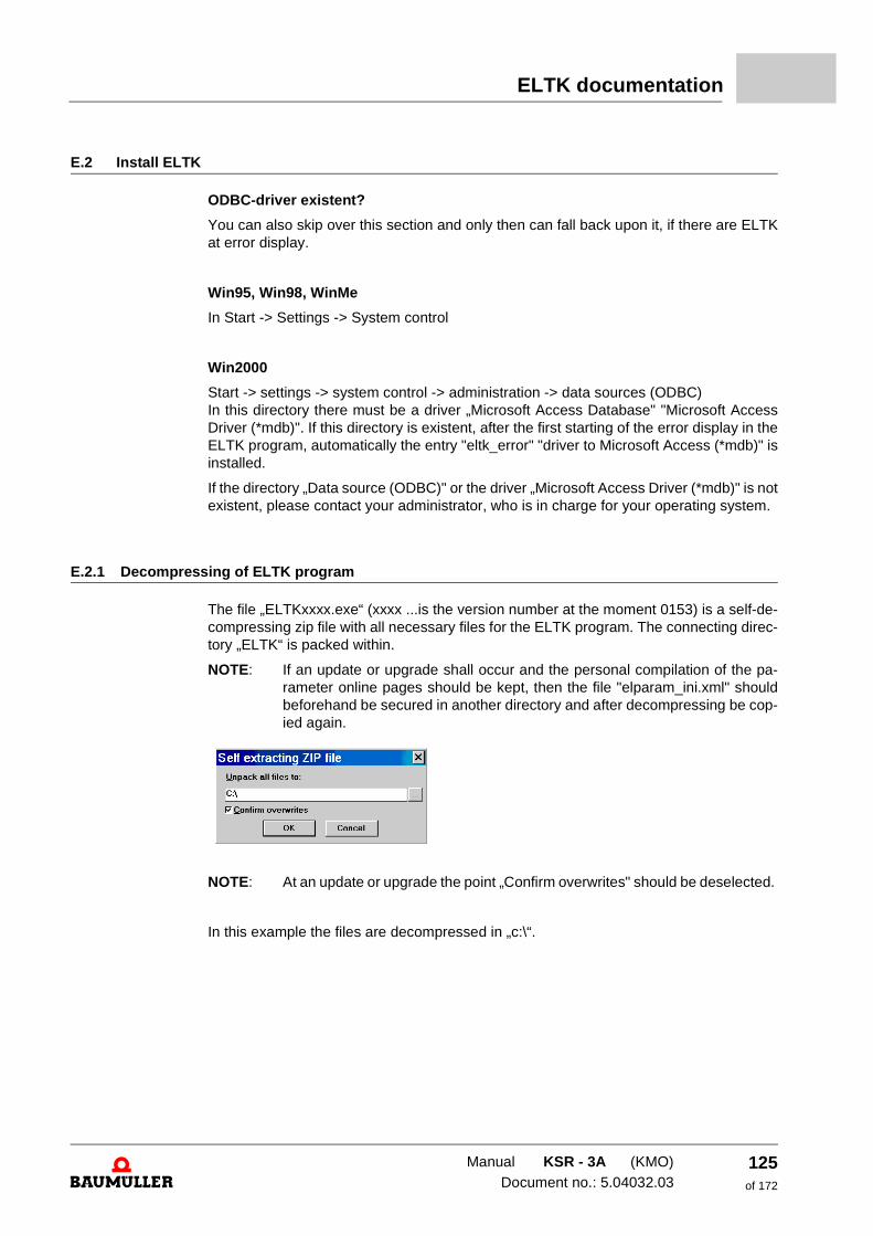
ELTK documentation
E.2 Install ELTK
ODBC-driver existent?
You can also skip over this section and only then can fall back upon it, if there are ELTK at error display.
Win95, Win98, WinMe
In Start -> Settings -> System control
Win2000
Start -> settings -> system control -> administration -> data sources (ODBC) In this directory there must be a driver „Microsoft Access Database" "Microsoft Access Driver (*mdb)". If this directory is existent, after the first starting of the error display in the ELTK program, automatically the entry "eltk_error" "driver to Microsoft Access (*mdb)" is installed.
If the directory „Data source (ODBC)" or the driver „Microsoft Access Driver (*mdb)" is not existent, please contact your administrator, who is in charge for your operating system.
E.2.1 Decompressing of ELTK program
The file „ELTKxxxx.exe“ (xxxx ...is the version number at the moment 0153) is a self-de-compressing zip file with all necessary files for the ELTK program. The connecting direc-tory „ELTK“ is packed within.
NOTE: If an update or upgrade shall occur and the personal compilation of the pa-rameter online pages should be kept, then the file "elparam_ini.xml" should beforehand be secured in another directory and after decompressing be cop-ied again.
NOTE: At an update or upgrade the point „Confirm overwrites" should be deselected.
In this example the files are decompressed in „c:\“.
Manual KSR - 3A (KMO)Document no.: 5.04032.03
125of 172
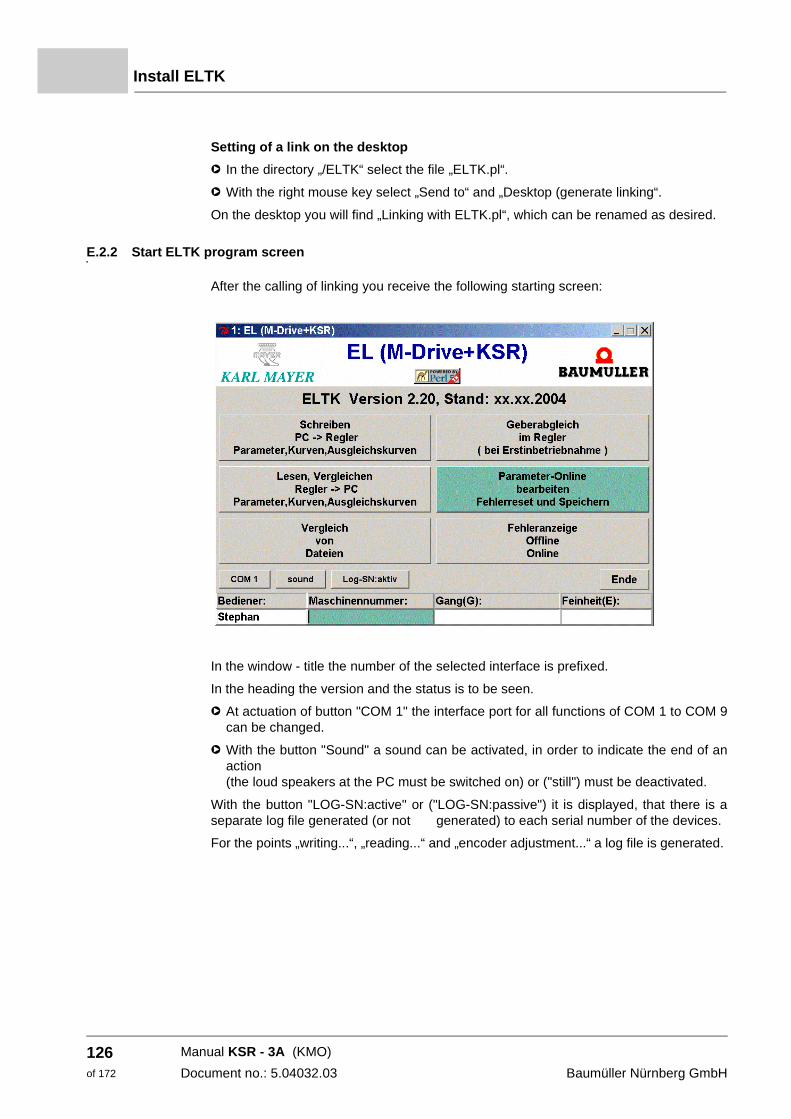
Install ELTK
Setting of a link on the desktop
h In the directory „/ELTK“ select the file „ELTK.pl“.
h With the right mouse key select „Send to“ and „Desktop (generate linking“.
On the desktop you will find „Linking with ELTK.pl“, which can be renamed as desired.
E.2.2 Start ELTK program screen
After the calling of linking you receive the following starting screen:
In the window - title the number of the selected interface is prefixed.
In the heading the version and the status is to be seen.
h At actuation of button "COM 1" the interface port for all functions of COM 1 to COM 9 can be changed.
h With the button "Sound" a sound can be activated, in order to indicate the end of an action (the loud speakers at the PC must be switched on) or ("still") must be deactivated.
With the button "LOG-SN:active" or ("LOG-SN:passive") it is displayed, that there is a separate log file generated (or not generated) to each serial number of the devices.
For the points „writing...“, „reading...“ and „encoder adjustment...“ a log file is generated.
Manual KSR - 3A (KMO)
Document no.: 5.04032.03 Baumüller Nürnberg GmbH
126of 172
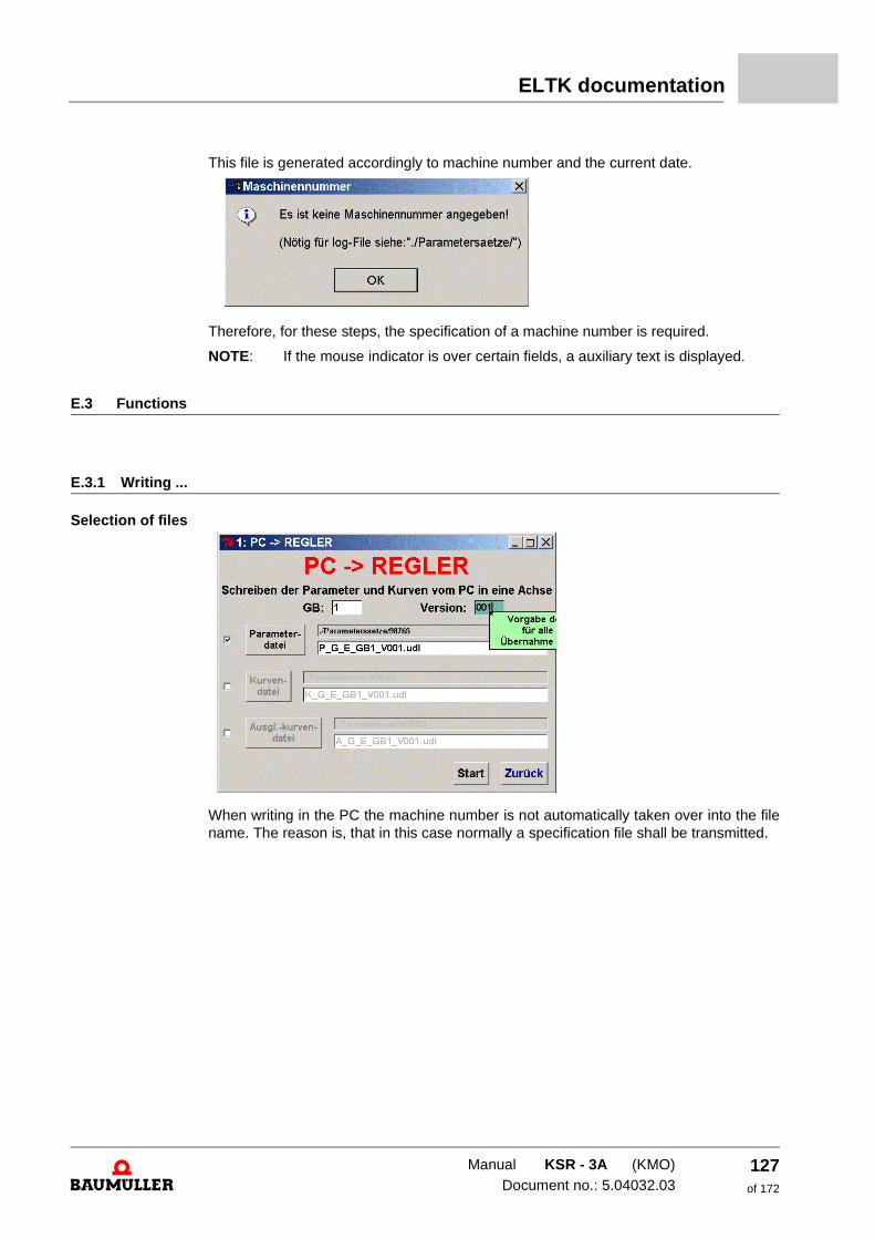
ELTK documentation
This file is generated accordingly to machine number and the current date.
Therefore, for these steps, the specification of a machine number is required.
NOTE: If the mouse indicator is over certain fields, a auxiliary text is displayed.
E.3 Functions
E.3.1 Writing ...
Selection of files
When writing in the PC the machine number is not automatically taken over into the file name. The reason is, that in this case normally a specification file shall be transmitted.
Manual KSR - 3A (KMO)Document no.: 5.04032.03
127of 172
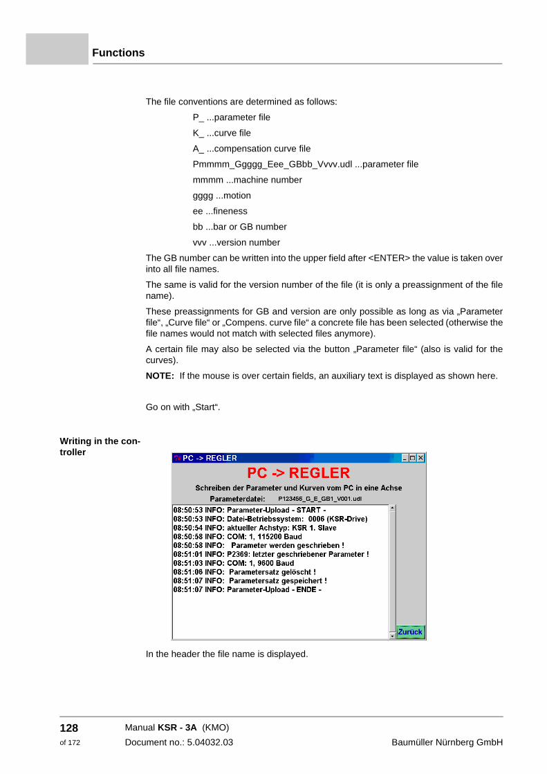
Functions
The file conventions are determined as follows:
P_ ...parameter file
K_ ...curve file
A_ ...compensation curve file
Pmmmm_Ggggg_Eee_GBbb_Vvvv.udl ...parameter file
mmmm ...machine number
gggg ...motion
ee ...fineness
bb ...bar or GB number
vvv ...version number
The GB number can be written into the upper field after <ENTER> the value is taken over into all file names.
The same is valid for the version number of the file (it is only a preassignment of the file name).
These preassignments for GB and version are only possible as long as via „Parameter file“, „Curve file“ or „Compens. curve file“ a concrete file has been selected (otherwise the file names would not match with selected files anymore).
A certain file may also be selected via the button „Parameter file“ (also is valid for the curves).
NOTE: If the mouse is over certain fields, an auxiliary text is displayed as shown here.
Go on with „Start“.
Writing in the con-troller
In the header the file name is displayed.
Manual KSR - 3A (KMO)
Document no.: 5.04032.03 Baumüller Nürnberg GmbH
128of 172
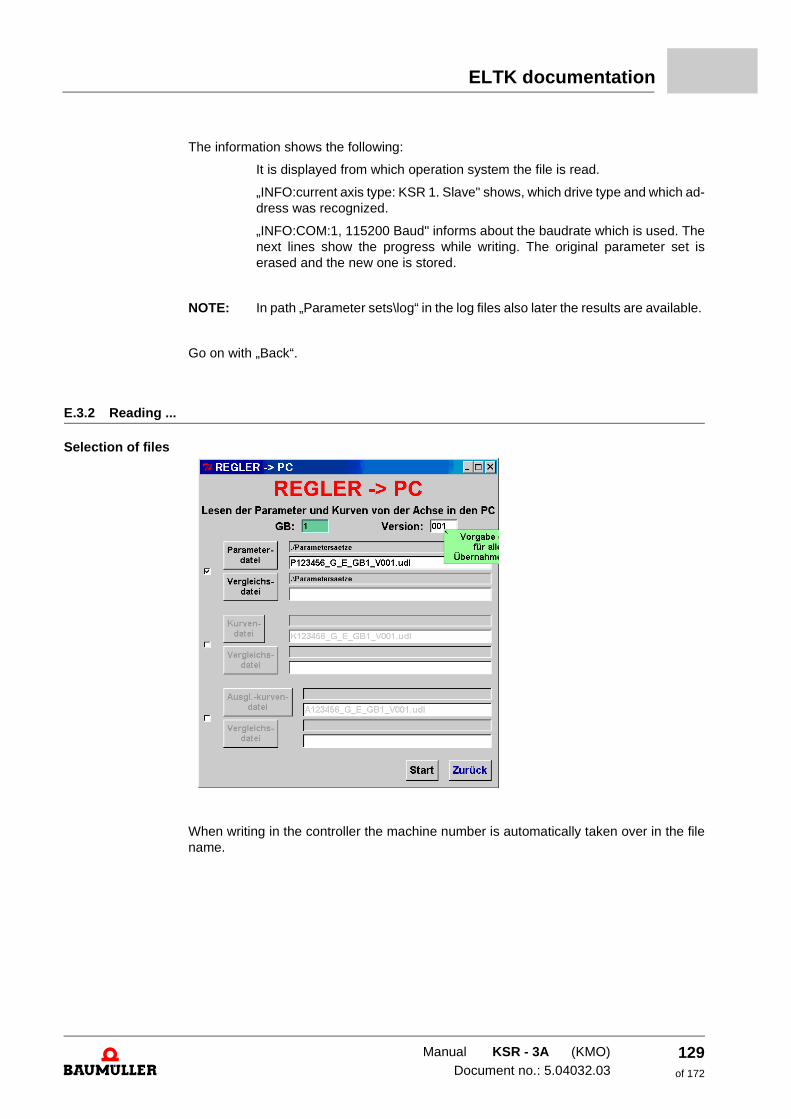
ELTK documentation
The information shows the following:
It is displayed from which operation system the file is read.
„INFO:current axis type: KSR 1. Slave" shows, which drive type and which ad-dress was recognized.
„INFO:COM:1, 115200 Baud" informs about the baudrate which is used. The next lines show the progress while writing. The original parameter set is erased and the new one is stored.
NOTE: In path „Parameter sets\log“ in the log files also later the results are available.
Go on with „Back“.
E.3.2 Reading ...
Selection of files
When writing in the controller the machine number is automatically taken over in the file name.
Manual KSR - 3A (KMO)Document no.: 5.04032.03
129of 172
Functions
The file conventions are determined as follows:
P_ ...parameter file
K_ ...curve file
A_ ...compensation curve file
Pmmmm_Ggggg_Eee_GBbb_Vvvv.udl ...parameter file
mmmm ...machine number
gggg ...motion
ee ...fineness
bb ...bar or GB number
vvv ...version number
The GB number can be entered in the upper field after <ENTER> the value is taken over in all file names.
The same is valid for the version number of the file (it is only a preassignment of the file name).
These preassignments for GB and version are only possible as long as via „Parameter file“, „Curve file“ or „Compens. curve file“ a concrete file has been selected (otherwise the file names would not match with selected files anymore).
Also a certain file can be selected via the button „Parameter file“ (the same is valid for the curves).
With the button „Comparison file“ a file can be selected, where the read file can immedi-ately be compared.
NOTE: If the mouse is over certain fields, an auxiliary text (as shown above) is dis-played.
Go on with „Start“.
Manual KSR - 3A (KMO)
Document no.: 5.04032.03 Baumüller Nürnberg GmbH
130of 172
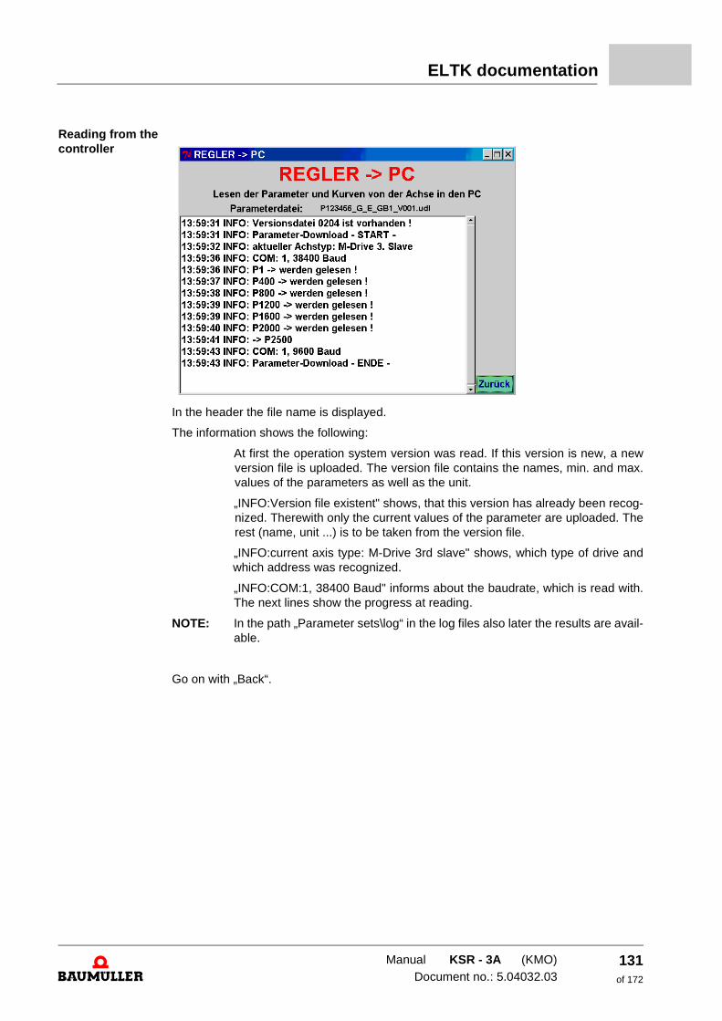
ELTK documentation
Reading from the controller
In the header the file name is displayed.
The information shows the following:
At first the operation system version was read. If this version is new, a new version file is uploaded. The version file contains the names, min. and max. values of the parameters as well as the unit.
„INFO:Version file existent" shows, that this version has already been recog-nized. Therewith only the current values of the parameter are uploaded. The rest (name, unit ...) is to be taken from the version file.
„INFO:current axis type: M-Drive 3rd slave" shows, which type of drive and which address was recognized.
„INFO:COM:1, 38400 Baud" informs about the baudrate, which is read with. The next lines show the progress at reading.
NOTE: In the path „Parameter sets\log“ in the log files also later the results are avail-able.
Go on with „Back“.
Manual KSR - 3A (KMO)Document no.: 5.04032.03
131of 172
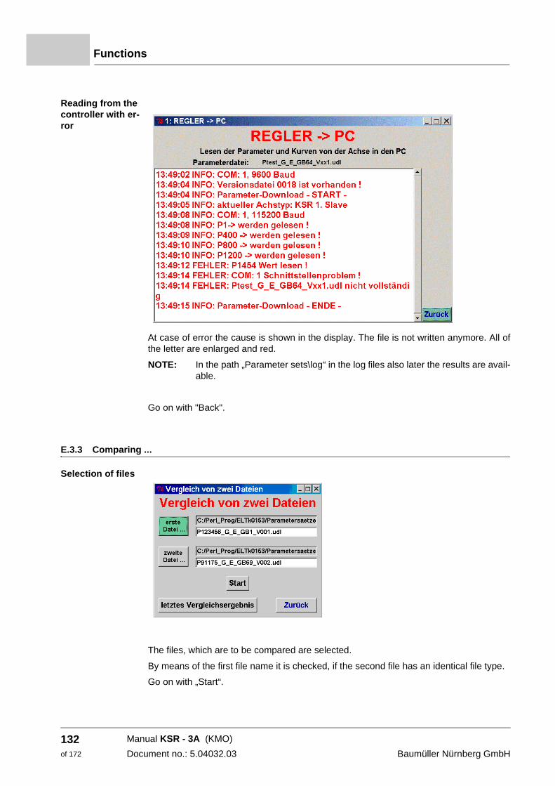
Functions
Reading from the controller with er-ror
At case of error the cause is shown in the display. The file is not written anymore. All of the letter are enlarged and red.
NOTE: In the path „Parameter sets\log“ in the log files also later the results are avail-able.
Go on with "Back".
E.3.3 Comparing ...
Selection of files
The files, which are to be compared are selected.
By means of the first file name it is checked, if the second file has an identical file type.
Go on with „Start“.
Manual KSR - 3A (KMO)
Document no.: 5.04032.03 Baumüller Nürnberg GmbH
132of 172
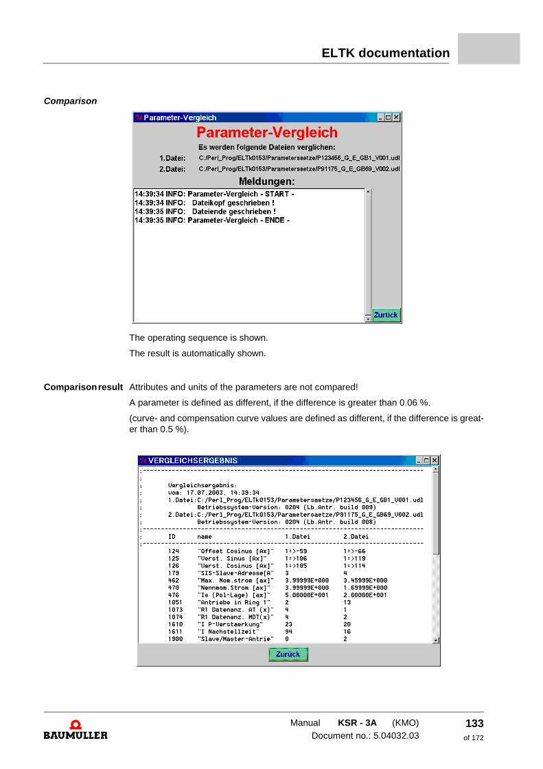
ELTK documentation
Comparison
The operating sequence is shown.
The result is automatically shown.
Comparison result Attributes and units of the parameters are not compared!
A parameter is defined as different, if the difference is greater than 0.06 %.
(curve- and compensation curve values are defined as different, if the difference is great-er than 0.5 %).
Manual KSR - 3A (KMO)Document no.: 5.04032.03
133of 172
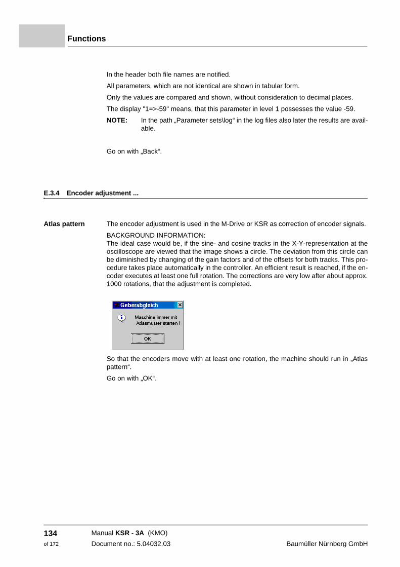
Functions
In the header both file names are notified.
All parameters, which are not identical are shown in tabular form.
Only the values are compared and shown, without consideration to decimal places.
The display "1=>-59" means, that this parameter in level 1 possesses the value -59.
NOTE: In the path „Parameter sets\log“ in the log files also later the results are avail-able.
Go on with „Back“.
E.3.4 Encoder adjustment ...
Atlas pattern The encoder adjustment is used in the M-Drive or KSR as correction of encoder signals.
BACKGROUND INFORMATION: The ideal case would be, if the sine- and cosine tracks in the X-Y-representation at the oscilloscope are viewed that the image shows a circle. The deviation from this circle can be diminished by changing of the gain factors and of the offsets for both tracks. This pro-cedure takes place automatically in the controller. An efficient result is reached, if the en-coder executes at least one full rotation. The corrections are very low after about approx. 1000 rotations, that the adjustment is completed.
So that the encoders move with at least one rotation, the machine should run in „Atlas pattern“.
Go on with „OK“.
Manual KSR - 3A (KMO)
Document no.: 5.04032.03 Baumüller Nürnberg GmbH
134of 172
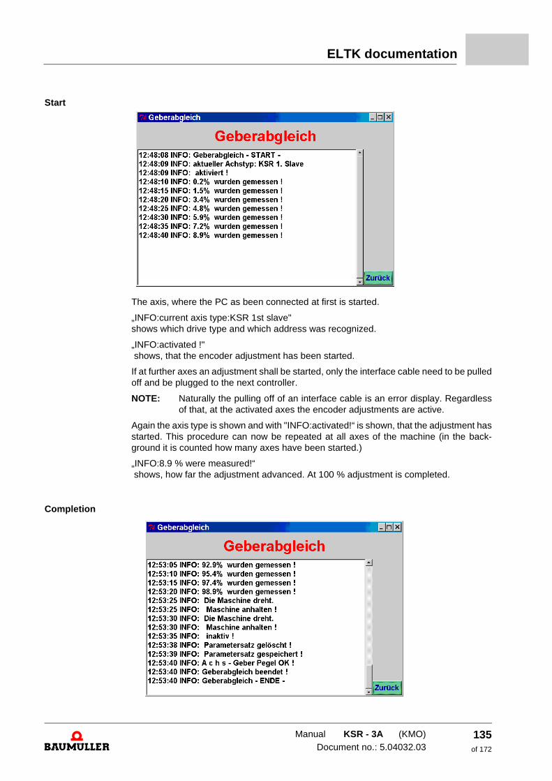
ELTK documentation
Start
The axis, where the PC as been connected at first is started.
„INFO:current axis type:KSR 1st slave" shows which drive type and which address was recognized.
„INFO:activated !" shows, that the encoder adjustment has been started.
If at further axes an adjustment shall be started, only the interface cable need to be pulled off and be plugged to the next controller.
NOTE: Naturally the pulling off of an interface cable is an error display. Regardless of that, at the activated axes the encoder adjustments are active.
Again the axis type is shown and with "INFO:activated!“ is shown, that the adjustment has started. This procedure can now be repeated at all axes of the machine (in the back-ground it is counted how many axes have been started.)
„INFO:8.9 % were measured!“ shows, how far the adjustment advanced. At 100 % adjustment is completed.
Completion
Manual KSR - 3A (KMO)Document no.: 5.04032.03
135of 172
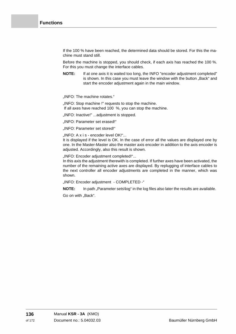
Functions
If the 100 % have been reached, the determined data should be stored. For this the ma-chine must stand still.
Before the machine is stopped, you should check, if each axis has reached the 100 %. For this you must change the interface cables.
NOTE: If at one axis it is waited too long, the INFO "encoder adjustment completed" is shown. In this case you must leave the window with the button „Back“ and start the encoder adjustment again in the main window.
„INFO: The machine rotates.“
„INFO: Stop machine !" requests to stop the machine. If all axes have reached 100 %, you can stop the machine.
„INFO: Inactive!" ...adjustment is stopped.
„INFO: Parameter set erased!“
„INFO: Parameter set stored!“
„INFO: A x i s - encoder level OK!“... It is displayed if the level is OK. In the case of error all the values are displayed one by one. In the Master-Master also the master axis encoder in addition to the axis encoder is adjusted. Accordingly, also this result is shown.
„INFO: Encoder adjustment completed!“... In this axis the adjustment therewith is completed. If further axes have been activated, the number of the remaining active axes are displayed. By replugging of interface cables to the next controller all encoder adjustments are completed in the manner, which was shown.
„INFO: Encoder adjustment - COMPLETED -“
NOTE: In path „Parameter sets\log“ in the log files also later the results are available.
Go on with „Back“.
Manual KSR - 3A (KMO)
Document no.: 5.04032.03 Baumüller Nürnberg GmbH
136of 172
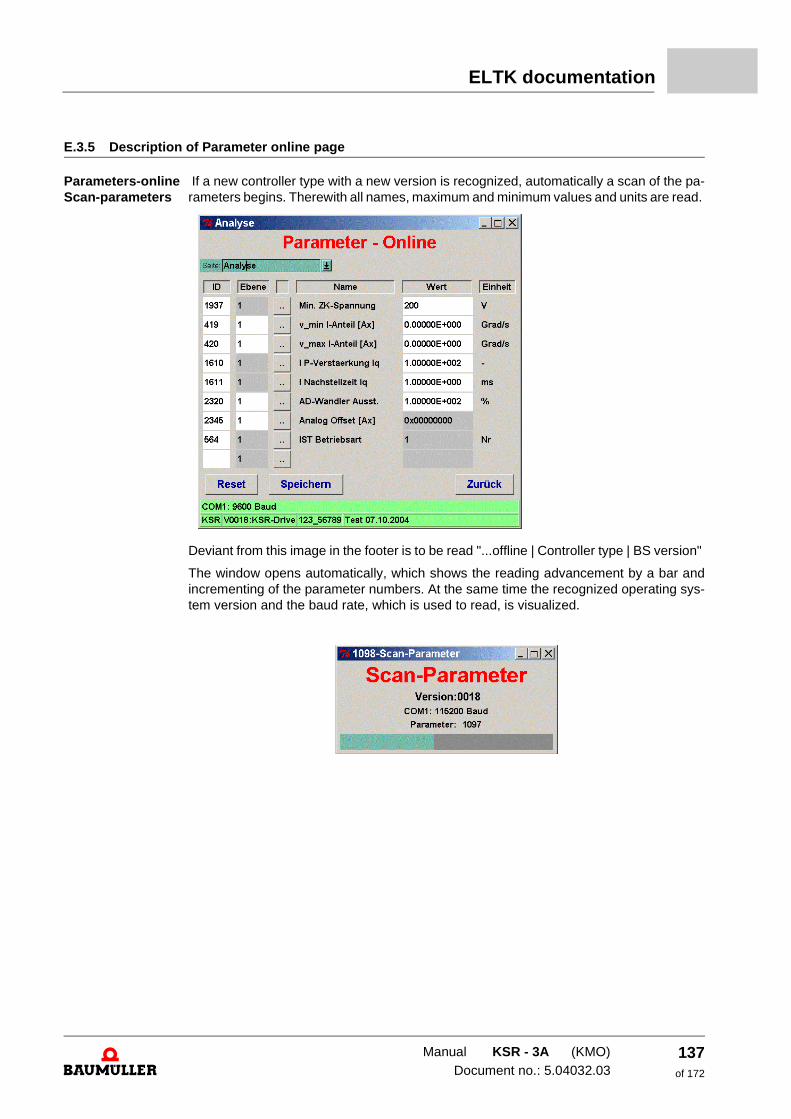
ELTK documentation
E.3.5 Description of Parameter online page
Parameters-online Scan-parameters
If a new controller type with a new version is recognized, automatically a scan of the pa-rameters begins. Therewith all names, maximum and minimum values and units are read.
Deviant from this image in the footer is to be read "...offline | Controller type | BS version"
The window opens automatically, which shows the reading advancement by a bar and incrementing of the parameter numbers. At the same time the recognized operating sys-tem version and the baud rate, which is used to read, is visualized.
Manual KSR - 3A (KMO)Document no.: 5.04032.03
137of 172
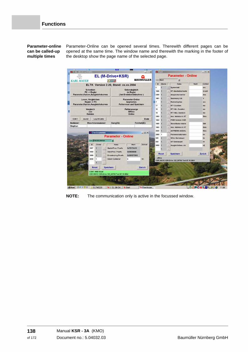
Functions
Parameter-online can be called-up multiple times
Parameter-Online can be opened several times. Therewith different pages can be opened at the same time. The window name and therewith the marking in the footer of the desktop show the page name of the selected page.
NOTE: The communication only is active in the focussed window.
Manual KSR - 3A (KMO)
Document no.: 5.04032.03 Baumüller Nürnberg GmbH
138of 172
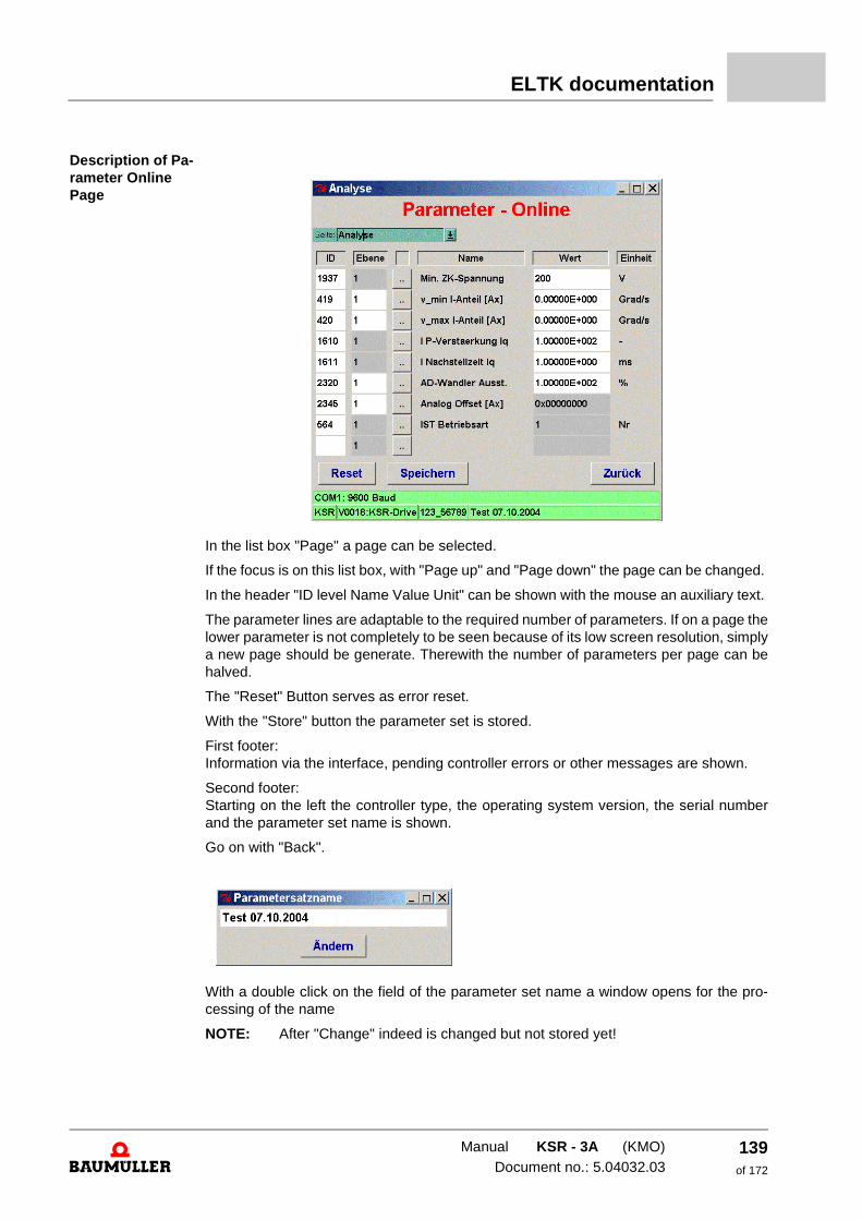
ELTK documentation
Description of Pa-rameter Online Page
In the list box "Page" a page can be selected.
If the focus is on this list box, with "Page up" and "Page down" the page can be changed.
In the header "ID level Name Value Unit" can be shown with the mouse an auxiliary text.
The parameter lines are adaptable to the required number of parameters. If on a page the lower parameter is not completely to be seen because of its low screen resolution, simply a new page should be generate. Therewith the number of parameters per page can be halved.
The "Reset" Button serves as error reset.
With the "Store" button the parameter set is stored.
First footer: Information via the interface, pending controller errors or other messages are shown.
Second footer: Starting on the left the controller type, the operating system version, the serial number and the parameter set name is shown.
Go on with "Back".
With a double click on the field of the parameter set name a window opens for the pro-cessing of the name
NOTE: After "Change" indeed is changed but not stored yet!
Manual KSR - 3A (KMO)Document no.: 5.04032.03
139of 172
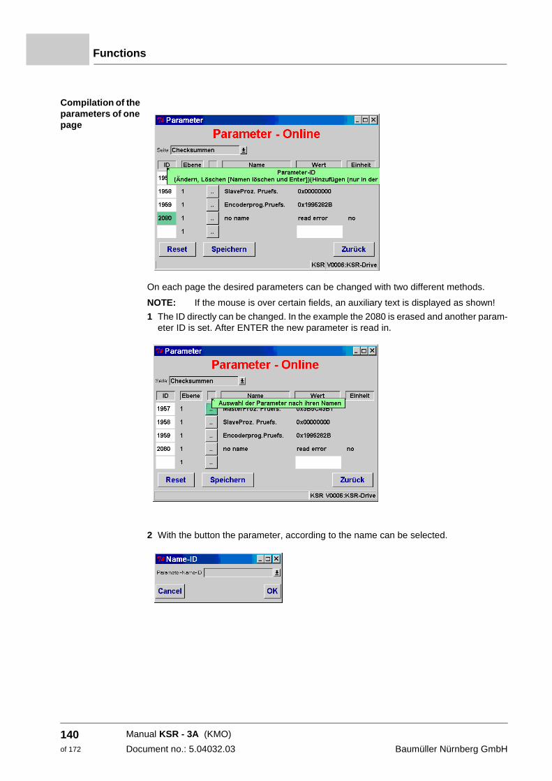
Functions
Compilation of the parameters of one page
On each page the desired parameters can be changed with two different methods.
NOTE: If the mouse is over certain fields, an auxiliary text is displayed as shown!
1 The ID directly can be changed. In the example the 2080 is erased and another param-eter ID is set. After ENTER the new parameter is read in.
2 With the button the parameter, according to the name can be selected.
Manual KSR - 3A (KMO)
Document no.: 5.04032.03 Baumüller Nürnberg GmbH
140of 172
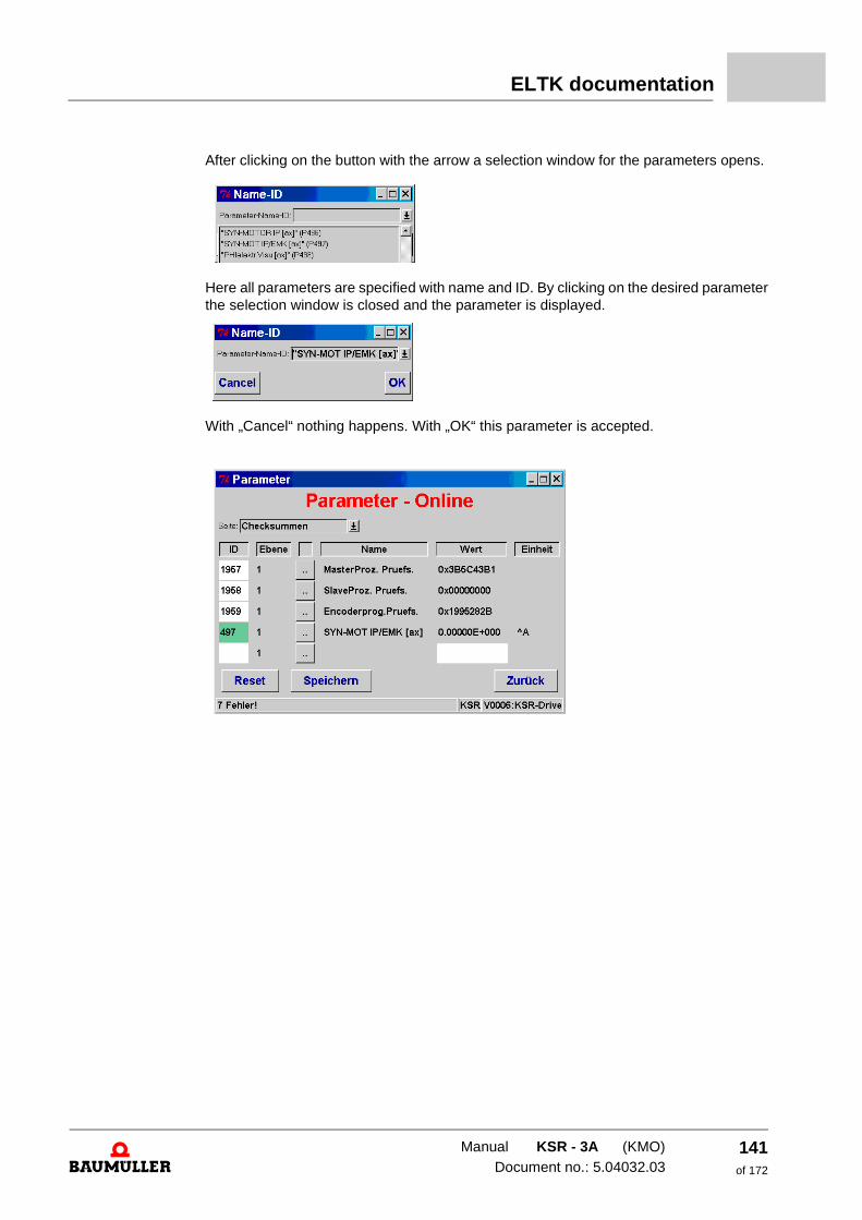
ELTK documentation
After clicking on the button with the arrow a selection window for the parameters opens.
Here all parameters are specified with name and ID. By clicking on the desired parameter the selection window is closed and the parameter is displayed.
With „Cancel“ nothing happens. With „OK“ this parameter is accepted.
Manual KSR - 3A (KMO)Document no.: 5.04032.03
141of 172
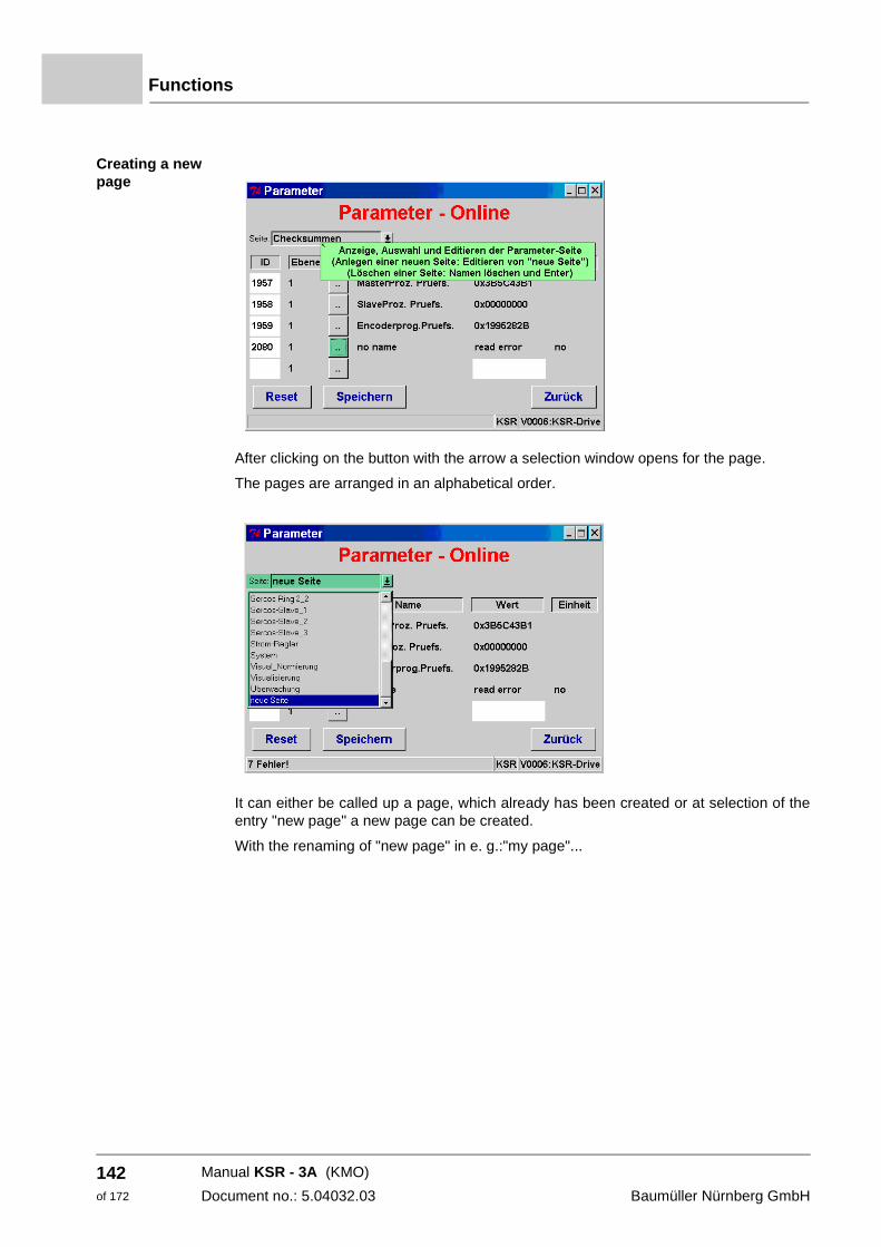
Functions
Creating a new page
After clicking on the button with the arrow a selection window opens for the page.
The pages are arranged in an alphabetical order.
It can either be called up a page, which already has been created or at selection of the entry "new page" a new page can be created.
With the renaming of "new page" in e. g.:"my page"...
Manual KSR - 3A (KMO)
Document no.: 5.04032.03 Baumüller Nürnberg GmbH
142of 172
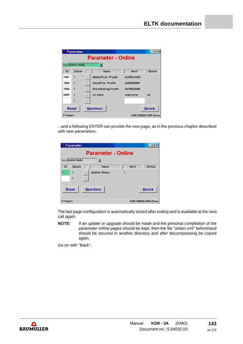
ELTK documentation
...and a following ENTER can provide the new page, as in the previous chapter described with new parameters.
The last page configuration is automatically stored after exiting and is available at the next call again.
NOTE: If an update or upgrade should be made and the personal compilation of the parameter online pages should be kept, then the file "seiten.xml" beforehand should be secured in another directory and after decompressing be copied again.
Go on with "Back".
Manual KSR - 3A (KMO)Document no.: 5.04032.03
143of 172
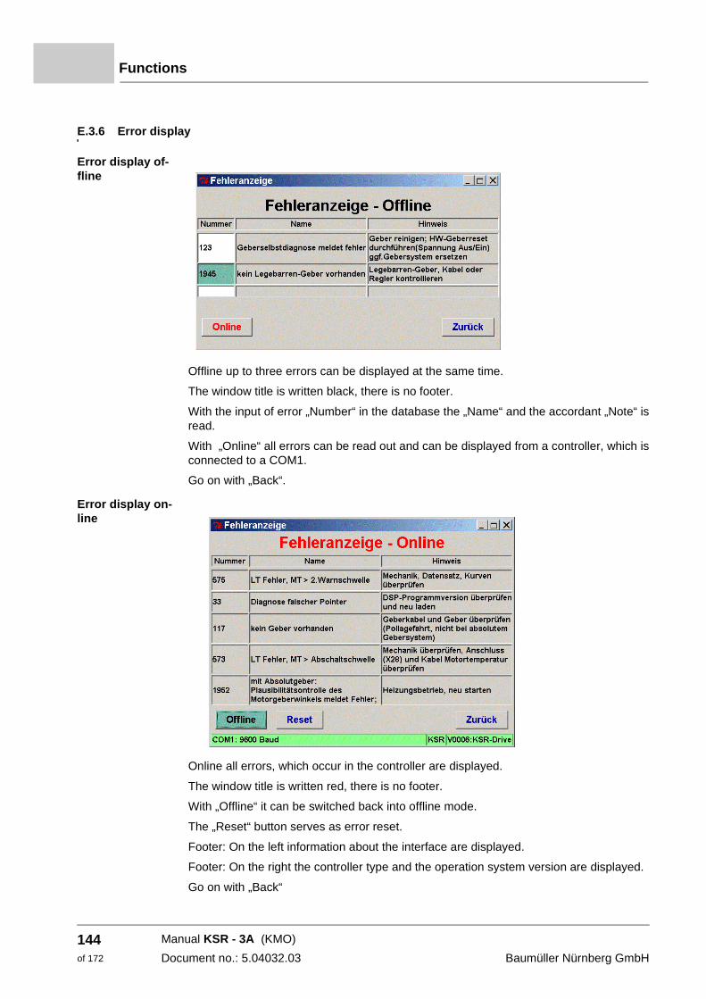
Functions
E.3.6 Error display
Error display of-fline
Offline up to three errors can be displayed at the same time.
The window title is written black, there is no footer.
With the input of error „Number“ in the database the „Name“ and the accordant „Note“ is read.
With „Online“ all errors can be read out and can be displayed from a controller, which is connected to a COM1.
Go on with „Back“.
Error display on-line
Online all errors, which occur in the controller are displayed.
The window title is written red, there is no footer.
With „Offline“ it can be switched back into offline mode.
The „Reset“ button serves as error reset.
Footer: On the left information about the interface are displayed.
Footer: On the right the controller type and the operation system version are displayed.
Go on with „Back“
Manual KSR - 3A (KMO)
Document no.: 5.04032.03 Baumüller Nürnberg GmbH
144of 172
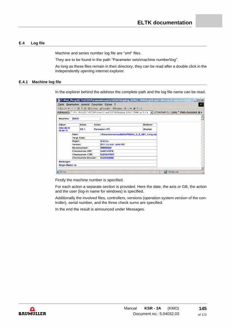
ELTK documentation
E.4 Log file
Machine and series number log file are "xml" files.
They are to be found in the path "Parameter sets\machine number\log".
As long as these files remain in their directory, they can be read after a double click in the independently opening internet explorer.
E.4.1 Machine log file
In the explorer behind the address the complete path and the log file name can be read.
Firstly the machine number is specified.
For each action a separate section is provided. Here the date, the axis or GB, the action and the user (log-in name for windows) is specified.
Additionally the involved files, controllers, versions (operation system version of the con-troller), serial number, and the three check sums are specified.
In the end the result is announced under Messages.
Manual KSR - 3A (KMO)Document no.: 5.04032.03
145of 172
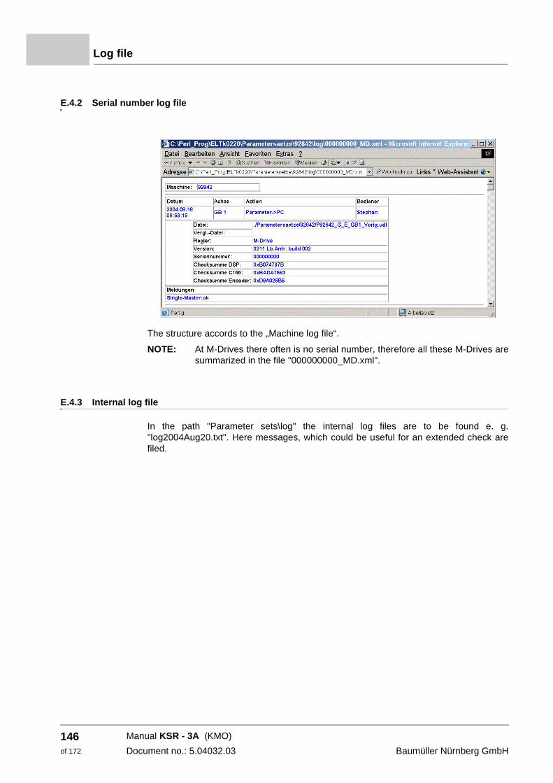
Log file
E.4.2 Serial number log file
The structure accords to the „Machine log file“.
NOTE: At M-Drives there often is no serial number, therefore all these M-Drives are summarized in the file "000000000_MD.xml".
E.4.3 Internal log file
In the path "Parameter sets\log" the internal log files are to be found e. g. "log2004Aug20.txt". Here messages, which could be useful for an extended check are filed.
Manual KSR - 3A (KMO)
Document no.: 5.04032.03 Baumüller Nürnberg GmbH
146of 172
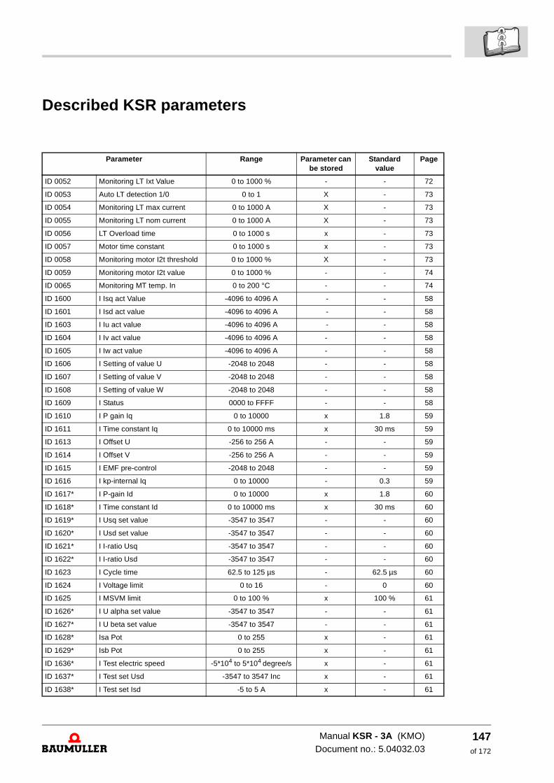
Described KSR parameters
Parameter Range Parameter can be stored
Standard value
Page
ID 0052 Monitoring LT Ixt Value 0 to 1000 % - - 72
ID 0053 Auto LT detection 1/0 0 to 1 X - 73
ID 0054 Monitoring LT max current 0 to 1000 A X - 73
ID 0055 Monitoring LT nom current 0 to 1000 A X - 73
ID 0056 LT Overload time 0 to 1000 s x - 73
ID 0057 Motor time constant 0 to 1000 s x - 73
ID 0058 Monitoring motor I2t threshold 0 to 1000 % X - 73
ID 0059 Monitoring motor I2t value 0 to 1000 % - - 74
ID 0065 Monitoring MT temp. In 0 to 200 °C - - 74
ID 1600 I Isq act Value -4096 to 4096 A - - 58
ID 1601 I Isd act value -4096 to 4096 A - - 58
ID 1603 I Iu act value -4096 to 4096 A - - 58
ID 1604 I Iv act value -4096 to 4096 A - - 58
ID 1605 I Iw act value -4096 to 4096 A - - 58
ID 1606 I Setting of value U -2048 to 2048 - - 58
ID 1607 I Setting of value V -2048 to 2048 - - 58
ID 1608 I Setting of value W -2048 to 2048 - - 58
ID 1609 I Status 0000 to FFFF - - 58
ID 1610 I P gain Iq 0 to 10000 x 1.8 59
ID 1611 I Time constant Iq 0 to 10000 ms x 30 ms 59
ID 1613 I Offset U -256 to 256 A - - 59
ID 1614 I Offset V -256 to 256 A - - 59
ID 1615 I EMF pre-control -2048 to 2048 - - 59
ID 1616 I kp-internal Iq 0 to 10000 - 0.3 59
ID 1617* I P-gain Id 0 to 10000 x 1.8 60
ID 1618* I Time constant Id 0 to 10000 ms x 30 ms 60
ID 1619* I Usq set value -3547 to 3547 - - 60
ID 1620* I Usd set value -3547 to 3547 - - 60
ID 1621* I I-ratio Usq -3547 to 3547 - - 60
ID 1622* I I-ratio Usd -3547 to 3547 - - 60
ID 1623 I Cycle time 62.5 to 125 µs - 62.5 µs 60
ID 1624 I Voltage limit 0 to 16 - 0 60
ID 1625 I MSVM limit 0 to 100 % x 100 % 61
ID 1626* I U alpha set value -3547 to 3547 - - 61
ID 1627* I U beta set value -3547 to 3547 - - 61
ID 1628* Isa Pot 0 to 255 x - 61
ID 1629* Isb Pot 0 to 255 x - 61
ID 1636* I Test electric speed -5*104 to 5*104 degree/s x - 61
ID 1637* I Test set Usd -3547 to 3547 Inc x - 61
ID 1638* I Test set Isd -5 to 5 A x - 61
Manual KSR - 3A (KMO)Document no.: 5.04032.03
147of 172
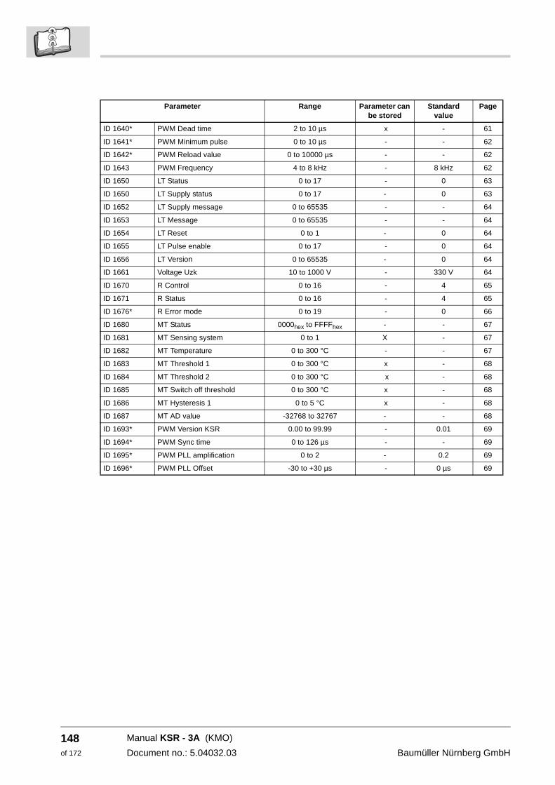
148of 172
ID 1640* PWM Dead time 2 to 10 µs x - 61
ID 1641* PWM Minimum pulse 0 to 10 µs - - 62
ID 1642* PWM Reload value 0 to 10000 µs - - 62
ID 1643 PWM Frequency 4 to 8 kHz - 8 kHz 62
ID 1650 LT Status 0 to 17 - 0 63
ID 1650 LT Supply status 0 to 17 - 0 63
ID 1652 LT Supply message 0 to 65535 - - 64
ID 1653 LT Message 0 to 65535 - - 64
ID 1654 LT Reset 0 to 1 - 0 64
ID 1655 LT Pulse enable 0 to 17 - 0 64
ID 1656 LT Version 0 to 65535 - 0 64
ID 1661 Voltage Uzk 10 to 1000 V - 330 V 64
ID 1670 R Control 0 to 16 - 4 65
ID 1671 R Status 0 to 16 - 4 65
ID 1676* R Error mode 0 to 19 - 0 66
ID 1680 MT Status 0000hex to FFFFhex - - 67
ID 1681 MT Sensing system 0 to 1 X - 67
ID 1682 MT Temperature 0 to 300 °C - - 67
ID 1683 MT Threshold 1 0 to 300 °C x - 68
ID 1684 MT Threshold 2 0 to 300 °C x - 68
ID 1685 MT Switch off threshold 0 to 300 °C x - 68
ID 1686 MT Hysteresis 1 0 to 5 °C x - 68
ID 1687 MT AD value -32768 to 32767 - - 68
ID 1693* PWM Version KSR 0.00 to 99.99 - 0.01 69
ID 1694* PWM Sync time 0 to 126 µs - - 69
ID 1695* PWM PLL amplification 0 to 2 - 0.2 69
ID 1696* PWM PLL Offset -30 to +30 µs - 0 µs 69
Parameter Range Parameter can be stored
Standard value
Page
Manual KSR - 3A (KMO)
Document no.: 5.04032.03 Baumüller Nürnberg GmbH
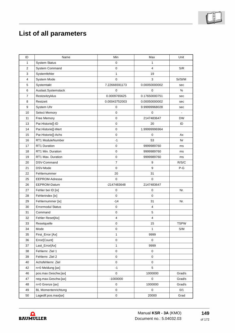
List of all parameters
ID Name Min Max Unit
1 System Status 0 1
2 System Command 0 4 S/R
3 Systemfehler 1 19
4 System Mode 0 3 Si/Sl/M
5 Systemtakt 7.22666591173 0.00050000002 sec
6 Auslast.Systemstack 0 0 %
7 Restzeitzyklus 0.0009765625 0.17650000751 sec
8 Restzeit 0.00043752003 0.00050000002 sec
9 System Uhr 0 9.99999968028 sec
10 Select Memory 0 0 -
11 Free Memory 0 2147483647 DW
13 Par.Historie[]-ID 0 20 ID
14 Par.Historie[]-Wert 0 1.99999996964
15 Par.Historie[]-Achs 0 0 Ax
16 RT1 ModuleNumber -1 53 Nr
17 RT1 Duration 0 9999989760 ms
18 RT1 Min. Duration 0 9999989760 ms
19 RT1 Max. Duration 0 9999989760 ms
20 DSV-Command 7 9 R/S/C
21 DSV-Mode 0 9 P-G
22 Fehlernummer 20 31
25 EEPROM-Adresse 0 0
26 EEPROM-Datum -2147483648 2147483647
27 Fehler bei ID [ix] 0 0 Nr.
28 Fehlerindex [ix] 0 0
29 Fehlernummer [ix] -14 31 Nr.
30 Errormodul Status 0 4
31 Command 0 5
32 Fehler Reset[Ax] 4 4
33 Resetquelle 0 15 TSPW
34 Mode 0 1 S/M
35 First_Error [Ax] 1 9999
36 Error[Count] 0 0
37 Last_Error[Ax] 1 9999
38 Fehlernr. Ziel 1 0 0
39 Fehlernr. Ziel 2 0 0
40 Achsfehlernr. Ziel 0 0
42 n=0 Meldung [ax] -1 5
46 pos.max.Geschw.[ax] 0 1000000 Grad/s
47 neg.max.Geschw.[ax] -1000000 0 Grad/s
48 n=0 Grenze [ax] 0 1000000 Grad/s
49 BL Momentenrichtung 0 0 0/1
50 Lagedif.pos.max[ax] 0 20000 Grad
Manual KSR - 3A (KMO)Document no.: 5.04032.03
149of 172
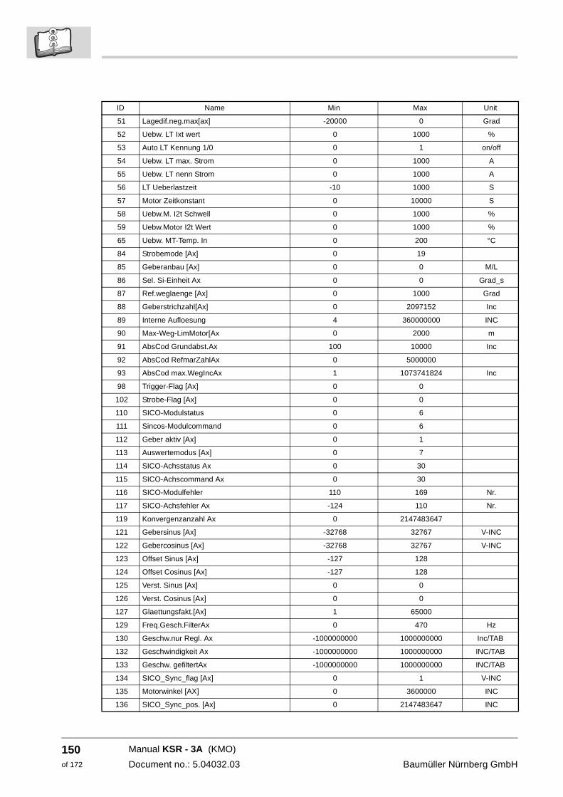
150of 172
51 Lagedif.neg.max[ax] -20000 0 Grad
52 Uebw. LT Ixt wert 0 1000 %
53 Auto LT Kennung 1/0 0 1 on/off
54 Uebw. LT max. Strom 0 1000 A
55 Uebw. LT nenn Strom 0 1000 A
56 LT Ueberlastzeit -10 1000 S
57 Motor Zeitkonstant 0 10000 S
58 Uebw.M. I2t Schwell 0 1000 %
59 Uebw.Motor I2t Wert 0 1000 %
65 Uebw. MT-Temp. In 0 200 °C
84 Strobemode [Ax] 0 19
85 Geberanbau [Ax] 0 0 M/L
86 Sel. Si-Einheit Ax 0 0 Grad_s
87 Ref.weglaenge [Ax] 0 1000 Grad
88 Geberstrichzahl[Ax] 0 2097152 Inc
89 Interne Aufloesung 4 360000000 INC
90 Max-Weg-LimMotor[Ax 0 2000 m
91 AbsCod Grundabst.Ax 100 10000 Inc
92 AbsCod RefmarZahlAx 0 5000000
93 AbsCod max.WegIncAx 1 1073741824 Inc
98 Trigger-Flag [Ax] 0 0
102 Strobe-Flag [Ax] 0 0
110 SICO-Modulstatus 0 6
111 Sincos-Modulcommand 0 6
112 Geber aktiv [Ax] 0 1
113 Auswertemodus [Ax] 0 7
114 SICO-Achsstatus Ax 0 30
115 SICO-Achscommand Ax 0 30
116 SICO-Modulfehler 110 169 Nr.
117 SICO-Achsfehler Ax -124 110 Nr.
119 Konvergenzanzahl Ax 0 2147483647
121 Gebersinus [Ax] -32768 32767 V-INC
122 Gebercosinus [Ax] -32768 32767 V-INC
123 Offset Sinus [Ax] -127 128
124 Offset Cosinus [Ax] -127 128
125 Verst. Sinus [Ax] 0 0
126 Verst. Cosinus [Ax] 0 0
127 Glaettungsfakt.[Ax] 1 65000
129 Freq.Gesch.FilterAx 0 470 Hz
130 Geschw.nur Regl. Ax -1000000000 1000000000 Inc/TAB
132 Geschwindigkeit Ax -1000000000 1000000000 INC/TAB
133 Geschw. gefiltertAx -1000000000 1000000000 INC/TAB
134 SICO_Sync_flag [Ax] 0 1 V-INC
135 Motorwinkel [AX] 0 3600000 INC
136 SICO_Sync_pos. [Ax] 0 2147483647 INC
ID Name Min Max Unit
Manual KSR - 3A (KMO)
Document no.: 5.04032.03 Baumüller Nürnberg GmbH
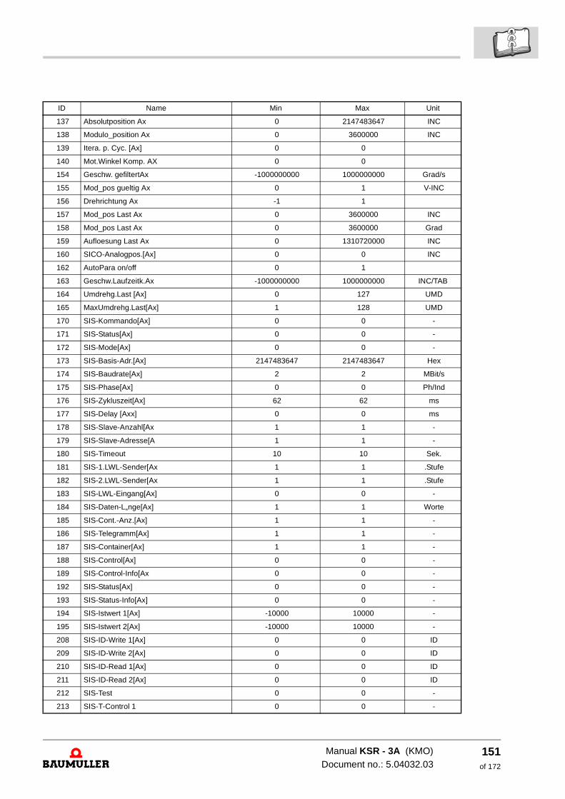
137 Absolutposition Ax 0 2147483647 INC
138 Modulo_position Ax 0 3600000 INC
139 Itera. p. Cyc. [Ax] 0 0
140 Mot.Winkel Komp. AX 0 0
154 Geschw. gefiltertAx -1000000000 1000000000 Grad/s
155 Mod_pos gueltig Ax 0 1 V-INC
156 Drehrichtung Ax -1 1
157 Mod_pos Last Ax 0 3600000 INC
158 Mod_pos Last Ax 0 3600000 Grad
159 Aufloesung Last Ax 0 1310720000 INC
160 SICO-Analogpos.[Ax] 0 0 INC
162 AutoPara on/off 0 1
163 Geschw.Laufzeitk.Ax -1000000000 1000000000 INC/TAB
164 Umdrehg.Last [Ax] 0 127 UMD
165 MaxUmdrehg.Last[Ax] 1 128 UMD
170 SIS-Kommando[Ax] 0 0 -
171 SIS-Status[Ax] 0 0 -
172 SIS-Mode[Ax] 0 0 -
173 SIS-Basis-Adr.[Ax] 2147483647 2147483647 Hex
174 SIS-Baudrate[Ax] 2 2 MBit/s
175 SIS-Phase[Ax] 0 0 Ph/Ind
176 SIS-Zykluszeit[Ax] 62 62 ms
177 SIS-Delay [Axx] 0 0 ms
178 SIS-Slave-Anzahl[Ax 1 1 -
179 SIS-Slave-Adresse[A 1 1 -
180 SIS-Timeout 10 10 Sek.
181 SIS-1.LWL-Sender[Ax 1 1 .Stufe
182 SIS-2.LWL-Sender[Ax 1 1 .Stufe
183 SIS-LWL-Eingang[Ax] 0 0 -
184 SIS-Daten-L„nge[Ax] 1 1 Worte
185 SIS-Cont.-Anz.[Ax] 1 1 -
186 SIS-Telegramm[Ax] 1 1 -
187 SIS-Container[Ax] 1 1 -
188 SIS-Control[Ax] 0 0 -
189 SIS-Control-Info[Ax 0 0 -
192 SIS-Status[Ax] 0 0 -
193 SIS-Status-Info[Ax] 0 0 -
194 SIS-Istwert 1[Ax] -10000 10000 -
195 SIS-Istwert 2[Ax] -10000 10000 -
208 SIS-ID-Write 1[Ax] 0 0 ID
209 SIS-ID-Write 2[Ax] 0 0 ID
210 SIS-ID-Read 1[Ax] 0 0 ID
211 SIS-ID-Read 2[Ax] 0 0 ID
212 SIS-Test 0 0 -
213 SIS-T-Control 1 0 0 -
ID Name Min Max Unit
Manual KSR - 3A (KMO)Document no.: 5.04032.03
151of 172
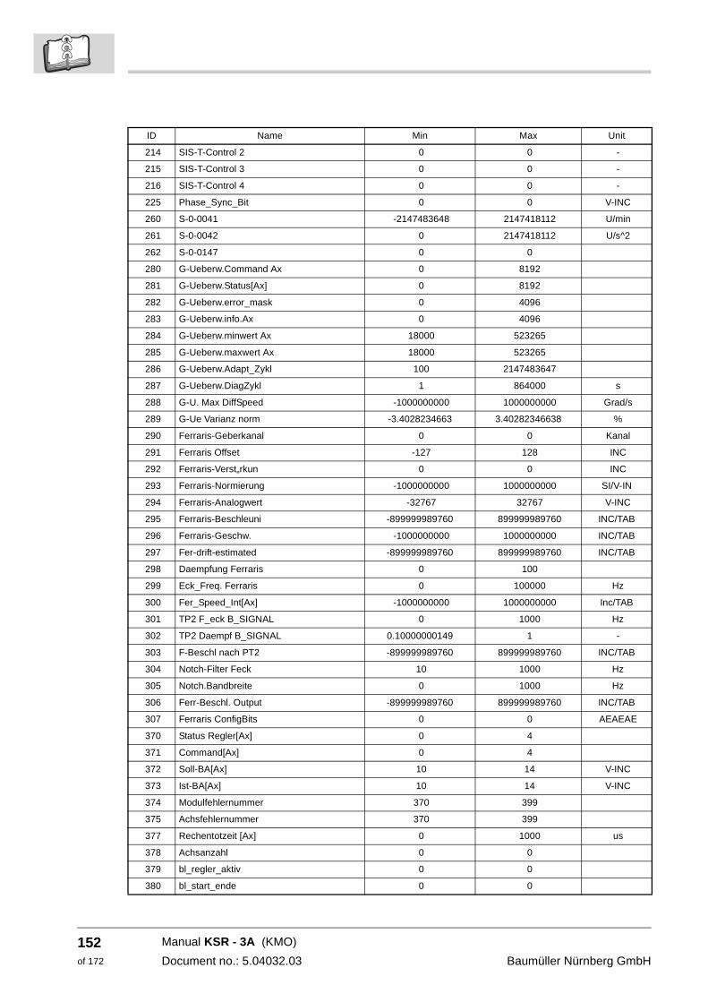
152of 172
214 SIS-T-Control 2 0 0 -
215 SIS-T-Control 3 0 0 -
216 SIS-T-Control 4 0 0 -
225 Phase_Sync_Bit 0 0 V-INC
260 S-0-0041 -2147483648 2147418112 U/min
261 S-0-0042 0 2147418112 U/s^2
262 S-0-0147 0 0
280 G-Ueberw.Command Ax 0 8192
281 G-Ueberw.Status[Ax] 0 8192
282 G-Ueberw.error_mask 0 4096
283 G-Ueberw.info.Ax 0 4096
284 G-Ueberw.minwert Ax 18000 523265
285 G-Ueberw.maxwert Ax 18000 523265
286 G-Ueberw.Adapt_Zykl 100 2147483647
287 G-Ueberw.DiagZykl 1 864000 s
288 G-U. Max DiffSpeed -1000000000 1000000000 Grad/s
289 G-Ue Varianz norm -3.4028234663 3.40282346638 %
290 Ferraris-Geberkanal 0 0 Kanal
291 Ferraris Offset -127 128 INC
292 Ferraris-Verst„rkun 0 0 INC
293 Ferraris-Normierung -1000000000 1000000000 SI/V-IN
294 Ferraris-Analogwert -32767 32767 V-INC
295 Ferraris-Beschleuni -899999989760 899999989760 INC/TAB
296 Ferraris-Geschw. -1000000000 1000000000 INC/TAB
297 Fer-drift-estimated -899999989760 899999989760 INC/TAB
298 Daempfung Ferraris 0 100
299 Eck_Freq. Ferraris 0 100000 Hz
300 Fer_Speed_Int[Ax] -1000000000 1000000000 Inc/TAB
301 TP2 F_eck B_SIGNAL 0 1000 Hz
302 TP2 Daempf B_SIGNAL 0.10000000149 1 -
303 F-Beschl nach PT2 -899999989760 899999989760 INC/TAB
304 Notch-Filter Feck 10 1000 Hz
305 Notch.Bandbreite 0 1000 Hz
306 Ferr-Beschl. Output -899999989760 899999989760 INC/TAB
307 Ferraris ConfigBits 0 0 AEAEAE
370 Status Regler[Ax] 0 4
371 Command[Ax] 0 4
372 Soll-BA[Ax] 10 14 V-INC
373 Ist-BA[Ax] 10 14 V-INC
374 Modulfehlernummer 370 399
375 Achsfehlernummer 370 399
377 Rechentotzeit [Ax] 0 1000 us
378 Achsanzahl 0 0
379 bl_regler_aktiv 0 0
380 bl_start_ende 0 0
ID Name Min Max Unit
Manual KSR - 3A (KMO)
Document no.: 5.04032.03 Baumüller Nürnberg GmbH
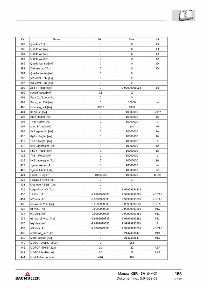
382 Quelle x2 [Ax] 0 0 ID
383 Quelle w1 [Ax] 0 0 ID
384 Quelle w2 [Ax] 0 0 ID
385 Quelle w3 [Ax] 0 0 ID
386 Quelle isq_soll[Ax] 0 0 ID
389 Ziel fuer ‚isq‘[Ax] 0 0 ID
394 Quellindex isq [Ax] 0 0
396 w2-Vorst. EIN [Ax] 0 2
397 w3-Vorst. EIN [Ax] 0 2
398 Zeit x-Trigger [Ax] 0 1.99999996964 us
399 speed_faktor[Ax] 0.5 10
401 Para 0/1/2 copy[Ax] 0 0
402 Para_neu Zeit [Ax] 0 10000 ms
403 Fakt. isq_soll [Ax] -1000 1000
404 Ks Verst. [Ax] 0 10000000 G/s²/A
405 Kp n-Regler [Ax] 0 10000000 1/s
406 Tn n-Regler [Ax] 0 10000000 s
407 Max. I-Anteil [Ax] 0 100 %
408 Kv Lageregler [Ax] 0 10000000 1/s
410 Kp1 n-Regler [Ax] 0 10000000 1/s
411 Tn1 n-Regler [Ax] 0 10000000 s
413 Kv1 Lageregler [Ax] 0 10000000 1/s
415 Kp2 n-Regler [Ax] 0 10000000 1/s
416 Tn2 n-Regler[Ax] 0 10000000 s
418 Kv2 Lageregler [Ax] 0 10000000 1/s
419 v_min I-Anteil [Ax] 0 10000000 ø/s
420 v_max I-Anteil [Ax] 0 10000000 ø/s
421 FKp3 B-Regler -10000000 10000000 1/TAB
424 RESET I-Anteil [Ax] 0 1
425 Getriebe RESET [Ax] 0 1
426 Lageoffset w/x [Ax] 0 9.99999984824
430 x2 Visu. [Ax] -9.9999999338 9.99999993381 INC/TAB
431 w2 Visu.[Ax] -9.9999999338 9.99999993381 INC/TAB
432 e2=w2-x2 Visu.[Ax] -9.9999999338 9.99999993381 INC/TAB
433 x1 Visu. [Ax] -9.9999999338 9.99999993381 INC
434 w1 Visu. [Ax] -9.9999999338 9.99999993381 INC
435 e1=w1-x1 Visu. [Ax] -9.9999999338 9.99999993381 INC
436 isq Visu. [Ax] -9.9999999338 9.99999993381 A
437 w3 Visu.[Ax] -9.9999999338 9.99999993381 INC/TAB
438 Mod.Pos_vorz [Ax] 0 2147483647 INC
439 Mod.Position [Ax] 0 2147483647 INC
440 MOTOR ACHS_MASK 0 255
442 MOTOR Soll-BA [ax] 20 22 AEP
443 MOTOR Ist-BA [ax] 20 22 AEP
444 Modulfehlernummer 440 469
ID Name Min Max Unit
Manual KSR - 3A (KMO)Document no.: 5.04032.03
153of 172
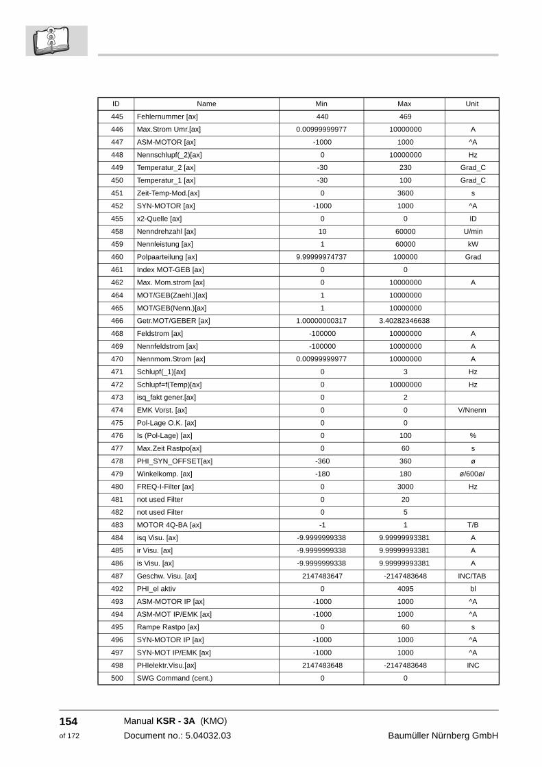
154of 172
445 Fehlernummer [ax] 440 469
446 Max.Strom Umr.[ax] 0.00999999977 10000000 A
447 ASM-MOTOR [ax] -1000 1000 ^A
448 Nennschlupf(_2)[ax] 0 10000000 Hz
449 Temperatur_2 [ax] -30 230 Grad_C
450 Temperatur_1 [ax] -30 100 Grad_C
451 Zeit-Temp-Mod.[ax] 0 3600 s
452 SYN-MOTOR [ax] -1000 1000 ^A
455 x2-Quelle [ax] 0 0 ID
458 Nenndrehzahl [ax] 10 60000 U/min
459 Nennleistung [ax] 1 60000 kW
460 Polpaarteilung [ax] 9.99999974737 100000 Grad
461 Index MOT-GEB [ax] 0 0
462 Max. Mom.strom [ax] 0 10000000 A
464 MOT/GEB(Zaehl.)[ax] 1 10000000
465 MOT/GEB(Nenn.)[ax] 1 10000000
466 Getr.MOT/GEBER [ax] 1.00000000317 3.40282346638
468 Feldstrom [ax] -100000 10000000 A
469 Nennfeldstrom [ax] -100000 10000000 A
470 Nennmom.Strom [ax] 0.00999999977 10000000 A
471 Schlupf(_1)[ax] 0 3 Hz
472 Schlupf=f(Temp)[ax] 0 10000000 Hz
473 isq_fakt gener.[ax] 0 2
474 EMK Vorst. [ax] 0 0 V/Nnenn
475 Pol-Lage O.K. [ax] 0 0
476 Is (Pol-Lage) [ax] 0 100 %
477 Max.Zeit Rastpo[ax] 0 60 s
478 PHI_SYN_OFFSET[ax] -360 360 ø
479 Winkelkomp. [ax] -180 180 ø/600ø/
480 FREQ-I-Filter [ax] 0 3000 Hz
481 not used Filter 0 20
482 not used Filter 0 5
483 MOTOR 4Q-BA [ax] -1 1 T/B
484 isq Visu. [ax] -9.9999999338 9.99999993381 A
485 ir Visu. [ax] -9.9999999338 9.99999993381 A
486 is Visu. [ax] -9.9999999338 9.99999993381 A
487 Geschw. Visu. [ax] 2147483647 -2147483648 INC/TAB
492 PHI_el aktiv 0 4095 bl
493 ASM-MOTOR IP [ax] -1000 1000 ^A
494 ASM-MOT IP/EMK [ax] -1000 1000 ^A
495 Rampe Rastpo [ax] 0 60 s
496 SYN-MOTOR IP [ax] -1000 1000 ^A
497 SYN-MOT IP/EMK [ax] -1000 1000 ^A
498 PHIelektr.Visu.[ax] 2147483648 -2147483648 INC
500 SWG Command (cent.) 0 0
ID Name Min Max Unit
Manual KSR - 3A (KMO)
Document no.: 5.04032.03 Baumüller Nürnberg GmbH
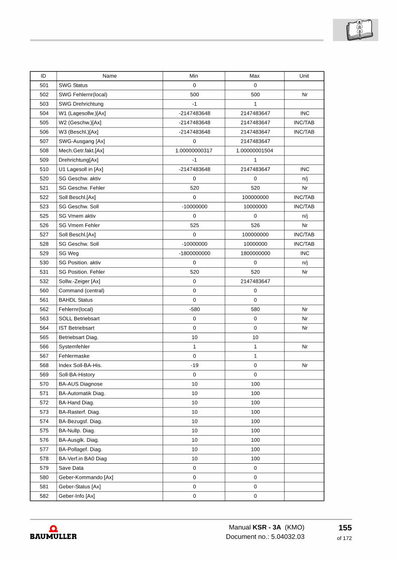
501 SWG Status 0 0
502 SWG Fehlernr(local) 500 500 Nr
503 SWG Drehrichtung -1 1
504 W1 (Lagesollw.)[Ax] -2147483648 2147483647 INC
505 W2 (Geschw.)[Ax] -2147483648 2147483647 INC/TAB
506 W3 (Beschl.)[Ax] -2147483648 2147483647 INC/TAB
507 SWG-Ausgang [Ax] 0 2147483647
508 Mech.Getr.fakt.[Ax] 1.00000000317 1.00000001504
509 Drehrichtung[Ax] -1 1
510 U1 Lagesoll in [Ax] -2147483648 2147483647 INC
520 SG Geschw. aktiv 0 0 n/j
521 SG Geschw. Fehler 520 520 Nr
522 Soll Beschl.[Ax] 0 100000000 INC/TAB
523 SG Geschw. Soll -10000000 10000000 INC/TAB
525 SG Vmem aktiv 0 0 n/j
526 SG Vmem Fehler 525 526 Nr
527 Soll Beschl.[Ax] 0 100000000 INC/TAB
528 SG Geschw. Soll -10000000 10000000 INC/TAB
529 SG Weg -1800000000 1800000000 INC
530 SG Position. aktiv 0 0 n/j
531 SG Position. Fehler 520 520 Nr
532 Sollw.-Zeiger [Ax] 0 2147483647
560 Command (central) 0 0
561 BAHDL Status 0 0
562 Fehlernr(local) -580 580 Nr
563 SOLL Betriebsart 0 0 Nr
564 IST Betriebsart 0 0 Nr
565 Betriebsart Diag. 10 10
566 Systemfehler 1 1 Nr
567 Fehlermaske 0 1
568 Index Soll-BA-His. -19 0 Nr
569 Soll-BA-History 0 0
570 BA-AUS Diagnose 10 100
571 BA-Automatik Diag. 10 100
572 BA-Hand Diag. 10 100
573 BA-Rasterf. Diag. 10 100
574 BA-Bezugsf. Diag. 10 100
575 BA-Nullp. Diag. 10 100
576 BA-Ausglk. Diag. 10 100
577 BA-Pollagef. Diag. 10 100
578 BA-Verf.in BA0 Diag 10 100
579 Save Data 0 0
580 Geber-Kommando [Ax] 0 0
581 Geber-Status [Ax] 0 0
582 Geber-Info [Ax] 0 0
ID Name Min Max Unit
Manual KSR - 3A (KMO)Document no.: 5.04032.03
155of 172
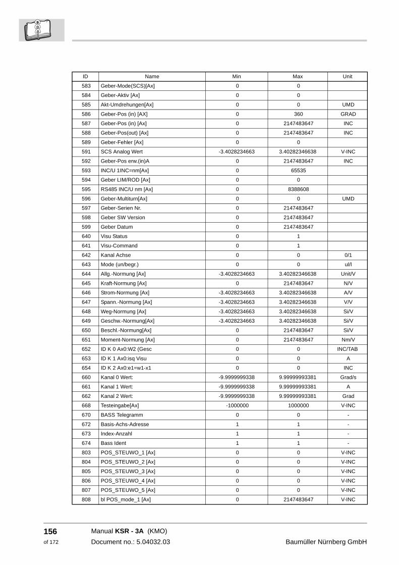
156of 172
583 Geber-Mode(SCS)[Ax] 0 0
584 Geber-Aktiv [Ax] 0 0
585 Akt-Umdrehungen[Ax] 0 0 UMD
586 Geber-Pos (in) [AX] 0 360 GRAD
587 Geber-Pos (in) [Ax] 0 2147483647 INC
588 Geber-Pos(out) [Ax] 0 2147483647 INC
589 Geber-Fehler [Ax] 0 0
591 SCS Analog Wert -3.4028234663 3.40282346638 V-INC
592 Geber-Pos erw.(in)A 0 2147483647 INC
593 INC/U 1INC=nm[Ax] 0 65535
594 Geber LIM/ROD [Ax] 0 0
595 RS485 INC/U nm [Ax] 0 8388608
596 Geber-Multiturn[Ax] 0 0 UMD
597 Geber-Serien Nr. 0 2147483647
598 Geber SW Version 0 2147483647
599 Geber Datum 0 2147483647
640 Visu Status 0 1
641 Visu-Command 0 1
642 Kanal Achse 0 0 0/1
643 Mode (un/begr.) 0 0 ul/l
644 Allg.-Normung [Ax] -3.4028234663 3.40282346638 Unit/V
645 Kraft-Normung [Ax] 0 2147483647 N/V
646 Strom-Normung [Ax] -3.4028234663 3.40282346638 A/V
647 Spann.-Normung [Ax] -3.4028234663 3.40282346638 V/V
648 Weg-Normung [Ax] -3.4028234663 3.40282346638 Si/V
649 Geschw.-Normung[Ax] -3.4028234663 3.40282346638 Si/V
650 Beschl.-Normung[Ax] 0 2147483647 Si/V
651 Moment-Normung [Ax] 0 2147483647 Nm/V
652 ID K 0 Ax0:W2 (Gesc 0 0 INC/TAB
653 ID K 1 Ax0:isq Visu 0 0 A
654 ID K 2 Ax0:e1=w1-x1 0 0 INC
660 Kanal 0 Wert: -9.9999999338 9.99999993381 Grad/s
661 Kanal 1 Wert: -9.9999999338 9.99999993381 A
662 Kanal 2 Wert: -9.9999999338 9.99999993381 Grad
668 Testeingabe[Ax] -1000000 1000000 V-INC
670 BASS Telegramm 0 0 -
672 Basis-Achs-Adresse 1 1 -
673 Index-Anzahl 1 1 -
674 Bass Ident 1 1 -
803 POS_STEUWO_1 [Ax] 0 0 V-INC
804 POS_STEUWO_2 [Ax] 0 0 V-INC
805 POS_STEUWO_3 [Ax] 0 0 V-INC
806 POS_STEUWO_4 [Ax] 0 0 V-INC
807 POS_STEUWO_5 [Ax] 0 0 V-INC
808 bl POS_mode_1 [Ax] 0 2147483647 V-INC
ID Name Min Max Unit
Manual KSR - 3A (KMO)
Document no.: 5.04032.03 Baumüller Nürnberg GmbH
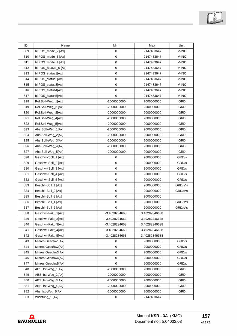
809 bl POS_mode_2 [Ax] 0 2147483647 V-INC
810 bl POS_mode_3 [Ax] 0 2147483647 V-INC
811 bl POS_mode_4 [Ax] 0 2147483647 V-INC
812 bl POS_MODE_5 [Ax] 0 2147483647 V-INC
813 bl POS_status1[Ax] 0 2147483647 V-INC
814 bl POS_status2[Ax] 0 2147483647 V-INC
815 bl POS_status3[Ax] 0 2147483647 V-INC
816 bl POS_status4[Ax] 0 2147483647 V-INC
817 bl POS_status5[Ax] 0 2147483647 V-INC
818 Rel.Soll-Weg_1[Ax] -2000000000 2000000000 GRD
819 Rel.Soll-Weg_2 [Ax] -2000000000 2000000000 GRD
820 Rel.Soll-Weg_3[Ax] -2000000000 2000000000 GRD
821 Rel.Soll-Weg_4[Ax] -2000000000 2000000000 GRD
822 Rel.Soll-Weg_5[Ax] -2000000000 2000000000 GRD
823 Abs.Soll-Weg_1[Ax] -2000000000 2000000000 GRD
824 Abs.Soll-Weg_2[Ax] -2000000000 2000000000 GRD
825 Abs.Soll-Weg_3[Ax] -2000000000 2000000000 GRD
826 Abs.Soll-Weg_4[Ax] -2000000000 2000000000 GRD
827 Abs.Soll-Weg_5[Ax] -2000000000 2000000000 GRD
828 Geschw.-Soll_1 [Ax] 0 2000000000 GRD/s
829 Geschw.-Soll_2 [Ax] 0 2000000000 GRD/s
830 Geschw.-Soll_3 [Ax] 0 2000000000 GRD/s
831 Geschw.-Soll_4 [Ax] 0 2000000000 GRD/s
832 Geschw.-Soll_5 [Ax] 0 2000000000 GRD/s
833 Beschl.-Soll_1 [Ax] 0 2000000000 GRD/s*s
834 Beschl.-Soll_2 [Ax] 0 2000000000 GRD/s*s
835 Beschl.-Soll_3 [Ax] 0 2000000000
836 Beschl.-Soll_4 [Ax] 0 2000000000 GRD/s*s
837 Beschl.-Soll_5 [Ax] 0 2000000000 GRD/s*s
838 Geschw.-Fakt_1[Ax] -3.4028234663 3.40282346638
839 Geschw.-Fakt_2[Ax] -3.4028234663 3.40282346638
840 Geschw.-Fakt_3[Ax] -3.4028234663 3.40282346638
841 Geschw.-Fakt_4[Ax] -3.4028234663 3.40282346638
842 Geschw.-Fakt_5[Ax] -3.4028234663 3.40282346638
843 Minres.Geschw1[Ax] 0 2000000000 GRD/s
844 Minres.Geschw2[Ax] 0 2000000000 GRD/s
845 Minres.Geschw3[Ax] 0 2000000000 GRD/s
846 Minres.Geschw4[Ax] 0 2000000000 GRD/s
847 Minres.Geschw5[Ax] 0 2000000000 GRD/s
848 ABS. Ist-Weg_1[Ax] -2000000000 2000000000 GRD
849 ABS. Ist-Weg_2[Ax] -2000000000 2000000000 GRD
850 ABS. Ist-Weg_3[Ax] -2000000000 2000000000 GRD
851 ABS. Ist-Weg_4[Ax] -2000000000 2000000000 GRD
852 Abs. Ist-Weg_5[Ax] -2000000000 2000000000 GRD
853 Wichtung_1 [Ax] 0 2147483647
ID Name Min Max Unit
Manual KSR - 3A (KMO)Document no.: 5.04032.03
157of 172
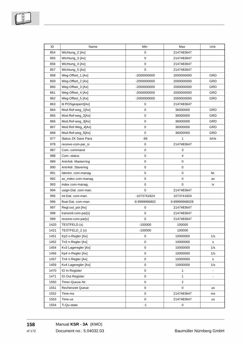
158of 172
854 Wichtung_2 [Ax] 0 2147483647
855 Wichtung_3 [Ax] 0 2147483647
856 Wichtung_4 [Ax] 0 2147483647
857 Wichtung_5 [Ax] 0 2147483647
858 Weg-Offset_1 [Ax] -2000000000 2000000000 GRD
859 Weg-Offset_2 [Ax] -2000000000 2000000000 GRD
860 Weg-Offset_3 [Ax] -2000000000 2000000000 GRD
861 Weg-Offset_4 [Ax] -2000000000 2000000000 GRD
862 Weg-Offset_5 [Ax] -2000000000 2000000000 GRD
863 bl POSgesperrt[Ax] 0 2147483647
864 Mod.Ref-weg_1[Ax] 0 36000000 GRD
865 Mod.Ref-weg_2[Ax] 0 36000000 GRD
866 Mod.Ref-weg_3[Ax] 0 36000000 GRD
867 Mod.Ref-Weg_4[Ax] 0 36000000 GRD
868 Mod.Ref-weg_5[Ax] 0 36000000 GRD
977 Status ZK Save Para -66 1 b/r/e
978 receive-com-par_si 0 2147483647
987 Com.-command 0 3
988 Com.-status 0 4
989 AntrAdr. Masterring 0 0
990 AntrAdr. Slavering 0 0
991 Identnr. com-manag. 0 0 Nr.
992 ax_index com-manag. 0 0 ax
993 index com-manag. 0 0 ix
994 usign-Dat. com-man. 0 2147483647
995 int-Dat. com-man. -1073741824 1073741824
996 float-Dat. com-man. -9.9999996802 9.99999968028
997 Regl.out_poi [Ax] 0 2147483647
998 transmit-com-par[x] 0 2147483647
999 receive-com-par[x] 0 2147483647
1420 TESTFELD (x) -100000 100000
1421 TESTFELD_2 (x) -100000 100000
1451 Kp3 n-Regler [Ax] 0 10000000 1/s
1452 Tn3 n-Regler [Ax] 0 10000000 s
1454 Kv3 Lageregler [Ax] 0 10000000 1/s
1456 Kp4 n-Regler [Ax] 0 10000000 1/s
1457 Tn4 n-Regler [Ax] 0 10000000 s
1459 Kv4 Lageregler [Ax] 0 10000000 1/s
1470 IO In Register 0 1 -
1471 IO Out Register 0 1 -
1550 Timer-Queue-Nr. 0 2
1551 Rechenzeit Queue 0 0 us
1552 Time-ms 0 2147483647 ms
1553 Time-us 0 2147483647 us
1554 Ti.Qu-state -1 0
ID Name Min Max Unit
Manual KSR - 3A (KMO)
Document no.: 5.04032.03 Baumüller Nürnberg GmbH
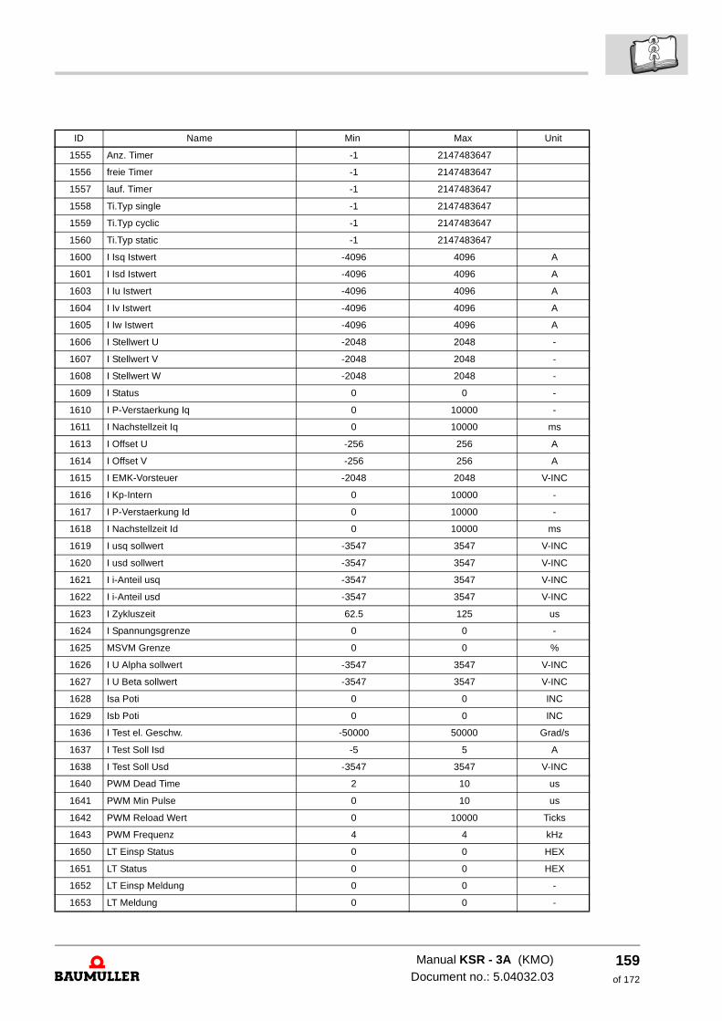
1555 Anz. Timer -1 2147483647
1556 freie Timer -1 2147483647
1557 lauf. Timer -1 2147483647
1558 Ti.Typ single -1 2147483647
1559 Ti.Typ cyclic -1 2147483647
1560 Ti.Typ static -1 2147483647
1600 I Isq Istwert -4096 4096 A
1601 I Isd Istwert -4096 4096 A
1603 I Iu Istwert -4096 4096 A
1604 I Iv Istwert -4096 4096 A
1605 I Iw Istwert -4096 4096 A
1606 I Stellwert U -2048 2048 -
1607 I Stellwert V -2048 2048 -
1608 I Stellwert W -2048 2048 -
1609 I Status 0 0 -
1610 I P-Verstaerkung Iq 0 10000 -
1611 I Nachstellzeit Iq 0 10000 ms
1613 I Offset U -256 256 A
1614 I Offset V -256 256 A
1615 I EMK-Vorsteuer -2048 2048 V-INC
1616 I Kp-Intern 0 10000 -
1617 I P-Verstaerkung Id 0 10000 -
1618 I Nachstellzeit Id 0 10000 ms
1619 I usq sollwert -3547 3547 V-INC
1620 I usd sollwert -3547 3547 V-INC
1621 I i-Anteil usq -3547 3547 V-INC
1622 I i-Anteil usd -3547 3547 V-INC
1623 I Zykluszeit 62.5 125 us
1624 I Spannungsgrenze 0 0 -
1625 MSVM Grenze 0 0 %
1626 I U Alpha sollwert -3547 3547 V-INC
1627 I U Beta sollwert -3547 3547 V-INC
1628 Isa Poti 0 0 INC
1629 Isb Poti 0 0 INC
1636 I Test el. Geschw. -50000 50000 Grad/s
1637 I Test Soll Isd -5 5 A
1638 I Test Soll Usd -3547 3547 V-INC
1640 PWM Dead Time 2 10 us
1641 PWM Min Pulse 0 10 us
1642 PWM Reload Wert 0 10000 Ticks
1643 PWM Frequenz 4 4 kHz
1650 LT Einsp Status 0 0 HEX
1651 LT Status 0 0 HEX
1652 LT Einsp Meldung 0 0 -
1653 LT Meldung 0 0 -
ID Name Min Max Unit
Manual KSR - 3A (KMO)Document no.: 5.04032.03
159of 172
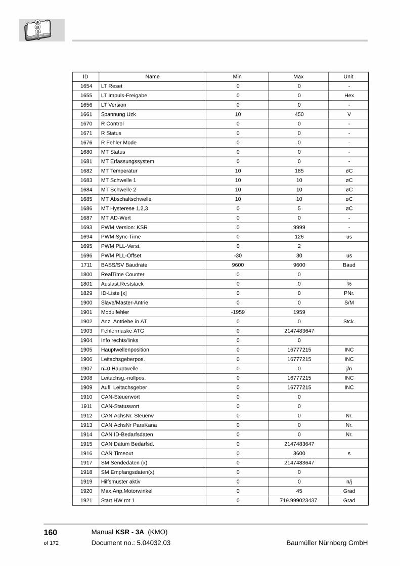
160of 172
1654 LT Reset 0 0 -
1655 LT Impuls-Freigabe 0 0 Hex
1656 LT Version 0 0 -
1661 Spannung Uzk 10 450 V
1670 R Control 0 0 -
1671 R Status 0 0 -
1676 R Fehler Mode 0 0 -
1680 MT Status 0 0 -
1681 MT Erfassungssystem 0 0 -
1682 MT Temperatur 10 185 øC
1683 MT Schwelle 1 10 10 øC
1684 MT Schwelle 2 10 10 øC
1685 MT Abschaltschwelle 10 10 øC
1686 MT Hysterese 1,2,3 0 5 øC
1687 MT AD-Wert 0 0 -
1693 PWM Version: KSR 0 9999 -
1694 PWM Sync Time 0 126 us
1695 PWM PLL-Verst. 0 2
1696 PWM PLL-Offset -30 30 us
1711 BASS/SV Baudrate 9600 9600 Baud
1800 RealTime Counter 0 0
1801 Auslast.Reststack 0 0 %
1829 ID-Liste [x] 0 0 PNr.
1900 Slave/Master-Antrie 0 0 S/M
1901 Modulfehler -1959 1959
1902 Anz. Antriebe in AT 0 0 Stck.
1903 Fehlermaske ATG 0 2147483647
1904 Info rechts/links 0 0
1905 Hauptwellenposition 0 16777215 INC
1906 Leitachsgeberpos. 0 16777215 INC
1907 n=0 Hauptwelle 0 0 j/n
1908 Leitachsg.-nullpos. 0 16777215 INC
1909 Aufl. Leitachsgeber 0 16777215 INC
1910 CAN-Steuerwort 0 0
1911 CAN-Statuswort 0 0
1912 CAN AchsNr. Steuerw 0 0 Nr.
1913 CAN AchsNr ParaKana 0 0 Nr.
1914 CAN ID-Bedarfsdaten 0 0 Nr.
1915 CAN Datum Bedarfsd. 0 2147483647
1916 CAN Timeout 0 3600 s
1917 SM Sendedaten (x) 0 2147483647
1918 SM Empfangsdaten(x) 0 0
1919 Hilfsmuster aktiv 0 0 n/j
1920 Max.Anp.Motorwinkel 0 45 Grad
1921 Start HW rot 1 0 719.999023437 Grad
ID Name Min Max Unit
Manual KSR - 3A (KMO)
Document no.: 5.04032.03 Baumüller Nürnberg GmbH
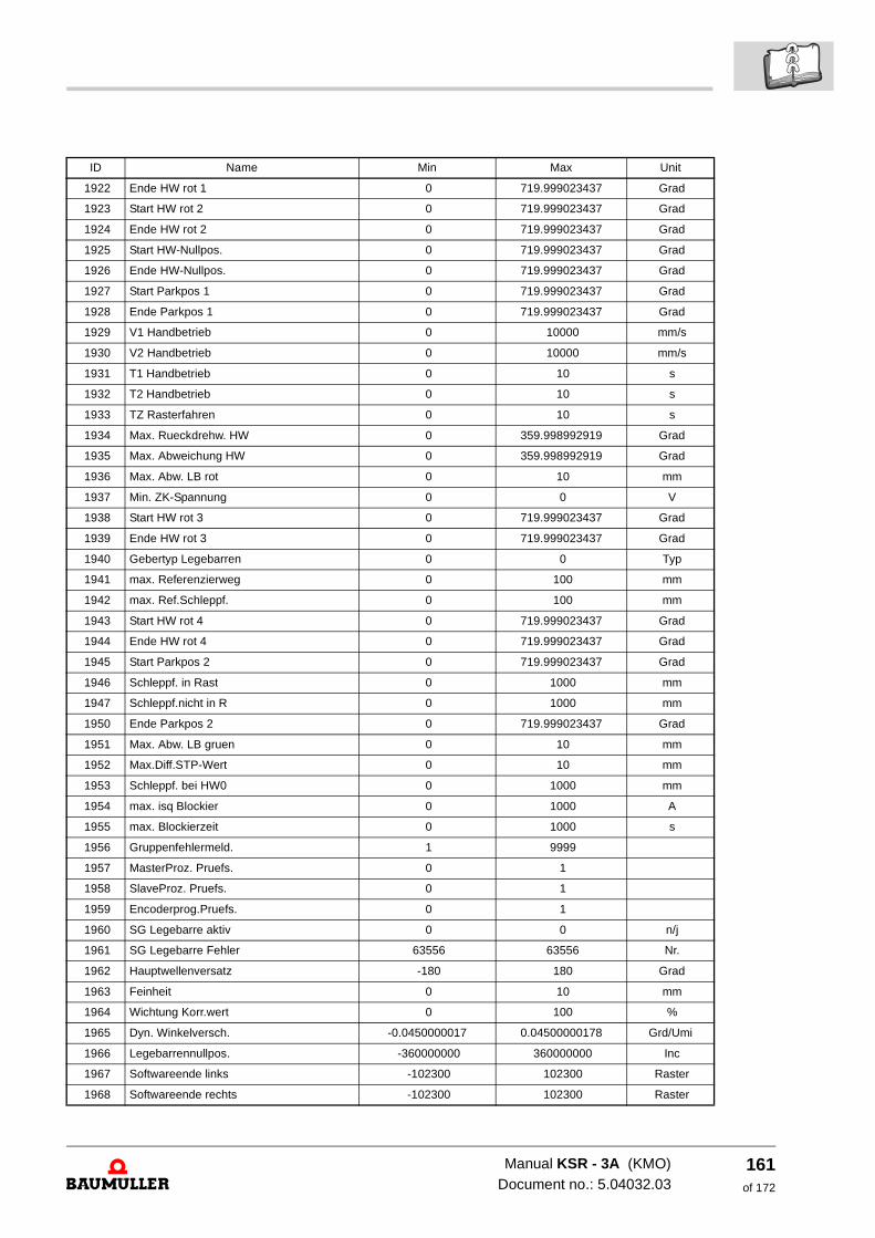
1922 Ende HW rot 1 0 719.999023437 Grad
1923 Start HW rot 2 0 719.999023437 Grad
1924 Ende HW rot 2 0 719.999023437 Grad
1925 Start HW-Nullpos. 0 719.999023437 Grad
1926 Ende HW-Nullpos. 0 719.999023437 Grad
1927 Start Parkpos 1 0 719.999023437 Grad
1928 Ende Parkpos 1 0 719.999023437 Grad
1929 V1 Handbetrieb 0 10000 mm/s
1930 V2 Handbetrieb 0 10000 mm/s
1931 T1 Handbetrieb 0 10 s
1932 T2 Handbetrieb 0 10 s
1933 TZ Rasterfahren 0 10 s
1934 Max. Rueckdrehw. HW 0 359.998992919 Grad
1935 Max. Abweichung HW 0 359.998992919 Grad
1936 Max. Abw. LB rot 0 10 mm
1937 Min. ZK-Spannung 0 0 V
1938 Start HW rot 3 0 719.999023437 Grad
1939 Ende HW rot 3 0 719.999023437 Grad
1940 Gebertyp Legebarren 0 0 Typ
1941 max. Referenzierweg 0 100 mm
1942 max. Ref.Schleppf. 0 100 mm
1943 Start HW rot 4 0 719.999023437 Grad
1944 Ende HW rot 4 0 719.999023437 Grad
1945 Start Parkpos 2 0 719.999023437 Grad
1946 Schleppf. in Rast 0 1000 mm
1947 Schleppf.nicht in R 0 1000 mm
1950 Ende Parkpos 2 0 719.999023437 Grad
1951 Max. Abw. LB gruen 0 10 mm
1952 Max.Diff.STP-Wert 0 10 mm
1953 Schleppf. bei HW0 0 1000 mm
1954 max. isq Blockier 0 1000 A
1955 max. Blockierzeit 0 1000 s
1956 Gruppenfehlermeld. 1 9999
1957 MasterProz. Pruefs. 0 1
1958 SlaveProz. Pruefs. 0 1
1959 Encoderprog.Pruefs. 0 1
1960 SG Legebarre aktiv 0 0 n/j
1961 SG Legebarre Fehler 63556 63556 Nr.
1962 Hauptwellenversatz -180 180 Grad
1963 Feinheit 0 10 mm
1964 Wichtung Korr.wert 0 100 %
1965 Dyn. Winkelversch. -0.0450000017 0.04500000178 Grd/Umi
1966 Legebarrennullpos. -360000000 360000000 Inc
1967 Softwareende links -102300 102300 Raster
1968 Softwareende rechts -102300 102300 Raster
ID Name Min Max Unit
Manual KSR - 3A (KMO)Document no.: 5.04032.03
161of 172
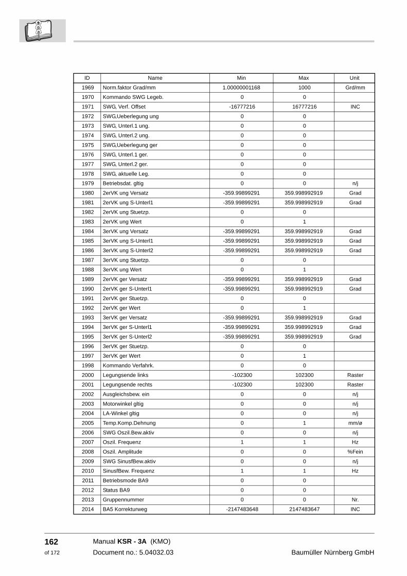
162of 172
1969 Norm.faktor Grad/mm 1.00000001168 1000 Grd/mm
1970 Kommando SWG Legeb. 0 0
1971 SWG, Verf. Offset -16777216 16777216 INC
1972 SWG,Ueberlegung ung 0 0
1973 SWG, Unterl.1 ung. 0 0
1974 SWG, Unterl.2 ung. 0 0
1975 SWG,Ueberlegung ger 0 0
1976 SWG, Unterl.1 ger. 0 0
1977 SWG, Unterl.2 ger. 0 0
1978 SWG, aktuelle Leg. 0 0
1979 Betriebsdat. gltig 0 0 n/j
1980 2erVK ung Versatz -359.99899291 359.998992919 Grad
1981 2erVK ung S-Unterl1 -359.99899291 359.998992919 Grad
1982 2erVK ung Stuetzp. 0 0
1983 2erVK ung Wert 0 1
1984 3erVK ung Versatz -359.99899291 359.998992919 Grad
1985 3erVK ung S-Unterl1 -359.99899291 359.998992919 Grad
1986 3erVK ung S-Unterl2 -359.99899291 359.998992919 Grad
1987 3erVK ung Stuetzp. 0 0
1988 3erVK ung Wert 0 1
1989 2erVK ger Versatz -359.99899291 359.998992919 Grad
1990 2erVK ger S-Unterl1 -359.99899291 359.998992919 Grad
1991 2erVK ger Stuetzp. 0 0
1992 2erVK ger Wert 0 1
1993 3erVK ger Versatz -359.99899291 359.998992919 Grad
1994 3erVK ger S-Unterl1 -359.99899291 359.998992919 Grad
1995 3erVK ger S-Unterl2 -359.99899291 359.998992919 Grad
1996 3erVK ger Stuetzp. 0 0
1997 3erVK ger Wert 0 1
1998 Kommando Verfahrk. 0 0
2000 Legungsende links -102300 102300 Raster
2001 Legungsende rechts -102300 102300 Raster
2002 Ausgleichsbew. ein 0 0 n/j
2003 Motorwinkel gltig 0 0 n/j
2004 LA-Winkel gltig 0 0 n/j
2005 Temp.Komp.Dehnung 0 1 mm/ø
2006 SWG Oszil.Bew.aktiv 0 0 n/j
2007 Oszil. Frequenz 1 1 Hz
2008 Oszil. Amplitude 0 0 %Fein
2009 SWG SinusfBew.aktiv 0 0 n/j
2010 SinusfBew. Frequenz 1 1 Hz
2011 Betriebsmode BA9 0 0
2012 Status BA9 0 0
2013 Gruppennummer 0 0 Nr.
2014 BA5 Korrekturweg -2147483648 2147483647 INC
ID Name Min Max Unit
Manual KSR - 3A (KMO)
Document no.: 5.04032.03 Baumüller Nürnberg GmbH
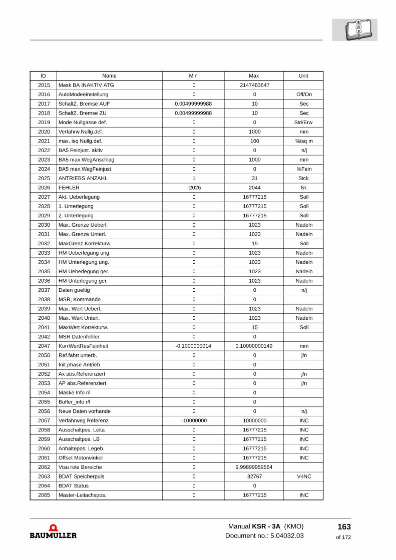
2015 Mask BA INAKTIV ATG 0 2147483647
2016 AutoModeeinstellung 0 0 Off/On
2017 SchaltZ. Bremse AUF 0.00499999988 10 Sec
2018 SchaltZ. Bremse ZU 0.00499999988 10 Sec
2019 Mode Nullgasse def. 0 0 Std/Erw
2020 Verfahrw.Nullg.def. 0 1000 mm
2021 max. isq Nullg.def. 0 100 %isq m
2022 BA5 Feinjust. aktiv 0 0 n/j
2023 BA5 max.WegAnschlag 0 1000 mm
2024 BA5 max.WegFeinjust 0 0 %Fein
2025 ANTRIEBS ANZAHL 1 31 Stck.
2026 FEHLER -2026 2044 Nr.
2027 Akt. Ueberlegung 0 16777215 Soll
2028 1. Unterlegung 0 16777215 Soll
2029 2. Unterlegung 0 16777215 Soll
2030 Max. Grenze Ueberl. 0 1023 Nadeln
2031 Max. Grenze Unterl. 0 1023 Nadeln
2032 MaxGrenz Korrekturw 0 15 Soll
2033 HM Ueberlegung ung. 0 1023 Nadeln
2034 HM Unterlegung ung. 0 1023 Nadeln
2035 HM Ueberlegung ger. 0 1023 Nadeln
2036 HM Unterlegung ger. 0 1023 Nadeln
2037 Daten gueltig 0 0 n/j
2038 MSR, Kommando 0 0
2039 Max. Wert Ueberl. 0 1023 Nadeln
2040 Max. Wert Unterl. 0 1023 Nadeln
2041 MaxWert Korrekturw. 0 15 Soll
2042 MSR Datenfehler 0 0
2047 KorrWertResFeinheit -0.1000000014 0.10000000149 mm
2050 Ref.fahrt unterb. 0 0 j/n
2051 Init.phase Antrieb 0 0
2052 Ax abs.Referenziert 0 0 j/n
2053 AP abs.Referenziert 0 0 j/n
2054 Maske Info r/l 0 0
2055 Buffer_info r/l 0 0
2056 Neue Daten vorhande 0 0 n/j
2057 Verfahrweg Referenz -10000000 10000000 INC
2058 Ausschaltpos. Leita 0 16777215 INC
2059 Ausschaltpos. LB 0 16777215 INC
2060 Anhaltepos. Legeb. 0 16777215 INC
2061 Offset Motorwinkel 0 16777215 INC
2062 Visu rote Bereiche 0 9.99899959564
2063 BDAT Speicherpuls 0 32767 V-INC
2064 BDAT Status 0 0
2065 Master-Leitachspos. 0 16777215 INC
ID Name Min Max Unit
Manual KSR - 3A (KMO)Document no.: 5.04032.03
163of 172
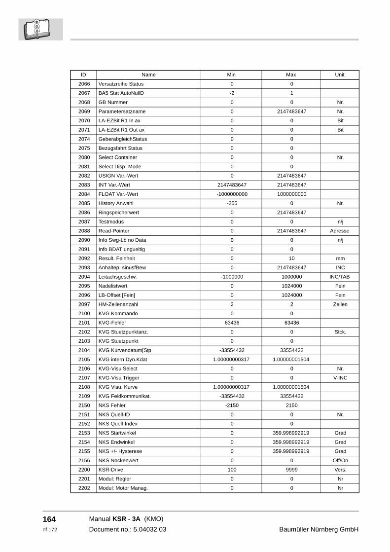
164of 172
2066 Versatzreihe Status 0 0
2067 BA5 Stat AutoNullD -2 1
2068 GB Nummer 0 0 Nr.
2069 Parametersatzname 0 2147483647 Nr.
2070 LA-EZBit R1 In ax 0 0 Bit
2071 LA-EZBit R1 Out ax 0 0 Bit
2074 GeberabgleichStatus 0 0
2075 Bezugsfahrt Status 0 0
2080 Select Container 0 0 Nr.
2081 Select Disp.-Mode 0 0
2082 USIGN Var.-Wert 0 2147483647
2083 INT Var.-Wert 2147483647 2147483647
2084 FLOAT Var.-Wert -1000000000 1000000000
2085 History Anwahl -255 0 Nr.
2086 Ringspeicherwert 0 2147483647
2087 Testmodus 0 0 n/j
2088 Read-Pointer 0 2147483647 Adresse
2090 Info Swg-Lb no Data 0 0 n/j
2091 Info BDAT ungueltig 0 0
2092 Result. Feinheit 0 10 mm
2093 Anhaltep. sinusfBew 0 2147483647 INC
2094 Leitachsgeschw. -1000000 1000000 INC/TAB
2095 Nadelistwert 0 1024000 Fein
2096 LB-Offset [Fein] 0 1024000 Fein
2097 HM-Zeilenanzahl 2 2 Zeilen
2100 KVG Kommando 0 0
2101 KVG-Fehler 63436 63436
2102 KVG Stuetzpunktanz. 0 0 Stck.
2103 KVG Stuetzpunkt 0 0
2104 KVG Kurvendatum[Stp -33554432 33554432
2105 KVG intern Dyn.Kdat 1.00000000317 1.00000001504
2106 KVG-Visu Select 0 0 Nr.
2107 KVG-Visu Trigger 0 0 V-INC
2108 KVG Visu. Kurve 1.00000000317 1.00000001504
2109 KVG Feldkommunikat. -33554432 33554432
2150 NKS Fehler -2150 2150
2151 NKS Quell-ID 0 0 Nr.
2152 NKS Quell-Index 0 0
2153 NKS Startwinkel 0 359.998992919 Grad
2154 NKS Endwinkel 0 359.998992919 Grad
2155 NKS +/- Hysterese 0 359.998992919 Grad
2156 NKS Nockenwert 0 0 Off/On
2200 KSR-Drive 100 9999 Vers.
2201 Modul: Regler 0 0 Nr
2202 Modul: Motor Manag. 0 0 Nr
ID Name Min Max Unit
Manual KSR - 3A (KMO)
Document no.: 5.04032.03 Baumüller Nürnberg GmbH
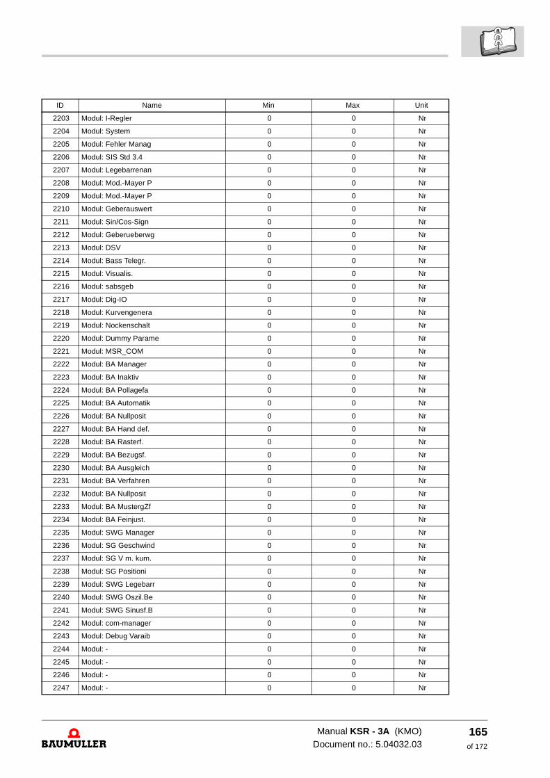
2203 Modul: I-Regler 0 0 Nr
2204 Modul: System 0 0 Nr
2205 Modul: Fehler Manag 0 0 Nr
2206 Modul: SIS Std 3.4 0 0 Nr
2207 Modul: Legebarrenan 0 0 Nr
2208 Modul: Mod.-Mayer P 0 0 Nr
2209 Modul: Mod.-Mayer P 0 0 Nr
2210 Modul: Geberauswert 0 0 Nr
2211 Modul: Sin/Cos-Sign 0 0 Nr
2212 Modul: Geberueberwg 0 0 Nr
2213 Modul: DSV 0 0 Nr
2214 Modul: Bass Telegr. 0 0 Nr
2215 Modul: Visualis. 0 0 Nr
2216 Modul: sabsgeb 0 0 Nr
2217 Modul: Dig-IO 0 0 Nr
2218 Modul: Kurvengenera 0 0 Nr
2219 Modul: Nockenschalt 0 0 Nr
2220 Modul: Dummy Parame 0 0 Nr
2221 Modul: MSR_COM 0 0 Nr
2222 Modul: BA Manager 0 0 Nr
2223 Modul: BA Inaktiv 0 0 Nr
2224 Modul: BA Pollagefa 0 0 Nr
2225 Modul: BA Automatik 0 0 Nr
2226 Modul: BA Nullposit 0 0 Nr
2227 Modul: BA Hand def. 0 0 Nr
2228 Modul: BA Rasterf. 0 0 Nr
2229 Modul: BA Bezugsf. 0 0 Nr
2230 Modul: BA Ausgleich 0 0 Nr
2231 Modul: BA Verfahren 0 0 Nr
2232 Modul: BA Nullposit 0 0 Nr
2233 Modul: BA MustergZf 0 0 Nr
2234 Modul: BA Feinjust. 0 0 Nr
2235 Modul: SWG Manager 0 0 Nr
2236 Modul: SG Geschwind 0 0 Nr
2237 Modul: SG V m. kum. 0 0 Nr
2238 Modul: SG Positioni 0 0 Nr
2239 Modul: SWG Legebarr 0 0 Nr
2240 Modul: SWG Oszil.Be 0 0 Nr
2241 Modul: SWG Sinusf.B 0 0 Nr
2242 Modul: com-manager 0 0 Nr
2243 Modul: Debug Varaib 0 0 Nr
2244 Modul: - 0 0 Nr
2245 Modul: - 0 0 Nr
2246 Modul: - 0 0 Nr
2247 Modul: - 0 0 Nr
ID Name Min Max Unit
Manual KSR - 3A (KMO)Document no.: 5.04032.03
165of 172
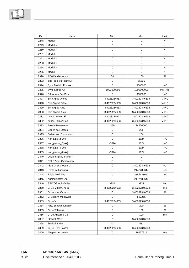
166of 172
2248 Modul: - 0 0 Nr
2249 Modul: - 0 0 Nr
2250 Modul: - 0 0 Nr
2251 Modul: - 0 0 Nr
2252 Modul: - 0 0 Nr
2253 Modul: - 0 0 Nr
2254 Modul: - 0 0 Nr
2255 Modul: - 0 0 Nr
2320 AD-Wandler Ausst. 50 150 %
2323 sico_geb_ctr_com[Ax 0 65535
2324 Sync Modulo Pos Ax 0 3600000 INC
2325 Sync Speed Ax -1000000000 1000000000 Inc/TAB
2326 Diff Ana.u.Ser-Pos 0 3600000 INC
2327 Sin Signal Offset -3.4028234663 3.40282346638 V-INC
2328 Cos Signal Offset -3.4028234663 3.40282346638 V-INC
2329 Sin Signal Amp -3.4028234663 3.40282346638 V-INC
2330 Cos Signal Amp -3.4028234663 3.40282346638 V-INC
2331 quadr. Fehler Sin -3.4028234663 3.40282346638 V-INC
2332 quadr. Fehler Cos -3.4028234663 3.40282346638 V-INC
2333 Anzahl Messwerte 250 14400000
2334 Geber Kor. Status 0 256
2335 Geber Kor. Command 0 256
2336 Kor_amp_2 [Ax] 0 1024 INC
2337 Kor_phase_2 [Ax] -1024 1024 INC
2338 Kor_amp_4 [Ax] 0 1024 INC
2339 Kor_phase_4 [Ax] -1024 1024 INC
2340 Oversampling Faktor 0 0
2341 CPLD-Vers.Geberausw 0 0 -
2342 -3dB Grenzfrequenz 0 3.40282346638 Hz
2343 Reale Aufloesung 0 2147483647 INC
2344 Reale Mod Pos 0 2147483647 INC
2345 Analog Offset [Ax] 0 2147483647
2346 SINCOS Achsfehler -114 -114 Nr.
2360 G-Ue Mittelw. norm -3.4028234663 3.40282346638 Inc
2361 G-Ue Max Varianz 0 3.40282346638 %
2362 G-Ueberw Messwert 0 523265
2363 G-Ue V -3.4028234663 3.40282346638
2364 Abs. Schwankungsbr. 0 200 %
2365 G-Ue Toleranz 0 100 %
2366 G-Ue Ansprechzeit 0 100 ms
2367 Statistik Wert -1 3.40282346638
2368 Statistik Index -3 511
2369 G-Ue Getr. Faktor -3.4028234663 3.40282346638
2400 Abspeicherzaehler 0 16777215 Anz.
ID Name Min Max Unit
Manual KSR - 3A (KMO)
Document no.: 5.04032.03 Baumüller Nürnberg GmbH
List of figures
List of figures
Danger area KSR....................................................................................................................... 21Danger areas at the mechanic mounting ................................................................................... 24Installation space ....................................................................................................................... 26Drilling pattern ............................................................................................................................ 27Mounting instruction ................................................................................................................... 28Danger areas at the electrical installation .................................................................................. 32Connection plan individual device.............................................................................................. 36Connection plan group circuit..................................................................................................... 37Connector assignment ............................................................................................................... 38Disconnection of Y-capacitors.................................................................................................... 40LED display ................................................................................................................................ 44Display operating status............................................................................................................. 44Survey power unit ...................................................................................................................... 50Survey peripheral board............................................................................................................. 51Survey processor board ............................................................................................................. 52Total structure KSR.................................................................................................................... 53PLD functions............................................................................................................................. 54Flow chart current control and PWM.......................................................................................... 55Parameter description scheme .................................................................................................. 57 Function block current controller ............................................................................................... 59Danger area KSR....................................................................................................................... 97
Manual KSR - 3A (KMO)Document no.: 5.04032.03
167of 172

168of 172
List of figures
Manual KSR - 3A (KMO)
Document no.: 5.04032.03 Baumüller Nürnberg GmbH
Index
Numbers73/23/EWG 109
AAcknowledge errors 79
CCable
EMC instructions 34Cable screens 34Cables
Laying 34Capacitors 101Class of protection 14Commissioning 45Connecting cable 33Control cabinet 41, 98Control, higher-level 42
DDanger areas 97Danger notes 16Dangers 7, 16DC-link 98Declaration of Conformity 109, 111Decompress ELTK 125Demounting 102Device 6Device description 19Discharge 98Display elements 44Disposal 103
EElectrical data 115ELTK 42EMC instructions 34Enable signals 42Encoder 35Encoder data (data sheet) 47Environmental conditions 41, 98, 114Error detection 77, 79Error indications 77Error message 78Executing commissioning 48
FFire fighting 15First steps 5Fuses 34
IIEC 60204-1 33Inappropriate use 13
Inspection intervals 98Install ELTK 125Installation 31
Electrical mains 33Preconditions 31
Installation ELTK 119Installation space 23, 26Introduction 5Isolation from supply 101
KKTY84 79
LLaying 34LED 44Legal instructions 12License conditions 120Line count 47Low Voltage Directive 109
MMains voltage 114Maintenance 78, 97Maintenance notes 98Manufacturer’s Declaration 109, 112Meaning of messages 77Modification 13Motor control 47Motor data (type plate) 47Mounting 23Mounting height 114Mounting instructions 28
NNon-electrical data 114
OOperating concept 42Operating sequence of installation 35Operating software 42Operating status 44Operation 41Operation elements 43Operation height 98
PPacking 17Parameter description
Structure 57Personnel 14, 77
qualified 14Power loss 115Power supply 114
Manual KSR - 3A (KMO)
Document no.: 5.04032.03
169of 172
170of 172
Index
Preconditions 46Preparations 46Prepare mounting 25Protective measures 7Pulse enable 42
QQualified personnel 14, 25, 42Quickstop 43
RRated mains input voltage 114Recommissioning 102Relative air humidity 98Repair 99Residual energy 15Responsibility and liability 15RS232 47
SSafety instructions 7, 16, 77Set out of operation 101, 102Signal level 42Skilled person 14Storage 101Storage conditions 102Survey KSR 5
TTechnical data 113Temperature 98Terminals 35Terms
definition 6Transportation 17
Climatic category 17Shock 17Temperature range 17
Troubleshooting 77
UUL 508 C 33Unpacking 17
WWarning 78
Manual KSR - 3A (KMO)
Document no.: 5.04032.03
Baumüller Nürnberg GmbH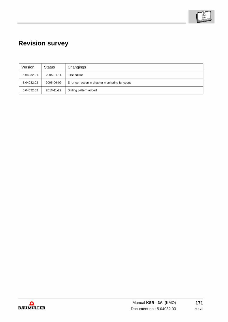
Revision survey
Version Status Changings
5.04032.01 2005-01-11 First edition
5.04032.02 2005-06-09 Error correction in chapter monitoring functions
5.04032.03 2010-11-22 Drilling pattern added
Manual KSR - 3A (KMO)
Document no.: 5.04032.03
171of 172
Notes:
Manual KSR - 3A (KMO)
Document no.: 5.04032.03 Baumüller Nürnberg GmbH
172of 172


Baumüller Nürnberg GmbH Ostendstraße 80-90 90482 Nürnberg T: +49(0)911-5432-0 F: +49(0)911-5432-130 www.baumueller.de
All information given in this manual is customer information, subject to change without notice. We reserve the right to futher develop and actualize our products continuously using our permanent revision service. Please notice, that specifications/data/information are current values according to the printing date.These statements are not legally binding according to the measurement, computation and calculations. Before you make any information given in this manual to the basis of your own calculations and/or applications, please make sure that you have the latest edition of the information in hand.No liability can be accepted concerning the correctness of the information.
Related Documents