48 | Vol.53 No.6 June, 2005 | . Introduction The design and construction of cable supported bridges relies to a large extent on past experience, where good and sometimes less good ideas from previous projects are evaluated and incorporated as appropriate in the new designs together with new ideas. Even though long span bridges can appear similar in the concept, all projects have to be individually designed considering the local conditions. Because the number of new long span bridges is relatively small, the development can appear to be slow compared to other industries. However, almost all major bridge projects contribute in one way or another to the development. Furthermore, the construction of a major bridge represents a significant investment where timely and safe construction is important for a successful completion of a project, which in some cases restrain the willingness to innovation. Finally, the basis for the design and construction - the national or international codes - are often established mainly to suit smaller bridges, which are constructed more frequent and there is often a delay in implementing the latest knowledge in the codes. This present paper focuses on state-of-the-art of design and construction of cable stayed and suspension bridges. . Bridge types There are basically two types of cable supported bridges, suspension bridges and cable stayed bridges. While suspension bridges have been designed and constructed for more than 150 years, the cable stayed bridge concept is relatively new and cable stayed bridges have only been constructed since the middle of the 20 th century. Lars HAUGE Chief Project Manager, COWI A/S Lyngby, Denmark [email protected] | 약 력| Lars Hauge, born 1962, graduated from the Technical University of Denmark in 1986. Since 1990 he has been employed by COWI A/S in Copenhagen in the department for major bridges, and has been involved in the design of some of the world's largest bridges. He has been working in Korea for the Busan-Geoje Fixed Link for the past two years as project manager for the design of the bridges. Construction and Technology of Long Span Bridges

Welcome message from author
This document is posted to help you gain knowledge. Please leave a comment to let me know what you think about it! Share it to your friends and learn new things together.
Transcript

48 | Vol.53 No.6 June, 2005 |
. Introduction
The design and construction of cable supported
bridges relies to a large extent on past experience,
where good and sometimes less good ideas from
previous projects are evaluated and incorporated
as appropriate in the new designs together with
new ideas. Even though long span bridges can
appear similar in the concept, all projects have to
be individually designed considering the local
conditions. Because the number of new long span
bridges is relatively small, the development can
appear to be slow compared to other industries.
However, almost all major bridge projects
contribute in one way or another to the
development. Furthermore, the construction of a
major bridge represents a significant investment
where timely and safe construction is important
for a successful completion of a project, which in
some cases restrain the willingness to innovation.
Finally, the basis for the design and construction -
the national or international codes - are often
established mainly to suit smaller bridges, which
are constructed more frequent and there is often a
delay in implementing the latest knowledge in the
codes.
This present paper focuses on state-of-the-art of
design and construction of cable stayed and
suspension bridges.
. Bridge types
There are basically two types of cable supported
bridges, suspension bridges and cable stayed
bridges. While suspension bridges have been
designed and constructed for more than 150
years, the cable stayed bridge concept is
relatively new and cable stayed bridges have only
been constructed since the middle of the 20th
century.
Lars HAUGEChief Project Manager, COWI A/SLyngby, [email protected]
| 약 력 |Lars Hauge, born 1962, graduated from the TechnicalUniversity of Denmark in 1986. Since 1990 he has beenemployed by COWI A/S in Copenhagen in the department formajor bridges, and has been involved in the design of some ofthe world's largest bridges. He has been working in Korea forthe Busan-Geoje Fixed Link for the past two years as projectmanager for the design of the bridges.
Construction and Technology of Long Span Bridges

49| Feature Article |
Trends in Design and Construction of Long Span Bridges
A ground anchored suspension bridge has the
bridge deck suspended from main cables by
hangers and the deck has roughly no other
function than to provide a carriageway for the
traffic. The main load carrying elements are the
towers, the anchor structure and the main cable.
The sag of the main cables, which controls the
cable steel quantities, is traditionally between 1 : 9
and 1 : 11. A suspension bridge is constructed by
constructing anchors and pylons first followed by
the main cable and finally the bridge deck which
is suspended from the main cables.
Traditionally a cable stayed bridge is constructed
by constructing the towers followed by the deck,
which is cantilevered from the towers. The height
of the towers above deck is normally not less than
approximately 1/5 times the main span. In a cable
stayed bridge, the deck is utilised as compression
members balancing the horizontal forces from the
cables.
This short description illustrates the main
differences between suspension bridges and cable
stayed bridges:
For the construction of a suspension bridge,
the elements are constructed sequential
leading to a long construction time where
most elements are on the critical path.
A suspension bridge requires an anchor
structure, which normally is expensive and
time critical with regard to construction, while
a cable stayed bridge utilises the bridge deck
to balance the horizontal component of the
cable forces.
The amount of cable steel is significantly
higher in a suspension bridge compared to a
cable stayed bridge, due to the reduced tower
height to span ratio.
It will almost always be economically
advantageous to construct a cable stayed bridge if
possible, unless special conditions prevail as for
instance good rock conditions for main cable
anchorage. However, due to the tower height and
the traditional construction methods there is an
upper limit to how long cable stayed bridge can be
constructed.
Attempts have been made to mitigate the
deficiencies of suspension bridge compared to cable
stayed bridges. Self-anchored suspension bridges
have been designed and constructed thus avoiding the
anchor block structure and utilising the bridge deck to
balance the horizontal forces from the main cables.
However, a major set-back is that the deck has to be
erected on temporary supports prior to cable erection,
which calls for temporary support of the bridge deck
during construction adding the bridge deck to the
critical path. An example of a self anchored
suspension bridge is YongJong Bridge in Korea,
where the span is moderate and where the bridge
deck is sufficiently large to carry the compression
force due to large capacity requirements.
Figure 1. Great Belt Suspension Bridge

50 | Vol.53 No.6 June, 2005 |
Construction and Technology of Long Span Bridges
1. Suspension BridgesA suspension bridge with an anchor block
structure is normally only constructed, if the
required span is longer than what can be
accommodated by a cable stayed bridge. This limit
is today around a main span of 1200 - 1400m, but
has moved over the past 50 years from 600 -
700m. Recent long span suspension bridges
include Akashi Kaikyo - Japan (1990m main
span), Great Belt East Bridge - Denmark (1624m
main span), Tsing Ma - Hong Kong (1377m main
span), Humber Bridge - UK (1410m main span)
and the High Coast Bridge - Sweden (1210m main
span). The High Coast Bridge was constructed
taking advantage of extremely good foundation
conditions for the main cables, thus being
economically optimal with a relatively shorter
span. There is a tendency towards even longer
spans, and the next big leap forward is likely to be
the bridge across the Messina Strait in Italy, where
a main span of 3300m is envisaged. This bridge is
out for tender now (spring/summer 2005).
Suspension bridges are sometimes constructed
with shorter spans. However, this is mostly the
case where the design is governed by other issues
than construction cost and time. Examples hereof
are East Bay Bridge in the US, Millenium Bridge
in the UK and Yong Jong Grand Bridge in Korea.
There are exemptions from these general rules
including Gwang An Bridge in Korea and
Carquinez Bridge in the US.
2. Cable Stayed BridgesCable stayed bridges can roughly be divided in three
groups - short spans, medium spans and long spans.
The Normandy Bridge (856m main span) in
France and the Tatara Bridge (890m main span) in
Japan, which were completed in the mid 1990'ies,
marked with main spans of more than 800 m a
large step forward and have paved the way for the
even longer spans of Stonecutters Bridge (1018m
main span) in Hong Kong and Sutong Bridge
(1088 m main span) in China - both currently
under construction. Al these bridges are
constructed with closed steel box girders in the
main span to increase the torsional rigidity. All the
long spans cable stayed bridges are designed
triangulated cable systems.
The cable configuration layout is important for
a long span cable stayed bridge. An A-tower will
in some cases increases the critical wind speed
by 20% compared to a H-tower. In Korea, the 2nd
YongJong Bridge, which currently are being
designed, and the 2nd Nanjing Yangtze Crossing
in China follows the same principles with
triangulated cable systems and closed steel box
Figure 2. Messina Strait Crossing
51| Feature Article |
Trends in Design and Construction of Long Span Bridges
girders. One of the most important parameters
for long span cable stayed bridges is the span to
with ratio and with a span of more than 40 times
the width, the Normandy Bridge in France is still
one of the slender cable stayed bridges in the
world.
In recent years several cables stayed bridges with
main spans of between 400 and 600m for
roadway traffic have been constructed. A concept
with open plated composite bridge decks and
concrete towers seems to be optimal with regard
to cost and time for construction for this range of
spans. There are several examples of this type of
bridge including: Alex Fraiser Bridge in Canada,
2nd Severn Bridge and Dartford Bridge in the UK,
SeoHae Grand Bridge and Sham Shui Po in
Korea, Uddevalla Bridge in Sweden, Rama 8
Bridge in Thailand (mono tower bridge) and
YangPu, XuPu and Ching Chau Min Yang in
China. The bridges of Busan-Geoje Fixed Link in
Korea and the Cooper River bridge in the US are
currently under construction and will become the
same basic bridge types. For main spans over
600m (500m in typhoon areas) it is difficult for
this bridge type to fulfil the requirement to
aerodynamic stability.
Numerous smaller span cable stayed bridges
have been constructed for various reasons - one
being the landmark quality of cable stayed
bridges.
Recently there has been a trend towards multi-
span cable supported bridges. In Hong Kong Ting
Kau Bridge was inaugurated in 1998 and Rion-
Antirion Bridge in Greece and Viaduc de Maillot
in France has recently been competed. In Korea is
the construction of the bridges of the Busan-Geoje
Fixed Link about to commence and the Link will
include a multi-span cable stayed bridge. For the
crossing of the Canal de Chacao in Chile a multi-
span suspension bridge is currently considered.
. Developments in Design
1. Development in Articulation(1) Cable stayed bridges
Hydraulics is commonly used for bridges
subjected to seismic loading to provide support
during a seismic event in the form of Shock
Transmission Units (STU). There has been a trend
towards utilising hydraulics to control the support
conditions of the bridge.
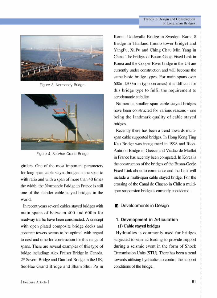
Figure 3. Normandy Bridge
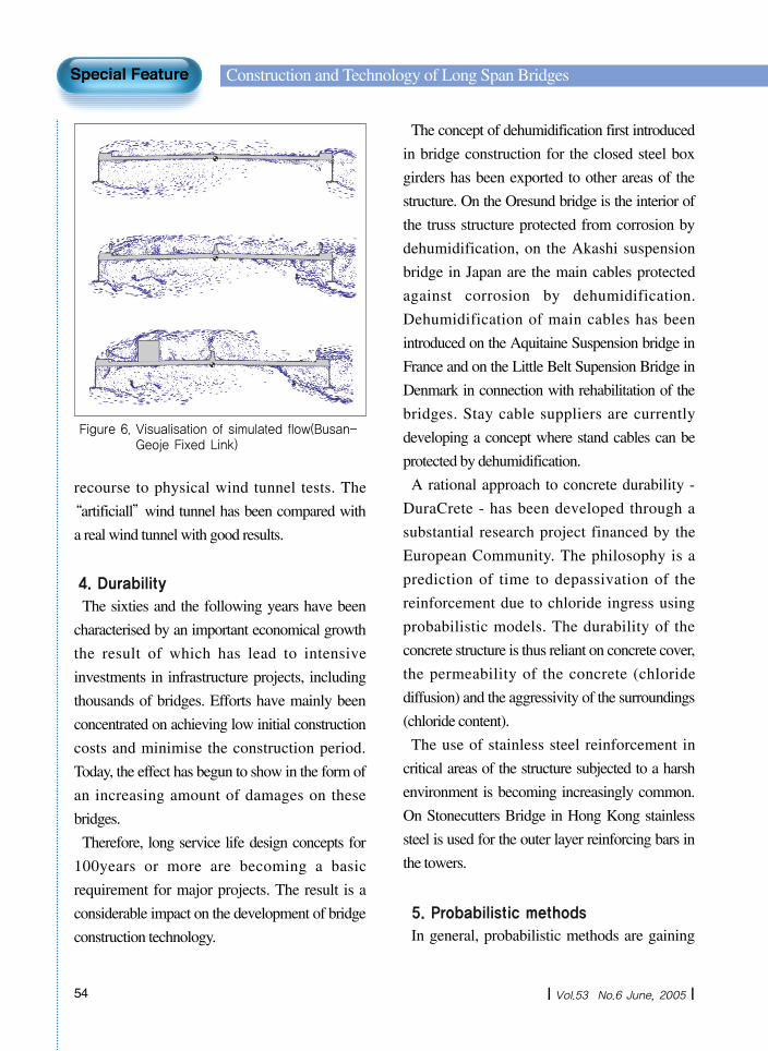
Figure 4. SeoHae Grand Bridge

52 | Vol.53 No.6 June, 2005 |
Construction and Technology of Long Span Bridges
On the Faroe Bridge - a cable stayed bridge
supported by a single plane of cables; the bridge
deck is only supported laterally and for twist at the
towers, while the bridge deck can move freely
vertically. The static system was obtained by the
use of coupled hydraulic pistons at both sides of
the bridge deck
On Stonecutters Bridge the bridge deck is
supported longitudinally for “quick”movements
from dynamic wind and live load, while it is free
to move for “slow”movements from temperature
variations. The advantages are that effects from
dynamic wind would have overloaded the back
span piers, if the deck was not supported by the
tower and the effects from temperature would
have overloaded the towers, if the deck had been
fully restrained.
On Sutong Bridge, the longitudinal movements
at the towers will be restrained by speed
dependent hydraulic dampers. (F=3750·V 0.4 )The bridge deck is not supported vertically at the
towers.
Another characteristic with the above bridges is
that vertical support at the towers is not provided,
thus eliminating the hard point at the towers,
which will attract large bending moments.
The articulation of the Normandy Bridge with
the 116 m cantilever in concrete and monolithic
joint between the girder and the pylon might seem
a little unconventional. However, having studied
the bridge in detail it is clear that these features are
advantageous for the bridge. During construction
the steel part of the girder acted as if it was
supported - not at the pylons - but 116 m out in the
main span, and thus reducing the deflection. The
fully restrained system was possible because the
pylon was supported on a flexible pile foundation
and because the curvature of the deck is large.
(2) Suspension bridge
Traditionally, suspension bridges have been
designed as “ three span structures”with
expansion joints and supports at the towers.
Experience has shown that maintenance works on
these parts constitute a major part of the
maintenance cost. Therefore a concept with a
continuous girder over the full cable supported
length would be attractive and was implemented
for the Great Belt East Bridge in Denmark and for
the High Coast Bridge in Sweden. One problem
to overcome with the continuous girder trough the
pylons was the handling of the forced bending
moments at the pylons caused by angular rotation
of the main cables over the cable saddles. The
girder deflection would more or less follow the
cable deflection, and bending moments would be
introduced. To minimise the forced moments in
combination with dead and live load actions, the
supporting conditions were optimised based on a
parametric study of hanger distances, hanger types
(locked coil versus parallel wire strands),
regulation of hanger forces, girder stiffness,
supporting of the girder for vertical forces at the
pylons, etc.
As a supplement the longitudinal movements at
the anchor blocks were limited by means of
hydraulic pistons in order to limit the angular
deflection of the hangers and the requirements to
the expansion joints. The system also acts against
quick movements to reduce the wear in the
expansion joints and the bearings.

53| Feature Article |
Trends in Design and Construction of Long Span Bridges
2. Closed box girder conceptThe closed steel box girder concept was first
introduced on the Severn suspension bridge in the
UK and the Little Belt suspension bridge in
Denmark in the 1960’ies. The advantages of the
closed steel box are high torsional stiffness,
relatively simple automated fabrication and easy
maintenance. A complex geometry, many edges
and large exposed surfaces are sensitive to
deterioration. Therefore, simple structural forms
as the closed steel box girder with a minimum of
exposure to the environment are preferred. The
outer surface is completely smooth with a
minimum of exposure and easy to maintain. The
interior, which comprises about 80 percent of the
total steel area with stiffening troughs and
bulkheads, can be corrosion protected by
dehumidification and thus does not need to be
painted. The principle in dehumidification is to
keep the relative humidity inside the box below
40 percent, leaving an adequate margin to 60
percent, the limit above which corrosion may take
place. This can be achieved by installation of a
simple fan system for circulation of the enclosed
air and a dehumidifier unit equipped with
hygroscopic filters. The closed steel box girder is
also superior with regard to aerodynamic
performance. The high torsional stiffness
increases the critical flutter wind speed and low
drag coefficients and derivatives reduce the effects
from wind loading.
3. AerodynamicThe failure of the Tacoma Narrows suspension
bridge in the US resulted in a general set back for
the development of design and construction of
long span bridges. Bridges designed and
constructed in the wake of the accident tended
towards heavier steel truss girder design, while the
sources of the undesired vibrations were
thoroughly investigated. Today substantial wind
tunnel testing is part of every long span bridge
design and comprise as a minimum section model
tests of the bridge deck and often 3D aeroelastic
full bridge model tests. These tests are often
supplemented with High Reynolds number tests,
cable vibration tests, terrain model tests and site
measurements of the wind climate.
As computer power increases, more and more
sophisticated calculations can be performed
providing the bridge designers with useful
information of the behaviour of the structures.
COWI has developed a computer tool, which
can be used with advantage for comparison of
bridge girder concepts, DWMflow. Based on a
description of the cross-section, DWMflow
calculates static wind load coefficients (drag-
coefficients), flutter-coefficients and vortex
shedding response. This means that a qualified
evaluation of for instance, different cross sections
could be carried out in a short time without
Figure 5 Stonecutters Bridge in the Monash wind tunnel
54 | Vol.53 No.6 June, 2005 |
Construction and Technology of Long Span Bridges
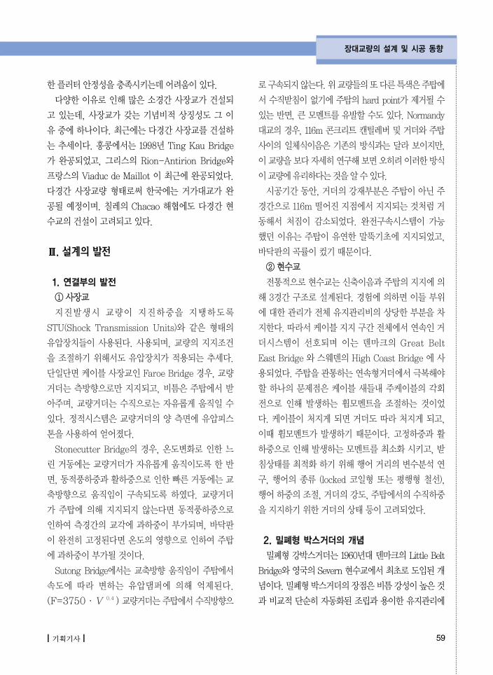
recourse to physical wind tunnel tests. The
“artificiall”wind tunnel has been compared with
a real wind tunnel with good results.
4. DurabilityThe sixties and the following years have been
characterised by an important economical growth
the result of which has lead to intensive
investments in infrastructure projects, including
thousands of bridges. Efforts have mainly been
concentrated on achieving low initial construction
costs and minimise the construction period.
Today, the effect has begun to show in the form of
an increasing amount of damages on these
bridges.
Therefore, long service life design concepts for
100years or more are becoming a basic
requirement for major projects. The result is a
considerable impact on the development of bridge
construction technology.
The concept of dehumidification first introduced
in bridge construction for the closed steel box
girders has been exported to other areas of the
structure. On the Oresund bridge is the interior of
the truss structure protected from corrosion by
dehumidification, on the Akashi suspension
bridge in Japan are the main cables protected
against corrosion by dehumidification.
Dehumidification of main cables has been
introduced on the Aquitaine Suspension bridge in
France and on the Little Belt Supension Bridge in
Denmark in connection with rehabilitation of the
bridges. Stay cable suppliers are currently
developing a concept where stand cables can be
protected by dehumidification.
A rational approach to concrete durability -
DuraCrete - has been developed through a
substantial research project financed by the
European Community. The philosophy is a
prediction of time to depassivation of the
reinforcement due to chloride ingress using
probabilistic models. The durability of the
concrete structure is thus reliant on concrete cover,
the permeability of the concrete (chloride
diffusion) and the aggressivity of the surroundings
(chloride content).
The use of stainless steel reinforcement in
critical areas of the structure subjected to a harsh
environment is becoming increasingly common.
On Stonecutters Bridge in Hong Kong stainless
steel is used for the outer layer reinforcing bars in
the towers.
5. Probabilistic methodsIn general, probabilistic methods are gaining
Figure 6. Visualisation of simulated flow(Busan-Geoje Fixed Link)

55| Feature Article |
Trends in Design and Construction of Long Span Bridges
more and more momentum in design of bridges.
In addition to durability calculations, probabilistic
methods are also used to establish ship collision
loading. Based on scenarios for the ship traffic,
assumptions and distributions of the navigation of
ships passing the bridge and capacity of the
structures, the probability of collapse can be
determined. AASTHO requires that the
probability of failure due to ship collision shall
correspond to a return period of 10.000 years.
Using this method it is possible to quantify and
take advantage of risk mitigating measures as for
instance use of pilots and surveillance systems in
the calculations. Furthermore, the design can be
optimised by for instance accepting higher risk in
case of poor foundation conditions against
reducing the risk elsewhere. The basis for the ship
collision loading for Busan-Geoje Fixed link has
been established on this basis.
Probabilistic methods are also used in
reassessment of remaining structural service life in
connection with rehabilitation.
. Development in Construction
Fabrication and erection of the major bridges
projects is characterised by off-shore/off-site
prefabrication, large transport distance and
erection of large elements. For the Great Belt
West Bridge altogether 324 pre-fabricated units,
comprising 62 caissons, 124 pier shafts and 138
bridge girders were cast in a pre-fabrication yard
close to the bridge site. The elements were cast in
five production lines and moved on sliding
surfaces by pushing units to the load-out jetties,
where they were lifted off by a large purpose-built
heavy lift crane vessel, the Swan, for further
transportation and installation at the bridge site.
Caissons, weighing up to 7,400 tonnes, were
placed by the Swan on 1.5 m thick crushed stone
foundation beds.
For the Oresund Link between Denmark and
Sweden, fabrication of the steel trusses for the
Oresund Bridges as well as casting of the concrete
deck was carried out in Spain. The complete 140 m
long girder sections, weighing up to 7,000tonnes,
were tugged on flat barges to the bridge site and
Figure 7. Pre-fab Yard for Great Belt West Bridge
Figure 8. Pylons for Busan- Geoje Fixed Link
‥

56 | Vol.53 No.6 June, 2005 |
Construction and Technology of Long Span Bridges
lifted into position on the piers by the Swan, the
vessel used for the Storebælt West Bridge. In
between the job on the two Danish bridges, The
Swan has been used to erect the 13km Prince
Edward Island Bridge in Canada after being
modified and having the lifting capacity increased
to 8,700 metric tons.
On the cable-stayed bridge the girder was also
erected in 140m sections on temporary supports
before being suspended by the stays. This method
is unusual for a cable-stayed bridge, but was
attractive due to the availability of the heavy lift
vessel, and it reduced the construction.
For the Busan Geoje Fixed Link it is envisaged to
have caissons, pier shafts and bridge girders for the
approach bridge prefabricated of site and transported
to the site assisted by a large floating crane.
The advantage is a rational industrialised
production in the prefabrication yard, where the
quality more easily can be controlled. Furthermore,
the production is less susceptible to adverse
weather conditions and transport of equipment and
labour to the site can be saved.
. Conclusion
The trends and tendencies in design and
construction of major bridges seem to be
developing in more or less in the same direction
world wide. Because of the size and the
frequency of the projects, it is common early in
the planning process to screen recent similar
projects.
There seems to be a development in the way the
project are procured from traditionally separate
design and construction typically controlled by a
public client, towards design-built project and
BOT projects, where more and more responsibility
is left with the contractor/concessionaire.
Because of the landmark value of these major
projects, there is a tendency towards increased
focus on aesthetics. For the Stonecutters Bridges,
the design was developed though an international
design competition and for the Busan-Geoje
Fixed Link, a special effort was made to give the
bridges an appearance, which would make the
bridges stand-out and which would associate the
bridges with Busan and Geoje Island and vice
versa.
기획 : 신수봉 편집간사장 [email protected]

57| 기획기사 |
. 머리말
케이블교량의 설계와 시공은 대부분 과거의 경험에근거하며, 새로운교량설계시예전프로젝트로부터 분석된 장단점과 새로운 아이디어가 적절하게 병합된다. 장대교량은개념상유사할지라도, 모든프로젝트는 개별적으로 지역적 특색에 맞추어 설계되어야 한다. 신설 장대교량의 수가 상대적으로 적기 때문에, 타 산업에 비해 성장속도가 더딜 수도 있지만교량 프로젝트의 산업발전에 대한 기여도를 결코 간과할 수 없다. 더욱이, 교량의 건설은 대체적으로 대규모의 투자를 의미하고, 정해진 기간내의 안전시공여부가 프로젝트의 성공여부를 좌우하기에, 혁신에대한 의지가 때론 좌절되기도 한다. 설계와 시공기준이 되는 국내 또는 국제 규정은 대개 빈번히 신축되는 소규모 교량에 적합하게 제정이 되며, 최근의정보 또는 지식을 국내외 규정에 반 하기까진 시간이걸린다. 본고에서는사장교와현수교의최첨단설계및시공에관한동향을담아내고자한다.
교량 형식
케이블교량은기본적으로사장교와현수교로나누어진다. 현수교는설계와시공이150년이상이루어졌지만, 20세기중반이래채택된사장교는이에비해비교
적새로운개념의교량이다. 타정식현수교는주케이블로부터행어에의해연결된교량거더가있고, 교량거더는주로차량통행만을제공하는역할을수행한다. 하중을지탱하는주요요소에는주탑, 앵커블록과주케이블이있다. 주케이블의강재량을결정하는주요변수인새그(sag)는일반적으로1 : 9와1 : 11 사이의비율로설치된다. 현수교는앵커와주탑을먼저설치한후에주케이블을설치하며, 주케이블에매달아교량거더를마지막으로건설한다. 사장교는일반적으로주탑을먼저설치하고, 주탑에서켄틸레버공법으로교량거더를설치하는공법을따른다. 교량상부주탑의높이는주경간의1/5배이상이어야한다. 사장교의교량거더는케이블장력의 수평분력을 분담하는 압축부재로써 활용된다.현수교와사장교의차이점을요약하면다음과같다.- 현수교의 건설은 긴 시공기간 동안 거의 모든
단계가주요공정으로순차적으로진행된다.- 현수교는 시공기간이 고려되어야 하고 값비싼
앵커구조물을필요로하는반면, 사장교는교량거더를 케이블 수평하중의 균형을 조절하는데활용한다.
- 주탑의높이와경간의비율감소로인하여, 현수교에사용되는케이블강재의양이사장교에비해현저히많다.
주케이블을정착하기에특별하게적합한암반조건이발견되지않은이상, 가능하면사장교를건설하는
장대교량 건설 및 기술
| 약 력 |
덴마트Technical University 졸업
덴마트COWI A/S 코펜하겐본사교량부입사
거가대교의교량설계부분프로젝트매니저
Lars HAUGEChief Project Manager, COWI A/SLyngby, [email protected]

58 | 제53권 제6호 2005년 6월 |
장대교량 건설 및 기술
것이 경제적으로 유리하다. 하지만, 주탑의 높이와전통적인 시공방법을 고려하면 사장교의 길이에는한계가있다. 사장교와비교해현수교의결함을완화시키기위한노력은계속되어왔다. 앵커블럭구조물을 대신해 자정식 현수교가 설계 및 시공되었고, 주케이블의 수평하중 성분을 부담하기 위해 교량거더를사용하 다. 그러나이러한방법의문제점은교량거더가 케이블이 설치되기 전에 가설지지구조물에먼저 설치되어, 결과적으로 임계경로에 교량거더가추가된다는것이다. 자정식현수교의예로써, 한국의종대교가있다. 종대교는보통길이의경간을가
진 교량으로, 대용량조건으로 인한 압축하중을 견딜정도로충분히큰교량거더를가지고있다.
1. 현수교통상적으로 앵커블록구조물로 이루어진 현수교는
필요한경간이사장교가수용할수있는거리의이상일때만 건설된다. 주경간의 한계는 보통 1200~1400m이지만, 50년전에는 600~700m이었다. 최근에건설된장대현수교의예는일본의Akashi Kaikyo(주경간1990m), 덴마크의 Great Belt East 교(주경간1624m), 홍콩의Tsing Ma 교(주경간 1377m), 국의Humber 교(주경간 1424m), 스웨덴의 High CoastBridge(주경간1210m) 등이있다. High Coast Bridge는주케이블설치에매우적합한기초공사조건으로인해, 비교적짧은경간일지라도경제적으로는최적화하다. 현재경간을더욱길게건설하려는추세이며, 획
기적인 도약으로써 3,300m 경간의 이탈리아의Messina Strait를 가로지르는 교량이 계획되고 현재(2005년봄/여름) 입찰중이다. 현수교는때론짧은경간으로 시공되기도 하는데, 그 이유는 시공비용과 시공기간을배제한기타다른이슈때문에설계되는경우다. 예로써, 미국의 East Bay Bridge, 국의Millennium Bridge와한국의 종대교등이있다. 이러한일반적인원칙에예외적인예로써한국의광안대
교와미국의Carginez 교등을손꼽을수있다.
2. 사장교사장교는크게소경간, 중경간, 장대경간교량으로나
뉘어진다. 1990년중반에완성된800m 이상의주경간대교로써 프랑스의 Normandy Bridge(주경간 856m)와일본의Tatara Bridge(주경간890m) 가있으며, 이들은 나아가 현재 건설중인 홍콩의 StonecuttersBridge(주경간1018m) 와중국의Sutong Bridge(주경간1018 m) 등장대경간교량을건설하는계기를마련했다. 위모든교량은비틈강성을증가하기위해주경간을 폐형 강박스거더로 설치하 으며, 모든 장대사장교는삼각케이블시스템으로설계하 다.케이블의 배치 및 배열은 장대사장교를 건설함에
있어특히중요하다. A형주탑은H형주탑에비해임계풍속을 20%까지 증가시킨다. 한국에서 현재 설계되고있는제2 종교와중국의제2 Nanjing YangtzCrossings 교는삼각케이블시스템및 폐형강박스거더를이용한다. 장대사장교의가장중요한변수중하나는폭-경간비이다. 경간이폭의40배이상인교량으로프랑스의Normandy Bridge 가여전히세계에서가장폭이좁은교량중하나로꼽힌다.최근 들어, 400~600m 주경간의 도로교통용 사장
교가건설되고있다. 상기범위의경간에소요되는공사비용과기간을최적화하는방안으로써개방형플레이트합성거더와콘크리트주탑이부각되고있다. 이러한 형식의 교량으로는 다음 예가 있다: 캐나다의Alex Fraiser Bridge, 국의 제2 Severn Bridge 와Dartfold Bridge, 한국의 서해대교와 삼천포대교, 스웨덴의 Uddevalla Bridge, 태국의 Rama 8 Bridge(Mono Tower Bridge), 중국의Yangpu 교, XuPu 교,Ching Chau Min Yang 교. 이들과동일한교량형식인한국의거가대교와미국의Cooper River Bridge는현재 건설 중에 있다. 주경간이 600m(태풍지역은500m)이상일시, 위와같은형식의교량은바람에의
59| 기획기사 |
장대교량의 설계 및 시공 동향
한플러터안정성을충족시키는데어려움이있다.다양한 이유로 인해 많은 소경간 사장교가 건설되
고 있는데, 사장교가 갖는 기념비적 상징성도 그 이유중에하나이다. 최근에는다경간사장교를건설하는 추세이다. 홍콩에서는 1998년 Ting Kau Bridge가 완공되었고, 그리스의 Rion-Antirion Bridge와프랑스의 Viaduc de Maillot 이 최근에 완공되었다.다경간 사장교량 형태로써 한국에는 거가대교가 완공될 예정이며. 칠레의 Chacao 해협에도 다경간 현수교의건설이고려되고있다.
. 설계의 발전
1. 연결부의 발전①①사사장장교교지진발생시 교량이 지진하중을 지탱하도록
STU(Shock Transmission Units)와 같은 형태의유압장치들이 사용된다. 사용되며, 교량의 지지조건을 조절하기 위해서도 유압장치가 적용되는 추세다.단일단면케이블사장교인Faroe Bridge 경우, 교량거더는 측방향으로만 지지되고, 비틈은 주탑에서 받아주며, 교량거더는 수직으로는 자유롭게 움직일 수있다. 정적시스템은 교량거더의 양 측면에 유압피스톤을사용하여얻어졌다.Stonecutter Bridge의 경우, 온도변화로 인한 느
린 거동에는 교량거더가 자유롭게 움직이도록 한 반면, 동적풍하중과활하중으로인한빠른거동에는교축방향으로 움직임이 구속되도록 하 다. 교량거더가 주탑에 의해 지지되지 않는다면 동적풍하중으로인하여 측경간의 교각에 과하중이 부가되며, 바닥판이 완전히 고정된다면 온도의 향으로 인하여 주탑에과하중이부가될것이다. Sutong Bridge에서는 교축방향 움직임이 주탑에서
속도에 따라 변하는 유압댐퍼에 의해 억제된다.(F=3750·V 0.4 ) 교량거더는주탑에서수직방향으
로구속되지않는다. 위교량들의또다른특색은주탑에서수직받침이없기에주탑의hard point가제거될수있는반면, 큰모멘트를유발할수도있다. Normandy대교의경우, 116m 콘크리트캔틸레버및거더와주탑사이의 일체식이음은 기존의 방식과는 달라 보이지만,이교량을보다자세히연구해보면오히려이러한방식이교량에유리하다는것을알수있다.시공기간동안, 거더의강재부분은주탑이아닌주
경간으로116m 떨어진지점에서지지되는것처럼거동해서 처짐이 감소되었다. 완전구속시스템이 가능했던 이유는 주탑이 유연한 말뚝기초에 지지되었고,바닥판의곡률이컸기때문이다.②②현현수수교교전통적으로현수교는신축이음과주탑의지지에의
해 3경간구조로설계된다. 경험에의하면이들부위에대한관리가전체유지관리비의상당한부분을차지한다. 따라서케이블지지구간전체에서연속인거더시스템이 선호되며 이는 덴마크의 Great BeltEast Bridge 와스웨덴의High Coast Bridge 에사용되었다. 주탑을관통하는연속형거더에서극복해야할 하나의 문제점은 케이블 새들내 주케이블의 각회전으로 인해 발생하는 휨모멘트을 조절하는 것이었다. 케이블이 처지게 되면 거더도 따라 처지게 되고,이때 휨모멘트가 발생하기 때문이다. 고정하중과 활하중으로인해발생하는모멘트를최소화시키고, 받침상태를최적화하기위해행어거리의변수분석연구, 행어의 종류 (locked 코일형 또는 평행형 철선),행어하중의조절, 거더의강도, 주탑에서의수직하중을지지하기위한거더의상태등이고려되었다.
2. 폐형 박스거더의 개념폐형강박스거더는1960년대덴마크의Little Belt
Bridge와 국의Severn 현수교에서최초로도입된개념이다. 폐형박스거더의장점은비틈강성이높은것과비교적단순히자동화된조립과용이한유지관리에

60 | 제53권 제6호 2005년 6월 |
장대교량 건설 및 기술
있다. 여러개의모서리와외부노출면적이넓은복잡한형태의구조물은쉽게노후화되므로, 폐형강박스거더처럼최소한의노출만을허용하는간단한구조물형태가선호된다. 매끄러운외곽표면은외부에최소한으로노출이되어유지관리가용이하다. 박스거더의내부는보강재과격벽으로이루어져강재면적의총80% 정도를차지하고있으며탈습은부식을방지하기때문에도색을할필요가없다. 탈습의원리는박스내부의상대습도를 40% 이하로 내리고, 부식이 발생할 수 있는한계마진을60% 정도까지유지시키는것이다. 이를위해선내부의공기를순환시키는간단한환풍시스템과습기흡수필터가장착된탈습기를설치하면된다.
폐형강박스거더는공기역학적효율성도탁월하다. 높은 비틈 강성은 임계 플러터풍속을 증가시키며, 공기력계수와그기울기를줄여서풍하중효과를감소시킨다.
3. 공기역학(Aerodynamic)미국Tacoma Narrows 현수교의붕괴는장대교량
의설계와시공발전의침체현상을초래하 다. 이후사고의 뼈저린 경험을 바탕으로 건설된 교량에는 두꺼운강트러스거더가사용되었고, 예측불허한진동의근원까지철저히조사되었다. 현재풍동실험은모든장대교량설계에있어기본이며, 교량거더의부분모형실험및3차원전교모형실험등의형태로이루어진다. 경우에 따라 이러한 실험에 High Reynold'sNumber실험, 케이블진동실험, 지형모델실험 또는풍향기후의 현장계측 등이 추가된다. COWI사는 컴퓨터 기술을 통해 교량거더와 비교해 보다 효과적인DVMFlow를 개발하 다. 교량 단면도를 기초로,DVMFlow는정적공기력계수(항력계수), 플러터계수,와류진동으로인한동적거동등을산출한다. 이는곧각기다른단면에대한평가를단시간내풍동실험없이실행할수있다는의미이기도하다. 가상풍동실험은실제풍동실험대비시만족할만한결과를보 다.
4. 내구성(Durability)60년대와 이후 서방국가에게는 경제적으로 중요한
성장기 고, 이는곧수천개의교량을포함해기반시설물에대한대대적인투자로이어졌다. 초기시공비용을저렴하게책정하고공사기간을단축시키는데집중한결과는 교량에 발생하는 손상의 증가로 이어졌다. 이후,대부분주요프로젝트의설계요건으로100년이상사용할수있는교량의설계가필수조건이되었고, 결과적으로교량시공기술발전에중대한전기를마련하 다.교량시공에있어탈습원리는 폐형강박스거더에
서 최초로 도입이 된 이래, 타 구조분야에도 빈번히응용되고 있다. Oresund Bridge에서는 트러스 구조의 내부를 탈습하여 부식방지를 하도록 하 으며,일본의Akashi 현수교의주케이블역시탈습으로인해부식을방지하고있다. 주케이블의탈습원리는프랑스의 Agitaine 현수교와 덴마트의 Little Belt 현수교에도도입되었다. 교량의보수와관련하여, 사장케이블 공급업자들은 현재 사장케이블이 탈습보호될수있도록연구하고있다.콘크리트의 내구성을 강화하기 위한 합리적인 방
안으로유럽공동체의재정지원하연구프로젝트를통해 DuraCrete이 개발되었다. 이는 클로라이드 침투로인한철근의탈부동태화시간을확률적공법을통해 예측하는 원리이다. 콘크리트구조물의 내구성은콘크리트덮개, 콘크리트의 침투성(클로라이드 확산),주위 조건 등에(클로라이드 함량) 의해 결정된다. 구조물의임계범위에서악천후대비용으로스테인레스철근을사용하는것은이미일반화가되었다. 홍콩의Stonecutter Bridge 경우, 주탑의 외부층 보강철근으로스테인레스철강을사용한다.
5. 확률론적 방법(Probabilistic Methods)확률론적 방법은 교량의 설계에 있어 점점 각광을
받고 있다. 내구성을 산출하는 것 이외에도, 확률론적 방법은 선박 충돌하중을 산정하는데도 사용되어
61| 기획기사 |
장대교량의 설계 및 시공 동향
진다. 해상항로의 시나리오에서 교량을 통과하는 선적 항해의 추정 및 분포도에 따라, 붕괴의 가능성이추정되어지기도 한다. AASTHO는 선박충돌로 인한붕괴확률을 10000년 재현주기에 근거하도록 규정하고 있다. 이 방법을 사용할 경우, 예컨대 항로안내서또는 감시시스템 등을 활용해 위험을 미연에 완화시킬수있는방법들을수치화할수있다.또한 다른 곳에서 위험을 감수하기 보다 기초가 부
실한 곳에서 높아진 위험부담을 수용하는 것과 같은방법으로설계는최적화될수있다. 거가대교의선박출동하중의기준도이러한기준에의해수립되었다.확률론적방법은보수공사시구조물의잔존수명을
재평가하는데사용되기도한다.
. 시공의 발전
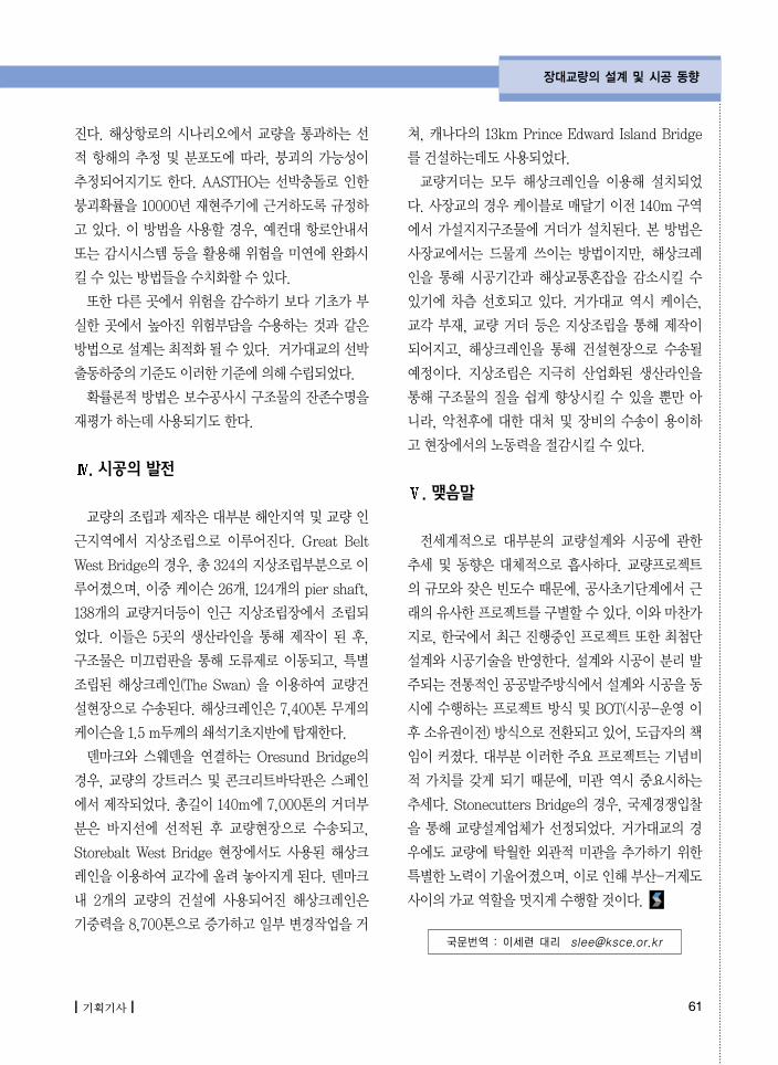
교량의조립과제작은대부분해안지역및교량인근지역에서 지상조립으로 이루어진다. Great BeltWest Bridge의경우, 총324의지상조립부분으로이루어졌으며, 이중 케이슨 26개, 124개의 pier shaft,138개의 교량거더등이 인근 지상조립장에서 조립되었다. 이들은 5곳의 생산라인을 통해 제작이 된 후,구조물은 미끄럼판을 통해 도류제로 이동되고, 특별조립된 해상크레인(The Swan) 을 이용하여 교량건설현장으로 수송된다. 해상크레인은 7,400톤 무게의케이슨을1.5 m두께의쇄석기초지반에탑재한다. 덴마크와 스웨덴을 연결하는 Oresund Bridge의
경우, 교량의 강트러스 및 콘크리트바닥판은 스페인에서제작되었다. 총길이 140m에 7,000톤의거더부분은 바지선에 선적된 후 교량현장으로 수송되고,Storebalt West Bridge 현장에서도 사용된 해상크레인을이용하여교각에올려놓아지게된다. 덴마크내 2개의 교량의 건설에 사용되어진 해상크레인은기중력을8,700톤으로증가하고일부변경작업을거
쳐, 캐나다의 13km Prince Edward Island Bridge를건설하는데도사용되었다.교량거더는 모두 해상크레인을 이용해 설치되었
다. 사장교의경우케이블로매달기이전 140m 구역에서 가설지지구조물에 거더가 설치된다. 본 방법은사장교에서는 드물게 쓰이는 방법이지만, 해상크레인을 통해 시공기간과 해상교통혼잡을 감소시킬 수있기에 차츰 선호되고 있다. 거가대교 역시 케이슨,교각 부재, 교량 거더 등은 지상조립을 통해 제작이되어지고, 해상크레인을 통해 건설현장으로 수송될예정이다. 지상조립은 지극히 산업화된 생산라인을통해 구조물의 질을 쉽게 향상시킬 수 있을 뿐만 아니라, 악천후에 대한 대처 및 장비의 수송이 용이하고현장에서의노동력을절감시킬수있다.
. 맺음말
전세계적으로 대부분의 교량설계와 시공에 관한추세 및 동향은 대체적으로 흡사하다. 교량프로젝트의규모와잦은빈도수때문에, 공사초기단계에서근래의유사한프로젝트를구별할수있다. 이와마찬가지로, 한국에서최근진행중인프로젝트또한최첨단설계와시공기술을반 한다. 설계와시공이분리발주되는전통적인공공발주방식에서설계와시공을동시에 수행하는 프로젝트 방식 및 BOT(시공-운 이후소유권이전) 방식으로전환되고있어, 도급자의책임이커졌다. 대부분이러한주요프로젝트는기념비적 가치를 갖게 되기 때문에, 미관 역시 중요시하는추세다. Stonecutters Bridge의 경우, 국제경쟁입찰을 통해 교량설계업체가 선정되었다. 거가대교의 경우에도 교량에 탁월한 외관적 미관을 추가하기 위한특별한노력이기울어졌으며, 이로인해부산-거제도사이의가교역할을멋지게수행할것이다.
국문번역 : 이세련 대리 [email protected]
Related Documents