KS-1017 Kachinko System (lip checker) Operating manual N T S C KS-1017 SPK MONI V-PROBE SEL. BATT. 1st 2nd 3rd DATA DELAY TIME DATA F F O MANU SET PRE A2 A2 A1 ms FRAME FRAME A2 LIP CHECKER . T OVER ON ms TH. START POWER GAIN + - 0 10 0 10 E O D 10 0 O D U A I V I A1 V A1 ( )

Welcome message from author
This document is posted to help you gain knowledge. Please leave a comment to let me know what you think about it! Share it to your friends and learn new things together.
Transcript

KS-1017Kachinko System (lip checker)
Operating manual
N T S C
KS-1017
SPKMONI
V-PROBE
SEL.BATT.
1st 2nd 3rd
DATA
DELAY TIME DATA
FFO
MANU
SETPRE
A2A2A1
ms
FRAME
FRAME
A2
LIP CHECKER .T OVER ON
ms
TH.
START
POWER
GAIN +-
0 100 10
EO
D
100
O
DUA
I
VI
A1
VA1
( )

3
Kachinko System
3
Kachinko System
The KS-1017 is used together with the KS-1018 “clapperboard” or with other synchronization sources to synchronize video and audio which may arrive via different feeds or be otherwise de-layed relative to each other.For example, if the video portion of a live international broad-cast is transmitted via satellite, and the audio portion via sub-marine cable, there will be a noticeable lag between the two sig-nals when they arrive at the local broadcast center. In this case, the audio should be delayed by a certain fixed amount before broadcast so that the audio and video are in sync. The Kamesan Kachinko System helps you to work out exactly how many milliseconds (or frames) the audio signal must be delayed in order to achieve proper sync.
Satellite transmission
Use a handheld camera to shoot
the KS-1018
KS-1018Audio and video data picked up simultaneously
Undersea cableAudio data captured with microphone or cable
Use the video probe to detect the signal on a TV monitor
KS-1017
Use a microphone, or a line input, to connect the audio signal to the KS-1017

4
Kachinko System
5
Kachinko System
The KS-1018 is used to produce a synchronized video and au-dio signal. See the separate manual for details of operation of this unit.Next, at the other end, the KS-1017 is connected to one or two audio feeds (typically the main and sub audio channels), and its video probe is used to read the screen showing the “clapper-board” so that the audio and video signals can be detected.The KS-1017 then computes the delay between the audio and the video signals.The time in milliseconds or frames between these signals is then read out and the delay adjusted appropriately. Note that the frame rate (NTSC or PAL/SECAM) is set at the factory and cannot be changed. The frame rate for the unit is shown on the front panel.
4
Kachinko System
5
Kachinko System
Parts of the KS-1018
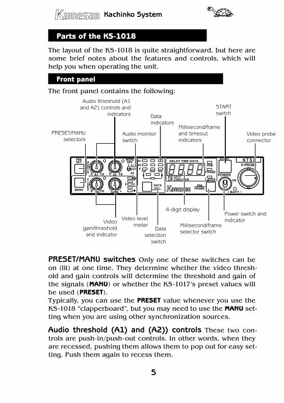
The layout of the KS-1018 is quite straightforward, but here are some brief notes about the features and controls, which will help you when operating the unit.
Front panel
The front panel contains the following:
N T S C
KS-1017
SPKMONI
V-PROBE
SEL.BATT.
1st 2nd 3rd
DATA
DELAY TIME DATA
FFO
MANU
SETPRE
A2A2A1
ms
FRAME
FRAME
A2
LIP CHECKER .T OVER ON
ms
TH.
START
POWER
GAIN +-
0 100 10
EOD
100
ODUA
I
VI
A1
VA1
( )
PRESET/MANU selectors
Audio monitor switch
Data indicators
Audio threshold (A1 and A2) controls and
indicators
Millisecond/frame and timeout indicators
START switch
Video probe connector
Video gain/threshold and indicator
Video level meter
Data selection
switch
4-digit display
Millisecond/frame selector switch
Power switch and indicator
PRESET/MANU switches Only one of these switches can be on (lit) at one time. They determine whether the video thresh-old and gain controls will determine the threshold and gain of the signals (MANU) or whether the KS-1017’s preset values will be used (PRESET).Typically, you can use the PRESET value whenever you use the KS-1018 “clapperboard”, but you may need to use the MANU set-ting when you are using other synchronization sources.
Audio threshold (A1) and (A2)) controls These two con-trols are push-in/push-out controls. In other words, when they are recessed, pushing them allows them to pop out for easy set-ting. Push them again to recess them.

6
Kachinko System
7
Kachinko System
They control the threshold level at which a signal received at ei-ther the A1 or A2 jack triggers the unit (as shown by the orange indicators).
MONI SPK (Audio monitor switch) The KS-1017 contains a small amplifier and speaker that you can use to monitor the au-dio signals received at the A1 and A2 jacks. Set this switch to monitor either A1, A2 or neither (OFF). The volume is adjustable using a recessed trimmer pot accessible from the side panel.
Data indicators (1st, 2nd, 3rd) This 3 x 3 matrix shows the order in which the audio and video signals have been received. Each column represents a signal and they are labeled 1st, 2nd, 3rd.The top row (yellow) shows whether the signal was received at the analog 1 input (A1), the second row (green) shows whether the signal was received at the analog 2 input (A2), and the third row (orange) shows whether the video signal was received (V).
Millisecond, frame and timeout indicators Depending on the setting made using the millisecond/frame selector switch, either the millisecond ms (green) or frame FRAME (yellow) indi-cator lights.The red timeout T.OVER indicator lights if the time interval be-tween the video and the audio signals is too long to be mea-sured accurately by the KS-1017.
START switch Use this switch to start the measurement pro-cess. The switch on the video probe has the same effect.
Video probe connector (V-PROBE) Connect the supplied video probe using this bayonet-type connector. The twist-ring locking lugs are at the top and bottom and the keying notch/lug section is at the left of the connector. Push the probe connector into place and twist the locking ring clockwise to secure it. Re-verse the process to disconnect the video probe.
Video gain/threshold controls and indicator Like the audio controls, these are push-in/push-out controls. Similar to an au-dio compressor, these allow you to select the gain of the video
6
Kachinko System
7
Kachinko System
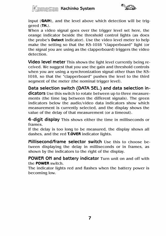
input (GAIN), and the level above which detection will be trig-gered (TH.). When a video signal goes over the trigger level set here, the orange indicator beside the threshold control lights (as does the probe’s Detect indicator). Use the video level meter to help make the setting so that the KS-1018 “clapperboard” light (or the signal you are using as the clapperboard) triggers the video detection.
Video level meter This shows the light level currently being re-ceived. We suggest that you use the gain and threshold controls when you are using a synchronization signal other than the KS-1018, so that the “clapperboard” pushes the level to the third segment of the meter (the nominal trigger level).
Data selection switch (DATA SEL.) and data selection in-dicators Use this switch to rotate between up to three measure-ments (the time lag between the different signals). The green indicators below the audio/video data indicators show which measurement is currently selected, and the display shows the value of the delay of that measurement (or a timeout).
4-digit display This shows either the time in milliseconds or frames.If the delay is too long to be measured, the display shows all dashes, and the red T.OVER indicator lights.
Millisecond/frame selector switch Use this to choose be-tween displaying the delay in milliseconds or in frames, as shown by the indicators to the right of the display.
POWER ON and battery indicator Turn unit on and off with the POWER switch. The indicator lights red and flashes when the battery power is becoming low.
8
Kachinko System
9
Kachinko System
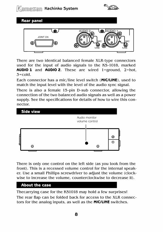
Rear panel
JOINT CN
LINE
MICMIC
LINE
AUDIO 2 AUDIO 1
There are two identical balanced female XLR-type connectors used for the input of audio signals to the KS-1018, marked AUDIO 1 and AUDIO 2. These are wired 1=ground, 2=hot, 3=cold. Each connector has a mic/line level switch (MIC/LINE), used to match the input level with the level of the audio sync signal.There is also a female 15-pin D-sub connector, allowing the connection of the two balanced audio signals as well as a power supply. See the specifications for details of how to wire this con-nector.
Side view����� ������������� �������
There is only one control on the left side (as you look from the front). This is a recessed volume control for the internal speak-er. Use a small Phillips screwdriver to adjust the volume (clock-wise to increase the volume, counterclockwise to decrease it).
About the case
Thecarrying case for the KS1018 may hold a few surprises! The rear flap can be folded back for access to the XLR connec-tors for the analog inputs, as well as the MIC/LINE switches.
8
Kachinko System
9
Kachinko System
The KS-1017 must be removed from the case if the combined connector is to be used.The top flap covering the control panel and the video probe pocket can be folded back on itself, and used as a stand to prop the KS-1017 up at a convenient angle on a working surface. Note that you must disconnect the video probe before closing the flap.
Batteries
The KS-1017 uses 4 AA dry-cell or rechargeable batteries.These are located in the battery compartment accessed using the hinged cover at the top of the unit.Take care that the batteries are inserted correctly with the po-larity correct.Never mix batteries of different types, or discarded (or partially-discharged) and new (or freshly-charged) batteries.Always follow the battery manufacturer’s instructions for charg-ing rechargeable batteries. Never attempt to recharge batteries which are not designed for this purpose.
10
Kachinko System
11
Kachinko System
Using the KS-1018 with the KS-1017
This procedure should take place in the rehearsal stage of the broadcast.1. Connect the audio signals to sig-
nals split off from the main and sub feeds. Ensure that the cor-rect signal level (mic or line) is selected.
2. Arrange for the remote source to turn on the light and sound using the MANU setting and the on/off button on the top of the KS-1018. Set the KS-1017 to the PRESET setting.
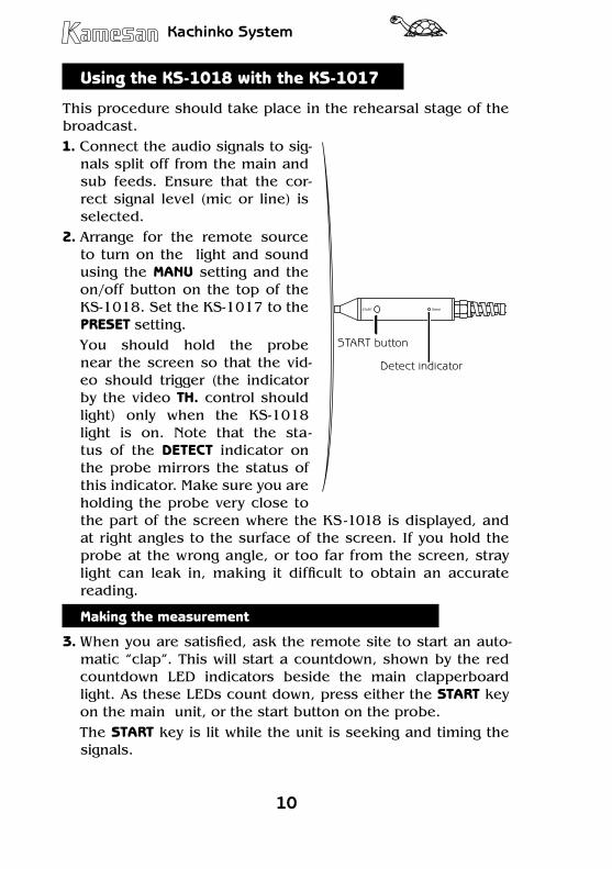
You should hold the probe near the screen so that the vid-eo should trigger (the indicator by the video TH. control should light) only when the KS-1018 light is on. Note that the sta-tus of the DETECT indicator on the probe mirrors the status of this indicator. Make sure you are holding the probe very close to the part of the screen where the KS-1018 is displayed, and at right angles to the surface of the screen. If you hold the probe at the wrong angle, or too far from the screen, stray light can leak in, making it difficult to obtain an accurate reading.
Making the measurement
3. When you are satisfied, ask the remote site to start an auto-matic “clap”. This will start a countdown, shown by the red countdown LED indicators beside the main clapperboard light. As these LEDs count down, press either the START key on the main unit, or the start button on the probe.
The START key is lit while the unit is seeking and timing the signals.
START Detect
START button
Detect indicator
10
Kachinko System
11
Kachinko System
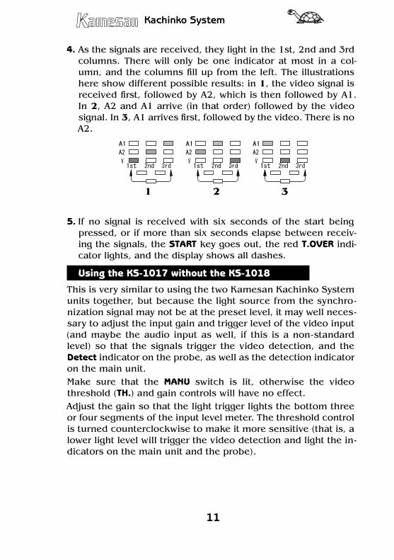
4. As the signals are received, they light in the 1st, 2nd and 3rd columns. There will only be one indicator at most in a col-umn, and the columns fill up from the left. The illustrations here show different possible results: in 1, the video signal is received first, followed by A2, which is then followed by A1. In 2, A2 and A1 arrive (in that order) followed by the video signal. In 3, A1 arrives first, followed by the video. There is no A2.
1 2 3
5. If no signal is received with six seconds of the start being pressed, or if more than six seconds elapse between receiv-ing the signals, the START key goes out, the red T.OVER indi-cator lights, and the display shows all dashes.
Using the KS-1017 without the KS-1018
This is very similar to using the two Kamesan Kachinko System units together, but because the light source from the synchro-nization signal may not be at the preset level, it may well neces-sary to adjust the input gain and trigger level of the video input (and maybe the audio input as well, if this is a non-standard level) so that the signals trigger the video detection, and the Detect indicator on the probe, as well as the detection indicator on the main unit.Make sure that the MANU switch is lit, otherwise the video threshold (TH.) and gain controls will have no effect.Adjust the gain so that the light trigger lights the bottom three or four segments of the input level meter. The threshold control is turned counterclockwise to make it more sensitive (that is, a lower light level will trigger the video detection and light the in-dicators on the main unit and the probe).

12
Kachinko System
13
Kachinko System
Interpreting the results
1. To read the figures, press the DATA SEL. key to cycle through the three different readings (between 1st and 2nd, and 2nd and 3rd on the top row of the three selection indicators, and between 1st and 3rd on the bottom).
2. The gap between the signals is shown in either milliseconds or in frames, depending on the setting made with the mS/FRAME switch.If an interval is too long to be displayed (over 6 seconds), the T.OVER indicator lights when the reading is selected and the display shows all dashes.
3. Use your audio or video delay to slip the signals by the appropriate amount so that the audio and video are properly synchronized.
12
Kachinko System
13
Kachinko System
Specifications
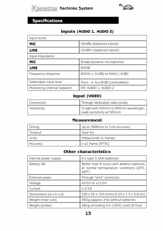
Inputs (AUDIO 1, AUDIO 2)
Input levels
MIC –60 dBs (balanced inputs)
LINE –10 dBm (balanced inputs)
Input impedance
MIC 30 kΩ (dynamic microphone)
LINE 600 Ω
Frequency response 400 Hz (–12 dB) to 6 kHz (–6 dB)
Detectable input level From –∞ to+16 dB (controllable)
Monitoring (internal speaker) Off, AUDIO 1, AUDIO 2
Input (VIDEO)
Connection Through dedicated video probe
Sensitivity To light with 350 nm to 800 nm wavelength; peak sensitivity at 560 nm
Measurement
Timing Up to 5999 ms to 1 ms accuracy
Timeout Over 6 s
Units Milliseconds or frames
Accuracy < ±1 frame (NTSC)
Other characteristics
Internal power supply 4 x type 3 (AA) batteries
Battery life Better than 6 hours with alkaline batteries at normal termperature conditions (20˚C, 68˚F)
External power Through “joint” connector
Voltage +9.0 V to +15.0 V
Current > 0.5 A
Dimensions (w x h x d) 159 x 33 x 150 (mm) 6.25 x 1.3 x 5.9 (in)
Weight (main unit) 950 g (approx 2 lb) without batteries
Weight (probe) 180 g (including 2 m (>6 ft) cord) (6.5 oz)
14
Kachinko System
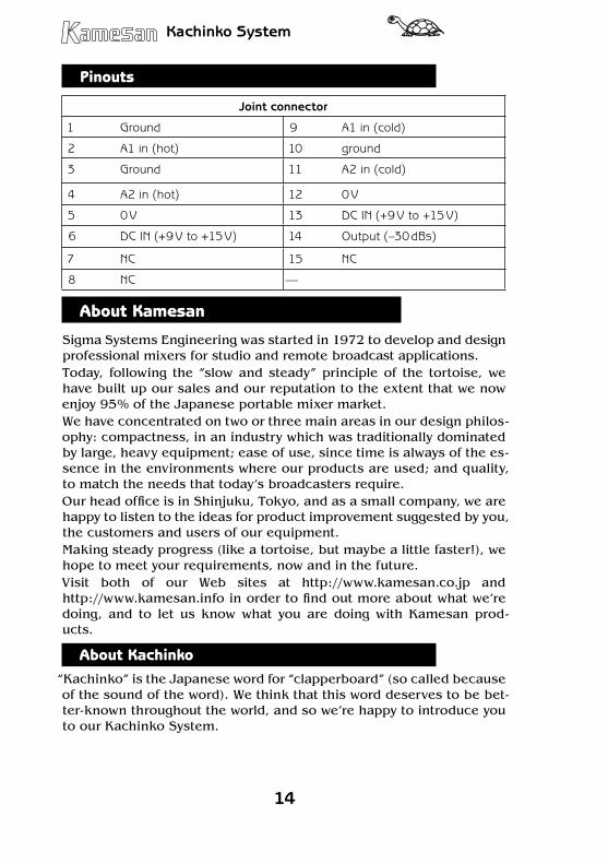
Pinouts
Joint connector
1 Ground 9 A1 in (cold)
2 A1 in (hot) 10 ground
3 Ground 11 A2 in (cold)
4 A2 in (hot) 12 0 V
5 0 V 13 DC IN (+9 V to +15 V)
6 DC IN (+9 V to +15 V) 14 Output (–30 dBs)
7 NC 15 NC
8 NC —
About Kamesan
Sigma Systems Engineering was started in 1972 to develop and design professional mixers for studio and remote broadcast applications.Today, following the “slow and steady” principle of the tortoise, we have built up our sales and our reputation to the extent that we now enjoy 95% of the Japanese portable mixer market.We have concentrated on two or three main areas in our design philos-ophy: compactness, in an industry which was traditionally dominated by large, heavy equipment; ease of use, since time is always of the es-sence in the environments where our products are used; and quality, to match the needs that today’s broadcasters require.Our head office is in Shinjuku, Tokyo, and as a small company, we are happy to listen to the ideas for product improvement suggested by you, the customers and users of our equipment.Making steady progress (like a tortoise, but maybe a little faster!), we hope to meet your requirements, now and in the future.Visit both of our Web sites at http://www.kamesan.co.jp and http://www.kamesan.info in order to find out more about what we’re doing, and to let us know what you are doing with Kamesan prod-ucts.
About Kachinko“Kachinko” is the Japanese word for “clapperboard” (so called because of the sound of the word). We think that this word deserves to be bet-ter-known throughout the world, and so we’re happy to introduce you to our Kachinko System.

14
Kachinko System

Sigma Systems Engineering Co. Ltd.3-5-2 OkuboShinjuku-kuTokyo 169-0072JAPAN
Tel: +81 3 3204 2611Fax: +81 3 3204 2250e-mail: [email protected]
Related Documents