KRA-21 Cutting Chart TOP OF ANTENNA W/O CAP •. 0(-------- TRANSMIT FREQUENCY IN MHz -------~}¥ 30 31 32 33 34 35 36 37 38 39 40 41 42 43 44 45 46 47 48 49 50 ! i11-f-i-!--i-! I-Ii- I I ! : i i i 30 31 32 33 34 35 36 37 38 39 40 41 42 43 44 45 46 47 48 49 50 5. To replace antenna cop, run 0 bead of Loctite@ # 414 or cyanoacrylate superglue around the inside walls of the antenna cap. Seat the cop fully on the anienno. LOST CAPS ore not covered by the warranty. CUITING INSTRUCTIONS 1. Cutting Chart Ruler to the right: Confirm that your chert is 1: 1 using 0 ruler. The cut length will be wrong if printed PDFs or copies ore not at e 1: 1 size ratio. 2. Remove cap from antenna. 3. Align top of antenna with top of graph corresponding to the desired transmit frequency. 4. Mark the antenna where the solid line intersects the nntenno and cui at that mark. 0" 1" 2" 3" 4" 5"

Welcome message from author
This document is posted to help you gain knowledge. Please leave a comment to let me know what you think about it! Share it to your friends and learn new things together.
Transcript
KRA-21Cutting Chart
TOP OFANTENNA W/O
CAP
•.0(-------- TRANSMIT FREQUENCY IN MHz -------~}¥
30 31 32 33 34 35 36 37 38 39 40 41 42 43 44 45 46 47 48 49 50
! i11-f-i-!--i-! I-Ii-II!
:iii
30 31 32 33 34 35 36 37 38 39 40 41 42 43 44 45 46 47 48 49 50
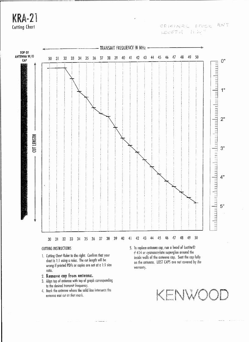
5. To replace antenna cop, run 0 bead of Loctite@# 414 or cyanoacrylate superglue around theinside walls of the antenna cap. Seat the cop fullyon the anienno. LOST CAPS ore not covered by thewarranty.
CUITING INSTRUCTIONS
1. Cutting Chart Ruler to the right: Confirm that yourchert is 1: 1 using 0 ruler. The cut length will bewrong if printed PDFs or copies ore not at e 1: 1 sizeratio.
2. Remove cap from antenna.3. Align top of antenna with top of graph corresponding
to the desired transmit frequency.4. Mark the antenna where the solid line intersects the
nntenno and cui at that mark.
0"
1"
2"
3"
4"
5"
KRA-21Field Tunable Antenno for TK-190 Serieslow Bond Portoble Tronceivers
The KRA-21 comes from the factory center tuned to29.7 MHz. The antenna may be tuned to another frequencybetween 29.7 and 50 MHz by cutting off the top part of theantenna. To determine the length, you should first removethe cap from the antenna. Then refer to the chart below oruse the cutting chart on the reverse side.
rnmllm~.I!IUl!ijl;IIlD. MlliuUijl;RtW _29.7 0 0.030 3/16 0.5
_..=..:31'-., 3/16 =0.=-5 _32 3/16 0.5
-3"3-- 9/16 .__ -'-1.~5 _34 1 2.535 1 3/16 3.0-36-- 1 9/16 ---"'4."'-0---37 1 3/4 4.438 1 7/8 4.839 21/4 5.840 25/8 6.741 . ..27/8 7.3
_4231/8 7.943· ; 33/8 .:. 8.6"
-44-··- ~3"5/8 9:245,-, .;;'37/8· .. --,-,9.=8=.c.·,~~-,-,-46' ~... . 41/8:' 10.4
-47 45/16 11.048 41/2 11.449 411/16 11.950 47/8 12.4
NOTES:• Antenna Bandwidth is 500 KHz
• Cut the copper-plated coil spring with a pair of hardenedcutters.
• CAP gluing instructions: Runa bead of Lbctite® # 414or cyanoacrylate superglue around the inside walls of theantenna cap. Seat the cap fully on the antenna. LOSTCAPS are not covered by the warranty.
• AFTER TUNING the antenna, please place thesupplied 1j. page colored ANTENNA PERFORMANCEinformation sheet with the end-user's TK-190 InstructionManual.
WARRANTY:The KRi\-21 is an accessory to the TK-190 transceiver, andis covered for a period of one vear, as mentioned in the radiowarrantv statement.
KENWOOD COMMUNICATIONS (ORPORATIO~2201 E.Dominguez StreetPO Box 22745Long Beach, CA, 90801-5745U.S.A.
PIOOOIS, V4, 12/13/D5, 5192.0022krn-Zlim.dor
© Kenwood Comm Corp [eb
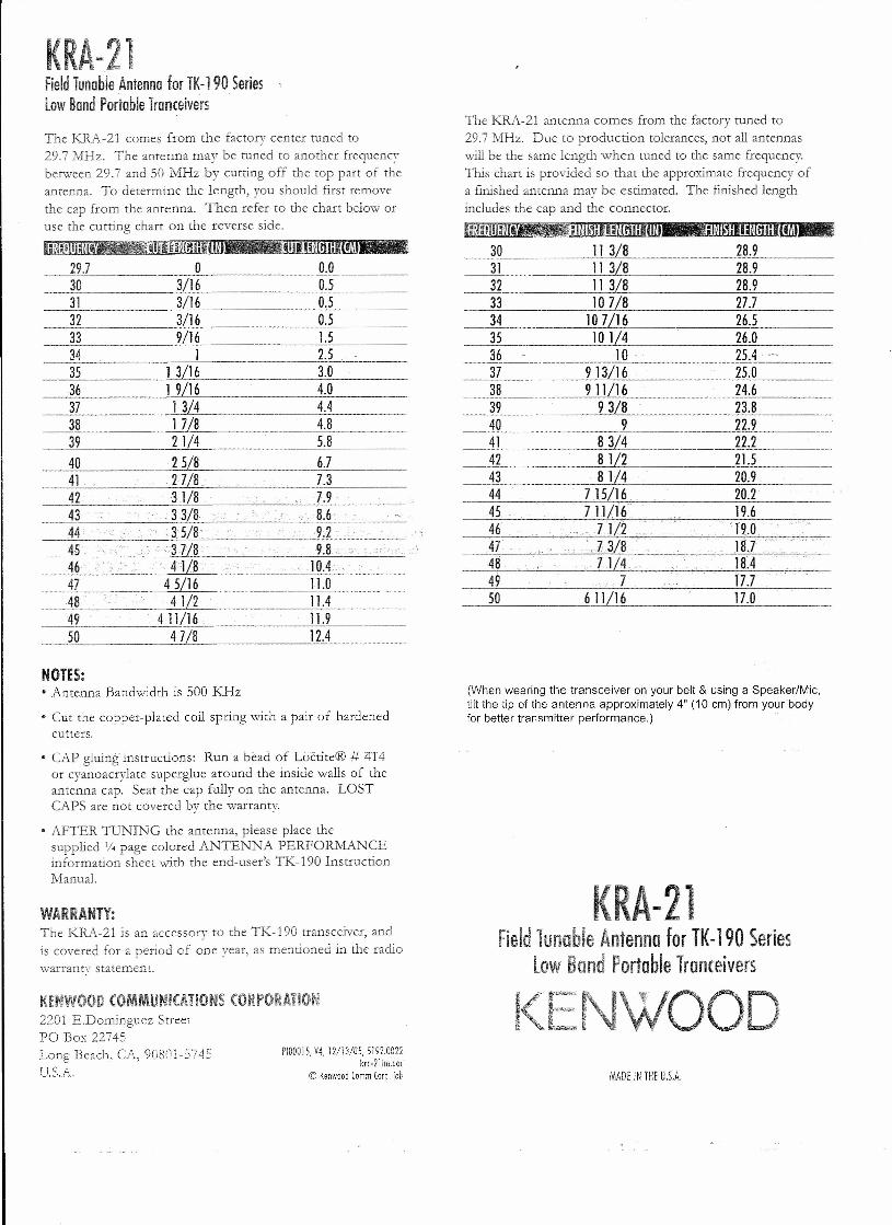
The KRA-21 antenna comes from the factory tuned to29.7 MHz. Due to production tolerances, not all antennaswill be the same length when tuned to the same frequency.This chart is provided so that the approximate frequency ofa finished antenna may be estimated.includes the cap and the connector.
l:a«'IIJmi4iiiilllIilll~':II*ijillffiJ J=m~111IiHijl;l(m
The finished length
30 11 3/8 28.931 11 3/8 28.932 11 3/8 28.933 10 7/8 27.734 10 7/16 26.535 101/4 26.036 10 ' 25.437 913/16 25.038 9 11/16 24.639 93/8 23.840 9 22.941 ~8=3/~4 ~22=.2~ _42 8 1/2 21.543 81/4 20.944 7.15/16. 20.245 ' 711/16 19.646.' . - ZJ(119.0
48 .. 71/4.... 18A49 .. ,7 17.750 611/16 17.0
(When wearing the transceiver on your belt & using a Speaker/Mic,tilt the tip of the antenna approximately 4" (10 cm) from yourbodyfor better transmitter performance.) .
KRA-21Field Tunable Antenna for TK-190 Series
low Band Portable Tronceivers
ENWOODMADE IN THE U.S.A.
Related Documents