ELASTIC PRESSURE DISTORTION OF THE VOLUMES OF A l,OOO-ATMOSPHERE BURNETT COMPRESSIBILITY APPARATUS OVER THE TEMPERATURE RANGE 0° TO 75° C By Ted C. Briggs and Alvin R. Howard ... ... ... ... ... ... ... ... ... ... ... report of investigations 7366 UNITED STATES DEPARTMENT OF THE INTERIOR BUREAU OF MINES

Welcome message from author
This document is posted to help you gain knowledge. Please leave a comment to let me know what you think about it! Share it to your friends and learn new things together.
Transcript

ELASTIC PRESSURE DISTORTION OF THE VOLUMES
OF A l,OOO-ATMOSPHERE BURNETT
COMPRESSIBILITY APPARATUS OVER
THE TEMPERATURE RANGE 0° TO 75° C
By Ted C. Briggs and Alvin R. Howard
... ... ... ... ... ... ... ... ... ... ... report of investigations 7366
UNITED STATES DEPARTMENT OF THE INTERIOR
BUREAU OF MINES

This pub I i cation has been cataloged as follows:
Briggs, Tedford C Elastic pressure distortion of the volumes of a 1,000-
atmosphere Burnett compressibility apparatus over the temperature range 0° to 75° C, by Ted C. Briggs and Alvin R. Howard. [Washington 1 u. S. Dept. of the Interior. Bureau of Mines (1970]
22 p. illus., tables. (U. S. Bureau of Mines. Report of investi~ gations 7366)
Includes bibliography.
1. Helium. 2. Gases, Compressed. 3. Pressure vessels. I. Howard, Alvin R., jt. auth. II. Burnett compressibility apparatus. III. Title. (Series)
TN23.U7 no. 7366 622.06173 U.S. Dept. of the Int. Library

CONTENTS
Abstract •••••..•• , •• II .... ,. • • .. .. • .... ... .. ... .. .. .. • ..... .. ... .. ... ••• • .. .. .. • ... • • • .. • .. • ••••• 1 Introduc tion .................................................................................. !!I .. ., " .. " .. • .. .. .. 1 Acknowledgment.. • ... .. .. • ... • .. • • .. ..... .. .. .. . .... .. .... ...... .. •• •• .. .. ..... .. .. .. ... •• .. ... •• .... 2 Experimental apparatus and experimental procedure.................... ..•• 2 Treatment of the experimental observations ••••••.••.•..•.•..•.•..•......• 10 Working pressure and yield pressure of the high-pressure containers •.•.•• 18 Discussion .......................................... II...................................................... 19 References ......................... 11 /I....................................................................... 21
1.
2. 3. 4. 5.
ILLUSTRATIONS
Pressure containers, valves, and fittings of a Burnett-type compressibility apparatus •••..•.•..•.•..•..•.•.......•....•....••••
Pressure container, Vbl .............. ,. ................ e ............. -I .......... 41 ..................... .
Pressure container, Removable pressure jacket •••.•..•..•••.••....•.•..••...•.•.•..••.•.•• Pressure dis tortion •••..•.•............•.........•........•
TABLES
2 3 4 5 6
1. Experimental external-pressure distortion coefficient data, volume Vb 1 + volume Vr d + volume Vt d" • . • • . . . • • . . . . • . • . . . . . . . . . • • • • 7
2. Experimental external-pressure distortion coefficient data, volume + volume Vfd + volume Vtd..................... .•.•.....• 9
3. Experimental external-pressure distortion coefficients, volume Vb 1 + volume Vr d + volume Vt d. • •• • • • • • • • • • • • • • • • • • • • • • . • • • • • 12
4. Experimental external-pressure distortion coefficients, volume Vb2 + volume Vr d + volume Vt d •• • • • • • • • • • • • • • • • • • • • • • • • •• • • •• 13
5. Values for the external-pressure distortion coefficients of vessels Vb 1 and Vb 2' • • . . . • • . . . • . . . . . . . • . . . . . • . . . . • . . . . . . • . . . . • .• 15
6. Values of Young's modulus of vessels Vbl and Vb2 ••.•....•....••..•••• 15

ELASTIC PRESSURE DISTORTION OF THE VOLUMES OF A 1,OOO-ATMOSPHERE BURNETT COMPRESSIBILITY APPARATUS
OVER THE TEMPERATURE RANGE 0° TO 75° C
by
Ted C. Briggs 1 and Alvin R. Howard 1
ABSTRACT
A removable-jacket distortion apparatus was constructed and used to measure distortion coefficients for two high-pressure vessels. The measured distortion coefficients were used to compute distortion coefficients for volumes VI and (V1 +V2 ) of a 1,OOO-atmosphere Burnett compressibility apparatus for the temperature range 0° to 75° C.
Young1s modulus for Armco 17-4 PH stainless steel, heat treated to condition Hl150-M, was computed from experimentally determined distortion coefficients. A 10- to 14-percent correction to the values obtained for Young's modulus may be required because pressure vessel end effects were neglected.
The distortion coefficients of the compressibility apparatus are believed to be accurate to about 1 percent.
INTRODUCTION
The Bureau of Mines Helium Research Center obtains gas phase compressibility data by the Burnett (9)2 method. The isothermal volume of the pressure vessels is a function of the-internal and external pressures. For maximum accuracy, a correction must be applied for the distortion due to pressure.
Neglecting the correction of pressure distortion would introduce an error of about 0.15 percent into the calculated compressibility factor for helium at 1,000 atmospheres and 0° C.
Burnett (2) used jacketed pressure vessels to reduce the magnitude of the pressure distortion. Subjecting a thick-wall cylinder to equal external and internal pressures reduces in magnitude, but does not eliminate, the distortion. Mueller (11), Canfield (lQ), Blancett (2), and others made distortion corrections to Burnett volumes by using elastic distortion theory and literature values for the required elastic properties.
lResearch chemist, Helium Research Center, Bureau of Mines, Amarillo, Tex. 2Underlined numbers in parentheses refer to items in the list of references at
the end of this report,

2
Briggs and Barieau (1) devised an experiment and procedure to measure external-pressure distortion coefficients and to compute internal-pressure distortion coefficients and Young's modulus from the measured quantities. In this study their method is used to evaluate the elastic pressure-distortion corrections for a newly constructed I,OOO-atmosphere Burnett-type compressibility apparatus.
ACKNOWLEDGMENT
The authors thank the staff of the Branch of Automatic Data Processing for a linear least squares evaluation of dinPr/dPJr and computation of average dinzr/dlnPr for each set of experimental data.
EXPERIMENTAL APPARATUS AND EXPERIMENTAL PROCEDURE
The objective of this work is to evaluate the distortion corrections for a specific compressibility apparatus. The apparatus volumes consist of two high-pressure vessels designated as Vbl and Vb2, the lower chamber of a differential pressure cell, valves, fittings, and connecting tubing. The bulk of the gas is confined in volume Vbl or (Vbl+Vb2); therefore, distortion of these volumes is of primary concern. Figure 1 shows the component volumes of the assembled Burnett apparatus, while figures 2 and 3 show design details of the vessels Vbl and Vb2.
Relevant volumes are listed below and are estimated from the component d imens ions:
a a '<t
V~l = 4.8859 ins; volume of the pressure vessel Vbl at zero internal and external pressures.
Pressure container /' I~" High pressure tubing .. -•.. ...,
Valve mountIng block -----....
Pressure contoiner
FIGURE 1. • Pressure Containers, Valves, and Fittings of a Burnett.Type Compressibility Apparatus.

::
:: -'
3
vf 1 = 0.0717 ins = volume of the tubing portion of V1 at zero internal and external pressures.
V~
0.0700 in3 = volume of fittings, including DPI cell and valves, connected to VI at zero internal and external pressures.
5.0276 in3
000 Vb 1 + Vt 1 + Vr 1 •
V~2 2.5297 in3 volume of pressure vessel Vb2 at zero internal and external pressures.
o Vt2 0.0325 in3 = volume of
tubing portion of Va at zero internal and external pressures.
V~2 0.0176 in3 = volume of fittings, including valves, connected to V2 at zero internal and external pressures.
V~ 2.5798 in3
V~ 2 + vf 2 + V~ 2 •
(0 0 Vbl +Vb2) 7.4156
o 0 (Vtl +Vt2) 0.1042
(W 1 +V~2) 0.0876 . 3 l.n •
(V~+V~) 7.6074 • 3 l.n •
The experimental distortion FIGURE 2. - Pressure Container, Vb l' determination method of Briggs and
Barieau (7) requires jacketed pressure vessels such that the change of the internal-pressure can be determined as a function of changing jacket pressure. Jacketed pressure containers for a 1,OOO-atmosphere Burnett apparatus would have the disadvantage of result~ ing in rather massive vessels for a relatively small internal volume, particularly if the jackets are adequately designed for pressures equal to the maximum pressures confined in the inner vessel.

4
:
-'
:
= -,
3"
FIGURE 3. - Pressure Container, Vb2"
=
A removable jacket (fig. 4) was purchased from Pressure Products Industries3 for the high-pressure containers specifically for the distortion experiment. The removable jacket was designed so that either volume Vbl or Vb2 could be placed in the jacket.
The removable jacket and volume Vbl or Vb2 were placed in a constanttemperature bath. The space between the removable jacket and external wall of Vbl or Vb2 was oil-filled and was connected to an oil displacement pump and oil-filled Bourdon tube pressure gage. The pressure around the vessel could be varied up to the maximum working pressure (10 X 103 psi) of the jacket.
The Bourdon tube gage had a pressure range of 10 X 103 psi and 10-psi scale divisions.
The inner pressure vessel (Vb 1 or Vb2) was connected to a high-pressure (20 X 103 psi) American Instrument Co. model 46-13425 diaphragm-type com-pressor and to the gas side
of a Ruska Instrument Corp. model 2416 diaphragm differential pressure cell. The reference side of the differential pressure cell was connected to a Ruska model 2400 oil-lubricated piston gage. The piston gage could measure pressures over the range 2 to 800 atmospheres with a precision and accuracy of better than 0.01 percent.
This arrangement allowed the inner vessel to be filled to high pressure, and the pressure could then be measured quite accurately with the piston gage.
3Manufacturers are identified to allow the reader to obtain detailed information about commercially available items. This identification should not be construed as Bureau of Mines endorsement or recommendation of any particular product or manufacturer.

FIGURE 4. - Removable Pressure Jacket.
Figure 5 shows the distortion apparatus; its relevant volumes, estimated from the component dimensions, are listed below:
Vfd,Uj = 0.0704 = volume of unjacketed tubing portion of distortion
V~
o Vttz
apparatus at zero internal and external pressures.
0.0135 volume of jacketed tubing portion of distortion apparatus at zero internal and external pressures (nipple connecting volume Vbl or Vb2 to
0.0873 ins = volume of fittings connected to distortion apparatus plus volume of hole through jacket cap at zero internal and external pressures.
o 0 • .0 0 S Vbl + Vttt ,uj + Vtd.,j + Vid. = 5.0571 in = volume of distortion apparatus when assembled with vessel Vbl.
V~z + V~d,Uj + V~d.,j + V~d. = 2.7009 ins = volume of distortion apparatus when assembled with vessel VbZ.
The experimental procedure was as follows: Vessel Vbl or Vb2 was placed in the removable jacket, and the assembly was placed in a constant-temperature bath. Temperature of the bath was adjusted to the desired value as determined with a Leeds & Northrup Co. (L & N) platinum resistance thermometer and a L & N G-2 Mueller bridge. Temperatures are in terms of the 1948 International Practical Scale (IPTS-48) and are the reported nominal values within a precision of ±0.005° C. Temperatures in the bath were constant to better than ±O.OOSo C.
The inner chamber of vessel Vb} or Vb2 was filled with helium gas to an initial pressure. Time was allowed for the confined helium to reach temperature equilibrium, and the pressure was measured with the piston gage. Resolution of the piston gage was equal to or better than 0.0007 atmosphere at all measured pressures. Jacket pressure was increased in incremental amounts, and
5

6
Oil reservoir
Pillion gage
indicator
Oil manometer
To vacuum pump
Oil displacement pump Heat exchanger coils Constant-for circu loting temperature bath
refrigerant
FIGURE 5. - Pressure Distortion Apparatus.
3,000- ps i rei ief
o
o
o
10,000-p s i baurdon
tube gage
Feed gas
cylinder
Oil displacement pump
each time the jacket pressure was increased, the internal pressure was accurately remeasured. Equilibrium was indicated by a constant reading of the piston gage and required about 30 minutes; however, about an hour was allowed between measurements.
The differential pressure cell was zeroed with atmospheric pressure applied to both sides of the diaphragm before each run. A correction was applied to the measured pressures for zero shift of the diaphragm as a function of pressure. Zero shift is not very significant during a run as the measured internal pressure changes by about 0.7 atmosphere for a 600-atmosphere change in the external pressure.
Volume Vbl or Vb2 was filled with helium to different pressures for each run. Impurities in the helium totaled less than 25 ppm in all cases. Previous work (~, p. 8) indicated that no impurities were introduced by compressing the gas with a diaphragm-type compressor.
Runs were made at 0°, 25°, 50°, and 75° C. Experimental observations are recorded in table 1 for vessel Vbl enclosed in the pressure jacket, and in table 2 for vessel Vb2 enclosed in the pressure jacket. rand Pr denote jacket pressure and internal pressure, respectively.
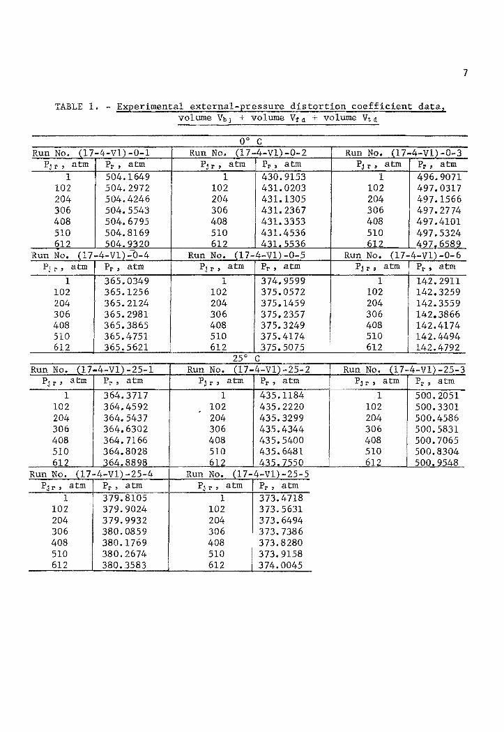
TABLE 1. - Experimental external-pressure distortion coefficient data, volume Vb + volume Vf + volume Vtd
Run No. (17-4-Vl)-0-1 Run No. (17-4-Vl)-O-2 Run No. (17-4-V1)-O-3 Pj r, atm Pr , atm P j r, atm Pr .' atm Pj r, atm Pr , atm
1 504.1649 1 430.9153 1 496.9071 102 504.2972 102 431.0203 102 497.0317 204 504.4246 204 431.1305 204 497.1566 306 504.5543 306 431. 2367 306 497.2774 408 504.6795 408 431.3353 408 497.4101 510 504.8169 510 431. 4536 510 497.5324 612 504.9320 612 431 5536 612 497.6589
Run No. (17-4-V1)~0-4 Run No. (17-4-Vl) -0-5 Run No. (17-4-Vl)-0-6 Pjr, atm Pr , atm P.l r, atm Pr , atm P.l r, atm Pr , atm
1 365.0349 1 374.9599 1 142.2911 102 365.1256 102 375.0572 102 142.3259 204 365.2124 204 375.1459 204 142.3559 306 365.2981 306 375.2357 306 142.3866 408 365.3865 408 375.3249 408 142.4174 510 365.4751 510 375.4174 510 142.4494 612 365.5621 612 375.5075 612 142.4792
7
Run No. (17-4-Vl)-25-1 Run No. (17-4-Vl)-25-2 Run No. (17-4-V1)-25-3 P~r' atm Pr , atm P j r, atm Pr , atm Pj r, atm Pr , atm
1 364.3717 1 435.1184 1 500.2051 102 364.4592 102 , 435.2220 102 500.3301 204 364.5437 204 435.3299 204 500.4586 306 364.6302 306 435.4344 306 500.5831 408 364.7166 408 435.5400 408 500.7065 510 364.8028 510 435.6481 510 500.8304 612 364.8898 612 435.7550 612 500.9548
Run No. (17-4-V1)-25-4 Run No. (17-4-V1)-25-5 Pj l'" atm Pr , atm Pjr , atm Pr , atm
1 379.8105 1 373.4718 102 379.9024 102 373.5631 204 379.9932 204 373.6494 306 380.0859 306 373.7386 408 380.1769 408 373.8280 510 380.2674 510 373.9158 612 380.3583 612 374.0045

8
TABLE 1. - Experimental external-pressure distortion coefficient data, volume Vbl + volume Vfd + volume Vtd--Continued
50" C Run No. (17-4-V1)-50-1 Run No. (17-4-Vl)-50-2 Run No. (17-4-Vl)-50-3
Pjr , atm Pr , atm Pj r, atm Pr , atm Pj I" atm Pr , atm
1 368.1443 1 437.4636 1 497.8509 102 368.2326 102 437.5725 102 497.9726 204 368.3202 204 437.6789 204 498.0936 306 368.4071 306 437.7829 306 498.2177 408 368.4941 408 437.8889 408 498.3376 510 368.5803 510 437.9951 510 498.4597 612 368.6676 612 438.0996 612 498.5826
Run No. (17-4-V1)-50-4 Run No. (17-4-V1)-50-5 Pj r' atm Pr , atm Pj r, atm PI" atm
1 434.0176 1 367.7199 102 434.1211 102 367.8017 204 434.2260 204 367.8885 306 434.3290 306 367.9750 408 434.4336 408 368.0606 510 434.5400 510 368.1471 612 434.6445 612 368.2340
Run No. (17-4-V1)-75-1 No. (17-4-V1)-75-2 Run No. (17-4-V1)-75-3 Pjr , atm PI" atm Pj I', atm Pr , atm Pj r, atm Pr , atm
1 373.9547 1 437.1291 1 494.4104 102 374.0763 102 437.2558 102 494.5310 204 374.1687 204 437.3626 204 494.6457 306 374.2566 306 437.4660 306 494.7700 408 374.3146 408 437.5689 408 494.8910 510 374.3988 510 437.6749 510 495.0127 612 374.4898 612 437.7793 612 495.1281

9
TABLE 2. - Experimental external-pressure distortion coefficient data, volume Vb2 + volume Via + volume Vta
Run No. (17-4-V2)-0-1 Run No. C17-4-V2)-0-2 Run No. (17-4-V2)-0-3 Pj I', atm PI" atm Pj I" atm PI" atm Pj I" atm _PI" atm
1 366.7151 1 432.9269 1 507.6880 102 366.8023 102 433.0299 102 507.8120 204 366.8849 204 433.1288 204 507.9330 306 366.9681 306 433.2329 306 508.0553 408 367.0508 408 433.3317 408 508.1744 510 367.1364 510 433.4341 510 508.2941 612 367.2233 612 433.5337 612 508.4152
25" C Run No. (17-4-V2)-25-1 Run No. (17-4-V2)-25-2 Run No. (17-4-V2)-25-3
Pj I" atm PI" atm Pj r, atm PI" atm Pj r, atm PI" atm 1 371.1763 1 440.4562 1 506.5533
102 371. 2605 102 440.5561 102 506.6707 204 371. 3445 204 440.6549 204 506.7901 306 371.4255 306 440.7586 306 506.9100 408 371.5059 408 440.8590 408 507.0287 510 371.5904 510 440.9605 510 507.1470 612 371.6745 612 441. 0600 612 507.2662
Run No. (17-4-V2)-50-1 Run No. (17-4-V2)-50-2 Run No. (17-4-V2)-50-3 Pj I' , atm Pr ji atm Pj r, atm PI' , atm Pj r, atm Pr , atm
1 370.4306 1 439.1686 1 510.1689 102 370.5174 102 439.2687 102 510.2893 204 370.5985 204 439.3700 204 510.4096 306 370.6830 306 439.4710 306 510.5292 408 370.7653 408 439.5696 408 510.6524 510 370.8486 510 439.6712 510 510.7740 612 370.9318 612 439.7701 612 510.8905
Run No. 17-4-V2)-75-1 Run No. Run No. (l7-4-V2 -75-3 PjI' , atm PI" atm Pj I" atm PI" atm
1 370.0747 1 444.5164 1 503.1478 102 370.1561 102 444.6193 102 503.2824 204 370.2388 204 444.7192 204 503.4003 306 370.3221 306 444.8236 306 503.5138 408 370.4048 408 444.9481 408 503.6332 510 370.4862 510 445.0472 510 503.7480 612 370.5689 612 445.1494 612 503.8650

10
TREATMENT OF THE EXPERIMENTAL OBSERVATIONS
Equations for the elastic distortion of a thick wall cylinder are reported in the literature Q, 1, 11.-12, 14).
Equation 1 describes the pressure distortion
AV 3(1-2cr)R~ + 2(1+cr)Rl
VO - E(Rl-R~)
(5-4cr)Rj
P r - E (Rl-R~ ) P.1 r (1)
of a thick-wall closed-end cylinder subjected to internal and external pressures where
!W change of volume,
VO = cylinder volume at zero internal and external pressures,
Rr = radius to internal wall of the cylinder,
Rj radius to external wall of the cylinder,
Pr pressure confined within the cylinder,
Pjr pressure acting on the external wall of the cylinder, or the jacket pressure,
cr Poisson's ratio,
and E = Young's modulus.
Equation 1 is of the form
where
and
k = 3(1-2g)R¥ + 2(1+cr)R1
E(Rl-R~)
(5-4cr)Rj k' =
E(R~ -R~)
Equation 4 can be rearranged to give
(5-4cr)Rl E - - ---:---"--
- k I (R1-R;)
A more exact form of the equation presented by Briggs and Barieau (1, p. 6, eq. 22) is
k' = (1 -
(2)
(3)
(4)
(5)
(6)

11
dtnPr The term dPjr of equation 6 can be evaluated experimentally. The quan-
tity dll1ZI' dlnP
I' can be evaluated by using equation 7
dtnZI' BPI' + 2C~ + 3D~ + 4EP: =
dtnPI' 1 + BPI' + CP: + D~ + EP! (7)
and published comEressibility data for helium (2, ~). Z1' = 1 + BPI' + CPr + D~ + EPi = compressibility factor of the confined gas at PI' •
The term (1 + kPI' kPI' b
1 + kPI' + k/pjI' can e
+ k'Pjr) of equation 6 can be set equal to one, and
neglected without causing a significant (less than 0.1
t) 1'n k'. percen error
Reduction of the experimental observations is a bit more complicated than that of an earlier report (2) because the distortion apparatus volumes were not equivalent to the volumes V1 or Va of the compressibility apparatus.
We adopt the following notation for the distortion coefficients because this notation was used in previous reports ~, 2):
a = internal-pressure distortion coefficient of volume (V1+Va) of the compressibility apparatus.
I a = external-pressure distortion coefficient of volume (V1+Va ) of the compressibility apparatus.
~ = internal-pressure distortion coefficient of volume V1 of the compressibility apparatus.
Sf = external-pressure distortion coefficient of volume Vl of the compressibility apparatus.
The distortion coefficients a, ai, S, and ~I are our ultimate goals. In the work of Briggs and Barieau (7), 8 I was measured experimentally; in the present investigation none of the coefficients are directly measured, but they can be derived from our measurements.
Additional quantities must be defined for this work:
kbl = internal-pressure distortion coefficient of the volume Vbl'
I external-pressure distortion coeff ic ient of the volume VOl' kbl =
kba = internal-pressure distortion coefficient of the volume Vba.
kb'a = external-pressure distortion coefficient of the volume Vbla •

12
ke'l external-pressure distortion coefficient of the distortion apparatus when the volume Vbl is assembled in the jacket.
external-pressure distortion coefficient of the distortion apparatus when vessel VbZ is assembled in the jacket.
The coefficients ka'l and kfz are experimentally determined; thus kb 1, kb'l' kbz, k;z, and ultimately a, aI, S, S' must be derived from the measured quantities. The derivation is straightforward.
Experimental values of ka'l and ka'z, computed from the experimental observations and equations 6 and 7, are listed in tables 3 and 4, respectively, for temperatures of 0°, 25°, 50°, and 75° C.
TABLE 3. - Experimental external-pressure distortion coefficients, volume Vb] + volume Vrd + volume Vt~
Run No. (cUnPr / dP j r) Xl061 Average fka'l ,t Xl06
, atm-1 Dev. from avg. dfYlZ r / dlliPr 1<,;.\ • t Xl06
, atm-1
(17-4-Vl)-0-1 2. 49778±0. 01745 0.1931814 (17-4-Vl)-0-2 2.42712 ±.01714 .1721999 (17 .. 4-Vl)-0-3 2.47432 ±.00887 .1911783 (17-4-Vl)-0-4 2.35509 ±.00708 .1517337 (17-4-Vl)-0-5 2.37470 ±.01247 .1549220 (l7-4-Vl) -0-6 2.14912 ±. 01794 .0684863 , Average kd 1 0 •••••• ·• •••••••••••••• • ••••••• , , Average standard error of kd 1 0 •••••••••••• , ' Standard error of a single kd 1 ,0 •••••••••••
(17-4-Vl)-25-l 2. 32079±0. 00379 0.l398794 (17-4-Vl)-25-2 2.39238 ±.00464 .1605526 (17-4-Vl)-25-3 2.44903 ±. 00728 .1782026 (17-4-Vl)-25-4 2.35808 ±. 00419 .1445330 (l7-4-Vl) -25-5 2.32786 :t.00576 .1426319 , Average k.il 25 ••••••••••••••••••••••••••••• , , Average standard error of kdl 25 •••••••••••
" Standard error of a single kd 1 ,25 ••••••••••
(17-4-Vl)-50-l 2. 32077±0. 00482 0.1309194 (l7-4-V1) -50-2 2.37220 ±.00713 .1500108 (17-4-V1)-50-3 2.40129 ±.00325 .1655624 (17-4-V1)-50-4 2.36149 ±.00345 .1490928 (l7-4-V1) -50- ') 2.29086 ±.00600 .1107963 , Average kil 50 •••••••••••• · •••••••••••••••• , /
Average standard error of kd 1 50 •••••••••••
" Standard error of a single kd J ,50 ••••••••••
-2. 01526±0. 01408 -2.00917 ±. 01419 - 2.00128 ±. 00717 -1. 99774 ±. 00601 -2.00681 ±.01054 -2.00193 ±.01671 -2.00536 ±.00467
± .01145 ±.00634
-1. 99616±0.00326 -2.00828 ±.00390 -2.01261 ±.00598 -2.01726 ±.00358 -1.99583 ±.00494
-2.00603 ±.00433 ±.00433 ±. 00969
-2. 01694±0. 00419 -2.01634 ±.00606 -2.00373 ±. 00271 -2.00941 ±.00294 -1. 99122 +.00522
-2.00753 ±. 00474 ±.00422 ±.01061
+0.00990 +.00381 -.00408 -000762 +.00145 -.00343
-0.00987 +.00225 +.00658 +.01123 -.01020
+0.00941 +.00881 -.00380 +.00188 -.01631

TABLE 3. - Experimental external-pressure distortion coefficients, volume Vbl + volume Vid + volume Vtd--Continued
Run No. (d,[nPr /dPj r )X106 Average kfl t X106 • atm-1 Dev. from
d,[nZr I d-£nPr ,
kll t X106 , ,
avg. atm-1
(17-4-Vl) -75-1 2. 24408±0.09035 0.1236615 -1. 96657±0. 07918 -0.04806 (17-4-V1)-75-2 2.39981 ±. 03389 .1401877 (l7-4-V1) -75-3 2.38153 ±. 00928 .1543551
Average 1<0.'1 75····························· , I Average standard error of kdl 75' •••.••••••
I' • Standard error of a single kil.7S •...• · ..••
-2.06339 ±.029l4 -2.01393 I.00785 -2.01463 ±.02795
±.03872 ±.04841
+.04876 -.00070
TABLE 4. - Experimental external-pressure distortion coefficients, volume Vba + volume Vfd + volume Vtd
13
Run No. Average d-£nZr / d,[nPr
! 6 1 kcta ,t XI0 , atm- Dev. from avg. k,{a t X106
, atm-1
(17-4-V2)-0-1 2. 25289±0. 00918 0.1522721 (17-4-V2) -0-2 2.29098 ±. 00615 .1727949 (l7-4-V2) -0-3 2.33681 ±.00720 • 1941399 Average 1<0.'2 0 •••••••••••••••••••••••• • ••••••••
, I Average standard error of kd2 0 •••••••••••••••
I' Standard error of a single kda,o .•.....••...••
(17-4-V2) -25-1 2.18528±0.00797 0.1419355 (17-4-V2) -25-2 2.24599 ±. 00436 .1620419 (17-4-V2) -25-3 2.30236 ±. 00184 .1798521
Average 1<0.'2 a5· •• ··· •.••.• · •• ·•·.··•· •• ····•·• , I Average standard error of kia as,., .•....•..••
" Standard error of a ki2,as •.......•..••
(17-4-V2)-50-1 (17-4-V2)-50-2 (17-4-V2)-50-3
2. 20576±0. 00711 I 0.1315680 2.24040 ±.00406 : .1504582 2.31841 ±.00575 .1686164
Average 1<o.'a 50·· •• • ••••••••••••••••• • •• • ••••••
Average standard error of k,{a 50 ••••••••••••••
" Standard error of a single ki2,SO .•.•....•.•••
(17-4-V2) -75-1 2. 18497±0. 00264 0.1226052 (17-4-V2)-75-2 2.35094 ±. 02757 .1420514 (17-4-V2)-75-3 a(2.26689 ±.00584) .1564672
-1. 90984±0. 00778 -1.89511 ±.00509 -1.88314 ±.00580 -1.89603 ±.00772
±.00622 ±. 01337
-1. 8751lJ: 0.00684 -1.88205 ±.00365 -1.88828 ±.00151 -1.88181 ±.00380
±.00400 :t.00659
-1.9l555±0.006l7 -1.90331 ±.00345 -1.92749 ±.00478 -1.91545 ±.00698
±.00480 ±.01209
-1.91708±0.00232 1 (-2.01699 ±.02365)
-1.91220 ±.O0493 Average kl2 75............ ........ ........ .... -1.91464
, I .00257
±.00363 ±.00345
Average standard error of kd2 76 ••••..•••••••• I' Standard error of a single kd2,7S ••.•....••..•
lOmitted in obtaining the average value for k/a 75'
2First pressure is omitted from the ca1cu1ation~.
+0.0l381 -.00092 -.01289
-0.00670 +.00024 +.00647
+0.00010 -.01214 +.01204
+0.00244 +.10235 -.00244
The pertinent change of volume of the assembled compressibility apparatus, due to a change of jacket pressure, is essentially equal to the change of the jacketed volume Vbl and Vb2 plus the change in volume of the jacketed nipple. We can write
T V~l I (8) = kbl . T,o + k t d ,.)
Viil v<J.l

14
and (9)
where I kt d ,j external-pressure distortion coefficient of the jacketed nipple
connecting the jacket cap to volume Vbl or Vb2
(5-4crtd ,j) R1,td,j (10)
The high-pressure tubing is 0.2S-in._OD by 0.083-in.-ID type 304 stainless steel. We substitute into equation 10 the numerical values,
0.305 (i) at all temperatures
0.125 in.
Rr ,t d ,3 0.0415 in.
We use the work of Briggs and Barieau (2) to obtain the values for Young's modulus as a function of temperature:
Therefore
Rearranging
and
d ~j
k' t d ,j ,25
k' td,j,50
I ktd,j,75
1. 9933
1.9772
1.9610
1. 9449
-2.1313
-2.1486
-2.1664
-2.1843
X
X
X
X
X
X
X
X
106 atm at 0° C
106 atm at 25°
106 atm at 50°
106 atm at 75°
10-6 atm-1
10-6 atm-1
10-6 atm-1
10-6 atm-\',
equations 8 and 9 we obtain
I I \fc.l - k I
vi d ,j
kbl = t d ,j V~l ~l
1 I I - k{ d ,j
Vi d ,1 Kb2 = kd2
V%z ~2
C
C
C.
(11)
(12)
Values for k~l and k;z can be calculated by using equations 11 and 12, the calculated values of ~/d j, the known values of the volumes, and experimental
I I' I! values of kd 1 and kdz. Computed values for kb 1 and kb2 are listed in table 5.

TABLE 5. - Values for the external-pressure distortion coefficients of vessels Vb and Vb
Temp, 0 C
o 25 50 75
I 6 1 kb 1 X 10 , atm-- 2. 0697±0. 0048 -2.0704 ±.0045 -2.0719 ±. 0050 -2.0792 ::!:.. 0289
-2. 0129±0. 0082 -1. 9977 ±. 0041 -2.0335 ±. 0075 -2.0325 ±.0027
The distortion coefficients of table 5 are used to compute values for Young's modulus for vessels Vbl and Vb2' Equations 13 and 14 are used in the calculations:
15
1 (13)
where
=
ab2 = 0.272 (1)
Rj b2 , Rr ,b 1 = Rr ,b 2
1. 5 in.
0.5 in.
(14)
Computed values of Young's modulus are recorded in table 6 for vessels Vbl and Vb2'
Temp, 0
0 25 50 75
TABLE 6. - Values of Young's modulus of vessels Vbl and Vb2
C Ebl X 10-6 , atm Eb2 X 10-6, atm
2.1264±0.0049 2. l864±0. 0089 2.1257 ±.OO46 2.2030 ±.0046 2.1241 ±. 0052 2.1642 ±.0080 2.1167 ±.0290 2.1653 ±. 0029
We can now use the following equations to calculate the change in volume of vessels Vbl and Vb2 with pressure:
AVb1 = 3 (1-2a b 1 ) R~ 2 b 1 + 2(1+an )R12 b1 Pr - (5-4Ubl)R12
'l1 1 Pj r (15)
~l Ebl (R1 ,bl - R~, bl) Ebl (R1 ,bl - R~, hI)
AVb2 = 3(1-2ub2)R; 2b2 + 2(1+ab2)Rl2b2 Pr - (5-4ub2)R! lba Pj r
(16) 0
Eb " (R1 ,b2 - R~ ,b2) Eba (R1 ,h2 - R~ ,b:;,) Vb2
By using previously listed values for the constants, we obtain
(17)
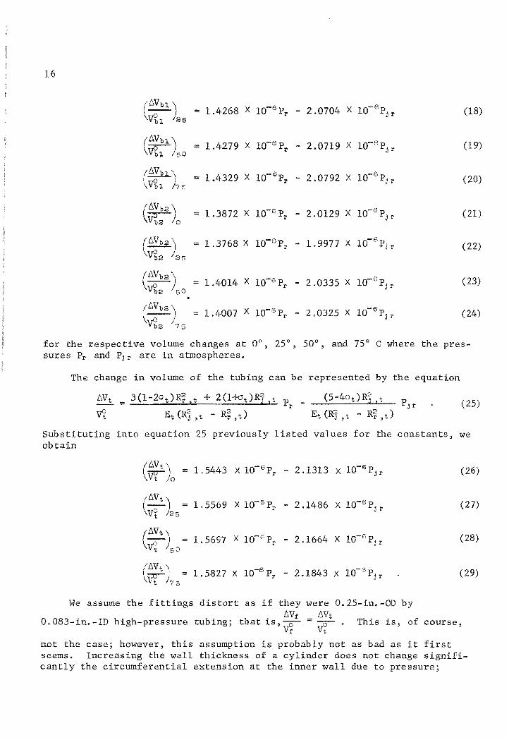
16
(DVOl) 1.4268 X 10⁻⁶ Pr - 2.0704 X 1O- 6 p (18) = ~l 26
j I'
(DVbl \ ~l /50
= 1.4279 X 1O-6 p I' - 2.0719 X 1O-6 p jr (19)
(DVbl ) ~l 75
= 1.4329 X lO- S PI' - 2.0792 X 10-S Pjr (20)
( DVb2 ) ~o
= 1.3872 X 10⁻⁶ PI' - 2.0129 X lO-s p j r (21)
(6,Vb2 '\ 1.3768 X lO-S Pr -6
== - 1.9977 X 10 Pjr (22) ~2 /25
(DV
b2) = ~2 50
1.4014 X 10⁻⁶ PI' - 2.0335 X 1O- 6 p J1'
(23)
• (
DV'o2) = 1.4007 X lO-s Pr - 2.0325 X
-6 (24) 10 Pj r
vi; 2 75
for the respective volume changes at 0°, 25°, 50°, and 75° C where the pressures PI' and PJ1' are in atmospheres.
The change in volume of the tubing can be represented by the equation
DVt = 3(1-2Jt)R~.t + 2 (1+vt )R1 ,t PI' _ (25) V~ Et (R~ ,t - R;, t )
substituting into equation 25 previously listed values for the constants, we obtain
(DVt) == v:r- 0 1.5443 X lO-sPr - 2.1313 X 10⁻⁶ Pj r (26)
(DVt) V~ 25 =
1.5569 X 1O-6 P1' - 2.1486 X 1O-6 p j I' (27)
(DVt) Vi 50 =
1.5697 X 10⁻⁶Pr - 2.1664 X lO-sp j r (28)
(tNt \ lO-Sp -6 (29) I<;:r-/ == 1. 5827 X I' - 2.1843 X 10 Pjr t 75
We assume the fittings distort as if they were 0.25-in.-OD by 6,Vf 6,Vt
0.083-in.-ID high-pressure tubing; that is --.- = --'0- This is, of course, 'v1 Vt
not the case; however, this assumption is probably not as bad as it first seems. Increasing the wall thickness of a cylinder does not change significantly the circumferential extension at the inner wall due to pressure;

17
therefore, we can assume the volume change in the fittings can be computed as if they were tubing without significant error in the final results.
The unit change of volume V1 of the compressibility apparatus is given by
At 0° C we may then write
or
(t:.Vl) \vi: 0
Similarly,
V~ (30)
The unit change of volume (V1 + V2) of the compressibility apparatus is given by
t:.(Vl +Vz )
(vi:+V~) t:.VbJ, + t:.Vb2 + t:.(Vu +Vt.a)
(vr+~) (vr+vg) (Vr+vg)
= t:.Vbl ~l + t:.Vb2
Vl;l (Vr+vg) V~2 (vi:+~)
+ t:.(Vu +V1'z)
(~l +Vi:,)
(V~l +V~2)
(Vr+~)
+ t:.(Vn +V f 2)
(Vr+vg)
+ t:.(Vu +Vt2) (V~l +V~2)
(Vi 1 +Vf2) (vf+v~)
(36)

18
At 0° C
or
Similarly,
/::,,(Vl +V2)
(V~+V~) (1 4264 X lO- 6p - 2 0697 X lO-6 P ) (4.885.9)
. r' j r 7.6074
+ (1.3872 X lO-6 Pr - 2.0129 X lO-6p )(2.5297) jr 7.6074
+ (1.5443 X 10⁻⁶Pr - 2 1313 X 10-6p )(0.1042) • j r 7.6074
( 44 X -6 10-6 ) (0 .0876) + 1.5 3 10 Pr - 2.1313 X Pjr 7.6074
WORKING PRESSURE AND YIELD PRESSURE OF THE HIGH-PRESSURE CONTAINERS
(37)
(38)
(39)
(40)
The pressure vessels Vbl and Vb2 were purchased from Pressure Products Industries. The working pressure is 15 X 103 psi.
The containers were fully X-rayed after fabrication. The radiographs indicated complete weld penetration for Vbl and no weld penetration for Vb2; therefore, for the following calculations we assume no weld penetration.
Dimensions of the containers are shown in figures 2 and 3.
Faupel (11) presents the equation
_ f-Ly)
f-Lu (42)
for the burst pressure of a thick-wall cylinder where
Pb = burst pressure of a thick-wall cylinder,

~y = yield strength,
~u ultimate strength,
cylinder external diameter divided by cylinder internal diameter.
The vessels were fabricated from 17-4 PH precipitation-hardening stainless steel, heat-treated in the Hl150-M condition.
With 85 X 1(13 psi,
iJ.u 125 X 103 psi, and
Ra. 2.4,
the calculated burst pressure is
Pb "" 113 X 103 psi ~ 7. 7 X 10³ atm.
The vessels are to be used at working pressures to 1,000 atmospheres; therefore, the safety factor is about 7.7 based upon these calculations.
Faupel (l!) presents the equation
19
P = ~:r (R'a - 1) y v'3 R~
(43)
for the elastic breakdown pressure of a heavy-wall cylinder, where
Py = yield pressure.
substituting into equation 43 we obtain
Py = 40.6 X 1(13 psi ~ 2.76 X 1(13 atm.
The pressure containers were tested to 22.5 X 10³ psi, or 1.5 times the design working pressure of 15 X 103 psi; therefore, the forces were below the proportional limit of the material of construction. We assume that there was no permanent distortion due to the pressure test.
DISCUSSION
The values of Young's modulus for 17-4 PH stainless steel computed our experimental measurements are larger than the value reported in the ture (1).4 Also, Young's modulus for Vb2 is larger than that for Vbl"
means there was less distortion of the vessels than one would calculate the distortion equations and literature value for Young's modulus.
from literaThis from
4For this comparison, we assume that the value (28.5 X 10⁶ psi) of Young's modulus reported for condition H90a is applicable for all hardened conditions (15, p. 23).

20
The decrease in distortion and attendant increase in the computed values for Young's modulus are, no doubt, due to end effects, as the distortion equations do not correct for this. Computed values for Young's modulus are larger for vessel Vb2 than for Vbl because is shorter than Vbl, and end effects would be expected to be more pronounced in Vb2'
Our experimentally determined value for Young's modulus, for room temperature, for Vbl is about 10 percent higher than the literature value and about 14 percent higher for Vb2' The significant aspect of these measurements is that an error of 10 to 14 percent would be introduced into the distortion coefficients for our particular pressure vessels if end effects were neglected.
The method of least squares was used to fit the data of table 6 to the equations
(2.1 0.002085) X 106 - (1.228±O.446) X l02 t (44)
(2.l9504±0.0134l) X 106 (4.084±2.868) X l02 t (45)
where t = temperature, 0 C, and E is in
Equations 44 and 45 indicate a small decrease in Young's modulus with increas temperature, but the observed effect of temperature was less than expected.
We believe the distortion coefficients of volumes VI and (V1 +V2) of the compressibility apparatus are known to about 1 percent. An error of about 1 percent in the distortion coefficients would cause an error of about 0.0015 in the calculated compressibility factor for helium at 0° C and 1,000 atmospheres' pressure.

21
REFERENCES
1. Armco Steel Corporation. Armco 17-4 PH Precipitation-Hardening Stainless Steel Bar and Wire. Product Data, No. S-6a, 16 pp.
2. Barieau, Robert E., and B. J. Dalton. A Method for Treating PVT Data From a Burnett Compressibility Apparatus. BuMines of Inv. 7020, 1967, 34 pp.
3. Bartlett, Edward P. The Compressibility Isotherms of Hydrogen, Nitrogen and Mixtures of These Gases at 0 0 and Pressures to 1000 Atmospheres. J. Am. Chern. Soc., v. 49, No.3, March 1927, p. 691.
4. Baumeister, Theodore Ced.). Mechanical Engineers' Handbook. McGraw-Hill Book Company, Inc., New York, 1958, pp. 5-6.
5. Blancett, Allen Leroy. Volumetric Behavior of Helium-Argon Mixtures at High Pressure and Moderate Temperature. ph.D. Thesis, Univ. of Oklahoma, 1966, 228 pp. Univ. Microfilms, Inc., Ann Arbor, Mich., Order No. 66-14,196.
6. Briggs, Ted C. Compressibility Data for Helium Over the Temperature Range -5° to 80 0 C and at Pressures to 800 Atmospheres. BuMines Rept. of Inv. 7352, 1970, 39 pp.
7. , Ted C., and Robert E. Barieau. Elastic Pressure Distortion of the Volumes of a Burnett Compressibility Apparatus Over the Temperature Range 0° to 80° C. BuMines Rept. of Inv. 7136, 1968, 32 pp.
8. Briggs, Ted C., B. J. Dalton, and Robert E. Barieau. Compressibility Data for Helium at 0° C and Pressures to 800 Atmospheres. BuMines Rept. of Inv. 7287, 1969, 54 pp.
9. Burnett, E. S. Compressibility Determinations Without Volume Measurements. J. Appl. Mech., v. 3, No.4, December 1936, pp. A136-A140.
10. Canfield, Frank B., Jr. The Compressibility Factors and Second Virial Coefficients for Helium-Nitrogen Mixtures at Low Temperature and High Pressure. Ph.D. Thesis, Rice Univ., May 1962, 321 pp.
11. Faupel, Joseph H. Engineering Design. John Wiley & Sons, Inc., New York, 1964, 980 pp.
12. Love, A. E. H. A Treatise on the Mathematical Theory of Elasticity. Dover Publications, New York, 4th ed., 1927, 643 pp.
13. Mueller, William H. Volumetric Properties of Gases at Low Temperatures by the Burnett Method. Ph.D. TheSis, Rice Univ., December 1959, 138 pp.

22
14. Newitt, Dudley M. The Design of Pressure Plant and the Properties of Fluids at High Pressure. Oxford University Press, London, England, 1940, 491 pp.
15. Roark, Raymond J. Formulas for Stress and Strain. McGraw-Hill Book Co., New York, 4th ed., 1965,432 pp.
INT.-SU.OF MINES,PGH.,PA. 14611