www.ajhplant.com KOMATSU PW140 Direct Rail Wheel Braking system operation and maintenance Document no: AJH116 Author: P. Hargreaves Issue Status: Issue 2 Date: 27/09/2018

Welcome message from author
This document is posted to help you gain knowledge. Please leave a comment to let me know what you think about it! Share it to your friends and learn new things together.
Transcript
www.ajhplant.com
KOMATSU PW140 Direct Rail Wheel Braking system operation
and maintenance
Document no: AJH116
Author: P. Hargreaves
Issue Status: Issue 2
Date: 27/09/2018

www.ajhplant.com
AJH116 27/09/2018
ISSUE 2 Page 2 of 28
CONTENTS
Section Heading Page
1 Issue and revision record 3
2 Introduction 4
3 Defined words 5
4 Document review 6
4.1 Facilities 7
4.2 Machine Safety 8
4.3 Personal protective equipment 8
5 General arrangement 9
5.1 System control 9
5.2 System operation 10
5.3 General 11
5.4 Staff Competency 12
6 Safe Working Practice 13
6.1 Tightening of Threaded Fasteners 15
6.2.1 Maintenance Frequencies 16
6.2.2 Summary of Jobs 16
6.3 Maintenance Instructions 17
6.3.1 Rail wheel brake system - Check 18
6.4.1 System integrity - Check 19
6.5.1 Brake pad wear – Adjust 20
6.5.2 Static brake torque test - Test 22
6.6.1 Brake pressure - Test 23
6.7.1 Brake pad change - Overhaul 24
6.7.2 Emergency Recovery - Procedure 27
7.0 Torque Table 29
8 Parts List 30
All information, illustrations and specifications in this Maintenance Programme are based on the latest information available at the time of publication. The right is reserved to make changes at any time without notice. Equipment operators and installers shall be responsible for ensuring that a safe working environment and safe systems of work are in place and in certain circumstances advice and permission from the controlling authority must be sought before any operation, installation or surveying work is carried out.
Prepared by:
Authorised by:
P. Hargreaves A. Hargreaves
www.ajhplant.com
AJH116 27/09/2018
ISSUE 2 Page 3 of 28
1. Issue and Revision Record This document will be updated when necessary by the re-issue of the complete document. Listed below are changes relevant to each issue.
Issue/ Revision
Description Date Revised
Page No.
Revised
By.
1 Initial Issue 15/05/2014 N/A N/A
2 Complete rework of manual 27/09/2018 ALL P.H
www.ajhplant.com
AJH116 27/09/2018
ISSUE 2 Page 4 of 30
2. Introduction This manual has been produced to cover the safe use and maintenance of the direct rail wheel braking system for rail mounted Komatsu PW140’s. It is provided as a supplement to the original manufacturers/converters manual and should be used in conjunction with those to provide safe operation and maintenance. It is important that all personnel are fully trained and familiar with the machine and rail wheel braking system and that they have read and understood the information contained in this manual before operating or maintaining this machine. That the user shall take due care when making changes to the machine to ensure the safety level is not compromised (it is recommended that the user should not make changes without having consulted the manufacturer or their representative).
www.ajhplant.com
AJH116 27/09/2018
ISSUE 2 Page 5 of 30
3. Defined Words
The following outlines the defined words used within this Maintenance Programme.
Term Action required
Adjust Correct to defined limits
Change Remove the original and fit a new or overhauled part or assembly in its place.
Check Determine a particular nominated condition before, during or after repair, for example completeness, security, position
Clean Remove all dirt and deposits
Defective Any fault or faults in a component or assembly, for example structural fractures or weld fractures, which may prevent the component or assembly from fulfilling its designed purpose
Dismantle Take to pieces
Examine Determine general condition before repair, for example wear, cracks, splits, leaks, scoring, erosion, breaks, distortion, looseness
Gauge Determine a nominated dimension by using suitable measuring equipment, for example ruler, micrometer, callipers, feeler gauges or Go/No-Go gauge
Inspect Determine general condition after repair and attention, that is, conformity to required standards
Lubricate Apply lubricant
Overhaul Do what is necessary to make an assembly or sub-assembly re-usable, that is dismantle, strip, clean, examine, fit new parts, repair, re-assemble, test and inspect as required
Paint To impart colour to a surface
Re-assemble Put together
Record Put down in writing a finding from examination, test, inspection or special checks.
Rectify To set right
Refit Put back and re-connect
Remove Disconnect and take off
Renew Remove, scrap the original part and put a new part in its place
Repair Restore an original part to the required condition by hand tooling, machining, build-up, welding, patching, bending, setting, heat-treating, re-securing etc
Strip Remove covering, that is, paint, polish, fabric
Test Prove correct operation by trial
www.ajhplant.com
AJH116 27/09/2018
ISSUE 2 Page 6 of 30
4. Document Review The following Maintenance Programme specified on the appropriate VAB certification for each product is reviewed as follows:
1. The Maintenance Programme is reviewed on an annual basis to investigate:
The potential for improvement.
The maintenance activities.
The vehicle performance and associated components.
National Incident Reports (NIR’s).
Changes in use and/or operating environment.
Manufacturer’s advice.
Directives from Network Rail.
The vehicle’s seven-year review.
2. A record of any decisions taken at this review are retained.
3. Always confirm with manufacturer to ensure the latest issue of this document is being used. The latest version of this manual can be found at www.ajhplant.com/downloads
Requirements The vehicle log book must be updated with the date and examination type of the last maintenance carried out. Record Keeping Auditable records of maintenance carried out in accordance with this manual shall be kept, this includes any measurements taken, brake tests, rail wheel dimensional checks, tyre pressure / condition
www.ajhplant.com
AJH116 27/09/2018
ISSUE 2 Page 7 of 30
4.1 Facilities In order to carry out this Maintenance Programme, the following minimum level of facilities is required, appropriate to the jobs being undertaken:
a) Clean, dry, covered accommodation for dealing with bearings, mechanical, hydraulic and electrical components, etc.
b) Adequate illumination for inspection of components.
c) Cleaning facilities which will not cause damage to the components.
d) Handling facilities for removal and refitting of components.
e) Protection from the weather of vulnerable areas of the vehicles and its components.
Any specific requirements additional to those listed are identified on the applicable job description

www.ajhplant.com
AJH116 27/09/2018
ISSUE 2 Page 8 of 30
4.2 Machine Safety Your safety and all who work with you is your responsibility. Personnel not permitted between moving machines Only authorised staff may start, operate or interfere with the machine Operator and other personnel should fully acquaint themselves with the operation manual before operating the machine. 4.3 Personal Protective Equipment The machine is intended to be used in a railway environment. In this environment, the minimum requirements include:
Safety Boots.
Hard Hats.
Safety Glasses/ Goggles.
Full orange reflective clothing
Gloves. Other equipment may be required according to local conditions such as dust masks. When operating the machine from within the cab it is permissible to remove gloves, hard hat and goggles.

www.ajhplant.com
AJH116 27/09/2018
ISSUE 2 Page 9 of 30
5. General Arrangement Each rail wheel is fitted with a hydraulically operated brake caliper of fail-safe spring applied design and operates upon a brake disc mounted to the inboard side of the rail wheel. Fig 1
As the system is of fail-safe design, upon loss of hydraulic pressure the park brake will engage and bring the machine to a halt. 5.1. System Control
The Rail wheel braking system is controlled by the machines OEM controls. The service brake is operated by releasing the drive control lever. Refer to the base machine operating manual for more information.

www.ajhplant.com
AJH116 27/09/2018
ISSUE 2 Page 10 of 30
5.2. System Operation
The system is integrated with the machines OEM controls and does not require additional operator control.
If the Trailer brake-away alarm sounds for more than 2 seconds it may be an indication that the system has developed a leak or sustained damage.
If the machine is not functioning correctly it shall be removed from service until repairs have been carried out.
www.ajhplant.com
AJH116 27/09/2018
ISSUE 2 Page 11 of 30
5.3. General
During the course of maintenance and testing, all missing items must be replaced; defective items must be repaired or renewed; all faults rectified and equipment correctly adjusted. Replacement parts shall be identical to the original parts in fit, function and performance.
In order to carry out this Maintenance Programme, the following minimum level of facilities is required, appropriate to the jobs being undertaken: f) Clean, dry, covered accommodation for dealing with bearings, mechanical, hydraulic and
electrical components, etc. g) Adequate illumination for inspection of components, bogies and underframes. h) Cleaning facilities which will not cause damage to the components. i) Handling facilities for removal and refitting of components such as rail bogies and engines. j) Protection from the weather of vulnerable areas of the vehicles and its components. k) Any specific requirements additional to those listed are identified on the applicable job
description.
Maintenance action is intended to ensure the continued safe operation of the rail wheel braking system and host vehicle. The maintenance programme has been derived from reliability and safety apportionment’s and failure by the owner to follow these activities would invalidate both warranty and safety systems given for the product.

www.ajhplant.com
AJH116 27/09/2018
ISSUE 2 Page 12 of 30
5.4. Staff Competency The following Maintenance Programme specified on the appropriate VAB / PAB certification for each product is as follows: In order to carry out this Maintenance Programme in a manner that achieves the required
safety and quality, the following minimum level of competence is required:
a) For all activities the person leading the task must be able to follow and carry out the instruction detailed in this document. All Safety Critical Work must be carried out by persons competent in accordance with: Health and safety executive publication “Railway safety principles and guidance” part 3 section A.ORR railway safety publication 1 “Developing and maintaining staff competence” March 2007. The railway and other guided transport systems “safety regulations 2006” and “Guidance on regulation, part 4 safety critical work.
b) All work relating to the maintenance and overhaul of axle bearings should be carried out by competent persons. Requirements for axle bearings are set out in GMGN2646; these do not apply to possession-only rail vehicles but may be used as a source of information.
c) Staff undertaking this work must have been trained and hold certificates of competency such as: SCW ID; apprentice-Trained Craftsman/NVQ level 3 in Plant Maintenance; Certificate issued by a CITB/CTA approved body – operation for maintenance purposes only; Re-assessment of competency in accordance with RPA Standards etc.
d) All staff to have undergone the training course for the appropriate equipment, to the extent of the responsibilities and the tasks they are asked to be perform by the machine and equipment owners and their agents.

www.ajhplant.com
AJH116 27/09/2018
ISSUE 2 Page 13 of 30
6.0 Safe Working Practice Before lubrication and maintenance tasks: Before working on hydraulic circuit, it is essential to relieve any trapped residual pressure as follows. Ensure the ignition is turned on and the safety armrest lowered. Move all joysticks and pedals with the ignition key on to relieve the service pressure and remaining pressure in the different main circuits. In addition, relieve the pressure in the hydraulic tank using the valve in the cap of the hydraulic tank. Ensure all hydraulic connections are tight. Machine must be on firm level ground. Before any work is undertaken; all applicable safety precautions must be carried out with special consideration for the safety of ALL staff. Where a particular job requires the parking brake to be released, wheel chocks MUST be applied in each direction to at least one wheel. Whenever it is necessary to leave a job unfinished, the work should be rendered safe; where this is not possible for any reason, the supervisor must be informed. Always clear up spilt oils or greases to ensure that there is no danger of slipping. When all examination work is completed and the machine can be released for use, ensure that Safety Checks are completed. If any further work is subsequently required then the relevant Safety Condition must be re-established.
Warning – Fluids
Handle fluids with care. Avoid skin contact with used oil. Protect hands with an effective barrier cream and/or gloves. Fluids under pressure can escape from extremely small holes. When checking for leaks use a piece of card, NEVER use your hand. Always dispose of waste lubricants and filters in a responsible manner.

www.ajhplant.com
AJH116 27/09/2018
ISSUE 2 Page 14 of 30
Warning-Hydraulic Connections
Ensure all hydraulic connections are tight. Relieve all pressure by moving the hydraulic control levers and allow the system to cool before disconnecting hoses or lines.
Threaded Fasteners
Renewal Policy: All split cotter pins, star washers, locking tabs, spring washers and prevailing torque nuts removed during maintenance and repairs SHALL BE RENEWED. All other fasteners removed during maintenance and repairs shall be renewed if any part of them is worn or distorted. Before any work is undertaken; all applicable safety precautions must be carried out with special consideration for the safety of ALL staff. Where a particular job requires the parking brake to be released, wheel chocks MUST be applied in each direction to at least one wheel. Whenever it is necessary to leave a job unfinished, the work should be rendered safe; where this is not possible for any reason, the supervisor must be informed. Handle fluids with care. Avoid skin contact with used oil. Protect hands with an effective barrier cream and/or gloves. Ensure all hydraulic connections are tight. Relieve all pressure in the hydraulic system by moving the hydraulic control levers and also allow the system to cool before disconnecting hoses or lines.
www.ajhplant.com
AJH116 27/09/2018
ISSUE 2 Page 15 of 30
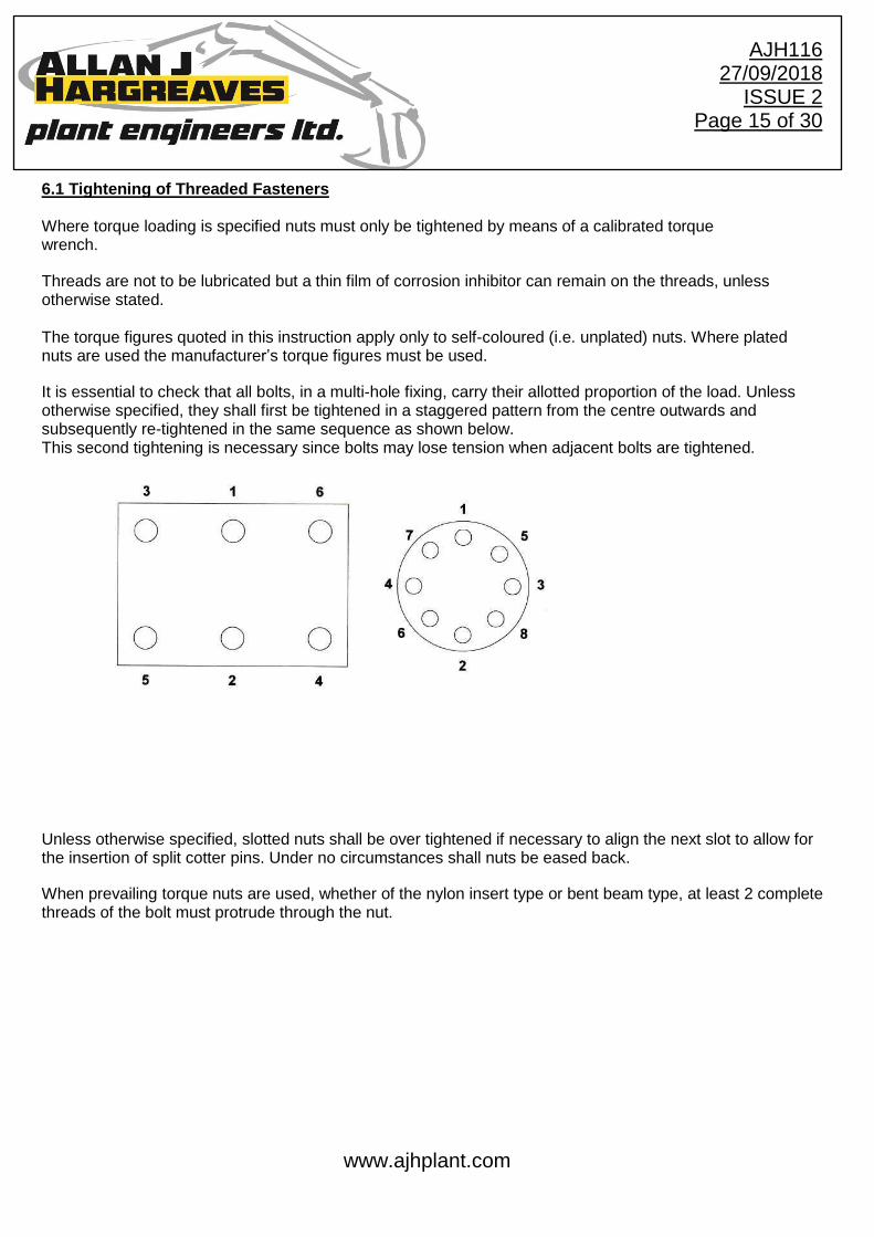
6.1 Tightening of Threaded Fasteners Where torque loading is specified nuts must only be tightened by means of a calibrated torque wrench. Threads are not to be lubricated but a thin film of corrosion inhibitor can remain on the threads, unless otherwise stated. The torque figures quoted in this instruction apply only to self-coloured (i.e. unplated) nuts. Where plated nuts are used the manufacturer’s torque figures must be used. It is essential to check that all bolts, in a multi-hole fixing, carry their allotted proportion of the load. Unless otherwise specified, they shall first be tightened in a staggered pattern from the centre outwards and subsequently re-tightened in the same sequence as shown below. This second tightening is necessary since bolts may lose tension when adjacent bolts are tightened.
Unless otherwise specified, slotted nuts shall be over tightened if necessary to align the next slot to allow for the insertion of split cotter pins. Under no circumstances shall nuts be eased back. When prevailing torque nuts are used, whether of the nylon insert type or bent beam type, at least 2 complete threads of the bolt must protrude through the nut.
www.ajhplant.com
AJH116 27/09/2018
ISSUE 2 Page 16 of 30
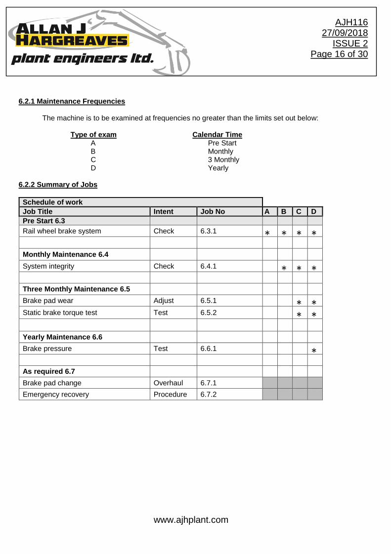
6.2.1 Maintenance Frequencies
The machine is to be examined at frequencies no greater than the limits set out below: Type of exam Calendar Time A Pre Start B Monthly C 3 Monthly D Yearly
6.2.2 Summary of Jobs
Schedule of work
Job Title Intent Job No A B C D
Pre Start 6.3
Rail wheel brake system Check 6.3.1 ∗ ∗ ∗ ∗
Monthly Maintenance 6.4
System integrity Check 6.4.1 ∗ ∗ ∗
Three Monthly Maintenance 6.5
Brake pad wear Adjust 6.5.1 ∗ ∗
Static brake torque test Test 6.5.2 ∗ ∗
Yearly Maintenance 6.6
Brake pressure Test 6.6.1 ∗
As required 6.7
Brake pad change Overhaul 6.7.1
Emergency recovery Procedure 6.7.2

www.ajhplant.com
AJH116 27/09/2018
ISSUE 2 Page 17 of 30
6.3 Maintenance instructions
Scheduled Work is that mandatory work which should be undertaken at the prescribed examinations. Arising Work is that work that is done to rectify the defects found in the course of carrying out Scheduled work. The items numbers of the two parts correspond, i.e. the work to be done to rectify a defect in item 2 of scheduled work will be found in item 2 of the arising work.
www.ajhplant.com
AJH116 27/09/2018
ISSUE 2 Page 18 of 30
6.3.1. Rail Wheel Brake System - Check Scheduled Work
1. Check all brake system components are securely attached and without damage. 2. With the park brake on ensure the all rail wheels are not free to rotate by hand, turn the
handbrake off and all the wheels should now be free to rotate. 3. Ensure no leaks or contamination of brake discs is present. 4. Place machine on track, drive for a short distance and operate the service brake to ensure the
system operates effectively. 5. Operate the service brake and park brake in turn and ensure the trailer brake away alarm
does not sound for more than 2 seconds.
If the machine is not functioning correctly it must be removed from service until repairs have been carried out.
Arising work 1. Renew missing / Faulty components. 2. Carry out job 6.4.1 & 6.6.1 3. Remove brake disc contamination with brake cleaner 5. Renew faulty wiring, re-secure loose connections, check flow switch operation.

www.ajhplant.com
AJH116 27/09/2018
ISSUE 2 Page 19 of 30
6.4.1 System Integrity – Check Scheduled Work
1. Check brake pad linings and discs for damage, contamination and security, a mirror should be used to check the brake pads on the outboard side of the brake disc.
2. Check the remaining brake pad lining is greater than 3mm (Fig 2). Fig 2
3. Check hydraulic hoses to the brake system and associated fittings. 4. Check for loose or missing fasteners. 5. Check lifeguards for damage and security, ensure the distance between the rubber and railhead is no
greater than 30mm. Arising work 1. Remove brake disc contamination with brake cleaner. 2. Renew defective or damaged brake discs, worn or contaminated brake pads. 3. Renew defective or damaged hoses and fittings. 4. Renew loose or missing fasteners. 5. Adjust rail scraper rubbers to achieve clearance.
BRAKE PAD LININGS

www.ajhplant.com
AJH116 27/09/2018
ISSUE 2 Page 20 of 30
6.5.1. Brake Pad Wear – Adjust Scheduled Work
1. Examine for signs of contamination on the brake pads. 2. Examine brake pad lining for wear (Fig 4). If remaining brake pad lining on any of the brakes
measures 3mm or less carry out job 6.7.1 3. To measure the outboard pad, the distance between the brake disc and the caliper housing
must be measured, as seen in Fig 3.
Fig 4
0.5mm GAP BETWEEN BRAKE PAD AND DISC ON INBOARD SIDE.
ENSURE THE BRAKE IS FULLY ENGAGED INBOARD ON ITS FLOATING PINS.
www.ajhplant.com
AJH116 27/09/2018
ISSUE 2 Page 21 of 30
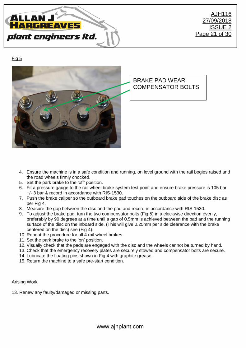
Fig 5
4. Ensure the machine is in a safe condition and running, on level ground with the rail bogies raised and the road wheels firmly chocked.
5. Set the park brake to the ‘off’ position. 6. Fit a pressure gauge to the rail wheel brake system test point and ensure brake pressure is 105 bar
+/- 3 bar & record in accordance with RIS-1530. 7. Push the brake caliper so the outboard brake pad touches on the outboard side of the brake disc as
per Fig 4. 8. Measure the gap between the disc and the pad and record in accordance with RIS-1530. 9. To adjust the brake pad, turn the two compensator bolts (Fig 5) in a clockwise direction evenly,
preferably by 90 degrees at a time until a gap of 0.5mm is achieved between the pad and the running surface of the disc on the inboard side. (This will give 0.25mm per side clearance with the brake centered on the disc) see (Fig 4).
10. Repeat the procedure for all 4 rail wheel brakes. 11. Set the park brake to the ‘on’ position. 12. Visually check that the pads are engaged with the disc and the wheels cannot be turned by hand. 13. Check that the emergency recovery plates are securely stowed and compensator bolts are secure. 14. Lubricate the floating pins shown in Fig 4 with graphite grease. 15. Return the machine to a safe pre-start condition.
Arising Work 13. Renew any faulty/damaged or missing parts.
BRAKE PAD WEAR COMPENSATOR BOLTS
www.ajhplant.com
AJH116 27/09/2018
ISSUE 2 Page 22 of 30
6.5.2. Static brake torque test – Test Note: The figures quoted for the Static brake torque test in AJH097 are derived values calculated to ensure brake performance is maintained until the next maintenance interval. Do not exceed 3000Nm when torque testing. Scheduled Work
1. Ensure the machine is in a safe condition, chock the road wheels and ensure the rail wheels are positioned so they are not externally influenced by the road wheels or the ground.
2. Visually check the brake components to ensure no contamination is present. 3. Apply the parking brake only. 4. Using a suitable torque wrench / multiplier apply a torque to the 1 inch square drive of each rail wheel
in turn, in line with the values for the park brake torque listed in AJH097. 5. The rail wheel should not turn. 6. Apply the service brake only. 7. Using a suitable torque wrench / multiplier apply a torque to the 1 inch square drive of each rail wheel
in turn, in line with the values for the service brake torque listed in AJH097. 8. The rail wheel should not turn. 9. Record results in accordance with RIS-1530-PLT.
If the machine is not functioning correctly it must be removed from service until repairs have been carried out. Arising work 2. Remove brake disc contamination with brake cleaner, renew defective, damaged, worn or contaminated brake pads. Remove brake disc glazing with emery cloth. 5,8. Carry out a check of the rail wheel brake system pads in accordance with job 6.4.1. 5,8. Carry out a pressure test of the rail wheel brake system in accordance with job 6.6.1. Repeat test after making any repairs or adjustments.
www.ajhplant.com
AJH116 27/09/2018
ISSUE 2 Page 23 of 30
6.6.1. Brake Pressure – Test Scheduled Work
1. Ensure the machine is in a safe condition on level ground with the rail bogies raised and the road wheels firmly chocked.
2. Locate and install a pressure test gauge to the brake pressure line. 3. Set the park brake to off, the park brake pressure should be 105bar +/- 3bar. 4. Fully depress the service brake pedal, the brake pressure should now read less than 10bar. 5. Set the park brake to the on position, the brake pressure should now read less than 5bar. 6. Record the results I.A.W RIS-1530. 7. Reinstate the machine to a pre use condition.
Arising Work 3. Adjust pressure reducing valve to achieve correct brake pressures. 4. Replace defective items, refer to manufacturer. Repeat test after making any repairs or adjustments.
www.ajhplant.com
AJH116 27/09/2018
ISSUE 2 Page 24 of 30
6.7.1. Brake Pad Change - Overhaul
Scheduled Work
1. Ensure the machine is in a safe condition on level ground with the rail bogies raised and the road
wheels firmly chocked.
2. Start the machine and set the park brake to off.
3. Using a Micrometer measure the brake disc thickness, if this value is less than or equal to 11.5mm
or the brake disc is found to have excessive scoring or damage the disc must be changed or
resurfaced as long as the final thickness is greater than 11.5mm.
4. Using a dial test indicator measure the lateral run-out (side to side movement) of the brake disc, if
the value is greater than 1.0mm the brake disc must be checked for correct seating to the rail wheel, if
the value is still out of limits the disc must be changed. Once a disc has been changed the run-out
should be rechecked ensuring a clean mating surface between the disc and wheel.
5. Remove the 2 main securing bolts attaching the caliper assembly to the rail axle.
6. Remove the bolts from the brake disc.
7. The caliper can now be lifted off the brake disc to allow access to the brake pads.
8. Set the park brake to on and turn off the machine.
9. Remove the nuts from the 4 long bolts holding the caliper assembly together and split the caliper at
the join where the brake disc would normally sit.
10. Remove the 2 screws retaining each brake pad in position to allow removal of the brake pads.
11. Rotate the 2 compensator plates (Fig 9) on the park brake side of the caliper anti-clockwise until
the pad adjustment is removed (i.e thread bottoms out but DO NOT TIGHTEN) whilst ensuring
alignment with the brake pad screws (this will reset the adjustment previously taken up to compensate
for pad wear on the old brake pads.

www.ajhplant.com
AJH116 27/09/2018
ISSUE 2 Page 25 of 30
Fig 9
12. Install the new brake pads to the caliper and tighten the retaining screws.
(All pads in the particular caliper must be changed at the same time and screws replaced).
14. Refit the 4 long bolts holding the caliper assembly together and tighten to 54Nm.
15. Ensure the caliper is free to slide on the floating pins and lubricate them with graphite grease.
16. Refit the brake caliper to the axle by installing the 2 main bolts and reinstall the brake disc bolts. All
fasteners must be torqued accordingly.
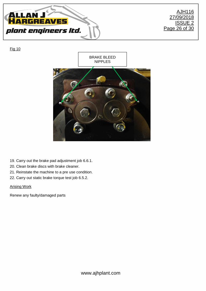
18. Start the machine and set the park brake to off, whilst using the brake bleed nipple Fig 10 to purge the
system of air, this must be repeated for all 4 wheels, whilst taking care due to the high pressure in the
system. It is advised to place a piece of small bore hose over the bleed nipple to avoid contaminating the disc
and pads with oil.
FLOATING PINS
PARK BRAKE COMPENSATOR PLATE
www.ajhplant.com
AJH116 27/09/2018
ISSUE 2 Page 26 of 30
Fig 10
19. Carry out the brake pad adjustment job 6.6.1.
20. Clean brake discs with brake cleaner.
21. Reinstate the machine to a pre use condition.
22. Carry out static brake torque test job 6.5.2. Arising Work Renew any faulty/damaged parts
BRAKE BLEED NIPPLES
www.ajhplant.com
AJH116 27/09/2018
ISSUE 2 Page 27 of 30
6.7.2. Emergency Recovery – Procedure
Prior to carrying out the emergency recovery procedure ensure the machine is coupled to the towing machine with a suitable drawbar. Scheduled Work
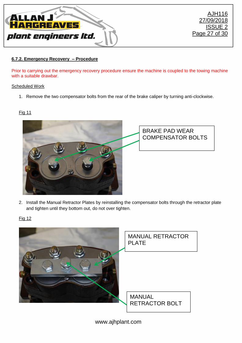
1. Remove the two compensator bolts from the rear of the brake caliper by turning anti-clockwise.
Fig 11
2. Install the Manual Retractor Plates by reinstalling the compensator bolts through the retractor plate
and tighten until they bottom out, do not over tighten.
Fig 12
BRAKE PAD WEAR COMPENSATOR BOLTS
MANUAL RETRACTOR PLATE
MANUAL RETRACTOR BOLT

www.ajhplant.com
AJH116 27/09/2018
ISSUE 2 Page 28 of 30
3. Tighten the retractor bolt until the brake pads are released from the disc and the wheel becomes free
to move (Do not over tighten).
4. Repeat the procedure for all 4 rail wheel brakes.
5. To reinstate the braking system, remove the Manual Retractor Plate and reinstall the two
compensator bolts.
6. Carry out brake pad wear adjust job 6.5.1
Arising Work Renew any faulty/damaged parts
www.ajhplant.com
AJH116 27/09/2018
ISSUE 2 Page 29 of 30
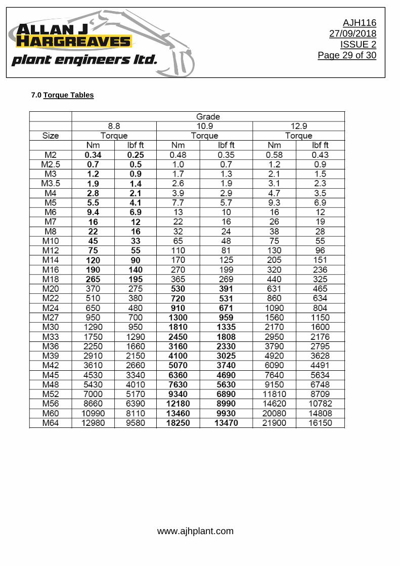
7.0 Torque Tables
www.ajhplant.com
AJH116 27/09/2018
ISSUE 2 Page 30 of 30
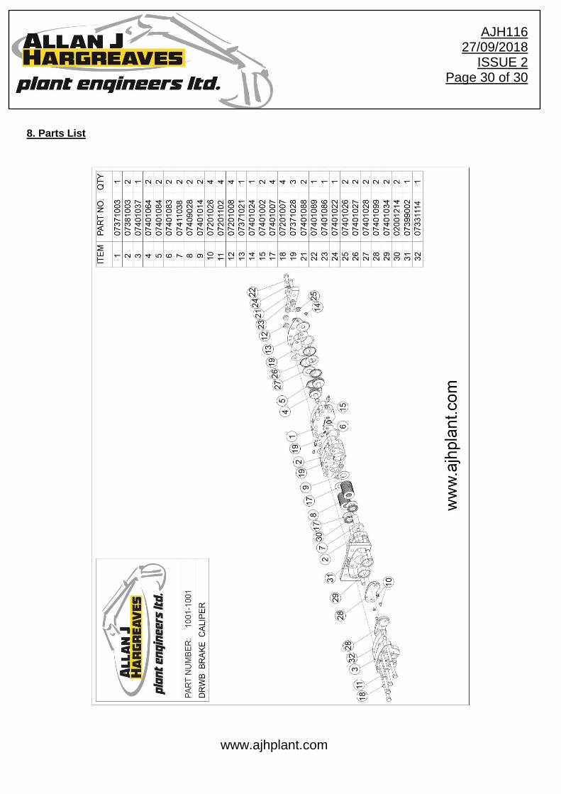
8. Parts List
Related Documents