Commercial and Recreational Mobile Generator Sets Model: 7.5EOR/EORZ 10EOR/EORZ 15EOR/EORZ 20EOR/EORZ TP-6061 3/00 Operation

Welcome message from author
This document is posted to help you gain knowledge. Please leave a comment to let me know what you think about it! Share it to your friends and learn new things together.
Transcript

Commercial and Recreational
Mobile Generator Sets
Model:
7.5EOR/EORZ
10EOR/EORZ
15EOR/EORZ
20EOR/EORZ
TP-6061 3/00
Operation

Engine exhaust from this product containschemicals known to the State of California to cause
cancer, birth defects, or other reproductive harm.
WARNING
California Proposition 65
TP-6061 3/00Table of Contents
Table of Contents
Safety Precautions and Instructions I. . . . . . . . .
Introduction i. . . . . . . . . . . . . . . . . . . . . . . . . . . . . . .
Service Assistance i. . . . . . . . . . . . . . . . . . . . . . . . .
Service Information i. . . . . . . . . . . . . . . . . . . . . . . . . . . . . .
Product Information ii. . . . . . . . . . . . . . . . . . . . . . . . . . . . . .
Maintenance and Service Parts/RelatedLiterature iii. . . . . . . . . . . . . . . . . . . . . . . . . . . . . . . . . .
Maintenance and Service Parts iii. . . . . . . . . . . . . . . . . . .
List of Related Literature iii. . . . . . . . . . . . . . . . . . . . . . . . .
Section 1 Service Views 1. . . . . . . . . . . . . . . . . . . .
Section 2 Operation 3. . . . . . . . . . . . . . . . . . . . . . . .
2.1 Prestart Checklist 3. . . . . . . . . . . . . . . . . . . . . . . . . .
2.2 Angular Operation 3. . . . . . . . . . . . . . . . . . . . . . . . .
2.3 Exercise the Generator Set 3. . . . . . . . . . . . . . . . . .
2.4 Start and Stop Procedure 4. . . . . . . . . . . . . . . . . . .
2.4.1 Controls and Indicators 4. . . . . . . . . . . . .
2.4.2 Start the Generator Set 4. . . . . . . . . . . . .
2.4.3 Remote Panel Gauge Operation 4. . . . .
2.4.4 Stop the Generator Set 4. . . . . . . . . . . . .
Section 3 Scheduled Maintenance 5. . . . . . . . . . .
3.1 General Maintenance 5. . . . . . . . . . . . . . . . . . . . . . .
3.2 Service Schedule 6. . . . . . . . . . . . . . . . . . . . . . . . . .
3.3 Lubrication System 7. . . . . . . . . . . . . . . . . . . . . . . . .
3.3.1 Oil Specifications 7. . . . . . . . . . . . . . . . . .
3.3.2 Oil Change Procedure 7. . . . . . . . . . . . . .
3.3.3 Oil Level 7. . . . . . . . . . . . . . . . . . . . . . . . . .
3.4 Fuel System 8. . . . . . . . . . . . . . . . . . . . . . . . . . . . . .
3.4.1 Fuel Specifications 8. . . . . . . . . . . . . . . . .
3.4.2 Fuel Filter 8. . . . . . . . . . . . . . . . . . . . . . . . .
3.4.3 Bleed the Fuel System 9. . . . . . . . . . . . . .
3.5 Air Intake Silencer/Cleaner 10. . . . . . . . . . . . . . . . . .
3.6 Exhaust System 11. . . . . . . . . . . . . . . . . . . . . . . . . . .
3.7 Cooling System 11. . . . . . . . . . . . . . . . . . . . . . . . . . . .
3.7.1 Check the Cooling System 11. . . . . . . . . .
3.7.2 Drain the Cooling System 12. . . . . . . . . . .
3.7.3 Flush and Clean the Cooling System 12.
3.7.4 Fill the Cooling System 12. . . . . . . . . . . . .
3.8 Belt Tension 13. . . . . . . . . . . . . . . . . . . . . . . . . . . . . . .
3.9 Battery 14. . . . . . . . . . . . . . . . . . . . . . . . . . . . . . . . . . .
3.10 Storage Procedure 14. . . . . . . . . . . . . . . . . . . . . . . . .
3.10.1 Lubricating System 14. . . . . . . . . . . . . . . . .
3.10.2 Cooling System 15. . . . . . . . . . . . . . . . . . . .
3.10.3 Fuel System 15. . . . . . . . . . . . . . . . . . . . . . .
3.10.4 Exterior 15. . . . . . . . . . . . . . . . . . . . . . . . . . .
Section 4 General Troubleshooting 17. . . . . . . . . .
Section 5 Wiring Diagrams 21. . . . . . . . . . . . . . . . .
5.1 7.5/10EOR 1 Phase 23. . . . . . . . . . . . . . . . . . . . . . . .
5.2 7.5/10EORZ 1 Phase 24. . . . . . . . . . . . . . . . . . . . . . .
5.3 15/20EOR 1 Phase 25. . . . . . . . . . . . . . . . . . . . . . . .
5.4 15/20EORZ 3 Phase 26. . . . . . . . . . . . . . . . . . . . . . .
Appendix A Abbreviations A-1. . . . . . . . . . . . . . . .
Appendix B Operating Hour Service Log A--3. . .

TP-6061 3/00 Table of Contents
TP-6061 3/00 ISafety Precautions and Instructions
Safety Precautions and Instructions
Electromechanical equipment,
including generator sets, transfer
switches,switchgear, andaccessories,
can cause bodily harm and pose
life-threatening danger when
improperly installed, operated, or
maintained. To prevent accidents be
aware of potential dangers and act
safely. Read and follow all safety
precautions and instructions. SAVE
THESE INSTRUCTIONS.
Thismanual hasseveral typesofsafety
precautions and instructions: Danger,
Warning, Caution, and Notice.
DANGER
Danger indicates the presence of a
hazard that will cause severe
personal injury,death, orsubstantial
property damage.
WARNING
Warning indicates the presence of a
hazard that can cause severe
personal injury,death,orsubstantial
property damage.
CAUTION
Caution indicates the presence of a
hazard that will or can cause minor
personal injury or property damage.
NOTICE
Notice communicates installation,
operation, or maintenance information
that is safety related but not hazard
related.
Safety decals affixed to the equipment
in prominent places alert the operator
or service technician to potential
hazards and explain how to act safely.
The decals are shown throughout this
publication to improve operator
recognition. Replace missing or
damaged decals.
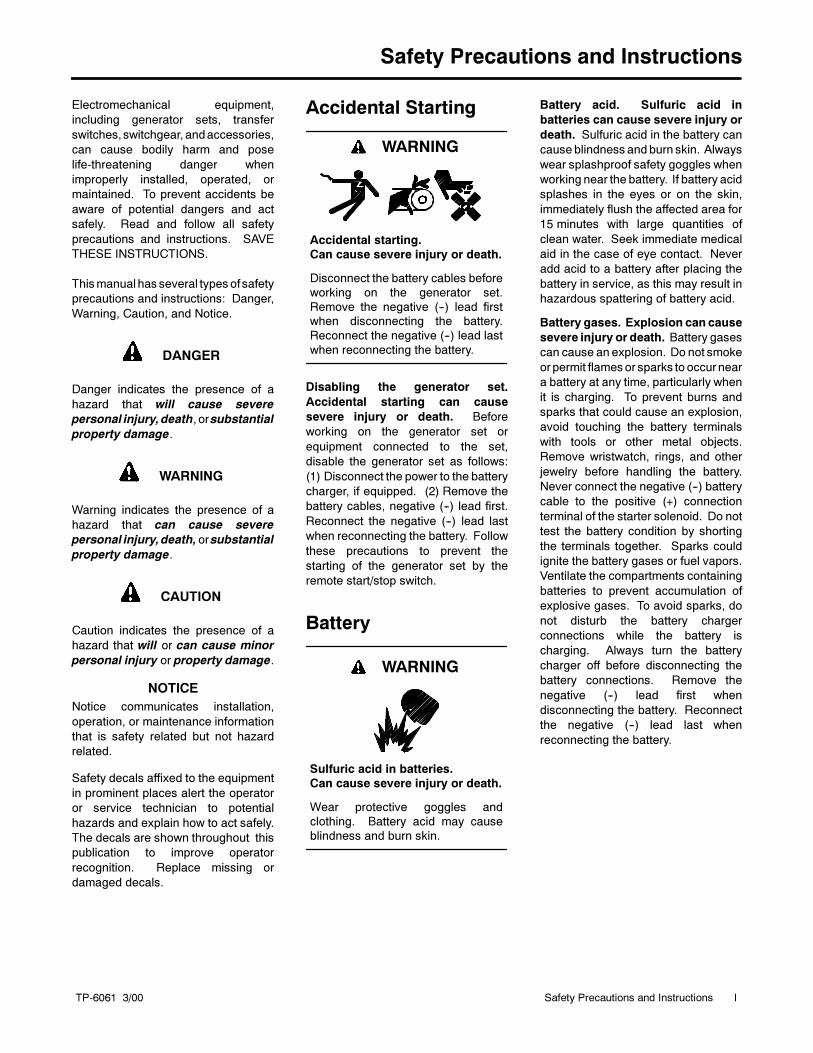
Accidental Starting
Accidental starting.
Can cause severe injury or death.
Disconnect the battery cables before
working on the generator set.
Remove the negative (--) lead first
when disconnecting the battery.
Reconnect the negative (--) lead last
when reconnecting the battery.
WARNING
Disabling the generator set.
Accidental starting can cause
severe injury or death. Before
working on the generator set or
equipment connected to the set,
disable the generator set as follows:
(1) Disconnect the power to the battery
charger, if equipped. (2) Remove the
battery cables, negative (--) lead first.
Reconnect the negative (--) lead last
when reconnecting the battery. Follow
these precautions to prevent the
starting of the generator set by the
remote start/stop switch.
Battery
Sulfuric acid in batteries.
Can cause severe injury or death.
Wear protective goggles and
clothing. Battery acid may cause
blindness and burn skin.
WARNING
Battery acid. Sulfuric acid in
batteries can cause severe injury or
death. Sulfuric acid in the battery can
causeblindnessandburn skin. Always
wear splashproof safety goggles when
working near the battery. If battery acid
splashes in the eyes or on the skin,
immediately flush the affected area for
15 minutes with large quantities of
clean water. Seek immediate medical
aid in the case of eye contact. Never
add acid to a battery after placing the
battery in service, as this may result in
hazardous spattering of battery acid.
Battery gases. Explosion can cause
severe injury or death. Battery gases
can cause an explosion. Do not smoke
orpermit flamesor sparks to occurnear
a battery at any time, particularly when
it is charging. To prevent burns and
sparks that could cause an explosion,
avoid touching the battery terminals
with tools or other metal objects.
Remove wristwatch, rings, and other
jewelry before handling the battery.
Never connect the negative (--) battery
cable to the positive (+) connection
terminal of the starter solenoid. Do not
test the battery condition by shorting
the terminals together. Sparks could
ignite the battery gases or fuel vapors.
Ventilate the compartments containing
batteries to prevent accumulation of
explosive gases. To avoid sparks, do
not disturb the battery charger
connections while the battery is
charging. Always turn the battery
charger off before disconnecting the
battery connections. Remove the
negative (--) lead first when
disconnecting the battery. Reconnect
the negative (--) lead last when
reconnecting the battery.

TP-6061 3/00II Safety Precautions and Instructions
Engine Backfire/Flash
Fire
Fire.
Can cause severe injury or death.
Do not smoke or permit flames or
sparks near fuels or the fuel system.
WARNING
Servicing the air cleaner. A sudden
backfire can cause severe injury or
death. Do not operate the generator
set with the air cleaner removed.
Combustible materials. A fire can
cause severe injury or death.
Generator set engine fuels and fuel
vapors are flammable and explosive.
Handle these materials carefully to
minimize the risk of fire or explosion.
Equip the compartment or nearby area
with a fully charged fire extinguisher.
Select a fire extinguisher rated ABC or
BC for electrical fires or as
recommended by the local fire code or
an authorized agency. Train all
personnel on fire extinguisher
operation and fire prevention
procedures.
Exhaust System
Carbon monoxide.
Can cause severe nausea,
fainting, or death.
The exhaust system must be
leakproof and routinely inspected.
WARNING
Generator set operation. Carbon
monoxidecancauseseverenausea,
fainting, or death. Carbon monoxide
is an odorless, colorless, tasteless,
nonirritating gas that can cause death if
inhaled for even a short time. Avoid
breathingexhaust fumeswhenworking
on or near the generator set. Never
operate the generator set inside a
building unless the exhaust gas is
piped safely outside. Never operate
the generator set where exhaust gas
couldaccumulateandseepback inside
a potentially occupied building or
vehicle. Do not obstruct the exhaust
outlet when parking your vehicle. The
exhaust gasesmust discharge freely to
prevent carbon monoxide from
deflecting into the vehicle.
Carbon monoxide symptoms.
Carbonmonoxide can cause severe
nausea, fainting, or death. Carbon
monoxide isapoisonousgaspresent in
exhaust gases. Carbon monoxide
poisoning symptoms include but are
not limited to the following:
� Light-headedness, dizziness
� Physical fatigue, weakness in
joints and muscles
� Sleepiness, mental fatigue,
inability to concentrate
or speak clearly, blurred vision
� Stomachache, vomiting, nausea
If experiencing any of these symptoms
and carbon monoxide poisoning is
possible, seek fresh air immediately
and remain active. Do not sit, lie down,
or fall asleep. Alert others to the
possibility of carbon monoxide
poisoning. Seek medical attention if
the condition of affected persons does
not improvewithinminutes of breathing
fresh air.
Copper tubing exhaust systems.
Carbonmonoxide can cause severe
nausea, fainting, or death. Do not
use copper tubing in diesel exhaust
systems. Sulfur in diesel exhaust
causes rapid deterioration of copper
tubing exhaust systems, resulting in
exhaust leakage.
Installing the exhaust tail pipe.
Carbonmonoxide can cause severe
nausea, fainting, or death. Install the
exhaust system tail pipe to prevent the
drawing of discharged exhaust gases
into the vehicle interior through
windows, doors, air conditioners, and
other openings. Do not use flexible tail
piping because it could crack and allow
lethal exhaust fumes to enter the
vehicle.
Inspecting the exhaust system.
Carbonmonoxide can cause severe
nausea, fainting, or death. For the
safetyof thevehicle’soccupants, install
a carbon monoxide detector. Consult
the coach builder or dealer for
approved detector location and
installation. Inspect thedetectorbefore
each generator set use. In addition to
routine exhaust system inspection, test
the carbon monoxide detector per the
manufacturer’s instructions and keep
the detector operational at all times.
Fuel System
Explosive fuel vapors.
Can cause severe injury or death.
Use extreme care when handling,
storing, and using fuels.
WARNING
TP-6061 3/00 IIISafety Precautions and Instructions
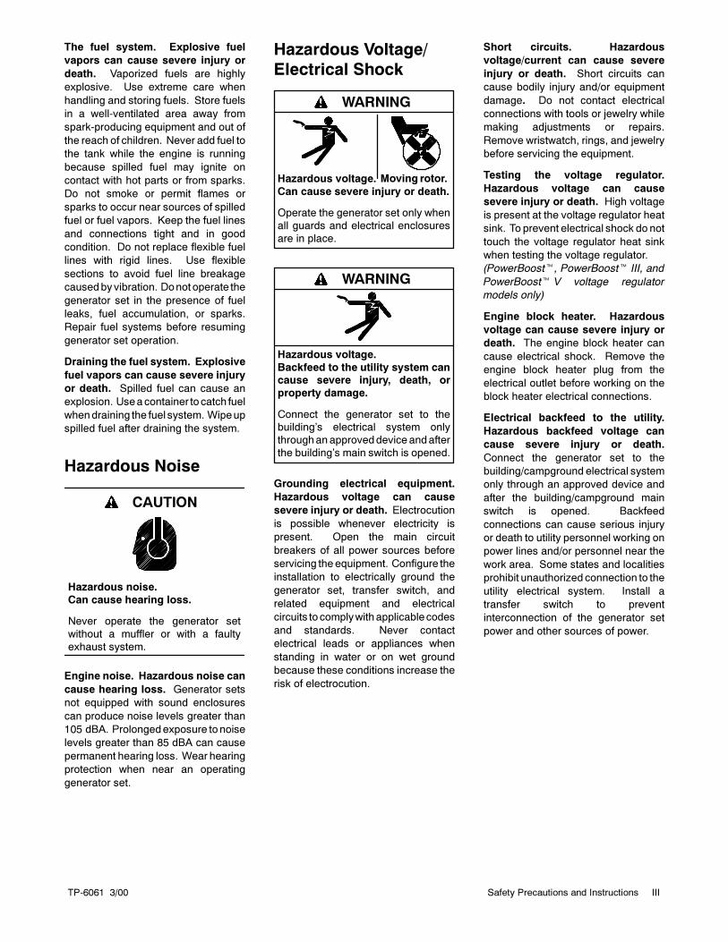
The fuel system. Explosive fuel
vapors can cause severe injury or
death. Vaporized fuels are highly
explosive. Use extreme care when
handling and storing fuels. Store fuels
in a well-ventilated area away from
spark-producing equipment and out of
the reach of children. Never add fuel to
the tank while the engine is running
because spilled fuel may ignite on
contact with hot parts or from sparks.
Do not smoke or permit flames or
sparks to occur near sources of spilled
fuel or fuel vapors. Keep the fuel lines
and connections tight and in good
condition. Do not replace flexible fuel
lines with rigid lines. Use flexible
sections to avoid fuel line breakage
causedbyvibration. Donotoperate the
generator set in the presence of fuel
leaks, fuel accumulation, or sparks.
Repair fuel systems before resuming
generator set operation.
Draining the fuel system. Explosive
fuel vapors can cause severe injury
or death. Spilled fuel can cause an
explosion. Useacontainer to catch fuel
whendraining the fuel system. Wipeup
spilled fuel after draining the system.
Hazardous Noise
Hazardous noise.
Can cause hearing loss.
Never operate the generator set
without a muffler or with a faulty
exhaust system.
CAUTION
Engine noise. Hazardous noise can
cause hearing loss. Generator sets
not equipped with sound enclosures
can produce noise levels greater than
105 dBA. Prolongedexposure tonoise
levels greater than 85 dBA can cause
permanent hearing loss. Wear hearing
protection when near an operating
generator set.
Hazardous Voltage/
Electrical Shock
Hazardous voltage.
Can cause severe injury or death.
Operate the generator set only when
all guards and electrical enclosures
are in place.
Moving rotor.
WARNING
Hazardous voltage.
Backfeed to the utility system can
cause severe injury, death, or
property damage.
Connect the generator set to the
building’s electrical system only
throughanapproveddevice andafter
the building’s main switch is opened.
WARNING
Grounding electrical equipment.
Hazardous voltage can cause
severe injury or death. Electrocution
is possible whenever electricity is
present. Open the main circuit
breakers of all power sources before
servicing theequipment. Configure the
installation to electrically ground the
generator set, transfer switch, and
related equipment and electrical
circuits to complywithapplicablecodes
and standards. Never contact
electrical leads or appliances when
standing in water or on wet ground
because these conditions increase the
risk of electrocution.
Short circuits. Hazardous
voltage/current can cause severe
injury or death. Short circuits can
cause bodily injury and/or equipment
damage. Do not contact electrical
connections with tools or jewelry while
making adjustments or repairs.
Remove wristwatch, rings, and jewelry
before servicing the equipment.
Testing the voltage regulator.
Hazardous voltage can cause
severe injury or death. High voltage
is present at the voltage regulator heat
sink. To prevent electrical shock do not
touch the voltage regulator heat sink
when testing the voltage regulator.
(PowerBoost�, PowerBoost� III, and
PowerBoost� V voltage regulator
models only)
Engine block heater. Hazardous
voltage can cause severe injury or
death. The engine block heater can
cause electrical shock. Remove the
engine block heater plug from the
electrical outlet before working on the
block heater electrical connections.
Electrical backfeed to the utility.
Hazardous backfeed voltage can
cause severe injury or death.
Connect the generator set to the
building/campground electrical system
only through an approved device and
after the building/campground main
switch is opened. Backfeed
connections can cause serious injury
or death to utility personnel working on
power lines and/or personnel near the
work area. Some states and localities
prohibit unauthorized connection to the
utility electrical system. Install a
transfer switch to prevent
interconnection of the generator set
power and other sources of power.
TP-6061 3/00IV Safety Precautions and Instructions
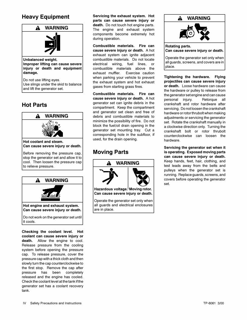
Heavy Equipment
Unbalanced weight.
Improper lifting can cause severe
injury or death and equipment
damage.
Do not use lifting eyes.
Use slings under the skid to balance
and lift the generator set.
WARNING
Hot Parts
Hot coolant and steam.
Can cause severe injury or death.
Before removing the pressure cap,
stop the generator set and allow it to
cool. Then loosen the pressure cap
to relieve pressure.
WARNING
Hot engine and exhaust system.
Can cause severe injury or death.
Do not work on the generator set until
it cools.
WARNING
Checking the coolant level. Hot
coolant can cause severe injury or
death. Allow the engine to cool.
Release pressure from the cooling
system before opening the pressure
cap. To release pressure, cover the
pressure capwith a thick cloth and then
slowly turn the cap counterclockwise to
the first stop. Remove the cap after
pressure has been completely
released and the engine has cooled.
Check the coolant level at the tank if the
generator set has a coolant recovery
tank.
Servicing the exhaust system. Hot
parts can cause severe injury or
death. Do not touch hot engine parts.
The engine and exhaust system
components become extremely hot
during operation.
Combustible materials. Fire can
cause severe injury or death. A hot
exhaust system can ignite adjacent
combustible materials. Do not locate
electrical wiring, fuel lines, or
combustible materials above the
exhaust muffler. Exercise caution
when parking your vehicle to prevent
the exhaust system and hot exhaust
gases from starting grass fires.
Combustible materials. Fire can
cause severe injury or death. A hot
generator set can ignite debris in the
compartment. Keep the compartment
and generator set clean and free of
debris and combustible materials to
minimize the possibility of fire. Do not
block the fuel/oil drain opening in the
generator set mounting tray. Cut a
corresponding hole in the subfloor, if
used, for the drain opening.
Moving Parts
Hazardous voltage.
Can cause severe injury or death.
Operate the generator set only when
all guards and electrical enclosures
are in place.
Moving rotor.
WARNING
Rotating parts.
Can cause severe injury or death.
Operate the generator set only when
all guards, screens, and covers are in
place.
WARNING
Tightening the hardware. Flying
projectiles can cause severe injury
or death. Loose hardware can cause
the hardware or pulley to release from
thegeneratorsetengineandcancause
personal injury. Retorque all
crankshaft and rotor hardware after
servicing. Donot loosen thecrankshaft
hardwareor rotor thrubolt whenmaking
adjustments or servicing the generator
set. Rotate the crankshaft manually in
a clockwise direction only. Turning the
crankshaft bolt or rotor thrubolt
counterclockwise can loosen the
hardware.
Servicing the generator set when it
is operating. Exposedmoving parts
can cause severe injury or death.
Keep hands, feet, hair, clothing, and
test leads away from the belts and
pulleys when the generator set is
running. Replaceguards, screens,and
covers before operating the generator
set.
TP-6061 3/00 VSafety Precautions and Instructions
Notice
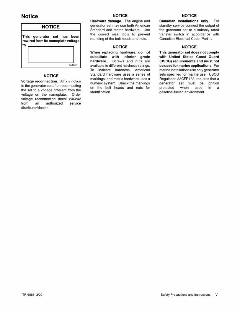
NOTICE
This generator set has been
rewired from its nameplate voltage
to
246242
NOTICE
Voltage reconnection. Affix a notice
to the generator set after reconnecting
the set to a voltage different from the
voltage on the nameplate. Order
voltage reconnection decal 246242
from an authorized service
distributor/dealer.
NOTICE
Hardware damage. The engine and
generator set may use both American
Standard and metric hardware. Use
the correct size tools to prevent
rounding of the bolt heads and nuts.
NOTICE
When replacing hardware, do not
substitute with inferior grade
hardware. Screws and nuts are
available in different hardness ratings.
To indicate hardness, American
Standard hardware uses a series of
markings, and metric hardware uses a
numeric system. Check the markings
on the bolt heads and nuts for
identification.
NOTICE
Canadian installations only. For
standby service connect the output of
the generator set to a suitably rated
transfer switch in accordance with
Canadian Electrical Code, Part 1.
NOTICE
This generator set does not comply
with United States Coast Guard
(USCG) requirements and must not
be used formarine applications. For
marine installations use only generator
sets specified for marine use. USCG
Regulation 33CFR183 requires that a
generator set must be ignition
protected when used in a
gasoline-fueled environment.

TP-6061 3/00VI Safety Precautions and Instructions
Notes

TP-6061 3/00 iIntroduction
Introduction
This manual provides operation instructions for
7.5--20EOR/EORZ model generator sets.
Refer to the engine service manual for generator set
engine service information.
x:in:001:001
Information in this publication represents data available
at the time of print. Kohler Co. reserves the right to
change this publication and the products represented
without notice and without any obligation or liability
whatsoever.
Read this manual and carefully follow all procedures
and safety precautions to ensure proper equipment
operation and to avoid bodily injury. Read and follow the
Safety Precautions and Instructions section at the
beginning of this manual. Keep this manual with the
equipment for future reference.
The equipment service requirements are very important
to safe and efficient operation. Inspect the parts often
and perform required service at the prescribed intervals.
Obtain service from an authorized service
distributor/dealer to keep equipment in top condition.
Before installing a mobile generator set, obtain the
most current installation manual from your local
distributor/dealer. Only qualified persons should
install the generator set.
x:in:001:002:a
Service Assistance
Service Information
Please contact a local authorized distributor/dealer for
sales, service, or other information about Kohler
Generator Division products.
To locate a local authorized distributor/dealer inside
the U.S.A. and Canada
� Look on the product or in the information includedwith
the product
� Consult the Yellow Pages under the heading
Generators— Electric
� Visit the Kohler Generator Division web site at
www.kohlergenerators.com
� Call 1-800-544-2444
To locate a local authorized distributor/dealer
outside the U.S.A. and Canada
� Look on the product or in the information included
with the product
� Consult the telephone directory under the heading
Generators—Electric
� Visit the Kohler Generator Division web site at
www.kohlergenerators.com
� Contact the nearest regional office
Africa, Europe, Middle East
London Regional Office
Langley, Slough, England
Phone: (44) 1753-580-771
Fax: (44) 1753-580-036
Australia
Australia Regional Office
Queensland, Australia
Phone: (617) 3893-0061
Fax: (617) 3893-0072
China
China Regional Office
Shanghai, People’s Republic of China
Phone: (86) 21-6482 1252
Fax: (86) 21-6482 1255
India, Bangladesh, Sri Lanka
India Regional Office
Bangalore, India
Phone: (91) 80-2284270
(91) 80-2284279
Fax: (91) 80-2284286
Japan
Japan Regional Office
Tokyo, Japan
Phone: (813) 3440-4515
Fax: (813) 3440-2727
Latin America
Latin America Regional Office
Lakeland, Florida, U.S.A.
Phone: (941) 619-7568
Fax: (941) 701-7131
South East Asia
Singapore Regional Office
Singapore, Republic of Singapore
Phone: (65) 264-6422
Fax: (65) 264-6455
TP-6061 3/00ii Introduction
Product Information
Product identification numbers determine service parts.
Record the product identification numbers in the spaces
below immediately after unpacking the products so that
the numbers are readily available for future reference.
Record field-installed kit numbers after installing the
kits.
Generator Set Identification Numbers
Record the product identification numbers from thegenerator set nameplate(s).
Model Number
Specification Number
Serial Number
Accessory Number Accessory Description
Engine Identification
Record the product identification information from theengine nameplate.
Manufacturer
Model Number
Serial Number

TP-6061 3/00 iiiIntroduction
Maintenance and Service Parts/Related Literature
Maintenance and Service Parts
Figure 1 identifies maintenance and service parts for
your generator set. Obtain a complete list of
maintenance and service parts from your authorized
generator distributor/dealer.
Models
Part Description 7.5EOR/EORZ 10EOR/EORZ 15EOR/EORZ 20EOR/EORZ
Air filter element 278858 A-226955
Battery charging fuse (10 amp) 223316
Black spray paint 221292
Fuel filter element 229715 252765
Input fuse (15 amp) 283645
Oil filter 229678 229841
Voltage regulator fuse (8 amp) 226935
Figure 1 Maintenance and Service Partsx:in:001:004
List of Related Literature
Figure 2 identifies related literature available for the
generator sets covered in this manual. Only trained and
qualified personnel should install or service the
generator set.
Literat re T pe Literat re NoLiterature Type Literature No.
Engine Service Manual
(7.5--15EOR) TP-5876
Engine Service Manual (20EOR) TP-6067
Installation Manual TP-6062
Operation Manual (Engine) TP-5968
Operation Manual (Generator) TP-6061
Parts Catalog* (7.5/10 kW) TP-6072
Parts Catalog* (15/20 kW) TP-5607
Service Manual (Generator) TP-6073
* Onemanual combines generator and engine information.
Figure 2 Generator Set Literature
x:in:001:005

TP-6061 3/00iv Introduction
Notes

TP-6061 3/00 1Section 1 Service Views
Section 1 Service Views
1 2 5 8
1314
10
7
11
15
16
17
9
ADV-6519
Inline Radiator
4 6
1. Controller
2. Nameplate3. Remote start connector
4. Air cleaner
5. Oil check6. Lifting eye
7. Coolant overflow bottle
8. Oil fill
9. Pressure cap10. Fuel injector pump
11. Radiator
12. Coolant drain
13. Oil drain14. Fuel pump
15. Oil filter
16. Customer load access connector17. Optional circuit breaker location
18. Input fuse
19. Battery charging fuse
20. Start/stop switch21. Hourmeter
STOP/START
1
10
0
TOTAL HOURS
00 0 0
15 A.
INPUT
10 A.
BATT> CHG>
226981
PREHEAT
18
19
20
21
Controller
12
3
Figure 1-1 7.5--10 kW Service View (Inline Radiator Model Shown)
TP-6061 3/002 Section 1 Service Views
1 2 6 8
1415
11
7
1220
16
19
1718
9
A-226966
ADV-6484
Inline Radiator
STOP/START
1
10
0
TOTAL HOURS
00 0 0
15 A.
INPUT
10 A.
BATT> CHG>
226981
PREHEAT
Controller
21
22
23
24
103 5
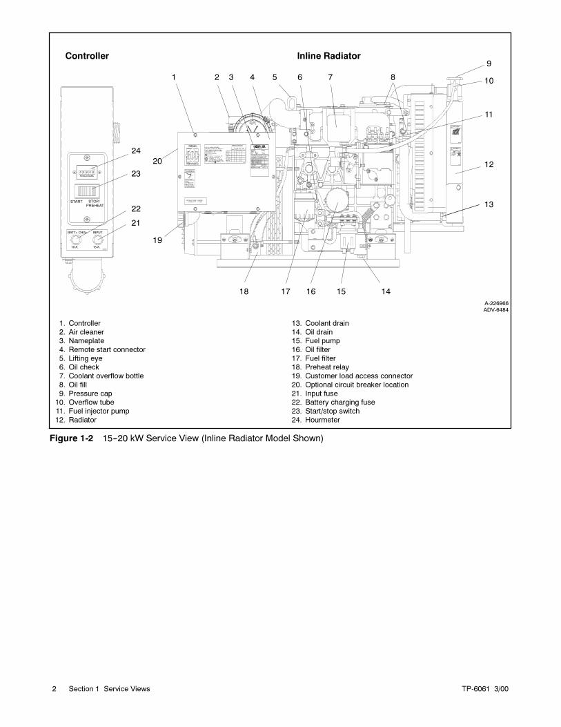
1. Controller
2. Air cleaner3. Nameplate
4. Remote start connector
5. Lifting eye6. Oil check
7. Coolant overflow bottle
8. Oil fill
9. Pressure cap10. Overflow tube
11. Fuel injector pump
12. Radiator
13. Coolant drain
14. Oil drain15. Fuel pump
16. Oil filter
17. Fuel filter18. Preheat relay
19. Customer load access connector
20. Optional circuit breaker location
21. Input fuse22. Battery charging fuse
23. Start/stop switch
24. Hourmeter
13
4
Figure 1-2 15--20 kW Service View (Inline Radiator Model Shown)
TP-6061 3/00 3Section 2 Operation
Section 2 Operation
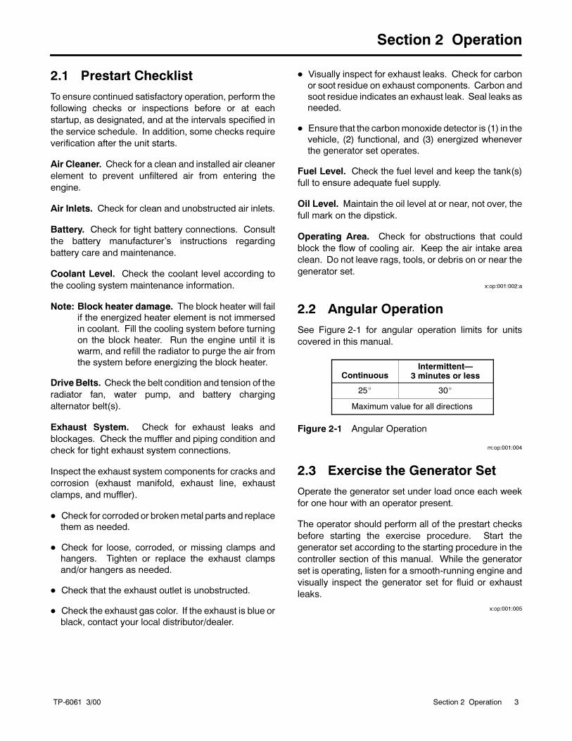
2.1 Prestart Checklist
To ensure continued satisfactory operation, perform the
following checks or inspections before or at each
startup, as designated, and at the intervals specified in
the service schedule. In addition, some checks require
verification after the unit starts.
Air Cleaner. Check for a clean and installed air cleaner
element to prevent unfiltered air from entering the
engine.
Air Inlets. Check for clean and unobstructed air inlets.
Battery. Check for tight battery connections. Consult
the battery manufacturer’s instructions regarding
battery care and maintenance.
Coolant Level. Check the coolant level according to
the cooling system maintenance information.
Note: Block heater damage. The block heater will fail
if the energized heater element is not immersed
in coolant. Fill the cooling system before turning
on the block heater. Run the engine until it is
warm, and refill the radiator to purge the air from
the system before energizing the block heater.
Drive Belts. Check the belt condition and tension of the
radiator fan, water pump, and battery charging
alternator belt(s).
Exhaust System. Check for exhaust leaks and
blockages. Check the muffler and piping condition and
check for tight exhaust system connections.
Inspect the exhaust system components for cracks and
corrosion (exhaust manifold, exhaust line, exhaust
clamps, and muffler).
� Check for corroded or brokenmetal parts and replace
them as needed.
� Check for loose, corroded, or missing clamps and
hangers. Tighten or replace the exhaust clamps
and/or hangers as needed.
� Check that the exhaust outlet is unobstructed.
� Check the exhaust gas color. If the exhaust is blue or
black, contact your local distributor/dealer.
� Visually inspect for exhaust leaks. Check for carbon
or soot residue on exhaust components. Carbon and
soot residue indicates an exhaust leak. Seal leaks as
needed.
� Ensure that the carbonmonoxide detector is (1) in the
vehicle, (2) functional, and (3) energized whenever
the generator set operates.
Fuel Level. Check the fuel level and keep the tank(s)
full to ensure adequate fuel supply.
Oil Level. Maintain the oil level at or near, not over, the
full mark on the dipstick.
Operating Area. Check for obstructions that could
block the flow of cooling air. Keep the air intake area
clean. Do not leave rags, tools, or debris on or near the
generator set.
x:op:001:002:a
2.2 Angular Operation
See Figure 2-1 for angular operation limits for units
covered in this manual.
ContinuousIntermittent—
3 minutes or less
25� 30�
Maximum value for all directions
Figure 2-1 Angular Operation
m:op:001:004
2.3 Exercise the Generator Set
Operate the generator set under load once each week
for one hour with an operator present.
The operator should perform all of the prestart checks
before starting the exercise procedure. Start the
generator set according to the starting procedure in the
controller section of this manual. While the generator
set is operating, listen for a smooth-running engine and
visually inspect the generator set for fluid or exhaust
leaks.
x:op:001:005
TP-6061 3/004 Section 2 Operation
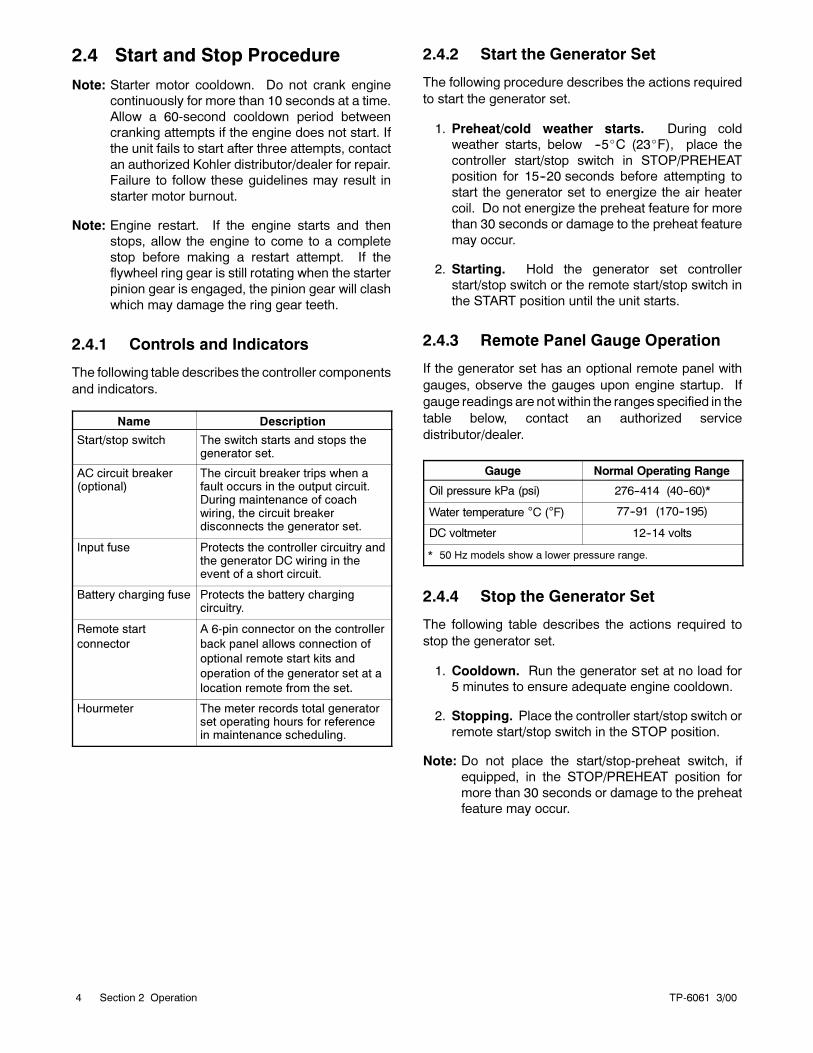
2.4 Start and Stop Procedure
Note: Starter motor cooldown. Do not crank engine
continuously for more than 10 seconds at a time.
Allow a 60-second cooldown period between
cranking attempts if the engine does not start. If
the unit fails to start after three attempts, contact
an authorized Kohler distributor/dealer for repair.
Failure to follow these guidelines may result in
starter motor burnout.
Note: Engine restart. If the engine starts and then
stops, allow the engine to come to a complete
stop before making a restart attempt. If the
flywheel ring gear is still rotating when the starter
pinion gear is engaged, the pinion gear will clash
which may damage the ring gear teeth.
2.4.1 Controls and Indicators
The following table describes the controller components
and indicators.
Name Description
Start/stop switch The switch starts and stops thegenerator set.
AC circuit breaker(optional)
The circuit breaker trips when afault occurs in the output circuit.During maintenance of coachwiring, the circuit breakerdisconnects the generator set.
Input fuse Protects the controller circuitry andthe generator DC wiring in theevent of a short circuit.
Battery charging fuse Protects the battery chargingcircuitry.
Remote start
connector
A 6-pin connector on the controller
back panel allows connection of
optional remote start kits and
operation of the generator set at a
location remote from the set.
Hourmeter The meter records total generatorset operating hours for referencein maintenance scheduling.
2.4.2 Start the Generator Set
The following procedure describes the actions required
to start the generator set.
1. Preheat/cold weather starts. During cold
weather starts, below --5�C (23�F), place the
controller start/stop switch in STOP/PREHEAT
position for 15--20 seconds before attempting to
start the generator set to energize the air heater
coil. Do not energize the preheat feature for more
than 30 seconds or damage to the preheat feature
may occur.
2. Starting. Hold the generator set controller
start/stop switch or the remote start/stop switch in
the START position until the unit starts.
2.4.3 Remote Panel Gauge Operation
If the generator set has an optional remote panel with
gauges, observe the gauges upon engine startup. If
gauge readings are not within the ranges specified in the
table below, contact an authorized service
distributor/dealer.
Gauge Normal Operating Range
Oil pressure kPa (psi) 276--414 (40--60)*
Water temperature �C (�F) 77--91 (170--195)
DC voltmeter 12--14 volts
* 50 Hz models show a lower pressure range.
2.4.4 Stop the Generator Set
The following table describes the actions required to
stop the generator set.
1. Cooldown. Run the generator set at no load for
5 minutes to ensure adequate engine cooldown.
2. Stopping. Place the controller start/stop switch or
remote start/stop switch in the STOP position.
Note: Do not place the start/stop-preheat switch, if
equipped, in the STOP/PREHEAT position for
more than 30 seconds or damage to the preheat
feature may occur.
TP-6061 3/00 5Section 3 Scheduled Maintenance
Section 3 Scheduled Maintenance
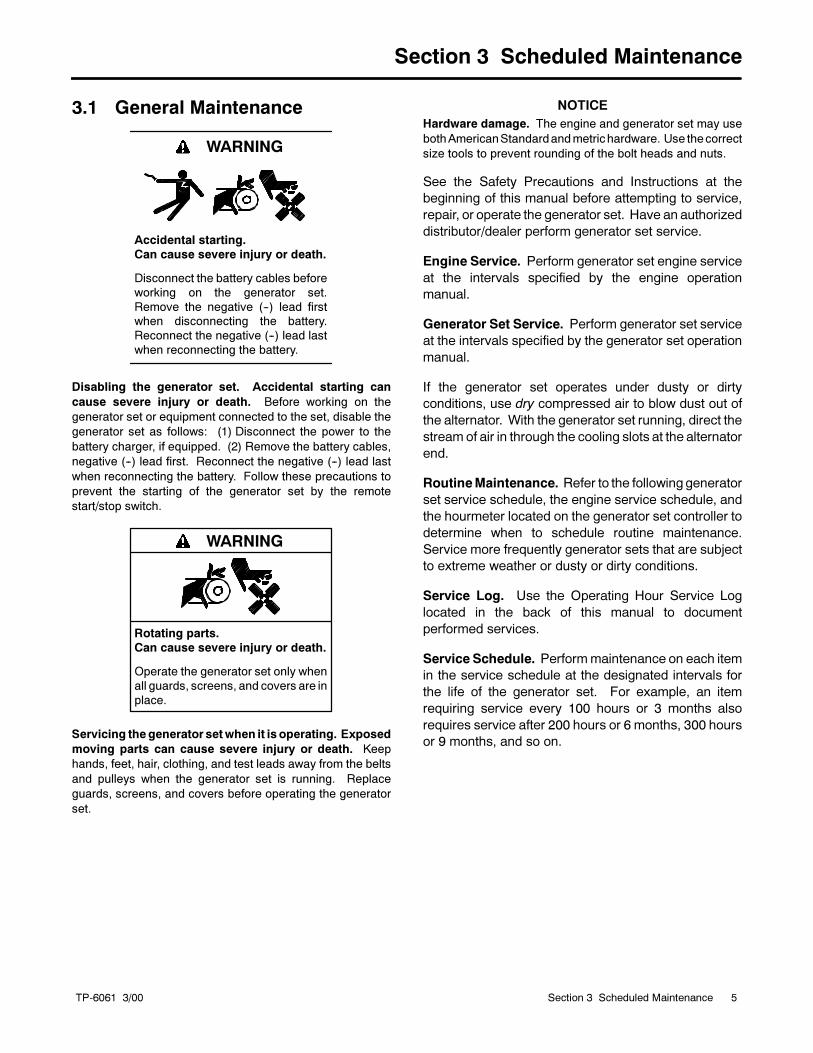
3.1 General Maintenance
Accidental starting.
Can cause severe injury or death.
Disconnect the battery cables before
working on the generator set.
Remove the negative (--) lead first
when disconnecting the battery.
Reconnect the negative (--) lead last
when reconnecting the battery.
WARNING
Disabling the generator set. Accidental starting can
cause severe injury or death. Before working on the
generator set or equipment connected to the set, disable the
generator set as follows: (1) Disconnect the power to the
battery charger, if equipped. (2) Remove the battery cables,
negative (--) lead first. Reconnect the negative (--) lead last
when reconnecting the battery. Follow these precautions to
prevent the starting of the generator set by the remote
start/stop switch.
Rotating parts.
Can cause severe injury or death.
Operate the generator set only when
all guards, screens, and covers are in
place.
WARNING
Servicing thegenerator setwhen it is operating. Exposed
moving parts can cause severe injury or death. Keep
hands, feet, hair, clothing, and test leads away from the belts
and pulleys when the generator set is running. Replace
guards, screens, and covers before operating the generator
set.
NOTICE
Hardware damage. The engine and generator set may use
bothAmericanStandardandmetrichardware. Use thecorrect
size tools to prevent rounding of the bolt heads and nuts.
See the Safety Precautions and Instructions at the
beginning of this manual before attempting to service,
repair, or operate the generator set. Have an authorized
distributor/dealer perform generator set service.
Engine Service. Perform generator set engine service
at the intervals specified by the engine operation
manual.
Generator Set Service. Perform generator set service
at the intervals specified by the generator set operation
manual.
If the generator set operates under dusty or dirty
conditions, use dry compressed air to blow dust out of
the alternator. With the generator set running, direct the
stream of air in through the cooling slots at the alternator
end.
RoutineMaintenance. Refer to the following generator
set service schedule, the engine service schedule, and
the hourmeter located on the generator set controller to
determine when to schedule routine maintenance.
Service more frequently generator sets that are subject
to extreme weather or dusty or dirty conditions.
Service Log. Use the Operating Hour Service Log
located in the back of this manual to document
performed services.
Service Schedule. Performmaintenance on each item
in the service schedule at the designated intervals for
the life of the generator set. For example, an item
requiring service every 100 hours or 3 months also
requires service after 200 hours or 6 months, 300 hours
or 9 months, and so on.
TP-6061 3/006 Section 3 Scheduled Maintenance
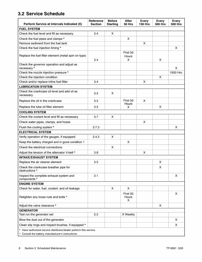
3.2 Service Schedule
Perform Service at Intervals Indicated (X)ReferenceSection
BeforeStarting
After50 Hrs
Every150 Hrs
Every300 Hrs
Every500 Hrs
FUEL SYSTEM
Check the fuel level and fill as necessary 3.4 X
Check the fuel pipes and clamps * X
Remove sediment from the fuel tank X
Check the fuel injection timing * X
Replace the fuel filter element (metal spin-on type)
3.4
First 50
Hours
X X
Check the governor operation and adjust as
necessary * X
Check the nozzle injection pressure * 1000 Hrs.
Check the injection condition X
Check and/or replace inline fuel filter 3.4 X
LUBRICATION SYSTEM
Check the crankcase oil level and add oil as
necessary3.3 X
Replace the oil in the crankcase 3.3 First 50Hours
X
Replace the lube oil filter element 3.3HoursX X
COOLING SYSTEM
Check the coolant level and fill as necessary 3.7 X
Check water pipes, clamps, and hoses X
Flush the cooling system * 3.7.3 X
ELECTRICAL SYSTEM
Verify operation of the gauges, if equipped 2.4.3 X
Keep the battery charged and in good condition � X
Check the electrical connections X
Adjust the tension of the alternator V-belt * 3.8 X
INTAKE/EXHAUST SYSTEM
Replace the air cleaner element 3.5 X
Check the crankcase breather pipe forobstructions *
X
Inspect the complete exhaust system andcomponents *
2.1 X
ENGINE SYSTEM
Check for water, fuel, coolant, and oil leakage X X
Retighten any loose nuts and bolts *First 50HoursX
X
Adjust the valve clearance * X
GENERATOR
Test run the generator set 2.3 X Weekly
Blow the dust out of the generator X
Clean slip rings and inspect brushes, if equipped * X
* Have authorized service distributor/dealer perform this service.
� Consult the battery manufacturer’s instructions.

TP-6061 3/00 7Section 3 Scheduled Maintenance
3.3 Lubrication System
See the Service Schedule for oil change and oil filter
replacement intervals. See Section 1, Service Views,
for the oil drain, oil check, oil fill, and oil filter locations.
x:sm:001:002:
3.3.1 Oil Specifications
Use oil that meets the American Petroleum Institute
(API) classification of CD, CC/CD, or CC. Using
unsuitable oil or neglecting an oil change may result in
engine damage and a shorter engine life. See
Figure 3-1 for the recommended Society of Automotive
Engineers (SAE) viscosity designation for various
operating temperature ranges.
TP-5856-1
SAEServiceGrade
Operating Temperature
Figure 3-1 Engine Oil Selection
3.3.2 Oil Change Procedure
Whenever possible, drain the oil while the generator set
is still warm.
1. Drain the oil.
a. Place the generator start/stop switch in the
STOP position.
b. Disconnect the power to the battery charger, if
equipped.
c. Disconnect the generator set engine starting
battery, negative (--) lead first.
d. Place an oil collection container below the oil
drain and remove the oil drain plug.
e. Allow time for the engine oil to drain completely.
f. Replace the oil drain plug.
2. Replace the oil filter.
a. Remove the oil filter by rotating it
counterclockwise with an oil filter wrench.
b. Clean the sealing surface of the oil filter
adapter.
c. Apply a light coat of clean oil to the rubber seal
of the new oil filter.
d. Install the new oil filter following the instructions
provided with the filter.
3. Fill with oil. For oil selection and capacity see
Figure 3-1 and Figure 3-2.
Model L (Qt.)
7.5 2.3 (2.4)
10 5.2 (5.5)
15/20 5.8 (6.1)
Figure 3-2 Oil Capacity with Filter
4. Check for oil leaks.
a. Check that the generator start/stop switch is in
the STOP position.
b. Reconnect the generator set engine starting
battery, negative (--) lead last.
c. Reconnect the power to the battery charger, if
equipped.
d. Start the generator set and check for leaks
around the oil filter and oil drain plug.
x:sm:001:003:
3.3.3 Oil Level
Maintain the oil level at or near, not over, the full mark on
the dipstick.
TP-6061 3/008 Section 3 Scheduled Maintenance
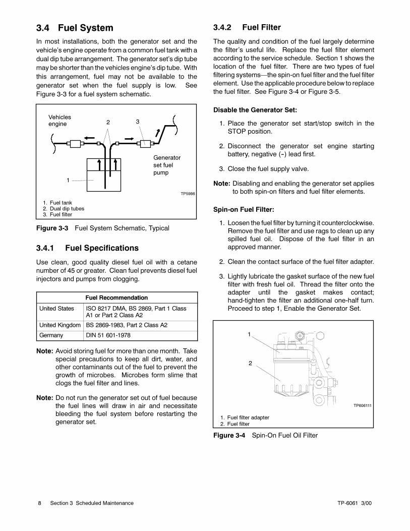
3.4 Fuel System
In most installations, both the generator set and the
vehicle’s engine operate from a common fuel tank with a
dual dip tube arrangement. The generator set’s dip tube
may be shorter than the vehicles engine’s dip tube. With
this arrangement, fuel may not be available to the
generator set when the fuel supply is low. See
Figure 3-3 for a fuel system schematic.
Generator
set fuel
pump
Vehiclesengine
1
2 3
1. Fuel tank2. Dual dip tubes3. Fuel filter
TP5986
Figure 3-3 Fuel System Schematic, Typical
3.4.1 Fuel Specifications
Use clean, good quality diesel fuel oil with a cetane
number of 45 or greater. Clean fuel prevents diesel fuel
injectors and pumps from clogging.
Fuel Recommendation
United States ISO 8217 DMA, BS 2869, Part 1 ClassA1 or Part 2 Class A2
United Kingdom BS 2869-1983, Part 2 Class A2
Germany DIN 51 601-1978
Note: Avoid storing fuel for more than onemonth. Take
special precautions to keep all dirt, water, and
other contaminants out of the fuel to prevent the
growth of microbes. Microbes form slime that
clogs the fuel filter and lines.
Note: Do not run the generator set out of fuel because
the fuel lines will draw in air and necessitate
bleeding the fuel system before restarting the
generator set.
3.4.2 Fuel Filter
The quality and condition of the fuel largely determine
the filter’s useful life. Replace the fuel filter element
according to the service schedule. Section 1 shows the
location of the fuel filter. There are two types of fuel
filtering systems—the spin-on fuel filter and the fuel filter
element. Use the applicable procedure below to replace
the fuel filter. See Figure 3-4 or Figure 3-5.
Disable the Generator Set:
1. Place the generator set start/stop switch in the
STOP position.
2. Disconnect the generator set engine starting
battery, negative (--) lead first.
3. Close the fuel supply valve.
Note: Disabling and enabling the generator set applies
to both spin-on filters and fuel filter elements.
Spin-on Fuel Filter:
1. Loosen the fuel filter by turning it counterclockwise.
Remove the fuel filter and use rags to clean up any
spilled fuel oil. Dispose of the fuel filter in an
approved manner.
2. Clean the contact surface of the fuel filter adapter.
3. Lightly lubricate the gasket surface of the new fuel
filter with fresh fuel oil. Thread the filter onto the
adapter until the gasket makes contact;
hand-tighten the filter an additional one-half turn.
Proceed to step 1, Enable the Generator Set.
1
TP606111
1. Fuel filter adapter
2. Fuel filter
2
Figure 3-4 Spin-On Fuel Oil Filter

TP-6061 3/00 9Section 3 Scheduled Maintenance
Fuel Filter Element:
1. Remove the retaining ring, filter cup, O-ring, spring,
and fuel filter element.
2. Replace the fuel filter element.
3. Reinstall the spring, O-ring, filter cup and retaining
ring. Proceed to step 1 under Enable the
Generator Set.
Enable the Generator Set:
1. Open the fuel supply valve.
2. Reconnect the generator set engine starting
battery, negative (--) lead last.
3. Bleed the fuel system. See Section 3.4.3.
1
TP561633
1. Fuel strainer assembly
2. Bleeding screw3. Body
4. Fuel element
5. Spring
6. O-ring7. Filter cup
8. Retaining ring
3
4
5
6
7
8
2
Figure 3-5 Fuel Oil Filter Element
3.4.3 Bleed the Fuel System
Bleed the air from the fuel system to prevent engine
starting failures and/or erratic operation. One or more of
the following causes air to collect in the fuel system:
� Operating the generator set until the fuel supply is
emptied
� Air leaking from the suction side of the fuel system
� Replacing the fuel filter
Note: Connect the battery during the priming procedure
to allow engine cranking. Do not allow the
engine/generator to start. To prevent starting,
toggle the start/stop switch by momentarily
placing the start/stop switch in the START
position for a few seconds and then placing the
switch in the STOP position.
Procedure to Bleed the Fuel System:
1. Fill the fuel tank.
2. Loosen the fuel filter vent screw. See Figure 3-6.
3. Toggle the start/stop switch until fuel, free of air
bubbles, flows from the vent screw. Tighten the
screw.
4. Loosen the line connection (bleed point) at the fuel
injection pump inlet.
5. Toggle the start/stop switch until fuel, free of air
bubbles, flows from the vent screw at the line
connection on the fuel injection pump inlet. Tighten
the connection.
TP-6061 3/0010 Section 3 Scheduled Maintenance
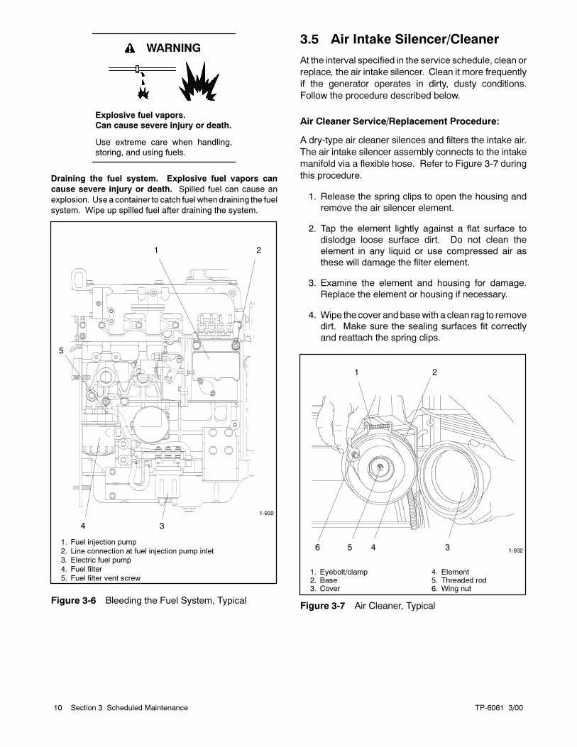
Explosive fuel vapors.
Can cause severe injury or death.
Use extreme care when handling,
storing, and using fuels.
WARNING
Draining the fuel system. Explosive fuel vapors can
cause severe injury or death. Spilled fuel can cause an
explosion. Usea container to catch fuelwhendraining the fuel
system. Wipe up spilled fuel after draining the system.
1-932
1 2
4 3
5
1. Fuel injection pump
2. Line connection at fuel injection pump inlet3. Electric fuel pump
4. Fuel filter
5. Fuel filter vent screw
Figure 3-6 Bleeding the Fuel System, Typical
3.5 Air Intake Silencer/Cleaner
At the interval specified in the service schedule, clean or
replace, the air intake silencer. Clean it more frequently
if the generator operates in dirty, dusty conditions.
Follow the procedure described below.
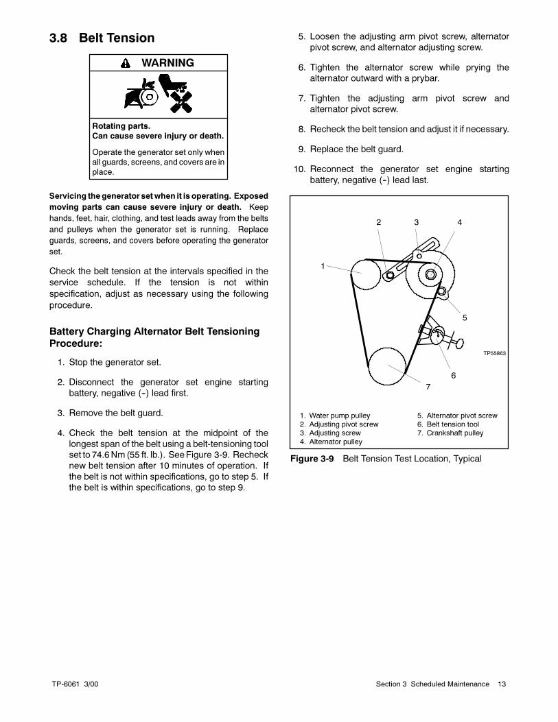
Air Cleaner Service/Replacement Procedure:
A dry-type air cleaner silences and filters the intake air.
The air intake silencer assembly connects to the intake
manifold via a flexible hose. Refer to Figure 3-7 during
this procedure.
1. Release the spring clips to open the housing and
remove the air silencer element.
2. Tap the element lightly against a flat surface to
dislodge loose surface dirt. Do not clean the
element in any liquid or use compressed air as
these will damage the filter element.
3. Examine the element and housing for damage.
Replace the element or housing if necessary.
4. Wipe the cover and basewith a clean rag to remove
dirt. Make sure the sealing surfaces fit correctly
and reattach the spring clips.
1-932
1. Eyebolt/clamp2. Base3. Cover
4. Element5. Threaded rod6. Wing nut
1 2
3456
Figure 3-7 Air Cleaner, Typical

TP-6061 3/00 11Section 3 Scheduled Maintenance
3.6 Exhaust System
Carbon monoxide.
Can cause severe nausea,
fainting, or death.
The exhaust system must be
leakproof and routinely inspected.
WARNING
Inspecting the exhaust system. Carbon monoxide can
cause severe nausea, fainting, or death. For the safety of
the vehicle’s occupants, install a carbon monoxide detector.
Consult the coach builder or dealer for approved detector
location and installation. Inspect the detector before each
generator set use. In addition to routine exhaust system
inspection, test the carbon monoxide detector per the
manufacturer’s instructions and keep the detector operational
at all times.
Exhaust System. Check for exhaust leaks and
blockages. Check the muffler and piping condition and
check for tight exhaust system connections.
Inspect the exhaust system components for cracks and
corrosion (exhaust manifold, exhaust line, exhaust
clamps, and muffler).
� Check for corroded or brokenmetal parts and replace
them as needed.
� Check for loose, corroded, or missing clamps and
hangers. Tighten or replace the exhaust clamps
and/or hangers as needed.
� Check that the exhaust outlet is unobstructed.
� Check the exhaust gas color. If the exhaust is blue or
black, contact your local distributor/dealer.
� Visually inspect for exhaust leaks. Check for carbon
or soot residue on exhaust components. Carbon and
soot residue indicates an exhaust leak. Seal leaks as
needed.
� Ensure that the carbonmonoxide detector is (1) in the
vehicle, (2) functional, and (3) energized whenever
the generator set operates.
3.7 Cooling System
The cooling system maintenance information
specifically applies to radiator-cooled models. These
models use a radiator with a pressure cap and a coolant
recovery tank. Refer to Figure 3-8 for coolant
capacities.
3.7.1 Check the Cooling System
Hot coolant and steam.
Can cause severe injury or death.
Before removing the pressure cap,
stop the generator set and allow it to
cool. Then loosen the pressure cap
to relieve pressure.
WARNING
Note: Block heater damage. The block heater will fail
if the energized heater element is not immersed
in coolant. Fill the cooling system before turning
on the block heater. Run the engine until it is
warm, and refill the radiator to purge the air from
the system before energizing the block heater.
To prevent generator shutdown or damage because of
overheating:
� Check and maintain the coolant level in the coolant
recovery tank between the high and low markings.
� Keep the cooling air inlets clean and unobstructed at
all times.
� Inspect the radiator’s exterior for obstructions and
remove dirt and foreign material with a soft brush or
cloth to avoid damaging the radiator fins.
� Check the hoses and connections for leaks and
replace any cracked, frayed, or spongy hoses.
� Check the condition and tension of the radiator fan
and water pump belt(s).
� Remove dirt and other debris from the pressure cap
and filler neck. The pressure cap raises the boiling
point of the coolant, enabling higher operating
temperatures. Check the seal of the pressure cap
and replace a cracked or deteriorated cap with one
having the same pressure rating. The pressure cap
typically has the pressure rating stamped on the cap
body.

TP-6061 3/0012 Section 3 Scheduled Maintenance
3.7.2 Drain the Cooling System
The radiator and/or engine block contain coolant drain
valve(s) to drain the cooling system. When draining the
coolant, remove the radiator’s pressure cap; this will
allow the entire system to drain and will prevent air
pockets from forming and restricting coolant passage to
the block.
3.7.3 Flush and Clean the Cooling System
For optimum protection, drain, flush, and refill the
cooling system at the intervals listed in the service
schedule. Use the instructions of the engine
manufacturer per the engine operation manual. If not
specified in the engine operation manual, use the
following procedure.
Flush and Clean the Cooling System Procedure:
1. Open the radiator and/or engine block coolant
drain valve(s) and allow the system to drain
completely.
2. Remove the pressure cap to simplify draining.
3. Drain, clean, and flush the coolant recovery tank.
4. Flush the cooling system with clean water.
5. Close the radiator and/or engine block coolant
drain valve(s).
6. Fill the cooling system with the recommended
coolant.
7. Install the pressure cap.
3.7.4 Fill the Cooling System
See Figure 3-8 for the cooling system capacities.
Model Capacity L (Qt.)
7.5 kW inline radiator 3.8 (4)
7.5 kW remote radiator Engine only 3.8 (4)
10 kW inline radiator 4.3 (4.5)
10 kW remote radiator Engine only 2.5 (2.6)
15 kW inline radiator 5.5 (5.8)
15 kW remote radiator Engine only 2.7 (2.85)
20 kW inline radiator 5.7 (6)
20 kW remote radiator Engine only 2.7 (2.85)
Figure 3-8 Cooling System Capacities
Fill the Cooling System Procedure:
1. Remove the pressure cap.
2. Close the radiator and/or engine block coolant
drain valve(s) and tighten the hose clamps.
3. Open air-bleed petcocks, if equipped. Close the
air-bleed petcocks when coolant begins to flow
from the petcock.
4. Add coolant additives or water pump lubricants per
the engine manufacturer’s recommendations in
the engine operation manual.
5. Fill the radiator with the recommended
coolant/antifreeze mixture of 50% ethylene glycol
and 50% clean water, to provide freezing
protection to --37�C (--34�F) and overheating
protection to 129�C (265�F).
6. Install the pressure cap.
7. Operate the generator set until the thermostat
opens. The thermostat is open when the upper
radiator hose becomes hot.
8. Stop the engine and allow it to cool.
9. Remove the pressure cap.
10. Add coolant to the radiator until the coolant level is
just below the overflow tube opening on the filler
neck.
11. Install the pressure cap.
12. Replace the coolant in the coolant recovery tank.
Fill the coolant recovery tank between the high and
low markings on the tank.
Note: Check the coolant level as prescribed in
Section 2.1, Prestart Checklist.
TP-6061 3/00 13Section 3 Scheduled Maintenance
3.8 Belt Tension
Rotating parts.
Can cause severe injury or death.
Operate the generator set only when
all guards, screens, and covers are in
place.
WARNING
Servicing thegenerator setwhen it is operating. Exposed
moving parts can cause severe injury or death. Keep
hands, feet, hair, clothing, and test leads away from the belts
and pulleys when the generator set is running. Replace
guards, screens, and covers before operating the generator
set.
Check the belt tension at the intervals specified in the
service schedule. If the tension is not within
specification, adjust as necessary using the following
procedure.
Battery Charging Alternator Belt Tensioning
Procedure:
1. Stop the generator set.
2. Disconnect the generator set engine starting
battery, negative (--) lead first.
3. Remove the belt guard.
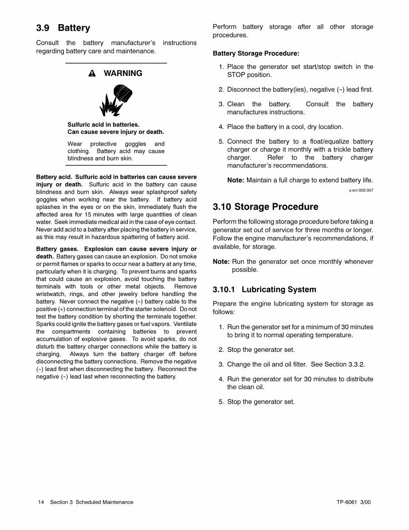
4. Check the belt tension at the midpoint of the
longest span of the belt using a belt-tensioning tool
set to 74.6Nm (55 ft. lb.). SeeFigure 3-9. Recheck
new belt tension after 10 minutes of operation. If
the belt is not within specifications, go to step 5. If
the belt is within specifications, go to step 9.
5. Loosen the adjusting arm pivot screw, alternator
pivot screw, and alternator adjusting screw.
6. Tighten the alternator screw while prying the
alternator outward with a prybar.
7. Tighten the adjusting arm pivot screw and
alternator pivot screw.
8. Recheck the belt tension and adjust it if necessary.
9. Replace the belt guard.
10. Reconnect the generator set engine starting
battery, negative (--) lead last.
1
7
6
5
2 3 4
TP55863
1. Water pump pulley
2. Adjusting pivot screw3. Adjusting screw
4. Alternator pulley
5. Alternator pivot screw
6. Belt tension tool7. Crankshaft pulley
Figure 3-9 Belt Tension Test Location, Typical
TP-6061 3/0014 Section 3 Scheduled Maintenance
3.9 Battery
Consult the battery manufacturer’s instructions
regarding battery care and maintenance.
Sulfuric acid in batteries.
Can cause severe injury or death.
Wear protective goggles and
clothing. Battery acid may cause
blindness and burn skin.
WARNING
Battery acid. Sulfuric acid in batteries can cause severe
injury or death. Sulfuric acid in the battery can cause
blindness and burn skin. Always wear splashproof safety
goggles when working near the battery. If battery acid
splashes in the eyes or on the skin, immediately flush the
affected area for 15 minutes with large quantities of clean
water. Seek immediatemedical aid in the case of eye contact.
Never add acid to a battery after placing the battery in service,
as this may result in hazardous spattering of battery acid.
Battery gases. Explosion can cause severe injury or
death. Battery gases can cause an explosion. Do not smoke
or permit flames or sparks to occur near a battery at any time,
particularly when it is charging. To prevent burns and sparks
that could cause an explosion, avoid touching the battery
terminals with tools or other metal objects. Remove
wristwatch, rings, and other jewelry before handling the
battery. Never connect the negative (--) battery cable to the
positive (+) connection terminal of the starter solenoid. Donot
test the battery condition by shorting the terminals together.
Sparks could ignite the battery gases or fuel vapors. Ventilate
the compartments containing batteries to prevent
accumulation of explosive gases. To avoid sparks, do not
disturb the battery charger connections while the battery is
charging. Always turn the battery charger off before
disconnecting the battery connections. Remove the negative
(--) lead first when disconnecting the battery. Reconnect the
negative (--) lead last when reconnecting the battery.
Perform battery storage after all other storage
procedures.
Battery Storage Procedure:
1. Place the generator set start/stop switch in the
STOP position.
2. Disconnect the battery(ies), negative (--) lead first.
3. Clean the battery. Consult the battery
manufactures instructions.
4. Place the battery in a cool, dry location.
5. Connect the battery to a float/equalize battery
charger or charge it monthly with a trickle battery
charger. Refer to the battery charger
manufacturer’s recommendations.
Note: Maintain a full charge to extend battery life.
x:sm:002:007
3.10 Storage Procedure
Perform the following storage procedure before taking a
generator set out of service for three months or longer.
Follow the engine manufacturer’s recommendations, if
available, for storage.
Note: Run the generator set once monthly whenever
possible.
3.10.1 Lubricating System
Prepare the engine lubricating system for storage as
follows:
1. Run the generator set for a minimum of 30 minutes
to bring it to normal operating temperature.
2. Stop the generator set.
3. Change the oil and oil filter. See Section 3.3.2.
4. Run the generator set for 30 minutes to distribute
the clean oil.
5. Stop the generator set.
TP-6061 3/00 15Section 3 Scheduled Maintenance
3.10.2 Cooling System
Prepare the cooling system for storage as follows:
1. Check the coolant freeze protection using a
coolant tester.
2. Add or replace coolant as necessary to ensure
adequate freezing protection. See Section 3.7.
3. Run the engine for 30minutes to redistribute added
coolant.
4. Stop the generator set.
3.10.3 Fuel System
Prepare the fuel system for storage as follows:
Diesel-Fueled Engines
1. Fill the fuel tank with #2 diesel fuel.
2. Condition the fuel system with compatible
additives.
3. Change the fuel filter/separator and bleed the fuel
system.
3.10.4 Exterior
1. Clean the exterior surface of the generator set.
2. Spread a light film of oil over unpainted metallic
surfaces to prevent rust and corrosion.

TP-6061 3/0016 Section 3 Scheduled Maintenance
Notes

TP-6061 3/00 17Section 4 General Troubleshooting
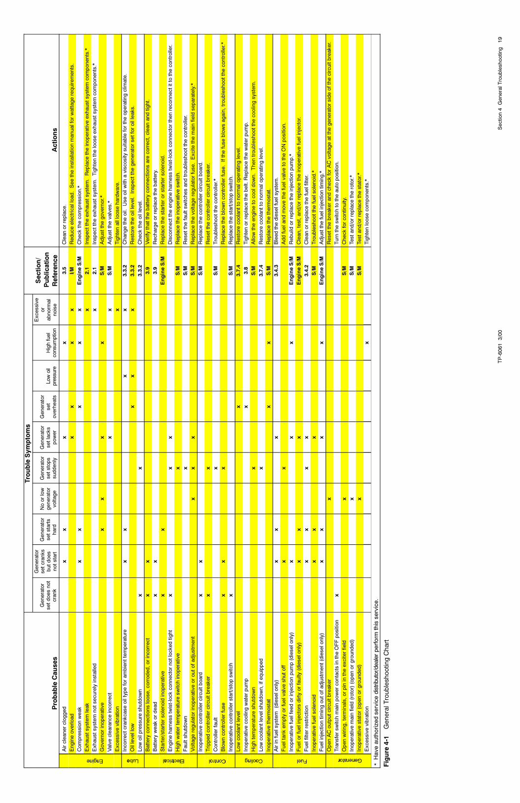
Section 4 General Troubleshooting
This section contains generator set troubleshooting,
diagnostic, and repair information.
Use the following chart to diagnose and correct common
problems. First check for simple causes such as a dead
engine starting battery or an open circuit breaker. The
chart includes a list of common problems, possible
causes of the problem, recommended corrective
actions, and references to detailed information or repair
procedures.
Maintain a record of repairs and adjustments performed
on the equipment. If the procedures in this manual do
not explain how to correct the problem, contact an
authorized distributor/dealer. Use the record to help
describe the problem and repairs or adjustments made
to the equipment.
The following table groups generator set faults and
suggests likely causes and remedies. The table also
refers you to more detailed information including
sections of this manual, the generator set service
manual (S/M), the generator set installation manual
(I/M), and the engine service manual (Engine S/M) to
correct the indicated problem.

TP-6061 3/0018 Section 4 General Troubleshooting
Notes
TP-6061
3/00
Section4
GeneralTroubleshooting
19
Trouble
Symptoms
Pro
bable
Causes
Generator
setdoesnot
crank
Generator
setcranks
butdoes
notstart
Generator
setstarts
hard
Noorlow
generator
voltage
Generator
setstops
suddenly
Generator
setlacks
power
Generator
set
overheats
Lowoil
pressure
Highfuel
consumption
Excessive
or
abnorm
al
noise
Section/
Publication
Reference
Actions
Aircleanerclogged
xx
xx
3.5
Cleanorreplace.
Engineoverload
xx
xx
I/M
Reduceelectricalload.Seetheinstalla
tionmanualforwattagerequirements.
Compressionweak
xx
xx
xEngineS/M
Checkthecompression.*
ne
Exhaustsystem
leak
x2.1
Inspecttheexhaustsystem.Replacetheinoperativeexhaustsystem
components.*
ngine
Exhaustsystem
notsecurely
installe
dx
2.1
Inspecttheexhaustsystem.Tightenthelooseexhaustsystem
components.*
Eng
Governorinoperative
xx
xx
S/M
Adjustthegovernor.*
Valveclearanceincorrect
xx
S/M
Adjustthevalves.*
Excessivevibration
xTightenallloosehardware.
e
Incorrectcrankcaseoiltypeforambienttemperature
xx
xx
3.3.2
Changetheoil.
Useoilwithaviscositysuitable
fortheoperatingclim
ate.
Lube
Oillevellow
xx
x3.3.2
Restore
theoillevel.
Inspectthegeneratorsetforoilleaks.
Lu
Lowoilpressure
shutdown
xx
3.3.2
Checktheoillevel.
Battery
connectionsloose,corroded,orincorrect
xx
3.9
Verify
thatthebattery
connectionsare
correct,cleanandtight.
Battery
weakordead
xx
3.9
Rechargeorreplacethebattery.
al
Starter/startersolenoid
inoperative
xx
EngineS/M
Replacethestarterorstartersolenoid.
trica
Engineharnesstwist-lockconnectornotlockedtight
xx
xDisconnecttheengineharnesstwist-lockconnectorthenreconnectitto
thecontroller.
Electr
Highwatertemperature
switchinoperative
xS/M
Replacetheinoperativeswitch.
El
Faultshutdown
xS/M
Resetthefaultswitchesandtroubleshootthecontroller.
Voltageregulatorinoperativeoroutofadjustm
ent
xx
xS/M
Replacethevoltageregulatorfuse.Excitethemain
field
separately.*
Inoperativecontrollercircuitboard
xx
S/M
Replacethecontrollercircuitboard.
ol
Trippedcontrollercircuitbreaker
xx
Resetthecontrollercircuitbreaker.
ontro
Controllerfault
xS/M
Troubleshootthecontroller.*
Con
Blowncontrollerfuse
xx
xReplacetheblowncontrolle
rfuse.Ifthefuseblowsagain,troubleshootthecontroller.*
C
Inoperativecontrollerstart/stopswitch
xS/M
Replacethestart/stopswitch.
Lowcoolantlevel
x3.7.4
Restore
coolantto
norm
aloperatinglevel.
ng
Inoperativecoolingwaterpump
x3.8
Tightenorreplacethebelt.Replacethewaterpump.
oolin
Hightemperature
shutdown
xS/M
Allo
wtheengineto
cooldown.Thentroubleshootthecoolingsystem.
Coo
Lowcoolantlevelshutdown,ifequipped
x3.7.4
Restore
coolantto
norm
aloperatinglevel.
Inoperativetherm
ostat
xx
S/M
Replacethetherm
ostat.
Airin
fuelsystem
(dieselonly)
xx
x3.4.3
Bleedthedieselfuelsystem.
Fueltankempty
orfuelvalveshutoff
xx
Addfuelandmovethefuelvalveto
theONposition.
Inoperativefuelfeedorinjectionpump(dieselonly)
xx
xEngineS/M
Rebuild
orreplacetheinjectionpump.*
uel
Fuelorfuelinjectors
dirty
orfaulty(dieselonly)
xx
xEngineS/M
Clean,test,and/orreplacetheinoperativefuelinjector.
Fue
Fuelfilterrestriction
xx
xx
3.4.2
Cleanorreplacethefuelfilter.
Inoperativefuelsolenoid
xx
xS/M
Troubleshootthefuelsolenoid.*
Fuelinjectiontimingoutofadjustm
ent(dieselonly)
xx
xx
EngineS/M
Adjustthefuelinjectiontiming.*
OpenACoutputcircuitbreaker
xResetthebreakerandcheckforACvoltageatthegeneratorsideofthecircuitbreaker.
or
Transferswitchmain
powercontacts
intheOFFposition
xTurn
theswitchto
theauto
position.
rator
Openwiring,term
inals,orpin
intheexciterfield
xS/M
Checkforcontinuity.
enera
Inoperativemain
field
(rotor)(openorgrounded)
xS/M
Testand/orreplacetherotor.*
Gen
Inoperativestator(openorgrounded)
xS/M
Testand/orreplacethestator.*
G
Excessivevibration
xTightenloosecomponents.*
*Haveauthorizedservicedistributor/dealerperform
this
service.
Figure
4-1
GeneralTroubleshootingChart

TP-6061
3/00
20
Section4
GeneralTroubleshooting
Notes

TP-6061 3/00 21Section 5 Wiring Diagrams
Section 5 Wiring Diagrams
Accidental starting.
Can cause severe injury or death.
Disconnect the battery cables before
working on the generator set.
Remove the negative (--) lead first
when disconnecting the battery.
Reconnect the negative (--) lead last
when reconnecting the battery.
WARNING
Disabling the generator set. Accidental starting can
cause severe injury or death. Before working on the
generator set or equipment connected to the set, disable the
generator set as follows: (1) Disconnect the power to the
battery charger, if equipped. (2) Remove the battery cables,
negative (--) lead first. Reconnect the negative (--) lead last
when reconnecting the battery. Follow these precautions to
prevent the starting of the generator set by the remote
start/stop switch.
Hazardous voltage.
Can cause severe injury or death.
Operate the generator set only when
all guards and electrical enclosures
are in place.
Moving rotor.
WARNING

TP-6061 3/0022 Section 5 Wiring Diagrams
Notes
TP-6061
3/00
23
Section5
DiagramsandDrawings
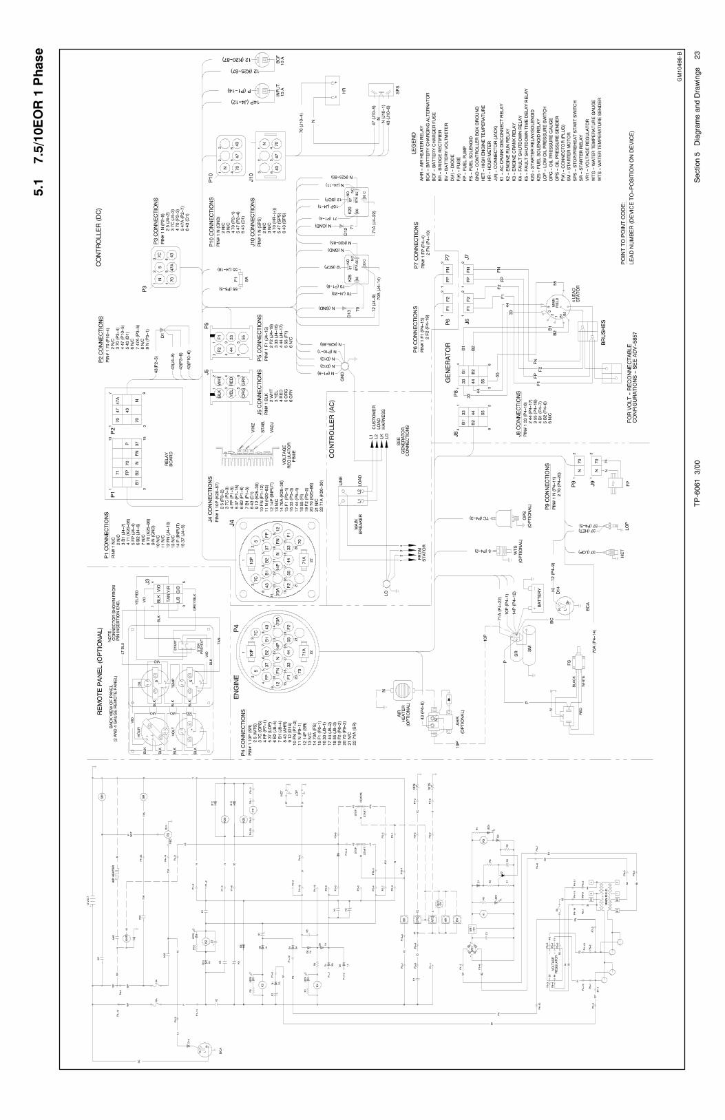
5.1
7.5/10EOR
1Phase
GM10486-B

TP-6061
3/00
Section5
WiringDiagrams
24
5.2
7.5/10EORZ1Phase
GM11416-B
TP-6061
3/00
25
Section5
DiagramsandDrawings
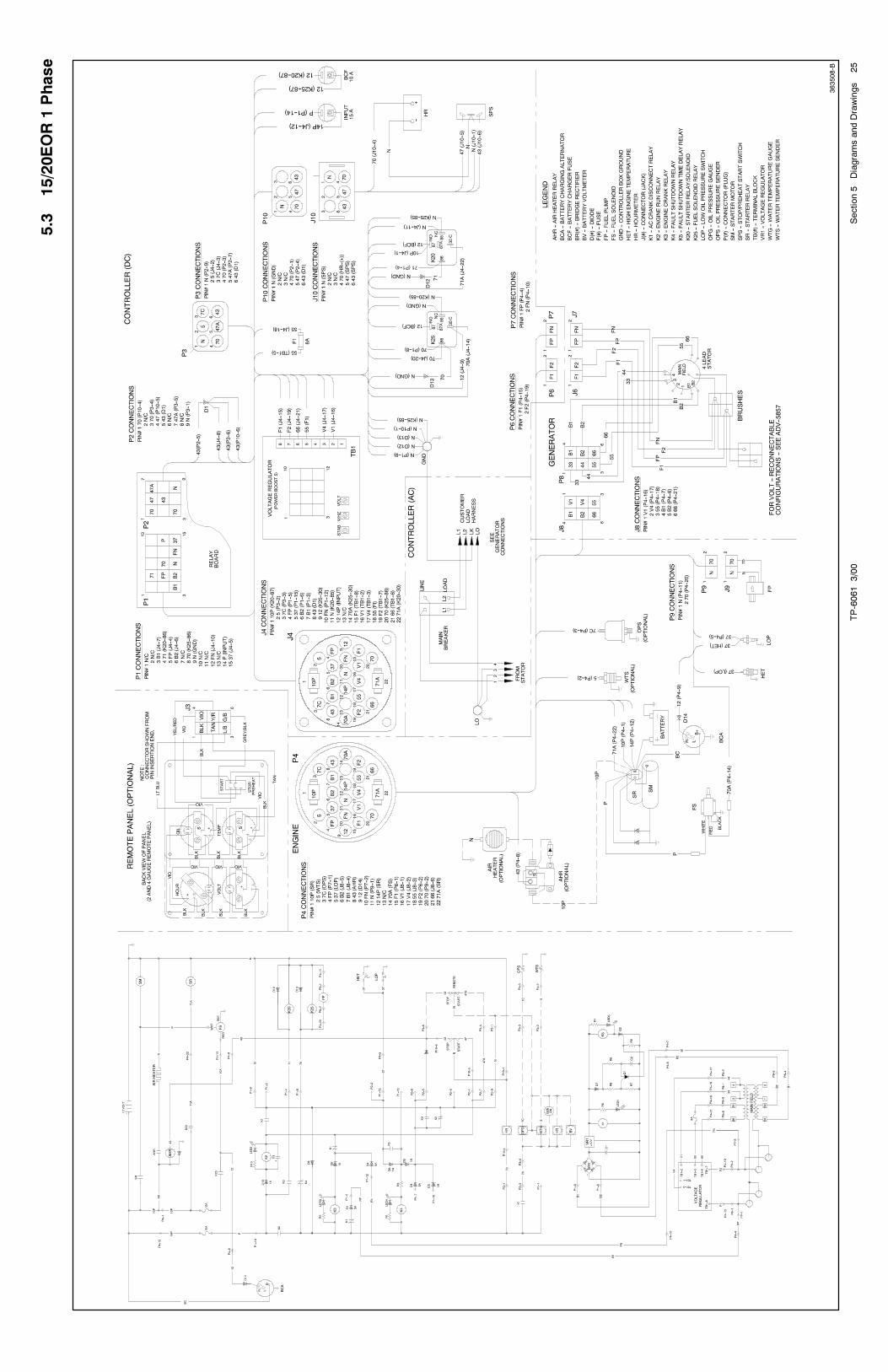
5.3
15/20EOR
1Phase
363508-B

TP-6061
3/00
Section5
WiringDiagrams
26
5.4
15/20EORZ3Phase
363509-B
LEGEND
AHR
--AIR
HEATERRELAY
BCA--BATTERYCHARGING
ALTERNATOR
BCF--BATTERYCHARGERFUSE
D(#)--DIO
DE
F(#)--FUSE
FS--FUELSOLENOID
GND
--CONTROLLERBOXGROUND
OPS--OIL
PRESSURESENDER
P(#)--CONNECTOR(PLUG)
SPS--STOP/PREHEATSTARTSWITCH
LOP--LOW
OIL
PRESSURESWITCH
HET--HIG
HENGINETEMPERATURE
HR
--HOURMETER
J(#)--CONNECTOR(JACK)
WTS--WATERTEMPERATURESENDER
TB(#)--TERMINALBLOCK
SR
--STARTERRELAY
SM
--STARTERMOTOR
FP--FUELPUMP
VR1--VOLTAGEREGULATOR
WTG
--WATERTEMPERATUREGAUGE
K4--FAULTSHUTDOWNRELAY
K3--ENGINECRANKRELAY
K1--ACCRANKDISCONNECTRELAY
K25--FUELSOLENOID
RELAY
OPG
--OIL
PRESSUREGAUGE
K20--STARTERRELAY/SOLENOID
K5--FAULTSHUTDOWNTIM
EDELAYRELAY
K2--ENGINERUNRELAY
BV--BATTERYVOLTMETER
BR(#)--BRIDGERECTIFIER
CONTROLLER(AC)
GENERATOR
CONNECTIO
NS
FN
BCA
37(P4--5)
37(HET)
37(LOP)
BLACK
70A(P4--14)
HET
FP
LOP
J9
1
70
N
70
N
2
BC
SM
FS
WHITE
RED
P
SR
P
10P
43(P4--8)
HEATER
AHR
10P
S
AIR
N
7C(P4--3)
5(P4--2)
12(P4--9)
B+
R L
D14
BATTERY
10P(P4--1)
14P(P4--12)
71A(P4--22)
WTS
P9CONNECTIO
NS
270(P4--20)
PIN
#1N(P4--11)
P9
1
70
N
2
OPS
LO
STATOR
FROM
13
24
RELAY
+
70A
537(LOP)
1
843(AHR)
15F1(P6--1)
2166(J8--6)
2271A(SR)
2070(P9--2)
19F2(P6--2)
1855(J8--3)
16V1(J8--1)
17V4(J8--2)
10FN(P7--2)
1470A(FS)
11N(P
9--1)
1214P(SR)
13N/C
6B2(J8--5)
912(D
14)
7B1(J8--4)
21
20
70
22
71A
66
37 11 V1
9
F1
15
16
10
12
FN5
FP
45
2
14P
V4
17
18
N
12
19
55
F2
13
14
B2
67
10P
7C 8
B1
43
3
25(W
TS)
37C(O
PS)
PIN#110P(SR)
P4CONNECTIO
NS
4FP(P7--1)
BLK
BLK
+
VOLT
TAN
ENGIN
EP4
S +
TEMP
BLK
BLK
PREHEAT
STOP/
VIO
BLK
START
1214P(INPUT)
F1
18
66
21
19
F2
70A
14
13
20
71A
22
70
V4
55
17
14P
12
11
V1
16
15
10
NFN
2271A(K20--30)
BREAKER
MAIN
L1
LOAD
L2
LINE
15F1(TB1--8)
16V1(TB1--2)
1470A(K25--30)
19F2(TB1--7)
2070(K25--86)
2166(TB1--6)
1855(FI)
17V4(TB1--3)
12
9
13N/C
FP
13N/C
14P(INPUT)
1537(J4--5)
12FN(J4--10)
7C
8
433
1
10P
B2
7
B1
6
5
37
54
2
GREY/BLKTAN
L/B
3
G/B
6
Y/R
PIN#110P(K20--87)
37C(P3--3)
25(P3--2)
843(D
1)
537(P1--15)
7B1(P1--3)
912(K25--30)
6B2(P1--6)
10FN(P1--12)
11N(K20--85)
4FP(P1--5)
J4
J4CONNECTIO
NS
BOARD
PIN
INSERTIO
NEND.
CONNECTORSHOWNFROM
REMOTEPANEL(O
PTIO
NAL)
(2AND4GAUGEREMOTEPANEL)
BACKVIEW
OFPANEL
BLK
BLK
HOUR
+
VIO
VIO
OIL
BLK
S
LTBLU
NOTE:
2N/C
PIN
#1N/C
3B1(J4--7)
P1CONNECTIO
NS
10N/C
7N/C
870(K25--86)
9N(G
ND)
6B2(J4--6)
5FP(J4--4)
11N/C
471(K20--86)
J3
BLK
VIO
1
BLK
4
VIO
YEL/R
ED
P1
3
71
B2
FP
B1
70 N
1
CUSTOMER
47(J10--5)
71A(J4--22)
12(J4--9)
N(J10--1)
43(J10--6)
CONFIG
URATIO
NS
--SEEADV--5857
FORVOLT--RECONNECTABLE
70A(J4--14)
FP
2V4(P4--17)
355(P4--18)
4B1(P4--7)
666(P4--21)
5B2(P4--6)
PIN#1V1(P4--16)
J8CONNECTIO
NS
6
66
55
3
STATOR
12LEAD
GENERATOR
4J8
B2
V4
B1
V1
1
SEE
LO
L2
LK
LOAD
HARNESS
2F2(P4--19) P6
1
F1
2
F2
1
P6CONNECTIO
NS
PIN#1F1(P4--15)
2FN(P4--10)
P7
FN
2
PIN#1FP(P
4--4)
P7CONNECTIO
NS
SPS
70(J10--4)
D1
25(J4--2)
8A 86
K25
F1
N(D12)
N(P1--9)
L1
GND
VOLT
STAB
V/H
Z
TB1
70(P1--8)
N(P10--1)
N(D13)
N(K25--85)
N(GND)
D13
70(J4--20)
70
1
43(J4--8)
43(P3--6)
43(P10--6)
(POWERBOOST5)
31
12
10
VOLTAGEREGULATOR
55(TB1--5)
55(F1)
V4(J4--17)
V1(J4--16)
3 25 4
F1(J4--15)
F2(J4--19)
66(J4--21)
7 68
3N/C
85
NO
30C
10P(J4--1)
12(BCF)
71(P1--4)
12(BCF)
N(GND)
NO
N(K20--85)
NC
30C
87
87A
85
N(GND)
71
86
K20
87A
87
D12
643(SPS)
470(H
R--(+))
547(SPS)
N(J4--11)
N(K25--85)
NC
N
PIN
#1N(G
ND)
55(J4--18)
J10CONNECTIO
NS
PIN
#1N(S
PS)
643(D
1)
2N/C
470(P2--1)
547(P2--4)
3N/C
2N/C
P10CONNECTIO
NS
37C(J4--3)
643(D
1)
547A(P2--7)
470(P2--3)
J10
P10
43(P2--5)
P2
47
43
15
3
P
37
70
70
9
N
47A
13
17
2N/C
370(P3--4)
747A(P3--5)
9N(P3--1)
447(P10--5)
8N/C
6N/C
543(D
1)
P3
P2CONNECTIO
NS
PIN#170(P
10--4)
PIN#1N(P2--9)
P3CONNECTIO
NS
HR
--+
VIO VIO
VIO
55
B1
FIELD
MAIN
B2
66
3
2 1
4
65
78
10 11 12
9AC
F--
F+
AC
AC
F1
F2
FP
FN
55V8
V7
66
B2
B1
314 6
P8
J6
F2
F1
1
FP
12
FN
J7
2
EXCITER
FIELD
EXCITER
FIELD
RECTIFIER
MODULE
(OPTIO
NAL)
(OPTIO
NAL)
(OPTIO
NAL)
(OPTIO
NAL)
5N
70
4
47A
5
12
43
63
7C
N
70
4
47
5
12
43
63
65
43
32
70
4
47
N
1
N
12(K25--87)
12(K20--87)
BCF
10A
15A
INPUTP(P1--14)
14P(J4--12)
CONTROLLER(D
C)
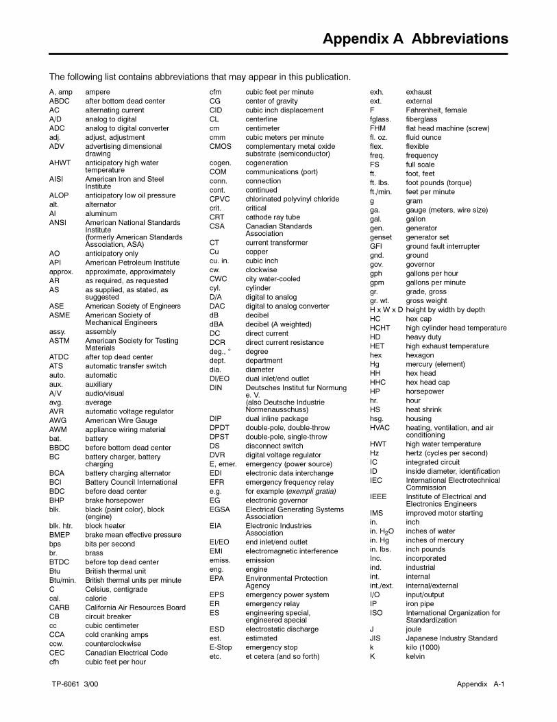
TP-6061 3/00 Appendix A-1
Appendix A Abbreviations
The following list contains abbreviations that may appear in this publication.
A, amp ampere
ABDC after bottom dead center
AC alternating current
A/D analog to digital
ADC analog to digital converter
adj. adjust, adjustment
ADV advertising dimensionaldrawing
AHWT anticipatory high watertemperature
AISI American Iron and SteelInstitute
ALOP anticipatory low oil pressure
alt. alternator
Al aluminum
ANSI American National StandardsInstitute(formerly American StandardsAssociation, ASA)
AO anticipatory only
API American Petroleum Institute
approx. approximate, approximately
AR as required, as requested
AS as supplied, as stated, assuggested
ASE American Society of Engineers
ASME American Society ofMechanical Engineers
assy. assembly
ASTM American Society for TestingMaterials
ATDC after top dead center
ATS automatic transfer switch
auto. automatic
aux. auxiliary
A/V audio/visual
avg. average
AVR automatic voltage regulator
AWG American Wire Gauge
AWM appliance wiring material
bat. battery
BBDC before bottom dead center
BC battery charger, batterycharging
BCA battery charging alternator
BCI Battery Council International
BDC before dead center
BHP brake horsepower
blk. black (paint color), block(engine)
blk. htr. block heater
BMEP brake mean effective pressure
bps bits per second
br. brass
BTDC before top dead center
Btu British thermal unit
Btu/min. British thermal units per minute
C Celsius, centigrade
cal. calorie
CARB California Air Resources Board
CB circuit breaker
cc cubic centimeter
CCA cold cranking amps
ccw. counterclockwise
CEC Canadian Electrical Code
cfh cubic feet per hour
cfm cubic feet per minute
CG center of gravity
CID cubic inch displacement
CL centerline
cm centimeter
cmm cubic meters per minute
CMOS complementary metal oxidesubstrate (semiconductor)
cogen. cogeneration
COM communications (port)
conn. connection
cont. continued
CPVC chlorinated polyvinyl chloride
crit. critical
CRT cathode ray tube
CSA Canadian StandardsAssociation
CT current transformer
Cu copper
cu. in. cubic inch
cw. clockwise
CWC city water-cooled
cyl. cylinder
D/A digital to analog
DAC digital to analog converter
dB decibel
dBA decibel (A weighted)
DC direct current
DCR direct current resistance
deg., � degree
dept. department
dia. diameter
DI/EO dual inlet/end outlet
DIN Deutsches Institut fur Normunge. V.(also Deutsche IndustrieNormenausschuss)
DIP dual inline package
DPDT double-pole, double-throw
DPST double-pole, single-throw
DS disconnect switch
DVR digital voltage regulator
E, emer. emergency (power source)
EDI electronic data interchange
EFR emergency frequency relay
e.g. for example (exempli gratia)
EG electronic governor
EGSA Electrical Generating SystemsAssociation
EIA Electronic IndustriesAssociation
EI/EO end inlet/end outlet
EMI electromagnetic interference
emiss. emission
eng. engine
EPA Environmental ProtectionAgency
EPS emergency power system
ER emergency relay
ES engineering special,engineered special
ESD electrostatic discharge
est. estimated
E-Stop emergency stop
etc. et cetera (and so forth)
exh. exhaust
ext. external
F Fahrenheit, female
fglass. fiberglass
FHM flat head machine (screw)
fl. oz. fluid ounce
flex. flexible
freq. frequency
FS full scale
ft. foot, feet
ft. lbs. foot pounds (torque)
ft./min. feet per minute
g gram
ga. gauge (meters, wire size)
gal. gallon
gen. generator
genset generator set
GFI ground fault interrupter
gnd. ground
gov. governor
gph gallons per hour
gpm gallons per minute
gr. grade, gross
gr. wt. gross weight
H x W x D height by width by depth
HC hex cap
HCHT high cylinder head temperature
HD heavy duty
HET high exhaust temperature
hex hexagon
Hg mercury (element)
HH hex head
HHC hex head cap
HP horsepower
hr. hour
HS heat shrink
hsg. housing
HVAC heating, ventilation, and airconditioning
HWT high water temperature
Hz hertz (cycles per second)
IC integrated circuit
ID inside diameter, identification
IEC International ElectrotechnicalCommission
IEEE Institute of Electrical andElectronics Engineers
IMS improved motor starting
in. inch
in. H2O inches of water
in. Hg inches of mercury
in. lbs. inch pounds
Inc. incorporated
ind. industrial
int. internal
int./ext. internal/external
I/O input/output
IP iron pipe
ISO International Organization forStandardization
J joule
JIS Japanese Industry Standard
k kilo (1000)
K kelvin

TP-6061 3/00A-2 Appendix
kA kiloampere
KB kilobyte (210 bytes)
kg kilogram
kg/cm2 kilograms per squarecentimeter
kgm kilogram-meter
kg/m3 kilograms per cubic meter
kHz kilohertz
kJ kilojoule
km kilometer
kOhm, k� kilo-ohm
kPa kilopascal
kph kilometers per hour
kV kilovolt
kVA kilovolt ampere
kVAR kilovolt ampere reactive
kW kilowatt
kWh kilowatt-hour
kWm kilowatt mechanical
L liter
LAN local area network
L x W x H length by width by height
lb. pound
lbm/ft3 pounds mass per cubic feet
LCB line circuit breaker
LCD liquid crystal display
ld. shd. load shed
LED light emitting diode
Lph liters per hour
Lpm liters per minute
LOP low oil pressure
LP liquefied petroleum
LPG liquefied petroleum gas
LS left side
Lwa sound power level, A weighted
LWL low water level
LWT low water temperature
m meter, milli (1/1000)
M mega (106 when used with SIunits), male
m3 cubic meter
m3/min. cubic meters per minute
mA milliampere
man. manual
max. maximum
MB megabyte (220 bytes)
MCM one thousand circular mils
meggar megohmmeter
MHz megahertz
mi. mile
mil one one-thousandth of an inch
min. minimum, minute
misc. miscellaneous
MJ megajoule
mJ millijoule
mm millimeter
mOhm, m�milliohm
MOhm, M�megohm
MOV metal oxide varistor
MPa megapascal
mpg miles per gallon
mph miles per hour
MS military standard
m/sec. meters per second
MTBF mean time between failure
MTBO mean time between overhauls
mtg. mounting
MW megawatt
mW milliwatt
�F microfarad
N, norm. normal (power source)
NA not available, not applicable
nat. gas natural gas
NBS National Bureau of Standards
NC normally closed
NEC National Electrical Code
NEMA National ElectricalManufacturers Association
NFPA National Fire ProtectionAssociation
Nm newton meter
NO normally open
no., nos. number, numbers
NPS National Pipe, Straight
NPSC National Pipe, Straight-coupling
NPT National Standard taper pipethread per general use
NPTF National Pipe, Taper-Fine
NR not required, normal relay
ns nanosecond
O/C overcrank
OD outside diameter
OEM original equipmentmanufacturer
O/F overfrequency
opt. option, optional
O/S oversize, overspeed
OSHA Occupational Safety and HealthAdministration
O/V overvoltage
oz. ounce
p., pp. page, pages
PA packed accessory
PC personal computer
PCB printed circuit board
pF picofarad
PF power factor
ph. phase
PHC Phillips head crimptite (screw)
PHH Phillips hex head (screw)
PHM pan head machine (screw)
PLC programmable logic control
PMG permanent magnet generator
pot potentiometer, potential
ppm parts per million
PROM programmable read onlymemory
psi pounds per square inch
pt. pint
PTC positive temperature coefficient
PTO power takeoff
PVC polyvinyl chloride
qt. quart
qty. quantity
R replacement (emergency)power source
rad. radiator, radius
RAM random access memory
RDO relay driver output
ref. reference
rem. remote
RFI radio frequency interference
RH round head
RHM round head machine (screw)
rly. relay
rms root mean square
rnd. round
ROM read only memory
rot. rotate, rotating
rpm revolutions per minute
RS right side
RTV room temperature vulcanization
SAE Society of AutomotiveEngineers
scfm standard cubic feet per minute
SCR silicon controlled rectifier
s, sec. second
SI Systeme international d’unites,International System of Units
SI/EO side in/end out
sil. silencer
SN serial number
SPDT single--pole, double--throw
SPST single--pole, single--throw
spec, specsspecification(s)
sq. square
sq. cm square centimeter
sq. in. square inch
SS stainless steel
std. standard
stl. steel
tach. tachometer
TD time delay
TDC top dead center
TDEC time delay engine cooldown
TDEN time delay emergency tonormal
TDES time delay engine start
TDNE time delay normal toemergency
TDOE time delay off to emergency
TDON time delay off to normal
temp. temperature
term. terminal
TIF telephone influence factor
TIR total indicator reading
tol. tolerance
turbo. turbocharger
typ. typical (same in multiplelocations)
U/F underfrequency
UHF ultrahigh frequency
UL Underwriter’s Laboratories, Inc.
UNC unified coarse thread (was NC)
UNF unified fine thread (was NF)
univ. universal
U/S undersize, underspeed
UV ultraviolet
U/V undervoltage
V volt
VAC volts alternating current
VAR voltampere reactive
VDC volts direct current
VFD vacuum fluorescent display
VGA video graphics adapter
VHF very high frequency
W watt
WCR withstand and closing rating
w/ with
w/o without
wt. weight
xfmr transformer

TP-6061 3/00 A--3Appendix
Appendix B Operating Hour Service Log
The following is provided to help you keep a cumulative
record of operating hours on your generator set and the
dates required services were performed. Enter hours to
the nearest quarter hour.
OPERATING HOURS SERVICE RECORD
DATE
RUN
HOURS
RUN
TOTAL
HOURS
SERVICE
DATE SERVICE

� Kohler Co., 2000. All rights reserved.
TP-6061 3/00
KOHLER CO. Kohler, Wisconsin 53044Phone 920-565-3381, Web site www.kohlergenerators.comFax 920-459-1646 (U.S.A. Sales), Fax 920-459-1614 (International)For the nearest sales and service outlet in U.S.A. and CanadaPhone 1-800-544-2444
Kohler� Power SystemsAsia Pacific Headquarters7 Jurong Pier RoadSingapore 619159Phone (65)264-6422, Fax (65)264-6455
Related Documents


