Kolhapur Institute of Technology’s College of Engineering (Autonomous), Kolhapur Curriculum and Structure for Electronics Engineering (Under Graduate Programme) From Academic Year 2019-2020

Welcome message from author
This document is posted to help you gain knowledge. Please leave a comment to let me know what you think about it! Share it to your friends and learn new things together.
Transcript
Kolhapur Institute of Technology’s
College of Engineering (Autonomous), Kolhapur
Curriculum and Structure
for
Electronics Engineering
(Under Graduate Programme)
From
Academic Year 2019-2020
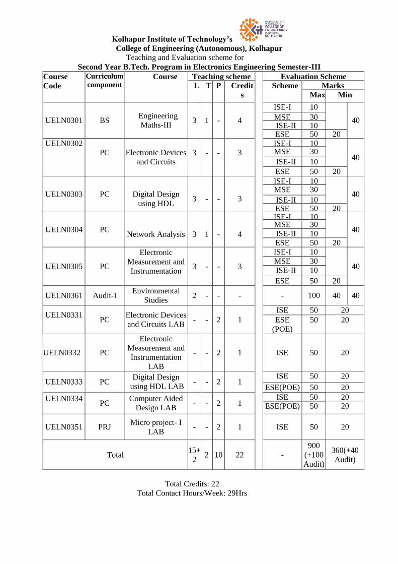
Kolhapur Institute of Technology’s
College of Engineering (Autonomous), Kolhapur
Teaching and Evaluation scheme for
Second Year B.Tech. Program in Electronics Engineering Semester-III
Course
Code
Curriculum
component Course Teaching scheme Evaluation Scheme
L T P Credit
s
Scheme Marks
Max Min
UELN0301 BS Engineering
Maths-III 3 1 - 4
ISE-I 10
40 MSE 30
ISE-II 10 ESE 50 20
UELN0302
PC
Electronic Devices
and Circuits 3
-
-
3
ISE-I 10
40
MSE 30
ISE-II 10
ESE 50 20
UELN0303 PC
Digital Design
using HDL
3
-
-
3
ISE-I 10
40
MSE 30
ISE-II 10 ESE 50 20
UELN0304 PC
Network Analysis
3
1
-
4
ISE-I 10
40 MSE 30
ISE-II 10
ESE 50 20
UELN0305 PC
Electronic
Measurement and
Instrumentation
3 - - 3
ISE-I 10
40
MSE 30
ISE-II 10
ESE 50 20
UELN0361 Audit-I Environmental
Studies 2 - - - - 100 40 40
UELN0331
PC
Electronic Devices
and Circuits LAB - - 2 1
ISE 50 20
ESE
(POE)
50 20
UELN0332 PC
Electronic
Measurement and
Instrumentation
LAB
- - 2 1 ISE 50 20
UELN0333 PC Digital Design
using HDL LAB - - 2 1
ISE 50 20
ESE(POE) 50 20
UELN0334
PC
Computer Aided
Design LAB - - 2 1
ISE 50 20 ESE(POE) 50 20
UELN0351 PRJ Micro project- I
LAB - - 2 1 ISE 50 20
Total 15+
2 2 10 22 -
900
(+100
Audit)
360(+40
Audit)
Total Credits: 22
Total Contact Hours/Week: 29Hrs
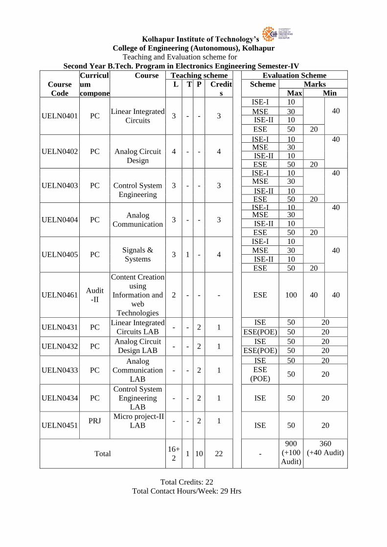
Kolhapur Institute of Technology’s
College of Engineering (Autonomous), Kolhapur
Teaching and Evaluation scheme for
Second Year B.Tech. Program in Electronics Engineering Semester-IV
Course
Code
Curricul
um
compone
nt
Course Teaching scheme Evaluation Scheme L T P Credit
s
Scheme Marks
Max Min
UELN0401 PC
Linear Integrated
Circuits
3 - - 3
ISE-I 10
40 MSE 30 ISE-II 10
ESE 50 20
UELN0402 PC
Analog Circuit
Design
4 - - 4
ISE-I 10
40 MSE 30 ISE-II 10 ESE 50 20
UELN0403 PC
Control System
Engineering
3 - - 3
ISE-I 10
40 MSE 30
ISE-II 10 ESE 50 20
UELN0404 PC Analog
Communication 3 - - 3
ISE-I 10
40 MSE 30
ISE-II 10
ESE 50 20
UELN0405 PC Signals &
Systems 3 1 - 4
ISE-I 10
40 MSE 30
ISE-II 10
ESE 50 20
UELN0461 Audit
-II
Content Creation
using
Information and
web
Technologies
2 - - - ESE 100 40 40
UELN0431 PC Linear Integrated
Circuits LAB - - 2 1
ISE 50 20
ESE(POE) 50 20
UELN0432 PC Analog Circuit
Design LAB
- - 2 1 ISE 50 20
ESE(POE) 50 20
UELN0433 PC
Analog
Communication
LAB
- - 2 1
ISE 50 20
ESE
(POE) 50 20
UELN0434 PC
Control System
Engineering
LAB
- - 2 1 ISE 50 20
UELN0451 PRJ
Micro project-II
LAB
-
-
2
1
ISE 50 20
Total 16+
2 1 10 22 -
900
(+100
Audit)
360
(+40 Audit)
Total Credits: 22
Total Contact Hours/Week: 29 Hrs
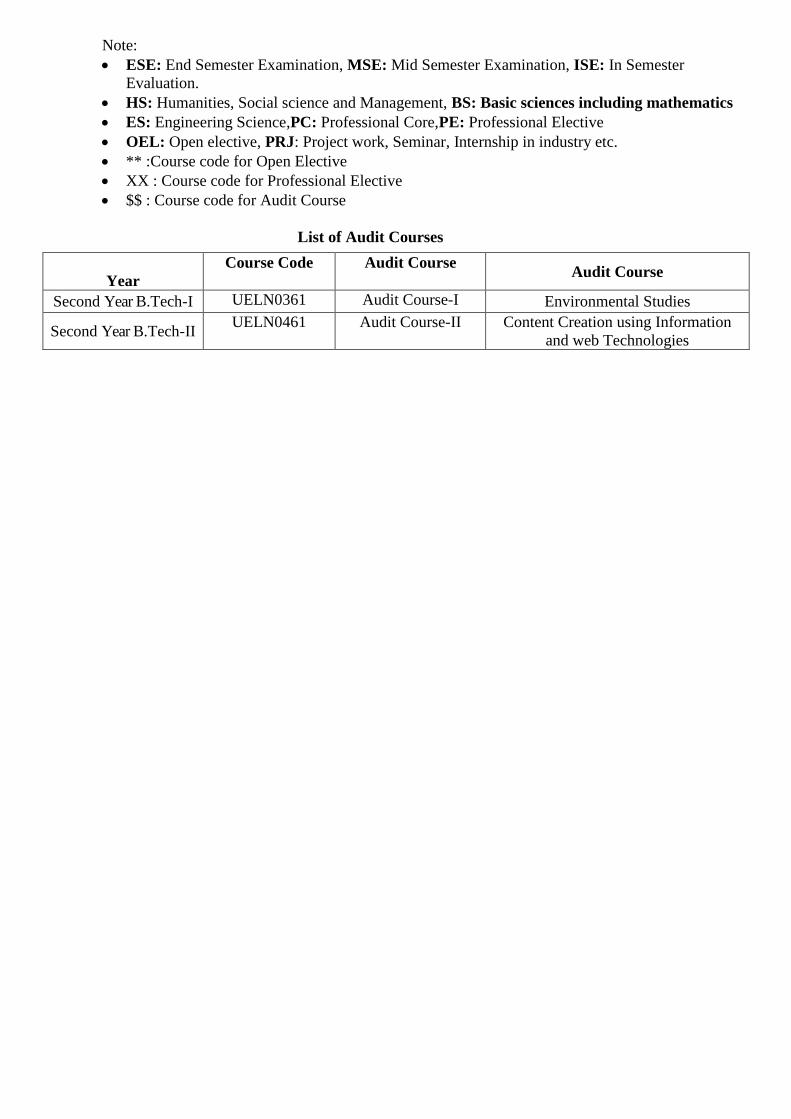
Note:
ESE: End Semester Examination, MSE: Mid Semester Examination, ISE: In Semester
Evaluation.
HS: Humanities, Social science and Management, BS: Basic sciences including mathematics
ES: Engineering Science,PC: Professional Core,PE: Professional Elective
OEL: Open elective, PRJ: Project work, Seminar, Internship in industry etc.
** :Course code for Open Elective
XX : Course code for Professional Elective
$$ : Course code for Audit Course
List of Audit Courses
Year
Course Code Audit Course Audit Course
Second Year B.Tech-I UELN0361 Audit Course-I Environmental Studies
Second Year B.Tech-II UELN0461 Audit Course-II Content Creation using Information
and web Technologies
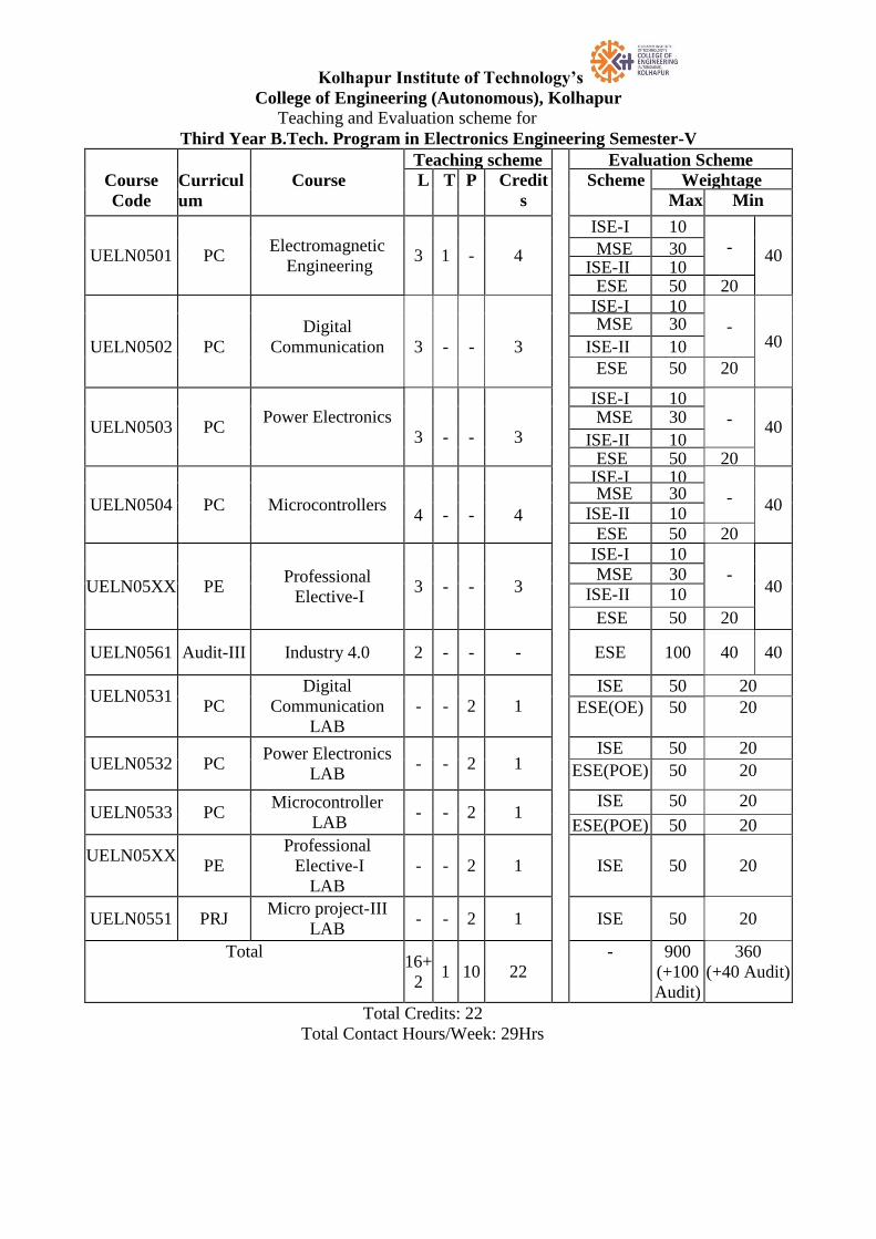
Kolhapur Institute of Technology’s
College of Engineering (Autonomous), Kolhapur
Teaching and Evaluation scheme for
Third Year B.Tech. Program in Electronics Engineering Semester-V
Course
Code
Curricul
um
compone
nt
Course
Teaching scheme Evaluation Scheme
L T P Credit
s
Scheme Weightage
Max Min
UELN0501 PC Electromagnetic
Engineering 3 1 - 4
ISE-I 10
- 40 MSE 30
ISE-II 10 ESE 50 20
UELN0502
PC
Digital
Communication
3
-
-
3
ISE-I 10
- 40
MSE 30
ISE-II 10
ESE 50 20
UELN0503 PC Power Electronics
3
-
-
3
ISE-I 10
- 40
MSE 30
ISE-II 10 ESE 50 20
UELN0504 PC Microcontrollers
4
-
-
4
ISE-I 10
- 40 MSE 30
ISE-II 10
ESE 50 20
UELN05XX PE Professional
Elective-I 3 - - 3
ISE-I 10
- 40
MSE 30
ISE-II 10
ESE 50 20
UELN0561 Audit-III Industry 4.0 2 - - - ESE 100 40 40
UELN0531
PC
Digital
Communication
LAB
- - 2 1
ISE 50 20
ESE(OE) 50 20
UELN0532 PC Power Electronics
LAB - - 2 1
ISE 50 20
ESE(POE) 50 20
UELN0533 PC
Microcontroller
LAB - - 2 1
ISE 50 20
ESE(POE) 50 20
UELN05XX
PE
Professional
Elective-I
LAB
- - 2 1 ISE 50 20
UELN0551 PRJ Micro project-III
LAB - - 2 1 ISE 50 20
Total 16+
2 1 10 22
- 900
(+100
Audit)
360
(+40 Audit)
Total Credits: 22
Total Contact Hours/Week: 29Hrs
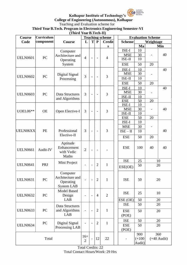
Kolhapur Institute of Technology’s
College of Engineering (Autonomous), Kolhapur
Teaching and Evaluation scheme for
Third Year B.Tech. Program in Electronics Engineering Semester-VI
(Third Year B.Tech-II)
Course
Code
Curriculum
component
Course
Teaching scheme Evaluation Scheme
L T P Credit
s
Scheme Weightage
Ma
x
Min
UELN0601 PC
Computer
Architecture and
Operating
System
4 - - 4
ISE-I 10
-
40 MSE 30 ISE-II 10
ESE 50 20
UELN0602 PC Digital Signal
Processing 3 - - 3
ISE-I 10
-
40 MSE 30
ISE-II 10
ESE 50 20
UELN0603 PC
Data Structures
and Algorithms
3 - - 3
ISE-I 10
-
40 MSE 30
ISE-II 10 ESE 50 20
UOEL06** OE Open Elective-I 3 - - 3
ISE-I 10
-
40 MSE 30
ISE-II 10
ESE 50 20
UELN06XX
PE
Professional
Elective-II
3
-
-
3
ISE-I 10
-
40 MSE 30
ISE – II 10
ESE 50 20
UELN0661 Audit-IV
Aptitude
Enhancement
with Vedic
Maths
2 - - -
ESE
100
40
40
UELN0641 PRJ Mini Project
- - 2 1
ISE 25 10
ESE(OE) 50
20
UELN0631 PC
Computer
Architecture and
Operating
System LAB
- - 2 1 ISE 50 20
UELN0632 PC
Model Based
Design
LAB
- - 4
2
ISE 25 10
ESE (OE) 50 20
UELN0633 PC
Data Structures
and Algorithms
LAB
- - 2 1
ISE 50 20
ESE
(POE)
50 20
UELN0634 PC
Digital Signal
Processing LAB
-
-
2
1
ISE 50 20
ESE
(POE)
50 20
Total 16+
2 - 12 22 -
900
(+100
Audit)
360
(+40 Audit)
Total Credits: 22
Total Contact Hours/Week: 29 Hrs
Note:
ESE: End Semester Examination, MSE: Mid Semester Examination, ISE: In Semester
Evaluation.
HS: Humanities, Social science and Management, BS: Basic sciences including mathematics
ES: Engineering Science,PC: Professional Core,PE: Professional Elective
OEL: Open elective, PRJ: Project work, Seminar, Internship in industry etc.
** :Course code for Open Elective
XX : Course code for Professional Elective
$$ : Course code for Audit Course
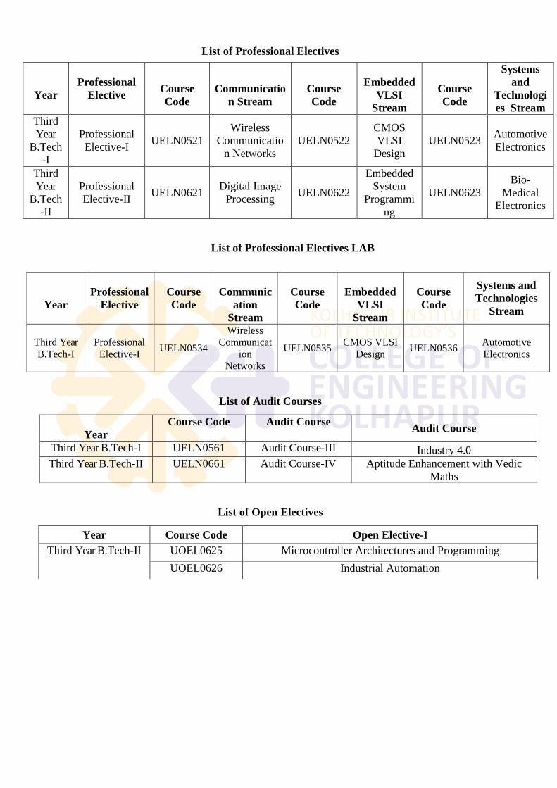
List of Professional Electives
List of Professional Electives LAB
List of Audit Courses
List of Open Electives
Year
Professional
Elective
Course
Code
Communicatio
n Stream
Course
Code
Embedded
VLSI
Stream
Course
Code
Systems
and
Technologi
es Stream
Third
Year
B.Tech
-I
Professional
Elective-I UELN0521
Wireless
Communicatio
n Networks
UELN0522
CMOS
VLSI
Design
UELN0523 Automotive
Electronics
Third
Year
B.Tech
-II
Professional
Elective-II UELN0621
Digital Image
Processing UELN0622
Embedded
System
Programmi
ng
UELN0623
Bio-
Medical
Electronics
Year
Professional
Elective
Course
Code
Communic
ation
Stream
Course
Code
Embedded
VLSI
Stream
Course
Code
Systems and
Technologies
Stream
Third Year
B.Tech-I
Professional
Elective-I UELN0534
Wireless
Communicat
ion
Networks
UELN0535 CMOS VLSI
Design UELN0536
Automotive
Electronics
Year
Course Code Audit Course Audit Course
Third Year B.Tech-I UELN0561 Audit Course-III Industry 4.0
Third Year B.Tech-II UELN0661 Audit Course-IV Aptitude Enhancement with Vedic
Maths
Year Course Code Open Elective-I
Third Year B.Tech-II UOEL0625 Microcontroller Architectures and Programming
UOEL0626 Industrial Automation
Kolhapur Institute of Technology’s
College of Engineering (Autonomous), Kolhapur
Teaching and Evaluation scheme for
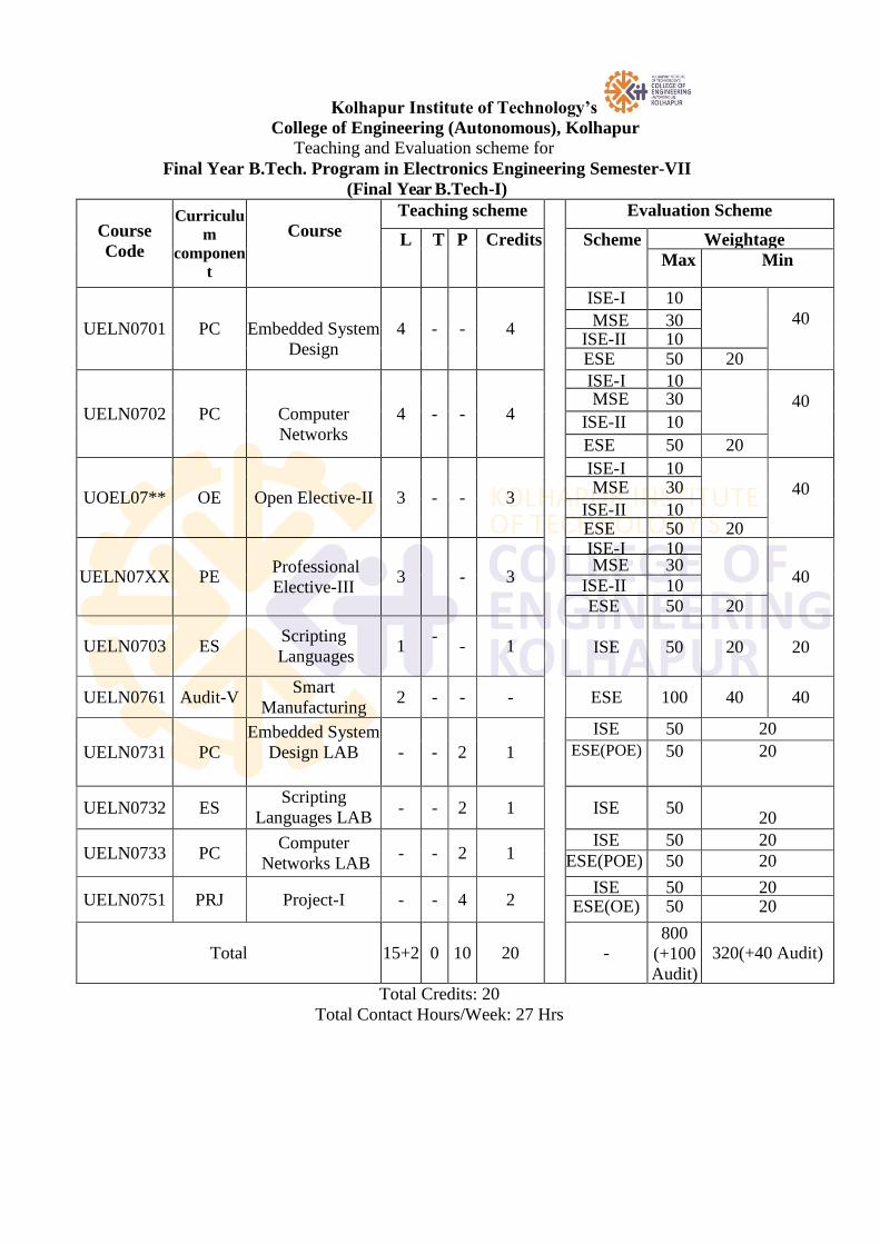
Final Year B.Tech. Program in Electronics Engineering Semester-VII
(Final Year B.Tech-I)
Course
Code
Curriculu
m
componen
t
Course
Teaching scheme Evaluation Scheme
L T P Credits Scheme Weightage
Max Min
UELN0701 PC
Embedded System
Design
4 - - 4
ISE-I 10
40 MSE 30 ISE-II 10
ESE 50 20
UELN0702 PC
Computer
Networks
4 - - 4
ISE-I 10
40 MSE 30
ISE-II 10
ESE 50 20
UOEL07** OE Open Elective-II 3 - - 3
ISE-I 10
40 MSE 30
ISE-II 10 ESE 50 20
UELN07XX PE Professional
Elective-III 3 - 3
ISE-I 10
40 MSE 30
ISE-II 10
ESE 50 20
UELN0703 ES Scripting
Languages 1
-
- 1
ISE
50
20
20
UELN0761 Audit-V Smart
Manufacturing 2 - - - ESE 100 40 40
UELN0731 PC
Embedded System
Design LAB
- - 2 1
ISE 50 20
ESE(POE) 50 20
UELN0732 ES Scripting
Languages LAB - - 2 1 ISE 50
20
UELN0733 PC Computer
Networks LAB - - 2 1
ISE 50 20
ESE(POE) 50 20
UELN0751 PRJ Project-I - - 4 2 ISE 50 20
ESE(OE) 50 20
Total 15+2 0 10 20 - 800
(+100
Audit)
320(+40 Audit)
Total Credits: 20
Total Contact Hours/Week: 27 Hrs
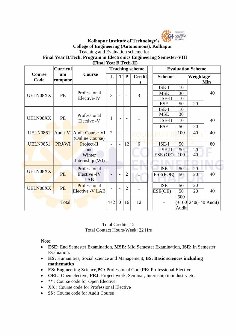
Kolhapur Institute of Technology’s
College of Engineering (Autonomous), Kolhapur
Teaching and Evaluation scheme for
Final Year B.Tech. Program in Electronics Engineering Semester-VIII
(Final Year B.Tech-II)
Total Credits: 12
Total Contact Hours/Week: 22 Hrs
Note:
ESE: End Semester Examination, MSE: Mid Semester Examination, ISE: In Semester
Evaluation.
HS: Humanities, Social science and Management, BS: Basic sciences including
mathematics
ES: Engineering Science,PC: Professional Core,PE: Professional Elective
OEL: Open elective, PRJ: Project work, Seminar, Internship in industry etc.
** : Course code for Open Elective
XX : Course code for Professional Elective
$$ : Course code for Audit Course
Course
Code
Curricul
um
compone
nt
Course
Teaching scheme Evaluation Scheme
L T P Credit
s
Scheme Weightage
Max
Min
UELN08XX PE Professional
Elective-IV 3 - - 3
ISE-I 10
40 MSE 30 ISE-II 10 ESE 50 20
UELN08XX PE Professional
Elective -V 1 - - 1
ISE-I 10
40
MSE 30
ISE-II 10
ESE 50 20
UELN0861 Audit-VI Audit Course-VI
(Online Course)
2 - - - - 100 40 40
UELN0851 PRJ/WI Project-II
and
Winter
Internship (WI)
- - 12 6 ISE-I 50 80
ISE-II 50 20 ESE (OE) 100 40
UELN08XX
PE
Professional
Elective -IV
LAB
- - 2 1
ISE 50 20
40 ESE(POE) 50 20
UELN08XX PE Professional
Elective -V LAB - - 2 1
ISE 50 20
40 ESE(OE) 50 20
Total 4+2 0 16 12 -
600
(+100
Audit
)
(+100
240(+40 Audit)
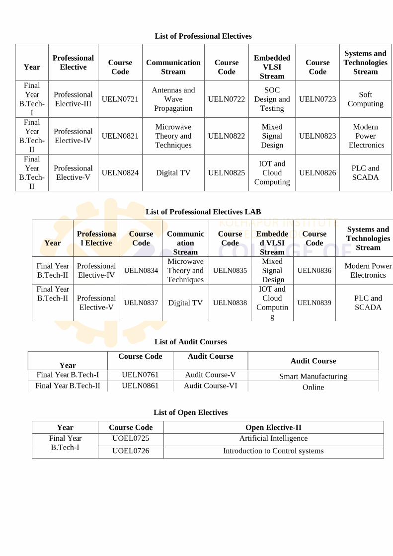
List of Professional Electives
List of Professional Electives LAB
List of Audit Courses
List of Open Electives
Year
Professional
Elective
Course
Code
Communication
Stream
Course
Code
Embedded
VLSI
Stream
Course
Code
Systems and
Technologies
Stream
Final
Year
B.Tech-
I
Professional
Elective-III UELN0721
Antennas and
Wave
Propagation
UELN0722
SOC
Design and
Testing
UELN0723 Soft
Computing
Final
Year
B.Tech-
II
Professional
Elective-IV UELN0821
Microwave
Theory and
Techniques
UELN0822
Mixed
Signal
Design
UELN0823
Modern
Power
Electronics
Final
Year
B.Tech-
II
Professional
Elective-V UELN0824 Digital TV UELN0825
IOT and
Cloud
Computing
UELN0826 PLC and
SCADA
Year
Professiona
l Elective
Course
Code
Communic
ation
Stream
Course
Code
Embedde
d VLSI
Stream
Course
Code
Systems and
Technologies
Stream
Final Year
B.Tech-II
Professional
Elective-IV UELN0834
Microwave
Theory and
Techniques
UELN0835
Mixed
Signal
Design
UELN0836 Modern Power
Electronics
Final Year
B.Tech-II Professional
Elective-V UELN0837 Digital TV UELN0838
IOT and
Cloud
Computin
g
UELN0839 PLC and
SCADA
Year
Course Code Audit Course Audit Course
Final Year B.Tech-I UELN0761 Audit Course-V Smart Manufacturing
Final Year B.Tech-II UELN0861 Audit Course-VI Online
Year Course Code Open Elective-II
Final Year
B.Tech-I
UOEL0725 Artificial Intelligence
UOEL0726 Introduction to Control systems
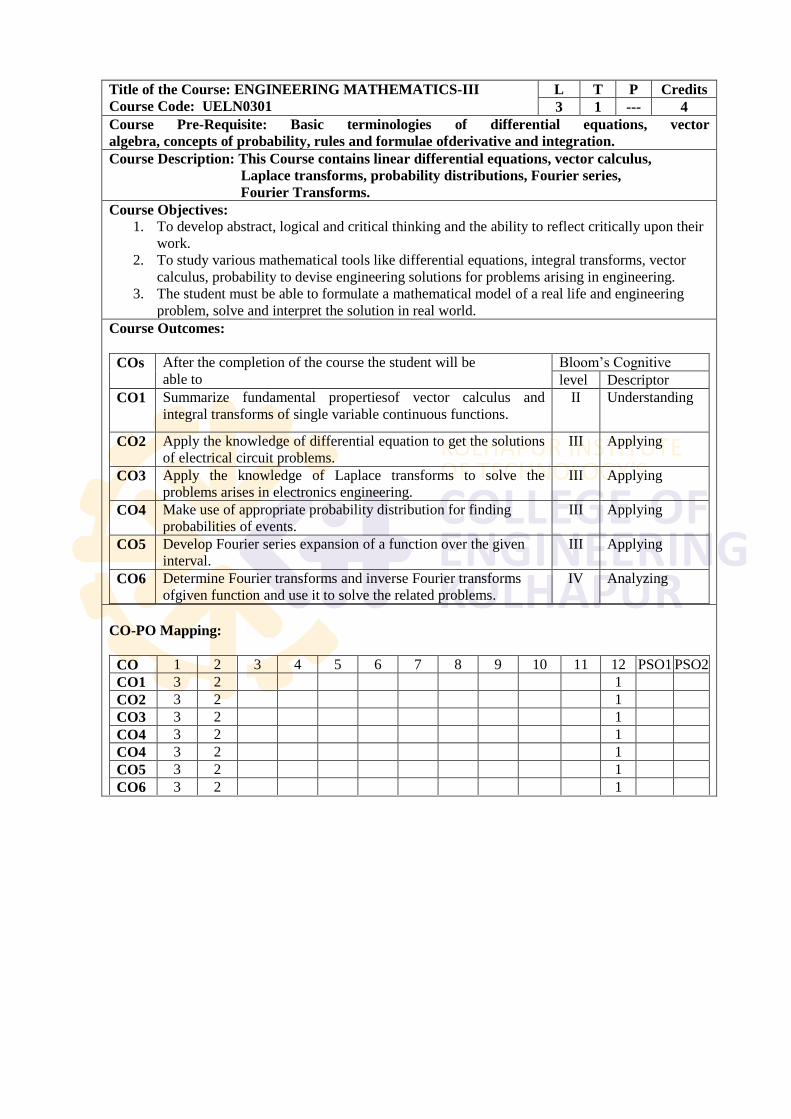
Title of the Course: ENGINEERING MATHEMATICS-III
Course Code: UELN0301
L T P Credits
3 1 --- 4
Course Pre-Requisite: Basic terminologies of differential equations, vector
algebra, concepts of probability, rules and formulae ofderivative and integration.
Course Description: This Course contains linear differential equations, vector calculus,
Laplace transforms, probability distributions, Fourier series,
Fourier Transforms.
Course Objectives: 1. To develop abstract, logical and critical thinking and the ability to reflect critically upon their
work.
2. To study various mathematical tools like differential equations, integral transforms, vector
calculus, probability to devise engineering solutions for problems arising in engineering.
3. The student must be able to formulate a mathematical model of a real life and engineering
problem, solve and interpret the solution in real world.
Course Outcomes:
COs After the completion of the course the student will be
able to
Bloom‘s Cognitive
level Descriptor
CO1 Summarize fundamental propertiesof vector calculus and
integral transforms of single variable continuous functions.
II Understanding
CO2 Apply the knowledge of differential equation to get the solutions
of electrical circuit problems.
III Applying
CO3 Apply the knowledge of Laplace transforms to solve the
problems arises in electronics engineering.
III Applying
CO4 Make use of appropriate probability distribution for finding
probabilities of events.
III Applying
CO5 Develop Fourier series expansion of a function over the given
interval.
III Applying
CO6 Determine Fourier transforms and inverse Fourier transforms
ofgiven function and use it to solve the related problems.
IV Analyzing
CO-PO Mapping:
CO 1 2 3 4 5 6 7 8 9 10 11 12 PSO1 PSO2
CO1 3 2 1
CO2 3 2 1
CO3 3 2 1
CO4 3 2 1
CO4 3 2 1
CO5 3 2 1
CO6 3 2 1
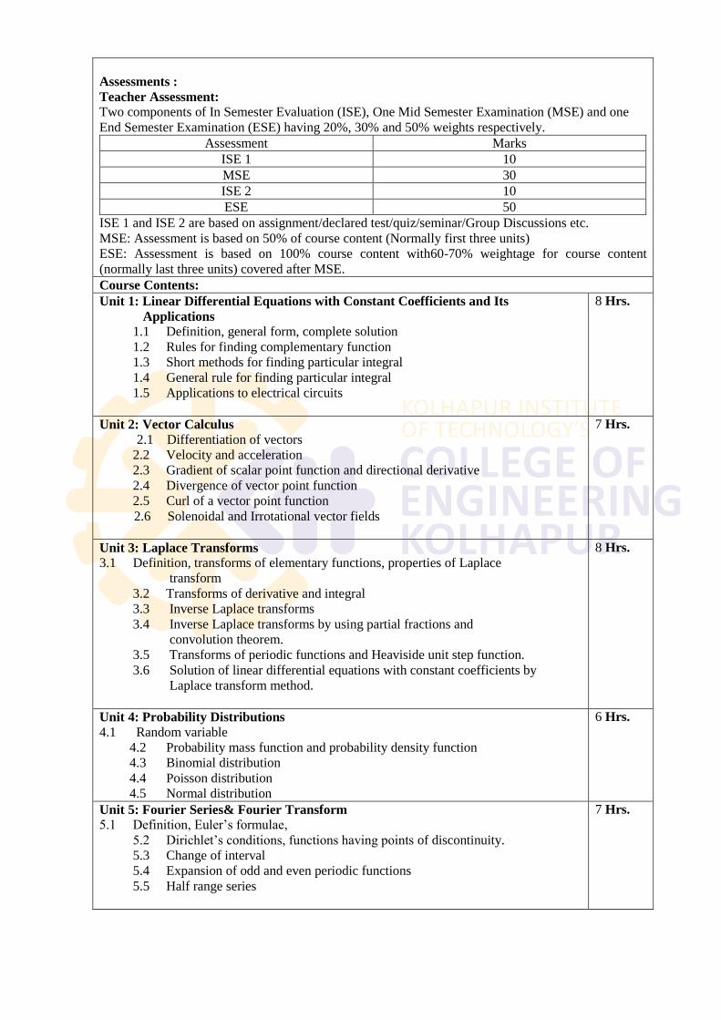
Assessments :
Teacher Assessment: Two components of In Semester Evaluation (ISE), One Mid Semester Examination (MSE) and one
End Semester Examination (ESE) having 20%, 30% and 50% weights respectively.
Assessment Marks
ISE 1 10
MSE 30
ISE 2 10
ESE 50
ISE 1 and ISE 2 are based on assignment/declared test/quiz/seminar/Group Discussions etc.
MSE: Assessment is based on 50% of course content (Normally first three units)
ESE: Assessment is based on 100% course content with60-70% weightage for course content
(normally last three units) covered after MSE.
Course Contents:
Unit 1: Linear Differential Equations with Constant Coefficients and Its
Applications 1.1 Definition, general form, complete solution
1.2 Rules for finding complementary function
1.3 Short methods for finding particular integral
1.4 General rule for finding particular integral
1.5 Applications to electrical circuits
8 Hrs.
Unit 2: Vector Calculus 2.1 Differentiation of vectors
2.2 Velocity and acceleration
2.3 Gradient of scalar point function and directional derivative
2.4 Divergence of vector point function
2.5 Curl of a vector point function
2.6 Solenoidal and Irrotational vector fields
7 Hrs.
Unit 3: Laplace Transforms 3.1 Definition, transforms of elementary functions, properties of Laplace
transform
3.2 Transforms of derivative and integral
3.3 Inverse Laplace transforms
3.4 Inverse Laplace transforms by using partial fractions and
convolution theorem.
3.5 Transforms of periodic functions and Heaviside unit step function.
3.6 Solution of linear differential equations with constant coefficients by
Laplace transform method.
8 Hrs.
Unit 4: Probability Distributions 4.1 Random variable
4.2 Probability mass function and probability density function
4.3 Binomial distribution
4.4 Poisson distribution
4.5 Normal distribution
6 Hrs.
Unit 5: Fourier Series& Fourier Transform 5.1 Definition, Euler‘s formulae,
5.2 Dirichlet‘s conditions, functions having points of discontinuity.
5.3 Change of interval
5.4 Expansion of odd and even periodic functions
5.5 Half range series
7 Hrs.
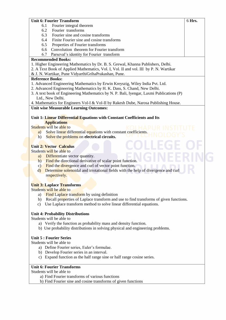
Unit 6: Fourier Transform 6.1 Fourier integral theorem
6.2 Fourier transforms
6.3 Fourier sine and cosine transforms
6.4 Finite Fourier sine and cosine transforms
6.5 Properties of Fourier transforms
6.6 Convolution theorem for Fourier transform
6.7 Parseval‘s identity for Fourier transform
6 Hrs.
Recommended Books: 1. Higher Engineering Mathematics by Dr. B. S. Grewal, Khanna Publishers, Delhi.
2. A Text Book of Applied Mathematics, Vol. I, Vol. II and vol. III by P. N. Wartikar
& J. N. Wartikar, Pune VidyarthiGrihaPrakashan, Pune.
Reference Books: 1. Advanced Engineering Mathematics by Erwin Kreyszig, Wiley India Pvt. Ltd.
2. Advanced Engineering Mathematics by H. K. Dass, S. Chand, New Delhi.
3. A text book of Engineering Mathematics by N. P. Bali, Iyengar, Laxmi Publications (P)
Ltd., New Delhi.
4. Mathematics for Engineers Vol-I & Vol-II by Rakesh Dube, Narosa Publishing House.
Unit wise Measurable Learning Outcomes:
Unit 1: Linear Differential Equations with Constant Coefficients and Its
Applications Students will be able to
a) Solve linear differential equations with constant coefficients.
b) Solve the problems on electrical circuits.
Unit 2: Vector Calculus Students will be able to
a) Differentiate vector quantity.
b) Find the directional derivative of scalar point function.
c) Find the divergence and curl of vector point function.
d) Determine solenoidal and irrotational fields with the help of divergence and curl
respectively.
Unit 3: Laplace Transforms Students will be able to
a) Find Laplace transform by using definition
b) Recall properties of Laplace transform and use to find transforms of given functions.
c) Use Laplace transform method to solve linear differential equations.
Unit 4: Probability Distributions Students will be able to
a) Verify the function as probability mass and density function.
b) Use probability distributions in solving physical and engineering problems.
Unit 5 : Fourier Series Students will be able to
a) Define Fourier series, Euler‘s formulae.
b) Develop Fourier series in an interval.
c) Expand function as the half range sine or half range cosine series.
Unit 6: Fourier Transforms Students will be able to
a) Find Fourier transforms of various functions
b) Find Fourier sine and cosine transforms of given functions
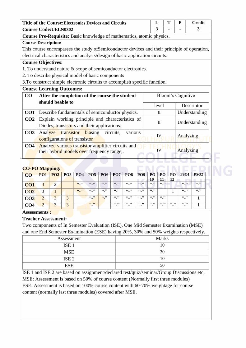
Title of the Course:Electronics Devices and Circuits
Course Code:UELN0302
L T P Credit
3 - - 3
Course Pre-Requisite: Basic knowledge of mathematics, atomic physics.
Course Description:
This course encompasses the study ofSemiconductor devices and their principle of operation,
electrical characteristics and analysis/design of basic application circuits.
Course Objectives:
1. To understand nature & scope of semiconductor electronics.
2. To describe physical model of basic components
3.To construct simple electronic circuits to accomplish specific function.
Course Learning Outcomes:
CO After the completion of the course the student
should beable to
Bloom‘s Cognitive
level Descriptor
CO1 Describe fundamentals of semiconductor physics. II Understanding
CO2 Explain working principle and characteristics of
Diodes, transistors and their applications. II Understanding
CO3 Analyze transistor biasing circuits, various
configurations of transistor IV Analyzing
CO4 Analyze various transistor amplifier circuits and
their hybrid models over frequency range,. IV Analyzing
CO-PO Mapping:
CO PO1 PO2 PO3 PO4 PO5 PO6 PO7 PO8 PO9 PO
10
PO
11
PO
12
PSO1 PSO2
CO1 3 2 ―-‖ ―-‖ ―-‖ ―-‖ ―-‖ ―-‖ ―-‖ ―-‖ ―-‖ ―-‖
CO2 3 1 ―-‖ ―-‖ ―-‖ ―-‖ ―-‖ ―-‖ ―-‖ 1 ―-‖ ―-‖
CO3 2 3 3 ―-‖ ―-‖ ―-‖ ―-‖ ―-‖ ―-‖ ―-‖ ―-‖ 1
CO4 2 3 3 ―-‖ ―-‖ ―-‖ ―-‖ ―-‖ ―-‖ ―-‖ ―-‖ 1
Assessments :
Teacher Assessment:
Two components of In Semester Evaluation (ISE), One Mid Semester Examination (MSE)
and one End Semester Examination (ESE) having 20%, 30% and 50% weights respectively.
Assessment Marks
ISE 1 10
MSE 30
ISE 2 10
ESE 50
ISE 1 and ISE 2 are based on assignment/declared test/quiz/seminar/Group Discussions etc.
MSE: Assessment is based on 50% of course content (Normally first three modules)
ESE: Assessment is based on 100% course content with 60-70% weightage for course
content (normally last three modules) covered after MSE.
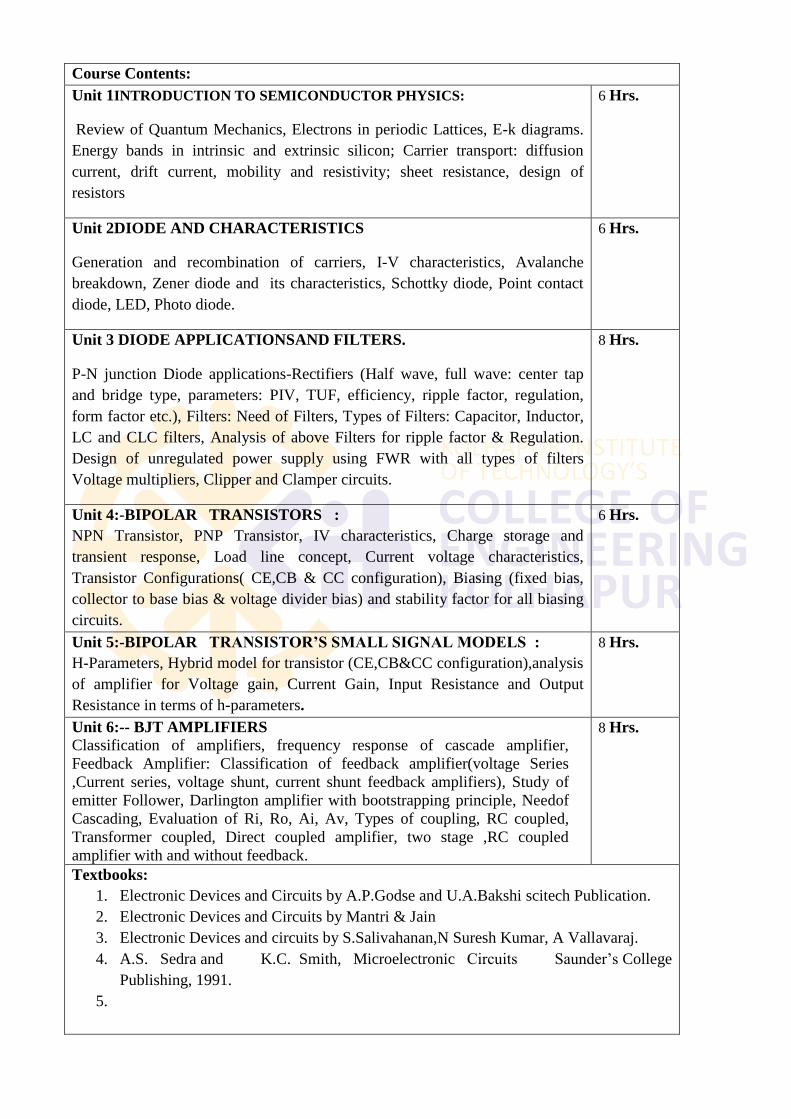
Course Contents:
Unit 1INTRODUCTION TO SEMICONDUCTOR PHYSICS:
Review of Quantum Mechanics, Electrons in periodic Lattices, E-k diagrams.
Energy bands in intrinsic and extrinsic silicon; Carrier transport: diffusion
current, drift current, mobility and resistivity; sheet resistance, design of
resistors
6 Hrs.
Unit 2DIODE AND CHARACTERISTICS
Generation and recombination of carriers, I-V characteristics, Avalanche
breakdown, Zener diode and its characteristics, Schottky diode, Point contact
diode, LED, Photo diode.
6 Hrs.
Unit 3 DIODE APPLICATIONSAND FILTERS.
P-N junction Diode applications-Rectifiers (Half wave, full wave: center tap
and bridge type, parameters: PIV, TUF, efficiency, ripple factor, regulation,
form factor etc.), Filters: Need of Filters, Types of Filters: Capacitor, Inductor,
LC and CLC filters, Analysis of above Filters for ripple factor & Regulation.
Design of unregulated power supply using FWR with all types of filters
Voltage multipliers, Clipper and Clamper circuits.
8 Hrs.
Unit 4:-BIPOLAR TRANSISTORS :
NPN Transistor, PNP Transistor, IV characteristics, Charge storage and
transient response, Load line concept, Current voltage characteristics,
Transistor Configurations( CE,CB & CC configuration), Biasing (fixed bias,
collector to base bias & voltage divider bias) and stability factor for all biasing
circuits.
6 Hrs.
Unit 5:-BIPOLAR TRANSISTOR’S SMALL SIGNAL MODELS :
H-Parameters, Hybrid model for transistor (CE,CB&CC configuration),analysis
of amplifier for Voltage gain, Current Gain, Input Resistance and Output
Resistance in terms of h-parameters.
8 Hrs.
Unit 6:-- BJT AMPLIFIERS
Classification of amplifiers, frequency response of cascade amplifier,
Feedback Amplifier: Classification of feedback amplifier(voltage Series
,Current series, voltage shunt, current shunt feedback amplifiers), Study of
emitter Follower, Darlington amplifier with bootstrapping principle, Needof
Cascading, Evaluation of Ri, Ro, Ai, Av, Types of coupling, RC coupled,
Transformer coupled, Direct coupled amplifier, two stage ,RC coupled
amplifier with and without feedback.
8 Hrs.
Textbooks:
1. Electronic Devices and Circuits by A.P.Godse and U.A.Bakshi scitech Publication.
2. Electronic Devices and Circuits by Mantri & Jain
3. Electronic Devices and circuits by S.Salivahanan,N Suresh Kumar, A Vallavaraj.
4. A.S. Sedra and K.C. Smith, Microelectronic Circuits Saunder‘s College
Publishing, 1991.
5.
References:
1. Electronic Devices and Circuit Theory by Boylestad, Pearson Publication.
2. Electronic Devices and Circuits by J.B.Gupta,Katson Publication
3. Electronic Devices and Circuits by Millman, Halkias, TMHPublication.
4. Schaum's Outlines, ― Electronic Devices and Circuits‖
5. Electronic Devices and Circuits by Allen Mottershead-PHI.
6. Solid State Electronic Devices by Ben Streetman, PearsonPublication.
Unit wise Measurable students Learning Outcomes:
1The student will be able to explain basics of semiconductor physics.
2. The student will be able to analyze diode circuit using basic engineering sciences.
3The student will be able tomake use of semiconductor devices as per industry practice in a
satisfactory manner.
4 The student will able to analyze transistor biasing circuits.
5 The student will be able to estimate h-parameters of CB, CC & CE transistor‘s
configurations
6 The student will be able to analyze and design various applications of bipolar junction
transistors such as feedback amplifiers
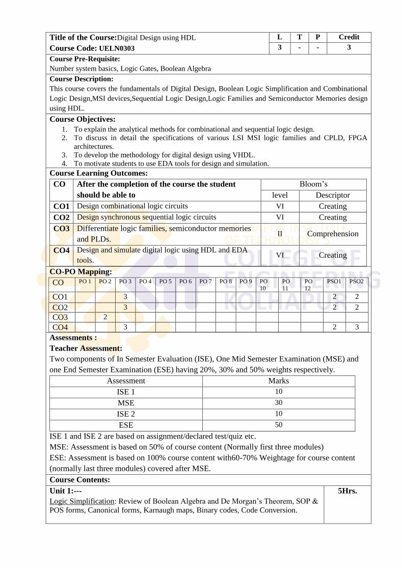
Title of the Course:Digital Design using HDL
Course Code: UELN0303
L T P Credit
3 - - 3
Course Pre-Requisite:
Number system basics, Logic Gates, Boolean Algebra
Course Description:
This course covers the fundamentals of Digital Design, Boolean Logic Simplification and Combinational
Logic Design,MSI devices,Sequential Logic Design,Logic Families and Semiconductor Memories design
using HDL.
Course Objectives:
1. To explain the analytical methods for combinational and sequential logic design.
2. To discuss in detail the specifications of various LSI MSI logic families and CPLD, FPGA
architectures.
3. To develop the methodology for digital design using VHDL.
4. To motivate students to use EDA tools for design and simulation.
Course Learning Outcomes:
CO After the completion of the course the student
should be able to
Bloom‘s
level Descriptor
CO1 Design combinational logic circuits VI Creating
CO2 Design synchronous sequential logic circuits VI Creating
CO3 Differentiate logic families, semiconductor memories
and PLDs. II Comprehension
CO4 Design and simulate digital logic using HDL and EDA
tools. VI Creating
CO-PO Mapping:
CO PO 1 PO 2 PO 3 PO 4 PO 5 PO 6 PO 7 PO 8 PO 9 PO
10
PO
11
PO
12
PSO1 PSO2
CO1 3 2 2
CO2 3 2 2
CO3 2
CO4 3 2 3
Assessments :
Teacher Assessment:
Two components of In Semester Evaluation (ISE), One Mid Semester Examination (MSE) and
one End Semester Examination (ESE) having 20%, 30% and 50% weights respectively.
Assessment Marks
ISE 1 10
MSE 30
ISE 2 10
ESE 50
ISE 1 and ISE 2 are based on assignment/declared test/quiz etc.
MSE: Assessment is based on 50% of course content (Normally first three modules)
ESE: Assessment is based on 100% course content with60-70% Weightage for course content
(normally last three modules) covered after MSE.
Course Contents:
Unit 1:---
Logic Simplification: Review of Boolean Algebra and De Morgan‘s Theorem, SOP &
POS forms, Canonical forms, Karnaugh maps, Binary codes, Code Conversion.
5Hrs.
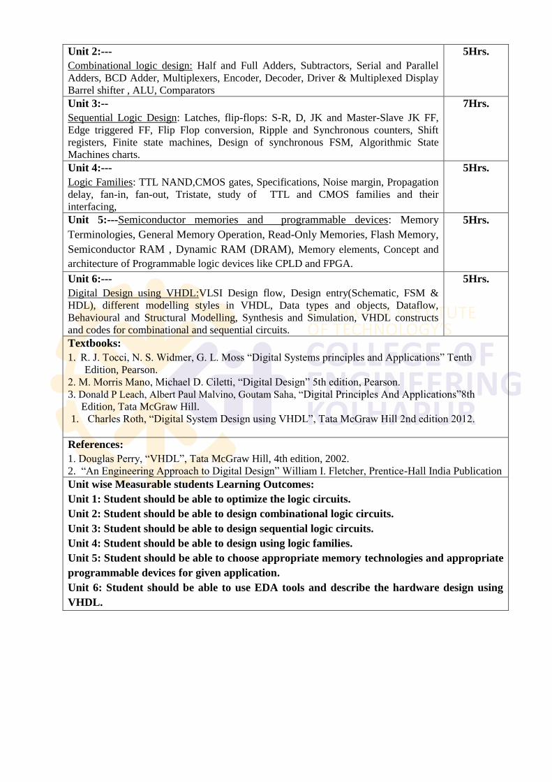
Unit 2:---
Combinational logic design: Half and Full Adders, Subtractors, Serial and Parallel
Adders, BCD Adder, Multiplexers, Encoder, Decoder, Driver & Multiplexed Display
Barrel shifter , ALU, Comparators
5Hrs.
Unit 3:--
Sequential Logic Design: Latches, flip-flops: S-R, D, JK and Master-Slave JK FF,
Edge triggered FF, Flip Flop conversion, Ripple and Synchronous counters, Shift
registers, Finite state machines, Design of synchronous FSM, Algorithmic State
Machines charts.
7Hrs.
Unit 4:---
Logic Families: TTL NAND,CMOS gates, Specifications, Noise margin, Propagation
delay, fan-in, fan-out, Tristate, study of TTL and CMOS families and their
interfacing,
5Hrs.
Unit 5:---Semiconductor memories and programmable devices: Memory
Terminologies, General Memory Operation, Read-Only Memories, Flash Memory,
Semiconductor RAM , Dynamic RAM (DRAM), Memory elements, Concept and
architecture of Programmable logic devices like CPLD and FPGA.
5Hrs.
Unit 6:---
Digital Design using VHDL:VLSI Design flow, Design entry(Schematic, FSM &
HDL), different modelling styles in VHDL, Data types and objects, Dataflow,
Behavioural and Structural Modelling, Synthesis and Simulation, VHDL constructs
and codes for combinational and sequential circuits.
5Hrs.
Textbooks:
1. R. J. Tocci, N. S. Widmer, G. L. Moss ―Digital Systems principles and Applications‖ Tenth
Edition, Pearson.
2. M. Morris Mano, Michael D. Ciletti, ―Digital Design‖ 5th edition, Pearson.
3. Donald P Leach, Albert Paul Malvino, Goutam Saha, ―Digital Principles And Applications‖8th
Edition, Tata McGraw Hill.
1. Charles Roth, ―Digital System Design using VHDL‖, Tata McGraw Hill 2nd edition 2012.
References:
1. Douglas Perry, ―VHDL‖, Tata McGraw Hill, 4th edition, 2002.
2. ―An Engineering Approach to Digital Design‖ William I. Fletcher, Prentice-Hall India Publication
Unit wise Measurable students Learning Outcomes:
Unit 1: Student should be able to optimize the logic circuits.
Unit 2: Student should be able to design combinational logic circuits.
Unit 3: Student should be able to design sequential logic circuits.
Unit 4: Student should be able to design using logic families.
Unit 5: Student should be able to choose appropriate memory technologies and appropriate
programmable devices for given application.
Unit 6: Student should be able to use EDA tools and describe the hardware design using
VHDL.
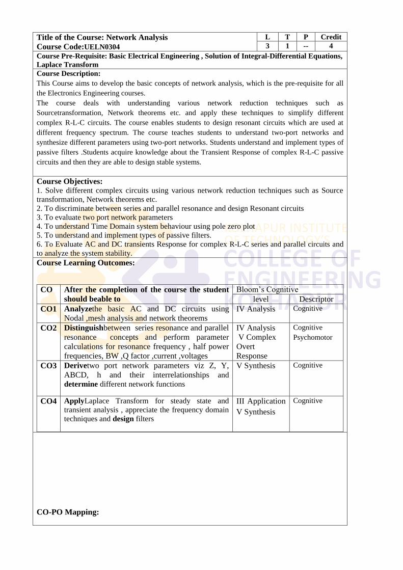
Title of the Course: Network Analysis
Course Code:UELN0304
L T P Credit
3 1 -- 4
Course Pre-Requisite: Basic Electrical Engineering , Solution of Integral-Differential Equations,
Laplace Transform
Course Description:
This Course aims to develop the basic concepts of network analysis, which is the pre-requisite for all
the Electronics Engineering courses.
The course deals with understanding various network reduction techniques such as
Sourcetransformation, Network theorems etc. and apply these techniques to simplify different
complex R-L-C circuits. The course enables students to design resonant circuits which are used at
different frequency spectrum. The course teaches students to understand two-port networks and
synthesize different parameters using two-port networks. Students understand and implement types of
passive filters .Students acquire knowledge about the Transient Response of complex R-L-C passive
circuits and then they are able to design stable systems.
Course Objectives: 1. Solve different complex circuits using various network reduction techniques such as Source
transformation, Network theorems etc.
2. To discriminate between series and parallel resonance and design Resonant circuits
3. To evaluate two port network parameters
4. To understand Time Domain system behaviour using pole zero plot
5. To understand and implement types of passive filters.
6. To Evaluate AC and DC transients Response for complex R-L-C series and parallel circuits and
to analyze the system stability.
Course Learning Outcomes:
CO After the completion of the course the student
should beable to
Bloom‘s Cognitive
level Descriptor
CO1 Analyzethe basic AC and DC circuits using
Nodal ,mesh analysis and network theorems
IV Analysis Cognitive
CO2 Distinguishbetween series resonance and parallel
resonance concepts and perform parameter
calculations for resonance frequency , half power
frequencies, BW ,Q factor ,current ,voltages
IV Analysis
V Complex
Overt
Response
Cognitive
Psychomotor
CO3 Derivetwo port network parameters viz Z, Y,
ABCD, h and their interrelationships and
determine different network functions
V Synthesis
Cognitive
CO4 ApplyLaplace Transform for steady state and
transient analysis , appreciate the frequency domain
techniques and design filters
III Application
V Synthesis
Cognitive
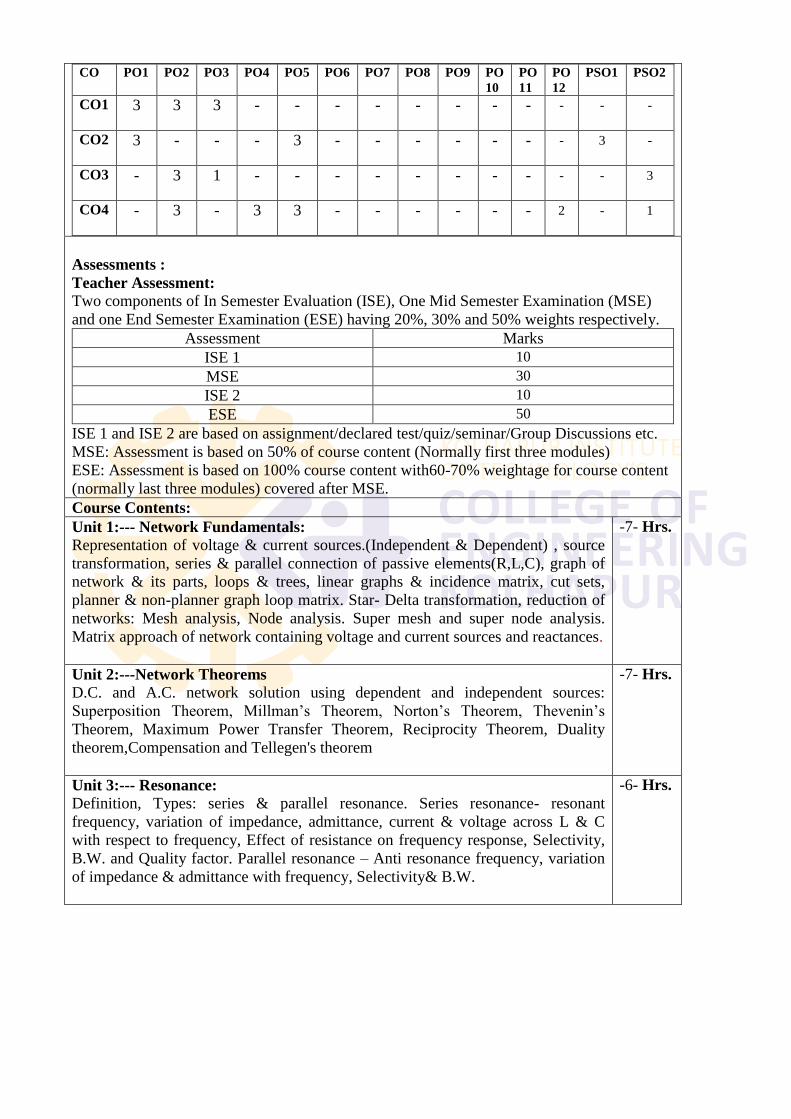
CO-PO Mapping:
CO PO1 PO2 PO3 PO4 PO5 PO6 PO7 PO8 PO9 PO
10
PO
11
PO
12
PSO1 PSO2
CO1 3 3 3 - - - - - - - - - - -
CO2 3 - - - 3 - - - - - - - 3 -
CO3 - 3 1 - - - - - - - - - - 3
CO4 - 3 - 3 3 - - - - - - 2 - 1
Assessments :
Teacher Assessment:
Two components of In Semester Evaluation (ISE), One Mid Semester Examination (MSE)
and one End Semester Examination (ESE) having 20%, 30% and 50% weights respectively.
Assessment Marks
ISE 1 10
MSE 30
ISE 2 10
ESE 50
ISE 1 and ISE 2 are based on assignment/declared test/quiz/seminar/Group Discussions etc.
MSE: Assessment is based on 50% of course content (Normally first three modules)
ESE: Assessment is based on 100% course content with60-70% weightage for course content
(normally last three modules) covered after MSE.
Course Contents:
Unit 1:--- Network Fundamentals:
Representation of voltage & current sources.(Independent & Dependent) , source
transformation, series & parallel connection of passive elements(R,L,C), graph of
network & its parts, loops & trees, linear graphs & incidence matrix, cut sets,
planner & non-planner graph loop matrix. Star- Delta transformation, reduction of
networks: Mesh analysis, Node analysis. Super mesh and super node analysis.
Matrix approach of network containing voltage and current sources and reactances.
-7- Hrs.
Unit 2:---Network Theorems
D.C. and A.C. network solution using dependent and independent sources:
Superposition Theorem, Millman‘s Theorem, Norton‘s Theorem, Thevenin‘s
Theorem, Maximum Power Transfer Theorem, Reciprocity Theorem, Duality
theorem,Compensation and Tellegen's theorem
-7- Hrs.
Unit 3:--- Resonance:
Definition, Types: series & parallel resonance. Series resonance- resonant
frequency, variation of impedance, admittance, current & voltage across L & C
with respect to frequency, Effect of resistance on frequency response, Selectivity,
B.W. and Quality factor. Parallel resonance – Anti resonance frequency, variation
of impedance & admittance with frequency, Selectivity& B.W.
-6- Hrs.
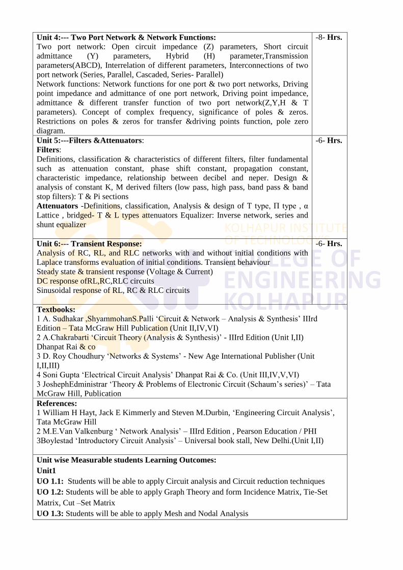
Unit 4:--- Two Port Network & Network Functions:
Two port network: Open circuit impedance (Z) parameters, Short circuit
admittance (Y) parameters, Hybrid (H) parameter,Transmission
parameters(ABCD), Interrelation of different parameters, Interconnections of two
port network (Series, Parallel, Cascaded, Series- Parallel)
Network functions: Network functions for one port & two port networks, Driving
point impedance and admittance of one port network, Driving point impedance,
admittance & different transfer function of two port network(Z,Y,H & T
parameters). Concept of complex frequency, significance of poles & zeros.
Restrictions on poles & zeros for transfer &driving points function, pole zero
diagram.
-8- Hrs.
Unit 5:---Filters &Attenuators:
Filters:
Definitions, classification & characteristics of different filters, filter fundamental
such as attenuation constant, phase shift constant, propagation constant,
characteristic impedance, relationship between decibel and neper. Design &
analysis of constant K, M derived filters (low pass, high pass, band pass & band
stop filters): T & Pi sections
Attenuators -Definitions, classification, Analysis & design of T type, Π type , α
Lattice , bridged- T & L types attenuators Equalizer: Inverse network, series and
shunt equalizer
-6- Hrs.
Unit 6:--- Transient Response:
Analysis of RC, RL, and RLC networks with and without initial conditions with
Laplace transforms evaluation of initial conditions. Transient behaviour
Steady state & transient response (Voltage & Current)
DC response ofRL,RC,RLC circuits
Sinusoidal response of RL, RC & RLC circuits
-6- Hrs.
Textbooks:
1 A. Sudhakar ,ShyammohanS.Palli ‗Circuit & Network – Analysis & Synthesis‘ IIIrd
Edition – Tata McGraw Hill Publication (Unit II,IV,VI)
2 A.Chakrabarti ‗Circuit Theory (Analysis & Synthesis)‘ - IIIrd Edition (Unit I,II)
Dhanpat Rai & co
3 D. Roy Choudhury ‗Networks & Systems‘ - New Age International Publisher (Unit
I,II,III)
4 Soni Gupta ‗Electrical Circuit Analysis‘ Dhanpat Rai & Co. (Unit III,IV,V,VI)
3 JoshephEdministrar ‗Theory & Problems of Electronic Circuit (Schaum‘s series)‘ – Tata
McGraw Hill, Publication
References:
1 William H Hayt, Jack E Kimmerly and Steven M.Durbin, ‗Engineering Circuit Analysis‘,
Tata McGraw Hill
2 M.E.Van Valkenburg ‗ Network Analysis‘ – IIIrd Edition , Pearson Education / PHI
3Boylestad ‗Introductory Circuit Analysis‘ – Universal book stall, New Delhi.(Unit I,II)
Unit wise Measurable students Learning Outcomes:
Unit1
UO 1.1: Students will be able to apply Circuit analysis and Circuit reduction techniques
UO 1.2: Students will be able to apply Graph Theory and form Incidence Matrix, Tie-Set
Matrix, Cut –Set Matrix
UO 1.3: Students will be able to apply Mesh and Nodal Analysis
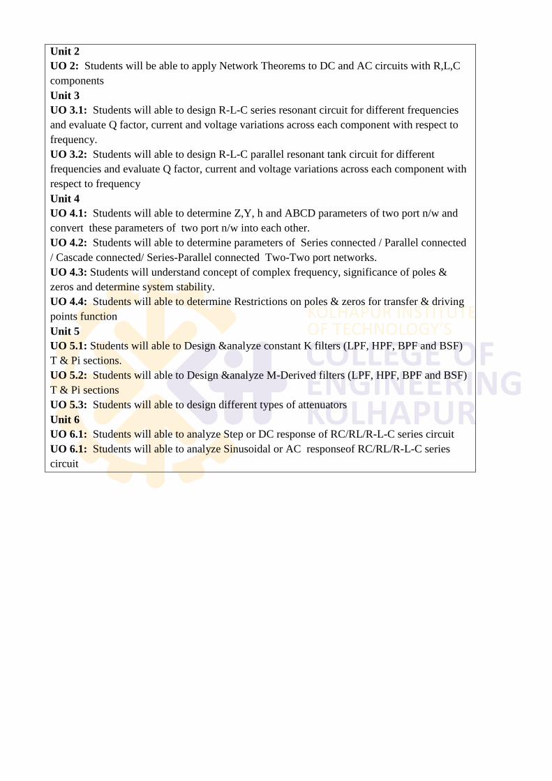
Unit 2
UO 2: Students will be able to apply Network Theorems to DC and AC circuits with R,L,C
components
Unit 3
UO 3.1: Students will able to design R-L-C series resonant circuit for different frequencies
and evaluate Q factor, current and voltage variations across each component with respect to
frequency.
UO 3.2: Students will able to design R-L-C parallel resonant tank circuit for different
frequencies and evaluate Q factor, current and voltage variations across each component with
respect to frequency
Unit 4
UO 4.1: Students will able to determine Z,Y, h and ABCD parameters of two port n/w and
convert these parameters of two port n/w into each other.
UO 4.2: Students will able to determine parameters of Series connected / Parallel connected
/ Cascade connected/ Series-Parallel connected Two-Two port networks.
UO 4.3: Students will understand concept of complex frequency, significance of poles &
zeros and determine system stability.
UO 4.4: Students will able to determine Restrictions on poles & zeros for transfer & driving
points function
Unit 5
UO 5.1: Students will able to Design &analyze constant K filters (LPF, HPF, BPF and BSF)
T & Pi sections.
UO 5.2: Students will able to Design &analyze M-Derived filters (LPF, HPF, BPF and BSF)
T & Pi sections
UO 5.3: Students will able to design different types of attenuators
Unit 6
UO 6.1: Students will able to analyze Step or DC response of RC/RL/R-L-C series circuit
UO 6.1: Students will able to analyze Sinusoidal or AC responseof RC/RL/R-L-C series
circuit
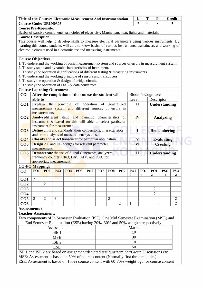
Title of the Course: Electronic Measurement And Instrumentation
Course Code: UELN0305
L T P Credit
3 0 - 3
Course Pre-Requisite:
Basics of passive components, principles of electricity, Magnetism, heat, lights and materials.
Course Description:
This course will help to develop skills to measure electrical parameters using various instruments. By
learning this course students will able to know basics of various Instruments, transducers and working of
electronic circuits used in electronic test and measuring instruments.
Course Objectives: 1. To understand the working of basic measurement system and sources of errors in measurement system.
2. To study static and dynamic characteristics of instrument.
3. To study the operation & applications of different testing & measuring instruments.
4. To understand the working principle of sensors and transducers.
5. To study the operation & design of bridge circuit.
6. To study the operation of DAS & data convertors.
Course Learning Outcomes:
CO After the completion of the course the student will
able to
Bloom‘s Cognitive
Level Descriptor
CO1 Explain the principle of operation of generalized
measurement system and different sources of errors in
measurements.
II Understanding
CO2 Analyzedifferent static and dynamic characteristics of
instrument & based on this will able to select particular
instrument for measurement.
IV Analyzing
CO3 Define units and standards, their conversions, characteristics
and error analysis of measurement systems. I Remembering
CO4 Classify and select transducer for particular application V Evaluating
CO5 Design AC and DC bridges for relevant parameter
measurement. VI Creating
CO6 Demonstrate the use of Signal Generators, analyzers,
frequency counter, CRO, DAS, ADC and DAC for
appropriate measurement.
II Understanding
CO-PO Mapping:
CO PO1 PO2 PO3 PO4 PO5 PO6 PO7 PO8 PO9 PO1
0
PO1
1
PO1
2
PSO
1
PSO
2
CO1 2
CO2 2
CO3 2
CO4 2
CO5 2 2 3 2 2
CO6 2 1 2
Assessments :
Teacher Assessment:
Two components of In Semester Evaluation (ISE), One Mid Semester Examination (MSE) and
one End Semester Examination (ESE) having 20%, 30% and 50% weights respectively.
Assessment Marks
ISE 1 10
MSE 30
ISE 2 10
ESE 50
ISE 1 and ISE 2 are based on assignment/declared test/quiz/seminar/Group Discussions etc.
MSE: Assessment is based on 50% of course content (Normally first three modules)
ESE: Assessment is based on 100% course content with 60-70% weight-age for course content
(normally last three modules) covered after MSE.
Course Contents:
Unit 1:---Basics of Measurement Systems
Introduction, definition of measurement, definition of instrumentation, generalized
block diagram of measurement system, different sources of errors in measurement,
calibration of instruments, performance characteristics of instruments – static
characteristics, dynamic characteristics, accuracy and precision, statistical analysis of
data, arithmetic mean, deviation, average and standard deviation, probable error.
6 Hrs.
Unit 2:---Analog and Digital Measurements
Analog instruments- classification, PMMC, MI, MC – construction, working principle
etc, range extension. Digital Instruments- Digital Voltmeter- ramp type DVM, integrating type DVM,
successive approximation type DVM, DFM, DMM, Digital Tachometer, Line mains
frequency indicator.
7 Hrs.
Unit 3:---Oscilloscopes and signal generators Digital Storage Oscilloscope- Block diagram, Working principle, measurement,
Parameters. Types of CRO: Dual Beam, Dual Trace, CRO probes. Signal generators- introduction, audio frequency generators, radio frequency generators,
function generator, pulse and square wave generators.
7 Hrs.
Unit 4:--- Transducers Classification; Selection of Transducers; Resistive Transducers – Potentiometer, Strain
gauges, Rosettes, Thermistor and RTD; Capacitive Transducers – Measurement of
Liquid level by change in variation of dielectric constant; inductive transducers-LVDT;
Piezoelectric Transducers; Photoelectric Transducers; thermocouple, pressure
transducers, load cell, Digital displacement Transducer, advanced industrial and
commercial sensors
7 Hrs.
Unit 5:--- AC and DC Bridges DC Bridges- Introduction, Wheatstone bridge, Kelvin‘s bridge sensitivity and
limitations.
AC Bridges- Introduction, Maxwell‘s bridge, Hay‘s bridge, Andersons bridge, Schering
bridge, wein bridge
7 Hrs.
Unit 6:--- Data Acquisition Systems Introduction to signal conditioning, various signal conditioning circuits, , S/H Circuits,
Introduction To Data Acquisition System, Various DAS Configurations, Single
Channel DAS, Multi-Channel DAS, IC Based DAS, Data Acquisition, Data Acquisition
in PLC.
Signal analyzers-Introduction, basic wave analyzer, heterodynes harmonic
distortion analyzer, Logic Analyzer.
8 Hrs.
Textbooks:
1. A. D. Helfik , W. N. Cooper, ―Modern electronic instrumentation & measurement techniques‖,
Pearson education
References: 1. A. K.Sawhney. ―A course in electrical & electronics measurements & instruments‖,
DhanpatRai & sons publication.
2. S. N.Patil,K.P. Pardesi ―Electronics measurements & instrumentation‖, Electrotech publication.
3. H.S.Kalsi, ―Electronics instrumentation‖, second edition, Tata McGraw Hill publication.
4. Alok Barua, ―Fundamentals of industrial instrumentation‖, Wiley India publication.
5. David A.Bell, ―Electronics instrumentation & measurements‖, 3rd edition Oxford publication.
6. M.M.S.Anand, ―Electronics instruments & instrumentation technology‖, PHI publication.
Unit wise Measurable students Learning Outcomes:
1. Student would able to different terms and parameters in Measurement system
2. Student should beable to analyze Static and dynamic Characteristics with their error format in
an Instrument.
3. Student should beable to select Components and instrument for testing different Measurement
4. Student should beable to choose transducer to measure physical parameters.
5. Student should beable to Design AC &DC bridges for measurement of Parameters of different
components.
6. Student should beable to Interpret the requirements of Data Acquisition system.
Audit Course-I
Shivaji University, Kolhapur
Second year undergraduate compulsory course in
ENVIRONMENTAL STUDIES
Course Code: UELN0361
Lecture: 02 Syllabus
Syllabus
1. Nature of Environmental Studies. (4 lectures)
Definition, scope and importance,Multidisciplinary nature of environmental studies,Need for public
awareness.
2. Natural Resources and Associated Problems. (4 lectures)
a) Forest resources: Use and over-exploitation, deforestation, dams and their effects on forests and
tribal people.
b) Water resources: Use and over-utilization of surface and ground water, floods, drought, conflicts
over water, dams benefits and problems.
c) Mineral resources: Usage and exploitation. Environmental effects of extracting and using mineral
resources.
d) Food resources: World food problem, changes caused by agriculture effect of modern agriculture,
fertilizer-pesticide problems.
e) Energy resources: Growing energy needs, renewable and non-renewable energy resources, use of
alternate energy sources.Solar energy, Biomass energy, Nuclear energy.
f) Land resources: Solar energy , Biomass energy, Nuclear energy,Land as a resource, land
degradation, man induced landslides, soil erosion and desertification.Roleof an individuals in
conservation of natural resources.
3. Ecosystems (6 lectures)
Concept of an ecosystem.Structure and function of an ecosystem.Producers, consumers and
decomposers.Energy flow in the ecosystem.Ecologicalsuccession.Food chains, food webs and
ecological pyramids.Introduction, types, characteristics features, structure and function of the
following ecosystem :-
a) Forest ecosystem, b) Grassland ecosystem, c) Desert ecosystem,
d) Aquatic ecosystems (ponds, streams, lakes, rivers, oceans, estuaries).
4. Biodiversity and its conservation (6 lectures)
Introduction- Definition: genetic, species and ecosystem diversity.Bio-geographical classification
ofIndia.Valueof biodiversity: consumptive use, productive use, social, ethical,aesthetic and option
values.India as a mega- diversity nation.WesternGhat as a biodiversity region.Hot-spot
ofbiodiversity.Threats to biodiversity habitat loss, poaching of wildlife, man- wildlife
conflicts.Endangered and endemic species ofIndia.Conservationof biodiversity: In-situ and Ex-situ
conservation of biodiversity.
5. Environmental Pollution (6 lectures)
Definition: Causes, effects and control measures of: Air pollution, Water pollution, soil pollution,
Marine pollution, Noise pollution, Thermal pollution, nuclear hazards. Solid waste Management:
Causes, effects and control measures of urban and industrial wastes. Role ofa individual in prevention
of pollution.
6. Social Issues and the Environment (8 lectures)
Disaster management: floods, earthquake, cyclone, tsunami and landslides. Urban problems related to
energy Water conservation, rain water harvesting, watershed management Resettlement and
rehabilitation of people; its problems and concerns. Environmental ethics: Issue and possible
solutions.Global warming, acid rain, ozone layer depletion, nuclear accidents and
holocaust.Wastelandreclamation.Consumerism and waste products.
7. Environmental Protection (8 lectures)
From Unsustainable to Sustainable development.Environmental Protection Act.Air (Prevention and
Control of Pollution) Act.Water (Prevention and control of Pollution) Act.Wildlife Protection
Act.Forest Conservation Act.Population Growth and Human Health, Human Rights.
References :
1) Agarwal, K.C.2001, Environmental Biology, Nidi Pub. Ltd., Bikaner.
2) BharuchaErach, The Biodiversity of India, Mapin Publishing Pvt.Ltd.,Ahmedabad 380013, India,
Email:[email protected] (R)
3) Brunner R.C.,1989, Hazardous Waste Incineration, McGraw Hill Inc.480p
4) Clank R.S. Marine Pollution, Clanderson Press Oxford (TB)
5) Cunningham, W.P. Cooper, T.H.Gorhani, E. & Hepworth, M.T.2001,Environmental Encyclopedia,
Jaico Pub. Mumbai, 1196p
6) De A.K., Environmental Chemistry, Wiley Wastern Ltd.
7) Down to Earth , Centre for Science and Environment , New Delhi.(R)
8) Gleick, H.,1993, Water in crisis, Pacific Institute for studies in Dev.,Environment& Security.
Stockholm Env. Institute. Oxford Univ. Press 473p
9) Hawkins R.E., Encyclopediaof Indian Natural History, Bombay Natural History Society, Bombay
(R)
10) Heywood, V.H.& Watson, R.T.1995, Global Biodiversity Assessment,Cambridge Univ. Press
1140p.
11) Jadhav, H.and Bhosale, V.M.1995, Environmental Protection and Laws,Himalaya Pub. House,
Delhi 284p.
12) Mickinney, M.L.and School. R.M.1196, Environmental Science Systems and Solutions, Web
enhanced edition, 639p.
13) Miller T.G. Jr., Environmental Science. Wadsworth Publications Co.(TB).
14) Odum, E.P.1971, Fundamentals of Ecology, W.B.Saunders Co. USA,574p.
15) Rao M.N.and Datta, A.K.1987, Waste Water Treatment, Oxford &IBHPubl. Co. Pvt. Ltd., 345p
16) Sharma B.K., 2001, Environmental Chemistry, Gokel Publ. Hkouse,
Meerut
17) Survey of the Environment, The Hindu (M)
18) Townsend C., Harper, J. and Michael Begon, Essentials ofEcology,Blackwell Science (TB)
19) Trivedi R.K. Handbook of Environmental Laws, Rules, Guidelines,Compliances and Standards,
vol. I and II, Environmental Media (R)
20) Trivedi R.K. and P.K. Goel, Introduction to air pollution, Techno-Science Publications (TB)
21) Wagner K.D.,1998, Environmental management, W.B. Saunders Co.Philadelphia, USA 499p.
22) Paryavaran shastra – Gholap T.N.
23) ParyavaranSahastra - Gharapure
(M) Magazine
(R) Reference
(TB) Textbook
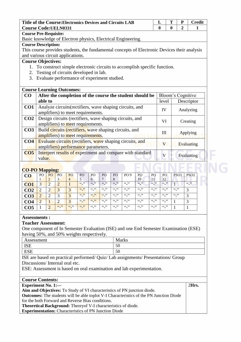
Title of the Course:Electronics Devices and Circuits LAB
Course Code:UELN0331
L T P Credit
0 0 2 1
Course Pre-Requisite:
Basic knowledge of Electron physics, Electrical Engineering.
Course Description:
This course provides students, the fundamental concepts of Electronic Devices their analysis
and various circuit applications.
Course Objectives:
1. To construct simple electronic circuits to accomplish specific function.
2. Testing of circuits developed in lab.
3. Evaluate performance of experiment studied.
Course Learning Outcomes:
CO After the completion of the course the student should be
able to
Bloom‘s Cognitive
level Descriptor
CO1 Analyze circuits(rectifiers, wave shaping circuits, and
amplifiers) to meet requirements. IV Analyzing
CO2 Design circuits (rectifiers, wave shaping circuits, and
amplifiers) to meet requirements. VI Creating
CO3 Build circuits (rectifiers, wave shaping circuits, and
amplifiers) to meet requirements. III Applying
CO4 Evaluate circuits (rectifiers, wave shaping circuits, and
amplifiers) performance parameters. V Evaluating
CO5 Interpret results of experiment and compare with standard
value. V Evaluating
CO-PO Mapping:
CO PO
1
PO
2
PO
3
PO
4
PO
5
PO
6
PO
7
PO
8
PO 9 PO
10
PO
11
PO
12
PSO1 PSO2
CO1 3 2 2 1 ―-‖ ―-‖ ―-‖ ―-‖ ―-‖ ―-‖ ―-‖ ―-‖ 1 ―-‖
CO2 2 2 3 3 ―-‖ ―-‖ ―-‖ ―-‖ ―-‖ ―-‖ ―-‖ ―-‖ ―-‖ 3
CO3 2 2 3 3 ―-‖ ―-‖ ―-‖ ―-‖ ―-‖ ―-‖ ―-‖ ―-‖ ―-‖ 3
CO4 2 1 2 3 ―-‖ ―-‖ ―-‖ ―-‖ ―-‖ ―-‖ ―-‖ ―-‖ 1 3
CO5 1 2 ―-‖ ―-‖ ―-‖ ―-‖ ―-‖ ―-‖ ―-‖ ―-‖ ―-‖ ―-‖ 1 1
Assessments :
Teacher Assessment:
One component of In Semester Evaluation (ISE) and one End Semester Examination (ESE)
having 50%, and 50% weights respectively.
Assessment Marks
ISE 50
ESE 50
ISE are based on practical performed/ Quiz/ Lab assignments/ Presentations/ Group
Discussions/ Internal oral etc.
ESE: Assessment is based on oral examination and lab experimentation.
Course Contents:
Experiment No. 1:---
Aim and Objectives: To Study of VI characteristics of PN junction diode.
Outcomes: The students will be able toplot V-I Characteristics of the PN Junction Diode
for the both Forward and Reverse Bias conditions.
Theoretical Background: Theoryof V-I characteristics of diode.
Experimentation: Characteristics of PN Junction Diode
2Hrs.
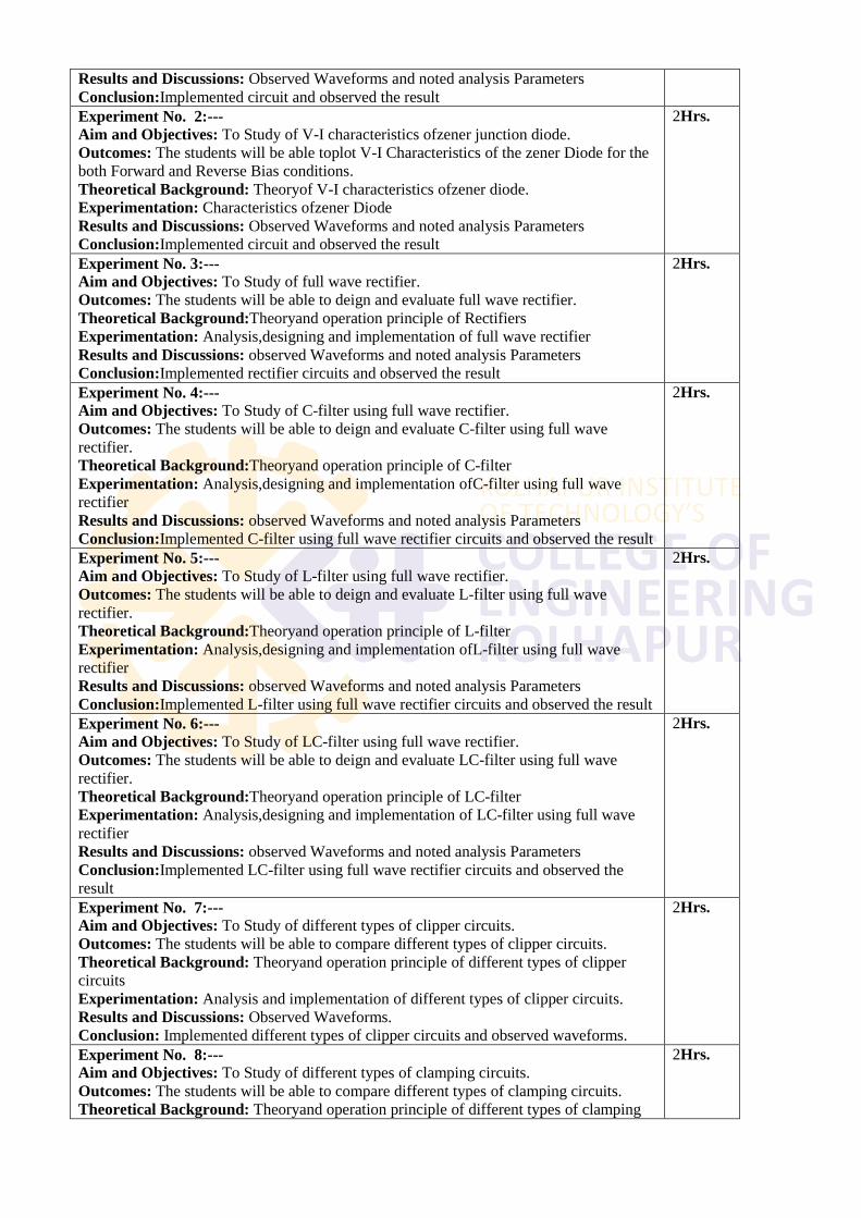
Results and Discussions: Observed Waveforms and noted analysis Parameters
Conclusion:Implemented circuit and observed the result
Experiment No. 2:---
Aim and Objectives: To Study of V-I characteristics ofzener junction diode.
Outcomes: The students will be able toplot V-I Characteristics of the zener Diode for the
both Forward and Reverse Bias conditions.
Theoretical Background: Theoryof V-I characteristics ofzener diode.
Experimentation: Characteristics ofzener Diode
Results and Discussions: Observed Waveforms and noted analysis Parameters
Conclusion:Implemented circuit and observed the result
2Hrs.
Experiment No. 3:---
Aim and Objectives: To Study of full wave rectifier.
Outcomes: The students will be able to deign and evaluate full wave rectifier.
Theoretical Background:Theoryand operation principle of Rectifiers
Experimentation: Analysis,designing and implementation of full wave rectifier
Results and Discussions: observed Waveforms and noted analysis Parameters
Conclusion:Implemented rectifier circuits and observed the result
2Hrs.
Experiment No. 4:---
Aim and Objectives: To Study of C-filter using full wave rectifier.
Outcomes: The students will be able to deign and evaluate C-filter using full wave
rectifier.
Theoretical Background:Theoryand operation principle of C-filter
Experimentation: Analysis,designing and implementation ofC-filter using full wave
rectifier
Results and Discussions: observed Waveforms and noted analysis Parameters
Conclusion:Implemented C-filter using full wave rectifier circuits and observed the result
2Hrs.
Experiment No. 5:---
Aim and Objectives: To Study of L-filter using full wave rectifier.
Outcomes: The students will be able to deign and evaluate L-filter using full wave
rectifier.
Theoretical Background:Theoryand operation principle of L-filter
Experimentation: Analysis,designing and implementation ofL-filter using full wave
rectifier
Results and Discussions: observed Waveforms and noted analysis Parameters
Conclusion:Implemented L-filter using full wave rectifier circuits and observed the result
2Hrs.
Experiment No. 6:---
Aim and Objectives: To Study of LC-filter using full wave rectifier.
Outcomes: The students will be able to deign and evaluate LC-filter using full wave
rectifier.
Theoretical Background:Theoryand operation principle of LC-filter
Experimentation: Analysis,designing and implementation of LC-filter using full wave
rectifier
Results and Discussions: observed Waveforms and noted analysis Parameters
Conclusion:Implemented LC-filter using full wave rectifier circuits and observed the
result
2Hrs.
Experiment No. 7:---
Aim and Objectives: To Study of different types of clipper circuits.
Outcomes: The students will be able to compare different types of clipper circuits.
Theoretical Background: Theoryand operation principle of different types of clipper
circuits
Experimentation: Analysis and implementation of different types of clipper circuits.
Results and Discussions: Observed Waveforms.
Conclusion: Implemented different types of clipper circuits and observed waveforms.
2Hrs.
Experiment No. 8:---
Aim and Objectives: To Study of different types of clamping circuits.
Outcomes: The students will be able to compare different types of clamping circuits.
Theoretical Background: Theoryand operation principle of different types of clamping
2Hrs.
circuits.
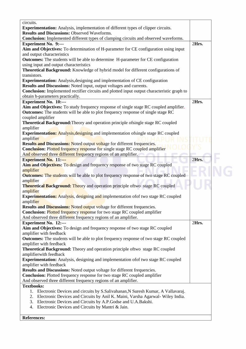
Experimentation: Analysis, implementation of different types of clipper circuits.
Results and Discussions: Observed Waveforms.
Conclusion: Implemented different types of clamping circuits and observed waveforms.
Experiment No. 9:---
Aim and Objectives: To determination of H-parameter for CE configuration using input
and output characteristics
Outcomes: The students will be able to determine H-parameter for CE configuration
using input and output characteristics
Theoretical Background: Knowledge of hybrid model for different configurations of
transistors.
Experimentation: Analysis,designing and implementation of CE configuration
Results and Discussions: Noted input, output voltages and currents.
Conclusion: Implemented rectifier circuits and plotted input output characteristic graph to
obtain h-parameters practically.
2Hrs.
Experiment No. 10:---
Aim and Objectives: To study frequency response of single stage RC coupled amplifier.
Outcomes: The students will be able to plot frequency response of single stage RC
coupled amplifier
Theoretical Background:Theory and operation principle ofsingle stage RC coupled
amplifier
Experimentation: Analysis,designing and implementation ofsingle stage RC coupled
amplifier
Results and Discussions: Noted output voltage for different frequencies.
Conclusion: Plotted frequency response for single stage RC coupled amplifier
And observed three different frequency regions of an amplifier.
2Hrs.
Experiment No. 11:---
Aim and Objectives: To design and frequency response of two stage RC coupled
amplifier
Outcomes: The students will be able to plot frequency response of two stage RC coupled
amplifier
Theoretical Background: Theory and operation principle oftwo stage RC coupled
amplifier
Experimentation: Analysis, designing and implementation ofof two stage RC coupled
amplifier
Results and Discussions: Noted output voltage for different frequencies.
Conclusion: Plotted frequency response for two stage RC coupled amplifier
And observed three different frequency regions of an amplifier.
2Hrs.
Experiment No. 12:---
Aim and Objectives: To design and frequency response of two stage RC coupled
amplifier with feedback
Outcomes: The students will be able to plot frequency response of two stage RC coupled
amplifier with feedback
Theoretical Background: Theory and operation principle oftwo stage RC coupled
amplifierwith feedback
Experimentation: Analysis, designing and implementation ofof two stage RC coupled
amplifier with feedback
Results and Discussions: Noted output voltage for different frequencies.
Conclusion: Plotted frequency response for two stage RC coupled amplifier
And observed three different frequency regions of an amplifier.
2Hrs.
Textbooks:
1. Electronic Devices and circuits by S.Salivahanan,N Suresh Kumar, A Vallavaraj.
2. Electronic Devices and Circuits by Anil K. Maini, Varsha Agarwal- Wiley India.
3. Electronic Devices and Circuits by A.P.Godse and U.A.Bakshi.
4. Electronic Devices and Circuits by Mantri & Jain.
References:
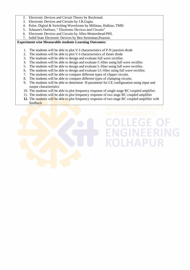
2. Electronic Devices and Circuit Theory by Boylestad.
3. Electronic Devices and Circuits by J.B.Gupta.
4. Pulse, Digital & Switching Waveforms by Millman, Halkias, TMH.
5. Schaum's Outlines, ― Electronic Devices and Circuits‖
6. Electronic Devices and Circuits by Allen Mottershead-PHI.
7. Solid State Electronic Devices by Ben Streetman,Pearson.
Experiment wise Measurable students Learning Outcomes:
1. The students will be able to plot V-I characteristics of P-N junction diode
2. The students will be able to plot V-I characteristics of Zener diode
3. The students will be able to design and evaluate full wave rectifier.
4. The students will be able to design and evaluate C-filter using full wave rectifier.
5. The students will be able to design and evaluate L-filter using full wave rectifier.
6. The students will be able to design and evaluate LC-filter using full wave rectifier.
7. The students will be able to compare different types of clipper circuits.
8. The students will be able to compare different types of clamping circuits.
9. The students will be able to determine H-parameter for CE configuration using input and
output characteristics
10. The students will be able to plot frequency response of single stage RC coupled amplifier.
11. The students will be able to plot frequency response of two stage RC coupled amplifier
12. The students will be able to plot frequency response of two stage RC coupled amplifier with
feedback
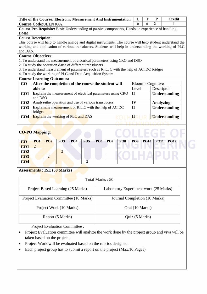
Title of the Course: Electronic Measurement And Instrumentation
Course Code:UELN 0332
L T P Credit
0 0 2 1
Course Pre-Requisite: Basic Understanding of passive components, Hands on experience of handling
DMM
Course Description:
This course will help to handle analog and digital instruments. The course will help student understand the
working and application of various transducers. Students will help in understanding the working of PLC
and DAS.
Course Objectives: 1. To understand the measurement of electrical parameters using CRO and DSO
2. To study the operation &use of different transducers
3. To understand measurement of parameters such as R, L, C with the help of AC, DC bridges
4. To study the working of PLC and Data Acquisition System
Course Learning Outcomes:
CO After the completion of the course the student will
able to
Bloom‘s Cognitive
Level Descriptor
CO1 Explain the measurement of electrical parameters using CRO
and DSO II Understanding
CO2 Analyzethe operation and use of various transducers IV Analyzing
CO3 Explainthe measurement of R,L,C with the help of AC,DC
bridges
II Understanding
CO4 Explain the working of PLC and DAS II Understanding
CO-PO Mapping:
CO PO1 PO2 PO3 PO4 PO5 PO6 PO7 PO8 PO9 PO10 PO11 PO12 l
CO1 2
CO2 2
CO3 2
CO4 2
Assessments : ISE (50 Marks)
Total Marks : 50
Project Based Learning (25 Marks) Laboratory Experiment work (25 Marks)
Project Evaluation Committee (10 Marks) Journal Completion (10 Marks)
Project Work (10 Marks) Oral (10 Marks)
Report (5 Marks) Quiz (5 Marks)
Project Evaluation Committee :
Project Evaluation committee will analyze the work done by the project group and viva will be
taken based on the project.
Project Work will be evaluated based on the rubrics designed.
Each project group has to submit a report on the project (Max.10 Pages)
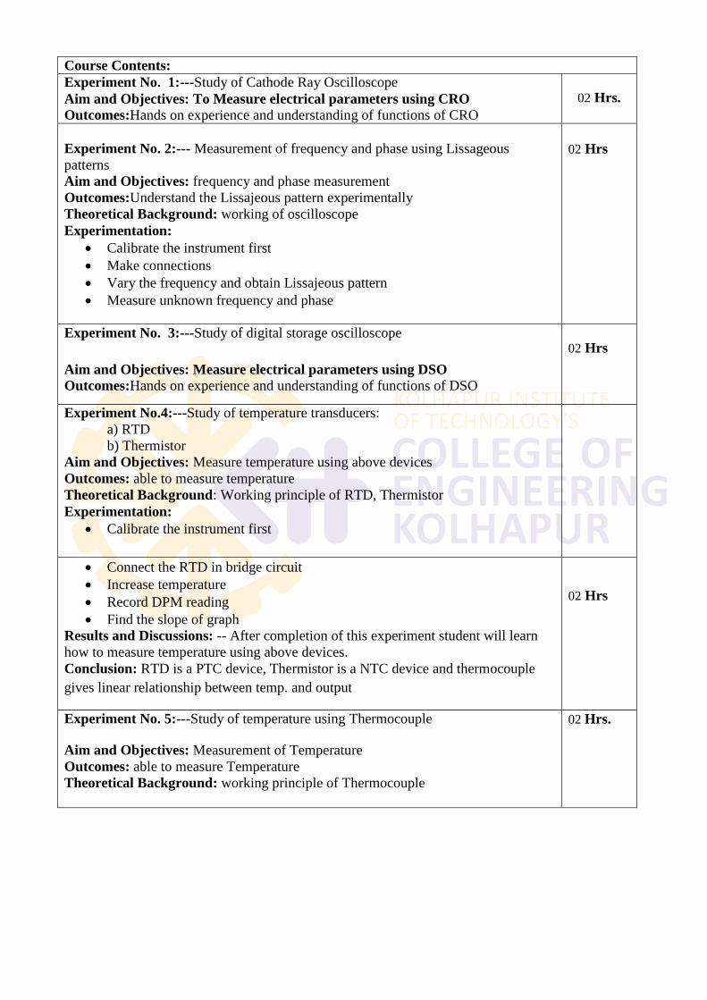
Course Contents:
Experiment No. 1:---Study of Cathode Ray Oscilloscope
Aim and Objectives: To Measure electrical parameters using CRO
Outcomes:Hands on experience and understanding of functions of CRO
02 Hrs.
Experiment No. 2:--- Measurement of frequency and phase using Lissageous
patterns
Aim and Objectives: frequency and phase measurement
Outcomes:Understand the Lissajeous pattern experimentally
Theoretical Background: working of oscilloscope
Experimentation:
Calibrate the instrument first
Make connections
Vary the frequency and obtain Lissajeous pattern
Measure unknown frequency and phase
02 Hrs
Experiment No. 3:---Study of digital storage oscilloscope
Aim and Objectives: Measure electrical parameters using DSO
Outcomes:Hands on experience and understanding of functions of DSO
02 Hrs
Experiment No.4:---Study of temperature transducers:
a) RTD
b) Thermistor
Aim and Objectives: Measure temperature using above devices
Outcomes: able to measure temperature
Theoretical Background: Working principle of RTD, Thermistor
Experimentation:
Calibrate the instrument first
Connect the RTD in bridge circuit
Increase temperature
Record DPM reading
Find the slope of graph
Results and Discussions: -- After completion of this experiment student will learn
how to measure temperature using above devices.
Conclusion: RTD is a PTC device, Thermistor is a NTC device and thermocouple
gives linear relationship between temp. and output
02 Hrs
Experiment No. 5:---Study of temperature using Thermocouple
Aim and Objectives: Measurement of Temperature
Outcomes: able to measure Temperature
Theoretical Background: working principle of Thermocouple
02 Hrs.
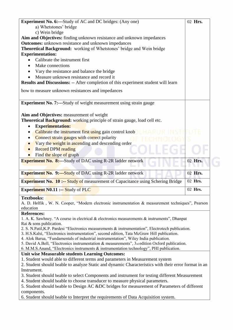
Experiment No. 6:---Study of AC and DC bridges: (Any one)
a) Whetstones‘ bridge
c) Wein bridge
Aim and Objectives: finding unknown resistance and unknown impedances
Outcomes: unknown resistance and unknown impedances
Theoretical Background: working of Whetstones‘ bridge and Wein bridge
Experimentation:
Calibrate the instrument first
Make connections
Vary the resistance and balance the bridge
Measure unknown resistance and record it
Results and Discussions: -- After completion of this experiment student will learn
how to measure unknown resistances and impedances
02 Hrs.
Experiment No. 7:---Study of weight measurement using strain gauge
Aim and Objectives: measurement of weight
Theoretical Background: working principle of strain gauge, load cell etc.
Experimentation:
Calibrate the instrument first using gain control knob
Connect strain gauges with correct polarity
Vary the weight in ascending and descending order
Record DPM reading
Find the slope of graph
Experiment No. 8:---Study of DAC using R-2R ladder network 02 Hrs.
Experiment No. 9:---Study of DAC using R-2R ladder network 02 Hrs.
Experiment No. 10 :-- Study of measurement of Capacitance using Schering Bridge 02 Hrs.
Experiment N0.11 :-- Study of PLC 02 Hrs.
Textbooks: A. D. Helfik , W. N. Cooper, ―Modern electronic instrumentation & measurement techniques‖, Pearson
education
References: 1. A. K. Sawhney. ―A course in electrical & electronics measurements & instruments‖, Dhanpat
Rai & sons publication.
2. S. N.Patil,K.P. Pardesi ―Electronics measurements & instrumentation‖, Electrotech publication.
3. H.S.Kalsi, ―Electronics instrumentation‖, second edition, Tata McGraw Hill publication.
4. Alok Barua, ―Fundamentals of industrial instrumentation‖, Wiley India publication.
5. David A.Bell, ―Electronics instrumentation & measurements‖, 3rd edition Oxford publication.
6. M.M.S.Anand, ―Electronics instruments & instrumentation technology‖, PHI publication.
Unit wise Measurable students Learning Outcomes:
1. Student would able to different terms and parameters in Measurement system
2. Student should beable to analyze Static and dynamic Characteristics with their error format in an
Instrument.
3. Student should beable to select Components and instrument for testing different Measurement
4. Student should beable to choose transducer to measure physical parameters.
5. Student should beable to Design AC &DC bridges for measurement of Parameters of different
components.
6. Student should beable to Interpret the requirements of Data Acquisition system.
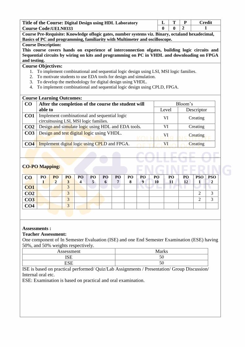
Title of the Course: Digital Design using HDL Laboratory
Course Code:UELN0333
L T P Credit
0 0 2 1
Course Pre-Requisite: Knowledge oflogic gates, number systems viz. Binary, octaland hexadecimal,
Basics of PC and programming, familiarity with Multimeter and oscilloscope.
Course Description:
This course covers hands on experience of interconnection ofgates, building logic circuits and
Sequential circuits by wiring on kits and programming on PC in VHDL and downloading on FPGA
and testing.
Course Objectives: 1. To implement combinational and sequential logic design using LSI, MSI logic families.
2. To motivate students to use EDA tools for design and simulation.
3. To develop the methodology for digital design using VHDL.
4. To implement combinational and sequential logic design using CPLD, FPGA.
Course Learning Outcomes:
CO After the completion of the course the student will
able to
Bloom‘s
Level Descriptor
CO1 Implement combinational and sequential logic
circuitsusing LSI, MSI logic families. VI Creating
CO2 Design and simulate logic using HDL and EDA tools. VI Creating
CO3 Design and test digital logic using VHDL. VI Creating
CO4 Implement digital logic using CPLD and FPGA. VI Creating
CO-PO Mapping:
CO PO
1
PO
2
PO
3
PO
4
PO
5
PO
6
PO
7
PO
8
PO
9
PO
10
PO
11
PO
12
PSO
1
PSO
2
CO1 3
CO2 3 2 3
CO3 3 2 3
CO4 3
Assessments :
Teacher Assessment:
One component of In Semester Evaluation (ISE) and one End Semester Examination (ESE) having
50%, and 50% weights respectively.
Assessment Marks
ISE 50
ESE 50
ISE is based on practical performed/ Quiz/Lab Assignments / Presentation/ Group Discussion/
Internal oral etc.
ESE: Examination is based on practical and oral examination.
Course Contents:
Note: Minimum of 15 experiments to be conducted on Digital IC Trainer and
Programming in VHDL in different modelling styles in VHDL (Dataflow,
Behavioural and Structural Modelling).
Experiments should be on the following topics.
Design of Half and Full Adders, Subtractors, Serial and Parallel Adders, BCD Adder,
ALU, S-R, JK and Master-Slave JK FF, Edge triggered FF, Ripple and Synchronous
counters, Shift registers, Finite state machines, Design of synchronous FSM, Pseudo
Random Binary Sequence generator, in different modelling styles in VHDL, Data types
and objects, Dataflow, Behavioural and Structural Modelling
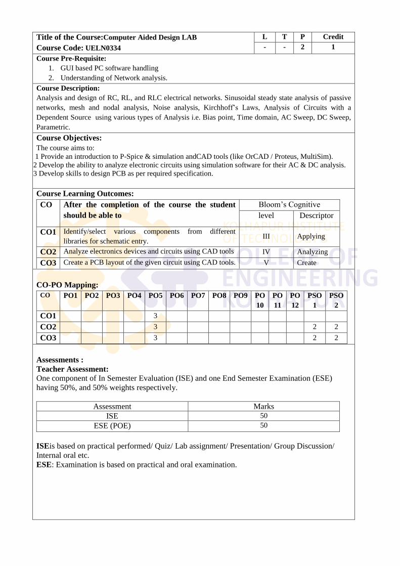
Title of the Course:Computer Aided Design LAB
Course Code: UELN0334
L T P Credit
- - 2 1
Course Pre-Requisite:
1. GUI based PC software handling
2. Understanding of Network analysis.
Course Description:
Analysis and design of RC, RL, and RLC electrical networks. Sinusoidal steady state analysis of passive
networks, mesh and nodal analysis, Noise analysis, Kirchhoff‘s Laws, Analysis of Circuits with a
Dependent Source using various types of Analysis i.e. Bias point, Time domain, AC Sweep, DC Sweep,
Parametric.
Course Objectives:
The course aims to:
1 Provide an introduction to P-Spice & simulation andCAD tools (like OrCAD / Proteus, MultiSim).
2 Develop the ability to analyze electronic circuits using simulation software for their AC & DC analysis.
3 Develop skills to design PCB as per required specification.
Course Learning Outcomes:
CO After the completion of the course the student
should be able to
Bloom‘s Cognitive
level Descriptor
CO1 Identify/select various components from different
libraries for schematic entry. III Applying
CO2 Analyze electronics devices and circuits using CAD tools IV Analyzing
CO3 Create a PCB layout of the given circuit using CAD tools. V Create
CO-PO Mapping:
CO PO1 PO2 PO3 PO4 PO5 PO6 PO7 PO8 PO9 PO
10
PO
11
PO
12
PSO
1
PSO
2
CO1 3
CO2 3 2 2
CO3 3 2 2
Assessments :
Teacher Assessment:
One component of In Semester Evaluation (ISE) and one End Semester Examination (ESE)
having 50%, and 50% weights respectively.
Assessment Marks
ISE 50
ESE (POE) 50
ISEis based on practical performed/ Quiz/ Lab assignment/ Presentation/ Group Discussion/
Internal oral etc.
ESE: Examination is based on practical and oral examination.
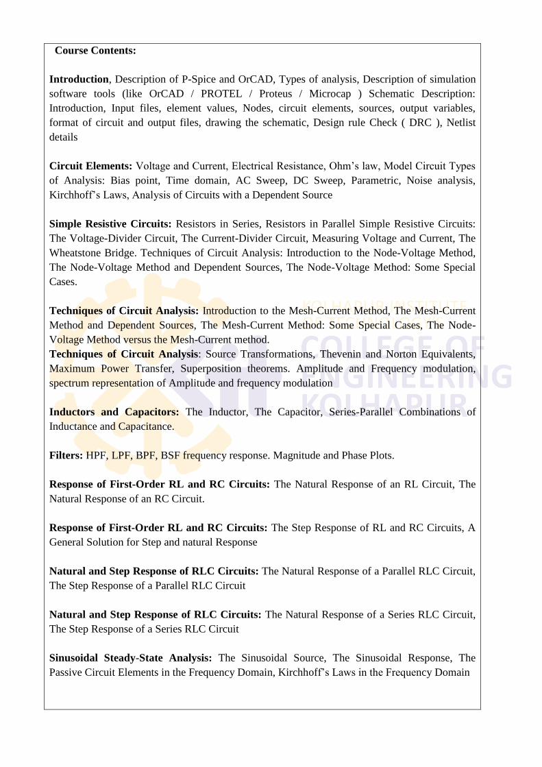
Course Contents:
Introduction, Description of P-Spice and OrCAD, Types of analysis, Description of simulation
software tools (like OrCAD / PROTEL / Proteus / Microcap ) Schematic Description:
Introduction, Input files, element values, Nodes, circuit elements, sources, output variables,
format of circuit and output files, drawing the schematic, Design rule Check ( DRC ), Netlist
details
Circuit Elements: Voltage and Current, Electrical Resistance, Ohm‘s law, Model Circuit Types
of Analysis: Bias point, Time domain, AC Sweep, DC Sweep, Parametric, Noise analysis,
Kirchhoff‘s Laws, Analysis of Circuits with a Dependent Source
Simple Resistive Circuits: Resistors in Series, Resistors in Parallel Simple Resistive Circuits:
The Voltage-Divider Circuit, The Current-Divider Circuit, Measuring Voltage and Current, The
Wheatstone Bridge. Techniques of Circuit Analysis: Introduction to the Node-Voltage Method,
The Node-Voltage Method and Dependent Sources, The Node-Voltage Method: Some Special
Cases.
Techniques of Circuit Analysis: Introduction to the Mesh-Current Method, The Mesh-Current
Method and Dependent Sources, The Mesh-Current Method: Some Special Cases, The Node-
Voltage Method versus the Mesh-Current method.
Techniques of Circuit Analysis: Source Transformations, Thevenin and Norton Equivalents,
Maximum Power Transfer, Superposition theorems. Amplitude and Frequency modulation,
spectrum representation of Amplitude and frequency modulation
Inductors and Capacitors: The Inductor, The Capacitor, Series-Parallel Combinations of
Inductance and Capacitance.
Filters: HPF, LPF, BPF, BSF frequency response. Magnitude and Phase Plots.
Response of First-Order RL and RC Circuits: The Natural Response of an RL Circuit, The
Natural Response of an RC Circuit.
Response of First-Order RL and RC Circuits: The Step Response of RL and RC Circuits, A
General Solution for Step and natural Response
Natural and Step Response of RLC Circuits: The Natural Response of a Parallel RLC Circuit,
The Step Response of a Parallel RLC Circuit
Natural and Step Response of RLC Circuits: The Natural Response of a Series RLC Circuit,
The Step Response of a Series RLC Circuit
Sinusoidal Steady-State Analysis: The Sinusoidal Source, The Sinusoidal Response, The
Passive Circuit Elements in the Frequency Domain, Kirchhoff‘s Laws in the Frequency Domain
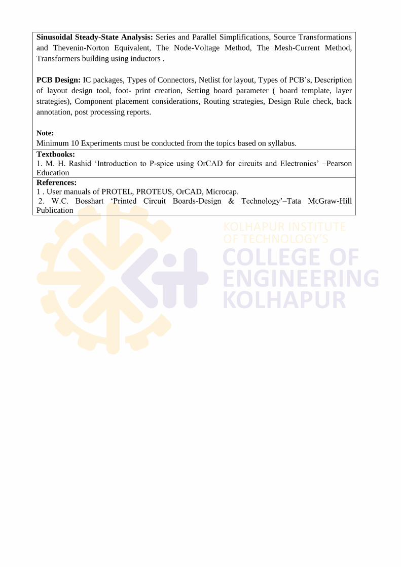
Sinusoidal Steady-State Analysis: Series and Parallel Simplifications, Source Transformations
and Thevenin-Norton Equivalent, The Node-Voltage Method, The Mesh-Current Method,
Transformers building using inductors .
PCB Design: IC packages, Types of Connectors, Netlist for layout, Types of PCB‘s, Description
of layout design tool, foot- print creation, Setting board parameter ( board template, layer
strategies), Component placement considerations, Routing strategies, Design Rule check, back
annotation, post processing reports.
Note:
Minimum 10 Experiments must be conducted from the topics based on syllabus.
Textbooks: 1. M. H. Rashid ‗Introduction to P-spice using OrCAD for circuits and Electronics‘ –Pearson
Education
References: 1 . User manuals of PROTEL, PROTEUS, OrCAD, Microcap.
2. W.C. Bosshart ‗Printed Circuit Boards-Design & Technology‘–Tata McGraw-Hill
Publication
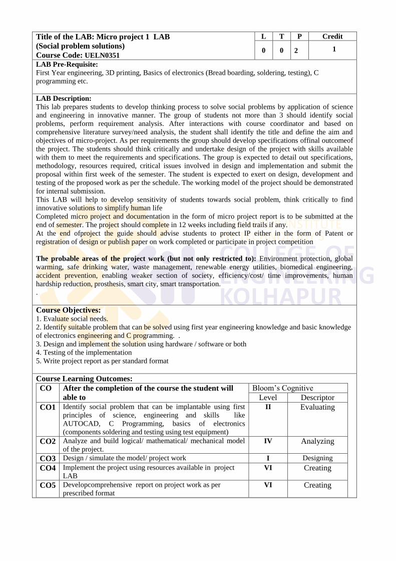
Title of the LAB: Micro project 1 LAB
(Social problem solutions)
Course Code: UELN0351
L T P Credit
0 0
2
1
LAB Pre-Requisite: First Year engineering, 3D printing, Basics of electronics (Bread boarding, soldering, testing), C
programming etc.
LAB Description:
This lab prepares students to develop thinking process to solve social problems by application of science
and engineering in innovative manner. The group of students not more than 3 should identify social
problems, perform requirement analysis. After interactions with course coordinator and based on
comprehensive literature survey/need analysis, the student shall identify the title and define the aim and
objectives of micro-project. As per requirements the group should develop specifications offinal outcomeof
the project. The students should think critically and undertake design of the project with skills available
with them to meet the requirements and specifications. The group is expected to detail out specifications,
methodology, resources required, critical issues involved in design and implementation and submit the
proposal within first week of the semester. The student is expected to exert on design, development and
testing of the proposed work as per the schedule. The working model of the project should be demonstrated
for internal submission.
This LAB will help to develop sensitivity of students towards social problem, think critically to find
innovative solutions to simplify human life
Completed micro project and documentation in the form of micro project report is to be submitted at the
end of semester. The project should complete in 12 weeks including field trails if any.
At the end ofproject the guide should advise students to protect IP either in the form of Patent or
registration of design or publish paper on work completed or participate in project competition
The probable areas of the project work (but not only restricted to): Environment protection, global
warming, safe drinking water, waste management, renewable energy utilities, biomedical engineering,
accident prevention, enabling weaker section of society, efficiency/cost/ time improvements, human
hardship reduction, prosthesis, smart city, smart transportation.
.
Course Objectives: 1. Evaluate social needs.
2. Identify suitable problem that can be solved using first year engineering knowledge and basic knowledge
of electronics engineering and C programming. .
3. Design and implement the solution using hardware / software or both
4. Testing of the implementation
5. Write project report as per standard format
Course Learning Outcomes:
CO After the completion of the course the student will
able to
Bloom‘s Cognitive
Level Descriptor
CO1 Identify social problem that can be implantable using first
principles of science, engineering and skills like
AUTOCAD, C Programming, basics of electronics
(components soldering and testing using test equipment)
II Evaluating
CO2 Analyze and build logical/ mathematical/ mechanical model
of the project. IV Analyzing
CO3 Design / simulate the model/ project work I Designing
CO4 Implement the project using resources available in project
LAB VI Creating
CO5 Developcomprehensive report on project work as per
prescribed format VI Creating
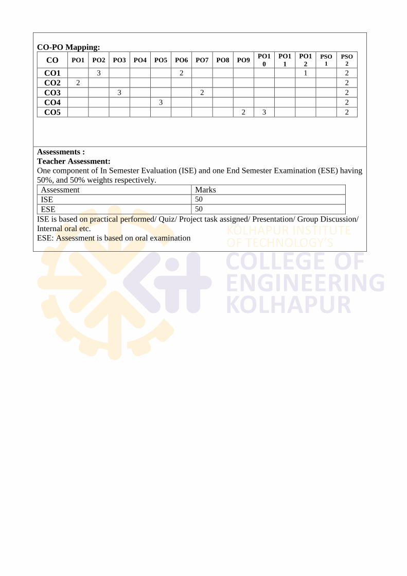
CO-PO Mapping:
CO PO1 PO2 PO3 PO4 PO5 PO6 PO7 PO8 PO9 PO1
0
PO1
1
PO1
2
PSO
1
PSO
2
CO1 3 2 1 2
CO2 2 2
CO3 3 2 2
CO4 3 2
CO5 2 3 2
Assessments :
Teacher Assessment:
One component of In Semester Evaluation (ISE) and one End Semester Examination (ESE) having
50%, and 50% weights respectively.
Assessment Marks
ISE 50
ESE 50
ISE is based on practical performed/ Quiz/ Project task assigned/ Presentation/ Group Discussion/
Internal oral etc.
ESE: Assessment is based on oral examination
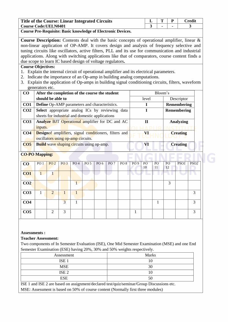
Title of the Course: Linear Integrated Circuits Course Code:UELN0401
L T P Credit
3 - - 3
Course Pre-Requisite: Basic knowledge of Electronic Devices.
Course Description: Contents deal with the basic concepts of operational amplifier, linear &
non-linear application of OP-AMP. It covers design and analysis of frequency selective and
tuning circuits like oscillators, active filters, PLL and its use for communication and industrial
applications. Along with switching applications like that of comparators, course content finds a
due scope to learn IC based design of voltage regulators.
Course Objectives:
1. Explain the internal circuit of operational amplifier and its electrical parameters.
2. Indicate the importance of an Op-amp in building analog computations.
3. Explain the application of Op-amps in building signal conditioning circuits, filters, waveform
generators etc.
CO After the completion of the course the student
should be able to
Bloom‘s
level Descriptor
CO1 Define Op-AMP parameters and characteristics. I Remembering
CO2 Select appropriate analog ICs by reviewing data
sheets for industrial and domestic applications
I Remembering
CO3 Analyze BJT Operational amplifier for DC and AC
inputs.
II Analyzing
CO4 Designof amplifiers, signal conditioners, filters and
oscillators using op-amp circuits.
VI Creating
CO5 Build wave shaping circuits using op-amp. VI Creating
CO-PO Mapping:
CO PO 1 PO 2 PO 3 PO 4 PO 5 PO 6 PO 7 PO 8 PO 9 PO
10
PO
11
PO
12
PSO1 PSO2
CO1 1 1
CO2 1 3
CO3 1 2 1 1 3
CO4 3 1 1 3
CO5 2 3 1 3
Assessments :
Teacher Assessment:
Two components of In Semester Evaluation (ISE), One Mid Semester Examination (MSE) and one End
Semester Examination (ESE) having 20%, 30% and 50% weights respectively.
Assessment Marks
ISE 1 10
MSE 30
ISE 2 10
ESE 50
ISE 1 and ISE 2 are based on assignment/declared test/quiz/seminar/Group Discussions etc.
MSE: Assessment is based on 50% of course content (Normally first three modules)
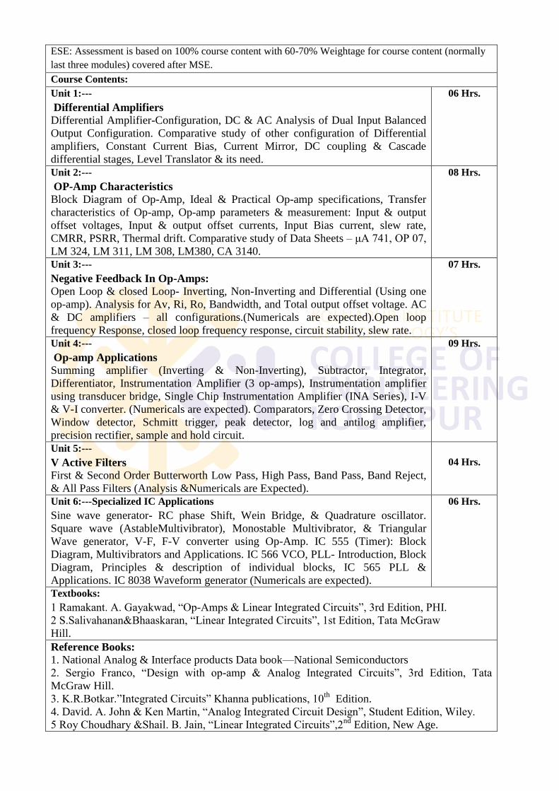
ESE: Assessment is based on 100% course content with 60-70% Weightage for course content (normally
last three modules) covered after MSE.
Course Contents:
Unit 1:---
Differential Amplifiers
Differential Amplifier-Configuration, DC & AC Analysis of Dual Input Balanced
Output Configuration. Comparative study of other configuration of Differential
amplifiers, Constant Current Bias, Current Mirror, DC coupling & Cascade
differential stages, Level Translator & its need.
06 Hrs.
Unit 2:---
OP-Amp Characteristics
Block Diagram of Op-Amp, Ideal & Practical Op-amp specifications, Transfer
characteristics of Op-amp, Op-amp parameters & measurement: Input & output
offset voltages, Input & output offset currents, Input Bias current, slew rate,
CMRR, PSRR, Thermal drift. Comparative study of Data Sheets – μA 741, OP 07,
LM 324, LM 311, LM 308, LM380, CA 3140.
08 Hrs.
Unit 3:---
Negative Feedback In Op-Amps:
Open Loop & closed Loop- Inverting, Non-Inverting and Differential (Using one
op-amp). Analysis for Av, Ri, Ro, Bandwidth, and Total output offset voltage. AC
& DC amplifiers – all configurations.(Numericals are expected).Open loop
frequency Response, closed loop frequency response, circuit stability, slew rate.
07 Hrs.
Unit 4:---
Op-amp Applications
Summing amplifier (Inverting & Non-Inverting), Subtractor, Integrator,
Differentiator, Instrumentation Amplifier (3 op-amps), Instrumentation amplifier
using transducer bridge, Single Chip Instrumentation Amplifier (INA Series), I-V
& V-I converter. (Numericals are expected). Comparators, Zero Crossing Detector,
Window detector, Schmitt trigger, peak detector, log and antilog amplifier,
precision rectifier, sample and hold circuit.
09 Hrs.
Unit 5:---
V Active Filters
First & Second Order Butterworth Low Pass, High Pass, Band Pass, Band Reject,
& All Pass Filters (Analysis &Numericals are Expected).
04 Hrs.
Unit 6:---Specialized IC Applications
Sine wave generator- RC phase Shift, Wein Bridge, & Quadrature oscillator.
Square wave (AstableMultivibrator), Monostable Multivibrator, & Triangular
Wave generator, V-F, F-V converter using Op-Amp. IC 555 (Timer): Block
Diagram, Multivibrators and Applications. IC 566 VCO, PLL- Introduction, Block
Diagram, Principles & description of individual blocks, IC 565 PLL &
Applications. IC 8038 Waveform generator (Numericals are expected).
06 Hrs.
Textbooks:
1 Ramakant. A. Gayakwad, ―Op-Amps & Linear Integrated Circuits‖, 3rd Edition, PHI.
2 S.Salivahanan&Bhaaskaran, ―Linear Integrated Circuits‖, 1st Edition, Tata McGraw
Hill.
Reference Books:
1. National Analog & Interface products Data book—National Semiconductors
2. Sergio Franco, ―Design with op-amp & Analog Integrated Circuits‖, 3rd Edition, Tata
McGraw Hill.
3. K.R.Botkar.‖Integrated Circuits‖ Khanna publications, 10th
Edition.
4. David. A. John & Ken Martin, ―Analog Integrated Circuit Design‖, Student Edition, Wiley.
5 Roy Choudhary &Shail. B. Jain, ―Linear Integrated Circuits‖,2nd
Edition, New Age.
Unit wise Measurable Students Learning Outcomes:
1. Students should be able to have a firm grasp of basic principles of many operational
amplifiers.
2. Student should beable to differentiate between different types of op-amps as well as able
to choose proper op-amp as per application requirement.
3. Student should beable to analyze and design op-amp parameter compensating networks.
4. Student should be able to find out circuit stability from frequency response as well as
frequency dependent parameters.
5. Students should be able to analyze and design different op-amp linear and non linear
applications.
6. Student should be able to analysis of different types of Active filters, different types of
monolithic ICs and its applications.
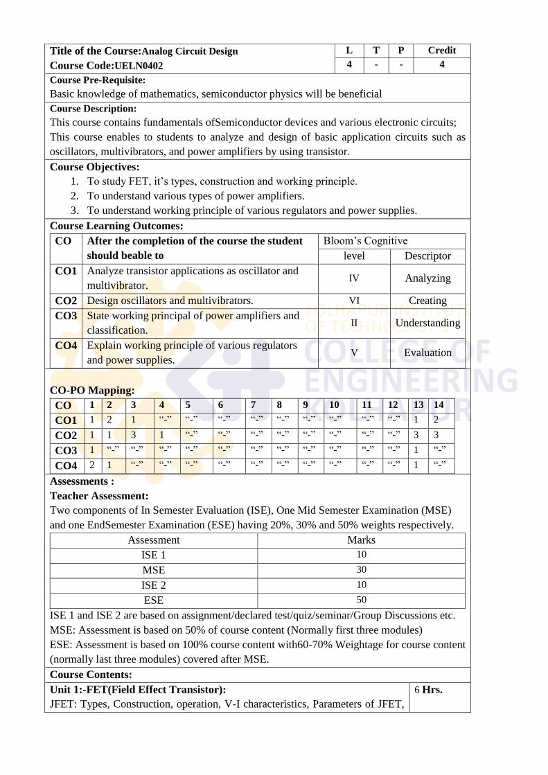
Title of the Course:Analog Circuit Design
Course Code:UELN0402
L T P Credit
4 - - 4
Course Pre-Requisite:
Basic knowledge of mathematics, semiconductor physics will be beneficial
Course Description:
This course contains fundamentals ofSemiconductor devices and various electronic circuits;
This course enables to students to analyze and design of basic application circuits such as
oscillators, multivibrators, and power amplifiers by using transistor.
Course Objectives:
1. To study FET, it‘s types, construction and working principle.
2. To understand various types of power amplifiers.
3. To understand working principle of various regulators and power supplies.
Course Learning Outcomes:
CO After the completion of the course the student
should beable to
Bloom‘s Cognitive
level Descriptor
CO1 Analyze transistor applications as oscillator and
multivibrator. IV Analyzing
CO2 Design oscillators and multivibrators. VI Creating
CO3 State working principal of power amplifiers and
classification. II Understanding
CO4 Explain working principle of various regulators
and power supplies. V Evaluation
CO-PO Mapping:
CO 1 2 3 4 5 6 7 8 9 10 11 12 13 14
CO1 1 2 1 ―-‖ ―-‖ ―-‖ ―-‖ ―-‖ ―-‖ ―-‖ ―-‖ ―-‖ 1 2
CO2 1 1 3 1 ―-‖ ―-‖ ―-‖ ―-‖ ―-‖ ―-‖ ―-‖ ―-‖ 3 3
CO3 1 ―-‖ ―-‖ ―-‖ ―-‖ ―-‖ ―-‖ ―-‖ ―-‖ ―-‖ ―-‖ ―-‖ 1 ―-‖
CO4 2 1 ―-‖ ―-‖ ―-‖ ―-‖ ―-‖ ―-‖ ―-‖ ―-‖ ―-‖ ―-‖ 1 ―-‖
Assessments :
Teacher Assessment:
Two components of In Semester Evaluation (ISE), One Mid Semester Examination (MSE)
and one EndSemester Examination (ESE) having 20%, 30% and 50% weights respectively.
Assessment Marks
ISE 1 10
MSE 30
ISE 2 10
ESE 50
ISE 1 and ISE 2 are based on assignment/declared test/quiz/seminar/Group Discussions etc.
MSE: Assessment is based on 50% of course content (Normally first three modules)
ESE: Assessment is based on 100% course content with60-70% Weightage for course content
(normally last three modules) covered after MSE.
Course Contents:
Unit 1:-FET(Field Effect Transistor):
JFET: Types, Construction, operation, V-I characteristics, Parameters of JFET,
6 Hrs.
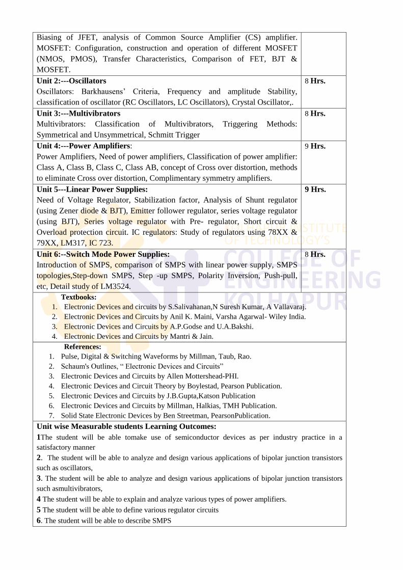
Biasing of JFET, analysis of Common Source Amplifier (CS) amplifier.
MOSFET: Configuration, construction and operation of different MOSFET
(NMOS, PMOS), Transfer Characteristics, Comparison of FET, BJT &
MOSFET.
Unit 2:---Oscillators
Oscillators: Barkhausens‘ Criteria, Frequency and amplitude Stability,
classification of oscillator (RC Oscillators, LC Oscillators), Crystal Oscillator,.
8 Hrs.
Unit 3:---Multivibrators
Multivibrators: Classification of Multivibrators, Triggering Methods:
Symmetrical and Unsymmetrical, Schmitt Trigger
8 Hrs.
Unit 4:---Power Amplifiers:
Power Amplifiers, Need of power amplifiers, Classification of power amplifier:
Class A, Class B, Class C, Class AB, concept of Cross over distortion, methods
to eliminate Cross over distortion, Complimentary symmetry amplifiers.
9 Hrs.
Unit 5---Linear Power Supplies:
Need of Voltage Regulator, Stabilization factor, Analysis of Shunt regulator
(using Zener diode & BJT), Emitter follower regulator, series voltage regulator
(using BJT), Series voltage regulator with Pre- regulator, Short circuit &
Overload protection circuit. IC regulators: Study of regulators using 78XX &
79XX, LM317, IC 723.
9 Hrs.
Unit 6:--Switch Mode Power Supplies:
Introduction of SMPS, comparison of SMPS with linear power supply, SMPS
topologies,Step-down SMPS, Step -up SMPS, Polarity Inversion, Push-pull,
etc, Detail study of LM3524.
8 Hrs.
Textbooks:
1. Electronic Devices and circuits by S.Salivahanan,N Suresh Kumar, A Vallavaraj.
2. Electronic Devices and Circuits by Anil K. Maini, Varsha Agarwal- Wiley India.
3. Electronic Devices and Circuits by A.P.Godse and U.A.Bakshi.
4. Electronic Devices and Circuits by Mantri & Jain.
References:
1. Pulse, Digital & Switching Waveforms by Millman, Taub, Rao.
2. Schaum's Outlines, ― Electronic Devices and Circuits‖
3. Electronic Devices and Circuits by Allen Mottershead-PHI.
4. Electronic Devices and Circuit Theory by Boylestad, Pearson Publication.
5. Electronic Devices and Circuits by J.B.Gupta,Katson Publication
6. Electronic Devices and Circuits by Millman, Halkias, TMH Publication.
7. Solid State Electronic Devices by Ben Streetman, PearsonPublication.
Unit wise Measurable students Learning Outcomes:
1The student will be able tomake use of semiconductor devices as per industry practice in a
satisfactory manner
2. The student will be able to analyze and design various applications of bipolar junction transistors
such as oscillators,
3. The student will be able to analyze and design various applications of bipolar junction transistors
such asmultivibrators,
4 The student will be able to explain and analyze various types of power amplifiers.
5 The student will be able to define various regulator circuits
6. The student will be able to describe SMPS
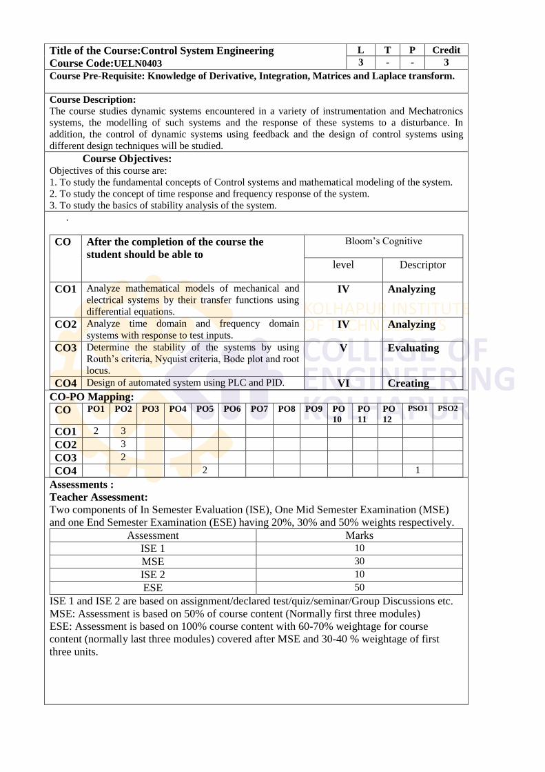
Title of the Course:Control System Engineering Course Code:UELN0403
L T P Credit
3 - - 3
Course Pre-Requisite: Knowledge of Derivative, Integration, Matrices and Laplace transform.
Course Description:
The course studies dynamic systems encountered in a variety of instrumentation and Mechatronics
systems, the modelling of such systems and the response of these systems to a disturbance. In
addition, the control of dynamic systems using feedback and the design of control systems using
different design techniques will be studied.
Course Objectives: Objectives of this course are:
1. To study the fundamental concepts of Control systems and mathematical modeling of the system.
2. To study the concept of time response and frequency response of the system.
3. To study the basics of stability analysis of the system.
.
CO After the completion of the course the
student should be able to
Bloom‘s Cognitive
level Descriptor
CO1 Analyze mathematical models of mechanical and
electrical systems by their transfer functions using
differential equations.
IV Analyzing
CO2 Analyze time domain and frequency domain
systems with response to test inputs. IV Analyzing
CO3 Determine the stability of the systems by using
Routh‘s criteria, Nyquist criteria, Bode plot and root
locus.
V Evaluating
CO4 Design of automated system using PLC and PID. VI Creating
CO-PO Mapping:
CO PO1 PO2 PO3 PO4 PO5 PO6 PO7 PO8 PO9 PO
10
PO
11
PO
12
PSO1 PSO2
CO1 2 3
CO2 3
CO3 2
CO4 2 1
Assessments :
Teacher Assessment:
Two components of In Semester Evaluation (ISE), One Mid Semester Examination (MSE)
and one End Semester Examination (ESE) having 20%, 30% and 50% weights respectively.
Assessment Marks
ISE 1 10
MSE 30
ISE 2 10
ESE 50
ISE 1 and ISE 2 are based on assignment/declared test/quiz/seminar/Group Discussions etc.
MSE: Assessment is based on 50% of course content (Normally first three modules)
ESE: Assessment is based on 100% course content with 60-70% weightage for course
content (normally last three modules) covered after MSE and 30-40 % weightage of first
three units.
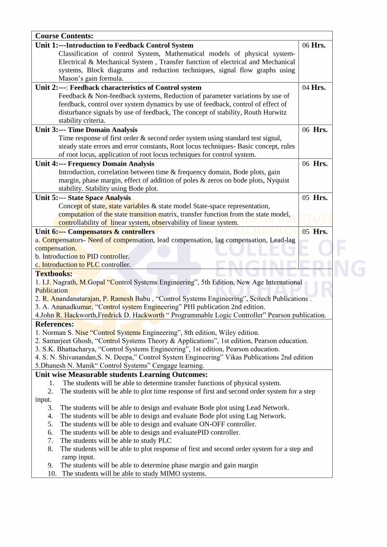
Course Contents:
Unit 1:---Introduction to Feedback Control System Classification of control System, Mathematical models of physical system-
Electrical & Mechanical System , Transfer function of electrical and Mechanical
systems, Block diagrams and reduction techniques, signal flow graphs using
Mason‘s gain formula.
06 Hrs.
Unit 2:---: Feedback characteristics of Control system
Feedback & Non-feedback systems, Reduction of parameter variations by use of
feedback, control over system dynamics by use of feedback, control of effect of
disturbance signals by use of feedback, The concept of stability, Routh Hurwitz
stability criteria.
04 Hrs.
Unit 3:--- Time Domain Analysis
Time response of first order & second order system using standard test signal,
steady state errors and error constants, Root locus techniques- Basic concept, rules
of root locus, application of root locus techniques for control system.
06 Hrs.
Unit 4:--- Frequency Domain Analysis
Introduction, correlation between time & frequency domain, Bode plots, gain
margin, phase margin, effect of addition of poles & zeros on bode plots, Nyquist
stability. Stability using Bode plot.
06 Hrs.
Unit 5:--- State Space Analysis Concept of state, state variables & state model State-space representation,
computation of the state transition matrix, transfer function from the state model,
controllability of linear system, observability of linear system.
05 Hrs.
Unit 6:--- Compensators & controllers
a. Compensators- Need of compensation, lead compensation, lag compensation, Lead-lag
compensation.
b. Introduction to PID controller.
c. Introduction to PLC controller.
05 Hrs.
Textbooks: 1. I.J. Nagrath, M.Gopal ―Control Systems Engineering‖, 5th Edition, New Age International
Publication
2. R. Anandanatarajan, P. Ramesh Babu , ―Control Systems Engineering‖, Scitech Publications .
3. A. Ananadkumar, ―Control system Engineering‖ PHI publication 2nd edition.
4.John R. Hackworth,Fredrick D. Hackworth ― Programmable Logic Controller‖ Pearson publication.
References: 1. Norman S. Nise ―Control Systems Engineering‖, 8th edition, Wiley edition.
2. Samarjeet Ghosh, ―Control Systems Theory & Applications‖, 1st edition, Pearson education.
3. S.K. Bhattacharya, ―Control Systems Engineering‖, 1st edition, Pearson education.
4. S. N. Shivanandan,S. N. Deepa,‖ Control System Engineering‖ Vikas Publications 2nd edition
5.Dhanesh N. Manik― Control Systems‖ Cengage learning.
Unit wise Measurable students Learning Outcomes: 1. The students will be able to determine transfer functions of physical system.
2. The students will be able to plot time response of first and second order system for a step
input.
3. The students will be able to design and evaluate Bode plot using Lead Network.
4. The students will be able to design and evaluate Bode plot using Lag Network.
5. The students will be able to design and evaluate ON-OFF controller.
6. The students will be able to design and evaluatePID controller.
7. The students will be able to study PLC
8. The students will be able to plot response of first and second order system for a step and
ramp input.
9. The students will be able to determine phase margin and gain margin
10. The students will be able to study MIMO systems.
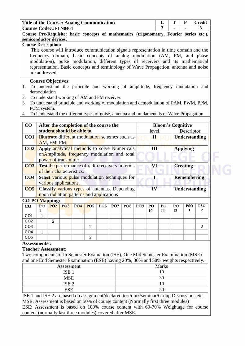
Title of the Course: Analog Communication
Course Code:UELN0404
L T P Credit
3 - - 3
Course Pre-Requisite: basic concepts of mathematics (trigonometry, Fourier series etc.),
semiconductor devices.
Course Description:
This course will introduce communication signals representation in time domain and the
frequency domain, basic concepts of analog modulation (AM, FM, and phase
modulation), pulse modulation, different types of receivers and its mathematical
representation. Basic concepts and terminology of Wave Propagation, antenna and noise
are addressed.
Course Objectives: 1. To understand the principle and working of amplitude, frequency modulation and
demodulation
2. To understand working of AM and FM receiver.
3. To understand principle and working of modulation and demodulation of PAM, PWM, PPM,
PCM system.
4. To Understand the different types of noise, antenna and fundamentals of Wave Propagation
CO After the completion of the course the
student should be able to
Bloom’s Cognitive
level Descriptor
CO1 Illustrate different modulation schemes such as
AM, FM, PM. II Understanding
CO2 Apply analytical methods to solve Numericals
onAmplitude, frequency modulation and total
power of transmitter.
III Applying
CO3 Test the performance of radio receivers in terms
of their characteristics. VI Creating
CO4 Select various pulse modulation techniques for
various applications. I Remembering
CO5 Classify various types of antennas. Depending
upon radiation patterns and applications IV Understanding
CO-PO Mapping:
CO PO
1
PO2 PO3 PO4 PO5 PO6 PO7 PO8 PO9 PO
10
PO
11
PO
12
PSO
1
PSO
2
CO1 1 CO2 2 CO3 2 2 CO4 1 CO5 2
Assessments :
Teacher Assessment:
Two components of In Semester Evaluation (ISE), One Mid Semester Examination (MSE)
and one End Semester Examination (ESE) having 20%, 30% and 50% weights respectively.
Assessment Marks
ISE 1 10
MSE 30
ISE 2 10
ESE 50
ISE 1 and ISE 2 are based on assignment/declared test/quiz/seminar/Group Discussions etc.
MSE: Assessment is based on 50% of course content (Normally first three modules)
ESE: Assessment is based on 100% course content with 60-70% Weightage for course
content (normally last three modules) covered after MSE.
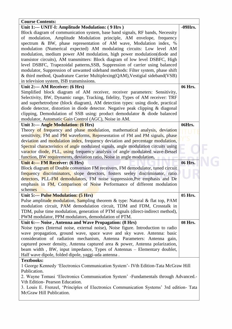
Course Contents:
Unit 1:--- UNIT-I: Amplitude Modulation: ( 9 Hrs )
Block diagram of communication system, base band signals, RF bands, Necessity
of modulation, Amplitude Modulation principle, AM envelope, frequency
spectrum & BW, phase representation of AM wave, Modulation index, %
modulation (Numerical expected) AM modulating circuits: Low level AM
modulation, medium power AM modulation, high power modulation(diode and
transistor circuits), AM transmitters: Block diagram of low level DSBFC, High
level DSBFC, Trapezoidal patterns,SSB, Suppression of carrier using balanced
modulator, Suppression of unwanted sideband methods: Filter system, phase shift
& third method, Quadrature Carrier Multiplexing(QAM),Vestigial sideband(VSB)
in television system, ISB transmissions.
-09Hrs.
Unit 2:--- AM Receiver: (6 Hrs)
Simplified block diagram of AM receiver, receiver parameters: Sensitivity,
Selectivity, BW, Dynamic range, Tracking, fidelity, Types of AM receiver: TRF
and superhetrodyne (block diagram), AM detection types: using diode, practical
diode detector, distortion in diode detector. Negative peak clipping & diagonal
clipping, Demodulation of SSB using: product demodulator & diode balanced
modulator, Automatic Gain Control (AGC), Noise in AM.
06 Hrs.
Unit 3:--- Angle Modulation: (6 Hrs)
Theory of frequency and phase modulation, mathematical analysis, deviation
sensitivity, FM and PM waveforms, Representation of FM and PM signals, phase
deviation and modulation index, frequency deviation and percentage modulation,
Spectral characteristics of angle modulated signals, angle modulation circuits using
varactor diode, PLL, using frequency analysis of angle modulated wave-Bessel
function, BW requirements, deviation ratio, Noise in angle modulation,
06Hrs.
Unit 4:--- FM Receiver: (6 Hrs)
Block diagram of Double conversion FM receivers, FM demodulator, tuned circuit
frequency discriminators, slope detectors, fosters seeley discriminator, ratio
detectors, PLL-FM demodulators, FM noise suppression,Pre emphasis and De
emphasis in FM, Comparison of Noise Performance of different modulation
schemes
06 Hrs.
Unit 5:--- Pulse Modulation: (5 Hrs)
Pulse amplitude modulation, Sampling theorem & type: Natural & flat top, PAM
modulation circuit, PAM demodulation circuit, TDM and FDM, Crosstalk in
TDM, pulse time modulation, generation of PTM signals (direct-indirect method),
PWM modulator, PPM modulators, demodulation of PTM.
05 Hrs.
Unit 6:--- Noise , Antenna and Wave Propagation: (8 Hrs)
Noise types (Internal noise, external noise), Noise figure. Introduction to radio
wave propagation, ground wave, space wave and sky wave. Antenna: basic
consideration of radiation mechanism, Antenna Parameters: Antenna gain,
captured power density, Antenna captured area & power, Antenna polarization,
beam width , BW, input impedance, Types of Antennas – Elementary doublet,
Half wave dipole, folded dipole, yaggi-uda antenna .
08 Hrs.
Textbooks:
1 George Kennedy ‗Electronics Communication System‘- IVth Edition-Tata McGraw Hill
Publication.
2. Wayne Tomasi ‗Electronics Communication System‘ -Fundamentals through Advanced.-
Vth Edition- Pearson Education.
3. Louis E. Frenzel, ‗Principles of Electronics Communication Systems‘ 3rd edition- Tata
McGraw Hill Publication.
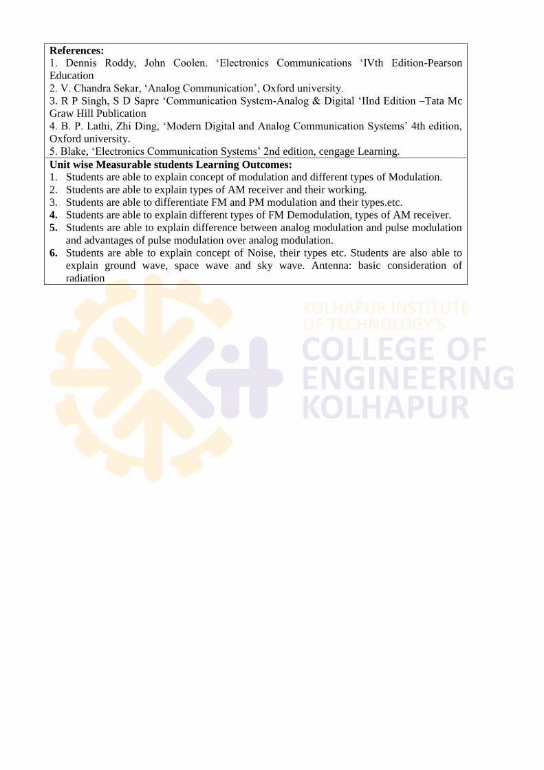
References:
1. Dennis Roddy, John Coolen. ‗Electronics Communications ‗IVth Edition-Pearson
Education
2. V. Chandra Sekar, ‗Analog Communication‘, Oxford university.
3. R P Singh, S D Sapre ‗Communication System-Analog & Digital ‗IInd Edition –Tata Mc
Graw Hill Publication
4. B. P. Lathi, Zhi Ding, ‗Modern Digital and Analog Communication Systems‘ 4th edition,
Oxford university.
5. Blake, ‗Electronics Communication Systems‘ 2nd edition, cengage Learning.
Unit wise Measurable students Learning Outcomes:
1. Students are able to explain concept of modulation and different types of Modulation.
2. Students are able to explain types of AM receiver and their working.
3. Students are able to differentiate FM and PM modulation and their types.etc.
4. Students are able to explain different types of FM Demodulation, types of AM receiver.
5. Students are able to explain difference between analog modulation and pulse modulation
and advantages of pulse modulation over analog modulation.
6. Students are able to explain concept of Noise, their types etc. Students are also able to
explain ground wave, space wave and sky wave. Antenna: basic consideration of
radiation
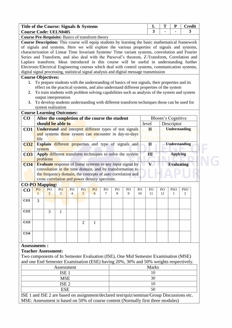
Title of the Course: Signals & Systems
Course Code: UELN0405
L T P Credit
3 - - 3
Course Pre-Requisite: Basics of transform theory
Course Description: This course will equip students by learning the basic mathematical framework
of signals and systems. Here we will explore the various properties of signals and systems,
characterization of Linear Time Invariant Systems/ Time variant systems, convolution and Fourier
Series and Transform, and also deal with the Parseval‘s theorem, Z-Transform, Correlation and
Laplace transform. Ideas introduced in this course will be useful in understanding further
Electronic/Electrical Engineering courses which deal with control systems, communication systems,
digital signal processing, statistical signal analysis and digital message transmission
Course Objectives: 1. To prepare students with the understanding of basics of test signals, their properties and its
effect on the practical systems, and also understand different properties of the system
2. To train students with problem solving capabilities such as analysis of the system and system
output interpretation
3. To develop students understanding with different transform techniques those can be used for
system realization
Course Learning Outcomes:
CO After the completion of the course the student
should be able to
Bloom‘s Cognitive
level Descriptor
CO1 Understand and interpret different types of test signals
and systems those system can encounter in day-to-days
life
II Understanding
CO2 Explain different properties and type of signals and
system II Understanding
CO3 Apply different transform techniques to solve the system
problems III Applying
CO4 Evaluate response of linear systems to any input signal by
convolution in the time domain, and by transformation to
the frequency domain, the concepts of auto correlation and
cross correlation and power density spectrum.
V Evaluating
CO-PO Mapping:
CO PO
1
PO
2
PO
3
PO
4
PO
5
PO
6
PO
7
PO
8
PO
9
PO
10
PO
11
PO
12
PSO
1
PSO
2
CO1 3
CO2 3 1
CO3 2 1
CO4
Assessments :
Teacher Assessment:
Two components of In Semester Evaluation (ISE), One Mid Semester Examination (MSE)
and one End Semester Examination (ESE) having 20%, 30% and 50% weights respectively.
Assessment Marks
ISE 1 10
MSE 30
ISE 2 10
ESE 50
ISE 1 and ISE 2 are based on assignment/declared test/quiz/seminar/Group Discussions etc.
MSE: Assessment is based on 50% of course content (Normally first three modules)
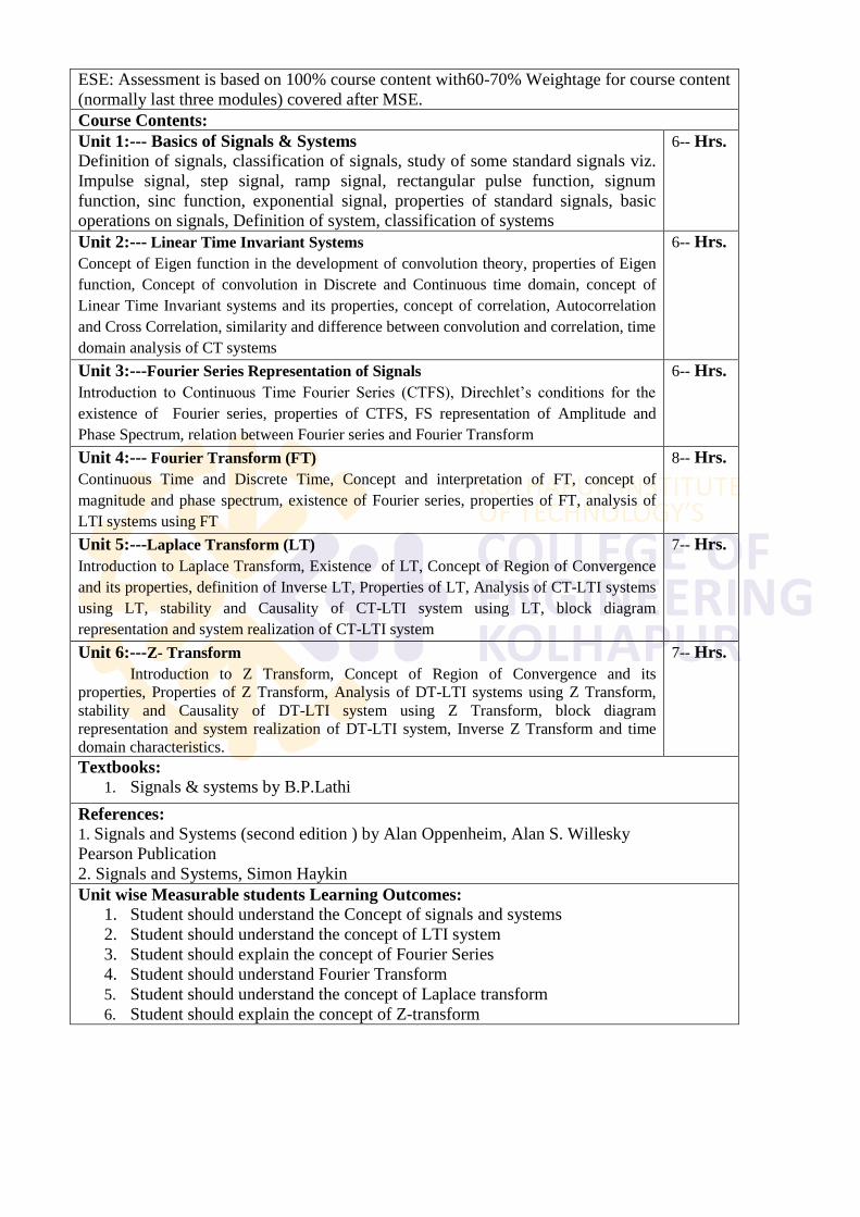
ESE: Assessment is based on 100% course content with60-70% Weightage for course content
(normally last three modules) covered after MSE.
Course Contents:
Unit 1:--- Basics of Signals & Systems
Definition of signals, classification of signals, study of some standard signals viz.
Impulse signal, step signal, ramp signal, rectangular pulse function, signum
function, sinc function, exponential signal, properties of standard signals, basic
operations on signals, Definition of system, classification of systems
6-- Hrs.
Unit 2:--- Linear Time Invariant Systems
Concept of Eigen function in the development of convolution theory, properties of Eigen
function, Concept of convolution in Discrete and Continuous time domain, concept of
Linear Time Invariant systems and its properties, concept of correlation, Autocorrelation
and Cross Correlation, similarity and difference between convolution and correlation, time
domain analysis of CT systems
6-- Hrs.
Unit 3:---Fourier Series Representation of Signals
Introduction to Continuous Time Fourier Series (CTFS), Direchlet‘s conditions for the
existence of Fourier series, properties of CTFS, FS representation of Amplitude and
Phase Spectrum, relation between Fourier series and Fourier Transform
6-- Hrs.
Unit 4:--- Fourier Transform (FT)
Continuous Time and Discrete Time, Concept and interpretation of FT, concept of
magnitude and phase spectrum, existence of Fourier series, properties of FT, analysis of
LTI systems using FT
8-- Hrs.
Unit 5:---Laplace Transform (LT)
Introduction to Laplace Transform, Existence of LT, Concept of Region of Convergence
and its properties, definition of Inverse LT, Properties of LT, Analysis of CT-LTI systems
using LT, stability and Causality of CT-LTI system using LT, block diagram
representation and system realization of CT-LTI system
7-- Hrs.
Unit 6:---Z- Transform
Introduction to Z Transform, Concept of Region of Convergence and its
properties, Properties of Z Transform, Analysis of DT-LTI systems using Z Transform,
stability and Causality of DT-LTI system using Z Transform, block diagram
representation and system realization of DT-LTI system, Inverse Z Transform and time
domain characteristics.
7-- Hrs.
Textbooks:
1. Signals & systems by B.P.Lathi
References:
1. Signals and Systems (second edition ) by Alan Oppenheim, Alan S. Willesky
Pearson Publication
2. Signals and Systems, Simon Haykin
Unit wise Measurable students Learning Outcomes:
1. Student should understand the Concept of signals and systems
2. Student should understand the concept of LTI system
3. Student should explain the concept of Fourier Series
4. Student should understand Fourier Transform
5. Student should understand the concept of Laplace transform
6. Student should explain the concept of Z-transform
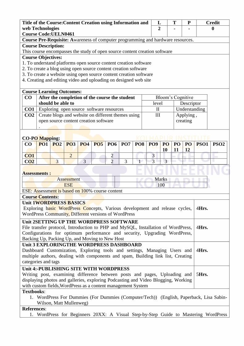
Title of the Course:Content Creation using Information and
web Technologies
Course Code:UELN0461
L T P Credit
2 - - 0
Course Pre-Requisite: Awareness of computer programming and hardware resources.
Course Description:
This course encompasses the study of open source content creation software
Course Objectives:
1. To understand platforms open source content creation software
2. To create a blog using open source content creation software
3. To create a website using open source content creation software
4. Creating and editing video and uploading on designed web site
Course Learning Outcomes:
CO After the completion of the course the student
should be able to
Bloom‘s Cognitive
level Descriptor
CO1 Exploring open source software resources II Understanding
CO2 Create blogs and website on different themes using
open source content creation software
.
III Applying ,
creating
CO-PO Mapping:
CO PO1 PO2 PO3 PO4 PO5 PO6 PO7 PO8 PO9 PO
10
PO
11
PO
12
PSO1 PSO2
CO1 2 2 3
CO2 3 3 2 3 1 3 3
Assessments :
Assessment Marks
ESE 100
ESE: Assessment is based on 100% course content
Course Contents:
Unit 1WORDPRESS BASICS Exploring basic WordPress Concepts, Various development and release cycles,
WordPress Community, Different versions of WordPress
4Hrs.
Unit 2SETTING UP THE WORDPRESS SOFTWARE
File transfer protocol, Introduction to PHP and MySQL, Installation of WordPress,
Configurations for optimum performance and security, Upgrading WordPress,
Backing Up, Packing Up, and Moving to New Host
4Hrs.
Unit 3 EXPLORINGTHE WORDPRESS DASHBOARD
Dashboard Customization, Exploring tools and settings, Managing Users and
multiple authors, dealing with components and spam, Building link list, Creating
categories and tags
4Hrs.
Unit 4:-PUBLISHING SITE WITH WORDPRESS
Writing post, examining difference between posts and pages, Uploading and
displaying photos and galleries, exploring Podcasting and Video Blogging, Working
with custom fields,WordPress as a content management System
5Hrs.
Textbooks:
1. WordPress For Dummies (For Dummies (Computer/Tech)) (English, Paperback, Lisa Sabin-
Wilson, Matt Mullenweg)
References:
1. WordPress for Beginners 20XX: A Visual Step-by-Step Guide to Mastering WordPress
(Webmaster Series Book 2) by Dr Andy Williams
Unit wise Measurable students Learning Outcomes:
1. The student will be able to explain basics of WordPress.
2. The student will be able to set the WordPress software.
3. The student will be able to explore various tools from WordPress dashboard.
4. The student will be able to create blog by using WordPress.
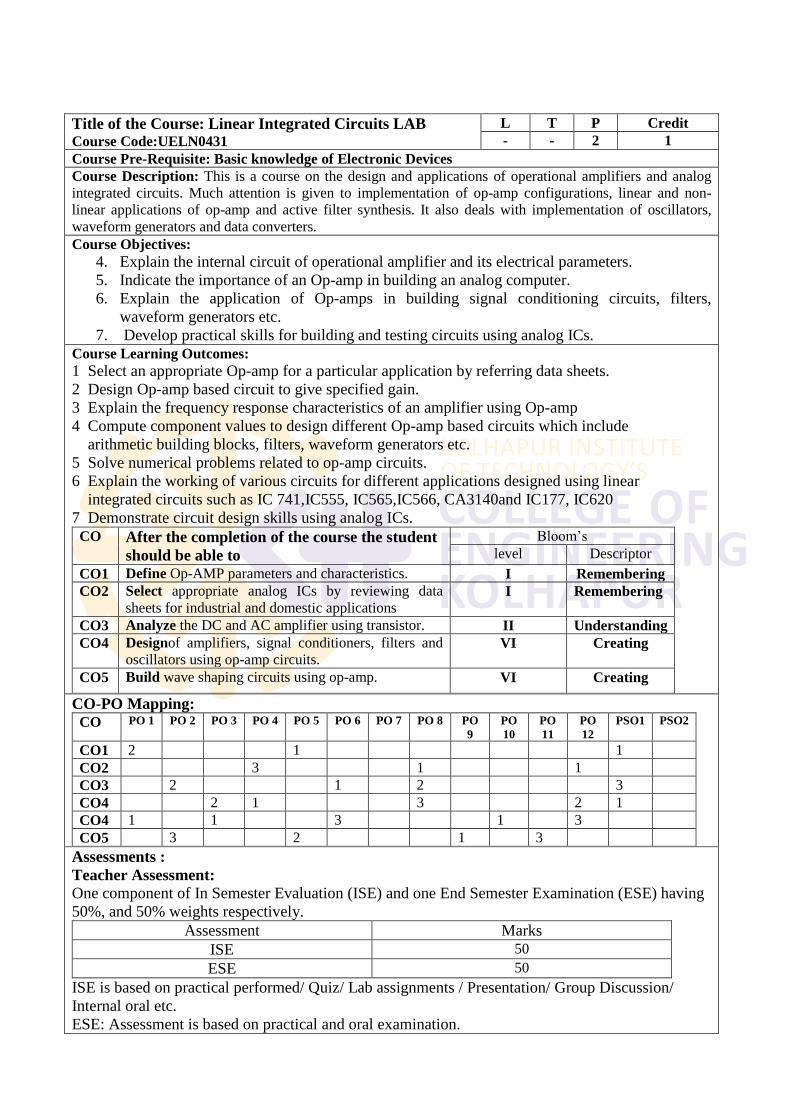
Title of the Course: Linear Integrated Circuits LAB Course Code:UELN0431
L T P Credit
- - 2 1
Course Pre-Requisite: Basic knowledge of Electronic Devices
Course Description: This is a course on the design and applications of operational amplifiers and analog
integrated circuits. Much attention is given to implementation of op-amp configurations, linear and non-
linear applications of op-amp and active filter synthesis. It also deals with implementation of oscillators,
waveform generators and data converters.
Course Objectives:
4. Explain the internal circuit of operational amplifier and its electrical parameters.
5. Indicate the importance of an Op-amp in building an analog computer.
6. Explain the application of Op-amps in building signal conditioning circuits, filters,
waveform generators etc.
7. Develop practical skills for building and testing circuits using analog ICs.
Course Learning Outcomes:
1 Select an appropriate Op-amp for a particular application by referring data sheets.
2 Design Op-amp based circuit to give specified gain.
3 Explain the frequency response characteristics of an amplifier using Op-amp
4 Compute component values to design different Op-amp based circuits which include
arithmetic building blocks, filters, waveform generators etc.
5 Solve numerical problems related to op-amp circuits.
6 Explain the working of various circuits for different applications designed using linear
integrated circuits such as IC 741,IC555, IC565,IC566, CA3140and IC177, IC620
7 Demonstrate circuit design skills using analog ICs.
CO After the completion of the course the student
should be able to
Bloom‘s
level Descriptor
CO1 Define Op-AMP parameters and characteristics. I Remembering
CO2 Select appropriate analog ICs by reviewing data
sheets for industrial and domestic applications I Remembering
CO3 Analyze the DC and AC amplifier using transistor. II Understanding
CO4 Designof amplifiers, signal conditioners, filters and
oscillators using op-amp circuits. VI Creating
CO5 Build wave shaping circuits using op-amp. VI Creating
CO-PO Mapping:
CO PO 1 PO 2 PO 3 PO 4 PO 5 PO 6 PO 7 PO 8 PO
9
PO
10
PO
11
PO
12
PSO1 PSO2
CO1 2 1 1
CO2 3 1 1
CO3 2 1 2 3
CO4 2 1 3 2 1
CO4 1 1 3 1 3
CO5 3 2 1 3
Assessments :
Teacher Assessment:
One component of In Semester Evaluation (ISE) and one End Semester Examination (ESE) having
50%, and 50% weights respectively.
Assessment Marks
ISE 50
ESE 50
ISE is based on practical performed/ Quiz/ Lab assignments / Presentation/ Group Discussion/
Internal oral etc.
ESE: Assessment is based on practical and oral examination.
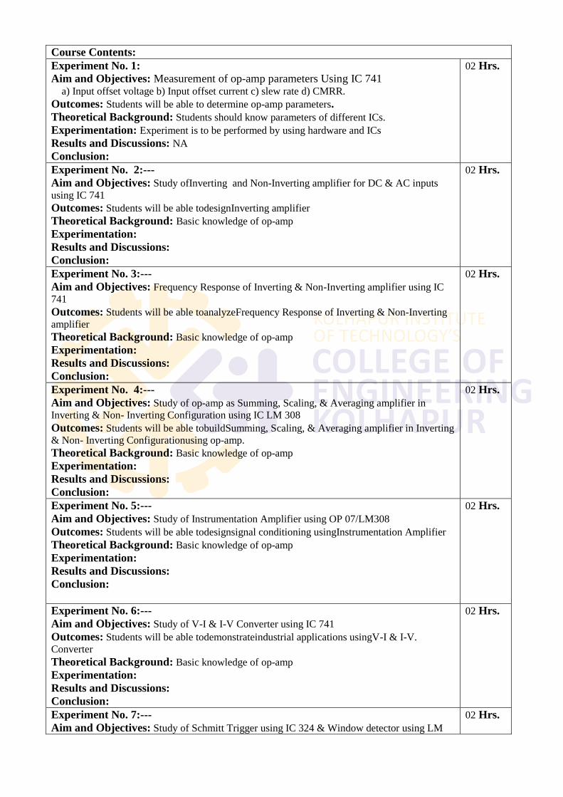
Course Contents:
Experiment No. 1:
Aim and Objectives: Measurement of op-amp parameters Using IC 741 a) Input offset voltage b) Input offset current c) slew rate d) CMRR.
Outcomes: Students will be able to determine op-amp parameters.
Theoretical Background: Students should know parameters of different ICs.
Experimentation: Experiment is to be performed by using hardware and ICs
Results and Discussions: NA
Conclusion:
02 Hrs.
Experiment No. 2:---
Aim and Objectives: Study ofInverting and Non-Inverting amplifier for DC & AC inputs
using IC 741
Outcomes: Students will be able todesignInverting amplifier
Theoretical Background: Basic knowledge of op-amp
Experimentation:
Results and Discussions:
Conclusion:
02 Hrs.
Experiment No. 3:---
Aim and Objectives: Frequency Response of Inverting & Non-Inverting amplifier using IC
741
Outcomes: Students will be able toanalyzeFrequency Response of Inverting & Non-Inverting
amplifier
Theoretical Background: Basic knowledge of op-amp
Experimentation:
Results and Discussions:
Conclusion:
02 Hrs.
Experiment No. 4:---
Aim and Objectives: Study of op-amp as Summing, Scaling, & Averaging amplifier in
Inverting & Non- Inverting Configuration using IC LM 308
Outcomes: Students will be able tobuildSumming, Scaling, & Averaging amplifier in Inverting
& Non- Inverting Configurationusing op-amp.
Theoretical Background: Basic knowledge of op-amp
Experimentation:
Results and Discussions:
Conclusion:
02 Hrs.
Experiment No. 5:---
Aim and Objectives: Study of Instrumentation Amplifier using OP 07/LM308
Outcomes: Students will be able todesignsignal conditioning usingInstrumentation Amplifier
Theoretical Background: Basic knowledge of op-amp
Experimentation:
Results and Discussions:
Conclusion:
02 Hrs.
Experiment No. 6:---
Aim and Objectives: Study of V-I & I-V Converter using IC 741
Outcomes: Students will be able todemonstrateindustrial applications usingV-I & I-V.
Converter
Theoretical Background: Basic knowledge of op-amp
Experimentation:
Results and Discussions:
Conclusion:
02 Hrs.
Experiment No. 7:---
Aim and Objectives: Study of Schmitt Trigger using IC 324 & Window detector using LM
02 Hrs.
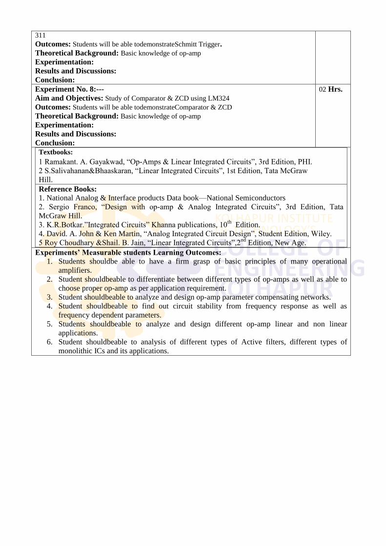
311
Outcomes: Students will be able todemonstrateSchmitt Trigger.
Theoretical Background: Basic knowledge of op-amp
Experimentation:
Results and Discussions:
Conclusion:
Experiment No. 8:---
Aim and Objectives: Study of Comparator & ZCD using LM324
Outcomes: Students will be able todemonstrateComparator & ZCD
Theoretical Background: Basic knowledge of op-amp
Experimentation:
Results and Discussions:
Conclusion:
02 Hrs.
Textbooks:
1 Ramakant. A. Gayakwad, ―Op-Amps & Linear Integrated Circuits‖, 3rd Edition, PHI.
2 S.Salivahanan&Bhaaskaran, ―Linear Integrated Circuits‖, 1st Edition, Tata McGraw
Hill.
Reference Books:
1. National Analog & Interface products Data book—National Semiconductors
2. Sergio Franco, ―Design with op-amp & Analog Integrated Circuits‖, 3rd Edition, Tata
McGraw Hill.
3. K.R.Botkar.‖Integrated Circuits‖ Khanna publications, 10th
Edition.
4. David. A. John & Ken Martin, ―Analog Integrated Circuit Design‖, Student Edition, Wiley.
5 Roy Choudhary &Shail. B. Jain, ―Linear Integrated Circuits‖,2nd
Edition, New Age.
Experiments’ Measurable students Learning Outcomes:
1. Students shouldbe able to have a firm grasp of basic principles of many operational
amplifiers.
2. Student shouldbeable to differentiate between different types of op-amps as well as able to
choose proper op-amp as per application requirement.
3. Student shouldbeable to analyze and design op-amp parameter compensating networks.
4. Student shouldbeable to find out circuit stability from frequency response as well as
frequency dependent parameters.
5. Students shouldbeable to analyze and design different op-amp linear and non linear
applications.
6. Student shouldbeable to analysis of different types of Active filters, different types of
monolithic ICs and its applications.
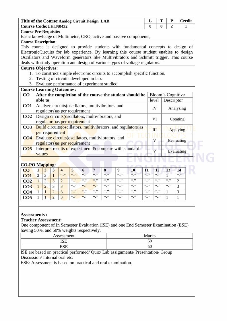
Title of the Course:Analog Circuit Design LAB
Course Code:UELN0432
L T P Credit
0 0 2 1
Course Pre-Requisite:
Basic knowledge of Multimeter, CRO, active and passive components,
Course Description:
This course is designed to provide students with fundamental concepts to design of
ElectronicCircuits for lab experience. By learning this course student enables to design
Oscillators and Waveform generators like Multivibrators and Schmitt trigger. This course
deals with study operation and design of various types of voltage regulators.
Course Objectives:
1. To construct simple electronic circuits to accomplish specific function.
2. Testing of circuits developed in lab.
3. Evaluate performance of experiment studied.
Course Learning Outcomes:
CO After the completion of the course the student should be
able to
Bloom‘s Cognitive
level Descriptor
CO1 Analyze circuits(oscillators, multivibrators, and
regulators)as per requirement IV Analyzing
CO2 Design circuits(oscillators, multivibrators, and
regulators)as per requirement VI Creating
CO3 Build circuits(oscillators, multivibrators, and regulators)as
per requirement III Applying
CO4 Evaluate circuits(oscillators, multivibrators, and
regulators)as per requirement V Evaluating
CO5 Interpret results of experiment & compare with standard
values V Evaluating
CO-PO Mapping:
CO 1 2 3 4 5 6 7 8 9 10 11 12 13 14
CO1 3 3 1 ―-‖ ―-‖ ―-‖ ―-‖ ―-‖ ―-‖ ―-‖ ―-‖ ―-‖ 1 ―-‖
CO2 1 2 3 2 ―-‖ ―-‖ ―-‖ ―-‖ ―-‖ ―-‖ ―-‖ ―-‖ ―-‖ 2
CO3 1 2 3 3 ―-‖ ―-‖ ―-‖ ―-‖ ―-‖ ―-‖ ―-‖ ―-‖ ―-‖ 3
CO4 1 1 2 3 ―-‖ ―-‖ ―-‖ ―-‖ ―-‖ ―-‖ ―-‖ ―-‖ 1 3
CO5 1 1 2 3 ―-‖ ―-‖ ―-‖ ―-‖ ―-‖ ―-‖ ―-‖ ―-‖ 1 1
Assessments :
Teacher Assessment:
One component of In Semester Evaluation (ISE) and one End Semester Examination (ESE)
having 50%, and 50% weights respectively.
Assessment Marks
ISE 50
ESE 50
ISE are based on practical performed/ Quiz/ Lab assignments/ Presentation/ Group
Discussion/ Internal oral etc.
ESE: Assessment is based on practical and oral examination.
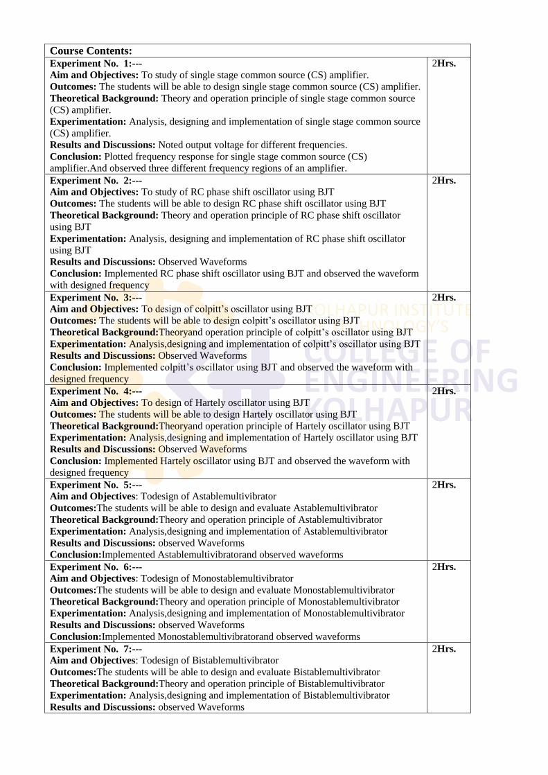
Course Contents:
Experiment No. 1:---
Aim and Objectives: To study of single stage common source (CS) amplifier.
Outcomes: The students will be able to design single stage common source (CS) amplifier.
Theoretical Background: Theory and operation principle of single stage common source
(CS) amplifier.
Experimentation: Analysis, designing and implementation of single stage common source
(CS) amplifier.
Results and Discussions: Noted output voltage for different frequencies.
Conclusion: Plotted frequency response for single stage common source (CS)
amplifier.And observed three different frequency regions of an amplifier.
2Hrs.
Experiment No. 2:---
Aim and Objectives: To study of RC phase shift oscillator using BJT
Outcomes: The students will be able to design RC phase shift oscillator using BJT
Theoretical Background: Theory and operation principle of RC phase shift oscillator
using BJT
Experimentation: Analysis, designing and implementation of RC phase shift oscillator
using BJT
Results and Discussions: Observed Waveforms
Conclusion: Implemented RC phase shift oscillator using BJT and observed the waveform
with designed frequency
2Hrs.
Experiment No. 3:---
Aim and Objectives: To design of colpitt‘s oscillator using BJT
Outcomes: The students will be able to design colpitt‘s oscillator using BJT
Theoretical Background:Theoryand operation principle of colpitt‘s oscillator using BJT
Experimentation: Analysis,designing and implementation of colpitt‘s oscillator using BJT
Results and Discussions: Observed Waveforms
Conclusion: Implemented colpitt‘s oscillator using BJT and observed the waveform with
designed frequency
2Hrs.
Experiment No. 4:---
Aim and Objectives: To design of Hartely oscillator using BJT
Outcomes: The students will be able to design Hartely oscillator using BJT
Theoretical Background:Theoryand operation principle of Hartely oscillator using BJT
Experimentation: Analysis,designing and implementation of Hartely oscillator using BJT
Results and Discussions: Observed Waveforms
Conclusion: Implemented Hartely oscillator using BJT and observed the waveform with
designed frequency
2Hrs.
Experiment No. 5:---
Aim and Objectives: Todesign of Astablemultivibrator
Outcomes:The students will be able to design and evaluate Astablemultivibrator
Theoretical Background:Theory and operation principle of Astablemultivibrator
Experimentation: Analysis,designing and implementation of Astablemultivibrator
Results and Discussions: observed Waveforms
Conclusion:Implemented Astablemultivibratorand observed waveforms
2Hrs.
Experiment No. 6:---
Aim and Objectives: Todesign of Monostablemultivibrator
Outcomes:The students will be able to design and evaluate Monostablemultivibrator
Theoretical Background:Theory and operation principle of Monostablemultivibrator
Experimentation: Analysis,designing and implementation of Monostablemultivibrator
Results and Discussions: observed Waveforms
Conclusion:Implemented Monostablemultivibratorand observed waveforms
2Hrs.
Experiment No. 7:---
Aim and Objectives: Todesign of Bistablemultivibrator
Outcomes:The students will be able to design and evaluate Bistablemultivibrator
Theoretical Background:Theory and operation principle of Bistablemultivibrator
Experimentation: Analysis,designing and implementation of Bistablemultivibrator
Results and Discussions: observed Waveforms
2Hrs.
Conclusion:Implemented Bistablemultivibratorand observed waveforms
Experiment No. 8:---
Aim and Objectives:To study zener shunt voltage regulator
Outcomes: The students will be able to test zener shunt voltage regulator Theoretical
Background:Theory and operation principle of zener shunt voltage regulator
Experimentation: Analysis, designing and implementation of zener shunt voltage
regulator
Results and Discussions: Observed Waveforms and noted analysis Parameters
Conclusion: Implemented zener shunt voltage regulatorand plotted the graph which
indicates regulation action.
2Hrs.
Experiment No. 9:---
Aim and Objectives:To study Emitter Follower Voltage Regulator Outcomes: The students will be able to test Emitter Follower Voltage Regulator
Theoretical Background:Theory and operation principle Emitter Follower Voltage
Regulator
Experimentation: Analysis, designing and implementation of Emitter Follower Voltage
Regulator
Results and Discussions: Observed Waveforms and noted analysis Parameters
Conclusion: Implemented Emitter Follower Voltage Regulator and plotted the graph
which indicates regulation action.
2Hrs.
Experiment No. 10:---
Aim and Objectives:To study Transistorised Series Voltage Regulator
Outcomes: The students will be able to test Transistorised Series Voltage Regulator
Theoretical Background:Theory and operation principle of Transistorised Series Voltage
Regulator
Experimentation: Analysis, designing and implementation of Transistorised Series
Voltage Regulator
Results and Discussions: Observed Waveforms and noted analysis Parameters
Conclusion: Implemented Transistorised Series Voltage Regulator and plotted the graph
which indicates regulation action.
2Hrs.
Experiment No. 11:---
Aim and Objectives: To study of Step up and stepdown SMPS
Outcomes: The students will be able to explain Step up and stepdown SMPS
Theoretical Background:Theoryand operation principle of Step up and stepdown SMPS
Experimentation: Analysis of Step up and stepdown SMPS
Results and Discussions: comparative understanding of Step up and stepdown SMPS
Conclusion: Studied Step up and stepdown SMPS
2Hrs.
Textbooks:
1. Electronic Devices and circuits by S.Salivahanan,N Suresh Kumar, A Vallavaraj.
2. Electronic Devices and Circuits by Anil K. Maini, Varsha Agarwal- Wiley India.
3. Electronic Devices and Circuits by A.P.Godse and U.A.Bakshi.
4. Electronic Devices and Circuits by Mantri & Jain.
References:
1. Pulse, Digital & Switching Waveforms by Millman, Taub, Rao.
2. Schaum's Outlines, ― Electronic Devices and Circuits‖
3. Electronic Devices and Circuits by Allen Mottershead-PHI.
4. Electronic Devices and Circuit Theory by Boylestad, Pearson Publication.
5. Electronic Devices and Circuits by J.B.Gupta,Katson Publication
6. Electronic Devices and Circuits by Millman, Halkias, TMH Publication.
7. Solid State Electronic Devices by Ben Streetman, PearsonPublication.
Experiment wise Measurable students Learning Outcomes:
1. The students will be able to design single stage common source (CS) amplifier using FET.
2. The students will be able to design RC phase shift oscillator using BJT
3. The students will be able to design colpitt‘s oscillator using BJT
4. The students will be able to design Hartelyoscillator using BJT
5. The students will be able to design and evaluate Astablemultivibrator
6. The students will be able to design and evaluate Monostablemultivibrator
7. The students will be able to design and evaluate Bistablemultivibrator
8. The students will be able to test zener shunt voltage regulator
9. The students will be able to test Emitter follower voltage regulator
10. The students will be able to design of transistorized series voltage regulator
11. The students will be able to explain Step up and stepdown SMPS
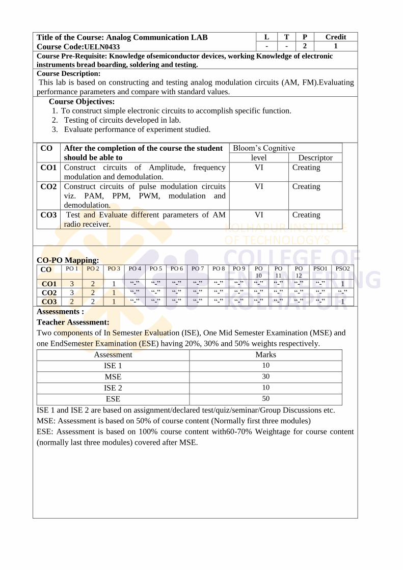
Title of the Course: Analog Communication LAB
Course Code:UELN0433
L T P Credit
- - 2 1
Course Pre-Requisite: Knowledge ofsemiconductor devices, working Knowledge of electronic
instruments bread boarding, soldering and testing.
Course Description:
This lab is based on constructing and testing analog modulation circuits (AM, FM).Evaluating
performance parameters and compare with standard values.
Course Objectives:
1. To construct simple electronic circuits to accomplish specific function.
2. Testing of circuits developed in lab.
3. Evaluate performance of experiment studied.
CO After the completion of the course the student
should be able to
Bloom‘s Cognitive
level Descriptor
CO1 Construct circuits of Amplitude, frequency
modulation and demodulation.
VI Creating
CO2 Construct circuits of pulse modulation circuits
viz. PAM, PPM, PWM, modulation and
demodulation.
VI Creating
CO3 Test and Evaluate different parameters of AM
radio receiver.
VI Creating
CO-PO Mapping:
CO PO 1 PO 2 PO 3 PO 4 PO 5 PO 6 PO 7 PO 8 PO 9 PO
10
PO
11
PO
12
PSO1 PSO2
CO1 3 2 1 ―-‖ ―-‖ ―-‖ ―-‖ ―-‖ ―-‖ ―-‖ ―-‖ ―-‖ ―-‖ 1
CO2 3 2 1 ―-‖ ―-‖ ―-‖ ―-‖ ―-‖ ―-‖ ―-‖ ―-‖ ―-‖ ―-‖ ―-‖
CO3 2 2 1 ―-‖ ―-‖ ―-‖ ―-‖ ―-‖ ―-‖ ―-‖ ―-‖ ―-‖ ―-‖ 1
Assessments :
Teacher Assessment:
Two components of In Semester Evaluation (ISE), One Mid Semester Examination (MSE) and
one EndSemester Examination (ESE) having 20%, 30% and 50% weights respectively.
Assessment Marks
ISE 1 10
MSE 30
ISE 2 10
ESE 50
ISE 1 and ISE 2 are based on assignment/declared test/quiz/seminar/Group Discussions etc.
MSE: Assessment is based on 50% of course content (Normally first three modules)
ESE: Assessment is based on 100% course content with60-70% Weightage for course content
(normally last three modules) covered after MSE.
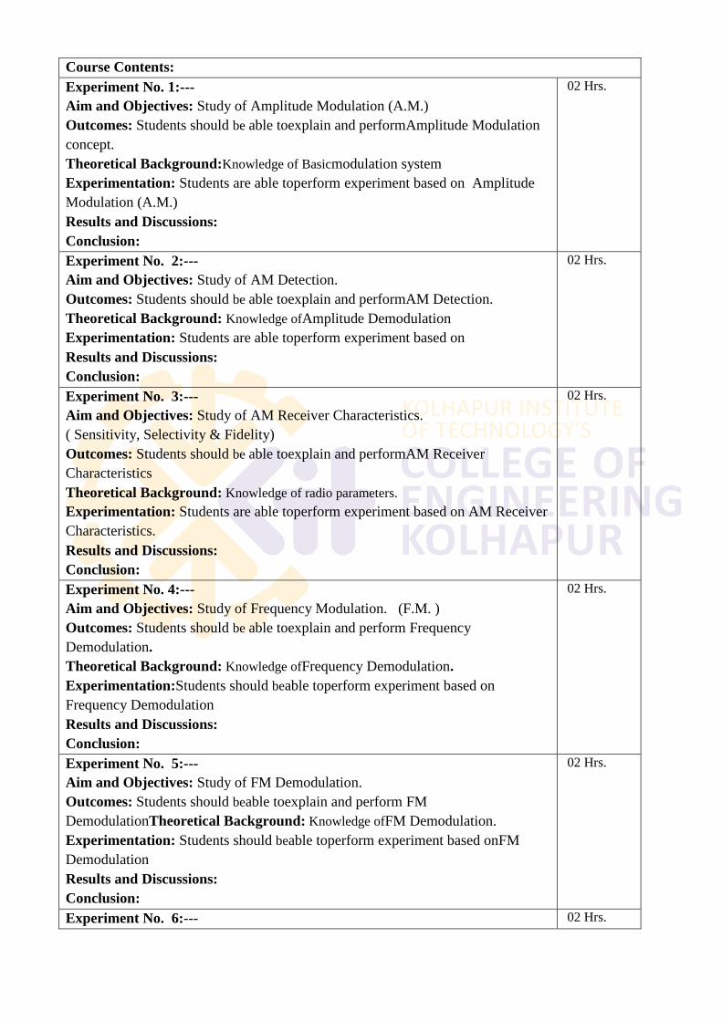
Course Contents:
Experiment No. 1:---
Aim and Objectives: Study of Amplitude Modulation (A.M.)
Outcomes: Students should be able toexplain and performAmplitude Modulation
concept.
Theoretical Background:Knowledge of Basicmodulation system
Experimentation: Students are able toperform experiment based on Amplitude
Modulation (A.M.)
Results and Discussions:
Conclusion:
02 Hrs.
Experiment No. 2:---
Aim and Objectives: Study of AM Detection.
Outcomes: Students should be able toexplain and performAM Detection.
Theoretical Background: Knowledge ofAmplitude Demodulation
Experimentation: Students are able toperform experiment based on
Results and Discussions:
Conclusion:
02 Hrs.
Experiment No. 3:---
Aim and Objectives: Study of AM Receiver Characteristics.
( Sensitivity, Selectivity & Fidelity)
Outcomes: Students should be able toexplain and performAM Receiver
Characteristics
Theoretical Background: Knowledge of radio parameters.
Experimentation: Students are able toperform experiment based on AM Receiver
Characteristics.
Results and Discussions:
Conclusion:
02 Hrs.
Experiment No. 4:---
Aim and Objectives: Study of Frequency Modulation. (F.M. )
Outcomes: Students should be able toexplain and perform Frequency
Demodulation.
Theoretical Background: Knowledge ofFrequency Demodulation.
Experimentation:Students should beable toperform experiment based on
Frequency Demodulation
Results and Discussions:
Conclusion:
02 Hrs.
Experiment No. 5:---
Aim and Objectives: Study of FM Demodulation.
Outcomes: Students should beable toexplain and perform FM
DemodulationTheoretical Background: Knowledge ofFM Demodulation.
Experimentation: Students should beable toperform experiment based onFM
Demodulation
Results and Discussions:
Conclusion:
02 Hrs.
Experiment No. 6:--- 02 Hrs.
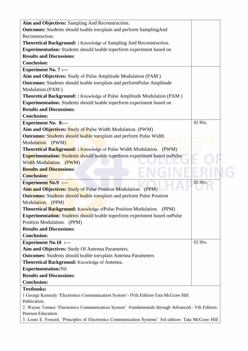
Aim and Objectives: Sampling And Reconstruction.
Outcomes: Students should beable toexplain and perform SamplingAnd
Reconstruction.
Theoretical Background: : Knowledge of Sampling And Reconstruction.
Experimentation: Students should beable toperform experiment based on
Results and Discussions:
Conclusion:
Experiment No. 7 :---
Aim and Objectives: Study of Pulse Amplitude Modulation (PAM )
Outcomes: Students should beable toexplain and performPulse Amplitude
Modulation (PAM )
Theoretical Background: : Knowledge of Pulse Amplitude Modulation (PAM )
Experimentation: Students should beable toperform experiment based on
Results and Discussions:
Conclusion:
Experiment No. 8:---
Aim and Objectives: Study of Pulse Width Modulation. (PWM)
Outcomes: Students should beable toexplain and perform Pulse Width
Modulation. (PWM)
Theoretical Background: : Knowledge of Pulse Width Modulation. (PWM)
Experimentation: Students should beable toperform experiment based onPulse
Width Modulation. (PWM)
Results and Discussions:
Conclusion:
02 Hrs.
Experiment No.9 :---
Aim and Objectives: Study of Pulse Position Modulation. (PPM)
Outcomes: Students should beable toexplain and perform Pulse Position
Modulation. (PPM)
Theoretical Background: Knowledge ofPulse Position Modulation. (PPM)
Experimentation: Students should beable toperform experiment based onPulse
Position Modulation. (PPM)
Results and Discussions:
Conclusion:
02 Hrs.
Experiment No.10 :---
Aim and Objectives: Study Of Antenna Parameters.
Outcomes: Students should beable toexplain Antenna Parameters
Theoretical Background: Knowledge of Antenna.
Experimentation:Nil
Results and Discussions:
Conclusion:
02 Hrs.
Textbooks:
1 George Kennedy ‗Electronics Communication System‘- IVth Edition-Tata McGraw Hill
Publication.
2. Wayne Tomasi ‗Electronics Communication System‘ -Fundamentals through Advanced.- Vth Edition-
Pearson Education.
3. Louis E. Frenzel, ‗Principles of Electronics Communication Systems‘ 3rd edition- Tata McGraw Hill
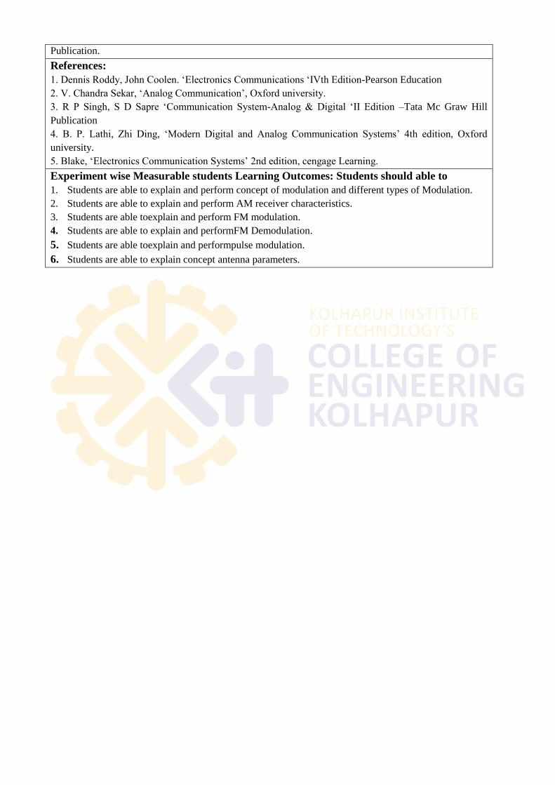
Publication.
References:
1. Dennis Roddy, John Coolen. ‗Electronics Communications ‗IVth Edition-Pearson Education
2. V. Chandra Sekar, ‗Analog Communication‘, Oxford university.
3. R P Singh, S D Sapre ‗Communication System-Analog & Digital ‗II Edition –Tata Mc Graw Hill
Publication
4. B. P. Lathi, Zhi Ding, ‗Modern Digital and Analog Communication Systems‘ 4th edition, Oxford
university.
5. Blake, ‗Electronics Communication Systems‘ 2nd edition, cengage Learning.
Experiment wise Measurable students Learning Outcomes: Students should able to
1. Students are able to explain and perform concept of modulation and different types of Modulation.
2. Students are able to explain and perform AM receiver characteristics.
3. Students are able toexplain and perform FM modulation.
4. Students are able to explain and performFM Demodulation.
5. Students are able toexplain and performpulse modulation.
6. Students are able to explain concept antenna parameters.
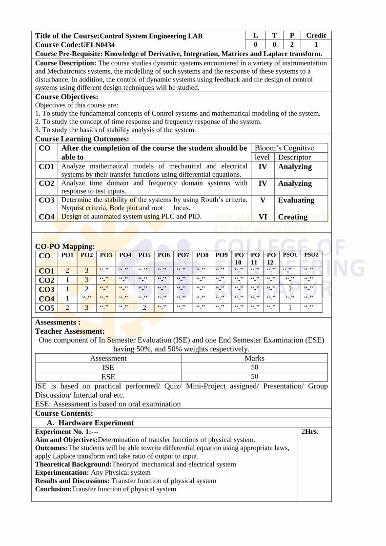
Title of the Course:Control System Engineering LAB
Course Code:UELN0434
L T P Credit
0 0 2 1
Course Pre-Requisite: Knowledge of Derivative, Integration, Matrices and Laplace transform.
Course Description: The course studies dynamic systems encountered in a variety of instrumentation
and Mechatronics systems, the modelling of such systems and the response of these systems to a
disturbance. In addition, the control of dynamic systems using feedback and the design of control
systems using different design techniques will be studied.
Course Objectives: Objectives of this course are:
1. To study the fundamental concepts of Control systems and mathematical modeling of the system.
2. To study the concept of time response and frequency response of the system.
3. To study the basics of stability analysis of the system.
Course Learning Outcomes:
CO After the completion of the course the student should be
able to
Bloom‘s Cognitive
level Descriptor
CO1 Analyze mathematical models of mechanical and electrical
systems by their transfer functions using differential equations. IV Analyzing
CO2 Analyze time domain and frequency domain systems with
response to test inputs. IV Analyzing
CO3 Determine the stability of the systems by using Routh‘s criteria,
Nyquist criteria, Bode plot and root locus. V Evaluating
CO4 Design of automated system using PLC and PID. VI Creating
CO-PO Mapping:
CO PO1 PO2 PO3 PO4 PO5 PO6 PO7 PO8 PO9 PO
10
PO
11
PO
12
PSO1 PSO2
CO1 2 3 ―-‖ ―-‖ ―-‖ ―-‖ ―-‖ ―-‖ ―-‖ ―-‖ ―-‖ ―-‖ ―-‖ ―-‖
CO2 1 3 ―-‖ ―-‖ ―-‖ ―-‖ ―-‖ ―-‖ ―-‖ ―-‖ ―-‖ ―-‖ ―-‖ ―-‖
CO3 1 2 ―-‖ ―-‖ ―-‖ ―-‖ ―-‖ ―-‖ ―-‖ ―-‖ ―-‖ ―-‖ 2 ―-‖
CO4 1 ―-‖ ―-‖ ―-‖ ―-‖ ―-‖ ―-‖ ―-‖ ―-‖ ―-‖ ―-‖ ―-‖ ―-‖ ―-‖
CO5 2 3 ―-‖ ―-‖ 2 ―-‖ ―-‖ ―-‖ ―-‖ ―-‖ ―-‖ ―-‖ 1 ―-‖
Assessments :
Teacher Assessment:
One component of In Semester Evaluation (ISE) and one End Semester Examination (ESE)
having 50%, and 50% weights respectively.
Assessment Marks
ISE 50
ESE 50
ISE is based on practical performed/ Quiz/ Mini-Project assigned/ Presentation/ Group
Discussion/ Internal oral etc.
ESE: Assessment is based on oral examination
Course Contents:
A. Hardware Experiment
Experiment No. 1:---
Aim and Objectives:Determination of transfer functions of physical system.
Outcomes:The students will be able towrite differential equation using appropriate laws,
apply Laplace transform and take ratio of output to input.
Theoretical Background:Theoryof mechanical and electrical system
Experimentation: Any Physical system
Results and Discussions: Transfer function of physical system
Conclusion:Transfer function of physical system
2Hrs.
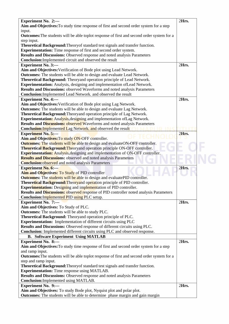
Experiment No. 2:---
Aim and Objectives:To study time response of first and second order system for a step
input.
Outcomes:The students will be able toplot response of first and second order system for a
step input.
Theoretical Background:Theoryof standard test signals and transfer function.
Experimentation: Time response of first and second order system.
Results and Discussions: Observed response and noted analysis Parameters
Conclusion:Implemented circuit and observed the result
2Hrs.
Experiment No. 3:---
Aim and Objectives:Verification of Bode plot using Lead Network.
Outcomes: The students will be able to design and evaluate Lead Network.
Theoretical Background: Theoryand operation principle of Lead Network.
Experimentation: Analysis, designing and implementation ofLead Network.
Results and Discussions: observed Waveforms and noted analysis Parameters
Conclusion:Implemented Lead Network. and observed the result
2Hrs.
Experiment No. 4:---
Aim and Objectives:Verification of Bode plot using Lag Network.
Outcomes: The students will be able to design and evaluate Lag Network.
Theoretical Background:Theoryand operation principle of Lag Network.
Experimentation: Analysis,designing and implementation ofLag Network.
Results and Discussions: observed Waveforms and noted analysis Parameters
Conclusion:Implemented Lag Network. and observed the result
2Hrs.
Experiment No. 5:---
Aim and Objectives:To study ON-OFF controller.
Outcomes: The students will be able to design and evaluateON-OFF controller.
Theoretical Background:Theoryand operation principle ON-OFF controller.
Experimentation: Analysis,designing and implementation of ON-OFF controller.
Results and Discussions: observed and noted analysis Parameters
Conclusion:observed and noted analysis Parameters
2Hrs.
Experiment No. 6:---
Aim and Objectives: To Study of PID controller
Outcomes: The students will be able to design and evaluatePID controller.
Theoretical Background:Theoryand operation principle of PID controller.
Experimentation: Designing and implementation of PID controller.
Results and Discussions: observed response of PID controller noted analysis Parameters
Conclusion:Implemented PID using PLC setup.
2Hrs.
Experiment No. 7:---
Aim and Objectives: To Study of PLC.
Outcomes: The students will be able to study PLC.
Theoretical Background: Theoryand operation principle of PLC.
Experimentation: Implementation of different circuits using PLC
Results and Discussions: Observed response of different circuits using PLC.
Conclusion: Implemented different circuits using PLC and observed response.
2Hrs.
B. Software Experiment Using MATLAB
Experiment No. 8:---
Aim and Objectives:To study time response of first and second order system for a step
and ramp input.
Outcomes:The students will be able toplot response of first and second order system for a
step and ramp input.
Theoretical Background:Theoryof standard test signals and transfer function.
Experimentation: Time response using MATLAB.
Results and Discussions: Observed response and noted analysis Parameters
Conclusion:Implemented using MATLAB.
2Hrs.
Experiment No. 9:---
Aim and Objectives: To study Bode plot, Nyquist plot and polar plot.
Outcomes: The students will be able to determine phase margin and gain margin
2Hrs.
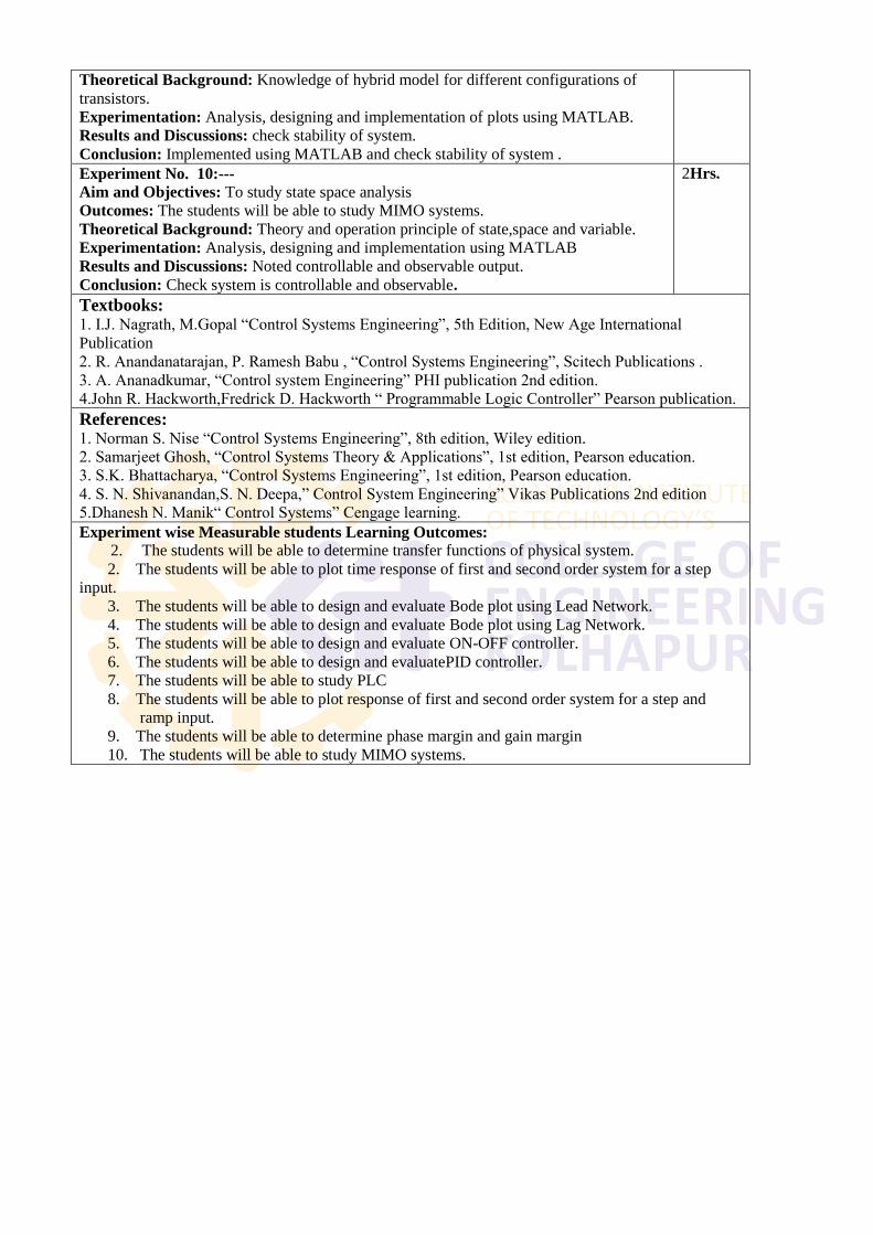
Theoretical Background: Knowledge of hybrid model for different configurations of
transistors.
Experimentation: Analysis, designing and implementation of plots using MATLAB.
Results and Discussions: check stability of system.
Conclusion: Implemented using MATLAB and check stability of system .
Experiment No. 10:---
Aim and Objectives: To study state space analysis
Outcomes: The students will be able to study MIMO systems.
Theoretical Background: Theory and operation principle of state,space and variable.
Experimentation: Analysis, designing and implementation using MATLAB
Results and Discussions: Noted controllable and observable output.
Conclusion: Check system is controllable and observable.
2Hrs.
Textbooks: 1. I.J. Nagrath, M.Gopal ―Control Systems Engineering‖, 5th Edition, New Age International
Publication
2. R. Anandanatarajan, P. Ramesh Babu , ―Control Systems Engineering‖, Scitech Publications .
3. A. Ananadkumar, ―Control system Engineering‖ PHI publication 2nd edition.
4.John R. Hackworth,Fredrick D. Hackworth ― Programmable Logic Controller‖ Pearson publication.
References: 1. Norman S. Nise ―Control Systems Engineering‖, 8th edition, Wiley edition.
2. Samarjeet Ghosh, ―Control Systems Theory & Applications‖, 1st edition, Pearson education.
3. S.K. Bhattacharya, ―Control Systems Engineering‖, 1st edition, Pearson education.
4. S. N. Shivanandan,S. N. Deepa,‖ Control System Engineering‖ Vikas Publications 2nd edition
5.Dhanesh N. Manik― Control Systems‖ Cengage learning.
Experiment wise Measurable students Learning Outcomes:
2. The students will be able to determine transfer functions of physical system.
2. The students will be able to plot time response of first and second order system for a step
input.
3. The students will be able to design and evaluate Bode plot using Lead Network.
4. The students will be able to design and evaluate Bode plot using Lag Network.
5. The students will be able to design and evaluate ON-OFF controller.
6. The students will be able to design and evaluatePID controller.
7. The students will be able to study PLC
8. The students will be able to plot response of first and second order system for a step and
ramp input.
9. The students will be able to determine phase margin and gain margin
10. The students will be able to study MIMO systems.
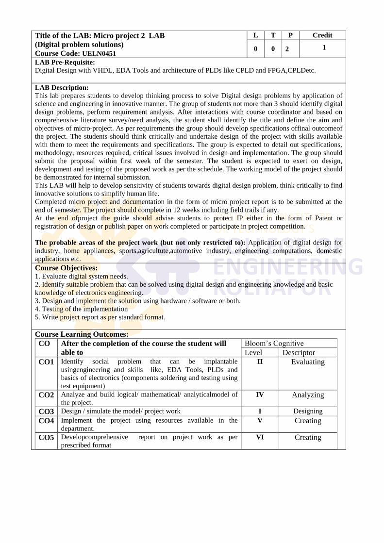
Title of the LAB: Micro project 2 LAB
(Digital problem solutions)
Course Code: UELN0451
L T P Credit
0 0
2
1
LAB Pre-Requisite: Digital Design with VHDL, EDA Tools and architecture of PLDs like CPLD and FPGA,CPLDetc.
LAB Description:
This lab prepares students to develop thinking process to solve Digital design problems by application of
science and engineering in innovative manner. The group of students not more than 3 should identify digital
design problems, perform requirement analysis. After interactions with course coordinator and based on
comprehensive literature survey/need analysis, the student shall identify the title and define the aim and
objectives of micro-project. As per requirements the group should develop specifications offinal outcomeof
the project. The students should think critically and undertake design of the project with skills available
with them to meet the requirements and specifications. The group is expected to detail out specifications,
methodology, resources required, critical issues involved in design and implementation. The group should
submit the proposal within first week of the semester. The student is expected to exert on design,
development and testing of the proposed work as per the schedule. The working model of the project should
be demonstrated for internal submission.
This LAB will help to develop sensitivity of students towards digital design problem, think critically to find
innovative solutions to simplify human life.
Completed micro project and documentation in the form of micro project report is to be submitted at the
end of semester. The project should complete in 12 weeks including field trails if any.
At the end ofproject the guide should advise students to protect IP either in the form of Patent or
registration of design or publish paper on work completed or participate in project competition.
The probable areas of the project work (but not only restricted to): Application of digital design for
industry, home appliances, sports,agricultute,automotive industry, engineering computations, domestic
applications etc.
Course Objectives: 1. Evaluate digital system needs.
2. Identify suitable problem that can be solved using digital design and engineering knowledge and basic
knowledge of electronics engineering.
3. Design and implement the solution using hardware / software or both.
4. Testing of the implementation
5. Write project report as per standard format.
Course Learning Outcomes:
CO After the completion of the course the student will
able to
Bloom‘s Cognitive
Level Descriptor
CO1 Identify social problem that can be implantable
usingengineering and skills like, EDA Tools, PLDs and
basics of electronics (components soldering and testing using
test equipment)
II Evaluating
CO2 Analyze and build logical/ mathematical/ analyticalmodel of
the project. IV Analyzing
CO3 Design / simulate the model/ project work I Designing
CO4 Implement the project using resources available in the
department. V Creating
CO5 Developcomprehensive report on project work as per
prescribed format VI Creating
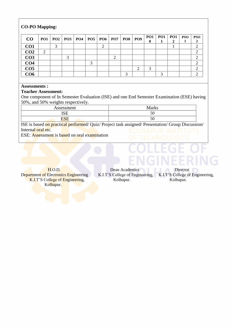
CO-PO Mapping:
CO PO1 PO2 PO3 PO4 PO5 PO6 PO7 PO8 PO9 PO1
0
PO1
1
PO1
2
PSO
1
PSO
2
CO1 3 2 1 2
CO2 2 2
CO3 3 2 2
CO4 3 2
CO5 2 3 2
CO6 3 3 2
Assessments :
Teacher Assessment:
One component of In Semester Evaluation (ISE) and one End Semester Examination (ESE) having
50%, and 50% weights respectively.
Assessment Marks
ISE 50
ESE 50
ISE is based on practical performed/ Quiz/ Project task assigned/ Presentation/ Group Discussion/
Internal oral etc.
ESE: Assessment is based on oral examination
H.O.D. Dean Academics Director
Department of Electronics Engineering K.I.T‘S College of Engineering, K.I.T‘S College of Engineering,
K.I.T‘S College of Engineering, Kolhapur. Kolhapur.
Kolhapur.
Related Documents