VERO TEC Electronics Packaging KM6 Subracks & Accessories

VEROTEC Km6-1_16.pdf · UK Tel: +44 (0)2380-246900 [email protected] USA Tel: 603.821.9921 [email protected] 1 KM6 Subracks 1.04 Guide clearance connector mounting holes
Jun 04, 2018
Welcome message from author
This document is posted to help you gain knowledge. Please leave a comment to let me know what you think about it! Share it to your friends and learn new things together.
Transcript

VEROTECElectronics Packaging
KM6 Subracks& Accessories

1.02 UK Tel: +44 (0)2380-246900 [email protected] Tel: 603.821.9921 [email protected]
1 K
M6
Su
bra
cks
KM
6
SU
BR
AC
KS OVERVIEW 1-16
Anintroductiontosubracksystems 3
EurocarddimensionalcriteriaforKM6subracksystems 4
IEC60297-3dimensionalcriteria 5-6
IEEE1101.10/11dimensionalcriteria 7-11
AguidetoEMCscreeningsubracks 12
Shockandvibration 13
Subrackmaterialsandfinishes 14
Customisingoptions 15
AguidetoKM6subracksystems 16
KM6-II SUBRACK SYSTEM 17-48
IntroductiontoKM6-II 17
KM6-IIDimensionalcriteria 18
KM6-IIStandardsubracks 19-20
KM6-IIUniversalsubracks 21-22
KM6-IIEMCconversion 23-27
KM6-IISubrackpieceparts 28-32
KM6-IIAccessories 33-48
KM6-RF SUBRACK SYSTEM 49-77
IntroductiontoKM6-RF 49-52
KM6-RF:3U,StyleAsubracks 53-54
KM6-RF:3U,StyleBsubracks 55-56
KM6-RF:6U,StyleAsubracks 57-58
KM6-RF:6U,StyleBsubracks 59-60
KM6-RF:3U,6U&9U,StyleCsubracks 61-62
KM6-RFSubrackpieceparts 63-73
KM6-RFAccessories 74-77
KM6-EC SUBRACK SYSTEM 79-82
IntroductiontoKM6-EC 80
KM6-ECSubracks 80
KM6-ECAccessories 81-82
KM6-HD SUBRACK SYSTEM 83-87
IntroductiontoKM6-HD 83-84
KM6-HDSubracks 84
KM6-HDSubrackpiecepartsandaccessories 85-87
KM6-II subrack system
KM6-RF subrack system
KM6-EC subrack system
KM6-HD subrack system
KM6 Subrack - Index
1.03UK Tel: +44 (0)2380-246900 [email protected] Tel: 603.821.9921 [email protected]
1 KM
6 S
ub
racks
An introduction to subrack systems
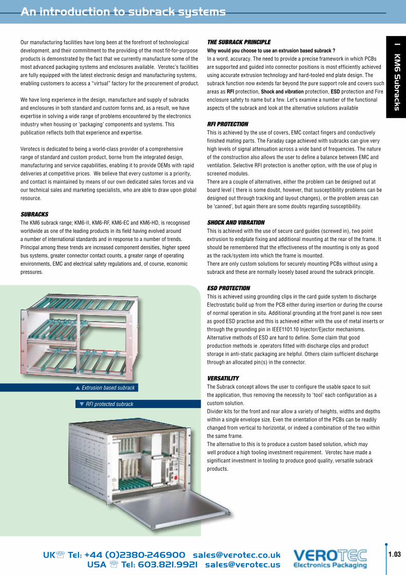
THE SUBRACK pRInCIplEWhy would you choose to use an extrusion based subrack ?
Inaword,accuracy.TheneedtoprovideapreciseframeworkinwhichPCBsaresupportedandguidedintoconnectorpositionsismostefficientlyachievedusingaccurateextrusiontechnologyandhard-tooledendplatedesign.ThesubrackfunctionnowextendsfarbeyondthepuresupportroleandcoverssuchareasasRFIprotection,Shock and vibrationprotection,ESDprotectionandFireenclosuresafetytonamebutafew.Let’sexamineanumberofthefunctionalaspectsofthesubrackandlookatthealternativesolutionsavailable
RFI pROTECTIOn Thisisachievedbytheuseofcovers,EMCcontactfingersandconductivelyfinishedmatingparts.TheFaradaycageachievedwithsubrackscangiveveryhighlevelsofsignalattenuationacrossawidebandoffrequencies.ThenatureoftheconstructionalsoallowstheusertodefineabalancebetweenEMCandventilation.SelectiveRFIprotectionisanotheroption,withtheuseofpluginscreenedmodules.Thereareacoupleofalternatives,eithertheproblemcanbedesignedoutatboardlevel(thereissomedoubt,however,thatsusceptibilityproblemscanbedesignedoutthroughtrackingandlayoutchanges),ortheproblemareascanbe‘canned’,butagaintherearesomedoubtsregardingsusceptibility.
SHOCK AnD VIBRATIOnThisisachievedwiththeuseofsecurecardguides(screwedin),twopointextrusiontoendplatefixingandadditionalmountingattherearoftheframe.Itshouldberememberedthattheeffectivenessofthemountingisonlyasgoodastherack/systemintowhichtheframeismounted.ThereareonlycustomsolutionsforsecurelymountingPCBswithoutusingasubrackandthesearenormallylooselybasedaroundthesubrackprinciple.
ESD pROTECTIOnThisisachievedusinggroundingclipsinthecardguidesystemtodischargeElectrostaticbuildupfromthePCBeitherduringinsertionorduringthecourseofnormaloperationinsitu.AdditionalgroundingatthefrontpanelisnowseenasgoodESDpractiseandthisisachievedeitherwiththeuseofmetalinsertsorthroughthegroundingpininIEEE1101.10Injector/Ejectormechanisms.AlternativemethodsofESDarehardtodefine.Someclaimthatgoodproductionmethodsie.operatorsfittedwithdischargeclipsandproductstorageinanti-staticpackagingarehelpful.Othersclaimsufficientdischargethroughanallocatedpin(s)intheconnector.
VERSATIlITYTheSubrackconceptallowstheusertoconfiguretheusablespacetosuittheapplication,thusremovingthenecessityto‘tool’eachconfigurationasacustomsolution.Dividerkitsforthefrontandrearallowavarietyofheights,widthsanddepthswithinasingleenvelopesize.EventheorientationofthePCBscanbereadilychangedfromverticaltohorizontal,orindeedacombinationofthetwowithinthesameframe.Thealternativetothisistoproduceacustombasedsolution,whichmaywellproduceahightoolinginvestmentrequirement.Verotechavemadeasignificantinvestmentintoolingtoproducegoodquality,versatilesubrackproducts.
Ourmanufacturingfacilitieshavelongbeenattheforefrontoftechnologicaldevelopment,andtheircommitmenttotheprovidingofthemostfit-for-purposeproductsisdemonstratedbythefactthatwecurrentlymanufacturesomeofthemostadvancedpackagingsystemsandenclosuresavailable.Verotec’sfacilitiesarefullyequippedwiththelatestelectronicdesignandmanufacturingsystems,enablingcustomerstoaccessa“virtual”factoryfortheprocurementofproduct.
Wehavelongexperienceinthedesign,manufactureandsupplyofsubracksandenclosuresinbothstandardandcustomformsand,asaresult,wehaveexpertiseinsolvingawiderangeofproblemsencounteredbytheelectronicsindustrywhenhousingor‘packaging’componentsandsystems.Thispublicationreflectsboththatexperienceandexpertise.
Verotecsisdedicatedtobeingaworld-classproviderofacomprehensiverangeofstandardandcustomproduct,bornefromtheintegrateddesign,manufacturingandservicecapabilities,enablingittoprovideOEMswithrapiddeliveriesatcompetitiveprices.Webelievethateverycustomerisapriority,andcontactismaintainedbymeansofourowndedicatedsalesforcesandviaourtechnicalsalesandmarketingspecialists,whoareabletodrawuponglobalresource.
SUBRACKSTheKM6subrackrange;KM6-II,KM6-RF,KM6-ECandKM6-HD,isrecognisedworldwideasoneoftheleadingproductsinitsfieldhavingevolvedaroundanumberofinternationalstandardsandinresponsetoanumberoftrends.Principalamongthesetrendsareincreasedcomponentdensities,higherspeedbussystems,greaterconnectorcontactcounts,agreaterrangeofoperatingenvironments,EMCandelectricalsafetyregulationsand,ofcourse,economicpressures.
RFI protected subrack
Extrusion based subrack

UK Tel: +44 (0)2380-246900 [email protected] Tel: 603.821.9921 [email protected]
1 K
M6
Su
bra
cks
1.04
Guideclearance
connectormountingholes
Guideclearance
SInGlE EUROCARD
frontpanel/mountingholescardejector
connectormountingholes
frontpanel/cardejectormountingholes
DOUBlE EUROCARD
Please note: Certain plastics can be adversely affected by organic solvents. Care
should be taken to avoid contamination by some cleaning agents, for instance.
With modified PPO's and PPE's such as Luranyl we recommend that when using
thread locking compounds they should be cyanoacrylate based, not anaerobic.
Eurocard dimensional criteria for KM6 subrack systems
InTRODUCTIOnKM6Subracksaredesignedaroundanumberofdimensionalstandardsthataimtoprovideabasiclevelofinterchangeabilitybetweendifferentversionsandbetweenmanufacturersofsimilarsystems.
The basis is the DIN41494 Eurocard standard.ThedimensionsforthehousingofEurocardsaredescribedinIEC60297section3SC48D.Plug-inunitsaremodularinconceptandarebasedonthefirstcardpositionbeing3,27mmfromthelefthanddatumlineoftheworkingaperture;subsequentcardpositionsareonmultiplesof5,08mm(1HP)fromthisfirstcardposition.
Toallowforauniformworkingclearancebetweenfrontpanels,whenused,theoverallwidthofafrontpanelis0,4mmlessthanthenominalHPx5,08dimensionsgenerallyquoted.
HeightsarenominallyquotedinU’s(multiplesof44,45mm)butitshouldbeborneinmindthatadevicequotedasnUhighwillnotbenx44,45mminoverallheight.
KM6-subrackscanaccommodateconnectorstoIEC130-4,DIN41612andVG95324specificationsormotherboardstotheIEC60297-3specification
Inaddition,referencewillbefoundtotheIEEE1101.1,.10and.11whichexpandontheabovespecificationsandforwhichKM6-RFprovidessuitableproduct.ThesedescribeanumberoffeaturesparticularlyrelevanttoVME64x,CompactPCI®andPXIbusstructures.
EUROCARDS - CRITICAl DIMEnSIOnSAswiththerestofthesystemtheprintedcircuitboardsizesarestandardised.AllPCBsshouldbeoftheEurocardsizeandconformtothelayoutshown.
A2,50mmwideborderisnecessaryatthetopandbottomofprintedcircuitboardstoallowclearanceforfittingintocardguidesandformountingintoplug-inunitguiderails.
OnthedoubleheightEurocard,owingtotheoverallsizeandpositionoftheconnectors,itisrecommendedthatwhenfittingcomponentstothefrontpanelsthegridaslaidouthereisadopted.Thiswillallowconsistencybetween3Uand6Uheightfrontpanelsifmixedconfigurationsareutilised.
USEFUl FROnT pAnEl AnD CIRCUIT BOARD DIMEnSIOnSThesedimensionsareusefulwhenaEurocardistobeattachedtoaKM6frontpanelusingcardmountingbrackets.
Connectortype(DIN41612) B C D E F G HDIMX 7,6 9,4 9,4 14,4 11,3 16,3 11,3
Carddepth+9,93(contypesB,C,D)+11,93(contypesF,G,H)
Normalposition
Adjacentfrontpanelpositions
Subrack front section features

UK Tel: +44 (0)2380-246900 [email protected] Tel: 603.821.9921 [email protected]
1 KM
6 S
ub
racks
1.05
IEC 60297-3 dimensional criteria
A
A
3
10,16 6
<449
11,75
>22
'Y'
'X'
2,54
2
3,27
2,54
TheseillustrationsshowdimensionsextractedfromIEC60297-3.Theyarenotcomprehensive,butshouldprovegenerallyinformative
Subrackdimensionsshownarefor3Ux84HPandsingleEurocardsHeightsincrementby44,45mm(1U)Widthsincrementby5,08mm(1HP)
Scrapviewof6Ushowingdimensionsavailablefor
centrerearextrusionwith6Uplug-inunits
ToaccommodatePCB1,6mm±0,2Pi
tch
line
Detail'X'
Rear
atta
chm
entp
lane
Detail'Y'
Pitc
hlin
e
5,08Typ
Firs
tfa
sten
ing
loca
tion
3U=
133
,35
Nom
inal
PCBPositionsincrementallyby5,08multiples
482,6Nominal
Aperture>84x5,08
Cent
reli
nefi
rst
PCB
EurocardCompatible
100+0/-0,30
Aper
ture
M1
12

UK Tel: +44 (0)2380-246900 [email protected] Tel: 603.821.9921 [email protected]
1 K
M6
Su
bra
cks
1.06
PCB
'V'
84x5,08
3,55
0,30,3
5,63
2,54
'W' 'Z'
6
175,24*
1,5
175,24*175,24*
2,5
2,54
4,07
8,8
3,62,7
M2,5
'U'7,62
nx5,08nx5,08
7,5
7,62
ab abc
128,
7+0
/-0,
3
90
122,
5±0,
2
IEC 60297-3 dimensional criteria
Detail'W' Alternativedetail'W'Optionalspacerm3
DIn 41612 connector mounted
on motherboard
Alternative for direct mounting of DIn 41612
connectors
*Rearattachmentplane(i.e.ConnectorMountingFace)ForDIN41612typesBCDMQRS
FortypesFGUVadd10mm
Motherboard
fixingcentres122,5
Guide
Fron
tpan
elfi
ce
ntre
s12
2,5
Detail'Z'
Frontattachmentplane
Section'A-A'
Fixingholesincrementingonmultiplesof5,08asrequired
Fixingholesonmultiplesof5,08
MotherboarddimensionsshowingType'B'&'C'DIN41612
connectorpositionsFrontview
Detail'U'
Pitc
hlin
e
Frontattachmentplane
Pitc
hlin
e
Detail'V'
Limitofcomponentmountingarea
Pitchline
2,5
90
122,
512
8,7
Type
‘B’
Type
‘C’
Pitc
hlin
e2,
54
5,63

UK Tel: +44 (0)2380-246900 [email protected] Tel: 603.821.9921 [email protected]
1 KM
6 S
ub
racks
1.07
InTRODUCTIOn
IEEE1101.1islargelyareiterationofthebasicIEC60297-3standard,withsomechangestoreflect.10and.11
IEEE110.10wasdrivenbyanumberofrequirements:ThestandardisationofEMCfrontpanelgeometrytoensurecompatibilitybetweenvariousmanufacturers’products.
Theintroductionofthefive-rowDIN41612connectorintoVMEandtheincorporationofMetricstandardconnectors.Bothhaveveryhighpincountsandresultanthighinsertion/withdrawalforcesthatrequireastandardinjector/extractorhandlegeometry.
Thestandardalsoaddressestheproblemsofelectrostaticprotectionandaneedtocodeplug-inunitstopreventincorrectplug-up,wheresuchactionscouldhavecatastrophicresults(inparticularinliveinsertionsituations).
IEEE1101.11standardisesthegeometryofrearplug-up(transition)moduleswherenopreviousstandardexisted.Rearplug-up-ortransition-isusedandrequiredwithinthecorespecificationsofmajoropen-architecturebusstructureswhereamidplaneisusedtoprovidearearI/Ointerface.
IEEE 1101.10/11 dimensional criteria
3,5
2,5
10 5,5
2,54
3x5,08 5,08
10,165,082,5l
2,0
max
0,5min
1,0max
4x5,08
15,24
Injector/Extractoroperatingfeature
EMCseals
Infill(blank)panel
Coding/ESDfeature
Injector/Extractor
Boxtypepluginunit
ConductivesurfacesorEMCgasket
Typical arrangement of 1101.10 subrack
Subrack conductive areas
Subrack Injector / extractor operating feature
3,4Ø(dia)
2,54 2,54 2,54
Subrack mounted coding / ESD feature
2,54
2,54
5,08
5,08
2,5
min

UK Tel: +44 (0)2380-246900 [email protected] Tel: 603.821.9921 [email protected]
1 K
M6
Su
bra
cks
1.08
IEEE 1101.10/11 dimensional criteria
Typicalplug-inunitshowinginjector/extractorcoding,ESDandfrontpanel
geometry
4max
(1,6)
(1,5)
(1,32)
(13,71)(maxcomponent
height)
(2,54)
14,1
2,5
2,0
max
3,8
max
1,15max
0,5min
1,0max
3,8
max
2,5
min
1,26
plug-in unit detail
Protectivecover(optional)
4HP(4x5,08)Typical
10
2,5
m14,5
m38
3,8
1,5
Test
dim
ensi
on(N
xU
)-4
,35
+0,
55
-0
,0
Detail for extractor
23max
Usab
lec
ompo
nent
spa
ce
location ESD detail
106
(3U)
239.
35(6
U)37
2.7
(9U)
4,9
3,1
3,14,75
13,0
4,4
7,64,62,4
2,4
2,1
1,0
Coding key
Interaction of coding key

UK Tel: +44 (0)2380-246900 [email protected] Tel: 603.821.9921 [email protected]
1 KM
6 S
ub
racks
1.09
IEEE 1101.10/11 dimensional criteria
M10
m60
A B C AC B
DEF FED
(160) (160)
2,76
0,5
153,67 (153.67)M70
1,5
2,5
2,76
0,5 5
0,5
Subrackfrontview
Alignment/ESDfeature
Alignment/ESDpin
1234Empty
Keyingchamber(subrackmounted) Keyingchamber
frontpanel
PrintedBoard
BoardtypePlug-inunitRearView
KeyingOptions
FrontExtrusion
Guiderail
Frontattachmentplane
GuiderailESDcontactarea
Rear Rear
Componentside Componentside
ESDcontactbreaksbeforeconnectorengagement ESDcontactmaintainedduringconnectorengagement
pCB ESD Contact strips top / bottom
1234Empty
1234Empty
1234Empty

UK Tel: +44 (0)2380-246900 [email protected] Tel: 603.821.9921 [email protected]
1 K
M6
Su
bra
cks
1.010
IEEE 1101.10/11 dimensional criteria
160
153,67
Db
Da
400340280220160100 6080100120140160
Rear
Dimensionsreferto160unit
Front rear plug-up options
In line configuration for rear (transition) plug-up EMC panels.
EMCseals
Injector/extractoroperatingfeature
EMCseals
Infill(blank)panel
CodingESDfeature
Injector/extractor
Rear(transition)plug-upunit
Typical arrangement of 1101.11 subrack with rear plug-up
Midplane
Front
Midplane
1003U233,356U366,79U
Rear(transition)plug-upunit/frontpanel
Midplane
Front(transition)plug-upunit/frontpanel
1.10

UK Tel: +44 (0)2380-246900 [email protected] Tel: 603.821.9921 [email protected]
1 KM
6 S
ub
racks
1.011
IEEE 1101.10/11 dimensional criteria
160
M6
172.8(1076.4.x)
182.48
max6170.3(IEC603-2)
InspectionDimension
Rear(transition)plugupdetail3Ushown
ESD/Electricalsafetyground
Framemountedcoding/ESD/location/electricalsafetygroundfeature
Midplane
Rearplug-updimensions(160shown)
SeeIEEE1101.1
Frontfixedconnector
Rearfixedconnector
Rearfreeconnector
Spacer(userdefined)
LockinginterfaceSeeIEC603-21
1076-4-x
Attachmentplane
(160shown)169.88(IEC603-2)172.38(IEC1076-4-x)
1.11
UK Tel: +44 (0)2380-246900 [email protected] Tel: 603.821.9921 [email protected]
1 K
M6
Su
bra
cks
1.12
A guide to EMC screening subracks
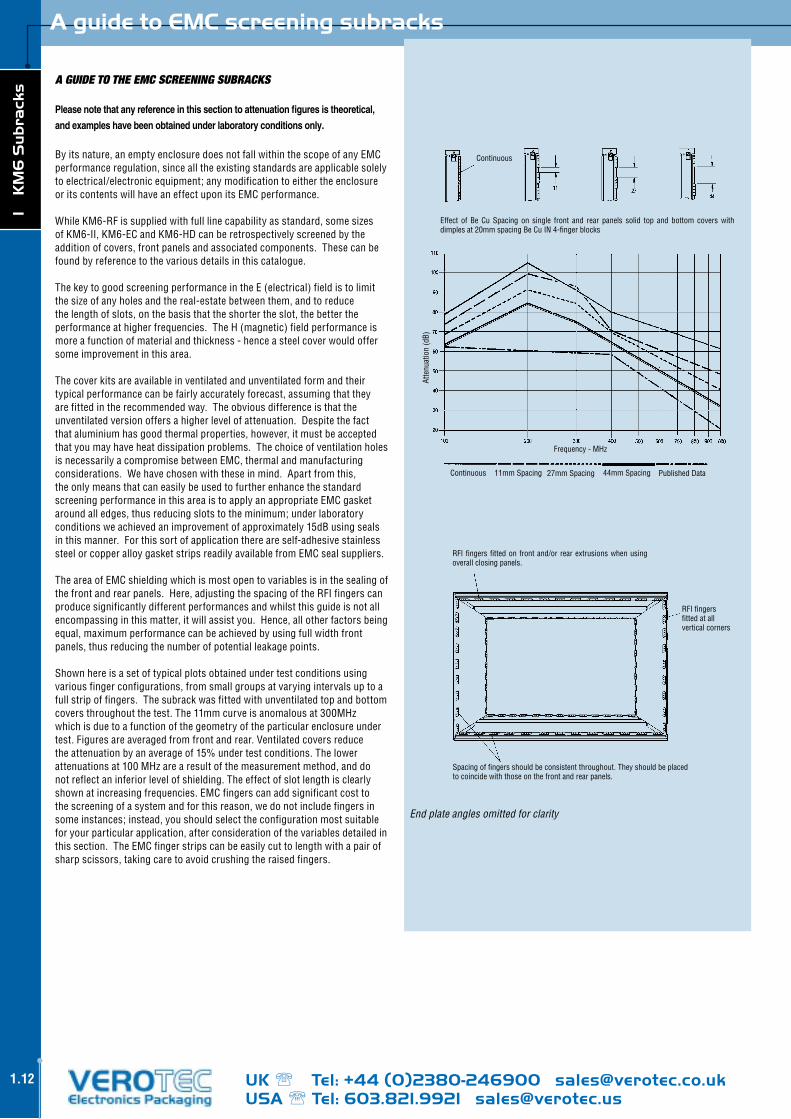
A GUIDE TO THE EMC SCREEnInG SUBRACKS
Please note that any reference in this section to attenuation figures is theoretical,
and examples have been obtained under laboratory conditions only.
Byitsnature,anemptyenclosuredoesnotfallwithinthescopeofanyEMCperformanceregulation,sincealltheexistingstandardsareapplicablesolelytoelectrical/electronicequipment;anymodificationtoeithertheenclosureoritscontentswillhaveaneffectuponitsEMCperformance.
WhileKM6-RFissuppliedwithfulllinecapabilityasstandard,somesizesofKM6-II,KM6-ECandKM6-HDcanberetrospectivelyscreenedbytheadditionofcovers,frontpanelsandassociatedcomponents.Thesecanbefoundbyreferencetothevariousdetailsinthiscatalogue.
ThekeytogoodscreeningperformanceintheE(electrical)fieldistolimitthesizeofanyholesandthereal-estatebetweenthem,andtoreducethelengthofslots,onthebasisthattheshortertheslot,thebettertheperformanceathigherfrequencies.TheH(magnetic)fieldperformanceismoreafunctionofmaterialandthickness-henceasteelcoverwouldoffersomeimprovementinthisarea.
Thecoverkitsareavailableinventilatedandunventilatedformandtheirtypicalperformancecanbefairlyaccuratelyforecast,assumingthattheyarefittedintherecommendedway.Theobviousdifferenceisthattheunventilatedversionoffersahigherlevelofattenuation.Despitethefactthataluminiumhasgoodthermalproperties,however,itmustbeacceptedthatyoumayhaveheatdissipationproblems.ThechoiceofventilationholesisnecessarilyacompromisebetweenEMC,thermalandmanufacturingconsiderations.Wehavechosenwiththeseinmind.Apartfromthis,theonlymeansthatcaneasilybeusedtofurtherenhancethestandardscreeningperformanceinthisareaistoapplyanappropriateEMCgasketaroundalledges,thusreducingslotstotheminimum;underlaboratoryconditionsweachievedanimprovementofapproximately15dBusingsealsinthismanner.Forthissortofapplicationthereareself-adhesivestainlesssteelorcopperalloygasketstripsreadilyavailablefromEMCsealsuppliers.
TheareaofEMCshieldingwhichismostopentovariablesisinthesealingofthefrontandrearpanels.Here,adjustingthespacingoftheRFIfingerscanproducesignificantlydifferentperformancesandwhilstthisguideisnotallencompassinginthismatter,itwillassistyou.Hence,allotherfactorsbeingequal,maximumperformancecanbeachievedbyusingfullwidthfrontpanels,thusreducingthenumberofpotentialleakagepoints.
Shownhereisasetoftypicalplotsobtainedundertestconditionsusingvariousfingerconfigurations,fromsmallgroupsatvaryingintervalsuptoafullstripoffingers.Thesubrackwasfittedwithunventilatedtopandbottomcoversthroughoutthetest.The11mmcurveisanomalousat300MHzwhichisduetoafunctionofthegeometryoftheparticularenclosureundertest.Figuresareaveragedfromfrontandrear.Ventilatedcoversreducetheattenuationbyanaverageof15%undertestconditions.Thelowerattenuationsat100MHzarearesultofthemeasurementmethod,anddonotreflectaninferiorlevelofshielding.Theeffectofslotlengthisclearlyshownatincreasingfrequencies.EMCfingerscanaddsignificantcosttothescreeningofasystemandforthisreason,wedonotincludefingersinsomeinstances;instead,youshouldselecttheconfigurationmostsuitableforyourparticularapplication,afterconsiderationofthevariablesdetailedinthissection.TheEMCfingerstripscanbeeasilycuttolengthwithapairofsharpscissors,takingcaretoavoidcrushingtheraisedfingers.
Continuous
Atte
nuat
ion
(dB)
Effect of Be Cu Spacing on single front and rear panels solid top and bottom covers withdimplesat20mmspacingBeCuIN4-fingerblocks
PublishedData
Frequency-MHz
Continuous 11mmSpacing 27mmSpacing 44mmSpacing
Spacingoffingersshouldbeconsistentthroughout.Theyshouldbeplacedtocoincidewiththoseonthefrontandrearpanels.
RFIfingersfittedatallverticalcorners
RFIfingersfittedonfrontand/orrearextrusionswhenusingoverallclosingpanels.
End plate angles omitted for clarity

UK Tel: +44 (0)2380-246900 [email protected] Tel: 603.821.9921 [email protected]
1 KM
6 S
ub
racks
1.13
Shock and vibration
Theincreasinguseofelectronicsinsuchapplicationsasmobile,roadside,factoryandearthquakeenvironmentshasledtoanincreasedawarenessoftheeffectsofshockandvibrationonfullsystems.
Theuseofsubracksintheseconditionsisgenerallylimitedbyanumberoffactors.
1) Theloading-bothtotalweightanditsdistribution;increasedheightto someextentimprovestheverticalstability;increasingwidthadversely affectsitsresistancetovibrationintheverticalaxisandthedeflectionof horizontalcomponents;increasingdepthencourages‘parallelogramming’ insidewaysshockandvibration.Placingheaviercomponentsascloseas possibletothemajorfixingpointswillalsohelpinallaxes.
2) Theoverallconstruction-aboxstructure(ieonewhichhassecurely fittedtopandbottom,frontandrearcovers)willbemuchmorerigidthan asimpleframework.Here,backplanes,frontandrearpanelswithmultiple fixings,offerconsiderablebenefit.
3) Constrainingtheassemblyattherear,aswellasthefront,providesan extremelygoodreturnfortheeffort.Carefuldesignherecanprevent movementinsidewaysandverticaldirections.
4) Positiveretentionofguidesaddstothecapabilityoftheassembly.Itis recommendedforparticularlyheavyplug-inssuchaspowersupplies, especiallyintransit,whereitmaybesubjectedtovibrationandshockon stifflysuspendedtrucksorduringhandling.
5) Themostdifficultproblemforthesubrackmanufactureristoadd asmuchmaterialtoextrusionswhilstmaintainingintegritywiththedimensionalstandardssuchasIEEE1101.1,ataslowacostaspossible andwithoutrestrictingairflowtoomuch.
6) LargePCBswillreactbadlytosidewaysvibrationandmayrequirethe incorporationofstiffeningdevicessecurelyfixedatcloseintervalsto prevent‘snaking’or‘panting’,bothofwhichputconsiderablestresson componentconnections.
Therearealargenumberofspecificationsandstandardswhichcanbeinvokedtoexpressthetestingrequirements,someofwhichareveryspecific,someextremelywidelydrawn.Amongthelatteryoumayfindmilitaryspecificationswhichareintendedtocoverawiderangeofenvironmentsfromstorageandtransport,throughship-borne,toairborneandmissileapplications.
Itisimportanttonotethatwhilst,Veroteccanmeetmostrequirements,overspecifyingtestanalysiswillinevitablycanleadtounnecessarycostpenalties,withlittleoverallagainattheendoftheprocess.
Inordertoensurethatyouselecttherightsubrack,orrequestthecorrecttestsetbeforeinstallingyoursystems,adiscussionofyourneedswithoneofourapplicationsspecialistsmaybebeneficial.
ForfurtherdetailspleasecontactourApplicationsSupportTeam
Subrack shock and vibration

UK Tel: +44 (0)2380-246900 [email protected] Tel: 603.821.9921 [email protected]
1 K
M6
Su
bra
cks
1.14
Subrack materials and finishes
Althoughaluminiumcanbeseenasamoreexpensivematerialthan,forinstance,steel,itoffersseveralbenefitsinthedesignandconstructionofsubrackswhichmakesithighlysuitable.Thereductioninweightwhichitoffersisparticularlyusefulfor‘one-man’handlinginrestrictedspaceandlessthanidealheights.Additionally,ithasexcellentheatconductionproperties.
Inextrudedform,itispossibletodesign-inawidevarietyoffeatureswhichwouldbedifficultandexpensivetoincorporateintoformedandmachinedmaterials.Italsopermitseasychangesoflength.
Thereareanumberofwaysofspecifyingtheactualmaterial-weuseBS1474.6063T6extrusion.
Insheetform,aluminiumcanoffergoodrigidityforitsweightandisrelativelyeasytopunchandhalfshearaccurately,withminimumtoolwear.OuraluminiumsheetisBSEN485-25251(H12-H26).
Ideally,fromthepointofviewofcorrosionandscuffresistanceandforagooddecorativefinish,anodisingisexcellent.Ourin-houseanodisingistoourownspecificationandwearerightlyproudoftheexcellentappearanceitproduces.
Aprocessknownas‘sub-surfaceprinting’isidealwhereapermanentwearandchemicalresistancearecalledfor,consistingofidentificationprintingbeforetheapplicationoftheanodicfilm.
Anodicfilm,whichiselectrolyticallyappliedisanexcellentinsulator.Itisthereforeunsuitableinmodernsubracksystemswhichneedtobeelectricallybondedduetoproblemsfromelectrostatics;theyalsofrequentlyhavetobeEMCscreenedbytheapplicationofcoversandpanelswhichmustallbeelectricallycontinuousasfaraspossible.
Forthatreason,mostofVerotec’ssubracksystemcomponentsarenowfinishedbymeansofachromateconversionprocess(typicaltradetermsareIrridite,Alocrom,Alodine).Thisprocessensuresthatthealuminiummaterialshaveagooddegreeofcorrosionresistance,whichinturnprevents‘selfanodising’overtime.Clearchromatehaslowsurfaceresistivity(lowerthanthecolourtypes)butbecauseitisonlyasurfacefilmcanbeaffectedbyscuffingandfinger-marking.Forthatreason,careshouldbetakenduringhandling.However,ithasagoodappearance.Fromaproductionpointofview,theuseofsteelinKM6-RFcoversoffersbenefitsinthatitprovidesstiffnessatlowerthicknesses.WeusemildsteelsheetCR4toBSEN10130
IncommonwithmoststeelcomponentsandfixingsthroughouttheVerotecsubrackrange,weuseclearpassivatedzincplatingtoprovidecorrosionresistancewithanacceptableappearance-althoughthecolourpassivationusedontappedstripsprovidesmuchgreaterprotectionagainstfrontpanelfixingscrews‘freezing’inprolongeduseorharshclimaticenvironments.
Mouldedplasticsareusedwherecomplexshapedcomponentsareusedinlargevolumes.Thereisahugerangeofbasicmaterialsavailable,butingeneralwearelookingforacosteffectiveplasticthathasgoodmouldingproperties,ismechanicallyanddimensionallystableoverafairlywiderangeoftemperaturesandhumidities,andconformstomodernrequirementsinfireresistance.ThelatterisusuallyexpressedasUL94-V*
(V0isthehighestlevel,V1beinggenerallyaslowaswewouldaccept).ItisimportanttonotethattheUL94testhasanumberofgradationsinthicknessandtestapplication.
Oneofthemajorproblemsassociatedwithplasticsistheirsusceptibilitytoattackbychemicalsolventsandwemakefrequentreferencetothis.Thiskindofdamagefrequentlyonlyshowswhenthematerialisunderstress(whenitisscreweddown,forinstance)andiscommonlycausedbythreadlockcompoundsorcleaningsolvents.Wherebreakagesoccur,asampleoftheitemconcernedcanusuallyestablishthenatureoftheproblem.
Itisimportanttonotethatmostplasticcomponentshavefine‘knitlines’wherethematerialflowsjoinduringthemouldingprocess-theyarenotnormallydeleterioustoperformancealthoughtheyarefrequentlymistakenforincipientcracks.
Theadditionofglassfibresaddstothestrengthofmouldedcomponents,andistypicallyusedinapplicationslikeinjector/extractors.Itisusedjudiciouslybecauseittendstoacceleratetoolwear.
MostofourmouldedsubrackcomponentsareproducedinmodifiedPPO(PolyphenyleneOxide)-typicallyunderthetradenamesLuranylorNoryl,orPolycarbonates-Makrolonforinstance.Thelatterisalsosuppliedinsheetformfortransparentpanels.
IntheareaofEMCseals,thereisageneraltrendtostainlesssteel,awayfromBerylliumCopper.Thelatterhasexcellentforming,spring,andconductiveproperties,butthereisconcernaboutitsdisposalattheendofequipmentlifecycles.
Subrack material and finishes

UK Tel: +44 (0)2380-246900 [email protected] Tel: 603.821.9921 [email protected]
1 KM
6 S
ub
racks
1.15
CUSTOMISInG SERVICE
Verotechasmanyyearsofexperienceinthedesignandproductionofcustomisedsubracks.
Mostofourstandardsubracksareeasilymodifiedinordertosuitawiderangeofapplications.
ThelistbelowgivesthecustomisingoptionsavailableoneachofourKM6systems.Alsoillustratedareexamplesofmodifiedsubrackswhichwecurrentlyproduceforvariouscustomers.
Pleasecontactusforfurtheradviceandassistance.
CUSTOMISInG OpTIOnS
n Height
n Width
n Depth
n Punching/Drilling n SurfacePrinting n SubsurfacePrinting n Engraving n Alocrom/Irridite n Painting n Plating n Assembly n Wiring n BackplaneAssembly n Cooling n Kitting n BulkPacking n RFICapability n Anodising
Customising options
Customised/printed front panels
Special subrack
Customised KM6-II subrack
Customised side panelCustomised KM6-subrack

UK Tel: +44 (0)2380-246900 [email protected] Tel: 603.821.9921 [email protected]
1 K
M6
Su
bra
cks
1.16
A guide to KM6 subrack systems
KM6-II subrack system
KM6-RF subrack system
KM6-EC subrack system
KM6-HD subrack system
InTRODUCTIOn
In order to meet the diverse mechanical, electrical and environmentalrequirementsthattoday’smarkets&applicationsdemand,Verotecofferfourdistinct subrack ranges. All are designed around a number of dimensionalstandards that aim to provide a basic level of interchangeability betweendifferentversionsandbetweenmanufacturesofsimilarsystems.Thebasisis theDIN41494Eurocardstandardand thedimensions for thehousingofEurocardsaredescribedinIEC60297-3,towhichKM6-IIisdesigned.KM6-RFtooisdesignedaroundthisspecificationbutalsomeetstherequirementsofIEEE1101.10/11whichbuildsonIEC60297-3toofferadditionalfunctionality.For high volume and price sensitive applications such as infrastructureprojects,thelowcostKM6-ECisanidealsolution.Verotec’sanswertoheavyduty applications is the KM6-HD subrack which is designed to meet MIL-STD-167andthereforemakesitsuitableforapplicationswhereresistancetoexcessshockandvibrationisrequired.
KM6-II SUBRACK SYSTEM
Fully compatible with DIN 41494 part 5 and IEC 60297-3, KM6-II subracksarestrong,versatileandeasytoassemble.Alltiebarshavetwoscrewfixingpositionsmakingtheconstructionrobustyetaccurateandwellsuitedtolightandmediumduty applications. The range is extensive, offering3U,4U,6Uand9Uheightsinwidthof24,42,60&84HPanddepthsof160,240,300,360&420mm.KM6-IISubracksaresuppliedeitherinkitformorindividualcomponent parts and are complimented by a wide range of accessories,includingEMCconversionkits,guides,frontpanelsandplug-inmodules.
KM6-RF SUBRACK SYSTEM
The KM6-RF subrack range meets the requirements of IEEE 1101.10 & 11,whichexpandsonIEC60297toaddfunctionalityrequiredformodernindustrialcomputingapplications.ThisincludesRFIshielding,areartransitionarea,frontpanelESD/codingandhandleswithaninjector/extractoroperatingfeature.KM6-RFisthereforewellsuitedtoVME64x,CompactPCIandPXIapplications,serving typical markets such as Telecoms, Medical and Instrumentation.Therangecatersforvariouscombinationsofheight,widthanddepthandiscomplimentedbyawiderangeofaccessories,includingguides,frontpanelsandplug-inmodules.KM6-RFsubracksaresuppliedincompletekitsorintheircomponentparts.
KM6-EC SUBRACK SYSTEM
KM6-ECsubrackshavebeendesignedandaresuitableforhighvolume,costsensitiveapplications.Whilsttheyarestillversatileandfullyconformtotherequirements of IEC60297, care has been taken to remove certain featuresfound in theKM6-II range to reduce themanufacturingcost.These includelighterextrusionprofiles,single-pointtiebarfixings(ratherthandouble)andZintecsideplates(ratherthanaluminium).TheyarebackwardcompatiblewithmanyofthestandardKM6-IIaccessoriesincludingcardguides,frontpanels,plug-inmodulesandcovers.
KM6-HD SUBRACK SYSTEM
The KM6-HD subrack system although primarily designed for military use,wouldsuitanyruggedapplicationwherearesistancetoshockandvibrationis required. Built to meet MIL-STD-167, its features include positive guideretention,heavytwoscrewfixingtiebars,3mmthicksideplates&rackanglesandaconductive finish throughout.TheKM6-HDsubrackacceptsstandardEurocards in3U,6U&9Uheights anddepthsofup to400mm inboth theIEC297andIEEE1101.10standards.TheyaresuppliedfullyassembledandcomplimentedbythestandardrangeofKM6accessories.
Related Documents