Revision B: June 7, 2016 Document No. 13-206CGW PILOT’S OPERATING HANDBOOK and FAA-Approved Airplane Flight Manual Supplement for the KING AIR MODEL C90/C90A Equipped with Raisbeck Engineering: Swept Blade Turbofan Propellers - STC SA3593NM Dual Aft Body Strakes - STC SA4010NM Increased Gross Weight - STC SA3593NM Increased ITT and Cruise Speeds - STC SA3593NM Optional 1,600 Cruise RPM - STC SA3593NM C90: LJ-527 thru LJ-1062 (including C90,C90-1) C90A: LJ-1063 thru LJ-1726, LJ-1728 thru LJ-1753, LJ-1755 (including C90A,C90B,C90SE)

Welcome message from author
This document is posted to help you gain knowledge. Please leave a comment to let me know what you think about it! Share it to your friends and learn new things together.
Transcript

Revision B: June 7, 2016 Document No. 13-206CGW
PILOT’S OPERATING HANDBOOK and
FAA-Approved Airplane Flight Manual Supplement
for the
KING AIR MODEL C90/C90A
Equipped with Raisbeck Engineering: Swept Blade Turbofan Propellers - STC SA3593NM Dual Aft Body Strakes - STC SA4010NM Increased Gross Weight - STC SA3593NM Increased ITT and Cruise Speeds - STC SA3593NM Optional 1,600 Cruise RPM - STC SA3593NM
C90: LJ-527 thru LJ-1062 (including C90,C90-1) C90A: LJ-1063 thru LJ-1726, LJ-1728 thru LJ-1753,
LJ-1755 (including C90A,C90B,C90SE)
BEECHCRAFT King Air C90/C90A Equipped With: Swept Blade Turbofan Propellers Dual Aft Body Strakes Document No. 13-206CGW Increased Gross Weight
FAA-Approved: Revision B: June 7, 2016 i
PILOT’S OPERATING HANDBOOK AND FAA-APPROVED
AIRPLANE FLIGHT MANUAL SUPPLEMENT FOR BEECHCRAFT KING AIR MODELS
C90/C90A
Equipped with Raisbeck Engineering: Swept Blade Turbofan Propellers - STC SA3593NM Dual Aft Body Strakes - STC SA4010NM Increased Gross Weight - STC SA3593NM (for PT6A-21 powered aircraft) Increased ITT and Cruise Speeds - STC SA3593NM (for C90 and C90-1) Optional 1,600 Cruise RPM Minimum Cruise - STC SA3593NM
Reg. No._____________________
Ser. No._____________________
This Supplement must be attached to the Beechcraft Pilot’s Operating Handbook and FAA-approved Airplane Flight Manual when Raisbeck Swept Blade Turbofan Propellers and Raisbeck Dual Aft Body Strakes are installed in accordance with the STCs listed above. The information contained in this document supplements or supersedes the basic manual only in those areas listed. For limitations, procedures, and performance information not contained in this supplement, consult the Beechcraft Pilot’s Operating Handbook and FAA-approved Airplane Flight Manual. The increased gross weight capability applies to aircraft powered by Pratt & Whitney Canada PT6A-21 engines.
I. GENERAL II. LIMITATIONS III. EMERGENCY PROCEDURES IV. NORMAL PROCEDURES V. PERFORMANCE VI. WEIGHT AND BALANCE VII. SYSTEMS DESCRIPTION
FAA-Approved: for Manager, Seattle Aircraft Certification Office Federal Aviation Administration Seattle, Washington
BEECHCRAFT King Air C90/C90A Equipped With: Swept Blade Turbofan Propellers Dual Aft Body Strakes Increased Gross Weight
ii FAA-Approved: Revision B: June 7, 2016
Document No. 13-206CGW
BEECHCRAFT KING AIR MODELS
C90/C90A
PILOT’S OPERATING HANDBOOK AND FAA-APPROVED AIRPLANE FLIGHT MANUAL SUPPLEMENT
Original Issue ................................................................................................................... December 12, 2013
Title Page
Pages i thru iii, 1-1, 2-1 thru 2-4, 3-1, 4-1, 4-2, 5-1 thru 5-55, 6-1, 6-2, and 7-1
LOG OF REVISIONS
REV PAGE(S) DESCRIPTION FAA-APPROVED DATE
IR All Initial Release
A 1-1, 2-1
2-4
2-4, 6-1, 6-2
6-1, 6-2
Changed propeller feather blade angle from 84.5° to 86.7°. Removed redundant reference to SL-08-BC-1. Expanded in-flight aft CG limit. Removed reference propeller weight and moment arm.
B Title, i, ii, 1-1 2-2
2-3, 2-4
5-5 thru 5-14, 5-54
5-53
Corrected title Deleted 10,350 lb from flight load factors. Revised weight limits and removed requirement for wing ballast weight. Calrified tire requirement. Replaced existing charts with revised performance charts Added max Landing Weight chart
BEECHCRAFT King Air C90/C90A Equipped With: Swept Blade Turbofan Propellers Dual Aft Body Strakes Document No. 13-206CGW Increased Gross Weight
FAA-Approved: Revision A: September 17, 2014 iii
TABLE OF DIVISIONS
SECTION I ............................................................................................................... GENERAL
SECTION II ......................................................................................................... LIMITATIONS
SECTION III ............................................................................. EMERGENCY PROCEDURES
SECTION IV ..................................................................................... NORMAL PROCEDURES
SECTION V .................................................................................................... PERFORMANCE
SECTION VI ...................................................................................... WEIGHT AND BALANCE
SECTION VII ................................................................................... SYSTEMS DESCRIPTION
BEECHCRAFT King Air C90/C90A Equipped With: Swept Blade Turbofan Propellers Dual Aft Body Strakes Increased Gross Weight
FAA-Approved: Revision B: June 7, 2016 1-1
Document No. 13-206CGW Section I - General
SECTION I — GENERAL
INTRODUCTION Thank you ...
for displaying your confidence in selecting quality products from RAISBECK ENGINEERING INC. Our design engineers, craftsmen, and technicians have utilized their professional skills and years of experience to provide you with state-of-the-art systems to enhance the performance, safety, and productivity of your King Air.
The information contained in this Pilot’s Operating Handbook and FAA-Approved Airplane Flight
Manual Supplement highlights the areas of performance improvement which can be expected from your Raisbeck-equipped King Air C90/C90A.
This Supplement is designed to facilitate maintaining the documents necessary for the efficient
operation of your airplane. It has been prepared in loose-leaf form for ease in maintenance, and incorporates quick reference tabs for each section.
After you have operated your Raisbeck-equipped Beechcraft King Air C90/C90A for a period of time,
we would like to hear your comments regarding our systems in service with your operation. Please feel free to contact us at any time by mail or telephone.
Raisbeck Engineering, Inc. 4411 South Ryan Way
Seattle, Washington 98178 U.S. 800-537-7277
Intl. 1-206-723-2000 FAX (206) 723-2884
For current revision status visit www.raisbeck.com
FAA-Approved information, limitations, performance, and data are on pages marked at the bottom: “FAA-Approved: Revision Level and Date .”
PROPELLERS
No. of Propellers: 2 Propeller Manufacturer: Hartzell Propeller Inc. No. of Blades: 4 Propeller Diameter:
Maximum: 96 inches Minimum: 95 inches
Propeller Type: Constant-speed, Full-feathering, Reversing, Counter-weighted,
Hydraulically Actuated consisting of D9510SK blades and HC-D4N-3C hubs.
Pitch Range (30-inch station):
Reverse: -10.0° ± 0.5° Feathered: +86.7° ± 0.5°
BEECHCRAFT King Air C90/C90A Equipped With: Swept Blade Turbofan Propellers Dual Aft Body Strakes Increased Gross Weight
FAA-Approved: Revision A: September 17, 2014 2-1
Document No. 13-206CGW Section II - Limitations
SECTION II — LIMITATIONS
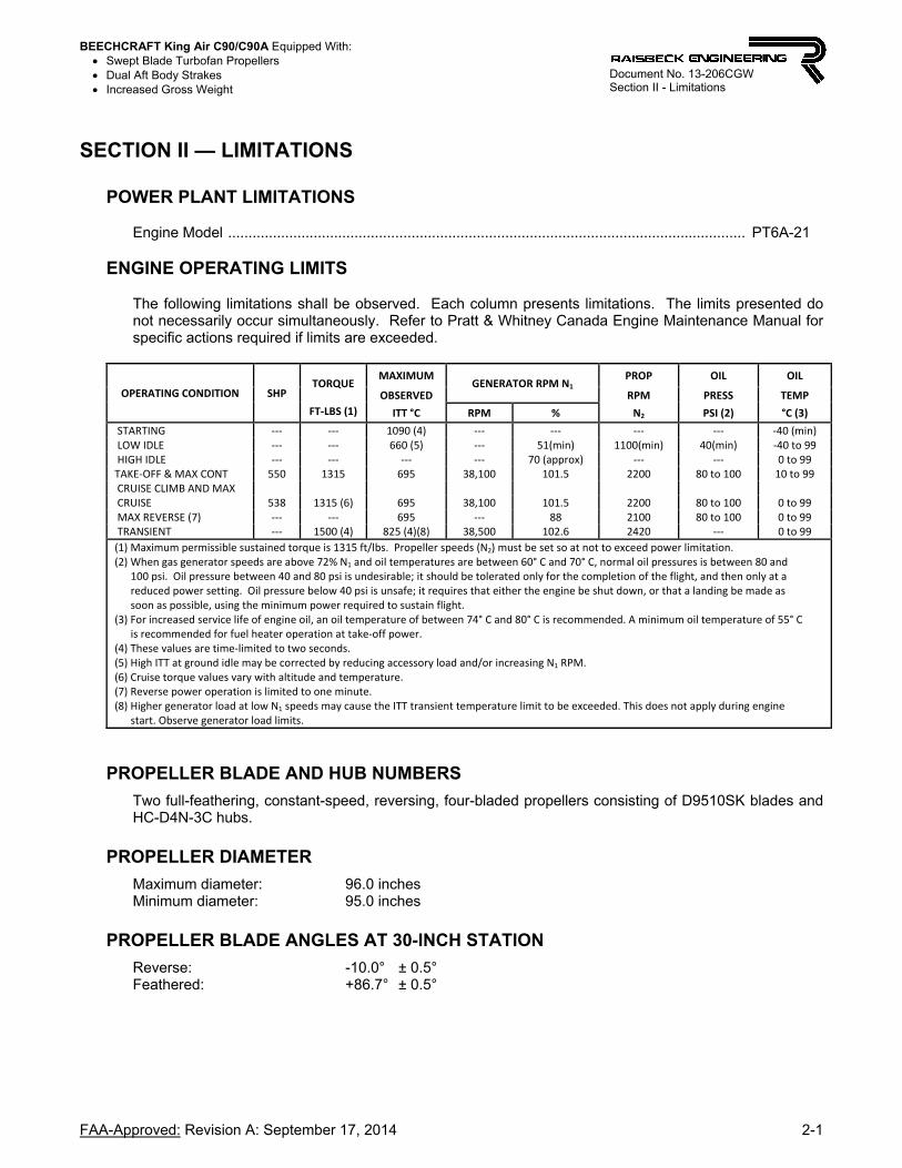
POWER PLANT LIMITATIONS Engine Model ............................................................................................................................... PT6A-21
ENGINE OPERATING LIMITS The following limitations shall be observed. Each column presents limitations. The limits presented do not necessarily occur simultaneously. Refer to Pratt & Whitney Canada Engine Maintenance Manual for specific actions required if limits are exceeded.
OPERATING CONDITION SHP TORQUE
MAXIMUM GENERATOR RPM N1
PROP OIL OIL
OBSERVED RPM PRESS TEMP
FT‐LBS (1) ITT °C RPM % N2 PSI (2) °C (3)
STARTING ‐‐‐ ‐‐‐ 1090 (4) ‐‐‐ ‐‐‐ ‐‐‐ ‐‐‐ ‐40 (min) LOW IDLE ‐‐‐ ‐‐‐ 660 (5) ‐‐‐ 51(min) 1100(min) 40(min) ‐40 to 99 HIGH IDLE ‐‐‐ ‐‐‐ ‐‐‐ ‐‐‐ 70 (approx) ‐‐‐ ‐‐‐ 0 to 99 TAKE‐OFF & MAX CONT 550 1315 695 38,100 101.5 2200 80 to 100 10 to 99 CRUISE CLIMB AND MAX CRUISE 538 1315 (6) 695 38,100 101.5 2200 80 to 100 0 to 99 MAX REVERSE (7) ‐‐‐ ‐‐‐ 695 ‐‐‐ 88 2100 80 to 100 0 to 99 TRANSIENT ‐‐‐ 1500 (4) 825 (4)(8) 38,500 102.6 2420 ‐‐‐ 0 to 99
(1) Maximum permissible sustained torque is 1315 ft/lbs. Propeller speeds (N2) must be set so at not to exceed power limitation.(2) When gas generator speeds are above 72% N1 and oil temperatures are between 60° C and 70° C, normal oil pressures is between 80 and 100 psi. Oil pressure between 40 and 80 psi is undesirable; it should be tolerated only for the completion of the flight, and then only at a reduced power setting. Oil pressure below 40 psi is unsafe; it requires that either the engine be shut down, or that a landing be made as soon as possible, using the minimum power required to sustain flight. (3) For increased service life of engine oil, an oil temperature of between 74° C and 80° C is recommended. A minimum oil temperature of 55° C is recommended for fuel heater operation at take‐off power. (4) These values are time‐limited to two seconds. (5) High ITT at ground idle may be corrected by reducing accessory load and/or increasing N1 RPM. (6) Cruise torque values vary with altitude and temperature. (7) Reverse power operation is limited to one minute. (8) Higher generator load at low N1 speeds may cause the ITT transient temperature limit to be exceeded. This does not apply during engine start. Observe generator load limits.
PROPELLER BLADE AND HUB NUMBERS
Two full-feathering, constant-speed, reversing, four-bladed propellers consisting of D9510SK blades and HC-D4N-3C hubs.
PROPELLER DIAMETER
Maximum diameter: 96.0 inches Minimum diameter: 95.0 inches
PROPELLER BLADE ANGLES AT 30-INCH STATION
Reverse: -10.0° ± 0.5° Feathered: +86.7° ± 0.5°
BEECHCRAFT King Air C90/C90A Equipped With: Swept Blade Turbofan Propellers Dual Aft Body Strakes Increased Gross Weight
2-2 FAA-Approved: Revision B: June 7, 2016
Document No. 13-206CGW Section II - Limitations
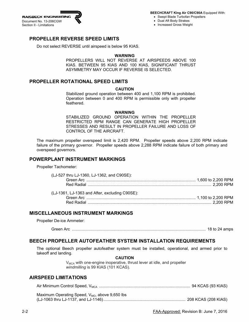
PROPELLER REVERSE SPEED LIMITS
Do not select REVERSE until airspeed is below 95 KIAS.
WARNING PROPELLERS WILL NOT REVERSE AT AIRSPEEDS ABOVE 100 KIAS. BETWEEN 95 KIAS AND 100 KIAS, SIGNIFICANT THRUST ASYMMETRY MAY OCCUR IF REVERSE IS SELECTED.
PROPELLER ROTATIONAL SPEED LIMITS
CAUTION Stabilized ground operation between 400 and 1,100 RPM is prohibited. Operation between 0 and 400 RPM is permissible only with propeller feathered.
WARNING
STABILIZED GROUND OPERATION WITHIN THE PROPELLER RESTRICTED RPM RANGE CAN GENERATE HIGH PROPELLER STRESSES AND RESULT IN PROPELLER FAILURE AND LOSS OF CONTROL OF THE AIRCRAFT.
The maximum propeller overspeed limit is 2,420 RPM. Propeller speeds above 2,200 RPM indicate failure of the primary governor. Propeller speeds above 2,288 RPM indicate failure of both primary and overspeed governors.
POWERPLANT INSTRUMENT MARKINGS
Propeller Tachometer:
(LJ-527 thru LJ-1360, LJ-1362, and C90SE): Green Arc ................................................................................................. 1,600 to 2,200 RPM Red Radial .............................................................................................................. 2,200 RPM
(LJ-1361, LJ-1363 and After, excluding C90SE):
Green Arc ................................................................................................. 1,100 to 2,200 RPM Red Radial .............................................................................................................. 2,200 RPM
MISCELLANEOUS INSTRUMENT MARKINGS
Propeller De-ice Ammeter: Green Arc ....................................................................................................................... 18 to 24 amps
BEECH PROPELLER AUTOFEATHER SYSTEM INSTALLATION REQUIREMENTS
The optional Beech propeller autofeather system must be installed, operational, and armed prior to takeoff and landing.
CAUTION VMCA with one-engine inoperative, thrust lever at idle, and propeller windmilling is 99 KIAS (101 KCAS).
AIRSPEED LIMITATIONS
Air Minimum Control Speed, VMCA ................................................................................. 94 KCAS (93 KIAS)
Maximum Operating Speed, VMO, above 9,650 lbs (LJ-1063 thru LJ-1137, and LJ-1146) ......................................................................... 208 KCAS (208 KIAS)

BEECHCRAFT King Air C90/C90A Equipped With: Swept Blade Turbofan Propellers Dual Aft Body Strakes Increased Gross Weight
FAA-Approved: Revision B: June 7, 2016 2-3
Document No. 13-206CGW Section II - Limitations
AIRSPEED INDICATOR MARKINGS
C90/C90-1 (LJ-502 thru LJ-1062)
Red Radial (Air Minimum Control Speed, VMCA) ................................................................ 94 KCAS
C90A/C90B/C90SE (LJ-1063 thru LJ-1726, LJ-1728 thru LJ-1753, LJ-1755)
Red Radial (Air Minimum Control Speed, VMCA) ................................................................. 93 KIAS (LJ-1063 thru LJ-1137, and LJ-1146 only)
Red Line .......................................................................................................................... 208 KIAS*
Red and White Hash-Marked Pointer ............................................................................ 0.46 Mach* *Maximum speed for any operation is 208 KIAS or value equal to 0.46 Mach, whichever is lower.
AIRCRAFT EQUIPPED WITH GARMIN G1000
AIRSPEED INDICATOR DISPLAY (With Placard P/N REI-1001-14 installed)
Two (2) placards have been installed, one above each Primary Flight Display unit, to notify the pilot to disregard the VMC RED LINE displayed on the airspeed tape.
FLIGHT LOAD FACTORS At the design gross weight of 10,500 lbs ............................... Maneuver – positive 3.27G – negative 1.31G
MAXIMUM WEIGHT
Maximum Taxi Weight .................................................................................................................. 10,560 lbs Maximum Takeoff Weight ............................................................................................................. 10,500 lbs Maximum Landing Weight .............................................................................................................. 9,700 lbs Maximum Zero Fuel Weight:
For MTOW below 9,650 lbs .......................................................................................... No limitation For MTOW between 9,650 and 10,500 lbs ....................................................................... 9,000 lbs
NOTE
10-ply rated main tires required for operation above 10,100 lbs.
DISREGARD VMC MARKING VMC = 93 KIAS
BEECHCRAFT King Air C90/C90A Equipped With: Swept Blade Turbofan Propellers Dual Aft Body Strakes Increased Gross Weight
2-4 FAA-Approved: Revision B: June 7, 2016
Document No. 13-206CGW Section II - Limitations
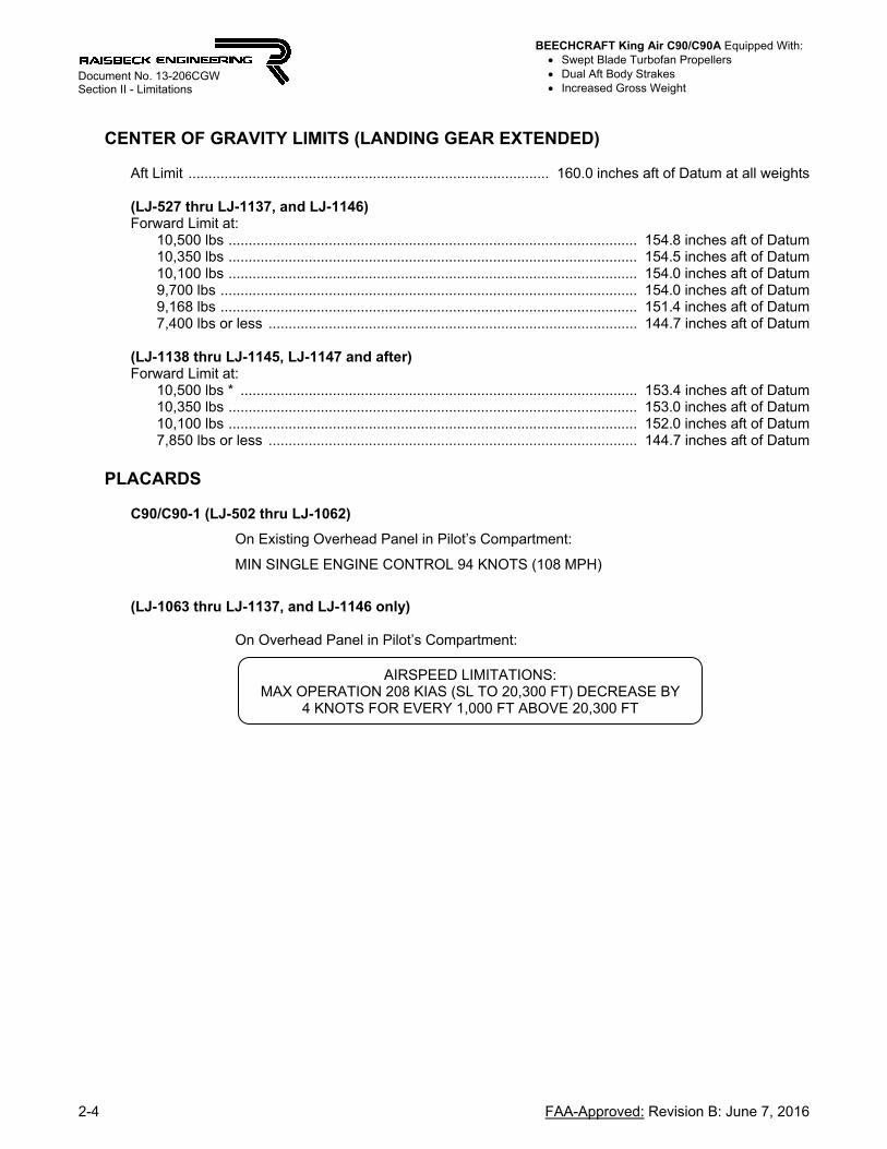
CENTER OF GRAVITY LIMITS (LANDING GEAR EXTENDED)
Aft Limit .......................................................................................... 160.0 inches aft of Datum at all weights (LJ-527 thru LJ-1137, and LJ-1146) Forward Limit at:
10,500 lbs ...................................................................................................... 154.8 inches aft of Datum 10,350 lbs ...................................................................................................... 154.5 inches aft of Datum 10,100 lbs ...................................................................................................... 154.0 inches aft of Datum 9,700 lbs ........................................................................................................ 154.0 inches aft of Datum 9,168 lbs ........................................................................................................ 151.4 inches aft of Datum 7,400 lbs or less ............................................................................................ 144.7 inches aft of Datum
(LJ-1138 thru LJ-1145, LJ-1147 and after) Forward Limit at:
10,500 lbs * ................................................................................................... 153.4 inches aft of Datum 10,350 lbs ...................................................................................................... 153.0 inches aft of Datum 10,100 lbs ...................................................................................................... 152.0 inches aft of Datum 7,850 lbs or less ............................................................................................ 144.7 inches aft of Datum
PLACARDS
C90/C90-1 (LJ-502 thru LJ-1062)
On Existing Overhead Panel in Pilot’s Compartment:
MIN SINGLE ENGINE CONTROL 94 KNOTS (108 MPH)
(LJ-1063 thru LJ-1137, and LJ-1146 only)
On Overhead Panel in Pilot’s Compartment:
AIRSPEED LIMITATIONS: MAX OPERATION 208 KIAS (SL TO 20,300 FT) DECREASE BY
4 KNOTS FOR EVERY 1,000 FT ABOVE 20,300 FT
BEECHCRAFT King Air C90/C90A Equipped With: Swept Blade Turbofan Propellers Dual Aft Body Strakes Increased Gross Weight
FAA-Approved: Revision A: September 17, 2014 3-1
Document No. 13-206CGW Section III – Emergency Procedures
SECTION III — EMERGENCY PROCEDURES
ELECTROTHERMAL PROPELLER DE-ICE Operation in icing conditions with abnormal readings on the de-ice ammeter are not recommended and ice removal cannot be assured. Normal Operation: 18 to 24 amps.
1. Zero Amps:
a. Breaker Switch - CHECK. b. If OFF, reposition to ON after 30 seconds. c. If ON with zero amps, system is inoperative. Position switch to OFF.
2. Zero to 18 Amps:
a. Continue operation. b. If propeller imbalance occurs, increase RPM briefly to aid in ice removal.
3. 24 to 29 Amps:
a. Continue operation. b. If propeller imbalance occurs, increase RPM briefly to aid in ice removal.
4. More than 29 Amps:
a. Avoid icing conditions, since continued operation of the system cannot be assured. b. Do not operate the system, except in emergencies. c. Restrict time of operation to a minimum.
BEECHCRAFT King Air C90/C90A Equipped With: Swept Blade Turbofan Propellers Dual Aft Body Strakes Increased Gross Weight
FAA-Approved: Revision A: September 17, 2014 4-1
Document No. 13-206CGW Section IV – Normal Procedures
SECTION IV — NORMAL PROCEDURES
AFTER STARTING ENGINES
CAUTION
Stabilized ground operation between 400 and 1,100 RPM is prohibited. Operation between 0 and 400 RPM is permissible only with propeller feathered.
WARNING
STABILIZED GROUND OPERATION WITHIN THE PROPELLER RESTRICTED RPM RANGE CAN GENERATE HIGH PROPELLER STRESSES AND RESULT IN PROPELLER FAILURE AND LOSS OF CONTROL OF THE AIRCRAFT.
ICING FLIGHT
Electrothermal Propeller De-ice:
CAUTION
Do not operate propeller de-ice when propellers are static.
a. Before Takeoff:
(1) Propeller Heat Switch - HEAT. (2) Propeller De-ice Ammeter - CHECK: 18 to 24 AMPERES. Monitor for 2 minutes
to assure automatic timer operation.
b. In Flight:
(1) Propeller Heat Switch - HEAT. The system may be operated continuously in flight and will function automatically until the switch is turned to OFF.
(2) Relieve propeller imbalance due to ice by increasing rpm briefly and returning to the desired setting. Repeat as necessary.
CAUTION
If the de-ice ammeter does not indicate 18 to 24 amperes, refer to the EMERGENCY PROCEDURES section.
LANDING
WARNING
PROPELLERS WILL NOT REVERSE AT AIRSPEEDS ABOVE 100 KIAS. BETWEEN 95 KIAS AND 100 KIAS, SIGNIFICANT THRUST ASYMMETRY MAY OCCUR IF REVERSE IS SELECTED.
SIMULATING ENGINE FAILURES
CAUTION
Using throttle cuts to simulate engine failures will result in the autofeather system being disarmed. In this configuration the VMCA is 99 KIAS (101 KCAS). Dynamic throttle cuts should only be attempted at airspeeds above 104 KIAS (105 KCAS).
BEECHCRAFT King Air C90/C90A Equipped With: Swept Blade Turbofan Propellers Dual Aft Body Strakes Increased Gross Weight
4-2 FAA-Approved: Revision B: June 7, 2016
Document No. 13-206CGW Section IV – Normal Procedures
NOISE CHARACTERISTICS
Approach to and departure from an airport should be made so as to avoid prolonged flight at low altitude near noise-sensitive areas. Avoidance of noise-sensitive areas, if practical, is preferable to overflight at relatively low altitudes. For VFR operations over outdoor assemblies of persons, recreational and park areas, and other noise-sensitive areas, pilots should make every effort to fly not less than 2,000 feet above the surface, weather permitting, even though flight at a lower level may be consistent with the provisions of government regulations.
NOTE The preceding recommended procedures do not apply where they would conflict with Air Traffic Control clearances or instructions, or where, in the pilot’s judgment, an altitude of less than 2,000 feet is necessary to adequately exercise his duty to see and avoid other airplanes.
The corrected takeoff noise level of this airplane, established in compliance with FAR Part 36, Appendix G (Amdt 36-28) and ICAO Annex 16, Chapter 10, is 84.4 dB as determined by flight tests. No determination has been made by the Federal Aviation Administration that the noise levels of this airplane are or should be acceptable for operation at, into, or out of any airport. The above statement notwithstanding, the noise level stated above has been verified by and approved by the Federal Aviation Administration in noise level test flights conducted in accordance with FAR Part 36, Appendix G, Amendment 28, Noise Standards: Airplane Type and Airworthiness Certification. The airplane noise is in compliance with all FAR Part 36 noise standards applicable to this type.
BEECHCRAFT King Air C90/C90A Equipped With: Swept Blade Turbofan Propellers Dual Aft Body Strakes Increased Gross Weight
FAA-Approved: Revision B: June 7, 2016 5-1
Document No. 13-206CGW Section V – Performance
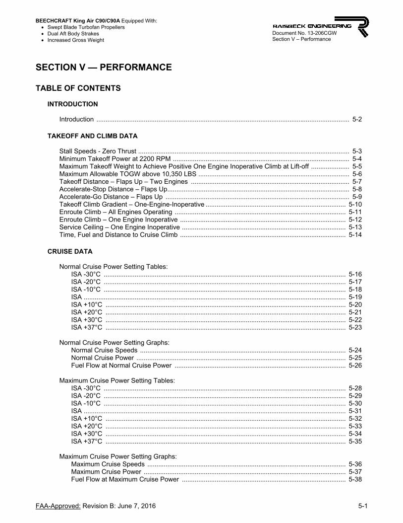
SECTION V — PERFORMANCE
TABLE OF CONTENTS
INTRODUCTION
Introduction ........................................................................................................................................... 5-2
TAKEOFF AND CLIMB DATA
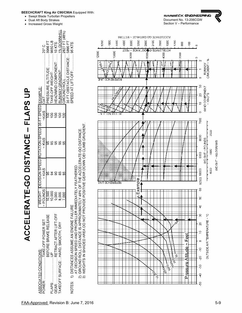
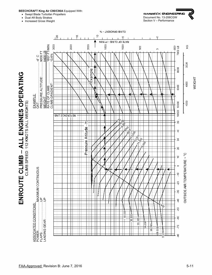
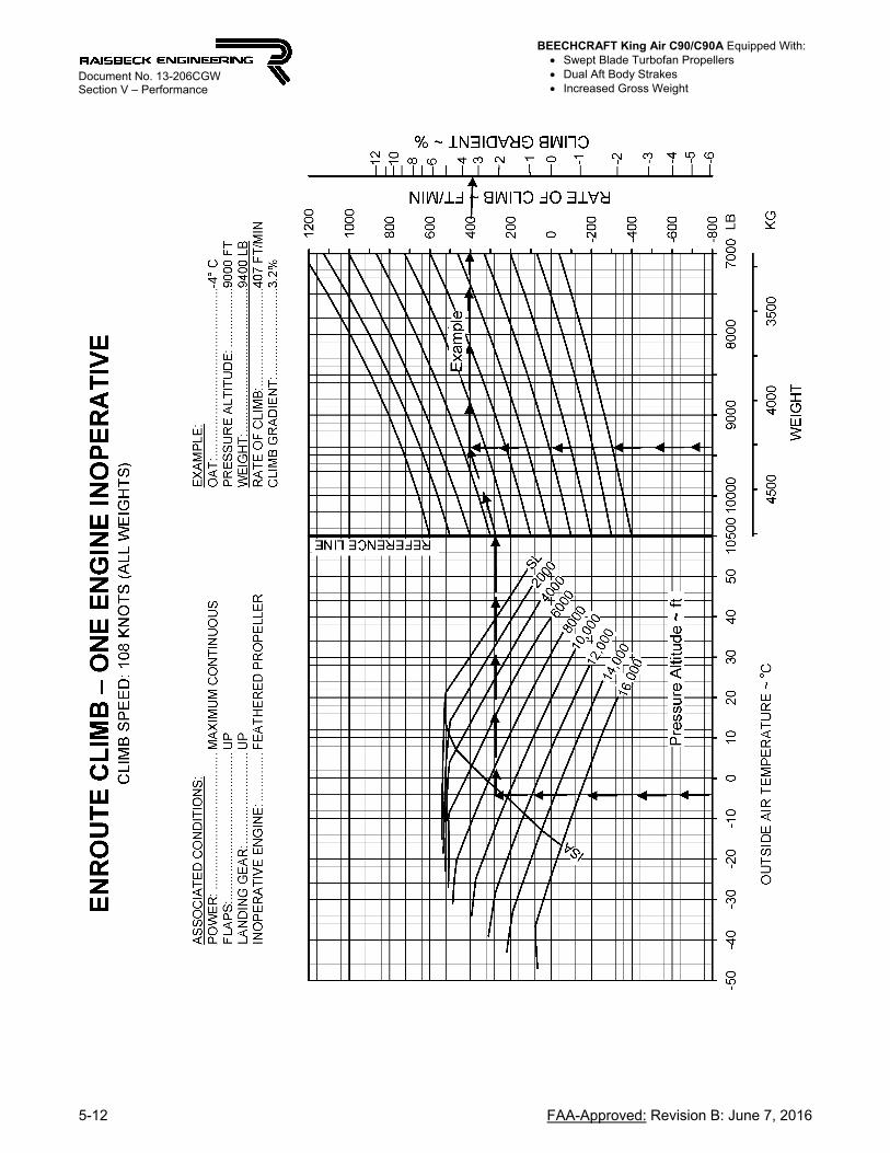
Stall Speeds - Zero Thrust .................................................................................................................... 5-3 Minimum Takeoff Power at 2200 RPM ................................................................................................. 5-4 Maximum Takeoff Weight to Achieve Positive One Engine Inoperative Climb at Lift-off ..................... 5-5 Maximum Allowable TOGW above 10,350 LBS ................................................................................... 5-6 Takeoff Distance – Flaps Up – Two Engines ....................................................................................... 5-7 Accelerate-Stop Distance – Flaps Up.................................................................................................... 5-8 Accelerate-Go Distance – Flaps Up ..................................................................................................... 5-9 Takeoff Climb Gradient – One-Engine-Inoperative ............................................................................. 5-10 Enroute Climb – All Engines Operating .............................................................................................. 5-11 Enroute Climb – One Engine Inoperative ........................................................................................... 5-12 Service Ceiling – One Engine Inoperative .......................................................................................... 5-13 Time, Fuel and Distance to Cruise Climb ........................................................................................... 5-14
CRUISE DATA
Normal Cruise Power Setting Tables:
ISA -30°C ..................................................................................................................................... 5-16 ISA -20°C ..................................................................................................................................... 5-17 ISA -10°C ..................................................................................................................................... 5-18 ISA ................................................................................................................................................ 5-19 ISA +10°C .................................................................................................................................... 5-20 ISA +20°C .................................................................................................................................... 5-21 ISA +30°C .................................................................................................................................... 5-22 ISA +37°C .................................................................................................................................... 5-23
Normal Cruise Power Setting Graphs: Normal Cruise Speeds ................................................................................................................. 5-24 Normal Cruise Power ................................................................................................................... 5-25 Fuel Flow at Normal Cruise Power .............................................................................................. 5-26
Maximum Cruise Power Setting Tables: ISA -30°C ..................................................................................................................................... 5-28 ISA -20°C ..................................................................................................................................... 5-29 ISA -10°C ..................................................................................................................................... 5-30 ISA ................................................................................................................................................ 5-31 ISA +10°C .................................................................................................................................... 5-32 ISA +20°C .................................................................................................................................... 5-33 ISA +30°C .................................................................................................................................... 5-34 ISA +37°C .................................................................................................................................... 5-35
Maximum Cruise Power Setting Graphs: Maximum Cruise Speeds ............................................................................................................. 5-36 Maximum Cruise Power ............................................................................................................... 5-37 Fuel Flow at Maximum Cruise Power .......................................................................................... 5-38

BEECHCRAFT King Air C90/C90A Equipped With: Swept Blade Turbofan Propellers Dual Aft Body Strakes Increased Gross Weight
5-2 FAA-Approved: Revision B: June 7, 2016
Document No. 13-206CGW Section V – Performance
Maximum Range Power Setting Tables:
ISA -30°C ..................................................................................................................................... 5-40 ISA -20°C ..................................................................................................................................... 5-41 ISA -10°C ..................................................................................................................................... 5-42 ISA ................................................................................................................................................ 5-43 ISA +10°C .................................................................................................................................... 5-44 ISA +20°C .................................................................................................................................... 5-45 ISA +30°C .................................................................................................................................... 5-46 ISA +37°C .................................................................................................................................... 5-47
Range with 384 Gallons Usable Fuel ................................................................................................. 5-48 Endurance with 384 Gallons Usable Fuel .......................................................................................... 5-49
DESCENT AND LANDING DATA
Holding Time ....................................................................................................................................... 5-51 Time, Fuel, and Distance to Descend ................................................................................................ 5-52 Maximum Landing Weight – Flaps Down ........................................................................................... 5-53 Climb – Balked Landing ...................................................................................................................... 5-54 Landing Distance Without Propeller Reversing .................................................................................. 5-55 Landing Distance With Propeller Reversing ....................................................................................... 5-56
INTRODUCTION
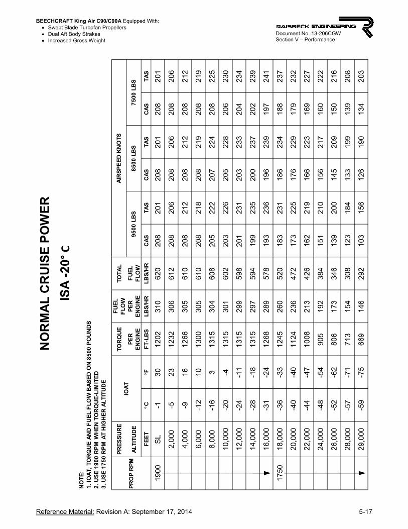
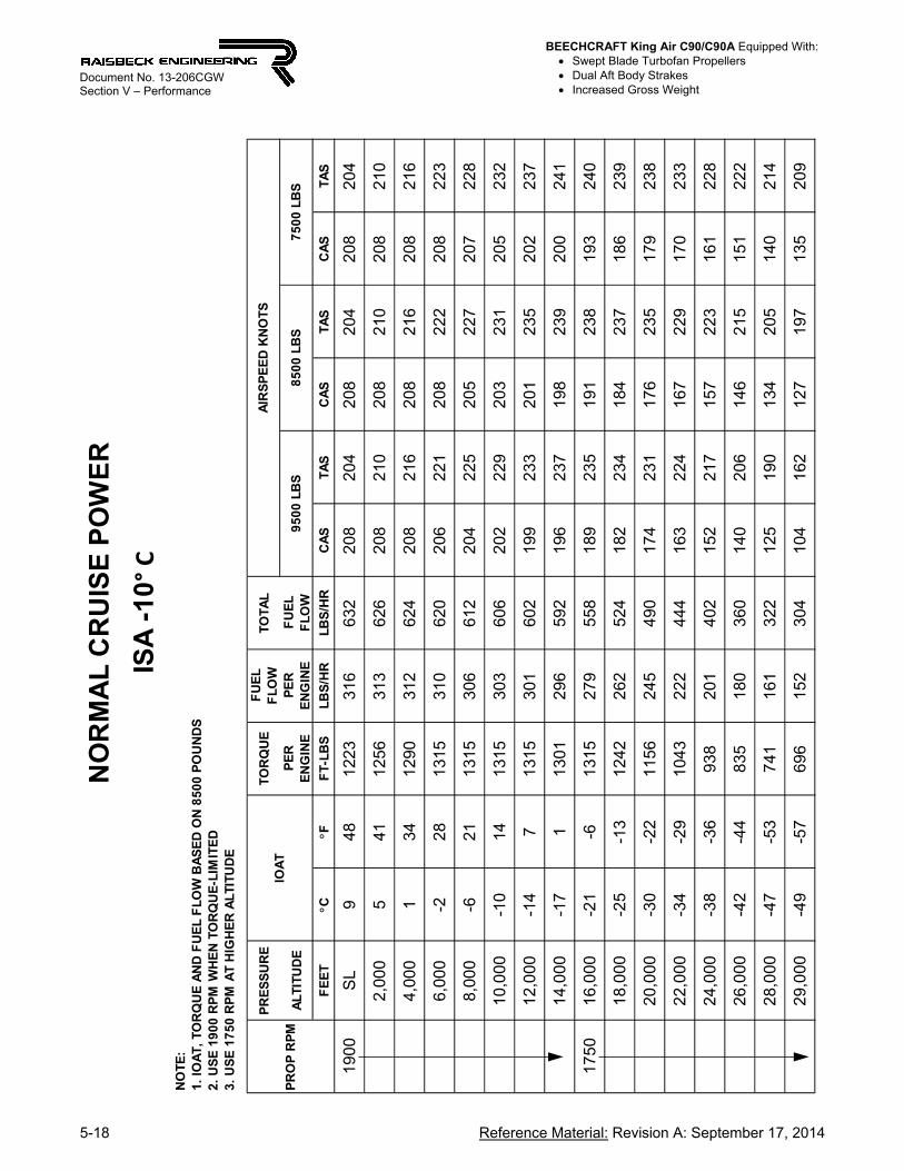
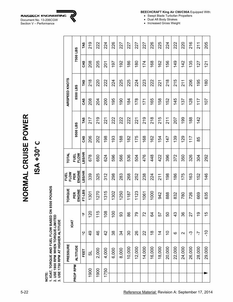
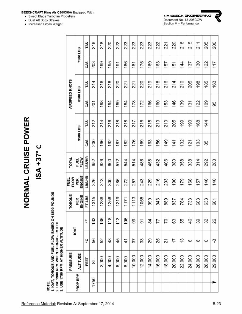
The performance of all Beechcraft King Air C90/C90A airplanes equipped with the Raisbeck Increased Gross Weight System will perform to the graphs and charts in this section, up to a maximum takeoff gross weight of 10,500 lbs and a maximum landing weight of 9,700 lbs. Federal Aviation Regulations for this class aircraft require only that the all-engines operating distance over a 50 foot height be presented for take-off distance. We include for your information accelerate-go, accelerate-stop, climb-limited weight, net climb gradient, and other FAR 25 transport category information. For data not shown in this section, refer to Section V of the Beechcraft POH. Cruise performance is divided into three sections: NORMAL CRUISE, MAXIMUM CRUISE, and MAXIMUM RANGE. All sections recommend 1,750 propeller RPM for maximum quietness combined with excellent performance. Propeller RPM reduction in flight to 1,600 RPM is an option, requiring a rigging change to the propeller governors (see applicable Raisbeck Installation and Maintenance Manuals). Cruise at 1,750 RPM does not require this option. MAXIMUM CRUISE power settings reflect an increase in maximum allowable engine ITT to 695° C for C90 and C90-1 airplanes, per Raisbeck Engineering and FAA recertification of Pratt & Whitney Canada certified limits for the PT6A-21 engines. Slight variance in cruise speeds (±4 KTAS) may be evident between pitot inlet airplanes (C90A, C90B, C90SE) and chin inlet airplanes (C90 & C90-1).

BEECHCRAFT King Air C90/C90A Equipped With: Swept Blade Turbofan Propellers Dual Aft Body Strakes Increased Gross Weight
FAA-Approved: Revision A: September 17, 2014 5-3
Document No. 13-206CGW Section V – Performance
BEECHCRAFT King Air C90/C90A Equipped With: Swept Blade Turbofan Propellers Dual Aft Body Strakes Increased Gross Weight
5-4 FAA-Approved: Revision A: September 17, 2014
Document No. 13-206CGW Section V – Performance
OUTSIDE AIR TEMPERATURE ~ DEGREES C
-40 -30 -20 -10 0 10 20 30 40 50 60
MIN
IMU
M T
OR
QU
E S
ET
TIN
G (
220
0 R
PM
) ~
FT
-LB
S
700
800
900
1000
1100
1200
1300
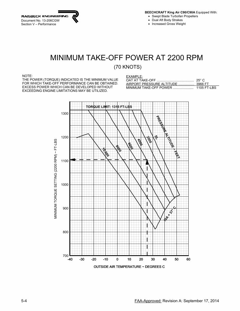
NOTE:THE POWER (TORQUE) INDICATED IS THE MINIMUM VALUEFOR WHICH TAKE-OFF PERFORMANCE CAN BE OBTAINED.EXCESS POWER WHICH CAN BE DEVELOPED WITHOUT EXCEEDING ENGINE LIMITATIONS MAY BE UTILIZED.
OUTSIDE AIR TEMPERATURE ~ DEGREES C
-40 -30 -20 -10 0 10 20 30 40 50 60
MINIMUM TAKE-OFF POWER AT 2200 RPM (70 KNOTS)
TORQUE LIMIT: 1315 FT-LBS
PR
ES
SU
RE
ALTITU
DE
~ FEE
T
SL2000
40006000
8000
10,000
ISA +
37°
C
EXAMPLE:OAT AT TAKE-OFF ........................................AIRPORT PRESSURE ALTITUDE ................. MINIMUM TAKE-OFF POWER ......................
25° C3966 FT 1105 FT-LBS
BEECHCRAFT King Air C90/C90A Equipped With: Swept Blade Turbofan Propellers Dual Aft Body Strakes Increased Gross Weight
FAA-Approved: Revision B: June 7, 2016 5-5
Document No. 13-206CGW Section V – Performance
BEECHCRAFT King Air C90/C90A Equipped With: Swept Blade Turbofan Propellers Dual Aft Body Strakes Increased Gross Weight
5-6 FAA-Approved: Revision A: September 17, 2014
Document No. 13-206CGW Section V – Performance
M
AX
AL
LOW
AB
LE
T.O
.G.W
. ~
LB
S
10350
10400
10450
10500
OUTSIDE AIR TEMPERATURE ~ DEGREES C
-30 -20 -10 0 10 20 30 40
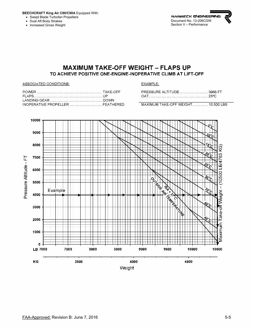
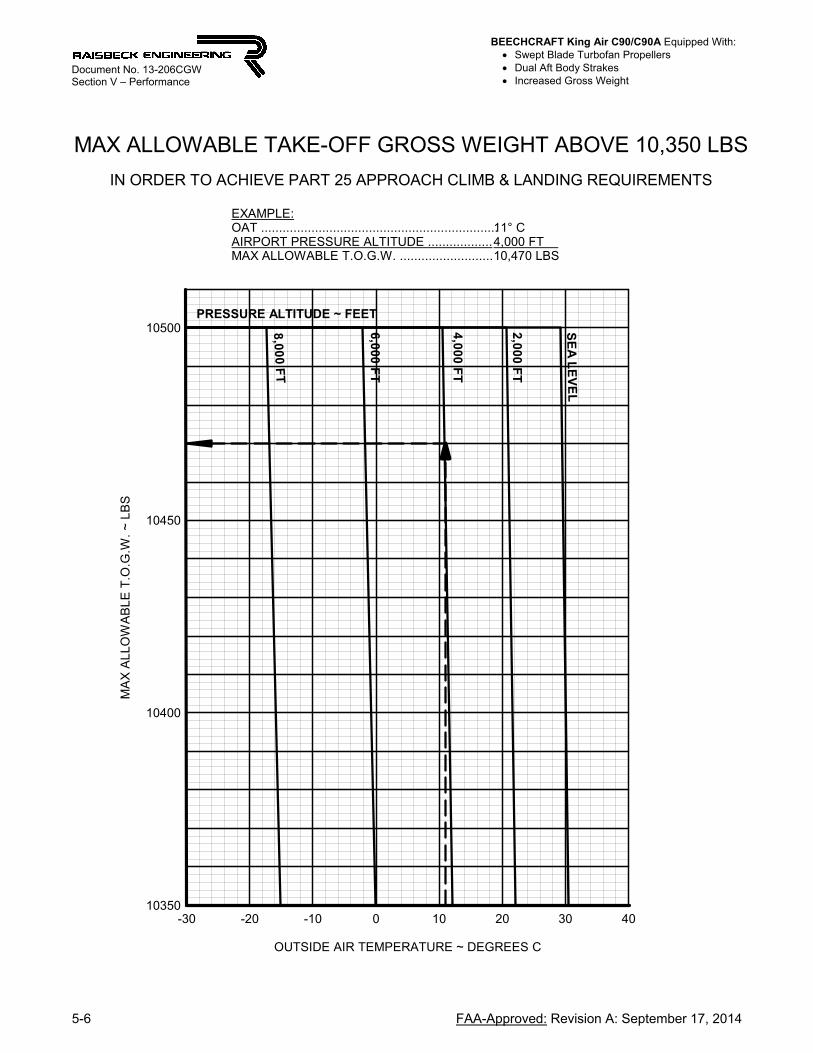
MAX ALLOWABLE TAKE-OFF GROSS WEIGHT ABOVE 10,350 LBS
IN ORDER TO ACHIEVE PART 25 APPROACH CLIMB & LANDING REQUIREMENTS
8,00
0 FT
EXAMPLE:OAT ..................................................................AIRPORT PRESSURE ALTITUDE ..................MAX ALLOWABLE T.O.G.W. ..........................
11° C4,000 FT 10,470 LBS
6,0
00 F
T
4,0
00 F
T
2,0
00 F
T
SE
A L
EV
EL
PRESSURE ALTITUDE ~ FEET
BEECHCRAFT King Air C90/C90A Equipped With: Swept Blade Turbofan Propellers Dual Aft Body Strakes Increased Gross Weight
FAA-Approved: Revision B: June 7, 2016 5-7
Document No. 13-206CGW Section V – Performance

BEECHCRAFT King Air C90/C90A Equipped With: Swept Blade Turbofan Propellers Dual Aft Body Strakes Increased Gross Weight
5-8 Reference Material: Revision B: June 7, 2016
Document No. 13-206CGW Section V – Performance
BEECHCRAFT King Air C90/C90A Equipped With: Swept Blade Turbofan Propellers Dual Aft Body Strakes Increased Gross Weight
FAA-Approved: Revision B: June 7, 2016 5-9
Document No. 13-206CGW Section V – Performance

BEECHCRAFT King Air C90/C90A Equipped With: Swept Blade Turbofan Propellers Dual Aft Body Strakes Increased Gross Weight
5-10 FAA-Approved: Revision B: June 7, 2016
Document No. 13-206CGW Section V – Performance
BEECHCRAFT King Air C90/C90A Equipped With: Swept Blade Turbofan Propellers Dual Aft Body Strakes Increased Gross Weight
FAA-Approved: Revision B: June 7, 2016 5-11
Document No. 13-206CGW Section V – Performance
BEECHCRAFT King Air C90/C90A Equipped With: Swept Blade Turbofan Propellers Dual Aft Body Strakes Increased Gross Weight
5-12 FAA-Approved: Revision B: June 7, 2016
Document No. 13-206CGW Section V – Performance

BEECHCRAFT King Air C90/C90A Equipped With: Swept Blade Turbofan Propellers Dual Aft Body Strakes Increased Gross Weight
Reference Material: Revision B: June 7, 2016 5-13
Document No. 13-206CGW Section V – Performance

BEECHCRAFT King Air C90/C90A Equipped With: Swept Blade Turbofan Propellers Dual Aft Body Strakes Increased Gross Weight
5-14 Reference Material: Revision B: June 7, 2016
Document No. 13-206CGW Section V – Performance
BEECHCRAFT King Air C90/C90A Equipped With: Swept Blade Turbofan Propellers Dual Aft Body Strakes Increased Gross Weight
Reference Material: Revision A: September 17, 2014 5-15
Document No. 13-206CGW Section V – Performance
C90 / C90-1 / C90A / C90B / C90SE
NORMAL CRUISE POWER SETTINGS
(LJ-527 and subsequent with PT6A-21 engines)

BEECHCRAFT King Air C90/C90A Equipped With: Swept Blade Turbofan Propellers Dual Aft Body Strakes Increased Gross Weight
5-16 Reference Material: Revision A: September 17, 2014
Document No. 13-206CGW Section V – Performance
NO
RM
AL
CR
UIS
E P
OW
ER
ISA
-3
0° C
PR
ES
SU
RE
TO
RQ
UE
FU
EL
F
LO
WT
OT
AL
AL
TIT
UD
EP
ER
E
NG
INE
PE
R
EN
GIN
EF
UE
L
FL
OW
FE
ET
CF
FT
-LB
SL
BS
/HR
LB
S/H
RC
AS
TA
SC
AS
TA
SC
AS
TA
S
1900
SL
-11
1211
8030
561
020
819
720
819
720
819
7
2,0
00-1
55
1209
301
602
208
203
208
203
208
203
4,0
00-1
9-2
1241
299
598
208
208
208
208
208
208
6,0
00-2
3-9
1274
298
596
208
214
208
214
208
214
8,0
00-2
6-1
513
0829
959
820
721
920
822
020
822
0
10,
000
-30
-22
1315
298
596
205
224
206
225
208
227
12,
000
-34
-29
1315
296
592
203
228
204
230
206
231
14,
000
-38
-36
1315
295
590
201
232
202
234
204
236
1750
16,
000
-42
-44
1315
276
552
193
230
195
233
197
235
18,
000
-46
-51
1202
250
500
183
225
185
228
187
231
20,
000
-50
-58
1083
226
452
172
219
175
223
178
226
22,
000
-54
-65
973
204
408
161
212
165
217
168
221
24,
000
-58
-72
870
184
368
150
204
155
211
159
216
26,
000
-63
-81
772
165
330
137
193
144
202
149
209
28,
000
-67
-89
682
147
294
120
175
131
191
138
201
29,
000
-71
-96
635
139
278
101
150
127
182
132
196
NO
TE
:1
. IO
AT
, T
OR
QU
E A
ND
FU
EL
FL
OW
BA
SE
D O
N 8
50
0 P
OU
ND
S2
. U
SE
19
00
RP
M W
HE
N T
OR
QU
E-L
IMIT
ED
3.
US
E 1
75
0 R
PM
AT
HIG
HE
R A
LT
ITU
DE
PR
OP
RP
M
AIR
SP
EE
D K
NO
TS
95
00
LB
S8
50
0 L
BS
75
00
LB
SIO
AT
BEECHCRAFT King Air C90/C90A Equipped With: Swept Blade Turbofan Propellers Dual Aft Body Strakes Increased Gross Weight
Reference Material: Revision A: September 17, 2014 5-17
Document No. 13-206CGW Section V – Performance
NO
RM
AL
CR
UIS
E P
OW
ER
ISA
-2
0° C
PR
ES
SU
RE
TO
RQ
UE
FU
EL
F
LO
WT
OT
AL
AL
TIT
UD
EP
ER
E
NG
INE
PE
R
EN
GIN
EF
UE
L
FL
OW
FE
ET
CF
FT
-LB
SL
BS
/HR
LB
S/H
RC
AS
TA
SC
AS
TA
SC
AS
TA
S
1900
SL
-130
1202
310
620
208
201
208
201
208
201
2,00
0-5
2312
3230
661
220
820
620
820
620
820
6
4,00
0-9
1612
6630
561
020
821
220
821
220
821
2
6,00
0-1
210
1300
305
610
208
218
208
219
208
219
8,00
0-1
63
1315
304
608
205
222
207
224
208
225
10,0
00-2
0-4
1315
301
602
203
226
205
228
206
230
12,0
00-2
4-1
113
1529
959
820
123
120
323
320
423
4
14,0
00-2
8-1
813
1529
759
419
923
520
023
720
223
9
16,0
00-3
1-2
412
6828
957
819
323
619
623
919
724
1
1750
18,0
00-3
6-3
312
4526
052
018
323
118
623
418
823
7
20,0
00-4
0-4
011
2423
647
217
322
517
622
917
923
2
22,0
00-4
4-4
710
0821
342
616
221
916
622
316
922
7
24,0
00-4
8-5
490
519
238
415
121
015
621
716
022
2
26,0
00-5
2-6
280
617
334
613
920
014
520
915
021
6
28,0
00-5
7-7
171
315
430
812
318
413
319
913
920
8
29,0
00-5
9-7
566
914
629
210
315
612
619
013
420
3
NO
TE
:1
. IO
AT
, T
OR
QU
E A
ND
FU
EL
FL
OW
BA
SE
D O
N 8
50
0 P
OU
ND
S2
. U
SE
19
00
RP
M W
HE
N T
OR
QU
E-L
IMIT
ED
3.
US
E 1
75
0 R
PM
AT
HIG
HE
R A
LT
ITU
DE
PR
OP
RP
MIO
AT
AIR
SP
EE
D K
NO
TS
95
00
LB
S8
50
0 L
BS
75
00
LB
S
BEECHCRAFT King Air C90/C90A Equipped With: Swept Blade Turbofan Propellers Dual Aft Body Strakes Increased Gross Weight
5-18 Reference Material: Revision A: September 17, 2014
Document No. 13-206CGW Section V – Performance
NO
RM
AL
CR
UIS
E P
OW
ER
ISA
-1
0° C
PR
ES
SU
RE
TO
RQ
UE
FU
EL
F
LO
WT
OT
AL
AL
TIT
UD
EP
ER
E
NG
INE
PE
R
EN
GIN
EF
UE
L
FL
OW
FE
ET
CF
FT
-LB
SL
BS
/HR
LB
S/H
RC
AS
TA
SC
AS
TA
SC
AS
TA
S
190
0S
L9
481
223
316
632
208
204
208
204
208
204
2,0
00
541
125
63
136
262
082
102
082
102
082
10
4,0
00
134
129
03
126
242
082
162
082
162
082
16
6,0
00
-228
131
53
106
202
062
212
082
222
082
23
8,0
00
-621
131
53
066
122
042
252
052
272
072
28
10,
000
-10
141
315
303
606
202
229
203
231
205
232
12,
000
-14
71
315
301
602
199
233
201
235
202
237
14,
000
-17
11
301
296
592
196
237
198
239
200
241
175
01
6,0
00-2
1-6
131
52
795
581
892
351
912
381
932
40
18,
000
-25
-13
124
22
625
241
822
341
842
371
862
39
20,
000
-30
-22
115
62
454
901
742
311
762
351
792
38
22,
000
-34
-29
104
32
224
441
632
241
672
291
702
33
24,
000
-38
-36
938
201
402
152
217
157
223
161
228
26,
000
-42
-44
835
180
360
140
206
146
215
151
222
28,
000
-47
-53
741
161
322
125
190
134
205
140
214
29,
000
-49
-57
696
152
304
104
162
127
197
135
209
NO
TE
:1
. IO
AT
, T
OR
QU
E A
ND
FU
EL
FL
OW
BA
SE
D O
N 8
50
0 P
OU
ND
S2
. U
SE
19
00
RP
M W
HE
N T
OR
QU
E-L
IMIT
ED
3.
US
E 1
75
0 R
PM
AT
HIG
HE
R A
LT
ITU
DE
PR
OP
RP
M8
50
0 L
BS
75
00
LB
S
AIR
SP
EE
D K
NO
TS
IOA
T9
50
0 L
BS

BEECHCRAFT King Air C90/C90A Equipped With: Swept Blade Turbofan Propellers Dual Aft Body Strakes Increased Gross Weight
Reference Material: Revision A: September 17, 2014 5-19
Document No. 13-206CGW Section V – Performance
NO
RM
AL
CR
UIS
E P
OW
ER
ISA
PR
ES
SU
RE
TO
RQ
UE
FU
EL
F
LO
WT
OT
AL
AL
TIT
UD
EP
ER
E
NG
INE
PE
R
EN
GIN
EF
UE
L
FL
OW
FE
ET
CF
FT
-LB
SL
BS
/HR
LB
S/H
RC
AS
TA
SC
AS
TA
SC
AS
TA
S
190
0S
L19
6612
4732
364
620
820
820
82
0820
82
08
2,0
0015
5912
8132
164
220
821
420
82
1420
82
14
4,0
0012
5413
1531
963
820
721
920
82
2120
82
20
6,0
008
4613
1531
362
620
522
320
62
2520
72
26
8,0
004
3913
1530
861
620
222
720
42
2920
52
31
10,
000
032
1315
304
608
200
232
202
234
203
235
12,
000
-425
1301
298
596
197
235
199
237
200
239
175
01
4,00
0-8
1813
1528
156
219
023
319
22
3619
32
38
16,
000
-12
1012
4326
553
018
223
218
52
3518
72
37
18,
000
-16
311
6924
949
817
523
017
82
3418
02
37
20,
000
-20
-410
9723
446
816
822
817
12
3217
42
36
22,
000
-24
-11
1023
220
440
160
225
164
230
167
234
24,
000
-28
-18
948
204
408
151
220
156
227
160
232
26,
000
-32
-26
862
187
374
140
211
147
221
151
227
28,
000
-36
-33
767
168
336
126
196
135
211
141
220
29,
000
-39
-38
719
159
318
104
167
128
203
135
215
NO
TE
:1
. IO
AT
, T
OR
QU
E A
ND
FU
EL
FL
OW
BA
SE
D O
N 8
50
0 P
OU
ND
S2
. U
SE
19
00
RP
M W
HE
N T
OR
QU
E-L
IMIT
ED
3.
US
E 1
75
0 R
PM
AT
HIG
HE
R A
LT
ITU
DE
PR
OP
RP
M9
50
0 L
BS
85
00
LB
S7
50
0 L
BS
IOA
TA
IRS
PE
ED
KN
OT
S

BEECHCRAFT King Air C90/C90A Equipped With: Swept Blade Turbofan Propellers Dual Aft Body Strakes Increased Gross Weight
5-20 Reference Material: Revision A: September 17, 2014
Document No. 13-206CGW Section V – Performance
NO
RM
AL
CR
UIS
E P
OW
ER
ISA
+1
0° C
PR
ES
SU
RE
TO
RQ
UE
FU
EL
F
LO
WT
OT
AL
AL
TIT
UD
EP
ER
E
NG
INE
PE
R
EN
GIN
EF
UE
L
FL
OW
FE
ET
CF
FT
-LB
SL
BS
/HR
LB
S/H
RC
AS
TA
SC
AS
TA
SC
AS
TA
S
190
0S
L2
984
127
033
06
6020
82
1220
82
1220
82
12
2,0
002
577
130
432
76
5420
82
1720
82
1820
82
18
4,0
002
272
131
532
16
4220
52
2120
72
2320
82
24
6,0
001
864
131
531
56
3020
32
2620
52
2720
62
29
8,0
001
457
131
530
96
1820
123
00
203
232
204
233
10,
00
01
050
128
029
85
9619
62
3219
82
3420
02
36
175
01
2,0
00
643
131
528
25
6419
02
3119
22
3419
42
36
14,
00
02
3612
42
266
532
183
230
185
233
187
235
16,
00
0-2
2811
71
251
502
176
229
179
232
181
235
18,
00
0-6
2111
02
236
472
169
227
172
231
175
234
20,
00
0-1
014
102
222
24
4416
12
2316
52
2816
72
32
22,
00
0-1
47
956
208
416
153
220
158
226
161
231
24,
00
0-1
80
895
196
392
145
215
150
223
154
229
26,
00
0-2
2-8
832
183
366
136
209
142
219
147
226
28,
00
0-2
6-1
57
6516
93
3812
31
9713
32
1213
92
22
29,
00
0-2
9-2
07
3016
23
2410
41
6912
72
0613
52
18
NO
TE
:1
. IO
AT
, T
OR
QU
E A
ND
FU
EL
FL
OW
BA
SE
D O
N 8
50
0 P
OU
ND
S2
. U
SE
19
00
RP
M W
HE
N T
OR
QU
E-L
IMIT
ED
3.
US
E 1
75
0 R
PM
AT
HIG
HE
R A
LT
ITU
DE
PR
OP
RP
M
AIR
SP
EE
D K
NO
TS
95
00
LB
S8
50
0 L
BS
75
00
LB
SIO
AT

BEECHCRAFT King Air C90/C90A Equipped With: Swept Blade Turbofan Propellers Dual Aft Body Strakes Increased Gross Weight
Reference Material: Revision A: September 17, 2014 5-21
Document No. 13-206CGW Section V – Performance
NO
RM
AL
CR
UIS
E P
OW
ER
ISA
+2
0° C
PR
ES
SU
RE
TO
RQ
UE
FU
EL
F
LO
WT
OT
AL
AL
TIT
UD
EP
ER
E
NG
INE
PE
R
EN
GIN
EF
UE
L
FL
OW
FE
ET
CF
FT
-LB
SL
BS
/HR
LB
S/H
RC
AS
TA
SC
AS
TA
SC
AS
TA
S
1900
SL
3910
212
903
3667
22
0821
52
0821
52
0821
5
2,00
03
69
713
153
3166
22
0622
02
0722
12
0822
2
4,00
03
29
013
153
2364
62
0422
42
0522
52
0722
7
6,00
02
88
213
083
1563
02
0122
72
0322
92
0423
1
8,00
02
47
512
502
9959
81
9522
81
9723
01
9923
2
1750
10,0
0020
6812
8528
25
6418
92
2719
12
3019
323
2
12,0
0016
6112
1626
65
3218
22
2618
52
2918
723
1
14,0
0012
5411
5025
25
0417
62
2517
92
2818
123
1
16,0
008
46
1086
237
474
169
224
172
228
175
231
18,0
004
39
1024
224
448
162
222
166
226
169
230
20,0
000
32
962
210
420
155
219
159
225
162
229
22,0
00-4
2590
21
9839
61
4721
51
5222
21
5622
7
24,0
00-8
1883
41
8537
01
3720
81
4421
71
4822
4
26,0
00-1
21
07
7217
33
4612
61
9813
52
1214
122
1
28,0
00-1
71
715
161
322
112
182
126
205
133
216
29,0
00-1
9-6
688
155
310
99
164
120
199
129
213
NO
TE
:1
. IO
AT
, T
OR
QU
E A
ND
FU
EL
FL
OW
BA
SE
D O
N 8
50
0 P
OU
ND
S2
. U
SE
19
00
RP
M W
HE
N T
OR
QU
E-L
IMIT
ED
3.
US
E 1
75
0 R
PM
AT
HIG
HE
R A
LT
ITU
DE
PR
OP
RP
M
AIR
SP
EE
D K
NO
TS
95
00
LB
S8
50
0 L
BS
75
00
LB
SIO
AT
BEECHCRAFT King Air C90/C90A Equipped With: Swept Blade Turbofan Propellers Dual Aft Body Strakes Increased Gross Weight
5-22 Reference Material: Revision A: September 17, 2014
Document No. 13-206CGW Section V – Performance
NO
RM
AL
CR
UIS
E P
OW
ER
ISA
+3
0° C
PR
ES
SU
RE
TO
RQ
UE
FU
EL
F
LO
WT
OT
AL
AL
TIT
UD
EP
ER
E
NG
INE
PE
R
EN
GIN
EF
UE
L
FL
OW
FE
ET
CF
FT
-LB
SL
BS
/HR
LB
S/H
RC
AS
TA
SC
AS
TA
SC
AS
TA
S
1900
SL
4912
013
0133
967
820
621
720
821
820
821
9
1900
2,00
046
115
1270
325
650
202
219
204
220
205
222
1750
4,00
042
108
1315
312
624
198
221
200
222
201
224
6,00
03
810
013
0229
859
619
322
219
522
419
722
6
8,00
03
493
1250
283
566
188
222
190
225
192
227
10,0
003
086
1187
268
536
182
222
184
225
186
227
12,0
002
679
1123
252
504
175
221
178
224
180
227
14,0
002
272
1061
238
476
168
219
171
223
174
227
16,0
001
864
1000
224
448
162
218
165
222
168
226
18,0
0014
5794
221
142
215
421
515
822
116
222
5
20,0
0010
5088
819
839
614
721
115
221
815
622
4
22,0
006
4383
218
637
213
920
714
521
514
922
2
24,0
002
3678
017
535
012
919
913
721
114
222
0
26,0
00-3
2772
616
332
611
718
812
820
613
521
6
28,0
00-7
1966
915
230
485
142
117
195
127
211
29,0
00-1
015
635
146
292
107
180
121
205
NO
TE
:1
. IO
AT
, T
OR
QU
E A
ND
FU
EL
FL
OW
BA
SE
D O
N 8
50
0 P
OU
ND
S2
. U
SE
19
00
RP
M W
HE
N T
OR
QU
E-L
IMIT
ED
3.
US
E 1
75
0 R
PM
AT
HIG
HE
R A
LT
ITU
DE
PR
OP
RP
M
AIR
SP
EE
D K
NO
TS
95
00
LB
S8
50
0 L
BS
75
00
LB
SIO
AT
BEECHCRAFT King Air C90/C90A Equipped With: Swept Blade Turbofan Propellers Dual Aft Body Strakes Increased Gross Weight
Reference Material: Revision A: September 17, 2014 5-23
Document No. 13-206CGW Section V – Performance
NO
RM
AL
CR
UIS
E P
OW
ER
ISA
+3
7° C
PR
ES
SU
RE
TO
RQ
UE
FU
EL
F
LO
WT
OT
AL
AL
TIT
UD
EP
ER
E
NG
INE
PE
R
EN
GIN
EF
UE
L
FL
OW
FE
ET
CF
FT
-LB
SL
BS
/HR
LB
S/H
RC
AS
TA
SC
AS
TA
SC
AS
TA
S
175
0S
L56
133
131
532
66
522
002
1220
121
420
32
16
2,00
052
136
128
631
36
261
962
1419
821
619
92
18
4,00
048
118
125
630
06
001
922
1619
421
819
52
20
6,00
045
113
121
928
65
721
872
1818
922
019
12
22
8,00
041
106
117
127
25
441
822
1818
422
118
62
23
10,0
00
3799
111
325
75
141
762
1717
822
118
12
23
12,0
00
3391
105
524
34
861
692
1617
222
017
52
23
14,0
00
2984
999
229
458
163
215
166
219
169
223
16,0
00
2577
943
216
432
156
213
160
218
163
222
18,0
00
2170
889
203
406
149
210
153
216
157
221
20,0
00
1763
837
190
380
141
205
146
214
151
220
22,0
00
1355
784
179
358
132
199
139
210
144
218
24,0
00
846
733
168
338
121
190
131
205
137
215
26,0
00
639
683
157
314
103
168
122
198
130
211
28,0
00
032
633
146
292
851
4410
918
512
22
05
29,0
00
-326
601
140
280
9516
311
72
00
NO
TE
:1
. IO
AT
, T
OR
QU
E A
ND
FU
EL
FL
OW
BA
SE
D O
N 8
50
0 P
OU
ND
S2
. U
SE
19
00
RP
M W
HE
N T
OR
QU
E-L
IMIT
ED
3.
US
E 1
75
0 R
PM
AT
HIG
HE
R A
LT
ITU
DE
PR
OP
RP
M
AIR
SP
EE
D K
NO
TS
95
00
LB
S8
50
0 L
BS
75
00
LB
SIO
AT
BEECHCRAFT King Air C90/C90A Equipped With: Swept Blade Turbofan Propellers Dual Aft Body Strakes Increased Gross Weight
5-24 Reference Material: Revision A: September 17, 2014
Document No. 13-206CGW Section V – Performance
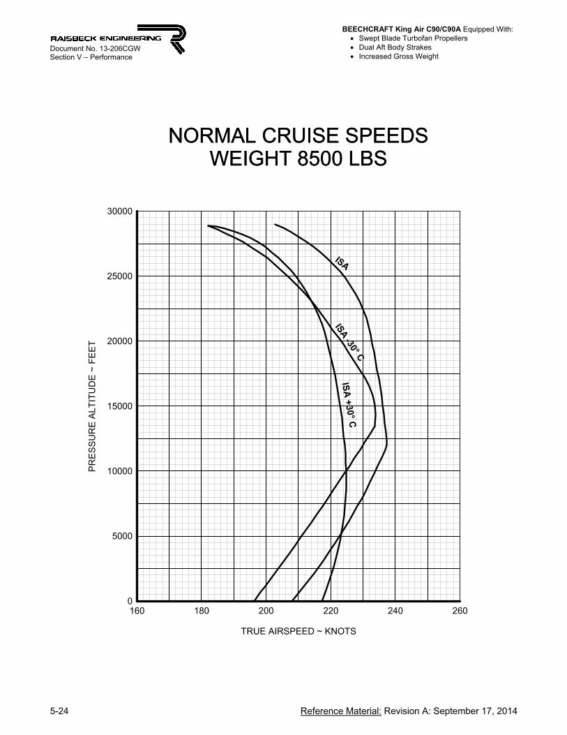
NORMAL CRUISE SPEEDSWEIGHT 8500 LBS
TRUE AIRSPEED ~ KNOTS
160 180 200 220 240 260
PR
ES
SU
RE
ALT
ITU
DE
~ F
EE
T
0
5000
10000
15000
20000
25000
30000
NORMAL CRUISE SPEEDSWEIGHT 8500 LBS
ISA
ISA -30° C
ISA
+30° C
BEECHCRAFT King Air C90/C90A Equipped With: Swept Blade Turbofan Propellers Dual Aft Body Strakes Increased Gross Weight
Reference Material: Revision A: September 17, 2014 5-25
Document No. 13-206CGW Section V – Performance
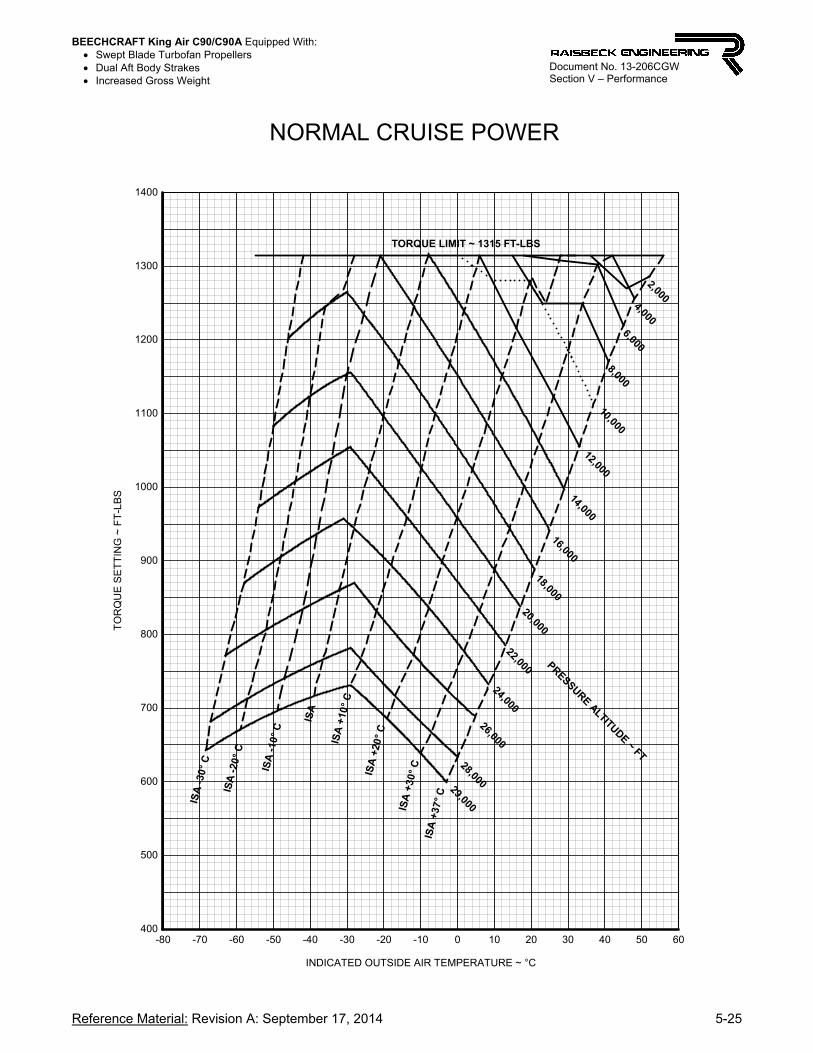
NORMAL CRUISE POWER
INDICATED OUTSIDE AIR TEMPERATURE ~ °C
-80 -70 -60 -50 -40 -30 -20 -10 0 10 20 30 40 50 60
TO
RQ
UE
SE
TT
ING
~ F
T-L
BS
400
500
600
700
800
900
1000
1100
1200
1300
1400
PRESSURE ALTITUDE ~ FT
29,000
28,000
26,000
24,000
22,000
20,000
18,000
16,000
14,000
12,000
10,000
8,000
6,000
4,000
2,000
TORQUE LIMIT ~ 1315 FT-LBS
ISA
-30
° C
ISA
-20
° C
ISA
-10
° C
ISA
ISA
+10
° C
ISA
+20
° C
ISA
+30
° C
ISA
+37
° C

BEECHCRAFT King Air C90/C90A Equipped With: Swept Blade Turbofan Propellers Dual Aft Body Strakes Increased Gross Weight
5-26 Reference Material: Revision A: September 17, 2014
Document No. 13-206CGW Section V – Performance
FUEL FLOW AT NORMAL CRUISE POWER
INDICATED OUTSIDE AIR TEMPERATURE ~ °C
-80 -70 -60 -50 -40 -30 -20 -10 0 10 20 30 40 50 60
FU
EL
FLO
W ~
LB
S /
HR
/ E
NG
INE
130
140
150
160
170
180
190
200
210
220
230
240
250
260
270
280
290
300
310
320
330
340
350
PRESSURE ALTITUDE ~ FT29,000
26,000
24,000
22,000
20,000
18,000
16,000
14,000
12,000
10,000
8,000
6,000
4,000
2,000
SL
28,000
ISA
+30
° C
ISA
-20
° C
ISA
-30
° C
ISA
ISA
+20
° C
ISA
-10
° C
ISA
+37
° C
ISA
+10
° C
BEECHCRAFT King Air C90/C90A Equipped With: Swept Blade Turbofan Propellers Dual Aft Body Strakes Increased Gross Weight
Reference Material: Revision A: September 17, 2014 5-27
Document No. 13-206CGW Section V – Performance
C90 / C90-1 / C90A / C90B / C90SE
MAXIMUM CRUISE POWER SETTINGS
(LJ-527 and subsequent with PT6A-21 engines)

BEECHCRAFT King Air C90/C90A Equipped With: Swept Blade Turbofan Propellers Dual Aft Body Strakes Increased Gross Weight
5-28 Reference Material: Revision A: September 17, 2014
Document No. 13-206CGW Section V – Performance
MA
XIM
UM
CR
UIS
E P
OW
ER
ISA
-3
0° C
PR
ES
SU
RE
TO
RQ
UE
FU
EL
F
LO
WT
OT
AL
AL
TIT
UD
EP
ER
E
NG
INE
PE
R
EN
GIN
EF
UE
L
FL
OW
FE
ET
CF
FT
-LB
SL
BS
/HR
LB
S/H
RC
AS
TA
SC
AS
TA
SC
AS
TA
S
190
0S
L-1
112
1315
335
670
218
207
220
208
221
209
2,00
0-1
55
1315
327
654
216
211
218
212
219
213
4,00
0-1
9-2
1315
320
640
214
215
216
216
217
217
6,00
0-2
2-8
1315
314
628
212
219
214
220
215
221
8,00
0-2
6-1
513
153
106
202
102
232
112
242
132
25
10,
000
-30
-22
1315
308
616
208
227
209
229
211
230
12,
000
-34
-29
1315
306
612
206
231
207
233
209
234
14,
000
-38
-36
1315
305
610
204
236
205
238
207
239
16,
000
-41
-42
1315
306
612
202
241
203
242
204
244
175
01
8,00
0-4
5-4
913
122
825
641
932
371
952
401
962
42
20,
000
-50
-58
1185
256
512
183
232
185
235
187
238
22,
000
-54
-65
1065
231
462
172
226
175
230
178
233
24,
000
-58
-72
958
209
418
162
219
165
224
168
228
26,
000
-62
-80
853
188
376
150
211
155
217
158
222
28,
000
-66
-87
758
168
336
137
200
144
209
149
216
29,
000
-69
-92
711
159
318
130
193
138
204
143
212
NO
TE
:1
. IO
AT
, T
OR
QU
E A
ND
FU
EL
FL
OW
BA
SE
D O
N 8
50
0 P
OU
ND
S2
. U
SE
19
00
RP
M W
HE
N T
OR
QU
E-L
IMIT
ED
3.
US
E 1
75
0 R
PM
AT
HIG
HE
R A
LT
ITU
DE
4.
OB
SE
RV
E V
MO
/ M
MO L
IMIT
AT
ION
WH
ER
E A
PP
LIC
AB
LE
PR
OP
RP
M9
50
0 L
BS
85
00
LB
S7
50
0 L
BS
IOA
TA
IRS
PE
ED
KN
OT
S

BEECHCRAFT King Air C90/C90A Equipped With: Swept Blade Turbofan Propellers Dual Aft Body Strakes Increased Gross Weight
Reference Material: Revision A: September 17, 2014 5-29
Document No. 13-206CGW Section V – Performance
MA
XIM
UM
CR
UIS
E P
OW
ER
ISA
-2
0° C
PR
ES
SU
RE
TO
RQ
UE
FU
EL
F
LO
WT
OT
AL
AL
TIT
UD
EP
ER
E
NG
INE
PE
R
EN
GIN
EF
UE
L
FL
OW
FE
ET
CF
FT
-LB
SL
BS
/HR
LB
S/H
RC
AS
TA
SC
AS
TA
SC
AS
TA
S
190
0S
L-1
3013
1533
767
421
72
0921
821
021
92
11
2,0
00-5
2313
1532
865
621
52
1321
621
421
72
15
4,0
00-9
1613
1532
264
421
32
1721
421
821
52
20
6,0
00-1
210
1315
317
634
211
221
212
223
213
224
8,0
00-1
63
1315
313
326
209
226
210
227
211
228
10,0
00
-20
-413
1531
032
020
62
3020
823
120
92
33
12,0
00
-24
-11
1315
309
318
204
234
206
236
207
237
14,0
00
-27
-17
1315
308
316
202
239
204
241
205
242
16,0
00
-31
-24
1315
309
618
200
244
201
246
203
247
18,0
00
-35
-31
1248
294
588
193
243
195
246
197
248
175
020
,00
0-3
9-3
812
2426
653
218
32
3818
624
118
82
44
22,0
00
-43
-45
1106
241
482
173
232
176
236
178
239
24,0
00
-48
-54
991
218
436
162
226
166
231
169
234
26,0
00
-52
-62
885
196
392
151
217
156
224
159
229
28,0
00
-56
-69
786
176
352
138
206
145
215
149
222
29,0
00
-58
-72
739
166
332
131
199
139
211
144
219
NO
TE
:1
. IO
AT
, T
OR
QU
E A
ND
FU
EL
FL
OW
BA
SE
D O
N 8
50
0 P
OU
ND
S2
. U
SE
19
00
RP
M W
HE
N T
OR
QU
E-L
IMIT
ED
3.
US
E 1
75
0 R
PM
AT
HIG
HE
R A
LT
ITU
DE
4.
OB
SE
RV
E V
MO
/ M
MO L
IMIT
AT
ION
WH
ER
E A
PP
LIC
AB
LE
PR
OP
RP
M9
50
0 L
BS
85
00
LB
S7
50
0 L
BS
IOA
TA
IRS
PE
ED
KN
OT
S
BEECHCRAFT King Air C90/C90A Equipped With: Swept Blade Turbofan Propellers Dual Aft Body Strakes Increased Gross Weight
5-30 Reference Material: Revision A: September 17, 2014
Document No. 13-206CGW Section V – Performance
MA
XIM
UM
CR
UIS
E P
OW
ER
ISA
-1
0° C
PR
ES
SU
RE
TO
RQ
UE
FU
EL
F
LO
WT
OT
AL
AL
TIT
UD
EP
ER
E
NG
INE
PE
R
EN
GIN
EF
UE
L
FL
OW
FE
ET
CF
FT
-LB
SL
BS
/HR
LB
S/H
RC
AS
TA
SC
AS
TA
SC
AS
TA
S
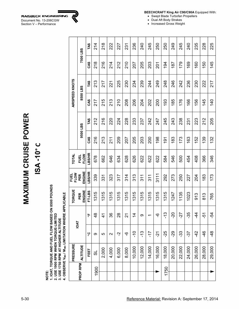
190
0S
L9
481
315
339
678
216
212
217
213
218
214
2,0
005
411
315
331
662
213
216
215
217
216
218
4,0
002
361
315
323
646
211
220
213
221
214
222
6,0
00-2
281
315
317
634
209
224
210
225
212
227
8,0
00-6
211
315
314
628
207
228
208
230
210
231
10,
000
-10
141
315
313
626
205
233
206
234
207
236
12,
000
-13
91
315
311
622
203
237
204
239
205
240
14,
000
-17
11
315
311
622
200
242
202
244
203
245
16,
000
-21
-61
315
3111
622
198
247
200
249
201
250
175
01
8,00
0-2
5-1
31
315
292
584
191
245
193
248
194
250
20,
000
-29
-20
124
727
354
618
32
431
8524
618
724
9
22,
000
-33
-27
113
525
050
017
32
381
7624
217
924
5
24,
000
-37
-35
102
322
745
416
32
311
6623
616
924
0
26,
000
-42
-44
913
204
408
152
223
156
230
160
235
28,
000
-46
-51
813
183
366
139
212
145
222
150
228
29,
000
-48
-54
765
173
346
132
205
140
217
145
225
NO
TE
:1
. IO
AT
, T
OR
QU
E A
ND
FU
EL
FL
OW
BA
SE
D O
N 8
50
0 P
OU
ND
S2
. U
SE
19
00
RP
M W
HE
N T
OR
QU
E-L
IMIT
ED
3.
US
E 1
75
0 R
PM
AT
HIG
HE
R A
LT
ITU
DE
4.
OB
SE
RV
E V
MO
/ M
MO L
IMIT
AT
ION
WH
ER
E A
PP
LIC
AB
LE
PR
OP
RP
M
AIR
SP
EE
D K
NO
TS
95
00
LB
S8
50
0 L
BS
75
00
LB
SIO
AT

BEECHCRAFT King Air C90/C90A Equipped With: Swept Blade Turbofan Propellers Dual Aft Body Strakes Increased Gross Weight
Reference Material: Revision A: September 17, 2014 5-31
Document No. 13-206CGW Section V – Performance
MA
XIM
UM
CR
UIS
E P
OW
ER
ISA
PR
ES
SU
RE
TO
RQ
UE
FU
EL
F
LO
WT
OT
AL
AL
TIT
UD
EP
ER
E
NG
INE
PE
R
EN
GIN
EF
UE
L
FL
OW
FE
ET
CF
FT
-LB
SL
BS
/HR
LB
S/H
RC
AS
TA
SC
AS
TA
SC
AS
TA
S
190
0S
L19
6613
153
4268
421
42
142
1521
521
62
16
2,0
0015
5913
153
3466
821
22
182
1321
921
42
20
4,0
0012
5413
153
2665
221
02
222
1122
421
22
25
6,0
008
4613
153
2164
220
82
272
0922
821
02
29
8,0
004
3913
153
1663
220
62
312
0723
320
82
34
10,0
000
3213
153
1362
620
32
362
0523
720
62
39
12,0
00-3
2713
153
1162
220
12
402
0324
220
42
43
14,0
00-7
1913
153
1162
219
92
452
0024
720
22
48
16,0
00-1
112
1246
296
592
192
244
194
247
196
249
175
018
,000
-15
512
642
7855
618
52
421
8724
518
92
48
20,0
00-1
9-2
1181
261
522
177
240
180
244
182
247
22,0
00-2
3-9
1100
245
490
170
238
173
242
175
245
24,0
00-2
7-1
710
232
2945
816
12
341
6523
916
82
43
26,0
00-3
1-2
49
362
1142
215
22
281
5623
516
02
40
28,0
00-3
6-3
38
391
9038
014
02
181
4622
715
02
34
29,0
00-3
8-3
67
891
8036
013
32
111
4022
214
52
30
NO
TE
:1
. IO
AT
, T
OR
QU
E A
ND
FU
EL
FL
OW
BA
SE
D O
N 8
50
0 P
OU
ND
S2
. U
SE
19
00
RP
M W
HE
N T
OR
QU
E-L
IMIT
ED
3.
US
E 1
75
0 R
PM
AT
HIG
HE
R A
LT
ITU
DE
4.
OB
SE
RV
E V
MO
/ M
MO L
IMIT
AT
ION
WH
ER
E A
PP
LIC
AB
LE
PR
OP
RP
M
AIR
SP
EE
D K
NO
TS
95
00
LB
S8
50
0 L
BS
75
00
LB
SIO
AT
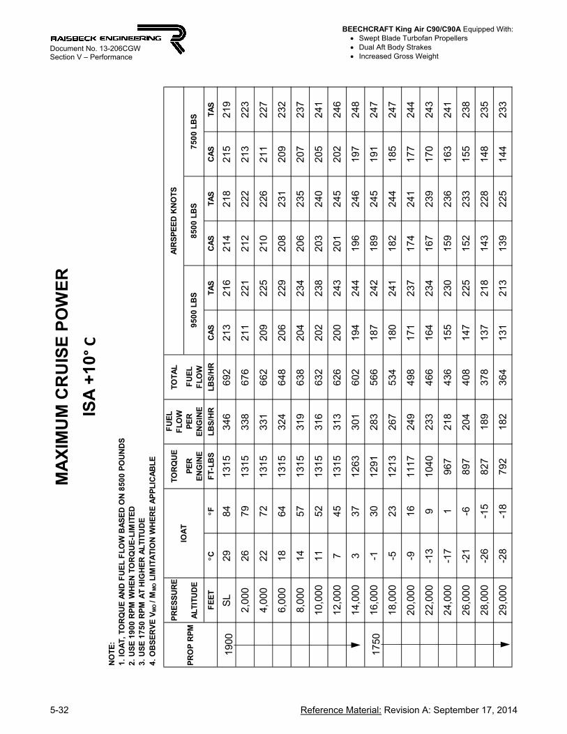
BEECHCRAFT King Air C90/C90A Equipped With: Swept Blade Turbofan Propellers Dual Aft Body Strakes Increased Gross Weight
5-32 Reference Material: Revision A: September 17, 2014
Document No. 13-206CGW Section V – Performance
MA
XIM
UM
CR
UIS
E P
OW
ER
ISA
+1
0° C
PR
ES
SU
RE
TO
RQ
UE
FU
EL
F
LO
WT
OT
AL
AL
TIT
UD
EP
ER
E
NG
INE
PE
R
EN
GIN
EF
UE
L
FL
OW
FE
ET
CF
FT
-LB
SL
BS
/HR
LB
S/H
RC
AS
TA
SC
AS
TA
SC
AS
TA
S
190
0S
L29
8413
153
466
922
132
162
142
182
152
19
2,00
026
7913
153
386
762
112
212
122
222
132
23
4,00
022
7213
153
316
622
092
252
102
262
112
27
6,00
018
6413
153
246
482
062
292
082
312
092
32
8,00
014
5713
153
196
382
042
342
062
352
072
37
10,
000
1152
1315
316
632
202
238
203
240
205
241
12,
000
745
1315
313
626
200
243
201
245
202
246
14,
000
337
1263
301
602
194
244
196
246
197
248
175
01
6,00
0-1
3012
912
835
661
872
421
892
451
912
47
18,
000
-523
1213
267
534
180
241
182
244
185
247
20,
000
-916
1117
249
498
171
237
174
241
177
244
22,
000
-13
910
402
334
661
642
341
672
391
702
43
24,
000
-17
19
672
184
361
552
301
592
361
632
41
26,
000
-21
-68
972
044
081
472
251
522
331
552
38
28,
000
-26
-15
827
189
378
137
218
143
228
148
235
29,
000
-28
-18
792
182
364
131
213
139
225
144
233
NO
TE
:1
. IO
AT
, T
OR
QU
E A
ND
FU
EL
FL
OW
BA
SE
D O
N 8
50
0 P
OU
ND
S2
. U
SE
19
00
RP
M W
HE
N T
OR
QU
E-L
IMIT
ED
3.
US
E 1
75
0 R
PM
AT
HIG
HE
R A
LT
ITU
DE
4.
OB
SE
RV
E V
MO
/ M
MO L
IMIT
AT
ION
WH
ER
E A
PP
LIC
AB
LE
PR
OP
RP
MIO
AT
AIR
SP
EE
D K
NO
TS
95
00
LB
S8
50
0 L
BS
75
00
LB
S

BEECHCRAFT King Air C90/C90A Equipped With: Swept Blade Turbofan Propellers Dual Aft Body Strakes Increased Gross Weight
Reference Material: Revision A: September 17, 2014 5-33
Document No. 13-206CGW Section V – Performance
MA
XIM
UM
CR
UIS
E P
OW
ER
ISA
+2
0° C
PR
ES
SU
RE
TO
RQ
UE
FU
EL
F
LO
WT
OT
AL
AL
TIT
UD
EP
ER
E
NG
INE
PE
R
EN
GIN
EF
UE
L
FL
OW
FE
ET
CF
FT
-LB
SL
BS
/HR
LB
S/H
RC
AS
TA
SC
AS
TA
SC
AS
TA
S
1900
SL
3910
213
153
49
698
211
219
213
220
214
221
2,0
0036
9713
153
41
682
209
223
211
224
212
225
4,0
0032
9013
153
33
666
207
227
208
229
210
230
6,0
0028
8213
153
27
654
205
232
206
233
208
234
8,0
0024
7513
153
22
644
203
236
204
238
205
239
10,
000
2170
1315
31
863
62
0024
12
0224
22
032
44
12,
000
1763
1252
30
260
41
9424
01
9624
31
982
45
1750
14,
000
1355
1281
28
557
01
8724
01
8924
21
912
44
16,
000
948
1206
26
853
61
8023
81
8324
11
852
44
18,
000
541
1132
25
250
41
7323
71
7624
01
782
43
20,
000
134
1063
23
747
41
6623
51
6923
91
722
42
22,
000
-327
996
22
344
61
5923
21
6223
71
652
41
24,
000
-719
917
20
841
61
5022
61
6223
31
582
38
26,
000
-12
108
451
94
388
140
220
154
228
150
235
28,
000
-16
37
801
80
360
130
211
146
223
142
231
29,
000
-18
07
471
74
348
123
205
133
220
138
229
NO
TE
:1
. IO
AT
, T
OR
QU
E A
ND
FU
EL
FL
OW
BA
SE
D O
N 8
50
0 P
OU
ND
S2
. U
SE
19
00
RP
M W
HE
N T
OR
QU
E-L
IMIT
ED
3.
US
E 1
75
0 R
PM
AT
HIG
HE
R A
LT
ITU
DE
4.
OB
SE
RV
E V
MO
/ M
MO L
IMIT
AT
ION
WH
ER
E A
PP
LIC
AB
LE
PR
OP
RP
MIO
AT
AIR
SP
EE
D K
NO
TS
95
00
LB
S8
50
0 L
BS
75
00
LB
S

BEECHCRAFT King Air C90/C90A Equipped With: Swept Blade Turbofan Propellers Dual Aft Body Strakes Increased Gross Weight
5-34 Reference Material: Revision A: September 17, 2014
Document No. 13-206CGW Section V – Performance
MA
XIM
UM
CR
UIS
E P
OW
ER
ISA
+3
0° C
PR
ES
SU
RE
TO
RQ
UE
FU
EL
F
LO
WT
OT
AL
AL
TIT
UD
EP
ER
E
NG
INE
PE
R
EN
GIN
EF
UE
L
FL
OW
FE
ET
CF
FT
-LB
SL
BS
/HR
LB
S/H
RC
AS
TA
SC
AS
TA
SC
AS
TA
S
190
0S
L50
122
131
535
270
421
02
212
1122
221
222
3
2,0
0046
115
131
534
368
620
82
252
0922
721
022
8
4,0
0042
108
131
533
567
020
62
292
0723
120
823
2
6,0
0038
100
131
532
865
620
42
342
0523
520
623
7
8,0
0034
931
303
320
640
200
237
202
239
203
241
175
01
0,00
030
861
315
302
604
194
237
196
239
197
241
12,
000
2781
126
328
557
018
72
361
8923
919
124
1
14,
000
2373
119
126
953
818
12
351
8323
818
524
1
16,
000
1966
112
325
450
817
42
341
7623
717
924
0
18,
000
1559
105
423
947
816
72
321
7023
617
223
9
20,
000
1050
990
225
450
159
229
163
234
166
238
22,
000
643
926
211
422
152
226
156
232
159
237
24,
000
236
865
198
396
144
221
149
229
153
235
26,
000
-228
806
185
370
134
215
141
225
146
233
28,
000
-621
740
172
344
122
203
132
219
138
228
29,
000
-818
705
165
330
114
193
126
213
133
225
NO
TE
:1
. IO
AT
, T
OR
QU
E A
ND
FU
EL
FL
OW
BA
SE
D O
N 8
50
0 P
OU
ND
S2
. U
SE
19
00
RP
M W
HE
N T
OR
QU
E-L
IMIT
ED
3.
US
E 1
75
0 R
PM
AT
HIG
HE
R A
LT
ITU
DE
4.
OB
SE
RV
E V
MO
/ M
MO L
IMIT
AT
ION
WH
ER
E A
PP
LIC
AB
LE
PR
OP
RP
M
AIR
SP
EE
D K
NO
TS
95
00
LB
S8
50
0 L
BS
75
00
LB
SIO
AT

BEECHCRAFT King Air C90/C90A Equipped With: Swept Blade Turbofan Propellers Dual Aft Body Strakes Increased Gross Weight
Reference Material: Revision A: September 17, 2014 5-35
Document No. 13-206CGW Section V – Performance
MA
XIM
UM
CR
UIS
E P
OW
ER
ISA
+3
7° C
PR
ES
SU
RE
TO
RQ
UE
FU
EL
F
LO
WT
OT
AL
AL
TIT
UD
EP
ER
E
NG
INE
PE
R
EN
GIN
EF
UE
L
FL
OW
FE
ET
CF
FT
-LB
SL
BS
/HR
LB
S/H
RC
AS
TA
SC
AS
TA
SC
AS
TA
S
190
0S
L5
713
513
1535
370
620
92
2221
122
421
22
25
2,0
005
312
713
1534
468
820
72
2720
822
821
02
29
4,0
004
912
013
1533
667
220
52
3120
623
320
72
34
6,0
004
511
312
9632
665
220
12
3420
323
620
42
37
175
08
,000
41
106
1315
309
618
196
234
197
236
199
238
10,0
00
37
9912
7029
158
418
92
3419
123
619
32
38
12,0
00
33
9111
9827
555
018
22
3318
523
618
62
38
14,0
00
29
8411
3025
951
817
62
3217
823
518
02
38
16,0
00
25
7710
6424
448
815
92
3017
223
417
42
37
18,0
00
21
7010
0022
945
816
22
2816
523
216
82
36
20,0
00
17
639
3921
643
215
42
2515
823
116
22
35
22,0
00
13
558
7820
240
414
72
2115
122
815
52
34
24,0
00
948
821
190
380
138
216
144
225
148
232
26,0
00
541
763
177
354
128
208
136
220
141
229
28,0
00
134
704
165
330
115
193
127
213
134
224
29,0
00
-130
674
159
318
103
176
121
208
129
222
NO
TE
:1
. IO
AT
, T
OR
QU
E A
ND
FU
EL
FL
OW
BA
SE
D O
N 8
50
0 P
OU
ND
S2
. U
SE
19
00
RP
M W
HE
N T
OR
QU
E-L
IMIT
ED
3.
US
E 1
75
0 R
PM
AT
HIG
HE
R A
LT
ITU
DE
4.
OB
SE
RV
E V
MO
/ M
MO L
IMIT
AT
ION
WH
ER
E A
PP
LIC
AB
LE
PR
OP
RP
MIO
AT
AIR
SP
EE
D K
NO
TS
95
00
LB
S8
50
0 L
BS
75
00
LB
S

BEECHCRAFT King Air C90/C90A Equipped With: Swept Blade Turbofan Propellers Dual Aft Body Strakes Increased Gross Weight
5-36 Reference Material: Revision A: September 17, 2014
Document No. 13-206CGW Section V – Performance
MAXIMUM CRUISE SPEEDS
TRUE AIRSPEED ~ KNOTS
140 160 180 200 220 240 260
PR
ES
SU
RE
AL
TIT
UD
E ~
FE
ET
0
5000
10000
15000
20000
25000
30000
MAXIMUM CRUISE SPEEDS
ISA
-30°
CIS
AIS
A +
30°
C

BEECHCRAFT King Air C90/C90A Equipped With: Swept Blade Turbofan Propellers Dual Aft Body Strakes Increased Gross Weight
Reference Material: Revision A: September 17, 2014 5-37
Document No. 13-206CGW Section V – Performance
MAXIMUM CRUISE POWER
INDICATED OUTSIDE AIR TEMPERATURE ~ °C
-80 -70 -60 -50 -40 -30 -20 -10 0 10 20 30 40 50 60
TO
RQ
UE
SE
TT
ING
~ F
T-L
BS
400
500
600
700
800
900
1000
1100
1200
1300
1400
PRESSURE ALTITUDE ~ FT
29,000
28,000
26,000
24,000
22,000
20,000
18,000
16,000
14,000
12,000
10,000
TORQUE LIMIT ~ 1315 FT-LBS
ISA
-30
° C
ISA
-20
° C
ISA
-10
° C
ISA
ISA
+10
° C
ISA
+20
° C
ISA
+30
° C
ISA
+37
° C
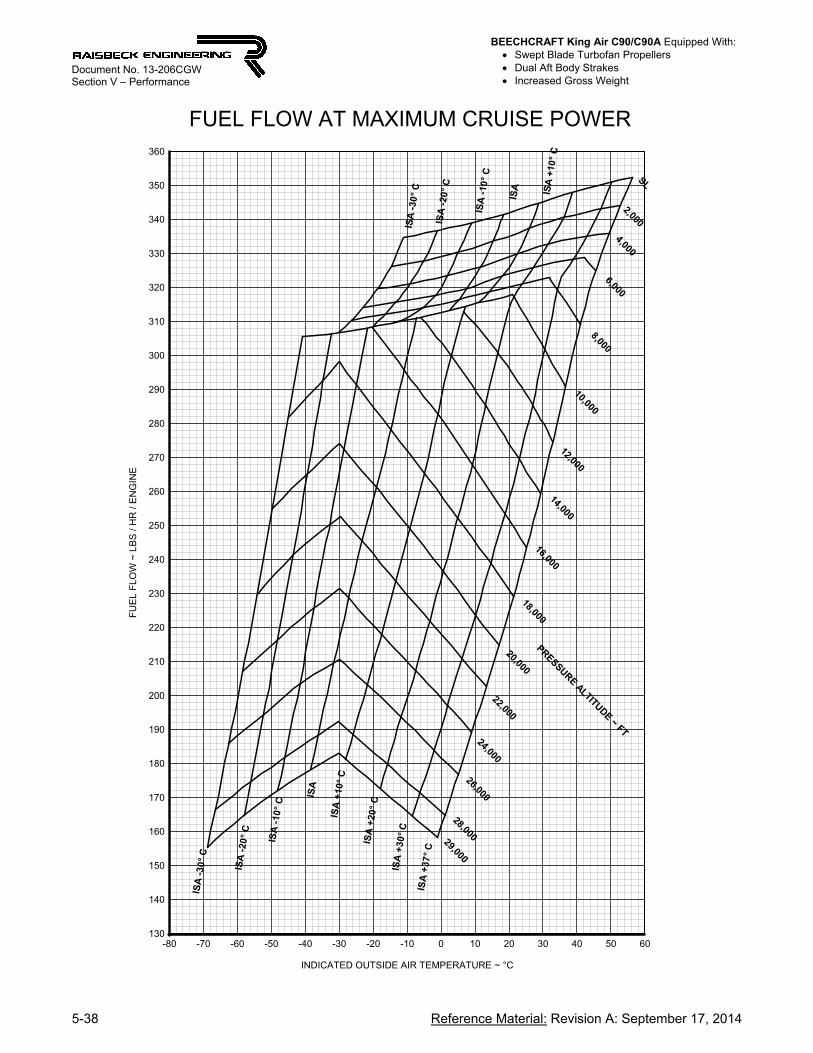
BEECHCRAFT King Air C90/C90A Equipped With: Swept Blade Turbofan Propellers Dual Aft Body Strakes Increased Gross Weight
5-38 Reference Material: Revision A: September 17, 2014
Document No. 13-206CGW Section V – Performance
FUEL FLOW AT MAXIMUM CRUISE POWER
INDICATED OUTSIDE AIR TEMPERATURE ~ °C
-80 -70 -60 -50 -40 -30 -20 -10 0 10 20 30 40 50 60
FU
EL
FLO
W ~
LB
S /
HR
/ E
NG
INE
130
140
150
160
170
180
190
200
210
220
230
240
250
260
270
280
290
300
310
320
330
340
350
360
PRESSURE ALTITUDE ~ FT
29,000
26,000
24,000
22,000
20,000
18,000
16,000
14,000
12,000
10,000
8,000
6,000
4,000
2,000
SL
28,000
ISA
+30
° C
ISA
-20
° C
ISA
-30
° C
ISA
ISA
+20
° C
ISA
-10
° C
ISA
+37
° C
ISA
+10
° C
ISA
-30
° C
ISA
-20
° C
ISA
-10
° C
ISA
ISA
+10
° C
BEECHCRAFT King Air C90/C90A Equipped With: Swept Blade Turbofan Propellers Dual Aft Body Strakes Increased Gross Weight
Reference Material: Revision A: September 17, 2014 5-39
Document No. 13-206CGW Section V – Performance
C90 / C90-1 / C90A / C90B / C90SE
MAXIMUM RANGE POWER SETTINGS AT
1750 RPM
(LJ-527 and subsequent with PT6A-21 engines)
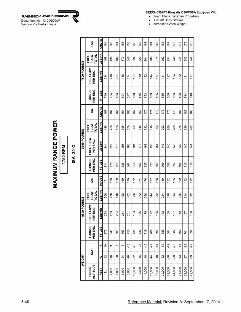
BEECHCRAFT King Air C90/C90A Equipped With: Swept Blade Turbofan Propellers Dual Aft Body Strakes Increased Gross Weight
5-40 Reference Material: Revision A: September 17, 2014
Document No. 13-206CGW Section V – Performance
FE
ET
°C°F
FT
-LB
SL
BS
/HR
LB
S/H
RK
NO
TS
FT
-LB
SL
BS
/HR
LB
S/H
RK
NO
TS
FT
-LB
SL
BS
/HR
LB
S/H
RK
NO
TS
SL
-12
10
877
253
506
171
814
244
488
167
749
234
468
164
2,00
0-1
63
841
239
478
170
775
229
458
167
704
218
436
163
4,00
0-2
0-4
801
224
448
170
729
213
426
165
653
201
402
161
6,00
0-2
4-6
767
211
422
169
686
198
396
164
604
186
372
158
8,00
0-2
8-1
875
020
140
217
066
71
8837
616
557
717
43
4815
8
10,0
00-3
2-2
673
919
338
617
265
91
8136
216
757
016
73
3416
0
12,0
00-3
6-3
373
218
637
217
465
31
7434
816
956
516
03
2016
2
14,0
00-4
0-4
071
917
935
817
663
71
6633
217
055
315
23
0416
3
16,0
00-4
4-4
770
617
234
417
762
31
5831
617
153
914
42
8816
4
18,0
00-4
8-5
469
416
633
217
860
91
5130
217
252
513
72
7416
5
20,0
00-5
2-6
268
616
232
418
059
91
4629
217
351
513
12
6216
6
22,0
00-5
6-6
968
415
831
618
259
61
4328
617
550
812
72
5416
7
24,0
00-6
0-7
668
715
731
418
559
71
4028
017
850
612
42
4817
0
26,0
00-6
3-8
170
015
831
619
059
81
3927
818
150
812
22
4417
3
28,0
00-6
7-8
970
115
731
419
261
01
4028
018
551
412
12
4217
6
29,0
00-6
9-9
269
715
631
219
261
91
4128
218
851
812
12
4217
8
M
AX
IMU
M R
AN
GE
PO
WE
R
ISA
-30
°C
WE
IGH
T95
00 P
OU
ND
S85
00 P
OU
ND
S75
00 P
OU
ND
S
1750
RP
M
PR
ES
S
AL
TIT
UD
EIO
AT
TO
RQ
UE
P
ER
EN
G.
FU
EL
FL
OW
P
ER
EN
G.
FU
EL
F
LO
W
TO
TA
L
FU
EL
FL
OW
P
ER
EN
G.
TA
SF
UE
L
FL
OW
T
OT
AL
TA
ST
OR
QU
E
PE
R E
NG
.F
UE
L F
LO
W
PE
R E
NG
.
FU
EL
F
LO
W
TO
TA
LT
AS
TO
RQ
UE
P
ER
EN
G.

BEECHCRAFT King Air C90/C90A Equipped With: Swept Blade Turbofan Propellers Dual Aft Body Strakes Increased Gross Weight
Reference Material: Revision A: September 17, 2014 5-41
Document No. 13-206CGW Section V – Performance
FE
ET
°C°F
FT
-LB
SL
BS
/HR
LB
S/H
RK
NO
TS
FT
-LB
SL
BS
/HR
LB
S/H
RK
NO
TS
FT
-LB
SL
BS
/HR
LB
S/H
RK
NO
TS
SL
-22
89
0525
951
81
758
4525
050
01
7278
924
14
8216
9
2,0
00-6
21
866
244
488
175
803
234
468
171
746
226
452
168
4,0
00-1
01
48
4723
346
61
767
7722
344
61
7271
221
34
2616
8
6,0
00-1
47
823
222
444
177
750
211
422
173
683
201
402
168
8,0
00-1
80
800
211
422
178
725
200
400
173
655
189
378
168
10,
000
-22
-87
7820
240
41
796
9718
937
81
7362
017
73
5416
7
12,
000
-26
-15
769
194
388
181
682
181
362
174
603
168
336
168
14,
000
-30
-22
760
188
376
183
674
174
348
176
591
161
322
170
16,
000
-34
-29
727
181
362
185
667
168
336
179
583
155
310
172
18,
000
-38
-36
738
175
350
186
658
162
324
181
575
149
298
174
20,
000
-42
-44
730
170
340
188
648
157
314
182
565
143
286
175
22,
000
-45
-49
719
166
332
189
638
152
304
184
556
138
276
177
24,
000
-49
-56
708
162
324
190
633
148
296
186
548
133
266
179
26,
000
-53
-63
711
161
322
193
633
146
292
189
544
130
260
181
28,
000
-57
-71
719
162
324
197
631
145
290
191
543
128
256
183
29,
000
-59
-74
713
161
322
197
632
144
288
192
546
128
256
185
M
AX
IMU
M R
AN
GE
PO
WE
R
ISA
-2
0°C
WE
IGH
T95
00 P
OU
ND
S85
00 P
OU
ND
S7
500
PO
UN
DS
1750
RP
M
PR
ES
S
AL
TIT
UD
EIO
AT
TO
RQ
UE
P
ER
EN
G.
FU
EL
FL
OW
P
ER
EN
G.
FU
EL
F
LO
W
TO
TA
LT
AS
FU
EL
F
LO
W
TO
TA
LT
AS
TO
RQ
UE
P
ER
EN
G.
FU
EL
FL
OW
P
ER
EN
G.
FU
EL
F
LO
W
TO
TA
LT
AS
TO
RQ
UE
P
ER
EN
G.
FU
EL
FL
OW
P
ER
EN
G.

BEECHCRAFT King Air C90/C90A Equipped With: Swept Blade Turbofan Propellers Dual Aft Body Strakes Increased Gross Weight
5-42 Reference Material: Revision A: September 17, 2014
Document No. 13-206CGW Section V – Performance
FE
ET
°C°F
FT
-LB
SL
BS
/HR
LB
S/H
RK
NO
TS
FT
-LB
SL
BS
/HR
LB
S/H
RK
NO
TS
FT
-LB
SL
BS
/HR
LB
S/H
RK
NO
TS
SL
846
864
255
510
173
801
245
490
170
745
236
472
167
2,00
04
3986
924
749
417
780
323
747
417
374
522
845
617
0
4,00
00
3286
623
747
418
079
922
745
417
673
621
843
617
2
6,00
0-4
2585
022
745
418
177
421
643
217
770
720
541
017
3
8,00
0-8
1883
321
743
418
375
920
641
217
968
519
539
017
4
10,0
00-1
210
813
209
418
184
740
198
396
180
666
186
372
175
12,0
00-1
63
794
200
400
185
724
189
378
181
649
178
356
176
14,0
00-2
0-4
775
192
384
187
709
181
362
183
630
169
338
177
16,0
00-2
4-1
175
918
537
018
869
717
535
018
561
616
232
417
8
18,0
00-2
7-1
774
017
835
618
968
716
833
618
760
615
531
018
0
20,0
00-3
1-2
472
117
134
218
967
416
232
418
859
815
030
018
3
22,0
00-3
5-3
172
016
833
619
165
815
731
418
959
114
529
018
5
24,0
00-3
9-3
872
516
733
419
564
115
130
218
958
314
128
218
7
26,0
00-4
3-4
572
116
533
019
663
614
829
619
157
513
727
418
8
28,0
00-4
7-5
372
616
533
019
964
514
829
619
556
313
326
618
9
29,0
00-4
9-5
672
916
633
220
164
414
829
619
655
813
126
218
9
17
50 R
PM
TA
S
M
AX
IMU
M R
AN
GE
PO
WE
R
ISA
-1
0°C
WE
IGH
T95
00 P
OU
ND
S8
500
PO
UN
DS
7500
PO
UN
DS
PR
ES
S
AL
TIT
UD
EIO
AT
TO
RQ
UE
P
ER
EN
G.
FU
EL
FL
OW
P
ER
EN
G.
FU
EL
F
LO
W
TO
TA
L
FU
EL
F
LO
W
TO
TA
LT
AS
TO
RQ
UE
P
ER
EN
G.
FU
EL
FL
OW
P
ER
EN
G.
FU
EL
F
LO
W
TO
TA
LT
AS
TO
RQ
UE
P
ER
EN
G.
FU
EL
FL
OW
P
ER
EN
G.

BEECHCRAFT King Air C90/C90A Equipped With: Swept Blade Turbofan Propellers Dual Aft Body Strakes Increased Gross Weight
Reference Material: Revision A: September 17, 2014 5-43
Document No. 13-206CGW Section V – Performance
FE
ET
°C°F
FT
-LB
SL
BS
/HR
LB
S/H
RK
NO
TS
FT
-LB
SL
BS
/HR
LB
S/H
RK
NO
TS
FT
-LB
SL
BS
/HR
LB
S/H
RK
NO
TS
SL
1864
879
260
520
176
788
246
492
171
717
235
470
166
2,00
014
5786
724
949
817
977
623
547
017
370
722
444
816
8
4,00
010
5085
923
947
818
177
322
645
217
670
421
543
017
1
6,00
06
4384
622
945
818
377
321
843
617
970
620
741
417
5
8,00
02
3682
621
843
618
476
720
941
818
170
219
939
817
8
10,0
00-2
2880
520
841
618
575
020
040
018
369
219
138
218
0
12,0
00-6
2178
519
939
818
672
919
038
018
466
918
136
218
0
14,0
00-1
014
775
193
386
189
709
183
366
185
655
174
348
182
16,0
00-1
39
772
189
378
191
693
176
352
186
638
167
334
183
18,0
00-1
71
767
183
366
194
679
169
338
187
621
159
318
185
20,0
00-2
1-6
756
178
356
195
673
164
328
190
608
153
306
186
22,0
00-2
5-1
373
217
134
219
567
016
032
019
359
414
729
418
7
24,0
00-2
9-2
072
016
833
619
566
415
631
219
558
014
228
418
8
26,0
00-3
3-2
773
316
933
820
065
115
230
419
556
913
727
418
9
28,0
00-3
7-3
573
316
933
820
264
315
030
019
657
113
527
019
2
29,0
00-3
9-3
874
017
034
020
465
115
130
219
957
413
527
019
4
17
50 R
PM
TA
S
M
AX
IMU
M R
AN
GE
PO
WE
R
ISA
WE
IGH
T95
00 P
OU
ND
S8
500
PO
UN
DS
7500
PO
UN
DS
PR
ES
S
AL
TIT
UD
EIO
AT
TO
RQ
UE
P
ER
EN
G.
FU
EL
FL
OW
P
ER
EN
G.
FU
EL
F
LO
W
TO
TA
L
FU
EL
F
LO
W
TO
TA
LT
AS
TO
RQ
UE
P
ER
EN
G.
FU
EL
FL
OW
P
ER
EN
G.
FU
EL
F
LO
W
TO
TA
LT
AS
TO
RQ
UE
P
ER
EN
G.
FU
EL
FL
OW
P
ER
EN
G.

BEECHCRAFT King Air C90/C90A Equipped With: Swept Blade Turbofan Propellers Dual Aft Body Strakes Increased Gross Weight
5-44 Reference Material: Revision A: September 17, 2014
Document No. 13-206CGW Section V – Performance
FE
ET
°C°F
FT
-LB
SL
BS
/HR
LB
S/H
RK
NO
TS
FT
-LB
SL
BS
/HR
LB
S/H
RK
NO
TS
FT
-LB
SL
BS
/HR
LB
S/H
RK
NO
TS
SL
2882
861
259
518
177
795
249
498
173
734
239
478
170
2,00
024
7586
525
150
218
079
323
947
817
671
922
845
617
1
4,00
020
6887
124
248
418
478
923
046
017
969
521
643
217
2
6,00
016
6186
923
446
818
778
622
144
218
268
920
741
417
5
8,00
012
5485
222
444
818
977
721
342
618
568
519
939
817
8
10,0
008
4683
521
543
019
176
120
340
618
668
019
138
218
0
12,0
004
3981
320
641
219
274
219
438
818
866
918
336
618
3
14,0
001
3479
619
839
619
372
418
637
218
965
117
535
018
4
16,0
00-3
2777
819
038
019
471
017
935
819
163
416
733
418
5
18,0
00-7
1975
918
336
619
570
117
334
619
361
815
931
818
6
20,0
00-1
112
743
178
356
195
687
168
336
194
615
156
312
189
22,0
00-1
55
746
176
352
198
669
162
324
194
608
151
302
191
24,0
00-1
9-2
744
174
348
201
657
157
314
195
603
147
294
194
26,0
00-2
3-9
734
171
342
201
660
156
312
198
587
142
284
194
28,0
00-2
7-1
775
817
535
020
865
915
430
820
057
313
727
419
4
29,0
00-2
9-2
0--
---
---
---
-65
415
330
620
057
113
627
219
5
17
50 R
PM
TA
S
M
AX
IMU
M R
AN
GE
PO
WE
R
ISA
+1
0°C
WE
IGH
T95
00 P
OU
ND
S8
500
PO
UN
DS
7500
PO
UN
DS
PR
ES
S
AL
TIT
UD
EIO
AT
TO
RQ
UE
P
ER
EN
G.
FU
EL
FL
OW
P
ER
EN
G.
FU
EL
F
LO
W
TO
TA
L
FU
EL
F
LO
W
TO
TA
LT
AS
TO
RQ
UE
P
ER
EN
G.
FU
EL
FL
OW
P
ER
EN
G.
FU
EL
F
LO
W
TO
TA
LT
AS
TO
RQ
UE
P
ER
EN
G.
FU
EL
FL
OW
P
ER
EN
G.

BEECHCRAFT King Air C90/C90A Equipped With: Swept Blade Turbofan Propellers Dual Aft Body Strakes Increased Gross Weight
Reference Material: Revision A: September 17, 2014 5-45
Document No. 13-206CGW Section V – Performance
FE
ET
°C°F
FT
-LB
SL
BS
/HR
LB
S/H
RK
NO
TS
FT
-LB
SL
BS
/HR
LB
S/H
RK
NO
TS
FT
-LB
SL
BS
/HR
LB
S/H
RK
NO
TS
SL
3810
087
626
452
818
077
224
849
617
371
923
947
817
0
2,00
034
9386
425
350
618
276
923
847
617
670
822
845
617
2
4,00
030
8685
824
348
618
576
922
945
817
970
021
843
617
4
6,00
026
7984
923
446
818
777
422
244
418
370
021
042
017
8
8,00
022
7283
622
444
818
977
421
442
818
669
520
240
418
1
10,0
0018
6481
821
442
819
176
420
641
218
969
719
539
018
4
12,0
0015
5979
720
541
019
274
519
639
219
068
518
737
418
6
14,0
0011
5278
319
739
419
372
718
837
619
167
017
935
818
8
16,0
007
4577
819
238
419
670
918
036
019
265
617
134
319
0
18,0
003
3778
018
737
419
969
317
334
619
363
916
432
819
1
20,0
00-1
3077
218
336
620
168
216
733
419
562
315
731
419
2
22,0
00-5
2375
117
735
420
168
316
432
819
860
915
130
219
3
24,0
00-9
1673
617
434
820
168
016
232
420
059
414
629
219
4
26,0
00-1
39
764
178
356
208
656
156
312
199
591
144
288
196
28,0
00-1
71
---
---
---
---
666
157
314
203
592
142
284
200
29,0
00-1
80
---
---
---
---
679
160
320
207
585
140
280
200
17
50 R
PM
TA
S
M
AX
IMU
M R
AN
GE
PO
WE
R
ISA
+2
0°C
WE
IGH
T95
00 P
OU
ND
S8
500
PO
UN
DS
7500
PO
UN
DS
PR
ES
S
AL
TIT
UD
EIO
AT
TO
RQ
UE
P
ER
EN
G.
FU
EL
FL
OW
P
ER
EN
G.
FU
EL
F
LO
W
TO
TA
L
FU
EL
F
LO
W
TO
TA
LT
AS
TO
RQ
UE
P
ER
EN
G.
FU
EL
FL
OW
P
ER
EN
G.
FU
EL
F
LO
W
TO
TA
LT
AS
TO
RQ
UE
P
ER
EN
G.
FU
EL
FL
OW
P
ER
EN
G.

BEECHCRAFT King Air C90/C90A Equipped With: Swept Blade Turbofan Propellers Dual Aft Body Strakes Increased Gross Weight
5-46 Reference Material: Revision A: September 17, 2014
Document No. 13-206CGW Section V – Performance
FE
ET
°C°F
FT
-LB
SL
BS
/HR
LB
S/H
RK
NO
TS
FT
-LB
SL
BS
/HR
LB
S/H
RK
NO
TS
FT
-LB
SL
BS
/HR
LB
S/H
RK
NO
TS
SL
4811
887
226
553
018
179
325
250
417
672
424
148
217
2
2,00
044
111
888
258
516
186
793
244
488
180
702
229
458
173
4,00
040
104
894
250
590
190
793
235
470
183
681
218
436
174
6,00
036
9788
424
148
219
278
922
645
218
667
720
941
817
7
8,00
032
9086
523
046
019
478
321
843
618
967
920
240
418
1
10,0
0029
8485
022
144
219
676
720
841
619
168
219
539
018
4
12,0
0025
7783
321
242
419
874
919
939
819
267
418
737
418
7
14,0
0021
7081
320
440
819
973
519
138
219
465
917
935
818
9
16,0
0017
6378
919
539
019
972
618
537
019
664
317
134
219
0
18,0
0013
5576
718
737
419
971
917
835
619
962
816
432
819
1
20,0
009
4874
718
036
019
970
517
234
420
061
915
831
619
3
22,0
005
4174
717
835
620
168
516
633
220
062
115
430
819
7
24,0
001
3476
918
036
020
866
616
032
019
961
715
030
020
0
26,0
00-3
2779
118
336
621
466
715
831
620
260
114
529
020
0
28,0
00-6
21--
---
---
---
-69
216
332
621
058
314
128
219
9
29,0
00--
---
---
---
---
---
---
---
---
---
-58
114
028
020
0
17
50 R
PM
TA
S
M
AX
IMU
M R
AN
GE
PO
WE
R
ISA
+3
0°C
WE
IGH
T95
00 P
OU
ND
S8
500
PO
UN
DS
7500
PO
UN
DS
PR
ES
S
AL
TIT
UD
EIO
AT
TO
RQ
UE
P
ER
EN
G.
FU
EL
FL
OW
P
ER
EN
G.
FU
EL
F
LO
W
TO
TA
L
FU
EL
F
LO
W
TO
TA
LT
AS
TO
RQ
UE
P
ER
EN
G.
FU
EL
FL
OW
P
ER
EN
G.
FU
EL
F
LO
W
TO
TA
LT
AS
TO
RQ
UE
P
ER
EN
G.
FU
EL
FL
OW
P
ER
EN
G.
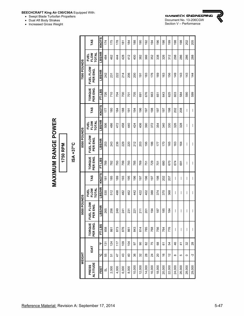
BEECHCRAFT King Air C90/C90A Equipped With: Swept Blade Turbofan Propellers Dual Aft Body Strakes Increased Gross Weight
Reference Material: Revision A: September 17, 2014 5-47
Document No. 13-206CGW Section V – Performance
FE
ET
°C°F
FT
-LB
SL
BS
/HR
LB
S/H
RK
NO
TS
FT
-LB
SL
BS
/HR
LB
S/H
RK
NO
TS
FT
-LB
SL
BS
/HR
LB
S/H
RK
NO
TS
SL
5513
185
826
553
018
178
925
350
617
772
624
248
417
4
2,00
051
124
861
256
512
185
782
243
486
180
710
231
462
175
4,00
047
117
873
249
498
189
793
236
472
184
704
222
444
178
6,00
043
109
876
241
482
193
799
229
458
188
700
214
428
181
8,00
040
104
861
231
462
195
793
220
440
191
701
206
412
184
10,0
0036
9784
322
144
219
678
521
242
419
470
520
040
018
8
12,0
0032
9081
421
142
219
776
920
340
619
669
119
138
219
0
14,0
0028
8278
520
140
219
675
119
539
019
767
618
336
619
2
16,0
0024
7576
819
438
819
772
918
637
219
866
317
635
219
4
18,0
0020
6875
618
737
419
870
117
735
419
765
116
933
819
6
20,0
0016
6176
418
537
020
268
017
034
019
764
316
332
619
8
22,0
0012
5477
618
436
820
767
016
533
019
862
515
631
219
9
24,0
008
46--
---
---
---
-67
416
332
620
260
314
929
819
8
26,0
005
41--
---
---
---
-69
116
432
820
858
414
328
619
8
28,0
000
32--
---
---
---
---
---
---
---
-59
014
328
620
2
29,0
00-2
28--
---
---
---
---
---
---
---
-59
914
428
820
5
1750
RP
M
TA
S
M
AX
IMU
M R
AN
GE
PO
WE
R
ISA
+37
°C
WE
IGH
T95
00 P
OU
ND
S8
500
PO
UN
DS
7500
PO
UN
DS
PR
ES
S
AL
TIT
UD
EIO
AT
TO
RQ
UE
P
ER
EN
G.
FU
EL
FL
OW
P
ER
EN
G.
FU
EL
F
LO
W
TO
TA
L
FU
EL
F
LO
W
TO
TA
LT
AS
TO
RQ
UE
P
ER
EN
G.
FU
EL
FL
OW
P
ER
EN
G.
FU
EL
F
LO
W
TO
TA
LT
AS
TO
RQ
UE
P
ER
EN
G.
FU
EL
FL
OW
P
ER
EN
G.
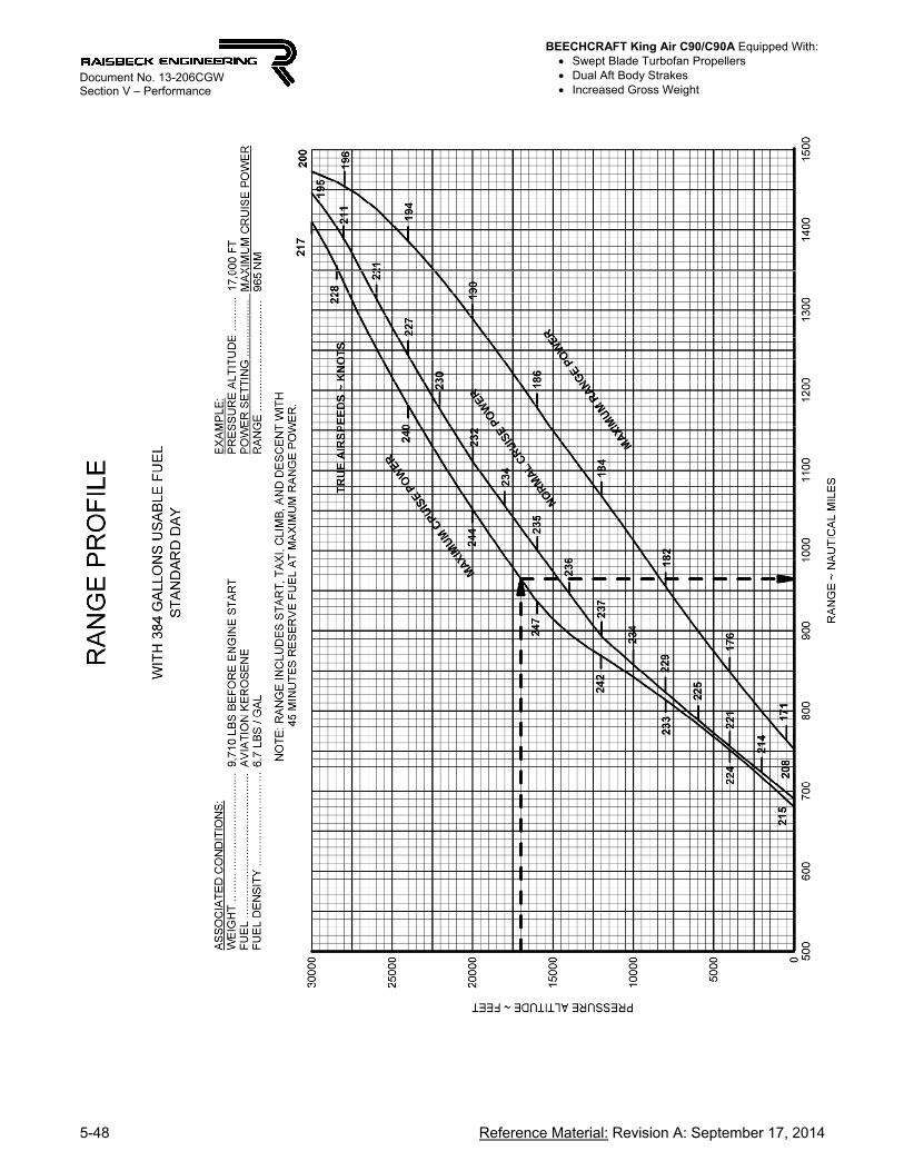
BEECHCRAFT King Air C90/C90A Equipped With: Swept Blade Turbofan Propellers Dual Aft Body Strakes Increased Gross Weight
5-48 Reference Material: Revision A: September 17, 2014
Document No. 13-206CGW Section V – Performance
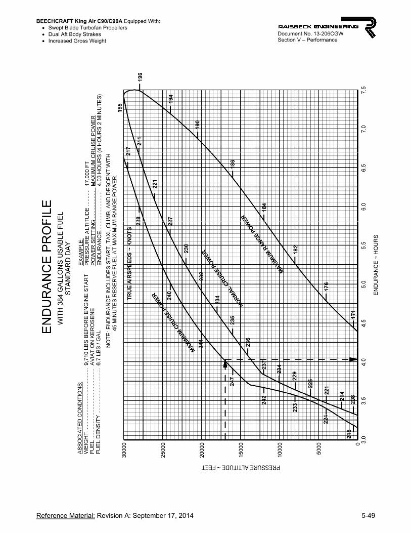
BEECHCRAFT King Air C90/C90A Equipped With: Swept Blade Turbofan Propellers Dual Aft Body Strakes Increased Gross Weight
Reference Material: Revision A: September 17, 2014 5-49
Document No. 13-206CGW Section V – Performance
BEECHCRAFT King Air C90/C90A Equipped With: Swept Blade Turbofan Propellers Dual Aft Body Strakes Increased Gross Weight
5-50 FAA-Approved: Revision A: September 17, 2014
Document No. 13-206CGW Section V – Performance
C90 / C90-1 / C90A / C90B / C90SE
DESCENT AND LANDING DATA
(LJ-527 and subsequent with PT6A-21 engines)

BEECHCRAFT King Air C90/C90A Equipped With: Swept Blade Turbofan Propellers Dual Aft Body Strakes Increased Gross Weight
Reference Material: Revision A: September 17, 2014 5-51
Document No. 13-206CGW Section V – Performance
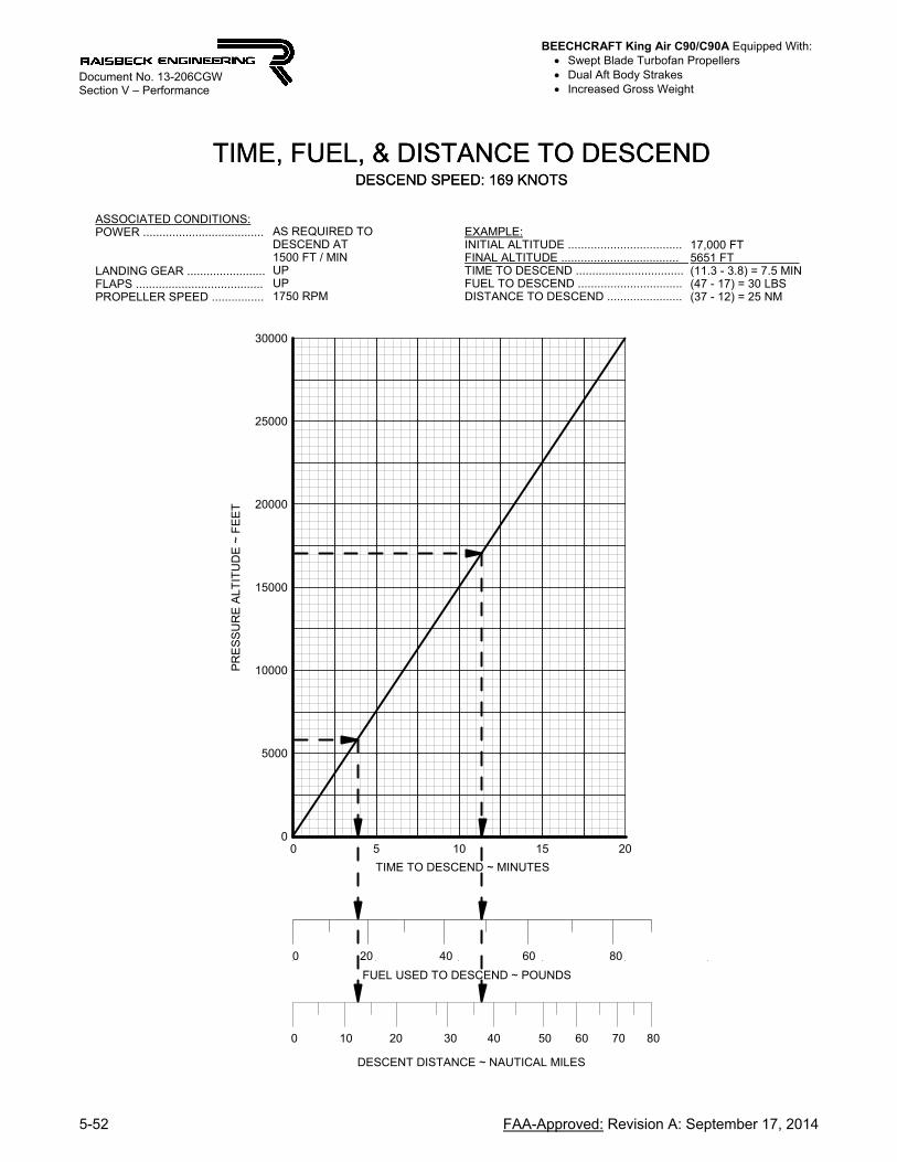
BEECHCRAFT King Air C90/C90A Equipped With: Swept Blade Turbofan Propellers Dual Aft Body Strakes Increased Gross Weight
5-52 FAA-Approved: Revision A: September 17, 2014
Document No. 13-206CGW Section V – Performance
TIME, FUEL, & DISTANCE TO DESCENDDESCEND SPEED: 169 KNOTS
TIME TO DESCEND ~ MINUTES
0 5 10 15 20
PR
ES
SU
RE
AL
TIT
UD
E ~
FE
ET
0
5000
10000
15000
20000
25000
30000
TIME, FUEL, & DISTANCE TO DESCENDDESCEND SPEED: 169 KNOTS
FUEL USED TO DESCEND ~ POUNDS
DESCENT DISTANCE ~ NAUTICAL MILES
0 20 40 60
0
80
10 20 30 40 50 60 70 80
EXAMPLE:INITIAL ALTITUDE ...................................FINAL ALTITUDE .................................... TIME TO DESCEND .................................FUEL TO DESCEND ................................DISTANCE TO DESCEND .......................
17,000 FT5651 FT (11.3 - 3.8) = 7.5 MIN(47 - 17) = 30 LBS(37 - 12) = 25 NM
ASSOCIATED CONDITIONS:POWER .....................................
LANDING GEAR ........................FLAPS .......................................PROPELLER SPEED ................
AS REQUIRED TO DESCEND AT1500 FT / MINUPUP1750 RPM
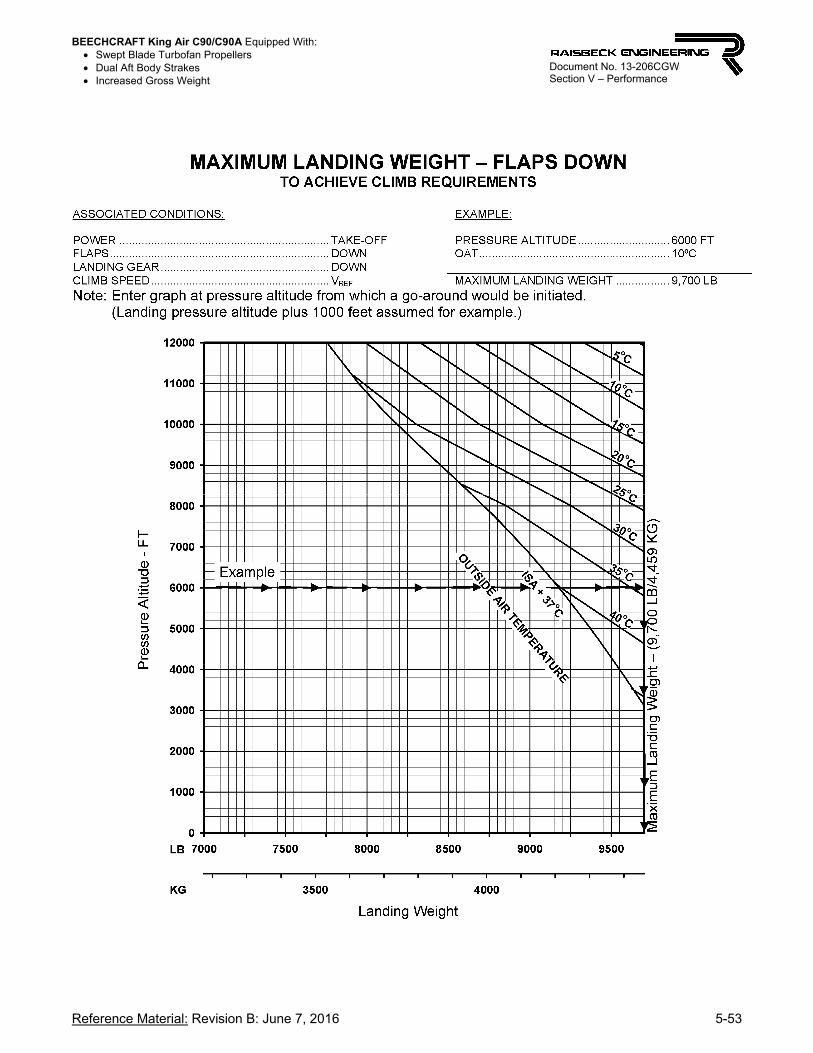
BEECHCRAFT King Air C90/C90A Equipped With: Swept Blade Turbofan Propellers Dual Aft Body Strakes Increased Gross Weight
Reference Material: Revision B: June 7, 2016 5-53
Document No. 13-206CGW Section V – Performance

BEECHCRAFT King Air C90/C90A Equipped With: Swept Blade Turbofan Propellers Dual Aft Body Strakes Increased Gross Weight
5-54 FAA-Approved: Revision B: June 7, 2016
Document No. 13-206CGW Section V – Performance
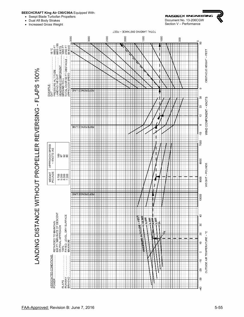
BEECHCRAFT King Air C90/C90A Equipped With: Swept Blade Turbofan Propellers Dual Aft Body Strakes Increased Gross Weight
FAA-Approved: Revision B: June 7, 2016 5-55
Document No. 13-206CGW Section V – Performance

BEECHCRAFT King Air C90/C90A Equipped With: Swept Blade Turbofan Propellers Dual Aft Body Strakes Increased Gross Weight
5-56 Reference Material: Revision B: June 7, 2016
Document No. 13-206CGW Section V – Performance
WE
IGH
T ~
PO
UN
DS
70
00
80
00
90
001
000
0
OB
ST
AC
LE H
EIG
HT
~ F
EE
T
05
0
TOTAL LANDING DISTANCE ~ FEET
050
0
10
00
15
00
20
00
25
00
30
00
35
00
OU
TS
IDE
AIR
TE
MP
ER
AT
UR
E ~
°C
-40
-30
-20
-10
01
02
030
40
50
WIN
D C
OM
PO
NE
NT
~ K
NO
TS
-10
01
02
03
0
PR
ES
SU
RE
AL
TIT
UD
E ~
FE
ET
REFERENCE LINE
REFERENCE LINE
REFERENCE LINE
SL
2,0
00
4,0
006,
000
8,0
00
10
,00
0
ISA
LAN
DIN
G D
IST
AN
CE
WIT
H P
RO
PE
LLE
R R
EV
ER
SIN
G -
FLA
PS
100
%E
XA
MP
LE:
OA
T .
....
.....
....
.....
....
.....
....
.....
....
.....
...
PR
ES
SU
RE
AL
TIT
UD
E ..
....
.....
....
...
LA
ND
ING
WE
IGH
T .
.....
....
.....
....
.....
.H
EA
DW
IND
CO
MP
ON
EN
T .
....
.....
..
G
RO
UN
D R
OL
L .
.....
.....
....
.....
....
.....
.
TO
TA
L O
VE
R 5
0 F
T O
BS
TA
CL
E .
..A
PP
RO
AC
H S
PE
ED
...
.....
....
.....
....
..
15
°C
56
50
FT
88
55
LB
S1
0 K
TS
7
60
FT
15
60
FT
96
KIA
S
WE
IGH
TP
OU
ND
S
9,7
00
9,0
00
8,0
00
7,0
00
AP
PR
OA
CH
SP
EE
D~
KN
OT
S I
AS
10
09
79
28
6
AS
SO
CIA
TE
D C
ON
DIT
ION
S:
PO
WE
R .
....
.....
....
.....
....
.....
....
FL
AP
S .
....
.....
....
.....
....
.....
....
..L
AN
DIN
G G
EA
R .
....
.....
....
.....
.R
UN
WA
Y .
....
.....
....
.....
....
.....
..B
RA
KIN
G .
....
.....
....
.....
....
.....
..
RE
TA
RD
ED
TO
MA
INT
AIN
800
FT
/ M
IN R
AT
E O
F D
ES
CE
NT
ON
FIN
AL
AP
PR
OA
CH
100
%D
OW
NP
AV
ED
, LE
VE
L, D
RY
SU
RF
AC
EM
AX
IMU
M W
ITH
OU
T S
LID
ING
TIR
ES
AN
DW
ITH
PR
OP
EL
LE
R R
EV
ER
SIN
G A
T T
OU
CH
DO
WN

BEECHCRAFT King Air C90/C90A Equipped With: Swept Blade Turbofan Propellers Dual Aft Body Strakes Increased Gross Weight
FAA Approved: Revision A: September 17, 2014 6-1
Document No. 13-206CGW Section VI – Weight and Balance
SECTION VI — WEIGHT AND BALANCE (LJ-527 thru LJ-1137, and LJ-1146)
CENTER-OF-GRAVITY LIMITS
CENTER OF GRAVITY ~ INCHES AFT OF DATUM
144 145 146 147 148 149 150 151 152 153 154 155 156 157 158 159 160 161
GR
OS
S W
EIG
HT
~ L
BS
7000
7500
8000
8500
9000
9500
10000
10500MAXIMUM TAKEOFF WEIGHT
MAXIMUM LANDING WEIGHT
MAXIMUM ZERO FUEL WEIGHT
NOTE: MAXIMUM RAMP WEIGHT 10,560 LBS

BEECHCRAFT King Air C90/C90A Equipped With: Swept Blade Turbofan Propellers Dual Aft Body Strakes Increased Gross Weight
6-2 FAA Approved: Revision A: September 17, 2014
Document No. 13-206CGW Section VI – Weight and Balance
SECTION VI — WEIGHT AND BALANCE (LJ-1138 thru LJ-1145, LJ-1147 and after)
CENTER-OF-GRAVITY LIMITS
CENTER OF GRAVITY ~ INCHES AFT OF DATUM
144 145 146 147 148 149 150 151 152 153 154 155 156 157 158 159 160 161
GR
OS
S W
EIG
HT
~ L
BS
7000
7500
8000
8500
9000
9500
10000
10500MAXIMUM TAKEOFF WEIGHT
MAXIMUM LANDING WEIGHT
MAXIMUM ZERO FUEL WEIGHT
NOTE: MAXIMUM RAMP WEIGHT 10,560 LBS

BEECHCRAFT King Air C90/C90A Equipped With: Swept Blade Turbofan Propellers Dual Aft Body Strakes Increased Gross Weight
Reference Material: Revision A: September 17, 2014 7-1
Document No. 13-206CGW Section VII – Systems Description
SECTION VII — SYSTEMS DESCRIPTION
HARTZELL/RAISBECK SWEPT BLADE TURBOFAN PROPELLER SYSTEM
Each engine is equipped with an advanced technology, lightweight, Hartzell/Raisbeck Swept Blade Turbofan propeller. Each propeller contains four blades, in full feathering, constant speed, counter-weighted, reversing, variable-pitch, and mounted on the output shaft of the reduction gearbox. The propeller pitch and speed are controlled by engine oil pressure, through single action engine-driven propeller governors. Centrifugal counter-weights, assisted by a feathering spring, move the blades toward the low RPM (high pitch) position and into the feathered position. Governor boosted engine oil pressure moves the propeller to the high RPM (low pitch) hydraulic stop and reverse position. The propellers have no low RPM (high pitch) stops; this allows the blades to feather after engine shut-down.
OPTIONAL 1,600 RPM MINIMUM CRUISE
For those wishing the absolute quietest cockpit and cabin in cruise, propeller cruise RPM as low as 1,600 RPM is available as an option. Resetting the propeller governor to Raisbeck specifications per Raisbeck Maintenance Manual (85-120) is required.
DUAL AFT BODY STRAKES The Raisbeck Dual Aft Body Strakes are mounted on the underside of the aft fuselage, and replace the single ventral fin. They are designed and engineered to attach and streamline the airflow over the aft body reducing drag, improving aircraft stability and VMC.
PROPELLER DE-ICE SYSTEM
The Hartzell propeller electric de-ice system includes an electronically heated boot for each propeller blade, brush assemblies, slip rings, an ammeter, a timer for automatic operation, and a manual control circuit for backup. The de-ice ammeter indicates the system amperage (normally 18 to 24 amperes). The timer directs current to the single-element boot on each blade in the following sequence: right propeller all elements; then left propeller all elements. Loss of one heating element circuit on one side does not mean that the entire system must be turned off. The timer switches every 90 seconds resulting in a complete cycle in approximately 3 minutes.
Related Documents