KINETICS™ Guide to Understanding IBC Seismic for MEP TABLE OF CONTENTS PAGE 1 of 3 D2.1 – 0.0 Toll Free (USA Only): 800-959-1229 RELEASED ON: 05/29/2008 International: 614-889-0480 FAX 614-889-0540 World Wide Web: www.kineticsnoise.com E-mail: [email protected] Dublin, Ohio, USA Ã Mississauga, Ontario, Canada Member TABLE OF CONTENTS Section Title D2.1 – 1.0 Introduction D2.1 – 2.0 Required Basic Project Information D2.1 – 2.1 Introduction D2.1 – 2.2 Building Use – Nature of Occupancy D2.1 – 2.3 Site Class D2.1 – 2.4 Mapped Acceleration Parameters D2.1 – 2.5 Seismic Design Category D2.1 – 2.6 Summary D2.1 – 3.0 Component Importance Factor D2.1 – 3.1 Introduction D2.1 – 3.2 Criteria for Assigning a Component Importance Factor D2.1 – 3.3 Summary D2.1 – 4.0 General Exemptions and Requirements D2.1 – 4.1 Introduction D2.1 – 4.2 Exemptions for Seismic Design Categories A and B D2.1 – 4.3 Exemptions for Seismic Design Category C D2.1 – 4.4 Exemptions for Seismic Design Categories D, E, and F D2.1 – 4.5 “Chandelier” Exemption D2.1 – 4.6 Component Size Relative to the Building Structure D2.1 – 4.7 Reference Documents D2.1 – 4.8 Allowable Stress Design D2.1 – 4.9 Submittals and Construction Documents D2.1 – 4.10 Equipment Certification for Essential Facilities D2.1 – 4.11 Consequential or Collateral Damage D2.1 – 4.12 Flexibility of Components and Their Supports and Restraints D2.1 – 4.13 Summary

Welcome message from author
This document is posted to help you gain knowledge. Please leave a comment to let me know what you think about it! Share it to your friends and learn new things together.
Transcript

KINETICS™ Guide to Understanding IBC Seismic for MEP
TABLE OF CONTENTSPAGE 1 of 3 D2.1 – 0.0
Toll Free (USA Only): 800-959-1229 RELEASED ON: 05/29/2008International: 614-889-0480FAX 614-889-0540World Wide Web: www.kineticsnoise.comE-mail: [email protected]
Dublin, Ohio, USA Mississauga, Ontario, Canada Member
TABLE OF CONTENTS
Section TitleD2.1 – 1.0 IntroductionD2.1 – 2.0 Required Basic Project Information
D2.1 – 2.1 Introduction
D2.1 – 2.2 Building Use – Nature of Occupancy
D2.1 – 2.3 Site Class
D2.1 – 2.4 Mapped Acceleration Parameters
D2.1 – 2.5 Seismic Design Category
D2.1 – 2.6 Summary
D2.1 – 3.0 Component Importance Factor
D2.1 – 3.1 Introduction
D2.1 – 3.2 Criteria for Assigning a Component Importance Factor
D2.1 – 3.3 Summary
D2.1 – 4.0 General Exemptions and Requirements
D2.1 – 4.1 Introduction
D2.1 – 4.2 Exemptions for Seismic Design Categories A and B
D2.1 – 4.3 Exemptions for Seismic Design Category C
D2.1 – 4.4 Exemptions for Seismic Design Categories D, E, and F
D2.1 – 4.5 “Chandelier” Exemption
D2.1 – 4.6 Component Size Relative to the Building Structure
D2.1 – 4.7 Reference Documents
D2.1 – 4.8 Allowable Stress Design
D2.1 – 4.9 Submittals and Construction Documents
D2.1 – 4.10 Equipment Certification for Essential Facilities
D2.1 – 4.11 Consequential or Collateral Damage
D2.1 – 4.12 Flexibility of Components and Their Supports and Restraints
D2.1 – 4.13 Summary

KINETICS™ Guide to Understanding IBC Seismic for MEP
TABLE OF CONTENTSPAGE 2 of 3 D2.1 – 0.0
Toll Free (USA Only): 800-959-1229 RELEASED ON: 05/29/2008International: 614-889-0480FAX 614-889-0540World Wide Web: www.kineticsnoise.comE-mail: [email protected]
Dublin, Ohio, USA Mississauga, Ontario, Canada Member
Section TitleD2.1 – 5.0 Exemptions for Piping Systems
D2.1 – 5.1 Introduction
D2.1 – 5.2 The 12 Rule
D2.1 – 5.3 Single Clevis Supported Pipe in Seismic Design Categories A and B
D2.1 – 5.4 Single Clevis Supported Pipe in Seismic Design Category C
D2.1 – 5.5 Single Clevis Supported Pipe in Seismic Design Categories D, E, and F
D2.1 – 5.6 Exemptions for Trapeze Supported Pipe per VISCMA Recommendations
D2.1 – 5.6.1 Trapeze Supported Pipe in Seismic Design Categories A and B
D2.1 – 5.6.2 Trapeze Supported Pipe in Seismic Design Category C
D2.1 – 5.6.3 Trapeze Supported Pipe in Seismic Design Category D
D2.1 – 5.6.4 Trapeze Supported Pipe in Seismic Design Categories E and F
D2.1 – 5.7 Summary
D2.1 – 6.0 Exemptions for HVAC Ductwork
D2.1 – 6.1 Introduction
D2.1 – 6.2 The 12 Rule
D2.1 – 6.3 Size Exemption
D2.1 – 6.4 Further Exemptions for Ductwork
D2.1 – 6.5 Restraint Allowance for In-Line Components
D2.1 – 6.6 Summary
D2.1 – 7.0 Exemptions for Electrical
D2.1 – 7.1 Introduction
D2.1 – 7.2 “Implied” Blanket Exemption Based on Component Importance Factor
D2.1 – 7.3 Conduit Size Exemptions
D2.1 – 7.4 Trapeze Supported Electrical Distribution Systems
D2.1 – 7.5 Summary
D2.1 – 8.0 Seismic Design Forces
D2.1 – 8.1 Introduction
D2.1 – 8.2 Horizontal Seismic Design Force
KINETICS™ Guide to Understanding IBC Seismic for MEP
TABLE OF CONTENTSPAGE 3 of 3 D2.1 – 0.0
Toll Free (USA Only): 800-959-1229 RELEASED ON: 05/29/2008International: 614-889-0480FAX 614-889-0540World Wide Web: www.kineticsnoise.comE-mail: [email protected]
Dublin, Ohio, USA Mississauga, Ontario, Canada Member
Section Title
D2.1 – 8.3 Vertical Seismic Design Force
D2.1 – 8 .4 The Evolution of Pa and PR Factors
D2.1 – 8.5 LRFD versus ASD
D2.1 – 8.6 Summary
D2.1 – 9.0 Anchorage of MEP Components to the Building Structure
D2.1 – 9.1 Introduction
D2.1 – 9.2 General Guidelines for MEP Component Anchorage
D2.1 – 9.3 Anchorage in (Cracked) Concrete and Masonry
D2.1 – 9.4 Undercut Anchors
D2.1 – 9.5 Prying of Bolts and Anchors
D2.1 – 9.6 Power Actuated or Driven Fasteners
D2.1 – 9.7 Friction Clips
D2.1 – 9.8 Summary

KINETICS™ Guide to Understanding IBC Seismic for MEP
INTRODUCTIONPAGE 1 of 2 D2.1 – 1.0
Toll Free (USA Only): 800-959-1229 RELEASED ON: 05/06/2008International: 614-889-0480FAX 614-889-0540World Wide Web: www.kineticsnoise.comE-mail: [email protected]
Dublin, Ohio, USA Mississauga, Ontario, Canada Member
INTRODUCTION
The purpose of this manual is to provide design professionals, contractors, and building officials
responsible for the MEP, Mechanical, Electrical, and Plumbing, with the information and guidance
required to ensure that the seismic restraints required for a specific project are selected and/or
designed, and installed in accordance with the provisions code. This guide will be written in
several easily referenced sections that deal with specific portions of the code.
This guide is based on the International Building Code (IBC). The 2000 IBC and the 2003 IBC are
very similar, and in fact are almost identical. When they are referenced in this manual, it will be as
2000/2003 IBC. The latest version of the IBC that is currently being adopted by the various states
is 2006 IBC. This is the version that will form the core basis for this manual. When appropriate the
differences between the 2006 IBC and the 2000/2003 IBC will be pointed out. The intent is to have
a working guide that is based on the current 2006 IBC, but is also relevant to the 2000/2003 IBC.
The code based requirements for the restraint of pipe and duct are found in the following
references.
1. 2007 ASHRAE HANDBOOK – Heating, Ventilating, and Air-Conditioning Applications;
American Society of Heating, Refrigerating and Air-Conditioning Engineers, Inc., 1791 Tullie
Circle, N.E. Atlanta, GA 30329, 2007; Chapter 54 Pp 54-11 and 54-12.
2. 2000 International Building Code; International Code Council, 5203 Leesburg Pike, Suite
708, Falls Church, Virginia, 22041-3401; 2000.
3. ASCE 7-98 Minimum Design Loads for Buildings and Other Structures; American Society of
Civil Engineers, 1801 Alexander Bell Drive, Reston, Virginia 20191-4400, Chapter 9.
4. 2003 International Building Code; International Code Council, Inc., 4051 West Flossmoor
Road, Country Club Hills, Illinois 60478-5795; 2002.
5. ASCE/SEI 7-02 Minimum Design Loads for Buildings and Other Structures; American
Society of Civil Engineers, 1801 Alexander Bell Drive, Reston, Virginia 20191-4400, Chapter
9.

KINETICS™ Guide to Understanding IBC Seismic for MEP
INTRODUCTIONPAGE 2 of 2 D2.1 – 1.0
Toll Free (USA Only): 800-959-1229 RELEASED ON: 05/06/2008International: 614-889-0480FAX 614-889-0540World Wide Web: www.kineticsnoise.comE-mail: [email protected]
Dublin, Ohio, USA Mississauga, Ontario, Canada Member
6. 2006 International Building Code; International Code Council, Inc., 4051 West Flossmoor
Road, Country Club Hills, Illinois 60478-5795; 2006.
7. ASCE/SEI 7-05 Minimum Design Loads for Buildings and Other Structures; American
Society of Civil Engineers, 1801 Alexander Bell Drive, Reston, Virginia 20191-4400,
Chapters 1, 2, 11, 13, 20, and 21.
8. SMACNA, Seismic Restraint Manual – Guidelines for Mechanical Systems with Addendum
No. 1 2nd Edition; Sheet Metal and Air Conditioning Contractors’ National Association, Inc.,
4201 Lafayette Center Drive, Chantilly, Virginia 20151-1209, 1998.
9. UNIFIED FACILITIES CRITERIA (UFC) – Seismic Design for Buildings; United States
Department of Defense Document UFC 3-310-03A, 1 March 2005; Table 3-3, Pp 3-13 – 3-
17.
The selection and installation of the proper seismic restraints for MEP systems requires good
coordination with the design professionals and contractors involved with the building project. A
good spirit of cooperation and coordination is especially required for projects that have been
designated as essential facilities, such as hospitals, emergency response centers, police and fire
stations. Coordination between the various design professionals and contractors will be a constant
theme throughout this guide. This coordination is vital for the following reasons.
1. The seismic restraints that are installed for a system can and will interfere with those of
another unless restraint locations are well coordinated.
2. The space required for the installed restraints can cause problems if non-structural walls
need to be penetrated, or other MEP components are in the designed load path for the
restraints.
3. The building end of the seismic restraints must always be attached to structure that is
adequate to carry the code mandated design seismic loads. It is the responsibility of the
structural engineer of record to verify this.
KINETICS™ Guide to Understanding IBC Seismic for MEP
REQUIRED BASIC PROJECT INFORMATIONPAGE 1 of 15 D2.1 – 2.0
Toll Free (USA Only): 800-959-1229 RELEASED ON: 05/06/2008International: 614-889-0480FAX 614-889-0540World Wide Web: www.kineticsnoise.comE-mail: [email protected]
Dublin, Ohio, USA Mississauga, Ontario, Canada Member
REQUIRED BASIC PROJECT INFORMATION
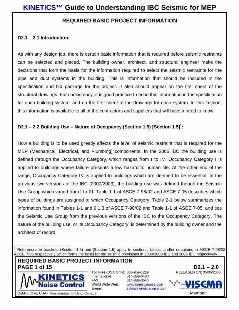
D2.1 – 2.1 Introduction:
As with any design job, there is certain basic information that is required before seismic restraints
can be selected and placed. The building owner, architect, and structural engineer make the
decisions that form the basis for the information required to select the seismic restraints for the
pipe and duct systems in the building. This is information that should be included in the
specification and bid package for the project. It also should appear on the first sheet of the
structural drawings. For consistency, it is good practice to echo this information in the specification
for each building system, and on the first sheet of the drawings for each system. In this fashion,
this information is available to all of the contractors and suppliers that will have a need to know.
D2.1 – 2.2 Building Use – Nature of Occupancy (Section 1.5) [Section 1.5]1:
How a building is to be used greatly affects the level of seismic restraint that is required for the
MEP (Mechanical, Electrical, and Plumbing) components. In the 2006 IBC the building use is
defined through the Occupancy Category, which ranges from I to IV. Occupancy Category I is
applied to buildings where failure presents a low hazard to human life. At the other end of the
range, Occupancy Category IV is applied to buildings which are deemed to be essential. In the
previous two versions of the IBC (2000/2003), the building use was defined though the Seismic
Use Group which varied from I to III. Table 1-1 of ASCE 7-98/02 and ASCE 7-05 describes which
types of buildings are assigned to which Occupancy Category. Table 2-1 below summarizes the
information found in Tables 1-1 and 9.1.3 of ASCE 7-98/02 and Table 1-1 of ASCE 7-05, and ties
the Seismic Use Group from the previous versions of the IBC to the Occupancy Category. The
nature of the building use, or its Occupancy Category, is determined by the building owner and the
architect of record.
1 References in brackets (Section 1.5) and [Section 1.5] apply to sections, tables, and/or equations in ASCE 7-98/02ASCE 7-05 respectively which forms the basis for the seismic provisions in 2000/2003 IBC and 2006 IBC respectively.

KINETICS™ Guide to Understanding IBC Seismic for MEP
REQUIRED BASIC PROJECT INFORMATIONPAGE 2 of 15 D2.1 – 2.0
Toll Free (USA Only): 800-959-1229 RELEASED ON: 05/06/2008International: 614-889-0480FAX 614-889-0540World Wide Web: www.kineticsnoise.comE-mail: [email protected]
Dublin, Ohio, USA Mississauga, Ontario, Canada Member
Table 2-1; Building Use vs. Occupancy Category & Seismic Use Group (Table 1-1, Table 9.1.3)[Table 1-1]
OccupancyCategory
2000/2003& 2006
IBC
SeismicUse
Group2000/2003
IBC
Building Use or Nature of Occupancy
I
Buildings and structures in which failure would pose a low hazard to human life. Thesebuildings include, but are not limited to:Ø Agricultural buildings and structures.Ø Certain temporary buildings and structures.Ø Minor storage buildings and structures.
II
I
Buildings and structures that are not listed as Occupancy Category I, III, or IV. Also,cogeneration power plants that do not supply power to the national power grid.
III II
Buildings and structures, in which failure would pose a substantial hazard to human life, havethe potential to create a substantial economic impact, and/or cause a mass disruption of day-to-day civilian life. These buildings include, but are not limited to:Ø Where more than 300 people congregate in one area.
Ø Daycare facilities with a capacity greater than 50.Ø Elementary and Secondary school facilities with a capacity greater than 250 and
colleges and adult educational facilities with a capacity greater than 500.Ø Healthcare facilities with 50 or more resident patients that do not have surgery or
emergency treatment facilities.Ø Jails, prisons, and detention facilities.Ø Power generation stations.Ø Water and sewage treatment facilities.Ø Telecommunication centers.
Buildings and structures which are not in Occupancy Category IV which contain enough toxicor explosive materials that would be hazardous to the public if released.
IV III
Buildings and structures which are designated as essential facilities which include but are notlimited to:Ø Hospitals & healthcare facilities with surgical or emergency treatment facilities.Ø Fire, rescue, ambulance, police stations, & emergency vehicle garages.Ø Designated emergency shelters.Ø Facilities designated for emergency preparedness & response.Ø Power generating stations and other public utilities required for emergency response
and recovery.Ø Ancillary structures required for the continued operation of Occupancy Category IV
buildings and structures.Ø Aviation control towers, air traffic control centers, and emergency aircraft hangers.Ø Water storage facilities and pumping stations required for fire suppression.Ø Buildings and structures required for national defense.Ø Buildings and structures that contain highly toxic and/or explosive materials in
sufficient quantity to pose a threat to the public.

KINETICS™ Guide to Understanding IBC Seismic for MEP
REQUIRED BASIC PROJECT INFORMATIONPAGE 3 of 15 D2.1 – 2.0
Toll Free (USA Only): 800-959-1229 RELEASED ON: 05/06/2008International: 614-889-0480FAX 614-889-0540World Wide Web: www.kineticsnoise.comE-mail: [email protected]
Dublin, Ohio, USA Mississauga, Ontario, Canada Member
D2.1 – 2.3 Site Class – Soil Type (Sections 9.4.1.2.1, 9.4.1.2.2) [Section 11.4.2 & Chapter 20]:
The Site Class is related to the type of soil and rock strata that directly underlies the building site.
The Site Class ranges from A to F progressing from the stiffest to the softest strata. Table 2-2 lists
the various Site Classes and their corresponding strata.
Generally the structural engineer is responsible for determining the Site Class for a project. If the
structural engineer’s firm does not have a geotechnical engineer on staff, this job will be
contracted to a geotechnical firm. The Site Class is determined in accordance with the references
stated above from ASCE 7-98/02 and ASCE 7-05. The site profile is normally obtained by drilling
several cores on the property. If there is insufficient information concerning the soil properties,
then the default Site Class D is assigned to the project.
Table 2-2; Site Class vs. Soil Type (Table 9.4.1.2) [Table 20.3-1]
Site Class Soil TypeA Hard RockB RockC Very Dense Soil & Soft RockD Stiff Soil (Default Site Class)E Soft Clay Soil
F Liquefiable Soils, Quick Highly Sensitive Clays, Collapsible Weakly Cemented Soils, & etc.These require site response analysis.
D2.1 – 2.4 Mapped Acceleration Parameters (Sections 9.4.1.2.4 & 9.4.1.2.5) [Sections 11.4.3
& 11.4.4 and Chapters 21 & 22]
The United States Geological Survey, USGS, has mapped all of the known fault lines in the United
States and its possessions. They have assigned ground level acceleration values to each location
based on the Maximum Considered Earthquake, MCE, for two earthquake periods, 0.2 sec and
1.0 sec, at 5% damping. The mapped values are listed in terms of %g, where 1g is 32.2 ft/sec2,
386.4 in/sec2, 9.8 m/sec2. The long period values are generally applied to the buildings and other

KINETICS™ Guide to Understanding IBC Seismic for MEP
REQUIRED BASIC PROJECT INFORMATIONPAGE 4 of 15 D2.1 – 2.0
Toll Free (USA Only): 800-959-1229 RELEASED ON: 05/06/2008International: 614-889-0480FAX 614-889-0540World Wide Web: www.kineticsnoise.comE-mail: [email protected]
Dublin, Ohio, USA Mississauga, Ontario, Canada Member
structures since they react more strongly to the long period excitation due to their relatively high
mass and low stiffness. The code specifies the use of short period values when evaluating non-
structural components, which include pipe and duct, as they respond more strongly to the short
period excitation due to their relatively low mass and high stiffness.
The Mapped Acceleration Parameters are available in ASCE 7-98/02 for 2000/2003 IBC and
ASCE 7-05 for 2006 IBC, or may be obtained from the USGS cataloged by ZIP Code. The short
period Mapped Acceleration Parameter is usually denoted as SS and the Long period Mapped
Acceleration Parameter is denoted as 1S . Note that the values for SS and 1S may be different for
2000/2003 IBC and 2006 IBC. Be sure the correct values are being used for the code that is in
force in your jurisdiction.
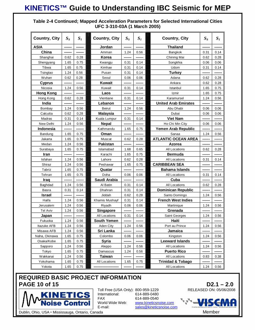
Special Note: For the purpose of making preliminary estimates, the long and short period
mapped acceleration parameters for selected U. S. cities are given in Table 2.4, and for selected
international cities in Table 2.5. Please be aware that these values do not necessarily represent
the maximum acceleration values that may occur in the named cities. For the U. S. cities please
refer to the data compiled by the USGS by ZIP CODE. For international locations, local geological
assessments should be sought from reputable sources at that location.
The Site Class information is then used to determine the Design Spectral Acceleration
Parameters, DSS and 1DS , for the short and long period MCE respectively. Equations 2-1 and 2-2
may be used to estimate the Design Spectral Acceleration Parameters.
SaDS SFS32
= Equation 2-1 (9.4.1.2.4-1) [11.4-3]
And
KINETICS™ Guide to Understanding IBC Seismic for MEP
REQUIRED BASIC PROJECT INFORMATIONPAGE 5 of 15 D2.1 – 2.0
Toll Free (USA Only): 800-959-1229 RELEASED ON: 05/06/2008International: 614-889-0480FAX 614-889-0540World Wide Web: www.kineticsnoise.comE-mail: [email protected]
Dublin, Ohio, USA Mississauga, Ontario, Canada Member
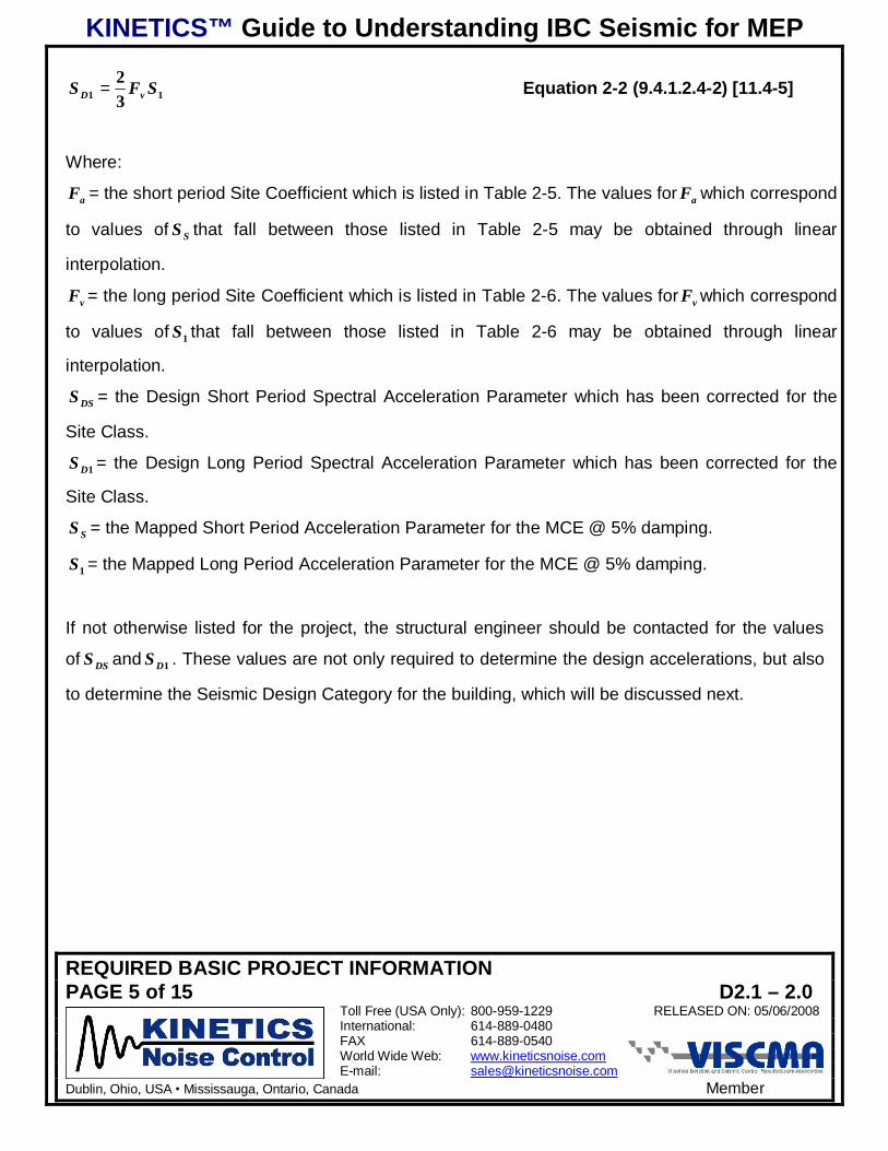
11 32 SFS vD = Equation 2-2 (9.4.1.2.4-2) [11.4-5]
Where:
aF = the short period Site Coefficient which is listed in Table 2-5. The values for aF which correspond
to values of SS that fall between those listed in Table 2-5 may be obtained through linear
interpolation.
vF = the long period Site Coefficient which is listed in Table 2-6. The values for vF which correspond
to values of 1S that fall between those listed in Table 2-6 may be obtained through linear
interpolation.
DSS = the Design Short Period Spectral Acceleration Parameter which has been corrected for the
Site Class.
1DS = the Design Long Period Spectral Acceleration Parameter which has been corrected for the
Site Class.
SS = the Mapped Short Period Acceleration Parameter for the MCE @ 5% damping.
1S = the Mapped Long Period Acceleration Parameter for the MCE @ 5% damping.
If not otherwise listed for the project, the structural engineer should be contacted for the values
of DSS and 1DS . These values are not only required to determine the design accelerations, but also
to determine the Seismic Design Category for the building, which will be discussed next.

KINETICS™ Guide to Understanding IBC Seismic for MEP
REQUIRED BASIC PROJECT INFORMATIONPAGE 6 of 15 D2.1 – 2.0
Toll Free (USA Only): 800-959-1229 RELEASED ON: 05/06/2008International: 614-889-0480FAX 614-889-0540World Wide Web: www.kineticsnoise.comE-mail: [email protected]
Dublin, Ohio, USA Mississauga, Ontario, Canada Member
Table S2-3; Mapped Acceleration Parameters for Selected U.S. Cities2000/2003 IBC & 2006 IBC
SS S1 SS S1State, City ZIP
CODE 20002003 2006 2000
2003 2006State, City ZIP
CODE 20002003 2006 2000
2003 2006
Alabama ------- ------ ------ ------ ------ Illinois ------- ------ ------ ------ ------Birmingham 35217 0.33 0.31 0.12 0.10 Chicago 60620 0.19 0.17 0.07 0.06
Mobile 36610 0.13 0.12 0.06 0.05 Moline 61265 0.14 0.14 0.06 0.06Montgomery 36104 0.17 0.16 0.08 0.07 Peoria 61605 0.18 0.18 0.09 0.08Arkansas ------- ------ ------ ------ ------ Rock Island 61201 0.13 0.13 0.06 0.06Little Rock 72205 0.48 0.50 0.18 0.16 Rockford 61108 0.17 0.15 0.06 0.06Arizona ------- ------ ------ ------ ------ Springfield 62703 0.27 0.29 0.12 0.11Phoenix 85034 0.23 0.19 0.07 0.06 Indiana ------- ------ ------ ------ ------Tucson 85739 0.33 0.29 0.09 0.08 Evansville 47712 0.82 0.72 0.23 0.21
California ------- ------ ------ ------ ------ Ft. Wayne 46835 0.17 0.15 0.06 0.06Fresno 93706 0.76 0.78 0.30 0.29 Gary 46402 0.18 0.16 0.07 0.06
Los Angeles 90026 1.55 2.25 0.60 0.83 Indianapolis 46260 0.18 0.19 0.09 0.08Oakland 94621 1.98 1.97 0.87 0.77 South Bend 46637 0.12 0.12 0.06 0.05
Sacramento 95823 0.59 0.64 0.23 0.25 Kansas ------- ------ ------ ------ ------San Diego 92101 1.61 1.62 0.86 0.82 Kansas City 66103 0.12 0.13 0.06 0.06
San Francisco 94114 1.50 1.61 0.86 0.82 Topeka 66614 0.19 0.17 0.06 0.05San Jose 95139 2.17 1.60 0.78 0.60 Wichita 67217 0.14 0.14 0.06 0.05
Colorado ------- ------ ------ ------ ------ Kentucky ------- ------ ------ ------ ------Colorado Springs 80913 0.18 0.22 0.06 0.06 Ashland 41101 0.22 0.19 0.09 0.07
Denver 80239 0.19 0.21 0.06 0.06 Covington 41011 0.19 0.18 0.09 0.08Connecticut ------- ------ ------ ------ ------ Louisville 40202 0.25 0.25 0.12 0.10
Bridgeport 06606 0.34 0.27 0.09 0.06 Louisiana ------- ------ ------ ------ ------Hartford 06120 0.27 0.24 0.09 0.06 Baton Rouge 70807 0.14 0.12 0.06 0.05
New Haven 06511 0.29 0.25 0.08 0.06 New Orleans 70116 0.13 0.11 0.06 0.05Waterbury 06702 0.29 0.25 0.09 0.06 Shreveport 71106 0.17 0.15 0.08 0.07Florida ------- ------ ------ ------ ------ Massachusetts ------- ------ ------ ------ ------
Ft. Lauderdale 33328 0.07 0.06 0.03 0.02 Boston 02127 0.33 0.28 0.09 0.07Jacksonville 32222 0.14 0.14 0.07 0.06 Lawrence 01843 0.38 0.33 0.09 0.07
Miami 33133 0.06 0.05 0.02 0.02 Lowell 01851 0.36 0.31 0.09 0.07St. Petersburg 33709 0.08 0.07 0.04 0.03 New Bedford 02740 0.26 0.22 0.08 0.06
Tampa 33635 0.08 0.07 0.03 0.03 Springfield 01107 0.26 0.23 0.09 0.07Georgia ------- ------ ------ ------ ------ Worchester 01602 0.27 0.24 0.09 0.07
Atlanta 30314 0.26 0.23 0.11 0.09 Maryland ------- ------ ------ ------ ------Augusta 30904 0.42 0.38 0.15 0.12 Baltimore 21218 0.20 0.17 0.06 0.05Columbia 31907 0.17 0.15 0.09 0.07 Maine ------- ------ ------ ------ ------Savannah 31404 0.42 0.43 0.15 0.13 Augusta 04330 0.33 0.30 0.10 0.08
Iowa ------- ------ ------ ------ ------ Portland 04101 0.37 0.32 0.10 0.08Council Bluffs 41011 0.19 0.18 0.09 0.08 Michigan ------- ------ ------ ------ ------
Davenport 52803 0.13 0.13 0.06 0.06 Detroit 48207 0.12 0.12 0.05 0.04Des Moines 50310 0.07 0.08 0.04 0.04 Flint 48506 0.09 0.09 0.04 0.04
Iowa ------- ------ ------ ------ ------ Grand Rapids 49503 0.09 0.09 0.04 0.04Boise 83705 0.35 0.30 0.11 0.10 Kalamazoo 49001 0.12 0.11 0.05 0.05
Pocatello 83201 0.60 0.63 0.18 0.19 Lansing 48910 0.11 0.10 0.04 0.04

KINETICS™ Guide to Understanding IBC Seismic for MEP
REQUIRED BASIC PROJECT INFORMATIONPAGE 7 of 15 D2.1 – 2.0
Toll Free (USA Only): 800-959-1229 RELEASED ON: 05/06/2008International: 614-889-0480FAX 614-889-0540World Wide Web: www.kineticsnoise.comE-mail: [email protected]
Dublin, Ohio, USA Mississauga, Ontario, Canada Member
Table 2-3 Continued; Mapped Acceleration Parameters for Selected U.S. Cities2000/2003 IBC & 2006 IBC
SS S1 SS S1State, City ZIP
CODE 20002003 2006 2000
2003 2006State, City ZIP
CODE 20002003 2006 2000
2003 2006
Minnesota ------- ------ ------ ------ ------ Raleigh 27610 0.22 0.21 0.10 0.08Duluth 55803 0.06 0.06 0.02 0.02 Winston-Salem 27106 0.28 0.24 0.12 0.09
Minneapolis 55422 0.06 0.06 0.03 0.03 North Dakota ------- ------ ------ ------ ------Rochester 55901 0.06 0.06 0.03 0.03 Fargo 58103 0.07 0.08 0.02 0.02St. Paul 55111 0.06 0.06 0.03 0.03 Grand Forks 58201 0.05 0.06 0.02 0.02
Missouri ------- ------ ------ ------ ------ Ohio ------- ------ ------ ------ ------Carthage 64836 0.16 0.17 0.09 0.08 Akron 44312 0.18 0.17 0.06 0.05Columbia 65202 0.19 0.21 0.10 0.09 Canton 44702 0.16 0.14 0.06 0.05
Jefferson City 65109 0.22 0.23 0.11 0.10 Cincinnati 45245 0.19 0.18 0.09 0.07Joplin 64801 0.15 0.16 0.08 0.08 Cleveland 44130 0.20 0.19 0.06 0.05
Kansas City 64108 0.15 0.13 0.06 0.06 Columbus 43217 0.17 0.15 0.07 0.06Springfield 65801 0.21 0.22 0.10 0.10 Dayton 45440 0.21 0.18 0.08 0.07St. Joseph 64501 0.12 0.12 0.05 0.05 Springfield 45502 0.26 0.21 0.08 0.07St. Louis 63166 0.59 0.58 0.19 0.17 Toledo 43608 0.17 0.16 0.06 0.05
Mississippi ------- ------ ------ ------ ------ Youngstown 44515 0.17 0.16 0.06 0.05Jackson 39211 0.19 0.20 0.10 0.09 Oklahoma ------- ------ ------ ------ ------
Montana ------- ------ ------ ------ ------ Oklahoma City 73145 0.34 0.33 0.09 0.07Billings 59101 0.16 0.17 0.06 0.07 Tulsa 74120 0.16 0.16 0.07 0.07Butte 59701 0.74 0.65 0.21 0.20 Oregon ------- ------ ------ ------ ------
Great Falls 59404 0.29 0.26 0.09 0.09 Portland 97222 1.05 0.99 0.35 0.34Nebraska ------- ------ ------ ------ ------ Salem 97301 1.00 0.80 0.4 0.34
Lincoln 68502 0.18 0.18 0.05 0.05 Pennsylvania ------- ------ ------ ------ ------Omaha 68144 0.13 0.13 0.04 0.04 Allentown 18104 0.29 0.26 0.08 0.06
Nevada ------- ------ ------ ------ ------ Bethlehem 18015 0.31 0.27 0.08 0.07Las Vegas 89106 0.64 0.57 0.19 0.18 Erie 16511 0.17 0.16 0.05 0.05
Reno 89509 1.36 1.92 0.50 0.77 Harrisburg 17111 0.23 0.20 0.07 0.05New Mexico ------- ------ ------ ------ ------ Philadelphia 19125 0.33 0.27 0.08 0.06Albuquerque 87105 0.63 0.59 0.19 0.18 Pittsburgh 15235 0.13 0.13 0.06 0.05
Santa Fe 87507 0.62 0.54 0.19 0.17 Reading 19610 0.30 0.26 0.08 0.06New York ------- ------ ------ ------ ------ Scranton 18504 0.23 0.20 0.08 0.06
Albany 12205 0.28 0.24 0.09 0.07 Rhode Island ------- ------ ------ ------ ------Binghamton 13903 0.19 0.17 0.07 0.06 Providence 02907 0.27 0.23 0.08 0.06
Buffalo 14222 0.32 0.28 0.07 0.06 South Carolina ------- ------ ------ ------ ------Elmira 14905 0.17 0.15 0.06 0.05 Charleston 29406 1.60 2.19 0.45 0.56
New York 10014 0.43 0.36 0.09 0.07 Columbia 29203 0.60 0.55 0.19 0.15Niagara Falls 14303 0.31 0.28 0.07 0.06 South Dakota ------- ------ ------ ------ ------
Rochester 14619 0.25 0.21 0.07 0.06 Rapid City 57703 0.16 0.17 0.04 0.04Schenectady 12304 0.28 0.24 0.09 0.09 Sioux Falls 57104 0.11 0.11 0.04 0.03
Syracuse 13219 0.19 0.18 0.08 0.06 Tennessee ------- ------ ------ ------ ------Utica 13501 0.25 0.22 0.09 0.07 Chattanooga 37415 0.52 0.46 0.14 0.12
North Carolina ------- ------ ------ ------ ------ Knoxville 37920 0.59 0.53 0.15 0.12Charlotte 28216 0.35 0.32 0.14 0.11 Memphis 38109 1.40 1.40 0.42 0.38
Greensboro 27410 0.26 0.23 0.11 0.08 Nashville 49503 0.09 0.09 0.04 0.04

KINETICS™ Guide to Understanding IBC Seismic for MEP
REQUIRED BASIC PROJECT INFORMATIONPAGE 8 of 15 D2.1 – 2.0
Toll Free (USA Only): 800-959-1229 RELEASED ON: 05/06/2008International: 614-889-0480FAX 614-889-0540World Wide Web: www.kineticsnoise.comE-mail: [email protected]
Dublin, Ohio, USA Mississauga, Ontario, Canada Member
Table 2-3 Continued; Mapped Acceleration Parameters for Selected U.S. Cities2000/2003 IBC & 2006 IBC
SS S1State, City ZIP
CODE 20002003 2006 2000
2003 2006
Texas ------- ------ ------ ------ ------Amarillo 79111 0.17 0.18 0.05 0.04Austin 78703 0.09 0.08 0.04 0.03
Beaumont 77705 0.12 0.10 0.05 0.04Corpus Christi 78418 0.10 0.08 0.02 0.02
Dallas 75233 0.12 0.11 0.06 0.05El Paso 79932 0.37 0.33 0.11 0.11
Ft. Worth 76119 0.11 0.11 0.06 0.05Houston 77044 0.11 0.10 0.05 0.04Lubbock 79424 0.10 0.11 0.03 0.03
San Antonio 78235 0.14 0.12 0.03 0.03Waco 76704 0.10 0.09 0.05 0.04Utah ------- ------ ------ ------ ------
Salt Lake City 84111 1.82 1.71 0.78 0.09Virginia ------- ------ ------ ------ ------Norfolk 23504 0.13 0.12 0.06 0.05
Richmond 23233 0.32 0.25 0.09 0.06Roanoke 24017 0.30 0.26 0.10 0.08
Vermont ------- ------ ------ ------ ------Burlington 05401 0.47 0.40 0.13 0.10
Washington ------- ------ ------ ------ ------Seattle 98108 1.56 1.57 0.54 0.54
Spokane 99201 0.38 0.40 0.09 0.11Tacoma 98402 1.24 1.22 0.40 0.42
Washington, D.C. ------- ------ ------ ------ ------Washington 20002 0.18 0.15 0.06 0.05Wisconsin ------- ------ ------ ------ ------Green Bay 54302 0.07 0.06 0.03 0.03Kenosha 53140 0.14 0.12 0.05 0.05Madison 53714 0.12 0.11 0.05 0.04
Milwaukee 53221 0.12 0.11 0.05 0.05Racine 53402 0.13 0.12 0.05 0.05
Superior 54880 0.06 0.06 0.02 0.2West Virginia ------- ------ ------ ------ ------
Charleston 25303 0.21 0.19 0.08 0.07Huntington 25704 0.23 0.20 0.09 0.07Wyoming ------- ------ ------ ------ ------
Casper 82601 0.38 0.39 0.08 0.08Cheyenne 82001 0.19 0.20 0.06 0.05
--------------------- ------- ------ ------ ------ --------------------------- ------- ------ ------ ------ --------------------------- ------- ------ ------ ------ --------------------------- ------- ------ ------ ------ ------

KINETICS™ Guide to Understanding IBC Seismic for MEP
REQUIRED BASIC PROJECT INFORMATIONPAGE 9 of 15 D2.1 – 2.0
Toll Free (USA Only): 800-959-1229 RELEASED ON: 05/06/2008International: 614-889-0480FAX 614-889-0540World Wide Web: www.kineticsnoise.comE-mail: [email protected]
Dublin, Ohio, USA Mississauga, Ontario, Canada Member
Table 2-4; Mapped Acceleration Parameters for Selected International CitiesUFC 3-310-03A (1 March 2005)
Country, City SS S1 Country, City SS S1 Country, City SS S1
AFRICA ------ ------ Kenya ------ ------ South Africa ------ ------Algeria ------ ------ Nairobi 0.62 0.28 Cape Town 1.24 0.56
Alger 1.24 0.56 Lesotho ------ ------ Durban 0.62 0.28Oran 1.24 0.56 Maseru 0.62 0.28 Johannesburg 0.62 0.28
Angola ------ ------ Liberia ------ ------ Natal 0.31 0.14Luanda 0.06 0.06 Monrovia 0.31 0.14 Pretoria 0.62 0.28Benin ------ ------ Libya ------ ------ Swaziland ------ ------
Cotonou 0.06 0.06 Tripoli 0.62 0.28 Mbabane 0.62 0.28Botswana ------ ------ Wheelus AFB 0.62 0.28 Tanzania ------ ------Gaborone 0.06 0.06 Malagasy Republic ------ ------ Dar es Salaam 0.62 0.28Burundi ------ ------ Tananarive 0.06 0.06 Zanzibar 0.62 0.28Bujumbura 1.24 0.56 Malawi ------ ------ Togo ------ ------
Cameroon ------ ------ Blantyre 1.24 0.56 Lome 0.31 0.14Douala 0.06 0.06 Lilongwe 1.24 0.56 Tunisia ------ ------
Yaounde 0.06 0.06 Zomba 1.24 0.56 Tunis 1.24 0.56Cape Verde ------ ------ Mali ------ ------ Uganda ------ ------
Praia 0.06 0.06 Bamako 0.06 0.06 Kampala 0.62 0.28Central African Republic ------ ------ Mauritania ------ ------ Upper Volta ------ ------
Bangui 0.06 0.06 Nouakchott 0.06 0.06 Ougadougou 0.06 0.06Chad ------ ------ Mauritius ------ ------ Zaire ------ ------
Ndjamena 0.06 0.06 Port Louis 0.06 0.06 Bukavu 1.24 0.56Congo ------ ------ Morocco ------ ------ Kinshasa 0.06 0.06
Brazzaville 0.06 0.06 Casablanca 0.62 0.28 Lubumbashi 0.62 0.28Djibouti ------ ------ Port Lyautey 0.31 0.14 Zambia ------ ------Djibouti 1.24 0.56 Rabat 0.62 0.28 Lusaka 0.62 0.28Egypt ------ ------ Tangier 1.24 0.56 Zimbabwe ------ ------
Alexandria 0.62 0.28 Mozambique ------ ------ Harare 1.24 0.56Cairo 0.62 0.28 Maputo 0.62 0.28 ASIA ------ ------
Port Said 0.62 0.28 Niger ------ ------ Afghanistan ------ ------Equatorial Guinea ------ ------ Niamey 0.06 0.06 Kabul 1.65 0.75
Malabo 0.06 0.06 Nigeria ------ ------ Bahrain ------ ------Ethiopia ------ ------ Ibadan 0.06 0.06 Manama 0.06 0.06
Addis Ababa 1.24 0.56 Kaduna 0.06 0.06 Bangladesh ------ ------Asmara 1.24 0.56 Lagos 0.06 0.06 Dacca 1.24 0.56Gabon ------ ------ Republic of Rwanda ------ ------ Brunei ------ ------Libreville 0.06 0.06 Kigali 1.24 0.56 Bandar Seri Begawan 0.31 0.14Gambia ------ ------ Senegal ------ ------ Burma ------ ------
Banjul 0.06 0.06 Dakar 0.06 0.06 Mandalay 1.24 0.56Guinea ------ ------ Seychelles ------ ------ Rangoon 1.24 0.56Bissau 0.31 0.14 Victoria 0.06 0.06 China ------ ------
Conakry 0.06 0.06 Sierra Leone ------ ------ Canton 0.62 0.28Ivory Coast ------ ------ Freetown 0.06 0.06 Chengdu 1.24 0.56
Abidijan 0.06 0.06 Somalia ------ ------ Nanking 0.62 0.28----------------------------------- ------ ------ Mogadishu 0.06 0.06 Peking 1.65 0.75
KINETICS™ Guide to Understanding IBC Seismic for MEP
REQUIRED BASIC PROJECT INFORMATIONPAGE 10 of 15 D2.1 – 2.0
Toll Free (USA Only): 800-959-1229 RELEASED ON: 05/06/2008International: 614-889-0480FAX 614-889-0540World Wide Web: www.kineticsnoise.comE-mail: [email protected]
Dublin, Ohio, USA Mississauga, Ontario, Canada Member
Table 2-4 Continued; Mapped Acceleration Parameters for Selected International CitiesUFC 3-310-03A (1 March 2005)
Country, City SS S1 Country, City SS S1 Country, City SS S1
ASIA ------ ------ Jordan ------ ------ Thailand ------ ------China ------ ------ Amman 1.24 0.56 Bangkok 0.31 0.14
Shanghai 0.62 0.28 Korea ------ ------ Chinmg Mai 0.62 0.28Shengyang 1.65 0.75 Kwangju 0.31 0.14 Songkhia 0.06 0.06
Tibwa 1.65 0.75 Kimhae 0.31 0.14 Udom 0.31 0.14Tsingtao 1.24 0.56 Pusan 0.31 0.14 Turkey ------ ------Wuhan 0.62 0.28 Seoul 0.06 0.06 Adana 0.62 0.28
Cyprus ------ ------ Kuwait ------ ------ Ankara 0.62 0.28Nicosia 1.24 0.56 Kuwait 0.31 0.14 Istanbul 1.65 0.75
Hong Kong ------ ------ Laos ------ ------ Izmir 1.65 0.75Hong Kong 0.62 0.28 Vientiane 0.31 0.14 Karamursel 1.24 0.56
India ------ ------ Lebanon ------ ------ United Arab Emirates ------ ------Bombay 1.24 0.56 Beirut 1.24 0.56 Abu Dhabi 0.06 0.06Calcutta 0.62 0.28 Malaysia ------ ------ Dubai 0.06 0.06Madras 0.31 0.14 Kuala Lumpur 0.31 0.14 Viet Nam ------ ------
New Delhi 1.24 0.56 Nepal ------ ------ Ho Chi Min City 0.06 0.06Indonesia ------ ------ Kathmandu 1.65 0.75 Yemen Arab Republic ------ ------
Bandung 1.65 0.75 Oman ------ ------ Sanaa 1.24 0.56Jakarta 1.65 0.75 Muscat 0.62 0.28 ATLANTIC OCEAN AREA ------ ------Medan 1.24 0.56 Pakistan ------ ------ Azorea ------ ------
Surabaya 1.65 0.75 Islamabad 1.68 0.65 All Locations 0.62 0.28Iran ------ ------ Karachi 1.65 0.75 Bermuda ------ ------
Isfahan 1.24 0.56 Lahore 0.62 0.28 All Locations 0.31 0.14Shiraz 1.24 0.56 Peshawar 1.65 0.75 CARIBBEAN SEA ------ ------Tabriz 1.65 0.75 Quatar ------ ------ Bahama Islands ------ ------Tehran 1.65 0.75 Doha 0.06 0.06 All Locations 0.31 0.14Iraq ------ ------ Saudi Arabia ------ ------ Cuba ------ ------
Baghdad 1.24 0.56 Al Batin 0.31 0.14 All Locations 0.62 0.28Basra 0.31 0.14 Dhahran 0.31 0.14 Dominican Republic ------ ------Israel ------ ------ Jiddah 0.62 0.28 Santo Domingo 1.24 0.56Haifa 1.24 0.56 Khamis Mushayf 0.31 0.14 French West Indies ------ ------
Jerusalem 1.24 0.56 Riyadh 0.06 0.06 Martinique 1.24 0.56Tel Aviv 1.24 0.56 Singapore ------ ------ Grenada ------ ------Japan ------ ------ All Locations 0.31 0.14 Saint Georges 1.24 0.56Fukuoka 1.24 0.56 South Yemen ------ ------ Haiti ------ ------
Itazuke AFB 1.24 0.56 Aden City 1.24 0.56 Port au Prince 1.24 0.56Misawa AFB 1.24 0.56 Sri Lanka ------ ------ Jamaica ------ ------
Naha, Okinawa 1.65 0.75 Colombo 0.06 0.06 Kingston 1.24 0.56Osaka/Kobe 1.65 0.75 Syria ------ ------ Leeward Islands ------ ------
Sapporo 1.24 0.56 Aleppo 1.24 0.56 All Locations 1.24 0.56Tokyo 1.65 0.75 Damascus 1.24 0.56 Puerto Rico ------ ------
Wakkanai 1.24 0.56 Taiwan ------ ------ All Locations 0.83 0.38Yokohama 1.65 0.75 All Locations 1.65 0.75 Trinidad & Tobago ------ ------
Yokota 1.65 0.75 -------------------- ------ ------ All Locations 1.24 0.56

KINETICS™ Guide to Understanding IBC Seismic for MEP
REQUIRED BASIC PROJECT INFORMATIONPAGE 11 of 15 D2.1 – 2.0
Toll Free (USA Only): 800-959-1229 RELEASED ON: 05/06/2008International: 614-889-0480FAX 614-889-0540World Wide Web: www.kineticsnoise.comE-mail: [email protected]
Dublin, Ohio, USA Mississauga, Ontario, Canada Member
Table 2-4 Continued; Mapped Acceleration Parameters for Selected International CitiesUFC 3-310-03A (1 March 2005)
Country, City SS S1 Country, City SS S1 Country, City SS S1
Belize ------ ------ Denmark ------ ------ Trieste 1.24 0.56Beimopan 0.62 0.28 Copenhagen 0.31 0.14 Turin 0.62 0.28
Canal Zone ------ ------ Finland ------ ------ Luxembourg ------ ------All Locations 0.62 0.28 Helsinki 0.31 0.14 Luxembourg 0.31 0.14Costa Rica ------ ------ France ------ ------ Malta ------ ------
San Jose 1.24 0.56 Bordeaux 0.62 0.28 Valletta 0.62 0.28El Salvador ------ ------ Lyon 0.31 0.14 Netherlands ------ ------San Slavador 1.65 0.75 Marseille 1.24 0.56 All Locations 0.06 0.06Guatemala ------ ------ Nice 1.24 0.56 Norway ------ ------Guatemala 1.65 0.75 Strasbourg 0.62 0.28 Oslo 0.62 0.28Honduras ------ ------ Germany ------ ------ Poland ------ ------Tegucigalpa 1.24 0.56 Berlin 0.06 0.06 Krakow 0.62 0.28Nicaragua ------ ------ Bonn 0.62 0.28 Poznan 0.31 0.14
Managua 1.65 0.75 Bremen 0.06 0.06 Waraszawa 0.31 0.14Panama ------ ------ Düsseldorf 0.31 0.14 Portugal ------ ------
Colon 1.24 0.56 Frankfurt 0.62 0.28 Lisbon 1.65 0.75Galeta 0.83 0.38 Hamburg 0.06 0.06 Oporto 1.24 0.56
Panama 1.24 0.56 Munich 0.31 0.14 Romania ------ ------Mexico ------ ------ Stuttgart 0.62 0.28 Bucharest 1.24 0.56
Ciudad Juarez 0.62 0.28 Vaihigen 0.62 0.28 Spain ------ ------Guadalajara 1.24 0.56 Greece ------ ------ Barcelona 0.62 0.28Hermosillo 1.24 0.56 Athens 1.24 0.56 Bilbao 0.62 0.28Matamoros 0.06 0.06 Kavalla 1.65 0.75 Madrid 0.06 0.06Mazatlan 0.60 0.28 Makri 1.65 0.56 Rota 0.62 0.28Merida 0.06 0.06 Rhodes 1.24 0.75 Seville 0.62 0.28
Mexico City 1.24 0.56 Sauda Bay 1.65 0.56 Sweden ------ ------Monterrey 0.06 0.06 Thessaloniki 1.65 0.56 Goteborg 0.62 0.28
Nuevo Laredo 0.06 0.06 Hungary ------ ------ Stockholm 0.31 0.14Tijuana 1.24 0.56 Budapest 0.62 0.28 Switzerland ------ ------
EUROPE ------ ------ Iceland ------ ------ Bern 0.62 0.28Albania ------ ------ Keflavick 1.24 0.56 Geneva 0.31 0.14
Tirana 1.24 0.56 Reykjavik 1.65 0.75 Zurich 0.62 0.28Austria ------ ------ Ireland ------ ------ United Kingdom ------ ------Salzburg 0.62 0.28 Dublin 0.06 0.06 Belfast 0.06 0.06Vienna 0.62 0.28 Italy ------ ------ Edinburgh 0.31 0.14
Belgium ------ ------ Aviano AFB 1.24 0.56 Edzell 0.31 0.14Antwerp 0.31 0.14 Brindisi 0.06 0.06 Glasgow/Renfrew 0.31 0.14Brussels 0.62 0.28 Florence 1.24 0.56 Hamilton 0.31 0.14
Bulgaria ------ ------ Genoa 1.24 0.56 Liverpool 0.31 0.14Sofia 1.24 0.56 Milan 0.62 0.28 London 0.62 0.28
Czechoslovakia ------ ------ Naples 1.24 0.56 Londonderry 0.31 0.14Bratislava 0.62 0.28 Palermo 1.24 0.56 Thurso 0.31 0.14
Prague 0.31 0.14 Rome 0.62 0.28 U. S. S. R. ------ -------------------------- ------ ------ Sicily 1.24 0.56 Kiev 0.06 0.06

KINETICS™ Guide to Understanding IBC Seismic for MEP
REQUIRED BASIC PROJECT INFORMATIONPAGE 12 of 15 D2.1 – 2.0
Toll Free (USA Only): 800-959-1229 RELEASED ON: 05/06/2008International: 614-889-0480FAX 614-889-0540World Wide Web: www.kineticsnoise.comE-mail: [email protected]
Dublin, Ohio, USA Mississauga, Ontario, Canada Member
Table 2-4 Continued; Mapped Acceleration Parameters for Selected International CitiesUFC 3-310-03A (1 March 2005)
Country, City SS S1 Country, City SS S1 Country, City SS S1
U. S. S. R. ------ ------ Valparaiso 1.65 0.75 Baguio 1.24 0.56Leningrad 0.06 0.06 Colombia ------ ------ Samoa ------ ------Moscow 0.06 0.06 Bogotá 1.24 0.56 All Locations 1.24 0.56
Yugoslavia ------ ------ Ecuador ------ ------ Wake Island ------ ------Belgrade 0.62 0.28 Quito 1.65 0.75 All Locations 0.06 0.06Zagreb 1.24 0.56 Guayaquil 1.24 0.56 -------------------- ------ ------
NORTH AMERICA ------ ------ Paraguay ------ ------ -------------------- ------ ------Greenland ------ ------ Asuncion 0.06 0.06 -------------------- ------ ------All Locations 0.31 0.14 Peru ------ ------ -------------------- ------ ------
Canada ------ ------ Lima 1.65 0.75 -------------------- ------ ------Argentia NAS 0.62 0.28 Piura 1.65 0.75 -------------------- ------ ------Calgary, Alb 0.31 0.14 Uruguay ------ ------ -------------------- ------ ------
Churchill, Man 0.06 0.06 Montevideo 0.06 0.06 -------------------- ------ ------Cold Lake, Alb 0.31 0.14 Venezuela ------ ------ -------------------- ------ ------Edmonton, Alb 0.31 0.14 Maracaibo 0.62 0.28 -------------------- ------ ------
East Harmon AFB 0.62 0.28 Caracas 1.65 0.75 -------------------- ------ ------Fort Williams, Ont. 0.06 0.06 PACIFIC OCEAN AREA ------ ------ -------------------- ------ ------
Frobisher N. W. Ter. 0.06 0.06 Australia ------ ------ -------------------- ------ ------Goose Airport 0.31 0.14 Brisbane 0.31 0.14 -------------------- ------ ------
Halifax 0.31 0.14 Canberra 0.31 0.14 -------------------- ------ ------Montreal, Quebec 1.24 0.56 Melbourne 0.31 0.14 -------------------- ------ ------
Ottawa, Ont. 0.31 0.28 Perth 0.31 0.14 -------------------- ------ ------St. John’s, Nfld. 1.24 0.56 Sydney 0.31 0.14 -------------------- ------ ------
Toronto, Ont. 0.31 0.14 Caroline Islands ------ ------ -------------------- ------ ------Vancouver 1.24 0.56 Koror, Paulau, Is. 0.62 0.28 -------------------- ------ ------
Winnipeg, Man. 0.31 0.14 Ponape 0.06 0.06 -------------------- ------ ------SOUTH AMERICA ------ ------ Fiji ------ ------ -------------------- ------ ------
Argentina ------ ------ Suva 1.24 0.56 -------------------- ------ ------Buenos Aires 0.25 0.10 Johnson Island ------ ------ -------------------- ------ ------
Brazil ------ ------ All Locations 0.31 0.14 -------------------- ------ ------Belem 0.06 0.06 Mariana Islands ------ ------ -------------------- ------ ------
Belo Horizonte 0.06 0.06 Guam 1.24 0.56 -------------------- ------ ------Brasilia 0.06 0.06 Saipan 1.24 0.56 -------------------- ------ ------Manaus 0.06 0.06 Tinian 1.24 0.56 -------------------- ------ ------
Porto Allegre 0.06 0.06 Marshall Islands ------ ------ -------------------- ------ ------Recife 0.06 0.06 All Locations 0.31 0.14 -------------------- ------ ------
Rio de Janeiro 0.06 0.06 New Zealand ------ ------ -------------------- ------ ------Salvador 0.06 0.06 Auckland 1.24 0.56 -------------------- ------ ------
Sao Paulo 0.31 0.14 Wellington 1.65 0.75 -------------------- ------ ------Bolivia ------ ------ Papua New Guinea ------ ------ -------------------- ------ ------La Paz 1.24 0.56 Port Moresby 1.65 0.75 -------------------- ------ ------
Santa Cruz 0.31 0.14 Philippine Islands ------ ------ -------------------- ------ ------Chile ------ ------ Cebu 1.65 0.75 -------------------- ------ ------
Santiago 1.65 0.75 Manila 1.65 0.75 -------------------- ------ ------
KINETICS™ Guide to Understanding IBC Seismic for MEP
REQUIRED BASIC PROJECT INFORMATIONPAGE 13 of 15 D2.1 – 2.0
Toll Free (USA Only): 800-959-1229 RELEASED ON: 05/06/2008International: 614-889-0480FAX 614-889-0540World Wide Web: www.kineticsnoise.comE-mail: [email protected]
Dublin, Ohio, USA Mississauga, Ontario, Canada Member
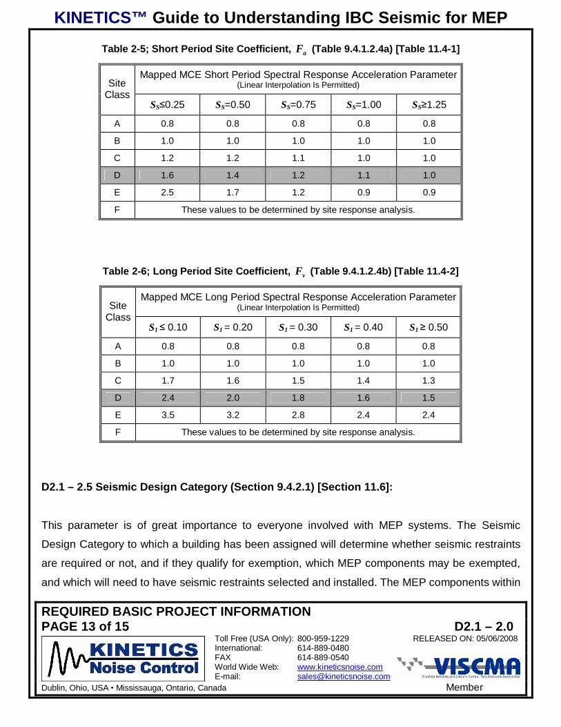
Table 2-5; Short Period Site Coefficient, aF (Table 9.4.1.2.4a) [Table 11.4-1]
Mapped MCE Short Period Spectral Response Acceleration Parameter(Linear Interpolation Is Permitted)Site
ClassSS 0.25 SS=0.50 SS=0.75 SS=1.00 SS 1.25
A 0.8 0.8 0.8 0.8 0.8
B 1.0 1.0 1.0 1.0 1.0
C 1.2 1.2 1.1 1.0 1.0
D 1.6 1.4 1.2 1.1 1.0
E 2.5 1.7 1.2 0.9 0.9
F These values to be determined by site response analysis.
Table 2-6; Long Period Site Coefficient, vF (Table 9.4.1.2.4b) [Table 11.4-2]
Mapped MCE Long Period Spectral Response Acceleration Parameter(Linear Interpolation Is Permitted)Site
ClassS1 0.10 S1 = 0.20 S1 = 0.30 S1 = 0.40 S1 0.50
A 0.8 0.8 0.8 0.8 0.8
B 1.0 1.0 1.0 1.0 1.0
C 1.7 1.6 1.5 1.4 1.3
D 2.4 2.0 1.8 1.6 1.5
E 3.5 3.2 2.8 2.4 2.4
F These values to be determined by site response analysis.
D2.1 – 2.5 Seismic Design Category (Section 9.4.2.1) [Section 11.6]:
This parameter is of great importance to everyone involved with MEP systems. The Seismic
Design Category to which a building has been assigned will determine whether seismic restraints
are required or not, and if they qualify for exemption, which MEP components may be exempted,
and which will need to have seismic restraints selected and installed. The MEP components within

KINETICS™ Guide to Understanding IBC Seismic for MEP
REQUIRED BASIC PROJECT INFORMATIONPAGE 14 of 15 D2.1 – 2.0
Toll Free (USA Only): 800-959-1229 RELEASED ON: 05/06/2008International: 614-889-0480FAX 614-889-0540World Wide Web: www.kineticsnoise.comE-mail: [email protected]
Dublin, Ohio, USA Mississauga, Ontario, Canada Member
a building will be assigned to the same Seismic Design Category as the building itself. There are
six Seismic Design Categories, A, B, C, D, E, and F. The level of restraint required increases from
Seismic Design Category A through F. Up through Seismic Design Category D, the Seismic
Design Category to which a building or structure is assigned is determined though the use of
Tables 2-6 and 2-7.
To determine the Seismic Design Category both the Long ( 1DS ) and Short ( DSS ) Period Design
Response Acceleration Parameter must be determined. The most stringent Seismic Design
Category, resulting from the two acceleration parameters, will be assigned to the project.
For Occupancy I, II, or III (Seismic Use Group I or II) structures, if the Mapped Spectral
Response Acceleration Parameter is greater than or equal to 0.75, 75.01 ≥S , then the structure will
be assigned to Seismic Design Category E. For Occupancy Category IV (Seismic Use Group III)
structures, if the Mapped Spectral Response Acceleration Parameter is greater than or equal to
0.75, 75.01 ≥S , then the structure will be assigned to Seismic Design Category F. To ensure
consistency, the Seismic Design Category should be determined by the structural engineer.
Table 2-7; Seismic Design Category Based on the Short Period DesignResponse Acceleration Parameter (Table 9.4.2.1a) [Table 11.6-1]
Occupancy Category(Seismic Use Group)
Value of SDS
I or II(I)
III(II)
IV(III)
SDS < 0.167 A A A
0.167 SDS < 0.33 B B C
0.33 SDS < 0.50 C C D
0.50 SDS D D D
KINETICS™ Guide to Understanding IBC Seismic for MEP
REQUIRED BASIC PROJECT INFORMATIONPAGE 15 of 15 D2.1 – 2.0
Toll Free (USA Only): 800-959-1229 RELEASED ON: 05/06/2008International: 614-889-0480FAX 614-889-0540World Wide Web: www.kineticsnoise.comE-mail: [email protected]
Dublin, Ohio, USA Mississauga, Ontario, Canada Member
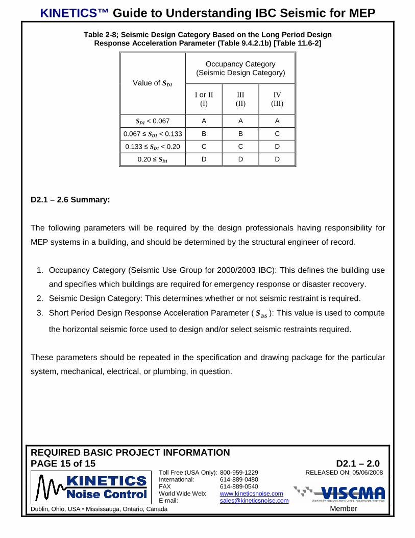
Table 2-8; Seismic Design Category Based on the Long Period DesignResponse Acceleration Parameter (Table 9.4.2.1b) [Table 11.6-2]
Occupancy Category(Seismic Design Category)
Value of SD1
I or II(I)
III(II)
IV(III)
SD1 < 0.067 A A A
0.067 SD1 < 0.133 B B C
0.133 SD1 < 0.20 C C D
0.20 SD1 D D D
D2.1 – 2.6 Summary:
The following parameters will be required by the design professionals having responsibility for
MEP systems in a building, and should be determined by the structural engineer of record.
1. Occupancy Category (Seismic Use Group for 2000/2003 IBC): This defines the building use
and specifies which buildings are required for emergency response or disaster recovery.
2. Seismic Design Category: This determines whether or not seismic restraint is required.
3. Short Period Design Response Acceleration Parameter ( DSS ): This value is used to compute
the horizontal seismic force used to design and/or select seismic restraints required.
These parameters should be repeated in the specification and drawing package for the particular
system, mechanical, electrical, or plumbing, in question.

KINETICS™ Guide to Understanding IBC Seismic for MEP
PIPE AND DUCT COMPONENT IMPORTANCE FACTORPAGE 1 of 3 D2.1 – 3.0
Toll Free (USA Only): 800-959-1229 RELEASED ON: 05/06/2008International: 614-889-0480FAX 614-889-0540World Wide Web: www.kineticsnoise.comE-mail: [email protected]
Dublin, Ohio, USA Mississauga, Ontario, Canada Member
COMPONENT IMPORTANCE FACTOR
D2.1 – 3.1 Introduction:
MEP components and systems are categorized in ASCE 7-98/02 and ASCE 7-05 as non-
structural components. There are just two values for the Component Importance Factors for MEP
components, 1.0 and 1.5, which are not directly linked to the importance factor for the building
structure. The Component Importance Factor is designated as PI in the body of the code. All MEP
components must be assigned a component importance factor. The design professional that has
responsibility for the MEP system in question is also responsible for assigning the Component
Importance Factor to that system.
D2.1 – 3.2 Criteria for Assigning a Component Importance Factor (Sections 9.6.1 and9.6.1.5) [Section 13.1.3]1:
For MEP systems, the Component Importance Factor ( PI ) assigned to the components within the
system shall be determined as follows.
1. If the MEP system is required to remain in place and function for life-safety purposes
following and earthquake the importance factor assigned to the MEP system and its
components shall be 1.5. Some examples of this type of system would be;
a. Fire sprinkler piping and fire suppression systems.
b. Smoke removal and fresh air ventilation systems.
c. Systems required for maintaining the proper air pressure in patient hospital rooms to
prevent the transmission of infectious diseases.
d. Systems that maintain proper air pressure, temperature, and humidity in surgical suites,
bio-hazard labs, and clean rooms.
1 References in brackets (Sections 9.6.1 and 9.6.1.5) and [Section 13.1.3] apply to sections, tables, and/or equations inASCE 7-98/02 and ASCE 7-05 respectively which forms the basis for the seismic provisions in 2000/2003 IBC and 2006IBC respectively..

KINETICS™ Guide to Understanding IBC Seismic for MEP
PIPE AND DUCT COMPONENT IMPORTANCE FACTORPAGE 2 of 3 D2.1 – 3.0
Toll Free (USA Only): 800-959-1229 RELEASED ON: 05/06/2008International: 614-889-0480FAX 614-889-0540World Wide Web: www.kineticsnoise.comE-mail: [email protected]
Dublin, Ohio, USA Mississauga, Ontario, Canada Member
e. Medical gas lines.
f. Steam lines or high pressure hot water lines.
2. If the MEP system contains or is used to transport hazardous materials, or materials that are
toxic if released in quantities that exceed the exempted limits a Component Importance
Factor of 1.5 shall be assigned to that MEP system and its components. Examples are as
follows.
a. Systems using natural gas.
b. Systems requiring fuel oil.
c. Systems used to exhaust laboratory fume hoods.
d. Boilers, furnaces and flue systems.
e. Systems that are used to ventilate bio-hazard areas and infectious patient rooms.
f. Chemical or by-product systems which are required for industrial processes.
3. If the MEP system is in or attached to a building that has been assigned to Occupancy
Category IV (Seismic Use Group III), i.e. essential or critical facilities, and is required for the
continued operation of that facility following an earthquake, then a Component Importance
Factor of 1.5 shall be assigned to that system and its components. Hospitals, emergency
response centers, police stations, fire stations, and etc. fall in Occupancy Category IV. The
failure of any system could cause the portion of the building it serves to be evacuated and
unusable would cause that system and its components to be assigned a Component
Importance Factor of 1.5. Even the failure of domestic water lines can flood a building and
render it uninhabitable. So, all of the items listed above under items 1 and 2 would apply to
facilities in Occupancy Category IV.
4. If the MEP system that is located in or attached to an Occupancy Category IV facility and its
failure would impair the operation of that facility, then a Component Importance Factor of 1.5
shall be assigned to that MEP system and its components. This implies that any MEP system
or component that could be assigned a Component Importance Factor of 1.0 that is located
above an MEP system or component that has been assigned a Component Importance
Factor of 1.5 must be reassigned to a Component Importance Factor of 1.5.

KINETICS™ Guide to Understanding IBC Seismic for MEP
PIPE AND DUCT COMPONENT IMPORTANCE FACTORPAGE 3 of 3 D2.1 – 3.0
Toll Free (USA Only): 800-959-1229 RELEASED ON: 05/06/2008International: 614-889-0480FAX 614-889-0540World Wide Web: www.kineticsnoise.comE-mail: [email protected]
Dublin, Ohio, USA Mississauga, Ontario, Canada Member
5. All other MEP systems that are not covered under items 1, 2, 3, or 4 may be assigned a
Component Importance Factor of 1.0.
D2.1 – 3.3 Summary:
The Component Importance Factor is very important to the designer responsible for selecting and
certifying the seismic restraints for an MEP system or component. This factor is a direct multiplier
for the horizontal seismic design force, which shall be discussed in a later section. The
Component Importance Factor will also be a key indicator as to whether a particular component
will qualify for and exemption or not. If a Component Importance Factor has not been assigned to
an MEP system, the designer responsible for selecting the seismic restraints must assume that
the Component Importance Factor is equal to 1.5. If the MEP system actually could be assigned a
Component Importance Factor of 1.0, this could result in a large increase in the size and number
of restraints required along with a corresponding increase in the cost for the system.
It is in the best interest of the design professionals responsible for an MEP system to properly
assign the Component Importance Factor to that MEP system. The Component Importance Factor
for each MEP system and component should be clearly indicated on the drawings that are
distributed to other design professionals, contractors, suppliers, and building officials.

KINETICS™ Guide to Understanding IBC Seismic for MEP
GENERAL EXEMPTIONS AND REQUIREMENTSPAGE 1 of 10 D2.1 – 4.0
Toll Free (USA Only): 800-959-1229 RELEASED ON: 07/15/2008International: 614-889-0480FAX 614-889-0540World Wide Web: www.kineticsnoise.comE-mail: [email protected]
Dublin, Ohio, USA Mississauga, Ontario, Canada Member
GENERAL EXEMPTIONS AND REQUIREMENTS
D2.1 – 4.1 Introduction:
The International Building Codes (IBC’s) allow certain exemptions to be made for MEP systems
and components from the need for seismic restraint. These exemptions are based on the Seismic
Design Category, the Component Importance Factor, and the size and weight, of the MEP
components.
There are further general provisions in the IBC pertaining to MEP components that must be
acknowledged at the outset of a project. These are provisions ranging from the upper bound size
for an MEP component in order for it to be considered as a non-structural component to the
component certifications and documentation required.
This section will present the general exemptions for MEP systems and components and discuss
the general requirements that apply to them.
D2.1 – 4.2 Exemptions for Seismic Design Categories A and B (Section 9.6.1-1 and 9.6.1-3)
[Section 13.1.4-1 and 13.1.4-2]1:
MEP systems and their components that are located in or on buildings that have been assigned to
Seismic Design Categories A and B are exempt from the requirements for seismic restraints.
These two exemptions point out the need for having the correct seismic deign in formation for the
project available to all of the design professionals and contractors during the bidding stage of the
project. Being able to use these exemptions can save the MEP contractors as much as 10% to
15% in their costs.
1 References in brackets (Section 9.6.1-1 and 9.6.1-2) [Section 13.1.4-1 and 13.1.4-2] apply to sections, tables, and/orequations in ASCE 7-98/02 and ASCE 7-05 respectively, which forms the basis for the seismic provisions in 2000/2003IBC and 2006 IBC respectively.
KINETICS™ Guide to Understanding IBC Seismic for MEP
GENERAL EXEMPTIONS AND REQUIREMENTSPAGE 2 of 10 D2.1 – 4.0
Toll Free (USA Only): 800-959-1229 RELEASED ON: 07/15/2008International: 614-889-0480FAX 614-889-0540World Wide Web: www.kineticsnoise.comE-mail: [email protected]
Dublin, Ohio, USA Mississauga, Ontario, Canada Member
For example, a critical piece of information required at the outset is the Site Class. If the Site
Class has not been determined by a qualified geotechnical engineer, then Site Class D must be
assumed. The resulting combination of the mapped acceleration parameters and soil profile of
Site Class D may force the project to be assigned to Seismic Design Category C which in turn
forces the requirement for seismic restraints. If instead the Site Class had been determined to be
Site Class B by a qualified geotechnical engineer, then the project may have been found to fall
into Seismic Design Category A or B, thus eliminating the need for seismic restraints for MEP
systems and components.
D2.1 – 4.3 Exemptions for Seismic Design Category C (Section 9.6.1-4) [Section 13.1.4-3]:
MEP systems and components that have been assigned to Seismic Design Category C, and that
have been assigned a Component Importance Factor of 1.0, are exempt from the requirements for
seismic restraints. In this case it is very important that the design professionals responsible for the
various MEP systems and components assign the correct Component Importance Factors to
those systems and components. If no Component Importance Factor is assigned, the installing
contractor should prudently assume that the Component Importance Factor is equal to 1.5, and
provide restraints for that system or component. This is particularly true of duct runs where it is
very likely that the ventilation components may also be required for smoke control.
It is also critical to know which MEP systems and components have a component Importance
Factor of 1.0 and which ones have a Component Importance Factor of 1.5. To the extent possible,
those with Component Importance Factors equal to 1.5 should be installed above those with
Component Importance Factors equal to 1.0 in order to reduce the over all number of restraints
needed for the project.

KINETICS™ Guide to Understanding IBC Seismic for MEP
GENERAL EXEMPTIONS AND REQUIREMENTSPAGE 3 of 10 D2.1 – 4.0
Toll Free (USA Only): 800-959-1229 RELEASED ON: 07/15/2008International: 614-889-0480FAX 614-889-0540World Wide Web: www.kineticsnoise.comE-mail: [email protected]
Dublin, Ohio, USA Mississauga, Ontario, Canada Member
D2.1 – 4.4 Exemptions for Seismic Design Categories D, E, and F (Sections 9.6.1-5 and9.1.6-6) [Sections 13.1.4-4 and 13.1.4-5]:
There are basically three exemptions that apply here.
1. MEP components that:
a. Are in Seismic Design Categories D, E, and F.
b. Have a Component Importance Factor equal to 1.0,
c. Have flexible connections between the components and all associated duct, piping,
conduit.
d. Are mounted at 4 ft (1.22 m) or less above a floor level.
e. And weigh 400 lbs (1780 N) or less.
2. MEP components that:
a. Are in Seismic Design Categories D, E, and F.
b. Have a Component Importance Factor equal to 1.0.
c. Have flexible connections between the components and all associated duct, piping,
conduit.
d. And weigh 20 lbs (89 N) or less.
3. MEP distribution systems that:
a. Are in Seismic Design Categories D, E, and F.
b. Have a Component Importance Factor equal to 1.0.
c. Have flexible connections between the components and all associated duct, piping,
conduit.
d. And weigh 5 lbs/ft (73 N/m) or less.
D2.1 – 4.5 “Chandelier” Exemption (Section 9.6.3.2) [Section 13.6.1]:
This exemption applies to light fixtures, lighted signs, ceiling fans, and other components that are
not connected to ducts or piping and which are supported by chains or other wise suspended from
KINETICS™ Guide to Understanding IBC Seismic for MEP
GENERAL EXEMPTIONS AND REQUIREMENTSPAGE 4 of 10 D2.1 – 4.0
Toll Free (USA Only): 800-959-1229 RELEASED ON: 07/15/2008International: 614-889-0480FAX 614-889-0540World Wide Web: www.kineticsnoise.comE-mail: [email protected]
Dublin, Ohio, USA Mississauga, Ontario, Canada Member
the structure by a method that allows the component to swing freely. These components will
require no further seismic support provided that all of the following conditions are met.
1. The design load for these components shall be equal to:
a. 3.0 times the operating load, applied as a gravity design load, for 2000/2003 IBC.
b. 1.4 times the operating weight of the component acting downward with a simultaneous
horizontal load that is also equal to 1.4 times the operating weight for 2006 IBC. The
horizontal load is to be applied in the direction that results in the most critical loading
and thus the most conservative result.
2. The component shall not impact other components, systems, or structures as it swings
through its projected range of motion.
3. The connection to the structure shall allow a 360° range of motion in the horizontal plane. In
other words, this must be a “free swinging” connection.
D2.1 – 4.6 Component Size Relative to the Building Structure (Section 9.6.1) [Section13.1.5]:
For the most part MEP components will be treated as nonstructural components by the code.
However, if the MEP component is very large relative to the building it must be treated as a
nonbuilding structure, which has a completely different set of design issues. For 2000/2006 IBC, If
the weight of the MEP component is greater than or equal to 25% of the combined weight of the
MEP Component and the supporting structure, the MEP component must be treated as a
nonbuilding structure per Section 9.14 of ASCE 7-98/02. For 2006 IBC, if the weight of the
nonstructural component is greater than or equal to 25% of the effective seismic weight of the
building as defined in Section 12.7.2 of ASCE 7-05, then that component must be classified as a
nonbuilding structure and designed accordingly.
When might this apply? This applies to very large pieces of MEP equipment such as large cooling
towers, and the very large air handling units that are placed on the roofs of buildings employing

KINETICS™ Guide to Understanding IBC Seismic for MEP
GENERAL EXEMPTIONS AND REQUIREMENTSPAGE 5 of 10 D2.1 – 4.0
Toll Free (USA Only): 800-959-1229 RELEASED ON: 07/15/2008International: 614-889-0480FAX 614-889-0540World Wide Web: www.kineticsnoise.comE-mail: [email protected]
Dublin, Ohio, USA Mississauga, Ontario, Canada Member
lightweight design techniques. The structural engineer of record will have a value for the effective
seismic weight of the building. This must be compared to the operating weight of the MEP
component in question.
D2.1 – 4.7 Reference and Accepted Standards (Sections 9.6.1.1 and 9.6.1.2) and Reference
Documents [Section 13.1.6]:
Typically reference standards, acceptance standards, and reference documents are other
publications that will provide a basis for earthquake resistant design. Examples of reference
documents currently in existence would be the SMACNA Seismic Restraint Manual, listed in
Section 1.0 Introduction of the guide, and NFPA 13. These documents may be used with the
approval of the jurisdiction having authority as long as the following conditions are met.
1. The design earthquake forces used for the design and selection of the seismic restraints
shall not be less that those specified in Section 9.6.1.3 of ASCE 7-98/02 and Section 13.3.1
of ASCE 7-05, which is also covered in Section 8.0 of this guide.
2. The seismic interaction of each MEP component with all other components and building
structures shall be accounted for in the design of the supports and restraints.
3. The MEP component must be able to accommodate drifts, deflections, and relative
displacements that are defined in ASCE 7-05. This means that flexible connections for pipe,
duct, and electrical cables for MEP components are in general, a good idea to prevent
damage if the MEP component, and/or the pipe, duct, and electrical cables that are attached
to it are unrestrained.
D2.1 – 4.8 Allowable Stress Design (Sections 2.3 and 2.4) [Sections 2.3, 2.4, and 13.1.7]:
Reference documents that use allowable stress design may be used as a basis for the design and
selection of seismic restraints. However, the design earthquake loads determined in accordance
with Section 9.6.1.3 of ASCE 7-98/02 and Section 13.3.1 of ASCE 7-05 must be multiplied by 0.7.

KINETICS™ Guide to Understanding IBC Seismic for MEP
GENERAL EXEMPTIONS AND REQUIREMENTSPAGE 6 of 10 D2.1 – 4.0
Toll Free (USA Only): 800-959-1229 RELEASED ON: 07/15/2008International: 614-889-0480FAX 614-889-0540World Wide Web: www.kineticsnoise.comE-mail: [email protected]
Dublin, Ohio, USA Mississauga, Ontario, Canada Member
D2.1 – 4.9 Submittals and Construction Documents (Sections 9.6.3.6, 9.6.3.15 and A.9.3.4.5)[Sections 13.2.1, 13.2.5, 13.2.6, and 13.2.7]:
Projects that require seismic restraints for MEP systems and components will require project
specific certification that the design of the seismic restraints selected for the MEP systems and
their components will meet the code, specification, or details which ever is most stringent. This
certification is to be provided both in the submittals and in the construction documents.
For the submittal of seismic restraints and supports, the certification may be satisfied by one of the
following means.
1. Project and site specific designs and documentation that are prepared and submitted by a
registered design professional. Please note that a specific discipline is not mentioned
regarding the registered design professional that is responsible for the design and signing
and sealing of the documentation.
2. Manufacturer’s certification accompanying the submittal the restraints are seismically
qualified for the project and site. The certification may be made in any one of three ways as
detailed below.
a. Analysis – this is typical for the seismic restraints used for MEP systems and
components. Manufacturers of these seismic restraint devices will normally have
families of the various types of restraint devices that have different seismic force
capacity ranges. The manufacturer will perform an analysis to determine the project
and site specific seismic design loads, and then analyze the MEP system and/or
components to determine the required restraint capacities at the restraint attachment
points to the system and/or components. The proper restraint will be selected from the
manufacturer’s standard product offering, or a special restraint may be designed and
built for the application. The manufacturer’s certification will include a statement
signed and seal by a registered design professional that the restraint devices will meet
the appropriate code, specification, and/or details.

KINETICS™ Guide to Understanding IBC Seismic for MEP
GENERAL EXEMPTIONS AND REQUIREMENTSPAGE 7 of 10 D2.1 – 4.0
Toll Free (USA Only): 800-959-1229 RELEASED ON: 07/15/2008International: 614-889-0480FAX 614-889-0540World Wide Web: www.kineticsnoise.comE-mail: [email protected]
Dublin, Ohio, USA Mississauga, Ontario, Canada Member
b. The manufacturer of the restraint devices may have them tested in accordance with
ICC-ES AC 156 as outlined in Sections 9.6.3.6 and A.9.3.4.5 of ASCE 7-98/02 and
Section 13.2.5 of ASCE 7-05. They will then provide a signed and sealed certification
document stating that the restraint devices will provide adequate protection for the
MEP system and components.
c. Experience data per the requirements in Sections 9.6.3.6 and A.9.3.4.5 of
ASCE 7-98/02 and Section 13.2.6 of ASCE 7-05. This is not a normal avenue for a
manufacturer of seismic restraint devices to use to certify their products as being fit for
a specific project. In using this method, the manufacturers would incur a great deal of
liability.
Section A.9.3.4.5 of ASCE 7-98/02 and Section 13.2.7 of ASCE 7-05 indicates that seismic
restraints for MEP systems and components will require construction documents that are prepared
and, signed and sealed by a registered design professional. Frequently, the submittal package
provided by the manufacturer of the seismic restraints will also have enough information to fulfill
this requirement.
The registered design professional mentioned above needs to be one with knowledge and
experience in force analysis, stress and analysis, and the proper use of steel, aluminum,
elastomers, and other engineering materials in the design of force resisting systems. There are
several disciplines that may fulfill these requirements such as, structural engineers, civil
engineers, and mechanical engineers involved in the area of machine design.
D2.1 – 4.10 Equipment Certification for Essential Facilities (Sections 9.6.3.6, 9.6.6.15, andA9.3.4.5) [Sections 13.2.2, 13.2.5, and 13.2.6]:
For buildings that have been assigned to Seismic Design Categories C, D, E, and F designated
seismic systems will require certification. Designated seismic systems are those whose failure has
the potential to cause loss of life or loss of function for buildings that were deemed essential for
recovery following an earthquake. Typically essential facilities are those that have been assigned

KINETICS™ Guide to Understanding IBC Seismic for MEP
GENERAL EXEMPTIONS AND REQUIREMENTSPAGE 8 of 10 D2.1 – 4.0
Toll Free (USA Only): 800-959-1229 RELEASED ON: 07/15/2008International: 614-889-0480FAX 614-889-0540World Wide Web: www.kineticsnoise.comE-mail: [email protected]
Dublin, Ohio, USA Mississauga, Ontario, Canada Member
to Occupancy Category IV, see Section 2.2 of this guide. For these types of systems, certification
shall be provided as follows.
1. For active MEP systems and components that must remain functional after an earthquake
shall be certified by the supplier or manufacturer as being operable after the design level
earthquake for the project site based on:
a. Shake table testing such as that specified in ICC-ES AC 156 as described in Section
A.9.3.4.5 of ASCE 7-98/02 and Section 13.2.5 of ASCE 7-05. Evidence of compliance is
to be submitted to the jurisdiction having authority and the design professional of record
for approval.
b. Experience or historical data as outlined in Sections 9.6.3.6, 9.6.3.15 and A.9.3.4.5 of
ASCE 7-98/02 and Section 13.2.6 of ASCE 7-05. This experience data is to come from
a nationally recognized procedures and data base that is acceptable to the authority
having jurisdiction. The substantiated seismic capacities from the experience data must
meet or exceed the specific seismic requirements for the project. As in a. above
evidence of compliance will need to be submitted to the design professional of record,
and the jurisdiction having authority for approval.
2. MEP systems and components that contain hazardous materials must be certified as
maintaining containment of the hazardous materials following an earth quake. Evidence of
compliance must be submitted to the design professional of record and the jurisdiction having
authority for approval. This certification may be made through:
a. Analysis.
b. Approved shake table testing specified in Section 9.6.3.6 of ASCE 7-98/02 and Section
13.2.5 of ASCE 7-05.
c. Experience data as described in Section 9.6.3.6 of ASCE 7-98/02 and Section 13.2.6 of
ASCE 7-05.

KINETICS™ Guide to Understanding IBC Seismic for MEP
GENERAL EXEMPTIONS AND REQUIREMENTSPAGE 9 of 10 D2.1 – 4.0
Toll Free (USA Only): 800-959-1229 RELEASED ON: 07/15/2008International: 614-889-0480FAX 614-889-0540World Wide Web: www.kineticsnoise.comE-mail: [email protected]
Dublin, Ohio, USA Mississauga, Ontario, Canada Member
D2.1 – 4.11 Consequential or Collateral Damage (Section 9.6.1) [Section 13.2.3]:
The potential interaction of the MEP systems and components with surrounding systems,
components or building structures must be considered when locating and restraining the MEP
systems and components. The failure of an MEP system or component that has been assigned a
Component Importance Factor equal to 1.0 must not cause the failure of an MEP system or
component that has been assigned a Component Importance Factor equal to 1.5. This goes back
to the issue of assigning a Component Importance Factor of 1.5 to MEP systems or components
with a Component Importance Factor of 1.0 whose failure would cause the failure of a system or
component with a Component Importance Factor of 1.5.
D2.1 – 4.12 Flexibility of Components and their Supports and Restraints (Sections 9.6.1 and9.6.1.2) [Section 13.2.4]:
All MEP systems and components that are constructed of normal engineering materials will have
a certain amount of flexibility, or springiness. So how these systems and components behave
during an earthquake will greatly affect their performance and survivability. The system or
component could have a flexibility that would put it to resonance with the building and/or the
earthquake, in which case the displacements and stresses in the system would be much larger
than expected. Conversely the flexibility of the system or component could be such that it was not
in resonance with either the building or the earthquake. In this case, the displacements and
stresses may be much lower than a code based analysis would indicate. Therefore, the code
indicates that the flexibility of the components and their supports be considered as well as the
strength of the parts to ensure that the worst cases are considered.

KINETICS™ Guide to Understanding IBC Seismic for MEP
GENERAL EXEMPTIONS AND REQUIREMENTSPAGE 10 of 10 D2.1 – 4.0
Toll Free (USA Only): 800-959-1229 RELEASED ON: 07/15/2008International: 614-889-0480FAX 614-889-0540World Wide Web: www.kineticsnoise.comE-mail: [email protected]
Dublin, Ohio, USA Mississauga, Ontario, Canada Member
D2.1 – 4.13 Summary:
The exemptions and requirements outlined in this section are intended to assist the MEP design
professionals and contractors in planning their project contribution efficiently. Also, they help
define the limits of responsibility for each MEP design profession and trade.

KINETICS™ Guide to Understanding IBC Seismic for MEP
EXEMPTIONS FOR PIPING SYSTEMSPAGE 1 of 6 D2.1 – 5.0
Toll Free (USA Only): 800-959-1229 RELEASED ON: 05/27/2008International: 614-889-0480FAX 614-889-0540World Wide Web: www.kineticsnoise.comE-mail: [email protected]
Dublin, Ohio, USA Mississauga, Ontario, Canada Member
EXEMPTIONS FOR PIPING SYSTEMS
D2.1 – 5.1 Introduction:
The exemptions that apply specifically to piping are covered in Section 9.6.3.11.4 of ASCE 7-
98/02 and Section 13.6.8 of ASCE 7-05. The provisions of this section do not cover elevator
system piping which is covered in Section 9.6.3.16 of ASCE 7-98/02 and Section 13.6.10 of
ASCE 7-05. The piping considered in this section is assumed to be high-deformability piping. This
implies pipes made from ductile materials that are joined by welding, brazing, or groove type
couplings, similar to VICTAULIC couplings, where the grooves in the pipe have been roll formed
rather than cut. Limited deformability piping on the other hand, would be pipes made of ductile
materials that are joined by threading, bonding, or the use of groove type couplings where the
grooves in the pipe have been machine cut. Low deformability piping would be comprised of pipes
made from relatively brittle materials such as cast iron or glass. Also not covered in this section is
fire protection piping. Fire protection piping will be covered in a separate publication.
D2.1 – 5.2 The 12 Rule (9.6.3.11.4-c) [Section 13.6.8-1]1:
No restraints will be required for piping that meets the requirements of the 12 Rule for the entire
piping run. The 12 Rule will be said to apply to a piping run if:
1. The piping is supported by rod hangers.
a. For single clevis supported pipe, all of the hangers in the piping run are 12 in. (305 mm)
or less in length from the top of the pipe to the supporting structure.
b. For trapeze supported pipe, all of the hangers in the piping run are 12 in. (305 mm) or
less in length from the top of the trapeze bar to the supporting structure.
2. For 2000/2003 IBC The hanger rods and their attachments are not to be subjected to
bending moments. For 2006 IBC the hangers are to be detailed to avoid bending of the
1 References in brackets (9.6.3.11.4-c) [Section 13.6.8-1] apply to sections, tables, and/or equations in ASCE 7-98/02 andASCE 7-05 respectively which forms the basis for the seismic provisions in 2000/2003 IBC and 2006 IBC respectively.
KINETICS™ Guide to Understanding IBC Seismic for MEP
EXEMPTIONS FOR PIPING SYSTEMSPAGE 2 of 6 D2.1 – 5.0
Toll Free (USA Only): 800-959-1229 RELEASED ON: 05/27/2008International: 614-889-0480FAX 614-889-0540World Wide Web: www.kineticsnoise.comE-mail: [email protected]
Dublin, Ohio, USA Mississauga, Ontario, Canada Member
hangers and their attachments. This statement very is ambiguous. It does not clearly define
the phrase “significant bending”, and leaves it up to the design professional responsible for
the piping system, or worse, the contractor responsible for installing the piping system. The
past practice by SMACNA and other recognized authorities in the industry to call for the
connection between the hanger and the supporting structure to be “non-moment generating”.
This means that the connector must be one that allows the piping run to swing freely on its
hangers without introducing a bending moment in the hanger.
3. There must be sufficient space around the piping run to accommodate the expected motion
of the pipe as it sways back and forth with the earthquake motion in the building.
4. Connections between the piping and the interfacing components must be designed and/or
selected to accept the full range of motion expected for both the pipe and the interfacing
component.
D2.1 – 5.3 Single Clevis Supported Pipe in Seismic Design Categories A and B (Sections9.6.1-1 and 9.6.1-3) [Sections 13.1.4-1 and 13.1.4-2]
No seismic restraints are required for piping in building assigned to Seismic Design Categories A
and B. This is implied by the general exemptions found in Section 9.6.1 of ASCE 7-98/02 and
Section 13.1.4 of ASCE 7-05.
D2.1 – 5.4 Single Clevis Supported Pipe in Seismic Design Category C (Sections 9.6.1-1 and
9.6.3.11.4-d2) [Sections 13.1.4-3 and 13.6.8-2b]
1. For single clevis supported piping in buildings assigned to Seismic Design Category C for
which the Component Importance Factor is equal to 1.0, no seismic restraint is required.
2. For piping in Buildings assigned to Seismic Design Category C, for which the Component
Importance Factor is equal to 1.5, and for which the nominal size is 2 in. (51 mm) or less; no
seismic restraint is required.

KINETICS™ Guide to Understanding IBC Seismic for MEP
EXEMPTIONS FOR PIPING SYSTEMSPAGE 3 of 6 D2.1 – 5.0
Toll Free (USA Only): 800-959-1229 RELEASED ON: 05/27/2008International: 614-889-0480FAX 614-889-0540World Wide Web: www.kineticsnoise.comE-mail: [email protected]
Dublin, Ohio, USA Mississauga, Ontario, Canada Member
D2.1 – 5.5 Single Clevis Supported Pipe in Seismic Design Categories D, E, and F (Sections9.6.3.11.4-d1 and 9.6.3.11.4-d3) [Sections 13.6.8-2a and 13.6.8-2c]
1. For single clevis supported piping in buildings assigned to Seismic Design Categories D, E,
and F, for which the Component Importance Factor is equal to 1.5, and for which the nominal
size is 1 in. (25 mm) or less; no seismic restraint is required.
2. For single clevis supported piping in buildings assigned to Seismic Design Categories D, E,
and F, for which the Component Importance Factor is equal to 1.0, and for which the nominal
size is 3 in. (76 mm) or less; no seismic restraint is required.
D2.1 – 5.6 Exemptions for Trapeze Supported Pipe per VISCMA Recommendations:
Neither ASCE 7-98/02 nor ASCE 7-05 specifies how the piping is to be supported. The point is
that many pipes of the exempted size may be supported on a common trapeze bar using hanger
rods of the same size as would be specified for a single clevis supported pipe. Keep in mind that
the purpose of the seismic restraints is to make sure the pipe moves with the building. The
amount of force that the hanger rod must carry will be a direct function of the weight of pipe being
supported. It is apparent that there must be some limit to how much weight a trapeze bar can
support for a given hanger rod size before seismic restraint is required. VISCMA (Vibration
Isolation and Seismic Control Manufacturer’s Association) has investigated this issue and can
make the following recommendations on the application of the exemptions in Sections 5.4 and 5.5
above to trapeze supported pipe, www.viscma.com.
The following basic provisions must apply.
1. The hangers must be ASTM A36 all-thread rod.
2. The threads must be roll formed.
3. The pipes must be rigidly attached to the hanger rods.

KINETICS™ Guide to Understanding IBC Seismic for MEP
EXEMPTIONS FOR PIPING SYSTEMSPAGE 4 of 6 D2.1 – 5.0
Toll Free (USA Only): 800-959-1229 RELEASED ON: 05/27/2008International: 614-889-0480FAX 614-889-0540World Wide Web: www.kineticsnoise.comE-mail: [email protected]
Dublin, Ohio, USA Mississauga, Ontario, Canada Member
4. Provisions must be made to avoid impact with adjacent pipe, duct, equipment, or building
structure, or to protect the pipe from such impact.
D2.1 – 5.6.1 Trapeze Supported Pipe in Seismic Design Categories A and B: (Sections 9.6.1-1 and 9.6.1-3) [Sections 13.1.4-1 and 13.1.4-2]
For trapeze supported piping in Seismic Design Categories A and B, no seismic restraint is
required.
D2.1 – 5.6.2 Trapeze Supported Pipe in Seismic Design Category C: (Sections 9.6.1-1 and
9.6.3.11-d2) [Sections 13.1.4-3 and 13.6.8-2b]
1. For trapeze supported piping in buildings assigned to Seismic Design Category C, which
have a Component Importance Factor equal to 1.0, and for which the nominal size is 2 in. (51
mm) or less, nor seismic restraint is required.
2. For trapeze supported piping in buildings assigned to Seismic Design Category C, which
have a Component Importance Factor equal to 1.5, and for which the nominal size is 2 in. (51
mm) or less, no seismic restraint is required if:
a. The trapeze bar is supported by 3/8-16 UNC, or larger, hanger rods.
b. The maximum hanger spacing is 10 ft. on center.
c. The total weight supported by the trapeze bar is 15 lbs/ft or less.
D2.1 – 5.6.3 Trapeze Supported Pipe in Seismic Design Category D: (Sections 9.6.1-6,9.6.3.11.4-d2 and 9.6.3.11.4-d3) [Sections 13.1.4-5, 13.6.8-2a, and 13.6.8-2c]
1. For trapeze supported piping in buildings assigned to Seismic Design Category D, which
have a Component Importance Factor equal to 1.5, and for which the nominal size is 1 in. (25
mm) or less, no seismic restraint is required if:
a. The trapeze bar is supported by 3/8-16 UNC, or larger, hanger rods.
b. The maximum hanger spacing is 7 ft. on center.
KINETICS™ Guide to Understanding IBC Seismic for MEP
EXEMPTIONS FOR PIPING SYSTEMSPAGE 5 of 6 D2.1 – 5.0
Toll Free (USA Only): 800-959-1229 RELEASED ON: 05/27/2008International: 614-889-0480FAX 614-889-0540World Wide Web: www.kineticsnoise.comE-mail: [email protected]
Dublin, Ohio, USA Mississauga, Ontario, Canada Member
c. The total weight supported by the trapeze bar is 4 lbs/ft or less.
2. For trapeze supported piping in buildings assigned to Seismic Design Category D, which
have a Component Importance Factor equal to 1.0, and for which the nominal size is 3 in. (76
mm) or less, no seismic restraint is required if:
a. The trapeze bar is supported by 1/2-13 UNC, or larger, hanger rods.
b. The maximum hanger spacing is 10 ft. on center.
c. The total weight supported by the trapeze bar is 25 lbs/ft or less.
D2.1 – 5.6.4 Trapeze Supported Pipe in Seismic Design Categories E and F: (Sections 9.6.1-
6, 9.6.3.11.4-d2 and 9.6.3.11.4-d3) [Sections 13.1.4-5, 13.6.8-2a, and 13.6.8-2c]
1. For trapeze supported piping in buildings assigned to Seismic Design Categories E and F,
which have a Component Importance Factor equal to 1.5, and for which the nominal size is 1
in. (25 mm) or less, no seismic restraint is required if:
a. The trapeze bar is supported by 3/8-16 UNC, or larger, hanger rods.
b. The maximum hanger spacing is 7 ft. on center.
c. The total weight supported by the trapeze bar is 4 lbs/ft or less.
2. For trapeze supported piping in buildings assigned to Seismic Design Category D, which
have a Component Importance Factor equal to 1.0, and for which the nominal size is 3 in. (76
mm) or less, no seismic restraint is required if:
a. The trapeze bar is supported by 1/2-13 UNC, or larger, hanger rods.
b. The maximum hanger spacing is 10 ft. on center.
c. The total weight supported by the trapeze bar is 11 lbs/ft or less.
D2.1 – 5.7 Summary:
The exemptions and allowances outlined in this section can, with careful planning save a lot of
time and money. They may also mean the difference between making a profit on a project and
breaking even, or worse, losing money. In order to take proper advantage of these exemptions,

KINETICS™ Guide to Understanding IBC Seismic for MEP
EXEMPTIONS FOR PIPING SYSTEMSPAGE 6 of 6 D2.1 – 5.0
Toll Free (USA Only): 800-959-1229 RELEASED ON: 05/27/2008International: 614-889-0480FAX 614-889-0540World Wide Web: www.kineticsnoise.comE-mail: [email protected]
Dublin, Ohio, USA Mississauga, Ontario, Canada Member
the Seismic Design Category to which the project has been assigned must be known. This is
readily available from the structural engineer. Also, the design professional who is responsible for
the piping system must assign an appropriate Component Importance Factor to the system.
As a sidebar to the previous statement, it should be noted that the specification for the building
may increase the Seismic Design Category in order to ensure an adequate safety margin and the
continued operation of the facility. This is a common practice with schools, government buildings,
and certain manufacturing facilities. Also, the building owner has the prerogative, through the
specification, to require all of the piping systems to be seismically restrained. So, careful attention
to the specification must be paid, as some or all of the exemptions in this section may be nullified
by specification requirements that are more stringent than those provided by the code.
KINETICS™ Guide to Understanding IBC Seismic for MEP
EXEMPTIONS FOR HVAC DUCTWORKPAGE 1 of 3 D2.1 – 6.0
Toll Free (USA Only): 800-959-1229 RELEASED ON: 05/06/2008International: 614-889-0480FAX 614-889-0540World Wide Web: www.kineticsnoise.comE-mail: [email protected]
Dublin, Ohio, USA Mississauga, Ontario, Canada Member
EXEMPTIONS FOR HVAC DUCTWORK
D2.1 – 6.1 Introduction:
The 2000/2003/2006 IBC has some general exemptions that apply to HVAC ductwork based on
Component Importance Factor and the size of the duct. At present, there are not as many
exemptions for ductwork as there are for piping. The number of exemptions for ductwork changed
with SMACNA being dropped as a reference document in the 2003/2006 IBC. This will be
discussed below in the appropriate section.
D2.1 – 6.2 The 12 Rule (Section 9.6.3.10-a) [Section 13.6.7-a]1:
No seismic restraints will be required for ductwork with a Component Importance Factor equal to
1.0 that meets the requirements of the 12 Rule for the entire run of ductwork. The 12 Rule is said
to apply to a run of ductwork if:
1. The HVAC ducts a suspended for hangers that are 12 (305 mm) or less in length for the
entire run of ductwork. This is usually measured from the supporting structure to the top of
the trapeze bar that is supporting the ductwork.
2. The hangers have been detailed and constructed in order to avoid significant bending of the
hanger and its attachments. As with the 12 rule applied to piping, the industry generally
interprets this to mean that the connection of the hanger to the structure must be “non-
moment generating”, or free swinging.
1 References in brackets (Section 9.6.3.10-a) [Section 13.6.7-a] apply to sections, tables, and/or equations inASCE 7-98/02 and ASCE 7-05 respectively which forms the basis for the seismic provisions in 2000/2003 IBC and 2006IBC respectively.

KINETICS™ Guide to Understanding IBC Seismic for MEP
EXEMPTIONS FOR HVAC DUCTWORKPAGE 2 of 3 D2.1 – 6.0
Toll Free (USA Only): 800-959-1229 RELEASED ON: 05/06/2008International: 614-889-0480FAX 614-889-0540World Wide Web: www.kineticsnoise.comE-mail: [email protected]
Dublin, Ohio, USA Mississauga, Ontario, Canada Member
D2.1 – 6.3 Size Exemption (Section 9.6.3.10-b) [Section 13.6.7-b]:
No seismic restraints are required for ductwork with a Component Importance Factor equal to 1.0
if the cross-sectional area is less than 6 ft2 (0.557 m2).
D2.1 – 6.4 Further Exemptions for Ductwork (Sections 9.6.1.1.2 and 9.6.3.10) [Section13.6.7]:
There are no further exemptions for ductwork in 2006 IBC. The SMACNA Seismic Restraint
Manual does have exemptions for ductwork that has been assigned a Component Importance
Factor equal to 1.5. For 2000 IBC the SMACNA Seismic Design Manual was an accepted
standard, and ductwork with a cross-sectional area of less than 6 ft2 (0.557 m2) may be exempted
from the need for seismic restraint. However for 2003 IBC and 2006 IBC, the SMACNA Seismic
Design Manual was removed from the design portion of the code and was, instead, incorporated
as an Accepted Standard in Section 9.6.1.1.2 of ASCE 7-02, which applies to 2003 IBC. The
SMACNA Seismic Restraint Manual is not specifically identified in ASCE 7-05, 2006 IBC instead
the following statement was inserted into the design portion of the code.
“HVAC duct systems fabricated and installed in accordance with standards approved by the
authority having jurisdiction shall be deemed to meet the lateral bracing requirements of this
section.”
In other words, it will be up to the local building authority to approve or disapprove SMACNA or
any other reference documents. So, the HVAC design professional and contractor will need to
petition the local building authority for permission to use the exemptions in the SMACNA Seismic
Restraint Manual.
KINETICS™ Guide to Understanding IBC Seismic for MEP
EXEMPTIONS FOR HVAC DUCTWORKPAGE 3 of 3 D2.1 – 6.0
Toll Free (USA Only): 800-959-1229 RELEASED ON: 05/06/2008International: 614-889-0480FAX 614-889-0540World Wide Web: www.kineticsnoise.comE-mail: [email protected]
Dublin, Ohio, USA Mississauga, Ontario, Canada Member
D2.1 – 6.5 Restraint Allowance for In-Line Components (Section 9.6.3.10) [Section 13.6.7]:
This allowance deals with components, such as fans, heat exchangers, humidifiers, VAV boxes,
and the like, that are installed in-line with the ductwork. Components that have an operating
weight of 75 lbs (334 N) or less may be supported and laterally, seismically, braced as part of the
duct system. Where the lateral braces, seismic restraints, have been designed and sized to meet
the requirements of ASCE 7-98/02 Section 9.6.1.3 or ASCE 7-05 Section 13.3.1. The following
requirements will also apply to these components.
1. At least one end of the component must be hard, rigidly, attached to the ductwork. The other
end may have a flex connector or be open. The flex connected, or open end, of the
component must be supported and laterally braced. This requirement is not mentioned as
part of ASCE 7-98, -02, or -05, but is a requirement that is born out of common sense.
2. Devices such as diffusers, louvers, and dampers shall be positively attached with mechanical
fasteners.
3. Unbraced piping and electrical power and control lines that are attached to in-line
components must be attached with flex connections that allow adequate motion to
accommodate the expected differential motions.
D2.1 – 6.6 Summary:
As with the piping exemptions these exemptions and allowances, with careful planning, can save
the contractor and the building owner a great deal of effort and money. There is also a great
advantage to petition the local building authority to allow the SMACNA Seismic Design Manual to
become a reference document for the project. This will allow the exemptions spelled out in the
SMACNA Seismic Design Manual to be utilized to best advantage

KINETICS™ Guide to Understanding IBC Seismic for MEP
EXEMPTIONS FOR ELECTRICALPAGE 1 of 4 D2.1 – 7.0
Toll Free (USA Only): 800-959-1229 RELEASED ON: 05/06/2008International: 614-889-0480FAX 614-889-0540World Wide Web: www.kineticsnoise.comE-mail: [email protected]
Dublin, Ohio, USA Mississauga, Ontario, Canada Member
EXEMPTIONS FOR ELECTRICAL
D2.1 – 7.1 Introduction:
The exemptions mentioned in both ASCE 7-98/02 and ASCE 7-05 are actually implied exemptions
that are stated as requirements. This section is an attempt to more fully define these provisions for
the design professional responsible for the design of the electrical components and distribution
systems, and also for the installing contractor who is responsible for bidding and installing the
restraints.
D2.1 – 7.2 “Implied” Blanket Exemption Based on Component Importance Factor PI
(Section 9.6.3.14) [Sections 13.6.4 and 13.6.5]1:
Section 9.6.3.14 of ASCE 7-98/02 states that;
“Attachments and supports for electrical equipment shall meet the force and displacement
provisions of Sections 9.6.1.3 and 9.6.1.4 and the additional provisions of this Section. In addition
to their attachments and supports, electrical equipment designated as having 5.1=PI , itself, shall
be designed to meet the force and displacement provisions of Sections 9.6.1.3 and 9.6.1.4 and
the additional provisions of this Section.”
In this statement, there really are no implied exemptions for electrical equipment, except that if the
supports for the equipment have been designed by the manufacturer to meet the seismic load
requirements with the specified mounting hardware, no further analysis and restraint will be
required.
In Section 13.6.4 of ASCE 7-05, the text reads as follows.
1 References in brackets (Section 9.6.3.14) [Sections 13.6.4 and 13.6.5] apply to sections, tables, and/or equations inASCE 7-98/02 and ASCE 7-05 respectively which forms the basis for the seismic provisions in 2000/2003 IBC and 2006IBC respectively.

KINETICS™ Guide to Understanding IBC Seismic for MEP
EXEMPTIONS FOR ELECTRICALPAGE 2 of 4 D2.1 – 7.0
Toll Free (USA Only): 800-959-1229 RELEASED ON: 05/06/2008International: 614-889-0480FAX 614-889-0540World Wide Web: www.kineticsnoise.comE-mail: [email protected]
Dublin, Ohio, USA Mississauga, Ontario, Canada Member
“Electrical components with PI greater than 1.0 shall be designed for the seismic forces and
relative displacements defined in Sections 13.3.1 and 13.3.2 ….”
ASCE 7-05 Section 13.6.5 states the following;
“Mechanical and electrical component supports (including those with 0.1=PI ) and the means by
which they are attached to the component shall be designed for the forces and displacements
determined in Sections 13.3.1 and 13.3.2. Such supports including structural members, braces,
frames, skirts, legs, saddles, pedestals, cables, guys, stays, snubbers, and tethers, as well as
elements forged or cast as part of the mechanical or electrical component.”
ASCE 7-05 Section 13.6.4 implies that electrical components that have been assigned a
Component Importance Factor equal to 1.0, regardless of the Seismic Design Category to which
they have been assigned, will not require seismic restraints beyond the attachment provisions
normally included with the component, provided that a qualified component is selected. This
means that if the component has four mounting feet with holes for 3/8 mounting hardware, then
the component should be attached to the structure with four 3/8 bolts, or anchors. Beyond that
nothing further is required.
However, ASCE 7-05 Section 13.6.5 insists that the supports must be designed to withstand the
code mounted forces and displacements. So, as with ASCE 7-98/02 this is not a general blanket
exemption. The manufacturer of the component must be able to certify that the supports designed
as part of the component will withstand the seismic requirements for the project using hardware of
the appropriate size and strength.
So, while additional analysis and restraint may not be required for electrical components
with 0.1=PI , the supports for this equipment must be designed by the manufacturer with sufficient
strength to meet the code mandated requirements. After this the design professional of record for
a project and the contractor may provide attachment hardware of the appropriate type, size, and

KINETICS™ Guide to Understanding IBC Seismic for MEP
EXEMPTIONS FOR ELECTRICALPAGE 3 of 4 D2.1 – 7.0
Toll Free (USA Only): 800-959-1229 RELEASED ON: 05/06/2008International: 614-889-0480FAX 614-889-0540World Wide Web: www.kineticsnoise.comE-mail: [email protected]
Dublin, Ohio, USA Mississauga, Ontario, Canada Member
strength, as recommended by the manufacturer of the equipment, without doing any further
analysis, or providing any further restraint.
While this sounds rather “wishy-washy”, it’s really not. If the manufacturer of the equipment and its
supports certifies that is was design to handle accelerations in excess of the design acceleration
for the project, then it may be exempted from the need for further seismic restraint or analysis.
D2.1 – 7.3 Conduit Size Exemption [13.6.5.5-6a]:
There are no specific size exemptions for electrical conduit in 2000/2003 IBC, ASCE 7-98/02.
However, 2006 IBC, ASCE 7-05 does have exemptions for electrical conduit. They seem to follow
the exemptions, in terms size, that are used for piping. Therefore, it is reasonable to use the
exemptions in 2006 IBC for 2000/2003 IBC since it is the most recent version, and takes into
account any new testing or analysis.
For 2006 IBC, ASCE 7-05, seismic restraints are not required for conduit that has been assigned
a Component Importance Factor equal to 1.5, and whose trade size is 2.5 in. (64mm) or less.
When sizing and selecting restraints for electrical conduit, that the weight per linear foot of conduit
varies greatly depending on the exact type of conduit being used. Also, when computing the total
weight per foot of the conduit plus the cabling, it standard practice to assume that there will be
~40% copper fill for the cabling.
D2.1 – 7.4 Trapeze Supported Electrical Distribution Systems [13.6.5.5-6b]:
As with conduit, no specific exemptions for trapeze supported electrical distribution systems exist
in 2000/2003 IBC, ASCE 7-98/02. However, an exemption is allowed under 2006 IBC, ASCE 7-
05. It makes sense to argue for the use of this exemption in 2000/2003 IBC as well. The
exemption matches the weight limits proposed for trapeze supported pipe in Section 5.6 of this
guide.

KINETICS™ Guide to Understanding IBC Seismic for MEP
EXEMPTIONS FOR ELECTRICALPAGE 4 of 4 D2.1 – 7.0
Toll Free (USA Only): 800-959-1229 RELEASED ON: 05/06/2008International: 614-889-0480FAX 614-889-0540World Wide Web: www.kineticsnoise.comE-mail: [email protected]
Dublin, Ohio, USA Mississauga, Ontario, Canada Member
No restraints are required for conduit, bus ducts, or cable trays that are supported on trapeze
bars, that have been assigned a Component Importance Factor equal to 1.5, and that have a total
weight that is 10 lb/ft (146 N/m) or less. This total weight includes not only the conduit, bus duct,
or cable trays, but also includes the trapeze bars as well.
D2.1 – 7.5 Summary:
All of the implied exemptions above are made without regard for the Seismic Design Category to
which the building has been assigned. Further, a complete reading of the project specification is in
order to ensure that these exemptions have not been negated by the wishes of the building owner.

KINETICS™ Guide to Understanding IBC Seismic for MEP
SEISMIC DESIGN FORCESPAGE 1 of 9 D2.1 – 8.0
Toll Free (USA Only): 800-959-1229 RELEASED ON: 07/18/2008International: 614-889-0480FAX 614-889-0540World Wide Web: www.kineticsnoise.comE-mail: [email protected]
Dublin, Ohio, USA Mississauga, Ontario, Canada Member
SESIMIC DESIGN FORCES
D2.1 – 8.1 Introduction:
The code based horizontal seismic force requirements for MEP systems and components are
either calculated by the seismic restraint manufacturer as a part of the selection and certification
process, or may be determined by the design professional of record for the MEP systems under
consideration.
This is an informational section. It will discuss the code based horizontal seismic force demand
equations and the variables that go into them. This discussion will provide a deeper understanding
for the designer responsible for selecting the seismic restraints for MEP systems and their
components and the nature of the seismic forces and the factors that affect them.
D2.1 – 8.2 Horizontal Seismic Design Force (Section 9.6.1.3) [Section 13.3.1]1:
The seismic force is a mass, or weight, based force, and as such is applied to the MEP
component at its center of gravity. Keep in mind that the earthquake ground motion moves the
base of the building first. Then the motion of the building will accelerate the MEP component
through its supports and/or seismic restraints. The horizontal seismic force acting on an MEP
component will be determined in accordance with Equation 9.6.1.3-1 of ASCE 7-98/02 and
Equation 13.3-1 of ASCE 7-05.
+
=
hz
IR
WSaF
P
P
PDSPP 214.0 Equation 8-1 (9.6.1.3-1) [13.3-1]
1 References in brackets (Section 9.6.1.3) [Section 13.3.1] refer to sections and/or tables in ASCE 7-98/02 andASCE 7-05 respectively which forms the basis for the seismic provisions in 2000/2003 IBC and 2006 IBC respectively.
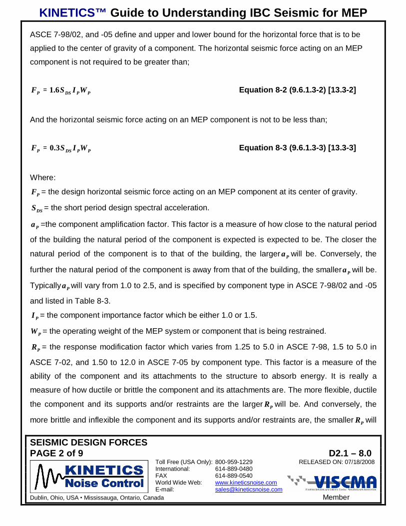
KINETICS™ Guide to Understanding IBC Seismic for MEP
SEISMIC DESIGN FORCESPAGE 2 of 9 D2.1 – 8.0
Toll Free (USA Only): 800-959-1229 RELEASED ON: 07/18/2008International: 614-889-0480FAX 614-889-0540World Wide Web: www.kineticsnoise.comE-mail: [email protected]
Dublin, Ohio, USA Mississauga, Ontario, Canada Member
ASCE 7-98/02, and -05 define and upper and lower bound for the horizontal force that is to be
applied to the center of gravity of a component. The horizontal seismic force acting on an MEP
component is not required to be greater than;
PPDSP WISF 6.1= Equation 8-2 (9.6.1.3-2) [13.3-2]
And the horizontal seismic force acting on an MEP component is not to be less than;
PPDSP WISF 3.0= Equation 8-3 (9.6.1.3-3) [13.3-3]
Where:
PF = the design horizontal seismic force acting on an MEP component at its center of gravity.
DSS = the short period design spectral acceleration.
Pa =the component amplification factor. This factor is a measure of how close to the natural period
of the building the natural period of the component is expected is expected to be. The closer the
natural period of the component is to that of the building, the larger Pa will be. Conversely, the
further the natural period of the component is away from that of the building, the smaller Pa will be.
Typically Pa will vary from 1.0 to 2.5, and is specified by component type in ASCE 7-98/02 and -05
and listed in Table 8-3.
PI = the component importance factor which be either 1.0 or 1.5.
PW = the operating weight of the MEP system or component that is being restrained.
PR = the response modification factor which varies from 1.25 to 5.0 in ASCE 7-98, 1.5 to 5.0 in
ASCE 7-02, and 1.50 to 12.0 in ASCE 7-05 by component type. This factor is a measure of the
ability of the component and its attachments to the structure to absorb energy. It is really a
measure of how ductile or brittle the component and its attachments are. The more flexible, ductile
the component and its supports and/or restraints are the larger PR will be. And conversely, the
more brittle and inflexible the component and its supports and/or restraints are, the smaller PR will

KINETICS™ Guide to Understanding IBC Seismic for MEP
SEISMIC DESIGN FORCESPAGE 3 of 9 D2.1 – 8.0
Toll Free (USA Only): 800-959-1229 RELEASED ON: 07/18/2008International: 614-889-0480FAX 614-889-0540World Wide Web: www.kineticsnoise.comE-mail: [email protected]
Dublin, Ohio, USA Mississauga, Ontario, Canada Member
be. The values are specified by component type in Table 8-1 for ASCE 7-98, Table 8-2 for ASCE
7-02, and Table 8-3 for ASCE 7-05.
z = the structural attachment mounting height of the MEP component in the building relative to the
grade line of the building.
h= the average height of the building roof as measured from the grade line of the building.
The 0.4 factor was introduced as a modifier for DSS as a recognition that the MEP components
inside the building would react more strongly to the long period earthquake ground motion than to
the short period motion. The 0.4 factor brings the design level acceleration for the MEP
components more in line with the design level acceleration that is applied to the building structure
itself.
The
+
hz21 term in Equation 8-1 is recognition of the fact that all buildings and structures become
more flexible as they increase in height. That is they are much stiffer, stronger, at the foundation
level than the roof. Since the ground motion from an earthquake enters the building structure at
the foundation level, the actual accelerations imparted an MEP component will be greater the
higher in the building they are attached. A building may be likened to a vertically mounted
cantilever beam that is being shaken by the bottom. It is a vibrating system that will have a certain
natural period that is, in a general fashion, based on its mass and stiffness. If the natural period of
the building is at, or close too, the earthquake period, the motion of the building could be extreme.
This was the case in the Mexico City earthquake of September 19, 1985.
The horizontal seismic design force must be applied independently to the component in at least
two perpendicular directions in the horizontal plane. The horizontal seismic design force must be
applied in conjunction with all of the expected dead loads and service loads. The idea here is that
the horizontal seismic design force is to be applied in the direction that causes the highest stress
in the supports and restraints, and thus produces the most conservative results.

KINETICS™ Guide to Understanding IBC Seismic for MEP
SEISMIC DESIGN FORCESPAGE 4 of 9 D2.1 – 8.0
Toll Free (USA Only): 800-959-1229 RELEASED ON: 07/18/2008International: 614-889-0480FAX 614-889-0540World Wide Web: www.kineticsnoise.comE-mail: [email protected]
Dublin, Ohio, USA Mississauga, Ontario, Canada Member
D2.1 – 8.3 Vertical Seismic Design Force (Sections 9.5.2.7 and 9.6.1.3) [Sections 12.4.2.2and 13.3.1]:
The MEP component, its supports, and its restraints must also be designed for a vertical seismic
design force that acts concurrently with the horizontal seismic design force. This vertical seismic
design force must be directed such that it also produces the highest stress in the supports and
restraints, thus producing the most conservative result. This vertical seismic design force is
defined as follows.
PDSV WSF 2.0±= Equation 8-4 (9.5.2.1-1/-2) [12.4-4]
Where:
VF = the vertical seismic design force.
D2.1 – 8.4 The Evolution of Pa and PR Factors (Sections 9.6.1.3 and 9.6.3.2 and Table 9.6.3.2)
[Sections 13.3.1 and 13.6.1 and Table 13.6-1]:
The MEP component, along with its supports, will also form a vibrating system with a natural
period that depends on the mass of the component and the stiffness of the supports. The
component amplification factor ( Pa ) is a measure of how closely the natural period of the
component and its supports matches the natural period of the building. For 0.1=Pa the natural
periods are not close, while for 5.2=pa the natural period of the MEP component and their
support is very close to that of the building.
The component response modification factor( PR )is a measure of how much energy the MEP
component along with its supports and attachments can absorb without sustaining crippling
damage. A common term used throughout the HVAC industry is fragility. As the term implies, it is
concerned with how fragile a component might be. That is, how easily a component may be

KINETICS™ Guide to Understanding IBC Seismic for MEP
SEISMIC DESIGN FORCESPAGE 5 of 9 D2.1 – 8.0
Toll Free (USA Only): 800-959-1229 RELEASED ON: 07/18/2008International: 614-889-0480FAX 614-889-0540World Wide Web: www.kineticsnoise.comE-mail: [email protected]
Dublin, Ohio, USA Mississauga, Ontario, Canada Member
damaged, and to what degree it might be damaged by a specified load and loading rate.
The PR factor, then, is considered to be an indicator of how fragile an MEP component might be.
For 0.1=PR the component is extremely fragile. For 0.12=PR , on the other hand, would be a
component that is very robust.
The values for Pa and PR are assigned by the ASCE 7 committee based on accumulated
experience throughout the building industry. The evolution of these factors may be traced through
Tables 8-1; 8-2, and 8-3 which represent 2000 IBC, ASCE 7-98; 2003 IBC, ASCE 7-02; and 2006
IBC, ASCE 7-05 respectively. The different values for the same items in the three tables indicate
the lack of knowledge and understanding concerning these components throughout the industry.
Only time, experience, and shake table testing will produce true usable values for Pa and PR .
D2.1 – 8.5 LRFD versus ASD: (Sections 2.3 and 2.4) [Sections 2.3, 2.4 and 13.1.7]
This topic was briefly touched upon in Section 4.8 of this guide. However, more should be said
about it in this section dealing the design seismic forces that will be applied to the MEP
components. The Civil and Structural Engineering community has adopted the LRFD, Load
Resistance Factor Design, philosophy. With this design philosophy the factors controlling the
serviceability of the structure as assigned to the design loads. ASD, Allowable Stress Design, is
the design philosophy which preceded LRFD. In ASD, the factors controlling the serviceability of
the structure are assigned to the yield strength or to the ultimate strength of the material.
Traditionally the factors controlling the serviceability of the structure have been known as the
Safety Factors, or Factors of Safety.
The forces calculated using Equations 8-1, 8-2, 8-3, and 8-4 will have magnitudes that correspond
to LRFD. Many standard components such a concrete anchors, bolts, screws, and etc. will have
their capacities listed as ASD values. Components whose capacities are listed as ASD values
may be compared to the LRFD results from Equations 8-1 through 8-4 by multiplying the ASD
values by 1.4.

KINETICS™ Guide to Understanding IBC Seismic for MEP
SEISMIC DESIGN FORCESPAGE 6 of 9 D2.1 – 8.0
Toll Free (USA Only): 800-959-1229 RELEASED ON: 07/18/2008International: 614-889-0480FAX 614-889-0540World Wide Web: www.kineticsnoise.comE-mail: [email protected]
Dublin, Ohio, USA Mississauga, Ontario, Canada Member
Table 8-1; Component Amplification and Response Modification Factors for 2000 IBC(Table 9.6.3.2)
Mechanical & Electrical Component2Pa 3
PR 4
General Mechanical Equipment ----- -----Boilers and furnaces. 1.0 2.5
Pressure vessels on skirts and free-standing. 2.5 2.5Stacks & cantilevered chimneys 2.5 2.5
Other 1.0 2.5Piping Systems ----- -----
High deformability elements and attachments (welded steel pipe & brazed copper pipe). 1.0 3.5Limited deformability elements and attachments (steel pipe with screwed connections, no hub
connections, and Victaulic type connections). 1.0 2.5
Low deformability elements and attachments (iron pipe with screwed connections, and glass linedpipe). 1.0 1.25
HVAC Systems ----- -----Vibration isolated. 2.5 2.5
Non-vibration isolated. 1.0 2.5Mounted-in-line with ductwork. 1.0 2.5
Other 1.0 2.5General Electrical ----- -----
Distributed systems (bus ducts, conduit, and cable trays). 2.5 5.0Equipment. 1.0 2.5
Lighting fixtures. 1.0 1.25
2 Components mounted on vibration isolators shall be restrained in each horizontal direction with bumpers or snubbers,and the horizontal seismic design force shall be equal to 2FP.3 The value for aP shall not be less than 1.0. Lower values shall not be used unless justified by a detailed dynamicanalysis. A value of aP=1.0 is to be applied to equipment that is rigid or rigidly attached. A value of aP=2.5 is to be appliedto equipment regarded as flexible or flexibly attached.4 A value of RP=1.25 is to be used for component anchorage design with expansion anchor bolts, shallow chemicalanchor, shall low deformability cast in place anchors, or when the component is constructed of brittle materials. Shallowanchors are those with an embedment depth to nominal diameter ratio that is less than 8.

KINETICS™ Guide to Understanding IBC Seismic for MEP
SEISMIC DESIGN FORCESPAGE 7 of 9 D2.1 – 8.0
Toll Free (USA Only): 800-959-1229 RELEASED ON: 07/18/2008International: 614-889-0480FAX 614-889-0540World Wide Web: www.kineticsnoise.comE-mail: [email protected]
Dublin, Ohio, USA Mississauga, Ontario, Canada Member
Table 8-2; Component Amplification and Response Modification Factors for 2003 IBC(Table 9.6.3.2)
Mechanical & Electrical Component5Pa 6
PRGeneral Mechanical Equipment ----- -----
Boilers and furnaces. 1.0 2.5Pressure vessels on skirts and free standing. 2.5 2.5
Stacks and cantilevered chimneys. 2.5 2.5Other 1.0 2.5
Piping Systems ----- -----High deformability elements and attachments (welded steel pipe & brazed copper pipe). 1.0 3.5
Limited deformability elements and attachments (steel pipe with screwed connections, no hubconnections, and Victaulic type connections). 1.0 2.5
Low deformability elements and attachments (iron pipe with screwed connections, and glass linedpipe). 1.0 1.5
HVAC Systems ----- -----Vibration isolated. 2.5 2.5
Non-vibration isolated. 1.0 2.5Mounted-in-line with ductwork. 1.0 2.5
Other 1.0 2.5General Electrical ----- -----
Distribution systems (bus ducts, conduit, and cable trays). 2.5 5.0Equipment 1.0 2.5
Lighting fixtures. 1.0 1.5
5 Components mounted on vibration isolators shall be restrained in each horizontal direction with bumpers or snubbers. Ifthe maximum bumper/snubber clearance, or air gap, is greater than 1/4 in., the horizontal seismic design force shall beequal to 2FP. If the maximum bumper/snubber clearance, air gap, is less than or equal to 1/4 in., the horizontal seismicdesign force shall be taken as FP.6 The value for aP shall not be less than 1.0. Lower values shall not be used unless justified by a detailed dynamicanalysis. A value of aP=1.0 is to be applied to equipment that is rigid or rigidly attached. A value of aP=2.5 is to be appliedto equipment regarded as flexible or flexibly attached.

KINETICS™ Guide to Understanding IBC Seismic for MEP
SEISMIC DESIGN FORCESPAGE 8 of 9 D2.1 – 8.0
Toll Free (USA Only): 800-959-1229 RELEASED ON: 07/18/2008International: 614-889-0480FAX 614-889-0540World Wide Web: www.kineticsnoise.comE-mail: [email protected]
Dublin, Ohio, USA Mississauga, Ontario, Canada Member
Table 8-3; Component Amplification and Response Modification Factors for 2006 IBC[Table 13.6-1]
MECHANICAL AND ELECTRICAL COMPONENTS Pa 7PR 8
Air-side HVAC – fans, air handlers, and other mechanical components with sheet metal framing. 2.5 6.0Wet-side HVAC – boilers, chillers, & other mechanical components constructed of ductile materials. 1.0 2.5
Engines, turbines, pumps compressors, and pressure vessels not supported on skirts. 1.0 2.5Skirt supported pressure vessels. 2.5 2.5
Generators, batteries, transformers, motors, & other electrical components made of ductile materials. 1.0 2.5Motor control cabinets, switchgear, & other components constructed of sheet metal framing. 2.5 6.0
Communication equipment, computers, instrumentation and controls. 1.0 2.5Roof-mounted chimneys, stacks, cooling and electrical towers braced below their C.G. 2.5 3.0Roof-mounted chimneys, stacks, cooling and electrical towers braced below their C.G. 1.0 2.5
Lighting fixtures. 1.0 1.5Other mechanical & electrical components. 1.0 1.5
Vibration Isolated Components & Systems ----- -----Components & systems isolated using neoprene elements & neoprene isolated floors with elastomeric
snubbers or resilient perimeter stops 2.5 2.5
Spring isolated components & systems & vibration isolated floors closely restrained with elastomericsnubbing devices or resilient perimeter stops. 2.5 2.0
Internally isolated components or systems. 2.5 2.0Suspended vibration isolated equipment including in-line duct devices & suspended internally isolated
components. 2.5 2.5
Distribution Systems ----- -----Piping in accordance with ASME B31, this includes in-line components, with joints made by welding or
brazing. 2.5 12.0
Piping in accordance with ASME B31, this includes in-line components, constructed of high or limiteddeformability materials with joints made by threading, bonding, compression couplings, or grooved
couplings.2.5 6.0
Piping & tubing that is not in accordance with ASME B31, this includes in-line components, constructedwith high deformability materials with joints made by welding or brazing. 2.5 9.0
Piping & tubing that is not in accordance with ASME B31, this includes in-line components, constructedof high or limited deformability materials with joints made by threading, bonding, compression
couplings, or grooved couplings.2.5 4.5
Piping & tubing of low deformability materials, such as cast iron, glass, or non-ductile plastics. 2.5 3.0Ductwork, including in-line components, constructed of high deformability materials, with joints made by
welding or brazing. 2.5 9.0
Ductwork, including in-line components, constructed of high or limited deformability materials, withjoints made by means other than welding or brazing. 2.5 6.0
Duct work constructed of low deformability materials such as cast iron, glass, or non-ductile plastics. 2.5 3.0Electrical conduit, bus ducts, rigidly mounted cable trays, & plumbing. 1.0 2.5
Suspended cable trays. 2.5 6.0
7 The value for aP shall not be less than 1.0. Lower values shall not be used unless justified by a detailed dynamicanalysis. A value of aP=1.0 is to be applied to components that are rigid or rigidly attached. A value of aP=2.5 is to beapplied to components regarded as flexible or flexibly attached.8 Components mounted on vibration isolators shall be restrained in each horizontal direction with bumpers or snubbers. Ifthe maximum bumper/snubber clearance, or air gap, is greater than 1/4 in., the horizontal seismic design force shall beequal to 2FP. If the maximum bumper/snubber clearance, air gap, is less than or equal to 1/4 in., the horizontal seismicdesign force shall be taken as FP.

KINETICS™ Guide to Understanding IBC Seismic for MEP
SEISMIC DESIGN FORCESPAGE 9 of 9 D2.1 – 8.0
Toll Free (USA Only): 800-959-1229 RELEASED ON: 07/18/2008International: 614-889-0480FAX 614-889-0540World Wide Web: www.kineticsnoise.comE-mail: [email protected]
Dublin, Ohio, USA Mississauga, Ontario, Canada Member
D2.1 – 8.6 Summary:
This section has provided an insight into the way in which the seismic design forces for MEP
systems and components are to be computed. It is generally not necessary for a designer to
actually run the computations for the seismic design forces. These forces are normally computed
by the manufacturer of the seismic restraint devices as part of the selection and certification
process to ensure that the proper components are selected per the code and the specification.

KINETICS™ Guide to Understanding IBC Seismic for MEP
ANCHORAGE OF MEP COMPONENTS TO THE BUILDING STRUCTUREPAGE 1 of 4 D2.1 – 9.0
Toll Free (USA Only): 800-959-1229 RELEASED ON: 07/18/2008International: 614-889-0480FAX 614-889-0540World Wide Web: www.kineticsnoise.comE-mail: [email protected]
Dublin, Ohio, USA Mississauga, Ontario, Canada Member
ANCHORAGE OF MEP COMPONENTS TO THE BUILDING STRUCTURE
D2.1 – 9.1 Introduction:
The anchorage, or attachment, of the MEP components and their seismic restraints to the building
structure has always been a gray area generally left to the installing contractor with little or no
guidance from the design professionals responsible for the MEP systems or the building structure.
ASCE/SEI 7-05 does give some general guidance for the making these attachments. However,
the design professionals involved with the MEP systems and the building structure must share the
responsibility for ensuring the adequacy of these attachments. This section will cover the guidance
provided to the design professionals of record in ASCE/SEI 7-05.
D2.1 – 9.2 General Guidelines for MEP Component Anchorage (Section 9.6.1.6 and 9.6.3.4)[Section 13.4]1:
1. The MEP component, its supports, and seismic restraints must be positively attached to the
building structure without relying on frictional resistance generated by the dead weight of the
component. The following are some of the acceptable ways and means of attachment.
a. Bolting
b. Welding
c. Post installed concrete anchors
d. Cast in place concrete anchors
2. There must be a continuous load path of sufficient strength and stiffness between the
component and the building structure to withstand the expected seismic loads and
displacements. This means that when cable restraints are used for distributed MEP systems,
the cables can not bend or wrap around any other component or structure in a straight line
path between the component and the structure.
1 References in brackets (Sections 9.6.1.6 and 9.6.3.4) [Section 13.4] apply to sections, tables, and/or equations in ASCE7-98/02 and ASCE 7-05 respectively which forms the basis for the seismic provisions in 2000/2003 IBC and 2006 IBCrespectively.
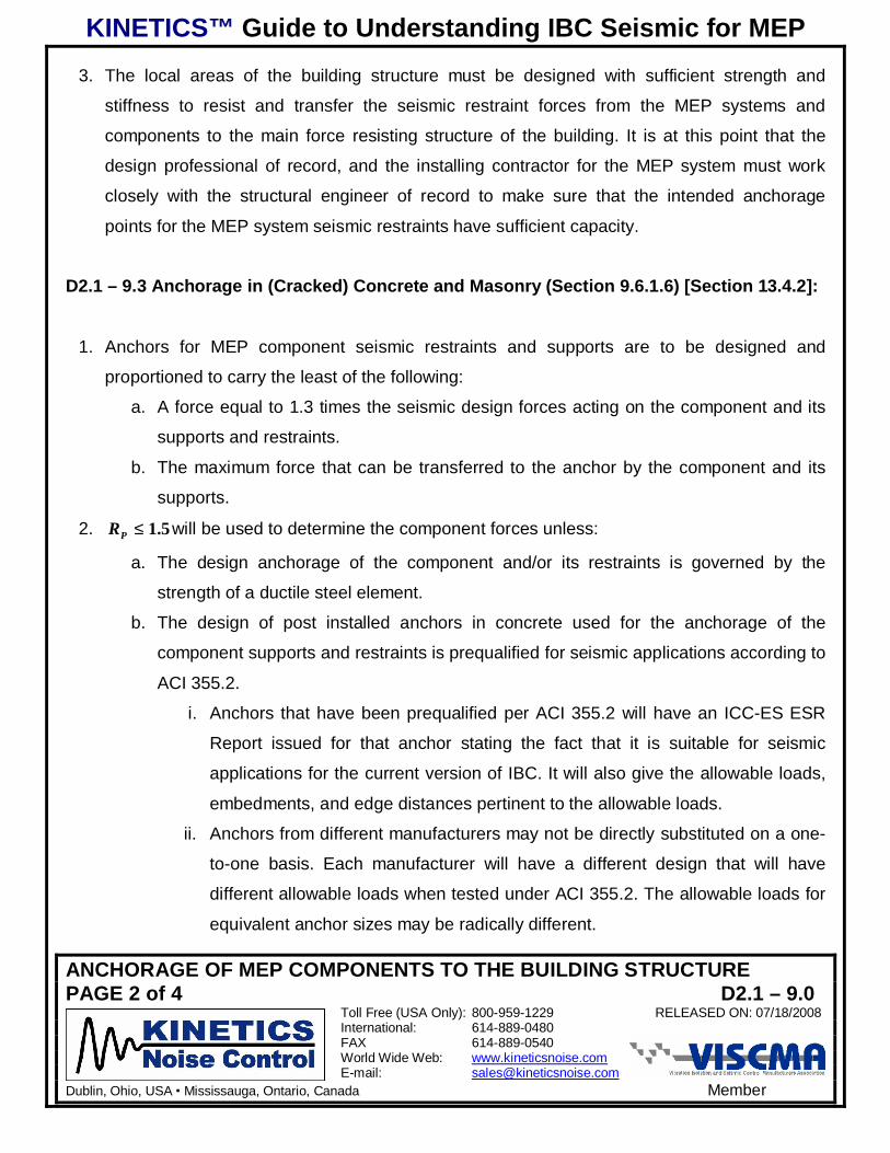
KINETICS™ Guide to Understanding IBC Seismic for MEP
ANCHORAGE OF MEP COMPONENTS TO THE BUILDING STRUCTUREPAGE 2 of 4 D2.1 – 9.0
Toll Free (USA Only): 800-959-1229 RELEASED ON: 07/18/2008International: 614-889-0480FAX 614-889-0540World Wide Web: www.kineticsnoise.comE-mail: [email protected]
Dublin, Ohio, USA Mississauga, Ontario, Canada Member
3. The local areas of the building structure must be designed with sufficient strength and
stiffness to resist and transfer the seismic restraint forces from the MEP systems and
components to the main force resisting structure of the building. It is at this point that the
design professional of record, and the installing contractor for the MEP system must work
closely with the structural engineer of record to make sure that the intended anchorage
points for the MEP system seismic restraints have sufficient capacity.
D2.1 – 9.3 Anchorage in (Cracked) Concrete and Masonry (Section 9.6.1.6) [Section 13.4.2]:
1. Anchors for MEP component seismic restraints and supports are to be designed and
proportioned to carry the least of the following:
a. A force equal to 1.3 times the seismic design forces acting on the component and its
supports and restraints.
b. The maximum force that can be transferred to the anchor by the component and its
supports.
2. 5.1≤PR will be used to determine the component forces unless:
a. The design anchorage of the component and/or its restraints is governed by the
strength of a ductile steel element.
b. The design of post installed anchors in concrete used for the anchorage of the
component supports and restraints is prequalified for seismic applications according to
ACI 355.2.
i. Anchors that have been prequalified per ACI 355.2 will have an ICC-ES ESR
Report issued for that anchor stating the fact that it is suitable for seismic
applications for the current version of IBC. It will also give the allowable loads,
embedments, and edge distances pertinent to the allowable loads.
ii. Anchors from different manufacturers may not be directly substituted on a one-
to-one basis. Each manufacturer will have a different design that will have
different allowable loads when tested under ACI 355.2. The allowable loads for
equivalent anchor sizes may be radically different.

KINETICS™ Guide to Understanding IBC Seismic for MEP
ANCHORAGE OF MEP COMPONENTS TO THE BUILDING STRUCTUREPAGE 3 of 4 D2.1 – 9.0
Toll Free (USA Only): 800-959-1229 RELEASED ON: 07/18/2008International: 614-889-0480FAX 614-889-0540World Wide Web: www.kineticsnoise.comE-mail: [email protected]
Dublin, Ohio, USA Mississauga, Ontario, Canada Member
c. The anchor is designed in accordance with Section 14.2.2.14 of ASCE 7-05.
For 2000 IBC, ASCE 7-98, the “cracked” concrete anchors are not required, and standard post
installed wedge type anchors may be used for seismic restraint as long as there is an ICC Legacy
report stating that the anchors may be used in seismic applications. For 2003 IBC, ASCE 7-02,
there are no specific statements in ASCE 7-02 that require the use of “cracked” concrete anchors
in seismic applications. However, ASCE 7-02 Section 9.9 adopts ACI 318-02 as a reference
document. ACI 318-02 specifies that the post installed anchors meet ACI 355.2 and “are required
to be qualified for moderate or high seismic risk zone usage.” ACI 355.2 is the test standard by
which post installed anchors are to be pre-qualified for seismic applications in cracked concrete.
So, by inference, “cracked” concrete anchors should also be used for 2003 IBC. However, that
has not yet been widely enforced since few if any post installed anchors had been qualified to this
standard before 2006 IBC was issued.
D2.1 – 9.4 Undercut Anchors (Section 9.6.3.13.2-c) [Section 13.6.5.5-5]:
For both 2000 IBC, ASCE 7-98, and 2006 IBC, ASCE 7-05, post installed expansion, wedge,
anchors may not be used for non-vibration isolated mechanical equipment rated over 10 hp (7.45
kW). However, post installed undercut expansion anchors may be used.
For 2003 IBC, ASCE 7-02, post installed expansion, wedge, anchors may not be used for non-
vibration isolated mechanical equipment. However, post installed undercut expansion anchors are
permitted.
D2.1 – 9.5 Prying of Bolts and Anchors (Section 9.6.1.6.3) [Section 13.4.3]:
The design of the attachment of the MEP component supports and restraints must take into
account the mounting conditions such as eccentricity in the supports and brackets, and prying of
the bolts or anchors.

KINETICS™ Guide to Understanding IBC Seismic for MEP
ANCHORAGE OF MEP COMPONENTS TO THE BUILDING STRUCTUREPAGE 4 of 4 D2.1 – 9.0
Toll Free (USA Only): 800-959-1229 RELEASED ON: 07/18/2008International: 614-889-0480FAX 614-889-0540World Wide Web: www.kineticsnoise.comE-mail: [email protected]
Dublin, Ohio, USA Mississauga, Ontario, Canada Member
D2.1 – 9.6 Power Actuated or Driven Fasteners (Section 9.6.1.6.5) [Section 13.4.5]:
Power actuated or driven fasteners, such as powder shot pins, may not be used for tensile load
applications in Seismic Design Categories D, E, and F unless specifically approved for this
application.
D2.1 – 9.7 Friction Clips (Section 9.6.3.13.2-b) [Section 13.4.6]:
Friction clips may not be used to attach seismic restraints to the component or the building
structure. A typical example would be the attachment of a cable restraint to a structural beam with
a standard beam clamp. A beam clamp with a restraint strap or safety strap, capable of resisting
the applied seismic load that will ensure that the clamp will be prevented from walking off the
beam may be used.
D2.1 – 9.8 Summary:
Attachment of the MEP components and their seismic restraints to the building structure is of the
utmost importance to maintaining the building function following an earthquake. It is the
responsibility of the design professionals of record for the MEP systems to work with the structural
engineer of record and the architect of record for the building to ensure that the anchorage points
for the MEP component supports and restraints have been properly designed to transfer the
design seismic loads as well as any other dead weight and service loads.
Related Documents