HAL Id: hal-02355195 https://hal.archives-ouvertes.fr/hal-02355195 Submitted on 8 Nov 2019 HAL is a multi-disciplinary open access archive for the deposit and dissemination of sci- entific research documents, whether they are pub- lished or not. The documents may come from teaching and research institutions in France or abroad, or from public or private research centers. L’archive ouverte pluridisciplinaire HAL, est destinée au dépôt et à la diffusion de documents scientifiques de niveau recherche, publiés ou non, émanant des établissements d’enseignement et de recherche français ou étrangers, des laboratoires publics ou privés. Kinematic Indices of rotation-floating space robots for on-orbit servicing Mathieu Rognant, Sofiane Kraiem, Jurek Sasiadek To cite this version: Mathieu Rognant, Sofiane Kraiem, Jurek Sasiadek. Kinematic Indices of rotation-floating space robots for on-orbit servicing. 15 th IFToMM World Congress, Jun 2019, CRACOVIE, Poland. hal-02355195

Welcome message from author
This document is posted to help you gain knowledge. Please leave a comment to let me know what you think about it! Share it to your friends and learn new things together.
Transcript
HAL Id: hal-02355195https://hal.archives-ouvertes.fr/hal-02355195
Submitted on 8 Nov 2019
HAL is a multi-disciplinary open accessarchive for the deposit and dissemination of sci-entific research documents, whether they are pub-lished or not. The documents may come fromteaching and research institutions in France orabroad, or from public or private research centers.
L’archive ouverte pluridisciplinaire HAL, estdestinée au dépôt et à la diffusion de documentsscientifiques de niveau recherche, publiés ou non,émanant des établissements d’enseignement et derecherche français ou étrangers, des laboratoirespublics ou privés.
Kinematic Indices of rotation-floating space robots foron-orbit servicing
Mathieu Rognant, Sofiane Kraiem, Jurek Sasiadek
To cite this version:Mathieu Rognant, Sofiane Kraiem, Jurek Sasiadek. Kinematic Indices of rotation-floating space robotsfor on-orbit servicing. 15 th IFToMM World Congress, Jun 2019, CRACOVIE, Poland. hal-02355195
Kinematic Indices of rotation-floating spacerobots for on-orbit servicing
Mathieu Rognant1, Sofiane Kraiem2, and Jurek Sasiadek3
1 [email protected], ONERA, Toulouse, France;2 [email protected], ISAE SUPAERO, Toulouse, France;3 [email protected], Carleton University, Ottawa, Canada.
Abstract. There is a growing need for space and in-orbit operationsthat would require use of advance robotic systems. The robotics systemscould be used in debris removal from orbits, as well as, in on-orbit servic-ing activities. This paper is addressing design and control problems re-lated to autonomous spacecraft-manipulator system for space operation.The dynamics equations for rotation floating manipulator were intro-duced using Lagrange approach with additional states representing thekinetic moment exchange actuators. In this paper, a serial-link manip-ulator with multi degree of freedoms mounted on the satellite platformwas used. For detailed analysis of base motion and manipulability of theend effector, the special indices were introduced. Simulation examples toillustrate kinematic indices were shown with physical parameters for amicrosatellite from Myriade series equipped with a robotic arm.
Keywords: Space robot, On-orbit servicing, Kinematic indices
1 Introduction
The orbit removal and servicing topics are expected to play a key part in futurespace missions [1], and the studied concepts often include robotic manipulatorsto carry out these missions[2]. Robotic manipulators in space are already in usebut are teleoperated given the complexity to steer them. Umanned servicingmissions have not been perform yet and fully autonomous control of spacecraft-manipulator is still an open research area, specially with non-cooperative target.
In litterature two control modes of the spacecraft-manipulator are commonlyconsidered: the free-flying mode where manipulator’s joints and spacecraft’s at-titude and position are actively controlled [3]; and the free-floating mode whereonly manipulator’s joints are controlled [4]. More recently Wilde and al. proposedin [5] to distinct three additional modes to fully covering all possible spacecraftmaneuvers: rotation flying and translation flying modes which are sub-modes ofthe free-flying and require reaction-jet thrusters. These actuators allow to ac-tively control the angular and/or linear momentum of the system but consumefuel and their using shorten the lifespan of the spacecraft. The third proposedmode, (rotation floating), is an extension of the free-floating mode in which theattitude of the satellite is actively controlled by using kinetic moment exchange
2 Mathieu Rognant and al.
devices. In this case the total kinetic momentum of the system are conservedand the used actuators (reaction wheels or control-moment gyrosocopes) requireonly electric power, which does not restrict the life of the spacecraft.
The free-floating manipulator kinematic was well known [6][7], and studieson space manipulator which consider kinetic moment exchange devices are fo-cussed on the compensation of the reaction manipulator torque on the base[8][9][10].Indeed as satellites integrate such devices to achieve attitude control,these actuators are most of the time controlled separately from the joint manip-ulator [11] and only few address the issue of the angular momentum distributionof the system[12] and its implication to the base actuators sizing[13].
In this paper, a common control of joint and kinetic moment exchange devicesis considered to achieve the desired motion of the spacecraft base and manipu-lator end-effector. To address design and control issues and evaluate the interestof a common control, we propose some kinematic indices which hightlight thecontribution of each actuator on the controlled states.
This paper is divided as follows: first, the kinematics and dynamics for arotation-floating robot are presented in Sec. II; then, in Sec. III, kinematic sensi-tivity indices are derived and their meanings are discussed; finally Sec IV outlinesa simulation example which serves to illustrate the contribution of the proposedindices.
2 Equation of motion of Rotation-floating space robots
2.1 Kinematic
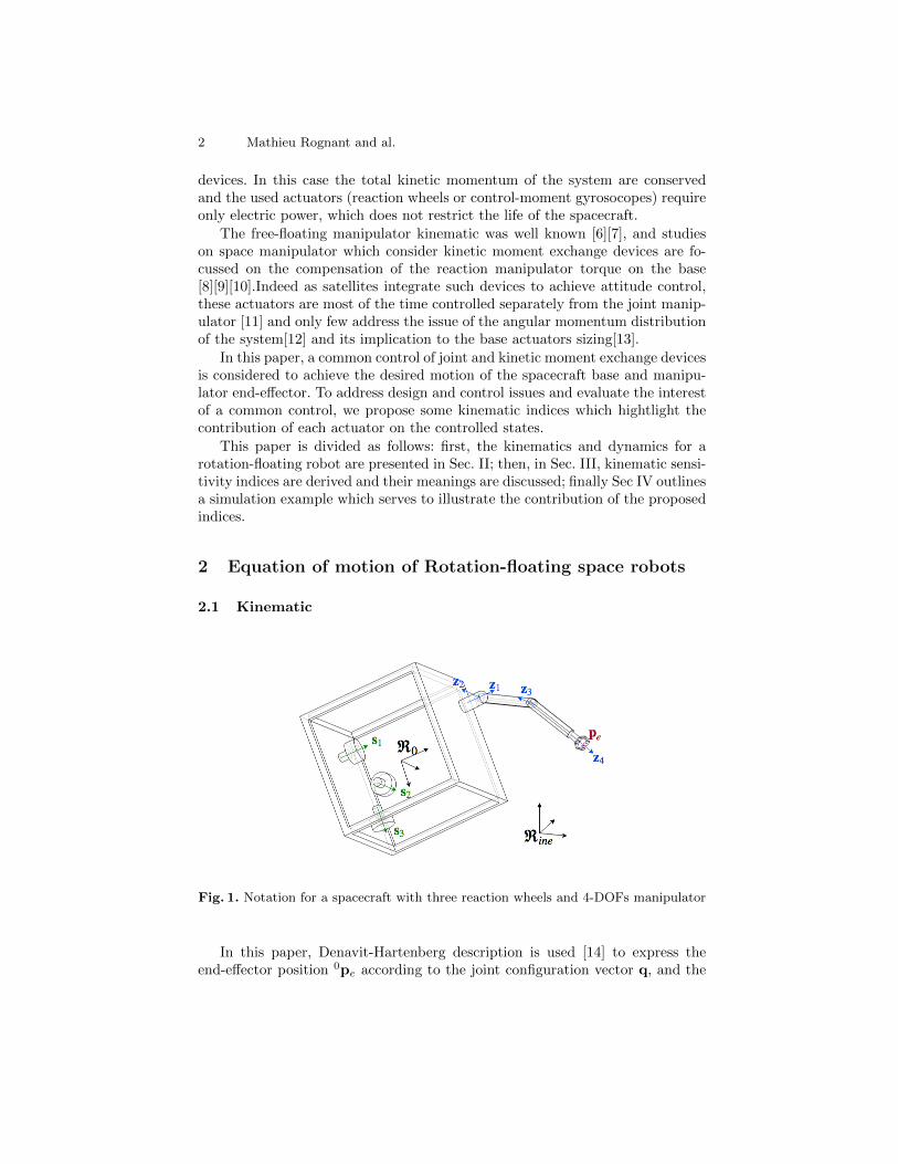
Fig. 1. Notation for a spacecraft with three reaction wheels and 4-DOFs manipulator
In this paper, Denavit-Hartenberg description is used [14] to express theend-effector position 0pe according to the joint configuration vector q, and the
Rotation-floating space kinematic 3
end-effector relative speed to the spacecraft base reference frame <0:[0ve0ωe
]= Jmq (1)
where q is the vector of the joint velocity (q =[q1 · · · qn
]T) and Jm the manip-
ulator jacobian matrix which is defined in R6×n [7].As the base of the spacecraft is also moving the total kinematic equation
of the end-effector of the space robot according to inertial reference frame <ine
expressed in the base B0 is [ve
ωe
]= Jbx0 + Jmq (2)
where x0 is the vector of the linear and angular velocity according to inertial
reference frame <ine expressed in the base B0 (x0 =[vT0 ω
T0
]T), and Jb ∈ R6×6
is the base jacobian matrix [7].
2.2 Dynamics equation of motion
The coupled dynamics of a spacecraft-manipulator system have been extensivelystudied in the available literature [15][16]. To address the issue of control ofrotation-floating robots, we propose to extend the free-floating dynamic modeldetailed in [5] by adding the states of the kinetic moment exchange actuators.By using the Lagragian approach, we just need to express the kinetic energyof the attitude actuator and add the term obtained by derivation of its kineticenergy according to the system state and time. In this paper only simple casewith reaction wheels will be considered, but this approach can be easily extendedto control-moment gyro. The kinetic energy Trj of a reaction wheel of index jis:
Trj =1
2
(ωT
0 + ωrj0sj
T)
Hrj
(ω0 + ωrj
0sj)
+1
2mrj p
T0 p0 (3)
where ωrj is the angular velocity and 0sj the rotation axis expressed in B0. mrj
and Hrj are respectively the mass and the inertia matrix of the reaction wheelsexpressed in B0.
In this paper, one serial manipulator with n-DOF is mounted on the satellite.However, multiple manipulators and manipulator with complex kinematic couldbe considered as well [5]. Consequently, Lagrange equation derivation of (3) leadsto the following dynamics equation of motion for spacecraft with nr reactionwheel: H0 H0m H0r
HT0m Hm 0
HT0r 0 Hr
x0
qωr
+
c0cmcr
=
0τm
τ r
(4)
The symbols used in this formulation are defined as follows:
H0 ∈ R6×6 : inertia matrix for the base.
4 Mathieu Rognant and al.
Hm ∈ Rn×n : inertia matrix for the links.H0m ∈ R6×n : coupling inertia matrix between the base and the manipulator.Hr ∈ Rnr×nr : inertia matrix for the reaction wheels.H0r ∈ R6×nr : coupling inertia matrix between the base and the reaction wheels.c0 ∈ R6×1, cm ∈ Rn×1 and cr ∈ Rnr×1 : are velocity dependent non-linear terms.τm ∈ Rn×1 and τ r ∈ Rnr×1 : are manipulator joint and reaction wheels torques.
H0rT =
[0nr×3 Hωr
T], and Hr is a nr × nr diagonal matrix whose the ith
component is equal to 0sTi Hri0si. The Hωr matrix is defined by:
Hωr =[Hr1
0s1 · · · Hrnr
0snr
](5)
2.3 Generalized Jacobian
Based on the assumptions that the torques caused by the environment are negli-gible and the initial kinematic momentum of the spacecraft is null, the conserva-tion of linear momentum and the angular momentum of the system yields to thegeneralized jacobian of the end-effector motion [4]. In this paper this expressionare extended in order to discern the contribution of base actuator and the jointactuator.
H0x0 + H0mq + H0rωr = 0 (6)
The inertia matrix H0 is symetric and positive-defined then
x0 = −H−10 H0mq−H−10 H0rωr (7)
From (7) one can express jacobian matrices J0q ∈ R6×n and J0
r ∈ R6×nr whichlink respectively the base kinematic to the joint and reaction wheel velocities:
J0q = −H−10 H0m and J0
r = −H−10 H0r (8)
By considering equation (2), one can also link the end-effector motion to thejoint and reaction wheel velocities:
xe = (Jm − JbH−10 H0m)q− JbH
−10 H0rωr (9)
and define the jacobian matrices Jeq ∈ R6×n and Je
r ∈ R6×nr :
Jeq = (Jm − JbH
−10 H0m) and Je
r = −JbH−10 H0r (10)
3 Kinematic Indices
According to these models we propose in this section to analyze the participa-tion of each actuators on the base motion. Then we evaluate the end-effectormanipulability variation according to the reaction wheel control mode.
Rotation-floating space kinematic 5
3.1 Base kinematic indices
The equation (6) can be decomposed as follows:[mttI3 −m0
ttp×g
m0ttp×g Hω
] [p0
ω0
]+
[Hvm
Hωm
]q +
[0
Hωr
]ωr =
[00
](11)
where 0p×g is the skew-symmetric matrix of 0pg which is the vector of the systemcenter of gravity expressed in B0 ; mtt and Hω are respectively the total massof the system and the inertia matrix expressed in B0; and Hvm and Hωm aresub-matrices of the coupling inertia matrix H0m introduced in (4).
Based on this decomposition of the spacecraft base inertia matrix H0, thisrelation can be inversed in analytic way by using a the Banachiewicz inversionformula [17] which yields to the following expression of H−10 as detailed in [5]:
H−10 =
[ I3mtt− (0p×g )S−1U (0p×g ) (0p×g )S−1U
S−1U (0p×g ) S−1U
]with SU = Hω +mtt(
0p×g )(0p×g )
(12)One can deduce from (8) and (12), the expression of the linear and angular partof the jacobian matrices J0
q and J0r:
Jv0q = −
((I3mtt− (0p×g )S−1U (0p×g )
)Hvm + (0p×g )S−1U Hωm
)and Jv0
r = −(0p×g )S−1U Hωr
(13)
Jω0q = −
(S−1U (0p×g )Hvm + S−1U Hωm
)and Jω0
r = −S−1U Hωr (14)
An equivalent decomposition of the translation and rotation have been proposedby Xu in [7] to compute Joint-to-Base Coupling Factors. In order to deal withthe range variation of each actuators, the following scaled jacobians will be usedfor analysis:
Jv0 =[Jv0q Qmax Jv0
r Ωmax
]and Jω0
=[Jω0q Qmax Jω0
r Ωmax
](15)
where Ωmax and Qmax are diagonal matrices of the maximal reaction wheelsand joints angular speed.
By considering relation (14), one can notice that the Jω0q and Jω0
r are both
factorized by S−1U . That implies that the relative contributions of the joints andreaction wheels to the base angular motion do not depend on the base inertiabut only on the relative angular momentum capabilities of the manipulator andthe base spacecraft actuator. This highlights that the distribution of the angularmomentum is a critical point to insure the controlability of the system anddedicated control algorithms are required [12].
A dedicated analysis of the components of SUJω0matrix of the system in a
design phasis could address this issue. The sum of the reaction wheels angularmomentum is bounded by ‖SUJω0
r Ωmax‖. Thus, in the angular momemtumspace, this sum belongs to the invariant polyedron whose the faces are normal tothe sj axis. Concerning the manipulator, its angular momentum is bounded by
6 Mathieu Rognant and al.
‖SUJω0q Ωmax‖, which is strongly sensitive to the joint configuration (variation
of the gravity center position and manipulator inertia (14)). Thus, to distinguishthe joint and reaction wheel contributions to the base motion according to thejoint configuration, we proposed the indices κqω0
and κrω0defined as follow:
κqω0=‖SUJω0
q Qmax‖2F‖SUJω0‖
2F
; κrω0=‖SUJω0
r Ωmax‖2F‖SUJω0‖
2F
(16)
where ‖·‖F is the Frobenius norm. As this norm can be evaluated analytically,these indicators could be an interesting tool to caracterize the base controla-bility on pre-design stages or select preferential joint configuration for controlpurpose. For example, joint configurations whose the index κqω0
respect the con-straint κqω0
≤ 0.5 are more suitable to achieve motion without changing the baseattitude.
3.2 End-effector indices
The end-effector control motion is the highest priority task, however the dy-namic coupling with the motion base could significantly reduce the manipulatorcapability, specially when fixed base attitude is required. To analyse this pointwe propose in this section dedicated manipulabity indices.
As for the base, one can defined from (10) the scaled jacobians of the linearand angular motion of the end-effector:
Jve =[Jveq Qmax Jve
r Ωmax
]and Jωe
=[Jωeq Qmax Jωe
r Ωmax
](17)
Then, the end-effector manipulability can be caracterized by the operator µ(J) =√det (JJT ) [6]
µve = µ(Jve) and µωe = µ(Jωe) (18)
As proposed by Nenchev and al. in [18] for redundant manipulator, nullmotion projector could be used to restrict the joint motion to a sub-space whichinsure zero base attitude disturbance. In the same manner null motion projectorcould be defined for a common control of the reaction-wheel and joint velocitiesas follows:
Nω0= I− J†ω0
Jω0(19)
where J†ω0is the pseudo-inverse of the Jω0 . By using this projector, one can
define manipulability indices of the end-effector without base motions:
µnve = µ(JveNω0) and µn
ωe= µ(JωeNω0) (20)
4 Simulation Example
In this section numerical simulations are provided to illustrate the kinematicindices proposed in this paper. All these evalutions are carried out by using thephysical parameters of the first microsatellite in the Myriade series, Demeter
Rotation-floating space kinematic 7
[19]. Demeter is equipped with three reaction wheels, which nominaly presentan inertia of 4.10−4 kg.m2 on their main axis and a maximal angular speedof 2800 rpm. Concerning the manipulator, the kinematic chain represented infigure 1 will be used. As this study is focussed on the end-effector linear speed,only the 3 first DOFs will be considered. As current space manipulator such asCanadarm2 and JEMRMS do not exceed the 0.7 rpm [20] we assume that jointsangular speed should not overpass 0.5 rpm and the used links mass, dimensionand inertia are summarized in Table 1. In a context of pre-design, the sizing of
- masse (kg) dimension (m) Ixx (kg.m2) Iyy (kg.m2) Izz (kg.m2)
base 100 0.6×0.6×0.6 40 20 40
link 1 1.97 0.15 35.10−4 7.10−4 4.10−4
link 2 1.58 1 28.10−4 917.10−4 268.10−4
link 3 1.17 0.6 7.10−4 924.10−4 273.10−4
Table 1. Model parameters
the spacecraft actuators is a critical task. Therefore, in this example, we proposedusing the suggested indices to compare two configurations of reaction wheels: afirst one equivalent of Demeter’s and a second one with twice the nominal inertiaHr.
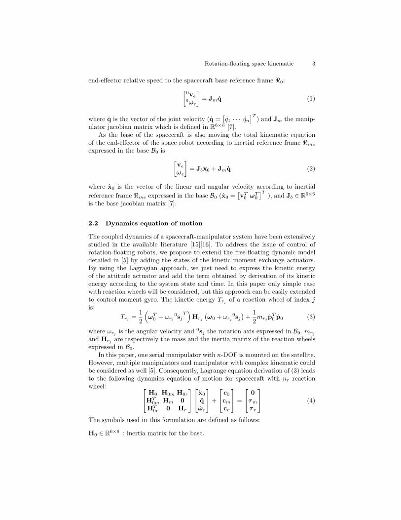
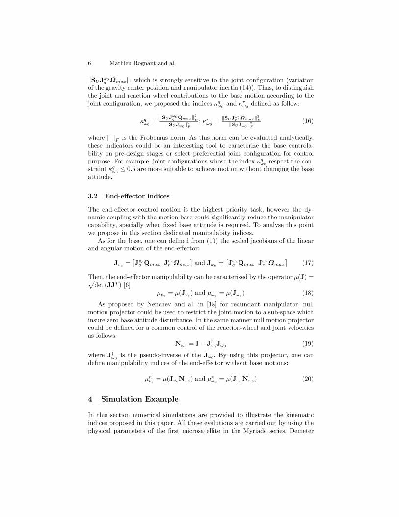
Fig. 2. Variation of the joints contribution to the base motion (κqω0
) plotted in <0 forthe initial reaction wheel (left) and the second actuators configuration (right)
8 Mathieu Rognant and al.
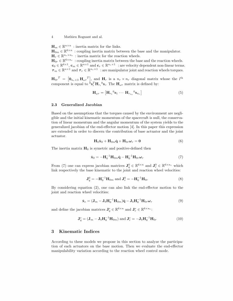
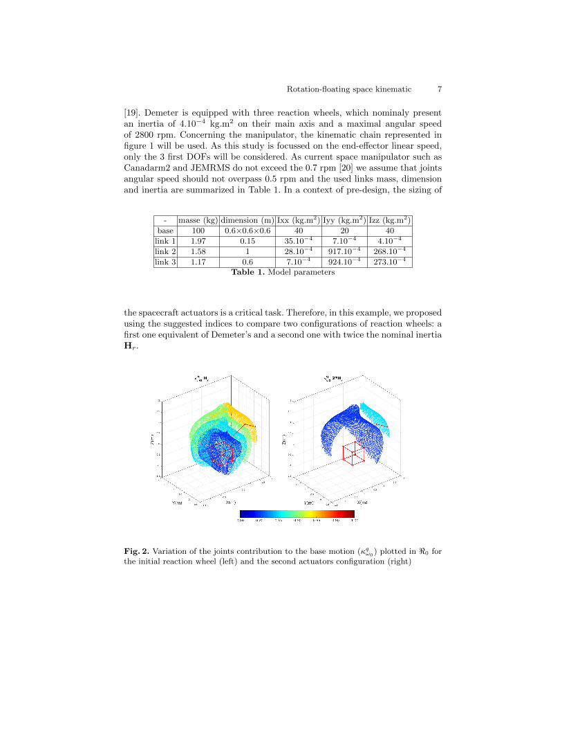
Fig. 3. Evolution of the end-effector normalized manipulability indices plotted in <0
for the initial reaction wheel (left) and the second actuators configuration (right)
To achieve this analysis, the indices have been evaluated for the two configu-rations in 6859 joints configurations uniformly distributed in the half-workspaceof the manipulator because the system is symmetric about the XZ plane. In fig-ures 2, 3 and 4 iso-surfaces of these indices are plotted and colours reflect value.In figure 3 and 4 manipulability indices are normalized by the mean manipulabil-ity of the manipulator on a fixe base. Figure 2 points that increasing the reactionwheels inertia allows to decrease the contribution of the joints and respectivelyto raise the one of the reaction wheels on the base attitude motion, as κqω0
andκrω0
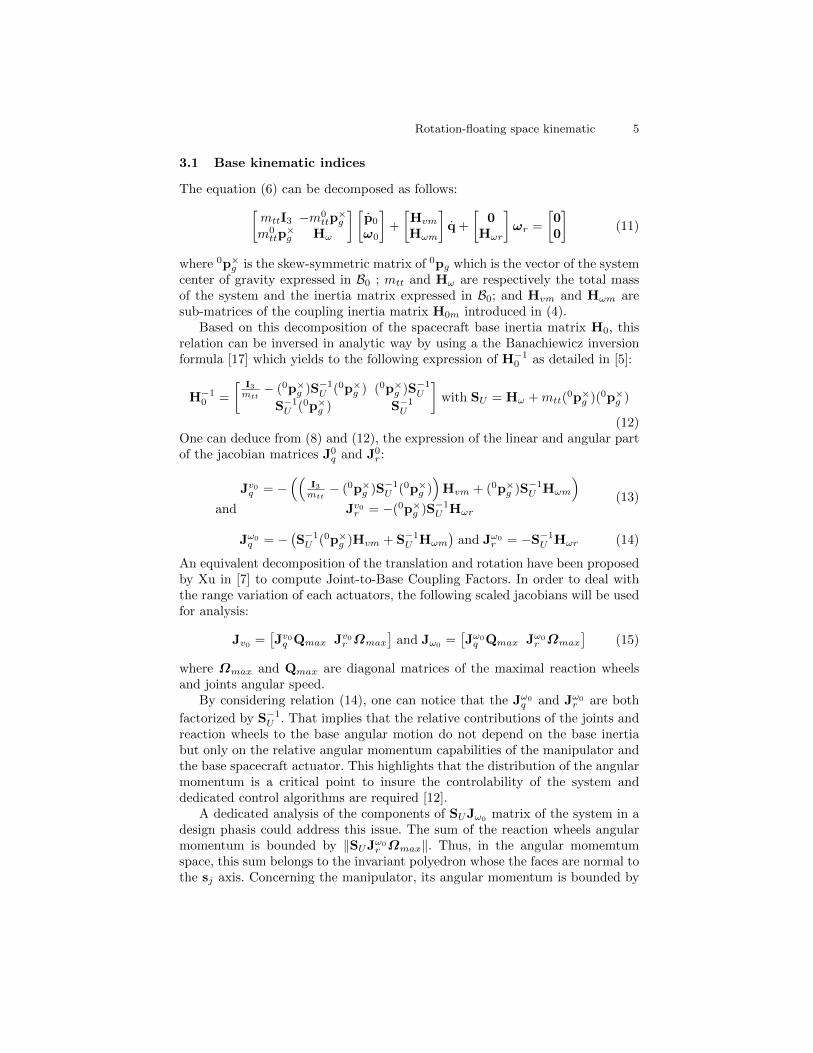
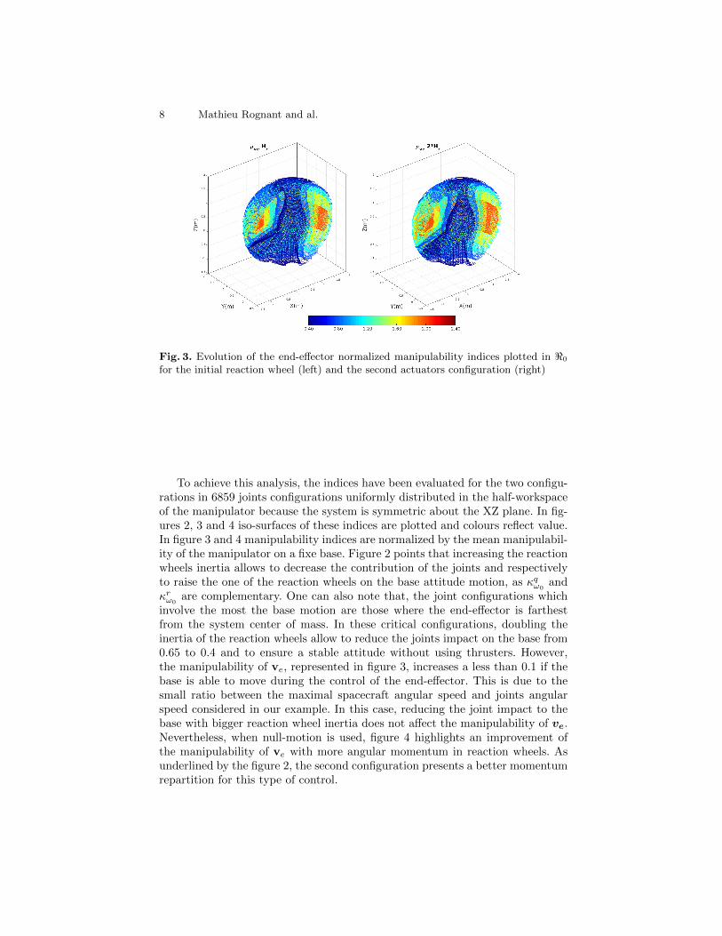
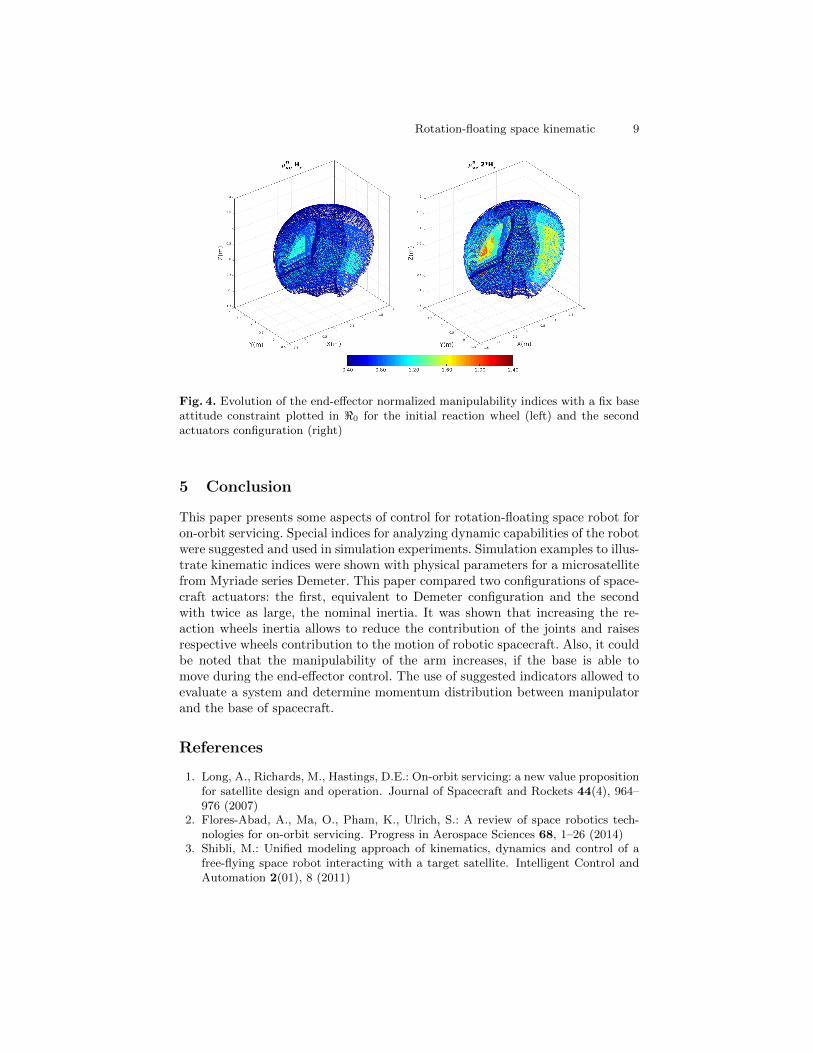
are complementary. One can also note that, the joint configurations whichinvolve the most the base motion are those where the end-effector is farthestfrom the system center of mass. In these critical configurations, doubling theinertia of the reaction wheels allow to reduce the joints impact on the base from0.65 to 0.4 and to ensure a stable attitude without using thrusters. However,the manipulability of ve, represented in figure 3, increases a less than 0.1 if thebase is able to move during the control of the end-effector. This is due to thesmall ratio between the maximal spacecraft angular speed and joints angularspeed considered in our example. In this case, reducing the joint impact to thebase with bigger reaction wheel inertia does not affect the manipulability of ve.Nevertheless, when null-motion is used, figure 4 highlights an improvement ofthe manipulability of ve with more angular momentum in reaction wheels. Asunderlined by the figure 2, the second configuration presents a better momentumrepartition for this type of control.
Rotation-floating space kinematic 9
Fig. 4. Evolution of the end-effector normalized manipulability indices with a fix baseattitude constraint plotted in <0 for the initial reaction wheel (left) and the secondactuators configuration (right)
5 Conclusion
This paper presents some aspects of control for rotation-floating space robot foron-orbit servicing. Special indices for analyzing dynamic capabilities of the robotwere suggested and used in simulation experiments. Simulation examples to illus-trate kinematic indices were shown with physical parameters for a microsatellitefrom Myriade series Demeter. This paper compared two configurations of space-craft actuators: the first, equivalent to Demeter configuration and the secondwith twice as large, the nominal inertia. It was shown that increasing the re-action wheels inertia allows to reduce the contribution of the joints and raisesrespective wheels contribution to the motion of robotic spacecraft. Also, it couldbe noted that the manipulability of the arm increases, if the base is able tomove during the end-effector control. The use of suggested indicators allowed toevaluate a system and determine momentum distribution between manipulatorand the base of spacecraft.
References
1. Long, A., Richards, M., Hastings, D.E.: On-orbit servicing: a new value propositionfor satellite design and operation. Journal of Spacecraft and Rockets 44(4), 964–976 (2007)
2. Flores-Abad, A., Ma, O., Pham, K., Ulrich, S.: A review of space robotics tech-nologies for on-orbit servicing. Progress in Aerospace Sciences 68, 1–26 (2014)
3. Shibli, M.: Unified modeling approach of kinematics, dynamics and control of afree-flying space robot interacting with a target satellite. Intelligent Control andAutomation 2(01), 8 (2011)
10 Mathieu Rognant and al.
4. Yoshida, K., Sashida, N., Kurazume, R., Umetani, Y.: Modeling of collision dy-namics for space free-floating links with extended generalized inertia tensor. In:Robotics and Automation, 1992. Proceedings., 1992 IEEE International Confer-ence on, pp. 899–904. IEEE (1992)
5. Wilde, M., Kwok Choon, S., Grompone, A., Romano, M.: Equations of motion offree-floating spacecraft-manipulator systems: An astronautical engineers tutorial.Frontiers in Robotics and AI 5, 41 (2018)
6. Umetani, Y., Yoshida, K.: Workspace and manipulability analysis of space manip-ulator. Transactions of the Society of Instrument and Control Engineers 26(2),188–195 (1990)
7. Xu, W., Peng, J., Liang, B., Mu, Z.: Hybrid modeling and analysis method fordynamic coupling of space robots. IEEE Transactions on Aerospace and ElectronicSystems 52(1), 85–98 (2016)
8. Ellery, A.: Robotic in-orbit servicers the need for control moment gyroscopes forattitude control. The Aeronautical Journal 108(1082), 207–214 (2004)
9. Dimitrov, D.N., Yoshida, K.: Utilization of distributed momentum control for plan-ning approaching trajectories of a space manipulator to a target satellite. In:Proceedings of the 8th Int. Symposium on Artificial Intelligence, Robotics andAutomation in Space, Munich, Germany (2005)
10. Wu, Y., Han, F., Zheng, M., He, M., Chen, Z., Hua, B., Wang, F.: Attitude controlfor on-orbit servicing spacecraft using hybrid actuator. Advances in Space Research61(6), 1600–1616 (2018)
11. Jaekel, S., Lampariello, R., Rackl, W., De Stefano, M., Giordano, A.M., Porges, O.,Pietras, M., Oumer, N., Brunner, B., Ratti, J., et al.: Design and operational ele-ments of the robotic subsystem for the e. deorbit debris removal mission. Frontiersin Robotics and AI 5, 100 (2018)
12. Oki, T., Nakanishi, H., Yoshida, K.: Time-optimal manipulator control for manage-ment of angular momentum distribution during the capture of a tumbling target.Advanced Robotics 24(3), 441–466 (2010)
13. Kim, Y.M., Kim, B.K.: Energy-efficient trajectory generation for space manipula-tors with reaction wheels under a fixed base orientation. Journal of Intelligent &Robotic Systems 76(2), 219–237 (2014)
14. Khalil, W., Dombre, E.: Modelisation, identification and control of robots (2002)15. Dubowsky, S., Papadopoulos, E.: The kinematics, dynamics, and control of free-
flying and free-floating space robotic systems. IEEE Transactions on robotics andautomation 9(5), 531–543 (1993)
16. Moosavian, S.A.A., Papadopoulos, E.: Free-flying robots in space: an overview ofdynamics modeling, planning and control. Robotica 25(5), 537–547 (2007)
17. Baksalary, J.K., Styan, G.P.: Generalized inverses of partitioned matrices in ba-nachiewicz – schur form. Linear algebra and its applications 354(1-3), 41–47 (2002)
18. Nenchev, D.N., Yoshida, K., Vichitkulsawat, P., Uchiyama, M.: Reaction null-spacecontrol of flexible structure mounted manipulator systems. IEEE Transactions onRobotics and Automation 15(6), 1011–1023 (1999)
19. Pittet, C., Arzelier, D.: Demeter: A benchmark for robust analysis and control ofthe attitude of flexible micro satellites. IFAC Proceedings Volumes 39(9), 661–666(2006)
20. Laryssa, P., Lindsay, E., Layi, O., Marius, O., Nara, K., Aris, L., Ed, T.: Interna-tional space station robotics: a comparative study of era, jemrms and mss. In: 7thESA Workshop on Advanced Space Technologies for Robotics and Automation,pp. 19–21 (2002)
Related Documents