KILNMASTER www.skutt.com 6441 SE Johnson Creek Blvd. Portland, OR 97206 (503) 774--6000 [email protected] REVISED 11/22/11 OPERATING MANUAL

Welcome message from author
This document is posted to help you gain knowledge. Please leave a comment to let me know what you think about it! Share it to your friends and learn new things together.
Transcript

KilnMaster
www.skutt.com6441 SE Johnson Creek Blvd. Portland, OR 97206 (503) 774--6000 [email protected]
Revised 11/22/11
Operating Manual

2 LetteR fRom the PResident
Thank You!
Dear Kiln Owner,
Thank you for purchasing a Skutt Kiln. At Skutt we have
been committed to making quality products and supporting them
with the best customer service possible for over 50 years. If for
any reason you feel we are not delivering on this commitment,
please let us know so we can do our best to make things right.
Kilns are very safe and easy to operate pieces of equipment
when you take the time to understand how they work. Even if
you are an experienced kiln operator you will want to read this
manual to take advantage of the many new features incorpo-
rated into the design of this latest generation of KilnMaster Kilns.
In the new KilnMasters, there are many advanced features that
are designed for our technicians to access data when helping
you to troubleshoot your kiln. There are also some advanced
programming techniques that you may never need. If you don’t
quite understand them, don’t worry about it. Just remember they
are there if you do need them.
If at anytime you need further explanation, please feel free to
contact us or your local Skutt distributor.
Again, on behalf of Skutt Kilns, thank you for buying a Skutt
Kiln.
Sincerely,
Jim SkuttPresident
3safety
Be safeTens of thousands of kilns are used safely in homes, schools, and professional studios throughout the world. With a good understanding of your kiln and a little common sense you can avoid any accidents. Please observe the following safety recommendations:
OperatiOn
The stainless steel jacket and some of the other fixtures surrounding the kiln will get hot enough to burn your skin when •the kiln is heated. Therefore, it is important to be extremely careful when working close to the kiln. We recommend posting warning signs of this potential hazard in the kiln room.
Keep anyone who cannot understand warning signs such as small children and pets •away from the kiln when it is firing.
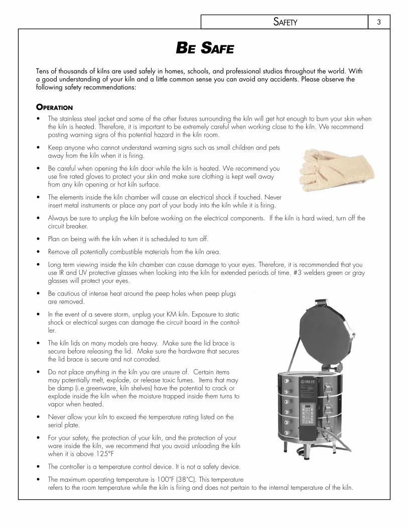
Be careful when opening the kiln door while the kiln is heated. We recommend you •use fire rated gloves to protect your skin and make sure clothing is kept well away from any kiln opening or hot kiln surface.
The elements inside the kiln chamber will cause an electrical shock if touched. Never •insert metal instruments or place any part of your body into the kiln while it is firing.
Always be sure to unplug the kiln before working on the electrical components. If the kiln is hard wired, turn off the •circuit breaker.
Plan on being with the kiln when it is scheduled to turn off.•
Remove all potentially combustible materials from the kiln area.•
Long term viewing inside the kiln chamber can cause damage to your eyes. Therefore, it is recommended that you •use IR and UV protective glasses when looking into the kiln for extended periods of time. #3 welders green or gray glasses will protect your eyes.
Be cautious of intense heat around the peep holes when peep plugs •are removed.
In the event of a severe storm, unplug your KM kiln. Exposure to static •shock or electrical surges can damage the circuit board in the control-ler.
The kiln lids on many models are heavy. Make sure the lid brace is •secure before releasing the lid. Make sure the hardware that secures the lid brace is secure and not corroded.
Do not place anything in the kiln you are unsure of. Certain items •may potentially melt, explode, or release toxic fumes. Items that may be damp (i.e.greenware, kiln shelves) have the potential to crack or explode inside the kiln when the moisture trapped inside them turns to vapor when heated.
Never allow your kiln to exceed the temperature rating listed on the •serial plate.
For your safety, the protection of your kiln, and the protection of your •ware inside the kiln, we recommend that you avoid unloading the kiln when it is above 125°F
The controller is a temperature control device. It is not a safety device.•
The maximum operating temperature is 100˚F (38˚C). This temperature •refers to the room temperature while the kiln is firing and does not pertain to the internal temperature of the kiln.

4
The minimum operating temperature is 33˚F (1˚C).•
The controller contains static-sensitive parts that may be damaged by static electricity. Use caution to avoid creating •static that may damage the equipment. In areas where static electricity is common, or during dry times of the year throughout the country, touch the kiln lid handle before touching the controller to discharge the static
installatiOn
As with all electrical products there is danger of electrical shock. Use only properly sized and rated copper wire •when installing the power supply for your kiln. We recommend this work is done by a licensed electrician
Kilns should always be located in a dry place to prevent electrical shock and corrosion.•
Follow all instruction for installation in this manual. Always observe fire, building and safety codes when installing any •Skutt Product.
If there are fire sprinklers located in the kiln room make sure they are rated high enough so they will not be set off •when the kiln is at peak temperature. This should be tested with the kiln at peak temperature, the ventilation system turned off and all doors and windows closed for maximum insurance.
We recommend having a fire extinguisher rated for electrical fires easily accessible near the kiln. •
Skutt Ceramic Products Inc. will not assume liability for injury or damages caused by variations from the instructions •put forth in this manual.
Kilns get hot. Observe all instructions to ensure proper clearances from flammable or temperature sensitive objects •and living things.
Ventilation is key to maintaining a healthy work environment and proper room temperature. Proper installation of a •Skutt Envirovent 2 will clear potentially harmful fumes from the room. To ensure proper room temperature is main-tained consult a qualified HVAC professional.
The proper placement of thermocouples is crucial to the proper operation of all automatically controlled kilns. Check •all thermocouples for damage and correct placement. Thermocouples must protrude into the kiln chamber at least 1” to ensure an accurate reading.
Only use the stand that is designated by Skutt Ceramic Products for your particular kiln model. Other stands may not •properly support the weight of your kiln, provide adequate clearance, and could pose a fire hazard.
The power cord is sized correctly to handle the power for your particular kiln. Never use an extension cord. •
Make sure the power cord is routed in such a way as to not touch any portion of the kiln that gets hot.•
Be careful of pinch hazards when working on or assembling the kiln.•
Be sure to properly tension the springs on kilns equipped with lid lifters.•
Maintenance
Always unplug the kiln before performing any repairs or general maintenance. If your kiln is wired direct, turn off the •breaker.
Use only Skutt replacement parts. Improperly sourced parts may pose a hazard to you and your kiln and void your •warranty.
Never modify your kiln without first consulting Skutt. Improper modifications may pose a hazard to you and your •kiln and void your warranty.. Items such as alternative thermocouples, controllers, kiln coatings may ruin your kiln if improperly installed or applied.
Replace any electrical components that are discolored ,brittle, or corroded.•
Inspect all stainless steel bands to ensure they are tight. If they are loose, tighten them as much as possible to prevent •the band from slipping or flexing.
safety

5tabLe of Contents
LetteR fRom the PResident ....................................................................2safety ...........................................................................................3QuiCk staRt ....................................................................................7
Cone fiRe ....................................................................... 7RamP/hoLd ..................................................................... 7
set-uP ............................................................................................8Content List ................................................................... 8anatomy of a kiLn ........................................................ 8eLeCtRiCaL CheCk List ......................................................... 9LoCating the kiLn .......................................................... 9PRePaRation ................................................................... 10test fiRing ..................................................................... 11tensioning the Lid LifteR ................................................... 12
PRogRamming ................................................................................13geneRaL PRogRamming infoRmation .................................... 13
Led disPLay ......................................................................... 13idLe mode ........................................................................... 13staRt/stoP/enteR ................................................................ 13deLay ................................................................................. 13aLaRm ............................................................................... 14menu ................................................................................ 14Review ............................................................................. 14view ................................................................................ 14Cone tabLe ....................................................................... 14duRing the fiRing ............................................................... 15afteR the fiRing ................................................................. 15fine tuning youR kiLn ........................................................ 15
Choosing a PRogRamming mode ...................................... 16PRogRamming Cone fiRe mode .......................................... 17advanCed Cone fiRe menu featuRes ................................... 19
wRiting Custom Cone fiRe PRogRams ....................................... 19sLow CooLing (Cone fiRe ContRoLLed CooLing) ....................... 19
PRogRamming RamP/hoLd mode .................................... 20advanCed featuRes ........................................................ 22
16 segment PRogRams .......................................................... 22skiP steP ............................................................................. 22Cone CoRReLation ................................................................ 22
Running a stoRed RamP/hoLd PRogRam ............................ 22
menu featuRes ..............................................................................23kiLn masteR menu tRee .................................................... 23new featuRes ................................................................ 24new menu Layout .......................................................... 24geneRaL PRogRamming tiPs ............................................... 24

6 tabLe of Contents
PRogRamming instRuCtions ............................................... 25settings ........................................................................ 25diagnostiCs .................................................................. 25ConfiguRation ............................................................... 26otheR ......................................................................... 30
tRoubLeshooting ............................................................................31getting heLP ................................................................. 31eRRoR Codes .................................................................. 31Questions and answeRs .................................................. 36
PReventative maintenanCe ................................................................38RePaiRs ........................................................................................ 39
RePLaCing waLL bRiCk ..................................................... 39Lid maintenanCe ............................................................ 40fLooR RePaiRs ................................................................. 40RePLaCing eLements ......................................................... 40RePLaCing theRmoCouPLe eLement on km automatiC kiLns ....... 41kiLnmasteR ContRoLLeR CiRCuitRy ....................................... 41
aPPendiCes ....................................................................................42aPPendix 1 — disassembLing muLti-seCtion kiLns ..................................... 42aPPendix 2 — using the Lid LifteR ........................................................ 42aPPendix 3 — heat woRk (Cones) ........................................................ 43aPPendix 4 — Loading tiPs .................................................................. 44aPPendix 5 — eLeCtRiCaL ReQuiRements ................................................... 45aPPendix 6 — set-uP and sPeCifiCations foR skutt Pk kiLns .......................... 48aPPendix 7 — setuP foR the km 1627 .................................................. 50aPPendix 8 — the waLL-mounted kiLnmasteR ContRoLLeR ......................... 52aPPendix 9 - PRimaRy disPLay messages ................................................... 54
wiRing diagRams ...........................................................................56my PRogRams ...............................................................................66
7QuiCk staRt
Quick start
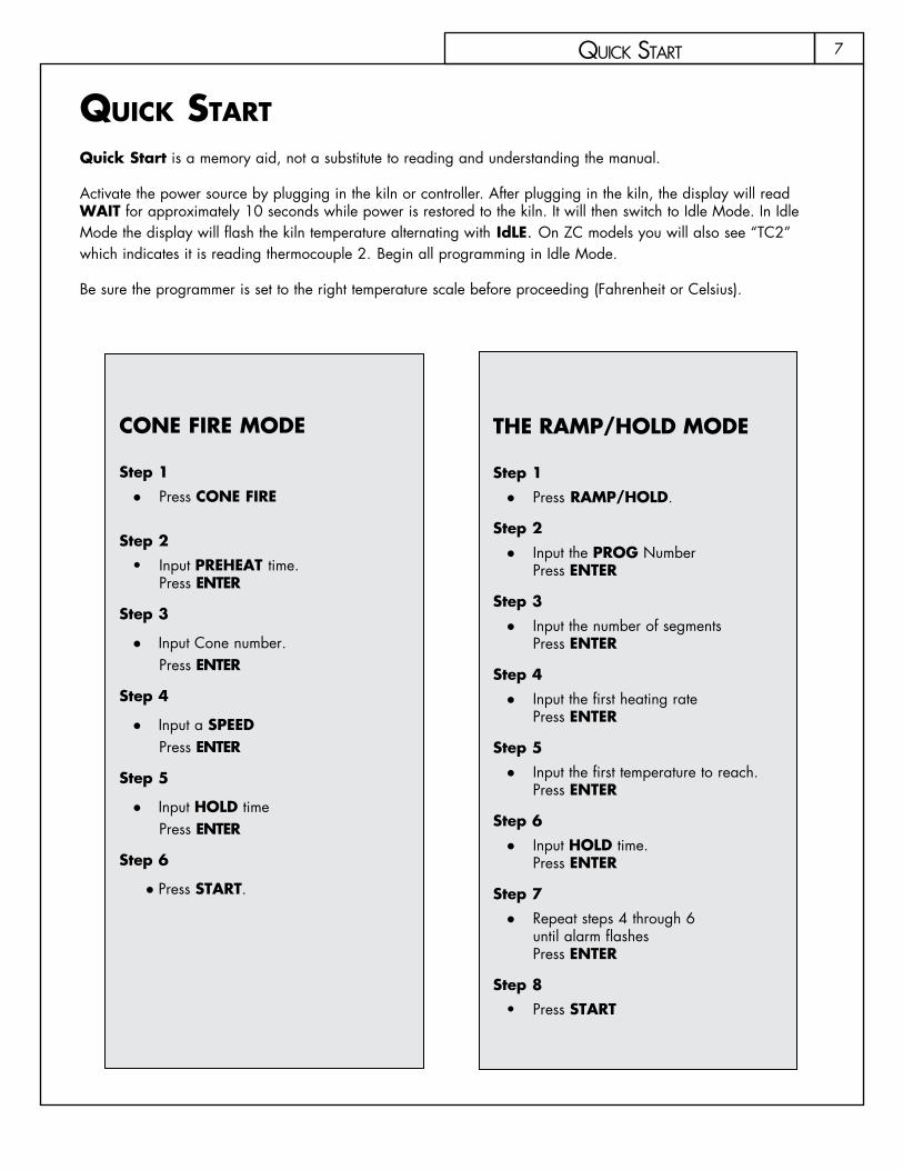
Quick Start is a memory aid, not a substitute to reading and understanding the manual.
Activate the power source by plugging in the kiln or controller. After plugging in the kiln, the display will read WAIT for approximately 10 seconds while power is restored to the kiln. It will then switch to Idle Mode. In Idle Mode the display will flash the kiln temperature alternating with IdLE. On ZC models you will also see “TC2” which indicates it is reading thermocouple 2. Begin all programming in Idle Mode.
Be sure the programmer is set to the right temperature scale before proceeding (Fahrenheit or Celsius).
cOne Fire MODe
Step 1Press ● CONE FIRE
Step 2Input • PREHEAT time. Press ENTER
Step 3
Input Cone number. ●Press ENTER
Step 4
Input a ● SPEED Press ENTER
Step 5
Input ● HOLD time Press ENTER
Step 6
Press ● START.
THE RAMP/HOLD MODE
Step 1Press ● RAMP/HOLD.
Step 2Input the ● PROG Number Press ENTER
Step 3Input the number of segments ●Press ENTER
Step 4Input the first heating rate ●Press ENTER
Step 5Input the first temperature to reach. ●Press ENTER
Step 6Input ● HOLD time. Press ENTER
Step 7Repeat steps 4 through 6 ●until alarm flashes Press ENTER
Step 8Press • START
8
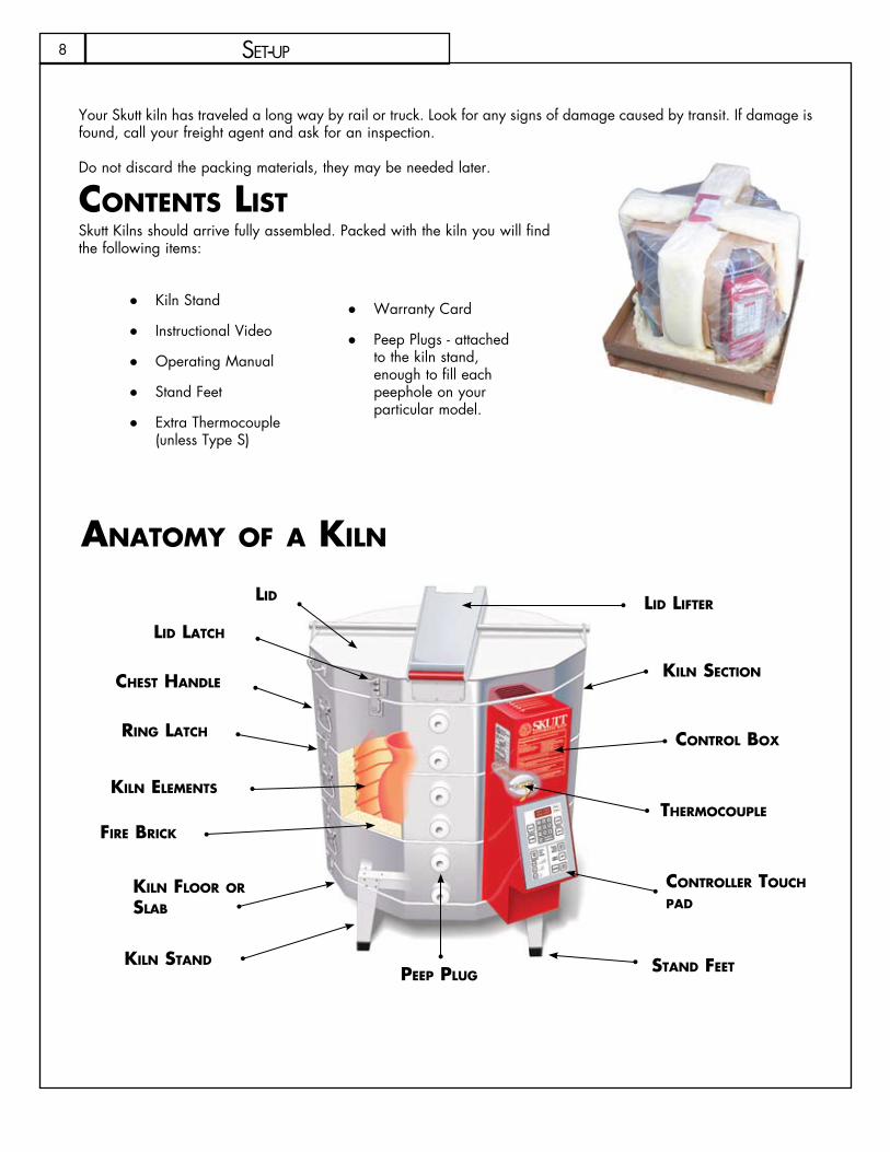
liD liFterliD
liD latch
kiln sectiOn
ring latch
Fire Brick
kiln eleMents
kiln FlOOr Or slaB
kiln stanD
cOntrOl BOx
peep plug
therMOcOuple
cOntrOller tOuch paD
stanD Feet
chest hanDle
anatOMy OF a kiln
set-uP
Your Skutt kiln has traveled a long way by rail or truck. Look for any signs of damage caused by transit. If damage is found, call your freight agent and ask for an inspection.
Do not discard the packing materials, they may be needed later.
cOntents listSkutt Kilns should arrive fully assembled. Packed with the kiln you will find the following items:
Kiln Stand ●
Instructional Video ●
Operating Manual ●
Stand Feet ●
Extra Thermocouple ●(unless Type S)
Warranty Card ●
Peep Plugs - attached ●to the kiln stand, enough to fill each peephole on your particular model.
9
electrical check list
Make sure serial plate matches electrical supply, if you are not sure, consult an electrician. See Appendix 5 Electrical Requirements.
lOcating the kiln Locate your kiln near your present electrical outlet or where a new circuit can be installed. Position the kiln ●to the left of your electrical outlet so the cord will have an easy run and will not place a strain on the plug or outlet.
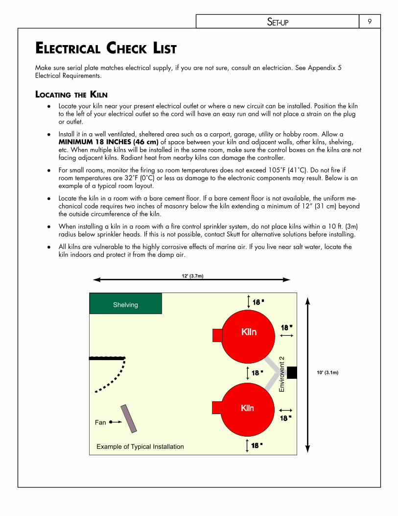
Install it in a well ventilated, sheltered area such as a carport, garage, utility or hobby room. Allow a ●MINIMuM 18 INCHES (46 cm) of space between your kiln and adjacent walls, other kilns, shelving, etc. When multiple kilns will be installed in the same room, make sure the control boxes on the kilns are not facing adjacent kilns. Radiant heat from nearby kilns can damage the controller.
For small rooms, monitor the firing so room temperatures does not exceed 105˚F (41˚C). Do not fire if ●room temperatures are 32˚F (0˚C) or less as damage to the electronic components may result. Below is an example of a typical room layout.
Locate the kiln in a room with a bare cement floor. If a bare cement floor is not available, the uniform me- ●chanical code requires two inches of masonry below the kiln extending a minimum of 12” (31 cm) beyond the outside circumference of the kiln.
When installing a kiln in a room with a fire control sprinkler system, do not place kilns within a 10 ft. (3m) ●radius below sprinkler heads. If this is not possible, contact Skutt for alternative solutions before installing.
All kilns are vulnerable to the highly corrosive effects of marine air. If you live near salt water, locate the ●kiln indoors and protect it from the damp air.
set-uP
18 "
Kiln18 "
Kiln 18 "
18 "
Envi
rove
nt 2
Example of Typical Installation
Fan
Shelving
10' (3.1m)
12' (3.7m)
10
preparatiOnCertain kiln models may have slightly different set-up instructions. Special set-up instructions for PK Kilns and the KM-1 Wall Mount Controller are located in the Appendices Section.
Save packing material until test fire is complete. The kiln comes almost completely assembled. If you ●
need to disassemble the kiln to make it lighter or smaller to move through doors, see Appendix 1.
lOaD the liD liFter springs If your kiln is equipped with a spring assisted Lid Lifter, you will need to load the springs. They have been de-tensioned to avoid damage to the kiln during shipping. Please consult Page 12 for instructions on tensioning the springs.
reMOve anD set-up stanD
step 1
Open the lid and secure the lid brace in place. ●
step 2
Slightly bend the stand packing cardboard to relieve the tension against the brick wall and carefully lift the ●stand out of the kiln, being careful not to damage the brick or the thermocouple.
step 3
Remove the cardboard and peep plugs attached to the stand. ●
step 4
Install the black plastic stand feet which are located in the plastic bag with the manual. ●
step 5
Place the stand where the kiln will be located. If you have an older style EnviroVent (where the fan motor ●mounts directly under the kiln), place it in the stand now.
place slaB (kiln BOttOM)
step 1
Undo the buckles that hold the kiln slab to the kiln. Lift the kiln off the slab and place on a clean flat ●surface. Be careful not to set the kiln on anything (watch the power cord), that will damage the bottom row of bricks.
step 2
Center the slab on the stand. Allow a minimum of eighteen inches (46 cm) of spacing from walls and other ●kilns.
step 3
If the stand is not level or wobbles, shim legs accordingly. Do not place shims between the stand ●and the slab.
placing the kiln
set-uP

11
step 1 With a partner, pick the kiln up by the chest handles and rest it on top of the kiln slab (floor).
step 2 On models with slabs that buckle to the kiln, reattach the buckles.
place peep plugs
Place the white porcelain peep plugs into the peepholes of the kiln. Give them a slight twist to lock them in. If you are not using an EnviroVent, EnviroVent 2, or any other Downdraft vent, be sure to leave the top peep plug out when firing.
clean
Vacuum the inside of the kiln to remove dust, brick chips, and other foreign matter from around the elements. Be sure not to get the hose too close to the touch pad. Static electricity built up in the hose can damage the electronics.
test firing
The test fire is very important and should not be skipped. It accomplishes several objectives
Ensures the kiln is operating correctly and nothing was damaged in ●shipping.
Burns off element oils and develops an oxide coating which will help ●prolong the life of the elements.
lOaDing This first firing should be done with only kiln shelves. Place the first shelf layer on one-inch (2.5 cm) posts above the slab. When loading ware in the kiln, it is important to load it evenly to ensure proper ventilation. For a full description on loading, see Appendix 4 — Loading Tips.
kiln Wash shelves
Brush coat one side of each shelf with high fire kiln wash. Apply a thin coat of kiln wash in one direction, allow to dry, and apply another thin coating in the opposite direction leaving a half inch (1.3 cm) margin from the outside edge of the shelf. Allow to dry overnight. Never kiln wash the walls or lid of your kiln!
place Witness cOnes A Cone 04 (1945˚F/1063˚C) is recommended for proper pre-oxidation of a new element. For more about cones, see Appendix 3 — Heat Work (Cones). If your kiln is equipped with a lid lifter, be sure to latch the lid shut.
test Fire the kiln
Follow the Cone Fire Mode programming instructions found in the Programming section of this manual to run a Cone 04 , Medium Speed program with No Hold time and No Preheat. Be sure to turn your downdraft vent on if one is installed or otherwise prop the lid to 1000º F (538º C) to allow smoke from oils on the elements to escape. After the kiln has cooled to room temperature, unload the kiln and inspect the cones. If the Cones are satisfactory you are ready to begin using the kiln. If there is a problem with the cones see the section on fine tuning your kiln on page 15.
set-uP
12
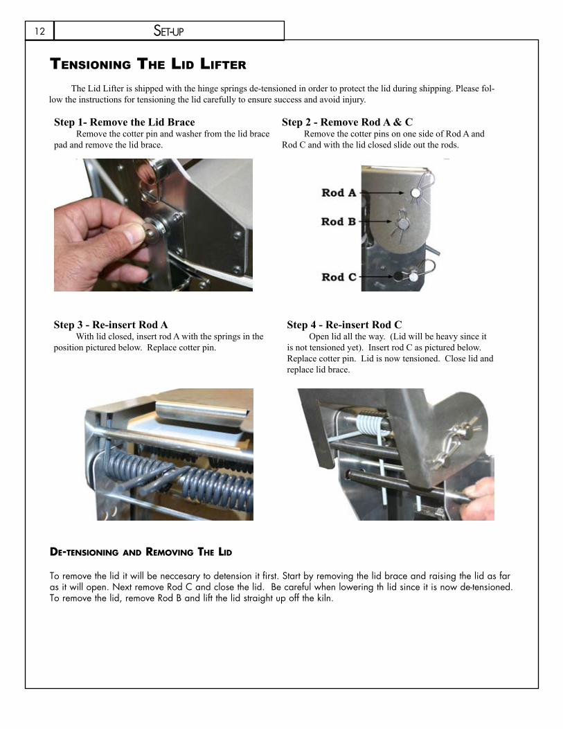
De-tensiOning anD reMOving the liD
To remove the lid it will be neccesary to detension it first. Start by removing the lid brace and raising the lid as far as it will open. Next remove Rod C and close the lid. Be careful when lowering th lid since it is now de-tensioned. To remove the lid, remove Rod B and lift the lid straight up off the kiln.
set-uP
The Lid Lifter is shipped with the hinge springs de-tensioned in order to protect the lid during shipping. Please fol-low the instructions for tensioning the lid carefully to ensure success and avoid injury.
tensiOning the lid lifter
Step 1- Remove the Lid BraceRemove the cotter pin and washer from the lid brace
pad and remove the lid brace.
Step 2 - Remove Rod A & CRemove the cotter pins on one side of Rod A and
Rod C and with the lid closed slide out the rods.
Step 3 - Re-insert Rod AWith lid closed, insert rod A with the springs in the
position pictured below. Replace cotter pin.
Step 4 - Re-insert Rod COpen lid all the way. (Lid will be heavy since it
is not tensioned yet). Insert rod C as pictured below. Replace cotter pin. Lid is now tensioned. Close lid and replace lid brace.

13PRogRamming
general prOgraMMing infOrMatiOnthe leD Display
The display, while improved, is still limited to 4 characters and 14 segments per character. This is not always enough to exactly represent the message presented. If you find you do not understand a message, consult the Display Messages section of this manual.
The controller may be programmed in either Celsius or Fahrenheit. It is very important to know which temperature scale it is using. If there is a LED illuminated in the lower right hand corner of the display, the temperature scale is set to Celsius. Refer to the MENU section of this manual to change scales if necessary.
When prompted to enter time values, there will be an LED illuminated in the lower center portion of the display. We refer to this as a decimal point. Everything to the left of the decimal will be hours and everything to the right will be minutes.
iDle MODe
When the kiln is flashing IdLE alternately with the current temperature of the kiln chamber we refer to the controller as being in Idle Mode. This simply means that the kiln is ready to be programmed. To return to Idle mode you may press STOP at any time. If controller is programmed for Zone Control, the display will also show current thermocouple being read.
start/stOp/enter
The START key begins the program which is currently loaded in memory. It may only be accessed when the kiln is in Idle Mode. The STOP key will turn off the kiln at any point of a program. It may also be used to return to Idle Mode in the middle of entering a program. ENTER must be pressed after entering any time, temperature or programming speed. ENTER is also used to turn an Alarm off that has sounded during a firing.
Delay
The Delay feature allows you to program, the kiln to automatically start at a future time. This feature is primarily used to take advantage of better off-peak electric rates or to time the shutoff of the kiln for a time that is convenient for you to be there. It can be set for a Ramp Hold Mode or Cone Fire Mode program and can be accessed only after the program has been entered and the controller is in Idle Mode. You can enter a delay time up to 99 hours and 99 minutes.
From Idle Mode, press DELAYInput Delay time in hours and minutes, then press ENTER
When START is pressed to begin the program, the time entered for the delay will reappear on the screen and begin counting down. When it reaches 00.00 the kiln will start the program currently loaded. The Delay time will stay in memory until it is cleared. To clear it, follow the instructions for entering a Delay and enter 00.00 for the Delay time.
14 PRogRamming
alarM
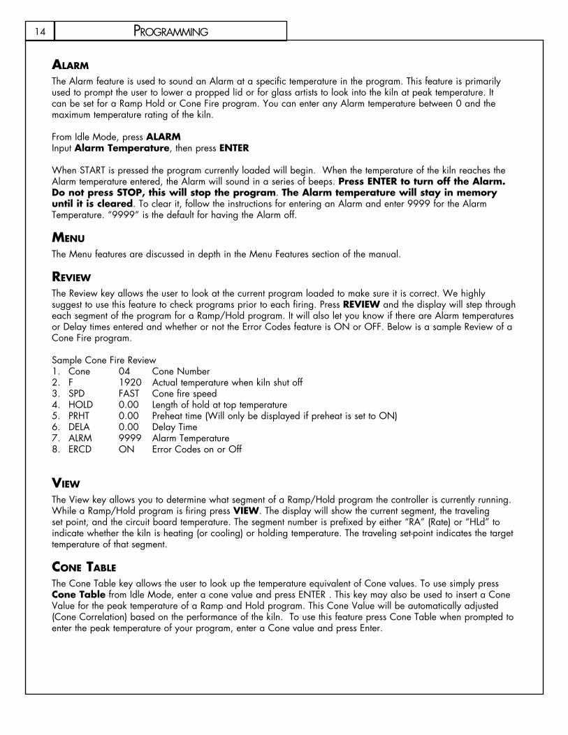
The Alarm feature is used to sound an Alarm at a specific temperature in the program. This feature is primarily used to prompt the user to lower a propped lid or for glass artists to look into the kiln at peak temperature. It can be set for a Ramp Hold or Cone Fire program. You can enter any Alarm temperature between 0 and the maximum temperature rating of the kiln.
From Idle Mode, press ALARMInput Alarm Temperature, then press ENTER
When START is pressed the program currently loaded will begin. When the temperature of the kiln reaches the Alarm temperature entered, the Alarm will sound in a series of beeps. Press ENTER to turn off the Alarm. Do not press STOP, this will stop the program. The Alarm temperature will stay in memory until it is cleared. To clear it, follow the instructions for entering an Alarm and enter 9999 for the Alarm Temperature. “9999” is the default for having the Alarm off.
Menu
The Menu features are discussed in depth in the Menu Features section of the manual.
revieW
The Review key allows the user to look at the current program loaded to make sure it is correct. We highly suggest to use this feature to check programs prior to each firing. Press REVIEW and the display will step through each segment of the program for a Ramp/Hold program. It will also let you know if there are Alarm temperatures or Delay times entered and whether or not the Error Codes feature is ON or OFF. Below is a sample Review of a Cone Fire program.
Sample Cone Fire ReviewCone 04 Cone Number1. F 1920 Actual temperature when kiln shut off2. SPD FAST Cone fire speed3. HOLD 0.00 Length of hold at top temperature4. PRHT 0.00 Preheat time (Will only be displayed if preheat is set to ON)5. DELA 0.00 Delay Time 6. ALRM 9999 Alarm Temperature7. ERCD ON Error Codes on or Off8.
vieW
The View key allows you to determine what segment of a Ramp/Hold program the controller is currently running. While a Ramp/Hold program is firing press VIEW. The display will show the current segment, the traveling set point, and the circuit board temperature. The segment number is prefixed by either “RA” (Rate) or “HLd” to indicate whether the kiln is heating (or cooling) or holding temperature. The traveling set-point indicates the target temperature of that segment.
cOne taBle
The Cone Table key allows the user to look up the temperature equivalent of Cone values. To use simply press Cone Table from Idle Mode, enter a cone value and press ENTER . This key may also be used to insert a Cone Value for the peak temperature of a Ramp and Hold program. This Cone Value will be automatically adjusted (Cone Correlation) based on the performance of the kiln. To use this feature press Cone Table when prompted to enter the peak temperature of your program, enter a Cone value and press Enter.
15PRogRamming
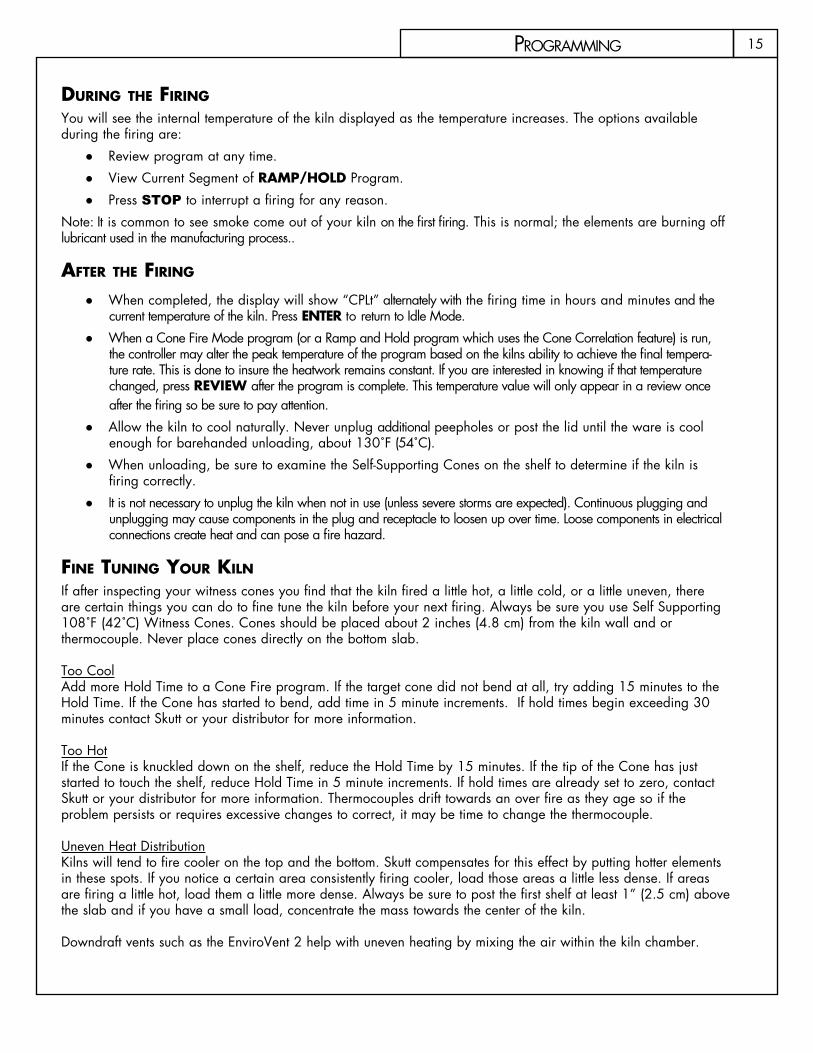
During the Firing You will see the internal temperature of the kiln displayed as the temperature increases. The options available during the firing are:
Review program at any time. ●View Current Segment of ● RAMP/HOLD Program.Press ● Stop to interrupt a firing for any reason.
Note: It is common to see smoke come out of your kiln on the first firing. This is normal; the elements are burning off lubricant used in the manufacturing process..
aFter the Firing When completed, the display will show “CPLt” alternately with the firing time in hours and minutes and the ●current temperature of the kiln. Press ENTER to return to Idle Mode.When a Cone Fire Mode program (or a Ramp and Hold program which uses the Cone Correlation feature) is run, ●the controller may alter the peak temperature of the program based on the kilns ability to achieve the final tempera-ture rate. This is done to insure the heatwork remains constant. If you are interested in knowing if that temperature changed, press REVIEW after the program is complete. This temperature value will only appear in a review once after the firing so be sure to pay attention.Allow the kiln to cool naturally. Never unplug additional peepholes or post the lid until the ware is cool ●enough for barehanded unloading, about 130˚F (54˚C).When unloading, be sure to examine the Self-Supporting Cones on the shelf to determine if the kiln is ●firing correctly.It is not necessary to unplug the kiln when not in use (unless severe storms are expected). Continuous plugging and ●unplugging may cause components in the plug and receptacle to loosen up over time. Loose components in electrical connections create heat and can pose a fire hazard.
Fine tuning yOur kiln
If after inspecting your witness cones you find that the kiln fired a little hot, a little cold, or a little uneven, there are certain things you can do to fine tune the kiln before your next firing. Always be sure you use Self Supporting 108˚F (42˚C) Witness Cones. Cones should be placed about 2 inches (4.8 cm) from the kiln wall and or thermocouple. Never place cones directly on the bottom slab.
Too CoolAdd more Hold Time to a Cone Fire program. If the target cone did not bend at all, try adding 15 minutes to the Hold Time. If the Cone has started to bend, add time in 5 minute increments. If hold times begin exceeding 30 minutes contact Skutt or your distributor for more information.
Too HotIf the Cone is knuckled down on the shelf, reduce the Hold Time by 15 minutes. If the tip of the Cone has just started to touch the shelf, reduce Hold Time in 5 minute increments. If hold times are already set to zero, contact Skutt or your distributor for more information. Thermocouples drift towards an over fire as they age so if the problem persists or requires excessive changes to correct, it may be time to change the thermocouple.
Uneven Heat DistributionKilns will tend to fire cooler on the top and the bottom. Skutt compensates for this effect by putting hotter elements in these spots. If you notice a certain area consistently firing cooler, load those areas a little less dense. If areas are firing a little hot, load them a little more dense. Always be sure to post the first shelf at least 1” (2.5 cm) above the slab and if you have a small load, concentrate the mass towards the center of the kiln.
Downdraft vents such as the EnviroVent 2 help with uneven heating by mixing the air within the kiln chamber.

16
ChOOsing a prOgraMMing MOdeThe first step in programming your kiln is to decide which “Programming Mode” to use. Before making this decision it helps to have a good understanding of Firing Programs. A Firing Program consists of a series of program segments. Each segment consists of a Rate, a Temperature and a Hold Time. These segments determine the rate at which the kiln will heat up or cool down and how much Heatwork the pieces in the kiln will receive. For more information on Heatwork see Appendix 3.
CONE FIRE MODEWith Cone Fire Mode the programs are written for you. You simply give the controller some key information regarding the pieces you are firing and it accesses a program which best suites your project. This is the most commonly used mode of programming. The programs were created by Ceramic Engineers and are designed to minimize problems that can occur during critical stages in the firing process.
Cone Fire Mode is incredibly easy to use however, the software itself is extremely advanced. Cone Fire Mode uses complex algorithms to simulate the heatwork of a Pyrometric Cone. What is impressive is that it automatically makes adjustments to the firing profile based on your kilns performance. Cone values are based on heatwork and heatwork is a function of time and temperature. Therefore, if your kiln is firing slow due to a heavy load or aging elements, Cone Fire Mode automatically adjusts the peak temperature down so you get the perfect amount of heatwork. There are very few reasons not to use this mode of programming.
raMp/hOlD MODERAMP/HOLD Mode allows you to write your own programs when the results you want cannot be achieved through Cone Fire Mode. It is a perfect tool for:
Fusing and slumping glass ●Annealing metal and glass ●Firing Precious Metals ●Clay ●Specialized glaze formulations and techniques ●
RamP/hoLd is generally considered an advanced form of programming. It requires in-depth knowledge of heatwork and a good feel for how your kiln performs under a range of conditions. Below is an example of a simple glass fusing RamP/hoLd program.
PRogRamming

17PRogRamming
prOgraMMing COne fire MOde
prOgraMMing steps
step 1
From Idle Mode. Press ● CONE FIRE.
Display will read PRHT alternately with 00.00.step 2
Input a ● PREHEAT TIME IN HOuRS AND MINuTES. Press ENTER. (See page 23 for more information on Preheat.)
Display will read CONE alternately with the last Cone Value entered.step 3
Input a ● CONE VALuE. Press ENTER.
Display will read Spd alternately with the last Speed entered.step 4
Press a ● SPEED (SLOW, MED or FAST). Press ENTER.
Display will read HOLD alternately with a Hold time value.step 5
Input a ● HOLD TIME if one is desired. Press ENTER.
Display will flash CPL, then will return to Idle Mode. At this point the program is loaded and ready to start. Before pressing START, it is a good idea to press REVIEW to make sure the program was input correctly. Also, verify that the lid latch is engaged if your kiln is equipped with a lid lifter and check to see the area is clear of all combustible materials.
step 6
Prepare ● Venting.If your kiln is equipped with and EnviroVent2 you will want to turn it on before pressing start. Be sure the lid is closed (and latched if you have a Lid Lifter) and all the Peep Plugs are in.
If your kiln is not equipped with a vent system you will want to prop the lid open until the chamber temperature reaches 1000 ˚F (538˚C). If your kiln is equipped with a Lid Lifter, use the installed Lid Prop. If your kiln does not have a built in Lid Prop, use a wedge of firebrick to prop it approximately 1 to 2 inches. Always use a fire proof glove to remove your prop. Leave the top peep plug out throughout the entire firing.
step 7
Press ● START.
Display will read -ON- briefly and then display the current temperature of the kiln. If a delay start has been entered the display will begin counting down the time entered.
When the firing is complete the display will read CPLT alternately with the current temperature of the kiln and the time it took to complete the program. To clear this data and return to Idle Mode and press ENTER.
18
DescriptiOn
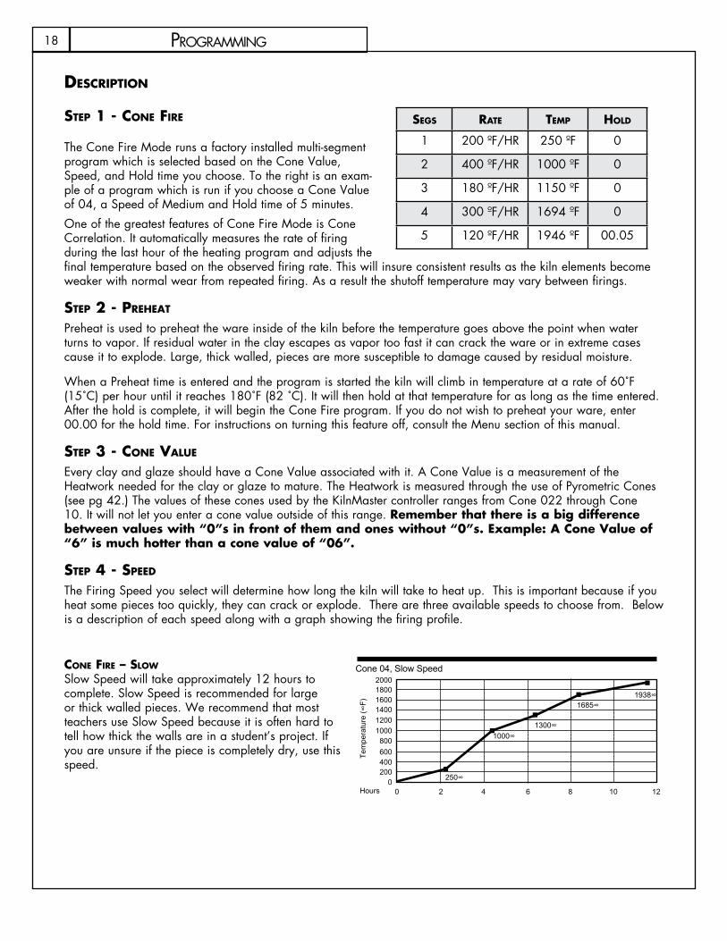
step 1 - cOne Fire
The Cone Fire Mode runs a factory installed multi-segment program which is selected based on the Cone Value, Speed, and Hold time you choose. To the right is an exam-ple of a program which is run if you choose a Cone Value of 04, a Speed of Medium and Hold time of 5 minutes.One of the greatest features of Cone Fire Mode is Cone Correlation. It automatically measures the rate of firing during the last hour of the heating program and adjusts the final temperature based on the observed firing rate. This will insure consistent results as the kiln elements become weaker with normal wear from repeated firing. As a result the shutoff temperature may vary between firings.
step 2 - preheat Preheat is used to preheat the ware inside of the kiln before the temperature goes above the point when water turns to vapor. If residual water in the clay escapes as vapor too fast it can crack the ware or in extreme cases cause it to explode. Large, thick walled, pieces are more susceptible to damage caused by residual moisture.
When a Preheat time is entered and the program is started the kiln will climb in temperature at a rate of 60˚F (15˚C) per hour until it reaches 180˚F (82 ˚C). It will then hold at that temperature for as long as the time entered. After the hold is complete, it will begin the Cone Fire program. If you do not wish to preheat your ware, enter 00.00 for the hold time. For instructions on turning this feature off, consult the Menu section of this manual.
step 3 - cOne value
Every clay and glaze should have a Cone Value associated with it. A Cone Value is a measurement of the Heatwork needed for the clay or glaze to mature. The Heatwork is measured through the use of Pyrometric Cones (see pg 42.) The values of these cones used by the KilnMaster controller ranges from Cone 022 through Cone 10. It will not let you enter a cone value outside of this range. Remember that there is a big difference between values with “0”s in front of them and ones without “0”s. Example: A Cone Value of “6” is much hotter than a cone value of “06”.
step 4 - speeD
The Firing Speed you select will determine how long the kiln will take to heat up. This is important because if you heat some pieces too quickly, they can crack or explode. There are three available speeds to choose from. Below is a description of each speed along with a graph showing the firing profile.
cOne Fire – slOW Slow Speed will take approximately 12 hours to complete. Slow Speed is recommended for large or thick walled pieces. We recommend that most teachers use Slow Speed because it is often hard to tell how thick the walls are in a student’s project. If you are unsure if the piece is completely dry, use this speed.
PRogRamming
segs rate teMp hOlD
1 200 ºF/HR 250 ºF 0
2 400 ºF/hR 1000 ºF 0
3 180 ºF/hR 1150 ºF 0
4 300 ºF/hR 1694 ºF 0
5 120 ºF/hR 1946 ºF 00.05
200018001600140012001000800600400200
00 2 4 6 8 10 12
Tem
pera
ture
(∞F)
Hours
250∞
1000∞1300∞
1685∞1938∞
Cone 04, Slow Speed

19
cOne Fire – MeDiuM
Medium Speed will take approximately 7.5 hours to fire. Medium Speed is fine for most firings. When in doubt, use the Slow Speed
cOne Fire – Fast
Fast Speed will take approximately 4 hours. This speed is only recommended for items such as lusters and decals which can handle the fast increase in temperature.
step 5 – hOlD tiMe
HOLD is another important feature of CONE FIRE MODE. Once the kiln has achieved its peak firing temperature, HOLD can maintain that temperature for a set amount of time. This allows the user to make fine tune adjustments to the firing process by introducing more heatwork which can help witness cones reach maturity. Additionally, a HOLD permits the kiln to equalize temperature, allowing for even firings and firings that fall between cone temperatures, for example cone 05.5.
CAuTION: Excessive hold time can result in over firings. A common mistake is to enter ten hours when a ten-minute hold is desired. 00.10 equals ten minutes, 10.00 equals ten hours.
step 6 – prepare venting - (see DescriptiOn On page 15)
step 7 – start
Start initiates the CONE FIRE MODE firing program. If a Delay is entered the kiln will start a countdown from the amount of entered delay time. Before pressing START, verify that the lid latch is engaged, and that all combustible materials are moved out of the vicinity
advanCed COne fire Menu featuresIn Cone Fire mode, the operator has the ability to modify the firing program. They can do this in one of two ways. The first method allows the user to program custom Cone Fire programs. The second involves control-ling the rate in which the kiln cools down
Writing custOM cOne Fire prOgraMs
This new feature on the 700 Board allows you to utilize the cone correlation benefits of Cone Fire Mode coupled with the flexibility of RAMP/HOLD Mode. To use Cone Correlation to calculate your final temperature during a RAMP/HOLD program press CONE TABLE instead of entering a temperature for your final heating segment. Input the Cone Value you would like to correlate and Press ENTER.
slOW cOOling (cOne Fire cOntrOlleD cOOling) COOL is a feature that allows you to add a 1-segment cooling program to the end of a Cone Fire program. When COOL is toggled “ON” it will prompt you to enter a “Rate”, “Temperature”, and “Hold Time” after you finish entering the Hold Time for a Cone Fire program. This is helpful when trying to achieve certain glaze effects. For instructions on how to use this feature refer to pages 24 and 25 of this manual.
PRogRamming
200018001600140012001000800600400200
00 2 4 6 8 10 12
Tem
pera
ture
(∞F)
Hours
1704∞1957∞
Cone 04, Fast Speed
200018001600140012001000800600400200
00 2 4 6 8 10 12
Tem
pera
ture
(∞F)
Hours
250∞
1000∞1150∞
1694∞1946∞
Cone 04, Medium Speed
20
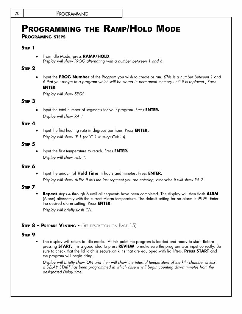
prOgraMMing the raMp/hOld MOdeprOgraMing steps
step 1
From Idle Mode, press ● RAMP/HOLD.Display will show PROG alternating with a number between 1 and 6.
step 2
Input the ● PROG Number of the Program you wish to create or run. (This is a number between 1 and 6 that you assign to a program which will be stored in permanent memory until it is replaced.) Press ENTERDisplay will show SEGS
step 3
Input the total number of segments for your program. ● Press ENTER.Display will show RA 1
step 4Input the first heating rate in degrees per hour. ● Press ENTER.Display will show ˚F 1 (or ˚C 1 if using Celsius)
step 5Input the first temperature to reach. ● Press ENTER.Display will show HLD 1.
step 6Input the amount of ● Hold Time in hours and minutes. Press ENTER.Display will show ALRM if this the last segment you are entering, otherwise it will show RA 2.
step 7Repeat• steps 4 through 6 until all segments have been completed. The display will then flash ALRM (Alarm) alternately with the current Alarm temperature. The default setting for no alarm is 9999. Enter the desired alarm setting. Press ENTER Display will briefly flash CPL
step 8 – prepare venting - (See deScription on page 15)
step 9The display will return to Idle mode. At this point the program is loaded and ready to start. Before •pressing START, it is a good idea to press REVIEW to make sure the program was input correctly. Be sure to check that the lid latch is secure on kilns that are equipped with lid lifters. Press START and the program will begin firing.Display will briefly show ON and then will show the internal temperature of the kiln chamber unless a DELAY START has been programmed in which case it will begin counting down minutes from the designated Delay time.
PRogRamming

21PRogRamming
DescriptiOn
step 1 – raMp/hOlDRamP/hoLd mode is a mode of programming that allows you to write your own firing program. When you are entering your program you will notice data already stored. Simply write over this information. If you mis-enter data you may either press zeros to clear the data and re-enter it or press STOP to start from the beginning.
step 2 – prOgraM nuMBer (prOg)You have the option of storing up to six firing programs. You may recall these programs at any time for future use. We recommend that you write down which number you have assigned each program so that you do not overwrite existing programs you have stored.
step 3 - segMents (segs)This step is prompting you to input the total number of segments you wish to use in your program. Each segment consists of a heating or cooling rate, a target temperature, and a hold time at that target temperature if one is desired. You may program up to eight segments. Two programs may be connected to achieve 16 segment programs. See instructions on page 20.
step 4 – rate (ra#) This step is prompting you to input a Temperature Rate. The display will show RA along with the current segment number you are programming alternately with the previous data entered. You may enter any rate between 1 ºF/hr (1 ºC/hr) to 9999 ºF/hr (9999 ºC/hr). This can be a cooling rate or a heating rate. The controller distinguishes between the two by checking to see if the temperature entered in the next segment is hotter or cooler than the previous segment.
Just because you enter a rate does not mean the kiln is capable of achieving that rate. Things such as element age, load density, and temperature range will all affect the kilns ability to heat. Conversely, the kiln’s insulation will influence its ability to cool. A rate must be entered for each segment.
step 5 – teMperature (ºF#) Or (ºc#)This prompt is asking you to enter a temperature to go to. When it gets to that temperature it will either hold at that temperature or switch to a new rate and aim for a new temperature. If you are programming in Celsius it will read ºC instead of ºF. The controller will allow you to program temperatures between 32 ºF (0 ºC) and 2400 ºF (1315 ºC). A temperature should not be entered which exceeds the kilns temperature rating.
step 6 – hOlD tiMe (HOLd)A HOLD time is generally entered to allow the kiln time to balance out and all of the pieces in the kiln to reach the input temperature before the kiln moves to the next segment. You may enter hold times of 00.00 to 99.99.
A Hold at peak temperature can be used for this reason or to gain additional heatwork to fine tune cone bends or to fire in-between cones. Remember that everything to the left of the decimal point on the display is Hours and everything to the right is Minutes. Excessive Hold times may cause over-fires.
step 7 – repeat
Continue to enter a rate, a temperature and a hold time for all the segments. When the last segment has been entered the display will prompt you to enter an Alarm temperature. The default is 9999 for no alarm. Input an Alarm temperature and Press ENTER. The display will briefly flash CPL for “complete” and then return to Idle Mode. The program is now loaded.
steps 8 anD 9 – prepare venting anD start
Before starting the program it is always a good idea to press REVIEW and make sure the data was entered correctly. If you find an error simply press RAMP/HOLD and continue to Press ENTER until you find the error and are able to correct it. If there is a Delay entered, when you press start the kiln will begin counting down from the input time. Remember to turn on your vent (or prop your lid) before pressing START
22 PRogRamming
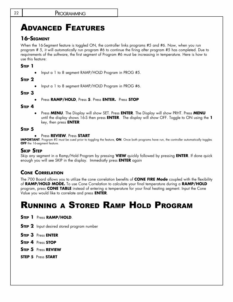
advanCed features 16-segMent
When the 16-Segment feature is toggled ON, the controller links programs #5 and #6. Now, when you run program # 5, it will automatically run program #6 to continue the firing after program #5 has completed. Due to requirements of the software, the first segment of Program #6 must be increasing in temperature. Here is how to use this feature:
step 1Input a 1 to 8 segment RAMP/HOLD Program in PROG #5. ●
step 2Input a 1 to 8 segment RAMP/HOLD Program in PROG #6. ●
step 3Press ● RAMP/HOLD, Press 5. Press ENTER. Press STOP
step 4Press ● MENu. The Display will show SET. Press ENTER. The Display will show PRHT. Press MENu until the display shows 16-S then press ENTER. The display will show OFF. Toggle to ON using the 1 key, then press ENTER
step 5Press ● REVIEW. Press START
IMPORTANT. Program #5 must be cued prior to toggling the feature, ON. Once both programs have run, the controller automatically toggles OFF the 16-segment feature.
skip stepSkip any segment in a Ramp/Hold Program by pressing VIEW quickly followed by pressing ENTER. If done quick enough you will see SKIP in the display. Immediatly press ENTER again
cOne cOrrelatiOn
The 700 Board allows you to utilize the cone correlation benefits of CONE FIRE Mode coupled with the flexibility of RAMP/HOLD MODE. To use Cone Correlation to calculate your final temperature during a RAMP/HOLD program, press CONE TABLE instead of entering a temperature for your final heating segment. Input the Cone Value you would like to correlate and press ENTER.
running a stOred raMp hOld prOgraMstep 1 Press RAMP/HOLD.
step 2 Input desired stored program number
step 3 Press ENTER
step 4 Press STOP
step 5 Press REVIEW
STEP 5 Press START

23menu featuRes
MENU
dIAGDiagnostics
CNFGConfiguration
SETSettings
- - - Hidden
TCOST/C Offset
RSETReset to Factory
COOLCooling segment
ERCdError Codes
PRHTPreheat
LEdLightup test
VOLTVoltage data
AMPSAmpere data
SW VS/W version
OUTSOutput test
bd TBoard Temp.
ERTFErr Temp & Time
for last firing
OUT4Output #4 options
MAXMax.
Programmable T.
IdKISS ID number
2KEY2 keys to START
ZONEZC options 1-4
dTCTCurrent Sensorís
max. rating
CYCLOutput cycle time
TYPET/C type: K/S
MAXbMax. allowable Board Temp.
16-S * Link RHM 5+6
1
4
3
2
5
6
7
8
CHGF to C
9
SHTO
NOTC
PId
OP b
OP C
OP A
ALR 4PCT
* - Only available when Ramp/Hold Program #5 is ìactiveî .
0
Kiln Master Menu tree
24
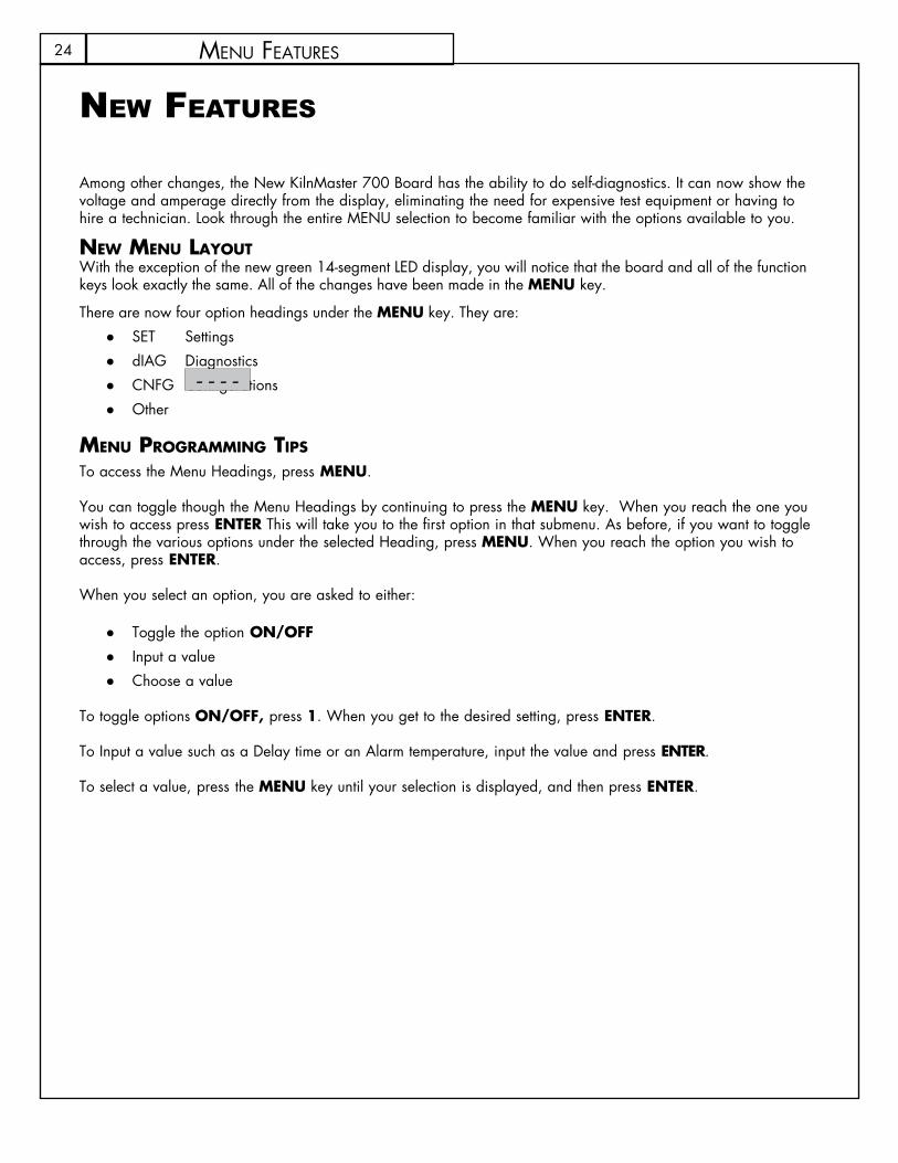
new features
Among other changes, the New KilnMaster 700 Board has the ability to do self-diagnostics. It can now show the voltage and amperage directly from the display, eliminating the need for expensive test equipment or having to hire a technician. Look through the entire MENU selection to become familiar with the options available to you.
neW Menu layOutWith the exception of the new green 14-segment LED display, you will notice that the board and all of the function keys look exactly the same. All of the changes have been made in the MENu key.
There are now four option headings under the MENu key. They are:SET Settings ●dIAG Diagnostics ●CNFG Configurations ●Other ●
Menu prOgraMMing tips
To access the Menu Headings, press MENu.
You can toggle though the Menu Headings by continuing to press the MENu key. When you reach the one you wish to access press ENTER This will take you to the first option in that submenu. As before, if you want to toggle through the various options under the selected Heading, press MENu. When you reach the option you wish to access, press ENTER.
When you select an option, you are asked to either:
Toggle the option ● ON/OFFInput ● a valueChoose a value ●
To toggle options ON/OFF, press 1. When you get to the desired setting, press ENTER.
To Input a value such as a Delay time or an Alarm temperature, input the value and press ENTER.
To select a value, press the MENu key until your selection is displayed, and then press ENTER.
menu featuRes
- - - -

25
prOgraMMing instruCtiOnsset (settings) SET, is where all of the commonly used options are located. The following options are available under the SET heading menu:
prht (preheat) ●This feature allows you to toggle the Preheat feature ON or OFF. The Preheat feature allows you to Input an amount of time to hold at 180˚F (82˚C) prior to running a CONE FIRE Program. This feature is recommended when firing large, thick-walled, or potentially damp ware. When the feature is toggled ON, it will prompt you to input a hold time value after the CONE FIRE key is pressed.
cOOl (cOne Fire cOntrOlleD cOOling) ●This feature allows you to add a 1-segment cooling program to the end of a CONE FIRE program. When it is toggled “ON”, it will prompt you to input a “Rate”, “Temperature”, and “Hold Time” after you input the Hold Time for a CONE FIRE program. This is helpful when trying to achieve certain glaze effects.
chg ° ● (Change FrOM Fahrenheit tO celsius scale) The controller can display temperature values in Fahrenheit or Celsius. If the scale is set to display in Celsius an LED dot will illuminate in the bottom right hand corner of the display. To select a new scale, press ENTER, and it will automatically toggle to the alternate scale. “ °C ” represents Celsius and “ °F “ represents Fahrenheit.
16-s (16-segMent) ●This option links the RAMP/HOLD programs stored in memory positions 5 and 6 to create a 16-segment program. Normally a program is limited to 8 segments. This feature will only display when a CONE FIRE Mode program or the number 5 Ramp/Hold program is loaded. See page 20 for programming instructions.
dIAG (DiagnOstics)“dIAG” or Diagnostics, is where all of the diagnostic tools are located. The following options are available under the “dIAG” menu:
ertF (err teMp & tiMe OF last Firing) ●
This feature will display the temperature and the point of time in the firing at which the last Error occurred. Often times this information is helpful in troubleshooting the problem which created the error. Once “ERTF” is selected, it will first flash the temperature at which the error occurred and then the time into the firing it occurred. The ERTF information will also appear automatically when an error alarm sounds and the program is terminated. Pressing any key, will show the temperature and elapsed time at which the error occurred.
vOlt (vOltage) ●
This feature is used to test the voltage supply to your kiln. It tests the voltage first with the elements off, “No Load” and then again with the kiln on, or “Full Load”. Select “VOLT” from the “dIAG” menu and press ENTER. After the “NOLd” reading is displayed, press ENTER to receive the “FLLd” reading. The power to the kiln will be switched on for a brief moment when the voltage under load is checked. Our technicians can use this information to help you troubleshoot voltage related problems over the phone. When the volt-age readings appear on your display, write them down. Often times voltage related problems can happen only at certain times of day, so try to obtain the readings at the same general time your kiln would be fir-ing.
menu featuRes

26 menu featuRes
aMps (aMperes) •This is probably the most useful diagnostic tool available to you. All KilnMaster kilns produced after 3/20/2006 are equipped with a current sensor in the control box. This allows us to test the current of each output to the kiln. This is very helpful in determining if a relay or element needs replacing.
When you select “AMPS” under the “dIAG” menu, it will give you an ampere reading for each output of the kiln (except the accessory and safety output). Which elements these outputs control will vary by model. If your kiln uses only one or two outputs it will still give you three readings but the unused outputs will give a reading of zero.
LEd (LED ● Display)This feature, when activated, lights up all of the segments in the LED display. This is helpful in locating any segments in the display that may have gone bad and may explain why some indicated readings are not correct.
bd T ( ● BOarD teMperature)The electronics on the controller’s circuit board may be damaged if the board exceeds 160˚F (71˚C). This should not occur under normal conditions. However, if the kiln is located in a small enclosure with poor ventilation or in areas where the temperatures are unusually hot, it is possible. Using this feature will tell you if your controller temperature is approaching potentially harmful levels.
If you find that your board temperature is consistently over 150˚F (65˚C), you may want to consider improving air circulation to the kiln room. A box fan blowing on the controller can help considerably.
sW v (sOFtWare versiOn) •At Skutt, we are continually working on ways of improving our products. This feature will indicate the software version your controller is using.
Outs (Output test) •There are four outputs that can be used on the board. There are three designated for elements and one designated to run an accessory. This feature allows you to test each output individually to see if it is operating correctly.
When activated this feature will test each output beginning with Output 1 and ending with Output 4. It will cycle each output on for approximately two minutes. You can advance to the next output at any time by pressing ENTER. To see if the elements are cycling ON, you can place a small piece of paper on each element. If the paper is burned, then the element came on. Be sure that the control box and kiln lid are closed before you use this feature in order to avoid electrical shock
cnFg (cOnFiguratiOn)cautiOn: Be sure to consult with a Skutt technician before making any configuration setting changes. Unadvised changes can cause permanent damage to your kiln and the ware inside it.
“CNFG” or Configuration, is where all of the controller configuration tools are located. The following options are available under the “CNFG” menu:

27menu featuRes
ERCd (Error Codes ON/OFF) Error codes are designed to help protect you, your kiln, and your ware when something goes wrong with the firing. There are times however, where you may wish to try a new technique which would trigger an error code under normal conditions. When error codes are turned off, the following codes are disabled:
Error 1 - Terminate firing when kiln temperature increasing at a rate slower than 12˚F (11˚C)/hr. ●Error 2 - Kiln Temperature 50˚F (10˚C) degrees above hold temperature. ●Error 3 - Kiln Temperature 50˚F (10˚C) degrees below hold temperature. ●Error 4 - Kiln Temperature 50˚F (10˚C) degrees above previous hold when ramping down. ●Error 5 - Kiln Temperature 50˚F (10˚C) degrees below traveling set point when ramping down. ●Error D - Kiln Temperature 50˚F (10˚C) degrees above traveling set point ●
tcOs (therMOcOuple OFFset) ●This feature allows you to calibrate the thermocouple when it is reading consistently and predictably incorrect. It is extremely important to consult with a Skutt technician before making thermocouple offset adjustments. Incorrect adjustments to the thermocouple offset can cause permanent damage to your kiln.Adjustments made to the thermocouple offset will affect all RAMP/HOLD and CONE FIRE programs.
If you are experiencing problems with CONE FIRE Mode, check to see if the ending temperature and hold time of the programs you are running have not been significantly altered from the factory programs before making thermocouple offset adjustments.
Access the TCOS setting through the CNFG menu. The display will flash °F0S alternately with the current offset setting. °F0S represents degrees Fahrenheit Offset. If the controller was programed to display in Celsius, the “F” would be replaced by a “C”. If there is currently an offset input, this could be the problem. To be safe, make adjustments in small increments and then run a test fire with Self-Supporting Cones.
tO Make the kiln Fire cOOler ●
Step 1Input ● 00 followed by the number of degrees you wish to offset the thermocouple.
Step 2Press ● ENTEREx: “0010” makes the kiln fire 10 degrees Cooler.
tO Make the kiln Fire hOtter ●
Step 1Input ● 90 followed by the number of degrees you wish to offset the thermocouple.
Step 2Press ● ENTEREx: “9010” makes the kiln fire 10 degrees Hotter.

28 menu featuRes
ZOne (ZOne cOntrOl OptiOns) ●Zone control is a feature that comes standard on the Production line of KilnMaster kilns. This line includes the following models PK1227 and PK1627. Zone Control is feature that allows the controller to indepen-dently fire sections on multiple section kilns to ensure even temperature top to bottom.There are three optional setting configurations for Zone Control which can be accessed through the “ZONE” feature under the “CNFG” menu
NOTC ●PId ●SHTO ●
nOtc (nuMBer OF therMOcOuples) ●Your kiln should be properly programmed for the correct number of thermocouples before it leaves the factory. All KilnMaster kilns will be set at 1 thermocouple except the KM1627 which comes standard with Zone Control. You cannot set a kiln to fire in more than one zone unless it is configured in the factory as a Zone Control kiln. If you try you will receive a “FAIL” error code.
To change the number of zones on a zone control kiln access the “ZONE” setting through the “CNFG” menu then use the menu key to toggle to the “NOTC” feature and Press ENTER. The controller will display the current “NOTC” setting. Input the desired value and press ENTER.
PId ( ● prOpOrtiOnal integral Derivative) PID is a zone control setting that uses the center section elements to help the bottom and top sections when necessary. In most kilns the center section is usually the hottest section. The PID option is designed to help speed up the firing when the top or bottom section is cooler and lagging behind the other sections.
When the top or bottom section is on full power (it is lagging behind), then output 2 comes on as a percentage of output 1 or output 3. The middle section will fire hotter and help the top and or bottom section catch up. The percentage can be set from 0 (zero) to 150. It is factory preset at 85%.
shtO (shutOFF) ●Shut off is a zone control feature that attempts to make firings more consistent. For 2 and 3 zone controllers, when shutoff is OFF the controller uses the average of all three thermocouples to transition from one segment to the next or to shut off the kiln. When “on” the kiln turns off, or transitions, when any one of the thermocouples reaches temperature. FOR ALL DOWN RAMPS, the controller transitions from one segment to the next as if shut off ”SHTO” were turned ON, I.e., when any one section reaches the next segment temperature.
Id ● (cOntrOl interFace systeM iD) CIS is an optional accessory that allows you to program and monitor multiple kilns from a PC. Each kiln hooked up to the CIS system needs to be identified with a unique number so the software can distinguish it from the other kilns. To set the identifying CIS number for each kiln access the “Id” setting through the “CNFG” menu, select a number between 1 and 99 and press ENTER
Out4 (Output 4 settings) ●There are three standard outputs, one safety output and one accessory output on your Skutt KilnMaster controller. The accessory output is designated as Output 4 and can control a number of optional accessories including vents, alarms and autodialers. Output 4 will cycle these accessories on and off at different times depending on the program you are running and the way you configure it under the “OUT4” feature setting. There are five different options for OUT4.
NOTE: “ALR4” is the factory default setting. When you access the Output 4 feature the feature options will appear in the order listed below. The first option listed is not necessarily the current setting.

29menu featuRes
alr4 (alarM 4) ● This is the factory default setting. If Output 4 is not being utilized this is the setting that should be selected. This feature can also control an external alarm or autodialer to initiate if an Error Code is generated or if the internal temperature of the kiln reaches the temperature programmed for the ALARM setting of the program. To deactivate the alarm press ENTER
pct (percent On) ● Output 4 can be programmed to be on for a percent of the time output 2 is on. This option is used when output 4 controls floor or lid elements. To ensure output 4 stays off at all times, use this option and set the percentage to zero. The percent can be set from 0 to 150. There are currently no Skutt Kiln designs that can utilize this feature.
Op a (OptiOn a) ● When option A is selected Output 4 will turn on when a CONE FIRE Mode program is started. When the program has run and the kiln has cooled to 150˚F (65˚C), output 4 will turn off.
When a RAMP/HOLD program is inputted it will ask whether you want the fan (or other accessory) on for each segment you program. After you Input the hold time for each segment the display will show “FAN” along with the number of the segment you are programming. Alternately it will flash the current setting, either “OFF” or “ON”. To change the setting toggle it with the 1 key and press ENTER to select that setting.
OP b ( ● OptiOn B) During a CONE FIRE program Output 4 will turn on when START is pressed. It will then turn off at 1450˚F (788˚C). It will turn back on when the kiln is cooling and the temperature drops below 1000˚F (538˚C). It will then turn off when the kiln cools to 150˚F (65˚C).
When a RAMP/HOLD program is inputted it will ask whether you want the fan (or other accessory) on for each segment you program. After you Input the hold time for each segment the display will show “FAN” along with the number of the segment you are programming. Alternately it will flash the current setting, either “OFF” or “ON”. To change the setting toggle it with the 1 key and Press ENTER to select that setting.
Op c (OptiOn c) ● When Option C is selected Output 4 does not come on during any portion of a CONE FIRE Mode program.
When a RamP/hoLd program is inputted it will ask whether you want the fan (or other accessory) on for each segment you program. After you Input the hold time for each segment the display will show “FAN” along with the number of the segment you are programming. Alternately it will flash the current setting, either “OFF” or “ON”. To change the setting toggle it with the “1” key and Press ENTER to select that setting.
Max (MaxiMuM prOgraMMaBle teMperature) ●The Maximum Programmable Temperature setting is a great feature to use when other people may be programming the kiln. It helps protect against an over fire by not allowing the programmer to input any value over the designated limit. To set your firing limit access the “MAX” setting through the “CNFG” menu, Input your desired limit and Press ENTER.
30 menu featuRes
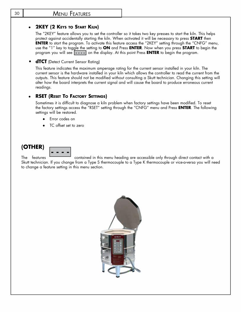
2key (2 keys tO start kiln) ●The “2KEY” feature allows you to set the controller so it takes two key presses to start the kiln. This helps protect against accidentally starting the kiln. When activated it will be necessary to press START then ENTER to start the program. To activate this feature access the “2KEY” setting through the “CNFG” menu, use the “1” key to toggle the setting to ON and Press ENTER. Now when you press START to begin the program you will see on the display. At this point Press ENTER to begin the program.
dTCT• (Detect Current Sensor Rating) This feature indicates the maximum amperage rating for the current sensor installed in your kiln. The current sensor is the hardware installed in your kiln which allows the controller to read the current from the outputs. This feature should not be modified without consulting a Skutt technician. Changing this setting will alter how the board interprets the current signal and will cause the board to produce erroneous current readings.
rset (reset tO FactOry settings) ●Sometimes it is difficult to diagnose a kiln problem when factory settings have been modified. To reset the factory settings access the “RSET” setting through the “CNFG” menu and Press ENTER. The following settings will be restored.
Error codes on ●TC offset set to zero ●
(OTHER)
The features contained in this menu heading are accessible only through direct contact with a Skutt technician. If you change from a Type S thermocouple to a Type K thermocouple or vice-a-versa you will need to change a feature setting in this menu section.
- - - -
- - - -
31tRoubLeshooting
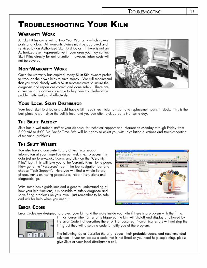
trOuBleshOOting YOur Kiln Warranty WOrk All Skutt Kilns come with a Two Year Warranty which covers parts and labor. All warranty claims must be approved and serviced by an Authorized Skutt Distributor. If there is not an Authorized Skutt Representative in your area you may contact Skutt Kilns directly for authorization, however, labor costs will not be covered.
nOn-Warranty WOrk Once the warranty has expired, many Skutt Kiln owners prefer to work on their own kilns to save money. We still recommend that you work closely with a Skutt representative to insure the diagnosis and repair are correct and done safely. There are a number of resources available to help you troubleshoot the problem efficiently and effectively.
yOur lOcal skutt DistriButOr Your local Skutt Distributor should have a kiln repair technician on staff and replacement parts in stock. This is the best place to start since the call is local and you can often pick up parts that same day.
the skutt FactOry Skutt has a well-trained staff at your disposal for technical support and information Monday through Friday from 8:00 AM to 5:00 PM Pacific Time. We will be happy to assist you with installation questions and troubleshooting of technical problems.
the skutt WeBsite You also have a complete library of technical support information at your fingertips on our web site. To access this data just go to www.skutt.com, and click on the “Ceramic Kilns” tab. This will take you to the Ceramic Kilns Home page. Now go to the “Resources” tab in the top navigation bar and choose “Tech Support”. Here you will find a whole library of documents on testing procedures, repair instructions and diagnostic tips.
With some basic guidelines and a general understanding of how your kiln functions, it is possible to safely diagnose and solve firing problems on your own. Just remember to be safe and ask for help when you need it.
errOr cODes
Error Codes are designed to protect your kiln and the ware inside your kiln if there is a problem with the firing. In most cases when an error is triggered the kiln will shutoff and display E followed by the Error Code that describes the error that occurred. Non-critical errors will not stop the firing but they will display a code to notify you of the problem.
The following tables describe the error codes, their probable cause, and recommended solutions. If you run across a code that is not listed or you need help explaining, please give Skutt or your local distributor a call.
32
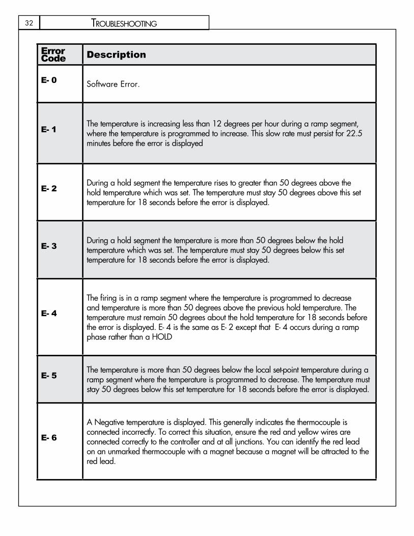
Error Code Description Causes Correction
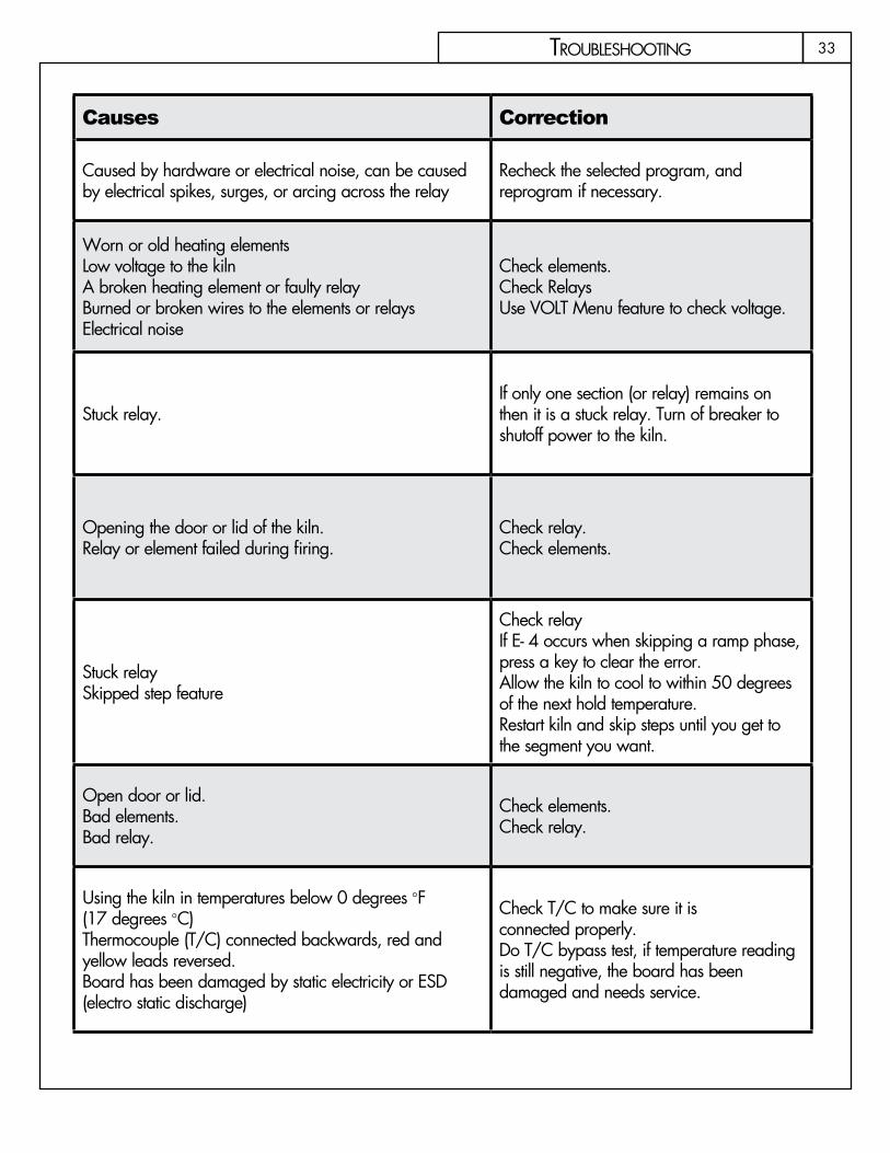
E- 0 Software Error. Caused by hardware or electrical noise, can be caused by electrical spikes, surges, or arcing across the relay
Recheck the selected program, and reprogram if necessary.
E- 1The temperature is increasing less than 12 degrees per hour during a ramp segment, where the temperature is programmed to increase. This slow rate must persist for 22.5 minutes before the error is displayed
Worn or old heating elementsLow voltage to the kilnA broken heating element or faulty relayBurned or broken wires to the elements or relaysElectrical noise
Check elements.Check RelaysUse VOLT Menu feature to check voltage.
E- 2During a hold segment the temperature rises to greater than 50 degrees above the hold temperature which was set. The temperature must stay 50 degrees above this set temperature for 18 seconds before the error is displayed.
Stuck relay.If only one section (or relay) remains on then it is a stuck relay. Turn of breaker to shutoff power to the kiln.
E- 3During a hold segment the temperature is more than 50 degrees below the hold temperature which was set. The temperature must stay 50 degrees below this set temperature for 18 seconds before the error is displayed.
Opening the door or lid of the kiln.Relay or element failed during firing.
Check relay.Check elements.
E- 4
The firing is in a ramp segment where the temperature is programmed to decrease and temperature is more than 50 degrees above the previous hold temperature. The temperature must remain 50 degrees about the hold temperature for 18 seconds before the error is displayed. E- 4 is the same as E- 2 except that E- 4 occurs during a ramp phase rather than a HOLD
Stuck relaySkipped step feature
Check relayIf E- 4 occurs when skipping a ramp phase, press a key to clear the error.Allow the kiln to cool to within 50 degrees of the next hold temperature.Restart kiln and skip steps until you get to the segment you want.
E- 5The temperature is more than 50 degrees below the local set-point temperature during a ramp segment where the temperature is programmed to decrease. The temperature must stay 50 degrees below this set temperature for 18 seconds before the error is displayed.
Open door or lid.Bad elements.Bad relay.
Check elements.Check relay.
E- 6
A Negative temperature is displayed. This generally indicates the thermocouple is connected incorrectly. To correct this situation, ensure the red and yellow wires are connected correctly to the controller and at all junctions. You can identify the red lead on an unmarked thermocouple with a magnet because a magnet will be attracted to the red lead.
Using the kiln in temperatures below 0 degrees °F (17 degrees °C)Thermocouple (T/C) connected backwards, red and yellow leads reversed.Board has been damaged by static electricity or ESD (electro static discharge)
Check T/C to make sure it is connected properly.Do T/C bypass test, if temperature reading is still negative, the board has been damaged and needs service.
tRoubLeshooting
33
Error Code Description Causes Correction
E- 0 Software Error. Caused by hardware or electrical noise, can be caused by electrical spikes, surges, or arcing across the relay
Recheck the selected program, and reprogram if necessary.
E- 1The temperature is increasing less than 12 degrees per hour during a ramp segment, where the temperature is programmed to increase. This slow rate must persist for 22.5 minutes before the error is displayed
Worn or old heating elementsLow voltage to the kilnA broken heating element or faulty relayBurned or broken wires to the elements or relaysElectrical noise
Check elements.Check RelaysUse VOLT Menu feature to check voltage.
E- 2During a hold segment the temperature rises to greater than 50 degrees above the hold temperature which was set. The temperature must stay 50 degrees above this set temperature for 18 seconds before the error is displayed.
Stuck relay.If only one section (or relay) remains on then it is a stuck relay. Turn of breaker to shutoff power to the kiln.
E- 3During a hold segment the temperature is more than 50 degrees below the hold temperature which was set. The temperature must stay 50 degrees below this set temperature for 18 seconds before the error is displayed.
Opening the door or lid of the kiln.Relay or element failed during firing.
Check relay.Check elements.
E- 4
The firing is in a ramp segment where the temperature is programmed to decrease and temperature is more than 50 degrees above the previous hold temperature. The temperature must remain 50 degrees about the hold temperature for 18 seconds before the error is displayed. E- 4 is the same as E- 2 except that E- 4 occurs during a ramp phase rather than a HOLD
Stuck relaySkipped step feature
Check relayIf E- 4 occurs when skipping a ramp phase, press a key to clear the error.Allow the kiln to cool to within 50 degrees of the next hold temperature.Restart kiln and skip steps until you get to the segment you want.
E- 5The temperature is more than 50 degrees below the local set-point temperature during a ramp segment where the temperature is programmed to decrease. The temperature must stay 50 degrees below this set temperature for 18 seconds before the error is displayed.
Open door or lid.Bad elements.Bad relay.
Check elements.Check relay.
E- 6
A Negative temperature is displayed. This generally indicates the thermocouple is connected incorrectly. To correct this situation, ensure the red and yellow wires are connected correctly to the controller and at all junctions. You can identify the red lead on an unmarked thermocouple with a magnet because a magnet will be attracted to the red lead.
Using the kiln in temperatures below 0 degrees °F (17 degrees °C)Thermocouple (T/C) connected backwards, red and yellow leads reversed.Board has been damaged by static electricity or ESD (electro static discharge)
Check T/C to make sure it is connected properly.Do T/C bypass test, if temperature reading is still negative, the board has been damaged and needs service.
tRoubLeshooting

34
Error Codes Descriptions Causes Correction
E- 8When using the CONE FIRE MODE, the temperature is decreasing during the last ramp segment. If this a KilnSitter Kiln using a Wall Mount Controller, KilnSitter may have shut off the kiln.
Faulty relayBroken ElementKilnSitter Shut-off kiln
Check relay.Check ElementsCheck Cone used in KilnSitter
pF Continuous PF in display. Indicates a long-term power outage The kiln has been shut down.
Press 1 to clear the display and restart the kiln.
Err pA continuous Err P indicates a short term power outage has occured and the kiln has continued with the program.
Power OutagePower Surge
Press 1 to clear the displayIf firing was in progress, it will continue.
Err- The Err with a dash indicates there was a power loss to the controller while writing a program to the non-volatile memory chip. Power loss Recheck the selected program, and
reprogram if necessary.
E- EorE- t
A hardware error has been detected by the controller software. Hardware error The controller must be returned for service.
E- d The kiln or one of the zones in a zone control kiln, is more than 100°F (37°C) above the travelling set point.
Stuck relay Check relay
E- A Invalid Program variable Reprogram if problem persists have board sent in for service
StUc Key was held too long or was stuck If problem persists after releasing key have keypad replaced
E- bd Controller is reading a board temperature above 160 degrees. Firing has stopped. Room temperature is too hot.. Lower room temperature below 100°F (37°C)
E- H Analog to Digital Converter did not pass the self – check diagnostic test on reset. Board will need to be serviced
FAIL Steady display all thermocouples (T/C’s) have failed. If flashing thermocouples of a zone control kiln has failed. Change T/C
tRoubLeshooting

35
Error Codes Descriptions Causes Correction
E- 8When using the CONE FIRE MODE, the temperature is decreasing during the last ramp segment. If this a KilnSitter Kiln using a Wall Mount Controller, KilnSitter may have shut off the kiln.
Faulty relayBroken ElementKilnSitter Shut-off kiln
Check relay.Check ElementsCheck Cone used in KilnSitter
pF Continuous PF in display. Indicates a long-term power outage The kiln has been shut down.
Press 1 to clear the display and restart the kiln.
Err pA continuous Err P indicates a short term power outage has occured and the kiln has continued with the program.
Power OutagePower Surge
Press 1 to clear the displayIf firing was in progress, it will continue.
Err- The Err with a dash indicates there was a power loss to the controller while writing a program to the non-volatile memory chip. Power loss Recheck the selected program, and
reprogram if necessary.
E- EorE- t
A hardware error has been detected by the controller software. Hardware error The controller must be returned for service.
E- d The kiln or one of the zones in a zone control kiln, is more than 100°F (37°C) above the travelling set point.
Stuck relay Check relay
E- A Invalid Program variable Reprogram if problem persists have board sent in for service
StUc Key was held too long or was stuck If problem persists after releasing key have keypad replaced
E- bd Controller is reading a board temperature above 160 degrees. Firing has stopped. Room temperature is too hot.. Lower room temperature below 100°F (37°C)
E- H Analog to Digital Converter did not pass the self – check diagnostic test on reset. Board will need to be serviced
FAIL Steady display all thermocouples (T/C’s) have failed. If flashing thermocouples of a zone control kiln has failed. Change T/C
tRoubLeshooting
36
QuestiOns and answers How can I correct a value that’s been incorrectly typed before pressing ENTER?Clear the display by pressing all zeros, then input the correct number and press ENTER. When a cone value has been incorrectly entered the process is slightly different. After pressing 0000, press ENTER. The display will again ask for a preheat value and then a cone value.
How can I change only one value for a RAMP/HOLD firing profile without re-entering the whole program?Follow tthe instructions for entering a new program and just press ENTER for every value that will remain the same. Make a change in the value that is incorrect, then continue.
How can I change the program after it has already started?Press the STOP key. This will stop the firing. Use either the CONE FIRE MODE or RAMP/HOLD MODE to input the new firing profile for the remaining portion of the firing. Press START to resume the firing. The controller will automatically determine where to start the program (based on the current internal temperature) and proceed with the adjusted program.
The kiln shuts off too early.The kiln can be restarted if the cones on the shelf indicate an under-fired load. (This should be used only if you were present when the kiln fired off.) The cones are no longer accurate if they have cooled much from the time of shut off. To restart follow these steps.
Press ● CONE FIRE or RAMP/HOLD to view the firing just completed.Press ● ENTER to accept any of the segments that are correct until the point where the cone number or final firing temperature is requested.Program in a hotter cone or higher firing temperature. You could also add a few minutes of hold time at ●the final firing temperature.Press ● START after the reprogramming is complete. The kiln will begin firing based on current temperature and will fire to completion using the newly programmed data.Helpful hint ● If the firing is just slightly under fired, program five minutes of hold time at the final firing temperature. This will allow the sections of the kiln that are somewhat cooler to catch up to the hotter sections.
The kiln displays CPLt but the kiln won’t cool off.Check the elements to see if any are still glowing inside the kiln. If a whole section of the kiln is glowing, a relay is stuck. Unplug the kiln and contact your distributor for further information.
At night I see a blue flash coming out of the control box when it clicks. Is it serious?The flash occurs when the contacts open causing a small arc. This is a normal occurrence and should not be a concern.
I programmed a RAMP/HOLD profile and when I pressed Start, the alarm sounded.Review the program to ensure that all segments of the profile have a value entered. Also, check the alarm to see if a value has been entered that is lower than the room temperature. The default setting for no alarm to sound is 9999.
tRoubLeshooting
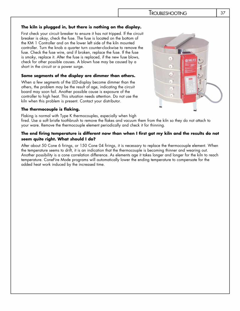
37
The kiln is plugged in, but there is nothing on the display. First check your circuit breaker to ensure it has not tripped. If the circuit breaker is okay, check the fuse. The fuse is located on the bottom of the KM 1 Controller and on the lower left side of the kiln mounted controller. Turn the knob a quarter turn counter-clockwise to remove the fuse. Check the fuse wire, and if broken, replace the fuse. If the fuse is smoky, replace it. After the fuse is replaced, if the new fuse blows, check for other possible causes. A blown fuse may be caused by a short in the circuit or a power surge.
Some segments of the display are dimmer than others.When a few segments of the LED-display become dimmer than the others, the problem may be the result of age, indicating the circuit board may soon fail. Another possible cause is exposure of the controller to high heat. This situation needs attention. Do not use the kiln when this problem is present. Contact your distributor.
The thermocouple is flaking.Flaking is normal with Type K thermocouples, especially when high fired. Use a soft bristle toothbrush to remove the flakes and vacuum them from the kiln so they do not attach to your ware. Remove the thermocouple element periodically and check it for thinning.
The end firing temperature is different now than when I first got my kiln and the results do not seem quite right. What should I do?After about 50 Cone 6 firings, or 150 Cone 04 firings, it is necessary to replace the thermocouple element. When the temperature seems to drift, it is an indication that the thermocouple is becoming thinner and wearing out. Another possibility is a cone correlation difference. As elements age it takes longer and longer for the kiln to reach temperature. ConeFire Mode programs will automatically lower the ending temperature to compensate for the added heat work induced by the increased time.
tRoubLeshooting
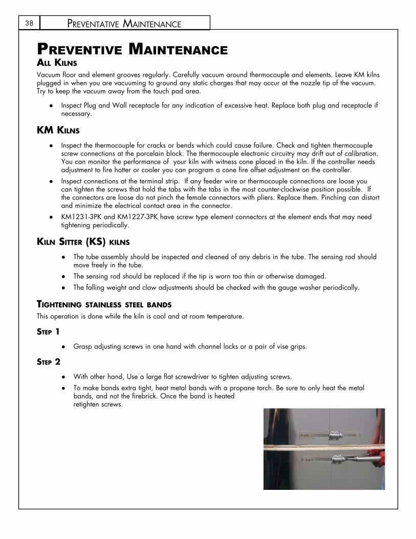
38 PReventative maintenanCe
preventive MaintenanCeall kilns
Vacuum floor and element grooves regularly. Carefully vacuum around thermocouple and elements. Leave KM kilns plugged in when you are vacuuming to ground any static charges that may occur at the nozzle tip of the vacuum. Try to keep the vacuum away from the touch pad area.
Inspect Plug and Wall receptacle for any indication of excessive heat. Replace both plug and receptacle if ●necessary.
kM kilns Inspect the thermocouple for cracks or bends which could cause failure. Check and tighten thermocouple ●screw connections at the porcelain block. The thermocouple electronic circuitry may drift out of calibration. You can monitor the performance of your kiln with witness cone placed in the kiln. If the controller needs adjustment to fire hotter or cooler you can program a cone fire offset adjustment on the controller. Inspect connections at the terminal strip. If any feeder wire or thermocouple connections are loose you ●can tighten the screws that hold the tabs with the tabs in the most counter-clockwise position possible. If the connectors are loose do not pinch the female connectors with pliers. Replace them. Pinching can distort and minimize the electrical contact area in the connector.KM1231-3PK and KM1227-3PK have screw type element connectors at the element ends that may need ●tightening periodically.
kiln sitter (ks) kilns
The tube assembly should be inspected and cleaned of any debris in the tube. The sensing rod should ●move freely in the tube. The sensing rod should be replaced if the tip is worn too thin or otherwise damaged. ●The falling weight and claw adjustments should be checked with the gauge washer periodically. ●
tightening stainless steel BanDs
This operation is done while the kiln is cool and at room temperature.
step 1
Grasp adjusting screws in one hand with channel locks or a pair of vise grips. ●
step 2
With other hand, Use a large flat screwdriver to tighten adjusting screws. ●To make bands extra tight, heat metal bands with a propane torch. Be sure to only heat the metal ●bands, and not the firebrick. Once the band is heated retighten screws.
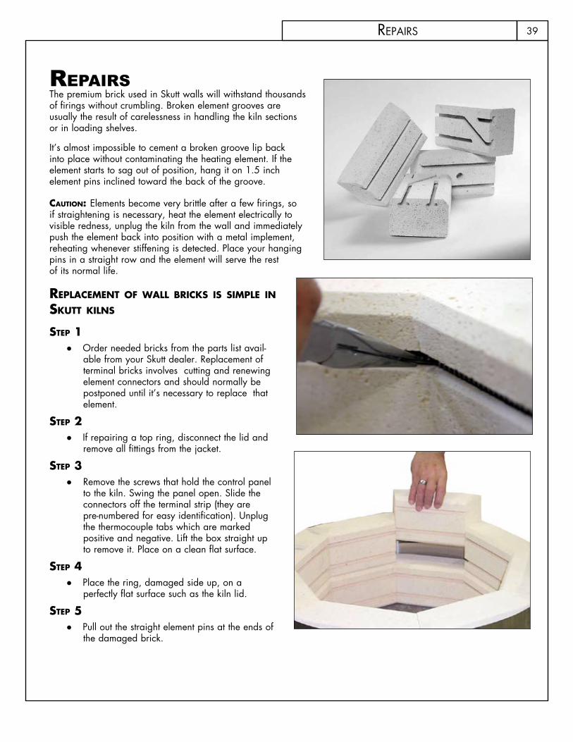
39
repairsThe premium brick used in Skutt walls will withstand thousands of firings without crumbling. Broken element grooves are usually the result of carelessness in handling the kiln sections or in loading shelves.
It’s almost impossible to cement a broken groove lip back into place without contaminating the heating element. If the element starts to sag out of position, hang it on 1.5 inch element pins inclined toward the back of the groove.
cautiOn: Elements become very brittle after a few firings, so if straightening is necessary, heat the element electrically to visible redness, unplug the kiln from the wall and immediately push the element back into position with a metal implement, reheating whenever stiffening is detected. Place your hanging pins in a straight row and the element will serve the rest of its normal life.
replaceMent OF Wall Bricks is siMple in skutt kilns
step 1Order needed bricks from the parts list avail- ●able from your Skutt dealer. Replacement of terminal bricks involves cutting and renewing element connectors and should normally be postponed until it’s necessary to replace that element.
step 2If repairing a top ring, disconnect the lid and ●remove all fittings from the jacket.
step 3Remove the screws that hold the control panel ●to the kiln. Swing the panel open. Slide the connectors off the terminal strip (they are pre-numbered for easy identification). Unplug the thermocouple tabs which are marked positive and negative. Lift the box straight up to remove it. Place on a clean flat surface.
step 4Place the ring, damaged side up, on a ●perfectly flat surface such as the kiln lid.
step 5Pull out the straight element pins at the ends of ●the damaged brick.
RePaiRs

40
step 6Gently lift elements from troughs with a pick or long-nose pliers and gently lift them out into firing chamber ●just far enough to allow damaged brick to be slipped out. Remember that the elements are brittle.
step 7Loosen the worm-type jacket fasteners equally, .5 inch to .75 inch. ●
step 8Make sure element troughs in the brick are proper side up. Insert the new brick. This is easiest if a helper ●holds the adjoining bricks away.
step 9Hold the worm-type jacket fastener housings with pliers and tighten them evenly until they meet resistance. ●
step 10Use sandpaper over a wood block to sand the edges of new brick down flush with its neighbors. Vacuum ●thoroughly when sanding is completed.
step 11Replace hinges and hardware, and position the kiln so you can finish tightening the jacket just before the ●kiln shuts off on your next Cone 06 or hotter firing.
liD Maintenance Skutt lids are coated with a refractory cement which helps protect the kiln chamber from falling brick particles.This refractory coating will form hairline expansion cracks after the first few firings. This is normal and should not get worse over time. If your lid does develop a larger crack, you can use a thin coating of refractory cement to seal it. Large patch jobs are not recommended.
Remember to tighten the lid band and lid hardware on a regular basis. If the inside surface of the lid ever gets to the point where it is unrepairable you can flip the lid over. Just detach all of the lid hardware, flip the lid and reattach the hardware.
FlOOr repairs Glaze drips on a properly kiln washed floor can easily be removed without damage to the surface below. Remember to remove all glaze drips before taking the kiln to porcelain/stoneware temperatures, where the glaze will over-fire and soak through the kiln wash.
The floor can be patched if needed. If several square inches have been damaged to a depth of 5/8 inch or less, using a sharp knife or X-Acto tool, undercut the edges of the area to be patched. Use a spackling knife to fill the hole with kiln patch which can be purchased through Skutt. Sand smooth
replacing eleMents While Skutt kiln elements are not difficult to replace, they require electrical connector tools. We recommend you ask your Skutt dealer about the procedure.
RePaiRs
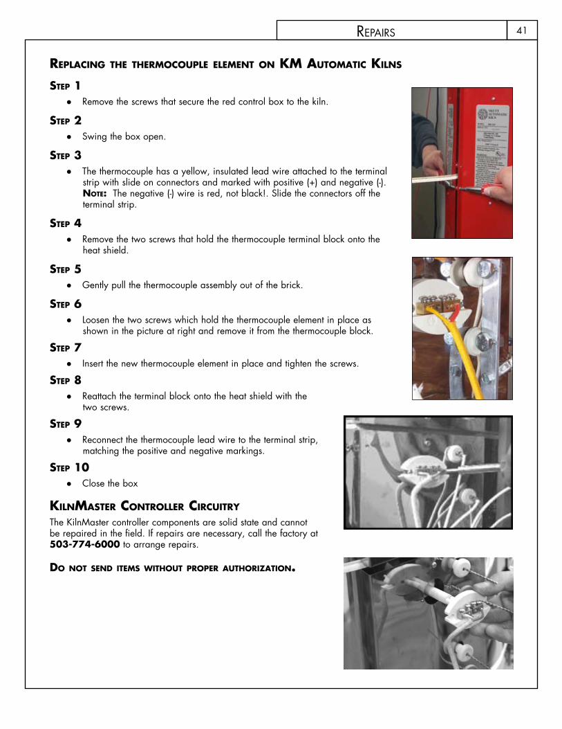
41
replacing the therMOcOuple eleMent On kM autOMatic kilns
step 1Remove the screws that secure the red control box to the kiln. ●
step 2Swing the box open. ●
step 3The thermocouple has a yellow, insulated lead wire attached to the terminal ●strip with slide on connectors and marked with positive (+) and negative (-). nOte: The negative (-) wire is red, not black!. Slide the connectors off the terminal strip.
step 4Remove the two screws that hold the thermocouple terminal block onto the ●heat shield.
step 5Gently pull the thermocouple assembly out of the brick. ●
step 6Loosen the two screws which hold the thermocouple element in place as ●shown in the picture at right and remove it from the thermocouple block.
step 7Insert the new thermocouple element in place and tighten the screws. ●
step 8Reattach the terminal block onto the heat shield with the ●two screws.
step 9 Reconnect the thermocouple lead wire to the terminal strip, ●matching the positive and negative markings.
step 10Close the box ●
kilnMaster cOntrOller circuitry The KilnMaster controller components are solid state and cannot be repaired in the field. If repairs are necessary, call the factory at 503-774-6000 to arrange repairs.
DO nOt senD iteMs WithOut prOper authOriZatiOn.
RePaiRs
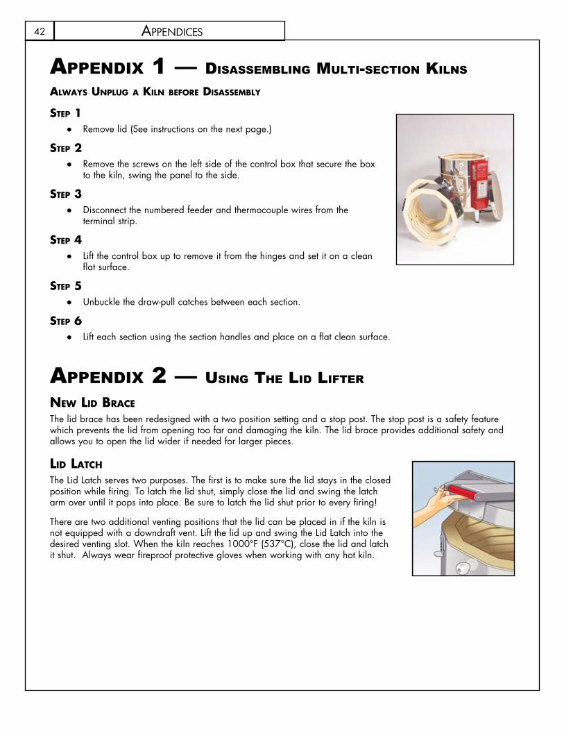
42
appendix 1 — disasseMBling Multi-seCtiOn Kilns alWays unplug a kiln BeFOre DisasseMBly
step 1Remove lid (See instructions on the next page.) ●
step 2Remove the screws on the left side of the control box that secure the box ●to the kiln, swing the panel to the side.
step 3Disconnect the numbered feeder and thermocouple wires from the ●terminal strip.
step 4Lift the control box up to remove it from the hinges and set it on a clean ●flat surface.
step 5Unbuckle the draw-pull catches between each section. ●
step 6Lift each section using the section handles and place on a flat clean surface. ●
appendix 2 — using the lid lifter neW liD Brace
The lid brace has been redesigned with a two position setting and a stop post. The stop post is a safety feature which prevents the lid from opening too far and damaging the kiln. The lid brace provides additional safety and allows you to open the lid wider if needed for larger pieces.
liD latch
The Lid Latch serves two purposes. The first is to make sure the lid stays in the closed position while firing. To latch the lid shut, simply close the lid and swing the latch arm over until it pops into place. Be sure to latch the lid shut prior to every firing!
There are two additional venting positions that the lid can be placed in if the kiln is not equipped with a downdraft vent. Lift the lid up and swing the Lid Latch into the desired venting slot. When the kiln reaches 1000°F (537°C), close the lid and latch it shut. Always wear fireproof protective gloves when working with any hot kiln.
aPPendiCes

43
appendix 3 — heatwOrK
Heatwork is the measurement of the effects of time and temperature. In Ceramics, this measurement is gauged through the use of Pyrometric Cones. They are composed of materials which are carefully measured and compressed into the shape of a tetrahedron. The cones are placed in the kiln on a shelf with your ware and, when they have received the proper amount of heatwork, they bend over indicating that it is time to turn off the kiln.
Pyrometric Cones come in a variety of shapes and sizes. Each size and shape has a different temperature chart associated with it. The chart below is based on a Large Self-Supporting Cone and has become the standard for commercial clay bodies, glazes and controller software.
All clay bodies and glazes are designed to fire to a certain cone value. In a KilnMaster Kiln the computer calculates the heatwork and shuts the kiln off at the proper heat and time combination. This is called Cone Correlation. ConeFire Mode programs all are controlled by Cone Correlation, Ramp and Hold Programs are not
Skutt Kilns are designed to fire a range of cone values from 022 to 10. As you can see by the chart below, the temperature associated with each cone value gradually increases from 022 to 10. It is very important not to forget
to add the leading zero when entering a cone value (if it is required) or the kiln will fire much hotter than you want it to.
Remember that heatwork is the combination of time and temperature. This is most important during the last 200 °F of the firing. If the kiln is firing very slow during this period, the controller will automatically adjust the temperature down to ensure the ware does not receive too much heatwork. The cone values listed in the chart are only valid if the kiln is firing at exactly 108 °F/hr. during the last 200 °F of the firing. That is why it is very important to know the capabilities of your kiln when writing Ramp Hold Programs or entering Hold times.
We recommend that you still use Self Supporting Witness cones on every firing to monitor the accuracy of your kiln. Place the appropriate cone on a shelf approximately 2 inches from the kiln wall and two inches from the tip of the
thermocouple. Make sure the space between the thermocouple and cone is unobstructed.
The Cone Measuring Template shown here can be used to determine the exact bend measured in degrees of angle. A perfect bend is considered to be at 90 degrees.
Remember that cones can vary slightly and are meant to be a general indicator of the heatwork within the kiln. Bends between 20 degrees and the tip of the cone just above the shelf are acceptable for most projects. If you fine your bends are consistently low or high you can usually fine tune the heatwork by adjusting Hold times.
aPPendiCes
Cone No. ◦F ◦C
022 1087 586021 1112 600020 1159 626019 1252 678018 1319 715017 1360 738016 1422 772015 1456 791014 1485 807013 1539 837012 1582 861011 1607 875010 1657 90309 1688 92008 1728 94207 1789 97606 1828 998
051/2 1859 101505 1888 103104 1945 106303 1987 108602 2016 110201 2046 11191 2079 11372 2088 11423 2106 11524 2124 11625 2167 1186
51/2 2197 12036 2232 12227 2262 12398 2280 12499 2300 126010 2345 1285

44
appendix 4 — lOading tips
Balance the lOaD •When planning how to load your kiln, keep in mind that the center of the kiln is generally the hottest. Therefore, you will want to distribute the load with the larger, thicker pieces towards the middle and the smaller, thinner pieces towards the top and bottom.
allOW the kiln tO Breath•Many studios work with glazes that require oxygen to develop properly. Provide enough space between items to allow them to “breath. Using half shelves with a .25 inch space gap in the middle will also help increase the flow of oxygen within the kiln chamber, especially when used in combination with an EnviroVent.
allOW FOr prOper clearances •Kilns lose most of their heat from the lid and the slab. Ideally, there should be at least two inches of space between the lid and the closest piece. The first shelf should be posted up one inch from the bottom slab.
Do not place shelves or ware directly on the floor of your kiln. Doing so could block the holes drilled for the EnviroVent and will not provide adequate heat flow under your ware.
Items placed too close to the thermocouple can bias the reading. Be sure to leave a 2” clearance around the thermocouple when loading shelves, ware and cones.
nOthing Directly unDer the envirOvent •hOles Holes drilled in the lids of kilns with EnviroVents allow air to be drawn into the kiln chamber. If a piece of ware is sitting directly under one of these holes, it could leave a spot in the glaze. If it is not possible to cap the load with a shelf, leave a five inch radius on the shelf directly below each hole.
DO nOt rush •Take the time to properly load and fire the kiln. Check each piece to ensure that too much glaze or unsteady placement will not cause disaster during the firing. A few extra minutes can save you a lot of frustration.
aPPendiCes
Rain Hoodor Vent
5“ Cutoutin Wall8“ Discharge
Tube, Cut as Necessary
BlowerW/Motor
RadiatorClamp
3“ Diameter Flex Tube
115 voltCordset W/Switch
Negative PressureNegative Pressure

45
appendix 5 — eleCtriCal reQuireMents Most important to proper operation of your new kiln is to make sure it has enough of the correct power to operate. If this is done, your kiln will give you years of satisfying service; if not, your first firing could be disappointing or even disastrous for your kiln. The specification charts on the following pages show the recommended electrical specifications for each kiln model. If you are uncertain about your existing outlets, have them checked by an electrician. If you are installing a new receptacle, have the electrician follow this guide:
three-phase OperatiOn On occasion we are asked if it is ok to use two legs of a 3 phase power supply to electrically connect a single phase kiln. This is possible in most cases, however, you should have this connection made by a licensed electrician who is familiar with 3 phase power supply and National and local electrical codes. It is not possible to connect a 3 phase kiln to 1 phase supply.
vOltage
As you can see from the chart, most Skutt models are available in either 208 or 240 volt versions. The exception is Model KM714 which is universal, and will fire with a 240V or 208V power supply.
While 120/240V supply is still by far the most common supply in residential communities, 120/208V supply is increasingly encountered in commercial areas, schools and occasionally newly-built communities.
If you find that the designated voltage of your kiln (found on the serial plate) does not match your supply, do not connect it. Doing so could damage the kiln and possibly overheat wiring in your electrical supply. Contact the factory for instructions on how to safely convert your particular model.
714 Wiring
iMpOrtant: The wall outlets for Model KM714 must be powered by 3-wire 120/240-208V solid neutral supply. No. 10 wire is required for runs under 50 feet. 30 Amp fuses or circuit breakers are recommended. The U-shaped fourth blade of the 4W30 Amp grounding plug is for the solid green grounding wire. The blade opposite this U-shaped one takes the solid white neutral wire.
aPPendiCes

46 aPPendiCes
kilnMaster kilns anD Wall MOunt cOntrOllers
Model PH Volts Amps WattsCopper Wire Size*
Fuse or Breaker
Size NEMA
Receptacle
KM614 1 115 20 2300 10 30 (Canada) 5 – 30KM614 1 115 20 2300 10 30 5 – 20KM714 1 208-240 20 3600 10 30 14 – 30KM818 1 240 27.8 6672 8 40 6 – 50KM818 1 208 26.7 5554 8 40 6 – 50KM818-30A 1 240 21.7 5208 10 30 6 – 30KM818-30A 1 208 24 4992 10 30 6 – 30KM822 1 240 33.4 8000 8 50 6 - 50KM822 1 208 38.5 8000 8 50 6 - 50KM1018 1 240 39.4 9456 6 50 6 – 50KM1018 1 208 40 8320 6 50 6 – 50KM1022 1 240 48 11520 6 60 6 – 50KM1022 1 208 48 9984 6 60 6 – 50KM1022 3 240 34.6 11520 8 50 15 – 50KM1022 3 208 34.6 9984 8 50 15 – 50KM1027 1 240 48 11520 6 60 6 – 50KM1027 1 208 48 9984 6 60 6 – 50KM1027 3 240 29.3 11520 8 40 15 – 50KM1027 3 208 31.7 11000 8 40 15 – 50KM1218 1 240 48 11520 6 60 6 – 50KM1218 1 208 48 9984 6 60 6 – 50KM1218 3 240 29.3 11520 8 40 15 – 50KM1218 3 208 29.5 9984 8 40 15 – 50KM1222-3 1 240 48 11520 6 60 6 – 50KM1222-3 1 208 48 9984 6 60 6 – 50KM1222-3 3 240 34.6 11520 8 50 15 – 50KM1222-3 3 208 40 11520 8 50 15 – 50KM1227 1 240 48 11520 6 60 6 – 50KM1227 1 208 48 9984 6 60 6 – 50KM1227 3 240 29.3 11520 8 40 15 – 50KM1227 3 208 31.7 11000 8 40 15 – 50KM-1 1 208- 240 Switching Capacity 48 AMPS 6 – 50KM-1 3 208-240 Switching Capacity 40 AMPS 15 – 50

47
pk speciFicatiOns
Model PH Volts Amps WattsCopper Wire Size*
NEMA Receptacle
Fuse or Breaker Size
KM1227PK 1 240 60 14400 4 Direct Wire 80KM1227PK 1 208 69 14352 4 Direct Wire 90KM1227PK 3 240 40 14300 6 Direct Wire 50KM1227PK 3 208 46.7 14300 6 Direct Wire 60KM1231PK 1 240 72 17280 2 Direct Wire 90KM1231PK 1 208 80 16640 2 Direct Wire 100KM1231PK 3 240 44.5 17300 6 Direct Wire 60KM1231PK 3 208 51.5 17300 6 Direct Wire 65KM1627PK-LF 1 240 68 16320 4 Direct Wire 85KM1627PK-LF 1 208 69 14352 4 Direct Wire 90KM1627PK-LF 3 240 46 16300 6 Direct Wire 60KM1627PK-LF 3 208 47 14300 6 Direct Wire 60KM1627PK 3 240 66 23600 4 Direct Wire 85KM1627PK 3 208 76 23600 4 Direct Wire 95
*For each additional 50 feet use heavier wire, numerically two numbers lower—for example, instead of #10, use #8. If you anticipate installing any larger kiln in the future, use the heavier wire. Electrical specifications listed above are suggested guidelines. Local electrical codes may vary.
aPPendiCes

48
appendix 6 — set-up and speCifiCatiOns fOr sKutt pK Kilnspk prODuctiOn kilns Skutt PK production kilns are heavy duty, high capacity units designed to meet the needs of the high fire production potter, tile maker and light industrial user. These kilns are equipped with upgraded components and wiring that will allow them to high fire extremely dense loads in a relatively short time.
Firing Skutt PK kilns feature our KilnMaster controller, so operation is identical to other KM kilns. Even though the earlier sections of this manual do not refer specifically to the PK kiln line, you may follow all the instructions on programming and firing routines.
kiln iMprOveMents If you are an intensive kiln user, you might find a PK kiln to be the appropriate choice for your next kiln purchase. Here are some of the differences from our standard KM kiln line
First, PK kilns are designed to fire full, Cone 10 loads without stalling on the high end. To do so, they are equipped with industrial gauge wiring and three types of elements for better firing balance. Because of their high rating, electrical codes require that they be direct wired by an electrician; therefore no plug is included.Mercury displacement relays are used for longer life and quieter operation.
The hinged control box is larger, and compression connectors are used on the feeder wires for easier element replacement.
Finally, Model KM1231PK comes with an additional stand for bottom slab support under heavy loads.
unpacking anD MOving pk kilns Follow the general instructions on kiln set-up found in this manual. You will probably want to separate the kiln into sections when you set it up or move it to a different location. These instructions are slightly different than for standard KM kilns.
cautiOn: Before disassembling any PK kiln, be sure to turn off power to the kiln by throwing the circuit breaker or removing the fuse on its circuit. Do not restore power to the kiln until it is fully reassembled.
nOte: The mercury relays in the switch box must be operated only with the switch box in a normal, vertical orientation.
aPPendiCes
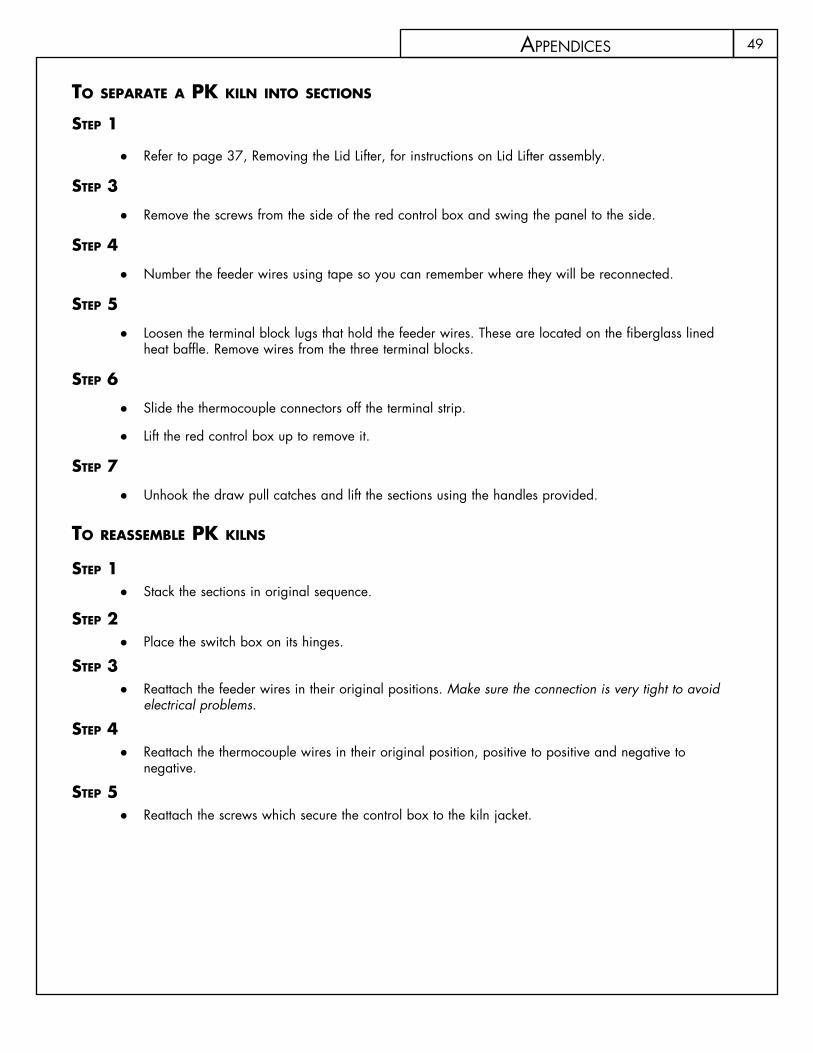
49
tO separate a pk kiln intO sectiOns
step 1
Refer to page 37, Removing the Lid Lifter, for instructions on Lid Lifter assembly. ●
step 3
Remove the screws from the side of the red control box and swing the panel to the side. ●
step 4
Number the feeder wires using tape so you can remember where they will be reconnected. ●
step 5
Loosen the terminal block lugs that hold the feeder wires. These are located on the fiberglass lined ●heat baffle. Remove wires from the three terminal blocks.
step 6
Slide the thermocouple connectors off the terminal strip. ●
Lift the red control box up to remove it. ●
step 7
Unhook the draw pull catches and lift the sections using the handles provided. ●
tO reasseMBle pk kilns
step 1Stack the sections in original sequence. ●
step 2Place the switch box on its hinges. ●
step 3Reattach the feeder wires in their original positions. ● Make sure the connection is very tight to avoid electrical problems.
step 4Reattach the thermocouple wires in their original position, positive to positive and negative to ●negative.
step 5Reattach the screws which secure the control box to the kiln jacket. ●
aPPendiCes

50
appendix 7 — setup fOr the KM 1627The 1627 will be packed in three separate boxes which will include the following:
BOx 1 KM1627 ●
BOx 2
3 Piece Fiber Slab Insert ●12 — 2 inch (2.54 centimeter) Posts ●
BOx 3 2 Piece Kiln Stand ●6 Peep Plugs ●“Goodie Bag” ●Operating Manual ●Warranty Card ●12 Plastic Stand Feet ●Lid Prop ●
set up Follow the general instructions on kiln setup in the Set Up section of this manual. There are three main differences that should be noted when setting up the KM1627:
Due to the weight of the KM1627 you will want to separate the kiln into sections when you set it up. ●The KM1627 has two stands that fit together for greater support. Place the stands flush together. ●The KM1627 includes a three piece rigid fiber liner that fits inside the bottom section on top of the slab. ●There are holes cast in the liner which hold the 2 inch (2.54 centimeter) ceramic posts. Carefully lay the fiber insert on top of the slab after the first section is placed in position and insert the posts.
cautiOn – Before disassembling any Oval kiln, be sure to turn off power to the kiln by throwing the circuit breaker or removing the fuse on its circuit. Do not restore power to the kiln until it is fully reassembled.
DisasseMBling the kM1627
step 1
Remove the screws from the left side of the control box. ●
step 2
Swing open the control box open. ●
step 3
Remove the screws holding the feeder wires to the two pole blocks on the heat baffle. ●
There are three sets with two feeder wires going into each set.
aPPendiCes

51
step 4
Remove the thermocouple wires from the thermocouple terminal strip on the baffle. ●
They are attached with slide on connectors and should be pulled straight off.
Pulling at an angle can damage the connector.
step 5
Lift the box up and set it aside. ●
Unfasten draw pull catches and lift sections apart using the handles ●
tO reasseMBle kM 1627
step 1Stack the sections in original sequence and secure the draw pull catches. ●
step 2Place the control box on its hinges. ●
step 3Reattach the feeder wires to their corresponding block. ●Make sure the connection is tight to avoid electrical problems. ●
step 4Reattach the thermocouple wires in correct order. ●
step 5Reattach the screws which secure the control box to the kiln jacket. ●
KM 1627Section Element Type Position
Upper Top/Bottom 1Top/Bottom 2Intermediate 3Intermediate 4
Master Center 5Center 6Center 7Center 8
Lower Intermediate 9Intermediate 10Top/Bottom 11Top/Bottom 12
aPPendiCes

52 aPPendiCes
appendix 8 — the wall-MOunted KilnMaster COntrOller The wall-mounted KM-1 KilnMaster gives automatic kiln control to most mod-ern Skutt 208/240V kilns and any other brand kiln which uses NEMA 6-50 (single phase) or NEMA 15-50 (3-phase) plugs and receptacles. It can be moved quickly from one kiln to another and can control virtually any kiln in a studio which has the proper cord plug and receptacle configuration.
Once installed, the KilnMaster controller uses the same operating instructions as other Skutt Automatic kilns. Choose a location that will put the controller at least two feet from the kiln to prevent overheating the controller. To mount the controller, mark the hole positions on the wall where the controller will be in-stalled using the paper template supplied with the controller and follow these instructions:
step 1 – tO MOunt the cOntrOller On stuD Or pOst
Use the holes marked ● A on the template and screw a #12 x 2 inch wood screw into the wall leaving a .25 inch gap.
Repeat for the second screw. ●
tO MOunt the cOntrOller in sheet rOck
Using holes marked ● A and B on the template, drill the necessary holes to properly mount the .25 inch x 2 inch molly bolts into the sheet rock.
Tighten the first bolt until there is a 1/8 inch gap. ●Repeat for the other three bolts. ●
Before hanging the controller on the wall, loop the cord attached to the quick reference card over a screw so that it hangs below the controller when mounted.
step 2 – cOnnecting tO the kiln single-phase ●(Switching capacity 48 Amps on 208-240V) To operate the wall-mounted controller, simply engage the kiln plug in the receptacle located on the back of the controller. Then plug the controller into the existing wall receptacle.
three-phase ●(Switching capacity 40 Amps on 208-240V) To connect your three-phase kiln, plug the power cord from the kiln into the receptacle mounted on the back of the controller. Plug the pilot cord (the smaller cord) into the small receptacle mounted on the underside of the controller. The controller is plugged into a wall receptacle which provides three phase voltage. You will no longer need to use the three-phase contractor box. However, an electrician may need to wire a receptacle for the controller if a three-phase contractor box was used previously. You may need to make other changes to the supply for kilns not made by Skutt. Other manufacturers may not use pilot cords. Please discuss this with your distributor.
therMOcOuple installatiOn Skutt kilns have a hole stamped in the stainless band where the thermocouple flange is to be installed. It is located to the right of the red switch boxes. The firebrick is visible through this hole. The thermocouple flange is a metal tube approximately 5/8 in. (1.59 cm) diameter and 1.5 in. (3.81 cm) long attached to a metal washer.

53aPPendiCes
Remove the thumbscrew from the flange. ●Align the thermocouple flange so that it is exactly over the hole in the stainless band. ●Position the flange so the thumbscrew is on the top. ●Attach the flange to the kiln using the two Phillips self-tapping screws provided. ●NOTE ● To start the screws, lightly hit each screw with a hammer until the point has pierced the stainless steel band.Insert a .5 in. (0.64 cm) twist drill or carpenter’s bit through the flange holder. ●Slowly drill through the kiln wall brick into the kiln chamber ●Insert the thermocouple into the kiln so that 1.25 in.(3.18 cm) to 1.5 in.(3.81 cm) of the tip protrudes into ●the kiln chamber. Tighten the thumbscrew.Uncoil the yellow thermocouple wire that is hanging from the bottom of the controller enclosure. ●Plug the thermocouple ends into the receptacle coming from the controller. There is only one way the plug ●will engage the receptacle.The controller is now ready for use. ●
therMOcOuple installatiOn in a kiln nOt MarkeD FOr a therMOcOuple.Mark a .5 in. (1.27 cm) to 5/8 in. (1.58 cm) diameter hole on the stainless jacket in the center of the ●brick next to the Kiln-Sitter brick (one brick to the right of the master switch box). Be sure placement is accurate so that you do not drill through an element. Do not drill yet.Align the flange holder accurately over the mark, positioning the thumbscrew hole on top. Mark the ●position of the small holes on the jacket. Push hard or tap out with a nail and hammer the small screw holes. Drill two, 3/32 in (0.23 cm) holes for the smaller sheet metal screws. Drill through the metal only. Install the flange with the sheet metal screws provided.For the remaining installation steps consult the previous section on Thermocouple Installation for a Skutt ●Kiln.
step 3 – Operating instructiOns FOr kilns With a kiln - sitter
The kiln switches, kiln-sitter and liMit tiMer (if so equipped) need to be properly set and adjusted for correct operation with the controller.
Place a Junior cone one or two numbers hotter than the cone equivalent ●you program into the KilnMaster to keep the Kiln-Sitter from shutting off the kiln early. For example, if you program a Cone 5 (2156˚) firing in the KilnMaster, place a Cone 6 or 7 Junior cone in the Kiln-Sitter. Push the plunger in. Repeat this procedure using new cones each firing. ●If your ● Dawson Kiln-Sitter is equipped with a limit timer, set the timer for 20 hours (the maximum). Because the KM-1 controller turns the power to your kiln on and off to control the temperature, the timer will only run intermittently and will be useless. If you fail to set a maximum time each firing, the timer may shut off the kiln early. You may want to disconnect the wires that operate the limit timer to eliminate the bother of resetting the timer each firing.Set all switches in your kiln to High. (Exception do not set the center section of the 818-WR above 4. ) ●
54
appendix 9 - priMarY displaY MessagesMessages displayed while accessing menu functions are described in the menu section of the manual. They are not listed below.
ALRM The controller is asking for an alarm temperature to be entered between 0° and 9999° that will alert the operator to take action.
CONE The kiln is in CONE FIRE MODE and needs the operator to input an appropriate Cone value from 022 to 10.
CPLt The controller has completed a firing profile. The firing time in hours and minutes is displayed along with the current internal temperature of the kiln. press ENTER to return to Idle Mode.
dELA This is a prompt to enter a time in hours and minutes to delay the firing before starting the program. Enter a time or all zeros for no delay.
E-## A software error has occurred. Press any key to display the elapsed firing time and the temperature when the error occurred. Consult section on Error Codes for troubleshooting information.
F1, F2, F3, F4, F5, F6, F7 Or F8 The controller is in RAMP/HOLD mode. The user needs to input an end temperature in °F or °C for each segment of the firing profile.
FAIL The thermocouple and controller are not properly connected. Fix the connection, then Press ENTER to display the kiln’s current temperature. Press Start after the connection is fixed. The thermocouple could be damaged. Check the connections, if still no luck you may need a new thermocouple.
HOLd Indicates a holding time in hours and minutes at the end of a CONE FIRE program.
HLd1, HLd2, HLd3, HLd4, HLd5, HLd6, HLd7 or HLd8 The controller is in RAMP/HOLD programming mode. The user needs to input a period of time in hours and minutes that the controller should maintain for each segment of the firing profile.
-On- Briefly displayed at the beginning of firing to indicate that the kiln has started.
PROG A prompt at the beginning of a RAMP/HOLD program which allows the user to select a stored program.
aPPendiCes
55
RA1, RA2, RA3, RA4, RA5, RA6, RA7 or RA8 The controller is in RAMP/HOLD programming mode. The user needs to input an appropriate temperature in °F/hr or °C/hr for each segment in the profile.
SEGS (Looks like SE65) The controller is in RAMP/HOLD mode. The user needs to Input the number of segments in the profile being programmed.
SKIP Short for Skip Step. Can be selected during a RAMP/HOLD program when one feels that adequate heat work has been done in the current segment. Immediately advances the program to the next segment.
SPd The controller is in CONE FIRE MODE. The user needs to Input the appropriate speed; slow, medium or fast for this firing.
STOP Designates the intentional termination of a program while in operation.
Wait Displays at the time the kiln is initially powered up. Wait for the display to return to Idle Mode.
Flashes twice at the end of programming while the controller is processing the information you have input.
Flashing teMperature anD iDle The kiln is in IdLE Mode. The kiln is off and the display is showing the kiln’s current temperature.
alternating Display OF tiMe anD teMperature The kiln is in a RAMP/HOLD firing profile and is in the soak stage. The display is indicating the kiln’s internal temperature and the remaining Hold time for that segment.
Decreasing tiMe The kiln is in a Delay start segment of a CONE FIRE or RAMP/HOLD mode. The display is showing the remaining time before the kiln starts to heat.
steaDy teMperature The kiln is in the ramping stage of either a CONE FIRE or RAMP/HOLD fire profile.
DeciMal pOint BetWeen 10’s anD 100’s Hours are to the left of the decimal an minutes are to the right.
right hanD DeciMal pOint On Kiln is operating in Celsius temperature scale. To change back to Fahrenheit temperature scale consult the MENU Options.
aPPendiCes
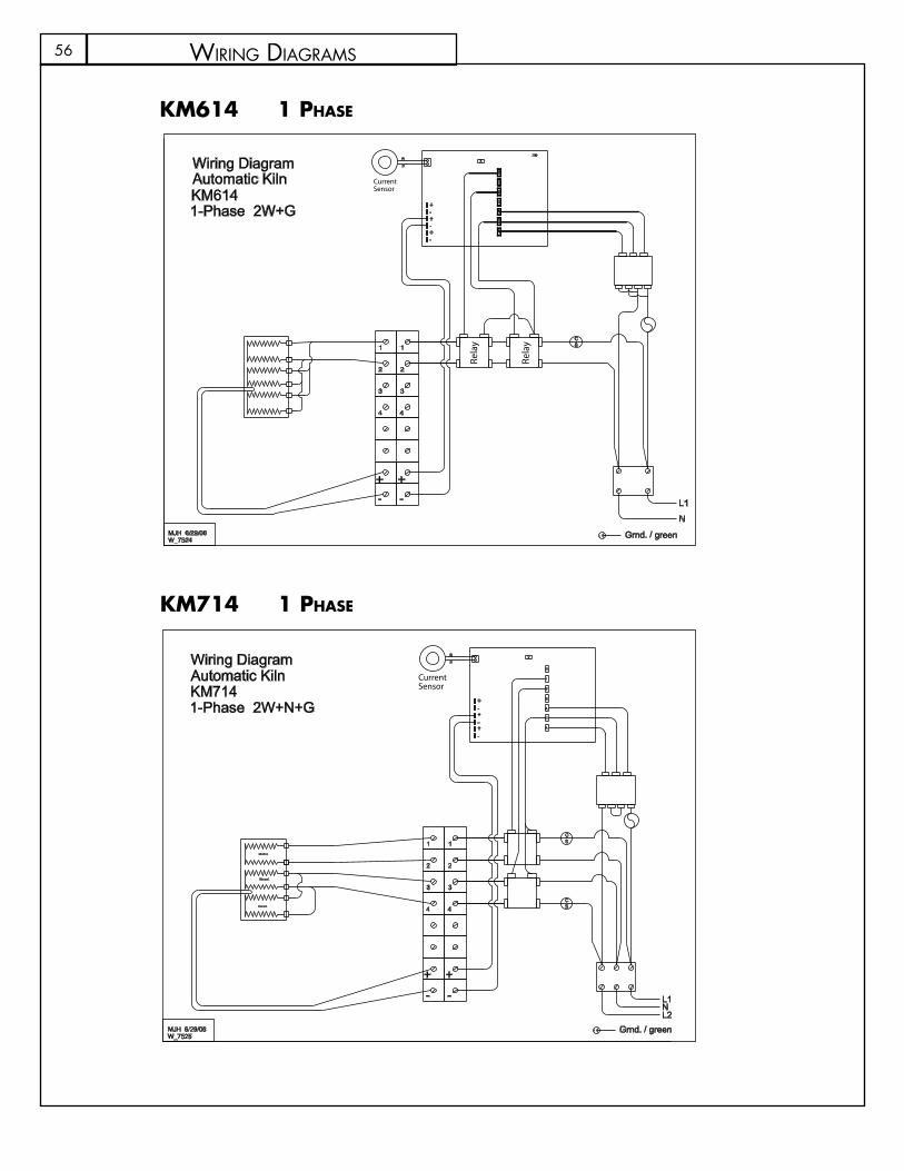
56
kM714 1 phase
kM614 1 phase
SC
700
XW
1
S
2
3
A
C
A
-+
+-
-
+
B
1
2
1
2
3
4 4
3
+ +
N
L1- -
W_7524
Automatic KilnKM6141-Phase 2W+G
MJH 6/29/06
Wiring Diagram
Grnd. / greenRe
lay
Relay
CurrentSensor
SC
CS
N
Element
Element
Element
XW
1
S
2
3
A
C
A
-+
+-
-
+
B
1
2
1
2
3
4 4
3
+ +
L2
L1- -
W_7525
Automatic KilnKM7141-Phase 2W+N+G
MJH 6/29/06
Wiring Diagram
Grnd. / green
CurrentSensor
wiRing diagRams
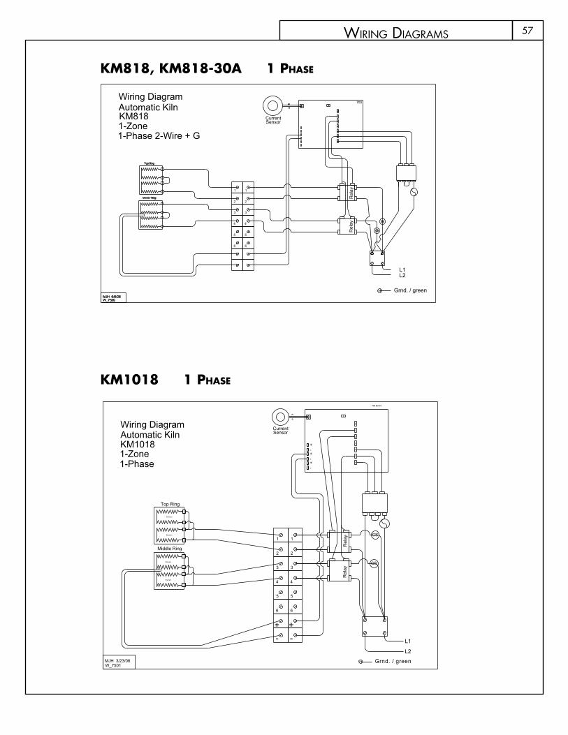
57
kM714 1 phase kM1018 1 phase
kM818, kM818-30a 1 phase
6
5
6
5
CS
CS
700 Board
-+
1
2
3
44
3
2
1
W
S
3
2
1
C
A
A
BX
W_7501
+-+
-+-
L1
L2
-+
Top Ring
Wiring Diagram
1-Phase
KM10181-Zone
Automatic Kiln
Element
Element
Element
Middle Ring
Element
MJH 3/23/06 Grnd. / green
Rel
ayR
elay
SensorCurrent
L2
Grnd. / green
L1
CS
CS
Rel
ayR
elay
700
1
2
3
4
5
66
5
4
3
2
1
1
S
2
3
C
A
A
W_7520
B
Sensor
XW
Current
Wiring Diagram
1-Phase 2-Wire + G1-Zone
Automatic Kiln
Top Ring
Master Ring
MJH 6/8/06
KM818
wiRing diagRams

58
KM822 / KM1022 / KM1222
MJH 1/21/11
Automatic KilnModels:
1-Zone1-Phase 2-Wire + G
Wiring Diagram
Current
W X
Sensor
B
W_7565
A
A
C
3
2
S
1
700
Grnd. / green.yel
L1L2
CS
66
-
+
-
+
5
4
5
4
3
2
3
2
1 1Element
Element
Master Ring
Element
Top Ring
CS
CS
Element
Element
kM822, kM1022, kM1222 1 phase
KM822 / KM1022 / KM1222
MJH 4/20/11
Automatic KilnModels:
1-Zone3-Phase 3-Wire + G
Wiring Diagram
Current
W X
Sensor
B
W_7569
A
A
C
3
2
S
1
700
Grnd. / green.yel
L1L2
CS
66
-
+
-
+
5
4
5
4
3
2
3
2
1 1Element
Element
Master Ring
Element
Top Ring
CS
CS
Element
Element
L3
kM822, kM1022, kM1222 3 phase
wiRing diagRams
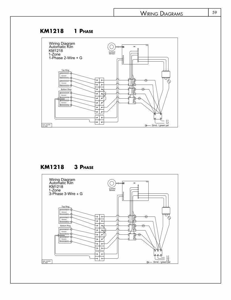
59
kM822, kM1022, kM1222 1 phase
kM822, kM1022, kM1222 3 phase
kM1218 1 phase
kM1218 3 phase
L2
CS
CS
Top Ring
Element
Bottom Ring
Element
Element
Element11
2
3
2
3
4
5
4
5
7
8
7
8
+
-
+
-
6 6
CS
L3L1
Grnd. / green.yel
700
1
S
2
3
C
A
A
W_7529
BX
W
Wiring Diagram
3-Phase 3-Wire + G1-Zone
Automatic Kiln
MJH 6/30/06
KM1218SensorCurrent
Rel
ayR
elay
Rel
ay
CS
CS
Top Ring
Element
Bottom Ring
Element
Element
Element11
2
3
2
3
4
5
4
5
7
8
7
8
+
-
+
-
6 6
CS
L2L1
Grnd. / green.yel
700
1
S
2
3
C
A
A
W_7522
BX
W
Wiring Diagram
1-Phase 2-Wire + G1-Zone
Automatic Kiln
MJH 6/22/06
KM1218SensorCurrent
Rel
ayR
elay
Rel
ay
wiRing diagRams
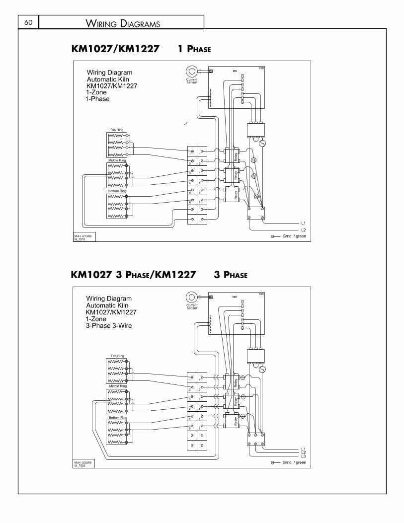
60
kM1027/kM1227 1 phase
kM1027 3 phase/kM1227 3 phase
CS
CS
SC
700
1
2
3
4
5
66
5
4
3
2
1
L3L2L1
1
S
2
3
C
A
A
W_7503
BX
W
Wiring Diagram
3-Phase 3-Wire1-Zone
Automatic Kiln
Top Ring
Middle Ring
Bottom Ring
MJH 3/23/06
KM1027/KM1227
Grnd. / green
Rel
ayR
elay
Rel
ay
SensorCurrent
700
CS
CS
CS
6
5
4
3
2
1
B
W
A
C
A
3
2
S
1
X
W_7510
1-Phase1-ZoneKM1027/KM1227Automatic KilnWiring Diagram
L2
L1
MJH 4/13/06
Bottom Ring
Top Ring
Middle Ring
6
5
4
3
2
1
Rel
ayR
elay
Rel
ayGrnd. / green
SensorCurrent
wiRing diagRams
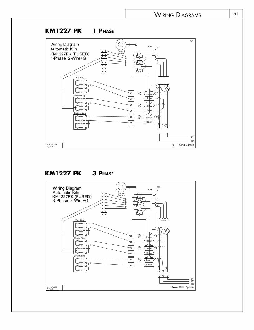
61
kM1227 pk 1 phase
kM1227 pk 3 phase
MJH 4/17/06W_7516
700
SB
W
CS
CS
CS
KM1227PK (FUSED)
Fuse
Fuse
Fuse
X
Relay
Relay
Relay
Relay
Relay
Relay
Pilot
Pilot
Pilot
MOV
MOV
MOV
-+
+-
-+
AC4321
--
++
--
++
--
++
L2
L1
BackFront
Terminal Strip
1-Phase 2-Wire+G
Automatic KilnWiring Diagram
SensorCurrent
Grnd. / green
Bottom Ring
Top Ring
Middle Ring
MJH 6/30/06W_7528
700
SB
W
CS
CS
CS
KM1227PK (FUSED)
Fuse
Fuse
Fuse
X
Pilot
Pilot
Pilot
MOV
MOV
MOV
-+
+-
-+
AC4321
--
++
--
++
--
++
L2L3
L1
3-Phase 3-Wire+G
Automatic KilnWiring Diagram
Transformer
Relay
Relay
Relay
Relay
Relay
Relay
SensorCurrent
Grnd. / green
Bottom Ring
Top Ring
Middle Ring
wiRing diagRams
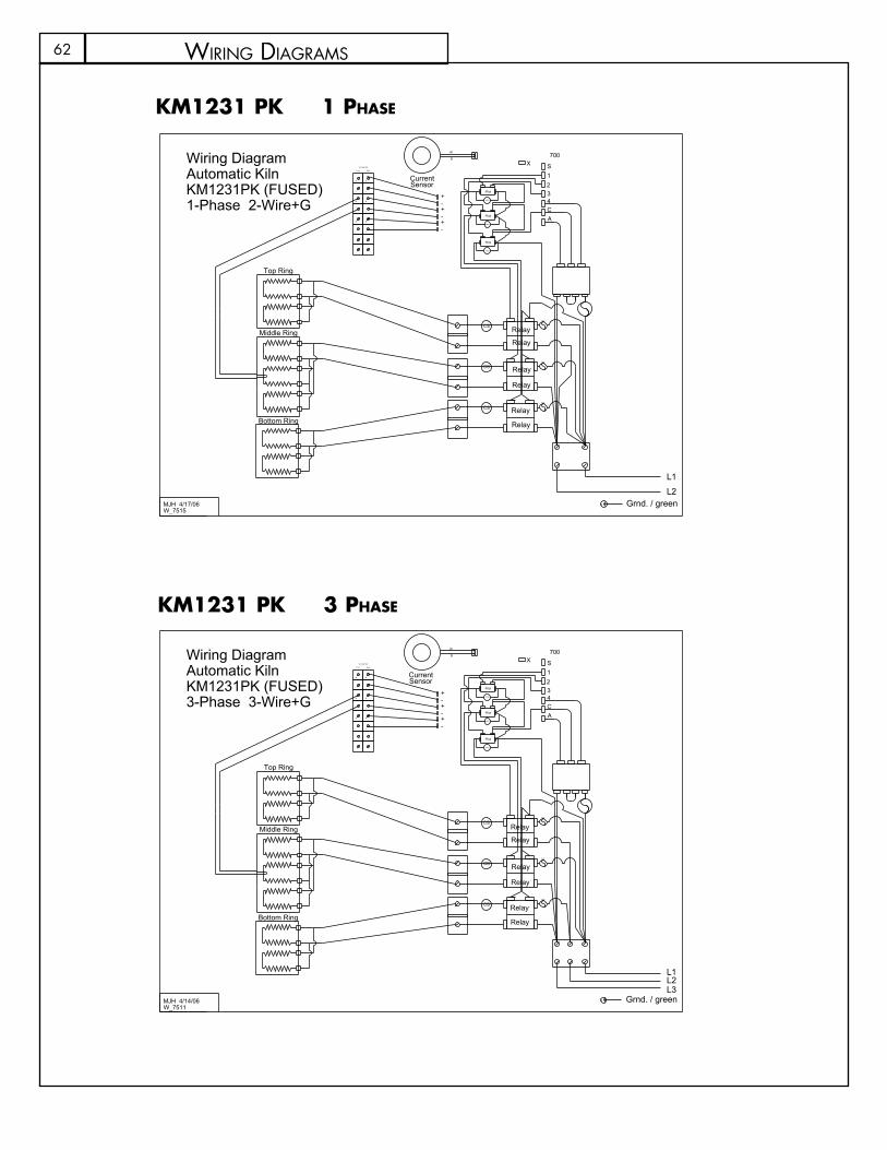
62
kM1231 pk 1 phase
kM1231 pk 3 phase
MJH 4/17/06W_7515
700
SB
W
CS
CS
CS
KM1231PK (FUSED)
Fuse
Fuse
Fuse
X
Pilot
Pilot
Pilot
MOV
MOV
MOV
-+
+-
-+
AC4321
--
++
--
++
--
++
L2
L1
BackFront
Terminal Strip
1-Phase 2-Wire+G
Automatic KilnWiring Diagram
SensorCurrent
Relay
Relay
Relay
Relay
Relay
Relay
Grnd. / green
Bottom Ring
Top Ring
Middle Ring
MJH 4/14/06W_7511
700
SB
W
CS
CS
CS
KM1231PK (FUSED)
Fuse
Fuse
Fuse
X
Pilot
Pilot
Pilot
MOV
MOV
MOV
-+
+-
-+
AC4321
--
++
--
++
--
++
L2L3
L1
BackFront
Terminal Strip
3-Phase 3-Wire+G
Automatic KilnWiring Diagram
Grnd. / green
Relay
Relay
Relay
Relay
Relay
Relay
Bottom Ring
Top Ring
Middle Ring
SensorCurrent
wiRing diagRams

63
kM1231 pk 3 phase
Fuse
Fuse
Fuse
L1L2L3
CS
CS
CS
W
B
CurrentSensor
S
700X
MJH 7/6/06W_7531
KM1627PK (Fused)
Relay
Relay
Relay
Relay
Relay
Relay
Pilot
Pilot
Pilot
MOV
MOV
MOV
-+
+-
-+
ACA321
--
++
--
++
--
++
Fuse
BackFront
Terminal Strip
3-Phase 3-WireAutomatic KilnWiring Diagram
Fuse
Bottom Ring
Top Ring
Middle Ring
Grnd. / green
kM1627 pk 3 phase
kM1627 pk 1 phase
CS
CS
CS
W
B
S
700X
MJH 7/6/06W_7530
KM1627PK (Fused)
Fuse
Fuse
Fuse
Pilot
Pilot
Pilot
MOV
MOV
MOV
-+
+-
-+
ACA321
--
++
--
++
--
++
L2L1
Fuse
BackFront
Terminal Strip
1-Phase 2-Wire
Automatic KilnWiring Diagram
Fuse
SensorCurrent
Grnd. / green
Relay
Relay
Relay
Relay
Relay
Relay
Bottom Ring
Top Ring
Middle Ring
wiRing diagRams

64
kM1627 lF 3 phase
kM1627 lF 1 phase
CS
CS
CS
ACA
700
SX
W
B
CurrentSensor
W_7532MJH 7/6/06
1
32
Transformer
Fuse
Fuse
Fuse
Fuse
MOV
Pilot
+-
-+-
+
++
--
++
--
++
--
Relay
Relay
Relay
Relay
Relay
Relay
L1L2
Automatic Kiln
1-Phase 2-Wire
Wiring Diagram
KM1627PKLF 1-Zone
Grnd. / green
Bottom Ring
Top Ring
Middle Ring
L2L1
L3
CS
CS
CS
ACA
700
SX
W
B
CurrentSensor
W_7533MJH 7/6/06
1
32
MOV
Pilot
+-
-+-
+
Front
++
Terminal Strip
Back
--
++
--
++
--
Terminal Strips
Automatic Kiln
3-Phase 3-Wire
Wiring Diagram
KM1627PKLF 1-Zone
Bottom Ring
Top Ring
Middle Ring
Fuse
Fuse
Fuse
Fuse
Relay
Relay
Relay
Relay
Relay
Relay
Grnd. / green
wiRing diagRams

65
kM1627 lF 1 phase
Contactor1-Phase50 Amp
1-Phase Plug1-Phase Recept.
250V
MOV
1-Phase
700 BOARD
-+
PILOT
T/C
A
654321S
-+-+
-+
2-Wire + G
W_7527
MJH 6/30/06
KM-1 1-zoneWiring Diagram
Transformer
Contactor3-Phase40 Amp 3-Phase Plug3-Phase Recept.
250V
MOV
SocketPilot Cord
190 - 250 Volts
700 BOARD
-+
PILOT
T/C
A
654321S
-+-+
-+
3-Wire + G
W_7526
MJH 6/30/06
KM-1 1-zoneWiring Diagram
Transformer
kM-1 3 phase
kM-1 1 phase
wiRing diagRams
66
PROGRAM 1SEGMENT RATE TEMP HOLD NOTES12345678
PROGRAM 2SEGMENT RATE TEMP HOLD NOTES12345678
PROGRAM 3SEGMENT RATE TEMP HOLD NOTES12345678
PROGRAM 4SEGMENT RATE TEMP HOLD NOTES12345678
my PRogRams
67
PROGRAM 5SEGMENT RATE TEMP HOLD NOTES12345678
PROGRAM 6SEGMENT RATE TEMP HOLD NOTES12345678
PROGRAM 7SEGMENT RATE TEMP HOLD NOTES12345678
PROGRAM 8SEGMENT RATE TEMP HOLD NOTES12345678
my PRogRams

www.skutt.com6441 SE Johnson Creek Blvd.. Portland, OR 97206 (503) 774--6000 [email protected]
Related Documents