Khalid Sarwar Engineer NGN HCTE RWP # 03135003545 DIGITAL CONCEPTS Transmitter The transmitter, also known as the sender or source, is the device that originates the information. Such devices include telephones, any variety of computer systems, and cameras in a videoconferencing application. Receiver The receiver, also known as the sink, is the device that receives the information. Again, such devices can include telephones and computers; in a videoconferencing application, the display device would be the receiver. Circuit A circuit is a communications path over an established medium, between two or more points from end to end, between transmitter and receiver. Circuit generally implies a logical connection over a physical line. Further, the term circuit is often used interchangeably with path, link, line, and channel, although such usage can be specific to the underlying technology, the context, and other factors. Circuits are either two-wire or four-wire Link A link is a two-point segment of an end-to-end circuit (e.g., from terminal to switch, or from switch to switch). Link is sometimes used interchangeably with line or circuit. A circuit may consist of a single link, as often is the case between a host computer and a peripheral. Line The term line has several definitions, resulting in confusion. In a PBX environment, a station line refers to the connection between the PBX switch and the station user’s terminal equipment, whether it is an analog or digital, telephone or workstation. In rate and tariff terminology, it refers to a local loop connection from the telephone company Central Office (CO) switch to the user’s premises in support of premise equipment other than a switch; for example, a single-line residence or business set, a multiline set, or a key system common control unit. In any event, a line refers to a voice-grade circuit; in other words, a circuit serving a single physical location, with a single telephone number and generally supporting a single transmission. Internal to the telephone companies, line is used to describe the user side or local loop side of the connection. In other words, the line side is the side of the network to which users connect, while the trunk side involves the high-capacity trunks that interconnect the various telephone company switching centers. Trunk SE NGNHCTE S/Town RWP

Khalid sarwar digital concepts of transmission and switching 2014
Aug 15, 2015
Welcome message from author
This document is posted to help you gain knowledge. Please leave a comment to let me know what you think about it! Share it to your friends and learn new things together.
Transcript
Khalid Sarwar Engineer NGN HCTE RWP # 03135003545
DIGITAL CONCEPTS
Transmitter The transmitter, also known as the sender or source, is the device that originates the information. Such devices include telephones, any variety of computer systems, and cameras in a videoconferencing application.
Receiver The receiver, also known as the sink, is the device that receives the information. Again, such devices can include telephones and computers; in a videoconferencing application, the display device would be the receiver.
Circuit A circuit is a communications path over an established medium, between two or more points from end to end, between transmitter and receiver. Circuit generally implies a logical connection over a physical line. Further, the term circuit is often used interchangeably with path, link, line, and channel, although such usage can be specific to the underlying technology, the context, and other factors. Circuits are either two-wire or four-wire
Link A link is a two-point segment of an end-to-end circuit (e.g., from terminal to switch, or from switch to switch). Link is sometimes used interchangeably with line or circuit. A circuit may consist of a single link, as often is the case between a host computer and a peripheral.
Line The term line has several definitions, resulting in confusion. In a PBX environment, a station line refers to the connection between the PBX switch and the station user’s terminal equipment, whether it is an analog or digital, telephone or workstation. In rate and tariff terminology, it refers to a local loop connection from the telephone company Central Office (CO) switch to the user’s premises in support of premise equipment other than a switch; for example, a single-line residence or business set, a multiline set, or a key system common control unit. In any event, a line refers to a voice-grade circuit; in other words, a circuit serving a single physical location, with a single telephone number and generally supporting a single transmission. Internal to the telephone companies, line is used to describe the user side or local loop side of the connection. In other words, the line side is the side of the network to which users connect, while the trunk side involves the high-capacity trunks that interconnect the various telephone company switching centers.
Trunk Communications circuit that is available to be shared among multiple users on a pooled basis and with contention for trunk access managed by an intelligent switching device. Trunks connect switches. For example, tie trunks connect PBXs in a private, leased-line network, central office exchange trunks connect PBXs to telephone company central office exchanges, and interoffice trunks interconnect central office exchange switches. Trunk groups are groups of trunks serving the same special purpose; examples include WATS (Wide Area Telecommunications Service). Trunks are directional; they can be one-way outgoing (originating), one-way incoming (terminating), or two-way (combination).
Channel In formal standards terms, a channel is a means of one-way connection between transmitter and receiver; therefore, it is a one-way circuit or path. In data processing terminology, particularly IBM, a channel is a high-speed connection between mainframe and peripheral. In common usage, a channel is a logical connection over a physical circuit to support a single conversation. A physical circuit can be treated in such a way as to support one or many logical conversations. Multichannel circuits are always four-wire—either physical or logical four-wire.
Switch A switch is a device that establishes, maintains, and changes logical connections over physical circuits. Common examples of switches include PBXs and Central Office (CO) exchanges. Switching
SE NGNHCTE S/Town RWP
Khalid Sarwar Engineer NGN HCTE RWP # 03135003545
traditionally has been accomplished on a circuit basis, for the establishment of connections between circuits on demand and in support of voice and data communications. Packet, frame, and cell switching have recently evolved in more sophisticated networks, primarily in support of data and image transfer.
SE NGNHCTE S/Town RWP
Khalid Sarwar Engineer NGN HCTE RWP # 03135003545
SE NGNHCTE S/Town RWP

Khalid Sarwar Engineer NGN HCTE RWP # 03135003545
VSATs
VSATs, or Very Small Aperture Terminals, are a breed of satellite system involving terrestrial dishes of very small diameter (aperture). Operating in the C–band and Ku–band, VSATs are digital and are designed primarily to support data communications on a point-to-multipoint basis for large private networks in applications such as retail inventory management and credit verification, and authorization. While some newer systems also support mesh networks and voice communications, they are unusual at this time. Bandwidth is in channel increments of 56/64 Kbps, generally up to an aggregate bandwidth of 1.544 Mbps. By far the largest concentration of users is in North America, claiming 68% of the market. According to Chuck Emmert of Telecom Applications Corp., Mobil Oil has an installed network of 5,000 sites and Shell Oil has a network of 3,000 sites [3-11].
Bandwidth
Satellites can support multiple transponders and, therefore, substantial bandwidth, with each transponder generally providing increments of [le]36 MHz. Each increment of bandwidth within a given frequency band is provided through a transponder. The amount of bandwidth, the number of frequency bands supported, the number of transponders, and the specific area of coverage all influence the size and power requirements of the satellite.
As in the case of other transmission systems, the higher frequency bands offer greater bandwidth, or capacity. C–band is the most limited, while Ka-band is the most attractive, in this sense, of the commercial satellite frequency bands. As a point of reference, Intelsat I could accommodate only 240 voice circuits, while Intelsat VI supported 120,000 voice circuits and 3 TV channels, with a total bandwidth of 3.46 GHz [3-12].
Error Performance Satellite transmission is susceptible to environmental interference, particularly at frequencies above 20 GHz. Sunspots and other types of electromagnetic interference particularly impact satellite and microwave transmission. Additionally, some satellite frequency bands (e.g., C–band) compete with terrestrial microwave (see Tables 3.2 and 3.4), again illustrating the requirement for careful frequency management. As a result of these several factors, satellite transmission often requires rather extensive error detection and correction capabilities [3-13].
Distance Satellite, generally speaking, is not considered to be distance-limited, as the signal largely travels through the vacuum of space. Further each signal travels approximately 22,300 miles in each direction, whether one is communicating across the street or across the country, and assuming that only a single satellite hop is required. However, additional power is required to serve areas which are far removed from the equator (e.g., New Zealand and South Africa), as the signals must travel through substantial atmosphere and as they are more likely to be reflected by the earth’s magnetic field at such a severe angle.
Applications
Satellite applications are many, and increasing rapidly as the traditional voice and data services have been augmented with more exotic applications such as GPS and ATMS. Traditional international voice and data services have been supplanted, to a considerable extent, by submarine fiber optic cable systems.
Traditional, and still viable, applications include international voice and data, remote voice and data (e.g., island nations, isolated areas and sparsely populated areas), television and radio broadcast, maritime navigation, videoconferencing, inventory management & control (VSATs), disaster recovery and paging. More recent and emerging applications include air navigation, Global Positioning Systems (GPS), mobile voice & data (LEOs),
SE NGNHCTE S/Town RWP
Khalid Sarwar Engineer NGN HCTE RWP # 03135003545
Advanced Traffic Management Systems (ATMS), Direct Broadcast Satellite (DBS) TV, Integrated Digital Services Network (ISDN), interactive Television, and interactive multimedia.
SE NGNHCTE S/Town RWP
Khalid Sarwar Engineer NGN HCTE RWP # 03135003545
Dedicated Circuits
Dedicated circuits involve dedicated physical circuits that directly connect devices (e.g., PBXs and host computers) across a network (Figure 2.1). Such circuits are reserved for the use of a single user organization rather than being available to serve multiple users. Dedicated circuits offer the user the advantage of a high degree of availability and specified levels of capacity and quality; dedicated circuits can be specially conditioned to deliver specific levels of performance, whereas switched circuits cannot. Additionally, dedicated circuit costs are not usage-sensitive; that is, they can be used continuously and to their full capacity without additional costs. However, the reservation of a circuit for a specific customer has a deleterious effect on the network provider (carrier), as it is no longer available for use in support of the traffic of other users. Therefore, dedicated circuits tend to be rather expensive, with cost being sensitive to distance and capacity. Additionally, the process of determining the correct number, capacity, and points of termination of such circuits can be a difficult and lengthy design and configuration process; in response to the customer request, long lead times are often required for the carrier(s) to provision such a circuit. Finally, as dedicated circuits are susceptible to disruption, backup circuits are often required to ensure effective communications in the event of catastrophic failure or performance degradation. Traditionally, dedicated digital circuits have been used to connect large data centers that communicate intensively; similarly, many large end user organizations with multiple locations have used dedicated circuits to tie together multiple PBXs. In both cases, the advantages of assured availability, capacity and quality often outweigh considerations of configuration difficulty and risk of circuit failure.
Switched Circuits
Switched circuits are connected on a flexible basis through a circuit switch, such as a customer-owned PBX or a telephone company Central Office exchange, as illustrated in Figure 2.2. The switch serves as a concentration and contention device; therefore switched circuits are available to be shared, on demand, among multiple subscribers and applications, as required and as available. As a result, the network providers clearly realize significant operational efficiencies. The end users realize the advantages of flexibility and redundancy because the network can generally provide a connection between any two physical locations through multiple alternate routes.
Virtual Circuits
Virtual circuits are logical, as opposed to physical, circuits, with virtual circuit connectivity being provided over high capacity, multichannel physical circuits, such as fiber optic cables. Virtual circuits are defined in software and made available as required and as available, with the physical path or circuit being defined and effectively guaranteed, perhaps on a priority basis. A virtual circuit transparently provides the same level of connectivity as a physical circuit; in other words, a virtual circuit provides connectivity as though it were a physical circuit. Such a physical circuit can often support many logical circuits, or logical connections. In the high-capacity, fiber optic backbone carrier networks, dedicated circuits are provided to users on a virtual basis; the capacity and other performance characteristics of the circuit behave as though the circuit were dedicated.
At this point, it is worth pausing to further define and contrast the terms transparent and virtual. Transparent means that a network element (e.g., hardware or software) exists but it appears to the user as though it does not. Virtual means that the network element does not exist but it appears to the user as though it does. In this context, a user would be provided access to a virtual circuit on a transparent basis.
It also is necessary to further define a logical circuit or channel, as opposed to one that is physical. A logical circuit refers to the entire range of network elements (e.g., physical circuits, buffers, switches, and control SE NGNHCTE S/Town RWP
Khalid Sarwar Engineer NGN HCTE RWP # 03135003545
software) that support or manage a communication between a transmitter and receiver. A physical path may be in the form of copper wire (e.g., twisted pair or coaxial cable), radio (e.g., microwave or satellite), or glass or plastic fiber (fiber optic). In order to establish connectivity between transmitter and receiver, a physical path must be selected for the information transfer [2-1].
Two-Wire Circuits
Two-wire circuits are those that carry information signals in both directions over the same physical link or path. Typically, such a circuit is provisioned through the use of a single twisted pair, copper wire connection. Within such a circuit, two wires are required to complete the electrical circuit and both wires carry the information. A typical example is a local loop connection between the Central Office or Central Exchange switching center and the individual single line or multiline residence or business terminal equipment, as depicted in Figure 2.3.
Two-wire circuits typically cover short distance; for example, most two-wire local loops are shorter than 20,000 feet [2-2]. Additionally, the bandwidth or capacity of such a circuit is relatively low, and only a single conversation is accommodated. Finally, two-wire circuits, generally speaking, are analog in nature; therefore, quality is poor.
Four-Wire Circuits
According to the most basic definition, four-wire circuits are those that carry information signals in both directions over separate physical links or paths, and in support of simultaneous, two-way transmission. Traditionally, such a circuit was provisioned through the use of two copper-pairs, one for transmission (forward path) and one for reception (reverse path); such a circuit is known as physical four-wire. However, current technology accommodates four-wire transmission over a single physical link or path such as coaxial cable, microwave, satellite, or fiber optic cable. In other words, the circuit may be physical two-wire (or even physical one-wire) and logical four-wire, performing as a four-wire circuit but employing fewer than four wires.
Although the absolute cost of four-wire circuits is higher than that of two-wire circuits, they offer considerably improved performance. Four-wire circuits accommodate multiple, simultaneous communications in a two-way, or conversational mode. Additionally, such circuits offer greater bandwidth, or capacity, and are typically digital, rather than analog in nature—as a result, error performance is generally improved. Long haul circuits (traditionally defined as [ge]50 miles or 80 km) usually are four-wire [2-2]. Figure 2.4 illustrates typical examples of cost-effective applications of four-wire circuits, specifically to interconnect PBX, CO, and Tandem switches in a voice environment.
SE NGNHCTE S/Town RWP
Khalid Sarwar Engineer NGN HCTE RWP # 03135003545
Bandwidth
Bandwidth is a measure of the capacity of a circuit or channel. More specifically, bandwidth refers to the total frequency that is available on the carrier for the transmission of data; as opposed to overhead signaling and control information. There is a direct relationship between the bandwidth of a circuit or a channel and both its frequency and the difference between the minimum and maximum frequencies supported. While the information (data) signal does not occupy the total capacity of a circuit, it generally and ideally occupies most of it. The more information to be sent in a given period of time, the more bandwidth required.
Carrier
Carrier is a constant signal on a circuit that is at a certain frequency, or within a certain frequency range. The carrier can accommodate both an information-bearing signal and signaling and control information, which is used to coordinate and manage network operation.
Hertz (Hz)
Hertz, named after Heinrich Rudolf Hertz, the physicist who discovered radio waves, is the measurement of bandwidth over analog circuits. Hertz refers to the number of electromagnetic wave forms (signals or signal changes) transmitted per second. Although some applications operate in very low capacity environments, measured in Hz or hundreds of Hz, the frequencies generally are much higher. Hence, analog bandwidth typically is measured in kHz or kiloHertz (thousands of Hz), MHz or MegaHertz (millions of Hz), or GHz or GigaHertz (billions of Hz).
Baud
Baud is an old term that refers to the number of signal events (signals or signal changes) occurring per second over an analog circuit. Generally baud is used to describe the signaling rate of a modem for data transmission over an analog circuit, with the baud rate being roughly equivalent to Hertz. Baud rate and bps, often and incorrectly, are used interchangeably. The distinction will be discussed in more detail in Chapter 7.
Bits per Second (bps)
Bps is the measurement of bandwidth over digital circuits. It refers to the number of binary data bits that can be transmitted per second. Over an analog circuit, the sine wave can be manipulated to allow multiple bits to be transmitted at a given baud rate, even without the application of special compression techniques. A thousand (1,000) bps is a kilobit per second or Kbps, a million (1,000,000) bps is a megabit per second or Mbps, a billion (1,000,000,000) bps is a gigabit per second or Gbps, and a trillion (1,000,000,000,000) bps is a terabit per second or Tbps.
Transmission Facilities
In terms of bandwidth, and in contemporary digital context, transmission facilities can be categorized as narrowband, wideband or broadband.
Narrowband A single channel ([le]64 Kbps) or some number of 64 Kbps channels (N × 64 Kbps), but less than wideband.
SE NGNHCTE S/Town RWP

Khalid Sarwar Engineer NGN HCTE RWP # 03135003545
Wideband Wideband is multichannel capacity that is between 1.544 Mbps and 45 Mbps according to U.S. standards (2.048 Mbps-34 Mbps according to European/international standards.) Broadband Broadband is multichannel capacity [ge]45 Mbps according to U.S. standards ([ge]34 Mbps according to European/international standards.)
Analog versus Digital
Along one dimension, communications can be classified in two categories, analog and digital. In the analog form of electronic communications, information is represented as a continuous electromagnetic wave form. Digital communications represents information in binary form (1s and 0s) through a series of discrete blips or pulses.
Analog Analog is best explained by examining the transmission of a natural form of information, such as sound or human speech, over an electrified copper wire. In its native form, human speech is an oscillatory disturbance in the air which varies in terms of its volume or power (amplitude) and its pitch or tone (frequency). As sound compression waves fall onto a transmitter, analogous (approximate) variations in electrical waveforms are created over an electrical circuit. Those waveforms maintain their various shapes across the wire until they fall on the receiver or speaker, which converts them back into their original form of variations in air pressure.
A similar, but more complicated, conversion process is employed to transmit video over networks. In its native form, video is a series of still images captured and transmitted in rapid succession in order to create the illusion of fluidity of motion; image information is reflected light waves. Analogous variations in electrical or radio waves are created in order to transmit the analog video image information signal over a network from a transmitter (TV station or CATV source) to a receiver (TV set), where an approximation (analog) of the original information is presented.
Information which is analog in its native form (voice and image) can vary continuously in terms of intensity (volume or brightness) and frequency (tone or color). Those variations in the native information stream are translated in an analog electrical network into variations in the amplitude and frequency of the carrier signal. In other words, the carrier signal is modulated (varied) in order to create an analog of the original information stream.
The electromagnetic sinusoidal wave form, or sine wave, can be varied in amplitude at a fixed frequency, using Amplitude Modulation (AM). Alternatively, the frequency of the sine wave can be varied at a constant amplitude, using Frequency Modulation (FM). Additionally, both frequency and amplitude can be modulated simultaneously in order to create an analog of the native signal, which generally varies along both parameters simultaneously. Finally, the position of the sine wave can appear to be manipulated, adding the third technique of Phase Modulation (also known as Phase Shift Keying or PSK). This provides additional benefits. These benefits will be discussed in Chapter 7.
Bandwidth, in the analog world, is measured in hertz (Hz). The available bandwidth for a particular signal is the difference between the highest and lowest frequencies supported. For example, a 3.3 kHz voice channel can be provided through a band-limiting filter supporting transmission at frequencies between 200 Hz and 3,500 Hz. Similarly, a 3.3 kHz channel is provided at frequencies between 7,000 Hz and 10,300 Hz. Passband refers to the upper and lower cutoff frequencies at which the filters operate [2-2].
Voice A voice grade channel is approximately 4,000 Hz, or 4 kHz. Approximately 3.3 kHz (200 Hz to 3,500 Hz) is used for the voice signal itself. The remaining bandwidth is used for purposes of network signaling and control, and in order to maintain separation between information channels. While human speech transmission
SE NGNHCTE S/Town RWP

Khalid Sarwar Engineer NGN HCTE RWP # 03135003545
and reception encompasses a much wider range of frequencies, 3.3 kHz is considered to be quite satisfactory and is cost-effective. Band-limiting filters are used in carrier networks to constrain the amount of bandwidth provided for a voice application [2-2] and [2-3]. Figure 2.5 illustrates an analog local loop supporting voice communications.
Video A CATV video channel is approximately 6,000,000 Hz, or 6 MHz. Approximately 4.5 MHz is used for information transmission, while the balance is used for guard bands to separate the various adjacent channels riding the common, analog coaxial cable system.
Digital
While the natural world is analog in nature, computers (which are decidedly unnatural beings) are digital in nature. Computers process, store, and communicate information in binary form. That is to say that a unique combination of 1s and 0s has a specific meaning in a computer language. A bit (binary digit) is an individual 1 or 0. Multiple bits travel across a network in a digital bit stream.
Digital communications dates to telegraphy, in that the varying length of making and breaking an electrical circuit resulted in a series of dots and dashes which, in a particular combination, communicated a character or series of characters. Early mechanical computers used a similar concept for input and output; contemporary computer systems communicate in binary mode through variations in electrical voltage.
Digital signaling, in an electrical network, involves a signal which varies in voltage to represent one of two discrete and well-defined states: such as either a positive (+) voltage and a null, or zero (0), voltage (unipolar); or a positive (+) or a negative (-) voltage (bipolar). The receiver monitors the signal, at a specific frequency and for a specific duration (bit time) to determine the state of the signal. Various data transmission protocols employ different physical states of the signal, such as voltage level or voltage transition. Because of the discrete nature of each bit transmitted, the bit form is often referred to as a square wave. Digital devices (Figure 2.6) prefer digital transmission facilities.
Digital signaling in an optical network can involve either the pulsing on and off of a light stream, or a variation in the intensity of the light signal. Digital transmission over radio systems (e.g., microwave, cellular or satellite) can be accomplished by varying the amplitude of the signal.
In the digital world, bandwidth is measured in bits per second (bps). The amount of bandwidth required depends on the amount of raw data to be sent, the desired speed of transmission of that set of data, and issues of transmission cost. Additionally, data is routinely compressed by various means in order to enhance the efficiency of transmission and to reduce transmission costs. Additionally, analog voice commonly is converted to a digital bit stream, requiring a maximum of 64 Kbps for full fidelity or quality.
Analog versus Digital Transmission: Which is Better?
Although analog voice and video can be converted to digital, and digital data can be converted to analog, each format has its own advantages.
Analog Advantages Analog transmission offers advantages in the transmission of analog information. Additionally, it is more bandwidth-conservative and is widely available.
SE NGNHCTE S/Town RWP
Khalid Sarwar Engineer NGN HCTE RWP # 03135003545
Analog Data Analog has an advantage with respect to the transmission of information which is analog in its native form, such as voice, image and video. The process of transmission of such information is relatively straightforward in an analog format, whereas conversion to a digital bit stream requires conversion equipment. Such equipment adds cost, contributes additional points of failure, and can negatively affect the quality of the signal through the conversion process, itself. The impacts on analog and digital conversion are discussed fully in the examination of T-carrier (Chapter 8).
Bandwidth A raw information stream consumes less bandwidth in analog form than in digital form. This is particularly evident in CATV transmission, where 50 or more analog channels routinely are provided over a single coaxial cable system. Without the application of compression techniques on the same cable system, only a few digital channels could be supported.
Digital Advantages Digital transmission offers advantage in the transmission of digital information. Additionally, such data can be compressed effectively and relatively easily. Security of the data can be more readily ensured and the error performance of digital networks are much improved over their analog counterparts. Finally, the cost-effectiveness of such networks is improved by virtue of the greater bandwidth they provide, especially since they can be more easily upgraded and more effectively managed.
Digital Data Just as it is better to transmit analog information in an analog format, it is better to transmit digital information in a digital format. Digital transmission certainly has the advantage where binary computer data is being transmitted. The equipment required to convert digital data to an analog format and send the digital bit streams over an analog network can be expensive, susceptible to failure, and can create errors in the information.
Compression Digital data can be compressed relatively easily, thereby increasing the efficiency of transmission. As a result, substantial volumes of voice, data, video and image information can be transmitted using relatively little raw bandwidth.
Security Digital systems offer better security. While analog systems offer some measure of security through the scrambling, or intertwining of several frequencies, scrambling is fairly simple to defeat. Digital information, on the other hand, can be encrypted to create the appearance of a single, pseudo-random bit stream. Thereby, the true meaning of individual bits, sets of bits, or the total bit stream cannot be determined without having the key to unlock the encryption algorithm employed.
Quality Digital transmission offers improved error performance (quality) as compared to analog. This is due to the devices that boost the signal at periodic intervals in the transmission system in order to overcome the effects of attenuation. Additionally, digital networks deal more effectively with noise, which always is present in transmission networks.
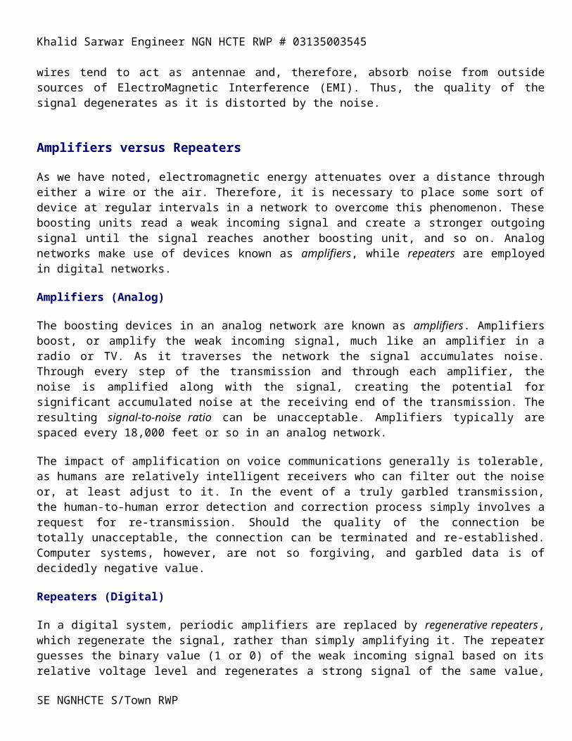
Attenuation Electromagnetic signals tend to weaken, or attenuate, over a distance; this is particularly true of electrical signals carried over twisted pair copper wire, due to the level of resistance in the wire. It is also particularly true of microwave radio and other terrestrial radio systems, due to matter in the air. Attenuation is sensitive to carrier frequency, with higher frequency signals attenuating more than lower frequency signals. Noise Signals also tend to pick up noise as they transverse the network. Again, this is particularly true of twisted pair, copper wire systems. Such wires tend to act as antennae and, therefore, absorb noise from outside sources of ElectroMagnetic Interference (EMI). Thus, the quality of the signal degenerates as it is distorted by the noise.
SE NGNHCTE S/Town RWP

Khalid Sarwar Engineer NGN HCTE RWP # 03135003545
Amplifiers versus Repeaters
As we have noted, electromagnetic energy attenuates over a distance through either a wire or the air. Therefore, it is necessary to place some sort of device at regular intervals in a network to overcome this phenomenon. These boosting units read a weak incoming signal and create a stronger outgoing signal until the signal reaches another boosting unit, and so on. Analog networks make use of devices known as amplifiers, while repeaters are employed in digital networks.
Amplifiers (Analog)
The boosting devices in an analog network are known as amplifiers. Amplifiers boost, or amplify the weak incoming signal, much like an amplifier in a radio or TV. As it traverses the network the signal accumulates noise. Through every step of the transmission and through each amplifier, the noise is amplified along with the signal, creating the potential for significant accumulated noise at the receiving end of the transmission. The resulting signal-to-noise ratio can be unacceptable. Amplifiers typically are spaced every 18,000 feet or so in an analog network.
The impact of amplification on voice communications generally is tolerable, as humans are relatively intelligent receivers who can filter out the noise or, at least adjust to it. In the event of a truly garbled transmission, the human-to-human error detection and correction process simply involves a request for re-transmission. Should the quality of the connection be totally unacceptable, the connection can be terminated and re-established. Computer systems, however, are not so forgiving, and garbled data is of decidedly negative value.
Repeaters (Digital)
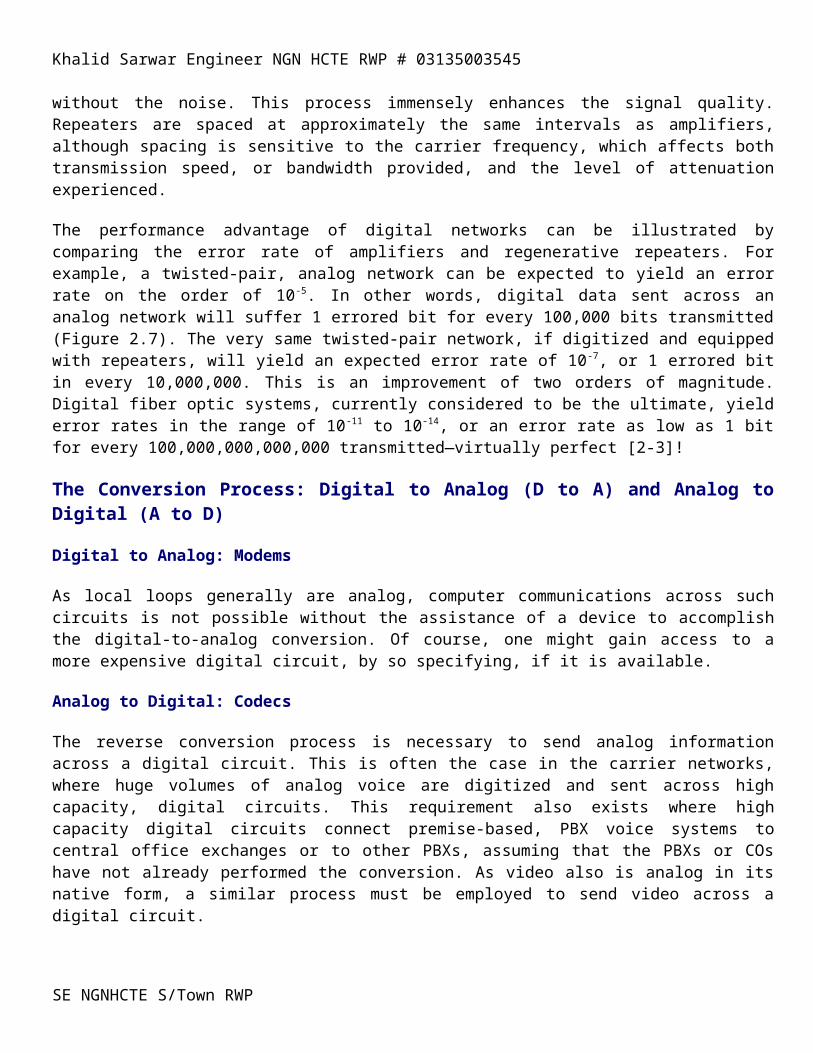
In a digital system, periodic amplifiers are replaced by regenerative repeaters, which regenerate the signal, rather than simply amplifying it. The repeater guesses the binary value (1 or 0) of the weak incoming signal based on its relative voltage level and regenerates a strong signal of the same value, without the noise. This process immensely enhances the signal quality. Repeaters are spaced at approximately the same intervals as amplifiers, although spacing is sensitive to the carrier frequency, which affects both transmission speed, or bandwidth provided, and the level of attenuation experienced.
The performance advantage of digital networks can be illustrated by comparing the error rate of amplifiers and regenerative repeaters. For example, a twisted-pair, analog network can be expected to yield an error rate on the order of 10-5. In other words, digital data sent across an analog network will suffer 1 errored bit for every 100,000 bits transmitted (Figure 2.7). The very same twisted-pair network, if digitized and equipped with repeaters, will yield an expected error rate of 10-7, or 1 errored bit in every 10,000,000. This is an improvement of two orders of magnitude. Digital fiber optic systems, currently considered to be the ultimate, yield error rates in the range of 10-11 to 10-14, or an error rate as low as 1 bit for every 100,000,000,000,000 transmitted—virtually perfect [2-3]!
The Conversion Process: Digital to Analog (D to A) and Analog to Digital (A to D)
Digital to Analog: Modems
As local loops generally are analog, computer communications across such circuits is not possible without the assistance of a device to accomplish the digital-to-analog conversion. Of course, one might gain access to a more expensive digital circuit, by so specifying, if it is available.
SE NGNHCTE S/Town RWP

Khalid Sarwar Engineer NGN HCTE RWP # 03135003545
Analog to Digital: Codecs
The reverse conversion process is necessary to send analog information across a digital circuit. This is often the case in the carrier networks, where huge volumes of analog voice are digitized and sent across high capacity, digital circuits. This requirement also exists where high capacity digital circuits connect premise-based, PBX voice systems to central office exchanges or to other PBXs, assuming that the PBXs or COs have not already performed the conversion. As video also is analog in its native form, a similar process must be employed to send video across a digital circuit.
The device that accomplishes the A-to-D conversion is known as a codec. Codecs COde an analog input into a digital (data) format on the transmit side of the connection, reversing the process, or DECoding the information, on the receive side, in order to reconstitute the analog signal (Figure 2.9).
Encoding is the process of converting an analog information stream (e.g., voice or video) into a digital data stream. The voice or video signal is sampled at frequent intervals with each sample of amplitude then being expressed in terms of a binary (computer) value, which is usually a 4-bit or 8-bit byte. The reverse process of decoding takes place on the receiving end, resulting in recomposition of the information in its original form, or at least a reasonable approximation thereof.
SE NGNHCTE S/Town RWP

Khalid Sarwar Engineer NGN HCTE RWP # 03135003545
MULTIPLEXERS (MUXs or MUXes)
The term multiplex has its roots in the Latin words multi (many) and plex (fold). Multiplexers (MUXs) act as both concentrators and contention devices to allow multiple, relatively low-speed terminal devices to share a single, high-capacity circuit (physical path) between two points in a network. The benefit of multiplexers is that they allow carriers and end users to take advantage of the economies of scale. Just as a multilane highway can carry increased volumes of traffic in multiple lanes at higher speeds and at relatively low incremental cost, a high capacity circuit can carry multiple conversations in multiple channels at relatively low incremental cost.
Contemporary multiplexers rely on four-wire circuits that permit multiple logical channels to be derived from a single physical circuit, and that permit high-speed transmission simultaneously in both directions. In this manner, multiple communications (either unidirectional or bidirectional) can be supported. Multiplexing is used commonly across all transmission media, including twisted pair, coaxial and fiber optic cables; and microwave, satellite and other radio systems.
Traditional multiplexing comes in several varieties, presented in chronological order of development and evolution. Included are Frequency Division Multiplexing (FDM), Time Division Multiplexing (TDM), and Statistical Time Division Multiplexing (STDM). Wavelength Division Multiplexing (WDM), although still in development, is discussed here in brief. WDM will be used in fiber optic cable systems.
Frequency Division Multiplexing (FDM)
Frequency Division Multiplexing (FDM) takes advantage of the fact that a single twisted pair, copper circuit can carry much more than the 4 kHz guaranteed for individual voice conversations. Even in the early days of vacuum tube technology, up to 96 kHz could be supported over a set of 2 copper pairs (a 4-wire circuit, with 2 wires in each direction), thereby enabling the carrying of up to 24 individual voice channels, separated by frequency bands [2-2]. In terms of a commonly understood analogy, multiple frequencies can be supported over a single, four-wire electrical circuit much as can multiple radio stations, and TV channels be supported over the airwaves through frequency separation.
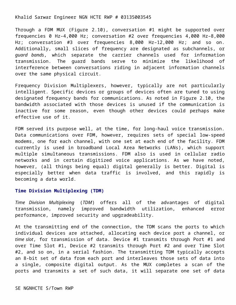
Through a FDM MUX (Figure 2.10), conversation #1 might be supported over frequencies 0 Hz–4,000 Hz; conversation #2 over frequencies 4,000 Hz–8,000 Hz; conversation #3 over frequencies 8,000 Hz–12,000 Hz; and so on. Additionally, small slices of frequency are designated as subchannels, or guard bands, which separate the carrier channels used for information transmission. The guard bands serve to minimize the likelihood of interference between conversations riding in adjacent information channels over the same physical circuit.
Frequency Division Multiplexers, however, typically are not particularly intelligent. Specific devices or groups of devices often are tuned to using designated frequency bands for communications. As noted in Figure 2.10, the bandwidth associated with those devices is unused if the communication is inactive for some reason, even though other devices could perhaps make effective use of it.
FDM served its purpose well, at the time, for long-haul voice transmission. Data communications over FDM, however, requires sets of special low-speed modems, one for each channel, with one set at each end of the facility. FDM currently is used in broadband Local Area Networks (LANs), which support multiple simultaneous transmissions. FDM also is used in cellular radio networks and in certain digitized voice applications. As we have noted, however, (all things being equal) digital generally is better. Digital is especially better when data traffic is involved, and this rapidly is becoming a data world.
SE NGNHCTE S/Town RWP
Khalid Sarwar Engineer NGN HCTE RWP # 03135003545
Time Division Multiplexing (TDM)
Time Division Multiplexing (TDM) offers all of the advantages of digital transmission, namely improved bandwidth utilization, enhanced error performance, improved security and upgradeability.
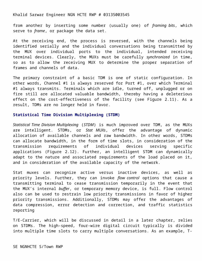
At the transmitting end of the connection, the TDM scans the ports to which individual devices are attached, allocating each device port a channel, or time slot, for transmission of data. Device #1 transmits through Port #1 and over Time Slot #1, Device #2 transmits through Port #2 and over Time Slot #2, and so on, in a serial fashion. The transmitting TDM typically accepts an 8-bit set of data from each port and interleaves those sets of data into a single, composite digital output. As the MUX completes a scan of the ports and transmits a set of such data, it will separate one set of data from another by inserting some number (usually one) of framing bits, which serve to frame, or package the data set.
At the receiving end, the process is reversed, with the channels being identified serially and the individual conversations being transmitted by the MUX over individual ports to the individual, intended receiving terminal devices. Clearly, the MUXs must be carefully synchronized in time, so as to allow the receiving MUX to determine the proper separation of frames and channels of data.
The primary constraint of a basic TDM is one of static configuration. In other words, Channel #1 is always reserved for Port #1, over which Terminal #1 always transmits. Terminals which are idle, turned off, unplugged or on fire still are allocated valuable bandwidth, thereby having a deleterious effect on the cost-effectiveness of the facility (see Figure 2.11). As a result, TDMs are no longer held in favor.
Statistical Time Division Multiplexing (STDM)
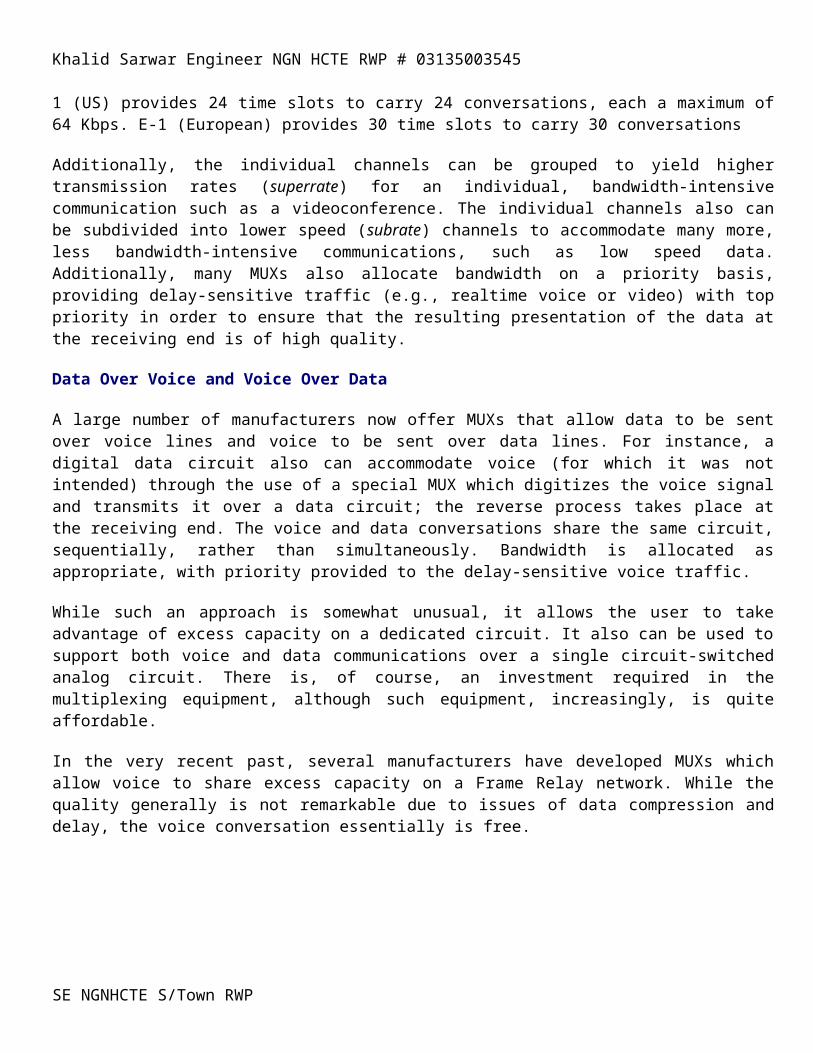
Statistical Time Division Multiplexing (STDM) is much improved over TDM, as the MUXs are intelligent. STDMs, or Stat MUXs, offer the advantage of dynamic allocation of available channels and raw bandwidth. In other words, STDMs can allocate bandwidth, in the form of time slots, in consideration of the transmission requirements of individual devices serving specific applications (Figure 2.12). Further, an intelligent STDM can dynamically adapt to the nature and associated requirements of the load placed on it, and in consideration of the available capacity of the network.
Stat muxes can recognize active versus inactive devices, as well as priority levels. Further, they can invoke flow control options that cause a transmitting terminal to cease transmission temporarily in the event that the MUX’s internal buffer, or temporary memory device, is full. Flow control also can be used to restrain low priority transmissions in favor of higher priority transmissions. Additionally, STDMs may offer the advantages of data compression, error detection and correction, and traffic statistics reporting
T/E-Carrier, which will be discussed in detail in a later chapter, relies on STDMs. The high-speed, four-wire digital circuit typically is divided into multiple time slots to carry multiple conversations. As an example, T-1 (US) provides 24 time slots to carry 24 conversations, each a maximum of 64 Kbps. E-1 (European) provides 30 time slots to carry 30 conversations
Additionally, the individual channels can be grouped to yield higher transmission rates (superrate) for an individual, bandwidth-intensive communication such as a videoconference. The individual channels also can be subdivided into lower speed (subrate) channels to accommodate many more, less bandwidth-intensive communications, such as low speed data. Additionally, many MUXs also allocate bandwidth on a priority basis, providing delay-sensitive traffic (e.g., realtime voice or video) with top priority in order to ensure that the resulting presentation of the data at the receiving end is of high quality.SE NGNHCTE S/Town RWP
Khalid Sarwar Engineer NGN HCTE RWP # 03135003545
Data Over Voice and Voice Over Data
A large number of manufacturers now offer MUXs that allow data to be sent over voice lines and voice to be sent over data lines. For instance, a digital data circuit also can accommodate voice (for which it was not intended) through the use of a special MUX which digitizes the voice signal and transmits it over a data circuit; the reverse process takes place at the receiving end. The voice and data conversations share the same circuit, sequentially, rather than simultaneously. Bandwidth is allocated as appropriate, with priority provided to the delay-sensitive voice traffic.
While such an approach is somewhat unusual, it allows the user to take advantage of excess capacity on a dedicated circuit. It also can be used to support both voice and data communications over a single circuit-switched analog circuit. There is, of course, an investment required in the multiplexing equipment, although such equipment, increasingly, is quite affordable.
In the very recent past, several manufacturers have developed MUXs which allow voice to share excess capacity on a Frame Relay network. While the quality generally is not remarkable due to issues of data compression and delay, the voice conversation essentially is free.
SE NGNHCTE S/Town RWP
Khalid Sarwar Engineer NGN HCTE RWP # 03135003545
Switches and Switching: The Fundamentals (and then some)
Switches serve to establish transmission paths between terminal devices (transmitters and receivers) on a flexible basis. They effectively serve as contention devices, managing contention between multiple transmit devices for access to shared circuits. In this manner, the usage and cost of expensive circuits can be optimized based on standard traffic engineering principles. Without switches, each device would require a direct, dedicated circuit to every other device. Such a full mesh network clearly is resource-intensive, impractical and even impossible, as early experience proved. This discussion of switches and switching is presented in chronological order of development, beginning with circuit switching and its evolution, and progressing through packet to frame and cell switching.
Circuit Switching
In the classic sense, circuit switching provides continuous and exclusive access between physical circuits for the duration of the conversation. Contemporary circuit switches provide continuous access to logical channels over high-capacity physical circuits for the duration of the conversation. While circuit switches originally were developed for voice communications, much data traffic currently also is switched in this fashion.
Packet Switching
Rather than employing circuit switching, which is far too expensive for intensive, interactive computer communications, ARPAnet, and its successors such as the Internet, make use of packet switching. Packet switching involves the transmission of data in packets of fixed length across a shared network. Each packet is individually addressed, in order that the packet switches can route each packet over the most appropriate and available circuit. In this manner, packets offered to the network by large numbers of users can make use of the same switches and transmission facilities, thereby dramatically lowering the cost of data transmission to the individual user organization.
Traditional packet switching offers the advantage of being based on mature and stable technologies. Additionally, it is widely available on an international basis and is low in cost. Its disadvantages include the fact that it is intended to support only relatively low-speed data transmission. As the switches assume a 1960-vintage analog network environment of twisted pair, each switch is responsible for examining each individual packet for errors created in transmission. Further, each switch is responsible for resolving identified errors through a request for retransmission. These factors, in combination, result in unpredictable, variable levels of delay in packet transmission. Therefore, packet switching generally is considered to be unsuitable for stream-oriented communications such as real-time voice and video.
X.25 (an international standard packet switching interface which will be discussed in Chapter 8) offers great advantage in terms of its ability to support the connection of virtually any computer system through its ability to accomplish protocol conversion. This highly desirable feature classified X.25-based packet networks as the first value-added networks.
Frame Switching (Frame Relay)
A relative newcomer, frame relay was first offered commercially in 1992 by Wiltel (U.S.). Much like packet switching, each frame is addressed individually. Frame relay also makes use of special switches and a shared network of very high speed. Unlike packet switching, frame relay supports the transmission of virtually any
SE NGNHCTE S/Town RWP

Khalid Sarwar Engineer NGN HCTE RWP # 03135003545
computer data stream in its native form—frames are variable in length (up to 4,096 bytes). Rapidly gaining in popularity, frame relay is widely available in many highly developed nations. International frame relay service is also becoming widely available. Disadvantages include the fact that frame relay, like packet switching, is oriented towards data transmission. Further, transmission delays are variable and uncertain in duration. While increasingly satisfactory technologies have been added for support of voice and video, frame relay is not designed with those applications in mind.
Cell Switching
Clearly, cell switching is fundamental to the future of communications. Encompassing both Switched Multimegabit Data Service (SMDS) and Asynchronous Transfer Mode (ATM), data is organized into cells of fixed length (53 octets), shipped across very high speed facilities and switched through very high speed, specialized switches. While SMDS has proved to be very effective for data communications, ATM will be pervasive in the future.
ATM is primarily data-oriented, although it is ultimately intended to support voice and video as well. Standards are still being developed and availability is limited. Current disadvantages include its relatively high cost and data communications orientation.
Photonic Switches
Still in development, photonic switches are yet another dimension in the evolution of switch technology. Capable of supporting circuit-, packet- frame- and cell switching, photonic switches will eliminate the requirement for optoelectric conversion when connected to a fiber optic transmission system. Clearly, they also will offer advantages in terms of speed and error performance. While prototype photonic switches currently are in use in testbed environments, it likely will be a decade or so before they are commercially viable in CO applications; it is highly unlikely that they will find application in the PBX world, at least not in the foreseeable future.
Signaling and Control
Signaling and control comprises a set of functions which must take place within any network in order ensure that it operates smoothly. In this context, various elements within the network must identify themselves, communicate their status and pass instructions. Fundamental examples include on-hook and off-hook indication, dialtone provision, call routing control, busy signal, and billing instructions. Further examples include dialed digits, route availability, routing preference, carrier preference, and originating number or circuit [2-2].
In more sophisticated, contemporary networks, the responsibility for overall signaling and control functions resides within a separate common channel signaling (CCS) and control network. Such a sophisticated CCS network involves highly intelligent devices which are capable of monitoring and managing large numbers of lower order devices in the communications network which it controls. From a centralized Network Control Center (NCC), the network can be monitored, and faults or performance failures can be identified, diagnosed, and isolated. Finally, the lower order devices in the communications network oftentimes can be addressed and commanded to correct the condition.
SE NGNHCTE S/Town RWP
Khalid Sarwar Engineer NGN HCTE RWP # 03135003545
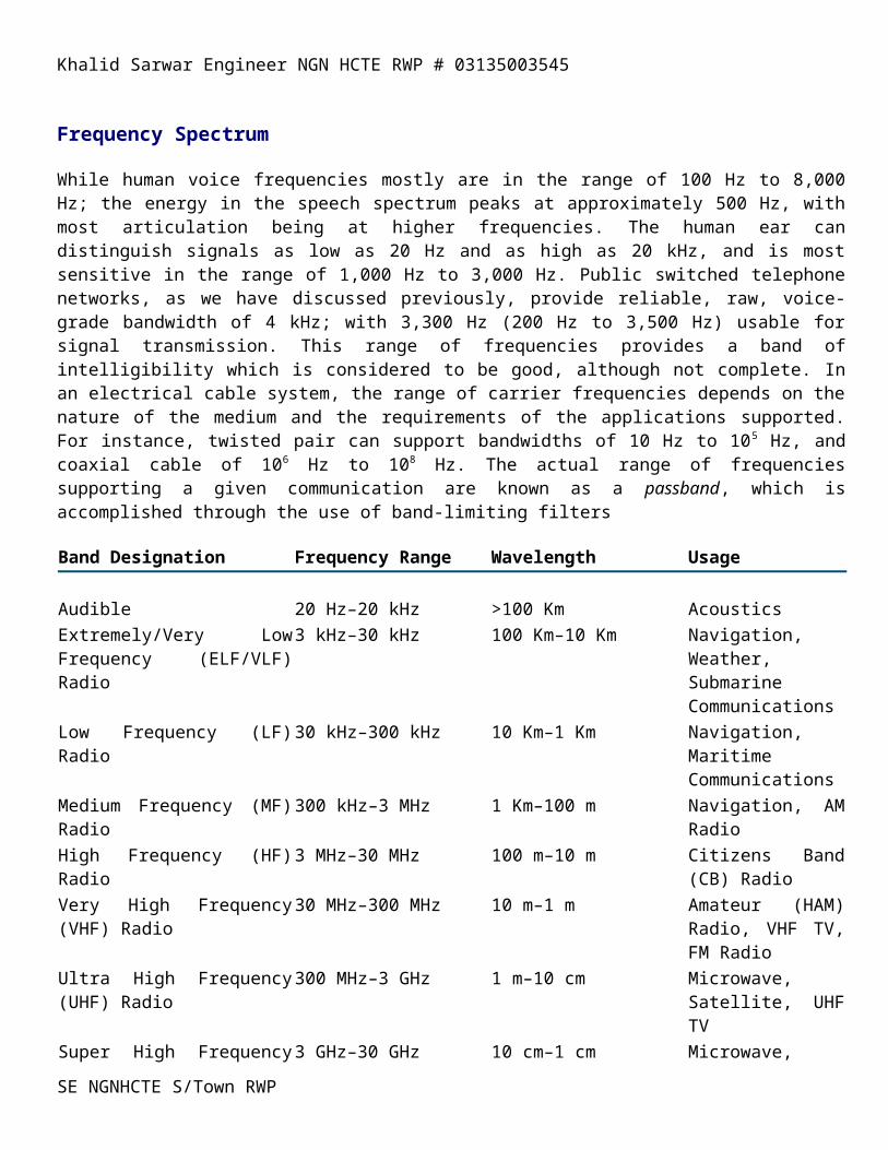
Frequency Spectrum
While human voice frequencies mostly are in the range of 100 Hz to 8,000 Hz; the energy in the speech spectrum peaks at approximately 500 Hz, with most articulation being at higher frequencies. The human ear can distinguish signals as low as 20 Hz and as high as 20 kHz, and is most sensitive in the range of 1,000 Hz to 3,000 Hz. Public switched telephone networks, as we have discussed previously, provide reliable, raw, voice-grade bandwidth of 4 kHz; with 3,300 Hz (200 Hz to 3,500 Hz) usable for signal transmission. This range of frequencies provides a band of intelligibility which is considered to be good, although not complete. In an electrical cable system, the range of carrier frequencies depends on the nature of the medium and the requirements of the applications supported. For instance, twisted pair can support bandwidths of 10 Hz to 105
Hz, and coaxial cable of 106 Hz to 108 Hz. The actual range of frequencies supporting a given communication are known as a passband, which is accomplished through the use of band-limiting filters
Band Designation Frequency Range Wavelength Usage
Audible 20 Hz–20 kHz >100 Km Acoustics Extremely/Very Low Frequency (ELF/VLF) Radio
3 kHz–30 kHz 100 Km–10 Km Navigation, Weather, Submarine Communications
Low Frequency (LF) Radio 30 kHz–300 kHz 10 Km–1 Km Navigation, Maritime Communications
Medium Frequency (MF) Radio 300 kHz–3 MHz 1 Km–100 m Navigation, AM
Radio High Frequency (HF) Radio 3 MHz–30 MHz 100 m–10 m Citizens Band (CB)
Radio Very High Frequency (VHF) Radio
30 MHz–300 MHz 10 m–1 m Amateur (HAM) Radio, VHF TV, FM Radio
Ultra High Frequency (UHF) Radio
300 MHz–3 GHz 1 m–10 cm Microwave, Satellite, UHF TV
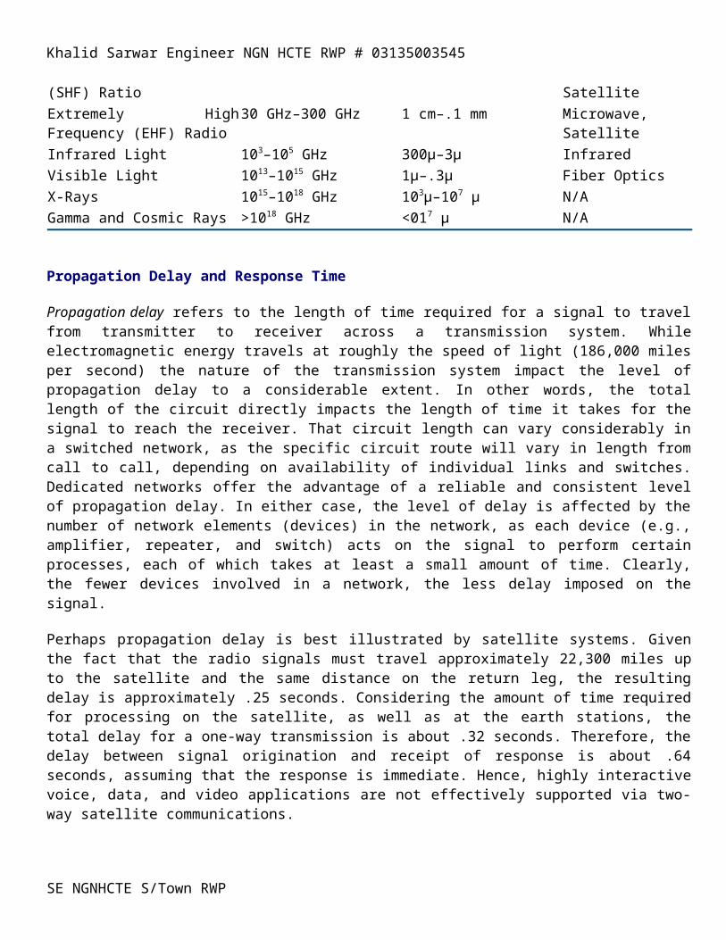
Super High Frequency (SHF) Ratio
3 GHz–30 GHz 10 cm–1 cm Microwave, Satellite
Extremely High Frequency (EHF) Radio
30 GHz–300 GHz 1 cm–.1 mm Microwave, Satellite
Infrared Light 103–105 GHz 300µ–3µ Infrared Visible Light 1013–1015 GHz 1µ–.3µ Fiber Optics X-Rays 1015–1018 GHz 103µ–107 µ N/A Gamma and Cosmic Rays >1018 GHz <017 µ N/A
Propagation Delay and Response Time
Propagation delay refers to the length of time required for a signal to travel from transmitter to receiver across a transmission system. While electromagnetic energy travels at roughly the speed of light (186,000 miles per second) the nature of the transmission system impact the level of propagation delay to a considerable extent. In other words, the total length of the circuit directly impacts the length of time it takes for the signal to reach the
SE NGNHCTE S/Town RWP
Khalid Sarwar Engineer NGN HCTE RWP # 03135003545
receiver. That circuit length can vary considerably in a switched network, as the specific circuit route will vary in length from call to call, depending on availability of individual links and switches. Dedicated networks offer the advantage of a reliable and consistent level of propagation delay. In either case, the level of delay is affected by the number of network elements (devices) in the network, as each device (e.g., amplifier, repeater, and switch) acts on the signal to perform certain processes, each of which takes at least a small amount of time. Clearly, the fewer devices involved in a network, the less delay imposed on the signal.
Perhaps propagation delay is best illustrated by satellite systems. Given the fact that the radio signals must travel approximately 22,300 miles up to the satellite and the same distance on the return leg, the resulting delay is approximately .25 seconds. Considering the amount of time required for processing on the satellite, as well as at the earth stations, the total delay for a one-way transmission is about .32 seconds. Therefore, the delay between signal origination and receipt of response is about .64 seconds, assuming that the response is immediate. Hence, highly interactive voice, data, and video applications are not effectively supported via two-way satellite communications.
Security Security, in the context of transmission systems, addresses the protection of data from interception as it transverses the network. Clearly, increasing amounts of sensitive data are being transmitted across wide and metropolitan area networks, outside the protection of one’s own premises. Therefore, security is of greater concern than ever before and will heighten as nations and commercial enterprises seek to gain competitive advantage and as they apply ever more sophisticated means to do so. In hearings (May 1996) before the United States Senate, it was stated that 120 nations either have or are in the process of developing sophisticated computer espionage capabilities.
Further, it should be noted that airwave systems (e.g., microwave and satellite) are inherently not secure, as unauthorized entities can gain access to that data through the use of a properly tuned and placed antenna, without the necessity of tapping a physical circuit. Finally, and as we discussed in a previous chapter, digital systems are inherently more secure than are their analog counterparts by virtue of the fact that the data can effectively be encrypted, or encoded, in order to conceal its true meaning. Particularly in the case of data networking, it also is important that access to a remote system and the data resident on it be limited to authorized users; therefore, some method of authentication, must be employed in order to verify that the access request is legitimate and authentic.
Mechanical Strength Mechanical strength applies most especially to wired systems. Twisted pair, coaxial, and fiber optic cables are manipulated physically as they are deployed and reconfigured. Clearly, each has certain physical limits to the amount of bending and twisting (flex strength) they can tolerate, as well as the amount of weight or longitudinal stress they can support (tensile strength), without breaking (break strength). Fiber optic cables are notoriously susceptible in this regard. Cables hung from poles expand and contract with changes in ambient temperature; while glass fiber optic cables expand and contract relatively little, twisted pair copper wire is more expansive
The issue of mechanical strength also applies to airwave systems, as reflective dishes, antennae, and other devices used in microwave, satellite, and infrared technologies must be mounted securely to deal with wind and other forces of nature. Additionally, the towers, walls and roofs on which they are mounted must be constructed and braced properly in order to withstand such forces, and must flex as appropriate.
SE NGNHCTE S/Town RWP
Khalid Sarwar Engineer NGN HCTE RWP # 03135003545
Twisted Pair: An Introduction to Telephone Wire
Metallic wires were used almost exclusively in telecommunications networks for the first 80 years, certainly until the development of microwave and satellite radio communications systems. Initially, uninsulated iron telegraph wires were used, although copper was soon found to be a much more appropriate medium. The early metallic electrical circuits were one-wire, supporting two-way communications with each telephone connected to ground in order to complete the circuit. In 1881, John J. Carty, a young American Bell technician and one of the original operators, suggested the use of a second wire to complete the circuit and, thereby, to avoid the emanation of electrical noise from the earth ground. In certain contemporary applications, copper-covered steel, copper alloy, nickel- and/or gold-plated copper, and even aluminum metallic conductors are employed. The most common form of copper wire used in communications is that of twisted pair [3-6].
The Twisting Process
The separately insulated conductors are twisted 90º at routine, specified intervals, hence the term twisted pair. This twisting process serves to improve the performance of the medium by containing the electromagnetic field within the pair. Thereby, the radiation of electromagnetic energy is reduced and the strength of the signal within the wire is improved over a distance. Clearly, this reduction of radiated energy also serves to minimize the impact on adjacent pairs in a multipair cable configuration. This is especially important in high-bandwidth applications, as higher frequency signals tend to lose power more rapidly over distance. Additionally, the radiated electromagnetic field tends to be greater at higher frequencies, impacting adjacent pairs to a greater extent. Generally speaking, the more twists per foot, the better the performance of the wire [3-1].
Gauge Gauge is a measure of the thickness of the conductor. The thicker the wire, the less the resistance, the stronger the signal over a given distance, and the better the performance of the medium. Thicker wires also offer the advantage of greater break strength.
American Wire Gauge (AWG) is a commonly used standard measurement of gauge, although others are used outside the United States. The gauge numbers are retrogressive; in other words, the larger the number, the smaller the conductor. Originally known as Brown and Sharp (B&S) Gauge, the AWG number indicated the number of times the copper wire was drawn through the wire machine to reduce its diameter. As an example, a 24-gauge (AWG) wire has a diameter of .0201 in. (.511mm), a weight of 1.22 lbs./ft. (1.82 kg./km.), a maximum break strength of 12.69 lbs. (5.756 kg.) and D.C. resistance ohms of 25.7/1000ft. (84.2/km.). Twisted pair commonly employed in telephone company networks varies from 19 to 28-gauge, with the most common being 24-gauge. Table 3.2 provides an abbreviated comparison of the various UTP Categories [3-7].
Table 3.2 Unshielded Twisted Pair (UTP) categories, as defined by the Electrical Industry Association (EIA) Category Gauge (AWG) Performance Data
Cat 1 Various Undetermined No Cat 2 22 & 24 Undetermined No Cat 3 22 & 24 16 MHz–10 Mbps Yes Cat 4 Various 16 Mbps Yes Cat 5 Various 100 Mbps Yes
Configuration
SE NGNHCTE S/Town RWP
Khalid Sarwar Engineer NGN HCTE RWP # 03135003545
In a single pair configuration, the pair of wires is enclosed in a sheath or jacket, also of polyethylene, polyvinyl chloride or Teflon. Oftentimes, multiple pairs are so bundled in order to minimize deployment costs associated with connecting multiple devices (e.g., electronic PBX or KTS telephone sets, data terminals, and modems) at a single workstation.
Larger number of pairs are bundled into large cables to serve departments, quadrants of a building, or floors of a high-rise office building—such cables may contain 25, 50, 100, 500 or more pairs. While twisted pair cables of up to 3,600 pairs are still used in outside plant applications, such continuing use is decidedly uncommon. In large cables, pairs are grouped into binder groups of 25 pairs for ease of connectivity management. Each binder group is wrapped (bound) with some sort of tape in order to separate it from other groups. Each pair within a binder group is color-coded for further ease of connectivity management. with the color codes being repeated within each binder group [3-5].
Bandwidth While a voice grade circuit over twisted pair is guaranteed at 4 kHz, standard copper is capable of supporting much greater bandwidth. A single twisted pair, in a typical telephone installation, is capable of providing up to 250 kHz, or 1–4 Mbps compressed, assuming amplifier or repeater spacing every 2-3 km [3-1]. Additional examples follow:
Security UTP is inherently an insecure transmission medium. It is relatively simple to place physical taps on UTP. Additionally, the radiated energy is easily intercepted through the use of antennae or inductive coils, without the requirement for placement of a physical tap.
Shielded Copper
Applications The additional cost of shielded copper limits its application to inside wire applications. Specifically, it generally is limited to application in high-noise environments. It also is deployed where high frequency signals are transmitted and there is concern about either distance performance or interference with adjacent pairs. Examples include LANs and image transmission.
Microwave Radio
Microwave radio, a form of radio transmission which uses ultra-high frequencies, developed out of experiments with radar (radio detecting and ranging) during the period preceding World War II. The first primitive systems, used in military applications in the European and Pacific theaters, could handle up to 2,400 voice conversations over 5 channels. Developed by Harold T. Friis and his associates at Bell Laboratories, the first public demonstration was conducted between the West Street lab and Neshanic, New Jersey in October 1945 [3-6].
There are several frequency ranges assigned to microwave systems, all of which are in the GigaHertz (GHz) range; in other words, billions of cycles per second. The wavelength is in the millimeter range; that is to say that each cycle or wave is in the range of a millimeter, with billions of such cycles generated during a second of transmission. This very short wavelength gives rise to the term microwave. Such high frequency signals are especially susceptible to attenuation and, therefore must be amplified (analog) or repeated (digital) frequently. Therefore, if the transmit and receive microwave radio antennae are separated by a considerable distance, there must be intermediate antennae at periodic intervals in order to boost the signal.
In order to maximize the strength of such a high frequency signal and, therefore, to increase the distance of transmission at acceptable levels, the radio beams are highly focused. The transmit antenna is centered in a concave, reflective metal dish which serves to focus the radio beam with maximum effect on the receiving
SE NGNHCTE S/Town RWP
Khalid Sarwar Engineer NGN HCTE RWP # 03135003545
antenna, as illustrated in Figure 3.4. The receiving antenna, similarly, is centered in a concave metal dish, which serves to collect the maximum amount of incoming signal.
The requirement to so tightly focus the signal clearly limits the application of microwave. It is a point-to-point, rather than a broadcast, transmission system. Additionally, each antenna must be within line of sight of the next antenna, as such high frequency radio waves will not pass through solid objects of any significance (buildings, mountains, or airplanes). Given the curvature of the earth, and the obvious problems of transmitting through it, microwave hops generally are limited to 50 miles (80 km.).
While all the various microwave frequency bands suffer from these limitations, the higher frequencies suffer to a greater extent. Those higher frequencies, set aside for digital microwave in the United States, suffer more from environmental interference including dust, smog, agricultural haze, and precipitation. Table 3.3 lists examples of frequency bands set aside by the Federal Communications Commission for commercial microwave [3-9].
Table 3.3 Microwave frequency bands (U.S.)
U.S. Frequency Bands Maximum Antenna Separation Analog/Digital
4–6 GHz 20–30 miles (32–48 km.) Analog 10–12 GHz 10–15 miles (16–24 km.) Digital 18–23 GHz 5–7 miles (8–11 km.) Digital
The several frequency bands set aside for microwave are protected by regulatory authority in most countries and regions. Additionally, the placement of the antennae and the power level of transmission is regulated, with licenses granted to individual carriers and end users. However, difficulties have developed over time in certain areas (e.g., Europe and Asia) due to factors that include the small size of the individual nations; conflicting regulations, or the lack thereof; conflicting commercial and military applications; and unwillingness of national regulators to govern the use of radio frequencies on a coordinated, regional basis.
Configuration Microwave radio consists of antennae centered within reflective dishes, that are attached to structures such as towers or buildings. Cables connect the antennae to the actual transmit/receive equipment.
Bandwidth Microwave offers substantial bandwidth, often in excess of 6 Gbps. T1 (1.544 Mbps) capacity is routine, even in end user applications, with many private microwave networks operating at T3 (45 Mbps) rates.
Error Performance Microwave, especially digital microwave, performs well in this regard, assuming proper design. However, such high frequency radio is particularly susceptible to environmental interference (e.g., precipitation, haze, smog, and smoke). Generally speaking, however, microwave performs well in this regard.
Distance Microwave clearly is distance-limited, especially at the higher frequencies (see Table 3.2). This limitation can be mitigated through special and more complex arrays of antennae incorporating spatial diversity in order to collect more signal.
Security As is the case with all radio systems, microwave is inherently not secure. Security must be imposed through encryption (scrambling) of the signal.
SE NGNHCTE S/Town RWP
Khalid Sarwar Engineer NGN HCTE RWP # 03135003545
Applications Microwave originally was used for long haul voice and data communications. Competing long distance carriers, first in the United States, found microwave a most attractive alternative to cabled systems, due to the speed and low cost of deployment; where feasible, however, fiber optic technology is currently used in this regard. Contemporary applications include private networks, carrier bypass, temporary disaster recovery, interconnection of cellular radio switches, and as an alternative to cabled systems in consideration of difficult terrain.
SE NGNHCTE S/Town RWP
Khalid Sarwar Engineer NGN HCTE RWP # 03135003545
Satellite Radio
Satellite radio, quite simply, is a nonterrestrial microwave transmission system utilizing a space relay station. The concept initially was offered in a letter published in Wireless World in February 1945 by Arthur C. Clarke, then a physicist at the British Interplanetary Society and since the author of 2001: A Space Odyssey and many other science fiction books. Since the launch of the Earlybird I satellite in 1965 proved the effectiveness of the concept of satellite communications, satellites have proved invaluable in extending the reach of voice, data, and video communications around the globe and into the most remote regions of the world. Exotic applications such as the Global Positioning System (GPS) would have been unthinkable without the benefit of satellites [3-10].
Geostationary Satellites
Contemporary satellite communications systems involve a satellite relay station which is launched into a geostationary, geosynchronous, or geostatic orbit, also known as a Clarke orbit. Such an orbit is approximately 22,237 miles (36,000 km.) above the equator (Figure 3.5). At that altitude and in an equatorial orbital slot, the satellite maintains its synchronization with the revolution of the earth. In other words, it maintains its relative position over the same spot of the earth’s surface. Consequently, transmit and receive earth stations (microwave dishes) can be pointed reliably at the satellite for communications purposes. Geosynchronous Earth Orbiting (GEO) satellites are also known as Fixed Satellite Systems (FSS).
The popularity of satellite communications has placed great demands on the international regulators (e.g., Intelsat) to manage and allocate available frequencies, as well as the limited number of orbital slots available for satellite positioning. As in the case of terrestrial microwave radio, there are a number of frequency bands assigned to satellite systems, most of which are in the MegaHertz (MHz) or GigaHertz (GHz) ranges. Due to the wide footprint, or area of coverage of a satellite, the frequencies must be carefully managed at national, regional and international levels. Generally speaking, geostationary satellites are positioned approximately 2º apart in order to minimize interference from adjacent satellites using overlapping frequencies [3-10].
Although such high frequency signals are especially susceptible to attenuation in the atmosphere, they can propagate (travel) infinite distances in the vacuum of space with no signal loss. Attenuation can, however, be problematic within the few miles of atmosphere on the uplink and downlink segments. The uplink and downlink generally utilize different frequencies for transmission, so as to avoid interference between incoming and outgoing signals. As suggested in Table 3.5, the higher of the two frequencies is used for the uplink, as that signal is stronger and can better deal with atmospheric distortion. The lower frequency, used for the downlink, can better penetrate the earth’s atmosphere and electromagnetic field, which can act to bend the incoming signal much as light bends when entering a pool of water. Table 3.4 provides a set of example frequencies and spacecraft serving various applications, with LEO referring to Low-Earth Orbiting satellites.
Table 3.4 Sample satellite communication frequencies.
Frequency Range Band Designation Example Spacecraft
136–137 & 148 MHz VHF NOAA (LEO Weather) 400 MHz UHF Orbcomm 1610–1625.5 MHz 2483.5–2500 MHz L–band Big LEOs SE NGNHCTE S/Town RWP
Khalid Sarwar Engineer NGN HCTE RWP # 03135003545
2310–2360 MHz S–band Civil Defense Radio 3700–4200 MHz 5925–6425 MHz C–band Galaxy, Satcom, Telstar, Intelsat, etc. 4 GHz–6 GHz C–band Intelsat, Comsat, etc. 11.7–12.2 GHz 14.0–14.5 GHz Ku–band Globalstar, etc. 20 GHz & 30 GHz Ka–band ACTS
Source: International Telecommunications Union (ITU); Comsat
Uplink
In order to maximize the strength of such a high frequency signal, as well as to direct the uplink transmission to a specific satellite, the uplink radio beams are highly focused. The transmit antenna is centered in a concave, reflective dish which serves to focus the radio beam, with maximum effect, on the receiving satellite antenna. The receiving antenna, similarly, is centered in a concave metal dish, which serves to collect the maximum amount of incoming signal. Table 3.5 provides example uplink and downlink frequencies, with mention of standard applications.
Table 3.5 Example uplink/downlink satellite frequencies.
Frequency Band Uplink/Downlink Frequency Range Example Application
C–band 6 GHz/4 GHz TV, Voice, Videoconferencing Ku–band 14 GHz/11 GHz TV, DBS/DSS Ka–band 30 GHz/20 GHz Mobile Voice
Downlink Similarly, the downlink transmission is focused on a particular footprint, or area of coverage. Although a satellite can see roughly one-third of the earth’s surface from its vantage point, the signal would weaken so as to be unusable at the fringes of such a footprint, were the signal not tightly focused. Spot beams, even more tightly focused downlinks, serve specific applications over smaller regions.
Broadcast
The wide footprint of a satellite radio system allows a signal to be broadcast over a wide area. Thereby any number (theoretically an infinite number) of terrestrial antennae can receive the signal, more or less simultaneously. In this manner, satellites can serve a point-to-multipoint network requirement through a single uplink station and multiple downlink stations.
Recently, satellites have been developed which can serve a mesh network requirement, whereby each terrestrial site can communicate directly with any other site. Previously, all such communications were required to travel through a centralized site, known as a head end. Such a mesh network, of course, imposes an additional level of difficulty on the network in terms of management of the flow and direction of traffic.
SE NGNHCTE S/Town RWP
Khalid Sarwar Engineer NGN HCTE RWP # 03135003545
Customer Premise Equipment (CPE)
As was have noted, CPE is the terminal and switching equipment located on the customer premise. While such equipment, traditionally, was rented to the subscriber by the LEC, deregulation generally places the responsibility and privilege of ownership on the customer. Similarly, inside wire and cable generally is deregulated.
Demarcation Point (demarc)
This constitutes the boundary between the end user and carrier domains. In a residential environment, the demarc is in the form of a Network Interface Unit (NIU). NIUs include a protector, which serves to protect the premise wiring and equipment from aberrant voltages which might be induced by carrier power supplies, power utility transformers, or lightening strikes. Contemporary NIUs also are intelligent, allowing telephone company technicians or automatic test systems to regularly test the local loop from the central office to the customer premise. The NIU is located outside the residence, perhaps on an outside wall or in the garage, as the telephone company is not allowed to place equipment inside the premise under the terms of the MFJ.
In a business environment, the demarc is defined as being the closest logical and practical point within the customer domain. In a high-rise office building, for instance, it typically is defined as being a point of the entrance cable 12” from the inside wall. Newer entrance cable facilities involve a physical demarc, while older facilities typically are tagged by telephone company technicians in order to indicate a logical point of demarcation. From that point inward, the cable and wire system is the responsibility of the user and/or building owner, as appropriate.
SE NGNHCTE S/Town RWP
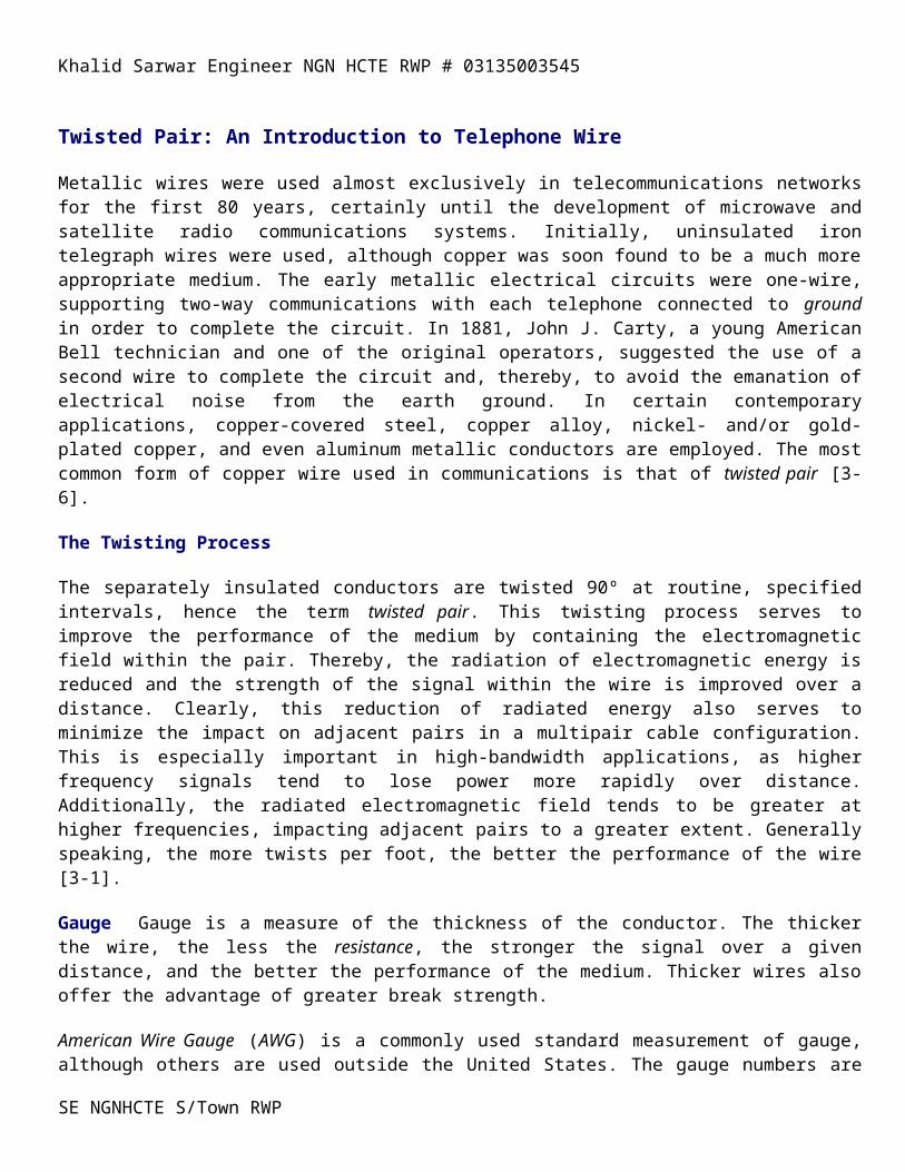
Khalid Sarwar Engineer NGN HCTE RWP # 03135003545
DCE: AN EXPANDED VIEW
While we have discussed, and will discuss, data networks and switches in great detail in other chapters, this is a convenient and meaningful place to pause and explore the concept and detail of several types of data communications equipment. Specifically, we will examine modems, codecs, terminal adapters, CSUs and DSUs, and front end processors.
Modems Modems MOdulate and DEModulate signals. In other words, they change the characteristics of the signal in some way. Modems are of several basic types, line drivers, short haul modems, and conventional modems.
Data Communications Equipment (DCE)
Also known as Data Circuit Terminating Equipment (DCTE), DCE is the equipment that interfaces the DTE to the network, in the process resolving any issues of incompatibility between those domains. Incompatibility issues can include digital versus analog, voltage level, transmission speed and bit density. DCE includes modems, DSUs and CSUs, and Front-End Processors (FEPs), all of which will be discussed in greater detail later in this chapter.
Line drivers
Line drivers actually are interface converters, rather than modems in the classic sense. Line drivers are used to extend the distance of a digital connection, within finite limits, by converting the digital signal to a low-voltage, low-impedance signal that can be transmitted more effectively and over longer distances over dedicated, specially conditioned twisted pair circuits. As an example, the RS-232 specification generally limits the distance between devices to 50 feet at transmission rates of 56 Kbps. At lower speeds, line drivers can reshape the digital pulses to extend that distance. At speeds of up to 9.6 Kbps, line drivers can extend that limitation to 500-5,000 feet. The distance can be extended further through the cascading of line drivers, in a unidirectional network; bi-directional communications requires separate wire pairs and separate sets of line drivers.
Short-Haul (limited-distance) modems Short-Haul (limited-distance) modems are used where line drivers fail in terms of either capacity or distance. Short-haul modems can work at distances between 5,000 and 100,000 feet, and usually are used for private line and hardwired links, but can operate over local loop facilities.
Conventional modems Conventional modems provide for digital communication across an analog circuit, accomplishing the digital-to-analog conversion in order to resolve that dimension of incompatibility between the DTE and the network. The original de facto standards for modems were set by AT&T with the introduction of the DataPhone in 1961 [7-2]. Currently, standards are international in nature, designated as the V.xx family of standards from the ITU-T. The digital input is in the form of varying electrical voltages, which represent binary 1s and 0s. The output from the modem is a modulated analog carrier wave, that can be modulated in terms of its amplitude, frequency or phase, or a combination. Through this process, the 1s and 0s of the digital data world can be sent over the plain old voice telephone network.
Amplitude Modulation (AM) Amplitude Modulation (AM) involves the modulation of the amplitude of the analog sine wave, as depicted in Figure 7.1. Using a single-bit AM technique, each 1 bit entering the transmitting modem is expressed as a relatively high amplitude sine wave or series of sine waves, and each 0 bit as low amplitude sine waves. It is possible to express multiple bits by defining four levels of amplitude. In a
SE NGNHCTE S/Town RWP
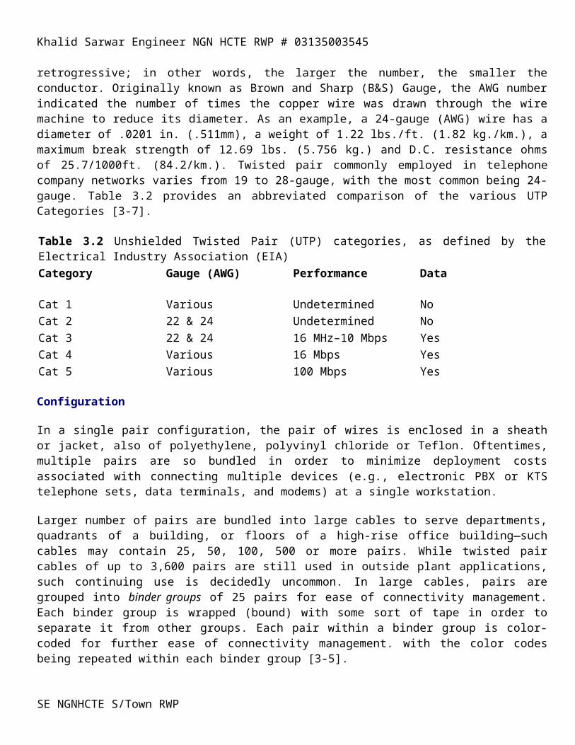
Khalid Sarwar Engineer NGN HCTE RWP # 03135003545
dibit (2-bit) coding scheme, for instance, the lowest level of amplitude represents a 00 bit pattern, the next highest a 01 bit pattern, the next a 10, and the highest a 11. In this fashion, the speed of data transmission is doubled at the same analog line speed; halving the connection time and reducing the cost of transmission. Amplitude modulation rarely is used individually as it is highly sensitive to the impacts of attenuation and line noise.
Figure 7.1 Amplitude Modulation.
Frequency Modulation (FM)
Frequency Modulation (FM), also known as Frequency Shift Keying (FSK), is the sole technique used in low-speed Hayes-compatible modems. FSK involves the modulation of the frequency of the analog sine wave (Figure 7.2). Using a single bit FM technique, 1 bits are transmitted as relatively low frequency signals, and 0 bits as high frequency signals. Again, the benefits of dibit transmission can be realized by defining four levels of frequency, with each sine wave representing a 2-bit pattern (00, 01, 10, 11).
Figure 7.2 Frequency Modulation.
Phase Modulation (PM)
Phase Modulation (PM), or Phase Shift Keying (PSK), involves the carefully synchronized shifting of the position of the sine wave (Figure 7.3). Using a single-bit technique, the continuous sine wave pattern is interrupted and restarted at the baseline to indicate a change in value (e.g., from a 1 bit to a 0 bit). Once again, the advantages of dibit transmission can be achieved by defining four degrees of phase shift. Through the definition of eight degrees of phase shift, contemporary modems can affect tribit transmission, achieving 3 bits of data per signal.
Figure 7.3 Phase Modulation.
Asynchronous versus Synchronous
Modems can be either asynchronous or synchronous. Asynchronous modems transmit a character at a time, with the receiving device relying on start and stop bits to separate transmitted characters. Synchronous modems are much faster, as the signal is synchronized (timed) by a transmit clock (TC) in either the transmit modem or the transmit terminal. The paired modems synchronize on that clocking pulse, in order to distinguish between blocks of data being transmitted, rather than identifying each individual character in a transmission. When large amounts of data are being transmitted, synchronous modems increase the efficiency of data transfer, resulting in increased speed of transfer and lower associated transmission cost [7-3].
Diagnostics
SE NGNHCTE S/Town RWP
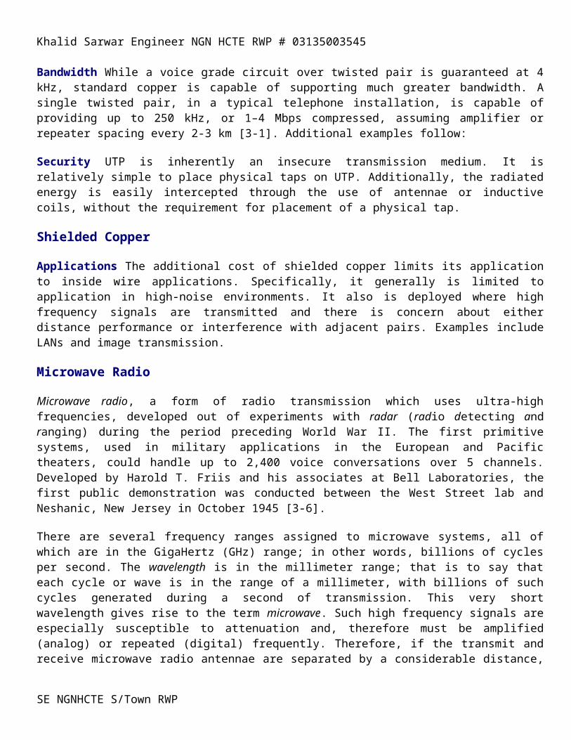
Khalid Sarwar Engineer NGN HCTE RWP # 03135003545
Diagnostics is a characteristic of higher-speed and more expensive modems. Such modems can test their internal clock, transmitter, and receive circuits. Additionally, they may have the capability to monitor their performance and even diagnose certain conditions contributing to performance degradation. Further, they are manageable through higher-level Element Management Systems, which typically are located remotely and which manage large numbers of modems and modem pools (groups of modems to which access is shared amongst multiple users).
Compression
Compression is a characteristic of high-speed modems, allowing the transmission of multiple bits with a single signal (sine wave) or change in signal. Compression makes use of digital shorthand to represent a large number of bits in a specific sequence through a much lesser set of analog signals or signal changes in a specific sequence. Compression rates of 4:1 are routine in many contemporary modems. In addition to numerous proprietary compression schemes, there are standard techniques such as those embedded in modems designed in compliance with ITU-T V.42bis recommendations. The term bis is from Latin, meaning second; in other words, the second and enhanced release of the standard. Third releases are designated ter, translated from Latin as third.
Equalizers Equalizers compensate for channel distortion, thereby improving transmission rate and error performance.
AGC (Automatic Gain Control) AGC (Automatic Gain Control) amplifiers are included to adjust for amplitude variations and to ensure that the incoming signal is of a constant strength.
Band-Limiting Band-Limiting filters improve error performance by managing the frequencies of the incoming signal, filtering out any extraneous frequencies.
Codecs The reverse conversion of analog to digital is necessary in situations where it is advantageous to send analog information across a digital circuit. Certainly, this is often the case in carrier networks, where huge volumes of analog voice are digitized and sent across high capacity, digital circuits. This requirement also exists where high capacity digital circuits connect premise-based, analog PBX or KTS voice systems to Central Office Exchanges or to other PBXs or KTSs.
The device which accomplishes the A-to-D conversion is known as a codec. Codecs code an analog input into a digital (data) format on the transmit side of the connection, reversing the process, or decoding the information on the receive side, in order to reconstitute the analog signal. Codecs are widely used to convert analog voice and video to digital format, and to reverse the process on the receiving end.
Terminal Adapters (TAs) and NT-Xs
Terminal Adapters (TAs) are interface adapters for connecting one or more non-ISDN devices to an ISDN network. TAs, which are ISDN DCE, are equivalent to protocol or interface converters for use with equipment that does not have ISDN capability. The TAs must be exactly tuned to the specific terminal equipment. Network Termination (NT), in ISDN networks, is a function accomplished through the use of Network Termination logic embedded in the carrier network and the user equipment. NT2 is an interface to an intelligent device responsible for the user’s side of the connection to the network, performing such functions as multiplexing and switching; a NT2 would be the interface to an ISDN-compatible PABX or router. NT1 is responsible for interfacing to the carrier’s side of the connection, performing such functions as signal conversion and maintenance of the local
SE NGNHCTE S/Town RWP
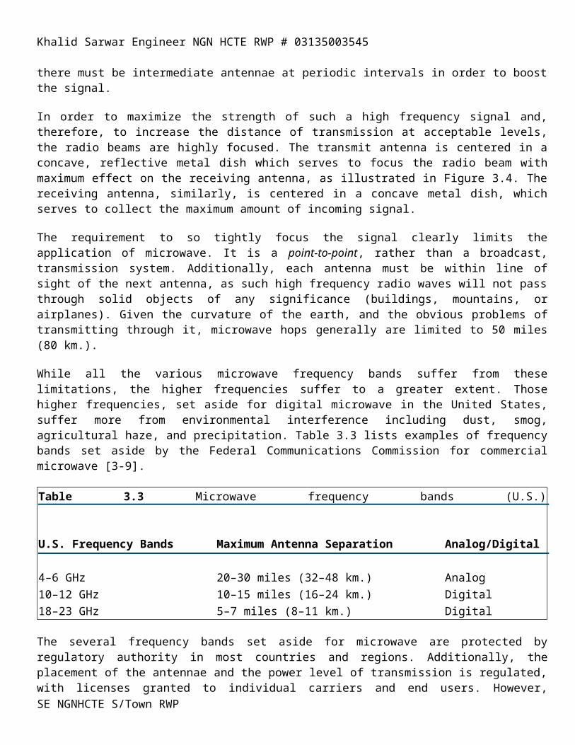
Khalid Sarwar Engineer NGN HCTE RWP # 03135003545
loop’s electrical characteristics. These functions are similar to those provided by Data Service Units (DSUs) and Channel Service Units (CSUs).
CSUs and DSUs
Channel Service Units (CSUs) and Digital Service Units (DSUs) are devices which, in combination, interface the user to the digital network. In contemporary systems. CSUs and DSUs generally are combined into a single device, known variously as a CSU/DSU, CDSU, or ISU (Integrated Service Unit). It typically is found under the skin of another device, such as a multiplexer (MUX). They are used in a wide variety of digital voice and data networks, including DDS and T-carrier, which will be discussed in detail in Chapter 8.
CSUs
These provide the customer interface to the circuit. They also allow the isolation of the DTE/CPE from the network for purposes of network testing. CSU functions include electrical isolation from the circuit for purposes of protection from aberrant voltages, serving the same function as a protector in the voice world. Additionally, the CSU can respond to a command from the carrier to close a contact, temporarily isolating the DTE domain from the carrier domain. This allows the carrier to conduct a loopback test in order to test the performance characteristics of the local loop from the serving central office to the CSU and back to the central office.
The CSU also serves to interface the DTE domain to the carrier domain in an electrical environment. For instance, within the DTE, 1 bits are represented as positive (+) voltages and 0 bits as null (0) voltages. The network requires that 1 bits be alternating + and - voltages and that the 0 bits be 0 voltages. Further, the network requires assurance that ones density is achieved. Depending on the carrier network, from 15 to 80 zeros can be transmitted in a row, as long the density of ones is at least 12.5% over a specified interval of time. CSUs will insert, or stuff, 1 bits on a periodic basis in order to ensure that the various network elements maintain synchronization.
The CSU also provides signal amplification and will generate keep alive signals to maintain the circuit in the event of a DTE transmission failure. Finally, the CSU will store in temporary memory data describing its performance in order that it might be considered by an upstream network management system.
DSUs DSUs convert the DTE unipolar signal into a bipolar signal that is demanded by the network. DSU functions include regeneration of digital signals, insertion of control signals, signal timing and reformatting.
Front-End Processors (FEPs)
FEPs combine the functions of a concentrator and a message switch. They have the ability to concentrate and switch traffic between multiple terminals and groups of terminals in order that a single circuit can be shared for access to mainframe resources. They also are an interface to Wide Area Network (WAN) circuits to serve mainframe resources to remote terminals. Most FEPs are midrange computers that, in turn, connect to the primary host mainframe; FEPs have their own databases. FEPs provide additional functions including error detection and correction, queuing, editing validation, and limited application processing. While the mainframe clearly could perform such tasks, it is more cost-effective to apply a lower order computer to the performance of such mundane responsibilities. In this fashion, the power of the mainframe is reserved for more difficult and demanding tasks in support of user-oriented applications.
Handshaking
SE NGNHCTE S/Town RWP
Khalid Sarwar Engineer NGN HCTE RWP # 03135003545
is the sequence that occurs between the devices over the circuit, establishing the fact that the circuit is available and operational. The handshaking process also establishes the level of device compatibility, determines the speed of transmission by mutual agreement, and so on.
Line Discipline is the sequence of network operations that actually transmits and receives the data, controls errors in transmission, deals with the sequencing of message sets (e.g., packets, blocks, frames, and cells), and provides for confirmation or validation of data received.
Protocol Converters are devices that translate from one native protocol into another, e.g., from ASCII to IBM SNA/SDLC.
Gateways are hardware/software combinations that connect devices running different native protocols. In addition to protocol conversion, gateways provide a gateway connection between incompatible networks. Examples include Ethernet-to-Token Ring gateways, X.25-to-Frame Relay gateways, and T-carrier-to-E-Carrier International Gateway Facilities (IGFs).
Protocol Analyzers are diagnostic tools for displaying and analyzing communications protocols. Analyzers allow technicians, engineers and managers to test the performance of the network to ensure that the systems and the network are functioning according to specifications. LAN managers, for instance, use protocol analyzers to perform network maintenance and troubleshooting and to plan network upgrades and expansions.
Line Set-Up/Connectivity
A very basic protocol issue involves the manner in which the circuit is set up between devices. There are three alternatives: simplex, half-duplex and full duplex (Figure 7-4).
Simplex transmission is unidirectional. The information flows in one direction across the circuit, with no capability to support a response in the other direction. Simplex transmission generally involves dedicated circuits. Simplex circuits are analogous to escalators, doorbells, fire alarms, and security systems. Contemporary applications for simplex circuits, although rare, include remote station printers, card readers, and a few alarm systems (fire and smoke alarms). Generally speaking, simplex transmission is conducted across dedicated circuits of low capacity.
Half-Duplex (HDX) transmission operates in both directions, although not simultaneously. HDX is generally used for relatively low-speed transmission, usually involving two-wire, analog circuits provided on a circuit-switched basis through the PSTN. As the circuit must be turned around in order to support the change in direction of the conversation, it tends to limit the speed and agreeability of conversational data communications. Line turnaround time is a limiting factor, being in the range of 50 to 500 milliseconds (thousands of a second), depending on the length of the circuit. In many environments, HDX is the predominant transmission mode, although high-performance networks are becoming increasingly available and cost-effective. Examples of HDX application include line printers, polling of buffers, and modem communications (many modems can support FDX, as well). HDX is used extensively in transaction-based communications, such as credit card verification and ATM (Automatic Teller Machine) networks. Such applications are not seriously affected by delays associated with line turnaround.
Full Duplex (FDX) is a fully bidirectional transmission mode in which communications is supported in both directions, simultaneously. FDX typically requires two simplex circuits, one operating in each direction. FDX circuits
SE NGNHCTE S/Town RWP
Khalid Sarwar Engineer NGN HCTE RWP # 03135003545
are generally characterized as being four-wire, high-capacity, dedicated circuits, most of which are multichannel in nature. All wideband and broadband circuits are FDX in nature, as are most multichannel circuits. FDX circuits are sometimes used to connect half-duplex terminals in order to avoid issues of line turnaround. More typical examples of FDX applications include channel links between host processors, channel links between controllers/concentrators and hosts, and other applications involving the interconnection of substantial computing systems. Carrier services that deliver FDX capabilities include DDS, E/T-carrier, and broadband services such as Frame Relay, SMDS and ATM, all of which will be discussed in later chapters.
SE NGNHCTE S/Town RWP
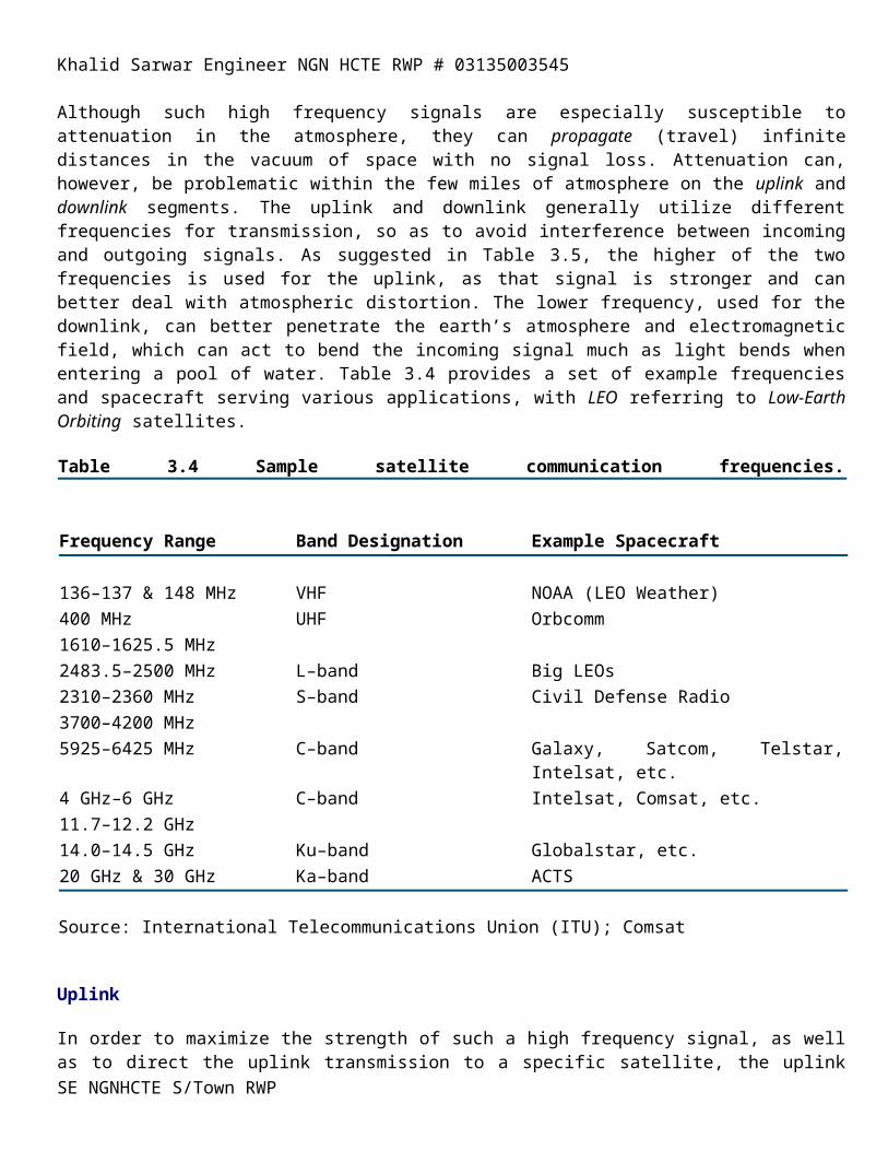
Khalid Sarwar Engineer NGN HCTE RWP # 03135003545
Transmission Methods
Asynchronous
Asynchronous, or character-framed, transmission, is a method which grew out of telegraphy and teletypewriting. From Latin and Greek, it translates as not together with time; in other words, it is not synchronous. Asynchronous transmission is a start-stop method of transmission in which each computer value (letter, number, or control character) is preceded by a start bit, which alerts the receiving terminal to the transmission of something worthy of its attention. The transmitted computer value is succeeded by a stop bit, which advises the receiving terminal that the transmission of that set of information is ended; some asynchronous protocols make use of two stop bits.
PCs, teletypes and other devices which make use of asynchronous transmission frame, or surround, each byte of information with start and stop bits, which are interpreted by the receiving terminal and subsequently stripped away. The inclusion of start and stop bits adds two or three bits of overhead to the transmission of each 8-bit byte. Additionally, asynchronous transmission adds a parity checking bit for relatively poor error control. The framing of the data with these three or four bits of control information yields an overhead, or inefficiency, factor of 20% to 30%.
Asynchronous transmission can be characterized as start-stop (not synchronized) transmission of one character at a time at a variable speed. Additionally, overhead is high and error control is poor.
Synchronous
From Latin and Greek orgins, synchronous translates as together with time. Such transmission is message-framed and overcomes the inefficiencies of asynchronous, start-stop, transmission for high-speed data communications applications. Rather than surrounding each character with start and stop bits, a relatively large set of data is framed or blocked, with one or more synchronization bits or bit patterns being used to synchronize the receiving terminal on the rate of transmission. Through the receipt of the synchronizing bits, or clocking pulses, the receiving device can match its speed of receipt to the rate of transmission across the circuit. Each bit and byte of data and control information can be separately distinguished, as the device knows when to expect what information, and in what sequence. As the large block or frame of data is surrounded by only a few framing bits and synchronizing bits, the overhead is much reduced, the efficiency of transmission is much increased and the effective throughput is much greater.
Error control is quite sophisticated and reliable, involving statistical sampling techniques and mathematical calculations performed on the set of data. Synchronous transmission can be characterized as transmission of multiple characters at a time, organized into character sets and presented in blocks or frames. The transmission is synchronized, and takes place at a predetermined and relatively high rate of speed. Further, error control is excellent and overhead is relatively low.
SE NGNHCTE S/Town RWP
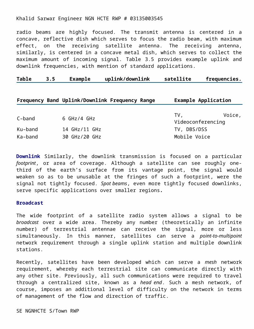
Khalid Sarwar Engineer NGN HCTE RWP # 03135003545
Extended Binary Coded Decimal Interchange Code (EBCDIC)
EBCDIC, developed by IBM in 1962, was the next standardized code to be used extensively. An improvement over earlier Binary Coded Decimal (BCD) (1950) and Extended Binary Coded Decimal (Extended BCD) (1951), EBCDIC was developed to allow different IBM computer systems to communicate based on a standard coding scheme. Although EBCDIC is standardized today, users can modify the coding scheme [7-4].
EBCDIC involves an 8-bit coding scheme, yielding 28 (256) possible combinations and, thereby, significantly increasing the range of expression. As a result, more complex languages can be supported, as can both upper and lower case letters, a full range of numbers (0 to 9) and all necessary punctuation marks. Equally importantly, if not more so, the 8-bit coding scheme supports a large number of control characters, which is critical in the coordination of communications between computers of real significance.
EBCDIC-based machines communicate on a synchronous basis, thereby improving on the speed on transmission. As start and stop bits do not surround each character, overhead is reduced and efficiency of transmission is improved. Further, a more complex, machine-to-machine error detection and correction technique yields improved performance in that regard—detected errors may require retransmission, although forward error correction is often employed, with the receiving system determining the errored bits and correcting for those errors.
American (National) Standard Code for Information Interchange (ANSCII or ASCII)
ASCII was first developed in 1963 and specifically oriented toward data processing applications. It was subsequently modified in 1967 by the American National Standards Institute (ANSI) to address modifications found in contemporary equipment—that version was originally known as ASCII II, but is now known simply as ASCII [7-5].
ASCII employs a 7-bit coding scheme (Figure 7.5), supporting 128 (27)characters, which is quite satisfactory for most alphabets, puctuation, characters, and so on. As ASCII was designed for use in asynchronous computer systems (non-IBM, in those days), fewer control characters were required, making a 7-bit scheme acceptable.
Figure 7.5 ASCII code example, with character framing.
As is the case with asynchronous communications, in general, start and stop bits frame each character, and synchronization bits are not employed. ASCII makes use of a simple error detection and correction scheme known as parity checking. Parity checking is error prone with detected errors often going unnoticed or requiring retransmission, although forward error correction often is currently employed.
SE NGNHCTE S/Town RWP
Khalid Sarwar Engineer NGN HCTE RWP # 03135003545
Parity Checking
Parity checking is by far the most commonly used method for error detection and correction, as it is used in asynchronous devices such as PCs. Parity involves the transmitting terminal’s appending one or more parity bits to the data set in order to create odd parity or even parity. In other words, an odd or even value is always created, character-by-character or set-by-set of data. While less than ideal, this approach is easily implemented and offers reasonable assurance of data integrity. There are two dimensions to parity checking, vertical redundancy checking, and longitudinal redundancy checking.
Block Parity
The technique of block parity improves considerably on simple parity checking. While Spiral Redundancy Checking (SRC) and interleaving improved on the detection of errors due to increased transmission speeds and more complex modulation techniques, they gave way to Cyclic Redundancy Checking (CRC), which is commonly employed today.
Cyclic Redundancy Checking (CRC) validates transmission of a set of data, formatted in a block or frame, through the use of a unique mathematical polynomial known to both transmitter and receiver. The transmitting device statistically samples the data in the block or frame and applies a 17-bit generator polynomial based on a Euclidean algorithm; the result of that calculation is appended to the block or frame or text as either a 16- or 32-bit value. The receiving device executes the identical process, comparing the results. The result is a integrity factor of 10-14; in other words, the possibility of an undetected error is 1 in 100 trillion. By way of example and at a transmission speed of 1 Mbps, 1 undetected error would be expected approximately every 30 years!
An unerrored block or frame is ACKnowledged by the receiving device through the transmission an ACK, whereas an errored block or frame is Negatively AcKnowledged with a NAK. A NAK prompts the transmitting device to retransmit that specific block or frame. The transmission of an ACK by the receiving device cues the sending device that the next block or frame of data can then be sent.
While CRC is relatively memory- and processor-intensive and therefore expensive to implement, it is easily accommodated in high-order computers which benefit from synchronous transmission techniques. As CRC ensures that data transmission is virtually error-free, it is considered mandatory in most sophisticated computer communications environments.
Forward Error Correction (FEC)
Forward Error Correction (FEC) involves the addition of redundant information embedded in the data set in order that the receiving device can detect errors and correct for them without requiring a retransmission [7-6]. The two most commonly employed techniques are Hamming and BCH (Bose, Chaudhuri and Hocquengham).
While even more memory- and processor-intensive than CRC, FEC allows the receiving device to correct for errors in transmission, thereby avoiding most requirement for retransmission of errored block or frames of data. As a result, FEC improves the efficiency, or throughput, of the network, reducing transmission costs in the process and without sacrificing data integrity.
Data Compression
SE NGNHCTE S/Town RWP
Khalid Sarwar Engineer NGN HCTE RWP # 03135003545
As the length of the data sets and the distances over which they travel increase, and as the likelihood of errors in transmission increases accordingly, data compression becomes sensible. Additionally, data compression reduces the bandwidth required to transmit a set of data—bandwidth=$$$. Data compression techniques can include formatting, redundant characters, commonly used characters, and commonly used strings of characters.
Formatting of data need not be transmitted across the network. In a basic example, data compression might involve the removal of formatting from a commonly used form, such as an expense report. Such formatting can involve a large amount of redundant data, as the receiving device can easily reformat the data, placing the various fields of data in the appropriate places on the form, which resides in memory.
Redundant characters can be easily identified by the transmitter communicated to the receiver. This approach is also known as string coding, yielding compression factors of as much as 4:1.
Commonly used characters can be easily identified and abbreviated through the use of an identifier and a smaller set of bits, much as the technique used by Samuel Morse in the development of Morse Code. Huffman Coding is commonly used in this instance, yielding compaction factors of 2:1 or 4:1.
Commonly used strings of characters similarly, can be identified and transmitted in abbreviated form. Such an approach relies on the probability of character occurrence following a specific character (e.g., Q is generally followed by U). Markov source and other techniques address this potential.
SE NGNHCTE S/Town RWP
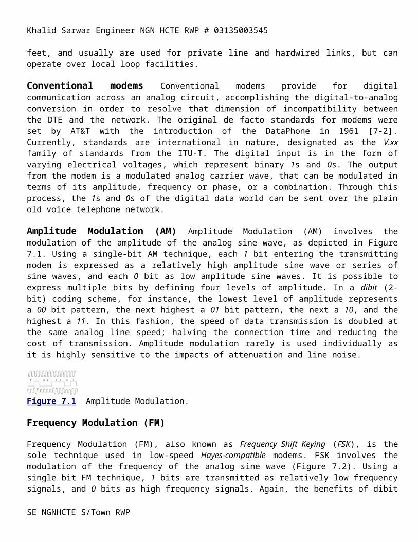
Khalid Sarwar Engineer NGN HCTE RWP # 03135003545
Asynchronous Data Link Control (DLC) Protocols
Asynchronous protocols are used primarily for low-speed data communications between PCs and very small computers. Framing occurs at the byte level, with each byte surrounded by a start bit (a 0 bit) and a stop bit (a 1 bit). A parity bit often accompanies each character, as well. Telex transmission incorporates an additional stop bit.
Kermit and XMODEM are asynchronous protocols, organizing information into 128-byte packets. Kermit also uses CRC error control. The data also can be blocked at the application level, and VRC can be complemented with the additional technique of LRC for improved error control.
Bit- versus Byte-Oriented Synchronous Protocols Two general types of data communications protocols exist, byte-oriented and bit-oriented. While the performance characteristics of byte-oriented protocols are acceptable for many applications, bit-oriented protocols are much more appropriate for communications-intensive applications where the integrity of the transmitted data is critical.
Byte-oriented protocols communicate value strings in byte formats, generally of 8 bits per byte. Control characters (e.g., start bit, parity bit, and stop bit) are embedded in the header and trailer of each byte or block of data. As byte-oriented protocols are overhead-intensive, they are used exclusively in older computer protocols, at the second layer, or link layer. Byte-oriented protocols generally are asynchronous and half-duplex (HDX), operating over dial-up, two-wire circuits. Examples include Bisynchronous Communications (Bisync or BSC).
Bit-oriented protocols transmit information in a much larger bit stream, with opening and closing flags identifying the text from the control information, which addresses control issues associated with the entire data set. Bit-oriented protocols are much less overhead-intensive; they are usually synchronous, full-duplex and operate over dedicated, four-wire circuits. Examples include IBM’s Synchronous Data Link Control (SDLC) and the ISO’s High-Level Data Link Control (HDLC).
Synchronous Data Link Control (SDLC)
SDLC, developed in the mid-1970s, is at the heart of IBM’s System Network Architecture (SNA). SDLC is a bit-oriented protocol that uses bit strings to represent characters. SDLC uses CRC error correction techniques, in this specific case known as Frame Check Sequence (FCS). SDLC supports high-speed transmission, and generally employs full-duplex (FDX), dedicated circuits. SDLC can work either in HDX or FDX, supports satellite transmission protocols, and works in point-to-point or multipoint network configurations.
Up to 128 frames can be sent in a string, with each frame containing up to 7 blocks, each of up to 512 characters. Each block within each frame is checked individually for errors. Errored blocks must be identified as such to the transmitting device within a given time limit, or they are assumed to have been received error-free.
The SDLC frame consists of synchronizing bits, data and control characters sent in a continuous data stream, frame-by-frame. The specific elements of the SDLC frame (Figure 7.9) are as follows and in sequence [7-7].
High-Level Data Link Control (HDLC)
HDLC was developed by the International Standards Organization (ISO) as a superset of IBM’s SDLC and the United States National Bureau of Standard’s (NBS) ADCCP protocols. A version of HDLC is the Link Access
SE NGNHCTE S/Town RWP
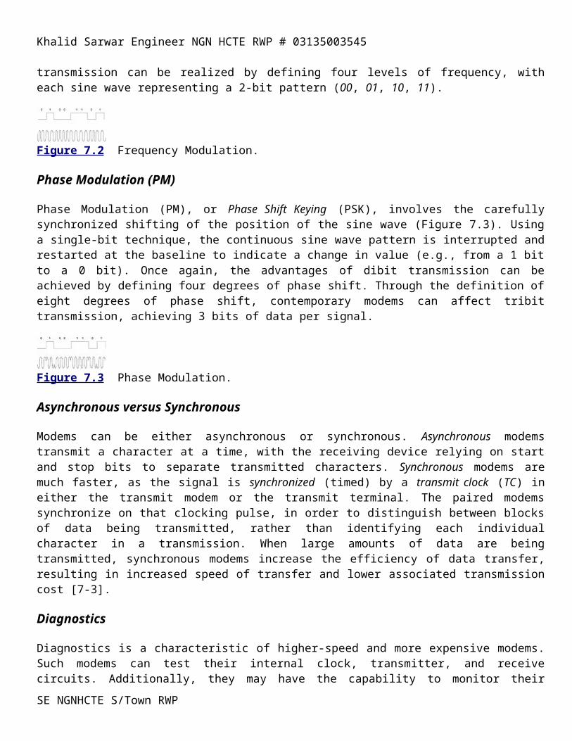
Khalid Sarwar Engineer NGN HCTE RWP # 03135003545
Protocol-Balanced (LAP-B), which is used in ITU-TS X.25 packet switched networks. While HDLC was built on SDLC and is very similar, the two generally are not compatible, depending on the framing conventions in the specific HDLC implementation.
SE NGNHCTE S/Town RWP
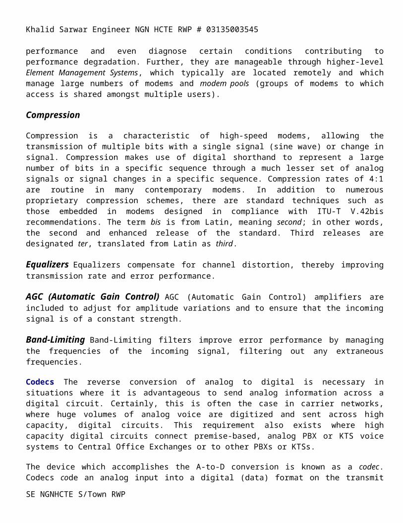
Khalid Sarwar Engineer NGN HCTE RWP # 03135003545
Switched 56 Kbps
Switched 56 is the generic name for Digital Switched Access (DSA), although 64 Kbps service is available in some areas. Switched 56 is a circuit-switched digital service intended generally for the same applications as DDS, although it is more cost-effective for less intensive communications. Although the service is switched, rather than dedicated, most of the general characteristics and all of the components are the same as DDS; the sole exception being that digital carrier exchanges are involved in setting up the DSA connections. DTE is in the form of computer systems that connect to digital local loops through DCE in the form of a DSU/CSU. Digital exchanges serve to switch the connection (see Figure 8.2), which is provided through digital carrier transmission facilities on the basis of special routing logic.
The key difference between DDS and Switched 56 is that the calls are switched between physical locations on the basis of a logical address, which is the computer equivalent of a voice telephone number. In fact, Switched 56 is the digital data equivalent of a circuit-switched voice call through the PSTN. Based on specific routing instructions, the digital network switches establish the end-to-end circuit over entirely digital circuits. The call is set up, maintained, and torn down much like a voice call and it is priced in much the same way; the cost of the call is sensitive to distance, duration, time of day, and day of year. The cost of the call and of the local loop ($30 to $75 per month), of course, are dependent on specific carrier tariffs and pricing strategies. As the carriers’ Switched 56 service networks typically are not interconnected, calling generally is limited to each specific carrier domain unless the user has made other arrangements.
While DDS is more cost-effective for applications in which communications are intensive between specific physical locations, Switched 56 Kbps service is more cost-effective for communications between locations that communicate less frequently or that communicate lesser amounts of data. Switched 56 services often are employed as a back-up to DDS facilities; calls are switched through the highly redundant carrier networks, rather than relying on vulnerable dedicated circuits as is the case with DDS.
Data Terminal Equipment (DTE)
The data equivalent of CPE (Customer Premise Equipment) in the voice world, DTE is the computer transmit and receive equipment, including a wide variety of dumb terminals, or terminals without embedded intelligence in the form of programmed logic. Such terminals are devices that merely provide a user interface to a more capable host computer; examples of dumb terminals include the Hewlett-Packard HP2521P and the Televideo 950. Semi-intelligent terminals (IBM 317x and 327x) possess a limited amount of intelligence, allowing them to perform certain, limited processes, independent of the intelligence contained in the host. Intelligent terminals generally are in the form of personal computers (PCs), which are networked to a host computer. Such devices are highly capable in their own right, although and in this context, they often are linked across a network to an even more capable host. At the top of the terminal food chain are client workstations, highly intelligent and capable devices that access a more capable server in a client/server environment. In such an operating environment, the clients’ requirements for access to files, applications and network communications software are satisfied by a server which typically is accessed across a LAN. As a result, the client workstation can perform certain appropriate functions (e.g., screen formatting) related to the specific user task at hand, while the server’s memory and processing power is dedicated to the performance of tasks that are accomplished more effectively on a centralized basis.
DTE also is in the form of host computers such as mainframes and midrange (minicomputer) computers. Host computers, also known as host nodes, are highly capable devices with substantial processing power and storage
SE NGNHCTE S/Town RWP

Khalid Sarwar Engineer NGN HCTE RWP # 03135003545
memory. Hosts also, at least theoretically, are carefully administered to ensure that they operate successfully and reliably. They also serve as effective information repositories, with the data backed up and archived on external storage media such as magnetic tapes.
SE NGNHCTE S/Town RWP
Khalid Sarwar Engineer NGN HCTE RWP # 03135003545
T-carrier Concept
T-carrier is a dedicated, digital, leased-line service offering that employs time division multiplexing (TDM) in order to derive multiple channels from a single four-wire circuit operating in full duplex (FDX) transmission mode. In capsule, T-carrier offers the advantages of digital error performance, increased bandwidth, and improved bandwidth utilization. As is the case with digital services it also delivers increased management and control capabilities to the carriers and end users. Additionally, T-carrier is medium-independent; it can be provisioned over twisted-pair, coax, microwave, satellite, infrared, or fiber optic cable. As is the case with any dedicated service offering, T-carrier cost is sensitive to distance and bandwidth. While T-carrier initially was deployed in support of voice transmission, it supports data, image and video, as well. Further, T-carrier will support any and all such information streams on an unbiased basis—it offers the advantage of supporting integrated communications. As shown in Figure 8.3, T-carrier can obviate the need for multiple voice, facsimile, data, video and image networks [8-3] and [8-4].
The significance of T-carrier extends well beyond its practical advantages. Specifically, as the first digital carrier system, it set the standards for digital transmission and switching, including the use of Pulse Code Modulation (PCM) for digitizing analog voice signals. T-carrier not only set the basis for the North American digital hierarchy (Table 8.1), but it led to the development of similar standards, such as E-carrier in Europe (Table 8.2) and J-carrier in Japan. Ultimately, the CCITT (now ITU-T) developed international standards in order to ensure interconnectivity. Although T-carrier, E-carrier, and J-carrier are very different in terms of certain specifics of the protocols employed (e.g., transmission rates, encoding techniques. and signaling and control methods), their basic characteristics are much the same.
Digital Signal (DS) Number
Data Rate (Mbps) Number of 64 Kbps Channels (DS-0’s)
Equivalent Number of Tx’s
DS-1 (T1) 1.544 24 1 T1 DS-1C (T1C) 3.152 48 2 T1 DS-2 (T2) 6.312 96 4 T1, 2 T1C DS-3 (T3) 44.736 672 28 T1, 14 T1C, 7 T2 DS-4 (T4) 274.176 4032 168 T1, 84 T1C, 42 T2, 6
T3
Level Number Data Rate (Mbps) Number of 64 Kbps Channels (DS-0s) 1 2.048 30 2 8.448 120 3 34.368 480 4 139.264 1920 5 565.148 7680
SE NGNHCTE S/Town RWP
Khalid Sarwar Engineer NGN HCTE RWP # 03135003545
Channelized T-carrier
The basic component of T-carrier is a 64 Kbps channel, referred to as DS-0 (Digital Signal #0). Digital carrier is a channelized service, at least in a standard implementation. In other words, a single, high-capacity digital circuit supports multiple logical channels, with each channel supporting a separate conversation. A T1 circuit, for instance, operates at 1.544 Mbps, supporting a standard 24 Time Division Multiplexed (TDM) channels, each of 64 Kbps. E1 supports 30 TDM channels of 64 Kbps; J1 supports 24 channels as does T1.
T-carrier hierarchy standards (Table 8.1) were set by the American National Standards Institute (ANSI) in its T1.107 specifications. Beginning at the T1 level, the hierarchy progresses up to T3, which provides bandwidth of approximately 45 Mbps in support of 672 channels. Most end users subscribe to T1 services, as one or more T1’s satisfy their bandwidth requirements. Generally, the next step is T3, with the intermediate levels being unusual in end-user implementation, although they are employed extensively in the carrier networks. As one might expect, as the data rate increases, the carrier reference frequency increases, and issues of signal attenuation and crosstalk increase; this fact creates special engineering problems [8-6] that can be resolved by various means including spacing repeaters more closely together [8-5].
The process of transmitting data (voice, data, video, or image) in given and consistently repeated channels, or time slots, is know as byte interleaving. Each byte of a given conversation to be transmitted is accepted by the MUX, assuming capacity is available, and is assigned one or more time slots. In a baseline example, those 64 Kbps time slots are reserved for that conversation, with the MUX providing the transmitting device with regular and repeated access to them for the duration of the communication.
Unchannelized T-carrier
Unchannelized T- carrier can be used to support bandwidth-intensive services that do not lend themselves to 64 Kbps channelization and standard framing conventions [8-8]. In other words, the traditional convention of 64 Kbps channels can be abandoned in favor of carving the T1 pipe into any segments of bandwidth of any usable size or increment. Additionally, any combination of bits can be transmitted, including an infinite number of zeros, without concern for the violation of the 1s density rules; in other words, a clear channel of 64 Kbps or more, rather than a 56 Kbps channel [8-5] and [8-6]. For instance, a very high-speed data communication or a full motion videoconference, might require a full T1 pipe. A less intensive communication might require 512 Kbps (8 channels, or one-third of a T1 facility).
Such services are supported through customer equipment in the form of highly intelligent TDM MUXs. In a private, dedicated leased-line network, this is easily accomplished. However, the carrier must be aware of the fact that such use will be made of the facility, in order that the entire facility can be properly allocated and managed.
Encoding
While T1 is a digital service, it supports the transmission of analog data as well. Voice and video, analog in their native forms, must be digitized through the use of codecs prior to being transmitted over a T1 circuit. The standard digitizing technique for voice, known as Pulse Code Modulation (PCM), was developed as an integral part of T-carrier. It also became the standard technique for digitizing voice in PBXs and other devices, for the obvious reason of providing seamless transmission between such devices and the network. The quantizing techniques typically employed include PCM and ADPCM; non-standard approaches included CVSD, VQL, VQC and HCV.SE NGNHCTE S/Town RWP
Khalid Sarwar Engineer NGN HCTE RWP # 03135003545
Pulse Code Modulation (PCM)
PCM is based on the Nyquist theorem developed by Harry Nyquist in 1928. Nyquist established the fact that the maximum signaling rate achievable over a circuit is twice the number of signal elements [8-9]. In consideration of the Nyquist theorem, PCM specifies that the analog voice signal be sampled at twice the highest frequency on the line. As a voice-grade analog line provides 4,000 Hz of bandwidth, the signal must be sampled 8,000 times per second. Each sample is a measurement of the amplitude of the sine wave; the frequency of signal change is automatically taken into account. The individual samples are encoded (quantized) into an 8-bit binary (digital) approximate value, based on a table of 255 standard values of amplitude. The individual samples then are transmitted in regular time slots over the T-carrier circuit, with the process reversed on the receiving end of the connection in order to reconstitute an approximation of the original analog voice signal (Figure 8.4). While the sampling rate and the 8-bit coding scheme were the subject of much debate, the yield is very high quality voice, although the bandwidth requirement is a bit excessive. It should be noted that sampling that is too infrequent results in a reconstructed analog voice signal that is less than smooth and accurate and, therefore, not pleasing. This phenomenon yields unacceptable levels of quantizing noise [8-2] and [8-5].
Figure 8.4 PCM encoding of analog voice signal, with reconstruction of approximate analog voice.
4,000 Hz X 2 8,000 Samples/Second X 8 Bits per Sample 64 Kbps
As noted in the above calculation, 8,000 8-bit samples per second yields a bandwidth requirement of 64 Kbps for a PCM-encoded digital voice signal. As PCM was the first standard technique widely used in digital carrier systems, the 64 Kbps channel became standard, worldwide, for all forms of digital networking.
SE NGNHCTE S/Town RWP

Khalid Sarwar Engineer NGN HCTE RWP # 03135003545
X.25 Packet Switching
Packet switching was invented in the early 1960s by Paul Baran and his research associates for the RAND Corporation. Interestingly enough, the concept first was published in 1964 as a means of transmitting secure voice for military application. In the late 1960s, the U.S. General Accounting Office (GAO) issued a report suggesting that there existed a large number of data centers supported, at least in part, by the federal government. Further, the report indicated that many of those data centers were underutilized, and others were severely stressed. The imbalance was due largely to the lack of a wide area network technology that would allow the sharing of those resources on a cost-effective basis.
As a result of that study, the Advanced Research Project Agency Network (ARPANET), the first sophisticated packet switched network, was created in 1971. ARPANET was developed to link computers on a time-share basis in order to share computer resources on a cost-effectively [8-15]. Specifically, ARPANET was designed to support various defense, higher education, and research and development organizations [8-16]. In 1983 the majority of ARPANET users spun off to form the Defense Data Network (DDN), also called MILNET (MILitary NETwork), which included European and Pacific Rim continents. The United States and European locations which remained ARPANET then merged with the Defense Advanced Research Project Agency Network to become DARPA Internet [8-17].
Packet switching soon was commercialized and made widely available by Telenet, Graphnet (a facsimile-like service) and others. Packet switching was utilized very early on and extensively in Europe, as well. In fact, packet switching quickly became available in most countries, and currently is virtually ubiquitous. The CCITT (now the ITU-T) in 1976 internationally standardized X.25 as the interface for a packet-switched network.
The wide availability of packet switching has made it consistently popular over the last twenty years or so. Additionally, packet networks are highly cost-effective for applications that require many-to-many connectivity, and which involve relatively low data volumes. That popularity is growing and is ensured well into the future, largely through its historical deployment as the network technology of the Internet. It should be noted that X.25 is an interface specification, and does not define the internal operations characteristics of the data network.
The Concept of Packet Switching
The basic concept of packet switching is one of a highly flexible, shared network in support of interactive computer communications across a wide area network (WAN). Previously, large numbers of users spread across a wide area with only occasional communications requirements had no cost-effective means of sharing computer resources (time-share) from their remote terminals. In specific, the issue revolved around the fact that asynchronous communications are bursty in nature; data transmission is in bursts of keystrokes or data file transfers, with lots of idle time on the circuit between transmissions in either direction or relatively small amounts of data. Additionally, those early networks consisted of analog, twisted-pair facilities, which offered very poor error performance and relatively low bandwidth.
Existing circuit-switched networks certainly offered the required flexibility, as users could dial up the various host computers on which the desired database resided. Through a low-speed modem, data is passed over the analog network, although error performance was less than desirable. However, the cost of the connection was significant, because calls were billed based on the entire duration of the connection, even though the circuit was idle most of the time. Dedicated circuits could solve the cost issue, as costs are not usage-sensitive; however, dedicated circuits are expensive. Further, users tended not to be concentrated in locations where they could make
SE NGNHCTE S/Town RWP
Khalid Sarwar Engineer NGN HCTE RWP # 03135003545
effective use of dedicated circuits on a shared basis. Finally, large numbers of dedicated circuits would be required to establish connectivity to the various hosts.
Packet switching solved many of those problems, in the context of the limitations of the existing networks—namely, analog, twisted-pair. Packet-switched networks support low-speed, asynchronous, conversational and bursty communications between computer systems. As packet-switched network usage is billed to the user on the basis of the number of packets transmitted, they are very cost-effective for low-volume, interactive data communications. This cost advantage comes from the fact that the bursty nature of such interactive applications allows large volumes of data transmissions from multiple users to be aggregated in order to share network facilities and bandwidth [8-17]. Further, packet-switched networks perform the process of error detection and correction at each of the packet switches, or nodes, improving the integrity of the transmitted data considerably.
Understanding the concept and nature of packet switching requires the examination of a number of dimensions and characteristics of such networks including packet structure, switching and transmission, error control, connection-oriented service, latency, permanent virtual circuits versus switched virtual circuits, protocol conversion, and access techniques.
Packet Structure
Information is transported and switched through the network on the basis of packets (Figure 8.6). Each packet is of a fixed maximum size, typically containing 128B (B=byte or octet) or 256B of payload (user data); packet sizes of up to 4,096B can be accommodated in some networks. The typical upper limit of a packet is 1,024B [8-18], as is the case in many airline reservation networks
Permanent Virtual Circuits (PVCs) and Switched Virtual Circuits (SVCs)
Packet switching supports a large number of conversations over virtual circuits using the same, previously designated circuit or path. While the individual packets of the typical user may travel different paths, large users may be supported by PVCs. In this scenario, all packets will travel the same path between two computers, which path is established by routing instructions programmed in the involved nodes. Alternatively, the network may select the most available and appropriate path on a call-by-call basis using Switched Virtual Circuits (SVCs). Again, all packets in a given session travel the same path [8-19].
Protocol Conversion
As an option, packet-switched networks will accomplish protocol conversion (Figure 8.8). Protocol conversion can include any protocol that is well-established, well-understood, widely-deployed and, therefore, supported by the carrier. As this process of protocol conversion adds value, packet networks (X.25) are widely recognized as the first Value-Added Networks (VANs). Protocols supported typically include asynchronous, IBM Bisync (BSC), and IBM SDLC.
SE NGNHCTE S/Town RWP
Khalid Sarwar Engineer NGN HCTE RWP # 03135003545
ISDN
Terminal Equipment (TE)
Terminal Equipment (TE) is the term for a functional device that connects a customer site to ISDN services. Examples include computers, telephones, facsimile machines, and videoconferencing units. TE1 has a built-in ISDN interface, while TE2 devices do not have native ISDN compatibility.
Terminal Adapters (TAs)
Terminal Adapters (TAs) are interface adapters for connecting one or more TE2 (non-ISDN) devices to an ISDN network. TAs act as ISDN DCE, serving a function equivalent to protocol or interface converters. Applied to equipment which does not have ISDN capability built within it; the TAs must be exactly tuned to the specific CPE/DTE. TAs can be in the form of either standalone units or printed circuit boards fitting into an expansion slot of a PC.
A key function of the TA is that of rate adaption, which effectively throttles down the transmission rate from 64 Kbps to the rate at which the non-ISDN device is capable [8-32]. As an example, a non-ISDN PC might be capable of only 19.2 Kbps through the serial port. Another example might involve a connection supported at only 56 Kbps (non-ISDN or Pacific Bell “ISDN”) on the receiving end; the device would throttle down to that rate, rather than 64 Kbps. Rate adaptation is accomplished in North America through the ITU-T V.120 protocol; the European standard is V.110.
Network Terminations (NTs) Network Terminations 0(NTs) are Network Termination devices, NT1s and NT2s.
NT2s NT2s (Network Termination type 2) are intelligent devices responsible for the user’s side of the connection to the network, performing such functions as multiplexing, switching or ISDN concentration. A NT2 device would likely be in the form of a PABX, LAN router or switching hub.
NT1s NT1s (Network Termination type 1) physically connect the customer site to the carrier side of the connection, performing such functions as signal conversion and maintenance of the local loop’s electrical characteristics. In a PRI environment, these functions are similar to those provided by Data Service Units (DSUs) and Channel Service Units (CSUs). In a BRI environment, these devices are TE1 devices.
Inverse MUXs, Inverse MUXs, offered by some manufacturers, allow multiple BRIs to be bonded, or linked, for greater aggregate transmission over a BRI circuit(s). For example, four BRIs can be linked to support a 512 Kbps data transmission. Such an approach competes effectively with Fractional T1 (FT1).
D-Channel Contention Devices D-Channel Contention Devices, offered by some manufacturers, allow as many as eight devices to share a BRI circuit, contending for access to the B-channel. The individual devices identify themselves to the network through contention for the D channel.
ISDN Characteristics And Benefits
SE NGNHCTE S/Town RWP
Khalid Sarwar Engineer NGN HCTE RWP # 03135003545
ISDN is unusual, if not unique, as it is undoubtedly the most carefully planned, well coordinated, and best documented network technology in history. Despite this fact, it will be at least a decade before it is widely available and implemented. The key characteristics of ISDN include its end-to-end digital nature, unusual for a circuit-switched network. Through a small family of interfaces, a wide range of services can be accessed through the LEC, IXC or CAP. Rate adaption and channel aggregation allow bandwidth-intensive applications to be supported on a dynamic basis.
ISDN’s reliance on SS7 (discussed in Chapter 6) offers a number of advantages, including faster call setup and nonintrusive signaling and control. Additionally, SS7 (either with or without ISDN) makes possible a number of interesting CLASS services, including Caller ID, Name ID, call trace, selective call forwarding, and selective call blocking.
ISDN also is interoperable with X.25, Frame Relay, SMDS and ATM. In fact ISDN standards were developed specifically with these services in mind. Frame Relay, in particular, is closely aligned with ISDN link-level protocols. Broadband ISDN (B-ISDN), although many years in the future, is dependent on ATM network technology.
ISDN Characteristics and Drawbacks
ISDN is not without its drawbacks, which include limited availability, standards variations, channel application, and high cost. As discussed earlier, availability is limited in most nations, because ISDN and SS7 software are costly for the carriers to deploy. While ISDN capability can be extended to non-ISDN CO exchanges, that incremental cost is not trivial. As discussed previously, standards vary by carrier and manufacturer, and BRI limits the user to a single voice channel.
Not surprisingly, cost/benefit considerations dictate the success or failure of technologies, regardless of how compelling they appear at first glance. The cost of an ISDN BRI circuit is more than twice that of an analog line—installation costs can range as high as $578.00 per BRI (Southwestern Bell). These costs tend to discourage ISDN to a considerable extent, particularly in voice-intensive environments—although ISDN provides three channels, only one can be used for voice at any given time.
Additionally, many carrier tariffs impose a usage surcharge in the form of a flat rate per minute. The usage charge may apply to local, as well as long distance, calls. Additionally, data calls often carry a higher usage rate than do voice calls. While this additional usage charge tends to discourage ISDN usage, the call connect time may be reduced significantly through ISDN. Pacific Bell [8-31] suggests that a 20MB file can be transmitted from California to Japan via a 90 Kbps ISDN connection in 3.7 minutes at a cost of $6.32. This compares quite favorably with an analog modem transfer at 14.4 Kbps, which would take 23.1 minutes and cost $29.85. Group IV facsimile transmission over ISDN lines also offers significant long distance cost savings when compared to Group III analog transmission.
Hardware Costs are additional in support of ISDN. In a BRI environment, such additional equipment might include Terminal Adapters (TAs), Inverse MUXs, and BRI contention devices. In a PRI application, ISDN software for PBXs and routers is an additional cost. Older systems might require replacement in order to effect ISDN compatibility.
A final cost issue centers on equal access charges, or Subscriber Line Charges (SLCs). In 1995, the FCC decision considered the application of the SLC to ISDN on a per-channel basis, rather than the standard per-circuit approach [8-33]. Although the FCC relented under pressure from carriers and users, regulators may strike a similar posture in the future.SE NGNHCTE S/Town RWP
Khalid Sarwar Engineer NGN HCTE RWP # 03135003545
ISDN Applications
The applications for ISDN are broad in range. While ISDN was long described as “a technology in search of an application,” it recently has been opened to applications developers, and aggressively so. There is no killer ap for ISDN, rather there are a number of applications that, in total, promise to ensure the future of ISDN. A host of applications which benefit from the improved quality of digital networking and that are bandwidth-intensive are well served by ISDN. Further, ISDN offers an affordable circuit-switched alternative to DDS, Switched 56, and T-carrier, which simply cannot be cost-justified in many cases.
Personal office internetworking, remote office internetworking, and telecommuting (or Telework) all are facilitated by the increased bandwidth and error performance offered by ISDN BRI. In such applications, file transfers and facsimile transmission are accomplished much more quickly and with much greater clarity; the improved quality of the voice communications are an added benefit [8-34].
ISDN also is used for access to X.25 packet networks, with users benefiting from the faster call setup and teardown time made available by virtue of SS7. As either the B channels or D channel can be used for packet data transfer in a BRI implementation, ISDN offers additional flexibility and bandwidth utilization. Additionally, some manufacturers of Terminal Adapters offer built-in X.25 PADs for end-to-end error correction [8-35].
As a replacement or backup for dedicated digital services, ISDN performs well for data and image networking, whether in a host-to-host, LAN-to-LAN, or remote LAN access application. Intensive users of the Internet and World Wide Web find ISDN bandwidth to be of great advantage, as the speed of call setup and file transfer are much increased compared to dialup analog connections. For instance, a typical WWW page takes 3 minutes to load over an analog line with a 14.4 Kbps modem, but less than 20 seconds at BRI speed of 128 Kbps [8-36]. As discussed in Chapter 4, incoming call centers can take advantage of ISDN to increase productivity, as well as make use of remote agents working from home.
For purposes of illustration, at least one example merits further discussion. A remote worker might desire to access an application residing on a LAN-connected server. An ISDN call to a local LAN site would save on long distance charges; that LAN site would connect the user to a remote site through another ISDN link. When the remote client workstation is idle, ISDN would disconnect the LAN-to-LAN link to save on long distance charges. Through a process known as spoofing, the application would remain alive, as it continues to see a logical link over the B-channel. The interactive data conversation can quickly be reinitiated due to the fast call setup time of SS7, which is an integral element of ISDN. The remote worker in this scenario might be a telecommuter, working from home several days a week.
In terms of vertical markets, ISDN is of particular interest in the healthcare and education sectors, largely because of its ability to support imaging and video through rate adaption. TeleMedicine, in particular, is of interest, as it allows specialists to diagnose and treat patients in remote areas based on video examination and transmission of X-ray images across error-free and high-speed ISDN links.
The applications for ISDN are virtually unlimited, at least in terms of the network services that can be accessed. Through a single ISDN local loop, voice, facsimile, data, video and image information can be accommodated. Additionally, simultaneous access to multiple networks and network services can be accomplished, perhaps including circuit-switched voice, X.25 packet, and Frame Relay. From a user perspective, ISDN is highly flexible. From a carrier perspective, ISDN offers the advantage of consolidating access to multiple networks; relieving the strain on local loop, switching, and transport facilities. Additionally, ISDN offers the LECs the promise of putting the telephone company world back together much like it was before deregulation, divestiture, SE NGNHCTE S/Town RWP
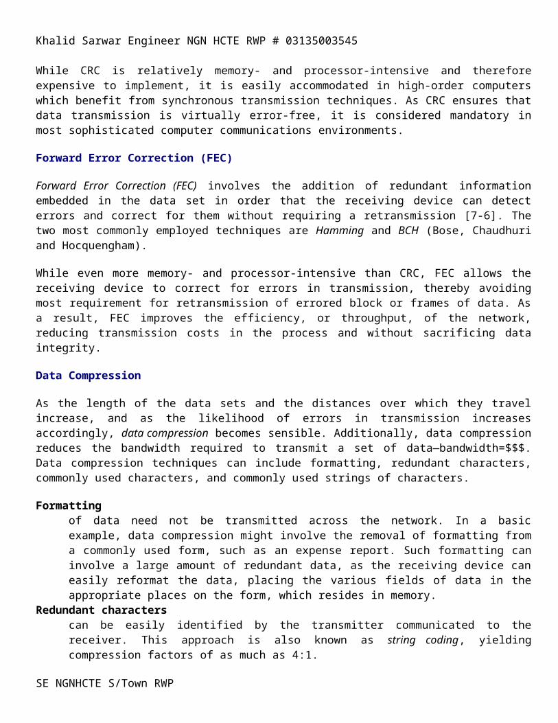
Khalid Sarwar Engineer NGN HCTE RWP # 03135003545
and competition. In other words, the LECs can market ISDN as a single network access solution—sort of a one-stop shop.
International ISDN: Variations on the Theme
ISDN has experienced differing levels of success around the world due to various marketing approaches, pricing strategies and, in some cases, aggressive government support. For instance, the Japanese government has lent strong support to the development and deployment of high-technology networks and network services.
Telecom Australia was very successful in marketing PRI to large user organizations, in part as an alternative to leased lines. An unusual offering is that of semi-permanent circuits within PRI, priced at approximately 50% of the cost of a dedicated circuit. In the competitive Australian telecom environment, this approach was successful in countering leased-line networks offered by alternative carriers such as Optus.
Deutsche Bundespost Telekom offers ISDN on a widely available and low cost basis. In excess of 80% of Germany’s population has access to ISDN within six weeks of placing an order. Pricing is very attractive compared to leased lines. For application development, CAPI (Common Application Programming Interface) is supported.
For years, carriers in Western Europe have offered a service known as 0B+D. That offering provides access to a solo 16 Kbps D-channel for low-speed data transmission. Packet data is supported at speeds up to 9.6 Kbps, with signaling and control consuming the balance of the capacity—no B-channels are involved. This service effectively challenges X.25 packet networking for transaction-oriented applications such as credit card authorization.
SE NGNHCTE S/Town RWP
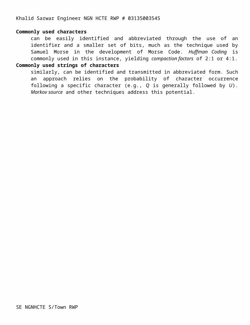
Khalid Sarwar Engineer NGN HCTE RWP # 03135003545
Broadband Data Networking
Although Broadband Data Networking will be discussed in detail in a later section, it is worth a quick overview of certain key technologies and service offerings, including Frame Relay and Cell Relay.
Frame Switching (Frame Relay)
A relative newcomer, Frame Relay was first deployed in the mid-1990s. Much like packet switching, each frame is addressed individually. Frame relay also makes use of special switches and a shared network, of very high speed. Unlike packet switching, frame relay supports the transmission of virtually any computer data stream and frames are variable in length (up to 4,096 bytes). Rapidly gaining in popularity, frame relay is widely available in many highly developed nations. International frame relay service is also becoming widely available. A service which is primarily data-oriented, Frame Relay does not support voice or video effectively. As is the case with X.25 packet switching, Frame Relay overhead can be relatively high, delays (latency) in transmission are expected, and network congestion can result in lost data; the responsibility for error detection and correction is shifted to the user in a Frame Relay environment.
Cell Switching
Clearly the future of communications networking, cell switching encompasses both Switched Multimegabit Data Service (SMDS) and Asynchronous Transfer Mode (ATM), data is organized into cells of fixed length (53 octets), shipped across very high-speed facilities and switched through very high speed, specialized switches. While SMDS has proved to be very effective for data communications ATM will be pervasive in the future; ATM will be the platform for Broadband ISDN (B-ISDN). ATM is primarily data-oriented, although it is ultimately intended to support voice and video. Standards are still developing and availability is limited. Current disadvantages of ATM include its relatively high cost, high overhead, and lack of fully developed standards.
SE NGNHCTE S/Town RWP
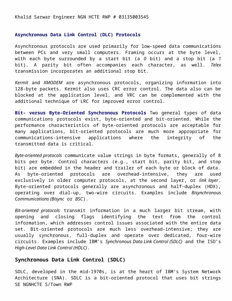
Khalid Sarwar Engineer NGN HCTE RWP # 03135003545
Broadband LANs
Broadband LANs are multichannel, analog LANs (Figure 9.5) typically based on coaxial cable as the transmission medium, although fiber optic cable is also used on occasion [9-2]. Individual channels offer bandwidth of 1 to 5 Mbps, with 20 to 30 channels typically supported. Aggregate bandwidth is as much as 500 MHz. The various channels are multiplexed onto the carrier through Frequency Division Multiplexing (FDM). Radio modems accomplish the digital-to-analog conversion process, providing the transmitting device access to an analog channel. The modems, which must be tuned and managed carefully, may be fixed-frequency or frequency-agile. Fixed-frequency modems are tuned to a specific frequency channel, while frequency-agile modems have the ability to search for an available channel. Although frequency-agile modems are more expensive to acquire and administer, they offer improved communications and bandwidth utilization. As the LAN is analog in nature, it can easily accommodate voice and video. Some broadband LANs are referred to as 10Broadband36, translated as 10 Mbps, Broadband (multichannel), with 3600 meters maximum separation between devices.
The characteristics of Broadband LANs, generally speaking, are not endearing. However, their unique properties do have application. As an example, a chain of theme parks uses Broadband LANs extensively to support paging (audio voice), closed circuit TV (video), and data. Becuase the LAN is analog, it supports audio and TV easily. Further, the application is static, rather than dynamic, as the paging zones and closed-circuit TV channels require fixed amounts of bandwidth, and the frequency channel assignments need be changed infrequently, if ever. Further, the locations of the terminal equipment (paging source and horns, and VCRs and TV monitors) are fixed, or seldom change.
Baseband LANs
Baseband LANs are single channel, supporting a single communication at a time (see Figure 9.5). They are digital in nature, varying the bit state through voltage on/off or light pulse on/off. Total bandwidth of 1 to 100 Mbps is provided over coax, UTP, STP, or fiber optic cable. Distance limitations depend on the medium employed and the specifics of the LAN protocol. Baseband LAN physical topologies include ring, bus, tree, and star.
Baseband LANs are by far the most popular and the most highly standardized. Ethernet, Token Passing, Token Ring and FDDI LANs are all baseband. They are intended only for data—data communications is, after all, the primary reason for the existence of LANs. Recently, however Ethernet, FDDI and other LANs have announced versions to support voice, video, and videoconferencing. While the support of such isochronous traffic offers clear advantages in support of workgroup communications, the LAN data traffic can be affected to a considerable extent.
High Bit-Rate Digital Subscriber Line (HDSL)
It is intended as a more cost-effective means of providing T-1 local loop circuits over existing UTP.
HDSL Technology
SE NGNHCTE S/Town RWP
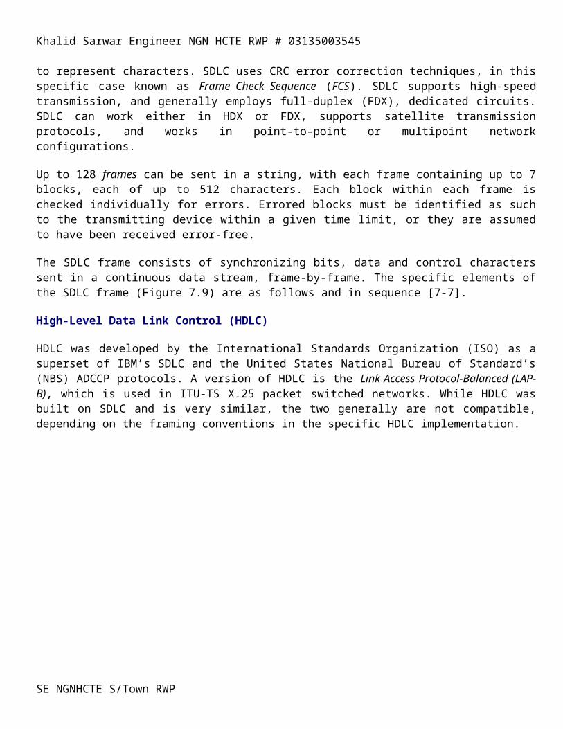
Khalid Sarwar Engineer NGN HCTE RWP # 03135003545
HDSL eliminates repeaters in the T1 local loop for distances up to 12,000 feet, using the same 2B1Q (2 Binary, 1 Quaternary) coding scheme used in ISDN. Conventional T1 uses 2 pairs, each of which operates in simplex mode (one transmitting and one receiving) in a different direction at the full T1 rate of 1.544 Mbps. At such high frequencies, interference can be significant between the T1 pairs and adjacent pairs in the cable; additionally, signal attenuation is considerable. Therefore, it is necessary that the repeaters be spaced approximately 6,000 feet apart in order to adjust for distortion and signal loss.
HDSL, while it also uses two pairs of UTP, splits the pairs into full-duplex (FDX) channels. Each pair operates at 784 Kbps, (see Figure 10.2) half the T-1 rate plus some additional overhead. As the transmission rate per pair is halved, the frequency level is roughly halved; therefore, signal loss and interference are much less. The yield is that of longer transmission distances (up to 9,000 feet) without repeaters. As one might expect, the UTP cable plant must be in good condition and free of bridged taps.
The real advantage of HDSL is that T1 service can be provisioned at much lower cost and in a much shorter interval of time. While HDSL equipment currently costs about $2,000 per circuit [10-12], that cost will come down quickly as the technology gains market share. As repeaters are eliminated or reduced in number, the incremental cost of HDSL is mitigated to some extent. Additionally, the cable plant supporting HDSL does not require special conditioning or engineering, further reducing costs, as well as allowing service to be provisioned much more quickly. Finally, HDSL offers error performance of approximately 10-10, as compared to the 10-7
level offered by repeatered T1 over twisted-pair, according to PairGain Technologies Inc., the leading supplier of HDSL equipment [10-13], with over 300,000 units sold.
SE NGNHCTE S/Town RWP
Khalid Sarwar Engineer NGN HCTE RWP # 03135003545
Frame Relay
Frame Relay has experienced unprecedented growth since its commercial introduction by Wiltel (since acquired by LDDS Worldcom) in 1992. AT&T, the largest U.S. domestic provider with about 35% of the market, enjoyed a 600% increase in Frame Relay service in 1995, following a 500% increase in 1994. The 1995 worldwide market for Frame Relay equipment and services is forecast at a total of $2.19 billion, up from the 1994 market of $1.71 billion, an increase of 28%. The carrier service revenues for Frame Relay were estimated by Infonetics Research to be approximately $700 million in 1995 and forecast to be $2.3 billion in 1997. The worldwide frame relay customer count grew from approximately 5,000 in January 1995 to about 15,000 by January 1996 [11-1].
Frame Relay Defined
Frame Relay is a network interface, or access, standard which was defined in 1988 by the ITU-T in its I.122 recommendation, “Framework for Providing Additional Packet Mode Bearer Services.” Access to a Frame Relay network is accomplished using the LAP-D (Link Access Protocol-D channel) signaling protocol developed for ISDN, as it originally was intended as an ISDN framing convention for a bearer service. Frame Relay standards say nothing about the manner in which the internal network operates. As is the case with X.25 packet networks, such issues are left to manufacturers that develop proprietary switching technologies [11-2]. Access rates generally range up to T1, although speeds of T3 and above are possible [11-3]. Notably, Frame Relay is backward-compatible, as it considers the characteristics of the embedded networks and the standards on which they are based. Electrical interfaces are not rigidly defined for Frame Relay.
Very much analogous to a streamlined and supercharged form of X.25 packet switching, Frame Relay sets up and tears down a call with control packets, as does X.25. Frame Relay also forwards packets of data, in the form of frames. Similar to X.25, Frame Relay effectively multiplexes frames of data over a shared network of virtual circuits for maximum network efficiency. The interface is in a FRAD (Frame Relay Access Device) which can be implemented on the customer premise, much as is the case with a X.25 PAD (Packet Assembler/Disassembler). As is the case with X.25, Frame Relay is intended for bursty data traffic. While both can support carry voice, video and audio, the presentation can be less than pleasing due to packet delay and loss.
At that point, the two technologies diverge (see Table 11.1 for a comparison between X.25 and Frame Relay). Frame Relay is a connection-oriented service that assumes a high-speed user link, as well as a high-speed transport system that is generally fiber optic in nature. Frame Relay assumes no responsibility for error detection and correction in the user information field as there are assumed to be no errors in transmission; rather, error control is the responsibility of the end user. In other words, Frame Relay operates at Layers 1 and 2 of the OSI Reference Model. This ceding of responsibility to the end user reduces the processing load on the network, reducing latency (delay) significantly and yielding faster transmission of each frame of data. Frame Relay does check for errors in the control field, which is used for routing and other network purposes; errors in this field cause frames to be discarded. Frame Relay is protocol-independent and provides no protocol conversion services.
Table 11.1 X.25/Frame Relay Comparison
ATTRIBUTE X.25 FRAME RELAY
FACILITIES Analog Assumed Digital Assumed
SE NGNHCTE S/Town RWP
Khalid Sarwar Engineer NGN HCTE RWP # 03135003545
PAYLOAD 128B/256B Fixed < 4,096B Variable ACCESS SPEED < 56 Kbps-DS1 < 56 Kbps-DS1, DS3 LINK LAYER PROTOCOL LAP-B LAP-D/LAP-F LATENCY High Moderate ORIENTATION Connection-Oriented Connection-Oriented ERROR CONTROL Network User PROTOCOL CONVERSION Yes No PRIMARY APPLICATION
Interactive Data LAN-to-LAN
Frame Relay Standards
Frame Relay is supported by a wide range of manufacturers and carriers, both domestic and international. Standards bodies include ANSI, ETSI and the ITU-T. The Frame Relay Forum, a voluntary group of manufacturers and other interested parties, develops and promotes Implementation Agreements (IAs), to address manufacturer interoperability issues based on the standards. Select applicable standards are noted in Table 11.2.
Frame Relay Access
Frame Relay access is provided on the basis of a dedicated digital link into a Frame Relay node. The typical speed of the access link can range up to 44.736 Mbps and can be in the form of DDS (56/64 Kbps), Switched 56/64 Kbps, ISDN BRI (64/128 Kbps) or PRI (1.544 Mbps), FT1 (N x 64 Kbps), T1 (1.544 Mbps) and T3 (44.736). In March 1996, LDDS Worldcom (MS) [11-4], and MCI (DC) announced Frame Relay service at speeds of 6 Mbps, 10 Mbps and 19.8 Mbps. No information is available relative to the success of these offerings, and no other carriers have followed suit at the time of this writing.
Customer DCE is the form of a FRAD (Frame Relay Assembler/Disassembler), which may be standalone, although it generally is embedded under the skin of another device such as a router. From the FRAD, access is gained to the link and, subsequently, to the Frame Relay network node. As the node resides in the FRND (Frame Relay Network Device). The UNI (User Network Interface), as defined by ANSI and ITU-T, defines the nature of this access interface.
Frame Relay Network
The Frame Relay network (Figure 11.2) consists of specified network interfaces in the form of the User Network Interface (UNI) and Network-to-Network Interface (NNI). The specifics of the internal carrier network are based on ISDN, making use of Permanent Virtual Circuits (PVCs). While Switched Virtual Circuits (SVCs) are not yet implemented; many of the major carriers intend to make them available by mid-1997. Among the first to implement SVCs will be Ameritech, MCI, and CompuServe [11-5]. Frame Relay networks can be public, private, or hybrid.
User Network Interface (UNI) is the demarcation point between the user DTE and the network, and is in the form of a FRAD (Frame Relay Access Device) and a FRND (Frame Relay Network Device).
Network-to-Network Interface (NNI) is defined as the interface between frame relay networks and is based on multinetwork PVCs. While some early implementation work has begun in this regard, most network-to-network connections are
SE NGNHCTE S/Town RWP

Khalid Sarwar Engineer NGN HCTE RWP # 03135003545
provided over digital trunks or ATM, where it is available. This current method of internetwork connection has implications relative to Implicit Congestion Notification and Network Management.
ISDN is the basis of the internal Frame Relay network although the user links generally are not ISDN, largely due to lack of availability. Additionally, the ISDN LAP-D protocol governs the user links, although they generally are not ISDN for reasons of availability and additional cost.
Permanent Virtual Circuits (PVCs) define fixed paths through the network for each source-destination pair, based on programmed logic. Such definitions are fixed in network routing tables, with alternative routes defined and invoked in the event of a network failure. Regardless of network traffic, the PVC will always be used to serve a given source-destination pair. Frame Relay networks currently are based on PVCs.
Switched Virtual Circuits (SVCs) are set up call by call, based on programmed network routing options. At the end of the conversation, the SVCs are torn down; the next SVC provided for the same source-destination pair could be quite different, depending on network availability. While the standards envision SVC networks, they are not yet available.
Data Link Connection Identifier (DLCI) 10 bits that identify the data link and its service parameters to the network. The service parameters include frame size, Committed Information Rate (CIR), Committed Burst Size (Bc), Burst Excess Size (Be), and Committed Rate Measurement Interval (Tc). The significance of these service parameters will be discussed later in this chapter
Command/Response (C/R) 1 bit is reserved for use of FRADs, rather than the Frame Relay network. Defined to facilitate the transport of polled protocols such as SNA, such protocols require a command/response for signaling and control.
Forward Explicit Congestion Notification (FECN) A 1-bit field available to the network is used to advise upstream devices of congestion. The receiving device clearly recognizes that the frame carrying the FECN survived. It also is advised that subsequent frames may not be so fortunate. Should subsequent frames be discarded or corrupted in transmission, the receiving device is advised that recovery may be required in the form of requests for retransmission. Should the upstream device be in control of the rate of data transfer, it has the opportunity to throttle back.
Backward Explicit Congestion Notification (BECN) A 1-bit field is used by the network to advise devices of congestion in the direction opposite to the traffic flow. If the user device is capable of reducing the frame rate, it is well advised to do so, as frames may be discarded by the network once the notification is posted.
Frame Relay Equipment
Frame Relay, as a service offering, depends on certain hardware and firmware in order to accomplish the interface. That equipment includes the Frame Relay Assembler/Disassembler (FRAD), the Frame Relay Network Device (FRND), and the Frame Relay switch.
Frame Relay Assembler/Disassemblers (FRADs) also known as Frame Relay Access Devices, are analogous to Packet Assembler/Disassemblers (PADs) in a X.25 packet-switched network. The FRAD essentially organizes the user data into a Protocol Data Unit (PDU) that can vary in size up to < 4,096B. The FRAD then encapsulates the PDU into a Frame Relay frame, placing the necessary control information around it. FRADs can be standalone units, serving multiple hardwired devices, or they can be in the form of a printed circuit board that fits into the
SE NGNHCTE S/Town RWP
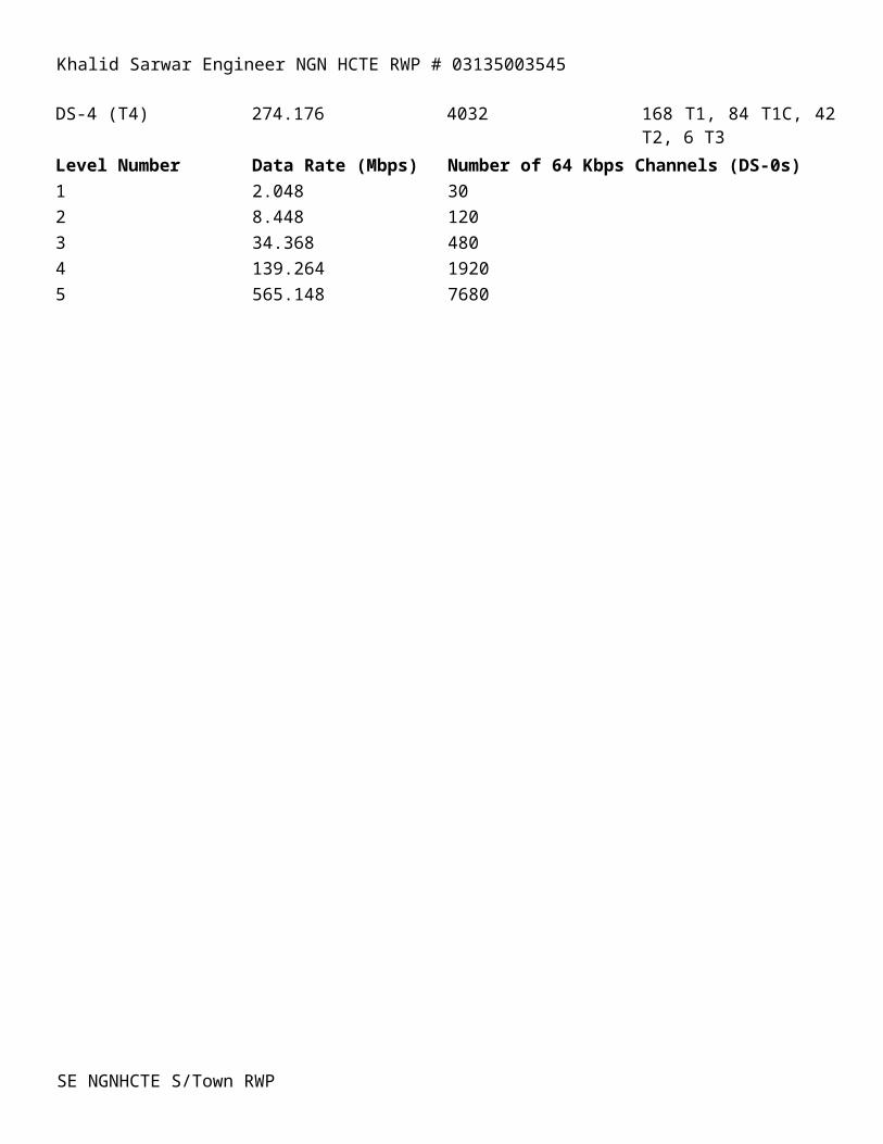
Khalid Sarwar Engineer NGN HCTE RWP # 03135003545
expansion slot of a workstation. Additionally, FRADs can be incorporated into X.25 PADs, T-carrier MUXs, or even PBXs for dedicated networks. More likely, they are incorporated into a high-end bridge or router serving a LAN. In early 1996, several vendors announced CO-based FRADs that offer the potential to eliminate the end user investment in such equipment. Although they are limited in functionality, intended to support conversion of SDLC traffic to frame format, they appear to offer advantages to users seeking to replace dedicated networks connecting large data centers [11-6] and [11-7].
Frame Relay Network Devices (FRNDs) are the link terminating equipment in the Central Office.
Frame Relay Switches are nodal processors capable of switching frames at very high speed. They contain buffers that, within limits, can absorb incoming frames until the switch can act on them, and buffers that can absorb outgoing frames until the link becomes available. The switches contain very high-speed switching matrixes and internal busses. They have sufficient intelligence, in the form of routing tables to read the control information embedded in the frames in order to route the frames correctly over the PVC, which has been identified previously in the call setup process. The nodal processors also have intelligence sufficient to check for errors in the frame, although error correction processes are performed at the end-user level. Since the switches perform no error correction or protocol conversion functions, they act on the frames very quickly, thereby minimizing latency. Frame Relay nodal processors can be managed from a centralized Network Operations Center, thereby enhancing the scalability of the network [11-8]. The Frame Relay switch also may contain a voice compressor module, where voice is communicated over Frame Relay. Memotec (CX 1000) and Micom (Netrunner) switches provide this capability, using the ACELP compression algorithm. While Frame Relay is not intended for voice, it can be accommodated with varying degrees of quality.
Local Management Interface (LMI) Protocol
The LMI protocol provides operational support for the User Network Interface (UNI). Originally defined by the Frame Relay Forum in 1990, it since has been adopted by ANSI and the ITU-T. The LMI is a polling protocol between the FRAD and the network that verifies the existence and availability of the PVC, as well as the integrity of the UNI link.
Congestion Management
As a shared network designed for intensive data communications, Frame Relay is subject to congestion. Indeed, it is designed for congestion as a natural occurrence which serves to reduce the overall cost of the network. Congestion management is addressed through the following parameters, specified in an addendum to ANSI T1.606 [11-3], [11-8], and [11-9]:
• Access Rate The maximum data rate (bandwidth) of the access channel. Data can also be transmitted or received over the access link at lesser rates. • Committed Information Rate (CIR) The data rate which the network guarantees to handle under normal conditions, based on mutual agreement between the carrier and the customer. In the event that the CIR is exceeded, the network reserves the option to mark excess frames as discard eligible. The discard function takes place at the entry node, in order to obviate any issues of unnecessary congestion in the network. • Offered Load The data rate offered to the network for delivery measured in bps. • Committed Burst Size (Bc) Maximum amount of data that the carrier agrees to handle under normal conditions.
SE NGNHCTE S/Town RWP

Khalid Sarwar Engineer NGN HCTE RWP # 03135003545
• Excess Burst Size (Be) Maximum amount of data that the network will attempt to deliver over a specified time (T), as required by the user. In recognition of the bursty nature of LAN-to-LAN communications, the transmitting device may burst above the CIR for a brief period of time, with the network attempting to accommodate such bursts within limits of burst size and burst interval. The network reserves the option to mark the excess data discard eligible. • Measurement Interval (T) The time interval measuring burst rates above the CIR and the length of such bursts. • Discard Eligibility (DE) Indicates the eligibility of the frame for discard, in the event of congestion. DE may be set by either the FRAD or the FRND. Theoretically, at least, the FRAD would be programmed to recognize when the CIR is exceeded and to volunteer frames for discard should the network suffer unreasonable levels of congestion. • Explicit Congestion Notification (ECN) The means by which the network advises devices of network congestion. Forward Explicit Congestion Notification (FECN) advises the target device of network congestion in order that it might adjust its expectations. Backward Explicit Congestion Notification (BECN) advises the transmitting device of network congestion in order that it might reduce its rate of transmission accordingly. Theoretically, it is the responsibility of the end devices to adjust. However, the effective assumption of such responsibility is unusual. For example, the Frame Relay network might send a BECN to advise a router of congestion in the network. While the router can impose a certain amount of flow control, its buffer memory is limited. Ultimately, it is the transmitting DTE that must adjust its rate of flow, which is unlikely. • Implicit Congestion Notification Inference by user equipment that congestion has occurred. Such inference is triggered by realization of the user device (e.g., FRAD, Mainframe, or Server) that one or more frames have been lost. Based on control mechanisms at the upper protocol layers of the end devices, the frames would be resent.
Frame Relay Advantages and Disadvantages
Frame Relay’s unique characteristics offer some distinct advantages over X.25, Switched 56/64 Kbps, and DDS. Additionally, Frame Relay is widely available both domestically and internationally. The market is highly competitive, which puts it in an advantageous position relative to other fast packet technologies (i.e., SMDS and ATM.)
Frame Relay Advantages
Advantages include its excellent support for bandwidth-intensive data and image traffic. Even stream-oriented traffic such as realtime voice and video can be supported, although not particularly effectively. The absolute speed of Frame Relay, its improved congestion control, and reduced latency certainly are improvements over X.25 networks. As Frame Relay is protocol-insensitive, it can carry virtually any form of data, and in variable-size frames. Bandwidth-on-demand, within the limit of the access line, is provided, with costs being reasonable for high-speed bursts. Additionally, the network is highly redundant, providing improved network resiliency.
The elimination of dedicated circuits makes Frame Relay highly cost-effective when compared to dedicated services such as DDS and T-carrier. Frame Relay is reasonably priced. In fact, savings of 30% to 40% over leased lines are commonly reported. Frame Relay costs, also, are scalable, maintaining a graceful relationship with the needs of the user organization in terms of bandwidth and number of terminating locations. Mesh networking, therefore, can be accomplished at reasonable cost, even on an asymmetrical basis.
Disadvantages
SE NGNHCTE S/Town RWP
Khalid Sarwar Engineer NGN HCTE RWP # 03135003545
Disadvantages include its latency. Although it is an improvment over X.25, it does not compare well with SMDS and ATM. The latency issue can be significant when the service is used in support of SNA traffic, and renders Frame Relay largely unsuitable for voice and video. Additionally, only a few IXCs (e.g., LDDS Worldcom and MCI) currently offer high-speed Frame Relay service. Finally, the carriers have not come to terms on interconnectivity, leaving the user typically bound to a single carrier [11-18] and [11-3].
Frame Relay Applications
Frame Relay was designed to fill the gap between packet-switched networks (X.25), circuit-switched networks (Switched 56/64 Kbps), and dedicated data networks (DDS, T/E-Carrier). It is intended for intensive data communications involving block-level communications of data and image information. Frame Relay will support voice and low-speed video, although the quality can be generally is poor due to intrinsic latency (delay) and discarded frames during periods of network congestion due to heavy usage.
Frame Relay applications primarily, therefore, are data or image in nature. LAN internetworking, of course, is the driving force behind Frame Relay, although, controller-to-host, terminal-to-host, and host-to-host applications abound. The recent availability of dialup access also makes the service cost-effective for bandwidth-intensive telecommuting application. Internet Service Providers (ISPs) recently have made significant use of Frame Relay, both for user access to the ISP and for backbone network applications. For instance, the CompuServe network is about 60% Frame Relay and 40% X.25 [11-19].
An excellent example of the application of Frame Relay is that of the airline reservation networks, all of which are in the process of transition. Apollo Travel Services is converting its reservation network to Frame Relay to connect approximately 15,000 travel agency workstations at 1,000 sites. Owned by United Airlines, USAir, and Air Canada, Apollo expects response time to improve to two seconds from the current four seconds. The network will run at 56 Kbps, as opposed to the current 2,400 to 4,800 bps. Using AT&T’s InterSpan Frame Relay Service, running over a TCP/IP network platform, the service also will offer mesh networking between travel agencies, without the need to go through the Apollo head-end for e-mail and other purposes [11-20].
Voice over Frame Relay, over both private and public networks, is an option that recently has created a lot of interest. Although the voice stream is subject to intrinsic Frame Relay delays and although the service is overhead-intensive for such an application, it does allow the user organization to take advantage of occasional excess bandwidth to connect voice for free. [11-21], [11-22], [11-23], [11-24], [11-25], [11-26], and [11-27]. Advanced compression techniques such as ACELP (Algebraic Code-Excited Linear Prediction) appear to offer the best quality voice at 16 Kbps, 8 Kbps, and even 4.8 Kbps [11-28].
CPE (Customer Premise Equipment)
CPE comprises Data Terminal Equipment (DTE), Data Communications Equipment (DCE), and true CPE.
DTE includes Mainframe, Mid-range and PC-server host computers connected through the UNI. DCE
comprises ATM-equipped bridges, routers, brouters and gateways connected through the DXI UNI. ATM premise switches are offered by a number of vendors. Such switches are used for LAN interconnection, employing a highly redundant cell-switching fabric capable of switching speeds which can reach as high as OC-3 (155 Mbps).
CPE
SE NGNHCTE S/Town RWP

Khalid Sarwar Engineer NGN HCTE RWP # 03135003545
includes ATM-based PBXs and Video Servers. While these devices currently do not exist, they will be added to this definition. First, ATM proves itself as being truly voice- and video-capable, and that capability must be standardized. Such devices will be connected via the UNI or the DXI.
SE NGNHCTE S/Town RWP

Khalid Sarwar Engineer NGN HCTE RWP # 03135003545
Wireless Defined
Wireless, quite simply, refers to communications without wires. While microwave and satellite communications are without wires, those technologies generally are considered to be high-speed, network backbone, or access technologies which are either point-to-point, point-to-mutipoint or broadcast in nature (see Chapter 3 for discussion of the principles and characteristics of radio transmission). In the context of this discussion, wireless technologies are local loop or local in nature and are application- and service-oriented, rather than being transport-oriented.
Frequency Allocation
Frequency Allocation or Spectrum Management, involves the designation of certain frequencies in the electromagnetic spectrum in support of certain applications. Examples include AM and FM broadcast radio, UHF and VHF broadcast TV, Trunk Mobile Radio (TMR), cellular radio and microwave radio. This requirement is essential in order to avoid interference among various applications using the same, or overlapping, frequency ranges. In limiting each application to a specific range of frequencies, the manufacturers, carriers, and end users of such systems can better be monitored and controlled.
Power Levels The power levels various transmitters must be regulated, as stronger signals propagate farther. Clearly, the end result of transmitting at too high a power level is that of interference with distant systems using the same, or overlapping frequency ranges.
Advantages and Disadvantages of Wireless
Before dealing with technology and applications specifics, we should pause to address the advantages and disadvantages of wireless, at least in a general way. The deployment and management of networks without wires offers clear benefits, but also suffers from severe limitations.
Deployment of wireless networks certainly can offer advantages of reduced cost of installation and reconfiguration. Tremendous costs can be saved by eliminating requirements to secure terrestrial right-of-way, dig trenches and plant poles, place conduits and hang crossarms, splice cables, place repeaters, and so on. For that matter, wired networks may not even be a viable option in rocky or soggy terrain. Additionally, wireless offers greatly improved speed of deployment and reconfiguration. Wireless networks also offer great portability; in other words, the antennae quite easily can be disassembled and reassembled at another location, whereas wired networks must be either abandoned or removed and sold as scrap metal. Finally, wireless networks can even offer the great advantage of mobility, as is the case with cordless telephony, cellular radio, and packet radio data networks.
Wireless also suffers from certain limitations, the most significant of which is that of spectrum availability—radio is a finite resource. The laws of physics and Mother Nature (not to mention Table 3.1), state that radio operates between 3 kHz and 30 GHz. While that may seem like a lot of spectrum, there also are a lot of applications and users competing for it. This limited radio spectrum is divided into even more limited spectrum allocated in support of each application (e.g, microwave and cellular radio). Within each slice of allocated spectrum there clearly exists only so much bandwidth. Regardless of how cleverly we design compression algorithms to maximize its use, there still is only so much bandwidth available. As was discussed in connection with microwave and satellite radio (Chapter 3), error performance and security are always issues with airwave transmission.
SE NGNHCTE S/Town RWP

Khalid Sarwar Engineer NGN HCTE RWP # 03135003545
The Cell Concept: Frequency Reuse
Radio systems are designed for a certain area of coverage. Even early radio and TV broadcast systems used the concept of coverage areas to provide service to a defined service area. Therefore, the same frequencies could be reused to support service in metropolitan areas some distance away. For instance, 98.1 (MHz) on your FM dial might be WXYZ in New York and KFRC in San Francisco, California. Similarly, Channel 7 on your TV might be WFAA in Dallas, Texas and KGO in San Francisco. Broadcast TV stations in the United States can reuse frequencies if separated by at least 150 miles [12-6].
The formal concept of radio cells dates back to 1947 when Bell Telephone Engineers developed a radio system concept that included numerous, low-power transmit/receive antennae [12-1]. Scattered throughout a metropolitan area, such an architecture would increase the effective subscriber capacity of radio systems by breaking the area of coverage into small cells, or smaller areas of coverage. Each frequency could be reused in non-adjacent cells. Additionally, the cells can be split, or subdivided further as the traffic demands of the system increase—the costs of the network are highly scaleable.
Frequency reuse is sensitive to factors which should now be familiar as a result of the discussion of microwave and satellite systems in Chapter 3. Specifically, these factors include frequency, power level, antenna design, and topography. Higher frequency signals always attenuate to a greater extent over distance given the same power level. Antenna design is sensitive to wavelength and other factors. Topography is always an issue, as line of sight is always preferable.
Cells are generally defined in three categories, macrocells, microcells, and picocells (Figure 0112.1). As the cells shrink, the advantages of frequency reuse increase significantly. However, the costs of network deployment increase dramatically and the issues of switching traffic from moving transmitters from cell-to-cell increase considerably. Nonetheless, the increase in traffic-handling capacity can be quite remarkable, with associated increases in revenue potential. Assuming that 12 channels are available for use in a metropolitan area of a 60-mile radius, consider the following theoretical scenario shown in Figure 12.1.
SE NGNHCTE S/Town RWP

Khalid Sarwar Engineer NGN HCTE RWP # 03135003545
Macrocells cover a relatively large area. One (1) macrocell might support 12 channels and only 12 simultaneous conversations. In a 7-cell reuse pattern (which is typical) with each cell covering a radius of about 11 miles, no improvement is realized; only 12 conversations can be supported. This lack of improvement is due to the fact that the cells must overlap; conversations on the same frequency channels in adjacent cells will interfere with each other.
Microcells cover a smaller area. If a macrocell were divided into microcells, in a 7-cell reuse pattern, a reuse factor of 128 is realized. The same 12 channels could support 1,536 simultaneous conversations
Picocells are quite small, covering only a few blocks of an urban area or, perhaps, a tunnel, walkway, or parking garage. In a 7-cell reuse pattern, with each cell covering a radius of approximately 1/2 mile, the reuse factor climbs to 514. The same 12 channels could theoretically support up to 6,168 simultaneous conversations. [12-2]
Digital versus Analog
Clearly, communications is going digital. Nonetheless, analog does have a place, if for no other reason than it is the incumbent technology. Transition from analog is expensive and disruptive, and will take some time to complete. This scenario holds true in the wireless, as well as the wired, world. Just as was the case in the wired world, digital wireless offers the advantages of more efficient use of bandwidth (spectrum), improved quality of transmission through enhanced error performance, increased throughput (a logical extension of diminished transmission errors), and improved security. There exist no less than 16 different means of modulating a radio signal, most of which relate to digital radio. Generally speaking, Amplitude Modulation (AM) alone is ineffective due to the phenomenon of fading. For the most part, a combination of Phase Shift Keying (PSK) and Amplitude Modulation (AM) is used to yield compression of up to 16:1.
Multiplexing and Access Techniques
Communications networks take great advantage of the concept of DAMA (Demand-Assigned Multiple Access). DAMA allows multiple devices to share access to the same network on a demand basis ( first come, first served). There exist a number of ways in which multiple access can be provided in a wireless network; those techniques largely are mutually exclusive.
Frequency Division Multiple Access (FDMA)
Frequency Division Multiple Access (FDMA) divides the assigned frequency range into multiple carrier frequencies to support multiple conversations as shown in Figure 12.2. Multiple narrowband frequency channels are derived from a wider band of radio spectrum, much as Frequency Division Multiplexers (FDMs) operate in the wired world (Chapter 2). Transmission #1 takes place on one frequency, while transmission #2 takes place on another. The station equipment must be frequency agile, in order to search and seize an available frequency channel, especially as the mobile transmitter/receiver moves from one cell to another in a cellular network.
Figure 12.2 Frequency Division Multiple Access (FDMA).
SE NGNHCTE S/Town RWP

Khalid Sarwar Engineer NGN HCTE RWP # 03135003545
Analog cellular systems employ FDMA, which also can be used in digital systems. In either scenario, each conversation is supported by a single channel; a single base station or cell site can support multiple channels, which are subsets of a wide band of radio spectrum. For instance, the U.S. AMPS (Advanced Mobile Phone System) system provides for a total allocation of 40 MHz, which is divided into 666 frequency pairs, each of which provides 60 kHz (30 kHz for the forward channel and 30 kHz for the reverse channel). The two channels supporting a single conversation are widely separated in order to avoid confusion on the part of the terminal equipment; the AMPS systems provides for 45 MHz separation. On average, U.S. AMPS cell sites support 57 frequency channels [12-6]. Table 12.1 provides a comparison of AMPS and GSM, a digital standard discussed later in this chapter.
Table 12.1 Comparison of AMPS (FDMA) and GSM (TDMA)
Transmission Mode Multiplexing Technique
Duplexing Technique
Frequency Band
AMPS Analog FDMA FDD 800 MHz GSM Duplex FDMA/TDMA TDD 800 MHz & 900 MHz
Frequency Division Duplex (FDD) is a means of providing duplex (bidirectional) communications. Forward and backward channels make use of separate frequencies. FDD is used with both analog and digital wireless technologies, including cordless telephony and cellular.
Time Division Multiple Access (TDMA)
Time Division Multiple Access (TDMA) is a digital technique which divides each frequency channel into multiple time slots, each of which supports an individual conversation (Figure 12.3). This concept is exactly the same as in the wired world where TDMs perform the same function. The total available bandwidth, the bandwidth of the individual channels, and the number of time slots per channel vary according to the particular standard in place, as well as the specific coding technique employed. For instance, GSM involves a carrier channel of 200 kHz, with a channel rate of approximately 200 Kbps. The channel is divided into 8 time slots of 25 Kbps each, easily supporting low-bit-rate digitized voice of 9.6 Kbps, plus overhead for framing and signaling. Each conversation makes use of 2 time slots, one for the forward channel and one for the reverse channel. Services based on TDMA offer roughly 3 times the traffic capacity of FDMA services [12-1]. A comparison of GSM and AMPS is provided in Table 12.1.
Figure 12.3 Time Division Multiple Access (TDMA).
TDMA terminal equipment is simpler and less expensive. This largely is due to the fact that the transmit and receive functions are not operative at the same point in time, eliminating the full-duplex (FDX) requirement. A typical TDMA system, such as GSM, actually is both FDMA and TDMA. Multiple carrier channels are provided, divided by frequency. Within each carrier frequency channel, multiple time slots (digital channels) are supported.
SE NGNHCTE S/Town RWP

Khalid Sarwar Engineer NGN HCTE RWP # 03135003545
E-TDMA (Enhanced TDMA), developed by Hughes Network Systems, is an improvement over TDMA, employing Digital Speech Interpolation (DSI) compression and half-rate vocoders (voice coders), operating at 4.8 Kbps, in order to improve on bandwidth utilization. E-TDMA is said to provide 16:1 improvement over analog technology.
Time Division Duplex (TDD) is a digital means of providing bidirectional communications. The forward and backward channels make use of separate time slots. TDD can be employed with both channels using the same frequency (ping-pong transmission), or it may be used in conjunction with FDD.
Code Division Multiple Access (CDMA)
Code Division Multiple Access (CDMA) is a relatively new technology that has its roots in spread-spectrum radio developed for secure military use. CDMA is in place in numerous trials, but is not widely deployed. In fact, the first commercial CDMA system was placed in service in Hong Kong only recently [12-5], where cellular phones are considered almost a necessity and where the networks have suffered terrible congestion. CDMA is a wideband radio technology, providing the full carrier channel to all terminals through a frequency-hopping technique, in tune with the base station. Each terminal has its own unique 10-bit code, which is applied to the channel; that code allows the terminal and base station to recognize data intended for it, rejecting all other data [12-3]. Each of a great number of transmissions is spread across the entire available spectrum and is denoted by a unique code which is imprinted on the packet radio transmission (Figure 12.4). In this manner, each transmission can be identified from all others, as well as from background noise; error performance is excellent.
Figure 12.4 Code Division Multiple Access (CDMA).
CDMA improves bandwidth utilization, as a great number of users can share the same wideband radio frequency channel. Improvements of up to 2000% (20x) are predicted, compared to AMPS. CDMA also provides excellent security as it is virtually impossible to intercept more than a small portion of a transmission; encryption can be used to provide additional security [12-7].
CDMA was perfected by Qualcomm, which develops, manufactures, markets and licenses CDMA products. CDMA recently has been licensed by a great number of manufacturers and providers of cellular, PCS, Wireless LAN and other systems and networks. CDMA is being trialed by Ameritech Mobile, Bell Atlantic Mobile, GTE Mobilnet, Southwestern Bell Mobile Systems, and other cellular providers [12-5]. NEC has also licensed the technology.
Switched Mobile Radio (SMR)/Trunk Mobile Radio (TMR)
The first experimental two-way mobile radio system was placed into service by the Detroit Police Department in 1921, operating in the 2-MHz band, followed by the Bayonne, New Jersey police department in the early 1930s. While this AM (Amplitude Modulation) radio application grew quickly, even as late as 1937 there were only 40 channels allocated by the FCC. In the late 1930s, FM (Frequency Modulation) replaced AM as the method of choice due to its improved quality of reception and lower power requirements. (FM receivers tend to lock in on the stronger competing signal, whereas AM recognizes all competing signals.) In 1949 the FCC recognized two-way mobile radio as a new class of service, and began to allocate spectrum and regulate its use [12-8] and [12-2].
SE NGNHCTE S/Town RWP
Khalid Sarwar Engineer NGN HCTE RWP # 03135003545
Commercial applications were first offered in 1946, when AT&T was granted the first license for two-way, mobile FM service in St. Louis, MO. This service offered the additional advantage of being connected to the PSTN WAN. The transmitters had a range of approximately 50 miles. As the costs were reasonable, the service grew in popularity and the systems were soon oversubscribed. In fact, it was not uncommon for a provider to load as many as 100 subscribers per channel; as a result, service was horrible. In 1976, by way of example, service in the New York metropolitan area (20 million population) consisted of 20 channels supporting 543 subscribers; there was a waiting list of approximately 3,700 [12-8].
Switched Mobile Radio (SMR), also know as Trunk Mobile Radio (TMR) entered the scene in the 1960s marketed as Improved Mobile Phone Service (IMTS). This service made better use of FM bandwidth through narrowband communications (smaller frequency ranges). IMTS also allowed users to search multiple frequencies on a manual basis. Shortly thereafter, intelligent mobile sets were developed that searched channels automatically. The concept of SMR/TMR remains much the same as it was originally. The provider places a radio tower and omnidirectional transmit/receive antennae on the highest possible point in the area and blasts the signal at the maximum allowable power level. As illustrated in Figure 12.5, this approach provides a coverage area of 50 miles or more, depending on topography.
Figure 12.5 Switched Mobile Radio (SMR) network.
SMR/TMR largely has been supplanted by cellular service offerings, although it still is widely used in dispatch and fleet applications such as police, fire, and emergency vehicles; taxi fleets, utility fleets (e.g., telephone companies, electric utilities, and CATV providers), and courier services. In the United States, 80 MHz has been allocated for SMR.
Enhanced Switched Mobile Radio (ESMR)
Enhanced Switched Mobile Radio (ESMR) is a technique developed by Nextel and Geotek Communications for the development of a voice and data, cellular-like network using embedded SMR networks operating at 800-900 MHz. For instance, Nextel acquired and linked a large number of SMR networks throughout the United States. Through the use of digital technology, each frequency channel is divided into multiple time slots to support multiple conversations; call hand-off is supported. MCI in 1995 withdrew its offer of US$1.3 billion for 17% of Nextel, without citing any reasons. It seems apparent that MCI had second thoughts about committing such a significant amount of money and putting its reputation on the line for a technology which is largely unproven. The Nextel network, which offers data throughput of 7.2 Kbps, is yet to be fully deployed [12-9].
Paging
The concept of a paging system to cover a local or metropolitan area was first introduced in 1950 in the New York, and involved proprietary solutions including the GOLAY standard from Motorola [12-8]. During the 1970s, the British Post Office (BPO) developed a standard set of code and signaling formats, which evolved into the POCSAG (Post Office Code Standardization Advisory Group) code. The POCSAG standard provides for transmission speed of 2400 bps, using bandwidth of 25 kHz. The CCIR (now ITU-R) standardized that code, internationally, in 1981. With the exception of the Japanese (not surprisingly), all developed nations have conformed to this standard. According to estimates from the Personal Communications Industry Association, at
SE NGNHCTE S/Town RWP

Khalid Sarwar Engineer NGN HCTE RWP # 03135003545
year-end 1995 there are well over 34 million pager subscribers, worldwide; it is estimated that there are over 27 million subscribers to over 2,000 paging services in the United States, alone [12-10] and [12-11].
Wireless LANs
As discussed in some detail in Chapter 9, Wireless LAN technology has enjoyed modest success in the LAN world during the last few years. Offering the obvious advantage of no wiring costs, Wireless LANs can be deployed to great benefit in a dynamic environment where there is frequent reconfiguration of the workplace. They also offer clear advantages in providing LAN connectivity in temporary quarters, where cabling soon would have to be abandoned. Wireless LANs are largely based on spread spectrum technology refined in World War II for use in radio-controlled torpedoes. This approach offers significantly increased security and throughput [12-3].
Standards are not yet entirely formalized, although the IEEE is examining the development of standards through the efforts of the 802.11 Working Group, which began its efforts in 1989. The emerging standard initially will aim at throughput of 2 Mbps [12-28]. Wireless LANs operate in three distinct radio frequency ranges, as well as on an infrared basis.
902 Mhz to 928 MHz are unlicensed ISM (Industrial, Scientific, Medical) frequencies. This approach avoids expensive and lengthy licensing by the regulatory authorities, but carries the potential for interference from other such systems in close proximity. As this frequency range was set aside by the FCC for unlicensed communications within buildings, such systems are susceptible to interference from other systems including cordless telephones and barcode scanning systems. Spread spectrum technology is generally used at these frequencies to mitigate issues of interference. Because power levels are low, distances generally are limited to 500 to 800 feet. Manufacturers include California Microwave, NCR and Proxim.
2.4 GHz-2.5 GHz and 5.8 GHz-5.9 GHz microwave systems using spread spectrum technology are also permitted to operate without licensing at low power levels and over limited distances. Manufacturers include Western Multiplex Corp. and Xircom. Many of the systems that use licensed frequencies in this range avoid the potential for interference, but do require that the manufacturer carefully police the deployment of such systems under the terms of an omnilicense. Alternatively, these frequencies can be used without licensing, if they are low-power and use spread-spectrum coding.
18 Ghz to 19 GHz are sometimes employed in a wireless LAN environment at low power levels. The same frequencies are used in commercial microwave systems offering the potential for interference unless spread-spectrum coding is employed. Manufacturers include Microwave Radio Corp. and Motorola.
Infrared light systems require no licensing. The potential for interference between systems is very limited and line-of-sight is required. Transmission rates of 4 Mbps are common, with some systems providing transmission of 10 Mbps and 16 Mbps. Typical applications include interbuilding connectivity. Manufacturers include A.T. Schindler Communications, InfraLAN Technologies, Laser Communications, Radiance Communications, and Spectrix Corp.
Wireless LANs: Applications and Futures
While Wireless LANs have gained a foothold in United States, their future is less certain elsewhere. Traditionally, DECT has been endorsed by ETSI as the standard, providing up to 1.14 Mbps. However, the 2.4
SE NGNHCTE S/Town RWP
Khalid Sarwar Engineer NGN HCTE RWP # 03135003545
GHz (U.K.) and 18 GHz (Germany) bands are also being promoted. The concern of ETSI and the EC seems to be that the use of these frequencies will favor U.S. manufacturers.
An interesting application for Wireless LANs is that of certain grocery stores in northern California. Some shopping carts are equipped with wireless terminals which communicate with servers through hub antennae using unlicensed frequencies and spread-spectrum technology. The shopper can key into the terminal the general categories of items on the shopping list and be guided through the store with the aid of a map displayed on the terminal screen. Scattered throughout the store are special in-store coupon offers that can be accepted through wireless acknowledgement. Once the shopper reaches the checkstand, the coupon acknowledgement is communicated to the intelligent point-of-sale device (cash register) and is credited against the purchase, without any paper changing hands.
SE NGNHCTE S/Town RWP

Khalid Sarwar Engineer NGN HCTE RWP # 03135003545
Wireless Local Loop (WLL)
The worldwide local loop market is estimated at $100 billion, most of which is still twisted-pair. The low cost of installing and maintaining Wireless Local Loops is likely to position it as a strong competitive threat into the future. Nortel (nee Northern Telecom) estimates that the cost of copper local loops in North America ranges from $1,200 to $1,300 per residence, and can run as high as $5,000 where terrain is especially difficult or where population density is low. Nortel also estimates that WLL can be provided for no more than $900 per subscriber, with the added advantages of much more rapid deployment and much lower operating costs (25% less than copper), which include repair, reconfiguration, and loop testing.
As discussed briefly in Chapter 10 and illustrated in Figure 12.9, a WLL configuration involves either wired or microwave links to the Central Office from the low-power, omnidirectional antennae. Each antennae covers a relatively small geographic area, such as a neighborhood. Multiple channels are provided through frequency separation and time division multiplexing. The channels can be narrowband in support of voice-grade services, or can be as large as T1 in support of PBX trunking.
Internet Telephony
Also known as IPhone, NetPhone, and Internet Voice, Internet Telephony is a means of transmitting voice over the Internet, bypassing the traditional PSTN and saving money in the process. Internet telephony is accomplished through the use of special software residing on a multimedia PC equipped with a microphone, speaker, and modem (14.4 Kbps or better). For the most part, the software works on a half-duplex basis, allowing only one person can to talk at a time using a push-to-talk protocol reminiscent of CB radio. Through appropriate modems and using recently developed software, full duplex communications also can be supported. In every case, a voice conversation currently is supported only through the use of matching software residing in both transmit/receive devices.
Whether full or half duplex, voice is not well-supported over packet networks due to issues of audio quality, packet delay, and packet loss. Additionally, it currently is necessary that both parties schedule the call in advance, typically either via e-mail over the Net or through a short preliminary telephone call. Current software/hardware technology does not allow the caller to ring the target PC over the Net. This limitation likely will be overcome in the near future through the development of a standalone device sitting between the PC and the access circuit, much like a contemporary voice/fax/modem splitter.
However, it is free if you are lucky enough to be a college student or faculty member. End users connecting to the Net directly or through an Internet Service Provider (ISP) can make use of this application essentially for free, although small usage charges may apply above a certain usage threshold. Users connecting through an information service provider (AOL, CompuServe, or Prodigy) face more significant, but still reasonable, usage charges. In any event, the cost of Internet usage compares quite favorably with long distance charges imposed by traditional PSTN carriers.
As one might expect, some of the PSTN carriers are very upset about this application. Contrary to what one might expect, others applaud it. ACTA (America’s Carriers Telecommunications Association), an association of smaller carriers, has filed a formal protest with the FCC. AT&T, on the other hand, has announced its support of Internet telephony. The carrier issue, clearly, is one of erosion of revenues. AT&T’s surprising position is a reflection of its position as the second largest ISP in the country. In fact, AT&T announced in July 1996 its intention to marry its PSTN and Internet service offerings in order to provide additional service and cost options
SE NGNHCTE S/Town RWP
Khalid Sarwar Engineer NGN HCTE RWP # 03135003545
to its customers. It would appear that AT&T intends to overwhelm its competition and dominate the Internet telephony market, which will find a constituency whether AT&T participates or not. Additionally and not surprisingly, Intel, Microsoft, and other chip and software manufacturers have thrown their weight behind Internet Telephony.
SE NGNHCTE S/Town RWP
Related Documents