KG-OSN-2009/3 Block, Bay of Bengal, Andhra Pradesh Project Report July 2014 Cairn India Limited

Welcome message from author
This document is posted to help you gain knowledge. Please leave a comment to let me know what you think about it! Share it to your friends and learn new things together.
Transcript

KG-OSN-2009/3 Block, Bay of Bengal, Andhra Pradesh
Project Report
July 2014
Cairn India Limited
------------------------------------------------------------------------------------------------------------------------------------------------------------------
CIL/KG-OSN-2009/3-Project Feasibility Report
2
Contents
1 Introduction to the ProjectIntroduction to the ProjectIntroduction to the ProjectIntroduction to the Project .............................................................................................. 3
2 NNNNeeeeeeeed d d d fffforororor tttthehehehe PPPProrororojjjjectectectect ....................................................................................................... 3
3 Overview of Block KGOverview of Block KGOverview of Block KGOverview of Block KG----OSNOSNOSNOSN----2009/32009/32009/32009/3 ............................................................................... 4
3.1 The Area of the Block KG-OSN-2009/3 ................................................................... 4
3.2 The Subsurface Geology of Block KG-OSN-2009/3 ................................................. 7
4 PPPPetroleumetroleumetroleumetroleum SSSSystemsystemsystemsystems AAAAnalysisnalysisnalysisnalysis.......................................................................................... 8
4.1 Reservoir ................................................................................................................. 8
4.2 Seal ......................................................................................................................... 8
4.3 Source ..................................................................................................................... 8
4.4 Hydrocarbon Charge ............................................................................................... 8
4.5 Trap ......................................................................................................................... 8
5 Exploration activity in the blockExploration activity in the blockExploration activity in the blockExploration activity in the block ...................................................................................... 9
5.1 Activity Prior to Current PSC and Results ................................................................ 9
5.2 Ongoing and Future Activity .................................................................................... 9
6 TechnoTechnoTechnoTechno----economic feasibility of economic feasibility of economic feasibility of economic feasibility of the proposalthe proposalthe proposalthe proposal ................................................................ 10
6.1 Appraisal of a Discovery ........................................................................................ 10
6.2 Development Plan ................................................................................................. 10
6.3 Environmental Impact Assessment ........................................................................ 11
7 Technical Aspects of the ProjectTechnical Aspects of the ProjectTechnical Aspects of the ProjectTechnical Aspects of the Project .................................................................................. 11
7.1 Drilling Process Description ................................................................................... 11
7.1.1 Jack-up Unit .................................................................................................... 11
7.1.2 Onshore Facilities ........................................................................................... 13
7.1.3 Support Vessels .............................................................................................. 14
7.1.4 Drilling Operation ............................................................................................ 14
7.1.5 Utilities and Resources ................................................................................... 17
7.1.6 Wastes and Emissions .................................................................................... 20
8 CIL’s Commitment to Environment and SafetyCIL’s Commitment to Environment and SafetyCIL’s Commitment to Environment and SafetyCIL’s Commitment to Environment and Safety ............................................................. 22
8.1 Health, Safety and Environment Compliance ......................................................... 22
8.2 Environmental Management Plan .......................................................................... 23

------------------------------------------------------------------------------------------------------------------------------------------------------------------
CIL/KG-OSN-2009/3-Project Feasibility Report
3
1111 INTRODUCTION TO THE INTRODUCTION TO THE INTRODUCTION TO THE INTRODUCTION TO THE PROJECTPROJECTPROJECTPROJECT
The KG-OSN-2009/3 Block was awarded to Cairn consortium on 30th June 2010 as part of the NELP-VIII round for exploration of hydrocarbons and production in the event of commercially viable discovery. The consortium comprises of Cairn India Limited with 90% participating interest and the rest 10% held by Cairn India Limited. As per the minimum work programme defined in the production sharing contract 6 exploratory / appraisal wells are to be drilled. Cairn however proposes to drill 10 (ten) wells. The data and information gathered from drilling of the ten initial wells will be used for planning other wells. The objectives of the wells are to explore hydrocarbon potential of the block.
The KG basin is a proven basin where there have been many hydrocarbon discoveries. There is however huge potential for further discoveries. Cairn acquired around 1000 Sq Km of 3D seismic data which is being processed & interpreted. The prospects / leads in the block have been identified based on interpretation of available data. While undertaking the EIA studies the acquired seismic data will be interpreted to identify the exact location of the wells.
At this stage the project is purely an oil and gas exploration project. Any field development activity which follows the discovery and appraisal of a new field will be subject to Government approval of a Development Plan and dedicated application for Environmental Clearance. This application covers exploratory/appraisal drilling and well testing only.
2222 NNNNEEEEEEEED D D D FFFFOROROROR TTTTHEHEHEHE PPPPROROROROJJJJECTECTECTECT
To date no exploratory well has been drilled in the contract area. 2D seismic data of different vintages are available. Few leads have been identified on the basis of seismic 2D data interpretation. Recently Cairn has acquired approx. 1000 sq.km. of 3D seismic data in this block currently being processed. The exact drilling locations will be ascertained after the 3D seismic data has been fully interpreted.
Though there is no well drilled in this block till date, large number of hydrocarbon discoveries have been made in the surrounding areas having similar geological setup. The hydrocarbon trend appears to be continuing into this block making it prospective from hydrocarbon point of view.
Exploratory/Appraisal drilling needs to be undertaken in the identified sub-surface structures to find out if there is presence of hydrocarbons in commercially exploitable quantities. It is proposed that up to 10101010 (ten)(ten)(ten)(ten) exploratory wells will be drilled in the various identified hydrocarbon leads. In case of a discovery, the wells will be tested by flowing hydrocarbons to assess the quality and commercial viability. Drilling of more wells will be considered after establishing presence of hydrocarbons from the first few wells.

------------------------------------------------------------------------------------------------------------------------------------------------------------------
CIL/KG-OSN-2009/3-Project Feasibility Report
4
3333 OVERVIEW OF BLOCK OVERVIEW OF BLOCK OVERVIEW OF BLOCK OVERVIEW OF BLOCK KGKGKGKG----OSNOSNOSNOSN----2002002002009999////3333
3.1 THE AREA OF THE BLOCK KG-OSN-2009/3
KG-OSN-2009/3 offshore block in Bay of Bengal, spread over in an area of about 1988-km2 which was later reduced to 1298 –km2 due to exclusion of area within firing range. The KG-OSN-2009/3 block is located in the shallow waters of the Indian Ocean along the East coast of India, approximately 1.5 km from the Indian coastline. The block covers partly the offshore areas of Prakasham and Guntur districts. This shallow-water block lies within 150 latitudes and 810 longitudes in water depths ranging from 0 to 500 meters below sea level. Figure 2-1: Shows location of the block with respect to nearby coastal area.
For the supply of equipment, consumable, food, water and fuel may be sourced from Krishnapatnam or Kakinada. Kakinada deep water port is located in the east coast of
India in Latitude 16o56' N Longitude 82
o15'E. This port is developed in naturally
sheltered bay called as Godavari sand spit. There are about 98 private steel dumb barges with total carrying capacity of about 35,400 Tons. Krishnapatnam Port is deep water all weather port that is equipped to handle dry bulk like iron ore, coal containers and liquid bulk cargo. The port is located in the Nellore district of Andhra Pradesh. The berths and stockyards are equipped with ship un-loaders and ship loaders, which can unload 3,000 Tonnes an hour and load 5,000Tonnes an hour. There are also two mobile harbour cranes, stackers, re-claimers and conveyors
The KG-OSN-2009/3 block is entirely offshore in the Bay of Bengal and covers partly the offshore areas of Prakasam and Guntur Districts. Ongole, the headquarters of Prakasam is around 138 Km from Vijayawada and 331 Km away from the state capital Hyderabad. The major coastal towns near to the block are Chinna Ganjam, Vetapalem & Chirala in Prakasam District and Bapatla & Nizampatam in Guntur District. The coastal areas are well connected by rail & road and the nearest airport is Vijayawada.
Physical and Geographical Features near to the KG-O SN/2009/3 Block
SSSSrrrr....NNNNo.o.o.o. FeaFeaFeaFeattttureureureure DDDDeeeettttaaaaililililssss
1 Nearest airport Rajamundry
2 Nearest towns, cities and districts
Ongole (138 km), Vijayawada (331 km), Chinna Ganjam, Vetapalem & Chirala in Prakasam District and Bapatla & Nizampatam in Guntur District
3 Protected areas Krishna Wildlife Sanctuary is located around 1.5 Km away from the eastern boundary of the block. The Krishna sanctuary is a mangrove habitat restricted within the shore areas and thus away from the block boundary. According to the forest department total area under mangrove is 5,000 ha. Mud flats in Krishna Wild Life Sanctuary support rich growth of algae belonging to genera Ulva, Enteromorpha, Chaetomorpha and Cyanophycean.

------------------------------------------------------------------------------------------------------------------------------------------------------------------
CIL/KG-OSN-2009/3-Project Feasibility Report
5
SSSSrrrr....NNNNo.o.o.o. FeaFeaFeaFeattttureureureure DDDDeeeettttaaaaililililssss
4 Sites of archaeological importance
There are no archaeologically important sites within 10 Km of the block.
5 Protected forests The Krishna wild life sanctuary has been established in a part of the mangrove wetland and it includes Sorlagondi reserve forest (RF), Nachugunta RF, Yelichetladibba RF, Kottapalem RF, Molagunta RF, Adavuladivi RF and Lankivanidibba RF they occupy the islands of the delta and the adjacent mainlands of both districts.
6 Defence installations A portion of the block has been excluded for exploration of hydrocarbons since it is used by Navy for their exercises.
There are no ecologically sensitive areas within the block, however the Krishna Wildlife Sanctuary is located around 1.5 Km away from the eastern boundary of the block. The Krishna sanctuary is a mangrove habitat restricted within the shore areas and thus away from the block boundary. Fishermen in surrounding areas use the mangrove resources for fishing, house construction and firewood. There are no coral reefs reported within or near to the KG-OSN-2009/3 block. There are no archaeologically important sites within 10 Km of the block. The landuse in the onshore areas near the block is predominantly agricultural. Paddy, tobacco, cotton and chillies are the main agricultural products cultivated in the region.
The headquarters of Guntur district is Guntur city. The district has 10 municipalities, 57 mandals, 11 towns and 729 villages. The district has a total population of 44,65,144 with approximately 71% of in rural areas. Out of the total geographical area of 11,328 sq.km. around 55% is under agriculture, 14% under forests, 13% for non-agricultural use and 3.4% barren.
The Prakasam district with its headquarters in Ongle has 3 revenue divisions 56 mandals and 1011 villages. The population in the district is 3054941 with approximately 84% in rural areas. Out of the total geographical area of 17140 sq.km. around 51% is under agriculture, 22% under forests and 26% under non-agricultural use.
Table 1.1Table 1.1Table 1.1Table 1.1
CoCoCoCo----ordinates of thordinates of thordinates of thordinates of the KGe KGe KGe KG----OSNOSNOSNOSN----2009/3 Block2009/3 Block2009/3 Block2009/3 Block
Position Longitude Latitude Distance from
Shore (Km)
A 80° 17' 0.000" E 15° 40' 0.000" N 1
B 80° 35' 0.000" E 15° 50' 0.000" N 3.82
C 80° 43' 0.000" E 15° 51' 0.000" N 3.32
D 80° 47' 0.000" E 15° 47' 0.000" N 0.864

------------------------------------------------------------------------------------------------------------------------------------------------------------------
CIL/KG-OSN-2009/3-Project Feasibility Report
6
Position Longitude Latitude Distance from
Shore (Km)
E 80° 47' 28.000" E 15° 40' 0.000" N 4.51
F 80° 45' 0.000" E 15° 39' 0.000" N 8.92
G 80° 49' 24.000" E 15° 33' 2.000" N 16.58
H 80° 46' 36.000" E 15° 24' 13.000" N 33.4
I 80° 40' 45.000" E 15° 23' 7.000" N 37.81
J 80° 40' 25.000" E 15° 21' 0.000" N 41.66
K 80° 37' 21.000" E 15° 19' 0.000" N 42.55
The location of project block in map of India and the block layout identifying the co-ordinate points are depicted in the following Figure 3.1.
Figure 3.1: Location of the Block and Block Boundar ies
------------------------------------------------------------------------------------------------------------------------------------------------------------------
CIL/KG-OSN-2009/3-Project Feasibility Report
7
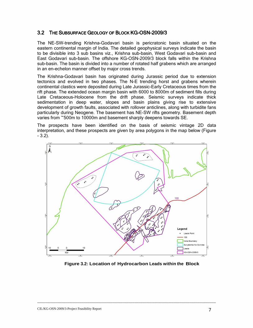
3.23.23.23.2 TTTTHEHEHEHE SSSSUBSURFACEUBSURFACEUBSURFACEUBSURFACE GGGGEOLOGYEOLOGYEOLOGYEOLOGY OFOFOFOF BBBBLOCKLOCKLOCKLOCK KGKGKGKG----OSNOSNOSNOSN----2009/32009/32009/32009/3
The NE-SW-trending Krishna-Godavari basin is pericratonic basin situated on the eastern continental margin of India. The detailed geophysical surveys indicate the basin to be divisible into 3 sub basins viz., Krishna sub-basin, West Godavari sub-basin and East Godavari sub-basin. The offshore KG-OSN-2009/3 block falls within the Krishna sub-basin. The basin is divided into a number of rotated half grabens which are arranged in an en-echelon manner offset by major cross trends.
The Krishna-Godavari basin has originated during Jurassic period due to extension tectonics and evolved in two phases. The N-E trending horst and grabens wherein continental clastics were deposited during Late Jurassic-Early Cretaceous times from the rift phase. The extended ocean margin basin with 6000 to 8000m of sediment fills during Late Cretaceous-Holocene from the drift phase. Seismic surveys indicate thick sedimentation in deep water, slopes and basin plains giving rise to extensive development of growth faults, associated with rollover anticlines, along with turbidite fans particularly during Neogene. The basement has NE-SW rifts geometry. Basement depth varies from ~500m to 10000m and basement sharply deepens towards SE.
The prospects have been identified on the basis of seismic vintage 2D data interpretation, and these prospects are given by area polygons in the map below (Figure - 3.2).
Figure 3.2: Location of Hydrocarbon Leads within the Block
------------------------------------------------------------------------------------------------------------------------------------------------------------------
CIL/KG-OSN-2009/3-Project Feasibility Report
8
4444 PETROLEUM SYSTEMS ANPETROLEUM SYSTEMS ANPETROLEUM SYSTEMS ANPETROLEUM SYSTEMS ANALYSISALYSISALYSISALYSIS
4.14.14.14.1 RRRRESERVOIRESERVOIRESERVOIRESERVOIR
Extensive sandstones deposition took place in all the depressions during syn-rift phase of the basin evolution. The reservoir characteristics of the syn-rift facies vary spatially with the environment of deposition, which typically are deposited in alluvial fan, braided deltas & lacustrine environments in the half-grabens. In the post rift, Late cretaceous deposits constitute mainly sandstone, but carbonate deposits have also been reported. Evidence for nearshore and offshore Paleogene strata is taken from seismic sections. Miocene-Pliocene continental sandstones are overlain by Quaternary alluvial cover marking the top of the sedimentary succession in the basin.
4.24.24.24.2 SSSSEALEALEALEAL
Presence of Jurassic & Cretaceous shales both laterally and vertically, will provide the much needed sealing potential to the reservoirs.
4.34.34.34.3 SSSSOURCEOURCEOURCEOURCE
Geochemical analysis of Late Jurassic-Early Cretaceous sediments of wells Nellore-1, Sidhavaram-1, KS-3-1 & KS-4-1 has identified hydrocarbon source rock units (Barremian –Aptian-Albian) with fair potential for generation of hydrocarbons. The present day organic carbon content for this section ranges from 1-3% while the Hydrogen index values range from 100 to 300. The Tmax values vary between 425⁰C
and 470⁰C. Significant maturation is indicated.
Good source rock units in Cretaceous and older sediments were encountered in the well KS-3-1, in the offshore block adjacent to KG-OSN-2009/3 block offered. A pre-Albian sequence in the Interval 1510-1630 m was identified to be a good source rock. The organic carbon content for this interval ranges between 1.02% and 2.77% while the Hydrogen Index varies from 102 to 255 (average HI=187). The studies indicate that the Cretaceous sequence has potential to generate both oil and gas.
The fact that oil and gas shows have been reported through the Cretaceous section in the adjoining areas is being viewed initially as encouraging.
4.44.44.44.4 HHHHYDROCARBON YDROCARBON YDROCARBON YDROCARBON CCCCHARGEHARGEHARGEHARGE
Initial basin modelling shows that hydrocarbon charge is evident from the Late Jurassic – Early Cretaceous source rocks.
4.54.54.54.5 TTTTRAPRAPRAPRAP
A variety of structural and stratigraphic trap styles are anticipated in the block. The drape features on median basement high making fourway dip closure & fault closures are main structural traps, Pinchout and shallow marine fans are main stratigraphic traps in the block.

------------------------------------------------------------------------------------------------------------------------------------------------------------------
CIL/KG-OSN-2009/3-Project Feasibility Report
9
5555 EXPLORATION ACTIVITYEXPLORATION ACTIVITYEXPLORATION ACTIVITYEXPLORATION ACTIVITY ININININ THE BLOCKTHE BLOCKTHE BLOCKTHE BLOCK
CIL, as the Operator of KG-OSN-2009/3, is engaged in exploration activity, which has the objective of finding commercial reservoirs within the KG-OSN-2009/3 Block. Exploration activity on the block is summarized as below.
5.1 AAAACTIVITYCTIVITYCTIVITYCTIVITY PPPPRIORRIORRIORRIOR TOTOTOTO CCCCURRENTURRENTURRENTURRENT PSCPSCPSCPSC ANDANDANDAND RRRRESULTSESULTSESULTSESULTS
Multivintage seismic data to the extent of 1300 LKM have been acquired by different companies through its departmental parties and/or External Geophysical Companies.
There is no well drilled in this block, however KRI-1-1, KS-3-1, KG-18-A-1 & KS-4-1 etc. were offset wells drilled in offshore basin and Nagayalanka-1z, Nagayalanka-SE-1, Bhavaderapalli-1 etc. are Offset onland wells.
These results are encouraging for the exploration within this block.
5.25.25.25.2 OOOONGOINGNGOINGNGOINGNGOING ANDANDANDAND FFFFUTUREUTUREUTUREUTURE AAAACTIVITYCTIVITYCTIVITYCTIVITY
The block was acquired by Cairn Energy in the NELP VIII Indian bid round. The PSC was executed on 30th June, 2010 and the Petroleum Exploration License issued on 5th August 2010 (Effective Date of the license). The exploration period will comprise two phases
Table : 5.1
Phase/PeriodPhase/PeriodPhase/PeriodPhase/Period Minimum Work ProgramMinimum Work ProgramMinimum Work ProgramMinimum Work Program
PhasePhasePhasePhase----IIII
� Acquisition of 4557 lkm 2D seismic data
� Acquisition of 1288 sq km 3D seismic data
� Drill 4 wells.
PhasePhasePhasePhase----IIIIIIII � 2 Exploration well
2D & 3D Seismic survey: Approximately 900 sqkm of 3D Seismic data acquisition is completed and processing of newly acquired 3D seismic data is ongoing. Based on the newly acquired 3D seismic data and 2D reprocessed data prospects will be identified. (Figure - 5.1). Different options for limited shallow water 2D /3D OBN/OBC/TZ survey to cover entire Block area are considered.

------------------------------------------------------------------------------------------------------------------------------------------------------------------
CIL/KG-OSN-2009/3-Project Feasibility Report
10
Figure Figure Figure Figure 5.15.15.15.1: 3D Seismic Survey Coverage: 3D Seismic Survey Coverage: 3D Seismic Survey Coverage: 3D Seismic Survey Coverage
Reprocessing of 1000 lkm of old 2D seismic lines:
Reprocessing of existing 2D seismic for approx.1000 LKM is in progress and expected to be completed in end of August 2014.
Drilling of 4 Exploration Wells:
As part of MWP, 4 exploratory / appraisal wells will be drilled during Phase-I and 2 during Phase-II exploration.
6666 TECHNOTECHNOTECHNOTECHNO----ECONOMIC FEASIBILITYECONOMIC FEASIBILITYECONOMIC FEASIBILITYECONOMIC FEASIBILITY OF THE PROPOSALOF THE PROPOSALOF THE PROPOSALOF THE PROPOSAL
Exploring for oil and gas is a risky business, in which the potential earnings of a discovery should be sufficient to offset the risk of unsuccessful exploration. The cost and complexity of exploration operations are significant.
6.16.16.16.1 AAAAPPRAISAL OF A PPRAISAL OF A PPRAISAL OF A PPRAISAL OF A DDDDISCOVERYISCOVERYISCOVERYISCOVERY
If a discovery is made it is likely to need to be appraised. This in an intermediate step between exploration and development necessary to confirm the reserve size and field deliverability to an acceptable degree of accuracy. This may be in order to determine whether the discovery is commercial, or to establish the parameters necessary to define the optimal development scheme for the field. Appraisal may consist of additional seismic, further drilling or extended testing of an existing well. Any or all of these types of operations may be deemed desirable or necessary.
6.26.26.26.2 DDDDEVELOPMENT EVELOPMENT EVELOPMENT EVELOPMENT PPPPLANLANLANLAN
Once sufficient information has been gathered to define the nature of the accumulation, to demonstrate its economic viability and to define the first phase of development then a
------------------------------------------------------------------------------------------------------------------------------------------------------------------
CIL/KG-OSN-2009/3-Project Feasibility Report
11
Development Plan is compiled. This document details the evaluation of the reservoir, and covers all aspects of the field development activities to be undertaken in the first phase, including but not limited to development wells (production, injection, completion etc), well flowlines, production facilities (for oil, gas and water separation and treatment etc), storage and export of oil, utilization and/or export of gas and disposal of produced water.
The Development Plan would also include a forecast of oil, gas and water production and injection to be achieved during the production phase, and the associated capital and operating costs. This enables each party, to the PSC, to calculate the cash flow profile and economic worth of the project.
This document is submitted to the relevant bodies within the Government of India for approval through the Management Committee for the KG-OSN/2009/1 Block constituted under Article 5 of the PSC.
6.36.36.36.3 EEEENVIRONMENTAL NVIRONMENTAL NVIRONMENTAL NVIRONMENTAL IIIIMPACT MPACT MPACT MPACT AAAASSESSMENTSSESSMENTSSESSMENTSSESSMENT
In addition, an Environmental Impact Assessment for the specific Development Plan will be compiled using both existing and newly acquired environmental data. It will include projections of emissions resulting from the production and processing of oil and gas, and detailing mitigation measures. Environmental acceptability is assessed at the National level through application to the Ministry of Environment and Forest for Environmental Clearance.
The technical feasibility, economic viability and environmental acceptability can therefore be assessed by the Joint Venture partners and the Government of India. If necessary, changes may be required to the Development Plan to ensure that the project is acceptable to all concerned.
7777 TECHNICAL ASPECTS OFTECHNICAL ASPECTS OFTECHNICAL ASPECTS OFTECHNICAL ASPECTS OF THE PROJECTTHE PROJECTTHE PROJECTTHE PROJECT
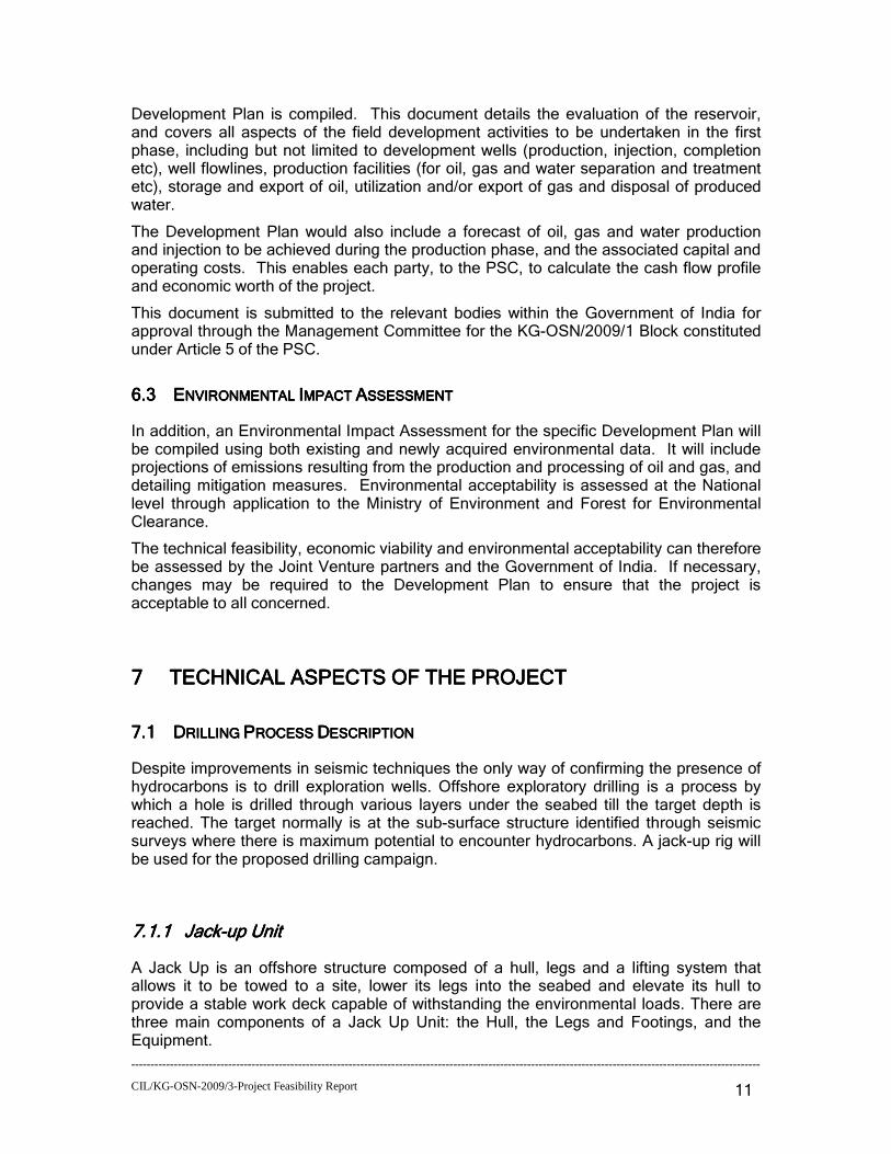
7.17.17.17.1 DDDDRRRRIIIILLLLLLLLIIIINNNNG G G G PPPPRRRROOOOCCCCEEEESSSSSSSS DDDDESCESCESCESCRRRRIIIIPPPPTTTTIIIIONONONON
Despite improvements in seismic techniques the only way of confirming the presence of hydrocarbons is to drill exploration wells. Offshore exploratory drilling is a process by which a hole is drilled through various layers under the seabed till the target depth is reached. The target normally is at the sub-surface structure identified through seismic surveys where there is maximum potential to encounter hydrocarbons. A jack-up rig will be used for the proposed drilling campaign.
7.1.17.1.17.1.17.1.1 JaJaJaJacccckkkk----up Unitup Unitup Unitup Unit
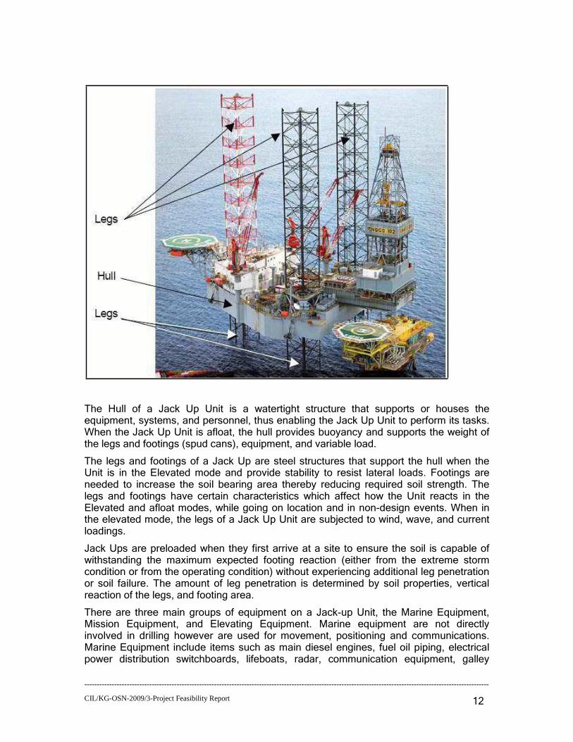
A Jack Up is an offshore structure composed of a hull, legs and a lifting system that allows it to be towed to a site, lower its legs into the seabed and elevate its hull to provide a stable work deck capable of withstanding the environmental loads. There are three main components of a Jack Up Unit: the Hull, the Legs and Footings, and the Equipment.
------------------------------------------------------------------------------------------------------------------------------------------------------------------
CIL/KG-OSN-2009/3-Project Feasibility Report
12
The Hull of a Jack Up Unit is a watertight structure that supports or houses the equipment, systems, and personnel, thus enabling the Jack Up Unit to perform its tasks. When the Jack Up Unit is afloat, the hull provides buoyancy and supports the weight of the legs and footings (spud cans), equipment, and variable load.
The legs and footings of a Jack Up are steel structures that support the hull when the Unit is in the Elevated mode and provide stability to resist lateral loads. Footings are needed to increase the soil bearing area thereby reducing required soil strength. The legs and footings have certain characteristics which affect how the Unit reacts in the Elevated and afloat modes, while going on location and in non-design events. When in the elevated mode, the legs of a Jack Up Unit are subjected to wind, wave, and current loadings.
Jack Ups are preloaded when they first arrive at a site to ensure the soil is capable of withstanding the maximum expected footing reaction (either from the extreme storm condition or from the operating condition) without experiencing additional leg penetration or soil failure. The amount of leg penetration is determined by soil properties, vertical reaction of the legs, and footing area.
There are three main groups of equipment on a Jack-up Unit, the Marine Equipment, Mission Equipment, and Elevating Equipment. Marine equipment are not directly involved in drilling however are used for movement, positioning and communications. Marine Equipment include items such as main diesel engines, fuel oil piping, electrical power distribution switchboards, lifeboats, radar, communication equipment, galley

------------------------------------------------------------------------------------------------------------------------------------------------------------------
CIL/KG-OSN-2009/3-Project Feasibility Report
13
equipment, etc. Mission equipment refers to aboard a Jack Up Unit, which are necessary for the Jack Up to complete the drilling process. Mission Equipment includes derricks, mud pumps, mud piping, drilling control systems, production equipment, cranes, combustible gas detection and alarms systems, etc. Elevating equipment refers to the equipment and systems aboard a Jack Up Unit which are necessary for the Jack Up to raise, lower, and lock-off the legs and hull of the Jack Up.
7.1.27.1.27.1.27.1.2 OnOnOnOnsssshorehorehorehore FFFFaaaacccciliiliiliilittttiiiieeeessss
Onshore facilities in the form of warehouse and jetty are required to support the drilling operation. The onshore facilities for KG-OSN-2009/3 are expected to be either at Kakinada port or Krishnapatnam port. However, Nizampatnam port can be used for small scale activities There will be two warehouses, i.e. one open and one closed for storing equipment’s and consumables for the proposed drilling. The open warehouse will be storing non-perishables like drill pipes and casings. The closed warehouse will be used for storing bentonite, chemicals, cement, lube oil etc. Equipments and consumables will be brought at the port via road or sea route. A jetty will be hired either on a sole user basis or shared during the drilling campaign. Material handling equipments like cranes, forklifts, trucks, pumps etc will be deployed for loading and unloading purposes. Skilled as well as unskilled workers will be employed for material management, security, loading and unloading activities and general administration.
Krishnapatnam Port
Krishnapatnam is a deep water all weather port that is equipped to handle dry bulk like Iron Ore, Coal and containers and liquid bulk cargo. The port is located in the Nellore District of Andhra Pradesh. The port has four berths for handling cargo. The berths and stockyards are equipped with ship un-loaders and ship loaders, which can unload 3,000 Tonnes an hour and load 5,000 Tonnes an hour. There are also two mobile harbour cranes, stackers, re-claimers and conveyors. It has a capacity to handle up to 40,000 to 60,000 Tonnes per day. The port has well designed, closed as well as open storage area for efficient and safe handling of dry cargo commodities. The port has 50,000 sq. metres of closed warehouses and 23,00,000 sq. meters of open storage area.
Kakinada Port Kakinada deep water port is situated in the east coast of India in Latitude 16o56' N Longitude 82o15'E. This is an all weather Lighterage Port developed in a naturally sheltered bay called as Godavari Sand Spit. There are about 98 Private Steel Dumb Barges with total carrying capacity of about 35,400 Tons. There are two mechanized barges with a carrying capacity of 250 tons
------------------------------------------------------------------------------------------------------------------------------------------------------------------
CIL/KG-OSN-2009/3-Project Feasibility Report
14
each for supply of fresh water to ships. There are 55 warehouses with floor area of 25,586 sq.mt. There is 50,300 Sqm.of Open Stockyards close to water front available for stacking about 1,00,00 M.Tons of bulk cargoes.
7.1.37.1.37.1.37.1.3 SSSSupport upport upport upport VesVesVesVessssseeeelslslsls
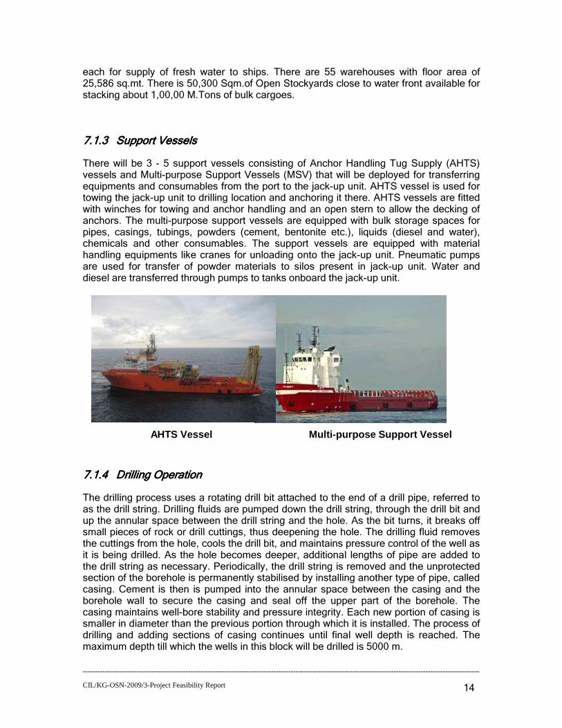
There will be 3 - 5 support vessels consisting of Anchor Handling Tug Supply (AHTS) vessels and Multi-purpose Support Vessels (MSV) that will be deployed for transferring equipments and consumables from the port to the jack-up unit. AHTS vessel is used for towing the jack-up unit to drilling location and anchoring it there. AHTS vessels are fitted with winches for towing and anchor handling and an open stern to allow the decking of anchors. The multi-purpose support vessels are equipped with bulk storage spaces for pipes, casings, tubings, powders (cement, bentonite etc.), liquids (diesel and water), chemicals and other consumables. The support vessels are equipped with material handling equipments like cranes for unloading onto the jack-up unit. Pneumatic pumps are used for transfer of powder materials to silos present in jack-up unit. Water and diesel are transferred through pumps to tanks onboard the jack-up unit.
AHTS Vessel Multi-purpose Support Vessel
7.1.47.1.47.1.47.1.4 Drilling OpDrilling OpDrilling OpDrilling Opeeeerrrraaaattttionionionion
The drilling process uses a rotating drill bit attached to the end of a drill pipe, referred to as the drill string. Drilling fluids are pumped down the drill string, through the drill bit and up the annular space between the drill string and the hole. As the bit turns, it breaks off small pieces of rock or drill cuttings, thus deepening the hole. The drilling fluid removes the cuttings from the hole, cools the drill bit, and maintains pressure control of the well as it is being drilled. As the hole becomes deeper, additional lengths of pipe are added to the drill string as necessary. Periodically, the drill string is removed and the unprotected section of the borehole is permanently stabilised by installing another type of pipe, called casing. Cement is then is pumped into the annular space between the casing and the borehole wall to secure the casing and seal off the upper part of the borehole. The casing maintains well-bore stability and pressure integrity. Each new portion of casing is smaller in diameter than the previous portion through which it is installed. The process of drilling and adding sections of casing continues until final well depth is reached. The maximum depth till which the wells in this block will be drilled is 5000 m.
------------------------------------------------------------------------------------------------------------------------------------------------------------------
CIL/KG-OSN-2009/3-Project Feasibility Report
15
Rig Mobilisation The Jack-up is towed onto location with its legs up and the barge section floating on the water. Upon arrival at the drilling location, the legs are jacked down onto the seafloor and preloaded to securely drive them into the seabed while the rig is held in position using several support vessels. All remaining legs are then jacked further down. Since the legs have been preloaded and will not penetrate the seafloor further, this jacking down of the legs has the effect of raising the barge and drilling package. In this manner, the entire barge and drilling structure are slowly raised to a predetermined height above the water, so that wave, tidal and current loading acts only on the relatively small legs and not the bulky barge.
Driving 30” Conductor
The 30” Conductor is driven to 130 m with a hydraulic Jack-Hammer. The conductor is cut and a 29 ½” diverter, Bell Nipple and flow line are connected. The Diverter is then tested.
Cleaning out 30” Conductor
A 22” bit and BHA are run into the conductor to the soil plug and the soil plug is cleaned out using sea water. The 22” bit is then pulled out to the surface and a 17 ½” bit and BHA are run to bottom and the casing displaced to Water Based Mud.
Drilling the 17 ½”” Hole The 17 ½”" hole will be drilled with WBM to 480-890 m t. with mud returns back to the barge. On reaching the section total depth, the well is then logged with electric wireline tools.
Running and Cementing the 13 3/8” Casing
Having drilled the 17 ½”" hole the diverter, riser and hydraulic latch are recovered and laid down. The required length of 13 3/8" casing string is made up.
Installing the Blow Out Preventer (BOP)
A blowout preventer is a large valve or series of valves that can seal off an oil or natural gas well being drilled or worked on. If underground pressure forces oil or gas into the wellbore, operators can close the valve remotely (usually via hydraulic actuators) to forestall a blowout, and regain control of the wellbore. Once this is accomplished, often the drilling mud density within the hole can be increased until adequate fluid pressure is placed on the influx zone, and the BOP can be opened for operations to resume. BOPs are fitted with hardened steel shearing surfaces that can actually cut through drill pipe

------------------------------------------------------------------------------------------------------------------------------------------------------------------
CIL/KG-OSN-2009/3-Project Feasibility Report
16
and tool strings, if all other barriers fail. BOPs come in two types i.e. ram and annular. A ram BOP utilizes horizontally opposed hydraulic rams that can be fitted out to, close around the drill string, shear through the drill string and then seal, or close off a wellbore when no drill pipe or tubing is in it. An annular BOP, utilizes a hemispherical donut-like rubber element reinforced with steel ribs. This closes around the drill string in a simultaneous upward and inward motion. Both Ram and Annular type BOPs are used together during drilling, called the BOP stack.
Drilling the 12 ¼ Hole
The 12 ¼" bit and BHA is made up and run to just above the cement inside the 13 3/8" casing. Prior to drilling out of the shoe the casing is pressure tested. To ensure that it is safe to drill ahead, a leak-off test will be performed immediately after drilling out of the casing shoe. The next section of hole (12 ¼”) is drilled to the required depth, cleaned out and the 9 5/8" casing is run and cemented. Exactly the same procedures are used for the 9 5/8" casing, as for the 13 3/8" casing string. If required, drilling may continue to greater depths by drilling a 8 1/2" hole and running and cementing 7" casing.
Well Cleaning, Testing and Completion
The well may be perforated with casing guns prior to the running of the tubing. The production casing will be cleaned up and the drilling fluid displaced with brine after the drilling operation is complete. A tubing string with a tubing hanger attached is run through the drilling riser and BOP, on either a completion riser or drill pipe, and landed in the wellhead. The pressure integrity of the tubing string, tubing hanger to wellhead seals and the production packer are then tested. The operation of the subsurface safety valve is also tested. Wireline plugs are set in the tailpipe of the packer and the tubing hanger and the completion riser is unlatched from the tubing hanger and retrieved. The BOP stack is unlatched from the wellhead and the stack and riser system is retrieved. A x-mas tree is installed over the well head. The well head is energised and all major functions are tested. The wireline plugs are retrieved from the tubing string. The perforating guns are run and the production casing is perforated. Flow from the well is then initiated and the well is cleaned up and tested.
Well testing represents a major source of data to engineers and geoscientists investigating the viability of the reservoir. Testing involves a range of techniques for establishing the characteristics of the reservoir and fluid such as pressure, temperature and flow rate. There will be a controlled flow of hydrocarbons back to the drill unit where they will be tested and subsequently flared. The exact volume of hydrocarbons to be flared during any testing period will not be known until the well is tested. The wells may be allowed to flow and hydrocarbons flared for 2 - 3 days.
Well Abandonment
If the well is dry and is to be abandoned several cement plugs will be set in the open hole section and a various positions in the casing and the casing will be cut and retrieved as

------------------------------------------------------------------------------------------------------------------------------------------------------------------
CIL/KG-OSN-2009/3-Project Feasibility Report
17
deep as possible. All strings of casing are cut 10ft. or more below the seabed, and all structures above this point should be recovered. Hydraulically operated casing cutting tools may be used to cut through the casing strings from the inside. Explosive charges may also be used to sever the wellhead below the seabed when the rig has moved off the location.
7.1.57.1.57.1.57.1.5 UUUUttttiliiliiliilittttiiiieeeessss aaaand nd nd nd RRRResesesesourourourourcccceseseses
DDDDrrrriiiilllllilililingngngng mudmudmudmud SSSSyyyyssssttttemememem
During drilling operations, the drilling fluid (or mud) is pumped through the drill string down to the drilling bit and returns at the drill pipe–casing annulus up to surface back into the circulation system after separation of drill cuttings /solids through solids control equipment. The functions of the drilling fluid are as follows:
Remove cuttings from the well bore - The primary function of drilling fluid is to ensure that the rock cuttings generated by the drill bit are continuously removed from the wellbore. If these cuttings are not removed from the bit face the drilling efficiency will decrease. The mud must be designed such that it can carry the cuttings to surface while circulating, suspend the cuttings while not circulating and drop the cuttings out of suspension at the surface. The drilled solids are removed at the surface by mechanical devices such as shale shakers, de-sanders and de-silters.
Prevent formation fluids flow into the well bore - The hydrostatic pressure exerted by the mud column prevents influx of formation fluids into the wellbore.
Maintain wellbore stability - The instability caused by the pressure differential between the borehole and the pore pressure can be overcome by increasing the mud weight. The hydration of the clays can only be overcome by using non water based muds, or partially addressed by treating the mud with chemicals which will reduce the ability of the water in the mud to hydrate the clays in the formation.
Cool and lubricate the bit – The rock cutting process will generate a great deal of heat at the bit. Unless it is cooled, it will overheat and quickly wear out. The circulation of the fluid will cool the bit down and help lubricate the cutting process.
Transmit hydraulic horsepower to drill bit - As fluid is circulated through the drill string, across the bit and up the annulus of the wellbore the power of the mud pumps will be expended in frictional pressure losses. The efficiency of the drilling process can be significantly enhanced if approximately 65% of this power is expended at the bit.
As discussed above, water based mud will be used for initial sections where difficult formations like shale is not encountered. The deeper sections or difficult formations will be drilled using synthetic base mud (SBM). Synthetic base mud unlike oil based mud (OBM) is biodegradable but can be re-used. At the end of drilling a well almost entire portion of the SBM is collected for use in next drilling operation. SBM systems promote good hole cleaning and cuttings suspension properties. They also suppress gas hydrate formation and exhibit improved conditions for well bore stability compared to most WBM. WBM typically consists of water, bentonite, polymers and barite. Other chemical additives viz. glycols and salts may be used in conjunction to mitigate potential problems related to hydrate formation. The mud to be used will be continuously tested for its density, viscosity, yield point, water loss, pH value etc. The mud will be prepared onsite (drill location) using centrifugal pumps, hoppers and treatment tanks. It is

------------------------------------------------------------------------------------------------------------------------------------------------------------------
CIL/KG-OSN-2009/3-Project Feasibility Report
18
estimated that about 830 m3 of drilling mud (SBM+WBM) will be required for each well with the jack-up unit having an approximate storage capacity of 250 m3 of liquid mud. The unusable portion of the mud, which is mostly WBM will be discharged into sea intermittently. It is estimated that approximately 400 m3 of waste mud will be disposed off per well.
Cuttings Disposal
During drilling activity, cuttings will be generated due to crushing action of the drill bit. These cuttings will be removed by pumping drilling fluid into the well via triplex mud pumps. The mud used during such operation will flush out formation cuttings from the well hole. Cuttings will be then separated from drilling mud using solids-control equipment. This will comprise a stepped system of processes consisting of linear motion vibrating screens called shale shakers, hydro-cyclones (including de-sanders and de-silters), and centrifuges to mechanically separate cuttings from the mud. Washed drill cuttings will be discharged off-shore into sea intermittently in accordance with MoEF guideline.
Typical Drill Cutting Separation / Treatment SystemTypical Drill Cutting Separation / Treatment SystemTypical Drill Cutting Separation / Treatment SystemTypical Drill Cutting Separation / Treatment System
It is estimated that approximately 200 m³ of drill cuttings will be generated from each well. The estimated quantities of mud and drill cuttings generated while drilling various sections has been described in Table 7.1.
Table Table Table Table 7777....1111 Estimated Quantities ofEstimated Quantities ofEstimated Quantities ofEstimated Quantities of Drill Cuttings and Drilling Mud GeneratedDrill Cuttings and Drilling Mud GeneratedDrill Cuttings and Drilling Mud GeneratedDrill Cuttings and Drilling Mud Generated
SSSSecececectitititionononon (i(i(i(inchenchenchenchessss))))
DDDDepepepeptttthhhh ((((m)m)m)m) VVVVoooollllumeumeumeume ooooffff CCCCuuuuttttttttiiiingsngsngsngs ((((mmmm³³³³))))
WasWasWasWastttteeee MMMMudududud GGGGeneneneneeeerarararattttedededed ((((mmmm³³³³))))
30” 130 12 40

------------------------------------------------------------------------------------------------------------------------------------------------------------------
CIL/KG-OSN-2009/3-Project Feasibility Report
19
SSSSecececectitititionononon (i(i(i(inchenchenchenchessss))))
DDDDepepepeptttthhhh ((((m)m)m)m) VVVVoooollllumeumeumeume ooooffff CCCCuuuuttttttttiiiingsngsngsngs ((((mmmm³³³³))))
WasWasWasWastttteeee MMMMudududud GGGGeneneneneeeerarararattttedededed ((((mmmm³³³³))))
17.5” 130 – ~650 80 125
12.25” 650 - 1500 64 135
8.5 1500 - 2500 36 80
Chemical usage
As discussed in the earlier sections various chemicals are used especially for attaining the desired properties of the drilling mud. The chemicals will be stored onboard the jack-up unit and replenished through MSV’s. The chemicals will be stored in a segregated manner with proper labelling. Material safety data sheets will be maintained for all hazardous chemicals. A typical list of chemicals that will be used during the drilling campaign along with estimated storage quantities is provided in Table 7.2.
Table 2.4Table 2.4Table 2.4Table 2.4 Type and Quantities Type and Quantities Type and Quantities Type and Quantities of Chemicals to be used during Drillingof Chemicals to be used during Drillingof Chemicals to be used during Drillingof Chemicals to be used during Drilling
Type Quantity
For Synthetic Base Mud
Emulsifiers 10 MT
Gilsonite 5 MT
Lime 5 MT
Organophilic Bentonite MT
Barite 80 MT
Synthetic biodegradable Oil (Saraline 185V) 70 MT
For Water based Mud
Bentonite 5 MT
Caustic Soda 2 MT
Potassium Chloride 30 MT
Cellulose 5 MT
Xanthan Gum 5 MT Water
The MODU will have a typical storage capacity of 4000 - 5000 bbls (635 - 800 m³) of drill water and 800 - 900 bbls (130 – 145 m³) of fresh water. The drill water is mainly consumed for preparation of mud. Minor quantities are used for washing and cleaning

------------------------------------------------------------------------------------------------------------------------------------------------------------------
CIL/KG-OSN-2009/3-Project Feasibility Report
20
the rig. The quantity of water required for preparation of WBM is around 800 bbls (130 m³) per day while for SBM it is 50 bbls (8 m³) per day. An estimated 20 m³/d of fresh water will be used for domestic consumption.
Power
DG sets are incorporated in the MODU design / infrastructure for self sustained operations at sea. Approximately 4 MW of power generating capacity will be available at rig using approximately 14 KLD of High Speed Diesel. Supply vessels will transport the required fuel from one of the three ports. The support vessels will have their individual power generation equipment as per the engine capacity for the class of marine vessel
Sanitation
There will be an On-board Sewage Treatment Plant to meet the requirements of the MARPOL Convention and the treated sewage will be discharged to sea. The on-board STP will typically consist of solids / oil separation and chemical oxidation to remove the organic load. The food wastes will be macerated through a grinder and disposed offshore, which will serve as a food source for marine and aquatic life.
7.1.67.1.67.1.67.1.6 WasWasWasWastetetetessss aaaandndndnd EEEEmimimimissssssssiiiioooonsnsnsns
Air Emissions
The source of air emissions anticipated from offshore drilling are those resulting from combustion of fuel in Diesel Generator sets on the offshore rigs, exhaust emissions from supply vessels and due to helicopter movements. CIL proposes to use low sulphur HSD as fuel to the DG sets. The power generation capacity required is around 4 MW and the maximum fuel consumption will be around 14 KLD. The operational period at a single well will be around 25 – 30 days. Based on standard emission factors and fuel quality, the pollutant emission rate is tabulate below:
Fuel type Max. Qty NOX (g/s) CO (g/s) SO2 (g/s) VOC (g/s)
HSD (0.05%
Sulphur)
14 KLD 1.14 2.62 0.14 0.262
The DG sets will be equipped with stack suitable for a marine vessel operation and designed to international norms and in compliance to common industry practise. The engines will also be subjected to periodic maintenance to ensure efficient combustion and minimise emission of particulate matter and exhaust gases.

------------------------------------------------------------------------------------------------------------------------------------------------------------------
CIL/KG-OSN-2009/3-Project Feasibility Report
21
Noise emission
The major sources of noise generation from offshore development drilling operations are:
� Operation of DG sets on the rig.
� Supply Vessel, Helicopter Movements.
� Process of drilling and operation of mud pumps, shale shakers.
� Operation of moving machinery relating to the rig.
The amount of noise generated i.e.; the resulting noise level immediately near the place where the DG sets are positioned is dependent on the capacity of the DG set and to an extent on the manufacturer’s specifications. It is anticipated that the maximum noise levels generated due to all the above operations on the MODU is around 75 dB(A) at a distance of 15 m. The DG sets will be located in lower deck keeping adequate distance from living accommodation. The above noise levels are without mitigation measures. However, the DG sets in the MODU will be housed in acoustic control enclosures at the deck and the exhausts are provided with silencers. With the mitigation measures the noise levels will be further restricted within very short distance from the source. The personnel operating in the high noise level area will be given earplugs and muffs.
Liquids and Solid Waste Discharges
During the operation of the offshore drilling rig, few liquid waste streams / products are generated. These wastes are stored, handled and disposed as per the requirements of MARPOL convention and in compliance to the applicable Indian regulation. The major liquid, solid waste discharges anticipated due to drilling operations include spent drilling mud and drill cuttings. All the major waste streams from drilling operations grouped under different categories are tabulated below:
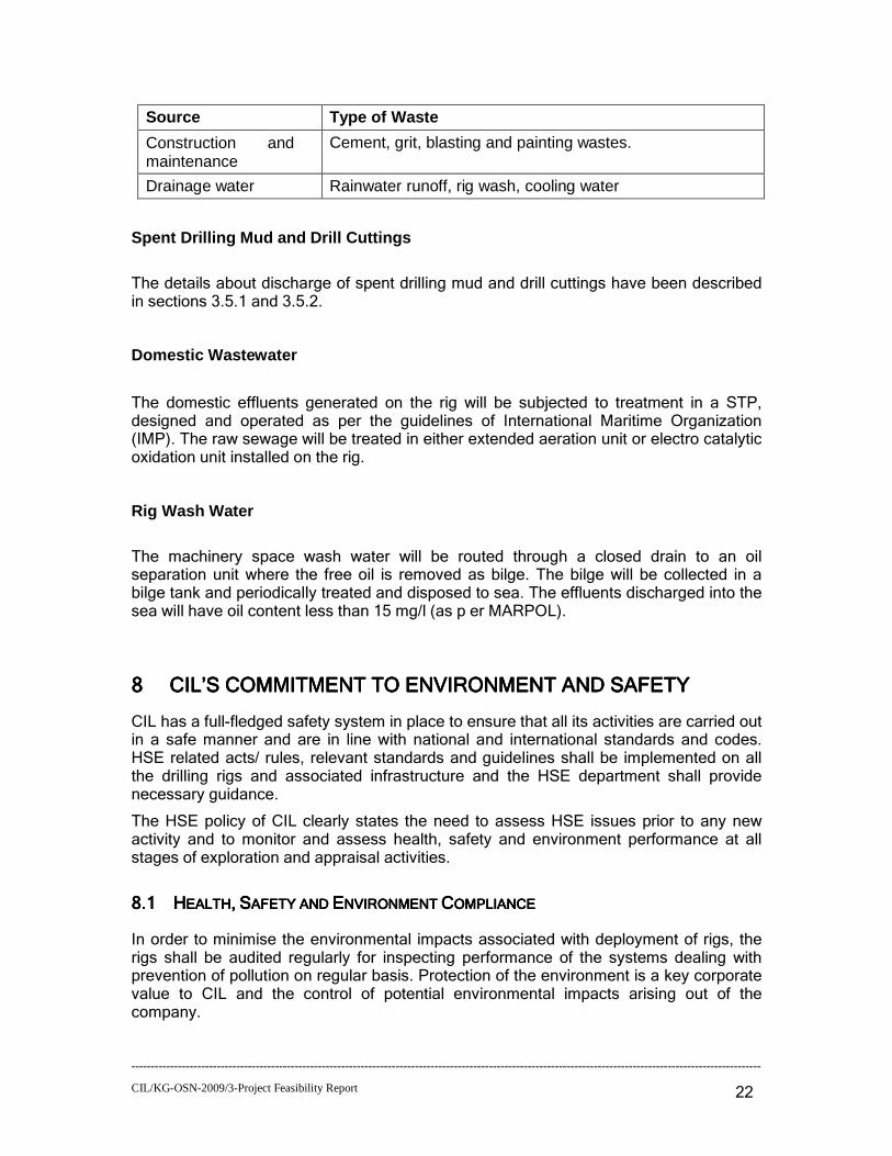
Source Type of Waste
Drilling Process waste Spent drilling WBM
Spent drilling SBM
Drill cuttings
Spent Lubricating Oil
Wastes associated with supplied materials
Packaging wastes including drums, wooden pallets, plastic containers, plastic foils.
Industrial waste: Left over chemicals and materials, scrap metal, sludges, scales, batteries, spent acids, spent lubricants, filters etc.
Domestic waste: Sanitary waste and kitchen wastes and general rubbish.
------------------------------------------------------------------------------------------------------------------------------------------------------------------
CIL/KG-OSN-2009/3-Project Feasibility Report
22
Source Type of Waste
Construction and maintenance wastes:
Cement, grit, blasting and painting wastes.
Drainage water Rainwater runoff, rig wash, cooling water
Spent Drilling Mud and Drill Cuttings
The details about discharge of spent drilling mud and drill cuttings have been described in sections 3.5.1 and 3.5.2.
Domestic Wastewater
The domestic effluents generated on the rig will be subjected to treatment in a STP, designed and operated as per the guidelines of International Maritime Organization (IMP). The raw sewage will be treated in either extended aeration unit or electro catalytic oxidation unit installed on the rig.
Rig Wash Water
The machinery space wash water will be routed through a closed drain to an oil separation unit where the free oil is removed as bilge. The bilge will be collected in a bilge tank and periodically treated and disposed to sea. The effluents discharged into the sea will have oil content less than 15 mg/l (as p er MARPOL).
8888 CILCILCILCIL’S COMMITMENT TO ’S COMMITMENT TO ’S COMMITMENT TO ’S COMMITMENT TO ENVIRONMENTENVIRONMENTENVIRONMENTENVIRONMENT AND SAFETYAND SAFETYAND SAFETYAND SAFETY
CIL has a full-fledged safety system in place to ensure that all its activities are carried out in a safe manner and are in line with national and international standards and codes. HSE related acts/ rules, relevant standards and guidelines shall be implemented on all the drilling rigs and associated infrastructure and the HSE department shall provide necessary guidance.
The HSE policy of CIL clearly states the need to assess HSE issues prior to any new activity and to monitor and assess health, safety and environment performance at all stages of exploration and appraisal activities.
8.18.18.18.1 HHHHEALTHEALTHEALTHEALTH,,,, SSSSAFETY AND AFETY AND AFETY AND AFETY AND EEEENVIRONMENT NVIRONMENT NVIRONMENT NVIRONMENT CCCCOMPLIANCEOMPLIANCEOMPLIANCEOMPLIANCE
In order to minimise the environmental impacts associated with deployment of rigs, the rigs shall be audited regularly for inspecting performance of the systems dealing with prevention of pollution on regular basis. Protection of the environment is a key corporate value to CIL and the control of potential environmental impacts arising out of the company.

------------------------------------------------------------------------------------------------------------------------------------------------------------------
CIL/KG-OSN-2009/3-Project Feasibility Report
23
Environmental Impact Assessment study will be carried out to analyze various areas on which exploratory drilling operation may cause environmental impacts and an Environmental Management Plan made.
Disaster Management Plans have been made for hazards identified in the QRA report and mock drills are planned to be carried out regularly to check the effectiveness of the plans.
8.28.28.28.2 EEEENVIRONMENTAL NVIRONMENTAL NVIRONMENTAL NVIRONMENTAL MMMMANAGEMENT ANAGEMENT ANAGEMENT ANAGEMENT PPPPLANLANLANLAN
An Environmental Management Plan is in place to identify project specific environmental actions that will be undertaken to mitigate and manage impacts associated with the exploration at KG-OSN/2009/1 Block. The EMP identifies
• Specific measures that will be taken to prevent, reduce or manage the environmental impacts of the proposed exploration activities.
• Where it is not possible to specify these at this stage, the level of environmental performance that will be expected of the proposed exploration and
• Proposal for monitoring and audit of the EIA implementation process.
Related Documents