Keysight Technologies Overcoming the Challenges of Simulating Phased-Array Radar Systems Application Note

Welcome message from author
This document is posted to help you gain knowledge. Please leave a comment to let me know what you think about it! Share it to your friends and learn new things together.
Transcript

Keysight Technologies Overcoming the Challenges of Simulating Phased-Array Radar Systems
Application Note

2
Phased array is widely used in modern radar systems for rapid multi-target search and track operations, as well as to achieve higher resolution and better detection performance. Despite these enviable benefits, when developing phased-array radar many issues may be encountered. For modern engineers, that often means a myriad of test challenges, not the least of which is finding a way to improve performance while also reducing the high cost associated with Transmit/Receive (T/R) modules with Direct Digital Synthesizers (DDSs), digital-to-analog converters (DACs) and Analog-to-Digital Converters (ADCs). Also of concern to the engineer is finding a way to work effectively with the entire development team—the system architect, the RF team and the signal processing team. Additionally, calibration of the T/R module can be difficult, not to mention time consuming and expensive. Addressing these challenges demands an appropriate method of designing and testing phased-array radar systems; one that streamlines the R&D lifecycle so that faster, cheaper, better phased-array radar systems can be achieved.
Introduction
3
Phased-array radar design: The basics
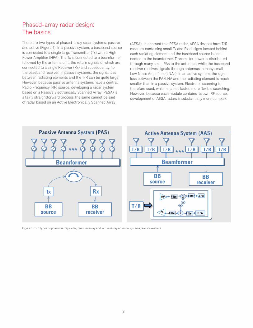
There are two types of phased-array radar systems: passive and active (Figure 1). In a passive system, a baseband source is connected to a single large Transmitter (Tx) with a High Power Amplifier (HPA). The Tx is connected to a beamformer followed by the antenna unit, the return signals of which are connected to a single Receiver (Rx) and subsequently, to the baseband receiver. In passive systems, the signal loss between radiating elements and the T/R can be quite large. However, because passive antenna systems have a central Radio Frequency (RF) source, developing a radar system based on a Passive Electronically Scanned Array (PESA) is a fairly straightforward process.The same cannot be said of radar based on an Active Electronically Scanned Array
(AESA). In contrast to a PESA radar, AESA devices have T/R modules containing small Tx and Rx designs located behind each radiating element and the baseband source is con-nected to the beamformer. Transmitter power is distributed through many small PAs to the antennas, while the baseband receiver receives signals through antennas in many small Low Noise Amplifiers (LNAs). In an active system, the signal loss between the PA/LNA and the radiating element is much smaller than in a passive system. Electronic scanning is therefore used, which enables faster, more flexible searching. However, because each module contains its own RF source, development of AESA radars is substantially more complex.
Figure 1. Two types of phased-array radar, passive-array and active-array antenna systems, are shown here.
4
The platform solution
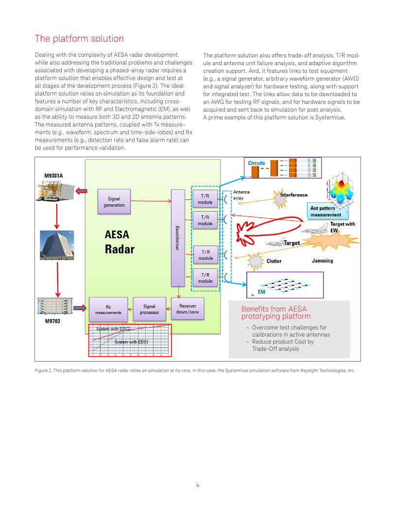
Dealing with the complexity of AESA radar development, while also addressing the traditional problems and challenges associated with developing a phased-array radar requires a platform solution that enables effective design and test at all stages of the development process (Figure 2). The ideal platform solution relies on simulation as its foundation and features a number of key characteristics, including cross-domain simulation with RF and Electromagnetic (EM), as well as the ability to measure both 3D and 2D antenna patterns. The measured antenna patterns, coupled with Tx measure-ments (e.g., waveform, spectrum and time-side-lobes) and Rx measurements (e.g., detection rate and false alarm rate) can be used for performance validation.
The platform solution also offers trade-off analysis, T/R mod-ule and antenna unit failure analysis, and adaptive algorithm creation support. And, it features links to test equipment (e.g., a signal generator, arbitrary waveform generator (AWG) and signal analyzer) for hardware testing, along with support for integrated test. The links allow data to be downloaded to an AWG for testing RF signals, and for hardware signals to be acquired and sent back to simulation for post analysis. A prime example of this platform solution is SystemVue.
Figure 2. This platform solution for AESA radar relies on simulation at its core, in this case, the SystemVue simulation software from Keysight Technologies, Inc.
Benefits from AESA prototyping platform
– Overcome test challenges for calibrations in active antennas
– Reduce product Cost by Trade-Off analysis
5
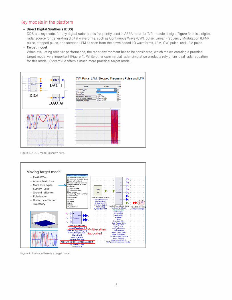
Key models in the platform – Direct Digital Synthesis (DDS)
DDS is a key model for any digital radar and is frequently used in AESA radar for T/R module design (Figure 3). It is a digital radar source for generating digital waveforms, such as Continuous Wave (CW), pulse, Linear Frequency Modulation (LFM) pulse, stepped pulse, and stepped LFM as seen from the downloaded I,Q waveforms, LFM, CW, pulse, and LFM pulse.
– Target model When evaluating receiver performance, the radar environment has to be considered, which makes creating a practical target model very important (Figure 4). While other commercial radar simulation products rely on an ideal radar equation for this model, SystemVue offers a much more practical target model.
Figure 3. A DDS model is shown here.
Figure 4. Illustrated here is a target model.
– Earth Effect – Atmospheric loss – More RCS types – System_Loss – Ground refleciton – Polarization – Dielectric effection – Trajectory
Moving target model
6
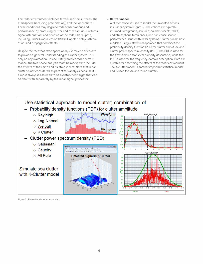
Figure 5. Shown here is a clutter model.
The radar environment includes terrain and sea surfaces, the atmosphere (including precipitation), and the ionosphere. These conditions may degrade radar observations and performance by producing clutter and other spurious returns, signal attenuation, and bending of the radar-signal path, including Radar Cross Section (RCS), Doppler, delay, attenu-ation, and propagation effects.
Despite the fact that “free space analysis” may be adequate to provide a general understanding of a radar system, it is only an approximation. To accurately predict radar perfor-mance, the free space analysis must be modified to include the effects of the earth and its atmosphere. Note that radar clutter is not considered as part of this analysis because it almost always is assumed to be a distributed target that can be dealt with separately by the radar signal processor.
– Clutter model A clutter model is used to model the unwanted echoes in a radar system (Figure 5). The echoes are typically returned from ground, sea, rain, animals/insects, chaff, and atmospheric turbulences, and can cause serious performance issues with radar systems. Clutter can be best modeled using a statistical approach that combines the probability density function (PDF) for clutter amplitude and clutter power spectrum density (PSD). The PDF is used for the time-domain statistical property description, while the PSD is used for the frequency-domain description. Both are suitable for describing the effects of the radar environment. The K-clutter model is another important statistical model and is used for sea and round clutters.

7
– Array antenna model The antenna pattern can be specified by the user using UserDefinedPattern or calculated based on the size of the antenna and illuminating window function including Uniform, Cosine, Parabolic, Triangle, Circular, Cosine Square, and Taylor. Array antenna models for the Tx and Rx allow the user to specify the arbitrary geometry of the antenna pattern using the AntennaPatternArray in the UserDefinedPattern (Figure 6). The ThetaAngleStart and TheatAngleEnd give the scope of the elevation angle, while the PhiAngleStart and PhiAngleEnd give the scope of the azimuth angle. AngleStep is the value of the angle step for the user defined pattern.
– Beamforming model Consider a uniform line array. Through signal processing, spatial filtering for interference can be archived. Propagation can form a response pattern with higher sensitivity in desired directions. One of the key technical problems of phased arrays is beamforming. To sum all signals from the array antenna coherently, the time delay of the signal received by the antenna element at the position has to be compensated. When Τ = θ, the channels are all time aligned for a signal from direction θ. Wi are beamformer weights. Using Wi with each element allows the signal to point in any direction. Gain in direction θ is Σwm. It is less in other directions due to incoherent addition. A beamforming model can be used to help ensure the beamforming technique is optimally implemented in a phased-array radar system (Figure 7).
Figure 6. An array antenna model is shown in this figure.
8
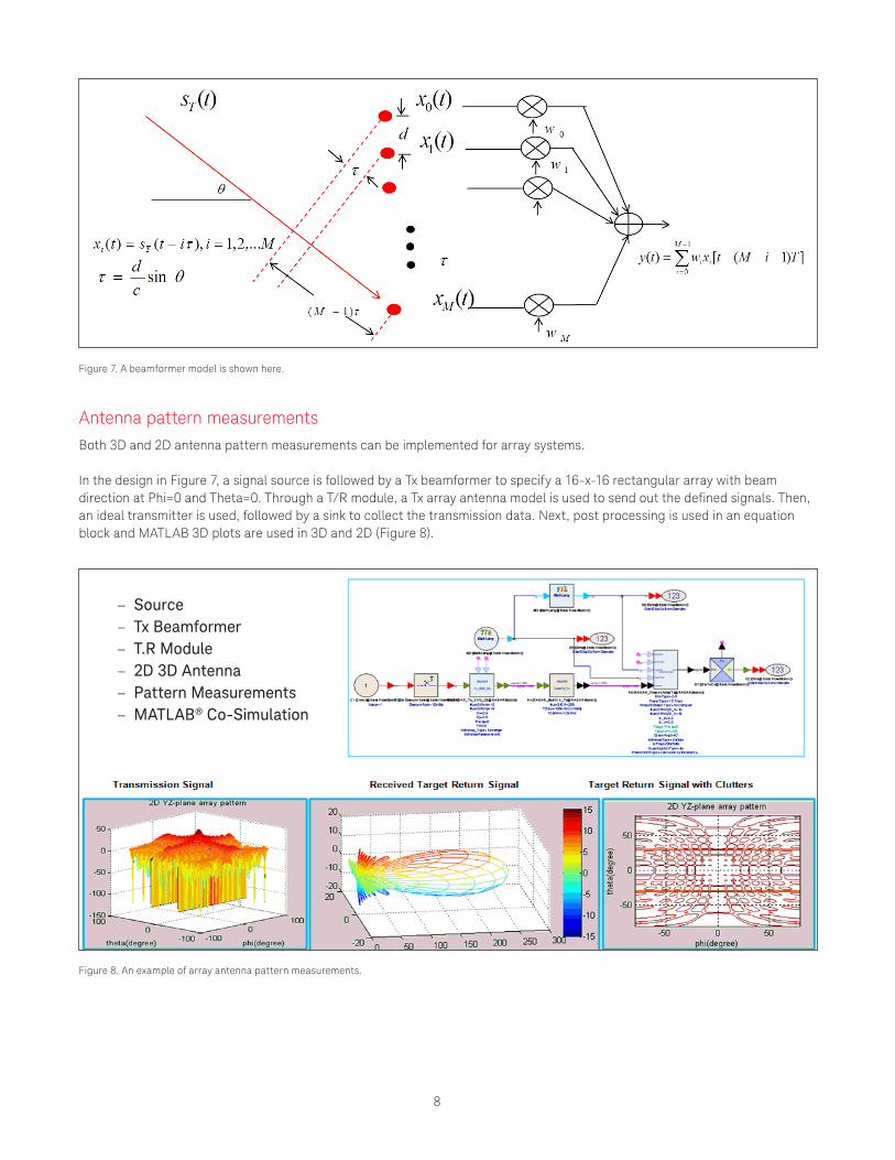
Figure 7. A beamformer model is shown here.
Figure 8. An example of array antenna pattern measurements.
Antenna pattern measurementsBoth 3D and 2D antenna pattern measurements can be implemented for array systems.
In the design in Figure 7, a signal source is followed by a Tx beamformer to specify a 16-x-16 rectangular array with beam direction at Phi=0 and Theta=0. Through a T/R module, a Tx array antenna model is used to send out the defined signals. Then, an ideal transmitter is used, followed by a sink to collect the transmission data. Next, post processing is used in an equation block and MATLAB 3D plots are used in 3D and 2D (Figure 8).
– Source – Tx Beamformer – T.R Module – 2D 3D Antenna – Pattern Measurements – MATLAB® Co-Simulation
9
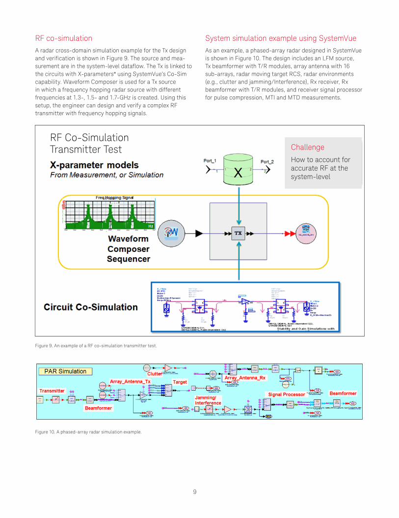
RF co-simulationA radar cross-domain simulation example for the Tx design and verification is shown in Figure 9. The source and mea-surement are in the system-level dataflow. The Tx is linked to the circuits with X-parameters* using SystemVue’s Co-Sim capability. Waveform Composer is used for a Tx source in which a frequency hopping radar source with different frequencies at 1.3-, 1.5- and 1.7-GHz is created. Using this setup, the engineer can design and verify a complex RF transmitter with frequency hopping signals.
System simulation example using SystemVueAs an example, a phased-array radar designed in SystemVue is shown in Figure 10. The design includes an LFM source, Tx beamformer with T/R modules, array antenna with 16 sub-arrays, radar moving target RCS, radar environments (e.g., clutter and jamming/Interference), Rx receiver, Rx beamformer with T/R modules, and receiver signal processor for pulse compression, MTI and MTD measurements.
Figure 9. An example of a RF co-simulation transmitter test.
Figure 10. A phased-array radar simulation example.
RF Co-SimulationTransmitter Test Challenge
How to account for accurate RF at the system-level
10
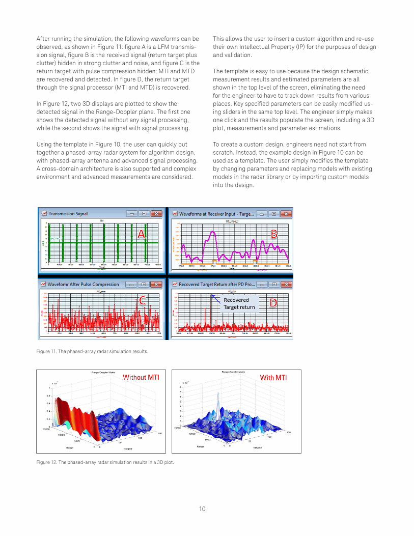
Figure 11. The phased-array radar simulation results.
Figure 12. The phased-array radar simulation results in a 3D plot.
After running the simulation, the following waveforms can be observed, as shown in Figure 11: figure A is a LFM transmis-sion signal, figure B is the received signal (return target plus clutter) hidden in strong clutter and noise, and figure C is the return target with pulse compression hidden; MTI and MTD are recovered and detected. In figure D, the return target through the signal processor (MTI and MTD) is recovered.
In Figure 12, two 3D displays are plotted to show the detected signal in the Range-Doppler plane. The first one shows the detected signal without any signal processing, while the second shows the signal with signal processing.
Using the template in Figure 10, the user can quickly put together a phased-array radar system for algorithm design, with phased-array antenna and advanced signal processing. A cross-domain architecture is also supported and complex environment and advanced measurements are considered.
This allows the user to insert a custom algorithm and re-use their own Intellectual Property (IP) for the purposes of design and validation.
The template is easy to use because the design schematic, measurement results and estimated parameters are all shown in the top level of the screen, eliminating the need for the engineer to have to track down results from various places. Key specified parameters can be easily modified us-ing sliders in the same top level. The engineer simply makes one click and the results populate the screen, including a 3D plot, measurements and parameter estimations.
To create a custom design, engineers need not start from scratch. Instead, the example design in Figure 10 can be used as a template. The user simply modifies the template by changing parameters and replacing models with existing models in the radar library or by importing custom models into the design.

11
Regardless of the radar system-level test solution utilized, core software is needed to integrate all test software and hardware together and automate the test. SystemVue is ideal for this task.
SystemVue integrates all test instruments together as a test system that provides complex radar test signals with environment scenarios to the Device-Under-Test (DUT), to capture DUT outputs and then synchronize signals, post processing the result to extract more information and obtain more advanced measurements, such as detection rate, false alarm rate, and imaging analysis. Without the integration and
Figure 13. Shown here is an integrated test system using SystemVue.
synchronization, each instrument would function on its own, making it impossible to perform complex tests.
Besides single-channel test, multi-channel test for phased array and MIMO radar is possible using SystemVue’s signal downloader to a Vector Signal Generator (VSG) or multi-channel VSG like the M9381A for a MIMO source. A VSA link to signal analyzers/scopes like the M9703 can be used for MIMO receiver test. The basic test system structure is shown in Figure 13.

12
Conclusion
Developing a phased-array radar system is challenging, especially when it involves an AESA device. In this case, the engineer requires a much more integrated solution with a wide breadth of functionality. Use of a platform solution that relies on simulation as its foundation now offers engineers an effective strategy for attacking the challenges they face when designing, verifying and testing phased-array radar systems. Utilizing this approach not only reduces design cycles, but also significantly reduces cost.
SystemVue is a prime example of just such a platform solution. There are a number of key benefits to using it to design and test phased-array radar systems. For example, trade-off analysis can be used to significantly reduce cost. Adaptive algorithms can be used to fix amplitude/phase errors for calibration purposes. SystemVue also provides emulation environments that account for clutter and Interfer-ence. Lastly, validation can be performed based on measured antenna patterns, Tx measurements such as waveform, spectrum, time-side-lobes; and Rx measurements such as detection rate and false alarm rate, which helps reduce the design cycle.
Using the design templates provided in the model-based SystemVue platform users can:
– Quickly put together a new system-level proposal by creating, with a higher level of confidence, an integrated RF and DSP architecture design.
– Easily integrate IP written in different languages (e.g., C++, MATLAB, ADS, and HDL) at the system level for a radar/Electronic Warfare (EW) system.
– Easily create complex radar/EW scenarios and verify systems with environment scenarios (e.g., clutter, jamming/deception, interference, and RCS) to meet complex system specifications and perform virtual flight testing to reduce the high cost of field test.
– Utilize an integrated test system.*X-parameters is a trademark of Keysight Technologies Inc. The X-parameters format and underlying equations are open and documented. For more information on the use of this trademark, refer to X-parameters Open Documentation, Trademark Usage & Partnerships.

Cover image courtesy of the US Navy.
www.keysight.com/find/ad
13 | Keysight | Overcoming the Challenges of Simulating Phased-Array Radar Systems - Application Note
This information is subject to change without notice.© Keysight Technologies, 2017Published in USA, December 1, 20175991-4060ENwww.keysight.com
For more information on Keysight Technologies’ products, applications or services, please contact your local Keysight office. The complete list is available at:www.keysight.com/find/contactus
Americas Canada (877) 894 4414Brazil 55 11 3351 7010Mexico 001 800 254 2440United States (800) 829 4444
Asia PacificAustralia 1 800 629 485China 800 810 0189Hong Kong 800 938 693India 1 800 11 2626Japan 0120 (421) 345Korea 080 769 0800Malaysia 1 800 888 848Singapore 1 800 375 8100Taiwan 0800 047 866Other AP Countries (65) 6375 8100
Europe & Middle EastAustria 0800 001122Belgium 0800 58580Finland 0800 523252France 0805 980333Germany 0800 6270999Ireland 1800 832700Israel 1 809 343051Italy 800 599100Luxembourg +32 800 58580Netherlands 0800 0233200Russia 8800 5009286Spain 800 000154Sweden 0200 882255Switzerland 0800 805353
Opt. 1 (DE)Opt. 2 (FR)Opt. 3 (IT)
United Kingdom 0800 0260637
For other unlisted countries:www.keysight.com/find/contactus(BP-9-7-17)
DEKRA CertifiedISO9001 Quality Management System
www.keysight.com/go/qualityKeysight Technologies, Inc.DEKRA Certified ISO 9001:2015Quality Management System
Evolving Since 1939Our unique combination of hardware, software, services, and people can help you reach your next breakthrough. We are unlocking the future of technology. From Hewlett-Packard to Agilent to Keysight.
myKeysightwww.keysight.com/find/mykeysightA personalized view into the information most relevant to you.
http://www.keysight.com/find/emt_product_registrationRegister your products to get up-to-date product information and find warranty information.
Keysight Serviceswww.keysight.com/find/serviceKeysight Services can help from acquisition to renewal across your instrument’s lifecycle. Our comprehensive service offerings—one-stop calibration, repair, asset management, technology refresh, consulting, training and more—helps you improve product quality and lower costs.
Keysight Assurance Planswww.keysight.com/find/AssurancePlansUp to ten years of protection and no budgetary surprises to ensure your instruments are operating to specification, so you can rely on accurate measurements.
Keysight Channel Partnerswww.keysight.com/find/channelpartnersGet the best of both worlds: Keysight’s measurement expertise and product breadth, combined with channel partner convenience.
Related Documents