Welcome message from author
This document is posted to help you gain knowledge. Please leave a comment to let me know what you think about it! Share it to your friends and learn new things together.
Transcript

This page intentionally left blank
Key Techniques inOrthopaedic Surgery
Key Techniques inOrthopaedic Surgery

This page intentionally left blank
Key Techniques inOrthopaedic Surgery
Steven H. Stern, M.D.Associate Professor of Clinical Orthopaedics
Department of OrthopaedicsNorthwestern University
Chicago, Illinois
2001Thieme
New York • Stuttgart
Key Techniques inOrthopaedic Surgery
Thieme New York333 Seventh AvenueNew York, NY 10001
Executive Editor: Jane Pennington, Ph.D.Assistant Editor: Michelle SchmittEditorial Assistant: Todd WarnockProduction Editor: David StewartDirector, Production and Manufacturing: Anne VinnicombeMarketing Director: Phyllis D. GoldSales Manager: Ross LumpkinChief Financial Officer: Peter van WoerdenPresident: Brian D. ScanlanCover Design: Kevin KallMedical Illustrator: Anthony M. PazosCompositor: V&M GraphicsPrinter: The Maple-Vail Book Manufacturing Group
Library of Congress Cataloging-in-Publication Data
Key techniques in orthopaedic surgery / [edited by] Steven H. Stern.p. ; cm.
Includes bibliographical references and index.ISBN 0-86577-922-8 (hardcover) — ISBN 3131248513 (hardcover)
1. Orthopedic surgery. 2. Musculoskeletal system—Diseases—Surgery. I.Stern, Steven H., 1958–
[DNLM: 1. Musculoskeletal Diseases—surgery. 2. Fractures—surgery.3. Orthopedic Procedures—methods. WE 168 K44 2001]RD731.K49 2001617.497—dc21
00-059942DNLM/DLC
Copyright © 2001 by Thieme Medical Publishers, Inc. This book, including all parts thereof, islegally protected by copyright. Any use, exploitation or commercialization outside the narrow limitsset by copyright legislation, without the publisher’s consent, is illegal and liable to prosecution. Thisapplies in particular to photostat reproduction, copying, mimeographing or duplication of anykind, translating, preparation of microfilms, and electronic data processing and storage.
Important note: Medical knowledge is ever-changing. As new research and clinical experiencebroaden our knowledge, changes in treatment and drug therapy may be required. The authors andthe editors of the material herein have consulted sources believed to be reliable in their efforts toprovide information that is complete and in accord with the standards accepted at the time ofpublication. However, in view of the possibility of human error by the authors, editors, or publisherof the work herein, or changes in medical knowledge, neither the authors, editors, publisher, norany other party who has been involved in the preparation of this work, warrants that theinformation contained herein is in every respect accurate or complete, and they are not responsiblefor any errors or omissions or for the results obtained from use of such information. Readers areencouraged to confirm the information contained herein with other sources. For example, readersare advised to check the product information sheet included in the package of each drug they planto use to be certain that the information contained in this publication is accurate and that changeshave not been made in the recommended doses or implant indications, or in the contraindicationsfor their use. This recommendation is of particular importance in connection with new orinfrequently used drugs or implants.
Some of the product names, patents, and registered designs referred to in this book are in factregistered trademarks or proprietary names even though specific reference to this fact is not alwaysmade in the text. Therefore, the appearance of a name without designation as proprietary is not tobe construed as a representation by the publisher that it is in the public domain.
Printed in the United States of America
5 4 3 2 1
TNY ISBN 0-86577-922-8GTV ISBN 3-13-124851-3
Contents
Preface ixAcknowledgments xiContributors xiii
Section One
Shoulder and Arm1. Open Acromioplasty Mark K. Bowen and Angelo DiFelice 32. Open Rotator Cuff Tendon Repair Mark K. Bowen and Angelo DiFelice 83. Open Anterior Shoulder Stabilization
Daniel D. Buss and William C. Jacobsen 144. Shoulder Arthroscopy Daniel D. Buss and John R. Green III 205. Proximal Humerus Fracture (ORIF)
Angelo DiFelice and Gordon W. Nuber 296. Proximal Humerus Fracture (Hemiarthroplasty)
Mark K. Bowen and Angelo DiFelice 347. Humeral Shaft Fracture (ORIF) Bradley R. Merk 40
Section Two
Elbow and Forearm8. Radial Head Fracture Brian J. Hartigan 499. Olecranon Fracture Brian J. Hartigan 54
10. Distal Humeral Fractures Brian J. Hartigan 6011. Forearm Diaphyseal Fractures (Radius and Ulna)
David M. Kalainov and Charles Carroll IV 6612. Forearm Fasciotomy Michael S. Bednar 74
Section Three
Wrist and Hand13. Open Carpal Tunnel Release Charles Carroll IV and David M. Kalainov 8114. Base of Thumb Metacarpal Fractures (Operative Repair)
Matthew Bernstein, David M. Kalainov, and Charles Carroll IV 8615. Distal Radius Fractures (ORIF) Franklin Chen and David M. Kalainov 9216. Distal Radius Fractures (External Fixation)
Franklin Chen and David M. Kalainov 9817. Extensor Tendon Repair Michael S. Bednar 104
v
v i C O N T E N T S
18. Flexor Tendon Repair Michael S. Bednar 10919. Fifth Metacarpal Fracture (Operative Repair)
David M. Kalainov and Franklin Chen 114
Section Four
Hip and Femur20. Total Hip Arthroplasty (Hybrid and Uncemented) Douglas E. Padgett 12321. Internal Fixation of Hip Fracture Steven H. Stern 13422. Hip Fracture (Hemiarthroplasty) Douglas E. Padgett 14223. Intramedullary Rodding of Femoral Shaft Fractures Scott D. Cordes 151
Section Five
Knee and Leg24. Arthroscopy Steven H. Stern 15925. Anterior Cruciate Ligament Surgery (Two Incision) Gordon W. Nuber 16726. Anterior Cruciate Ligament Surgery (Endoscopic) Steven H. Stern 17427. Total Knee Arthroplasty Steven H. Stern 18228. High Tibial Osteotomy Stephen G. Manifold and Giles R. Scuderi 19029. Supracondylar Femoral Osteotomy
Stephen G. Manifold and Giles R. Scuderi 19530. Lateral Tibial Plateau Fracture (ORIF) Scott D. Cordes 19931. Intramedullary Rodding of Tibial Shaft Fractures Scott D. Cordes 20532. Operative Treatment of Patella Fractures
Mark E. Easley and Giles R. Scuderi 21133. Extensor Mechanism Injuries (Quadriceps Ruptures
and Patella Tendon Ruptures) Mark E. Easley and Giles R. Scuderi 21734. Tibial Fasciotomy Bradley R. Merk 225
Section Six
Ankle and Foot35. Ankle Arthroscopy Armen S. Kelikian 23336. Ankle Fractures (ORIF) Scott D. Cordes 23737. Achilles Tendon Repair Steven Kodros 24438. Bunions and Hallux Valgus Armen S. Kelikian 24839. Hammer Toe Correction Armen S. Kelikian 25240. Morton’s Neuroma Excision Steven Kodros 25641. Proximal Fifth Metatarsal Jones Fractures (Internal Fixation)
Steven Kodros 260
C O N T E N T S v i i
Section Seven
Spine42. Lumbar Discectomy Srdjan Mirkovic 26743. Anterior Approach to the Cervical Spine
(Discectomy, Fusion, and Vertebrectomy) Serena S. Hu 27244. Lumbar Spine Fusion Srdjan Mirkovic 27945. Spinal Lumbar Decompression Srdjan Mirkovic 285
Section Eight
Pediatrics46. Slipped Capital Femoral Epiphysis Hip Pinning
Kirk Aadalen and John F. Sarwark 29347. Clubfoot Surgery (Posteromedial and Posterolateral Releases)
Michael Kuczmanski and John F. Sarwark 29848. Distal Humerus Supracondylar Fracture (Reduction and Pinning)
John J. Grayhack 30349. Hip Aspiration Roger Dunteman and John F. Sarwark 30750. Idiopathic Scoliosis (Posterior Spinal Instrumentation and Fusion)
Erik C. King and John J. Grayhack 311
Section Nine
Miscellaneous51. Femoral and Tibial Traction Pin Placement Bradley R. Merk 321
Index 327

To my wife Sharon,
my children Anna, Jacqueline, and Rebecca,
and my parents Martin and Marilyn,
all of whom have contributed and sacrificed endlessly to make my life meaningful
and to allow for a book like this to be written.
It is impossible to thank them enough.
Preface
Numerous orthopaedic textbooks are currently available that do an excellentjob covering diverse topics in orthopaedics, ranging from cervical spine to footsurgery. Commonly, these texts draw liberally from the subspecialty expertisenow widely available in almost all areas of orthopaedics. However, in somecases, the comprehensiveness of the text is somewhat foreboding and the taskof reading individual chapters is daunting and time consuming. Despite thedepth of detail in these books, specific information on the precise clinical stepsthat need to be followed in the operating room can be limited.
The idea for this text, Key Techniques in Orthopaedic Surgery, came directly asa response to these concerns. The specific goal of this book is to fill a void thatthe more comprehensive subspecialty texts may have created. The book isdesigned to cover the basic surgical aspects of common orthopaedic proceduresin a straightforward and reproducible manner. It is hoped that its style willallow it to be easily read by practicing surgeons, resident physicians, and med-ical students. The chapters are designed to allow the reader to quickly review thebasic steps and important issues associated with orthopaedic procedures.However, at its heart, this is a text focused on surgical technique and this sec-tion is the main focus of each chapter. Thus, it can serve as a handy referencethat can be quickly reviewed just prior to performing an orthopaedic operation.
One of the keys to this book is the consistent organization of each chap-ter. Each chapter reviews a different surgical procedure in a concise, straight-forward manner. The book employs a “cookbook” outline format, with theinformation in each section presented in a numbered fashion. This structure isdesigned to allow the reader to quickly read about an operative procedure andreview the salient points associated with the procedure, with special emphasison the operative technique.
Structurally each chapter conforms to a similar outline format and isdivided into the following individual sections.
1. Indications: lists the common indications for the procedure.2. Contraindications: lists the common contraindications for the procedure.3. Preoperative Preparation, Special Instruments, Position, and Anesthe-
sia: lists the common issues associated with these topics.4. Tips and Pearls: lists special tips that the authors feel are especially help-
ful to remember in conjunction with the procedure.5. What To Avoid: lists common pitfalls to try to avoid that are associated
with the procedure.6. Postoperative Care Issues: lists common issues in postsurgical care asso-
ciated with the procedure.
i x
x P R E FA C E
7. Operative Technique: lists common basic steps necessary to performthe orthopaedic procedures; many procedures have optional or alter-native steps that may be indicated or required depending on the clini-cal situation.
Each chapter is augmented by a number of illustrations. Because of the desireto make this a wide-ranging text that includes multiple common orthopaedicprocedures, the number of illustrations that could be included was limited. Thus,the pictures attempt to augment the text by depicting the most salient points ofthe surgical procedures. The illustrations are all referenced in the text.
For many of the chapter authors, I have drawn liberally from my col-leagues at Northwestern University. In general, the goal in selecting authorswas to pick surgeons who have actual clinical experience performing the oper-ative procedures. Hopefully, this allows for a more realistic description of sur-gical techniques that are currently being actively employed.
It must be remembered that orthopaedics is a surgical art that continuesto change and evolve. Thus, the techniques in these chapters represent onemethod of performing each procedure at the time they were written. Manyreaders will employ their own appropriate variations to the listed steps in orderto adapt them to their own surgical technique. The individual chapter authorswill also modify and refine the techniques presented in this text as the field oforthopaedics evolves. Thus, these steps are not designed to be slavishly fol-lowed without regard for the clinical situation. Rather, they serve as a generaloutline or guidebook in performing these particular procedures. In no way dothe authors or the text attempt to define the listed operative techniques as rep-resentative of the only, best, or standard way of performing surgery. In a sim-ilar manner, the other sections of the book should not be construed asrepresentative of the only, best, or standard way of dealing with a particularclinical situation. As in all aspects of medicine, clinical judgement shouldalways be employed in each individual situation.
Because the book is not designed to be all encompassing, I encourage read-ers to augment this book with subspecialty texts of their choosing. Furthermore,the book attempts to review common orthopaedic procedures that areemployed to treat common orthopaedic problems. Therefore, the techniqueslisted may be less applicable to complex, revision, or other unusual cases.
Finally, I would like to suggest my own “pearl” that I think is applicable toalmost all of the techniques in this book, and one that I have frequently toldto residents and medical students. It has always been my thought that mostorthopaedic procedures are relatively easy and straightforward, if appropriatevisualization can be achieved. In fact, the most technically adept surgeons thatI have ever worked with were those that were the most skilled in achievingexcellent surgical exposure. Thus, I have always felt that (in most cases) “if youcan see it, you can do it.” It is hoped that the techniques in this book will aidthe reader in achieving the necessary exposure and visualization, so they toocan “see it” and “do it.”
Steven H. Stern, M.D.
Acknowledgments
This book represents an accumulative amount of work by many authors, aswell as many others behind the scenes. I would like to acknowledge some ofthose who have made this work possible.
I appreciate the time and effort that every author put into this project.Each author had to endure many phone calls from me as I pestered them tocomplete and optimize their chapters.
The credit for all of the book’s illustrations goes to Tony Pazos. He wasasked to undertake a vast project, requiring anatomical illustrations from theentire musculoskeletal system. His constant diligence to detail throughout theproject has helped ensure that the graphical illustrations correspond as best aspossible to the relevant clinical anatomy.
Specifically, I wish to acknowledge Jane Pennington. She provided the ini-tial inspiration for this text, and I appreciate her invaluable advice and guid-ance in helping to define the exact scope and format of the book. It was hervision that commenced this project
There have been many people at Thieme who have been instrumental inhelping to bring this project to fruition. Esther Gumpert was invaluable inensuring that the final stages of this project went smoothly. Todd Warnock,the Editorial Assistant at Thieme for most of the project, was responsible forworking with all of the authors and with the illustrator to coordinate theircombined efforts. Furthermore, he had to put up with almost daily phone callsfrom me on the book’s status. Finally, I would like to acknowledge DavidStewart, Production Editor. David was in charge of the book’s actual produc-tion from original manuscript to final bound book, and was responsible for thelayout and design.
Thanks go to Carol Schreiber, Tina Blythe, Joyce Kelly, and DeannaKrolczyk. Their efforts in typing and editing the book’s chapters were mostappreciated.
I would like to acknowledge Fran Khoury who serves as my clinical assis-tant. She was responsible for ensuring that the clinical aspect of my practicecontinued smoothly, despite the time I needed to commit to this book.
Finally, John Insall, M.D. for his help and guidance throughout the years.He has been an inspiration to me in all phases of my professional life for hisclinical expertise, his academic excellence, and his research efforts. Above all,I value his friendship.
x i

This page intentionally left blank
Key Techniques inOrthopaedic Surgery
Contributors
Kirk Aadalen, M.D.Orthopaedic ResidentDepartment of Orthopaedic SurgeryNorthwestern University Medical School;Department of Pediatric Orthopaedic SurgeryChildren’s Memorial HospitalChicago, Illinois
Michael S. Bednar, M.D.Associate ProfessorDepartment of Orthopaedic Surgery and RehabilitationStritch School of MedicineLoyola UniversityMaywood, Illinois
Matthew Bernstein, M.D.Orthopaedic ResidentDepartment of Orthopaedic SurgeryNorthwestern University Medical SchoolChicago, Illinois
Mark K. Bowen, M.D.Associate Clinical Professor of Orthopaedic SurgeryDepartment of Orthopaedic SurgeryNorthwestern University Medical SchoolChicago, Illinois
Daniel D. Buss, M.D.Associate ProfessorDepartment of Orthopaedic SurgeryUniversity of MinnesotaMinneapolis, Minnesota
Charles Carroll IV, M.D.Assistant Professor of Clinical Orthopaedic SurgeryDepartment of Orthopaedic SurgeryNorthwestern University Medical SchoolChicago, Illinois
Franklin Chen, M.D.Attending Hand SurgeonEdison-Metuchen Orthopaedic GroupEdison, New Jersey
Scott D. Cordes, M.D.Assistant Professor of Clinical Orthopaedic SurgeryDepartment of Orthopaedic SurgeryNorthwestern University Medical SchoolChicago, Illinois
Angelo DiFelice, M.D.Fellow, Sports MedicineDepartment of Orthopaedic SurgeryNorthwestern University Medical SchoolChicago, Illinois
Roger Dunteman, M.D.Orthopaedic ResidentDepartment of Orthopaedic SurgeryNorthwestern University Medical School;Department of Pediatric Orthopaedic SurgeryChildren’s Memorial HospitalChicago, Illinois
Mark E. Easley, M.D.Orthopaedic FellowDepartment of Orthopaedic SurgeryBeth Israel Medical CenterNew York, New York
John J. Grayhack, M.D.Assistant ProfessorDepartment of Orthopaedic SurgeryNorthwestern University Medical SchoolChicago, Illinois
John R. Green III, M.D.Assistant ProfessorDepartment of Orthopaedic SurgeryLSU Medical CenterShreveport, Louisiana
Brian J. Hartigan, M.D.Clinical InstructorDepartment of Orthopaedic SurgeryNorthwestern University Medical SchoolChicago, Illinois
x i i i
x i v C O N T R I B U TO R S
Serena S. Hu, M.D.Associate ProfessorDepartment of Orthopaedic SurgeryUniversity of California San FranciscoSan Francisco, California
William C. Jacobsen, M.D.Fellow, Sports MedicineMinneapolis Sports Medicine CenterMinneapolis, Minnesota
David M. Kalainov, M.D.Instructor of Clinical Orthopaedic SurgeryDepartment of Orthopaedic SurgeryNorthwestern University Medical SchoolChicago, Illinois
Armen S. Kelikian, M.D.Associate ProfessorDepartment of Orthopaedic SurgeryNorthwestern University Medical SchoolChicago, Illinois
Erik C. King, M.D.InstructorDepartment of Orthopaedic SurgeryNorthwestern University Medical SchoolChicago, Illinois
Steven Kodros, M.D.Assistant Professor of Clinical Orthopaedic SurgeryDepartment of Orthopaedic SurgeryNorthwestern University Medical SchoolChicago, Illinois
Michael Kuczmanski, M.D.Orthopaedic ResidentDepartment of Orthopaedic SurgeryNorthwestern University Medical School;Department of Pediatric Orthopaedic SurgeryChildren’s Memorial HospitalChicago, Illinois
Stephen G. Manifold, M.D.Orthopaedic FellowDepartment of Orthopaedic SurgeryBeth Israel Medical CenterNew York, New York
Bradley R. Merk, M.D.Instructor of Orthopaedic SurgeryDepartment of Orthopaedic SurgeryNorthwestern University Medical SchoolChicago, Illinois
Srdjan Mirkovic, M.D.Assistant Clinical Professor of Orthopaedic SurgeryDepartment of Orthopaedic SurgeryNorthwestern University Medical SchoolChicago, Illinois
Gordon W. Nuber, M.D.Academic Professor of Clinical Orthopaedic SurgeryDepartment of Orthopaedic SurgeryNorthwestern University Medical SchoolChicago, Illinois
Douglas E. Padgett, M.D.Assistant Professor of Orthopaedic SurgeryHospital for Special SurgeryCornell University Medical CollegeNew York, New York
John F. Sarwark, M.D.Associate Professor of OrthopaedicsDepartment of Orthopaedic SurgeryNorthwestern University Medical School;Interim Division HeadDepartment of Pediatric Orthopaedic SurgeryChildren’s Memorial HospitalChicago, Illinois
Giles R. Scuderi, M.D.Assistant Clinical Professor of Orthopaedic SurgeryDepartment of Orthopaedic SurgeryBeth Israel Medical CenterNew York, New York
Steven H. Stern, M.D.Associate Professor of Clinical OrthopaedicsDepartment of Orthopaedic SurgeryNorthwestern University Medical SchoolChicago, Illinois
Section One
Shoulder and Arm

This page intentionally left blank
Key Techniques inOrthopaedic Surgery
Indications1. Radiographically documented impingement that
has failed nonsurgical management (rest, localmodalities, nonsteroidal anti-inflammatory drugs(NSAIDs), physical therapy, and judicious subacro-mial cortisone injections)
2. Full-thickness rotator cuff tears—not repairable3. Partial-thickness rotator cuff tears—less than 50%
thickness of tendon
Contraindications1. Neuropathic joint2. Active soft tissue or glenohumeral infection3. Failed prior surgical treatment with associated del-
toid insufficiency4. Degenerative glenohumeral arthritis (relative);
consider combining acromioplasty with shoulderarthroplasty
5. Patient’s overall medical condition (relative)6. Patient unable to comply with postoperative reha-
bilitation (relative)
Preoperative Preparation1. Physical examination should include assessment of
acromioclavicular (AC) joint tenderness and/or painwith shoulder adduction.
2. Obtain radiographs
a. Anteroposterior (AP) in plane of scapula (“trueAP”)
b. AP shoulder (check distal clavicle for “spurs”)c. Axillary view (check for os acromiale, gleno-
humeral arthritis)d. Supraspinatus outlet view (assess acromion
shape [types I–III], spinoacromial angle)e. Twenty-five degree caudal tilt (“Rockwood view”)
(optional)
3. Consider magnetic resonance imaging (MRI): Helpsevaluate extent (“full” versus “partial” thickness) of rotator cuff tears, and presence of muscle atro-phy or tendon retraction; observe mass effect ofacromion and AC joint on supraspinatus tendon(impingement).
Special Instruments, Position, and Anesthesia1. Small sagittal or oscillating saw for bone resection2. 1.6-mm drill bit for deltoid reattachment3. Small, half-circle curved free Mayo needle, and #2
braided nonabsorbable suture4. 5-mm round burr and broad flap rasp to “fine-tune”
acromioplasty5. Semisitting or beach chair position. The patient is
moved as close to the side of the table as possiblewhile still being stable. A beanbag-type McConnellhead holder (McConnell Surgical Mfg., Greenville,TX) or AMSCO “captain’s chair” is useful to secure
3
C H A P T E R 1
Open Acromioplasty
Mark K. Bowen and Angelo DiFelice
and stabilize the head in a safe neutral position.Care must be taken to pad all bony prominences.
6. The head may be secured gently with a padded strapor tape across a pad on the forehead. Care must betaken to avoid the strap or tape from sliding downover the eyes.
7. The procedure can be done with either general orinterscalene block anesthesia.
Tips and Pearls1. Prior to initiating surgery use a marking pen to out-
line prominent anatomic landmarks. Identificationof the acromion, scapular spine, and clavicle is crit-ical for accurate arthroscopic portal and skin inci-sion placement.
2. Consider arthroscopic evaluation of the gleno-humeral joint including the articular surfaces,glenohumeral ligaments, biceps tendon, and theundersurface of the rotator cuff for completeness.Threading an absorbable suture through a spinalneedle placed through the torn area can markpartial-thickness tears.
3. Arthroscopic evaluation of the subacromial spacemay reveal near complete full-thickness rotator cufftears in the setting of an apparent intact cuff onintra-articular examination.
What To Avoid1. Make sure the patient is properly positioned on
the operating room table. Avoid excessive cervicaltraction or brachial plexus traction. Ensure properpadding of all bony prominences to minimize riskof neuropraxias.
2. Avoid fracturing the acromion during either theacromioplasty or deltoid reattachment.
3. Avoid inadequate or insecure repair of the deltoid tothe acromion.
Postoperative Care Issues1. A sling is used for comfort.2. Start the patient on pendulum-type passive exer-
cises the day of surgery.
3. Physical therapy is begun approximately 2 weekspostoperatively. Initially, the patient starts perform-ing passive and active assisted range-of-motion exer-cises. The patient must avoid active motions for 4weeks to protect the deltoid repair. The patientbegins strengthening exercises as tolerated.
Operative Technique
Approach1. Position the patient on the operating room table as
outlined above.2. Prepare and drape the entire arm and shoulder gir-
dle “free.”3. Carefully outline prominent anatomic landmarks:
coracoid process, clavicle, AC joint, acromion, andscapular spine.
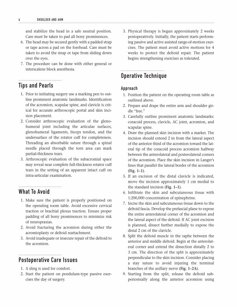
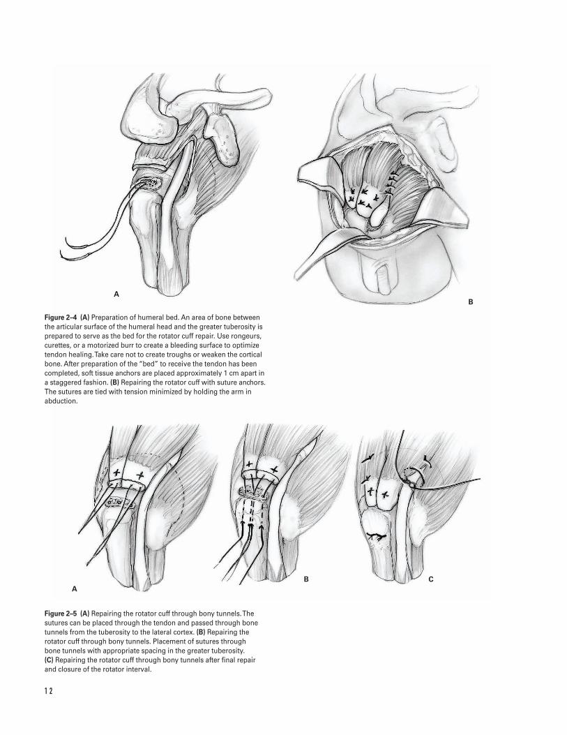
4. Draw the planned skin incision with a marker. Theincision should extend 2 in from the lateral aspectof the anterior third of the acromion toward the lat-eral tip of the coracoid process acromion halfwaybetween the anterolateral and posterolateral cornersof the acromion. Place the skin incision in Langer’slines that parallel the lateral border of the acromion(Fig. 1–1).
5. If an excision of the distal clavicle is indicated,move the incision approximately 1 cm medial tothe standard incision (Fig. 1–1).
6. Infiltrate the skin and subcutaneous tissue with1:200,000 concentration of epinephrine.
7. Incise the skin and subcutaneous tissue down to thedeltoid fascia. Develop the prefascial plane to exposethe entire anterolateral corner of the acromion andthe lateral aspect of the deltoid. If AC joint excisionis planned, dissect further medially to expose thedistal 2 cm of the clavicle.
8. Split the deltoid muscle in the raphe between theanterior and middle deltoid. Begin at the anterolat-eral corner and extend the dissection distally 2 to 3 cm. The direction of the split is approximatelyperpendicular to the skin incision. Consider placinga stay suture to avoid injuring the terminalbranches of the axillary nerve (Fig. 1–2A).
9. Starting from the split, release the deltoid sub-periosteally along the anterior acromion using
4 S H O U L D E R A N D A R M
5
B
A
a
b
Figure 1–1 Skin incision. The incision should extend 4 cm from thelateral aspect of the anterior third of the acromion toward the lateraltip of the coracoid process halfway between the anterolateral andposterolateral corners of the acromion. Place the skin incision inLanger’s lines that parallel the lateral border of the acromion (a).Note that if excision of the distal clavicle is planned, the skin incisionshould be positioned approximately 1 cm medial to the standardincision (b).
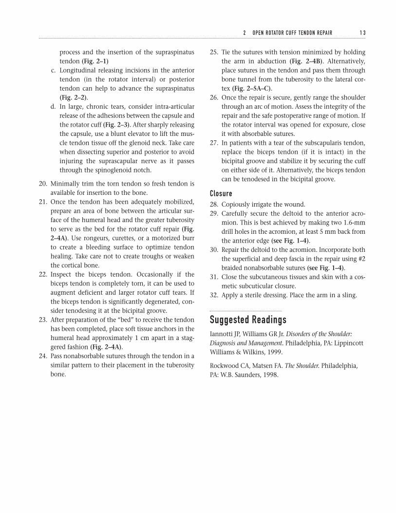
Figure 1–2 (A) Deltoid exposure. Split the deltoid muscle in the raphebetween the anterior and middle deltoid. This incision should begin atthe anterolateral corner and extend distally 2 to 3 cm. The direction ofthe split is approximately perpendicular to the skin incision. Considerplacing a stay suture to avoid injuring the terminal branches of theaxillary nerve. Starting from the split, you should release the deltoidsubperiosteally along the anterior acromion using an electrocautery.Extend the incision along the clavicle when a distal clavicle excision is planned. (B) Lateral view of deltoid detachment. Completely detachthe coracoacromial ligament, usually along with the deep deltoidfascia, from its attachment on the acromion.
A
B
A
B
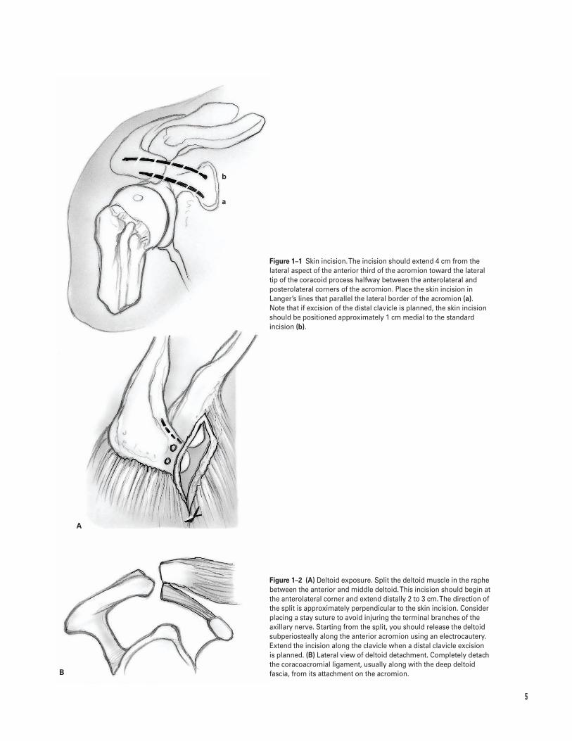
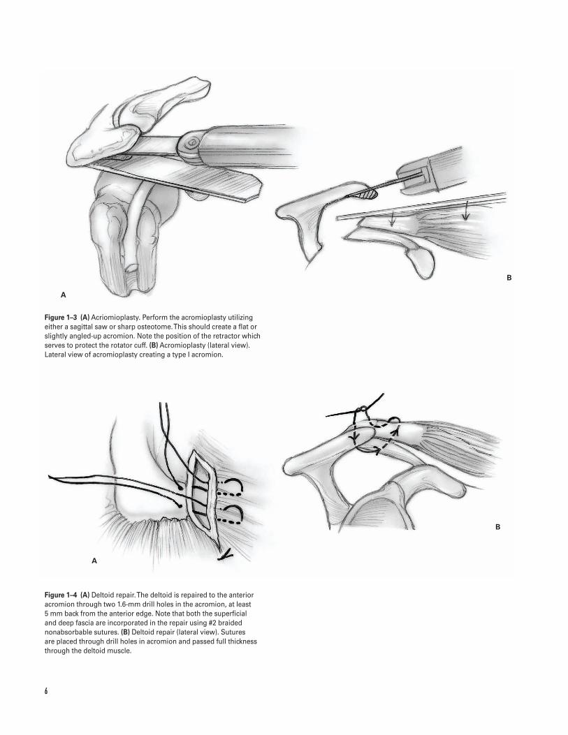
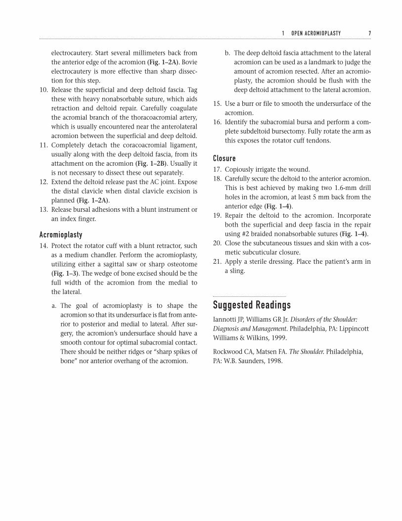
Figure 1–3 (A) Acriomioplasty. Perform the acromioplasty utilizingeither a sagittal saw or sharp osteotome. This should create a flat orslightly angled-up acromion. Note the position of the retractor whichserves to protect the rotator cuff. (B) Acromioplasty (lateral view).Lateral view of acromioplasty creating a type I acromion.
Figure 1–4 (A) Deltoid repair. The deltoid is repaired to the anterioracromion through two 1.6-mm drill holes in the acromion, at least 5 mm back from the anterior edge. Note that both the superficial and deep fascia are incorporated in the repair using #2 braidednonabsorbable sutures. (B) Deltoid repair (lateral view). Sutures are placed through drill holes in acromion and passed full thicknessthrough the deltoid muscle.
6
electrocautery. Start several millimeters back fromthe anterior edge of the acromion (Fig. 1–2A). Bovieelectrocautery is more effective than sharp dissec-tion for this step.
10. Release the superficial and deep deltoid fascia. Tagthese with heavy nonabsorbable suture, which aidsretraction and deltoid repair. Carefully coagulatethe acromial branch of the thoracoacromial artery,which is usually encountered near the anterolateralacromion between the superficial and deep deltoid.
11. Completely detach the coracoacromial ligament,usually along with the deep deltoid fascia, from itsattachment on the acromion (Fig. 1–2B). Usually itis not necessary to dissect these out separately.
12. Extend the deltoid release past the AC joint. Exposethe distal clavicle when distal clavicle excision isplanned (Fig. 1–2A).
13. Release bursal adhesions with a blunt instrument oran index finger.
Acromioplasty14. Protect the rotator cuff with a blunt retractor, such
as a medium chandler. Perform the acromioplasty,utilizing either a sagittal saw or sharp osteotome(Fig. 1–3). The wedge of bone excised should be thefull width of the acromion from the medial to the lateral.
a. The goal of acromioplasty is to shape theacromion so that its undersurface is flat from ante-rior to posterior and medial to lateral. After sur-gery, the acromion’s undersurface should have asmooth contour for optimal subacromial contact.There should be neither ridges or “sharp spikes ofbone” nor anterior overhang of the acromion.
b. The deep deltoid fascia attachment to the lateralacromion can be used as a landmark to judge theamount of acromion resected. After an acromio-plasty, the acromion should be flush with thedeep deltoid attachment to the lateral acromion.
15. Use a burr or file to smooth the undersurface of theacromion.
16. Identify the subacromial bursa and perform a com-plete subdeltoid bursectomy. Fully rotate the arm asthis exposes the rotator cuff tendons.
Closure17. Copiously irrigate the wound.18. Carefully secure the deltoid to the anterior acromion.
This is best achieved by making two 1.6-mm drillholes in the acromion, at least 5 mm back from theanterior edge (Fig. 1–4).
19. Repair the deltoid to the acromion. Incorporateboth the superficial and deep fascia in the repairusing #2 braided nonabsorbable sutures (Fig. 1–4).
20. Close the subcutaneous tissues and skin with a cos-metic subcuticular closure.
21. Apply a sterile dressing. Place the patient’s arm ina sling.
Suggested ReadingsIannotti JP, Williams GR Jr. Disorders of the Shoulder:Diagnosis and Management. Philadelphia, PA: LippincottWilliams & Wilkins, 1999.
Rockwood CA, Matsen FA. The Shoulder. Philadelphia,PA: W.B. Saunders, 1998.
1 O P E N A C R O M I O P L A S T Y 7
Indications (Rotator Cuff Repair)1. Patients with chronic shoulder pain or weakness
with a documented rotator cuff tear that has failednonsurgical management (rest, local modalities,NSAIDs, physical therapy, and judicious subacro-mial cortisone injections)
2. Acute, traumatic full-thickness rotator cuff tears3. Partial-thickness rotator cuff tears greater than 50%
Indications for associated acromioclavicular (AC)joint resectionã AC joint tenderness on physical examinationã Radiographic changes of AC joint arthritisã Exposure optimization of a retracted supraspinatus
tendon in chronic or massive rotator cuff tears
Contraindications1. Active soft tissue or glenohumeral infection2. Neuropathic joint3. Chronic axillary nerve injury4. Failed prior surgical treatment with associated del-
toid insufficiency (relative)5. Degenerative arthritis (relative); consider combin-
ing rotator cuff repair with shoulder arthroplasty6. Patient’s overall medical condition (relative)7. Parkinson’s disease or other diseases that cause
uncontrolled muscle activity (relative)8. Patient unable to comply with postoperative
rehabilitation
Preoperative Preparation1. Physical examination to include assessment of
AC joint tenderness and/or pain with shoulderadduction
2. Obtain radiographs
a. Anteroposterior (AP) in plane of scapula (trueAP)
b. AP shoulder (check distal clavicle for “spurs”)c. Axillary view (check for os acromiale, gleno-
humeral arthritis)d. Supraspinatus outlet view (assess acromion shape
[types I–III], spinoacromial angle)e. 25 degree caudal tilt (“Rockwood view”) (optional)
3. Consider magnetic resonance imaging (MRI): helpsevaluate extent (“full” versus “partial” thickness)of rotator cuff tears, and presence of muscle atro-phy or tendon retraction; observe mass effect ofacromion and AC joint on supraspinatus tendon(impingement).
Special Instruments, Position, andAnesthesia1. Small sagittal or oscillating saw for bone resection2. 1.6-mm drill bit for deltoid reattachment3. Small, half-circle curved free Mayo needle, and #2
braided nonabsorbable suture4. 5-mm round burr and broad flap rasp to “fine-tune”
acromioplasty
8
C H A P T E R 2
Open Rotator Cuff Tendon Repair
Mark K. Bowen and Angelo DiFelice
2 O P E N R OTATO R C U F F T E N D O N R E PA I R 9
5. Semi-sitting or beach chair position. The patient ismoved as close to the side of the table as possiblewhile still being stable. A beanbag-type McConnellhead holder (McConnell Surgical Mfg., Greenville,TX) or AMSCO “captain’s chair” is useful to secureand stabilize the head in a safe neutral position.Care must be taken to pad all bony prominences.
6. The head may be secured gently with a padded strapor tape across a pad on the forehead. Care must betaken to avoid the strap or tape from sliding downover the eyes.
7. The procedure can be done with either general orinterscalene block anesthesia.
Tips and Pearls1. A thorough preoperative evaluation is critical to
a successful rotator cuff repair. A complete physicalexamination, review of plain radiographs, and MRI provide meaningful information to plan sur-gery and counsel patients preoperatively. The sizeof tear and the degree of tendon retraction andmuscle atrophy can suggest the degree of difficultyin attempting to repair the rotator cuff and thepossible need for postoperative abduction braceimmobilization.
2. Check passive range of motion preoperatively andunder anesthesia. Gentle shoulder manipulationmay be necessary to release capsular adhesions. Ifadhesive capsulitis is severe, consider a stagedmanipulation and subsequent rotator cuff repair tominimize post-surgical loss of motion.
3. Mobilization of the rotator cuff tendon along itssuperior and inferior surfaces and release of acontracted coracohumeral ligament is important to minimize undesirable tension on the tissue and repair.
4. Define the anterior and posterior aspects of therotator cuff tear and advance and secure these areasfirst. This closes the tear and relieves tension on therepair at the tuberosity.
5. A secure deltoid repair to the acromion is as impor-tant as the rotator cuff repair in restoring shoulderstrength and function.
What To Avoid1. Make sure the patient is properly positioned on the
operating room table. Avoid excessive cervical trac-tion and brachial plexus traction. Ensure properpadding of all bony prominences to minimize riskof neuropraxias.
2. Avoid fracturing the acromion during either theacromioplasty or deltoid reattachment.
3. Do not mistake the flimsy bursal tissue for the rota-tor cuff tendon and use it in the cuff repair.
4. Avoid inadequate or insecure repair of the deltoid tothe acromion.
Postoperative Care Issues1. A sling or abduction pillow is used postoperatively
to protect the rotator cuff repair. The choice of post-operative protection depends on the type of patient,the quality of the tendon tissue, the tension on thesutures, and the adequacy of the cuff and deltoidrepair.
2. Three phases of rehabilitation—time in each stagedepends on tendon quality and assessment of repair.
a. Phase 1. Passive range of motion: includes pen-dulum saw, and tummy rub exercises
b. Phase 2. Active-assisted range of motion exer-cises and gentle cuff isometrics
c. Phase 3. Active range of motion and resistanceexercises
Operative Technique
Approach1. Position the patient on the operating room table as
outlined above.2. Prepare and drape the entire arm and shoulder
girdle “free.”3. Carefully outline prominent anatomic landmarks:
coracoid process, clavicle, AC joint, acromion andscapular spine.
4. Draw the planned skin incision with a marker. Theincision should extend 2 in from the lateral aspectof the anterior third of the acromion toward the lat-eral tip of the coracoid process acromion halfwaybetween the anterolateral and posterolateral cornersof the acromion. Place the skin incision in Langer’slines that parallel the lateral border of the acromion(see Fig. 1–1).
5. If an excision of the distal clavicle is indicated,move the incision approximately 1 cm medial tothe standard incision (see Fig. 1–1).
6. Infiltrate the skin and subcutaneous tissue with1:200,000 concentration of epinephrine.
7. Incise the skin and subcutaneous tissue down to the deltoid fascia. Develop the prefascial plane toexpose the entire anterolateral corner of the acro-mion and the lateral aspect of the deltoid. If ACjoint excision is planned, dissect further medially toexpose the distal 2 cm of the clavicle.
8. Split the deltoid muscle in the raphe between theanterior and middle deltoid. Begin at the anterolat-eral corner and extend the dissection distally 2 to 3 cm. The direction of the split is approximatelyperpendicular to the skin incision. Consider placinga stay suture to avoid injuring the terminal branchesof the axillary nerve (see Fig. 1–2A).
9. Starting from the split, release the deltoid subpe-riosteally along the anterior acromion using an elec-trocautery. Start several millimeters back from theanterior edge of the acromion (see Fig. 1–2A). Bovieelectrocautery is more effective than sharp dissec-tion for this step.
10. Release the superficial and deep deltoid fascia. Tagthese with heavy nonabsorbable suture, which aidsretraction and deltoid repair. Carefully coagulatethe acromial branch of the thoracoacromial arterythat is usually encountered near the anterolateralacromion between the superficial and deep deltoid.
11. Completely detach the coracoacromial ligament,usually along with the deep deltoid fascia, from its attachment on the acromion (see Fig. 1–2B).Usually it is not necessary to dissect these outseparately.
12. Extend the deltoid release past the AC joint. Exposethe distal clavicle when distal clavicle excision isplanned (see Fig. 1–2A).
13. Release bursal adhesions with a blunt instrument oran index finger.
Acromioplasty14. Protect the rotator cuff with a blunt retractor, such as
a medium chandler. Perform an acromioplasty utiliz-ing either a sagittal saw or a sharp osteotome (seeFig. 1–3A). The wedge of bone excised should be thefull width of the acromion from the medial to lateral.
a. The goal of the acromioplasty is to shape theacromion so its undersurface is flat from anteriorto posterior and medial to lateral. After surgery,the acromion’s undersurface should have asmooth contour for optimal subacromial con-tact. There should be no ridges or sharp spikes ofbone, nor should there be anterior overhang of the acromion.
b. The deep deltoid fascia attachment to the lateralacromion can be used as a landmark to judge theamount of acromion resected. After an acromio-plasty, the acromion should be flush with thedeep deltoid attachment to the lateral acromion.
15. Use a burr or file to smooth the undersurface of theacromion.
Rotator cuff repair16. Identify the subacromial bursa and perform a com-
plete subdeltoid bursectomy. Fully rotating the armexposes the rotator cuff tendons.
17. Assess the size of the rotator cuff tendon tear, theprecise rotator cuff tendon anatomy, the shape ofthe tendon tear, the tendons involved, the degreeof tendon retraction, the anterior and posteriorextent of the tear, and the quality of the tendonavailable for repair.
18. Tag the torn edges of the rotator cuff with heavynonabsorbable suture. Assess the need for mobiliza-tion of the tendon.
19. Several methods are useful in mobilizing the rotatorcuff
a. Release and excision of the subacromial and sub-deltoid bursa
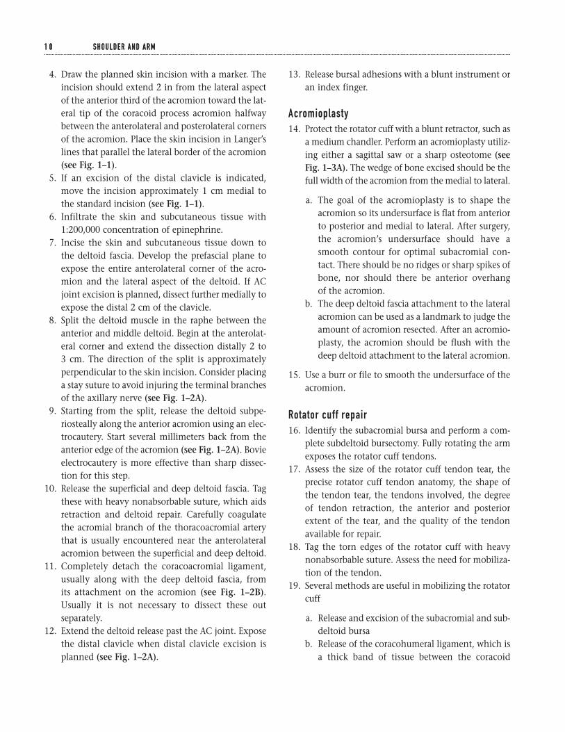
b. Release of the coracohumeral ligament, which isa thick band of tissue between the coracoid
1 0 S H O U L D E R A N D A R M1 0 S H O U L D E R A N D A R M
1 1
A B
AB
Figure 2–1 Releasing the coracohumeralligament. The coracohumeral ligament,which is a thick band of tissue betweenthe coracoid process and the supra-spinatus tendon, can be released tomobilize the rotator cuff.
Figure 2–2 (A) Longitudinal releasing incisions. Longitudinal releasingincisions in the anterior tendon (in the rotator interval) or posteriortendon can help to advance the supraspinatus. (B) Closure of theinterval. The interval is closed after the tendon is repaired to bone.
Figure 2–3 Releasing intra-articular adhesion. In large, chronic tears,consider intra-articular release of the adhesions between the capsuleand the rotator cuff. If the tendon is retracted and tethered by thecapsule at the glenoid, the capsule is incised. Use a blunt elevator to lift the muscle tendon tissue off the glenoid neck. Take care whendissecting superior and posterior to avoid injuring the suprascapularnerve as it passes through the spinoglenoid notch. (B) Intra-articularadhesion release. These steps demonstrate the mobilization,advancement, and repair of the rotator cuff tendon.
1 2
AB
AB C
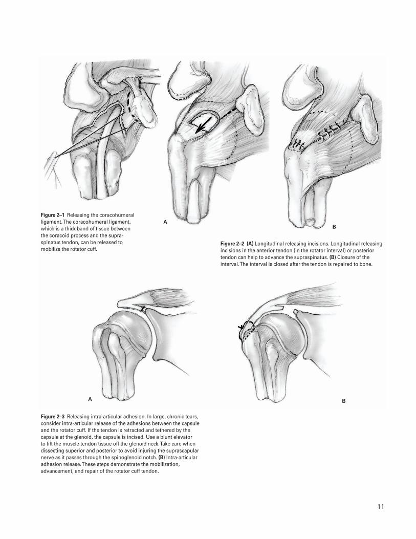
Figure 2–4 (A) Preparation of humeral bed. An area of bone betweenthe articular surface of the humeral head and the greater tuberosity isprepared to serve as the bed for the rotator cuff repair. Use rongeurs,curettes, or a motorized burr to create a bleeding surface to optimizetendon healing. Take care not to create troughs or weaken the corticalbone. After preparation of the “bed” to receive the tendon has beencompleted, soft tissue anchors are placed approximately 1 cm apart ina staggered fashion. (B) Repairing the rotator cuff with suture anchors.The sutures are tied with tension minimized by holding the arm inabduction.
Figure 2–5 (A) Repairing the rotator cuff through bony tunnels. Thesutures can be placed through the tendon and passed through bonetunnels from the tuberosity to the lateral cortex. (B) Repairing therotator cuff through bony tunnels. Placement of sutures through bone tunnels with appropriate spacing in the greater tuberosity. (C) Repairing the rotator cuff through bony tunnels after final repairand closure of the rotator interval.
process and the insertion of the supraspinatustendon (Fig. 2–1)
c. Longitudinal releasing incisions in the anteriortendon (in the rotator interval) or posteriortendon can help to advance the supraspinatus(Fig. 2–2).
d. In large, chronic tears, consider intra-articularrelease of the adhesions between the capsule andthe rotator cuff (Fig. 2–3). After sharply releasingthe capsule, use a blunt elevator to lift the mus-cle tendon tissue off the glenoid neck. Take carewhen dissecting superior and posterior to avoidinjuring the suprascapular nerve as it passesthrough the spinoglenoid notch.
20. Minimally trim the torn tendon so fresh tendon isavailable for insertion to the bone.
21. Once the tendon has been adequately mobilized,prepare an area of bone between the articular sur-face of the humeral head and the greater tuberosityto serve as the bed for the rotator cuff repair (Fig.2–4A). Use rongeurs, curettes, or a motorized burrto create a bleeding surface to optimize tendonhealing. Take care not to create troughs or weakenthe cortical bone.
22. Inspect the biceps tendon. Occasionally if thebiceps tendon is completely torn, it can be used toaugment deficient and larger rotator cuff tears. Ifthe biceps tendon is significantly degenerated, con-sider tenodesing it at the bicipital groove.
23. After preparation of the “bed” to receive the tendonhas been completed, place soft tissue anchors in thehumeral head approximately 1 cm apart in a stag-gered fashion (Fig. 2–4A).
24. Pass nonabsorbable sutures through the tendon in asimilar pattern to their placement in the tuberositybone.
25. Tie the sutures with tension minimized by holdingthe arm in abduction (Fig. 2–4B). Alternatively,place sutures in the tendon and pass them throughbone tunnel from the tuberosity to the lateral cor-tex (Fig. 2–5A–C).
26. Once the repair is secure, gently range the shoulderthrough an arc of motion. Assess the integrity of therepair and the safe postoperative range of motion. Ifthe rotator interval was opened for exposure, closeit with absorbable sutures.
27. In patients with a tear of the subscapularis tendon,replace the biceps tendon (if it is intact) in thebicipital groove and stabilize it by securing the cuffon either side of it. Alternatively, the biceps tendoncan be tenodesed in the bicipital groove.
Closure28. Copiously irrigate the wound.29. Carefully secure the deltoid to the anterior acro-
mion. This is best achieved by making two 1.6-mmdrill holes in the acromion, at least 5 mm back fromthe anterior edge (see Fig. 1–4).
30. Repair the deltoid to the acromion. Incorporate boththe superficial and deep fascia in the repair using #2braided nonabsorbable sutures (see Fig. 1–4).
31. Close the subcutaneous tissues and skin with a cos-metic subcuticular closure.
32. Apply a sterile dressing. Place the arm in a sling.
Suggested ReadingsIannotti JP, Williams GR Jr. Disorders of the Shoulder:Diagnosis and Management. Philadelphia, PA: LippincottWilliams & Wilkins, 1999.
Rockwood CA, Matsen FA. The Shoulder. Philadelphia,PA: W.B. Saunders, 1998.
2 O P E N R OTATO R C U F F T E N D O N R E PA I R 1 3
Indications1. Recurrent anterior shoulder instability with pain
that limits activities
Contraindications1. Voluntary shoulder instability2. History of psychiatric disease3. Active infection4. Multidirectional shoulder instability or generalized
ligamentous laxity (relative)5. Glenohumeral arthritis (relative)6. Presence of a large Hill-Sachs lesion or glenoid defi-
ciency may alter approach
Preoperative Preparation1. Shoulder radiographs
a. True anteroposterior (AP) viewb. Axillary lateral viewc. Consider an AP view with internal rotation of
the humerus.d. Consider Stryker-notch view.e. Consider West Point modified axillary view.f. Consider scapular “Y” views.
2. Consider computed tomography (CT) arthrography,magnetic resonance imaging (MRI), or magneticresonance (MR) arthrogram (if necessary).
3. Assess passive and active range of motion.
4. Document neurovascular examination.5. Consider diagnostic arthroscopy (if examination
under anesthesia [EUA] is not consistent with clini-cal diagnosis).
6. Appropriate medical and anesthesia preoperativeevaluation.
Special Instruments, Position, and Anesthesia1. Specialized shoulder retractors for soft tissues and
humeral head2. Suture anchors3. Beach chair position with beanbag4. If available, a McConnell arm holder is helpful
(McConnell Surgical Mfg., Greenville, TX).5. All pressure points should be well padded.6. The procedure can be done with regional anesthesia
(interscalene block) and/or general anesthesia.
Tips and Pearls1. Intravenous antibiotics are administered prior to
the skin incision.2. A concealed anterior axillary skin incision is pre-
ferred. The arm is adducted across the body aftersterile prepping and draping is completed. Thishelps define the natural axillary skin folds, whichcan then be marked with a sterile pen.
3. Limit arthroscopy time so that the soft tissues donot become too edematous.
C H A P T E R 3
Open Anterior Shoulder Stabilization
Daniel D. Buss and William C. Jacobsen
1 4
3 O P E N A N T E R I O R S H O U L D E R S TA B I L I Z AT I O N 1 5
4. EUA is performed to assess the direction and degreeof shoulder instability and the results comparedwith the contralateral shoulder.
What To Avoid1. Avoid incisions outside the natural skin lines.2. If possible, avoid injury to the cephalic vein. Com-
monly, it is preserved and retracted laterally withthe deltoid.
3. Attempt to avoid injury to the axillary and musculo-skeletal nerves by protecting them at all times.
4. Avoid damaging the glenohumeral articular cartilage.5. Avoid “overtightening” the shoulder during the cap-
sular shift and/or repair of the subscapularis tendon.
Postoperative Care Issues1. The neurovascular examination should be performed
and documented. The examination may be affectedby regional anesthesia in the immediate postopera-tive period.
2. Consider using an ice and compression device,which helps with swelling and pain control.
3. The shoulder is immobilized in a sling for up to 3 to4 weeks for comfort only. The patient may use theelbow and hand normally for light activity.
4. Postoperative rehabilitation begins by working onachieving adequate range of shoulder motion, thenprogresses to strengthening of the shoulder muscles,and finally to a functional program to reestablishproprioception and muscular coordination.
5. Exercises commence with pendulum exercises,forward flexion in the plane of the scapula usingpulleys and wands, and passive range-of-motionexercises including external rotation in the pre-determined safe zone. The safe zone is determinedby the surgeon at the time of surgical repair.
6. Active and active-assisted range-of-motion exer-cises are started at 4 to 6 weeks postoperatively tostrengthen the deltoid, rotator cuff, and scapularmuscles.
7. At 3 months postoperatively, therapy is directed at regaining full strength and endurance of theshoulder.
8. At 4 months postoperatively, functional exercisesare added.
9. At 4 to 6 months postsurgery, it is possible for thepatient to return to sports and to engage in fullactivity.
Operative TechniqueApproach
1. Position the patient supine on the table. Place blan-kets or pillows under the patient’s thighs. Flex thewaist approximately 35 degrees, the knees approxi-mately 40 degrees, and the back approximately 20degrees.
2. With the head and neck in neutral position, contourthe beanbag around the patient and deflate the bag.
3. Position the patient so the operative shoulder ispulled to the bed’s edge to allow adequate access.Secure the patient to the bed.
4. Prepare and drape the limb in the hospital’s stan-dard sterile fashion.
5. Draw the bony landmarks, including the acromion,clavicle, spine of the scapula, and coracoid tip, onthe skin.
6. Perform glenohumeral arthroscopy (optional—seeChapter 4 on shoulder arthroscopy).
7. Infiltrate the incision site with a dilute epinephrinesolution.
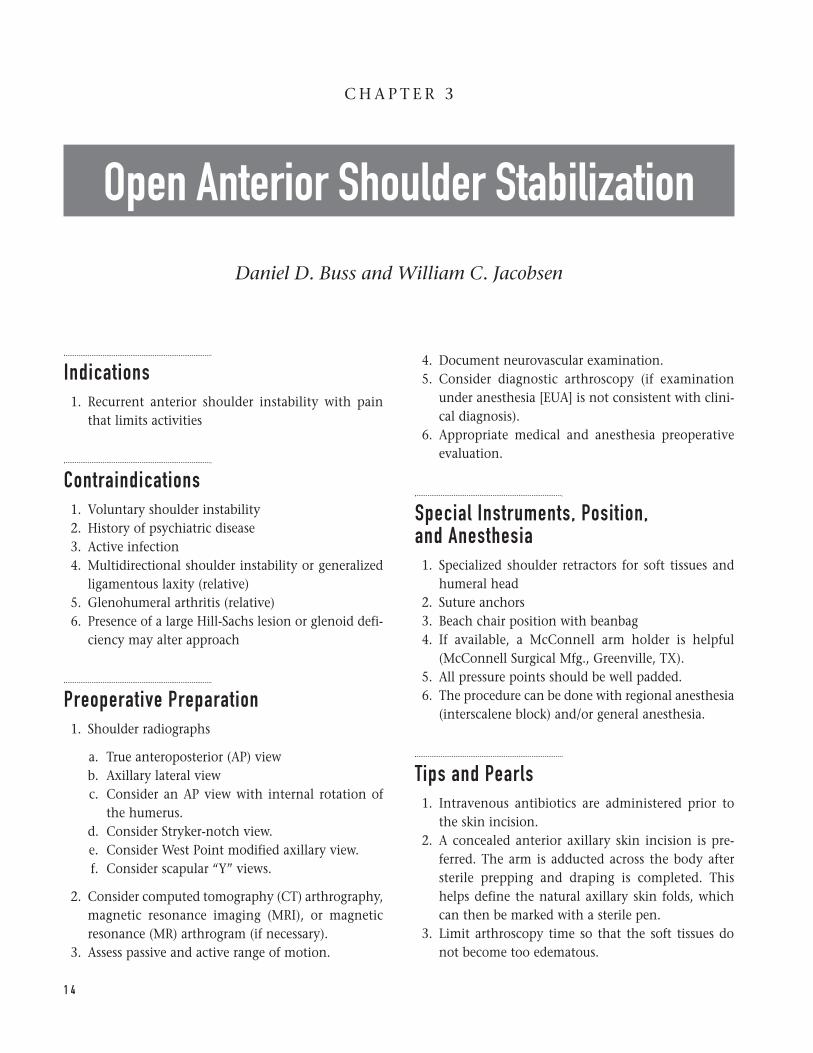
8. Make a 5- to 8-cm incision. Start 2 cm below thecoracoid tip and extend the incision down towardthe anterior axillary line. Elevate skin flaps to aidretraction (Fig. 3–1).
9. Identify the deltopectoral interval and the cephalicvein, which is usually seen as a fat stripe betweenthe deltoid and pectoralis major.
10. Expose and mobilize the cephalic vein. Commonly,dissection is performed on the vein’s medial side,which allows the vein to be retracted laterally withthe deltoid.
11. Open the deltopectoral interval. Carry the dissec-tion 1 cm proximal to the coracoid tip. Stay lateralto the coracoid.
12. Undermine the deltoid and pectoralis to aid retrac-tion. The upper portion of the pectoralis may haveto be released to aid in retraction in well-muscled
“T” should be made between the inferior and mid-dle glenohumeral ligaments.
26. The advantages of the lateral versus medial arthro-tomy are described by Bigliani (1996).
27. Use a humeral head retractor to help visualize theglenoid.
28. Evaluate the labrum to determine if reattachment isneeded.
29. Roughen the anterior glenoid neck with a curette.Consider “rose-pedaling” the area with a smallosteotome.
30. Evaluate the joint for loose bodies, articular carti-lage damage, and humeral head defects.
Labral reattachment31. We prefer suture anchors for labral reattachment.
This can also be accomplished with transosseousdrill holes.
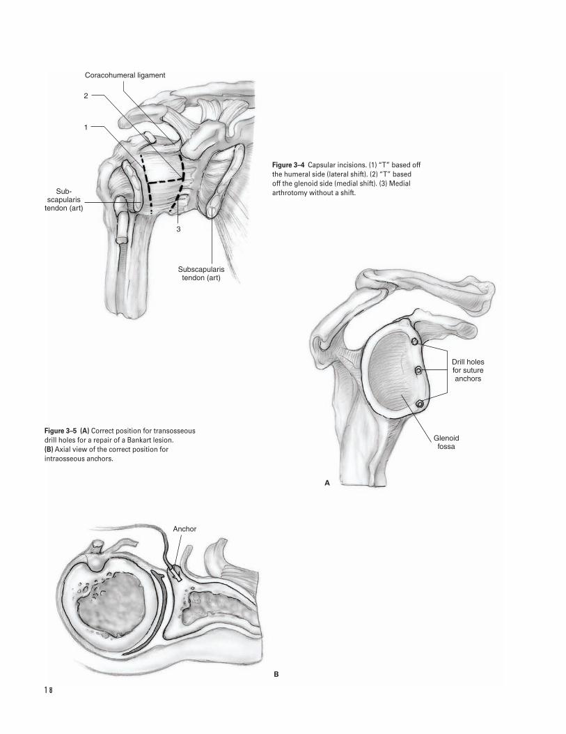
32. Place suture anchors along the glenoid rim at the 7,9, and 11 o’clock position for the left shoulder andat the 1, 3, and 5 o’clock position for the rightshoulder (Fig. 3–5).
33. If a Bankart lesion is present, pass both suture limbsof each anchor through the labrum and tie themdown. If desired, these can be passed through the“shifted” capsule.
34. For a medial arthrotomy, shift the capsule superi-orly as far as possible and medially 2 to 3 mm.
35. For the lateral arthrotomy, the capsule is shiftedsuperiorly and laterally.
36. Use the stay sutures placed along the edges of thecapsule to pull it in the desired direction.
37. Reattach the edges of the shifted capsule to thecapsular edge not involved in the shift with a non-absorbable suture on a noncutting needle.
38. For the “T” incision, the inferior capsule is shifted asdescribed above. The superior limb is then broughtinferiorly and medially for the medial arthrotomyand inferiorly and laterally for the lateral arthro-tomy. These arthrotomies are reattached similarly.
39. Proper arm position is important to ensure that thecapsular shift is effective and allows adequate shoul-der function. Place the arm in approximately 20degrees of external rotation and abduction and 10 degrees of forward flexion. For overhead ath-letes, consider positioning the arm with slightlygreater external rotation and abduction.
1 6 S H O U L D E R A N D A R M
individuals. Place a self-retaining retractor underthe deltoid and pectoralis.
13. Open the clavipectoral fascia. Identify the lateraledge of the conjoined tendon.
14. Identify the subscapularis tendon, long head of thebiceps tendon and lesser tuberosity. Internal andexternal rotation helps define the subscapularistendon.
15. Palpate the axillary nerve by sliding your fingerdown the subscapularis tendon and internally rotatethe arm when you reach the inferior border of thesubscapularis. This is known as the “tug test.”
16. Protect the axillary nerve with a retractor.17. Identify the rotator interval. The superior edge of
the subscapularis is at the rotator interval and theanterior humeral circumflex vessels (“three sis-ters”) mark the inferior edge. Expose and cauterizethese vessels.
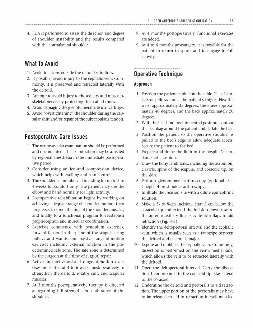
18. With the arm externally rotated, divide the sub-scapularis tendon in its midportion. Typically this isat a point 1 to 1.5 cm medial to the lesser tuberos-ity. Carry the dissection down to but not throughthe shoulder capsule. The fibers of the tendon runtransversely. The tendon can be divided completelyor partially (Fig. 3–2).
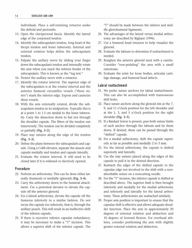
19. Place stay sutures along the edge of the tendon(Fig. 3–3).
20. Define the plane between the subscapularis and cap-sule. Using a Cobb elevator, separate the muscle andcapsule medially and tendon and capsule laterally.
21. Evaluate the rotator interval. It will need to beclosed later if it is widened or electively opened.
Procedure22. Perform an arthrotomy. This can be done either lat-
erally (humeral) or medially (glenoid) (Fig. 3–4).23. Carry the arthrotomy down to the humeral attach-
ment. Use a periosteal elevator to elevate the cap-sule off the anterior glenoid.
24. For a lateral arthrotomy, elevate the capsule off thehumerus inferiorly in a similar fashion. Do notincise the capsule too inferiorly, that is, through theaxillary pouch. This will result in an ineffective shiftof the inferior capsule.
25. If there is excessive inferior capsular redundancy, it may be necessary to make a “T” incision. Thisallows a superior shift of the inferior capsule. The
1 7
Deltoid muscle
Acromion
Coracoid process
Cephalic vein
Pectoralis major muscle
Cautery
(Partial)
Axillary nerve
(Complete)
Coracoid process
Capsule
Subscapularis tendon
Biceps tendon
Figure 3–1 Skin incision and subcutaneousexposure.
Figure 3–2 Deep exposure depicting a completeor a partial tenotomy of the subscapularistendon.
Figure 3–3 Axial view of the cut subscapularistendon and underlying capsule.
1 8
Coracohumeral ligament
2
1
Sub- scapularis
tendon (art)
3
Subscapularis tendon (art)
Drill holes for suture anchors
Glenoid fossa
Anchor
A
B
Figure 3–4 Capsular incisions. (1) “T” based offthe humeral side (lateral shift). (2) “T” based off the glenoid side (medial shift). (3) Medialarthrotomy without a shift.
Figure 3–5 (A) Correct position for transosseousdrill holes for a repair of a Bankart lesion. (B) Axial view of the correct position forintraosseous anchors.
49. Close the skin with staples or a running subcuticu-lar stitch and steristrips.
50. Apply a sterile compressive dressing.51. Place the arm in a sling device. Transfer the patient
to the recovery room.
Suggested ReadingsBigliani, Louis U, eds. The Unstable Shoulder. Rosemont,IL: American Academy of Orthopaedic Surgery, 1996.
Craig, EV, ed. The shoulder. Master Techniques inOrthopedic Surgery. New York, NY: Raven, 1995.
Rowe CR, Patel D, Southmayd WW. The Bankartprocedure. J Bone Joint Surg 1978;60A:1–16.
3 O P E N A N T E R I O R S H O U L D E R S TA B I L I Z AT I O N 1 9
Closure40. Thoroughly irrigate the wound with antibiotic
irrigation.41. Ensure adequate hemostasis has been achieved.42. A drain is usually not necessary.43. Remove all retractors. Repeat the “tug-test” to verify
continuity and mobility of the axillary nerve.44. If necessary, close the rotator interval.45. Reapproximate the subscapularis tendon with the
arm in slight external rotation to avoid loss of exter-nal rotation. Nonabsorbable suture is preferred.
46. If the pectoralis was released, reapproximate it witha single, nonabsorbable suture.
47. Close the deltopectoral interval with absorbablesutures. Protect the cephalic vein.
48. Close the subcutaneous tissue with absorbable suture.
Indications1. Loose body2. Foreign body3. Labral tear4. Impingement syndrome5. Instability6. Acromioclavicular arthritis7. Infection8. Diagnostic dilemma
Contraindications1. Acute adjacent soft tissue injury resulting in risk of
neurovascular compromise from fluid extravasation(relative)
Preoperative Preparation1. Shoulder radiographs including true anteroposterior
(Grashe), outlet or “Y,” and axillary views; Stryker-notch view is also obtained for patients with insta-bility symptoms.
2. Consider magnetic resonance imaging (MRI) to con-firm diagnoses.
3. Document preoperative neurovascular examinationof upper extremity.
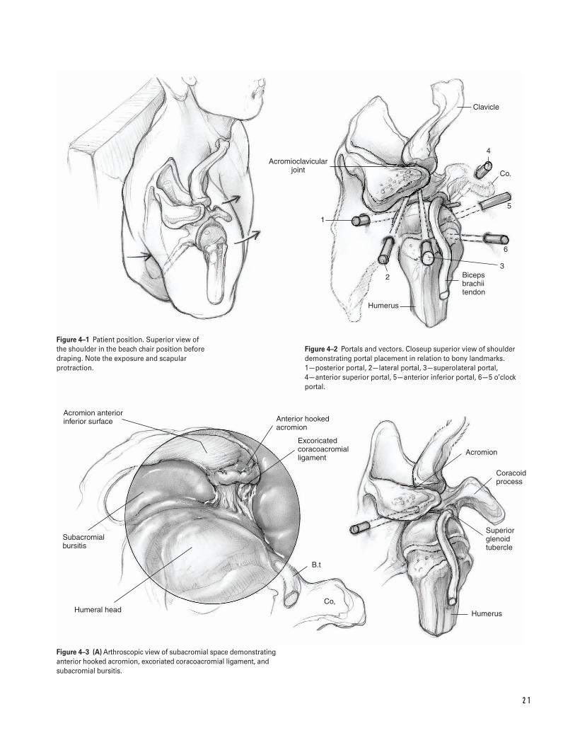
Special Instruments, Position, and Anesthesia1. Beach chair position on full-body beanbag.
a. Keep head midline with neck in neutral orslightly flexed position.
b. Protract the scapula, which exposes the medialborder of the scapula. Drape the shoulder freefrom the medial border of the scapula posteriorlyto the midline of the clavicle anteriorly (Fig. 4–1).
2. Alternatively, consider using the modified lateraldecubitus position which aligns the glenoid surfacehorizontal. The arm is slightly forward flexed andabducted 50 degrees with 10 to 15 lb of longitudi-nal suspension applied from a traction tower.
3. All pressure points should be padded, particularlythe peroneal nerve.
4. The procedure can be performed with generaland/or scalene block anesthesia.
5. Routine arthroscopy equipment is required for diag-nostic arthroscopy. Additional specialized instru-mentation is necessary for each operative procedure.Open shoulder instrumentation should be available.
Tips and Pearls1. Perform a physical examination under anesthesia to
assess shoulder stability and range of motion.
C H A P T E R 4
Shoulder Arthroscopy
Daniel D. Buss and John R. Green III
2 0
2 1
Acromion anterior inferior surface
Subacromial bursitis
Humeral head
Anterior hooked acromion
Excoricated coracoacromial ligament
B.t
Co,
Humerus
Superior glenoid tubercle
Acromion
Coracoid process
Clavicle
4
Co.
5
6
Biceps brachii tendon
Humerus
2
1
Acromioclavicular joint
3
Figure 4–1 Patient position. Superior view of the shoulder in the beach chair position beforedraping. Note the exposure and scapularprotraction.
Figure 4–2 Portals and vectors. Closeup superior view of shoulderdemonstrating portal placement in relation to bony landmarks. 1—posterior portal, 2—lateral portal, 3—superolateral portal, 4—anterior superior portal, 5—anterior inferior portal, 6—5 o’clockportal.
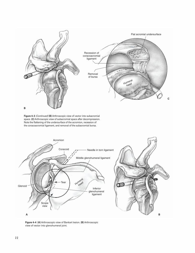
Figure 4–3 (A) Arthroscopic view of subacromial space demonstratinganterior hooked acromion, excoriated coracoacromial ligament, andsubacromial bursitis.
2 2
B
C
A B
Flat acromial undersurface
Recession of coracoacromial
ligament
Removal of bursa
Humeral
head
Acromion
Coracoid Needle in torn ligament
Middle glenohumeral ligament
Tear
Glenoid
Scope view
Inferior glenohumeral �
ligament
Humeral
head
Figure 4–3 (Continued) (B) Arthroscopic view of vector into subacromialspace. (C) Arthroscopic view of subacromial space after decompression.Note the flattening of the undersurface of the acromion, recession of the coracoacromial ligament, and removal of the subacromial bursa.
Figure 4–4 (A) Arthroscopic view of Bankart lesion. (B) Arthroscopicview of vector into glenohumeral joint.
4 S H O U L D E R A RT H R O S C O P Y 2 3
2. Drawing landmarks on the skin can help facilitateaccurate portal placement.
3. Routine intravenous antibiotics should be adminis-tered prior to incision.
4. Confirm placement of the posterior portal with an18-gauge 31⁄2-in spinal needle. Distend the gleno-humeral joint with 20 cc of 0.5% bupivicaine withepinephrine.
5. Infiltrate the portal sites with 0.5% bupivicainewith epinephrine.
6. Consider relative hypotensive anesthesia becausethis decreases intraoperative bleeding, thereby per-mitting lower fluid pressures which helps minimizefluid extravasation.
What To Avoid1. Avoid chondral injury by using blunt obturators to
enter the joint under careful control. Do not plunge!2. Avoid inadvertent rotator cuff tendon tears during
posterior portal placement by internal rotation ofthe humerus.
3. Minimize risk of neurovascular injury by placingthe anterior portal lateral to the coracoid and keep-ing the humerus adducted when creating anteriorportals.
Postoperative Care Issues1. Use a sling with a 6-in elastic bandage wrapped
around the body. The elastic bandage can be re-moved when the scalene block has worn off.
2. After arthroscopic shoulder decompression, the slingis removed after 2 days, and early active, active-assisted, and passive range-of-motion exercises arebegun. In addition, isotonic rotator cuff strengthen-ing and scapular stabilization exercises are alsobegun. The goal is full, active, pain-free range ofmotion 4 weeks after surgery.
3. After an arthroscopic Bankart repair, the sling isworn for 4 weeks. During this time, elbow range-of-motion exercises, squeezing a tennis ball for grip,co-contracture of the biceps and triceps, and pen-dulum exercises are instituted. At 4 weeks, isometricrotator cuff strengthening and active, active-assisted,
and passive range-of-motion exercises are begun.External rotation is limited to 20 degrees until 6 weeks after surgery. At 6 weeks, the patient beginsisotonic strengthening exercises. Heavy lifting andthrowing programs are deferred until 4 monthsafter surgery.
Operative Technique1. Position the patient supine on the table. Place
blankets or pillows under the patient’s thighs. Flexthe waist approximately 35 degrees, the kneesapproximately 40 degrees, and the back approxi-mately 40 degrees.
2. With the head and neck in neutral position, con-tour the beanbag around the patient and deflatethe bag.
3. Position the patient so the operative shoulder ispulled to the bed’s edge to allow adequate access.Secure the patient to the bed.
4. Prepare and drape the limb in the hospital’s stan-dard sterile fashion.
5. Draw the bony landmarks, including the acromion,clavicle, spine of the scapula, and coracoid tip, onthe skin.
Diagnostic arthroscopy—posterior portal6. Place the posterior portal in the “soft spot” between
the infraspinatus, teres minor, and edge of deltoid.This is located 2 to 3 cm inferior and 1 to 2 cmmedial to the posterolateral corner of the acromion.Localize the plane of the glenoid with an 18-gaugespinal needle. Enter the joint using a blunt obturator(Fig. 4–2).
7. Establish intra-articular orientation with the arthro-scope looking straight inferior (the light cord facingstraight up) by viewing the biceps tendon’s insertioninto the superior labrum and the plane of the gle-noid. The inflow is through the arthroscope sheath.
8. Insert the arthroscope deeper into the shoulder tovisualize the subscapularis tendon.
9. Rotate the arthroscope medially to view the sub-scapularis recess.
10. Rotate the arthroscope laterally to follow the sub-scapularis tendon. Visualize the undersurface of thebiceps tendon, the superior glenohumeral ligament
upon the procedure being performed. A more supe-rior position is desirable for stabilizing a superiorlabral tear or debriding a partial thickness rotatorcuff tear, while a more inferior position is beneficialfor performing an anterior capsulolabral repair, anda more medial position is advantageous for excisingthe distal clavicle excision (Fig. 4–2).
19. Evaluate the area between the subscapularis tendonand the supraspinatus tendon (rotator interval).Under direct vision insert an 18-gauge 31⁄2-in spinalneedle into this triangle passing the needle tipbelow the biceps tendon. The external entry point isgenerally midway between the coracoid and theanterior acromion. If an anterior portal is indicated,insert a cannula with a blunt obturator at the sameangle as the spinal needle. If there is no indicationfor an anterior portal, use this needle to probe thesuperior labral attachment (Fig. 4–2). Alternatively,an anterior portal may also be made from inside-out.Drive the arthroscope anteriorly against the capsulein the triangle formed by the humeral head, glenoid,and biceps tendon. Remove the arthroscope from itssheath and insert a Wissinger rod or switching stickthrough the cannula so it can be palpated under theskin. Incise the tented skin with a scalpel. Pass a can-nula over the rod into the joint (Fig. 4–2).
Diagnostic arthroscopy—subacromial space20. Approach the subacromial space using the same
skin incision as the posterior portal for the gleno-humeral arthroscopy. With a blunt obturator inplace, withdraw the arthroscopic sheath from theglenohumeral joint. Direct it superiorly in the sub-cutaneous tissue along the undersurface of theacromion until it rests against the coracoacromialligament. Err on the side of scraping superiorlyagainst the inferior acromion rather than inferiorlyagainst the rotator cuff. Withdraw the cannula 1 cm,insert the arthroscope, and turn on the inflowthrough the arthroscopic sheath.
21. Initial visualization can sometimes be difficult inthe presence of subacromial bursa pathology. Inthis situation, pass a switching stick through thearthroscopic cannula and out the anterior portal.Pass a second cannula over the rod anteriorly intothe subacromial space. This cannula passes just
2 4 S H O U L D E R A N D A R M
crossing between the subscapularis tendon and thelong head of the biceps tendon, and the transverseligament securing the biceps tendon in the bicipitalgroove.
11. Retract the arthroscope and examine the anteriorlabrum. Externally rotate the humerus to accentuateand visualize the middle glenohumeral ligament.
12. “Drive through” the joint into the axillary recess byinserting the arthroscope deeper while rotating it tolook inferiorly. Inspect the anterior band of theinferior glenohumeral ligament. The arthroscope’stip should be anterior to the articular surface tominimize the risk of abrasion.
13. Rotate the arthroscope to look superior. Raise thecamera to view the inferior labrum and the humeralinsertion of the anterior band of the inferior gleno-humeral ligament.
14. Follow the labrum posteriorly, externally rotate thehumerus to improve visualization.
15. Continue following the labrum superiorly. Examinethe superior glenohumeral recess with the humerusabducted 20 to 30 degrees.
16. Follow the superior surface of the biceps tendonlaterally. Forward flex the patient’s arm slightlyand begin abducting and externally rotating thehumerus. Examine the supraspinatus tendon’sinsertion on to the greater tuberosity.
17. Visualize the insertion of the entire rotator cufffrom greater tuberosity to axillary recess by slowlyinternally rotating the humerus and withdrawingthe arthroscope. The bare area on the posterolateralhumeral head is seen adjacent to the posterior cuffinsertion. Minimize the risk of iatrogenic articularcartilage injury by using gentle pressure to keep thetip of the arthroscope off the chondral surface.
18. External rotation assists in viewing the articularsurface of the posterior humeral head. A Hill-Sachslesion is found on the superior posterolateral hume-ral head. Inspect the remaining humeral surface byinternally rotating the arm.
Diagnostic arthroscopy—anterior portalã An anterior portal is indicated to visualize posterior
shoulder pathology. It provides the best view of themiddle glenohumeral ligament and anterior labrum.Optimal position for the anterior portal depends
medial to the coracoacromial ligament. Insert amotorized shaver through the anterior cannula toclear away tissue and improve visualization in thesubacromial space.
22. Diagnostic arthroscopy of the subacromial spaceincludes assessment of the subacromial bursa, cora-coacromial ligament, acromion, and outer surfaceof the rotator cuff. If indicated, dissect mediallythrough a small fibrofatty layer to expose theundersurface of the acromioclavicular joint and the distal clavicle.
Arthroscopic subacromial decompressionã Always perform a diagnostic arthroscopy of the
glenohumeral joint to rule out intra-articular causesof shoulder pain.
ã Typical subacromial arthroscopic findings in im-pingement syndrome include bursal thickening,inflammation, or fibrosis, coracoacromial ligamentthickening or excoriation, and subacromial spurring(Fig. 4–3A).
a. Place the arthroscope in the posterior portal andthe inflow so it runs through an anterior portal(Fig. 4–3B).
b. Use a needle localization technique under directvision to create a lateral portal. Start the needleapproximately 2 cm distal to the lateral border ofthe acromion in the sagittal plane of the posterioraspect of the acromioclavicular joint (Fig. 4–2).
c. Work through a lateral portal. Alternate use of the electrocautery and motorized shaver toremove bursal tissue.
d. Cut across the soft tissue on the anterior half ofthe undersurface of the acromion in a cross-hatch fashion with the electrocautery. Removethe soft tissue with the motorized shaver.
e. Incise the coracoacromial ligament with the elec-trocautery from lateral to medial at its attachmentto the anterior acromion. Minimize bleeding bystaying close to bone. After the ligament is com-pletely released from its acromial attachment, itwill recess approximately 3 to 4 mm.
f. Perform an acromioplasty with a 6.0 oval burr.Resect bone starting from the lateral portal toremove the acromial hook in the sagittal plane.
Continue the resection to the level of the ante-rior aspect of the acromioclavicular joint.
g. Pass the burr over a switching stick to the poste-rior portal while viewing from the lateral portal.Flatten the inferior surface of the acromionwith the burr. Minimize bone resection to theamount required to remove the anterior hookand flatten the undersurface to preserve the del-toid attachment.
h. With the patient’s arm in 120 degrees of forwardflexion, assess the adequacy of the decompres-sion with a probe. If a question remains regard-ing the extent of the decompression, enlarge thelateral portal to facilitate introduction of a fingerto manually palpate the acromion.
Arthroscopic anterior stabilizationã Always perform a diagnostic arthroscopy of the
glenohumeral joint to rule out intra-articular causesof shoulder pain.
ã The typical lesion in anterior instability is adetached anterior-inferior glenohumeral ligamentwith or without a detached labrum (Bankart lesion).You should evaluate the subscapularis and capsu-loligamentous tissue for intrasubstance injury. If theanterior capsule is either absent or markedly attenu-ated, or a significant bone fragment has avulsedfrom the inferior glenoid (bony Bankart lesion), per-form an alternative procedure (Fig. 4–4A).
ã The goal of repair is to advance capsular tissue supe-riorly and medially, generally 3 to 4 mm. Doing sorecreates a capsulolabral rim of tissue that is securelyfixed as close as possible to the articular surface ofthe glenoid. The amount of imbrication dependsupon the distance from the glenoid fixation pointthat the tissue is pierced by a suture or tack (up to 2to 3 cm in extremely lax capsules). This can beaccomplished by a variety of techniques includingabsorbable tacks or suture anchors, and generallyproceeds from inferior (most difficult) to superior.Three points of fixation are routine with the exactnumber being determined by the extent and patternof the lesion, and assessment of repair security.
ã Consider rotator interval plication for shoulderswith significant inferior laxity with the arm
4 S H O U L D E R A RT H R O S C O P Y 2 5
adducted (positive sulcus sign) during the initialexamination under anesthesia.
a. Use a needle localization technique (outside-in)under direct vision to create a superolateral por-tal. Insert the needle through the lateral edge ofthe rotator interval adjacent to the biceps tendon.Use this portal to view glenoid preparation, passsutures, and place superior fixation (Fig. 4–4B).
b. Place an anterior inferior portal at the inferioredge of the rotator interval using either an out-side-in or inside-out technique. This portal shouldenter the skin just lateral to the coracoid andpenetrate the joint just above the subscapularistendon. Alternatively, create a more inferior por-tal from inside-out at the 5 o’clock position.Penetrate the subscapularis tendon as lateral aspossible just superior to the anterior band of the inferior glenohumeral ligament. Keep thearm adducted during placement of all anteriorportals to minimize danger to the musculocu-taneous nerve. The cannulae should be largeenough (8 mm) to accommodate instrumentsand threaded to prevent dislodgment.
c. Prepare the glenoid neck with an arthroscopicelevator. Rasp this region down to bleedingbone. If sclerotic bone is encountered, use a smallround motorized burr. Remove soft tissue debriswith a motorized shaver.
Suture anchor technique
ã The exact procedure for implanting specific sutureanchors should be checked with the manufacturer’ssuggested technique manual. Insertion of somesuture anchors requires predrilling.
ã There are a variety of arthroscopic knots, whichwhen well tied, provide secure fixation. Becausethey are all technically demanding to tie, youshould practice them in the laboratory prior to sur-gery. Generally, knots are best seated by pushingpast the knot with the knot pusher. Commonly,three alternating post, reversed half-hitches areplaced to reinforce arthroscopic slipknots.
a. Place the arthroscope in the more superior ante-rior portal. Place anchors through the more infe-rior cannula.
b. Place the first suture anchor along the glenoidneck adjacent to the articular surface. Generally,the position of this anchor is as close as possibleto the 6 o’clock position.
c. Move the arthroscope to the posterior portal.Take both ends of the suture out the more supe-rior anterior portal. Tag them with a hemostat.
d. Assess anchor fixation by firmly pulling on bothends of the suture.
e. Commonly, place additional anchors near the 2and 4 o’clock positions. Adjust these positions asneeded based on the location of the pathology.
f. After each anchor is inserted, pull the sutures outthe more superior anterior portal. Tag them witha hemostat. Assess anchor fixation by firmlypulling on both ends of the suture.
g. Starting inferiorly, pull one suture limb into theinferior cannula with a crochet hook. Then passit though the tissue under the labrum, inferiorand lateral to the anchor, using a suture hook orsuture punch. The amount of tissue imbricateddepends upon the degree of soft tissue laxitypresent.
h. Pass the other suture limb in a similar manner tocreate a horizontal mattress stitch. Alternatively,directly pull the suture out through the inferiorcannula and tie it to form a simple stitch.
i. Pass the knot pusher down one of the suturelimbs to ensure no twists are present. Tie anarthroscopic knot outside the cannula. Seat itwith a knot pusher.
j. Test the knot’s security with a probe. Cut thesuture ends to prevent entanglement with othersutures.
k. If needed, pass additional sutures through thecapsulolabral tissue. Tie, test, and cut these in asimilar fashion.
Absorbable tack technique
ã The sequence of tack placement is also from inferiorto superior.
a. Position the arthroscope in the more superioranterior portal. Use the inferior portal as a work-ing portal.
b. Spear the capsulolabral tissue with a guide pinthat protrudes 2 to 3 mm from the drill. The
2 6 S H O U L D E R A N D A R M
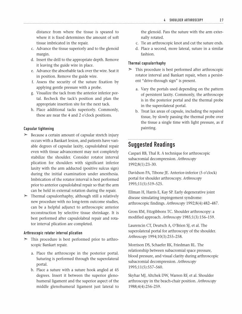
distance from where the tissue is speared towhere it is fixed determines the amount of softtissue imbricated in the repair.
c. Advance the tissue superiorly and to the glenoidmargin.
d. Insert the drill to the appropriate depth. Removeit leaving the guide wire in place.
e. Advance the absorbable tack over the wire. Seat itin position. Remove the guide wire.
f. Assess the security of the suture fixation byapplying gentle pressure with a probe.
g. Visualize the tack from the anterior inferior por-tal. Recheck the tack’s position and plan theappropriate insertion site for the next tack.
h. Place additional tacks superiorly. Commonly,these are near the 4 and 2 o’clock positions.
Capsular tightening
ã Because a certain amount of capsular stretch injuryoccurs with a Bankart lesion, and patients have vari-able degrees of capsular laxity, capsulolabral repaireven with tissue advancement may not completelystabilize the shoulder. Consider rotator intervalplication for shoulders with significant inferiorlaxity with the arm adducted (positive sulcus sign)during the initial examination under anesthesia.Imbrication of the rotator interval is best performedprior to anterior capsulolabral repair so that the armcan be held in external rotation during the repair.
ã Thermal capsulorrhaphy, although still a relativelynew procedure with no long-term outcome studies,can be a helpful adjunct to arthroscopic anteriorreconstruction by selective tissue shrinkage. It isbest performed after capsulolabral repair and rota-tor interval plication are completed.
Arthroscopic rotator interval plication
ã This procedure is best performed prior to arthro-scopic Bankart repair.
a. Place the arthroscope in the posterior portal.Suturing is performed through the superolateralportal.
b. Place a suture with a suture hook angled at 45degrees. Insert it between the superior gleno-humeral ligament and the superior aspect of themiddle glenohumeral ligament just lateral to
the glenoid. Pass the suture with the arm exter-nally rotated.
c. Tie an arthroscopic knot and cut the suture ends.d. Place a second, more lateral, suture in a similar
fashion.
Thermal capsulorrhaphy
ã This procedure is best performed after arthroscopicrotator interval and Bankart repair, when a persist-ent “drive-through sign” is present.
a. Vary the portals used depending on the patternof persistent laxity. Commonly, the arthroscopeis in the posterior portal and the thermal probein the superolateral portal.
b. Treat lax areas of capsule, including the repairedtissue, by slowly passing the thermal probe overthe tissue a single time with light pressure, as ifpainting.
Suggested ReadingsCaspari RB, Thal R. A technique for arthroscopicsubacromial decompression. Arthroscopy1992;8(1):23–30.
Davidson PA, Tibone JE. Anterior-inferior (5 o’clock)portal for shoulder arthroscopy. Arthroscopy1995;11(5):519–525.
Ellman H, Harris E, Kay SP. Early degenerative jointdisease simulating impingement syndrome:arthroscopic findings. Arthroscopy 1992;8(4):482–487.
Gross RM, Fitzgibbons TC. Shoulder arthroscopy: amodified approach. Arthroscopy 1985;1(3):156–159.
Laurencin CT, Deutsch A, O’Brien SJ, et al. Thesuperolateral portal for arthroscopy of the shoulder.Arthroscopy 1994;10(3):255–258.
Morrison DS, Schaefer RK, Friedman RL. Therelationship between subacromial space pressure, blood pressure, and visual clarity during arthroscopicsubacromial decompression. Arthroscopy1995;11(5):557–560.
Skyhar MJ, Altchek DW, Warren RF, et al. Shoulderarthroscopy in the beach-chair position. Arthroscopy1988;4(4):256–259.
4 S H O U L D E R A RT H R O S C O P Y 2 7

Torpey BM, Ikeda K, Wang M, et al. The deltoid muscleorigin: histologic characteristics and effects ofsubacromial decompression. Am J Sports Med1998;26(3):379–383.
Warner JJ, Kann S, Maddox LM. The “arthroscopicimpingement test”. Arthroscopy 1994;10(2):224–230.
Wolf EM. Anterior portals in shoulder arthroscopy.Arthroscopy 1989;5(3):201–208.
2 8 S H O U L D E R A N D A R M
Indications1. Proximal humerus fracture with displacement of
fracture fragments greater than 1 cm or 45 degreesof fracture angulation as described by Neer (1970)
2. Unstable fracture reductions3. Irreducible fracture dislocation4. Displaced tuberosity fracture5. Three- or four-part fracture in younger patients6. Open fracture7. Fracture with an associated vascular injury
Contraindications1. Poor bone quality (relative)2. Patients with a guarded overall medical condition
and poor rehabilitation potential (relative)3. Marked deltoid dysfunction (relative)
Preoperative Preparation1. Shoulder radiographs (trauma series) to include an
AP shoulder view, an AP scapular view (Grasheyview), and an axillary view
2. If needed, CT scan to define articular surface defectsor assess reduction of the glenohumeral joint
3. Document status of preoperative neurovascularexamination.
Special Instruments, Position, and Anesthesia1. The patient is placed in the semi-sitting position
(30 degrees upright).2. All pressure points should be padded.3. The procedure can be done with general or inter-
scalene block anesthesia.4. Trauma fixation sets should be available. These
should include small and large fragment sets, aswell as modified Enders rods.
5. Fluoroscopy should be available.
Tips and Pearls1. Be sure to drape the entire shoulder girdle and arm
free.2. Check that the fracture can be adequately evaluated
with the fluoroscopy prior to prepping the patient.If needed, adjust the patient accordingly.
3. Administer intravenous antibiotics prior to begin-ning the operation.
What To Avoid1. Avoid excessive stripping of fracture fragments.2. Avoid making shallow holes for the heavy suture or
wire in the humeral shaft and tuberosities.
2 9
C H A P T E R 5
Proximal Humerus FractureOpen Reduction and Internal Fixation
Angelo DiFelice and Gordon W. Nuber
Postoperative Care Issues1. A suction-type drain can be used and normally dis-
continued the morning after surgery.2. A compressive dressing should be placed at the end
of surgery and is normally changed approximately48 hours after the procedure.
3. Assessment of the patient’s distal neurovascular ex-amination should be made the evening of surgery.
4. Early motion should be employed based on the sta-bility of the fixation construct and the quality ofthe patient’s bone.
5. Initiate three phases of rehabilitation based on 4- to6-week intervals:
a. Phase 1. Patient is allowed to come out of thebrace and begin pendulum exercises, and sawand tummy rub exercises
b. Phase 2. Patient works with a therapist to beginactive-assistive exercises and more aggressivepassive range-of-motion exercises
c. Phase 3. Once radiographic evidence of healingis noted, resistive and stretching exercises for therotator cuff muscles are instituted
Operative TechniqueApproach1. Place the patient in the semi-sitting position (30
degrees upright) on the operating room table.2. Place a small bump under the operative scapula to
help access the entire shoulder girdle.3. Make a standard deltopectoral incision. Open the
deltopectoral interval and mobilize the cephalicvein laterally.
4. Retract the deltoid muscle laterally. If needed, par-tially release the deltoid at its insertion.
5. If additional exposure is required, release the cora-coacromial ligament proximally and partiallyrelease the pectoralis major tendon distally. Thepectoralis tendon should be repaired at the time ofwound closure with heavy nonabsorbable suture.
6. Identify the long head of the biceps. This structurehelps outline the fracture pattern and serves as aguide to fracture reduction (Fig. 5–1).
Reduction and fixation7. Mobilize the fracture fragments. Take care to pre-
serve bone fragment vascularity by avoiding exten-sive soft tissue dissection.
8. Place stay sutures in the fracture fragments. Inspectthe humeral head for impaction or malposition.
9. Consider using a Cobb elevator to reduce thehumeral head into the glenoid and to clear the frac-ture site of hematoma.
10. Reduce the fracture fragments. If needed, provision-ally hold them in place with 0.062 K-wires.
11. After the humeral head is reduced, make two drillholes through the anterior aspect of the humeralshaft on each side of the bicipital groove (Fig. 5–2A).
12. Drill a 2-mm hole through the greater tuberosityand lesser tuberosity (Fig. 5–2B).
13. Use a 14-gauge angiocath as a guide for either an18-gauge wire or a #5 braided nonabsorbable suture.Place the wire or suture through a hole in the ante-rior aspect of the humeral shaft (Fig. 5–3).
14. Use a 14-gauge angiocath as a guide for passing thepreviously positioned 18-gauge wire or #5 braidednonabsorbable suture through the rotator cuff ten-don, greater tuberosity, subscapularis, and lessertuberosity.
15. Ensure that the humeral head is reduced on theshaft and the tuberosities are anatomically reduced.Using the biceps and bicipital groove as landmarks,fix the suture or wire in a figure eight fashion.
16. After tensioning of the suture is complete, place asecond wire or suture in a similar tension bandtechnique, thereby securing the tuberosities to thehumeral shaft (Fig. 5–4).
17. Ensure that the wires or sutures cross the fracturesite. This allows them to apply compression andhelps achieve a stable construct that moves as a unit(Fig. 5–5).
Closure18. Loosely approximate the deltopectoral interval with
an absorbable suture.19. Close the subcutaneous tissue in layers over a suc-
tion drainage.20. Close the skin using a subcuticular skin closure.
Apply steristrips.
3 0 S H O U L D E R A N D A R M
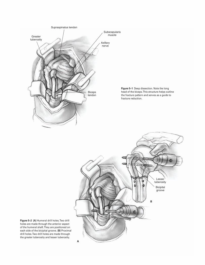
3 1
Greater tuberosity
Subscapularis muscle
Axillary nerve
Supraspinatus tendon
Biceps tendon
Lesser tuberosity
Bicipital groove
A
B
Figure 5–2 (A) Humeral drill holes. Two drill holes are made through the anterior aspect of the humeral shaft. They are positioned on each side of the bicipital groove. (B) Proximaldrill holes. Two drill holes are made through the greater tuberosity and lesser tuberosity.
Figure 5–1 Deep dissection. Note the long head of the biceps. This structure helps outlinethe fracture pattern and serves as a guide tofracture reduction.
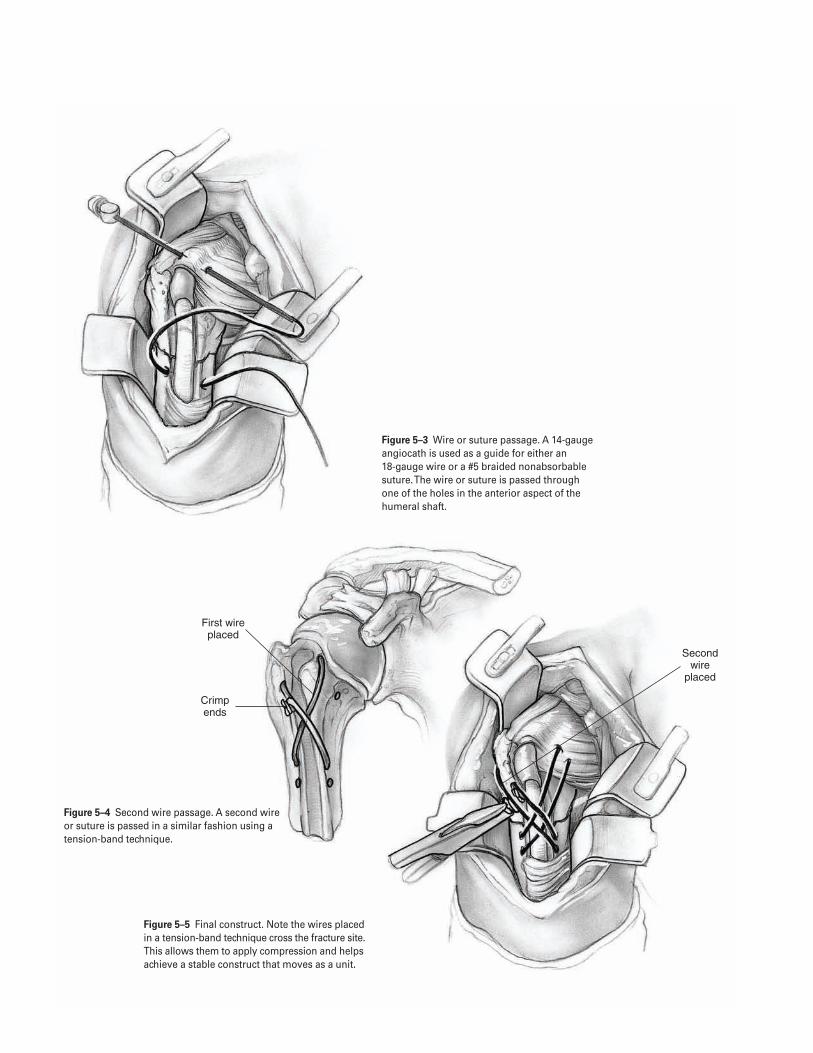
3 2
First wire placed
Crimp ends
Second wire
placed
Figure 5–4 Second wire passage. A second wireor suture is passed in a similar fashion using atension-band technique.
Figure 5–5 Final construct. Note the wires placedin a tension-band technique cross the fracture site.This allows them to apply compression and helpsachieve a stable construct that moves as a unit.
Figure 5–3 Wire or suture passage. A 14-gaugeangiocath is used as a guide for either an 18-gauge wire or a #5 braided nonabsorbablesuture. The wire or suture is passed through one of the holes in the anterior aspect of thehumeral shaft.

Suggested ReadingsNeer CS. Displaced proximal humerus fractures. I.Classification and evaluation. J Bone Joint Surg1970;52A(6):1077–1089.
The shoulder. In: Hoppenfeld S, deBoer P, eds. SurgicalExposures in Orthopaedics: The Anatomic Approach. 2nded. Philadelphia, PA: J.B. Lippincott, 1994:5–13.
5 P R O X I M A L H U M E R U S F R A C T U R E ( O R I F ) 3 3
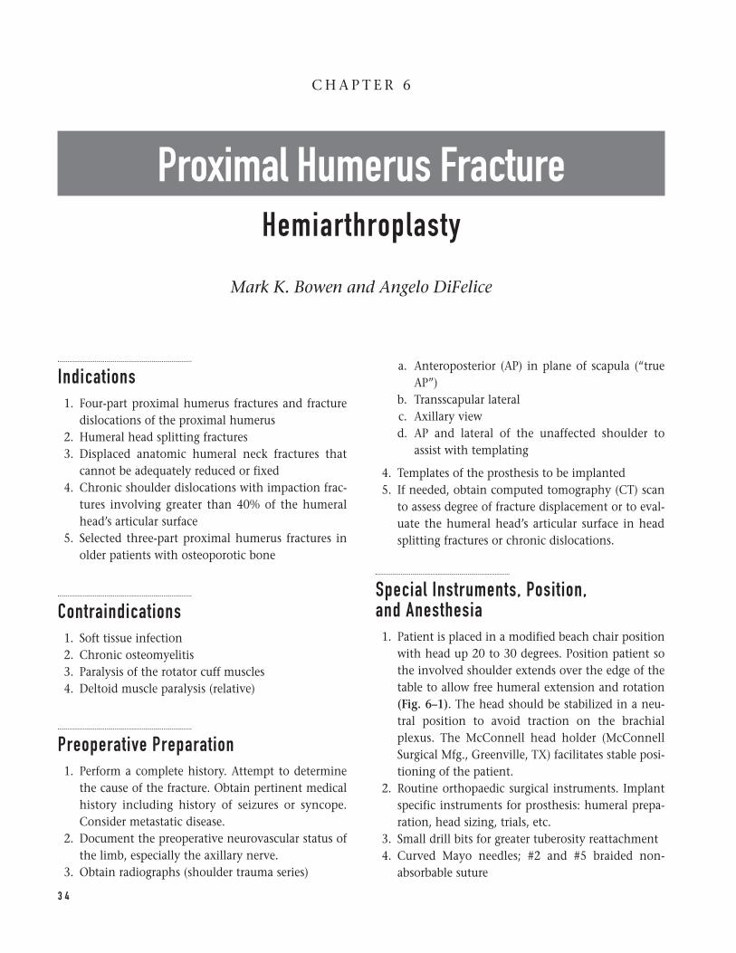
Indications1. Four-part proximal humerus fractures and fracture
dislocations of the proximal humerus2. Humeral head splitting fractures3. Displaced anatomic humeral neck fractures that
cannot be adequately reduced or fixed4. Chronic shoulder dislocations with impaction frac-
tures involving greater than 40% of the humeralhead’s articular surface
5. Selected three-part proximal humerus fractures inolder patients with osteoporotic bone
Contraindications1. Soft tissue infection2. Chronic osteomyelitis3. Paralysis of the rotator cuff muscles4. Deltoid muscle paralysis (relative)
Preoperative Preparation1. Perform a complete history. Attempt to determine
the cause of the fracture. Obtain pertinent medicalhistory including history of seizures or syncope.Consider metastatic disease.
2. Document the preoperative neurovascular status ofthe limb, especially the axillary nerve.
3. Obtain radiographs (shoulder trauma series)
a. Anteroposterior (AP) in plane of scapula (“trueAP”)
b. Transscapular lateralc. Axillary viewd. AP and lateral of the unaffected shoulder to
assist with templating
4. Templates of the prosthesis to be implanted5. If needed, obtain computed tomography (CT) scan
to assess degree of fracture displacement or to eval-uate the humeral head’s articular surface in headsplitting fractures or chronic dislocations.
Special Instruments, Position, and Anesthesia1. Patient is placed in a modified beach chair position
with head up 20 to 30 degrees. Position patient sothe involved shoulder extends over the edge of thetable to allow free humeral extension and rotation(Fig. 6–1). The head should be stabilized in a neu-tral position to avoid traction on the brachialplexus. The McConnell head holder (McConnellSurgical Mfg., Greenville, TX) facilitates stable posi-tioning of the patient.
2. Routine orthopaedic surgical instruments. Implantspecific instruments for prosthesis: humeral prepa-ration, head sizing, trials, etc.
3. Small drill bits for greater tuberosity reattachment4. Curved Mayo needles; #2 and #5 braided non-
absorbable suture
3 4
C H A P T E R 6
Proximal Humerus FractureHemiarthroplasty
Mark K. Bowen and Angelo DiFelice
Tips and Pearls1. Intravenous antibiotics should be given prior to the
beginning of the operation.2. The patient must be positioned with the arm able to
hang free over the table’s side so that it can be eas-ily hyperextended and internally and externallyrotated.
3. Restoring the proper length of the humerus is criti-cal to proper function: if the prosthesis is left proudstiffness will result; if the prosthesis is inserted toodeep loss of soft tissue tension may cause instability.
4. Restoring proper humeral retroversion is critical tooptimizing shoulder function and stability.
5. Achieving secure fixation of the greater and lessertuberosities to each other, as well as the prosthesisand humeral shaft is the important final step in per-forming a successful shoulder reconstruction.
What To Avoid1. Avoid excessive operating room traffic.2. Avoid excessive or aggressive reaming or broaching
of the humeral canal to minimize the risk of intra-operative humeral fracture.
3. Avoid dissection beyond the medial border of thecoracoid to minimize the risk of injuring the neu-rovascular structures.
4. Avoid implanting the humeral component inanteversion.
5. Avoid deep or proud placement of the humeralcomponent that may significantly change gleno-humeral mechanics or lead to shoulder instability.
Postoperative Care Issues1. Passive motion is usually begun on the first postop-
erative day under the supervision of a therapist. Therange of motion is limited by the stability of theintraoperative tuberosity fixation. The patient usu-ally performs pendulum, saw, and tummy rub exer-cises for approximately 4 weeks.
2. After 4 weeks, the patient generally begins activeassisted range-of-motion exercises to improve theshoulder’s range of motion.
3. After radiographic evidence of tuberosity union,active range-of-motion exercises may be added tothe rehabilitation program.
4. Usually by 10 to 12 weeks, the patient is able tobegin resistance-type exercises and a more aggres-sive stretching program.
Operative TechniqueApproach1. Position the patient on the operating room table as
outlined above.2. Prepare and drape the entire shoulder girdle. Isolate
an operative field that extends to the midclavicleanteriorly, below the axilla inferiorly, and to themiddle of the scapular spine posteriorly.
3. Make a long deltopectoral incision. Begin the inci-sion just below the clavicle and extend it over thelateral aspect of the coracoid to the deltoid inser-tion on the humeral shaft (Fig. 6–2).
4. Identify the cephalic vein. Retract it laterally withthe deltoid muscle.
5. To aid exposure, partially elevate the insertion ofthe deltoid and partially release the pectoralis majortendon one-half of its length. Tag the pectoralis ten-don to facilitate its repair during closure.
6. To further facilitate exposure, resect the coracoacro-mial ligament for humeral shaft preparation andimplant placement.
Fracture exposure7. Place retractors underneath the deltoid muscle and
underneath the lateral borders of the coracoid mus-cles to assist in exposing the fracture.
8. Evacuate the hematoma. Debride bone and softtissue debris.
9. Identify by palpation the musculocutaneous andaxillary nerves. Carefully retract and protect thesestructures at all times.
10. Identify the long head of the biceps tendon distallyand followed proximally to its insertion on the gle-noid. The biceps tendon is a key landmark to iden-tify fracture fragments and aids in assessing softtissue tension during prosthesis insertion. Thebiceps tendon identifies the interval between thelesser and greater tuberosities.
6 P R O X I M A L H U M E R U S F R A C T U R E ( H E M I A RT H R O P L A S T Y ) 3 5
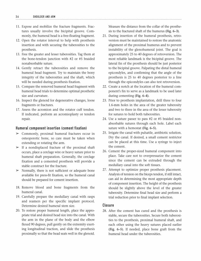
11. Expose and mobilize the fracture fragments. Frac-tures usually involve the bicipital groove. Com-monly, the humeral head is a free-floating fragment.
12. Open the rotator interval to help with prosthesisinsertion and with securing the tuberosities to theprosthesis.
13. Free the greater and lesser tuberosities. Tag them atthe bone-tendon junction with #2 or #5 braidednonabsorbable suture.
14. Gently retract the tuberosities and remove thehumeral head fragment. Try to maintain the bonyintegrity of the tuberosities and the shaft, whichwill be needed during prosthesis fixation.
15. Compare the removed humeral head fragment withhumeral head trials to determine optimal prostheticsize and curvature.
16. Inspect the glenoid for degenerative changes, loosefragments or fractures.
17. Assess the acromion and the rotator cuff tendon. If indicated, perform an acromioplasty or tendonrepair.
Humeral component insertion (cement fixation)â Commonly, proximal humeral fractures occur in
osteoporotic bone, so care must be taken whenextending or rotating the arm.
â If a nondisplaced fracture of the proximal shaftoccurs, place a cerclage wire or heavy suture prior tohumeral shaft preparation. Generally, the cerclagefixation and a cemented prosthesis will provide astable construct for the fracture.
â Normally, there is not sufficient or adequate boneavailable for press-fit fixation, so the humeral canalshould be prepared for cement insertion.
18. Remove blood and bone fragments from thehumeral canal.
19. Carefully prepare the medullary canal with raspsand reamers per the specific implant protocol.Determine desired humeral stem size.
20. To restore proper humeral length, place the appro-priate trial and desired head size into the canal. Withthe arm in the plane of the body and the elbowflexed 90 degrees, pull gently on the extremity exert-ing longitudinal traction, and slide the prosthesisproximally so that the head seats well in the glenoid.
Measure the distance from the collar of the prosthe-sis to the fractured shaft of the humerus (Fig. 6–3).
21. During insertion of the humeral prosthesis, retro-version must be maintained to restore the anatomicalignment of the proximal humerus and to preventinstability of the glenohumeral joint. The goal isapproximately 25 to 40 degrees of retroversion. Themost reliable landmark is the bicipital groove. Thelateral fin of the prosthesis should be just posteriorto the bicipital groove. Palpating the distal humeralepicondyles, and confirming that the angle of theprosthesis is 25 to 40 degrees posterior to a linethrough the epicondyles can also test retroversion.
22. Create a notch at the location of the humeral com-ponent’s fin to serve as a landmark to be used laterduring cementing (Fig. 6–4).
23. Prior to prosthesis implantation, drill three to four1.6-mm holes in the area of the greater tuberosityand two to three in the area of the lesser tuberosityfor sutures to hold both tuberosities.
24. Use a suture passer to pass #2 or #5 braided non-absorbable sutures through each hole. Label eachsuture with a hemostat (Fig. 6–5).
25. Irrigate the canal with pulsatile, antibiotic solution.Dry the canal. If desired, a small cement restrictorcan be placed at this time. Use a syringe to injectthe cement.
26. Cement the proper-sized humeral component intoplace. Take care not to overpressurize the cementsince the cement can be extruded through themedullary canal into the soft tissues.
27. Attempt to optimize proper prosthesis placement.Analysis of tension on the biceps tendon, if still intact,can aid in determining the most appropriate depthof component insertion. The height of the prosthesisshould be slightly above the level of the greatertuberosity. Determine final head size and perform atrial reduction prior to final implant selection.
Closure28. After the cement has cured and the prosthesis is
stable, secure the tuberosities. Secure both tuberosi-ties to the prosthesis, proximal humeral shaft, andeach other using the heavy sutures placed earlier(Fig. 6–5). If needed, place bone graft from thehumeral head under the tuberosities.
3 6 S H O U L D E R A N D A R M
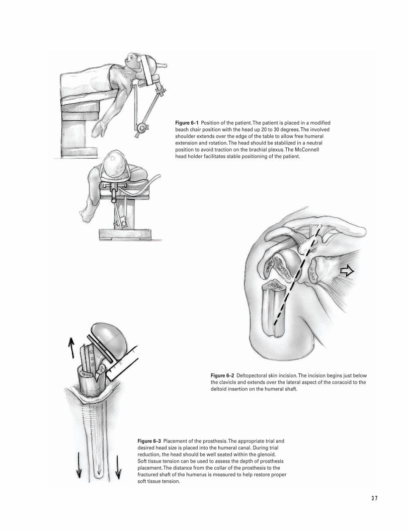
3 7
Figure 6–1 Position of the patient. The patient is placed in a modifiedbeach chair position with the head up 20 to 30 degrees. The involvedshoulder extends over the edge of the table to allow free humeralextension and rotation. The head should be stabilized in a neutralposition to avoid traction on the brachial plexus. The McConnell head holder facilitates stable positioning of the patient.
Figure 6–2 Deltopectoral skin incision. The incision begins just belowthe clavicle and extends over the lateral aspect of the coracoid to thedeltoid insertion on the humeral shaft.
Figure 6–3 Placement of the prosthesis. The appropriate trial anddesired head size is placed into the humeral canal. During trialreduction, the head should be well seated within the glenoid. Soft tissue tension can be used to assess the depth of prosthesisplacement. The distance from the collar of the prosthesis to thefractured shaft of the humerus is measured to help restore proper soft tissue tension.
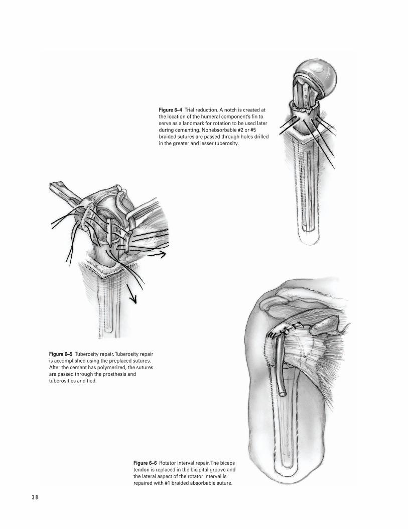
3 8
Figure 6–4 Trial reduction. A notch is created atthe location of the humeral component’s fin toserve as a landmark for rotation to be used laterduring cementing. Nonabsorbable #2 or #5braided sutures are passed through holes drilledin the greater and lesser tuberosity.
Figure 6–5 Tuberosity repair. Tuberosity repair is accomplished using the preplaced sutures.After the cement has polymerized, the suturesare passed through the prosthesis andtuberosities and tied.
Figure 6–6 Rotator interval repair.The bicepstendon is replaced in the bicipital groove and the lateral aspect of the rotator interval isrepaired with #1 braided absorbable suture.

29. Replace the biceps tendon in the bicipital groove.Repair the rotator interval with #1 braidedabsorbable suture (Fig. 6–6).
30. Gently internally and externally rotate the arm totest the stability of the tuberosity repair.
31. Loosely close the deltopectoral interval. Close thesubcutaneous tissues in layers using absorbablesutures over a suction drain.
Suggested ReadingsIannotti JP, Williams GR Jr. Disorders of the Shoulder:Diagnosis and Management. Philadelphia, PA: LippincottWilliams & Wilkins, 1999.
Rockwood CA, Matsen FA. The Shoulder. Philadelphia,PA: W.B. Saunders, 1998.
6 P R O X I M A L H U M E R U S F R A C T U R E ( H E M I A RT H R O P L A S T Y ) 3 9
Indications1. Humeral shaft fracture which failed nonoperative
treatment (“acceptable” nonoperative treatmentrequires maintenance of fracture reduction with lessthan 20 degrees of sagittal and 30 degrees of coro-nal angulation and less than 5 cm of shortening)
2. Open humeral shaft fracture3. Humeral shaft fracture associated with a vascular
injury4. Humeral shaft fracture in a polytrauma patient5. Humeral shaft fracture associated with a floating
elbow6. Bilateral humeral fractures7. Segmental humeral shaft fracture8. Humeral shaft fracture associated with an ipsilateral
brachial plexus injury9. Humeral shaft fracture associated with pelvic or
lower extremity injuries necessitating crutch ambu-lation
10. Pathologic humeral shaft fracture (intramedullarydevice generally preferred)
11. Humeral shaft fracture associated with a secondaryradial nerve palsy (controversial)
12. Nonunion or malunion after a humeral shaft fracture
Contraindications1. Acceptable fracture alignment in a closed isolated
injury
2. Gustillo grade IIIB or IIIC open fracture with exten-sive wound contamination (external fixation gener-ally preferred)
Preoperative Preparation1. Careful documentation of the admitting neurovas-
cular status (especially the radial nerve); the neuro-vascular status should be reevaluated and againdocumented after fracture reduction.
2. Careful assessment of soft tissue injuries (obvious oroccult); administer appropriate antibiotics andtetanus prophylaxis in the event of an open fracture
3. Appropriate examination of the spine, pelvis, andother limbs to rule out associated injury
4. Radiographs to include AP and lateral views of theshoulder, humerus, and elbow
5. Displaced or angulated fractures should be reducedand provisionally splinted with a coaptation splintor a hanging arm cast prior to surgical stabilization.
6. Postreduction AP and lateral views of the humerusshould be obtained to evaluate the postreductionfracture alignment.
7. The fracture should be classified by descriptive ter-minology ( i.e., location, fracture pattern, soft tissueinjury, and bone quality) or with the AO/OTA clas-sification scheme.
8. Preoperative templating and planning should beundertaken to facilitate fracture reduction and sta-bilization as outlined by the AO group.
4 0
C H A P T E R 7
Humeral Shaft FractureOpen Reduction and Internal Fixation
Bradley R. Merk
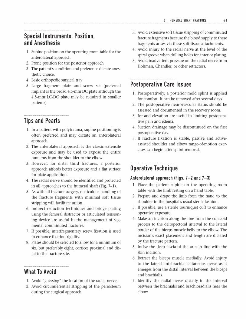
Special Instruments, Position, and Anesthesia1. Supine position on the operating room table for the
anterolateral approach2. Prone position for the posterior approach3. The patient’s condition and preference dictate anes-
thetic choice.4. Basic orthopedic surgical tray5. Large fragment plate and screw set (preferred
implant is the broad 4.5-mm DC plate although the4.5-mm LC-DC plate may be required in smallerpatients)
Tips and Pearls1. In a patient with polytrauma, supine positioning is
often preferred and may dictate an anterolateralapproach.
2. The anterolateral approach is the classic extensileexposure and may be used to expose the entirehumerus from the shoulder to the elbow.
3. However, for distal third fractures, a posteriorapproach affords better exposure and a flat surfacefor plate application.
4. The radial nerve should be identified and protectedin all approaches to the humeral shaft (Fig. 7–1).
5. As with all fracture surgery, meticulous handling ofthe fracture fragments with minimal soft tissuestripping will facilitate union.
6. Indirect reduction techniques and bridge platingusing the femoral distractor or articulated tension-ing device are useful in the management of seg-mental comminuted fractures.
7. If possible, interfragmentary screw fixation is usedto enhance fixation rigidity.
8. Plates should be selected to allow for a minimum ofsix, but preferably eight, cortices proximal and dis-tal to the fracture site.
What To Avoid1. Avoid “guessing” the location of the radial nerve.2. Avoid circumferential stripping of the periosteum
during the surgical approach.
3. Avoid extensive soft tissue stripping of comminutedfracture fragments because the blood supply to thesefragments arises via these soft tissue attachments.
4. Avoid injury to the radial nerve at the level of thespiral groove when drilling holes for anterior plating.
5. Avoid inadvertent pressure on the radial nerve fromHohman, Chandler, or other retractors.
Postoperative Care Issues1. Postoperatively, a posterior mold splint is applied
for comfort. It can be removed after several days.2. The postoperative neurovascular status should be
assessed and documented in the recovery room.3. Ice and elevation are useful in limiting postopera-
tive pain and edema.4. Suction drainage may be discontinued on the first
postoperative day.5. If fracture fixation is stable, passive and active-
assisted shoulder and elbow range-of-motion exer-cises can begin after splint removal.
Operative TechniqueAnterolateral approach (Figs. 7–2 and 7–3)1. Place the patient supine on the operating room
table with the limb resting on a hand table.2. Prepare and drape the limb from the hand to the
shoulder in the hospital’s usual sterile fashion.3. If possible, use a sterile tourniquet cuff to enhance
operative exposure.4. Make an incision along the line from the coracoid
process to the deltopectoral interval to the lateralborder of the biceps muscle belly to the elbow. Theincision’s exact placement and length are dictatedby the fracture pattern.
5. Incise the deep fascia of the arm in line with theskin incision.
6. Retract the biceps muscle medially. Avoid injury to the lateral antebrachial cutaneous nerve as itemerges from the distal interval between the bicepsand brachialis.
7. Identify the radial nerve distally in the intervalbetween the brachialis and brachioradialis near theelbow.
7 H U M E R A L S H A F T F R A C T U R E 4 1
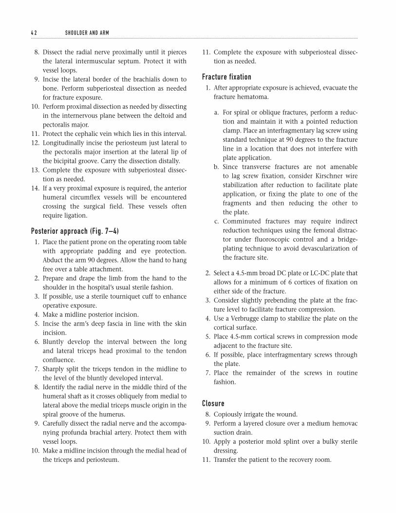
8. Dissect the radial nerve proximally until it piercesthe lateral intermuscular septum. Protect it withvessel loops.
9. Incise the lateral border of the brachialis down tobone. Perform subperiosteal dissection as neededfor fracture exposure.
10. Perform proximal dissection as needed by dissectingin the internervous plane between the deltoid andpectoralis major.
11. Protect the cephalic vein which lies in this interval.12. Longitudinally incise the periosteum just lateral to
the pectoralis major insertion at the lateral lip ofthe bicipital groove. Carry the dissection distally.
13. Complete the exposure with subperiosteal dissec-tion as needed.
14. If a very proximal exposure is required, the anteriorhumeral circumflex vessels will be encounteredcrossing the surgical field. These vessels oftenrequire ligation.
Posterior approach (Fig. 7–4)1. Place the patient prone on the operating room table
with appropriate padding and eye protection.Abduct the arm 90 degrees. Allow the hand to hangfree over a table attachment.
2. Prepare and drape the limb from the hand to theshoulder in the hospital’s usual sterile fashion.
3. If possible, use a sterile tourniquet cuff to enhanceoperative exposure.
4. Make a midline posterior incision.5. Incise the arm’s deep fascia in line with the skin
incision.6. Bluntly develop the interval between the long
and lateral triceps head proximal to the tendonconfluence.
7. Sharply split the triceps tendon in the midline tothe level of the bluntly developed interval.
8. Identify the radial nerve in the middle third of thehumeral shaft as it crosses obliquely from medial tolateral above the medial triceps muscle origin in thespiral groove of the humerus.
9. Carefully dissect the radial nerve and the accompa-nying profunda brachial artery. Protect them withvessel loops.
10. Make a midline incision through the medial head ofthe triceps and periosteum.
11. Complete the exposure with subperiosteal dissec-tion as needed.
Fracture fixation1. After appropriate exposure is achieved, evacuate the
fracture hematoma.
a. For spiral or oblique fractures, perform a reduc-tion and maintain it with a pointed reductionclamp. Place an interfragmentary lag screw usingstandard technique at 90 degrees to the fractureline in a location that does not interfere withplate application.
b. Since transverse fractures are not amenable to lag screw fixation, consider Kirschner wirestabilization after reduction to facilitate plateapplication, or fixing the plate to one of thefragments and then reducing the other to the plate.
c. Comminuted fractures may require indirectreduction techniques using the femoral distrac-tor under fluoroscopic control and a bridge-plating technique to avoid devascularization ofthe fracture site.
2. Select a 4.5-mm broad DC plate or LC-DC plate thatallows for a minimum of 6 cortices of fixation oneither side of the fracture.
3. Consider slightly prebending the plate at the frac-ture level to facilitate fracture compression.
4. Use a Verbrugge clamp to stabilize the plate on thecortical surface.
5. Place 4.5-mm cortical screws in compression modeadjacent to the fracture site.
6. If possible, place interfragmentary screws throughthe plate.
7. Place the remainder of the screws in routinefashion.
Closure8. Copiously irrigate the wound.9. Perform a layered closure over a medium hemovac
suction drain.10. Apply a posterior mold splint over a bulky sterile
dressing.11. Transfer the patient to the recovery room.
4 2 S H O U L D E R A N D A R M
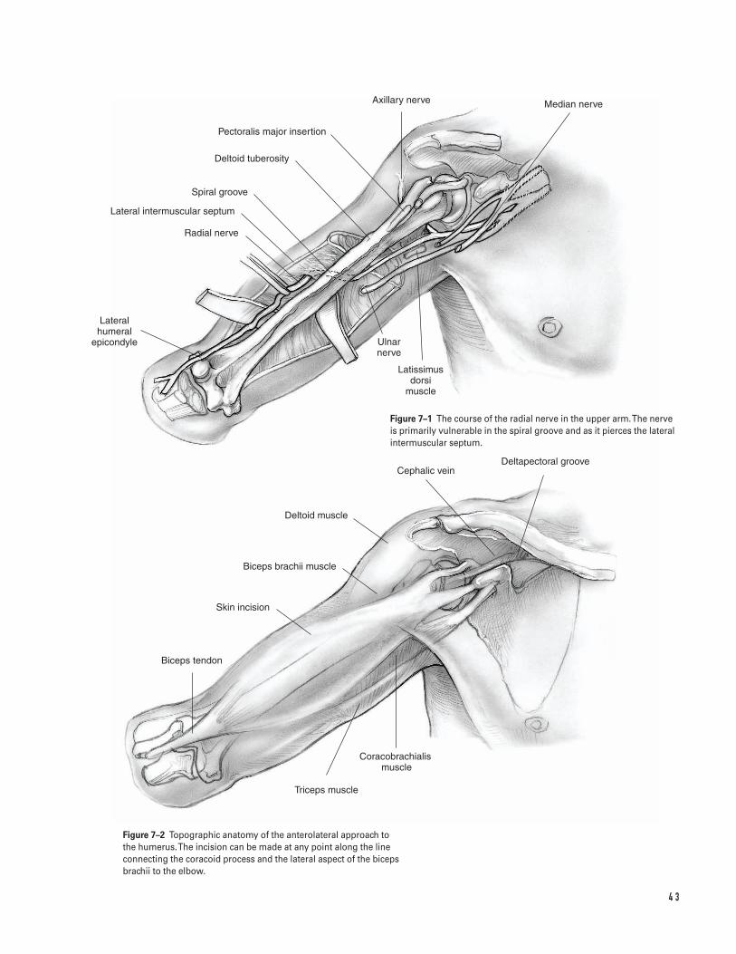
4 3
Lateral humeral
epicondyle
Radial nerve
Lateral intermuscular septum
Spiral groove
Deltoid tuberosity
Pectoralis major insertion
Axillary nerve Median nerve
Ulnar nerve
Latissimus dorsi
muscle
Deltapectoral grooveCephalic vein
Deltoid muscle
Biceps brachii muscle
Skin incision
Biceps tendon
Coracobrachialis �muscle
Triceps muscle
Figure 7–1 The course of the radial nerve in the upper arm. The nerveis primarily vulnerable in the spiral groove and as it pierces the lateralintermuscular septum.
Figure 7–2 Topographic anatomy of the anterolateral approach to the humerus. The incision can be made at any point along the lineconnecting the coracoid process and the lateral aspect of the bicepsbrachii to the elbow.
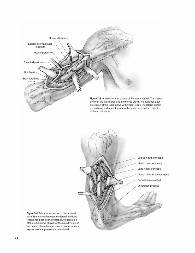
4 4
Humeral fracture
Lateral intermuscular septum
Radial nerve
Elevated periosteum
Brachialis
Brachioradialis muscle
Lateral head of triceps
Long head of triceps
Medial head of triceps
Medial head of triceps (split)
Periosteum elevated
Olecranon process
Figure 7–3 Anterolateral exposure of the humeral shaft. The intervalbetween the brachioradialis and biceps brachii is developed afterprotection of the radial nerve with vessel loops. The lateral margin of brachialis and periosteum have been elevated and are held byHohman retractors.
Figure 7–4 Posterior exposure of the humeralshaft. The interval between the lateral and longtriceps head has been developed. Visualization of the radial nerve allows for the safe division ofthe medial (deep) head of triceps brachii to allowexposure of the posterior humeral shaft.

Suggested ReadingsAllgower M, ed. Manual of Internal Fixation. 3rd ed. NewYork, NY: Springer Verlag, 1995.
Chapman MW, ed. Operative Orthopaedics. 2nd ed.Philadelphia, PA: J.B. Lippincott, 1994.
Hoppenfeld S, deBoer MA. Surgical Exposures inOrthopaedics: The Anatomic Approach. 2nd ed.Philadelphia, PA: J.B. Lippincott, 1994.
7 H U M E R A L S H A F T F R A C T U R E 4 5

This page intentionally left blank
Key Techniques inOrthopaedic Surgery
Section Two
Elbow and Forearm

This page intentionally left blank
Key Techniques inOrthopaedic Surgery
Indications1. Displacement greater than 2 mm or angulation of
the neck2. Large fragment (more than marginal lip or greater
than 25% articular surface)3. Elbow motion or forearm rotation mechanically
blocked4. Associated injury to interosseous ligament/distal
radioulnar joint, elbow collateral ligaments or coro-noid process
Contraindications1. Severe comminution precluding rigid internal fixa-
tion; consider excision or excision and prostheticreplacement when associated with injury to inte-rosseous ligament/distal radioulnar joint, collateralligament, or coronoid process
2. Low demand patient (relative); consider excision3. Open fracture with contaminated wound
Preoperative Preparation1. Evaluation
a. Document complete neurovascular examina-tion, especially posterior interosseous nerve.
b. Assess medial collateral ligament—tendernessand valgus stress test at 30 degrees flexion.
c. Assess interosseous ligament/distal radioulnarjoint—tenderness along forearm and wrist.
d. Assess for mechanical block; consider sterileintra-articular injection of local anesthetic toallow evaluation of range of motion.
2. Adequate radiographs
a. AP and lateral of the elbowb. Neutral PA view of the wrist with contralateral
comparison view to assess for longitudinalstability
c. Consider CT scan with axial, sagittal and coro-nal cuts to assess fragment size, comminution,and degree of displacement.
3. Prepare patient for possible need for excision if re-duction and internal fixation technically impossible.
Special Instruments, Position, and Anesthesia1. Patient supine on operating table with affected arm
positioned over the chest2. Tourniquet placed high up on arm3. Can be done with general or regional anesthetic4. Instrumentation
a. Kirschner wiresb. Mini-fragment internal fixation set with recon-
struction platesc. Herbert mini-screw set
4 9
C H A P T E R 8
Radial Head Fracture
Brian J. Hartigan
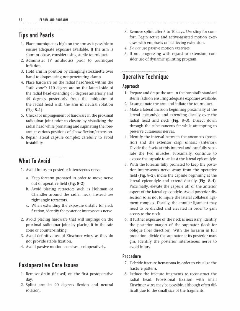
Tips and Pearls1. Place tourniquet as high on the arm as is possible to
ensure adequate exposure available. If the arm isshort or obese, consider using sterile tourniquet.
2. Administer IV antibiotics prior to tourniquetinflation.
3. Hold arm in position by clamping stockinette overhand to drapes using nonpenetrating clamp.
4. Place hardware on the radial head/neck within the“safe zone”: 110 degree arc on the lateral side ofthe radial head extending 65 degrees anteriorly and45 degrees posteriorly from the midpoint of the radial head with the arm in neutral rotation(Fig. 8–1).
5. Check for impingement of hardware in the proximalradioulnar joint prior to closure by visualizing theradial head while pronating and supinating the fore-arm at various positions of elbow flexion/extension.
6. Repair lateral capsule complex carefully to avoidinstability.
What To Avoid1. Avoid injury to posterior interosseous nerve.
a. Keep forearm pronated in order to move nerveout of operative field (Fig. 8–2).
b. Avoid placing retractors such as Hohman orChandler around the radial neck; instead useright angle retractors.
c. When extending the exposure distally for neckfixation, identify the posterior interosseous nerve.
2. Avoid placing hardware that will impinge on theproximal radioulnar joint by placing it in the safezone or counter-sinking.
3. Avoid definitive use of Kirschner wires, as they donot provide stable fixation.
4. Avoid passive motion exercises postoperatively.
Postoperative Care Issues1. Remove drain (if used) on the first postoperative
day.2. Splint arm in 90 degrees flexion and neutral
rotation.
3. Remove splint after 5 to 10 days. Use sling for com-fort. Begin active and active-assisted motion exer-cises with emphasis on achieving extension.
4. Do not use passive motion exercises.5. If not progressing with regard to extension, con-
sider use of dynamic splinting program.
Operative TechniqueApproach1. Prepare and drape the arm in the hospital’s standard
sterile fashion ensuring adequate exposure available.2. Exsanguinate the arm and inflate the tourniquet.3. Make a lateral incision beginning proximally at the
lateral epicondyle and extending distally over theradial head and neck (Fig. 8–3). Dissect downthrough the subcutaneous fat while attempting topreserve cutaneous nerves.
4. Identify the interval between the anconeus (poste-rior) and the extensor carpi ulnaris (anterior).Divide the fascia at this interval and carefully sepa-rate the two muscles. Proximally, continue toexpose the capsule to at least the lateral epicondyle.
5. With the forearm fully pronated to keep the poste-rior interosseous nerve away from the operativefield (Fig. 8–2), incise the capsule beginning at thelateral epicondyle and extend distally (Fig. 8–4).Proximally, elevate the capsule off of the anterioraspect of the lateral epicondyle. Avoid posterior dis-section so as not to injure the lateral collateral liga-ment complex. Distally, the annular ligament mayneed to be divided and elevated in order to gainaccess to the neck.
6. If further exposure of the neck is necessary, identifythe posterior margin of the supinator (look foroblique fiber direction). With the forearm in fullpronation, divide the supinator at its posterior mar-gin. Identify the posterior interosseous nerve toavoid injury.
Procedure7. Debride fracture hematoma in order to visualize the
fracture pattern.8. Reduce the fracture fragments to reconstruct the
radial head. Provisional fixation with smallKirschner wires may be possible, although often dif-ficult due to the small size of the fragments.
5 0 E L B OW A N D F O R E A R M
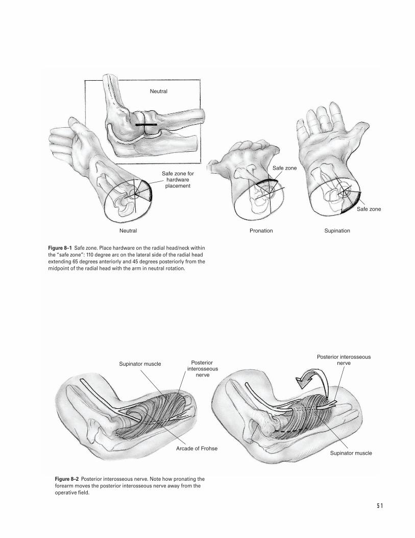
5 1
Neutral
Safe zone for hardware placement
Safe zone
Safe zone
Neutral Pronation Supination
Supinator muscle Posterior interosseous
nerve
Arcade of Frohse
Posterior interosseous nerve
Supinator muscle
Figure 8–1 Safe zone. Place hardware on the radial head/neck withinthe “safe zone”: 110 degree arc on the lateral side of the radial headextending 65 degrees anteriorly and 45 degrees posteriorly from themidpoint of the radial head with the arm in neutral rotation.
Figure 8–2 Posterior interosseous nerve. Note how pronating theforearm moves the posterior interosseous nerve away from theoperative field.
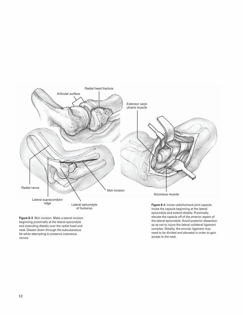
5 2
Radial head fracture
Articular surface
Extensor carpi ulnaris muscle
Anconeus muscleSkin incision
Lateral epicondyle of humerus
Lateral supracondylor ridge
Radial nerve
Figure 8–3 Skin incision. Make a lateral incisionbeginning proximally at the lateral epicondyleand extending distally over the radial head andneck. Dissect down through the subcutaneous fat while attempting to preserve cutaneousnerves.
Figure 8–4 Incise radiohumeral joint capsule.Incise the capsule beginning at the lateralepicondyle and extend distally. Proximally,elevate the capsule off of the anterior aspect ofthe lateral epicondyle. Avoid posterior dissectionso as not to injure the lateral collateral ligamentcomplex. Distally, the annular ligament may need to be divided and elevated in order to gainaccess to the neck.
9. Fill defects with cancellous bone graft.10. Fixation—obtain rigid internal fixation.
a. Radial head fracture alone: choices for fixationinclude minifragment screws (1.5 to 2.7 mm)placed in the safe zone (Fig. 8–1). If unable toplace in the safe zone, consider counter-sinkinga minifragment screw or using a small Herbertscrew that can be placed below the articular sur-face. Avoid overdrilling of the proximal cortexfor lag technique which could result in com-minution of fragment. Therefore, consider place-ment of the screw without overdrilling bymanually compressing the fracture during inser-tion or using a self-compressing Herbert screw.
b. Radial head and neck fracture: reconstruct theradial head as above and use 2.0-, 2.4-, or 2.7-mmcontoured T-, L-, or Y-plate or condylar plate forfixation to proximal radius.
c. Radial neck fracture alone: use contoured 2.0-,2.4-, or 2.7-mm T-, L-, or Y-plate or condylar platefor fixation to proximal radius.Note: If unable to obtain rigid fixation, considerexcision and possible prosthetic replacement.
11. Assess reduction and check for hardware impinge-ment by pronating and supinating the forearm invarious positions of flexion and extension. Modifyhardware placement if impingement occurs at theproximal radioulnar joint.
12. Assess valgus stability and consider repair of medialcollateral complex if unstable.
Closure13. Irrigate the wound.14. Release the tourniquet and obtain hemostasis.
Consider using a drain if unable to obtain accept-able hemostasis.
15. Repair the lateral capsular complex primarily ininterrupted fashion with absorbable sutures.Consider reattaching the capsule to the lateral epi-condyle with suture anchors.
16. Close subcutaneous tissue in interrupted, invertedfashion with absorbable sutures.
17. Close skin with staples, nylon or prolene.18. Dress in sterile fashion and place in bulky dressing
with splint arm in 90 degrees flexion and neutralrotation.
Suggested ReadingsThe elbow. In: Hoppenfeld S, deBoer P, eds. SurgicalExposures in Orthopaedics: The Anatomic Approach. 2nded. Philadelphia, PA: J.B. Lippincott, 1994, pp. 103–109.
Hotchkiss RN. Fractures and dislocations of the elbow.In: Rockwood CA, Green DP, Bucholz RW, Heckman JD,eds. Rockwood and Green’s Fractures in Adults. 4th ed.Philadelphia, PA: Lippincott-Raven, 1996, pp.929–1024.
Hotchkiss RN. Fractures of the radial head. In: NorrisTR, ed. Orthopaedic Knowledge Update: Shoulder and Elbow.Rosemont, IL: American Academy of OrthopaedicSurgeons, 1997, pp. 387–395.
Hotchkiss RN. Displaced fractures of the radial head:internal fixation or excision? J Am Acad Orthop Surg1997;5:1–10.
Morrey BF. Surgical exposures of the elbow. In: MorreyBF, ed. The Elbow and Its Disorders. 2nd ed. Philadelphia,PA: W.B. Saunders, 1993, pp. 139–165.
Morrey BF. Radial head fracture. In: Morrey BF, ed. The Elbow and Its Disorders. 2nd ed. Philadelphia, PA:W.B. Saunders, 1993, pp. 383–404.
8 R A D I A L H E A D F R A C T U R E 5 3
Indications1. Any displaced olecranon fracture
a. Tension band fixation
i. Transverse fracture without comminution orjoint instability
ii. Large avulsion fracture
b. Interfragmentary and/or plate fixation
i. Comminuted fractureii. Oblique fracture with or without comminu-
tioniii. Small avulsion fracture in high demand
patient
c. Excision of Fragment and Advancement of Triceps
i. Extensively comminuted fractureii. Small avulsion fracture in low demand patient
(consider nonoperative treatment)
Contraindications1. Open fracture with contaminated wound2. Inadequate soft tissue coverage3. Avoid excision and triceps advancement when asso-
ciated with disruption of coronoid or anterior softtissues, dislocation of radial head and/or ulna, or com-minution of distal aspect (consider plate fixation).
Preoperative Preparation1. Document complete neurovascular examination,
especially ulnar nerve function.2. Obtain adequate radiographs including AP and true
lateral of elbow.3. Splint arm at 90 degrees flexion and neutral rota-
tion and ice/elevate arm until surgery.4. Determine tentative plan for fixation and ensure
instrumentation options available.
Special Instruments, Position, and Anesthesia1. Patient supine on operating table with affected arm
positioned over the chest, possibly on sterile Mayostand (Fig. 9–1A)
2. Tourniquet placed high on the arm3. Can be done with general or regional anesthetic4. Instrumentation
a. Bone reduction clampsb. Kirschner wiresc. Stainless steel wired. 3.5-mm AO recon plate and small fragment set
Tips and Pearls1. Test for active elbow extension before determining
a fracture to be nondisplaced.
5 4
C H A P T E R 9
Olecranon Fracture
Brian J. Hartigan
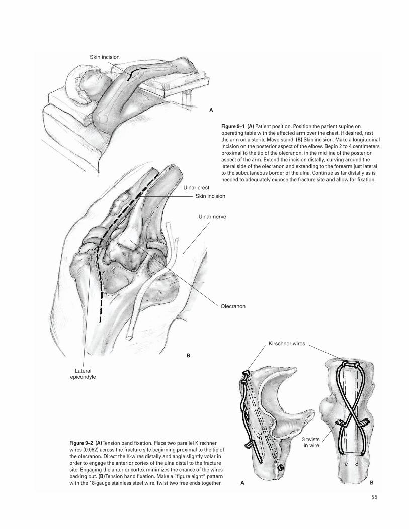
5 5
Kirschner wires
3 twists in wire
Ulnar nerve
Skin incision
Olecranon
Lateral epicondyle
Skin incision
Ulnar crest
A
B
A B
Figure 9–1 (A) Patient position. Position the patient supine onoperating table with the affected arm over the chest. If desired, rest the arm on a sterile Mayo stand. (B) Skin incision. Make a longitudinalincision on the posterior aspect of the elbow. Begin 2 to 4 centimetersproximal to the tip of the olecranon, in the midline of the posterioraspect of the arm. Extend the incision distally, curving around thelateral side of the olecranon and extending to the forearm just lateralto the subcutaneous border of the ulna. Continue as far distally as isneeded to adequately expose the fracture site and allow for fixation.
Figure 9–2 (A)Tension band fixation. Place two parallel Kirschnerwires (0.062) across the fracture site beginning proximal to the tip ofthe olecranon. Direct the K-wires distally and angle slightly volar inorder to engage the anterior cortex of the ulna distal to the fracturesite. Engaging the anterior cortex minimizes the chance of the wiresbacking out. (B)Tension band fixation. Make a “figure eight” patternwith the 18-gauge stainless steel wire. Twist two free ends together.
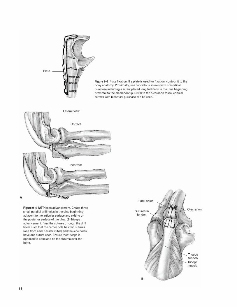
5 6
Triceps tendonTriceps muscle
Olecranon
3 drill holes
Sutures in tendon
Lateral view
Correct
Incorrect
B
A
Plate
Figure 9–3 Plate fixation. If a plate is used for fixation, contour it to thebony anatomy. Proximally, use cancellous screws with unicorticalpurchase including a screw placed longitudinally in the ulna beginningproximal to the olecranon tip. Distal to the olecranon fossa, corticalscrews with bicortical purchase can be used.
Figure 9–4 (A)Triceps advancement. Create threesmall parallel drill holes in the ulna beginningadjacent to the articular surface and exiting onthe posterior surface of the ulna. (B)Tricepsadvancement. Pass the sutures through the drillholes such that the center hole has two sutures(one from each Kessler stitch) and the side holeshave one suture each. Ensure that triceps isopposed to bone and tie the sutures over thebone.
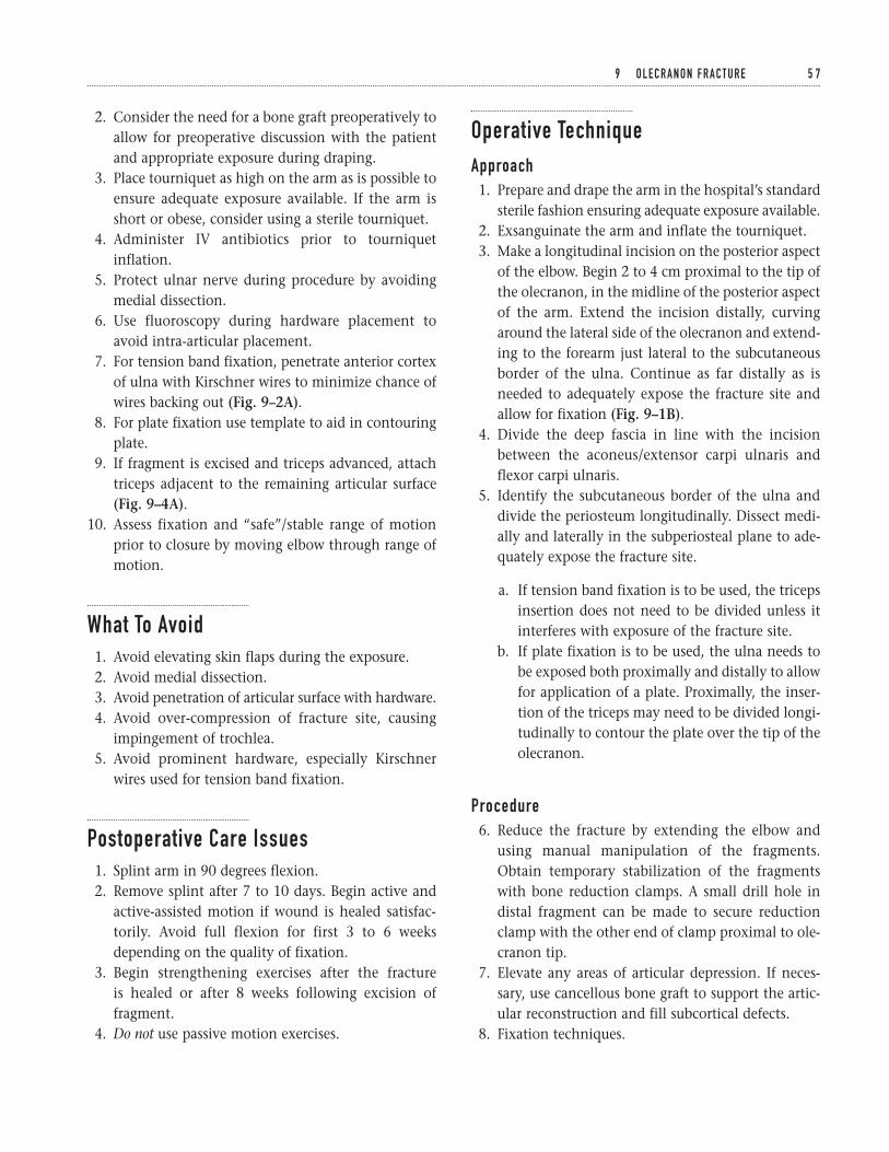
2. Consider the need for a bone graft preoperatively toallow for preoperative discussion with the patientand appropriate exposure during draping.
3. Place tourniquet as high on the arm as is possible toensure adequate exposure available. If the arm isshort or obese, consider using a sterile tourniquet.
4. Administer IV antibiotics prior to tourniquetinflation.
5. Protect ulnar nerve during procedure by avoidingmedial dissection.
6. Use fluoroscopy during hardware placement toavoid intra-articular placement.
7. For tension band fixation, penetrate anterior cortexof ulna with Kirschner wires to minimize chance ofwires backing out (Fig. 9–2A).
8. For plate fixation use template to aid in contouringplate.
9. If fragment is excised and triceps advanced, attachtriceps adjacent to the remaining articular surface(Fig. 9–4A).
10. Assess fixation and “safe”/stable range of motionprior to closure by moving elbow through range ofmotion.
What To Avoid1. Avoid elevating skin flaps during the exposure.2. Avoid medial dissection.3. Avoid penetration of articular surface with hardware.4. Avoid over-compression of fracture site, causing
impingement of trochlea.5. Avoid prominent hardware, especially Kirschner
wires used for tension band fixation.
Postoperative Care Issues1. Splint arm in 90 degrees flexion.2. Remove splint after 7 to 10 days. Begin active and
active-assisted motion if wound is healed satisfac-torily. Avoid full flexion for first 3 to 6 weeksdepending on the quality of fixation.
3. Begin strengthening exercises after the fracture is healed or after 8 weeks following excision offragment.
4. Do not use passive motion exercises.
Operative TechniqueApproach1. Prepare and drape the arm in the hospital’s standard
sterile fashion ensuring adequate exposure available.2. Exsanguinate the arm and inflate the tourniquet.3. Make a longitudinal incision on the posterior aspect
of the elbow. Begin 2 to 4 cm proximal to the tip ofthe olecranon, in the midline of the posterior aspectof the arm. Extend the incision distally, curvingaround the lateral side of the olecranon and extend-ing to the forearm just lateral to the subcutaneousborder of the ulna. Continue as far distally as isneeded to adequately expose the fracture site andallow for fixation (Fig. 9–1B).
4. Divide the deep fascia in line with the incisionbetween the aconeus/extensor carpi ulnaris andflexor carpi ulnaris.
5. Identify the subcutaneous border of the ulna anddivide the periosteum longitudinally. Dissect medi-ally and laterally in the subperiosteal plane to ade-quately expose the fracture site.
a. If tension band fixation is to be used, the tricepsinsertion does not need to be divided unless itinterferes with exposure of the fracture site.
b. If plate fixation is to be used, the ulna needs tobe exposed both proximally and distally to allowfor application of a plate. Proximally, the inser-tion of the triceps may need to be divided longi-tudinally to contour the plate over the tip of theolecranon.
Procedure6. Reduce the fracture by extending the elbow and
using manual manipulation of the fragments.Obtain temporary stabilization of the fragmentswith bone reduction clamps. A small drill hole indistal fragment can be made to secure reductionclamp with the other end of clamp proximal to ole-cranon tip.
7. Elevate any areas of articular depression. If neces-sary, use cancellous bone graft to support the artic-ular reconstruction and fill subcortical defects.
8. Fixation techniques.
9 O L E C R A N O N F R A C T U R E 5 7
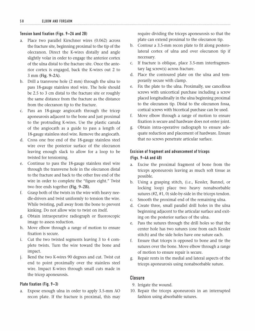
Tension band fixation (Figs. 9–2A and 2B)
a. Place two parallel Kirschner wires (0.062) across the fracture site, beginning proximal to the tip of theolecranon. Direct the K-wires distally and angleslightly volar in order to engage the anterior cortexof the ulna distal to the fracture site. Once the ante-rior cortex is engaged, back the K-wires out 2 to 3 mm (Fig. 9–2A).
b. Drill a transverse hole (2 mm) through the ulna topass 18-gauge stainless steel wire. The hole shouldbe 2.5 to 3 cm distal to the fracture site or roughlythe same distance from the fracture as the distancefrom the olecranon tip to the fracture.
c. Pass an 18-gauge angiocath through the tricepaponeurosis adjacent to the bone and just proximalto the protruding K-wires. Use the plastic canula of the angiocath as a guide to pass a length of 18-gauge stainless steel wire. Remove the angiocath.
d. Cross one free end of the 18-gauge stainless steelwire over the posterior surface of the olecranonleaving enough slack to allow for a loop to betwisted for tensioning.
e. Continue to pass the 18-gauge stainless steel wirethrough the transverse hole in the olecranon distalto the fracture and back to the other free end of thewire in order to complete the “figure eight.” Twisttwo free ends together (Fig. 9–2B).
f. Grasp both of the twists in the wire with heavy nee-dle-drivers and twist uniformly to tension the wire.While twisting, pull away from the bone to preventkinking. Do not allow wire to twist on itself.
g. Obtain intraoperative radiograph or fluoroscopicimage to assess reduction.
h. Move elbow through a range of motion to ensurefixation is secure.
i. Cut the two twisted segments leaving 3 to 4 com-plete twists. Turn the wire toward the bone andimpact.
j. Bend the two K-wires 90 degrees and cut. Twist cutend to point proximally over the stainless steelwire. Impact K-wires through small cuts made inthe tricep aponeurosis.
Plate fixation (Fig. 9–3)
a. Expose enough ulna in order to apply 3.5-mm AOrecon plate. If the fracture is proximal, this may
require dividing the triceps aponeurosis so that theplate can extend proximal to the olecranon tip.
b. Contour a 3.5-mm recon plate to fit along postero-lateral cortex of ulna and over olecranon tip ifnecessary.
c. If fracture is oblique, place 3.5-mm interfragmen-tary lag screw(s) across fracture.
d. Place the contoured plate on the ulna and tem-porarily secure with clamp.
e. Fix the plate to the ulna. Proximally, use cancellousscrews with unicortical purchase including a screwplaced longitudinally in the ulna beginning proximalto the olecranon tip. Distal to the olecranon fossa,cortical screws with bicortical purchase can be used.
f. Move elbow through a range of motion to ensurefixation is secure and hardware does not enter joint.
g. Obtain intra-operative radiograph to ensure ade-quate reduction and placement of hardware. Ensurethat no screws penetrate articular surface.
Excision of fragment and advancement of triceps (Figs. 9–4A and 4B)
a. Excise the proximal fragment of bone from thetriceps aponeurosis leaving as much soft tissue aspossible.
b. Using a grasping stitch, (i.e., Kessler, Bunnel, orlocking loop) place two heavy nonabsorbablesutures (#2, #1, 0) side-by-side in the triceps tendon.
c. Smooth the proximal end of the remaining ulna.d. Create three, small parallel drill holes in the ulna
beginning adjacent to the articular surface and exit-ing on the posterior surface of the ulna.
e. Pass the sutures through the drill holes so that thecenter hole has two sutures (one from each Kesslerstitch) and the side holes have one suture each.
f. Ensure that triceps is opposed to bone and tie thesutures over the bone. Move elbow through a rangeof motion to ensure repair is secure.
g. Repair rents in the medial and lateral aspects of thetriceps aponeurosis using nonabsorbable suture.
Closure9. Irrigate the wound.
10. Repair the triceps aponeurosis in an interruptedfashion using absorbable sutures.
5 8 E L B OW A N D F O R E A R M
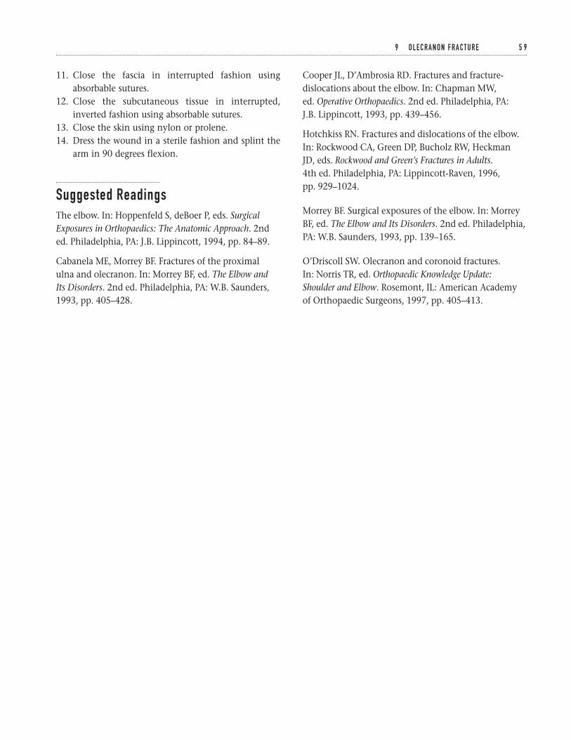
11. Close the fascia in interrupted fashion usingabsorbable sutures.
12. Close the subcutaneous tissue in interrupted,inverted fashion using absorbable sutures.
13. Close the skin using nylon or prolene.14. Dress the wound in a sterile fashion and splint the
arm in 90 degrees flexion.
Suggested ReadingsThe elbow. In: Hoppenfeld S, deBoer P, eds. SurgicalExposures in Orthopaedics: The Anatomic Approach. 2nded. Philadelphia, PA: J.B. Lippincott, 1994, pp. 84–89.
Cabanela ME, Morrey BF. Fractures of the proximal ulna and olecranon. In: Morrey BF, ed. The Elbow and Its Disorders. 2nd ed. Philadelphia, PA: W.B. Saunders,1993, pp. 405–428.
Cooper JL, D’Ambrosia RD. Fractures and fracture-dislocations about the elbow. In: Chapman MW, ed. Operative Orthopaedics. 2nd ed. Philadelphia, PA: J.B. Lippincott, 1993, pp. 439–456.
Hotchkiss RN. Fractures and dislocations of the elbow.In: Rockwood CA, Green DP, Bucholz RW, Heckman JD, eds. Rockwood and Green’s Fractures in Adults.4th ed. Philadelphia, PA: Lippincott-Raven, 1996, pp. 929–1024.
Morrey BF. Surgical exposures of the elbow. In: MorreyBF, ed. The Elbow and Its Disorders. 2nd ed. Philadelphia,PA: W.B. Saunders, 1993, pp. 139–165.
O’Driscoll SW. Olecranon and coronoid fractures. In: Norris TR, ed. Orthopaedic Knowledge Update: Shoulder and Elbow. Rosemont, IL: American Academyof Orthopaedic Surgeons, 1997, pp. 405–413.
9 O L E C R A N O N F R A C T U R E 5 9
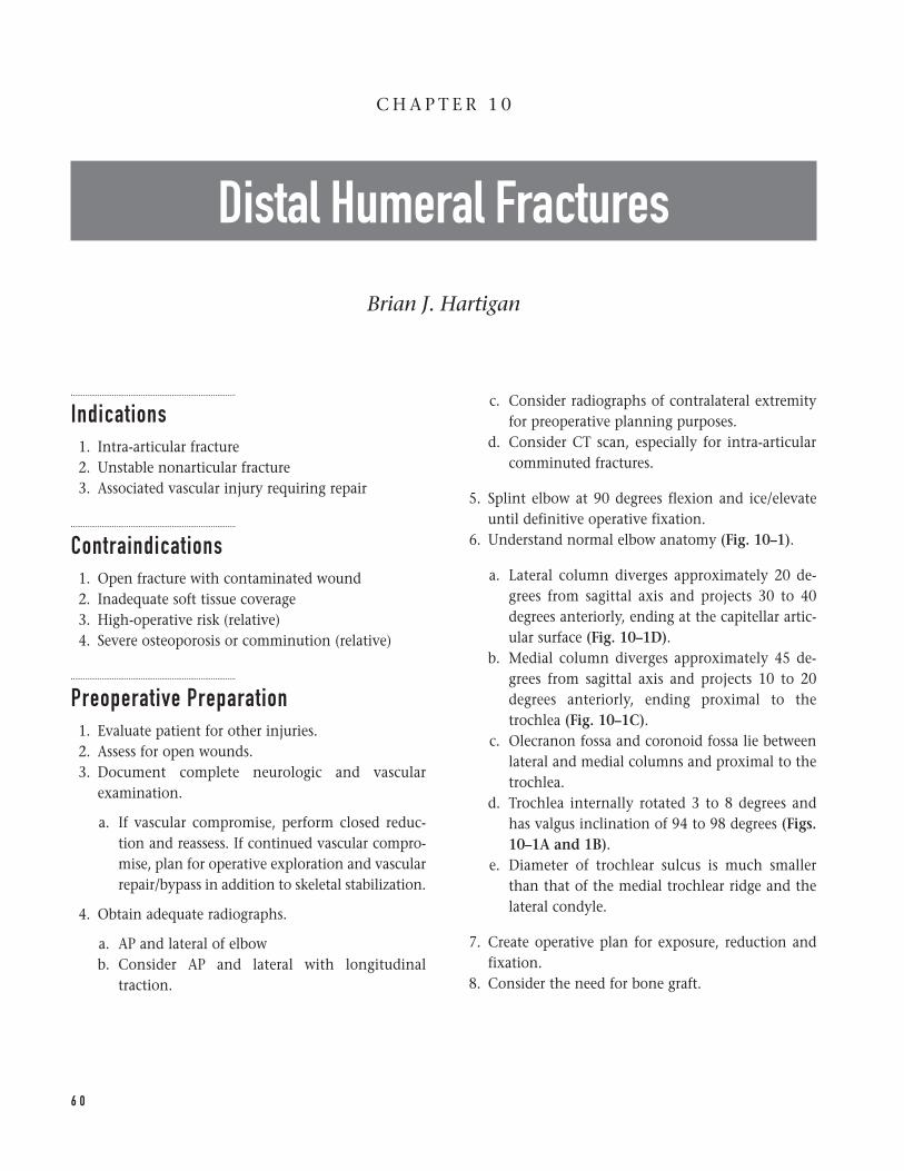
Indications1. Intra-articular fracture2. Unstable nonarticular fracture3. Associated vascular injury requiring repair
Contraindications1. Open fracture with contaminated wound2. Inadequate soft tissue coverage3. High-operative risk (relative)4. Severe osteoporosis or comminution (relative)
Preoperative Preparation1. Evaluate patient for other injuries.2. Assess for open wounds.3. Document complete neurologic and vascular
examination.
a. If vascular compromise, perform closed reduc-tion and reassess. If continued vascular compro-mise, plan for operative exploration and vascularrepair/bypass in addition to skeletal stabilization.
4. Obtain adequate radiographs.
a. AP and lateral of elbowb. Consider AP and lateral with longitudinal
traction.
c. Consider radiographs of contralateral extremityfor preoperative planning purposes.
d. Consider CT scan, especially for intra-articularcomminuted fractures.
5. Splint elbow at 90 degrees flexion and ice/elevateuntil definitive operative fixation.
6. Understand normal elbow anatomy (Fig. 10–1).
a. Lateral column diverges approximately 20 de-grees from sagittal axis and projects 30 to 40degrees anteriorly, ending at the capitellar artic-ular surface (Fig. 10–1D).
b. Medial column diverges approximately 45 de-grees from sagittal axis and projects 10 to 20degrees anteriorly, ending proximal to thetrochlea (Fig. 10–1C).
c. Olecranon fossa and coronoid fossa lie betweenlateral and medial columns and proximal to thetrochlea.
d. Trochlea internally rotated 3 to 8 degrees andhas valgus inclination of 94 to 98 degrees (Figs.10–1A and 1B).
e. Diameter of trochlear sulcus is much smallerthan that of the medial trochlear ridge and thelateral condyle.
7. Create operative plan for exposure, reduction andfixation.
8. Consider the need for bone graft.
6 0
C H A P T E R 1 0
Distal Humeral Fractures
Brian J. Hartigan
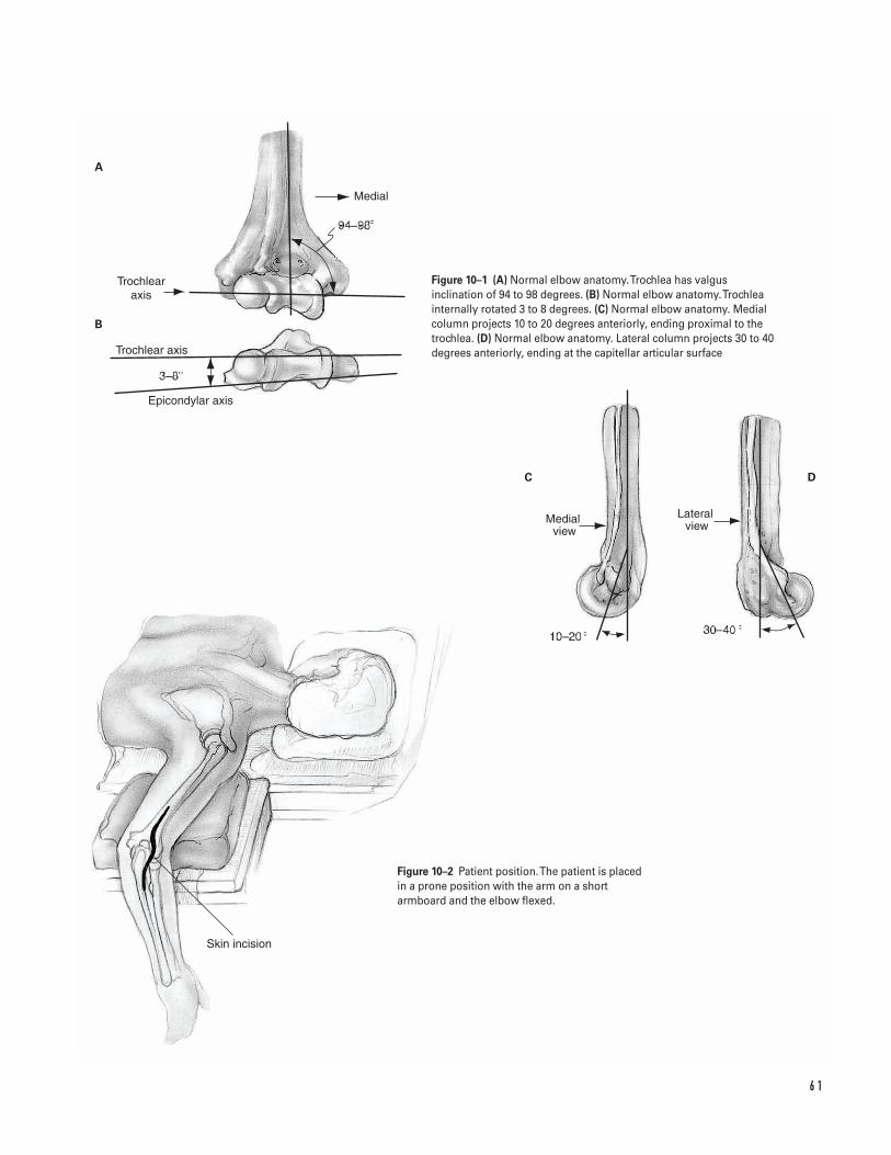
6 1
Medial
Trochlear�axis
Trochlear axis
Epicondylar axis
Medial view
Lateral view
Skin incision
B
A
C D
Figure 10–1 (A) Normal elbow anatomy. Trochlea has valgusinclination of 94 to 98 degrees. (B) Normal elbow anatomy. Trochleainternally rotated 3 to 8 degrees. (C) Normal elbow anatomy. Medialcolumn projects 10 to 20 degrees anteriorly, ending proximal to thetrochlea. (D) Normal elbow anatomy. Lateral column projects 30 to 40degrees anteriorly, ending at the capitellar articular surface
Figure 10–2 Patient position. The patient is placedin a prone position with the arm on a shortarmboard and the elbow flexed.
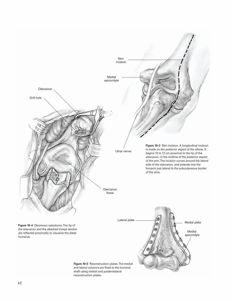
6 2
Olecranon
Drill hole
Olecranon fossa
Lateral plateMedial plate
Medial �epicondyle
Skin �incision
Medial epicondyle
Ulnar nerve
Figure 10–3 Skin incision. A longitudinal incisionis made on the posterior aspect of the elbow. Itbegins 10 to 12 cm proximal to the tip of theolecranon, in the midline of the posterior aspectof the arm. The incision curves around the lateralside of the olecranon, and extends into theforearm just lateral to the subcutaneous borderof the ulna.
Figure 10–4 Olecranon osteotomy. The tip of the olecranon and the attached triceps tendon are reflected proximally to visualize the distalhumerus.
Figure 10–5 Reconstruction plates. The medialand lateral columns are fixed to the humeralshaft using medial and posterolateralreconstruction plates.
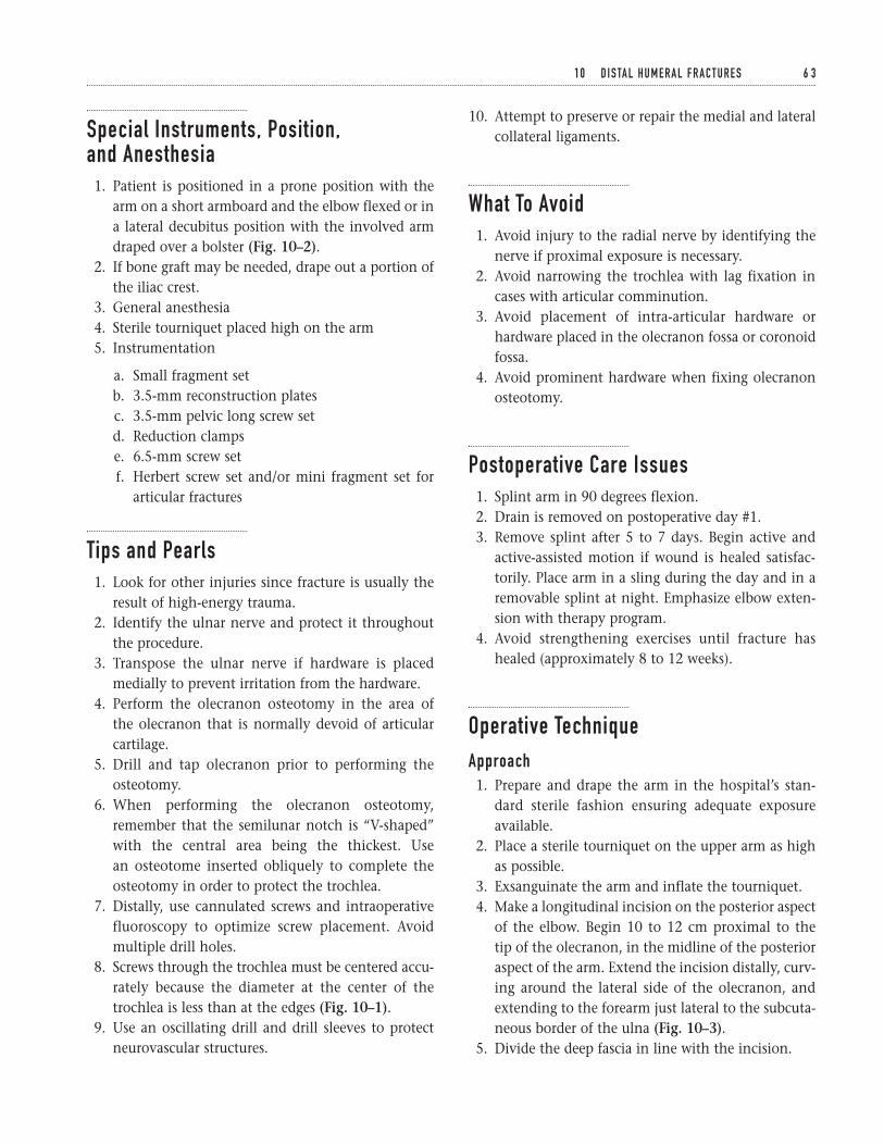
Special Instruments, Position, and Anesthesia1. Patient is positioned in a prone position with the
arm on a short armboard and the elbow flexed or ina lateral decubitus position with the involved armdraped over a bolster (Fig. 10–2).
2. If bone graft may be needed, drape out a portion ofthe iliac crest.
3. General anesthesia4. Sterile tourniquet placed high on the arm5. Instrumentation
a. Small fragment setb. 3.5-mm reconstruction platesc. 3.5-mm pelvic long screw setd. Reduction clampse. 6.5-mm screw setf. Herbert screw set and/or mini fragment set for
articular fractures
Tips and Pearls1. Look for other injuries since fracture is usually the
result of high-energy trauma.2. Identify the ulnar nerve and protect it throughout
the procedure.3. Transpose the ulnar nerve if hardware is placed
medially to prevent irritation from the hardware.4. Perform the olecranon osteotomy in the area of
the olecranon that is normally devoid of articularcartilage.
5. Drill and tap olecranon prior to performing theosteotomy.
6. When performing the olecranon osteotomy,remember that the semilunar notch is “V-shaped”with the central area being the thickest. Use an osteotome inserted obliquely to complete theosteotomy in order to protect the trochlea.
7. Distally, use cannulated screws and intraoperativefluoroscopy to optimize screw placement. Avoidmultiple drill holes.
8. Screws through the trochlea must be centered accu-rately because the diameter at the center of thetrochlea is less than at the edges (Fig. 10–1).
9. Use an oscillating drill and drill sleeves to protectneurovascular structures.
10. Attempt to preserve or repair the medial and lateralcollateral ligaments.
What To Avoid1. Avoid injury to the radial nerve by identifying the
nerve if proximal exposure is necessary.2. Avoid narrowing the trochlea with lag fixation in
cases with articular comminution.3. Avoid placement of intra-articular hardware or
hardware placed in the olecranon fossa or coronoidfossa.
4. Avoid prominent hardware when fixing olecranonosteotomy.
Postoperative Care Issues1. Splint arm in 90 degrees flexion.2. Drain is removed on postoperative day #1.3. Remove splint after 5 to 7 days. Begin active and
active-assisted motion if wound is healed satisfac-torily. Place arm in a sling during the day and in aremovable splint at night. Emphasize elbow exten-sion with therapy program.
4. Avoid strengthening exercises until fracture hashealed (approximately 8 to 12 weeks).
Operative TechniqueApproach1. Prepare and drape the arm in the hospital’s stan-
dard sterile fashion ensuring adequate exposureavailable.
2. Place a sterile tourniquet on the upper arm as highas possible.
3. Exsanguinate the arm and inflate the tourniquet.4. Make a longitudinal incision on the posterior aspect
of the elbow. Begin 10 to 12 cm proximal to the tip of the olecranon, in the midline of the posterioraspect of the arm. Extend the incision distally, curv-ing around the lateral side of the olecranon, andextending to the forearm just lateral to the subcuta-neous border of the ulna (Fig. 10–3).
5. Divide the deep fascia in line with the incision.
1 0 D I S TA L H U M E R A L F R A C T U R E S 6 3
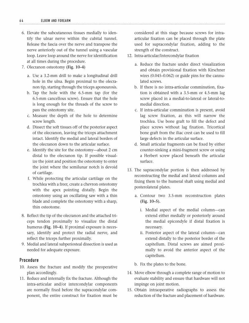
6. Elevate the subcutaneous tissues medially to iden-tify the ulnar nerve within the cubital tunnel.Release the fascia over the nerve and transpose thenerve anteriorly out of the tunnel using a vascularloop. Leave loop around the nerve for identificationat all times during the procedure.
7. Olecranon osteotomy (Fig. 10–4)
a. Use a 3.2-mm drill to make a longitudinal drillhole in the ulna. Begin proximal to the olecra-non tip, starting through the triceps aponeurosis.
b. Tap the hole with the 6.5-mm tap (for the 6.5-mm cancellous screw). Ensure that the holeis long enough for the threads of the screw topass the osteotomy site.
c. Measure the depth of the hole to determinescrew length.
d. Dissect the soft tissues off of the posterior aspectof the olecranon, leaving the triceps attachmentintact. Identify the medial and lateral borders ofthe olecranon down to the articular surface.
e. Identify the site for the osteotomy—about 2 cmdistal to the olecranon tip. If possible visual-ize the joint and position the osteotomy to enterthe joint where the semilunar notch is devoidof cartilage.
f. While protecting the articular cartilage on thetrochlea with a freer, create a chevron osteotomywith the apex pointing distally. Begin theosteotomy using an oscillating saw with a thinblade and complete the osteotomy with a sharp,thin osteotome.
8. Reflect the tip of the olecranon and the attached tri-ceps tendon proximally to visualize the distalhumerus (Fig. 10–4). If proximal exposure is neces-sary, identify and protect the radial nerve, andreflect the triceps further proximally.
9. Medial and lateral subperiosteal dissection is used asneeded for adequate exposure.
Procedure10. Assess the fracture and modify the preoperative
plan accordingly.11. Reduce and internally fix the fracture. Although the
intra-articular and/or intercondylar components are normally fixed before the supracondylar com-ponent, the entire construct for fixation must be
considered at this stage because screws for intra-articular fixation can be placed through the plateused for supracondylar fixation, adding to thestrength of the construct.
12. Intra-articular/Intercondylar fixation
a. Reduce the fracture under direct visualizationand obtain provisional fixation with Kirschnerwires (0.045–0.062) or guide pins for the cannu-lated screws.
b. If there is no intra-articular comminution, fixa-tion is obtained with a 3.5-mm or 4.5-mm lagscrew placed in a medial-to-lateral or lateral-to-medial direction.
c. If intra-articular comminution is present, avoidlag screw fixation, as this will narrow thetrochlea. Use bone graft to fill the defect andplace screws without lag fixation. Tricorticalbone graft from the iliac crest can be used to filllarge defects in the articular surface.
d. Small articular fragments can be fixed by eithercounter-sinking a mini-fragment screw or usinga Herbert screw placed beneath the articularsurface.
13. The supracondylar portion is then addressed byreconstructing the medial and lateral columns andfixing them to the humeral shaft using medial andposterolateral plates.
a. Contour two 3.5-mm reconstruction plates (Fig. 10–5).
i. Medial aspect of the medial column—canextend either medially or posteriorly aroundthe medial epicondyle if distal fixation isnecessary.
ii. Posterior aspect of the lateral column—canextend distally to the posterior border of thecapitellum. Distal screws are aimed proxi-mally to avoid the anterior aspect of thecapitellum.
b. Fix the plates to the bone.
14. Move elbow through a complete range of motion toevaluate stability and ensure that hardware will notimpinge on joint motion.
15. Obtain intraoperative radiographs to assess thereduction of the fracture and placement of hardware.
6 4 E L B OW A N D F O R E A R M
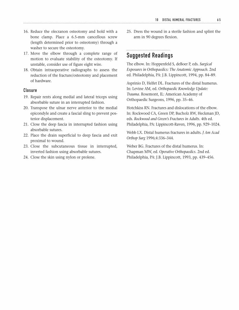
16. Reduce the olecranon osteotomy and hold with abone clamp. Place a 6.5-mm cancellous screw(length determined prior to osteotomy) through awasher to secure the osteotomy.
17. Move the elbow through a complete range ofmotion to evaluate stability of the osteotomy. Ifunstable, consider use of figure eight wire.
18. Obtain intraoperative radiographs to assess thereduction of the fracture/osteotomy and placementof hardware.
Closure19. Repair rents along medial and lateral triceps using
absorbable suture in an interrupted fashion.20. Transpose the ulnar nerve anterior to the medial
epicondyle and create a fascial sling to prevent pos-terior displacement.
21. Close the deep fascia in interrupted fashion usingabsorbable sutures.
22. Place the drain superficial to deep fascia and exitproximal to wound.
23. Close the subcutaneous tissue in interrupted,inverted fashion using absorbable sutures.
24. Close the skin using nylon or prolene.
25. Dress the wound in a sterile fashion and splint thearm in 90 degrees flexion.
Suggested ReadingsThe elbow. In: Hoppenfeld S, deBoer P, eds. SurgicalExposures in Orthopaedics: The Anatomic Approach. 2nded. Philadelphia, PA: J.B. Lippincott, 1994, pp. 84–89.
Asprinio D, Helfet DL. Fractures of the distal humerus.In: Levine AM, ed. Orthopaedic Knowledge Update:Trauma. Rosemont, IL: American Academy ofOrthopaedic Surgeons, 1996, pp. 35–46.
Hotchkiss RN. Fractures and dislocations of the elbow.In: Rockwood CA, Green DP, Bucholz RW, Heckman JD,eds. Rockwood and Green’s Fractures in Adults. 4th ed.Philadelphia, PA: Lippincott-Raven, 1996, pp. 929–1024.
Webb LX. Distal humerus fractures in adults. J Am AcadOrthop Surg 1996;4:336–344.
Weber BG. Fractures of the distal humerus. In:Chapman MW, ed. Operative Orthopaedics. 2nd ed.Philadelphia, PA: J.B. Lippincott, 1993, pp. 439–456.
1 0 D I S TA L H U M E R A L F R A C T U R E S 6 5
Indications1. Radial shaft fracture with angulation greater than
10 degrees, malrotation, or disturbance of the nor-mal radial bow
2. Ulnar shaft fracture with angulation greater than 10degrees, malrotation, displacement greater than50%, or shortening with distal radio-ulnar jointincongruency
3. Both-bones forearm fracture4. Monteggia fracture5. Galeazzi fracture6. Open fracture7. Segmental or comminuted fracture (relative)8. Concomitant soft-tissue injury requiring frequent
wound care (e.g., burn)9. Compartment syndrome
Contraindications1. Nondisplaced radial shaft fracture2. Minimally displaced ulnar shaft fracture (“night-
stick” fracture)3. Severe coexisting medical illness4. Childhood injury (relative). In general, a greater
degree of initial displacement can be accepted in children given their potential for remodelingduring growth and high incidence of satisfactoryfunctional outcomes with nonoperative treatment.
Preoperative Preparation1. Standard AP and lateral radiographs of the injured
forearm, elbow, and wrist2. Comparative views of the contralateral forearm and
wrist may be helpful.3. Determine the radiographic characteristics of the
fracture.
a. One or both bonesb. Shaft location—proximal, middle, or distal thirdc. Pattern of injury—transverse, oblique, spiral,
comminuted, segmental, bone lossd. Degree and direction of displacement
4. Document the neurovascular status and evaluate theextremity for associated trauma (e.g., radial head dis-location, distal radio-ulnar joint instability).
5. Assess for elevated forearm compartment pressures.6. Plan the surgical approach: anterior, posterior,
ulnar.7. Discuss with the patient the common potential
complications associated with operative treatmentof forearm fractures.
Special Instruments, Position, and Anesthesia1. Supine position with a hand table extension2. Regional or general anesthesia
6 6
C H A P T E R 1 1
Forearm Diaphyseal FracturesRadius and Ulna
David M. Kalainov and Charles Carroll IV
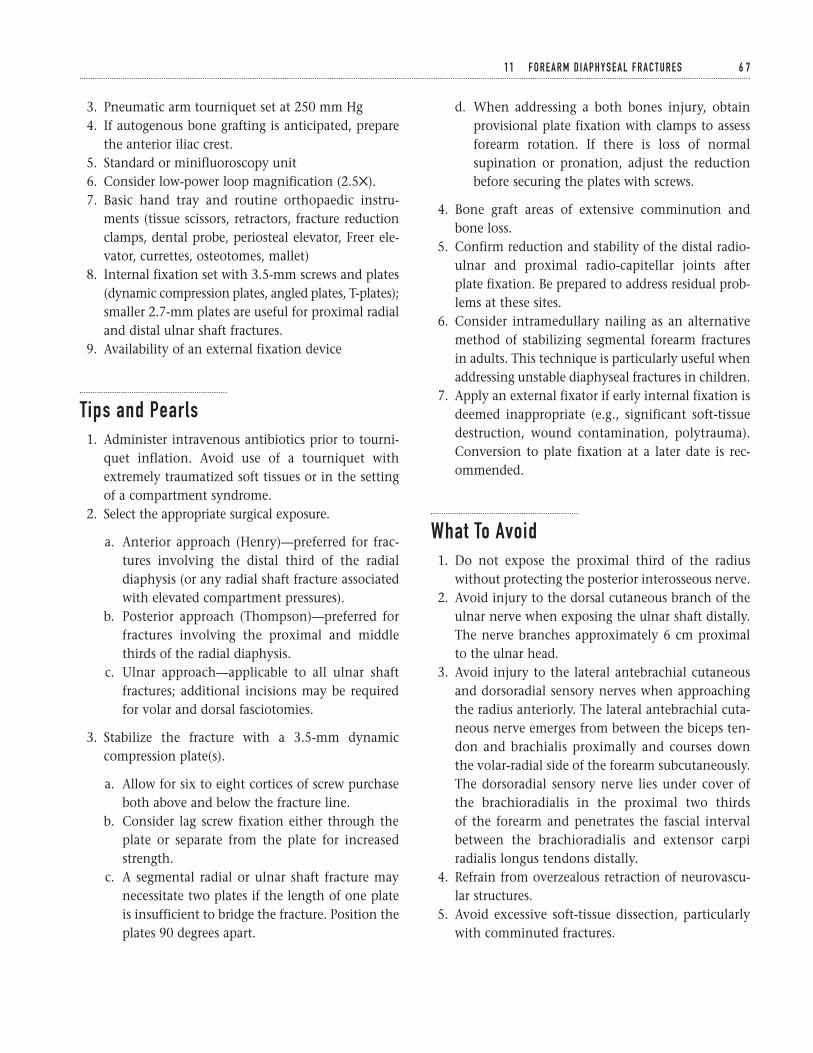
3. Pneumatic arm tourniquet set at 250 mm Hg4. If autogenous bone grafting is anticipated, prepare
the anterior iliac crest.5. Standard or minifluoroscopy unit6. Consider low-power loop magnification (2.55).7. Basic hand tray and routine orthopaedic instru-
ments (tissue scissors, retractors, fracture reductionclamps, dental probe, periosteal elevator, Freer ele-vator, currettes, osteotomes, mallet)
8. Internal fixation set with 3.5-mm screws and plates(dynamic compression plates, angled plates, T-plates);smaller 2.7-mm plates are useful for proximal radialand distal ulnar shaft fractures.
9. Availability of an external fixation device
Tips and Pearls1. Administer intravenous antibiotics prior to tourni-
quet inflation. Avoid use of a tourniquet withextremely traumatized soft tissues or in the settingof a compartment syndrome.
2. Select the appropriate surgical exposure.
a. Anterior approach (Henry)—preferred for frac-tures involving the distal third of the radialdiaphysis (or any radial shaft fracture associatedwith elevated compartment pressures).
b. Posterior approach (Thompson)—preferred forfractures involving the proximal and middlethirds of the radial diaphysis.
c. Ulnar approach—applicable to all ulnar shaftfractures; additional incisions may be requiredfor volar and dorsal fasciotomies.
3. Stabilize the fracture with a 3.5-mm dynamiccompression plate(s).
a. Allow for six to eight cortices of screw purchaseboth above and below the fracture line.
b. Consider lag screw fixation either through theplate or separate from the plate for increasedstrength.
c. A segmental radial or ulnar shaft fracture maynecessitate two plates if the length of one plateis insufficient to bridge the fracture. Position theplates 90 degrees apart.
d. When addressing a both bones injury, obtainprovisional plate fixation with clamps to assessforearm rotation. If there is loss of normalsupination or pronation, adjust the reductionbefore securing the plates with screws.
4. Bone graft areas of extensive comminution andbone loss.
5. Confirm reduction and stability of the distal radio-ulnar and proximal radio-capitellar joints after plate fixation. Be prepared to address residual prob-lems at these sites.
6. Consider intramedullary nailing as an alternativemethod of stabilizing segmental forearm fracturesin adults. This technique is particularly useful whenaddressing unstable diaphyseal fractures in children.
7. Apply an external fixator if early internal fixation isdeemed inappropriate (e.g., significant soft-tissuedestruction, wound contamination, polytrauma).Conversion to plate fixation at a later date is rec-ommended.
What To Avoid1. Do not expose the proximal third of the radius
without protecting the posterior interosseous nerve.2. Avoid injury to the dorsal cutaneous branch of the
ulnar nerve when exposing the ulnar shaft distally.The nerve branches approximately 6 cm proximalto the ulnar head.
3. Avoid injury to the lateral antebrachial cutaneousand dorsoradial sensory nerves when approachingthe radius anteriorly. The lateral antebrachial cuta-neous nerve emerges from between the biceps ten-don and brachialis proximally and courses downthe volar-radial side of the forearm subcutaneously.The dorsoradial sensory nerve lies under cover ofthe brachioradialis in the proximal two thirds of the forearm and penetrates the fascial intervalbetween the brachioradialis and extensor carpiradialis longus tendons distally.
4. Refrain from overzealous retraction of neurovascu-lar structures.
5. Avoid excessive soft-tissue dissection, particularlywith comminuted fractures.
1 1 F O R E A R M D I A P H Y S E A L F R A C T U R E S 6 7
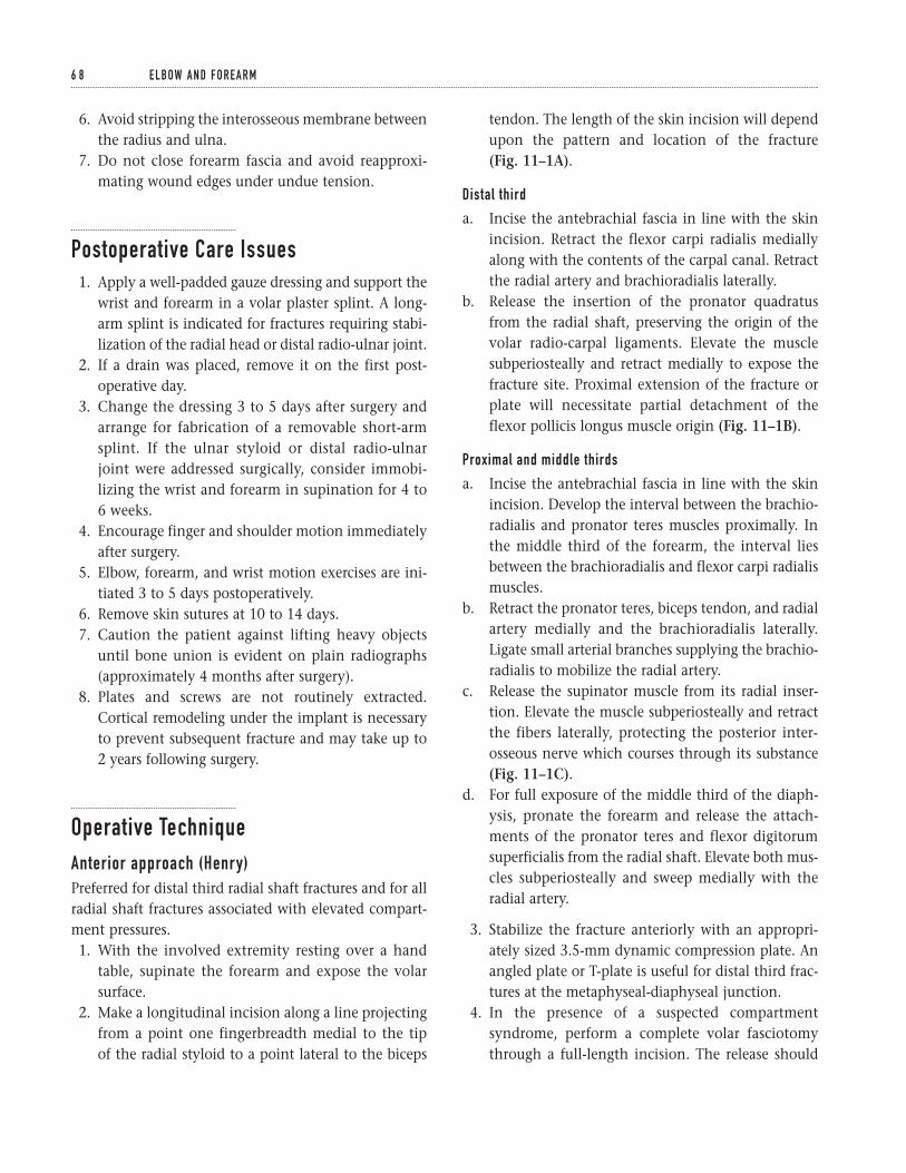
6. Avoid stripping the interosseous membrane betweenthe radius and ulna.
7. Do not close forearm fascia and avoid reapproxi-mating wound edges under undue tension.
Postoperative Care Issues1. Apply a well-padded gauze dressing and support the
wrist and forearm in a volar plaster splint. A long-arm splint is indicated for fractures requiring stabi-lization of the radial head or distal radio-ulnar joint.
2. If a drain was placed, remove it on the first post-operative day.
3. Change the dressing 3 to 5 days after surgery andarrange for fabrication of a removable short-armsplint. If the ulnar styloid or distal radio-ulnarjoint were addressed surgically, consider immobi-lizing the wrist and forearm in supination for 4 to6 weeks.
4. Encourage finger and shoulder motion immediatelyafter surgery.
5. Elbow, forearm, and wrist motion exercises are ini-tiated 3 to 5 days postoperatively.
6. Remove skin sutures at 10 to 14 days.7. Caution the patient against lifting heavy objects
until bone union is evident on plain radiographs(approximately 4 months after surgery).
8. Plates and screws are not routinely extracted.Cortical remodeling under the implant is necessaryto prevent subsequent fracture and may take up to2 years following surgery.
Operative TechniqueAnterior approach (Henry)Preferred for distal third radial shaft fractures and for allradial shaft fractures associated with elevated compart-ment pressures.1. With the involved extremity resting over a hand
table, supinate the forearm and expose the volarsurface.
2. Make a longitudinal incision along a line projectingfrom a point one fingerbreadth medial to the tip of the radial styloid to a point lateral to the biceps
tendon. The length of the skin incision will dependupon the pattern and location of the fracture (Fig. 11–1A).
Distal third
a. Incise the antebrachial fascia in line with the skinincision. Retract the flexor carpi radialis mediallyalong with the contents of the carpal canal. Retractthe radial artery and brachioradialis laterally.
b. Release the insertion of the pronator quadratusfrom the radial shaft, preserving the origin of thevolar radio-carpal ligaments. Elevate the musclesubperiosteally and retract medially to expose thefracture site. Proximal extension of the fracture orplate will necessitate partial detachment of theflexor pollicis longus muscle origin (Fig. 11–1B).
Proximal and middle thirds
a. Incise the antebrachial fascia in line with the skinincision. Develop the interval between the brachio-radialis and pronator teres muscles proximally. Inthe middle third of the forearm, the interval liesbetween the brachioradialis and flexor carpi radialismuscles.
b. Retract the pronator teres, biceps tendon, and radialartery medially and the brachioradialis laterally.Ligate small arterial branches supplying the brachio-radialis to mobilize the radial artery.
c. Release the supinator muscle from its radial inser-tion. Elevate the muscle subperiosteally and retractthe fibers laterally, protecting the posterior inter-osseous nerve which courses through its substance(Fig. 11–1C).
d. For full exposure of the middle third of the diaph-ysis, pronate the forearm and release the attach-ments of the pronator teres and flexor digitorumsuperficialis from the radial shaft. Elevate both mus-cles subperiosteally and sweep medially with theradial artery.
3. Stabilize the fracture anteriorly with an appropri-ately sized 3.5-mm dynamic compression plate. Anangled plate or T-plate is useful for distal third frac-tures at the metaphyseal-diaphyseal junction.
4. In the presence of a suspected compartmentsyndrome, perform a complete volar fasciotomythrough a full-length incision. The release should
6 8 E L B OW A N D F O R E A R M
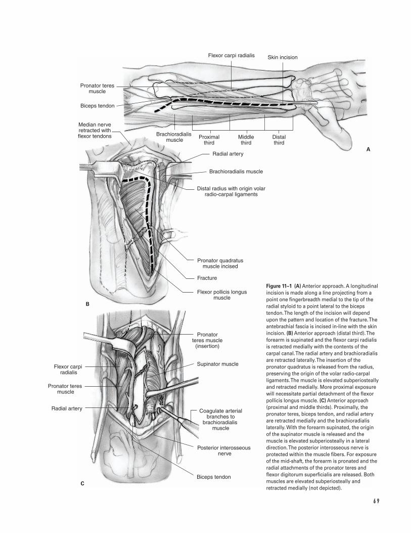
6 9
A
B
C
Pronator teres muscle
Biceps tendon
Flexor carpi radialis Skin incision
Proximal third
Middle third
Distal third
Distal radius with origin volar radio-carpal ligaments
Pronator quadratus muscle incised
Radial artery
Brachioradialis muscle
Fracture
Flexor pollicis longus muscle
Median nerve retracted with flexor tendons
Pronator teres muscle
(insertion)
Supinator muscle
Coagulate arterial branches to
brachioradialis �muscle
Posterior interosseous �nerve
Biceps tendon
Flexor carpi radialis
Pronator teres �muscle
Radial artery
Brachioradialis �muscle
Figure 11–1 (A) Anterior approach. A longitudinalincision is made along a line projecting from apoint one fingerbreadth medial to the tip of theradial styloid to a point lateral to the bicepstendon. The length of the incision will dependupon the pattern and location of the fracture. Theantebrachial fascia is incised in-line with the skinincision. (B) Anterior approach (distal third). Theforearm is supinated and the flexor carpi radialisis retracted medially with the contents of thecarpal canal. The radial artery and brachioradialisare retracted laterally. The insertion of thepronator quadratus is released from the radius,preserving the origin of the volar radio-carpalligaments. The muscle is elevated subperiosteallyand retracted medially. More proximal exposurewill necessitate partial detachment of the flexorpollicis longus muscle. (C) Anterior approach(proximal and middle thirds). Proximally, thepronator teres, biceps tendon, and radial arteryare retracted medially and the brachioradialislaterally. With the forearm supinated, the originof the supinator muscle is released and themuscle is elevated subperiosteally in a lateraldirection. The posterior interosseous nerve isprotected within the muscle fibers. For exposureof the mid-shaft, the forearm is pronated and theradial attachments of the pronator teres andflexor digitorum superficialis are released. Bothmuscles are elevated subperiosteally andretracted medially (not depicted).
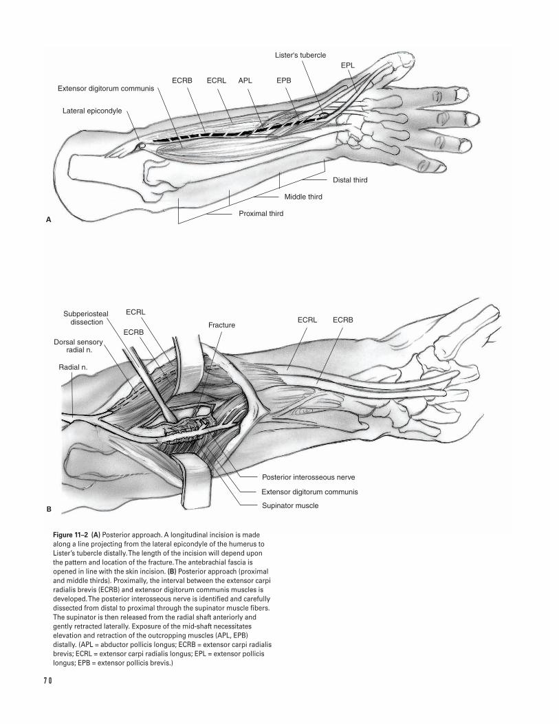
7 0
Subperiosteal dissection
Lateral epicondyle
Extensor digitorum communisECRB ECRL EPBAPL
Lister's tubercleEPL
Distal third
Middle third
Proximal third
Radial n.
Dorsal sensory radial n.
ECRB
ECRL
FractureECRL ECRB
Supinator muscle
Posterior interosseous nerve
Extensor digitorum communis
A
B
Figure 11–2 (A) Posterior approach. A longitudinal incision is madealong a line projecting from the lateral epicondyle of the humerus toLister’s tubercle distally. The length of the incision will depend uponthe pattern and location of the fracture. The antebrachial fascia isopened in line with the skin incision. (B) Posterior approach (proximaland middle thirds). Proximally, the interval between the extensor carpiradialis brevis (ECRB) and extensor digitorum communis muscles isdeveloped. The posterior interosseous nerve is identified and carefullydissected from distal to proximal through the supinator muscle fibers.The supinator is then released from the radial shaft anteriorly andgently retracted laterally. Exposure of the mid-shaft necessitateselevation and retraction of the outcropping muscles (APL, EPB)distally. (APL = abductor pollicis longus; ECRB = extensor carpi radialisbrevis; ECRL = extensor carpi radialis longus; EPL = extensor pollicislongus; EPB = extensor pollicis brevis.)
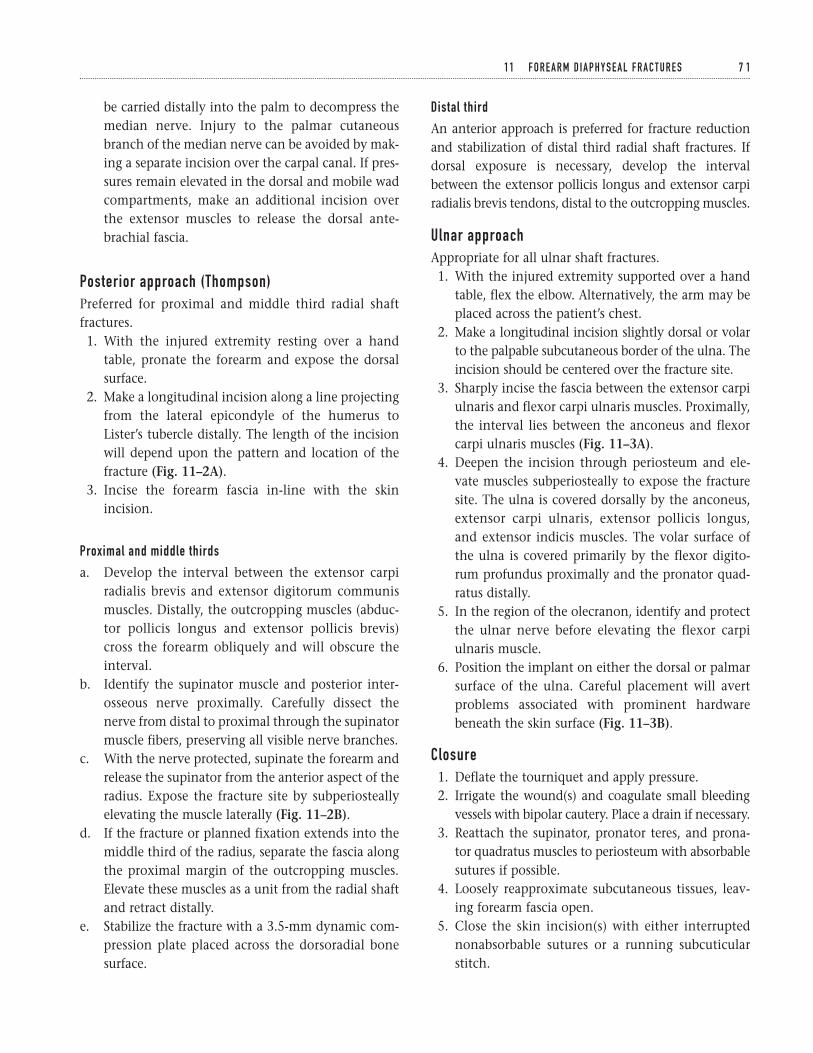
be carried distally into the palm to decompress themedian nerve. Injury to the palmar cutaneousbranch of the median nerve can be avoided by mak-ing a separate incision over the carpal canal. If pres-sures remain elevated in the dorsal and mobile wadcompartments, make an additional incision overthe extensor muscles to release the dorsal ante-brachial fascia.
Posterior approach (Thompson)Preferred for proximal and middle third radial shaftfractures.1. With the injured extremity resting over a hand
table, pronate the forearm and expose the dorsalsurface.
2. Make a longitudinal incision along a line projectingfrom the lateral epicondyle of the humerus toLister’s tubercle distally. The length of the incisionwill depend upon the pattern and location of thefracture (Fig. 11–2A).
3. Incise the forearm fascia in-line with the skinincision.
Proximal and middle thirds
a. Develop the interval between the extensor carpiradialis brevis and extensor digitorum communismuscles. Distally, the outcropping muscles (abduc-tor pollicis longus and extensor pollicis brevis)cross the forearm obliquely and will obscure theinterval.
b. Identify the supinator muscle and posterior inter-osseous nerve proximally. Carefully dissect thenerve from distal to proximal through the supinatormuscle fibers, preserving all visible nerve branches.
c. With the nerve protected, supinate the forearm andrelease the supinator from the anterior aspect of theradius. Expose the fracture site by subperiosteallyelevating the muscle laterally (Fig. 11–2B).
d. If the fracture or planned fixation extends into themiddle third of the radius, separate the fascia alongthe proximal margin of the outcropping muscles.Elevate these muscles as a unit from the radial shaftand retract distally.
e. Stabilize the fracture with a 3.5-mm dynamic com-pression plate placed across the dorsoradial bonesurface.
Distal third
An anterior approach is preferred for fracture reductionand stabilization of distal third radial shaft fractures. Ifdorsal exposure is necessary, develop the intervalbetween the extensor pollicis longus and extensor carpiradialis brevis tendons, distal to the outcropping muscles.
Ulnar approachAppropriate for all ulnar shaft fractures.1. With the injured extremity supported over a hand
table, flex the elbow. Alternatively, the arm may beplaced across the patient’s chest.
2. Make a longitudinal incision slightly dorsal or volarto the palpable subcutaneous border of the ulna. Theincision should be centered over the fracture site.
3. Sharply incise the fascia between the extensor carpiulnaris and flexor carpi ulnaris muscles. Proximally,the interval lies between the anconeus and flexorcarpi ulnaris muscles (Fig. 11–3A).
4. Deepen the incision through periosteum and ele-vate muscles subperiosteally to expose the fracturesite. The ulna is covered dorsally by the anconeus,extensor carpi ulnaris, extensor pollicis longus,and extensor indicis muscles. The volar surface ofthe ulna is covered primarily by the flexor digito-rum profundus proximally and the pronator quad-ratus distally.
5. In the region of the olecranon, identify and protectthe ulnar nerve before elevating the flexor carpiulnaris muscle.
6. Position the implant on either the dorsal or palmarsurface of the ulna. Careful placement will avertproblems associated with prominent hardwarebeneath the skin surface (Fig. 11–3B).
Closure1. Deflate the tourniquet and apply pressure.2. Irrigate the wound(s) and coagulate small bleeding
vessels with bipolar cautery. Place a drain if necessary.3. Reattach the supinator, pronator teres, and prona-
tor quadratus muscles to periosteum with absorbablesutures if possible.
4. Loosely reapproximate subcutaneous tissues, leav-ing forearm fascia open.
5. Close the skin incision(s) with either interruptednonabsorbable sutures or a running subcuticularstitch.
1 1 F O R E A R M D I A P H Y S E A L F R A C T U R E S 7 1
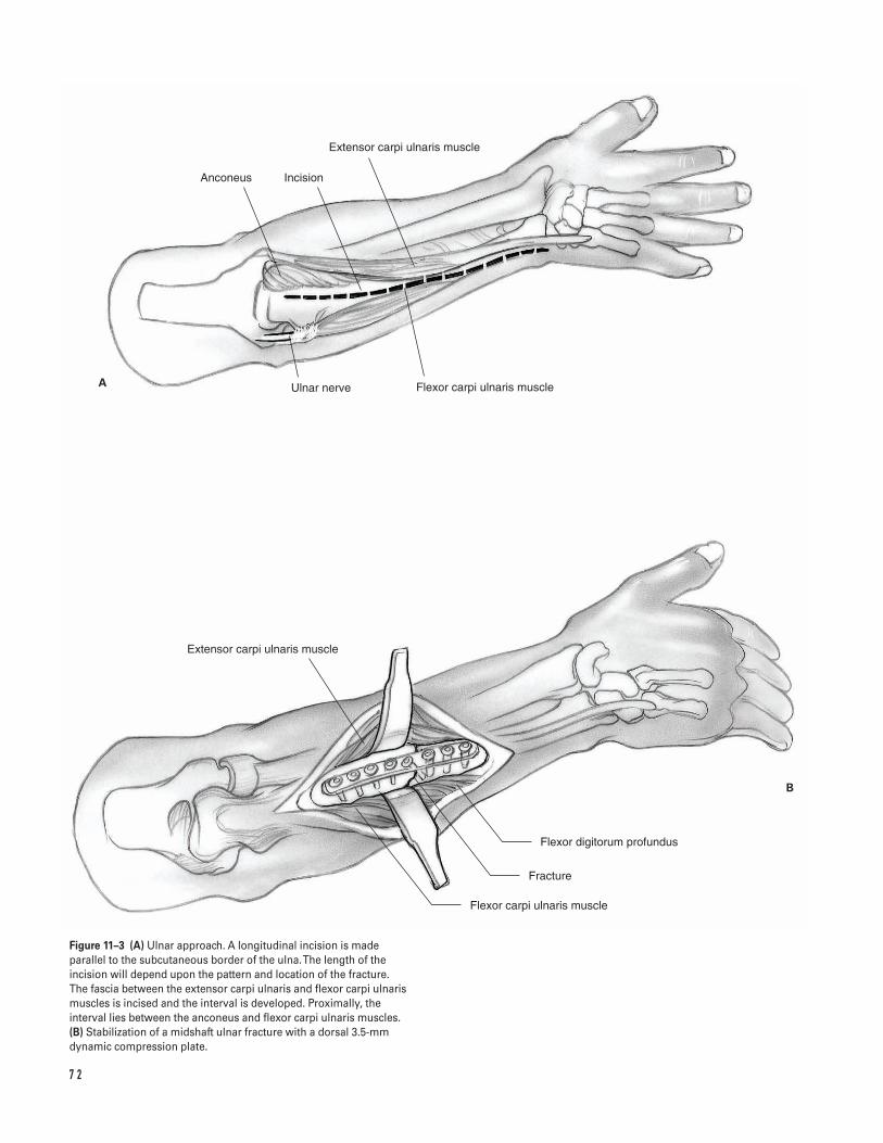
7 2
A
B
Anconeus Incision
Extensor carpi ulnaris muscle
Ulnar nerve Flexor carpi ulnaris muscle
Extensor carpi ulnaris muscle
Flexor carpi ulnaris muscle
Fracture
Flexor digitorum profundus
Figure 11–3 (A) Ulnar approach. A longitudinal incision is madeparallel to the subcutaneous border of the ulna. The length of theincision will depend upon the pattern and location of the fracture. The fascia between the extensor carpi ulnaris and flexor carpi ulnarismuscles is incised and the interval is developed. Proximally, theinterval lies between the anconeus and flexor carpi ulnaris muscles.(B) Stabilization of a midshaft ulnar fracture with a dorsal 3.5-mmdynamic compression plate.
6. Apply a well-padded dressing and volar wrist splint.A long-arm splint is indicated for fractures requiringstabilization of the radial head or distal radio-ulnarjoint. Support the extremity in a sling.
7. If there is undue tension on the repair, leave thewounds open and temporarily secure the skin edgeswith sterile elastic bands. A delayed primary woundclosure or split-thickness skin graft procedure is per-formed 2 to 3 days later.
8. Injuries necessitating a compartmental release aresimilarly treated by delayed primary wound closureand/or split thickness skin grafting.
9. Significant contamination and soft-tissue destruc-tion may also necessitate a delay in wound closure.Soft-tissue coverage requiring microvascular free tis-sue transfer is ideally performed within 1 week ofinjury. Bone grafting should be delayed until thetime of definitive soft-tissue reconstruction.
Suggested ReadingsBotte MJ, Cohen MS, Levernia CJ, et al. The dorsalbranch of the ulnar nerve: an anatomic study. J HandSurg 1990;15A:603–607.
Chapman, MW, Gordon JE, Zissimos AG. Compressionplate fixation of acute fractures of the diaphysis of theradius and ulna. J Bone Joint Surg 1989;71A:159–169.
Godina M. Early microsurgical reconstruction ofcomplex trauma of the extremities. Plast Reconstr Surg1986;78:285–292.
Hanel DP. Volar plate fixation of distal radius fractures.Atlas Hand Clin 1997;2:1–24.
Hoppenfeld S, deBoer P. The forearm. In: Hoppenfeld S,deBoer P, eds. Surgical Exposures in Orthopaedics: TheAnatomic Approach. 2nd ed. Philadelphia, PA: J.B.Lippincott, 1994, pp. 117–146.
Hotchkiss RN. Displaced fractures of the radial head:internal fixation or excision? J Am Acad Orthop Surg1997;5:1–10.
Jupiter JB, Kellam JF. Diaphyseal fractures of the forearm.In: Browner BD, Jupiter JB, Levine AM, Trafton PG, eds.Skeletal Trauma. 2nd ed. Philadelphia, PA: W.B. Saunders,1998, pp. 1421–1454.
Luhmann SJ, Gordon JE, Schoenecker PL. Intramedullaryfixation of unstable both-bone forearm fractures inchildren. J Pediatr Orthop 1998;18:451–456.
Noonan KJ, Price CT. Forearm and distal radius fracturesin children. J Am Acad Orthop Surg 1998;6:146–156.
Rowland SA. Fasciotomy: the treatment of compartmentsyndrome. In: Green DP, Hotchkiss RN, Pederson WC,eds. Green’s Operative Hand Surgery. 4th ed. Philadelphia,PA: Churchill Livingstone, 1999, pp. 689–710.
1 1 F O R E A R M D I A P H Y S E A L F R A C T U R E S 7 3
Indications1. Increased forearm compartment pressure, either:
a. Greater than 30 mm Hg orb. Greater than 20 mm Hg below diastolic blood
pressure
2. Limb ischemia for greater than 6 h3. Following open reduction and internal fixation of
radius and ulna fractures in severe crush injury4. Electrocution injury
ContraindicationsNone
Preoperative PreparationDocument status of preoperative neurovascularexamination.
Special Instruments, Position, and Anesthesia1. The patient is positioned supine on the operating
table. The arm is positioned on an arm board.2. An upper arm tourniquet is applied with cast
padding.3. The procedure may be done with general or
regional anesthesia (not a Bier block).
4. Routine small-joint orthopaedic surgical instru-ments are required.
Tips and Pearls1. Attempt to release the forearm compartments
within 6 h from when increased compartment pres-sures begin.
2. The structures that need to be released are the lac-ertus fibrosis, the mobile wad (fascia of the brachio-radialis, extensor carpi radialis longus, and extensorcarpi radialis brevis), the palmar fascia, and thetransverse carpal ligament. Therefore the skin inci-sion must extend from the elbow to mid palm.
3. The median nerve exits from the muscle of theflexor digitorum superficialis in the distal 6 to 8 cmof the forearm. The skin incision should be ulnar atthis distal location to provide soft tissue coveragefor the nerve.
4. The epimysium of the individual muscles should bereleased in addition to the forearm fascia.
What To Avoid1. Avoid leaving the median nerve exposed at the end
of the procedure.2. Avoid injury of the cutaneous nerves during the
approach.3. Avoid closing the skin. If possible, the skin should
be left open or partially closed with rubber bands orvessel loops and staples.
7 4
C H A P T E R 1 2
Forearm Fasciotomy
Michael S. Bednar
Postoperative Care Issues1. The extremity should be elevated so that it is above
the level of the heart.2. Active and passive range of motion of the fingers is
encouraged as soon as the patient is comfortable.3. Plan to return the patient to the operating room 48 to
72 h after the initial operation for a “second look”procedure. Consider possible debridement and skinclosure (delayed primary or split-thickness skin graft).
Operative Technique1. Place the patient supine on the operating room
table. Extend the arm on an arm board. Place anupper arm tourniquet over cast padding on theproximal limb.
2. Prepare and drape the limb in the usual sterilefashion.
Anterior compartment release3. Begin the incision at the cubital tunnel 1 to 2 cm
anterior to the medial epicondyle. Extend the inci-sion going radial toward the muscle of the brachio-radialis. At the junction of the proximal and middlethirds to the forearm, swing the incision distallyand ulnarly to lie just radial to the extensor carpiulnaris tendon at the distal quarter of the forearm.Continue the incision distally to the flexor crease ofthe wrist. Extend the incision radially in the wristcrease to the location of the usual carpal tunnelrelease incision. This is found by drawing a linefrom the third web space. Distally, carry the inci-sion 3 to 4 cm into the palm (Fig. 12–1).
4. Identify and protect branches of the medial ante-brachial cutaneous nerve near the medial epi-condyle. This incision, which stays ulnar to thepalmaris longus, will protect the palmar cutaneousbranch of the median nerve.
5. Release the fascia of the anterior compartment.6. Identify and release the lacertus fibrosis, which
comes from the biceps tendon and passes distallyand ulnarly.
7. Distally identify the median nerve as it exits fromthe muscle of the flexor digitorum superficialis in the
distal quarter of the forearm. Protect the nerve dis-tally while releasing the transverse carpal ligament.
8. Release of the transverse carpal ligament usuallydecompresses the ulnar nerve at the wrist. If theulnar neurovascular structures appear compressed orif the patient had significant ulnar symptoms beforethe fasciotomy, consider releasing Guyon’s canal.
a. Identify the ulnar nerve and artery in the fore-arm under the flexor carpi ulnaris. The artery ismore radial and more easily recognized. Thetransverse carpal ligament forms the floor ofGuyon’s canal.
b. Protect the neurovascular structures while thefascia is released. At the distal end of the canal,the ulnar artery goes radial to form the superfi-cial transverse arch. Since this passes superficialto the sensory nerves, take care to protect it dur-ing release of both Guyon’s canal and the carpaltunnel.
9. After the median and ulnar nerves are identifiedand protected, release the fascia of the individualmuscles. Make sure to release the muscles of thedeep palmar compartment (flexor digitorum pro-fundus, flexor pollicis longus, and pronator quad-ratus) (Fig. 12–2).
Posterior compartment releaseã Commonly, release of the anterior compartment
will decompress the posterior compartment.ã Consider measuring posterior compartment pres-
sure intraoperatively. If uncertainty exists, the pos-terior compartment should be released.
10. The line of the incision is between the lateral epi-condyle and Lister’s tubercle. Begin the incision 1to 2 cm distal to the lateral epicondyle. Extend it tothe junction of the middle and distal thirds of theforearm (Fig. 12–3).
11. Take care to avoid injuring the posterior cutaneousnerves. Release the fascia of the extensor digitorumcomminus and the extensor carpi ulnaris (Fig. 12–4).
Closure12. Deflate the tourniquet. Check the vascular status
of the muscle. In most instances after a primaryfasciotomy, poorly perfused muscle should be
1 2 F O R E A R M FA S C I OTO M Y 7 5
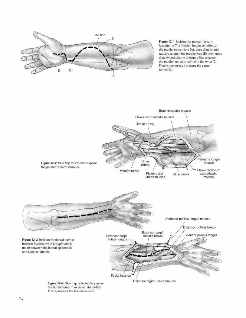
7 6
C
Incision
Radial artery
Flexor carpi radialis muscle
Brachioradialis muscle
Median nerveFlexor carpi
ulnaris muscle
Ulnar artery
Ulnar nerveFlexor digitorum
superficialis muscle
Palmaris longus muscle
Extensor carpi radialis longus
Extensor carpi radialis brevis
Abductor pollicis longus muscle
Extensor pollicis brevis
Extensor pollicis longus
Facial incision
Extensor digitorum communis
D
A
BFigure 12–1 Incision for palmar forearmfasciotomy. The incision begins anterior to the medial epicondyle (A), goes distally andradially to open the mobile wad (B), then goesdistally and ulnarly to form a flap to cover the median nerve proximal to the wrist (C).Finally, the incision crosses the carpal tunnel (D).
Figure 12–2 Skin flap reflected to exposethe palmar forearm muscles.
Figure 12–3 Incision for dorsal palmarforearm fasciotomy. A straight line ismade between the lateral epicondyleand Lister’s tubercle.
Figure 12–4 Skin flap reflected to exposethe dorsal forearm muscles. The dottedline represents the fascial incision.
rechecked in 48 h before it is debrided. However, inthe case of infection, debride all necrotic muscle atthe original operation.
13. Do not close the fascia. Close the skin over thecarpal tunnel primarily. Partially close the otherwounds by using sterile vessel loops and staples. Tiethe vessel loop in a knot and staple the knot to theproximal corner of the wound. Staple the vesselloop to the radial and ulnar wound borders approx-imately 2 cm distal to the corner. Crisscross the ves-sel loop over the wound and repeat the process.
14. Directly cover the wound with a nondesiccatingdressing. Apply a bulky dressing followed with asugartong plaster splint.
15. Transfer the patient to the recovery room with thearm elevated above the level of the heart.
Suggested ReadingsGelberman RH, Garfin SR, Hergenroeder PT, MubarakSJ, Menon J. Compartment syndromes of the forearm:diagnosis and treatment. Clin Orthop 1981;161:252–261.
Rowland SA. Fasciotomy: the treatment of compartmentsyndrome. In: Green DP, Hotchkiss RN, Pederson WC,eds. Green’s Operative Hand Surgery. 4th ed. New York,NY: Churchill Livingstone, 1999, pp. 689–710.
1 2 F O R E A R M FA S C I OTO M Y 7 7

This page intentionally left blank
Key Techniques inOrthopaedic Surgery
Section Three
Wrist and Hand

This page intentionally left blank
Key Techniques inOrthopaedic Surgery
Indications1. Persistent pain, numbness, or weakness in the
median nerve distribution that is not due to cervi-cal radiculitis, brachial plexopathy, pronator syn-drome, or nerve laceration and
2. Positive findings on physical examination (Tinel,Phalen, carpal compression) and
3. Failure of nonoperative management (splinting,steroid injections)
Contraindications1. Inconsistent clinical history and/or equivocal phys-
ical examination2. Negative electrodiagnostic study (relative)3. Psychological and socioeconomic issues that may
preclude a good surgical outcome
Preoperative Preparation1. Appropriate history and physical examination2. AP and lateral wrist X-rays3. Consider electrodiagnostic testing.
Special Instruments, Position,and Anesthesia1. Position patient supine with the hand on a table
extension.2. Upper extremity padded tourniquet(s) set to
250-mm Hg3. Hand instruments and low-power loupe magni-
fication4. Microscope if neurolysis is anticipated5. Local or regional block with intravenous sedation
Tips and Pearls1. Obtain hemostasis during exposure.2. Identify the superficial palmar arch, Guyon’s canal,
and carpal tunnel before releasing the transversecarpal ligament.
3. Dissect beneath the transverse carpal ligament witha smooth curved clamp and divide the tissuesharply. Use curved blunt-tipped scissors to releaseproximal ligament/forearm fascia.
4. Dissect ulnar to the median nerve to minimize therisk of injury to the motor branch. The motorbranch may vary in position beneath the ligament.
8 1
C H A P T E R 1 3
Open Carpal Tunnel Release
Charles Carroll IV and David M. Kalainov
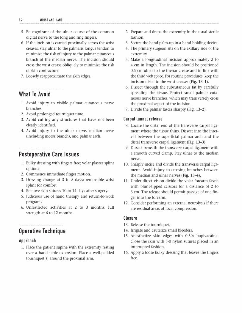
5. Be cognizant of the ulnar course of the commondigital nerve to the long and ring fingers.
6. If the incision is carried proximally across the wristcreases, stay ulnar to the palmaris longus tendon tominimize the risk of injury to the palmar cutaneousbranch of the median nerve. The incision shouldcross the wrist crease obliquely to minimize the riskof skin contracture.
7. Loosely reapproximate the skin edges.
What To Avoid1. Avoid injury to visible palmar cutaneous nerve
branches.2. Avoid prolonged tourniquet time.3. Avoid cutting any structures that have not been
clearly identified.4. Avoid injury to the ulnar nerve, median nerve
(including motor branch), and palmar arch.
Postoperative Care Issues1. Bulky dressing with fingers free; volar plaster splint
optional2. Commence immediate finger motion.3. Dressing change at 3 to 5 days; removable wrist
splint for comfort4. Remove skin sutures 10 to 14 days after surgery.5. Judicious use of hand therapy and return-to-work
programs6. Unrestricted activities at 2 to 3 months; full
strength at 6 to 12 months
Operative TechniqueApproach1. Place the patient supine with the extremity resting
over a hand table extension. Place a well-paddedtourniquet(s) around the proximal arm.
2. Prepare and drape the extremity in the usual sterilefashion.
3. Secure the hand palm-up in a hand holding device.4. The primary surgeon sits on the axillary side of the
extremity.5. Make a longitudinal incision approximately 3 to
4 cm in length. The incision should be positioned0.5 cm ulnar to the thenar crease and in line withthe third web space. For routine procedures, keep theincision distal to the wrist creases (Fig. 13–1).
6. Dissect through the subcutaneous fat by carefullyspreading the tissue. Protect small palmar cuta-neous nerve branches, which may transversely crossthe proximal aspect of the incision.
7. Divide the palmar fascia sharply (Fig. 13–2).
Carpal tunnel release8. Locate the distal end of the transverse carpal liga-
ment where the tissue thins. Dissect into the inter-val between the superficial palmar arch and thedistal transverse carpal ligament (Fig. 13–3).
9. Dissect beneath the transverse carpal ligament witha smooth curved clamp. Stay ulnar to the mediannerve.
10. Sharply incise and divide the transverse carpal liga-ment. Avoid injury to crossing branches betweenthe median and ulnar nerves (Fig. 13–4).
11. Under direct vision divide the volar forearm fasciawith blunt-tipped scissors for a distance of 2 to 3 cm. The release should permit passage of one fin-ger into the forearm.
12. Consider performing an external neurolysis if thereare residual areas of focal compression.
Closure13. Release the tourniquet.14. Irrigate and cauterize small bleeders.15. Anesthetize skin edges with 0.5% bupivacaine.
Close the skin with 5-0 nylon sutures placed in aninterrupted fashion.
16. Apply a loose bulky dressing that leaves the fingersfree.
8 2 W R I S T A N D H A N D
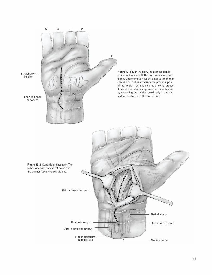
8 3
Straight skin incision
For additional exposure
Palmar fascia incised
Palmaris longus
Ulnar nerve and artery
Flexor digitorum �superficialis
Radial artery
Flexor carpi radialis
Median nerve
1
2345
Figure 13–1 Skin incision. The skin incision ispositioned in line with the third web space andplaced approximately 0.5 cm ulnar to the thenarcrease. For routine exposure the proximal pole of the incision remains distal to the wrist crease.If needed, additional exposure can be obtainedby extending the incision proximally in a zigzagfashion as shown by the dotted line.
Figure 13–2 Superficial dissection. Thesubcutaneous tissue is retracted and the palmar fascia sharply divided.
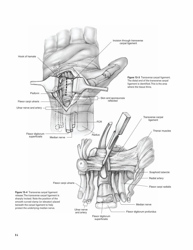
8 4
Hook of hamate
Pisiform
Flexor carpi ulnaris
Ulnar nerve and artery
Flexor digitorum �superficialis Median nerve
Radius
FCR
Skin and aponeurosis reflected
Incision through transverse carpal ligament
Transverse carpal ligament
Thenar muscles
Scaphoid tubercle
Radial artery
Flexor carpi radialis
Median nerve
Flexor digitorum profundus
Flexor digitorum superficialis
Ulnar nerve and artery
Flexor carpi ulnaris
P.
Figure 13–3 Transverse carpal ligament.The distal end of the transverse carpalligament is identified. This is the areawhere the tissue thins.
Figure 13–4 Transverse carpal ligamentrelease. The transverse carpal ligament issharply incised. Note the position of thesmooth curved clamp (or elevator) placedbeneath the carpal ligament to helpprotect the underlying median nerve.
Suggested ReadingsBrown RA, Gelberman RH, Seiler JG III, et al. Carpaltunnel release. A prospective, randomized assessment of open and endoscopic methods. J Bone Joint Surg Am1993;75A(9):1265–1275.
Phalen GS. The carpal-tunnel syndrome. Seventeenyears’ experience in diagnosis and treatment of sixhundred fifty-four hands. J Bone Joint Surg Am1966;48A(2):211–228.
Tomaino MM, Plakseychuk A. Identification andpreservation of Palmar cutaneous nerves during opencarpal tunnel release. J Hand Surg [Br] 1998;23(5):607–608.
1 3 O P E N C A R PA L T U N N E L R E L E A S E 8 5
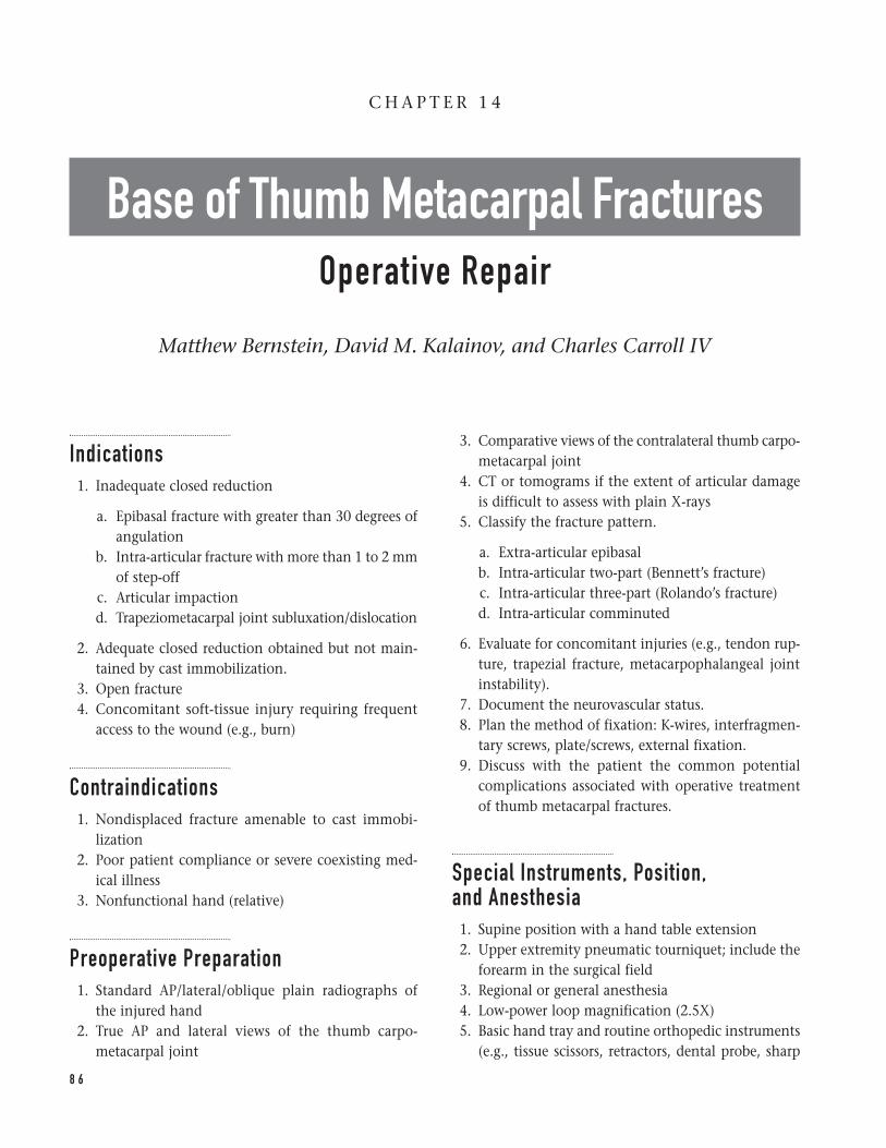
Indications1. Inadequate closed reduction
a. Epibasal fracture with greater than 30 degrees ofangulation
b. Intra-articular fracture with more than 1 to 2 mmof step-off
c. Articular impactiond. Trapeziometacarpal joint subluxation/dislocation
2. Adequate closed reduction obtained but not main-tained by cast immobilization.
3. Open fracture4. Concomitant soft-tissue injury requiring frequent
access to the wound (e.g., burn)
Contraindications1. Nondisplaced fracture amenable to cast immobi-
lization2. Poor patient compliance or severe coexisting med-
ical illness3. Nonfunctional hand (relative)
Preoperative Preparation1. Standard AP/lateral/oblique plain radiographs of
the injured hand2. True AP and lateral views of the thumb carpo-
metacarpal joint
3. Comparative views of the contralateral thumb carpo-metacarpal joint
4. CT or tomograms if the extent of articular damageis difficult to assess with plain X-rays
5. Classify the fracture pattern.
a. Extra-articular epibasalb. Intra-articular two-part (Bennett’s fracture)c. Intra-articular three-part (Rolando’s fracture)d. Intra-articular comminuted
6. Evaluate for concomitant injuries (e.g., tendon rup-ture, trapezial fracture, metacarpophalangeal jointinstability).
7. Document the neurovascular status.8. Plan the method of fixation: K-wires, interfragmen-
tary screws, plate/screws, external fixation.9. Discuss with the patient the common potential
complications associated with operative treatmentof thumb metacarpal fractures.
Special Instruments, Position, and Anesthesia1. Supine position with a hand table extension2. Upper extremity pneumatic tourniquet; include the
forearm in the surgical field3. Regional or general anesthesia4. Low-power loop magnification (2.5X)5. Basic hand tray and routine orthopedic instruments
(e.g., tissue scissors, retractors, dental probe, sharp
8 6
C H A P T E R 1 4
Base of Thumb Metacarpal FracturesOperative Repair
Matthew Bernstein, David M. Kalainov, and Charles Carroll IV
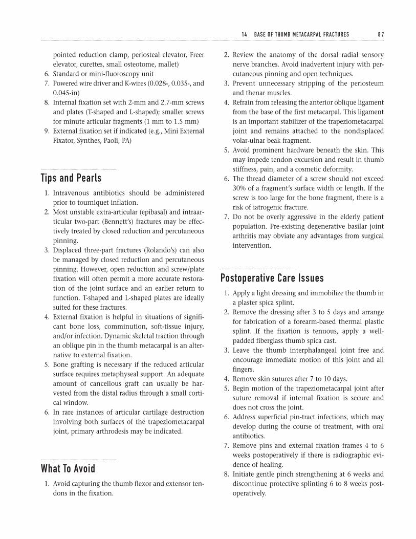
pointed reduction clamp, periosteal elevator, Freerelevator, curettes, small osteotome, mallet)
6. Standard or mini-fluoroscopy unit7. Powered wire driver and K-wires (0.028-, 0.035-, and
0.045-in)8. Internal fixation set with 2-mm and 2.7-mm screws
and plates (T-shaped and L-shaped); smaller screwsfor minute articular fragments (1 mm to 1.5 mm)
9. External fixation set if indicated (e.g., Mini ExternalFixator, Synthes, Paoli, PA)
Tips and Pearls1. Intravenous antibiotics should be administered
prior to tourniquet inflation.2. Most unstable extra-articular (epibasal) and intraar-
ticular two-part (Bennett’s) fractures may be effec-tively treated by closed reduction and percutaneouspinning.
3. Displaced three-part fractures (Rolando’s) can alsobe managed by closed reduction and percutaneouspinning. However, open reduction and screw/platefixation will often permit a more accurate restora-tion of the joint surface and an earlier return tofunction. T-shaped and L-shaped plates are ideallysuited for these fractures.
4. External fixation is helpful in situations of signifi-cant bone loss, comminution, soft-tissue injury,and/or infection. Dynamic skeletal traction throughan oblique pin in the thumb metacarpal is an alter-native to external fixation.
5. Bone grafting is necessary if the reduced articularsurface requires metaphyseal support. An adequateamount of cancellous graft can usually be har-vested from the distal radius through a small corti-cal window.
6. In rare instances of articular cartilage destructioninvolving both surfaces of the trapeziometacarpaljoint, primary arthrodesis may be indicated.
What To Avoid1. Avoid capturing the thumb flexor and extensor ten-
dons in the fixation.
2. Review the anatomy of the dorsal radial sensorynerve branches. Avoid inadvertent injury with per-cutaneous pinning and open techniques.
3. Prevent unnecessary stripping of the periosteumand thenar muscles.
4. Refrain from releasing the anterior oblique ligamentfrom the base of the first metacarpal. This ligamentis an important stabilizer of the trapeziometacarpaljoint and remains attached to the nondisplacedvolar-ulnar beak fragment.
5. Avoid prominent hardware beneath the skin. Thismay impede tendon excursion and result in thumbstiffness, pain, and a cosmetic deformity.
6. The thread diameter of a screw should not exceed30% of a fragment’s surface width or length. If thescrew is too large for the bone fragment, there is arisk of iatrogenic fracture.
7. Do not be overly aggressive in the elderly patientpopulation. Pre-existing degenerative basilar jointarthritis may obviate any advantages from surgicalintervention.
Postoperative Care Issues1. Apply a light dressing and immobilize the thumb in
a plaster spica splint.2. Remove the dressing after 3 to 5 days and arrange
for fabrication of a forearm-based thermal plasticsplint. If the fixation is tenuous, apply a well-padded fiberglass thumb spica cast.
3. Leave the thumb interphalangeal joint free andencourage immediate motion of this joint and allfingers.
4. Remove skin sutures after 7 to 10 days.5. Begin motion of the trapeziometacarpal joint after
suture removal if internal fixation is secure anddoes not cross the joint.
6. Address superficial pin-tract infections, which maydevelop during the course of treatment, with oralantibiotics.
7. Remove pins and external fixation frames 4 to 6weeks postoperatively if there is radiographic evi-dence of healing.
8. Initiate gentle pinch strengthening at 6 weeks anddiscontinue protective splinting 6 to 8 weeks post-operatively.
1 4 BA S E O F T H U M B M E TA C A R PA L F R A C T U R E S 8 7
9. Consider removing buried implants after fractureunion if the hardware is irritating and/or prominent.
Operative TechniqueClosed reduction and percutaneous pinning1. Epibasal fracture
a. Apply longitudinal distraction and gentle prona-tion and extension forces to the thumb meta-carpal with digital pressure across the fractureapex.
b. Stabilize with two 0.045-in K-wires (Fig. 14–1A).
2. Bennett’s fracture
a. Apply longitudinal distraction and gentle prona-tion and extension forces to the thumb meta-carpal with digital pressure against the dorsoradialmargin of the trapeziometacarpal joint.
b. Stabilize with two 0.045-in K-wires. Spearingthe volar-ulnar fragment is not necessary(Fig. 14–1B).
3. Rolando’s and comminuted fractures
a. Apply longitudinal distraction to the thumbmetacarpal.
b. Manipulate the fracture fragments with a pointedreduction clamp and stabilize with two or moreK-wires.
c. Consider concomitant external fixation or dyna-mic pin traction for added stability.
Open reduction and internal fixation—radiovolarapproach (Epibasal, Bennett’s, Rolando’s,comminuted)1. Make a longitudinal incision over the subcutaneous
border of the thumb metacarpal along the demarca-tion of the glabrous and nonglabrous skin. At thedistal wrist crease, curve the incision ulnarly towardthe radial edge of the flexor carpi radialis tendon(Fig. 14–2A).
2. Bluntly dissect through the subcutaneous tissues toexpose the base of the first metacarpal, thenar mus-cles, and carpometacarpal joint capsule. Protectbranches of the radial sensory nerve that course par-allel to and/or cross the incision. Branches of the
lateral antebrachial cutaneous nerve, palmar cuta-neous branch of the median nerve, and the superfi-cial palmar branch of the radial artery may beencountered proximally.
3. Elevate the thenar muscles (abductor pollicis brevisand opponens pollicis) subperiosteally from thevolar base of the first metacarpal and dissect the fibers off the carpometacarpal joint capsule.Avoid releasing the bony insertion of the abductorpollicis longus tendon from the base of the meta-carpal (Fig. 14–2B).
4. Open the carpometacarpal joint capsule trans-versely for a limited distance, preserving capsularattachments between the trapezium and nondis-placed metacarpal fracture fragment(s). Pay particu-lar attention to the capsular thickening mediallywhich represents the anterior oblique ligament.Clean and irrigate the fracture site (Fig. 14–2C).
5. Develop the interval between the abductor pollicislongus and extensor pollicis brevis tendons to serveas a portal for hardware placement.
6. Apply appropriate reduction forces to the thumbmetacarpal and manipulate the fragments intoposition with a dental pick, Freer elevator, K-wire,and/or pointed reduction clamp.
7. Elevate areas of articular cartilage impaction andbone graft subchondral defects.
8. Obtain provisional fixation with K-wires.9. Confirm the reduction under direct visualization
and with the image intensifier.10. Achieve final stabilization with K-wires, interfrag-
mentary screws, and/or a plate (Figs. 14–3A and 3B).
External fixation1. Place one or two pins across the intact diaphysis of
the first metacarpal through a small incision. Thepins should be positioned in the mid-lateral planeto avoid tethering the thenar muscles and thumbextensor tendons.
2. Place one or two additional pins into the trapezium,distal radius, or second metacarpal.
3. Assemble clamps and connecting bars onto thepins, reduce the fracture, and tighten the construct.
4. If significant articular displacement remains, con-sider open reduction and supplemental K-wire fixa-tion. Subchondral defects should be bone grafted(Fig. 14–4).
8 8 W R I S T A N D H A N D
8 9
A B
A
B
C
Epibasal fracture
Superficial palmar branch of radial artery
Palmar cutaneous branch of median nerve
Palmaris longus
Median nerve
Flexor carpi radialis Radial artery
Radial sensory nerve
Skin incision
M1
Abductor pollicis longus tendon
Extensor pollicis brevis tendon
Trapezium and origin of thenar muscle
Limited transverse capsular incision
Figure 14–1 Techniques of percutaneous pinning.(A) Epibasal fracture. (B) Bennett’s fracture.
Figure 14–2 Radiovolar approach. (A) Alongitudinal incision is made along thesubcutaneous border of the thumb metacarpal at the demarcation of the glabrous andnonglabrous skin. The incision is curved ulnarlyat the distal wrist crease, extending to the radial edge of the flexor carpi radialis tendon. (B)The carpometacarpal joint is exposed byelevating the thenar muscles subperiosteally,preserving the bony insertion of the abductorpollicis longus tendon. (C) A limited transverseincision is made in the joint capsule, taking carenot to disrupt the anterior oblique ligament.
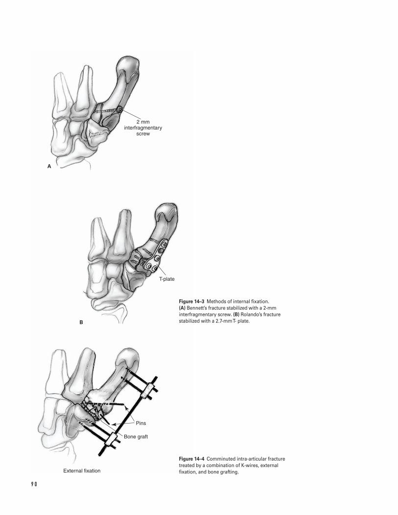
9 0
A
B
2 mm interfragmentary
screw
T-plate
Pins
Bone graft
External fixation
Figure 14–3 Methods of internal fixation. (A) Bennett’s fracture stabilized with a 2-mminterfragmentary screw. (B) Rolando’s fracturestabilized with a 2.7-mm T- plate.
Figure 14–4 Comminuted intra-articular fracturetreated by a combination of K-wires, externalfixation, and bone grafting.
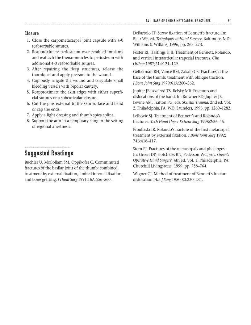
Closure1. Close the carpometacarpal joint capsule with 4-0
reabsorbable sutures.2. Reapproximate periosteum over retained implants
and reattach the thenar muscles to periosteum withadditional 4-0 reabsorbable sutures.
3. After repairing the deep structures, release thetourniquet and apply pressure to the wound.
4. Copiously irrigate the wound and coagulate smallbleeding vessels with bipolar cautery.
5. Reapproximate the skin edges with either superfi-cial sutures or a subcuticular closure.
6. Cut the pins external to the skin surface and bendor cap the ends.
7. Apply a light dressing and thumb spica splint.8. Support the arm in a temporary sling in the setting
of regional anesthesia.
Suggested ReadingsBuchler U, McCollam SM, Oppikofer C. Comminutedfractures of the basilar joint of the thumb; combinedtreatment by external fixation, limited internal fixation,and bone grafting. J Hand Surg 1991;16A:556–560.
DeBartolo TF. Screw fixation of Bennett’s fracture. In:Blair WF, ed. Techniques in Hand Surgery. Baltimore, MD:Williams & Wilkins, 1996, pp. 265–273.
Foster RJ, Hastings H II. Treatment of Bennett, Rolando,and vertical intraarticular trapezial fractures. ClinOrthop 1987;214:121–129.
Gelberman RH, Vance RM, Zakaib GS. Fractures at thebase of the thumb: treatment with oblique traction. J Bone Joint Surg 1979;61A:260–262.
Jupiter JB, Axelrod TS, Belsky MR. Fractures anddislocations of the hand. In: Browner BD, Jupiter JB,Levine AM, Trafton PG, eds. Skeletal Trauma. 2nd ed. Vol.2. Philadelphia, PA: W.B. Saunders, 1998, pp. 1269–1282.
Leibovic SJ. Treatment of Bennett’s and Rolando’sfractures. Tech Hand Upper Extrem Surg 1998;2:36–46.
Proubasta IR. Rolando’s fracture of the first metacarpal;treatment by external fixation. J Bone Joint Surg 1992;74B:416–417.
Stern PJ. Fractures of the metacarpals and phalanges. In: Green DP, Hotchkiss RN, Pederson WC, eds. Green’sOperative Hand Surgery. 4th ed. Vol. 1. Philadelphia, PA:Churchill Livingstone, 1999, pp. 758–764.
Wagner CJ. Method of treatment of Bennett’s fracturedislocation. Am J Surg 1950;80:230–231.
1 4 BA S E O F T H U M B M E TA C A R PA L F R A C T U R E S 9 1
Indications1. Fractures that cannot be adequately reduced by
closed means2. Displaced dorsal and volar shear fractures (i.e., dor-
sal Barton’s and volar Barton’s fractures)3. Fractures involving the lunate fossa with separation
of the dorsal and palmar components4. In combination with external fixation for radio-
carpal fracture-dislocations and complex, high-energy fractures with greater than 2 mm of articulardisplacement
Contraindications1. Stable nondisplaced fractures2. Fractures amenable to treatment by closed means3. Severe coexisting medical illness or patient non-
compliance4. Active local infection5. Significant soft-tissue or bone loss
Preoperative Preparation1. AP/lateral/oblique plain radiographs; comparative
views of the contralateral wrist may be helpful.2. Determine the fracture pattern: extra-articular,
intra-articular, articular gap/step-off, direction ofdisplacement, amount of displacement, comminu-tion, ulnar styloid involvement.
3. The classification scheme used to describe the frac-ture is less important than a general understandingof the fracture pattern.
4. Consider CT scanning if the complexity of thefracture is not clearly evident on plain radio-graphs. CT has been shown to be more reliable thanplain radiography in quantifying articular surfaceincongruencies.
5. Evaluate the entire extremity for associated injuries(e.g., scaphoid fracture, scapholunate dissociation,distal radioulnar joint instability, compartmentsyndrome).
6. Document the neurovascular status; median nervesymptoms are not uncommon. Worsening signsand symptoms of median nerve compressionshould be addressed by carpal tunnel release.
Special Instruments, Position, and Anesthesia1. Supine position with a hand table extension2. Upper extremity pneumatic tourniquet3. Basic hand tray and routine orthopedic instruments4. Standard or mini-fluoroscopy unit5. Familiarize yourself with the available plating sys-
tem. Plates and screws ranging in size from 2 to 3.5 mm are recommended.
6. Intra-operative traction is sometimes necessary andcan be achieved with temporary external fixation orfinger-trap traction.
9 2
C H A P T E R 1 5
Distal Radius FracturesOpen Reduction and Internal Fixation
Franklin Chen and David M. Kalainov
7. The procedure is performed under regional or gen-eral anesthesia.
Tips and Pearls1. A clear understanding of the fracture pattern is crit-
ical for planning the surgical approach and methodof fracture stabilization.
2. Autogenous bone grafting may be necessary in thesetting of significant comminution and/or bone loss.A trephine can be used to harvest cancellous graftfrom the anterior iliac crest through a small incision.
3. Complex fractures may require open reduction withboth internal and external fixation to adequatelystabilize the distal radius. The external fixatorshould be applied first to assist with intra-operativefragment reduction. In rare instances of extensivedorsal and volar comminution, both surfaces of thedistal radius may require plating in addition to tem-porary external fixation.
4. It is not necessary to place a screw through everyhole in a plate.
5. Provisional fixation with K-wires can be helpful(0.045 to 0.062 in).
6. For small, but critical bone fragments consider aug-menting the fixation with screws and washers.
7. When placing screws in the distal radius, rememberto accommodate for normal radial inclination andvolar angulation to avoid inadvertent penetrationinto the joint.
8. Opening the extensor retinaculum in a step-cutfashion will facilitate subsequent closure by allow-ing the retinaculum to be reapproximated in alengthened state.
9. Intravenous antibiotics should be given prior totourniquet inflation.
10. Discuss with the patient the common potentialcomplications associated with operative treatmentof distal radius fractures.
What To Avoid1. Avoid excessive retraction of the neurovascular
structures.2. Do not violate the volar capsule as injury to the volar
radio-carpal ligaments may lead to carpal instability.
3. Avoid leaving the tendons in direct contact withthe plate, which may cause tendon irritation andeventual rupture. In a volar approach, reattach theremaining pronator quadratus as a buffer over theplate. In a dorsal approach, elevate the fourthextensor compartment in a subperiosteal fashion,preserving both the periosteum and tendon sheath.A strip of the extensor retinaculum can be used asan interpositional material between the radial wristextensors and dorsal plate.
4. Do not be overly aggressive in the elderly patientpopulation. Internal fixation of osteoporotic bonecan be difficult and the fixation tenuous. Low-demand elderly individuals often tolerate deformitybetter than younger patients.
Postoperative Care Issues1. A well-padded gauze dressing is applied at the con-
clusion of the case. The wrist is supported in a volarplaster splint with the digits left free.
2. If fracture stability is a concern, a sugar tong splintcan be applied with the forearm in neutral position.
3. A temporary arm sling is useful especially in the set-ting of regional anesthesia.
4. The drain is usually removed prior to discharge onthe first postoperative day.
5. Digital motion should be encouraged immediatelyafter surgery. Some patients may benefit from theassistance of an occupational therapist.
6. Do not neglect elbow and shoulder mobilizationexercises.
7. If stable internal fixation is achieved, guarded wristmotion may begin within 2 weeks of surgery.
8. In the setting of concomitant external fixation, the fixator can often be removed 4 to 5 weekspostoperatively.
Operative TechniqueDorsal approach1. Position the patient supine with the involved
extremity resting over a hand table. Place a well-padded pneumatic tourniquet around the upper arm.
1 5 D I S TA L R A D I U S F R A C T U R E S ( O R I F ) 9 3
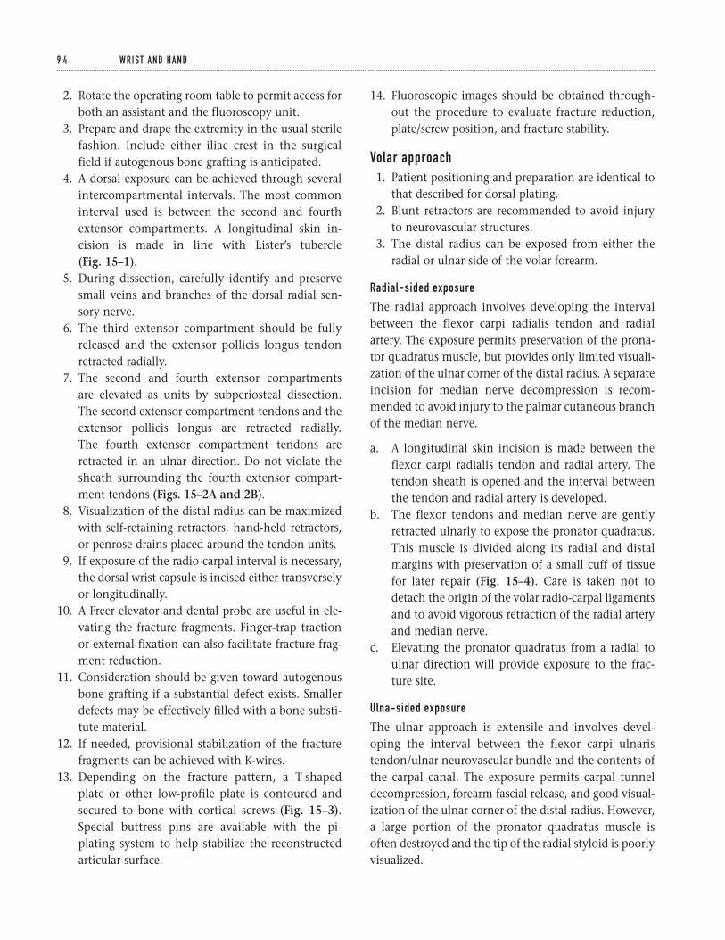
2. Rotate the operating room table to permit access forboth an assistant and the fluoroscopy unit.
3. Prepare and drape the extremity in the usual sterilefashion. Include either iliac crest in the surgicalfield if autogenous bone grafting is anticipated.
4. A dorsal exposure can be achieved through severalintercompartmental intervals. The most commoninterval used is between the second and fourthextensor compartments. A longitudinal skin in-cision is made in line with Lister’s tubercle (Fig. 15–1).
5. During dissection, carefully identify and preservesmall veins and branches of the dorsal radial sen-sory nerve.
6. The third extensor compartment should be fullyreleased and the extensor pollicis longus tendonretracted radially.
7. The second and fourth extensor compartments are elevated as units by subperiosteal dissection. The second extensor compartment tendons and theextensor pollicis longus are retracted radially.The fourth extensor compartment tendons areretracted in an ulnar direction. Do not violate thesheath surrounding the fourth extensor compart-ment tendons (Figs. 15–2A and 2B).
8. Visualization of the distal radius can be maximizedwith self-retaining retractors, hand-held retractors,or penrose drains placed around the tendon units.
9. If exposure of the radio-carpal interval is necessary,the dorsal wrist capsule is incised either transverselyor longitudinally.
10. A Freer elevator and dental probe are useful in ele-vating the fracture fragments. Finger-trap tractionor external fixation can also facilitate fracture frag-ment reduction.
11. Consideration should be given toward autogenousbone grafting if a substantial defect exists. Smallerdefects may be effectively filled with a bone substi-tute material.
12. If needed, provisional stabilization of the fracturefragments can be achieved with K-wires.
13. Depending on the fracture pattern, a T-shaped plate or other low-profile plate is contoured andsecured to bone with cortical screws (Fig. 15–3).Special buttress pins are available with the pi-plating system to help stabilize the reconstructedarticular surface.
14. Fluoroscopic images should be obtained through-out the procedure to evaluate fracture reduction,plate/screw position, and fracture stability.
Volar approach1. Patient positioning and preparation are identical to
that described for dorsal plating.2. Blunt retractors are recommended to avoid injury
to neurovascular structures.3. The distal radius can be exposed from either the
radial or ulnar side of the volar forearm.
Radial-sided exposure
The radial approach involves developing the intervalbetween the flexor carpi radialis tendon and radialartery. The exposure permits preservation of the prona-tor quadratus muscle, but provides only limited visuali-zation of the ulnar corner of the distal radius. A separateincision for median nerve decompression is recom-mended to avoid injury to the palmar cutaneous branchof the median nerve.
a. A longitudinal skin incision is made between theflexor carpi radialis tendon and radial artery. Thetendon sheath is opened and the interval betweenthe tendon and radial artery is developed.
b. The flexor tendons and median nerve are gentlyretracted ulnarly to expose the pronator quadratus.This muscle is divided along its radial and distalmargins with preservation of a small cuff of tissuefor later repair (Fig. 15–4). Care is taken not todetach the origin of the volar radio-carpal ligamentsand to avoid vigorous retraction of the radial arteryand median nerve.
c. Elevating the pronator quadratus from a radial toulnar direction will provide exposure to the frac-ture site.
Ulna-sided exposure
The ulnar approach is extensile and involves devel-oping the interval between the flexor carpi ulnaristendon/ulnar neurovascular bundle and the contents of the carpal canal. The exposure permits carpal tunneldecompression, forearm fascial release, and good visual-ization of the ulnar corner of the distal radius. However,a large portion of the pronator quadratus muscle isoften destroyed and the tip of the radial styloid is poorlyvisualized.
9 4 W R I S T A N D H A N D
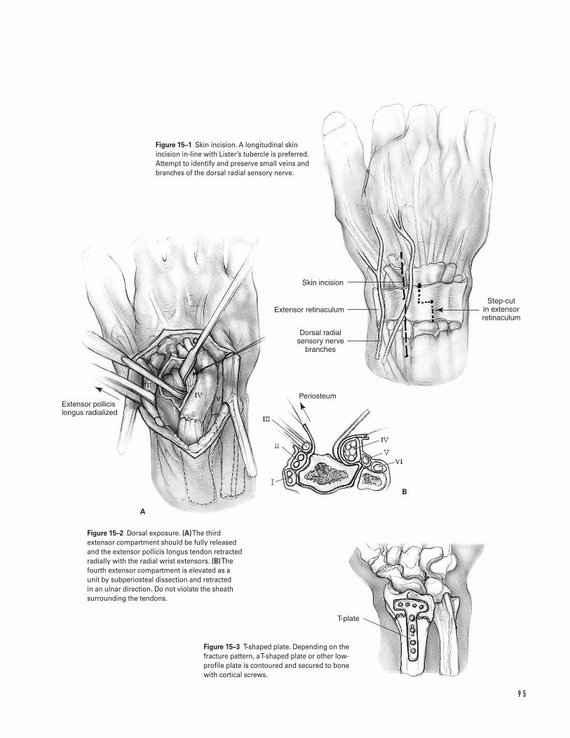
9 5
A
B
Skin incision
Extensor retinaculum
Dorsal radial sensory nerve
branches
Step-cut in extensor retinaculum
Extensor pollicis longus radialized
Periosteum
T-plate
Figure 15–1 Skin incision. A longitudinal skinincision in-line with Lister’s tubercle is preferred.Attempt to identify and preserve small veins andbranches of the dorsal radial sensory nerve.
Figure 15–2 Dorsal exposure. (A)The thirdextensor compartment should be fully releasedand the extensor pollicis longus tendon retractedradially with the radial wrist extensors. (B)Thefourth extensor compartment is elevated as aunit by subperiosteal dissection and retracted in an ulnar direction. Do not violate the sheathsurrounding the tendons.
Figure 15–3 T-shaped plate. Depending on thefracture pattern, a T-shaped plate or other low-profile plate is contoured and secured to bonewith cortical screws.
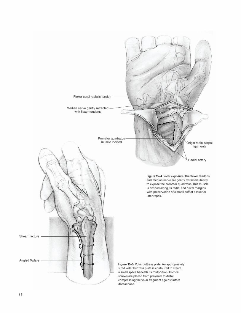
9 6
Flexor carpi radialis tendon
Median nerve gently retracted with flexor tendons
Pronator quadratus muscle incised Origin radio-carpal
ligaments
Radial artery
Angled T-plate
Shear fracture
Figure 15–4 Volar exposure. The flexor tendonsand median nerve are gently retracted ulnarly to expose the pronator quadratus. This muscle is divided along its radial and distal margins with preservation of a small cuff of tissue forlater repair.
Figure 15–5 Volar buttress plate. An appropriatelysized volar buttress plate is contoured to create a small space beneath its midportion. Corticalscrews are placed from proximal to distal,compressing the volar fragment against intactdorsal bone.
a. A longitudinal incision is made through palmar skinoverlying the carpal canal. The incision is extendedproximally across the wrist in an ulnar direction.When the radial border of the flexor carpi ulnaristendon is reached, the incision is angled obliquelytoward the mid-line of the volar forearm.
b. The palmar fascia and transverse carpal ligament areopened in-line with the skin incision, exposing thecarpal canal. The forearm fascia is released proxi-mally along the radial border of the flexor carpiulnaris tendon.
c. The interval between the flexor carpi ulnaristendon/ulnar neurovascular bundle and the carpaltunnel tendons is developed and the structureswithin the carpal canal are gently retracted radially.
d. The pronator quadratus muscle is incised longitudi-nally and a segment is removed for exposure of thedistal radius.
4. An appropriately sized volar buttress plate is con-toured to create a small space beneath its midpor-tion. Cortical screws are placed from proximal todistal, compressing the volar fragment againstintact dorsal bone (Fig. 15–5). If there is dorsalcomminution, the volar plate acts only as a passiverestraint and should be contoured to the presumedshape of the pre-injured radius.
5. In assessing intra-articular fracture reduction, avoidopening the volar wrist capsule. Evaluate the reduc-tion with fluoroscopy and plain radiographs. Asmall dorsal arthrotomy or diagnostic wrist arthro-scopy may be helpful in equivocal cases.
Closure1. Repair the deep soft tissues with 4-0 or 5-0 absorbable
suture (volar approach: pronator quadratus; dorsalapproach: extensor retinaculum). Ensure that thereis a soft-tissue barrier between the plate and overly-ing tendons.
2. Do not repair the extensor pollicis longus tendonsheath when closing the extensor retinaculum. Theextensor pollicis longus tendon should be positionedsuperficial to the repaired extensor retinaculum.
3. After closing the deep structures, release the tourni-quet and apply pressure.
4. The wound is copiously irrigated and small bleed-ing vessels are electrocoagulated.
5. A drain is frequently placed to minimize the risk ofhematoma formation.
6. The skin edges are reapproximated with eitherinterrupted sutures or a subcuticular closure.
7. A compressive dressing and splint should be applied.8. The patient is transferred to the recovery room,
once deemed stable by the anesthesiologist.9. In cases where excessive swelling precludes primary
closure, the wound can either be covered with asplit-thickness skin graft or the skin edges tem-porarily secured with sterile elastic bands. Whenthe swelling subsides, the patient is returned to theoperating room for delayed primary wound closure.
Suggested ReadingsCole RJ, Bindra RR, Evanoff BA, et al. Radiographicevaluation of osseous displacement following intra-articular fractures of the distal radius: reliability of plainradiography versus computed tomography. J Hand Surg1997;22A:792–800.
Hanel DP. Volar plate fixation of distal radius fractures.Atlas Hand Clin 1997;2:1–24.
Ring D, Jupiter JB. Dorsal fixation of the distal radiususing the pi plate. Atlas Hand Clin 1997;2:25–44.
Ring D, Jupiter JB. Open reduction internal fixation of the distal radius. In: Gellman H, ed. Fractures of theDistal Radius. Chicago, IL: AAOS Monograph Series,1998, pp. 37–53.
1 5 D I S TA L R A D I U S F R A C T U R E S ( O R I F ) 9 7
Indications1. Unstable extra-articular fractures with metaphyseal
comminution2. Unstable intra-articular fractures3. Fractures requiring re-reduction after initial closed
treatment4. In conjunction with open reduction and internal
fixation for intra-operative distraction or as supple-mental fixation
5. Open fractures with extensive soft tissue injury
Contraindications1. Stable fractures amenable to cast immobilization2. Associated ipsilateral fractures prohibiting secure
placement of fixator pins3. Patient noncompliance or severe coexisting medical
illness
Preoperative Preparation1. Standard AP/lateral/oblique plain radiographs2. Identify fracture pattern and degree of comminution.3. Evaluate entire extremity for associated injuries
(e.g., scaphoid fracture, distal radioulnar joint insta-bility, median nerve contusion/compression).
4. When initially treating a fracture by closed reduc-tion and casting, obtain frequent radiographicfollow-up to assess for fracture displacement.
Special Instruments, Position, and Anesthesia1. Supine position2. Hand table3. Upper extremity pneumatic tourniquet4. Standard or mini-fluoroscopy unit5. Routine orthopedic instruments6. External fixation systems are abundant. Familiarize
yourself with one system and understand its capa-bilities and limitations.
7. Ensure availability of internal fixation plates, K-wires (0.045- and 0.062-in), and a powered wiredriver if supplemental fixation is anticipated.
8. Small Bennett and Hohman retractors are helpful forsoft-tissue retraction. A Freer elevator is useful notonly for retraction but also for periosteal elevation.
9. The procedure can be performed under regional orgeneral anesthesia.
10. Prepare the iliac crest if autogenous bone grafting isanticipated.
Tips and Pearls1. K-wires can provide additional stability to the frac-
ture. Recent studies have suggested that K-wiresupplementation may allow for earlier fixatorremoval and wrist motion.
2. In the situation of a depressed intra-articular frac-ture, external fixation for ligamentotaxis combined
9 8
C H A P T E R 1 6
Distal Radius FracturesExternal Fixation
Franklin Chen and David M. Kalainov
with local bone grafting is useful. The impactedgraft will provide structural support and may permitearlier fixator removal.
3. Preoperative antibiotics should be administeredprior to tourniquet inflation.
4. The fixator should be positioned to minimize inter-ference with thumb motion. In addition, AP andlateral radiographic views of the distal radius shouldbe unobstructed by the pins, connecting bars, andclamps.
5. Although no universal criteria have been estab-lished, in general, loss of reduction with radialshortening greater than 5 mm, radial inclinationless than 15 degrees, sagittal angulation more than15 degrees dorsal or more than 20 degrees volar, orarticular incongruity greater than 2 mm shouldprompt one to consider abandoning cast treatment.Some authors have suggested 10 degrees as theacceptable upper limit for dorsal angulation.
6. Remember that the frame is only as strong as itsweakest link; there is no need to use larger diameterpins in the radius if smaller ones are used in themetacarpal.
7. Inform the patient of the common potential compli-cations associated with distal radius fractures and theuse of external fixation.
8. If signs of worsening median nerve compressionare present, perform a concurrent carpal tunnelrelease. Carpal tunnel pressures have been shown toincrease with progressive wrist flexion in the treat-ment of Colles’ fractures.
9. Have available an appropriate wrench or similarinstrument for postoperative adjustment and tight-ening of the frame in the follow-up period.
What To Avoid1. Do not place the pins percutaneously. This may
increase the risk of cutaneous sensory nerve injury.2. Do not leave the wrist in over-distraction as this will
greatly increase the potential for finger stiffness anddelayed union.
3. Avoid excessive ulnar deviation and/or flexion. Ifsuch positioning is necessary to maintain align-ment, supplemental fixation should be considered.
4. Avoid tight closure of the skin around the pins asthis will lead to skin irritation.
5. Avoid tethering tendons and muscles with the pins.
Postoperative Care Issues1. A light compressive dressing is applied around the
pin sites and is changed at the first follow-up visit.2. Overnight hospitalization for observation may be
indicated.3. Immediate finger motion is emphasized and assis-
tance from an occupational therapist may be help-ful in the early postoperative period.
4. Do not neglect range of motion activities for theforearm, elbow, and shoulder.
5. Remove stitches after 10 days.6. Obtain follow-up radiographs at 1, 3, and 6 weeks.7. The timing of fixator removal is controversial.
Generally, the fixator is kept in place for approxi-mately 6 weeks. Earlier removal can occur in the set-ting of bone grafting and/or supplemental fixation.
Operative Technique1. With the patient supine, ensure good access to the
dorsal-radial aspect of the wrist.2. The extremity is prepared and draped free in the
usual sterile fashion. The planned incision sites areshaved.
3. The primary surgeon is seated at the patient’s axilla.The fluoroscopy unit is positioned for easy access tothe surgical field, either at the end of the hand tableextension or opposite the primary surgeon.
4. First perform a closed reduction maneuver, thenproceed with frame application; 10 to 12 pounds offinger-trap traction can be helpful.
5. The tourniquet should be inflated prior to pinplacement.
6. Pins should be oriented 35 to 45 degrees from thefrontal plane to avoid interference with thumbmotion. Constructing the frame at this angle willalso permit unobstructed lateral radiographs of thedistal radius.
7. Distal pin placement is performed through eithertwo stab incisions or a single longitudinal incision(Figs. 16–1A and 1B).
1 6 D I S TA L R A D I U S F R A C T U R E S ( E X T E R N A L F I X AT I O N ) 9 9
a. When dissecting down to the bone, care shouldbe taken to avoid damage to dorsal veins andbranches of the radial sensory nerve.
b. Visualize the central portion of the indexmetacarpal to facilitate sound bicortical pur-chase during pin placement.
c. Pin guides included with the external fixator sys-tem are generally used to assist in pre-drillingand pin placement.
d. The AO/ASIF system allows for metacarpal pinsto be placed at a converging angle to maximizebone purchase (a converging angle of 40 to 60 degrees is recommended). Many newer fixa-tor systems necessitate pin placement perpendi-cular to the metacarpal shaft.
e. The more proximal of the 2 pins can also beengaged into the radial cortex of the thirdmetacarpal for additional purchase strength.This will often require placement of all fixatorpins in line with the frontal plane.
f. Avoid tethering the first dorsal interosseousmuscle when placing pins.
8. Proximal pin placement is generally in the middleto distal portion of the radius.
a. The proximal pins should be oriented in thesame plane as the distal pins (35 to 45 degreesfrom the frontal plane).
b. An open approach is recommended as blind pinplacement risks injury to the radial sensorynerve and branches of the lateral antebrachialcutaneous nerve. The incision is generally 4 to5 cm in length, centered at the junction of themiddle and distal one-thirds of the radius.
c. The interval between the extensor carpi radialislongus and extensor carpi radialis brevis tendonsis identified and developed. The abductor polli-cis longus and the extensor pollicis brevis ten-dons are frequently visualized at the distal endof the incision (Fig. 16–2).
d. The dorsal and volar margins of the radial shaftshould be exposed to ensure central placementof the pins.
e. Templates or guides can be used to facilitate pre-drilling and pin placement.
9. Verify bicortical fixation of all 4 fixator pins withfluoroscopy.
10. Irrigate the wounds and close the skin edges looselywith interrupted sutures.
11. Deflate the tourniquet.12. Assemble the fixator frame onto the pins, taking
into account radiographic accessibility to the frac-ture site.
13. Before tightening the fixator, make final adjust-ments to the fracture reduction.
a. At this stage, K-wires can be used as joysticks forfracture manipulation and also as supplementalfixation.
b. Fine tuning of fracture alignment is possiblewith most fixator systems.
c. The ideal position of the wrist is neutral flex-ion/extension and radial/ulnar deviation. Ifexcessive flexion or ulnar deviation is requiredto maintain fracture alignment, supplementalfixation is recommended (Fig. 16–3).
d. Check the carpus under fluoroscopy for over-dis-traction. The radiocarpal interval should be nomore than 1 to 2 mm wider than the midcarpalinterval on the AP projection. The carpal heightindex (CHI) can also be helpful in determiningover-distraction. Caution is advised in over-reliance upon radiographic parameters, how-ever, as recent investigators have questionedtheir reliability.
e. Make sure that the fingers can be easily flexed toa complete fist as an additional check againstover-distraction.
14. If K-wires have been placed, the exposed tips areeither bent or capped.
15. Check the skin around the pins for excessive ten-sion and make relaxing skin incisions as necessary.
16. A light compressive dressing is applied and thepatient is transferred to the recovery room oncestable.
17. A postoperative sling can be used for comfort.Instructions are given to begin early finger motionand to elevate and ice the wrist to reduce postoper-ative swelling.
1 0 0 W R I S T A N D H A N D
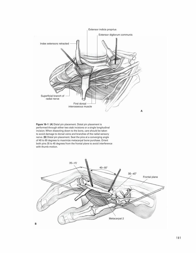
1 0 1
Extensor digitorum communis
Extensor indicis proprius
Index extensors retracted
First dorsal �interosseous muscle
Superficial branch of radial nerve
Frontal plane
Metacarpal 2
A
B
Figure 16–1 (A) Distal pin placement. Distal pin placement isperformed through either two stab incisions or a single longitudinalincision. When dissecting down to the bone, care should be taken to avoid damage to dorsal veins and branches of the radial sensorynerve. (B) Distal pin placement. Seat the pins at a converging angle of 40 to 60 degrees to maximize metacarpal bone purchase. Orientboth pins 35 to 45 degrees from the frontal plane to avoid interferencewith thumb motion.
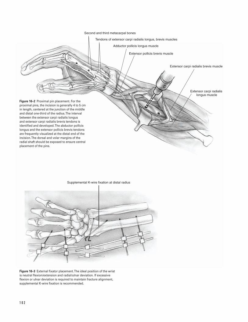
1 0 2
Second and third metacarpal bones
Tendons of extensor carpi radialis longus, brevis muscles
Adductor pollicis longus muscle
Extensor pollicis brevis muscle
Extensor carpi radialis brevis muscle
Extensor carpi radialis �longus muscle
Supplemental K-wire fixation at distal radius
Figure 16–2 Proximal pin placement. For theproximal pins, the incision is generally 4 to 5 cmin length, centered at the junction of the middleand distal one-third of the radius. The intervalbetween the extensor carpi radialis longus and extensor carpi radialis brevis tendons isidentified and developed. The abductor pollicislongus and the extensor pollicis brevis tendonsare frequently visualized at the distal end of theincision. The dorsal and volar margins of theradial shaft should be exposed to ensure centralplacement of the pins.
Figure 16–3 External fixator placement. The ideal position of the wristis neutral flexion/extension and radial/ulnar deviation. If excessiveflexion or ulnar deviation is required to maintain fracture alignment,supplemental K-wire fixation is recommended.
Suggested ReadingsGelberman RH, Szabo RM, Mortensen WW. Carpaltunnel pressures and wrist position in patients withColles’ fractures. J Trauma 1984;24:747–749.
Graham TJ. Surgical correction of malunited fractures ofthe distal radius. J Am Acad Orthop Surg 1997;5:270–281.
Gupta R, Bozentka DJ, Bora FW. The evaluation oftension in an experimental model of external fixationof distal radius fractures. J Hand Surg 1999;24A:108–112.
Kaempffe FA, Wheeler DJ, Peimer CA, et al. Severefractures of the distal radius: effect of amount andduration of external fixator distraction on outcome. J Hand Surg 1993;18A:33–41.
Leung KS, Shen WY, Tsang HK, et al. An effectivetreatment of comminuted fractures of the distal radius.J Hand Surg 1990;15A:11–17.
McQueen M, Caspers J. Colles fracture: does theanatomical result affect the final function? J Bone JointSurg 1988;70B:649–651.
Putnam MD, Fischer MD. Treatment of unstable distalradius fractures: methods and comparison of externaldistraction and ORIF versus external distraction-ORIFneutralization. J Hand Surg 1997;22A:238–251.
Seitz WH Jr. External fixation of distal radius fractures:indications and technical principles. Orthop Clin NorthAm 1993;24:255–264.
Wolfe SW, Lorenze MD, Austin G, et al. Load-displacement behavior in a distal radial fracture model:the effect of simulated healing on motion. J Bone JointSurg 1999;81A:53–59.
1 6 D I S TA L R A D I U S F R A C T U R E S ( E X T E R N A L F I X AT I O N ) 1 0 3
Indications1. Extensor tendon laceration in zones 1 through 8
(Figs. 17–1 and 17–2)2. Following incision of extensor tendon for exposure
of proximal phalanx (Chamay approach)
Contraindications1. Lacerations in zone 6 proximal to the raffe and
lacerations in zones 7 and 8 greater than 10 to 14days old (myostatic contracture of the muscle willkeep the tendon from being pulled out to its normallength; if a repair is attempted with excessive ten-sion, the repair will be too tight)
2. Closed rupture of extensor tendon in zone 1 (malletfinger) or zone 3 (acute boutonniere deformity)
3. Crush injury with loss of tendon (requires primaryor delayed grafting, depending on status of skin)
4. Infected wound (need to debride prior to placingsutures in tendon)
Preoperative Preparation1. Document status of preoperative neurovascular
examination.2. If a delayed primary repair is to be performed (within
10 to 14 days), the wound is initially irrigated andclosed. The extremity is splinted with the wrist in 20degrees of extension and the fingers fully extended.
Special Instruments, Position, and Anesthesia1. The patient is positioned supine on the operating
table. The arm is positioned on an arm board.2. An upper arm tourniquet is applied with cast
padding.3. The procedure may be done with general or regional
anesthesia (regional is preferred to help protect herepair while the patient awakens from anesthesia).
4. Routine small joint orthopaedic surgical instru-ments are required. A Bunnell tendon retriever or#8 pediatric feeding tube may be required if the ten-don has retracted proximally.
Tips and Pearls1. Extensor tendons are thin. The average thickness
is 0.5 to 0.8 mm over the phalanges and 1.5 to 1.8 mm over the metacarpals. Care must be taken inhandling the tissue to avoid shredding it.
2. Distal to the raffe, the extensor tendon will not gapmore than a few millimeters. Rather than pullingthe ends of the tendon toward each other, hyper-extend the joints slightly to create a tension-freerepair. Because the tendon ends are easily visualizedin zones 1 through 5, most of these repairs can bedone in the emergency room.
3. Proximal to the raffe (zones 6 through 8), the prox-imal tendon may retract. Because of this retractionand the requirement to make a proximal incision,
1 0 4
C H A P T E R 1 7
Extensor Tendon Repair
Michael S. Bednar
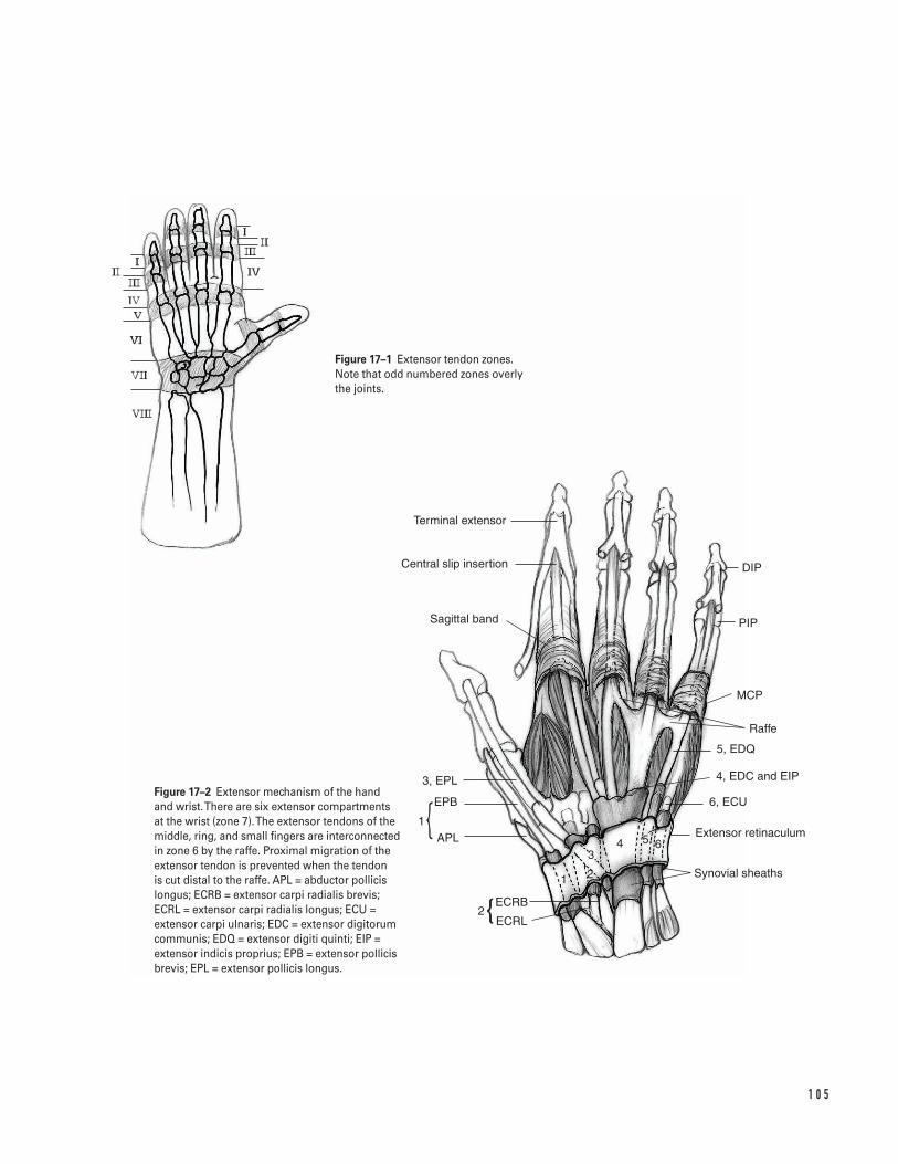
1 0 5
Terminal extensor
Central slip insertion
Sagittal band
3, EPL
EPB
APL1
ECRB
ECRL2
1 2
34 5 6
Synovial sheaths
Extensor retinaculum
6, ECU
5, EDQ
4, EDC and EIP
Raffe
MCP
PIP
DIP
Figure 17–1 Extensor tendon zones. Note that odd numbered zones overly the joints.
Figure 17–2 Extensor mechanism of the handand wrist. There are six extensor compartmentsat the wrist (zone 7). The extensor tendons of themiddle, ring, and small fingers are interconnectedin zone 6 by the raffe. Proximal migration of theextensor tendon is prevented when the tendon is cut distal to the raffe. APL = abductor pollicislongus; ECRB = extensor carpi radialis brevis;ECRL = extensor carpi radialis longus; ECU =extensor carpi ulnaris; EDC = extensor digitorumcommunis; EDQ = extensor digiti quinti; EIP =extensor indicis proprius; EPB = extensor pollicisbrevis; EPL = extensor pollicis longus.
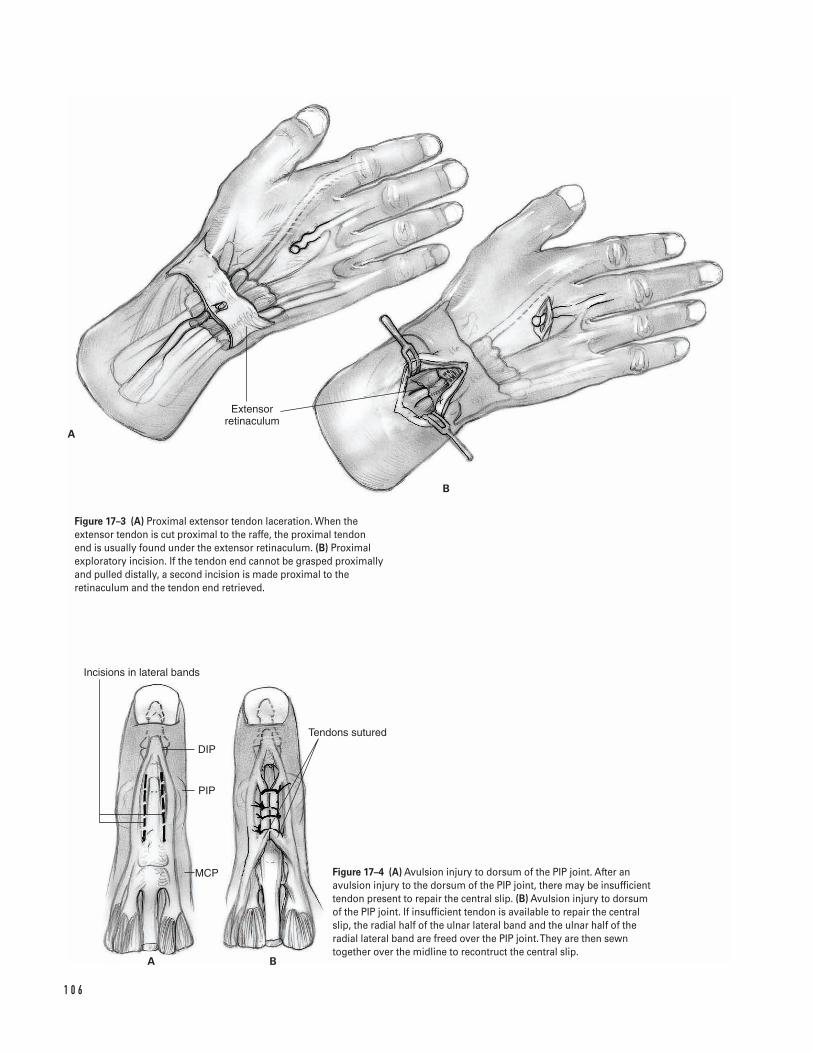
1 0 6
B
A
Extensor retinaculum
Incisions in lateral bands
DIP
PIP
MCP
Tendons sutured
A B
Figure 17–3 (A) Proximal extensor tendon laceration. When theextensor tendon is cut proximal to the raffe, the proximal tendon end is usually found under the extensor retinaculum. (B) Proximalexploratory incision. If the tendon end cannot be grasped proximallyand pulled distally, a second incision is made proximal to theretinaculum and the tendon end retrieved.
Figure 17–4 (A) Avulsion injury to dorsum of the PIP joint. After anavulsion injury to the dorsum of the PIP joint, there may be insufficienttendon present to repair the central slip. (B) Avulsion injury to dorsumof the PIP joint. If insufficient tendon is available to repair the centralslip, the radial half of the ulnar lateral band and the ulnar half of theradial lateral band are freed over the PIP joint. They are then sewntogether over the midline to recontruct the central slip.
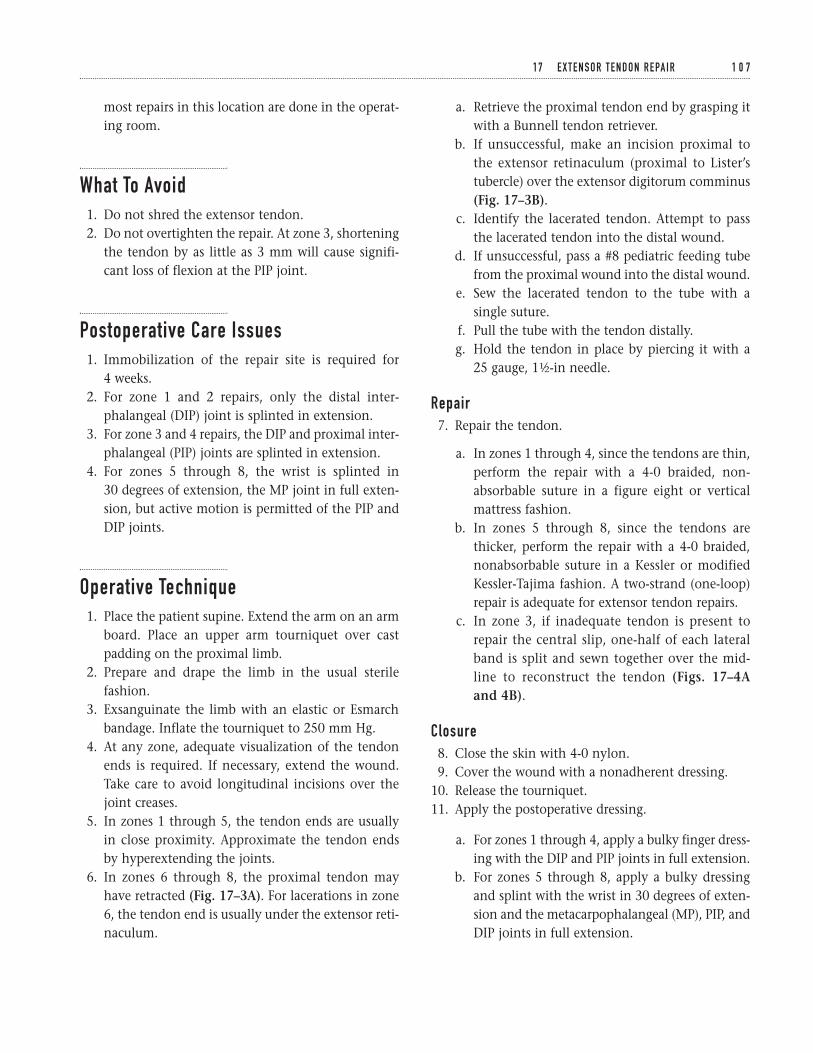
most repairs in this location are done in the operat-ing room.
What To Avoid1. Do not shred the extensor tendon.2. Do not overtighten the repair. At zone 3, shortening
the tendon by as little as 3 mm will cause signifi-cant loss of flexion at the PIP joint.
Postoperative Care Issues1. Immobilization of the repair site is required for
4 weeks.2. For zone 1 and 2 repairs, only the distal inter-
phalangeal (DIP) joint is splinted in extension.3. For zone 3 and 4 repairs, the DIP and proximal inter-
phalangeal (PIP) joints are splinted in extension.4. For zones 5 through 8, the wrist is splinted in
30 degrees of extension, the MP joint in full exten-sion, but active motion is permitted of the PIP andDIP joints.
Operative Technique1. Place the patient supine. Extend the arm on an arm
board. Place an upper arm tourniquet over castpadding on the proximal limb.
2. Prepare and drape the limb in the usual sterilefashion.
3. Exsanguinate the limb with an elastic or Esmarchbandage. Inflate the tourniquet to 250 mm Hg.
4. At any zone, adequate visualization of the tendonends is required. If necessary, extend the wound.Take care to avoid longitudinal incisions over thejoint creases.
5. In zones 1 through 5, the tendon ends are usuallyin close proximity. Approximate the tendon endsby hyperextending the joints.
6. In zones 6 through 8, the proximal tendon mayhave retracted (Fig. 17–3A). For lacerations in zone6, the tendon end is usually under the extensor reti-naculum.
a. Retrieve the proximal tendon end by grasping itwith a Bunnell tendon retriever.
b. If unsuccessful, make an incision proximal tothe extensor retinaculum (proximal to Lister’stubercle) over the extensor digitorum comminus(Fig. 17–3B).
c. Identify the lacerated tendon. Attempt to passthe lacerated tendon into the distal wound.
d. If unsuccessful, pass a #8 pediatric feeding tubefrom the proximal wound into the distal wound.
e. Sew the lacerated tendon to the tube with asingle suture.
f. Pull the tube with the tendon distally.g. Hold the tendon in place by piercing it with a
25 gauge, 11⁄2-in needle.
Repair7. Repair the tendon.
a. In zones 1 through 4, since the tendons are thin,perform the repair with a 4-0 braided, non-absorbable suture in a figure eight or verticalmattress fashion.
b. In zones 5 through 8, since the tendons arethicker, perform the repair with a 4-0 braided,nonabsorbable suture in a Kessler or modifiedKessler-Tajima fashion. A two-strand (one-loop)repair is adequate for extensor tendon repairs.
c. In zone 3, if inadequate tendon is present torepair the central slip, one-half of each lateralband is split and sewn together over the mid-line to reconstruct the tendon (Figs. 17–4Aand 4B).
Closure8. Close the skin with 4-0 nylon.9. Cover the wound with a nonadherent dressing.
10. Release the tourniquet.11. Apply the postoperative dressing.
a. For zones 1 through 4, apply a bulky finger dress-ing with the DIP and PIP joints in full extension.
b. For zones 5 through 8, apply a bulky dressingand splint with the wrist in 30 degrees of exten-sion and the metacarpophalangeal (MP), PIP, andDIP joints in full extension.
1 7 E X T E N S O R T E N D O N R E PA I R 1 0 7

c. If the extensor pollicis longus is repaired proximalto the interphalangeal (IP) joint, apply a bulkydressing and splint with the wrist in 30 degrees ofextension, the CMC joint in extension and adduc-tion, and the MCP and IP joints in extension.
12. Transfer the patient to the recovery room with thearm elevated above the level of the heart.
Suggested ReadingsAulicino PL. Extensor tendon injuries. In: Light TR, ed.Hand Surgery Update 2. Rosemont, IL: AmericanAcademy of Orthopaedic Surgery, 1999, pp. 149–158.
Dolye JR. Extensor tendons—acute injuries. In: GreenDP, Hotchkiss RN, Pederson WC, eds. Green’s OperativeHand Surgery. 4th ed. New York, NY: ChurchillLivingstone, 1999, pp. 1950–1987.
1 0 8 W R I S T A N D H A N D
Indications1. Flexor tendon laceration in zones I through V
(Fig. 18–1)2. Flexor digitorum profundus avulsion3. Flexor tendon rupture
Contraindications1. Flexor tendon lacerations or avulsions greater than
7 to 10 days old in which a myostatic contracture ofthe muscle has developed
2. Crush injury with tendon loss (requires primary ortwo-stage grafting depending on the status of skin,pulleys, and bones)
3. Infected wound (need to debride prior to placingsutures in tendon)
Preoperative Preparation1. Document status of preoperative neurovascular
examination.2. If a delayed primary repair is performed (within 10
to 14 days), the wound is initially irrigated andclosed. The extremity is splinted with the wrist in30 degrees of flexion and the metacarpophalangeal(MCP) joints in 50 degrees of flexion.
Special Instruments, Position,and Anesthesia1. The patient is positioned supine on the operating
table. The arm is positioned on an arm board.2. An upper arm tourniquet is applied with cast
padding.3. The procedure may be done with general or
regional anesthesia (regional anesthesia is preferredto help protect the repair while the patient awakensfrom anesthesia).
4. Routine small-joint orthopaedic surgical instru-ments are required. A Bunnell tendon retriever or#8 pediatric feeding tube may be required if the ten-don has retracted proximally.
Tips and Pearls1. The diagnosis of a flexor tendon laceration can
often be made by observation. Loss of the normalcascade of the digits, with extension of the involvedfinger, indicates a flexor laceration. In addition, lossof the tenodesis effect or loss of passive flexion withactive extension of the wrist also indicates a lacera-tion. Finally, if the flexor tendon is intact, compres-sion of the flexor muscles in the forearm shouldcause the finger to flex.
1 0 9
C H A P T E R 1 8
Flexor Tendon Repair
Michael S. Bednar
2. When testing the flexor digitorum superficialis(FDS) tendon of an involved finger, all other fingersmust be in full extension. This prevents the flexordigitorum profundus (FDP) tendon from flexing thePIP joint. Remember that in some patients, the FDSof the ring and small fingers have a common mus-cle belly. Therefore, if the FDS of the small fingerdoes not appear to be working, allow the ring andsmall fingers to flex at the same time while holdingthe index and middle in extension.
3. Adequate exposure is essential to achieve optimalvisualization of the tendons, pulleys, and neurovas-cular structures.
4. If possible, repair both the FDS and FDP tendons.5. Zone II flexor tendon repairs must be done while
preserving the A2 and A4 pulleys. The most difficultrepairs are those occurring at, or near, the pulleys. Ifpossible, suture the tendon proximal to the pulleyby flexing the DIP joint. If this cannot be done, thetendon is pulled distal to the pulley, the coresutures placed, and repair passed back proximally(Figs. 18–1 and 18–2).
6. The proximal end of the tendon may be hard tofind when it retracts. Wrist flexion and distal mas-sage of the flexor muscles may improve tendonvisualization. In addition, one or two passes withthe Bunnell tendon passer can assist in retrievingthe tendon from the proximal sheath. However,repeated attempts are discouraged as they can leadto scarring in the sheath.
7. If necessary, depending on the laceration level, theproximal tendon end can be identified proximal tothe carpal tunnel or in the mid palm. A number 8pediatric feeding tube can be passed from the fingerwound to the proximal incision. The proximal ten-don end is then sewn to the feeding tube and thetube pulled distally. Once the core suture is placed,the tendon is again pulled proximally, the suture tothe feeding tube is cut, and the tube withdrawnfrom the finger.
What To Avoid1. Avoid touching the epitenon with forceps. Wherever
the epitenon is grabbed, this becomes a potential sitefor development of adhesions.
2. Avoid cutting the A2 or A4 pulleys. This can pro-duce a flexion contracture and limit flexion excur-sion, which limits active flexion (Fig. 18–2).
3. Avoid advancing the tendon more than 1 cm. If alarger gap is present, a tendon graft is required.Advancement of the FDP tendon more than 1 cmwill weaken the adjacent profundi tendons becauseof their common origin (quadriga effect).
Postoperative Care Issues1. Motion at the tendon repair site is required to
minimize adhesion formation. However, excessivemotion can result in repair gapping or rupture.
2. Early mobilization techniques use passive flexionand active extension of the digit in a protective dor-sal blocking splint. The splint holds the wrist in 20degrees of flexion and the MCP joint in 50 degreesof flexion. With the modified Duran technique thedistal interphalangeal (DIP), proximal interpha-langeal (PIP), and MCP joints are passively flexed bythe contralateral hand and actively extended. In theKleinert technique, passive flexion is accomplishedby a rubber band attached to a hook glued to thefingernail. Passive flexion is continued for 4 to 5weeks after surgery. Composite flexion then begins;the splint is removed and the patient extends thewrist and flexes the fingers.
a. Passive finger extension is begun in postopera-tive week 6.
b. Strengthening is begun in postoperative week 8.c. Strengthening and unrestricted use is begun in
postoperative weeks 10 through 12.
3. With the development of the four strand flexor ten-don repair (see Operative Technique, below), activefinger flexion begins in the first postoperative week.Patients are allowed to actively extend the wrist andpassively flex the fingers. Digital flexion is main-tained for about 5 s. Other parts of the protocol areessentially unchanged.
Operative Technique1. Place the patient supine. Extend the arm on an arm
board. Place an upper arm tourniquet over castpadding on the proximal limb.
1 1 0 W R I S T A N D H A N D
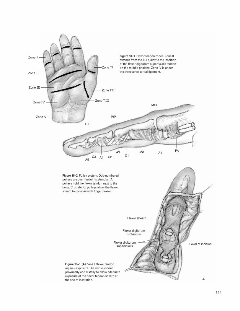
1 1 1
Zone
Zone T
Zone T
Zone T
Zone
Zone
Zone
Zone
DIP
MCP
PIP
A5C2C3 A4
A3C1
A2 A1PA
Flexor sheath
Flexor digitorum profundus
Flexor digitorum superficialis
Level of incision
A
Figure 18–1 Flexor tendon zones. Zone IIextends from the A-1 pulley to the insertionof the flexor digitorum superficialis tendonon the middle phalanx. Zone IV is underthe transverse carpal ligament.
Figure 18–2 Pulley system. Odd-numberedpulleys are over the joints. Annular (A)pulleys hold the flexor tendon next to thebone. Cruciate (C) pulleys allow the flexorsheath to collapse with finger flexion.
Figure 18–3 (A) Zone II flexor tendonrepair—exposure. The skin is incisedproximally and distally to allow adequateexposure of the flexor tendon sheath atthe site of laceration.
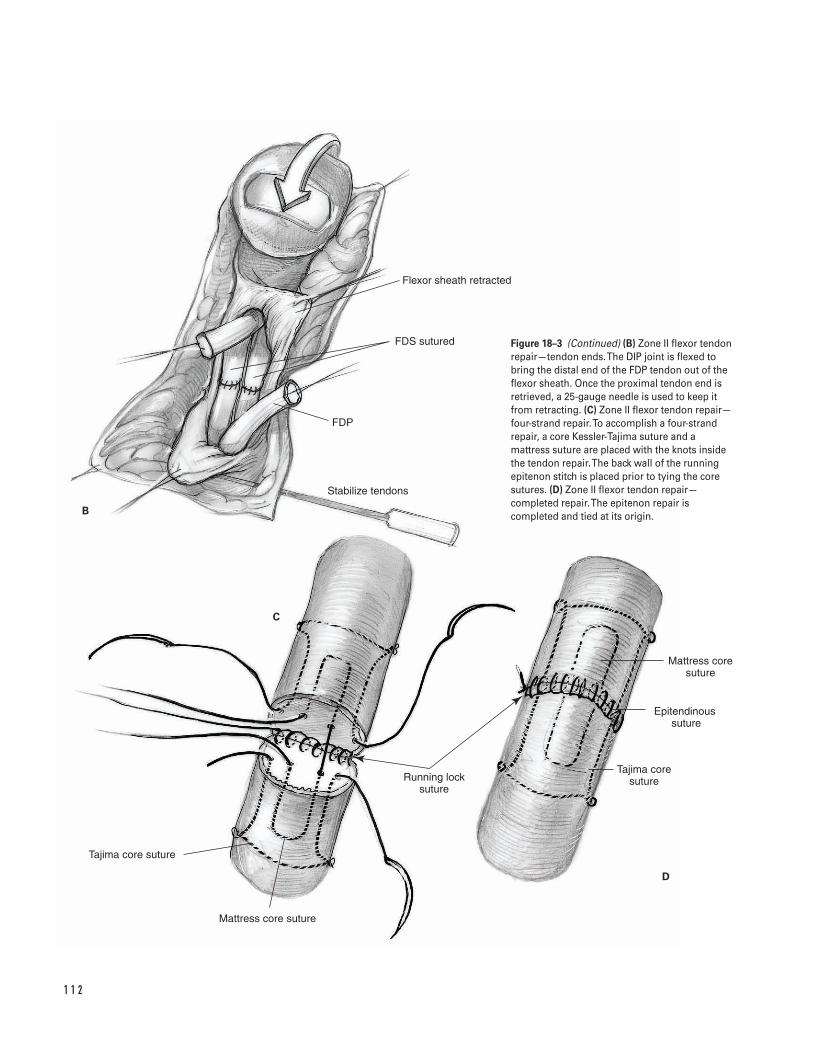
1 1 2
Flexor sheath retracted
FDS sutured
FDP
Stabilize tendons
B
C
D
Mattress core suture
Epitendinous �suture
Tajima core sutureRunning lock
suture
Tajima core suture
Mattress core suture
Figure 18–3 (Continued) (B) Zone II flexor tendonrepair—tendon ends. The DIP joint is flexed tobring the distal end of the FDP tendon out of theflexor sheath. Once the proximal tendon end isretrieved, a 25-gauge needle is used to keep itfrom retracting. (C) Zone II flexor tendon repair—four-strand repair. To accomplish a four-strandrepair, a core Kessler-Tajima suture and amattress suture are placed with the knots insidethe tendon repair. The back wall of the runningepitenon stitch is placed prior to tying the coresutures. (D) Zone II flexor tendon repair—completed repair. The epitenon repair iscompleted and tied at its origin.
2. Prepare and drape the limb in the usual sterile fashion.
3. Exsanguinate the limb with an elastic or Esmarchbandage. Inflate the tourniquet to 250 mm Hg.
4. At any zone, adequate visualization of the tendonends is required. If necessary, extend the wound. In zones 1 and 2, wound extension is either byBrunner zigzag incisions or with a midlateral inci-sion (Fig. 18–3A). In zones 3 and 4, Brunner incisionsare preferred.
5. Protect the neurovascular structures, the A2 and A4pulleys and the transverse carpal ligament wheninvolved in the incision. If possible, also preservethe A1, A3, and A5 pulleys (see Fig. 18–2).
6. Make a window in the flexor sheath at the site of thelaceration. Bring the tendon ends to this site (Fig.18–3B). Identification of the proximal tendon end isdiscussed in Tips and Pearls, above. At least 1 cm oftendon must be exposed through the window forplacement of the core sutures. If an inadequateamount of tendon is exposed, bring the tendon endthrough the adjacent window for sutures placement.Take care to re-establish the anatomic relationshipbetween the FDS and FDP tendons in zone 2.
7. Consider holding the tendon ends in position by passing a 25-gauge needle through the tendon and pulley. First place core sutures into each end of the tendon. Many different types of coresutures have been described. One well-describedmethod (Strickland) uses a 3-0 or 4-0 braided, non-absorbable sutures in a modified Kessler-Tajimafashion (Fig. 18–3C).
a. Place the first core suture through the cut end of the tendon on either the radial or ulnar side.The suture should exit the tendon approximately1 cm from the end.
b. Pass the suture through a small portion of thetendon to lock it at this site.
c. Pass the suture transversely across the tendon.Lock it on the other side before passing it backout the cut end.
d. Repeat the process on the opposite end of thelacerated tendon.
e. Place the dorsal half of a running epitenonstitch. Use a 6-0 nylon to capture the distal 3 to4 mm of the epitenon (Fig. 18–3C).
f. Place a second core suture in a mattress fashion.Place one 3-0 or 4-0 braided, nonabsorbablesuture similarly to the Kessler-Tajima stitch. Thedifference is the suture is not locked in the cor-ners and the same suture is placed into theproximal and distal ends of the tendon. Thisleaves one knot instead of two inside the ten-don repair site.
g. Tie the core sutures. Complete the palmar half ofthe epitenon suture. Take care to maintain thewrist and fingers in flexion after the sutures aretied (Fig. 18–3D).
8. Repair the flexor sheath with 6-0 nylon.9. Close the skin wound with nonabsorbable sutures.
10. Apply a bulky dressing and splint with wrist in 30degrees of flexion and the MCP joints in 60 degreesof flexion.
11. Transfer the patient to the recovery room with thearm elevated above the level of the heart.
Suggested ReadingsCannon NM, Strickland JW. Therapy following flexortendon surgery. Hand Clin 1985;1:147–165.
Kleinert HE, Cash SL. Current guidelines for flexortendon repair within the fibroosseous tunnel:indications, timing, and techniques. In: Hunter JM,Schneider LH, Mackin EJ, eds. Tendon Surgery in theHand. St. Louis, MO: C.V. Mosby, 1987, pp. 118–125.
Strickland JW. Flexor tendons—acute injuries. In: GreenDP, Hotchkiss RN, Pederson WC, eds. Green’s OperativeHand Surgery. 4th ed. New York, NY: ChurchillLivingston, 1999, pp. 1851–1897.
1 8 F L E X O R T E N D O N R E PA I R 1 1 3
Indications1. Inadequate closed reduction
a. Head: greater than 1 mm to 2 mm articular step-off, collateral ligament avulsion fracture withmore than 2 mm displacement, malrotation
b. Neck (Boxer’s Fracture): greater than 50 degreesapex dorsal angulation (relative), palmar promi-nence of the metacarpal head, malrotation
c. Shaft: greater than 20 to 30 degrees apex dorsalangulation, more than 3 to 4 mm shortening,less than 50% bone apposition, malrotation
d. Base: greater than 1 to 2 mm articular step-off,carpometacarpal joint subluxation/dislocation,malrotation
2. Adequate closed reduction obtained but not main-tained by cast, splint, or functional brace
3. Open fracture4. Comminuted fracture (relative)5. Segmental bone loss6. Multiple metacarpal fractures (relative)7. Concomitant soft-tissue injury requiring frequent
access to the wound (e.g., burn)8. Tendon repair necessitating early metacarpophalan-
geal joint motion (relative)
Contraindications1. Stable, reduced fracture2. Patient noncompliance or severe coexisting medical
illness3. Nonfunctional hand (relative)
Preoperative Preparation1. Standard AP/lateral/oblique plain radiographs of
the injured hand2. Special imaging studies
a. Brewerton view—head fracturesb. CT or tomograms—articular injuries
3. Characterize the fracture
a. Location: head, neck, shaft, baseb. Pattern of injury: transverse, oblique, spiral,
comminuted, segmental bone lossc. Degree and direction of displacementd. Stabilitye. Soft-tissue integrity
4. Document the neurovascular status and evaluatethe extremity for associated trauma.
1 1 4
C H A P T E R 1 9
Fifth Metacarpal FractureOperative Repair
David M. Kalainov and Franklin Chen
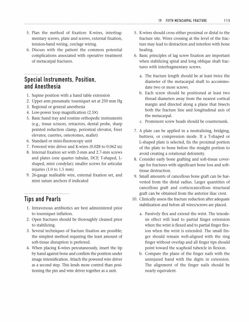
5. Plan the method of fixation: K-wires, interfrag-mentary screws, plate and screws, external fixation,tension-band wiring, cerclage wiring.
6. Discuss with the patient the common potentialcomplications associated with operative treatmentof metacarpal fractures.
Special Instruments, Position, and Anesthesia1. Supine position with a hand table extension2. Upper arm pneumatic tourniquet set at 250 mm Hg3. Regional or general anesthesia4. Low-power loop magnification (2.55)5. Basic hand tray and routine orthopedic instruments
(e.g., tissue scissors, retractors, dental probe, sharppointed reduction clamp, periosteal elevator, Freerelevator, curettes, osteotomes, mallet)
6. Standard or mini-fluoroscopy unit7. Powered wire driver and K-wires (0.028 to 0.062 in)8. Internal fixation set with 2-mm and 2.7-mm screws
and plates (one quarter tubular, DCP, T-shaped, L-shaped, mini condylar); smaller screws for articularinjuries (1.0 to 1.5 mm)
9. 26-gauge malleable wire, external fixation set, andmini suture anchors if indicated
Tips and Pearls1. Intravenous antibiotics are best administered prior
to tourniquet inflation.2. Open fractures should be thoroughly cleaned prior
to stabilizing.3. Several techniques of fracture fixation are possible;
the simplest method requiring the least amount ofsoft-tissue disruption is preferred.
4. When placing K-wires percutaneously, insert the tipby hand against bone and confirm the position underimage intensification. Attach the powered wire driveras a second step. This lends more control than posi-tioning the pin and wire driver together as a unit.
5. K-wires should cross either proximal or distal to thefracture site. Wires crossing at the level of the frac-ture may lead to distraction and interfere with bonehealing.
6. Basic principles of lag screw fixation are importantwhen stabilizing spiral and long oblique shaft frac-tures with interfragmentary screws.
a. The fracture length should be at least twice thediameter of the metacarpal shaft to accommo-date two or more screws.
b. Each screw should be positioned at least twothread diameters away from the nearest corticalmargin and directed along a plane that bisectsboth the fracture line and longitudinal axis ofthe metacarpal.
c. Prominent screw heads should be countersunk.
7. A plate can be applied in a neutralizing, bridging,buttress, or compression mode. If a T-shaped or L-shaped plate is selected, fix the proximal portionof the plate to bone before the straight portion toavoid creating a rotational deformity.
8. Consider early bone grafting and soft-tissue cover-age for fractures with significant bone loss and soft-tissue destruction.
9. Small amounts of cancellous bone graft can be har-vested from the distal radius. Larger quantities ofcancellous graft and corticocancellous structuralgraft can be obtained from the anterior iliac crest.
10. Clinically assess the fracture reduction after adequatestabilization and before all wires/screws are placed.
a. Passively flex and extend the wrist. The tenode-sis effect will lead to partial finger extensionwhen the wrist is flexed and to partial finger flex-ion when the wrist is extended. The small fin-ger should remain well-aligned with the ringfinger without overlap and all finger tips shouldpoint toward the scaphoid tubercle in flexion.
b. Compare the plane of the finger nails with theuninjured hand with the digits in extension.The alignment of the finger nails should benearly equivalent.
1 9 F I F T H M E TA C A R PA L F R A C T U R E 1 1 5
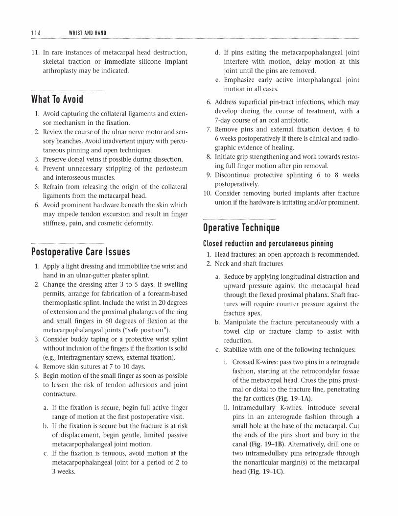
11. In rare instances of metacarpal head destruction,skeletal traction or immediate silicone implantarthroplasty may be indicated.
What To Avoid1. Avoid capturing the collateral ligaments and exten-
sor mechanism in the fixation.2. Review the course of the ulnar nerve motor and sen-
sory branches. Avoid inadvertent injury with percu-taneous pinning and open techniques.
3. Preserve dorsal veins if possible during dissection.4. Prevent unnecessary stripping of the periosteum
and interosseous muscles.5. Refrain from releasing the origin of the collateral
ligaments from the metacarpal head.6. Avoid prominent hardware beneath the skin which
may impede tendon excursion and result in fingerstiffness, pain, and cosmetic deformity.
Postoperative Care Issues1. Apply a light dressing and immobilize the wrist and
hand in an ulnar-gutter plaster splint.2. Change the dressing after 3 to 5 days. If swelling
permits, arrange for fabrication of a forearm-basedthermoplastic splint. Include the wrist in 20 degreesof extension and the proximal phalanges of the ringand small fingers in 60 degrees of flexion at themetacarpophalangeal joints (“safe position”).
3. Consider buddy taping or a protective wrist splintwithout inclusion of the fingers if the fixation is solid(e.g., interfragmentary screws, external fixation).
4. Remove skin sutures at 7 to 10 days.5. Begin motion of the small finger as soon as possible
to lessen the risk of tendon adhesions and jointcontracture.
a. If the fixation is secure, begin full active fingerrange of motion at the first postoperative visit.
b. If the fixation is secure but the fracture is at riskof displacement, begin gentle, limited passivemetacarpophalangeal joint motion.
c. If the fixation is tenuous, avoid motion at themetacarpophalangeal joint for a period of 2 to 3 weeks.
d. If pins exiting the metacarpophalangeal jointinterfere with motion, delay motion at this joint until the pins are removed.
e. Emphasize early active interphalangeal jointmotion in all cases.
6. Address superficial pin-tract infections, which maydevelop during the course of treatment, with a 7-day course of an oral antibiotic.
7. Remove pins and external fixation devices 4 to 6 weeks postoperatively if there is clinical and radio-graphic evidence of healing.
8. Initiate grip strengthening and work towards restor-ing full finger motion after pin removal.
9. Discontinue protective splinting 6 to 8 weekspostoperatively.
10. Consider removing buried implants after fractureunion if the hardware is irritating and/or prominent.
Operative TechniqueClosed reduction and percutaneous pinning1. Head fractures: an open approach is recommended.2. Neck and shaft fractures
a. Reduce by applying longitudinal distraction andupward pressure against the metacarpal headthrough the flexed proximal phalanx. Shaft frac-tures will require counter pressure against thefracture apex.
b. Manipulate the fracture percutaneously with atowel clip or fracture clamp to assist withreduction.
c. Stabilize with one of the following techniques:
i. Crossed K-wires: pass two pins in a retrogradefashion, starting at the retrocondylar fossaeof the metacarpal head. Cross the pins proxi-mal or distal to the fracture line, penetratingthe far cortices (Fig. 19–1A).
ii. Intramedullary K-wires: introduce severalpins in an anterograde fashion through asmall hole at the base of the metacarpal. Cutthe ends of the pins short and bury in thecanal (Fig. 19–1B). Alternatively, drill one ortwo intramedullary pins retrograde throughthe nonarticular margin(s) of the metacarpalhead (Fig. 19–1C).
1 1 6 W R I S T A N D H A N D
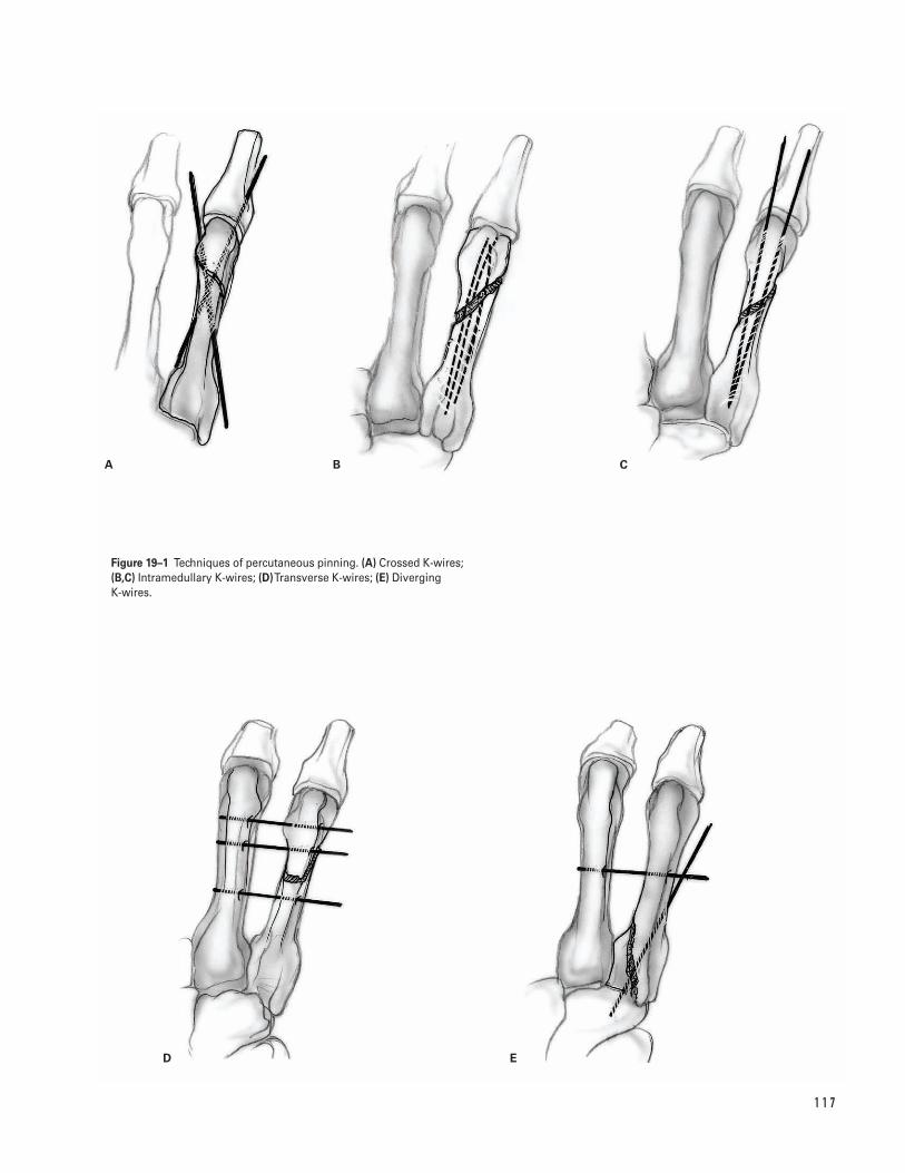
1 1 7
A B C
D E
Figure 19–1 Techniques of percutaneous pinning. (A) Crossed K-wires;(B,C) Intramedullary K-wires; (D)Transverse K-wires; (E) Diverging K-wires.
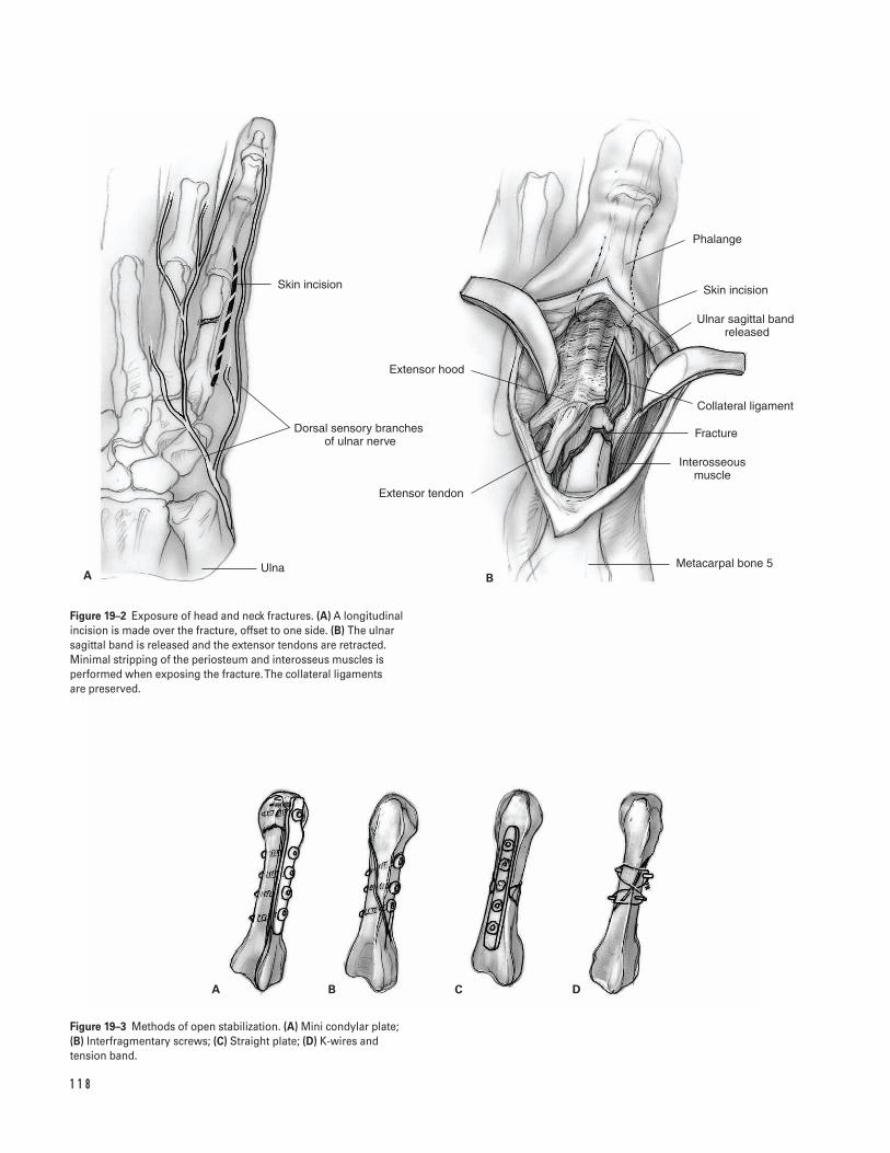
1 1 8
A B C D
Skin incision
Dorsal sensory branches �of ulnar nerve
Ulna
Extensor hood
Extensor tendon
Phalange
Skin incision
Ulnar sagittal band released
Collateral ligament
Fracture
Interosseous muscle
Metacarpal bone 5A B
Figure 19–2 Exposure of head and neck fractures. (A) A longitudinalincision is made over the fracture, offset to one side. (B) The ulnarsagittal band is released and the extensor tendons are retracted.Minimal stripping of the periosteum and interosseus muscles isperformed when exposing the fracture. The collateral ligaments are preserved.
Figure 19–3 Methods of open stabilization. (A) Mini condylar plate; (B) Interfragmentary screws; (C) Straight plate; (D) K-wires and tension band.
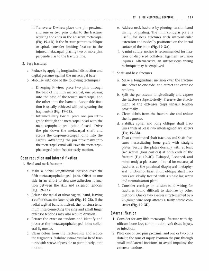
iii. Transverse K-wires: place one pin proximaland one or two pins distal to the fracture,securing the ends in the adjacent metacarpal(Fig. 19–1D). If the fracture pattern is obliqueor spiral, consider limiting fixation to theinjured metacarpal, placing two or more pinsperpendicular to the fracture line.
3. Base fractures
a. Reduce by applying longitudinal distraction anddigital pressure against the metacarpal base.
b. Stabilize with one of the following techniques:
i. Diverging K-wires: place two pins throughthe base of the fifth metacarpal, one passinginto the base of the fourth metacarpal andthe other into the hamate. Acceptable fixa-tion is usually achieved without spearing thefragment(s) (Fig. 19–1E).
ii. Intramedullary K-wire: place one pin retro-grade through the metacarpal head with themetacarpophalangeal joint flexed. Drive the pin down the metacarpal shaft andacross the carpometacarpal joint into thecarpus. Advancing the pin proximally intothe metacarpal canal will leave the metacarpo-phalangeal joint free for early motion.
Open reduction and internal fixation1. Head and neck fractures
a. Make a dorsal longitudinal incision over thefifth metacarpophalangeal joint. Offset to oneside in an effort to decrease adhesion forma-tion between the skin and extensor tendons(Fig. 19–2A).
b. Release the radial or ulnar sagittal band, leavinga cuff of tissue for later repair (Fig. 19–2B). If theradial sagittal band is incised, the junctura tend-inum interconnecting the ring and small fingerextensor tendons may also require division.
c. Retract the extensor tendons and identify andpreserve the metacarpophalangeal joint collat-eral ligaments.
d. Clean debris from the fracture site and reducethe fragments. Stabilize intra-articular head frac-tures with screws if possible to permit early jointmotion.
e. Address neck fractures by pinning, tension bandwiring, or plating. The mini condylar plate isuseful for neck fractures with intra-articularextension and is ideally positioned on the lateralsurface of the bone (Fig. 19–3A).
f. A mini suture anchor is recommended for fixa-tion of displaced collateral ligament avulsioninjuries. Alternatively, an intraosseous wiringtechnique may be employed.
2. Shaft and base fractures
a. Make a longitudinal incision over the fracturesite, offset to one side, and retract the extensortendons.
b. Split the periosteum longitudinally and exposethe fracture subperiosteally. Preserve the attach-ment of the extensor carpi ulnaris tendonproximally.
c. Clean debris from the fracture site and reducethe fragments.
d. Stabilize spiral and long oblique shaft frac-tures with at least two interfragmentary screws (Fig. 19–3B).
e. Treat comminuted shaft fractures and shaft frac-tures necessitating bone graft with straightplates. Secure the plates dorsally with at leasttwo screws (four cortices) at both ends of thefracture (Fig. 19–3C). T-shaped, L-shaped, andmini condylar plates are indicated for metacarpalfractures at the proximal diaphyseal metaphy-seal junction or base. Short oblique shaft frac-tures are ideally treated with a single lag screwand neutralization plate.
f. Consider cerclage or tension-band wiring forfractures found difficult to stabilize by othermethods. One or two K-wires supplemented by a26-gauge wire loop affords a fairly stable con-struct (Fig. 19–3D).
External fixation1. Consider for any fifth metacarpal fracture with sig-
nificant bone loss, comminution, soft-tissue injury,or infection.
2. Place one or two pins proximal and one or two pinsdistal to the zone of injury. Position the pins throughsmall mid-lateral incisions to avoid impaling theextensor tendons.
1 9 F I F T H M E TA C A R PA L F R A C T U R E 1 1 9
3. Assemble clamps and connecting bars onto thepins, bring the fracture out to length, reduce thefragments, and tighten the construct.
4. If significant displacement persists, consider con-comitant open reduction with supplemental K-wire/screw fixation. Subchondral defects shouldbe bone grafted; larger defects may necessitatestructural grafting.
Closure1. Reapproximate the periosteum over the implants if
possible using 4-0 resorbable sutures.2. If the junctura tendinum and one or both sagittal
bands have been divided, repair with 4-0 non-resorbable sutures.
3. After repairing the deep structures, release thetourniquet and apply pressure to the wound.
4. Copiously irrigate the wound and coagulate smallbleeding vessels with bipolar cautery.
5. Reapproximate the skin edges with either inter-rupted sutures or a subcuticular closure.
6. Cut pins external to the skin surface and bend orcap the ends.
7. Apply a light dressing and ulnar gutter splint.8. Support the arm in a temporary sling in the setting
of regional anesthesia.
Suggested ReadingsFaraj AA, Davis TRC. Percutaneous intramedullaryfixation of metacarpal shaft fractures. J Hand Surg1999;24B:76–79.
Foster RJ. Stabilization of ulnar carpometacarpaldislocations or fracture dislocations. Clin Orthop1996;327:94–97.
Freeland AE, Jabaley ME. Stabilization of fractures inthe hand and wrist with traumatic soft tissue and boneloss. Hand Clin 1988;4:425–436.
Greene TL, Noellert RC, Belsole RJ. Treatment of unstablemetacarpal and phalangeal fractures with tension bandwiring techniques. Clin Orthop 1987;214:78–84.
Gropper PT, Bowen V. Cerclage wiring of metacarpalfractures. Clin Orthop 1984;188:203–207.
Jupiter JB, Axelrod TS, Belsky MR. Fractures anddislocations of the hand. In: Browner BD, Jupiter JB,Levine AM, Trafton PG, eds. Skeletal Trauma. 2nd ed.Vol. 2. Philadelphia, PA: W.B. Saunders, 1998, pp.1249–1269.
Lane CS. Detecting occult fractures of the metacarpalhead: the Brewerton view. J Hand Surg 1977;2:131–133.
Njus N. Percutaneous pin fixation of the diaphysis ofthe metacarpals. In: Blair WF, ed. Techniques in HandSurgery. Baltimore, MD: Williams & Wilkins, 1996, pp. 229–238.
Parsons SW, Fitzgerald JAW, Shearer JR. Externalfixation of unstable metacarpal and phalangealfractures. J Hand Surg 1992;17B:151–155.
Stern PJ. Fractures of the metacarpals and phalanges. In: Green DP, Hotchkiss RN, Pederson WC, eds. Green’sOperative Hand Surgery. 4th ed. Vol. 1. Philadelphia, PA: Churchill Livingstone, 1999, pp. 711–732.
1 2 0 W R I S T A N D H A N D
Section Four
Hip and Femur

This page intentionally left blank
Key Techniques inOrthopaedic Surgery
IndicationsThe prime indications for total hip arthroplasty arerelief of hip pain and improvement of hip function as aresult of any disabling hip condition. These conditionsinclude:1. Osteoarthritis2. Inflammatory arthritis (rheumatoid arthritis, psori-
atic arthritis, etc.)3. Posttraumatic arthritis4. Osteonecrosis
Contraindications1. Active sepsis (absolute)2. Active causalgia/reflex dystrophy (absolute)3. Neuropathic joint (relative)4. Insufficient musculature about the hip girdle
(relative)5. Inability or unwillingness to adhere to postopera-
tive precautions (relative)
Preoperative Preparation1. Complete history and physical examination.
Record location, quality and activities associatedwith hip pain. Also document gait pattern, leglength, and range of motion.
2. Appropriate medical and anesthetic evaluation.
3. Document preoperative neurovascular status.4. Radiographs including anteroposterior (AP) of the
pelvis, true or “frog leg” lateral of affected hip, andAP and lateral of lumbar spine.
5. The preoperative radiographs should be assessed inconjunction with the appropriate hip prosthetictemplates to determine approximate sizes for boththe acetabular and femoral components. Existingacetabular bone stock, as well as any deficienciesin the dome or rim of the acetabulum influenceacetabular component size. Femoral templatinghelps determine:
a. Level of femoral neck resectionb. Femoral component sizec. Distances from fixed points on the femur to the
center of hip rotation in order to help optimizepostoperative limb length
d. If femoral implant adequately reconstructsfemoral offset and proper hip mechanics
Special Instruments, Position, and Anesthesia1. The preferred patient position for a posterolateral
approach to the hip joint is the lateral decubitusposition. Adequate padding of the axilla is neces-sary to avoid injury to the brachial plexus. Whilethe patient must be secure on the operation roomtable, avoid excessive tightening of pelvic posts,
1 2 3
C H A P T E R 2 0
Total Hip ArthroplastyHybrid and Uncemented
Douglas E. Padgett
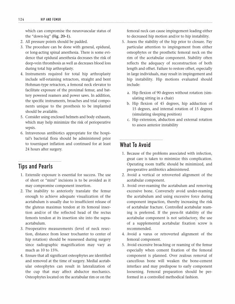
which can compromise the neurovascular status ofthe “down-leg” (Fig. 20–1).
2. All pressure points should be padded.3. The procedure can be done with general, epidural,
or long-acting spinal anesthesia. There is some evi-dence that epidural anesthesia decreases the risk ofdeep-vein thrombosis as well as decreases blood lossduring total hip arthroplasty.
4. Instruments required for total hip arthroplastyinclude self-retaining retractors, straight and bentHohman-type retractors, a femoral neck elevator tofacilitate exposure of the proximal femur, and bat-tery powered reamers and power saws. In addition,the specific instruments, broaches and trial compo-nents unique to the prosthesis to be implantedshould be available.
5. Consider using enclosed helmets and body exhausts,which may help minimize the risk of perioperativesepsis.
6. Intravenous antibiotics appropriate for the hospi-tal’s bacterial flora should be administered prior to tourniquet inflation and continued for at least 24 hours after surgery.
Tips and Pearls1. Extensile exposure is essential for success. The use
of short or “mini” incisions is to be avoided as itmay compromise component insertion.
2. The inability to anteriorly translate the femurenough to achieve adequate visualization of theacetabulum is usually due to insufficient release ofthe gluteus maximus tendon at its femoral inser-tion and/or of the reflected head of the rectusfemoris tendon at its insertion site into the supra-acetabulum.
3. Preoperative measurements (level of neck resec-tion, distance from lesser trochanter to center ofhip rotation) should be reassessed during surgerysince radiographic magnification may vary asmuch as 10 to 15%.
4. Ensure that all significant osteophytes are identifiedand removed at the time of surgery. Medial acetab-ular osteophytes can result in lateralization of the cup that may affect abductor mechanics.Osteophytes located on the acetabular rim or on the
femoral neck can cause impingement leading eitherto decreased hip motion and/or to hip instability.
5. Assess the stability of the hip prior to closure. Payparticular attention to impingement from eitherosteophytes or the prosthetic femoral neck on therim of the acetabular component. Stability oftenreflects the adequacy of reconstruction of bothlength and offset. Failure to restore offset, especiallyin large individuals, may result in impingement andhip instability. Hip motions evaluated shouldinclude:
a. Hip flexion of 90 degrees without rotation (sim-ulating sitting in a chair)
b. Hip flexion of 45 degrees, hip adduction of 15 degrees, and internal rotation of 15 degrees(simulating sleeping position)
c. Hip extension, abduction and external rotationto assess anterior instability
What To Avoid1. Because of the problems associated with infection,
great care is taken to minimize this complication.Operating room traffic should be minimized, andpreoperative antibiotics administered.
2. Avoid a vertical or retroverted alignment of theacetabular component.
3. Avoid over-reaming the acetabulum and removingexcessive bone. Conversely avoid under-reamingthe acetabulum and using excessive force duringcomponent impaction, thereby increasing the riskof acetabular fracture. Controlled acetabular ream-ing is preferred. If the press-fit stability of theacetabular component is not satisfactory, the use of a supplemental acetabular fixation screw isrecommended.
4. Avoid a varus or retroverted alignment of thefemoral component.
5. Avoid excessive broaching or reaming of the femurespecially when cement fixation of the femoralcomponent is planned. Over zealous removal ofcancellous bone will weaken the bone-cementinterface and may predispose to early componentloosening. Femoral preparation should be per-formed in a controlled methodical fashion.
1 2 4 H I P A N D F E M U R
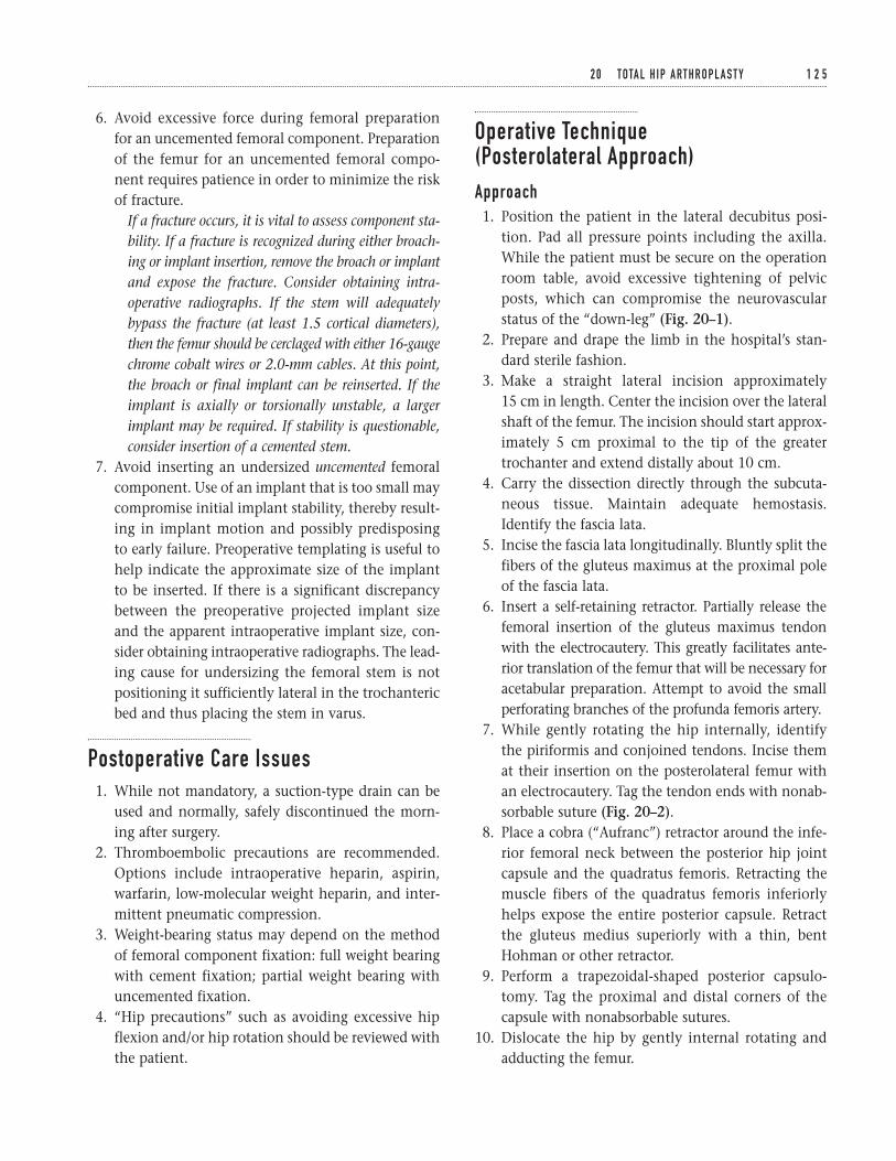
6. Avoid excessive force during femoral preparationfor an uncemented femoral component. Preparationof the femur for an uncemented femoral compo-nent requires patience in order to minimize the riskof fracture.
If a fracture occurs, it is vital to assess component sta-bility. If a fracture is recognized during either broach-ing or implant insertion, remove the broach or implantand expose the fracture. Consider obtaining intra-operative radiographs. If the stem will adequatelybypass the fracture (at least 1.5 cortical diameters),then the femur should be cerclaged with either 16-gaugechrome cobalt wires or 2.0-mm cables. At this point,the broach or final implant can be reinserted. If theimplant is axially or torsionally unstable, a largerimplant may be required. If stability is questionable,consider insertion of a cemented stem.
7. Avoid inserting an undersized uncemented femoralcomponent. Use of an implant that is too small maycompromise initial implant stability, thereby result-ing in implant motion and possibly predisposingto early failure. Preoperative templating is useful tohelp indicate the approximate size of the implantto be inserted. If there is a significant discrepancybetween the preoperative projected implant sizeand the apparent intraoperative implant size, con-sider obtaining intraoperative radiographs. The lead-ing cause for undersizing the femoral stem is notpositioning it sufficiently lateral in the trochantericbed and thus placing the stem in varus.
Postoperative Care Issues1. While not mandatory, a suction-type drain can be
used and normally, safely discontinued the morn-ing after surgery.
2. Thromboembolic precautions are recommended.Options include intraoperative heparin, aspirin,warfarin, low-molecular weight heparin, and inter-mittent pneumatic compression.
3. Weight-bearing status may depend on the methodof femoral component fixation: full weight bearingwith cement fixation; partial weight bearing withuncemented fixation.
4. “Hip precautions” such as avoiding excessive hipflexion and/or hip rotation should be reviewed withthe patient.
Operative Technique (Posterolateral Approach)Approach1. Position the patient in the lateral decubitus posi-
tion. Pad all pressure points including the axilla.While the patient must be secure on the operationroom table, avoid excessive tightening of pelvicposts, which can compromise the neurovascularstatus of the “down-leg” (Fig. 20–1).
2. Prepare and drape the limb in the hospital’s stan-dard sterile fashion.
3. Make a straight lateral incision approximately 15 cm in length. Center the incision over the lateralshaft of the femur. The incision should start approx-imately 5 cm proximal to the tip of the greatertrochanter and extend distally about 10 cm.
4. Carry the dissection directly through the subcuta-neous tissue. Maintain adequate hemostasis.Identify the fascia lata.
5. Incise the fascia lata longitudinally. Bluntly split thefibers of the gluteus maximus at the proximal poleof the fascia lata.
6. Insert a self-retaining retractor. Partially release thefemoral insertion of the gluteus maximus tendonwith the electrocautery. This greatly facilitates ante-rior translation of the femur that will be necessary foracetabular preparation. Attempt to avoid the smallperforating branches of the profunda femoris artery.
7. While gently rotating the hip internally, identifythe piriformis and conjoined tendons. Incise themat their insertion on the posterolateral femur withan electrocautery. Tag the tendon ends with nonab-sorbable suture (Fig. 20–2).
8. Place a cobra (“Aufranc”) retractor around the infe-rior femoral neck between the posterior hip jointcapsule and the quadratus femoris. Retracting themuscle fibers of the quadratus femoris inferiorlyhelps expose the entire posterior capsule. Retractthe gluteus medius superiorly with a thin, bentHohman or other retractor.
9. Perform a trapezoidal-shaped posterior capsulo-tomy. Tag the proximal and distal corners of thecapsule with nonabsorbable sutures.
10. Dislocate the hip by gently internal rotating andadducting the femur.
2 0 TOTA L H I P A RT H R O P L A S T Y 1 2 5
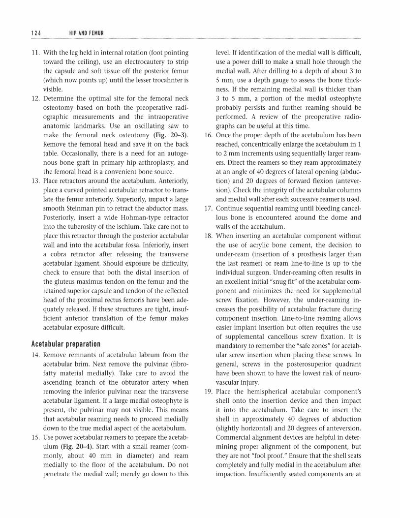
11. With the leg held in internal rotation (foot pointingtoward the ceiling), use an electrocautery to stripthe capsule and soft tissue off the posterior femur(which now points up) until the lesser trocahnter isvisible.
12. Determine the optimal site for the femoral neckosteotomy based on both the preoperative radi-ographic measurements and the intraoperativeanatomic landmarks. Use an oscillating saw tomake the femoral neck osteotomy (Fig. 20–3).Remove the femoral head and save it on the backtable. Occasionally, there is a need for an autoge-nous bone graft in primary hip arthroplasty, andthe femoral head is a convenient bone source.
13. Place retractors around the acetabulum. Anteriorly,place a curved pointed acetabular retractor to trans-late the femur anteriorly. Superiorly, impact a largesmooth Steinman pin to retract the abductor mass.Posteriorly, insert a wide Hohman-type retractorinto the tuberosity of the ischium. Take care not toplace this retractor through the posterior acetabularwall and into the acetabular fossa. Inferiorly, inserta cobra retractor after releasing the transverseacetabular ligament. Should exposure be difficulty,check to ensure that both the distal insertion of the gluteus maximus tendon on the femur and the retained superior capsule and tendon of the reflectedhead of the proximal rectus femoris have been ade-quately released. If these structures are tight, insuf-ficient anterior translation of the femur makesacetabular exposure difficult.
Acetabular preparation14. Remove remnants of acetabular labrum from the
acetabular brim. Next remove the pulvinar (fibro-fatty material medially). Take care to avoid theascending branch of the obturator artery whenremoving the inferior pulvinar near the transverseacetabular ligament. If a large medial osteophyte ispresent, the pulvinar may not visible. This meansthat acetabular reaming needs to proceed mediallydown to the true medial aspect of the acetabulum.
15. Use power acetabular reamers to prepare the acetab-ulum (Fig. 20–4). Start with a small reamer (com-monly, about 40 mm in diameter) and reammedially to the floor of the acetabulum. Do notpenetrate the medial wall; merely go down to this
level. If identification of the medial wall is difficult,use a power drill to make a small hole through themedial wall. After drilling to a depth of about 3 to 5 mm, use a depth gauge to assess the bone thick-ness. If the remaining medial wall is thicker than 3 to 5 mm, a portion of the medial osteophyteprobably persists and further reaming should beperformed. A review of the preoperative radio-graphs can be useful at this time.
16. Once the proper depth of the acetabulum has beenreached, concentrically enlarge the acetabulum in 1to 2 mm increments using sequentially larger ream-ers. Direct the reamers so they ream approximatelyat an angle of 40 degrees of lateral opening (abduc-tion) and 20 degrees of forward flexion (antever-sion). Check the integrity of the acetabular columnsand medial wall after each successive reamer is used.
17. Continue sequential reaming until bleeding cancel-lous bone is encountered around the dome andwalls of the acetabulum.
18. When inserting an acetabular component withoutthe use of acrylic bone cement, the decision tounder-ream (insertion of a prosthesis larger thanthe last reamer) or ream line-to-line is up to theindividual surgeon. Under-reaming often results inan excellent initial “snug fit” of the acetabular com-ponent and minimizes the need for supplementalscrew fixation. However, the under-reaming in-creases the possibility of acetabular fracture duringcomponent insertion. Line-to-line reaming allowseasier implant insertion but often requires the useof supplemental cancellous screw fixation. It ismandatory to remember the “safe zones” for acetab-ular screw insertion when placing these screws. Ingeneral, screws in the posterosuperior quadranthave been shown to have the lowest risk of neuro-vascular injury.
19. Place the hemispherical acetabular component’sshell onto the insertion device and then impact it into the acetabulum. Take care to insert the shell in approximately 40 degrees of abduction(slightly horizontal) and 20 degrees of anteversion.Commercial alignment devices are helpful in deter-mining proper alignment of the component, butthey are not “fool proof.” Ensure that the shell seatscompletely and fully medial in the acetabulum afterimpaction. Insufficiently seated components are at
1 2 6 H I P A N D F E M U R
1 2 7
Acetabular rim
Superior capsule
PiriformisSuperior gemellus
muscle
Inferior capsule
Obturator externus muscle
Obturator internus muscle
Inferior gemellus muscle
Tensor fascia lata
Vastus ridge
Figure 20–1 Patient position. The preferredpatient position for a posterolateral approach to the hip joint is the lateral decubitus position.Adequate padding of the axilla is necessaryto avoid injury to the brachial plexus. Avoidexcessive tightening of pelvic posts, which can compromise the neurovascular status of the “down-leg.”
Figure 20–2 External rotator exposure. Thepiriformis and conjoined tendons (superiorgemellus, obturator internus and inferiorgemellus) are identified with the hip maintainedin gentle internal rotation.
Figure 20–3 Femoral neck osteotomy. Anoscillating saw is used to make the femoral neck osteotomy.
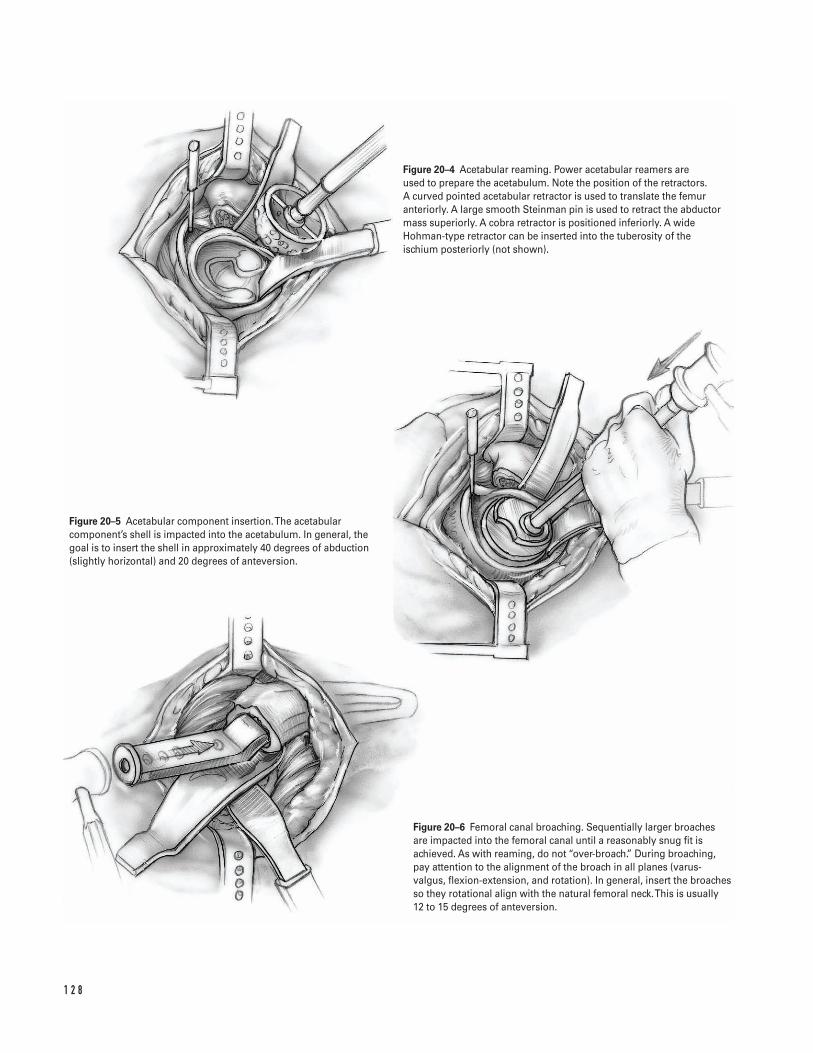
1 2 8
Figure 20–4 Acetabular reaming. Power acetabular reamers are used to prepare the acetabulum. Note the position of the retractors. A curved pointed acetabular retractor is used to translate the femuranteriorly. A large smooth Steinman pin is used to retract the abductormass superiorly. A cobra retractor is positioned inferiorly. A wideHohman-type retractor can be inserted into the tuberosity of theischium posteriorly (not shown).
Figure 20–5 Acetabular component insertion. The acetabularcomponent’s shell is impacted into the acetabulum. In general, thegoal is to insert the shell in approximately 40 degrees of abduction(slightly horizontal) and 20 degrees of anteversion.
Figure 20–6 Femoral canal broaching. Sequentially larger broaches are impacted into the femoral canal until a reasonably snug fit isachieved. As with reaming, do not “over-broach.” During broaching,pay attention to the alignment of the broach in all planes (varus-valgus, flexion-extension, and rotation). In general, insert the broachesso they rotational align with the natural femoral neck. This is usually 12 to 15 degrees of anteversion.
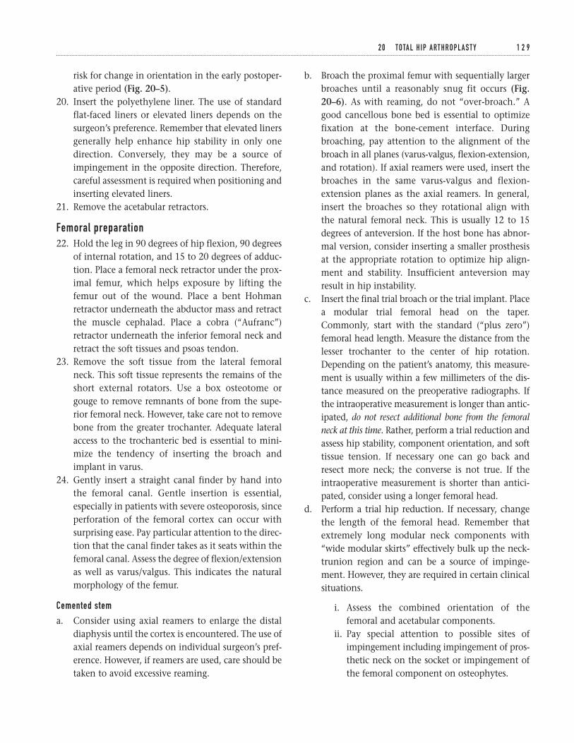
risk for change in orientation in the early postoper-ative period (Fig. 20–5).
20. Insert the polyethylene liner. The use of standardflat-faced liners or elevated liners depends on thesurgeon’s preference. Remember that elevated linersgenerally help enhance hip stability in only onedirection. Conversely, they may be a source ofimpingement in the opposite direction. Therefore,careful assessment is required when positioning andinserting elevated liners.
21. Remove the acetabular retractors.
Femoral preparation22. Hold the leg in 90 degrees of hip flexion, 90 degrees
of internal rotation, and 15 to 20 degrees of adduc-tion. Place a femoral neck retractor under the prox-imal femur, which helps exposure by lifting thefemur out of the wound. Place a bent Hohmanretractor underneath the abductor mass and retractthe muscle cephalad. Place a cobra (“Aufranc”)retractor underneath the inferior femoral neck andretract the soft tissues and psoas tendon.
23. Remove the soft tissue from the lateral femoralneck. This soft tissue represents the remains of theshort external rotators. Use a box osteotome orgouge to remove remnants of bone from the supe-rior femoral neck. However, take care not to removebone from the greater trochanter. Adequate lateralaccess to the trochanteric bed is essential to mini-mize the tendency of inserting the broach andimplant in varus.
24. Gently insert a straight canal finder by hand intothe femoral canal. Gentle insertion is essential,especially in patients with severe osteoporosis, sinceperforation of the femoral cortex can occur withsurprising ease. Pay particular attention to the direc-tion that the canal finder takes as it seats within thefemoral canal. Assess the degree of flexion/extensionas well as varus/valgus. This indicates the naturalmorphology of the femur.
Cemented stem
a. Consider using axial reamers to enlarge the distaldiaphysis until the cortex is encountered. The use ofaxial reamers depends on individual surgeon’s pref-erence. However, if reamers are used, care should betaken to avoid excessive reaming.
b. Broach the proximal femur with sequentially largerbroaches until a reasonably snug fit occurs (Fig.20–6). As with reaming, do not “over-broach.” Agood cancellous bone bed is essential to optimizefixation at the bone-cement interface. Duringbroaching, pay attention to the alignment of thebroach in all planes (varus-valgus, flexion-extension,and rotation). If axial reamers were used, insert thebroaches in the same varus-valgus and flexion-extension planes as the axial reamers. In general,insert the broaches so they rotational align with the natural femoral neck. This is usually 12 to 15degrees of anteversion. If the host bone has abnor-mal version, consider inserting a smaller prosthesisat the appropriate rotation to optimize hip align-ment and stability. Insufficient anteversion mayresult in hip instability.
c. Insert the final trial broach or the trial implant. Placea modular trial femoral head on the taper.Commonly, start with the standard (“plus zero”)femoral head length. Measure the distance from thelesser trochanter to the center of hip rotation.Depending on the patient’s anatomy, this measure-ment is usually within a few millimeters of the dis-tance measured on the preoperative radiographs. Ifthe intraoperative measurement is longer than antic-ipated, do not resect additional bone from the femoralneck at this time. Rather, perform a trial reduction andassess hip stability, component orientation, and softtissue tension. If necessary one can go back andresect more neck; the converse is not true. If theintraoperative measurement is shorter than antici-pated, consider using a longer femoral head.
d. Perform a trial hip reduction. If necessary, changethe length of the femoral head. Remember thatextremely long modular neck components with“wide modular skirts” effectively bulk up the neck-trunion region and can be a source of impinge-ment. However, they are required in certain clinicalsituations.
i. Assess the combined orientation of thefemoral and acetabular components.
ii. Pay special attention to possible sites ofimpingement including impingement of pros-thetic neck on the socket or impingement ofthe femoral component on osteophytes.
2 0 TOTA L H I P A RT H R O P L A S T Y 1 2 9
iii. Assess component stability. Examine the hipat: 90 degrees of hip flexion-simulating sit-ting; flexion, adduction and internal rotationsimulating the fetal sleeping position; and inextension, abduction and external rotation,assessing for any evidence of anterior insta-bility. The performance of the “push-pull”(shuck test) test to determine myofascial ten-sion appears to be less reliable.
iv. Assess leg lengths. While restoring “normal”extremity length is desirable, it is not alwayspossible. It may be necessary to accept somedegree of leg length inequality in order tooptimize component fit, soft tissue tension,and hip stability.
e. After the optimal femoral head length is deter-mined, dislocate the hip and remove the trial com-ponents. Return the hip to its starting position offlexion and internal rotation.
f. Replace the femoral retractors. Measure the femoralcanal for a distal cement plug. Insert the plug so itresides in the femoral canal approximately 2 cm dis-tal to where the end of the stem will sit. This helpsensure adequate distal cement. Upon reaching thecorrect insertion depth, check the fit of the plug bypushing it further distally. It should feel tight. Donot pull back on the plug. Our concern is distaladvancement of the plug, not that it will fail bybacking retrograde out of the femur. If the plug isloose, remove and place the next larger size.
g. Irrigate the femoral canal with a pulsatile jet lavagesystem. Remove all loose cancellous bone. Pack thefemoral canal with either vaginal packing or sponge.If needed, consider using an epinephrine soakedsponge, which can decrease the amount of blood inthe femoral canal. The goal is to obtain a clean, drybone bed for interdigitation with the cement.
h. Mix the acrylic cement. Consider a vacuum-mixingtechnique to enhance cement consistency andreduce overall cement porosity. In general, 80 gramsof methylmethacrylate is sufficient for an adultfemur. However, 120 grams may be needed in largercanals. It is preferable to have extra cement thannot enough.
i. Use a cement gun to insert the cement when itreaches a “doughy” state and no longer adheres to
the surgical gloves. Push the cement nozzle downto, but not past, the cement plug. Introduce thecement by applying slow, steady pressure to thecement gun. Allow the cement pressure to gentlypush the gun out of the canal. Remove the gunwhen the femur is full of cement. Break off the noz-zle. Attach the proximal pressurizer to the gun andplace it against the upper femur. Pressurize thecement with slow, steady pressure (Fig. 20–7).Commonly, this causes marrow extrusion out ofnutrient foramina of the proximal femur.
j. Insert the stem along the same axis and at the samealignment as the broaches were inserted. In addi-tion, take care to replicate component version. Usepredominately manual force when inserting thecement, rather than using a mallet. Additionalcement pressurization is usually apparent at thetime. Use a mallet to fully seat the implant the lastfew millimeters down to the level of the neckosteotomy. Perform a final check of axial and tor-sional orientation (Fig. 20–8).
k. Excise excess cement. Until cement polymerizationis complete, keep motion of the stem-femur com-posite to a minimum.
l. Clean and dry the modular taper. Insert the appro-priate modular head based on the trial reduction.
m. Reduce the hip and reassess hip stability (Fig. 20–9).
Uncemented stem
The exact technique for preparing the femur prior toinserting an uncemented stem depends greatly on thespecific instruments unique to each individual hip sys-tem. Therefore, the following steps should be used as ageneral operative guide for implanting an uncementedfemoral stem; however, the exact procedure for specificfemoral components should be checked with the man-ufacturer’s suggested technique manual.
a. If required, use sequential larger axial reamers untilcortical engagement is detected. Preoperative tem-plating is a good indicator to the extent of canalreaming required. Avoid over-reaming.
b. Use sequential broaches to prepare the femoralcanal. Broaching should be methodical sinceattempts at rapid canal preparation can result in dis-astrous consequences. Use firm mallet blows togradually enlarge the canal with sequentially larger
1 3 0 H I P A N D F E M U R
1 3 1
Figure 20–7 Cement insertion. A cement gun isused to introduce the cement into the femoralcanal. Introduce the cement by applying slow,steady pressure to the cement gun.
Figure 20–8 Femoral component insertion. The femoral stem is inserted into the femoralcanal along the same axis and with the samealignment and anteversion as the broaches. Theimplant should be inserted using predominatelymanual force and a mallet used to fully seat theimplant the last few millimeters down to the levelof the neck osteotomy.
Figure 20–9 Hip reduction. The hip is reducedand stability reassessed.
Figure 20–10 Closure external rotators. Thetagging sutures for the posterior capsule andshort external rotators are pulled through theholes (two or three) in the greater trochanter.The capsule sutures are tied to each other andthe short external rotator sutures are tied to each other.
broaches. Use the broach to assess both axial andtorsional stability. If there is obvious motion of thebroach within the canal (exceeding 1 to 2 mm),then insert the next larger broach (Fig. 20–6).
i. For straight stems, insert the broaches so theyrotational align with the natural femoralneck. This is usually 12 to 15 degrees ofanteversion. Insufficient anteversion mayresult in hip instability. If the host bone hasabnormal version, consider inserting asmaller cemented prosthesis at the appropri-ate rotation to optimize hip alignment andstability (a rare occurrence).
ii. For anatomic (curved) stems, the broacheswill “conform” to the natural morphologyand version of the proximal femur. Do notattempt to rotate the broaches into eitheranteversion or retroversion. If the host bonehas abnormal version, consider inserting asmaller cemented prosthesis at the appropri-ate rotation to optimize hip alignment andstability (a rare occurrence).
c. When using the apparent final broach, carefullyassess hip stability and femoral cortical integrity. Ifa fracture is identified, use the steps previously out-lined for management.
d. Place a modular trial femoral head on the taper.Commonly, start with the standard (“plus zero”)femoral head length. Measure the distance from thelesser trochanter to the center of hip rotation.Depending on the patient’s anatomy, this measure-ment is usually within a few millimeters of thedistance measured on the preoperative radiographs.If the intraoperative measurement is longer thananticipated, do not resect additional bone from thefemoral neck at this time. Rather perform a trial reduc-tion and assess hip stability, component orientation,and soft tissue tension. If necessary one can go back and resect more neck; the converse is not true.If the intraoperative measurement is shorter thananticipated, consider using a longer femoral head.
e. Perform a trial hip reduction. If necessary, changethe length of the femoral head. Remember thatextremely long modular neck components with“wide modular skirts” effectively bulk up the
neck-trunion region and can be a source of impinge-ment. However, they are required in certain clinicalsituations.
i. Assess the combined orientation of the femoraland acetabular components.
ii. Pay special attention to possible sites of im-pingement, including impingement of pros-thetic neck on the socket or impingement ofthe femoral component on osteophytes.
iii. Assess component stability. Examine the hipat: 90 degrees of hip flexion-simulating sit-ting; flexion, adduction and internal rotationsimulating the fetal sleeping position; and inextension, abduction and external rotationassessing for any evidence of anterior insta-bility. The performance of the “push-pull”(shuck test) test to determine myofascial ten-sion appears to be less reliable.
iv. Assess leg lengths. While restoring “normal”extremity length is desirable, it is not alwayspossible. Restoration of leg length is evenmore difficult than with cemented femoralstems since implant height is dictated almostexclusively by the extent of component fitand fill within the canal. Some degree of leglength modification can be achieved by useof the modular heads. However, it may benecessary to accept some degree of leg lengthinequality in order to optimize componentfit, soft tissue tension, and hip stability.
f. After the optimal femoral head length is deter-mined, dislocate the hip and remove the trial com-ponents. Return the hip to its starting position offlexion and internal rotation.
g. Replace the femoral retractors. Irrigate the femoralcanal with a pulsatile jet lavage system.
h. Confirm implant size on the packaging prior toopening. Insert the real implant with a series ofsteady mallet blows. Avoid rapid or excessive forcewhen inserting the component since this can pre-dispose to fracture. During implant insertion, allowample time for the femur to adapt to the implantbeing impacted because the visco-elastic propertiesof bone will allow some bone expansion and facili-tate insertion.
1 3 2 H I P A N D F E M U R
Commonly, the real implant is 1 to 2 mm larger thanthe final broach due to the thickness of the porouscoating. The discrepancy between trial and realimplant varies greatly between manufacturers and isbased upon manufacturing tolerances, implantdesign, and type of porous coating. Familiarity withthe system being utilized is essential.
The prosthesis is fully seated when the implantappears stable and no longer moves axially into thefemur with mallet blows. The final position oftenresults in the implant being either proud or coun-tersunk a few millimeters. The key is to achieveoptimal stability of the component in the femoralcanal. Do not compromise component stability byincompletely inserting the implant. Leg length canbe adjusted by use of the appropriate modularheads. Conversely, do not attempt to use excessiveforce to “countersink” an implant that is fullyseated but proud a few millimeters (Fig. 20–8).
i. Following stem insertion, reassess proximal corticalintegrity. If a fracture is identified, use the steps pre-viously outlined for management.
j. Evaluate the final position of the stem and reassesswhich length of modular femoral head is mostappropriate. If necessary, perform a trial reductionwith trial modular femoral heads placed on the realimplant.
k. Clean and dry the modular taper. Gently impact theappropriate modular head on the modular taper ofthe real implant.
l. Reduce the hip. Recheck hip stability in both flex-ion and extension. If stability is adequate, begin clo-sure (Fig. 20–9).
Closure and transfer25. Irrigate the wound with copious antibiotic irrigation.26. Maintain appropriate hemostasis.27. If a suction drain is utilized, place it subfacial
through a separate incision that exits the anterolat-eral thigh at the distal extent of the incision. Takecare throughout the closure to minimize the risk ofinadvertently sewing in the drain.
28. Make two drill holes in the posterolateral aspect ofthe greater trochanter approximately 1 cm apart (it
may be easier to make these drill holes prior toreducing the hip).
29. Pull the tagging sutures of the posterior capsule andshort external rotators through the holes. Tie thecapsule sutures to each other; then tie the shortexternal rotator sutures to each other (Fig. 20–10).
30. If possible, repair the quadratus femoris muscle-tendon.
31. Repair the tendinous insertion of the gluteus max-imus with absorbable sutures.
32. Close the deep fascial layer in a meticulous fashionwith multiple absorbable sutures (normally zero ornumber one).
33. Close the subcutaneous tissue in a layered fashionwith interrupted absorbable sutures (normally num-ber one, zero and 2-0 sutures).
34. Close the skin with staples, nylon, or prolene.35. Apply a sterile dressing and a compressive bandage
to the hip.36. Transfer the patient off the operating table taking
care to avoid excessive hip rotation or flexion.Transfer the patient to recovery room.
37. Obtain a radiograph in the recovery room to ensurethe hip is reduced.
Suggested ReadingsHuo MH, Waldman BJ. Cemented total hipreplacement. In: Craig EV, ed. Clinical Orthopaedics.Baltimore, MD: Lippincott Williams & Wilkins, 1999,pp. 522–534.
Nestor BJ, Buly RL. Cementless total hip arthroplasty.In: Craig EV, ed. Clinical Orthopaedics. Baltimore, MD:Lippincott Williams & Wilkins, 1999, pp. 535–548.
Pellicci PM, Padgett DE. Atlas of Total Hip Replacement.New York, NY: Churchill Livingstone, 1995.
Sharrock NE, Minco R, Urquhart B, Salvati EA. Theeffect of two levels of hypotension on intraoperativeblood loss during total hip arthroplasty performedunder lumbar epidural anesthesia. Anesth Analg1993;76(3):580–584.
2 0 TOTA L H I P A RT H R O P L A S T Y 1 3 3
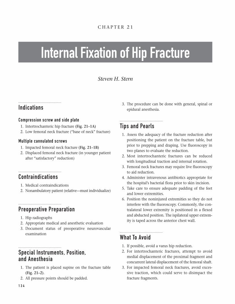
Indications
Compression screw and side plate1. Intertrochanteric hip fracture (Fig. 21–1A)2. Low femoral neck fracture (“base of neck” fracture)
Multiple cannulated screws1. Impacted femoral neck fracture (Fig. 21–1B)2. Displaced femoral neck fracture (in younger patient
after “satisfactory” reduction)
Contraindications1. Medical contraindications2. Nonambulatory patient (relative—must individualize)
Preoperative Preparation1. Hip radiographs2. Appropriate medical and anesthetic evaluation3. Document status of preoperative neurovascular
examination
Special Instruments, Position, and Anesthesia1. The patient is placed supine on the fracture table
(Fig. 21–2).2. All pressure points should be padded.
3. The procedure can be done with general, spinal orepidural anesthesia.
Tips and Pearls1. Assess the adequacy of the fracture reduction after
positioning the patient on the fracture table, butprior to prepping and draping. Use fluoroscopy intwo planes to evaluate the reduction.
2. Most intertrochanteric fractures can be reducedwith longitudinal traction and internal rotation.
3. Femoral neck fractures may require live fluoroscopyto aid reduction.
4. Administer intravenous antibiotics appropriate forthe hospital’s bacterial flora prior to skin incision.
5. Take care to ensure adequate padding of the feetand lower extremities.
6. Position the noninjured extremities so they do notinterfere with the fluoroscopy. Commonly, the con-tralateral lower extremity is positioned in a flexedand abducted position. The ispilateral upper extrem-ity is taped across the anterior chest wall.
What To Avoid1. If possible, avoid a varus hip reduction.2. For intertrochanteric fractures, attempt to avoid
medial displacement of the proximal fragment andconcurrent lateral displacement of the femoral shaft.
3. For impacted femoral neck fractures, avoid exces-sive traction, which could serve to disimpact thefracture fragments.
1 3 4
C H A P T E R 2 1
Internal Fixation of Hip Fracture
Steven H. Stern
4. Avoid placing the cannulated screws below the levelof the lesser trochanter. This can result in a “stressriser” in the lateral femoral cortex and increase therisk of a subtrochanteric fracture.
5. Avoid allowing the guidepin to penetrate throughthe femoral head into the soft tissues of the pelvis.
Postoperative Care Issues1. When medically possible, attempt to mobilize the
patient in the postoperative period. If the medicalcondition permits, the patient should be placed in asitting position as expeditiously as possible.
2. Consider utilizing some form of deep-vein thrombosisprophylaxis. Options include warfarin, low-molecu-lar weight heparin, and intermittent pneumaticcompression.
3. Depending on the fracture stability, adequacy of thereduction and the patient’s bone quality, ambula-tion can commence either with non-weight bearing(NWB), toe-touch weight bearing (TTWB) or weightbearing as tolerated (WBAT).
4. Reassessment of the distal neurovascular examina-tion should be done after surgery.
Operative TechniqueCompression screw and side plate1. Position the patient supine on the fracture table.
The patient should be positioned directly againstthe groin post. Pad the extremities. Most fracturescan be reduced with a combination of traction andinternal rotation. The degree of internal rotation canbe assessed by evaluating knee rotation (Fig. 21–2).
2. Prior to prepping and draping the patient, evaluatethe fracture using biplanar fluoroscopy. It is impor-tant prior to draping to assess the patient’s positionto ensure that the fluoroscopic C-arm adequatelyobtains satisfactory AP and lateral hip images. Opti-mize the fracture reduction at this time.
3. Prepare and drape the patient and extremity per thehospital’s standard sterile protocol. Commonly, alarge plastic drape (“shower curtain”) is utilized.
4. Obtain an AP hip fluoroscopic image to assist inpositioning the skin incision. Place a metal clamp
or Steinman pin on the anterior thigh so it serves asa visible landmark on the fluoroscopic image.
5. Make a skin incision along the lateral aspect of thethigh. Palpate the femur to ensure that the incisionis positioned in the femur’s AP mid-point. The skinincision should be approximately 15 cm in length.The incision’s proximal pole should extend 1 to 2 cm proximal to the lesser trochanter (Fig. 21–3).
6. Carry the dissection directly through the subcuta-neous tissue. Maintain adequate hemostasis. Identifythe tensor fascia lata (Fig. 21–4).
7. Sharply incise the tensor fascia lata longitudinally.Place retractors deep to the tensor fascia lata.Identify the vastus lateralis.
8. Retract the vastus lateralis anteriorly. Sharply incisethe fascia of the vastus lateralis longitudinally. Thisincision is positioned to allow dissection throughthe posterior one-third of the vastus lateralis. Takecare to incise only the fascia and not the muscle(Fig. 21–5).
9. Use a periosteal elevator to bluntly dissect throughthe muscle fibers of the vastus lateralis. Carry thedissection down to the femur. Place a Bennett retrac-tor over the anterior femur so it lies against themedial femoral cortex. Use it to retract the soft tis-sues medially to enhance visualization (Fig. 21–6).
10. Use a medium- (~3.5 mm—commonly, the drill bitthat will be used later in the procedure for the cor-tical screws is used) size drill bit to locate the opti-mal starting point on the lateral femoral cortex for the compression screw. Optimize the superior-inferior starting hole position by evaluating APfluoroscopic hip images. Generally, the startinghole should be at or below the level of the lessertrochanter. Palpate the femur to ensure that thestarting hole is midway between the anterior andposterior femoral cortex (Fig. 21–6).
11. Drill the hole through the lateral femoral cortex.First start drilling perpendicular to the bone’s longaxis to gain purchase in the lateral femoral cortex.Then drill a “sloppy” hole by aiming the drill at theapproximate angle desired for the compressionscrew. The “sloppy” hole enhances accurate place-ment of the guidepin in the next step.
12. Introduce the guidepin into the hole in the lateral femoral cortex. Drill the guidepin throughthe femoral neck and into the femoral head. The
2 1 I N T E R N A L F I X AT I O N O F H I P F R A C T U R E 1 3 5
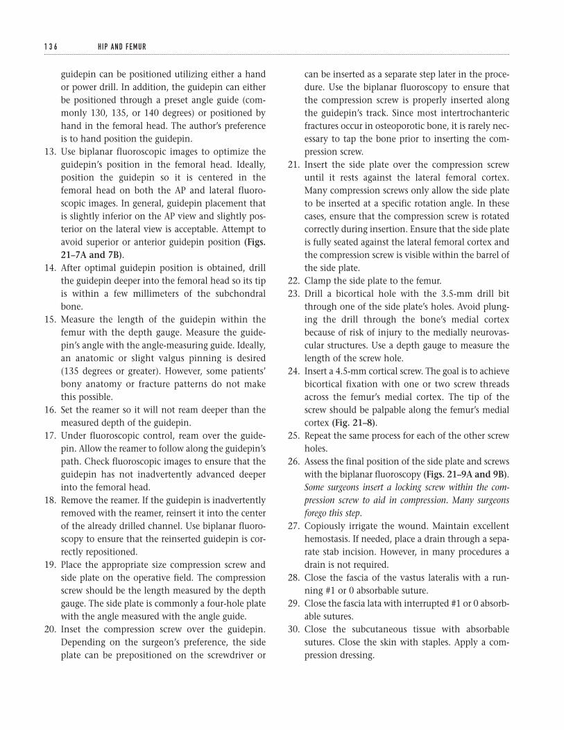
guidepin can be positioned utilizing either a handor power drill. In addition, the guidepin can eitherbe positioned through a preset angle guide (com-monly 130, 135, or 140 degrees) or positioned byhand in the femoral head. The author’s preferenceis to hand position the guidepin.
13. Use biplanar fluoroscopic images to optimize theguidepin’s position in the femoral head. Ideally,position the guidepin so it is centered in thefemoral head on both the AP and lateral fluoro-scopic images. In general, guidepin placement thatis slightly inferior on the AP view and slightly pos-terior on the lateral view is acceptable. Attempt toavoid superior or anterior guidepin position (Figs.21–7A and 7B).
14. After optimal guidepin position is obtained, drillthe guidepin deeper into the femoral head so its tipis within a few millimeters of the subchondralbone.
15. Measure the length of the guidepin within thefemur with the depth gauge. Measure the guide-pin’s angle with the angle-measuring guide. Ideally,an anatomic or slight valgus pinning is desired(135 degrees or greater). However, some patients’bony anatomy or fracture patterns do not makethis possible.
16. Set the reamer so it will not ream deeper than themeasured depth of the guidepin.
17. Under fluoroscopic control, ream over the guide-pin. Allow the reamer to follow along the guidepin’spath. Check fluoroscopic images to ensure that theguidepin has not inadvertently advanced deeperinto the femoral head.
18. Remove the reamer. If the guidepin is inadvertentlyremoved with the reamer, reinsert it into the centerof the already drilled channel. Use biplanar fluoro-scopy to ensure that the reinserted guidepin is cor-rectly repositioned.
19. Place the appropriate size compression screw andside plate on the operative field. The compressionscrew should be the length measured by the depthgauge. The side plate is commonly a four-hole platewith the angle measured with the angle guide.
20. Inset the compression screw over the guidepin.Depending on the surgeon’s preference, the sideplate can be prepositioned on the screwdriver or
can be inserted as a separate step later in the proce-dure. Use the biplanar fluoroscopy to ensure thatthe compression screw is properly inserted alongthe guidepin’s track. Since most intertrochantericfractures occur in osteoporotic bone, it is rarely nec-essary to tap the bone prior to inserting the com-pression screw.
21. Insert the side plate over the compression screwuntil it rests against the lateral femoral cortex.Many compression screws only allow the side plateto be inserted at a specific rotation angle. In thesecases, ensure that the compression screw is rotatedcorrectly during insertion. Ensure that the side plateis fully seated against the lateral femoral cortex andthe compression screw is visible within the barrel ofthe side plate.
22. Clamp the side plate to the femur.23. Drill a bicortical hole with the 3.5-mm drill bit
through one of the side plate’s holes. Avoid plung-ing the drill through the bone’s medial cortexbecause of risk of injury to the medially neurovas-cular structures. Use a depth gauge to measure thelength of the screw hole.
24. Insert a 4.5-mm cortical screw. The goal is to achievebicortical fixation with one or two screw threadsacross the femur’s medial cortex. The tip of thescrew should be palpable along the femur’s medialcortex (Fig. 21–8).
25. Repeat the same process for each of the other screwholes.
26. Assess the final position of the side plate and screwswith the biplanar fluoroscopy (Figs. 21–9A and 9B).Some surgeons insert a locking screw within the com-pression screw to aid in compression. Many surgeonsforego this step.
27. Copiously irrigate the wound. Maintain excellenthemostasis. If needed, place a drain through a sepa-rate stab incision. However, in many procedures adrain is not required.
28. Close the fascia of the vastus lateralis with a run-ning #1 or 0 absorbable suture.
29. Close the fascia lata with interrupted #1 or 0 absorb-able sutures.
30. Close the subcutaneous tissue with absorbablesutures. Close the skin with staples. Apply a com-pression dressing.
1 3 6 H I P A N D F E M U R
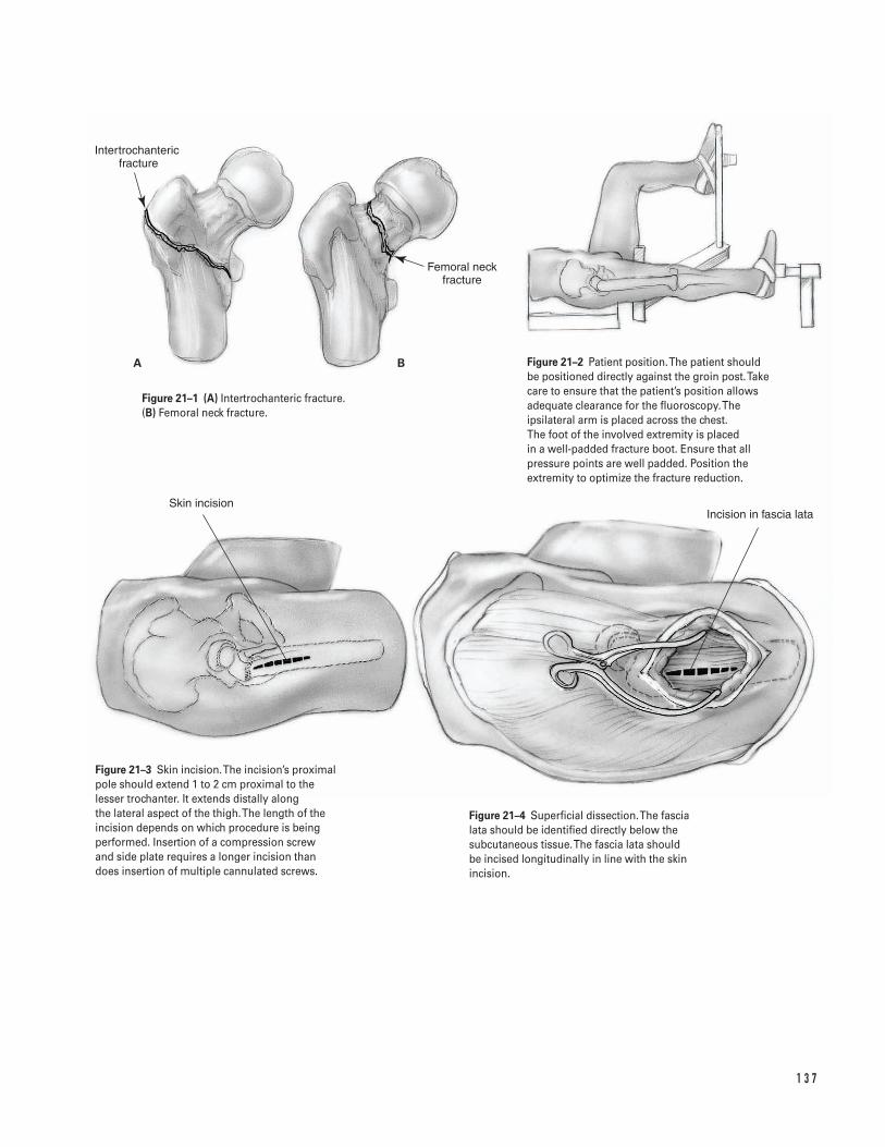
1 3 7
A B
Intertrochanteric �fracture
Femoral neck fracture
Skin incisionIncision in fascia lata
Figure 21–1 (A) Intertrochanteric fracture. (B) Femoral neck fracture.
Figure 21–2 Patient position. The patient shouldbe positioned directly against the groin post. Takecare to ensure that the patient’s position allowsadequate clearance for the fluoroscopy. Theipsilateral arm is placed across the chest. The foot of the involved extremity is placed in a well-padded fracture boot. Ensure that allpressure points are well padded. Position theextremity to optimize the fracture reduction.
Figure 21–3 Skin incision. The incision’s proximalpole should extend 1 to 2 cm proximal to thelesser trochanter. It extends distally along the lateral aspect of the thigh. The length of theincision depends on which procedure is beingperformed. Insertion of a compression screw and side plate requires a longer incision thandoes insertion of multiple cannulated screws.
Figure 21–4 Superficial dissection. The fascia lata should be identified directly below thesubcutaneous tissue. The fascia lata should be incised longitudinally in line with the skinincision.
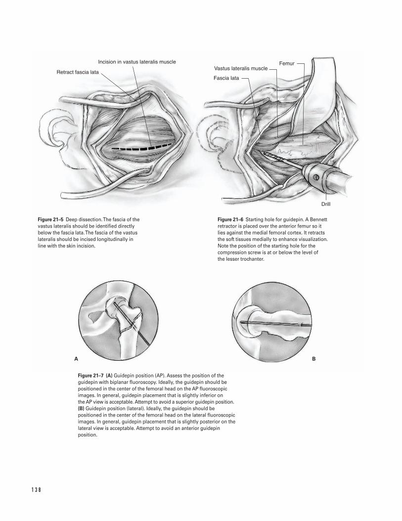
1 3 8
A B
Retract fascia lata
Incision in vastus lateralis muscle
Fascia lata
Vastus lateralis muscleFemur
Drill
Figure 21–5 Deep dissection. The fascia of thevastus lateralis should be identified directlybelow the fascia lata. The fascia of the vastuslateralis should be incised longitudinally in line with the skin incision.
Figure 21–6 Starting hole for guidepin. A Bennettretractor is placed over the anterior femur so itlies against the medial femoral cortex. It retractsthe soft tissues medially to enhance visualization.Note the position of the starting hole for thecompression screw is at or below the level of the lesser trochanter.
Figure 21–7 (A) Guidepin position (AP). Assess the position of theguidepin with biplanar fluoroscopy. Ideally, the guidepin should bepositioned in the center of the femoral head on the AP fluoroscopicimages. In general, guidepin placement that is slightly inferior on the AP view is acceptable. Attempt to avoid a superior guidepin position.(B) Guidepin position (lateral). Ideally, the guidepin should bepositioned in the center of the femoral head on the lateral fluoroscopicimages. In general, guidepin placement that is slightly posterior on thelateral view is acceptable. Attempt to avoid an anterior guidepinposition.
Multiple cannulated screws1. Position the patient supine on the fracture table.
The patient should be positioned directly againstthe groin post. Pad the extremities. For impactedfemoral neck fractures, avoid excessive traction,which could disimpact the fracture fragments. Thedegree of hip rotation can be assessed by evaluatingknee rotation (Fig. 21–2).
2. Prior to prepping and draping the patient, evaluatethe fracture using biplanar fluoroscopy. It is impor-tant prior to draping to assess the patient’s positionto ensure that the fluoroscopic C-arm adequatelyobtains satisfactory AP and lateral hip images. Op-timize the fracture reduction at this time.
3. Prepare and drape the patient and extremity per thehospital’s standard sterile protocol. Commonly, alarge plastic drape (“shower curtain”) is utilized.
4. Obtain an AP hip fluoroscopic image to assist inpositioning the skin incision. Place a metal clampor guidepin on the anterior thigh so it serves as avisible landmark on the fluoroscopic image.
5. Make a skin incision along the lateral aspect of thethigh. Palpate the femur to ensure that the incisionis positioned in the femur’s anteroposterior mid-point. The skin incision should be long enough forplacement of three screws. The incision’s proximalpole should extend 1 to 2 cm proximal to the lessertrochanter (Fig. 21–3).
6. Carry the dissection directly through the sub-cutaneous tissue. Maintain adequate hemostasis.Identify the fascia lata (Fig. 21–4).
7. Sharply incise the tensor fascia lata longitudinally.Place retractors deep to the tensor fascia lata. Identifythe vastus lateralis.
8. Retract the vastus lateralis anteriorly. For most frac-tures, it is not necessary to incise the fascia of thevastus lateralis.
9. Place the guidepin for the cannulated screwthrough the vastus lateralis directly onto the lateralfemoral cortex. Optimize the superior-inferior posi-tion by evaluating AP fluoroscopic hip images. Theguidepin should be at or above the level of thelesser trochanter. Avoid positioning the guidepinbelow the level of the lesser trochanter. In general,most fractures can be fixed with three screws placedin a triangular configuration with the apex of the
triangle inferior. Commonly, the guidepin for theinferior screw is the first one inserted.
10. Use a power drill to insert the guidepin through the femoral neck and into the femoral head. Usebiplanar fluoroscopic images to optimize the guide-pin’s position in the femoral head. Ideally, positionthe first guidepin so it is in the inferior portion of thefemoral head on the AP fluoroscopic images and inthe center of the femoral head on the lateral fluoro-scopic images.
11. After optimal guidepin position is obtained, drill theguidepin deeper into the femoral head so its tip iswithin a few millimeters of the subchondral bone.
12. Insert two more guidepins utilizing either a “free-hand” technique or by inserting the guidepinsthrough a triangular template guide. Commonly, atriangular configuration with the apex of the tri-angle inferior is employed. Therefore, one pin shouldbe slightly superior-anterior and one pin superior-posterior to the initial inferior guidepin. Use bipla-nar fluoroscopy to optimize the position of theseguidepins within the femoral head.
13. Check to ensure that all of the guidepins are drilledwithin the femoral head so the tip is within a fewmillimeters of the subchondral bone. Starting withthe inferior guidepin, measure the length of theguidepin within the femur with a depth gauge.
14. Insert the appropriate length cannulated screw overthe guidepin. If self-tapping screws are utilized or ifthe bone is significantly osteoporotic, it is notnecessary to overdrill the lateral femoral cortex.However, if needed, make a starting hole in the lat-eral femoral cortex with a cannulated drill insertedover the guidepin.
15. Insert the screws so they are fully seated. Check toensure that all of the screw threads lie in the proxi-mal femoral head fragment. Ideally, when the screwis fully seated, none of the threads should lie acrossthe fracture.
16. Using a similar technique, insert the other twoscrews over the remaining two guidepins.
17. Assess the final position of the screws with thebiplanar fluoroscopy (Figs. 21–10A and 10B).
18. Copiously irrigate the wound. Maintain excellenthemostasis. In most procedures a drain is notrequired.
2 1 I N T E R N A L F I X AT I O N O F H I P F R A C T U R E 1 3 9
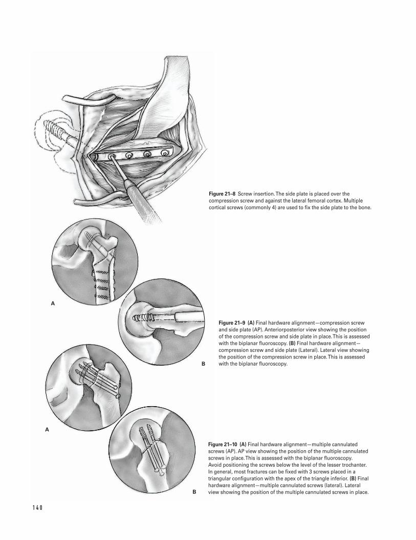
1 4 0
A
B
A
B
Figure 21–8 Screw insertion. The side plate is placed over thecompression screw and against the lateral femoral cortex. Multiplecortical screws (commonly 4) are used to fix the side plate to the bone.
Figure 21–9 (A) Final hardware alignment—compression screw and side plate (AP). Anteriorposterior view showing the position of the compression screw and side plate in place. This is assessed with the biplanar fluoroscopy. (B) Final hardware alignment—compression screw and side plate (Lateral). Lateral view showing the position of the compression screw in place. This is assessed with the biplanar fluoroscopy.
Figure 21–10 (A) Final hardware alignment—multiple cannulatedscrews (AP). AP view showing the position of the multiple cannulatedscrews in place. This is assessed with the biplanar fluoroscopy. Avoid positioning the screws below the level of the lesser trochanter.In general, most fractures can be fixed with 3 screws placed in atriangular configuration with the apex of the triangle inferior. (B) Finalhardware alignment—multiple cannulated screws (lateral). Lateralview showing the position of the multiple cannulated screws in place.
19. Close the fascia lata with interrupted #1 or 0absorbable sutures.
20. Close the subcutaneous tissue with absorbablesutures. Close the skin with staples. Apply a com-pression dressing.
Suggested ReadingsBartlett CS III, Buly, RL, Helfet, DL. Intertrochantericand subtrochanteric fractures of the proximal femur. In:Craig EV, ed. Clinical Orthopaedics. Baltimore, MD:Lippincott Williams & Willkins, 1999, pp. 439–478.
Brennan, MJ. Intertrochanteric femur fractures. In:Levine AM, ed. Orthopaedic Knowledge Update: Trauma.
Rosemont, IL: American Academy of OrthopaedicSurgeons, 1996, pp. 121–126.
Cornell, CN. Intracapsular fractures of the femoralneck. In: Craig EV, ed. Clinical Orthopaedics. Baltimore,MD: Lippincott Williams & Willkins, 1999, pp. 479–490.
Proceedings of the American College of Chest Physicians5th Consensus on Antithrombotic Therapy. Chest 1998;114(Suppl 5):439S–769S.
Turen, CH. Intracapsular hip fractures. In: Levine AM,ed. Orthopaedic Knowledge Update: Trauma. Rosemont,IL: American Academy of Orthopaedic Surgeons, 1996,pp. 113–120.
2 1 I N T E R N A L F I X AT I O N O F H I P F R A C T U R E 1 4 1
Indications1. Displaced femoral neck fractures not appropriate for
reduction and internal fixation2. Displaced low femoral neck fractures (“base of neck”)
not appropriate for reduction and internal fixation
Contraindications1. Proximal femoral fracture in the setting of active
sepsis: either acute osteomyelitis or acute suppara-tive arthritis (absolute)
2. Proximal femoral fracture in the setting of neuro-pathic joint (relative)
3. Proximal femoral fracture in patients unable orunwilling to comply with postoperative protocolsthat minimize the risk of hip dislocation (relative)
4. Decubitus wounds contiguous with the plannedsurgical incision (relative)
Preoperative PreparationFractures of the proximal femur are a sentinel event in the life of any patient. Femoral neck fractures inpatients under the age of 50 usually result either fromhigh-energy trauma or in association with significantmetabolic bone disease that has weakened the femur.Femoral neck fractures in the elderly are usually not
high-energy injuries, but frequently occur in patientswith significant medical cormorbidities. Elderly patientswith these fractures are at a significant risk for morbid-ity and/or mortality in the perioperative period. Thesefacts should always be remembered when treating apatient with a proximal femoral fracture.
1. Complete history and physical examination2. Appropriate medical and anesthetic evaluation3. Document preoperative neurovascular status.4. Examine and document the status of the skin’s
integrity since many of the patients are at risk forpostoperative decubitus ulcers.
5. Radiographs including anteroposterior (AP) of thepelvis and lateral of the proximal femur. Occultfractures may not be apparent on plain radiographsand require either magnetic resonance imaging(MRI) or bone scintingraphy to diagnose a fracture.
6. The preoperative radiographs should be assessed inconjunction with the appropriate hip prosthetictemplates to determine approximate componentsizes. Preoperative templating should be performedto determine:
a. Level of femoral neck resectionb. Femoral component sizec. Distances from fixed points on the femur to the
center of hip rotation in order to help optimizepostoperative limb length
d. If the femoral implant adequately reconstructsfemoral offset and proper hip mechanics
1 4 2
C H A P T E R 2 2
Hip FractureHemiarthroplasty
Douglas E. Padgett
e. Approximate size of bipolar head to be utilized.With current modular systems, the size of thebipolar cup determines the femoral head size(22, 26, or 28 mm) that allows adequate poly-ethylene thickness.
Special Instruments, Position, and Anesthesia1. The patient is placed in the lateral decubitus posi-
tion with the affected hip upward. Adequatepadding of the axilla is necessary to avoid injury tothe brachial plexus. While the patient must besecure on the operating room table, excessive tight-ening of pelvic posts should be avoided, since thiscan compromise the neurovascular status of the“down-leg” (Fig. 22–1).
2. All pressure points should be padded.3. The procedure can be done with general, epidural,
or long-acting spinal anesthesia. There is some evi-dence that epidural anesthesia decreases the risk ofdeep-vein thrombosis as well as decreasing bloodloss during total hip arthroplasty (presumably by areduction in pelvic venous pressure). In addition,postoperative analgesia may be administered viathe epidural catheter.
4. Instruments required for hemiarthroplasty includeself-retaining retractors, straight and bent Hohman-type retractors, a femoral neck elevator to facilitateexposure of the proximal femur, and power saws. Inaddition, the specific instruments, broaches, andtrial components unique to the prosthesis to beimplanted should be available.
5. Consider using enclosed helmets and body exhausts,which may help minimize the risk of perioperativesepsis.
6. Intravenous antibiotics appropriate for the hospi-tal’s bacterial flora should be administered prior totourniquet inflation and continued for at least 24 hafter surgery.
Tips and Pearls1. Accurate re-establishment of the preoperative leg
length is difficult to accomplish in the setting of a
displaced femoral neck fracture. On occasion, theapproximate leg length can be estimated basedupon the opposite extremity.
2. Due to the edema associated with an acute hip frac-ture, some of the tissue planes adjacent to the poste-rior capsule can be difficult to identify. If necessary,consider taking down the posterior capsule and shortexternal rotator tendons as one large flap.
3. The use of a ligamentum teres knife (a curved blade)is useful in aiding extraction of the femoral headfrom the acetabulum.
4. If the bone is extremely osteoporotic, considerusing only broaches for femoral preparation (tocompact the cancellous bone) rather than a combi-nation of broaching and reaming (which tends toremove the cancellous bone bed).
5. The size of the bipolar head is determined by feel.Consider measuring the diameter of the excisedfemoral head. This serves as a rough guide for theappropriate size of the bipolar head. The trial bipo-lar head should fit easily into the acetabular socket.However, there should be a slight suction fit of thetrial component.
6. Optimizing stability with bipolar hemiarthroplastyis essential. In situations where there is a large fixed flexion contracture with adduction, alteringsurgical approach to an anterior or anterolateral(Hardinge) approach can be considered.
7. The use of cement for femoral component fixationis recommended for treatment of the majority ofthese fractures.
What To Avoid1. Because of the problems associated with infection,
great care is taken to minimize this complication.Operating room traffic should be minimized, andpreoperative antibiotics administered.
2. Avoid “overstuffing” the acetabulum socket with anoversized bipolar component. This may be a sourceof postoperative groin pain or increase the risk ofcomponent dislocation in some patients.
3. Avoid compromising cement technique in order to“rush through” the case. An adequate cement man-tel is critical for success in both total hip arthroplasty
2 2 H I P F R A C T U R E 1 4 3
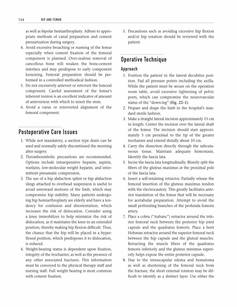
as well as bipolar hemiarthroplasty. Adhere to appro-priate methods of canal preparation and cementpressurization during surgery.
4. Avoid excessive broaching or reaming of the femurespecially when cement fixation of the femoralcomponent is planned. Over-zealous removal ofcancellous bone will weaken the bone-cementinterface and may predispose to early componentloosening. Femoral preparation should be per-formed in a controlled methodical fashion.
5. Do not excessively antevert or retrovert the femoralcomponent. Careful assessment of the femur’sinherent torsion is an excellent indicator of amountof anteversion with which to insert the stem.
6. Avoid a varus or retroverted alignment of thefemoral component.
Postoperative Care Issues1. While not mandatory, a suction type drain can be
used and normally safely discontinued the morningafter surgery.
2. Thromboembolic precautions are recommended.Options include intraoperative heparin, aspirin,warfarin, low-molecular weight heparin, and inter-mittent pneumatic compression.
3. The use of a hip abduction splint or hip abductionslings attached to overhead suspension is useful toavoid untoward motions of the limb, which maycompromise hip stability. Many patients undergo-ing hip hemiarthroplasty are elderly and have a ten-dency for confusion and disorientation, whichincreases the risk of dislocation. Consider using a knee immobilizer to help minimize the risk ofdislocation, as it maintains the knee in an extendedposition, thereby making hip flexion difficult. Thus,the chance that the hip will be placed in a hyper-flexed position, which predisposes it to dislocation,is reduced.
4. Weight-bearing status is dependent upon fixation,integrity of the trochanter, as well as the presence ofany other associated fractures. This informationmust be conveyed to the physical therapy staff andnursing staff. Full weight bearing is most commonwith cement fixation.
5. Precautions such as avoiding excessive hip flexionand/or hip rotation should be reviewed with thepatient.
Operative TechniqueApproach1. Position the patient in the lateral decubitus posi-
tion. Pad all pressure points including the axilla.While the patient must be secure on the operationroom table, avoid excessive tightening of pelvicposts, which can compromise the neurovascularstatus of the “down-leg” (Fig. 22–1).
2. Prepare and drape the limb in the hospital’s stan-dard sterile fashion.
3. Make a straight lateral incision approximately 15 cmin length. Center the incision over the lateral shaftof the femur. The incision should start approxi-mately 5 cm proximal to the tip of the greatertrochanter and extend distally about 10 cm.
4. Carry the dissection directly through the subcuta-neous tissue. Maintain adequate hemostasis.Identify the fascia lata.
5. Incise the fascia lata longitudinally. Bluntly split thefibers of the gluteus maximus at the proximal poleof the fascia lata.
6. Insert a self-retaining retractor. Partially release thefemoral insertion of the gluteus maximus tendonwith the electrocautery. This greatly facilitates ante-rior translation of the femur that will be necessaryfor acetabular preparation. Attempt to avoid thesmall perforating branches of the profunda femorisartery.
7. Place a cobra (“Aufranc”) retractor around the infe-rior femoral neck between the posterior hip jointcapsule and the quadratus femoris. Place a bentHohman retractor around the superior femoral neckbetween the hip capsule and the gluteal muscles.Retracting the muscle fibers of the quadratusfemoris inferiorly and the gluteus minimus superi-orly helps expose the entire posterior capsule.
8. Due to the intrascapular edema and hematoma as well as shortening of the femoral neck from the fracture, the short external rotators may be dif-ficult to identify as a distinct layer. Use either the
1 4 4 H I P A N D F E M U R
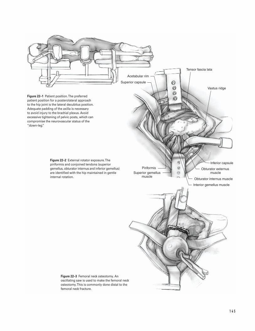
1 4 5
Acetabular rim
Superior capsule
PiriformisSuperior gemellus
muscle
Inferior capsule
Obturator externus muscle
Obturator internus muscle
Interior gemellus muscle
Tensor fascia lata
Vastus ridge
Figure 22–1 Patient position. The preferredpatient position for a posterolateral approach to the hip joint is the lateral decubitus position.Adequate padding of the axilla is necessary to avoid injury to the brachial plexus. Avoidexcessive tightening of pelvic posts, which cancompromise the neurovascular status of the“down-leg.”
Figure 22–2 External rotator exposure. Thepiriformis and conjoined tendons (superiorgemellus, obturator internus and inferior gemellus)are identified with the hip maintained in gentleinternal rotation.
Figure 22–3 Femoral neck osteotomy. Anoscillating saw is used to make the femoral neckosteotomy.This is commonly done distal to thefemoral neck fracture.
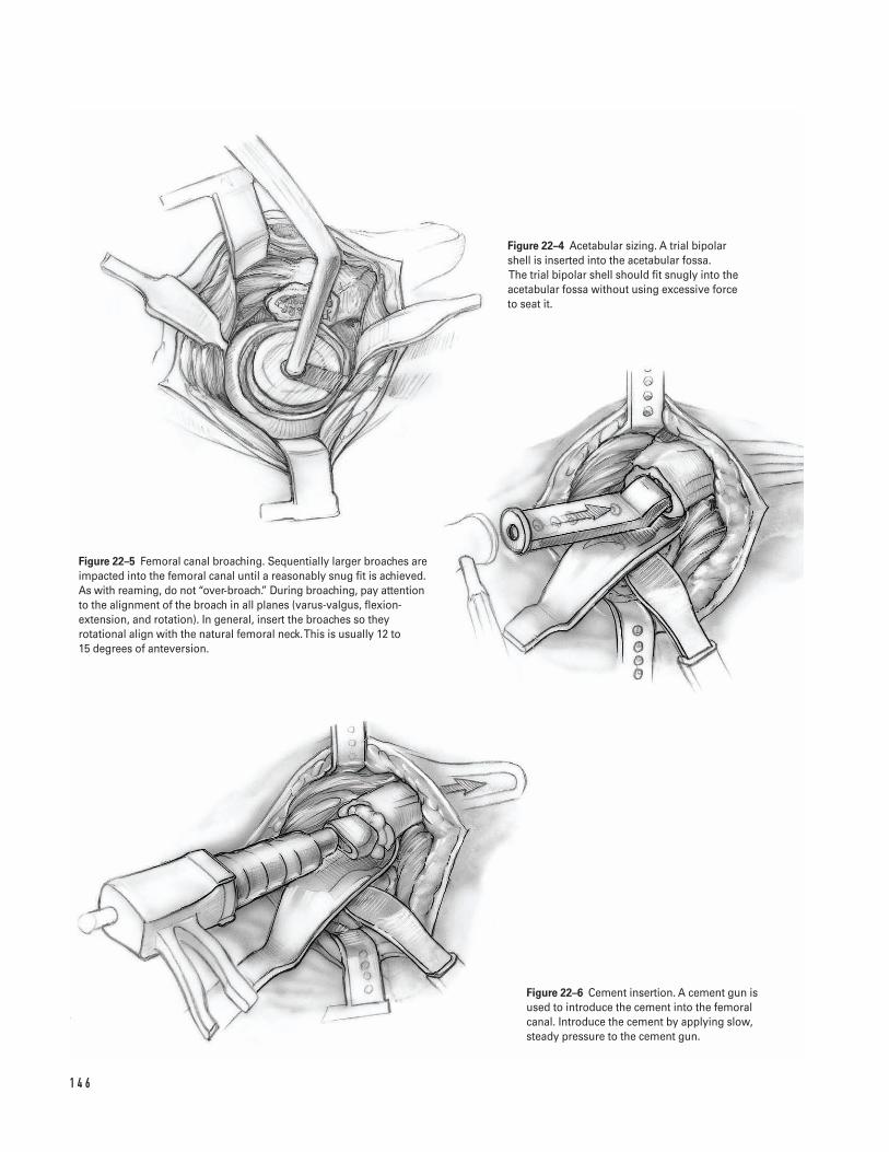
1 4 6
Figure 22–4 Acetabular sizing. A trial bipolarshell is inserted into the acetabular fossa.The trial bipolar shell should fit snugly into theacetabular fossa without using excessive force to seat it.
Figure 22–5 Femoral canal broaching. Sequentially larger broaches areimpacted into the femoral canal until a reasonably snug fit is achieved.As with reaming, do not “over-broach.” During broaching, pay attentionto the alignment of the broach in all planes (varus-valgus, flexion-extension, and rotation). In general, insert the broaches so theyrotational align with the natural femoral neck. This is usually 12 to 15 degrees of anteversion.
Figure 22–6 Cement insertion. A cement gun isused to introduce the cement into the femoralcanal. Introduce the cement by applying slow,steady pressure to the cement gun.
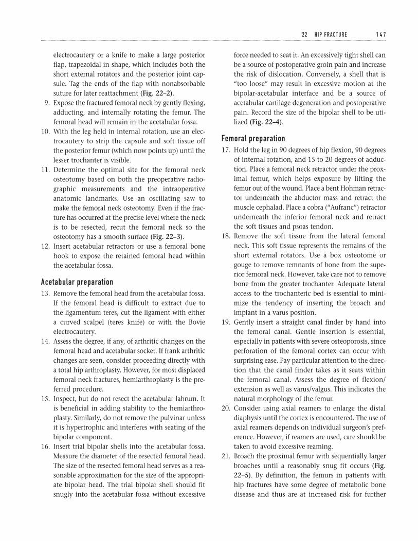
electrocautery or a knife to make a large posteriorflap, trapezoidal in shape, which includes both theshort external rotators and the posterior joint cap-sule. Tag the ends of the flap with nonabsorbablesuture for later reattachment (Fig. 22–2).
9. Expose the fractured femoral neck by gently flexing,adducting, and internally rotating the femur. Thefemoral head will remain in the acetabular fossa.
10. With the leg held in internal rotation, use an elec-trocautery to strip the capsule and soft tissue off the posterior femur (which now points up) until thelesser trochanter is visible.
11. Determine the optimal site for the femoral neckosteotomy based on both the preoperative radio-graphic measurements and the intraoperativeanatomic landmarks. Use an oscillating saw tomake the femoral neck osteotomy. Even if the frac-ture has occurred at the precise level where the neckis to be resected, recut the femoral neck so theosteotomy has a smooth surface (Fig. 22–3).
12. Insert acetabular retractors or use a femoral bonehook to expose the retained femoral head withinthe acetabular fossa.
Acetabular preparation13. Remove the femoral head from the acetabular fossa.
If the femoral head is difficult to extract due to the ligamentum teres, cut the ligament with either a curved scalpel (teres knife) or with the Bovieelectrocautery.
14. Assess the degree, if any, of arthritic changes on thefemoral head and acetabular socket. If frank arthriticchanges are seen, consider proceeding directly witha total hip arthroplasty. However, for most displacedfemoral neck fractures, hemiarthroplasty is the pre-ferred procedure.
15. Inspect, but do not resect the acetabular labrum. Itis beneficial in adding stability to the hemiarthro-plasty. Similarly, do not remove the pulvinar unlessit is hypertrophic and interferes with seating of thebipolar component.
16. Insert trial bipolar shells into the acetabular fossa.Measure the diameter of the resected femoral head.The size of the resected femoral head serves as a rea-sonable approximation for the size of the appropri-ate bipolar head. The trial bipolar shell should fitsnugly into the acetabular fossa without excessive
force needed to seat it. An excessively tight shell canbe a source of postoperative groin pain and increasethe risk of dislocation. Conversely, a shell that is“too loose” may result in excessive motion at thebipolar-acetabular interface and be a source ofacetabular cartilage degeneration and postoperativepain. Record the size of the bipolar shell to be uti-lized (Fig. 22–4).
Femoral preparation17. Hold the leg in 90 degrees of hip flexion, 90 degrees
of internal rotation, and 15 to 20 degrees of adduc-tion. Place a femoral neck retractor under the prox-imal femur, which helps exposure by lifting thefemur out of the wound. Place a bent Hohman retrac-tor underneath the abductor mass and retract themuscle cephalad. Place a cobra (“Aufranc”) retractorunderneath the inferior femoral neck and retractthe soft tissues and psoas tendon.
18. Remove the soft tissue from the lateral femoralneck. This soft tissue represents the remains of theshort external rotators. Use a box osteotome orgouge to remove remnants of bone from the supe-rior femoral neck. However, take care not to removebone from the greater trochanter. Adequate lateralaccess to the trochanteric bed is essential to mini-mize the tendency of inserting the broach andimplant in a varus position.
19. Gently insert a straight canal finder by hand intothe femoral canal. Gentle insertion is essential,especially in patients with severe osteoporosis, sinceperforation of the femoral cortex can occur withsurprising ease. Pay particular attention to the direc-tion that the canal finder takes as it seats within the femoral canal. Assess the degree of flexion/extension as well as varus/valgus. This indicates thenatural morphology of the femur.
20. Consider using axial reamers to enlarge the distaldiaphysis until the cortex is encountered. The use ofaxial reamers depends on individual surgeon’s pref-erence. However, if reamers are used, care should betaken to avoid excessive reaming.
21. Broach the proximal femur with sequentially largerbroaches until a reasonably snug fit occurs (Fig.22–5). By definition, the femurs in patients withhip fractures have some degree of metabolic bonedisease and thus are at increased risk for further
2 2 H I P F R A C T U R E 1 4 7
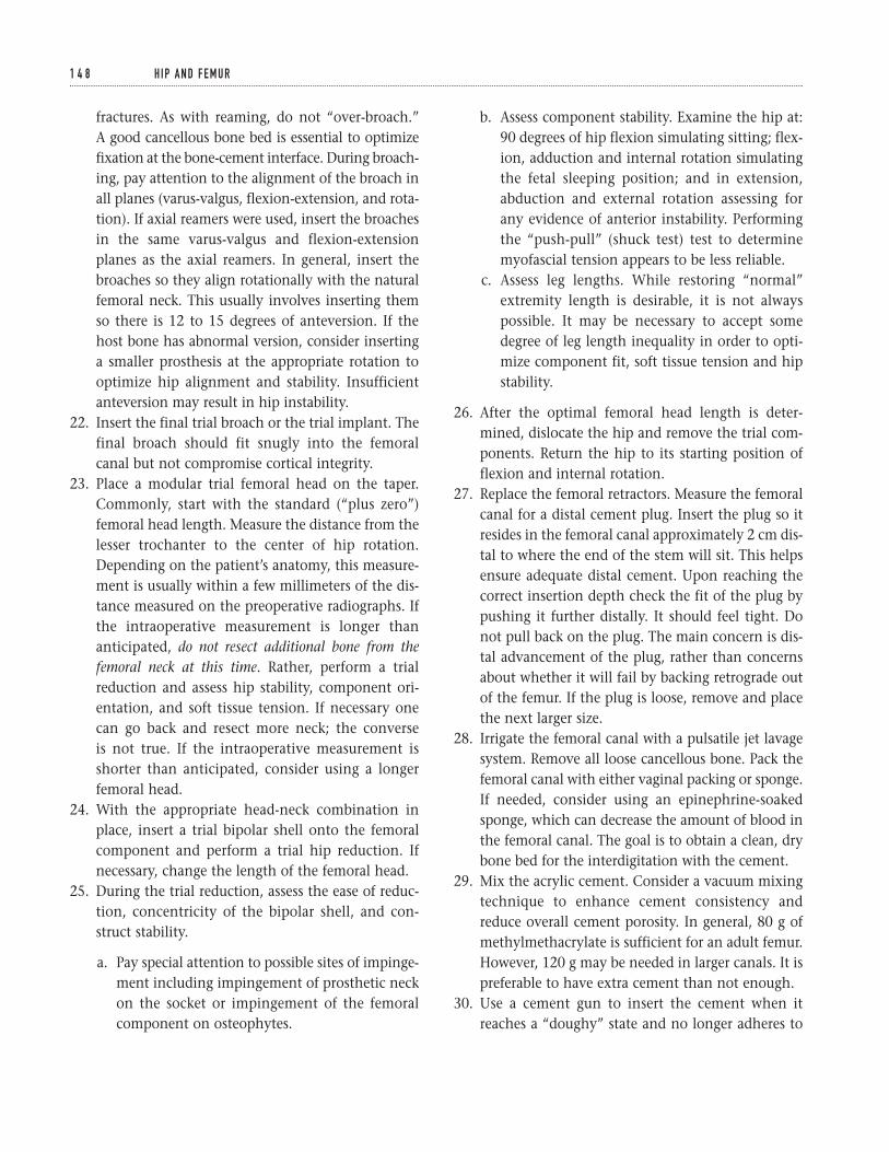
fractures. As with reaming, do not “over-broach.” A good cancellous bone bed is essential to optimizefixation at the bone-cement interface. During broach-ing, pay attention to the alignment of the broach inall planes (varus-valgus, flexion-extension, and rota-tion). If axial reamers were used, insert the broachesin the same varus-valgus and flexion-extensionplanes as the axial reamers. In general, insert thebroaches so they align rotationally with the naturalfemoral neck. This usually involves inserting themso there is 12 to 15 degrees of anteversion. If thehost bone has abnormal version, consider insertinga smaller prosthesis at the appropriate rotation tooptimize hip alignment and stability. Insufficientanteversion may result in hip instability.
22. Insert the final trial broach or the trial implant. Thefinal broach should fit snugly into the femoralcanal but not compromise cortical integrity.
23. Place a modular trial femoral head on the taper.Commonly, start with the standard (“plus zero”)femoral head length. Measure the distance from thelesser trochanter to the center of hip rotation.Depending on the patient’s anatomy, this measure-ment is usually within a few millimeters of the dis-tance measured on the preoperative radiographs. Ifthe intraoperative measurement is longer thananticipated, do not resect additional bone from thefemoral neck at this time. Rather, perform a trialreduction and assess hip stability, component ori-entation, and soft tissue tension. If necessary onecan go back and resect more neck; the converse is not true. If the intraoperative measurement isshorter than anticipated, consider using a longerfemoral head.
24. With the appropriate head-neck combination inplace, insert a trial bipolar shell onto the femoralcomponent and perform a trial hip reduction. Ifnecessary, change the length of the femoral head.
25. During the trial reduction, assess the ease of reduc-tion, concentricity of the bipolar shell, and con-struct stability.
a. Pay special attention to possible sites of impinge-ment including impingement of prosthetic neckon the socket or impingement of the femoralcomponent on osteophytes.
b. Assess component stability. Examine the hip at:90 degrees of hip flexion simulating sitting; flex-ion, adduction and internal rotation simulatingthe fetal sleeping position; and in extension,abduction and external rotation assessing forany evidence of anterior instability. Performingthe “push-pull” (shuck test) test to determinemyofascial tension appears to be less reliable.
c. Assess leg lengths. While restoring “normal”extremity length is desirable, it is not alwayspossible. It may be necessary to accept somedegree of leg length inequality in order to opti-mize component fit, soft tissue tension and hipstability.
26. After the optimal femoral head length is deter-mined, dislocate the hip and remove the trial com-ponents. Return the hip to its starting position offlexion and internal rotation.
27. Replace the femoral retractors. Measure the femoralcanal for a distal cement plug. Insert the plug so itresides in the femoral canal approximately 2 cm dis-tal to where the end of the stem will sit. This helpsensure adequate distal cement. Upon reaching thecorrect insertion depth check the fit of the plug bypushing it further distally. It should feel tight. Donot pull back on the plug. The main concern is dis-tal advancement of the plug, rather than concernsabout whether it will fail by backing retrograde outof the femur. If the plug is loose, remove and placethe next larger size.
28. Irrigate the femoral canal with a pulsatile jet lavagesystem. Remove all loose cancellous bone. Pack thefemoral canal with either vaginal packing or sponge.If needed, consider using an epinephrine-soakedsponge, which can decrease the amount of blood inthe femoral canal. The goal is to obtain a clean, drybone bed for the interdigitation with the cement.
29. Mix the acrylic cement. Consider a vacuum mixingtechnique to enhance cement consistency andreduce overall cement porosity. In general, 80 g ofmethylmethacrylate is sufficient for an adult femur.However, 120 g may be needed in larger canals. It ispreferable to have extra cement than not enough.
30. Use a cement gun to insert the cement when itreaches a “doughy” state and no longer adheres to
1 4 8 H I P A N D F E M U R
1 4 9
Figure 22–7 Femoral component insertion. The femoral stem is inserted into the femoralcanal along the same axis and with the samealignment and anteversion as the broaches. Theimplant should be inserted using predominatelymanual force and a mallet used to fully seat theimplant the last few millimeters down to the levelof the neck osteotomy.
Figure 22–8 Bipolar assembly. The appropriatebipolar shell is inserted onto the modular head. It is imperative that the bipolar shell is completelyseated on the modular head of the stem.
Figure 22–9 Bipolar reduction. The hip is reducedand stability reassessed. Figure 22–10 Closure external rotators. The tagging sutures for the
posterior capsule and short external rotators are pulled through the holes (two or three) in the greater trochanter.The capsule suturesare tied to each other and the short external rotator sutures are tied to each other.
the surgical gloves (Fig. 22–6). Push the cementnozzle down to, but not past, the cement plug.Introduce the cement by applying slow, steady pres-sure to the cement gun. Allow the cement pressureto gently push the gun out of the canal. Remove thegun when the femur is full of cement. Break off the nozzle. Attach the proximal pressurizer to thegun and place it against the upper femur. Insert the cement with slow, steady pressure. Commonly,this causes marrow extrusion out of nutrient foram-ina of the proximal femur. The anesthesia teamshould be alerted when femoral cementing com-mences. Some patients may respond to cementinsertion with hypotension and/or hypoxemia andrequire appropriate resuscitation.
31. Insert the stem along the same axis and at the samealignment that the broaches were inserted (Fig.22–7). In addition, take care to replicate componentversion. Use predominately manual force wheninserting the component, rather than using a mal-let. Additional cement pressurization is usuallyapparent at the time. Use a mallet to fully seat thelast few millimeters of the implant down to thelevel of the neck osteotomy. Perform a final checkof axial and torsional orientation.
32. Excise excess cement. Until cement polymerizationis complete, keep motion of the stem-femur com-posite to a minimum.
33. Clean and dry the modular taper. Insert the appro-priate modular head based on the trial reduction.Insert the appropriate bipolar shell onto the mod-ular head. It is imperative that the bipolar shellcompletely seat on the modular head of the stem(Fig. 22–8).
34. Irrigate the acetabular fossa. Inspect the acetabularfossa to ensure that there is no evidence of retainedbone debris, loose acrylic cement, or soft tissue.
35. Reduce the bipolar hemiarthroplasty into theacetabulum. Perform a final assessment of the com-ponent position and hip stability (Fig. 22–9).
Closure36. Irrigate the wound with copious antibiotic irrigation.37. Maintain appropriate hemostasis.38. If a suction drain is utilized, place it subfacial through
a separate incision that exits the anterolateral thigh
at the distal extent of the incision. Take carethroughout the closure to minimize the risk of inad-vertently sewing in the drain. Make two drill holes inthe posterolateral aspect of the greater trochanterapproximately 1 cm apart (it may be easier to makethese drill holes prior to reducing the hip).
39. Pull the tagging sutures on the short external rota-tors and posterior capsular flap through the holes.Tie the capsule sutures to each other; then tie the short external rotator sutures to each other (Fig. 22–10).
40. If possible, repair the quadratus femoris muscle-ten-don. In some instances, there may be sufficient tis-sue for reattachment. It can enhance the extent ofthe posterior soft tissue envelope.
41. Repair the tendinous insertion of the gluteus max-imus with absorbable sutures.
42. Close the deep fascial layer in a meticulous fashionwith multiple absorbable sutures (normally 0 or #1).
43. Close the subcutaneous tissue in a layered fashionwith interrupted absorbable sutures (normally num-ber 1, 0, and 2-0 sutures).
44. Close the skin with staples, nylon, or prolene.45. Apply a sterile dressing and a compressive bandage
to the hip.46. Transfer the patient off the operating table taking
care to avoid excessive hip rotation or flexion.Transport the patient to recovery room.
47. Obtain a radiograph in the recovery room to ensurethe hip is reduced.
Suggested ReadingsCornell CN. Intracapsular fractures of the femoral neck.In: Craig EV, ed. Clinical Orthopaedics. Baltimore, MD:Lippincott Williams & Wilkins, 1999, pp. 479–490.
Pellicci PM, Padgett DE. Atlas of Total Hip Replacement.New York, NY: Churchill Livingstone, 1995.
Sharrock NE, Minco R, Urquhart B, Salvati EA. Theeffect of two levels of hypotension on intraoperativeblood loss during total hip arthroplasty performedunder lumbar epidural anesthesia. Anesth Analg1993;76(3):580–584.
1 5 0 H I P A N D F E M U R
Indications1. Closed displaced femoral shaft fractures2. Open grade 1 or 2 femoral shaft fractures (can be
done acutely after a thorough irrigation and debride-ment of the open wound)
Contraindications1. Gross wound contamination2. Nonviable soft tissue envelope3. Proximal or distal shaft fractures with significant
metaphyseal extension
Preoperative Preparation1. Appropriate extremity radiographs including hip
and knee joints2. Template radiographs to ensure that femoral nails
of the appropriate length and diameter are available3. Neurovascular exam with emphasis on assessing
arterial blood flow and distal nerve function4. Assessment of the skin and soft tissues; evaluate for
compartment syndrome.
Special Instruments, Position, and Anesthesia1. General or regional anesthesia; avoid long-acting
regional anesthesia because they make assessmentof compartment syndrome difficult.
2. Position patient supine on a fracture table.3. Check the fluoroscopy prior to draping the patient
to ensure that it is in working order and that the C-arm can be positioned to obtain adequate AP andlateral images from the hip to the knee.
Tips and Pearls1. Position the patient on the fracture table with ade-
quate leg and torso adduction. The exact amount ofadduction depends on patient size and body habi-tus. Extremity adduction allows optimal access tothe piriformis fossa and minimizes rod impinge-ment during insertion.
2. Make sure the skin over the entry point for the dis-tal screws is not “draped out” of the operative field.
3. Make sure adequate radiographs of the femoral neckhave been obtained and reviewed. Concurrentfemoral neck fractures are not uncommon and canbe difficult to detect.
1 5 1
C H A P T E R 2 3
Intramedullary Rodding of Femoral Shaft Fractures
Scott D. Cordes
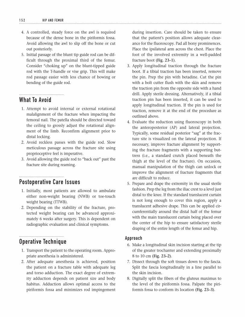
4. A controlled, steady force on the awl is requiredbecause of the dense bone in the piriformis fossa.Avoid allowing the awl to slip off the bone or cutout posteriorly.
5. Initial passage of the blunt tip guide rod can be dif-ficult through the proximal third of the femur.Consider “choking up” on the blunt-tipped guiderod with the T-handle or vise grip. This will makerod passage easier with less chance of bowing orbending of the guide rod.
What To Avoid1. Attempt to avoid internal or external rotational
malalignment of the fracture when impacting thefemoral nail. The patella should be directed towardthe ceiling to grossly adjust the rotational align-ment of the limb. Reconfirm alignment prior todistal locking.
2. Avoid reckless passes with the guide rod. Slowmeticulous passage across the fracture site usingproprioceptive feel is imperative.
3. Avoid allowing the guide rod to “back out” past thefracture site during reaming.
Postoperative Care Issues1. Initially, most patients are allowed to ambulate
either non-weight bearing (NWB) or toe-touchweight bearing (TTWB).
2. Depending on the stability of the fracture, pro-tected weight bearing can be advanced approxi-mately 6 weeks after surgery. This is dependent onradiographic evaluation and clinical symptoms.
Operative Technique1. Transport the patient to the operating room. Appro-
priate anesthesia is administered.2. After adequate anesthesia is achieved, position
the patient on a fracture table with adequate legand torso adduction. The exact degree of extrem-ity adduction depends on patient size and bodyhabitus. Adduction allows optimal access to thepiriformis fossa and minimizes rod impingement
during insertion. Care should be taken to ensurethat the patient’s position allows adequate clear-ance for the fluoroscopy. Pad all bony prominences.Place the ipsilateral arm across the chest. Place thefoot of the involved extremity in a well-paddedfracture boot (Fig. 23–1).
3. Apply longitudinal traction through the fractureboot. If a tibial traction has been inserted, removethe pin. Prep the pin with betadine. Cut the pinwith a bolt cutter flush with the skin and removethe traction pin from the opposite side with a handdrill. Apply sterile dressing. Alternatively, if a tibialtraction pin has been inserted, it can be used toapply longitudinal traction. If the pin is used fortraction, remove it at the end of the procedure asoutlined above.
4. Evaluate the reduction using fluoroscopy in both the anteroposterior (AP) and lateral projection.Typically, some residual posterior “sag” at the frac-ture site is visualized on the lateral projection. Ifnecessary, improve fracture alignment by support-ing the fracture fragments with a supporting but-tress (i.e., a standard crutch placed beneath thethigh at the level of the fracture). On occasion,manual manipulation of the thigh can unlock orimprove the alignment of fracture fragments thatare difficult to reduce.
5. Prepare and drape the extremity in the usual sterilefashion. Prep the leg from the iliac crest to a level justdistal to the knee. If the standard translucent curtainis not long enough to cover this region, apply atranslucent adhesive drape. This can be applied cir-cumferentially around the distal half of the femurwith the main translucent curtain being placed overthe center of the hip to ensure satisfactory steriledraping of the entire length of the femur and hip.
Approach6. Make a longitudinal skin incision starting at the tip
of the greater trochanter and extending proximally8 to 10 cm (Fig. 23–2).
7. Dissect through the soft tissues down to the fascia.Split the fascia longitudinally in a line parallel tothe skin incision.
8. Digitally split the fibers of the gluteus maximus tothe level of the piriformis fossa. Palpate the piri-formis fossa to conform its location (Fig. 23–3).
1 5 2 H I P A N D F E M U R
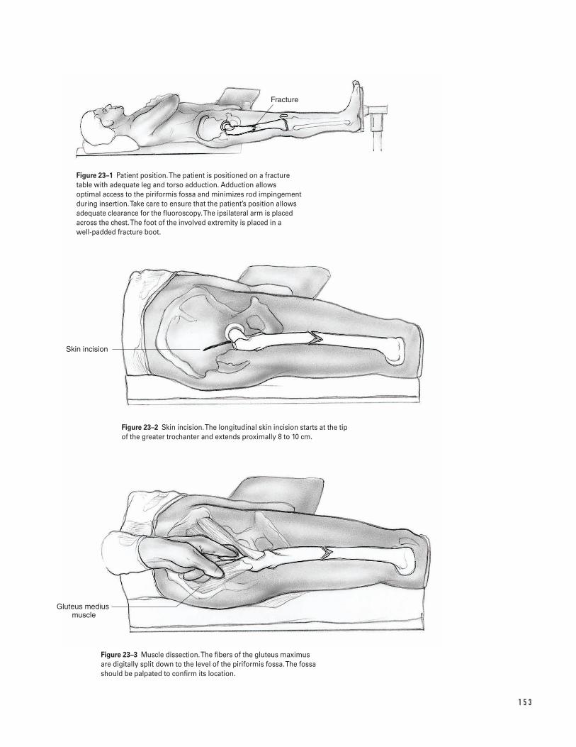
1 5 3
Fracture
Skin incision
Gluteus medius muscle
Figure 23–1 Patient position. The patient is positioned on a fracturetable with adequate leg and torso adduction. Adduction allowsoptimal access to the piriformis fossa and minimizes rod impingementduring insertion. Take care to ensure that the patient’s position allowsadequate clearance for the fluoroscopy. The ipsilateral arm is placedacross the chest. The foot of the involved extremity is placed in a well-padded fracture boot.
Figure 23–2 Skin incision. The longitudinal skin incision starts at the tipof the greater trochanter and extends proximally 8 to 10 cm.
Figure 23–3 Muscle dissection. The fibers of the gluteus maximus are digitally split down to the level of the piriformis fossa. The fossashould be palpated to confirm its location.
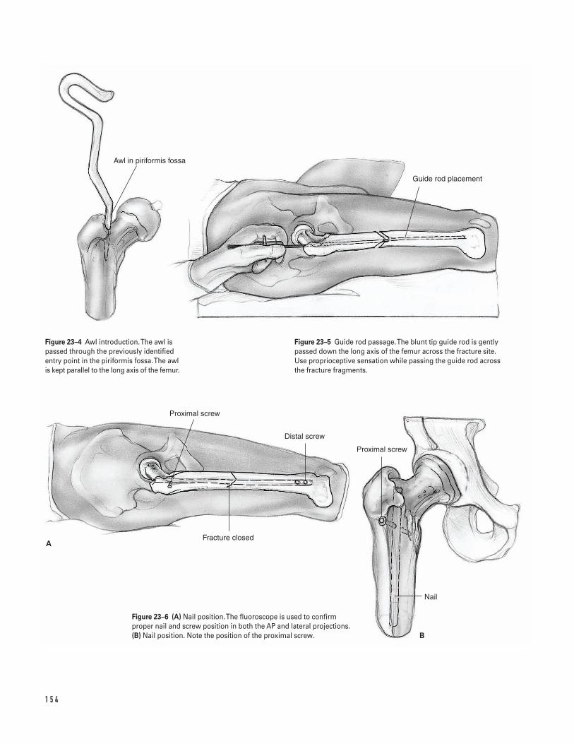
1 5 4
A
B
Awl in piriformis fossa
Guide rod placement
Proximal screw
Nail
Proximal screw
Distal screw
Fracture closed
Figure 23–4 Awl introduction. The awl ispassed through the previously identifiedentry point in the piriformis fossa. The awlis kept parallel to the long axis of the femur.
Figure 23–5 Guide rod passage. The blunt tip guide rod is gentlypassed down the long axis of the femur across the fracture site. Use proprioceptive sensation while passing the guide rod across the fracture fragments.
Figure 23–6 (A) Nail position. The fluoroscope is used to confirmproper nail and screw position in both the AP and lateral projections.(B) Nail position. Note the position of the proximal screw.
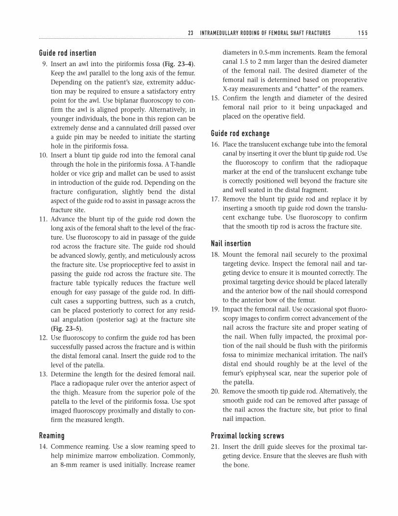
Guide rod insertion9. Insert an awl into the piriformis fossa (Fig. 23–4).
Keep the awl parallel to the long axis of the femur.Depending on the patient’s size, extremity adduc-tion may be required to ensure a satisfactory entrypoint for the awl. Use biplanar fluoroscopy to con-firm the awl is aligned properly. Alternatively, inyounger individuals, the bone in this region can beextremely dense and a cannulated drill passed overa guide pin may be needed to initiate the startinghole in the piriformis fossa.
10. Insert a blunt tip guide rod into the femoral canalthrough the hole in the piriformis fossa. A T-handleholder or vice grip and mallet can be used to assistin introduction of the guide rod. Depending on thefracture configuration, slightly bend the distalaspect of the guide rod to assist in passage across thefracture site.
11. Advance the blunt tip of the guide rod down thelong axis of the femoral shaft to the level of the frac-ture. Use fluoroscopy to aid in passage of the guiderod across the fracture site. The guide rod should be advanced slowly, gently, and meticulously acrossthe fracture site. Use proprioceptive feel to assist inpassing the guide rod across the fracture site. Thefracture table typically reduces the fracture wellenough for easy passage of the guide rod. In diffi-cult cases a supporting buttress, such as a crutch,can be placed posteriorly to correct for any resid-ual angulation (posterior sag) at the fracture site(Fig. 23–5).
12. Use fluoroscopy to confirm the guide rod has beensuccessfully passed across the fracture and is withinthe distal femoral canal. Insert the guide rod to thelevel of the patella.
13. Determine the length for the desired femoral nail.Place a radiopaque ruler over the anterior aspect ofthe thigh. Measure from the superior pole of thepatella to the level of the piriformis fossa. Use spotimaged fluoroscopy proximally and distally to con-firm the measured length.
Reaming14. Commence reaming. Use a slow reaming speed to
help minimize marrow embolization. Commonly,an 8-mm reamer is used initially. Increase reamer
diameters in 0.5-mm increments. Ream the femoralcanal 1.5 to 2 mm larger than the desired diameterof the femoral nail. The desired diameter of thefemoral nail is determined based on preoperative X-ray measurements and “chatter” of the reamers.
15. Confirm the length and diameter of the desiredfemoral nail prior to it being unpackaged andplaced on the operative field.
Guide rod exchange16. Place the translucent exchange tube into the femoral
canal by inserting it over the blunt tip guide rod. Usethe fluoroscopy to confirm that the radiopaquemarker at the end of the translucent exchange tubeis correctly positioned well beyond the fracture siteand well seated in the distal fragment.
17. Remove the blunt tip guide rod and replace it byinserting a smooth tip guide rod down the translu-cent exchange tube. Use fluoroscopy to confirmthat the smooth tip rod is across the fracture site.
Nail insertion18. Mount the femoral nail securely to the proximal
targeting device. Inspect the femoral nail and tar-geting device to ensure it is mounted correctly. Theproximal targeting device should be placed laterallyand the anterior bow of the nail should correspondto the anterior bow of the femur.
19. Impact the femoral nail. Use occasional spot fluoro-scopy images to confirm correct advancement of thenail across the fracture site and proper seating of the nail. When fully impacted, the proximal por-tion of the nail should be flush with the piriformisfossa to minimize mechanical irritation. The nail’sdistal end should roughly be at the level of thefemur’s epiphyseal scar, near the superior pole ofthe patella.
20. Remove the smooth tip guide rod. Alternatively, thesmooth guide rod can be removed after passage ofthe nail across the fracture site, but prior to finalnail impaction.
Proximal locking screws21. Insert the drill guide sleeves for the proximal tar-
geting device. Ensure that the sleeves are flush withthe bone.
2 3 I N T R A M E D U L L A RY R O D D I N G O F F E M O R A L S H A F T F R A C T U R E S 1 5 5
22. Make a bicortical drill hole under fluoroscopic guid-ance. Determine the desired length for the screwusing the depth gauge or reading off of the drill bit.
23. Insert the appropriate proximal locking screw.Remove the proximal targeting device.
Distal locking screws24. Adjust the fluoroscopy so it is exactly perpendicular
to the long axis of the femur. Use the fluoroscopy tovisualize the distal holes in the nail as perfect circleson the lateral image. If the nail holes appear asellipses on the image, adjust the C-arm until perfectcircles are obtained. Normally, only small C-armadjustments are necessary to achieve flawless imagecircles.
25. Make a small longitudinal stab incision in the skindirectly over the visualized nail holes seen on thefluoroscopic image. A ring forcep can be used tolocate the appropriate spot.
26. Use a sharp tip Steinman pin or disposable trocarpin to make a starting entry point in the bone. Adisposable sharp tip pin minimizes sliding awayfrom the hole’s epicenter. Center the pin’s tipdirectly in the middle of the perfect circle seen onthe fluoroscopy.
27. After this unicortical hole is established, make abicortical drill hole through the nail. Alternately, usea radiolucent drill. Align the targeting device of thedrill concentrically with the visualized circular holein the nail. Use the drill to make a bicortical hole.
28. Similarly to the proximal screws, use a standarddepth gauge to measure the desired screw length.Insert the appropriate length distal-locking screws.
29. If necessary, utilize a similar technique for addi-tional distal-locking screws.
30. Use the fluoroscope to confirm proper nail and screwposition in both the AP and lateral projections.Appropriately placed locking screws will obliteratethe visualized holes in the femoral nail (Fig. 23–6).
Closure31. Copiously irrigate the wounds (especially the prox-
imal one) to remove any residual reaming at thelevel of the piriformis fossa. This may minimizelater heterotopic bone formation.
32. Close the fascia with interrupted or figure eight OVicryl.
33. Use a standard closure for the skin and subcu-taneous tissue.
Suggested ReadingsJones, AL. Fractures of the femur. In: Levine AM, ed.Orthopaedic Knowledge Update: Trauma. Rosemont, IL:American Academy of Orthopaedic Surgeons, 1996, pp. 127–136.
Whittle, AP. In: Canale ST. Campbell’s OperativeOrthopaedics, 9th ed. St. Louis, MO: Mosby-Year Book,Inc., 1998, pp. 2136–2166.
1 5 6 H I P A N D F E M U R

Section Five
Knee and Leg

This page intentionally left blank
Key Techniques inOrthopaedic Surgery

1 5 9
C H A P T E R 2 4
Arthroscopy
Steven H. Stern
Indications1. Symptomatic meniscal tear (medial or lateral)2. Loose body3. Osteochondritis dissecans4. Septic knee5. Evaluation of the articular cartilage and osteochon-
dral structures of the knee6. Arthritis (relative). Arthroscopy is an unpredictable
procedure in treating mild to moderate arthritis orpatellofemoral syndrome (“chondromalacia”). It israrely beneficial in severe osteoarthritis unless thereis a significant mechanical component causing thepatient symptoms.
Contraindications1. Unsatisfactory skin condition2. History of knee reflex sympathetic dystrophy
(relative)
Preoperative Preparation1. Knee radiographs2. Magnetic resonance imaging (MRI) depending on
the patient’s symptoms and the specific surgicalprocedure planned
Special Instruments, Position, and Anesthesia1. The patient is placed supine on the operating room
table.2. All pressure points should be padded.3. The procedure can be done with general, spinal, or
local anesthesia with sedation.4. A leg holder or lateral support post can be used.5. A pneumatic thigh tourniquet should be placed as
proximal as possible on the thigh. However, moststandard arthroscopic procedures can successfullybe completed without tourniquet inflation.
6. Standard arthroscopic instruments are needed.These should include an arthroscopic “shaver.”
7. If a meniscal repair is contemplated, the instru-ments and implants for introduction of an absorbablefixation device should be available.
Tips and Pearls1. Arthroscopy is most reliable for symptomatic
mechanical problems within the knee such asmeniscal tears and loose bodies. The resultsachieved with articular cartilage debridement forpatellofemoral syndrome (“chondromalacia”) orosteoarthritis or with menisectomy for asympto-matic or incidental meniscal tears are significantlyless predictable. The best results occur when the
patient’s preoperative symptoms and physical exam-ination correlate with mechanical finding on adiagnostic study (i.e., MRI).
2. If a leg holder is utilized it should be positioned asproximal as possible on the thigh. If a lateral sup-port post is utilized, it should be positioned just dis-tal to the tourniquet on the proximal thigh.
3. In general, all procedures should commence with asystematic diagnostic inspection of the entire jointperformed in a standard manner prior to any oper-ative surgery. However, if a loose body is found, it isappropriate (and desirable) to immediately proceedwith its removal while it is easily visualized. Theauthor’s preferred order for the systematic diagnos-tic inspection of the entire knee joint is: suprapatel-lar pouch, patellofemoral joint, lateral gutter, medialgutter, medial compartment, intercondylar notch,and lateral compartment.
4. Add epinephrine to the inflow bags to minimizebleeding.
5. Remember the arthroscope and camera move inde-pendently. The arthroscope should be positionedand rotated to optimize the field of view. The cam-era should then be rotated to insure correct pictureorientation on the video monitor. The light cordinserts on the arthroscope 180 degrees from thescope’s field of view (Fig. 24–2).
What To Avoid1. Try to avoid multiple operations on the same knee
for the same problem over a short time period.2. Avoid violating the patella tendon with placement
of the portals.3. Attempt to minimize damage to the articular carti-
lage with the arthroscopic instruments and shavers.4. Avoid leaving free meniscal debris floating within
the joint after morselization of the meniscus.
Postoperative Care Issues1. Consider injecting a local anesthetic (i.e., 0.25%
bupivacaine) into the knee at the end of the proce-dure to minimize postoperative pain.
2. A compressive dressing should be placed at the endof surgery and is normally removed approximately48 hours after the procedure.
3. In most cases, patients can weight-bear as tolerated(WBAT) after surgery. Most patients are able to dis-continue crutches in the first week after surgery.
4. Range-of-motion and strengthening exercises canbe initiated immediately after the procedure. Routineformal physical therapy is not required for all pa-tients. Most patients can successfully rehabilitatewith a home exercise program.
Operative Technique
Arthroscope insertion1. Position the patient supine on the operating room
table. Place a thigh tourniquet as proximal as possi-ble on the thigh. While most cases can be per-formed without tourniquet inflation, the tourniquetcan be inflated if bleeding impedes visualization.
2. Depending on surgeon preference, either a post orthigh holder can be used. Position the lateral postjust distal to the thigh tourniquet. If a thigh holderis utilized, position it as proximal as possible.
3. Prepare and drape the limb in the hospital’s stan-dard sterile fashion.
4. Extend the knee and make a small stab wound supe-rior and medial to the patellar. Ideally this shouldbe medial to the quadriceps tendon (Fig. 24–1).
5. Introduce the inflow cannula into the joint utiliz-ing the blunt obturator. Commonly, a “pop” can befelt as the obturator enters the knee capsule. Do notinflate the joint at this time, since the fluid willobscure the landmarks used in placement of theremaining portals.
6. Flex the knee. Identify the “soft spot” for the infe-rior lateral portal. This can be palpated as a softindentation in the lateral retinaculum which liesjust lateral to the patellar tendon at the level of thejoint line. Many surgeons use the inferior pole ofthe patellar as a landmark. Make a small stab inci-sion in this spot (the author prefers a horizontalincision). Inflate the joint (Fig. 24–1).
7. Introduce the cannula for the arthroscope throughthis portal. This is best done with the knee still
1 6 0 K N E E A N D L E G
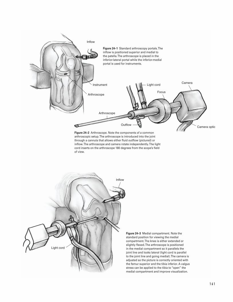
1 6 1
Inflow
Instrument
Arthroscope
Arthroscope
Light cord
Focus
Camera
OutflowCamera optic
Light cord
Inflow
Figure 24–1 Standard arthroscopy portals. Theinflow is positioned superior and medial to the patella. The arthroscope is placed in theinferior-lateral portal while the inferior-medialportal is used for instruments.
Figure 24–2 Arthroscope. Note the components of a commonarthroscopic setup. The arthroscope is introduced into the joint through a cannula that allows either fluid outflow (pictured) or inflow. The arthroscope and camera rotate independently. The lightcord inserts on the arthroscope 180 degrees from the scope’s field of view.
Figure 24–3 Medial compartment. Note thestandard position for viewing the medialcompartment. The knee is either extended orslightly flexed. The arthroscope is positioned in the medial compartment so it parallels the joint line and looks lateral (light cord is parallel to the joint line and going medial). The camera isadjusted so the picture is correctly oriented withthe femur superior and the tibia inferior. A valgusstress can be applied to the tibia to “open” themedial compartment and improve visualization.
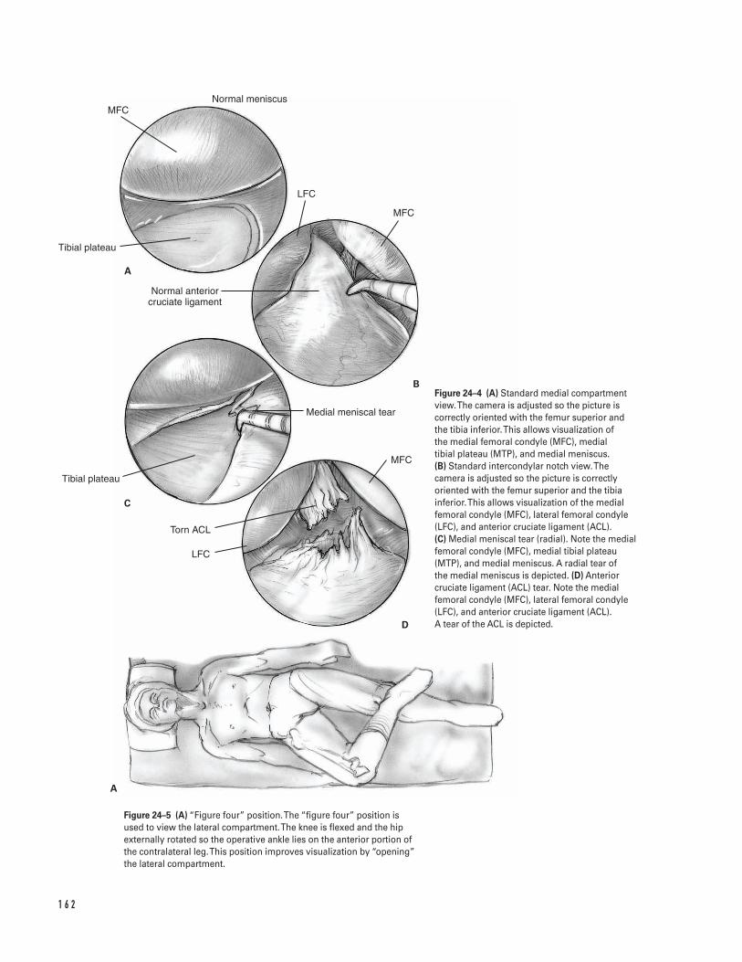
1 6 2
MFC
Tibial plateau
Normal anterior cruciate ligament
Tibial plateau
Torn ACL
LFC
MFC
Medial meniscal tear
LFC
MFC
Normal meniscus
A
B
C
D
A
Figure 24–4 (A) Standard medial compartmentview. The camera is adjusted so the picture iscorrectly oriented with the femur superior andthe tibia inferior. This allows visualization of the medial femoral condyle (MFC), medial tibial plateau (MTP), and medial meniscus. (B) Standard intercondylar notch view.Thecamera is adjusted so the picture is correctlyoriented with the femur superior and the tibiainferior. This allows visualization of the medialfemoral condyle (MFC), lateral femoral condyle(LFC), and anterior cruciate ligament (ACL). (C) Medial meniscal tear (radial). Note the medialfemoral condyle (MFC), medial tibial plateau(MTP), and medial meniscus. A radial tear of the medial meniscus is depicted. (D) Anteriorcruciate ligament (ACL) tear. Note the medialfemoral condyle (MFC), lateral femoral condyle(LFC), and anterior cruciate ligament (ACL). A tear of the ACL is depicted.
Figure 24–5 (A) “Figure four” position. The “figure four” position isused to view the lateral compartment. The knee is flexed and the hipexternally rotated so the operative ankle lies on the anterior portion ofthe contralateral leg. This position improves visualization by “opening”the lateral compartment.
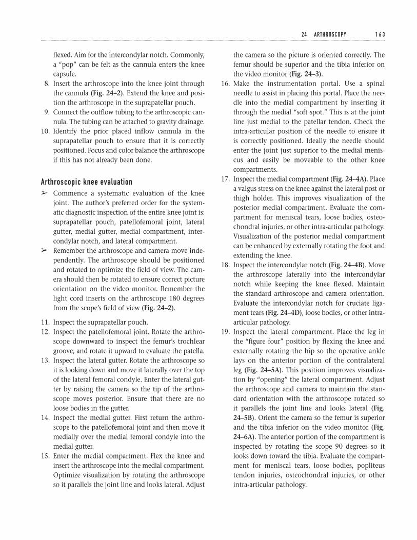
flexed. Aim for the intercondylar notch. Commonly,a “pop” can be felt as the cannula enters the kneecapsule.
8. Insert the arthroscope into the knee joint throughthe cannula (Fig. 24–2). Extend the knee and posi-tion the arthroscope in the suprapatellar pouch.
9. Connect the outflow tubing to the arthroscopic can-nula. The tubing can be attached to gravity drainage.
10. Identify the prior placed inflow cannula in thesuprapatellar pouch to ensure that it is correctlypositioned. Focus and color balance the arthroscopeif this has not already been done.
Arthroscopic knee evaluationâ Commence a systematic evaluation of the knee
joint. The author’s preferred order for the system-atic diagnostic inspection of the entire knee joint is:suprapatellar pouch, patellofemoral joint, lateralgutter, medial gutter, medial compartment, inter-condylar notch, and lateral compartment.
â Remember the arthroscope and camera move inde-pendently. The arthroscope should be positionedand rotated to optimize the field of view. The cam-era should then be rotated to ensure correct pictureorientation on the video monitor. Remember thelight cord inserts on the arthroscope 180 degreesfrom the scope’s field of view (Fig. 24–2).
11. Inspect the suprapatellar pouch.12. Inspect the patellofemoral joint. Rotate the arthro-
scope downward to inspect the femur’s trochleargroove, and rotate it upward to evaluate the patella.
13. Inspect the lateral gutter. Rotate the arthroscope soit is looking down and move it laterally over the topof the lateral femoral condyle. Enter the lateral gut-ter by raising the camera so the tip of the arthro-scope moves posterior. Ensure that there are noloose bodies in the gutter.
14. Inspect the medial gutter. First return the arthro-scope to the patellofemoral joint and then move itmedially over the medial femoral condyle into themedial gutter.
15. Enter the medial compartment. Flex the knee andinsert the arthroscope into the medial compartment.Optimize visualization by rotating the arthroscopeso it parallels the joint line and looks lateral. Adjust
the camera so the picture is oriented correctly. Thefemur should be superior and the tibia inferior onthe video monitor (Fig. 24–3).
16. Make the instrumentation portal. Use a spinalneedle to assist in placing this portal. Place the nee-dle into the medial compartment by inserting itthrough the medial “soft spot.” This is at the jointline just medial to the patellar tendon. Check theintra-articular position of the needle to ensure it is correctly positioned. Ideally the needle shouldenter the joint just superior to the medial menis-cus and easily be moveable to the other kneecompartments.
17. Inspect the medial compartment (Fig. 24–4A). Placea valgus stress on the knee against the lateral post orthigh holder. This improves visualization of theposterior medial compartment. Evaluate the com-partment for meniscal tears, loose bodies, osteo-chondral injuries, or other intra-articular pathology.Visualization of the posterior medial compartmentcan be enhanced by externally rotating the foot andextending the knee.
18. Inspect the intercondylar notch (Fig. 24–4B). Movethe arthroscope laterally into the intercondylarnotch while keeping the knee flexed. Maintain the standard arthroscope and camera orientation.Evaluate the intercondylar notch for cruciate liga-ment tears (Fig. 24–4D), loose bodies, or other intra-articular pathology.
19. Inspect the lateral compartment. Place the leg inthe “figure four” position by flexing the knee andexternally rotating the hip so the operative anklelays on the anterior portion of the contralateral leg (Fig. 24–5A). This position improves visualiza-tion by “opening” the lateral compartment. Adjustthe arthroscope and camera to maintain the stan-dard orientation with the arthroscope rotated so it parallels the joint line and looks lateral (Fig.24–5B). Orient the camera so the femur is superiorand the tibia inferior on the video monitor (Fig.24–6A). The anterior portion of the compartment isinspected by rotating the scope 90 degrees so itlooks down toward the tibia. Evaluate the compart-ment for meniscal tears, loose bodies, popliteustendon injuries, osteochondral injuries, or otherintra-articular pathology.
2 4 A RT H R O S C O P Y 1 6 3
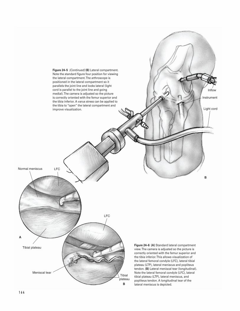
1 6 4
A
B
Inflow
Instrument
Light cord
Normal meniscus LFC
Tibial plateau
Meniscal tearTibial
plateau
LFC
B
Figure 24–5 (Continued) (B) Lateral compartment.Note the standard figure four position for viewingthe lateral compartment. The arthroscope ispositioned in the lateral compartment so itparallels the joint line and looks lateral (light cord is parallel to the joint line and goingmedial). The camera is adjusted so the picture is correctly oriented with the femur superior andthe tibia inferior. A varus stress can be applied tothe tibia to “open” the lateral compartment andimprove visualization.
Figure 24–6 (A) Standard lateral compartmentview. The camera is adjusted so the picture iscorrectly oriented with the femur superior andthe tibia inferior. This allows visualization of the lateral femoral condyle (LFC), lateral tibialplateau (LTP), lateral meniscus and popliteustendon. (B) Lateral meniscal tear (longitudinal).Note the lateral femoral condyle (LFC), lateraltibial plateau (LTP), lateral meniscus, andpopliteus tendon. A longitudinal tear of thelateral meniscus is depicted.
If needed, alter the knee position to improvevisualization. In general, increased knee flexionimproves posterior structure (i.e., popliteus or poste-rior lateral meniscus) visualization. However, kneeflexion can also restrict the fluid inflow, therebyimpairing visualization. If necessary, the inflow canbe improved by moving it so the fluid flows into thejoint through the arthroscope’s cannula.
20. Perform appropriate procedures depending on theintra-articular pathology found.
Partial meniscectomy
â Perform a partial menisectomy if a meniscal tear is felt not appropriate for an attempt at meniscalrepair.
â In general, attempt to limit the amount of meniscusremoved to the degree necessary to leave a stableperipheral meniscal rim.
â The exact menisectomy technique will depend on the type and severity of the tear present.Commonly, a combination of techniques is useddepending on the specific meniscal pathology.General guidelines follow.
a. Bucket handle tearsEvaluate the extent of the tear with a probe. Use abiting instrument to incise the posterior horn of themeniscus at the level of the posterior extent of the tear. Then incise the meniscus’s anterior hornattachments at the level of the anterior extent ofthe tear. Grasp the torn meniscal fragment with agrabber and remove it through a portal. Use anarthroscopic shaver to contour the meniscal rem-nant into a stable peripheral meniscal rim. Probethe meniscal remnant to ensure that the remainingperipheral meniscal is stable.
b. Radial or complex degenerative tearsEvaluate the extent of the tear with a probe (Figs.24–4C and 6B). Use a biting instrument to morselizethe torn portion of the meniscus. Remove onlyenough meniscal tissue to leave a stable peripheralmeniscal rim. Use an arthroscopic shaver to contourthe meniscal remnant into a stable peripheralmeniscal rim. Probe the meniscal remnant to ensurethat the remaining peripheral meniscal is stable.
Meniscal repairs
â Perform a partial menisectomy if a meniscal tear isfelt to be appropriate for an attempt at meniscalrepair. Various methods can be employed. Theseinclude placement of sutures using either inside-outor outside-in techniques or placement of absorbableintra-articular fixation devices (“arrows” or “tacks”).
Anterior cruciate ligament (ACL) tears
â For treatment of anterior cruciate ligament (ACL)tears (Fig. 24–4D), see Chapters 25 and 26.
Loose body removal
â Loose bodies can be difficult to find in the knee.Thus, when a loose body is found, it is appropriate(and desirable) to immediately proceed with itsremoval while it is easily visualized. Standard re-moval techniques require triangulation with thearthroscope and arthroscopic grabber and removalof the loose body through the appropriate portal. Ifnecessary, make accessory portals to aid in loosebody removal.
Arthroscopic debridement
â If desired, loose and fibrillated articular cartilagecan be debrided arthroscopically. Use an arthro-scopic shaver to debride the loose or fibrillatedarticular cartilage.
â In general, attempt to limit the amount of debride-ment performed to the amount necessary to removeonly the severely diseased articular cartilage. If pos-sible, avoid debriding back to subchondral bone asthis can be counterproductive.
Closure21. After the operative arthroscopy is completed, re-
evaluate the knee to ensure there is no furtherpathology amenable to treatment.
22. Copiously irrigate the joint.23. Inject bupivacaine (0.25%) into the joint to mini-
mize postoperative pain.24. Close the portals per surgeon’s preference. The
author prefers a subcuticular suture and steristrips.25. Dress the wound sterilely in the operating room.
Transfer the patient to the recovery room.
2 4 A RT H R O S C O P Y 1 6 5

Suggested ReadingsBoland AL, Southerland SR. Meniscal tear and cyst:arthroscopic menisectomy. In: Craig EV, ed. ClinicalOrthopaedics. Baltimore, MD: Lippincott Williams &Wilkins, 1999, pp. 741–749.
Cannon WD Jr. Arthroscopic survey of the knee joint.In: Scott WN, ed. The Knee. St. Louis, MO: Mosby-YearBook, 1994, pp. 497–514.
1 6 6 K N E E A N D L E G
Indications1. Active individual with an acute torn anterior cruci-
ate ligament (ACL)2. Individual with recurrent instability who has failed
rehabilitation and bracing3. A sedentary individual who displays instability
related to his or her anterior cruciate ligament—deficient knee with daily activities
Contraindications1. Active knee infection2. Lack of neurovascular control3. A sedentary individual without demonstrable
instability4. Older age (relative)5. Pediatric patient with open growth plate
Preoperative Preparation1. Knee radiographs: anteroposterior (AP), lateral, and
skyline2. Magnetic resonance imaging (MRI): not a necessity,
but helps to assess other injuries.3. Wait for knee swelling and active range of motion
to normalize prior to surgery (may necessitate pre-operative physical therapy).
Special Instruments, Position, andAnesthesia1. Position the patient supine on the operating room
table.2. The contralateral extremity should be padded to
avoid pressure on susceptible areas.3. Leg holder or post4. General, epidural, or spinal anesthetic5. Routine arthroscopic setup and routine orthopaedic
surgical instruments6. Tibial and femoral alignment guides for positioning
the tunnel guide pins7. Interference screws for graft fixation; these can be
metal or bioabsorbable. A screw and washer may be used as a “post.”
8. A tendon passer (either wire loop, Hewson tendonpasser)
Tips and Pearls1. The anterior knee incision should extend from the
lower pole of the patella to a point slightly medialto the tibial tubercle.
2. The lateral incision extends proximal from the lat-eral epicondyle, approximately 2 to 3 cm.
3. Examine the knee under anesthesia. Assess the sta-bility and document.
1 6 7
C H A P T E R 2 5
Anterior Cruciate Ligament SurgeryTwo Incision
Gordon W. Nuber
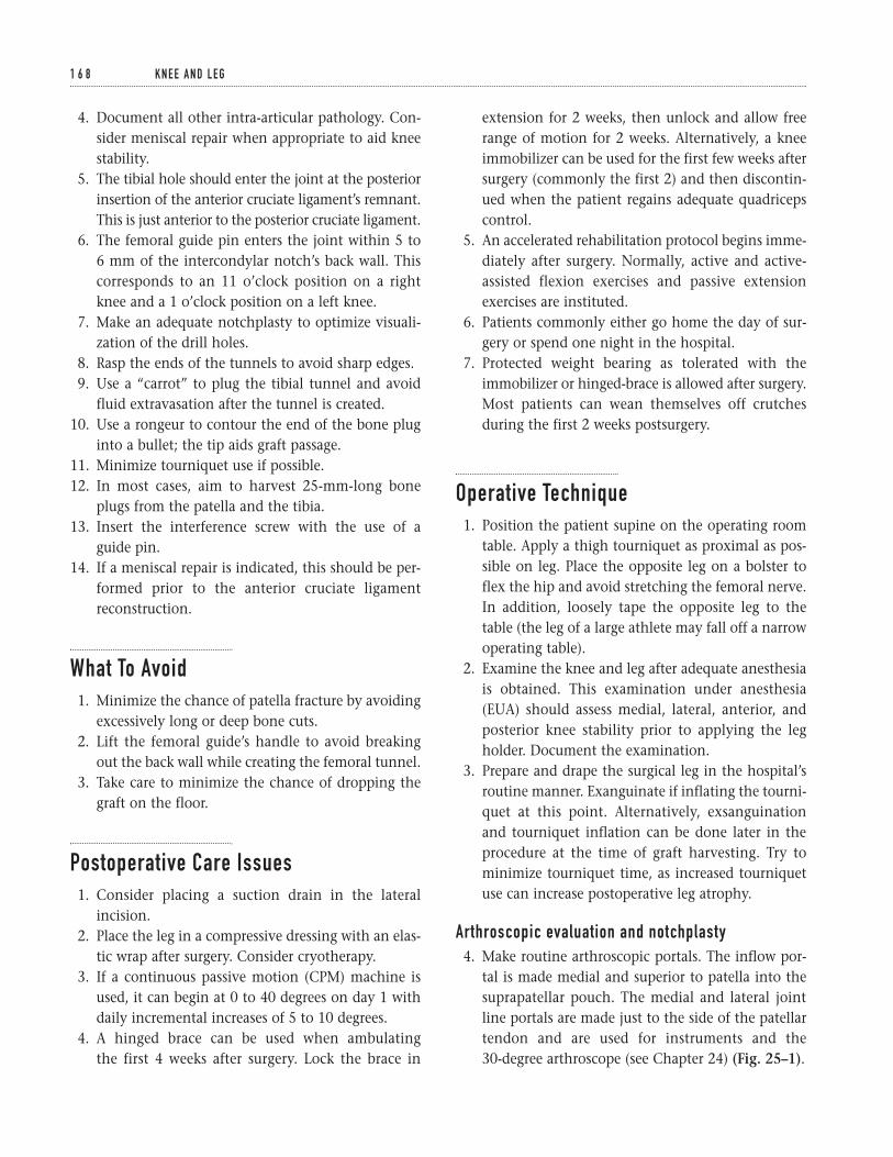
4. Document all other intra-articular pathology. Con-sider meniscal repair when appropriate to aid kneestability.
5. The tibial hole should enter the joint at the posteriorinsertion of the anterior cruciate ligament’s remnant.This is just anterior to the posterior cruciate ligament.
6. The femoral guide pin enters the joint within 5 to 6 mm of the intercondylar notch’s back wall. Thiscorresponds to an 11 o’clock position on a rightknee and a 1 o’clock position on a left knee.
7. Make an adequate notchplasty to optimize visuali-zation of the drill holes.
8. Rasp the ends of the tunnels to avoid sharp edges.9. Use a “carrot” to plug the tibial tunnel and avoid
fluid extravasation after the tunnel is created.10. Use a rongeur to contour the end of the bone plug
into a bullet; the tip aids graft passage.11. Minimize tourniquet use if possible.12. In most cases, aim to harvest 25-mm-long bone
plugs from the patella and the tibia.13. Insert the interference screw with the use of a
guide pin.14. If a meniscal repair is indicated, this should be per-
formed prior to the anterior cruciate ligamentreconstruction.
What To Avoid1. Minimize the chance of patella fracture by avoiding
excessively long or deep bone cuts.2. Lift the femoral guide’s handle to avoid breaking
out the back wall while creating the femoral tunnel.3. Take care to minimize the chance of dropping the
graft on the floor.
Postoperative Care Issues1. Consider placing a suction drain in the lateral
incision.2. Place the leg in a compressive dressing with an elas-
tic wrap after surgery. Consider cryotherapy.3. If a continuous passive motion (CPM) machine is
used, it can begin at 0 to 40 degrees on day 1 withdaily incremental increases of 5 to 10 degrees.
4. A hinged brace can be used when ambulating the first 4 weeks after surgery. Lock the brace in
extension for 2 weeks, then unlock and allow freerange of motion for 2 weeks. Alternatively, a kneeimmobilizer can be used for the first few weeks aftersurgery (commonly the first 2) and then discontin-ued when the patient regains adequate quadricepscontrol.
5. An accelerated rehabilitation protocol begins imme-diately after surgery. Normally, active and active-assisted flexion exercises and passive extensionexercises are instituted.
6. Patients commonly either go home the day of sur-gery or spend one night in the hospital.
7. Protected weight bearing as tolerated with theimmobilizer or hinged-brace is allowed after surgery.Most patients can wean themselves off crutchesduring the first 2 weeks postsurgery.
Operative Technique1. Position the patient supine on the operating room
table. Apply a thigh tourniquet as proximal as pos-sible on leg. Place the opposite leg on a bolster toflex the hip and avoid stretching the femoral nerve.In addition, loosely tape the opposite leg to thetable (the leg of a large athlete may fall off a narrowoperating table).
2. Examine the knee and leg after adequate anesthesiais obtained. This examination under anesthesia(EUA) should assess medial, lateral, anterior, andposterior knee stability prior to applying the legholder. Document the examination.
3. Prepare and drape the surgical leg in the hospital’sroutine manner. Exanguinate if inflating the tourni-quet at this point. Alternatively, exsanguinationand tourniquet inflation can be done later in theprocedure at the time of graft harvesting. Try tominimize tourniquet time, as increased tourniquetuse can increase postoperative leg atrophy.
Arthroscopic evaluation and notchplasty4. Make routine arthroscopic portals. The inflow por-
tal is made medial and superior to patella into thesuprapatellar pouch. The medial and lateral jointline portals are made just to the side of the patellartendon and are used for instruments and the 30-degree arthroscope (see Chapter 24) (Fig. 25–1).
1 6 8 K N E E A N D L E G
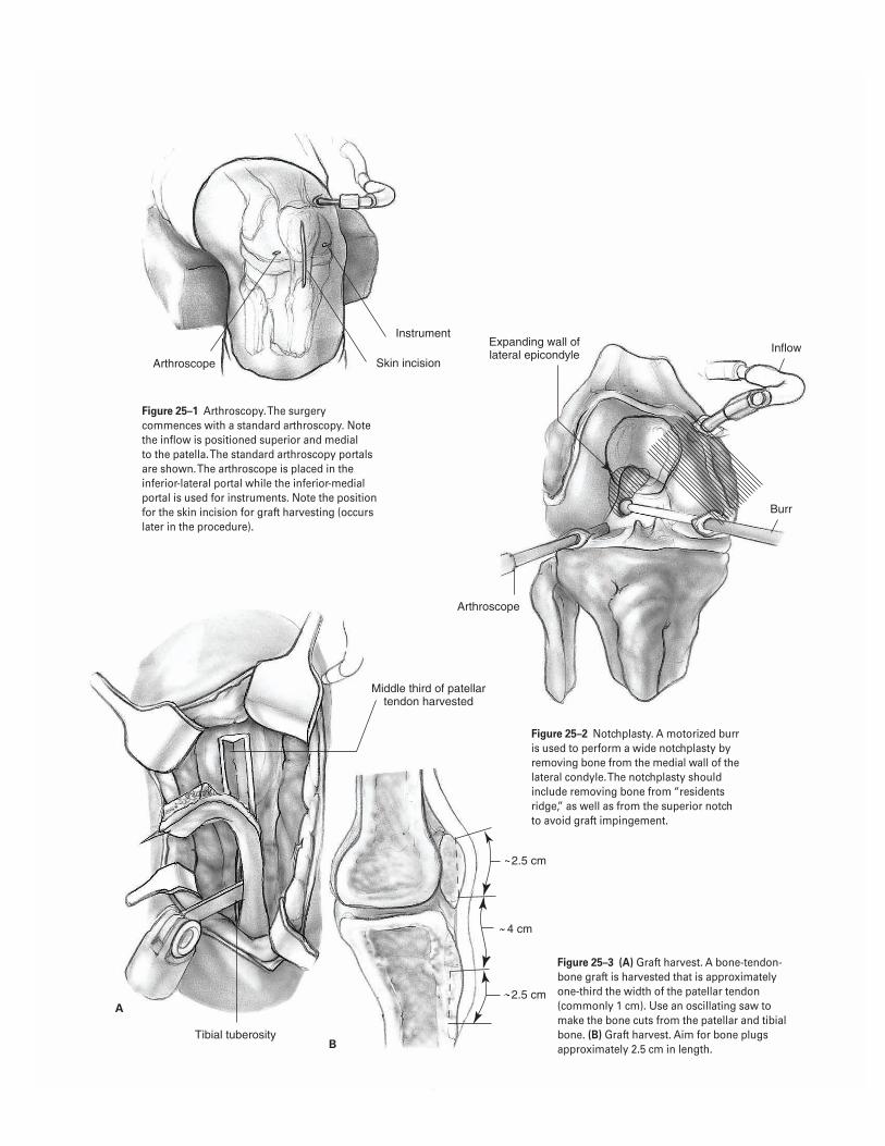
1 6 9
2.5 cm
2.5 cm
4 cm
Arthroscope
Instrument
Skin incision
Expanding wall of lateral epicondyle
Inflow
Burr
Arthroscope
Middle third of patellar tendon harvested
Tibial tuberosity
A
B
Figure 25–1 Arthroscopy. The surgerycommences with a standard arthroscopy. Notethe inflow is positioned superior and medial to the patella. The standard arthroscopy portalsare shown. The arthroscope is placed in theinferior-lateral portal while the inferior-medialportal is used for instruments. Note the positionfor the skin incision for graft harvesting (occurslater in the procedure).
Figure 25–2 Notchplasty. A motorized burris used to perform a wide notchplasty byremoving bone from the medial wall of thelateral condyle. The notchplasty shouldinclude removing bone from “residentsridge,” as well as from the superior notchto avoid graft impingement.
Figure 25–3 (A) Graft harvest. A bone-tendon-bone graft is harvested that is approximatelyone-third the width of the patellar tendon(commonly 1 cm). Use an oscillating saw tomake the bone cuts from the patellar and tibialbone. (B) Graft harvest. Aim for bone plugsapproximately 2.5 cm in length.
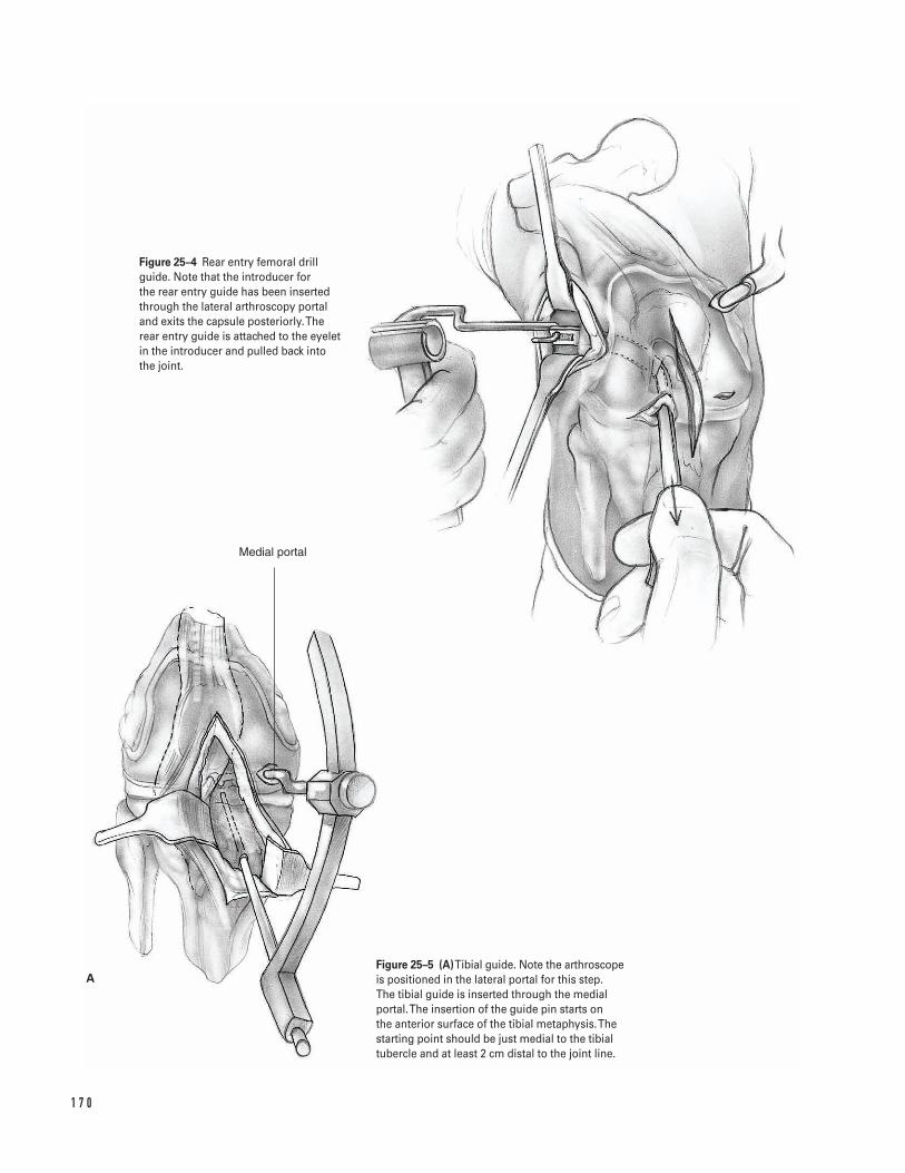
1 7 0
Medial portal
A
Figure 25–4 Rear entry femoral drillguide. Note that the introducer for the rear entry guide has been insertedthrough the lateral arthroscopy portaland exits the capsule posteriorly. Therear entry guide is attached to the eyeletin the introducer and pulled back intothe joint.
Figure 25–5 (A)Tibial guide. Note the arthroscopeis positioned in the lateral portal for this step. The tibial guide is inserted through the medialportal. The insertion of the guide pin starts on the anterior surface of the tibial metaphysis. Thestarting point should be just medial to the tibialtubercle and at least 2 cm distal to the joint line.
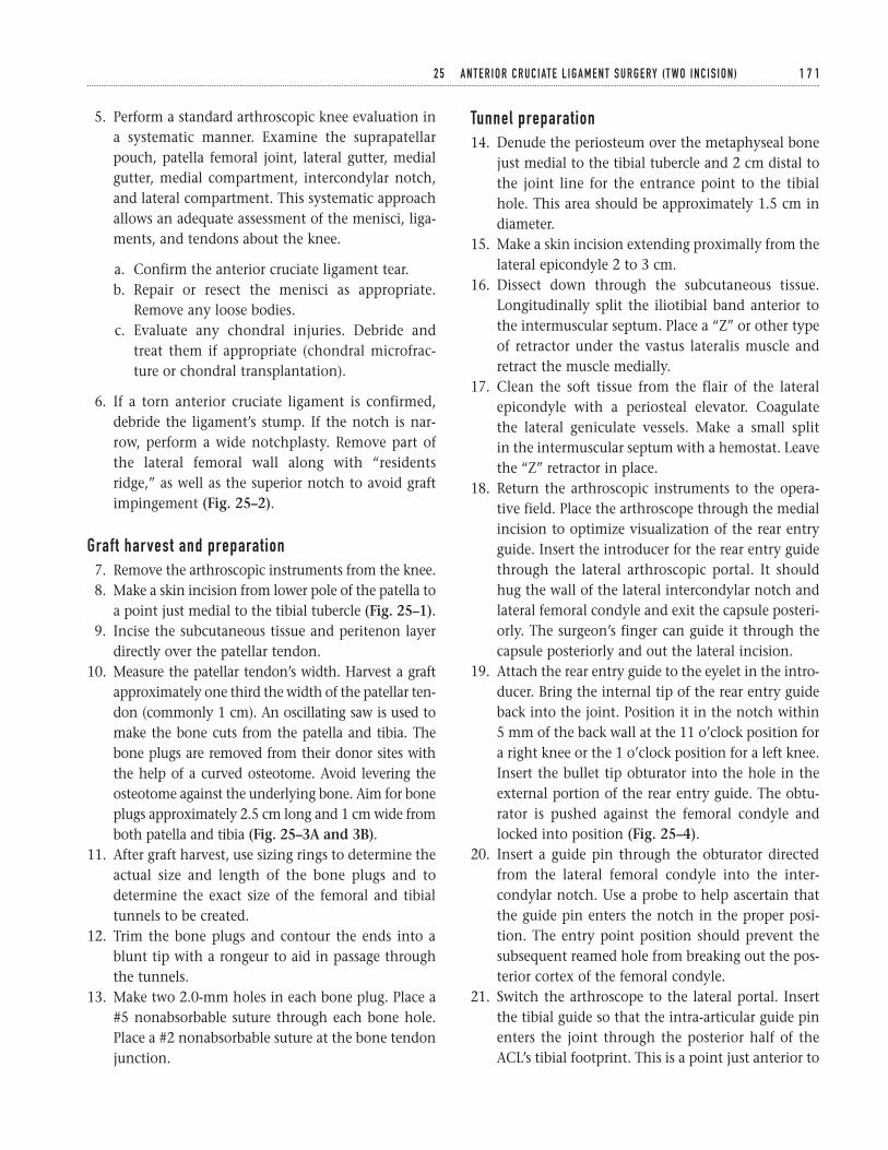
5. Perform a standard arthroscopic knee evaluation ina systematic manner. Examine the suprapatellarpouch, patella femoral joint, lateral gutter, medialgutter, medial compartment, intercondylar notch,and lateral compartment. This systematic approachallows an adequate assessment of the menisci, liga-ments, and tendons about the knee.
a. Confirm the anterior cruciate ligament tear.b. Repair or resect the menisci as appropriate.
Remove any loose bodies.c. Evaluate any chondral injuries. Debride and
treat them if appropriate (chondral microfrac-ture or chondral transplantation).
6. If a torn anterior cruciate ligament is confirmed,debride the ligament’s stump. If the notch is nar-row, perform a wide notchplasty. Remove part ofthe lateral femoral wall along with “residentsridge,” as well as the superior notch to avoid graftimpingement (Fig. 25–2).
Graft harvest and preparation7. Remove the arthroscopic instruments from the knee.8. Make a skin incision from lower pole of the patella to
a point just medial to the tibial tubercle (Fig. 25–1).9. Incise the subcutaneous tissue and peritenon layer
directly over the patellar tendon.10. Measure the patellar tendon’s width. Harvest a graft
approximately one third the width of the patellar ten-don (commonly 1 cm). An oscillating saw is used tomake the bone cuts from the patella and tibia. Thebone plugs are removed from their donor sites withthe help of a curved osteotome. Avoid levering theosteotome against the underlying bone. Aim for boneplugs approximately 2.5 cm long and 1 cm wide fromboth patella and tibia (Fig. 25–3A and 3B).
11. After graft harvest, use sizing rings to determine theactual size and length of the bone plugs and todetermine the exact size of the femoral and tibialtunnels to be created.
12. Trim the bone plugs and contour the ends into ablunt tip with a rongeur to aid in passage throughthe tunnels.
13. Make two 2.0-mm holes in each bone plug. Place a#5 nonabsorbable suture through each bone hole.Place a #2 nonabsorbable suture at the bone tendonjunction.
Tunnel preparation14. Denude the periosteum over the metaphyseal bone
just medial to the tibial tubercle and 2 cm distal tothe joint line for the entrance point to the tibialhole. This area should be approximately 1.5 cm indiameter.
15. Make a skin incision extending proximally from thelateral epicondyle 2 to 3 cm.
16. Dissect down through the subcutaneous tissue.Longitudinally split the iliotibial band anterior tothe intermuscular septum. Place a “Z” or other typeof retractor under the vastus lateralis muscle andretract the muscle medially.
17. Clean the soft tissue from the flair of the lateral epicondyle with a periosteal elevator. Coagulate the lateral geniculate vessels. Make a small split in the intermuscular septum with a hemostat. Leavethe “Z” retractor in place.
18. Return the arthroscopic instruments to the opera-tive field. Place the arthroscope through the medialincision to optimize visualization of the rear entryguide. Insert the introducer for the rear entry guidethrough the lateral arthroscopic portal. It shouldhug the wall of the lateral intercondylar notch andlateral femoral condyle and exit the capsule posteri-orly. The surgeon’s finger can guide it through thecapsule posteriorly and out the lateral incision.
19. Attach the rear entry guide to the eyelet in the intro-ducer. Bring the internal tip of the rear entry guideback into the joint. Position it in the notch within5 mm of the back wall at the 11 o’clock position fora right knee or the 1 o’clock position for a left knee.Insert the bullet tip obturator into the hole in theexternal portion of the rear entry guide. The obtu-rator is pushed against the femoral condyle andlocked into position (Fig. 25–4).
20. Insert a guide pin through the obturator directedfrom the lateral femoral condyle into the inter-condylar notch. Use a probe to help ascertain thatthe guide pin enters the notch in the proper posi-tion. The entry point position should prevent thesubsequent reamed hole from breaking out the pos-terior cortex of the femoral condyle.
21. Switch the arthroscope to the lateral portal. Insertthe tibial guide so that the intra-articular guide pinenters the joint through the posterior half of theACL’s tibial footprint. This is a point just anterior to
2 5 A N T E R I O R C R U C I AT E L I G A M E N T S U R G E RY ( T WO I N C I S I O N ) 1 7 1
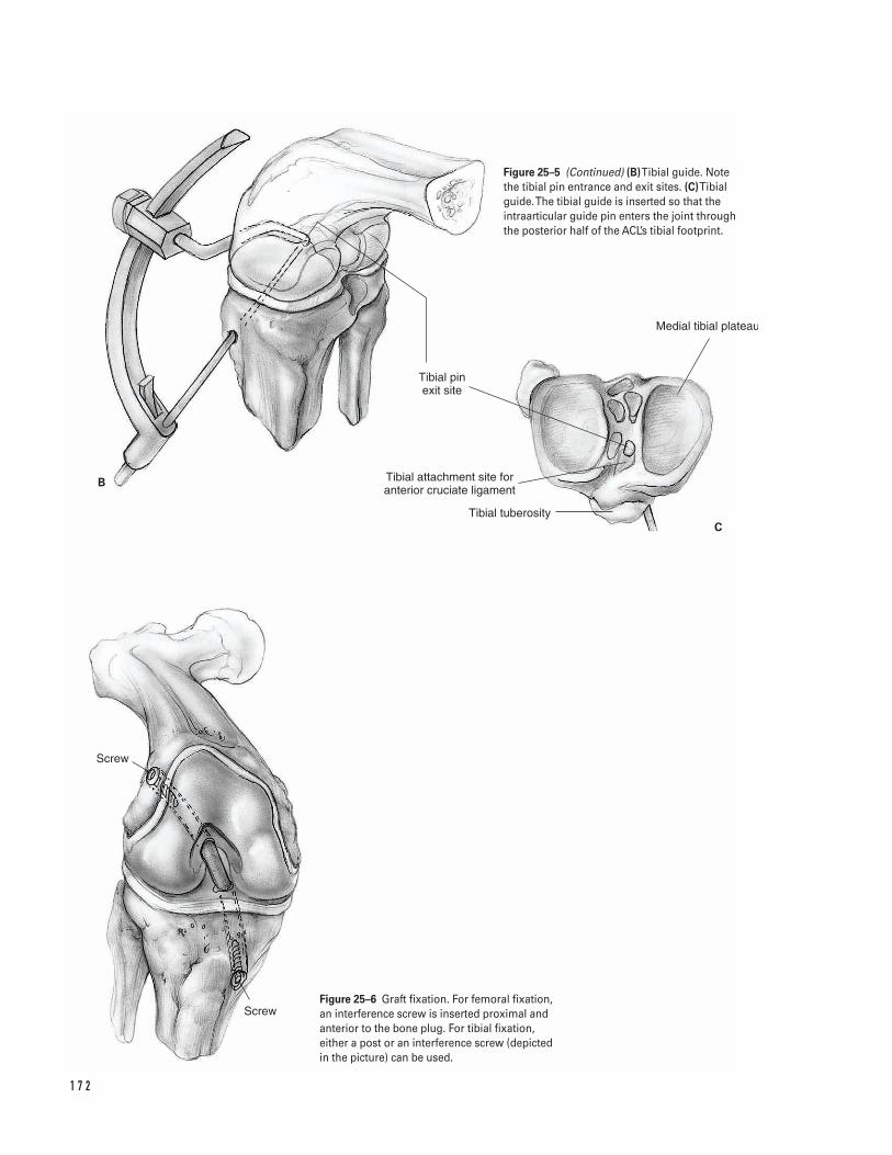
1 7 2
B
C
Screw
Screw
Tibial pin exit site
Tibial attachment site for anterior cruciate ligament
Tibial tuberosity
Medial tibial plateau
Figure 25–5 (Continued) (B)Tibial guide. Note the tibial pin entrance and exit sites. (C)Tibialguide. The tibial guide is inserted so that theintraarticular guide pin enters the joint throughthe posterior half of the ACL’s tibial footprint.
Figure 25–6 Graft fixation. For femoral fixation,an interference screw is inserted proximal andanterior to the bone plug. For tibial fixation,either a post or an interference screw (depicted in the picture) can be used.
the posterior cruciate ligament. Start the guide pinon the anterior surface of the tibial metaphysis. Thestarting point is just medial to the tibia tubercle andat least 2 cm distal to the joint line. This corre-sponds to the previously denuded area of perios-teum (Fig. 25–5).
22. Insert the guide pin through the tibia and a few mil-limeters into the knee joint to ascertain its position.Run the knee through a range of motion. Arthro-scopically visualize the guide pin with the kneeextended. Ensure that it clears the superior notchand that the graft will not impinge.
23. Over-ream each of the guide pins with disposablereamers (generally 9 to 12 mm diameter). Rasp theedges of each hole to smooth the border. An arthro-scopic shaver can be used to clean soft tissue fromthe intraarticular holes. Use a “carrot” to plug thetibia hole to prevent fluid extravasation.
Graft passage24. Insert a malleable tendon passer (Hewson or wire
loop) into the tibial hole and through the femoralhole so it exits through the lateral incision. Placethe patellar tendon graft sutures through the loopin the tendon passer. Pull the sutures back throughthe femoral and tibial tunnels.
25. Using the sutures, pull the graft into the femoraltunnel and down into the tibial tunnel. Use theprobe to assist graft passage into the tibial tunnel. Ifthe femoral and tibial tunnels are different sizes, thelead end of the graft should have the smallest boneplug. Using this technique, the bone plug ends usu-ally sit flush with the tibial and femoral cortex.
26. Arthroscopically visualize the graft to ensure that itdoes not impinge against either the lateral or superiornotch as the knee is run through a range of motion.
Graft fixationâ Fix the bone plugs either with interference screws or
over a “post” depending on surgeon’s preference. Ahalf-turn twist in the graft is felt to strengthen itprior to fixation.
â Use a guide wire to assist placement of an interfer-ence screw. Slide the guide wire into the tunnelalong the side of the bone plug. The wire shouldslide easily, so it can be removed once the interfer-ence screw engages in the hole.
27. Fix the femoral side first. Insert an interferencescrew proximal and anterior to the bone plug (Fig. 25–6).
28. Fix the tibial side.
a. If using an interference screw, insert it anteriorand medial to the bone plug (Fig. 25–6).
b. If using a “post,” insert a low-profile screw fromanterior to posterior 1 cm distal to the tibialhole. Tie the graft sutures around the screw.Fully seat the screw.
29. Maintain tension on the graft with the knee at 30degrees of flexion or near full extension while fixingthe tibial bone plug.
30. After graft fixation, perform a Lachman test toassess knee stability. Range the knee to assess forgraft impingement. If impingement is present,expand the notchplasty.
Closure31. Pack extra bone removed from the graft bone plugs
into the patellar and tibial defects as a bone graft.32. Close the patellar tendon defect loosely with
absorbable sutures.33. Close the paratenon over the patellar tendon as a
separate layer.34. Close the subcutaneous tissue with absorbable
suture. Close the skin and portals per surgeon’spreference.
35. A drain may be used in the lateral wound but mustbe removed prior to the patient’s departure fromthe hospital.
36. Inject intra-articular marcaine into the wounds andthe knee joint after closure to diminish postopera-tive pain.
37. Place a surgical dressing on the wound. Apply ahinge brace or knee immobilizer in the operatingroom.
Suggested ReadingNogalski MP, Bach BR Jr. Acute anterior cruciateligament injuries. In: Fu FH, Harner CD, Vince KG, eds.Knee Surgery. Baltimore, MD: Williams & Willkins, 1994,pp. 679–730.
2 5 A N T E R I O R C R U C I AT E L I G A M E N T S U R G E RY ( T WO I N C I S I O N ) 1 7 3
Indications1. Active individual with an acute tear of the anterior
cruciate ligament2. Individual with a chronic tear of the anterior cruci-
ate ligament with recurrent instability, who hasfailed nonoperative treatment
3. A sedentary individual, who displays instabilityrelated to his anterior cruciate ligament deficientknee with daily activities
Contraindications1. Active knee infection2. Lack of neurovascular control3. A sedentary individual without demonstrable insta-
bility4. Older age (relative)5. Pediatric patient with open growth plate6. Patella alta with extremely long patella tendon
(relative); consider two-incision technique
Preoperative Preparation1. Knee radiographs: anteroposterior (AP), lateral, and
skyline2. Magnetic Resonance Imaging (MRI): not a necessity,
but helps to assess other injuries.
3. Wait for knee swelling and active range of motionto normalize prior to surgery (may necessitate pre-operative physical therapy).
Special Instruments, Position, and Anesthesia1. Position the patient supine on the operating room
table. The patient’s position should allow for kneehyperflexion during the procedure.
2. The contralateral extremity should be padded toavoid pressure on susceptible areas.
3. Leg holder or post4. General, epidural, or spinal anesthetic5. Routine arthroscopic setup and routine orthopaedic
surgical instruments6. Tibial and femoral alignment guides for positioning
the tunnel guide pins7. Interference screws for graft fixation; these can be
metal or bioabsorbable. A screw and washer may be used as a “post.”
Tips and Pearls1. The anterior knee incision should extend from the
lower pole of the patella to a point slightly medialto tibial tubercle.
2. Examine the knee under anesthesia. Assess the sta-bility and document.
1 7 4
C H A P T E R 2 6
Anterior Cruciate Ligament SurgeryEndoscopic
Steven H. Stern
3. Document all other intra-articular pathology. Con-sider meniscal repair when appropriate to aid kneestability.
4. Attempt to make the portals as close to the mid-lineas possible without violating the patella tendon.This position optimizes visualization into inter-condylar notch.
5. The tibial hole should enter the joint at the poste-rior insertion of the anterior cruciate ligament’sremnant. This is just anterior to the posterior cruci-ate ligament.
6. The femoral hole needs to be positioned posteriorly,but care should be taken to minimize the chance of“blowout” of the posterior femoral wall.
7. Make an adequate notchplasty to optimize visuali-zation of the drill holes.
8. Rasp the ends of the tunnels to avoid sharp edges.9. Use a “carrot” to plug the tibial tunnel and avoid
fluid extravasation after the tunnel is created.10. Use a rongeur to contour the end of the bone plug
into a bullet; the tip aids graft passage.11. Minimize tourniquet use if possible.12. In most cases, aim to harvest 25-mm-long bone
plugs from the patella and the tibia.13. Insert the femoral interference screw with the knee
hyperflexed to help optimize its position.14. Insert the interference screws with the use of a
guide pin.15. If a meniscal repair is indicated, this should be per-
formed prior to the anterior cruciate ligamentreconstruction.
What To Avoid1. Minimize the chance of patella fracture by avoiding
excessively long or deep bone cuts.2. Avoid positioning the patient on the proximal part
of the table. The patient must be positioned as dis-tal as possible on the surgical table. This allows forknee hyperflexion, which is essential in optimizingposition of the femoral interference screw. Do notoverlook this small technical point.
3. Take care to minimize the chance of dropping thegraft on the floor.
Postoperative Care Issues1. Place the leg in a compressive dressing with an elas-
tic wrap after surgery. Consider cryotherapy.2. If a continuous passive motion machine (CPM) is
used, it can begin at 0 to 40 degrees on day one withdaily incremental increases of 5 to 10 degrees.
3. A knee immobilizer can be used for the first fewweeks after surgery (commonly the first two) andthen discontinued when the patient regains ade-quate quadriceps control. Alternatively, a hingedbrace can be used when ambulating during the firstfour weeks after surgery. Lock the brace in extensionfor two weeks, then unlock and allow free range ofmotion for two weeks.
4. An accelerated rehabilitation protocol begins imme-diately after surgery. Normally active and active-assisted flexion exercises and passive extensionexercises are instituted.
5. Patients commonly either go home the day of sur-gery or spend one night in the hospital.
6. Protected weight bearing as tolerated with theimmobilizer or hinged-brace is allowed after surgery.Most patients can wean themselves off crutches dur-ing the first two weeks status post surgery.
Operative Technique1. Position the patient supine and as distally as possible
on the operating room table to allow for knee hyper-flexion later in the procedure. Apply a thigh tourni-quet as proximal as possible on the leg. Pad pressurepoints and the contralateral Achilles tendon.
2. Examine the knee and leg after adequate anesthe-sia is obtained. This examination under anesthesia(EUA) should assess medial, lateral, anterior, andposterior knee stability. Document the examination.
3. Prepare and drape the surgical leg in the hospital’sroutine manner. Exanguinate if inflating the tourni-quet at this point. Alternatively, exsanguinationand tourniquet inflation can be done later in theprocedure at the time of graft harvesting. Try tominimize tourniquet time because increased tourni-quet use can increase postoperative leg atrophy.
2 6 A N T E R I O R C R U C I AT E L I G A M E N T S U R G E RY ( E N D O S C O P I C ) 1 7 5
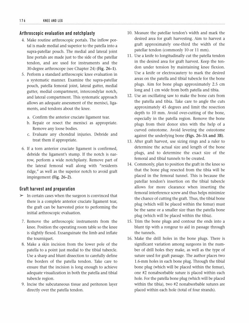
Arthroscopic evaluation and notchplasty4. Make routine arthroscopic portals. The inflow por-
tal is made medial and superior to the patella into asupra-patellar pouch. The medial and lateral jointline portals are made just to the side of the patellartendon, and are used for instruments and the 30-degree arthroscope (see Chapter 24) (Fig. 26–1).
5. Perform a standard arthroscopic knee evaluation ina systematic manner. Examine the supra-patellarpouch, patella femoral joint, lateral gutter, medialgutter, medial compartment, intercondylar notch,and lateral compartment. This systematic approachallows an adequate assessment of the menisci, liga-ments, and tendons about the knee.
a. Confirm the anterior cruciate ligament tear.b. Repair or resect the menisci as appropriate.
Remove any loose bodies.c. Evaluate any chondral injuries. Debride and
treat them if appropriate.
6. If a torn anterior cruciate ligament is confirmed,debride the ligament’s stump. If the notch is nar-row, perform a wide notchplasty. Remove part ofthe lateral femoral wall along with “residentsridge,” as well as the superior notch to avoid graftimpingement (Fig. 26–2).
Graft harvest and preparationâ In certain cases when the surgeon is convinced that
there is a complete anterior cruciate ligament tear,the graft can be harvested prior to performing theinitial arthroscopic evaluation.
7. Remove the arthroscopic instruments from theknee. Position the operating room table so the kneeis slightly flexed. Exsanguinate the limb and inflatethe tourniquet.
8. Make a skin incision from the lower pole of thepatella to a point just medial to the tibial tubercle.Use a sharp and blunt dissection to carefully definethe borders of the patella tendon. Take care toensure that the incision is long enough to achieveadequate visualization in both the patella and tibialtubercle region.
9. Incise the subcutaneous tissue and peritenon layerdirectly over the patella tendon.
10. Measure the patellar tendon’s width and mark thedesired area for graft harvesting. Aim to harvest agraft approximately one-third the width of thepatellar tendon (commonly 10 or 11 mm).
11. Use a knife to longitudinally cut the patella tendonin the desired area for graft harvest. Keep the ten-don under tension by maintaining knee flexion.Use a knife or electrocautery to mark the desiredareas on the patella and tibial tubercle for the boneplugs. Aim for bone plugs approximately 2.5 cmlong and 1 cm wide from both patella and tibia.
12. Use an oscillating saw to make the bone cuts fromthe patella and tibia. Take care to angle the cutsapproximately 45 degrees and limit the resectiondepth to 10 mm. Avoid over-cutting of the bone,especially in the patella region. Remove the boneplugs from their donor sites with the help of acurved osteotome. Avoid levering the osteotomeagainst the underlying bone (Figs. 26–3A and 3B).
13. After graft harvest, use sizing rings and a ruler todetermine the actual size and length of the boneplugs, and to determine the exact size of thefemoral and tibial tunnels to be created.
14. Commonly, plan to position the graft in the knee sothat the bone plug resected from the tibia will beplaced in the femoral tunnel. This is because thepatellar tendon’s insertion on the tibial tubercleallows for more clearance when inserting thefemoral interference screw and thus helps minimizethe chance of cutting the graft. Thus, the tibial boneplug (which will be placed within the femur) mustbe the same or a smaller size than the patella boneplug (which will be placed within the tibia).
15. Trim the bone plugs and contour the ends into ablunt tip with a rongeur to aid in passage throughthe tunnels.
16. Make the drill holes in the bone plugs. There issignificant variation among surgeons in the num-ber of drill holes they make, as well as the type ofsuture used for graft passage. The author places two1.6-mm holes in each bone plug. Through the tibialbone plug (which will be placed within the femur),one #2 nonabsorbable suture is placed within eachhole. For the patella bone plug (which will be placedwithin the tibia), two #2 nonabsorbable sutures areplaced within each hole (total of four strands).
1 7 6 K N E E A N D L E G
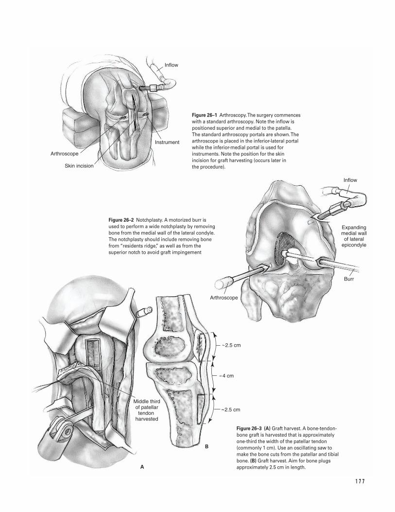
1 7 7
Arthroscope
Middle third of patellar tendon
harvested
Inflow
Arthroscope
Skin incision
Instrument
Inflow
Expanding medial wall of lateral
epicondyle
Burr
A
B
2.5 cm
2.5 cm
4 cm
Figure 26–1 Arthroscopy. The surgery commenceswith a standard arthroscopy. Note the inflow ispositioned superior and medial to the patella. The standard arthroscopy portals are shown. Thearthroscope is placed in the inferior-lateral portalwhile the inferior-medial portal is used forinstruments. Note the position for the skinincision for graft harvesting (occurs later in the procedure).
Figure 26–2 Notchplasty. A motorized burr isused to perform a wide notchplasty by removingbone from the medial wall of the lateral condyle.The notchplasty should include removing bonefrom “residents ridge,” as well as from thesuperior notch to avoid graft impingement
Figure 26–3 (A) Graft harvest. A bone-tendon-bone graft is harvested that is approximatelyone-third the width of the patellar tendon(commonly 1 cm). Use an oscillating saw tomake the bone cuts from the patellar and tibialbone. (B) Graft harvest. Aim for bone plugsapproximately 2.5 cm in length.
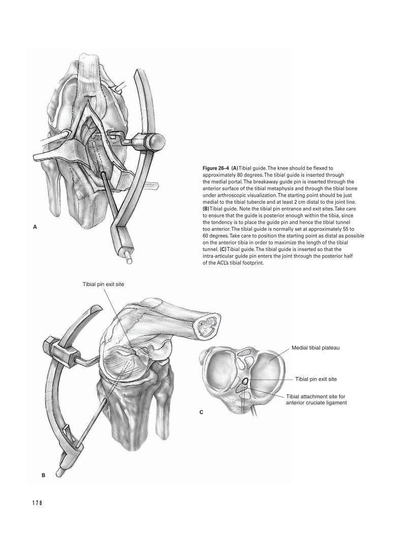
1 7 8
B
A
C
Tibial pin exit site
Tibial pin exit site
Tibial attachment site for anterior cruciate ligament
Medial tibial plateau
Figure 26–4 (A)Tibial guide. The knee should be flexed toapproximately 80 degrees. The tibial guide is inserted through the medial portal. The breakaway guide pin is inserted through theanterior surface of the tibial metaphysis and through the tibial boneunder arthroscopic visualization. The starting point should be justmedial to the tibial tubercle and at least 2 cm distal to the joint line. (B)Tibial guide. Note the tibial pin entrance and exit sites. Take care to ensure that the guide is posterior enough within the tibia, since the tendency is to place the guide pin and hence the tibial tunnel too anterior. The tibial guide is normally set at approximately 55 to 60 degrees. Take care to position the starting point as distal as possibleon the anterior tibia in order to maximize the length of the tibialtunnel. (C)Tibial guide. The tibial guide is inserted so that the intra-articular guide pin enters the joint through the posterior half of the ACL’s tibial footprint.
Tunnel preparation17. Denude the periosteum over the metaphyseal bone
just medial to the tibial tubercle and 2 cm distal tothe joint line for the entrance point to the tibialhole. This area should be approximately 1.5 cm indiameter.
18. Replace the arthroscopic instruments in the knee.Place the tibial alignment guide through the medialportal and into the intercondylar notch. Flex theknee to approximately 80 degrees. Position the tib-ial alignment guide so that the intra-articular guidepin enters the joint through the posterior half ofthe ACL’s tibial footprint. This is a point just ante-rior to the posterior cruciate ligament. Take care toensure that the guide is posterior enough within thetibia, since the tendency is to place the guide pinand hence the tibial tunnel too anterior (Figs.26–4A, 4B, and 4C).
19. Drill the break-away guide pin through the anteriorsurface of the tibial metaphysis and through the tib-ial bone under arthroscopic visualization. The tibialguide is normally set at approximately 55 to 60 de-grees. Take care to position the starting point asdistal as possible on the anterior tibia in order tomaximize the length of the tibial tunnel. The start-ing point is just medial to the tibia tubercle and atleast 2 cm distal to the joint line. This correspondsto the area previously denuded of periosteum.
20. Insert the guide pin through the tibia and a few mil-limeters into the knee joint to ascertain its position.Run the knee through a range of motion. Arthro-scopically visualize the guide pin with the kneeextended. Ensure that it clears the superior notchand that the graft will not impinge. If the positionof the guide pin is felt to be unsatisfactory, the pinis removed and reinserted.
21. Over-ream the guide pin with the appropriate sizedisposable reamers. The reamer normally corre-sponds to the larger sized bone plug (commonly 10or 11 mm in diameter). Rasp the edge of the hole tosmooth the border. Use an arthroscopic shaver tohelp clear any soft tissue from the intra-articulartunnel hole. Use a “carrot” to plug the tibial tunneland prevent fluid extravasation.
22. Flex the knee to approximately 90 degrees. Carefullyposition the appropriate femoral offset aiming device
within the knee. Take care to optimize visualizationand fluid inflow at this point in the procedure.
In general, a 6- or 7-mm femoral offset should beused for a 10-mm femoral tunnel. This helps toensure a 1 to 2 mm “backwall.” If an 11-mmfemoral tunnel is desired, consider using a 7-mmfemoral offset to help ensure a 1.5-mm “back-wall.” Similarly for a 9-mm femoral tunnel, con-sider using a 5- or 6-mm femoral offset to helpensure a 0.5- to 1.5-mm “backwall.”
23. While maintaining the knee in the flexed positionand aligning the femoral offset guide against theposterior aspect of the intercondylar notch, drill the large beath (“harpoon”) guide pin through thefemur. The guide pin should exit the anterior lateralfemoral cortex and pierce the skin on the anteriorlateral thigh. Place a chuck over the tip of the guide pin to minimize injury to the surgical team(Fig. 26–5).
24. Continue to maintain the knee in the same flexedposition. Insert the reamer over the guide pin intothe knee’s intercondylar notch. While maintainingoptimal visualization, drill the femoral tunnel. Drillthe tunnel to a depth approximately 1 cm greaterthan the length of the bone plug that will be intro-duced. Remove the reamer by hand.
25. Use the arthroscopic shaver to debride the inter-condylar notch of any small bone fragments ordebris that was produced during the reaming. Inaddition, use the shaver to remove some of thebone along the anterior aspect of the femoral hole.This improves visualization and helps form a start-ing point for the interference screw to be placedlater in the case.
Graft passage26. Place the tendon graft sutures through the eye of
the large beath (“harpoon”) guide pin. Pull the guidepin through the knee so the sutures exit the ante-rior lateral thigh.
27. Pull the leading edge of the graft through the tib-ial tunnel into the intercondylar notch and theninto the femoral tunnel. Visualize the graft as itenters the femoral tunnel to ensure proper rotation(the tendon should be posterior and the cancellous
2 6 A N T E R I O R C R U C I AT E L I G A M E N T S U R G E RY ( E N D O S C O P I C ) 1 7 9
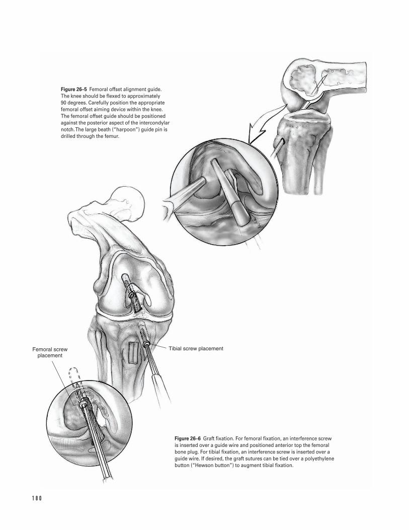
1 8 0
Femoral screw placement
Tibial screw placement
Figure 26–5 Femoral offset alignment guide. The knee should be flexed to approximately 90 degrees. Carefully position the appropriatefemoral offset aiming device within the knee. The femoral offset guide should be positionedagainst the posterior aspect of the intercondylarnotch. The large beath (“harpoon”) guide pin isdrilled through the femur.
Figure 26–6 Graft fixation. For femoral fixation, an interference screwis inserted over a guide wire and positioned anterior top the femoralbone plug. For tibial fixation, an interference screw is inserted over aguide wire. If desired, the graft sutures can be tied over a polyethylenebutton (“Hewson button”) to augment tibial fixation.
portion of the bone plug pointed anterior). Ifneeded, introduce a probe through the medial por-tal to help align the graft in the proper rotation.
28. Check the position of the graft within the tibialtunnel. If the tibial bone plug is prominent, thegraft can be recessed several millimeters into thefemoral tunnel.
Graft fixation29. Fix the femoral side first. Hyperflex the knee. Make
a small vertical incision in the medial retinaculum.This should be just medial to the patella tendon andjust superior to the top of the tibia.
30. Introduce a guide wire through this rent and posi-tion it in the intercondylar notch. It is imperativethat visualization is satisfactory at this point in theprocedure. In some cases, visualization is improvedby turning off the inflow and “going dry.”
31. Place the guide wire into the femoral tunnel justanterior to the graft. Insert a 7-mm interferencescrew over the guide wire. Maintain arthroscopicvisualization as the screw is put in place. Recess thescrew within the tunnel. Remove the guide wireprior to fully seating the screw (Fig. 26–6).
32. Straighten the operative table so the patient laysflat. Insert a guide wire alongside the bone plugwithin the tibial tunnel. Attempt to place the wirealong the side of the bone plug where the suturesdo not exit to minimize the risk of cutting thesutures. Use the graft sutures to tension the graftwith the knee at 30 degrees of flexion or near fullextension, while fixing the tibial bone plug. Removethe guide wire prior to the screw fully seating (Fig.26–6). If desired, the graft sutures can be tied over apolyethylene button (“Hewson button”) to aug-ment tibial fixation.
33. After graft fixation, perform a Lachman test toassess knee stability. Range the knee to assess forgraft impingement. If impingement is present,expand the notchplasty.
Closure34. Pack extra bone removed from the graft bone plugs
into the patellar and tibial defects as a bone graft.35. Close the tendon and paratenon with interrupted
#1 absorbable sutures. Both can be closed in onelayer. Alternatively, the paratenon can be closed asa separate layer with 2-0 absorbable sutures.
36. Close the subcutaneous tissue with absorbable suture.Close the skin and portals per surgeon’s preference.
37. Inject intra-articular marcaine into the wounds andthe knee joint after closure to diminish postopera-tive pain.
38. Place a surgical dressing on the wound. Apply a hingebrace or knee immobilizer in the operating room.
Suggested ReadingsBach BR Jr. Endoscopic anterior cruciate ligamentreconstruction using autograft patellar tendonsubstitution. In: Craig EV, ed. Clinical Orthopaedics.Baltimore, MD: Lippincott Williams & Willkins, 1999,pp. 750–763.
Kurzweil PR, Jackson DW. Chronic anterior cruciateligament injuries. In: Fu FH, Harner CD, Vince KG, eds.Knee Surgery. Baltimore, MD: Williams & Willkins, 1994,pp. 731–747.
Nogalski MP, Bach BR Jr. Acute anterior cruciate ligamentinjuries. In: Fu FH, Harner CD, Vince KG, eds. KneeSurgery. Baltimore, MD: Williams & Willkins, 1994, pp. 679–730.
2 6 A N T E R I O R C R U C I AT E L I G A M E N T S U R G E RY ( E N D O S C O P I C ) 1 8 1
Indications1. Osteoarthritis knee2. Rheumatoid arthritis knee3. Post-traumatic arthritis knee
Contraindications1. Active knee infection (absolute)2. Neuropathic joint (relative)3. Unsatisfactory soft tissue envelope4. Marked ligamentous insufficiency (requires con-
strained knee prosthesis)5. Dysfunctional extensor mechanism
Preoperative Preparation1. Knee radiographs, including standing anteroposte-
rior (AP), lateral, and skyline views2. Appropriate medical and anesthetic evaluation3. Document status of preoperative neurovascular
examination4. Assessment of preoperative mechanical axis (Fig.
27–1).
Special Instruments, Position,and Anesthesia1. The patient is placed supine on the operating room
table.
2. All pressure points should be padded.3. The procedure can be done with general, epidural,
or long-acting spinal anesthesia.4. Routine orthopaedic surgical instrumentation should
be available. In addition, the specific instrumentsand cutting guides unique to the prosthesis to beimplanted should be available.
Tips and Pearls1. If at all possible, prior vertical incision should be
incorporated into the current skin incision. Trans-verse incisions may be crossed at a perpendicularangle.
2. The preoperative arc of motion should be assessedprior to the procedure with special attention to anyflexion deformity (inability to fully extend the kneeboth actively and passively). Extra bone may needto be resected from the distal femur in the event ofa fixed flexion deformity.
3. The tourniquet should be placed as proximal as pos-sible on the thigh in order to minimize anyinfringement on the surgical field. In a patient withsignificant peripheral vascular disease, or status postbypass surgery, consideration may be given to per-forming the surgery without tourniquet control.
4. Intravenous antibiotics appropriate for the hospi-tal’s bacterial flora should be administered prior totourniquet inflation.
5. A “quadriceps snip” (“rectus snip”) can be used inknees where exposure is difficult and eversion of
1 8 2
C H A P T E R 2 7
Total Knee Arthroplasty
Steven H. Stern
the patellar hard to achieve. This is accomplishedby making an oblique incision, starting from themost proximal portion of the medial arthrotomyand angled superior and lateral through the quadri-ceps tendon (Fig. 27–3). At the end of the surgery,this incision is closed in a standard fashion; and inmost cases, normal postoperative rehabilitation canbe instituted.
What To Avoid1. Because of the problems associated with infection,
great care is taken to minimize this complication.Operating room traffic should be minimized, andpreoperative antibiotics administered.
2. Ligamentous stability of the knee should be assessedprior to the procedure in order to ascertain the mostappropriate prosthesis for implantation.
3. Avoid internal rotation of either the femoral or tib-ial components.
Postoperative Care Issues1. A suction-type drain can be used and normally,
safely discontinued the morning after surgery.2. Constant passive motion (CPM) machines can be
employed in the postoperative period. These can bestarted in extension and with gradually increasingflexion, or used with an early motion protocol start-ing at 50 to 100 degrees the day of surgery, and pro-gressing toward extension.
3. A compressive dressing should be placed at the endof surgery and is normally changed approximately48 h after the procedure.
4. Assessment of the patient’s distal neurovascularexamination should be made the evening of sur-gery. If there is evidence of a peroneal nerve palsy,the dressing should be loosened and the kneeplaced in a flexed position. Knees with a preopera-tive valgus alignment or significant preoperativeflexion deformities are at particular risk for devel-oping a peroneal nerve palsy (though this com-plication can occur idiopathically in any kneeundergoing an arthroplasty procedure).
Operative Technique
Approach1. Position the patient supine on the operating room
table. Place a thigh tourniquet as proximal as possi-ble on the thigh.
2. Prepare and drape the limb in the hospital’s stan-dard sterile fashion. Exsanguinate the limb andinflate the tourniquet.
3. Make an anterior skin incision utilizing either astraight mid-line or a medial parapatellar incision.Dissect directly down to the extensor mechanismwhile minimizing skin flaps. Adequate exposure ofthe extensor mechanism with visualization of boththe proximal quadriceps tendon and distal patellartendon should be achieved prior to performing theretinacular arthrotomy (Fig. 27–2).
4. Make a medial arthrotomy utilizing either a straightmid-line, medial parapatellar, or mid-vastus retinac-ular incision. The distal exposure is similar in all ofthese techniques with the distal limb of the retinac-ular incision carried along the proximal tibia medialto the tibial tubercle. Extend the retinacular inci-sion as far proximally as necessary to achieve ade-quate exposure (Fig. 27–3).
5. Use a periosteal elevator to subperiosteally strip theperisoteum off the proximal medial tibia. Take careto keep this layer in continuity.
6. Evert the patella and flex the knee (Fig. 27–4). Takecare not to avulse the patellar tendon. If it is notpossible to evert the patella, perform a “quadricepssnip” (“rectus snip”) (Fig. 27–3).
7. Dissect the proximal tibial periosteum.
a. Varus knees. Continue to subperiosteally stripthe proximal medial tibial periosteum and thesemimembranosus insertion from the proximalmedial tibial brim. Carry this dissection aroundto the posterior medial corner of the tibia.
b. Valgus knees. Limit the medial dissection. Striponly enough periosteum to achieve adequateexposure.
8. Remove marginal osteophytes. Resect the anteriorcruciate ligament (ACL) or any ACL remnant.
2 7 TOTA L K N E E A RT H R O P L A S T Y 1 8 3
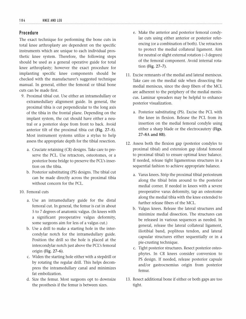
ProcedureThe exact technique for performing the bone cuts intotal knee arthroplasty are dependent on the specificinstruments which are unique to each individual pros-thetic knee system. Therefore, the following stepsshould be used as a general operative guide for totalknee arthroplasty; however the exact procedure forimplanting specific knee components should bechecked with the manufacturer’s suggested techniquemanual. In general, either the femoral or tibial bonecuts can be made first.9. Proximal tibial cut. Use either an intramedullary or
extramedullary alignment guide. In general, theproximal tibia is cut perpendicular to the long axisof the tibia in the frontal plane. Depending on theimplant system, the cut should have either a neu-tral or a posterior slope from front to back. Avoidanterior tilt of the proximal tibia cut (Fig. 27–5).Most instrument systems utilize a stylus to helpassess the appropriate depth for the tibial resection.
a. Cruciate retaining (CR) designs. Take care to pre-serve the PCL. Use retractors, osteotomes, or aposterior bone bridge to preserve the PCL’s inser-tion on the tibia.
b. Posterior substituting (PS) designs. The tibial cutcan be made directly across the proximal tibiawithout concern for the PCL.
10. Femoral cuts
a. Use an intramedullary guide for the distalfemoral cut. In general, the femur is cut in about5 to 7 degrees of anatomic valgus. (In knees witha significant preoperative valgus deformity,some surgeons aim for less of a valgus cut.)
b. Use a drill to make a starting hole in the inter-condylar notch for the intramedullary guide.Position the drill so the hole is placed at theintercondylar notch just above the PCL’s femoralorigin (Fig. 27–6).
c. Widen the starting hole either with a stepdrill orby rotating the regular drill. This helps decom-press the intramedullary canal and minimizesfat embolization.
d. Size the femur. Most surgeons opt to downsizethe prosthesis if the femur is between sizes.
e. Make the anterior and posterior femoral condy-lar cuts using either anterior or posterior refer-encing (or a combination of both). Use retractorsto protect the medial collateral ligament. Aimfor neutral or slight external rotation (~3 degrees)of the femoral component. Avoid internal rota-tion (Fig. 27–7).
11. Excise remnants of the medial and lateral meniscus.Take care on the medial side when dissecting themedial meniscus, since the deep fibers of the MCLare adherent to the periphery of the medial menis-cus. Laminar spreaders may be helpful to enhanceposterior visualization.
a. Posterior substituting (PS). Excise the PCL withthe knee in flexion. Release the PCL from itsinsertion on the medial femoral condyle usingeither a sharp blade or the electrocautery (Figs.27–8A and 8B).
12. Assess both the flexion gap (posterior condyles toproximal tibial) and extension gap (distal femoralto proximal tibial) to ensure optimal knee balance.If needed, release tight ligamentous structures in asequential fashion to achieve appropriate balance.
a. Varus knees. Strip the proximal tibial periosteumalong the tibial brim around to the posteriormedial corner. If needed in knees with a severepreoperative varus deformity, tap an osteotomealong the medial tibia with the knee extended tofurther release fibers of the MCL.
b. Valgus knees. Release the lateral structures andminimize medial dissection. The structures canbe released in various sequences as needed. Ingeneral, release the lateral collateral ligament,iliotibial band, popliteus tendon, and lateralcapsular structures either sequentially or in apie-crusting technique.
c. Tight posterior structures. Resect posterior osteo-phytes. In CR knees consider conversion to PS design. If needed, release posterior capsuleand/or gastrocnemius origin from posteriorfemur.
13. Resect additional bone if either or both gaps are tootight.
1 8 4 K N E E A N D L E G
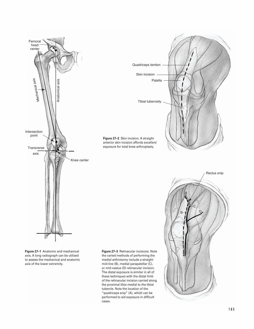
1 8 5
Femoral head center
Ana
tom
ical
axis
Mec
hani
cala
xis
Intersection point
Transverse
axis
Knee center
Rectus snip
B
C
A
D
Quadriceps tendon
Skin incision
Patella
Tibial tuberosity
Figure 27–2 Skin incision. A straightanterior skin incision affords excellentexposure for total knee arthroplasty.
Figure 27–1 Anatomic and mechanicalaxis. A long radiograph can be utilized to assess the mechanical and anatomicaxis of the lower extremity.
Figure 27–3 Retinacular incisions. Notethe varied methods of performing themedial arthrotomy include a straight mid-line (B), medial parapatellar (C), or mid-vastus (D) retinacular incision. The distal exposure is similar in all ofthese techniques with the distal limb of the retinacular incision carried alongthe proximal tibia medial to the tibialtubercle. Note the location of the“quadriceps snip” (A), which can beperformed to aid exposure in difficultcases.
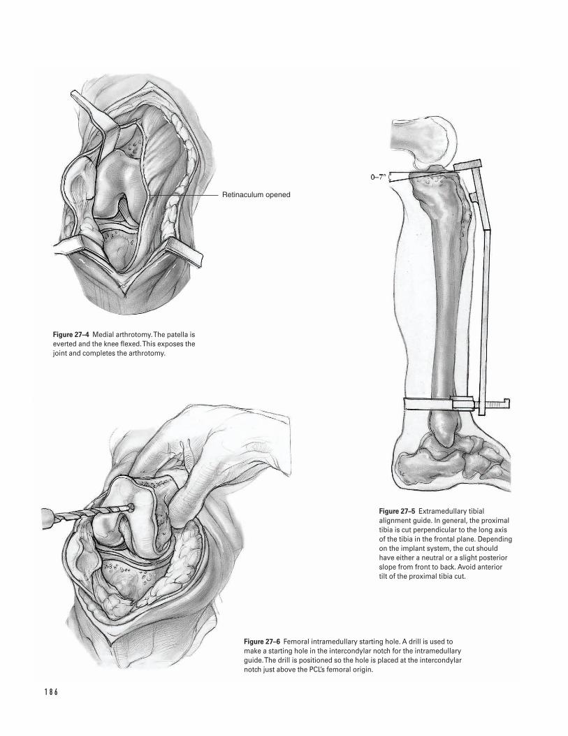
1 8 6
Retinaculum opened
Figure 27–4 Medial arthrotomy. The patella iseverted and the knee flexed. This exposes thejoint and completes the arthrotomy.
Figure 27–5 Extramedullary tibialalignment guide. In general, the proximaltibia is cut perpendicular to the long axisof the tibia in the frontal plane. Dependingon the implant system, the cut shouldhave either a neutral or a slight posteriorslope from front to back. Avoid anterior tilt of the proximal tibia cut.
Figure 27–6 Femoral intramedullary starting hole. A drill is used tomake a starting hole in the intercondylar notch for the intramedullaryguide. The drill is positioned so the hole is placed at the intercondylarnotch just above the PCL’s femoral origin.
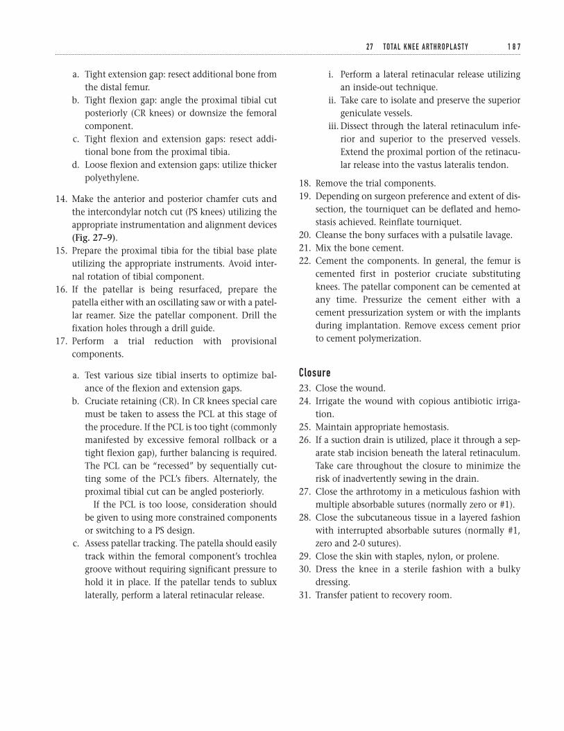
a. Tight extension gap: resect additional bone fromthe distal femur.
b. Tight flexion gap: angle the proximal tibial cutposteriorly (CR knees) or downsize the femoralcomponent.
c. Tight flexion and extension gaps: resect addi-tional bone from the proximal tibia.
d. Loose flexion and extension gaps: utilize thickerpolyethylene.
14. Make the anterior and posterior chamfer cuts andthe intercondylar notch cut (PS knees) utilizing theappropriate instrumentation and alignment devices(Fig. 27–9).
15. Prepare the proximal tibia for the tibial base plateutilizing the appropriate instruments. Avoid inter-nal rotation of tibial component.
16. If the patellar is being resurfaced, prepare thepatella either with an oscillating saw or with a patel-lar reamer. Size the patellar component. Drill thefixation holes through a drill guide.
17. Perform a trial reduction with provisionalcomponents.
a. Test various size tibial inserts to optimize bal-ance of the flexion and extension gaps.
b. Cruciate retaining (CR). In CR knees special caremust be taken to assess the PCL at this stage ofthe procedure. If the PCL is too tight (commonlymanifested by excessive femoral rollback or atight flexion gap), further balancing is required.The PCL can be “recessed” by sequentially cut-ting some of the PCL’s fibers. Alternately, theproximal tibial cut can be angled posteriorly.
If the PCL is too loose, consideration shouldbe given to using more constrained componentsor switching to a PS design.
c. Assess patellar tracking. The patella should easilytrack within the femoral component’s trochleagroove without requiring significant pressure tohold it in place. If the patellar tends to subluxlaterally, perform a lateral retinacular release.
i. Perform a lateral retinacular release utilizingan inside-out technique.
ii. Take care to isolate and preserve the superiorgeniculate vessels.
iii. Dissect through the lateral retinaculum infe-rior and superior to the preserved vessels.Extend the proximal portion of the retinacu-lar release into the vastus lateralis tendon.
18. Remove the trial components.19. Depending on surgeon preference and extent of dis-
section, the tourniquet can be deflated and hemo-stasis achieved. Reinflate tourniquet.
20. Cleanse the bony surfaces with a pulsatile lavage.21. Mix the bone cement.22. Cement the components. In general, the femur is
cemented first in posterior cruciate substitutingknees. The patellar component can be cemented atany time. Pressurize the cement either with acement pressurization system or with the implantsduring implantation. Remove excess cement priorto cement polymerization.
Closure23. Close the wound.24. Irrigate the wound with copious antibiotic irriga-
tion.25. Maintain appropriate hemostasis.26. If a suction drain is utilized, place it through a sep-
arate stab incision beneath the lateral retinaculum.Take care throughout the closure to minimize therisk of inadvertently sewing in the drain.
27. Close the arthrotomy in a meticulous fashion withmultiple absorbable sutures (normally zero or #1).
28. Close the subcutaneous tissue in a layered fashionwith interrupted absorbable sutures (normally #1,zero and 2-0 sutures).
29. Close the skin with staples, nylon, or prolene.30. Dress the knee in a sterile fashion with a bulky
dressing.31. Transfer patient to recovery room.
2 7 TOTA L K N E E A RT H R O P L A S T Y 1 8 7
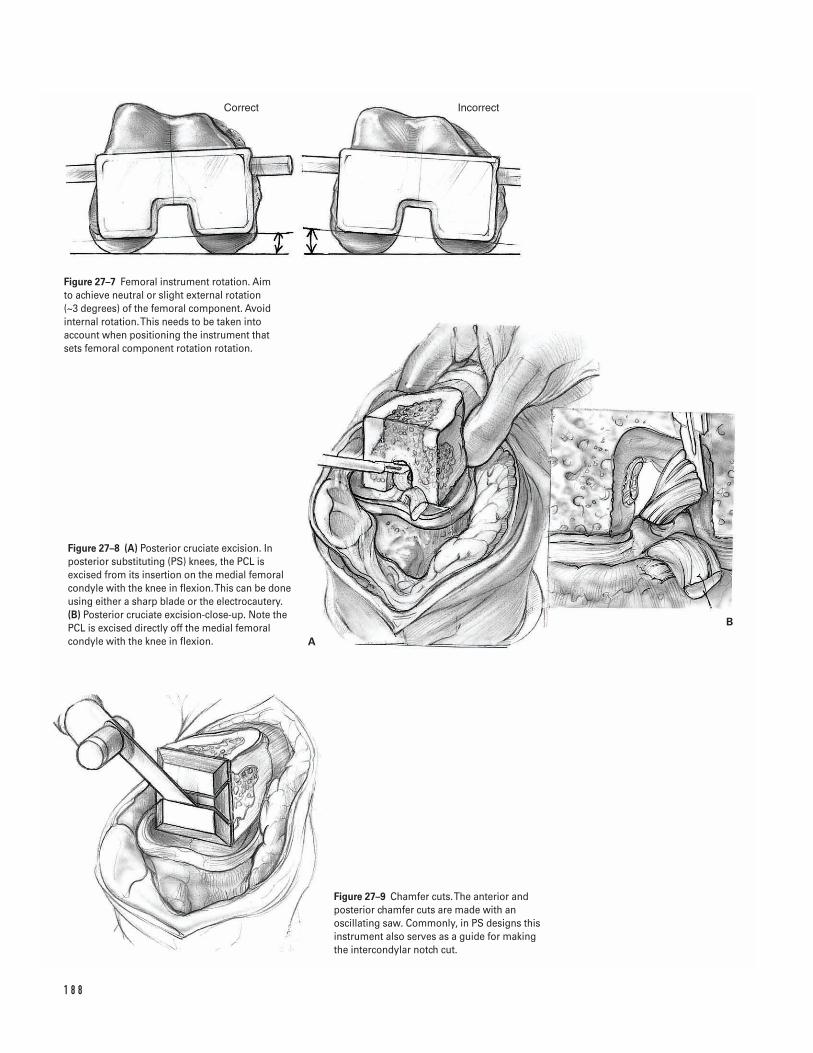
1 8 8
Correct Incorrect
A
B
Figure 27–7 Femoral instrument rotation. Aim to achieve neutral or slight external rotation (~3 degrees) of the femoral component. Avoidinternal rotation. This needs to be taken intoaccount when positioning the instrument thatsets femoral component rotation rotation.
Figure 27–8 (A) Posterior cruciate excision. Inposterior substituting (PS) knees, the PCL isexcised from its insertion on the medial femoralcondyle with the knee in flexion. This can be doneusing either a sharp blade or the electrocautery.(B) Posterior cruciate excision-close-up. Note thePCL is excised directly off the medial femoralcondyle with the knee in flexion.
Figure 27–9 Chamfer cuts. The anterior andposterior chamfer cuts are made with anoscillating saw. Commonly, in PS designs thisinstrument also serves as a guide for making the intercondylar notch cut.

Suggested ReadingsGarvin KL, Scuderi G, Insall JN. Evolution of thequadriceps snip. Clin Orthop 1995;321:131–137.
Scuderi GR, Insall JN. Fixed varus and valgusdeformities. In: Lotke PA, ed. Master Techniques inOrthopedic Surgery: Knee Arthroplasty. New York, NY:Raven Press, 1995, pp. 111–127.
Stern SH. Surgical exposure in total knee arthroplasty.In: Fu FH, Harner CD, Vince KG, eds. Knee Surgery.Baltimore, MD: Williams & Willkins, 1994, pp.1289–1302.
Stern SH. Total knee replacement. In: Craig EV, ed.Clinical Orthopaedics. Baltimore, MD: LippincottWilliams & Willkins, 1999, pp. 642–649.
Vince KG. Revision knee arthroplasty technique.Instructional Course Lectures 1993;42:325–339.
Yashar AA, Venn-Watson E, Welsh T, Colwell CW Jr.,Lotke P. Continuous passive motion with acceleratedflexion after total knee arthroplasty. Clin Orthop 1997;345:38–43.
Younger AS, Duncan CP, Masri BA. Surgical exposures inrevision total knee arthroplasty. J Am Acad Orthop Surg1998;6(1):55–64.
2 7 TOTA L K N E E A RT H R O P L A S T Y 1 8 9
Indications1. Unicompartmental medial knee osteoarthritis2. Age less than 50 years old3. High activity level (e.g., heavy laborers)4. Varus deformity 10 degrees or less5. Flexion arc greater than 90 degrees
Contraindications1. Rheumatoid arthritis or inflammatory arthritides2. Flexion contracture greater than 10 degrees3. Tibiofemoral subluxation (lateral) greater than 1 cm4. Lateral thrust of knee during gait (high adductor
moment)
Preoperative Preparation1. Knee radiographs, including anteroposterior (AP),
lateral, sunrise and standing three-joint films2. Determine the femoral-tibial angle and the mechan-
ical axis (Fig. 28–1).3. Calculate the size of bone wedge to be removed
from the proximal tibia.4. Consider preoperative physical therapy to increase
quadriceps strength and decrease flexion contracture.5. Patient education to establish reasonable expectations
Special Instruments, Position, and Anesthesia1. Supine position on a radiolucent operating table
with a small padded bolster under the ipsilateralbuttock.
2. The surgery can be performed with general, epidural,or long-acting spinal anesthesia.
3. Use basic orthopaedic instrumentation.4. Use 1/8-in Steinmann pins, sharp straight osteo-
tomes, and a sagittal saw.5. Consider variable angle proximal tibia cutting guides
to make accurate osteotomy cuts.6. An L buttress plate should be available for fixation
of the osteotomy site.7. Use a fluoroscopic image intensifier for intra-
operative imaging.
Tips and Pearls1. For patients without contraindications (i.e., signifi-
cant peripheral vascular disease), a tourniquet shouldbe placed as proximal as possible on the thigh toavoid minimizing the surgical exposure.
2. Intravenous antibiotics should be administeredprior to inflation of the tourniquet.
3. A vertical skin incision is preferred in order toimprove exposure for internal fixation and to facil-itate possible total knee arthroplasty in the future.
1 9 0
C H A P T E R 2 8
High Tibial Osteotomy
Stephen G. Manifold and Giles R. Scuderi
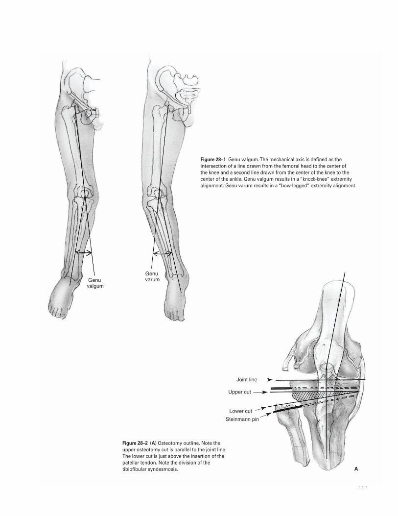
1 9 1
Genu �valgum
Genu �varum
Joint line
Upper cut
Lower cut
Steinmann pin
A
Figure 28–1 Genu valgum. The mechanical axis is defined as theintersection of a line drawn from the femoral head to the center of the knee and a second line drawn from the center of the knee to thecenter of the ankle. Genu valgum results in a “knock-knee” extremityalignment. Genu varum results in a “bow-legged” extremity alignment.
Figure 28–2 (A) Osteotomy outline. Note theupper osteotomy cut is parallel to the joint line.The lower cut is just above the insertion of thepatellar tendon. Note the division of thetibiofibular syndesmosis.
4. The Steinmann pins should be positioned parallelin the lateral plane to avoid rotational problemsafter the osteotomy.
5. Maintain at least a 2-cm-thick proximal tibialfragment.
6. Obtain stable internal fixation of the osteotomy toallow early aggressive knee rehabilitation.
What To Avoid1. Do not extend the osteotomy cuts through the medial
cortex of the proximal tibia to prevent translationof the osteotomy fragments.
2. Avoid excessive retraction of the soft tissues overthe lateral aspect of the knee, which could lead topostoperative peroneal nerve palsy.
3. Avoid undercorrection of the deformity as this canlead to early symptom recurrence.
4. Avoid excessive force during closure of the osteo-tomy site. If resistance is encountered, verify thatthe tibio-fibular syndesmosis has been completelydisrupted.
Postoperative Care Issues1. Remove the suction drain from the knee on the first
postoperative day. The surgical dressing should beremoved on the second postoperative day. Skinsutures or staples are removed approximately 3 weeksfrom the date of surgery.
2. Place the knee in a continuous passive motion(CPM) machine in the recovery room with initialsettings of 0 to 60 degrees. Advance the machine’sflexion 10 degrees or more per day as tolerated; 90degrees of flexion is the goal by the time of hospitaldischarge.
3. Begin physical therapy on the first postoperativeday. Focus on range of motion and isometric exer-cises. Place the patient in a hinged knee brace. Toe-touch weight bearing is allowed initially; however,progression to full weight bearing status is notallowed for at least 6 weeks.
Operative Technique1. Place the patient in the supine position on a radi-
olucent operating table with a bolster under theipsilateral hip.
2. Prepare and drape the knee in the standard sterilefashion. Elevate the leg and inflate the tourniquetto 350 mm Hg.
3. Make a vertical mid-line skin incision over the ante-rior aspect of the knee. Carry it down through thesubcutaneous tissue. Elevate skin flaps only enoughto provide adequate exposure and take care not toviolate the extensor mechanism.
4. Incise the fascia over the lateral portion of the prox-imal tibia. Elevate the overlying muscle and perios-teum laterally from the tibial crest using a periostealelevator. The knee joint should not be entered dur-ing this dissection.
5. Disrupt the tibiofibular joint with the elevator dur-ing the lateral dissection of the soft tissues. Thisallows the fibular head to move freely on the tibia.Closure of the tibial osteotomy site requires fibularosteotomy, fibular head resection or tibiofibularjoint dissociation. We prefer the latter technique tominimize the risk of injury to the common per-oneal nerve (Fig. 28–2A).
6. Use the periosteal elevator to continue dissectionaround the posterior aspect of the proximal tibia.Take care to keep the elevator on the surface of thebone and avoid injury to the posterior neurovascu-lar structures.
7. Measure and mark the level of the proximal tibia 2 cm distal to the joint line using a methylene bluepen or the electrocautery. Identify the joint lineeither with a needle or by direct inspection.
8. Drill a 1/8-in Steinmann pin at this level parallel tothe joint line from a lateral to medial direction.Check the position of the pin in both the AP andlateral planes using the sterile draped C-arm imageintensifier. The pin should be parallel to the jointline in both planes.
9. Place a second Steinmann pin distal to the first pinon the lateral aspect of the proximal tibia at a levelthat will yield the appropriate thickness of bonewedge as determined preoperatively. Consider usingtemplates and cutting guides that incorporate the
1 9 2 K N E E A N D L E G
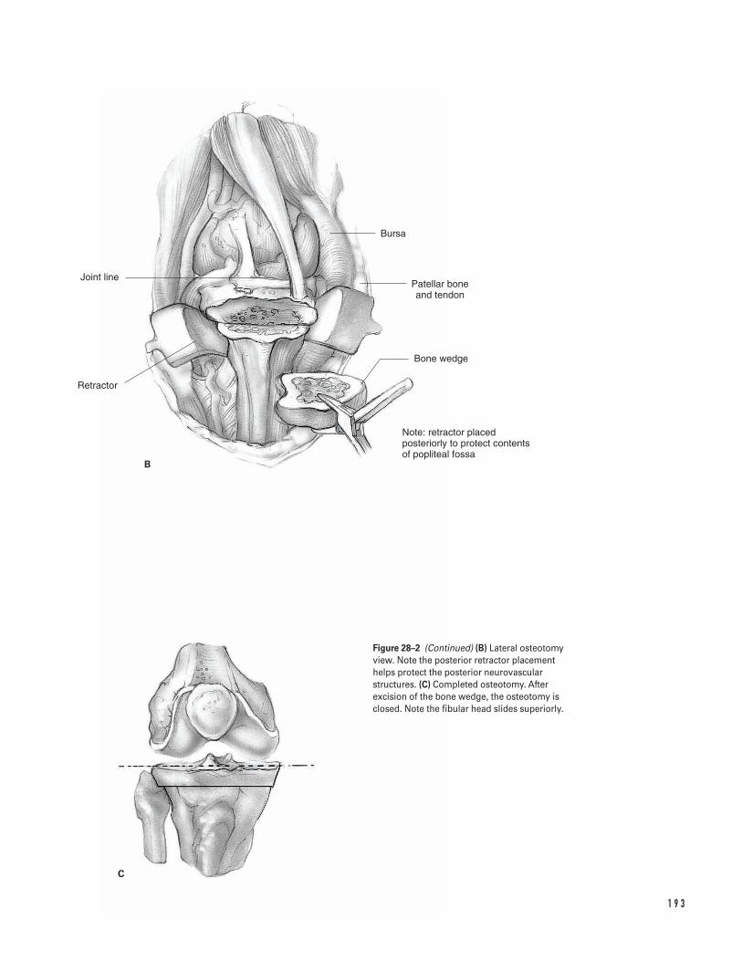
1 9 3
B
C
Bursa
Patellar bone and tendon
Bone wedge
Note: retractor placed posteriorly to protect contents of popliteal fossa
Joint line
Retractor
Figure 28–2 (Continued) (B) Lateral osteotomyview. Note the posterior retractor placementhelps protect the posterior neurovascularstructures. (C) Completed osteotomy. Afterexcision of the bone wedge, the osteotomy isclosed. Note the fibular head slides superiorly.
precise angle of the desired correction to aid in theplacement of this second pin. Aim the tip of the sec-ond pin so it converges with that of the first pin atthe medial tibial cortex.
10. Check the position of the second pin with the C-arm image intensifier. The pins should be parallel toeach other in the lateral plane to avoid rotationalmalalignment during closure of the osteotomy.
11. Place retractors along the posterior surface of theproximal tibia and beneath the patellar tendon toprotect the soft tissues from injury during theosteotomy (Fig. 28–2B).
12. Start the osteotomy from the lateral side of theproximal tibia. Use a sagittal saw or sharp osteotometo make the initial cut along the axis of the proxi-mal Steinmann pin. Make the second cut along theaxis of the more distal Steinmann pin. Extend theseosteotomy cuts only approximately three-quartersof the way across the tibia to prevent inadvertentdivision of the medial tibial cortex.
13. Remove the wedge of bone formed by the osteotomycuts. Complete the remainder of the osteotomyunder direct visualization. Perforate the medialcortex by placing several drill holes through it.However, the periosteal hinge is left intact to pre-vent translation of the osteotomy fragments (Fig.28–2B).
14. Close the osteotomy site by applying a gentle valgusforce to the tibia. Resistance to this maneuvershould be minimal. Take care not to close the sitewith excessive force which could result in fractureof the proximal tibia. Confirm osteotomy closurewith the C-arm image intensifier (Fig. 28–2C).
15. Use a long alignment rod to assess the overallextremity alignment in a similar manner to a totalknee arthroplasty. Align the rod over the center ofthe ankle joint and the tibial tubercle. This shouldresult in the proximal end of the rod passing at least2.5 cm medial to the center of the hip joint.
16. Maintain alignment of the fragments with internalfixation. We prefer stable internal fixation with theuse of a low-profile L plate secured to the lateralaspect of the proximal tibia. Confirm final align-ment and fixation with the image intensifier.
17. Deflate the tourniquet and achieve hemostasis.Copiously irrigate the wound with antibioticsolution.
18. Perform a layered closure over a suction drain. Re-approximate the muscle over the proximal tibia with0-vicryl sutures. However leave the fascia open to pre-vent the development of a compartment syndrome.
19. Close the subcutaneous tissue with 00-vicryl sutures.Close the skin with staples.
20. Apply a sterile gauze dressing and secure it with acotton roll. Wrap an ace bandage loosely aroundthe surgical dressing and connect the collectioncontainer for the drain.
21. Take the patient to the recovery room.
Suggested ReadingInsall JN. Osteotomy. In: Insall JN, Windsor RE, ScottWN, Kelly MA, Aglietti P, eds. Surgery of the Knee. 2nded. New York, NY: Churchill Livingstone, 1993, pp.635–676.
1 9 4 K N E E A N D L E G
Indications1. Unicompartmental lateral knee osteoarthritis2. Age less than 50 years old3. High-activity level (heavy laborers)4. Valgus deformity 15 degrees or less5. Flexion arc greater than 90 degrees
Contraindications1. Rheumatoid or inflammatory arthritides2. Tibiofemoral subluxation (medial) greater than 1 cm
Preoperative Preparation1. Knee radiographs including anteroposterior, lateral,
sunrise, and standing three-joint films2. Determine the femoral-tibial angle and the mechan-
ical axis (see Chapter 28, Fig. 28–1).3. Calculate the size of bone wedge to be removed
from the distal femur.4. Consider preoperative physical therapy to increase
quadriceps strength and decrease flexion contracture.5. Patient education to establish reasonable expectations
Special Instruments, Position, and Anesthesia1. Supine position on a radiolucent operating table
with a small padded bolster under the ipsilateralbuttock
2. Surgery can be performed with general, epidural, orlong-acting spinal anesthesia.
3. Use basic orthopedic instrumentation.4. Use 1/8-in Steinmann pins, sharp straight osteo-
tomes, and a sagittal saw.5. Consider variable angle proximal tibia cutting
guides to make accurate osteotomy cuts.6. A 90-degree blade plate should be available for fixa-
tion of the osteotomy site.7. Use fluoroscopic image intensifier for intraoperative
imaging.
Tips and Pearls1. Insertion of the 90-degree blade plate-seating chisel
should be performed prior to the osteotomy of thedistal femur.
2. For patients without contraindications (i.e., signifi-cant peripheral vascular disease), a tourniquetshould be placed as proximal as possible on thethigh to avoid minimizing the surgical exposure.
3. Intravenous antibiotics should be administeredprior to inflation of the tourniquet.
4. A vertical skin incision is preferred in order toimprove exposure for internal fixation and to facil-itate possible total knee arthroplasty in the future.
5. The Steinmann pins should be positioned parallelin the lateral plane to avoid rotational problemsafter the osteotomy.
6. Maintain at least a 2-cm thick proximal femoralfragment. Obtain stable internal fixation of the oste-otomy to allow early aggressive knee rehabilitation.
1 9 5
C H A P T E R 2 9
Supracondylar Femoral Osteotomy
Stephen G. Manifold and Giles R. Scuderi
What To Avoid1. Do not violate the lateral cortex of the distal femur
during SCFO to prevent translation of the osteo-tomy fragments.
2. Avoid undercorrection of the deformity as this willlead to early recurrence of symptoms.
3. Avoid excessive force during closure of the osteo-tomy site to prevent inadvertent fracture.
Postoperative Care Issues1. Remove the suction drain from the knee on the first
postoperative day. The surgical dressing should be removed on the second postoperative day. Skinsutures or staples are removed approximately 3 weeksfrom the date of surgery.
2. Place the knee in a continuous passive motion(CPM) machine in the recovery room with initialsettings of 0 to 60 degrees. Advance the machine’sflexion 10 degrees or more per day as tolerated; 90 degrees of flexion is the goal by the time of hos-pital discharge.
3. Begin physical therapy on the first postoperativeday. Focus on range of motion and isometric exer-cises. Place the patient in a hinged knee brace.Toe-touch weight bearing is allowed initially, how-ever progression to full weight bearing status is notallowed for at least 6 weeks.
Operative Technique1. Place the patient in a supine position on a radio-
lucent operating table.2. Prepare and drape the extremity in the usual sterile
fashion. Elevate the leg and inflate the tourniquetto 350 mm Hg.
3. Make a vertical mid-line skin incision over the knee.Dissect down through the subcutaneous tissue tothe level of the extensor mechanism.
4. Perform a medial parapatellar arthrotomy. Leave ap-proximately 1 cm of quadriceps tendon medially toprovide good tissue for a strong repair during clo-sure. Elevate the periosteum from the anterior,medial, and posterior aspects of the supracondylar
femur. Take care not to injure the collateral liga-ments at the epicondyles during this dissection.
5. Mark the level and wedge size of the osteotomy site, as calculated from preoperative standing radio-graphs, on the distal femur with methylene blue. Thedistal arm of the wedge should be inclined obliquelyso that it is parallel to the joint line. The proximalarm is perpendicular to the shaft of the distal femur.This will ensure a transverse osteotomy site followingremoval of the bone wedge (Fig. 29–1).
6. Insert the blade plate-seating chisel into the lateralfemoral condyle at an angle, which is complemen-tary to that of the osteotomy.
7. Insert a 90-degree, 4-hole blade plate until the plateimpinges proximally against the lateral cortex ofthe distal femur. Place the plate laterally because itsshape does not fit well on the medial side. In addi-tion, the location of Hunter’s canal and its vesselsproximally and medially along the distal femur pre-clude the application of a compressive device in thisregion.
8. Place retractors on the medial and lateral aspects ofthe distal femur to protect the surrounding soft tis-sues during the osteotomy. Maintain the knee in aflexed position during the osteotomy to allow theposterior neurovascular structures to fall away fromthe bone.
9. Perform the osteotomy of the distal femur in amedial to lateral direction with a power saw. Theosteotomy follows the outlined wedge of bone inthe distal femur. Extend the cuts only approxi-mately three-quarters of the way through the femurto prevent inadvertent division of the lateralfemoral cortex.
10. Remove the wedge of bone formed by the cuts.Complete the remainder of the osteotomy underdirect visualization. Perforate the lateral femoralcortex by drilling several holes through it. However,leave the periosteal hinge intact to prevent transla-tion of the osteotomy fragments.
11. Close the osteotomy site by applying a gentle varusforce to the distal fragment. Avoid using excessiveforce to prevent possible fracture of the distal femur.After osteotomy closure, fully seat the lateral plateand secure it with screws to the proximal femur.
12. Evaluate the overall extremity alignment by using along alignment rod. When the rod is centered over
1 9 6 K N E E A N D L E G
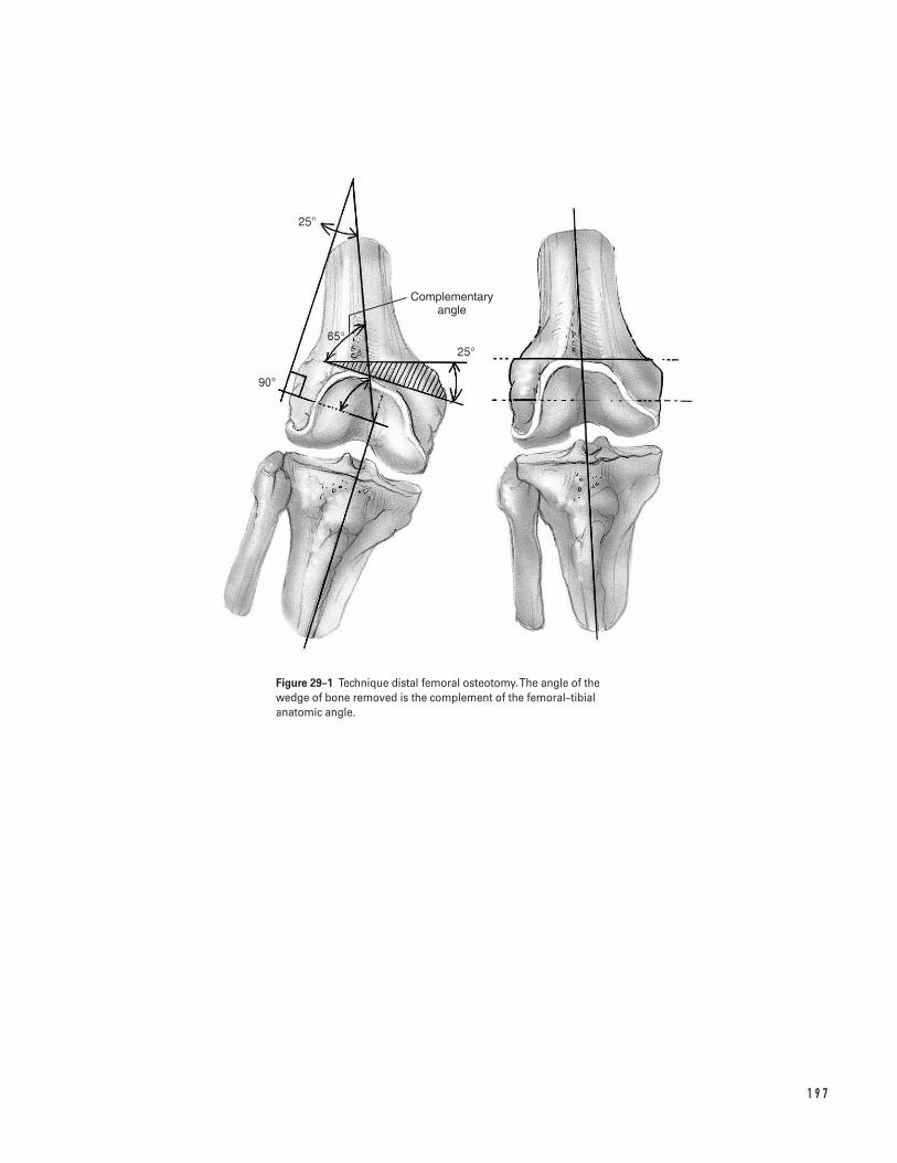
1 9 7
Complementary angle
Figure 29–1 Technique distal femoral osteotomy. The angle of thewedge of bone removed is the complement of the femoral–tibialanatomic angle.
the hip and knee, its distal end should align with thelateral malleolus but not be lateral to it. Align the kneein full extension with 2 to 3 degrees of valgus.
13. Deflate the tourniquet and achieve hemostasis.Following hemostasis, copiously irrigate the woundwith antibiotic solution.
14. Close the wound in a layered fashion over a suctiondrain. Close the medial parapatellar arthrotomyusing 0-vicryl suture. If patellar tracking is not bal-anced, a lateral release and, if necessary, proximalrealignment of the quadriceps tendon can be per-formed at this time.
15. Close the subcutaneous tissue with 00-vicryl sutures.Close the skin with staples.
16. Apply a sterile gauze dressing and secure it with acotton roll. Loosely wrap an ace bandage over thesurgical dressing and connect the collection con-tainer for the drain.
17. Take the patient to the recovery room.
Suggested ReadingInsall JN. Osteotomy. In: Insall JN, Windsor RE, ScottWN, Kelly MA, Aglietti P, eds. Surgery of the Knee. 2nded. New York, NY: Churchill Livingstone, 1993, pp. 635–676.
1 9 8 K N E E A N D L E G
DefinitionsThere are several classifications for tibial plateau frac-tures, the most common being the Schatzker classifica-tion. Three fracture types involve the lateral condyle: (I) a split fracture of the lateral tibial plateau; (II) a splitcompression fracture of the lateral tibial plateau; and(III) a compression fracture of the lateral tibial plateau.A type IV fracture involves the medial tibial plateau. TypeV is a bicondylar fracture and type VI is a tibial plateaufracture with metaphyseal diaphyseal disassociation.This chapter will address the surgical management ofthe three fracture patterns involving the lateral tibialplateau.
Indications1. Knee instability in extension greater than 10 degrees
with valgus or varus stress
The following are relative guidelines for considerationof operative treatment.
2. Radiographic lateral tibial plateau tilt greater than 5 degrees (relative)
3. Radiographic depression of the lateral tibial plateaugreater than 3 mm (relative)
4. Radiographic evidence of condylar widening ofgreater than 5 mm (relative)
ContraindicationsThe following are relative guidelines for considerationof nonoperative treatment.1. Advanced age (relative)2. Systemic disease (relative)3. Severe osteopenia (relative)4. Pre-existing osteoarthritis (relative)
Preoperative Preparation1. Standard X-rays anteroposterior (AP), lateral, 45 de-
gree oblique views); consider obtaining a 10 to 15 degree caudad AP view. The X-ray beam in thisview matches the posterior slope of the proximaltibia (tibial plateau view).
2. Consider obtaining AP and lateral tomograms at 5-mm intervals or computed tomography (CT).These studies are beneficial in evaluating the extentof the articular injury. CT is felt to be superior indelineating the fracture and is better tolerated bypatients. MRI can also be used to assess any cartilageor ligamentous pathology.
1 9 9
C H A P T E R 3 0
Lateral Tibial Plateau FractureOpen Reduction and Internal Fixation
Scott D. Cordes
Special Instruments, Position, and Anesthesia1. Place the patient supine on a standard operating
table. Positioning a sand bag beneath the ipsilateralbuttocks may enhance access to the lateral aspect ofthe knee.
2. Pad all bony prominences.3. Use general, epidural, or spinal anesthetic.4. Use routine orthopedic surgical instrumentation.5. Use a large fragment bone set (4.5 cortical screws
and 6.5 cancellous screws with L or T buttress plates,large bone reduction clamps, and a selection ofKirschner wires for provisional fracture fixation).
6. For limited internal fixation, a large cancellous can-nulated screw tray (6.5, 7.0, or 7.3) is required.
7. Autogenous bone graft or synthetic bone filler willbe necessary depending on the surgeon’s choice. Ifautogenous iliac bone graft is chosen, the ipsilateraliliac crest should be prepped and draped.
Tips and Pearls1. Assess the status of the leg compartments. Examine
and document the status of the peroneal and tibialnerves and the distal pulses.
2. Perform a careful ligament examination. Assess forany varus–valgus instability with the knee in fullextension.
What To Avoid1. Avoid undermining the soft tissue flaps more than
necessary.2. Avoid further bony devascularization by minimiz-
ing soft tissue dissection.3. Be aware of the peroneal nerve location. Attempt to
protect it throughout the procedure to minimizethe chance of injury.
4. Avoid injury to the lateral meniscus. Attempt topreserve and protect it throughout the procedure.
Postoperative Care Issues1. The splint or cast can usually be removed approxi-
mately 2 to 6 weeks after surgery and range ofmotion exercises commenced. The exact timing of removal depends on the complexity of the frac-ture, the stability of the fixation, and the quality ofthe bone.
2. Protective weight bearing is continued for approxi-mately 6 to 12 weeks after surgery. This again dependson the complexity of the fracture, the stability ofthe fixation and the quality of the bone. Radio-graphic analysis of healing can help guide advance-ment of weight bearing.
Operative TechniqueType I (split fracture)In pure type I split fractures where there is no significantcomminution or depression, the fracture can often bestabilized with less surgical dissection. Using ligamento-taxis, the type I split fractures can often be reducedanatomically with traction and manipulation, and sta-bilized using percutaneous cannulated large cancellousscrews.1. Reduce the fracture as described above. Limit the
surgical dissection to the amount needed to ade-quately reduce the fracture if closed techniques areunsuccessful in anatomic restoration.
2. Use fluoroscopy or radiographs to confirm adequatefracture reduction.
3. Make small lateral stab incisions. Insert cannulatedguide wires (preferably two or three) 1.5 to 2 cmbelow and parallel to the joint line. The guide wiresshould be placed parallel to each other. Use themeasuring device to determine screw length.
4. Drill the lateral tibial cortex and metaphysis withthe cannulated drill.
5. Insert cancellous screws over the guide wires. Whenthe screw is fully seated, the screw threads should notcross the fracture line. The screw threads shouldpass beyond the fracture plane and lie within themedial bone fragment (Fig. 30–5).
2 0 0 K N E E A N D L E G
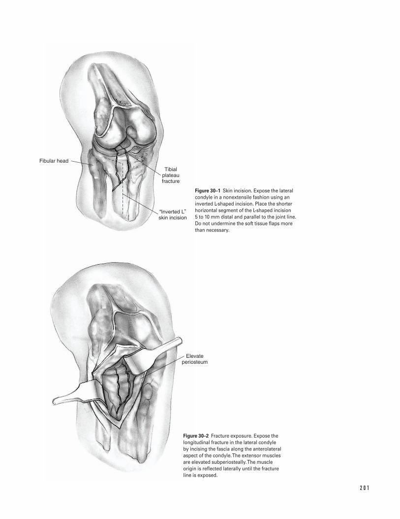
2 0 1
Fibular head
Tibial plateau fracture
Inverted L skin incision
Elevate periosteum
Figure 30–1 Skin incision. Expose the lateralcondyle in a nonextensile fashion using aninverted L-shaped incision. Place the shorterhorizontal segment of the L-shaped incision 5 to 10 mm distal and parallel to the joint line. Do not undermine the soft tissue flaps more than necessary.
Figure 30–2 Fracture exposure. Expose thelongitudinal fracture in the lateral condyle by incising the fascia along the anterolateralaspect of the condyle. The extensor muscles are elevated subperiosteally.The muscle origin is reflected laterally until the fracture line is exposed.
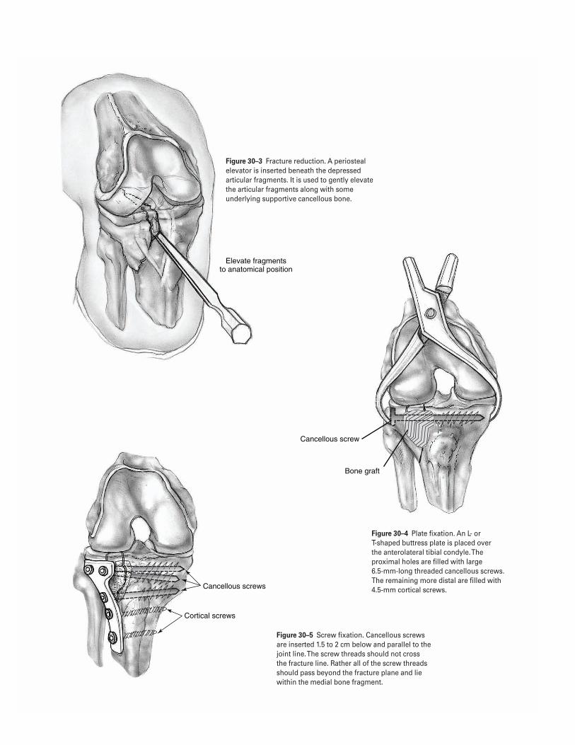
2 0 2
Elevate fragments to anatomical position
Cancellous screw
Bone graft
Cancellous screws
Cortical screws
Figure 30–3 Fracture reduction. A periostealelevator is inserted beneath the depressedarticular fragments. It is used to gently elevatethe articular fragments along with someunderlying supportive cancellous bone.
Figure 30–4 Plate fixation. An L- or T-shaped buttress plate is placed over the anterolateral tibial condyle. Theproximal holes are filled with large 6.5-mm-long threaded cancellous screws.The remaining more distal are filled with4.5-mm cortical screws.
Figure 30–5 Screw fixation. Cancellous screwsare inserted 1.5 to 2 cm below and parallel to thejoint line. The screw threads should not cross the fracture line. Rather all of the screw threadsshould pass beyond the fracture plane and liewithin the medial bone fragment.
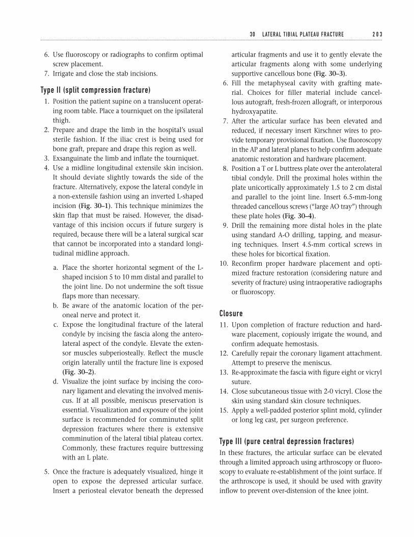
6. Use fluoroscopy or radiographs to confirm optimalscrew placement.
7. Irrigate and close the stab incisions.
Type II (split compression fracture)1. Position the patient supine on a translucent operat-
ing room table. Place a tourniquet on the ipsilateralthigh.
2. Prepare and drape the limb in the hospital’s usualsterile fashion. If the iliac crest is being used forbone graft, prepare and drape this region as well.
3. Exsanguinate the limb and inflate the tourniquet.4. Use a midline longitudinal extensile skin incision.
It should deviate slightly towards the side of thefracture. Alternatively, expose the lateral condyle ina non-extensile fashion using an inverted L-shapedincision (Fig. 30–1). This technique minimizes theskin flap that must be raised. However, the disad-vantage of this incision occurs if future surgery isrequired, because there will be a lateral surgical scarthat cannot be incorporated into a standard longi-tudinal midline approach.
a. Place the shorter horizontal segment of the L-shaped incision 5 to 10 mm distal and parallel tothe joint line. Do not undermine the soft tissueflaps more than necessary.
b. Be aware of the anatomic location of the per-oneal nerve and protect it.
c. Expose the longitudinal fracture of the lateralcondyle by incising the fascia along the antero-lateral aspect of the condyle. Elevate the exten-sor muscles subperiosteally. Reflect the muscleorigin laterally until the fracture line is exposed(Fig. 30–2).
d. Visualize the joint surface by incising the coro-nary ligament and elevating the involved menis-cus. If at all possible, meniscus preservation isessential. Visualization and exposure of the jointsurface is recommended for comminuted splitdepression fractures where there is extensivecomminution of the lateral tibial plateau cortex.Commonly, these fractures require buttressingwith an L plate.
5. Once the fracture is adequately visualized, hinge itopen to expose the depressed articular surface.Insert a periosteal elevator beneath the depressed
articular fragments and use it to gently elevate thearticular fragments along with some underlyingsupportive cancellous bone (Fig. 30–3).
6. Fill the metaphyseal cavity with grafting mate-rial. Choices for filler material include cancel-lous autograft, fresh-frozen allograft, or interporoushydroxyapatite.
7. After the articular surface has been elevated andreduced, if necessary insert Kirschner wires to pro-vide temporary provisional fixation. Use fluoroscopyin the AP and lateral planes to help confirm adequateanatomic restoration and hardware placement.
8. Position a T or L buttress plate over the anterolateraltibial condyle. Drill the proximal holes within theplate unicortically approximately 1.5 to 2 cm distaland parallel to the joint line. Insert 6.5-mm-longthreaded cancellous screws (“large AO tray”) throughthese plate holes (Fig. 30–4).
9. Drill the remaining more distal holes in the plateusing standard A-O drilling, tapping, and measur-ing techniques. Insert 4.5-mm cortical screws inthese holes for bicortical fixation.
10. Reconfirm proper hardware placement and opti-mized fracture restoration (considering nature andseverity of fracture) using intraoperative radiographsor fluoroscopy.
Closure11. Upon completion of fracture reduction and hard-
ware placement, copiously irrigate the wound, andconfirm adequate hemostasis.
12. Carefully repair the coronary ligament attachment.Attempt to preserve the meniscus.
13. Re-approximate the fascia with figure eight or vicrylsuture.
14. Close subcutaneous tissue with 2-0 vicryl. Close theskin using standard skin closure techniques.
15. Apply a well-padded posterior splint mold, cylinderor long leg cast, per surgeon preference.
Type III (pure central depression fractures)In these fractures, the articular surface can be elevatedthrough a limited approach using arthroscopy or fluoro-scopy to evaluate re-establishment of the joint surface. Ifthe arthroscope is used, it should be used with gravityinflow to prevent over-distension of the knee joint.
3 0 L AT E R A L T I B I A L P L AT E A U F R A C T U R E 2 0 3
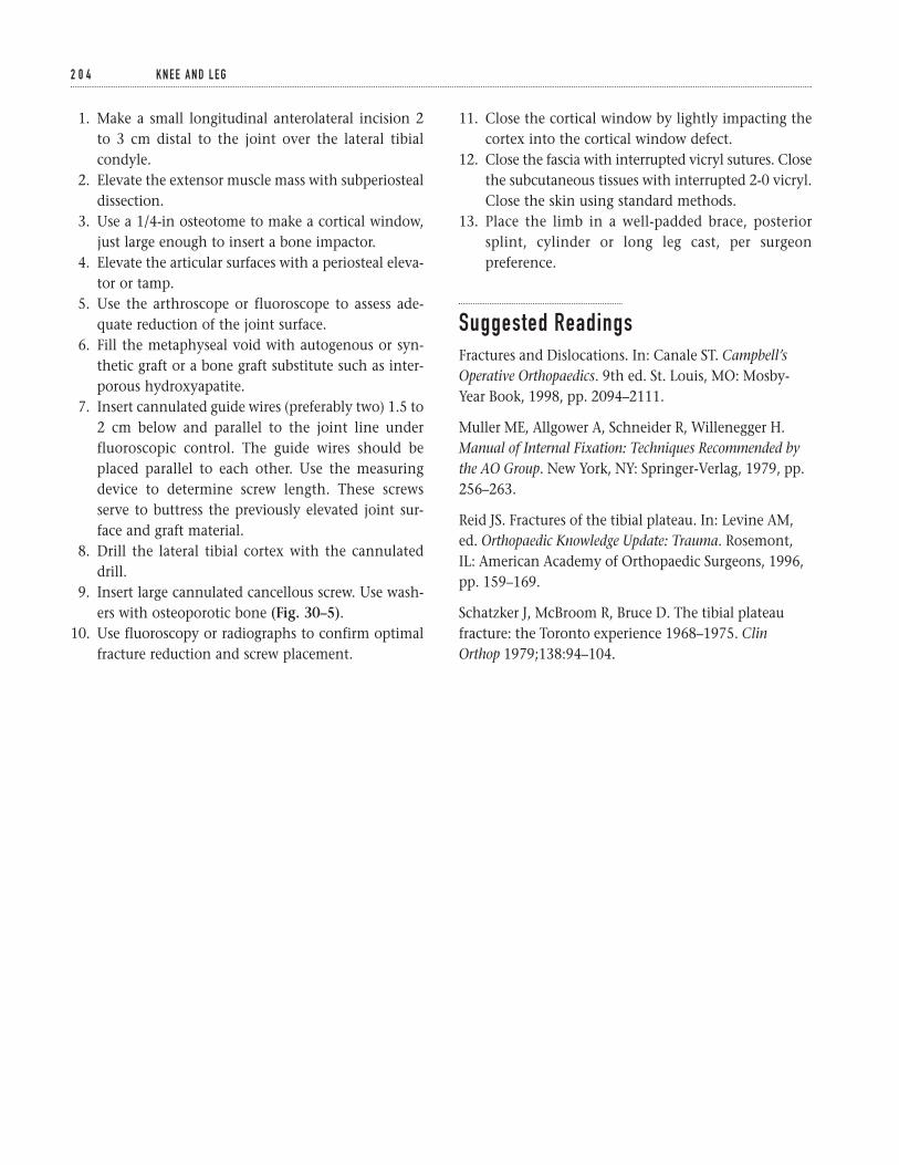
1. Make a small longitudinal anterolateral incision 2to 3 cm distal to the joint over the lateral tibialcondyle.
2. Elevate the extensor muscle mass with subperiostealdissection.
3. Use a 1/4-in osteotome to make a cortical window,just large enough to insert a bone impactor.
4. Elevate the articular surfaces with a periosteal eleva-tor or tamp.
5. Use the arthroscope or fluoroscope to assess ade-quate reduction of the joint surface.
6. Fill the metaphyseal void with autogenous or syn-thetic graft or a bone graft substitute such as inter-porous hydroxyapatite.
7. Insert cannulated guide wires (preferably two) 1.5 to2 cm below and parallel to the joint line underfluoroscopic control. The guide wires should beplaced parallel to each other. Use the measuringdevice to determine screw length. These screwsserve to buttress the previously elevated joint sur-face and graft material.
8. Drill the lateral tibial cortex with the cannulateddrill.
9. Insert large cannulated cancellous screw. Use wash-ers with osteoporotic bone (Fig. 30–5).
10. Use fluoroscopy or radiographs to confirm optimalfracture reduction and screw placement.
11. Close the cortical window by lightly impacting thecortex into the cortical window defect.
12. Close the fascia with interrupted vicryl sutures. Closethe subcutaneous tissues with interrupted 2-0 vicryl.Close the skin using standard methods.
13. Place the limb in a well-padded brace, posteriorsplint, cylinder or long leg cast, per surgeonpreference.
Suggested ReadingsFractures and Dislocations. In: Canale ST. Campbell’sOperative Orthopaedics. 9th ed. St. Louis, MO: Mosby-Year Book, 1998, pp. 2094–2111.
Muller ME, Allgower A, Schneider R, Willenegger H.Manual of Internal Fixation: Techniques Recommended bythe AO Group. New York, NY: Springer-Verlag, 1979, pp.256–263.
Reid JS. Fractures of the tibial plateau. In: Levine AM,ed. Orthopaedic Knowledge Update: Trauma. Rosemont,IL: American Academy of Orthopaedic Surgeons, 1996,pp. 159–169.
Schatzker J, McBroom R, Bruce D. The tibial plateaufracture: the Toronto experience 1968–1975. ClinOrthop 1979;138:94–104.
2 0 4 K N E E A N D L E G
Indications1. Closed displaced tibial shaft fractures2. Open grade 1 tibial shaft fractures (after adequate
irrigation and debridement of the open wound)3. Open grade 2 or 3 tibial shaft fractures (controver-
sial—depends on soft tissue envelope and adequacyof debridement)
4. Nail conversion after external fixator (controver-sial—can be done acutely 1–2 weeks after fixatorapplication if pin sites are clean and dry withoutany evidence of drainage or infection)
Contraindications1. Gross wound contamination2. Nonviable soft tissues3. Proximal or distal shaft fractures with significant
metaphyseal extension
Preoperative Preparation1. Appropriate extremity radiographs including knee
and ankle joints2. Template radiographs to ensure that tibial nails of
the appropriate length and diameter are available3. Neurovascular examination with emphasis on assess-
ing arterial blood flow and distal nerve function
4. Assessment of the skin and soft tissues. Evaluate forcompartment syndrome.
Special Instruments, Position, and Anesthesia1. General or regional anesthesia. Avoid long-acting
regional anesthesia, as they make assessment of com-partment syndrome difficult.
2. Position patient supine on either fracture or radio-lucent table. The author prefers a radiolucent table.
3. Check the fluoroscopy prior to draping the patientto ensure that it is in working order and that the C-arm can be positioned to obtain adequate anterio-posterior (AP) and lateral images.
Tips and Pearls1. The more distal the patient is positioned on the
radiolucent table, the less likely the table’s base willinterfere with the C-arm.
2. If a circumferential cast has been previously applied,bivalve it in the preoperative area. This minimizesdust and contamination in the operating room.However, the bivalved cast can be left in place for support and protection until the patient isanesthetized.
2 0 5
C H A P T E R 3 1
Intramedullary Rodding of Tibial Shaft Fractures
Scott D. Cordes
3. Make sure the skin over the entry point for the dis-tal screws is not “draped out” of the operative field.The malleoli should be visible after draping hasbeen completed to help optimize rotational align-ment of the extremity.
4. Consider “choking up” on the blunt tipped guiderod with the T-handle or vise grip. This will makerod passage easier with less chance of bowing orbending of the guide rod.
What To Avoid1. Avoid rotational malalignment when impacting
the tibial nail. Reconfirm alignment prior to distallocking.
2. Avoid reckless passes with the guide rod. Slow metic-ulous passage across the fracture site using proprio-ceptive feel is imperative.
3. Avoid allowing the guide rod to “back out” past thefracture site during reaming.
Postoperative Care Issues1. If a posterior mold is placed, it can normally be
removed within two weeks of the procedure. This isdependent on patient comfort and associated fibu-lar fracture.
2. Initially, most patients are allowed to ambulate eithernon-weight bearing (NWB) or toe-touch weight bear-ing (TTWB).
3. Depending on the stability of the fracture, pro-tected weight bearing can be advanced approxi-mately 6 weeks after surgery. This is dependent onradiographic evaluation and clinical symptoms.
Operative Technique1. Transport the patient to the operating room.
Position the patient on a fluoroscopic table. (A frac-ture table can be used, but the author prefers a stan-dard translucent table.) Care should be taken toensure that the patient’s position allows adequateclearance for the fluoroscopy.
2. After adequate anesthesia is achieved, remove thepreviously bivalved cast.
3. Place a tourniquet around the proximal thigh. This isnot necessarily used during surgery, but is availablefor use at the discretion of the treating physician.
4. Prepare the entire leg. If possible, hold the extremityusing gentle longitudinal traction to minimize fur-ther soft tissue trauma. An assistant may be requiredfor prepping.
5. Drape the leg with a standard extremity drape. Asterile adherent dressing can be used for the foot,but it is important to keep the malleoli exposed toallow access for distal locking and to improve visu-alization of rotational alignment. The drapes shouldcover both sides of the surgical table.
6. Flex the extremity at the hip and knee. Either havean assistant hold the thigh and leg at the fracturesite, or support the extremity with a bolster.
Approach7. Make a longitudinal incision extending from the
inferior pole of the patella to the tibial tubercle (Fig. 31–1).
8. Dissect through the soft tissues down to the patellartendon.
9. Make a longitudinal incision either through theretinaculum just adjacent to the patellar tendon ordirectly through the patellar tendon. The authorprefers to make the longitudinal exposure directlythrough the tendon.
10. Place a self-retaining retractor in place and exposethe proximal tibia. Identify the flattened surface ofthe anterior proximal tibia. This is roughly 2 cmproximal to the tibial tubercle at the anterior edgeof the tibial plateau. This is the standard entry pointfor the awl (Fig. 31–2).
Guide rod insertion11. Make an entry hole with the awl at the previously
identified entry point. Attempt to introduce the awlinto the tibia so it parallels the tibia’s long axis.Avoid passing the awl’s tip posteriorly (Fig. 31–3).
12. Pass a blunt tip guide rod down the long axis of thetibia to the fracture site.
13. Based on the fracture pattern, pass the guide rodunder fluoroscopic visualization in one of several
2 0 6 K N E E A N D L E G
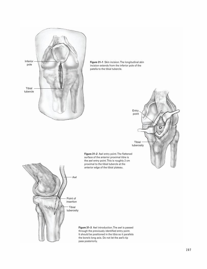
2 0 7
Inferior pole
Tibial tubercle
Entry point
Tibial tuberosity
Awl
Point of insertion
Tibial tuberosity
Figure 31–1 Skin incision. The longitudinal skinincision extends from the inferior pole of thepatella to the tibial tubercle.
Figure 31–2 Awl entry point. The flattenedsurface of the anterior proximal tibia is the awl entry point. This is roughly 2 cmproximal to the tibial tubercle at theanterior edge of the tibial plateau.
Figure 31–3 Awl introduction. The awl is passedthrough the previously identified entry point. It should be positioned in the tibia so it parallelsthe bone’s long axis. Do not let the awl’s tip pass posteriorly.
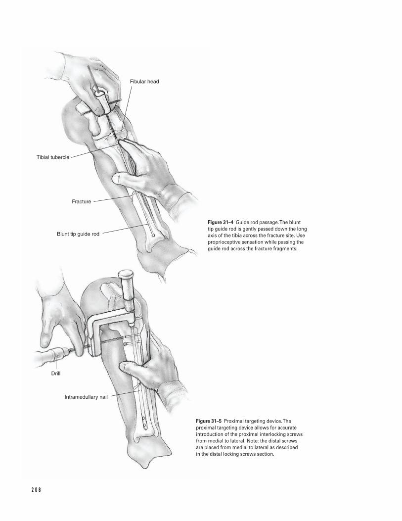
2 0 8
Drill
Intramedullary nail
Blunt tip guide rod
Fracture
Tibial tubercle
Fibular head
Figure 31–4 Guide rod passage. The blunt tip guide rod is gently passed down the long axis of the tibia across the fracture site. Useproprioceptive sensation while passing the guide rod across the fracture fragments.
Figure 31–5 Proximal targeting device. Theproximal targeting device allows for accurateintroduction of the proximal interlocking screwsfrom medial to lateral. Note: the distal screws are placed from medial to lateral as described in the distal locking screws section.
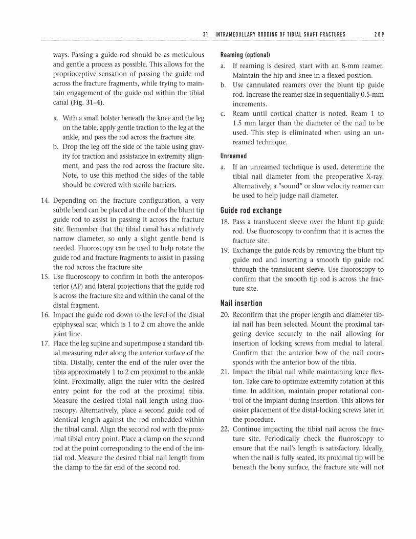
ways. Passing a guide rod should be as meticulousand gentle a process as possible. This allows for theproprioceptive sensation of passing the guide rodacross the fracture fragments, while trying to main-tain engagement of the guide rod within the tibialcanal (Fig. 31–4).
a. With a small bolster beneath the knee and the legon the table, apply gentle traction to the leg at theankle, and pass the rod across the fracture site.
b. Drop the leg off the side of the table using grav-ity for traction and assistance in extremity align-ment, and pass the rod across the fracture site.Note, to use this method the sides of the tableshould be covered with sterile barriers.
14. Depending on the fracture configuration, a verysubtle bend can be placed at the end of the blunt tipguide rod to assist in passing it across the fracturesite. Remember that the tibial canal has a relativelynarrow diameter, so only a slight gentle bend isneeded. Fluoroscopy can be used to help rotate theguide rod and fracture fragments to assist in passingthe rod across the fracture site.
15. Use fluoroscopy to confirm in both the anteropos-terior (AP) and lateral projections that the guide rodis across the fracture site and within the canal of thedistal fragment.
16. Impact the guide rod down to the level of the distalepiphyseal scar, which is 1 to 2 cm above the anklejoint line.
17. Place the leg supine and superimpose a standard tib-ial measuring ruler along the anterior surface of thetibia. Distally, center the end of the ruler over thetibia approximately 1 to 2 cm proximal to the anklejoint. Proximally, align the ruler with the desiredentry point for the rod at the proximal tibia.Measure the desired tibial nail length using fluo-roscopy. Alternatively, place a second guide rod ofidentical length against the rod embedded withinthe tibial canal. Align the second rod with the prox-imal tibial entry point. Place a clamp on the secondrod at the point corresponding to the end of the ini-tial rod. Measure the desired tibial nail length fromthe clamp to the far end of the second rod.
Reaming (optional)
a. If reaming is desired, start with an 8-mm reamer.Maintain the hip and knee in a flexed position.
b. Use cannulated reamers over the blunt tip guiderod. Increase the reamer size in sequentially 0.5-mmincrements.
c. Ream until cortical chatter is noted. Ream 1 to 1.5 mm larger than the diameter of the nail to beused. This step is eliminated when using an un-reamed technique.
Unreamed
a. If an unreamed technique is used, determine thetibial nail diameter from the preoperative X-ray.Alternatively, a “sound” or slow velocity reamer canbe used to help judge nail diameter.
Guide rod exchange18. Pass a translucent sleeve over the blunt tip guide
rod. Use fluoroscopy to confirm that it is across thefracture site.
19. Exchange the guide rods by removing the blunt tipguide rod and inserting a smooth tip guide rodthrough the translucent sleeve. Use fluoroscopy toconfirm that the smooth tip rod is across the frac-ture site.
Nail insertion20. Reconfirm that the proper length and diameter tib-
ial nail has been selected. Mount the proximal tar-geting device securely to the nail allowing forinsertion of locking screws from medial to lateral.Confirm that the anterior bow of the nail corre-sponds with the anterior bow of the tibia.
21. Impact the tibial nail while maintaining knee flex-ion. Take care to optimize extremity rotation at thistime. In addition, maintain proper rotational con-trol of the implant during insertion. This allows foreasier placement of the distal-locking screws later inthe procedure.
22. Continue impacting the tibial nail across the frac-ture site. Periodically check the fluoroscopy toensure that the nail’s length is satisfactory. Ideally,when the nail is fully seated, its proximal tip will bebeneath the bony surface, the fracture site will not
3 1 I N T R A M E D U L L A RY R O D D I N G O F T I B I A L S H A F T F R A C T U R E S 2 0 9
be distracted, and the nail’s distal tip will be 1 to 2 cm above the ankle joint.
23. Remove the smooth tip guide rod prior to proximallocking.
Proximal locking screws24. Make medial stab incisions through the proximal
targeting device for placement of the proximal lock-ing screws. Maintain the knee in flexion.
25. Utilizing the proximal targeting guide and appro-priate drill sleeves, make a bicortical drill hole underfluoroscopic assistance (Fig. 31–5).
26. Use a standard depth gauge and insert the appro-priate length locking screw. Confirm that the screwheads are flush with the tibial surface with digitalpalpation and fluoroscopy.
27. If necessary, utilize a similar technique for addi-tional proximal locking screws.
28. Remove the proximal targeting device.
Distal locking screws29. Bring the leg into full extension. Rest it on a trans-
lucent base, elevating it above the uninvolved oppo-site extremity.
30. Adjust the fluoroscopy so it is exactly perpendicularto the tibia’s long axis. Use the fluoroscopy to visu-alize the distal holes in the nail as perfect circles onthe lateral image. If the nail holes appear as ellipseson the image, either internally or externally rotatethe involved limb, or airplane the table until perfectcircles are obtained. Normally, only small patientposition adjustments are necessary to achieve flaw-less image circles.
31. Make a small longitudinal stab incision in the skindirectly over the visualized nail holes seen on thefluoroscopic image. A ring forcep can be used tolocate the appropriate spot.
32. Use a sharp tip Steinman pin or disposable trocarpin to make a starting entry point in the bone. Adisposable sharp tip pin minimizes sliding away
from the hole’s epicenter. Center the pin’s tipdirectly in the middle of the perfect circle seen onthe fluoroscopy.
33. After this unicortical hole is established, make abicortical drill hole through the nail. Alternatively,use a radiolucent drill. Align the targeting device of the drill concentrically with the visualized circu-lar hole in the nail. Use the drill to make a bicorti-cal hole.
34. Similarly to the proximal screws, use a standarddepth gauge to measure the desired screw length.Insert the appropriate length distal locking screws.
35. If necessary, utilize a similar technique for addi-tional distal locking screws.
36. Use the fluoroscope to confirm proper nail andscrew position in both the AP and lateral projec-tions. Appropriate placed locking screws will oblit-erate the visualized holes in the tibial nail.
Closure37. Copiously irrigate the wounds.38. Reapproximate the patellar tendon with interrupted
or figure eight 0 Vicryl sutures.39. Close the peritenon with interrupted or figure eight
2-0 Vicryl sutures. Use a standard closure for theskin and subcutaneous tissue.
40. Apply a soft compression dressing with or withouta posterior mold per surgeon discretion.
Suggested ReadingsFractures and Dislocations. In: Canale ST. Campbell’sOperative Orthopaedics. 9th ed. St. Louis, MO: Mosby-Year Book, 1998, pp. 2067–2094.
Russell TA. Fractures of the tibial diaphysis. In: LevineAM, ed. Orthopaedic Knowledge Update: Trauma.Rosemont, IL: American Academy of OrthopaedicSurgeons, 1996, pp. 171–182.
2 1 0 K N E E A N D L E G
Indications1. Extensor mechanism insufficiency2. Articular incongruency3. Fracture displacement greater than 3 mm (particu-
larly with a transverse fracture pattern)4. Open fracture
Contraindications1. Nondisplaced fracture (nonoperative treatment)2. Minimally displaced fracture with intact extensor
mechanism3. Fracture of the nonarticular surface with intact
extensor mechanism
Preoperative Preparation1. History and physical examination2. Knee radiographs
a. Anteroposterior (AP) and lateral to assess frac-ture pattern
b. Sunrise view (may be useful to identify osteo-chondral/marginal fractures)
3. Other imaging studies
a. Rarely CTb. Rarely arthrographyc. MRI may be useful in identifying osteochon-
dral/marginal fractures.
Special Instruments, Position, and Anesthesia1. Supine position2. If extremity tends to externally rotate, place a
“bump” under the ipsilateral hip.3. General, spinal, or epidural anesthesia
a. Relaxes muscles to facilitate repairb. Permits tourniquet use
4. Intravenous antibiotics5. Standard instrument set6. Standard small fragment set7. Large tenaculum clamps8. Tension band wire (18 gauge)9. Cannulated screws (4.0 mm)
10. Kirschner wires (2.0 mm)11. Nonabsorbable suture (#5)12. Intraoperative fluoroscopy or X-ray
Tips and Pearls1. Universal vertical midline incision
a. Allows adequate exposureb. Functional incision if future surgery is needed
2. Place a tourniquet as proximal as possible on thethigh.
3. Remember to perform a meticulous retinacular repair.4. Remove loose, minor fracture fragments—not all of
the bone fragments need to be preserved. Pre-servation of only the major fragments is necessary.
2 1 1
C H A P T E R 3 2
Operative Treatment of Patella Fractures
Mark E. Easley and Giles R. Scuderi
5. Inspect the articular surfaces of the patella andfemur because their condition will have a signifi-cant effect on the clinical outcome.
6. If necessary, consider lateral release to improvepatella tracking.
Tension band principle
a. Converts distraction forces into compressive forcesb. Strongest fixationc. Wire tension band must be on the anterior aspect of
the patella to ensure compression at the articularsurface.
Cannulated screws
a. Wire tension band is passed through the cannulatedscrews.
b. The cannulated screws must be buried within thebone for the tension band principle to act on the bone(otherwise the tension will only be created on thescrew ends).
What To Avoid1. If skin contamination is present secondary to either
an open injury or skin abrasion, then delay internalfixation until the wound is clean.
2. Avoid creating multiple layers. Attempt to createtwo full-thickness tissue flaps medially and laterally.
3. If possible, avoid prolonged operative delay. Aim forsurgery within the first 10 to 14 days after injury.
4. Avoid intra-articular step-off. If possible, palpate thepatella’s articular surface.
5. Avoid improper placement of the wire tension band(otherwise the compressive effect will be forfeited).
6. If possible, avoid performing a patellectomy (onlyindicated if bone comminution and/or articular sur-face damage is too extensive for repair).
Postoperative Care Issues1. Suction drain for 24 hours may avoid hematoma.
Compressive dressing for 24 to 48 hours is also useful.2. Immobilize for 4 to 6 weeks in either a knee immo-
bilizer or cylinder cast. However, earlier mobiliza-tion of the knee is permitted for patella fractures
when fixation is adequate. This applies particularlyto fractures repaired with the tension band princi-ple in which motion results in compression acrossthe fracture.
3. Weight bearing as tolerated with knee immobilizedin extension
4. Weight bearing may actually reduce the forces acrossthe quadriceps when compared to forces required tosupport the limb in non-weight bearing.
Operative TechniqueGeneral principlesâ Debride minor fracture fragments and evacuate
hematoma.â Inspect joint.â Remove loose bone fragments.â Identify any osteochondral injuries.
Approach1. Position patient supine on the operating room
table. Place thigh tourniquet as proximal as possibleon the thigh.
2. Prepare and drape the limb in the hospital’s stan-dard sterile fashion. Exsanguinate the limb andinflate the tourniquet.
3. Make an anterior skin incision utilizing a straightmidline incision. Dissect directly down to the exten-sor mechanism while minimizing skin flaps.
Transverse fracture (tension band technique K-wires)
a. Excise any comminuted fracture fragments fromthe central portion of the patella.
b. Reduce the major fracture fragments with a tenacu-lum clamp (Fig. 32–1A).
c. Ensure that the articular surface is congruent by pal-pating the articular surface through the retinaculardefects.
d. Place Kirschner wires (2.0 mm) or lag screws acrossthe fracture. A slightly anterior position helps tooptimize the tension band principle (Fig. 32–1A).
e. Pass the 18-gauge wire through the quadriceps ten-don at the patella’s superior pole and through thepatella tendon at the patella’s inferior pole. The wire
2 1 2 K N E E A N D L E G
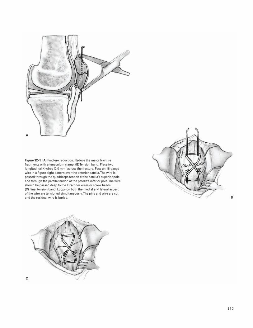
2 1 3
A
C
B
Figure 32–1 (A) Fracture reduction. Reduce the major fracturefragments with a tenaculum clamp. (B)Tension band. Place twolongitudinal K-wires (2.0 mm) across the fracture. Pass an 18-gaugewire in a figure eight pattern over the anterior patella. The wire ispassed through the quadriceps tendon at the patella’s superior poleand through the patella tendon at the patella’s inferior pole. The wireshould be passed deep to the Kirschner wires or screw heads. (C) Final tension band. Loops on both the medial and lateral aspect of the wire are tensioned simultaneously. The pins and wire are cutand the residual wire is buried.
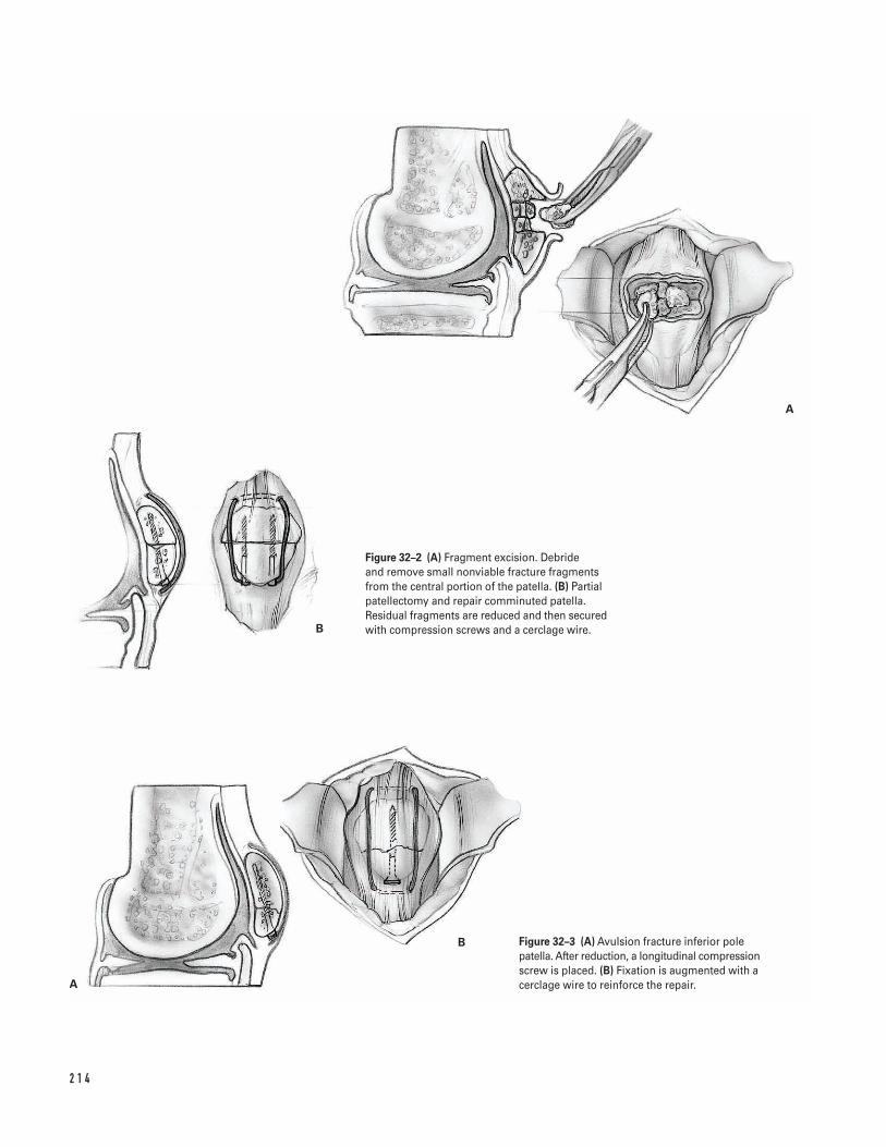
2 1 4
A
B
A
B
Figure 32–2 (A) Fragment excision. Debride and remove small nonviable fracture fragmentsfrom the central portion of the patella. (B) Partialpatellectomy and repair comminuted patella.Residual fragments are reduced and then securedwith compression screws and a cerclage wire.
Figure 32–3 (A) Avulsion fracture inferior polepatella. After reduction, a longitudinal compressionscrew is placed. (B) Fixation is augmented with acerclage wire to reinforce the repair.
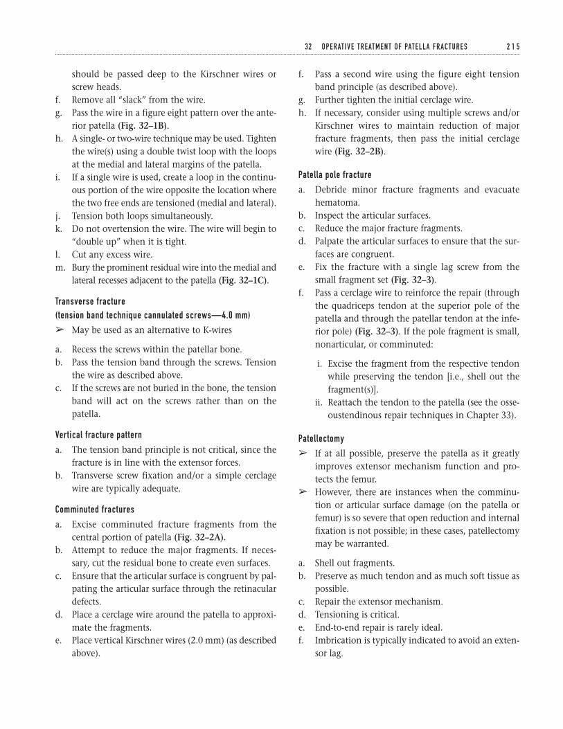
should be passed deep to the Kirschner wires orscrew heads.
f. Remove all “slack” from the wire.g. Pass the wire in a figure eight pattern over the ante-
rior patella (Fig. 32–1B).h. A single- or two-wire technique may be used. Tighten
the wire(s) using a double twist loop with the loopsat the medial and lateral margins of the patella.
i. If a single wire is used, create a loop in the continu-ous portion of the wire opposite the location wherethe two free ends are tensioned (medial and lateral).
j. Tension both loops simultaneously.k. Do not overtension the wire. The wire will begin to
“double up” when it is tight.l. Cut any excess wire.m. Bury the prominent residual wire into the medial and
lateral recesses adjacent to the patella (Fig. 32–1C).
Transverse fracture (tension band technique cannulated screws—4.0 mm)
â May be used as an alternative to K-wires
a. Recess the screws within the patellar bone.b. Pass the tension band through the screws. Tension
the wire as described above.c. If the screws are not buried in the bone, the tension
band will act on the screws rather than on thepatella.
Vertical fracture pattern
a. The tension band principle is not critical, since thefracture is in line with the extensor forces.
b. Transverse screw fixation and/or a simple cerclagewire are typically adequate.
Comminuted fractures
a. Excise comminuted fracture fragments from thecentral portion of patella (Fig. 32–2A).
b. Attempt to reduce the major fragments. If neces-sary, cut the residual bone to create even surfaces.
c. Ensure that the articular surface is congruent by pal-pating the articular surface through the retinaculardefects.
d. Place a cerclage wire around the patella to approxi-mate the fragments.
e. Place vertical Kirschner wires (2.0 mm) (as describedabove).
f. Pass a second wire using the figure eight tensionband principle (as described above).
g. Further tighten the initial cerclage wire.h. If necessary, consider using multiple screws and/or
Kirschner wires to maintain reduction of majorfracture fragments, then pass the initial cerclagewire (Fig. 32–2B).
Patella pole fracture
a. Debride minor fracture fragments and evacuatehematoma.
b. Inspect the articular surfaces.c. Reduce the major fracture fragments.d. Palpate the articular surfaces to ensure that the sur-
faces are congruent.e. Fix the fracture with a single lag screw from the
small fragment set (Fig. 32–3).f. Pass a cerclage wire to reinforce the repair (through
the quadriceps tendon at the superior pole of thepatella and through the patellar tendon at the infe-rior pole) (Fig. 32–3). If the pole fragment is small,nonarticular, or comminuted:
i. Excise the fragment from the respective tendonwhile preserving the tendon [i.e., shell out thefragment(s)].
ii. Reattach the tendon to the patella (see the osse-oustendinous repair techniques in Chapter 33).
Patellectomy
â If at all possible, preserve the patella as it greatlyimproves extensor mechanism function and pro-tects the femur.
â However, there are instances when the comminu-tion or articular surface damage (on the patella orfemur) is so severe that open reduction and internalfixation is not possible; in these cases, patellectomymay be warranted.
a. Shell out fragments.b. Preserve as much tendon and as much soft tissue as
possible.c. Repair the extensor mechanism.d. Tensioning is critical.e. End-to-end repair is rarely ideal.f. Imbrication is typically indicated to avoid an exten-
sor lag.
3 2 O P E R AT I V E T R E AT M E N T O F PAT E L L A F R A C T U R E S 2 1 5
g. However, excessive imbrication may result in anextension contracture.
h. The repair should be tight between 45 to 90 degreesof flexion (if it only tightens beyond 90 degrees offlexion, then an extension lag will usually result).
Closure4. Repair the retinaculum.
a. Begin the retinacular repair with the most poste-rior defects. Close toward the patella.
b. Use either nonabsorbable or absorbable suture. Ifnonabsorbable suture is used, attempt to burythe knots.
5. Reinforce the soft-tissue repair anterior to thepatella with absorbable sutures.
6. Consider a lateral release if the patella tracking isnot satisfactory. This can be performed prior to thelateral retinacular repair.
7. Close the subcutaneous tissue and skin in a stan-dard fashion.
Suggested ReadingBono JV, Haas SB, Scuderi GR. Traumatic maladies of theextensor mechanism. In: Scuderi GR, ed. The Patella.New York, NY: Springer-Verlag, 1995, pp. 253–276.
2 1 6 K N E E A N D L E G
IndicationsExtensor mechanism insufficiency with:1. Complete ruptures2. Partial ruptures3. Chronic ruptures
Contraindications1. Functional extensor mechanism (no extensor
“lag”)
Preoperative Preparation1. History and physical examination2. Knee radiographs
a. Lateral—to identify patella baja (quadriceps rup-ture) or patella alta (patella tendon rupture)
b. Consider obtaining comparison radiographs ofthe contralateral knee.
3. Other imaging studies
a. MRI is often useful in identifying discontinuityin tendon substance if diagnosis is in doubt or ifpartial tear is present.
Special Instruments, Position, and Anesthesia1. Supine position2. If extremity tends to externally rotate, place a
“bump” under the ipsilateral hip.3. General, spinal, or epidural anesthesia
a. Relaxes muscles to facilitate repairb. Permits tourniquet use
4. Intravenous antibiotics5. Standard instrument set6. Nonabsorbable suture (#5)7. Drill8. Keith needle9. Suture passer
10. Beath needle11. Pneumatic burr12. Cerclage wire13. Nonabsorbable tape (such as mersilene tape)14. Intraoperative fluoroscopy or X-ray
2 1 7
C H A P T E R 3 3
Extensor Mechanism InjuriesQuadriceps Ruptures and Patella Tendon Ruptures
Mark E. Easley and Giles R. Scuderi
15. Tendon stripper (if patella tendon repair warrantsaugmentation with the semitendinosus or gracilis)
Tips and Pearls1. Universal vertical midline incision
a. Allows adequate exposureb. Functional incision if future surgery is needed
2. Place a tourniquet as proximal as possible on thethigh.
3. Remember to perform a meticulous retinacular repair.4. Use a Krakow suture technique (interlocking stitch)
to ensure adequate purchase of the suture in thetendon.
5. Beath needle
a. Use to pass suture through patellar tunnels (inlieu of drilling) and then passing a Keith needleor suture passer
b. Saves a step and minimizes the difficulty of find-ing the tunnel after drilling
6. Tendon stripper (in the event that patella tendonrepair requires augmentation with the semitendi-nosus or gracilis)
7. If necessary, consider a lateral release to improvepatella tracking.
What To AvoidGeneral principles:1. If skin contamination is present secondary to either
an open injury or skin abrasion, then delay internalfixation until the wound is clean.
2. Avoid creating multiple layers. Attempt to createtwo full-thickness tissue flaps medially and laterally.
3. If possible, avoid prolonged operative delay. Aim forsurgery within the first 10 to 14 days after injury.
4. Avoid reattaching the tendon on the anterior aspectof the patella (this leads to tilt of the patella withtension).
5. Avoid overtightening the patella tendon repair (willcreate a patella infera). Check intraoperative fluo-roscopy or knee X-ray at 45 degrees of flexion; the
inferior pole of the patella should be superior to theroof of the intercondylar notch.
Postoperative Care Issues1. A suction drain for 24 hours may avoid hematoma.
Compressive dressing for 24 to 48 hours is also useful.2. Immobilize for 4 to 6 weeks in either a knee immo-
bilizer or cylinder cast.3. Weight bearing as tolerated with knee immobilized
in extension4. Weight bearing may actually reduce the forces
across the quadriceps when compared to forcesrequired to support the limb in non-weight bearing.
Operative TechniqueApproach1. Position patient supine on the operating room
table. Place thigh tourniquet as proximal as possibleon the thigh.
2. Prepare and drape the limb in the hospital’s stan-dard sterile fashion. Exsanguinate the limb andinflate the tourniquet.
3. Make an anterior skin incision utilizing a straightmidline incision. Dissect directly down to theextensor mechanism while minimizing skin flaps.
I . Quadricep TendonAcute ruptures quadricep tendon (mid-substance)
a. Debride damaged tissue back to normal-appearingtendon. However, avoid excising too much tissue.
b. Repair end-to-end using #2 or #5 nonabsorbablesutures (interrupted).
c. Repair the retinaculum with a nonabsorbable orabsorbable #0 suture.
d. If necessary, perform a lateral release to improvepatellar tracking.
e. If repair is tenuous, reinforce repair with a cerclagewire or nonabsorbable tape (such as mersilene tape).
f. Proximally, pass the reinforcing wire or tape trans-versely through the quadriceps tendon.
g. Distally, pass the reinforcing wire or tape trans-versely through a drill hole in the patella.
2 1 8 K N E E A N D L E G
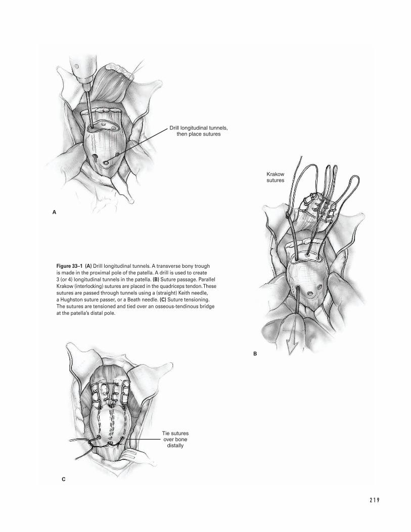
2 1 9
A
B
C
Tie sutures over bone
distally
Drill longitudinal tunnels, then place sutures
Krakow sutures
Figure 33–1 (A) Drill longitudinal tunnels. A transverse bony trough is made in the proximal pole of the patella. A drill is used to create 3 (or 4) longitudinal tunnels in the patella. (B) Suture passage. ParallelKrakow (interlocking) sutures are placed in the quadriceps tendon. Thesesutures are passed through tunnels using a (straight) Keith needle, a Hughston suture passer, or a Beath needle. (C) Suture tensioning.The sutures are tensioned and tied over an osseous-tendinous bridgeat the patella’s distal pole.
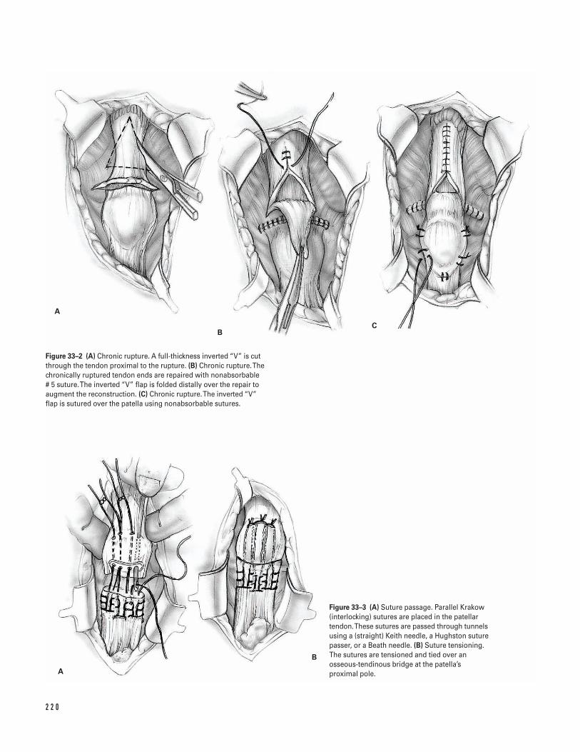
2 2 0
A
BC
A
B
Figure 33–2 (A) Chronic rupture. A full-thickness inverted “V” is cutthrough the tendon proximal to the rupture. (B) Chronic rupture. Thechronically ruptured tendon ends are repaired with nonabsorbable # 5 suture. The inverted “V” flap is folded distally over the repair toaugment the reconstruction. (C) Chronic rupture. The inverted “V” flap is sutured over the patella using nonabsorbable sutures.
Figure 33–3 (A) Suture passage. Parallel Krakow(interlocking) sutures are placed in the patellartendon. These sutures are passed through tunnelsusing a (straight) Keith needle, a Hughston suturepasser, or a Beath needle. (B) Suture tensioning.The sutures are tensioned and tied over anosseous-tendinous bridge at the patella’sproximal pole.

Acute ruptures quadricep tendon (osteotendinous junction)
a. Debride back to healthy tendon and evacuatehematoma.
b. Create a transverse bony trough in the proximalpole of the patella (Fig. 33–1A).
c. To avoid patella tilting after the repair, place thetrough near the patella’s anterior cortex, but not atthe patella’s articular surface.
d. Place 2 (or 3) parallel Krakow (interlocking) suturesin the tendon (#5 nonabsorbable suture).
e. Create 3 (or 4) vertical tunnels in the patella (Fig. 33–1A).
f. Pass the lateral suture through the lateral tunnel,the two central sutures through the central tun-nel(s), and the medial suture through the medialtunnel (Fig. 33–1B).
g. Traditionally, the suture is passed using either a(straight) Keith needle or a Hughston suture passer(Fig. 33–1B).
â Alternatively, the tunnels may be drilled using aBeath needle.
i. The Beath needle has an eye so that the suturescan be passed using the same “needle” that wasused to drill the tunnels.
h. Tension the sutures and tie them over an osseous-tendinous bridge at the distal pole of the patella(Fig. 33–1C).
Chronic ruptures quadricep tendon
â If the tendon ends cannot be opposed, use theCordivilla technique.
a. Create a full-thickness inverted “V” cut through thetendon proximal to the rupture (Fig. 33–2A).
b. Extend the inverted “V” approximately 1 to 2 cmproximal to the rupture (Fig. 33–2A). The inverted“V” allows for tissue advancement to reapproximatethe ruptured tendon ends (Fig. 33–2B).
c. Freshen the chronically ruptured tendon ends and repair them with nonabsorbable #5 suture (Fig. 33–2B).
d. Repair the retinaculum.e. Fold the inverted “V” flap distally over the repair to
augment the reconstruction (Fig. 33–2B). Suture
the extensor mechanism over the patella using non-absorbable suture (if possible bury the sutures) (Fig. 33–2C).
f. Close the proximal gap using absorbable or non-absorbable suture in a side-to-side fashion (Fig.33–2C).
II . Patella Tendon RupturesAcute ruptures patella tendon (osteotendinous junction)
a. Debride back to healthy tendon and evacuatehematoma.
b. Create a transverse trough in the inferior pole of thepatella.
c. Place 2 (or 3) parallel Krakow (interlocking) suturesin the patellar tendon (#2 or #5 nonabsorbablesutures) (Fig. 33–3A).
d. Make 3 (or 4) longitudinal tunnels in the patella(Fig. 33–3A).
e. Pass the lateral suture through the lateral tunnel,the two central sutures through the central tun-nel(s), and the medial sutures through the medialtunnel (Fig. 33–3A).
f. Traditionally, the suture is passed using either a(straight) Keith needle or a Hughston suture passer(Fig. 33–3A).
â Alternatively, the tunnels may be drilled using aBeath needle.
i. The Beath needle has an eye so that the suturescan be passed using the same “needle” that wasused to drill the tunnels.
g. Tension the sutures. Use a smooth clamp to provi-sionally hold the sutures at the proximal pole of thepatella.
h. Move the knee through a range-of-motion to assesstension and tracking.
i. Avoid overtightening the patella tendon repair (thiswill create a patella infera). Check intraoperativefluoroscopy or knee X-ray at 45 degrees of flexion:inferior pole of patella should be superior to theroof of the intercondylar notch.
j. If the patella is maltracking, perform a lateral release.k. Tension the sutures. Tie them over an osseous-
tendinous bridge at the proximal pole of the patella(Fig. 33–3B).
3 3 E X T E N S O R M E C H A N I S M I N J U R I E S 2 2 1
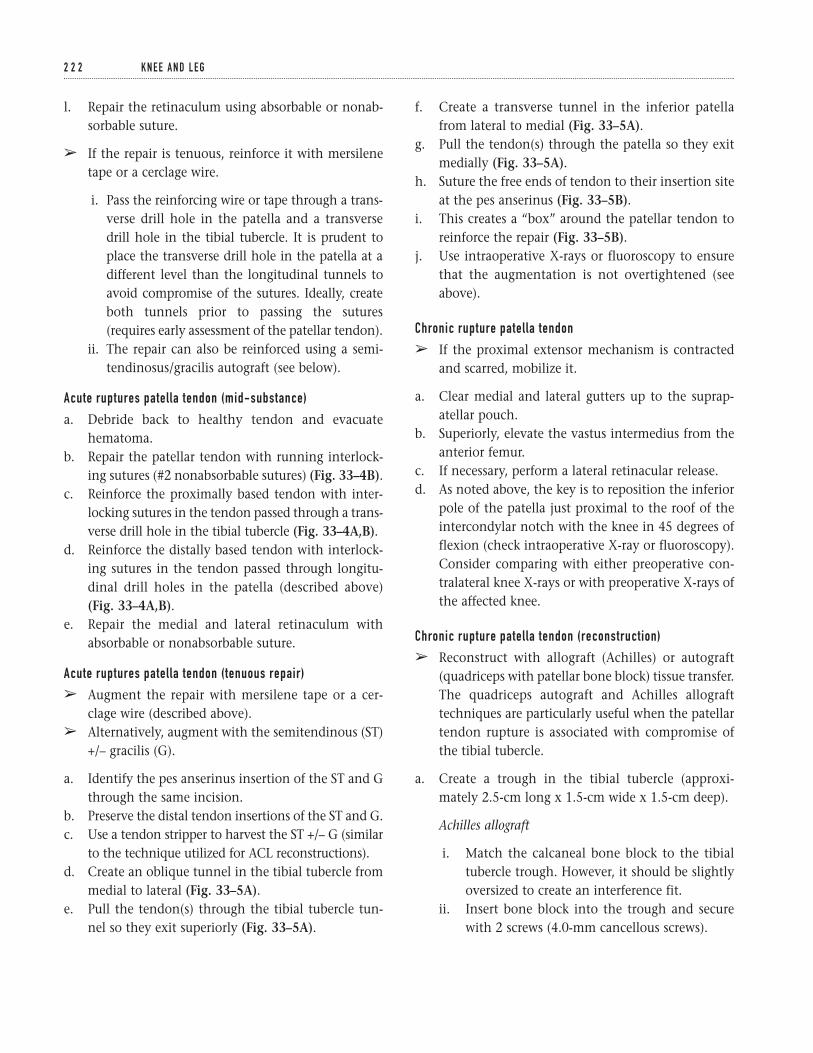
l. Repair the retinaculum using absorbable or nonab-sorbable suture.
â If the repair is tenuous, reinforce it with mersilenetape or a cerclage wire.
i. Pass the reinforcing wire or tape through a trans-verse drill hole in the patella and a transversedrill hole in the tibial tubercle. It is prudent toplace the transverse drill hole in the patella at adifferent level than the longitudinal tunnels toavoid compromise of the sutures. Ideally, createboth tunnels prior to passing the sutures(requires early assessment of the patellar tendon).
ii. The repair can also be reinforced using a semi-tendinosus/gracilis autograft (see below).
Acute ruptures patella tendon (mid-substance)
a. Debride back to healthy tendon and evacuatehematoma.
b. Repair the patellar tendon with running interlock-ing sutures (#2 nonabsorbable sutures) (Fig. 33–4B).
c. Reinforce the proximally based tendon with inter-locking sutures in the tendon passed through a trans-verse drill hole in the tibial tubercle (Fig. 33–4A,B).
d. Reinforce the distally based tendon with interlock-ing sutures in the tendon passed through longitu-dinal drill holes in the patella (described above)(Fig. 33–4A,B).
e. Repair the medial and lateral retinaculum withabsorbable or nonabsorbable suture.
Acute ruptures patella tendon (tenuous repair)
â Augment the repair with mersilene tape or a cer-clage wire (described above).
â Alternatively, augment with the semitendinous (ST)+/– gracilis (G).
a. Identify the pes anserinus insertion of the ST and Gthrough the same incision.
b. Preserve the distal tendon insertions of the ST and G.c. Use a tendon stripper to harvest the ST +/– G (similar
to the technique utilized for ACL reconstructions).d. Create an oblique tunnel in the tibial tubercle from
medial to lateral (Fig. 33–5A).e. Pull the tendon(s) through the tibial tubercle tun-
nel so they exit superiorly (Fig. 33–5A).
f. Create a transverse tunnel in the inferior patellafrom lateral to medial (Fig. 33–5A).
g. Pull the tendon(s) through the patella so they exitmedially (Fig. 33–5A).
h. Suture the free ends of tendon to their insertion siteat the pes anserinus (Fig. 33–5B).
i. This creates a “box” around the patellar tendon toreinforce the repair (Fig. 33–5B).
j. Use intraoperative X-rays or fluoroscopy to ensurethat the augmentation is not overtightened (seeabove).
Chronic rupture patella tendon
â If the proximal extensor mechanism is contractedand scarred, mobilize it.
a. Clear medial and lateral gutters up to the suprap-atellar pouch.
b. Superiorly, elevate the vastus intermedius from theanterior femur.
c. If necessary, perform a lateral retinacular release.d. As noted above, the key is to reposition the inferior
pole of the patella just proximal to the roof of theintercondylar notch with the knee in 45 degrees offlexion (check intraoperative X-ray or fluoroscopy).Consider comparing with either preoperative con-tralateral knee X-rays or with preoperative X-rays ofthe affected knee.
Chronic rupture patella tendon (reconstruction)
â Reconstruct with allograft (Achilles) or autograft(quadriceps with patellar bone block) tissue transfer.The quadriceps autograft and Achilles allografttechniques are particularly useful when the patellartendon rupture is associated with compromise ofthe tibial tubercle.
a. Create a trough in the tibial tubercle (approxi-mately 2.5-cm long x 1.5-cm wide x 1.5-cm deep).
Achilles allograft
i. Match the calcaneal bone block to the tibialtubercle trough. However, it should be slightlyoversized to create an interference fit.
ii. Insert bone block into the trough and securewith 2 screws (4.0-mm cancellous screws).
2 2 2 K N E E A N D L E G
2 2 3
A
B
A B
Figure 33–4 (A) Patellar tendon rupture. The proximally based tendonis reinforced with interlocking sutures passed through a transverse drillhole in the tibial tubercle. The distally based tendon is reinforced withinterlocking sutures in the tendon and passed through longitudinal drillholes in the patella. (B) Suture tensioning. The sutures are tensionedand tied over an osseous-tendinous bridge at the patella’s proximalpole. The patellar tendon is repaired with running interlocking sutures.
Figure 33–5 (A) Semitendinous augmentation. The tendon(s) arepassed through the tibial tubercle tunnel so they exit superiorly. The tendon(s) are passed through the patella so they exit medially.(B) Suture tensioning. The free suture ends of tendon are tensionedand then sutured to their insertion site at the pes anserinus. Thiscreates a “box” around the patellar tendon to reinforce the repair.
iii. Split the Achilles tendon longitudinally intothirds.
iv. Place interlocking sutures into each third withexcess tendon at the free ends.
v. Create a longitudinal tunnel in the patellafrom the inferior pole to the superior pole.
vi. Pass the central third of the Achilles tendonthrough the longitudinal patellar tunnel.
vii. Use intraoperative fluoroscopy or X-ray to setthe proper tension in the reconstruction.
viii. Secure the central third of the tendon to thequadriceps proximally and the inferior pole
of the patella distally (using a nonabsorbablesuture).
ix. Use nonabsorbable suture to secure the medialand lateral thirds to the medial and lateralretinaculi.
Suggested ReadingsBono JV, Haas SB, Scuderi GR. Traumatic maladies of theextensor mechanism. In: Scuderi GR, ed. The Patella.New York, NY: Springer Verlag, 1995, pp. 253–276.
2 2 4 K N E E A N D L E G
Indications1. Acute compartment syndrome of the leg2. Major arterial disruption of the lower extremity
with ischemia times greater than 4 to 6 hours priorto revascularization
3. Full thickness extremity burns at initial presentation4. Chronic exertional compartment syndrome
Contraindications1. None
Preoperative Preparation1. Initial stabilization by ATLS protocols2. Anteroposterior (AP) and lateral radiographs of the
knee, tibial shaft, and ankle3. Careful documentation of preoperative neurovascu-
lar status4. Careful assessment of soft tissue injuries (obvious or
occult); administer appropriate antibiotics andtetanus prophylaxis in the event of an open fracture.
5. Noncircumferential splinting of fractures allowsextremity access for serial examinations.
6. If the compartment syndrome diagnosis is equivo-cal, measure intracompartmental pressure in allfour compartments (pressures greater than 30 mmHg or within 20 mm Hg of diastolic blood pressureis suggestive of compartment syndrome).
Special Instruments, Position, and Anesthesia1. Supine position on the operating room table2. Consider using a radiolucent table in fracture cases.3. General anesthesia or regional techniques are accept-
able. However, regional anesthesia may cloud post-operative neurologic evaluation.
4. Basic orthopedic surgical tray5. Concomitant soft tissue or skeletal injury dictates
additional instruments.
Tips and Pearls1. In patients at risk for compartment syndrome, con-
stant vigilance with regard to diagnosis and treat-ment must be maintained.
2. The earliest and most reliable signs of compartmentsyndrome is pain out of proportion to the injury,firm or tense swelling of the involved compart-ment, and pain with passive stretch of the involvedmusculotendinous units.
3. Paresthesias are a later finding. Unreliable signs ofcompartment syndrome are skin color and pedalpulses. Commonly, the foot remains pink with intactpulses during a compartment syndrome.
4. Avoid circumferential casts and tight dressings inpatients with high-risk injuries.
5. There is no such thing as a mini-open fasciotomyand the skin as well as the fascia should be dividedadequately.
2 2 5
C H A P T E R 3 4
Tibial Fasciotomy
Bradley R. Merk
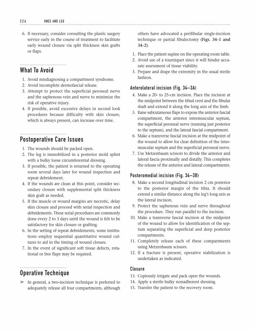
6. If necessary, consider consulting the plastic surgeryservice early in the course of treatment to facilitateearly wound closure via split thickness skin grafts or flaps.
What To Avoid1. Avoid misdiagnosing a compartment syndrome.2. Avoid incomplete dermofascial release.3. Attempt to protect the superficial peroneal nerve
and the saphenous vein and nerve to minimize therisk of operative injury.
4. If possible, avoid excessive delays in second lookprocedures because difficulty with skin closure,which is always present, can increase over time.
Postoperative Care Issues1. The wounds should be packed open.2. The leg is immobilized in a posterior mold splint
with a bulky loose circumferential dressing.3. If possible, the patient is returned to the operating
room several days later for wound inspection andrepeat debridement.
4. If the wounds are clean at this point, consider sec-ondary closure with supplemental split thicknessskin graft as needed.
5. If the muscle or wound margins are necrotic, delayskin closure and proceed with serial inspection anddebridements. These serial procedures are commonlydone every 2 to 3 days until the wound is felt to besatisfactory for skin closure or grafting.
6. In the setting of repeat debridements, some institu-tions employ sequential quantitative wound cul-tures to aid in the timing of wound closure.
7. In the event of significant soft tissue defects, rota-tional or free flaps may be required.
Operative Techniqueâ In general, a two-incision technique is preferred to
adequately release all four compartments, although
others have advocated a perifibular single-incisiontechnique or partial fibulectomy (Figs. 34–1 and34–2).
1. Place the patient supine on the operating room table.2. Avoid use of a tourniquet since it will hinder accu-
rate assessment of tissue viability.3. Prepare and drape the extremity in the usual sterile
fashion.
Anterolateral incision (Fig. 34–3A)4. Make a 20- to 25-cm incision. Place the incision at
the midpoint between the tibial crest and the fibularshaft and extend it along the long axis of the limb.
5. Raise subcutaneous flaps to expose the anterior fascialcompartment, the anterior intermuscular septum,the superficial peroneal nerve (running just posteriorto the septum), and the lateral fascial compartment.
6. Make a transverse fascial incision at the midpoint ofthe wound to allow for clear definition of the inter-muscular septum and the superficial peroneal nerve.
7. Use Metzenbaum scissors to divide the anterior andlateral fascia proximally and distally. This completesthe release of the anterior and lateral compartments.
Posteromedial incision (Fig. 34–3B)8. Make a second longitudinal incision 2 cm posterior
to the posterior margin of the tibia. It shouldextend a similar distance along the leg’s long axis asthe lateral incision.
9. Protect the saphenous vein and nerve throughoutthe procedure. They run parallel to the incision.
10. Make a transverse fascial incision at the midpoint of the wound to allow for identification of the sep-tum separating the superficial and deep posteriorcompartments.
11. Completely release each of these compartmentsusing Metzenbaum scissors.
12. If a fracture is present, operative stabilization isundertaken as indicated.
Closure13. Copiously irrigate and pack open the wounds.14. Apply a sterile bulky nonadherent dressing.15. Transfer the patient to the recovery room.
2 2 6 K N E E A N D L E G
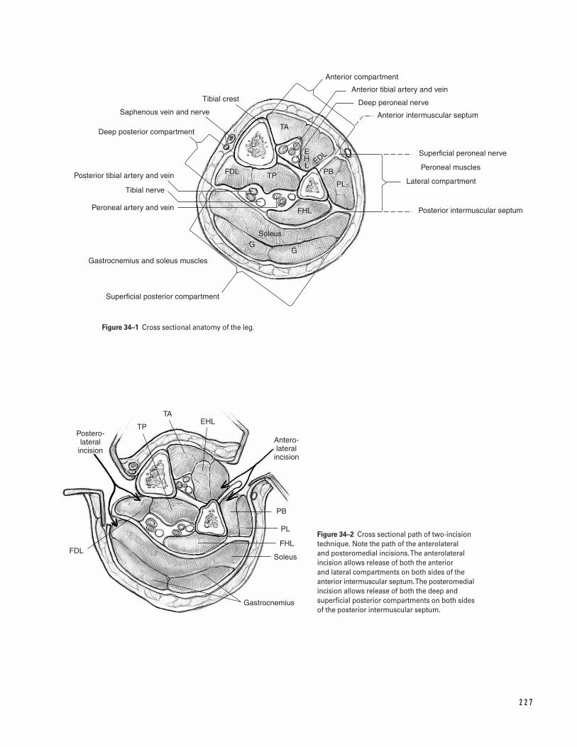
2 2 7
TA
Anterior compartment
Anterior tibial artery and vein
Deep peroneal nerve
Anterior intermuscular septum
Superficial peroneal nerve
Peroneal muscles
Lateral compartment
Posterior intermuscular septum
Tibial crest
Saphenous vein and nerve
Deep posterior compartment
Posterior tibial artery and vein
Tibial nerve
Peroneal artery and vein
Gastrocnemius and soleus muscles
Superficial posterior compartment
Postero- lateral
incisionAntero- lateral
incision
TAEHL
TP
PB
PL
FHL
Soleus
Gastrocnemius
FDL
FDL TP PB
PL
FHL
SoleusG
G
EDLEHL
Figure 34–1 Cross sectional anatomy of the leg.
Figure 34–2 Cross sectional path of two-incisiontechnique. Note the path of the anterolateral and posteromedial incisions. The anterolateralincision allows release of both the anterior and lateral compartments on both sides of theanterior intermuscular septum. The posteromedialincision allows release of both the deep andsuperficial posterior compartments on both sidesof the posterior intermuscular septum.
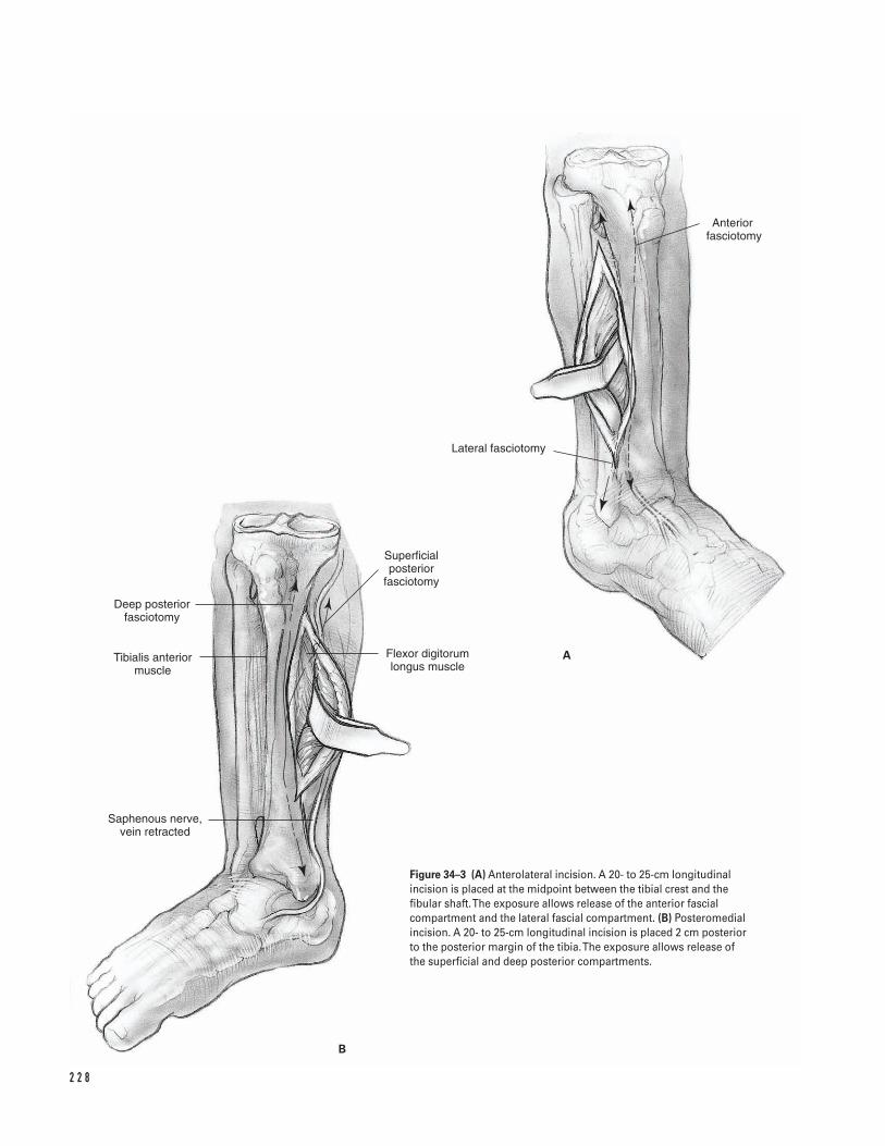
2 2 8
Deep posterior fasciotomy
Tibialis anterior muscle
Saphenous nerve, vein retracted
Superficial posterior
fasciotomy
Flexor digitorum longus muscle
Lateral fasciotomy
Anterior fasciotomy
A
B
Figure 34–3 (A) Anterolateral incision. A 20- to 25-cm longitudinalincision is placed at the midpoint between the tibial crest and thefibular shaft. The exposure allows release of the anterior fascialcompartment and the lateral fascial compartment. (B) Posteromedialincision. A 20- to 25-cm longitudinal incision is placed 2 cm posteriorto the posterior margin of the tibia. The exposure allows release of the superficial and deep posterior compartments.

Suggested ReadingsHoppenfeld S, deBoer, MA. Surgical Exposures in Ortho-paedics: The Anatomic Approach. 2nd ed. Philadelphia,PA: J.B. Lippincott, 1994.
Mubarak SJ, Owen CA. Double-incision fasciotomy ofthe leg for decompression in compartment syndrome. J Bone Joint Surg 1977; 59A:184.
3 4 T I B I A L FA S C I OTO M Y 2 2 9

This page intentionally left blank
Key Techniques inOrthopaedic Surgery
Section Six
Ankle and Foot

This page intentionally left blank
Key Techniques inOrthopaedic Surgery
Indications1. Loose bodies2. Anterior tibiotalar osteophytes3. Soft tissue impingement4. Osteochondritis dessicans5. Synovectomy6. Arthritis
Contraindications1. Soft tissue infection (cellulitis)2. End stage arthritis3. Peripheral vascular disease4. Marked limitation of motion5. Sympathetic dystrophy
Preoperative Preparation1. Thorough history and physical examination2. Check for instability patterns3. Examine subtalar joint4. Weight-bearing anteroposterior/lateral radiographs
of ankle5. Optional views include mortise, Broden’s, and stress
X-rays6. CT/MRI for osteochondral lesion staging
Special Instruments, Position, and Anesthesia1. Regional/general anesthesia2. Place the patient supine on a standard operating
room table. Secure the opposite limb.3. Flex the hip and knee 45 degrees with a soft bump
or use a thigh holder proximal to the popliteal fossa(Fig. 35–1).
4. 4.0- and 2.7-mm (short) arthroscopes with 30- and70-degree obliquity
5. Small arthroscopy instruments: probes, basket for-ceps, graspers, awls, and curettes
6. Motorized 3.5- and 2.9-mm shaver tips7. High flow-inflow system8. Noninvasive soft tissue distraction system
Tips and Pearls1. Mark and identify anatomical landmarks such as
the dorsalis pedis artery, superficial and deep per-oneal nerves, peroneus tertius and anterior tibialtendons, and both malleoli (Fig. 35–2).
2. The patient should be as far cephalad on the oper-ating room table as possible to allow for optimal uti-lization of the distal distraction device.
3. Invert the foot to visualize the superficial peronealnerve.
2 3 3
C H A P T E R 3 5
Ankle Arthroscopy
Armen S. Kelikian
4. The foot and ankle should be freely suspended.5. Manually attach the foot strap and then pull the
distraction lever bar out to length and clamp it.Now begin distraction.
6. Suck all air bubbles out of the high-inflow line.
What To Avoid1. Attempt to minimize the risk of neurological com-
plications from injuries to the peroneal, saphenousor sural nerves at the portal sites. The key to limit-ing neurological complications is preoperativeanatomical markings and the safe use of portals.Avoid the posteromedial and central portals. Withnoninvasive distraction, there are fewer complica-tions than with invasive techniques with distrac-tion pins.
Postoperative Care Issues1. Close the portals with 4-0 interrupted nylon to
minimize risk of sinus tract formation.2. Splint the ankle in a bulky dressing and posterior
mold for 5 to 7 days at zero degrees dorsiflexion.3. May begin weight-bearing as tolerated and rehabili-
tation when posterior mold is removed.4. If microfracture or fixation was used for osteochon-
dral lesions, weight-bearing is delayed 4 to 6 weeks.
Operative Technique1. Prepare and drape the ankle in the hospital’s stan-
dard sterile fashion ensuring adequate exposure.2. At the joint line, usually 1 cm above the tip of the
medial malleolus and just medial to the anterior tibialtendon, introduce a #18 gauge spinal needle angledobliquely from anteromedial to posterolateral.
3. Insufflate the joint with 10 to 20 ccs of fluid.4. Cut the skin with a #15 scalpel. Use a hemostat to
spread the incision in a vertical direction. Penetratethe joint capsule with the hemostat to establish theanteromedial portal.
5. Introduce the arthroscope/cannula into the ankle.Begin inflow and visualize the joint (Fig. 35–3).
6. Establish the anterolateral portal by way of a needlejust lateral to the peroneus tertius. Avoid the per-oneal nerve. Cut the skin as in Step 3 and bluntlydissect with a hemostat.
7. If necessary, an optional posterolateral portal can becreated by passing the arthroscope from anterome-dial to posterolateral through the notch of Harty.Palpate the fibular tip and introduce a spinal needle1.5 cm above the fibular tip and just lateral to the Achilles. Introduce a #18 gauge needle anglingobliquely 45 degrees from posterolateral to antero-medial. The needle should pass between the pos-teroinferior tibial/fibular ligament. This portal canbe used for inflow, visualization, or instrumentationby utilizing interchangeable cannulas.
8. Examine the ankle systematically. Start from antero-medial to anterolateral, then centrally and finallyposteriorly using the 21 point reference examina-tion of Ferkel.
Specific pathologiesa. Loose bodies. Distraction and patience are pre-
requisites for removal of loose bodies. Anteriorloose bodies are easily removed while visualizedfrom the opposite portal. When posterior, theycan be manipulated anteriorly and removed orviewed from anterior and removed through aposterior portal.
b. Tibiotalar osteophytes. These usually occur an-terolaterally, but may occur on the medial orposterior malleoli. Expose the osteophyte byshaving the synovium or the anterior capsule. A 4.0-mm high-speed burr can then facilitate athorough removal. Optionally, a lateral radi-ograph or fluoroscopy can be utilized to assessthe degree of bone removed.
c. Soft tissue impingement. The fascicle of theanteroinferior tibial/fibular ligament can impingeon the talus anterolaterally. Impingement mayalso occur in the lateral gutter (evaluate with the 70-degrees arthroscope introduced from theanteromedial portal), syndesmosis, or posteri-orly. Begin debridement with a basket forcepsthen a motorized shaver.
d. Osteochondritis dessicans. These lesions usuallyoccur anterolaterally or posteromedially. At firstglance, prior to limited synovectomy and probing,
2 3 4 A N K L E A N D F O OT
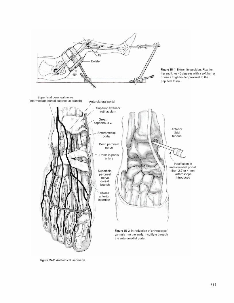
2 3 5
Bolster
Superficial peroneal nerve (intermediate dorsal cutaneous branch) Anterolateral portal
Superior extensor retinaculum
Great saphenous v.
Anteromedial portal
Deep peroneal nerve
Dorsalis pedis artery
Superficial peroneal
nerve dorsal branch
Tibialis anterior insertion
Anterior tibial
tendon
Insufflation in anteromedial portal,
then 2.7 or 4 mm arthroscope introduced
Figure 35–1 Extremity position. Flex thehip and knee 45 degrees with a soft bumpor use a thigh holder proximal to thepopliteal fossa.
Figure 35–3 Introduction of arthroscope/cannula into the ankle. Insufflate throughthe anteromedial portal.
Figure 35–2 Anatomical landmarks.
they may seem miniscule. Acute lesions may bepinned with polylactic acid (PLLA) absorbablepins. Chronic lesions can be debrided anddrilled either with a 0.062-in K-wire or withright-angled awls. A transmalleolar drilling guideor free-hand technique can be used (microvec-tor). Ideally, the holes should be drilled to adepth of 10 mm with interval separation of 5 mm. By flexing and extending the ankle, mul-tiple talar holes can be drilled through 1 or 2 tib-ial entry sites. Alternatively, for large lesions orfailed debridement, the OATS procedure hasshown promise.
e. Synovectomy. Limited or extensive synovec-tomy can be performed for inflammatory orinfectious arthritis. The full radius 3.5 or 2.9shavers can be used.
9. After the arthroscopy is complete, close the portalswith 4-0 interrupted nylon to minimize risk of sinustract formation.
Suggested ReadingsFerkel RD, Scranton PE Jr. Arthoscopy of the ankle andfoot. J Bone Joint Surg 1993;75A:1233–1242.
Ferkel RD, Cheng JC. Ankle and subtalar arthroscopy.In: Kelikian AS, ed. Operative Treatment of the Foot and Ankle. Stamford, CT: Appleton & Lange, 1999, pp. 321–350.
Hangody L, Kish G, Karpatiz Z, Szerb I, Eberhardt R.Treatment of osteochondritis dessicans of the talus: useof mosaicplasty technique—a preliminary report. FootAnkle Int 1997;18:628–634.
2 3 6 A N K L E A N D F O OT
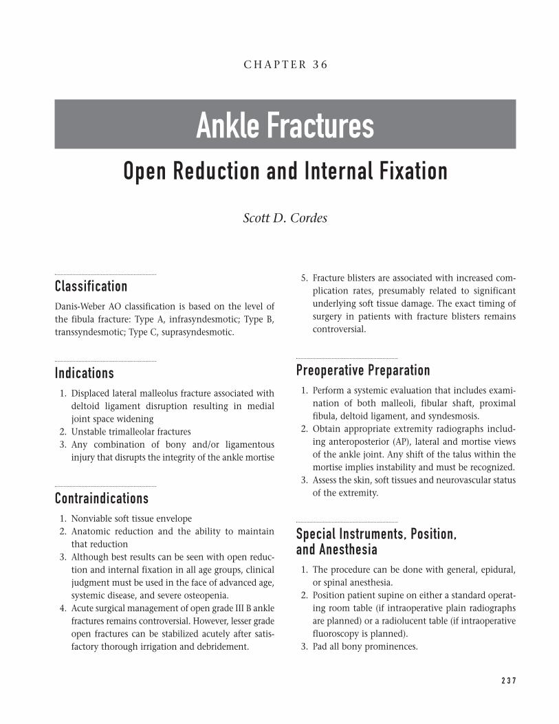
ClassificationDanis-Weber AO classification is based on the level ofthe fibula fracture: Type A, infrasyndesmotic; Type B,transsyndesmotic; Type C, suprasyndesmotic.
Indications1. Displaced lateral malleolus fracture associated with
deltoid ligament disruption resulting in medialjoint space widening
2. Unstable trimalleolar fractures3. Any combination of bony and/or ligamentous
injury that disrupts the integrity of the ankle mortise
Contraindications1. Nonviable soft tissue envelope2. Anatomic reduction and the ability to maintain
that reduction3. Although best results can be seen with open reduc-
tion and internal fixation in all age groups, clinicaljudgment must be used in the face of advanced age,systemic disease, and severe osteopenia.
4. Acute surgical management of open grade III B anklefractures remains controversial. However, lesser gradeopen fractures can be stabilized acutely after satis-factory thorough irrigation and debridement.
5. Fracture blisters are associated with increased com-plication rates, presumably related to significantunderlying soft tissue damage. The exact timing ofsurgery in patients with fracture blisters remainscontroversial.
Preoperative Preparation1. Perform a systemic evaluation that includes exami-
nation of both malleoli, fibular shaft, proximalfibula, deltoid ligament, and syndesmosis.
2. Obtain appropriate extremity radiographs includ-ing anteroposterior (AP), lateral and mortise viewsof the ankle joint. Any shift of the talus within themortise implies instability and must be recognized.
3. Assess the skin, soft tissues and neurovascular statusof the extremity.
Special Instruments, Position, and Anesthesia1. The procedure can be done with general, epidural,
or spinal anesthesia.2. Position patient supine on either a standard operat-
ing room table (if intraoperative plain radiographsare planned) or a radiolucent table (if intraoperativefluoroscopy is planned).
3. Pad all bony prominences.
2 3 7
C H A P T E R 3 6
Ankle FracturesOpen Reduction and Internal Fixation
Scott D. Cordes
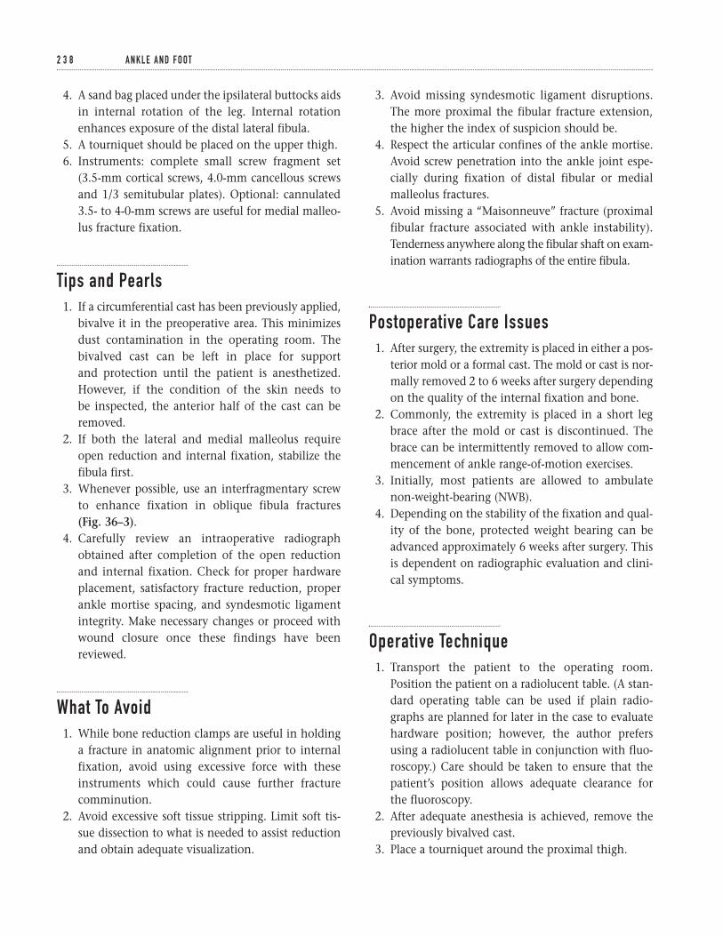
4. A sand bag placed under the ipsilateral buttocks aidsin internal rotation of the leg. Internal rotationenhances exposure of the distal lateral fibula.
5. A tourniquet should be placed on the upper thigh.6. Instruments: complete small screw fragment set
(3.5-mm cortical screws, 4.0-mm cancellous screwsand 1/3 semitubular plates). Optional: cannulated3.5- to 4-0-mm screws are useful for medial malleo-lus fracture fixation.
Tips and Pearls1. If a circumferential cast has been previously applied,
bivalve it in the preoperative area. This minimizesdust contamination in the operating room. Thebivalved cast can be left in place for support and protection until the patient is anesthetized.However, if the condition of the skin needs to be inspected, the anterior half of the cast can beremoved.
2. If both the lateral and medial malleolus requireopen reduction and internal fixation, stabilize thefibula first.
3. Whenever possible, use an interfragmentary screwto enhance fixation in oblique fibula fractures (Fig. 36–3).
4. Carefully review an intraoperative radiographobtained after completion of the open reductionand internal fixation. Check for proper hardwareplacement, satisfactory fracture reduction, properankle mortise spacing, and syndesmotic ligamentintegrity. Make necessary changes or proceed withwound closure once these findings have beenreviewed.
What To Avoid1. While bone reduction clamps are useful in holding
a fracture in anatomic alignment prior to internalfixation, avoid using excessive force with theseinstruments which could cause further fracturecomminution.
2. Avoid excessive soft tissue stripping. Limit soft tis-sue dissection to what is needed to assist reductionand obtain adequate visualization.
3. Avoid missing syndesmotic ligament disruptions.The more proximal the fibular fracture extension,the higher the index of suspicion should be.
4. Respect the articular confines of the ankle mortise.Avoid screw penetration into the ankle joint espe-cially during fixation of distal fibular or medialmalleolus fractures.
5. Avoid missing a “Maisonneuve” fracture (proximalfibular fracture associated with ankle instability).Tenderness anywhere along the fibular shaft on exam-ination warrants radiographs of the entire fibula.
Postoperative Care Issues1. After surgery, the extremity is placed in either a pos-
terior mold or a formal cast. The mold or cast is nor-mally removed 2 to 6 weeks after surgery dependingon the quality of the internal fixation and bone.
2. Commonly, the extremity is placed in a short legbrace after the mold or cast is discontinued. Thebrace can be intermittently removed to allow com-mencement of ankle range-of-motion exercises.
3. Initially, most patients are allowed to ambulatenon-weight-bearing (NWB).
4. Depending on the stability of the fixation and qual-ity of the bone, protected weight bearing can beadvanced approximately 6 weeks after surgery. Thisis dependent on radiographic evaluation and clini-cal symptoms.
Operative Technique1. Transport the patient to the operating room.
Position the patient on a radiolucent table. (A stan-dard operating table can be used if plain radio-graphs are planned for later in the case to evaluatehardware position; however, the author prefersusing a radiolucent table in conjunction with fluo-roscopy.) Care should be taken to ensure that thepatient’s position allows adequate clearance for the fluoroscopy.
2. After adequate anesthesia is achieved, remove thepreviously bivalved cast.
3. Place a tourniquet around the proximal thigh.
2 3 8 A N K L E A N D F O OT
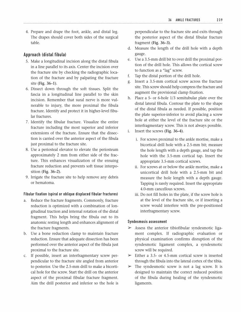
4. Prepare and drape the foot, ankle, and distal leg.The drapes should cover both sides of the surgicaltable.
Approach (distal fibula)5. Make a longitudinal incision along the distal fibula
in a line parallel to its axis. Center the incision overthe fracture site by checking the radiographic loca-tion of the fracture and by palpating the fracturesite (Fig. 36–1).
6. Dissect down through the soft tissues. Split thefascia in a longitudinal line parallel to the skinincision. Remember that sural nerve is more vul-nerable to injury, the more proximal the fibulafracture. Identify and protect it in higher-level fibu-lar fractures.
7. Identify the fibular fracture. Visualize the entirefracture including the most superior and inferiorextensions of the fracture. Ensure that the dissec-tion is carried over the anterior aspect of the fibulajust proximal to the fracture site.
8. Use a periosteal elevator to elevate the periosteumapproximately 2 mm from either side of the frac-ture. This enhances visualization of the ensuingfracture reduction and prevents soft tissue interpo-sition (Fig. 36–2).
9. Irrigate the fracture site to help remove any debrisor hematoma.
Fibular fixation (spiral or oblique displaced fibular fractures)
a. Reduce the fracture fragments. Commonly, fracturereduction is optimized with a combination of lon-gitudinal traction and internal rotation of the distalfragment. This helps bring the fibula out to itsanatomic resting length and enhances alignment ofthe fracture fragments.
b. Use a bone reduction clamp to maintain fracturereduction. Ensure that adequate dissection has beenperformed over the anterior aspect of the fibula justproximal to the fracture site.
c. If possible, insert an interfragmentary screw per-pendicular to the fracture site angled from anteriorto posterior. Use the 2.5-mm drill to make a bicorti-cal hole for the screw. Start the drill on the anterioraspect of the proximal fibular fracture fragment.Aim the drill posterior and inferior so the hole is
perpendicular to the fracture site and exits throughthe posterior aspect of the distal fibular fracturefragment (Fig. 36–3).
d. Measure the length of the drill hole with a depthgauge.
e. Use a 3.5-mm drill bit to over drill the proximal por-tion of the drill hole. This allows the cortical screwto function as a “lag” screw.
f. Tap the distal portion of the drill hole.g. Insert a 3.5-mm cortical screw across the fracture
site. This screw should help compress the fracture andaugment the provisional clamp fixation.
h. Place a 5- or 6-hole 1/3 semitubular plate over thedistal lateral fibula. Contour the plate to the shapeof the distal fibula as needed. If possible, positionthe plate superior-inferior to avoid placing a screwhole at either the level of the fracture site or theinterfragmentary screw. This is not always possible.
i. Insert the screws (Fig. 36–4).
i. For screws proximal to the ankle mortise, make abicortical drill hole with a 2.5-mm bit; measurethe hole length with a depth gauge, and tap thehole with the 3.5-mm cortical tap. Insert theappropriate 3.5-mm cortical screws.
ii. For screws at or below the ankle mortise, make aunicortical drill hole with a 2.5-mm bit andmeasure the hole length with a depth gauge.Tapping is rarely required. Insert the appropriate4.0-mm cancellous screws.
iii. Do not fill holes in the plate, if the screw hole isat the level of the fracture site, or if inserting ascrew would interfere with the pre-positionedinterfragmentary screw.
Syndesmosis assessment
â Assess the anterior tibiofibular syndesmotic liga-ment complex. If radiographic evaluation orphysical examination confirms disruption of thesyndesmotic ligament complex, a syndesmoticscrew will be required.
â Either a 3.5- or 4.5-mm cortical screw is insertedthrough the fibula into the lateral cortex of the tibia.
â The syndesmotic screw is not a lag screw. It isdesigned to maintain the correct reduced positionof the fibula during healing of the syndesmoticligaments.
3 6 A N K L E F R A C T U R E S 2 3 9
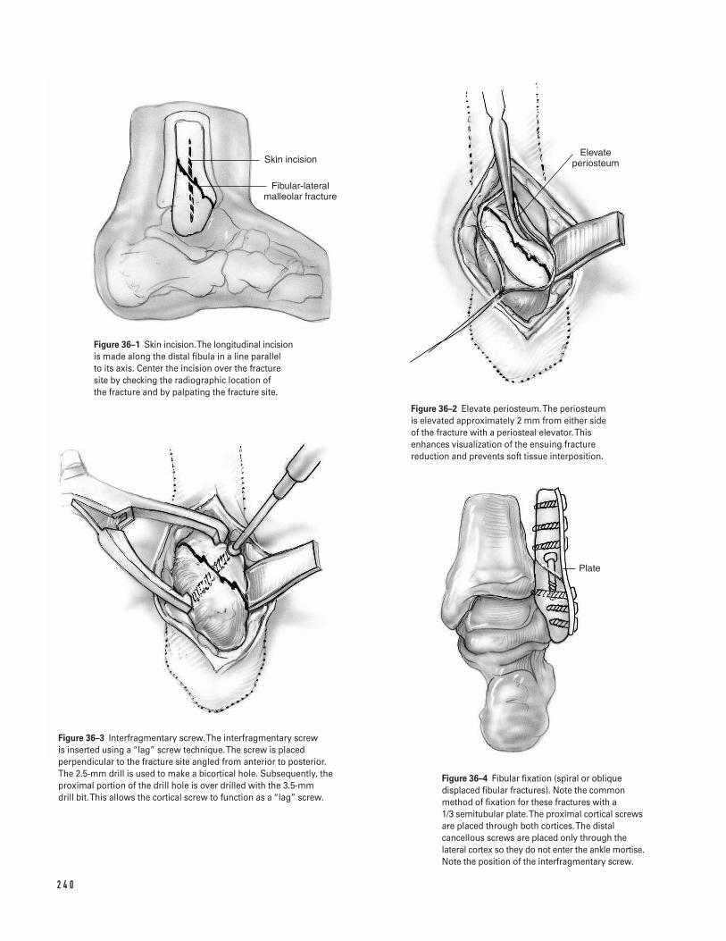
2 4 0
Skin incision
Fibular-lateral malleolar fracture
Elevate periosteum
Plate
Figure 36–1 Skin incision. The longitudinal incisionis made along the distal fibula in a line parallel to its axis. Center the incision over the fracturesite by checking the radiographic location of the fracture and by palpating the fracture site.
Figure 36–2 Elevate periosteum. The periosteumis elevated approximately 2 mm from either sideof the fracture with a periosteal elevator. Thisenhances visualization of the ensuing fracturereduction and prevents soft tissue interposition.
Figure 36–3 Interfragmentary screw.The interfragmentary screw is inserted using a “lag” screw technique. The screw is placedperpendicular to the fracture site angled from anterior to posterior. The 2.5-mm drill is used to make a bicortical hole. Subsequently, theproximal portion of the drill hole is over drilled with the 3.5-mm drill bit. This allows the cortical screw to function as a “lag” screw.
Figure 36–4 Fibular fixation (spiral or obliquedisplaced fibular fractures). Note the commonmethod of fixation for these fractures with a 1/3 semitubular plate. The proximal cortical screwsare placed through both cortices. The distalcancellous screws are placed only through thelateral cortex so they do not enter the ankle mortise.Note the position of the interfragmentary screw.
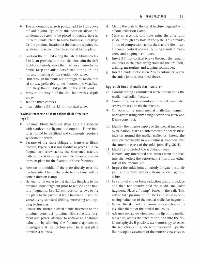
d. Clamp the plate to the distal fracture fragment witha bone reduction clamp.
e. Make an eccentric drill hole, using the offset drillguide, through any hole in the plate. This provides1 mm of compression across the fracture site. Inserta 3.5-mm cortical screw after using standard meas-uring and tapping techniques.
f. Insert 3.5-mm cortical screws through the remain-ing holes in the plate using standard (neutral hole)drilling, measuring, and tapping techniques.
g. Insert a syndesmotic screw 2 to 3 centimeters abovethe ankle joint as described above.
Approach (medial malleolar fracture)â Consider using a cannulated screw system to fix the
medial malleollar fracture.â Commonly, two 4.0-mm-long threaded cannulated
screws are used to fix the fracture.â On occasion, a small medial malleolar fragment
necessitates using only a single screw or a screw andK-wire construct.
10. Identify the inferior aspect of the medial malleolusby palpation. Make an anteromedial “hockey stick”incision around the medial malleolus. Extend theincision proximally in a curvilinear direction overthe anterior aspect of the ankle joint (Fig. 36–5).
11. Identify and protect the saphenous vein.12. Remove any interposed soft tissues from the frac-
ture site. Reflect the periosteum 2 mm from eitherside of the fracture site.
13. Inspect the ankle joint anteriorly. Irrigate the anklejoint and remove any hematoma or cartilaginousdebris.
14. Use a towel clip or bone reduction clamp to reduceand then temporarily hold the medial malleolarfragment. Place a “bump” beneath the calf. Thisacts to take pressure off the heel and assist in opti-mizing reduction of the medial malleolar fragment.
15. Retract the skin with a narrow ribbon retractor tovisualize the tip of the medial malleolus.
16. Advance two guide wires from the tip of the medialmalleolus, across the fracture site, and into the tib-ial metaphysis. If possible, use fluoroscopy to assessthe reduction and guide wire placement. Specificfluoroscopic assessment of the mortise view ensures
3 6 A N K L E F R A C T U R E S 2 4 1
â The syndesmotic screw is positioned 2 to 3 cm abovethe ankle joint. Typically, this position allows thesyndesmotic screw to be placed through a hole inthe semitubular plate. In high-fibular fractures (typeC), the proximal location of the fracture requires thesyndesmotic screw to be placed distal to the plate.
a. Position the drill bit along the lateral fibular cortex2 to 3 cm proximal to the ankle joint. Aim the drillslightly anteriorly, since the tibia lies anterior to thefibula. Keep the ankle dorsiflexed during drillingfor, and inserting of, the syndesmotic screw.
b. Drill through the fibula and through the medial tib-ial cortex, preferably under fluoroscopic visualiza-tion. Keep the drill bit parallel to the ankle joint.
c. Measure the length of the drill hole with a depthgauge.
d. Tap the three cortices.e. Insert either a 3.5- or 4.5-mm cortical screw.
Proximal transverse or short oblique fibular fractures (type C)
â Proximal fibula fractures (type C) are associatedwith syndesmotic ligament disruption. These frac-tures should be stabilized and commonly require asyndesmotic screw.
â Because of the short oblique or transverse fibulafracture, typically it is not feasible to place an inter-fragmentary screw across the shortened fracturepattern. Consider using a six-hole low-profile com-pression plate for the fixation of these fractures.
a. Position the middle of the plate directly over thefracture site. Clamp the plate to the bone with abone reduction clamp.
b. Generally, it is easier to first stabilize the plate to theproximal bone fragment prior to reducing the frac-ture fragments. Use 3.5-mm cortical screws to fixthe plate to the proximal bone fragment. Insert thescrews using standard drilling, measuring and tap-ping techniques.
c. Reduce the unstable distal fibula fragment to theproximal construct (proximal fibula fracture frag-ment and plate). Attempt to achieve an anatomicreduction by allowing the fracture fragments tointerdigitate at the fracture site. The lateral plateprovides a buttress.
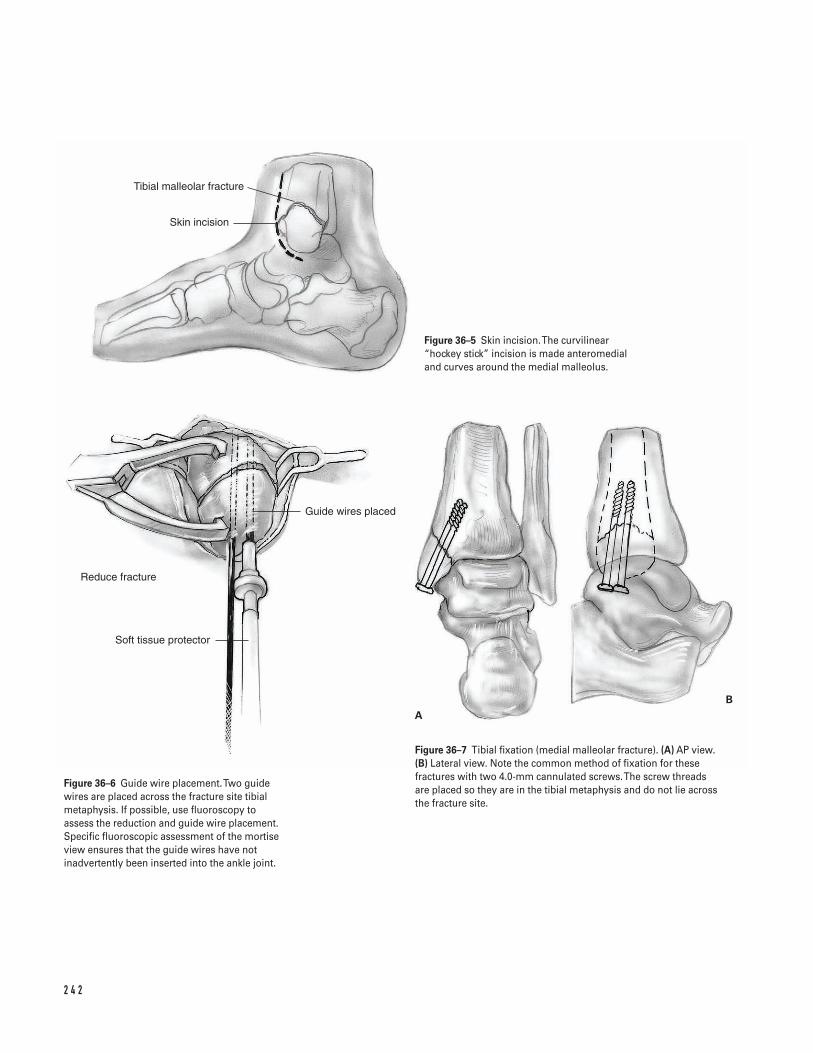
2 4 2
Skin incision
Tibial malleolar fracture
Guide wires placed
Soft tissue protector
AB
Reduce fracture
Figure 36–5 Skin incision. The curvilinear“hockey stick” incision is made anteromedial and curves around the medial malleolus.
Figure 36–6 Guide wire placement. Two guidewires are placed across the fracture site tibialmetaphysis. If possible, use fluoroscopy toassess the reduction and guide wire placement.Specific fluoroscopic assessment of the mortiseview ensures that the guide wires have notinadvertently been inserted into the ankle joint.
Figure 36–7 Tibial fixation (medial malleolar fracture). (A) AP view. (B) Lateral view. Note the common method of fixation for thesefractures with two 4.0-mm cannulated screws. The screw threads are placed so they are in the tibial metaphysis and do not lie acrossthe fracture site.
that the guide wires have not inadvertently beeninserted into the ankle joint (Fig. 36–6).
17. After adequate guide wire position is confirmed,insert two 4.0-mm cannulated screws over the guidepins if the fracture is of satisfactory size. This isaccomplished by drilling the outer cortex with thecannulated drill and using a standard depth gauge.If necessary, tap the outer cortex. Occasionally, insmall medial malleolar fragments, only a singlescrew and/or screw and K-wire fixation can be used(Figs. 36–7A and 7B).
Intraoperative assessment18. Use intra-operative fluoroscopy or standard radi-
ographs to assess hardware placement and fracturealignment.
a. Confirm proper hardware placement. Ensurethat the screws do not penetrate into the anklemortise and their lengths are satisfactory.
b. Confirm anatomic restoration of the ankle mor-tise and the fibula. If there was evidence of del-toid ligament disruption, ensure closure of themedial joint space.
c. If there was an associated syndesmotic disrup-tion, confirm proper syndesmotic screw place-ment and an anatomic restoration of the anklemortise.
d. If a posterior malleolar fracture was present, con-firm that it has satisfactorily been reduced withrestoration of appropriate fibular length.
Closure19. Irrigate both wounds.20. Reapproximate the periosteum over the medial
malleolus and the subcutaneous tissues with inter-rupted 2-0 vicryl.
21. Laterally, close the fascia with figure eight or inter-rupted 0-vicryl sutures. Close the subcutaneous tis-sues with interrupted 2-0 vicryl. Optionally, a draincan be used per surgeon preference.
22. Close the skin using standard skin closure tech-niques, preferably staples or interrupted nylon suture.
23. Place the leg in a well padded posterior mold or shortleg cast, with the ankle immobilized at 90 degrees.
Suggested ReadingsGregory PR, Sanders RW. Ankle and foot injuries. In:Levine AM, ed. Orthopaedic Knowledge Update: Trauma.Rosemont, IL: American Academy of OrthopaedicSurgeons, 1996, pp. 191–209.
Muller ME, Allgower A, Schneider R, Willenegger H.Manual of Internal Fixation: Techniques Recommended bythe AO Group. 2nd ed. New York, NY: Springer-Verlag,1979, pp. 282–299.
Whittle AP. Fractures of lower extremities. In: Canale ST,ed. Campbell’s Operative Orthopaedics. 9th ed. St. Louis,MO: Mosby-Year Book, 1998, pp. 2043–2066.
3 6 A N K L E F R A C T U R E S 2 4 3
Indications1. Acute rupture of the Achilles tendon in a competi-
tive or high-level athlete2. Acute ruptures of the Achilles tendon in which treat-
ment has been delayed: the exact length of delaythat “requires” operative intervention is debatable,but treatment delays beyond approximately 2 weeksgenerally increase the benefits of surgery. In theevent that treatment has been extensively delayed(e.g., greater than 6 to 8 weeks), surgical repair of theruptured Achilles tendon may require additionalaugmentation with fascial turndown flaps or flexorhallucis longus tendon transfer.
Contraindications1. Poor skin or soft tissue condition in the area of
desired surgical repair2. Patients with conditions that may increase the risk
of wound-healing problems (e.g., peripheral vascu-lar disease, diabetes mellitus, heavy tobacco use)(relative)
Preoperative Preparation1. Evaluate the patient to assess the benefits of surgi-
cal versus nonoperative treatment.2. Discuss both surgical and nonsurgical treatment
(and their respective pros and cons) options withthe patient.
3. If a calcaneal avulsion fracture is suspected, radi-ographs of the ankle and foot may be beneficial.
4. While an appropriate history and physical exami-nation can reliably identify most Achilles tendonruptures, consider obtaining a MRI if diagnosis is indoubt.
Special Instruments, Position,and Anesthesia1. If augmentation with the plantaris tendon or other
additional procedures is being considered, tendonstrippers and weavers may be beneficial.
2. The procedure is usually done with the patient inthe prone position. However, if desired, the proce-dure can be done with the patient supine by placinga rolled blanket beneath the contralateral buttockto externally rotate the affected limb.
3. A thigh tourniquet is utilized.4. The procedure is done with either general or spinal
anesthesia.
Tips and Pearls1. Preoperatively, pay close attention to the normal
plantarflexion resting position and tone of thecontralateral foot and ankle in order to reproducethis as best as possible when repairing the rupturedside. If necessary, both lower extremities can beprepped and draped to allow this comparisonintraoperatively.
2 4 4
C H A P T E R 3 7
Achilles Tendon Repair
Steven Kodros
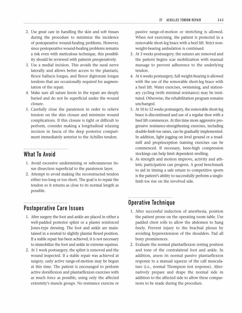
2. Use great care in handling the skin and soft tissuesduring the procedure to minimize the incidence of postoperative wound-healing problems. However,since postoperative wound-healing problems remainsa risk even with meticulous technique, this possibil-ity should be reviewed with patients preoperatively.
3. Use a medial incision. This avoids the sural nervelaterally and allows better access to the plantaris,flexor hallucis longus, and flexor digitorum longustendons that are occasionally required for augmen-tation of the repair.
4. Make sure all suture knots in the repair are deeplyburied and do not lie superficial under the woundclosure.
5. Carefully close the paratenon in order to relievetension on the skin closure and minimize woundcomplications. If this closure is tight or difficult toperform, consider making a longitudinal relaxingincision in fascia of the deep posterior compart-ment immediately anterior to the Achilles tendon.
What To Avoid1. Avoid excessive undermining or subcutaneous tis-
sue dissection superficial to the paratenon layer.2. Attempt to avoid making the reconstructed tendon
either too long or too short. The goal is to repair thetendon so it returns as close to its normal length aspossible.
Postoperative Care Issues1. After surgery the foot and ankle are placed in either a
well-padded posterior splint or a plaster reinforcedJones-type dressing. The foot and ankle are main-tained in a neutral to slightly plantar flexed position.If a stable repair has been achieved, it is not necessaryto immobilize the foot and ankle in extreme equinus.
2. At 1 week postsurgery, the splint is removed and thewound inspected. If a stable repair was achieved atsurgery, early active range-of-motion may be begunat this time. The patient is encouraged to performactive dorsiflexion and plantarflexion exercises withas much force as possible, using only the affectedextremity’s muscle groups. No resistance exercise or
passive range-of-motion or stretching is allowed.When not exercising, the patient is protected in aremovable short-leg brace with a heel lift. Strict non-weight-bearing ambulation is continued.
3. At 3 weeks postsurgery, the sutures are removed andthe patient begins scar mobilization with manualmassage to prevent adherence to the underlyingtendon.
4. At 6 weeks postsurgery, full weight-bearing is allowedwith the use of the removable short-leg brace witha heel lift. Water exercises, swimming, and station-ary cycling (with minimal resistance) may be insti-tuted. Otherwise, the rehabilitation program remainsunchanged.
5. At 10 to 12 weeks postsurgery, the removable short-legbrace is discontinued and use of a regular shoe with aheel lift commences. At this time more aggressive pro-gressive resistance-strengthening exercises, includingdouble-limb toe raises, can be gradually implemented.In addition, light jogging on level ground or a tread-mill and proprioception training exercises can becommenced. If necessary, knee-high compressionstockings can help limit dependent swelling.
6. As strength and motion improve, activity and ath-letic participation can progress. A good benchmarkto aid in timing a safe return to competitive sportsis the patient’s ability to successfully perform a single-limb toe rise on the involved side.
Operative Technique1. After successful induction of anesthesia, position
the patient prone on the operating room table. Usepadded chest rolls to allow the abdomen to hangfreely. Prevent injury to the brachial plexus byavoiding hyperextension of the shoulders. Pad allbony prominences.
2. Evaluate the normal plantarflexion resting positionand tone of the contralateral foot and ankle. Inaddition, assess its normal passive plantarflexionresponse to a manual squeeze of the calf muscula-ture (i.e., normal Thompson test response). Alter-natively prepare and drape the normal side inaddition to the affected side to allow these compar-isons to be made during the procedure.
3 7 A C H I L L E S T E N D O N R E PA I R 2 4 5
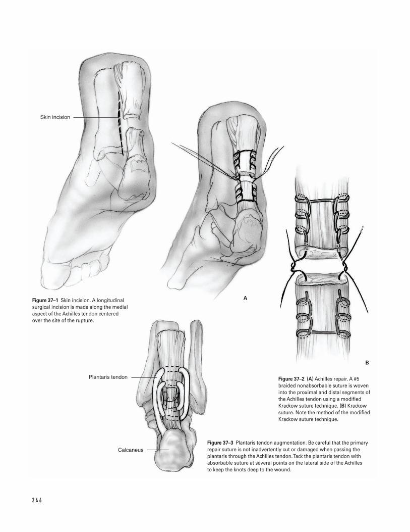
2 4 6
Skin incision
Plantaris tendon
Calcaneus
A
B
Figure 37–1 Skin incision. A longitudinalsurgical incision is made along the medialaspect of the Achilles tendon centeredover the site of the rupture.
Figure 37–2 (A) Achilles repair. A #5braided nonabsorbable suture is woveninto the proximal and distal segments ofthe Achilles tendon using a modifiedKrackow suture technique. (B) Krackowsuture. Note the method of the modifiedKrackow suture technique.
Figure 37–3 Plantaris tendon augmentation. Be careful that the primaryrepair suture is not inadvertently cut or damaged when passing theplantaris through the Achilles tendon. Tack the plantaris tendon withabsorbable suture at several points on the lateral side of the Achilles to keep the knots deep to the wound.
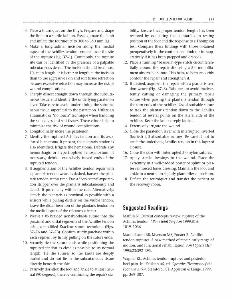
3. Place a tourniquet on the thigh. Prepare and drapethe limb in a sterile fashion. Exsanguinate the limband inflate the tourniquet to 300 to 350 mm Hg.
4. Make a longitudinal incision along the medialaspect of the Achilles tendon centered over the siteof the rupture (Fig. 37–1). Commonly, the rupturesite can be identified by the presence of a palpablesubcutaneous defect. The incision should be at least10 cm in length. It is better to lengthen the incisionthan to use aggressive skin and soft tissue retractionbecause excessive retraction may increase the risk ofwound complications.
5. Sharply dissect straight down through the subcuta-neous tissue and identify the underlying paratenonlayer. Take care to avoid undermining the subcuta-neous tissue superficial to the paratenon. Utilize anatraumatic or “no touch” technique when handlingthe skin edges and soft tissues. These efforts help tominimize the risk of wound complications.
6. Longitudinally incise the paratenon.7. Identify the ruptured Achilles tendon and its asso-
ciated hematoma. If present, the plantaris tendon isalso identified. Irrigate the hematoma. Debride anyhemorrhagic or hypertrophied tenosynovium. Ifnecessary, debride excessively frayed ends of theruptured tendon.
8. If augmentation of the Achilles tendon repair witha plantaris tendon weave is desired, harvest the plan-taris tendon at this time. Pass a “cork screw”-type ten-don stripper over the plantaris subcutaneously anddetach it proximally within the calf. Alternatively,detach the plantaris as proximal as possible with ascissors while pulling distally on the visible tendon.Leave the distal insertion of the plantaris tendon onthe medial aspect of the calcaneous intact.
9. Weave a #5 braided nonabsorbable suture into theproximal and distal segments of the Achilles tendonusing a modified Krackow suture technique (Figs.37–2A and 37–2B). Confirm sturdy purchase withineach segment by firmly pulling on the suture ends.
10. Securely tie the suture ends while positioning theruptured tendon as close as possible to its normallength. Tie the sutures so the knots are deeplyburied and do not lie in the subcutaneous tissuedirectly beneath the skin.
11. Passively dorsiflex the foot and ankle to at least neu-tral (90 degrees), thereby confirming the repair’s sta-
bility. Ensure that proper tendon length has beenrestored by evaluating the plantarflexion restingposition of the foot and the response to a Thompsontest. Compare these findings with those obtainedpreoperatively in the contralateral limb (or intraop-eratively if it has been prepped and draped).
12. Place a running “baseball”-type stitch circumferen-tially around the repair site using a 3-0 monofila-ment absorbable suture. This helps to both smoothlycontour the repair and strengthen it.
13. If desired, augment the repair with a plantaris ten-don weave (Fig. 37–3). Take care to avoid inadver-tently cutting or damaging the primary repairsuture when passing the plantaris tendon throughthe torn ends of the Achilles. Use absorbable sutureto tack the plantaris tendon down to the Achillestendon at several points on the lateral side of theAchilles. Keep the knots deeply buried.
14. Extensively irrigate the wound.15. Close the paratenon layer with interrupted inverted
(buried) 2-0 absorbable sutures. Be careful not tocatch the underlying Achilles tendon in this layer ofclosure.
16. Close the skin with interrupted 3-0 nylon sutures.17. Apply sterile dressings to the wound. Place the
extremity in a well-padded posterior splint or plas-ter reinforced Jones dressing. Maintain the foot andankle in a neutral to slightly plantarflexed position.
18. Deflate the tourniquet and transfer the patient tothe recovery room.
Suggested ReadingsMaffuli N. Current concepts review: rupture of theAchilles tendon. J Bone Joint Surg Am 1999;81A:1019–1036.
Mandelbaum BR, Myerson MS, Forster R. Achillestendon ruptures. A new method of repair, early range ofmotion, and functional rehabilitation. Am J Sports Med1995;23:392–395.
Wapner KL. Achilles tendon ruptures and posterior heel pain. In: Kelikian AS, ed. Operative Treatment of theFoot and Ankle. Stamford, CT: Appleton & Lange, 1999,pp. 369–387.
3 7 A C H I L L E S T E N D O N R E PA I R 2 4 7
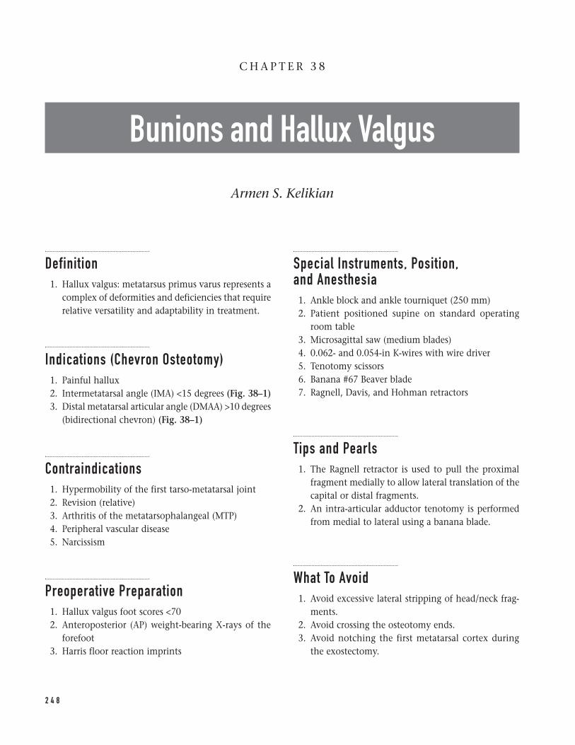
Definition1. Hallux valgus: metatarsus primus varus represents a
complex of deformities and deficiencies that requirerelative versatility and adaptability in treatment.
Indications (Chevron Osteotomy)1. Painful hallux2. Intermetatarsal angle (IMA) <15 degrees (Fig. 38–1)3. Distal metatarsal articular angle (DMAA) >10 degrees
(bidirectional chevron) (Fig. 38–1)
Contraindications1. Hypermobility of the first tarso-metatarsal joint2. Revision (relative)3. Arthritis of the metatarsophalangeal (MTP)4. Peripheral vascular disease5. Narcissism
Preoperative Preparation1. Hallux valgus foot scores <702. Anteroposterior (AP) weight-bearing X-rays of the
forefoot3. Harris floor reaction imprints
Special Instruments, Position, and Anesthesia1. Ankle block and ankle tourniquet (250 mm)2. Patient positioned supine on standard operating
room table3. Microsagittal saw (medium blades)4. 0.062- and 0.054-in K-wires with wire driver5. Tenotomy scissors6. Banana #67 Beaver blade7. Ragnell, Davis, and Hohman retractors
Tips and Pearls1. The Ragnell retractor is used to pull the proximal
fragment medially to allow lateral translation of thecapital or distal fragments.
2. An intra-articular adductor tenotomy is performedfrom medial to lateral using a banana blade.
What To Avoid1. Avoid excessive lateral stripping of head/neck frag-
ments.2. Avoid crossing the osteotomy ends.3. Avoid notching the first metatarsal cortex during
the exostectomy.
2 4 8
C H A P T E R 3 8
Bunions and Hallux Valgus
Armen S. Kelikian
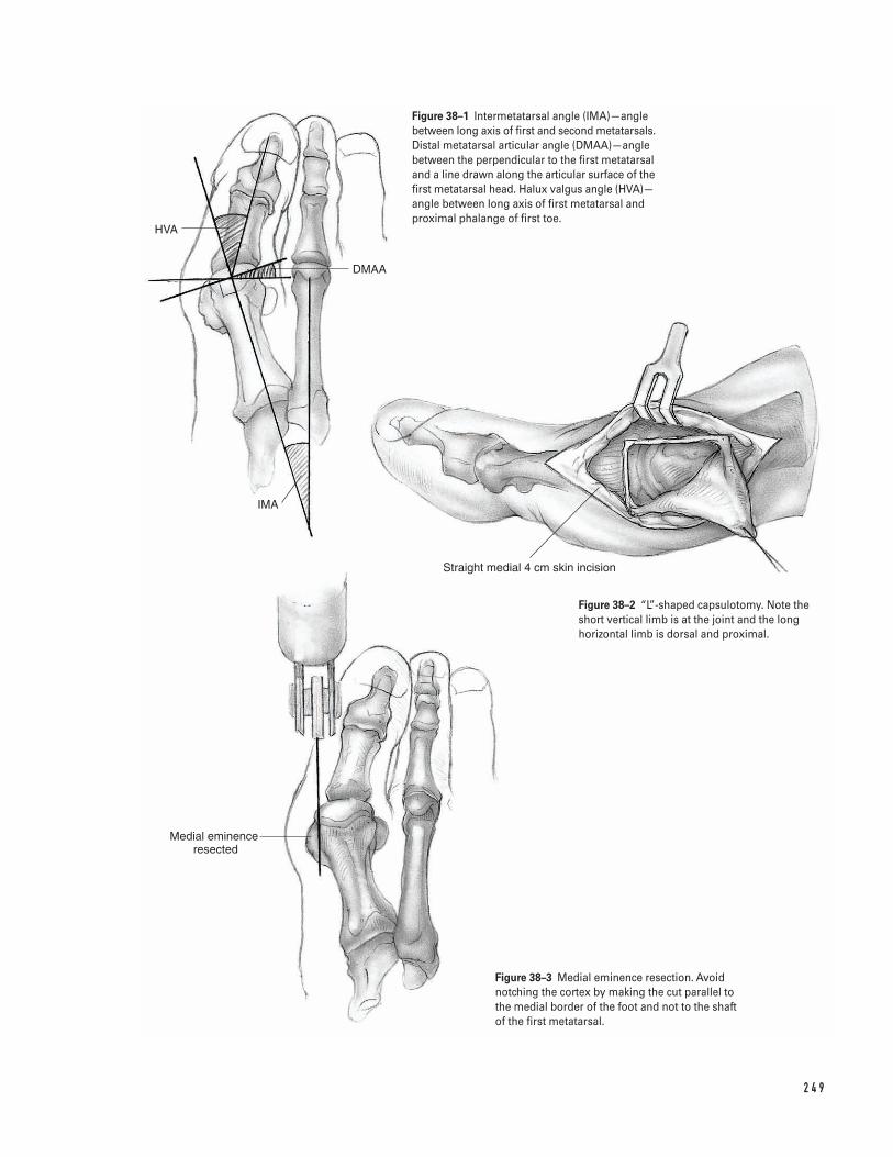
2 4 9
HVA
DMAA
IMA
Straight medial 4 cm skin incision
Medial eminence resected
Figure 38–1 Intermetatarsal angle (IMA)—anglebetween long axis of first and second metatarsals.Distal metatarsal articular angle (DMAA)—anglebetween the perpendicular to the first metatarsaland a line drawn along the articular surface of thefirst metatarsal head. Halux valgus angle (HVA)—angle between long axis of first metatarsal andproximal phalange of first toe.
Figure 38–2 “L”-shaped capsulotomy. Note theshort vertical limb is at the joint and the longhorizontal limb is dorsal and proximal.
Figure 38–3 Medial eminence resection. Avoidnotching the cortex by making the cut parallel tothe medial border of the foot and not to the shaftof the first metatarsal.
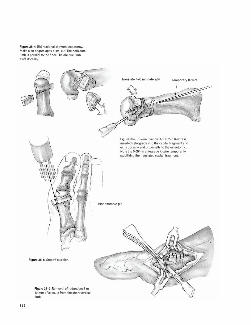
2 5 0
Translate 4–6 mm laterally Temporary K-wire
Bioabsorable pin
Figure 38–4 Bidirectional chevron osteotomy.Make a 70-degree apex distal cut. The horizontallimb is parallel to the floor. The oblique limb exits dorsally.
Figure 38–5 K-wire fixation. A 0.062-in K-wire isinserted retrograde into the capital fragment andexits dorsally and proximally to the osteotomy.Note the 0.054-in antegrade K-wire temporarilystabilizing the translated capital fragment.
Figure 38–6 Stepoff excision.
Figure 38–7 Removal of redundant 8 to 10 mm of capsule from the short verticallimb.
Postoperative Care Issues1. Apply a bulky, bunion compression dressing after
surgery. This is removed 5 to 7 days after surgeryand a commercial bunion splint is applied.
2. The postoperative shoe is used for 4 weeks. Abunion splint is used at night for an additional 4 weeks. Gym shoes are allowed at this stage usingtoe spacers.
3. Toe extension exercises are encouraged after thefirst postoperative visit.
Operative TechniqueApproach1. Prepare and drape the ankle in the hospital’s stan-
dard sterile fashion ensuring adequate exposure.2. If a tourniquet is to be utilized, the foot should be
exsanguinated and the ankle tourniquet inflated.3. Make a straight 4-cm medial skin incision centered
over the metatarsophalangeal (MTP) joint. Place aretraction skin suture to improve exposure. Elevatedorsal and plantar flaps subfascially with a teno-tomy scissors. Identify the dorsal cutaneous nerve.
4. Make an inverted “L”-shaped capsulotomy. Theshort vertical limb is at the joint and the long hori-zontal limb is dorsal and proximal (Fig. 38–2).
Procedure5. Expose the metatarsal neck. Remove the exostosis (1
to 2 mm). Caution, one should not be parallel to theshaft of the first metatarsal, but to the medial borderof the foot to avoid notching the cortex (Fig. 38–3).
6. Make a 70-degree apex distal cut. The horizontallimb is parallel to the floor. The oblique limb exitsdorsally. Caution: do not cross the limbs at the cen-ter (Fig. 38–4).
7. Complete the cuts with thin Mannerfelt osteotomes.8. Displace the head fibularward by pulling the shaft
medially with a Ragnell retractor.9. If the DMAA is high, make a second dorsal oblique
osteotomy. Initially, leave a 1- to 2-mm sliver ofbone medially which is subsequently removed.
10. After translation and correction, use a 0.054-in K-wire antegrade to stabilize the head.
11. Insert either an antegrade or retrograde 0.062-in K-wire. The author prefers the retrograde techniquebeginning in the capital fragment and exiting dor-sally and proximally to the osteotomy (Fig. 38–5).
12. Measure the length of the pin. Insert a 1.5-mm byeither a 20- or 30-mm Bionix (PLLA) pin.
13. If the construct is unstable, add a second pin.14. Excise the stepoff (Fig. 38–6).15. Perform an adductor tenotomy if needed.16. Balance the medial capsular tissue. Remove the
redundant 8 to 10 mm of capsule from the shortvertical limb (Fig. 38–7).
Closure17. Use 2-0 Vicryl suture to perform the capsulorrhaphy.18. Close the skin with 5-0 Nylon suture. Apply a bulky
compression dressing.
Suggested ReadingsKelikian AS. Hallux valgus. In: Kelikian AS, ed. OperativeTreatment of the Foot and Ankle. Stamford, CT: Appleton& Lange, 1999, pp. 61–94.
3 8 B U N I O N S A N D H A L L U X VA L G U S 2 5 1
Definitions1. Mallet toe: flexion deformity at the distal interpha-
langeal (DIP) joint2. Hammer toe: flexion deformity at the proximal
interphalangeal (PIP) joint and mild extension atthe metatarsophalangeal? (MTP) and DIP joints
3. Claw toe: flexion deformity at the PIP joint andhyperextension at the MTP joint
4. Deviated toe: MTP joint in either varus or valgus5. Crossover toe: medial deviation of the second toe
crossing over the first toe with an associated ham-mer toe deformity
6. Curly toe: the fourth or fifth toes may appearcurved, but they are not angulated
Indications1. Fixed deformity2. Nonresponsive to conservative measures such as
wide toe box shoes and pads, toe crescents
Contraindications1. Peripheral vascular disease2. Narcissism
Preoperative Preparation1. Physical examination
a. Cock-up test (hyperextension at the MTP jointwith plantar pressure)
b. Lachman test (instability of the second MTPjoint)
c. Assess position of the hallux and first ray.d. Examine the foot for associated hard corns, ker-
atoses, and soft corns (clavus).
Special Instruments, Position, and Anesthesia1. Patient positioned supine on standard operating
room table2. This procedure can de done under local anesthesia.3. An ankle tourniquet (at 250 mm) is optional.4. #15 blade5. Freer elevator6. Meyerding retractors7. Double skin hooks8. Microsagittal saw blade9. 0.045-, 0.054-, 0.062-in smooth K-wire
10. 3-0 Vicryl sutures11. 5-0 Nylon sutures
Tips and Pearls1. A pulse oximeter placed on the toe is an excellent
method of checking oxygen delivery to the foot.
What To Avoid1. If toe circulation is compromised after K-wire
instrumentation, it should be removed.
2 5 2
C H A P T E R 3 9
Hammer Toe Correction
Armen S. Kelikian
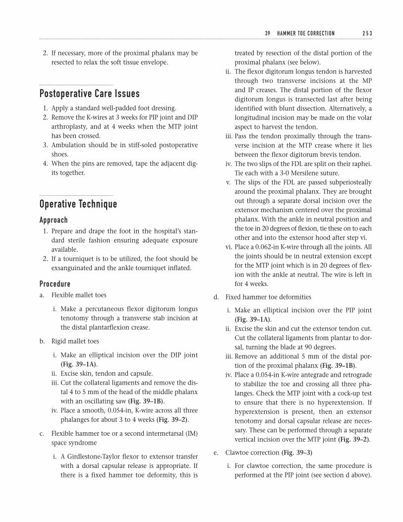
2. If necessary, more of the proximal phalanx may beresected to relax the soft tissue envelope.
Postoperative Care Issues1. Apply a standard well-padded foot dressing.2. Remove the K-wires at 3 weeks for PIP joint and DIP
arthroplasty, and at 4 weeks when the MTP jointhas been crossed.
3. Ambulation should be in stiff-soled postoperativeshoes.
4. When the pins are removed, tape the adjacent dig-its together.
Operative TechniqueApproach1. Prepare and drape the foot in the hospital’s stan-
dard sterile fashion ensuring adequate exposureavailable.
2. If a tourniquet is to be utilized, the foot should beexsanguinated and the ankle tourniquet inflated.
Procedurea. Flexible mallet toes
i. Make a percutaneous flexor digitorum longustenotomy through a transverse stab incision atthe distal plantarflexion crease.
b. Rigid mallet toes
i. Make an elliptical incision over the DIP joint(Fig. 39–1A).
ii. Excise skin, tendon and capsule.iii. Cut the collateral ligaments and remove the dis-
tal 4 to 5 mm of the head of the middle phalanxwith an oscillating saw (Fig. 39–1B).
iv. Place a smooth, 0.054-in, K-wire across all threephalanges for about 3 to 4 weeks (Fig. 39–2).
c. Flexible hammer toe or a second intermetarsal (IM)space syndrome
i. A Girdlestone-Taylor flexor to extensor transferwith a dorsal capsular release is appropriate. Ifthere is a fixed hammer toe deformity, this is
treated by resection of the distal portion of theproximal phalanx (see below).
ii. The flexor digitorum longus tendon is harvestedthrough two transverse incisions at the MP and IP creases. The distal portion of the flexordigitorum longus is transected last after beingidentified with blunt dissection. Alternatively, alongitudinal incision may be made on the volaraspect to harvest the tendon.
iii. Pass the tendon proximally through the trans-verse incision at the MTP crease where it liesbetween the flexor digitorum brevis tendon.
iv. The two slips of the FDL are split on their raphei.Tie each with a 3-0 Mersilene suture.
v. The slips of the FDL are passed subperiosteallyaround the proximal phalanx. They are broughtout through a separate dorsal incision over theextensor mechanism centered over the proximalphalanx. With the ankle in neutral position andthe toe in 20 degrees of flexion, tie these on to eachother and into the extensor hood after step vi.
vi. Place a 0.062-in K-wire through all the joints. Allthe joints should be in neutral extension exceptfor the MTP joint which is in 20 degrees of flex-ion with the ankle at neutral. The wire is left infor 4 weeks.
d. Fixed hammer toe deformities
i. Make an elliptical incision over the PIP joint(Fig. 39–1A).
ii. Excise the skin and cut the extensor tendon cut.Cut the collateral ligaments from plantar to dor-sal, turning the blade at 90 degrees.
iii. Remove an additional 5 mm of the distal por-tion of the proximal phalanx (Fig. 39–1B).
iv. Place a 0.054-in K-wire antegrade and retrogradeto stabilize the toe and crossing all three pha-langes. Check the MTP joint with a cock-up testto ensure that there is no hyperextension. Ifhyperextension is present, then an extensortenotomy and dorsal capsular release are neces-sary. These can be performed through a separatevertical incision over the MTP joint (Fig. 39–2).
e. Clawtoe correction (Fig. 39–3)
i. For clawtoe correction, the same procedure isperformed at the PIP joint (see section d above).
3 9 H A M M E R TO E C O R R E C T I O N 2 5 3
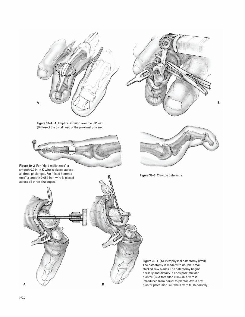
2 5 4
A B
A B
Figure 39–1 (A) Elliptical incision over the PIP joint.(B) Resect the distal head of the proximal phalanx.
Figure 39–2 For “rigid mallet toes” asmooth 0.054-in K-wire is placed acrossall three phalanges. For “fixed hammertoes” a smooth 0.054-in K-wire is placedacross all three phalanges.
Figure 39–3 Clawtoe deformity.
Figure 39–4 (A) Metaphyseal osteotomy (Weil).The osteotomy is made with double, smallstacked saw blades. The osteotomy beginsdorsally and distally. It ends proximal andplantar. (B) A threaded 0.062-in K-wire isintroduced from dorsal to plantar. Avoid anyplantar protrusion. Cut the K-wire flush dorsally.
For mild deformities, a separate incision maybe made over the MTP joint in order to releasethe dorsal capsule. For moderate claw toe defor-mities, the author prefers the Sarrafian extensortenodesis.
ii. Make a T-incision with the short limb at the PIP joint and the long limb proximal to the MTP joint.
iii. Incise the extensor mechanism at the MTPjoint level with the dorsal capsule.
iv. Free the periosteum, capsule, and extensormechanism from the lateral band from proxi-mal to distal.
v. Fold the extensor tendon and retract it distally.Resect the distal 5 to 6 mm of the proximalphalanx after incising the collateral ligaments.
vi. Make two transverse 0.045-in drill holes 1 cmapart through the proximal phalanx. Pass 3-0nonabsorbable suture through each pilot hole.
vii. Place an antegrade/retrograde 0.062-in K-wireacross the toe and all the joints.
viii. Hold the toe in zero degrees of extension at theDIP and PIP joints and the MTP in 20 degreesof flexion, while the ankle is held in neutralposition. The 3-0 nonabsorbable sutures, whichwere previously passed through the proximalphalanx, are sutured to the extensor tendonwhich is pulled proximally and then tied.
ix. The lateral bands are brought dorsally andsutured to the extensor tendon on both sides,both proximal and distal.
Closure3. The skin is then closed.
Optional (for transfer lesion of the metatarsal)Always check the adjacent metatarsals for transferlesions and treat as needed.
a. If the patient has a transfer lesion of the metatarsal,a plantar DuVries procedure may be performedprior to stabilizing the MTP joint. This is done by removing 25% of the plantar portion of themetatarsal head.
b. Alternatively, a shortening elevating, oblique, meta-physeal osteotomy (Weil) will achieve the same endas the DuVries condylectomy. If the patient has a rel-atively long second metatarsal with a transfer lesion,this additional step provides an excellent correction.
i. Double small saw blades are used stacked on oneanother. The osteotomy begins dorsally and dis-tally. It ends proximal and plantar (Fig. 39–4A).
ii. The head is shifted dorsally 2 to 3 mm and prox-imally 6 to 12 mm depending on the correction.
iii. A threaded 0.062-in K-wire is introduced fromdorsal to plantar. This should not protrude plan-tarly. It should be cut flush dorsally (Fig. 39–4B).
Suggested ReadingsSarrafian SK. Correction of fixed hammer toedeformities with resection of the heads of the proximalphalanx and extensor tendon tenodesis. Foot Ankle Int1995;16:449–451.
Watson AD, Anderson RB, Davis WH. Toe deformities.In: Kelikian AS, ed. Operative Treatment of the Foot andAnkle. Stamford, CT: Appleton & Lange, 1999, pp.99–115.
3 9 H A M M E R TO E C O R R E C T I O N 2 5 5
â Morton’s neuromas are felt to be secondary to per-ineural fibrosis that develops around the interdigi-tal nerve. About 90% of Morton’s neuromas occurin the third interspace.
â Only about 10% of Morton’s neuromas occur in thesecond interspace. Therefore, remember to considerother possible causes for metatarsalgia symptoms inthis area.
Indications1. Patients with Morton’s neuromas who have failed
nonoperative treatment (e.g., accommodative shoes,metatarsal pad, cortisone injection)
Contraindications1. Dysvascular disease2. Patients with conditions that may increase the risk
of wound healing problems (e.g., peripheral vascu-lar disease, diabetes mellitus, heavy tobacco use)(relative)
Preoperative Preparation1. If circulatory status is questionable (e.g., elderly
patients, diabetics, etc.), consider obtaining nonin-vasive arterial blood flow studies (with absolute toepressures).
2. Inform patients about permanent numbness ofaffected toes that results from successful neuromaexcision.
Special Instruments, Position, and Anesthesia1. The procedure can be done under an ankle block
with the use of monitored anesthesia care and intra-venous sedation. Alternatively, general or othermethods of regional anesthesia can be employed.
2. An ankle tourniquet (just above the malleoli) is uti-lized and set at 250 mm Hg.
3. A small laminar spreader, which can be placedbetween the respective metatarsals, facilitatesexposure.
Tips and Pearls1. Perform the ankle block prior to prepping and drap-
ing the extremity. This helps ensure that there is anadequate amount of time for the block to achieveoptimal effectiveness after it has been performed.
2. Elevating the limb for a couple of minutes beforetourniquet inflation can exsanguinate the foot.
3. When the proximal portion of the nerve is excised,be sure that a hemostat clamp is used to apply dis-tally directed longitudinal traction on the nerve. AFreer elevator can be used retract the soft tissuesproximally and then the nerve should be transectedsharply as proximal as possible within the wound.These efforts allow the proximal end of the cutnerve to retract proximally within the midfoot andthereby minimize the risk of developing a sympto-matic stump neuroma.
2 5 6
C H A P T E R 4 0
Morton’s Neuroma Excision
Steven Kodros
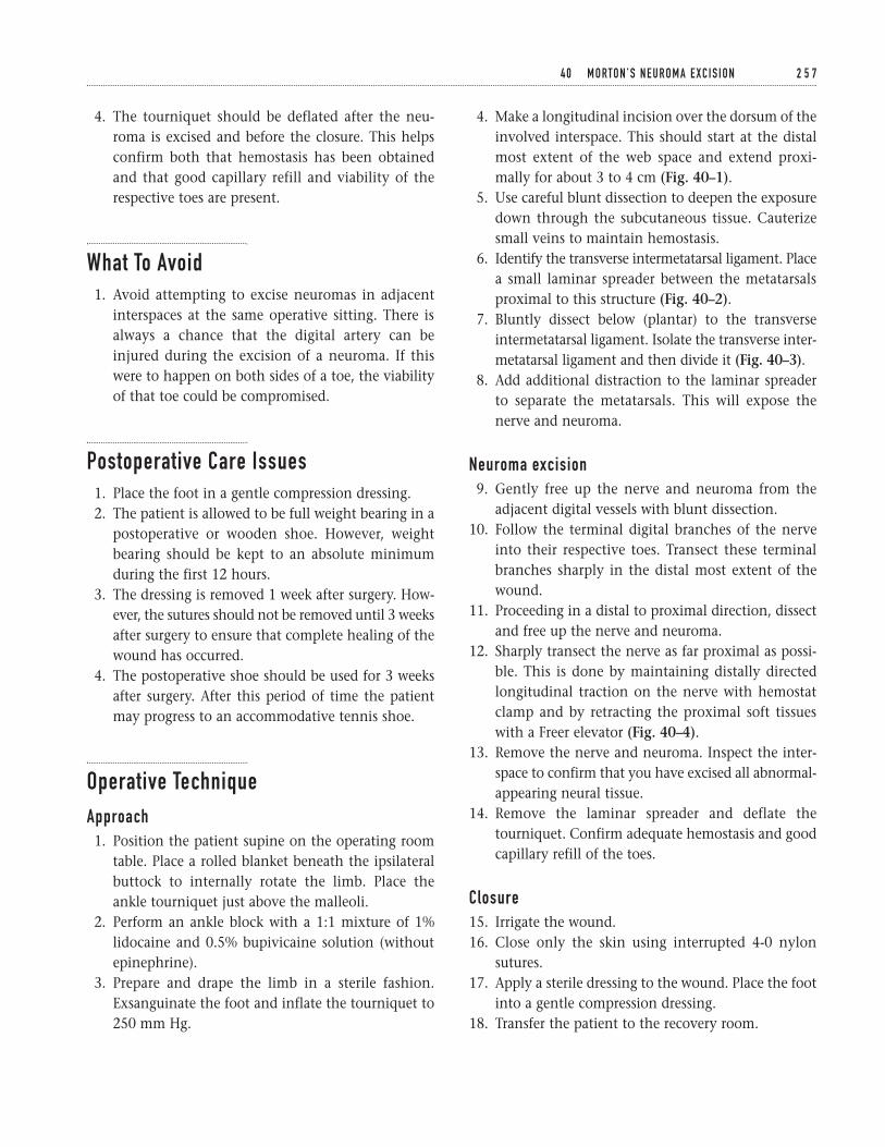
4. The tourniquet should be deflated after the neu-roma is excised and before the closure. This helpsconfirm both that hemostasis has been obtainedand that good capillary refill and viability of therespective toes are present.
What To Avoid1. Avoid attempting to excise neuromas in adjacent
interspaces at the same operative sitting. There isalways a chance that the digital artery can beinjured during the excision of a neuroma. If thiswere to happen on both sides of a toe, the viabilityof that toe could be compromised.
Postoperative Care Issues1. Place the foot in a gentle compression dressing.2. The patient is allowed to be full weight bearing in a
postoperative or wooden shoe. However, weightbearing should be kept to an absolute minimumduring the first 12 hours.
3. The dressing is removed 1 week after surgery. How-ever, the sutures should not be removed until 3 weeksafter surgery to ensure that complete healing of thewound has occurred.
4. The postoperative shoe should be used for 3 weeksafter surgery. After this period of time the patientmay progress to an accommodative tennis shoe.
Operative TechniqueApproach1. Position the patient supine on the operating room
table. Place a rolled blanket beneath the ipsilateralbuttock to internally rotate the limb. Place theankle tourniquet just above the malleoli.
2. Perform an ankle block with a 1:1 mixture of 1%lidocaine and 0.5% bupivicaine solution (withoutepinephrine).
3. Prepare and drape the limb in a sterile fashion.Exsanguinate the foot and inflate the tourniquet to250 mm Hg.
4. Make a longitudinal incision over the dorsum of theinvolved interspace. This should start at the distalmost extent of the web space and extend proxi-mally for about 3 to 4 cm (Fig. 40–1).
5. Use careful blunt dissection to deepen the exposuredown through the subcutaneous tissue. Cauterizesmall veins to maintain hemostasis.
6. Identify the transverse intermetatarsal ligament. Placea small laminar spreader between the metatarsalsproximal to this structure (Fig. 40–2).
7. Bluntly dissect below (plantar) to the transverseintermetatarsal ligament. Isolate the transverse inter-metatarsal ligament and then divide it (Fig. 40–3).
8. Add additional distraction to the laminar spreaderto separate the metatarsals. This will expose thenerve and neuroma.
Neuroma excision9. Gently free up the nerve and neuroma from the
adjacent digital vessels with blunt dissection.10. Follow the terminal digital branches of the nerve
into their respective toes. Transect these terminalbranches sharply in the distal most extent of thewound.
11. Proceeding in a distal to proximal direction, dissectand free up the nerve and neuroma.
12. Sharply transect the nerve as far proximal as possi-ble. This is done by maintaining distally directedlongitudinal traction on the nerve with hemostatclamp and by retracting the proximal soft tissueswith a Freer elevator (Fig. 40–4).
13. Remove the nerve and neuroma. Inspect the inter-space to confirm that you have excised all abnormal-appearing neural tissue.
14. Remove the laminar spreader and deflate thetourniquet. Confirm adequate hemostasis and goodcapillary refill of the toes.
Closure15. Irrigate the wound.16. Close only the skin using interrupted 4-0 nylon
sutures.17. Apply a sterile dressing to the wound. Place the foot
into a gentle compression dressing.18. Transfer the patient to the recovery room.
4 0 M O RTO N ’ S N E U R O M A E X C I S I O N 2 5 7
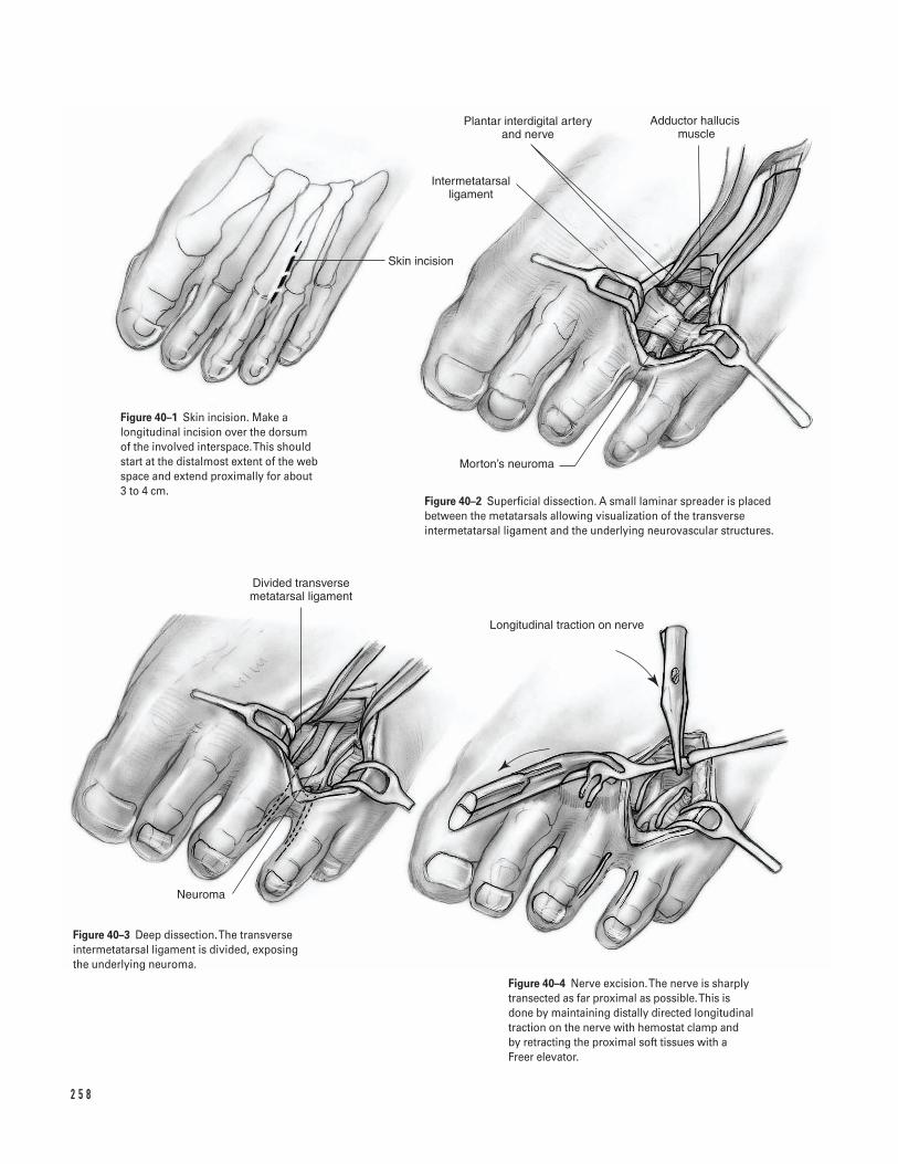
2 5 8
Skin incision
Intermetatarsal ligament
Plantar interdigital artery and nerve
Adductor hallucis muscle
Morton’s neuroma
Neuroma
Divided transverse metatarsal ligament
Longitudinal traction on nerve
Figure 40–1 Skin incision. Make alongitudinal incision over the dorsum of the involved interspace. This shouldstart at the distalmost extent of the webspace and extend proximally for about 3 to 4 cm.
Figure 40–2 Superficial dissection. A small laminar spreader is placedbetween the metatarsals allowing visualization of the transverseintermetatarsal ligament and the underlying neurovascular structures.
Figure 40–3 Deep dissection. The transverseintermetatarsal ligament is divided, exposing the underlying neuroma.
Figure 40–4 Nerve excision. The nerve is sharplytransected as far proximal as possible. This isdone by maintaining distally directed longitudinaltraction on the nerve with hemostat clamp and by retracting the proximal soft tissues with aFreer elevator.

Suggested ReadingsKodros SA. Armamentarium and implants. In: KelikianAS, ed. Operative Treatment of the Foot and Ankle. Stamford,CT: Appleton & Lange, 1999, pp. 53–60.
Kodros SA. Nerve entrapment. In: Kelikian AS, ed.Operative Treatment of the Foot and Ankle. Stamford, CT: Appleton & Lange, 1999, pp. 201–210.
4 0 M O RTO N ’ S N E U R O M A E X C I S I O N 2 5 9
â Jones fractures are transverse fractures located at theproximal metaphyseal-diaphyseal junction of thefifth metatarsal.
â Jones fractures have a much higher incidence ofdeveloping a symptomatic nonunion or fibrousunion than simple avulsion fractures of the fifthmetatarsal tuberosity (located more proximally)(Fig. 41–1).
â Commonly, nonoperative treatment includes ashort leg cast and non-weight-bearing for 6 to 8weeks. After this period, patients can be convertedto either a short leg brace or walking cast which ismaintained until fracture union has occurred (usu-ally another 6 to 8 weeks).
Indications1. Proximal fifth metatarsal (Jones) fractures that fail
to show progression toward bony union after treat-ment in a non-weight-bearing short-leg cast for 6 to8 weeks
2. Acute proximal fifth metatarsal (Jones) fractures inyoung athletic individuals who wish to shorten thetime to return to sport and minimize the prolonged
course of immobilization and rehabilitation that isassociated with nonoperative treatment
3. Proximal fifth metatarsal (Jones) fractures in patientswho desire surgical management, as opposed to non-operative treatment
4. Stress fractures, delayed unions, or nonunions ofthe proximal fifth metatarsal
Contraindications1. Medullary canal diameter that is too small to
accommodate an adequate-sized screw2. Patients with conditions that may increase the risk
of wound healing problems (e.g., peripheral vascu-lar disease, diabetes mellitus, heavy tobacco use)(relative)
Preoperative Preparation1. Determine the appropriate screw size by measuring
the width of the fifth metatarsal’s medullary canalon the preoperative radiographs. Commonly, ascrew that is between 4.5 and 6.5 mm in size willusually provide appropriate canal fill and purchaseand have adequate strength for internal fixation.
2 6 0
C H A P T E R 4 1
Proximal Fifth Metatarsal Jones Fractures
Internal Fixation
Steven Kodros
Special Instruments, Position, and Anesthesia1. A cannulated screw system will facilitate intra-
medullary screw placement when using a “rela-tively” percutaneous technique.
2. Intraoperative fluoroscopy and a radiolucent operat-ing table are necessary for accurate screw placement.
3. The patient is positioned supine on the operatingtable with a large padded roll placed beneath theipsilateral buttock. This helps to internally rotatethe affected extremity.
4. The procedure can be done under an ankle blockwith the use of monitored anesthesia care and intra-venous sedation. Alternatively, general or othermethods of regional anesthesia can be employed.
5. An ankle tourniquet (just above the malleoli) is uti-lized and set at 250 mm Hg.
Tips and Pearls1. Prior to the procedure, ensure that adequate fluoro-
scopic images of the fifth metatarsal can beobtained in multiple projections, including antero-posterior, lateral, and oblique views.
2. Prior to the skin incision, place a guide wire directlyover the shaft of the fifth metatarsal. Assess its posi-tion with fluoroscopic images in the anteroposte-rior and lateral planes. Use a marking pen to drawlines along the guide wire. These lines will help youto achieve proper placement of the intraoperativeintramedullary guide wire.
3. If the initial position of the intraoperative intra-medullary guide wire is undesirable, try to repositionit while spinning the drill in reverse (counterclock-wise). This helps to prevent the threaded tip of theguide wire from engaging the previous track.
4. If a solid intramedullary screw is desired, the guidewire and cannulated drill bit from a cannulatedscrew system can be used (if the cannulated drill bitis of the appropriate diameter) to facilitate accurateintramedullary placement of the hole.
5. If a fully threaded screw is used, the near (proximal)segment of the fifth metatarsal should be overdrilled to the diameter of the screw. This creates a
gliding hole and allows for interfragmentary com-pression across the fracture site.
What To Avoid1. Avoid using a screw with a diameter that is too large
for the medullary canal of the fifth metatarsal. Thiscan result in an iatrogenic fracture of the fifthmetatarsal.
2. Attempt to avoid injuring branches of the suralnerve and developing an incisional neuroma bybluntly dissecting through the subcutaneous tissue.
Postoperative Care Issues1. The extremity should be placed in a short-leg splint
or cast immediately after surgery. Strict non-weightbearing is maintained for the affected foot.
2. At 2 weeks postsurgery, the sutures are removed andthe extremity placed in a short leg brace. Early func-tional rehabilitation exercises for the foot and anklecan be started.
3. For acute fractures at 2 weeks postsurgery, weightbearing can be advanced as tolerated in the shortleg brace. At 6 weeks postsurgery, the short leg bracemay be discontinued if early fracture healing isapparent radiographically.
4. For nonunions and for some stress fractures, weightbearing should be deferred for approximately 4 to 6weeks postsurgery and the short leg brace contin-ued until follow-up radiographs show clear signs offracture healing.
Operative Technique1. Position the patient supine on the operating room
table. Place a rolled blanket beneath the ipsilateralbuttock to internally rotate the limb. Place theankle tourniquet just above the malleoli.
2. Perform an ankle block with a 1:1 mixture of 1%lidocaine and 0.5% bupivicaine solution (withoutepinephrine).
3. Prepare and drape the limb in a sterile fashion.Exsanguinate the foot and inflate the tourniquet to250 mm Hg.
4 1 P R O X I M A L F I F T H M E TATA R S A L J O N E S F R A C T U R E S 2 6 1
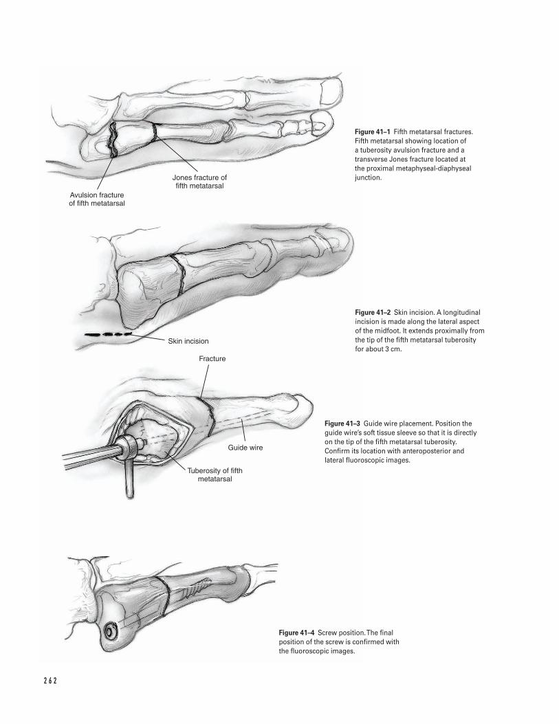
2 6 2
Avulsion fracture of fifth metatarsal
Jones fracture of fifth metatarsal
Skin incision
Fracture
Guide wire
Tuberosity of fifth metatarsal
Figure 41–1 Fifth metatarsal fractures.Fifth metatarsal showing location of a tuberosity avulsion fracture and atransverse Jones fracture located at the proximal metaphyseal-diaphysealjunction.
Figure 41–2 Skin incision. A longitudinalincision is made along the lateral aspectof the midfoot. It extends proximally fromthe tip of the fifth metatarsal tuberosityfor about 3 cm.
Figure 41–3 Guide wire placement. Position theguide wire’s soft tissue sleeve so that it is directlyon the tip of the fifth metatarsal tuberosity.Confirm its location with anteroposterior andlateral fluoroscopic images.
Figure 41–4 Screw position. The finalposition of the screw is confirmed withthe fluoroscopic images.
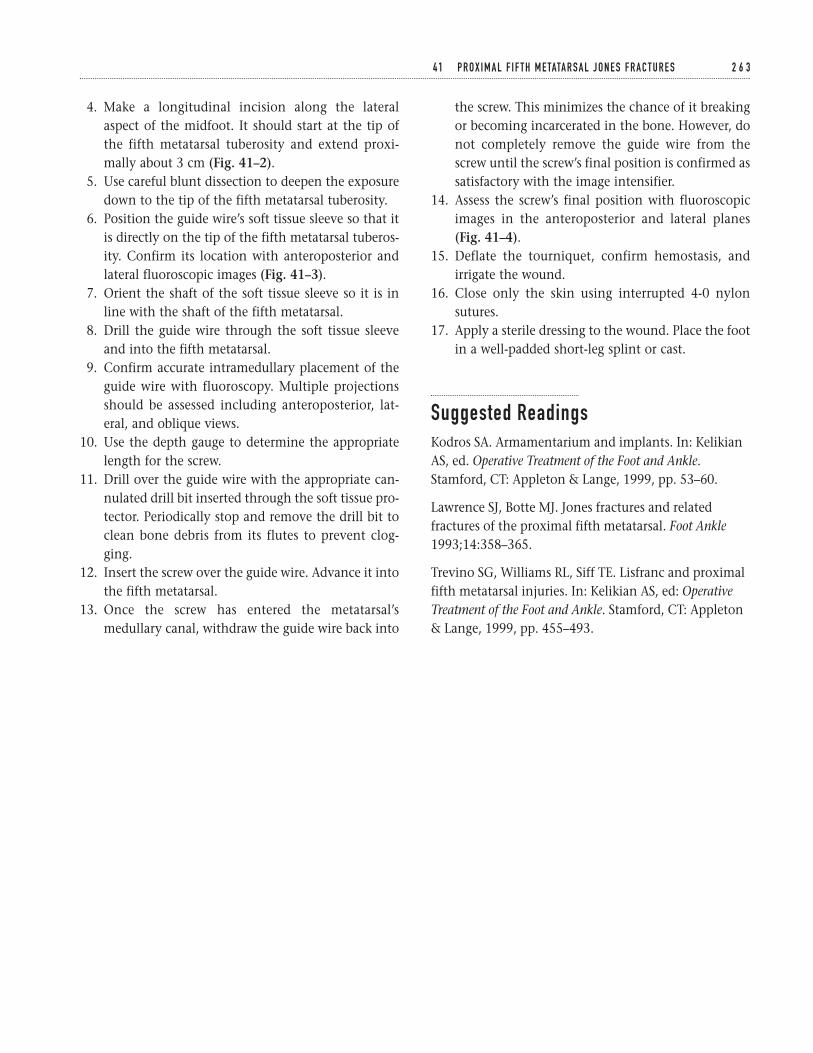
4. Make a longitudinal incision along the lateralaspect of the midfoot. It should start at the tip ofthe fifth metatarsal tuberosity and extend proxi-mally about 3 cm (Fig. 41–2).
5. Use careful blunt dissection to deepen the exposuredown to the tip of the fifth metatarsal tuberosity.
6. Position the guide wire’s soft tissue sleeve so that itis directly on the tip of the fifth metatarsal tuberos-ity. Confirm its location with anteroposterior andlateral fluoroscopic images (Fig. 41–3).
7. Orient the shaft of the soft tissue sleeve so it is inline with the shaft of the fifth metatarsal.
8. Drill the guide wire through the soft tissue sleeveand into the fifth metatarsal.
9. Confirm accurate intramedullary placement of theguide wire with fluoroscopy. Multiple projectionsshould be assessed including anteroposterior, lat-eral, and oblique views.
10. Use the depth gauge to determine the appropriatelength for the screw.
11. Drill over the guide wire with the appropriate can-nulated drill bit inserted through the soft tissue pro-tector. Periodically stop and remove the drill bit toclean bone debris from its flutes to prevent clog-ging.
12. Insert the screw over the guide wire. Advance it intothe fifth metatarsal.
13. Once the screw has entered the metatarsal’smedullary canal, withdraw the guide wire back into
the screw. This minimizes the chance of it breakingor becoming incarcerated in the bone. However, donot completely remove the guide wire from thescrew until the screw’s final position is confirmed assatisfactory with the image intensifier.
14. Assess the screw’s final position with fluoroscopicimages in the anteroposterior and lateral planes(Fig. 41–4).
15. Deflate the tourniquet, confirm hemostasis, andirrigate the wound.
16. Close only the skin using interrupted 4-0 nylonsutures.
17. Apply a sterile dressing to the wound. Place the footin a well-padded short-leg splint or cast.
Suggested ReadingsKodros SA. Armamentarium and implants. In: KelikianAS, ed. Operative Treatment of the Foot and Ankle.Stamford, CT: Appleton & Lange, 1999, pp. 53–60.
Lawrence SJ, Botte MJ. Jones fractures and relatedfractures of the proximal fifth metatarsal. Foot Ankle1993;14:358–365.
Trevino SG, Williams RL, Siff TE. Lisfranc and proximalfifth metatarsal injuries. In: Kelikian AS, ed: OperativeTreatment of the Foot and Ankle. Stamford, CT: Appleton& Lange, 1999, pp. 455–493.
4 1 P R O X I M A L F I F T H M E TATA R S A L J O N E S F R A C T U R E S 2 6 3

This page intentionally left blank
Key Techniques inOrthopaedic Surgery
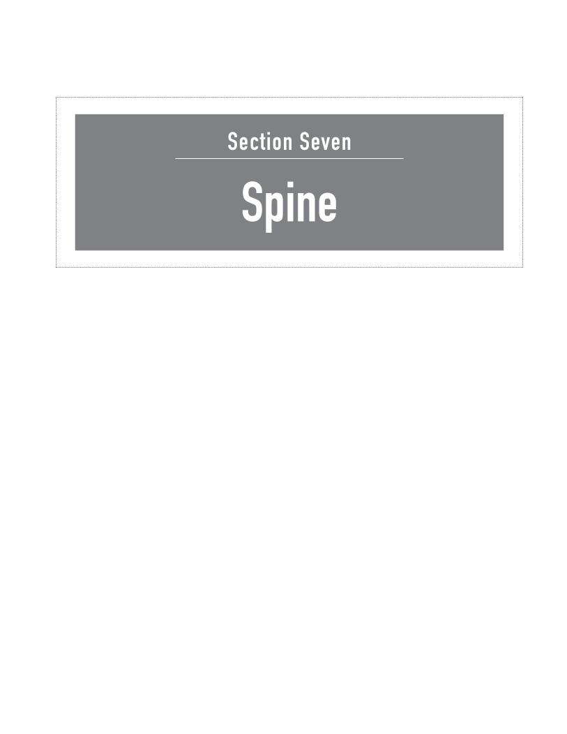
Section Seven
Spine

This page intentionally left blank
Key Techniques inOrthopaedic Surgery
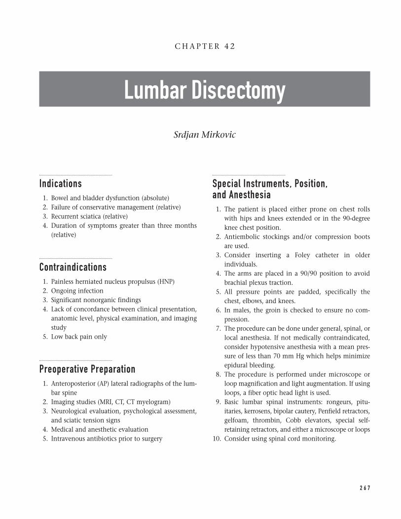
Indications1. Bowel and bladder dysfunction (absolute)2. Failure of conservative management (relative)3. Recurrent sciatica (relative)4. Duration of symptoms greater than three months
(relative)
Contraindications1. Painless herniated nucleus propulsus (HNP)2. Ongoing infection3. Significant nonorganic findings4. Lack of concordance between clinical presentation,
anatomic level, physical examination, and imagingstudy
5. Low back pain only
Preoperative Preparation1. Anteroposterior (AP) lateral radiographs of the lum-
bar spine2. Imaging studies (MRI, CT, CT myelogram)3. Neurological evaluation, psychological assessment,
and sciatic tension signs4. Medical and anesthetic evaluation5. Intravenous antibiotics prior to surgery
Special Instruments, Position, and Anesthesia1. The patient is placed either prone on chest rolls
with hips and knees extended or in the 90-degreeknee chest position.
2. Antiembolic stockings and/or compression bootsare used.
3. Consider inserting a Foley catheter in olderindividuals.
4. The arms are placed in a 90/90 position to avoidbrachial plexus traction.
5. All pressure points are padded, specifically thechest, elbows, and knees.
6. In males, the groin is checked to ensure no com-pression.
7. The procedure can be done under general, spinal, orlocal anesthesia. If not medically contraindicated,consider hypotensive anesthesia with a mean pres-sure of less than 70 mm Hg which helps minimizeepidural bleeding.
8. The procedure is performed under microscope orloop magnification and light augmentation. If usingloops, a fiber optic head light is used.
9. Basic lumbar spinal instruments: rongeurs, pitu-itaries, kerrosens, bipolar cautery, Penfield retractors,gelfoam, thrombin, Cobb elevators, special self-retaining retractors, and either a microscope or loops
10. Consider using spinal cord monitoring.
2 6 7
C H A P T E R 4 2
Lumbar Discectomy
Srdjan Mirkovic
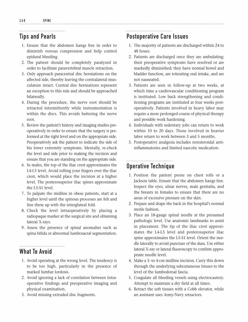
Tips and Pearls1. Ensure that the abdomen hangs free in order to
diminish venous compression and help controlepidural bleeding.
2. The patient should be completely paralyzed inorder to facilitate paravertebral muscle retraction.
3. Only approach paracentral disc herniations on theaffected side, thereby leaving the contralateral mus-culature intact. Central disc herniations representan exception to this rule and should be approachedbilaterally.
4. During the procedure, the nerve root should beretracted intermittently while instrumentation iswithin the discs. This avoids battering the nerveroot.
5. Review the patient’s history and imaging studies pre-operatively in order to ensure that the surgery is per-formed at the right level and on the appropriate side.Preoperatively ask the patient to indicate the side ofhis lower extremity symptoms. Mentally, re-checkthe level and side prior to making the incision andensure that you are standing on the appropriate side.
6. In males, the top of the iliac crest approximates theL4-L5 level. Avoid rolling your fingers over the iliaccrest, which would place the incision at a higherlevel. The posterosuperior iliac spines approximatethe L5-S1 level.
7. To palpate the midline in obese patients, start at ahigher level until the spinous processes are felt andline these up with the intergluteal fold.
8. Check the level intraoperatively by placing aradiopaque marker at the surgical site and obtaininglateral X-rays.
9. Assess the presence of spinal anomalies such asspina bifida or abnormal lumbosacral segmentation.
What To Avoid1. Avoid operating at the wrong level. The tendency is
to be too high, particularly in the presence ofmarked lumbar lordosis.
2. Avoid ignoring a lack of correlation between intra-operative findings and preoperative imaging andphysical examination.
3. Avoid missing extruded disc fragments.
Postoperative Care Issues1. The majority of patients are discharged within 24 to
48 hours.2. Patients are discharged once they are ambulating;
their preoperative symptoms have resolved or aremarkedly diminished; they have normal bowel andbladder function, are tolerating oral intake, and arenot nauseated.
3. Patients are seen in follow-up at two weeks, atwhich time a cardiovascular conditioning programis instituted. Low back strengthening and condi-tioning programs are instituted at four weeks post-operatively. Patients involved in heavy labor mayrequire a more prolonged course of physical therapyand possible work hardening.
4. Individuals with sedentary jobs can return to workwithin 10 to 20 days. Those involved in heavierlabor return to work between 3 and 5 months.
5. Postoperative analgesia includes nonsteroidal anti-inflammatories and limited narcotic medication.
Operative Technique1. Position the patient prone on chest rolls or a
Jackson table. Ensure that the abdomen hangs free.Inspect the eyes, ulnar nerves, male genitalia, andthe breasts in females to ensure that there are noareas of excessive pressure on the skin.
2. Prepare and drape the back in the hospital’s normalsterile fashion.
3. Place an 18-gauge spinal needle at the presumedpathologic level. Use anatomic landmarks to assistin placement. The tip of the iliac crest approxi-mates the L4-L5 level and posterosuperior iliacspine approximates the L5-S1 level. Orient the nee-dle laterally to avoid puncture of the dura. Use eitherlateral X-ray or lateral fluoroscopy to confirm appro-priate needle level.
4. Make a 3- to 4-cm midline incision. Carry this downthrough the underlying subcutaneous tissues to thelevel of the lumbodorsal fascia.
5. Coagulate all bleeding vessels using electrocautery.Attempt to maintain a dry field at all times.
6. Retract the soft tissues with a Cobb elevator, whilean assistant uses Army-Navy retractors.
2 6 8 S P I N E
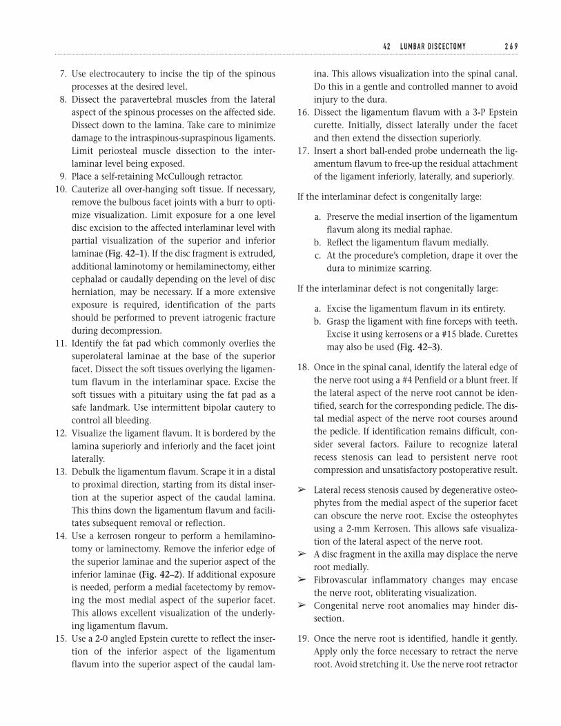
7. Use electrocautery to incise the tip of the spinousprocesses at the desired level.
8. Dissect the paravertebral muscles from the lateralaspect of the spinous processes on the affected side.Dissect down to the lamina. Take care to minimizedamage to the intraspinous-supraspinous ligaments.Limit periosteal muscle dissection to the inter-laminar level being exposed.
9. Place a self-retaining McCullough retractor.10. Cauterize all over-hanging soft tissue. If necessary,
remove the bulbous facet joints with a burr to opti-mize visualization. Limit exposure for a one leveldisc excision to the affected interlaminar level withpartial visualization of the superior and inferiorlaminae (Fig. 42–1). If the disc fragment is extruded,additional laminotomy or hemilaminectomy, eithercephalad or caudally depending on the level of discherniation, may be necessary. If a more extensiveexposure is required, identification of the partsshould be performed to prevent iatrogenic fractureduring decompression.
11. Identify the fat pad which commonly overlies thesuperolateral laminae at the base of the superiorfacet. Dissect the soft tissues overlying the ligamen-tum flavum in the interlaminar space. Excise thesoft tissues with a pituitary using the fat pad as asafe landmark. Use intermittent bipolar cautery tocontrol all bleeding.
12. Visualize the ligament flavum. It is bordered by thelamina superiorly and inferiorly and the facet jointlaterally.
13. Debulk the ligamentum flavum. Scrape it in a distalto proximal direction, starting from its distal inser-tion at the superior aspect of the caudal lamina.This thins down the ligamentum flavum and facili-tates subsequent removal or reflection.
14. Use a kerrosen rongeur to perform a hemilamino-tomy or laminectomy. Remove the inferior edge ofthe superior laminae and the superior aspect of theinferior laminae (Fig. 42–2). If additional exposureis needed, perform a medial facetectomy by remov-ing the most medial aspect of the superior facet.This allows excellent visualization of the underly-ing ligamentum flavum.
15. Use a 2-0 angled Epstein curette to reflect the inser-tion of the inferior aspect of the ligamentumflavum into the superior aspect of the caudal lam-
ina. This allows visualization into the spinal canal.Do this in a gentle and controlled manner to avoidinjury to the dura.
16. Dissect the ligamentum flavum with a 3-P Epsteincurette. Initially, dissect laterally under the facetand then extend the dissection superiorly.
17. Insert a short ball-ended probe underneath the lig-amentum flavum to free-up the residual attachmentof the ligament inferiorly, laterally, and superiorly.
If the interlaminar defect is congenitally large:
a. Preserve the medial insertion of the ligamentumflavum along its medial raphae.
b. Reflect the ligamentum flavum medially.c. At the procedure’s completion, drape it over the
dura to minimize scarring.
If the interlaminar defect is not congenitally large:
a. Excise the ligamentum flavum in its entirety.b. Grasp the ligament with fine forceps with teeth.
Excise it using kerrosens or a #15 blade. Curettesmay also be used (Fig. 42–3).
18. Once in the spinal canal, identify the lateral edge ofthe nerve root using a #4 Penfield or a blunt freer. Ifthe lateral aspect of the nerve root cannot be iden-tified, search for the corresponding pedicle. The dis-tal medial aspect of the nerve root courses aroundthe pedicle. If identification remains difficult, con-sider several factors. Failure to recognize lateralrecess stenosis can lead to persistent nerve rootcompression and unsatisfactory postoperative result.
â Lateral recess stenosis caused by degenerative osteo-phytes from the medial aspect of the superior facetcan obscure the nerve root. Excise the osteophytesusing a 2-mm Kerrosen. This allows safe visualiza-tion of the lateral aspect of the nerve root.
â A disc fragment in the axilla may displace the nerveroot medially.
â Fibrovascular inflammatory changes may encasethe nerve root, obliterating visualization.
â Congenital nerve root anomalies may hinder dis-section.
19. Once the nerve root is identified, handle it gently.Apply only the force necessary to retract the nerveroot. Avoid stretching it. Use the nerve root retractor
4 2 L U M BA R D I S C E C TO M Y 2 6 9
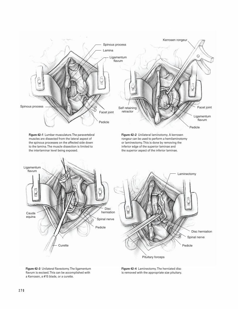
2 7 0
Pedicle
Ligamentum flavum
Facet joint
Kerrosen rongeur
Self retaining retractor
Pedicle
Facet joint
Ligamentum flavum
Lamina
Spinous process
Spinous process
Ligamentum flavum
Cauda equina
Curette
Pedicle
Spinal nerve
Disc herniation
Pituitary forceps
Laminectomy
Disc herniation
Spinal nerve
Pedicle
Figure 42–1 Lumbar musculature. The paravertebralmuscles are dissected from the lateral aspect ofthe spinous processes on the affected side downto the lamina. The muscle dissection is limited tothe interlaminar level being exposed.
Figure 42–2 Unilateral laminotomy. A kerrosenrongeur can be used to perform a hemilaminotomyor laminectomy. This is done by removing theinferior edge of the superior laminae and the superior aspect of the inferior laminae.
Figure 42–3 Unilateral flavectomy.The ligamentumflavum is excised. This can be accomplished witha Kerrosen, a #15 blade, or a curette.
Figure 42–4 Laminectomy.The herniated disc is removed with the appropriate size pituitary.
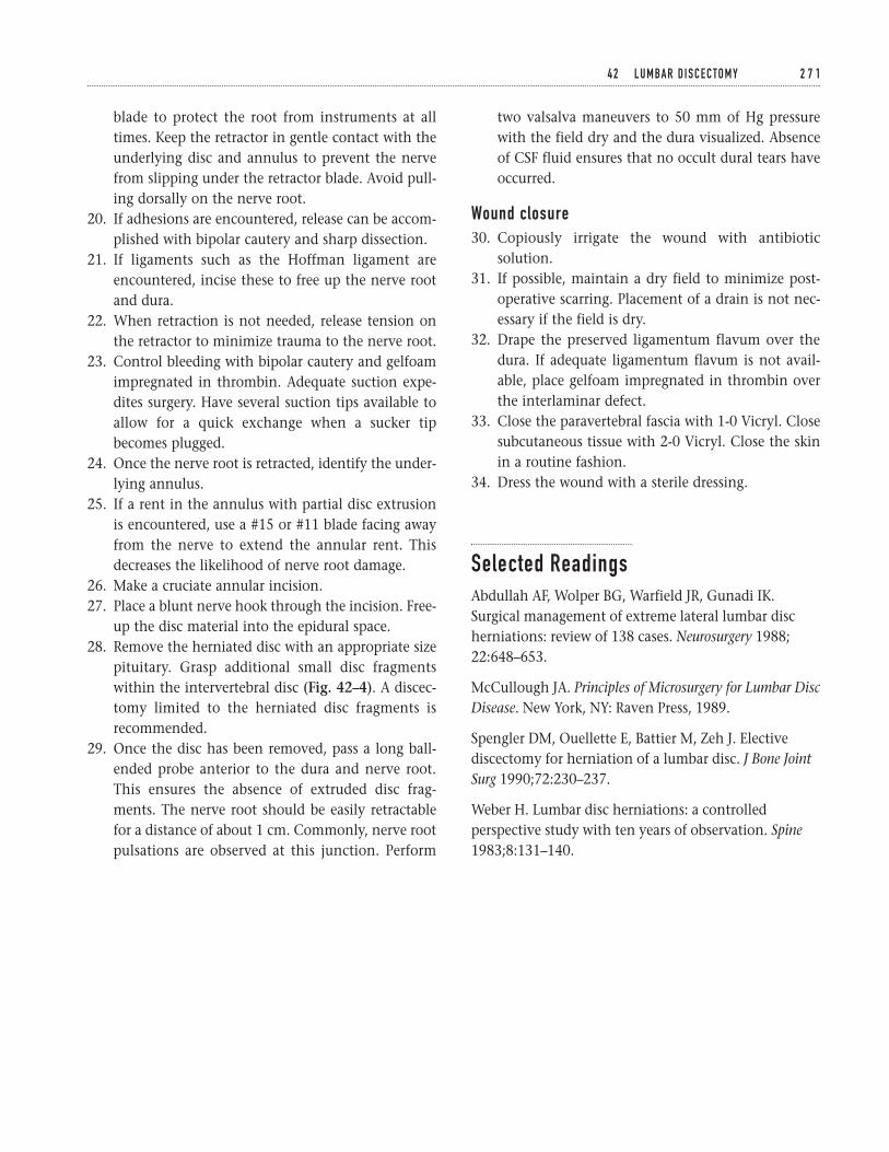
blade to protect the root from instruments at alltimes. Keep the retractor in gentle contact with theunderlying disc and annulus to prevent the nervefrom slipping under the retractor blade. Avoid pull-ing dorsally on the nerve root.
20. If adhesions are encountered, release can be accom-plished with bipolar cautery and sharp dissection.
21. If ligaments such as the Hoffman ligament areencountered, incise these to free up the nerve rootand dura.
22. When retraction is not needed, release tension onthe retractor to minimize trauma to the nerve root.
23. Control bleeding with bipolar cautery and gelfoamimpregnated in thrombin. Adequate suction expe-dites surgery. Have several suction tips available toallow for a quick exchange when a sucker tipbecomes plugged.
24. Once the nerve root is retracted, identify the under-lying annulus.
25. If a rent in the annulus with partial disc extrusionis encountered, use a #15 or #11 blade facing awayfrom the nerve to extend the annular rent. Thisdecreases the likelihood of nerve root damage.
26. Make a cruciate annular incision.27. Place a blunt nerve hook through the incision. Free-
up the disc material into the epidural space.28. Remove the herniated disc with an appropriate size
pituitary. Grasp additional small disc fragmentswithin the intervertebral disc (Fig. 42–4). A discec-tomy limited to the herniated disc fragments isrecommended.
29. Once the disc has been removed, pass a long ball-ended probe anterior to the dura and nerve root.This ensures the absence of extruded disc frag-ments. The nerve root should be easily retractablefor a distance of about 1 cm. Commonly, nerve rootpulsations are observed at this junction. Perform
two valsalva maneuvers to 50 mm of Hg pressurewith the field dry and the dura visualized. Absenceof CSF fluid ensures that no occult dural tears haveoccurred.
Wound closure30. Copiously irrigate the wound with antibiotic
solution.31. If possible, maintain a dry field to minimize post-
operative scarring. Placement of a drain is not nec-essary if the field is dry.
32. Drape the preserved ligamentum flavum over thedura. If adequate ligamentum flavum is not avail-able, place gelfoam impregnated in thrombin overthe interlaminar defect.
33. Close the paravertebral fascia with 1-0 Vicryl. Closesubcutaneous tissue with 2-0 Vicryl. Close the skinin a routine fashion.
34. Dress the wound with a sterile dressing.
Selected ReadingsAbdullah AF, Wolper BG, Warfield JR, Gunadi IK.Surgical management of extreme lateral lumbar discherniations: review of 138 cases. Neurosurgery 1988;22:648–653.
McCullough JA. Principles of Microsurgery for Lumbar DiscDisease. New York, NY: Raven Press, 1989.
Spengler DM, Ouellette E, Battier M, Zeh J. Electivediscectomy for herniation of a lumbar disc. J Bone JointSurg 1990;72:230–237.
Weber H. Lumbar disc herniations: a controlledperspective study with ten years of observation. Spine1983;8:131–140.
4 2 L U M BA R D I S C E C TO M Y 2 7 1
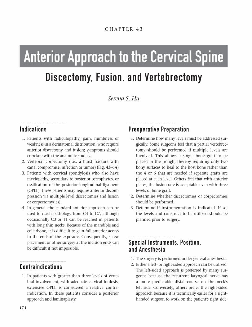
Indications1. Patients with radiculopathy, pain, numbness or
weakness in a dermatomal distribution, who requireanterior discectomy and fusion; symptoms shouldcorrelate with the anatomic studies.
2. Vertebral corpectomy (i.e., a burst fracture withcanal compromise, infection or tumor) (Fig. 43–6A)
3. Patients with cervical spondylosis who also havemyelopathy, secondary to posterior osteophytes, orossification of the posterior longitudinal ligament(OPLL); these patients may require anterior decom-pression via multiple level discectomies and fusionor corpectomy(ies).
4. In general, the standard anterior approach can beused to reach pathology from C4 to C7, althoughoccasionally C3 or T1 can be reached in patientswith long thin necks. Because of the mandible andcollarbone, it is difficult to gain full anterior accessto the ends of the exposure. Consequently, screwplacement or other surgery at the incision ends canbe difficult if not impossible.
Contraindications1. In patients with greater than three levels of verte-
bral involvement, with adequate cervical lordosis,extensive OPLL is considered a relative contra-indication. In these patients consider a posteriorapproach and laminaplasty.
Preoperative Preparation1. Determine how many levels must be addressed sur-
gically. Some surgeons feel that a partial vertebrec-tomy should be performed if multiple levels areinvolved. This allows a single bone graft to beplaced in the trough, thereby requiring only twobony surfaces to heal to the host bone rather thanthe 4 or 6 that are needed if separate grafts areplaced at each level. Others feel that with anteriorplates, the fusion rate is acceptable even with threelevels of bone graft.
2. Determine whether discectomies or corpectomiesshould be performed.
3. Determine if instrumentation is indicated. If so, the levels and construct to be utilized should beplanned prior to surgery.
Special Instruments, Position, and Anesthesia1. The surgery is performed under general anesthesia.2. Either a left- or right-sided approach can be utilized.
The left-sided approach is preferred by many sur-geons because the recurrent laryngeal nerve has a more predictable distal course on the neck’sleft side. Conversely, others prefer the right-sidedapproach because it is technically easier for a right-handed surgeon to work on the patient’s right side.
2 7 2
C H A P T E R 4 3
Anterior Approach to the Cervical SpineDiscectomy, Fusion, and Vertebrectomy
Serena S. Hu
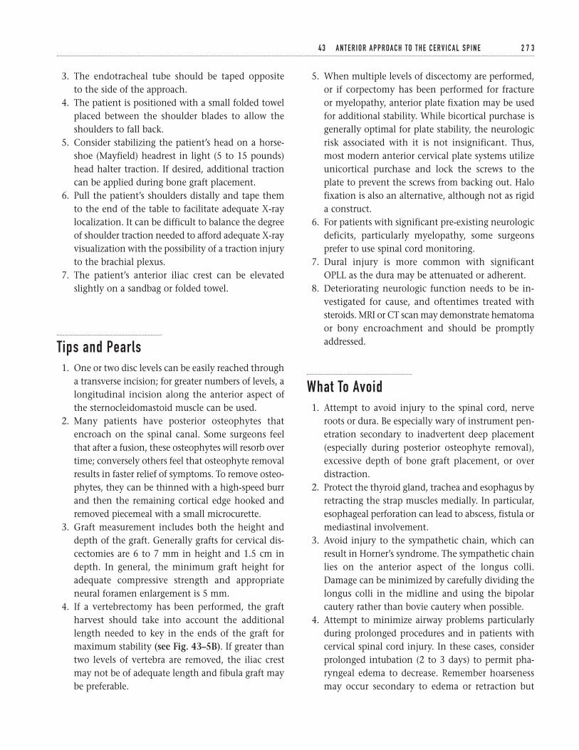
3. The endotracheal tube should be taped opposite to the side of the approach.
4. The patient is positioned with a small folded towelplaced between the shoulder blades to allow theshoulders to fall back.
5. Consider stabilizing the patient’s head on a horse-shoe (Mayfield) headrest in light (5 to 15 pounds)head halter traction. If desired, additional tractioncan be applied during bone graft placement.
6. Pull the patient’s shoulders distally and tape themto the end of the table to facilitate adequate X-raylocalization. It can be difficult to balance the degreeof shoulder traction needed to afford adequate X-rayvisualization with the possibility of a traction injuryto the brachial plexus.
7. The patient’s anterior iliac crest can be elevatedslightly on a sandbag or folded towel.
Tips and Pearls1. One or two disc levels can be easily reached through
a transverse incision; for greater numbers of levels, alongitudinal incision along the anterior aspect ofthe sternocleidomastoid muscle can be used.
2. Many patients have posterior osteophytes thatencroach on the spinal canal. Some surgeons feelthat after a fusion, these osteophytes will resorb overtime; conversely others feel that osteophyte removalresults in faster relief of symptoms. To remove osteo-phytes, they can be thinned with a high-speed burrand then the remaining cortical edge hooked andremoved piecemeal with a small microcurette.
3. Graft measurement includes both the height anddepth of the graft. Generally grafts for cervical dis-cectomies are 6 to 7 mm in height and 1.5 cm indepth. In general, the minimum graft height foradequate compressive strength and appropriateneural foramen enlargement is 5 mm.
4. If a vertebrectomy has been performed, the graftharvest should take into account the additionallength needed to key in the ends of the graft formaximum stability (see Fig. 43–5B). If greater thantwo levels of vertebra are removed, the iliac crestmay not be of adequate length and fibula graft maybe preferable.
5. When multiple levels of discectomy are performed,or if corpectomy has been performed for fracture or myelopathy, anterior plate fixation may be usedfor additional stability. While bicortical purchase isgenerally optimal for plate stability, the neurologicrisk associated with it is not insignificant. Thus,most modern anterior cervical plate systems utilizeunicortical purchase and lock the screws to theplate to prevent the screws from backing out. Halofixation is also an alternative, although not as rigida construct.
6. For patients with significant pre-existing neurologicdeficits, particularly myelopathy, some surgeonsprefer to use spinal cord monitoring.
7. Dural injury is more common with significantOPLL as the dura may be attenuated or adherent.
8. Deteriorating neurologic function needs to be in-vestigated for cause, and oftentimes treated withsteroids. MRI or CT scan may demonstrate hematomaor bony encroachment and should be promptlyaddressed.
What To Avoid1. Attempt to avoid injury to the spinal cord, nerve
roots or dura. Be especially wary of instrument pen-etration secondary to inadvertent deep placement(especially during posterior osteophyte removal),excessive depth of bone graft placement, or overdistraction.
2. Protect the thyroid gland, trachea and esophagus byretracting the strap muscles medially. In particular,esophageal perforation can lead to abscess, fistula ormediastinal involvement.
3. Avoid injury to the sympathetic chain, which canresult in Horner’s syndrome. The sympathetic chainlies on the anterior aspect of the longus colli.Damage can be minimized by carefully dividing thelongus colli in the midline and using the bipolarcautery rather than bovie cautery when possible.
4. Attempt to minimize airway problems particularlyduring prolonged procedures and in patients withcervical spinal cord injury. In these cases, considerprolonged intubation (2 to 3 days) to permit pha-ryngeal edema to decrease. Remember hoarsenessmay occur secondary to edema or retraction but
4 3 A N T E R I O R A P P R OA C H TO T H E C E R V I C A L S P I N E 2 7 3
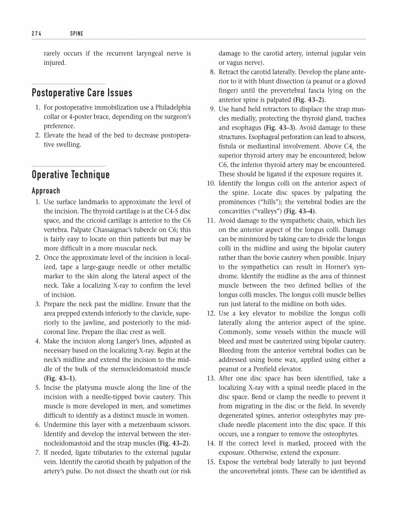
rarely occurs if the recurrent laryngeal nerve isinjured.
Postoperative Care Issues1. For postoperative immobilization use a Philadelphia
collar or 4-poster brace, depending on the surgeon’spreference.
2. Elevate the head of the bed to decrease postopera-tive swelling.
Operative TechniqueApproach1. Use surface landmarks to approximate the level of
the incision. The thyroid cartilage is at the C4-5 discspace, and the cricoid cartilage is anterior to the C6vertebra. Palpate Chassaignac’s tubercle on C6; thisis fairly easy to locate on thin patients but may bemore difficult in a more muscular neck.
2. Once the approximate level of the incision is local-ized, tape a large-gauge needle or other metallicmarker to the skin along the lateral aspect of theneck. Take a localizing X-ray to confirm the level of incision.
3. Prepare the neck past the midline. Ensure that thearea prepped extends inferiorly to the clavicle, supe-riorly to the jawline, and posteriorly to the mid-coronal line. Prepare the iliac crest as well.
4. Make the incision along Langer’s lines, adjusted asnecessary based on the localizing X-ray. Begin at theneck’s midline and extend the incision to the mid-dle of the bulk of the sternocleidomastoid muscle(Fig. 43–1).
5. Incise the platysma muscle along the line of theincision with a needle-tipped bovie cautery. Thismuscle is more developed in men, and sometimesdifficult to identify as a distinct muscle in women.
6. Undermine this layer with a metzenbaum scissors.Identify and develop the interval between the ster-nocleidomastoid and the strap muscles (Fig. 43–2).
7. If needed, ligate tributaries to the external jugularvein. Identify the carotid sheath by palpation of theartery’s pulse. Do not dissect the sheath out (or risk
damage to the carotid artery, internal jugular veinor vagus nerve).
8. Retract the carotid laterally. Develop the plane ante-rior to it with blunt dissection (a peanut or a glovedfinger) until the prevertebral fascia lying on theanterior spine is palpated (Fig. 43–2).
9. Use hand held retractors to displace the strap mus-cles medially, protecting the thyroid gland, tracheaand esophagus (Fig. 43–3). Avoid damage to thesestructures. Esophageal perforation can lead to abscess,fistula or mediastinal involvement. Above C4, thesuperior thyroid artery may be encountered; belowC6, the inferior thyroid artery may be encountered.These should be ligated if the exposure requires it.
10. Identify the longus colli on the anterior aspect ofthe spine. Locate disc spaces by palpating theprominences (“hills”); the vertebral bodies are theconcavities (“valleys”) (Fig. 43–4).
11. Avoid damage to the sympathetic chain, which lieson the anterior aspect of the longus colli. Damagecan be minimized by taking care to divide the longuscolli in the midline and using the bipolar cauteryrather than the bovie cautery when possible. Injuryto the sympathetics can result in Horner’s syn-drome. Identify the midline as the area of thinnestmuscle between the two defined bellies of thelongus colli muscles. The longus colli muscle belliesrun just lateral to the midline on both sides.
12. Use a key elevator to mobilize the longus collilaterally along the anterior aspect of the spine.Commonly, some vessels within the muscle willbleed and must be cauterized using bipolar cautery.Bleeding from the anterior vertebral bodies can beaddressed using bone wax, applied using either apeanut or a Penfield elevator.
13. After one disc space has been identified, take alocalizing X-ray with a spinal needle placed in thedisc space. Bend or clamp the needle to prevent itfrom migrating in the disc or the field. In severelydegenerated spines, anterior osteophytes may pre-clude needle placement into the disc space. If thisoccurs, use a ronguer to remove the osteophytes.
14. If the correct level is marked, proceed with theexposure. Otherwise, extend the exposure.
15. Expose the vertebral body laterally to just beyondthe uncovertebral joints. These can be identified as
2 7 4 S P I N E
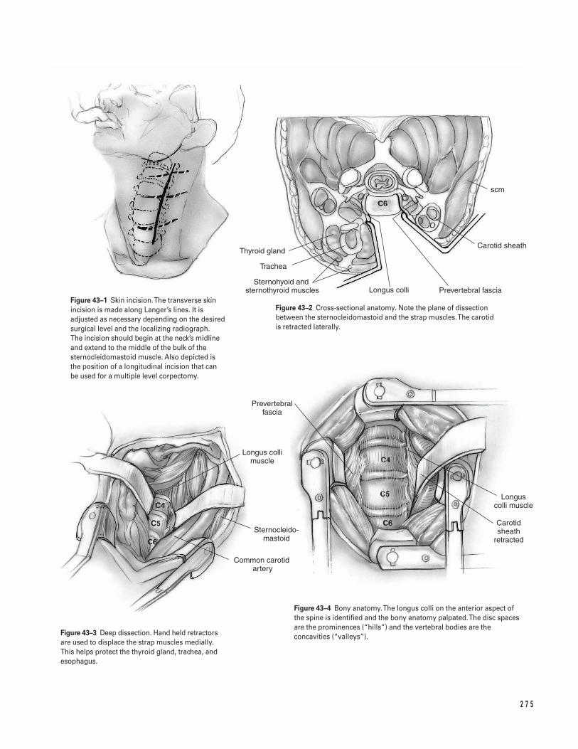
2 7 5
Thyroid gland
Trachea
Sternohyoid and �sternothyroid muscles Longus colli Prevertebral fascia
Carotid sheath
scm
Longus colli muscle
Sternocleido- mastoid
Common carotid artery
Prevertebral fascia
Carotid sheath
retracted
Longus colli muscle
Figure 43–1 Skin incision. The transverse skinincision is made along Langer’s lines. It isadjusted as necessary depending on the desiredsurgical level and the localizing radiograph. The incision should begin at the neck’s midlineand extend to the middle of the bulk of thesternocleidomastoid muscle. Also depicted is the position of a longitudinal incision that can be used for a multiple level corpectomy.
Figure 43–2 Cross-sectional anatomy. Note the plane of dissectionbetween the sternocleidomastoid and the strap muscles. The carotid is retracted laterally.
Figure 43–3 Deep dissection. Hand held retractorsare used to displace the strap muscles medially.This helps protect the thyroid gland, trachea, andesophagus.
Figure 43–4 Bony anatomy. The longus colli on the anterior aspect ofthe spine is identified and the bony anatomy palpated. The disc spacesare the prominences (“hills”) and the vertebral bodies are theconcavities (“valleys”).
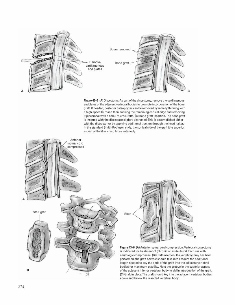
2 7 6
Remove cartilagenous
end plates
Spurs removed
Bone graft
Anterior spinal cord
compressed
Strut graft Slots
A B
A
B
C
Figure 43–5 (A) Discectomy. As part of the discectomy, remove the cartilagenousendplates of the adjacent vertebral bodies to promote incorporation of the bonegraft. If needed, posterior osteophytes can be removed by initially thinning witha high-speed burr and then hooking the remaining cortical edge and removingit piecemeal with a small microcurette. (B) Bone graft insertion. The bone graftis inserted with the disc space slightly distracted. This is accomplished eitherwith the distractor or by applying additional traction through the head halter.In the standard Smith-Robinson style, the cortical side of the graft (the superioraspect of the iliac crest) faces anteriorly.
Figure 43–6 (A) Anterior spinal cord compression. Vertebral corpectomyis indicated for treatment of (chronic or acute) burst fractures withneurologic compromise. (B) Graft insertion. If a vertebrectomy has beenperformed, the graft harvest should take into account the additionallength needed to key the ends of the graft into the adjacent vertebralbodies for maximum stability. Note the groove in the superior aspectof the adjacent inferior vertebral body to aid in introduction of the graft.(C) Graft in place. The graft should key into the adjacent vertebral bodiesabove and below the resected vertebral body.
the anterior body slants more posteriorly. If noinstrumentation is planned, as with the majority of single level discectomies, only half the adjacentvertebral body above and below need be exposed. Ifplating is planned, as may be indicated for multiplelevel fusions, burst fractures, or corpectomies, theentire adjacent vertebral bodies should be exposedso that the margin of the adjacent disc space can be identified.
16. Place self-retaining Cloward retractors. Use thetoothed blades to retract the longus colli muscleand the smooth blades for longitudinal exposure.
17. Incise the disc space with a 15-blade scalpel. Re-move the disc material using a pituitary ronguerand curved and straight microcurettes.
18. Use magnification (lupes or microscope) after theinitial stages of the discectomy even if they havenot been used since the beginning of the case. Ifavailable, a distractor utilizing pins placed into thevertebral body above and below enhances exposureand graft placement. Avoid straying beyond ordeeper than the vertebral body by ensuring that thecurette is used against bone at all times.
19. Perform the discectomy into the uncovertebraljoints, which can be identified as they angle cepha-lad relative to the endplate.
20. Palpate the posterior edge of the vertebral bodywith the curette or a small nerve hook. Identify theposterior longitudinal ligament. The longitudinally-running fibers are easily discernible from the morecircumferentially-running annular fibers of the disc.It is not necessary to incise the PLL. However, if asoft disc protrusion was noted on the preoperativeMRI or if a rent in the PLL is encountered, gentlyintroduce a small nerve hook. This facilitates re-moval of the extruded fragment, or allows the rentin the PLL to be enlarged permitting direct view ofthe fragment for removal.
21. If desired, remove posterior osteophytes by initiallythinning with a high-speed burr, and then hookingthe remaining cortical edge and removing it piece-meal with a small microcurette (Fig. 43–5A).
22. If only discectomies are to be performed, proceed tothe next disc or bone graft harvesting. Use gelfoamto slow slight endplate-oozing while working else-where.
Vertebrectomy (optional)â Vertebral corpectomy is indicated for treatment of
(chronic or acute) burst fractures with neurologiccompromise (Fig. 43–6A).
a. Identify and partially remove the two adjacentdiscs.
b. Remove the anterior portion of the vertebralbody with a ronguer.
c. Use a high-speed burr to remove the posterioraspect of the vertebral body. Consider changingto a diamond-tipped burr, which is less likely tocut the dura, as dissection proceeds nearer to thedenser cortical bone of the posterior vertebralbody.
d. Once the posterior cortex is thinned to a fineshell with a developed edge, use a microcuretteto gently lift the shell away from the dura andspinal cord.
23. After the decompression has been completed, relaxthe self-retaining retractors.
I l iac crest bone graft harvest24. Measure the defect to be filled using either calipers
or a paper ruler. Harvest a tricortical graft (Smith-Robinson technique). Graft measurement shouldinclude both the height and depth of the graft.Commonly, grafts for cervical discectomies are 6 to7 mm in height and 1.5 cm in depth. In general, theminimum graft height for adequate compressivestrength and appropriate neural foramen enlarge-ment is 5 mm. If a vertebrectomy has been per-formed, the graft harvest should take into accountthe additional length needed to key in the ends of thegraft for maximum stability (Figs. 43–6B and 6C). Ifgreater than two levels of vertebra are removed, theiliac crest may not support a graft of adequate lengthand a fibula graft may be preferable.
25. Exposed the iliac crest in a routine fashion.26. Leave an adequate margin from the anterior supe-
rior iliac crest to minimize the risk of avulsion fractures (normally, at least 1 in) and harvest thestructural graft using an oscillating saw.
27. If separate grafts are to be used in the disc spaces, itis usually easier to cut the pieces separately from the crest. After the first cut has been made, place a
4 3 A N T E R I O R A P P R OA C H TO T H E C E R V I C A L S P I N E 2 7 7
narrow osteotome in the slot so that the second cutparallels the first. Make the deep transverse cut witha curved osteotome after all the vertical cuts havebeen completed. Hold the grafts before this last stepto prevent inadvertent loss of the graft.
28. Pack this incision for later simultaneous closure.Prior to closure, smooth the sharp edges of the cutiliac crest with a ronguer and bone wax or gelfoamto decrease bleeding.
Bone graft placement29. Respread the self-retaining retractors within the neck
wound. Ensure that the sharp teeth are still nestledwithin the muscle substance of the longus colli.
30. Burr the endplates to bleeding bone (Fig. 43–5A).31. Place the graft with the disc space slightly dis-
tracted, either using the distractor or by applyingadditional traction through the head halter. In thestandard Smith-Robinson style, the cortical side ofthe graft (the superior aspect of the iliac crest) facesanteriorly (Fig. 43–5B).
32. Gently impact the graft into place and countersinkit a couple of millimeters.
33. Obtain a lateral radiograph to assess graft position.34. If a vertebrectomy has been performed, the graft har-
vest should take into account the additional lengthneeded to key in the ends of the graft for maximumstability (Figs. 43–6B and 6C). If greater than twolevels of vertebra are removed, the iliac crest may nothave adequate length and a fibula is preferred.
Closure35. Close the surgical site with interrupted sutures
attempting to allow egress of blood to minimize therisk of hematoma formation. Rarely, airway or neu-rologic compromise occurs secondary to hematomapressure. Consider placing a small Jackson-Pratt orPenrose-type drain overnight to decrease this risk.
36. Reapproximate the sternocleidomastoid muscle tothe strap muscles with one or two sutures.
37. Close the platysma with interrupted sutures.38. Close the skin with intracuticular sutures or staples.
If intracuticular sutures are used, the suture shouldbe able to slide in order to facilitate prompt removalif necessary.
Suggested ReadingsEmery SE, Smith MD, Bohlman HH. Upper airwayobstruction after multilevel cervical corpectomy formyelopathy. J Bone Joint Surg 1991;73A:544–551.
Flynn TB. Neurologic complications of anterior cervicalinterbody fusion. Spine 1982;7:536–539.
White A III, Jupiter J, Southwick WO, Panjabi MM. Anexperimental study of the immediate load bearing ofthree surgical constructions for anterior spine fusions.Clin Orthop 1973;91:21–28.
2 7 8 S P I N E
Indications1. Incapacitating discogenic low back pain2. Spinal stenosis with instability3. Spondylolisthesis4. Scoliosis or kyphosis5. Pseudoarthrosis6. Instability adjacent to a previous fusion7. Re-do lumbar discectomy.
Contraindications1. Spinal stenosis without deformity or known risk for
deformity2. Primary discectomy3. Low back pain associated with multi-level degener-
ative disc disease
Preoperative Preparation1. Medical and anesthetic evaluation2. Anteroposterior (AP), lateral, oblique, and flexion
extension X-rays3. Lumbar imaging (MRI, CT myelography)4. Consider electrodiagnostic studies.5. Consider preoperative diagnostic studies (facet blocks,
SI blocks, discograms, nerve root blocks).6. Preoperative neurovascular assessment7. Attempt to establish realistic expectations.
8. Encourage the patient to discontinue smoking. Ifpossible, cessation of smoking should occur 6 monthsprior to the fusion.
Special Instruments, Position, and Anesthesia1. The prone position is used for posterior spinal
fusions.2. Position the hips in neutral or slight extension.
This helps maintain lumbar lordosis, which isimperative.
3. All pressure points should be carefully padded. Theabdomen and genitalia (in males) should hang free.The arms must be placed in a 90/90 position toavoid brachial plexus traction injury. The ulnarnerve should be protected.
4. The lower extremities are placed in anti-embolicstockings and compression boots.
5. Spinal cord monitoring may be used.6. X-rays and fluoroscopy should be available for veri-
fication of the appropriate level and in the case ofinstrumentation, to verify appropriate instrumenta-tion placement.
7. If fluoroscopy is to be used, the undersurface of thetable should be free to allow C-arm rotation.
8. Use specific instrumentation for planned spinalhardware.
9. In revision fusion surgery, determine prior to sur-gery which iliac crest(s) were harvested.
2 7 9
C H A P T E R 4 4
Lumbar Spine Fusion
Srdjan Mirkovic
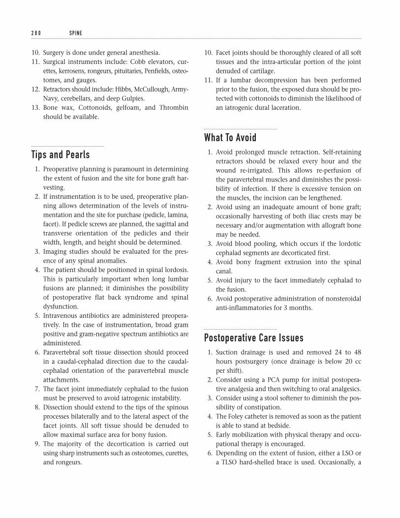
10. Surgery is done under general anesthesia.11. Surgical instruments include: Cobb elevators, cur-
ettes, kerrosens, rongeurs, pituitaries, Penfields, osteo-tomes, and gauges.
12. Retractors should include: Hibbs, McCullough, Army-Navy, cerebellars, and deep Gulpies.
13. Bone wax, Cottonoids, gelfoam, and Thrombinshould be available.
Tips and Pearls1. Preoperative planning is paramount in determining
the extent of fusion and the site for bone graft har-vesting.
2. If instrumentation is to be used, preoperative plan-ning allows determination of the levels of instru-mentation and the site for purchase (pedicle, lamina,facet). If pedicle screws are planned, the sagittal andtransverse orientation of the pedicles and theirwidth, length, and height should be determined.
3. Imaging studies should be evaluated for the pres-ence of any spinal anomalies.
4. The patient should be positioned in spinal lordosis.This is particularly important when long lumbarfusions are planned; it diminishes the possibility of postoperative flat back syndrome and spinaldysfunction.
5. Intravenous antibiotics are administered preopera-tively. In the case of instrumentation, broad grampositive and gram-negative spectrum antibiotics areadministered.
6. Paravertebral soft tissue dissection should proceedin a caudal-cephalad direction due to the caudal-cephalad orientation of the paravertebral muscleattachments.
7. The facet joint immediately cephalad to the fusionmust be preserved to avoid iatrogenic instability.
8. Dissection should extend to the tips of the spinousprocesses bilaterally and to the lateral aspect of thefacet joints. All soft tissue should be denuded toallow maximal surface area for bony fusion.
9. The majority of the decortication is carried outusing sharp instruments such as osteotomes, curettes,and rongeurs.
10. Facet joints should be thoroughly cleared of all softtissues and the intra-articular portion of the jointdenuded of cartilage.
11. If a lumbar decompression has been performedprior to the fusion, the exposed dura should be pro-tected with cottonoids to diminish the likelihood ofan iatrogenic dural laceration.
What To Avoid1. Avoid prolonged muscle retraction. Self-retaining
retractors should be relaxed every hour and thewound re-irrigated. This allows re-perfusion of the paravertebral muscles and diminishes the possi-bility of infection. If there is excessive tension onthe muscles, the incision can be lengthened.
2. Avoid using an inadequate amount of bone graft;occasionally harvesting of both iliac crests may benecessary and/or augmentation with allograft bonemay be needed.
3. Avoid blood pooling, which occurs if the lordoticcephalad segments are decorticated first.
4. Avoid bony fragment extrusion into the spinalcanal.
5. Avoid injury to the facet immediately cephalad tothe fusion.
6. Avoid postoperative administration of nonsteroidalanti-inflammatories for 3 months.
Postoperative Care Issues1. Suction drainage is used and removed 24 to 48
hours postsurgery (once drainage is below 20 cc per shift).
2. Consider using a PCA pump for initial postopera-tive analgesia and then switching to oral analgesics.
3. Consider using a stool softener to diminish the pos-sibility of constipation.
4. The Foley catheter is removed as soon as the patientis able to stand at bedside.
5. Early mobilization with physical therapy and occu-pational therapy is encouraged.
6. Depending on the extent of fusion, either a LSO ora TLSO hard-shelled brace is used. Occasionally, a
2 8 0 S P I N E
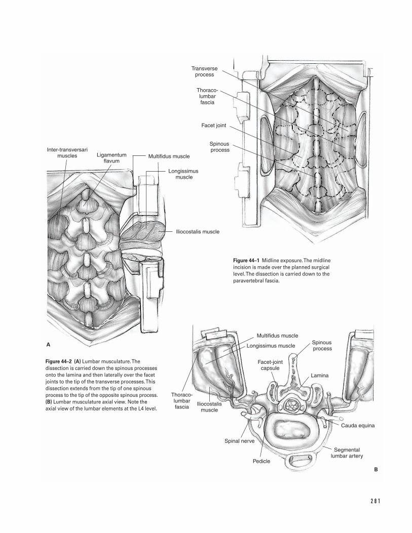
2 8 1
A
B
Inter-transversari muscles Ligamentum
flavumMultifidus muscle
Longissimus muscle
Iliocostalis muscle
Facet joint
Spinous process
Transverse process
Thoraco- lumbar fascia
Multifidus muscle
Longissimus muscle
Facet-joint capsule
Spinous process
Lamina
Cauda equina
Segmental lumbar artery
Pedicle
Spinal nerve
Iliocostalis muscle
Thoraco- lumbar fascia
Figure 44–1 Midline exposure. The midlineincision is made over the planned surgical level. The dissection is carried down to theparavertebral fascia.
Figure 44–2 (A) Lumbar musculature. Thedissection is carried down the spinous processesonto the lamina and then laterally over the facetjoints to the tip of the transverse processes. Thisdissection extends from the tip of one spinousprocess to the tip of the opposite spinous process.(B) Lumbar musculature axial view. Note theaxial view of the lumbar elements at the L4 level.
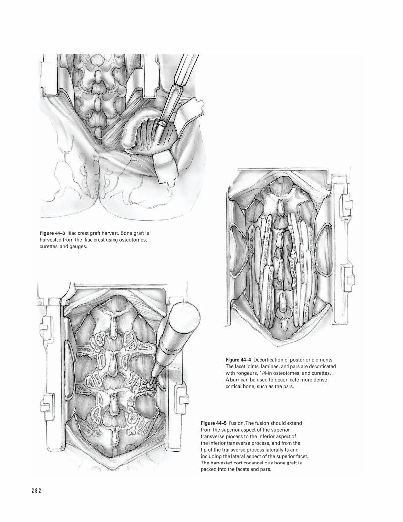
2 8 2
Figure 44–3 Iliac crest graft harvest. Bone graft isharvested from the iliac crest using osteotomes,curettes, and gauges.
Figure 44–4 Decortication of posterior elements.The facet joints, laminae, and pars are decorticatedwith rongeurs, 1/4-in osteotomes, and curettes. A burr can be used to decorticate more densecortical bone, such as the pars.
Figure 44–5 Fusion. The fusion should extendfrom the superior aspect of the superiortransverse process to the inferior aspect of the inferior transverse process, and from the tip of the transverse process laterally to andincluding the lateral aspect of the superior facet.The harvested corticocancellous bone graft ispacked into the facets and pars.
thigh cuff is added to the brace in cases where thefusion extends across L5-S1.
7. Barring medical contraindications, calcium intakeof 1000 mg a day is encouraged in conjunction witha daily vitamin supplement.
8. Smoking is discouraged.9. Neurovascular examination is performed frequently
in the first 48 to 72 hours.10. Patients are encouraged to donate two units of
autologous blood.
Operative TechniqueApproach1. Administer preoperative antibiotics. After general
anesthesia is administrated, insert a Foley catheter.Place compression boots and anti-embolic stockingsover the lower extremities. Institute spinal cordmonitoring.
2. Turn the patient prone on either chest rolls or aJackson table. Carefully pad the extremities andprotect the groin (males) and the breasts (females).Maintain the hips in neutral or slight extensionwhile maintaining knee flexion. Allow the belly tohang free.
3. Prepare and drape the back and iliac crest in a ster-ile fashion.
4. Make a midline incision measuring about 4 in inlength. Center it over the level of the planned sur-gery. The superior aspect of the iliac crest approxi-mates the L4-L5 level and the posterior superioriliac spines approximates the L5-S1 level.
5. Carry the dissection down to the paravertebralfascia (Fig. 44–1).
6. Control bleeding with a Bovie cautery.7. Use self-retaining cerebellar retractors.8. Criss-crossing thoracolumbar fascial decussations
serve as an additional guide to the L5-S1 level.9. Incise the paravertebral fasciae insertion into the
spinous processes. Bilaterally, carry the dissectiondown the spinous processes onto the lamina andthen laterally over the facet joints to the tip of thetransverse processes. This dissection should extendfrom the tip of one spinous process to the tip of theopposite spinous process.
10. Denude soft tissues off the facet joints, the pars, thelamina, and the transverse processes. Use a burr todenude some of the soft tissues.
11. Place deep self-retaining retractors. The author prefersthe McCullough retractor either alone or in conjunc-tion with an Overhill or Adson-Beckman retractor.
12. Control bleeding throughout the procedure usingbipolar and Bovie cautery.
13. At this point, exposure should be adequate so that all posterior elements are clearly visualized(Fig. 44–2A and 2B).
14. If instrumentation is indicated, appropriate lamin-otomies for hook placement can be made, and ana-tomic landmarks are used to determine the pedicleentry point.
I l iac crest bone graft harvest
The iliac crest ipsilateral to the patient’s most severeback and/or leg symptoms is chosen.
â If the fusion extends to S1, consider exposing theiliac crest from the same midline incision, byextending the dissection in the plane between thesubcutaneous tissues and the lumbosacral fasciatowards the iliac crest. Avoid excessive soft tissueretraction when performing the approach throughthe same incision.
â If the location of the iliac crest is too lateral or if thefusion extends to L5 or more proximally, a separateincision should be made over the iliac crest.
a. Incise the periosteum and reflect it off the inner andouter walls of the iliac crest. Dissect the outer wallby reflecting the gluteus muscles off of the posterioriliac crest. Carry the iliac crest dissection from theposterosuperior iliac spine medially for a distance ofabout 10 cm laterally. This diminishes the possibil-ity of injury to the cluneal nerves.
b. After the iliac crest is exposed, place a deep self-retaining retractor such as an Overhill withassisted manual Hibbs retraction to provide ade-quate exposure.
c. Harvest bone from the iliac crest using osteotomes.Cut long longitudinal slivers of bone. Undercutthem using a curved osteotome.
d. Harvest cancellous bone using curettes and gauges.Augment the volume of osteoprogenitor cells by
4 4 L U M BA R S P I N E F U S I O N 2 8 3
aspirating bone marrow and placing it over thebone graft (Fig. 44–3).
e. Once ample bone graft has been harvested, copi-ously irrigate the wound with antibiotic solution.
f. Use bone wax to tamponade cancellous bleeders. Adry piece of gelfoam can be placed to maintainhemostasis. If the field is dry, a drain is not alwaysnecessary. Otherwise, tunnel a drain cephalad later-ally to allow easy access postoperatively and to keepthe drain away from the perianal area.
g. Approximate the paravertebral fascia with 1-0 Vicryl.Close the subcutaneous tissue with two layers of 2-0 Vicryl. Close the skin with either staples orvertical 3-0 nylon mattress sutures. In individualswith a small incision, a subcuticular 4-0 Vicryl canbe employed.
h. Dress the wound with sterile dressing.
Fusion15. Copiously irrigate the main lumbar incision with
antibiotic solution. Use one or two Hibbs retractorsto retract the soft tissues bilaterally over the trans-verse processes.
16. Copiously irrigate the lateral gutters with antibioticsolution. Avoid irrigation once decortication com-mences in order to preserve the decorticated bone,as well as the osteoprogenitor potential of the de-corticated cancellous surfaces.
17. Denude the facet joints of cartilage and scrape themwith a curette.
18. Continue decorticating in a cephalad-to-caudaldirection. Avoid blood pooling, which occurs if thelordotic cephalad segments are decorticated first.
19. Split the transverse processes dorsally in the mid-line. Expose the cancellous surfaces by openingthem like a book. Avoid fracturing the transverseprocesses.
20. Decorticate the facet joints, laminae, and pars usingrongeurs, 1/4-in osteotomes, and curettes. In par-ticular, the lateral aspect of the facet joint must bedecorticated, augmenting the surface area for the
fusion. Use a burr to decorticate more dense corticalbone, such as the pars (Fig. 44–4).
21. If the fusion extends to S1, perform an osteotomy ofthe superior sacral ala. Reflect the osteotomizedbone in the L5-S1 intertransverse process interval.
22. Use a curette to scoop the exposed cancellous alarbone, thereby augmenting the fusion bed.
23. Place half of the harvested corticocancellous chipsinto the lateral gutters. Impact these using a tamp.The fusion should extend from the superior aspectof the superior transverse process to the inferioraspect of the inferior transverse process, and fromthe tip of the transverse process laterally to andincluding the lateral aspect ofthe superior facet.
24. Pack the facet joint intra-articularly with bone graft.Also place bone graft into the facets and pars (Fig. 44–5).
25. Drape the paravertebral muscles over the bonegraft. Avoid medial displacement of the bone graftduring retractor removal.
26. Repeat the same procedure on the opposite side.
Closure27. Place a drain.28. Approximate the deep paravertebral muscles to
each other with #1 Vicryl. This helps obliterate thedeep dead space.
29. Approximate the paravertebral fascia with #1 Vicrylin figure eight watertight fashion.
30. Close the superficial layers with 2-0 Vicryl; close theskin in a standard fashion.
31. Dress the wound with a compressive dressing.
Suggested ReadingsKurz LT, Samberg LC, Herkowitz HN. Spinal fusion:techniques and complications. In: Herkowitz HN,Garfin SR, Balderston RA, Eismont FJ, Bell GR, WieselSW, eds. The Spine. 3rd ed. Philadelphia, PA: W.B.Saunders, 1992, pp. 1756–1773.
2 8 4 S P I N E
Indications1. Spinal stenosis
a. Failure to respond to nonoperative treatment witha predominance of lower extremity symptoms
b. Unremitting pain and marked limitations ofdaily activities
2. Precipitous neurologic deterioration3. Cauda equina syndrome
Contraindications1. Low back pain in the presence of multi-level degen-
erative disc disease2. Lack of confirmatory imaging study
Preoperative Preparation1. Medical and anesthetic clearance2. Clear identification of the exact location of spinal
stenosis3. If possible, cessation of smoking4. Fitness education and weight reduction5. Radiographic imaging (MRI, CT myelogram) includ-
ing sagittal foraminal reconstruction
Special Instruments, Position, and Anesthesia1. Position the patient in a prone kneeling position
on chest rolls with the abdomen hanging free. Thekneeling position is contraindicated in the presenceof knee or hip disease.
2. Use spinal or general anesthesia for short segment,decompressive laminectomy without instrumenta-tion. Use general anesthesia for long segment decom-pression or instrumentation. Consider hypotensiveanesthesia to diminish epidural bleeding if there areno medical contraindications.
3. Special instruments: 45-degree angled Kerrosenrongeurs ranging in size from 1 to 4 mm.
4. Luksell rongeurs are used to debulk lamina, facetjoints, remove spinous processes, and decorticate.
5. Use 4-mm and 5-mm burrs to thin lamina and facet joints.
6. Penfield elevators are used to palpate nerve rootsand dura, and dissect surgical planes.
7. Different sized ball-ended probes are used to evalu-ate foraminal decompression.
8. Microscope or loop magnification and light aug-mentation
9. Angled curettes are used to free-up scar tissue anddevelop surgical planes.
2 8 5
C H A P T E R 4 5
Spinal Lumbar Decompression
Srdjan Mirkovic
10. Use gelfoam impregnated in thrombin to facilitatehemostasis.
11. Bipolar coagulation
Tips and Pearls1. The interlaminar space may be completely obliter-
ated in patients with severe spine degeneration. Thesuperior aspect of the lamina can be difficult toidentify due to severe shingling. Consider placing alaminar distractor between the spinous processes,thereby allowing distraction of the interlaminarspace and delineation of the inferior border of thesuperior laminae, ligamentum flavum, and facetjoints. This facilitates initiation of the laminectomywith kerrosens posterior to the ligamentum flavum.Once the ligamentum flavum plane is identified,the laminar spreaders can be removed and thespinous processes rongeured with a Luksell andremoved with kerrosens. The laminectomy canthen proceed in routine fashion.
2. The three common areas for significant nerve rootcompression are: the lateral recess secondary tofacet joint hypertrophy; the central stenosis due to the hypertrophied ligamentum flavum; and the foraminal stenosis due to degenerative disc nar-rowing. Decompression of the superior aspect of the caudal lamina is facilitated by either partially or completely removing the spinous processes of the inferior vertebra. The underlying lamina is thick and should be thinned with a burr or with a rongeur.
3. In patients with one level spinal stenosis (e.g., theL4-L5 level), the inferior half of the lamina of L4and the superior half of the lamina of L5 need to beremoved.
4. Lateral recess stenosis due to dorsal compressionfrom the overhanging hypertrophied facet is a com-mon cause of surgical failure. Affected nerve rootsneed to be clearly decompressed with clear visuali-zation of the medial aspect of the correspondingpedicle.
5. Check the foramina for impingement using ball-ended probes.
6. Consider concomitant spinal fusion in the presenceof degenerative spondylolisthesis, scoliosis and/or
kyphosis, greater than 50% excision of the facetbilaterally, as well as recurrent stenosis above a pre-vious fusion.
7. If a kneeling position is used with a patient’s back in kyphosis, ensure that adequate foraminal decom-pression has been performed to avoid postoperativestenosis when the patient resumes standing in thelordotic position.
What To Avoid1. Avoid inadequate decompression.2. If possible, avoid complete excision of the facet
joints to minimize the incidence of postoperativeinstability.
3. Avoid dural tears. Minimize dural tears by care-fully identifying the surgical planes (notably theplane between bone and ligamentum flavum, andbetween the ligamentum flavum and the epiduralspace). Cottonoids placed in the plane of dissectionduring laminectomy protect the dura and assist in hemostasis.
4. Avoid foregoing radiographs. Verify radiographi-cally that the decompression has extended theextent of the desired surgery.
Postoperative Care Issues1. The drain is commonly removed 24 to 48 hours
after surgery when drainage is less than 20 mL pershift.
2. Physical therapy and occupational therapy are insti-tuted on postoperative day one.
3. The Foley catheter is removed when the patient cansit or stand by the bedside.
4. Since spinal stenosis is a common condition in theelderly, prolonged immobilization particularly inthese elderly patients leads to deconditioning andshould be avoided. Patients are encouraged to sit bythe bedside for as long as tolerated.
5. A soft corset is preferred in patients who do notundergo lumbar fusion. A rigid brace is recom-mended for patients who undergo lumbar fusionprocedures.
6. Antibiotics are given for 48 hours postoperatively.
2 8 6 S P I N E
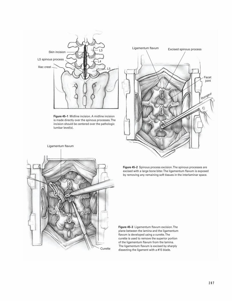
2 8 7
L3
L4
L5
Skin incision
L5 spinous process
Iliac crest
Ligamentum flavum Excised spinous process
Facet joint
Rongeur
Ligamentum flavum
Curette
Figure 45–1 Midline incision. A midline incisionis made directly over the spinous processes. Theincision should be centered over the pathologiclumbar level(s).
Figure 45–2 Spinous process excision. The spinous processes areexcised with a large bone biter. The ligamentum flavum is exposed by removing any remaining soft tissues in the interlaminar space.
Figure 45–3 Ligamentum flavum excision. Theplane between the lamina and the ligamentumflavum is developed using a curette. The curette is used to remove the superior portion of the ligamentum flavum from the lamina.The ligamentum flavum is excised by sharplydissecting the ligament with a #15 blade.
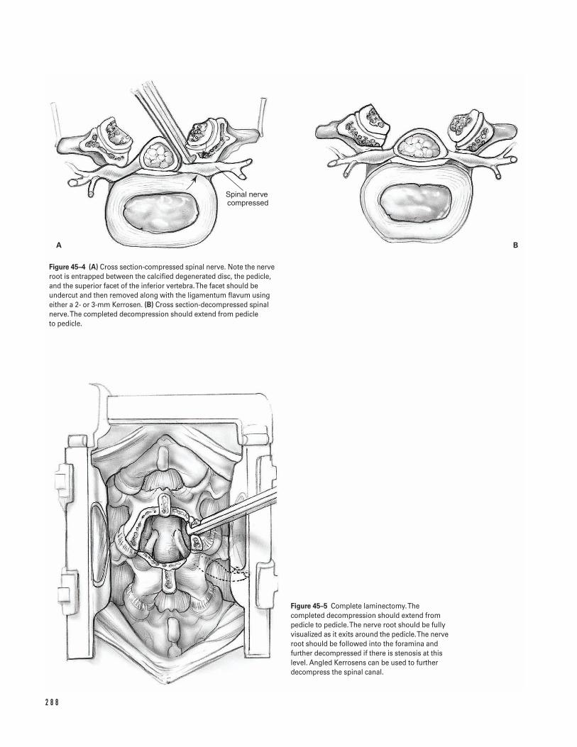
2 8 8
Spinal nerve compressed
A B
Figure 45–4 (A) Cross section-compressed spinal nerve. Note the nerveroot is entrapped between the calcified degenerated disc, the pedicle,and the superior facet of the inferior vertebra. The facet should beundercut and then removed along with the ligamentum flavum usingeither a 2- or 3-mm Kerrosen. (B) Cross section-decompressed spinalnerve. The completed decompression should extend from pedicle to pedicle.
Figure 45–5 Complete laminectomy. Thecompleted decompression should extend frompedicle to pedicle. The nerve root should be fullyvisualized as it exits around the pedicle. The nerveroot should be followed into the foramina andfurther decompressed if there is stenosis at thislevel. Angled Kerrosens can be used to furtherdecompress the spinal canal.
7. Judicious use of pain medication avoids confusionand disorientation in the elderly population.
8. Sutures are removed at 2 weeks. Patients are placedin a gentle cardiovascular-conditioning program atthat time.
9. Low back exercises are begun 4 weeks postoperatively.10. In the absence of fusion, the majority of patients
can return to sedentary work 2 to 4 weeks aftersurgery. More demanding work is normally possible6 to 12 weeks after surgery.
Operative TechniquePreoperative1. Administer prophylactic antibiotics preoperatively.2. Place the patient in the prone position. Consider
using anti-embolic stockings, intermittent pneu-matic compression, and spinal cord monitoring.
3. Insert a Foley catheter. Protect all extremities in-cluding the ulnar nerve, brachial plexus, genitaliain males, and breasts in females.
4. Prepare and drape the patient’s back in the hospi-tal’s routine sterile fashion.
5. Determine the appropriate level for the spinal in-cision. Begin by examining the anteroposteriorradiographs. Conventionally, these radiographs arepositioned on the viewbox as if the examiner is fac-ing the patient’s back. Thus, the radiograph is posi-tioned so the patient’s right side is on the right sideon the radiograph. Use the iliac crest as a landmarkfor the L4-L5 level and the posterior superior iliacspine as an L5-S1 landmark.
6. Place a spinal needle at the presumed pathologicallevel. Use lateral radiographs and/or fluoroscopy toverify the position.
Approach7. Infiltrate the paravertebral muscles with 1:500,000
epinephrine and saline solution.8. Make a midline incision directly over the spinous
processes (Fig. 45–1).9. Dissect directly down through the soft tissues to the
thoracolumbar fascia, which inserts into the spinousprocesses. Place self-retaining cerebellar retractors.
10. Dissect subperiosteally down the spinous processesto the laminae. Avoid violating the intramuscular
vessels and causing unnecessary hemorrhages. Co-agulate all blood vessels that are encountered inorder to optimize visualization.
11. Use the decussations of the lumbodorsal fascialfibers at the lumbosacral junction (L5-S1) as anadditional intraoperative landmark.
12. Identify the paraspinal muscles which attach to thespinous processes. Dissect the paraspinal muscleswith cautery by proceeding in a caudal-to-cephaladdirection.
13. Use Cobb elevators to expose the laminae. Exposureshould extend from the spinous processes mediallyto the facet joints laterally. Avoid stripping the facetjoints unless a fusion is planned.
14. Remove the remaining soft tissues from the laminaand interlaminar space using curettes, pituitaries, or a burr. Place deep self-retaining retractors. Theauthor prefers a McCullough retractor which allowsflexibility with blades of different depth and width.Place the tips of the retractor blades over the facetjoints to preserve the facet capsules, the muscularattachments, and innervation.
15. Re-check that the appropriate level has been exposedby placing a radiopaque marker at the interlaminarspace and verifying its position on cross table lateralX-rays or fluoroscopy.
Decompressionâ Minimize trauma to the soft tissues by removing
the self-retaining retractors every hour for 5 min-utes while copiously irrigating the wound withantibiotic solution.
â Control bleeding throughout the procedure usingbipolar cautery on low intensity, thrombin impreg-nated gelfoam, and occasionally Avetene.
16. Remove the spinous processes with a large bonebiter (Fig. 45–2). Control bleeding from the softcancellous bone with bone wax. Expose the liga-mentum flavum by removing any remaining softtissues in the interlaminar space.
17. Thin the lamina of the involved segments with arongeur or cutting burr. Bleeding from the bone canbe controlled with bone wax. Clear visualizationwithin the operative field facilitates subsequentlaminectomy with kerrosens.
4 5 S P I N A L L U M BA R D E C O M P R E S S I O N 2 8 9
18. Develop the plane between the lamina and theligamentum flavum using a 2-0 Epstein curette (Fig. 45–3). Place cottonoids in this plane, therebyprotecting the underlying dura and ligamentumflavum.
19. Begin the decompression in the midline.20. After the central decompression, proceed laterally
excising the lateral aspect of the lamina. Do notextend the lateral decompression past the pars.Carefully protect the pars intra-articularis, thusminimizing the incidence of instability.
21. Decompress lateral recess stenosis by using aKerrosen. A burr or a 1/4-in osteotome may also beused. The decompression should allow completevisualization of the ligamentum flavum.
22. Pass a ball-ended probe through the midline of theligamentum flavum and split the ligamentum alongits midline raphe.
23. Carry out a flavectomy by dissecting the ligamentsharply with a #15 blade (Fig. 45–3). Laterally, theligamentum flavum contributes to lateral recessstenosis and adheres to the undersurface of thehypertrophied degenerated facet joint. The nerveroot is entrapped between the calcified degenerateddisc, the pedicle, and the superior facet of the infe-rior vertebra. Commonly this is seen with severedisc degeneration with marked collapse of the inter-vertebral disc and overriding of the facet joints.
24. Undercut the facet and remove the ligamentumflavum using either a 2- or 3-mm Kerrosen. If thelateral recess is very tight, use a 1-mm Kerrosen.Remove the posterior aspect of the disc with sharpdissection. Alternatively, if the disc is markedly cal-cified use a small osteotome or less frequently a burr(Fig. 45–4A).
25. Fully visualize the nerve root exiting around the pedicle. If additional lateral recess stenosis is still present, further decompress the spinal canal byperforming a foraminotomy. Follow the nerve rootinto the foramina. Remember that the dorsal
root ganglion, which lies just inferior to the pedicle,is a significant source of pain mediators and shouldbe thoroughly decompressed.
26. Carefully inspect the foramina using ball-endedprobes up to 5 mm in diameter. If residual foraminalstenosis is present, further decompress the spinalforamina using an angled Kerrosen (Fig. 45–4A).
Severe stenosis
â The decompression once completed should extendfrom pedicle to pedicle (Fig. 45–4B). The possibilityof an underlying disc herniation, contributing tothe spinal stenosis should also be ruled out byinspecting the anterior aspect of the dura and nerveroot. This is accomplished by carefully retractingthe dura and the nerve root medially (Fig. 45–5).
Closure27. Once the decompression is completed, copiously
irrigate the wound with antibiotic solution.28. Cover the length of the dura with gelfoam impreg-
nated in thrombin.29. Place a hemovac drain.30. Approximate the paravertebral muscles with 1-0
Vicryl to diminish the dead space.31. Close the paravertebral fascia with1-0 Vicryl and
the subcutaneous tissue with 2-0 Vicryl.32. Approximate the skin edges in routine fashion per
surgeon’s choice and apply a compressive dressing.
Suggested ReadingsGarfin SR, Herkowitz HN, Mirkovic S. Spinal stenosis. J Bone Joint Surg 1999;81A(4):572–583.
Russell M, Hanley E. Indications, techniques and resultsof decompressive laminectomy. In: Herkowitz HN,Garfin SR, Balderston RA, Eismont FJ, Bell GR, WieselSW, eds. The Spine. 4th ed. Philadelphia, PA: W.B.Saunders, 1999, pp. 806F–806M.
2 9 0 S P I N E

Section Eight
Pediatrics

This page intentionally left blank
Key Techniques inOrthopaedic Surgery
DefinitionsNew terminologyUnstable slip: defined as clinical and radiographic evi-dence of slipped capital femoral epiphysis (SCFE) andinability to bear weight, even with assistive devices sec-ondary to pain.Stable slip: defined as clinical and radiographic evidenceof SCFE and the ability to bear weight.
Indications1. Mild, moderate, and some severe unstable (acute or
acute-on-chronic) slipped capital femoral epiphysis(SCFE) (Figs. 46–1A and 1B)
2. Mild or moderate stable (chronic) SCFE
Contraindications1. Severe acute on chronic SCFE2. Severe chronic SCFE
Preoperative Preparation1. Obtain hip radiographs including anteroposterior
(AP) and true or cross table lateral views of the af-fected hip.
2. Appropriate medical and anesthesiology evaluation3. Strict bed rest4. Skin traction to affected limb for comfort
Special Instruments, Position, andAnesthesia1. C-arm image intensifier fluoroscopy is required for
percutaneous pinning.2. A power driver with Kirshner wires and a 7.3-mm
cannulated screw set is required.3. The patient is placed supine on a radiolucent table
or fracture table with the affected leg abducted10–15 degrees and internally rotated moderatelyand without force (Fig. 46–2).
4. Carefully pad all pressure points. 5. Place image intensifier between the patient’s legs in
order to obtain AP and lateral hip images by simplyrotating around the arc of the C-arm machine.
6. General anesthesia is used during the procedure.
Tips and Pearls1. Position the leg with 10–15 degrees of abduction
and moderate internal rotation. This places thefemoral neck as close as possible to a positionparallel to the floor in order to obtain true AP andlateral views.
2 9 3
C H A P T E R 4 6
Slipped Capital Femoral Epiphysis Hip Pinning
Kirk Aadalen and John F. Sarwark
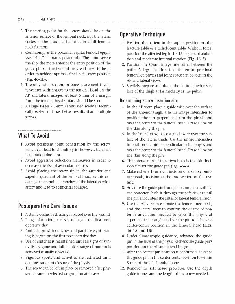
2. The starting point for the screw should be on theanterior surface of the femoral neck, not the lateralcortex of the proximal femur as in adult femoralneck fixation.
3. Commonly, as the proximal capital femoral epiph-ysis “slips” it rotates posteriorly. The more severethe slip, the more anterior the entry position of theguide pin on the femoral neck will need to be inorder to achieve optimal, final, safe screw position(Fig. 46–1B).
4. The only safe location for screw placement is cen-ter-center with respect to the femoral head on theAP and lateral images. At least 5 mm of a marginfrom the femoral head surface should be seen.
5. A single larger 7.3-mm cannulated screw is techni-cally easier and has better results than multiplescrews.
What To Avoid1. Avoid persistent joint penetration by the screw,
which can lead to chondrolysis; however, transientpenetration does not.
2. Avoid aggressive reduction maneuvers in order todecrease the risk of avascular necrosis.
3. Avoid placing the screw tip in the anterior andsuperior quadrant of the femoral head, as this candamage the terminal branches of the lateral cervicalartery and lead to segmental collapse.
Postoperative Care Issues1. A sterile occlusive dressing is placed over the wound.2. Range-of-motion exercises are begun the first post-
operative day.3. Ambulation with crutches and partial weight bear-
ing is begun on the first postoperative day.4. Use of crutches is maintained until all signs of syn-
ovitis are gone and full painless range of motion isachieved (usually 6 weeks).
5. Vigorous sports and activities are restricted untildemonstration of closure of the physis.
6. The screw can be left in place or removed after phy-seal closure in selected or symptomatic cases.
Operative Technique1. Position the patient in the supine position on the
fracture table or a radiolucent table. Without force,position the affected leg in 10–15 degrees of abduc-tion and moderate internal rotation (Fig. 46–2).
2. Position the C-arm image intensifier between thepatient’s legs. Confirm that the entire proximalfemoral epiphysis and joint space can be seen in theAP and lateral views.
3. Sterilely prepare and drape the entire anterior sur-face of the thigh as far medially as the pubis.
Determining screw insertion site4. In the AP view, place a guide wire over the surface
of the anterior thigh. Use the image intensifier toposition the pin perpendicular to the physis andover the center of the femoral head. Draw a line onthe skin along the pin.
5. In the lateral view, place a guide wire over the sur-face of the lateral thigh. Use the image intensifier to position the pin perpendicular to the physis andover the center of the femoral head. Draw a line onthe skin along the pin.
6. The intersection of these two lines is the skin inci-sion site for the guide pin (Fig. 46–3).
7. Make either a 1- or 2-cm incision or a simple punc-ture (stab) incision at the intersection of the twolines.
8. Advance the guide pin through a cannulated soft tis-sue protector. Push it through the soft tissues untilthe pin encounters the anterior lateral femoral neck.
9. Use the AP view to estimate the femoral neck axis,and the lateral view to confirm the degree of pos-terior angulation needed to cross the physis at a perpendicular angle and for the pin to achieve acenter-center position in the femoral head (Figs.46–1A and 1B).
10. Under fluoroscopic guidance, advance the guide pin to the level of the physis. Recheck the guide pin’sposition on the AP and lateral images.
11. After the correct pin position is confirmed, advancethe guide pin in the center-center position to within5 mm of the subchondral bone.
12. Remove the soft tissue protector. Use the depthguide to measure the length of the screw needed.
2 9 4 P E D I AT R I C S
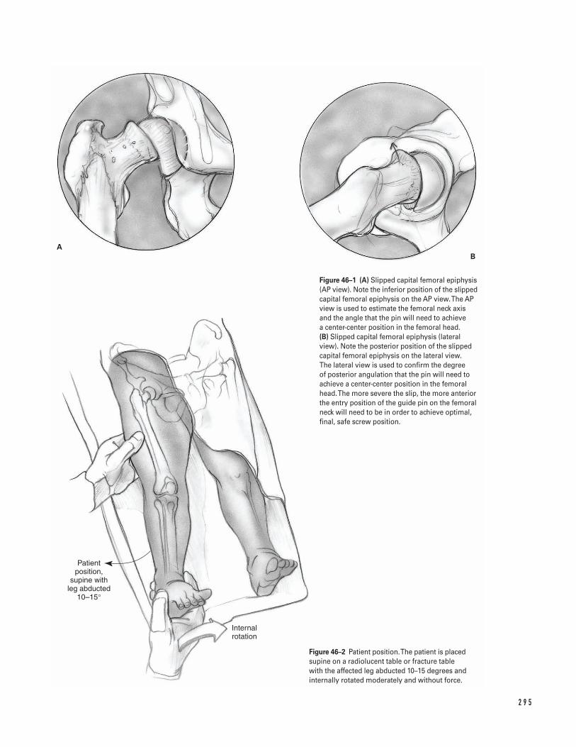
2 9 5
Patient position,
supine with leg abducted
10–15°
Internal rotation
AB
Figure 46–1 (A) Slipped capital femoral epiphysis(AP view). Note the inferior position of the slippedcapital femoral epiphysis on the AP view. The APview is used to estimate the femoral neck axisand the angle that the pin will need to achieve a center-center position in the femoral head. (B) Slipped capital femoral epiphysis (lateralview). Note the posterior position of the slippedcapital femoral epiphysis on the lateral view. The lateral view is used to confirm the degree of posterior angulation that the pin will need toachieve a center-center position in the femoralhead. The more severe the slip, the more anteriorthe entry position of the guide pin on the femoralneck will need to be in order to achieve optimal,final, safe screw position.
Figure 46–2 Patient position. The patient is placedsupine on a radiolucent table or fracture tablewith the affected leg abducted 10–15 degrees andinternally rotated moderately and without force.
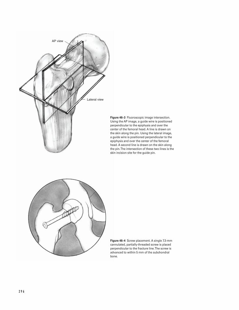
2 9 6
AP view
Lateral view
Figure 46–3 Fluoroscopic image intersection.Using the AP image, a guide wire is positionedperpendicular to the epiphysis and over thecenter of the femoral head. A line is drawn on the skin along the pin. Using the lateral image, a guide wire is positioned perpendicular to theepiphysis and over the center of the femoralhead. A second line is drawn on the skin alongthe pin. The intersection of these two lines is theskin incision site for the guide pin.
Figure 46–4 Screw placement. A single 7.3-mmcannulated, partially-threaded screw is placedperpendicular to the fracture line. The screw isadvanced to within 5 mm of the subchondralbone.
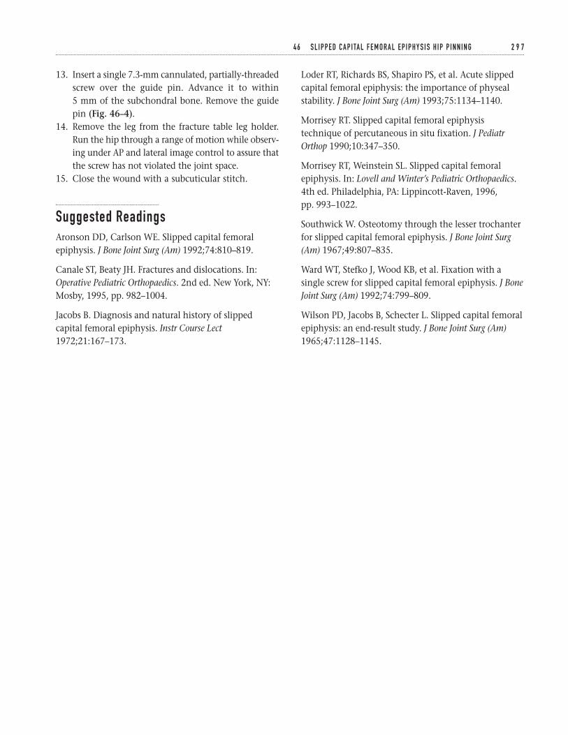
13. Insert a single 7.3-mm cannulated, partially-threadedscrew over the guide pin. Advance it to within 5 mm of the subchondral bone. Remove the guidepin (Fig. 46–4).
14. Remove the leg from the fracture table leg holder.Run the hip through a range of motion while observ-ing under AP and lateral image control to assure thatthe screw has not violated the joint space.
15. Close the wound with a subcuticular stitch.
Suggested ReadingsAronson DD, Carlson WE. Slipped capital femoralepiphysis. J Bone Joint Surg (Am) 1992;74:810–819.
Canale ST, Beaty JH. Fractures and dislocations. In:Operative Pediatric Orthopaedics. 2nd ed. New York, NY:Mosby, 1995, pp. 982–1004.
Jacobs B. Diagnosis and natural history of slippedcapital femoral epiphysis. Instr Course Lect1972;21:167–173.
Loder RT, Richards BS, Shapiro PS, et al. Acute slippedcapital femoral epiphysis: the importance of physealstability. J Bone Joint Surg (Am) 1993;75:1134–1140.
Morrisey RT. Slipped capital femoral epiphysistechnique of percutaneous in situ fixation. J PediatrOrthop 1990;10:347–350.
Morrisey RT, Weinstein SL. Slipped capital femoralepiphysis. In: Lovell and Winter’s Pediatric Orthopaedics.4th ed. Philadelphia, PA: Lippincott-Raven, 1996,pp. 993–1022.
Southwick W. Osteotomy through the lesser trochanterfor slipped capital femoral epiphysis. J Bone Joint Surg(Am) 1967;49:807–835.
Ward WT, Stefko J, Wood KB, et al. Fixation with asingle screw for slipped capital femoral epiphysis. J BoneJoint Surg (Am) 1992;74:799–809.
Wilson PD, Jacobs B, Schecter L. Slipped capital femoralepiphysis: an end-result study. J Bone Joint Surg (Am)1965;47:1128–1145.
4 6 S L I P P E D C A P I TA L F E M O R A L E P I P H Y S I S H I P P I N N I N G 2 9 7
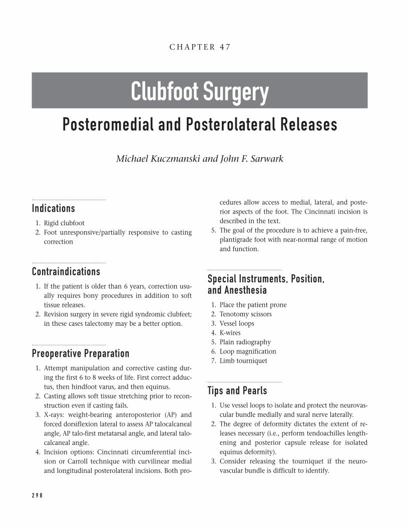
Indications1. Rigid clubfoot2. Foot unresponsive/partially responsive to casting
correction
Contraindications1. If the patient is older than 6 years, correction usu-
ally requires bony procedures in addition to softtissue releases.
2. Revision surgery in severe rigid syndromic clubfeet;in these cases talectomy may be a better option.
Preoperative Preparation1. Attempt manipulation and corrective casting dur-
ing the first 6 to 8 weeks of life. First correct adduc-tus, then hindfoot varus, and then equinus.
2. Casting allows soft tissue stretching prior to recon-struction even if casting fails.
3. X-rays: weight-bearing anteroposterior (AP) andforced dorsiflexion lateral to assess AP talocalcanealangle, AP talo-first metatarsal angle, and lateral talo-calcaneal angle.
4. Incision options: Cincinnati circumferential inci-sion or Carroll technique with curvilinear medialand longitudinal posterolateral incisions. Both pro-
cedures allow access to medial, lateral, and poste-rior aspects of the foot. The Cincinnati incision isdescribed in the text.
5. The goal of the procedure is to achieve a pain-free,plantigrade foot with near-normal range of motionand function.
Special Instruments, Position, and Anesthesia1. Place the patient prone2. Tenotomy scissors3. Vessel loops4. K-wires5. Plain radiography6. Loop magnification7. Limb tourniquet
Tips and Pearls1. Use vessel loops to isolate and protect the neurovas-
cular bundle medially and sural nerve laterally.2. The degree of deformity dictates the extent of re-
leases necessary (i.e., perform tendoachilles length-ening and posterior capsule release for isolatedequinus deformity).
3. Consider releasing the tourniquet if the neuro-vascular bundle is difficult to identify.
2 9 8
C H A P T E R 4 7
Clubfoot SurgeryPosteromedial and Posterolateral Releases
Michael Kuczmanski and John F. Sarwark
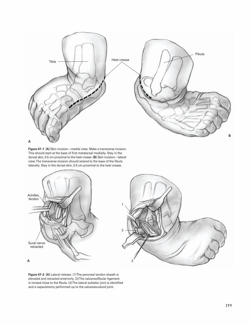
2 9 9
Tibia Heel crease
Fibula
Achilles tendon
Sural nerve retracted
1
2
3
A
B
A
Figure 47–1 (A) Skin incision—medial view. Make a transverse incision.This should start at the base of first metatarsal medially. Stay in thedorsal skin, 0.5 cm proximal to the heel crease. (B) Skin incision—lateralview. The transverse incision should extend to the base of the fibulalaterally. Stay in the dorsal skin, 0.5 cm proximal to the heel crease.
Figure 47–2 (A) Lateral release. (1) The peroneal tendon sheath iselevated and retracted anteriorly. (2) The calcaneofibular ligament is incised close to the fibula. (3) The lateral subtalar joint is identifiedand a capsulotomy performed up to the calcaneocuboid joint.
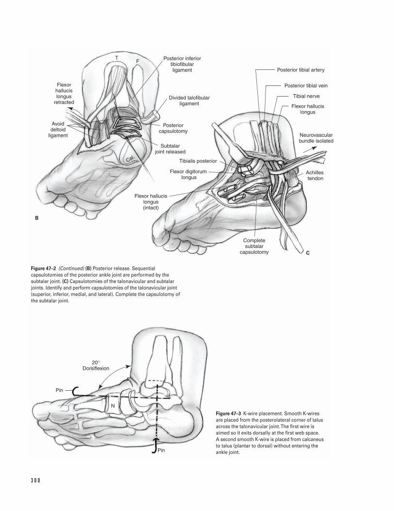
3 0 0
B
C
TF
Flexor hallucis longus
retracted
Avoid deltoid
ligament
Cal.
Posterior inferior tibiofibular ligament
Divided talofibular ligament
Posterior capsulotomy
Subtalar joint released
Tibialis posterior
Flexor digitorum longus
Flexor hallucis longus (intact)
Complete subtalar
capsulotomy
Achilles tendon
Neurovascular bundle isolated
Flexor hallucis longus
Tibial nerve
Posterior tibial vein
Posterior tibial artery
Pin
Pin
20°Dorsiflexion
N
Figure 47–2 (Continued) (B) Posterior release. Sequentialcapsulotomies of the posterior ankle joint are performed by thesubtalar joint. (C) Capsulotomies of the talonavicular and subtalarjoints. Identify and perform capsulotomies of the talonavicular joint(superior, inferior, medial, and lateral). Complete the capsulotomy ofthe subtalar joint.
Figure 47–3 K-wire placement. Smooth K-wiresare placed from the posterolateral corner of talusacross the talonavicular joint. The first wire isaimed so it exits dorsally at the first web space. A second smooth K-wire is placed from calcaneusto talus (plantar to dorsal) without entering theankle joint.
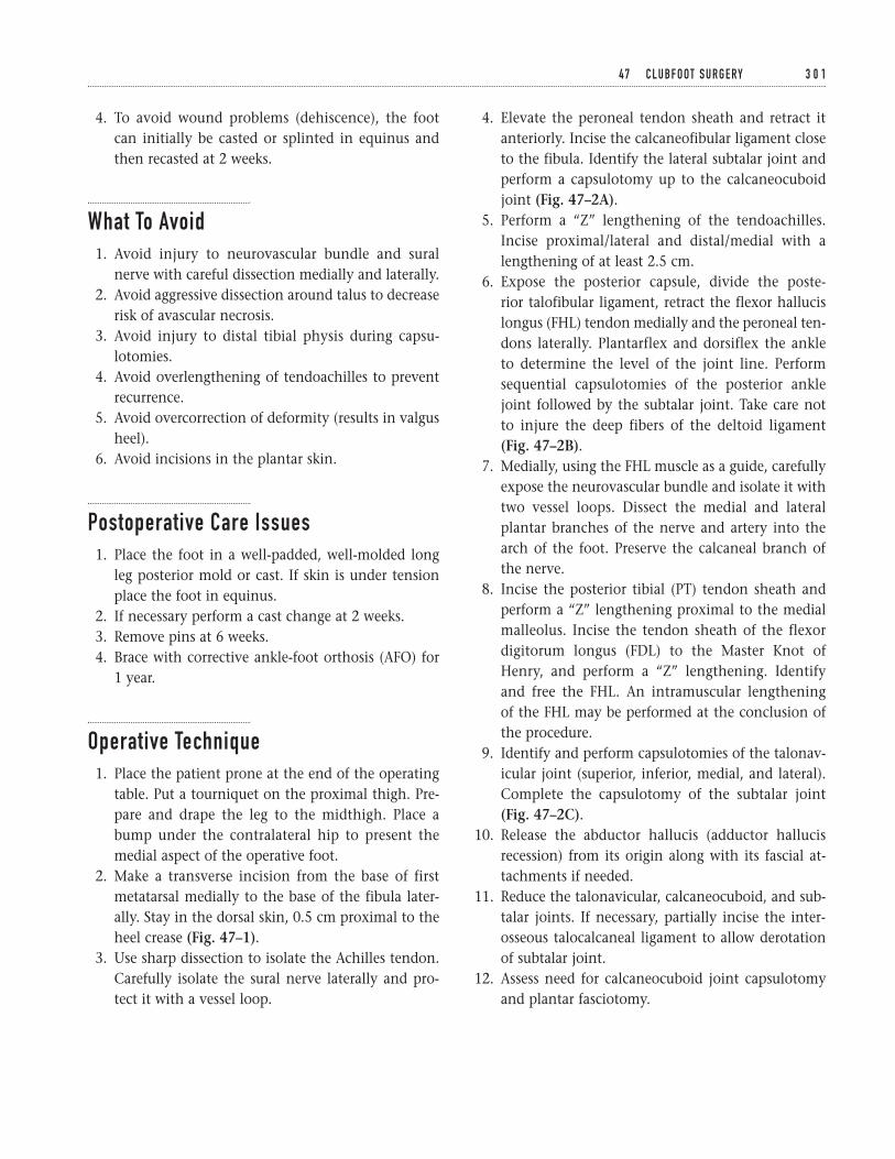
4. To avoid wound problems (dehiscence), the footcan initially be casted or splinted in equinus andthen recasted at 2 weeks.
What To Avoid1. Avoid injury to neurovascular bundle and sural
nerve with careful dissection medially and laterally.2. Avoid aggressive dissection around talus to decrease
risk of avascular necrosis.3. Avoid injury to distal tibial physis during capsu-
lotomies.4. Avoid overlengthening of tendoachilles to prevent
recurrence.5. Avoid overcorrection of deformity (results in valgus
heel).6. Avoid incisions in the plantar skin.
Postoperative Care Issues1. Place the foot in a well-padded, well-molded long
leg posterior mold or cast. If skin is under tensionplace the foot in equinus.
2. If necessary perform a cast change at 2 weeks.3. Remove pins at 6 weeks.4. Brace with corrective ankle-foot orthosis (AFO) for
1 year.
Operative Technique1. Place the patient prone at the end of the operating
table. Put a tourniquet on the proximal thigh. Pre-pare and drape the leg to the midthigh. Place abump under the contralateral hip to present themedial aspect of the operative foot.
2. Make a transverse incision from the base of firstmetatarsal medially to the base of the fibula later-ally. Stay in the dorsal skin, 0.5 cm proximal to theheel crease (Fig. 47–1).
3. Use sharp dissection to isolate the Achilles tendon.Carefully isolate the sural nerve laterally and pro-tect it with a vessel loop.
4. Elevate the peroneal tendon sheath and retract itanteriorly. Incise the calcaneofibular ligament closeto the fibula. Identify the lateral subtalar joint andperform a capsulotomy up to the calcaneocuboidjoint (Fig. 47–2A).
5. Perform a “Z” lengthening of the tendoachilles.Incise proximal/lateral and distal/medial with alengthening of at least 2.5 cm.
6. Expose the posterior capsule, divide the poste-rior talofibular ligament, retract the flexor hallucislongus (FHL) tendon medially and the peroneal ten-dons laterally. Plantarflex and dorsiflex the ankle to determine the level of the joint line. Performsequential capsulotomies of the posterior anklejoint followed by the subtalar joint. Take care not to injure the deep fibers of the deltoid ligament(Fig. 47–2B).
7. Medially, using the FHL muscle as a guide, carefullyexpose the neurovascular bundle and isolate it withtwo vessel loops. Dissect the medial and lateralplantar branches of the nerve and artery into thearch of the foot. Preserve the calcaneal branch ofthe nerve.
8. Incise the posterior tibial (PT) tendon sheath andperform a “Z” lengthening proximal to the medialmalleolus. Incise the tendon sheath of the flexordigitorum longus (FDL) to the Master Knot ofHenry, and perform a “Z” lengthening. Identify and free the FHL. An intramuscular lengthening of the FHL may be performed at the conclusion ofthe procedure.
9. Identify and perform capsulotomies of the talonav-icular joint (superior, inferior, medial, and lateral).Complete the capsulotomy of the subtalar joint(Fig. 47–2C).
10. Release the abductor hallucis (adductor hallucisrecession) from its origin along with its fascial at-tachments if needed.
11. Reduce the talonavicular, calcaneocuboid, and sub-talar joints. If necessary, partially incise the inter-osseous talocalcaneal ligament to allow derotationof subtalar joint.
12. Assess need for calcaneocuboid joint capsulotomyand plantar fasciotomy.
4 7 C L U B F O OT S U R G E RY 3 0 1
13. Place a smooth K-wire from the posterolateral cor-ner of talus across the talonavicular joint. Aim thewire to exit dorsally at the first web space. Place a second smooth K-wire from calcaneus to talus(plantar to dorsal) without entering the ankle joint(Fig. 47–3).
14. Release the tourniquet prior to taking films. Achievehemostasis.
15. Assess the correction with plain films (AP and lat-eral). The lateral is the most useful.
16. Suture the tendons with foot in 20 degrees of dorsi-flexion. Ensure that the peroneal tendons are lo-cated and stable.
17. Close the wound with interrupted or running sub-cuticular suture.
Suggested ReadingsBeaty JH. Congenital anomalies of the foot and lowerextremity. In: Canale ST, Beaty JH, eds. OperativePediatric Orthopaedics. St. Louis, MO: C.V. Mosby, 1995,pp. 72–134.
Crawford AH, Marxen JL, Osterfeld DL. The Cincinnatiincision: a comprehensive approach for surgicalprocedures of the foot and ankle in childhood. J BoneJoint Surg 1982;64A:1355–1358.
Sullivan JA. The child’s foot. In: Morrissy RT, WeinsteinSL, eds. Lovell and Winter’s Pediatric Orthopaedics.Philadelphia, PA: Lippincott-Raven, 1996, pp.1077–1135.
3 0 2 P E D I AT R I C S
Indications1. Distal humerus supracondylar fractures with signif-
icant displacement or angulation2. Minimally or nondisplaced distal humerus supra-
condylar fractures with associated trauma or injury(i.e., neurovascular compromise, compartment syn-drome, associated fractures or soft tissue loss)
Contraindicationsâ Avascular/ischemic distal upper extremity before or
after attempted reduction (relative)
Preoperative Preparation1. Physical examination to include
a. Evaluation of skin integrity and examination ofsoft tissues
b. Assessment of any impingement of fracture frag-ments in muscle
c. Analysis of distal pulses (palpation and/or Dop-pler) and capillary return
d. Distal neurological evaluation (all nerves andnerve branches—motor and sensory)
e. Assessment of any evidence of a compartmentsyndrome
2. Appropriate medical and anesthesiology evaluations3. Elevation and splinting (avoid significant elbow
flexion) of involved limb4. Close observation with intermittent re-examination
of distal motor, sensory, and vascular status5. Elbow radiographs including true anteroposterior
(AP) and lateral views; if needed, contralateral elbowradiographs may be helpful.
Special Instruments, Position, and Anesthesia1. Inverted C-arm fluoroscopy is necessary.2. A power drill and Kirschner wire set are required.3. Sterile Doppler ultrasound probe may be required
for certain cases.4. The patient is positioned supine on the operating
room table with ipsilateral shoulder at table edgeand abducted 60 to 90 degrees. The patient’s arm isplaced over (or upon) the inverted C-arm. This isutilized as the operating surface. The elbow shouldrest at the center of the C-arm surface.
5. General anesthesia is preferred for this procedure.The anesthesiologist should be made aware of theforce necessary for appropriate traction duringreduction.
3 0 3
C H A P T E R 4 8
Distal Humerus Supracondylar FractureReduction and Pinning
John J. Grayhack
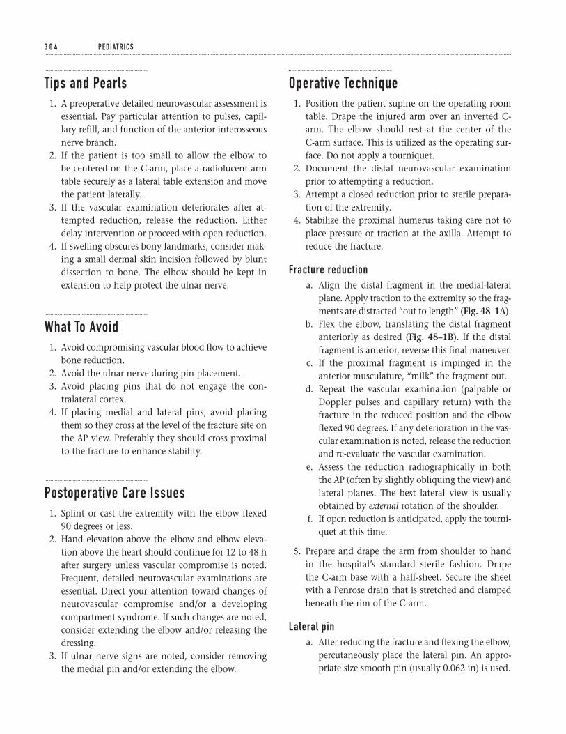
Tips and Pearls1. A preoperative detailed neurovascular assessment is
essential. Pay particular attention to pulses, capil-lary refill, and function of the anterior interosseousnerve branch.
2. If the patient is too small to allow the elbow to be centered on the C-arm, place a radiolucent armtable securely as a lateral table extension and movethe patient laterally.
3. If the vascular examination deteriorates after at-tempted reduction, release the reduction. Eitherdelay intervention or proceed with open reduction.
4. If swelling obscures bony landmarks, consider mak-ing a small dermal skin incision followed by bluntdissection to bone. The elbow should be kept inextension to help protect the ulnar nerve.
What To Avoid1. Avoid compromising vascular blood flow to achieve
bone reduction.2. Avoid the ulnar nerve during pin placement.3. Avoid placing pins that do not engage the con-
tralateral cortex.4. If placing medial and lateral pins, avoid placing
them so they cross at the level of the fracture site onthe AP view. Preferably they should cross proximalto the fracture to enhance stability.
Postoperative Care Issues1. Splint or cast the extremity with the elbow flexed
90 degrees or less.2. Hand elevation above the elbow and elbow eleva-
tion above the heart should continue for 12 to 48 hafter surgery unless vascular compromise is noted.Frequent, detailed neurovascular examinations areessential. Direct your attention toward changes ofneurovascular compromise and/or a developingcompartment syndrome. If such changes are noted,consider extending the elbow and/or releasing thedressing.
3. If ulnar nerve signs are noted, consider removingthe medial pin and/or extending the elbow.
Operative Technique1. Position the patient supine on the operating room
table. Drape the injured arm over an inverted C-arm. The elbow should rest at the center of the C-arm surface. This is utilized as the operating sur-face. Do not apply a tourniquet.
2. Document the distal neurovascular examinationprior to attempting a reduction.
3. Attempt a closed reduction prior to sterile prepara-tion of the extremity.
4. Stabilize the proximal humerus taking care not toplace pressure or traction at the axilla. Attempt toreduce the fracture.
Fracture reductiona. Align the distal fragment in the medial-lateral
plane. Apply traction to the extremity so the frag-ments are distracted “out to length” (Fig. 48–1A).
b. Flex the elbow, translating the distal fragmentanteriorly as desired (Fig. 48–1B). If the distalfragment is anterior, reverse this final maneuver.
c. If the proximal fragment is impinged in theanterior musculature, “milk” the fragment out.
d. Repeat the vascular examination (palpable orDoppler pulses and capillary return) with thefracture in the reduced position and the elbowflexed 90 degrees. If any deterioration in the vas-cular examination is noted, release the reductionand re-evaluate the vascular examination.
e. Assess the reduction radiographically in boththe AP (often by slightly obliquing the view) andlateral planes. The best lateral view is usuallyobtained by external rotation of the shoulder.
f. If open reduction is anticipated, apply the tourni-quet at this time.
5. Prepare and drape the arm from shoulder to hand in the hospital’s standard sterile fashion. Drape the C-arm base with a half-sheet. Secure the sheet with a Penrose drain that is stretched and clampedbeneath the rim of the C-arm.
Lateral pina. After reducing the fracture and flexing the elbow,
percutaneously place the lateral pin. An appro-priate size smooth pin (usually 0.062 in) is used.
3 0 4 P E D I AT R I C S
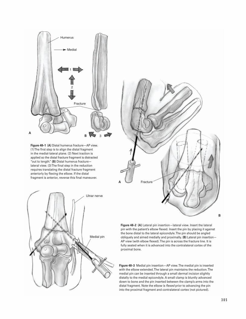
3 0 5
Humerus
Fracture
Fracture
Ulnar nerve
Medial pin
AB
A
B
Medial
1
2
3
Figure 48–1 (A) Distal humerus fracture—AP view.(1) The first step is to align the distal fragment in the medial-lateral plane. (2) Next traction isapplied so the distal fracture fragment is distracted“out to length.” (B) Distal humerus fracture—lateral view. (3) The final step in the reductionrequires translating the distal fracture fragmentanteriorly by flexing the elbow. If the distalfragment is anterior, reverse this final maneuver.
Figure 48–2 (A) Lateral pin insertion—lateral view. Insert the lateral pin with the patient’s elbow flexed. Insert the pin by placing it againstthe bone distal to the lateral epicondyle. The pin should be angledobliquely and aimed medially and proximally. (B) Lateral pin insertion—AP view (with elbow flexed). The pin is across the fracture line. It isfully seated when it is advanced into the contralateral cortex of theproximal bone.
Figure 48–3 Medial pin insertion—AP view. The medial pin is insertedwith the elbow extended. The lateral pin maintains the reduction. Themedial pin can be inserted through a small dermal incision slightlydistally to the medial epicondyle. A small clamp is bluntly advanceddown to bone and the pin inserted between the clamp’s arms into thedistal fragment. Note the elbow is flexed prior to advancing the pininto the proximal fragment and contralateral cortex (not pictured).
b. Insert the pin by starting distal to the lateral epi-condyle. Angle the pin obliquely. Aim mediallyand proximally.
c. First advance the pin through the distal frag-ment and then across the fracture line. Continueadvancing the pin into the contralateral cortexof the proximal bone (Figs. 48–2A and 2B).There is no consensus on the optimal number oflateral pins to be placed (one or two) or whethera medial pin should be inserted. If you insert asecond lateral pin, place it parallel to the initialpin. Some surgeons believe two lateral pins aresufficient, while others believe a medial pinshould supplement lateral pin fixation. In gen-eral, lateral pins minimize risks to the ulnarnerve, however, biomechanically they may notachieve equivalent fixation to crossed pins(medial and lateral pins).
Medial pinTake care while inserting the medial pin to avoid injuryto the ulnar nerve. Crossed pins (medial pin in con-junction with lateral pin(s)) may optimize stability.
a. Extend the elbow partially or fully. Maintain thereduction with the lateral pin.
b. Palpate and protect the ulnar nerve.c. If swelling is significant, make a 4-mm dermal
incision slightly distally to the medial epicondyle.Bluntly dissect down to the medial epicondyle.
d. Advance an appropriate size smooth pin (usually0.062 in) to the bone between the arms of a mos-quito clamp (Fig. 48–3).
e. Advance the pin into the distal fragment withthe patient’s elbow extended.
f. Flex the elbow and advance the pin into the prox-imal fragment and contralateral cortex. The me-dial and lateral pins must not cross at the levelof fracture site on AP view. Commonly, theycross proximal to the fracture site.
6. Perform a final assessment of the reduction, fixa-tion, and vascular status.
7. Bend the pins over, being careful not to pull theseback from the contralateral cortex. Cut them offoutside the skin. However, ensure that the ends ofthe pins protrude sufficiently so that they do notrecede beneath the skin.
8. Apply a sterile dressing.9. Apply a splint or cast with the elbow flexed not
more than 90 degrees. Assess elbow radiographs forreduction and pin placement.
Suggested Readings
Canale ST. Fractures and dislocations. In: OperativePediatric Orthopaedics. 2nd ed. St. Louis, MO: Mosby-Year Book, 1995, p. 1043.
Green NE. Fractures and dislocations about the elbow.In: Skeletal Trauma in Children. Vol. 3. 2nd ed.Philadelphia, PA: W.B. Saunders, 1998, pp. 271–274.
3 0 6 P E D I AT R I C S
Indications1. Evaluation of infectious, inflammatory, or meta-
bolic disorders2. Assessment of reduction and morphology of the
cartilaginous femoral epiphysis in hip dysplasia3. Decompression of significant joint effusions due to
septic arthritis, hemarthrosis, or inflammation4. Injection of therapeutic agents into the joint
Contraindications1. Soft tissue cellulitis in the path of needle placement2. Tumor tissue in the path of needle placement3. Uncontrolled bleeding tendency
Preoperative Preparation1. Obtain anteroposterior (AP) pelvis and lateral hip
radiographs.2. If infection is suspected, send blood for culture,
complete blood count (CBC), differential, erythro-cyte sedimentation rate (ESR), and C-reactive protein(CRP) prior to initiation of antibiotics.
3. Obtain vials for cell count, Gram stain, culture (aero-bic, anaerobic, acid-fast bacteria, and fungal), crys-tal analysis, and chemistry (glucose and protein).
Special Instruments, Position, and Anesthesia1. Monitored intramuscular or intravenous sedation
(preferred) or general anesthesia2. For local anesthesia, 1% lidocaine can be injected
subdermally. Remember lidocaine is bacteriostatic.Do not inject it into the joint.
3. Fluoroscope or fluoroscopy4. Sterile preps, drapes, and gloves5. 18 to 20-gauge lumbar puncture needle with stylet
to prevent inadvertent breaking or needle plugging6. Sterile saline (nonbacteriostatic)7. Two 10-cc syringes8. Two intravenous extension tubes9. Cell count and culture tubes (as above)
10. Use diatrizoate sodium (Renograffin) diluted to half-strength as a contrast medium.
Tips and Pearls1. Use air instead of contrast media to prove that the
needle tip needle is in the joint. Extra-articular con-trast media will obscure the field.
2. Most contrast media is bactericidal and will reducethe culture’s sensitivity if injected prior to obtainingan adequate fluid sample.
3. Do not judge the presence or absence of infectionbased on the aspirated fluid’s appearance.
3 0 7
C H A P T E R 4 9
Hip Aspiration
Roger Dunteman and John F. Sarwark
4. The hip joint cavity extends distal to its capsularinsertion at the cervicotrochanteric line.
What To Avoid1. Avoid injecting the femoral vessels. Consider mark-
ing the vessels with a pen prior to the procedure.Remember the nerve, artery, and vein lie from lat-eral to medial in the femoral triangle.
2. Avoid injecting the round ligament or the articularcartilage. Using the anterior approach may reducethis possibility.
3. Avoid injecting or traumatizing the physis, espe-cially when using the anterior or lateral approach.
4. Avoid injecting the bone or cartilage when usingcontrast dye. This problem can be minimized byslowly rotating and withdrawing the needle whilesimultaneously injecting the dye.
Postoperative Care Issues1. Some patients develop an acute, painful, sterile
effusion after aspiration usually within 12 h. Re-aspiration is not usually necessary, but normallyreveals no organisms.
2. Mild allergic reactions consisting or urticaria andpruritis can occur within 15 min of contrast dyeinjection.
3. Joint infection is extremely rare following arthro-grams (one infection in 25,000 arthrograms).
Operative TechniqueThree approaches are commonly used: medial (adduc-tor), anterior, and lateral.1. Position the patient as described below depending
on the approach chosen.2. Prepare and drape the patient in a standard fashion.
Allow for later manipulation of the hip joint.3. Fill and label one syringe with saline and the other
with contrast.
Adductor medial approacha. Position the hip in maximum abduction, maxi-
mum external rotation, and 60 to 90 degrees ofhip flexion (Fig. 49–1).
b. Insert the needle into the skin posterior to theadductor longus. Confirm placement with fluo-roscopy. Incline the needle 20 degrees posteriorand advance it toward the ipsilateral axilla.
c. Continue advancing the needle until the femoralneck is encountered. A “pop” may be felt as thehip capsule is pierced.
d. Confirm needle position by moving the thigh.The needle head should move in the oppositedirection of the hip. The tip may be felt scratch-ing the cartilage.
e. Confirm needle position utilizing radiographs orfluoroscopy. The image should show the needledirected at the upper portion of the femoral neck.
Anterior approacha. Position the hip in neutral rotation and in the
maximal extension tolerable to the patient.b. Insert the needle into the skin one to two finger-
breadths lateral to the femoral artery pulse andone fingerbreadth below the middle of inguinalligament. Confirm placement with fluoroscopy.
c. Incline the needle 20 degrees medially and pos-teriorly and advance it. Keep the bevel facing the femoral neck to minimize physeal trauma(Fig. 49–2).
d. A “pop” maybe felt as the hip capsule is pierced.e. Confirm needle position by moving the thigh.
The needle head should move in the oppositedirection of the hip. The tip may be felt scratch-ing the cartilage.
f. Confirm needle position utilizing radiographs orfluoroscopy. The image should show the needletip in the upper portion of the femoral neck, dis-tal to the femoral physis.
Lateral approachThis approach is useful when the full length of the nee-dle needs to be visualized. It is not a useful approach inobese patients.
3 0 8 P E D I AT R I C S
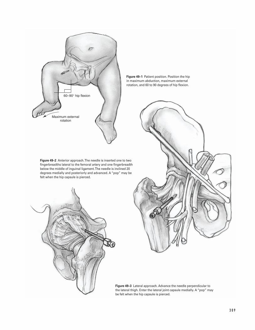
3 0 9
Maximum external rotation
60–90° hip flexion
Figure 49–1 Patient position. Position the hip in maximum abduction, maximum externalrotation, and 60 to 90 degrees of hip flexion.
Figure 49–2 Anterior approach. The needle is inserted one to twofingerbreadths lateral to the femoral artery and one fingerbreadthbelow the middle of inguinal ligament. The needle is inclined 20degrees medially and posteriorly and advanced. A “pop” may be felt when the hip capsule is pierced.
Figure 49–3 Lateral approach. Advance the needle perpendicular tothe lateral thigh. Enter the lateral joint capsule medially. A “pop” maybe felt when the hip capsule is pierced.
a. Position the hip in neutral rotation.b. Insert the needle into the skin just proximal to
the tip of the greater trochanter. Confirm place-ment with fluoroscopy.
c. Advance the needle perpendicular to the lateralthigh. Enter the lateral joint capsule medially(Fig. 49–3). A “pop” may be felt when the hipcapsule is pierced.
d. Confirm needle position by moving the thigh.The needle head should move in the oppositedirection of the hip. The tip may be felt scratch-ing the cartilage.
e. Confirm needle position utilizing radiographs orfluoroscopy. The image should show the needledirected at the center of the femoral head.
4. Reconfirm needle position with fluoroscopy.5. Consider injecting air into the joint to make fluoro-
scopic detection easier.6. Inject 1 to 3 cc of sterile saline (nonbacteriostatic).
If the saline is difficult to inject the needle is prob-ably inside the articular cartilage.
7. Attempt to withdraw the sterile saline. If the salineis difficult to withdraw, the needle is probably extra-articular.
8. Draw samples for culture and analysis when needleis believed to be correctly positioned.
9. After fluid is aspirated, but not prior to this time,inject radio-opaque dye. This procedure outlines thejoint surface and confirms that the needle positionis extra-articular.
10. Apply gentle pressure to obtain hemostasis.11. Apply sterile dressing.
Suggested ReadingsAliabadi P, Baker ND, Jaramillo D. Hip Arthrography,aspiration, block, and bursography. Radiol Clin NorthAm 1998;36:673–690.
Blake MP, Halasz SJ. Effect of X-ray contrast media onbacterial growth. Australas Radiol 1995;39:10–13.
Freiberger RH. Introducing arthrography. In: FreibergerRH, Kaye JJ, eds. Arthrography. Norwalk, CT: Appleton-Century-Crofts, 1979, pp. 1–3.
Kasser JR. Bone and Joint Infections. In: Canale ST,Beatty SH, eds. Operative Pediatric Orthopaedics. 2nd ed.St. Louis, MO: Mosby-Year Book, 1995, pp. 1128–1129.
Kilcoyne RF, Kaplan P. The lateral approach for hiparthrography. Skeletal Radiol 1992;21:239–240.
Sponseller PD, Stevens HM. Handbook of PediatricOrthopedics. Boston, MA: Little, Brown, 1997.
Tachdjian MO. Pediatric Orthopedics. 2nd ed.Philadelphia, PA: W.B. Saunders, 1990.
Towers JD. Radiographic evaluation of the hip. In: Callaghan JJ, Rosenberg AG, Rubash HE, eds. The Adult Hip. Philadelphia, PA: Lippincott-Raven,1998, pp. 338–372.
3 1 0 P E D I AT R I C S
Indications1. Thoracic curve greater than 50 degrees2. Thoracolumbar curve greater than 40 degrees3. Progressive curve greater than 40 degrees in a skele-
tally immature patient that is associated with signi-ficant spinal imbalance or that cannot be controlledwith a brace
4. Cosmetically unacceptable spinal deformity
Contraindications1. Active infection or sepsis (absolute)2. Anemia3. Cardiac, pulmonary, or other medical comorbidities
that have not been optimally managed
Preoperative Preparation1. Comprehensive physical examination including
neurologic testing if indicated2. Full-length (14 in 5 36 in) standing coronal antero-
posterior (AP) and sagittal (lateral) radiographs ofthe thoracic-lumbar-sacral spine. If desired by thesurgeon, preoperative supine right and left side-bending radiographs to assist in the selection ofspinal levels for fusion.
3. The planned instrumentation pattern (hooks, wires,screws, and rods) is drawn on the coronal radiograph.
4. Two to four units of autologous or directed donorblood should be cross-matched. Intraoperative bloodsalvage (cell-saver) may also be utilized.
5. Pulmonary function tests if indicated6. Discussion of indications, goals, perioperative care,
and common potential risks with the patient andfamily
Special Instruments, Position, and Anesthesia1. Spinal components and techniques are selected pre-
operatively.2. Prone positioning device, such as the Hall-Relton
or Wilson frame, which cushions pressure pointsand permits free expansion of the thorax and ab-domen; minimizing abdominal pressure decreasesvenous pressure, and aids in reducing intraoperativebleeding.
3. Multiple self-retaining retractors such as Weitlaner,Gelpi, and Adson-Beckman retractors
4. Somatosensensory-evoked potential (SSEP) moni-toring; motor-evoked potential (MEP) monitoring isalso used by some spine surgeons.
5. Headlamp6. Bone graft substitute and/or bone graft extender
products7. Gelfoam and thrombin8. The procedure is performed under general anesthesia.
3 1 1
C H A P T E R 5 0
Idiopathic ScoliosisPosterior Spinal Instrumentation and Fusion
Erik C. King and John J. Grayhack
Tips and Pearls1. Carefully document the preoperative neurologic
examination (motor, sensory, and reflexes) so that a comparison can be made in the event that a neu-rologic deficit is detected during the postoperativeperiod.
2. Prepare and drape the surgical area widely in casesurgical extension is required.
3. Scrutinize preoperative radiographs for:
a. Anatomic anomalies that may predispose thepatient to unexpected neurologic injury (e.g.,spina bifida occulta, hemivertebra)
b. Sagittal imbalancec. Anatomic relationships that will aid intraopera-
tive decision making (e.g., apex of deformity,relationship of iliac crest to lower vertebralbodies)
4. Intravenous antibiotics should be administered priorto the skin incision and repeated at appropriateintervals. Because of blood loss and fluid shifts, the dosing interval is shorter than in nonoperativesituations.
5. Ensure that the anesthesiologist monitors the pa-tient’s coagulation status. Baseline health status,duration of procedure, intraoperative blood loss,and temperature influence coagulation.
6. A separate skin incision to harvest iliac crest bonemay be used if the caudal end of the planned fusionends in the upper lumbar spine. Alternatively, thecrest may be approached through the spine incisionby subcutaneous dissection and a separate fascialincision directly over the iliac crest.
What To Avoid1. Avoid straying from the subperiosteal plane when
exposing the spine.2. Avoid incorrect placement of instruments in the
vicinity of the dura and/or nerve roots.3. Avoid inserting implants at unintended levels. Do
not accept a less than adequate intraoperative scoutradiograph when identifying vertebral levels. If nec-essary, repeat the radiograph.
4. Avoid ending the implanted construct in the apicesof secondary coronal or sagittal curves. Chronic insta-bility and late deformity progression may result frompartially fusing a curve.
5. Avoid imprecise use of instrumentation implants(e.g., stripping or cross-threading screws/nuts).
Postoperative Care Issues1. A suction drain is optional. If a drain is used, a
closed suction drain should be placed superficial tothe deep fascial closure.
2. Neurologic examination should be performed im-mediately after termination of general anesthesiaand repeated frequently during the postoperativeperiod. If a significant neurologic deficit develops,consider removal of the implanted instrumentation.
3. Consider patient controlled anesthesia (PCA) forpostoperative analgesia. Alternatively, epidural anes-thesia can be used if adequate pain control can beobtained without motor blockade.
4. Postoperative immobilization is not mandatory.However, some surgeons may elect to use a brace ifthey are concerned with the quality of the internalfixation.
5. The patient is allowed to sit up and take a few stepswith assistance on the day after surgery.
6. The surgical dressing is changed on the second post-operative day. It is discontinued on the fifth postop-erative day if there is no wound drainage.
Operative TechniqueThis chapter describes basic surgical techniques for per-forming a selective thoracic fusion for an idiopathicthoracic curve, King–Moe type II or III curve. There are several alternative techniques to those described.Successful techniques have in common the followingprinciples: meticulous subperiosteal dissection, clearunderstanding of the biomechanics of spinal deformity,precise technical handling of spinal implants, and thor-ough decortication of posterior elements. Several spinalinstrumentation systems are available for selection.
3 1 2 P E D I AT R I C S
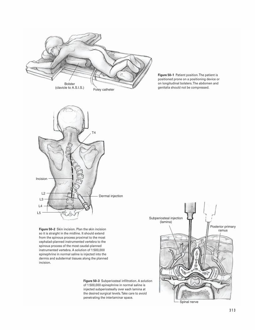
3 1 3
Spinal nerve
Subperiosteal injection (lamina)
Posterior primary ramus
Dermal injection
L5
L4
L3
L2
Incision
T4
Bolster (clavicle to A.S.I.S.) Foley catheter
Figure 50–1 Patient position. The patient ispositioned prone on a positioning device or on longitudinal bolsters. The abdomen andgenitalia should not be compressed.
Figure 50–2 Skin incision. Plan the skin incisionso it is straight in the midline. It should extendfrom the spinous process proximal to the mostcephalad-planned instrumented vertebra to thespinous process of the most caudal-plannedinstrumented vertebra. A solution of 1:500,000epinephrine in normal saline is injected into thedermis and subdermal tissues along the plannedincision.
Figure 50–3 Subperiosteal infiltration. A solutionof 1:500,000 epinephrine in normal saline isinjected subperiosteally over each lamina at the desired surgical levels. Take care to avoidpenetrating the interlaminar space.
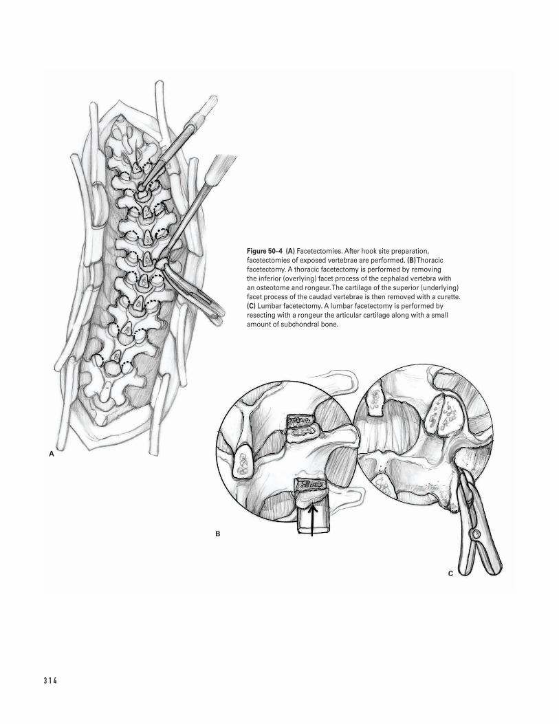
3 1 4
A
B
C
Figure 50–4 (A) Facetectomies. After hook site preparation,facetectomies of exposed vertebrae are performed. (B)Thoracicfacetectomy. A thoracic facetectomy is performed by removing the inferior (overlying) facet process of the cephalad vertebra with an osteotome and rongeur. The cartilage of the superior (underlying)facet process of the caudad vertebrae is then removed with a curette.(C) Lumbar facetectomy. A lumbar facetectomy is performed byresecting with a rongeur the articular cartilage along with a smallamount of subchondral bone.
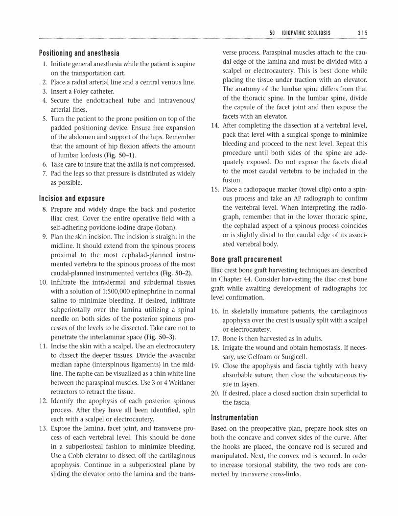
Positioning and anesthesia1. Initiate general anesthesia while the patient is supine
on the transportation cart.2. Place a radial arterial line and a central venous line.3. Insert a Foley catheter.4. Secure the endotracheal tube and intravenous/
arterial lines.5. Turn the patient to the prone position on top of the
padded positioning device. Ensure free expansionof the abdomen and support of the hips. Rememberthat the amount of hip flexion affects the amountof lumbar lordosis (Fig. 50–1).
6. Take care to insure that the axilla is not compressed.7. Pad the legs so that pressure is distributed as widely
as possible.
Incision and exposure8. Prepare and widely drape the back and posterior
iliac crest. Cover the entire operative field with aself-adhering povidone-iodine drape (Ioban).
9. Plan the skin incision. The incision is straight in themidline. It should extend from the spinous processproximal to the most cephalad-planned instru-mented vertebra to the spinous process of the mostcaudal-planned instrumented vertebra (Fig. 50–2).
10. Infiltrate the intradermal and subdermal tissueswith a solution of 1:500,000 epinephrine in normalsaline to minimize bleeding. If desired, infiltratesubperiostally over the lamina utilizing a spinalneedle on both sides of the posterior spinous pro-cesses of the levels to be dissected. Take care not topenetrate the interlaminar space (Fig. 50–3).
11. Incise the skin with a scalpel. Use an electrocauteryto dissect the deeper tissues. Divide the avascularmedian raphe (interspinous ligaments) in the mid-line. The raphe can be visualized as a thin white linebetween the paraspinal muscles. Use 3 or 4 Weitlanerretractors to retract the tissue.
12. Identify the apophysis of each posterior spinousprocess. After they have all been identified, spliteach with a scalpel or electrocautery.
13. Expose the lamina, facet joint, and transverse pro-cess of each vertebral level. This should be done in a subperiosteal fashion to minimize bleeding.Use a Cobb elevator to dissect off the cartilaginousapophysis. Continue in a subperiosteal plane bysliding the elevator onto the lamina and the trans-
verse process. Paraspinal muscles attach to the cau-dal edge of the lamina and must be divided with ascalpel or electrocautery. This is best done whileplacing the tissue under traction with an elevator.The anatomy of the lumbar spine differs from thatof the thoracic spine. In the lumbar spine, dividethe capsule of the facet joint and then expose thefacets with an elevator.
14. After completing the dissection at a vertebral level,pack that level with a surgical sponge to minimizebleeding and proceed to the next level. Repeat thisprocedure until both sides of the spine are ade-quately exposed. Do not expose the facets distal to the most caudal vertebra to be included in thefusion.
15. Place a radiopaque marker (towel clip) onto a spin-ous process and take an AP radiograph to confirmthe vertebral level. When interpreting the radio-graph, remember that in the lower thoracic spine,the cephalad aspect of a spinous process coincidesor is slightly distal to the caudal edge of its associ-ated vertebral body.
Bone graft procurementIliac crest bone graft harvesting techniques are describedin Chapter 44. Consider harvesting the iliac crest bonegraft while awaiting development of radiographs forlevel confirmation.
16. In skeletally immature patients, the cartilaginousapophysis over the crest is usually split with a scalpelor electrocautery.
17. Bone is then harvested as in adults.18. Irrigate the wound and obtain hemostasis. If neces-
sary, use Gelfoam or Surgicell.19. Close the apophysis and fascia tightly with heavy
absorbable suture; then close the subcutaneous tis-sue in layers.
20. If desired, place a closed suction drain superficial tothe fascia.
InstrumentationBased on the preoperative plan, prepare hook sites onboth the concave and convex sides of the curve. Afterthe hooks are placed, the concave rod is secured andmanipulated. Next, the convex rod is secured. In orderto increase torsional stability, the two rods are con-nected by transverse cross-links.
5 0 I D I O PAT H I C S C O L I O S I S 3 1 5
3 1 6
A
B
AB C D
Figure 50–5 (A)Thoracic claw preparation. Note the anatomy showingthe location of the pedicle and transverse process. (B)Thoracic claw. A thoracic claw consists of a caudal-facing transverse process hookand a cephalad-facing pedicle hook.
Figure 50–6 A typical maneuver sequence to treat a right thoracicscoliotic curvature. Hook positions are designated by up-going anddown-going thin arrows. Compression forces and distraction forcesthat are applied by the surgeon are designated by thick arrows. (A) After placing the hooks, the left concave rod is secured and thenslowly rotated dorsally and toward the midline. Normal thoracickyphosis is re-established. (B)The caudad claw is compressed togetherand tightened. The intermediate hooks are then distracted andtightened. (C)The cephalad and caudad claws are distracted awayfrom each other. (D)The right convex rod is placed, and then thecephalad and caudad claws of both rods are compressed andtightened. Transverse cross-link connectors are then placed.
Transverse process hook preparation (caudad-facing or down-going)
a. Expose the transverse process of the vertebra toreceive the hook. Transverse process hooks are usu-ally placed on the most cephalad vertebra instru-mented as part of a claw construct spanning one ortwo levels.
b. Pass the laminar hook starter or pedicle hook starterover the cephalad edge of the selected vertebra.Ensure that the hook starter is placed around thetransverse process since this structure can be easilybroken.
c. Remove the hook starter.
Pedicle hook preparation (cephalad-facing or up-going)
a. Make a transverse osteotomy on the inferior edge of the lamina (and inferior articular process) of thevertebra. Position the osteotomy so that the tips ofthe bifid pedicle hook will engage the pedicle as theshoulder of the hook touches the bone of the osteo-tomized inferior facet.
b. Remove the full thickness of bone at the osteotomysite with a rongeur. This should expose the articularsurface of the superior facet of the next caudalvertebra.
c. Remove the articular cartilage of the superior facetwith a curette.
d. Insert the trial pedicle hook (pedicle finder) into theprepared site and seat it gently with a mallet. Makesure that you do not split the tables of the lamina.Great care must be taken not to allow the tips ofthis instrument to slip into the spinal canal. This is best accomplished by directing the trial pediclehook in a cephalad and lateral direction.
e. Remove the pedicle hook trial.
Supralaminar hook preparation (caudad-facing or down-going)
a. Using a rongeur, remove the spinous process cepha-lad to the vertebra to receive the supralaminar hook.Continue removing bone until the instraspinousspace and the ligamentum flavum are exposed.
b. Create a 3-mm opening in the midline portion ofthe ligamentum flavum with a narrow rongeur or a #15 scalpel. Bulging epidural fat signals successfulentrance into the spinal canal.
c. Excise the ipsilateral ligamentum flavum using nar-row rongeurs and kerrison rongeurs.
d. Perform a laminotomy by using kerrosen rongeursto remove the inferior lamina of the next cephaladvertebra. Remove as little bone as possible from thesuperior edge of the lamina of the selected vertebra.Excess bone removal will compromise purchase ofthe caudally facing hook.
e. Place the laminar hook starter into the preparedspace.
f. Remove the hook starter.
Infralaminar hook preparation (cephalad-facing or up-going)
a. Using a laminar elevator, elevate the ligamentumflavum from the undersurface of the caudal edge ofthe vertebra. Stay close to the midline.
b. Insert the laminar hook starter along the tract thathas just been created underneath the caudal edge.Preserve the interspinous ligament distal to thespinous process of the most caudal instrumentedvertebra.
c. Remove the hook starter.
Facetectomy and decortication21. Remove all trial hooks and perform facetectomies
(Fig. 50–4A).22. There are several facetectomy techniques, all of
which share the goal of promoting arthrodesis of the facet joint. In the thoracic spine, remove theinferior facet with a straight or curved osteotome(Fig. 50–4B) and then curette the articular cartilageof the superior facet of the caudal vertebra. In thetechnique popularized by Moe, corticancellous bonegraft is impacted into the defect of the facet joint. Inthe lumbar spine, resect with a rongeur the articularcartilage along with a small amount of subchondralbone (Fig. 50–4C). Remember the locations of thepreviously prepared hook sites, as any further boneremoval could impair the integrity of these sites.
23. Decorticate the spinous process, the laminae, andthe transverse process with an osteotome or a power burr.
Implantation24. Measure, cut, and contour the metal rods. The con-
cave rod should conform to the normal sagittal
5 0 I D I O PAT H I C S C O L I O S I S 3 1 7
contour of the spine segment to be fused. Some sur-geons contour the convex rod with less thoracickyphosis than normal (i.e., flatter). The purpose ofthis under-contouring is to place an anterior directedcorrective force against the rib prominence.
25. Place appropriate size hooks into the previously pre-pared hook sites (Figs. 50–5A and 5B).
26. Place bone graft over the decorticated bone surfaces.27. Place the concave rod and secure it to the hooks.
The assistant should stabilize the hooks and aid inthe assembly of the components of the construct.
28. Seat the hooks by segmental distraction using a rodholder, vise grip, distraction device, and compres-sion device. The exact sequence varies among spinesurgeons.
29. Rotate the rod slowly and gently. The direction ofrotation is such that the scoliotic (coronal) contour is converted to a kyphotic (sagittal) contour (Fig.50–6A). The rod should be rotated no more than 90degrees. Check SSEP and MEP signals prior to andthroughout rod rotation. In some cases, the assis-tant can facilitate rotation by applying anterior-directed pressure over the rib prominence.
30. Check the seating of the hooks and the integrity ofthe bone-hook and hook-rod interfaces.
31. Compress together and then tighten the caudal claw(Fig. 50–6B).
32. Distract the intermediate hooks and then tighten(Fig. 50–6B).
33. Distract the cephalad and caudad claws away fromeach other (Fig. 50–6C).
34. Insert the convex rod and secure it to the hooks.Compress the hooks enough to seat them firmly.
35. Compress and tighten the cephalad and caudad clawsof both rods (Fig. 50–6D).
36. Perform a final tightening of all components.37. Connect the rods with two transverse cross-links,
one near each end.38. Irrigate the wound thoroughly.39. Place the remainder of the bone graft over exposed
bone surfaces and metal implants.
Closure40. Re-approximate the apophyses and myofascial lay-
ers with a heavy absorbable suture.41. If desired, place a suction drain superficial to the
fascial closure.42. Close the subcutaneous tissue and skin in layers.43. Apply a sterile dressing.44. Carefully turn the patient to the supine position and
transfer to the transportation cart.45. Take a long cassette AP radiograph of the spine.46. Review the radiograph for curve correction, hard-
ware position, and pneumothorax. Conclude gen-eral anesthesia if the radiographic findings aresatisfactory.
47. Perform a brief neurologic examination.48. Transfer the patient to the recovery room.
Suggested ReadingsAsher MA. Isola instrumentation. In: Bradford DS, ed.The Spine. Philadelphia, PA: Lippincott-Raven, 1997, pp. 407–434.
Cotrel Y, Dubousset J, Guillaumat M. New universalinstrumentation in spinal surgery. Clin Orthop 1988;227:10–23.
Johnston CE II, Ashman RB, Richards BS, Herring JA.TSRH universal spine instrumentation. In: Bradford KH,Bridwell RL, eds. The Textbook of Spinal Surgery.Philadelphia, PA: Lippincott-Raven, 1997, pp. 535–567.
King HA, Moe JH, Bradford DS, Winter RB. Theselection of fusion levels in thoracic idiopathicscoliosis. J Bone Joint Surg 1983;65A:1302–1313.
Shufflebarger HI. Theory and mechanisms of posteriorderotation spinal systems. In: Weinstein SI, ed. ThePediatric Spine: Principles and Practice. New York, NY:Raven Press, 1994, 1515–1543.
3 1 8 P E D I AT R I C S

Section Nine
Miscellaneous

This page intentionally left blank
Key Techniques inOrthopaedic Surgery
Indications1. Ipsilateral pelvic, acetabular, or femoral fracture as a
definitive or temporary treatment2. Preoperative soft tissue relaxation prior to limb
lengthening reconstruction3. Adjunctive aid to fracture reduction in the opera-
tive treatment of femoral or acetabular trauma
Contraindications1. Active local infection2. Significant local wound contamination3. Inadequate soft tissue envelope4. Polyligamentous knee injury or tibia fracture (avoid
tibial traction)
Preoperative Preparation1. If necessary, initial stabilization per ATLS protocols.2. Obtain appropriate biplanar radiographs to allow
for the identification and classification of the skele-tal injury.
3. Document preoperative neurovascular and soft tis-sue examination.
Special Instruments, Position, and Anesthesia1. Supine position2. Place a bump under the knee to allow for free access
to the limb.3. If available, fluoroscopy may be helpful in mini-
mizing the risk of physeal injury and/or to mark theknee joint axis in the coronal plane.
4. The procedure is generally performed under localanesthesia. The anesthetic is injected into the sub-cutaneous and subperiosteal tissues on both themedial and lateral sides of the extremity.
5. A minor surgical tray, a threaded Steinmann pin set,a hand drill, a Steinmann pin holder or Kirschnerwire bow, and a bolt cutter are required.
Tips and Pearls1. Don’t be distracted by the obvious injury. Be sure to
fully assess the entire skeletal system.2. If the skeletal injury allows, assess the ligamentous
knee integrity prior to placement of a tibial trac-tion pin.
3. The Steinmann pin must be placed orthogonal tothe long axis of the limb in all three planes. This isthe most important if traction is to be used for the
3 2 1
C H A P T E R 5 1
Femoral and Tibial Traction Pin Placement
Bradley R. Merk
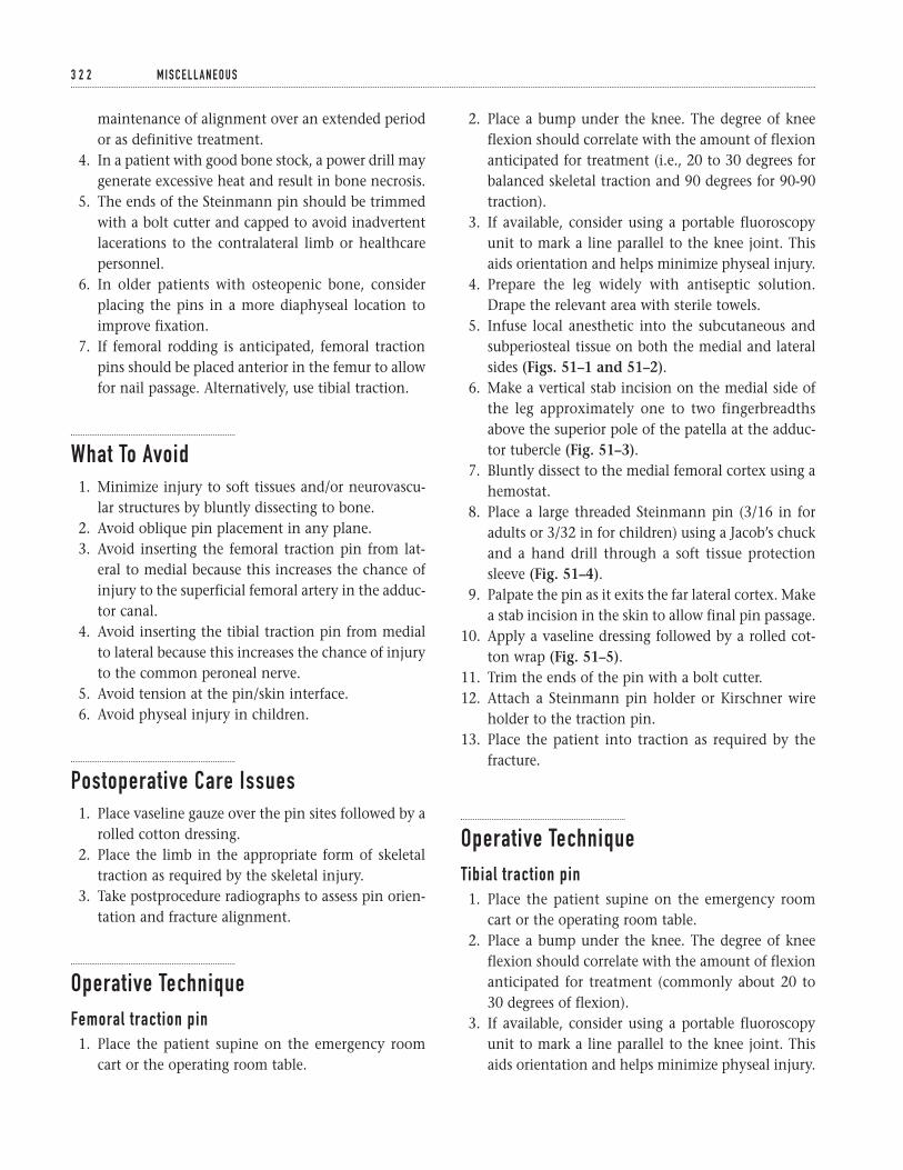
maintenance of alignment over an extended periodor as definitive treatment.
4. In a patient with good bone stock, a power drill maygenerate excessive heat and result in bone necrosis.
5. The ends of the Steinmann pin should be trimmedwith a bolt cutter and capped to avoid inadvertentlacerations to the contralateral limb or healthcarepersonnel.
6. In older patients with osteopenic bone, considerplacing the pins in a more diaphyseal location toimprove fixation.
7. If femoral rodding is anticipated, femoral tractionpins should be placed anterior in the femur to allowfor nail passage. Alternatively, use tibial traction.
What To Avoid1. Minimize injury to soft tissues and/or neurovascu-
lar structures by bluntly dissecting to bone.2. Avoid oblique pin placement in any plane.3. Avoid inserting the femoral traction pin from lat-
eral to medial because this increases the chance ofinjury to the superficial femoral artery in the adduc-tor canal.
4. Avoid inserting the tibial traction pin from medialto lateral because this increases the chance of injuryto the common peroneal nerve.
5. Avoid tension at the pin/skin interface.6. Avoid physeal injury in children.
Postoperative Care Issues1. Place vaseline gauze over the pin sites followed by a
rolled cotton dressing.2. Place the limb in the appropriate form of skeletal
traction as required by the skeletal injury.3. Take postprocedure radiographs to assess pin orien-
tation and fracture alignment.
Operative TechniqueFemoral traction pin1. Place the patient supine on the emergency room
cart or the operating room table.
2. Place a bump under the knee. The degree of kneeflexion should correlate with the amount of flexionanticipated for treatment (i.e., 20 to 30 degrees forbalanced skeletal traction and 90 degrees for 90-90traction).
3. If available, consider using a portable fluoroscopyunit to mark a line parallel to the knee joint. Thisaids orientation and helps minimize physeal injury.
4. Prepare the leg widely with antiseptic solution.Drape the relevant area with sterile towels.
5. Infuse local anesthetic into the subcutaneous andsubperiosteal tissue on both the medial and lateralsides (Figs. 51–1 and 51–2).
6. Make a vertical stab incision on the medial side ofthe leg approximately one to two fingerbreadthsabove the superior pole of the patella at the adduc-tor tubercle (Fig. 51–3).
7. Bluntly dissect to the medial femoral cortex using ahemostat.
8. Place a large threaded Steinmann pin (3/16 in foradults or 3/32 in for children) using a Jacob’s chuckand a hand drill through a soft tissue protectionsleeve (Fig. 51–4).
9. Palpate the pin as it exits the far lateral cortex. Makea stab incision in the skin to allow final pin passage.
10. Apply a vaseline dressing followed by a rolled cot-ton wrap (Fig. 51–5).
11. Trim the ends of the pin with a bolt cutter.12. Attach a Steinmann pin holder or Kirschner wire
holder to the traction pin.13. Place the patient into traction as required by the
fracture.
Operative TechniqueTibial traction pin1. Place the patient supine on the emergency room
cart or the operating room table.2. Place a bump under the knee. The degree of knee
flexion should correlate with the amount of flexionanticipated for treatment (commonly about 20 to30 degrees of flexion).
3. If available, consider using a portable fluoroscopyunit to mark a line parallel to the knee joint. Thisaids orientation and helps minimize physeal injury.
3 2 2 M I S C E L L A N E O U S
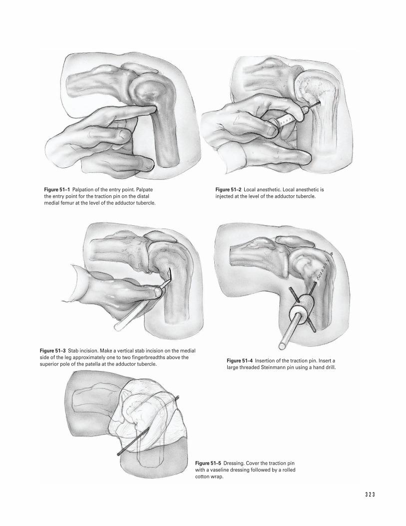
3 2 3
Figure 51–1 Palpation of the entry point. Palpatethe entry point for the traction pin on the distalmedial femur at the level of the adductor tubercle.
Figure 51–2 Local anesthetic. Local anesthetic isinjected at the level of the adductor tubercle.
Figure 51–3 Stab incision. Make a vertical stab incision on the medialside of the leg approximately one to two fingerbreadths above thesuperior pole of the patella at the adductor tubercle.
Figure 51–4 Insertion of the traction pin. Insert alarge threaded Steinmann pin using a hand drill.
Figure 51–5 Dressing. Cover the traction pin with a vaseline dressing followed by a rolledcotton wrap.
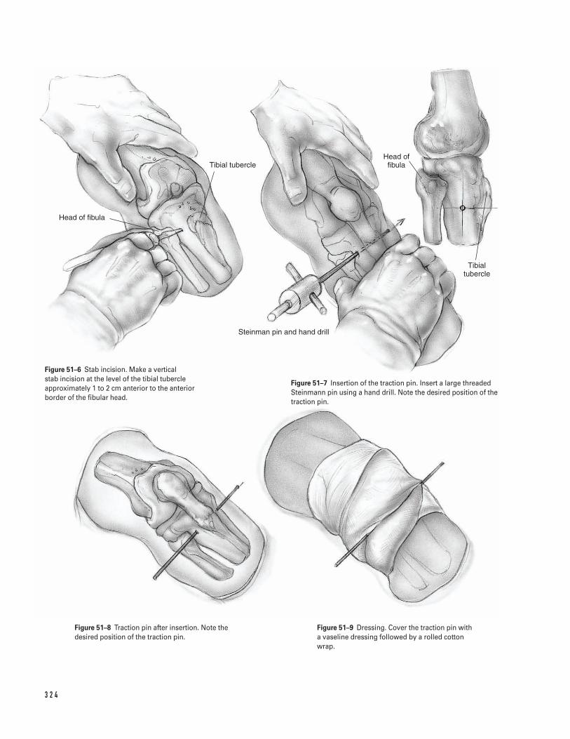
3 2 4
Head of fibula
Tibial tubercle
Steinman pin and hand drill
Head of fibula
Tibial tubercle
Figure 51–6 Stab incision. Make a vertical stab incision at the level of the tibial tubercleapproximately 1 to 2 cm anterior to the anteriorborder of the fibular head.
Figure 51–7 Insertion of the traction pin. Insert a large threadedSteinmann pin using a hand drill. Note the desired position of thetraction pin.
Figure 51–8 Traction pin after insertion. Note thedesired position of the traction pin.
Figure 51–9 Dressing. Cover the traction pin witha vaseline dressing followed by a rolled cottonwrap.

4. Prepare the leg widely with antiseptic solution. Drapethe relevant area with sterile towels.
5. Infuse local anesthetic into the subcutaneous andsubperiosteal tissue on both the medial and lateralsides.
6. Make a vertical stab incision at the level of the tib-ial tubercle approximately 1 to 2 cm anterior to theanterior border of the fibular head (Fig. 51–6).
7. Bluntly dissect to the lateral tibial cortex using ahemostat.
8. Place a large threaded Steinmann pin (3/16 in foradults or 3/32 in for children) using a Jacob’s chuck
and a hand drill through a soft tissue protectionsleeve (Fig. 51–7).
9. Palpate the pin as it exits the far medial cortex.Make a stab incision in the skin to allow final pas-sage of the pin (Fig. 51–8).
10. Apply a vaseline dressing followed by a rolled cot-ton wrap (Fig. 51–9).
11. Trim the ends of the pin with a bolt cutter.12. Attach a Steinmann pin holder or Kirschner wire
holder to the traction pin.13. Place the patient into traction as required by the
fracture.
5 1 F E M O R A L A N D T I B I A L T R A C T I O N P I N P L A C E M E N T 3 2 5

This page intentionally left blank
Key Techniques inOrthopaedic Surgery

Note: Illustrative material is represented with an “i” followingthe page on which it appears.
Abductor pollicis longusin diaphyseal fracture repair, 70iin distal radial fracture repair, 102iin extensor tendon repair, 105iin fasciotomy, 76iin metacarpal fracture repair, 89i
Acetabulumin hemiarthroplasty, 145i–146i, 147in total arthroplasty, 126, 127i, 128i
Achilles tendonin clubfoot repair, 299i–300iin patellar tendon reconstruction, 222, 224
Achilles tendon repair, 244–247indications/contraindications, 244operative technique, 245, 246i, 247postoperative care issues, 245preoperative preparation and instrumentation, 244professional hints, 244–245
ACL repair. See Anterior cruciate ligament arthroscopyAcromioclavicular joint, in shoulder arthroscopy, 21i, 23Acromion
in arthroscopic evaluation, 21i–22iin shoulder stabilization, 17i
Acromioplasty, 3–7indications/contraindications, 3operative technique, 4–7, 5i–6ipostoperative care issues, 4preoperative preparation and instrumentation, 3–4professional hints, 4in rotator cuff tendon repair, 6i, 10
Adductor hallucis, in Morton’s neuroma excision, 258iAdductor tubercle, in traction pin placement, 323iAdhesions, in rotator cuff tendon repair, 11iAllograft, Achilles, 222, 224Anconeus muscle
in diaphyseal fracture repair, 72iin radial head fracture repair, 52i
Ankle and foot, 233–263Achilles tendon repair, 244–247ankle fracture repair, 237–243. See also Open reduction and
internal fixationarthroscopy, 233–236bunion and hallux valgus repair, 248–251clubfoot repair, pediatric, 298–302hammer toe repair, 252–255Jones fracture repair, 260–263Morton’s neuroma, excision, 256–259
Anterior cruciate ligament arthroscopy, 162i
endoscopic repairindications/contraindications, 174operative technique, 175–176, 177i–178i, 179, 180i, 181postoperative care issues, 175preoperative preparation and instrumentation, 174professional hints, 174–175
two incision techniqueindications/contraindications, 167operative technique, 168, 169i–170i, 171, 172i, 173postoperative care issues, 168preoperative preparation and instrumentation, 167professional hints, 167–168
Aponeurosis, in carpal tunnel release, 84iArcade of Frohse, in radial head fracture repair, 51iArm. See specific bone or jointArthroplasty. See also Hemiarthroplasty
hip, hybrid and uncemented, 123–133indications/contraindications, 123operative technique, 125–126, 127i–128i, 129–130, 131i,
132–133postoperative care issues, 125preoperative preparation and instrumentation, 123–124professional hints, 124–125
knee, 182–189indications/contraindications, 182operative technique, 183–184, 185i–186i, 187, 188ipostoperative care issues, 183preoperative preparation and instrumentation, 182professional hints, 182–183
Arthroscope, 161iArthroscopy
in ACL repair. See Anterior cruciate ligament arthroscopyof ankle, 233–236
indications/contraindications, 233operative technique, 234, 235i, 236postoperative care issues, 234preoperative preparation and instrumentation, 233professional hints, 233–234
in knee evaluation, 159–166indications/contraindications, 159operative technique, 160, 161i–162i, 163, 164i, 165postoperative care issues, 160preoperative preparation and instrumentation, 159professional hints, 159–160
of shoulder, 20–28indications/contraindications, 20operative technique, 21i–22i, 23–27postoperative care issues, 23
3 2 7
Index

Arthroscopy (continued)preoperative preparation and instrumentation, 20, 21iprofessional hints, 20, 23
Arthrotomyin knee arthroplasty, 185i, 186in shoulder stabilization, 16, 18i
Articular cartilage, debridement in knee, 165Aspiration, of pediatric hip, 307–310
indications/contraindications, 307operative technique, 308, 309i, 310postoperative care issues, 308preoperative preparation and instrumentation, 307–308professional hints, 307–308
Avulsion injuryfifth metatarsal fracture repair, 260, 262ito metacarpal joint, repair, 106i, 107patella fracture repair, 214i
Awl insertionin femoral shaft fracture repair, 154iin tibial shaft fracture repair, 206, 207i
Axillary nervein open reduction and internal fixation of humerus
for proximal fracture, 31ifor shaft fracture, 43i
in shoulder stabilization, 17i
Bankart lesion repair, 16, 18iBeath instrumentation
in ACL repair, 180iin extensor tendon repair, 219i–220i, 221
Bennett’s fracture repair, 88, 89i–90iBiceps brachii muscle, in humeral shaft fracture repair, 43iBiceps brachii tendon, in shoulder arthroscopy, 21iBiceps tendon
in diaphyseal fracture repair, 69iin humeral fracture repair
of humeral shaft, 43iof proximal humerus, 31i
in shoulder stabilization, 17iBicipital groove, in proximal humerus fracture repair, 31iBipolar reduction, in hip hemiarthroplasty, 149i, 150Bipolar shell, in hip hemiarthroplasty, 149i, 150Bone graft. See GraftsBrachialis, in humeral shaft fracture repair, 44iBrachioradialis muscle
in diaphyseal fracture repair, 69iin forearm fasciotomy, 76iin humeral shaft fracture repair, 44i
Broaching. See Femoral canal broachingBucket handle meniscus tear, repair, 165Bunion and hallux valgus repair, 248–251
indications/contraindications, 248operative technique, 249i, 251postoperative care issues, 251preoperative preparation and instrumentation, 248professional hints, 248
Bursain high tibial osteotomy, 193iin shoulder, arthroscopic removal, 22i
Bursitis, subacromial, 21iButtress plate, volar, 96i
Calcaneofibular ligament, in clubfoot repair, 299iCalcaneus
in Achilles tendon repair, 246iin clubfoot repair, 300i
Capsulotomyin ACL repair, 170iin bunion and hallux valgus repair, 249i–250i, 251in clubfoot repair, 299i–300iin metacarpal fracture repair, 89iin shoulder stabilization, 17i–18i
Carotid, in cervical spine repair, 275iCarpal ligament. See Transverse carpal ligamentCarpal tunnel release, 81–85
indications/contraindications, 81operative technique, 82, 83i–84ipostoperative care issues, 82preoperative preparation and instrumentation, 81professional hints, 81–82
Cartilage debridementin cervical spine, 276iin knee, 165in thoracic facetectomy, 314i
Cauda equinain discectomy, 270iin spinal fusion, 281i
Cement insertionin hip hemiarthroplasty, 146i, 150in total hip arthroplasty, 130, 131i
Central slip insertion, in extensor tendon repair, 105iCephalic vein
in humeral shaft fracture repair, 43iin shoulder stabilization, 17i
Cervical spine, anterior approach, 272–278Chamfer cuts, in knee arthroplasty, 187, 188iChevron osteotomy, in bunion and hallux valgus repair, 250i,
251Clavicle
in acromioplasty, 4, 5iin shoulder arthroscopy, 21i
Claw toe repair, 253, 254i, 255Clubfoot repair, pediatric, 298–302
indications/contraindications, 298operative technique, 299i–300i, 301–302postoperative care issues, 301preoperative preparation and instrumentation, 298professional hints, 298, 301
Coagulation, in diaphyseal fracture repair, 69iCollateral ligament, in metacarpal fracture repair, 118iComminuted fracture, open reduction and internal fixation, 88Compression fracture repair, tibial, 201i–202i, 203–204Condylar plate, in metacarpal fracture repair, 118i, 119Coracoacromial ligament, in shoulder arthroscopy, 21i–22iCoracobrachialis muscle, in humeral shaft fracture repair, 43iCoracohumeral ligament
in rotator cuff tendon repair, 10, 11i, 13in shoulder stabilization, 18i
Coracoid processin shoulder arthroscopy, 21i–22iin shoulder stabilization, 17i
Decompression, of lumbar spine, 285–290
3 2 8 I N D E X

indications/contraindications, 285operative technique, 287i–288i, 289–290postoperative care issues, 286, 289preoperative preparation and instrumentation, 285–286professional hints, 286
Decortication, in spinal fusion, 282i, 284for idiopathic scoliosis repair, 314i, 317
Deltapectoral groove, in humeral shaft fracture repair, 43iDeltoid ligament, in clubfoot repair, 300iDeltoid muscle
in acromioplasty, 4, 5i–6i, 7, 10in humeral shaft fracture repair, 43iin rotator cuff tendon repair, 5i, 10, 13in shoulder stabilization, 17i
Deltoid tuberosity, 43iDeltopectoral skin incision, in humeral hemiarthroplasty, 35,
37iDiaphyseal fracture repair, in forearm, 66–73
indications/contraindications, 66operative technique, 68, 69i–70i, 71, 72i, 73postoperative care issues, 68preoperative preparation and instrumentation, 66–67professional hints, 67–68
Disc herniation, 270iDiscectomy
of cervical spine, anterior approach, 272–278indications/contraindications, 272operative technique, 274, 275i–276i, 277–278postoperative care issues, 274preoperative preparation and instrumentation, 272–273professional hints, 273–274
of lumbar spine, 267–271indications/contraindications, 267operative technique, 268–269, 270i, 271postoperative care issues, 268preoperative preparation and instrumentation, 267professional hints, 268
Distal humeral fracture repair, 60–65indications/contraindications, 60operative technique, 61i–62i, 63–65postoperative care issues, 63preoperative preparation and instrumentation, 60, 63professional hints, 63supracondylar, pediatric
indications/contraindications, 303operative technique, 304, 305i, 306postoperative care issues, 304preoperative preparation and instrumentation, 303professional hints, 304
Distal radial fracture repair. See External fixation; Openreduction and internal fixation
Dorsal forearm fasciotomy. See FasciotomyDorsalis pedis artery, in ankle arthroscopy, 235iDrill holes
in ACL repair, 170i, 180iin ankle fracture repair, 239iin knee arthroplasty, 184, 186iin olecranon osteotomy, 62iin proximal humerus fracture repair, 31iin tendon repairof patellar rupture, 220i, 221–222, 223i
of quadriceps rupture, 218, 219i, 221in tibial shaft fracture repair, 208iin traction pin placement, 323i–324i
Elbowanatomy, 60, 61iin diaphyseal fracture repair, 70i, 72iin humeral fracture repair
of distal fracture, 60–65of supracondylar fracture, 304, 305i, 306
in olecranon fracture repair, 54–59in radial head fracture repair, 49–53
Endoscopy. See Anterior cruciate ligament arthroscopyEpibasal fracture repair, 88, 89iEpicondyle. See Lateral epicondyle; Medial epicondyleEpitendinous suture, in flexor tendon repair, 112iExpansion hood, in metacarpal fracture repair, 118iExtensor carpi radialis brevis
in diaphyseal fracture repair, 70iin distal radial fracture repair, 102iin extensor tendon repair, 105iin forearm fasciotomy, 76i
Extensor carpi radialis longusin diaphyseal fracture repair, 70iin distal radial fracture repair, 102iin extensor tendon repair, 105iin forearm fasciotomy, 76i
Extensor carpi ulnarisin diaphyseal fracture repair, 72iin extensor tendon repair, 105iin radial head fracture repair, 52i
Extensor digitorum communisin diaphyseal fracture repair, 70iin distal radial fracture repair, 101iin extensor tendon repair, 105iin forearm fasciotomy, 76i
Extensor hood, in metacarpal fracture repair, 118iExtensor indicis, in distal radial fracture repair, 101iExtensor muscles, in tibial plateau fracture repair, 201iExtensor pollicis brevis
in diaphyseal fracture repair, 70iin distal radial fracture repair, 102iin extensor tendon repair, 105iin forearm fasciotomy, 76iin metacarpal fracture repair, 89i
Extensor pollicis longusin diaphyseal fracture repair, 70iin distal radial fracture repair, 95iin extensor tendon repair, 105iin forearm fasciotomy, 76i
Extensor retinaculumin distal radial fracture repair, 95iin extensor tendon repair, 105i–106i, 107
Extensor tendon repairin hand and wrist, 104–108
indications/contraindications, 104operative technique, 105i–106i, 107–108postoperative care issues, 107preoperative preparation and instrumentation, 104professional hints, 104, 107
in leg, 217–224
I N D E X 3 2 9

Extensor tendon repair (continued)indications/contraindications, 217operative technique, 218, 219i–220i, 221–222, 223i, 224patellar rupture, 218, 220i, 221–222, 223i, 224postoperative care issues, 218preoperative preparation and instrumentation, 217–218professional hints, 218quadriceps rupture, 218, 219i, 221
Extensor tendonsin metacarpal fracture repair, 118izones, 104, 105i
External fixationof distal radial fracture, 98–103
indications/contraindications, 98operative technique, 99–100, 101i–102ipostoperative care issues, 99preoperative preparation and instrumentation, 98professional hints, 98–99
in metacarpal fracture repair, 90iExternal rotator of hip
in hemiarthroplasty, 149i, 150in total arthroplasty, 125, 127i, 131i, 133
Extramedullary tibial alignment guide, in knee arthroplasty,184, 186i
Facet joint, of vertebrain idiopathic scoliosis repair, 314i, 317in lumbar decompression, 288iin lumbar discectomy, 270iin spinal fusion, 281i–282i, 284
Facetectomy, in idiopathic scoliosis repair, 314i, 317Fascia
in carpal tunnel release, 82, 83iin cervical spine repair, 275iin hip fracture repair, 135, 137i–138i, 139in spinal fusion, 281i
Fasciotomyforearm, 74–77
indications/contraindications, 74operative technique, 75, 76i, 77postoperative care issues, 75preoperative preparation and instrumentation, 74professional hints, 74
tibial, 225–229indications/contraindications, 225operative technique, 226, 227i–228ipostoperative care issues, 226preoperative preparation and instrumentation, 225professional hints, 225–226
Femoral artery, in pediatric hip aspiration, 309iFemoral canal broaching
in hip hemiarthroplasty, 146i, 147in total hip arthroplasty, 128i, 132
Femoral condyle, arthroscopic evaluation, 162i, 164iFemoral neck osteotomy
in hip hemiarthroplasty, 145i, 147in total hip arthroplasty, 126, 127i
Femoral-tibial angle, in supracondylar femoral osteotomy, 196,197i
Femur, 123–156in ACL repair, 170i, 171, 172i, 173, 179, 180i, 181
in arthroplastyof hip, 123–133of knee, 184, 185i–186i, 187, 188i
in epiphysis repair, pediatric, 293–297in hip fracture repair
hemiarthroplasty, 142–150internal fixation, 134–141intramedullary rodding, 151–156
osteotomy. See Femoral neck osteotomy; Supracondylarfemoral osteotomy
shaft fracture repair. See Intramedullary roddingtraction pin placement, 321–325
Fibulain ankle fracture repair, 238, 239iin clubfoot repair, 299iin high tibial osteotomy, 193iin tibial fasciotomy, 228iin tibial fracture repair
of plateau fracture, 201iof shaft fracture, 208i
in traction pin placement, 324iFibular fixation, in ankle fracture repair, 239i, 241Fibular-lateral malleolar fracture, 238, 239iFifth metacarpal. See Metacarpal fracturesFifth metatarsal, Jones fracture repair, 260–263Figure four position, in knee arthroscopy, 162i, 163Fixation. See specific type of fixationFlavectomy, 269, 270iFlexor carpi radialis
in carpal tunnel release, 83i–84iin diaphyseal fracture repair, 69iin distal radial fracture repair, 96iin forearm fasciotomy, 76iin metacarpal fracture repair, 89i
Flexor carpi ulnarisin carpal tunnel release, 84iin diaphyseal fracture repair, 72iin forearm fasciotomy, 76i
Flexor digitorum longusin clubfoot repair, 300iin tibial fasciotomy, 228i
Flexor digitorum profundusin carpal tunnel release, 84iin diaphyseal fracture repair, 72iin flexor tendon repair, 111i–112i
Flexor digitorum superficialisin carpal tunnel release, 83i–84iin flexor tendon repair, 111i, 112in forearm fasciotomy, 76i
Flexor hallucis longus, in clubfoot repair, 300iFlexor pollicis longus, in diaphyseal fracture repair, 69iFlexor sheath, in flexor tendon repair, 110, 111i–112i, 113Flexor tendon repair, 109–113
indications/contraindications, 109operative technique, 110, 111i–112i, 113postoperative care issues, 110preoperative preparation and instrumentation, 109professional hints, 109–110
Flexor tendonsin diaphyseal fracture repair, 69iin distal radial fracture repair, 96i
3 3 0 I N D E X

zones, 110Foot. See Ankle and footForearm. See also Elbow; Radius; Ulna
fasciotomy, 74–77Frohse, Arcade of, in radial head fracture repair, 51iFusion. See Spinal fusion
Gastrocnemius, in tibial fasciotomy, 227iGemellus muscle
in hip hemiarthroplasty, 145iin total hip arthroplasty, 127i
Genu valgum, 191iGlenohumeral ligament, in shoulder arthroscopy, 22iGlenoid fossa
in shoulder arthroscopy, 22iin shoulder stabilization, 18i
Gluteus maximus, in femoral shaft fracture repair, 152, 153iGrafts
in ACL repair. See Anterior cruciate ligament arthroscopyin cervical spine repair, 276i, 277–278in idiopathic scoliosis repair, 315in metacarpal fracture repair, 90iin spinal fusion, 282i, 284in tibial plateau fracture repair, 202i
Guide pins/wires/rods. See Pin placement; Rod placement; Wireplacement
Hallux valgus. See Bunion and hallux valgus repairHammer toe repair, 252–255
indications/contraindications, 252operative technique, 253, 254i, 255postoperative care issues, 253preoperative preparation and instrumentation, 252professional hints, 252–253
Hand. See Wrist and handHarpoon guideline, 180iHeel crease, in clubfoot repair, 299iHemiarthroplasty
for hip fracture, 142–150external rotator exposure, 145i, 147indications/contraindications, 142operative technique, 144, 145i–146i, 147–148, 149i, 150postoperative care issues, 144preoperative preparation and instrumentation, 142–143professional hints, 143–144
for proximal humerus fracture, 34–39indications/contraindications, 34operative technique, 35–36, 37i–38i, 39postoperative care issues, 35preoperative preparation and instrumentation, 34professional hints, 35
Henry approach, in radial diaphysis fracture repair, 67, 68, 69i,71
Herniated disc, in lumbar discectomy, 270iHewson button, 180iHip, 123–156
in ankle arthroscopy, 235iarthroplasty, 123–133fracture, 137i. See also specific procedure
hemiarthroplasty, 142–150internal fixation, 134–141
intramedullary rodding, 151–156pediatric
aspiration, 307–310femoral epiphysis repair, 293–297
Hip reduction, in arthroplasty, 130, 131iHook of hamate, in carpal tunnel release, 84iHook placement, in idiopathic scoliosis repair, 316i, 317Hughston suture passer, 219i–220i, 221Humeral bed, in rotator cuff tendon repair, 12i, 13Humerus
distal fracture. See Distal humeral fracture repairproximal fracture. See Hemiarthroplasty; Open reduction and
internal fixationshaft fracture. See Open reduction and internal fixationin shoulder arthroscopy, 21i–22i
Idiopathic scoliosis repair, 311–318. See also Spinal fusionIliac crest graft harvest
in cervical spine, 276i, 277–278in idiopathic scoliosis repair, 315in spinal fusion, 282i, 284
Iliocostalis muscle, in lumbar spine fusion, 281iIndex extensors, in distal radial fracture repair, 101iInferior capsule
in hip hemiarthroplasty, 145iin total hip arthroplasty, 127i
Inferior tibiofibular ligament, in clubfoot repair, 300iInguinal ligament, in pediatric hip aspiration, 309iInsufflation, in ankle arthroscopy, 235iIntercondylar notch, arthroscopic evaluation, 162iInterdigital artery and nerve, in Morton’s neuroma excision,
256–257, 258iInterfragmentary screws, in metacarpal fracture repair, 118i,
119Interior gemellus muscle
in hip hemiarthroplasty, 145iin total hip arthroplasty, 127i
Intermetatarsal ligament, in Morton’s neuroma excision, 258iInternal fixation
of hip fractureindications/contraindications, 134operative technique, 135–136, 137i–138i, 139, 140i, 141postoperative care issues, 135preoperative preparation and instrumentation, 134professional hints, 134–135
of Jones fracture, 260–263indications/contraindications, 260operative technique, 261, 262ipostoperative care issues, 261preoperative preparation and instrumentation, 260–261professional hints, 261
open reduction and. See Open reduction and internalfixation
Interosseous musclein distal radial fracture repair, 101iin metacarpal fracture repair, 118i
Interosseous nervein diaphyseal fracture repair, 69i–70iin radial head fracture repair, 50, 51i
Interphalangeal joint, in hammer toe repair, 252–253, 254i, 255Intertransversarii muscles, in lumbar spine fusion, 281i
I N D E X 3 3 1

Intertrochanteric fracture, 137iIntramedullary rodding
of femoral shaft, 151–156indications/contraindications, 151operative technique, 152, 153i–154i, 155–156postoperative care issues, 152preoperative preparation and instrumentation, 151professional hints, 151–152
of tibial shaft, 205–210indications/contraindications, 205operative technique, 206, 207i–208i, 209–210postoperative care issues, 206preoperative preparation and instrumentation, 205professional hints, 205–206
Joints. See Arthroplasty; Arthroscopy; specific jointJones fracture repair. See Internal fixation
K-wires. See Kirschner wire placementKeith needle, 219i–220i, 221Kerrosen instrumentation
in lumbar decompression, 288iin lumbar discectomy, 270i
Kirschner wire placementin bunion and hallux valgus repair, 250i, 251in clubfoot repair, 300i, 302in distal radial fracture repair, 102iin hammer toe repair, 252–253, 254i, 255in metacarpal fracture repair, 90i, 117i–118i, 119in olecranon fracture repair, 55iin patella fracture repair, 212, 213i, 215
KneeACL repair. See Anterior cruciate ligament arthroscopyin ankle arthroscopy, 235iarthroplasty, 182–189arthroscopic evaluation, 159–166extensor tendon rupture repair, 217–224patella. See Patellatraction pin placement, 321–325
Krakow suturesin Achilles tendon repair, 246i, 247in patellar rupture repair, 220i, 221–222, 223i, 224in quadriceps rupture repair, 219i, 221
Labral reattachment, in shoulder stabilization, 16Lamina, vertebral
in discectomy, 269, 270i, 271in idiopathic scoliosis repair, 313iin lumbar decompression, 288i, 290in spinal fusion, 281i–282i, 284
Langer’s linesin cervical spine repair, 275iin rotator cuff tendon repair, 4, 5i, 10
Lateral decubitus positionin hip hemiarthroplasty, 143, 144, 145iin total hip arthroplasty, 124, 125, 127i
Lateral epicondylein ACL repair, 177iin diaphyseal fracture repair, 70iin humeral fracture repair
of shaft fracture, 43i
of supracondylar fracture, 305iin olecranon fracture repair, 55iin radial head fracture repair, 52i
Lateral femoral condyle, arthroscopic evaluation, 162i, 164iLateral intermuscular septum, in humeral shaft fracture repair,
43i–44iLateral meniscus tear, arthroscopic evaluation, 164iLateral supracondylar ridge, in radial head fracture repair, 52iLateral tibial plateau
arthroscopic evaluation, 164ifracture repair. See Open reduction and internal fixation
Latissimus dorsi muscle, in humeral shaft fracture repair, 43iLeg. See specific bone or jointLesser tuberosity, in proximal humerus fracture repair, 31iLigaments. See specific ligamentLigamentum flavum
in discectomy, 270iin lumbar decompression, 287i, 290in spinal fusion, 281i
Limited transverse capsular incision, in metacarpal fracturerepair, 89i
Lister’s tuberclein diaphyseal fracture repair, 70iin distal radius fracture repair, 95i
Longissimus muscle, in lumbar spine fusion, 281iLongus coli, in cervical spine repair, 275iLumbar artery, in spinal fusion, 281iLumbar musculature
in discectomy, 269, 270iin spinal fusion, 281i, 283
Lumbar spinedecompression, 285–290discectomy, 267–271facetectomy, in idiopathic scoliosis repair, 314ifusion, 279–284
Mallet toe repair, 252–253, 254i, 255Mattress core suture, in flexor tendon repair, 112iMedial epicondyle
in ACL repair, 172iin distal humeral fracture repair, 62iin humeral supracondylar fracture repair, 305i
Medial femoral condyle, arthroscopic evaluation, 162iMedial malleolar fracture, 240i, 242, 243Medial meniscus tear, arthroscopic evaluation, 162iMedial tibial plateau, arthroscopic evaluation, 162iMedian nerve
in carpal tunnel release, 83i–84iin diaphyseal fracture repair, 69iin distal radial fracture repair, 96iin forearm fasciotomy, 76iin metacarpal fracture repair, 89iin open reduction and internal fixation
of distal radial fracture, 96iof humeral shaft fracture, 43i
Meniscectomy, partial, 165Meniscus
arthroscopic evaluation, 162i, 164ipartial meniscectomy, 165
Metacarpal bones, in distal radial fracture repair, 102iMetacarpal fractures, open reduction and internal fixation
3 3 2 I N D E X

at base of thumb, 86–91indications/contraindications, 86operative technique, 88, 89i–90i, 91postoperative care issues, 87–88preoperative preparation and instrumentation, 86–87professional hints, 87
of fifth metacarpal, 114–120indications/contraindications, 114operative technique, 116, 117i–118i, 119–120postoperative care issues, 116preoperative preparation and instrumentation, 114–115professional hints, 115–116
Metacarpal jointsin extensor tendon repair, 105i–106iin flexor tendon repair, 111i–112i
Metaphyseal osteotomy, in hammer toe repair, 254i, 255Metatarsals. See Ankle and footMetatarsophalangeal joint, in hammer toe repair, 252–253,
254i, 255Morton’s neuroma excision, 256–259
indications/contraindications, 256operative technique, 257, 258ipostoperative care issues, 257preoperative preparation and instrumentation, 256professional hints, 256–257
MTP joint, in hammer toe repair, 252–253, 254i, 255Multifidus muscle, in spinal fusion, 281i
Nail positionin femoral shaft fracture repair, 154i, 155in tibial shaft fracture repair, 208i
Neuroma, Morton’s neuroma excision, 256–259Notchplasty, in ACL repair
endoscopic, 176, 177itwo incision technique, 169i, 171
Obturator externusin hip hemiarthroplasty, 145iin total hip arthroplasty, 127i
Obturator internusin hip hemiarthroplasty, 145iin total hip arthroplasty, 127i
Olecranon, in humeral fracture repairosteotomy, 62i, 64of shaft fracture, 44i
Olecranon fracture repair, 54–59indications/contraindications, 54operative technique, 55i–56i, 57–59postoperative care issues, 57preoperative preparation and instrumentation, 54professional hints, 54, 57
Open acromioplasty. See AcromioplastyOpen anterior shoulder stabilization. See Shoulder stabilizationOpen carpal tunnel release. See Carpal tunnel releaseOpen reduction and internal fixation
of ankle fracture, 237–243indications/contraindications, 237operative technique, 238, 239i–240i, 241–243postoperative care issues, 238preoperative preparation and instrumentation, 237–238professional hints, 238, 239i
of distal radial fracture, 92–97indications/contraindications, 92operative technique, 93–94, 95i–96i, 97postoperative care issues, 93preoperative preparation and instrumentation, 92–93professional hints, 93
of humeral shaft fracture, 40–45indications/contraindications, 40operative technique, 41–42, 43i–44ipostoperative care issues, 41preoperative preparation and instrumentation, 40–41professional hints, 41
of lateral tibial plateau fracture, 199–204of metacarpal fracture. See Metacarpal fracturesof proximal humeral fracture, 29–33
indications/contraindications, 29operative technique, 30, 31i–32ipostoperative care issues, 30preoperative preparation and instrumentation, 29professional hints, 29
of tibial plateau fracture, 199–204indications/contraindications, 199operative technique, 200, 201i–202i, 203–204postoperative care issues, 200preoperative preparation and instrumentation, 199–200professional hints, 200
Open rotator cuff tendon repair. See Rotator cuff tendon repairOsteophytes, removal from cervical spine, 272, 273, 274, 276i,
277Osteotomy
in bunion and hallux valgus repair, 250i, 251femoral. See Femoral neck osteotomy; Supracondylar femoral
osteotomyin hammer toe repair, 254i, 255high tibial, 190–194
indications/contraindications, 190operative technique, 191i, 192, 193i, 194postoperative care issues, 192preoperative preparation and instrumentation, 190, 191iprofessional hints, 190, 192
olecranon, in distal humeral fracture repair, 62i, 64
Palmar forearm fasciotomy. See FasciotomyPalmaris longus
in carpal tunnel release, 83iin forearm fasciotomy, 76iin metacarpal fracture repair, 89i
Paravertebral fascia, in spinal fusion, 281iPars, in spinal fusion, 282i, 284Partial meniscectomy, 165Patella
in high tibial osteotomy, 193iin knee arthroplasty, 185iin tendon repair
of patellar rupture, 220i, 221–222, 223i, 224of quadriceps rupture, 218, 219i–220i, 221
in tibial shaft fracture repair, 207iin traction pin placement, 323i
Patella fracture repair, 211–216indications/contraindications, 211operative technique, 212, 213i–214i, 215–216
I N D E X 3 3 3

Patella fracture repair (continued)postoperative care issues, 212preoperative preparation and instrumentation, 211professional hints, 211–212
Patellar tendonin ACL repair, 169i, 177iin high tibial osteotomy, 191i, 193irupture repair, 217–224. See also Extensor tendon repair
Patellectomy, 215Pectoralis major
in humeral shaft fracture repair, 43iin shoulder stabilization, 17i
Pediatric procedures, 293–318clubfoot repair, 298–302distal humeral supracondylar fracture repair, 303–306femoral epiphysis repair, 293–297hip aspiration, 307–310idiopathic scoliosis repair, 311–318
Pedicle, of vertebral archin discectomy, 270iin lumbar decompression, 288iin spinal fusion, 281i
Percutaneous pinning, in metacarpal fracture repair, 89i, 116,117i, 119
Periosteumin ankle fracture repair, 239iin diaphyseal fracture repair, 70iin distal radial fracture repair, 95i, 102iin humeral shaft fracture repair, 44iin metacarpal fracture repair, 118i, 119in tibial plateau fracture repair, 201i–202i
Peroneal artery, in tibial fasciotomy, 227iPeroneal muscles, in tibial fasciotomy, 227iPeroneal nerve
in ankle arthroscopy, 235iin tibial fasciotomy, 227i
Peroneal tendon, in clubfoot repair, 299iPeroneal vein, in tibial fasciotomy, 227iPhalanges. See Ankle and Foot; Wrist and handPin placement
in ACL repairendoscopic technique, 178i, 179, 180i, 181two incision technique, 171, 172i–173i
in bunion and hallux valgus repair, 250i, 251in clubfoot repair, 300iin femoral and tibial traction, 321–325
indications/contraindications, 321operative technique, 322, 323i–324i, 325postoperative care issues, 322preoperative preparation and instrumentation, 321professional hints, 321–322
in femoral epiphysis repair, pediatric, 293–297indications/contraindications, 293operative technique, 294, 295i–296i, 297postoperative care issues, 294preoperative preparation and instrumentation, 293professional hints, 293–294
in high tibial osteotomy, 191i, 192in humeral supracondylar fracture repair, 304, 305i, 306in internal fixation of hip fracture, 136, 138iin metacarpal fracture repair, 89i–90i, 116, 117i
in radial fracture repair, 100, 101i–102iPIP joint. See Proximal interphalangeal jointPiriformis fossa
in femoral shaft fracture repair, 153i–154i, 155in hip hemiarthroplasty, 145iin total hip arthroplasty, 127i
Pisiform, in carpal tunnel release, 84iPituitary forceps, 270iPlantaris tendon augmentation, 246i, 247Plate fixation
in distal humeral fracture repair, 62i, 64in distal radial fracture repair, 95i–96iin metacarpal fracture repair, 90i, 118iin olecranon fracture repair, 56i, 58in tibial plateau fracture repair, 202i
Plateau fracture, tibial. See Open reduction and internalfixation
Popliteal fossain ankle arthroscopy, 235iin high tibial osteotomy, 193i
Popliteus tendon, arthroscopic evaluation, 164iPortals, arthroscopic
in ankle, 235iin knee, 160, 161i, 163in ACL repair, 169i–170i, 177i–178i, 180iin shoulder, 21i, 23
Posterior cruciate ligament, in knee arthroplasty, 184, 188iPosteromedial and posterolateral releases, of clubfoot, 298–302Pronator quadratus
in diaphyseal fracture repair, 69iin distal radial fracture repair, 96i
Pronator teres, in diaphyseal fracture repair, 69iProsthesis placement
in hemiarthroplastyof hip, 149i, 150of proximal humerus, 36, 37i
in hip arthroplastyacetabular component, 128ifemoral component, 130, 131i, 132, 133
in knee arthroplasty, 184, 188iProximal extensor tendon repair, 106i, 107Proximal fifth metatarsal, Jones fracture repair, 260–263Proximal humerus fracture. See Hemiarthroplasty; Open
reduction and internal fixationProximal interphalangeal joint
in avulsion injury repair, 106i, 107in hammer toe repair, 252–253, 254i
Pulley system, in flexor tendon repair, 111i
Quadriceps tendonin knee arthroplasty, 185irupture repair, 217–224. See also Extensor tendon repair
Radial arteryin carpal tunnel release, 83iin diaphyseal fracture repair, 69iin distal radial fracture repair, 96iin forearm fasciotomy, 76iin metacarpal fracture repair, 89i
Radial head fracture repair, 49–53indications/contraindications, 49
3 3 4 I N D E X

operative technique, 50, 51i–52i, 53postoperative care issues, 50preoperative preparation and instrumentation, 49professional hints, 50
Radial nervein diaphyseal fracture repair, 70iin distal radial fracture repair, 95i, 101iin humeral shaft fracture repair, 41, 43i–44iin metacarpal fracture repair, 89iin radial head fracture repair, 52i
Radiala, in diaphyseal fracture repair, 69iRadiocarpal ligaments
in diaphyseal fracture repair, 69iin distal radial fracture repair, 96i
Radiohumeral joint, in radial head fracture repair, 50, 52iRadius
in carpal tunnel release, 84idiaphyseal fracture. See Diaphyseal fracture repair, in forearmdistal fracture. See External fixation; Open reduction and
internal fixationradial head fracture. See Radial head fracture repair
Raffe, in extensor tendon repair, 105i–106iRamus, in idiopathic scoliosis repair, 313iReaming
acetabular, 128iin femoral shaft fracture repair, 155
Reconstruction plates. See Plate fixationRetinaculum
in ankle arthroscopy, 235iin knee arthroplasty, 183, 185i
Retractor, self-retaining, in lumbar discectomy, 270iRod placement
in femoral shaft fracture repair, 154i, 155in idiopathic scoliosis repair, 317–318intramedullary. See Intramedullary roddingin tibial shaft fracture repair, 208i, 209
Rolando’s fracture, open reduction and internal fixation, 88,90i
Rotator cuff, in acromioplasty, 6i, 7, 10Rotator cuff tendon repair, 8–13
indications/contraindications, 8operative technique, 9–13, 11i–12ipostoperative care issues, 9preoperative preparation and instrumentation, 8–9professional hints, 9
Rotator interval repair, in proximal humeral hemiarthroplasty,38i, 39
Running lock suture, in flexor tendon repair, 112i
Safe zone, in radial head fracture repair, 51i, 53Sagittal band
in extensor tendon repair, 105iin metacarpal fracture repair, 118i, 119
Saphenous nerve, in tibial fasciotomy, 227i–228iSaphenous vein
in ankle arthroscopy, 235iin tibial fasciotomy, 227i–228i
Scaphoid tubercle, in carpal tunnel release, 84iScoliosis. See Spinal fusion, in idiopathic scoliosisScrew fixation/insertion
in ACL repair, 172i, 173, 180i, 181
in ankle fracture repair, 239iin femoral shaft fracture repair, 154i, 155–156in internal fixation of hip fracture, 136, 139, 140iin Jones fracture repair, 262i, 263in metacarpal fracture repair, 90i, 118iin patella fracture repair, 213i–214iin pediatric femoral epiphysis repair, 294, 296i, 297in tibial repair
of plateau fracture, 200, 202i, 203of shaft fracture, 208i, 210
Segmental lumbar artery, in spinal fusion, 281iSelf-retaining retractor, in lumbar discectomy, 270iSeptum, intermuscular
in humeral shaft fracture repair, 43i–44iin tibial fasciotomy, 227i
Shear fracture, repair in distal radius, 96iShoulder
arthroscopy, 20–28in humeral fracture repair
hemiarthroplasty, 34–39open reduction and internal fixation, 29–33, 43i
rotator cuff damageacromioplasty, 3–7tendon repair, 8–13
stabilization, 14–19Shoulder stabilization, 14–19
indications/contraindications, 14operative technique, 15-19, 17i–18ipostoperative care issues, 15preoperative preparation and instrumentation, 14professional hints, 14–15
Skin incisionin acromioplasty, 4, 5iin ankle or foot
for Achilles tendon repair, 246i, 247for ankle fracture repair, 239i–240i, 241for bunion and hallux valgus repair, 249i, 251for clubfoot repair, 299i, 301for hammer toe repair, 253, 254ifor Jones fracture repair, 262i, 263for metatarsal fracture repair, 262i, 263for Morton’s neuroma excision, 257, 258i
in femoral fracture repairof epiphysis fracture, 294, 296iof shaft fracture, 153i
in hand or wristfor carpal tunnel release, 82, 83ifor flexor tendon repair, 111ifor metacarpal fracture repair, 89i, 118i, 119
in hip fracture repair, 135, 137i, 139in humeral repair
of distal fracture, 61i–62i, 63hemiarthroplasty, 37iof shaft fracture, 43i
in kneefor ACL repair, 169i, 171, 177ifor arthroscopic evaluation, 160, 161i, 164ifor total arthroplasty, 183, 185i
in radial fracture repairdiaphyseal fracture, 69i–70i, 72iof distal fracture, 94, 95i
I N D E X 3 3 5

Skin incision (continued)of radial head fracture, 50, 52i
in shoulder stabilization, 15, 17iin spine surgery
on cervical spine, 274, 275ifor idiopathic scoliosis, 313ifor lumbar decompression, 287i, 289
in tibial repairfasciotomy, 226, 227iof plateau fracture, 201i, 203of shaft fracture, 206, 207i
in ulnar fracture repairdiaphyseal fracture, 69i–70i, 72iof olecranon fracture, 55iof shaft fracture, 72i
Soleus muscles, in tibial fasciotomy, 227iSpinal cord, in cervical spine repair, 276iSpinal fusion
of cervical spine, anterior approach, 272–278indications/contraindications, 272operative technique, 274, 275i–276i, 277–278postoperative care issues, 274preoperative preparation and instrumentation, 272–273professional hints, 273–274
in idiopathic scoliosis, 311–318indications/contraindications, 311operative technique, 312, 313i–314i, 315, 316i, 317–318postoperative care issues, 312preoperative preparation and instrumentation, 311professional hints, 312
of lumbar spine, 279–284, 284indications/contraindications, 279operative technique, 281i–282i, 283–284postoperative care issues, 280, 283preoperative preparation and instrumentation, 279–280professional hints, 280
Spinal nervein idiopathic scoliosis repair, 313iin lumbar decompression, 288iin lumbar discectomy, 270iin spinal fusion, 281i
Spine, 267–290cervical, anterior approach, 272–278fusion. See Spinal fusionlumbar
decompression, 285–290discectomy, 267–271
Spinous processin idiopathic scoliosis repair, 313iin lumbar decompression, 287i, 289in lumbar discectomy, 270iin spinal fusion, 281i
Spiral groove, radial nerve in, 43iSteinmann pin
in femoral and tibial traction pin placement, 323i–324i, 325in high tibial osteotomy, 191i, 192
Stenosis, in lumbar decompression, 288i, 290Step-cut, in distal radial fracture repair, 95iStep-off excision, in bunion and hallux valgus repair, 250iSternocleidomastoid muscle, in cervical spine repair, 275iSternohyoid and sternothyroid muscles, in cervical spine
repair, 275iStrut graft, 276iSubacromial bursitis, in shoulder arthroscopy, 21iSubperiosteal injection, in idiopathic scoliosis repair, 313i, 315Subscapularis muscle, in humerus fracture repair, 31iSubscapularis tendon, in shoulder stabilization, 16, 17i–18iSubtalar joint, in clubfoot repair, 299i–300iSuperior capsule
in hip hemiarthroplasty, 145iin total hip arthroplasty, 127i
Superior gemellus musclein hip hemiarthroplasty, 145iin total hip arthroplasty, 127i
Superior glenoid tubercle, in shoulder arthroscopy, 21iSupinator muscle
in forearm diaphyseal fracture repair, 69i–70iin radial head fracture repair, 51i
Supracondylar femoral osteotomy, 195–198indications/contraindications, 195operative technique, 196, 197i, 198postoperative care issues, 196preoperative preparation and instrumentation, 195professional hints, 195–196
Supraspinatus tendon, in humeral fracture repair, 31iSural nerve, in clubfoot repair, 299iSutures
in extensor tendon repairin hand and wrist, 106iof patellar rupture, 220i, 221–222, 223i, 224of quadriceps rupture, 218, 219i–220i, 221
in flexor tendon repair, 112iin hip arthroplasty, 131iKrakow. See Krakow suturesin olecranon fracture repair, 56iin proximal humerus fracture repair
hemiarthroplasty, 38iopen reduction and internal fixation, 32i
Synovectomy, in ankle arthroscopy, 236Synovial sheaths, in wrist, 105i
T-plate fixationin distal radial fracture repair, 95i–96iin metacarpal fracture repair, 90i
Tajima core suture, in flexor tendon repair, 112iTalofibular ligament, in clubfoot repair, 300iTalonavicular joint, in clubfoot repair, 300iTenaculum clamp, in patella fracture repair, 213iTendons. See also specific tendon
in ACL repair. See Anterior cruciate ligament arthroscopyextensors
in hand and wrist, repair, 104–108in leg, repair, 217–224in metacarpal fracture repair, 118izones, 104, 105i
flexorsin diaphyseal fracture repair, 69iin distal radial fracture repair, 96irepair, 109–113zones, 110
Tenotomy, in shoulder stabilization, 16, 17iTension band
3 3 6 I N D E X

in metacarpal fracture repair, 118iin olecranon fracture repair, 55i, 57, 58in patella fracture repair, 212, 213i, 215
Tensor fascia latain hip hemiarthroplasty, 145iin total hip arthroplasty, 127i
Terminal extensor, 105iThenar muscle
in carpal tunnel release, 84iin metacarpal fracture repair, 89i
Thompson approach, in radial diaphysis fracture repair, 67, 70i,71
Thoracic claw, in idiopathic scoliosis repair, 316i, 317, 318Thoracic facetectomy, in idiopathic scoliosis repair, 314iThoracolumbar fascia, in spinal fusion, 281iThyroid gland, in cervical spine repair, 275iTibia
in ACL repairendoscopic technique, 178i, 179, 180i, 181two incision technique, 170i, 171, 172i, 173
in ankle fracture repair, 240i, 243in clubfoot repair, 299ifasciotomy, 225–229in knee arthroplasty, 184, 186iosteotomy, 190–194in supracondylar femoral osteotomy, 195traction pin placement, 321–325
Tibia fracture repairintramedullary rodding, 205–210of lateral plateau fracture, 199–204of shaft fracture, 205–210
Tibial arteryin clubfoot repair, 300iin tibial fasciotomy, 227i
Tibial crest, in tibial fasciotomy, 227i–228iTibial malleolar fracture, 240i, 242–243Tibial nerve
in clubfoot repair, 300iin tibial fasciotomy, 227i
Tibial plateauarthroscopic evaluation, 162i, 164ifracture repair. See Open reduction and internal fixation
Tibial tendon, in ankle arthroscopy, 235iTibial tubercle
in extensor tendon repair, 223iin femoral and tibial traction pin placement, 324iin tibial shaft fracture repair, 207i–208iin traction pin placement, 324i, 325
Tibial tuberosityin ACL repair, 169i, 172iin knee arthroplasty, 185iin tibial shaft fracture repair, 207i
Tibial veinin clubfoot repair, 300iin tibial fasciotomy, 227i
Tibialis anteriorin ankle arthroscopy, 235iin tibial fasciotomy, 228i
Tibialis posterior, in clubfoot repair, 300iTibiofibular ligament, in clubfoot repair, 300iTibiofibular syndesmosis, in high tibial osteotomy, 191i
Toesin bunion and hallux valgus repair, 248–251hammer toe repair, 252–255
Trachea, in cervical spine repair, 275iTraction
in humeral supracondylar fracture repair, 304, 305iin Morton’s neuroma excision, 257, 258ipin placement, in femur and tibia, 321–325
Transverse carpal ligamentin carpal tunnel release, 84iin flexor tendon repair, 111i
Trapezium, in metacarpal fracture repair, 89iTriceps muscle
in humeral shaft fracture repair, 43i–44iin olecranon fracture repair, 56i, 58
Triceps tendonin olecranon fracture repair, 56i, 58in olecranon osteotomy, 62i
Trochlea, in distal humeral fracture repair, 61i–62iTubercle
scaphoid, in carpal tunnel release, 84iin traction pin placement, 323i–324i, 325
Tuberositydeltoid, 43iin fifth metatarsal, 262iin proximal humerus fracture repair
hemiarthroplasty, 37, 38iopen reduction and internal fixation, 31i
tibial. See Tibial tuberosityTwo incision technique
in ACL repair. See Anterior cruciate ligament arthroscopyin tibial fasciotomy, 226, 227i
Ulnadiaphyseal fracture. See Diaphyseal fracture repair,
in forearmin metacarpal fracture repair, 118iolecranon fracture repair, 54–59shaft fracture repair, 67, 71, 72i
Ulnar arteryin carpal tunnel release, 83i–84iin forearm fasciotomy, 76i
Ulnar nervein carpal tunnel release, 83i–84iin diaphyseal fracture repair, 72iin forearm fasciotomy, 76iin humeral fracture repair
of distal fracture, 62iof shaft fracture, 43iof supracondylar fracture, 305i
in metacarpal fracture repair, 118iin olecranon fracture repair, 55i
Vastus lateralis, in internal fixation of hip fracture, 135, 138iVastus ridge
in hip hemiarthroplasty, 145iin total hip arthroplasty, 127i
Vertebra, fusion. See Spinal fusionVertebrectomy, of cervical spine, 272, 273, 276i, 277Vola buttress plate, in distal radial fracture repair, 96i, 97Volar approach, in distal radial fracture repair, 94, 96i
I N D E X 3 3 7

Wire placementin ankle fracture repair, 240i, 242–243in humeral fracture repair, 32iin Jones fracture repair, 262i, 263Kirschner wires. See Kirschner wire placementin patella fracture repair, 213i
Wrist and hand, 81–120carpal tunnel release, open, 81–85
distal radial fracture repair, external fixation, 98–103open reduction and internal fixation
of distal radial fracture repair, 92–97of fifth metacarpal fracture, 114–120of metacarpal fracture at base of thumb, 86–91
tendon repairof extensor tendon, 104–108of flexor tendon, 109–113
3 3 8 I N D E X
Related Documents