Welcome message from author
This document is posted to help you gain knowledge. Please leave a comment to let me know what you think about it! Share it to your friends and learn new things together.
Transcript

KM_Master12_R000_R001_MINCH_EN.qxp:Layout 1 3/23/12 1:39 PM Page Q2

www.kennametal.com R1
Copy Mills
KenFeed 2X • Double-Sided High-Feed Milling Cutters . . . . . . . . . . . . . . . . . . . . . . . . . . . . . . . . . . . .R2–R7
KenFeed Mini • Single-Sided Insert, Small High-Feed Milling Cutters . . . . . . . . . . . . . . . . . . . . . . .R8–R11
Rodeka • Double-Sided Round Insert, IC12 . . . . . . . . . . . . . . . . . . . . . . . . . . . . . . . . . . . . . . . . . . . .R12–R19
Rodeka IC12, 12 Cutting Edges . . . . . . . . . . . . . . . . . . . . . . . . . . . . . . . . . . . . . . . . . . . . . . . . . .R13–R17
Rodeka 8, IC12 Turbine Blade Version . . . . . . . . . . . . . . . . . . . . . . . . . . . . . . . . . . . . . . . . . . . . .R18–R19
KDM Platform • Round Inserts, Particularly for the Die and Mold Industry . . . . . . . . . . . . . . . . . .R20–R37
RD.X07 . . . . . . . . . . . . . . . . . . . . . . . . . . . . . . . . . . . . . . . . . . . . . . . . . . . . . . . . . . . . . . . . . . . . .R21–R24
RD.X10 . . . . . . . . . . . . . . . . . . . . . . . . . . . . . . . . . . . . . . . . . . . . . . . . . . . . . . . . . . . . . . . . . . . . .R25–R29
RD.X12 . . . . . . . . . . . . . . . . . . . . . . . . . . . . . . . . . . . . . . . . . . . . . . . . . . . . . . . . . . . . . . . . . . . . .R30–R34
RD.X16 . . . . . . . . . . . . . . . . . . . . . . . . . . . . . . . . . . . . . . . . . . . . . . . . . . . . . . . . . . . . . . . . . . . . .R35–R37
KSRM Platform • Round Inserts, Specially Developed for Titanium and Stainless Steel . . . . . . .R38–R59
RP.T1204 . . . . . . . . . . . . . . . . . . . . . . . . . . . . . . . . . . . . . . . . . . . . . . . . . . . . . . . . . . . . . . . . . . .R39–R44
RP.T1605 . . . . . . . . . . . . . . . . . . . . . . . . . . . . . . . . . . . . . . . . . . . . . . . . . . . . . . . . . . . . . . . . . . .R45–R50
RCGT64 . . . . . . . . . . . . . . . . . . . . . . . . . . . . . . . . . . . . . . . . . . . . . . . . . . . . . . . . . . . . . . . . . . . .R51–R55
RCGT86 . . . . . . . . . . . . . . . . . . . . . . . . . . . . . . . . . . . . . . . . . . . . . . . . . . . . . . . . . . . . . . . . . . . .R56–R59
Beyond BLAST KSRM Platform • New Generation Round Inserts with Through Coolant . . . . . . .R60–R69
RCGX64 . . . . . . . . . . . . . . . . . . . . . . . . . . . . . . . . . . . . . . . . . . . . . . . . . . . . . . . . . . . . . . . . . . . .R61–R65
RCGX86 . . . . . . . . . . . . . . . . . . . . . . . . . . . . . . . . . . . . . . . . . . . . . . . . . . . . . . . . . . . . . . . . . . . .R66–R69
KDMB and KDMT Platforms • Indexable Ball Nose and Toroidal Inserts for Complex Parts . . . .R70–R91
KDMB • Ball Nose Inserts . . . . . . . . . . . . . . . . . . . . . . . . . . . . . . . . . . . . . . . . . . . . . . . . . . . . . . .R71–R86
KDMT • Toroidal and High-Feed Inserts . . . . . . . . . . . . . . . . . . . . . . . . . . . . . . . . . . . . . . . . . . . .R87–R91
Z-Axis • Plunge Milling Cutters . . . . . . . . . . . . . . . . . . . . . . . . . . . . . . . . . . . . . . . . . . . . . . . . . . . . .R92–R100
KDMR • Multifunction Cutters . . . . . . . . . . . . . . . . . . . . . . . . . . . . . . . . . . . . . . . . . . . . . . . . . . . . .R102–R106
KIPR and KSSR • Round Ceramic Milling Cutters . . . . . . . . . . . . . . . . . . . . . . . . . . . . . . . . . . . . .R108–R117
RPG2150, RPG32, RPG43 • Positive Insert Style . . . . . . . . . . . . . . . . . . . . . . . . . . . . . . . . . . .R109–R114
RNG45 • Negative Insert Style, Double Sided . . . . . . . . . . . . . . . . . . . . . . . . . . . . . . . . . . . . . .R115–R117
KM_Master12_R000_R001_MINCH_EN.qxp:Layout 1 3/23/12 1:39 PM Page Q3

Primary ApplicationKenFeed 2X is a double-sided trigon insert with six cutting edges engineered to provide you a superior MRR and productivity through high-feed rates for roughing operations.
Strong design with a thick insert
provides outstanding reliability.
Platform designed for pocketing,
ramping, and helical interpolations.
No need for additional clamping device.
Screw provides easy handling.
Double-sided insert with six real cutting edges
for better cost per edge position with full usage.
Just two topographies to cover
all applications with easy selection.
Screw-On, end mill, and shell
mill cutters with internal coolant.
KenFeed™ 2X • The Ultimate and Innovative Concept for Applying the Latest High-Feed Milling Strategies
Features and Benefits
www.kennametal.comR2
KM_Master12_R002_R003_MINCH_EN.qxp:Layout 1 3/7/12 3:31 PM Page R2

www.kennametal.com R3
order number catalog number D1 max D1 D WF G3X L2 Ap1 max Z max RPM insert 1 lbs
4109575 KF2X100W0902M12L138 1.000 .350 .827 .667 M12 1.380 .059 2 36600 WOEJ090512__ .20
4109576 KF2X125W0902M16L169 1.250 .622 1.142 .864 M16 1.690 .059 2 31000 WOEJ090512__ .46
4109577 KF2X125W0903M16L169 1.250 .622 1.142 .864 M16 1.690 .059 3 31000 WOEJ090512__ .45
4109578 KF2X150W0903M16L169 1.500 .869 1.142 .864 M16 1.691 .059 3 27500 WOEJ090512__ .52
4109579 KF2X150W0904M16L169 1.500 .869 1.142 .866 M16 1.691 .059 4 27400 WOEJ090512__ .51
KenFeed™ 2X Series
• Dramatically improves MRR
using the latest milling strategies.
• Engineered to run up to 0,1 IPT.
• Ideal for pocketing, ramping, and helical
interpolations. Z-plunge capabilities.
• First choice for deep cavities or from 3 x D.
� Screw-On End Mills • Inch
order number catalog number D1 max D1 D L LBX Ap1 max Z max RPM insert 1 lbs
4109580 KF2X100W0902C100L600 1.000 .350 1.000 6.000 1.780 .059 2 36600 WOEJ090512__ 1.15
4109581 KF2X100W0902C100L800 1.000 .350 1.000 8.000 1.780 .059 2 36600 WOEJ090512__ 1.58
4109582 KF2X125W0903C125L600 1.250 .619 1.250 6.000 1.690 .059 3 31000 WOEJ090512__ 1.84
4109593 KF2X125W0903C125L800 1.250 .622 1.250 8.000 1.690 .059 3 31000 WOEJ090512__ 2.53
4109594 KF2X150W0903C125L600 1.500 .869 1.250 6.000 1.691 .059 3 27400 WOEJ090512__ 1.94
4109595 KF2X150W0903C125L800 1.500 .869 1.250 8.000 1.691 .059 3 27400 WOEJ090512__ 2.61
D1 maxinsert screw in. lbs.
Torx Plus driver
1.000 MS2235 15 DT8IP
1.250 MS2235 15 DT8IP
1.500 MS2235 15 DT8IP
� End Mills • Inch
� Spare Parts
Screw-On End Mills • End Mills • WOEJ09...
Cop
y M
ills
KM_Master12_R002_R003_MINCH_EN.qxp:Layout 1 3/7/12 3:31 PM Page R3

www.kennametal.comR4
order number catalog number D1 max D1 D D6 L Ap1 max Z max RPM insert 1 lbs
4109596 KF2X150W0904S050L157 1.500 .869 .500 1.417 1.571 .059 4 27400 WOEJ090512__ .40
4109597 KF2X200W0905S075L157 2.000 1.363 .750 1.772 1.575 .059 5 22900 WOEJ090512__ .71
4109598 KF2X200W0906S075L157 2.000 1.366 .750 1.732 1.570 .059 6 22900 WOEJ090512__ .69
4109599 KF2X250W0906S075L175 2.500 1.864 .750 1.732 1.750 .059 6 20000 WOEJ090512__ 1.16
4109600 KF2X300W0907S100L175 3.000 2.362 1.000 2.189 1.750 .059 7 18000 WOEJ090512__ 1.77
KenFeed™ 2X Series
Shell Mills • WOEJ09...
• Dramatically improves MRR
using the latest milling strategies.
• Engineered to run up to 0,1 IPT.
• Ideal for pocketing, ramping, and helical
interpolations. Z-plunge capabilities.
• First choice for deep cavities or from 3 x D.
� Face Mills • Inch
� Spare Parts
Cop
y M
ills
D1 maxinsert screw in. lbs.
Torx Plus driver
socket-headcap screw
1.500 MS2235 15.00 DT8IP S424
2.000 MS2235 15.00 DT8IP S445
2.500 MS2235 15.00 DT8IP S445
3.000 MS2235 15.00 DT8IP S458
KM_Master12_R004_R005_MINCH_EN.qxp:Layout 1 3/7/12 3:31 PM Page R4

www.kennametal.com R5
KenFeed™ 2X Series
Inserts
� Insert Selection Guide
P � � �
M � � �
K � � �
N
S � �
H �
catalog number D Rε Scutting edges K
C5
22M
KC
72
5M
KC
K15
KC
PK
30
WOEJ090512SRGD .350 .048 .213 6 � � �
catalog number D Rε Scutting edges K
C5
22
M
KC
72
5M
KC
K1
5
KC
PK
30
WOEJ090512SRHD .351 .048 .215 6 � � � �
Indexable Inserts • WOEJ09....
WOEJ-GD WOEJ-HD
� first choice
� alternate choice
• Double-sided insert with six cutting edges.
• Unique and strong insert design that enables high-feed conditions, up to 0,1 IPT.
• HD geometry is the first choice for steels, high-strength steels, and cast iron.
• GD provides lower cutting forces, first choice for soft materials.
� WOEJ-GD
� WOEJ-HD
MaterialGroup
Light Machining General Purpose Heavy Machining
Geometry Grade Geometry Grade Geometry Grade
P1–P2 .S..GD KC522M .S..GD KCPK30 .S..GD KCPK30
P3–P4 .S..HD KC522M .S..HD KCPK30 .S..HD KCPK30
P5–P6 .S..HD KC522M .S..HD KCPK30 .S..HD KCPK30
M1–M2 .S..GD KC522M .S..GD KC725M .S..GD KC725M
M3 .S..GD KC725M .S..GD KCPK30 .S..HD KCPK30
K1–K2 .S..HD KCK15 .S..HD KCK15 .S..HD KCPK30
K3 .S..HD KCK15 .S..HD KCK15 .S..HD KCPK30
N1–N2 — — — — — —
N3 — — — — — —
S1–S2 .S..GD KC522M .S..GD KC725M — —
S3 .S..GD KC725M .S..GD KC725M — —
S4 .S..GD KC725M .S..GD KC725M — —
H1 .S..HD KC522M — — — —
Cop
y M
ills
KM_Master12_R004_R005_MINCH_EN.qxp:Layout 1 3/7/12 3:31 PM Page R5

www.kennametal.comR6
InsertGeometry
Programmed Feed per Tooth (fz)as a % of Radial Depth of Cut (ae) Insert
Geometry10% 20% 30% 40% 50–100%
.S..GD .033 .065 .148 .024 .046 .095 .021 .040 .080 .020 .037 .074 .019 .036 .072 .S..GD
.S..HD .033 .090 .162 .024 .062 .102 .021 .053 .085 .020 .049 .079 .019 .048 .077 .S..HD
Light Machining
General Purpose
Heavy Machining
NOTE: Use “Light Machining” values as starting feed rate.
� Recommended Starting Feeds [IPT]
KenFeed™ 2X Series
Recommended Starting Speeds and Feeds
� Recommended Starting Speeds [SFM]
Group KC522M KC725M KCK15 KCPK30
P
1 1300 1130 1060 1030 900 840 — — — 1780 1560 1450
2 1080 950 790 860 760 640 — — — 1100 1000 900
3 1000 840 700 790 670 550 — — — 1000 900 820
4 890 730 590 710 590 470 — — — 740 690 620
5 730 660 590 590 530 470 — — — 1020 910 830
6 650 490 400 520 400 310 — — — 620 540 —
M
1 800 710 650 670 590 540 — — — 820 720 620
2 730 620 520 610 520 430 — — — 730 640 550
3 550 480 370 460 400 310 — — — 570 520 460
K
1 900 820 720 — — — 1660 1510 1340 1160 1050 940
2 710 640 590 — — — 1310 1170 1090 920 830 760
3 590 530 480 — — — 1100 980 900 770 690 640
N1 — — — — — — — — — — — —
2 — — — — — — — — — — — —
S
1 160 140 110 140 120 100 — — — — — —
2 160 140 110 140 120 100 — — — — — —
3 200 160 110 180 140 100 — — — — — —
4 280 200 140 240 180 120 — — — — — —
H
1 470 360 280 — — — — — — — — —
2 — — — — — — — — — — — —
3 — — — — — — — — — — — —
NOTE: FIRST choice starting speeds are in bold type.As the average chip thickness increases, the speed should be decreased.
Small Ap1 values and higher feed ratesgenerate lower cutting forces versus
traditional milling strategies.
For CAM programming, the loads can beprogrammed as a toroidal tool type by using the Rt value as the insert radius.
Recommended when long overhang is necessary due to lower radial forces.
Maximum L/D ratio of 10 x D.
Rt Wt t
.110 .312 .045
General Programming Information for Applying KenFeed 2X • IC09
Cop
y M
ills
KM_Master12_R006_R007_MINCH_EN.qxp:Layout 1 3/7/12 3:22 PM Page R6

www.kennametal.com R7
KenFeed™ 2X Series
ramp angle
shoulder cut
ramping
helical
interpolation
Ø DH/DH1DH min = Minimum blind hole diameter with helical interpolation
DH1 max = Maximum flat-bottom hole diameter
� Maximum Linear Ramping and Helical Interpolation from Solid
cuttertype catalog number
recommendedramping angle(for continuous
ramping process)
max ramp angle when Ap max (not
for continuousramping process)
max ramp angle for
360° helical interpolation
min hole diameter
(DH min)
max flat-bottom
hole diameter(DH1 max)
max diameter (no flat bottom)
Screw-On KF2X100W0902M12L138 3.5° 5.2° 3.1° 1.291 1.35 2.0
KF2X125W0902M16L169 1.9° 2.8° 1.7° 1.813 1.87 2.5
KF2X125W0903M16L169 1.9° 2.8° 1.7° 1.813 1.87 2.5
KF2X150W0903M16L169 1.4° 2.1° 1.2° 2.310 2.37 3.0
KF2X150W0904M16L169 1.4° 2.1° 1.2° 2.310 2.37 3.0
End Mills KF2X100W0902C100L600 3.5° 5.2° 3.1° 1.291 1.35 2.0
KF2X100W0902C100L800 3.5° 5.2° 3.1° 1.291 1.35 2.0
KF2X125W0903C125L600 1.9° 2.8° 1.7° 1.813 1.87 2.5
KF2X125W0903C125L800 1.9° 2.8° 1.7° 1.813 1.87 2.5
KF2X150W0903C125L600 1.4° 2.1° 1.2° 2.310 2.37 3.0
KF2X150W0903C125L800 1.4° 2.1° 1.2° 2.310 2.37 3.0
Face Mills KF2X150W0904S050L157 1.4° 2.1° 1.2° 2.310 2.37 3.0
KF2X200W0905S075L157 1.0° 1.4° 0.8° 3.307 3.37 4.0
KF2X200W0906S075L157 1.0° 1.4° 0.8° 3.307 3.37 4.0
KF2X250W0906S075L175 0.7° 1.1° 0.6° 4.305 4.36 5.0
KF2X300W0907S100L175 0.6° 1.0° 0.5° 5.303 5.36 6.0
Application Data
Cop
y M
ills
KM_Master12_R006_R007_MINCH_EN.qxp:Layout 1 3/7/12 3:22 PM Page R7

Primary ApplicationRoughing operations through the latest milling strategies up to 55 HRC. Specially suited for small parts or machines with lower power capacity. The KenFeed Mini delivers higher productivity with reduced tooling costs.
KenFeed™ Mini • Small High-Feed Milling Cutters for Machining Small and Medium Components
www.kennametal.comR8
Platform designed for pocketing,
ramping, and helical interpolations.
Strong design capacity to
support higher cutting forces
and unstable situations.
Insert and body design with superior copy milling capabilities enable us to run the
cutter with true ramping, profiling, and pocketing capabilities.
Just two topographies to cover
all applications with easy selection.
Screw-On and shell mill cutters with internal coolant.
Coolant holes: better chip evacuation and higher the tool life.
Features and Benefits
Excellent runout
accuracy increases
general performance
and higher tool life.
KM_Master12_R008_R009_MINCH_EN.qxp:Layout 1 3/7/12 3:28 PM Page R8

www.kennametal.com R9
order number catalog number D1 max D1 D WF G3X L2 Ap1 max Zmax
ramp angle max RPM insert 1 lbs
3652852 KF063WP0302M08100 .625 .398 .512 .386 M8 1.000 .033 2 8.5° 25055 WP..0302.. .06
4138464 KF075WP0303M10118 .750 .490 .699 .589 M10 1.180 .040 3 5.3° 16700 WP..0302.. .12
4138465 KF100WP0304M12138 1.000 .708 .827 .667 M12 1.378 .040 4 3.0° 12500 WP..0302.. .21
KenFeed™ Mini
• Engineered to use with small machines and/or
components using high-feed milling strategies.
• Fine-pitch cutters boost productivity;
able to run up to 0,05 IPT.
• Pocketing, ramping, and helical interpolations.
• First choice above 3 x D applications.
� Screw-On End Mills • Inch
L
order number catalog number D1 max D1 D L L2 Ap1 max Zmax
ramp angle max RPM insert 1 lbs
3652893 KF063WP0302C063L100 .625 .393 .625 3.362 1.000 .033 2 8.5° 20050 WP..0302.. .25
4138466 KF075WP0303C075L150 .750 .492 .750 4.500 1.391 .040 3 5.3° 16700 WP..0302.. .48
4138467 KF075WP0303C075L250 .750 .461 .750 6.000 2.394 .040 3 5.3° 16700 WP..0302.. .65
4138468 KF100WP0304C100L150 1.000 .740 1.000 4.800 1.391 .040 4 5.3° 12500 WP..0302.. .95
4138469 KF100WP0304C100L250 1.000 .740 1.000 6.000 2.359 .040 4 3.0° 12500 WP..0302.. 1.18
D1 maxinsert screw in. lbs.
Torx wrench
.625 192.416 8 FT7
.750 192.416 8 FT7
1.000 192.416 8 FT7
� End Mills • Inch
� Spare Parts
Screw-On End Mills • Cylindrical End Mills
Cop
y M
ills
KM_Master12_R008_R009_MINCH_EN.qxp:Layout 1 3/7/12 3:28 PM Page R9

www.kennametal.comR10
KenFeed™ Mini
Inserts
� Insert Selection Guide
P � � � � �
M � � � �
K � � �
N
S � �
H � �
catalog number D S RWcutting edges K
C5
10
M
KC
52
2M
KC
72
5M
KC
PM
20
KC
PK
30
WPGX030204LD080 .217 .094 .315 3 � � � �
WPGX030204LN080 .217 .094 .315 3 �
Indexable Insert • WPGX03...
WPGX-LD WPGX-LN
� first choice
� alternate choice
• Positive single-sided insert for lower cutting forces for high-feed milling process.
• Engineered to run up to 0,05 IPT. Boost productivity in small machines and/or components.
• LD first choice for majority of materials, providing lower cutting forces.
• LN geometry is the first choice for high-strength steel and hard machining up to 55 HRC.
� WPGX-LD and -LN
MaterialGroup
Light Machining General Purpose Heavy Machining
Geometry Grade Geometry Grade Geometry Grade
P1–P2 .LD.. KC522M .LD.. KCPK30 .LD.. KCPK30
P3–P4 .LD.. KC522M .LD.. KCPK30 .LD.. KCPK30
P5–P6 .LD.. KCPK30 .LD.. KCPM20 — —
M1–M2 .LD.. KC522M .LD.. KC725M — —
M3 .LD.. KC522M .LD.. KC725M — —
K1–K2 .LN.. KC510M .LD.. KCPK30 — —
K3 .LN.. KC510M .LD.. KCPK30 — —
N1–N2 — — — — — —
N3 — — — — — —
S1–S2 .LD.. KC522M .LD.. KC725M — —
S3 .LD.. KC725M .LD.. KC725M — —
S4 .LD.. KC522M .LD.. KC725M — —
H1 .LN.. KC510M .LN.. KC510M — —
Cop
y M
ills
KM_Master12_R010_R011_MINCH_EN.qxp:Layout 1 3/7/12 3:31 PM Page R10

www.kennametal.com R11
InsertGeometry
Programmed Feed per Tooth (fz)as a % of Radial Depth of Cut (ae) Insert
Geometry10% 20% 30% 40% 50–100%
.LD.. .027 .070 .121 .019 .049 .081 .017 .042 .068 .016 .040 .063 .015 .039 .062 .LD..
.LN.. .027 .070 .121 .019 .049 .081 .017 .042 .068 .016 .040 .063 .015 .039 .062 .LN..
Light Machining
General Purpose
Heavy Machining
NOTE: Use “Light Machining” values as starting feed rate.
KenFeed™ Mini
Recommended Starting Speeds and Feeds
� Recommended Starting Speeds [SFM]
Material
GroupKC510M KC522M KC725M KCPM20 KCPK30
P
1 — — — 1300 1130 1060 1030 900 840 2170 1910 1760 1780 1560 1450
2 — — — 1080 950 790 860 760 640 1340 1210 1090 1100 1000 900
3 — — — 1000 840 700 790 670 550 1210 1090 1000 1000 900 820
4 960 780 660 890 730 590 710 590 470 910 840 760 740 690 620
5 — — — 730 660 590 590 530 470 1090 980 900 1020 910 830
6 — — — 650 490 400 520 400 310 760 660 570 620 540 —
M
1 — — — 800 710 650 670 590 540 880 790 680 820 720 620
2 — — — 730 620 520 610 520 430 800 700 620 730 640 550
3 — — — 550 480 370 460 400 310 640 570 490 570 520 460
K
1 1150 1040 940 900 820 720 — — — 1420 1280 1150 1160 1050 940
2 910 820 760 710 640 590 — — — 1130 1010 920 920 830 760
3 770 680 620 590 530 480 — — — 950 840 780 770 690 640
N1 2520 2240 2060 — — — — — — — — — — — —
2 — — — — — — — — — — — — — — —
S
1 — — — 160 140 110 140 120 100 — — — — — —
2 — — — 160 140 110 140 120 100 — — — — — —
3 — — — 200 160 110 180 140 100 — — — — — —
4 — — — 280 200 140 240 180 120 — — — — — —
H
1 600 500 370 470 360 280 — — — 550 460 370 — — —
2 — — — — — — — — — — — — — — —
3 — — — — — — — — — — — — — — —
NOTE: FIRST choice starting speeds are in bold type.As the average chip thickness increases, the speed should be decreased.
� Recommended Starting Feeds [IPT]
General Programming Information for Applying KenFeed Mini
Rt Wt t
.039 .094 .016
Small Ap1 values and higher feed ratesgenerate lower cutting forces versus
traditional milling strategies.
For CAM programming, the loads canbe programmed as a toroidal tool type
by using the Rt value as the insert radius.
Cop
y M
ills
KM_Master12_R010_R011_MINCH_EN.qxp:Layout 1 3/7/12 3:31 PM Page R11

Rodeka™ • The New Round Insert Generation
Primary ApplicationKennametal introduces a new and revolutionary double-sided round milling insert capable to run in multiple types of milling operations and workpiece materials, providing the latest double-sided insert technology to boost your productivity with the most efficient cost per edge.
www.kennametal.comR12
Features and Benefits
Double-sided insert with up to
12 cutting edges for a more
productive cutting process.
Higher clearance in bodies to
permit pocketing, profiling,
and 5-axis machining.
Three insert and topography styles to cover
any type of component and application.
Unique anti-rotation feature for excellent
stability with higher feed rates and cutting
forces. User-friendly insert rotation.
Screw-On, end mill, and shell
mill cutters with internal coolant.
To learn more, scan here.
For instructions on how to scan, please see page xxix.
KM_Master12_R012_R013_MINCH_EN.qxp:Layout 1 3/7/12 3:33 PM Page R12
www.kennametal.com R13
order number catalog number D1 max D1 D WF G3X L2 Ap1 max Z lbs max RPM insert 1
4178114 KDR125R1203M16L150 1.25 .778 1.142 .94 M16 1.50 .117 3 .37 39310 RN_J1204M0__
4178115 KDR150R1203M16L150 1.50 1.028 1.142 .94 M16 1.50 .117 3 .42 35890 RN_J1204M0__
4178116 KDR150R1204M16L150 1.50 1.028 1.142 .94 M16 1.50 .117 4 .42 35890 RN_J1204M0__
Rodeka™ IC 12
• Double-sided round insert with 12 indexable positions.
• Anti-rotation features enable higher cutting data and extra stability.
• Pocketing and profiling capabilities.
� Screw-On End Mills
order number catalog number D1 max D1 D L LBX Ap1 max Z lbs max RPM insert 1
4178119 KDR125R1202W100L200 1.25 .778 1.00 4.28 2.00 .117 2 .86 39310 RN_J1204M0__
� Weldon End Mills
D1 maxinsert screw in. lbs. wrench
1.25 193.492 35 170.025
1.50 193.492 35 170.025
� Spare Parts
Screw-On End Mills • Weldon® End Mills • Inch
Cop
y M
ills
KM_Master12_R012_R013_MINCH_EN.qxp:Layout 1 3/7/12 3:34 PM Page R13

www.kennametal.comR14
order number catalog number D1 max D1 D L LBX Ap1 max Z lbs max RPM insert 1
4178120 KDR125R1202C125L900 1.25 .778 1.25 9.00 1.50 .117 2 2.79 39310 RN_J1204M0__
4178121 KDR150R1203C150L900 1.50 1.028 1.50 9.00 1.50 .117 3 4.03 35890 RN_J1204M0__
D1 maxinsert screw in. lbs. wrench
1.25 193.492 35 170.025
1.50 193.492 35 170.025
Rodeka™ IC 12
Cylindrical End Mills • Inch
• Double-sided round insert with 12 indexable positions.
• Anti-rotation features enable higher cutting data and extra stability.
• Pocketing and profiling capabilities.
� Cylindrical End Mills
� Spare Parts
Cop
y M
ills
KM_Master12_R014_R015_MINCH_EN.qxp:Layout 1 3/7/12 3:22 PM Page R14

www.kennametal.com R15
order number catalog number D1 max D1 D D6 L Ap1 max Z lbs max RPM insert 1
4178122 KDR150R1204S050L157 1.50 1.028 .50 1.300 1.57 .117 4 .40 35890 RN_J1204M0__
4178123 KDR200R1204S075L200 2.00 1.528 .75 1.750 2.00 .117 4 1.01 31080 RN_J1204M0__
4178124 KDR200R1205S075L200 2.00 1.528 .75 1.750 2.00 .117 5 .97 31080 RN_J1204M0__
4178125 KDR250R1207S075L200 2.50 2.028 .75 1.750 2.00 .117 7 1.42 27800 RN_J1204M0__
4178126 KDR300R1208S100L200 3.00 2.528 1.00 2.189 2.00 .117 8 2.01 25370 RN_J1204M0__
4178127 KDR400R1209S150L200 4.00 3.528 1.50 3.380 2.00 .117 9 3.95 21970 RN_J1204M0__
D1 maxinsert screw in. lbs.
socket-headcap screw
socket-head cap screwwith coolant groove wrench
1.50 193.492 35 S422 S422CG 170.025
2.00 193.492 35 S445 S445CG 170.025
2.50 193.492 35 S445 S445CG 170.025
3.00 193.492 35 S458 S458CG 170.025
4.00 193.492 35 — — 170.025
Rodeka™ IC 12
Shell Mills
• Double-sided round insert with 12 indexable positions.
• Anti-rotation features enable higher cutting data and extra stability.
• Pocketing and profiling capabilities.
� Shell Mills
� Spare Parts
Cop
y M
ills
KM_Master12_R014_R015_MINCH_EN.qxp:Layout 1 3/7/12 3:22 PM Page R15

www.kennametal.comR16
Rodeka™ IC 12
Inserts
� Insert Selection Guide
Indexable Inserts • RNGJ12....
RNGJ-LD RNGJ-GD RNGJ-HD
� first choice
� alternate choice
• -FLDJ geometry is for non-ferrous metals.
• -LD geometry is the first choice for stainless steel and titanium machining at lower cutting forces.
• -GD geometry is for general use in steel and for stainless steel.
• -HD geometry is the first choice for heavy machining high-strength steel and cast iron.
� RNGJ-LD
� RNGJ-GD
� RNGJ-HD
MaterialGroup
Light Machining General Purpose Heavy Machining
Geometry Grade Geometry Grade Geometry Grade
P1–P2 .E..LD KCPK30 .S..GD KCPK30 .S..HD KCPK30
P3–P4 .S..GD KC522M .S..HD KCPM20 .S..HD KCPK30
P5–P6 .S..GD KC522M .S..GD KCPK30 .S..HD KCPM20
M1–M2 .E..LD KC522M .E..LD KC522M .S..GD KC725M
M3 .E..LD KC522M .S..GD KCPK30 .S..HD KCPK30
K1–K2 .S..HD KCK15 .S..HD KCK15 .S..HD KCPK30
K3 .S..HD KCK15 .S..HD KCK15 .S..HD KCPK30
N1–N2 .F..LDJ KC422M .F..LDJ KC422M — —
N3 .F..LDJ KC422M .F..LDJ KC422M — —
S1–S2 .E..LD KC725M .S..GD KC725M .S..HD KC725M
S3 .E..LD KC725M .S..GD KC725M .S..HD KC725M
S4 .E..LD KC725M .E..LD KC725M .S..GD KC725M
H1 .S..GD KC522M .S..HD KCPM20 — —
P � � � �
M � � � �
K � � �
N �
S � �
H � �
catalog number D S hmcutting edges K
C422M
KC
522M
KC
725M
KC
K15
KC
PM
20
KC
PK
30
RNGJ1204M0ELD .472 .187 .0015 12 � � �
RNGJ1204M0FLDJ .472 .187 .0015 12 �
catalog number D S hmcutting edges K
C4
22
M
KC
52
2M
KC
72
5M
KC
K1
5
KC
PM
20
KC
PK
30
RNGJ1204M0SGD .472 .187 .0034 12 � � �
catalog number D S hmcutting edges K
C4
22
M
KC
52
2M
KC
72
5M
KC
K1
5
KC
PM
20
KC
PK
30
RNGJ1204M0SHD .472 .187 .007 12 � � � �
Cop
y M
ills
KM_Master12_R016_R017_MINCH_EN.qxp:Layout 1 3/7/12 3:32 PM Page R16
InsertGeometry
Programmed Feed per Tooth (fz)as a % of Radial Depth of Cut (ae) Insert
Geometry10% 20% 30% 40% 50–100%
.F..LDJ .007 .013 .022 .005 .009 .016 .005 .008 .014 .004 .008 .013 .004 .007 .013 .F..LDJ
.E..LD .007 .013 .022 .005 .009 .016 .005 .008 .014 .004 .008 .013 .004 .007 .013 .E..LD
.S..GD .017 .029 .052 .012 .021 .038 .011 .018 .032 .010 .017 .030 .010 .017 .029 .S..GD
.S..HD .028 .043 .066 .021 .031 .047 .018 .027 .040 .017 .025 .037 .016 .024 .037 .S..HD
InsertGeometry
Programmed Feed per Tooth (fz)as a % of Radial Depth of Cut (ae) Insert
Geometry10% 20% 30% 40% 50–100%
.F..LDJ .005 .009 .016 .004 .007 .012 .004 .006 .010 .003 .006 .010 .003 .005 .010 .F..LDJ
.E..LD .005 .009 .016 .004 .007 .012 .004 .006 .010 .003 .006 .010 .003 .005 .010 .E..LD
.S..GD .012 .021 .038 .009 .016 .027 .008 .013 .024 .007 .013 .022 .007 .012 .022 .S..GD
.S..HD .020 .031 .047 .015 .023 .034 .013 .020 .029 .012 .018 .027 .012 .018 .027 .S..HD
10%Insert
Geometry
Programmed Feed per Tooth (fz)as a % of Radial Depth of Cut (ae) Insert
Geometry40% 50–100%
.F..LDJ .004 .007 .012 .003 .005 .009 .003 .005 .008 .003 .004 .007 .002 .004 .007 .F..LDJ
.E..LD .004 .007 .012 .003 .005 .009 .003 .005 .008 .003 .004 .007 .002 .004 .007 .E..LD
.S..GD .009 .016 .028 .007 .012 .021 .006 .010 .018 .006 .010 .017 .006 .009 .016 .S..GD
.S..HD .015 .023 .035 .011 .017 .026 .010 .015 .022 .009 .014 .021 .009 .014 .020 .S..HD
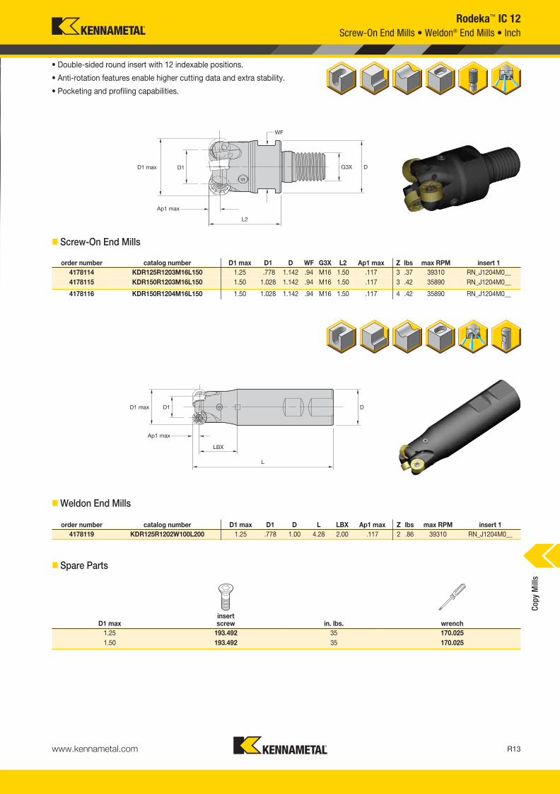
www.kennametal.com R17
Rodeka™ IC 12
Material
GroupKC422M KC522M KC725M KCK15 KCPM20 KCPK30
P
1 — — — 1300 1130 1060 1030 900 840 — — — 2170 1910 1760 1780 1560 1450
2 — — — 1080 950 790 860 760 640 — — — 1340 1210 1090 1100 1000 900
3 — — — 1000 840 700 790 670 550 — — — 1210 1090 1000 1000 900 820
4 — — — 890 730 590 710 590 470 — — — 910 840 760 740 690 620
5 — — — 730 660 590 590 530 470 — — — 1090 980 900 1020 910 830
6 — — — 650 490 400 520 400 310 — — — 760 660 570 620 540 —
M
1 — — — 800 710 650 670 590 540 — — — 880 790 680 820 720 620
2 — — — 730 620 520 610 520 430 — — — 800 700 620 730 640 550
3 — — — 550 480 370 460 400 310 — — — 640 570 490 570 520 460
K
1 — — — 900 820 720 — — — 1660 1510 1340 1420 1280 1150 1160 1050 940
2 — — — 710 640 590 — — — 1310 1170 1090 1130 1010 920 920 830 760
3 — — — 590 530 480 — — — 1100 980 900 950 840 780 770 690 640
N1–2 4220 3720 3440 — — — — — — — — — — — — — — —
3 3720 3440 3000 — — — — — — — — — — — — — — —
S
1 — — — 160 140 110 140 120 100 — — — — — — — — —
2 — — — 160 140 110 140 120 100 — — — — — — — — —
3 — — — 200 160 110 180 140 100 — — — — — — — — —
4 — — — 280 200 140 240 180 120 — — — — — — — — —
H 1 — — — 470 360 280 — — — — — — 550 460 370 — — —
NOTE: FIRST choice starting speeds are in bold type.As the average chip thickness value increases, the speed should be decreased.
� Recommended Starting Speeds [SFM]
� Recommended Starting Feeds [IPT]
NOTE: Use “Light Machining” values as starting feed rate.
Light Machining
General Purpose
Heavy Machining
Recommended Starting Speeds and Feeds
At .030 Axial Depth of Cut (ap)
At .059 Axial Depth of Cut (ap)
At .118 Axial Depth of Cut (ap)
20% 30%
Cop
y M
ills
KM_Master12_R016_R017_MINCH_EN.qxp:Layout 1 3/7/12 3:32 PM Page R17

www.kennametal.comR18
Rodeka 8 Turbine Blade Version Revolutionary double-sided round insert engineered for turbine blade machining. Special geometries, insert styles, and dedicated cutter bodies have been developed to serve this demanding application.
Power Plant
Rodeka 8
Turbine Blade
Steam Turbine
Four indexes per side, in total eight
cutting edges. With higher Ap
capabilities, up to 6mm.
Specific high positive geometries
with improved chip forming and
higher tool life.
Insert location twisted by 45°
between top and bottom side
for equal performance over all
eight cutting edges.
Unique anti-rotation feature with
higher contact area for excellent
stability, allowing higher feed rates.
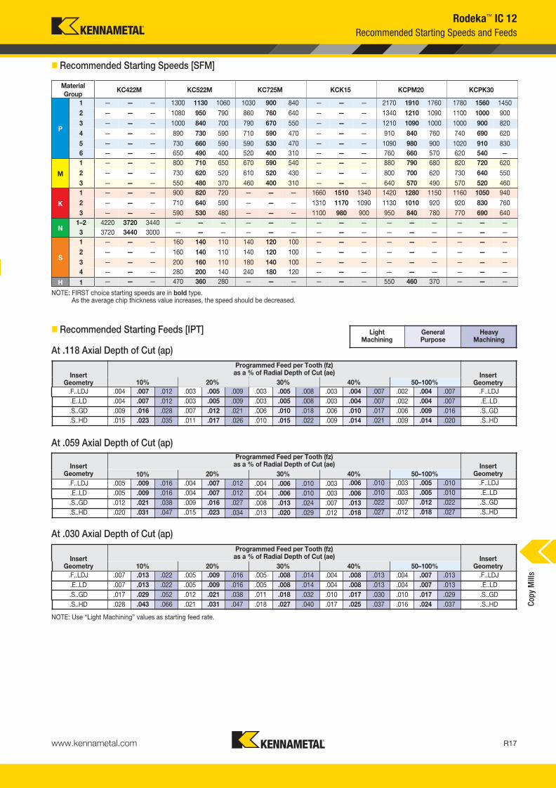
Rodeka™ 8, IC 12
KM_Master12_R018_R019_MINCH_EN.qxp:Layout 1 3/21/12 3:32 PM Page R18
www.kennametal.com R19
catalog number
RNGJ1204M0ENLDJX
RNGJ1204M0ENLDX
RNGJ1204M0SNGDJX
RNGJ1204M0SNGDX
P
M
S
P
M
S
-LD -GD
Light/Medium Machining
First choice for stainless steel and titanium machining.
Medium/Heavy Machining
First choice for medium/heavy operations. Forged blades
or “bad skin”.
KC
522M
KC
725M
KC
MP
30
P � � �
M � � �
K
N
S � � �
H
� first choice
� alternate choice
� �
�
� �
�
� Indexable Inserts
MM# catalog number D1 max D1 D D6 L Ap1 max Z
5104420 KDR40Z04S16RN12X 40 28 16 38 40 6 4
5104421 KDR50Z05S22RN12X 50 38 22 42 40 6 5
5104422 KDR50Z05S22RN12XL 50 38 22 49 40 6 5
5104423 KDR52Z05S22RN12X 52 40 22 42 40 6 5
5104424 KDR63Z06S22RN12X 63 51 22 49 40 6 6
5104425 KDR66Z06S27RN12X 66 54 27 60 40 6 6
5104426 KDR80Z07S27RN12X 80 68 27 60 50 6 7
�Shell Mills
Product Offering
Rodeka™ 8, IC 12
KM_Master12_R018_R019_MINCH_EN.qxp:Layout 1 3/21/12 3:32 PM Page R19

www.kennametal.comR20
KDM • Strong, Flexible, and Highly Accurate
Primary ApplicationRoughing and finishing milling operations on complex parts. First choice for die and mold industry up to 55 HRC.
Features and Benefits
Platform Features
• Big draft clearance angle to improve the pocketing operations performance.
• Big clearance area in the bottom, superior ramping, and helical values.
• High accuracy and tight runout.
Value Proposition
• Real HSM capabilities: more teeth and close accuracy.
• Strongest and most rigid design for roughing operations.
• Addressed to the die and mold and general engineering markets, mainly.
• PSTS and ground inserts are offered through different inserts sizes.
• Shell mill, Weldon® and straight shank, and Screw-On body cutters.
• Multiple grades available; wide range of workpieces and applications.
KM_Master12_R020_R021_MINCH_EN.qxp:Layout 1 3/7/12 3:24 PM Page R20

www.kennametal.com R21
order number catalog number D1 max D1 D D2 DPM G3X L2 Ap1 max Zmax
ramp angle lbs insert 1
2511327 KDM050RD0702M08075 .500 .224 .512 .453 .335 M8 1.102 .138 2 10.0° .08 RD.X07T1..
2511345 KDM063RD0702M08100 .625 .349 .512 .559 .335 M8 1.000 .138 2 7.0° .08 RD.X0702..
2511346 KDM063RD0703M08100 .625 .349 .512 .559 .335 M8 1.000 .138 3 7.0° .08 RD.X0702..
2511347 KDM075RD0703M10118 .750 .474 .709 .740 .413 M10 1.180 .138 4 6.0° .15 RD.X0702..
2511348 KDM100RD0703M12138 1.000 .724 .827 .929 .492 M12 1.380 .138 3 5.0° .27 RD.X0702..
2511349 KDM100RD0705M12138 1.000 .724 .827 .929 .492 M12 1.380 .138 5 5.0° .26 RD.X0702..
D1 maxinsert screw in. lbs.
Torx wrench
.500 193.364 10 FT7
.625 193.341 10 FT7
.750 193.341 10 FT7
1.000 193.341 10 FT7
KDM RD.X07...
Indexable Screw-On End Mills • RD.X07...
• Engineered for maximum performance.
• High runout accuracy.
• Suitable for die and mold manufacturing.
� Screw-On End Mills • RD.X07 Inserts
� Spare Parts
Cop
y M
ills
KM_Master12_R020_R021_MINCH_EN.qxp:Layout 1 3/7/12 3:24 PM Page R21
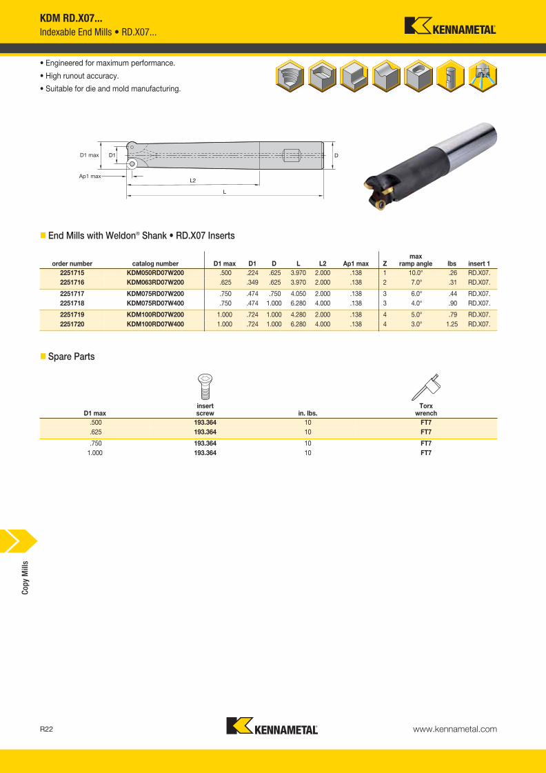
www.kennametal.comR22
order number catalog number D1 max D1 D L L2 Ap1 max Zmax
ramp angle lbs insert 1
2251715 KDM050RD07W200 .500 .224 .625 3.970 2.000 .138 1 10.0° .26 RD.X07.
2251716 KDM063RD07W200 .625 .349 .625 3.970 2.000 .138 2 7.0° .31 RD.X07.
2251717 KDM075RD07W200 .750 .474 .750 4.050 2.000 .138 3 6.0° .44 RD.X07.
2251718 KDM075RD07W400 .750 .474 1.000 6.280 4.000 .138 3 4.0° .90 RD.X07.
2251719 KDM100RD07W200 1.000 .724 1.000 4.280 2.000 .138 4 5.0° .79 RD.X07.
2251720 KDM100RD07W400 1.000 .724 1.000 6.280 4.000 .138 4 3.0° 1.25 RD.X07.
D1 maxinsert screw in. lbs.
Torx wrench
.500 193.364 10 FT7
.625 193.364 10 FT7
.750 193.364 10 FT7
1.000 193.364 10 FT7
• Engineered for maximum performance.
• High runout accuracy.
• Suitable for die and mold manufacturing.
� End Mills with Weldon® Shank • RD.X07 Inserts
� Spare Parts
KDM RD.X07...
Indexable End Mills • RD.X07...C
opy
Mill
s
KM_Master12_R022_R023_MINCH_EN.qxp:Layout 1 3/7/12 3:24 PM Page R22

www.kennametal.com R23
P � � � �
M � � �
K � � �
N �
S � �
H �
catalog number D S hm KC
510M
KC
522M
KC
725M
KC
PM
20
KT
PK
20
RDHX0702M0FLP .276 .094 .001 � � �
catalog number D S hm KC
510M
KC
522M
KC
725M
KC
PM
20
KT
PK
20
RDHX07T1M0SLN .276 .078 .002 � �
RDHX0702M0SLN .276 .094 .003 � � � �
RDHX0702M0TLN .276 .094 .003 �
catalog number D S hm KC
51
0M
KC
52
2M
KC
72
5M
KC
PM
20
KT
PK
20
RDPX0702M0SLN .275 .094 .002 �
Indexable Inserts • RD.X07...
RDHX-LP RDHX-LNRDPX-LN
� first choice
� alternate choice
� RDHX-LP
� RDHX-LN
� RDPX-LN
KDM RD.X07...
Inserts
� Insert Selection Guide
MaterialGroup
Light Machining General Purpose Heavy Machining
Geometry Grade Geometry Grade Geometry Grade
P1–P2 .F..LP KC522M .F..LP KC725M .S..LN KC725M
P3–P4 .S..LN KCPM20 .S..LN KC522M .S..LN KC725M
P5–P6 .S..LN KC522M .S..LN KCPM20 .S..LN KCPM20
M1–M2 .F..LP KC522M .F..LP KC725M — —
M3 .F..LP KC725M — — — —
K1–K2 .F..LP KC510M .S..LN KC510M .S..LN KC510M
K3 .S..LN KC510M .S..LN KC510M .S..LN KC510M
N1–N2 .F..LP KC510M .F..LP KC510M .F..LP KC510M
N3 .F..LP KC510M .F..LP KC510M .F..LP KC510M
S1–S2 .F..LP KC522M .F..LP KC725M — —
S3 .F..LP KC725M — — — —
S4 .F..LP KC725M — — — —
H1 .S..LN KC510M .S..LN KC510M .S..LN KCPM20
Cop
y M
ills
KM_Master12_R022_R023_MINCH_EN.qxp:Layout 1 3/7/12 3:24 PM Page R23

www.kennametal.comR24
KDM RD.X07...
Recommended Starting Speeds and Feeds
� Recommended Starting Speeds [SFM]
Material
GroupKC510M KC522M KC725M KCPM20 KTPK20
P
1 — — — 1300 1130 1060 1030 900 840 2170 1910 1760 1440 1180 1010
2 — — — 1080 950 790 860 760 640 1340 1210 1090 890 740 620
3 — — — 1000 840 700 790 670 550 1210 1090 1000 800 670 560
4 960 780 660 890 730 590 710 590 470 910 840 760 600 520 430
5 — — — 730 660 590 590 530 470 1090 980 900 830 680 580
6 — — — 650 490 400 520 400 310 760 660 570 500 410 —
M
1 — — — 800 710 650 670 590 540 880 790 680 940 770 650
2 — — — 730 620 520 610 520 430 800 700 620 850 720 600
3 — — — 550 480 370 460 400 310 640 570 490 640 530 —
K
1 1150 1040 940 900 820 720 — — — 1420 1280 1150 910 770 640
2 910 820 760 710 640 590 — — — 1130 1010 920 720 590 520
3 770 680 620 590 530 480 — — — 950 840 780 600 500 420
N1–2 2520 2240 2060 — — — — — — — — — — — —
3 2280 2100 1920 — — — — — — — — — — — —
S
1 — — — 160 140 110 140 120 100 — — — — — —
2 — — — 160 140 110 140 120 100 — — — — — —
3 — — — 200 160 110 180 140 100 — — — — — —
4 — — — 280 200 140 240 180 120 — — — — — —
H 1 630 510 360 470 360 280 — — — 550 460 370 — — —
NOTE: FIRST choice starting speeds are in bold type.As the average chip thickness increases, the speed should be decreased.
InsertGeometry
Programmed Feed per Tooth (fz)as a % of Radial Depth of Cut (ae) Insert
Geometry10% 20% 30% 40% 50–100%
.F..LP .003 .005 .014 .003 .004 .010 .002 .003 .009 .002 .003 .008 .002 .003 .008 .F..LP
.S..LN .006 .016 .028 .004 .012 .020 .004 .010 .018 .003 .010 .016 .003 .010 .016 .S..LN
.T..LN .007 .017 .028 .005 .013 .020 .004 .011 .018 .004 .010 .016 .004 .010 .016 .T..LN
InsertGeometry
Programmed Feed per Tooth (fz)as a % of Radial Depth of Cut (ae) Insert
Geometry10% 20% 30% 40% 50–100%
.F..LP .004 .006 .016 .003 .005 .012 .003 .004 .010 .002 .004 .009 .002 .004 .009 .F..LP
.S..LN .007 .019 .032 .005 .014 .023 .004 .012 .020 .004 .011 .019 .004 .011 .018 .S..LN
.T..LN .008 .020 .032 .006 .015 .023 .005 .013 .020 .005 .012 .019 .005 .012 .018 .T..LN
InsertGeometry
Programmed Feed per Tooth (fz)as a % of Radial Depth of Cut (ae) Insert
Geometry10% 20% 30% 40% 50–100%
.F..LP .005 .008 .021 .004 .006 .015 .003 .005 .013 .003 .005 .012 .003 .005 .012 .F..LP
.S..LN .009 .025 .042 .006 .018 .031 .006 .016 .027 .005 .015 .025 .005 .015 .024 .S..LN
.T..LN .010 .026 .042 .008 .019 .031 .007 .017 .027 .006 .015 .025 .006 .015 .024 .T..LN
InsertGeometry
Programmed Feed per Tooth (fz)as a % of Radial Depth of Cut (ae) Insert
Geometry10% 20% 30% 40% 50–100%
.F..LP .007 .011 .028 .005 .008 .021 .005 .007 .018 .004 .007 .017 .004 .007 .017 .F..LP
.S..LN .012 .034 .059 .009 .025 .042 .008 .022 .036 .007 .020 .034 .007 .020 .033 .S..LN
.T..LN .014 .036 .059 .010 .026 .042 .009 .023 .036 .008 .021 .034 .008 .021 .033 .T..LN
NOTE: Use “Light Machining” values as starting feed rate.
Light Machining
General Purpose
Heavy Machining
� Recommended Starting Feeds [IPT]
At .138 Axial Depth of Cut (ap)
At .069 Axial Depth of Cut (ap)
At .034 Axial Depth of Cut (ap)
At .017 Axial Depth of Cut (ap)
Cop
y M
ills
KM_Master12_R024_R025_MINCH_EN.qxp:Layout 1 3/7/12 3:28 PM Page R24
www.kennametal.com R25
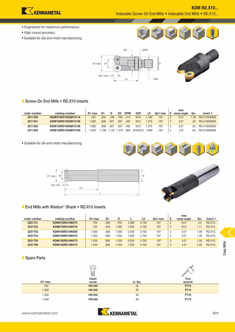
order number catalog number D1 max D1 D D2 DPM G3X L2 Ap1 max Zmax
ramp angle lbs insert 1
2511350 KDM075RD1002M10118 .750 .356 .709 .768 .413 M10 1.180 .197 2 10.0° 1.59 RD.X1003M0S
2511351 KDM100RD1002M12138 1.000 .606 .827 .937 .492 M12 1.375 .197 2 6.0° .26 RD.X1003M0S
2511352 KDM100RD1003M12138 1.000 .606 .827 .937 .492 M12 1.375 .197 3 6.0° .25 RD.X1003M0S
2511463 KDM150RD1004M16169 1.500 1.106 1.142 1.319 .669 M16X2.0 1.690 .197 4 4.0° .63 RD.X1003M0S
KDM RD.X10...
• Engineered for maximum performance.
• High runout accuracy.
• Suitable for die and mold manufacturing.
� Screw-On End Mills • RD.X10 Inserts
order number catalog number D1 max D1 D L L3 Ap1 max Zmax
ramp angle lbs insert 1
2251721 KDM075RD10W275 .750 .356 .750 4.480 2.750 .197 2 10.0° .53 RD.X10.
2251722 KDM075RD10W475 .750 .356 1.000 7.030 4.750 .197 2 10.0° 1.17 RD.X10.
2251753 KDM100RD10W300 1.000 .606 1.000 5.280 2.750 .197 2 6.0° 1.06 RD.X10.
2251754 KDM100RD10W475 1.000 .606 1.000 7.030 4.750 .197 2 6.0° 1.39 RD.X10.
2251755 KDM125RD10W275 1.250 .856 1.250 5.030 2.750 .197 3 4.0° 1.56 RD.X10.
2251756 KDM125RD10W475 1.250 .856 1.250 7.030 4.750 .197 3 4.0° 2.20 RD.X10.
D1 maxinsert screw in. lbs.
Torx wrench
.750 193.342 30 FT15
1.000 193.342 30 FT15
1.250 193.342 30 FT15
• Suitable for die and mold manufacturing.
� End Mills with Weldon® Shank • RD.X10 Inserts
� Spare Parts
1.500 193.342 30 FT15
Indexable Screw-On End Mills • Indexable End Mills • RD.X10...
Cop
y M
ills
KM_Master12_R024_R025_MINCH_EN.qxp:Layout 1 3/7/12 3:28 PM Page R25

www.kennametal.comR26
order number catalog number D1 max D1 D D6 L Ap1 max Zmax
ramp angle lbs insert 1
2251762 KDM150RD10S050F 1.500 1.106 .500 1.360 1.500 .197 5 4.0° .66 RD..1003..
2251763 KDM200RD10S075F 2.000 1.606 .750 1.650 1.970 .197 7 4.0° .99 RD..1003..
D1 maxinsert screw in. lbs.
Torx wrench
socket-headcap screw
1.500 193.342 30 FT15 S424
2.000 193.342 30 FT15 S445
KDM RD.X10...
Indexable Shell Mills • RD.X10...
• Engineered for maximum performance.
• High runout accuracy.
• Suitable for die and mold manufacturing.
� Shell Mills • RD.X10 Inserts
� Spare Parts
Cop
y M
ills
KM_Master12_R026_R027_MINCH_EN.qxp:Layout 1 3/7/12 3:27 PM Page R26

www.kennametal.com R27
KDM RD.X10...
Inserts
� Insert Selection Guide
P � � � � �
M � � � �
K � � � �
N � �
S � �
H �
catalog number D S hm K110M
KC
510M
KC
522M
KC
725M
KC
PM
20
KC
PK
30
KT
PK
20
RDHX1003M0FLP .394 .125 .001 � � � �
catalog number D S hm K110M
KC
510M
KC
522M
KC
725M
KC
PM
20
KC
PK
30
KT
PK
20
RDHX1003M0SGN .394 .125 .003 � � �
RDHX1003M0TGN .394 .125 .004 �
catalog number D S hm K1
10
M
KC
51
0M
KC
52
2M
KC
72
5M
KC
PM
20
KC
PK
30
KT
PK
20
RDPX1003M0SHP .394 .125 .004 � � � �
catalog number D S hm K11
0M
KC
51
0M
KC
52
2M
KC
72
5M
KC
PM
20
KC
PK
30
KT
PK
20
RDPX1003M0SHN .394 .125 .005 � � � �
Indexable Inserts • RD.X10...
RDHX-FLP RDPX-HP RDHX-GNRDPX-HN
� first choice
� alternate choice
� RDHX-FLP
� RDHX-GN
� RDPX-HP
� RDPX-HN
MaterialGroup
Light Machining General Purpose Heavy Machining
Geometry Grade Geometry Grade Geometry Grade
P1–P2 .F..LP KC725M .S..HP KC725M .S..HP KC725M
P3–P4 .S..HP KC522M .S..HP KCPK30 .S..HP KCPK30
P5–P6 .S..HP KC522M .S..HP KCPM20 .S..HN KCPM20
M1–M2 .F..LP KC725M .S..HP KC725M — —
M3 .S..HP KC522M .S..HP KC725M — —
K1–K2 .S..GN KC510M .S..HP KCPK30 .S..HP KCPK30
K3 .S..GN KC510M .S..HP KCPK30 .S..HP KCPK30
N1–N2 .F..LP K110M .F..LP K110M .F..LP KC510M
N3 .F..LP K110M .F..LP KC510M .F..LP KC510M
S1–S2 — — .S..HP KC725M — —
S3 — — .S..HP KC725M — —
S4 — — .S..HP KC725M — —
H1 .S..HN KC510M .S..HN KC510M .S..HN KCPM20
Cop
y M
ills
KM_Master12_R026_R027_MINCH_EN.qxp:Layout 1 3/7/12 3:27 PM Page R27

www.kennametal.comR28
KDM RD.X10...
Recommended Starting Speeds
� Recommended Starting Speeds [SFM]
Material
GroupKC110M KC510M KC522M KC725M
KCPM20 KCPK30 KTPK20
P
1 — — — — — — 1300 1130 1060 1030 900 840
2170 1910 1760 1780 1560 1450 1440 1180 1010
2 — — — — — — 1080 950 790 860 760 640
1340 1210 1090 1100 1000 900 890 740 620
3 — — — — — — 1000 840 700 790 670 550
1210 1090 1000 1000 900 820 800 670 560
4 — — — 960 780 660 890 730 590 710 590 470
910 840 760 740 690 620 600 520 430
5 — — — — — — 730 660 590 590 530 470
1090 980 900 1020 910 830 830 680 580
6 — — — — — — 650 490 400 520 400 310
760 660 570 620 540 — 500 410 —
M
1 — — — — — — 800 710 650 670 590 540
880 790 680 820 720 620 940 770 650
2 — — — — — — 730 620 520 610 520 430
800 700 620 730 640 550 850 720 600
3 — — — — — — 550 480 370 460 400 310
640 570 490 570 520 460 640 530 —
K
1 510 480 450 1150 1040 940 900 820 720 — — —
1420 1280 1150 1160 1050 940 910 770 640
2 450 420 390 910 820 760 710 640 590 — — —
1130 1010 920 920 830 760 720 590 520
3 400 350 310 770 680 620 590 530 480 — — —
950 840 780 770 690 640 600 500 420
N1–2 1980 1860 1770 2520 2240 2060 — — — — — —
— — — — — — — — —
3 1620 1440 1260 — — — — — — — — —
— — — — — — — — —
S
1 — — — — — — 160 140 110 140 120 100
— — — — — — — — —
2 — — — — — — 160 140 110 140 120 100
— — — — — — — — —
3 — — — — — — 200 160 110 180 140 100
— — — — — — — — —
4 — — — — — — 280 200 140 240 180 120
— — — — — — — — —
H 1 — — — 630 510 360 470 360 280 — — —
550 460 370 — — — — — —
NOTE: FIRST choice starting speeds are in bold type.As the average chip thickness increases, the speed should be decreased.
Material
Group
P
1
2
3
4
5
6
M
1
2
3
K
1
2
3
N1–2
3
S
1
2
3
4
H 1
Cop
y M
ills
KM_Master12_R028_R029_MINCH_EN.qxp:Layout 1 3/7/12 3:23 PM Page R28
www.kennametal.com R29
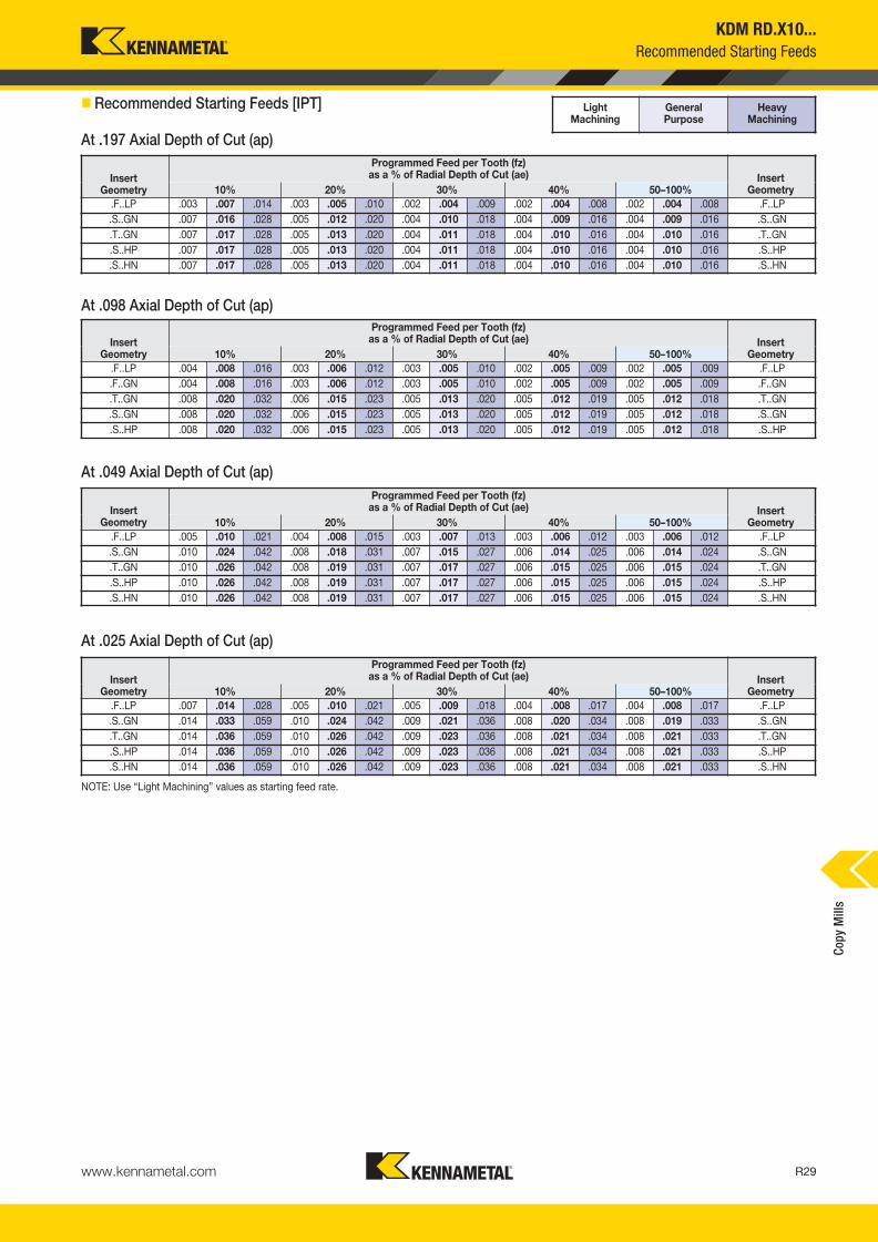
KDM RD.X10...
Recommended Starting Feeds
� Recommended Starting Feeds [IPT]
InsertGeometry
Programmed Feed per Tooth (fz)as a % of Radial Depth of Cut (ae) Insert
Geometry10% 20% 30% 40% 50–100%
.F..LP .003 .007 .014 .003 .005 .010 .002 .004 .009 .002 .004 .008 .002 .004 .008 .F..LP
.S..GN .007 .016 .028 .005 .012 .020 .004 .010 .018 .004 .009 .016 .004 .009 .016 .S..GN
.T..GN .007 .017 .028 .005 .013 .020 .004 .011 .018 .004 .010 .016 .004 .010 .016 .T..GN
.S..HP .007 .017 .028 .005 .013 .020 .004 .011 .018 .004 .010 .016 .004 .010 .016 .S..HP
.S..HN .007 .017 .028 .005 .013 .020 .004 .011 .018 .004 .010 .016 .004 .010 .016 .S..HN
InsertGeometry
Programmed Feed per Tooth (fz)as a % of Radial Depth of Cut (ae) Insert
Geometry10% 20% 30% 40% 50–100%
.F..LP .004 .008 .016 .003 .006 .012 .003 .005 .010 .002 .005 .009 .002 .005 .009 .F..LP
.F..GN .004 .008 .016 .003 .006 .012 .003 .005 .010 .002 .005 .009 .002 .005 .009 .F..GN
.T..GN .008 .020 .032 .006 .015 .023 .005 .013 .020 .005 .012 .019 .005 .012 .018 .T..GN
.S..GN .008 .020 .032 .006 .015 .023 .005 .013 .020 .005 .012 .019 .005 .012 .018 .S..GN
.S..HP .008 .020 .032 .006 .015 .023 .005 .013 .020 .005 .012 .019 .005 .012 .018 .S..HP
InsertGeometry
Programmed Feed per Tooth (fz)as a % of Radial Depth of Cut (ae) Insert
Geometry10% 20% 30% 40% 50–100%
.F..LP .005 .010 .021 .004 .008 .015 .003 .007 .013 .003 .006 .012 .003 .006 .012 .F..LP
.S..GN .010 .024 .042 .008 .018 .031 .007 .015 .027 .006 .014 .025 .006 .014 .024 .S..GN
.T..GN .010 .026 .042 .008 .019 .031 .007 .017 .027 .006 .015 .025 .006 .015 .024 .T..GN
.S..HP .010 .026 .042 .008 .019 .031 .007 .017 .027 .006 .015 .025 .006 .015 .024 .S..HP
.S..HN .010 .026 .042 .008 .019 .031 .007 .017 .027 .006 .015 .025 .006 .015 .024 .S..HN
InsertGeometry
Programmed Feed per Tooth (fz)as a % of Radial Depth of Cut (ae) Insert
Geometry10% 20% 30% 40% 50–100%
.F..LP .007 .014 .028 .005 .010 .021 .005 .009 .018 .004 .008 .017 .004 .008 .017 .F..LP
.S..GN .014 .033 .059 .010 .024 .042 .009 .021 .036 .008 .020 .034 .008 .019 .033 .S..GN
.T..GN .014 .036 .059 .010 .026 .042 .009 .023 .036 .008 .021 .034 .008 .021 .033 .T..GN
.S..HP .014 .036 .059 .010 .026 .042 .009 .023 .036 .008 .021 .034 .008 .021 .033 .S..HP
.S..HN .014 .036 .059 .010 .026 .042 .009 .023 .036 .008 .021 .034 .008 .021 .033 .S..HN
NOTE: Use “Light Machining” values as starting feed rate.
Light Machining
General Purpose
Heavy Machining
At .197 Axial Depth of Cut (ap)
At .098 Axial Depth of Cut (ap)
At .049 Axial Depth of Cut (ap)
At .025 Axial Depth of Cut (ap)
Cop
y M
ills
KM_Master12_R028_R029_MINCH_EN.qxp:Layout 1 3/7/12 3:23 PM Page R29

www.kennametal.comR30
order number catalog number D1 max D1 D D2 DPM G3X L2 Ap1 max Zmax
ramp angle lbs insert 1
2511464 KDM100RD1202M12138 1.000 .528 .827 .906 .492 M12 1.375 .236 2 10.0° .24 RD.X12T3..
2511465 KDM125RD1203M16169 1.250 .778 1.142 1.327 .669 M16 1.690 .236 3 8.0° .49 RD.X12T3..
2511466 KDM150RD1204M16169 1.500 1.028 1.142 1.591 .669 M16 1.690 .236 4 7.0° .60 RD.X12T3..
D1 maxinsert screw in. lbs.
Torx wrench
clampscrew
1.000 193.342 30 FT15 193.338
1.250 193.342 30 FT15 193.338
1.500 193.342 30 FT15 193.338
KDM RD.X12...
• Engineered for maximum performance.
• High runout accuracy.
• Suitable for die and mold manufacturing.
� Screw-On End Mills • RD.X12 Inserts
� Spare Parts
order number catalog number D1 max D1 D L L2 Ap1 max Zmax
ramp angle lbs insert 1
2251757 KDM100RD12W275 1.000 .528 1.250 5.030 2.750 .236 2 10.0° .99 RD.X12T3..
2251758 KDM100RD12W475 1.000 .528 1.250 7.030 4.750 .236 2 10.0° 1.65 RD.X12T3..
2251759 KDM125RD12W375 1.250 .778 1.250 6.030 3.750 .236 3 8.0° 1.87 RD.X12T3..
2251760 KDM150RD12W275 1.500 1.028 1.500 5.510 2.750 .236 3 7.0° 2.42 RD.X12T3..
2251761 KDM150RD12W475 1.500 1.028 1.500 7.506 4.750 .236 3 7.0° 3.31 RD.X12T3..
D1 maxinsert screw in. lbs.
Torx wrench
1.000 193.342 30 FT15
1.250 193.342 30 FT15
1.500 193.342 30 FT15
• Suitable for die and mold manufacturing.
� End Mills with Weldon® Shank • RD.X12 Inserts
� Spare Parts
Indexable Screw-On End Mills • Indexable End Mills • RD.X12...C
opy
Mill
s
KM_Master12_R030_R031_MINCH_EN.qxp:Layout 1 3/7/12 3:28 PM Page R30

order number catalog number D1 max D1 D D6 L Ap1 max Zmax
ramp angle lbs insert 1
2251774 KDM200RD12S075C 2.000 1.528 .750 1.650 1.970 .236 3 5.0° .99 RD.X12T3..
2251764 KDM200RD12S075F 2.000 1.528 .750 1.650 1.970 .236 5 5.0° .99 RD.X12T3..
2251765 KDM250RD12S100F 2.500 2.028 1.000 2.070 1.970 .236 6 4.0° 1.39 RD.X12T3..
2251766 KDM300RD12S100C 3.000 2.528 1.000 2.070 1.970 .236 5 3.0° 2.20 RD.X12T3..
2251775 KDM300RD12S100F 3.000 2.528 1.000 2.070 1.970 .236 7 3.0° 2.20 RD.X12T3..
2251767 KDM400RD12S125C 4.000 3.528 1.250 2.750 1.970 .236 5 1.5° 3.75 RD.X12T3..
2251776 KDM400RD12S125F 4.000 3.528 1.250 2.750 1.970 .236 8 1.5° 3.75 RD.X12T3..
D1 maxinsert screw in. lbs.
Torx wrench
clampscrew
socket-headcap screw
2.000 193.342 30 FT15 193.338 S445
2.500 193.342 30 FT15 193.338 S458
3.000 193.342 30 FT15 193.338 —
4.000 193.342 30 FT15 193.338 —
KDM RD.X12...
Indexable Shell Mills • RD.X12...
• Engineered for maximum performance.
• High runout accuracy.
• Suitable for die and mold manufacturing.
� Shell Mills • RD.X12 Inserts
� Spare Parts
Cop
y M
ills
www.kennametal.com R31
KM_Master12_R030_R031_MINCH_EN.qxp:Layout 1 3/7/12 3:28 PM Page R31

www.kennametal.comR32
KDM RD.X12...
Inserts
� Insert Selection Guide
MaterialGroup
Light Machining General Purpose Heavy Machining
Geometry Grade Geometry Grade Geometry Grade
P1–P2 .F..LP KC725M .S..HP KC725M .S..HP KC725M
P3–P4 .S..HP KC522M .S..HP KCPK30 .S..HP KCPK30
P5–P6 .S..HP KC522M .S..HP KCPM20 .S..HN KCPM20
M1–M2 — — .S..HP KC725M — —
M3 — — .S..HP KC725M — —
K1–K2 .S..HN KC510M .S..HP KCPK30 .S..HP KCPK30
K3 .S..HN KC510M .S..HP KCPK30 .S..HP KCPK30
N1–N2 .F..LP K110M .F..LP KC510M .F..LP KC510M
N3 .F..LP KC510M .F..LP KC510M .F..GN KC510M
S1–S2 — — .S..HP KC725M — —
S3 — — .S..HP KC725M — —
S4 — — .S..HP KC725M — —
H1 .S..HN KC510M .S..HN KC510M .S..HN KCPM20
P � � � � � �
M � � � � �
K � � � �
N � �
S � � �
H �
catalog number D S hm K110M
KC
510M
KC
522M
KC
525M
KC
725M
KC
PM
20
KC
PK
30
KT
PK
20
RDHX12T3M0FLP .472 .156 .001 � � � �
catalog number D S hm K110M
KC
510M
KC
522M
KC
525M
KC
725M
KC
PM
20
KC
PK
30
KT
PK
20
RDHX12T3M0SGN .472 .156 .004 � � � �
RDHX12T3M0TGN .472 .156 .005 �
catalog number D S hm K1
10
M
KC
51
0M
KC
52
2M
KC
52
5M
KC
72
5M
KC
PM
20
KC
PK
30
KT
PK
20
RDPX12T3M0SHP .472 .156 .005 � � � �
catalog number D S hm K1
10
M
KC
51
0M
KC
52
2M
KC
52
5M
KC
72
5M
KC
PM
20
KC
PK
30
KT
PK
20
RDPX12T3M0SHN .472 .156 .007 � � � �
Indexable Round Inserts • KDM RD.X12...
RDHX-FLP RDPX-HP RDHX-GNRDPX-HN
� first choice
� alternate choice
� RDHX-FLP
� RDHX-GN
� RDPX-HP
� RDPX-HN
Cop
y M
ills
KM_Master12_R032_R033_MINCH_EN.qxp:Layout 1 3/7/12 3:32 PM Page R32

www.kennametal.com R33
KDM RD.X12...
Recommended Starting Speeds
� Recommended Starting Speeds [SFM]
Material
GroupKC110M KC510M KC522M KC525M
KC725M KCPM20 KCPK30 KTPK20
P
1 — — — — — — 1300 1130 1060 860 790 710
1030 900 840 2170 1910 1760 1780 1560 1450 1440 1180 1010
2 — — — — — — 1080 950 790 710 620 590
860 760 640 1340 1210 1090 1100 1000 900 890 740 620
3 — — — — — — 1000 840 700 620 590 550
790 670 550 1210 1090 1000 1000 900 820 800 670 560
4 — — — 960 780 660 890 730 590 550 520 470
710 590 470 910 840 760 740 690 620 600 520 430
5 — — — — — — 730 660 590 590 550 520
590 530 470 1090 980 900 1020 910 830 830 680 580
6 — — — — — — 650 490 400 520 470 430
520 400 310 760 660 570 620 540 — 500 410 —
M
1 — — — — — — 800 710 650 590 550 520
670 590 540 880 790 680 820 720 620 940 770 650
2 — — — — — — 730 620 520 520 470 430
610 520 430 800 700 620 730 640 550 850 720 600
3 — — — — — — 550 480 370 360 310 280
460 400 310 640 570 490 570 520 460 640 530 —
K
1 510 480 450 1150 1040 940 900 820 720 — — —
— — — 1420 1280 1150 1160 1050 940 910 770 640
2 450 420 390 910 820 760 710 640 590 — — —
— — — 1130 1010 920 920 830 760 720 590 520
3 400 350 310 770 680 620 590 530 480 — — —
— — — 950 840 780 770 690 640 600 500 420
N1–2 1980 1860 1770 2520 2240 2060 — — — — — —
— — — — — — — — — — — —
3 1620 1440 1260 — — — — — — — — —
— — — — — — — — — — — —
S
1 — — — — — — 160 140 110 240 220 190
140 120 100 — — — — — — — — —
2 — — — — — — 160 140 110 240 220 190
140 120 100 — — — — — — — — —
3 — — — — — — 200 160 110 190 180 160
180 140 100 — — — — — — — — —
4 — — — — — — 280 200 140 240 190 160
240 180 120 — — — — — — — — —
H 1 — — — 630 510 360 470 360 280 — — —
— — — 550 460 370 — — — — — —
NOTE: FIRST choice starting speeds are in bold type.As the average chip thickness increases, the speed should be decreased.
Material
Group
P
1
2
3
4
5
6
M
1
2
3
K
1
2
3
N1–2
3
S
1
2
3
4
H 1
Cop
y M
ills
KM_Master12_R032_R033_MINCH_EN.qxp:Layout 1 3/7/12 3:32 PM Page R33

www.kennametal.comR34
KDM RD.X12...
Recommended Starting Feeds
� Recommended Starting Feeds [IPT]
InsertGeometry
Programmed Feed per Tooth (fz)as a % of Radial Depth of Cut (ae) Insert
Geometry10% 20% 30% 40% 50–100%
.F..LP .003 .007 .014 .003 .005 .010 .002 .004 .009 .002 .004 .008 .002 .004 .008 .F..LP
.F..GN .003 .007 .014 .003 .005 .010 .002 .004 .009 .002 .004 .008 .002 .004 .008 .F..GN
.T..GN .007 .017 .028 .005 .013 .020 .004 .011 .018 .004 .010 .016 .004 .010 .016 .T..GN
.S..GN .007 .017 .028 .005 .013 .020 .004 .011 .018 .004 .010 .016 .004 .010 .016 .S..GN
.S..HP .007 .017 .028 .005 .013 .020 .004 .011 .018 .004 .010 .016 .004 .010 .016 .S..HP
.S..HN .007 .017 .028 .005 .013 .020 .004 .011 .018 .004 .010 .016 .004 .010 .016 .S..HN
InsertGeometry
Programmed Feed per Tooth (fz)as a % of Radial Depth of Cut (ae) Insert
Geometry10% 20% 30% 40% 50–100%
.F..LP .004 .008 .016 .003 .006 .012 .003 .005 .010 .002 .005 .009 .002 .005 .009 .F..LP
.F..GN .004 .008 .016 .003 .006 .012 .003 .005 .010 .002 .005 .009 .002 .005 .009 .F..GN
.T..GN .008 .020 .032 .006 .015 .023 .005 .013 .020 .005 .012 .019 .005 .012 .018 .T..GN
.S..GN .008 .020 .032 .006 .015 .023 .005 .013 .020 .005 .012 .019 .005 .012 .018 .S..GN
.S..HP .008 .020 .032 .006 .015 .023 .005 .013 .020 .005 .012 .019 .005 .012 .018 .S..HP
.S..HN .008 .020 .032 .006 .015 .023 .005 .013 .020 .005 .012 .019 .005 .012 .018 .S..HN
InsertGeometry
Programmed Feed per Tooth (fz)as a % of Radial Depth of Cut (ae) Insert
Geometry10% 20% 30% 40% 50–100%
.F..LP .005 .010 .021 .004 .008 .015 .003 .007 .013 .003 .006 .012 .003 .006 .012 .F..LP
.F..GN .005 .010 .021 .004 .008 .015 .003 .007 .013 .003 .006 .012 .003 .006 .012 .F..GN
.T..GN .010 .026 .042 .008 .019 .031 .007 .017 .027 .006 .015 .025 .006 .015 .024 .T..GN
.S..GN .010 .026 .042 .008 .019 .031 .007 .017 .027 .006 .015 .025 .006 .015 .024 .S..GN
.S..HP .010 .026 .042 .008 .019 .031 .007 .017 .027 .006 .015 .025 .006 .015 .024 .S..HP
.S..HN .010 .026 .042 .008 .019 .031 .007 .017 .027 .006 .015 .025 .006 .015 .024 .S..HN
InsertGeometry
Programmed Feed per Tooth (fz)as a % of Radial Depth of Cut (ae) Insert
Geometry10% 20% 30% 40% 50–100%
.F..LP .007 .014 .028 .005 .010 .021 .005 .009 .018 .004 .008 .017 .004 .008 .017 .F..LP
.F..GN .007 .014 .028 .005 .010 .021 .005 .009 .018 .004 .008 .017 .004 .008 .017 .F..GN
.T..GN .014 .036 .059 .010 .026 .042 .009 .023 .036 .008 .021 .034 .008 .021 .033 .T..GN
.S..GN .014 .036 .059 .010 .026 .042 .009 .023 .036 .008 .021 .034 .008 .021 .033 .S..GN
.S..HP .014 .036 .059 .010 .026 .042 .009 .023 .036 .008 .021 .034 .008 .021 .033 .S..HP
.S..HN .014 .036 .059 .010 .026 .042 .009 .023 .036 .008 .021 .034 .008 .021 .033 .S..HN
NOTE: Use “Light Machining” values as starting feed rate.
Light Machining
General Purpose
Heavy Machining
At .236 Axial Depth of Cut (ap)
At .030 Axial Depth of Cut (ap)
At .059 Axial Depth of Cut (ap)
At .118 Axial Depth of Cut (ap)
Cop
y M
ills
KM_Master12_R034_R035_MINCH_EN.qxp:Layout 1 3/7/12 3:30 PM Page R34

www.kennametal.com R35
order number catalog number D1 max D1 D D6 L Ap1 max Zmax
ramp angle lbs insert 1
2251768 KDM200RD16S075F 2.000 1.370 .750 1.650 1.970 .315 4 8.0° .99 RD.X1604..
2251769 KDM250RD16S100F 2.500 1.870 1.000 2.070 1.970 .315 5 6.0° 1.61 RD.X1604..
2251770 KDM300RD16S100F 3.000 2.370 1.000 2.070 1.970 .315 6 4.0° 2.20 RD.X1604..
2251771 KDM400RD16S125F 4.000 3.370 1.250 2.750 2.170 .315 7 1.5° 4.30 RD.X1604..
2251772 KDM500RD16S150F 5.000 4.370 1.500 3.690 2.170 .315 8 — 7.28 RD.X1604..
2251773 KDM600RD16S150F 6.000 5.370 1.500 3.690 2.170 .315 9 — 9.92 RD.X1604..
D1 maxinsert screw in. lbs.
Torx wrench
clampscrew
socket-headcap screw
2.000 193.343 30 FT20 193.383 S445
2.500 193.343 30 FT20 193.383 S458
3.000 193.343 30 FT20 193.383 —
4.000 193.343 30 FT20 193.383 —
5.000 193.343 30 FT20 193.383 —
6.000 193.343 30 FT20 193.383 —
� Shell Mills • RD.X16 Inserts
� Spare Parts
order number catalog number D1 max D1 D D2 DPM G3X L2 Ap1 max Zmax
ramp angle lbs insert 1
2511467 KDM125RD1602M16169 1.250 .620 1.142 1.102 .669 M16 1.690 .315 2 15.0° .45 RD.X1604..
D1 maxinsert screw in. lbs.
Torx wrench
1.250 193.343 30 FT20
KDM RD.X16...
• Engineered for maximum performance.
• High runout accuracy.
• Suitable for die and mold manufacturing.
� Screw-On End Mills • RD.X16 Inserts
� Spare Parts
Indexable Screw-On End Mills • Indexable Shell Mills • RD.X16...
Cop
y M
ills
KM_Master12_R034_R035_MINCH_EN.qxp:Layout 1 3/7/12 3:30 PM Page R35

www.kennametal.comR36
KDM RD.X16...
Inserts
� Insert Selection Guide
MaterialGroup
Light Machining General Purpose Heavy Machining
Geometry Grade Geometry Grade Geometry Grade
P1–P2 .F..LP KC725M .S..GN KC725M .S..HP KC725M
P3–P4 .S..HP KC522M .S..HP KCPK30 .S..HN KC725M
P5–P6 .S..HP KC522M .S..HP KCPM20 .S..HN KCPM20
M1–M2 — — .S..HP KC725M — —
M3 — — .S..HP KC725M — —
K1–K2 .S..HN KC510M .S..HP KCPK30 .S..HP KCPK30
K3 .S..HN KC510M .S..HP KCPK30 .S..HP KCPK30
N1–N2 .F..LP KC510M .F..LP KC510M .F..LP KC510M
N3 .F..LP KC510M .F..LP KC510M .F..LP KC510M
S1–S2 — — .S..HP KC725M — —
S3 — — .S..HP KC725M — —
S4 — — .S..HP KC725M — —
H1 .S..GN KC510M .S..HN KC510M .S..HN KCPM20
P � � � �
M � � � �
K � � � �
N �
S � �
H �
catalog number D S hm KC
510M
KC
522M
KC
725M
KC
PM
20
KC
PK
30
RDHX1604M0FLP .630 .188 .001 � � �
catalog number D S hm KC
510M
KC
522M
KC
725M
KC
PM
20
KC
PK
30
RDHX1604M0SGN .630 .188 .008 � � �
catalog number D S hm KC
51
0M
KC
52
2M
KC
72
5M
KC
PM
20
KC
PK
30
RDPX1604M0SHP .630 .187 .005 � � � �
catalog number D S hm KC
51
0M
KC
52
2M
KC
72
5M
KC
PM
20
KC
PK
30
RDPX1604M0SHN .630 .187 .008 � � � �
RDHX-FLP RDPX-HP RDHX-GNRDPX-HN
� first choice
� alternate choice
� RDHX-FLP
� RDHX-GN
� RDPX-HP
� RDPX-HN
Indexable Round Inserts • KDM RD.X16...
Cop
y M
ills
KM_Master12_R036_R037_MINCH_EN.qxp:Layout 1 3/7/12 3:25 PM Page R36

www.kennametal.com R37
KDM RD.X16...
Recommended Starting Speeds and Feeds
� Recommended Starting Speeds [SFM]
Material
GroupKC510M KC522M KC725M KCPM20 KCPK30
P
1 — — — 1300 1130 1060 1030 900 840 2170 1910 1760 1780 1560 1450
2 — — — 1080 950 790 860 760 640 1340 1210 1090 1100 1000 900
3 — — — 1000 840 700 790 670 550 1210 1090 1000 1000 900 820
4 960 780 660 890 730 590 710 590 470 910 840 760 740 690 620
5 — — — 730 660 590 590 530 470 1090 980 900 1020 910 830
6 — — — 650 490 400 520 400 310 760 660 570 620 540 —
M
1 — — — 800 710 650 670 590 540 880 790 680 820 720 620
2 — — — 730 620 520 610 520 430 800 700 620 730 640 550
3 — — — 550 480 370 460 400 310 640 570 490 570 520 460
K
1 1150 1040 940 900 820 720 — — — 1420 1280 1150 1160 1050 940
2 910 820 760 710 640 590 — — — 1130 1010 920 920 830 760
3 770 680 620 590 530 480 — — — 950 840 780 770 690 640
N1–2 2520 2240 2060 — — — — — — — — — — — —
3 — — — — — — — — — — — — — — —
S
1 — — — 160 140 110 140 120 100 — — — — — —
2 — — — 160 140 110 140 120 100 — — — — — —
3 — — — 200 160 110 180 140 100 — — — — — —
4 — — — 280 200 140 240 180 120 — — — — — —
H 1 630 510 360 470 360 280 — — — 550 460 370 — — —
NOTE: FIRST choice starting speeds are in bold type.As the average chip thickness increases, the speed should be decreased.
� Recommended Starting Feeds [IPT]
InsertGeometry
Programmed Feed per Tooth (fz)as a % of Radial Depth of Cut (ae) Insert
Geometry10% 20% 30% 40% 50–100%
.F..LP .003 .007 .014 .003 .005 .010 .002 .004 .009 .002 .004 .008 .002 .004 .008 .F..LP
.S..GN .007 .017 .028 .005 .013 .020 .004 .011 .018 .004 .010 .016 .004 .010 .016 .S..GN
.S..HP .007 .017 .028 .005 .013 .020 .004 .011 .018 .004 .010 .016 .004 .010 .016 .S..HP
.S..HN .007 .017 .028 .005 .013 .020 .004 .011 .018 .004 .010 .016 .004 .010 .016 .S..HN
InsertGeometry
Programmed Feed per Tooth (fz)as a % of Radial Depth of Cut (ae) Insert
Geometry10% 20% 30% 40% 50–100%
.F..LP .004 .008 .016 .003 .006 .012 .003 .005 .010 .002 .005 .009 .002 .005 .009 .F..LP
.S..GN .008 .020 .032 .006 .015 .023 .005 .013 .020 .005 .012 .019 .005 .012 .018 .S..GN
.S..HP .008 .020 .032 .006 .015 .023 .005 .013 .020 .005 .012 .019 .005 .012 .018 .S..HP
.S..HN .008 .020 .032 .006 .015 .023 .005 .013 .020 .005 .012 .019 .005 .012 .018 .S..HN
InsertGeometry
Programmed Feed per Tooth (fz)as a % of Radial Depth of Cut (ae) Insert
Geometry10% 20% 30% 40% 50–100%
.F..LP .005 .010 .021 .004 .008 .015 .003 .007 .013 .003 .006 .012 .003 .006 .012 .F..LP
.S..GN .010 .026 .042 .008 .019 .031 .007 .017 .027 .006 .015 .025 .006 .015 .024 .S..GN
.S..HP .010 .026 .042 .008 .019 .031 .007 .017 .027 .006 .015 .025 .006 .015 .024 .S..HP
.S..HN .010 .026 .042 .008 .019 .031 .007 .017 .027 .006 .015 .025 .006 .015 .024 .S..HN
InsertGeometry
Programmed Feed per Tooth (fz)as a % of Radial Depth of Cut (ae) Insert
Geometry10% 20% 30% 40% 50–100%
.F..LP .007 .014 .028 .005 .010 .021 .005 .009 .018 .004 .008 .017 .004 .008 .017 .F..LP
.S..GN .014 .036 .059 .010 .026 .042 .009 .023 .036 .008 .021 .034 .008 .021 .033 .S..GN
.S..HP .014 .036 .059 .010 .026 .042 .009 .023 .036 .008 .021 .034 .008 .021 .033 .S..HP
.S..HN .014 .036 .059 .010 .026 .042 .009 .023 .036 .008 .021 .034 .008 .021 .033 .S..HN
NOTE: Use “Light Machining” values as starting feed rate.
Light Machining
General Purpose
Heavy Machining
At .315 Axial Depth of Cut (ap)
At .157 Axial Depth of Cut (ap)
At .079 Axial Depth of Cut (ap)
At .039 Axial Depth of Cut (ap)
Cop
y M
ills
KM_Master12_R036_R037_MINCH_EN.qxp:Layout 1 3/7/12 3:25 PM Page R37

Features and Benefits
KSRM™ • Multipurpose Milling Cutters
Primary ApplicationSpecially developed for machining titanium and stainless steel. KSRM platform enables you to pocket, profile, ramp, and plunge with up to .039" (1mm) fz with consistent performance, providing outstanding metal removal rates with the lowest cutting forces in roughing applications.
Up to eight indexable
positions for fast and
accurate insert changes.
High clearance on the cutters for
a superior plunging, ramping,
and chip load capacities.
Anti-rotation screw provides excellent stability
with higher feed rates and cutting forces.
High positive rake angle with stronger
cutting edge inserts for lower cutting forces,
specially developed for machining titanium.
Screw-On, end mill, and shell mill
cutters with internal coolant.
www.kennametal.comR38
KM_Master12_R038_R039_MINCH_EN.qxp:Layout 1 3/7/12 3:24 PM Page R38

www.kennametal.com R39
KSRM™ RP.T1204
• Engineered for titanium and stainless steel machining.
• Anti-rotation components feature eight indexable positions.
• Pocketing, ramping, plunging, and helical interpolation capabilities.
� Screw-On End Mills
� Spare Parts
� Weldon End Mills
order number catalog number D1 max D1 D DPM G3X L2 Ap1 max Zmax
ramp angle max RPM lbs insert 1
4042688 BMD125R1203M16L150 1.250 .778 1.142 .670 M16 1.500 .236 3 5.7° 43500 .35 RP..T1204M0…
4042690 BMD150R1204M16L150 1.500 1.028 1.142 .670 M16 1.500 .236 4 9.2° 39700 .41 RP..T1204M0…
D1 maxinsert screw in. lbs.
anti-rotationscrew
Torx Plus driver
1.250 MS2077 20 MS-2225 DT15IP
1.500 MS2077 20 MS-2225 DT15IP
order number catalog number D1 max D1 D L L2 Ap1 max Zmax
ramp angle max RPM lbs insert 1
4042691 BMD125R1203W125L200 1.250 .778 1.250 4.280 2.000 .236 3 5.7° 43500 1.17 RP..T1204M0…
3891915 BMD150R1204W150L200 1.500 1.028 1.500 4.690 2.000 .236 4 9.2° 39700 1.94 RP..T1204M0…
D1 maxinsert screw in. lbs.
anti-rotationscrew
Torx Plus driver
1.250 MS2077 20 MS-2225 DT15IP
1.500 MS2077 20 MS-2225 DT15IP
� Spare Parts
Screw-On End Mills • Weldon® End Mills • Inch
Cop
y M
ills
KM_Master12_R038_R039_MINCH_EN.qxp:Layout 1 3/7/12 3:25 PM Page R39

www.kennametal.comR40
order number catalog number D1 max D1 D L L2 Ap1 max Zmax
ramp angle max RPM lbs insert 1
4042692 BMD125R1203C125L700 1.250 .778 1.250 7.000 1.575 .236 3 5.7° 43500 2.11 RP..T1204M0…
4042713 BMD150R1203C125L800 1.500 1.028 1.250 8.000 1.575 .236 3 9.8° 39700 2.54 RP..T1204M0…
D1 maxinsert screw in. lbs.
anti-rotationscrew
Torx Plus driver
1.250 MS2077 20 MS-2225 DT15IP
1.500 MS2077 20 MS-2225 DT15IP
KSRM™ RP.T1204
Cylindrical End Mills • Inch
• Engineered for titanium and stainless steel machining.
• Anti-rotation components feature eight indexable positions.
• Pocketing, ramping, plunging, and helical interpolation capabilities.
� Cylindrical End Mills
� Spare Parts
Cop
y M
ills
KM_Master12_R040_R041_MINCH_EN.qxp:Layout 1 3/7/12 3:32 PM Page R40

www.kennametal.com R41
order number catalog number D1 max D1 D D6 L Ap1 max Zmax
ramp angle max RPM lbs insert 1
3891882 BMD150R1204S050L158 1.500 1.028 .500 1.440 1.575 .236 4 9.2° 39700 .47 RP..T1204M0…
4042714 BMD200R1203S075L200 2.000 1.528 .750 1.752 2.000 .236 3 10.5° 34400 1.02 RP..T1204M0…
4042715 BMD200R1205S075L200 2.000 1.528 .750 1.752 2.000 .236 5 7.7° 34400 1.01 RP..T1204M0…
4042716 BMD250R1207S100L200 2.500 2.028 1.000 2.190 2.000 .236 7 4.1° 30800 1.61 RP..T1204M0…
3885499 BMD300R1206S100L200 3.000 2.528 1.000 2.752 2.000 .236 6 5.7° 28100 2.44 RP..T1204M0…
4042717 BMD300R1208S100L200 3.000 2.528 1.000 2.752 2.000 .236 8 3.5° 28100 2.57 RP..T1204M0…
4042718 BMD400R1207S125L200 4.000 3.528 1.250 2.878 2.000 .236 7 3.3° 23800 3.23 RP..T1204M0…
4002349 BMD400R1209S125L200 4.000 3.528 1.250 2.878 2.000 .236 9 3.0° 23800 3.20 RP..T1204M0…
D1 maxinsert screw in. lbs.
anti-rotationscrew
socket-headcap screw
socket-head cap screwwith coolant groove *
coolant lock screw assembly
T-handlehex wrench
Torx Plus driver
1.500 MS2077 20 MS-2225 S424 S422CG — — DT15IP
2.000 MS2077 20 MS-2225 S446 S446CG — — DT15IP
2.500 MS2077 20 MS-2225 S459 S459CG — — DT15IP
3.000 MS2077 20 MS-2225 S459 S459CG — — DT15IP
4.000 MS2077 20 MS-2225 — — S2162C THW2M DT15IP
KSRM™ RP.T1204
Face Mills • Inch
• Engineered for titanium and stainless steel machining.
• Anti-rotation components feature eight indexable positions.
• Pocketing, ramping, plunging, and helical interpolation capabilities.
� Face Mills
� Spare Parts
Cop
y M
ills
* Socket head cap screw with coolant groove sold separately as a spare part.
KM_Master12_R040_R041_MINCH_EN.qxp:Layout 1 3/7/12 3:32 PM Page R41

www.kennametal.comR42
KSRM™ RP.T1204
Inserts
� Insert Selection Guide
MaterialGroup
Light Machining General Purpose Heavy Machining
Geometry Grade Geometry Grade Geometry Grade
P1–P2 .E..LE KC725M .S..GE KC725M .S..GP KC725M
P3–P4 .E..LE KCPK30 .S..GE KCPK30 .S..GP KCPK30
P5–P6 .S..GE KCPK30 .S..GP KCPK30 .S..GP KCPM20
M1–M2 .E..LE KC725M .E..LE KC725M .S..GE KC725M
M3 .E..LE KCPK30 .E..LE KCPK30 .S..GE KCPK30
K1–K2 — — .S..GP KCPK30 — —
K3 — — .S..GP KCPK30 — —
N1–N2 .E..LEJ KC422M .E..LEJ KC422M .E..LEJ KC422M
N3 .E..LEJ KC422M .E..LEJ KC422M .E..LEJ KC422M
S1–S2 .E..LE KC725M .S..GE KC725M .S..GP KC725M
S3 .E..LE KC725M .S..GE KC725M .S..GP KC725M
S4 .E..LE KC725M .E..LE KC725M .S..GE KC725M
H1 — — — — — —
P � � � �
M � � � �
K � � �
N �
S � �
H
catalog number .D S hmcutting edges K
C422M
KC
522M
KC
725M
KC
PM
20
KC
PK
30
RPET1204M0ELEJ .472 .188 .001 8 � � �
RPET1204M0ELE .472 .188 .002 8 � � �
catalog number D S hmcutting edges K
C4
22
M
KC
52
2M
KC
72
5M
KC
PM
20
KC
PK
30
RPET1204M0SGE .472 .188 .004 8 � � �
RPET1204M0SGEJ .472 .188 .005 8 � �
catalog number D S hmcutting edges K
C4
22
M
KC
52
2M
KC
72
5M
KC
PM
20
KC
PK
30
RPPT1204M0SGP .472 .188 .005 8 � � �
Indexable Round Inserts • KSRM
RPET-LERPET-GE
RPPT-GP
� first choice
� alternate choice
• SGE and ELE are the first choice for titanium machining.
• SGE geometry is the first choice for medium and heavy applications.
• ELE is the first choice for lower cutting forces to avoid built-up edge.
� RPET-LE
� RPET-GE
� RPPT-GP
Cop
y M
ills
KM_Master12_R042_R043_MINCH_EN.qxp:Layout 1 3/7/12 3:24 PM Page R42

www.kennametal.com R43
Material
GroupKC422M KC522M KC725M KCPM20 KCPK30
P
1 — — — 1300 1130 1060 1030 900 840 2170 1910 1760 1780 1560 1450
2 — — — 1080 950 790 860 760 640 1340 1210 1090 1100 1000 900
3 — — — 1000 840 700 790 670 550 1210 1090 1000 1000 900 820
4 — — — 890 730 590 710 590 470 910 840 760 740 690 620
5 — — — 730 660 590 590 530 470 1090 980 900 1020 910 830
6 — — — 650 490 400 520 400 310 760 660 570 620 540 —
M
1 — — — 800 710 650 670 590 540 880 790 680 820 720 620
2 — — — 730 620 520 610 520 430 800 700 620 730 640 550
3 — — — 550 480 370 460 400 310 640 570 490 570 520 460
K
1 — — — 900 820 720 — — — 1420 1280 1150 1160 1050 940
2 — — — 710 640 590 — — — 1130 1010 920 920 830 760
3 — — — 590 530 480 — — — 950 840 780 770 690 640
N1–2 4220 3720 3440 — — — — — — — — — — — —
3 3720 3440 3000 — — — — — — — — — — — —
S
1 — — — 160 140 110 140 120 100 — — — — — —
2 — — — 160 140 110 140 120 100 — — — — — —
3 — — — 200 160 110 180 140 100 — — — — — —
4 — — — 280 200 140 240 180 120 — — — — — —
H 1 — — — 470 360 280 — — — 550 460 370 — — —
KSRM™ RP.T1204
� Recommended Starting Speeds [SFM]
NOTE: FIRST choice starting speeds are in bold type.As the average chip thickness value increases, the speed should be decreased.
� Recommended Starting Feeds [IPT]
InsertGeometry
Programmed Feed per Tooth (fz)as a % of Radial Depth of Cut (ae) Insert
Geometry10% 20% 30% 40% 50–100%
.E..LEJ .003 .005 .008 .003 .004 .006 .002 .003 .005 .002 .003 .005 .002 .003 .005 .E..LEJ
.E..LE .005 .008 .014 .004 .006 .010 .003 .005 .009 .003 .005 .008 .003 .005 .008 .E..LE
.S..GE .007 .017 .028 .005 .013 .020 .004 .011 .018 .004 .010 .016 .004 .010 .016 .S..GE
.S..GP .007 .017 .028 .005 .013 .020 .004 .011 .018 .004 .010 .016 .004 .010 .016 .S..GP
InsertGeometry
Programmed Feed per Tooth (fz)as a % of Radial Depth of Cut (ae) Insert
Geometry10% 20% 30% 40% 50–100%
.E..LEJ .004 .006 .009 .003 .004 .007 .003 .004 .006 .002 .004 .006 .002 .003 .006 .E..LEJ
.E..LE .005 .010 .016 .004 .007 .012 .004 .006 .010 .003 .006 .009 .003 .006 .009 .E..LE
.S..GE .008 .020 .032 .006 .015 .023 .005 .013 .020 .005 .012 .019 .005 .012 .018 .S..GE
.S..GP .008 .020 .032 .006 .015 .023 .005 .013 .020 .005 .012 .019 .005 .012 .018 .S..GP
InsertGeometry
Programmed Feed per Tooth (fz)as a % of Radial Depth of Cut (ae) Insert
Geometry10% 20% 30% 40% 50–100%
.E..LEJ .005 .008 .012 .004 .006 .009 .003 .005 .008 .003 .005 .007 .003 .005 .007 .E..LEJ
.E..LE .007 .013 .021 .005 .009 .015 .005 .008 .013 .004 .008 .012 .004 .008 .012 .E..LE
.S..GE .010 .026 .042 .008 .019 .031 .007 .017 .027 .006 .015 .025 .006 .015 .024 .S..GE
.S..GP .010 .026 .042 .008 .019 .031 .007 .017 .027 .006 .015 .025 .006 .015 .024 .S..GP
InsertGeometry
Programmed Feed per Tooth (fz)as a % of Radial Depth of Cut (ae) Insert
Geometry10% 20% 30% 40% 50–100%
.E..LEJ .007 .010 .017 .005 .008 .012 .005 .007 .011 .004 .006 .010 .004 .006 .010 .E..LEJ
.E..LE .010 .018 .028 .007 .013 .021 .006 .011 .018 .006 .011 .017 .006 .010 .017 .E..LE
.S..GE .014 .036 .059 .010 .026 .042 .009 .023 .036 .008 .021 .034 .008 .021 .033 .S..GE
.S..GP .014 .036 .059 .010 .026 .042 .009 .023 .036 .008 .021 .034 .008 .021 .033 .S..GP
NOTE: Use “Light Machining” values as starting feed rate.
Light Machining
General Purpose
Heavy Machining
Recommended Starting Speeds and Feeds
At .236 Axial Depth of Cut (ap)
At .030 Axial Depth of Cut (ap)
At .059 Axial Depth of Cut (ap)
At .118 Axial Depth of Cut (ap)
Cop
y M
ills
KM_Master12_R042_R043_MINCH_EN.qxp:Layout 1 3/7/12 3:24 PM Page R43

www.kennametal.comR44
catalog numbermax
ramp anglemax
plunging depthmin hole
diameter (DH min)max flat-bottom
hole diameter (DH1 max)max diameter
(no flat bottom)
BMD125R1203M16L150 5.7° 0.061 1.719 2.028 2.5
BMD150R1204M16L150 9.2° 0.130 2.112 2.528 3.0
BMD125R1203W125L200 5.7° 0.061 1.719 2.028 2.5
BMD150R1204W150L200 9.2° 0.130 2.112 2.528 3.0
BMD125R1203C125L700 5.7° 0.061 1.719 2.028 2.5
BMD150R1203C125L800 9.8° 0.138 2.104 2.528 3.0
BMD150R1204S050L158 9.2° 0.130 2.112 2.528 3.0
BMD200R1203S075L200 10.5° 0.236 3.058 3.528 4.0
BMD200R1205S075L200 7.7° 0.173 3.074 3.528 4.0
BMD250R1207S100L200 4.1° 0.130 4.114 4.528 5.0
BMD300R1206S100L200 5.7° 0.228 5.048 5.528 6.0
BMD300R1208S100L200 3.5° 0.138 5.078 5.528 6.0
BMD400R1207S125L200 3.3° 0.189 7.068 7.528 8.0
BMD400R1209S125L200 3.0° 0.173 7.525 7.528 8.0
KSRM™ RP.T1204
Application Data
ramp angle
shoulder cut
ramping
helical
interpolation
Ø DH/DH1DH min = Minimum blind hole diameter with helical interpolation
DH1 max = Maximum flat-bottom hole diameter
� Maximum Linear Ramping and Helical Interpolation from Solid
Cop
y M
ills
KM_Master12_R044_R045_MINCH_EN.qxp:Layout 1 3/7/12 3:33 PM Page R44

www.kennametal.com R45
order number catalog number D1 max D1 D DPM G3X L2 Ap1 max Zmax
ramp angle max RPM lbs insert 1
4043037 BMD150R1603M16 1.500 .870 1.142 .670 M16 1.500 .315 3 9.9° 28000 .35 RP..T1605M0…
KSRM™ RP.T1605
• Engineered for titanium and stainless steel machining.
• Anti-rotation components feature eight indexable positions.
• Pocketing, ramping, plunging, and helical interpolation capabilities.
� Screw-On End Mills
order number catalog number D1 max D1 D L L2 Ap1 max Zmax
ramp angle max RPM lbs insert 1
4043038 BMD150R1603W125L200 1.500 .870 1.250 4.280 2.000 .315 3 9.9° 28000 1.24 RP..T1605M0…
D1 maxinsert screw in. lbs.
anti-rotationscrew
Torx Plus driver
1.500 MS-2071 35 MS-2225 DT15IP
� Weldon End Mills
� Spare Parts
Screw-On End Mills • Weldon® End Mills • Inch
Cop
y M
ills
KM_Master12_R044_R045_MINCH_EN.qxp:Layout 1 3/7/12 3:33 PM Page R45

www.kennametal.comR46
order number catalog number D1 max D1 D L L2 Ap1 max Zmax
ramp angle max RPM lbs insert 1
4043039 BMD150R1602C125L800 1.500 .870 1.250 8.000 1.500 .315 2 11.1° 28000 2.48 RP..T1605M0…
D1 maxinsert screw in. lbs.
anti-rotationscrew
Torx Plus driver
1.500 MS-2071 35 MS-2225 DT15IP
KSRM™ RP.T1605
End Mills • Inch
• Engineered for titanium and stainless steel machining.
• Anti-rotation components feature eight indexable positions.
• Pocketing, ramping, plunging, and helical interpolation capabilities.
� Cylindrical End Mills
� Spare Parts
Cop
y M
ills
KM_Master12_R046_R047_MINCH_EN.qxp:Layout 1 3/7/12 3:30 PM Page R46

www.kennametal.com R47
order number catalog number D1 max D1 D D6 L Ap1 max Zmax
ramp angle max RPM lbs insert 1
4043040 BMD200R1603S075L200 2.000 1.370 .750 1.752 2.000 .315 3 11.7° 24200 .82 RP..T1605M0…
4043041 BMD200R1604S075L200 2.000 1.370 .750 1.752 2.000 .315 4 9.7° 24200 .83 RP..T1605M0…
4043042 BMD250R1605S100L200 2.500 1.870 1.000 2.189 2.000 .315 5 11.7° 21700 1.43 RP..T1605M0…
4043053 BMD300R1605S100L200 3.000 2.370 1.000 2.750 2.000 .315 5 8.8° 19800 2.37 RP..T1605M0…
3997748 BMD300R1607S100L200 3.000 2.370 1.000 2.750 2.000 .315 7 6.8° 19800 2.38 RP..T1605M0…
4043054 BMD400R1608S125L200 4.000 3.370 1.250 2.875 2.000 .315 8 4.6° 16600 2.79 RP..T1605M0…
4043055 BMD500R1609S150L250 5.000 4.370 1.500 3.811 2.500 .315 9 4.2° 14500 5.86 RP..T1605M0…
4043056 BMD600R1610S150L250 6.000 5.370 1.500 3.811 2.500 .315 10 3.4° 13100 7.86 RP..T1605M0…
D1 maxinsert screw in. lbs.
anti-rotationscrew
socket-headcap screw
socket-head cap screwwith coolant groove *
coolant lock screw assembly
T-handlehex wrench
Torx Plus driver
2.000 MS-2071 35 MS-2225 S446 S446CG — — DT15IP
2.500 MS-2071 35 MS-2225 S459 S459CG — — DT15IP
3.000 MS-2071 35 MS-2225 S459 S459CG — — DT15IP
4.000 MS-2071 35 MS-2225 — — S2162C THW2M DT15IP
5.000 MS-2071 35 MS-2225 — — S2163C THW2M DT15IP
6.000 MS-2071 35 MS-2225 — — S2163C THW2M DT15IP
KSRM™ RP.T1605
Face Mills • Inch
• Engineered for titanium and stainless steel machining.
• Anti-rotation components feature eight indexable positions.
• Pocketing, ramping, plunging, and helical interpolation capabilities.
� Face Mills
� Spare Parts
Cop
y M
ills
* Socket head cap screw with coolant groove sold separately as a spare part.
KM_Master12_R046_R047_MINCH_EN.qxp:Layout 1 3/7/12 3:30 PM Page R47

www.kennametal.comR48
KSRM™ RP.T1605
Inserts
� Insert Selection Guide
MaterialGroup
Light Machining General Purpose Heavy Machining
Geometry Grade Geometry Grade Geometry Grade
P1–P2 .E..LE KC725M .S..GE KC725M .S..HP KC725M
P3–P4 .E..LE KCPK30 .S..GE KCPK30 .S..HP KCPK30
P5–P6 .S..GE KCPK30 .S..HP KCPK30 .S..HP KCPM20
M1–M2 .E..LE KC725M .E..LE KC725M .S..GE KC725M
M3 .E..LE KCPK30 .E..LE KCPK30 .S..GE KCPK30
K1–K2 — — .S..HP KCPK30 — —
K3 — — .S..HP KCPK30 — —
N1–N2 .E..LEJ KC422M .E..LEJ KC422M .E..LEJ KC422M
N3 .E..LEJ KC422M .E..LEJ KC422M .E..LEJ KC422M
S1–S2 .E..LE KC725M .S..GE KC725M .S..HP KC725M
S3 .E..LE KC725M .S..GE KC725M .S..HP KC725M
S4 .E..LE KC725M .S..GE KC725M .S..GE KC725M
H1 — — — — — —
P � � � �
M � � � �
K � � �
N �
S � �
H
catalog number D S hmcutting edges K
C422M
KC
522M
KC
725M
KC
PM
20
KC
PK
30
RPET1605M0ELEJ .630 .219 .001 8 � � �
RPET1605M0ELE .630 .219 .002 8 � � �
catalog number D S hmcutting edges K
C4
22
M
KC
52
2M
KC
72
5M
KC
PM
20
KC
PK
30
RPET1605M0SGE .630 .219 .004 8 � � �
RPET1605M0SGEJ .630 .219 .005 8 � �
catalog number D S hmcutting edges K
C4
22
M
KC
52
2M
KC
72
5M
KC
PM
20
KC
PK
30
RPPT1605M0SHP .630 .219 .007 8 � � �
Indexable Round Inserts • KSRM
RPET-LERPET-GE
RPPT-HP
� first choice
� alternate choice
• SGE and ELE are the first choice for titanium machining.
• SGE geometry is the first choice for medium and heavy applications.
• ELE is the first choice for lower cutting forces to avoid built-up edge.
� RPET-LE
� RPET-GE
� RPPT-HP
Cop
y M
ills
KM_Master12_R048_R049_MINCH_EN.qxp:Layout 1 3/7/12 3:24 PM Page R48
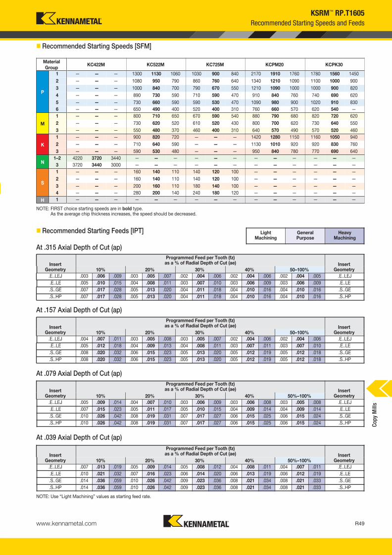
www.kennametal.com R49
Material
GroupKC422M KC522M KC725M KCPM20 KCPK30
P
1 — — — 1300 1130 1060 1030 900 840 2170 1910 1760 1780 1560 1450
2 — — — 1080 950 790 860 760 640 1340 1210 1090 1100 1000 900
3 — — — 1000 840 700 790 670 550 1210 1090 1000 1000 900 820
4 — — — 890 730 590 710 590 470 910 840 760 740 690 620
5 — — — 730 660 590 590 530 470 1090 980 900 1020 910 830
6 — — — 650 490 400 520 400 310 760 660 570 620 540 —
M
1 — — — 800 710 650 670 590 540 880 790 680 820 720 620
2 — — — 730 620 520 610 520 430 800 700 620 730 640 550
3 — — — 550 480 370 460 400 310 640 570 490 570 520 460
K
1 — — — 900 820 720 — — — 1420 1280 1150 1160 1050 940
2 — — — 710 640 590 — — — 1130 1010 920 920 830 760
3 — — — 590 530 480 — — — 950 840 780 770 690 640
N1–2 4220 3720 3440 — — — — — — — — — — — —
3 3720 3440 3000 — — — — — — — — — — — —
S
1 — — — 160 140 110 140 120 100 — — — — — —
2 — — — 160 140 110 140 120 100 — — — — — —
3 — — — 200 160 110 180 140 100 — — — — — —
4 — — — 280 200 140 240 180 120 — — — — — —
H 1 — — — — — — — — — — — — — — —
KSRM™ RP.T1605
� Recommended Starting Speeds [SFM]
NOTE: FIRST choice starting speeds are in bold type.As the average chip thickness increases, the speed should be decreased.
� Recommended Starting Feeds [IPT]
InsertGeometry
Programmed Feed per Tooth (fz)as a % of Radial Depth of Cut (ae) Insert
Geometry10% 20% 30% 40% 50–100%
.E..LEJ .003 .006 .009 .003 .005 .007 .002 .004 .006 .002 .004 .006 .002 .004 .005 .E..LEJ
.E..LE .005 .010 .015 .004 .008 .011 .003 .007 .010 .003 .006 .009 .003 .006 .009 .E..LE
.S..GE .007 .017 .028 .005 .013 .020 .004 .011 .018 .004 .010 .016 .004 .010 .016 .S..GE
.S..HP .007 .017 .028 .005 .013 .020 .004 .011 .018 .004 .010 .016 .004 .010 .016 .S..HP
InsertGeometry
Programmed Feed per Tooth (fz)as a % of Radial Depth of Cut (ae) Insert
Geometry10% 20% 30% 40% 50–100%
.E..LEJ .004 .007 .011 .003 .005 .008 .003 .005 .007 .002 .004 .006 .002 .004 .006 .E..LEJ
.E..LE .005 .012 .018 .004 .009 .013 .004 .008 .011 .003 .007 .011 .003 .007 .010 .E..LE
.S..GE .008 .020 .032 .006 .015 .023 .005 .013 .020 .005 .012 .019 .005 .012 .018 .S..GE
.S..HP .008 .020 .032 .006 .015 .023 .005 .013 .020 .005 .012 .019 .005 .012 .018 .S..HP
InsertGeometry
Programmed Feed per Tooth (fz)as a % of Radial Depth of Cut (ae) Insert
Geometry10% 20% 30% 40% 50%–100%
.E..LEJ .005 .009 .014 .004 .007 .010 .003 .006 .009 .003 .006 .008 .003 .005 .008 .E..LEJ
.E..LE .007 .015 .023 .005 .011 .017 .005 .010 .015 .004 .009 .014 .004 .009 .014 .E..LE
.S..GE .010 .026 .042 .008 .019 .031 .007 .017 .027 .006 .015 .025 .006 .015 .024 .S..GE
.S..HP .010 .026 .042 .008 .019 .031 .007 .017 .027 .006 .015 .025 .006 .015 .024 .S..HP
InsertGeometry
Programmed Feed per Tooth (fz)as a % of Radial Depth of Cut (ae) Insert
Geometry10% 20% 30% 40% 50%–100%
.E..LEJ .007 .013 .019 .005 .009 .014 .005 .008 .012 .004 .008 .011 .004 .007 .011 .E..LEJ
.E..LE .010 .021 .032 .007 .016 .023 .006 .014 .020 .006 .013 .019 .006 .012 .019 .E..LE
.S..GE .014 .036 .059 .010 .026 .042 .009 .023 .036 .008 .021 .034 .008 .021 .033 .S..GE
.S..HP .014 .036 .059 .010 .026 .042 .009 .023 .036 .008 .021 .034 .008 .021 .033 .S..HP
NOTE: Use “Light Machining” values as starting feed rate.
Light Machining
General Purpose
Heavy Machining
Recommended Starting Speeds and Feeds
At .315 Axial Depth of Cut (ap)
At .157 Axial Depth of Cut (ap)
At .079 Axial Depth of Cut (ap)
At .039 Axial Depth of Cut (ap)
Cop
y M
ills
KM_Master12_R048_R049_MINCH_EN.qxp:Layout 1 3/7/12 3:24 PM Page R49

www.kennametal.comR50
catalog numbermax
ramp anglemax
plunging depthmin hole
diameter (DH min)max flat-bottom
hole diameter (DH1 max)max diameter
(no flat bottom)
BMD150R1603M16L150 9.9° 0.106 1.904 2.37 3.0
BMD150R1603W125L200 9.9° 0.106 1.904 2.37 3.0
BMD150R1602C125L800 11.0° 0.117 1.888 2.37 3.0
BMD200R1603S075L200 11.7° 0.217 2.776 3.37 4.0
BMD200R1604S075L200 9.7° 0.181 2.81 3.37 4.0
BMD250R1605S100L200 11.7° 0.315 3.744 4.37 5.0
BMD300R1605S100L200 8.8° 0.315 4.738 5.37 6.0
BMD300R1607S100L200 6.8° 0.245 4.768 5.37 6.0
BMD400R1608S125L200 4.6° 0.245 6.762 7.37 8.0
BMD500R1609S150L250 4.2° 0.295 8.744 9.37 10.0
BMD600R1610S150L250 3.4° 0.295 10.744 11.37 12.0
KSRM™ RP.T1605
Application Data
ramp angle
shoulder cut
ramping
helical
interpolation
Ø DH/DH1
DH min = Minimum blind hole diameter with helical interpolation
DH1 max = Maximum flat-bottom hole diameter
� Maximum Linear Ramping and Helical Interpolation from Solid
Cop
y M
ills
KM_Master12_R050_R051_MINCH_EN.qxp:Layout 1 3/7/12 3:32 PM Page R50

www.kennametal.com R51
Cop
y M
ills
order number catalog number D1 max D1 D L L2 Ap1 max Zmax
ramp angle max RPM lbs insert 1
2610667 BMD200R6403W150L200 2.000 1.250 1.500 4.690 2.000 .375 3 0.60° 29000 2.15 RCG_64___
D1 maxinsert screw in. lbs.
anti-rotationscrew
Torx wrench
2.000 MS1162 45 S2160 TT25
KSRM™ RCGT64
Weldon® End Mills • Inch
• Engineered for roughing with large depths of cut
through positive geometries.
• Anti-rotation feature with six indexable positions.
• Excellent for long overhangs.
� Weldon • End Mills
� Spare Parts
KM_Master12_R050_R051_MINCH_EN.qxp:Layout 1 3/7/12 3:32 PM Page R51

www.kennametal.comR52
order number catalog number D1 max D1 D D6 L Ap1 max Zmax
ramp angle max RPM lbs insert 1
2610668 BMD250R6404S075L200 2.500 1.750 .750 1.750 2.000 .375 4 0.60° 26000 1.16 RCG_64___
2610670 BMD300R6405S100L200 3.000 2.250 1.000 2.190 2.000 .375 5 0.70° 22000 1.78 RCG_64___
2610672 BMD400R6405S125L200 4.000 3.250 1.250 2.875 2.000 .375 5 0.70° 18000 3.17 RCG_64___
2610683 BMD400R6406S125L200 4.000 3.250 1.250 2.875 2.000 .375 6 0.60° 18000 3.15 RCG_64___
2610684 BMD500R6406S150L250 5.000 4.250 1.500 3.810 2.500 .375 6 0.80° 15000 7.08 RCG_64___
2610685 BMD500R6408S150L250 5.000 4.250 1.500 3.810 2.500 .375 8 0.70° 15000 7.07 RCG_64___
2610686 BMD600R6407S150L250 6.000 5.250 1.500 3.810 2.500 .375 7 0.70° 14000 9.48 RCG_64___
2610687 BMD600R6408S150L250 6.000 5.250 1.500 3.810 2.500 .375 8 0.70° 14000 9.52 RCG_64___
2610688 BMD800R6409S250L250 8.000 7.250 2.500 5.000 2.500 .375 9 0.60° 12500 13.08 RCG_64___
D1 maxinsert screw in. lbs.
Torx wrench
anti-rotationscrew
coolant lock screw assembly
socket-head cap screwwith coolant groove
coolant cap assembly
2.500 MS1162 45 TT25 S2160 — S445CG —
3.000 MS1162 45 TT25 S2160 — S458CG —
4.000 MS1162 45 TT25 S2160 S2162C — —
5.000 MS1162 45 TT25 S2160 S2163C — —
6.000 MS1162 45 TT25 S2160 S2163C — —
8.000 MS1162 45 TT25 S2160 — — MCC080001
KSRM™ RCGT64
Shell Mills • Inch
• Engineered for roughing with large depths of cut
through positive geometry inserts.
• Anti-rotation feature with six indexable positions.
• Excellent for long overhangs.
� Shell Mills
� Spare Parts
Cop
y M
ills
KM_Master12_R052_R053_MINCH_EN.qxp:Layout 1 3/7/12 3:27 PM Page R52

www.kennametal.com R53
Cop
y M
ills
KSRM™ RCGT64
Inserts
� Insert Selection Guide
MaterialGroup
Light Machining General Purpose Heavy Machining
Geometry Grade Geometry Grade Geometry Grade
P1–P2 .E..LF KC725M .S..GF KC725M .S..HF KC725M
P3–P4 .E..LF KC522M .S..GF KC725M .S..HF KCPK30
P5–P6 .E..LF KC522M .S..HF KCPK30 .S..HF KCPK30
M1–M2 .E..LF KC725M .S..GF KC725M .S..HF KC725M
M3 .E..LF KCPK30 .S..GF KC725M .S..HF KCPK30
K1–K2 — — .S..HF KCPK30 — —
K3 — — .S..HF KCPK30 — —
N1–N2 — — — — — —
N3 — — — — — —
S1–S2 .E..LF KC725M .S..GF KC725M .S..HF KC725M
S3 .E..LF KC725M .S..GF KC725M .S..HF KC725M
S4 .E..LF KC725M .S..GF KC725M .S..HF KC725M
H1 — — — — — —
P � � � �
M � � �
K � �
N �
S � �
H
catalog number D S hmcutting edges K
C522M
KC
715M
KC
725M
KC
PK
30
RCGT64ELF .750 .250 .002 6 � � � �
catalog number D S hmcutting edges K
C5
22
M
KC
71
5M
KC
72
5M
KC
PK
30
RCGT64SGF .750 .250 .004 6 � �
catalog number D S hmcutting edges K
C5
22
M
KC
71
5M
KC
72
5M
KC
PK
30
RCGT64SHF .750 .250 .010 6 � � �
Indexable Round Inserts • KSRM
RCGT-LFRCGT-GFRCGT-HF � first choice
� alternate choice
• ELF is the first choice for lower cutting forces to avoid built-up edge.
• SGF geometry for general purpose in roughing applications.
• SHF is the first choice for heavy duty applications.
� RCGT-LF
� RCGT-GF
� RCGT-HF
KM_Master12_R052_R053_MINCH_EN.qxp:Layout 1 3/7/12 3:27 PM Page R53

www.kennametal.comR54
KSRM™ RCGT64
Recommended Starting Speeds and Feeds
� Recommended Starting Speeds [SFM]
Material
GroupKC522M KC715M KC725M KCPK30
P
1 1300 1130 1060 1340 1180 1090 1030 900 840 1780 1560 1450
2 1080 950 790 830 740 670 860 760 640 1100 1000 900
3 1000 840 700 740 670 610 790 670 550 1000 900 820
4 890 730 590 560 520 470 710 590 470 740 690 620
5 730 660 590 770 680 620 590 530 470 1020 910 830
6 650 490 400 470 410 — 520 400 310 620 540 —
M
1 800 710 650 880 770 710 670 590 540 820 720 620
2 730 620 520 — — — 610 520 430 730 640 550
3 550 480 370 — — — 460 400 310 570 520 460
K
1 900 820 720 — — — — — — 1160 1050 940
2 710 640 590 — — — — — — 920 830 760
3 590 530 480 — — — — — — 770 690 640
N1–2 — — — — — — — — — — — —
3 — — — — — — — — — — — —
S
1 160 140 110 — — — 140 120 100 — — —
2 160 140 110 — — — 140 120 100 — — —
3 200 160 110 — — — 180 140 100 — — —
4 280 200 140 — — — 240 180 120 — — —
H 1 — — — — — — — — — — — —
NOTE: FIRST choice starting speeds are in bold type.As the average chip thickness increases, the speed should be decreased.
� Recommended Starting Feeds [IPT]
InsertGeometry
Programmed Feed per Tooth (fz)as a % of Radial Depth of Cut (ae) Insert
Geometry10% 20% 30% 40% 50–100%
.E..LF .004 .007 .013 .003 .005 .009 .002 .004 .008 .002 .004 .008 .002 .004 .008 .E..LF
.S..GF .007 .017 .028 .005 .013 .020 .004 .011 .018 .004 .010 .016 .004 .010 .016 .S..GF
.S..HF .007 .017 .028 .005 .013 .020 .004 .011 .018 .004 .010 .016 .004 .010 .016 .S..HF
InsertGeometry
Programmed Feed per Tooth (fz)as a % of Radial Depth of Cut (ae) Insert
Geometry10% 20% 30% 40% 50–100%
.E..LF .004 .008 .015 .003 .006 .011 .003 .005 .009 .003 .005 .009 .002 .005 .009 .E..LF
.S..GF .008 .020 .032 .006 .015 .023 .005 .013 .020 .005 .012 .019 .005 .012 .018 .S..GF
.S..HF .008 .020 .032 .006 .015 .023 .005 .013 .020 .005 .012 .019 .005 .012 .018 .S..HF
InsertGeometry
Programmed Feed per Tooth (fz)as a % of Radial Depth of Cut (ae) Insert
Geometry10% 20% 30% 40% 50–100%
.E..LF .005 .010 .019 .004 .008 .014 .004 .007 .012 .003 .006 .012 .003 .006 .011 .E..LF
.S..GF .010 .026 .042 .008 .019 .031 .007 .017 .027 .006 .015 .025 .006 .015 .024 .S..GF
.S..HF .010 .026 .042 .008 .019 .031 .007 .017 .027 .006 .015 .025 .006 .015 .024 .S..HF
InsertGeometry
Programmed Feed per Tooth (fz)as a % of Radial Depth of Cut (ae) Insert
Geometry10% 20% 30% 40% 50–100%
.E..LF .007 .014 .027 .005 .011 .020 .005 .009 .017 .004 .009 .016 .004 .008 .015 .E..LF
.S..GF .014 .036 .059 .010 .026 .042 .009 .023 .036 .008 .021 .034 .008 .021 .033 .S..GF
.S..HF .014 .036 .059 .010 .026 .042 .009 .023 .036 .008 .021 .034 .008 .021 .033 .S..HF
NOTE: Use “Light Machining” values as starting feed rate.
Light Machining
General Purpose
Heavy Machining
At .375 Axial Depth of Cut (ap)
At .188 Axial Depth of Cut (ap)
At .094 Axial Depth of Cut (ap)
At .047 Axial Depth of Cut (ap)
Cop
y M
ills
KM_Master12_R054_R055_MINCH_EN.qxp:Layout 1 3/7/12 3:35 PM Page R54

Cop
y M
ills
ramp angle
shoulder cut
ramping
helical
interpolation
Ø DH/DH1
DH min = Minimum blind hole diameter with helical interpolation
DH1 max = Maximum flat-bottom hole diameter
insert IC catalog number
max ramp angle (ra)
when hx = .005"
max ramp angle (ra)
when hx = .020"
max plunge radial depth (ae) when hx = .020"
min hole diameter
max flat-bottomhole diameter
max hole diameter
(no flat bottom)
RCGX64 BMD200R6403W150L200 1.27° 0.70° 0.509 3.040 3.253 4.000
RCGX64 BMD250R6404S075L200 1.27° 0.59° 0.516 4.006 4.253 5.000
RCGX64 BMD300R6405S100L200 1.22° 0.70° 0.529 4.955 5.253 6.000
RCGX64 BMD400R6405S125L200 1.12° 0.67° 0.547 6.911 7.253 8.000
RCGX64 BMD400R6406S125L200 0.73° 0.64° 0.544 6.920 7.253 8.000
RCGX64 BMD500R6406S150L250 1.00° 0.75° 0.578 8.851 9.253 10.000
RCGX64 BMD500R6408S150L250 0.98° 0.68° 0.575 8.867 9.253 10.000
RCGX64 BMD600R6407S150L250 0.90° 0.69° 0.590 10.827 11.253 12.000
RCGX64 BMD600R6408S150L250 0.90° 0.67° 0.586 10.834 11.253 12.000
RCGX64 BMD800R6409S250L250 0.74° 0.59° 0.603 14.798 15.253 16.000
KSRM™ RCGT64
Application Data
www.kennametal.com R55
KM_Master12_R054_R055_MINCH_EN.qxp:Layout 1 3/7/12 3:35 PM Page R55

www.kennametal.comR56
order number catalog number D1 max D1 D D6 L Ap1 max Zmax
ramp angle max RPM lbs insert 1
2610689 BMD300R8603S075L200 3.000 2.000 .750 1.750 2.000 .500 3 0.90° 15500 1.22 RCGT86___
2610691 BMD400R8605S125L250 4.000 3.000 1.250 2.875 2.500 .500 5 0.80° 12000 4.01 RCGT86___
2610697 BMD500R8606S150L250 5.000 4.000 1.500 3.810 2.500 .500 6 0.80° 9000 6.62 RCGT86___
2610694 BMD600R8607S150L250 6.000 5.000 1.500 3.810 2.500 .500 7 0.80° 8800 8.63 RCGT86___
2610696 BMD800R8608S250L250 8.000 7.000 2.500 5.000 2.500 .500 8 0.70° 8500 11.81 RCGT86___
D1 maxinsert screw in. lbs.
Torx wrench
anti-rotationscrew
coolant lock screw assembly
coolant cap assembly
socket-head cap screwwith coolant groove
3.000 MS1162 45 TT25 S2160 — — S445CG
4.000 MS1162 45 TT25 S2160 S2164C — —
5.000 MS1162 45 TT25 S2160 S2163C — —
6.000 MS1162 45 TT25 S2160 S2163C — —
8.000 MS1162 45 TT25 S2160 — MCC080001 —
KSRM™ RCGT86
Shell Mills • Inch
• Engineered for roughing with large depths of cut
through positive geometry inserts.
• Anti-rotation feature with six indexable positions.
• Excellent for long overhangs.
� Shell Mills
� Spare Parts
Cop
y M
ills
KM_Master12_R056_R057_MINCH_EN.qxp:Layout 1 3/7/12 3:33 PM Page R56

www.kennametal.com R57
Cop
y M
ills
KSRM™ RCGT86
Inserts
� Insert Selection Guide
MaterialGroup
Light Machining General Purpose Heavy Machining
Geometry Grade Geometry Grade Geometry Grade
P1–P2 .E..LF KC725M .S..GF KC725M .S..HF KC725M
P3–P4 .S..GF KC522M .S..GF KC725M .S..HF KCPK30
P5–P6 .S..GF KC522M .S..HF KCPK30 .S..HF KCPK30
M1–M2 .E..LF KC725M .S..GF KC725M .S..HF KC725M
M3 .E..LF KC725M .S..GF KC725M .S..HF KCPK30
K1–K2 — — .S..HF KCPK30 — —
K3 — — .S..HF KCPK30 — —
N1–N2 — — — — — —
N3 — — — — — —
S1–S2 .E..LF KC725M .S..GF KC725M .S..HF KC725M
S3 .E..LF KC725M .S..GF KC725M .S..HF KC725M
S4 .E..LF KC725M .S..GF KC725M .S..HF KC725M
H1 — — — — — —
P � � � �
M � � �
K � �
N �
S � �
H
catalog number D S hmcuttingedges K
C522M
KC
715M
KC
725M
KC
PK
30
RCGT86ELF 1.000 .375 .002 6 � � � �
catalog number D S hmcuttingedges K
C5
22M
KC
715M
KC
725M
KC
PK
30
RCGT86SGF 1.000 .375 .004 6 � �
catalog number D S hmcuttingedges K
C5
22
M
KC
71
5M
KC
72
5M
KC
PK
30
RCGT86SHF 1.000 .375 .010 6 � � �
RCGT-LFRCGT-GFRCGT-HF
� first choice
� alternate choice
• ELF is the first choice for lower cutting forces to avoid built-up edge.
• SGF geometry for general purpose in roughing applications.
• SHF is the first choice for heavy duty applications.
� RCGT-LF
� RCGT-GF
� RCGT-HF
Indexable Round Inserts • KSRM
KM_Master12_R056_R057_MINCH_EN.qxp:Layout 1 3/7/12 3:33 PM Page R57

www.kennametal.comR58
KSRM™ RCGT86
Recommended Starting Speeds and Feeds
� Recommended Starting Speeds [SFM]
Material
GroupKC522M KC715M KC725M KCPK30
P
1 1300 1130 1060 1340 1180 1090 1030 900 840 1780 1560 1450
2 1080 950 790 830 740 670 860 760 640 1100 1000 900
3 1000 840 700 740 670 610 790 670 550 1000 900 820
4 890 730 590 560 520 470 710 590 470 740 690 620
5 730 660 590 770 680 620 590 530 470 1020 910 830
6 650 490 400 470 410 — 520 400 310 620 540 —
M
1 800 710 650 880 770 710 670 590 540 820 720 620
2 730 620 520 — — — 610 520 430 730 640 550
3 550 480 370 — — — 460 400 310 570 520 460
K
1 900 820 720 — — — — — — 1160 1050 940
2 710 640 590 — — — — — — 920 830 760
3 590 530 480 — — — — — — 770 690 640
N1–2 — — — — — — — — — — — —
3 — — — — — — — — — — — —
S
1 160 140 110 — — — 140 120 100 — — —
2 160 140 110 — — — 140 120 100 — — —
3 200 160 110 — — — 180 140 100 — — —
4 280 200 140 — — — 240 180 120 — — —
H 1 — — — — — — — — — — — —
NOTE: FIRST choice starting speeds are in bold type.As the average chip thickness increases, the speed should be decreased.
� Recommended Starting Feeds [IPT]
InsertGeometry
Programmed Feed per Tooth (fz)as a % of Radial Depth of Cut (ae) Insert
Geometry10% 20% 30% 40% 50–100%
.E..LF .004 .007 .013 .003 .005 .009 .002 .004 .008 .002 .004 .008 .002 .004 .008 .E..LF
.S..GF .007 .017 .028 .005 .013 .020 .004 .011 .018 .004 .010 .016 .004 .010 .016 .S..GF
.S..HF .007 .017 .028 .005 .013 .020 .004 .011 .018 .004 .010 .016 .004 .010 .016 .S..HF
InsertGeometry
Programmed Feed per Tooth (fz)as a % of Radial Depth of Cut (ae) Insert
Geometry10% 20% 30% 40% 50–100%
.E..LF .004 .008 .015 .003 .006 .011 .003 .005 .009 .003 .005 .009 .002 .005 .009 .E..LF
.S..GF .008 .020 .032 .006 .015 .023 .005 .013 .020 .005 .012 .019 .005 .012 .018 .S..GF
.S..HF .008 .020 .032 .006 .015 .023 .005 .013 .020 .005 .012 .019 .005 .012 .018 .S..HF
InsertGeometry
Programmed Feed per Tooth (fz)as a % of Radial Depth of Cut (ae) Insert
Geometry10% 20% 30% 40% 50–100%
.E..LF .005 .010 .019 .004 .008 .014 .004 .007 .012 .003 .006 .012 .003 .006 .011 .E..LF
.S..GF .010 .026 .042 .008 .019 .031 .007 .017 .027 .006 .015 .025 .006 .015 .024 .S..GF
.S..HF .010 .026 .042 .008 .019 .031 .007 .017 .027 .006 .015 .025 .006 .015 .024 .S..HF
InsertGeometry
Programmed Feed per Tooth (fz)as a % of Radial Depth of Cut (ae) Insert
Geometry10% 20% 30% 40% 50–100%
.E..LF .007 .014 .027 .005 .011 .020 .005 .009 .017 .004 .009 .016 .004 .008 .015 .E..LF
.S..GF .014 .036 .059 .010 .026 .042 .009 .023 .036 .008 .021 .034 .008 .021 .033 .S..GF
.S..HF .014 .036 .059 .010 .026 .042 .009 .023 .036 .008 .021 .034 .008 .021 .033 .S..HF
NOTE: Use “Light Machining” values as starting feed rate.
Light Machining
General Purpose
Heavy Machining
At .500 Axial Depth of Cut (ap)
At .125 Axial Depth of Cut (ap)
At .250 Axial Depth of Cut (ap)
At .063 Axial Depth of Cut (ap)
Cop
y M
ills
KM_Master12_R058_R059_MINCH_EN.qxp:Layout 1 3/7/12 3:33 PM Page R58

www.kennametal.com R59
Cop
y M
ills
ramp angle
shoulder cut
ramping
helical
interpolation
Ø DH/DH1
DH min = Minimum blind hole diameter with helical interpolation
DH1 max = Maximum flat-bottom hole diameter
insert IC catalog number
max ramp angle (ra)
when hx = .005"
max ramp angle (ra)
when hx = .020"
max plunge radial depth (ae) when hx = .020"
min hole diameter
max flat-bottomhole diameter
max hole diameter
(no flat bottom)
RCGX86 BMD300R8603S075L200 1.35° 0.89° 0.690 4.622 5.004 6.000
RCGX86 BMD400R8605S125L250 1.27° 0.83° 0.721 6.576 7.004 8.000
RCGX86 BMD500R8606S150L250 1.17° 0.80° 0.741 8.526 9.004 10.000
RCGX86 BMD600R8607S150L250 1.08° 0.78° 0.762 10.485 11.004 12.000
RCGX86 BMD800R8608S250L250 0.92° 0.73° 0.790 14.424 15.004 16.000
KSRM™ RCGT86
Application Data
KM_Master12_R058_R059_MINCH_EN.qxp:Layout 1 3/7/12 3:33 PM Page R59

Beyond BLAST™ KSRM™ • Next Generation Round Inserts with Through Coolant
Primary ApplicationSpecially developed for machining titanium. Beyond BLAST KSRM platform boosts your productivity with its new and revolutionary technology, PCT (Precision Coolant Technology), enabling consistent performance and providing outstanding metal removal rates and longer tool life.
Features and Benefits
www.kennametal.comR60
Platform Features
Channeling coolant through the insert.
Anti-rotation feature with six indexes.
High positive topography with strong cutting edges.
High clearance on the cutters and inserts.
Benefits
Increase productivity, tool life, and chip control.
Superior productivity and better insertutilization/cost per edge.
Long tool life and better MRR.
Able to convert all milling applications.
To learn more, scan here.
For instructions on how to scan, please see page xxix.
KM_Master12_R060_R061_MINCH_EN.qxp:Layout 1 3/7/12 3:31 PM Page R60

www.kennametal.com R61
order number catalog number D1 max D1 D L LBX Ap1 max Z max RPM insert 1 lbs
4109182 KSRM200R64BB03W150L200 2.000 1.250 1.500 4.690 2.000 .375 3 20100 RCGX64__ 2.06
D1 maxinsert screw in. lbs.
universal bit torque driver drive bit
2.000 MS1162 45 KPTW45 BT25L50
Beyond BLAST™ KSRM™
Weldon® End Mills • BB KSRM • RCGX64...
• Use PCT technology, coolant through the insert.
• Engineered to provide the maximum performance in titanium machining.
• Anti-rotation feature enables up to six indexables rotations.
• Pocketing, ramping, plunging, and helical interpolations capabilities.
� Weldon End Mills • Inch
� Spare Parts
Geometry for medium and heavy machining
S
Geometry for light and medium machining
S
Best-in-Class Performance Booster in Machining Titanium
Cop
y M
ills
-ELF -SGF
KM_Master12_R060_R061_MINCH_EN.qxp:Layout 1 3/7/12 3:31 PM Page R61

www.kennametal.comR62
order number catalog number D1 max D1 D D6 L Ap1 max Z max RPM insert 1 lbs
4109183 KSRM250R64BB04S075L200 2.500 1.750 .750 1.750 2.000 .375 4 17000 RCGX64__ 1.08
4109184 KSRM300R64BB05S100L200 3.000 2.250 1.000 2.750 2.000 .375 5 15000 RCGX64__ 2.24
4109185 KSRM400R64BB05S125L200 4.000 3.250 1.250 2.875 2.000 .375 5 12400 RCGX64__ 3.20
4109186 KSRM400R64BB06S125L200 4.000 3.250 1.250 2.875 2.000 .375 6 12400 RCGX64__ 3.23
4109187 KSRM500R64BB06S150L250 5.000 4.250 1.500 3.811 2.500 .375 6 10900 RCGX64__ 6.77
4109188 KSRM500R64BB08S150L250 5.000 4.250 1.500 3.811 2.500 .375 8 10900 RCGX64__ 6.80
4109189 KSRM600R64BB07S150L250 6.000 5.250 1.500 3.811 2.500 .375 7 9800 RCGX64__ 9.28
4109190 KSRM600R64BB08S150L250 6.000 5.250 1.500 3.811 2.500 .375 8 9800 RCGX64__ 9.22
4109191 KSRM800R64BB09S250L250 8.000 7.250 2.500 5.000 2.500 .375 9 8300 RCGX64__ 12.08
D1 maxinsert screw in. lbs.
universal bit torque driver
drive bit
coolant lock screw assembly
coolant shower plate assembly
socket-head cap screwwith coolant groove
2.500 MS1162 45 KPTW45 BT25L50 — — S445CG
3.000 MS1162 45 KPTW45 BT25L50 — — S458CG
4.000 MS1162 45 KPTW45 BT25L50 S2162C — —
5.000 MS1162 45 KPTW45 BT25L50 S2163C — —
6.000 MS1162 45 KPTW45 BT25L50 S2163C — —
8.000 MS1162 45 KPTW45 BT25L50 — MCC080001 —
Beyond BLAST™ KSRM™
Face Mills • BB KSRM • RCGX64...
• Use PCT technology, coolant through the insert.
• Engineered to provide the maximum performance in titanium machining.
• Anti-rotation feature enables up to six indexables rotations.
• Pocketing, ramping, plunging, and helical interpolations capabilities.
� Face Mills • Inch
� Spare Parts
Cop
y M
ills
KM_Master12_R062_R063_MINCH_EN.qxp:Layout 1 3/7/12 3:32 PM Page R62

RCGX64SGF .750 .250 .004 6 �
www.kennametal.com R63
Beyond BLAST™ KSRM™
Inserts
� Insert Selection Guide
MaterialGroup
Light Machining General Purpose Heavy Machining
Geometry Grade Geometry Grade Geometry Grade
P1–P2 — — — — — —
P3–P4 — — — — — —
P5–P6 — — — — — —
M1–M2 — — — — — —
M3 — — — — — —
K1–K2 — — — — — —
K3 — — — — — —
N1–N2 — — — — — —
N3 — — — — — —
S1–S2 — — — — — —
S3 — — — — — —
S4 .E..LF KC725M .S..GF KC725M .S..GF KC725M
H1 — — — — — —
P
M
K
N
S �
H
catalog number D S hmcutting edges K
C725M
RCGX64ELF .750 .250 .003 6 �
Indexable Ground Insert • BB KSRM
RCGX-LFRCGX-GF
� first choice
� alternate choice
• ELF geometry for lower cutting forces to avoid built-up edge.
• SGF in the first choice for higher chip load and heavy applications.
� RCGX-LF and -GF
Cop
y M
ills
KM_Master12_R062_R063_MINCH_EN.qxp:Layout 1 3/7/12 3:33 PM Page R63
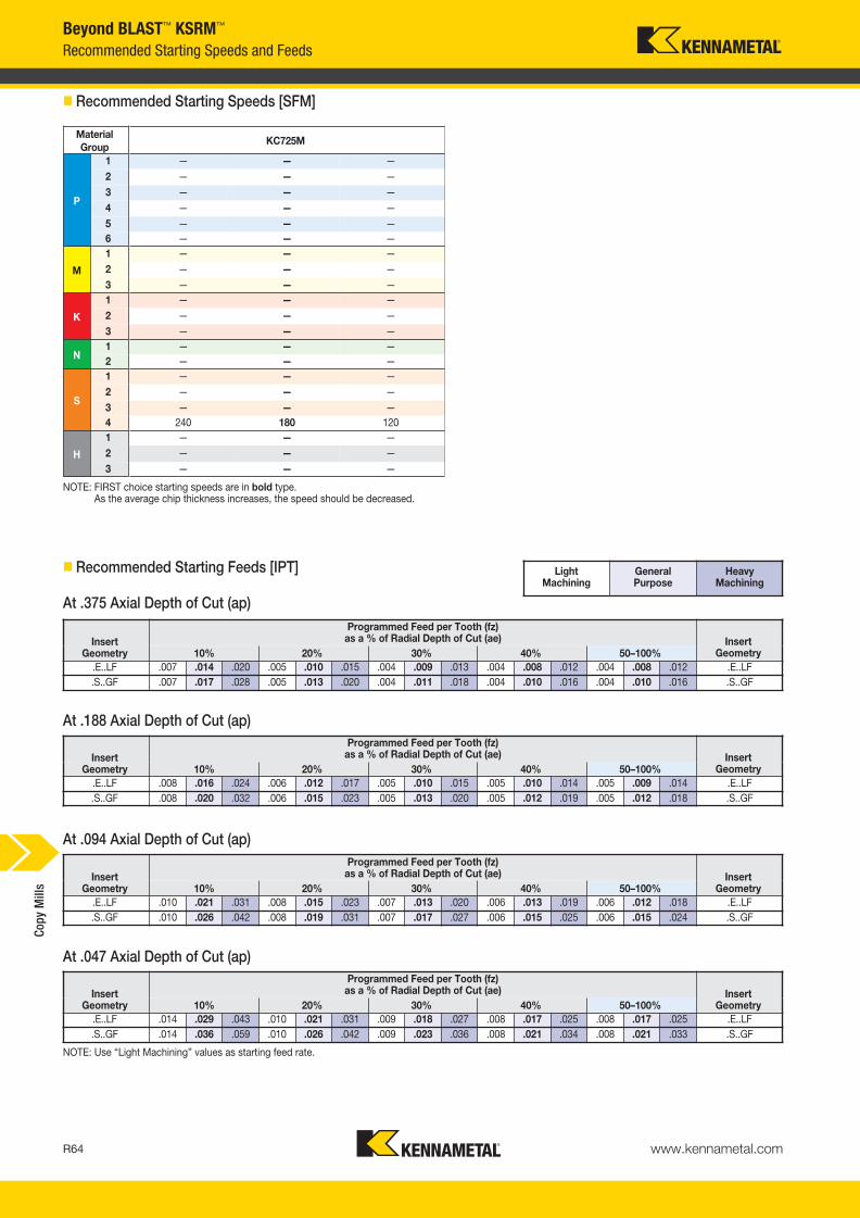
www.kennametal.comR64
Material
GroupKC725M
P
1 — — —
2 — — —
3 — — —
4 — — —
5 — — —
6 — — —
M
1 — — —
2 — — —
3 — — —
K
1 — — —
2 — — —
3 — — —
N1 — — —
2 — — —
S
1 — — —
2 — — —
3 — — —
4 240 180 120
H
1 — — —
2 — — —
3 — — —
Beyond BLAST™ KSRM™
Recommended Starting Speeds and Feeds
� Recommended Starting Speeds [SFM]
NOTE: FIRST choice starting speeds are in bold type.As the average chip thickness increases, the speed should be decreased.
� Recommended Starting Feeds [IPT]
InsertGeometry
Programmed Feed per Tooth (fz)as a % of Radial Depth of Cut (ae) Insert
Geometry10% 20% 30% 40% 50–100%
.E..LF .007 .014 .020 .005 .010 .015 .004 .009 .013 .004 .008 .012 .004 .008 .012 .E..LF
.S..GF .007 .017 .028 .005 .013 .020 .004 .011 .018 .004 .010 .016 .004 .010 .016 .S..GF
InsertGeometry
Programmed Feed per Tooth (fz)as a % of Radial Depth of Cut (ae) Insert
Geometry10% 20% 30% 40% 50–100%
.E..LF .008 .016 .024 .006 .012 .017 .005 .010 .015 .005 .010 .014 .005 .009 .014 .E..LF
.S..GF .008 .020 .032 .006 .015 .023 .005 .013 .020 .005 .012 .019 .005 .012 .018 .S..GF
InsertGeometry
Programmed Feed per Tooth (fz)as a % of Radial Depth of Cut (ae) Insert
Geometry10% 20% 30% 40% 50–100%
.E..LF .010 .021 .031 .008 .015 .023 .007 .013 .020 .006 .013 .019 .006 .012 .018 .E..LF
.S..GF .010 .026 .042 .008 .019 .031 .007 .017 .027 .006 .015 .025 .006 .015 .024 .S..GF
InsertGeometry
Programmed Feed per Tooth (fz)as a % of Radial Depth of Cut (ae) Insert
Geometry10% 20% 30% 40% 50–100%
.E..LF .014 .029 .043 .010 .021 .031 .009 .018 .027 .008 .017 .025 .008 .017 .025 .E..LF
.S..GF .014 .036 .059 .010 .026 .042 .009 .023 .036 .008 .021 .034 .008 .021 .033 .S..GF
NOTE: Use “Light Machining” values as starting feed rate.
Light Machining
General Purpose
Heavy Machining
At .375 Axial Depth of Cut (ap)
At .047 Axial Depth of Cut (ap)
At .094 Axial Depth of Cut (ap)
At .188 Axial Depth of Cut (ap)
Cop
y M
ills
KM_Master12_R064_R065_MINCH_EN.qxp:Layout 1 3/9/12 8:27 AM Page R64

www.kennametal.com R65
insert IC catalog numbermax
ramp anglemax
ramp depthmax
plunging depthmin hole
diameter (DH min)max flat-bottom
hole diameter (DH1 max)max diameter
(no flat bottom)
RCGX64 KSRM200R64BB03W150L200 1.27° 0.025 0.045 2.989 3.253 4.000
RCGX64 KSRM250R64BB04S075L200 1.27° 0.035 0.058 3.939 4.253 5.000
RCGX64 KSRM300R64BB05S100L200 1.22° 0.044 0.068 4.904 5.253 6.000
RCGX64 KSRM400R64BB05S125L200 1.12° 0.060 0.084 6.850 7.253 8.000
RCGX64 KSRM400R64BB06S125L200 0.73° 0.039 0.083 6.921 7.253 8.000
RCGX64 KSRM500R64BB06S150L250 1.00° 0.071 0.094 8.818 9.253 10.000
RCGX64 KSRM500R64BB08S150L250 0.98° 0.069 0.092 8.823 9.253 10.000
RCGX64 KSRM600R64BB07S150L250 0.90° 0.079 0.101 10.795 11.253 12.000
RCGX64 KSRM600R64BB08S150L250 0.90° 0.079 0.100 10.796 11.253 12.000
RCGX64 KSRM800R64BB09S250L250 0.74° 0.091 0.111 14.766 15.253 16.000
Beyond BLAST™ KSRM™
Application Data
� Ramping and Helical Interpolation Values from Solid
� Round Insert RCGX64
ramp angle
shoulder cut
ramping
helical
interpolation
Ø DH/DH1DH min = Minimum blind hole diameter with helical interpolation
DH1 max = Maximum flat-bottom hole diameter
Cop
y M
ills
KM_Master12_R064_R065_MINCH_EN.qxp:Layout 1 3/9/12 8:27 AM Page R65

www.kennametal.comR66
order number catalog number D1 max D1 D D6 L Ap1 max Z max RPM insert 1 lbs
4109138 KSRM300R86BB03S075L200 3.000 2.000 .750 1.750 2.000 .500 3 15500 RCGX86__ 1.30
4109139 KSRM400R86BB05S125L250 4.000 3.000 1.250 2.875 2.500 .500 5 12000 RCGX86__ 3.76
4109140 KSRM500R86BB06S150L250 5.000 4.000 1.500 3.812 2.500 .500 6 9000 RCGX86__ 6.22
4109141 KSRM600R86BB07S150L250 6.000 5.000 1.500 3.812 2.500 .500 7 8800 RCGX86__ 8.47
4109142 KSRM800R86BB08S250L250 8.000 7.000 2.500 5.000 2.500 .500 8 8500 RCGX86__ 11.21
D1 maxinsert screw in. lbs.
universal bit torque driver
drivebit
coolant lock screw assembly
coolant shower plate assembly
socket-head cap screwwith coolant groove
3.000 MS1162 45 KPTW45 BT25L50 — — S445CG
4.000 MS1162 45 KPTW45 BT25L50 S2164C — —
5.000 MS1162 45 KPTW45 BT25L50 S2163C — —
6.000 MS1162 45 KPTW45 BT25L50 S2163C — —
8.000 MS1162 45 KPTW45 BT25L50 — MCC080001 —
Beyond BLAST™ KSRM™
Face Mills • BB KSRM RCGX86...
• Use PCT technology, coolant through the insert.
• Engineered to provide the maximum performance in titanium machining.
• Anti-rotation feature enables up to six indexables rotations.
• Pocketing, ramping, plunging, and helical interpolations capabilities.
� Face Mills • Inch
� Spare Parts
Cop
y M
ills
KM_Master12_R066_R067_MINCH_EN.qxp:Layout 1 3/7/12 3:30 PM Page R66
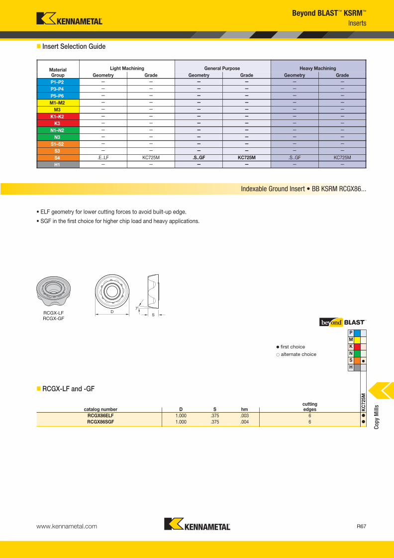
www.kennametal.com R67
Beyond BLAST™ KSRM™
Inserts
� Insert Selection Guide
MaterialGroup
Light Machining General Purpose Heavy Machining
Geometry Grade Geometry Grade Geometry Grade
P1–P2 — — — — — —
P3–P4 — — — — — —
P5–P6 — — — — — —
M1–M2 — — — — — —
M3 — — — — — —
K1–K2 — — — — — —
K3 — — — — — —
N1–N2 — — — — — —
N3 — — — — — —
S1–S2 — — — — — —
S3 — — — — — —
S4 .E..LF KC725M .S..GF KC725M .S..GF KC725M
H1 — — — — — —
P
M
K
N
S �
H
catalog number D S hmcutting edges K
C725M
RCGX86ELF 1.000 .375 .003 6 �
RCGX86SGF 1.000 .375 .004 6 �
Indexable Ground Insert • BB KSRM RCGX86...
RCGX-LFRCGX-GF
� first choice
� alternate choice
• ELF geometry for lower cutting forces to avoid built-up edge.
• SGF in the first choice for higher chip load and heavy applications.
� RCGX-LF and -GF
Cop
y M
ills
KM_Master12_R066_R067_MINCH_EN.qxp:Layout 1 3/7/12 3:30 PM Page R67

www.kennametal.comR68
Material
GroupKC725M
P
1 — — —
2 — — —
3 — — —
4 — — —
5 — — —
6 — — —
M
1 — — —
2 — — —
3 — — —
K
1 — — —
2 — — —
3 — — —
N1 — — —
2 — — —
S
1 — — —
2 — — —
3 — — —
4 240 180 120
H
1 — — —
2 — — —
3 — — —
Recommended Starting Speeds and Feeds
� Recommended Starting Speeds [SFM]
NOTE: FIRST choice starting speeds are in bold type.As the average chip thickness increases, the speed should be decreased.
Beyond BLAST™ KSRM™
� Recommended Starting Feeds [IPT]
InsertGeometry
Programmed Feed per Tooth (fz)as a % of Radial Depth of Cut (ae) Insert
Geometry10% 20% 30% 40% 50–100%
.E..LF .007 .014 .020 .005 .010 .015 .004 .009 .013 .004 .008 .012 .004 .008 .012 .E..LF
.S..GF .007 .017 .028 .005 .013 .020 .004 .011 .018 .004 .010 .016 .004 .010 .016 .S..GF
InsertGeometry
Programmed Feed per Tooth (fz)as a % of Radial Depth of Cut (ae) Insert
Geometry10% 20% 30% 40% 50–100%
.E..LF .008 .016 .024 .006 .012 .017 .005 .010 .015 .005 .010 .014 .005 .009 .014 .E..LF
.S..GF .008 .020 .032 .006 .015 .023 .005 .013 .020 .005 .012 .019 .005 .012 .018 .S..GF
InsertGeometry
Programmed Feed per Tooth (fz)as a % of Radial Depth of Cut (ae) Insert
Geometry10% 20% 30% 40% 50–100%
.E..LF .010 .021 .031 .008 .015 .023 .007 .013 .020 .006 .013 .019 .006 .012 .018 .E..LF
.S..GF .010 .026 .042 .008 .019 .031 .007 .017 .027 .006 .015 .025 .006 .015 .024 .S..GF
InsertGeometry
Programmed Feed per Tooth (fz)as a % of Radial Depth of Cut (ae) Insert
Geometry10% 20% 30% 40% 50–100%
.E..LF .014 .029 .043 .010 .021 .031 .009 .018 .027 .008 .017 .025 .008 .017 .025 .E..LF
.S..GF .014 .036 .059 .010 .026 .042 .009 .023 .036 .008 .021 .034 .008 .021 .033 .S..GF
NOTE: Use “Light Machining” values as starting feed rate.
Light Machining
General Purpose
Heavy Machining
At .500 Axial Depth of Cut (ap)
At .063 Axial Depth of Cut (ap)
At .125 Axial Depth of Cut (ap)
At .250 Axial Depth of Cut (ap)
Cop
y M
ills
KM_Master12_R068_R069_MINCH_EN.qxp:Layout 1 3/7/12 3:33 PM Page R68
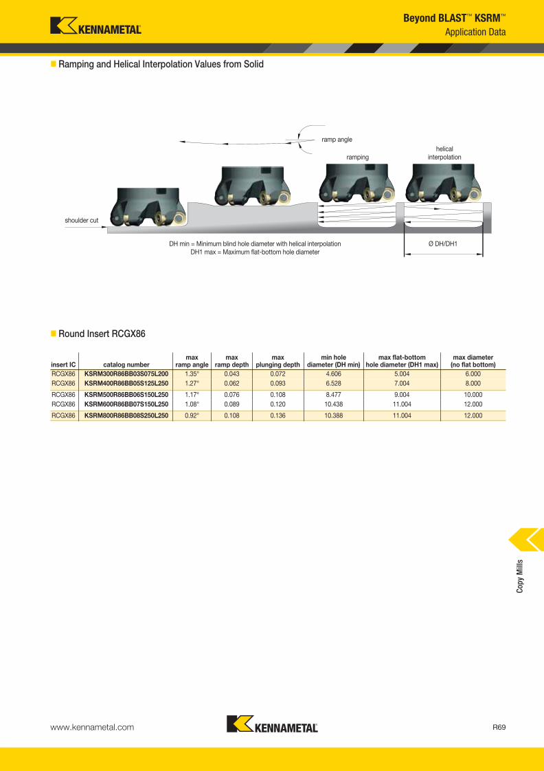
www.kennametal.com R69
insert IC catalog numbermax
ramp anglemax
ramp depthmax
plunging depthmin hole
diameter (DH min)max flat-bottom
hole diameter (DH1 max)max diameter
(no flat bottom)
RCGX86 KSRM300R86BB03S075L200 1.35° 0.043 0.072 4.606 5.004 6.000
RCGX86 KSRM400R86BB05S125L250 1.27° 0.062 0.093 6.528 7.004 8.000
RCGX86 KSRM500R86BB06S150L250 1.17° 0.076 0.108 8.477 9.004 10.000
RCGX86 KSRM600R86BB07S150L250 1.08° 0.089 0.120 10.438 11.004 12.000
RCGX86 KSRM800R86BB08S250L250 0.92° 0.108 0.136 10.388 11.004 12.000
Beyond BLAST™ KSRM™
Application Data
� Ramping and Helical Interpolation Values from Solid
� Round Insert RCGX86
ramp angle
shoulder cut
ramping
helical
interpolation
Ø DH/DH1DH min = Minimum blind hole diameter with helical interpolation
DH1 max = Maximum flat-bottom hole diameter
Cop
y M
ills
KM_Master12_R068_R069_MINCH_EN.qxp:Layout 1 3/7/12 3:33 PM Page R69

KDMB™ and KDMT™ • Indexable Copy Insert Platform
Primary ApplicationBall nose and toroidal styles for roughing and finishing operations. Engineered with the ultimate technologies and supported with a wide range of diameters and insert styles, this platform provides exceptional performance and productivity. The new High-Feed insert style provides the highest metal removal rates for roughing applications.
Features and Benefits
Longer Tool Life and Improved Geometries
• Longer tool life for finishing operations, up to 63 HRC.
• High-accuracy inserts and holders: overall runout .0004".
• Improved geometries for roughing and finishing operations.
• Smaller diameters from .25" to replace SCEM, setting a more productive machining process.
Superior Productivity
• Due to the new helical geometry, we obtain better surface quality.
• New ultra-grain grade for outstanding tool life.
• Diameters .250" and .312" natural replacement for SEM tools.
• Better cost per edge.
Usability and Flexibility
• Wide diameter range enables it to be applied across a wide range of machining conditions.
• Many workpiece materials are possible — from hardened steel to aluminum.
• Large holder style offering: screw-on, cylindrical, and tapered steel and carbide holders.
www.kennametal.comR70
KM_Master12_R070_R071_MINCH_EN.qxp:Layout 1 3/7/12 3:27 PM Page R70

www.kennametal.com R71
• Cutting diameter ranges from .375–1.250".
• Ball nose finishers for 3-dimensional milling applications.
• Suitable for roughing and finishing operations.
� Necked End Mills • Steel Shank
order number catalog number D1 D D3 L L2 Ap1 max Z Z Umax
ramp angle max RPM lbs insert 1
2877812 KDMB0375R354A038SN .375 .500 .335 3.543 1.378 .188 1 2 3.0° 40000 .07 KDMB0375..
2878434 KDMB0500R512A050SN .500 .500 .413 5.120 1.260 .250 1 2 3.0° 40000 .22 KDMB0500..
2878433 KDMB0500R591A050SN .500 .500 .413 5.906 1.810 .250 1 2 3.0° 40000 .22 KDMB0500..
2878435 KDMB0625R551A063SN .625 .625 .551 5.512 1.420 .313 1 2 3.0° 40000 .44 KDMB0625..
2878436 KDMB0625R630A063SN .625 .625 .551 6.299 2.090 .313 1 2 3.0° 40000 .44 KDMB0625..
2878437 KDMB0750R630A075SN .750 .750 .709 6.281 1.753 .375 1 2 3.0° 40000 .88 KDMB0750..
2878438 KDMB0750R689A075SN .750 .750 .709 6.890 2.362 .375 1 2 3.0° 40000 .88 KDMB0750..
2878439 KDMB0750R827A075SN .750 .750 .709 8.268 2.360 .375 1 2 3.0° 40000 .99 KDMB0750..
2878440 KDMB1000R630A100SN 1.000 1.000 .882 6.299 1.770 .500 1 2 3.0° 40000 1.32 KDMB1000..
2878441 KDMB1000R748A100SN 1.000 1.000 .882 7.480 2.760 .500 1 2 3.0° 40000 1.54 KDMB1000..
2878442 KDMB1250R689A125SN 1.250 1.250 1.126 6.890 2.205 .625 1 2 3.0° 40000 2.20 KDMB1250..
2878443 KDMB1250R827A125SN 1.250 1.250 1.126 8.268 3.150 .625 1 2 3.0° 40000 2.57 KDMB1250..
D1insert screw in. lbs.
Torx wrench
.375 193.394 27 KT15
.500 193.393 35 KT20
.625 193.392 44 KT20
.750 193.391 53 KT20
1.000 193.390 58 KT30
1.250 193.389 58 KT30
� Spare Parts
KDMB
Ball Nose Finisher • Necked End Mills • Steel Shank
Cop
y M
ills
KM_Master12_R070_R071_MINCH_EN.qxp:Layout 1 3/7/12 3:27 PM Page R71
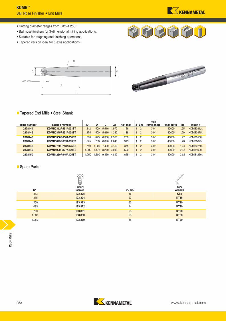
www.kennametal.comR72
order number catalog number D1 D L L2 Ap1 max Z Z Umax
ramp angle max RPM lbs insert 1
2878444 KDMB0312R551A031ST .312 .500 5.510 1.970 .156 1 2 3.0° 40000 .25 KDMB0312..
2878445 KDMB0375R591A038ST .375 .500 5.910 1.380 .188 1 2 3.0° 40000 .29 KDMB0375..
2878446 KDMB0500R630A050ST .500 .625 6.300 2.360 .250 1 2 3.0° 40000 .47 KDMB0500..
2878447 KDMB0625R689A063ST .625 .750 6.890 2.640 .313 1 2 3.0° 40000 .76 KDMB0625..
2878448 KDMB0750R748A075ST .750 1.000 7.480 3.150 .375 1 2 3.0° 40000 1.41 KDMB0750..
2878449 KDMB1000R827A100ST 1.000 1.476 8.270 3.940 .500 1 2 3.0° 40000 2.45 KDMB1000..
2878450 KDMB1250R945A125ST 1.250 1.500 9.450 4.840 .625 1 2 3.0° 40000 3.82 KDMB1250..
D1insert screw in. lbs.
Torx wrench
.313 193.395 18 KT8
.375 193.394 27 KT15
.500 193.393 35 KT20
.625 193.392 44 KT20
.750 193.391 53 KT20
1.000 193.390 58 KT30
1.250 193.389 58 KT30
KDMB™
Ball Nose Finisher • End Mills
• Cutting diameter ranges from .312–1.250".
• Ball nose finishers for 3-dimensional milling applications.
• Suitable for roughing and finishing operations.
• Tapered version ideal for 5-axis applications.
� Tapered End Mills • Steel Shank
� Spare Parts
Cop
y M
ills
KM_Master12_R072_R073_MINCH_EN.qxp:Layout 1 3/7/12 3:30 PM Page R72

www.kennametal.com R73
order number catalog number D1 D D3 L L2 Ap1 max Z Z Ucoolant supply
max ramp angle max RPM insert 1
4177170 KDMB025R394A025HN .250 .250 .211 3.937 1.575 .125 1 2 No 3.0° 40000 KDMB0250..
4177171 KDMB025R591A025HN .250 .250 .211 5.906 2.756 .125 1 2 No 3.0° 40000 KDMB0250..
4177172 KDMB025R788A025HN .250 .250 .211 7.874 3.937 .125 1 2 No 3.0° 40000 KDMB0250..
4177243 KDMB025R788A025HNS .250 .250 .211 7.874 .551 .125 1 2 No 3.0° 40000 KDMB0250..
4177167 KDMB025R394A038HN .250 .375 .213 3.937 1.599 .125 1 2 No 3.0° 40000 KDMB0250..
4177244 KDMB0312R788A031HN .312 .312 .276 7.874 3.955 .156 1 2 No 3.0° 40000 KDMB0312..
4177168 KDMB0312R394A038HN .312 .375 .276 3.937 1.032 .156 1 2 No 3.0° 40000 KDMB0312..
4177169 KDMB0312R591A038HN .312 .375 .276 5.906 1.623 .156 1 2 No 3.0° 40000 KDMB0312..
2879403 KDMB0375R472A038HNC .375 .375 .350 4.730 1.310 .375 1 2 Yes 3.0° 30000 KDMB0375..
2879404 KDMB0375R591A038HNC .375 .375 .350 5.910 1.900 .188 1 2 Yes 3.0° 30000 KDMB0375..
2879405 KDMB0500R472A050HNC .500 .500 .420 4.730 1.392 .188 1 2 Yes 3.0° 40000 KDMB0500..
2879406 KDMB0500R630A050HNC .500 .500 .420 6.300 1.982 .313 1 2 Yes 3.0° 40000 KDMB0500..
2879407 KDMB0625R551A063HNC .625 .625 .560 5.520 1.572 .313 1 2 Yes 3.0° 40000 KDMB0625..
2879408 KDMB0625R689A063HNC .625 .625 .560 6.890 2.163 .250 1 2 Yes 3.0° 40000 KDMB0625..
2879409 KDMB0750R551A075HNC .750 .750 .710 5.520 1.950 .250 1 2 Yes 3.0° 40000 KDMB0750..
2879410 KDMB0750R827A075HNC .750 .750 .710 8.270 2.362 .500 1 2 Yes 3.0° 40000 KDMB0750..
2879411 KDMB1000R630A100HNC 1.000 1.000 .890 6.307 2.370 .375 1 2 Yes 3.0° 30000 KDMB1000..
2879412 KDMB1000R906A100HNC 1.000 1.000 .890 8.270 3.539 .500 1 2 Yes 3.0° 30000 KDMB1000..
2879413 KDMB1250R748A125HNC 1.250 1.250 1.130 7.480 2.554 .625 1 2 Yes 3.0° 30000 KDMB1250..
2879414 KDMB1250R945A125HNC 1.250 1.250 1.130 9.450 4.129 .625 1 2 Yes 3.0° 30000 KDMB1250..
D1insert screw in. lbs.
Torx wrench
.250 MS2236 18 KT6
.312 193.395 18 KT8
.375 193.394 27 KT15
.500 193.393 35 KT20
.625 193.392 44 KT20
.750 193.391 53 KT20
1.000 193.390 58 KT30
1.250 193.389 58 KT30
KDMB™
Ball Nose Finisher • Necked End Mills • Carbide
• Cutting diameter ranges from .250–1.250".
• Ball nose finishers for 3-dimensional milling applications.
• Suitable for roughing and finishing operations.
� Necked End Mills • Carbide Shank
� Spare Parts
Cop
y M
ills
KM_Master12_R072_R073_MINCH_EN.qxp:Layout 1 3/7/12 3:30 PM Page R73

www.kennametal.comR74
KDMB™
Inserts
� Insert Selection Guide
KDMB Ball Nose Platform • .250"
MaterialGroup
Light Machining General Purpose Heavy Machining
Geometry Grade Geometry Grade Geometry Grade
P1–P2 .E..GP KC515M .E..GP KC515M .E..GP KC515M
P3–P4 .E..GP KC515M .E..GP KC515M .E..GP KC515M
P5–P6 .E..GP KC515M .E..GP KC515M .E..GP KC515M
M1–M2 .E..GP KC515M .E..GP KC515M — —
M3 .E..GP KC515M .E..GP KC515M — —
K1–K2 .E..GP KC515M .E..GP KC515M — —
K3 .E..GP KC515M .E..GP KC515M — —
N1–N2 .E..LD K115M .E..LD K115M — —
N3 .E..LD K115M .E..LD K115M — —
S1–S2 — — — — — —
S3 — — — — — —
S4 — — .E..GP KC515M — —
H1 .E..GP KC515M .E..GP KC515M — —
MaterialGroup
Light Machining General Purpose Heavy Machining
Geometry Grade Geometry Grade Geometry Grade
P1–P2 .E..GP KC515M .E..GP KC515M .E..GP KC515M
P3–P4 .E..GP KC505M .E..GP KC515M .E..GP KC515M
P5–P6 .E..GP KC505M .E..GP KC515M .E..GP KC515M
M1–M2 .E..GP KC515M .E..GP KC515M — —
M3 .E..GP KC515M .E..GP KC515M — —
K1–K2 .E..GP KC515M — — — —
K3 .E..GP KC515M — — — —
N1–N2 .E..LD K115M .E..LD K115M — —
N3 .E..LD K115M .E..LD K115M — —
S1–S2 — — — — — —
S3 — — — — — —
S4 .E..LD K115M .E..GP KC515M — —
H1 .E..GP KC505M .E..GP KC505M .E..GP KC515M
KDMB Ball Nose Platform • .375"
MaterialGroup
Light Machining General Purpose Heavy Machining
Geometry Grade Geometry Grade Geometry Grade
P1–P2 .E..GP KC515M .E..GP KC515M .E..GP KC515M
P3–P4 .E..GP KC505M .E..GP KC515M .E..GP KC515M
P5–P6 .E..GP KC505M .E..GP KC515M .E..GP KC515M
M1–M2 .E..GP KC515M .E..GP KC515M — —
M3 .E..GP KC515M .E..GP KC515M — —
K1–K2 .E..GP KC515M .E..GP KC515M — —
K3 .E..GP KC515M .E..GP KC515M — —
N1–N2 .E..LD K115M .E..LD K115M — —
N3 .E..LD K115M .E..LD K115M — —
S1–S2 — — — — — —
S3 — — — — — —
S4 .E..LD K115M .E..GP KC515M — —
H1 .E..GP KC505M .E..GP KC505M .E..GP KC515M
MaterialGroup
Light Machining General Purpose Heavy Machining
Geometry Grade Geometry Grade Geometry Grade
P1–P2 .E..GP KC515M .E..GP KC515M .E..HC KC530M
P3–P4 .E..GP KC505M .E..GP KC515M .E..HC KC530M
P5–P6 .E..GP KC505M .E..GP KC515M .E..HC KC530M
M1–M2 .E..GP KC515M .E..HC KC530M .E..HC KC530M
M3 .E..GP KC515M .E..HC KC530M .E..HC KC530M
K1–K2 .E..GP KC515M .E..GN KC515M .E..GN KC515M
K3 .E..GP KC515M .E..GN KC515M .E..GN KC515M
N1–N2 .E..LD K115M .E..LD K115M — —
N3 .E..LD K115M .E..LD K115M — —
S1–S2 — — — — — —
S3 — — — — — —
S4 .E..LD K115M .E..GP KC515M .E..HC KC530M
H1 .E..GP KC505M .E..GP KC505M .E..GN KC515M
KDMB Ball Nose Platform • .625"
MaterialGroup
Light Machining General Purpose Heavy Machining
Geometry Grade Geometry Grade Geometry Grade
P1–P2 .E..GP KC515M .E..GP KC515M .E..HC KC530M
P3–P4 .E..GP KC505M .E..GP KC515M .E..HC KC530M
P5–P6 .E..GP KC505M .E..GP KC515M .E..HC KC530M
M1–M2 .E..GP KC515M .E..HC KC530M .E..HC KC530M
M3 .E..GP KC515M .E..HC KC530M .E..HC KC530M
K1–K2 .E..GP KC515M .E..GP KC515M — —
K3 .E..GP KC515M .E..GP KC515M — —
N1–N2 .E..LD K115M .E..LD K115M — —
N3 .E..LD K115M .E..LD K115M — —
S1–S2 — — — — — —
S3 — — — — — —
S4 .E..LD K115M .E..GP KC515M .E..HC KC530M
H1 .E..GP KC505M .E..GP KC505M .E..GP KC515M
KDMB Ball Nose Platform • .750"
MaterialGroup
Light Machining General Purpose Heavy Machining
Geometry Grade Geometry Grade Geometry Grade
P1–P2 .E..GP KC515M .E..GP KC515M .E..HC KC530M
P3–P4 .E..GP KC505M .E..GP KC515M .E..HC KC530M
P5–P6 .E..GP KC505M .E..GP KC515M .E..HC KC530M
M1–M2 .E..GP KC515M .E..HC KC530M .E..HC KC530M
M3 .E..GP KC515M .E..HC KC530M .E..HC KC530M
K1–K2 .E..GP KC515M .E..GN KC515M .E..GN KC515M
K3 .E..GP KC515M .E..GN KC515M .E..GN KC515M
N1–N2 .E..LD K115M .E..LD K115M — —
N3 .E..LD K115M .E..LD K115M — —
S1–S2 — — — — — —
S3 — — — — — —
S4 .E..LD K115M .E..GP KC515M .E..HC KC530M
H1 .E..GP KC505M .E..GP KC505M .E..GN KC515M
KDMB Ball Nose Platform • .312"
KDMB Ball Nose Platform • .500"
Cop
y M
ills
KM_Master12_R074_R075_MINCH_EN.qxp:Layout 1 3/7/12 3:28 PM Page R74

www.kennametal.com R75
KDMB™
Inserts
KDMB Ball Nose Platform • 1.00"
MaterialGroup
Light Machining General Purpose Heavy Machining
Geometry Grade Geometry Grade Geometry Grade
P1–P2 .E..GP KC515M .E..GP KC515M .E..HC KC530M
P3–P4 .E..GP KC505M .E..GP KC515M .E..HC KC530M
P5–P6 .E..GP KC505M .E..GP KC515M .E..HC KC530M
M1–M2 .E..GP KC515M .E..HC KC530M .E..HC KC530M
M3 .E..GP KC515M .E..HC KC530M .E..HC KC530M
K1–K2 .E..GP KC515M .E..GN KC515M .E..GN KC515M
K3 .E..GP KC515M .E..GN KC515M .E..GN KC515M
N1–N2 .E..LD K115M .E..LD K115M — —
N3 .E..LD K115M .E..LD K115M — —
S1–S2 — — — — — —
S3 — — — — — —
S4 .E..LD K115M .E..GP KC515M .E..HC KC530M
H1 .E..GP KC505M .E..GP KC505M .E..GN KC515M
KDMB Ball Nose Platform • 1.25"
MaterialGroup
Light Machining General Purpose Heavy Machining
Geometry Grade Geometry Grade Geometry Grade
P1–P2 .E..GP KC515M .E..GP KC515M .E..GP KC515M
P3–P4 .E..GP KC505M .E..GP KC515M .E..GP KC515M
P5–P6 .E..GP KC505M .E..GP KC515M .E..GP KC515M
M1–M2 .E..GP KC515M .E..GP KC515M — —
M3 .E..GP KC515M .E..GP KC515M — —
K1–K2 .E..GP KC515M — — — —
K3 .E..GP KC515M — — — —
N1–N2 .E..LD K115M .E..LD K115M — —
N3 .E..LD K115M .E..LD K115M — —
S1–S2 — — — — — —
S3 — — — — — —
S4 .E..LD K115M .E..GP KC515M — —
H1 .E..GP KC505M .E..GP KC505M .E..GP KC515M
Insert Style
PSTS geometry with chipbreaker for roughing.Semi-finishing and rest material of steel, cast steel, and high-temperature alloys.
HC Geometry:
High-precision insert with helical geometry for semi-finishing and finishing of steel up to 63 HRC, cast steel, and high-temperature alloys.
GP Geometry:
Geometry with extremely solid cutting edge for roughing cast steel, high-temperaturealloys, and hardened steel up to 60 HRC.
GN Geometry:
roughing, rest material semi-finishing, finishing finishing
� Insert Selection Guide
Cop
y M
ills
KM_Master12_R074_R075_MINCH_EN.qxp:Layout 1 3/7/12 3:28 PM Page R75

www.kennametal.comR76
P � � �
M � � �
K � � �
N �
S �
H � � �
catalog number W S RC hm K115M
KC
505M
KC
515M
KC
530M
KDMB0250M0ERLD .250 .063 .125 .002 �
KDMB0312M0ERLD .313 .079 .156 .002 �
KDMB0375M0ERLD .375 .098 .188 .002 �
KDMB0500M0ERLD .500 .098 .250 .002 �
KDMB0625M0ERLD .625 .118 .313 .002 �
KDMB0750M0ERLD .750 .118 .375 .002 �
KDMB1000M0ERLD 1.000 .158 .500 .002 �
KDMB1250M0ERLD 1.250 .197 .625 .002 �
catalog number W S RC hm K115M
KC
505M
KC
515M
KC
530M
KDMB0250M0ERGP .250 .063 .125 .002 �
KDMB0312M0ERGP .312 .079 .156 .002 �
KDMB0375M0ERGP .375 .098 .188 .002 � �
KDMB0500M0ERGP .500 .098 .250 .002 �
KDMB0625M0ERGP .625 .118 .313 .002 � �
KDMB0750M0ERGP .750 .118 .375 .002 � �
KDMB1000M0ERGP 1.000 .158 .500 .002 � �
KDMB1250M0ERGP 1.250 .197 .625 .002 � �
catalog number W S RC hm K115M
KC
505M
KC
515M
KC
530M
KDMB0500M0ERGN .500 .098 .250 .003 �
KDMB0750M0ERGN .750 .118 .375 .003 �
KDMB1000M0ERGN 1.000 .158 .500 .003 �
catalog number W S RC hm K115M
KC
505M
KC
515M
KC
530M
KDMB0500M0ERHC .500 .098 .250 .004 �
KDMB0625M0ERHC .625 .118 .313 .004 �
KDMB0750M0ERHC .750 .118 .375 .004 �
KDMB1000M0ERHC 1.000 .158 .500 .004 �
KDMB™
Indexable Inserts • KDMB...
KDMB-LD KDMB-GP KDMB-GN KDMB-HC
� first choice
� alternate choice
� KDMB-LD • High-Precision Positive Geometry • Non-Ferrous and Titanium
� KDMB-GP • High-Precision Helical Geometry and Lower Cutting Forces
� KDMB-GN • High Precision • Extremely Solid Cutting Edge
� KDMB-HC • PSTS Insert Developed • Roughing and Rest Material Operations
Cop
y M
ills
KM_Master12_R076_R077_MINCH_EN.qxp:Layout 1 3/7/12 3:27 PM Page R76

www.kennametal.com R77
KDMB™
Working Diameter
Working Diameter (Dw) at Axial Depth of Cut (ap)
D1 max 0.125 0.050 0.025 0.013
0.250 0.250 0.200 0.150 0.109
Working Diameter (Dw) at Axial Depth of Cut (ap)
D1 max 0.156 0.047 0.031 0.016
0.313 0.313 0.223 0.188 0.136
Working Diameter (Dw) at Axial Depth of Cut (ap)
D1 max 0.188 0.056 0.038 0.019
0.375 0.375 0.268 0.225 0.163
Working Diameter (Dw) at Axial Depth of Cut (ap)
D1 max 0.250 0.075 0.050 0.025
0.500 0.500 0.357 0.300 0.218
Working Diameter (Dw) at Axial Depth of Cut (ap)
D1 max 0.313 0.094 0.063 0.031
0.625 0.625 0.446 0.375 0.272
Working Diameter (Dw) at Axial Depth of Cut (ap)
D1 max 0.375 0.113 0.075 0.038
0.750 0.750 0.536 0.450 0.327
Working Diameter (Dw) at Axial Depth of Cut (ap)
D1 max 0.500 0.150 0.100 0.050
1.000 1.000 0.714 0.600 0.436
Working Diameter (Dw) at Axial Depth of Cut (ap)
D1 max 0.625 0.188 0.125 0.063
1.250 1.250 0.893 0.750 0.545
� KDMB Ball Nose • .250" � KDMB Ball Nose • .312"
� KDMB Ball Nose • .375" � KDMB Ball Nose • .500"
� KDMB Ball Nose • .625" � KDMB Ball Nose • .750"
� KDMB Ball Nose • 1.00" � KDMB Ball Nose • 1.25"
Cop
y M
illsNOTE: Working diameter (Dw) or effective diameter has to be considered when calculating appropriate RPM.
KM_Master12_R076_R077_MINCH_EN.qxp:Layout 1 3/7/12 3:27 PM Page R77

www.kennametal.comR78
KDMB™
Recommended Starting Speeds
NOTE: FIRST choice starting speeds are in bold type.As the average chip thickness increases, the speed should be decreased.
� Recommended Starting Speeds [SFM]
α
Calculating Working Diameter and Resulting Surface Speed
It is important to consider the effective diameter (Dw) when using light depths of cut in order to properly calculate RPM values. Use the followingformula when machining flatsurfaces or inclinations of 10˚ or less to find the Dw value. Then, use this for RPM calculations, as opposed to using the overall insert diameter (D1).
When machining inclinationsbetween 11˚ and 55˚, furthermodification of vc is required. Apply factor “k” from the givenformula to calculate the correct vc (vceff). This corrected value is then used to calculate the proper RPM for the tool.
k =1
sin [α + arcCos (1-(2 (Ap1/D1)))]Dw = √D12-(D1-2Ap1)2
vceff = vc X k
Case 1: Case 2:
MaterialGroup
K115M KC505M KC515M KC530M
P
1 — — — — — — 1080 960 840 900 780 660
2 — — — — — — 1020 900 780 780 660 540
3 — — — — — — 900 780 660 660 600 540
4 — — — 1180 860 710 780 660 540 600 540 480
5 — — — 1180 860 710 660 540 420 540 480 420
6 — — — 1140 780 620 540 420 360 420 360 300
M
1 — — — — — — 1080 900 780 900 720 600
2 — — — — — — 900 720 540 600 480 420
3 — — — — — — 720 600 480 480 420 360
K
1 720 600 480 — — — 1440 1080 720 — — —
2 600 480 360 — — — 1080 840 600 — — —
3 360 300 240 — — — 480 360 240 — — —
N1–2 1440 1080 720 — — — — — — — — —
3 960 720 600 — — — — — — — — —
S
1 — — — — — — — — — — — —
2 — — — — — — — — — — — —
3 — — — — — — — — — — — —
4 300 230 160 — — — — — — 260 200 170
H 1 — — — 860 670 550 550 400 310 260 200 170
Cop
y M
ills
KM_Master12_R078_R079_MINCH_EN.qxp:Layout 1 3/7/12 3:26 PM Page R78

www.kennametal.com R79
KDMB™
Recommended Starting Feeds
InsertGeometry
Programmed Feed per Tooth (fz)as a % of Radial Depth of Cut (ae) Insert
Geometry10% 20% 30% 40% 50–100%
.E..LD .005 .007 .012 .004 .005 .009 .003 .004 .008 .003 .004 .007 .003 .004 .007 .E..LD
.E..GP .005 .007 .012 .004 .005 .009 .003 .004 .008 .003 .004 .007 .003 .004 .007 .E..GP
InsertGeometry
Programmed Feed per Tooth (fz)as a % of Radial Depth of Cut (ae) Insert
Geometry10% 20% 30% 40% 50–100%
.E..LD .006 .008 .015 .004 .006 .011 .004 .005 .010 .004 .005 .009 .004 .005 .009 .E..LD
.E..GP .006 .008 .015 .004 .006 .011 .004 .005 .010 .004 .005 .009 .004 .005 .009 .E..GP
InsertGeometry
Programmed Feed per Tooth (fz)as a % of Radial Depth of Cut (ae) Insert
Geometry10% 20% 30% 40% 50–100%
.E..LD .008 .011 .020 .006 .008 .015 .005 .007 .013 .005 .007 .012 .005 .007 .012 .E..LD
.E..GP .008 .011 .020 .006 .008 .015 .005 .007 .013 .005 .007 .012 .005 .007 .012 .E..GP
InsertGeometry
Programmed Feed per Tooth (fz)as a % of Radial Depth of Cut (ae) Insert
Geometry10% 20% 30% 40% 50–100%
.E..LD .011 .016 .028 .008 .012 .020 .007 .010 .018 .007 .009 .016 .006 .009 .016 .E..LD
.E..GP .011 .016 .028 .008 .012 .020 .007 .010 .018 .007 .009 .016 .006 .009 .016 .E..GP
NOTE: Use “Light Machining” values as starting feed rate.
Light Machining
General Purpose
Heavy Machining
� Recommended Starting Feeds [IPT] • Ball Nose Insert Size .250"
At .025 Axial Depth of Cut (ap)
At .050 Axial Depth of Cut (ap)
At .013 Axial Depth of Cut (ap)
At .125 Axial Depth of Cut (ap)
Cop
y M
ills
KM_Master12_R078_R079_MINCH_EN.qxp:Layout 1 3/7/12 3:26 PM Page R79

www.kennametal.comR80
KDMB™
Recommended Starting Feeds
InsertGeometry
Programmed Feed per Tooth (fz)as a % of Radial Depth of Cut (ae) Insert
Geometry10% 20% 30% 40% 50–100%
.E..LD .005 .007 .012 .004 .005 .009 .003 .004 .008 .003 .004 .007 .003 .004 .007 .E..LD
.E..GP .005 .007 .012 .004 .005 .009 .003 .004 .008 .003 .004 .007 .003 .004 .007 .E..GP
InsertGeometry
Programmed Feed per Tooth (fz)as a % of Radial Depth of Cut (ae) Insert
Geometry10% 20% 30% 40% 50–100%
.E..LD .007 .009 .017 .005 .007 .012 .004 .006 .011 .004 .006 .010 .004 .006 .010 .E..LD
.E..GP .007 .009 .017 .005 .007 .012 .004 .006 .011 .004 .006 .010 .004 .006 .010 .E..GP
InsertGeometry
Programmed Feed per Tooth (fz)as a % of Radial Depth of Cut (ae) Insert
Geometry10% 20% 30% 40% 50–100%
.E..LD .008 .011 .020 .006 .008 .015 .005 .007 .013 .005 .007 .012 .005 .007 .012 .E..LD
.E..GP .008 .011 .020 .006 .008 .015 .005 .007 .013 .005 .007 .012 .005 .007 .012 .E..GP
InsertGeometry
Programmed Feed per Tooth (fz)as a % of Radial Depth of Cut (ae) Insert
Geometry10% 20% 30% 40% 50–100%
.E..LD .011 .016 .028 .008 .012 .020 .007 .010 .018 .007 .009 .016 .006 .009 .016 .E..LD
.E..GP .011 .016 .028 .008 .012 .020 .007 .010 .018 .007 .009 .016 .006 .009 .016 .E..GP
Light Machining
General Purpose
Heavy Machining
NOTE: Use “Light Machining” values as starting feed rate.
At .031 Axial Depth of Cut (ap)
At .016 Axial Depth of Cut (ap)
At .047 Axial Depth of Cut (ap)
� Recommended Starting Feeds [IPT] • Ball Nose Insert Size .312"
At .156 Axial Depth of Cut (ap)
Cop
y M
ills
KM_Master12_R080_R081_MINCH_EN.qxp:Layout 1 3/7/12 3:26 PM Page R80

www.kennametal.com R81
KDMB™
Recommended Starting Feeds
InsertGeometry
Programmed Feed per Tooth (fz)as a % of Radial Depth of Cut (ae) Insert
Geometry10% 20% 30% 40% 50–100%
.E..LD .005 .007 .012 .004 .005 .009 .003 .004 .008 .003 .004 .007 .003 .004 .007 .E..LD
.E..GP .005 .007 .012 .004 .005 .009 .003 .004 .008 .003 .004 .007 .003 .004 .007 .E..GP
InsertGeometry
Programmed Feed per Tooth (fz)as a % of Radial Depth of Cut (ae) Insert
Geometry10% 20% 30% 40% 50–100%
.E..LD .007 .009 .017 .005 .007 .012 .004 .006 .011 .004 .006 .010 .004 .006 .010 .E..LD
.E..GP .007 .009 .017 .005 .007 .012 .004 .006 .011 .004 .006 .010 .004 .006 .010 .E..GP
InsertGeometry
Programmed Feed per Tooth (fz)as a % of Radial Depth of Cut (ae) Insert
Geometry10% 20% 30% 40% 50–100%
.E..LD .008 .011 .020 .006 .008 .015 .005 .007 .013 .005 .007 .012 .005 .007 .012 .E..LD
.E..GP .008 .011 .020 .006 .008 .015 .005 .007 .013 .005 .007 .012 .005 .007 .012 .E..GP
InsertGeometry
Programmed Feed per Tooth (fz)as a % of Radial Depth of Cut (ae) Insert
Geometry10% 20% 30% 40% 50–100%
.E..LD .011 .016 .028 .008 .012 .020 .007 .010 .018 .007 .009 .016 .006 .009 .016 .E..LD
.E..GP .011 .016 .028 .008 .012 .020 .007 .010 .018 .007 .009 .016 .006 .009 .016 .E..GP
Light Machining
General Purpose
Heavy Machining
At .019 Axial Depth of Cut (ap)
� Recommended Starting Feeds [IPT] • Ball Nose Insert Size .375"
At .056 Axial Depth of Cut (ap)
NOTE: Use “Light Machining” values as starting feed rate.
At .038 Axial Depth of Cut (ap)
At .188 Axial Depth of Cut (ap)
Cop
y M
ills
KM_Master12_R080_R081_MINCH_EN.qxp:Layout 1 3/7/12 3:26 PM Page R81

www.kennametal.comR82
KDMB™
Recommended Starting Feeds
InsertGeometry
Programmed Feed per Tooth (fz)as a % of Radial Depth of Cut (ae) Insert
Geometry10% 20% 30% 40% 50–100%
.E..LD .005 .007 .012 .004 .005 .009 .003 .004 .008 .003 .004 .007 .003 .004 .007 .E..LD
.E..GP .005 .007 .012 .004 .005 .009 .003 .004 .008 .003 .004 .007 .003 .004 .007 .E..GP
.E..GN .007 .010 .018 .005 .008 .013 .004 .007 .011 .004 .006 .011 .004 .006 .011 .E..GN
.E..HC .007 .014 .024 .005 .010 .018 .004 .009 .015 .004 .008 .014 .004 .008 .014 .E..HC
InsertGeometry
Programmed Feed per Tooth (fz)as a % of Radial Depth of Cut (ae) Insert
Geometry10% 20% 30% 40% 50–100%
.E..LD .007 .009 .017 .005 .007 .012 .004 .006 .011 .004 .006 .010 .004 .006 .010 .E..LD
.E..GP .007 .009 .017 .005 .007 .012 .004 .006 .011 .004 .006 .010 .004 .006 .010 .E..GP
.E..GN .009 .014 .025 .007 .011 .019 .006 .009 .016 .006 .009 .015 .006 .008 .015 .E..GN
.E..HC .009 .019 .034 .007 .014 .025 .006 .012 .021 .006 .011 .020 .006 .011 .020 .E..HC
InsertGeometry
Programmed Feed per Tooth (fz)as a % of Radial Depth of Cut (ae) Insert
Geometry10% 20% 30% 40% 50–100%
.E..LD .008 .011 .020 .006 .008 .015 .005 .007 .013 .005 .007 .012 .005 .007 .012 .E..LD
.E..GP .008 .011 .020 .006 .008 .015 .005 .007 .013 .005 .007 .012 .005 .007 .012 .E..GP
.E..GN .011 .017 .030 .008 .013 .022 .007 .011 .019 .007 .010 .018 .007 .010 .018 .E..GN
.E..HC .011 .023 .041 .008 .017 .030 .007 .015 .026 .007 .014 .024 .007 .013 .023 .E..HC
InsertGeometry
Programmed Feed per Tooth (fz)as a % of Radial Depth of Cut (ae) Insert
Geometry10% 20% 30% 40% 50–100%
.E..LD .011 .016 .028 .008 .012 .020 .007 .010 .018 .007 .009 .016 .006 .009 .016 .E..LD
.E..GP .011 .016 .028 .008 .012 .020 .007 .010 .018 .007 .009 .016 .006 .009 .016 .E..GP
.E..GN .016 .024 .042 .012 .017 .031 .010 .015 .026 .009 .014 .025 .009 .014 .024 .E..GN
.E..HC .016 .032 .057 .012 .023 .041 .010 .020 .035 .009 .019 .033 .009 .018 .032 .E..HC
Light Machining
General Purpose
Heavy Machining
At .050 Axial Depth of Cut (ap)
NOTE: Use “Light Machining” values as starting feed rate.
� Recommended Starting Feeds [IPT] • Ball Nose Insert Size .500"
At .025 Axial Depth of Cut (ap)
At .075 Axial Depth of Cut (ap)
At .250 Axial Depth of Cut (ap)
Cop
y M
ills
KM_Master12_R082_R083_MINCH_EN.qxp:Layout 1 3/7/12 3:26 PM Page R82

www.kennametal.com R83
KDMB™
Recommended Starting Feeds
InsertGeometry
Programmed Feed per Tooth (fz)as a % of Radial Depth of Cut (ae) Insert
Geometry10% 20% 30% 40% 50–100%
.E..LD .005 .007 .012 .004 .005 .009 .003 .004 .008 .003 .004 .007 .003 .004 .007 .E..LD
.E..GP .005 .007 .012 .004 .005 .009 .003 .004 .008 .003 .004 .007 .003 .004 .007 .E..GP
.E..HC .007 .014 .024 .005 .010 .018 .004 .009 .015 .004 .008 .014 .004 .008 .014 .E..HC
InsertGeometry
Programmed Feed per Tooth (fz)as a % of Radial Depth of Cut (ae) Insert
Geometry10% 20% 30% 40% 50–100%
.E..LD .007 .009 .017 .005 .007 .012 .004 .006 .011 .004 .006 .010 .004 .006 .010 .E..LD
.E..GP .007 .009 .017 .005 .007 .012 .004 .006 .011 .004 .006 .010 .004 .006 .010 .E..GP
.E..HC .009 .019 .034 .007 .014 .025 .006 .012 .021 .006 .011 .020 .006 .011 .020 .E..HC
InsertGeometry
Programmed Feed per Tooth (fz)as a % of Radial Depth of Cut (ae) Insert
Geometry10% 20% 30% 40% 50–100%
.E..LD .008 .011 .020 .006 .008 .015 .005 .007 .013 .005 .007 .012 .005 .007 .012 .E..LD
.E..GP .008 .011 .020 .006 .008 .015 .005 .007 .013 .005 .007 .012 .005 .007 .012 .E..GP
.E..HC .011 .023 .041 .008 .017 .030 .007 .015 .026 .007 .014 .024 .007 .013 .023 .E..HC
InsertGeometry
Programmed Feed per Tooth (fz)as a % of Radial Depth of Cut (ae) Insert
Geometry10% 20% 30% 40% 50–100%
.E..LD .011 .016 .028 .008 .012 .020 .007 .010 .018 .007 .009 .016 .006 .009 .016 .E..LD
.E..GP .011 .016 .028 .008 .012 .020 .007 .010 .018 .007 .009 .016 .006 .009 .016 .E..GP
.E..HC .016 .032 .057 .012 .023 .041 .010 .020 .035 .009 .019 .033 .009 .018 .032 .E..HC
Light Machining
General Purpose
Heavy Machining
� Recommended Starting Feeds [IPT] • Ball Nose Insert Size .625"
At .094 Axial Depth of Cut (ap)
At .063 Axial Depth of Cut (ap)
At .031 Axial Depth of Cut (ap)
NOTE: Use “Light Machining” values as starting feed rate.
At .313 Axial Depth of Cut (ap)
Cop
y M
ills
KM_Master12_R082_R083_MINCH_EN.qxp:Layout 1 3/7/12 3:26 PM Page R83

www.kennametal.comR84
KDMB™
Recommended Starting Feeds
InsertGeometry
Programmed Feed per Tooth (fz)as a % of Radial Depth of Cut (ae) Insert
Geometry10% 20% 30% 40% 50–100%
.E..LD .005 .007 .012 .004 .005 .009 .003 .004 .008 .003 .004 .007 .003 .004 .007 .E..LD
.E..GP .005 .007 .012 .004 .005 .009 .003 .004 .008 .003 .004 .007 .003 .004 .007 .E..GP
.E..GN .007 .010 .018 .005 .008 .013 .004 .007 .011 .004 .006 .011 .004 .006 .011 .E..GN
.E..HC .007 .014 .024 .005 .010 .018 .004 .009 .015 .004 .008 .014 .004 .008 .014 .E..HC
InsertGeometry
Programmed Feed per Tooth (fz)as a % of Radial Depth of Cut (ae) Insert
Geometry10% 20% 30% 40% 50–100%
.E..LD .007 .009 .017 .005 .007 .012 .004 .006 .011 .004 .006 .010 .004 .006 .010 .E..LD
.E..GP .007 .009 .017 .005 .007 .012 .004 .006 .011 .004 .006 .010 .004 .006 .010 .E..GP
.E..GN .009 .014 .025 .007 .011 .019 .006 .009 .016 .006 .009 .015 .006 .008 .015 .E..GN
.E..HC .009 .019 .034 .007 .014 .025 .006 .012 .021 .006 .011 .020 .006 .011 .020 .E..HC
InsertGeometry
Programmed Feed per Tooth (fz)as a % of Radial Depth of Cut (ae) Insert
Geometry10% 20% 30% 40% 50–100%
.E..LD .008 .011 .020 .006 .008 .015 .005 .007 .013 .005 .007 .012 .005 .007 .012 .E..LD
.E..GP .008 .011 .020 .006 .008 .015 .005 .007 .013 .005 .007 .012 .005 .007 .012 .E..GP
.E..GN .011 .017 .030 .008 .013 .022 .007 .011 .019 .007 .010 .018 .007 .010 .018 .E..GN
.E..HC .011 .023 .041 .008 .017 .030 .007 .015 .026 .007 .014 .024 .007 .013 .023 .E..HC
InsertGeometry
Programmed Feed per Tooth (fz)as a % of Radial Depth of Cut (ae) Insert
Geometry10% 20% 30% 40% 50–100%
.E..LD .011 .016 .028 .008 .012 .020 .007 .010 .018 .007 .009 .016 .006 .009 .016 .E..LD
.E..GP .011 .016 .028 .008 .012 .020 .007 .010 .018 .007 .009 .016 .006 .009 .016 .E..GP
.E..GN .016 .024 .042 .012 .017 .031 .010 .015 .026 .009 .014 .025 .009 .014 .024 .E..GN
.E..HC .016 .032 .057 .012 .023 .041 .010 .020 .035 .009 .019 .033 .009 .018 .032 .E..HC
Light Machining
General Purpose
Heavy Machining
� Recommended Starting Feeds [IPT] • Ball Nose Insert Size .750"
At .038 Axial Depth of Cut (ap)
NOTE: Use “Light Machining” values as starting feed rate.
At .075 Axial Depth of Cut (ap)
At .113 Axial Depth of Cut (ap)
At .375 Axial Depth of Cut (ap)
Cop
y M
ills
KM_Master12_R084_R085_MINCH_EN.qxp:Layout 1 3/7/12 3:25 PM Page R84

www.kennametal.com R85
KDMB™
Recommended Starting Feeds
InsertGeometry
Programmed Feed per Tooth (fz)as a % of Radial Depth of Cut (ae) Insert
Geometry10% 20% 30% 40% 50–100%
.E..LD .005 .007 .012 .004 .005 .009 .003 .004 .008 .003 .004 .007 .003 .004 .007 .E..LD
.E..GP .005 .007 .012 .004 .005 .009 .003 .004 .008 .003 .004 .007 .003 .004 .007 .E..GP
.E..GN .007 .010 .018 .005 .008 .013 .004 .007 .011 .004 .006 .011 .004 .006 .011 .E..GN
.E..HC .007 .014 .024 .005 .010 .018 .004 .009 .015 .004 .008 .014 .004 .008 .014 .E..HC
InsertGeometry
Programmed Feed per Tooth (fz)as a % of Radial Depth of Cut (ae) Insert
Geometry10% 20% 30% 40% 50–100%
.E..LD .007 .009 .017 .005 .007 .012 .004 .006 .011 .004 .006 .010 .004 .006 .010 .E..LD
.E..GP .007 .009 .017 .005 .007 .012 .004 .006 .011 .004 .006 .010 .004 .006 .010 .E..GP
.E..GN .009 .014 .025 .007 .011 .019 .006 .009 .016 .006 .009 .015 .006 .008 .015 .E..GN
.E..HC .009 .019 .034 .007 .014 .025 .006 .012 .021 .006 .011 .020 .006 .011 .020 .E..HC
InsertGeometry
Programmed Feed per Tooth (fz)as a % of Radial Depth of Cut (ae) Insert
Geometry10% 20% 30% 40% 50–100%
.E..LD .008 .011 .020 .006 .008 .015 .005 .007 .013 .005 .007 .012 .005 .007 .012 .E..LD
.E..GP .008 .011 .020 .006 .008 .015 .005 .007 .013 .005 .007 .012 .005 .007 .012 .E..GP
.E..GN .011 .017 .030 .008 .013 .022 .007 .011 .019 .007 .010 .018 .007 .010 .018 .E..GN
.E..HC .011 .023 .041 .008 .017 .030 .007 .015 .026 .007 .014 .024 .007 .013 .023 .E..HC
InsertGeometry
Programmed Feed per Tooth (fz)as a % of Radial Depth of Cut (ae) Insert
Geometry10% 20% 30% 40% 50–100%
.E..LD .011 .016 .028 .008 .012 .020 .007 .010 .018 .007 .009 .016 .006 .009 .016 .E..LD
.E..GP .011 .016 .028 .008 .012 .020 .007 .010 .018 .007 .009 .016 .006 .009 .016 .E..GP
.E..GN .016 .024 .042 .012 .017 .031 .010 .015 .026 .009 .014 .025 .009 .014 .024 .E..GN
.E..HC .016 .032 .057 .012 .023 .041 .010 .020 .035 .009 .019 .033 .009 .018 .032 .E..HC
Light Machining
General Purpose
Heavy Machining
� Recommended Starting Feeds [IPT] • Ball Nose Insert Size 1.00"
At .150 Axial Depth of Cut (ap)
NOTE: Use “Light Machining” values as starting feed rate.
At .050 Axial Depth of Cut (ap)
At .100 Axial Depth of Cut (ap)
At .500 Axial Depth of Cut (ap)
Cop
y M
ills
KM_Master12_R084_R085_MINCH_EN.qxp:Layout 1 3/7/12 3:26 PM Page R85

www.kennametal.comR86
KDMB™
Recommended Starting Feeds
InsertGeometry
Programmed Feed per Tooth (fz)as a % of Radial Depth of Cut (ae) Insert
Geometry10% 20% 30% 40% 50–100%
.E..LD .005 .007 .012 .004 .005 .009 .003 .004 .008 .003 .004 .007 .003 .004 .007 .E..LD
.E..GP .005 .007 .012 .004 .005 .009 .003 .004 .008 .003 .004 .007 .003 .004 .007 .E..GP
InsertGeometry
Programmed Feed per Tooth (fz)as a % of Radial Depth of Cut (ae) Insert
Geometry10% 20% 30% 40% 50–100%
.E..LD .007 .009 .017 .005 .007 .012 .004 .006 .011 .004 .006 .010 .004 .006 .010 .E..LD
.E..GP .007 .009 .017 .005 .007 .012 .004 .006 .011 .004 .006 .010 .004 .006 .010 .E..GP
InsertGeometry
Programmed Feed per Tooth (fz)as a % of Radial Depth of Cut (ae) Insert
Geometry10% 20% 30% 40% 50–100%
.E..LD .008 .011 .020 .006 .008 .015 .005 .007 .013 .005 .007 .012 .005 .007 .012 .E..LD
.E..GP .008 .011 .020 .006 .008 .015 .005 .007 .013 .005 .007 .012 .005 .007 .012 .E..GP
InsertGeometry
Programmed Feed per Tooth (fz)as a % of Radial Depth of Cut (ae) Insert
Geometry10% 20% 30% 40% 50–100%
.E..LD .011 .016 .028 .008 .012 .020 .007 .010 .018 .007 .009 .016 .006 .009 .016 .E..LD
.E..GP .011 .016 .028 .008 .012 .020 .007 .010 .018 .007 .009 .016 .006 .009 .016 .E..GP
Light Machining
General Purpose
Heavy Machining
� Recommended Starting Feeds [IPT] • Ball Nose Insert Size 1.25"
At .125 Axial Depth of Cut (ap)
At .188 Axial Depth of Cut (ap)
NOTE: Use “Light Machining” values as starting feed rate.
At .063 Axial Depth of Cut (ap)
At .625 Axial Depth of Cut (ap)
Cop
y M
ills
KM_Master12_R086_R087_MINCH_EN.qxp:Layout 1 3/7/12 3:25 PM Page R86

www.kennametal.com R87
order number catalog number D1 D D3 L L2 Ap1 max Z Z Umax
ramp angle max RPM lbs insert 1
2957828 KDMT0500R512A050SN .500 .500 .420 5.120 1.339 .118 1 2 3.0° 40000 .22 KDMT0500..
2957829 KDMT0500R591A050SN .500 .500 .420 5.909 1.890 .118 1 2 3.0° 40000 .22 KDMT0500..
2957830 KDMT0625R551A063SN .625 .625 .560 5.510 1.496 .157 1 2 3.0° 40000 .44 KDMT0625..
2957831 KDMT0625R630A063SN .625 .625 .560 6.300 2.165 .157 1 2 3.0° 40000 .44 KDMT0625..
2957832 KDMT0750R630A075SN .750 .750 .710 6.300 1.850 .197 1 2 3.0° 40000 .88 KDMT0750..
2958143 KDMT0750R827A075SN .750 .750 .710 8.270 2.362 .197 1 2 3.0° 40000 .88 KDMT0750..
2958144 KDMT1000R630A100SN 1.000 1.000 .890 6.300 1.850 .236 1 2 3.0° 40000 1.32 KDMT1000..
2958145 KDMT1000R748A100SN 1.000 1.000 .890 7.480 2.835 .236 1 2 3.0° 40000 1.54 KDMT1000..
2958146 KDMT1000R906A100SN 1.000 1.000 .890 9.059 3.150 .236 1 2 3.0° 40000 1.76 KDMT1000..
D1insert screw in. lbs.
Torx wrench
.500 193.393 35 KT20
.625 193.392 44 KT20
.750 193.391 53 KT20
1.000 193.390 58 KT30
KDMT™
Flat-Bottom and Back-Draft Finishing End Mills
• Cutting diameter ranges from .500–1.000".
• High precision and runout accuracy.
• Can be used with the heat shrink technology, h6 shank tolerance.
• Suitable for roughing and finishing operations.
• Works with toroidal and High-Feed inserts.
� Necked End Mills • Cylindrical Shank • Steel
� Spare Parts
Cop
y M
ills
KM_Master12_R086_R087_MINCH_EN.qxp:Layout 1 3/7/12 3:25 PM Page R87

www.kennametal.comR88
order number catalog number D1 D D3 L L2 Ap1 max Z Z Umax
ramp angle max RPM lbs insert 1
2878452 KDMT0500R472A050HNC .500 .500 .420 4.803 1.457 .118 1 2 3.0° 40000 .39 KDMT0500..
2878733 KDMT0500R630A050HNC .500 .500 .420 6.378 2.047 .118 1 2 3.0° 40000 .53 KDMT0500..
2878734 KDMT0625R551A063HNC .625 .625 .560 5.590 1.496 .157 1 2 3.0° 40000 .43 KDMT0625..
2878735 KDMT0625R689A063HNC .625 .625 .560 6.969 2.244 .157 1 2 3.0° 40000 .89 KDMT0625..
2878736 KDMT0750R551A075HNC .750 .750 .710 5.590 2.047 .197 1 2 3.0° 40000 1.03 KDMT0750..
2878737 KDMT0750R748A075HNC .750 .750 .710 7.559 3.032 .197 1 2 3.0° 40000 1.46 KDMT0750..
2878738 KDMT1000R630A100HNC 1.000 1.000 .890 6.378 2.441 .236 1 2 3.0° 30000 2.01 KDMT1000..
2878739 KDMT1000R827A100HNC 1.000 1.000 .890 8.347 3.622 .236 1 2 3.0° 30000 2.68 KDMT1000..
D1insert screw in. lbs.
Torx wrench
.500 193.393 35 KT20
.625 193.392 44 KT20
.750 193.391 53 KT20
1.000 193.390 58 KT30
KDMT™
Flat-Bottom and Back-Draft Finishing End Mills
• Cutting diameter ranges from .500–1.000".
• High precision and runout accuracy.
• Can be used with the heat shrink technology, h6 shank tolerance.
• Suitable for roughing and finishing operations.
• Works with toroidal and High-Feed inserts.
� Necked End Mills • Carbide Shank with Through Coolant
� Spare Parts
Cop
y M
ills
KM_Master12_R088_R089_MINCH_EN.qxp:Layout 1 3/7/12 3:25 PM Page R88

www.kennametal.com R89
KDMT™
Inserts
� Insert Selection Guide
MaterialGroup
Light Machining General Purpose Heavy Machining
Geometry Grade Geometry Grade Geometry Grade
P1–P2 .E..GC KC515M .E..GC KC515M .E..GN KC515M
P3–P4 .E..GN KC515M .E..GN KC515M .E..GN KC515M
P5–P6 .E..GN KC515M .E..GN KC515M .E..GN KC515M
M1–M2 — — .E..GN KC515M — —
M3 — — .E..GN KC515M — —
K1–K2 .E..GN KC515M .E..GN KC515M .E..GN KC515M
K3 .E..GN KC515M .E..GN KC515M .E..GN KC515M
N1–N2 — — — — — —
N3 — — — — — —
S1–S2 — — — — — —
S3 — — — — — —
S4 — — — — — —
H1 — — .E..GN KC515M — —
Cop
y M
ills
KDMT-GC KDMT-GN
P �
M �
K �
N
S
H �
� first choice
� alternate choice
� KDMT-GC • High-Tolerance Helical Geometry • Finishing Lower Cutting Force
catalog number LI W S RR hm KC
515M
KDMT05004ERGC .550 .500 .098 .063 .003 �
KDMT05002ERGC .550 .500 .098 .032 .003 �
KDMT06254ERGC .625 .625 .118 .063 .003 �
KDMT06252ERGC .625 .625 .118 .032 .003 �
KDMT07502ERGC .700 .750 .118 .032 .003 �
KDMT07504ERGC .700 .750 .118 .063 .003 �
KDMT10004ERGC .925 1.000 .157 .063 .003 �
KDMT10008ERGC .925 1.000 .157 .125 .003 �
KDMT10002ERGC .925 1.000 .157 .032 .003 �
� KDMT-GN • High-Precision Insert • Semi-Finishing and Finishing
catalog number LI W S RR hm KC
51
5M
KDMT05004ERGN .550 .500 .098 .063 .003 �
KDMT05002ERGN .550 .500 .098 .032 .003 �
KDMT06252ERGN .625 .625 .118 .032 .003 �
KDMT06254ERGN .625 .625 .118 .063 .003 �
KDMT07502ERGN .700 .750 .118 .032 .003 �
KDMT07504ERGN .700 .750 .118 .063 .003 �
KDMT10004ERGN .925 1.000 .157 .063 .003 �
KDMT10008ERGN .925 1.000 .157 .125 .003 �
KDMT10002ERGN .925 1.000 .157 .032 .003 �
NOTE: Ap1 max = RR
NOTE: Ap1 max = RR
Indexable Inserts • KDMS... • KDMT...
KM_Master12_R088_R089_MINCH_EN.qxp:Layout 1 3/7/12 3:25 PM Page R89

www.kennametal.comR90
KDMT-HF
KDMT™
Indexable Inserts • KDMS... • KDMT...
P �
M �
K �
N
S
H �
� first choice
� alternate choice
� KDMT-HF • Geometry Developed • High-Feed Machining up to 55 HRC
catalog number LI W S RT hm KC
515M
KDMT0500SRHF .550 .500 .098 .045 .003 �
KDMT0625SRHF .630 .625 .118 .050 .003 �
KDMT0750SRHF .710 .750 .118 .080 .003 �
NOTE: RT = Programming Radius
Recommended Starting Speeds and Feeds
Material
GroupKC515M
P
1 1080 960 840
2 1020 900 780
3 900 780 660
4 780 660 540
5 660 540 420
6 540 420 360
M
1 1080 900 780
2 900 720 540
3 720 600 480
K
1 1440 1080 720
2 1080 840 600
3 480 360 240
N1–2 — — —
3 — — —
S
1 — — —
2 — — —
3 — — —
4 — — —
H 1 550 400 310
NOTE: FIRST choice starting speeds are in bold type.As the average chip thickness increases, the speed should be decreased.
InsertGeometry
Programmed Feed per Tooth (fz)as a % of Radial Depth of Cut (ae) Insert
Geometry10% 20% 30% 40% 50–100%
.E..GC .007 .010 .014 .005 .008 .010 .004 .007 .009 .004 .006 .008 .004 .006 .008 .E..GC
.E..GN .007 .010 .014 .005 .008 .010 .004 .007 .009 .004 .006 .008 .004 .006 .008 .E..GN
NOTE: Use “Light Machining” values as starting feed rate.For plunging in Z-axis, use the 50–100% values (no chip thinning).
Light Machining
General Purpose
Heavy Machining
� Recommended Starting Speeds [SFM]
� Recommended Starting Feeds [IPT]
Cop
y M
ills
KM_Master12_R090_R091_MINCH_EN.qxp:Layout 1 3/7/12 3:34 PM Page R90
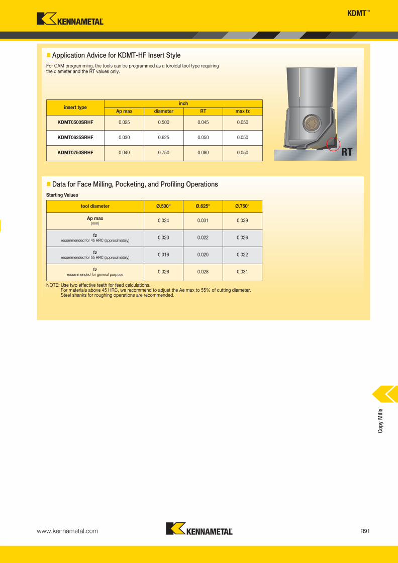
www.kennametal.com R91
KDMT™
Cop
y M
ills
� Application Advice for KDMT-HF Insert Style
insert typeinch
Ap max diameter RT max fz
KDMT0500SRHF 0.025 0.500 0.045 0.050
KDMT0625SRHF 0.030 0.625 0.050 0.050
KDMT0750SRHF 0.040 0.750 0.080 0.050
For CAM programming, the tools can be programmed as a toroidal tool type requiring the diameter and the RT values only.
tool diameter Ø.500" Ø.625" Ø.750"
Ap max(mm)
0.024 0.031 0.039
fzrecommended for 45 HRC (approximately)
0.020 0.022 0.026
fzrecommended for 55 HRC (approximately)
0.016 0.020 0.022
fzrecommended for general purpose
0.026 0.028 0.031
� Data for Face Milling, Pocketing, and Profiling Operations
Starting Values
NOTE: Use two effective teeth for feed calculations.For materials above 45 HRC, we recommend to adjust the Ae max to 55% of cutting diameter.Steel shanks for roughing operations are recommended.
RT
KM_Master12_R090_R091_MINCH_EN.qxp:Layout 1 3/7/12 3:35 PM Page R91

Coolant nozzles
— Precise coolant delivery
to all pockets.
Chip gash serrations
— Improved chip flow.
Linear movement clearance
— Clearance allowed for
.04 IPT (fz=1mm) when
plunging or face milling.
Dropped cutting edge
— Improved chip flow.
www.kennametal.comR92
Platform Features
• Nine coolant nozzle sizes enable customized flow by machine tool.
• Unique design is unmatched for chip evacuation.
• Improved performance at a reduced cost per cutting edge.
• Positive geometry lowers cutting force and reduces power requirements, enabling higher feed rates.
• Chip control when slotting.
• Fast and easy insert indexing.
Z-Axis Plunge Mill
Primary ApplicationSpecifically engineered to eliminate vibration and improve metal removal rates in roughing applications. Ideally suited for rough slotting applications in aerospace, general engineering, die and mold, and power generation.
Features and Benefits
KM_Master12_R092_R093_MINCH_EN.qxp:Layout 1 3/7/12 3:34 PM Page R92
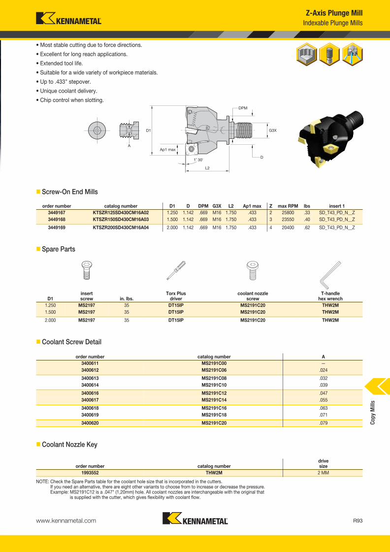
www.kennametal.com R93
Z-Axis Plunge Mill
Cop
y M
ills
order number catalog number D1 D DPM G3X L2 Ap1 max Z max RPM lbs insert 1
3449167 KTSZR125SD430CM16A02 1.250 1.142 .669 M16 1.750 .433 2 25800 .33 SD_T43_PD_N__Z
3449168 KTSZR150SD430CM16A03 1.500 1.142 .669 M16 1.750 .433 3 23550 .40 SD_T43_PD_N__Z
3449169 KTSZR200SD430CM16A04 2.000 1.142 .669 M16 1.750 .433 4 20400 .62 SD_T43_PD_N__Z
D1insert screw in. lbs.
Torx Plus driver
coolant nozzle screw
T-handlehex wrench
1.250 MS2197 35 DT15IP MS2191C20 THW2M
1.500 MS2197 35 DT15IP MS2191C20 THW2M
2.000 MS2197 35 DT15IP MS2191C20 THW2M
order number catalog number A
3400611 MS2191C00 —
3400612 MS2191C06 .024
3400613 MS2191C08 .032
3400614 MS2191C10 .039
3400616 MS2191C12 .047
3400617 MS2191C14 .055
3400618 MS2191C16 .063
3400619 MS2191C18 .071
3400620 MS2191C20 .079
order number catalog numberdrive size
1993552 THW2M 2 MM
Z-Axis Plunge Mill
Indexable Plunge Mills
• Most stable cutting due to force directions.
• Excellent for long reach applications.
• Extended tool life.
• Suitable for a wide variety of workpiece materials.
• Up to .433" stepover.
• Unique coolant delivery.
• Chip control when slotting.
� Screw-On End Mills
� Spare Parts
� Coolant Screw Detail
� Coolant Nozzle Key
NOTE: Check the Spare Parts table for the coolant hole size that is incorporated in the cutters.If you need an alternative, there are eight other variants to choose from to increase or decrease the pressure.Example: MS2191C12 is a .047" (1,20mm) hole. All coolant nozzles are interchangeable with the original that
is supplied with the cutter, which gives flexibility with coolant flow.
KM_Master12_R092_R093_MINCH_EN.qxp:Layout 1 3/7/12 3:34 PM Page R93
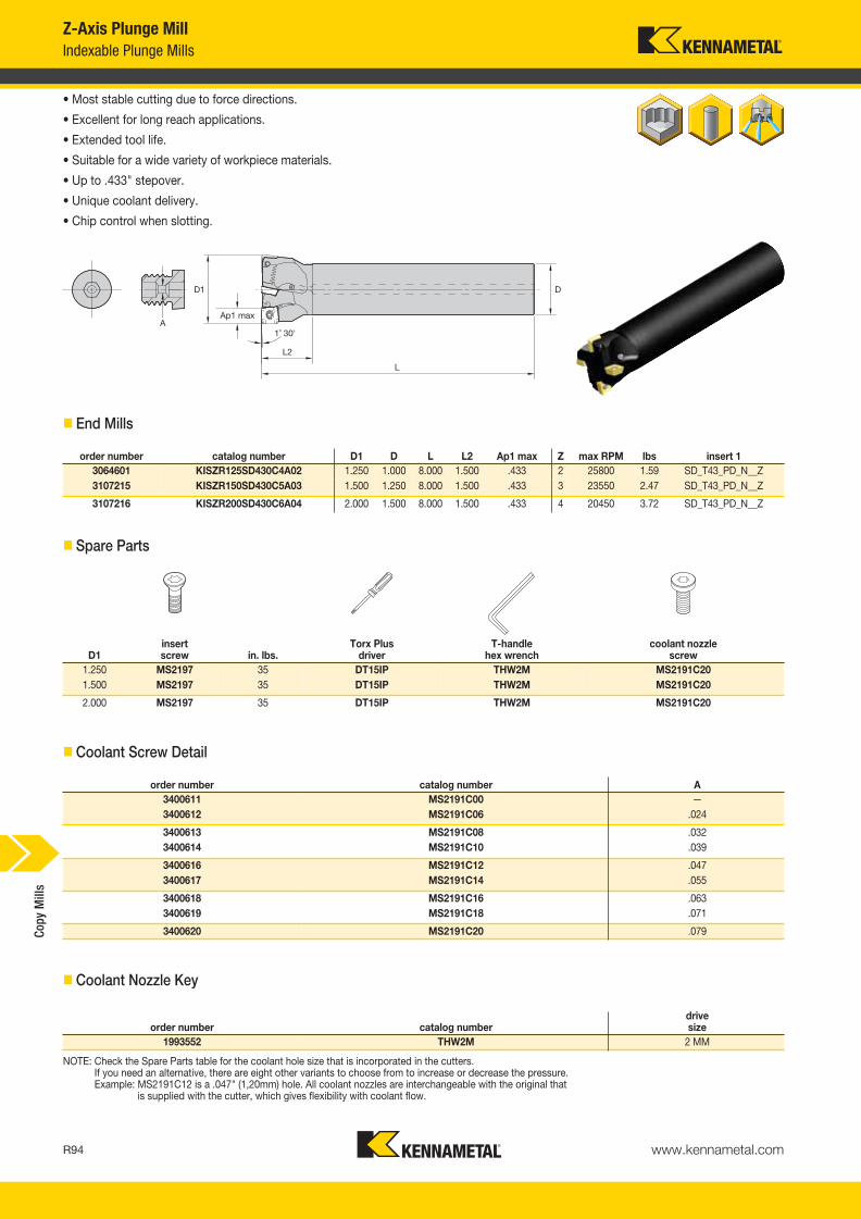
www.kennametal.comR94
Cop
y M
ills
order number catalog number D1 D L L2 Ap1 max Z max RPM lbs insert 1
3064601 KISZR125SD430C4A02 1.250 1.000 8.000 1.500 .433 2 25800 1.59 SD_T43_PD_N__Z
3107215 KISZR150SD430C5A03 1.500 1.250 8.000 1.500 .433 3 23550 2.47 SD_T43_PD_N__Z
3107216 KISZR200SD430C6A04 2.000 1.500 8.000 1.500 .433 4 20450 3.72 SD_T43_PD_N__Z
D1insert screw in. lbs.
Torx Plus driver
T-handlehex wrench
coolant nozzle screw
1.250 MS2197 35 DT15IP THW2M MS2191C20
1.500 MS2197 35 DT15IP THW2M MS2191C20
2.000 MS2197 35 DT15IP THW2M MS2191C20
order number catalog number A
3400611 MS2191C00 —
3400612 MS2191C06 .024
3400613 MS2191C08 .032
3400614 MS2191C10 .039
3400616 MS2191C12 .047
3400617 MS2191C14 .055
3400618 MS2191C16 .063
3400619 MS2191C18 .071
3400620 MS2191C20 .079
order number catalog numberdrivesize
1993552 THW2M 2 MM
Z-Axis Plunge Mill
Indexable Plunge Mills
• Most stable cutting due to force directions.
• Excellent for long reach applications.
• Extended tool life.
• Suitable for a wide variety of workpiece materials.
• Up to .433" stepover.
• Unique coolant delivery.
• Chip control when slotting.
� End Mills
� Spare Parts
� Coolant Screw Detail
� Coolant Nozzle Key
NOTE: Check the Spare Parts table for the coolant hole size that is incorporated in the cutters.If you need an alternative, there are eight other variants to choose from to increase or decrease the pressure.Example: MS2191C12 is a .047" (1,20mm) hole. All coolant nozzles are interchangeable with the original that
is supplied with the cutter, which gives flexibility with coolant flow.
KM_Master12_R094_R095_MINCH_EN.qxp:Layout 1 3/7/12 3:34 PM Page R94

www.kennametal.com R95
Cop
y M
ills
order number catalog number D1 D D6 L Ap1 max Z max RPM lbs insert 1
3054849 KSSZR200SD430C3A04 2.000 .750 1.664 1.750 .433 4 20450 .66 SD_T43_PD_N__Z
3064755 KSSZR200SD430M3A05 2.000 .750 1.664 1.750 .433 5 20450 .72 SD_T43_PD_N__Z
3448592 KSSZR250SD430C3A05 2.500 .750 1.664 1.750 .433 5 18290 .98 SD_T43_PD_N__Z
3448913 KSSZR250SD430M3A06 2.500 .750 1.664 1.750 .433 6 18290 1.03 SD_T43_PD_N__Z
3064493 KSSZR300SD430C4A05 3.000 1.000 2.190 2.000 .433 5 16700 1.94 SD_T43_PD_N__Z
3064602 KSSZR300SD430M4A06 3.000 1.000 2.190 2.000 .433 6 16700 1.96 SD_T43_PD_N__Z
3064902 KSSZR300SD430F4A07 3.000 1.000 2.190 2.000 .433 7 16700 1.97 SD_T43_PD_N__Z
3448914 KSSZR400SD430C5A07 4.000 1.250 2.880 2.500 .433 7 14460 4.23 SD_T43_PD_N__Z
3448915 KSSZR400SD430M5A08 4.000 1.250 2.880 2.500 .433 8 14460 4.34 SD_T43_PD_N__Z
3066674 KSSZR400SD430F5A09 4.000 1.250 2.880 2.500 .433 9 14460 4.41 SD_T43_PD_N__Z
3448916 KSSZR400SD430C6A07 4.000 1.500 3.375 2.500 .433 7 14460 4.51 SD_T43_PD_N__Z
3448917 KSSZR400SD430M6A08 4.000 1.500 3.375 2.500 .433 8 14460 4.64 SD_T43_PD_N__Z
3448918 KSSZR400SD430F6A09 4.000 1.500 3.375 2.500 .433 9 14460 4.72 SD_T43_PD_N__Z
3448919 KSSZR500SD430C6A08 5.000 1.500 3.810 2.500 .433 8 12940 7.23 SD_T43_PD_N__Z
3448920 KSSZR500SD430M6A09 5.000 1.500 3.810 2.500 .433 9 12940 7.40 SD_T43_PD_N__Z
3448921 KSSZR500SD430F6A10 5.000 1.500 3.810 2.500 .433 10 12940 7.43 SD_T43_PD_N__Z
3066673 KSSZR600SD430C6A09 6.000 1.500 3.810 2.500 .433 9 11800 9.09 SD_T43_PD_N__Z
3448922 KSSZR600SD430M6A10 6.000 1.500 3.810 2.500 .433 10 11800 9.17 SD_T43_PD_N__Z
3448923 KSSZR600SD430F6A12 6.000 1.500 3.810 2.500 .433 12 11800 9.36 SD_T43_PD_N__Z
D1insert screw in. lbs.
Torx Plus wrench
coolant nozzle screw
T-handlehex wrench
coolant lock screw assembly
socket-head cap screwwith coolant groove
2.000 MS2197 35.0 DT15IP MS2191C10 THW2M — S445CG
2.000 MS2197 35.0 DT15IP MS2191C12 THW2M — S445CG
2.500 MS2197 35.0 DT15IP MS2191C10 THW2M — S445CG
3.000 MS2197 35.0 DT15IP MS2191C10 THW2M — S458CG
3.000 MS2197 35.0 DT15IP MS2191C08 THW2M — S458CG
4.000 MS2197 35.0 DT15IP MS2191C10 THW2M S2162C —
4.000 MS2197 35.0 DT15IP MS2191C10 THW2M S2163C —
5.000 MS2197 35.0 DT15IP MS2191C10 THW2M S2163C —
5.000 MS2197 35.0 DT15IP MS2191C08 THW2M S2163C —
6.000 MS2197 35.0 DT15IP MS2191C08 THW2M S2163C —
6.000 MS2197 35.0 DT15IP MS2191C10 THW2M S2163C —
Z-Axis Plunge Mill
Indexable Plunge Mills
• Easy cutting.
• Four cutting edges.
• Consumes less power.
• Suitable for a wide variety of workpiece materials.
• Up to .433" stepover.
• Fast and easy insert indexing.
• Unique coolant delivery.
• Chip control when slotting.
� Shell Mills
� Spare Parts
KM_Master12_R094_R095_MINCH_EN.qxp:Layout 1 3/7/12 3:34 PM Page R95

Cop
y M
ills
Z-Axis Plunge Mill
Indexable Plunge Mills
order number catalog number A
3400611 MS2191C00 —
3400612 MS2191C06 .024
3400613 MS2191C08 .032
3400614 MS2191C10 .039
3400616 MS2191C12 .047
3400617 MS2191C14 .055
3400618 MS2191C16 .063
3400619 MS2191C18 .071
3400620 MS2191C20 .079
order number catalog numberdrivesize
1993552 THW2M 2 MM
� Coolant Screw Detail
� Coolant Nozzle Key
NOTE: Check the Spare Parts table for the coolant hole size that is incorporated in the cutters.If you need an alternative, there are eight other variants to choose from to increase or decrease the pressure.Example: MS2191C12 is a .047" (1,20mm) hole. All coolant nozzles are interchangeable with the original that
is supplied with the cutter, which gives flexibility with coolant flow.
www.kennametal.comR96
KM_Master12_R096_R097_MINCH_EN.qxp:Layout 1 3/7/12 3:34 PM Page R96
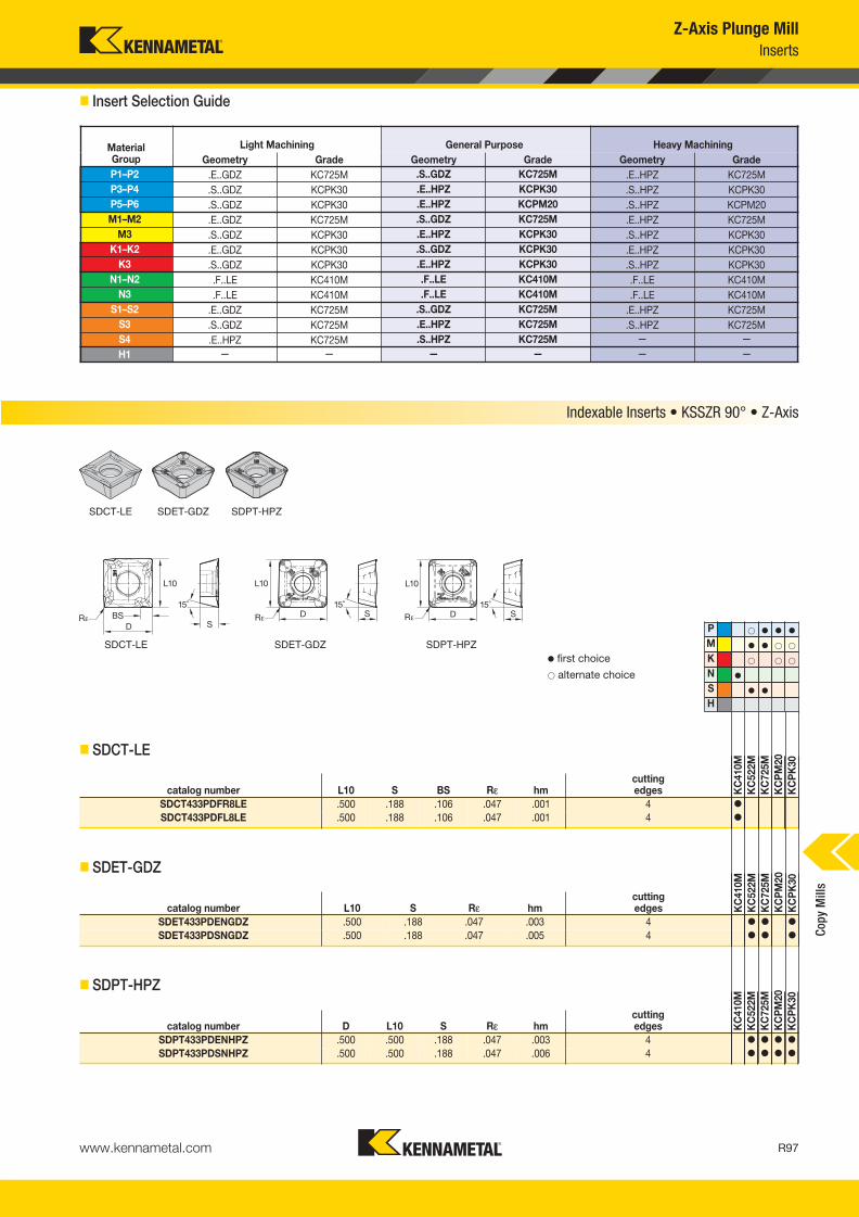
www.kennametal.com R97
Cop
y M
ills
Z-Axis Plunge Mill
Inserts
� Insert Selection Guide
MaterialGroup
Light Machining General Purpose Heavy Machining
Geometry Grade Geometry Grade Geometry Grade
P1–P2 .E..GDZ KC725M .S..GDZ KC725M .E..HPZ KC725M
P3–P4 .S..GDZ KCPK30 .E..HPZ KCPK30 .S..HPZ KCPK30
P5–P6 .S..GDZ KCPK30 .E..HPZ KCPM20 .S..HPZ KCPM20
M1–M2 .E..GDZ KC725M .S..GDZ KC725M .E..HPZ KC725M
M3 .S..GDZ KCPK30 .E..HPZ KCPK30 .S..HPZ KCPK30
K1–K2 .E..GDZ KCPK30 .S..GDZ KCPK30 .E..HPZ KCPK30
K3 .S..GDZ KCPK30 .E..HPZ KCPK30 .S..HPZ KCPK30
N1–N2 .F..LE KC410M .F..LE KC410M .F..LE KC410M
N3 .F..LE KC410M .F..LE KC410M .F..LE KC410M
S1–S2 .E..GDZ KC725M .S..GDZ KC725M .E..HPZ KC725M
S3 .S..GDZ KC725M .E..HPZ KC725M .S..HPZ KC725M
S4 .E..HPZ KC725M .S..HPZ KC725M — —
H1 — — — — — —
P � � � �
M � � � �
K � � �
N �
S � �
H
catalog number L10 S BS Rε hmcutting edges K
C410M
KC
522M
KC
725M
KC
PM
20
KC
PK
30
SDCT433PDFR8LE .500 .188 .106 .047 .001 4 �
SDCT433PDFL8LE .500 .188 .106 .047 .001 4 �
catalog number L10 S Rε hmcutting edges K
C4
10M
KC
522M
KC
725M
KC
PM
20
KC
PK
30
SDET433PDENGDZ .500 .188 .047 .003 4 � � �
SDET433PDSNGDZ .500 .188 .047 .005 4 � � �
catalog number D L10 S Rε hmcutting edges K
C4
10
M
KC
52
2M
KC
72
5M
KC
PM
20
KC
PK
30
SDPT433PDENHPZ .500 .500 .188 .047 .003 4 � � � �
SDPT433PDSNHPZ .500 .500 .188 .047 .006 4 � � � �
Indexable Inserts • KSSZR 90° • Z-Axis
SDCT-LE SDET-GDZ SDPT-HPZ
� first choice
� alternate choice
� SDCT-LE
� SDET-GDZ
� SDPT-HPZ
SDCT-LE SDET-GDZ SDPT-HPZ
KM_Master12_R096_R097_MINCH_EN.qxp:Layout 1 3/7/12 3:34 PM Page R97
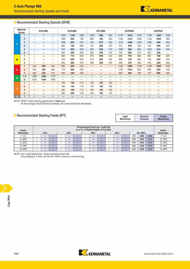
www.kennametal.comR98
Cop
y M
ills
Z-Axis Plunge Mill
Recommended Starting Speeds and Feeds
Material
GroupKC410M KC522M KC725M KCPM20 KCPK30
P
1 — — — 1300 1130 1060 1030 900 840 2170 1910 1760 1780 1560 1450
2 — — — 1080 950 790 860 760 640 1340 1210 1090 1100 1000 900
3 — — — 1000 840 700 790 670 550 1210 1090 1000 1000 900 820
4 — — — 890 730 590 710 590 470 910 840 760 740 690 620
5 — — — 730 660 590 590 530 470 1090 980 900 1020 910 830
6 — — — 650 490 400 520 400 310 760 660 570 620 540 —
M
1 — — — 800 710 650 670 590 540 880 790 680 820 720 620
2 — — — 730 620 520 610 520 430 800 700 620 730 640 550
3 — — — 550 480 370 460 400 310 640 570 490 570 520 460
K
1 510 480 450 900 820 720 — — — 1420 1280 1150 1160 1050 940
2 450 420 390 710 640 590 — — — 1130 1010 920 920 830 760
3 400 350 310 590 530 480 — — — 950 840 780 770 690 640
N1–2 1980 1860 1770 — — — — — — — — — — — —
3 1620 1440 1260 — — — — — — — — — — — —
S
1 — — — 160 140 110 140 120 100 — — — — — —
2 — — — 160 140 110 140 120 100 — — — — — —
3 — — — 200 160 110 180 140 100 — — — — — —
4 — — — 280 200 140 240 180 120 — — — — — —
H 1 — — — — — — — — — — — — — — —
NOTE: FIRST choice starting speeds are in bold type.As the average chip thickness increases, the speed should be decreased.
InsertGeometry
Programmed Feed per Tooth (fz)as a % of Radial Depth of Cut (ae) Insert
Geometry10% 20% 30% 40% 50–100%
.F..LE — — — — — — — — — — — — .002 .004 .008 .F..LE
.E..GDZ — — — — — — — — — — — — .004 .010 .016 .E..GDZ
.S..GDZ — — — — — — — — — — — — .004 .010 .016 .S..GDZ
.E..HPZ — — — — — — — — — — — — .004 .010 .016 .E..HPZ
.S..HPZ — — — — — — — — — — — — .004 .010 .016 .S..HPZ
NOTE: Use “Light Machining” values as starting feed rate.For plunging in Z-Axis, use the 50–100% values (no chip thinning).
Light Machining
General Purpose
Heavy Machining
� Recommended Starting Speeds [SFM]
� Recommended Starting Feeds [IPT]
KM_Master12_R098_R099_MINCH_EN.qxp:Layout 1 3/7/12 3:34 PM Page R98

www.kennametal.com R99
Cop
y M
ills
� Z-Axis
Best Machining Practices
When finishing a workpiece, you sometimes have to use a Z-axis solutionversus a conventional end mill solution to get the best results.
When the length-to-diameter ratio protrudes farther than 3:1, you will needto use a Z-axis solution. This is when the end mill starts to vibrate and thesurface finish and noise are unacceptable.
When vibration occurs, the feed rates are compromised, which normallyslows down the production of the workpiece.
Programming
At this point, there is very little software for this type of application on the market. We suggest that a simple macro is created for this type of application, which can be recalled and the “X” and “Y” movement changed.
The process can be repeated, so the cutter can be removed from theworkpiece in the rapid (G00) movement. Tool life will be improved by not allowing the insert to rub on the retract path.
Slotting:
There are several differing ways to machine a slot in a component using the Z-axis cutter solution.
Figure 1
This shows the typical way of machining a slot. The movements are feeding down and straight back up (Z+) in the same axis and will have a negative impact on the insert radii (cutting edge) that could lead to premature failure of the nose radii. When looking at the component, it will show the rapid travel in the Z+ direction. This will highlight the spiral of the insert/cutter operating at a high feed. It looks similar to an oil groove spiraling upwards.
Figure 3
Align the cutter with the center of the slot on the component and define the stepover that's required. Move the Y-axis into a position for the first cut, take the first pass to a depth in the Z-axis, and when itreaches the bottom of the slot, program a 2-axis move to retract thecutting edge for the workpiece.
The 2-axis move will move the Z-axis in a positive direction at 45° (.010")away from the component, and the Y-axis will move away from theworkpiece by the same amount at the same angle. Now the cutter can be retracted from the component, and the insert will not rub on the retract move.
Move the cutter to the left of the slot to define the new position and makethe cut. When reaching the base, a 3-axis move will need to be made.Again, the Z-axis will be in a positive direction at 45° (.010"), and thecorresponding Y-axis will move away the same respective amount from the wall.
The insert/cutter has now moved away from the workpiece, and the rapidZ+ can take place. Repeat the process on the other side of the slot,remembering the X-axis move needs to be moving the other way.
NOTE: When starting the process, it's better to start at the center of theslot. After the slot has been defined, you no longer need to put thecutter on the center path. Passes from both sides create the slotwidth and enable clearance for the subsequent moves, so theinsert/cutter can be moved away from the side walls of the material.
Figure 2
Using a cutter that is smaller than the slot width allows the insert/cutter tobe removed from the material when (G00) rapid motion is retracting fromthe component. Because this type of cutter can be used across varioustypes of machines, assume a 2.00" (50mm) diameter cutter is being usedto machine a slot of 2.50" (63mm) wide on a vertical 3-axis machine.
(continued)
Z-Axis Plunge Mill
Methods of Manufacture
KM_Master12_R098_R099_MINCH_EN.qxp:Layout 1 3/7/12 3:34 PM Page R99

www.kennametal.comR100
Cop
y M
ills
Z-Axis Plunge Mill
Methods of Manufacture
External Profiling
This artwork represents the typical application for this type of process.Move into the cut and follow the external profile of the workpiece. Whenmoving the cutter back to the start position, it's always advisable to movethe insert from contacting the workpiece. This should be done with a 2- or3-axis move (use .010") at 0,25mm. All axes moving in a Z+ direction willstop the rubbing in the retract move.
Internal Profiling
When taking the first pass of a depth, there is also a need to move theinsert/cutter away from the material on the retract motion. Each of thepasses that follow should adopt the same method on the retract move.
Follow the cutter path until the component has been finished.
Machining Around a Radii
This artwork shows the cutter taking a larger radial width of cut. Whenmoving down in the Z-axis, the insert could start to take a larger radialwidth of cut. Typical application could be the manufacture of a turbineblade from a rectangular piece of material. Always remember that it'sadvisable to move the insert/cutter away from the material on the retract motion.
� Z-Axis (continued)
Linear Plunge Milling
Entering the cutter along a parallel axis, the radial width of cut needs to be defined because the cutter might need to move away from theworkpiece material.
If the radial width of cut takes more than 60% of the cutter diameter, it ismore difficult to remove the insert/cutter because the machine programwants to move the cutter upwards to (G00) Z+. When taking more than60% of the cutter diameter, the material is enveloping the cutter and isdifficult to remove because a cusp has been created.
It is suggested to make the radial width of cut 50% of the cutter diameterto allow the insert/cutter to be removed without any problems.
KM_Master12_R100_R101_MINCH_EN.qxp:Layout 1 3/9/12 9:11 AM Page R100

www.kennametal.com
Experience the advantages at your Authorized Kennametal Distributor or at www.kennametal.com.
Screw-On Milling Cutter AdaptersThe Complete Solution to Milling
• High metal removal rates.
• High runout accuracy.
• Maximum performance capability.
• Optimizing productivity with long reach and short overhang to support all types of applications.
• Cutter is kept on centre for precision and maximum performance compared to Weldon® shank system.
• Ability to extend with standard offering extensions and reducers.
• Ground face contact for rigidity and accuracy.
Features and Benefits
KM_Master12_R100_R101_MINCH_EN.qxp:Layout 1 3/9/12 9:11 AM Page R101

www.kennametal.comR102
KDMR™ • Multifunction Cutter
Primary ApplicationAn extensive offering of versatile mills that can also drill.
Features and Benefits
Platform Features
• Just two grades needed for a wide variety of materials.
• Reduced shank for machining down a side wall.
• Metric and inch sizes available.
• Reduced shank diameters for access down long side walls.
• Extensive product portfolio.
• Use compressed air when drilling for improved chip evacuation.
• Full two-edge line with improved stability.
• Lower cutting resistance and long shank types are available.
• New grade provides stability and longer tool life.
• Good chip evacuation, even when slant milling and drilling.
1
2
3
4
67
8
5
Vertical Milling/Plunging
Helical Milling
Ramping and Helical Milling
Pocketing
Shouldering/Profiling
Drilling
Slotting
Ramping
1
2
3
4
5
6
7
8
KM_Master12_R102_R103_MINCH_EN.qxp:Layout 1 3/7/12 3:29 PM Page R102
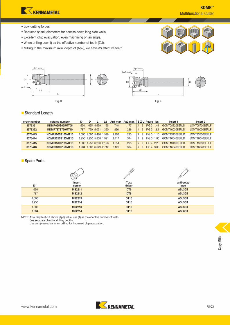
www.kennametal.com R103
KDMR™
Multifunctional Cutter
• Low cutting forces.
• Reduced shank diameters for access down long side walls.
• Excellent chip evacuation, even machining on an angle.
• When drilling use (1) as the effective number of teeth (ZU).
• Milling to the maximum axial depth of (Ap2), we have (2) effective teeth.
Fig. 3 Fig. 4
� Standard Length
� Spare Parts
NOTE: Axial depth of cut above (Ap2) value, use (1) as the effective number of teeth.See separate chart for drilling depths.Use compressed air when drilling for improved chip evacuation.
order number catalog number D1 D L L2 Ap1 max Ap2 max Z Z U figure lbs insert 1 insert 2
3578351 KDMR625S625MT08 .630 .625 4.699 1.195 .748 .177 4 2 FIG 3 .49 GOMT08T208ERLD JOMT08T208ERLF
3578352 KDMR787S750MT10 .787 .750 5.091 1.350 .866 .236 4 2 FIG 3 .82 GOMT100308ERLD JOMT100308ERLF
3578443 KDMR1000S100MT13 1.000 1.000 5.486 1.549 1.102 .295 4 2 FIG 3 1.15 GOMT13T308ERLD JOMT13T308ERLF
3578444 KDMR1250S125MT16 1.250 1.250 5.858 1.921 1.417 .374 4 2 FIG 3 1.80 GOMT160408ERLD JOMT160408ERLF
3578445 KDMR1500S125MT13 1.500 1.250 6.260 2.126 1.654 .295 7 2 FIG 4 2.25 GOMT13T308ERLD JOMT13T308ERLF
3578446 KDMR2000S150MT16 1.984 1.500 6.649 2.712 2.126 .374 7 2 FIG 4 3.86 GOMT160408ERLD JOMT160408ERLF
D1insert screw
Torx driver
anti-seize lube
.630 MS2211 DT6 ASL3GT
.787 MS2212 DT8 ASL3GT
1.000 MS2213 DT10 ASL3GT
1.250 MS2214 DT15 ASL3GT
1.500 MS2213 DT10 ASL3GT
1.984 MS2214 DT15 ASL3GT
Cop
y M
ills
KM_Master12_R102_R103_MINCH_EN.qxp:Layout 1 3/7/12 3:29 PM Page R103

www.kennametal.comR104
KDMR™
Inserts
� Insert Selection Guide
Indexable Insert • KDMR • JOMT-LF • GOMT-LD
JOMT-LF GOMT-LD
� first choice
� alternate choice
� JOMT • Side Insert
MaterialGroup
Light Machining General Purpose Heavy Machining
Geometry Grade Geometry Grade Geometry Grade
P1–P2 .LD/.LF KC720M .LD/.LF KC720M .LD/.LF KC720M
P3–P4 .LD/.LF KC720M .LD/.LF KC720M .LD/.LF KC720M
P5–P6 .LD/.LF KC720M .LD/.LF KC720M .LD/.LF KC720M
M1–M2 .LD/.LF KC720M .LD/.LF KC720M .LD/.LF KC720M
M3 .LD/.LF KC720M .LD/.LF KC720M .LD/.LF KC720M
K1–K2 .LD/.LF KC505M .LD/.LF KC505M .LD/.LF KC505M
K3 .LD/.LF KC505M .LD/.LF KC505M .LD/.LF KC505M
N1–N2 — — — — — —
N3 — — — — — —
S1–S2 — — — — — —
S3 — — — — — —
S4 — — — — — —
H1 — — — — — —
P � �
M �
K �
N
S
H
� GOMT • Center Insert
Cop
y M
ills
catalog number S W L10 Rεε hmcutting edges K
C505M
KC
720M
JOMT08T208ERLF .109 .202 .335 .031 .002 2 � �
JOMT100308ERLF .125 .253 .402 .031 .002 2 � �
JOMT160408ERLF .188 .381 .657 .031 .002 2 � �
JOMT13T308ERLF .146 .317 .520 .031 .002 2 � �
catalog number S W L10 Rε hmcutting edges K
C5
05
M
KC
72
0M
GOMT13T308ERLD .152 .329 .520 .031 .002 2 � �
GOMT08T208ERLD .109 .205 .343 .031 .002 2 � �
GOMT100308ERLD .130 .258 .421 .031 .002 2 � �
GOMT160408ERLD .188 .395 .657 .031 .002 2 � �
KM_Master12_R104_R105_MINCH_EN.qxp:Layout 1 3/7/12 3:29 PM Page R104

www.kennametal.com R105
KDMR™
NOTE: FIRST choice starting speeds are in bold type.As the average chip thickness increases, the speed should be decreased.
NOTE: Use “Light Machining” values as starting feed rate.
Material
GroupKC505M KC720M
P
1 — — — 860 790 710
2 — — — 790 710 630
3 — — — 710 630 550
4 1180 860 710 630 590 550
5 1180 860 710 550 470 400
6 1140 780 620 400 310 310
M
1 — — — 780 710 630
2 — — — 630 550 470
3 — — — 470 400 310
K
1 620 560 490 — — —
2 575 510 440 — — —
3 375 310 245 — — —
N1–2 — — — — — —
3 — — — — — —
S
1 — — — — — —
2 — — — — — —
3 — — — — — —
4 — — — — — —
H 1 — — — — — —
InsertGeometry
Programmed Feed per Tooth (fz)as a % of Radial Depth of Cut (ae) Insert
Geometry10% 20% 30% 40% 50–100%
.LD/.LF .006 .014 .020 .004 .010 .015 .004 .009 .013 .003 .008 .012 .002 .008 .012 .LD/.LF
Light Machining
General Purpose
Heavy Machining
end mill applicable insert for each cutter diameter
D1 side insert quantity center insert quantity
.630 JOMT08T208ERLF 3 GOMT08T208ERLD 1
.787 JOMT100308ERLF 3 GOMT100308ERLD 1
1.000 JOMT13T308ERLF 3 GOMT13T308ERLD 1
1.250 JOMT160408ERLF 3 GOMT160408ERLD 1
1.500 JOMT13T308ERLF 6 GOMT13T308ERLD 1
1.984 JOMT160408ERLF 6 GOMT160408ERLD 1
� Recommended Starting Speeds [SFM]
� Recommended Starting Feeds [IPT]
� Insert Cross Reference
Cop
y M
ills
Recommended Starting Speeds and Feeds • 90° Approach Angle • Technical Information
KM_Master12_R104_R105_MINCH_EN.qxp:Layout 1 3/7/12 3:29 PM Page R105

www.kennametal.comR106
• Calculate the drilling feeds based on (1) effective tooth. • Use compressed air during drilling routine. • When drilling sticky materials, use the peck drill routine. • For stainless steel machining, use coolant.
feed rates (in/tooth)workpiece material
drilling profile/slottinggrade
steel .003~.005 .002~.010 KC720M
stainless steel .003~.006 .002~.006 KC720M
cast iron .002~.008 .002~.010 KC505M
drilling
cutting diameter maximum depth (inch)
Ø .630 .511
Ø .787 .511
Ø 1.000 .866
Ø 1.250 1.000
Ø 1.500 1.000
Ø 1.984 1.000
Ø.625, Ø 1.299" Ø1.299, Ø 2.000"
drilled hole bottom shape
cutting diameter Ø .630" Ø .787" Ø 1.000" Ø 1.250" Ø 1.500" Ø 1.984"
A (inch) .020" .027" .034" .045" .061" .065"
Maximum 8° ramp angle
• Ramping angle not to exceed 8°.• Ramping axial depth of cut not to exceed 50% of the cutter diameter.• When machining, use compressed air for chip evacuation.
� Ramping
� Drilled Hole Bottom Shape
� Drilling
� Recommended Cutting Data by Operation and Workpiece Material
KDMR™
Technical InformationC
opy
Mill
s
KM_Master12_R106_R107_MINCH_EN.qxp:Layout 1 3/9/12 9:21 AM Page R106

www.kennametal.com
Experience the advantages at your Authorized Kennametal Distributor or at www.kennametal.com.
Load-Deflection chart
Defl
ecti
on
[m
m]
@ 1
50m
m
Bending Moment [Nm]
KM4X™
Features and Benefits• Run jobs at significantly faster feeds and speeds than is achievable with other spindle interfaces.
• Unique use of clamping force and interference level increases clamping capability 2–3 times.
• You experience lower cost of ownership, increased throughput, and superior results.
The Latest Innovation in Spindle Interface Technology!
Dramatically increase your metal removal rates when
machining high-temperature alloys!
KM_Master12_R106_R107_MINCH_EN.qxp:Layout 1 3/9/12 9:21 AM Page R107

www.kennametal.comR108
KIPR™ and KSSR™ • Ceramic Milling Cutters
Primary ApplicationThe Kennametal ceramic milling platform has been specifically engineered to machine high-temperature alloys, PH series, stainless steel, and hardened materials. With excellent productivity through the massive reduction of machining time, Kennametal ceramics can run more than 10 times faster than comparable carbide grades.
Features and Benefits
Unbeatable Productivity
• Engineering to provide outstanding metal removal rates and productivityin nickel-based and/or cobalt-based alloys, stellites, stainless steel, and PH series through HSM.
• High axial and radial runout accuracy.
• Improved insert clearance and thickness tolerance to increase overall performance.
• New clamping system design provides higher spare part tool life and reliability and higher RPM.
Usability and Offering• Three grades and three insert sizes available to cover
a wide range of applications.
• Wide diameter range with shell mills, end mills, and Screw-On cutters, from diameter .625".
• High clearance on the cutters for superior ramping capacities.
• Through-coolant option in all the cutters. Only for air use.
KM_Master12_R108_R109_MINCH_EN.qxp:Layout 1 3/7/12 3:27 PM Page R108

www.kennametal.com R109
order number catalog number D1 max D1 D DPM G3X L2 WF Ap1 max Zmax
ramp angle max RPM lbs insert 1
3760369 KIPR100RP32M1203 1.000 .625 .827 .492 M12 1.250 .709 .188 3 8.0° 20450 .17 RP_32_
3760370 KIPR125RP43M1603 1.250 .750 1.142 .669 M16 1.500 .866 .250 3 2.5° 21000 .32 RP_43_
KIPR-RP RPGN..Screw-On End Mills
• For machining high-temp alloys, PH stainless, stainless steels,
and hardened materials.
• Excellent productivity through massive reduction of machining time.
• Face milling, pocketing, and ramping capabilities.
• Through-body coolant delivery for internal air supply only.
� Screw-On End Mills
� Spare Parts
Cop
y M
ills
D1 max clampclampscrew in. lbs.
Torx driver
Torx Plus wrench
1.000 KCI2 191.725 31 DT15 —
1.250 KCI3M 193.409 53 — TTP20
KM_Master12_R108_R109_MINCH_EN.qxp:Layout 1 3/7/12 3:27 PM Page R109
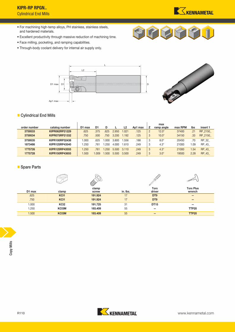
D1 max clampclampscrew in. lbs.
Torx driver
Torx Plus wrench
.625 KCI1 191.924 17 DT9 —
.750 KCI1 191.924 17 DT9 —
1.000 KCI2 191.725 31 DT15 —
1.250 KCI3M 193.409 55 — TTP20
1.500 KCI3M 193.409 55 — TTP20
www.kennametal.comR110
order number catalog number D1 max D1 D L L2 Ap1 max Zmax
ramp angle max RPM lbs insert 1
3759533 KIPR062RP21229 .625 .375 .625 2.950 1.021 .125 2 12.0° 37400 .21 RP_2150_
3759534 KIPR075RP21332 .750 .500 .750 3.200 1.192 .125 3 10.0° 34150 .33 RP_2150_
3759535 KIPR100RP32438 1.000 .625 1.000 3.800 1.556 .188 3 8.0° 20450 .70 RP_32_
1873486 KIPR125RP43540 1.250 .761 1.250 4.000 1.610 .249 3 4.3° 21000 1.09 RP_43_
1775726 KIPR125RP43555 1.250 .761 1.250 5.500 3.110 .249 3 4.3° 21000 1.54 RP_43_
1775728 KIPR150RP43655 1.500 1.009 1.500 5.500 3.500 .249 3 3.0° 19500 2.28 RP_43_
KIPR-RP RPGN..
Cylindrical End Mills
• For machining high-temp alloys, PH stainless, stainless steels,
and hardened materials.
• Excellent productivity through massive reduction of machining time.
• Face milling, pocketing, and ramping capabilities.
• Through-body coolant delivery for internal air supply only.
� Cylindrical End Mills
� Spare Parts
Cop
y M
ills
KM_Master12_R110_R111_MINCH_EN.qxp:Layout 1 3/7/12 3:29 PM Page R110
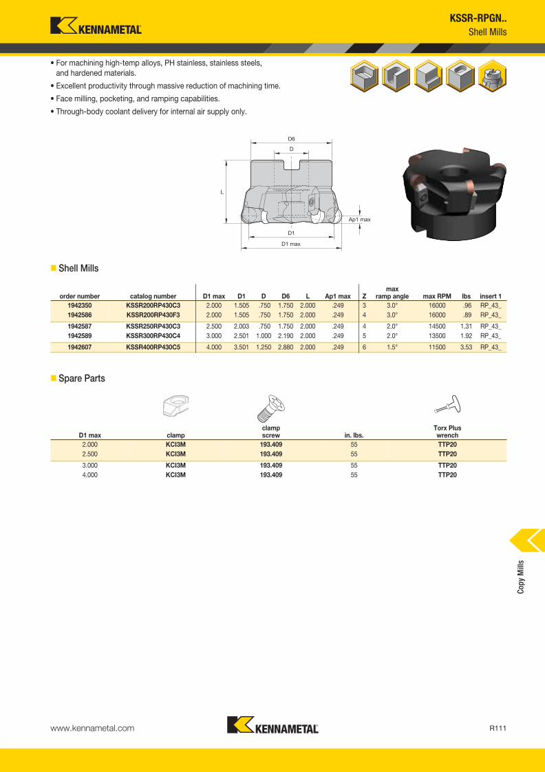
www.kennametal.com R111
order number catalog number D1 max D1 D D6 L Ap1 max Zmax
ramp angle max RPM lbs insert 1
1942350 KSSR200RP430C3 2.000 1.505 .750 1.750 2.000 .249 3 3.0° 16000 .96 RP_43_
1942586 KSSR200RP430F3 2.000 1.505 .750 1.750 2.000 .249 4 3.0° 16000 .89 RP_43_
1942587 KSSR250RP430C3 2.500 2.003 .750 1.750 2.000 .249 4 2.0° 14500 1.31 RP_43_
1942589 KSSR300RP430C4 3.000 2.501 1.000 2.190 2.000 .249 5 2.0° 13500 1.92 RP_43_
1942607 KSSR400RP430C5 4.000 3.501 1.250 2.880 2.000 .249 6 1.5° 11500 3.53 RP_43_
KSSR-RPGN..
Shell Mills
• For machining high-temp alloys, PH stainless, stainless steels,
and hardened materials.
• Excellent productivity through massive reduction of machining time.
• Face milling, pocketing, and ramping capabilities.
• Through-body coolant delivery for internal air supply only.
� Shell Mills
� Spare Parts
Cop
y M
ills
D1 max clampclampscrew in. lbs.
Torx Plus wrench
2.000 KCI3M 193.409 55 TTP20
2.500 KCI3M 193.409 55 TTP20
3.000 KCI3M 193.409 55 TTP20
4.000 KCI3M 193.409 55 TTP20
KM_Master12_R110_R111_MINCH_EN.qxp:Layout 1 3/7/12 3:29 PM Page R111

�
www.kennametal.comR112
KIPR- • KSSR- • RPGN... • High Temp
Inserts
� Insert Selection Guide
RPGN06… High Temp
MaterialGroup
Light Machining General Purpose Heavy Machining
Geometry Grade Geometry Grade Geometry Grade
P1–P2 — — — — — —
P3–P4 — — — — — —
P5–P6 ..E KYSP30 ..E KYSP30 ..E KYSP30
M1–M2 — — — — — —
M3 ..E KYSM10 ..E KYSM10 ..E KYSM10
K1–K2 — — — — — —
K3 — — — — — —
N1–N2 — — — — — —
N3 — — — — — —
S1–S2 ..E KYSP30 ..E KYSP30 ..E KYSP30
S3 ..E KYSP30 ..E KYHS10 ..E KYHS10
S4 — — — — — —
H1 ..E KYHS10 ..E KYHS10 — —
RPGN09… High Temp
MaterialGroup
Light Machining General Purpose Heavy Machining
Geometry Grade Geometry Grade Geometry Grade
P1–P2 — — — — — —
P3–P4 — — — — — —
P5–P6 ..E KYSP30 ..E KYSP30 ..E KYSP30
M1–M2 — — — — — —
M3 ..E KYSM10 ..E KYSM10 ..E KYSM10
K1–K2 — — — — — —
K3 — — — — — —
N1–N2 — — — — — —
N3 — — — — — —
S1–S2 ..E KYSP30 ..E KYSP30 ..E KYSP30
S3 ..E KYSP30 ..E KYHS10 ..E KYHS10
S4 — — — — — —
H1 ..E KYHS10 ..E KYHS10 — —
RPGN12… High Temp
MaterialGroup
Light Machining General Purpose Heavy Machining
Geometry Grade Geometry Grade Geometry Grade
P1–P2 — — — — — —
P3–P4 — — — — — —
P5–P6 ..E KYSP30 ..E KYSP30 ..E KYSP30
M1–M2 — — — — — —
M3 ..E KYSM10 ..E KYSM10 ..E KYSM10
K1–K2 — — — — — —
K3 — — — — — —
N1–N2 — — — — — —
N3 — — — — — —
S1–S2 ..E KYSP30 ..E KYSP30 ..E KYSP30
S3 ..E KYSP30 ..E KYHS10 ..E KYHS10
S4 — — — — — —
H1 ..E KYHS10 ..E KYHS10 — —
RPGN
� first choice
� alternate choice
� RPGN
NOTE: A — Use these tools with the appropriate equipment/machines. Machines have to be covered for safety reasons: Hot flowing chips and loud noise are involved, which is common during the milling process.
B — Use only air flow as coolant method.
C — Higher RPMs are involved; use balanced toolholder for higher tool life and safer operation.
D — Consider increasing the fz in hard machining when smaller ap are applied.
Indexable Ceramic Inserts • KIPR-RP • KSSR-RP
catalog number D S KY
S3
0
KY
SP
30
KY
SM
10
KY
HS
10
RPG2150E .250 .094 � � � �
RPG32E .375 .125 � � � �
RPG32T0420 .375 .125 �
RPG43E .500 .188 � � � �
RPG43T0420 .500 .188 �
P � �
M �
K
N
S � �
H �
Cop
y M
ills
KM_Master12_R112_R113_MINCH_EN.qxp:Layout 1 3/7/12 3:23 PM Page R112
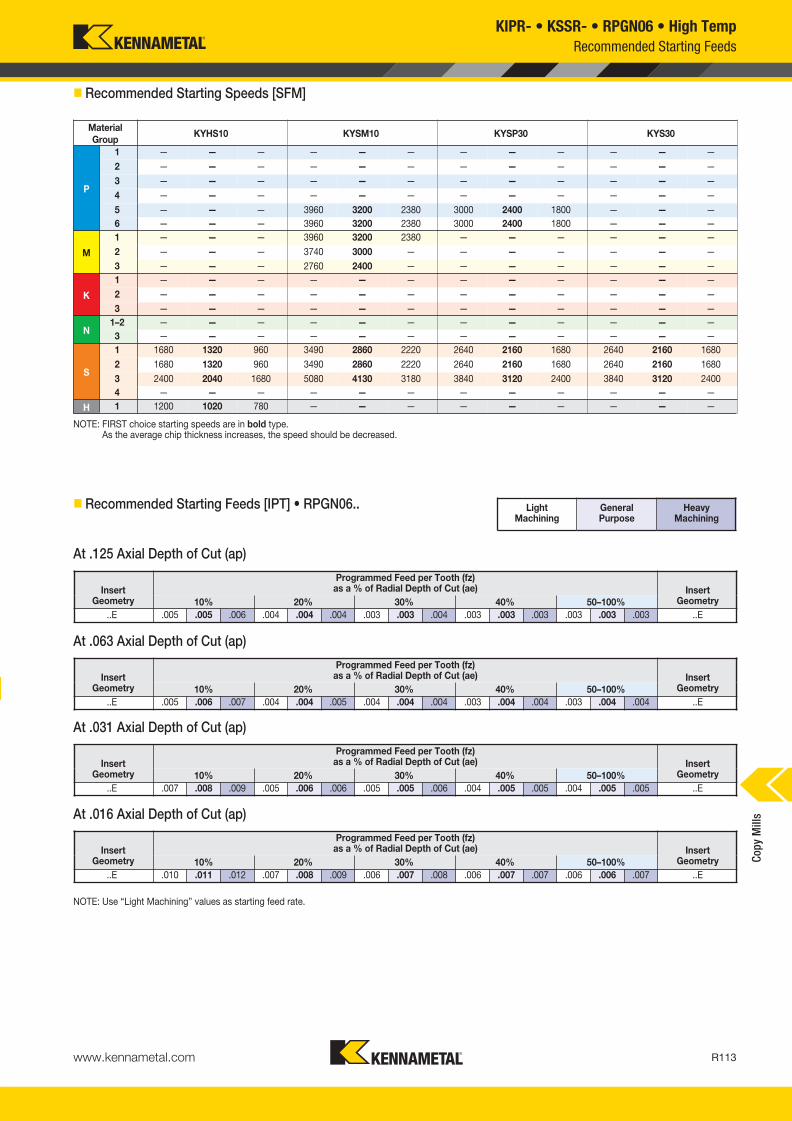
www.kennametal.com R113
Material
GroupKYHS10 KYSM10 KYSP30 KYS30
P
1 — — — — — — — — — — — —
2 — — — — — — — — — — — —
3 — — — — — — — — — — — —
4 — — — — — — — — — — — —
5 — — — 3960 3200 2380 3000 2400 1800 — — —
6 — — — 3960 3200 2380 3000 2400 1800 — — —
M
1 — — — 3960 3200 2380 — — — — — —
2 — — — 3740 3000 — — — — — — —
3 — — — 2760 2400 — — — — — — —
K
1 — — — — — — — — — — — —
2 — — — — — — — — — — — —
3 — — — — — — — — — — — —
N1–2 — — — — — — — — — — — —
3 — — — — — — — — — — — —
S
1 1680 1320 960 3490 2860 2220 2640 2160 1680 2640 2160 1680
2 1680 1320 960 3490 2860 2220 2640 2160 1680 2640 2160 1680
3 2400 2040 1680 5080 4130 3180 3840 3120 2400 3840 3120 2400
4 — — — — — — — — — — — —
H 1 1200 1020 780 — — — — — — — — —
KIPR- • KSSR- • RPGN06 • High Temp
NOTE: Use “Light Machining” values as starting feed rate.
Light Machining
General Purpose
Heavy Machining
� Recommended Starting Speeds [SFM]
At .016 Axial Depth of Cut (ap)
At .031 Axial Depth of Cut (ap)
At .063 Axial Depth of Cut (ap)
� Recommended Starting Feeds [IPT] • RPGN06..
At .125 Axial Depth of Cut (ap)
Recommended Starting Feeds
InsertGeometry
Programmed Feed per Tooth (fz)as a % of Radial Depth of Cut (ae) Insert
Geometry10% 20% 30% 40% 50–100%
..E .005 .005 .006 .004 .004 .004 .003 .003 .004 .003 .003 .003 .003 .003 .003 ..E
InsertGeometry
Programmed Feed per Tooth (fz)as a % of Radial Depth of Cut (ae) Insert
Geometry10% 20% 30% 40% 50–100%
..E .005 .006 .007 .004 .004 .005 .004 .004 .004 .003 .004 .004 .003 .004 .004 ..E
InsertGeometry
Programmed Feed per Tooth (fz)as a % of Radial Depth of Cut (ae) Insert
Geometry10% 20% 30% 40% 50–100%
..E .007 .008 .009 .005 .006 .006 .005 .005 .006 .004 .005 .005 .004 .005 .005 ..E
InsertGeometry
Programmed Feed per Tooth (fz)as a % of Radial Depth of Cut (ae) Insert
Geometry10% 20% 30% 40% 50–100%
..E .010 .011 .012 .007 .008 .009 .006 .007 .008 .006 .007 .007 .006 .006 .007 ..E
NOTE: FIRST choice starting speeds are in bold type.As the average chip thickness increases, the speed should be decreased.
Cop
y M
ills
KM_Master12_R112_R113_MINCH_EN.qxp:Layout 1 3/7/12 3:23 PM Page R113

www.kennametal.comR114
Recommended Starting Feeds
Light Machining
General Purpose
Heavy Machining
� Recommended Starting Feeds [IPT] • RPGN09..
At .047 Axial Depth of Cut (ap)
At .023 Axial Depth of Cut (ap)
At .094 Axial Depth of Cut (ap)
At .031 Axial Depth of Cut (ap)
At .125 Axial Depth of Cut (ap)
At .063 Axial Depth of Cut (ap)
NOTE: Use “Light Machining” values as starting feed rate.
At .188 Axial Depth of Cut (ap)
At .250 Axial Depth of Cut (ap)
KIPR- • KSSR- • RPGN09 • RPGN12 • High Temp
InsertGeometry
Programmed Feed per Tooth (fz)as a % of Radial Depth of Cut (ae) Insert
Geometry10% 20% 30% 40% 50–100%
..E .005 .005 .006 .004 .004 .004 .003 .003 .004 .003 .003 .003 .003 .003 .003 ..E
InsertGeometry
Programmed Feed per Tooth (fz)as a % of Radial Depth of Cut (ae) Insert
Geometry10% 20% 30% 40% 50–100%
..E .005 .006 .007 .004 .004 .005 .004 .004 .004 .003 .004 .004 .003 .004 .004 ..E
InsertGeometry
Programmed Feed per Tooth (fz)as a % of Radial Depth of Cut (ae) Insert
Geometry10% 20% 30% 40% 50–100%
..E .007 .008 .009 .005 .006 .006 .005 .005 .006 .004 .005 .005 .004 .005 .005 ..E
InsertGeometry
Programmed Feed per Tooth (fz)as a % of Radial Depth of Cut (ae) Insert
Geometry10% 20% 30% 40% 50–100%
..E .010 .011 .012 .007 .008 .009 .006 .007 .008 .006 .007 .007 .006 .006 .007 ..E
InsertGeometry
Programmed Feed per Tooth (fz)as a % of Radial Depth of Cut (ae) Insert
Geometry10% 20% 30% 40% 50–100%
..E .005 .005 .006 .004 .004 .004 .003 .003 .004 .003 .003 .003 .003 .003 .003 ..E
InsertGeometry
Programmed Feed per Tooth (fz)as a % of Radial Depth of Cut (ae) Insert
Geometry10% 20% 30% 40% 50–100%
..E .005 .006 .007 .004 .004 .005 .004 .004 .004 .003 .004 .004 .003 .004 .004 ..E
InsertGeometry
Programmed Feed per Tooth (fz)as a % of Radial Depth of Cut (ae) Insert
Geometry10% 20% 30% 40% 50–100%
..E .007 .008 .009 .005 .006 .006 .005 .005 .006 .004 .005 .005 .004 .005 .005 ..E
InsertGeometry
Programmed Feed per Tooth (fz)as a % of Radial Depth of Cut (ae) Insert
Geometry10% 20% 30% 40% 50–100%
..E .010 .011 .012 .007 .008 .009 .006 .007 .008 .006 .007 .007 .006 .006 .007 ..E
� Recommended Starting Feeds [IPT] • RPGN12..
Cop
y M
ills
KM_Master12_R114_R115_MINCH_EN.qxp:Layout 1 3/7/12 3:23 PM Page R114

www.kennametal.com R115
order number catalog number D1 max D1 D D6 L Ap1 max Z max RPM lbs insert 1
1775730 KDNR200RN40C3 2.000 1.501 .750 44,450 2.000 .249 3 13700 .90 RNG45__
1775731 KDNR250RN40C3 2.500 2.000 .750 49,530 2.000 .249 4 12300 1.20 RNG45__
1775753 KDNR300RN40C4 3.000 2.499 1.000 66,680 2.000 .249 5 11200 1.80 RNG45__
1775754 KDNR400RN40C5 4.000 3.496 1.250 73,150 2.000 .249 6 9700 3.50 RNG45__
D1 max clampclampscrew washer in. lbs.
Torx wrench
2.000 KCI4 MS1221 191.279 65 TT25
2.500 KCI4 MS1221 191.279 65 TT25
3.000 KCI4 MS1221 191.279 65 TT25
4.000 KCI4 MS1221 191.279 65 TT25
KDNR • RNGN..
Shell Mills
• First choice for face milling high-temp alloys and hard or hardened materials up to 60 HRC.
• Excellent productivity through massive reduction of machining time.
� Shell Mills • RNGN 1207
� Spare Parts
Cop
y M
ills
KM_Master12_R114_R115_MINCH_EN.qxp:Layout 1 3/7/12 3:23 PM Page R115

www.kennametal.comR116
KSSR™ • RNGN45 • High Temp
Inserts
� Insert Selection Guide
MaterialGroup
Light Machining General Purpose Heavy Machining
Geometry Grade Geometry Grade Geometry Grade
P1–P2 — — — — — —
P3–P4 — — — — — —
P5–P6 — — ..T.. KY2100 / KYSM10 — —
M1–M2 — — — — — —
M3 ..T.. KY2100 / KYSM10 ..T.. KY2100 / KYSM10 ..T.. KY2100 / KYSM10
K1–K2 — — — — — —
K3 — — — — — —
N1–N2 — — — — — —
N3 — — — — — —
S1–S2 ..E KY4300 / KYHS10 ..T.. KYS30 ..T.. KY2100 / KYSM10
S3 ..T.. KYS30 ..T.. KYS30 ..T.. KY4300 / KYHS10
S4 — — — — — —
H1 ..E KY4300 / KYHS10 ..T.. KY4300 / KYHS10 — —
Indexable Ceramic Inserts • KIPR-RP • KSSR-RP • KSSR-RN
RNGN
� RNGN
NOTE: A — Use these tools with the appropriate equipment/machines. Machines have to be covered for safety reasons: Hot flowing chips and loud noise are involved, which is common during the milling process.
B — Use only air flow as coolant method.
C — Higher RPMs are involved; use balanced toolholder for higher tool life and safer operation.
D — Consider increasing the fz in hard machining when smaller ap are applied.
P �
M �
K
N
S � �
H �
catalog number D S KY
S30
KY
2100
KY
4300
RNG45E .500 .313 � � �
RNG45T0420 .500 .313 � � �
� first choice
� alternate choice
Cop
y M
ills
KM_Master12_R116_R117_MINCH_EN.qxp:Layout 1 3/7/12 3:23 PM Page R116

www.kennametal.com R117
KSSR™ • RNGN45 • High Temp
InsertGeometry
Programmed Feed per Tooth (fz)as a % of Radial Depth of Cut (ae) Insert
Geometry10% 20% 30% 40% 50–100%
..E .004 .004 .005 .003 .003 .003 .002 .003 .003 .002 .003 .003 .002 .002 .003 ..E
..T.. .007 .010 .011 .005 .008 .009 .004 .007 .007 .004 .006 .007 .004 .006 .007 ..T..
InsertGeometry
Programmed Feed per Tooth (fz)as a % of Radial Depth of Cut (ae) Insert
Geometry10% 20% 30% 40% 50–100%
..E .004 .005 .005 .003 .004 .004 .003 .003 .003 .003 .003 .003 .003 .003 .003 ..E
..T.. .008 .012 .013 .006 .009 .010 .005 .008 .009 .005 .007 .008 .005 .007 .008 ..T..
InsertGeometry
Programmed Feed per Tooth (fz)as a % of Radial Depth of Cut (ae) Insert
Geometry10% 20% 30% 40% 50–100%
..E .006 .006 .007 .004 .005 .005 .004 .004 .004 .003 .004 .004 .003 .004 .004 ..E
..T.. .010 .016 .017 .008 .012 .013 .007 .010 .011 .006 .010 .010 .006 .009 .010 ..T..
InsertGeometry
Programmed Feed per Tooth (fz)as a % of Radial Depth of Cut (ae) Insert
Geometry10% 20% 30% 40% 50–100%
..E .008 .009 .009 .006 .006 .007 .005 .006 .006 .005 .005 .006 .005 .005 .006 ..E
..T.. .014 .022 .024 .010 .016 .018 .009 .014 .015 .008 .013 .014 .008 .013 .014 ..T..
Light Machining
General Purpose
Heavy Machining
� Recommended Starting Speeds [SFM]
At .125 Axial Depth of Cut (ap)
At .063 Axial Depth of Cut (ap)
At .031 Axial Depth of Cut (ap)
� Recommended Starting Feeds [IPT] • RNGN45..
At .250 Axial Depth of Cut (ap)
Recommended Starting Speeds and Feeds
NOTE: FIRST choice starting speeds are in bold type.As the average chip thickness increases, the speed should be decreased.
NOTE: Use “Light Machining” values as starting feed rate.
Cop
y M
ills
MaterialGroup
KYS30 KY2100 KY4300
P
1 — — — — — — — — —
2 — — — — — — — — —
3 — — — — — — — — —
4 — — — — — — — — —
5 — — — 3960 3200 2380 — — —
6 — — — 3960 3200 2380 — — —
M
1 — — — 3960 3200 2380 — — —
2 — — — 3740 3000 — — — —
3 — — — 2760 2400 — — — —
K
1 — — — — — — — — —
2 — — — — — — — — —
3 — — — — — — — — —
N1–2 — — — — — — — — —
3 — — — — — — — — —
S
1 2640 2160 1680 3490 2860 2220 1680 1320 960
2 2640 2160 1680 3490 2860 2220 1680 1320 960
3 3840 3120 2400 5080 4130 3180 2400 2040 1680
4 — — — — — — — — —
H 1 — — — — — — 1200 1020 780
KM_Master12_R116_R117_MINCH_EN.qxp:Layout 1 3/7/12 3:23 PM Page R117
Related Documents