Kelly Younge, Ph.D Kelly Younge, Ph.D Don Roberts, Benedick Fraass, Daniel McShan, and Martha Matuszak University of Michigan, Department of Radiation Oncology, University of Michigan, Department of Radiation Oncology, Ann Arbor, Michigan Ann Arbor, Michigan June 16, 2011 June 16, 2011

Kelly Younge, Ph.DKelly Younge, Ph.D Don Roberts, Benedick Fraass, Daniel McShan, and Martha Matuszak University of Michigan, Department of Radiation Oncology,University.
Dec 28, 2015
Welcome message from author
This document is posted to help you gain knowledge. Please leave a comment to let me know what you think about it! Share it to your friends and learn new things together.
Transcript

Kelly Younge, Ph.DKelly Younge, Ph.DDon Roberts, Benedick Fraass, Daniel McShan, and Martha Matuszak
University of Michigan, Department of Radiation Oncology, University of Michigan, Department of Radiation Oncology, Ann Arbor, MichiganAnn Arbor, Michigan
June 16, 2011June 16, 2011
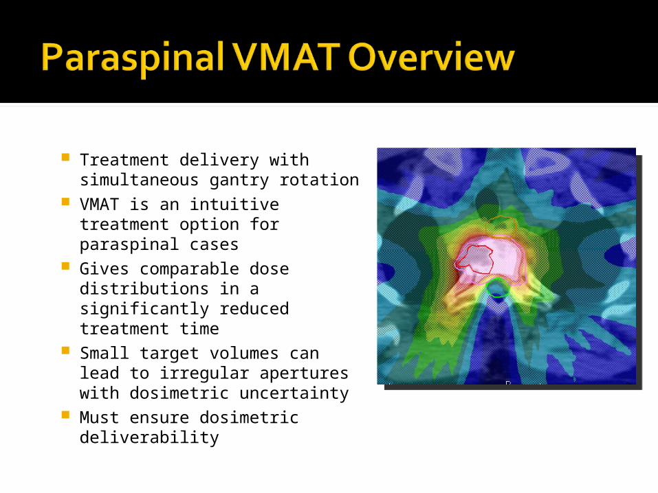
Treatment delivery with simultaneous gantry rotation
VMAT is an intuitive treatment option for paraspinal cases
Gives comparable dose distributions in a significantly reduced treatment time
Small target volumes can lead to irregular apertures with dosimetric uncertainty
Must ensure dosimetric deliverability
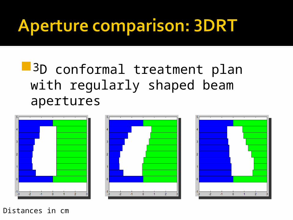
3D conformal treatment plan with regularly shaped beam apertures
Distances in cm
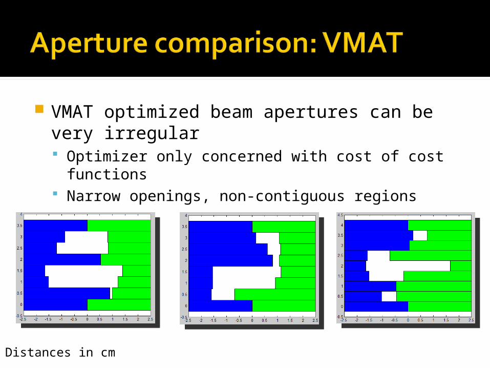
VMAT optimized beam apertures can be very irregular Optimizer only concerned with cost of cost functions Narrow openings, non-contiguous regions
Distances in cm
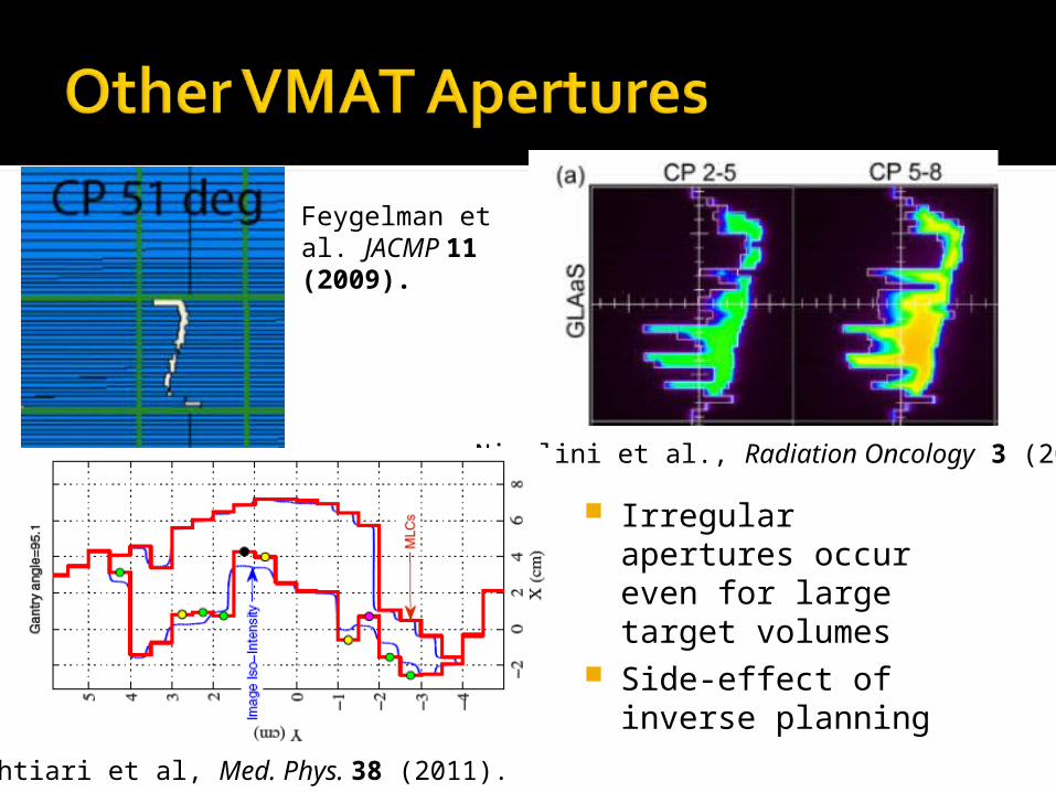
Nicolini et al., Radiation Oncology 3 (2008).
Bakhtiari et al, Med. Phys. 38 (2011).
Irregular apertures occur even for large target volumes
Side-effect of inverse planning
Feygelman et al. JACMP 11 (2009).
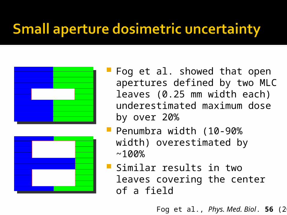
Fog et al. showed that open apertures defined by two MLC leaves (0.25 mm width each) underestimated maximum dose by over 20%
Penumbra width (10-90% width) overestimated by ~100%
Similar results in two leaves covering the center of a field
Fog et al., Phys. Med. Biol. 56 (2011)

Goal: Improve deliverability of plans by preventing the optimizer from generating fields known to result in unacceptable error Develop metrics to predict error
based on aperture shape Incorporate metrics in a cost function
that penalizes undesirable aperture shapes
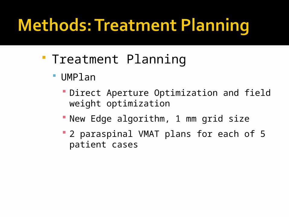
Treatment Planning UMPlan
Direct Aperture Optimization and field weight optimization
New Edge algorithm, 1 mm grid size
2 paraspinal VMAT plans for each of 5 patient cases
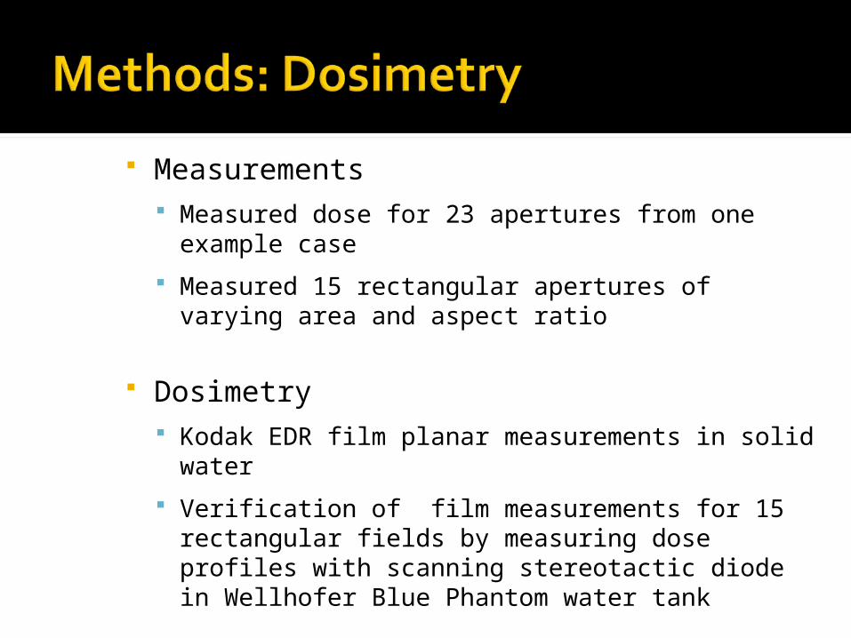
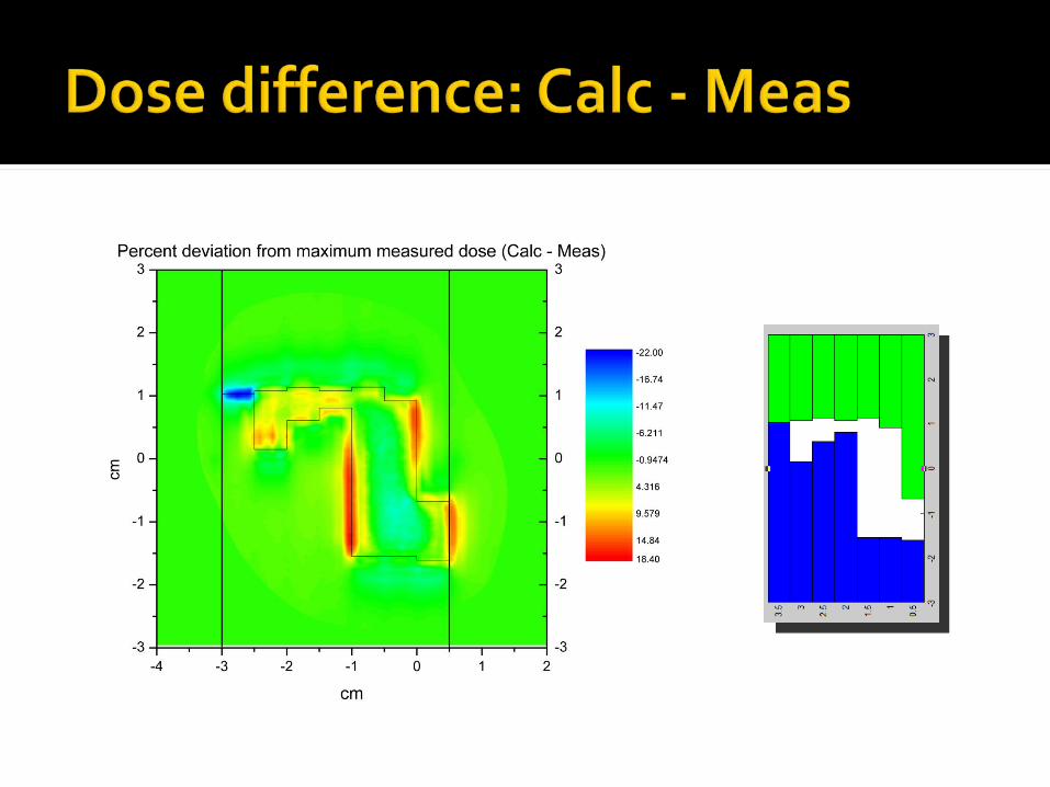
Measurements Measured dose for 23 apertures from one
example case
Measured 15 rectangular apertures of varying area and aspect ratio
Dosimetry Kodak EDR film planar measurements in solid
water
Verification of film measurements for 15 rectangular fields by measuring dose profiles with scanning stereotactic diode in Wellhofer Blue Phantom water tank
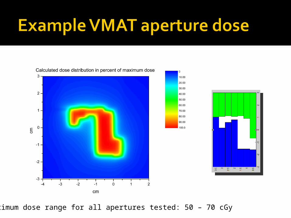
Maximum dose range for all apertures tested: 50 – 70 cGy

• Edge error on MLC leaf sides:• No
compensation for tongue on MLC
• 11-17% deviation as a percent of maximum dose
11-17%

• Edge error on MLC leaf ends:• Rounded edge
of leaf end is better modeled in the planning system
• 0-5% deviation as a percent of maximum dose
0-5%
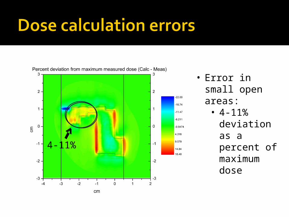
• Error in small open areas:• 4-11% deviation
as a percent of maximum dose
4-11%

• Leakage between closed MLC leafs:• ~22% deviation
as a percent of maximum dose
~22%

Errors of small irregular fields occur because we cannot model all parameters of each field perfectly
What can we learn from looking at these dose deviations? Areas where dose calculation algorithm can be
improved
Aperture shapes that should be avoided to ensure plans with optimal deliverability
Goal is to increase likelihood of accurate delivery
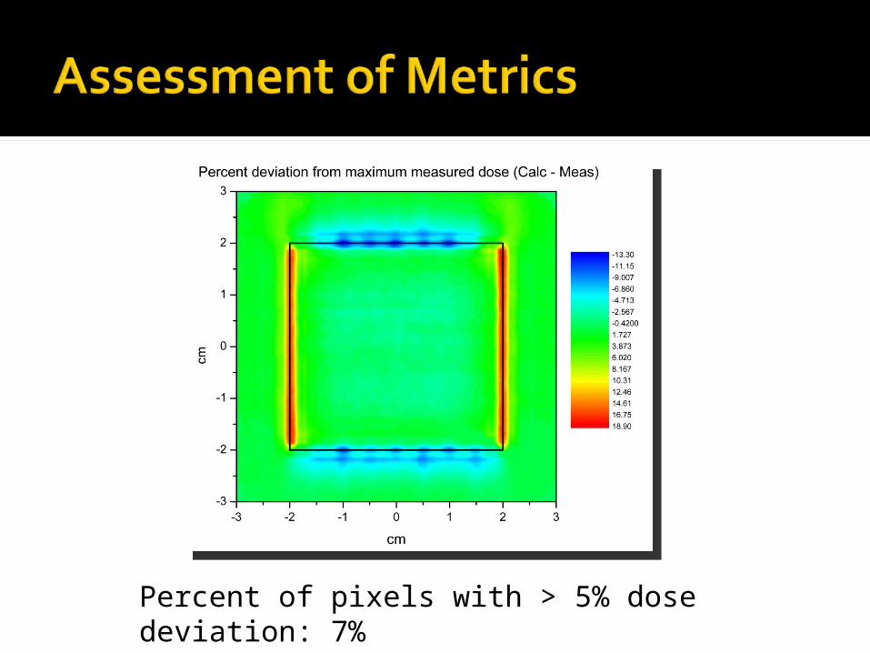
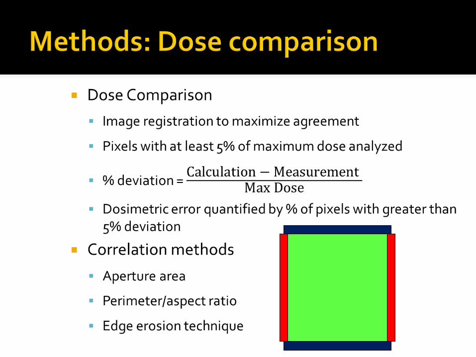
Percent of pixels with > 5% dose deviation: 7%

15 Rectangles: area 0.4 cm2 to 20 cm2,aspect ratio 0.2 to 5
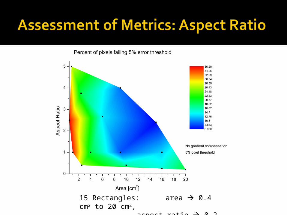
15 Rectangles: area 0.4 cm2 to 20 cm2,
aspect ratio 0.2 to 5
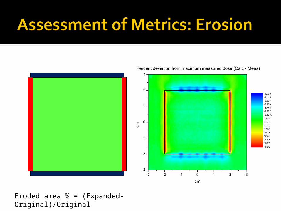
Eroded area % = (Expanded-Original)/Original

Parameters: Expand 0.2 cm 0n leaf end Expand 0.05 cm 0n leaf side
Rectangular Fields
Example expanded area

Parameters: Expand 0.025 cm on leaf end Contract 0.025 cm on leaf end Expand 0.1 cm on leaf side Contract 0.1 cm on leaf side
Eroded area % = (Expanded – Contracted)/Original
VMAT Fields
Example expanded area
VMAT is a promising treatment technique, but the accuracy of plans with small, irregular apertures is questionable These inaccuracies can be masked when using distance-to-
agreement criteria
Calculational errors can be better understood by analyzing dose differences
Edge erosion is a promising metric for identifying undesirable apertures Edge erosion can be used for different dose calculation
algorithms if the unique erosion parameters are identified
Adding a cost function based on aperture shape should help to minimize apertures that will lead to unacceptable error

UM Team VMAT
Jean Moran James BalterColleen Fox

Erosion parameters Determine optimal parameters for erosion in x
and y Test with other dose calculation algorithms
Add cost function to optimizer to penalize beams that may lead to large errors
Compare plans with and without aperture shape cost functions
Related Documents