Kelly Kelly Kelly Kelly KDH KDH KDH KDHE High High High High Power Power Power Power Series/PM Series/PM Series/PM Series/PM Motor Motor Motor Motor Controller Controller Controller Controller User User User User’s Manual Manual Manual Manual V 1.1 .1 .1 .1 Kelly Kelly Kelly Kelly KDH KDH KDH KDHE High High High High Power Power Power Power Series/PM Series/PM Series/PM Series/PM Motor Motor Motor Motor Controller Controller Controller Controller User User User User’s Manual Manual Manual Manual Rev.1.1 May. 2010 KDH12101E KDH12101E KDH12101E KDH12101E KDH KDH KDH KDH12121E 12121E 12121E 12121E KDH12151E KDH12151E KDH12151E KDH12151E KDH12181E KDH12181E KDH12181E KDH12181E KDH14601E KDH14601E KDH14601E KDH14601E KDH1 KDH1 KDH1 KDH14801E 4801E 4801E 4801E KDH14101E KDH14101E KDH14101E KDH14101E KDH14121E KDH14121E KDH14121E KDH14121E

Welcome message from author
This document is posted to help you gain knowledge. Please leave a comment to let me know what you think about it! Share it to your friends and learn new things together.
Transcript
KellyKellyKellyKelly KDHKDHKDHKDHEEEE HighHighHighHigh PowerPowerPowerPower Series/PMSeries/PMSeries/PMSeries/PM MotorMotorMotorMotor ControllerControllerControllerController UserUserUserUser’’’’ssss ManualManualManualManual VVVV 1111.1.1.1.1
KellyKellyKellyKelly KDHKDHKDHKDHEEEE HighHighHighHigh PowerPowerPowerPower Series/PMSeries/PMSeries/PMSeries/PMMotorMotorMotorMotor ControllerControllerControllerController UserUserUserUser’’’’ssss ManualManualManualManual
Rev.1.1May. 2010
KDH12101EKDH12101EKDH12101EKDH12101EKDHKDHKDHKDH12121E12121E12121E12121EKDH12151EKDH12151EKDH12151EKDH12151EKDH12181EKDH12181EKDH12181EKDH12181EKDH14601EKDH14601EKDH14601EKDH14601EKDH1KDH1KDH1KDH14801E4801E4801E4801EKDH14101EKDH14101EKDH14101EKDH14101EKDH14121EKDH14121EKDH14121EKDH14121E
KellyKellyKellyKelly KDHKDHKDHKDHEEEE HighHighHighHigh PowerPowerPowerPower Series/PMSeries/PMSeries/PMSeries/PM MotorMotorMotorMotor ControllerControllerControllerController UserUserUserUser’’’’ssss ManualManualManualManual VVVV 1111.1.1.1.1
Page 1
ContentsContentsContentsContentsChapter 1 Introduction............................................................................................ 2
1.1 Overview..................................................................................................... 2
Chapter 2 Main Features and Specifications..........................................................3
2.1 General functions........................................................................................3
2.2 Features......................................................................................................3
2.3 Specifications..............................................................................................4
Chapter 3 Wiring and Installation............................................................................4
3.1 Mounting the Controller.............................................................................. 4
3.2 Connections................................................................................................ 6
3.3 Installation Checkout................................................................................ 13
Chapter 4 Maintenance.........................................................................................14
4.1 Cleaning....................................................................................................14
4.2 Configuration.............................................................................................14
Table 1: LED CODES............................................................................................15
Contact Us:........................................................................................................... 17
KellyKellyKellyKelly KDHKDHKDHKDHEEEE HighHighHighHigh PowerPowerPowerPower Series/PMSeries/PMSeries/PMSeries/PM MotorMotorMotorMotor ControllerControllerControllerController UserUserUserUser’’’’ssss ManualManualManualManual VVVV 1111.1.1.1.1
Page 2
ChapterChapterChapterChapter 1111 IntroductionIntroductionIntroductionIntroduction1.11.11.11.1 OverviewOverviewOverviewOverviewThe manual introduces Kelly KDHE High Power motor controllers’ features, installation and
maintenance. Read the manual carefully and thoroughly before using the controller. If you haveany questions, please contact the support center of Kelly Controls, LLC.
Kelly’s programmable motor controllers provide efficient, smooth and quite controls forelectrical vehicles like golf cart, go-cart, electric motorcycle, fork lift, hybrid vehicle, as well aselectric boat and industry motor speed control. It uses high power MOSFET, fast PWM toachieve efficiency 99% in most cases. Powerful microprocessor brings in comprehensive andprecise control to the controllers. It also allows users to set parameters, conduct tests, andobtain diagnostic information quickly and easily.
KellyKellyKellyKelly KDHKDHKDHKDHEEEE HighHighHighHigh PowerPowerPowerPower Series/PMSeries/PMSeries/PMSeries/PM MotorMotorMotorMotor ControllerControllerControllerController UserUserUserUser’’’’ssss ManualManualManualManual VVVV 1111.1.1.1.1
Page 3
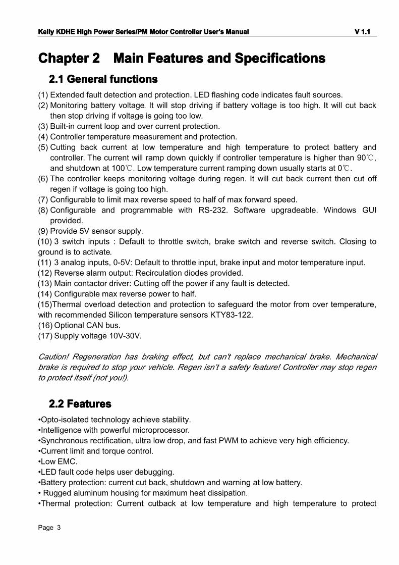
ChapterChapterChapterChapter 2222 MainMainMainMain FeaturesFeaturesFeaturesFeatures andandandand SpecificationsSpecificationsSpecificationsSpecifications2.12.12.12.1 GeneralGeneralGeneralGeneral functionsfunctionsfunctionsfunctions
(1) Extended fault detection and protection. LED flashing code indicates fault sources.(2) Monitoring battery voltage. It will stop driving if battery voltage is too high. It will cut back
then stop driving if voltage is going too low.(3) Built-in current loop and over current protection.(4) Controller temperature measurement and protection.(5) Cutting back current at low temperature and high temperature to protect battery and
controller. The current will ramp down quickly if controller temperature is higher than 90℃,and shutdown at 100℃. Low temperature current ramping down usually starts at 0℃.
(6) The controller keeps monitoring voltage during regen. It will cut back current then cut offregen if voltage is going too high.
(7) Configurable to limit max reverse speed to half of max forward speed.(8) Configurable and programmable with RS-232. Software upgradeable. Windows GUI
provided.(9) Provide 5V sensor supply.(10) 3 switch inputs : Default to throttle switch, brake switch and reverse switch. Closing toground is to activate.(11) 3 analog inputs, 0-5V: Default to throttle input, brake input and motor temperature input.(12) Reverse alarm output: Recirculation diodes provided.(13) Main contactor driver: Cutting off the power if any fault is detected.(14) Configurable max reverse power to half.(15)Thermal overload detection and protection to safeguard the motor from over temperature,with recommended Silicon temperature sensors KTY83-122.(16) Optional CAN bus.(17) Supply voltage 10V-30V.
Caution! Regeneration has braking effect, but can't replace mechanical brake. Mechanicalbrake is required to stop your vehicle. Regen isn’t a safety feature! Controller may stop regento protect itself (not you!).
2.22.22.22.2 FeaturesFeaturesFeaturesFeatures•Opto-isolated technology achieve stability.•Intelligence with powerful microprocessor.•Synchronous rectification, ultra low drop, and fast PWM to achieve very high efficiency.•Current limit and torque control.•Low EMC.•LED fault code helps user debugging.•Battery protection: current cut back, shutdown and warning at low battery.• Rugged aluminum housing for maximum heat dissipation.•Thermal protection: Current cutback at low temperature and high temperature to protect
KellyKellyKellyKelly KDHKDHKDHKDHEEEE HighHighHighHigh PowerPowerPowerPower Series/PMSeries/PMSeries/PMSeries/PM MotorMotorMotorMotor ControllerControllerControllerController UserUserUserUser’’’’ssss ManualManualManualManual VVVV 1111.1.1.1.1
Page 4
battery and controller.•High pedal protection: Disable operation if power up with non-zero throttle.•Brake switch is used to start regen.•0-5V brake signal is used to command regen current.•Easy installation: 1-4V "Hall Active" throttle or "3 Wire" potentiometer(<100K) can work.
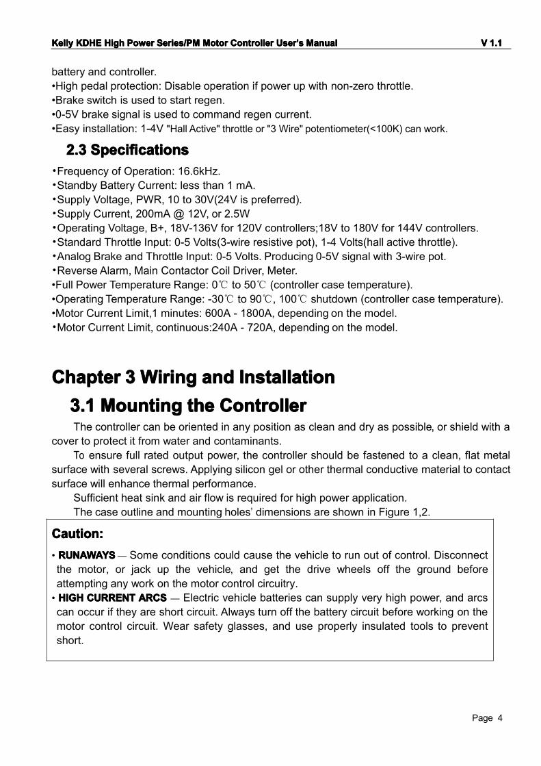
2.32.32.32.3 SpecificationsSpecificationsSpecificationsSpecifications•Frequency of Operation: 16.6kHz.•Standby Battery Current: less than 1 mA.•Supply Voltage, PWR, 10 to 30V(24V is preferred).•Supply Current, 200mA @ 12V, or 2.5W•Operating Voltage, B+, 18V-136V for 120V controllers;18V to 180V for 144V controllers.•Standard Throttle Input: 0-5 Volts(3-wire resistive pot), 1-4 Volts(hall active throttle).•Analog Brake and Throttle Input: 0-5 Volts. Producing 0-5V signal with 3-wire pot.•Reverse Alarm, Main Contactor Coil Driver, Meter.•Full Power Temperature Range: 0℃ to 50℃ (controller case temperature).•Operating Temperature Range: -30℃ to 90℃, 100℃ shutdown (controller case temperature).•Motor Current Limit,1 minutes: 600A - 1800A, depending on the model.•Motor Current Limit, continuous:240A - 720A, depending on the model.
ChapterChapterChapterChapter 3333 WiringWiringWiringWiring andandandand InstallationInstallationInstallationInstallation3.13.13.13.1 MountingMountingMountingMounting thethethethe ControllerControllerControllerControllerThe controller can be oriented in any position as clean and dry as possible, or shield with a
cover to protect it from water and contaminants.To ensure full rated output power, the controller should be fastened to a clean, flat metal
surface with several screws. Applying silicon gel or other thermal conductive material to contactsurface will enhance thermal performance.
Sufficient heat sink and air flow is required for high power application.The case outline and mounting holes’ dimensions are shown in Figure 1,2.
Caution:Caution:Caution:Caution:• RUNAWAYSRUNAWAYSRUNAWAYSRUNAWAYS— Some conditions could cause the vehicle to run out of control. Disconnectthe motor, or jack up the vehicle, and get the drive wheels off the ground beforeattempting any work on the motor control circuitry.• HIGHHIGHHIGHHIGH CURRENTCURRENTCURRENTCURRENT ARCSARCSARCSARCS — Electric vehicle batteries can supply very high power, and arcscan occur if they are short circuit. Always turn off the battery circuit before working on themotor control circuit. Wear safety glasses, and use properly insulated tools to preventshort.

KellyKellyKellyKelly KDHKDHKDHKDHEEEE HighHighHighHigh PowerPowerPowerPower Series/PMSeries/PMSeries/PMSeries/PM MotorMotorMotorMotor ControllerControllerControllerController UserUserUserUser’’’’ssss ManualManualManualManual VVVV 1111.1.1.1.1
Page 5
FigureFigureFigureFigure 1:1:1:1: Height: 84 millimetersLength: 204 millimeters
Controller models with above dimension: KDH12101E, KDH12121E,KDH14601E, KDH14801E
KellyKellyKellyKelly KDHKDHKDHKDHEEEE HighHighHighHigh PowerPowerPowerPower Series/PMSeries/PMSeries/PMSeries/PM MotorMotorMotorMotor ControllerControllerControllerController UserUserUserUser’’’’ssss ManualManualManualManual VVVV 1111.1.1.1.1
Page 6
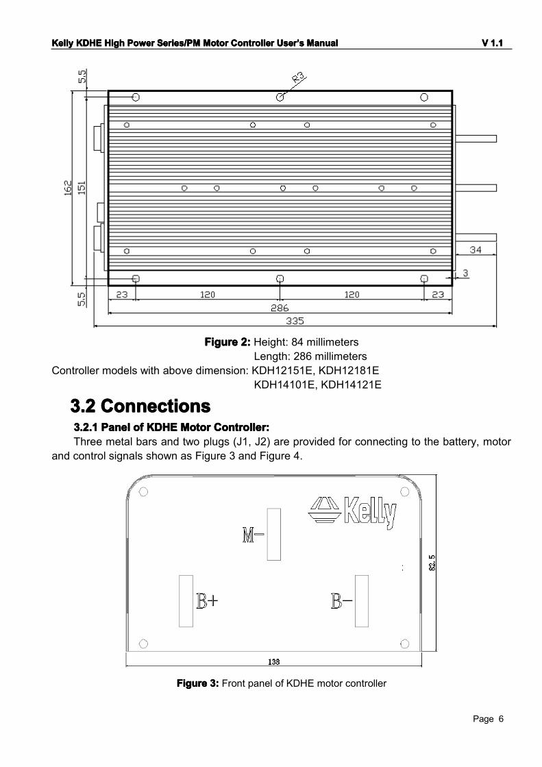
FigureFigureFigureFigure 2222:::: Height: 84 millimetersLength: 286 millimeters
Controller models with above dimension: KDH12151E, KDH12181EKDH14101E, KDH14121E
3.23.23.23.2 ConnectionsConnectionsConnectionsConnections3.2.13.2.13.2.13.2.1 PanelPanelPanelPanel ofofofof KDHKDHKDHKDHEEEE MotorMotorMotorMotor Controller:Controller:Controller:Controller:Three metal bars and two plugs (J1, J2) are provided for connecting to the battery, motor
and control signals shown as Figure 3 and Figure 4.
FigureFigureFigureFigure 3333:::: Front panel of KDHE motor controller
KellyKellyKellyKelly KDHKDHKDHKDHEEEE HighHighHighHigh PowerPowerPowerPower Series/PMSeries/PMSeries/PMSeries/PM MotorMotorMotorMotor ControllerControllerControllerController UserUserUserUser’’’’ssss ManualManualManualManual VVVV 1111.1.1.1.1
Page 7
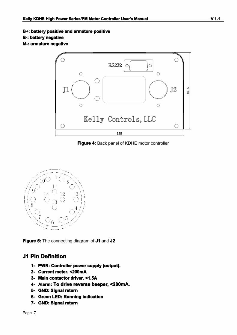
B+:B+:B+:B+: batterybatterybatterybattery positivepositivepositivepositive andandandand armaturearmaturearmaturearmature positivepositivepositivepositiveB-:B-:B-:B-: bbbbatteryatteryatteryattery negativenegativenegativenegativeMMMM----:::: aaaarmaturermaturermaturermature negativenegativenegativenegative
FigureFigureFigureFigure 4444:::: Back panel of KDHE motor controller
FigureFigureFigureFigure 5555:::: The connecting diagram of J1J1J1J1 and J2J2J2J2
J1J1J1J1 PinPinPinPin DefinitionDefinitionDefinitionDefinition1-1-1-1- PWRPWRPWRPWR:::: ControlControlControlControllerlerlerler powerpowerpowerpower supplysupplysupplysupply (output).(output).(output).(output).2-2-2-2- CurrentCurrentCurrentCurrent meter.meter.meter.meter. <200mA<200mA<200mA<200mA3-3-3-3- MainMainMainMain contactorcontactorcontactorcontactor driver.driver.driver.driver. <<<<1.51.51.51.5AAAA4-4-4-4- Alarm:Alarm:Alarm:Alarm: ToToToTo drivedrivedrivedrive reversereversereversereverse beeperbeeperbeeperbeeper,,,, <200mA<200mA<200mA<200mA....5-5-5-5- GND:GND:GND:GND: SignalSignalSignalSignal returnreturnreturnreturn6-6-6-6- GreenGreenGreenGreen LED:LED:LED:LED: RunningRunningRunningRunning indicationindicationindicationindication7-7-7-7- GND:GND:GND:GND: SignalSignalSignalSignal returnreturnreturnreturn
KellyKellyKellyKelly KDHKDHKDHKDHEEEE HighHighHighHigh PowerPowerPowerPower Series/PMSeries/PMSeries/PMSeries/PM MotorMotorMotorMotor ControllerControllerControllerController UserUserUserUser’’’’ssss ManualManualManualManual VVVV 1111.1.1.1.1
Page 8
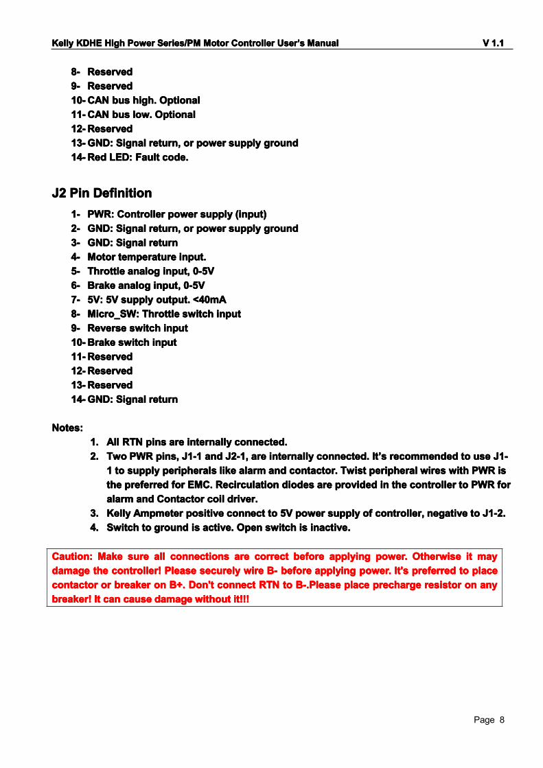
8-8-8-8- ReservedReservedReservedReserved9-9-9-9- ReservedReservedReservedReserved10-10-10-10-CANCANCANCAN busbusbusbus highhighhighhigh.... OptionalOptionalOptionalOptional11-11-11-11-CANCANCANCAN busbusbusbus lowlowlowlow.... OptionalOptionalOptionalOptional12-12-12-12-ReservedReservedReservedReserved13-13-13-13-GND:GND:GND:GND: SignalSignalSignalSignal rrrreturn,eturn,eturn,eturn, orororor powerpowerpowerpower supplysupplysupplysupply groundgroundgroundground14-14-14-14-RedRedRedRed LED:LED:LED:LED: FFFFaultaultaultault codecodecodecode....
J2J2J2J2 PinPinPinPin DefinitionDefinitionDefinitionDefinition1-1-1-1- PWRPWRPWRPWR:::: ControlControlControlControllerlerlerler powerpowerpowerpower supplysupplysupplysupply (input)(input)(input)(input)2-2-2-2- GND:GND:GND:GND: SignalSignalSignalSignal rrrreturn,eturn,eturn,eturn, orororor powerpowerpowerpower supplysupplysupplysupply groundgroundgroundground3-3-3-3- GND:GND:GND:GND: SignalSignalSignalSignal rrrreturneturneturneturn4-4-4-4- MotorMotorMotorMotor temperaturetemperaturetemperaturetemperature input.input.input.input.5-5-5-5- ThrottleThrottleThrottleThrottle analoganaloganaloganalog input,input,input,input, 0-5V0-5V0-5V0-5V6-6-6-6- BBBBrakerakerakerake analoganaloganaloganalog inputinputinputinput,,,, 0-5V0-5V0-5V0-5V7-7-7-7- 5V:5V:5V:5V: 5V5V5V5V supplysupplysupplysupply output.output.output.output. <40mA<40mA<40mA<40mA8-8-8-8- Micro_SW:Micro_SW:Micro_SW:Micro_SW: ThrottleThrottleThrottleThrottle switchswitchswitchswitch inputinputinputinput9-9-9-9- RRRReverseeverseeverseeverse switchswitchswitchswitch inputinputinputinput10-10-10-10-BrakeBrakeBrakeBrake switchswitchswitchswitch inputinputinputinput11-11-11-11-ReservedReservedReservedReserved12-12-12-12-ReservedReservedReservedReserved13-13-13-13-ReservedReservedReservedReserved14-14-14-14-GND:GND:GND:GND: SignalSignalSignalSignal rrrreturneturneturneturn
Notes:Notes:Notes:Notes:1.1.1.1. AllAllAllAll RTNRTNRTNRTN pinspinspinspins areareareare internallyinternallyinternallyinternally connected.connected.connected.connected.2.2.2.2. TwoTwoTwoTwo PWRPWRPWRPWR pins,pins,pins,pins, J1-J1-J1-J1-1111 andandandand J2-1,J2-1,J2-1,J2-1, areareareare internallyinternallyinternallyinternally connected.connected.connected.connected. ItItItIt’’’’ssss recommendedrecommendedrecommendedrecommended totototo useuseuseuse J1-J1-J1-J1-
1111 totototo supplysupplysupplysupply peripheralsperipheralsperipheralsperipherals likelikelikelike alarmalarmalarmalarm andandandand contactorcontactorcontactorcontactor.... TwistTwistTwistTwist peripheralperipheralperipheralperipheral wireswireswireswires withwithwithwith PWRPWRPWRPWR isisisisthethethethe preferredpreferredpreferredpreferred forforforfor EMC.EMC.EMC.EMC. RecirculationRecirculationRecirculationRecirculation diodesdiodesdiodesdiodes areareareare providedprovidedprovidedprovided inininin thethethethe controllercontrollercontrollercontroller totototo PWRPWRPWRPWR forforforforalarmalarmalarmalarm andandandand ContactorContactorContactorContactor coilcoilcoilcoil driver.driver.driver.driver.
3.3.3.3. KellyKellyKellyKelly AmpmeterAmpmeterAmpmeterAmpmeter positivepositivepositivepositive connectconnectconnectconnect totototo 5V5V5V5V powerpowerpowerpower supplysupplysupplysupply ofofofof controller,controller,controller,controller, negativenegativenegativenegative totototo J1-2.J1-2.J1-2.J1-2.4.4.4.4. SwitchSwitchSwitchSwitch totototo groundgroundgroundground isisisis active.active.active.active. OpenOpenOpenOpen switchswitchswitchswitch isisisis inactiveinactiveinactiveinactive....
Caution:Caution:Caution:Caution: MakeMakeMakeMake suresuresuresure allallallall connectionsconnectionsconnectionsconnections areareareare correctcorrectcorrectcorrect beforebeforebeforebefore applyapplyapplyapplyinginginging power.power.power.power. OOOOtherwisetherwisetherwisetherwise itititit maymaymaymaydamagedamagedamagedamage thethethethe controller!controller!controller!controller! PleasePleasePleasePlease securelysecurelysecurelysecurely wirewirewirewire B-B-B-B- beforebeforebeforebefore applyingapplyingapplyingapplying power.power.power.power. It'sIt'sIt'sIt's preferredpreferredpreferredpreferred totototo placeplaceplaceplacecontactorcontactorcontactorcontactor orororor breakerbreakerbreakerbreaker onononon B+.B+.B+.B+. Don'tDon'tDon'tDon't connectconnectconnectconnect RTNRTNRTNRTN totototo B-.PleaseB-.PleaseB-.PleaseB-.Please placeplaceplaceplace prechargeprechargeprechargeprecharge resistorresistorresistorresistor onononon anyanyanyanybreaker!breaker!breaker!breaker! ItItItIt cancancancan causecausecausecause damagedamagedamagedamage withoutwithoutwithoutwithout it!!!it!!!it!!!it!!!
KellyKellyKellyKelly KDHKDHKDHKDHEEEE HighHighHighHigh PowerPowerPowerPower Series/PMSeries/PMSeries/PMSeries/PM MotorMotorMotorMotor ControllerControllerControllerController UserUserUserUser’’’’ssss ManualManualManualManual VVVV 1111.1.1.1.1
Page 9
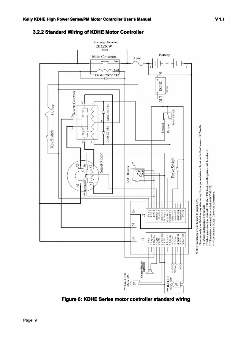
3.2.3.2.3.2.3.2.2222 StandardStandardStandardStandard WiringWiringWiringWiring ofofofof KDHKDHKDHKDHEEEE MotorMotorMotorMotor ControllerControllerControllerController
FigureFigureFigureFigure 6666:::: KDHKDHKDHKDHEEEE SeriesSeriesSeriesSeries motormotormotormotor controllercontrollercontrollercontroller standardstandardstandardstandard wiringwiringwiringwiring
KellyKellyKellyKelly KDHKDHKDHKDHEEEE HighHighHighHigh PowerPowerPowerPower Series/PMSeries/PMSeries/PMSeries/PM MotorMotorMotorMotor ControllerControllerControllerController UserUserUserUser’’’’ssss ManualManualManualManual VVVV 1111.1.1.1.1
Page 10
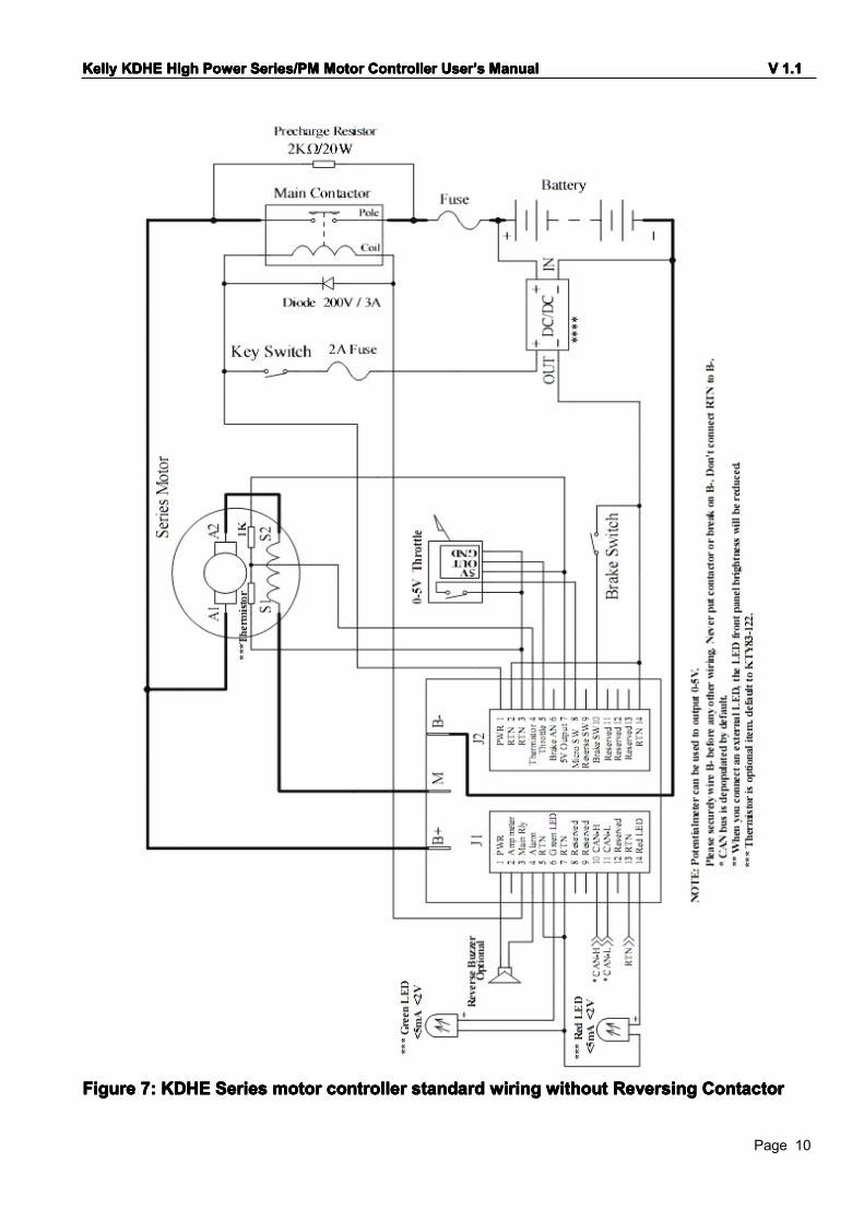
FigureFigureFigureFigure 7777:::: KDHKDHKDHKDHEEEE SeriesSeriesSeriesSeries motormotormotormotor controllercontrollercontrollercontroller standardstandardstandardstandard wiringwiringwiringwiring withoutwithoutwithoutwithout ReversingReversingReversingReversing ContactorContactorContactorContactor

KellyKellyKellyKelly KDHKDHKDHKDHEEEE HighHighHighHigh PowerPowerPowerPower Series/PMSeries/PMSeries/PMSeries/PM MotorMotorMotorMotor ControllerControllerControllerController UserUserUserUser’’’’ssss ManualManualManualManual VVVV 1111.1.1.1.1
Page 11
FigureFigureFigureFigure 8888:::: KDHKDHKDHKDHEEEE PMPMPMPMmotormotormotormotor controllercontrollercontrollercontroller standardstandardstandardstandard wiringwiringwiringwiring
KellyKellyKellyKelly KDHKDHKDHKDHEEEE HighHighHighHigh PowerPowerPowerPower Series/PMSeries/PMSeries/PMSeries/PM MotorMotorMotorMotor ControllerControllerControllerController UserUserUserUser’’’’ssss ManualManualManualManual VVVV 1111.1.1.1.1
Page 12
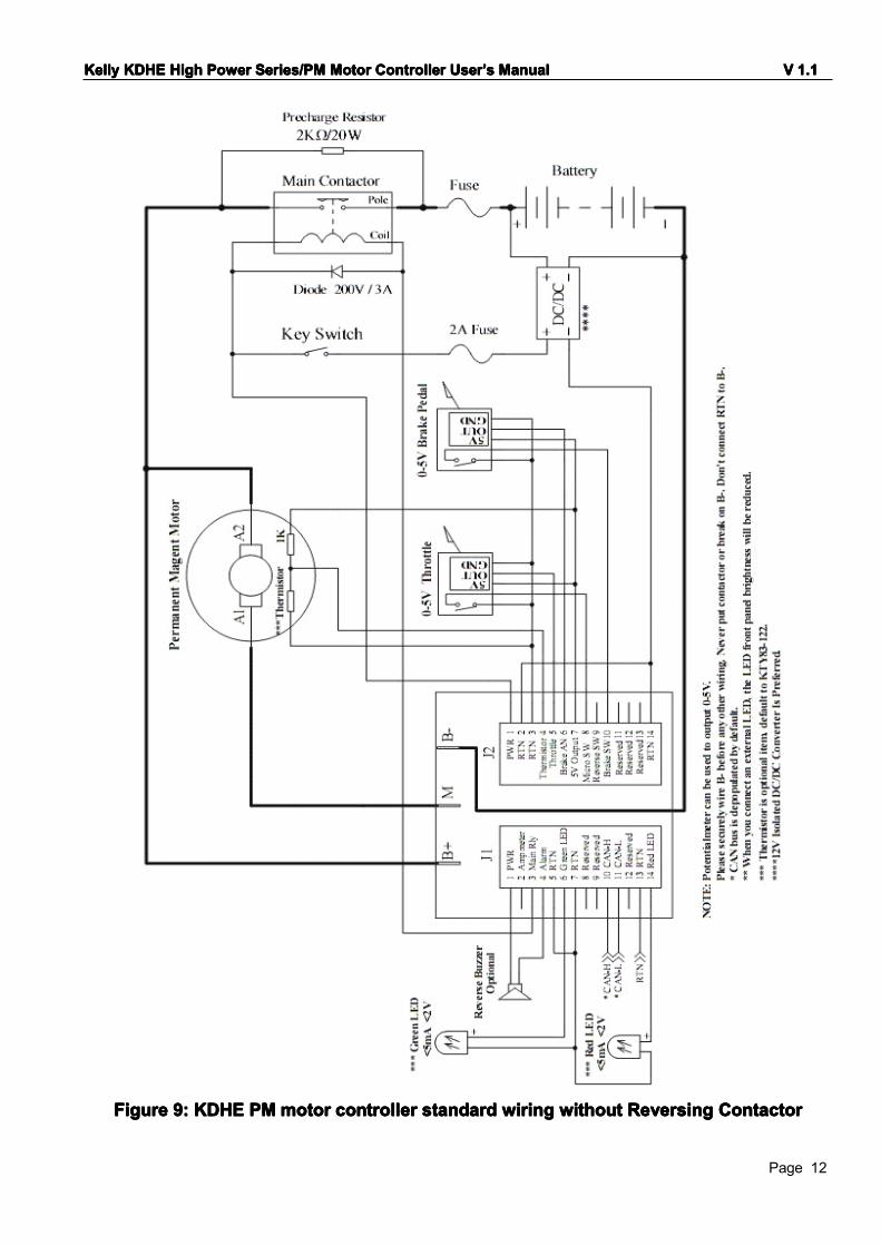
FigureFigureFigureFigure 9999:::: KDHKDHKDHKDHEEEE PMPMPMPMmotormotormotormotor controllercontrollercontrollercontroller standardstandardstandardstandard wiringwiringwiringwiring withoutwithoutwithoutwithout ReversingReversingReversingReversing ContactorContactorContactorContactor
KellyKellyKellyKelly KDHKDHKDHKDHEEEE HighHighHighHigh PowerPowerPowerPower Series/PMSeries/PMSeries/PMSeries/PM MotorMotorMotorMotor ControllerControllerControllerController UserUserUserUser’’’’ssss ManualManualManualManual VVVV 1111.1.1.1.1
Page 13
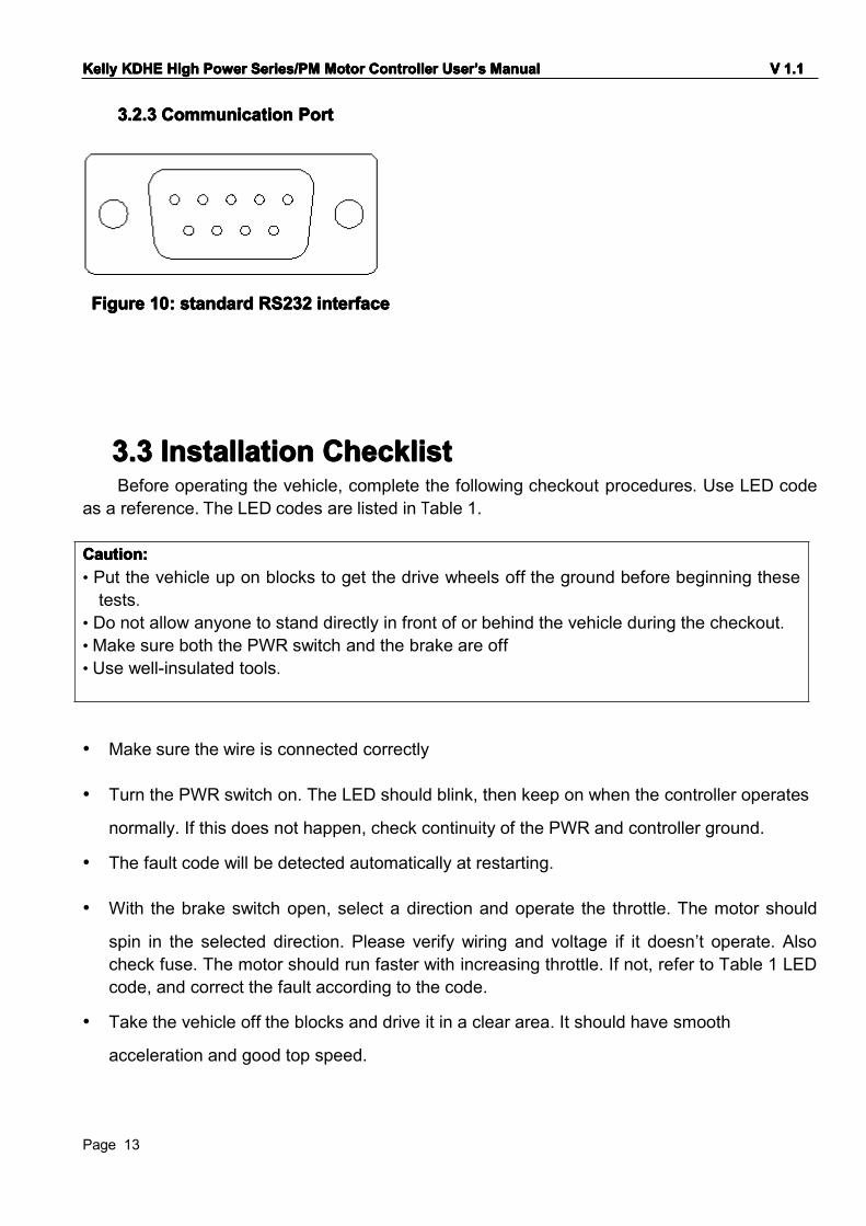
3.2.3.2.3.2.3.2.3333 CommunicationCommunicationCommunicationCommunication PortPortPortPort
FigureFigureFigureFigure 10101010:::: standardstandardstandardstandard RS232RS232RS232RS232 interfaceinterfaceinterfaceinterface
3.33.33.33.3 InstallationInstallationInstallationInstallation ChecklistChecklistChecklistChecklistBefore operating the vehicle, complete the following checkout procedures. Use LED code
as a reference. The LED codes are listed in Table 1.
• Make sure the wire is connected correctly
• Turn the PWR switch on. The LED should blink, then keep on when the controller operates
normally. If this does not happen, check continuity of the PWR and controller ground.
• The fault code will be detected automatically at restarting.
• With the brake switch open, select a direction and operate the throttle. The motor should
spin in the selected direction. Please verify wiring and voltage if it doesn’t operate. Alsocheck fuse. The motor should run faster with increasing throttle. If not, refer to Table 1 LEDcode, and correct the fault according to the code.
• Take the vehicle off the blocks and drive it in a clear area. It should have smooth
acceleration and good top speed.
Caution:Caution:Caution:Caution:• Put the vehicle up on blocks to get the drive wheels off the ground before beginning thesetests.
• Do not allow anyone to stand directly in front of or behind the vehicle during the checkout.•Make sure both the PWR switch and the brake are off• Use well-insulated tools.

KellyKellyKellyKelly KDHKDHKDHKDHEEEE HighHighHighHigh PowerPowerPowerPower Series/PMSeries/PMSeries/PMSeries/PM MotorMotorMotorMotor ControllerControllerControllerController UserUserUserUser’’’’ssss ManualManualManualManual VVVV 1111.1.1.1.1
Page 14
ChapterChapterChapterChapter 4444 MaintenanceMaintenanceMaintenanceMaintenanceThere are no user-serviceable parts inside the controllers. Do not attempt to open the
controller, or you will damage it. However, clearing the controller exterior periodically should benecessary.
The controller is inherently a high power device. When working with any battery poweredvehicle, proper safety precautions should be taken. These include, but are not limited to: propertraining, wearing eye protection, avoiding loose clothing and jewelry, and using insulatedwrenches.
4.14.14.14.1 CleaningCleaningCleaningCleaningAlthough the controller requires virtually no maintenance after properly installation, the
following minor maintenance is recommended in certain applications.
• Remove power by disconnecting the battery.
• Discharge the capacitors in the controller by connecting a load (such as a contactor coil or
a horn) across the controller’s B+ and B- terminals.
• Remove any dirt or corrosion from the bus bar area. The controller should be wiped down
with a moist rag. Be sure it is dry before reconnecting the battery.
•••• Make sure the connections to the bus bars are tight. Use two wrenches for this task in order
to avoid stressing the bus bars; the wrenches should be well insulated.
4.24.24.24.2 ConfigurationConfigurationConfigurationConfigurationYou can configure the controller with a host computer through RS232.
• Use a standard RS232 cable connecting the 9pin connector on face penal to a host
computer. The cable should be straight.
• Provide 10V to 30V supply to PWR (either J2 pin1 or J1 pin1). Wire power supply ground to
any RTN pin.
• Do not connect B+, throttle and so on. The controller may display fault code, but it doesn't
affect programming or configuration.
Download and setup the configuration software:
http://www.newkellycontroller.com/support.phphttp://www.newkellycontroller.com/support.phphttp://www.newkellycontroller.com/support.phphttp://www.newkellycontroller.com/support.php
KellyKellyKellyKelly KDHKDHKDHKDHEEEE HighHighHighHigh PowerPowerPowerPower Series/PMSeries/PMSeries/PMSeries/PM MotorMotorMotorMotor ControllerControllerControllerController UserUserUserUser’’’’ssss ManualManualManualManual VVVV 1111.1.1.1.1
Page 15
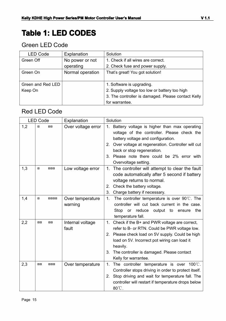
TableTableTableTable 1:1:1:1: LEDLEDLEDLED CODESCODESCODESCODESGreen LED Code
Red LED Code
LED Code Explanation SolutionGreen Off No power or not
operating1. Check if all wires are correct.2. Check fuse and power supply.
Green On Normal operation That’s great! You got solution!
Green and Red LEDKeep On
1. Software is upgrading.2. Supply voltage too low or battery too high3. The controller is damaged. Please contact Kellyfor warrantee.
LED Code Explanation Solution1,2 ¤ ¤¤ Over voltage error 1. Battery voltage is higher than max operating
voltage of the controller. Please check thebattery voltage and configuration.
2. Over voltage at regeneration. Controller will cutback or stop regeneration.
3. Please note there could be 2% error withOvervoltage setting.
1,3 ¤ ¤¤¤ Low voltage error 1. The controller will attempt to clear the faultcode automatically after 5 second if batteryvoltage returns to normal.
2. Check the battery voltage.3. Charge battery if necessary.
1,4 ¤ ¤¤¤¤ Over temperaturewarning
1. The controller temperature is over 90℃. Thecontroller will cut back current in the case.Stop or reduce output to ensure thetemperature fall.
2,2 ¤¤ ¤¤ Internal voltagefault
1. Check if the B+ and PWR voltage are correct,refer to B- or RTN. Could be PWR voltage low.
2. Please check load on 5V supply. Could be highload on 5V. Incorrect pot wiring can load itheavily.
3. The controller is damaged. Please contactKelly for warrantee.
2,3 ¤¤ ¤¤¤ Over temperature 1. The controller temperature is over 100℃.Controller stops driving in order to protect itself.
2. Stop driving and wait for temperature fall. Thecontroller will restart if temperature drops below80℃.
KellyKellyKellyKelly KDHKDHKDHKDHEEEE HighHighHighHigh PowerPowerPowerPower Series/PMSeries/PMSeries/PMSeries/PM MotorMotorMotorMotor ControllerControllerControllerController UserUserUserUser’’’’ssss ManualManualManualManual VVVV 1111.1.1.1.1
Page 16
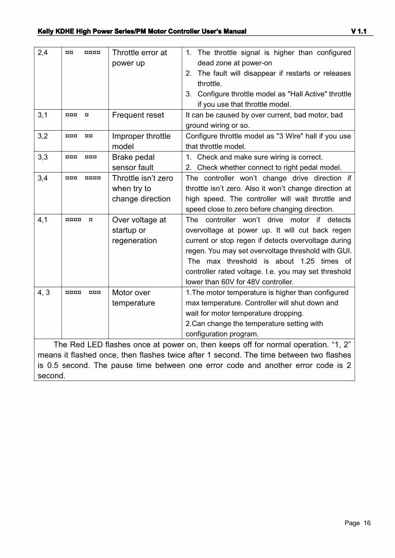
2,4 ¤¤ ¤¤¤¤ Throttle error atpower up
1. The throttle signal is higher than configureddead zone at power-on
2. The fault will disappear if restarts or releasesthrottle.
3. Configure throttle model as "Hall Active" throttleif you use that throttle model.
3,1 ¤¤¤ ¤ Frequent reset It can be caused by over current, bad motor, badground wiring or so.
3,2 ¤¤¤ ¤¤ Improper throttlemodel
Configure throttle model as "3 Wire" hall if you usethat throttle model.
3,3 ¤¤¤ ¤¤¤ Brake pedalsensor fault
1. Check and make sure wiring is correct.2. Check whether connect to right pedal model.
3,4 ¤¤¤ ¤¤¤¤ Throttle isn’t zerowhen try tochange direction
The controller won’t change drive direction ifthrottle isn’t zero. Also it won’t change direction athigh speed. The controller will wait throttle andspeed close to zero before changing direction.
4,1 ¤¤¤¤ ¤ Over voltage atstartup orregeneration
The controller won’t drive motor if detectsovervoltage at power up. It will cut back regencurrent or stop regen if detects overvoltage duringregen. You may set overvoltage threshold with GUI.The max threshold is about 1.25 times ofcontroller rated voltage. I.e. you may set thresholdlower than 60V for 48V controller.
4, 3 ¤¤¤¤ ¤¤¤ Motor overtemperature
1.The motor temperature is higher than configuredmax temperature. Controller will shut down andwait for motor temperature dropping.2.Can change the temperature setting withconfiguration program.
The Red LED flashes once at power on, then keeps off for normal operation. “1, 2”means it flashed once, then flashes twice after 1 second. The time between two flashesis 0.5 second. The pause time between one error code and another error code is 2second.

KellyKellyKellyKelly KDHKDHKDHKDHEEEE HighHighHighHigh PowerPowerPowerPower Series/PMSeries/PMSeries/PMSeries/PM MotorMotorMotorMotor ControllerControllerControllerController UserUserUserUser’’’’ssss ManualManualManualManual VVVV 1111.1.1.1.1
Page 17
ContactContactContactContact Us:Us:Us:Us:
KellyKellyKellyKelly Controls,Controls,Controls,Controls, LLCLLCLLCLLC
HomeHomeHomeHome Page:Page:Page:Page:http://www.kellycontroller.com
E-mail:E-mail:E-mail:E-mail:[email protected]
Phone:Phone:Phone:Phone:(01) 224 637 5092
Related Documents