Welcome message from author
This document is posted to help you gain knowledge. Please leave a comment to let me know what you think about it! Share it to your friends and learn new things together.
Transcript


First Edition 2007 © ABU SAHMAH MOHD SUPA’AT & ABU BAKAR MOHAMMAD 2007
Hak cipta terpelihara. Tiada dibenarkan mengeluar ulang mana-mana bahagian artikel, ilustrasi, dan isi kandungan buku ini dalam apa juga bentuk dan cara apa jua sama ada dengan cara elektronik, fotokopi, mekanik, atau cara lain sebelum mendapat izin bertulis daripada Timbalan Naib Canselor (Penyelidikan dan Inovasi), Universiti Teknologi Malaysia, 81310 Skudai, Johor Darul Ta’zim, Malaysia. Perundingan tertakluk kepada perkiraan royalti atau honorarium. All rights reserved. No part of this publication may be reproduced or transmitted in any form or by any means, electronic or mechanical including photocopy, recording, or any information storage and retrieval system, without permission in writing from Universiti Teknologi Malaysia, 81310 Skudai, Johor Darul Ta’zim, Malaysia.
Perpustakaan Negara Malaysia Cataloguing-in-Publication Data
Advances in free space optical technology / edited by Abu Sahmah Mohd Supa’at, Abu Bakar Mohammad. Includes index ISBN 978-983-52-0670-2 1. Optical communications. 2. Wireless communication systems. I. Abu Sahmah M. Supaat. II. Abu Bakar Mohammad. 621.3827
Editor: Abu Sahmah Mohd Supa’at & Rakan Pereka Kulit: Mohd Nazir Md. Basri & Mohd Asmawidin Bidin
Diatur huruf oleh / Typeset by Fakulti Kejuruteraan Elektrik
Diterbitkan di Malaysia oleh / Published in Malaysia by PENERBIT
UNIVERSITI TEKNOLOGI MALAYSIA 34 – 38, Jln. Kebudayaan 1, Taman Universiti,
81300 Skudai, Johor Darul Ta’zim, MALAYSIA.
(PENERBIT UTM anggota PERSATUAN PENERBIT BUKU MALAYSIA/ MALAYSIAN BOOK PUBLISHERS ASSOCIATION dengan no. keahlian 9101)
Dicetak di Malaysia oleh / Printed in Malaysia by
UNIVISION PRESS SDN. BHD. Lot. 47 & 48, Jalan SR 1/9, Seksyen 9,
Jalan Serdang Raya, Taman Serdang Raya, 43300 Seri Kembangan,
Selangor Darul Ehsan, MALAYSIA.

v
CONTENTS
Preface ix
Chapter 1 Indoor Optical Wireless Communication Sevia Mahdaliza Idrus, Faridah Pajapoyi and Sabariah Abdullah
1
Chapter 2 Infrared Physical Layer for Outdoor Portable Palm Device Sevia Mahdaliza Idrus, Boo Yan Jiong and Lee Sin Loong
13
Chapter 3 Inter-Satellite Optical Wireless System Abu Bakar Mohamad, Siti Norfarawahidatun Lela and Amir Masood Khalid
24
Chapter 4 A Review on Optical Wireless Front-End Receiver Design Abu Sahmah Mohd Supa’at, Arnidza Ramli and Sevia Mahdaliza Idrus
37
Chapter 5
Shunt Bootstrap Transimpedance Amplifier for Optical Wireless Receiver Abu Sahmah Mohd Supa’at, Sevia Mahdaliza Idrus, Siti Sara Rais and Arnidza Ramli
47
vi
Chapter 6 Laser Nonlinearity Reduction Model Using Taylor Series Expansion for Free Space Optical Communication System Sevia Mahdaliza Idrus, Ahmed Bashir Maiteeg and Hilman Harun
62
Chapter 7 Nonlinearity Compensation in Laser Diode by Means Feed-Forward Linearization for Free Space Optical Link Sevia Mahdaliza Idrus and Amir Masood Khalid
76
Chapter 8 GRIN Collimating Lenses Abu Sahmah Mohd Supa’at, Christie Laura Albert and Eileen Ma Fui Lin
84
Chapter 9 Self Alignment Optical Antenna Outdoor Optical Wireless Communication Sevia Mahdaliza Idrus, Pandian Meiyappan Siva and Arnidza Ramli
93
Chapter 10 Chapter 11
Performance Analysis of 2.4 GHz ISM-Band Wireless LAN for Indoor Wireless Communication Links Nor Hafizah Ngajikin, Sevia Mahdaliza Idrus, Fazlin Shariff Udin and Suryani Alifah Channel Assignment and MAC protocol for Indoor Wireless Infrared Ad Hoc Network Zurkarmawan Abu Bakar and Roger J. Green
102
113

vii
Chapter 12
The Use and Effectiveness of Wireless Network Service in UTM Colleges Sevia Mahdaliza Idrus and Mohd Hadi A. Rani and Mohd Farid Sarji
131
Index 149


PREFACE
The ways in which the world communicates are undergoing radical change. Driven by information technology, carriers and service providers are demanding high-capacity networks that are cost-effective and easy to deploy.
Free-Space Optics (FSO) has garnered much attention from the info-communications industry, as it represents a potential solution for carriers and service providers who are looking at high bandwidth technology that is cost effective and able to provide quick access to customers in need of high speed connection. In addition, no upfront cost for licensed spectrum translates into dramatic cost saving for service providers using FSO technology. The technology is useful where the physical connection by the means of fiber optic cables is impractical, due to high costs or other considerations. This book is allocated of the advances in free space optical technology which is the one interested researches in Photonic Technology Centre (PTC).
Chapter 1 is stated the history of optical wireless communications (free space optical links) and shown that wireless communications based on infrared (IR) technology is one of the most growing areas in telecommunications. In Chapter 2, the physical layer for an infrared communication system is studied to increase the link distance for more effective system. The laser’s application in satellite and how it works is stated in Chapter 3. Chapter 4 provides an overview of the optical wireless front-end receiver designs where a fundamental requirement is the achievement of wide dynamic range and broad bandwidth. In Chapter 5, the Shunt Bootstrap Transimpedance Amplifier for

Preface x
Large Windows Optical Wireless Receiver is presented which a significant bandwidth enhancement compared to transimpedance front-end has been achieved. In Chapter 6 the mathematical modeling of the nonlinearity compensation of laser diode by employing Taylor’s series expansion is presented. The simulation of the nonlinearity reduction of directly modulated laser diode for the application of wireless LAN (WLAN) is narrated in Chapter 7. In Chapter 8, gradient index (GRIN) lens is discussed and how can be used to build collimating lenses. In Chapter 9, self alignment optical antenna outdoor optical wireless communication is developed to increase the efficiency of optical receiver. The performance analysis of 2.4 GHZ ISM-Band wireless LAN for indoor wireless communication links is shown and done in Chapter 10. Chapter 11 present the channel assignment and reassignment method and MAC protocol algorithm for wireless infrared ad-hoc networking which utilises directional emitters and is fully controlled by microcontroller M16/C. Finally, the analysis of the usage and effectiveness of wireless network services (WNS) in UTM colleges will be presented in Chapter 12.
The Editors thank all authors for their valuable time and tremendous efforts they have put into written these chapters. Editor: Abu Sahmah Mohd Supa’at Abu Bakar Mohammad Photonics Technology Centre, Universiti Teknologi Malaysia 2007

Indoor Optical Wireless Communication 1
1
INDOOR OPTICAL WIRELESS COMMUNICATION
Sevia Mahdaliza Idrus Faridah Pajapoyi
Sabariah Abdullah
1.1 INTRODUCTION In lately few years, there has been a rapidly growing in optical wireless communication system for indoor and outdoor applications. Nowadays, the most popular indoor wireless communication is radio frequency (RF) and infrared (IR). Infrared is preferred for many reasons. This article presents an up-to-date review of the optical wireless communication system features for indoor use. There are some explanations on benefit and limitation, advantages and disadvantages, different source of noise, the different possible configuration and finally current and future trends of indoor IR system are visualized.
One may see the computer terminals are clustered within office, labs, education institution, libraries and other environments. Due to high cost of reconfiguring and maintaining of wired system, make wireless an economical and flexible alternative to wired systems. Wireless offer flexibility in the placement of terminals and save of time and cost in reconfiguring. IR radiation is a high-speed of indoor wireless communication. The idea of using IR as a medium for indoor communication was first proposed about two decades ago [1,2]. As optical system operates in the near part of spectrum, they use of very low cost optoelectronic components. Usually, these components are small and consume little power,
2 Advances in Free Space Optical Technology
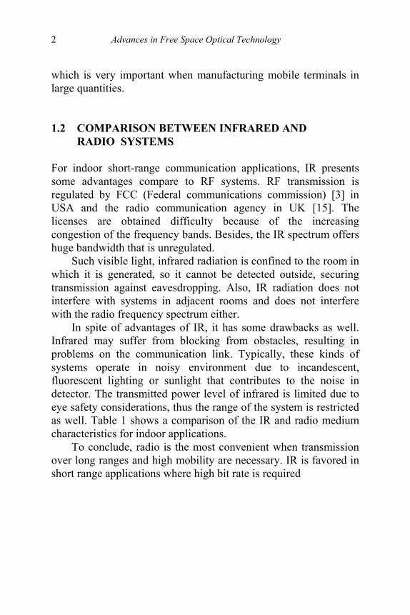
which is very important when manufacturing mobile terminals in large quantities. 1.2 COMPARISON BETWEEN INFRARED AND RADIO SYSTEMS For indoor short-range communication applications, IR presents some advantages compare to RF systems. RF transmission is regulated by FCC (Federal communications commission) [3] in USA and the radio communication agency in UK [15]. The licenses are obtained difficulty because of the increasing congestion of the frequency bands. Besides, the IR spectrum offers huge bandwidth that is unregulated.
Such visible light, infrared radiation is confined to the room in which it is generated, so it cannot be detected outside, securing transmission against eavesdropping. Also, IR radiation does not interfere with systems in adjacent rooms and does not interfere with the radio frequency spectrum either.
In spite of advantages of IR, it has some drawbacks as well. Infrared may suffer from blocking from obstacles, resulting in problems on the communication link. Typically, these kinds of systems operate in noisy environment due to incandescent, fluorescent lighting or sunlight that contributes to the noise in detector. The transmitted power level of infrared is limited due to eye safety considerations, thus the range of the system is restricted as well. Table 1 shows a comparison of the IR and radio medium characteristics for indoor applications.
To conclude, radio is the most convenient when transmission over long ranges and high mobility are necessary. IR is favored in short range applications where high bit rate is required

Indoor Optical Wireless Communication 3
Table 1 Comparison of radio and infrared properties for indoor wireless communication
1.3 SYSTEM CONFIGURATION The configuration of IR links have been classified, relying on the existence of a line-of-sight (LOS) path between transmitter and receiver, and the degree of directionally (directed, hybrid and non-directed) [2,4]. The six configurations are shown in Figure 1.
LOS link systems improve power efficiency and minimized multipath distortion. In spite, Non-LOS links increase link robustness as they allow the system to operate even when obstacles are placed between the transmitter and receiver, and alignment is not required. Directed links also improve power efficiency as the path loss is minimized, but this kind of systems need alignment of transmitter, receiver or both, resulting less convenient to use for certain applications. Directed-LOS link systems improve power efficiency because the transmitted power is concentrated into a narrow optical beam, making possible the use of narrower field-of-

4 Advances in Free Space Optical Technology
view (FOV) receivers. Also this system does not suffer from multipath distortion, and predetermined maximum transmission distance can be assured for a given optical power, independently of the reflective properties as far as LOS not interrupted. Thus, the drawback is that it is susceptible to blocking and requires aiming of the transmitter or receiver. This configuration offers the advantages of maximum power efficiency and high coverage.
Figure 1 Configurations of Infrared links
Hybrid-non-LOS systems do not present the blocking problem but suffer from multipath distortion that increases as area is increase.
The most attractive configuration is the nondirected-non-LOS or diffuse. It does not require a direct LOS or alignment between the transmitter and receiver because the optical waves are spread possibly in the room by making use the reflective properties of the walls and ceiling. This kind of link is the most robust and flexible configuration as it can operate even when obstacles are placed between transmitter and receiver. However, it suffers from multipath dispersion and higher optical losses than LOS and hybrid-LOS.

Indoor Optical Wireless Communication 5
1.4 CURRENT INFRARED COMMUNICATION SYSTEMS Many manufacturers have developed different systems to communicate within indoor and outdoor environments using IR. Most of the manufacturers base their designs on the directed-LOS and hybrid-LOS configurations, the topologies that allow higher bit rates (sometimes above 100Mb/s), as they are free from multipath distortion. Besides, it can be developed at very low costs.
Directed-LOS configuration is one of the most popular currently. An example of this kind of system is the FiRLAN point-to point system manufactured by A.T. Schindler Communications Inc [5]. Directed and non directed-LOS systems typically transmit using just one LED that emits an average power of several 10mW at wavelengths between 850 - 950nm to optimize performance for the responsivity peak of p-i-n photodiodes at these wavelengths. Usually it has a FOV of 15 - 30°. Hybrid-LOS systems use hemispherical concentrators to maintain a wide FOV (about 60°) and to concentrate the received light. Hybrid-LOS links present higher coverage areas than LOS, but the power efficiency is reduced and they suffer blocking problems. A good example of this kind of configuration (Hybrid-LOS links) is the VIPSLAN-10 system manufactured by JVC [6].
Directed-LOS links use an optical concentrator that allows a narrower FOV, but provides a higher degree of concentration. There are also some systems based on the diffuse configuration. A natural application for this system may be a group of mobile, hand-held terminals within a room with access to a host computer via a base station located in the ceiling. The Spextrix Corporation has produced a system called SpectrixLitew [7], under this configuration. This uses arrays of LEDs oriented in different directions, to provide diversity of propagation paths.
Diffuse systems can employ one or several silicon p-i-n detectors orientated in different directions to achieve a wider FOV. In most cases, detectors are encapsulated in hemispherical lenses, allow a wide FOV and provide high concentration. A typical
6 Advances in Free Space Optical Technology
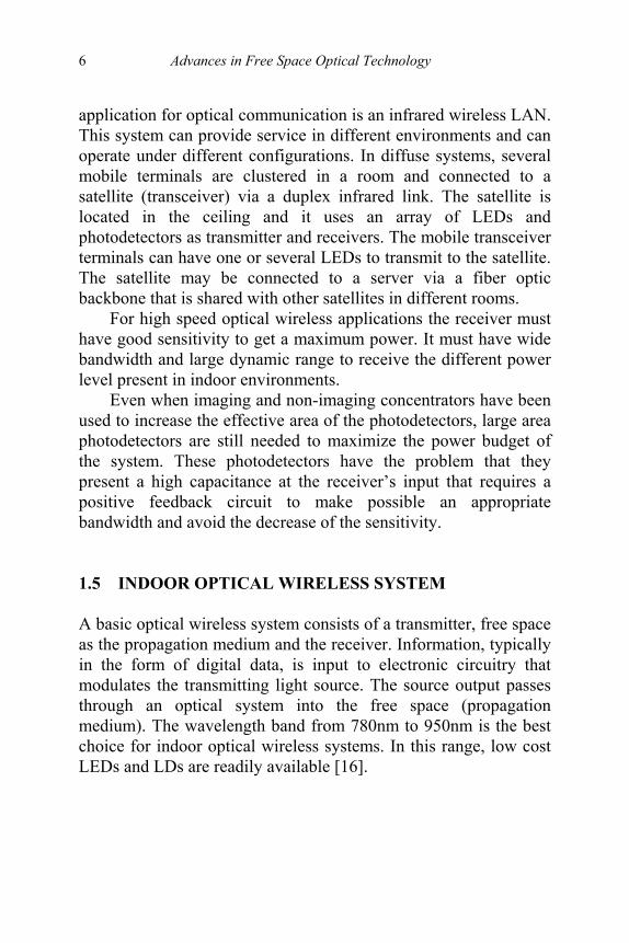
application for optical communication is an infrared wireless LAN. This system can provide service in different environments and can operate under different configurations. In diffuse systems, several mobile terminals are clustered in a room and connected to a satellite (transceiver) via a duplex infrared link. The satellite is located in the ceiling and it uses an array of LEDs and photodetectors as transmitter and receivers. The mobile transceiver terminals can have one or several LEDs to transmit to the satellite. The satellite may be connected to a server via a fiber optic backbone that is shared with other satellites in different rooms.
For high speed optical wireless applications the receiver must have good sensitivity to get a maximum power. It must have wide bandwidth and large dynamic range to receive the different power level present in indoor environments.
Even when imaging and non-imaging concentrators have been used to increase the effective area of the photodetectors, large area photodetectors are still needed to maximize the power budget of the system. These photodetectors have the problem that they present a high capacitance at the receiver’s input that requires a positive feedback circuit to make possible an appropriate bandwidth and avoid the decrease of the sensitivity. 1.5 INDOOR OPTICAL WIRELESS SYSTEM A basic optical wireless system consists of a transmitter, free space as the propagation medium and the receiver. Information, typically in the form of digital data, is input to electronic circuitry that modulates the transmitting light source. The source output passes through an optical system into the free space (propagation medium). The wavelength band from 780nm to 950nm is the best choice for indoor optical wireless systems. In this range, low cost LEDs and LDs are readily available [16].

Indoor Optical Wireless Communication 7
1.5.1 Transmitter Options The two commonly used sources for IR transmitters are: light emitting diodes (LEDs) and laser diodes (LDs). LEDs are usually cheaper and harder to damage than laser diodes, makes them the preferred choice for different manufacturers. Also, LEDs achieve higher power capability. However, laser diodes can be used at higher modulation rates than LEDs. As mentioned before, operation of these devices is in the near-infrared region, utilizing the wavelengths of 850nm, 950nm, 1300nm, 1480nm and 1550nm. The wavelengths are safer as they are closer to the visible part of the spectrum. 1.5.2 Receiver Options The two common detectors for the different configurations are: PIN photodiodes and avalanche photodiodes. The PIN detector is preferred in most of the systems, because of its low-bias-voltage requirement and its tolerance to temperature fluctuations. However, PIN detectors are about 10-15dB less sensitive than avalanche photodiodes [11,12].
Avalanche photodiodes provide a more robust communication link due to their increased power. This reduces the problem of accurate alignment of lenses and allows for reduction of preamplifier noise, laser power and miscellaneous losses. 1.5.3 Concentrators Optical concentrators are used to improve the collection efficiency of the receptors by transforming light rays incident over a large area into a set of rays that emerge from a smaller area. This implies that smaller photodiodes can be used that decreases the capacitance, cost, and improves receiver sensitivity. A further advantage is that the transmitted power level can be decreased, which avoids the problems related to optical safety considerations and reduces power consumption. The most widely used

8 Advances in Free Space Optical Technology
concentrators are a truncated spherical lens, but different kind of concentrators such as the compound parabolic, have also been investigated. 1.6 DATA TRANSMISSION LIMITAIONS There are basically three factors that limit the data transmission rate in indoor optical wireless systems: ambient light, multipath dispersion, and LED transient time [16].
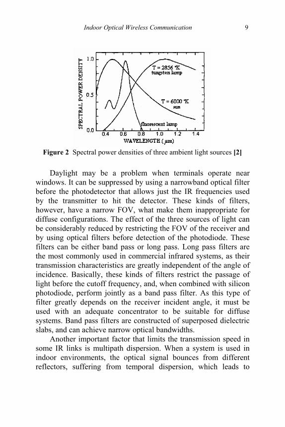
In most of the indoor communication systems environments, the receiver photodiode is not just exposed to the IR radiation of the transmitter, but also to ambient light from lamps. These lamps have a fraction of light in the IR part of the spectrum, which causes noise in the receiver. There are basically three sources of ambient light in indoor environments: fluorescent lamps, incandescent lamps and daylight. Figure.2 shows the spectral power densities of these light sources [2]. Fluorescent light has just a small amount of IR radiation, but daylight and incandescent light present a higher amount. Tungsten is the worst source. Fluorescent light has a low power density at the wavelengths used by photodetectors. Most of the indoor environments where optical systems are employed use fluorescent light instead of incandescent light, but the light generated the high noise level. The effects of this noise source can be minimized using subcarrier modulation, or by using a data coding scheme with a suppressed spectrum at low frequencies.
Indoor Optical Wireless Communication 9
Figure 2 Spectral power densities of three ambient light sources [2]
Daylight may be a problem when terminals operate near windows. It can be suppressed by using a narrowband optical filter before the photodetector that allows just the IR frequencies used by the transmitter to hit the detector. These kinds of filters, however, have a narrow FOV, what make them inappropriate for diffuse configurations. The effect of the three sources of light can be considerably reduced by restricting the FOV of the receiver and by using optical filters before detection of the photodiode. These filters can be either band pass or long pass. Long pass filters are the most commonly used in commercial infrared systems, as their transmission characteristics are greatly independent of the angle of incidence. Basically, these kinds of filters restrict the passage of light before the cutoff frequency, and, when combined with silicon photodiode, perform jointly as a band pass filter. As this type of filter greatly depends on the receiver incident angle, it must be used with an adequate concentrator to be suitable for diffuse systems. Band pass filters are constructed of superposed dielectric slabs, and can achieve narrow optical bandwidths.
Another important factor that limits the transmission speed in some IR links is multipath dispersion. When a system is used in indoor environments, the optical signal bounces from different reflectors, suffering from temporal dispersion, which leads to

10 Advances in Free Space Optical Technology
multipath fading. The diffuse configuration suffers more from this effect, because the large beamwidth will result in more light reflected from the different reflectors. It has been shown that, for diffuse systems, the maximum transmission speed is 260Mbit/s for a typical room size of 10 m x 10 m x 3 m [2].
One more limitation to the data transmission rate is due to the rise and fall times of LEDs. 1.7 EYE SAFETY Eye safety is the most important restriction for the emitted power level of the sources of many indoor optical wireless applications. IR radiation can damage the retina and the cornea when used inappropriately. The limits of the output power levels of the LDs are set by the International Electrotechnical Commission (IEC) [8], which describes the allowable exposure limits (AEL) that ensures the system is safe under all circumstances of use. The limits are a function of the size of the optical sources, the wavelength of the optical signal and the viewing time. The sources are classified depending on if the eye can focus the source (point source), or if the source forms an extended image on the retina (large area sources). LDs are point source emitters that must have reduced emission power levels if they have to satisfy the IEC 825-1 standard [16]. Table 2 shows a safety classification for laser sources [13]. Class 1 products are safe even when viewed with optical instruments. Optical wireless systems are required to this category. LED's are large area emitters that can be operated safely at larger emission power levels. That makes them the preferred optical source for indoor wireless systems. Also, an array of LEDs may be used as the optical source to increase the transmitted power level.

Indoor Optical Wireless Communication 11
Table 2 Safety classification for a laser source
A way to reduce the danger of damage in the retina is to use a diffusing screen placed after the laser, to change the point into a large area source. A very important contribution to overcome the problem is the hologram [9]. 1.8 CONCLUSION For indoor wireless system applications, the use of optical communications offers an important alternative for the growing area of communications. Thus, techniques to improve the operation of IR wireless systems within room environments have still to be found. Researchers and manufacturers are trying to find ways to improve the data bit rates and the range offered by current systems. Much effort also has been spent on trying to reduce the problems associated with multipath distortion, improving the system components to achieve higher SNRs, reducing their power consumption, and optimizing the coverage of the systems. REFERENCES [1] [2]
Mahdy A. and Deogun J.S., “Wireless Optical Communications: A Survey,” pp. 2399- 2404, Vol.4, March 2004. Kahn J.M. and Barry J.R., “Wireless Infrared Communications,” IEEE Proceeding, pp. 265-298, Vol. 85, Feb 1997.
12 Advances in Free Space Optical Technology
[3] [4] [5] [6] [7] [8] [9] [10] [11] [12] [13] [14] [15] [16]
FCC homepage: http://www.fcc.gov/ Marsh, G.W. and Kahn, J.M. “Channel Reuse Strategies for Indoor Infrared Wireless Communications,” IEEE Transaction on, Vol. 45, pp. 1280-1290, Oct 1997. FiRLAN: http://www.firlan.com/ VIPSLAN:http://www.google.com/patents?vid=USPAT5994998&id=PFwXAAAAEBAJ&printsec=abstract&zoom=4/ http://ieeexplore.ieee.org/iel1/2/7409/x0168520.pdf/ IEC homepage: http://www.iec.ch/ P.L.Eardley, D. R. Wisely, D. Wood, and P. McKee, "Holograms for Optical Wireless LANs," IEE Proc. -Optoelectronics, Vo1.143, No.6, pp. 365-369, Dec. 1996. IrDA: http://www.irda.com/ T.S. Chu and M.J. Gans, "High Speed Infrared Local Wireless Communication," IEEE Communications Magazine, vo1.25, no.8, pp. 4-10, 1987 Ta-Shing Chu and Gans M., "High Speed Infrared Local Wireless Communication", IEEE Comms. Magazine, vol. 25, pp.4-10, Aug 1987 D.J.T. Heatley, D.R. Wisely, I. Neild, and P. Cochrane, "Optical Wireless: The Story So Far," IEEE Comms. Magazine, pp.72-82, 1998. A.M. Street, P.N. Stavrinou, D.C. OBrien, D.J. Edwards, "Indoor Optical Wireless Systems: A Review," Optical and Quantum Electron. No. 29, pp.349-378, 1997 Ramirez-Iniguez R. and Green, R.J., “Indoor Optical Wireless Communications,” Optical Wireless Communications (Ref. No. 1999/128), IEE Colloquium, pp. 14/1-14/7 , 1999. Chaturi Singh, Joseph John, Y.N. Singh, and K.K. Tripathi, "A Review On Indoor Optical Wireless System"

Infrared Physical Layer For Outdoor Portable Palm Device 13
2
INFRARED PHYSICAL LAYER FOR OUTDOOR PORTABLE PALM DEVICE
Sevia Mahdaliza Idrus Boo Yan Jiong Lee Sin Loong
2.1 INTRODUCTION This study will brief the readers about the physical layer for a infrared communication system for portable devices, it will discuss the infrared physical layer from few perspectives, e.g: power consumption, link distance, radiation pattern etc. Few vital mathematics equations will be outline briefly along the discussion. It then follows by the infrared emitter and detector analysis. Lastly, it will discuss some relevent method to increase the link distance for more effective system.
Infrared light, commonly referred to as “IR”, is a common, easy-to-use, low power and low-cost media to transmit information. Among the few “wireless” communication choices, IR has the significant advantage of compatibility with hundreds of millions of electronic devices with IR ports (i.e., laptop PCs, PDAs). The vast majority of IR-capable devices are compatible with a set of standards established by the Infrared Data Association, or IrDA®. These standards include guidelines for implementing the IR Physical Layer (IrDA Serial Infrared Physical Layer specification), ensuring that IR communication can be established through free space between two dissimilar devices.
IR behavior can be predicted more easily than can RF behavior. The devices that emit and detect IR are very simple. The
14 Advances in Free Space Optical Technology
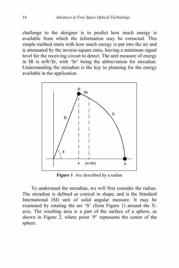
challenge to the designer is to predict how much energy is available from which the information may be extracted. This simple method starts with how much energy is put into the air and is attenuated by the inverse-square ratio, leaving a minimum signal level for the receiving circuit to detect. The unit measure of energy in IR is mW/Sr, with ‘Sr’ being the abbreviation for steradian. Understanding the steradian is the key to planning for the energy available in the application.
Figure 1 Arc described by a radian
To understand the steradian, we will first consider the radian. The steradian is defined as conical in shape, and is the Standard International (SI) unit of solid angular measure. It may be examined by rotating the arc ‘S’ (from Figure 1) around the X-axis. The resulting area is a part of the surface of a sphere, as shown in Figure 2, where point ‘P’ represents the center of the sphere.

Infrared Physical Layer For Outdoor Portable Palm Device 15
Figure 2 Area described by a steradian
The solid (conical) angle ‘Q’, representing one steradian, is such that the area ‘A’ of the subtended portion of the sphere is equal to R2, where ‘R’ is the radius of the sphere. There are 4π, or approximately 12.57 steradians, in a complete sphere
))cos(1(2 2 aRA −= π (1) At relatively long distances from the emitter, the curved surface area, defined by ‘A’, can be replaced by the area of a flat circle, as indicated in Figure 3.
2
2
RrSr π
= (2)
(use a relatively long distance from emitter) Thus, when the distance ‘R’ is longer, the coverage area ‘A’ will subsequently larger. Refer to the Equation 1, if the radius were increased to 2, ‘A’ would increase by a factor of 4 (while maintaining the same half-angle). This distance-square function of the area is the reason the available power drops as a function of the square of the distance. The total power projected on the larger area is the same, though the area that the power is distributed across increases. This relationship is illustrated in Figure 4.

16 Advances in Free Space Optical Technology
Figure 3 Flat circle approximates segments of sphere
Figure 4 Power as a function of distance
2.2 INFRARED EMITTER TRANSMITTER There are many off-the-shelf, commercially available, IR LED emitters that can be used for a discrete infrared transceiver circuit design. It should be mentioned here that there are also a number of integrated transceivers that the designer can choose as well. However, designing a discrete transceiver yourself may yield significant gains in distance, power consumption, lower cost or all the above. In general, there are four characteristics of IR emitters that designers have to be wary of:
Infrared Physical Layer For Outdoor Portable Palm Device 17
• Rise and Fall Time • Emitter Wavelength • Emitter Power • Emitter Half-angle
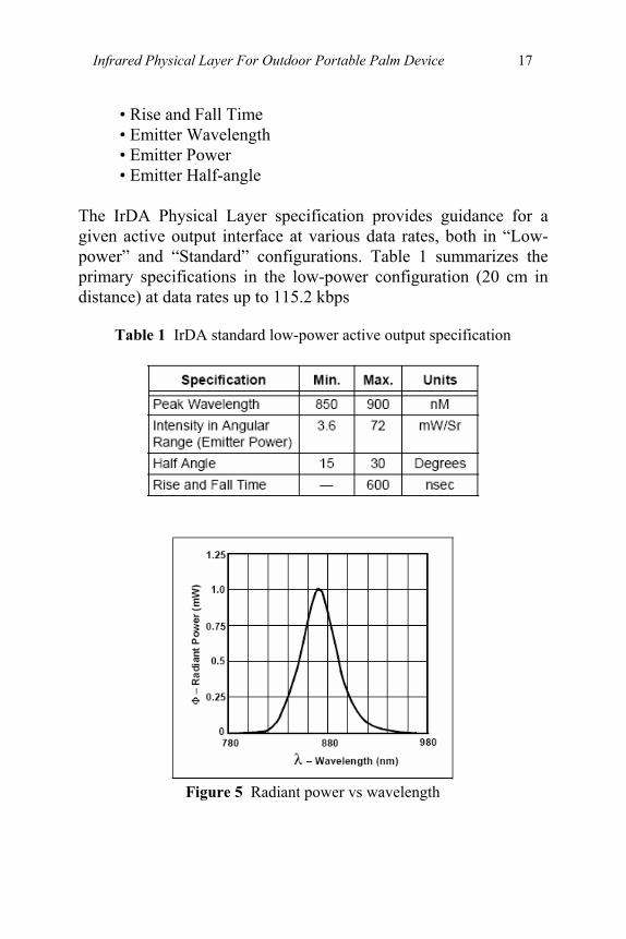
The IrDA Physical Layer specification provides guidance for a given active output interface at various data rates, both in “Low-power” and “Standard” configurations. Table 1 summarizes the primary specifications in the low-power configuration (20 cm in distance) at data rates up to 115.2 kbps
Table 1 IrDA standard low-power active output specification
Figure 5 Radiant power vs wavelength

18 Advances in Free Space Optical Technology
Besides the data that state above, it is interesting to highlight the characteristic for a typical infrared emitter, from the radiant power and wavelength perspectives. Thus, figure 6 shows that a graph (radiant power versus wavelength) for a IR emitter (TSHF5400). 2.3 INFRARED DETECTOR The most common device used for detecting light energy in the IrDA standard data stream is a photodiode. Integrated IrDA standard transceivers use a photodiode as the receiver, while TVR applications commonly use a photo transistor. Photo transistors are not typically used in IrDA standard-compatible systems because of their slow speed. Photo transistors typically have ton/toff of 2 μs or more. A photo transistor may be used, however, if the data rate is limited to 9.6 kb with a pulse width of 19.5 μs. Figure 6 shows a common symbol for a photodiode
Figure 6 Photodiode
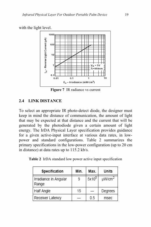
A photodiode is similar in many ways to a standard diode, with the exception of its packaging. A photodiode is packaged in such a way as to allow light to strike the PN junction. In infrared applications, it is common practice to apply a reverse bias to the device. Refer to Figure 7 for a characteristic curve of a reverse biased photodiode. There will be a reverse current that will vary
Infrared Physical Layer For Outdoor Portable Palm Device 19
with the light level.
Figure 7 IR radiance vs current
2.4 LINK DISTANCE To select an appropriate IR photo-detect diode, the designer must keep in mind the distance of communication, the amount of light that may be expected at that distance and the current that will be generated by the photodiode given a certain amount of light energy. The IrDA Physical Layer specification provides guidance for a given active-input interface at various data rates, in low-power and standard configurations. Table 2 summarizes the primary specifications in the low-power configuration (up to 20 cm in distance) at data rates up to 115.2 kb/s.
Table 2 IrDA standard low power active input specification
20 Advances in Free Space Optical Technology
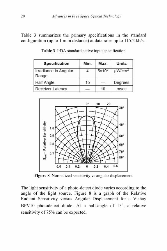
Table 3 summarizes the primary specifications in the standard configuration (up to 1 m in distance) at data rates up to 115.2 kb/s.
Table 3 IrDA standard active input specification
Figure 8 Normalized sensitivity vs angular displacement
The light sensitivity of a photo-detect diode varies according to the angle of the light source. Figure 8 is a graph of the Relative Radiant Sensitivity versus Angular Displacement for a Vishay BPV10 photodetect diode. At a half-angle of 15°, a relative sensitivity of 75% can be expected.
Infrared Physical Layer For Outdoor Portable Palm Device 21
2.5 INCREASING THE LINK DISTANCE Finally, more than one meter may be required for IR communication in some applications, even though the physical layer of the IrDA standard configuration is built around this distance. Let's take an example where an application needs to communicate with a standard device, like a Palm™ PDA, at an extended distance. Since the power emitted by the Palm IR driver is fixed, one approach would be to ensure that the sensitivity of the receiver is sufficient to support the available light intensity. Increasing this sensitivity by a factor of 4 would only double the distance to 2 meters. The receiver cost and complexity will therefore increase much faster than the increase in distance. As mentioned in the previous section, two or more photodetector diodes can be connected in parallel to achieve a higher current output. Such an increase in sensitivity takes care of one-half of the link, but data must be sent back to the Palm PDA as well.
Increasing the emitter power by a factor of 4 would also increase the link distance to 2 meters. This approach has limited potential because the emitter power must be limited for eye safety reasons. The pupil of the human eye will not react to IR light and the instinct to look away is not triggered. A single-point IR source of greater than 200 mW/Sr at 1 meter should be avoided for this reason.
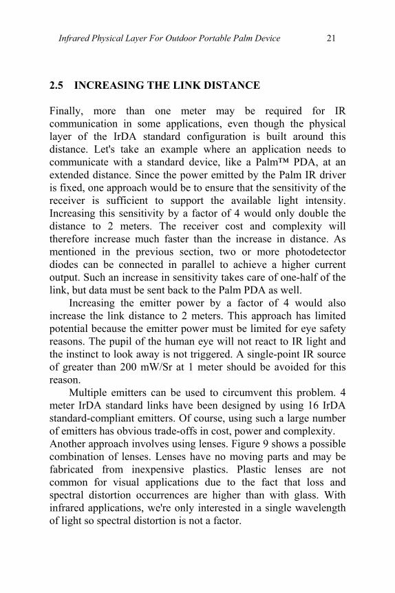
Multiple emitters can be used to circumvent this problem. 4 meter IrDA standard links have been designed by using 16 IrDA standard-compliant emitters. Of course, using such a large number of emitters has obvious trade-offs in cost, power and complexity. Another approach involves using lenses. Figure 9 shows a possible combination of lenses. Lenses have no moving parts and may be fabricated from inexpensive plastics. Plastic lenses are not common for visual applications due to the fact that loss and spectral distortion occurrences are higher than with glass. With infrared applications, we're only interested in a single wavelength of light so spectral distortion is not a factor.
22 Advances in Free Space Optical Technology
Figure 9 Using a lens to increase distance
In practice, it's more common to be compatible with a standard device (e.g., Palm PDA), so one lens on the photo-diode (detector) side will suffice. If compatibility with a standard device is not an issue, links on the order of tens of meters can easily be achieved by implementing lenses on both sides 2.6 CONCLUSION Whether designing to the IrDA standard or developing custom interfaces, the fundamentals of the infrared physical layer are straightforward, since the behavior of IR is easy to predict. The system designer can use an integrated transceiver or select low-cost, off-the-shelf components to implement an effective IR port, once the Link Budget and application requirements are understood.
REFERENCES [1]
[2] [3]
Infrared Data Association Serial Infrared Physical Layer Specification, Version 1.4, May, 2001. “High Speed IR Emitting Diode in φ 5 mm (T-1¾) Package”, TSHF5400 Data Sheet, Vishay Semiconductors, 1999. “Silicon PIN Photodiode”, BPV10 Data Sheet, Vishay Semiconductors, 1999.

23
3
INTER-SATELLITE OPTICAL WIRELESS SYSTEM
Abu Bakar Mohamad Siti Noorfarawahidatun Lela
Amir Masood Khalid
3.1 INTRODUCTION Nowadays, the usage of Optical fibers and optical devices are evolved. Optical system has been used in many applications including space communication, which is satellite communication system. Laser technology is one of the advance optical technologies on satellite communication that is using optical wireless system. This chapter will discuss about the laser’s application in satellite and how it works. Space-based, free-space optical communications is a concept that has been around for many years. In the last few years, however, there has been impressive activity to bring the concept to fruition in civilian and government non-classified projects. Today's market for space-based optical communications is primarily inter-satellite links (ISLs) which are the main focus of this chapter. There is also a place for high data rate (many Gbps) space-earth links, though propagation effects due to the atmosphere and weather make this a much more difficult link.
Laser satellite communication (LSC) which is an optical wireless system, uses free space as a propagation medium for various applications such as inter-satellite communication or satellite network. An LSC system includes a laser transmitter and an optical receiver. Space to space crosslink’s will afford
24 Advances in Free Space Optical Technology
information transfer to even the most remote site on earth without the expense of intermediate ground relay stations. Laser crosslink will enable this transfer of data between satellites at rates compatible with the ground fiber networks. This is an exciting era for space laser communications. The receiver configurations of satellite have improved with advanced technique in the area of silicon avalanche photodiodes (APDs) and fiber preamplifiers [1]. 3.2 WHAT IS SATELLITE? Before we go to the main topic that needs to discuss, the satellite properties will be described briefly. A satellite is an object that orbits or revolves around another object in space. Satellite communication systems were originally developed to provide long-distance telephone service. In the late 1960s, a 500 kg satellite in geostationary earth orbit (GEO) had been launched, with a capacity of 5000 telephone circuits. The basic component of a communications satellite is a receiver-transmitter combination called a transponder. A satellite stays in orbit because the gravitational pull of the earth is balanced by the centripetal force of the revolving satellite. Satellite orbits about the earth are either circular or elliptical.
Satellite segments are divided into two important segments which is Space segment (Payload and Platform) and Ground segment (Mission Control Station). Satellite is control by earth station known as Telemetry, Tracking And Commanding (TT&C).The Space segment is contains the transponder and antennas while Ground segment contains the receiver, transmitter and antennas.[3]

Inter-Satellite Optical Wireless System 25
Figure 1 Satellite Segment [3]
3.3 LASER COMMUNICATION Inter-satellite communications is used primarily for "networking" a constellation of satellites at data rates up to many Gbps or for data relay purposes from tens of Mbps up to Gbps. These Inter-satellite Laser ISLs can be between all the various orbits that one might consider: low earth orbit (LEO), medium earth orbit (MEO), highly elliptical orbit (HEO), and geosynchronous earth orbit (GEO). Free space optical communication is based on the use of lasers as signal carriers and is considered to be one of the key technologies for realizing an ultra-high speed large- capacity aerospace communication. Because of the advantages of optical systems related earlier, Japanese, European and U.S. researchers are investigating optical space-earth links from LEO as well as the far reaches of outer space.
The first laser communication experiment between a satellite and a ground station was conducted by the Communication Research Laboratory (CRL) using the Engineering Test Satellite (ETS-VI). The satellite was launched into a high-elliptical orbit in 1994, and the laser communication experiment was performed using a 35,000 Km link between the satellite and the ground
26 Advances in Free Space Optical Technology
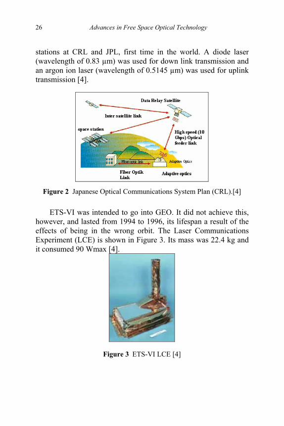
stations at CRL and JPL, first time in the world. A diode laser (wavelength of 0.83 µm) was used for down link transmission and an argon ion laser (wavelength of 0.5145 µm) was used for uplink transmission [4].
Figure 2 Japanese Optical Communications System Plan (CRL).[4]
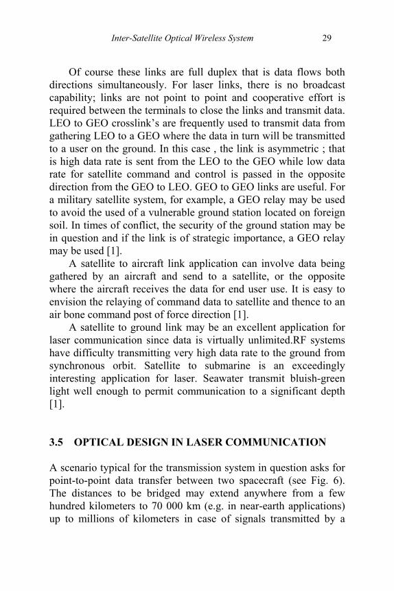
ETS-VI was intended to go into GEO. It did not achieve this, however, and lasted from 1994 to 1996, its lifespan a result of the effects of being in the wrong orbit. The Laser Communications Experiment (LCE) is shown in Figure 3. Its mass was 22.4 kg and it consumed 90 Wmax [4].
Figure 3 ETS-VI LCE [4]

Inter-Satellite Optical Wireless System 27
3.4 ADVANTAGES AND APPLICATION Laser communication offer many advantages over radio frequency (RF) systems. Most of the differences between laser communication and RF in satellite arise from very large difference in wavelength. RF wavelength is thousands of times longer than those at optical frequencies. This high ratio of wavelength leads to some interesting differences in the two systems. First, the beamwidth attainable with the laser communication system is narrower than that of the RF system by the same ratio at the same antennas diameters (the telescope of the laser communication system is frequently referred to as an antenna). For the given transmitter power level, the laser beam is brighter at the receiver by square of this ratio due to the very narrow beam that exists the transmit telescope. System comparisons reveal these advantages of laser communication over RF;
• Smaller antenna size • Lower weight, usually significant • Lower power • Minimal integration on the satellite.
Last but very important, laser communication is capable of much higher data rates than RF, again by virtue of that same wavelength (frequency ) ratio [1].
There are number of application for which laser communication is well suited inter-satellite. Laser will never totally replace RF system for space to ground communications where the message must be sent from space to ground, ground to space. The reason for this is of course that laser signals do not readily pass through clouds [1].

28 Advances in Free Space Optical Technology
Figure 4 Laser communication [6]
Figure 4 shows that laser communicate inter-satellite. The laser does not send to ground, but from one satellite to others (inter-satellite). The applications for laser communication in satellite is divide into four distinct laser communication categories , satellite crosslink’s, satellite to air or ground terminals, submarine laser communication, and deep space links.
Satellite crosslink’s are communication links in space and may be from LEO to LEO, LEO to GEO or from GEO to GEO.
Figure 5 Type of Satellite [3]
Inter-Satellite Optical Wireless System 29
Of course these links are full duplex that is data flows both directions simultaneously. For laser links, there is no broadcast capability; links are not point to point and cooperative effort is required between the terminals to close the links and transmit data. LEO to GEO crosslink’s are frequently used to transmit data from gathering LEO to a GEO where the data in turn will be transmitted to a user on the ground. In this case , the link is asymmetric ; that is high data rate is sent from the LEO to the GEO while low data rate for satellite command and control is passed in the opposite direction from the GEO to LEO. GEO to GEO links are useful. For a military satellite system, for example, a GEO relay may be used to avoid the used of a vulnerable ground station located on foreign soil. In times of conflict, the security of the ground station may be in question and if the link is of strategic importance, a GEO relay may be used [1].
A satellite to aircraft link application can involve data being gathered by an aircraft and send to a satellite, or the opposite where the aircraft receives the data for end user use. It is easy to envision the relaying of command data to satellite and thence to an air bone command post of force direction [1].
A satellite to ground link may be an excellent application for laser communication since data is virtually unlimited.RF systems have difficulty transmitting very high data rate to the ground from synchronous orbit. Satellite to submarine is an exceedingly interesting application for laser. Seawater transmit bluish-green light well enough to permit communication to a significant depth [1]. 3.5 OPTICAL DESIGN IN LASER COMMUNICATION A scenario typical for the transmission system in question asks for point-to-point data transfer between two spacecraft (see Fig. 6). The distances to be bridged may extend anywhere from a few hundred kilometers to 70 000 km (e.g. in near-earth applications) up to millions of kilometers in case of signals transmitted by a

30 Advances in Free Space Optical Technology
space probe.4) Today the data rates in mind range from several hundred kbit/s to some 10 Gbit/s. Terminals for optical communication in space are mostly designed for bi-directional links, at least concerning the optical tracking function. They comprise both a transmitter and a receiver that generally share the optical antenna. Another peculiarity is the necessity of beam steering (or pointing) capability with sub-microradian angular resolution and possibly with an angular coverage exceeding a hemisphere [1].
Figure 6 A scenario of laser use in space [2]
These requirements lead to a transceiver block diagram as shown in Fig. 7. The light source S is a laser, preferably operating in a single transverse mode in order to achieve the highest possible antenna gain. If the laser operates continuously or in a pulsed mode producing a periodic pulse train, an external modulator (M) is utilized to impress the data signal onto the beam. Alternatively, internal modulation may be employed with some lasers.

Inter-Satellite Optical Wireless System 31
Figure 7 Block diagram of optical transceiver for space-to-space links [2]
The modulated beam passes an optical duplexer (DUP) and a fine pointing assembly (FPA) before it enters telescope acting as transmit antenna (ANT). The telescope increases the beam diameter and thus reduces the beam divergence. A coarse pointing assembly (CPA) provides for steering the antenna. The received radiation also passes the antenna and the fine pointing assembly, and is then directed to the receive part of the terminal with the aid of the duplexer. A beam splitter (BS) directs one part of the received beam to the data detector (DD) for demodulation and further signal processing in the data electronics unit (DE). Another part of the received power is used for controlling the fine and coarse pointing mechanisms in such a way that the acquisition and tracking detector (ATD) is always hit centrally. A point-ahead assembly (PAA) has to be inserted in either the transmit path or the receive path to allow electronic control of the internal angular alignment between transmission and reception [1].
It should be stressed that the block diagram of Fig. 7 shows only a basic outline and that it may be modified in several respects. Among such modifications are:
32 Advances in Free Space Optical Technology
• the provision of separate laser sources to generate extra beams for acquisition and for tracking (beacon lasers),
• separate antennas for the outgoing and the incoming beam, • means to deliberately increase the divergence of the beam
used as beacon in order to illuminate the opposite terminal during the acquisition process,
• the provision of separate photodetectors for acquisition and for tracking, or the use of a single photodetector for data detection, acquisition, and tracking,
• the installation of an optical booster amplifier to increase the output power. In any case, the task of engineering a laser terminal may be divided into three major complexes, namely – one covering the data transmission aspects,
• one providing for pointing, acquiring and tracking (PAT) the very narrow laser beams, and one of designing space-qualifiable optomechanical structures and proper interfacing with the spacecraft platform. While each of them requires a sophisticated concept, it should be stressed here that the problems associated with PAT are generally underestimated [1].
3.6 APPLICATION SCENARIO One of the first scenarios considered was a bidirectional, symmetric link between two geostationary satellites (GEOs). The orbital distance between the GEO satellites may lie anywhere between a few degrees and some 120°, corresponding to distances between a few thousand kilometers and 75 000 km (see Fig. 8a).
Inter-Satellite Optical Wireless System 33
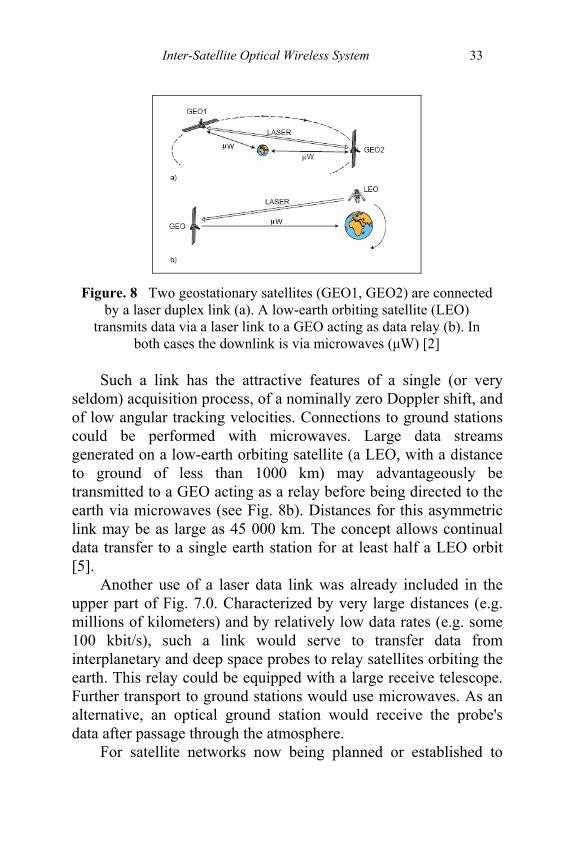
Figure. 8 Two geostationary satellites (GEO1, GEO2) are connected
by a laser duplex link (a). A low-earth orbiting satellite (LEO) transmits data via a laser link to a GEO acting as data relay (b). In
both cases the downlink is via microwaves (μW) [2]
Such a link has the attractive features of a single (or very seldom) acquisition process, of a nominally zero Doppler shift, and of low angular tracking velocities. Connections to ground stations could be performed with microwaves. Large data streams generated on a low-earth orbiting satellite (a LEO, with a distance to ground of less than 1000 km) may advantageously be transmitted to a GEO acting as a relay before being directed to the earth via microwaves (see Fig. 8b). Distances for this asymmetric link may be as large as 45 000 km. The concept allows continual data transfer to a single earth station for at least half a LEO orbit [5].
Another use of a laser data link was already included in the upper part of Fig. 7.0. Characterized by very large distances (e.g. millions of kilometers) and by relatively low data rates (e.g. some 100 kbit/s), such a link would serve to transfer data from interplanetary and deep space probes to relay satellites orbiting the earth. This relay could be equipped with a large receive telescope. Further transport to ground stations would use microwaves. As an alternative, an optical ground station would receive the probe's data after passage through the atmosphere.
For satellite networks now being planned or established to

34 Advances in Free Space Optical Technology
serve mobile data transfer, interconnectivity at very high data rates could be achieved by optical links (see Fig. 7). Frequency allocation problems - as they persist increasingly for radio links - are practically non-existent, with the merit of negligible mutual interference. Another advantage is the expected smaller mass and volume of optical terminals [2]. 3.7 CONCLUSION The usage of laser communication inter-satellite is very important in our world nowadays. There are a lot of useful applications that can be implemented by laser space. However, this laser communication is only limited to the communication between satellite in space because there is other factor that obstruct the laser from go through the cloud. But unfortunately, this is not been discussed in this chapter. The application using laser in satellite system is the advanced technologies that can give a lot of beneficial to world communication.
REFERENCES [1] [2] [3] [4] [5] [6]
Stephen G.Lambert and William L.Casey, “Laser Communications in Space”, Artech House, Boston, London, 1995. http://publik.tuwien.ac.at/files/pub- et_4235.pdf (13/2/07) Dr. Razali Ngah. “Slide Presentation Satellite Part 1”, 2006. http://www.esa.int/esapub/bulletin/bullet91/b91lutz.htm. (8/2/07) www.rpphotonics.com/free_space_optical_communications. html http://cictr.ee.psu.edu/research/ni/LaserTransformation.htm
37
4
A REVIEW ON OPTICAL WIRELESS FRONT-END RECEIVER DESIGN
Abu Sahmah Mohd Supa’at Arnidza Ramli
Sevia Mahdaliza Idrus
4.1 INTRODUCTION The growing demand for wireless broadband communications and congestion of Radio Frequency (RF) spectrum resulting on the considerable attention received by Optical wireless or Free Space Optics (FSO). In optical wireless application, the overall performance is significantly determined by the performance of the receiver. Receiver is required to have large aperture or large detection area. However, large detection area produces high photodetector capacitance which tends to reduce the bandwidth. In this chapter, the optical wireless front-end receiver designs have been reviewed where a fundamental requirement is the achievement of wide dynamic range and broad bandwidth. Through a review on reported works, the bootstrapping technique is found effectively reduces the photodetector capacitance associated with the large area photodetector. Consequently, the overall bandwidth of the system can be improved.
Over the last two decades, wireless communications have gained enormous popularity. Two transmission techniques for wireless communications have been deployed are RF and Optical Wireless [1,2]. Optical wireless or FSO has received considerable attention as an alternative to existing fiber and RF communication system. This is due to the low dispersion offers by FSO and low

Advances in Free Space Optical Technology
38
cost since no requirement in laying the optical cables compared to the optical fiber and the growing demand for wireless broadband communications, congestion and limitation on bandwidth of RF spectrum. Besides, FSO offers nice feature contrary to RF which are require no licenses, unregulated spectrum and unlimited bandwidth [2,3]. FSO systems also can function over distances of several kilometers as long as there is a clear line of sight between the source and the destination [4].
In addition to licensing and bandwidth, optical wireless has many other advantages. Optical radiation in the infrared (IR) range do not interfere with relatively nearby signals of the same nature as well as RF signals facilitating system design and resulting in a significant cost savings. Moreover, IR signals are more immune to fading than radio signals and less power loss to attenuation. Security is another advantage of infrared signal over RF. The inability to penetrate physical objects limits the coverage of infrared systems to the boundaries of the room in which the system is installed. Table 1 shows the advantages of optical wireless [2].
Table 1 Advantages of Optical Wireless Systems
Advantage Discussion Unregulated Spectrum Leads to virtually unlimited use of spectrum by
individual networks. Huge Bandwidth Great support for high-speed application No Strict Laws License free operation
Optoelectronics Technology Leads to manufacturing inexpensive components and little power consumption
Less Interference Facilitates system design and results in a significant cost savings
Fading Immunity Results in less power loss to attenuation
Reusability Enables use of same communication equipments and wavelength by nearby system
Confinement Results in simpler security measures and data encryption requirement
4.2 OPTICAL WIRELESS SYSTEM

A Review on Optical Wireless Front-End Receiver Design
39
Optical wireless links transmit information by employing an optoelectronic light modulator, typically a light emitting diode (LED). The up and down-conversion from baseband frequencies to transmission frequencies is accomplished without the use of high frequency RF circuit design techniques, but accomplished with inexpensive LEDs and photodiodes. The transmission of wireless optical refers to the transmission of modulated visible or IR beams through the air to obtain optical communications. Like fiber, FSO uses laser to transmit data, but instead of transmitting data in a glass fiber, it is transmitted through the air. It is a secure, cost-effective alternative to other wireless connectivity options.
The basic structure of an optical receiver is similar to that of a direct detection RF receiver: a low-noise preamplifier, the front-end (photodiode), feeds further amplification stages, the post-amplifier, before filtering and further signal processing [1]. In direct detection optical communication systems, the optical signal incident on the photodiode is converted into an electrical current, which is then amplified and further processed before the information carried by the optical signal can be extracted as shown in Figure 1.
Figure 1 Block diagram of direct detection channel

Advances in Free Space Optical Technology
40
4.3 OPTICAL WIRELESS RECEIVER ARCHITECTURE Optical wireless receiver consists of photodiode, preamplifier and additional signal processing circuit. Since the overall performance is determined by the performance of the receiver, thus the front-end design (photodiode and preamplifier) is the crucial element to be considered. In applications that require good sensitivity and wide bandwidth, small area which means small aperture will be deployed. Contrary to optical wireless applications, it requires large area photodiode so that it will be able to collect as much radiant optical power as possible. However, large area photodiode has large junction capacitance or photodetector capacitance according to the equation:
0 rj
d
ACl
ε ε= (1)
where A is an area of the depletion region, ε0 is a permittivity in vacuum, εr is a relative permittivity of the semiconductor and ld is a depletion region length.
This capacitance affects the bandwidth performance of the receiver where the relationship between photodiode or junction capacitance and the bandwidth is shown below:
inl
dB CRf
π21
3 = (2)
where Cin is the summation of photodiode capacitance, Cd and input capacitance of an amplifier, Cs.
The effects of capacitance can be mitigated by operating the diode with a low value of load resistor but in cost of increasing the thermal noise corresponding to the equation:
l
RnRKTBi l
4)(
2 = (3)
A Review on Optical Wireless Front-End Receiver Design
41
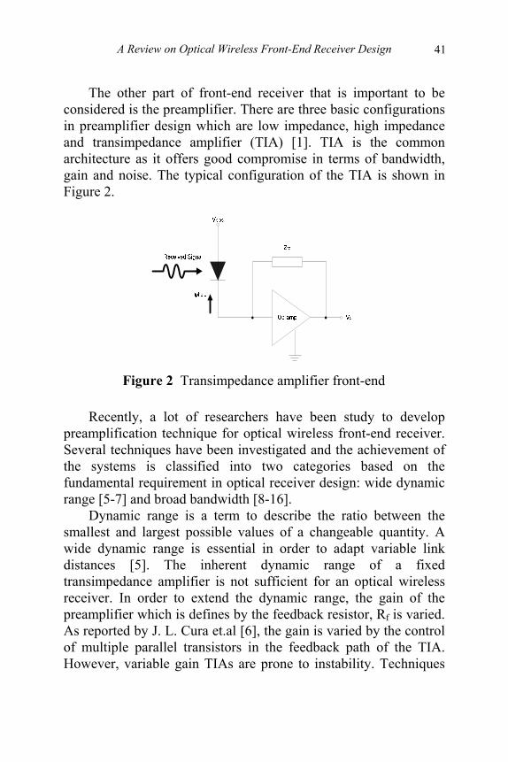
The other part of front-end receiver that is important to be considered is the preamplifier. There are three basic configurations in preamplifier design which are low impedance, high impedance and transimpedance amplifier (TIA) [1]. TIA is the common architecture as it offers good compromise in terms of bandwidth, gain and noise. The typical configuration of the TIA is shown in Figure 2.
Figure 2 Transimpedance amplifier front-end
Recently, a lot of researchers have been study to develop preamplification technique for optical wireless front-end receiver. Several techniques have been investigated and the achievement of the systems is classified into two categories based on the fundamental requirement in optical receiver design: wide dynamic range [5-7] and broad bandwidth [8-16].
Dynamic range is a term to describe the ratio between the smallest and largest possible values of a changeable quantity. A wide dynamic range is essential in order to adapt variable link distances [5]. The inherent dynamic range of a fixed transimpedance amplifier is not sufficient for an optical wireless receiver. In order to extend the dynamic range, the gain of the preamplifier which is defines by the feedback resistor, Rf is varied. As reported by J. L. Cura et.al [6], the gain is varied by the control of multiple parallel transistors in the feedback path of the TIA. However, variable gain TIAs are prone to instability. Techniques
Advances in Free Space Optical Technology
42
to overcome this problem have been reported, by adopting the current mode amplifier as the feedforward gain element where the loop gain is independent of the transimpedance gain or Rf [5,7].
Growing demand for broadband applications on optical wireless technology results on the requirement of broad bandwidth design. Many efforts to enhance the bandwidth of preamplifier were introduced. Common techniques used to increase the bandwidth are the capacitive peaking [8] and inductive shunt peaking [9,10]. These techniques have been reported for optical fiber communications. For optical wireless, the bandwidth is limits by the large photodiode capacitance associated with the large area photodiode required in order to receive the attenuated IR signal over free space. Technique to reduce the photodiode capacitance will enhance the bandwidth of optical wireless receiver. 4.4 BANDWIDTH ENHANCEMENT TECHNIQUE Presently, the bandwidth of optical wireless front-end receiver have been reported is up to 100GHz. However, the commercially available systems offer bandwidth in range of 100MHz to 2.5GHz. Several techniques to reduce the effective photodiode capacitance were previously reported. The technique proposed by C. S. Hsieh et.al [11] modifies the conventional common-gate (CG) input stage to regulated cascode (RGC) circuit. The RGC provides a low input impedance to isolate the photodiode capacitance resulting on the bandwidth independent from the pole of the preamplifier.
Other techniques reported for broad bandwidth design are bootstrapping technique. The bootstrap transimpedance amplifier was firstly reported by R. J. Green et.al. [12] which consists of four stages: the unity gain, FET buffer, cascade amplifier and buffer output. The basic bootstrapping principle is to employ additional buffer amplifier to actively charge and discharge the input capacitance as required. Consequently, the effective detector capacitance can be reduced, enabling the overall bandwidth of the circuit to be increased [13]. The bootstrap configuration is
A Review on Optical Wireless Front-End Receiver Design
43
preferred because it offers the reduction on the photodetector capacitance which is the main limiting factor for the bandwidth of optical wireless front-end receiver.
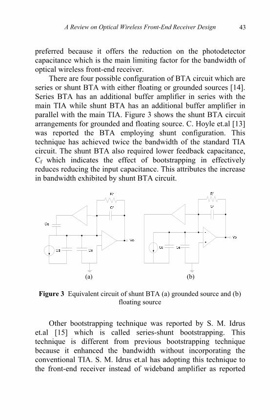
There are four possible configuration of BTA circuit which are series or shunt BTA with either floating or grounded sources [14]. Series BTA has an additional buffer amplifier in series with the main TIA while shunt BTA has an additional buffer amplifier in parallel with the main TIA. Figure 3 shows the shunt BTA circuit arrangements for grounded and floating source. C. Hoyle et.al [13] was reported the BTA employing shunt configuration. This technique has achieved twice the bandwidth of the standard TIA circuit. The shunt BTA also required lower feedback capacitance, Cf which indicates the effect of bootstrapping in effectively reduces reducing the input capacitance. This attributes the increase in bandwidth exhibited by shunt BTA circuit.
(a) (b)
Figure 3 Equivalent circuit of shunt BTA (a) grounded source and (b)
floating source
Other bootstrapping technique was reported by S. M. Idrus
et.al [15] which is called series-shunt bootstrapping. This technique is different from previous bootstrapping technique because it enhanced the bandwidth without incorporating the conventional TIA. S. M. Idrus et.al has adopting this technique to the front-end receiver instead of wideband amplifier as reported

Advances in Free Space Optical Technology
44
previously by F. Centrulli et.al [16]. The new bootstrap configuration has exploits the series-shunt positive capacitive feedback to compensate the pole-splitting action at base-collector capacitance, Cµ. As reported, the series-shunt bootstrap circuit has boosted the bandwidth up to 1GHz. This compensation technique commonly applied for buffered differential amplifier and has been used in very large bandwidth amplifiers. 4.5 CONCLUSION Several techniques to achieve the fundamental requirement in optical wireless receiver design were discussed. Variable gain TIAs were commonly applied for wide dynamic range optical receiver while techniques to reduce detector input capacitance is essential in order to obtain broad bandwidth design. Previous works show that the bootstrapping techniques have extended the bandwidth of the front-end optical wireless receiver. The important key is an ability to reduce the effective detector input capacitance which is the main limiting factor for bandwidth performance of such systems.
REFERENCES [1] [2] [3]
R. R. Iniguez, S. M. Idrus, and Z. Sun, "Optical Wireless Communications: IR for Wireless Connectivity," Auerbach Publications, Taylor and Francis Books Inc, New York, 2007. ISBN: 0849372097. A. Mahdy and J. S. Deogun, "Wireless Optical Communications: A Survey", Wireless Communications and Networking Conference (WCNC 2004), vol.4, pp.2399-2404, 2004. J. M. Kahn and J. R. Barry, "Wireless Infrared Communications", Proceedings of the IEEE, vol. 85, no.2,
A Review on Optical Wireless Front-End Receiver Design
45
[4] [5] [6] [7] [8] [9] [10] [11] [12]
pp. 265-278, 1997. K. Wakamori, K. Kazaura and I. Oka, "Experiment on Regional Broadband Network using Free-Space-Optical Communication Systems", Journal of Lightwave Technology, vol.25, no.11, pp. 3265-3273, 2007. K. Phang and D. A. Johns, "A CMOS Optical Preamplifier for Wireless Infrared Communications", IEEE Transactions on Circuits and Systems II: Analog and Digital Signal Processing, vol. 46, no.7, pp. 852-859. 1999. J. L. Cura and R. L. Aguiar, "Dynamic Range Boosting for Wireless Optical Receivers", IEEE International Symposium on Circuits and Systems, vol.4, pp. 686-689, 2001. R. Y. Chen, T. S. Hung and C.Y. Hung, "A CMOS Infrared Wireless Optical Receiver Front-End with a Variable-Gain Fully-Differential Transimpedance Amplifier", IEEE Transactions on Consumer Electronics, vol. 51, no.2, pp. 424-428, 2005. B. Analui and A. Hajimiri, "Bandwidth Enhancement for Transimpedance Amplifier", IEEE Journal of Solid-State Circuits, vol. 39, no.8, pp. 1263-1270, 2004. Y. H. Oh and S. G. Lee, "An Inductance Enhancement Technique and Its Application to a Shunt-Peaked 2.5Gb/s Transimpedance Amplifier Design", IEEE Transactions on Circuits and Systems II: Express Briefs, vol. 51, no. 11, pp. 624-628, 2004. Z. Lu, K. S. Yeo, J. Ma, M. A. Do, W. M. Lim and X. Chen, "Broad-Band Design Techniques for Transimpedance Amplifiers", IEEE Transactions on Circuits and Systems I: Regular Papers, vol. 54, no. 3, pp. 590-599, 2007 C. S. Hsieh and H. Y. Huang, "A High-Bandwidth Wireless Infrared Receiver with Feedforward Offset Extractor", Proceedings of the International Symposium on Circuits and Systems, vol.1, pp.73-76, 2003 R. J. Green and M. G. McNeill, "Bootstrap Transimpedance Amplifier: A New Configuration", IEE Proceedings, vol.

Advances in Free Space Optical Technology
46
[13] [14] [15] [16] [18]
136, no.2, pp. 57-61, 1989. C. Hoyle and A. Peyton, "Shunt Bootstrapping Technique to Improve Bandwidth of Transimpedance Amplifiers", Electronics Letters, vol. 35, no.5, pp. 369-370. 1999. S. M. Idrus, N. Ngajikin, N. N. N. A. Malik and S. I. A. Aziz, "Performance Analysis of Bootstrap Transimpedance Amplifier for Large Windows Optical Wireless Receiver", International RF and Microwave Conference Proceedings, pp. 416-420, 2006. S. M.Idrus, S. S. Rais & A. S. Supaat, ‘Analysis of Shunt Bootstrap Transimpedance Amplifier For Large Windows Optical Wireless Receiver’, International Joint Conference TSSA & WSSA 2006, Bandung Indonesia, 8-9 December 2006. F. Centurelli, R. Luzzi, M. Olivieri and A. Trifiletti, "A Bootstrap Technique for Wideband Amplifiers", IEEE Transactions on Circuits and Systems, vol. 49, no.10, pp.1474-1480, 2002. E. J. Fairlie, "Photodiode Preamplifier Systems: Low Noise Positive Feedback", Applied Optics, vol. 16, pp. 385-392. 1977.
Shunt Bootstrap Transimpedance Amplifier for Optical Wireless Receiver 47
5
SHUNT BOOTSTRAP TRANSIMPEDANCE AMPLIFIER FOR
OPTICAL WIRELESS RECEIVER Abu Sahmah Mohd Supa’at
Sevia Mahdaliza Idrus Siti Sara Rais Arnidza Ramli
5.1 INTRODUCTION Due to optical wireless link power budget considerations, the receiver is required to have a large collection area. Typical large photodetection area commercial wireless photodetectors has capacitance are around 100-300pF compared to 50pF in fiber link. Hence, techniques to reduce the effective detector capacitance are required in order to achieve a low noise and wide bandwidth design. The bootstrap transimpedance amplifications (BTA) technique offers the usual advantages of the transimpedance amplifier together with an effective capacitance reduction technique for optical wireless detector. In this chapter, analysis on the shunt-BTA for input capacitance reduction will be reported. Significant bandwidths enhancement was achieved by shunt-BTA compared to transimpedance front-end.
Optical wireless link operates in relatively high noise environments as a result of ambient light levels with limited transmitter power due to safety considerations. Thus, the performance of the optical receiver has a significant impact on the overall system performance. Due to link budget considerations, the
48 Advances in Optical Free Space Technology
receiver is required to have a large collection area, which may be achieved through the use of an optical concentrator (effectively noiseless gain) [1], a large area photodetector or a combination of the two. Since indoor optical transceivers are intended for mass computer and peripheral markets, the receiver design is extremely cost sensitive, which can make sophisticated optical systems unattractive.
The optical wireless receiver system are, essentially consists of the photodetector plus a pre-amplifier with possibly additional signal processing circuit. Therefore, it is necessary to consider the properties of the photodetector in the context of the associated circuitry combined in the receiver. It is essential that the detector perform efficiently with the following amplifying and signal processing. However for all optical receivers, fiber and wireless alike, their sensitivity is a trade off between photodiode parameters and circuit noise. Applications that require a good sensitivity and a broad bandwidth will invariably use a small area photodiode, which means that the aperture is small. Receivers for long distance point-to-point fiber systems generally fall into this category. Conversely, for wireless optic applications require a large aperture and so must use a large area photodiode, where upon sensitivity and speeds are reduced [2]. As expected the sensitivity improves (i.e., reduces in numerical value) as the photodiode area reduces because of the correspondingly lower capacitance. However, small area photodiodes incur a greater coupling loss due to the small aperture they present to the incoming beam, so a careful trade off between these factors is necessary to optimize the overall performance. 5.2 OPTICAL FRONT-END RECEIVER An optical receiver’s front-end design can be usually grouped into these pre-amplification techniques: low-impedance voltage

Shunt Bootstrap Transimpedance Amplifier for Optical Wireless Receiver 49
amplifier; a high impedance amplifier; and a trans-impedance amplifier. Any of the configurations can be built using contemporary electronics devices i.e. bipolar junction transistors (BJT), field effect transistors (FET), or high electron mobility transistors (CMOS). The receiver performance that is achieved will depend on the devices and design techniques used. The current from the detector is usually converted to a voltage before the signal is amplified. The current to voltage converter is perhaps the most important section of any optical receiver circuit. An improperly designed circuit will often suffer from excessive noise associated with ambient light focused onto the detector. To get the most from the optical signal through the air system, the right front-end circuitry design must be considered.
An equivalent circuit of a PN junction photodetector with and input the preamplifier stage is shown in Figure 1. The diode shunt resistance, Rd, in a reverse biased junction is usually very large (>106Ω), compared to the load impedance Rl, and can be neglected. The resistance Rs represents ohmic losses in the bulk p and n regions adjacent to the junction, and Cd represent the dynamic photodiode capacitance.
Figure 1 Simple equivalent circuit for PN or PIN photodetector The design of the front-end requires a trade-off between speed
and sensitivity. Since using a large load resistor RL can increase the input voltage to the preamplifier, high impedance front-end is often used. Furthermore, a large RL reduces the thermal noise and
50 Advances in Optical Free Space Technology
improves the receiver sensitivity. The main drawback of high impedance front-end is its low bandwidth given by
BW= (2πRLCin )-1, (1)
where Rs « RL is assumed and total capacitance, Cin includes the contributions from the photodiode (Cd) and the transistor used for amplification (Ca). A high-impedance front-end cannot be used if BW is considerably less than the bit rate. An equalizer is sometime used to increase the bandwidth. The equalizer acts as a filter that attenuates low-frequency components of the signal more than the high-frequency components, thereby effectively increase the front-end bandwidth. If the receiver sensitivity is not of concern, one can simply decrease RL to increase the bandwidth, resulting in a low impedance front-end. Transimpedance front ends provide a configuration that has high sensitivity together with a large bandwidth. Its dynamic range is also improved compared with high-impedance front ends.
Optical fiber receivers mostly employ a transimpedance design because this affords a good compromise between bandwidth and noise, both of which are influenced by the capacitance of the photodiode. However, the large area photodiodes that are essential in optical wireless require designs that are significantly more tolerant of high device capacitances. A design that is will use in optical wireless receivers combines transimpedance with bootstrapping, the latter of which reduces the effective photodiode capacitance as perceived by signals. This allows a relatively high feedback impedance to be used, which reduces noise and increases sensitivity.

Shunt Bootstrap Transimpedance Amplifier for Optical Wireless Receiver 51
5.3 BOOTSTRAPPING TECHNIQUE Due to optical wireless link power budget considerations, the receiver is required to have a large collection area. One of the main noise mechanisms in wideband preamplifiers employing large area detectors is the noise due to the low pass filter formed by the detector capacitance and the input impedance to the preamplifier. Typical large detection area of commercial optical wireless detectors has capacitance are around 100-300 pF or higher for good acceptance angle. Hence, techniques to reduce the effective detector capacitance are required in order to achieve a low noise and wide bandwidth design.
Significantly, in any photodetector application, capacitance is a major factor, which limits response time. Decreasing load resistance improves this aspect, but at the expense of sensitivity. In the subsequent amplifier, positive feedback may be used with caution. It is possible to combine the effective stability of negative feedback with the desirable features of the positive type. Beside that, the input capacitance in effect constitutes part of the feedback network of the op-amp and hence reduces the available loop gain at high frequencies. In some cases a high input capacitance can cause the circuit to have a lightly damped or unstable dynamic response. Lag compensation by simply adding feedback capacitance is generally used to guarantee stability, however this approach does not permit the full gain-bandwidth characteristic of the op-amp to be fully exploited. This is shown in Figure 2 below, where Cf represent the feedback capacitance of the amplifier.

52 Advances in Optical Free Space Technology
Figure 2 Frequency response of TIA with Cf, without Cf and the limit
case with Cin=0 & Cf=0
An alternative approach, the bootstrap transimpedance amplifier (BTA) for input capacitance reduction has been reported by [3,4] was previously intended for receiver bandwidth enhancement. This technique offers the usual advantages of the transimpedance amplifier together with an effective capacitance reduction technique for optical wireless detector mentioned above. There are four possible bootstrap configurations (series or shunt bootstrapping modes, with either floating or grounded sources), both are shown in Figure 3 (a) and (b) respectively, which can be applied to the basic circuit. The series configuration and shunt technique can be found in [5].
(a)
Cf
+
-
OUT
Bootstrap Amplifier
A1
Rf
Cd
A2(s) Vo
Id
1 2
Cs
Shunt Bootstrap Transimpedance Amplifier for Optical Wireless Receiver 53
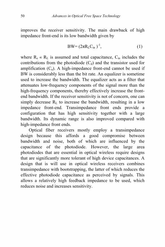
(b)
Figure 3 Equivalent circuit for BTA (a) grounded source & series BTA and (b) floating source & shunt BTA.
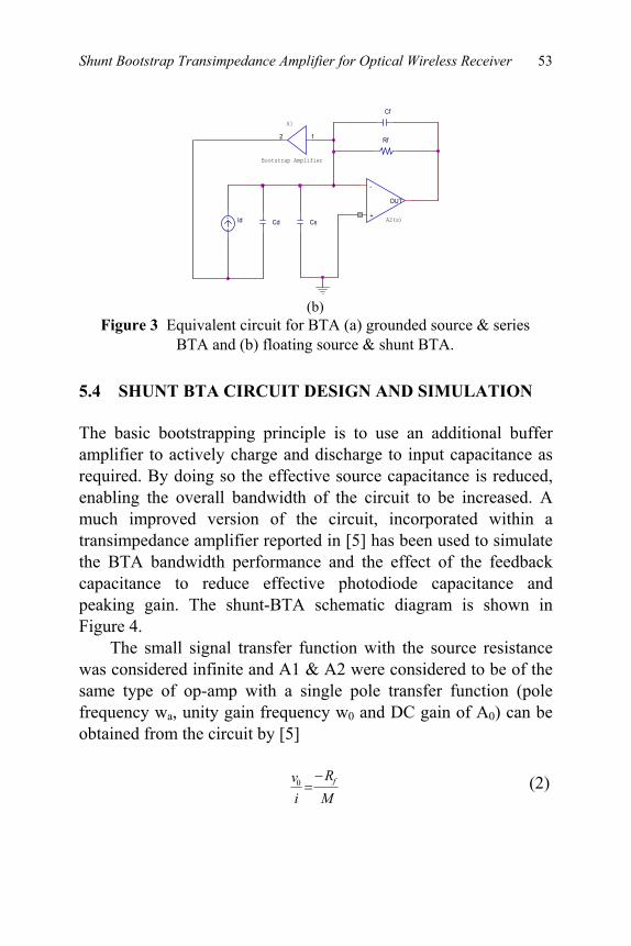
5.4 SHUNT BTA CIRCUIT DESIGN AND SIMULATION The basic bootstrapping principle is to use an additional buffer amplifier to actively charge and discharge to input capacitance as required. By doing so the effective source capacitance is reduced, enabling the overall bandwidth of the circuit to be increased. A much improved version of the circuit, incorporated within a transimpedance amplifier reported in [5] has been used to simulate the BTA bandwidth performance and the effect of the feedback capacitance to reduce effective photodiode capacitance and peaking gain. The shunt-BTA schematic diagram is shown in Figure 4.
The small signal transfer function with the source resistance was considered infinite and A1 & A2 were considered to be of the same type of op-amp with a single pole transfer function (pole frequency wa, unity gain frequency w0 and DC gain of A0) can be obtained from the circuit by [5]
MR
iv f−=0 (2)
Cs A2(s)Id
Cf
A1
Rf
+
-
OUT
Bootstrap Amplifier
Cd
12
54 Advances in Optical Free Space Technology
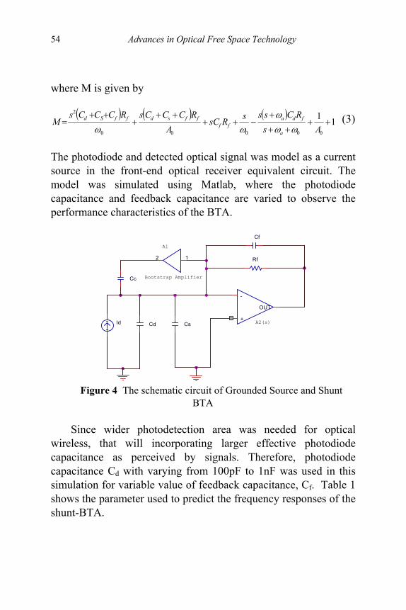
where M is given by
( ) ( ) ( )11
00000
2
++++
+−++
+++
++=
AsRCsssRsC
ARCCCsRCCCs
Ma
fdaff
ffsdffSd
ωωω
ωω (3)
The photodiode and detected optical signal was model as a current source in the front-end optical receiver equivalent circuit. The model was simulated using Matlab, where the photodiode capacitance and feedback capacitance are varied to observe the performance characteristics of the BTA.
Figure 4 The schematic circuit of Grounded Source and Shunt
BTA
Since wider photodetection area was needed for optical wireless, that will incorporating larger effective photodiode capacitance as perceived by signals. Therefore, photodiode capacitance Cd with varying from 100pF to 1nF was used in this simulation for variable value of feedback capacitance, Cf. Table 1 shows the parameter used to predict the frequency responses of the shunt-BTA.
Cf
Bootstrap Amplifier
CsId
12
Cc
+
-
OUT
A2(s)
A1
Cd
Rf

Shunt Bootstrap Transimpedance Amplifier for Optical Wireless Receiver 55
Table 1 Parameter for Grounded Source and Shunt BTA
A0 50dB Cs 20pF Cd 80pF-980pF fa 40Hz fo 4MHz Cf 1.4pF Rf 1MΩ
Figure 5 shows the frequency response of the simulated BTA
with total input capacitance, CT=100pF-1nF, feedback capacitance, Cf = 1.4pF. The peaking gain, Mp and 3dB bandwidth were plotted in Figure 6(a) and (b) respectively. By varying the Cd with fixed value of Cf, it was shown that the BW decreases and peaking gain appear. The highest 3dB BW (1.62MHz) archived by CT=300pF. While the peaking gain start to appear at this total input capacitance.
Figure 5 BTA frequency response with feedback capacitance, Cf = 1.4pF and total receiver capacitance, CT=100pF-1nF
CT = 1nF
CT = 100pF

56 Advances in Optical Free Space Technology
Bandwidth vs Total Capacitance of BTA 50dB DC gain amplifier
1
1.1
1.2
1.3
1.4
1.5
1.6
1.7
1 2 3 4 5 6 7 8 9 10x100pF(Total C)
Ban
dwid
th(M
Hz)
BTA 50dB DCgain ampl.
(a)
Peaking gain vs Total capacitance of BTA 50dB DC gain amplifier
0
5
10
15
20
25
30
35
1 2 3 4 5 6 7 8 9 10x100pF(Total C)
Pea
king
Gai
n(dB
)
BTA 50dB DCgain ampl.
(b)
Figure 6 Result of simulations corresponding to Figure 5 (a) 3dB Bandwidth (b) Peaking Gain
By varying the Cf with fixed value of Cd, the BW decreases
and peaking gain were reduced simultaneously. This is shown by Figure 7 for the effect of the feedback capacitance, which the Cf will improve system stability. From this result, Cf between 1.5pF to 2pF was chosen i.e. if we choose Cf>2pF, the bandwidth will reduce. Therefore, frequency response with varying Cf 1.5 to 2pF was plotted to see better performance of the amplifier bandwidth and stability. This is shown in Figure 8, hence the best Cf is 1.7pF that will give system stability although reduced the bandwidth

Shunt Bootstrap Transimpedance Amplifier for Optical Wireless Receiver 57
compared to Cf=1.4pF. Finally, with the improved system stability, the frequency response can be plotted as shown in Figure 9, where the very high photodiode capacitance 1nF has producing 1.49MHz
Figure 7 BTA frequency response with variable feedback
capacitance, Cf = 1.5pF-5pF and total receiver capacitance, CT=400pF
Figure 8 BTA frequency response with variable feedback capacitance, Cf = 1.5pF-2pF and total receiver capacitance, CT=400pF
Cf=1.5pF Cf=5pF
Cf = 1.5pF
Cf = 2pF

58 Advances in Optical Free Space Technology
Figure 9 BTA frequency response with varying feedback capacitance, Cf and total receiver capacitance, CT=100pF-1nF
By measuring the bandwidth for each value of varied feedback capacitance and total capacitance, CT, the comparison between the fixed feedback capacitance and the variable feedback capacitance can be plotted as shown in Figure 10. Thus in general observation, it was found that the most effective value of feedback capacitance can give wide bandwidth and produce a critically damped response.
Comparison between fixed value of Cf and varible Cf
11.11.21.31.41.51.61.7
1 2 3 4 5 6 7 8 9 10x100pF(Total C)
Ban
dwid
th(M
Hz)
fixed Cfvariable Cf
Figure 10 BTA frequency response with varying feedback capacitance, Cf and total receiver capacitance, CT=100pF-1nF.
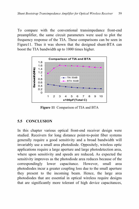
Shunt Bootstrap Transimpedance Amplifier for Optical Wireless Receiver 59
To compare with the conventional transimpedance front-end preamplifier, the same circuit parameters were used to plot the frequency response of the TIA. These comparisons can be seen in Figure11. Thus it was shown that the designed shunt-BTA can boost the TIA bandwidth up to 1000 times higher.
Comparison of TIA and BTA
00.20.40.60.8
11.21.41.61.8
1 2 3 4 5 6 7 8 9 10x100pF(Total C)
Ban
dwid
th(M
Hz)
TIA 50dBBTA 50dB
Figure 11 Comparison of TIA and BTA
5.5 CONCLUSION In this chapter various optical front-end receiver design were studied. Receivers for long distance point-to-point fiber systems generally require a good sensitivity and a broad bandwidth will invariably use a small area photodiode. Oppositely, wireless optic applications require a large aperture and large photodetection area, where upon sensitivity and speeds are reduced. As expected the sensitivity improves as the photodiode area reduces because of the correspondingly lower capacitance. However, small area photodiodes incur a greater coupling loss due to the small aperture they present to the incoming beam. Hence, the large area photodiodes that are essential in optical wireless require designs that are significantly more tolerant of high device capacitances,
60 Advances in Optical Free Space Technology
which the bootstrapping techniques reduces the effective photodiode capacitance as perceived by signals.
This chapter has presented an overview of basic bootstrap configurations for the standard transimpedance amplifier. The circuit was simulated and frequency responses of the grounded source and shunt bootstrap transimpedance amplifier were presented. The design has presented an example of a shunt bootstrap amplifier based on two operational amplifiers of the same type and shows that the techniques can be used to realized a faster response than is possible with a single amplifier alone. This method may provide a viable design option for applications with high gain and requiring a wide bandwidth.
REFERENCES [1] [2] [3] [4] [5] [6]
R. Ramirez-Iniguez and R. J. Green, "Totally Internally Reflecting Optical Antennas for Wireless IR Communication," IEEE Wireless Design Conference, London, UK, pp. 129-132, May 2002. McCullagh and D.R. Wisely 155Mbit/s Optical Wireless Link using a Bootstrapped Silicon APD Receiver’, Electronics Letter, 3rd March 1994 Vol. 30 No. 5, pg 430-432. R. J. Green, “Experimental Performance of a Bandwidth Enhancement Technique for Photodetectors”. Electronics Letters, Vol. 22 (3), pp. 153-55, Jan. 1986. R. J. Green and M. G. McNeill, “Bootstrap Transimpedance Amplifier: A New Configuration”. IEE Proc. Pt G, Vol. 136 (2), pp. 57-61, April 1989. C. Hoyle A. Peyton ‘Bootstrapping Techniques to Improve the Bandwidth of Transimpedance Amplifiers’, IEEE Proceeding, pg 7/1-7/6. D.J.T. Heatley and Ian Neild, “Optical Wireless: The

Shunt Bootstrap Transimpedance Amplifier for Optical Wireless Receiver 61
[7]
Promise and The Reality” IEEE Proc. pg 1/2 -1/6. S.M.Idrus, R.Ramierez-Inguiez & R.J.Green, ‘Receiver Amplifiers for Optical Wireless Communication System’, 3rd PREP, University Of Keele, UK, p19-20, Apr. 2001.
62
6
LASER NONLINEARITY REDUCTION MODEL USING TAYLOR SERIES EXPANSION FOR FREE SPACE
OPTICAL COMMUNICATION SYSTEM Sevia Mahdaliza Idrus Ahmed Bashir Maiteeg
Hilman Harun
6.1 INTRODUCTION One primary limitation on the performance of the optical transceiver is the nonlinearity of the laser transmitter, which produces intermodulation distortions and necessitates various compromises between modulation depth, channel spacing and types of modulation scheme, leading to degraded bandwidth efficiency. Nonlinearity of a directly modulated laser diode imposes limitations in the performance of the optical communication systems. Many laser linearization techniques involve the use of duplicate lasers or optical modulators, and those, which attempt to create physical structures within the optical modulators, and lasers can obviously increase the cost relative to ordinary optical transmitters. Fundamentally, linearization techniques can be divided into one of the following categories: feedforward, feedback, precorrective distortion. In this chapter a new free space optical link non-linearity correction system has been introduced employing the Feedforward Linearization technique, so called Optical Free Space Feedforward Linearization System (OFFLS). The system was modeled by Taylor series and the results of the simulations have shown a significant reduction in
Laser Nonlinearity Reduction Model Using Taylor Series Expansion For Free Space Optical Communication System
63
the 3th and 5th order intermodulation distortion products (IMD) by 30 dB over 2GHz bandwidth.
Free Space Optics (FSO), the industry term for “Cable-free Optical Communication Systems”, is a line-of-sight optical technology in which voice; video and data are sent through the air (free space) on low-power light beams at speeds of megabytes or even gigabytes per second. A free-space optical link consists of two optical transceivers accurately aligned to each other with a clear line of sight. Typically, the optical transceivers are mounted on building rooftops or behind windows. These transceivers consist of a laser transmitter and a detector to provide full duplex capability. It works over distances of several hundred meters to a few kilometers.
One of the major concerns with FSO and any communications system is the issue of noise and interference. The general definition of what makes up noise, can encompass any signal present at an output other than the one desired. Sources of noise are numerous, ranging from the conventional sources, such as thermal and shot noise. Though unwanted, interference from other signals, whether it is in the form of harmonic distortion or intermodulation distortion, arising from non-linearities of various components, are not classed as noise. Therefore, noise is thought of as those sources such as thermal and shot noise, whereas those associated with non-linearities are usually classed as interference or distortion and require a signal input.
Laser diodes (LDs) are often used in point-to-point free-space optical links because of their coherence, tight beam width, and narrow optical spectrum. However, they have the disadvantage that the power–current characteristic tends to be nonlinear above the threshold. Usually, the nonlinearities produced in the other system components are small in comparison with those produced in the LD. Therefore, it is only LD nonlinear distortion that is addressed here.
Intermodulation products are those that result from the combination of two or more input signals, i.e. for a two tone signal, fa and fb, the 2nd order intermodulation products (IMD2),
Advances in Free Space Optical Technology
64
would be at fb + fa and fa + fb. Similarly, the 3rd order intermodulation products (IMD3) for a two tone case would be at 2 fa + fb and 2fb+ fa. Intermodulation products will also appear at the fundamental frequencies of fa and fb.
6.2 LASER NONLINEARITY COMPENSATION TECHNIQUES
Several techniques have been used to improve the linearity of semiconductor lasers using Optoelectronic Feedback technique, Predistortion and feedforward linearization. Optoelectronic feedback [5] can be used to reduce the distortion in a same way as electronic feedback but the limitations are that the loop delay must be very small and this limits the maximum frequency of operation.
Predistortion is a simple linearization technique and utilizes a non linear device which generates distortion products that are equal in amplitude but opposite in phase compared to that of the transmitter. This results in the overall system that is much more linear. This technique has been widely used in linearizing LDs [3], laser transmitters for CATV [4] and radio over fiber systems for 0.4 – 2 GHz [5]. The predistortion circuit requires the network to be matched and adjusted to the individual laser and does not reduce non linear distortion of all orders.
Therefore, feedforward linearization is preferred. Although the circuit for the feedforward compensation is more complicated and can be difficult to implement, it seems to be the most promising technique for broadband linearization and offers a number of advantages compared to other techniques such as broadband distortion reduction at microwave frequencies, reduction in all orders of distortion can be achieved, and the non linear characteristics of the lasers do not need to be known.
In the context of RF power amplifiers, the above techniques
have been known to have the qualitative trade-offs shown in Table 1 [1]. A quantitative comparison of the various linearization
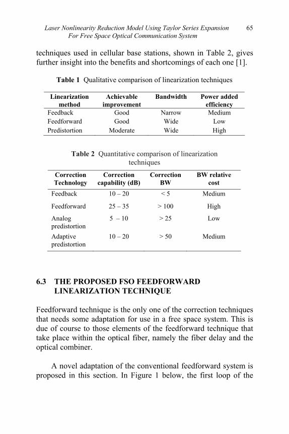
Laser Nonlinearity Reduction Model Using Taylor Series Expansion For Free Space Optical Communication System
65
techniques used in cellular base stations, shown in Table 2, gives further insight into the benefits and shortcomings of each one [1].
Table 1 Qualitative comparison of linearization techniques
Linearization method
Achievable improvement
Bandwidth Power added efficiency
Feedback Good Narrow Medium Feedforward Good Wide Low Predistortion Moderate Wide High
Table 2 Quantitative comparison of linearization
techniques
Correction Technology
Correction capability (dB)
Correction BW
BW relative cost
Feedback 10 – 20 < 5 Medium
Feedforward 25 – 35 > 100 High
Analog predistortion
5 – 10 > 25 Low
Adaptive predistortion
10 – 20 > 50 Medium
6.3 THE PROPOSED FSO FEEDFORWARD
LINEARIZATION TECHNIQUE Feedforward technique is the only one of the correction techniques that needs some adaptation for use in a free space system. This is due of course to those elements of the feedforward technique that take place within the optical fiber, namely the fiber delay and the optical combiner.
A novel adaptation of the conventional feedforward system is
proposed in this section. In Figure 1 below, the first loop of the

Advances in Free Space Optical Technology
66
free space system is the same as for the fiber system (with the exception of a beam splitter being used to divide the free space beams). However, the second loop is vastly different. In the free space system, both the main signal and error signal are transmitted and received separately. The two LDs will still have to be of slightly different wavelengths due to the fact that practically, they will be physically positioned close to each other and any coherent interference between the two signals still needs to be avoided.
This has the advantage of no chromatic dispersion (or at least so small an amount as to be insignificant) due to the optical signals travelling through free space and not fiber. This will make the timing less difficult to realize and is the first benefit to be seen of this technique.
Figure 1 Optical free space feedforward techniques
The two signals then pass through appropriate optical concentrators placed in front of their respective PD receiving units to further ensure against any coherent interference. The main path signal is then delayed for the required time before the two signals are electronically combined, with the opposite phase non-linearities (and some noise) cancelling each other out, leaving only the desired signal.
As can be seen from the above diagram, there is a need for three, rather than the standard two, receiving units. This will add to the cost of the system, however, compared to standard feedforward
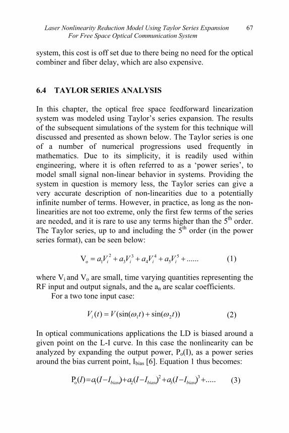
Laser Nonlinearity Reduction Model Using Taylor Series Expansion For Free Space Optical Communication System
67
system, this cost is off set due to there being no need for the optical combiner and fiber delay, which are also expensive.
6.4 TAYLOR SERIES ANALYSIS In this chapter, the optical free space feedforward linearization system was modeled using Taylor’s series expansion. The results of the subsequent simulations of the system for this technique will discussed and presented as shown below. The Taylor series is one of a number of numerical progressions used frequently in mathematics. Due to its simplicity, it is readily used within engineering, where it is often referred to as a ‘power series’, to model small signal non-linear behavior in systems. Providing the system in question is memory less, the Taylor series can give a very accurate description of non-linearities due to a potentially infinite number of terms. However, in practice, as long as the non-linearities are not too extreme, only the first few terms of the series are needed, and it is rare to use any terms higher than the 5th order. The Taylor series, up to and including the 5th order (in the power series format), can be seen below:
(1)
where Vi and Vo are small, time varying quantities representing the RF input and output signals, and the an are scalar coefficients.
For a two tone input case:
(2) In optical communications applications the LD is biased around a given point on the L-I curve. In this case the nonlinearity can be analyzed by expanding the output power, Po(I), as a power series around the bias current point, Ibias [6]. Equation 1 thus becomes:
(3)
......V 55
44
33
21o ++++= iiii VaVaVaVa
))sin()(sin()( 21 ttVtVi ωω +=
.....)()()()(P 33
221o +−+−+−= biasebiasebiase IIaIIaIIaI
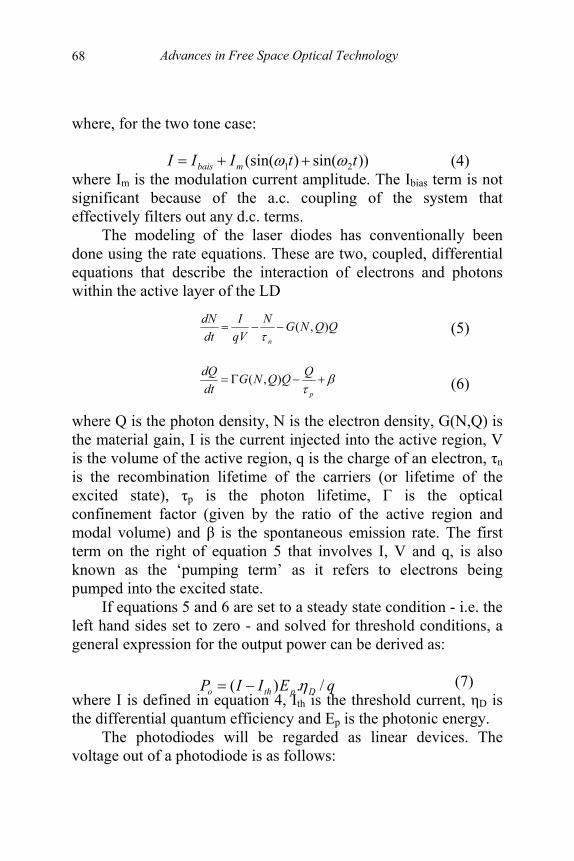
Advances in Free Space Optical Technology
68
where, for the two tone case: (4) where Im is the modulation current amplitude. The Ibias term is not significant because of the a.c. coupling of the system that effectively filters out any d.c. terms.
The modeling of the laser diodes has conventionally been done using the rate equations. These are two, coupled, differential equations that describe the interaction of electrons and photons within the active layer of the LD
(5) (6)
where Q is the photon density, N is the electron density, G(N,Q) is the material gain, I is the current injected into the active region, V is the volume of the active region, q is the charge of an electron, τn is the recombination lifetime of the carriers (or lifetime of the excited state), τp is the photon lifetime, Γ is the optical confinement factor (given by the ratio of the active region and modal volume) and β is the spontaneous emission rate. The first term on the right of equation 5 that involves I, V and q, is also known as the ‘pumping term’ as it refers to electrons being pumped into the excited state.
If equations 5 and 6 are set to a steady state condition - i.e. the left hand sides set to zero - and solved for threshold conditions, a general expression for the output power can be derived as:
(7)
where I is defined in equation 4, Ith is the threshold current, ηD is the differential quantum efficiency and Ep is the photonic energy.
The photodiodes will be regarded as linear devices. The voltage out of a photodiode is as follows:
))sin()(sin( 21 ttIII mbais ωω ++=
QQNGNqVI
dtdN
n
),(−−=τ
βτ
+−Γ=p
QQQNGdtdQ ),(
qEIIP Dptho /.)( η−=

Laser Nonlinearity Reduction Model Using Taylor Series Expansion For Free Space Optical Communication System
69
and ℜ =q. ηP/Ep (8) where R is the PD load impedance of 50Ω, Io is the dark response of the PD, which is a very small d.c. offset and hence can be ignored. Pin is the incoming signal power and is related to Po(I) subject to attenuation dependant on the distance travelled in free space (i.e. 20dB/km). R is the responsivity of the PD and is made up of the electronic charge q, the internal quantum efficiency ηP (around 0.3) and the photonic energy Ep, as defined in equation 8. Together R and Pin create the input photocurrent and is a reverse of the electrical/optical conversion process of the LD.
The two-tone input for the simulations was set with frequencies at 2GHz and 2.05GHz, with peak amplitude of 0.7V, giving a peak input current of 14mA, for a 50Ω LD load impedance. This gives a modulation index of 0.4 from the equation 9 below: (9) where Mcur is the modulation index, with Ibais set at 50mA and Ith set at 15mA. The higher is the modulation index, the greater the performance of the link in the presence of noise. 6.5 RESULTS AND DISCUSSIONS The simulations were run with both the 3rd and 5th order non-linearities included, with FFTs using commercial MATLAB software. Figure 2 and 3 are presenting the results of the simulation for the output section of the system.
Referring to Figure 2, with the output of the main receiving PD, i.e. the pre-correction case, the 3rd and 5th order non-linearities can clearly be seen at the expected frequencies either side of the two fundamentals. The fundamentals are at just around 0dBm, with the 3rd order IMD at around 90 dBs below. This is
)( inoLout PIRV ℜ+=
thbais
peakcur II
IM
−=

Advances in Free Space Optical Technology
70
actually small enough that they may not interfere with the main signal.
Figure 2 Results for Pre-corrective case for Taylor’s series optical feedforward non-linearity simulation at 2 and 2.05GHz
Looking at the final corrected output in as shown by Figure 3; the 3rd order IMD can be seen to have been reduced by approximately 30dB with the 5th order IMD reduced by a similar amount to well below the noise floor of –170dBm. This reduction of 3rd order IMD by 30dB is in agreement with previous theoretical work [4] and [5].
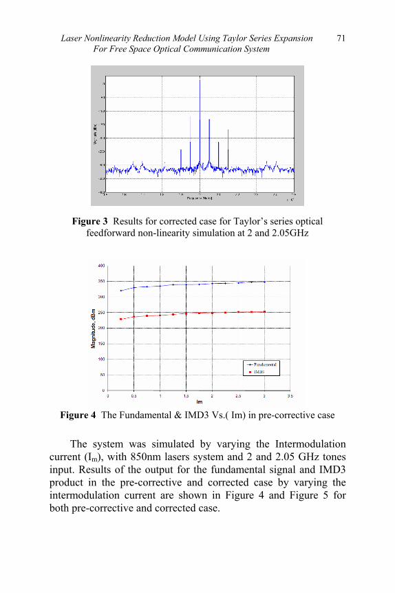
Laser Nonlinearity Reduction Model Using Taylor Series Expansion For Free Space Optical Communication System
71
Figure 3 Results for corrected case for Taylor’s series optical feedforward non-linearity simulation at 2 and 2.05GHz
Figure 4 The Fundamental & IMD3 Vs.( Im) in pre-corrective case
The system was simulated by varying the Intermodulation current (Im), with 850nm lasers system and 2 and 2.05 GHz tones input. Results of the output for the fundamental signal and IMD3 product in the pre-corrective and corrected case by varying the intermodulation current are shown in Figure 4 and Figure 5 for both pre-corrective and corrected case.

Advances in Free Space Optical Technology
72
Figure 5 The Fundamental & IMD3 Vs.( Im) in the Corrected case.
Comparing the IMD3 products in Figure 4 and Figure 5 for the two cases, again show an approximate reduction of around 30dB. These two graphs are included as additional demonstrations of the feedforward technique are possible to implement.
The simulation was again repeated for 200MHz and 205MHz, with λ=850nm for the LD. referring to the diagrams shown in Figure 6 and Figure 7, it can be seen that the levels of IMD3 for the Taylor’s series model for both pre and post correction, are identical to those shown in Figure 2 and 3 respectively. This to be expected as the Taylor’s series analysis has no frequency dependent amplitude components.
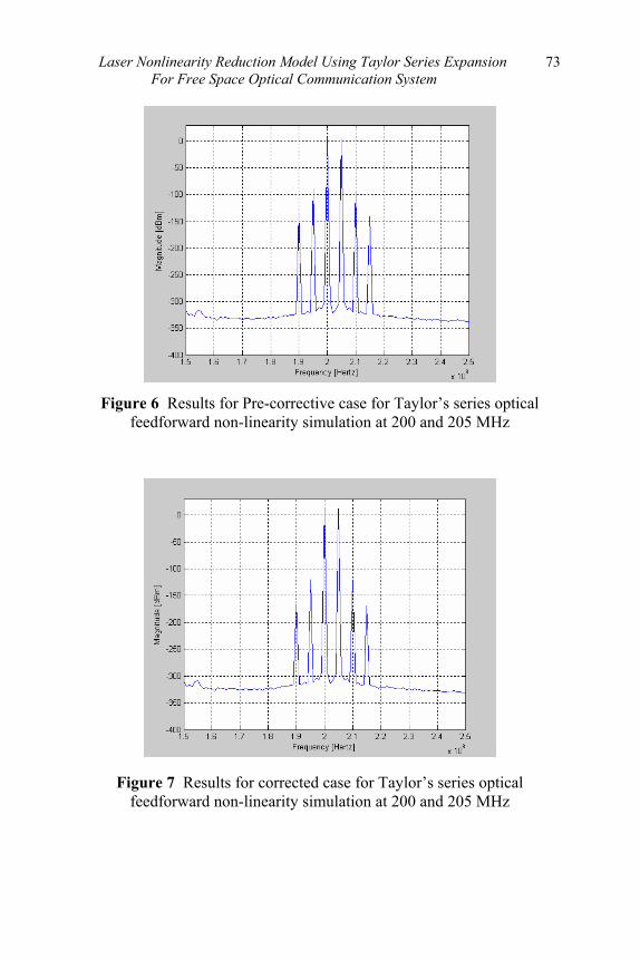
Laser Nonlinearity Reduction Model Using Taylor Series Expansion For Free Space Optical Communication System
73
Figure 6 Results for Pre-corrective case for Taylor’s series optical
feedforward non-linearity simulation at 200 and 205 MHz
Figure 7 Results for corrected case for Taylor’s series optical feedforward non-linearity simulation at 200 and 205 MHz
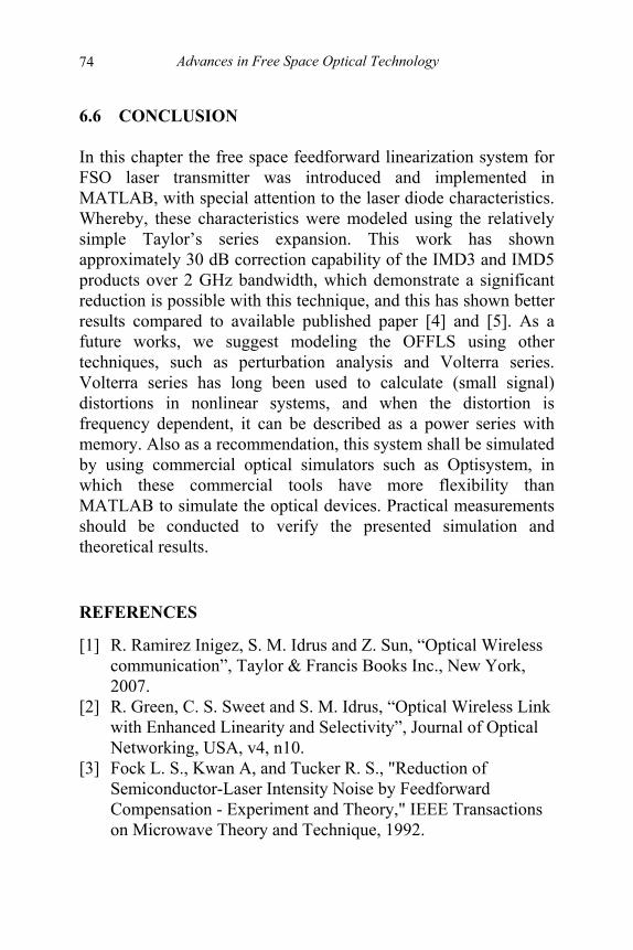
Advances in Free Space Optical Technology
74
6.6 CONCLUSION In this chapter the free space feedforward linearization system for FSO laser transmitter was introduced and implemented in MATLAB, with special attention to the laser diode characteristics. Whereby, these characteristics were modeled using the relatively simple Taylor’s series expansion. This work has shown approximately 30 dB correction capability of the IMD3 and IMD5 products over 2 GHz bandwidth, which demonstrate a significant reduction is possible with this technique, and this has shown better results compared to available published paper [4] and [5]. As a future works, we suggest modeling the OFFLS using other techniques, such as perturbation analysis and Volterra series. Volterra series has long been used to calculate (small signal) distortions in nonlinear systems, and when the distortion is frequency dependent, it can be described as a power series with memory. Also as a recommendation, this system shall be simulated by using commercial optical simulators such as Optisystem, in which these commercial tools have more flexibility than MATLAB to simulate the optical devices. Practical measurements should be conducted to verify the presented simulation and theoretical results.
REFERENCES
[1] [2] [3]
R. Ramirez Inigez, S. M. Idrus and Z. Sun, “Optical Wireless communication”, Taylor & Francis Books Inc., New York, 2007. R. Green, C. S. Sweet and S. M. Idrus, “Optical Wireless Link with Enhanced Linearity and Selectivity”, Journal of Optical Networking, USA, v4, n10. Fock L. S., Kwan A, and Tucker R. S., "Reduction of Semiconductor-Laser Intensity Noise by Feedforward Compensation - Experiment and Theory," IEEE Transactions on Microwave Theory and Technique, 1992.

Laser Nonlinearity Reduction Model Using Taylor Series Expansion For Free Space Optical Communication System
75
[4] [5] [6]
Hassin D. and Vahldieck R., "Feedforward Linearization of Analog Modulated Laser- Diodes - Theoretical-Analysis and Experimental-Verification," IEEE Transactions on Microwave Theory and Technique, 1993. T. Ismail and A. J. Seeds, “Laser Diode Nonlinear Distortion Reduction in Directly Modulated Semiconductor Laser using Feedforward Linearization”, IEEE, 2003. Liang, K., “Non linear Characterization of Quantum well Laser and Linearization by predistortion for 1.8 GHz Narrow Band Optical Transmitters”, in Department of Electronic Imaging and Media Communication, University of Bradford, 2000.
76
7 NONLINEARITY COMPENSATION IN
LASER DIODE BY MEANS FEED-FORWARD LINEARIZATION FOR FREE
SPACE OPTICAL LINK Sevia Mahdaliza Idrus Amir Masood Khalid
7.1 INTRODUCTION Free-space optics, sometimes referred to as optical wireless, is the area in telecommunications research that has seen rapid development over the last several years, which is capable of offering high-bandwidth services over relatively short distances at attractive costs and obtains broadband communication.
The dilemma in employing this technology is the performance reduction due to the nonlinearity present in the directly modulated optical transmitter, hence causes the inband, harmonic and intermodulation distortion (IMD) in the modulated signal. The technique of feedforward distortion compensation provides the better solution because it can minimize the (IMD3) in modulated optical signal operating at wavelength 1550nm, also reduces all the other higher orders of distortions. In this chapter a novel design for the free space optical link utilizing OFFLS (optical feed forward linearization system) which reduces non-linearity of the optical transmitter up to 17dB i.e. laser diode at carrier frequency 2.4GHz for the IEEE 802.11b/g standard and wavelength of 1550nm employing the feedforward linearization technique is presented.
Non Linearity Compensation In Laser Diode By Means Feed-Forward 77 Linearization For Free Space Optical Link
Recently, various wireless access systems have been developed in order to establish broadband wireless communication networks. The optical wireless communication systems which use light wave instead of the electric wave for the data transmission medium attract much attention [1,2]. It is because that lightwaves are obstructed only by physical obstacles. In addition, there is no electromagnetic interference between other electronic equipments.
Free space optics also called free space photonics (FSP) provides one of better solution for the high bandwidth requirements for broadband services. The benefit of the transmission of high frequency signals by using this optical wireless technology is the low cost, as compared to the conventional coaxial cable, with that, it provides fiber-optic connectivity without requiring physical fiber-optic cable. FSO is a line of sight technology that uses invisible beams of light to provide optical bandwidth connections that can send and receive voice, video, and data information at bandwidths up to 1.25 Gbps. The problem in this technology is the reduction in the performance due to the nonlinear behavior of the laser transmitter i.e. directly modulated laser diode. Direct modulation of laser diode has limited dynamic range due to intermodulation distortion products present in the laser output intensity spectrum [3].
Non linear distortion produce by the semiconductor laser such as intermodulation distortion (IMD) can also give rise to inter channel interference which degrades the quality of the received signal. Intermodulation distortion is the result of two or more signals interacting in a non linear device to produce additional unwanted signals. These additional signals (intermodulation products) occur mainly in devices such as amplifiers and semiconductor laser diode [2]. The major concern here is the IMD3 which is the two tone 3rd order intermodulation distortion near the carrier, all other distortion can be cancelled by using band pass filters.
Many techniques are being used to reduce the non-linearity of the semiconductor laser transmitter, such as feedback (or closed
78 Advances in Free Space Optical Technology
loop), phase-shift harmonic cancellation (PSHC), predistortion, quasi-feedforward and feedforward. The feedback and PSHC techniques have considerable limitations and are not really serious options for optical cellular systems. Predistortion networks have had limited success since they must be matched to individual lasers and must take into account the strong frequency dependent distortion generated by semiconductor laser diodes and other undesired effects such as laser aging. Quasi feedforward linearization schemes require matched lasers, which are very difficult to obtain. Even though feedforward is a relatively complicated and sensitive scheme we consider it a promising linearization solution especially in view of the demand for high channel capacity light wave systems.[7].. Feedforward technique is the only one of the correction techniques that needs some adaptation for use in a free space system. Most of the non-linear correction techniques that have been established for optical communication were originally developed for microwave high power amplifier links. 7.2 FEEDFORWARD IMPLEMENTATION The feedforward method for non-linearity improvement is basically developed for the lightwave systems. The performance of an optical transmission system depends greatly on the nonlinearity of a laser diode. Since the intermodulation distortion generated by the laser non-linearity can cause spectral re-growth some form of distortion compensation is required. Figure. 1 shows the proposed optical feedforward-linearization system. Conceptually the system consists of two loops, the first loop is signal-cancellation or error determination loop and the second loop is error-injection loop Considering the first loop first, the RF input signal is split into two paths at the electrical splitter, where one modulates the primary laser diode circuit LD1, whereas the other is the error-free reference path.

Non Linearity Compensation In Laser Diode By Means Feed-Forward 79 Linearization For Free Space Optical Link
Figure 1 The block diagram of feedforward linearization
system
Due to the nonlinearity of laser diode circuit LD1, the
modulated optical output signal contains IMD products. The output is split into two paths and then is detected using a photodiode circuit PD1, followed by a variable gain inverter amplifier A1. The output of inverter amplifier A1 containing signal and distortion products, together with the intensity noise generated in laser LD1, is subtracted from the error-free reference path at electrical combiner C1.
The resulting output signal ideally should consist of the error signal only [4],(i.e., the nonlinear distortion products and the detected noise of the primary laser LD1). The resulting output signal is 180 phase shifted and injected into the distortion-cancellation loop and modulating the secondary laser LD2. The modulated optical output signal from laser LD2 is an optical representation of the error signal (i.e., distortion products) at the output of the primary laser LD2 but inverted in sign. Since laser LD2, is directly modulated with the low-level distortion products, it can be assumed to operate linearly and not generate significant distortion of its own .The output of laser LD2 is detected by photodiode PD1 and is combined with signal from photodiode
80 Advances in Free Space Optical Technology
PD2.Both the signal-cancellation and the distortion-cancellation loops require correct amplitude and phase for the cancellation of the carrier signal at the electrical combiner C1, and distortion products at the receiver photodiode PD2. This is facilitated with variable attenuators and variable-gain amplifiers for amplitude matching and fine tuned with electrical phase shifters for phase matching. 7.3 SIMULATION SECHEME This section describes the simulation arrangement of feedforward linearization and explains the tuning and testing of the system. The design and analysis of these systems, which normally include nonlinear devices and non-Gaussian noise sources, are highly complex and extremely time-intensive; as a result, these tasks can now only be performed efficiently and effectively with the help of advanced new software tools. OptiSystem is innovative optical communication system simulation software that designs, tests, and optimizes virtually any type of optical link in the physical layer of a broad spectrum of optical networks, from analog video broadcasting systems to intercontinental backbones.
The simulation is done using commercial software Optisystem version 7.The system consist of two directly modulation laser that modelled by laser rate equation. Laser L1 wavelength is 1529 nm, with a mean optical output power of 2 mW (3 dBm) at 38-mA bias current .Laser L2 is of the same type as Laser 1, but it operates at 1532 nm, to avoid optical interference at the transmitter. Because the effects of amplitude- and phase tuning parameters are interrelated, in order to fine tune the whole system, it is necessary to first tune the signal-cancellation loop and, then, the distortion-cancellation loop. If the two paths in the carrier-cancellation loop have the same frequency response, then a complete cancellation of the fundamental signal should be obtained at the output of substractor. The cancellation will be broadband to the extent that

Non Linearity Compensation In Laser Diode By Means Feed-Forward 81 Linearization For Free Space Optical Link
the frequency-dependent gain and phase shifts of the two parallel branches are identical. Frequency response of the loop was measured for amplitude and phase matching with the reference path connected and disconnected.
For the distortion-cancellation loop, the electrical reference signal is temporarily removed. The distortion-cancellation loop is optimized and tested. Frequency responses of the loop for amplitude and phase matching are measured with the laser L2 path connected and disconnected. The difference between these frequency responses is the suppression ratio, which indicates the performance of the distortion-cancellation loop. 7.4 RESULTS AND DISCUSSION Figure 2(a) shows the detected RF spectrum with out feedforward technique at the carrier frequency of 2.4 GHz, third order Intermodulation distortion IMD3, which is at channel spacing of 1 MHz near the carrier is quite high about -76dBm, which can agitate the original signal and cause reduction in performance. The input power to the system is about 37dBm, wavelength used for the modulation of the laser diode is 1550nm which is optimum for optical communication.
Figure 2(b) shows the detected RF spectrum with using feed forward linearization at same carrier frequency 2.4 GHz. The third order intermodulation distortion IMD3 is reduced by 17dB i.e. the received power at IMD3 is about -93dBm, where as all other parameters are same which is mentioned above for the system simulated without feed forward linearization. The intermodulation distortion is compensated at the same received carrier power level which is about -20dBm.
The performance of the feedforward linearization has been assessed and in Figure 3 the results show approximately 17 dB suppression in IMD3 around 2.4 GHz with the channel spaced by 1MHz. Further suppression of the IMD to the noise floor level can

82 Advances in Free Space Optical Technology
be achieved by more accurate phase and amplitude matching.
(a) (b)
Figure 2 Detected RF spectrum without and with feedforward linearization
Figure 3 shows the higher order of intermodulation distortion products IMD4 and IMD5 are also suppressed to a little extent by using feedforward linearization, where the received power amplitude level of the carrier is same.
0 1 2 3 4 5 6 7 8
x 109
-100
-80
-60
-40
-20
0
20
Frequency Hz
Pow
er (
dbm
)
Detect RF spectrum with and without feedforward at 2.4 GHz Frequency
Without Feedforward
With Feedforward
Figure 3 Comparison b/w with and without feedforward linearization
at 2.4 GHz

Non Linearity Compensation In Laser Diode By Means Feed-Forward 83 Linearization For Free Space Optical Link
7.5 CONCLUSION In this chapter, the feedforward linearization technique has been demonstrated to reduce the intermodulation distortion IMD at the frequency 2.4 GHz required Wire LAN (WLAN) which utilize IEEE 802.11b/g standard by using a directly modulated laser diode, hence achieving 17-dB IMD3 suppression. Further improvements will make the feedforward a wideband system to cover the IEEE802.11a frequency range around 5.2 GHz. The system is simulated by using a commercial software OptiSystem by Optiwave and hence the IMD3 reduction of 17-DB is obtained.
REFERENCES [1] [2] [3] [4] [5] [6]
R. S. Tucker, “Linearisation Techniques for Wideband Analog Transmitters,” in Summer Top. Meeting Tech. Dig. LEOS, 1992, pp. 54–55. Reducing IM Distortion In Modern Receivers, Measuretest 95/1, Marconi Instruments Jan 1995. D. Hassin and R. Vahldieck, “Improved Feed-forward Linearisation of Laser Diodes—Simulation and Experimental Results,” in Proc. IEEE MTT-S IMS, 1990, pp. 727–730. A. B. Maiteeg, S. M. Idrus and H. Harun, “Laser Non-Linearity Compensation Model using Taylor Series Expansion for Free Space Optical Communication System”, WEC Penang Malaysia, 2007. Liang, K., “Non linear Characterization of Quantum Well Laser and Linearization by Predistortion for 1.8 GHz Narrow Band Optical Transmitters”, in Department of Electronic Imaging and Media Communication, Uni. of Bradford, 2000. J. H. Seo, Y. K. Seo, W. Y. Choi, “Nonlinear Distortion Suppression in Directly Modulated DFB Lasers by Sidemode Optical Injection”, IEEE MTT-S Digest, pp 555 – 558, 2001.

84
8
GRIN COLLIMATING LENSES Abu Sahmah Mohd Supa’at
Christie Laura Albert Eileen Ma Fui Lin
8.1 INTRODUCTION This chapter will discuss on how GRIN (gradient index) can be used to build a collimating lenses. e also discuss what is GRIN and all the advantages that GRIN has which is suitable to be used as a material for a collimated lens compare to all the other types of lenses.
A collimating lens is a lens used to collimate light, which is to gather it together in a parallel beam. There are a lot of type lenses to construct a collimating lens which varies from fiber lenses, ball lenses, a spherical lenses, spherical singlet and doublets, GRIN lenses, microscope objectives and cylindrical lenses. Lens materials can vary from glass to plastic to silicon. By a large margin, most of the fiber optic collimators used today are made using GRIN lenses. GRIN lenses are small, easy to handle, relatively low cost, and competitive in optical performance. They do have limitations though. GRIN lenses rarely come in large size and their performance is marginal in the visible spectrum range. 8.2 GRIN LENSES GRIN lenses are used to focus and collimate light within a variety of fiber optic components. GRIN lenses, short for gradient index, focus light through a precisely controlled radial variation of the

GRIN Collimating Lens
85
lens material’s index of refraction from the optical axis to the edge of the lens. This allows a GRIN lens with flat or angle polished surfaces to collimate light emitted from an optical fiber or to focus an incident beam into an optical fiber. End faces can be provided with an antireflection coating to avoid unwanted back reflection.
GRIN lenses offer an alternative to the often painstaking craft of polishing curvatures onto glass lenses. By gradually varying the index of refraction within the lens material, light rays can be smoothly and continually redirected towards a point of focus. The internal structure of this index "gradient" can dramatically reduce the need for tightly controlled surface curvatures and results in simple, compact lens geometry.
GRIN lenses are used in a wide array of products that require either passive or active electrical components. Passive component manufacturers use GRIN lenses in wavelength division multiplexers (WDM), optical switches, and attenuators. In active components, GRIN lenses are used in fiber-to-detector and laser-to-fiber coupling. GRIN lenses are well suited to coupling the output of diode lasers into optical fibers because they can achieve aberration correction without complex multi-element systems or aspheric lenses; and because real images can be formed at the lens surface. In the field of fiber coupling or in creating beam patterns, GRIN lenses are an economical, special alternative to conventional lenses.
When determining which of the available GRIN lenses is best for the application at hand, the following specifications are of greatest import: effective focal length, lens diameter, radius of the curvature, and the thickness of the edge and the center. Focal length is the distance from the lens the light converges. Focal lengths are positive for a converging system and negative for a diverging system. Diameter refers to the lens when viewed straight on. This could also be thought of as the height. The radius of curvature can be determined if the lens were extrapolated into a sphere, then the radius of that sphere would be the radius of curvature. Center thickness of GRIN lenses is simply the thickness of the lens at its center, while edge thickness is the thickness of the
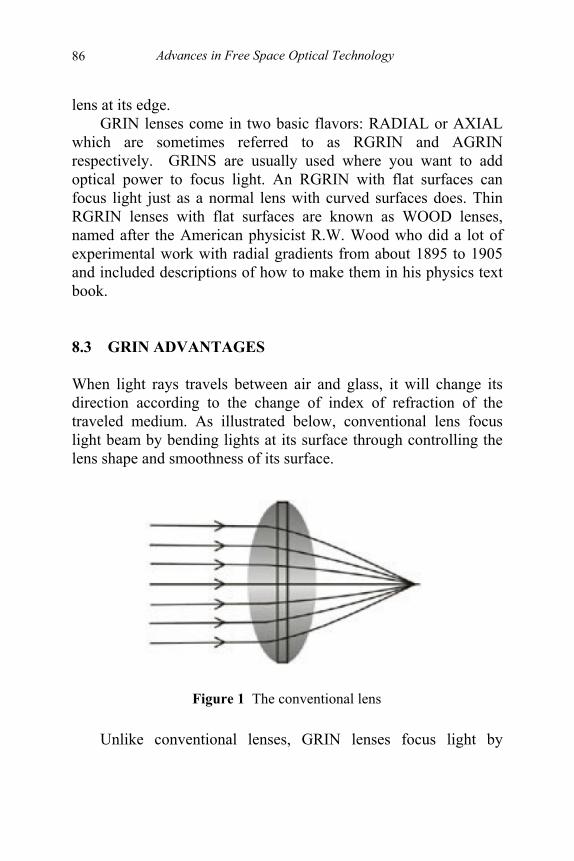
Advances in Free Space Optical Technology
86
lens at its edge. GRIN lenses come in two basic flavors: RADIAL or AXIAL
which are sometimes referred to as RGRIN and AGRIN respectively. GRINS are usually used where you want to add optical power to focus light. An RGRIN with flat surfaces can focus light just as a normal lens with curved surfaces does. Thin RGRIN lenses with flat surfaces are known as WOOD lenses, named after the American physicist R.W. Wood who did a lot of experimental work with radial gradients from about 1895 to 1905 and included descriptions of how to make them in his physics text book. 8.3 GRIN ADVANTAGES When light rays travels between air and glass, it will change its direction according to the change of index of refraction of the traveled medium. As illustrated below, conventional lens focus light beam by bending lights at its surface through controlling the lens shape and smoothness of its surface.
Figure 1 The conventional lens
Unlike conventional lenses, GRIN lenses focus light by
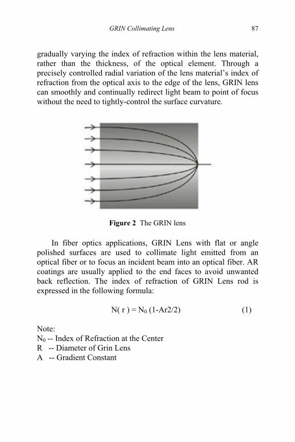
GRIN Collimating Lens
87
gradually varying the index of refraction within the lens material, rather than the thickness, of the optical element. Through a precisely controlled radial variation of the lens material’s index of refraction from the optical axis to the edge of the lens, GRIN lens can smoothly and continually redirect light beam to point of focus without the need to tightly-control the surface curvature.
Figure 2 The GRIN lens
In fiber optics applications, GRIN Lens with flat or angle
polished surfaces are used to collimate light emitted from an optical fiber or to focus an incident beam into an optical fiber. AR coatings are usually applied to the end faces to avoid unwanted back reflection. The index of refraction of GRIN Lens rod is expressed in the following formula:
N( r ) = N0 (1-Ar2/2) (1) Note: N0 -- Index of Refraction at the Center R -- Diameter of Grin Lens A -- Gradient Constant
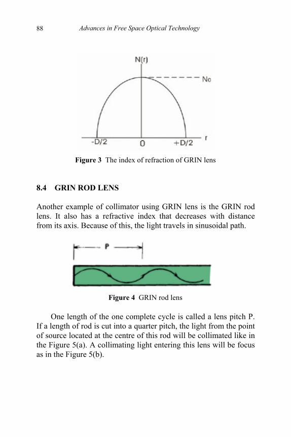
Advances in Free Space Optical Technology
88
Figure 3 The index of refraction of GRIN lens
8.4 GRIN ROD LENS Another example of collimator using GRIN lens is the GRIN rod lens. It also has a refractive index that decreases with distance from its axis. Because of this, the light travels in sinusoidal path.
Figure 4 GRIN rod lens
One length of the one complete cycle is called a lens pitch P.
If a length of rod is cut into a quarter pitch, the light from the point of source located at the centre of this rod will be collimated like in the Figure 5(a). A collimating light entering this lens will be focus as in the Figure 5(b).
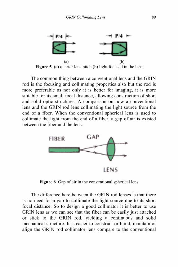
GRIN Collimating Lens
89
(a) (b)
Figure 5 (a) quarter lens pitch (b) light focused in the lens
The common thing between a conventional lens and the GRIN rod is the focusing and collimating properties also but the rod is more preferable as not only it is better for imaging, it is more suitable for its small focal distance, allowing construction of short and solid optic structures. A comparison on how a conventional lens and the GRIN rod lens collimating the light source from the end of a fiber. When the conventional spherical lens is used to collimate the light from the end of a fiber, a gap of air is existed between the fiber and the lens.
Figure 6 Gap of air in the conventional spherical lens
The difference here between the GRIN rod lenses is that there
is no need for a gap to collimate the light source due to its short focal distance. So to design a good collimator it is better to use GRIN lens as we can see that the fiber can be easily just attached or stick to the GRIN rod, yielding a continuous and solid mechanical structure. It is easier to construct or build, maintain or align the GRIN rod collimator lens compare to the conventional
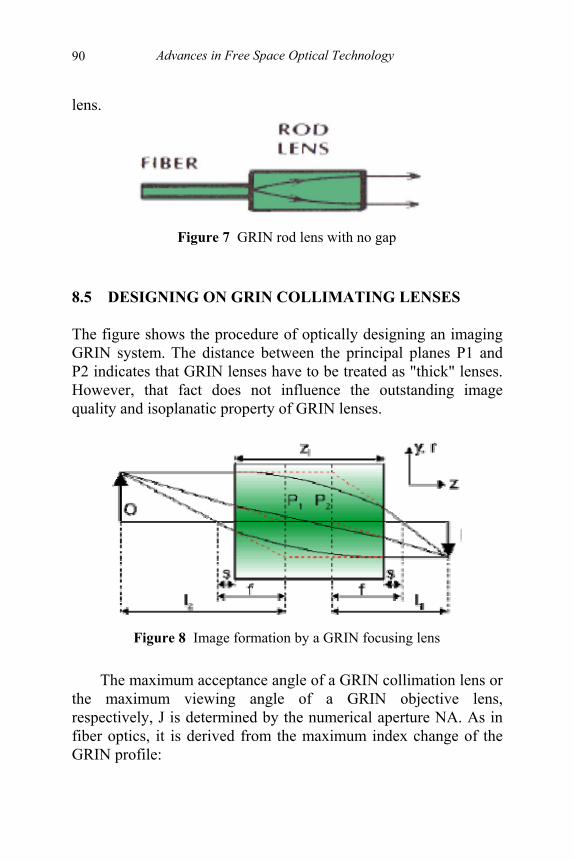
Advances in Free Space Optical Technology
90
lens.
Figure 7 GRIN rod lens with no gap
8.5 DESIGNING ON GRIN COLLIMATING LENSES The figure shows the procedure of optically designing an imaging GRIN system. The distance between the principal planes P1 and P2 indicates that GRIN lenses have to be treated as "thick" lenses. However, that fact does not influence the outstanding image quality and isoplanatic property of GRIN lenses.
Figure 8 Image formation by a GRIN focusing lens
The maximum acceptance angle of a GRIN collimation lens or
the maximum viewing angle of a GRIN objective lens, respectively, J is determined by the numerical aperture NA. As in fiber optics, it is derived from the maximum index change of the GRIN profile:
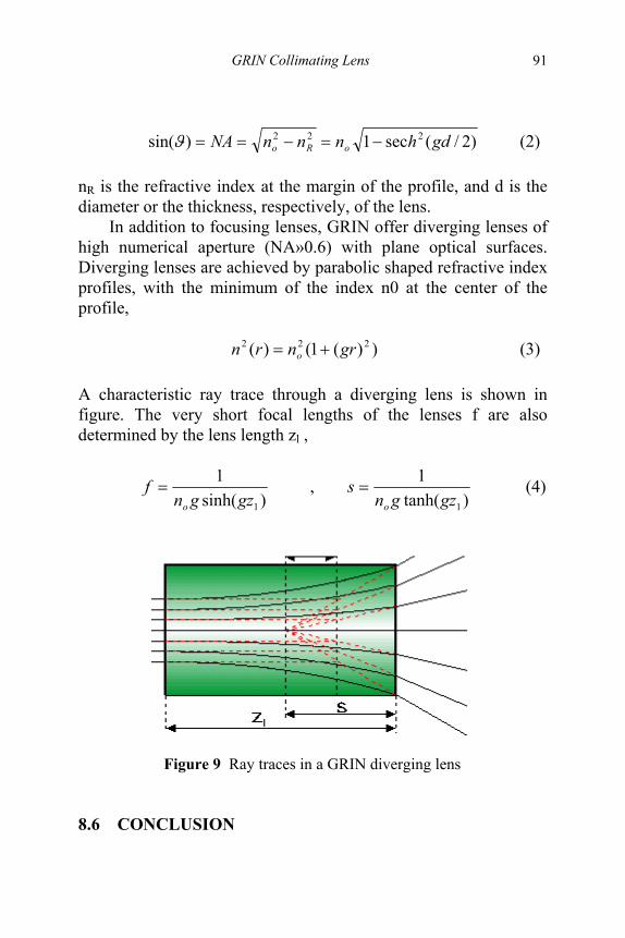
GRIN Collimating Lens
91
)2/(sec1)sin( 222 gdhnnnNA oRo −=−==ϑ (2)
nR is the refractive index at the margin of the profile, and d is the diameter or the thickness, respectively, of the lens.
In addition to focusing lenses, GRIN offer diverging lenses of high numerical aperture (NA»0.6) with plane optical surfaces. Diverging lenses are achieved by parabolic shaped refractive index profiles, with the minimum of the index n0 at the center of the profile, ))(1()( 222 grnrn o += (3)
A characteristic ray trace through a diverging lens is shown in figure. The very short focal lengths of the lenses f are also determined by the lens length zl ,
)sinh(
1
1gzgnf
o
= , )tanh(
1
1gzgns
o
= (4)
Figure 9 Ray traces in a GRIN diverging lens
8.6 CONCLUSION

Advances in Free Space Optical Technology
92
A lens is a device for either concentrating or diverging light, usually formed from a piece of shaped glass. Analogous devices used with other types of electromagnetic radiation are also called lenses. GRIN lens is short for graded-index or gradient index lens. It refers to an optical element in which the refractive index varies. More specifically (from the Photonics Dictionary) a GRIN lens is a lens whose material refractive index varies continuously as a function of spatial coordinates in the medium. Also, a graded index fiber describes an optical fiber having a core refractive index that decreases almost parabolically and radially outward toward the cladding.
GRIN lens in other word is used to focus and collimate light sources. A collimating lens is a lens used to collimate light, that is, to gather it together in a parallel beam. Collimated light is light whose rays are parallel and thus has a plane wavefront. Light can be collimated by a number of processes, the easiest being to shine it on a parabolic concave mirror with the source at the focus.
REFERENCES [1] [2] [3] [4]
Joseph C. Palais, "Fiber Optic Communications", Prentice Hall, New Jersey, 2004. John Gowar, “Optical Communication Systems”, Prentice Hall, 1993. Govind P. Prawal, “Fiber Optic Communication System”, John Wiley And Sons, 2002 Biswanath Mukherjee, “Optical Communication Network”, Macgraw Hill, 1997

93
9
SELF ALIGNMENT OPTICAL ANTENNA OUTDOOR OPTICAL WIRELESS
COMMUNICATION Sevia Mahdaliza Idrus
Pandian Meiyappan Siva Arnidza Ramli
9.1 INTRODUCTION This work is concerned with wireless optical receiver .The normal point to point wireless optical communication (WOC) systems with a static receiver will be modified into an auto adjustable/self alignment receiver. The newly invented optical antenna has provoked the inspiration of designing an optical antenna/receiver which is able to self align itself to get the transmitted signal from the transmitters located in different buildings with each building varying in height and angle from the receiver building. The source code details of the PIC microcontroller will be articulated clearly for further enhancements of the system. The primary advantages of this system is that, this system increases total detection optical power and simultaneously improves the signal to noise ratio (SNR) of the WOC link due to the usage of the optical antenna.
The high cost of maintaining and reconfiguring wired communication has resulted in the active usage of wireless communication system. Wireless communication system can be divided in two main categories which is the radio frequency (RF) or Infrared (IR) type. The IR type is increasingly famous because of its low cost and free licensing.
Basically optical communication uses IR communication. The
Advances in Free Space Optical Technology
94
fundamental wireless optical communication systems are used to transmit information from a point to another point which is the receiver. There will be a line of sight (LOS). The normal wireless optical system is not reliable if the transmitter is dislocated. This is because there will be loss of information if the transmitter and receiver are not directed or not in line of sight. To counter settle this problem there is should be receiver which can move and align itself to get the maximum signal from the transmitter.
Therefore this work is particularly concerned to develop a self alignment optical antenna/receiver. The system usage can be implemented in both indoor and outdoor application. But in this chapter the outdoor application will be described thoroughly. 9.2 INFRARED TECHNOLOGY Optical wireless communication offers a very good alternative to RF communication. This is basically because this optical wireless system uses IR, and this technology has significant benefits over RF. When it comes to wireless system both infrared and RF can be used, but RF is not much preferred because it can only support limited bandwidth because of restricted spectrum availability and interference, while this restriction does not apply to IR [1]. IR systems can provide cable free communication at very high bit rates. It has higher transfer rate (up to 155 Mbps and above), has a greater noise protection, a high secrecy, and does not require obtaining allowing for frequency band using. At the same time prices for equipment of laser link are quite comparable to the prices on a radio one [2]. Laser diodes or LEDs are transmitter, photodiodes as receivers for optical wireless systems.
The information in digital data form will get inserted into the electronic circuitry that modulates the transmitting light source (LEDs/LDs) [3]. The output of the source (which is the modulated signal) passes through an optical system (telescope and optical diplexer) and goes into the free space (propagation medium).
In the receiver part, the modulated signal passes through an

Self Alignment Optical Antenna Outdoor Optical Wireless Communication
95
optical system (lens) and gets into the photo detector (PIN diodes/APDs) and thereafter the modulated signal gets to the signal processing electronics to demodulate the signal to get the original information [4].
Figure 1 Usage of optical wireless system in outdoor
9.3 OPTICAL ANTENNA The optical antenna is so accurate to the extent that it can detect a signal on one particular wavelength of light and is 100 times more efficient at collecting signal than any other kind of optical sensor. So this provides an advantage to this project of self alignment wireless optical antenna because the antenna allows transmitter and receiver to operate in significant angle to each and other. The distance between transmitter and receiver can be up to 3 miles.
Figure 2 Optical Antenna [4]
Advances in Free Space Optical Technology
96
The main advantages of optical antennas are as below: - Optical antennas are point detectors having a detection area of
about the square of the detected wavelength. - Optical antenna can be tuned to a specific wavelength. But their
lossy character of the metallic structures at optical frequency, resonances are expected to be broadened and this might limit their tuning capability.
- Optical antenna can be monolithically integrated with electronics and auxiliary optics.
9.4 PROBLEM AND SOLUTION The problem of the normal wireless optical communication is that it is not efficient if both transmitter and receiver are not in LOS (line of sight). There will be an information loss if the transmitter and receiver are not directed. Only minimal IR rays will be captured by the receiver if transmitter is dislocated. So it is very important to increase the coverage area of the receiver.
If there are three and more buildings with the optical wireless system, how will all buildings communicate with one building as a receiver and others as transmitters? So to accommodate this kind of system we will have to create a self alignment wireless receiver where the receiver can align itself to establish a LOS and align itself to receive the maximum transmitted signal from each and every transmitter although the transmitters are in different angle and location.
The only solution to this problem is using a self alignment wireless outdoor optical which can align itself towards the transmitter which transmit the laser ray. It can be done by programming the PIC microcontroller as such it moves the respective degree towards the building of the transmitter and scan vertically for the laser beam. 9.5 SYSTEM OPERATION
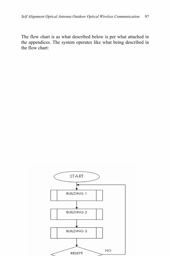
Self Alignment Optical Antenna Outdoor Optical Wireless Communication
97
The flow chart is as what described below is per what attached in the appendices. The system operates like what being described in the flow chart:
Advances in Free Space Optical Technology
98
Figure 3 System Operation (Flow Chart)
9.6 HARDWARE DEVELOPMENT AND MEASUREMENT The hardware is being developed based on the fundamental block diagrams per below:

Self Alignment Optical Antenna Outdoor Optical Wireless Communication
99
Figure 4 Basic Block Diagram
Below is the measurement data. The voltage is only available
in the angle of 0°, 10° and -10°. This practically shows that the photodiode cannot detect the signal if the receiver is dislocated more than 20° from the transmitter which is the laser. Moreover the data’s are also limited because of the laser which is being used is considered low in cost and quality for experimental purposes.
Table 1 Measurement data
70cm 60cm 50cm 40cm 30cm
Receiver (Photodiode)
Motor
PIC circuit board
Transmitter 1
Transmitter 2
Transmitter 3
Laser rays without any modulated signal

Advances in Free Space Optical Technology
100
0º 4.64V 4.64V 4.78V 4.81V 4.86V 10º and -10º 0.01V 0.02V 0.02V 0.02V 0.02V 20º and -20º 0 0 0 0 0 30º and -30º 0 0 0 0 0 40º and -40º 0 0 0 0 0 50º and -50º 0 0 0 0 0 60º and -60º 0 0 0 0 0 70º and -70º 0 0 0 0 0 80º and -80º 0 0 0 0 0 90º and -90º 0 0 0 0 0
100º and -100º 0 0 0 0 0 110º and -110º 0 0 0 0 0 120º and -120º 0 0 0 0 0 130º and -130º 0 0 0 0 0 140º and -140º 0 0 0 0 0 150º and -150º 0 0 0 0 0 160º and -160º 0 0 0 0 0 170º and -170º 0 0 0 0 0 180º and -180º 0 0 0 0 0
9.7 CONCLUSION The self alignment wireless outdoor optical antenna has numerous advantages because of the usage of the newly invented optical antenna. The optical antenna which will be located in front of the photodiode will increase the SNR of the wireless optical communication system. The system (hardware and software) are workable and practically implementable. REFERENCES [1] [2]
R. Ramirez-Iniguez and R. J. Green, “Indoor Optical Wireless Communication”, London, UK Evgeniy D. Golovin and Oleg V. Stukach, “Advanced Large
Self Alignment Optical Antenna Outdoor Optical Wireless Communication
101
[3] [4] [5] [6]
Distance Optical Free-Space Link on the Infrared Diode in Nanosecond Pulsed Mode”, Tomsk Polytechnic University. D. Kerr, K. Bouazza-Marouf, K. Girach and T. West, “Free space laser communication links for short range control”. R. Ramirez-Iniguez, “Semi Hemispherical Dielectric Totally Internally Reflecting Concentrator (DTIRC) Design”, IEEE Wireless Design Conference, London, UK, pp. 129-132, May 2002. S. M. Idrus, R. Ramierez-Inguiez & R. J. Green, “Receiver Amplifiers For Optical Wireless Communication System”, 3rd PREP, University Of Keele, UK, p19-20, Apr. 2001. S.M.Idrus & R.J.Green, “Photoparametric Amplifier For Optical Wireless Communication System”, 4th IEEE HFPC Conference, Cardiff, p36-41, Sept. 2001.

102
10
PERFORMANCE ANALYSIS OF 2.4 GHZ ISM-BAND WIRELESS LAN FOR
INDOOR WIRELESS COMMUNICATION LINKS
Nor Hafizah Ngajikin Sevia Mahdaliza Idrus
Fazlin Shariff Udin Suryani Alifah
10.1 INTRODUCTION. Wireless communication is one of the fastest growing segments of the telecommunication and consumer electronics industries. The powerful technology and market trends towards portable computing and communications imply an increasingly important role for wireless access in the next generation. However, there are several obstacles that will deduce the network performance such as architectural design of building, placement and composition of wall, furniture arrangement and any other factors. Thereby, this chapter presents a propagation measurement analysis for indoor wireless communication performance. Measurement is done by using Network Stumbler and IxChariot software at operating frequency of 2.4 GHz based on IEEE 802.11b standard. The indoor radio wave propagation in U-shape building was predicted within 2nd floor, block UA2, Kolej 9, Universiti Teknologi Malaysia (UTM). 13 Access Point (AP) are arranged to setup the whole network. Network performances are analyzed based on response time, transaction rate, connectivity, delay and throughput in the
Performance Analysis of 2.4 GHz ISM-Band Wireless LAN for Indoor Wireless Communication Links
103
network. Comparison of different file size and distance between AP to study the behavior of the network is presented.
Wireless network is seems to be an evolution of technology in computer network access. This can best be seen in academic circles such as University campuses, health-care, manufacturing, and warehousing. However, the threat is on fading effect cause by multipath propagation and obstacle such as building architecture, furniture and other surrounding object.
On the Internet and in other networks, Quality of Service (QoS) is the idea that transmission rates, error rates, and other characteristics can be measured, improved, and, to some extent, guaranteed in advance [1]. QoS is of particular concern for the continuous transmission of high-bandwidth video and multimedia information. Recently, there are several software had been used to monitor the QoS performance. This chapter discussed the measurement results on response time, transaction rate, connectivity, delay and throughput performance that had been measured using Network Stumbler and Ixchariot software. 10.2 MEASUREMENT TECHNIQUE 10.2.1 IxChariot
IxChariot measures QoS performance between pairs of networked computers. Using flows of real data, IxChariot emulates different kinds of distributed applications, captures and analyzes the resulting performance. Each computer used in IxChariot, must be setup using Performance Endpoint software. This tool set the connected computers as an endpoint. These endpoints used to collect data and produces reports on response time, transaction rate, connectivity and throughput in the network.
For a particular test, each endpoint pair comprises the network addresses of two paired computers, same network protocol, and same type of application. Tests can be done in a small network with just one endpoint pair, or can be more complex, involving
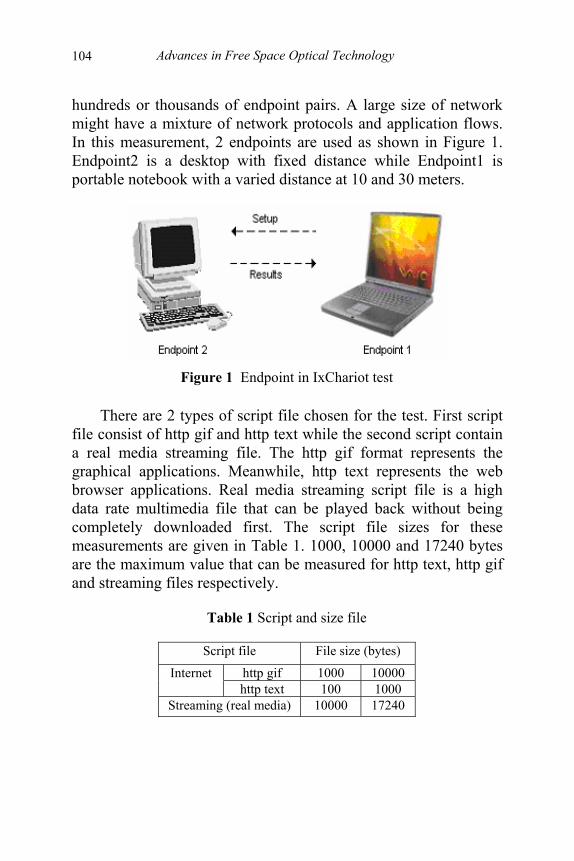
Advances in Free Space Optical Technology
104
hundreds or thousands of endpoint pairs. A large size of network might have a mixture of network protocols and application flows. In this measurement, 2 endpoints are used as shown in Figure 1. Endpoint2 is a desktop with fixed distance while Endpoint1 is portable notebook with a varied distance at 10 and 30 meters.
Figure 1 Endpoint in IxChariot test
There are 2 types of script file chosen for the test. First script
file consist of http gif and http text while the second script contain a real media streaming file. The http gif format represents the graphical applications. Meanwhile, http text represents the web browser applications. Real media streaming script file is a high data rate multimedia file that can be played back without being completely downloaded first. The script file sizes for these measurements are given in Table 1. 1000, 10000 and 17240 bytes are the maximum value that can be measured for http text, http gif and streaming files respectively.
Table 1 Script and size file
Script file File size (bytes)
http gif 1000 10000 Internet http text 100 1000
Streaming (real media) 10000 17240

Performance Analysis of 2.4 GHz ISM-Band Wireless LAN for Indoor Wireless Communication Links
105
Output from Ixchariot software for both internet script file is a graph of throughput, transaction rate and response time. On the other hand, for real media streaming file, the results present the graph of throughput, one-way delay, lost data and jitter. All measured parameters are briefly defined as follow:
• Throughput
timeelapsed received bytes totalsent bytes totalThroughput filesinternet
+=
timeMeasured)(Endpoint2 received bytes totalThroughput files streaming =
• Transaction rate
timeMeasuredcountn Transactioraten Transactio =
• Response Time
countn TransactioTime Measured timeResponse =
• One Way Delay - Endpoints can calculate delay (time taken to
receive a data) statistics in a single direction and pairs for each timing record in a test.
• Percentage bytes lost - Calculated as the difference between the first two columns of data.
• Maximum Consecutive Lost Datagrams - The highest number of consecutive datagrams lost for a particular streaming pair.
• Jitter - The statistical variance of the datagram inter arrival time expressed as a mean deviation for each pair.
10.2.2 Network Stumbler Network Stumbler is a tool to detect Wireless Local Area Networks (WLANs) signal and noise power for WLAN 802.11a, 802.11b and 802.11g standard. This software is purposely can be used for site survey where it is important to pick locations and channels in such a way that interference is minimum. Network Stumbler with D-Link AirPlus 22 Mbps Wireless Network Adapter

Advances in Free Space Optical Technology
106
is used for this survey. The measurements was conducted within 2nd floor, block UA2, College 9, Universiti Teknologi Malaysia. Figure 2 shows the arrangement of 13 AP and 3 measurement locations for performance evaluation.
Figure 2 AP Arrangement in Kolej 9 UTM building
The output graph appears in the Network Stumbler presenting
the Received Signal Strength Indication (RSSI). The strength of the received signal is in arbitrary units. RSSI often appears on a scale from 0 to 100dBm. 10.3 RESULTS AND DISCUSSION 10.3.1 IxChariot 10.3.1.1 Http Gif
The results for http gif are shown in Table 2. Throughput for both distance were increased when the file size are increased. At 30m, the throughput was lower than throughput obtained at 10m. Meanwhile, the transaction rate was decreased when the file size increased at both distance. Transaction rate at 10m was higher than results obtained at 30m. As defined earlier, response time is the

Performance Analysis of 2.4 GHz ISM-Band Wireless LAN for Indoor Wireless Communication Links
107
inverse of the transaction rate. The results obtained prove the theory for both distances. Longer time to response the script for 30m, due to the longer distance used.
Table 2 Results for http gif
Distance (m) 10 30 File size 1000 10000 1000 10000 Throughput (Mbps) 0.343 1.251 0.184 0.328 Transaction rate (s) 33.124 15.202 17.72 3.986 Response time (s) 0.030 0.066 0.056 0.251
10.3.1.2 Http Text The results for http text were summarizes by Table 3. The result of the throughput for both distance increased when the file size increased. At 30m, the throughput was lower than throughput obtained at 10m. Meanwhile, the transaction rate was decreased when the file size increased at both distance. Transaction rate at 10m was higher than results obtained at 30m. Response time for http text was inversed with transaction rate. Longer time to response the script for 30m, due to the longer distance used. All the results for http text were similar to http gif, which both performed the internet script file.
Table 3 Results for http text
Distance (m) 10 30 Types\ File size 100 1000 100 1000 Throughput (Mbps) 0.277 0.280 0.151 0.157 Transaction rate (s) 87.260 26.957 49.358 34.933 Response time (s) 0.011 0.037 0.020 0.029
10.3.1.3 Real Media Streaming File Throughput, delay, lost data and jitter measurement for 10000 and 17240 bytes size streaming file at 10m and 30m distance are
Advances in Free Space Optical Technology
108
shown in Table 4. The results for real media streaming file are differs compared to both internet script. Table 4 shows that throughput for both distance increased when the file size increased. At 30m, the throughput was lower than throughput obtained at 10m. From the table, they are 0 lost data at 10m. Meanwhile, at 30m, the lost data increased when the file size increased. The delay increased when the file size and the distance increased. This is due to interference occurred during the transmission between the endpoint.
Table 4 Results for real media streaming file
Distance (m) 10 30 Types\File size 10000 17240 10000 17240 Throughput (Mbps) 0.293 0.299 0.115 0.286 1 way delay (ms) 20 39 249 291 Lost data (%) 0 0 0.172 2.800 Maximum consecutive lost datagrams
0 0 3 24
RFC 1889 jitter (ms) 0.720 0.800 2.210 2.306 Jitter (delay variation ) maximum (ms)
65 95 174 299
10.3.2 NetStumbler 10.3.2.1 First Location Network Stumbler can detect 6 access points (AP) which are AP30, AP31, AP31A, AP32, AP33 and AP34 from the first location. Highest signal strength for each AP are given in Table 5. As in Table 5, AP31A got the highest RSSI achieved. This is followed by AP31, AP30, AP32 and AP33. Meanwhile, AP34 got the lowest RSSI achieved. AP31A got the highest signal because of the shortest distance due to measurement location. On the other hand, AP34 got the lowest signal due to longest distance and also interference from walls at the corner area. However, even AP 31A
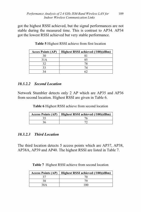
Performance Analysis of 2.4 GHz ISM-Band Wireless LAN for Indoor Wireless Communication Links
109
got the highest RSSI achieved, but the signal performances are not stable during the measured time. This is contrast to AP34. AP34 got the lowest RSSI achieved but very stable performance.
Table 5 Highest RSSI achieve from first location
Acces Points (AP) Highest RSSI achieved (/100)(dBm) 30 81
31A 85 32 78 33 74 34 62
10.3.2.2 Second Location Network Stumbler detects only 2 AP which are AP35 and AP36 from second location. Highest RSSI are given in Table 6.
Table 6 Highest RSSI achieve from second location
Access Points (AP) Highest RSSI achieved (/100)(dBm) 35 76 36 72
10.3.2.3 Third Location
The third location detects 5 access points which are AP37, AP38, AP38A, AP39 and AP40. The highest RSSI are listed in Table 7.
Table 7 Highest RSSI achieve from second location
Access Points (AP) Highest RSSI achieved (/100)(dBm) 37 70 38 79
38A 100

Advances in Free Space Optical Technology
110
39 87 40 85
10.3.2.4 Factors Contribute to a RSSI Reduction Interference caused by walls, corners and people movement is some of the factors that contribute to the signal fading and distortion. AP39 is chosen for reference to study the effect to the wireless signal. Signals are transmitted from AP39 at second floor and measured at first floor and ground floor in the same building. This measurement method can be use to study the effect of interference by wall. Figure 3 illustrates the huge loss occurred when the signal penetrate through walls. More losses occurred from ground floor to 2nd floor due to more walls to penetrate and longer distance from AP. The UA2 block design has U-shape corner which can cause diffraction and reduce the signal strength. The fluctuations of signal strength due to penetration by corner are shown in Figure 4. While, the Figure 5 shows a small amount of interference cause by people movement compared to walls. The reduction is around 15dBm.
(a) RSSI at AP39 (Second Floor)
(b) RSSI at First Floor

Performance Analysis of 2.4 GHz ISM-Band Wireless LAN for Indoor Wireless Communication Links
111
(c) RSSI at Ground Floor
Figure 3 Interference by walls
Figure 4 Penetration of Signal Strength by U-shape Corner
Figure 5 Interference by people movement
10.3 CONCLUSION Performance of indoor radio wave propagation inside building was predicted and the objectives of this work have been achieved. The measurement has successfully done within 2nd floor, block UA2, College 9, Universiti Teknologi Malaysia. Wireless Local Area Networks (WLANs) 802.11g standard with 22Mbps at 2.4GHz operating frequency had been setup. The results show that the signal strength is differ due to several factors such as distance, file size, walls, corner and people movement people during the transmission.
It was suggested that further measurement can be done in future to study the signal performance in this area at different carrier
Advances in Free Space Optical Technology
112
frequency. The effect of WLAN network 5.2GHz carrier frequency (Unlicensed National Information Infrastructure (UNII) band) can be use and compare to the 2.4GHz ISM band. Finally, it is very interesting to investigate the interference cause by other devices operating at same UNII band.
REFERENCES [1] [2] [3] [4] [5] [6]
Wen Ching Chang, Yang Han Lee, Chih Hui Ko, Chun Ku Chen (2001). A Novel Prediction Tool for Indoor Wireless LAN under the Microwave Oven Interference. Tamkang University, Taiwan. Bates R. J. (1994). Wireless Networked Communications. New York, McGraw-Hill. Simpson R. (1992). Spread Spectrum Wireless Information Networks for the Small Office. Kluwer Academic Publishers: Boston, MA. Jing Lei, Roy Yates, Larry Greenstein, Hang Liu (2004). Wireless Link SNR Mapping Onto An Indoor Testbed. WINLAB, Rutgers University, USA. T. S. Rappaport (2002). Wireless Communications: Principles and Practice. Second Edition, Prentice Hall. Leslie Ann Rusch (2001). Indoor Wireless Communications: Capacity and Coexistence on the Unlicensed Bands. Intel Technology Journal.

113
11
CHANNEL ASSIGMENT AND MAC PROTOCOL FOR INDOOR WIRELESS
INFRARED AD HOC NETWORK Zukarmawan Abu Bakar
Roger J.Green
11.1 INTRODUCTION. This chapter discusses our proposed channel assignment and reassignment method and MAC protocol algorithm for wireless infrared ad-hoc networking based on our transceiver design which utilises directional emitters and is fully controlled by microcontroller M16/C. In channel assignment two control handshake signal codes are used; the SCAN and INFORM signals which are conveyed on two different carrier frequencies/channels. The channel assignment and reassignment method together with the directional emitters enable to resolve the problem of co-channel interference. Five control handshake signals; two directional Request to Send (RTS), two directional Clear to Send (CTS) and a directional Acknowledgement (ACK), are used at Medium Access Control (MAC) protocol for resolving potential collisions among the transceivers. Two known popular problems in Ad-Hoc network; the exposed terminal and hidden terminal problems are efficiently managed by our MAC protocol. Ad hoc networking is a network, when a number of mobile terminals (MTs) (e.g. laptops, PDA) communicating with each other without any infrastructure device such as a base station. The absence of the infrastructure device which normally organising and controlling the network (e.g. in wireless LAN or cellular network)

114 Channel Assigment And Mac Protocol For Indoor Wireless Infrared Ad Hoc Network
has made ad-hoc network very challenging to manage. Example applications of ad-hoc networks are in the meeting or conference room when the participants wish to share any information between them, in emergency situations such as a situation in an earthquake disasters when emergency rescuers would like to quickly exchange information but all the communication infrastructures have collapsed and etc. Three types of physical layer interfaces have been featured in the standard IEEE 802.11 namely; Direct Sequence and Frequency Hopping which uses the Radio Frequency (RF) systems and the other is Infrared systems on band 850 nm to 950 nm. Generally three important factors must be design efficiently to realise ad-hoc networking; the routing protocols which are useful for multihop communication, the MAC protocols and the channel assignment algorithms. Although there have been many research discussing extensively about ad-hoc networking but most of them have been concerned with RF systems as discussed in [4-21]. Infrared systems can also offer some significant advantages over its RF counterpart such as; the transmission bandwidth being generally larger, higher security (because the radiation is confined into one room), no license is needed when commissioned and other beneficial factors. Papers [1-2] reviewed the issues of infrared systems in general. The challenging issues when designing the physical device, the channel assignment and the MAC protocols are the exposed and the hidden terminal problems. In this paper, it is the authors intention to discuss only about the channel assignment algorithm and the MAC protocols. We have constructed three transceivers for indoor infrared wireless ad-hoc network utilising directional emitters. The rest of the paper is organised as follows; Section 11.2 presents the general review of some single and multichannel MAC protocols and channel assignment. Section 3 describes the infrared transceiver description and operations Section 4 discusses our proposed channel assignment and followed by section 5 which discusses our proposed MAC protocol based on directional emitter. Finally the conclusion in section 11.6.

Advances in Free Space Optical Technology 115
11.2 REVIEW: MAC PROTOCOLS AND CHANNEL ASSIGNMENT
MAC protocols can be divided into two types; Single channel MAC and the Multichannel MAC. In single channel MAC, only one carrier frequency/channel is used to transmit any control handshakes signal while in multichannel MAC, multiple carrier frequencies/channels are used to convey the control handshakes signal.
In single channel MAC protocols, there have been many papers proposed attempting to reduce the hidden and exposed terminal problems. Among them are as discussed in [5] and [6]. In [5] the authors introduces Multiple Access with Collision Avoidance (MACA) with the introduction of short handshake messages of Request to Send (RTS) and Clear to Send (CTS) where both the RTS and CTS blocks other mobile terminals to interfere while communication between two mobile terminals are taking place and is proven to reduce the hidden terminal problem. In [6], the authors introduces the Multiple Access with Collision Avoidance for Wireless LAN(MACAW) which adopted (RTS/CTS/DATA/DS/ACK) and the performance is improved over MACA by adding some extra control signals; data sending (DS) and acknowledgement (ACK).
This is the solution adopted by IEEE standard 802.11 for wireless MAC in the Distributed Coordination Function (DCF) along with the CSMA scheme. However according to [7], the author claimed that MACA and MACAW didn’t fully resolved the hidden and exposed terminal problems.
All the protocol above assumed a single channel MAC where a single channel is shared by the mobile terminals. The probability of collisions between control handshakes signal is higher in a

116 Channel Assigment And Mac Protocol For Indoor Wireless Infrared Ad Hoc Network
single channel environment as the number of mobile terminals participating in the an-hoc network increases.
Therefore multiple channels for control handshake signals are preferred as it can offers some significant performance improvement over single channel MAC protocols such as; lower the probability of collisions between the control handshake signals, as they are conveyed on the different channels and hence higher throughput can be achieved.
In [7], [10], [11] and [12], the authors proposed their MAC protocols based on the multiple channel schemes. In [7] the author proposed Dual Busy Tone Multiple Access (DBTMA) specially to combat the hidden and exposed terminal problem. Two busy tones are required, where one of them is set up by the transmitter to protect the RTS signals and the other one is set up by the receiver when receiving data. All mobile terminals hearing the busy tone keep silent. It requires a separate channel for the busy tones and it reserve one channel for data transfer. The simulations results show that the DBTMA is superior to other schemes that rely on RTS/CTS signals on a single channel. In [10], the author proposed the Request to Send (RTS)/Object to send (OTS)/Carrier sensing (CS)/Agree to send (ATS) or ROSA where two separates channel are used; the data channel where the data/information is transmitted while the the control handshake signals (e.g. RTS, OTS and etc.) are transmitted on the control channel.
All the MAC protocols above assumed omnidirectional antennas. Although the omnidirectional antenna radiation is 360o which offers better coverage but in certain applications omdirectional antenna offers some disadvantages if the MAC protocols is not carefully design to combat the hidden/exposed terminal problems. The radiation of a directional antenna is focus into one direction and thus this will reduces more interferences compare to omdirectional antenna. A study has been conducted in [3], where the effort to compare between the omdirectional and directional antenna-based MAC protocols is done. Obviously from

Advances in Free Space Optical Technology 117
their discussions, directional antenna offer certain advantages against omnidirectional antenna. References [14-15], designed their MAC protocols based on directional antennas. In [14], the MAC protocols control the directional antennas by setting them to active and passive modes. In this approach, the control handshake signals are only sent to the intended mobile terminal without interfering another mobile terminal. While in [15], although the directional antennas are exploited but additional device such as a GPS is needed to determine the physical locations of mobile terminals which will add costs to the system.
References [16-21], discussed together issues about the channel assignment method, and about MAC protocols. In [17], on demand, dynamic and location awareness channel assignment, GRID-B has been proposed, but needs additional devices such as GPS for location awareness. Two pairs of communicating transceivers utilising the same unique channel may interfere with each other, if their radiation patterns overlap each other, and thus produce co-channel interference. In [19], the authors proposed the channel assignment and reassignment protocols, to eliminate the co-channel interference.
11.3 INFRARED TRANSCEIVER DESCRIPTION AND OPERATIONS.
Figure. 3 shows the block diagram and the layout of the transceiver [22]. The channel assignment and MAC protocols algorithm programs are embedded into the memory of M16C microcontroller. The features of the transceiver are as the following;

118 Channel Assigment And Mac Protocol For Indoor Wireless Infrared Ad Hoc Network
Figure 1 The block diagram and the layout of the infrared transceiver
1) A transceiver employs an on-off keying modulation method and
equipped with two directional emitters where each one them is driven by the amplifier and the led/emitter drivers at the transmitter and it also has four photodetectors and corresponding band pass filters to pass the desired selected carrier frequencies and they are fully controlled by the microcontroller M16C.
2) It has a carrier frequencies/channels source which is programmabled via the M16/C microcontroller. It is set to generate five carrier frequencies (f1, f2, f3, f4 and f5).
3) The directional emitters and photodiodes can be set active/non active independently based on the situations of the channel assignment and MAC protocols algorithm
Advances in Free Space Optical Technology 119
Assuming that a transceiver is assigned a carrier f1 which then modulated on-off keying the random data, and the modulated data is then amplified and transmitted via one of the emitters selected by the M16/C. Upon reception at the front end, the M16/C selects an appropriate photodetector which best receives the carrier f1, and it then goes through the process of amplification and rectification and subsequently passing through the corresponding band pass filter (bpf) for carrier f1, also selected by M16C, and it is then ‘squared up’ by the comparator to obtain the original data.
11.4 CHANNEL ASSIGNMENT DESCRIPTIONS In a traditional network (e.g. wireless LAN), each participating transceiver is assigned a unique carrier frequency/unique channel; either the terminal is fixed with a unique channel, or is assigned by a base station. In an ad-hoc network, the channel assignment is done autonomously and dynamically. An algorithm for the negotiation process allows each transceiver to be assigned a unique channel and reassignment of the unique channel (reused frequency in a cellular network). Each transceiver sends a data packet using its unique channel to its neighbours and is able to receive and transmit data concurrently, if the data packets are transmitted/received at the different emitters and photodetectors. Two main stages are needed for unique channel allocations; the discovery stage, where the control signals handshakes are used to detect the participant transceivers within one hop, and the unique channel assignment stage, where the unique channels are assigned to the participant transceivers. Two types of control signal handshakes are; the SCAN control signal which is conveyed on carrier signal f4, and the INFORM control signal which is conveyed on carrier signal f5. The unique channel is selected

120 Channel Assigment And Mac Protocol For Indoor Wireless Infrared Ad Hoc Network
based on a programmable table, which contained the list of the unique channels (f1, f2 and f3) that are controlled by the M16/C. The unique channel f1 is allocated to any of the transceivers which receives the SCAN signal and the unique channel f2 is allocated when any of the transceiver receives the INFORM signal. Note that no other control signal response is made by any of the transceivers which receives the INFORM signal; instead it proceeds with the unique channel assignment. Let us consider three scenarios to visualise the channel assignment algorithm as listed below;
1) Scenario 1: As shown in Figure. 2. In this scenario, assume only two transceivers are participating in the network, and transceiver Y initiates the SCAN signal. The SCAN signals are transmitted via the emitter 1 and emitter 2. At transceiver X, the SCAN signal is received via photodiode B, and when the M16C microcontroller identifies it as a SCAN signal, it will select carrier frequency f1, and it is then allocated to transceiver X as its unique channel, and recognises transceiver Y as its neighbour. It will also reply with INFORM signal via emitter 2. Transceiver Y receives the INFORM signal via photodiode A, and, as the M16C recognises it as an INFORM signal, it will then allocate a carrier frequency f2 for transceiver X as its unique channel and recognise transceiver X as its neighbour. At the end of the control signals handshake, as shown in the circle, transceiver X and transceiver Y are allocated with unique channels f1 and f2 respectively. If transceiver X wants to send a message, it will do so via the unique channel f1, and the same concept applies to transceiver Y, but via the unique channel f2.
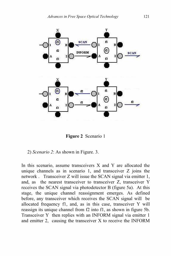
Advances in Free Space Optical Technology 121
Figure 2 Scenario 1
2) Scenario 2: As shown in Figure. 3.
In this scenario, assume transceivers X and Y are allocated the unique channels as in scenario 1, and transceiver Z joins the network . Transceiver Z will issue the SCAN signal via emitter 1, and, as the nearest transceiver to transceiver Z, transceiver Y receives the SCAN signal via photodetector B (figure 5a). At this stage, the unique channel reassignment emerges. As defined before, any transceiver which receives the SCAN signal will be allocated frequency f1, and, as in this case, transceiver Y will reassign its unique channel from f2 into f1, as shown in figure 5b. Transceiver Y then replies with an INFORM signal via emitter 1 and emitter 2, causing the transceiver X to receive the INFORM

122 Channel Assigment And Mac Protocol For Indoor Wireless Infrared Ad Hoc Network
signal, and reassign its unique channel carrier from f1 to f2, and also this results in transceiver Z being allocated with unique channel f2.
3) Scenario 3: As shown in Figure. 4.
In this scenario, assume there are three transceivers participating in the network, and transceiver Y issues the SCAN signal via emitter 1 and emitter 2. Transceiver X and transceiver Z receive the SCAN signal via their corresponding photodiodes, and unique channel f1 is assigned to both of the transceivers. Due to the reception of the SCAN signal, transceiver X and transceiver Z issue the INFORM signals, and, as a result of this, the unique channel f2 is assigned to transceiver Y (figure 6a). All the transceivers then, if they wish to send any data, do so through their respective unique channels ( figure 6b).
From the discussions above, we have observed that the unique channel assignment and reassignment algorithm ensure that no identical unique channels are assigned to the transceivers within one hop(e.g. transceivers X and Y are within one hop while transceiver X and Z are two hops apart). This is essential to avoid co-channel interference between them.

Advances in Free Space Optical Technology 123
Figure 3 Scenario 2
11.5 MAC PROTOCOLS DESCRIPTION In order to best utilise the directional emitters, a MAC protocol must be designed accordingly to exploit the features of the directional emitters. This MAC protocol has some similarity with IEEE 802.11 which, this protocol is based on control handshakes signal; Request to Send(RTS), Clear to Send(CTS) and Acknowledgement (ACK) but with a different approach [20]. In this paper exploits a different approach to that in paper [20]. We have two RTS control signals(RTS1 and RTS2) and two CTS control signals(CTS 1 and CTS 2). We adopts multichannel approach in our protocols where RTS1 and RTS2 are conveyed on unique channel f4, and the CTS1, CTS2 and ACK are conveyed in unique channel f5. In this approach can hinder the collisions between the control handshake signals.
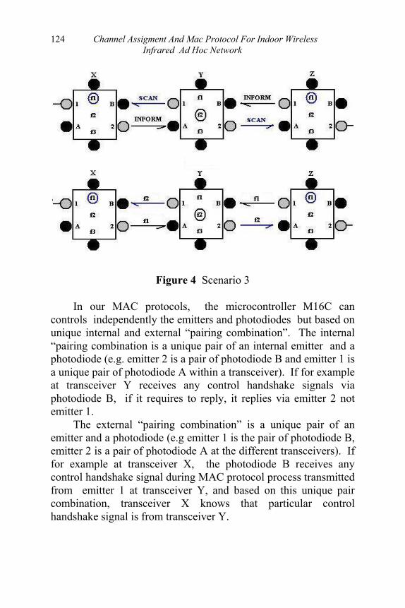
124 Channel Assigment And Mac Protocol For Indoor Wireless Infrared Ad Hoc Network
Figure 4 Scenario 3 In our MAC protocols, the microcontroller M16C can controls independently the emitters and photodiodes but based on unique internal and external “pairing combination”. The internal “pairing combination is a unique pair of an internal emitter and a photodiode (e.g. emitter 2 is a pair of photodiode B and emitter 1 is a unique pair of photodiode A within a transceiver). If for example at transceiver Y receives any control handshake signals via photodiode B, if it requires to reply, it replies via emitter 2 not emitter 1. The external “pairing combination” is a unique pair of an emitter and a photodiode (e.g emitter 1 is the pair of photodiode B, emitter 2 is a pair of photodiode A at the different transceivers). If for example at transceiver X, the photodiode B receives any control handshake signal during MAC protocol process transmitted from emitter 1 at transceiver Y, and based on this unique pair combination, transceiver X knows that particular control handshake signal is from transceiver Y.
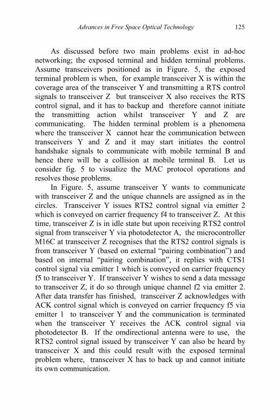
Advances in Free Space Optical Technology 125
As discussed before two main problems exist in ad-hoc networking; the exposed terminal and hidden terminal problems. Assume transceivers positioned as in Figure. 5, the exposed terminal problem is when, for example transceiver X is within the coverage area of the transceiver Y and transmitting a RTS control signals to transceiver Z but transceiver X also receives the RTS control signal, and it has to backup and therefore cannot initiate the transmitting action whilst transceiver Y and Z are communicating. The hidden terminal problem is a phenomena where the transceiver X cannot hear the communication between transceivers Y and Z and it may start initiates the control handshake signals to communicate with mobile terminal B and hence there will be a collision at mobile terminal B. Let us consider fig. 5 to visualize the MAC protocol operations and resolves those problems. In Figure. 5, assume transceiver Y wants to communicate with transceiver Z and the unique channels are assigned as in the circles. Transceiver Y issues RTS2 control signal via emitter 2 which is conveyed on carrier frequency f4 to transceiver Z. At this time, transceiver Z is in idle state but upon receiving RTS2 control signal from transceiver Y via photodetector A, the microcontroller M16C at transceiver Z recognises that the RTS2 control signals is from transceiver Y (based on external “pairing combination”) and based on internal “pairing combination”, it replies with CTS1 control signal via emitter 1 which is conveyed on carrier frequency f5 to transceiver Y. If transceiver Y wishes to send a data message to transceiver Z, it do so through unique channel f2 via emitter 2. After data transfer has finished, transceiver Z acknowledges with ACK control signal which is conveyed on carrier frequency f5 via emitter 1 to transceiver Y and the communication is terminated when the transceiver Y receives the ACK control signal via photodetector B. If the omdirectional antenna were to use, the RTS2 control signal issued by transceiver Y can also be heard by transceiver X and this could result with the exposed terminal problem where, transceiver X has to back up and cannot initiate its own communication.
126 Channel Assigment And Mac Protocol For Indoor Wireless Infrared Ad Hoc Network
Now assume, transceiver X wants to initiate the communication with transceiver Y while transceivers Y and Z are communicating. As described above, the microcontroller M16C can control independently the emitters and photodiodes but based on unique internal and external “pairing combination”. In this case while transceivers Y and Z are communicating, even though the internal and external “pairing combinations” at the other side of transmitter Y (the side facing transceiver X) do not play any role for communication between transceiver Y and Z, but they are in the idle/ready state and can be made active if any of the communication links required. In this way, transceivers X and Y can communicating with each other (as the concept explained before) while transceiver Y and Z are communicating. At this moment microcontroller M16/C at transceiver Y switches concurrently the pairs of communicating transceivers and this will hinder the hidden terminal problem.
11.6 CONCLUSIONS
Two control handshakes signals are used at channel assignment protocol and efficiently assign different channels within one hop communication while at MAC multichannel MAC protocols concept are adapted where five control handshakes signals are used and can hinder the exposed and hidden terminal problems.

Advances in Free Space Optical Technology 127
Figure 5 Visualisation of the MAC protocols
REFERENCES
[1] Ramirez-Iniguez, R., Green R.J, “Indoor Optical Wireless
Communications”, IEE Colloquium Optical Wireless Communications, 1999, pp. 14/1 – 14/7.
[2] Heatley, D.J.T.; Wisely, D.R.; Neild, I.; Cochrane, P.; “ Optical wireless: the story so far “ IEEE Communications Magazine , Volume: 36 Issue: 12, Dec 1998, pp. 72 –82.
[3] Zhuochuan Huang, and Chien-Chung Shen, “A comparison study of omnidirectional and directional MAC protocols for ad hoc networks” Global Telecommunications Conference, 2002, Volume 1, Nov 2002, pp. 57-61.
[4] F.A Tobagi and L. Kleinrock, “Packet switching in radio channels: Part II – the hidden terminal problem in carrier sense multiple access modes and the busy tone solution”, IEEE Transaction Communication, vol 23, no. 12, 1975, pp. 1417-1433.
128 Channel Assigment And Mac Protocol For Indoor Wireless Infrared Ad Hoc Network
[5] P. Karn, “MACA – A new channel access method for packet radio”, Proceeding ARRL/CRRL Amateur Radio 9th Computer Networking Conference, 1990, pp. 134-140.
[6] Bhargavan; A Demers; S. Shenker and L. Zhang, “A media access protocol for wireless LAN’s”, Proceeding ACM SIGCOMM, 1994, pp. 212-225.
[7] Z.J. Haas and J. Deng, “Dual busy tone multiple access (DBTMA) – Performance evaluation”, Proceeding IEEE Vehicular Technology Conference, 1999, pp. 314-319.
[8] C.L. Fullmer and J.J. Garcia-Luna-Aceves, “Floor acquisition multiple access (FAMA) for packet radio networks”, Proceeding ACM SIGCOMM, 1995, pp. 262-273.
[9] Qingchun Ren and Wei Guo, “A novel medium access control (MAC) protocol for ad hoc network”, International Conference Advanced Information Networking and Applications, March 2003, pp. 521 –524.
[10] Hairong Zhou; Chi-Hsiang Yeh; Mouftah, H., “ A solution for multiple access in variable-radius mobile ad hoc networks”, IEEE International Conference Communications, Circuits and Systems and West Sino Expositions, Vol 1, 2002, pg. 150 –154.
[11] C.H. Yeh, “ROC: A wireless MAC protocol for solving the moving terminal problem”, Proceeding IEEE International Conference Wireless LANs and Home Networks, 2001, pp. 182-189.
[12] C.H. Yeh, “ROAD : A class of variable-radius MAC protocols for ad hoc wireless networks”, Proceeding IEEE vehicular Technology Conference, 2002, pp. 399-403.
[13] Lopez-Rodriguez, D., Perez-Jimenez R., “Distributed method for channel assignment in CDMA based “ad-hoc” wireless local area networks”, IEEE Symposium Technologies for Wireless Applications, Feb. 1999, pp. 11 –16.
[14] Nasipuri A.; Ye S.; You J.; Hiromoto R.E., “A MAC protocol for mobile ad hoc networks using directional

Advances in Free Space Optical Technology 129
antennas”, IEEE Wireless Communications and Networking Conference, Vol 3 , Sept. 2000, PP. 1214 –1219.
[15] Young-Bae Ko; Shankarkumar, V.; Vaidya N.H., “Medium access control protocols using directional antennas in ad hoc networks”, INFOCOM 2000. Nineteenth Annual Joint Conference of the IEEE Computer and Communications Societies, Vol 1, 2000 , pp. 13 –21.
[16] Yu-Chee Tseng; Shih-Lin Wu; Chih-Yu Lin; Jang-Ping Sheu, “A multi-channel MAC protocol with power control for multi-hop mobile ad hoc networks” International Conference Distributed Computing Systems Workshop, 2001, pp. 419 –424.
[17] Yu-Chee Tseng, Chih–Min Chao, Shih-Lin Wu, Jang-Ping Sheu, “Dynamic channel allocation with location awareness for multi-hop mobile ad hoc networks”. Computer Communications 25, Vol 7, 2002, pp. 676-688
[18] Young-Bae Ko, Shankarkumar, V., Vaidya N.H., “Medium access control protocols using directional antennas in ad hoc networks”, INFOCOM 2000. Nineteenth Annual Joint Conference of the IEEE Computer and Communications Societies, Vol 1, 2000 , pp. 13 –21.
[19] Shih-Lin Wu, Chih-Yu Lin, Yu-Chee Tseng, Jang-Ping Sheu, “A new multi-channel MAC protocol with on-demand channel assignment for multi-hop mobile ad hoc networks”, Proceedings International Symposium Parallel Architectures, Algorithms and Networks, 2000 pp. 232 – 237.
[20] Chih-Yung Chang, Chao-Tsun Chang, Po-Chih Huang, “Dynamic channel assignment and reassignment for exploiting channel reuse opportunities in ad hoc wireless networks”, The 8th International Conference on Communication Systems, vol 2, Nov 2002, pp. 1053-1057.
[21] Lopez-Rodriguez D. Perez-Jimenez R., “Distributed method for channel assignment in CDMA based “ad-hoc” wireless local area networks”, IEEE Symposium

130 Channel Assigment And Mac Protocol For Indoor Wireless Infrared Ad Hoc Network
Technologies for Wireless Applications, Feb. 1999, pp. 11-16.
[22] Z. Abu Bakar and R.J Green, “Realising Indoor Infrared Ad Hoc Networking”, Proceedings PREP 2004, Hertfordshire, April 2004, pp. 15-16.

131
12
THE USE AND EFFECTIVENESS OF WIRELESS NETWORK SERVICE IN
UTM COLLEGES Sevia M.Idrus
Mohd Hadi A. Rani Mohd Farid Sarji
12.1 INTRODUCTION. This chapter presents the analysis of the usage and effectiveness of wireless network services (WNS) in UTM colleges. To maintain a high quality of communication in an infrastructure network, the construction of one or more wireless access points (AP) is necessary. For economic reasons and radio spectrum conversation, AP should be placed well to achieve the optimum coverage region for wireless communication. Hence in this work, the information for building interior database and database for access point (AP) are gathered within College 17, UTM. Performance and measurement analysis has been made in term of signal strength coverage, throughput, transaction rate, lost data and delay within the area. Customer survey has been done to gain response about the service from the respondent. The survey was analyzed to answer questions about where, when, how much, and for what the wireless network is being used. Such information is important in evaluating design principles and planning for future network expansion of the UTM wireless network service at student colleges. As internet is widely adopted for educational purposes, e-learning is often interchangeably used with web-based learning or

132 Advances in Free Space Optical Technology
learning with technology. Also, there are many studies, suggesting effective strategies for e-learning. The studies on e-learning seem to show the case of large universities, equipped with luxury facilities or at least having potential to do so. Their findings, thus, do not make any sense to the case of the universities with little infra structure on providing internet network to the student. In today’s campus life, access to the internet can be consider as an important necessity to students. It seems a mirror image of the current educational environment. The current research aims to better understanding of e-learning and its reality on campus and to find solutions to improve its environment. Hence, it is a necessity to any university who endeavor e-learning to provide the internet facility to student thus they have good access to the internet either in campus or at their own room in college. In the evolution of computer network access, wireless computer networking or wireless network service (WNS) can be seen as the next step. Wireless service is intended as a convenience for portable use. It is not a general substitute for the normal wired network. The wireless network uses shared access points with substantially slower data transfer speeds than the switched wired network. Additionally, the wireless network is not secure; unencrypted connections can be easily captured by others. One of the major attractions of wireless as a medium for computer networking is its ability to easily accommodate dynamic changes. This translates into a system that can easily and effectively accommodates both office and network topological changes. It also means that the network can be quickly relocated meeting not only the needs of a dynamic room structure or temporary but also the needs of our group of nomadic workers. 12.2 WIRELESS AGAINST WIRED NETWORK SERVICE Most large universities have been quick in introducing of their wireless networking service to the staff and students. A debate has also sprung up as to what is the best solution for wireless

The Use And Effectiveness Of Wireless Network Service In UTM Colleges 133
computing like many of the networking solutions of the past. This debate caught the interest of the standards boards and efforts are being made to standardize these networks. In order to understand the standards situation, there is a need to understand the topologies of a wireless network versus a wired network. Convenience is the primary reason for using a wireless medium instead of a wired alternative. Although, with networked multimedia software packages, transmission speed is a pressing concern, wireless networking usually involves the networking of portable computers. These portable units are traditionally slower than desktop, which use wired networks. As a result, the megabit ranges achievable on a wireless medium fall well within the needed transmission rates. However, convenience alone does not completely the answer of why the choice would be a wireless instead of a wired medium. Many have argued that users have grown accustom to having to wire a computer network and will not perceive the need to physically wire their portable units as an inconvenience. Others, however, have pointed out that society is becoming increasingly accustomed to a wide range of wireless conveniences such as cellular phones and the next logical step is wireless networking of portable computers. However, the question that still remains is whether or not there are sufficient applications or situations where users would require wireless as their means of network access. What about the university student? Would they also get benefit from wireless connections? There are many reason can be made when the university move forward to provide wireless medium the student. In many of today’s student life, the study room layout can be dynamic. With WNS infrastructure available on campus, student can access to the internet thus interact to wider knowledge source i.e the internet in mobile. A look at the desired features in a wireless local area network (WLAN) will provide further insight into the architectural issues of this form of networking. The reasons for this included high prices, low data rates, occupational safety concerns, and licensing requirements. As these problems have been addressed, the

134 Advances in Free Space Optical Technology
popularity of wireless LANs has grown rapidly. A suitable balance between service performance, network efficiency, and terminal cost will generally have to be realized through subjective engineering judgment rather than service optimization.
12.3 WIRELESS NETWORK SERVICE IN UTM CAMPUS
In the case of Universiti Teknologi Malaysia (UTM), the university has made a good move to provide internet infrastructures to student. The university can be consider well-equipped in term of wired network compared to many university in developing countries. Since the current situation and campus trend that are more mobile facility are needed, thus the WSN need to be provided to the whole UTM campus either in Skudai or College of Science and Technology in Kuala Lumpur to improved student accessibility to the internet. Wireless network service is available throughout the UTM Skudai campus; this is shown by Figure 1. The Center for Information & Communication Technology of UTM (CICT), has provided three hot spots for each student colleges which the installations begins early 2007. The wireless network design is using ‘Thin Client’ technology where the technology control directly to the wireless controller server in CICT compare the wireless built by other WNS service provider where using open access and unsecured. The wireless service also covered to the International Blocks at two colleges using ‘Bridging Point to Multi Point’ technology. This service is provided and managed by the CICT, which they has provides general information about wireless service, including campus buildings with coverage, recommended wireless adapters, and configuration information at their website. At the students’ colleges, the access points (AP) was place at the most common areas to the student such as at the cafeteria or college administration office. Most of the faculties and departments in UTM have WNS coverage and usually monitored by the IT units
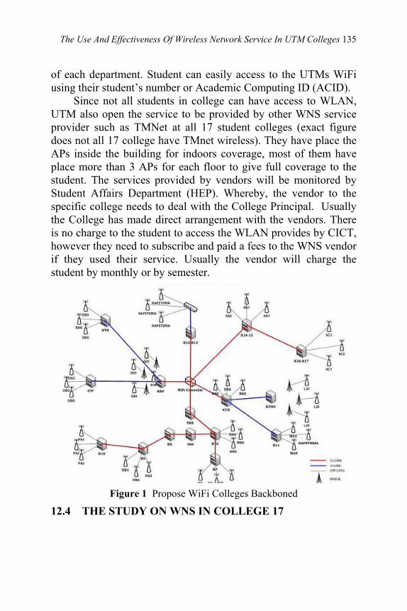
The Use And Effectiveness Of Wireless Network Service In UTM Colleges 135
of each department. Student can easily access to the UTMs WiFi using their student’s number or Academic Computing ID (ACID). Since not all students in college can have access to WLAN, UTM also open the service to be provided by other WNS service provider such as TMNet at all 17 student colleges (exact figure does not all 17 college have TMnet wireless). They have place the APs inside the building for indoors coverage, most of them have place more than 3 APs for each floor to give full coverage to the student. The services provided by vendors will be monitored by Student Affairs Department (HEP). Whereby, the vendor to the specific college needs to deal with the College Principal. Usually the College has made direct arrangement with the vendors. There is no charge to the student to access the WLAN provides by CICT, however they need to subscribe and paid a fees to the WNS vendor if they used their service. Usually the vendor will charge the student by monthly or by semester.
Figure 1 Propose WiFi Colleges Backboned
12.4 THE STUDY ON WNS IN COLLEGE 17
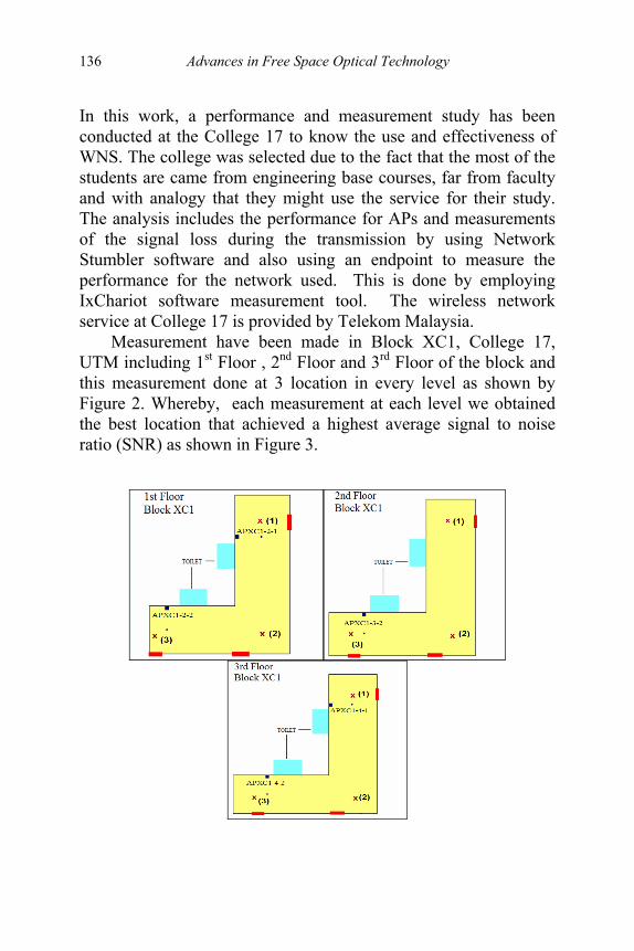
136 Advances in Free Space Optical Technology
In this work, a performance and measurement study has been conducted at the College 17 to know the use and effectiveness of WNS. The college was selected due to the fact that the most of the students are came from engineering base courses, far from faculty and with analogy that they might use the service for their study. The analysis includes the performance for APs and measurements of the signal loss during the transmission by using Network Stumbler software and also using an endpoint to measure the performance for the network used. This is done by employing IxChariot software measurement tool. The wireless network service at College 17 is provided by Telekom Malaysia. Measurement have been made in Block XC1, College 17, UTM including 1st Floor , 2nd Floor and 3rd Floor of the block and this measurement done at 3 location in every level as shown by Figure 2. Whereby, each measurement at each level we obtained the best location that achieved a highest average signal to noise ratio (SNR) as shown in Figure 3.

The Use And Effectiveness Of Wireless Network Service In UTM Colleges 137
Figure 2 Measurements at 1st Floor, 2nd Floor and 3rd Floor Block XC1
On the other hand, to predict the performances for indoor wireless link the IxChariot measurement software was used. Whereby, 10m and 30m of the distances were used for measurement from the server station so-called Endpoint1. The script file for these measurements is shown in Table 1. Those measurement results can be found in Table 2. The file size used to measure the performance was larger than internet script file. This is due to live file such as video conference that has to sending in the network. From the results, throughput for both increased when the file size increased. At 10m, the throughput was lower than throughput obtained at 30m. There are 0 percent of data was lost at 30m with 10000 file size. The delay increased when the file size increased at 30m. The conclusion that we can made for the Real Media is, when there is a lost of data during transmission, the performance of throughput was decreased. It is due to the delay that happened between Endpoint 1 and Endpoint 2. In additional, the jitters also increased within that time. There are two types of jitter which is RFC 1889 and delay variations. The functions of both jitter is to measure the quality of network and it shows a poor quality of multimedia transmission. In the datagram approach, each packet is treated independently. So, the packets, each with same destination address, do not all follow the same route and they may arrive out sequence at exit point. It is possible for a packet to be destroyed in the network. Consequently, the lost data occurred thus make the performance of the throughput decreased.
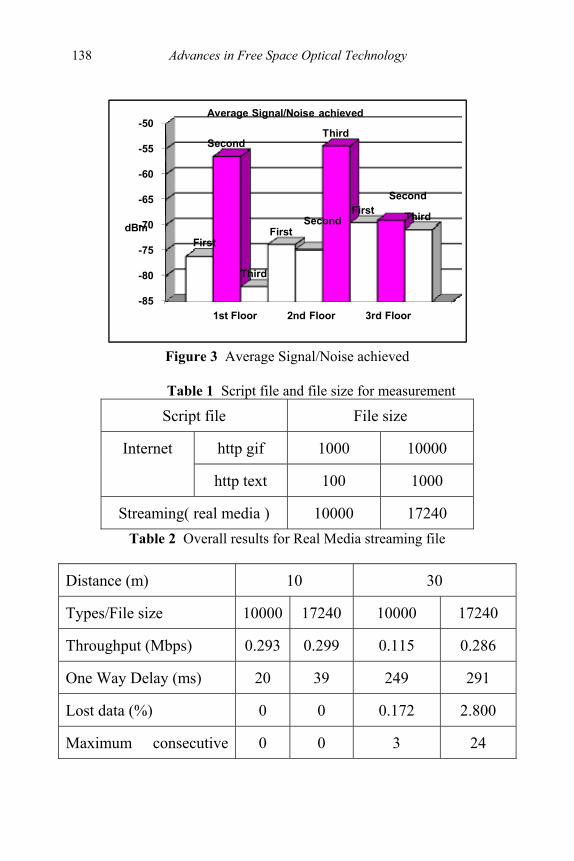
138 Advances in Free Space Optical Technology
-85
-80
-75
-70
-65
-60
-55
-50
First
Second
Third
FirstSecond
Third
FirstSecond
ThirddBm
1st Floor 2nd Floor 3rd Floor
Average Signal/Noise achieved
Figure 3 Average Signal/Noise achieved
Table 1 Script file and file size for measurement
Script file File size
http gif 1000 10000 Internet
http text 100 1000
Streaming( real media ) 10000 17240 Table 2 Overall results for Real Media streaming file
Distance (m) 10 30
Types/File size 10000 17240 10000 17240
Throughput (Mbps) 0.293 0.299 0.115 0.286
One Way Delay (ms) 20 39 249 291
Lost data (%) 0 0 0.172 2.800
Maximum consecutive 0 0 3 24
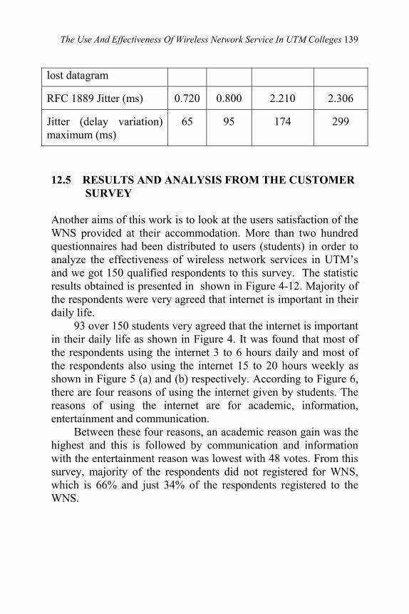
The Use And Effectiveness Of Wireless Network Service In UTM Colleges 139
lost datagram
RFC 1889 Jitter (ms) 0.720 0.800 2.210 2.306
Jitter (delay variation) maximum (ms)
65 95 174 299
12.5 RESULTS AND ANALYSIS FROM THE CUSTOMER
SURVEY Another aims of this work is to look at the users satisfaction of the WNS provided at their accommodation. More than two hundred questionnaires had been distributed to users (students) in order to analyze the effectiveness of wireless network services in UTM’s and we got 150 qualified respondents to this survey. The statistic results obtained is presented in shown in Figure 4-12. Majority of the respondents were very agreed that internet is important in their daily life. 93 over 150 students very agreed that the internet is important in their daily life as shown in Figure 4. It was found that most of the respondents using the internet 3 to 6 hours daily and most of the respondents also using the internet 15 to 20 hours weekly as shown in Figure 5 (a) and (b) respectively. According to Figure 6, there are four reasons of using the internet given by students. The reasons of using the internet are for academic, information, entertainment and communication. Between these four reasons, an academic reason gain was the highest and this is followed by communication and information with the entertainment reason was lowest with 48 votes. From this survey, majority of the respondents did not registered for WNS, which is 66% and just 34% of the respondents registered to the WNS.

140 Advances in Free Space Optical Technology
Figure 4 The importance of internet in daily life
Figure 5 (a) Frequency using internet per day; and (b) frequency using internet per week

The Use And Effectiveness Of Wireless Network Service In UTM Colleges 141
Figure 6 Reason using the internet
12.5.1 Not Registered Student
There are three main reason respondents do not register with the WNS such as 61% o0f them because they have other alternative, 27% due to budget problem and 12% not really use the internet, as shown in Figure 7. For the students that did not register for wireless network service, they have several alternatives to access internet such as at the CICT as the highest alternative followed by the College Cyber Café, the faculty, the library and at their member’s room, that can be referred on the Figure 8.
Figure 7 Why not register
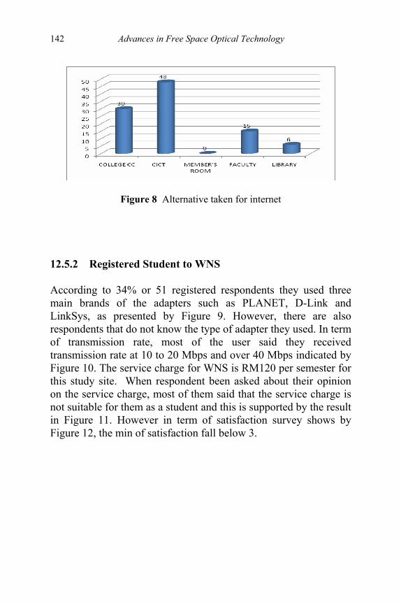
142 Advances in Free Space Optical Technology
Figure 8 Alternative taken for internet 12.5.2 Registered Student to WNS According to 34% or 51 registered respondents they used three main brands of the adapters such as PLANET, D-Link and LinkSys, as presented by Figure 9. However, there are also respondents that do not know the type of adapter they used. In term of transmission rate, most of the user said they received transmission rate at 10 to 20 Mbps and over 40 Mbps indicated by Figure 10. The service charge for WNS is RM120 per semester for this study site. When respondent been asked about their opinion on the service charge, most of them said that the service charge is not suitable for them as a student and this is supported by the result in Figure 11. However in term of satisfaction survey shows by Figure 12, the min of satisfaction fall below 3.
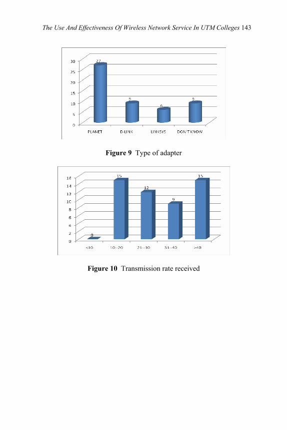
The Use And Effectiveness Of Wireless Network Service In UTM Colleges 143
Figure 9 Type of adapter
Figure 10 Transmission rate received

144 Advances in Free Space Optical Technology
Figure 11 Opinion on wireless service charge
Figure 12 User satisfaction
12.6 CONCLUSION

The Use And Effectiveness Of Wireless Network Service In UTM Colleges 145
The paper has discussed the attractions of wireless as a medium for computer networking and the reason for using a wireless medium instead of a wired network at university. Hence, it was shown that the main factor for e-learning to be effective is that the university need to be well equipped with the information and communication technology (ICT) infrastructure to the student. To look at the use and effectiveness of the WNS available at the UTM colleges, a performance study was conducted. The measurement and analysis of the performance of APs and signal loss during the transmission and an endpoint measurement of the network used have been discussed in this report. This is followed by the customer survey satisfaction study. The customer or user satisfaction rate in UTM is lower due to several reasons such as service charge that not suitable for students, transmission rate received and also available alternatives those students have for using the internet. It was shown that there are four main reasons for using the internet which is for academic, information, entertainment and communication. Whereby, academic reason was found to the highest, thus this is indicates that the internet is very important in UTM student’s daily life. The survey has analyzed to answer questions about where, when, how much, and for what the wireless network is being used. Such information is important in evaluating design principles and planning for future network expansion of the UTM wireless network service at student colleges. The study was only conducted at one college, thus similar works need to be conducted at other colleges and at the faculty to see the overall of use and effectiveness of WNS at UTM.
REFERENCES
[1] Bates R.J. (1994). Wireless Networked Communications. New York: Mc GrawHill.

146 Advances in Free Space Optical Technology
[2] Simpson R. (1992). Spread Spectrum Wireless Information Networks For The Small Office. Kluwer Academic Publishers: Boston, MA.
[3] T.S Rappaport (2002). Wireless Communications: Principles and Practice. Second Edition, Prentice Hall.
[4] Jing Lei, Roy Yates, Larry Greenstein, Hang Liu. (2004). Wireless Link SNR Mapping Onto An Indoor Testbed. WINLAB, Rutgers University, USA
[5] William Stallings (2004). Data and Computer Communications. 7th Edition. Upper Saddle River, New Jersey: Pearson Education Inc.
[6] T.H. Chua (2005). WLAN and Bluetooth Hands-On Training. WCC, FKE, UTM.
[7] Marie T.Conte (1995). Indoor Wireless Networks: An Exploration of Some of The Engineering Issues Involved. Faculty of the University of Delaware: Bachelor of Electrical Engineering.
[8] Richard L. Abrahams, Comparison of Wireless LAN Performance, Intersil Corporation, Palm Bay, Florida.
[9] L.J Greenstein, N.B. Mandayam and I.Seskar. Propagation Models for Short-Range Wireless Channels With Predictable Path Geometries. Members of IEEE.
[10] Hayder Radha, Chiu Yeong Ngo, Takashi Sato and Mahesh Balakrishnan, Multimedia Over Wireless. Philips Research, Briarcliff Manor, New York.
[11] Jorgen Bach Anderson, Theodore S. Rappaport and Susumu Yoshida (1995). Propagation Measurement and Models for Wireless Communications Channels. IEEE Communication Magazine.
Index
147
INDEX
Ambient light, 8, 45, 47 Ad-hoc networking, 110-133 Atmosphere, 23, 33 Avalanche photodiode, 7, 24 Bandwidth, 2, 6, 9, 35, 36, 38 –
42, 45, 46, 48 – 51, 53, 54, 56 – 58, 60, 61, 63, 72, 74, 75, 92, 100
Bootstrap, 40, 42, 45, 50, 58 Bootstrap transimpedance
amplifier, 40, 50, 58 Collimating lenses, 82, 88, 90 Coupling, 46, 57, 66, 83 Detection area, 35, 49, 94 Detector, 13, 18, 22, 31, 40, 42,
45 – 47, 49, 50, 61, 83, 93, 94 Dynamic range, 6, 35, 39, 42,
48, 75 Emitter, 10, 13, 15 – 18, 21 Feedforward linearization, 60,
62, 63, 65, 72, 73, 74, 76 – 81 Free space optics advantages, 2, 27, 36 disadvantages, 2 Large aperture, 35, 46, 57 Laser diode, 6, 7, 60, 61, 66, 72,
74 – 77, 79, 81, 92
intermodulation distortion, 60, 61, 74 – 76, 79 – 81
line of sight, 3, 36, 61, 75, 92, 94
nonlinearity, 60, 62, 65, 74, 76, 77
photodiode capacitance, 38, 40, 47, 48, 51, 52, 55, 58
Taylor Series, 60, 65 GRIN, 82 – 90 High data rates, 23, 29, 34, 101 Index of refraction, 83 – 85 Indoor optical wireless, 1, 6, 8, 10 Infrared, 1, 2, 5 – 7, 9, 13, 16, 18,
21, 22 Infrared system configuration directed, 3, 5 hybrid, 3 – 5 non-directed, 3 – 5 Intensity, 21, 75, 77 Inter-satellite links, 23 Interference, 34, 36, 61, 64, 75, 78,
92, 102, 105 – 107, 109 Intermodulation distortion, 60, 61,
74 – 76, 79 – 81 ISM band, 109, 135

Index
148
Laser transmitter, 23, 60 – 62, 72, 74
Light emitting diode, 7, 37 Linearization technique feedback, 60, 62, 75, 76 feedforward, 60, 62, 63 – 65,
70, 72, 74, 76, 78 – 81 predistortion, 62, 74, 76 Link distance long distance, 2, 15, 24, 46,
57, 104, 106, 107 short distance, 2, 74, 106 Noise, 1, 2, 7, 8, 38, 39, 45 – 49,
61, 64, 67, 68, 77 – 79, 92, 102
Nonlinearity, 60, 65, 74, 76, 77 Optical antenna, 30, 91 – 94, 97 Optical concentrator, 5, 7, 46, 64 Optical fiber, 23, 36, 40, 48, 63,
83, 85, 90 Optical power, 4, 38, 84, 91 Optical wireless, 23, 35 – 42, 45,
46, 48 – 50, 52, 57, 74, 75, 91 – 94
Optical wireless communication indoor, 1, 2, 5, 6, 9 – 11, 92,
99, 108 outdoor, 1, 5, 13, 92, 94, 97 Optoelectronics, 1, 36, 37, 62 Photodetector capacitance, 35, 38, 41 detection area, 35, 49, 94 Photodiode avalanche, 7, 24
capacitance, 38, 40, 47, 48, 51, 52, 55, 58
PIN, 7 Physical layer, 13, 17, 19, 21, 22, 77 Power consumption, 8, 11, 13,
16, 36 Preamplifier, 7, 24, 37 – 40, 47 –
49, 57 Preamplifier circuit bootstrap transimpedance
amplifier, 40, 50, 58 transimpedance amplifier, 39,
40, 45, 50, 51, 58 Radio frequency, 1, 2, 27, 35, 91 Radio wave propagation, 99, 108 Response time, 49, 99, 102, 104 RF spectrum, 36, 79 Satellite, 6, 23 – 25, 27 – 29, 32 –
34 Self alignment receiver, 91 Sensitivity, 6, 7, 20, 21, 38, 46, 48,
49, 57 Signal-to-noise ratio, 91 Space-earth links, 23, 25 Taylor Series, 60, 65 Telecommunication, 74, 98 Throughput, 99, 100, 102 – 105 Transceivers, 6, 16, 18, 22, 30,
46, 60, 61 Transimpedance amplifier, 39,
40, 45, 50, 51, 58 Wavelength, 5 – 8, 10, 17, 18,
21, 26, 27, 36, 64, 74, 78, 79, 83, 93, 94
Wireless network service, 134-7.
Related Documents