P/N: 2900-301556 Rev 1 www.kramerAV.com USER MANUAL MODEL: KDS-7-MNGR 4K AVoIP Manager

Welcome message from author
This document is posted to help you gain knowledge. Please leave a comment to let me know what you think about it! Share it to your friends and learn new things together.
Transcript

P/N: 2900-301556 Rev 1 www.kramerAV.com
USER MANUAL MODEL:
KDS-7-MNGR 4K AVoIP Manager
Kramer Electronics Ltd.
KDS-7-MNGR – Contents i
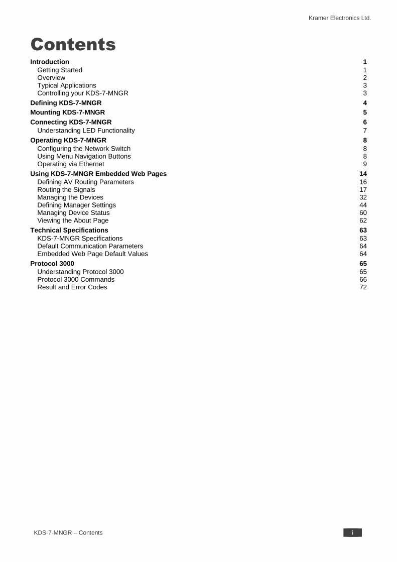
Contents Introduction 1
Getting Started 1 Overview 2 Typical Applications 3 Controlling your KDS-7-MNGR 3
Defining KDS-7-MNGR 4
Mounting KDS-7-MNGR 5
Connecting KDS-7-MNGR 6 Understanding LED Functionality 7
Operating KDS-7-MNGR 8 Configuring the Network Switch 8 Using Menu Navigation Buttons 8 Operating via Ethernet 9
Using KDS-7-MNGR Embedded Web Pages 14 Defining AV Routing Parameters 16 Routing the Signals 17 Managing the Devices 32 Defining Manager Settings 44 Managing Device Status 60 Viewing the About Page 62
Technical Specifications 63 KDS-7-MNGR Specifications 63 Default Communication Parameters 64 Embedded Web Page Default Values 64
Protocol 3000 65 Understanding Protocol 3000 65 Protocol 3000 Commands 66 Result and Error Codes 72
Kramer Electronics Ltd.
KDS-7-MNGR – Introduction 1
Introduction
Welcome to Kramer Electronics! Since 1981, Kramer Electronics has been providing a world
of unique, creative, and affordable solutions to the vast range of problems that confront the
video, audio, presentation, and broadcasting professional on a daily basis. In recent years, we
have redesigned and upgraded most of our line, making the best even better!
Getting Started
We recommend that you:
• Unpack the equipment carefully and save the original box and packaging materials for
possible future shipment.
• Review the contents of this user manual.
Go to www.kramerav.com/downloads/KDS-7-MNGR to check for up-to-date user manuals,
application programs, and to check if firmware upgrades are available (where appropriate).
Achieving Best Performance
• Use only good quality connection cables (we recommend Kramer high-performance,
high-resolution cables) to avoid interference, deterioration in signal quality due to poor
matching, and elevated noise levels (often associated with low quality cables).
• Do not secure the cables in tight bundles or roll the slack into tight coils.
• Avoid interference from neighboring electrical appliances that may adversely influence
signal quality.
• Position your Kramer KDS-7-MNGR away from moisture, excessive sunlight and dust.
Safety Instructions
Caution:
• This equipment is to be used only inside a building. It may only be connected to other equipment that is installed inside a building.
• For products with relay terminals and GPI\O ports, please refer to the permitted rating for an external connection, located next to the terminal or in the User Manual.
• There are no operator serviceable parts inside the unit.
Warning:
• Use only the power cord that is supplied with the unit.
• To ensure continuous risk protection, replace fuses only according to the rating specified on the product label which is located on the bottom of the unit.
Kramer Electronics Ltd.
KDS-7-MNGR – Introduction 2
Recycling Kramer Products
The Waste Electrical and Electronic Equipment (WEEE) Directive 2002/96/EC aims to reduce
the amount of WEEE sent for disposal to landfill or incineration by requiring it to be collected
and recycled. To comply with the WEEE Directive, Kramer Electronics has made
arrangements with the European Advanced Recycling Network (EARN) and will cover any
costs of treatment, recycling and recovery of waste Kramer Electronics branded equipment on
arrival at the EARN facility. For details of Kramer’s recycling arrangements in your particular
country go to our recycling pages at www.kramerav.com/il/quality/environment.
Overview
Congratulations on purchasing your Kramer KDS-7-MNGR 4K AVoIP Manager. KDS-7-
MNGR is the solution for configuration and management of KDS−7 deployments within the
same network. Simply install the unit into the same local network as the extenders (encoders
and decoders) to easily define and configure channel routing selections (including video,
audio, and a variety of control interface types) using the embedded web pages.
Additionally, this unit supports controlling and configuring the matrix, video wall, and KVM
modes of connected KDS−7 devices as well as device grouping and group operations.
The settings of all connected encoder/decoder units, including IP configuration, compatibility
settings, and extender status are clearly displayed and easily updated.
KDS-7-MNGR provides outstanding end-user experience, robust security, and is ideal for
large-scale deployment and operation.
Outstanding End-user Experience
• Instant Auto−discovery and status with preview.
• Access via remote Web UI or by using a local monitor with a USB keyboard and mouse.
Robust Security
• Enterprise IT-grade security − 802.1x and HTTPS/TLS.
• Security certification − OWASP Top 10 certificate.
• Can be deployed in the same LAN used for AV data streaming or in a separate LAN.
Efficient Large-Scale Deployment and Operation
• Highly scalable – manages up to 999 channels.
• Configuration of virtual video matrix, KVM, and video walls.
• Configuration of Device Grouping, Preset Definition, and Activation via UI or APIs.
• FW configuration – For a single device or a group of devices.
• Simple Planning and Rollout – Cost-effective from day one.
• Full product range for any site and any application.
Kramer Electronics Ltd.
KDS-7-MNGR – Introduction 3
Advanced and User-friendly Operation
• Convenient and Comprehensive Control – Control the unit using intuitive embedded web
pages, Protocol 3000 API commands via Ethernet, or front panel LCD and navigation
buttons.
• PoE Support – Powered with PoE connection from PoE switch.
• Keyboard and Mouse Roaming.
• Control Gateway - Through P3K or special TCP connection, users can
control/communicate with IR, RS-232, or CEC to the connected devices.
Typical Applications
KDS-7-MNGR is ideal for the following typical applications:
• Real-time essential installations such as command and control rooms.
• Large scale AV content sharing installations using existing wires and infrastructure in
corporate offices and government applications.
• AV distribution systems with one or more sources and multiple displays in schools,
universities, and public venues.
• AV installations where low latency KM/KVM capabilities are required.
Controlling your KDS-7-MNGR
Control your KDS-7-MNGR directly via Navigation buttons, or via:
• The Ethernet using built-in user-friendly web pages.
• Protocol commands.
Kramer Electronics Ltd.
KDS-7-MNGR – Defining KDS-7-MNGR 4
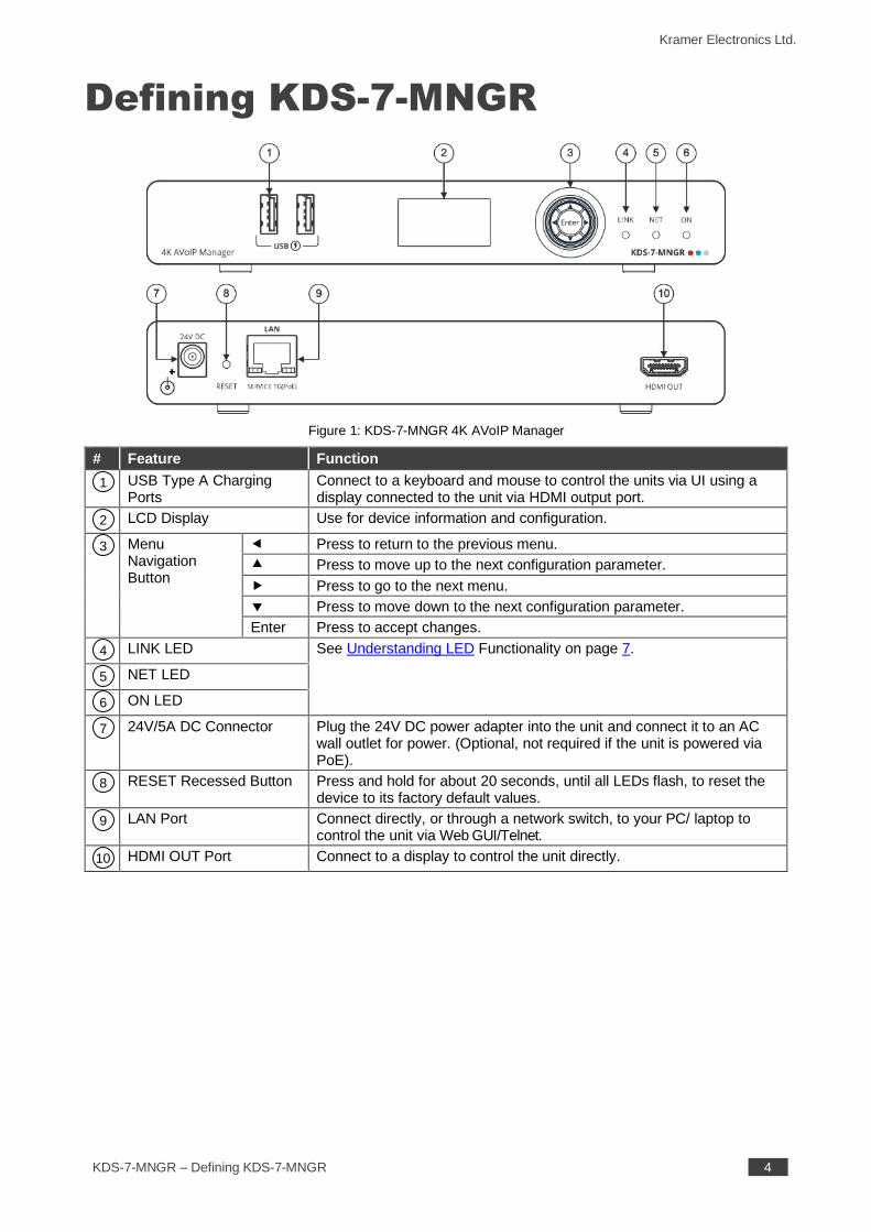
Defining KDS-7-MNGR
Figure 1: KDS-7-MNGR 4K AVoIP Manager
# Feature Function
USB Type A Charging Ports
Connect to a keyboard and mouse to control the units via UI using a display connected to the unit via HDMI output port.
LCD Display Use for device information and configuration.
Menu Navigation Button
Press to return to the previous menu.
Press to move up to the next configuration parameter.
Press to go to the next menu.
Press to move down to the next configuration parameter.
Enter Press to accept changes.
LINK LED See Understanding LED Functionality on page 7.
NET LED
ON LED
24V/5A DC Connector Plug the 24V DC power adapter into the unit and connect it to an AC
wall outlet for power. (Optional, not required if the unit is powered via PoE).
RESET Recessed Button Press and hold for about 20 seconds, until all LEDs flash, to reset the
device to its factory default values.
LAN Port Connect directly, or through a network switch, to your PC/ laptop to
control the unit via Web GUI/Telnet.
HDMI OUT Port Connect to a display to control the unit directly.
1
2
3
4
5
6
7
8
9
10
Kramer Electronics Ltd.
KDS-7-MNGR – Mounting KDS-7-MNGR 5
Mounting KDS-7-MNGR
This section provides instructions for mounting KDS-7-MNGR. Before installing, verify that the
environment is within the recommended range:
• Operation temperature – 0 to 40C (32 to 104F).
• Storage temperature – -40 to +70C (-40 to +158F).
• Humidity – 10% to 90%, RHL non-condensing.
Caution:
• Mount KDS-7-MNGR before connecting any cables or power.
Warning:
• Ensure that the environment (e.g., maximum ambient temperature & air flow) is compatible for the device.
• Avoid uneven mechanical loading.
• Appropriate consideration of equipment nameplate ratings should be used for avoiding overloading of the circuits.
• Reliable earthing of rack-mounted equipment should be maintained.
• Maximum mounting height for the device is 2 meters.
Mount KDS-7-MNGR in a rack:
• Use the recommended rack adapter
(see www.kramerav.com/product/KDS-7-MNGR).
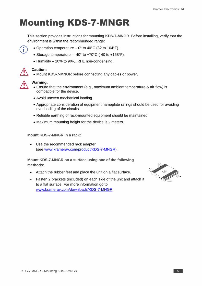
Mount KDS-7-MNGR on a surface using one of the following
methods:
• Attach the rubber feet and place the unit on a flat surface.
• Fasten 2 brackets (included) on each side of the unit and attach it
to a flat surface. For more information go to
www.kramerav.com/downloads/KDS-7-MNGR.
Kramer Electronics Ltd.
KDS-7-MNGR – Connecting KDS-7-MNGR 6
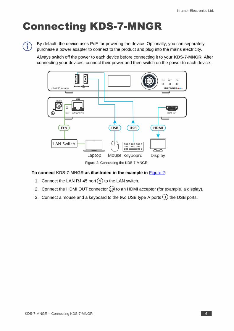
Connecting KDS-7-MNGR
By-default, the device uses PoE for powering the device. Optionally, you can separately
purchase a power adapter to connect to the product and plug into the mains electricity.
Always switch off the power to each device before connecting it to your KDS-7-MNGR. After
connecting your devices, connect their power and then switch on the power to each device.
Figure 2: Connecting the KDS-7-MNGR
To connect KDS-7-MNGR as illustrated in the example in Figure 2:
1. Connect the LAN RJ-45 port to the LAN switch.
2. Connect the HDMI OUT connector to an HDMI acceptor (for example, a display).
3. Connect a mouse and a keyboard to the two USB type A ports .the USB ports.
9
10
1
Kramer Electronics Ltd.
KDS-7-MNGR – Connecting KDS-7-MNGR 7
Understanding LED Functionality
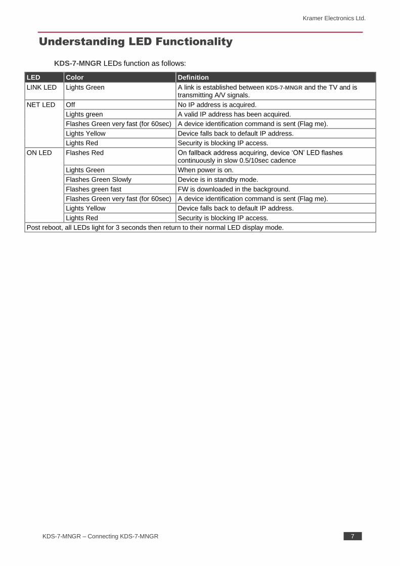
KDS-7-MNGR LEDs function as follows:
LED Color Definition
LINK LED Lights Green A link is established between KDS-7-MNGR and the TV and is transmitting A/V signals.
NET LED Off No IP address is acquired.
Lights green A valid IP address has been acquired.
Flashes Green very fast (for 60sec) A device identification command is sent (Flag me).
Lights Yellow Device falls back to default IP address.
Lights Red Security is blocking IP access.
ON LED Flashes Red On fallback address acquiring, device ‘ON’ LED flashes continuously in slow 0.5/10sec cadence
Lights Green When power is on.
Flashes Green Slowly Device is in standby mode.
Flashes green fast FW is downloaded in the background.
Flashes Green very fast (for 60sec) A device identification command is sent (Flag me).
Lights Yellow Device falls back to default IP address.
Lights Red Security is blocking IP access.
Post reboot, all LEDs light for 3 seconds then return to their normal LED display mode.
Kramer Electronics Ltd.
KDS-7-MNGR – Operating KDS-7-MNGR 8
Operating KDS-7-MNGR
This section describes the following actions:
• Configuring the Network Switch on page 8.
• Using Menu Navigation Buttons on page 8.
• Operating via Ethernet on page 9.
Configuring the Network Switch
Before setting the system, make sure that your AV over IP network switch meets the following
minimum requirements:
• Jumbo Frames – On. (at least 8000 bytes).
• IGMP Snooping – On.
• IGMP Querier – On.
• IGMP Immediate/Fast Leave – On.
• Unregistered Multicast Filtering – On.
Using Menu Navigation Buttons
Connect the device to the 24V DC power adapter and connect the adapter to the mains
electricity. The ON LED lights green, and the LINK LED flashes (indicating that no streaming
activity is detected).
Use the navigation button to easily view and set basic device parameters via the Device
menu, appearing on the device LCD display , see:
• Using KDS-7-MNGR Navigation Buttons on page 9.
Use the Navigation buttons / Use the:
• Down arrow – to move to the previous configuration parameter.
• Up arrow – to move to the next configuration parameter.
• Left arrow – to return to the previous menu.
• Right arrow – to go to the next menu.
• Enter button – accept and save the change.
2
3
Kramer Electronics Ltd.
KDS-7-MNGR – Operating KDS-7-MNGR 9
Using KDS-7-MNGR Navigation Buttons
• Defining Device Status on page 9.
• Viewing Device Information on page 9.
Defining Device Status
View the device parameters.
To view device parameters:
1. Press the Enter or right arrow to access the device status (DEV STATUS) menu.
2. Press the up or down arrows to view the following information:
▪ LAN STATUS, including IP address, Subnet mask and Gateway address
▪ HDMI STATUS, including video output resolution.
▪ Device internal TEMPERATURE (°C).
Device status is viewed.
Viewing Device Information
Displays the device information.
To view device parameters:
1. Press the left or right arrows to access the device status menu.
2. Press the up or down arrows to view the device firmware and hardware information:
▪ Firmware version (FW).
▪ Bootloader information (BL).
▪ Hardware version (HW).
Device information is viewed.
Operating via Ethernet
This section describes the following actions:
• Allocating the IP Address via LCD screen menu on page 10.
• Accessing the Web UI on page 10.
• Connecting Ethernet Port Directly to a PC on page 11.
• Connecting Ethernet Port via a Network Hub or Switch on page 13.
• Configuring Ethernet Port on page 13.
Kramer Electronics Ltd.
KDS-7-MNGR – Operating KDS-7-MNGR 10
Allocating the IP Address via LCD screen menu
KDS-7-MNGR IP default static addresses is: 192.168.1.39 By default, DHCP is enabled, and
assigns an IP address to the device. If DHCP Server is not available, for example, in case a
device is connected directly to the laptop, that device gets the default IP address. If these IP
address is already in use, the system searches for a random unique IP in the range of
192.168.X.Y. the allocated IP address can be identified using the LCD screen menu.
By default, KDS-7-MNGR is DHCP-enabled. This section describes how to operate via the
Ethernet and access the IP address when DHCP is enabled and when a static IP address is
used.
You can connect to KDS-7-MNGR via Ethernet using either of the following methods:
• When DHCP is enabled (see, for example, KDS-7-MNGR Network Settings on page 48).
When using a static IP Address (DHCP is disabled):
• Directly to the PC using a crossover cable (see Connecting Ethernet Port Directly to a
PC on page 11).
• Via a network hub, switch, or router, (using a static IP address) using a straight-through
cable (see Connecting Ethernet Port via a Network Hub on page 13).
If you want to connect via a router and your IT system is based on IPv6, speak to your IT
department for specific installation instructions.
Accessing the Web UI
By default, IP setting is DHCP.
To access the Web UI, perform the following:
1. Connect the LAN port of the device to a local area network.
Make sure that there is a DHCP server in the Network so that the device can obtain a
valid IP address.
2. Connect your PC to the same network as the device.
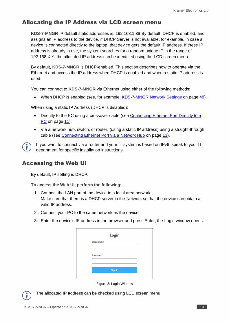
3. Enter the device’s IP address in the browser and press Enter, the Login window opens.
Figure 3: Login Window
The allocated IP address can be checked using LCD screen menu.
Kramer Electronics Ltd.
KDS-7-MNGR – Operating KDS-7-MNGR 11
4. Input username and password (default username/password: admin/admin) and click
Sign In to enter the main page of web UI.
See Defining User Management on page 57 for defining new users.
Connecting Ethernet Port Directly to a PC
You can connect the Ethernet port of KDS-7-MNGR directly to the Ethernet port on your PC
using a crossover cable with RJ-45 connectors.
This type of connection is recommended for identifying KDS-7-MNGR
with the factory configured default IP address.
After connecting KDS-7-MNGR to the Ethernet port, configure your PC as follows:
1. Click Start > Control Panel > Network and Sharing Center.
2. Click Change Adapter Settings.
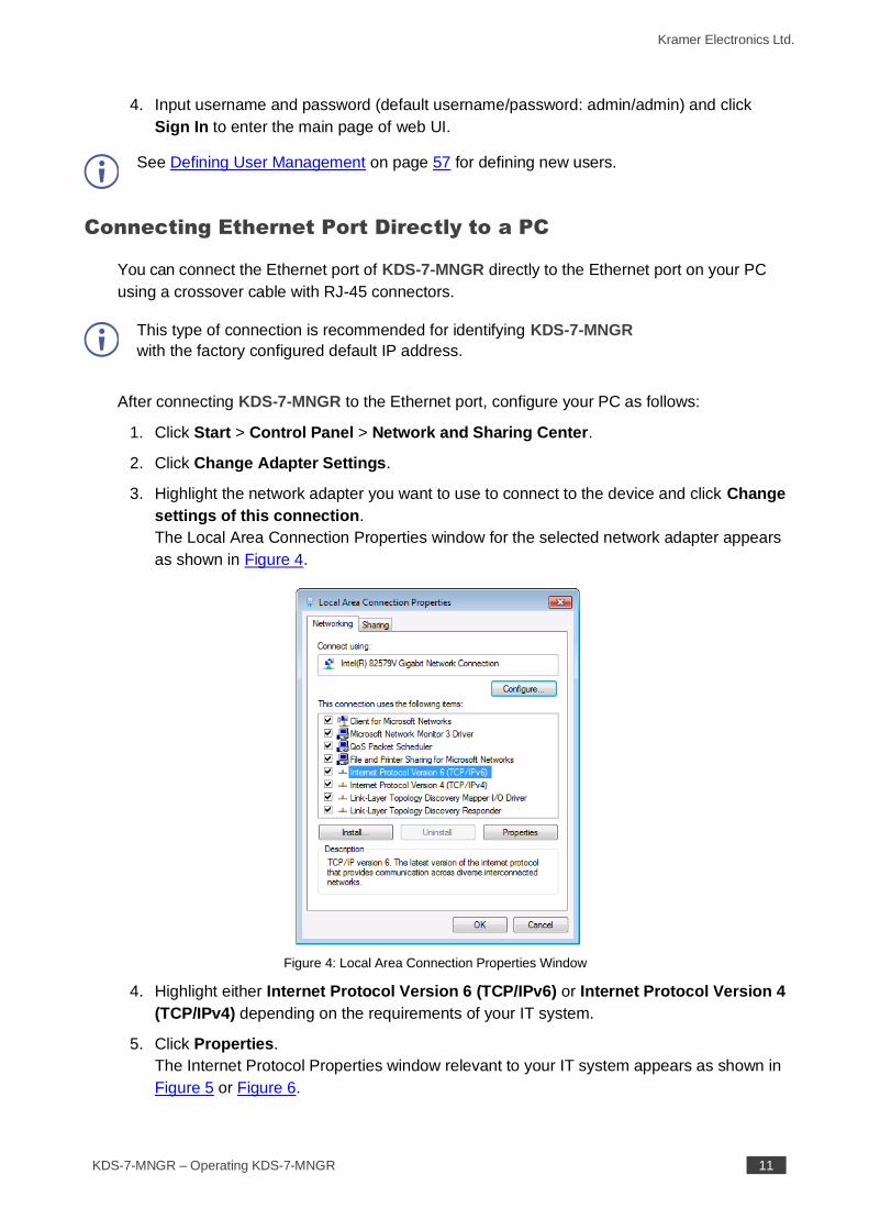
3. Highlight the network adapter you want to use to connect to the device and click Change
settings of this connection.
The Local Area Connection Properties window for the selected network adapter appears
as shown in Figure 4.
Figure 4: Local Area Connection Properties Window
4. Highlight either Internet Protocol Version 6 (TCP/IPv6) or Internet Protocol Version 4
(TCP/IPv4) depending on the requirements of your IT system.
5. Click Properties.
The Internet Protocol Properties window relevant to your IT system appears as shown in
Figure 5 or Figure 6.
Kramer Electronics Ltd.
KDS-7-MNGR – Operating KDS-7-MNGR 12
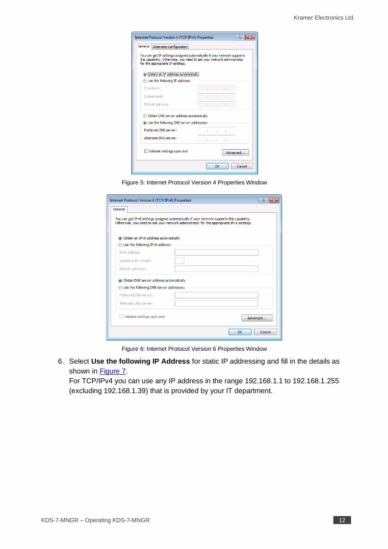
Figure 5: Internet Protocol Version 4 Properties Window
Figure 6: Internet Protocol Version 6 Properties Window
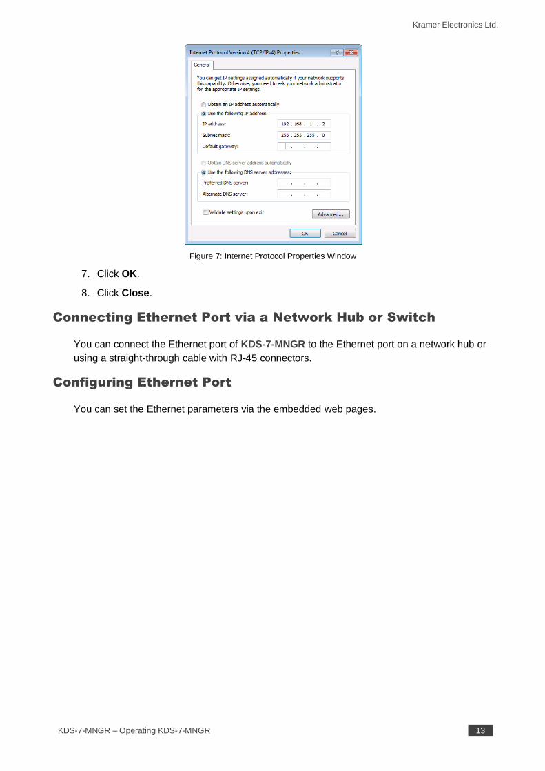
6. Select Use the following IP Address for static IP addressing and fill in the details as
shown in Figure 7.
For TCP/IPv4 you can use any IP address in the range 192.168.1.1 to 192.168.1.255
(excluding 192.168.1.39) that is provided by your IT department.
Kramer Electronics Ltd.
KDS-7-MNGR – Operating KDS-7-MNGR 13
Figure 7: Internet Protocol Properties Window
7. Click OK.
8. Click Close.
Connecting Ethernet Port via a Network Hub or Switch
You can connect the Ethernet port of KDS-7-MNGR to the Ethernet port on a network hub or
using a straight-through cable with RJ-45 connectors.
Configuring Ethernet Port
You can set the Ethernet parameters via the embedded web pages.
Kramer Electronics Ltd.
KDS-7-MNGR – Using KDS-7-MNGR Embedded Web Pages 14
Using KDS-7-MNGR Embedded
Web Pages
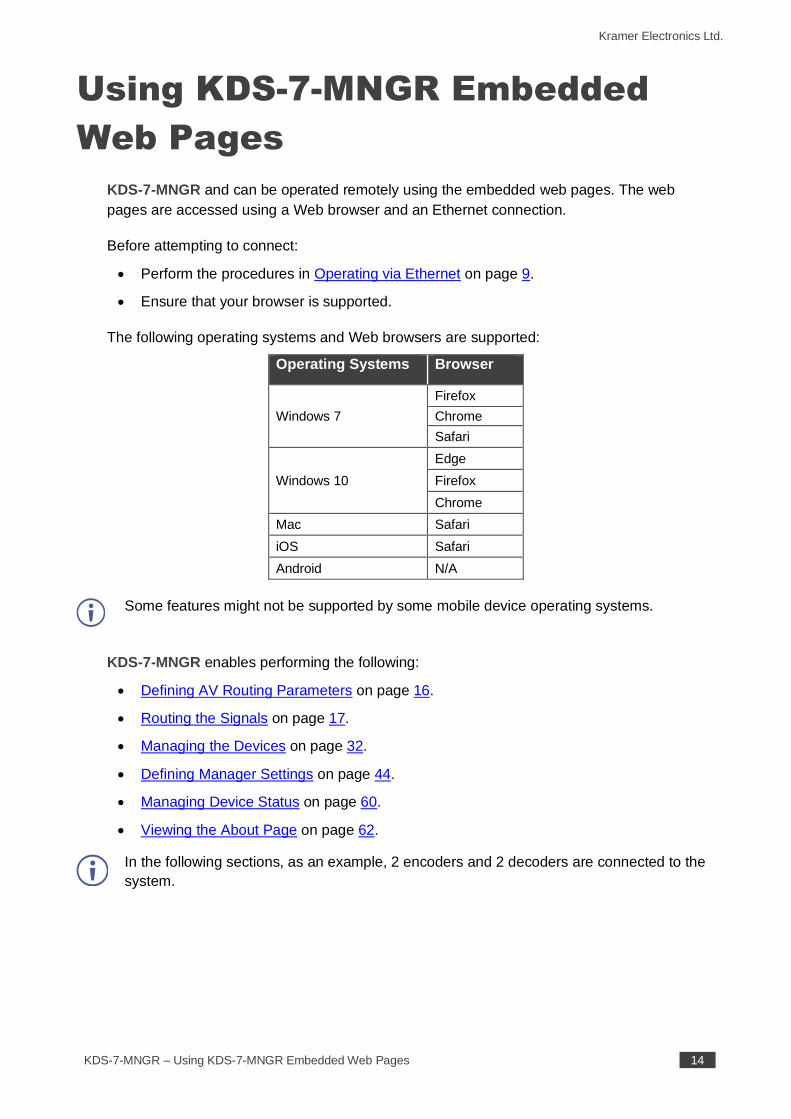
KDS-7-MNGR and can be operated remotely using the embedded web pages. The web
pages are accessed using a Web browser and an Ethernet connection.
Before attempting to connect:
• Perform the procedures in Operating via Ethernet on page 9.
• Ensure that your browser is supported.
The following operating systems and Web browsers are supported:
Operating Systems Browser
Windows 7
Firefox
Chrome
Safari
Windows 10
Edge
Firefox
Chrome
Mac Safari
iOS Safari
Android N/A
Some features might not be supported by some mobile device operating systems.
KDS-7-MNGR enables performing the following:
• Defining AV Routing Parameters on page 16.
• Routing the Signals on page 17.
• Managing the Devices on page 32.
• Defining Manager Settings on page 44.
• Managing Device Status on page 60.
• Viewing the About Page on page 62.
In the following sections, as an example, 2 encoders and 2 decoders are connected to the
system.
Kramer Electronics Ltd.
KDS-7-MNGR – Using KDS-7-MNGR Embedded Web Pages 15
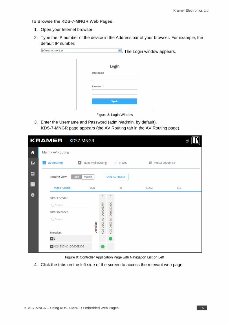
To Browse the KDS-7-MNGR Web Pages:
1. Open your Internet browser.
2. Type the IP number of the device in the Address bar of your browser. For example, the
default IP number:
. The Login window appears.
Figure 8: Login Window
3. Enter the Username and Password (admin/admin, by default).
KDS-7-MNGR page appears (the AV Routing tab in the AV Routing page).
Figure 9: Controller Application Page with Navigation List on Left
4. Click the tabs on the left side of the screen to access the relevant web page.
Kramer Electronics Ltd.
KDS-7-MNGR – Using KDS-7-MNGR Embedded Web Pages 16
Defining AV Routing Parameters
Set the KDS-7-MNGR AV routing parameters.
To set AV routing parameters, as needed:
1. In the Navigation pane, Select Main>AV Routing. The AV Routing page appears (see
Figure 9).
2. Next to Routing View, click Matrix (default) to view the system as a matrix (see
Figure 9) or click Icon to view each encoder/decoder as icons.
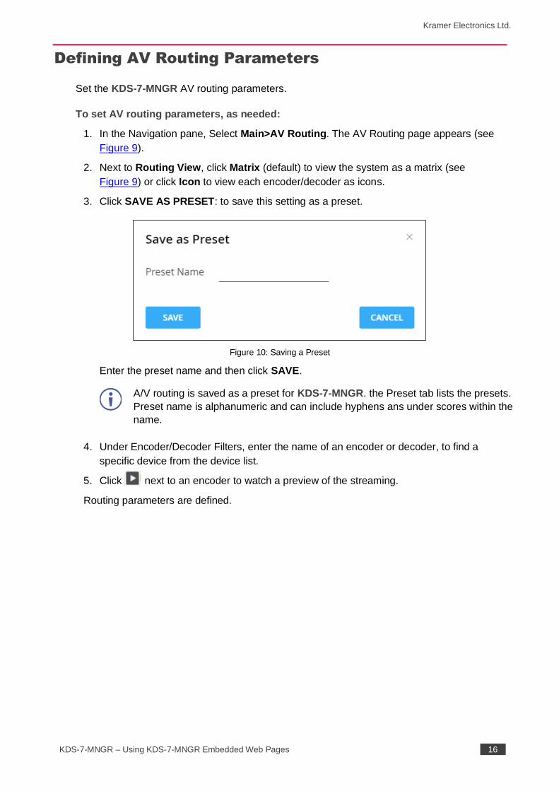
3. Click SAVE AS PRESET: to save this setting as a preset.
Figure 10: Saving a Preset
Enter the preset name and then click SAVE.
A/V routing is saved as a preset for KDS-7-MNGR. the Preset tab lists the presets.
Preset name is alphanumeric and can include hyphens ans under scores within the
name.
4. Under Encoder/Decoder Filters, enter the name of an encoder or decoder, to find a
specific device from the device list.
5. Click next to an encoder to watch a preview of the streaming.
Routing parameters are defined.
Kramer Electronics Ltd.
KDS-7-MNGR – Using KDS-7-MNGR Embedded Web Pages 17
Routing the Signals
KDS-7-MNGR enables routing AV signals as well as USB, IR, RS-232 and CEC signals.
When the routing view is set to Icon, all the signals are routed together by dragging and
dropping an encoder icon to a decoder. Only in the Matrix format you can select each signal
separately.
KDS-7-MNGR enables routing and managing the signals as follows:
• Routing Video and Audio Signals on page 17.
• Routing a USB Signal on page 18.
• Routing an IR Signal on page 20.
• Routing an RS-232 Signal on page 22.
• Routing a CEC Signal on page 24.
• Routing to a Video Wall on page 27.
• Managing Presets on page 30.
• Performing a Preset Sequence on page 31.
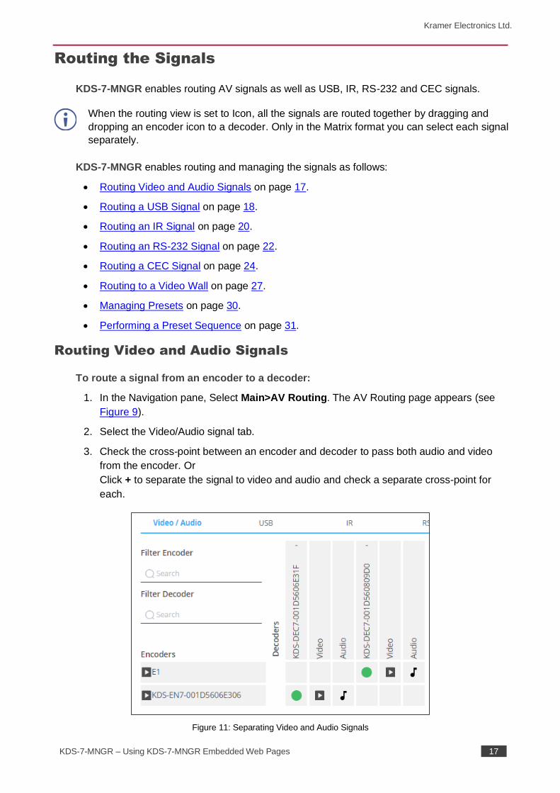
Routing Video and Audio Signals
To route a signal from an encoder to a decoder:
1. In the Navigation pane, Select Main>AV Routing. The AV Routing page appears (see
Figure 9).
2. Select the Video/Audio signal tab.
3. Check the cross-point between an encoder and decoder to pass both audio and video
from the encoder. Or
Click + to separate the signal to video and audio and check a separate cross-point for
each.
Figure 11: Separating Video and Audio Signals
Kramer Electronics Ltd.
KDS-7-MNGR – Using KDS-7-MNGR Embedded Web Pages 18
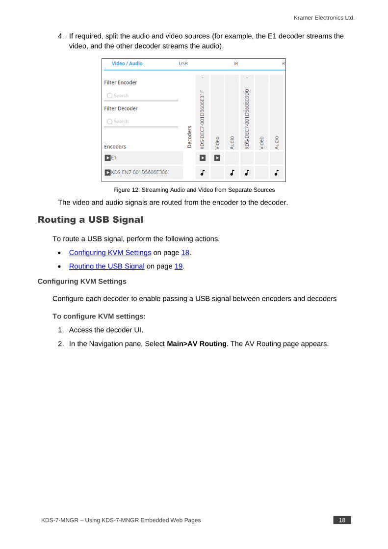
4. If required, split the audio and video sources (for example, the E1 decoder streams the
video, and the other decoder streams the audio).
Figure 12: Streaming Audio and Video from Separate Sources
The video and audio signals are routed from the encoder to the decoder.
Routing a USB Signal
To route a USB signal, perform the following actions.
• Configuring KVM Settings on page 18.
• Routing the USB Signal on page 19.
Configuring KVM Settings
Configure each decoder to enable passing a USB signal between encoders and decoders
To configure KVM settings:
1. Access the decoder UI.
2. In the Navigation pane, Select Main>AV Routing. The AV Routing page appears.
Kramer Electronics Ltd.
KDS-7-MNGR – Using KDS-7-MNGR Embedded Web Pages 19
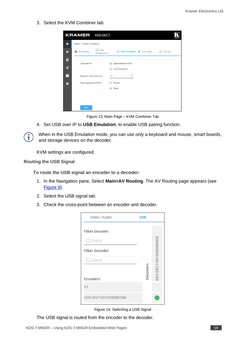
3. Select the KVM Combiner tab.
Figure 13: Main Page – KVM Combiner Tab
4. Set USB over IP to USB Emulation, to enable USB pairing function.
When in the USB Emulation mode, you can use only a keyboard and mouse, smart boards,
and storage devices on the decoder.
KVM settings are configured.
Routing the USB Signal
To route the USB signal an encoder to a decoder:
1. In the Navigation pane, Select Main>AV Routing. The AV Routing page appears (see
Figure 9).
2. Select the USB signal tab.
3. Check the cross-point between an encoder and decoder.
Figure 14: Switching a USB Signal
The USB signal is routed from the encoder to the decoder.
Kramer Electronics Ltd.
KDS-7-MNGR – Using KDS-7-MNGR Embedded Web Pages 20
Routing an IR Signal
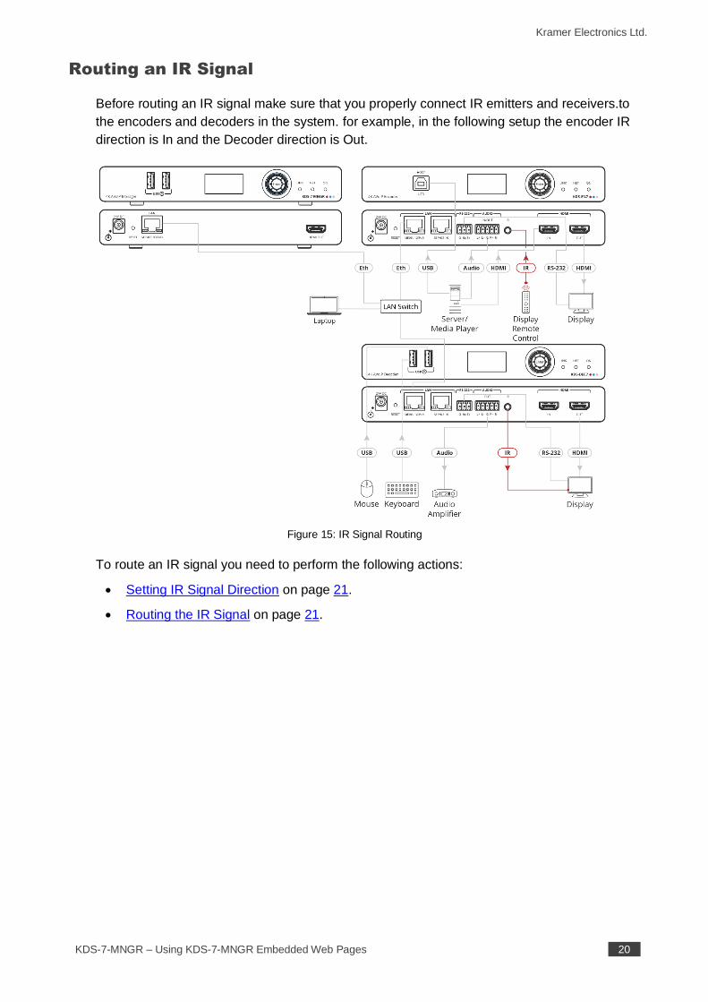
Before routing an IR signal make sure that you properly connect IR emitters and receivers.to
the encoders and decoders in the system. for example, in the following setup the encoder IR
direction is In and the Decoder direction is Out.
Figure 15: IR Signal Routing
To route an IR signal you need to perform the following actions:
• Setting IR Signal Direction on page 21.
• Routing the IR Signal on page 21.
Kramer Electronics Ltd.
KDS-7-MNGR – Using KDS-7-MNGR Embedded Web Pages 21
Setting IR Signal Direction
Set the signal direction for the specific encoders and decoders.
To route a signal from an encoder to a decoder:
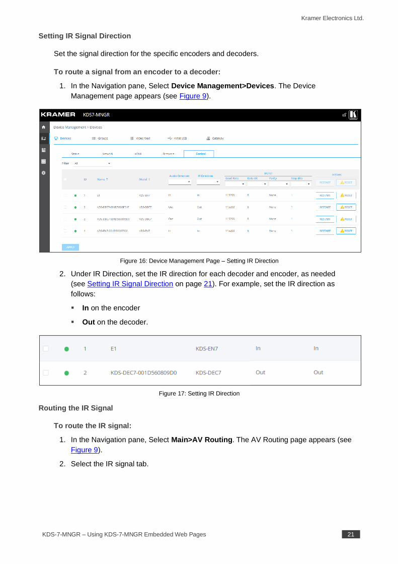
1. In the Navigation pane, Select Device Management>Devices. The Device
Management page appears (see Figure 9).
Figure 16: Device Management Page – Setting IR Direction
2. Under IR Direction, set the IR direction for each decoder and encoder, as needed
(see Setting IR Signal Direction on page 21). For example, set the IR direction as
follows:
▪ In on the encoder
▪ Out on the decoder.
Figure 17: Setting IR Direction
Routing the IR Signal
To route the IR signal:
1. In the Navigation pane, Select Main>AV Routing. The AV Routing page appears (see
Figure 9).
2. Select the IR signal tab.
Kramer Electronics Ltd.
KDS-7-MNGR – Using KDS-7-MNGR Embedded Web Pages 22
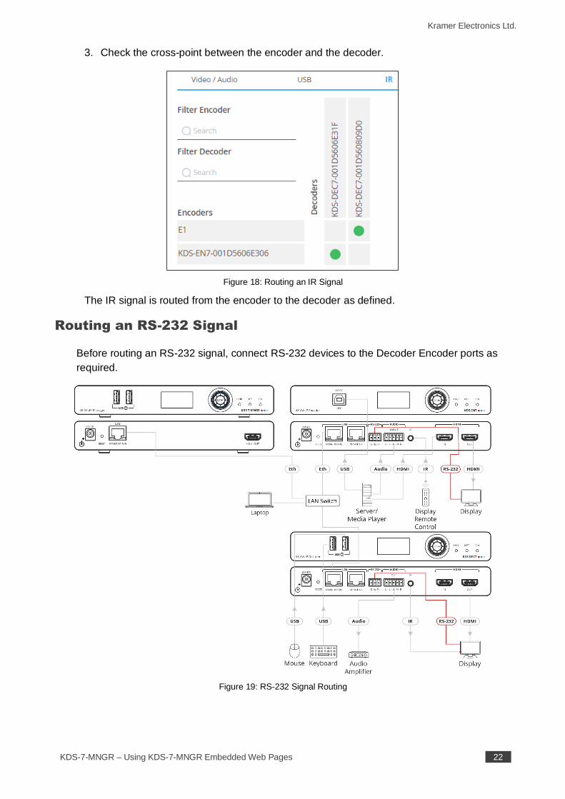
3. Check the cross-point between the encoder and the decoder.
Figure 18: Routing an IR Signal
The IR signal is routed from the encoder to the decoder as defined.
Routing an RS-232 Signal
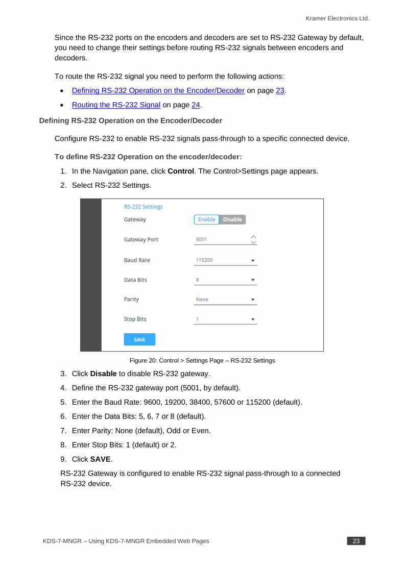
Before routing an RS-232 signal, connect RS-232 devices to the Decoder Encoder ports as
required.
Figure 19: RS-232 Signal Routing
Kramer Electronics Ltd.
KDS-7-MNGR – Using KDS-7-MNGR Embedded Web Pages 23
Since the RS-232 ports on the encoders and decoders are set to RS-232 Gateway by default,
you need to change their settings before routing RS-232 signals between encoders and
decoders.
To route the RS-232 signal you need to perform the following actions:
• Defining RS-232 Operation on the Encoder/Decoder on page 23.
• Routing the RS-232 Signal on page 24.
Defining RS-232 Operation on the Encoder/Decoder
Configure RS-232 to enable RS-232 signals pass-through to a specific connected device.
To define RS-232 Operation on the encoder/decoder:
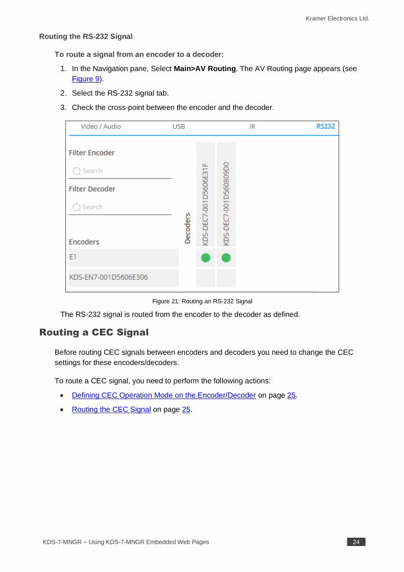
1. In the Navigation pane, click Control. The Control>Settings page appears.
2. Select RS-232 Settings.
Figure 20: Control > Settings Page – RS-232 Settings
3. Click Disable to disable RS-232 gateway.
4. Define the RS-232 gateway port (5001, by default).
5. Enter the Baud Rate: 9600, 19200, 38400, 57600 or 115200 (default).
6. Enter the Data Bits: 5, 6, 7 or 8 (default).
7. Enter Parity: None (default), Odd or Even.
8. Enter Stop Bits: 1 (default) or 2.
9. Click SAVE.
RS-232 Gateway is configured to enable RS-232 signal pass-through to a connected
RS-232 device.
Kramer Electronics Ltd.
KDS-7-MNGR – Using KDS-7-MNGR Embedded Web Pages 24
Routing the RS-232 Signal
To route a signal from an encoder to a decoder:
1. In the Navigation pane, Select Main>AV Routing. The AV Routing page appears (see
Figure 9).
2. Select the RS-232 signal tab.
3. Check the cross-point between the encoder and the decoder.
Figure 21: Routing an RS-232 Signal
The RS-232 signal is routed from the encoder to the decoder as defined.
Routing a CEC Signal
Before routing CEC signals between encoders and decoders you need to change the CEC
settings for these encoders/decoders.
To route a CEC signal, you need to perform the following actions:
• Defining CEC Operation Mode on the Encoder/Decoder on page 25.
• Routing the CEC Signal on page 25.
Kramer Electronics Ltd.
KDS-7-MNGR – Using KDS-7-MNGR Embedded Web Pages 25
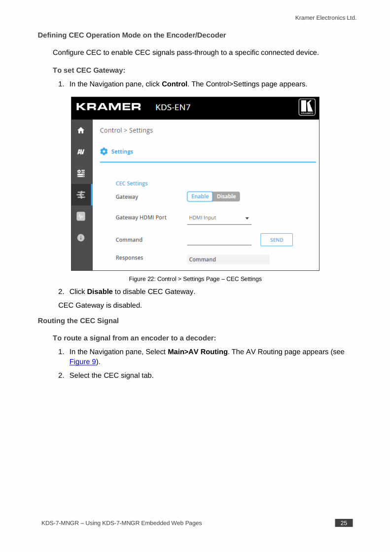
Defining CEC Operation Mode on the Encoder/Decoder
Configure CEC to enable CEC signals pass-through to a specific connected device.
To set CEC Gateway:
1. In the Navigation pane, click Control. The Control>Settings page appears.
Figure 22: Control > Settings Page – CEC Settings
2. Click Disable to disable CEC Gateway.
CEC Gateway is disabled.
Routing the CEC Signal
To route a signal from an encoder to a decoder:
1. In the Navigation pane, Select Main>AV Routing. The AV Routing page appears (see
Figure 9).
2. Select the CEC signal tab.
Kramer Electronics Ltd.
KDS-7-MNGR – Using KDS-7-MNGR Embedded Web Pages 26
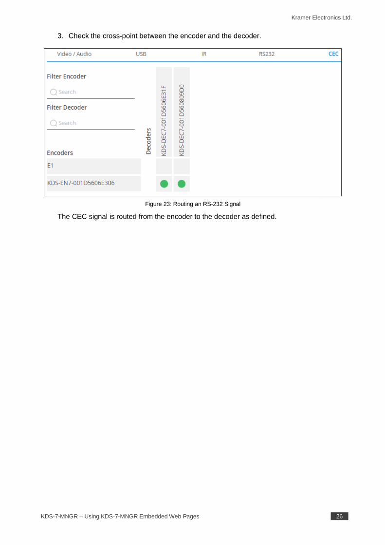
3. Check the cross-point between the encoder and the decoder.
Figure 23: Routing an RS-232 Signal
The CEC signal is routed from the encoder to the decoder as defined.
Kramer Electronics Ltd.
KDS-7-MNGR – Using KDS-7-MNGR Embedded Web Pages 27
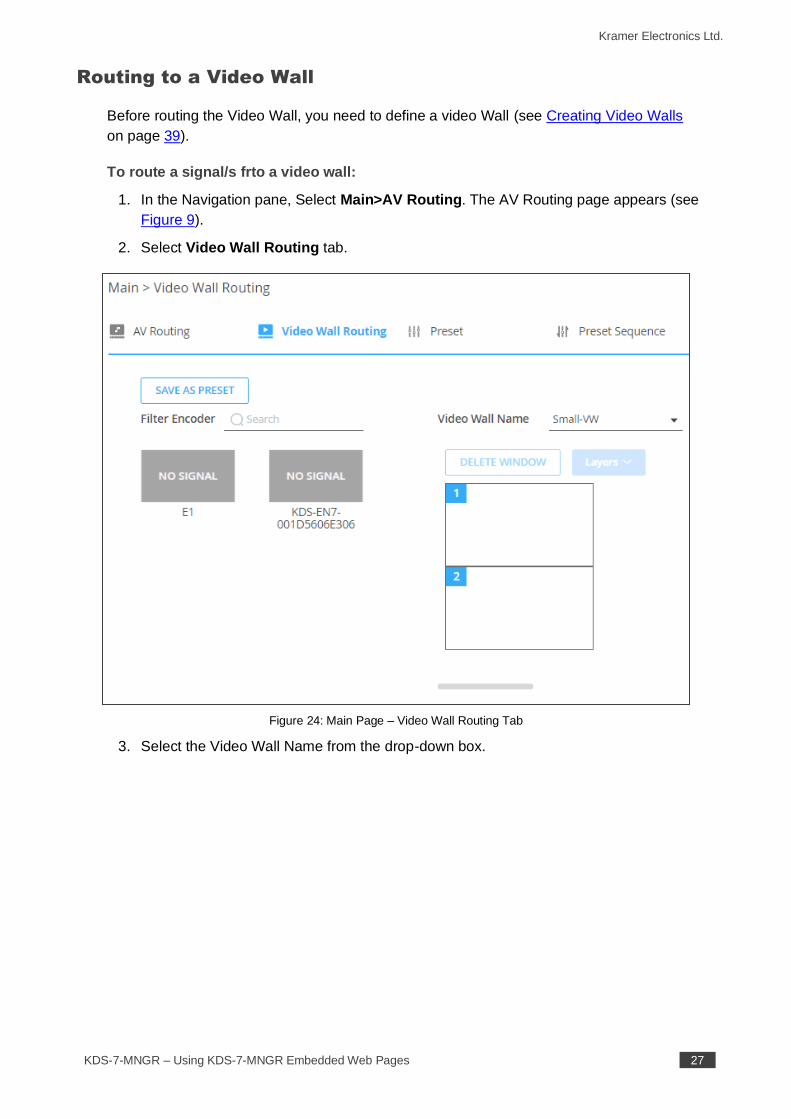
Routing to a Video Wall
Before routing the Video Wall, you need to define a video Wall (see Creating Video Walls
on page 39).
To route a signal/s frto a video wall:
1. In the Navigation pane, Select Main>AV Routing. The AV Routing page appears (see
Figure 9).
2. Select Video Wall Routing tab.
Figure 24: Main Page – Video Wall Routing Tab
3. Select the Video Wall Name from the drop-down box.

Kramer Electronics Ltd.
KDS-7-MNGR – Using KDS-7-MNGR Embedded Web Pages 28
4. Select the encoder to stream to the video wall and drag it to the video wall image.
Figure 25: Dragging an Encoder Source
5. Perform one of the following actions:
▪ Select and drag the same encoder or a different encoder to display an encoder
source on each screen.
In the example below, each screen (that is connected to a decoder) displays a
different source.
Figure 26: Video Wall Encoders Setting
Kramer Electronics Ltd.
KDS-7-MNGR – Using KDS-7-MNGR Embedded Web Pages 29
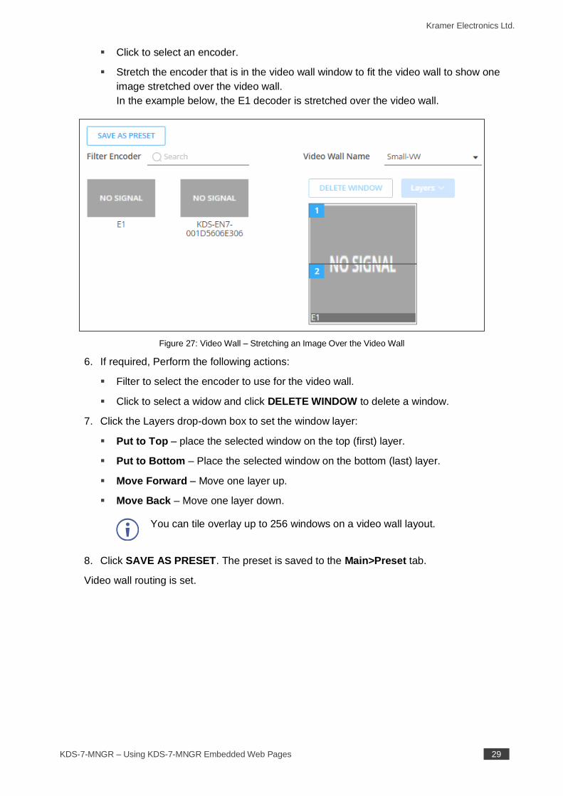
▪ Click to select an encoder.
▪ Stretch the encoder that is in the video wall window to fit the video wall to show one
image stretched over the video wall.
In the example below, the E1 decoder is stretched over the video wall.
Figure 27: Video Wall – Stretching an Image Over the Video Wall
6. If required, Perform the following actions:
▪ Filter to select the encoder to use for the video wall.
▪ Click to select a widow and click DELETE WINDOW to delete a window.
7. Click the Layers drop-down box to set the window layer:
▪ Put to Top – place the selected window on the top (first) layer.
▪ Put to Bottom – Place the selected window on the bottom (last) layer.
▪ Move Forward – Move one layer up.
▪ Move Back – Move one layer down.
You can tile overlay up to 256 windows on a video wall layout.
8. Click SAVE AS PRESET. The preset is saved to the Main>Preset tab.
Video wall routing is set.
Kramer Electronics Ltd.
KDS-7-MNGR – Using KDS-7-MNGR Embedded Web Pages 30
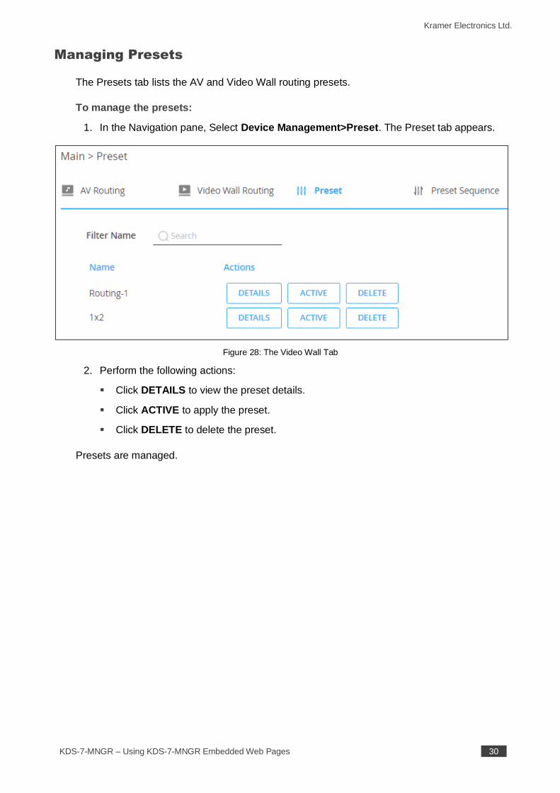
Managing Presets
The Presets tab lists the AV and Video Wall routing presets.
To manage the presets:
1. In the Navigation pane, Select Device Management>Preset. The Preset tab appears.
Figure 28: The Video Wall Tab
2. Perform the following actions:
▪ Click DETAILS to view the preset details.
▪ Click ACTIVE to apply the preset.
▪ Click DELETE to delete the preset.
Presets are managed.
Kramer Electronics Ltd.
KDS-7-MNGR – Using KDS-7-MNGR Embedded Web Pages 31
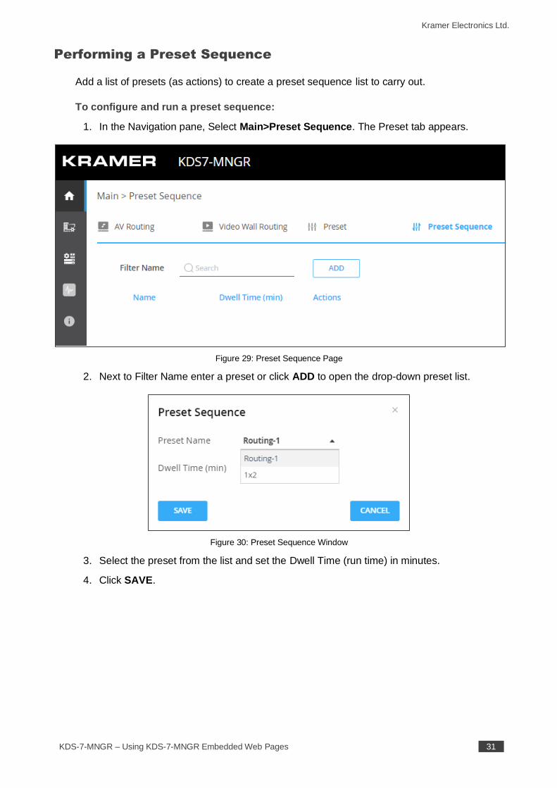
Performing a Preset Sequence
Add a list of presets (as actions) to create a preset sequence list to carry out.
To configure and run a preset sequence:
1. In the Navigation pane, Select Main>Preset Sequence. The Preset tab appears.
Figure 29: Preset Sequence Page
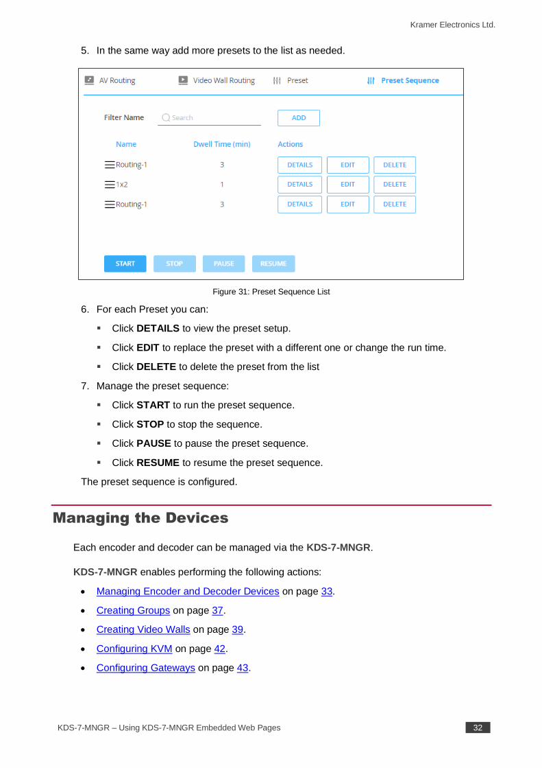
2. Next to Filter Name enter a preset or click ADD to open the drop-down preset list.
Figure 30: Preset Sequence Window
3. Select the preset from the list and set the Dwell Time (run time) in minutes.
4. Click SAVE.
Kramer Electronics Ltd.
KDS-7-MNGR – Using KDS-7-MNGR Embedded Web Pages 32
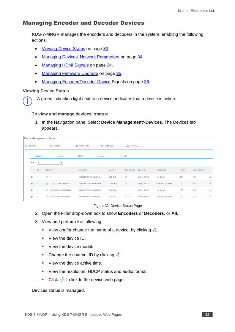
5. In the same way add more presets to the list as needed.
Figure 31: Preset Sequence List
6. For each Preset you can:
▪ Click DETAILS to view the preset setup.
▪ Click EDIT to replace the preset with a different one or change the run time.
▪ Click DELETE to delete the preset from the list
7. Manage the preset sequence:
▪ Click START to run the preset sequence.
▪ Click STOP to stop the sequence.
▪ Click PAUSE to pause the preset sequence.
▪ Click RESUME to resume the preset sequence.
The preset sequence is configured.
Managing the Devices
Each encoder and decoder can be managed via the KDS-7-MNGR.
KDS-7-MNGR enables performing the following actions:
• Managing Encoder and Decoder Devices on page 33.
• Creating Groups on page 37.
• Creating Video Walls on page 39.
• Configuring KVM on page 42.
• Configuring Gateways on page 43.
Kramer Electronics Ltd.
KDS-7-MNGR – Using KDS-7-MNGR Embedded Web Pages 33
Managing Encoder and Decoder Devices
KDS-7-MNGR manages the encoders and decoders in the system, enabling the following
actions:
• Viewing Device Status on page 33.
• Managing Devices’ Network Parameters on page 34.
• Managing HDMI Signals on page 34.
• Managing Firmware Upgrade on page 35.
• Managing Encoder/Decoder Device Signals on page 36.
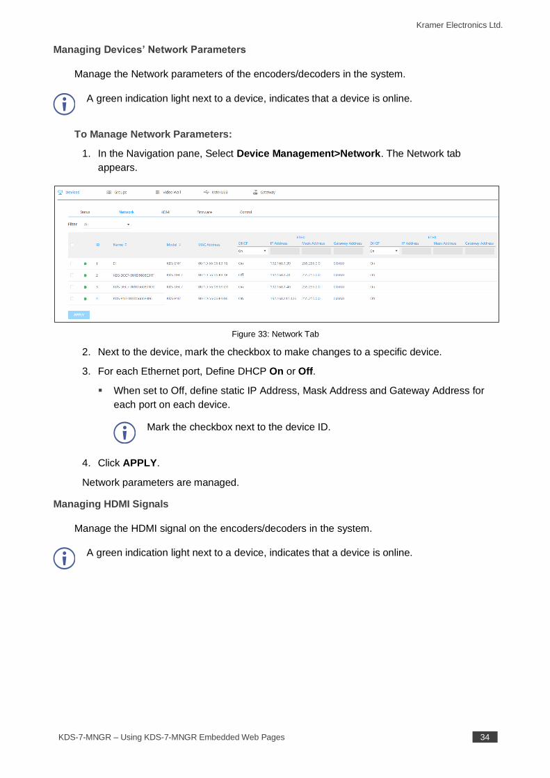
Viewing Device Status
A green indication light next to a device, indicates that a device is online.
To view and manage devices’ status:
1. In the Navigation pane, Select Device Management>Devices. The Devices tab
appears.
Figure 32: Device Status Page
2. Open the Filter drop-down box to show Encoders or Decoders, or All.
3. View and perform the following:
▪ View and/or change the name of a device, by clicking .
▪ View the device ID.
▪ View the device model.
▪ Change the channel ID by clicking .
▪ View the device active time.
▪ View the resolution, HDCP status and audio format.
▪ Click to link to the device web page.
Devices status is managed.
Kramer Electronics Ltd.
KDS-7-MNGR – Using KDS-7-MNGR Embedded Web Pages 34
Managing Devices’ Network Parameters
Manage the Network parameters of the encoders/decoders in the system.
A green indication light next to a device, indicates that a device is online.
To Manage Network Parameters:
1. In the Navigation pane, Select Device Management>Network. The Network tab
appears.
Figure 33: Network Tab
2. Next to the device, mark the checkbox to make changes to a specific device.
3. For each Ethernet port, Define DHCP On or Off.
▪ When set to Off, define static IP Address, Mask Address and Gateway Address for
each port on each device.
Mark the checkbox next to the device ID.
4. Click APPLY.
Network parameters are managed.
Managing HDMI Signals
Manage the HDMI signal on the encoders/decoders in the system.
A green indication light next to a device, indicates that a device is online.
Kramer Electronics Ltd.
KDS-7-MNGR – Using KDS-7-MNGR Embedded Web Pages 35
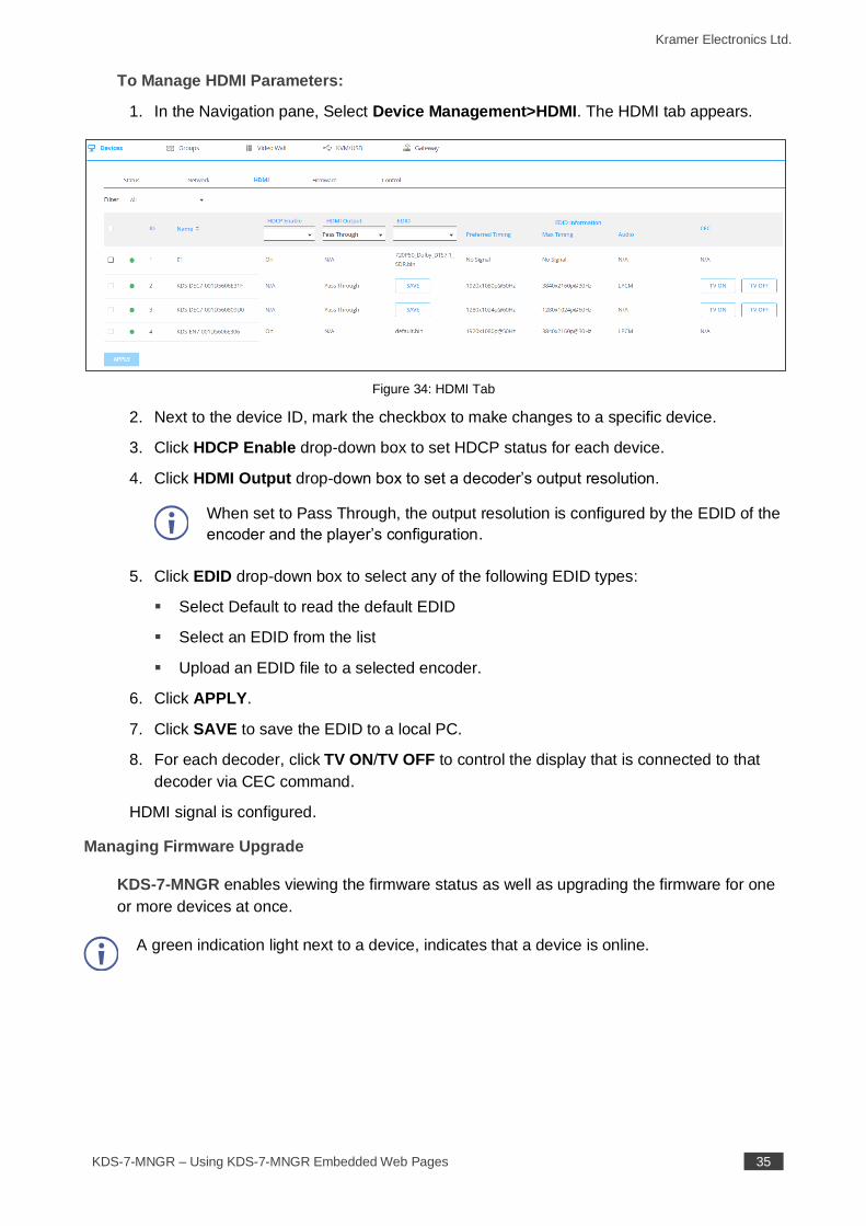
To Manage HDMI Parameters:
1. In the Navigation pane, Select Device Management>HDMI. The HDMI tab appears.
Figure 34: HDMI Tab
2. Next to the device ID, mark the checkbox to make changes to a specific device.
3. Click HDCP Enable drop-down box to set HDCP status for each device.
4. Click HDMI Output drop-down box to set a decoder’s output resolution.
When set to Pass Through, the output resolution is configured by the EDID of the
encoder and the player’s configuration.
5. Click EDID drop-down box to select any of the following EDID types:
▪ Select Default to read the default EDID
▪ Select an EDID from the list
▪ Upload an EDID file to a selected encoder.
6. Click APPLY.
7. Click SAVE to save the EDID to a local PC.
8. For each decoder, click TV ON/TV OFF to control the display that is connected to that
decoder via CEC command.
HDMI signal is configured.
Managing Firmware Upgrade
KDS-7-MNGR enables viewing the firmware status as well as upgrading the firmware for one
or more devices at once.
A green indication light next to a device, indicates that a device is online.
Kramer Electronics Ltd.
KDS-7-MNGR – Using KDS-7-MNGR Embedded Web Pages 36
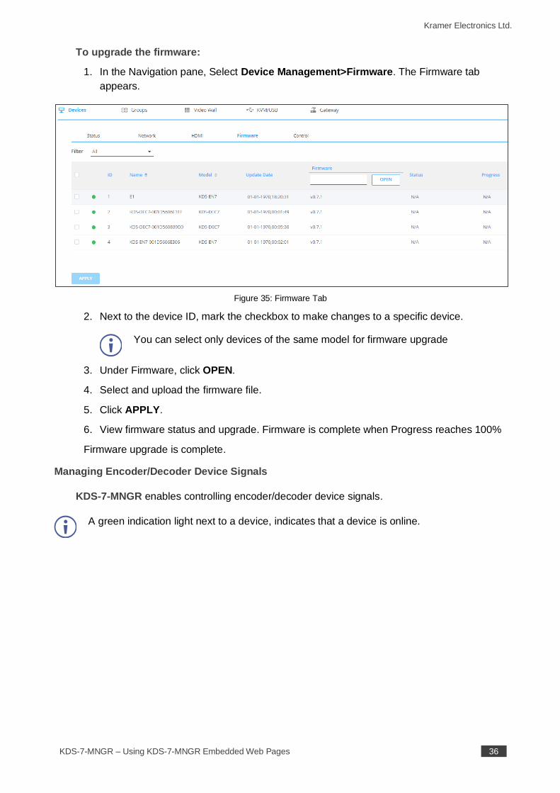
To upgrade the firmware:
1. In the Navigation pane, Select Device Management>Firmware. The Firmware tab
appears.
Figure 35: Firmware Tab
2. Next to the device ID, mark the checkbox to make changes to a specific device.
You can select only devices of the same model for firmware upgrade
3. Under Firmware, click OPEN.
4. Select and upload the firmware file.
5. Click APPLY.
6. View firmware status and upgrade. Firmware is complete when Progress reaches 100%
Firmware upgrade is complete.
Managing Encoder/Decoder Device Signals
KDS-7-MNGR enables controlling encoder/decoder device signals.
A green indication light next to a device, indicates that a device is online.
Kramer Electronics Ltd.
KDS-7-MNGR – Using KDS-7-MNGR Embedded Web Pages 37
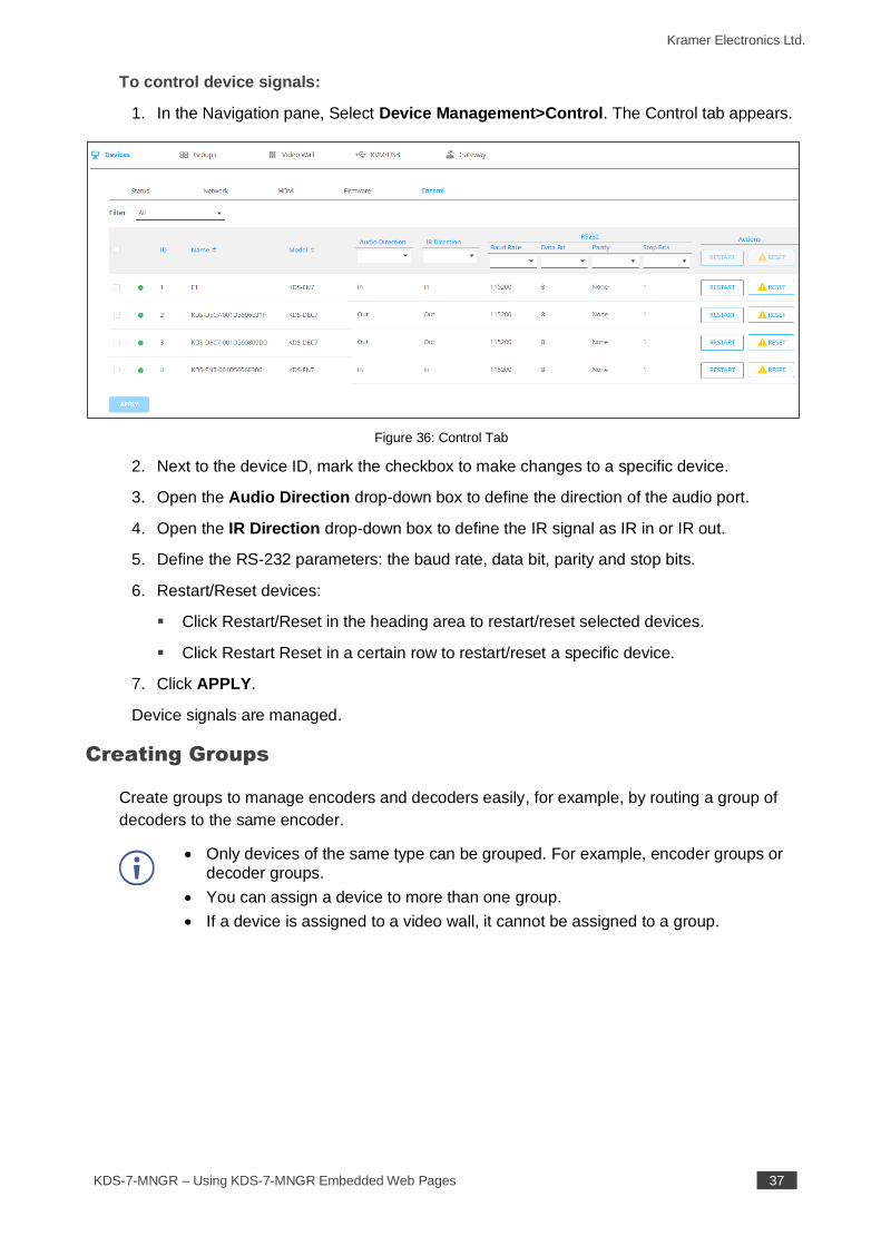
To control device signals:
1. In the Navigation pane, Select Device Management>Control. The Control tab appears.
Figure 36: Control Tab
2. Next to the device ID, mark the checkbox to make changes to a specific device.
3. Open the Audio Direction drop-down box to define the direction of the audio port.
4. Open the IR Direction drop-down box to define the IR signal as IR in or IR out.
5. Define the RS-232 parameters: the baud rate, data bit, parity and stop bits.
6. Restart/Reset devices:
▪ Click Restart/Reset in the heading area to restart/reset selected devices.
▪ Click Restart Reset in a certain row to restart/reset a specific device.
7. Click APPLY.
Device signals are managed.
Creating Groups
Create groups to manage encoders and decoders easily, for example, by routing a group of
decoders to the same encoder.
• Only devices of the same type can be grouped. For example, encoder groups or
decoder groups.
• You can assign a device to more than one group.
• If a device is assigned to a video wall, it cannot be assigned to a group.
Kramer Electronics Ltd.
KDS-7-MNGR – Using KDS-7-MNGR Embedded Web Pages 38
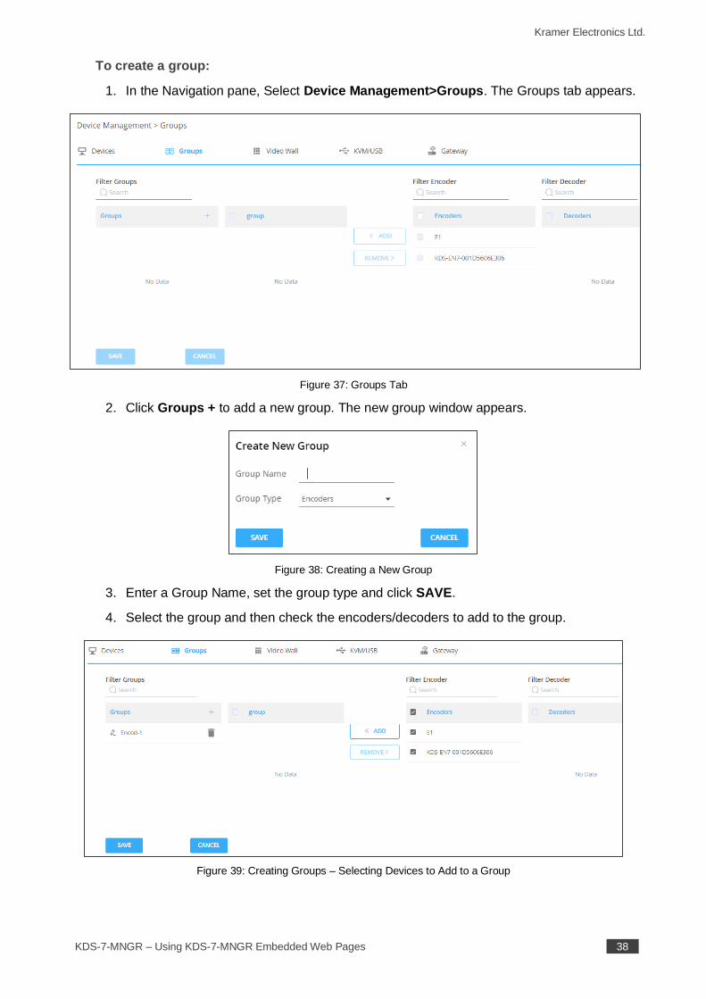
To create a group:
1. In the Navigation pane, Select Device Management>Groups. The Groups tab appears.
Figure 37: Groups Tab
2. Click Groups + to add a new group. The new group window appears.
Figure 38: Creating a New Group
3. Enter a Group Name, set the group type and click SAVE.
4. Select the group and then check the encoders/decoders to add to the group.
Figure 39: Creating Groups – Selecting Devices to Add to a Group
Kramer Electronics Ltd.
KDS-7-MNGR – Using KDS-7-MNGR Embedded Web Pages 39
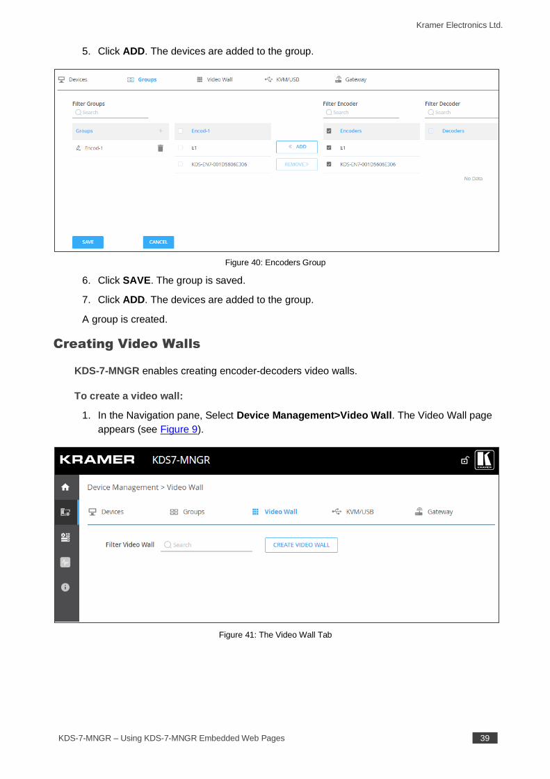
5. Click ADD. The devices are added to the group.
Figure 40: Encoders Group
6. Click SAVE. The group is saved.
7. Click ADD. The devices are added to the group.
A group is created.
Creating Video Walls
KDS-7-MNGR enables creating encoder-decoders video walls.
To create a video wall:
1. In the Navigation pane, Select Device Management>Video Wall. The Video Wall page
appears (see Figure 9).
Figure 41: The Video Wall Tab
Kramer Electronics Ltd.
KDS-7-MNGR – Using KDS-7-MNGR Embedded Web Pages 40
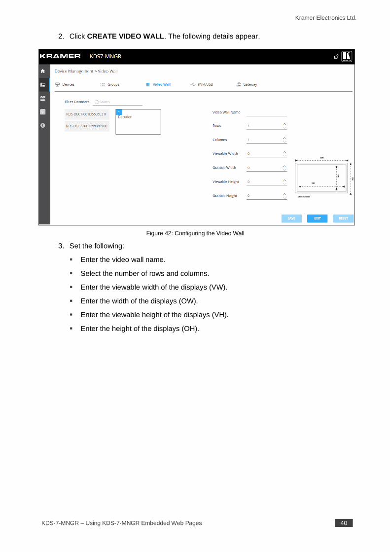
2. Click CREATE VIDEO WALL. The following details appear.
Figure 42: Configuring the Video Wall
3. Set the following:
▪ Enter the video wall name.
▪ Select the number of rows and columns.
▪ Enter the viewable width of the displays (VW).
▪ Enter the width of the displays (OW).
▪ Enter the viewable height of the displays (VH).
▪ Enter the height of the displays (OH).
Kramer Electronics Ltd.
KDS-7-MNGR – Using KDS-7-MNGR Embedded Web Pages 41
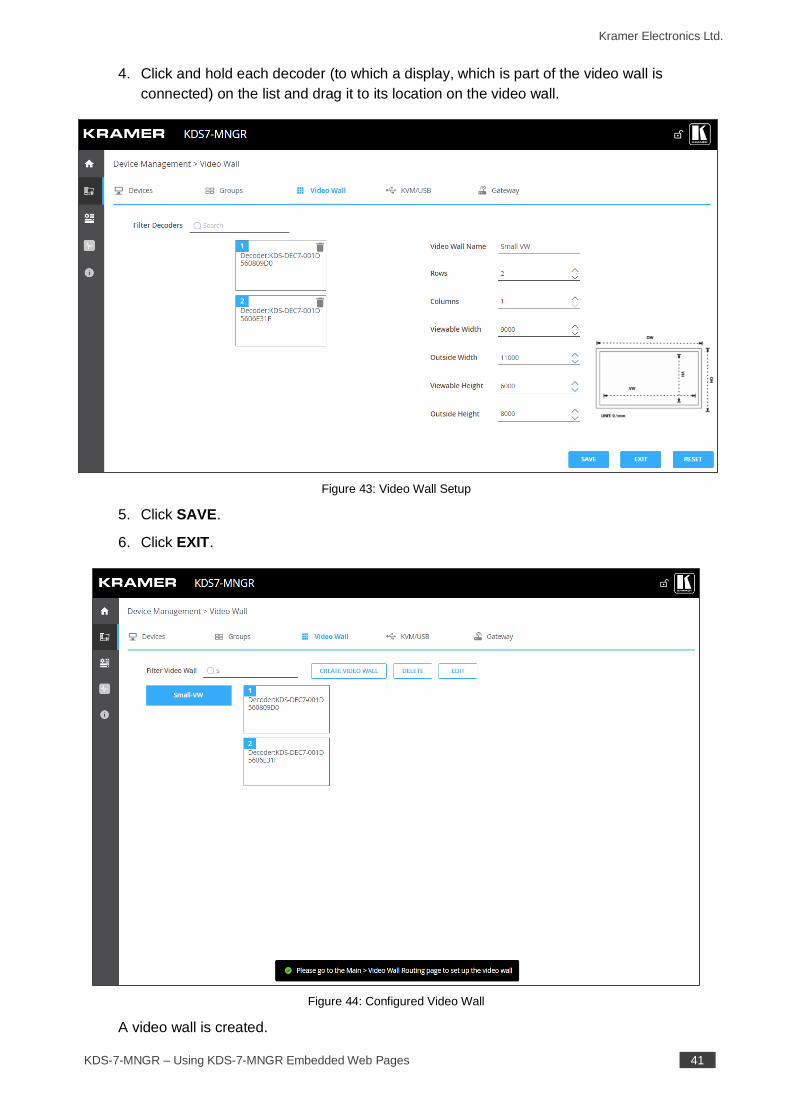
4. Click and hold each decoder (to which a display, which is part of the video wall is
connected) on the list and drag it to its location on the video wall.
Figure 43: Video Wall Setup
5. Click SAVE.
6. Click EXIT.
Figure 44: Configured Video Wall
A video wall is created.
Kramer Electronics Ltd.
KDS-7-MNGR – Using KDS-7-MNGR Embedded Web Pages 42
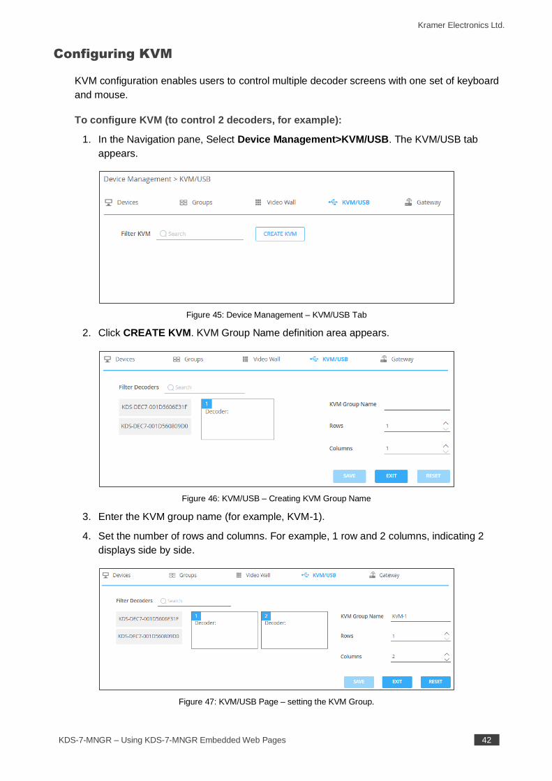
Configuring KVM
KVM configuration enables users to control multiple decoder screens with one set of keyboard
and mouse.
To configure KVM (to control 2 decoders, for example):
1. In the Navigation pane, Select Device Management>KVM/USB. The KVM/USB tab
appears.
Figure 45: Device Management – KVM/USB Tab
2. Click CREATE KVM. KVM Group Name definition area appears.
Figure 46: KVM/USB – Creating KVM Group Name
3. Enter the KVM group name (for example, KVM-1).
4. Set the number of rows and columns. For example, 1 row and 2 columns, indicating 2
displays side by side.
Figure 47: KVM/USB Page – setting the KVM Group.
Kramer Electronics Ltd.
KDS-7-MNGR – Using KDS-7-MNGR Embedded Web Pages 43
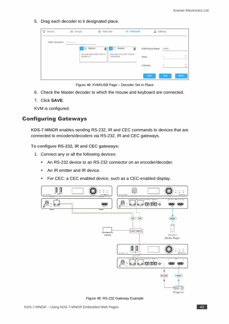
5. Drag each decoder to it designated place.
Figure 48: KVM/USB Page – Decoder Set in Place
6. Check the Master decoder to which the mouse and keyboard are connected.
7. Click SAVE.
KVM is configured.
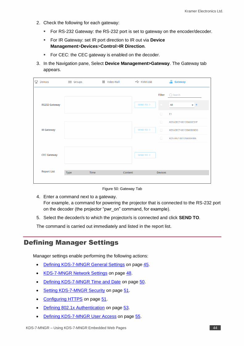
Configuring Gateways
KDS-7-MNGR enables sending RS-232, IR and CEC commands to devices that are
connected to encoders/decoders via RS-232, IR and CEC gateways.
To configure RS-232, IR and CEC gateways:
1. Connect any or all the following devices:
▪ An RS-232 device to an RS-232 connector on an encoder/decoder.
▪ An IR emitter and IR device.
▪ For CEC: a CEC enabled device, such as a CEC-enabled display.
Figure 49: RS-232 Gateway Example
Kramer Electronics Ltd.
KDS-7-MNGR – Using KDS-7-MNGR Embedded Web Pages 44
2. Check the following for each gateway:
▪ For RS-232 Gateway: the RS-232 port is set to gateway on the encoder/decoder.
▪ For IR Gateway: set IR port direction to IR out via Device
Management>Devices>Control>IR Direction.
▪ For CEC: the CEC gateway is enabled on the decoder.
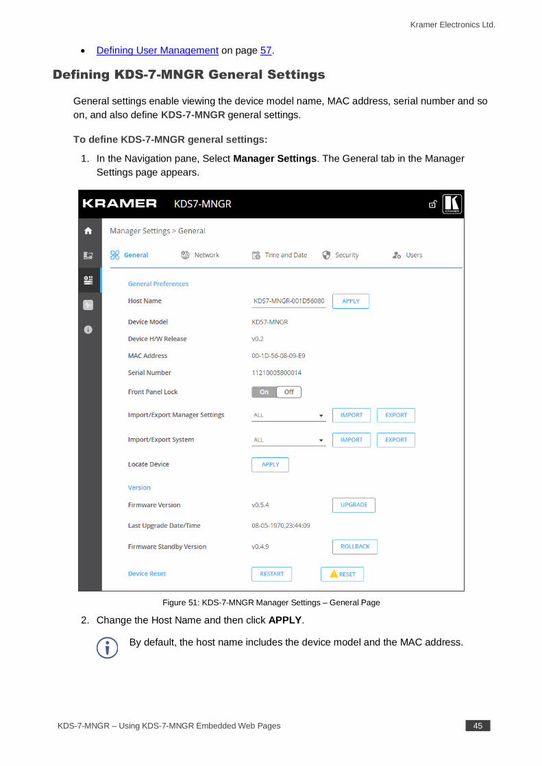
3. In the Navigation pane, Select Device Management>Gateway. The Gateway tab
appears.
Figure 50: Gateway Tab
4. Enter a command next to a gateway.
For example, a command for powering the projector that is connected to the RS-232 port
on the decoder (the projector “pwr_on” command, for example).
5. Select the decoder/s to which the projector/s is connected and click SEND TO.
The command is carried out immediately and listed in the report list.
Defining Manager Settings
Manager settings enable performing the following actions:
• Defining KDS-7-MNGR General Settings on page 45.
• KDS-7-MNGR Network Settings on page 48.
• Defining KDS-7-MNGR Time and Date on page 50.
• Setting KDS-7-MNGR Security on page 51.
• Configuring HTTPS on page 51.
• Defining 802.1x Authentication on page 53.
• Defining KDS-7-MNGR User Access on page 55.
Kramer Electronics Ltd.
KDS-7-MNGR – Using KDS-7-MNGR Embedded Web Pages 45
• Defining User Management on page 57.
Defining KDS-7-MNGR General Settings
General settings enable viewing the device model name, MAC address, serial number and so
on, and also define KDS-7-MNGR general settings.
To define KDS-7-MNGR general settings:
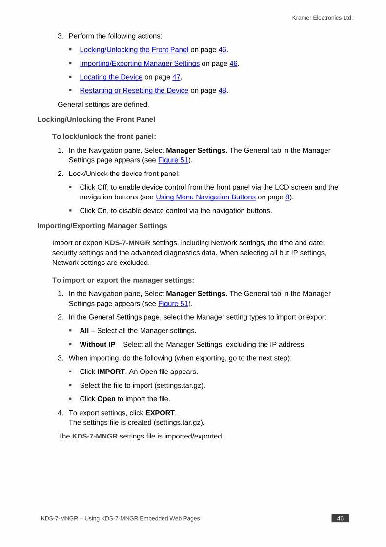
1. In the Navigation pane, Select Manager Settings. The General tab in the Manager
Settings page appears.
Figure 51: KDS-7-MNGR Manager Settings – General Page
2. Change the Host Name and then click APPLY.
By default, the host name includes the device model and the MAC address.
Kramer Electronics Ltd.
KDS-7-MNGR – Using KDS-7-MNGR Embedded Web Pages 46
3. Perform the following actions:
▪ Locking/Unlocking the Front Panel on page 46.
▪ Importing/Exporting Manager Settings on page 46.
▪ Locating the Device on page 47.
▪ Restarting or Resetting the Device on page 48.
General settings are defined.
Locking/Unlocking the Front Panel
To lock/unlock the front panel:
1. In the Navigation pane, Select Manager Settings. The General tab in the Manager
Settings page appears (see Figure 51).
2. Lock/Unlock the device front panel:
▪ Click Off, to enable device control from the front panel via the LCD screen and the
navigation buttons (see Using Menu Navigation Buttons on page 8).
▪ Click On, to disable device control via the navigation buttons.
Importing/Exporting Manager Settings
Import or export KDS-7-MNGR settings, including Network settings, the time and date,
security settings and the advanced diagnostics data. When selecting all but IP settings,
Network settings are excluded.
To import or export the manager settings:
1. In the Navigation pane, Select Manager Settings. The General tab in the Manager
Settings page appears (see Figure 51).
2. In the General Settings page, select the Manager setting types to import or export.
▪ All – Select all the Manager settings.
▪ Without IP – Select all the Manager Settings, excluding the IP address.
3. When importing, do the following (when exporting, go to the next step):
▪ Click IMPORT. An Open file appears.
▪ Select the file to import (settings.tar.gz).
▪ Click Open to import the file.
4. To export settings, click EXPORT.
The settings file is created (settings.tar.gz).
The KDS-7-MNGR settings file is imported/exported.
Kramer Electronics Ltd.
KDS-7-MNGR – Using KDS-7-MNGR Embedded Web Pages 47
Importing/Exporting Encoder/Decoder System Settings
Import or export the settings of the encoders and decoders in the system. you can
import/export Video Wall Routing, Preset, Preset Sequence, Groups, Video Wall, and
KVM/USB settings, or select a specific setting to import/export.
To import or export the system settings:
1. In the Navigation pane, Select Manager Settings. The General tab in the Manager
Settings page appears (see Figure 51).
2. In the General Settings page, select the system setting types to import or export.
▪ All – Select all the settings.
▪ Groups – Select all the settings in the Groups page (see Creating Groups
on page 37).
▪ Video Wall – Select all the video wall settings (see Creating Video Walls
on page 39) and routing video walls (see Routing to a Video Wall on page 27).
▪ KVM – Select all the KVM/USB settings (see Configuring KVM on page 42).
▪ Presets – Select all the preset settings (see Managing Presets on page 30).
▪ Sequence – Select all the preset sequence settings (see Performing a Preset
Sequence on page 31).
3. When importing, do the following (when exporting, go to the next step):
▪ Click IMPORT. An Open file appears.
▪ Select the file to import (settings.tar.gz).
▪ Click Open to import the file.
4. To export settings, click EXPORT.
The settings file is created (settings.tar.gz).
The system settings file is imported/exported.
Locating the Device
Locate the specific device in the system.
To locate the device:
1. In the Navigation pane, Select Manager Settings. The General tab in the Manager
Settings page appears (see Figure 51).
2. In the General Device Settings page, click APPLY next to Locate Device.
the located device NET and ON LEDs on the font panel flash for 60 seconds.
The device is located in the system.
Kramer Electronics Ltd.
KDS-7-MNGR – Using KDS-7-MNGR Embedded Web Pages 48
Managing the Firmware
Upgrade the firmware, view the date of the last upgrade, or rollback to the previous firmware
revision in case of a problem.
Click ROLLBACK to update to the previous FW version.
If the device firmware version is lower than 0.5.4, contact Kramer tech support team at
[email protected] or go to our Web site at
k.kramerav.com/support/downloads.asp.
To upgrade the firmware:
1. In the Navigation pane, Select Manager Settings. The General tab in the Manager
Settings page appears (see Figure 51).
2. Next to Firmware Version, click UPGRADE. The Open window appears.
3. Select the FW file and click Open. The FW upgrade pop-up window appears. Wait for
upgrade completion.
4. Once completed, refresh the web page and log-in.
Firmware upgrade is complete.
Restarting or Resetting the Device
Click RESTART to reboot the device and click RESET to restore device factory default
settings.
KDS-7-MNGR Network Settings
Manage KDS-7-MNGR Network settings.
To define KDS-7-MNGR Network settings:
1. In the Navigation pane, Select Manager Settings. The General tab in the Manager
Settings page appears (see Figure 51).
Kramer Electronics Ltd.
KDS-7-MNGR – Using KDS-7-MNGR Embedded Web Pages 49
2. Select the Network tab.
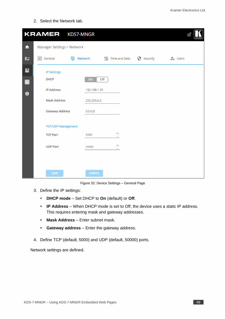
Figure 52: Device Settings – General Page
3. Define the IP settings:
▪ DHCP mode – Set DHCP to On (default) or Off.
▪ IP Address – When DHCP mode is set to Off, the device uses a static IP address.
This requires entering mask and gateway addresses.
▪ Mask Address – Enter subnet mask.
▪ Gateway address – Enter the gateway address.
4. Define TCP (default, 5000) and UDP (default, 50000) ports.
Network settings are defined.
Kramer Electronics Ltd.
KDS-7-MNGR – Using KDS-7-MNGR Embedded Web Pages 50
Defining KDS-7-MNGR Time and Date
You can set the device time and date manually or Sync the device time and date to any
server around the world.
To define KDS-7-MNGR Time and Date:
1. In the Navigation pane, Select Manager Settings. The General tab in the Manager
Settings page appears (see Figure 51).
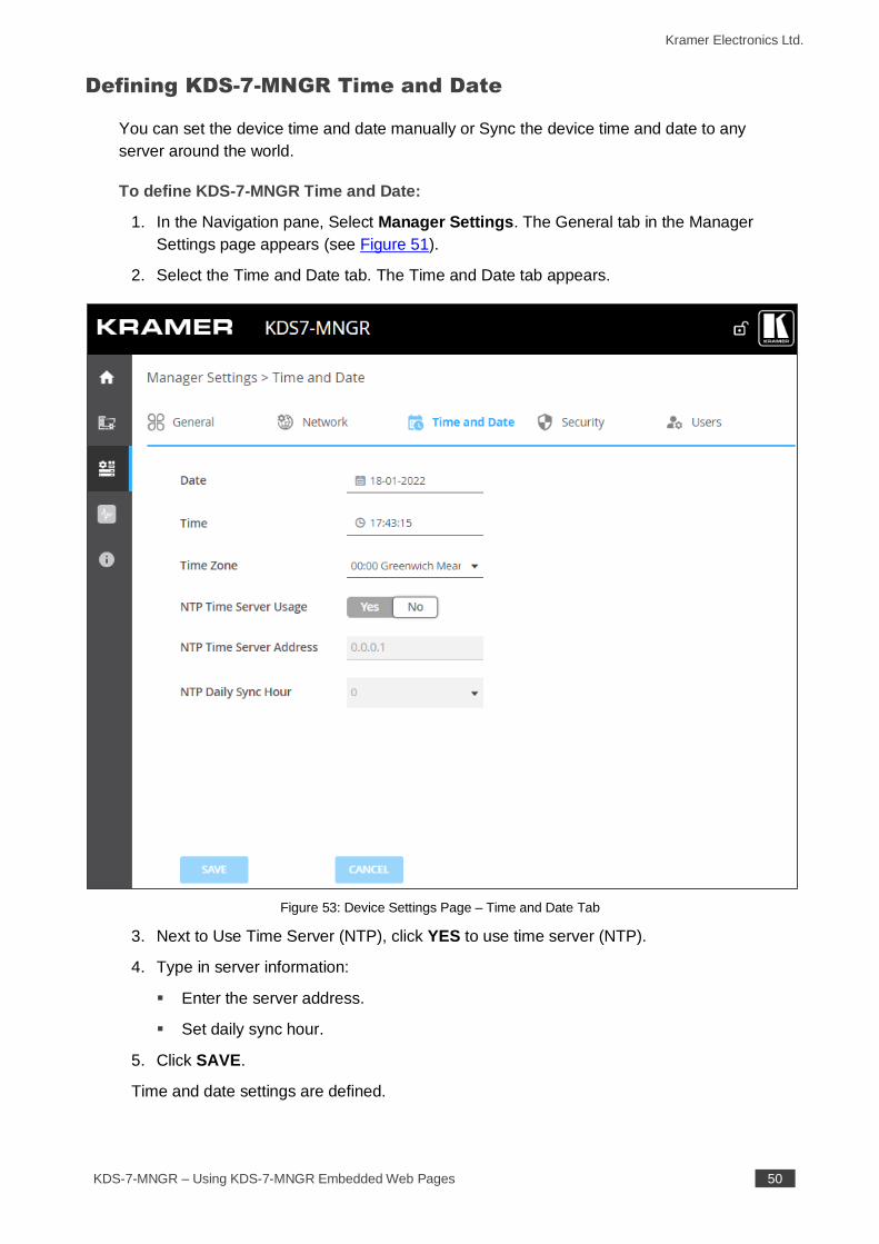
2. Select the Time and Date tab. The Time and Date tab appears.
Figure 53: Device Settings Page – Time and Date Tab
3. Next to Use Time Server (NTP), click YES to use time server (NTP).
4. Type in server information:
▪ Enter the server address.
▪ Set daily sync hour.
5. Click SAVE.
Time and date settings are defined.
Kramer Electronics Ltd.
KDS-7-MNGR – Using KDS-7-MNGR Embedded Web Pages 51
Setting KDS-7-MNGR Security
The Security tab configures device authentication to limit unauthorized access to LAN/WLAN
Network.
Contact your IT administrator for the network access authentication.
The Security tab configures device 802.1x authentication to limit unauthorized access, and
HTTPS/TLS for establishing an encrypted connection to an authenticated peer over the
network.
This section describes the following actions:
• Configuring HTTPS on page 51.
• Defining 802.1x Authentication on page 53.
Contact your IT administrator for the network access authentication.
Configuring HTTPS
To configure HTTPS:
1. In the Navigation pane, click Manager Settings. The General tab in the Manager
Settings page appears (see Figure 51).
Kramer Electronics Ltd.
KDS-7-MNGR – Using KDS-7-MNGR Embedded Web Pages 52
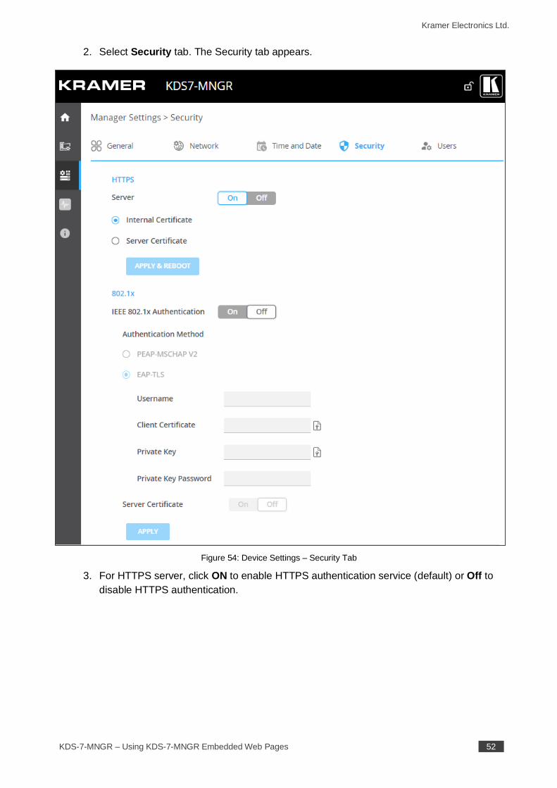
2. Select Security tab. The Security tab appears.
Figure 54: Device Settings – Security Tab
3. For HTTPS server, click ON to enable HTTPS authentication service (default) or Off to
disable HTTPS authentication.
Kramer Electronics Ltd.
KDS-7-MNGR – Using KDS-7-MNGR Embedded Web Pages 53
4. When set to ON check one of the following settings:
▪ Internal Certificate – To use the factory default certificate for authentication.
▪ Server Certificate – To submit certificate from the server for authentication. To do
so, click to upload the certificate. enter the private key password (assigned by
the IT administrator) and click APPLY & REBOOT.
Figure 55: Security Tab – Server Certificate
5. Click APPLY.
HTTPS is configured.
Defining 802.1x Authentication
To configure security:
1. In the Navigation pane, click Manager Settings. The General tab in the Manager
Settings page appears (see Figure 51).
2. Select Security tab. The Security tab appears (see Figure 54).
3. For 802.1x authentication, click ON to enable 802.1x authentication service. 802.1x
supports authentication based on port and MAC address.
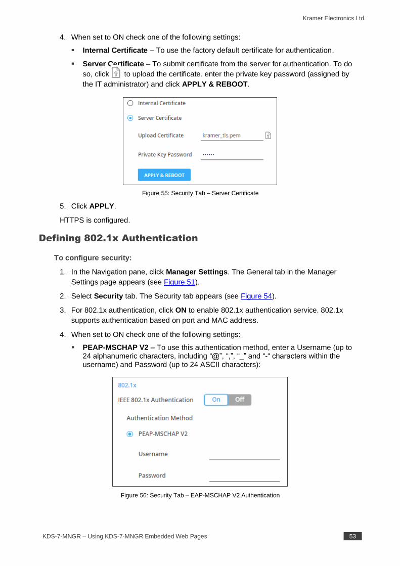
4. When set to ON check one of the following settings:
▪ PEAP-MSCHAP V2 – To use this authentication method, enter a Username (up to 24 alphanumeric characters, including “@”, “,”, “_” and “-“ characters within the username) and Password (up to 24 ASCII characters):
Figure 56: Security Tab – EAP-MSCHAP V2 Authentication
Kramer Electronics Ltd.
KDS-7-MNGR – Using KDS-7-MNGR Embedded Web Pages 54
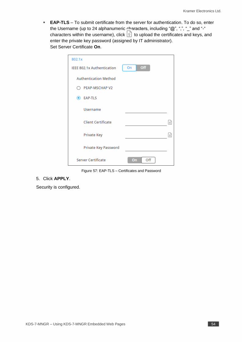
▪ EAP-TLS – To submit certificate from the server for authentication. To do so, enter
the Username (up to 24 alphanumeric characters, including “@”, “,”, “_” and “-“
characters within the username), click to upload the certificates and keys, and
enter the private key password (assigned by IT administrator).
Set Server Certificate On.
Figure 57: EAP-TLS – Certificates and Password
5. Click APPLY.
Security is configured.
Kramer Electronics Ltd.
KDS-7-MNGR – Using KDS-7-MNGR Embedded Web Pages 55
Defining KDS-7-MNGR User Access
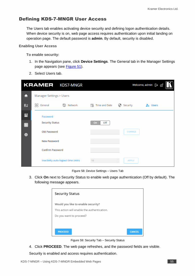
The Users tab enables activating device security and defining logon authentication details.
When device security is on, web page access requires authentication upon initial landing on
operation page. The default password is admin. By default, security is disabled.
Enabling User Access
To enable security:
1. In the Navigation pane, click Device Settings. The General tab in the Manager Settings
page appears (see Figure 51).
2. Select Users tab.
Figure 58: Device Settings – Users Tab
3. Click On next to Security Status to enable web page authentication (Off by default). The
following message appears.
Figure 59: Security Tab – Security Status
4. Click PROCEED. The web page refreshes, and the password fields are visible.
Security is enabled and access requires authentication.
Kramer Electronics Ltd.
KDS-7-MNGR – Using KDS-7-MNGR Embedded Web Pages 56
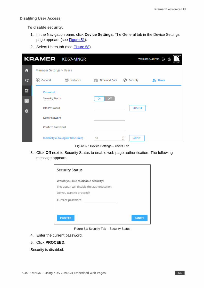
Disabling User Access
To disable security:
1. In the Navigation pane, click Device Settings. The General tab in the Device Settings
page appears (see Figure 51).
2. Select Users tab (see Figure 58).
Figure 60: Device Settings – Users Tab
3. Click Off next to Security Status to enable web page authentication. The following
message appears.
Figure 61: Security Tab – Security Status
4. Enter the current password.
5. Click PROCEED.
Security is disabled.
Kramer Electronics Ltd.
KDS-7-MNGR – Using KDS-7-MNGR Embedded Web Pages 57
Logging Out
Define the time of inactivity before the page logs out automatically by setting the Inactivity
auto-logout time (in minutes).
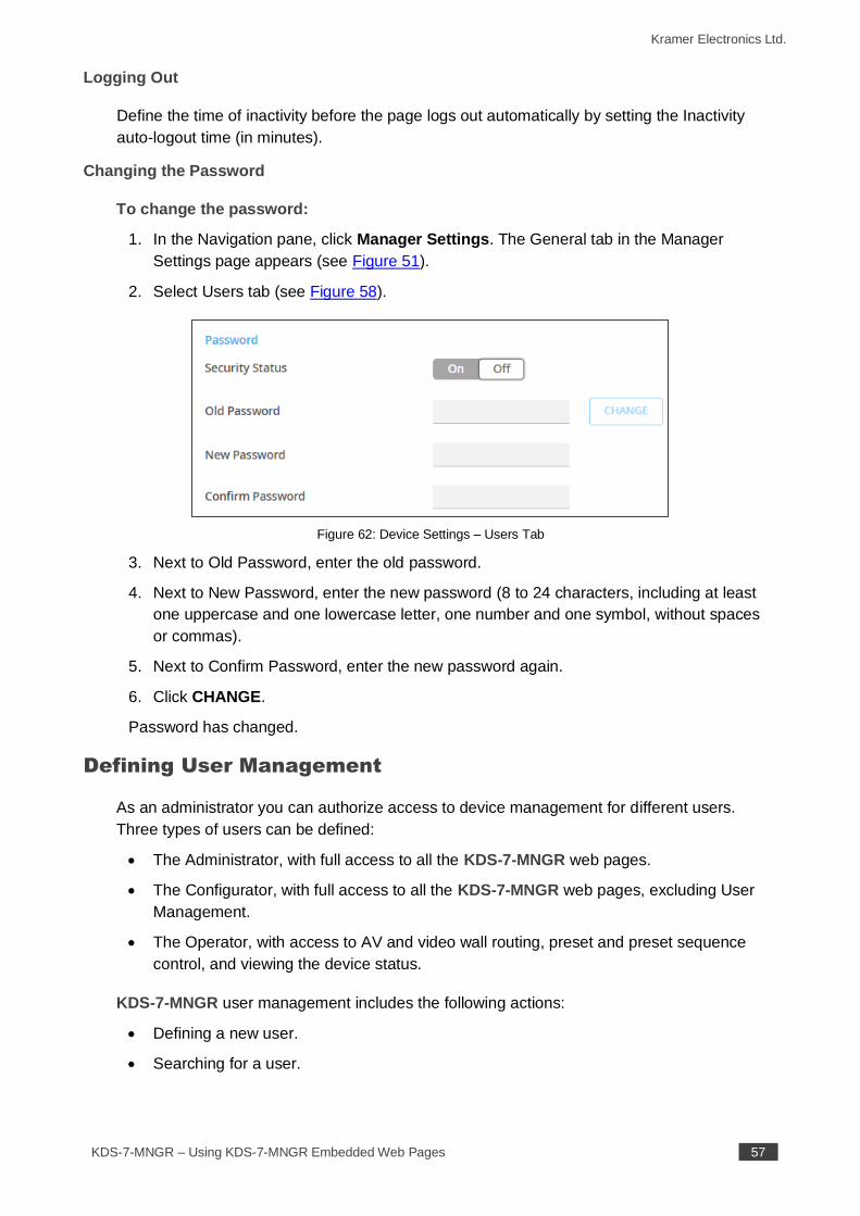
Changing the Password
To change the password:
1. In the Navigation pane, click Manager Settings. The General tab in the Manager
Settings page appears (see Figure 51).
2. Select Users tab (see Figure 58).
Figure 62: Device Settings – Users Tab
3. Next to Old Password, enter the old password.
4. Next to New Password, enter the new password (8 to 24 characters, including at least
one uppercase and one lowercase letter, one number and one symbol, without spaces
or commas).
5. Next to Confirm Password, enter the new password again.
6. Click CHANGE.
Password has changed.
Defining User Management
As an administrator you can authorize access to device management for different users.
Three types of users can be defined:
• The Administrator, with full access to all the KDS-7-MNGR web pages.
• The Configurator, with full access to all the KDS-7-MNGR web pages, excluding User
Management.
• The Operator, with access to AV and video wall routing, preset and preset sequence
control, and viewing the device status.
KDS-7-MNGR user management includes the following actions:
• Defining a new user.
• Searching for a user.
Kramer Electronics Ltd.
KDS-7-MNGR – Using KDS-7-MNGR Embedded Web Pages 58
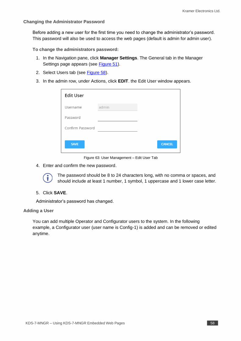
Changing the Administrator Password
Before adding a new user for the first time you need to change the administrator’s password.
This password will also be used to access the web pages (default is admin for admin user).
To change the administrators password:
1. In the Navigation pane, click Manager Settings. The General tab in the Manager
Settings page appears (see Figure 51).
2. Select Users tab (see Figure 58).
3. In the admin row, under Actions, click EDIT. the Edit User window appears.
Figure 63: User Management – Edit User Tab
4. Enter and confirm the new password.
The password should be 8 to 24 characters long, with no comma or spaces, and
should include at least 1 number, 1 symbol, 1 uppercase and 1 lower case letter.
5. Click SAVE.
Administrator’s password has changed.
Adding a User
You can add multiple Operator and Configurator users to the system. In the following
example, a Configurator user (user name is Config-1) is added and can be removed or edited
anytime.
Kramer Electronics Ltd.
KDS-7-MNGR – Using KDS-7-MNGR Embedded Web Pages 59
To add a user:
1. In the Navigation pane, click Manager Settings. The General tab in the Manager
Settings page appears (see Figure 51).
2. Select Users tab (see Figure 58).
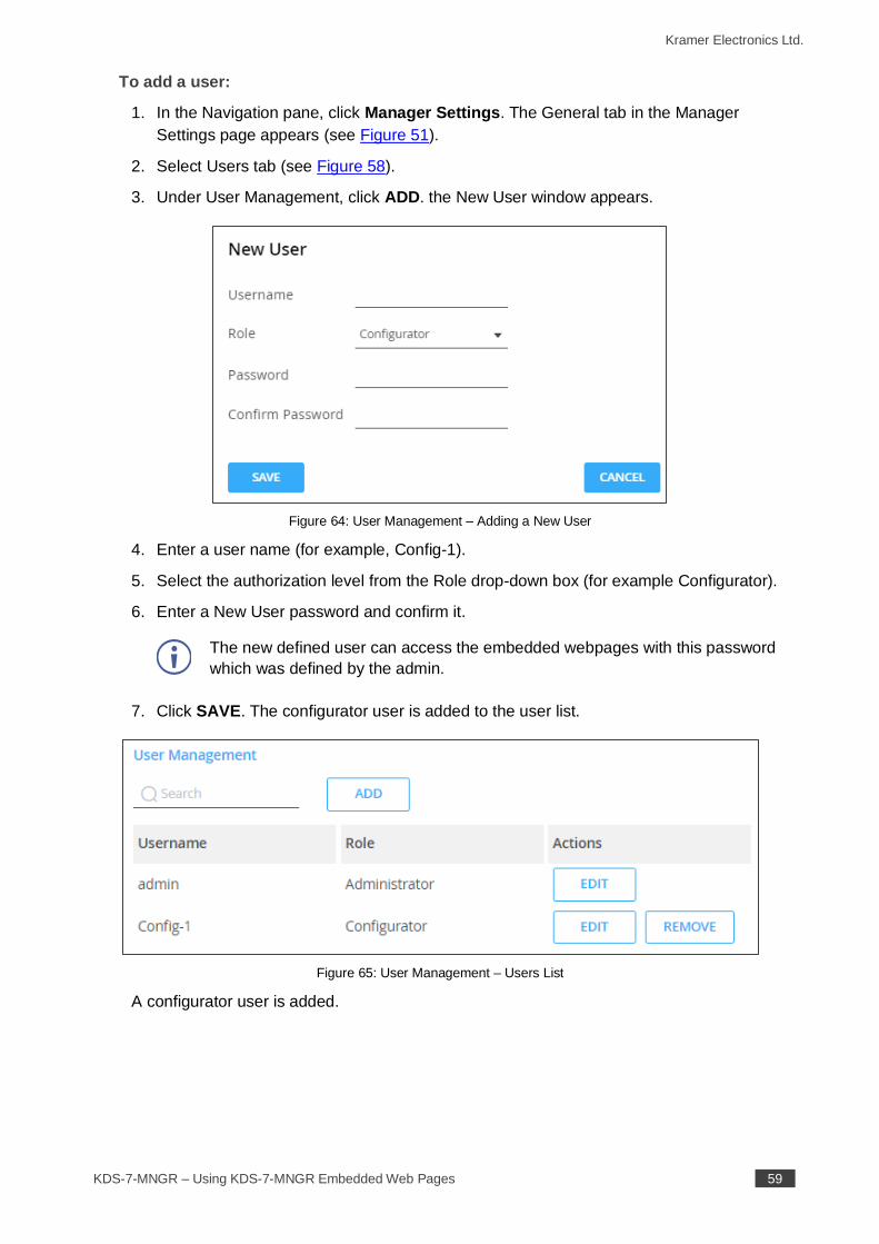
3. Under User Management, click ADD. the New User window appears.
Figure 64: User Management – Adding a New User
4. Enter a user name (for example, Config-1).
5. Select the authorization level from the Role drop-down box (for example Configurator).
6. Enter a New User password and confirm it.
The new defined user can access the embedded webpages with this password
which was defined by the admin.
7. Click SAVE. The configurator user is added to the user list.
Figure 65: User Management – Users List
A configurator user is added.
Kramer Electronics Ltd.
KDS-7-MNGR – Using KDS-7-MNGR Embedded Web Pages 60
Managing Device Status
KDS-7-MNGR diagnostics enables the following actions:
• Viewing KDS-7-MNGR Status on page 60.
• Viewing KDS-7-MNGR Advanced Status on page 61.
Viewing KDS-7-MNGR Status
View the device status.
To view device status:
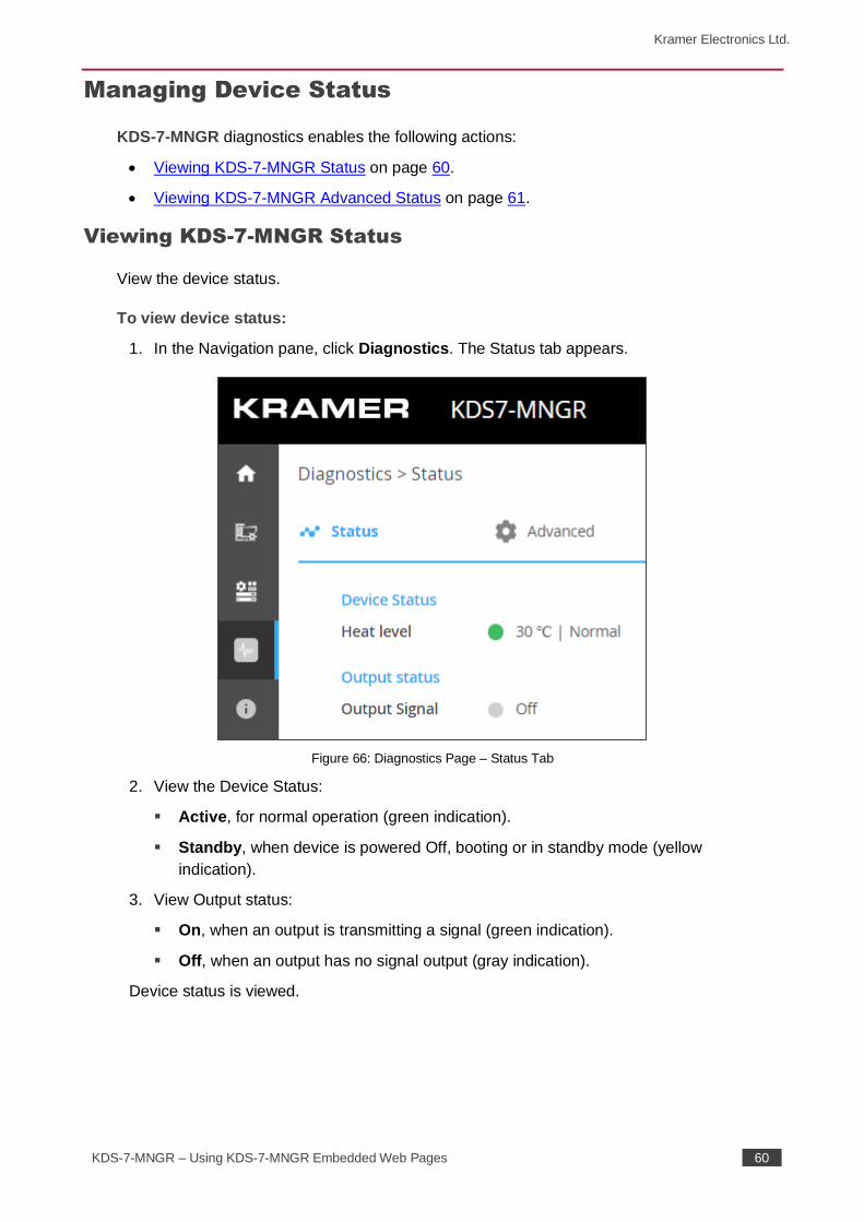
1. In the Navigation pane, click Diagnostics. The Status tab appears.
Figure 66: Diagnostics Page – Status Tab
2. View the Device Status:
▪ Active, for normal operation (green indication).
▪ Standby, when device is powered Off, booting or in standby mode (yellow
indication).
3. View Output status:
▪ On, when an output is transmitting a signal (green indication).
▪ Off, when an output has no signal output (gray indication).
Device status is viewed.
Kramer Electronics Ltd.
KDS-7-MNGR – Using KDS-7-MNGR Embedded Web Pages 61
Viewing KDS-7-MNGR Advanced Status
View the system log and gateway messages counter.
To view/export log:
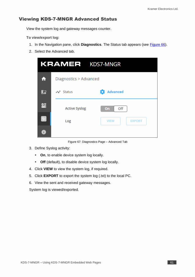
1. In the Navigation pane, click Diagnostics. The Status tab appears (see Figure 66).
2. Select the Advanced tab.
Figure 67: Diagnostics Page – Advanced Tab
3. Define Syslog activity:
▪ On, to enable device system log locally.
▪ Off (default), to disable device system log locally.
4. Click VIEW to view the system log, if required.
5. Click EXPORT to export the system log (.txt) to the local PC.
6. View the sent and received gateway messages.
System log is viewed/exported.
Kramer Electronics Ltd.
KDS-7-MNGR – Using KDS-7-MNGR Embedded Web Pages 62
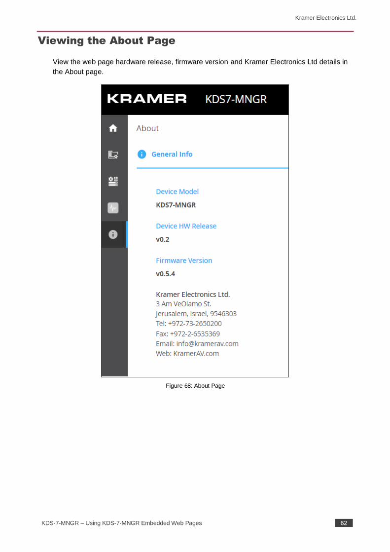
Viewing the About Page
View the web page hardware release, firmware version and Kramer Electronics Ltd details in
the About page.
Figure 68: About Page
Kramer Electronics Ltd.
KDS-7-MNGR – Technical Specifications 63
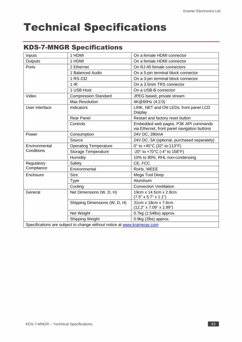
Technical Specifications
KDS-7-MNGR Specifications Inputs 1 HDMI On a female HDMI connector
Outputs 1 HDMI On a female HDMI connector
Ports 2 Ethernet On RJ-45 female connectors
1 Balanced Audio On a 5-pin terminal block connector
1 RS-232 On a 3-pin terminal block connector
1 IR On a 3.5mm TRS connector
1 USB Host On a USB-B connector
Video Compression Standard JPEG based, private stream
Max Resolution 4K@60Hz (4:2:0)
User Interface Indicators LINK, NET and ON LEDs, front panel LCD Display
Rear Panel Restart and factory reset button
Controls Embedded web pages, P3K API commands via Ethernet, front panel navigation buttons
Power Consumption 24V DC, 280mA
Source 24V DC, 5A (optional, purchased separately)
Environmental Conditions
Operating Temperature 0° to +45°C (32° to 113°F)
Storage Temperature -20° to +70°C (-4° to 158°F)
Humidity 10% to 90%, RHL non-condensing
Regulatory Compliance
Safety CE, FCC
Environmental RoHs, WEEE
Enclosure Size Mega Tool Deep
Type Aluminum
Cooling Convection Ventilation
General Net Dimensions (W, D, H) 19cm x 14.5cm x 2.8cm (7.5" x 5.7" x 1.1")
Shipping Dimensions (W, D, H) 31cm x 18cm x 7.6cm (12.2" x 7.09" x 2.99")
Net Weight 0.7kg (1.54lbs) approx.
Shipping Weight 0.9kg (2lbs) approx.
Specifications are subject to change without notice at www.kramerav.com
Kramer Electronics Ltd.
KDS-7-MNGR – Technical Specifications 64
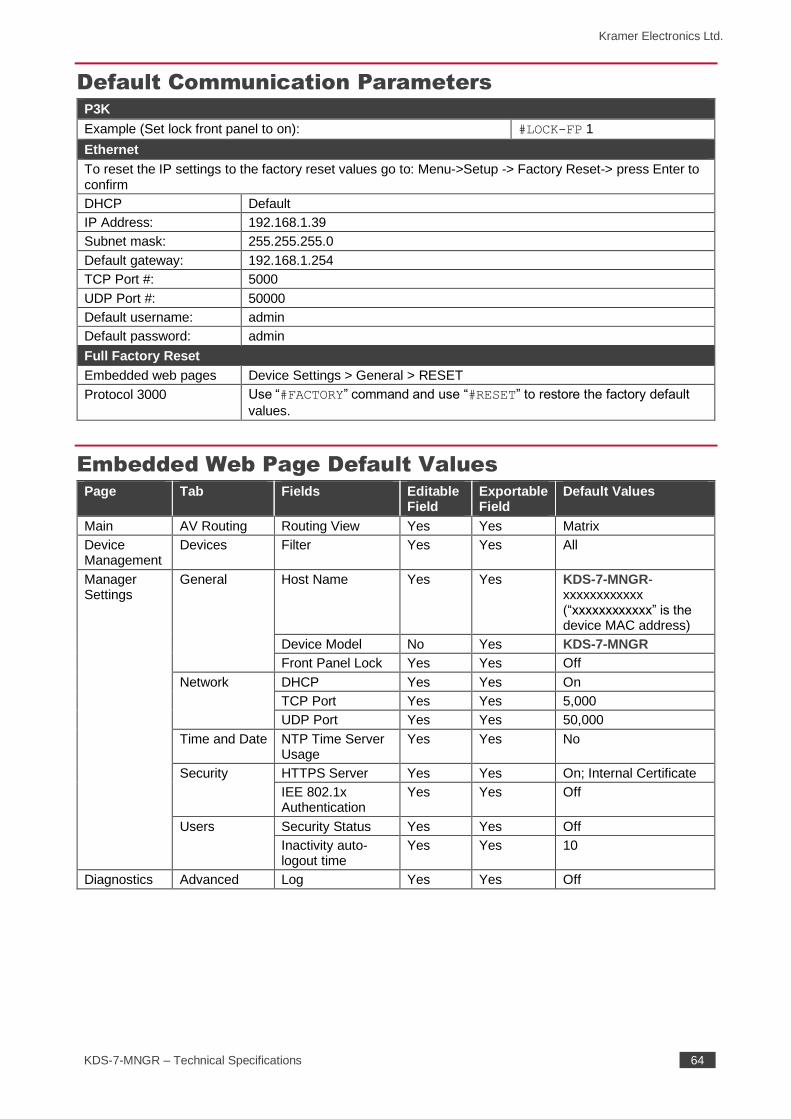
Default Communication Parameters P3K
Example (Set lock front panel to on): #LOCK-FP 1
Ethernet
To reset the IP settings to the factory reset values go to: Menu->Setup -> Factory Reset-> press Enter to confirm
DHCP Default
IP Address: 192.168.1.39
Subnet mask: 255.255.255.0
Default gateway: 192.168.1.254
TCP Port #: 5000
UDP Port #: 50000
Default username: admin
Default password: admin
Full Factory Reset
Embedded web pages Device Settings > General > RESET
Protocol 3000 Use “#FACTORY” command and use “#RESET” to restore the factory default
values.
Embedded Web Page Default Values Page Tab Fields Editable
Field Exportable Field
Default Values
Main AV Routing Routing View Yes Yes Matrix
Device Management
Devices Filter Yes Yes All
Manager Settings
General Host Name Yes Yes KDS-7-MNGR-xxxxxxxxxxxx (“xxxxxxxxxxxx” is the device MAC address)
Device Model No Yes KDS-7-MNGR
Front Panel Lock Yes Yes Off
Network DHCP Yes Yes On
TCP Port Yes Yes 5,000
UDP Port Yes Yes 50,000
Time and Date NTP Time Server Usage
Yes Yes No
Security HTTPS Server Yes Yes On; Internal Certificate
IEE 802.1x Authentication
Yes Yes Off
Users Security Status Yes Yes Off
Inactivity auto-logout time
Yes Yes 10
Diagnostics Advanced Log Yes Yes Off
Kramer Electronics Ltd.
KDS-7-MNGR – Protocol 3000 65
Protocol 3000
Kramer devices can be operated using Kramer Protocol 3000 commands sent via Ethernet
ports.
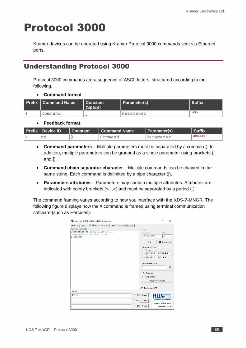
Understanding Protocol 3000
Protocol 3000 commands are a sequence of ASCII letters, structured according to the
following.
• Command format:
Prefix Command Name Constant (Space)
Parameter(s) Suffix
# Command Parameter <CR>
• Feedback format:
Prefix Device ID Constant Command Name Parameter(s) Suffix
~ nn @ Command Parameter <CR><LF>
• Command parameters – Multiple parameters must be separated by a comma (,). In
addition, multiple parameters can be grouped as a single parameter using brackets ([
and ]).
• Command chain separator character – Multiple commands can be chained in the
same string. Each command is delimited by a pipe character (|).
• Parameters attributes – Parameters may contain multiple attributes. Attributes are
indicated with pointy brackets (<…>) and must be separated by a period (.).
The command framing varies according to how you interface with the KDS-7-MNGR. The
following figure displays how the # command is framed using terminal communication
software (such as Hercules):
Kramer Electronics Ltd.
KDS-7-MNGR – Protocol 3000 66
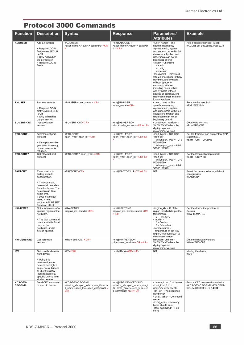
Protocol 3000 Commands Function Description Syntax Response Parameters/
Attributes Example
ADDUSER Add a new user + Require LOGIN firstly even SECUR is Off + Only admin has the permission + Require LOGIN firstly
#ADDUSER <user_name>,<level>,<password><CR>
~nn@ADDUSER <user_name>,<level>,<password><CR>
<user_name> - The specific username, alphanumeric, hyphen and underscore within 24 characters, hyphen and underscore can not at beginning or end <level> - User level - admin - config - operator <password> - Password, 8 to 24 characters (letters, numbers, and symbols without spaces or commas), at least including one number, one symbols without spaces or commas, one uppercase letter and one lowercase letter.
Add a configurator user (Bob): #ADDUSER Bob,config,Pass1234
RMUSER Remove an user + Require LOGIN firstly even SECUR is Off + Only admin has the permission
#RMUSER <user_name><CR> ~nn@RMUSER <user_name><CR>
<user_name> - The specific username, alphanumeric, hyphen and underscore within 24 characters, hyphen and underscore can not at beginning or end
Remove the user Bob: #RMUSER Bob
BL-VERSION? Get bootloader version
#BL-VERSION?<CR> ~nn@BL-VERSION <bootloader_version><CR><LF>
<bootloader_version> – XX.XX.XXXX where the digit groups are: major.minor.version
Get the BL version: #BL-VERSION?
ETH-PORT Set Ethernet port protocol. + If the port number you enter is already in use, an error is returned.
#ETH-PORT <port_type>,<port_id><CR>
~nn@ETH PORT <port_type>,<port_id><CR><LF>
<port_type> - TCP/UDP <port_id> - When port_type = TCP: 5000~5099 When port_type = UDP: 50000~50999
Set the Ethernet port protocol for TCP to port 5001: #ETH-PORT TCP,5001
ETH-PORT? Get Ethernet port protocol.
#ETH-PORT? <port_type><CR> ~nn@ETH PORT <port_type>,<port_id><CR><LF>
<port_type> - TCP/UDP <port_id> - When port_type = TCP: 5000~5099 When port_type = UDP: 50000~50999
Get the Ethernet port protocol: #ETH-PORT? TCP
FACTORY Reset device to factory default configuration. + This command deletes all user data from the device. The deletion can take some time. It does not trigger reset, it need another API 'RESET' for taking effect
#FACTORY<CR> ~nn@FACTORY ok<CR><LF> N/A Reset the device to factory default configuration: #FACTORY
HW-TEMP? Get temperature of a specific region of the hardware. + The Get command is not available for all parts of the hardware, and is device specific.
#HW-TEMP? <region_id>,<mode><CR>
~nn@HW-TEMP <region_id>,<temperature><CR><LF>
<region_id> - ID of the region for which to get the temperature 0 - First CPU <mode> - 0 - Celsius 1 - Fahrenheit <temperature> - Temperature of the HW region, rounded down to the closest integer
Get the device temperature in Celsius: #HW-TEMP? 0,0
HW-VERSION? Get hardware version
#HW-VERSION? <CR> ~nn@HW-VERSION <hardware_version><CR><LF>
hardware_version – XX.XX.XXXX where the digit groups are: major.minor.version
Get the hardware version: #HW-VERSION?
IDV Set visual indication from device. + Using this command, some devices can light a sequence of buttons or LEDs to allow identification of a specific device from similar devices.
#IDV<CR> ~nn@IDV ok<CR><LF> N/A Identify the device: #IDV
KDS-DEV-CEC-SND
Send CEC command to specific device
#KDS-DEV-CEC-SND <device_id>,<port_index>,<sn_id>,<cmd_name>,<cec_len>,<cec_command><CR>
~nn@KDS-DEV-CEC-SND <device_id>,<port_index>,<sn_id>,<cmd_name>,<cec_len>,<cec_command><CR><LF>
<device_id> - ID of device <port_id> - 1 to n (machine dependent) <sn_id> - The sequence number ID <cmd_name> - Command name <cmd_len> - How many bytes should send <cec_command> - Hex string
Send a CEC command to a device #KDS-DEV-CEC-SND KDS-DEC7-001D56080B53,1,1,1,2,4004
Kramer Electronics Ltd.
KDS-7-MNGR – Protocol 3000 67
Function Description Syntax Response Parameters/ Attributes
Example
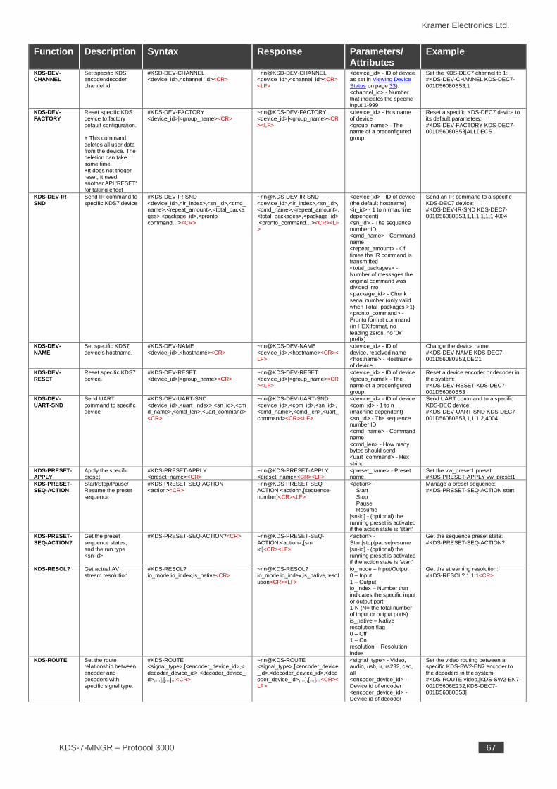
KDS-DEV-CHANNEL
Set specific KDS encoder/decoder channel id.
#KSD-DEV-CHANNEL <device_id>,<channel_id><CR>
~nn@KSD-DEV-CHANNEL <device_id>,<channel_id><CR><LF>
<device_id> - ID of device as set in Viewing Device Status on page 33). <channel_id> - Number that indicates the specific input 1-999
Set the KDS-DEC7 channel to 1: #KDS-DEV-CHANNEL KDS-DEC7-001D56080B53,1
KDS-DEV-FACTORY
Reset specific KDS device to factory default configuration. + This command deletes all user data from the device. The deletion can take some time. +It does not trigger reset, it need another API 'RESET' for taking effect
#KDS-DEV-FACTORY <device_id>|<group_name><CR>
~nn@KDS-DEV-FACTORY <device_id>|<group_name><CR><LF>
<device_id> - Hostname of device <group_name> - The name of a preconfigured group
Reset a specific KDS-DEC7 device to its default parameters: #KDS-DEV-FACTORY KDS-DEC7-001D56080B53|ALLDECS
KDS-DEV-IR-SND
Send IR command to specific KDS7 device
#KDS-DEV-IR-SND <device_id>,<ir_index>,<sn_id>,<cmd_name>,<repeat_amount>,<total_packages>,<package_id>,<pronto command…><CR>
~nn@KDS-DEV-IR-SND <device_id>,<ir_index>,<sn_id>,<cmd_name>,<repeat_amount>,<total_packages>,<package_id>,<pronto_command…><CR><LF>
<device_id> - ID of device (the default hostname) <ir_id> - 1 to n (machine dependent) <sn_id> - The sequence number ID <cmd_name> - Command name <repeat_amount> - Of times the IR command is transmitted <total_packages> - Number of messages the original command was divided into <package_id> - Chunk serial number (only valid when Total_packages >1) <pronto_command> - Pronto format command (in HEX format, no leading zeros, no ‘0x’ prefix)
Send an IR command to a specific KDS-DEC7 device: #KDS-DEV-IR-SND KDS-DEC7-001D56080B53,1,1,1,1,1,1,4004
KDS-DEV-NAME
Set specific KDS7 device's hostname.
#KDS-DEV-NAME <device_id>,<hostname><CR>
~nn@KDS-DEV-NAME <device_id>,<hostname><CR><LF>
<device_id> - ID of device, resolved name <hostname> - Hostname of device
Change the device name: #KDS-DEV-NAME KDS-DEC7-001D56080B53,DEC1
KDS-DEV-RESET
Reset specific KDS7 device.
#KDS-DEV-RESET <device_id>|<group_name><CR>
~nn@KDS-DEV-RESET <device_id>|<group_name><CR><LF>
<device_id> - ID of device <group_name> - The name of a preconfigured group.
Reset a device encoder or decoder in the system: #KDS-DEV-RESET KDS-DEC7-001D56080B53
KDS-DEV-UART-SND
Send UART command to specific device
#KDS-DEV-UART-SND <device_id>,<uart_index>,<sn_id>,<cmd_name>,<cmd_len>,<uart_command><CR>
~nn@KDS-DEV-UART-SND <device_id>,<com_id>,<sn_id>,<cmd_name>,<cmd_len>,<uart_command><CR><LF>
<device_id> - ID of device <com_id> - 1 to n (machine dependent) <sn_id> - The sequence number ID <cmd_name> - Command name <cmd_len> - How many bytes should send <uart_command> - Hex string
Send UART command to a specific KDS-DEC device: #KDS-DEV-UART-SND KDS-DEC7-001D56080B53,1,1,1,2,4004
KDS-PRESET-APPLY
Apply the specific preset
#KDS-PRESET-APPLY <preset_name><CR>
~nn@KDS-PRESET-APPLY <preset_name><CR><LF>
<preset_name> - Preset name
Set the vw_preset1 preset: #KDS-PRESET-APPLY vw_preset1
KDS-PRESET-SEQ-ACTION
Start/Stop/Pause/ Resume the preset sequence
#KDS-PRESET-SEQ-ACTION <action><CR>
~nn@KDS-PRESET-SEQ-ACTION <action>,[sequence-number]<CR><LF>
<action> - Start Stop Pause Resume [sn-id] - (optional) the running preset is activated if the action state is 'start'
Manage a preset sequence: #KDS-PRESET-SEQ-ACTION start
KDS-PRESET-SEQ-ACTION?
Get the preset sequence states, and the run type <sn-id>
#KDS-PRESET-SEQ-ACTION?<CR> ~nn@KDS-PRESET-SEQ-ACTION <action>,[sn-id]<CR><LF>
<action> - Start|stop|pause|resume [sn-id] - (optional) the running preset is activated if the action state is 'start'
Get the sequence preset state: #KDS-PRESET-SEQ-ACTION?
KDS-RESOL? Get actual AV stream resolution
#KDS-RESOL? io_mode,io_index,is_native<CR>
~nn@KDS-RESOL? io_mode,io_index,is_native,resolution<CR><LF>
io_mode – Input/Output 0 – Input 1 – Output io_index – Number that indicates the specific input or output port: 1-N (N= the total number of input or output ports) is_native – Native resolution flag 0 – Off 1 – On resolution – Resolution index
Get the streaming resolution: #KDS-RESOL? 1,1,1<CR>
KDS-ROUTE Set the route relationship between encoder and decoders with specific signal type.
#KDS-ROUTE <signal_type>,[<encoder_device_id>,<decoder_device_id>,<decoder_device_id>,...],[...]...<CR>
~nn@KDS-ROUTE <signal_type>,[<encoder_device_id>,<decoder_device_id>,<decoder_device_id>,...],[...]...<CR><LF>
<signal_type> - Video, audio, usb, ir, rs232, cec, all <encoder_device_id> - Device id of encoder <encoder_device_id> - Device id of decoder
Set the video routing between a specific KDS-SW2-EN7 encoder to the decoders in the system: #KDS-ROUTE video,[KDS-SW2-EN7-001D5606E232,KDS-DEC7-001D56080B53]
Kramer Electronics Ltd.
KDS-7-MNGR – Protocol 3000 68
Function Description Syntax Response Parameters/ Attributes
Example
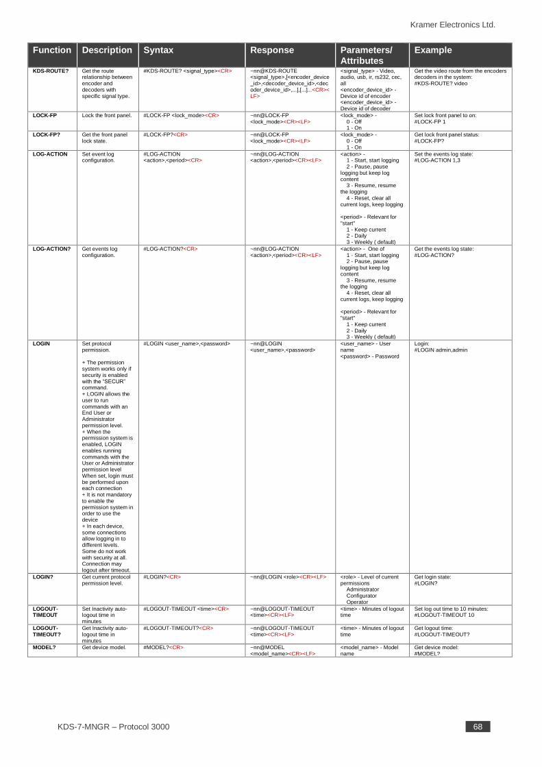
KDS-ROUTE? Get the route relationship between encoder and decoders with specific signal type.
#KDS-ROUTE? <signal_type><CR> ~nn@KDS-ROUTE <signal_type>,[<encoder_device_id>,<decoder_device_id>,<decoder_device_id>,...],[...]...<CR><LF>
<signal_type> - Video, audio, usb, ir, rs232, cec, all <encoder_device_id> - Device id of encoder <encoder_device_id> - Device id of decoder
Get the video route from the encoders decoders in the system: #KDS-ROUTE? video
LOCK-FP Lock the front panel. #LOCK-FP <lock_mode><CR> ~nn@LOCK-FP <lock_mode><CR><LF>
<lock_mode> - 0 - Off 1 - On
Set lock front panel to on: #LOCK-FP 1
LOCK-FP? Get the front panel lock state.
#LOCK-FP?<CR> ~nn@LOCK-FP <lock_mode><CR><LF>
<lock_mode> - 0 - Off 1 - On
Get lock front panel status: #LOCK-FP?
LOG-ACTION Set event log configuration.
#LOG-ACTION <action>,<period><CR>
~nn@LOG-ACTION <action>,<period><CR><LF>
<action> - 1 - Start, start logging 2 - Pause, pause logging but keep log content 3 - Resume, resume the logging 4 - Reset, clear all current logs, keep logging <period> - Relevant for "start" 1 - Keep current 2 - Daily 3 - Weekly ( default)
Set the events log state: #LOG-ACTION 1,3
LOG-ACTION? Get events log configuration.
#LOG-ACTION?<CR> ~nn@LOG-ACTION <action>,<period><CR><LF>
<action> - One of 1 - Start, start logging 2 - Pause, pause logging but keep log content 3 - Resume, resume the logging 4 - Reset, clear all current logs, keep logging <period> - Relevant for "start" 1 - Keep current 2 - Daily 3 - Weekly ( default)
Get the events log state: #LOG-ACTION?
LOGIN Set protocol permission. + The permission system works only if security is enabled with the “SECUR” command. + LOGIN allows the user to run commands with an End User or Administrator permission level. + When the permission system is enabled, LOGIN enables running commands with the User or Administrator permission level When set, login must be performed upon each connection + It is not mandatory to enable the permission system in order to use the device + In each device, some connections allow logging in to different levels. Some do not work with security at all. Connection may logout after timeout.
#LOGIN <user_name>,<password> ~nn@LOGIN <user_name>,<password>
<user_name> - User name <password> - Password
Login: #LOGIN admin,admin
LOGIN? Get current protocol permission level.
#LOGIN?<CR> ~nn@LOGIN <role><CR><LF> <role> - Level of current permissions Administrator Configurator Operator
Get login state: #LOGIN?
LOGOUT-TIMEOUT
Set Inactivity auto-logout time in minutes
#LOGOUT-TIMEOUT <time><CR> ~nn@LOGOUT-TIMEOUT <time><CR><LF>
<time> - Minutes of logout time
Set log out time to 10 minutes: #LOGOUT-TIMEOUT 10
LOGOUT-TIMEOUT?
Get Inactivity auto-logout time in minutes
#LOGOUT-TIMEOUT?<CR> ~nn@LOGOUT-TIMEOUT <time><CR><LF>
<time> - Minutes of logout time
Get logout time: #LOGOUT-TIMEOUT?
MODEL? Get device model. #MODEL?<CR> ~nn@MODEL <model_name><CR><LF>
<model_name> - Model name
Get device model: #MODEL?
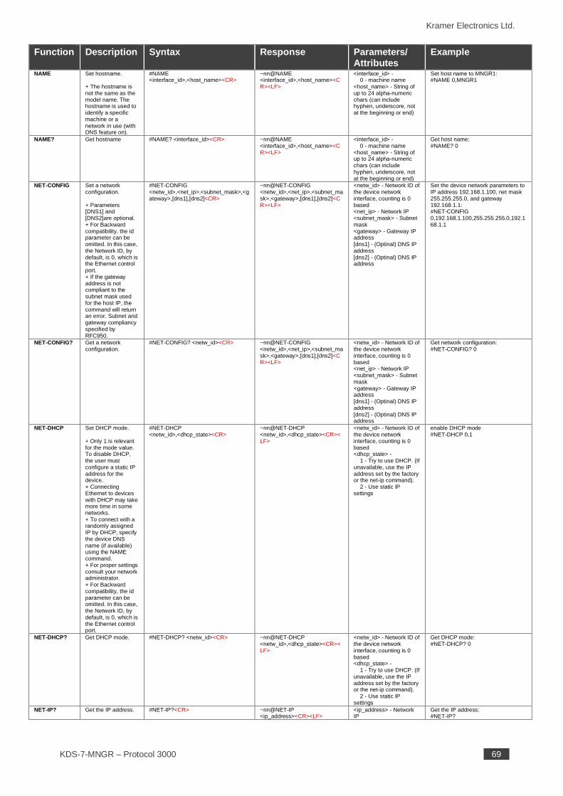
Kramer Electronics Ltd.
KDS-7-MNGR – Protocol 3000 69
Function Description Syntax Response Parameters/ Attributes
Example
NAME Set hostname. + The hostname is not the same as the model name. The hostname is used to identify a specific machine or a network in use (with DNS feature on).
#NAME <interface_id>,<host_name><CR>
~nn@NAME <interface_id>,<host_name><CR><LF>
<interface_id> - 0 - machine name <host_name> - String of up to 24 alpha-numeric chars (can include hyphen, underscore, not at the beginning or end)
Set host name to MNGR1: #NAME 0,MNGR1
NAME? Get hostname #NAME? <interface_id><CR> ~nn@NAME <interface_id>,<host_name><CR><LF>
<interface_id> - 0 - machine name <host_name> - String of up to 24 alpha-numeric chars (can include hyphen, underscore, not at the beginning or end)
Get host name: #NAME? 0
NET-CONFIG Set a network configuration. + Parameters [DNS1] and [DNS2]are optional. + For Backward compatibility, the id parameter can be omitted. In this case, the Network ID, by default, is 0, which is the Ethernet control port. + If the gateway address is not compliant to the subnet mask used for the host IP, the command will return an error. Subnet and gateway compliancy specified by RFC950.
#NET-CONFIG <netw_id>,<net_ip>,<subnet_mask>,<gateway>,[dns1],[dns2]<CR>
~nn@NET-CONFIG <netw_id>,<net_ip>,<subnet_mask>,<gateway>,[dns1],[dns2]<CR><LF>
<netw_id> - Network ID of the device network interface, counting is 0 based <net_ip> - Network IP <subnet_mask> - Subnet mask <gateway> - Gateway IP address [dns1] - (Optinal) DNS IP address [dns2] - (Optinal) DNS IP address
Set the device network parameters to IP address 192.168.1.100, net mask 255.255.255.0, and gateway 192.168.1.1: #NET-CONFIG 0,192.168.1.100,255.255.255.0,192.168.1.1
NET-CONFIG? Get a network configuration.
#NET-CONFIG? <netw_id><CR> ~nn@NET-CONFIG <netw_id>,<net_ip>,<subnet_mask>,<gateway>,[dns1],[dns2]<CR><LF>
<netw_id> - Network ID of the device network interface, counting is 0 based <net_ip> - Network IP <subnet_mask> - Subnet mask <gateway> - Gateway IP address [dns1] - (Optinal) DNS IP address [dns2] - (Optinal) DNS IP address
Get network configuration: #NET-CONFIG? 0
NET-DHCP Set DHCP mode. + Only 1 is relevant for the mode value. To disable DHCP, the user must configure a static IP address for the device. + Connecting Ethernet to devices with DHCP may take more time in some networks. + To connect with a randomly assigned IP by DHCP, specify the device DNS name (if available) using the NAME command. + For proper settings consult your network administrator. + For Backward compatibility, the id parameter can be omitted. In this case, the Network ID, by default, is 0, which is the Ethernet control port.
#NET-DHCP <netw_id>,<dhcp_state><CR>
~nn@NET-DHCP <netw_id>,<dhcp_state><CR><LF>
<netw_id> - Network ID of the device network interface, counting is 0 based <dhcp_state> - 1 - Try to use DHCP. (If unavailable, use the IP address set by the factory or the net-ip command). 2 - Use static IP settings
enable DHCP mode #NET-DHCP 0,1
NET-DHCP? Get DHCP mode. #NET-DHCP? <netw_id><CR> ~nn@NET-DHCP <netw_id>,<dhcp_state><CR><LF>
<netw_id> - Network ID of the device network interface, counting is 0 based <dhcp_state> - 1 - Try to use DHCP. (If unavailable, use the IP address set by the factory or the net-ip command). 2 - Use static IP settings
Get DHCP mode: #NET-DHCP? 0
NET-IP? Get the IP address. #NET-IP?<CR> ~nn@NET-IP <ip_address><CR><LF>
<ip_address> - Network IP
Get the IP address: #NET-IP?
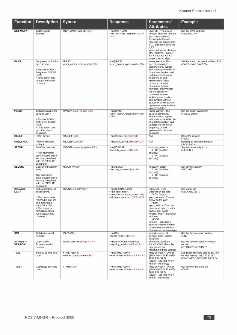
Kramer Electronics Ltd.
KDS-7-MNGR – Protocol 3000 70
Function Description Syntax Response Parameters/ Attributes
Example
NET-MAC? Get the MAC address.
#NET-MAC? <net_id><CR> ~nn@NET-MAC <net_id>,<mac_address><CR><LF>
<net_id> - The device network interface (if there are more than one). Counting is 0 based, meaning the control port is ‘0’, additional ports are 1,2,3…. <mac_address> - Unique MAC address. Format: XX-XX-XX-XX-XX-XX where X is hex digit
Get the MAC address: #NET-MAC? 0
PASS Set password for the specific user. + Require LOGIN firstly even SECUR is Off + Only admin can chang other user's password
#PASS <user_name>,<password><CR>
~nn@PASS <user_name>,<password><CR>
<user_name> - The specific username, alphanumeric, hyphen and underscore within 24 characters, hyphen and underscore can not at beginning or end <password> - New password, 8 to 24 characters (letters, numbers, and symbols without spaces or commas), at least including one number, one symbols without spaces or commas, one uppercase letter and one lowercase letter.
Set the admin password to Pass1234: #PASS admin,Pass1234
PASS? Get password of the specific user? + Require LOGIN firstly even SECUR is Off + Only admin can get other user's password
#PASS? <user_name><CR> ~nn@PASS <user_name>,<password><CR><LF>
<user_name> - The specific username, alphanumeric, hyphen and underscore within 24 characters, hyphen and underscore can not at beginning or end <password> - Current password
Get the admin password: #PASS? admin
RESET Reset device. #RESET<CR> ~nn@RESET ok<CR><LF> N/A Reset the device: #RESET
ROLLBACK Perform firmware rollback
#ROLLBACK<CR> ~nn@ROLLBACK ok<CR><LF> N/A Rollback to previous firmware: #ROLLBACK
SECUR Start/stop security. + The permission system works only if security is enabled with the “SECUR” command.
#SECUR <security_state><CR> ~nn@SECUR <security_state><CR><LF>
<security_state> - 0 - Off (disables security) 1 - On (enables security)
Ser device security to on #SECUR 1
SECUR? Get current security state. The permission system works only if security is enabled with the “SECUR” command.
#SECUR?<CR> ~nn@SECUR <security_state><CR><LF>
<security_state> - 0 - Off (disables security) 1 - On (enables security)
Get device security: #SECUR?
SIGNALS-LIST?
Get signal ID list of this machine. + The response is returned in one line and terminated with<CR><LF>. + The response format lists signal IDs separated by commas.
#SIGNALS-LIST?<CR> ~nn@SIGNALS LIST [<direction_type>. <port_format>.<port_index>.<signal_type>.<index>,..,]<CR><LF>
<direction_type> - Direction of the port: OUT - Output <port_format> - Type of signal on the port: HDMI <port_index> - The port number as printed on the front or rear panel <signal_type> - Signal ID attribute: VIDEO <index> - Indicates a specific channel number when there are multiple channels of the same type
Get signal list: #SIGNALS-LIST?
SN? Get device serial number.
#SN?<CR> ~nn@SN <serial_num><CR><LF>
<serial_num> - 14 decimal digits, factory assigned
Get the device serial number: #SN?
STANDBY-VERSION?
Get standby firmware version number.
#STANDBY-VERSION?<CR> ~nn@STANDBY-VERSION <standby_version><CR><LF>
<firmware_version> - XX.XX.XXXX where the digit groups are: major.minor.build version
Get the device standby firmware version: #STANDBY-VERSION?
TIME Set device time and date.
#TIME <day-of-week>,<date>,<time><CR>
~nn@TIME <day-of-week>,<date>,<time><CR><LF>
<day-of-week> - One of {SUN, MON, TUE, WED, THU, FRI, SAT} <date> - DD-MM-YYYY <time> - Hh:mm:ss
Set device time and date to 5:24:04 on Wednesday may 18th 2022 #TIME WED,18-05-2022,05:24:04
TIME? Get device time and date.
#TIME?<CR> ~nn@TIME <day-of-week>,<date>,<time><CR><LF>
<day-of-week> - One of {SUN, MON, TUE, WED, THU, FRI, SAT} <date> - DD-MM-YYYY <time> - Hh:mm:ss
Get device time and date: #TIME?
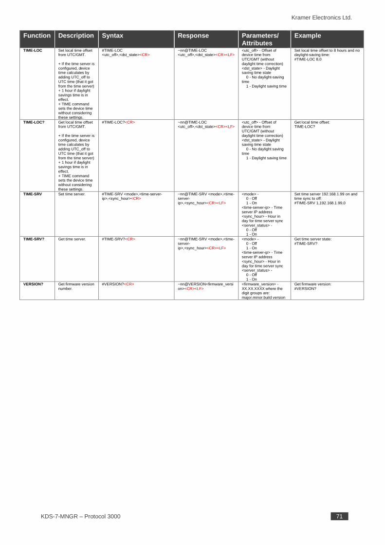
Kramer Electronics Ltd.
KDS-7-MNGR – Protocol 3000 71
Function Description Syntax Response Parameters/ Attributes
Example
TIME-LOC Set local time offset from UTC/GMT. + If the time server is configured, device time calculates by adding UTC_off to UTC time (that it got from the time server) + 1 hour if daylight savings time is in effect. + TIME command sets the device time without considering these settings.
#TIME-LOC <utc_off>,<dst_state><CR>
~nn@TIME-LOC <utc_off>,<dst_state><CR><LF>
<utc_off> - Offset of device time from UTC/GMT (without daylight time correction) <dst_state> - Daylight saving time state 0 - No daylight-saving time 1 - Daylight saving time
Set local time offset to 8 hours and no daylight-saving time: #TIME-LOC 8,0
TIME-LOC? Get local time offset from UTC/GMT. + If the time server is configured, device time calculates by adding UTC_off to UTC time (that it got from the time server) + 1 hour if daylight savings time is in effect. + TIME command sets the device time without considering these settings.
#TIME-LOC?<CR> ~nn@TIME-LOC <utc_off>,<dst_state><CR><LF>
<utc_off> - Offset of device time from UTC/GMT (without daylight time correction) <dst_state> - Daylight saving time state 0 - No daylight saving time 1 - Daylight saving time
Get local time offset: TIME-LOC?
TIME-SRV Set time server. #TIME-SRV <mode>,<time-server-ip>,<sync_hour><CR>
~nn@TIME-SRV <mode>,<time-server-ip>,<sync_hour><CR><LF>
<mode> - 0 - Off 1 - On <time-server-ip> - Time server IP address <sync_hour> - Hour in day for time server sync <server_status> - 0 - Off 1 - On
Set time server 192.168.1.99 on and time sync to off: #TIME-SRV 1,192.168.1.99,0
TIME-SRV? Get time server. #TIME-SRV?<CR> ~nn@TIME-SRV <mode>,<time-server-ip>,<sync_hour><CR><LF>
<mode> - 0 - Off 1 - On <time-server-ip> - Time server IP address <sync_hour> - Hour in day for time server sync <server_status> - 0 - Off 1 - On
Get time server state: #TIME-SRV?
VERSION? Get firmware version number.
#VERSION?<CR> ~nn@VERSION<firmware_version><CR><LF>
<firmware_version> - XX.XX.XXXX where the digit groups are: major.minor.build version
Get firmware version: #VERSION?
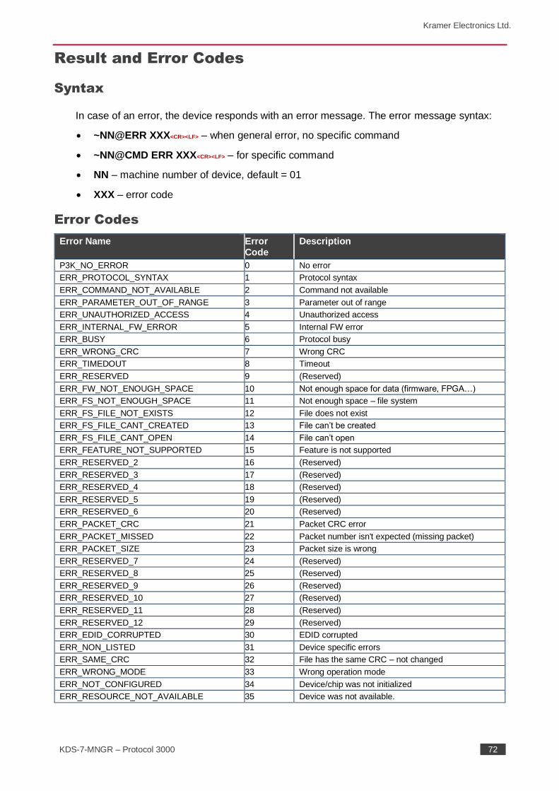
Kramer Electronics Ltd.
KDS-7-MNGR – Protocol 3000 72
Result and Error Codes
Syntax
In case of an error, the device responds with an error message. The error message syntax:
• ~NN@ERR XXX<CR><LF> – when general error, no specific command
• ~NN@CMD ERR XXX<CR><LF> – for specific command
• NN – machine number of device, default = 01
• XXX – error code
Error Codes
Error Name Error Code
Description
P3K_NO_ERROR 0 No error
ERR_PROTOCOL_SYNTAX 1 Protocol syntax
ERR_COMMAND_NOT_AVAILABLE 2 Command not available
ERR_PARAMETER_OUT_OF_RANGE 3 Parameter out of range
ERR_UNAUTHORIZED_ACCESS 4 Unauthorized access
ERR_INTERNAL_FW_ERROR 5 Internal FW error
ERR_BUSY 6 Protocol busy
ERR_WRONG_CRC 7 Wrong CRC
ERR_TIMEDOUT 8 Timeout
ERR_RESERVED 9 (Reserved)
ERR_FW_NOT_ENOUGH_SPACE 10 Not enough space for data (firmware, FPGA…)
ERR_FS_NOT_ENOUGH_SPACE 11 Not enough space – file system
ERR_FS_FILE_NOT_EXISTS 12 File does not exist
ERR_FS_FILE_CANT_CREATED 13 File can’t be created
ERR_FS_FILE_CANT_OPEN 14 File can’t open
ERR_FEATURE_NOT_SUPPORTED 15 Feature is not supported
ERR_RESERVED_2 16 (Reserved)
ERR_RESERVED_3 17 (Reserved)
ERR_RESERVED_4 18 (Reserved)
ERR_RESERVED_5 19 (Reserved)
ERR_RESERVED_6 20 (Reserved)
ERR_PACKET_CRC 21 Packet CRC error
ERR_PACKET_MISSED 22 Packet number isn't expected (missing packet)
ERR_PACKET_SIZE 23 Packet size is wrong
ERR_RESERVED_7 24 (Reserved)
ERR_RESERVED_8 25 (Reserved)
ERR_RESERVED_9 26 (Reserved)
ERR_RESERVED_10 27 (Reserved)
ERR_RESERVED_11 28 (Reserved)
ERR_RESERVED_12 29 (Reserved)
ERR_EDID_CORRUPTED 30 EDID corrupted
ERR_NON_LISTED 31 Device specific errors
ERR_SAME_CRC 32 File has the same CRC – not changed
ERR_WRONG_MODE 33 Wrong operation mode
ERR_NOT_CONFIGURED 34 Device/chip was not initialized
ERR_RESOURCE_NOT_AVAILABLE 35 Device was not available.
The warranty obligations of Kramer Electronics Inc. (“Kramer Electronics”) for this product are limited to the terms set forth below:
What is Covered
This limited warranty covers defects in materials and workmanship in this product.
What is Not Covered
This limited warranty does not cover any damage, deterioration or malfunction resulting from any alteration, modification, improper or unreasonable use or maintenance, misuse, abuse, accident, neglect, exposure to excess moisture, fire, improper packing and shipping (such claims must be presented to the carrier), lightning, power surges, or other acts of nature. This limited warranty does not cover any damage, deterioration or malfunction resulting from the installation or removal of this product from any installation, any unauthorized tampering with this product, any repairs attempted by anyone unauthorized by Kramer Electronics to make such repairs, or any other cause which does not relate directly to a defect in materials and/or workmanship of this product. This limited warranty does not cover cartons, equipment enclosures, cables or accessories used in conjunction with this product. Without limiting any other exclusion herein, Kramer Electronics does not warrant that the product covered hereby, including, without limitation, the technology and/or integrated circuit(s) included in the product, will not become obsolete or that such items are or will remain compatible with any other product or technology with which the product may be used.
How Long this Coverage Lasts The standard limited warranty for Kramer products is seven (7) years from the date of original purchase, with the following exceptions:
1. All Kramer VIA hardware products are covered by a standard three (3) year warranty for the VIA hardware and a standard three (3) year
warranty for firmware and software updates; all Kramer VIA accessories, adapters, tags, and dongles are covered by a standard one (1) year warranty.
2. Kramer fiber optic cables, adapter-size fiber optic extenders, pluggable optical modules, active cables, cable retractors, ring mounted adapters, portable power chargers, Kramer speakers, and Kramer touch panels are covered by a standard one (1) year warranty. Kramer 7-inch touch panels purchased on or after April 1st, 2020 are covered by a standard two (2) year warranty.
3. All Kramer Calibre products, all Kramer Minicom digital signage products, all HighSecLabs products, all streaming, and all wi reless products are covered by a standard three (3) year warranty.
4. All Sierra Video MultiViewers are covered by a standard five (5) year warranty.
5. Sierra switchers & control panels are covered by a standard seven (7) year warranty (excluding power supplies and fans that are covered for three (3) years).
6. K-Touch software is covered by a standard one (1) year warranty for software updates.
7. All Kramer passive cables are covered by a lifetime warranty.
Who is Covered Only the original purchaser of this product is covered under this limited warranty. This limited warranty is not transferable to subsequent purchasers or owners of this product.
What Kramer Electronics Will Do
Kramer Electronics will, at its sole option, provide one of the following three remedies to whatever extent it shall deem necessary to satisfy a proper claim under this limited warranty:
1. Elect to repair or facilitate the repair of any defective parts within a reasonable period of time, free of any charge for the necessary parts and labor to complete the repair and restore this product to its proper operating condition. Kramer Electronics will also pay the shipping costs necessary to return this product once the repair is complete.
2. Replace this product with a direct replacement or with a similar product deemed by Kramer Electronics to perform substantially the same function as the original product. If a direct or similar replacement product is supplied, the original product’s end warranty date remains unchanged and is transferred to the replacement product.
3. Issue a refund of the original purchase price less depreciation to be determined based on the age of the product at the time remedy is sought
under this limited warranty.
What Kramer Electronics Will Not Do Under This Limited Warranty If this product is returned to Kramer Electronics or the authorized dealer from which it was purchased or any other party authorized to repair Kramer Electronics products, this product must be insured during shipment, with the insurance and shipping charges prepaid by you. If this product is returned uninsured, you assume all risks of loss or damage during shipment. Kramer Electronics will not be responsible for any costs related to the removal or re-installation of this product from or into any installation. Kramer Electronics will not be responsible for any costs related to any setting up this product, any adjustment of user controls or any programming required for a specific installation of this product.
How to Obtain a Remedy Under This Limited Warranty
To obtain a remedy under this limited warranty, you must contact either the authorized Kramer Electronics reseller from whom you purchased this product or the Kramer Electronics office nearest you. For a list of authorized Kramer Electronics resellers and/or Kramer Electronics authorized service providers, visit our web site at www.kramerav.com or contact the Kramer Electronics office nearest you. In order to pursue any remedy under this limited warranty, you must possess an original, dated receipt as proof of purchase from an authorized Kramer Electronics reseller. If this product is returned under this limited warranty, a return authorization number, obtained from Kramer Electronics, will be required (RMA number). You may also be directed to an authorized reseller or a person authorized by Kramer Electronics to repair the product. If it is decided that this product should be returned directly to Kramer Electronics, this product should be properly packed, preferably in the original carton, for shipping. Cartons not bearing a return authorization number will be refused.
Limitation of Liability THE MAXIMUM LIABILITY OF KRAMER ELECTRONICS UNDER THIS LIMITED WARRANTY SHALL NOT EXCEED THE ACTUAL PURCHASE PRICE PAID FOR THE PRODUCT. TO THE MAXIMUM EXTENT PERMITTED BY LAW, KRAMER ELECTRONICS IS NOT RESPONSIBLE FOR DIRECT, SPECIAL, INCIDENTAL OR CONSEQUENTIAL DAMAGES RESULTING FROM ANY BREACH OF WARRANTY OR CONDITION, OR UNDER ANY OTHER LEGAL THEORY. Some countries, districts or states do not allow the exclusion or limitation of relief, special, incidental, consequential or indirect damages, or the limitation of liability to specified amounts, so the above limitations or exclusions may not apply to you.
Exclusive Remedy
TO THE MAXIMUM EXTENT PERMITTED BY LAW, THIS LIMITED WARRANTY AND THE REMEDIES SET FORTH ABOVE ARE EXCLUSIVE AND IN LIEU OF ALL OTHER WARRANTIES, REMEDIES AND CONDITIONS, WHETHER ORAL OR WRITTEN, EXPRESS OR IMPLIED. TO THE MAXIMUM EXTENT PERMITTED BY LAW, KRAMER ELECTRONICS SPECIFICALLY DISCLAIMS ANY AND ALL IMPLIED WARRANTIES, INCLUDING, WITHOUT LIMITATION, WARRANTIES OF MERCHANTABILITY AND FITNESS FOR A PARTICULAR PURPOSE. IF KRAMER ELECTRONICS CANNOT LAWFULLY DISCLAIM OR EXCLUDE IMPLIED WARRANTIES UNDER APPLICABLE LAW, THEN ALL IMPLIED WARRANTIES COVERING THIS PRODUCT, INCLUDING WARRANTIES OF MERCHANTABILITY AND FITNESS FOR A PARTICULAR PURPOSE, SHALL APPLY TO THIS PRODUCT AS PROVIDED UNDER APPLICABLE LAW. IF ANY PRODUCT TO WHICH THIS LIMITED WARRANTY APPLIES IS A “CONSUMER PRODUCT” UNDER THE MAGNUSON-MOSS WARRANTY ACT (15 U.S.C.A. §2301, ET SEQ.) OR OTHER APPLICABLE LAW, THE FOREGOING DISCLAIMER OF IMPLIED WARRANTIES SHALL NOT APPLY TO YOU, AND ALL IMPLIED WARRANTIES ON THIS PRODUCT, INCLUDING WARRANTIES OF MERCHANTABILITY AND FITNESS FOR THE PARTICULAR PURPOSE, SHALL APPLY AS PROVIDED UNDER APPLICABLE LAW.
Other Conditions This limited warranty gives you specific legal rights, and you may have other rights which vary from country to country or state to state.
This limited warranty is void if (i) the label bearing the serial number of this product has been removed or defaced, (ii) the product is not distributed by Kramer Electronics or (iii) this product is not purchased from an authorized Kramer Electronics reseller. If you are unsure whether a reseller is an authorized Kramer Electronics reseller, visit our web site at www.kramerav.com or contact a Kramer Electronics office from the list at the end of this document. Your rights under this limited warranty are not diminished if you do not complete and return the product registration form or complete and submit the online product registration form. Kramer Electronics thanks you for purchasing a Kramer Electronics product. We hope it will give you years of satisfaction.

www.KramerAV.com [email protected]
P/N: 2900- 301556 Rev: 1
SAFETY WARNING
Disconnect the unit from the power supply before opening and servicing
For the latest information on our products anwd a list of Kramer distributors, visit our website where
updates to this user manual may be found.
We welcome your questions, comments, and feedback.
The terms HDMI, HDMI High-Definition Multimedia Interface, and the HDMI Logo are trademarks or registered trademarks of HDMI Licensing Administrator, Inc.
All brand names, product names, and trademarks are the property of their respective owners.
Related Documents